sopc builder data sheet
TRANSCRIPT
July 2002, Version 1.0 Data Sheet
SOPC Builder
Introduction
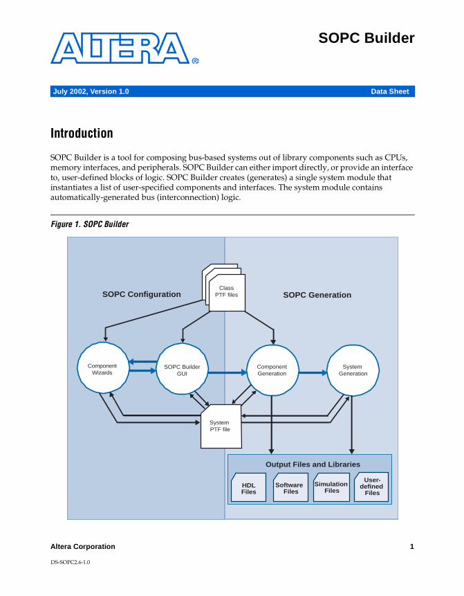
SOPC Builder is a tool for composing bus-based systems out of library components such as CPUs, memory interfaces, and peripherals. SOPC Builder can either import directly, or provide an interface to, user-defined blocks of logic. SOPC Builder creates (generates) a single system module that instantiates a list of user-specified components and interfaces. The system module contains automatically-generated bus (interconnection) logic.
Figure 1. SOPC Builder
ComponentWizards
ComponentGeneration
SOPC Generation SOPC Configuration
Output Files and Libraries
Simulation Files
User-defined
FilesSoftware
Files
System Generation
ClassPTF files
System PTF file
SOPC Builder GUI
HDLFiles
Altera Corporation 1
DS-SOPC2.6-1.0
SOPC Builder Data Sheet
SOPC Builder automatically generates interconnect (bus) logic between Avalon master and slave ports on all system components. SOPC Builder is most often used to construct embedded microprocessor systems that include CPUs, memories, and I/O peripherals. SOPC Builder can, however, generate useful dataflow systems with no CPU at all. SOPC Builder allows you to specify bus topologies with multiple masters and slaves. Bus logic, including arbitrators, are automatically generated during system construction.
SOPC Builder library components can be very simple blocks of fixed logic, or they can be complex, parameterized, dynamically-generated subsystems. Many Altera SOPC Builder library components include (for example) Wizard-based graphical interfaces for configuration, and HDL generator programs that can deliver the component as either synthesizable Verilog or VHDL.
SOPC Builder simplifies system-level synthesis and simulation. SOPC Builder includes an integrated synthesis tool (SOPC Builder incorporates LeonardoSpectrum™) and runs synthesis automatically as part of the system-generation process.
Starting SOPC Builder
The SOPC Builder tool is accessible through the Quartus® II Software. You may use SOPC Builder once you have either created a new Quartus II project. To access SOPC Builder from the Quartus II software, follow this step:
v To access SOPC Builder from the Quartus II software, choose SOPC Builder (Tools menu).
Figure 2. SOPC Builder
f See the Altera literature page at http://www.altera.com/literature/lit-index.html for tutorials on using SOPC Builder and information about about Quartus II software.
2 Altera Corporation
SOPC Builder Data Sheet
A convenient method for re-running SOPC Builder to edit an existing system module is to double-click the system module’s symbol in the Quartus schematic editor.
SOPC Builder Tool
SOPC Builder consists of two substantially separate pieces:
1. A graphical user interface (GUI) for listing and arranging system components. Within the GUI, each component may also, itself, provide a graphical user interface for its own configuration. The GUI creates a description of the system called “the system PTF file.”
2. A generator-program that converts the system description (PTF file) into its hardware implementation. The generator program (among other tasks) creates an HDL description of the system and then synthesizes it for the selected target device.
SOPC Builder GUI
SOPC Builder provides a GUI for specifying what components the system will contain and how the components are arranged and generated. The GUI itself does not generate any logic, create any software, or perform any other system-generation task. The GUI is just a “front-end” or “editor” for the system-description file (system PTF file).
1 You can edit the system PTF file directly in any text editor. Be sure, however, that SOPC Builder GUI is closed as the SOPC-GUI is functionally a PTF editor, and having the same file open simultaneously in two editors may produce unpredictable results.
The SOPC Builder’s graphical user interface consists of several pages (tabs):
■ System Contents ■ Arbitration Priorities■ An additional page for every CPU component in the system■ A final “System Generation” page
The System Contents Page
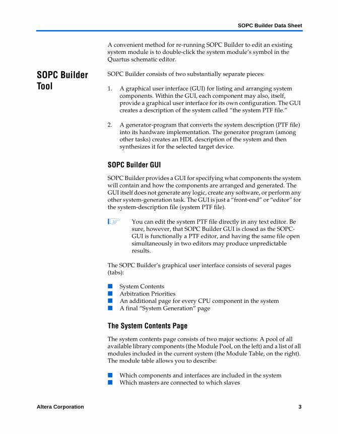
The system contents page consists of two major sections: A pool of all available library components (the Module Pool, on the left) and a list of all modules included in the current system (the Module Table, on the right). The module table allows you to describe:
■ Which components and interfaces are included in the system■ Which masters are connected to which slaves
Altera Corporation 3
SOPC Builder Data Sheet
■ The system address map■ The system IRQ assignments■ Arbitration priorities for shared slaves
The left-hand side of the Module Table displays interconnections between masters and slaves. Any module in the system can have one or more master or slave ports. Any master can be connected to any slave if both master and slave use the same bus protocol. Notice that Avalon and Avalon_tristate are different bus-protocols, and therefore a bridge-component is required to interface an avalon master to an avalon_tristate slave. Every master in the system has a corresponding column on the left side of the Module Table. Using the View menu, you can change the appearance of the master columns. You can hide the master columns entirely, display them as a patch-panel (interconnection-priority only), or display the numeric arbitration priorities.
Figure 3. SOPC Builder System Contents Page
4 Altera Corporation
SOPC Builder Data Sheet
Arbitration Priorities
Whenever two masters share (have access to) the same slave, SOPC Builder automatically inserts an arbiter to control access to the slave. The arbiter determines which master is granted access to the slave when simultaneous requests occur. There will be one arbiter inserted for each shared slave. A slave will have an integer arbitration priority for each of its masters. Conflicts are resolved according to the following rule: If each master has a priority Pi, and the sum of all the priorities is Ptotal, then master number i will win arbitration Pi times out of every Ptotal conflicts.
v To view arbitration priorities, choose Show Arbitration Priorities (View menu).
CPU Pages
Each CPU in your system will have an associated tab
■ This tab allows you to specify interrelationships (bindings) between a CPU and other modules in your system. For example, every CPU will treat some other system module as its default program–memory.
■ SOPC Builder will display an additional tab for every component that has a Bind_Program assignment in its class.ptf (library definition) file. This assignment is typically only set for CPUs, but it may be set for any other type of component as well.
The Generator Program Page
The SOPC Builder generator program can be run directly from the command-line, or by pressing Generate in the GUI.
The Generator program performs the following tasks:
■ Reads the system description (system PTF file).
■ Creates software files (drivers, libraries, and utilities) for any system-components that provide software support in their library definition.
■ Runs every component’s individual generator program. Each component in the system may have its own generator program (which may, for example, create an HDL description of the component). The main SOPC Builder generator program runs the sub-generator program associated with every component that has one.
■ Generates the system-level HDL file (in either VHDL or Verilog) This generation file contains:
Altera Corporation 5
SOPC Builder Data Sheet
– An instance of every component in the system– Bus logic for implementing module interconnect, including:
- Address decoders- Data bus multiplexers- Arbiters for shared resources- Reset-generation and conditioning logic- Interrupt prioritization logic- Dynamic bus sizing (for adapting masters to slaves with
wider or narrower data busses) - All passive interconnections between master and slave ports
– A simulation test-bench that: - Instantiates the system module- Drives clock and reset inputs with default behaviors- Instantiates and connects any simulation models for system-
external components (for example; memory models)■ Creates a symbol (.bsf-file) for the system module■ Creates a ModelSim® simulation project directory that includes:
– Simulation data-files for all memory components that specify contents
– A setup_sim.do file that contains useful setup and aliases customized for simulating the generated system
– A wave_presets.do file that contains a useful initial set of bus-interface waveforms
– A ModelSim project (.mpf file) for the current system
■ Synthesizes the entire system module and all its contents using LeonardoSpectrum. The result is an .edf-file ready for place-and-route or inclusion as a module in a larger design.
■ Writes a command-line system-generation script so the system can be conveniently regenerated in the future without using the GUI.
■ Writes a TCL script into each SDK directory which can be run from Quartus. This TCL script initializes Quartus's software mode with all the files in the SDK's library, and appropriate command-line switches for a debug build. You must still add your main()routine.
Running the Generator Program from the Command Line
The SOPC Builder generator program is an executable script that can be run from your system’s command line. You provide the name of the current system (ptf filename), the system directory, and other parameters as command-line arguments. Every time you generate a system, SOPC Builder creates a script that runs the generator program with the correct arguments needed to generate your system named <your_system_name>_generation_script. Running this script has the same effect as pressing Generate in the SOPC Builder GUI.
6 Altera Corporation
SOPC Builder Data Sheet
The SOPC Builder Library
When building a system, you can add modules from one of two sources:
1. Predefined modules that are installed in the SOPC Builder library.
2. User-defined modules. You may incorporate blocks of user-defined logic directly into your SOPC Builder system, or you may request an interface customized to fit your block of system-external logic. See “Interfacing User-Designed Logic to SOPC Builder” on page 9.
SOPC Builder is delivered with a set of built-in library components (modules), including a UART, a timer, a PIO, an Avalon Tri-state bridge, and several simple memory interfaces. You can obtain additional SOPC Builder components from Altera or third-party IP developers. When you install new SOPC Builder library components, they will be automatically “discovered” by SOPC Builder and appear in the Module Pool the next time you run the GUI.
f Check Altera’s web site http://www.altera.com/literature/lit-index.html for up-to-date information about available SOPC Builder library components.
Library Search Path SOPC Builder finds all library components installed on your system by scanning for component directories in a search-path. The order of the search is as follows:
■ The components directory within the SOPC Builder installation■ The current project directory■ One or more user-specified directories (File > Setup menu)
Components found latest in the search have priority over those found earliest. This allows project- and user-specified components to override any built-in components.
Library class.ptf Files
All valid library components are recognized by the presence of a single file in their directory named class.ptf. A component’s class.ptf file declares and defines all the information about that component so it can appear in, and be used by, SOPC Builder. A class.ptf file will, for example, contain the formal name of a component, a description of its master- and slave-ports, and a default configuration for all new instances of that component. It may also contain a complete declaration of all I/O ports on that component, and it may even contain a complete description of a GUI for configuring the component.
Altera Corporation 7
SOPC Builder Data Sheet
f IP developers can check the SOPC Builder PTF File Reference Manual at the Altera literature web page at http://www.altera.com/literature/lit-index.html for up-to-date documents that detail all of the recognized sections and assignments in class.ptf files.
In addition to the class.ptf file, a components’ library directory may also contain the logic that implements the component (for example, a VHDL, Verilog, or encrypted netlist file), software libraries and drivers that support the component, documentation, and any other component-specific information provided by the vendor. Many Altera library components contain a generator program that emit synthesizable Verilog or VHDL.
Bus Protocols SOPC Builder supports two bus types: AMBA™–AHB and Avalon.
■ For more information on the advanced microprocessor bus architecture (AMBA) hardware bus (AHB) bus protocol, see http://www.arm.com/armtech/AMBA_Spec?OpenDocument
■ For more information on the Avalon bus protocol, see the Avalon Bus Specification Reference Manual
AHB is an industry-standard bus protocol for connecting IP cores via an on-chip bus. Avalon is a flexible bus interface that is intended as a superset of popular, simple microprocessor bus interfaces (e.g. Wishbone, VCI and others). Most IP cores with a simple bus interface can express their interface signals and timing by selecting amongst preexisting Avalon signals and settings.
Any IP block (module) used within SOPC Builder can have multiple master and/or slave interfaces. Master interfaces can be either Avalon or AHB bus-types. For example, the Altera Avalon UART has a single Avalon slave interface. The Nios CPU has two Avalon master interfaces (separate instruction and data busses). An IP author can create a library component with both Avalon and AHB masters and slaves on the same module. There is no hard limit to the number or type of master and slave interfaces a module can have, though in practice few modules have more than two or three interfaces, and most only have one slave interface.
SOPC Builder allows you to specify any arbitrary connection between masters and slaves using the patch panel interface. The patch panel interface is not displayed by default for simple systems, but can always be displayed by selecting Show Master Connections from the View menu.
8 Altera Corporation
SOPC Builder Data Sheet
Mixing Bus Interfaces
SOPC Builder automatically generates interconnect logic to connect masters and slaves of the same bus type. This interconnect logic is included in the final, generated top-level system module, and is synthesized and simulated along with all other system components. However, masters and slaves cannot be directly connected, if they have different bus types. To allow connections between different bus types, SOPC-Builder includes bridges in the component library. For example, to connect an Avalon master M to an AHB slave S, you would need to insert an Avalon-to-AHB bridge. In this example, M would be connected to the bridge’s slave port, and S is connected to the bridge’s master port. Likewise, an AHB master can connect to an Avalon slave by inserting an AHB-to-Avalon bridge.
Tri-State Bus Interfaces
SOPC Builder makes it easy to handle external (off-chip) devices and memory as library components by providing a tri-state variant of the Avalon bus protocol. Asynchronous and simple synchronous device interfaces can be expressed by the properly-selected Avalon interface signals and parameters. Some of the example components delivered with SOPC Builder (for example, SRAM and FLASH interfaces) are external devices represented as Avalon Tri-State slaves. Note that Avalon Tri-state is considered a different bus-protocol than Avalon. Consequently, you must insert an Avalon Tri-state Bridge component to connect an Avalon master to an (always off-chip) Avalon Tri-state component.
Interfacing User-Designed Logic to SOPC Builder
Most practical SOPC Builder systems include both modules taken from the library and some custom (user-designed) logic. There are four broad mechanisms for using an SOPC Builder system module with user–designed logic:
1. Simple PIO Connection — Include one or more PIO devices in the SOPC Builder system. The PIO’s input- and output-pins will appear as I/O ports at the top level (i.e. as pins on the aggregate system module). If you connect these pins to other logic, the system-module software can directly control (or read) the logic level on each pin.
2. Instantiation Inside the System Module — SOPC Builder can incorporate a block of user-logic by instantiating it directly within the system module. SOPC Builder will create bus-logic and connect it to all designated bus-ports on the user-designed block. All I/O pins not designated as bus-connections will be promoted to the top
Altera Corporation 9
SOPC Builder Data Sheet
level, and appear as I/O pins on the system module. The user-designed block can be instantiated either as a black-box, or as HDL which is synthesized along with the rest of the system during the generation phase.
3. Bus Interface to External Logic — SOPC Builder can add a set of bus-interface pins customized to fit an external logic block. The bus interface includes address, data, and control signals (including decoded device-select) suitable for direct connection to a bus-interface on the device.
4. Publishing a Local SOPC Builder Component — SOPC Builder can publish your logic or interface as a library component on your local system.
Instantiating a User-Logic Block Inside the System Module
The easiest way to include a pre-existing block of user-logic in an SOPC Builder system is to incorporate it directly into the system module. SOPC Builder provides a GUI that allows you to specify the design-files (VHDL, Verilog, schematic (.bdf), or netlist (.edf) files) that implement the block. SOPC Builder scans the design files and find all of the block’s top-level I/O pins. The GUI provides a simple method for designating which pins are bus-connection ports, and which pins are promoted to I/O pins at the system-module’s top level. When you instantiate a block of user-logic inside the system module, SOPC Builder automatically generates all HDL necessary to instantiate, connect, and control your block.
To instantiate a block of user-defined logic in an SOPC Builder system module see Figure 4 and the process flow in Figure 5.
10 Altera Corporation
SOPC Builder Data Sheet
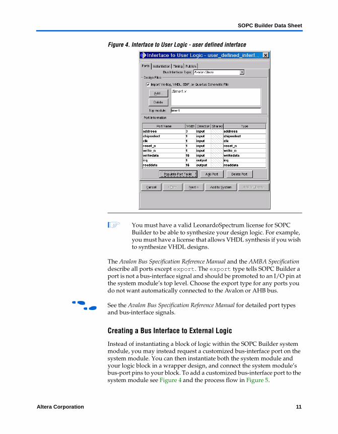
Figure 4. Interface to User Logic - user defined interface
1 You must have a valid LeonardoSpectrum license for SOPC Builder to be able to synthesize your design logic. For example, you must have a license that allows VHDL synthesis if you wish to synthesize VHDL designs.
The Avalon Bus Specification Reference Manual and the AMBA Specification describe all ports except export. The export type tells SOPC Builder a port is not a bus-interface signal and should be promoted to an I/O pin at the system module’s top level. Choose the export type for any ports you do not want automatically connected to the Avalon or AHB bus.
f See the Avalon Bus Specification Reference Manual for detailed port types and bus-interface signals.
Creating a Bus Interface to External Logic
Instead of instantiating a block of logic within the SOPC Builder system module, you may instead request a customized bus-interface port on the system module. You can then instantiate both the system module and your logic block in a wrapper design, and connect the system module’s bus-port pins to your block. To add a customized bus-interface port to the system module see Figure 4 and the process flow in Figure 5.
Altera Corporation 11
SOPC Builder Data Sheet
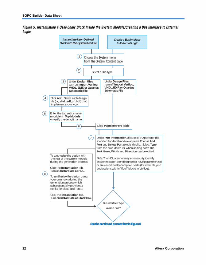
Figure 5. Instantiating a User-Logic Block Inside the System Module/Creating a Bus Interface to External Logic
Instantiate User-Defined Block into the System Module
Create a Bus Inteface to External Logic
Choose the System menu from the System Content page
Select a Bus Type
Under Design Files, turn on Import Verilog, VHDL, EDIF, or Quartus Schematic File
Click Add. Select each design file (.v, .vhd, .edf, or .bdf) that implements your logic.
Enter the top entity name(module) in Top Module or verify the default name
1
2
3
4
5
6 Click Populate Port Table
Under Port Information, a list of all I/O ports for thespecified top-level module appears. Choose Add Port and Delete Port to edit this list. Select Type from the drop-down list when adding ports. The Port Name, Width and Direction can be edited.
Note: The HDL scanner may erroneously identify and/or miss ports for designs that have parameterized or are conditionally-compiled ports. (for example, port declarations within "ifdef" blocks in Verilog).
7
8
To synthesize the design with the rest of the system moduleduring the generation process:
Click the Instantiation tab. Turn on Instantiate as HDL.
Bus Interface Type
Avalon Bus ?
To synthesize the design using your own tools during the generation process which subsequentially provides a netlist for place-and-route:
Click the Instantiation tab. Turn on Instantiate as Black Box.
Under Design Files, turn off Import Verilog, VHDL, EDIF, or Quartus Schematic File
See the continued process flow in Figure 6See the continued process flow in Figure 6
12 Altera Corporation
SOPC Builder Data Sheet
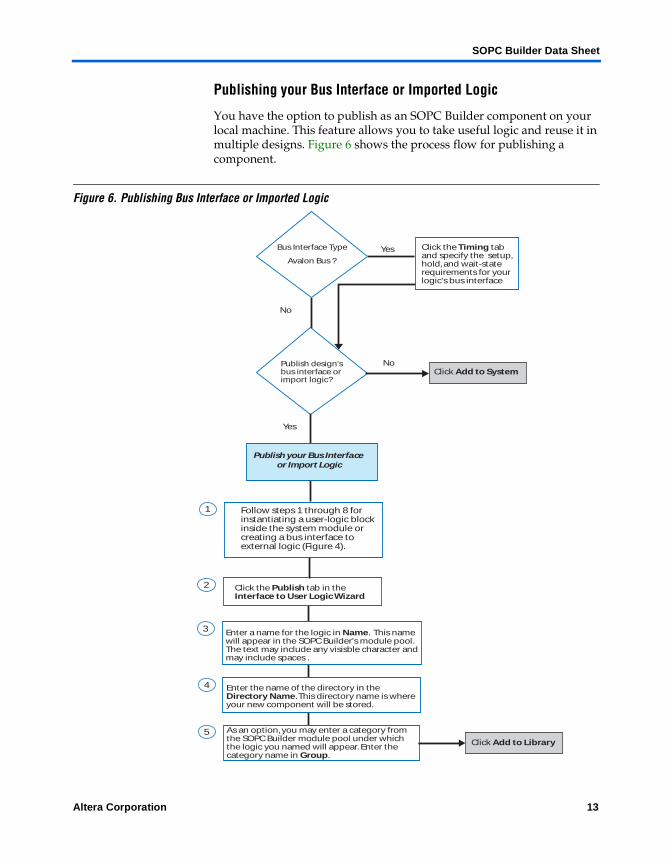
Publishing your Bus Interface or Imported Logic
You have the option to publish as an SOPC Builder component on your local machine. This feature allows you to take useful logic and reuse it in multiple designs. Figure 6 shows the process flow for publishing a component.
Figure 6. Publishing Bus Interface or Imported Logic
Bus Interface Type
Avalon Bus ?
Yes
No
Click the Timing tab and specify the setup, hold, and wait-state requirements for your logic's bus interface
Publish design'sbus interface or import logic?
No
Yes
Click Add to System
Click the Publish tab in the Interface to User Logic Wizard
Publish your Bus Interface or Import Logic
Enter a name for the logic in Name. This name will appear in the SOPC Builder's module pool. The text may include any visisble character and may include spaces .
Enter the name of the directory in the Directory Name. This directory name is where your new component will be stored.
As an option, you may enter a category fromthe SOPC Builder module pool under which the logic you named will appear. Enter the category name in Group.
Click Add to Library
1
2
3
4
5
Follow steps 1 through 8 for instantiating a user-logic block inside the system module or creating a bus interface to external logic (Figure 4).
Altera Corporation 13
SOPC Builder Data Sheet
Bus Interface Address Alignment Rules
When you create a bus interface to a block of logic, one of the ports on the system module will be an address-bus. The system module will have an address-output port for each external-module interface (except when address ports are shared). For most interfaces, the system module’s address-output port will be the same width as the module’s address-input port, and there is no ambiguity about how the two should be connected.
Sometimes, the address-output port on the system module will be wider than the address-input port on the external module. This typically happens for modules connected to a tri-state data bus. SOPC Builder uses the following rules to determine the width of any outgoing address port:
■ For external modules that do not use a tri-state data bus, (i.e. modules with separate, unidirectional readdata and/or writedata ports) the system module’s address-output port will be exactly the same width as the module’s input-port.
■ For external modules that do use a tri-state data bus, the system module’s address-output port will always carry a byte-address. For example, if you create an interface for an external 32-bit-wide memory chip with 14 address pins (64Kbytes of memory), the corresponding address-output pin on the system module will be 16 bits wide (16 bits are required to address every byte in a 64Kbyte memory). For correct system operation, you must connect pins A[15..2] to the 14 address pins on your 32-bit memory (address bits 1 and 0 are left unconnected in this example).
Connecting to Memory Devices
The Interface to User Logic GUI includes a check-box option for connecting to memory devices. If your logic is an interface to a memory device, select this option. Checking the Is this peripheral a memory device? option has two effects:
1. The Avalon bus will implement Dynamic Bus Sizing when connecting this peripheral to any master with a different data bus width.
2. This module will now appear on the available list of available memory devices in (for example) the CPU’s Program Memory drop-down setting.
f See the Avalon Bus Specification Reference Manual for more information about Dynamic Bus Sizing.
14 Altera Corporation
SOPC Builder Data Sheet
The PTF File The system PTF file contains all design-specific data needed to generate an SOPC system out of basic library components. When you create a new system module named, for example, “my_system_module”, SOPC Builder will create the file my_system_module.ptf in your current Quartus project directory. All settings, choices, and parameters entered through the GUI are recorded in the system PTF file. The primary input to the SOPC Builder generator program is the PTF file. In principle, you should be able to recreate your system module given only its system PTF file (and all the necessary components in the library).
System PTF Construction
When you first create a system, SOPC Builder makes a new PTF file with only a handful of global system-wide settings (like the system input clock frequency and the target device for synthesis). Every time you add a module to your system, it shows up in the Module Table, and a corresponding MODULE section is added to the system PTF file. The contents of the MODULE section is initially taken from that module’s definition in the library. A section of that module’s class.ptf file is copied wholesale into the new MODULE section in the system’s PTF file.
Some library components allow the newly-added module to be parameterized, and may provide their own GUI for configuration. Any changes made by a module’s GUI will be recorded in that module’s MODULE section in the system PTF file.
When the SOPC Builder’s generate program is run (for example, by pressing the “Generate” button in the GUI), each module in the system is checked to see if it has a corresponding “Generator_Program” (typically in its library directory). If so, SOPC Builder runs it. A module’s generator program may modify or add to the contents of a module’s MODULE section in the system PTF file. Many library components have generator programs that, for example, create I/O port declarations in the corresponding MODULE sections in the system PTF file.
After every module’s “Generator_Program” (if any) has been run, the PTF file contents are considered complete, and bus-generation can begin. In summary, information is added to a system’s PTF file by four separate processes:
1. When a system is first created, a small amount of system-global information is added.
2. For each new module added to the system, a new MODULE section is added to the PTF file and initialized with contents taken from that module’s library definition.
Altera Corporation 15
SOPC Builder Data Sheet
3. Every time a module is configured (typically through its GUI), settings are modified or added to its MODULE section in the system PTF file.
4. During the generation-phase, every module may run a “Generator_Program” that can add or modify information in that module’s MODULE section.
The MODULE section associated with any given module in the system may or may not have information from any of these sources, depending on how the module is implemented in the library.
1 In a module’s class.ptf file, the MODULE_DEFAULTS section is copied directly into a system’s PTF file every time a new module of that type is added.
f Refer to the SOPC Builder PTF File Reference Manual at the Altera literature web page for detailed information about PTF files.
Copyright © 2002 Altera Corporation. All rights reserved. Altera, The Programmable Solutions Company, thestylized Altera logo, specific device designations, and all other words and logos that are identified astrademarks and/or service marks are, unless noted otherwise, the trademarks and service marks of AlteraCorporation in the U.S. and other countries. All other product or service names are the property of theirrespective holders. Altera products are protected under numerous U.S. and foreign patents and pendingapplications, mask work rights, and copyrights. Altera warrants performance of itssemiconductor products to current specifications in accordance with Altera’s standardwarranty, but reserves the right to make changes to any products and services at any timewithout notice. Altera assumes no responsibility or liability arising out of the applicationor use of any information, product, or service described herein except as expressly agreedto in writing by Altera Corporation. Altera customers are advised to obtain the latestversion of device specifications before relying on any published information and beforeplacing orders for products or services.
16 Altera Corporation
101 Innovation DriveSan Jose, CA 95134(408) 544-7000http://www.altera.comApplications Hotline:(800) 800-EPLDLiterature Services:[email protected]