contents mvds trophy terrestrial dvb-s2 broadcasting
TRANSCRIPT

DA
TA
-SH
EE
T
CO
NT
EN
TS
MVDS TROPHY TERRESTRIAL DVB-S2 BROADCASTING
INTRODUCTION.........................................................................................................
The advantages of MVDS-TROPHY DVB-S2 terrestrial broadcasting........................
TROPHY MVDS HEAD-END.......................................................................................
AMD-53-S2DVB-S2 MODULATOR /120-CHANNEL MULTIPLEXER............... GENERAL INFORMATION.................................................................... MAIN FUNCTIONS OF AMD-53-S2 MODULATOR / MULTIPLEXER... INSTALLING AND OPERATING INSTRUCTIONS................................ SAFETY INSTRUCTIONS..................................................................... GENERAL DESCRIPTION OF FUNCTIONS......................................... MULTIPLEXER/REMULTIPLEXER/PID FILTER.................................... INSTALLING FUNCTIONAL ELEMENTS AND FACTORY SETTINGS. SETTINGS FOR THE ETHERNET NETWORK INTERFACE................ SSH access............................................................................................ CONFIGURATIONS VIA THE ETHERNET INTERFACE....................... CONNECTION SETUP........................................................................... INPUTS.................................................................................................. PROGRAMS.......................................................................................... EIT (EPG) Server................................................................................... XMLTV File Format................................................................................ SI GENERATOR.................................................................................... NIT GENERATOR.................................................................................. MODULATOR PARAMETERS............................................................... SPECIFICATIONS..................................................................................
SUBS_SEND_V.2 subscription management software.................................... GENERAL INFORMATION.................................................................... Conditional access system (CAS) built into the modulator/multiplexer.. Modulators (streams) and groups.......................................................... TROPHY-ACCESS CAS........................................................................ Enabling the scrambling mode............................................................... Mask and types of scrambling................................................................ Decoder number and geographic zone.................................................. Working with the subs_send program....................................................
DVB_BILLING_V.5 subscriber accounting software......................................... MAIN INFORMATION............................................................................ DVB-BILLING Software and Statistics Billing......................................... Main parameters of DVB-BILLING Subscribers Accounting Program.... The Main Menu Review..........................................................................
BILLING SERVER............................................................................................. Billing program options...........................................................................
1
2
5
677999910111113131517182021222324
262727282929313132
3334343536
3940
CONTENTS
CO
NT
EN
TS
MVDS TROPHY TERRESTRIAL DVB-S2 BROADCASTING
AMD seriesDC&10MHz reference INJECTOR................................................. GENERAL INFORMATION.................................................................... INSTALLING AND OPERATING INSTRUCTIONS................................ SAFETY INSTRUCTIONS..................................................................... GENERAL DESCRIPTION OF FUNCTIONS......................................... SPECIFICATIONS..................................................................................
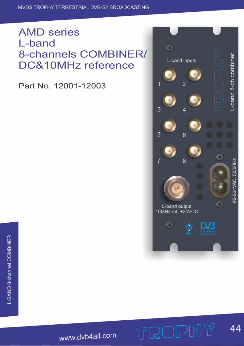
AMD series L-band 8-channels COMBINER/ DC&10MHz reference............... GENERAL INFORMATION.................................................................... INSTALLING AND OPERATING INSTRUCTIONS................................ SAFETY INSTRUCTIONS..................................................................... GENERAL DESCRIPTION OF FUNCTIONS......................................... SPECIFICATIONS.................................................................................. Optical transmitter (OPT-TX DT) and optical receiver (OPT-RX DT)................ SAFETY WARNING............................................................................... Product description................................................................................. USER INSTRUCTIONS......................................................................... Dimensioning a Fibre Optic system........................................................ TECHNICAL SPECIFICATIONS............................................................
SDI-410C STI-410C Common Interface S/S2/T/T2/C to IP STREAMERS....... PRODUCT DESCRIPTION.................................................................... FRONT PANEL...................................................................................... Installation instructions........................................................................... INITIAL CONFIGURATION.................................................................... GENERAL CONFIGURATION............................................................... Initial program screen............................................................................. Device information table......................................................................... Input settings.......................................................................................... RF input table......................................................................................... Input status table.................................................................................... List of services table............................................................................... Detailed service information................................................................... Output settings....................................................................................... Streaming settings table......................................................................... SAP/SDP settings table.......................................................................... Output streams table.............................................................................. Advanced output settings....................................................................... IP settings............................................................................................... CAM settings.......................................................................................... SNMP settings........................................................................................ System menu......................................................................................... Event logs............................................................................................... Export parameters.................................................................................. Import parameters.................................................................................. Firmware upgrade.................................................................................. User management.................................................................................. Restore defaults..................................................................................... Reset the device..................................................................................... Language............................................................................................... Specifications.........................................................................................
414242424243
444545454546
474849525255
57585959606161616262636364646465666667686869696970707171717172
CO
NT
EN
TS
MVDS TROPHY TERRESTRIAL DVB-S2 BROADCASTING
2W KU-BAND BLOCK-UP-CONVERTER (BUC)........................................................
4W KU-BAND BLOCK-UP-CONVERTER (BUC)........................................................
OMNIDIRECTIONAL SLOT ANTENNA.......................................................................
ATD-54 DVB-S/S2 to DVB-S2 Transmodulator............................................................ GENERAL INFORMATION............................................................................... MAIN FUNCTIONS OF ATD-54-S/S2 to DVB-S2 TRANSMODULATOR......... THE MAIN APPLICATION OF DVB-S2 to DVB-S2 TRANSMODULATORS.... FUNCTIONAL ELEMENTS............................................................................... INSTALLING AND OPERATING INSTRUCTIONS........................................... SAFETY INSTRUCTIONS................................................................................ GENERAL DESCRIPTION OF FUNCTIONS................................................... MANAGEMENT BY USB-INTERFACE............................................................. SPECIFICATIONS............................................................................................ REMOTE ACCESS CONTROLLER............................................................................ SAFETY INSTRUCTIONS................................................................................ NETWORK MANAGEMENT VIA REMOTE ACCESS CONTROLLER........ DATA BETWEEN CONTROLLER AND THE TRANSMODULATORS............. RS-485 COMMUNICATION LINE..................................................................... SSH ACCESS................................................................................................... MANAGEMENT VIA WEB-INTERFACE......................................................... 12VDC SUPPLYING VIA REMOTE ACCESS CONTROLLER...................... SPECIFICATIONS............................................................................................ TDX-480 TDQ-480 8 DVB-S/S2 to 8 DVB-T/C transmodulators................................. Product description........................................................................................... Specifications.................................................................................................... Front Panel........................................................................................................ OPERATING..................................................................................................... Initial configuration............................................................................................ General configuration........................................................................................ Initial Web interface screen............................................................................... Device information table.................................................................................... Output bitrates table.......................................................................................... Input status table............................................................................................... Transport Streams............................................................................................ RF inputs........................................................................................................... NIT.................................................................................................................... RF outputs......................................................................................................... IP settings......................................................................................................... E-mail-settings.................................................................................................. SNMP settings.................................................................................................. System menu.................................................................................................... Event logs......................................................................................................... Export parameters............................................................................................. Import parameters............................................................................................. Firmware upgrade.............................................................................................
SAT Dishes. Penta series............................................................................................
73
74
76
77787880818282828389
909191929293949798
99101102103103104104104105106106107108109110110110111112112112112112
113
INT
RO
DU
CT
ION
1
MVDS TROPHY TERRESTRIAL DVB-S2 BROADCASTING
INTRODUCTION
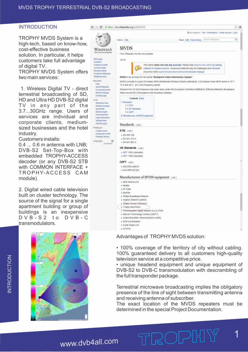
TROPHY MVDS System is a high-tech, based on know-how, cost-effective business solution. In particular, it helps customers take full advantage of digital TV. TROPHY MVDS System offers two main services:
1. Wireless Digital TV - direct terrestrial broadcasting of SD, HD and Ultra HD DVB-S2 digital TV i n any pa r t o f t he 3.7...30GHz range. Users of services are individual and corporate clients, medium-sized businesses and the hotel industry. Customers installs:0.4 ... 0.6 m antenna with LNB;DVB-S2 Set-Top-Box with embedded TROPHY-ACCESS decoder (or any DVB-S2 STB with COMMON INTERFACE + T R O P H Y- A C C E S S C A M module).
2. Digital wired cable television built on cluster technology. The source of the signal for a single apartment building or group of buildings is an inexpensive D V B - S 2 t o D V B - C transmodulators.
Advantages of TROPHY MVDS solution:
• 100% coverage of the territory of city without cabling. 100% guaranteed delivery to all customers high-quality television service at a competitive price.• unique headend equipment and unique equipment of DVB-S2 to DVB-C transmodulation with descrambling of the full transponder package.
Terrestrial microwave broadcasting implies the obligatory presence of the line of sight between transmitting antenna and receiving antenna of subscriber. The exact location of the MVDS repeaters must be determined in the special Project Documentation.
TH
E A
DV
AN
TA
GE
S O
F M
VD
S
2
MVDS TROPHY TERRESTRIAL DVB-S2 BROADCASTING
The advantages of MVDS-TROPHY DVB-S2 terrestrial broadcasting:
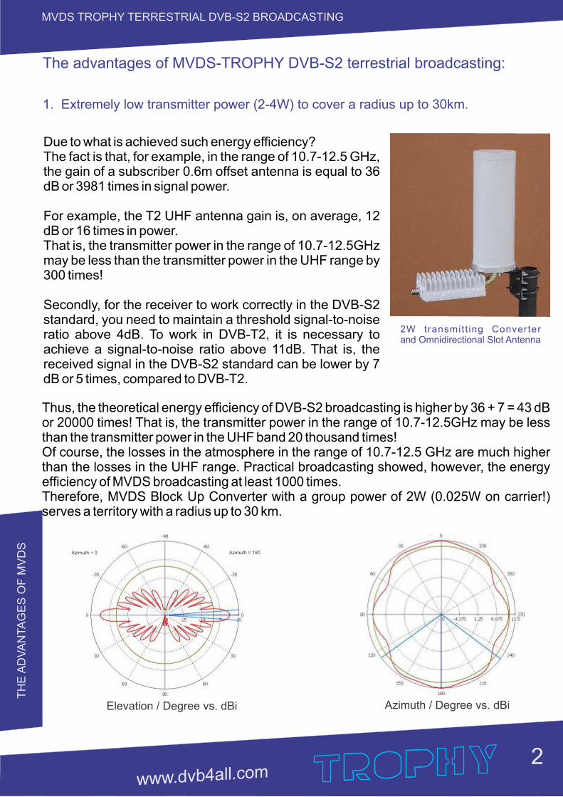
1. Extremely low transmitter power (2-4W) to cover a radius up to 30km.
Due to what is achieved such energy efficiency?The fact is that, for example, in the range of 10.7-12.5 GHz, the gain of a subscriber 0.6m offset antenna is equal to 36 dB or 3981 times in signal power.
For example, the T2 UHF antenna gain is, on average, 12 dB or 16 times in power.That is, the transmitter power in the range of 10.7-12.5GHz may be less than the transmitter power in the UHF range by 300 times!
Secondly, for the receiver to work correctly in the DVB-S2 standard, you need to maintain a threshold signal-to-noise ratio above 4dB. To work in DVB-T2, it is necessary to achieve a signal-to-noise ratio above 11dB. That is, the received signal in the DVB-S2 standard can be lower by 7 dB or 5 times, compared to DVB-T2.
Elevation / Degree vs. dBi
Azimuth = 0 Azimuth = 180
Azimuth / Degree vs. dBi
Thus, the theoretical energy efficiency of DVB-S2 broadcasting is higher by 36 + 7 = 43 dB or 20000 times! That is, the transmitter power in the range of 10.7-12.5GHz may be less than the transmitter power in the UHF band 20 thousand times!Of course, the losses in the atmosphere in the range of 10.7-12.5 GHz are much higher than the losses in the UHF range. Practical broadcasting showed, however, the energy efficiency of MVDS broadcasting at least 1000 times.Therefore, MVDS Block Up Converter with a group power of 2W (0.025W on carrier!) serves a territory with a radius up to 30 km.
2W transmit t ing Converter and Omnidirectional Slot Antenna
TH
E A
DV
AN
TA
GE
S O
F M
VD
S
3
MVDS TROPHY TERRESTRIAL DVB-S2 BROADCASTING
2. The use of standard LNB’s and standard satellite receiving 0.4m-0.6m antennas.
In MVDS, we use two types of signal modulation: QPSK and 8PSK, that is phase modulations. To receive a signal, it is sufficient to use inexpensive down-converters with low linear mixer requirements.For example, in MMDS broadcasting, amplitude modulation methods of the 16QAM and 64QAM signal are used, which implies the use of ultra-linear modes in receiving equipment. And this, in turn, leads to higher prices for down-converters.The most significant reduction in the cost of creating a subscriber network is achieved in the 3.7-4.2 GHz and 10.7-12.75 GHz bands. Here can be used household LNB worth $1-2. In other ranges, non-standard converters have to be used, which increases the cost of down-converters and prices become comparable with MMDS converters.
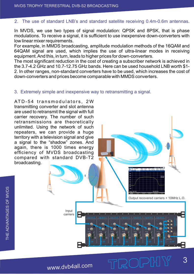
3. Extremely simple and inexpensive way to retransmitting a signal.
AT D - 5 4 t r a n s m o d u l a t o r s , 2 W transmitting converter and slot antenna are used to retransmit the signal with full carrier recovery. The number of such retransmissions are theoretically unlimited. Using the network of such repeaters, we can provide a huge territory with a television signal and give a signal to the “shadow” zones. And again, there is 1000 times energy efficiency of MVDS broadcasting compared with standard DVB-T2 broadcasting.
L-band inputs
L-band output10MHz ref. +24VDC
90-2
64V
AC
50/6
0H
zL
-ba
nd
8-c
h c
om
bin
er
1 2
3 4
5 6
7 8
L-b
and o
utp
ut
ATD-54 S/S2 to S2 Transmodulator
L-band input
Loop
Input error
Fault
Lock
RS
-485
US
B
DC + L
-band o
utp
ut
ATD-54 S/S2 to S2 Transmodulator
L-band input
Loop
Input error
Fault
Lock
RS
-485
US
B
DC + L
-band o
utp
ut
ATD-54 S/S2 to S2 Transmodulator
L-band input
Loop
Input error
Fault
Lock
RS
-485
US
B
DC + L
-band o
utp
ut
ATD-54 S/S2 to S2 Transmodulator
L-band input
Loop
Input error
Fault
Lock
RS
-485
US
B
DC + L
-band o
utp
ut
ATD-54 S/S2 to S2 Transmodulator
L-band input
Loop
Input error
Fault
Lock
RS
-485
US
B
DC +L
-band o
utp
ut
ATD-54 S/S2 to S2 Transmodulator
L-band input
Loop
Input error
Fault
Lock
RS
-485
US
B
DC +L
-band o
utp
ut
ATD-54 S/S2 to S2 Transmodulator
L-band input
Loop
Input error
Fault
Lock
RS
-485
US
B
DC +
Input carriers
Output recovered carriers + 10MHz L.O.
TH
E A
DV
AN
TA
GE
S O
F M
VD
S
4
MVDS TROPHY TERRESTRIAL DVB-S2 BROADCASTING
4. The presence of a wide frequency spectrum, compared with the UHF range.
Practically, one transmitting converter provides a signal bandwidth up to 800 MHz. With such a band, it is possible to broadcast up to 1700 Mbit of useful data. For example, using multi-pass transcoding technology, it is possible to form a packet of 100SD channels (1 Mbit each) + 300HD channels (2 Mbit each) + 40UltraHD channels (25 Mbit each).Using a smaller band reduces the number of channels accordingly.
5. Own DVB-S2 modulators/multiplexers and original TROPHY-ACCESS Conditional Access System.
This factor allows you to install an extremely inexpensive Head-End with the highest functionality and quality.
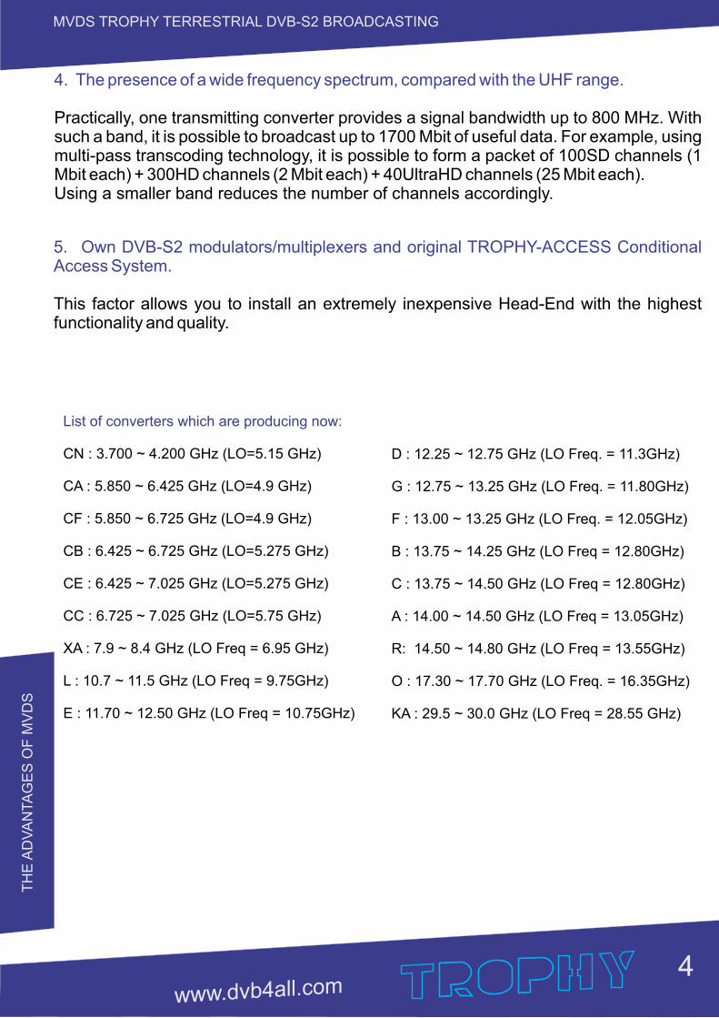
List of converters which are producing now:
CN : 3.700 ~ 4.200 GHz (LO=5.15 GHz)
CA : 5.850 ~ 6.425 GHz (LO=4.9 GHz)
CF : 5.850 ~ 6.725 GHz (LO=4.9 GHz)
CB : 6.425 ~ 6.725 GHz (LO=5.275 GHz)
CE : 6.425 ~ 7.025 GHz (LO=5.275 GHz)
CC : 6.725 ~ 7.025 GHz (LO=5.75 GHz)
XA : 7.9 ~ 8.4 GHz (LO Freq = 6.95 GHz)
L : 10.7 ~ 11.5 GHz (LO Freq = 9.75GHz)
E : 11.70 ~ 12.50 GHz (LO Freq = 10.75GHz)
D : 12.25 ~ 12.75 GHz (LO Freq. = 11.3GHz)
G : 12.75 ~ 13.25 GHz (LO Freq. = 11.80GHz)
F : 13.00 ~ 13.25 GHz (LO Freq. = 12.05GHz)
B : 13.75 ~ 14.25 GHz (LO Freq = 12.80GHz)
C : 13.75 ~ 14.50 GHz (LO Freq = 12.80GHz)
A : 14.00 ~ 14.50 GHz (LO Freq = 13.05GHz)
R: 14.50 ~ 14.80 GHz (LO Freq = 13.55GHz)
O : 17.30 ~ 17.70 GHz (LO Freq. = 16.35GHz)
KA : 29.5 ~ 30.0 GHz (LO Freq = 28.55 GHz)
TR
OP
HY
MV
DS
HE
AD
-EN
D
5
MVDS TROPHY TERRESTRIAL DVB-S2 BROADCASTING
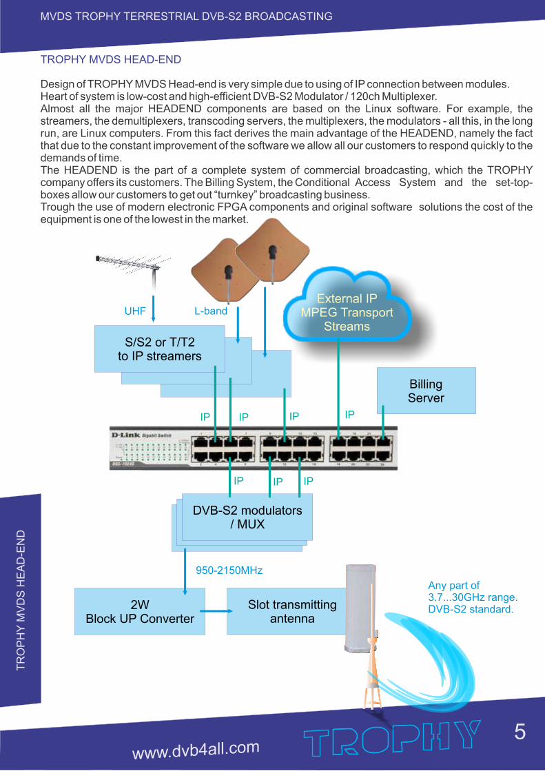
External IP MPEG Transport
Streams
S/S2 or T/T2to IP streamers
UHF L-band
IP IP IP IP
IP IP IP
DVB-S2 modulators/ MUX
2W Block UP Converter
950-2150MHz
Slot transmitting antenna
Any part of3.7...30GHz range.DVB-S2 standard.
Billing Server
TROPHY MVDS HEAD-END
Design of TROPHY MVDS Head-end is very simple due to using of IP connection between modules.Heart of system is low-cost and high-efficient DVB-S2 Modulator / 120ch Multiplexer. Almost all the major HEADEND components are based on the Linux software. For example, the streamers, the demultiplexers, transcoding servers, the multiplexers, the modulators - all this, in the long run, are Linux computers. From this fact derives the main advantage of the HEADEND, namely the fact that due to the constant improvement of the software we allow all our customers to respond quickly to the demands of time.The HEADEND is the part of a complete system of commercial broadcasting, which the TROPHY company offers its customers. The Billing System, the Conditional Access System and the set-top-boxes allow our customers to get out “turnkey” broadcasting business.Trough the use of modern electronic FPGA components and original software solutions the cost of the equipment is one of the lowest in the market.
AM
D-5
3-S
2 M
OD
ULA
TO
R/ M
UX
6
MVDS TROPHY TERRESTRIAL DVB-S2 BROADCASTING
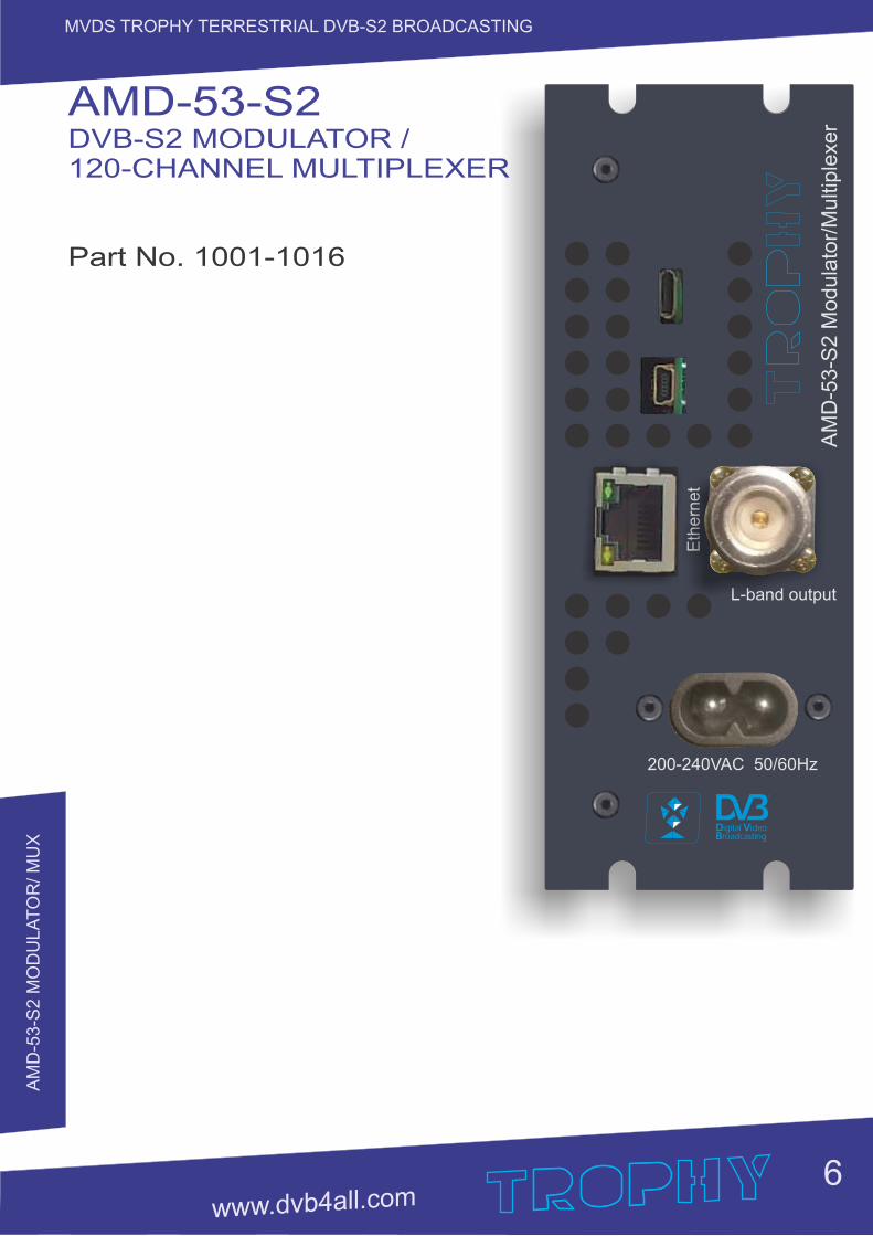
AMD-53-S2 DVB-S2 MODULATOR / 120-CHANNEL MULTIPLEXER
Part No. 1001-1016
Eth
ern
et
200-240VAC 50/60Hz
L-band output
AM
D-5
3-S
2 M
od
ula
tor/
Mu
ltip
lexe
r
AM
D-5
3-S
2 M
OD
ULA
TO
R/ M
UX
7
MVDS TROPHY TERRESTRIAL DVB-S2 BROADCASTING
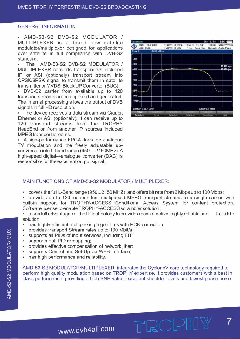
MAIN FUNCTIONS OF AMD-53-S2 MODULATOR / MULTIPLEXER:
Ÿ covers the full L-Band range (950...2150 MHZ) and offers bit rate from 2 Mbps up to 100 Mbps; Ÿ provides up to 120 independent multiplexed MPEG transport streams to a single carrier, with built-in support for TROPHY-ACCESS Conditional Access System for content protection. Software license to enable TROPHY-ACCESS scrambler solution;Ÿ takes full advantages of the IP technology to provide a cost effective, highly reliable and f lex ib le solution;Ÿ has highly efficient multiplexing algorithms with PCR correction;Ÿ provides transport Stream rates up to 100 Mbit/s;Ÿ supports all PIDs of input services ;, including EITŸ supports Full PID remapping;Ÿ provides effective compensation of network jitter;Ÿ supports Control and Set-Up via WEB-interface;Ÿ has high performance and reliability.
AMD-53-S2 MODULATOR/MULTIPLEXER integrates the CycloneV core technology required to perform high quality modulation based on TROPHY expertise. It provides customers with a best in class performance, providing a high SNR value, excellent shoulder levels and lowest phase noise.
GENERAL INFORMATION
Ÿ AMD-53-S2 DVB-S2 MODULATOR / MULTIPLEXER is a brand new satellite modulator/multiplexer designed for applications over satellite in full compliance with DVB-S2 standard.Ÿ The AMD-53-S2 DVB-S2 MODULATOR / MULTIPLEXER converts transponders included IP or ASI (optionaly) transport stream into QPSK/8PSK signal to transmit them in satellite transmitter or MVDS Block UP Converter (BUC). Ÿ DVB-S2 carrier from available up to 120 transport streams are multiplexed and generated. The internal processing allows the output of DVB signals in full HD resolution.Ÿ The device receives a data stream via Gigabit Ethernet or ASI (optionaly). It can receive up to 120 transport streams from the TROPHY HeadEnd or from another IP sources included MPEG transport streams. Ÿ A high-performance FPGA does the analogue TV modulation and the freely adjustable up-conversion into L-band range (950 ... 2150MHz). A high-speed digital→analogue converter (DAC) is responsible for the excellent output signal.
AM
D-5
3-S
2 M
OD
ULA
TO
R/ M
UX
8
MVDS TROPHY TERRESTRIAL DVB-S2 BROADCASTING
ASI input
Demux Mux
WEBcontrol
TS input
1G
b E
the
rne
t
TS Switch
TROPHY-ACCESSscrambler
LocalOscillator
DV
B-S
2 Q
PS
K/8
PS
K m
od
ula
tor
1Gb Ethernet Switch
Up to 120single
MPEG TS
MPEG Transport Streams over IP
Eth
ern
et
200-240VAC 50/60Hz
L-band output
AM
D-5
3-S
2 M
odula
tor/
Multip
lexer
Eth
ern
et
200-240VAC 50/60Hz
L-band output
AM
D-5
3-S
2 M
odula
tor/
Multip
lexer
Eth
ern
et
200-240VAC 50/60Hz
L-band output
AM
D-5
3-S
2 M
odula
tor/
Multip
lexer
Eth
ern
et
200-240VAC 50/60Hz
L-band outputA
MD
-53-S
2 M
odula
tor/
Multip
lexer
Eth
ern
et
200-240VAC 50/60Hz
L-band output
AM
D-5
3-S
2 M
odula
tor/
Multip
lexer
Eth
ern
et
200-240VAC 50/60Hz
L-band output
AM
D-5
3-S
2 M
odula
tor/
Multip
lexer
Eth
ern
et
200-240VAC 50/60Hz
L-band output
AM
D-5
3-S
2 M
odula
tor/
Multip
lexer
L-band inputs
L-band output10MHz ref. +24VDC
90-2
64V
AC
50/6
0H
zL-b
and 8
-ch c
om
bin
er
1 2
3 4
5 6
7 8
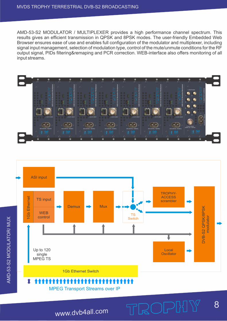
AMD-53-S2 MODULATOR / MULTIPLEXER provides a high performance channel spectrum. This results gives an efficient transmission in QPSK and 8PSK modes. The user-friendly Embedded Web Browser ensures ease of use and enables full configuration of the modulator and multiplexer, including signal input management, selection of modulation type, control of the mute/unmute conditions for the RF output signal, PIDs filtering&remaping and PCR correction. WEB-interface also offers monitoring of all input streams.
AM
D-5
3-S
2 M
OD
ULA
TO
R/ M
UX
9
MVDS TROPHY TERRESTRIAL DVB-S2 BROADCASTING
INSTALLING AND OPERATING INSTRUCTIONS
SAFETY INSTRUCTIONSWhen assembling and commissioning the AMD-53-S2 MOD/MUX and executing the settings, always follow the accompanying instructions exactly.The devices are not to be assembled and brought into use by anybody who is not an authorised technician.When components are being installed in areas where reception is important, ensure that EMC regulations are observed.All assembly, installation and cable connection must take place when no electricity has been connected.The provisions of DIN EN 50083 must be observed at all times when working with the equipment. In particular, DIN EN 60728-11 regarding safety may on no account be ignored.
GENERAL DESCRIPTION OF FUNCTIONSThe device is transport stream multiplexer and DVB-S2 modulator. With them the user‘s own digital program “bouquets“ in the DVB-S2 carrier can be produced. The output signal are provided via RF-output and configurable by IP interface. The signal can be broadcast or fed into the MVDS or satellite TV network. Depending on the application, the device are pre-configured by hardware. Using the integrated user interface, the operating parameters can be varied within wide limits.Deliveries are made with the following configurations/ device versions:
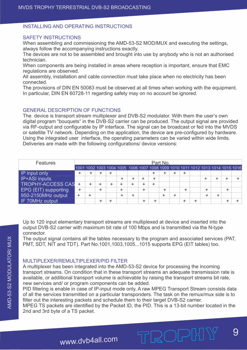
Up to 120 input elementary transport streams are multiplexed at device and inserted into the output DVB-S2 carrier with maximum bit rate of 100 Mbps and is transmitted via the N-type connector. The output signal contains all the tables necessary to the program and associated services (PAT, PMT, SDT, NIT and TDT). Part No.1001,1003,1005...1015 supports EPG (EIT tables) too.
MULTIPLEXER/REMULTIPLEXER/PID FILTERA multiplexer has been integrated into the AMD-53-S2 device for processing the incoming transport streams. On condition that in these transport streams an adequate transmission rate is available, or additional transport volume is achievable by raising the transport streams bit rate, new services and/ or program components can be added.PID filtering is enable in case of IP-input mode only. A raw MPEG Transport Stream consists data of all the services transmitted on a particular transponders. The task on the remux/mux side is to filter out the interesting packets and schedule them to their target DVB-S2 carrier.MPEG TS packets are identified by the Packet ID, the PID. This is a 13-bit number located in the 2nd and 3rd byte of a TS packet.
Features Part No. 1001 1002 1003 1004 1005 1006 1007 1008 1009 1010 1011 1012 1013 1014 1015 1016
IP input only + + + + + + + + IP+ASI inputs + + + + + + + + TROPHY-ACCESS CAS + + + + + + + +EPG (EIT) supporting + + + + + + + + 950-2150MHz output + + + + + + + +IF 70MHz output + + + + + + + +
AM
D-5
3-S
2 M
OD
ULA
TO
R/ M
UX
10
MVDS TROPHY TERRESTRIAL DVB-S2 BROADCASTING
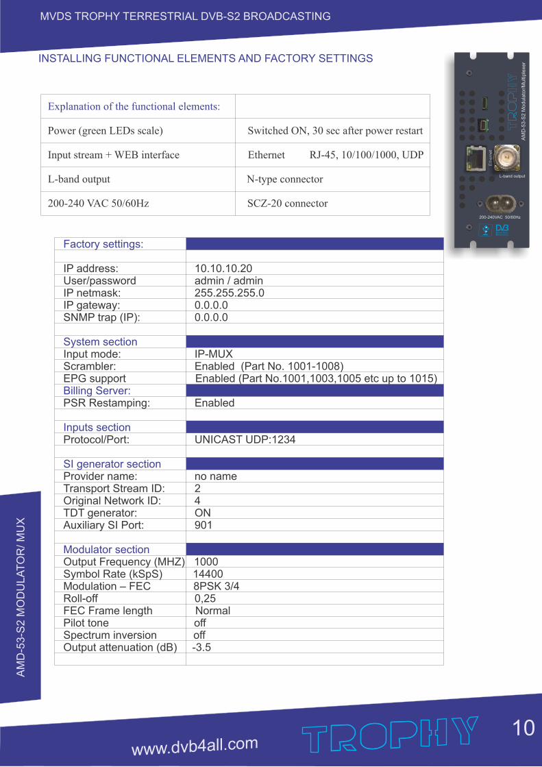
Explanation of the functional elements:
Power (green LEDs scale) Switched ON, 30 sec after power restart
Input stream + WEB interface Ethernet RJ-45, 10/100/1000, UDP
L-band output N-type connector
200-240 VAC 50/60Hz SCZ-20 connector
Factory settings:
IP address: 10.10.10.20User/password admin / adminIP netmask: 255.255.255.0IP gateway: 0.0.0.0SNMP trap (IP): 0.0.0.0
System sectionInput mode: IP-MUXScrambler: Enabled (Part No. 1001-1008)EPG support Enabled (Part No.1001,1003,1005 etc up to 1015)Billing Server:PSR Restamping: Enabled
Inputs sectionProtocol/Port: UNICAST UDP:1234
SI generator sectionProvider name: no nameTransport Stream ID: 2Original Network ID: 4TDT generator: ONAuxiliary SI Port: 901
Modulator sectionOutput Frequency (MHZ) 1000Symbol Rate (kSpS) 14400Modulation – FEC 8PSK 3/4Roll-off 0,25FEC Frame length NormalPilot tone offSpectrum inversion offOutput attenuation (dB) -3.5
INSTALLING FUNCTIONAL ELEMENTS AND FACTORY SETTINGS
Eth
ern
et
200-240VAC 50/60Hz
L-band output
AM
D-5
3-S
2 M
odula
tor/
Multi
ple
xer
AM
D-5
3-S
2 M
OD
ULA
TO
R/ M
UX
11
MVDS TROPHY TERRESTRIAL DVB-S2 BROADCASTING
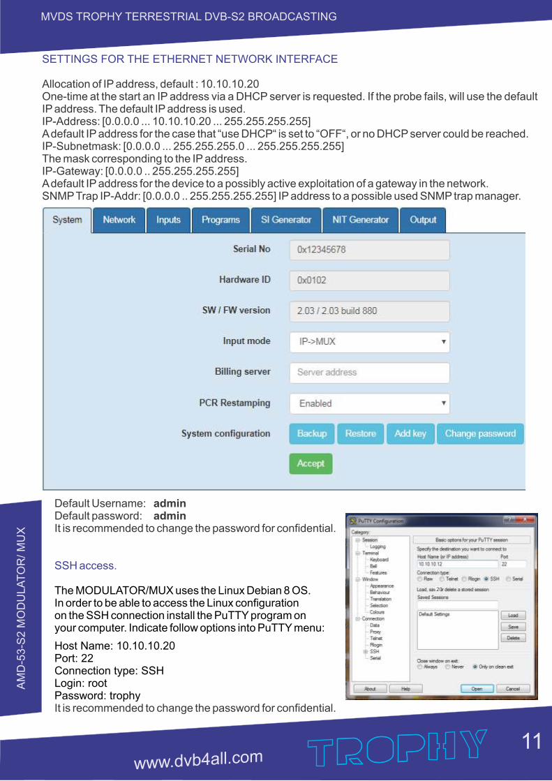
SETTINGS FOR THE ETHERNET NETWORK INTERFACE
Allocation of IP address, default : 10.10.10.20One-time at the start an IP address via a DHCP server is requested. If the probe fails, will use the default IP address. The default IP address is used.IP-Address: [0.0.0.0 ... 10.10.10.20 ... 255.255.255.255]A default IP address for the case that “use DHCP“ is set to “OFF“, or no DHCP server could be reached.IP-Subnetmask: [0.0.0.0 ... 255.255.255.0 ... 255.255.255.255]The mask corresponding to the IP address.IP-Gateway: [0.0.0.0 .. 255.255.255.255]A default IP address for the device to a possibly active exploitation of a gateway in the network.SNMP Trap IP-Addr: [0.0.0.0 .. 255.255.255.255] IP address to a possible used SNMP trap manager.
Default Username: adminDefault password: adminIt is recommended to change the password for confidential.
SSH access.
The MODULATOR/MUX uses the Linux Debian 8 OS. In order to be able to access the Linux configuration on the SSH connection install the PuTTY program on your computer. Indicate follow options into PuTTY menu:
Host Name: 10.10.10.20 Port: 22 Connection type: SSH Login: root Password: trophyIt is recommended to change the password for confidential.
20
AM
D-5
3-S
2 M
OD
ULA
TO
R/ M
UX
12
MVDS TROPHY TERRESTRIAL DVB-S2 BROADCASTING
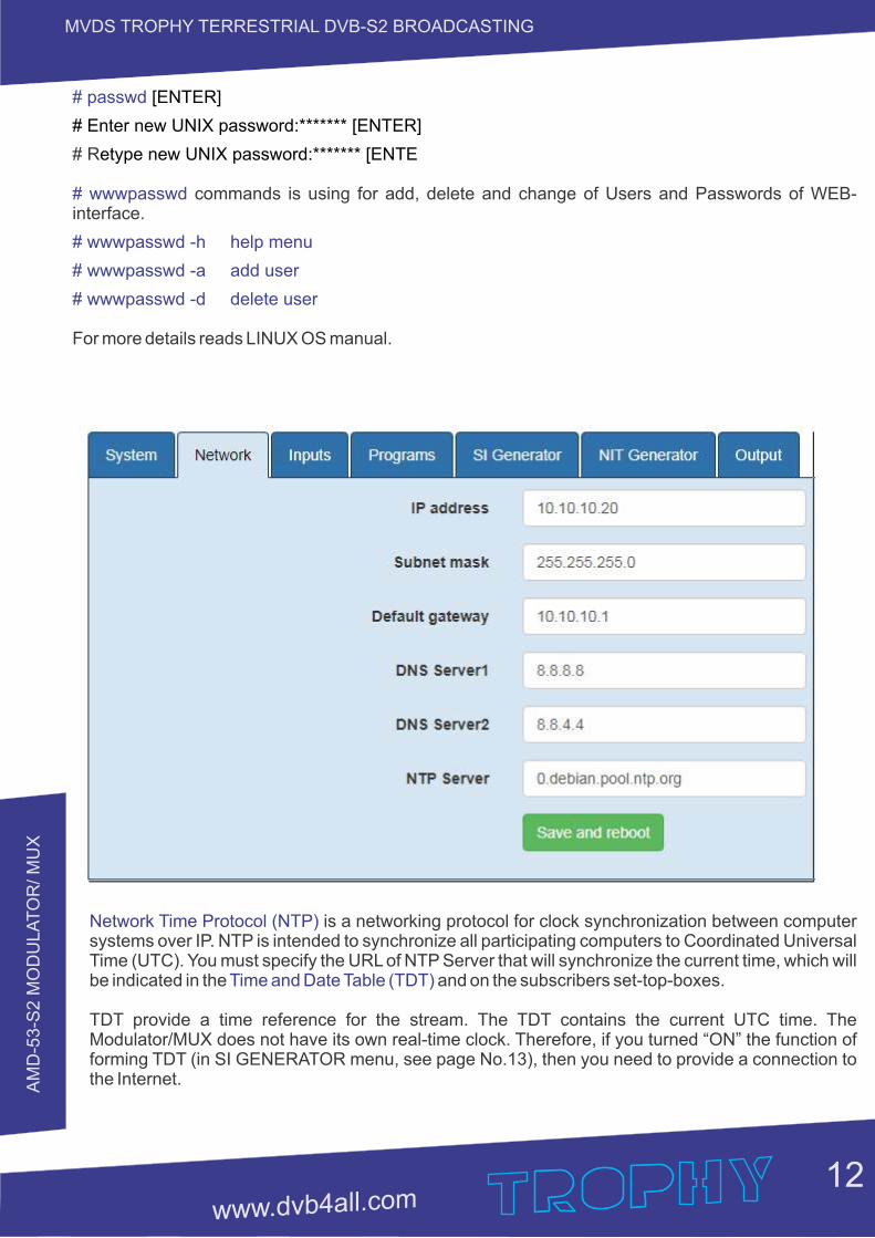
Network Time Protocol (NTP) is a networking protocol for clock synchronization between computer systems over IP. NTP is intended to synchronize all participating computers to Coordinated Universal Time (UTC). You must specify the URL of NTP Server that will synchronize the current time, which will be indicated in the and on the subscribers set-top-boxes.Time and Date Table (TDT)
TDT provide a time reference for the stream. The TDT contains the current UTC time. The Modulator/MUX does not have its own real-time clock. Therefore, if you turned “ON” the function of forming TDT (in SI GENERATOR menu, see page No.13), then you need to provide a connection to the Internet.
# passwd [ENTER]
# Enter new UNIX password:******* [ENTER]
# Retype new UNIX password:******* [ENTE
# wwwpasswd commands is using for add, delete and change of Users and Passwords of WEB-interface.
# wwwpasswd -h help menu
# wwwpasswd -a add user
# wwwpasswd -d delete user
For more details reads LINUX OS manual.
AM
D-5
3-S
2 M
OD
ULA
TO
R/ M
UX
13
MVDS TROPHY TERRESTRIAL DVB-S2 BROADCASTING
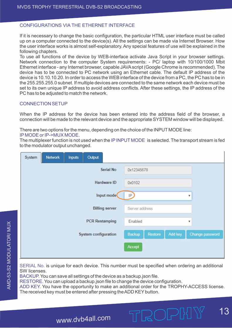
CONFIGURATIONS VIA THE ETHERNET INTERFACE
If it is necessary to change the basic configuration, the particular HTML user interface must be called up on a computer connected to the device(s). All the settings can be made via Internet Browser. How the user interface works is almost self-explanatory. Any special features of use will be explained in the following chapters.To use all functions of the device by WEB-interface activate Java Script in your browser settings. Network connection to the computer System requirements: - PC/ laptop with 10/100/1000 Mbit Ethernet interface - any Internet browser, capable JAVA script (Google Chrome is recommended). The device has to be connected to PC network using an Ethernet cable. The default IP address of the device is 10.10.10.20. In order to access the WEB interface of the device from a PC, the PC has to be in the 255.255.255.0 subnet. If multiple devices are connected to the same network each device must be set to its own unique IP address to avoid address conflicts. After these settings, the IP address of the PC has to be adjusted to match the network.
CONNECTION SETUP
When the IP address for the device has been entered into the address field of the browser, a connection will be made to the relevant device and the appropriate SYSTEM window will be displayed.
There are two options for the menu, depending on the choice of the INPUT MODE line:IP MODE or IP-˃MUX MODE.The multiplexer function is not used when the is selected. The transport stream is fed IP INPUT MODE to the modulator output unchanged.
SERIAL No. is unique for each device. This number must be specified when ordering an additional SW licenses.BACKUP. You can save all settings of the device as a backup.json file.RESTORE. You can upload a backup.json file to change the device configuration.ADD KEY. You have the opportunity to make an additional order for the TROPHY-ACCESS license. The received key must be entered after pressing the ADD KEY button.
AM
D-5
3-S
2 M
OD
ULA
TO
R/ M
UX
14
MVDS TROPHY TERRESTRIAL DVB-S2 BROADCASTING
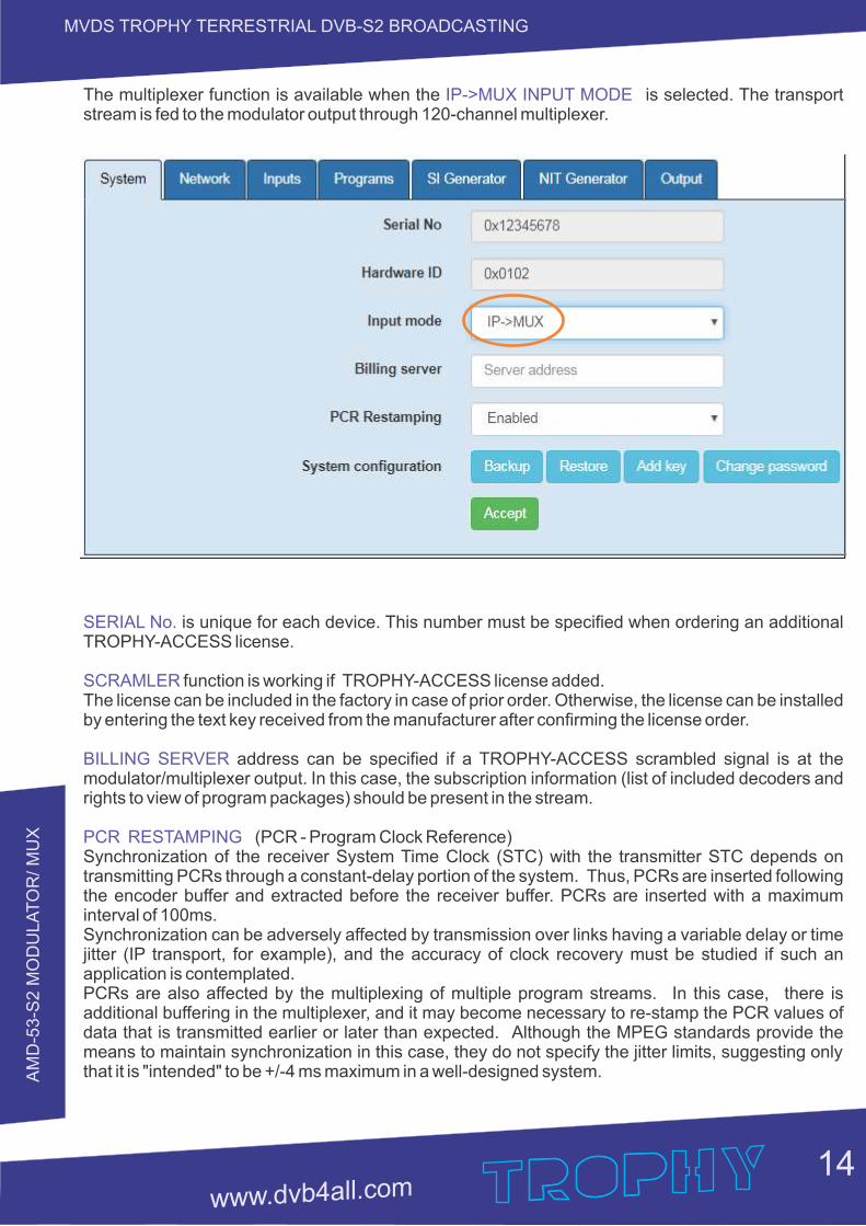
The multiplexer function is available when the is selected. The transport IP-˃MUX INPUT MODE stream is fed to the modulator output through 120-channel multiplexer.
SERIAL No. is unique for each device. This number must be specified when ordering an additional TROPHY-ACCESS license.
SCRAMLER function is working if TROPHY-ACCESS license added. The license can be included in the factory in case of prior order. Otherwise, the license can be installed by entering the text key received from the manufacturer after confirming the license order.
BILLING SERVER address can be specified if a TROPHY-ACCESS scrambled signal is at the modulator/multiplexer output. In this case, the subscription information (list of included decoders and rights to view of program packages) should be present in the stream.
PCR RESTAMPING (PCR - Program Clock Reference)Synchronization of the receiver System Time Clock (STC) with the transmitter STC depends on transmitting PCRs through a constant-delay portion of the system. Thus, PCRs are inserted following the encoder buffer and extracted before the receiver buffer. PCRs are inserted with a maximum interval of 100ms.Synchronization can be adversely affected by transmission over links having a variable delay or time jitter (IP transport, for example), and the accuracy of clock recovery must be studied if such an application is contemplated.PCRs are also affected by the multiplexing of multiple program streams. In this case, there is additional buffering in the multiplexer, and it may become necessary to re-stamp the PCR values of data that is transmitted earlier or later than expected. Although the MPEG standards provide the means to maintain synchronization in this case, they do not specify the jitter limits, suggesting only that it is "intended" to be +/-4 ms maximum in a well-designed system.
AM
D-5
3-S
2 M
OD
ULA
TO
R/ M
UX
15
MVDS TROPHY TERRESTRIAL DVB-S2 BROADCASTING
INPUTS
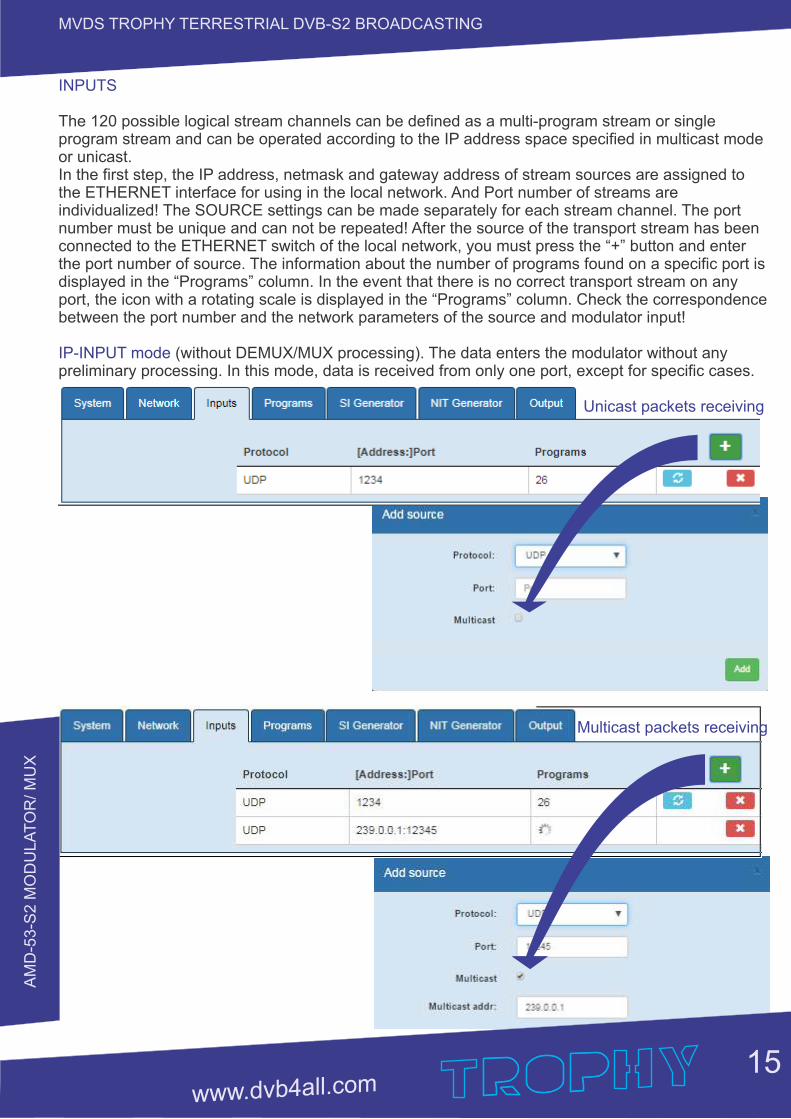
The 120 possible logical stream channels can be defined as a multi-program stream or single program stream and can be operated according to the IP address space specified in multicast mode or unicast.In the first step, the IP address, netmask and gateway address of stream sources are assigned to the ETHERNET interface for using in the local network. And Port number of streams are individualized! The SOURCE settings can be made separately for each stream channel. The port number must be unique and can not be repeated! After the source of the transport stream has been connected to the ETHERNET switch of the local network, you must press the “+” button and enter the port number of source. The information about the number of programs found on a specific port is displayed in the “Programs” column. In the event that there is no correct transport stream on any port, the icon with a rotating scale is displayed in the “Programs” column. Check the correspondence between the port number and the network parameters of the source and modulator input!
IP-INPUT mode (without DEMUX/MUX processing). The data enters the modulator without any preliminary processing. In this mode, data is received from only one port, except for specific cases. Unicast packets receiving
Multicast packets receiving
AM
D-5
3-S
2 M
OD
ULA
TO
R/ M
UX
16
MVDS TROPHY TERRESTRIAL DVB-S2 BROADCASTING
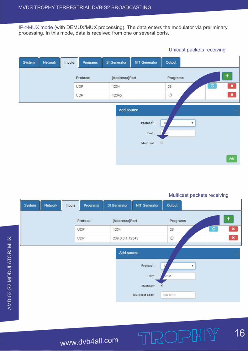
IP-˃MUX mode (with DEMUX/MUX processing). The data enters the modulator via preliminary processing. In this mode, data is received from one or several ports.
Unicast packets receiving
Multicast packets receiving
AM
D-5
3-S
2 M
OD
ULA
TO
R/ M
UX
17
MVDS TROPHY TERRESTRIAL DVB-S2 BROADCASTING
PROGRAMS
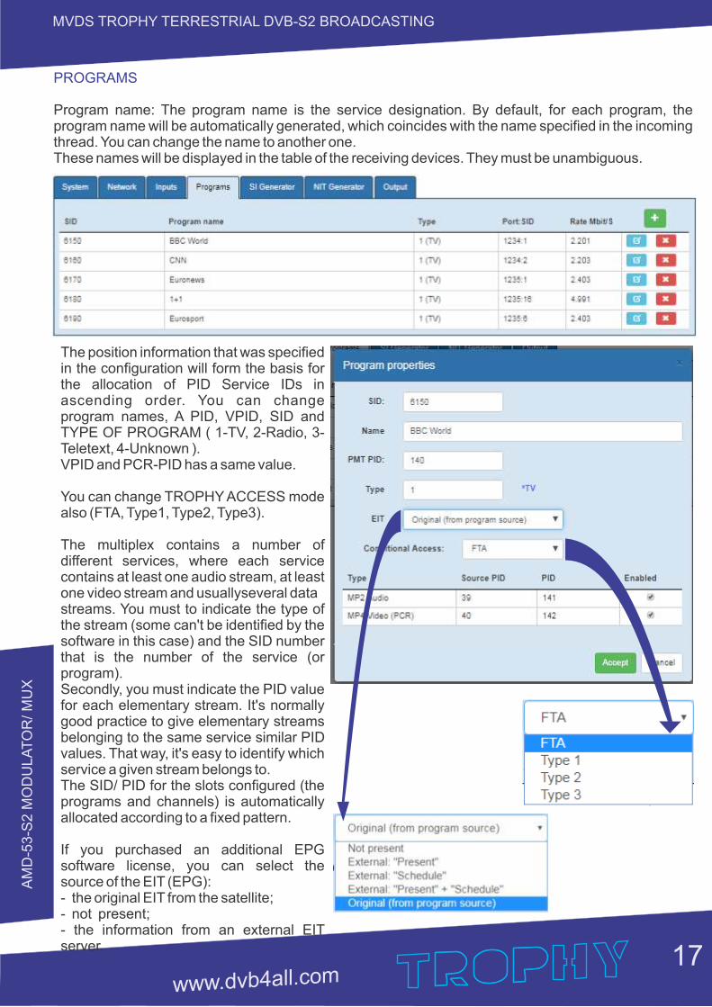
Program name: The program name is the service designation. By default, for each program, the program name will be automatically generated, which coincides with the name specified in the incoming thread. You can change the name to another one.These names will be displayed in the table of the receiving devices. They must be unambiguous.
The position information that was specified in the configuration will form the basis for the allocation of PID Service IDs in ascending order. You can change program names, A PID, VPID, SID and TYPE OF PROGRAM ( 1-TV, 2-Radio, 3-Teletext, 4-Unknown ).VPID and PCR-PID has a same value.
You can change TROPHY ACCESS mode also (FTA, Type1, Type2, Type3).
The multiplex contains a number of different services, where each service contains at least one audio stream, at least one video stream and usuallyseveral data streams. You must to indicate the type of the stream (some can't be identified by the software in this case) and the SID number that is the number of the service (or program).Secondly, you must indicate the PID value for each elementary stream. It's normally good practice to give elementary streams belonging to the same service similar PID values. That way, it's easy to identify which service a given stream belongs to. The SID/ PID for the slots configured (the programs and channels) is automatically allocated according to a fixed pattern.
If you purchased an additional EPG software license, you can select the source of the EIT (EPG):- the original EIT from the satellite; - not present;- the information from an external EIT server.
AM
D-5
3-S
2 M
OD
ULA
TO
R/ M
UX
18
MVDS TROPHY TERRESTRIAL DVB-S2 BROADCASTING
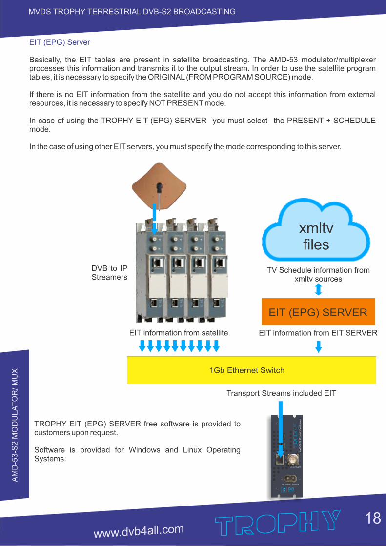
EIT (EPG) Server
Basically, the EIT tables are present in satellite broadcasting. The AMD-53 modulator/multiplexer processes this information and transmits it to the output stream. In order to use the satellite program tables, it is necessary to specify the ORIGINAL (FROM PROGRAM SOURCE) mode.
If there is no EIT information from the satellite and you do not accept this information from external resources, it is necessary to specify NOT PRESENT mode.
In case of using the TROPHY EIT (EPG) SERVER you must select the PRESENT + SCHEDULE mode.
In the case of using other EIT servers, you must specify the mode corresponding to this server.
xmltvfiles
EIT (EPG) SERVER
1Gb Ethernet Switch
EIT information from satellite
TV Schedule information fromxmltv sources
EIT information from EIT SERVER
Transport Streams included EIT
TROPHY EIT (EPG) SERVER free software is provided to customers upon request.
Software is provided for Windows and Linux Operating Systems.
DVB to IP Streamers
Eth
ern
et
200-240VAC 50/60Hz
L-band output
AM
D-5
3-S
2 M
od
ula
tor/
Mu
ltip
lexe
r
AM
D-5
3-S
2 M
OD
ULA
TO
R/ M
UX
19
MVDS TROPHY TERRESTRIAL DVB-S2 BROADCASTING
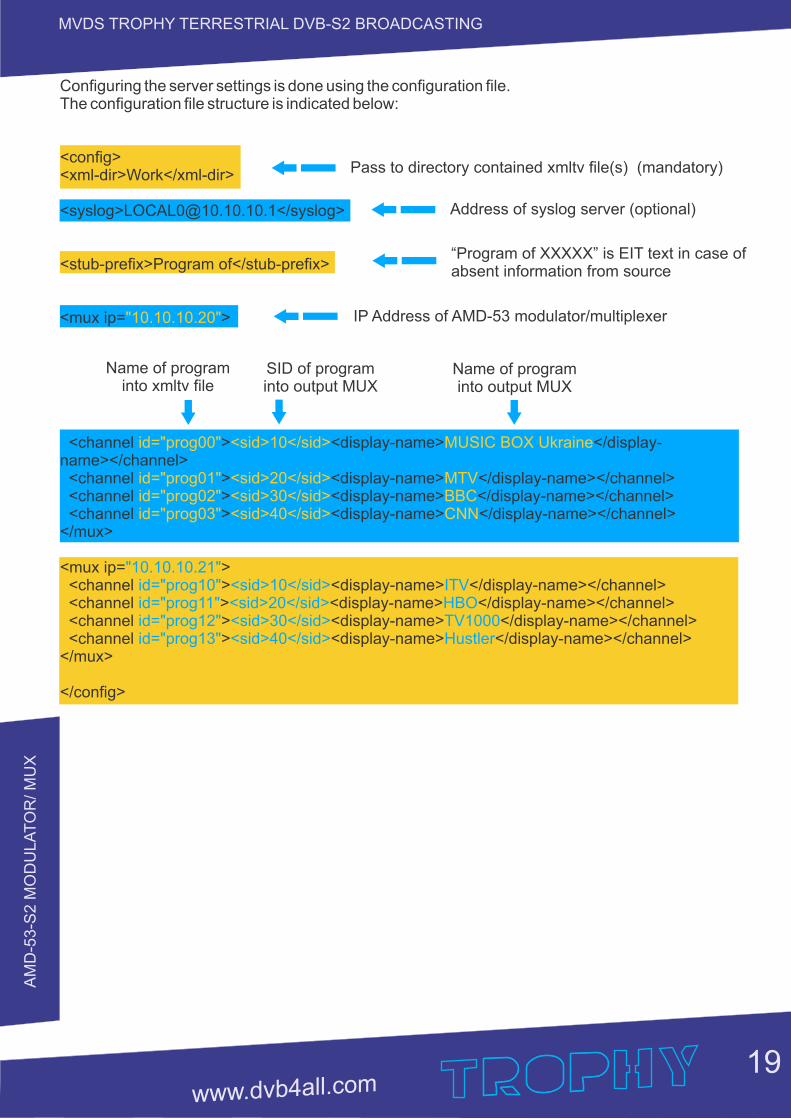
Address of syslog server (optional)
“Program of XXXXX” is EIT text in case of absent information from source
IP Address of AMD-53 modulator/multiplexer
Name of programinto xmltv file
SID of programinto output MUX
Name of programinto output MUX
Configuring the server settings is done using the configuration file.The configuration file structure is indicated below:
<config><xml-dir>Work</xml-dir>
<syslog>[email protected]</syslog>
<stub-prefix>Program of</stub-prefix>
<mux ip= >"10.10.10.20"
<channel > <display-name </display-id="prog00" <sid>10</sid> MUSIC BOX Ukraine>name></channel> <channel > <display-name> </display-name></channel>id="prog01" <sid>20</sid> MTV <channel > <display-name> </display-name></channel>id="prog02" <sid>30</sid> BBC <channel > <display-name> </display-name></channel>id="prog03" <sid>40</sid> CNN</mux>
<mux ip= >"10.10.10.21" <channel > <display-name </display-name></channel>id="prog10" <sid>10</sid> ITV> <channel > <display-name> </display-name></channel>id="prog11" <sid>20</sid> HBO <channel > <display-name> </display-name></channel>id="prog12" <sid>30</sid> TV1000 <channel > <display-name> </display-name></channel>id="prog13" <sid>40</sid> Hustler</mux>
</config>
Pass to directory contained xmltv file(s) (mandatory)
AM
D-5
3-S
2 M
OD
ULA
TO
R/ M
UX
20
MVDS TROPHY TERRESTRIAL DVB-S2 BROADCASTING
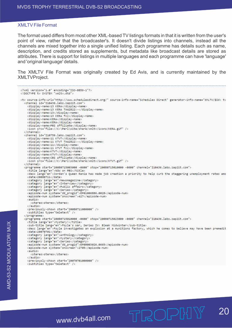
XMLTV File Format
The format used differs from most other XML-based TV listings formats in that it is written from the user's point of view, rather that the broadcaster's. It doesn't divide listings into channels, instead all the channels are mixed together into a single unified listing. Each programme has details such as name, description, and credits stored as supplements, but metadata like broadcast details are stored as attributes. There is support for listings in multiple languages and each programme can have 'language' and 'original language' details.
The XMLTV File Format was originally created by Ed Avis, and is currently maintained by the XMLTVProject.
AM
D-5
3-S
2 M
OD
ULA
TO
R/ M
UX
21
MVDS TROPHY TERRESTRIAL DVB-S2 BROADCASTING
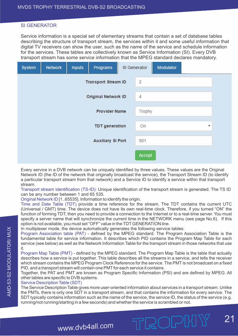
SI GENERATOR
Service information is a special set of elementary streams that contain a set of database tables describing the structure of transport stream, the services within it and some useful information that digital TV receivers can show the user, such as the name of the service and schedule information for the services. These tables are collectively known as Service Information (SI). Every DVB transport stream has some service information that the MPEG standard declares mandatory.
Every service in a DVB network can be uniquely identified by three values. These values are the Original Network ID (the ID of the network that originally broadcast the service), the Transport Stream ID (to identify a particular transport stream from that network) and a Service ID to identify a service within that transport stream. Transport stream identification (TS-ID): Unique identification of the transport stream is generated. The TS ID can be any number between 1 and 65 535.Original Network ID [1..65535]. Information to identify the origin.Time and Date Table (TDT) provide a time reference for the stream. The TDT contains the current UTC (Universal / GMT) time. The device does not have its own real-time clock. Therefore, if you turned “ON” the function of forming TDT, then you need to provide a connection to the Internet or to a real-time server. You must specify a server name that will synchronize the current time in the NETWORK menu (see page No.6). If this option is not available, you must set “OFF” value in the TDT GENERATION line.In multiplexer mode, the device automatically generates the following service tables:Program Association table (PAT) - defined by the MPEG standard. The Program Association Table is the fundamental table for service information. It describes which PID contains the Program Map Table for each service (see below) as well as the Network Information Table for the transport stream in those networks that use it.Program Map Table (PMT) - defined by the MPEG standard. The Program Map Table is the table that actually describes how a service is put together. This table describes all the streams in a service, and tells the receiver which stream contains the MPEG Program Clock Reference for the service. The PMT is not broadcast on a fixed PID, and a transport stream will contain one PMT for each service it contains.Together, the PAT and PMT are known as Program Specific Information (PSI) and are defined by MPEG. All other tables are specific to DVB systems.Service Description Table (SDT)The Service Description Table gives more user-oriented information about services in a transport stream. Unlike the PMTs, there is only one SDT in a transport stream, and that contains the information for every service. The SDT typically contains information such as the name of the service, the service ID, the status of the service (e.g. running/not running/starting in a few seconds) and whether the service is scrambled or not.
AM
D-5
3-S
2 M
OD
ULA
TO
R/ M
UX
22
MVDS TROPHY TERRESTRIAL DVB-S2 BROADCASTING
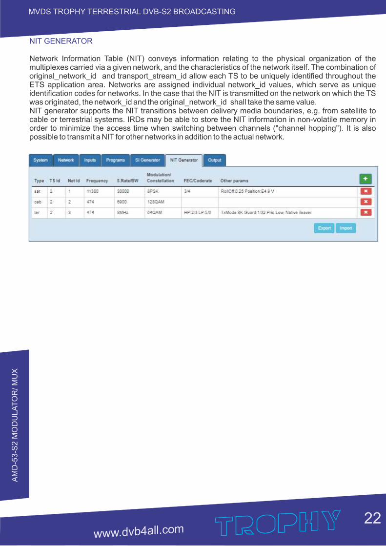
NIT GENERATOR
Network Information Table (NIT) conveys information relating to the physical organization of the multiplexes carried via a given network, and the characteristics of the network itself. The combination of original_network_id and transport_stream_id allow each TS to be uniquely identified throughout the ETS application area. Networks are assigned individual network_id values, which serve as unique identification codes for networks. In the case that the NIT is transmitted on the network on which the TS was originated, the network_id and the original_network_id shall take the same value.NIT generator supports the NIT transitions between delivery media boundaries, e.g. from satellite to cable or terrestrial systems. IRDs may be able to store the NIT information in non-volatile memory in order to minimize the access time when switching between channels ("channel hopping"). It is also possible to transmit a NIT for other networks in addition to the actual network.
Payload rate: 30,155 Mbit (0,94%) Subs rate: 1,93 Mb
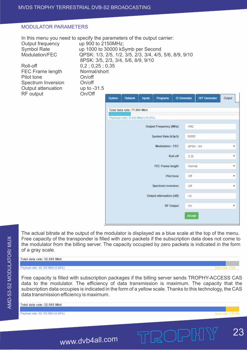
MODULATOR PARAMETERS
In this menu you need to specify the parameters of the output carrier:Output frequency up 900 to 2150MHz;Symbol Rate up 1000 to 30000 kSymb per SecondModulation/FEC QPSK: 1/3, 2/5, 1/2, 3/5, 2/3, 3/4, 4/5, 5/6, 8/9, 9/10 8PSK: 3/5, 2/3, 3/4, 5/6, 8/9, 9/10Roll-off 0,2 ; 0,25 ; 0,35FEC Frame length Normal/short Pilot tone On/offSpectrum Inversion On/off Output attenuation up to -31.5RF output On/Off
The actual bitrate at the output of the modulator is displayed as a blue scale at the top of the menu.Free capacity of the transponder is filled with zero packets if the subscription data does not come to the modulator from the billing server. The capacity occupied by zero packets is indicated in the form of a gray scale.
Free capacity is filled with subscription packages if the billing server sends TROPHY-ACCESS CAS data to the modulator. The efficiency of data transmission is maximum. The capacity that the subscription data occupies is indicated in the form of a yellow scale. Thanks to this technology, the CAS data transmission efficiency is maximum.
AM
D-5
3-S
2 M
OD
ULA
TO
R/ M
UX
23
MVDS TROPHY TERRESTRIAL DVB-S2 BROADCASTING
Payload rate: 30,155 Mbit (0,94%) Subs rate: 0 Mb
AM
D-5
3-S
2 M
OD
ULA
TO
R/ M
UX
24
MVDS TROPHY TERRESTRIAL DVB-S2 BROADCASTING
SPECIFICATIONS
Standards
Carrier ID
DVB-S2
MPEG-TS
DVB MPEG-TS over ASI
DVB MPEG-TS over IP
MPEG-2 PSI Tables (PAT,PMT,NIT etc)
IP input
Stream port + WEB interface
Connector
Streaming protocol
Streaming mode
Encryption 0,25 to 120Mbps
RF Output
L-Band
SNR
Shoulders rejection
Main RF output
Attenuation range
ETSI 103 129
EN 302 307
EN 301 210
EN50083-9; ETSI TR 101 891
ETSI TS 102 034
EN 300 468 (additional license for EPG table)
Ethernet, 10/100/1000 Base-T
RJ-45
UDP, Unicast/Multicast
CBR/VBR
TROPHY-ACCESS (additional license)
900MHz to 2150MHz, 10kHz step
> 40dB @ 0dBm – 16APSK – 30Mbaud
< -50dB @ 0dBm & f/fN=1,5 for 20% roll-off
N Type, 50Ohm
0dBm to -31.5dBm, 0,1dB step
AM
D-5
3-S
2 M
OD
ULA
TO
R/ M
UX
25
MVDS TROPHY TERRESTRIAL DVB-S2 BROADCASTING
Multiplexer
Quantity of multiplexed channels
PID quantity supported
Modulation
DVB-S2
Supported DVB modes
DVB-S2 frames
Pilots
Variable symbol rate
Control & Monitoring
Physical
TROPHY-ACCESS Options
Type of CAS
Size of the decoder address field
Quantity of addressable decoder
The number of serviced channels
The number of packets serviced
Automatic decoder disconnection
Individual addressable message
up to 120
All PIDs of input sevices
QPSK: 1/3, 2/5, 1/2, 3/5, 2/3, 3/4, 4/5, 5/6, 8/9, 9/10
8PSK: 3/5, 2/3, 3/4, 5/6, 8/9, 9/10
CCM: Constant Coding and Modulation
VCM: Variable Coding and Modulation
SeamlessACM: Adaptive Coding and Modulation
Short (16200), Normal (64800)
On or Off
From 1 to 30Mbaud, step 1Baud Web Browser Control & Monitoring
10/100/1000 Base-T Ethernet ports
90 to 240VAC/50Hz/15W
2kg Weight
0°C to 50°C temperature range
FPGA based, doesn’t match CSA algorithm
32 bits
4,294,967,295
without any restrictions
without any restrictions
with zero balances in the subscriber account
up to 120 characters
SU
BS
_S
EN
D S
OF
TW
AR
E
26
MVDS TROPHY TERRESTRIAL DVB-S2 BROADCASTING
SUBS_SEND_V.2
subscription management software
SU
BS
_S
EN
D S
OF
TW
AR
E
27
MVDS TROPHY TERRESTRIAL DVB-S2 BROADCASTING
GENERAL INFORMATION
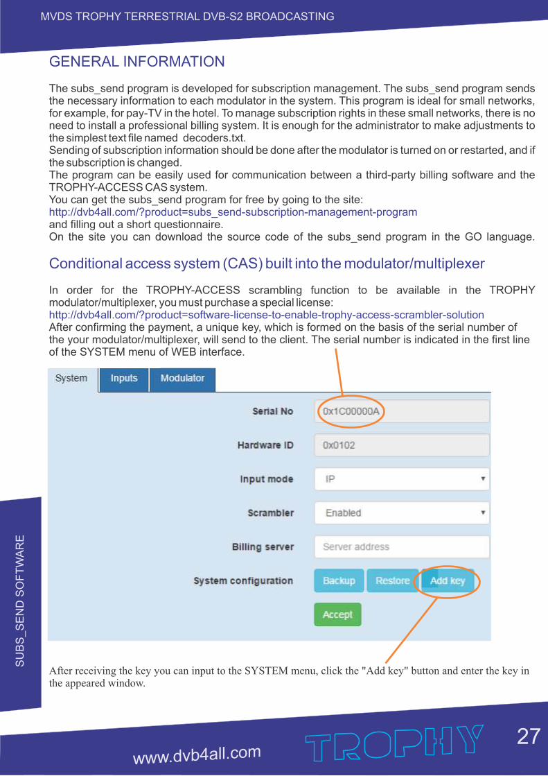
The subs_send program is developed for subscription management. The subs_send program sends the necessary information to each modulator in the system. This program is ideal for small networks, for example, for pay-TV in the hotel. To manage subscription rights in these small networks, there is no need to install a professional billing system. It is enough for the administrator to make adjustments to the simplest text file named decoders.txt.Sending of subscription information should be done after the modulator is turned on or restarted, and if the subscription is changed.The program can be easily used for communication between a third-party billing software and the TROPHY-ACCESS CAS system.You can get the subs_send program for free by going to the site:http://dvb4all.com/?product=subs_send-subscription-management-programand filling out a short questionnaire.On the site you can download the source code of the subs_send program in the GO language.
Conditional access system (CAS) built into the modulator/multiplexer
In order for the TROPHY-ACCESS scrambling function to be available in the TROPHY modulator/multiplexer, you must purchase a special license:http://dvb4all.com/?product=software-license-to-enable-trophy-access-scrambler-solutionAfter confirming the payment, a unique key, which is formed on the basis of the serial number of the your modulator/multiplexer, will send to the client. The serial number is indicated in the first line of the SYSTEM menu of WEB interface.
After receiving the key you can input to the SYSTEM menu, click the "Add key" button and enter the key in the appeared window.
SU
BS
_S
EN
D S
OF
TW
AR
E
28
MVDS TROPHY TERRESTRIAL DVB-S2 BROADCASTING
ASI input
Demux Mux
WEBcontrol
TS input
1G
b E
thern
et
TS Switch
TROPHY-ACCESSscrambler
LocalOscillator
DV
B-S
2 Q
PS
K/8
PS
K/1
6A
PS
K/3
2A
PS
K m
odula
tor
1Gb Ethernet Switch
Up to 120single
MPEG TS
MPEG Transport Streams over IP
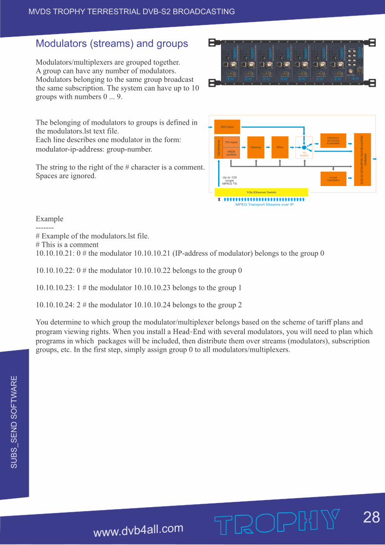
Modulators (streams) and groups
Modulators/multiplexers are grouped together. A group can have any number of modulators. Modulators belonging to the same group broadcast the same subscription. The system can have up to 10 groups with numbers 0 ... 9.
The belonging of modulators to groups is defined in the modulators.lst text file. Each line describes one modulator in the form: modulator-ip-address: group-number.
The string to the right of the # character is a comment. Spaces are ignored.
Example-------# Example of the modulators.lst file.# This is a comment10.10.10.21: 0 # the modulator 10.10.10.21 (IP-address of modulator) belongs to the group 0
10.10.10.22: 0 # the modulator 10.10.10.22 belongs to the group 0
10.10.10.23: 1 # the modulator 10.10.10.23 belongs to the group 1
10.10.10.24: 2 # the modulator 10.10.10.24 belongs to the group 2
You determine to which group the modulator/multiplexer belongs based on the scheme of tariff plans and program viewing rights. When you install a Head-End with several modulators, you will need to plan which programs in which packages will be included, then distribute them over streams (modulators), subscription groups, etc. In the first step, simply assign group 0 to all modulators/multiplexers.
Eth
erne
t
200-240VAC 50/60Hz
L-band output
AM
D-5
3-S
2 M
odul
ator
/Mul
tiple
xer
Eth
erne
t
200-240VAC 50/60Hz
L-band output
AM
D-5
3-S
2 M
odul
ator
/Mul
tiple
xer
Eth
erne
t
200-240VAC 50/60Hz
L-band output
AM
D-5
3-S
2 M
odul
ator
/Mul
tiple
xer
Eth
erne
t
200-240VAC 50/60Hz
L-band output
AM
D-5
3-S
2 M
odul
ator
/Mul
tiple
xer
Eth
erne
t
200-240VAC 50/60Hz
L-band output
AM
D-5
3-S
2 M
odul
ator
/Mul
tiple
xer
Eth
erne
t
200-240VAC 50/60Hz
L-band output
AM
D-5
3-S
2 M
odul
ator
/Mul
tiple
xer
Eth
erne
t
200-240VAC 50/60Hz
L-band output
AM
D-5
3-S
2 M
odul
ator
/Mul
tiple
xer
L-band inputs
L-band output10MHz ref. +24VDC
90-2
64V
AC
50/
60H
zL-
band
8-c
h co
mbi
ner
1 2
3 4
5 6
7 8
SU
BS
_S
EN
D S
OF
TW
AR
E
29
MVDS TROPHY TERRESTRIAL DVB-S2 BROADCASTING
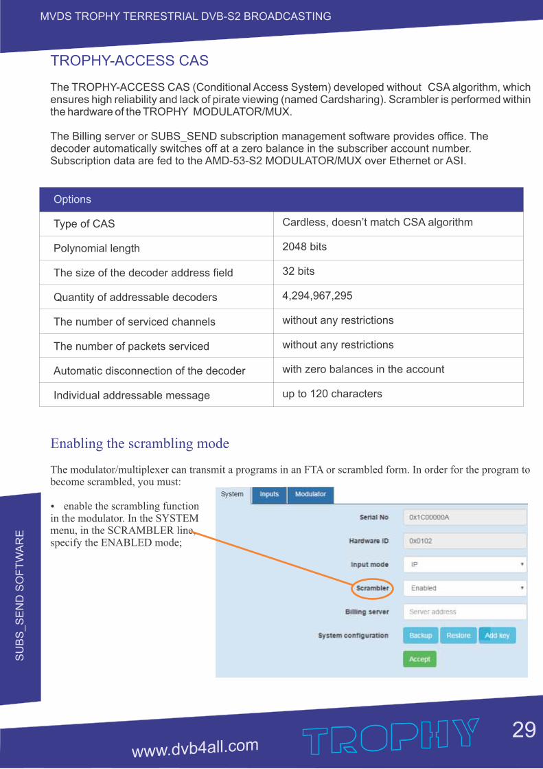
TROPHY-ACCESS CAS
The TROPHY-ACCESS CAS (Conditional Access System) developed without CSA algorithm, which ensures high reliability and lack of pirate viewing (named Cardsharing). Scrambler is performed within the hardware of the TROPHY MODULATOR/MUX.
The Billing server or SUBS_SEND subscription management software provides office. The decoder automatically switches off at a zero balance in the subscriber account number. Subscription data are fed to the AMD-53-S2 MODULATOR/MUX over Ethernet or ASI.
Enabling the scrambling mode
The modulator/multiplexer can transmit a programs in an FTA or scrambled form. In order for the program to become scrambled, you must:
Ÿ enable the scrambling function in the modulator. In the SYSTEM menu, in the SCRAMBLER line, specify the ENABLED mode;
Options
Type of CAS
Polynomial length
The size of the decoder address field
Quantity of addressable decoders
The number of serviced channels
The number of packets serviced
Automatic disconnection of the decoder
Individual addressable message
Cardless, doesn’t match CSA algorithm
2048 bits
32 bits
4,294,967,295
without any restrictions
without any restrictions
with zero balances in the account
up to 120 characters
SU
BS
_S
EN
D S
OF
TW
AR
E
30
MVDS TROPHY TERRESTRIAL DVB-S2 BROADCASTING
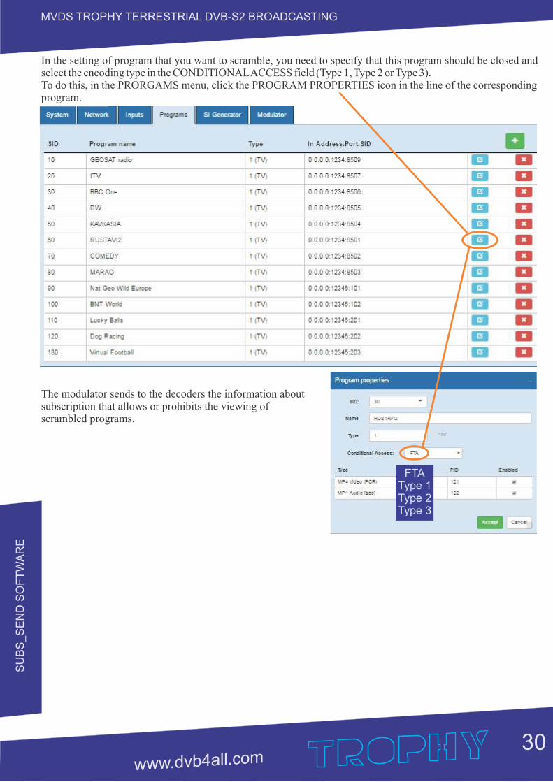
In the setting of program that you want to scramble, you need to specify that this program should be closed and select the encoding type in the CONDITIONAL ACCESS field (Type 1, Type 2 or Type 3). To do this, in the PRORGAMS menu, click the PROGRAM PROPERTIES icon in the line of the corresponding program.
The modulator sends to the decoders the information about subscription that allows or prohibits the viewing of scrambled programs.
FTAType 1Type 2Type 3
SU
BS
_S
EN
D S
OF
TW
AR
E
31
MVDS TROPHY TERRESTRIAL DVB-S2 BROADCASTING
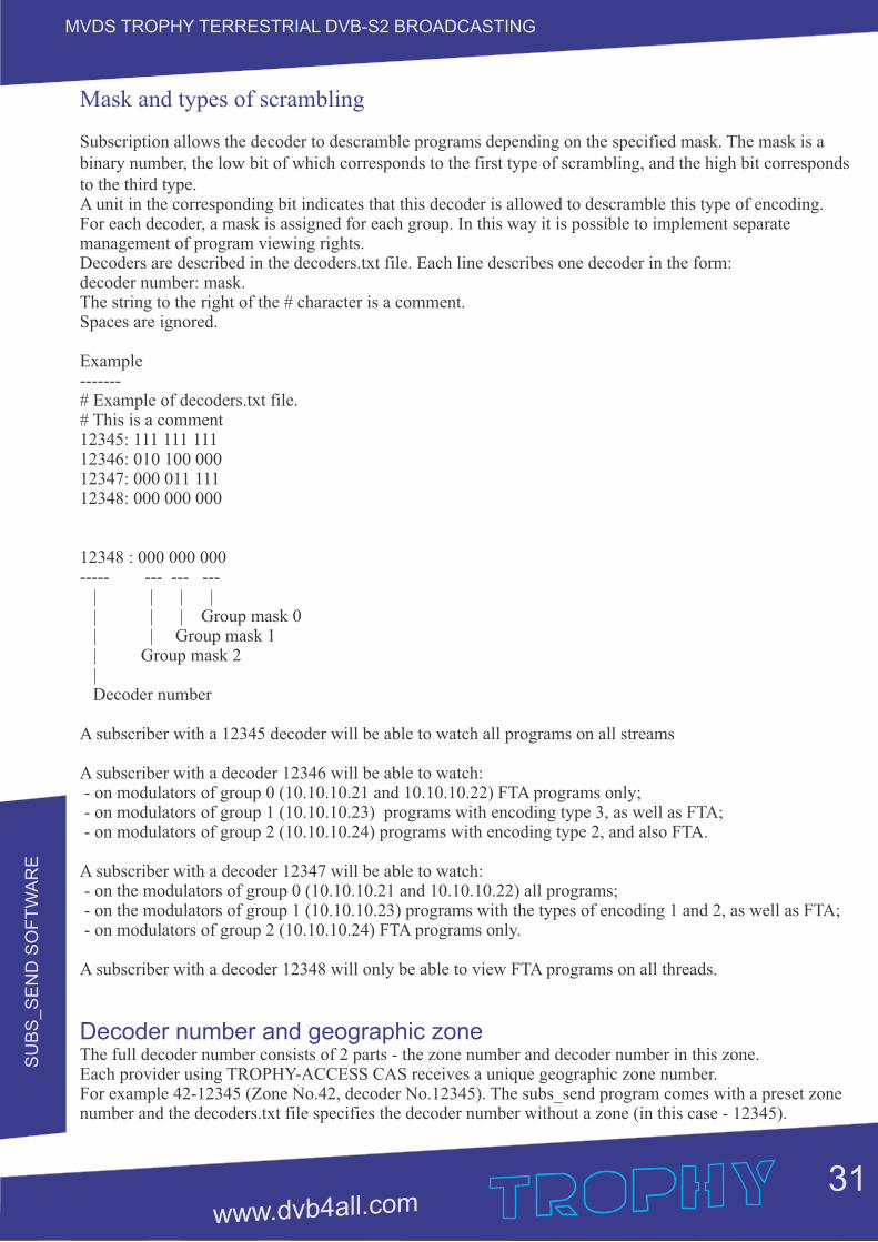
Mask and types of scrambling
Subscription allows the decoder to descramble programs depending on the specified mask. The mask is a binary number, the low bit of which corresponds to the first type of scrambling, and the high bit corresponds to the third type.A unit in the corresponding bit indicates that this decoder is allowed to descramble this type of encoding. For each decoder, a mask is assigned for each group. In this way it is possible to implement separate management of program viewing rights.Decoders are described in the decoders.txt file. Each line describes one decoder in the form: decoder number: mask.The string to the right of the # character is a comment. Spaces are ignored.
Example-------# Example of decoders.txt file.# This is a comment12345: 111 111 11112346: 010 100 00012347: 000 011 11112348: 000 000 000
12348 : 000 000 000----- --- --- --- | | | | | | | Group mask 0 | | Group mask 1 | Group mask 2 | Decoder number
A subscriber with a 12345 decoder will be able to watch all programs on all streams
A subscriber with a decoder 12346 will be able to watch: - on modulators of group 0 (10.10.10.21 and 10.10.10.22) FTA programs only; - on modulators of group 1 (10.10.10.23) programs with encoding type 3, as well as FTA; - on modulators of group 2 (10.10.10.24) programs with encoding type 2, and also FTA.
A subscriber with a decoder 12347 will be able to watch: - on the modulators of group 0 (10.10.10.21 and 10.10.10.22) all programs; - on the modulators of group 1 (10.10.10.23) programs with the types of encoding 1 and 2, as well as FTA; - on modulators of group 2 (10.10.10.24) FTA programs only.
A subscriber with a decoder 12348 will only be able to view FTA programs on all threads.
Decoder number and geographic zoneThe full decoder number consists of 2 parts - the zone number and decoder number in this zone.Each provider using TROPHY-ACCESS CAS receives a unique geographic zone number.For example 42-12345 (Zone No.42, decoder No.12345). The subs_send program comes with a preset zone number and the decoders.txt file specifies the decoder number without a zone (in this case - 12345).
SU
BS
_S
EN
D S
OF
TW
AR
E
32
MVDS TROPHY TERRESTRIAL DVB-S2 BROADCASTING
Working with the subs_send program
The subs_send program is a console application, so you need to run it from the Windows console. You can create a command file and run it from the explorer:Create a file called subs_send.cmd in any text editor, Notepad for example, with one line:
---------------------------------Subs_send_v2.exe -z 42 ** The version of the program compiled for the 42nd Geographical Zone.
Save this file in the directory where is subs_send_v2.exe. Run now subs_send.cmd
You can also create a shortcut to the subs_send_v2.exe program, then in the properties of this shortcut, in the "Target" field add -z 42 key.
subs_send_v2.exe should be run after you create the modulators.lst anddecoders.txt files. This program sends over the network subscription data from the above files to modulators. If the modulator is restarted, the subs_send_v2.exe should be repeated, since subscription data is not stored on modulators. You should also sending (run the program) after making changes to the modulators.lst ordecoders.txt files.
The subs_send_v2.src file that you want to download for free from the site should be created with the number of your geographic zone. In order for you to become acquainted with the program, an example program for Zone 42 is posted on the site.In the archive there are two files collected with the zone No.42 by default, for Windows x32 and x64.
DV
B_B
ILLIN
G S
OF
TW
AR
E
33
MVDS TROPHY TERRESTRIAL DVB-S2 BROADCASTING
DVB_BILLING_V.5 subscriber accounting software

DV
B_B
ILLIN
G S
OF
TW
AR
E
34
MVDS TROPHY TERRESTRIAL DVB-S2 BROADCASTING
MAIN INFORMATION
DVB-BILLING Software and Statistics Billing
The DVB-BILLING program is designed to manage the subscriber base and manage subscriber decoders in large commercial broadcasting DVB networks.The DVB-BILLING software comes with a Statistics Server. Depending on the sales order, the Statistics Server can be either the simplest (demo version) or the most complex, up to a group of servers assembled by cluster technology. The main functions of the statistics server are:Ÿ management of subscriber decoders;Ÿ keeping records of subscribers' payments;Ÿ feed to the EPG data stream;Ÿ input of service information PAT, PMT, CAT, TSDT, NIT, SDT, EIT, TDT (formed in full compliance with the specification EN 300 468) into the transport stream;Ÿ creation of various reports on payments.
Additional functions of the Statistics Server are:Ÿ As part of the TROPHY base station, the Server takes full control of the DB100, DB800 and DB800CI streamers. The data generated by the Statistics Server is sent to the streamers using the dvbserver program.The program is launched as follows: cd / dvbserver / bin killall camserver ./camserver dvbX, where X is the stream number. Repeat the sequence of commands on all threads.Ÿ Displaying real-time monitoring data of the streamers;Ÿ Integration of the Statistics Server with the system of bank payment terminals.
How is everything arranged inside?
The system is installed on the Linux OS Debian 4.0.The main components of the system are located in the /opt directory. Firebird is database. The database is located /var/db. Some components of the system are located in the /home/palich/bin/ directory, namely:- net_cam_server - the subscription server with its configuration camserver.conf file;- the generator of service tables si_gen with its configuration file si_gen.conf;- parser xmlTV files with TV program xmlreadEPG;- scripts for updating programs and auxiliary files.

DV
B_B
ILLIN
G S
OF
TW
AR
E
35
MVDS TROPHY TERRESTRIAL DVB-S2 BROADCASTING
Main parameters of DVB-BILLING Subscribers Accounting Program
Interface Language English, Russian
Number of channels served No restrictions
Number of serviced packets No restrictions
Number at a time served customers No restrictions
Information about subscribers Contract number, Date of Contract, name, phone, city, street, house, apartment, e-mail,
notes
The ability to quickly add client decoder number and installation the required application for a certain period Yes
Automatic addition of the Contract Date and Registration data after assigning the decoder number Yes
Automatic decoder shutdown whenzero balance on subscriber's account Yes
When you make a payment, the program instantlymakes money to the client on the account and shows on what number is paid. In VIEW mode
Ability to perform a quick search of customers by any criterion specified in the search list Yes
Ability to print reports Yes
Ability to enter different tariffs Yes
The possibility of temporary disconnection andautomatic activation at a specified time Yes
Types of reports: For payments for the period, for services, for tariffs, for balance, for viewing channels,
for disabled subscribers for a certain date
Sending address messages Up to 120 characters
Automatic sending of address messages about the need to deposit money into the account Yes
Interface type WEB
Architecture type Open
DV
B_B
ILLIN
G S
OF
TW
AR
E
36
MVDS TROPHY TERRESTRIAL DVB-S2 BROADCASTING
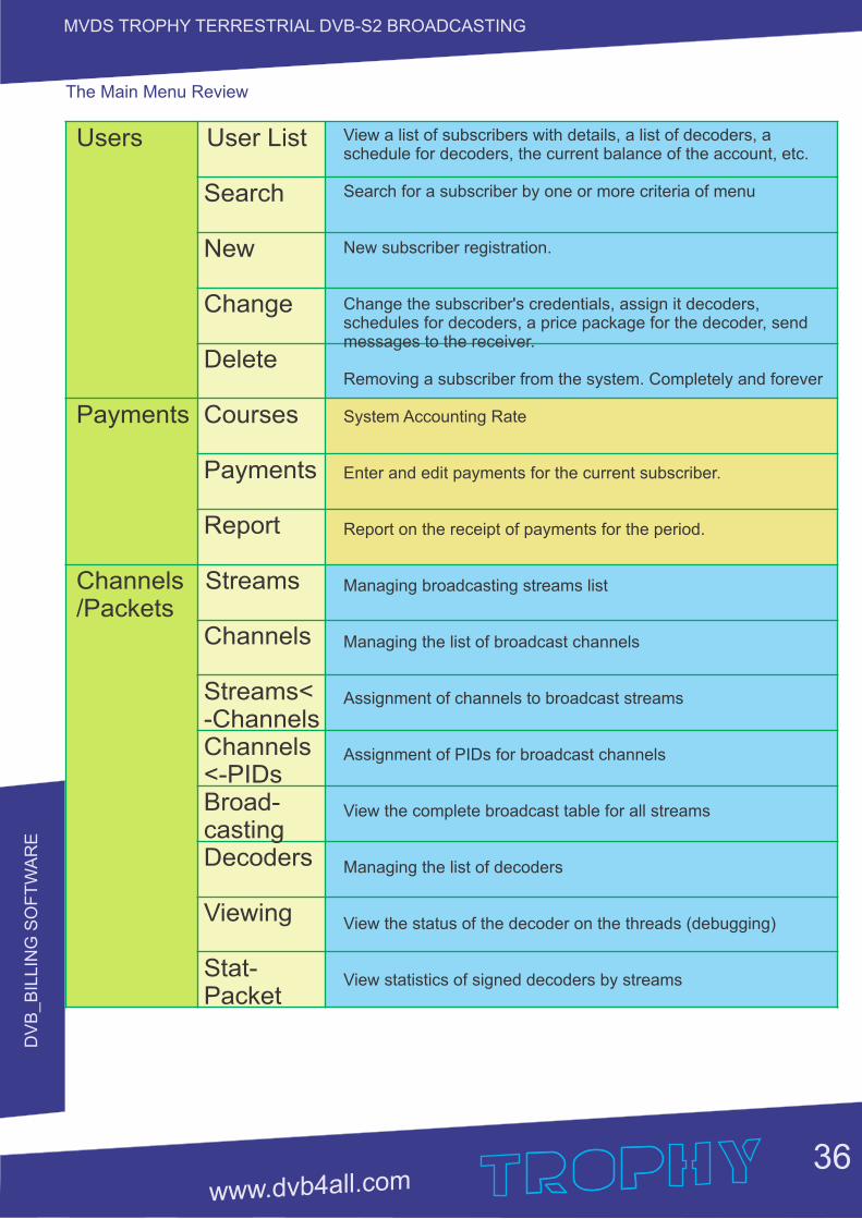
The Main Menu Review
Users User List
Search
New
Change
Delete
Payments Courses
Payments
Report
Channels Streams/Packets Channels
Streams< -Channels Channels <-PIDs Broad- casting Decoders
Viewing
Stat- Packet
View a list of subscribers with details, a list of decoders, a schedule for decoders, the current balance of the account, etc.
Search for a subscriber by one or more criteria of menu
New subscriber registration.
Change the subscriber's credentials, assign it decoders, schedules for decoders, a price package for the decoder, send messages to the receiver.
Removing a subscriber from the system. Completely and forever
System Accounting Rate
Enter and edit payments for the current subscriber.
Report on the receipt of payments for the period.
Managing broadcasting streams list
Managing the list of broadcast channels
Assignment of channels to broadcast streams
Assignment of PIDs for broadcast channels
View the complete broadcast table for all streams
Managing the list of decoders
View the status of the decoder on the threads (debugging)
View statistics of signed decoders by streams
DV
B_B
ILLIN
G S
OF
TW
AR
E
37
MVDS TROPHY TERRESTRIAL DVB-S2 BROADCASTING
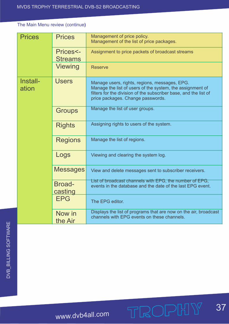
The Main Menu review (continue)
Prices Prices
Prices<- Streams Viewing
Install- Usersation
Groups
Rights
Regions
Logs
Messages
Broad- casting EPG
Now in the Air
Management of price policy.Management of the list of price packages. Assignment to price packets of broadcast streams
Reserve
Manage users, rights, regions, messages, EPG.Manage the list of users of the system, the assignment of filters for the division of the subscriber base, and the list of price packages. Change passwords.
Manage the list of user groups.
Assigning rights to users of the system.
Manage the list of regions.
Viewing and clearing the system log.
View and delete messages sent to subscriber receivers.
List of broadcast channels with EPG, the number of EPG, events in the database and the date of the last EPG event.
The EPG editor. Displays the list of programs that are now on the air, broadcast channels with EPG events on these channels.
DV
B_B
ILLIN
G S
OF
TW
AR
E
38
MVDS TROPHY TERRESTRIAL DVB-S2 BROADCASTING
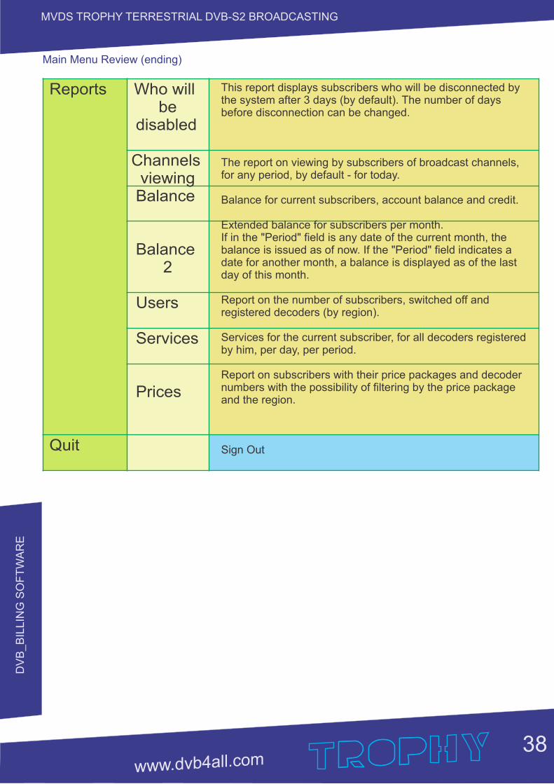
Main Menu Review (ending)
Reports Who will be disabled
Channels viewing Balance Balance 2
Users
Services
Prices
Quit
This report displays subscribers who will be disconnected by the system after 3 days (by default). The number of days before disconnection can be changed.
The report on viewing by subscribers of broadcast channels, for any period, by default - for today.
Balance for current subscribers, account balance and credit.
Extended balance for subscribers per month. If in the "Period" field is any date of the current month, the balance is issued as of now. If the "Period" field indicates a date for another month, a balance is displayed as of the last day of this month.
Report on the number of subscribers, switched off and registered decoders (by region).
Services for the current subscriber, for all decoders registered by him, per day, per period.
Report on subscribers with their price packages and decoder numbers with the possibility of filtering by the price package and the region.
Sign Out
BIL
LIN
G S
ER
VE
R
39
MVDS TROPHY TERRESTRIAL DVB-S2 BROADCASTING
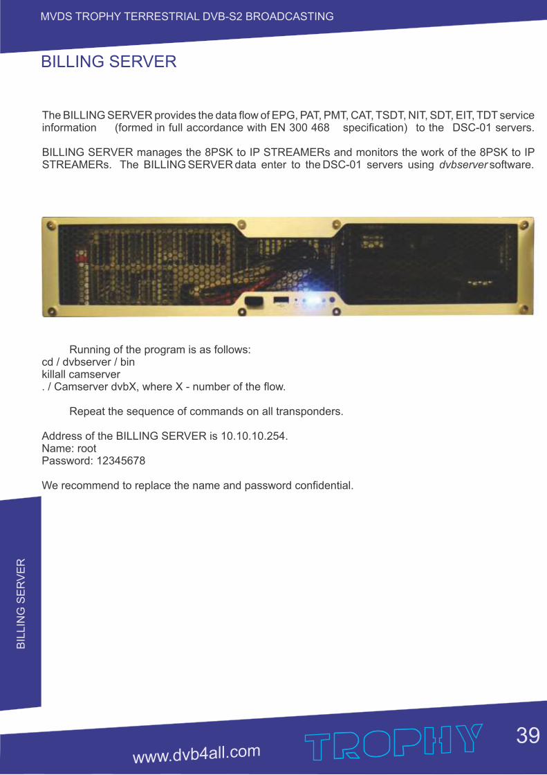
The BILLING SERVER provides the data flow of EPG, PAT, PMT, CAT, TSDT, NIT, SDT, EIT, TDT service information (formed in full accordance with EN 300 468 specification) to the DSC-01 servers.
BILLING SERVER manages the 8PSK to IP STREAMERs and monitors the work of the 8PSK to IP STREAMERs. The BILLING SERVER data enter to the DSC-01 servers using dvbserver software.
BILLING SERVER
Running of the program is as follows:cd / dvbserver / binkillall camserver. / Camserver dvbX, where X - number of the flow.
Repeat the sequence of commands on all transponders.
Address of the BILLING SERVER is 10.10.10.254.Name: rootPassword: 12345678
We recommend to replace the name and password confidential.
BIL
LIN
G S
ER
VE
R
40
MVDS TROPHY TERRESTRIAL DVB-S2 BROADCASTING
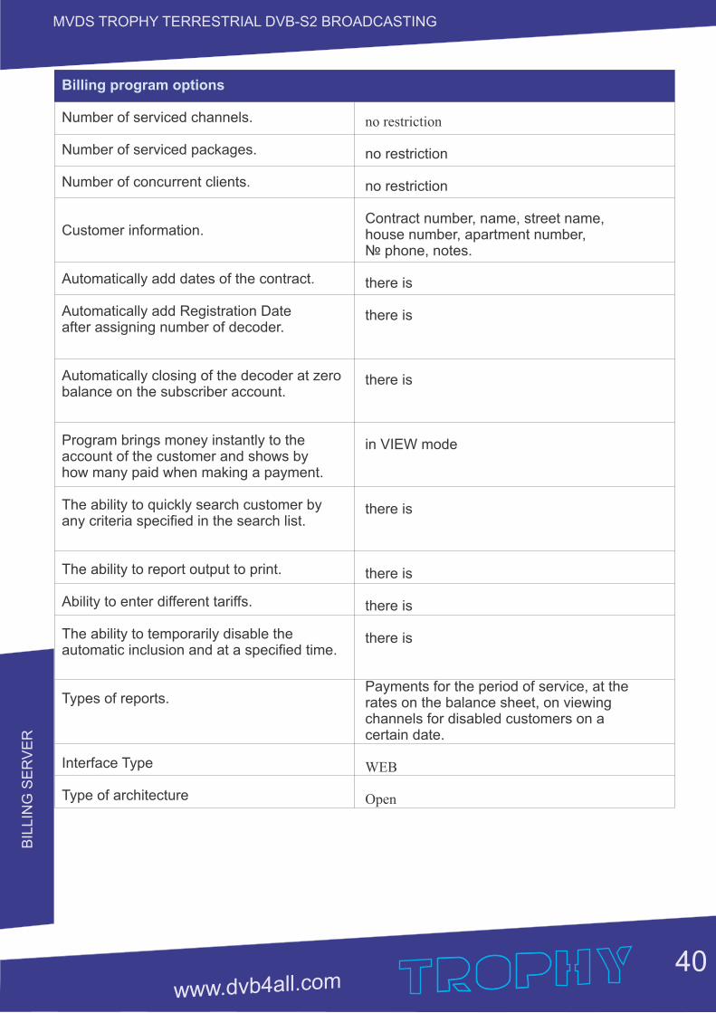
Billing program options
Number of serviced channels.
Number of serviced packages.
Number of concurrent clients.
Customer information.
Automatically add dates of the contract.
Automatically add Registration Date after assigning number of decoder.
Automatically closing of the decoder at zero balance on the subscriber account.
Program brings money instantly to the account of the customer and shows by how many paid when making a payment.
The ability to quickly search customer by any criteria specified in the search list.
The ability to report output to print.
Ability to enter different tariffs.
The ability to temporarily disable the automatic inclusion and at a specified time.
Types of reports.
Interface Type
Type of architecture
no restriction
no restriction
no restriction
Contract number, name, street name, house number, apartment number, phone, notes.
there is
there is
there is
in VIEW mode
there is
there is
there is
there is
Payments for the period of service, at the rates on the balance sheet, on viewing channels for disabled customers on a certain date.
WEB
Open
10
MH
z &
DC
IN
JEC
TO
R
41
MVDS TROPHY TERRESTRIAL DVB-S2 BROADCASTING
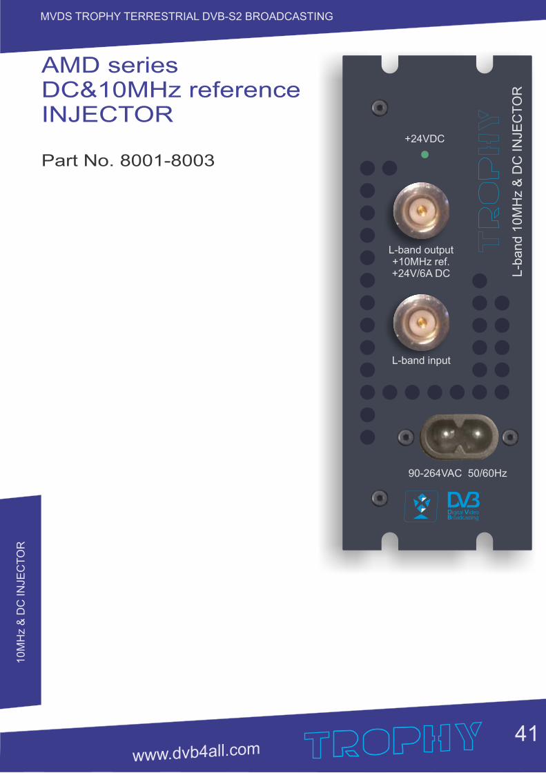
AMD series DC&10MHz reference INJECTOR
Part No. 8001-8003
90-264VAC 50/60Hz
L-band input
L-b
an
d 1
0M
Hz &
DC
IN
JE
CT
OR
L-band output+10MHz ref.+24V/6A DC
+24VDC
10
MH
z &
DC
IN
JEC
TO
R
42
MVDS TROPHY TERRESTRIAL DVB-S2 BROADCASTING
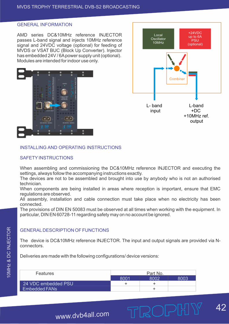
GENERAL INFORMATION
AMD series DC&10MHz reference INJECTOR passes L-band signal and injects 10MHz reference signal and 24VDC voltage (optional) for feeding of MVDS or VSAT BUC (Block Up Converter). Injector has embedded 24V / 6A power supply unit (optional).Modules are intended for indoor use only.
Combiner
LocalOscillator10MHz
L- band L-band input +DC +10MHz ref. output
+24VDCup to 6A
PSU(optional)
INSTALLING AND OPERATING INSTRUCTIONS
SAFETY INSTRUCTIONS
When assembling and commissioning the DC&10MHz reference and executing the INJECTORsettings, always follow the accompanying instructions exactly.The devices are not to be assembled and brought into use by anybody who is not an authorised technician.When components are being installed in areas where reception is important, ensure that EMC regulations are observed.All assembly, installation and cable connection must take place when no electricity has been connected.The provisions of DIN EN 50083 must be observed at all times when working with the equipment. In particular, DIN EN 60728-11 regarding safety may on no account be ignored.
GENERAL DESCRIPTION OF FUNCTIONS
The device is DC&10MHz reference . The input and output signals are provided via N-INJECTORconnectors.
Deliveries are made with the following configurations/ device versions:
Features Part No. 8001 8002 8003 + +24 VDC embedded PSU Embedded FANs +
90-264VAC 50/60Hz
L-band input
L-b
an
d 1
0M
Hz &
DC
IN
JE
CT
OR
L-band output+10MHz ref.+24V/6A DC
+24VDC
Eth
ern
et
200-240VAC 50/60Hz
L-band output
AM
D-5
3-S
2 M
od
ula
tor/
Mu
ltip
lexe
r
10
MH
z &
DC
IN
JEC
TO
R
43
MVDS TROPHY TERRESTRIAL DVB-S2 BROADCASTING
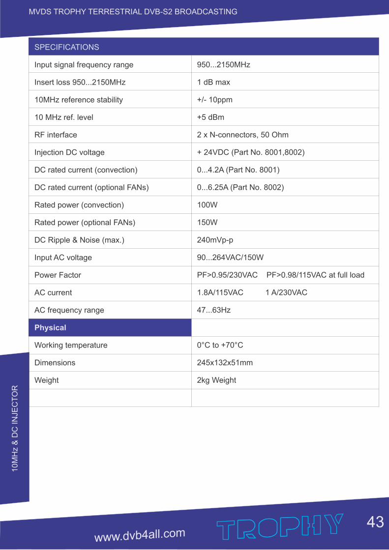
SPECIFICATIONS
Input signal frequency range
Insert loss 950...2150MHz
10MHz reference stability
10 MHz ref. level
RF interface
Injection DC voltage
DC rated current (convection)
DC rated current (optional FANs)
Rated power (convection)
Rated power (optional FANs)
DC Ripple & Noise (max.)
Input AC voltage
Power Factor
AC current
AC frequency range
Physical
Working temperature
Dimensions
Weight
950...2150MHz
1 dB max
+/- 10ppm
+5 dBm
2 x N-connectors, 50 Ohm
+ 24VDC (Part No. 8001,8002)
0...4.2A (Part No. 8001)
0...6.25A (Part No. 8002)
100W
150W
240mVp-p
90...264VAC/150W
PF>0.95/230VAC PF>0.98/115VAC at full load
1.8A/115VAC 1 A/230VAC
47...63Hz
0°C to +70°C
245x132x51mm
2kg Weight
L-B
AN
D 8
-channel C
OM
BIN
ER
44
MVDS TROPHY TERRESTRIAL DVB-S2 BROADCASTING
AMD series L-band 8-channels COMBINER/DC&10MHz reference
Part No. 12001-12003
L-band inputs
L-band output10MHz ref. +24VDC
90
-26
4V
AC
5
0/6
0H
zL
-ba
nd
8-c
h c
om
bin
er
1 2
3 4
5 6
7 8
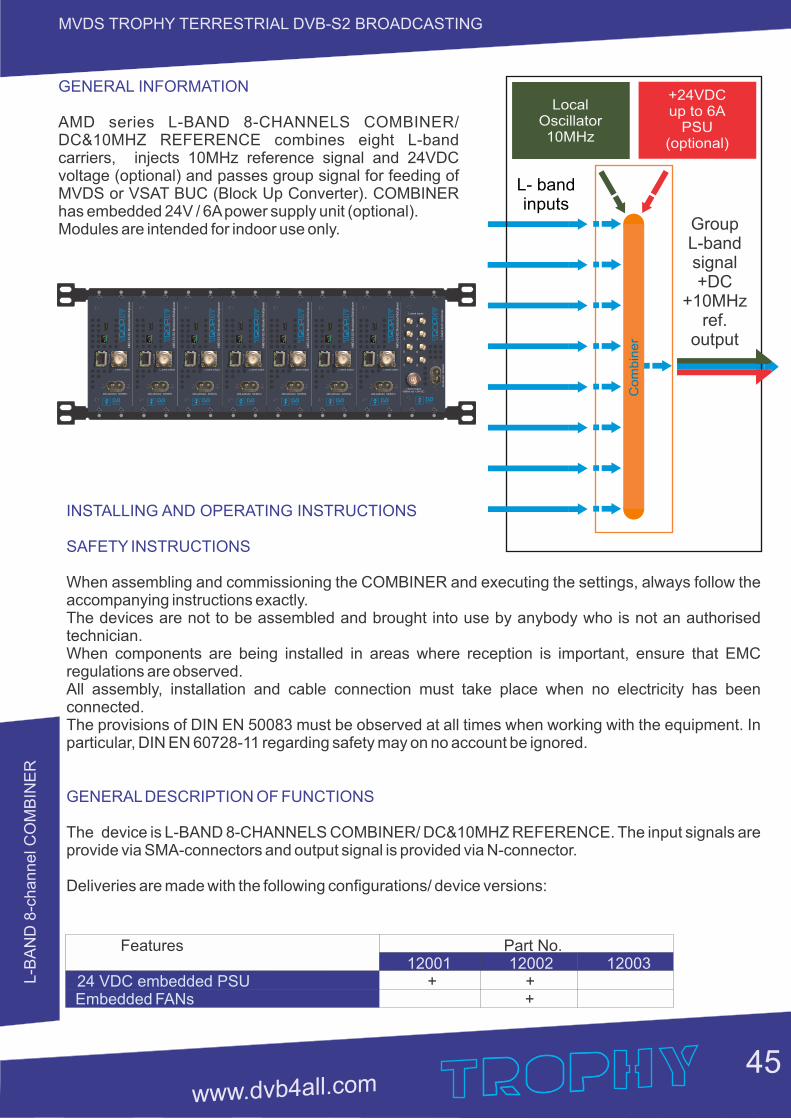
L-B
AN
D 8
-channel C
OM
BIN
ER
45
MVDS TROPHY TERRESTRIAL DVB-S2 BROADCASTING
GENERAL INFORMATION
AMD series L-BAND 8-CHANNELS COMBINER/ DC&10MHZ REFERENCE combines eight L-band carriers, injects 10MHz reference signal and 24VDC voltage (optional) and passes group signal for feeding of MVDS or VSAT BUC (Block Up Converter). COMBINER has embedded 24V / 6A power supply unit (optional).Modules are intended for indoor use only.
INSTALLING AND OPERATING INSTRUCTIONS
SAFETY INSTRUCTIONS
When assembling and commissioning the COMBINER and executing the settings, always follow the accompanying instructions exactly.The devices are not to be assembled and brought into use by anybody who is not an authorised technician.When components are being installed in areas where reception is important, ensure that EMC regulations are observed.All assembly, installation and cable connection must take place when no electricity has been connected.The provisions of DIN EN 50083 must be observed at all times when working with the equipment. In particular, DIN EN 60728-11 regarding safety may on no account be ignored.
GENERAL DESCRIPTION OF FUNCTIONS
The device is L-BAND 8-CHANNELS COMBINER/ DC&10MHZ . The input signals are REFERENCEprovide via SMA-connectors and output signal is provided via N-connector.
Deliveries are made with the following configurations/ device versions:
Features Part No. 12001 12002 12003 + +24 VDC embedded PSU Embedded FANs +
LocalOscillator10MHz
L- band inputs
+24VDCup to 6A
PSU(optional)
Co
mb
ine
r
GroupL-bandsignal +DC
+10MHzref.
output
Eth
ern
et
200-240VAC 50/60Hz
L-band output
AM
D-5
3-S
2 M
odula
tor/
Multi
ple
xer
Eth
ern
et
200-240VAC 50/60Hz
L-band output
AM
D-5
3-S
2 M
odula
tor/
Multi
ple
xer
Eth
ern
et
200-240VAC 50/60Hz
L-band output
AM
D-5
3-S
2 M
odula
tor/
Multi
ple
xer
Eth
ern
et
200-240VAC 50/60Hz
L-band output
AM
D-5
3-S
2 M
odula
tor/
Multi
ple
xer
Eth
ern
et
200-240VAC 50/60Hz
L-band output
AM
D-5
3-S
2 M
odula
tor/
Multi
ple
xer
Eth
ern
et
200-240VAC 50/60Hz
L-band output
AM
D-5
3-S
2 M
odula
tor/
Multi
ple
xer
Eth
ern
et
200-240VAC 50/60Hz
L-band output
AM
D-5
3-S
2 M
odula
tor/
Multi
ple
xer
L-band inputs
L-band output10MHz ref. +24VDC
90-2
64V
AC
50/6
0H
zL
-ba
nd
8-c
h c
om
bin
er
1 2
3 4
5 6
7 8
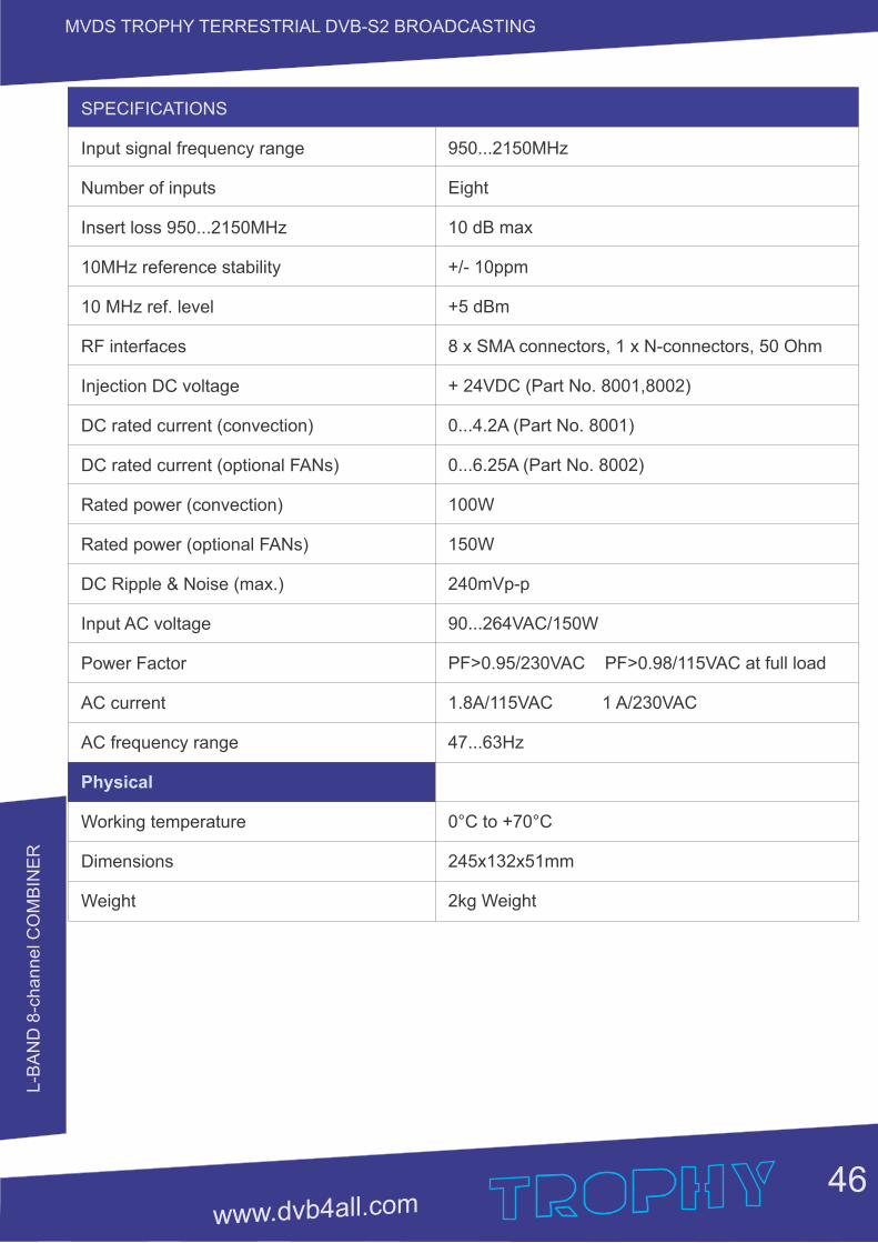
L-B
AN
D 8
-channel C
OM
BIN
ER
46
MVDS TROPHY TERRESTRIAL DVB-S2 BROADCASTING
SPECIFICATIONS
Input signal frequency range
Number of inputs
Insert loss 950...2150MHz
10MHz reference stability
10 MHz ref. level
RF interfaces
Injection DC voltage
DC rated current (convection)
DC rated current (optional FANs)
Rated power (convection)
Rated power (optional FANs)
DC Ripple & Noise (max.)
Input AC voltage
Power Factor
AC current
AC frequency range
Physical
Working temperature
Dimensions
Weight
950...2150MHz
Eight
10 dB max
+/- 10ppm
+5 dBm
8 x SMA connectors, 1 x N-connectors, 50 Ohm
+ 24VDC (Part No. 8001,8002)
0...4.2A (Part No. 8001)
0...6.25A (Part No. 8002)
100W
150W
240mVp-p
90...264VAC/150W
PF>0.95/230VAC PF>0.98/115VAC at full load
1.8A/115VAC 1 A/230VAC
47...63Hz
0°C to +70°C
245x132x51mm
2kg Weight
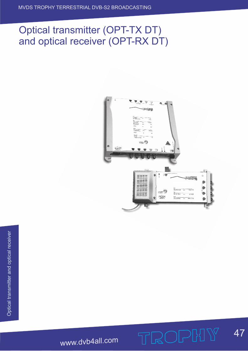
Optic
al t
ransm
itter
and o
ptic
al r
ece
iver
47
MVDS TROPHY TERRESTRIAL DVB-S2 BROADCASTING
Optical transmitter (OPT-TX DT) and optical receiver (OPT-RX DT)

48
MVDS TROPHY TERRESTRIAL DVB-S2 BROADCASTING
SAFETY WARNING.
The product must be installed by a qualified engineer, according to the local safety standards and regulations. The product is classified as Class II, in accordance with EN 60065, and for this reason it doesn't need to be connected to the protective earth (PE) of the mains supply.
Installation warnings
Only use the original power cable (adaptor) supplied and install the product so that the mains plug is easily accessible. The product must not be exposed to dripping or splashing liquids and so must be installed indoors in a dry place. Humidity and condensation could damage the product. In case of condensation, wait until the product is dry before using it.
Don't install the product above or close to heat sources, in dusty places or where it might come into contact with corrosive substances. Keep the product away from heat sources to prevent some parts or components of the unit to catching fire. To fix the product to the wall use suitable expansion bolts.
Leave enough space around the product housing to ensure sufficient ventilation. “An excessive operating temperature and/or excessive heat may affect the performance and the life span of the product.”
Never look inside the product's optical connectors. The laser radiation is not visible with the naked eye and therefore it is not possible to prevent long term damage. When working with the splitter's optical connectors make sure that the lasers of any optical transmitters connected to it are switched off.
In accordance with the European Directive 2004/108/EC (EMC), the product must be installed using devices, cables and accessories that comply with this directives requirements for fixed installations.
Aerial system earth connection The unit must be connected to the ground electrode of the antenna installation according to the standard EN60728-11. We recommend following the provisions of standard EN60728-11 therefore not connecting the ground electrode to the earthing of the power supply network.
IMPORTANT: Only trained and authorised personnel can open the product. In case of failure, do not try to repair the product; otherwise the guarantee will no longer be valid.
INVISIBLE LASER RADIATIONDO NOT VIEW DIRECTLY WITH
OPTICAL INSTRUMENTS(MAGNIFIERS)
CLASS 1M LASER PRODUCT
LASER RADIATION
Optic
al t
ransm
itter
and o
ptic
al r
ece
iver

49
MVDS TROPHY TERRESTRIAL DVB-S2 BROADCASTINGO
ptic
al t
ransm
itter
and o
ptic
al r
ece
iver
Product description
Optical transmitter (OPT-TX DT) and optical receiver (OPT-RX DT) for distributing satellite and digital terrestrial signals through a single-mode fibre optic cable.
The incoming RF signals to the OPT-TX DT transmitter are converted and distributed through a single-mode fibre optic that can be split by splitters and passive taps enabling them to be sent to multiple optical connections (PON=Passive Optical Network) using a single transmitter.
The OPT-RX DT receiver converts the incoming optical signal in to 4 universal outputs, therefore enabling the TV and SAT signal to be available for 4 different users. The system requires the use of a conventional LNB and provides a traditional 5 core output (4 SAT + 1 TV) to enable a cascadable installation to additional transmitters or to a traditional multiswitch system.
The AGC (Automatic Gain Control) in the transmitter makes the product configuration much easier by automatically adjusting the input signal level to the optical laser.
SATInput
TVInput
TestSAT
SATOutput
OpticalOutput
TV Output
Test TV
Alarm LED
Power SupplyPower on LED
OPT-TX DT
SAT INPUT: F input connectors for the four IF satellite polarities (950 - 2150MHz) with LNB remote power. TV INPUT: F input connector for the TV signal (87 - 862MHz) .TEST SAT: F output connector for the SAT test signal, HH polarity (RF level: 60dBμV per transponder). TEST TV: F output connector for the TV signal 87 - 862MHz (RF level: 74dBμV overall power). OPTICAL OUTPUT: SC-APC output connector for the optical transmitter for the fibre link. SAT OUTPUT: F output connectors for the four IF satellite polarities (950 - 2150MHz) for possible cascade applications to other devices TV OUT : F output connector for the TV signal (87 - 862MHz). POWER ON LED: On (green) to show the product is turned on. ALARM LED: the alarm LED shows that the transmission laser is not working correctly. Earthing the antenna installation (according to EN60728-11 standard).
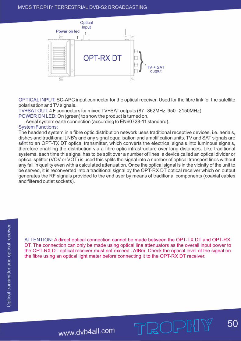
50
MVDS TROPHY TERRESTRIAL DVB-S2 BROADCASTINGO
ptic
al t
ransm
itter
and o
ptic
al r
ece
iver
TV + SAToutput
OpticalInput
Power on led
OPT-RX DT
OPTICAL INPUT: SC-APC input connector for the optical receiver. Used for the fibre link for the satellite polarisation and TV signals. TV+SAT OUT: 4 F connectors for mixed TV+SAT outputs (87 - 862MHz, 950 - 2150MHz). POWER ON LED: On (green) to show the product is turned on. Aerial system earth connection (according to EN60728-11 standard). System Functions: The headend system in a fibre optic distribution network uses traditional receptive devices, i.e. aerials, dishes and traditional LNB's and any signal equalisation and amplification units. TV and SAT signals are sent to an OPT-TX DT optical transmitter, which converts the electrical signals into luminous signals, therefore enabling the distribution via a fibre optic infrastructure over long distances. Like traditional systems, each time this signal has to be split over a number of lines, a device called an optical divider or optical splitter (VOV or VOT) is used this splits the signal into a number of optical transport lines without any fall in quality even with a calculated attenuation. Once the optical signal is in the vicinity of the unit to be served, it is reconverted into a traditional signal by the OPT-RX DT optical receiver which on output generates the RF signals provided to the end user by means of traditional components (coaxial cables and filtered outlet sockets).
ATTENTION: A direct optical connection cannot be made between the OPT-TX DT and OPT-RX DT. The connection can only be made using optical line attenuators as the overall input power to the OPT-RX DT optical receiver must not exceed -7dBm. Check the optical level of the signal on the fibre using an optical light meter before connecting it to the OPT-RX DT receiver.
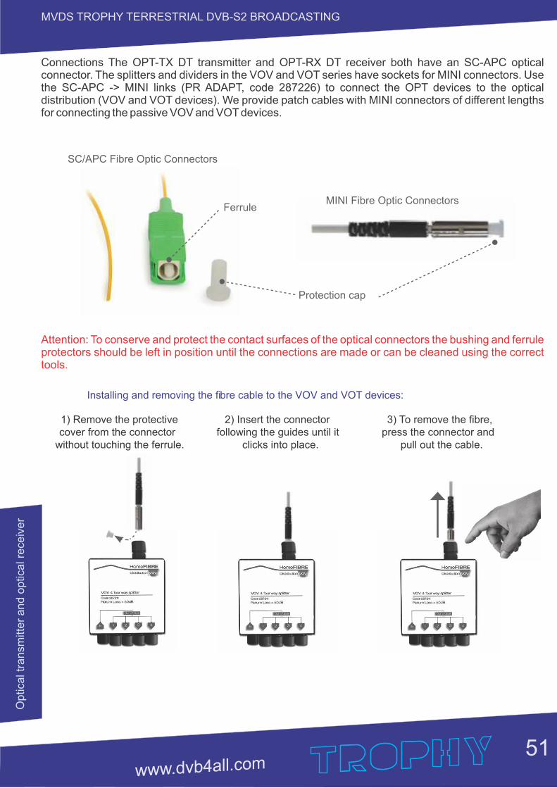
51
MVDS TROPHY TERRESTRIAL DVB-S2 BROADCASTINGO
ptic
al t
ransm
itter
and o
ptic
al r
ece
iver
Connections The OPT-TX DT transmitter and OPT-RX DT receiver both have an SC-APC optical connector. The splitters and dividers in the VOV and VOT series have sockets for MINI connectors. Use the SC-APC -> MINI links (PR ADAPT, code 287226) to connect the OPT devices to the optical distribution (VOV and VOT devices). We provide patch cables with MINI connectors of different lengths for connecting the passive VOV and VOT devices.
MINI Fibre Optic Connectors
Protection cap
SC/APC Fibre Optic Connectors
Ferrule
Attention: To conserve and protect the contact surfaces of the optical connectors the bushing and ferrule protectors should be left in position until the connections are made or can be cleaned using the correct tools.
Installing and removing the fi bre cable to the VOV and VOT devices:
1) Remove the protective cover from the connector
without touching the ferrule.
2) Insert the connector following the guides until it
clicks into place.
3) To remove the fi bre, press the connector and
pull out the cable.
52
MVDS TROPHY TERRESTRIAL DVB-S2 BROADCASTINGO
ptic
al t
ransm
itter
and o
ptic
al r
ece
iver
USER INSTRUCTIONS.
Dimensioning a Fibre Optic system.
When designing a fibre optic system it is important to consider the optical input level to the OPT- RX DT receivers, suitable attenuation is required and must be calculated at each point to ensure the system falls within the required parameters. The optical output power from the OPT-TX DT transmitter is fixed (+7.5dBm typical).
The OPT-RX DT receivers can guarantee that the correct level of TV and SAT signals are available to the end users sockets. This guarantee is on the proviso that the input level of the optical signal is between -8dBm and -14dBm therefore giving an optical attenuation range of 15 to 21dB.
ATTENTION: Direct connections are not allowed between the OPT-TX DT and OPT-RX DT, unless the correct line optical attenuators are used. An optical signal reader must be used to check the optical input level to the OPT-RX DT and to prevent damaging the receiving photodiode (damage can be caused if the optical input signal is higher than 0dBm). If the quality of the input signals are not optimised, or if a lot of signals have to be distributed to a lot of sockets, the optical budget should be reduced or professional splitters should be used with SC-APC connectors.
Requirements for the input signal to the OPT-TX DT optical transmitter
For the signals to be correctly transmitted through the fibre optic, the RF signals must respect the following requirements:
TV (DTT/CATV) To ensure the TV signals are transmitted and received correctly, the input signals to the transmitter should be equalised, especially if a lot of channels are being transmitted. As an indication, the input signals should respect the following requirements:
1. The transmitter signal level should be ≥ 74dBμV to guarantee correct reception by the OPT- RX DT receivers, even after an optical attenuation of 21dB.
2. Overall input power: -19dBm (90dBμV)
3. The overall power ≤ -19dBm (90dBμV) is guaranteed in the following cases: 40 TV channels equalised at 74dBμV 20 TV channels with a maximum level of 77dBμV 16 TV channels with a maximum level of 78dBμV 8 TV channels with a maximum level of 81dBμV If the TV input signal quality is not optimal or not correctly equalised, then the system should be designed considering an optical attenuation lower than 21dB to guarantee correct signal reception at the socket (especially when a lot of channels are being transmitted).
FM and DAB The FM and DAB signal levels should be at least 10dB lower than the overall input power of the TV signal.
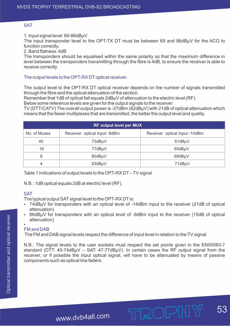
53
MVDS TROPHY TERRESTRIAL DVB-S2 BROADCASTINGO
ptic
al t
ransm
itter
and o
ptic
al r
ece
iver
SAT
1. Input signal level: 69-86dBμV The input transponder level to the OPT-TX DT must be between 69 and 86dBμV for the ACG to function correctly. 2. Band flatness: 4dB The transponders should be equalised within the same polarity so that the maximum difference in level between the transponders transmitting through the fibre is 4dB, to ensure the receiver is able to receive correctly.
The output levels to the OPT-RX DT optical receiver.
The output level to the OPT-RX DT optical receiver depends on the number of signals transmitted through the fibre and the optical attenuation of the section. Remember that 1dB of optical fall equals 2dBμV of attenuation to the electric level (RF). Below some reference levels are given for the output signals to the receiver: TV (DTT/CATV) The overall output power is -27dBm (82dBμV) with 21dB of optical attenuation which means that the fewer multiplexes that are transmitted, the better the output level and quality.
RF output level per MUX
No. of Muxes Receiver optical Input -8dBm Receiver optical Input -14dBm
40 73dBµV 61dBµV
16 77dBµV 65dBµV
8 80dBµV 68dBµV
4 83dBµV 71dBµV
Table 1 Indications of output levels to the OPT-RX DT – TV signal
N.B.: 1dB optical equals 2dB at electric level (RF).
SAT The typical output SAT signal level to the OPT-RX DT is: Ÿ 74dBμV for transponders with an optical level of -14dBm input to the receiver (21dB of optical
attenuation) Ÿ 86dBμV for transponders with an optical level of -8dBm input to the receiver (15dB of optical
attenuation) Ÿ
FM and DAB The FM and DAB signal levels respect the difference of input level in relation to the TV signal. N.B.: The signal levels to the user sockets must respect the set points given in the EN50083-7 standard (DTT: 45-74dBμV – SAT: 47-77dBμV). In certain cases the RF output signal from the receiver, or if possible the input optical signal, will have to be attenuated by means of passive components such as optical line faders.
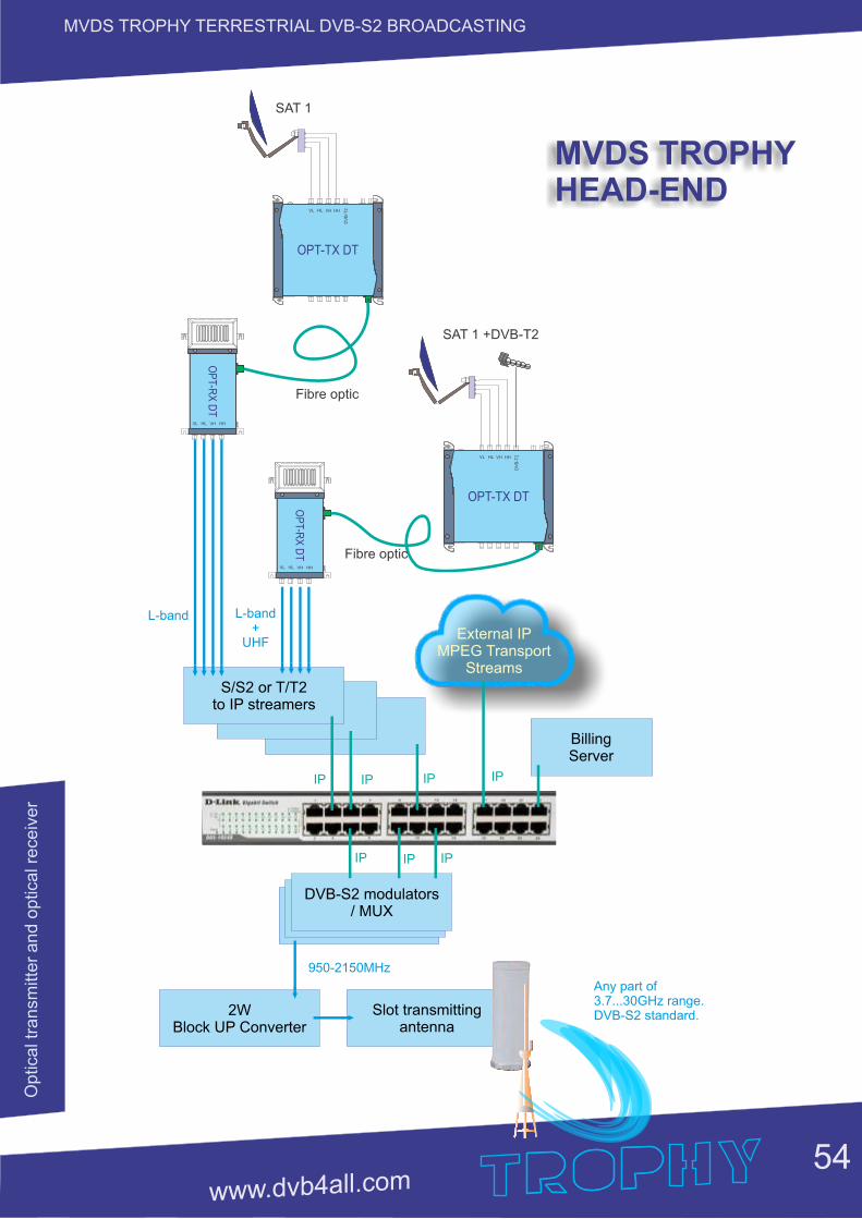
54
MVDS TROPHY TERRESTRIAL DVB-S2 BROADCASTINGO
ptic
al t
ransm
itter
and o
ptic
al r
ece
iver
OPT-TX DT
VL VHHL HH
DV
B-T
2
OP
T-RX
DT
External IP MPEG Transport
Streams
S/S2 or T/T2to IP streamers
L-band+
UHF
IP IP IP IP
IP IP IP
DVB-S2 modulators/ MUX
2W Block UP Converter
950-2150MHz
Slot transmitting antenna
Any part of3.7...30GHz range.DVB-S2 standard.
Billing Server
VL VHHL HH
OPT-TX DT
VL VHHL HH
DV
B-T
2
OP
T-RX
DT
VL VHHL HH
L-band
SAT 1
SAT 1 +DVB-T2
Fibre optic
Fibre optic
MVDS TROPHYHEAD-END
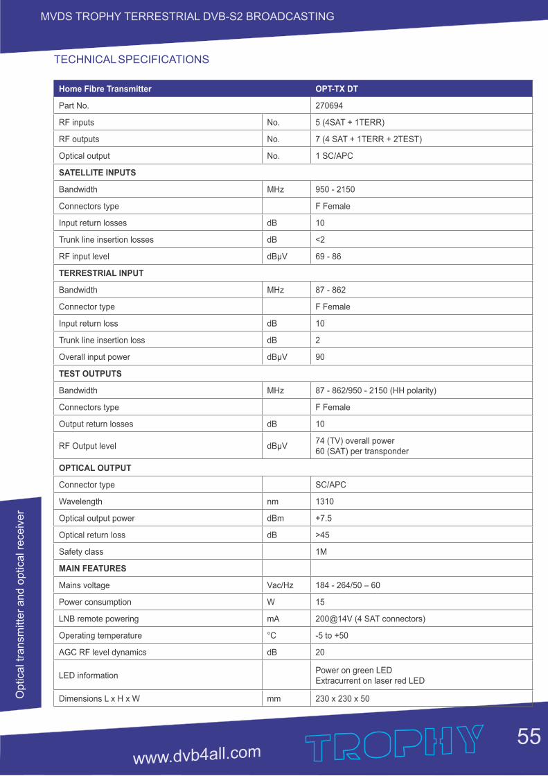
55
MVDS TROPHY TERRESTRIAL DVB-S2 BROADCASTINGO
ptic
al t
ransm
itter
and o
ptic
al r
ece
iver
Home Fibre Transmitter OPT-TX DT
Part No. 270694
RF inputs No. 5 (4SAT + 1TERR)
RF outputs No. 7 (4 SAT + 1TERR + 2TEST)
Optical output No. 1 SC/APC
SATELLITE INPUTS
Bandwidth MHz 950 - 2150
Connectors type F Female
Input return losses dB 10
Trunk line insertion losses dB <2
RF input level dBµV 69 - 86
TERRESTRIAL INPUT
Bandwidth MHz 87 - 862
Connector type F Female
Input return loss dB 10
Trunk line insertion loss dB 2
Overall input power dBµV 90
TEST OUTPUTS
Bandwidth MHz 87 - 862/950 - 2150 (HH polarity)
Connectors type F Female
Output return losses dB 10
RF Output level dBµV74 (TV) overall power60 (SAT) per transponder
OPTICAL OUTPUT
Connector type SC/APC
Wavelength nm 1310
Optical output power dBm +7.5
Optical return loss dB >45
Safety class 1M
MAIN FEATURES
Mains voltage Vac/Hz 184 - 264/50 – 60
Power consumption W 15
LNB remote powering mA 200@14V (4 SAT connectors)
Operating temperature °C -5 to +50
AGC RF level dynamics dB 20
LED informationPower on green LED Extracurrent on laser red LED
Dimensions L x H x W mm 230 x 230 x 50
TECHNICAL SPECIFICATIONS
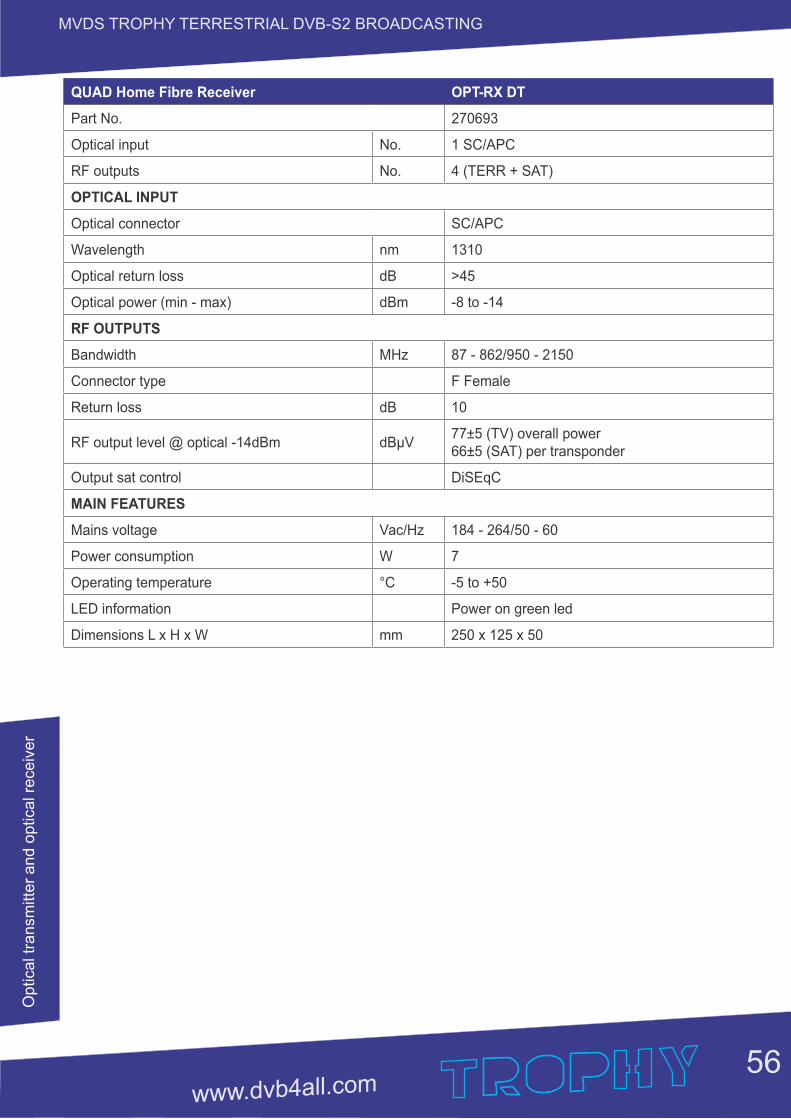
56
MVDS TROPHY TERRESTRIAL DVB-S2 BROADCASTINGO
ptic
al t
ransm
itter
and o
ptic
al r
ece
iver
QUAD Home Fibre Receiver OPT-RX DT
Part No. 270693
Optical input No. 1 SC/APC
RF outputs No. 4 (TERR + SAT)
OPTICAL INPUT
Optical connector SC/APC
Wavelength nm 1310
Optical return loss dB >45
Optical power (min - max) dBm -8 to -14
RF OUTPUTS
Bandwidth MHz 87 - 862/950 - 2150
Connector type F Female
Return loss dB 10
RF output level @ optical -14dBm dBµV77±5 (TV) overall power66±5 (SAT) per transponder
Output sat control DiSEqC
MAIN FEATURES
Mains voltage Vac/Hz 184 - 264/50 - 60
Power consumption W 7
Operating temperature °C -5 to +50
LED information Power on green led
Dimensions L x H x W mm 250 x 125 x 50
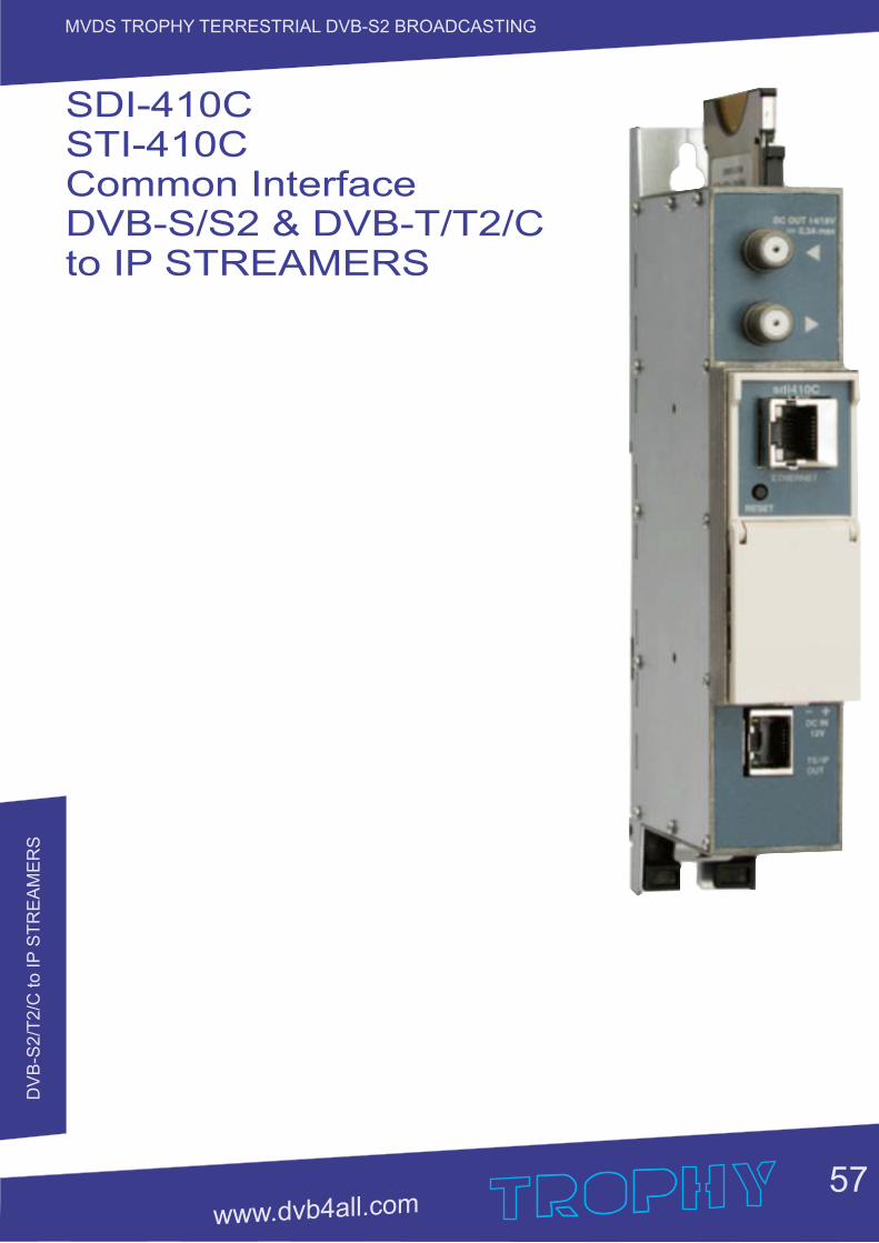
DV
B-S
2/T
2/C
to IP
ST
RE
AM
ER
S
57
MVDS TROPHY TERRESTRIAL DVB-S2 BROADCASTING
SDI-410CSTI-410CCommon Interface DVB-S/S2 & DVB-T/T2/Cto IP STREAMERS
DV
B-S
2/T
2/C
to IP
ST
RE
AM
ER
S
58
MVDS TROPHY TERRESTRIAL DVB-S2 BROADCASTING
PRODUCT DESCRIPTION
DVB-S/S2 (SDI-410C), DVB-T/T2/C (STI-410C) to IP streamers designed to broadcast in multicast on an IP network the services (TV or Radio programmes) issued from FTA or encrypted digital reception; in case of encrypted signal, a CAM containing the operator's smart card must fit the slot. The IP streams can be viewed using an IPTV set-top box or a software video player. Modules are intended for indoor use only.
Characteristics:
Ÿ Input: one DVB transport stream (MPTS).Ÿ Output: up to 24 simultaneous, IP-encapsulated services (TV or Radio programs), with individual
multicast addresses and one MPTS stream.Ÿ Information filtering of DVB tables.Ÿ UDP & RTP transmission protocols.Ÿ Web interface for configuration and setting.Ÿ SNMP agent for monitoring and alarms.Ÿ SAP & SDP protocols that facilitate automatic service selection on the user's STB and provide
information to external servers.Ÿ PID filtering.Ÿ PSI/SI parsing.Ÿ Transparent ECM & EMM messaging.Ÿ PAT, PMT and SDT table regeneration.Ÿ Routing or blocking for CAT, EIT, TDT tables.Ÿ Configurable QoS marking.Ÿ Configurable Time To Live.
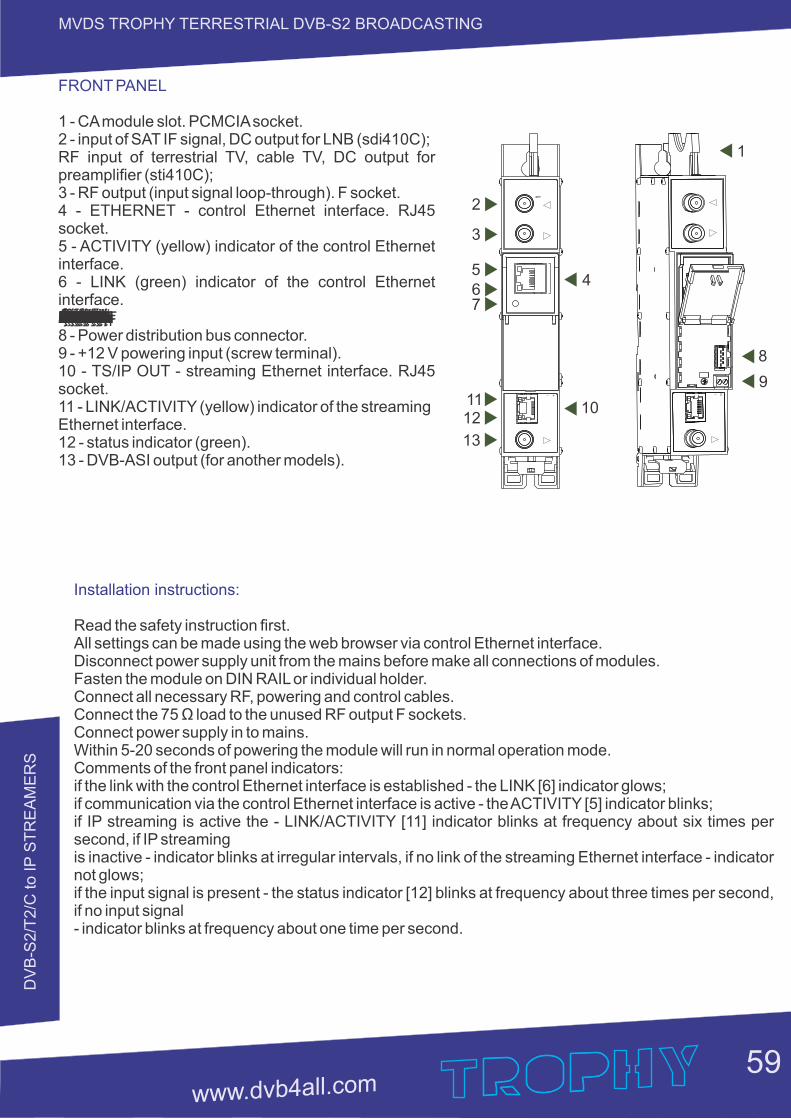
DV
B-S
2/T
2/C
to IP
ST
RE
AM
ER
S
59
MVDS TROPHY TERRESTRIAL DVB-S2 BROADCASTING
2
3
567
1112
13
4
10
1
8
9
FRONT PANEL
1 - CA module slot. PCMCIA socket.2 - input of SAT IF signal, DC output for LNB (sdi410C); RF input of terrestrial TV, cable TV, DC output for preamplifier (sti410C);3 - RF output (input signal loop-through). F socket.4 - ETHERNET - control Ethernet interface. RJ45 socket.5 - ACTIVITY (yellow) indicator of the control Ethernet interface.6 - LINK (green) indicator of the control Ethernet interface.áåíÉêÑ~ÅÉKbíÜÉêåÉí=Åçåíêçä=íÜÉ=çÑ=~ÇÇêÉëë=fm=ÇÉÑ~ìäí=ëÉí=íç=ëÉÅçåÇë=íÜêÉÉ=íÜ~å=ãçêÉ=Ñçê=Äìííçå=íÜáë=mêÉëë=ãçÇìäÉK=íÜÉ=êÉëí~êí=íç=ëÜçêíäó=Äìííçå=íÜáë=mêÉëë=ÄìííçåK=obpbq=J=T=8 - Power distribution bus connector.9 - +12 V powering input (screw terminal).10 - TS/IP OUT - streaming Ethernet interface. RJ45 socket.11 - LINK/ACTIVITY (yellow) indicator of the streamingEthernet interface.12 - status indicator (green).13 - DVB-ASI output (for another models).
Installation instructions:
Read the safety instruction first.All settings can be made using the web browser via control Ethernet interface.Disconnect power supply unit from the mains before make all connections of modules.Fasten the module on DIN RAIL or individual holder.Connect all necessary RF, powering and control cables.Connect the 75 Ω load to the unused RF output F sockets.Connect power supply in to mains.Within 5-20 seconds of powering the module will run in normal operation mode.Comments of the front panel indicators:if the link with the control Ethernet interface is established - the LINK [6] indicator glows;if communication via the control Ethernet interface is active - the ACTIVITY [5] indicator blinks;if IP streaming is active the - LINK/ACTIVITY [11] indicator blinks at frequency about six times per second, if IP streamingis inactive - indicator blinks at irregular intervals, if no link of the streaming Ethernet interface - indicator not glows;if the input signal is present - the status indicator [12] blinks at frequency about three times per second, if no input signal- indicator blinks at frequency about one time per second.
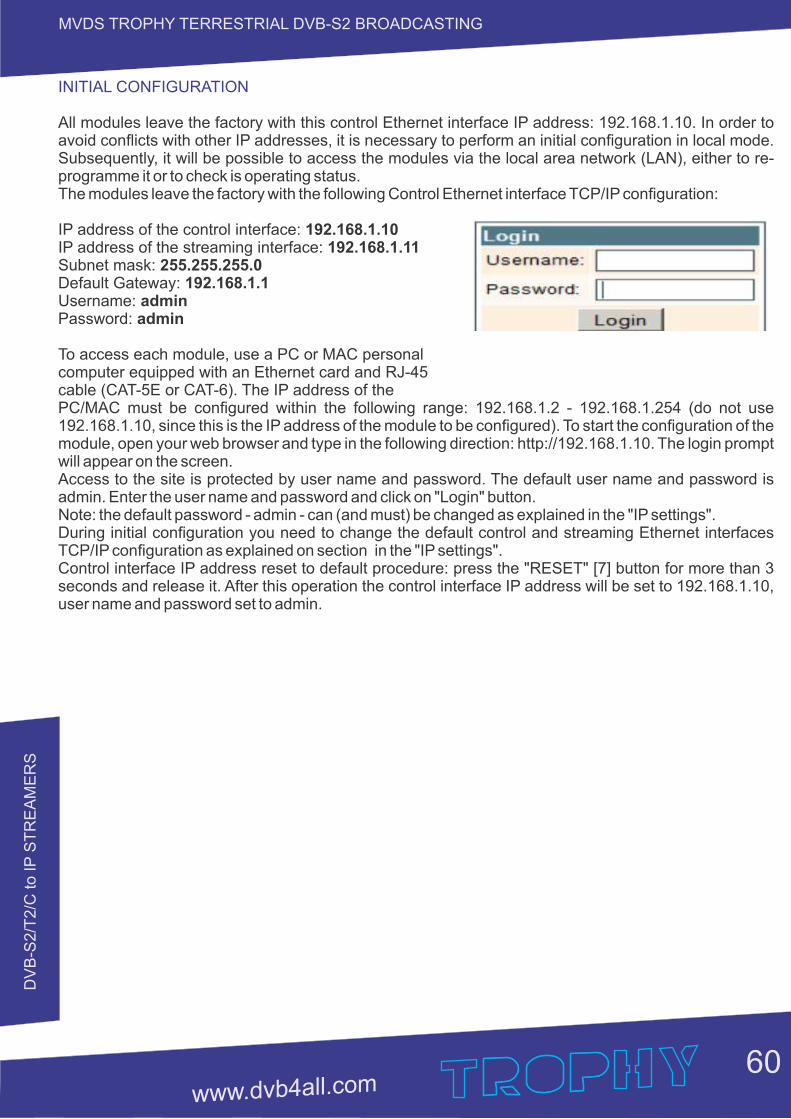
DV
B-S
2/T
2/C
to IP
ST
RE
AM
ER
S
60
MVDS TROPHY TERRESTRIAL DVB-S2 BROADCASTING
INITIAL CONFIGURATION
All modules leave the factory with this control Ethernet interface IP address: 192.168.1.10. In order to avoid conflicts with other IP addresses, it is necessary to perform an initial configuration in local mode. Subsequently, it will be possible to access the modules via the local area network (LAN), either to re-programme it or to check is operating status.The modules leave the factory with the following Control Ethernet interface TCP/IP configuration: IP address of the control interface: 192.168.1.10IP address of the streaming interface: 192.168.1.11Subnet mask: 255.255.255.0Default Gateway: 192.168.1.1Username: adminPassword: admin
To access each module, use a PC or MAC personal computer equipped with an Ethernet card and RJ-45 cable (CAT-5E or CAT-6). The IP address of the PC/MAC must be configured within the following range: 192.168.1.2 - 192.168.1.254 (do not use 192.168.1.10, since this is the IP address of the module to be configured). To start the configuration of the module, open your web browser and type in the following direction: http://192.168.1.10. The login prompt will appear on the screen.Access to the site is protected by user name and password. The default user name and password is admin. Enter the user name and password and click on "Login" button.Note: the default password - admin - can (and must) be changed as explained in the "IP settings".During initial configuration you need to change the default control and streaming Ethernet interfaces TCP/IP configuration as explained on section in the "IP settings".Control interface IP address reset to default procedure: press the "RESET" [7] button for more than 3 seconds and release it. After this operation the control interface IP address will be set to 192.168.1.10, user name and password set to admin.
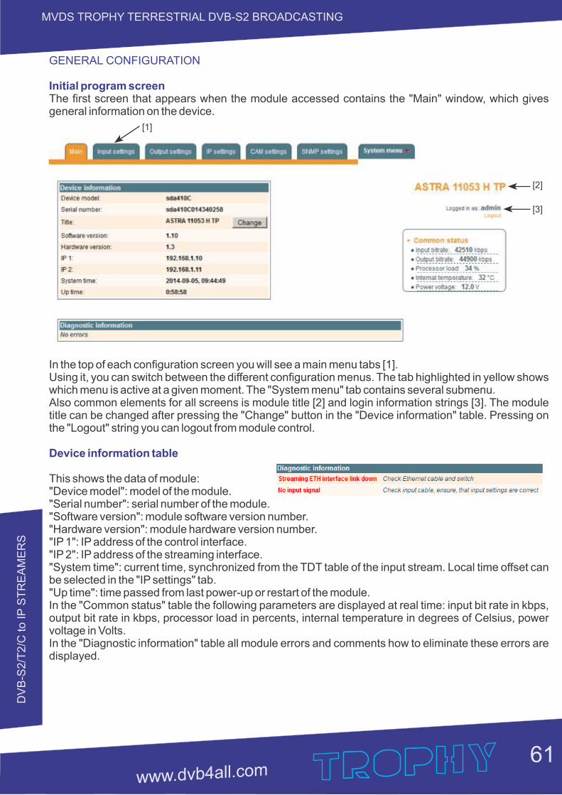
DV
B-S
2/T
2/C
to IP
ST
RE
AM
ER
S
61
MVDS TROPHY TERRESTRIAL DVB-S2 BROADCASTING
GENERAL CONFIGURATION
Initial program screenThe first screen that appears when the module accessed contains the "Main" window, which gives general information on the device.
In the top of each configuration screen you will see a main menu tabs [1].Using it, you can switch between the different configuration menus. The tab highlighted in yellow shows which menu is active at a given moment. The "System menu" tab contains several submenu.Also common elements for all screens is module title [2] and login information strings [3]. The module title can be changed after pressing the "Change" button in the "Device information" table. Pressing on the "Logout" string you can logout from module control.
Device information table
This shows the data of module:"Device model": model of the module."Serial number": serial number of the module."Software version": module software version number."Hardware version": module hardware version number."IP 1": IP address of the control interface."IP 2": IP address of the streaming interface."System time": current time, synchronized from the TDT table of the input stream. Local time offset can be selected in the "IP settings" tab."Up time": time passed from last power-up or restart of the module.In the "Common status" table the following parameters are displayed at real time: input bit rate in kbps, output bit rate in kbps, processor load in percents, internal temperature in degrees of Celsius, power voltage in Volts.In the "Diagnostic information" table all module errors and comments how to eliminate these errors are displayed.
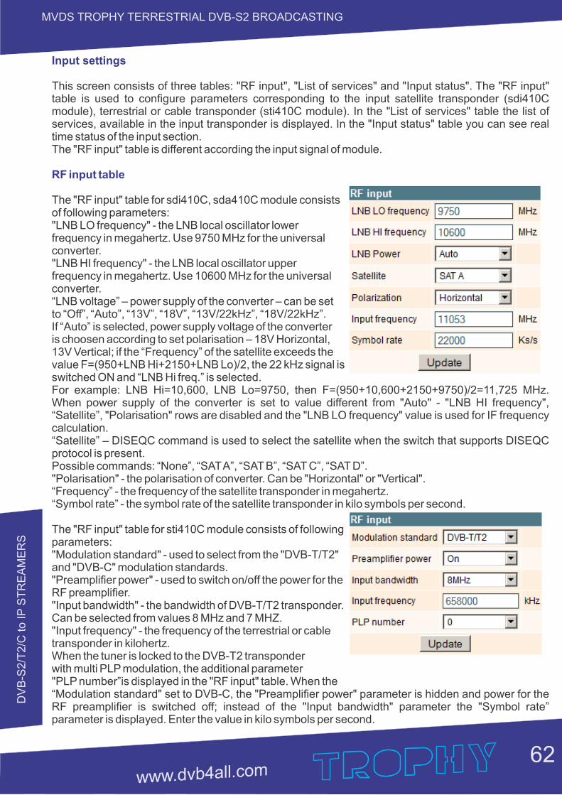
DV
B-S
2/T
2/C
to IP
ST
RE
AM
ER
S
62
MVDS TROPHY TERRESTRIAL DVB-S2 BROADCASTING
Input settings
This screen consists of three tables: "RF input", "List of services" and "Input status". The "RF input" table is used to configure parameters corresponding to the input satellite transponder (sdi410C module), terrestrial or cable transponder (sti410C module). In the "List of services" table the list of services, available in the input transponder is displayed. In the "Input status" table you can see real time status of the input section.The "RF input" table is different according the input signal of module.
RF input table
The "RF input" table for sdi410C, sda410C module consists of following parameters:"LNB LO frequency" - the LNB local oscillator lower frequency in megahertz. Use 9750 MHz for the universal converter."LNB HI frequency" - the LNB local oscillator upper frequency in megahertz. Use 10600 MHz for the universal converter.“LNB voltage” – power supply of the converter – can be set to “Off”, “Auto”, “13V”, “18V”, “13V/22kHz”, “18V/22kHz”. If “Auto” is selected, power supply voltage of the converter is choosen according to set polarisation – 18V Horizontal, 13V Vertical; if the “Frequency” of the satellite exceeds the value F=(950+LNB Hi+2150+LNB Lo)/2, the 22 kHz signal is switched ON and “LNB Hi freq.” is selected.For example: LNB Hi=10,600, LNB Lo=9750, then F=(950+10,600+2150+9750)/2=11,725 MHz. When power supply of the converter is set to value different from "Auto" - "LNB HI frequency", “Satellite”, "Polarisation" rows are disabled and the "LNB LO frequency" value is used for IF frequency calculation.“Satellite” – DISEQC command is used to select the satellite when the switch that supports DISEQC protocol is present.Possible commands: “None”, “SAT A”, “SAT B”, “SAT C”, “SAT D”."Polarisation" - the polarisation of converter. Can be "Horizontal" or "Vertical".“Frequency” - the frequency of the satellite transponder in megahertz.“Symbol rate” - the symbol rate of the satellite transponder in kilo symbols per second.
The "RF input" table for sti410C module consists of following parameters:"Modulation standard" - used to select from the "DVB-T/T2" and "DVB-C" modulation standards."Preamplifier power" - used to switch on/off the power for the RF preamplifier."Input bandwidth" - the bandwidth of DVB-T/T2 transponder. Can be selected from values 8 MHz and 7 MHZ."Input frequency" - the frequency of the terrestrial or cable transponder in kilohertz.When the tuner is locked to the DVB-T2 transponder with multi PLP modulation, the additional parameter "PLP number”is displayed in the "RF input" table. When the“Modulation standard" set to DVB-C, the "Preamplifier power" parameter is hidden and power for the RF preamplifier is switched off; instead of the "Input bandwidth" parameter the "Symbol rate” parameter is displayed. Enter the value in kilo symbols per second.
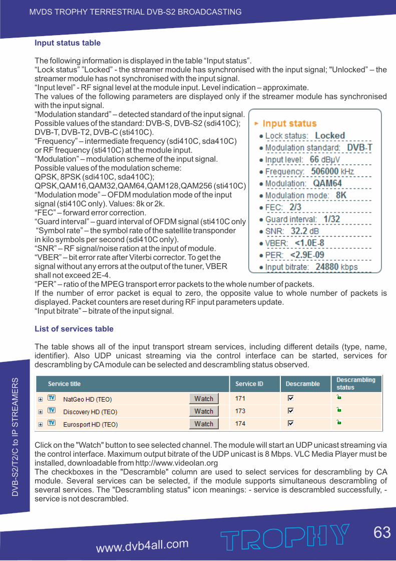
DV
B-S
2/T
2/C
to IP
ST
RE
AM
ER
S
63
MVDS TROPHY TERRESTRIAL DVB-S2 BROADCASTING
Input status table
The following information is displayed in the table “Input status”.“Lock status” ”Locked” - the streamer module has synchronised with the input signal; "Unlocked” – the streamer module has not synchronised with the input signal.“Input level” - RF signal level at the module input. Level indication – approximate.The values of the following parameters are displayed only if the streamer module has synchronised with the input signal.“Modulation standard” – detected standard of the input signal. Possible values of the standard: DVB-S, DVB-S2 (sdi410C); DVB-T, DVB-T2, DVB-C (sti410C).“Frequency” – intermediate frequency (sdi410C, sda410C) or RF frequency (sti410C) at the module input.“Modulation” – modulation scheme of the input signal. Possible values of the modulation scheme: QPSK, 8PSK (sdi410C, sda410C); QPSK,QAM16,QAM32,QAM64,QAM128,QAM256 (sti410C).“Modulation mode” – OFDM modulation mode of the inputsignal (sti410C only). Values: 8k or 2k.“FEC” – forward error correction.“Guard interval” – guard interval of OFDM signal (sti410C only). “Symbol rate” – the symbol rate of the satellite transponder in kilo symbols per second (sdi410C only).“SNR” – RF signal/noise ration at the input of module.“VBER” – bit error rate after Viterbi corrector. To get the signal without any errors at the output of the tuner, VBER shall not exceed 2Е-4.“PER” – ratio of the MPEG transport error packets to the whole number of packets.If the number of error packet is equal to zero, the opposite value to whole number of packets is displayed. Packet counters are reset during RF input parameters update.“Input bitrate” – bitrate of the input signal.
List of services table
The table shows all of the input transport stream services, including different details (type, name, identifier). Also UDP unicast streaming via the control interface can be started, services for descrambling by CA module can be selected and descrambling status observed.
Click on the "Watch" button to see selected channel. The module will start an UDP unicast streaming via the control interface. Maximum output bitrate of the UDP unicast is 8 Mbps. VLC Media Player must be installed, downloadable from http://www.videolan.orgThe checkboxes in the "Descramble" column are used to select services for descrambling by CA module. Several services can be selected, if the module supports simultaneous descrambling of several services. The "Descrambling status" icon meanings: - service is descrambled successfully, - service is not descrambled.
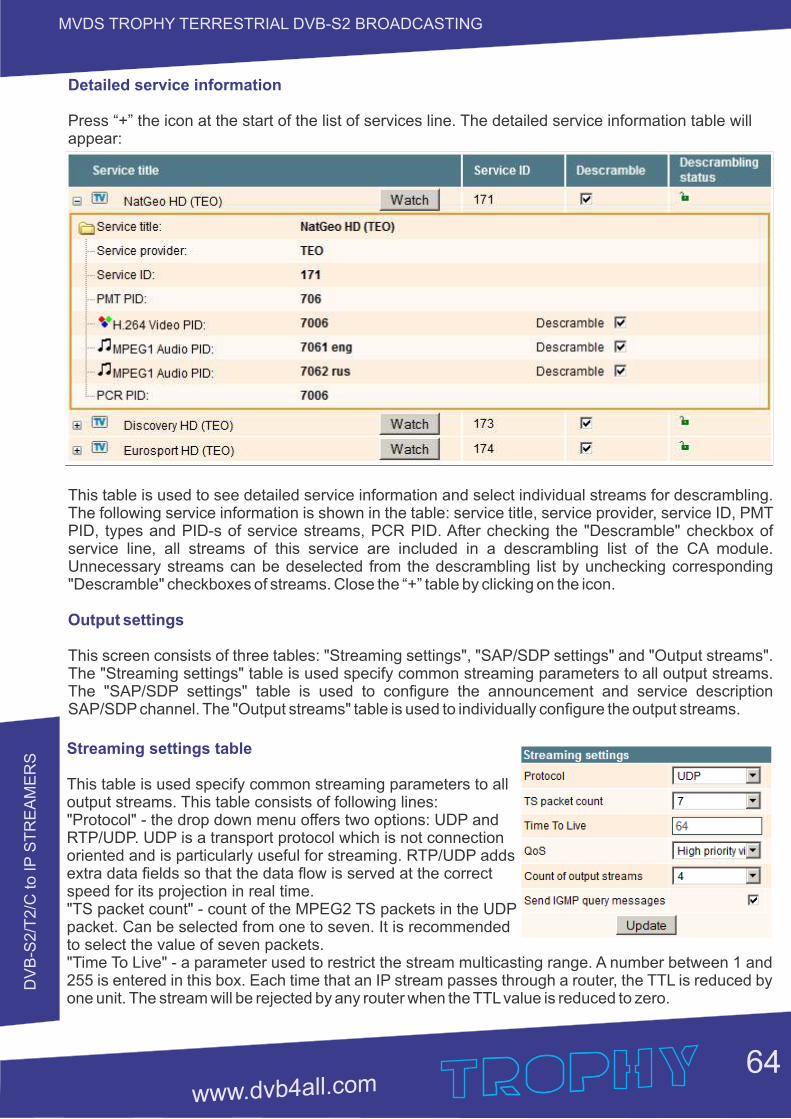
DV
B-S
2/T
2/C
to IP
ST
RE
AM
ER
S
64
MVDS TROPHY TERRESTRIAL DVB-S2 BROADCASTING
Detailed service information
Press “+” the icon at the start of the list of services line. The detailed service information table will appear:
This table is used to see detailed service information and select individual streams for descrambling. The following service information is shown in the table: service title, service provider, service ID, PMT PID, types and PID-s of service streams, PCR PID. After checking the "Descramble" checkbox of service line, all streams of this service are included in a descrambling list of the CA module. Unnecessary streams can be deselected from the descrambling list by unchecking corresponding "Descramble" checkboxes of streams. Close the “+” table by clicking on the icon.
Output settings
This screen consists of three tables: "Streaming settings", "SAP/SDP settings" and "Output streams". The "Streaming settings" table is used specify common streaming parameters to all output streams. The "SAP/SDP settings" table is used to configure the announcement and service description SAP/SDP channel. The "Output streams" table is used to individually configure the output streams.
Streaming settings table
This table is used specify common streaming parameters to all output streams. This table consists of following lines:"Protocol" - the drop down menu offers two options: UDP and RTP/UDP. UDP is a transport protocol which is not connection oriented and is particularly useful for streaming. RTP/UDP adds extra data fields so that the data flow is served at the correct speed for its projection in real time."TS packet count" - count of the MPEG2 TS packets in the UDP packet. Can be selected from one to seven. It is recommended to select the value of seven packets."Time To Live" - a parameter used to restrict the stream multicasting range. A number between 1 and 255 is entered in this box. Each time that an IP stream passes through a router, the TTL is reduced by one unit. The stream will be rejected by any router when the TTL value is reduced to zero.
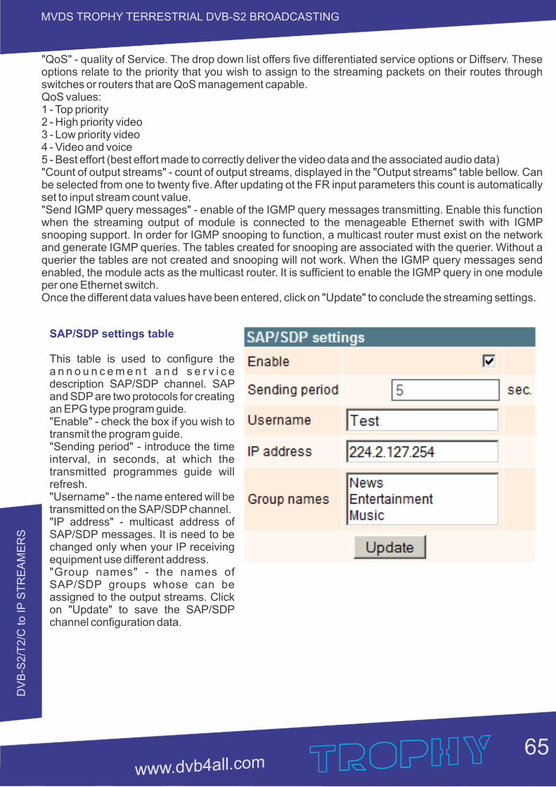
DV
B-S
2/T
2/C
to IP
ST
RE
AM
ER
S
65
MVDS TROPHY TERRESTRIAL DVB-S2 BROADCASTING
"QoS" - quality of Service. The drop down list offers five differentiated service options or Diffserv. These options relate to the priority that you wish to assign to the streaming packets on their routes through switches or routers that are QoS management capable.QoS values:1 - Top priority2 - High priority video3 - Low priority video4 - Video and voice5 - Best effort (best effort made to correctly deliver the video data and the associated audio data) "Count of output streams" - count of output streams, displayed in the "Output streams" table bellow. Can be selected from one to twenty five. After updating ot the FR input parameters this count is automatically set to input stream count value."Send IGMP query messages" - enable of the IGMP query messages transmitting. Enable this function when the streaming output of module is connected to the menageable Ethernet swith with IGMP snooping support. In order for IGMP snooping to function, a multicast router must exist on the network and generate IGMP queries. The tables created for snooping are associated with the querier. Without a querier the tables are not created and snooping will not work. When the IGMP query messages send enabled, the module acts as the multicast router. It is sufficient to enable the IGMP query in one module per one Ethernet switch.Once the different data values have been entered, click on "Update" to conclude the streaming settings.
SAP/SDP settings table
This table is used to configure the a n n o u n c e m e n t a n d s e r v i c e description SAP/SDP channel. SAP and SDP are two protocols for creating an EPG type program guide."Enable" - check the box if you wish to transmit the program guide."Sending period" - introduce the time interval, in seconds, at which the transmitted programmes guide will refresh."Username" - the name entered will be transmitted on the SAP/SDP channel."IP address" - multicast address of SAP/SDP messages. It is need to be changed only when your IP receiving equipment use different address."Group names" - the names of SAP/SDP groups whose can be assigned to the output streams. Click on "Update" to save the SAP/SDP channel configuration data.
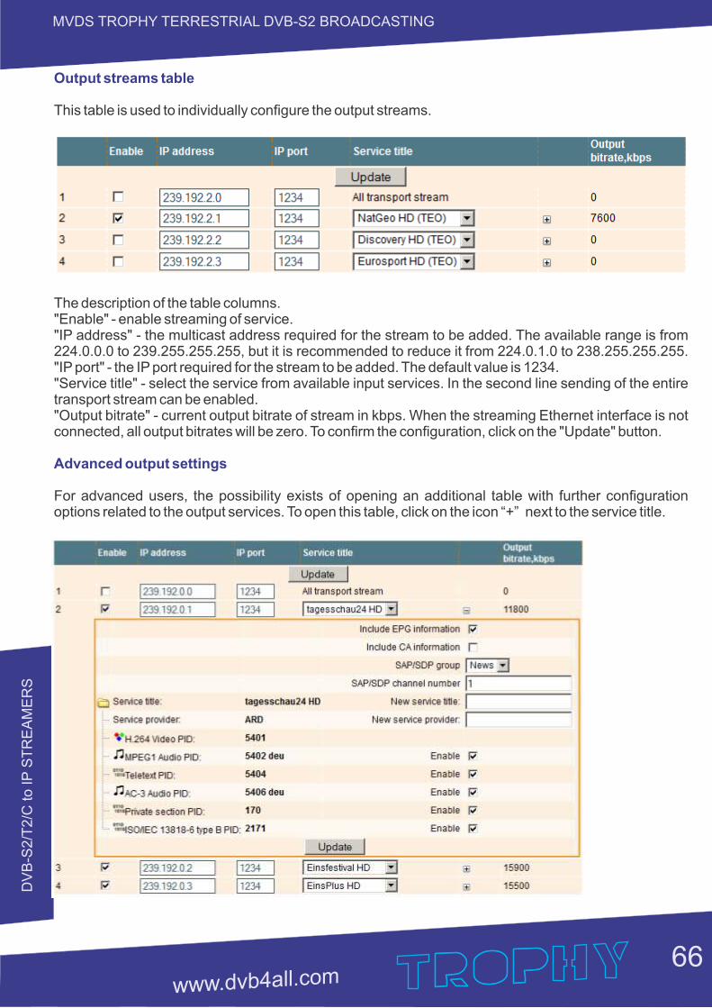
DV
B-S
2/T
2/C
to IP
ST
RE
AM
ER
S
66
MVDS TROPHY TERRESTRIAL DVB-S2 BROADCASTING
Output streams table
This table is used to individually configure the output streams.
The description of the table columns."Enable" - enable streaming of service."IP address" - the multicast address required for the stream to be added. The available range is from 224.0.0.0 to 239.255.255.255, but it is recommended to reduce it from 224.0.1.0 to 238.255.255.255. "IP port" - the IP port required for the stream to be added. The default value is 1234."Service title" - select the service from available input services. In the second line sending of the entire transport stream can be enabled."Output bitrate" - current output bitrate of stream in kbps. When the streaming Ethernet interface is not connected, all output bitrates will be zero. To confirm the configuration, click on the "Update" button.
Advanced output settings
For advanced users, the possibility exists of opening an additional table with further configuration options related to the output services. To open this table, click on the icon “+” next to the service title.
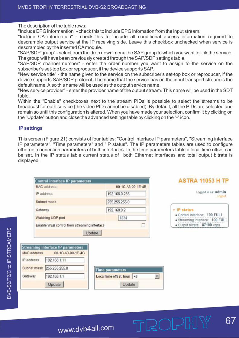
DV
B-S
2/T
2/C
to IP
ST
RE
AM
ER
S
67
MVDS TROPHY TERRESTRIAL DVB-S2 BROADCASTING
The description of the table rows:"Include EPG informantion" - check this to include EPG infomation from the input stream."Include CA information" - check this to include all conditional access information required to descramble output service at the IP receiving side. Leave this checkbox unchecked when service is descrambled by the inserted CA module."SAP/SDP gruop" - select from the drop down menu the SAP group to which you want to link the service. The group will have been previously created through the SAP/SDP settings table."SAP/SDP channel number" - enter the order number you want to assign to the service on the subscriber's set-top box or reproducer, if the device supports SAP."New service title" - the name given to the service on the subscriber's set-top box or reproducer, if the device supports SAP/SDP protocol. The name that the service has on the input transport stream is the default name. Also this name will be used as the output service name."New service provider" - enter the provider name of the output stream. This name will be used in the SDT table.Within the "Enable" checkboxes next to the stream PIDs is possible to select the streams to be broadcast for eath service (the video PID cannot be disabled). By default, all the PIDs are selected and remain so until this configuration is altered. When you have made your selection, confirm it by clicking on the "Update" button and close the advanced settings table by clicking on the “-“ icon.
IP settings
This screen (Figure 21) consists of four tables: "Control interface IP parameters", "Streaming interface IP parameters", "Time parameters" and "IP status". The IP parameters tables are used to configure ethernet connection parameters of both interfaces. In the time parameters table a local time offset can be set. In the IP status table current status of both Ethernet interfaces and total output bitrate is displayed.
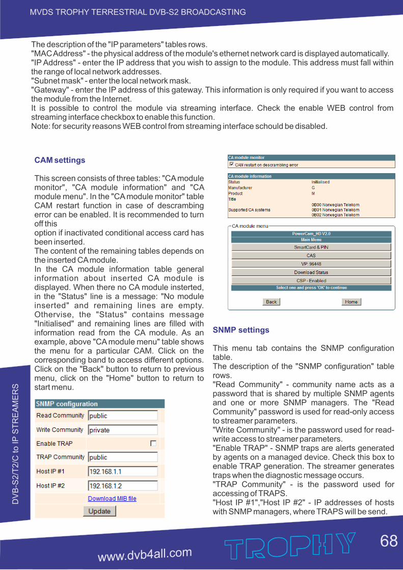
DV
B-S
2/T
2/C
to IP
ST
RE
AM
ER
S
68
MVDS TROPHY TERRESTRIAL DVB-S2 BROADCASTING
The description of the "IP parameters" tables rows."MAC Address" - the physical address of the module's ethernet network card is displayed automatically."IP Address" - enter the IP address that you wish to assign to the module. This address must fall within the range of local network addresses."Subnet mask" - enter the local network mask."Gateway" - enter the IP address of this gateway. This information is only required if you want to access the module from the Internet.It is possible to control the module via streaming interface. Check the enable WEB control from streaming interface checkbox to enable this function. Note: for security reasons WEB control from streaming interface schould be disabled.
CAM settings
This screen consists of three tables: "CA module monitor", "CA module information" and "CA module menu". In the "CA module monitor" table CAM restart function in case of descrambing error can be enabled. It is recommended to turn off thisoption if inactivated conditional access card has been inserted.The content of the remaining tables depends on the inserted CA module.In the CA module information table general information about inserted CA module is displayed. When there no CA module insterted, in the "Status" line is a message: "No module inserted" and remaining lines are empty. Othervise, the "Status" contains message "Initialised" and remaining lines are filled with information read from the CA module. As an example, above "CA module menu" table shows the menu for a particular CAM. Click on the corresponding band to access different options. Click on the "Back" button to return to previous menu, click on the "Home" button to return to start menu.
SNMP settings
This menu tab contains the SNMP configuration table.The description of the "SNMP configuration" table rows."Read Community" - community name acts as a password that is shared by multiple SNMP agents and one or more SNMP managers. The "Read Community" password is used for read-only access to streamer parameters."Write Community" - is the password used for read-write access to streamer parameters."Enable TRAP" - SNMP traps are alerts generated by agents on a managed device. Check this box to enable TRAP generation. The streamer generates traps when the diagnostic message occurs."TRAP Community" - is the password used for accessing of TRAPS."Host IP #1","Host IP #2" - IP addresses of hosts with SNMP managers, where TRAPS will be send.
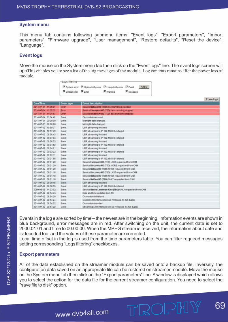
DV
B-S
2/T
2/C
to IP
ST
RE
AM
ER
S
69
MVDS TROPHY TERRESTRIAL DVB-S2 BROADCASTING
System menu
This menu tab contains following submenu items: "Event logs", "Export parameters", "Import parameters", "Firmware upgrade", "User management", "Restore defaults", "Reset the device", "Language".
Event logs
Move the mouse on the System menu tab then click on the "Event logs" line. The event logs screen will appThis enables you to see a list of the log messages of the module. Log contents remains after the power loss of module.
Events in the log e are sorted by time – the newest are in the beginning. Information events are shown in blue background, error messages are in red. After switching on the unit, the current date is set to 2000:01:01 and time to 00.00.00. When the MPEG stream is received, the information about date and is decoded too, and the values of these parameter are corrected.Local time offset in the log is used from the time parameters table. You can filter required messages setting corresponding "Logs filtering" checkboxes.
Export parameters
All of the data established on the streamer module can be saved onto a backup file. Inversely, the configuration data saved on an appropriate file can be restored on streamer module. Move the mouse on the System menu tab then click on the "Export parameters" line. A window is displayed which allows you to select the action for the data file for the current streamer configuration. You need to select the "save file to disk" option.

DV
B-S
2/T
2/C
to IP
ST
RE
AM
ER
S
70
MVDS TROPHY TERRESTRIAL DVB-S2 BROADCASTING
Import parameters
Select this option in "System menu" tab. The Import parameters window is displayed.
Click on "Click to select file" and select the file containing the configuration data that you wish to restore on the streamer module. Once you have selected the file, click on the "Upload" button at the bottom of the screen. The upload confirmation window will be displayed.
Firmware upgrade
If you wish to update the streamer's firmware, select this option in "System menu". The card displayed shows the firmware version that the streamer has at the present time.
Click on "Click to select file" and select the firmware update file from the hard drive. When the file name is in the box, click on "Upload". The new firmware will be installed on the streamer.
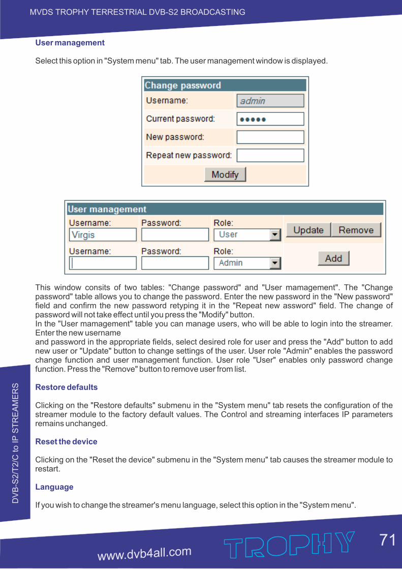
DV
B-S
2/T
2/C
to IP
ST
RE
AM
ER
S
71
MVDS TROPHY TERRESTRIAL DVB-S2 BROADCASTING
User management
Select this option in "System menu" tab. The user management window is displayed.
This window consits of two tables: "Change password" and "User mamagement". The "Change password" table allows you to change the password. Enter the new password in the "New password" field and confirm the new password retyping it in the "Repeat new assword" field. The change of password will not take effect until you press the "Modify" button.In the "User mamagement" table you can manage users, who will be able to login into the streamer. Enter the new usernameand password in the appropriate fields, select desired role for user and press the "Add" button to add new user or "Update" button to change settings of the user. User role "Admin" enables the password change function and user management function. User role "User" enables only password change function. Press the "Remove" button to remove user from list.
Restore defaults
Clicking on the "Restore defaults" submenu in the "System menu" tab resets the configuration of the streamer module to the factory default values. The Control and streaming interfaces IP parameters remains unchanged.
Reset the device
Clicking on the "Reset the device" submenu in the "System menu" tab causes the streamer module to restart.
Language
If you wish to change the streamer's menu language, select this option in the "System menu".
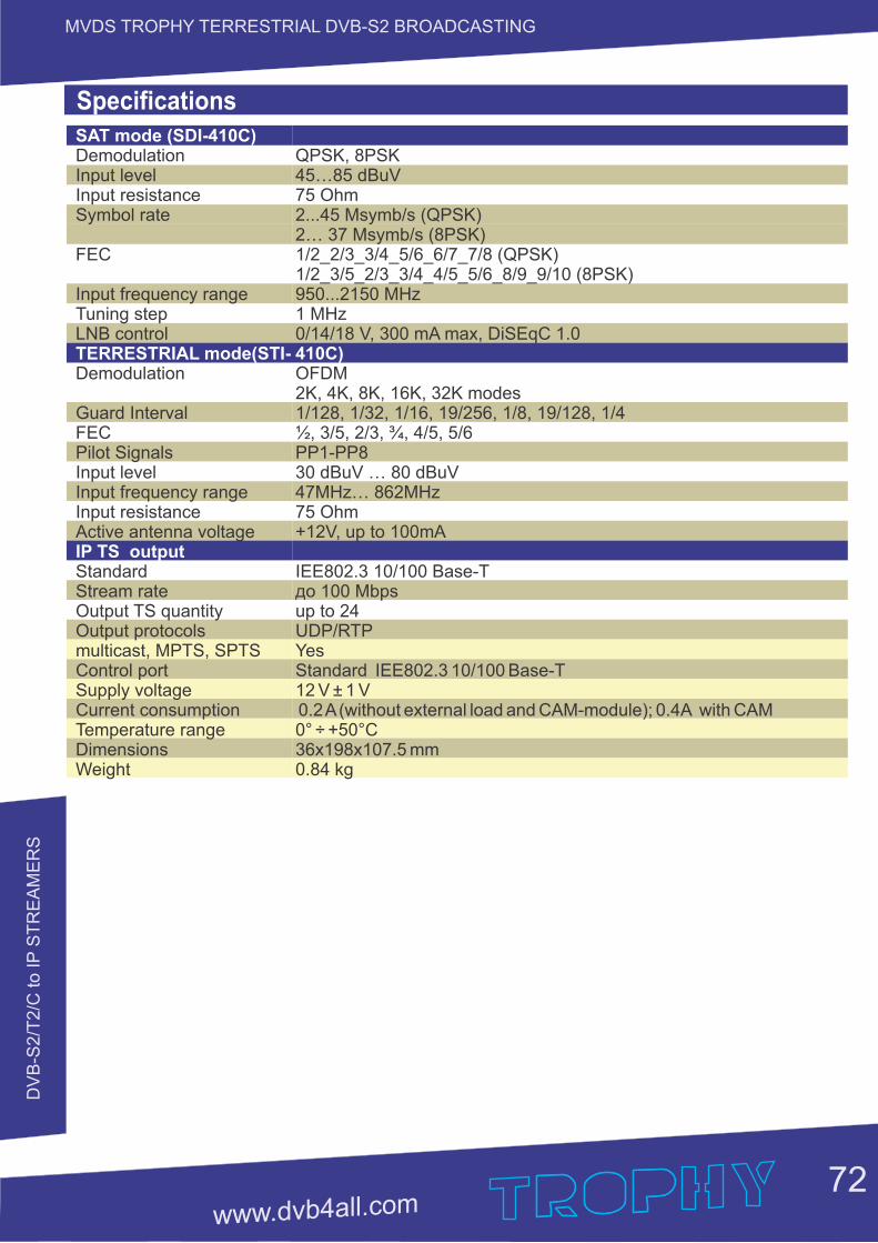
DV
B-S
2/T
2/C
to IP
ST
RE
AM
ER
S
72
MVDS TROPHY TERRESTRIAL DVB-S2 BROADCASTING
SAT mode (SDI-410C)DemodulationInput levelInput resistanceSymbol rate
FEC
Input frequency rangeTuning stepLNB controlTERRESTRIAL mode(STI-Demodulation
Guard IntervalFECPilot SignalsInput levelInput frequency rangeInput resistanceActive antenna voltageIP TS outputStandardStream rateOutput TS quantityOutput protocolsmulticast, MPTS, SPTSControl portSupply voltageCurrent consumptionTemperature rangeDimensionsWeight
QPSK, 8PSK45…85 dBuV75 Ohm2...45 Мsymb/s (QPSK)2… 37 Msymb/s (8PSK)1/2_2/3_3/4_5/6_6/7_7/8 (QPSK)1/2_3/5_2/3_3/4_4/5_5/6_8/9_9/10 (8PSK)950...2150 MHz1 MHz0/14/18 V, 300 mA max, DiSEqC 1.0 410C)OFDM2K, 4K, 8K, 16K, 32K modes1/128, 1/32, 1/16, 19/256, 1/8, 19/128, 1/4½, 3/5, 2/3, ¾, 4/5, 5/6PP1-PP830 dBuV … 80 dBuV47MHz… 862MHz75 Ohm+12V, up to 100mA
IEE802.3 10/100 Base-Tдо 100 Mbpsup to 24UDP/RTPYesStandard IEE802.3 10/100 Base-T 12 V ± 1 V 0.2 A (without external load and CAM-module); 0.4A with CAM0° ÷ +50°C36x198x107.5 mm0.84 kg
Specifications
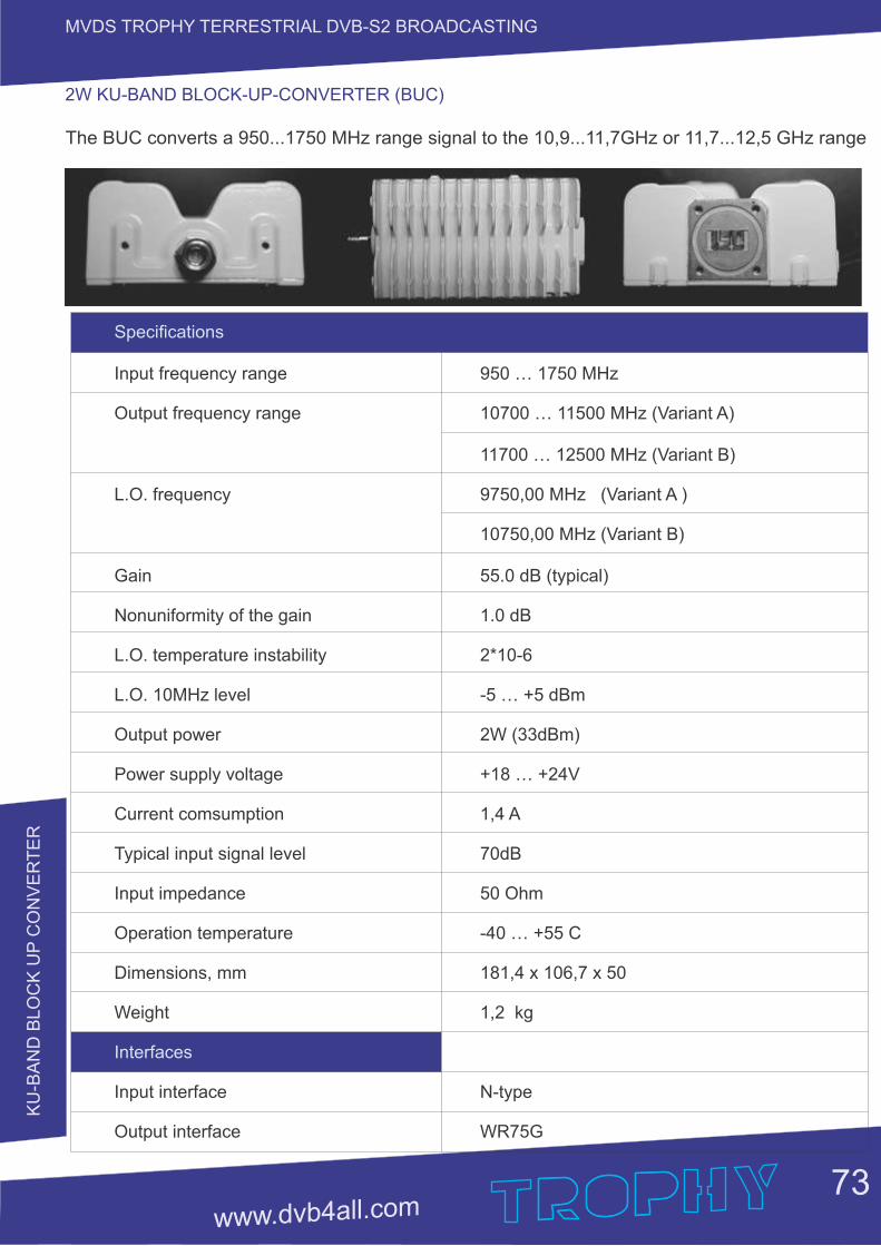
KU
-BA
ND
BLO
CK
UP
CO
NV
ER
TE
R
73
MVDS TROPHY TERRESTRIAL DVB-S2 BROADCASTING
Specifications
Input frequency range 950 … 1750 MHz
Output frequency range 10700 … 11500 MHz (Variant A)
11700 … 12500 MHz (Variant B)
L.O. frequency 9750,00 MHz (Variant A )
10750,00 MHz (Variant B)
Gain 55.0 dB (typical)
Nonuniformity of the gain 1.0 dB
L.O. temperature instability 2*10-6
L.O. 10MHz level -5 … +5 dBm
Output power 2W (33dBm)
Power supply voltage +18 … +24V
Current comsumption 1,4 A
Typical input signal level 70dB
Input impedance 50 Ohm
Operation temperature -40 … +55 C
Dimensions, mm 181,4 x 106,7 x 50
Weight 1,2 kg
Interfaces
Input interface N-type
Output interface WR75G
The BUC converts a 950...1750 MHz range signal to the 10,9...11,7GHz or 11,7...12,5 GHz range
2W KU-BAND BLOCK-UP-CONVERTER (BUC)
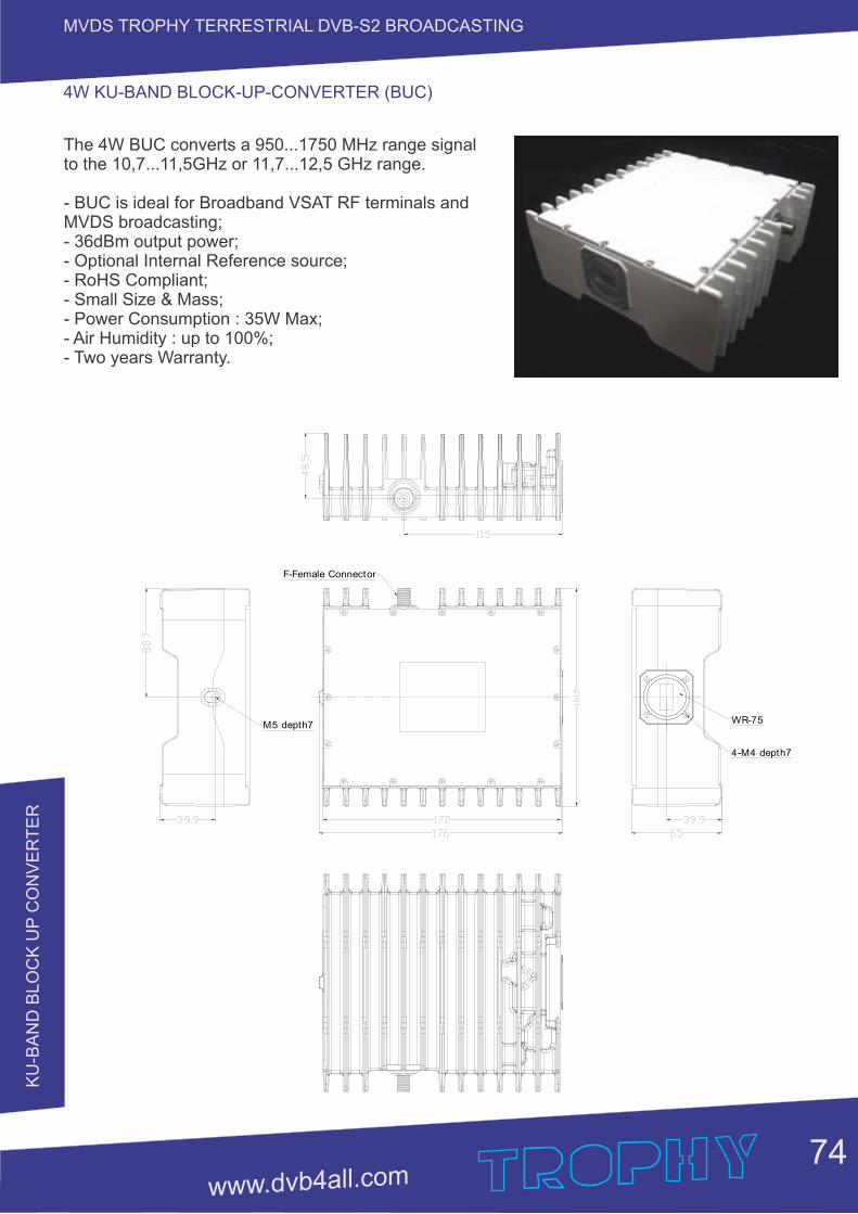
KU
-BA
ND
BLO
CK
UP
CO
NV
ER
TE
R
74
MVDS TROPHY TERRESTRIAL DVB-S2 BROADCASTING
4W KU-BAND BLOCK-UP-CONVERTER (BUC)
The 4W BUC converts a 950...1750 MHz range signal to the 10,7...11,5GHz or 11,7...12,5 GHz range.
- BUC is ideal for Broadband VSAT RF terminals and MVDS broadcasting; - 36dBm output power; - Optional Internal Reference source; - RoHS Compliant; - Small Size & Mass; - Power Consumption : 35W Max; - Air Humidity : up to 100%;- Two years Warranty.
M5 depth7
4-M4 depth7
WR-75
F-Female Connector
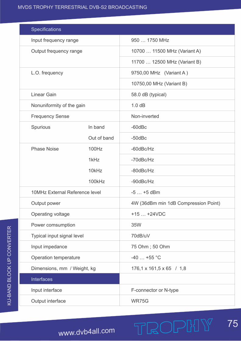
KU
-BA
ND
BLO
CK
UP
CO
NV
ER
TE
R
75
MVDS TROPHY TERRESTRIAL DVB-S2 BROADCASTING
Specifications
Input frequency range 950 … 1750 MHz
Output frequency range 10700 … 11500 MHz (Variant A)
11700 … 12500 MHz (Variant B)
L.O. frequency 9750,00 MHz (Variant A )
10750,00 MHz (Variant B)
Linear Gain 58.0 dB (typical)
Nonuniformity of the gain 1.0 dB
Frequency Sense Non-inverted
Spurious In band -60dBc
Out of band -50dBc
Phase Noise 100Hz -60dBc/Hz
1kHz -70dBc/Hz
10kHz -80dBc/Hz
100kHz -90dBc/Hz
10MHz External Reference level -5 … +5 dBm
Output power 4W (36dBm min 1dB Compression Point)
Operating voltage +15 … +24VDC
Power comsumption 35W
Typical input signal level 70dB/uV
Input impedance 75 Ohm ; 50 Ohm
Operation temperature -40 … +55 °C
Dimensions, mm / Weight, kg 176,1 x 161,5 x 65 / 1,8
Interfaces
Input interface F-connector or N-type
Output interface WR75G
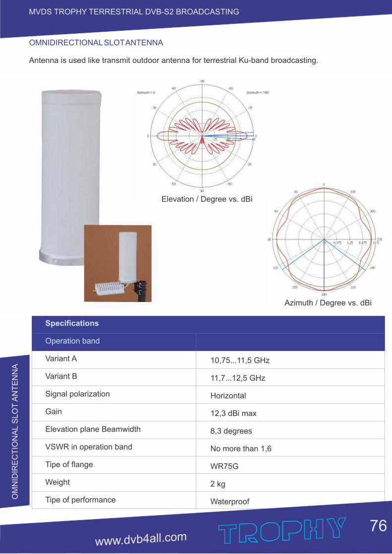
OM
NID
IRE
CT
ION
AL S
LO
T A
NT
EN
NA
76
MVDS TROPHY TERRESTRIAL DVB-S2 BROADCASTING
Specifications
Operation band
Variant A
Variant B
Signal polarization
Gain
Elevation plane Beamwidth
VSWR in operation band
Tipe of flange
Weight
Tipe of performance
10,75...11,5 GHz
11,7...12,5 GHz
Horizontal
12,3 dBi max
8,3 degrees
No more than 1,6
WR75G
2 kg
Waterproof
Elevation / Degree vs. dBi
Azimuth = 0 Azimuth = 180
Azimuth / Degree vs. dBi
OMNIDIRECTIONAL SLOT ANTENNA
Antenna is used like transmit outdoor antenna for terrestrial Ku-band broadcasting.
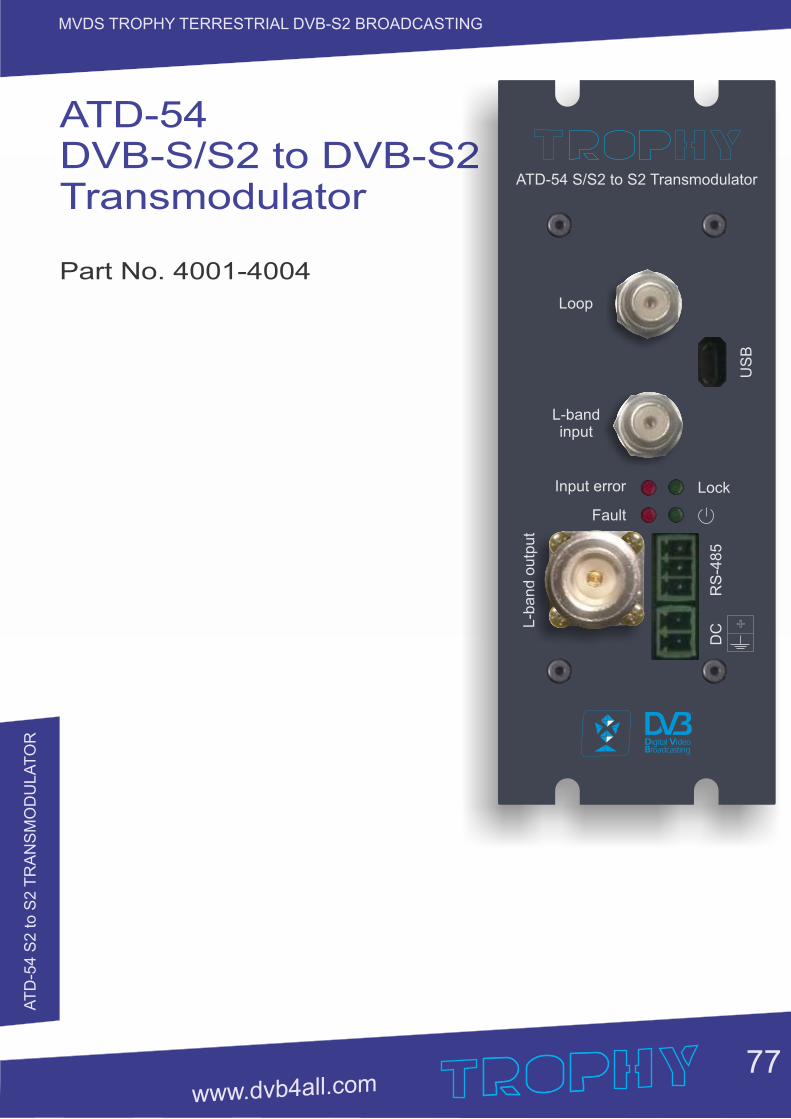
AT
D-5
4 S
2 to S
2 T
RA
NS
MO
DU
LA
TO
R
77
MVDS TROPHY TERRESTRIAL DVB-S2 BROADCASTING
ATD-54DVB-S/S2 to DVB-S2Transmodulator
Part No. 4001-4004
L-b
an
d o
utp
ut
ATD-54 S/S2 to S2 Transmodulator
L-band input
Loop
Input error
Fault
Lock
RS
-48
5
US
B
DC +

AT
D-5
4 S
2 to S
2 T
RA
NS
MO
DU
LA
TO
R
78
MVDS TROPHY TERRESTRIAL DVB-S2 BROADCASTING
GENERAL INFORMATION
ATD-54-S/S2 to DVB-S2 TRANSMODULATOR is a brand new transmodulator from DVB-S/S2 to DVB-S2 designed for applications over satellite or MVDS in full compliance with DVB-S2 standard. The ATD-54-S/S2 to DVB-S2 TRANSMODULATOR:Ÿ receives&demodulates DVB-S or DVB-S2 transponder;Ÿ descrambles all TROPHY-ACCESS channels (optionally);Ÿ modulates new DVB-S2 transponder to transmit in satellite transmitter or MVDS Block UP Converter (BUC). As a result, the maximum MER value for the new carrier is restored. The form and quality of the repeater signal becomes the same as that of the base station signal.Attention! Symbol rate of output transponder must be equal to or bigger than symbol rate of input transponder. But output symbol rate must not exceed more than 20% value of input symbol rate.
A high-performance FPGA does the analogue TV modulation and the freely adjustable up-conversion into L-band range (950 ... 2150MHz). A high-speed digital→analogue converter (DAC) is responsible for the excellent output signal.
MAIN FUNCTIONS OF R:ATD-54-S/S2 to DVB-S2 TRANSMODULATO
Ÿ covers the full L-Band range (900...2150 MHz) and offers bit rate from1 Mbps up to 94 Mbps;
Ÿ provides all input channels to a single carrier, with built-in support for TROPHY-ACCESS descrambler (optionally). Software license to enable TROPHY-ACCESS descrambler solution;
Ÿ provides transport Stream rates up to 94 Mbit/s;
Ÿ supports all PIDs of input services;
Ÿ supports Control and Set-Up via USB and RS-485 interfaces;
Ÿ has high performance and reliability.
Ÿ network management is optional, using a special Remote Access Controller (see page 16). The Remote Access Controller provides WEB monitoring of the input parameters of the transmodulator/ transmodulators.
ATD-54-S/S2 to DVB-S2 TRANSMODULATOR integrates the CycloneV core technology required to perform high quality modulation based on TROPHY expertise. It provides customers with a best in class performance, providing a high SNR value, excellent shoulder levels and lowest phase noise.
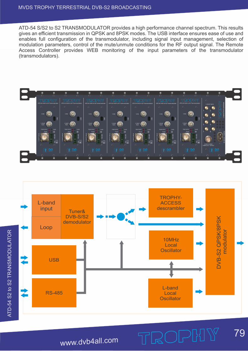
AT
D-5
4 S
2 to S
2 T
RA
NS
MO
DU
LA
TO
R
79
MVDS TROPHY TERRESTRIAL DVB-S2 BROADCASTING
TROPHY-ACCESS
descrambler
L-band Local
Oscillator
DV
B-S
2 Q
PS
K/8
PS
K m
od
ula
tor
L-bandinput
Loop
Tuner&DVB-S/S2
demodulator
USB
RS-485
10MHzLocal
Oscillator
ATD-54 S/S2 to S2 TRANSMODULATOR provides a high performance channel spectrum. This results gives an efficient transmission in QPSK and 8PSK modes. The USB interface ensures ease of use and enables full configuration of the transmodulator, including signal input management, selection of modulation parameters, control of the mute/unmute conditions for the RF output signal. The Remote Access Controller provides WEB monitoring of the input parameters of the transmodulator (transmodulators).
L-band inputs
L-band output10MHz ref. +24VDC
90-2
64V
AC
50/6
0H
zL-b
and 8
-ch c
om
bin
er
1 2
3 4
5 6
7 8
L-b
and o
utp
ut
ATD-54 S/S2 to S2 Transmodulator
L-band input
Loop
Input error
Fault
Lock
RS
-485
US
B
DC + L
-band o
utp
ut
ATD-54 S/S2 to S2 Transmodulator
L-band input
Loop
Input error
Fault
Lock
RS
-485
US
B
DC + L
-band o
utp
ut
ATD-54 S/S2 to S2 Transmodulator
L-band input
Loop
Input error
Fault
Lock
RS
-485
US
B
DC + L
-band o
utp
ut
ATD-54 S/S2 to S2 Transmodulator
L-band input
Loop
Input error
Fault
Lock
RS
-485
US
B
DC + L
-band o
utp
ut
ATD-54 S/S2 to S2 Transmodulator
L-band input
Loop
Input error
Fault
Lock
RS
-485
US
B
DC + L
-band o
utp
ut
ATD-54 S/S2 to S2 Transmodulator
L-band input
Loop
Input error
Fault
Lock
RS
-485
US
B
DC + L
-band o
utp
ut
ATD-54 S/S2 to S2 Transmodulator
L-band input
Loop
Input error
Fault
Lock
RS
-485
US
B
DC +
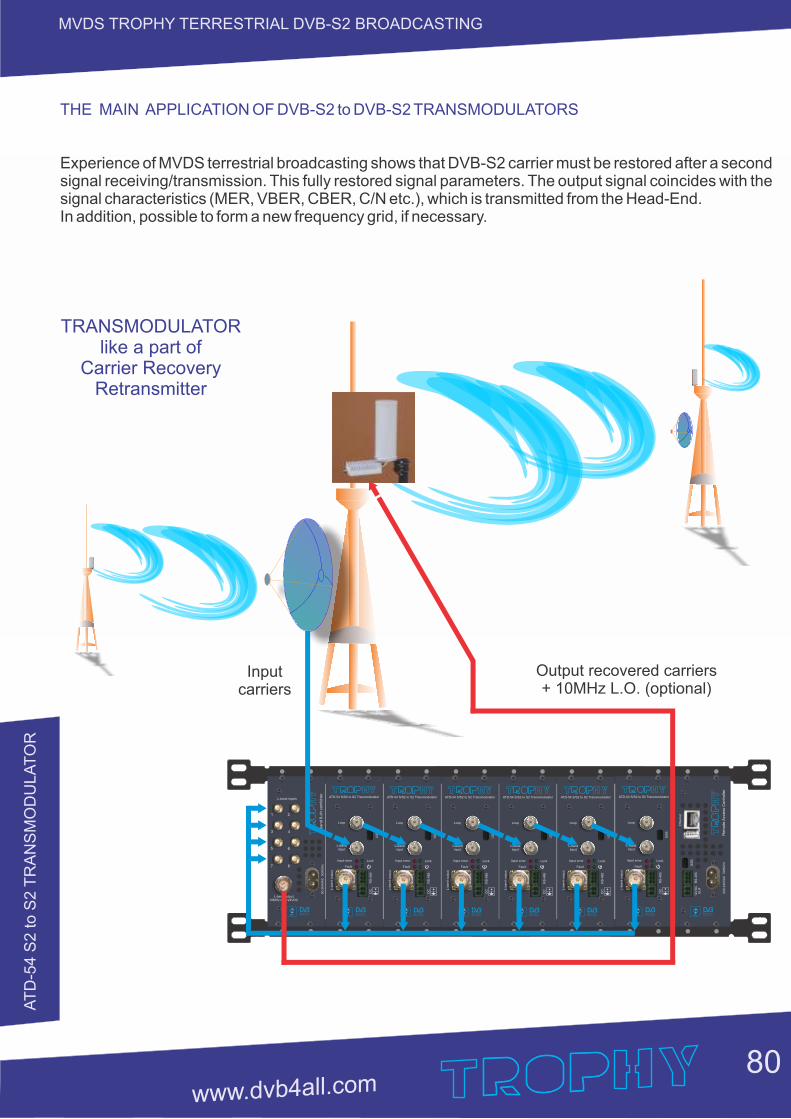
AT
D-5
4 S
2 to S
2 T
RA
NS
MO
DU
LA
TO
R
80
MVDS TROPHY TERRESTRIAL DVB-S2 BROADCASTING
THE MAIN APPLICATION OF DVB-S2 to DVB-S2 TRANSMODULATORS
Experience of MVDS terrestrial broadcasting shows that DVB-S2 carrier must be restored after a second signal receiving/transmission. This fully restored signal parameters. The output signal coincides with the signal characteristics (MER, VBER, CBER, C/N etc.), which is transmitted from the Head-End.In addition, possible to form a new frequency grid, if necessary.
L-band inputs
L-band output10MHz ref. +24VDC
90
-26
4V
AC
5
0/6
0H
zL
-ba
nd
8-c
h c
om
bin
er
1 2
3 4
5 6
7 8
L-b
an
d o
utp
ut
ATD-54 S/S2 to S2 Transmodulator
L-band input
Loop
Input error
Fault
Lock
RS
-48
5
US
B
DC + L
-ba
nd
ou
tpu
t
ATD-54 S/S2 to S2 Transmodulator
L-band input
Loop
Input error
Fault
Lock
RS
-48
5
US
B
DC + L
-ba
nd
ou
tpu
t
ATD-54 S/S2 to S2 Transmodulator
L-band input
Loop
Input error
Fault
Lock
RS
-48
5
US
B
DC + L
-ba
nd
ou
tpu
t
ATD-54 S/S2 to S2 Transmodulator
L-band input
Loop
Input error
Fault
Lock
RS
-48
5
US
B
DC + L
-ba
nd
ou
tpu
t
ATD-54 S/S2 to S2 Transmodulator
L-band input
Loop
Input error
Fault
Lock
RS
-48
5
US
B
DC +L
-ba
nd
ou
tpu
t
ATD-54 S/S2 to S2 Transmodulator
L-band input
Loop
Input error
Fault
Lock
RS
-48
5
US
B
DC +
TRANSMODULATOR like a part of
Carrier Recovery Retransmitter
Input carriers
Output recovered carriers + 10MHz L.O. (optional)
RS
-48
5
US
B
20
0-2
40
VA
C
50
/60
Hz
Rem
ote
Acc
ess
Contr
olle
r
12
VD
CO
UT
Eth
ern
et
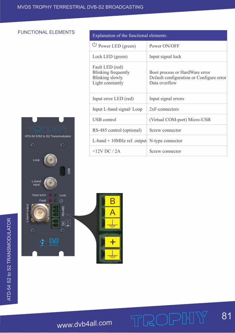
AT
D-5
4 S
2 to S
2 T
RA
NS
MO
DU
LA
TO
R
81
MVDS TROPHY TERRESTRIAL DVB-S2 BROADCASTING
FUNCTIONAL ELEMENTSL-b
and o
utp
ut
ATD-54 S/S2 to S2 Transmodulator
L-band input
Loop
Input error
Fault
Lock
RS
-485
US
B
DC +
+
B
A
Explanation of the functional elements:
Power LED (green) Power ON/OFF
Lock LED (green) Input signal lock
Fault LED (red) Blinking frequently Boot process or HardWare error Blinking slowly Default configuration or Configure errorLight constantly Data overflow
Input error LED (red) Input signal errors
Input L-band signal/ Loop 2xF-connectors
USB control (Virtual COM-port) Micro-USB
RS-485 control (optional) Screw connector L-band + 10MHz ref. output N-type connector
+12V DC / 2A Screw connector
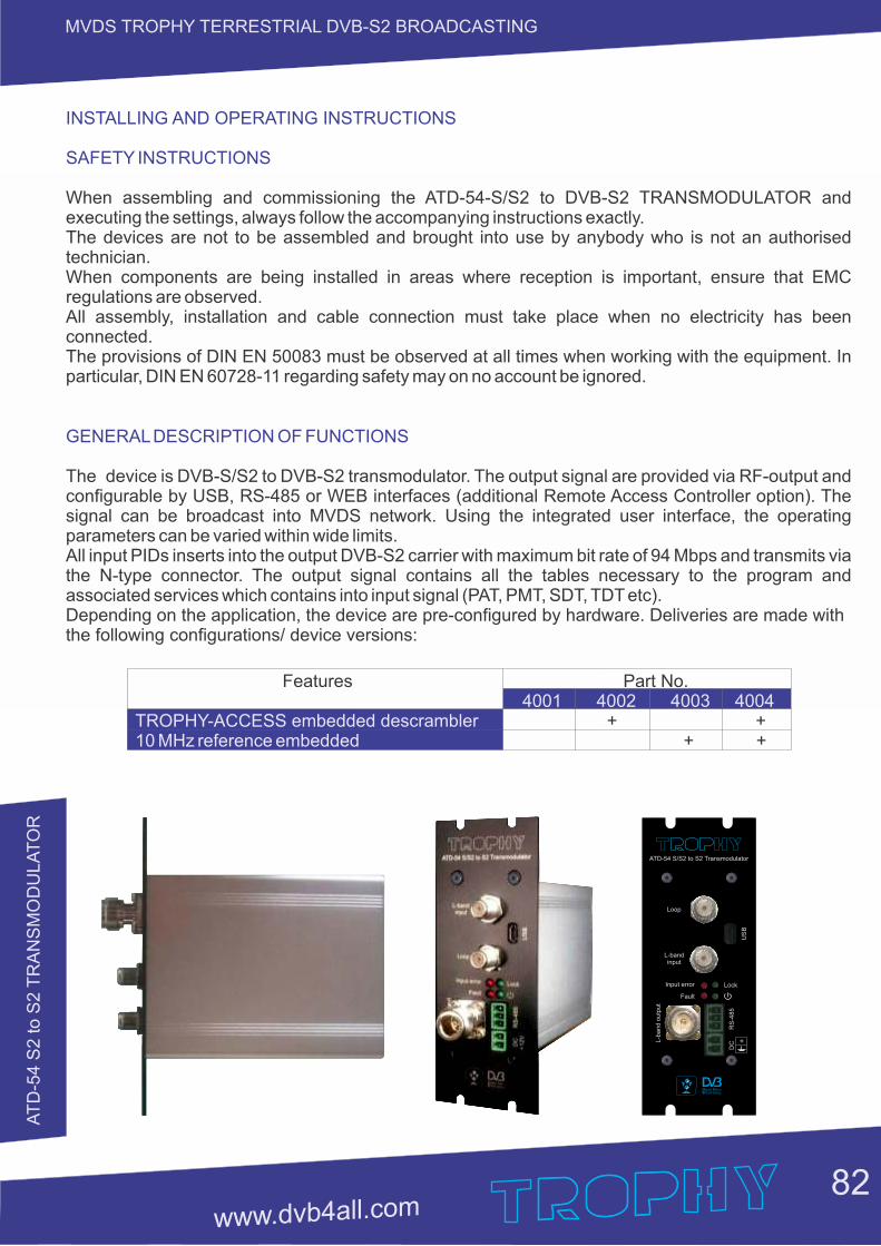
AT
D-5
4 S
2 to S
2 T
RA
NS
MO
DU
LA
TO
R
82
MVDS TROPHY TERRESTRIAL DVB-S2 BROADCASTING
INSTALLING AND OPERATING INSTRUCTIONS
SAFETY INSTRUCTIONS
When assembling and commissioning the ATD-54-S/S2 to DVB-S2 TRANSMODULATOR and executing the settings, always follow the accompanying instructions exactly.The devices are not to be assembled and brought into use by anybody who is not an authorised technician.When components are being installed in areas where reception is important, ensure that EMC regulations are observed.All assembly, installation and cable connection must take place when no electricity has been connected.The provisions of DIN EN 50083 must be observed at all times when working with the equipment. In particular, DIN EN 60728-11 regarding safety may on no account be ignored.
GENERAL DESCRIPTION OF FUNCTIONS
The device is DVB-S/S2 to DVB-S2 transmodulator. The output signal are provided via RF-output and configurable by USB, RS-485 or WEB interfaces (additional Remote Access Controller option). The signal can be broadcast into MVDS network. Using the integrated user interface, the operating parameters can be varied within wide limits.All input PIDs inserts into the output DVB-S2 carrier with maximum bit rate of 94 Mbps and transmits via the N-type connector. The output signal contains all the tables necessary to the program and associated services which contains into input signal (PAT, PMT, SDT, TDT etc). Depending on the application, the device are pre-configured by hardware. Deliveries are made with the following configurations/ device versions:
Features Part No. 4001 4002 4003 4004TROPHY-ACCESS embedded descrambler + +10 MHz reference embedded + +
L-b
an
d o
utp
ut
ATD-54 S/S2 to S2 Transmodulator
L-band input
Loop
Input error
Fault
Lock
RS
-48
5
US
B
DC +
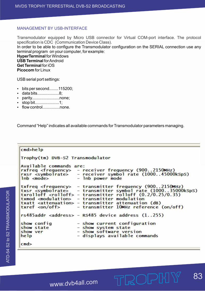
AT
D-5
4 S
2 to S
2 T
RA
NS
MO
DU
LA
TO
R
83
MVDS TROPHY TERRESTRIAL DVB-S2 BROADCASTING
MANAGEMENT BY USB-INTERFACE
Transmodulator equipped by Micro USB connector for Virtual COM-port interface. The protocol specification is CDC (Communication Device Class).In order to be able to configure the Transmodulator configuration on the SERIAL connection use any terminal program on your computer, for example:HyperTerminal for WindowsUSB Terminal for AndroidGet Terminal for iOSPicocom for Linux
USB serial port settings:
Ÿ bits per second........115200;Ÿ data bits...................8;Ÿ parity........................none;Ÿ stop bit.....................1;Ÿ flow control...............none.
Command “Help” indicates all available commands for Transmodulator parameters managing.
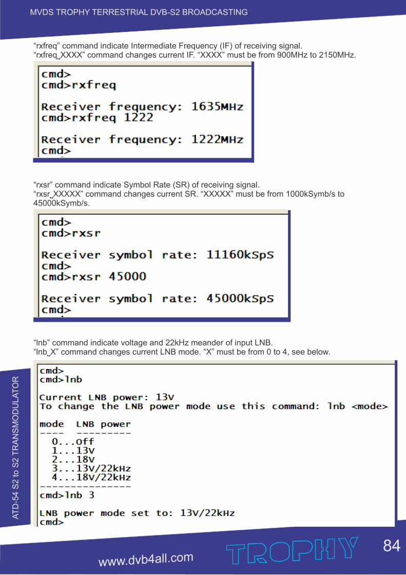
AT
D-5
4 S
2 to S
2 T
RA
NS
MO
DU
LA
TO
R
84
MVDS TROPHY TERRESTRIAL DVB-S2 BROADCASTING
“rxfreq” command indicate Intermediate Frequency (IF) of receiving signal.“rxfreq˽XXXX” command changes current IF. “XXXX” must be from 900MHz to 2150MHz.
“rxsr” command indicate Symbol Rate (SR) of receiving signal.“rxsr˽XXXXX” command changes current SR. “XXXXX” must be from 1000kSymb/s to 45000kSymb/s.
“lnb” command indicate voltage and 22kHz meander of input LNB.“lnb˽X” command changes current LNB mode. “X” must be from 0 to 4, see below.
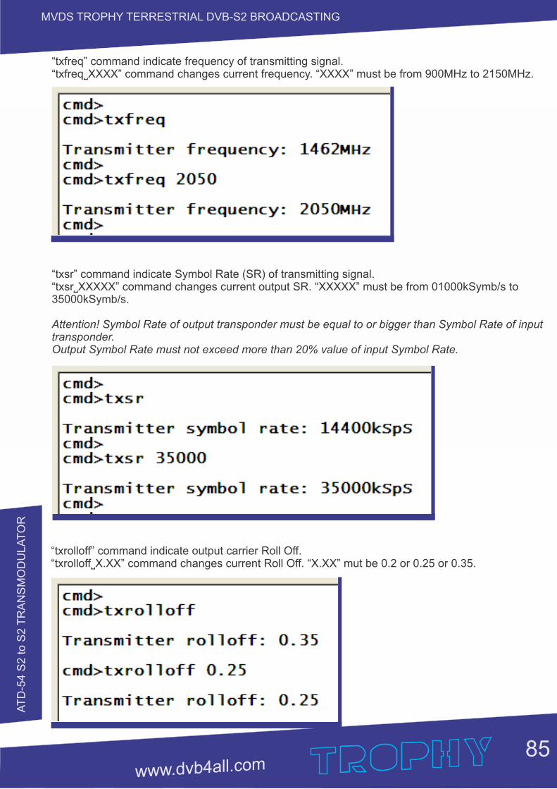
AT
D-5
4 S
2 to S
2 T
RA
NS
MO
DU
LA
TO
R
85
MVDS TROPHY TERRESTRIAL DVB-S2 BROADCASTING
“txfreq” command indicate frequency of transmitting signal.“txfreq˽XXXX” command changes current frequency. “XXXX” must be from 900MHz to 2150MHz.
“txsr” command indicate Symbol Rate (SR) of transmitting signal.“txsr˽XXXXX” command changes current output SR. “XXXXX” must be from 01000kSymb/s to 35000kSymb/s.
Attention! Symbol Rate of output transponder must be equal to or bigger than Symbol Rate of input transponder. Output Symbol Rate must not exceed more than 20% value of input Symbol Rate.
“txrolloff” command indicate output carrier Roll Off.“txrolloff˽X.XX” command changes current Roll Off. “X.XX” mut be 0.2 or 0.25 or 0.35.
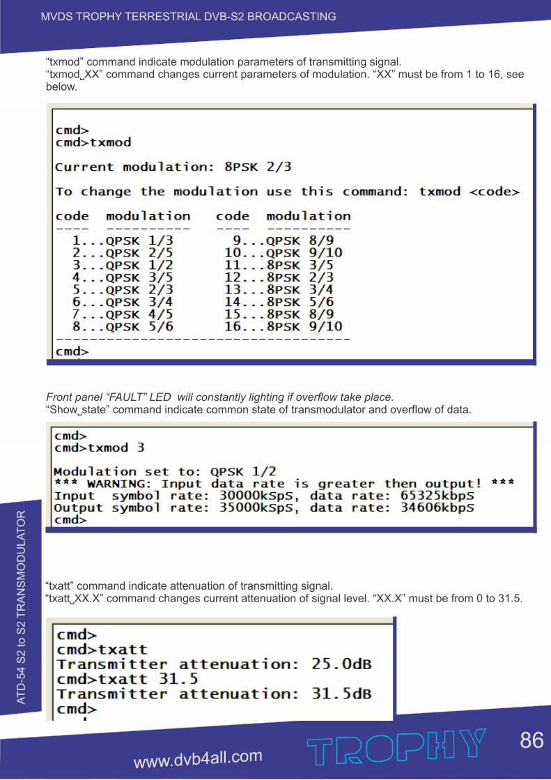
AT
D-5
4 S
2 to S
2 T
RA
NS
MO
DU
LA
TO
R
MVDS TROPHY TERRESTRIAL DVB-S2 BROADCASTING
86
“txmod” command indicate modulation parameters of transmitting signal.“txmod˽XX” command changes current parameters of modulation. “XX” must be from 1 to 16, see below.
Front panel “FAULT” LED will constantly lighting if overflow take place. “Show˽state” command indicate common state of transmodulator and overflow of data.
“txatt” command indicate attenuation of transmitting signal.“txatt˽XX.X” command changes current attenuation of signal level. “XX.X” must be from 0 to 31.5.
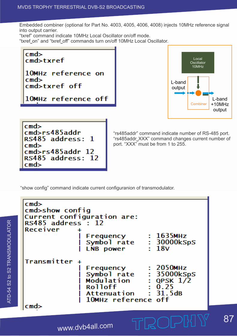
AT
D-5
4 S
2 to S
2 T
RA
NS
MO
DU
LA
TO
R
87
MVDS TROPHY TERRESTRIAL DVB-S2 BROADCASTING
Embedded combiner (optional for Part No. 4003, 4005, 4006, 4008) injects 10MHz reference signal into output carrier.“txref” command indicate 10MHz Local Oscillator on/off mode.“txref˽on” and “txref˽off” commands turn on/off 10MHz Local Oscillator.
Combiner
LocalOscillator10MHz
L-band+10MHz output
L-band output
“rs485addr” command indicate number of RS-485 port. “rs485addr˽XXX” command changes current number of port. “XXX” must be from 1 to 255.
“show config” command indicate current configuranion of transmodulator.

AT
D-5
4 S
2 to S
2 T
RA
NS
MO
DU
LA
TO
R
88
MVDS TROPHY TERRESTRIAL DVB-S2 BROADCASTING
“show state” command indicate common state of Transmodulator:Ÿ Input signal LOCK/UNLOCKŸ Input signal LEVELŸ Input signal S/N ratioŸ Mode of input carrierŸ Input Symbol Rate and data rate (if tuner is LOCK)Ÿ Output Symbol Rate and data rateŸ CPU temperatureŸ Overflow of data
“show ver” command indicate HardWare and SoftWare versions of device.
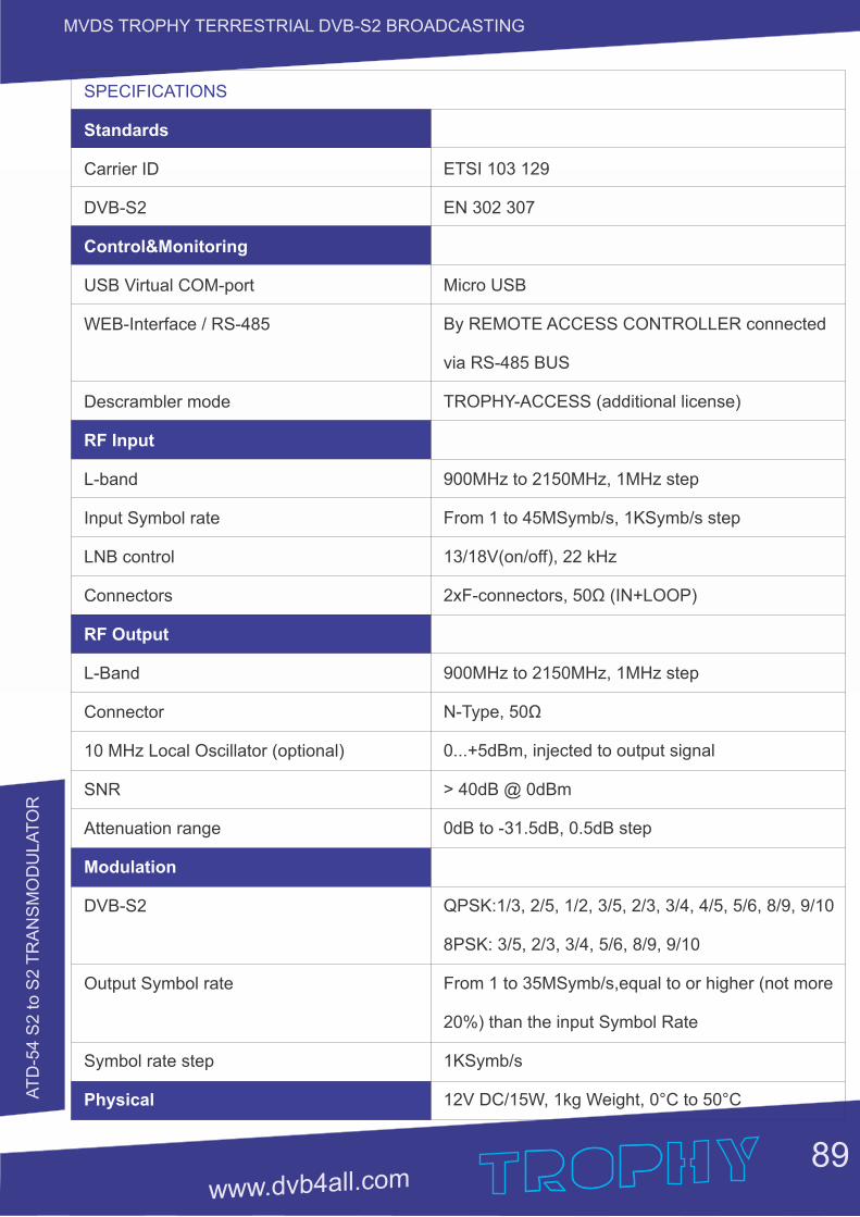
AT
D-5
4 S
2 to S
2 T
RA
NS
MO
DU
LA
TO
R
89
MVDS TROPHY TERRESTRIAL DVB-S2 BROADCASTING
SPECIFICATIONS
Standards
Carrier ID
DVB-S2
Control&Monitoring
USB Virtual COM-port
WEB-Interface / RS-485
Descrambler mode
RF Input
L-band
Input Symbol rate
LNB control
Connectors
RF Output
L-Band
Connector
10 MHz Local Oscillator (optional)
SNR
Attenuation range
Modulation
DVB-S2
Output Symbol rate
Symbol rate step
Physical
ETSI 103 129
EN 302 307
Micro USB
By REMOTE ACCESS CONTROLLER connected
via RS-485 BUS
TROPHY-ACCESS (additional license)
900MHz to 2150MHz, 1MHz step
From 1 to 45MSymb/s, 1KSymb/s step
13/18V(on/off), 22 kHz
2xF-connectors, 50Ω (IN+LOOP)
900MHz to 2150MHz, 1MHz step
N-Type, 50Ω
0...+5dBm, injected to output signal
> 40dB @ 0dBm
0dB to -31.5dB, 0.5dB step
QPSK:1/3, 2/5, 1/2, 3/5, 2/3, 3/4, 4/5, 5/6, 8/9, 9/10
8PSK: 3/5, 2/3, 3/4, 5/6, 8/9, 9/10
From 1 to 35MSymb/s,equal to or higher (not more
20%) than the input Symbol Rate
1KSymb/s
12V DC/15W, 1kg Weight, 0°C to 50°C
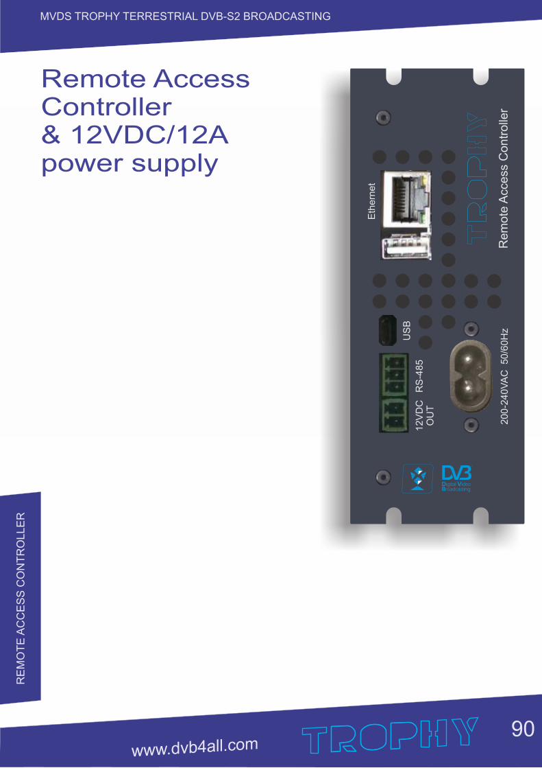
RE
MO
TE
AC
CE
SS
CO
NT
RO
LLE
R
MVDS TROPHY TERRESTRIAL DVB-S2 BROADCASTING
90
RS
-485
US
B
200-2
40
VA
C 50/6
0H
zR
em
ote
Acc
ess
Contr
olle
r
12V
DC
OU
T
Eth
ern
et
Remote AccessController& 12VDC/12A power supply
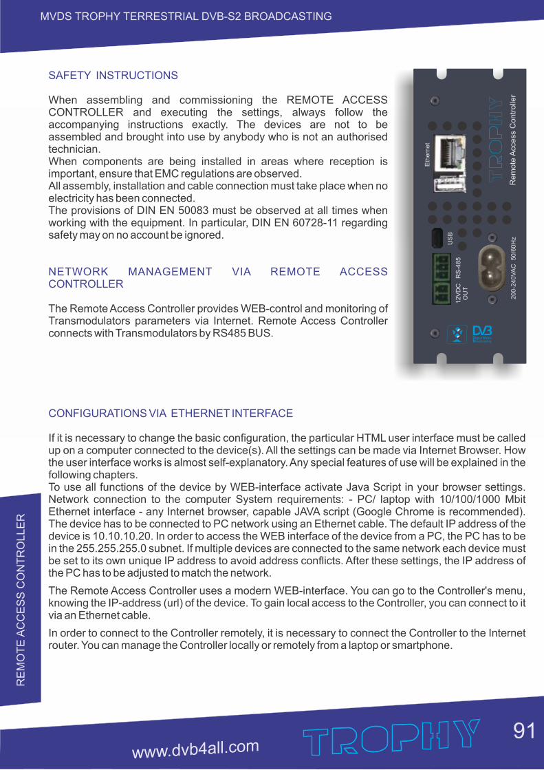
91
MVDS TROPHY TERRESTRIAL DVB-S2 BROADCASTING
SAFETY INSTRUCTIONS
When assembling and commissioning the REMOTE ACCESS CONTROLLER and executing the settings, always follow the accompanying instructions exactly. The devices are not to be assembled and brought into use by anybody who is not an authorised technician.When components are being installed in areas where reception is important, ensure that EMC regulations are observed.All assembly, installation and cable connection must take place when no electricity has been connected.The provisions of DIN EN 50083 must be observed at all times when working with the equipment. In particular, DIN EN 60728-11 regarding safety may on no account be ignored.
NETWORK MANAGEMENT VIA REMOTE ACCESS CONTROLLER
The Remote Access Controller provides WEB-control and monitoring of Transmodulators parameters via Internet. Remote Access Controller connects with Transmodulators by RS485 BUS.
RS
-485
US
B
200-2
40
VA
C 50/6
0H
zR
em
ote
Acc
ess
Contr
olle
r
12V
DC
OU
T
Eth
ern
et
CONFIGURATIONS VIA ETHERNET INTERFACE
If it is necessary to change the basic configuration, the particular HTML user interface must be called up on a computer connected to the device(s). All the settings can be made via Internet Browser. How the user interface works is almost self-explanatory. Any special features of use will be explained in the following chapters.To use all functions of the device by WEB-interface activate Java Script in your browser settings. Network connection to the computer System requirements: - PC/ laptop with 10/100/1000 Mbit Ethernet interface - any Internet browser, capable JAVA script (Google Chrome is recommended). The device has to be connected to PC network using an Ethernet cable. The default IP address of the device is 10.10.10.20. In order to access the WEB interface of the device from a PC, the PC has to be in the 255.255.255.0 subnet. If multiple devices are connected to the same network each device must be set to its own unique IP address to avoid address conflicts. After these settings, the IP address of the PC has to be adjusted to match the network.
The Remote Access Controller uses a modern WEB-interface. You can go to the Controller's menu, knowing the IP-address (url) of the device. To gain local access to the Controller, you can connect to it via an Ethernet cable.
In order to connect to the Controller remotely, it is necessary to connect the Controller to the Internet router. You can manage the Controller locally or remotely from a laptop or smartphone.
RE
MO
TE
AC
CE
SS
CO
NT
RO
LLE
R
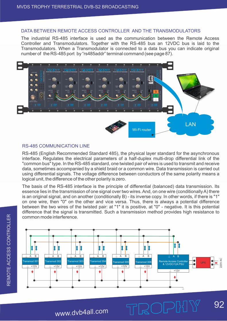
92
MVDS TROPHY TERRESTRIAL DVB-S2 BROADCASTING
RS-485 COMMUNICATION LINE
RS-485 (English Recommended Standard 485), the physical layer standard for the asynchronous interface. Regulates the electrical parameters of a half-duplex multi-drop differential link of the "common bus" type. In the RS-485 standard, one twisted pair of wires is used to transmit and receive data, sometimes accompanied by a shield braid or a common wire. Data transmission is carried out using differential signals. The voltage difference between conductors of the same polarity means a logical unit, the difference of the other polarity is zero.
The basis of the RS-485 interface is the principle of differential (balanced) data transmission. Its essence lies in the transmission of one signal over two wires. And, on one wire (conditionally A) there is an original signal, and on another (conditionally B) - its inverse copy. In other words, if there is "1" on one wire, then "0" on the other and vice versa. Thus, there is always a potential difference between the two wires of the twisted pair: at "1" it is positive, at "0" - negative. It is this potential difference that the signal is transmitted. Such a transmission method provides high resistance to common mode interference.
А В
+12V
Transmod 001
+12V
Remote Access Controller& 12VDC/12A PSU
UPS
А В
+12V
Transmod 002
А В
+12V
Transmod 003
А В
+12V
Transmod 005
А В
+12V
Transmod 004
А В
22
0V
AC
А В
+12V
Transmod 006
DATA BETWEEN REMOTE ACCESS CONTROLLER AND THE TRANSMODULATORS
The industrial RS-485 interface is used as the communication between the Remote Access Controller and Transmodulators. Together with the RS-485 bus an 12VDC bus is laid to the Transmodulators. When a Transmodulator is connected to a data bus you can indicate original number of the RS-485 port by terminal command (see page 87).“rs485addr”
Wi-Fi router
LAN
L-band inputs
L-band output10MHz ref. +24VDC
90
-26
4V
AC
5
0/6
0H
zL
-ba
nd
8-c
h c
om
bin
er
1 2
3 4
5 6
7 8
L-band output
ATD-54 S/S2 to S2 Transmodulator
L-band input
Loop
Input error
Fault
Lock
RS
-485
US
B
DC +
ATD-54 S/S2 to S2 Transmodulator
L-band output
ATD-54 S/S2 to S2 Transmodulator
L-band input
Loop
Input error
Fault
Lock
RS
-485
US
B
DC +
ATD-54 S/S2 to S2 Transmodulator
L-band output
ATD-54 S/S2 to S2 Transmodulator
L-band input
Loop
Input error
Fault
Lock
RS
-485
US
B
DC +
ATD-54 S/S2 to S2 Transmodulator
L-band output
ATD-54 S/S2 to S2 Transmodulator
L-band input
Loop
Input error
Fault
LockR
S-4
85
US
B
DC +
ATD-54 S/S2 to S2 Transmodulator
L-band output
ATD-54 S/S2 to S2 Transmodulator
L-band input
Loop
Input error
Fault
Lock
RS
-485
US
B
DC +
ATD-54 S/S2 to S2 Transmodulator
L-band output
ATD-54 S/S2 to S2 Transmodulator
L-band input
Loop
Input error
Fault
Lock
RS
-485
US
B
DC +
ATD-54 S/S2 to S2 Transmodulator
RS
-485
US
B
200-2
40
VA
C 50/6
0H
zR
em
ote
Acc
ess
Contr
olle
r
12V
DC
OU
T
Eth
ern
et
B
A
RE
MO
TE
AC
CE
SS
CO
NT
RO
LLE
R
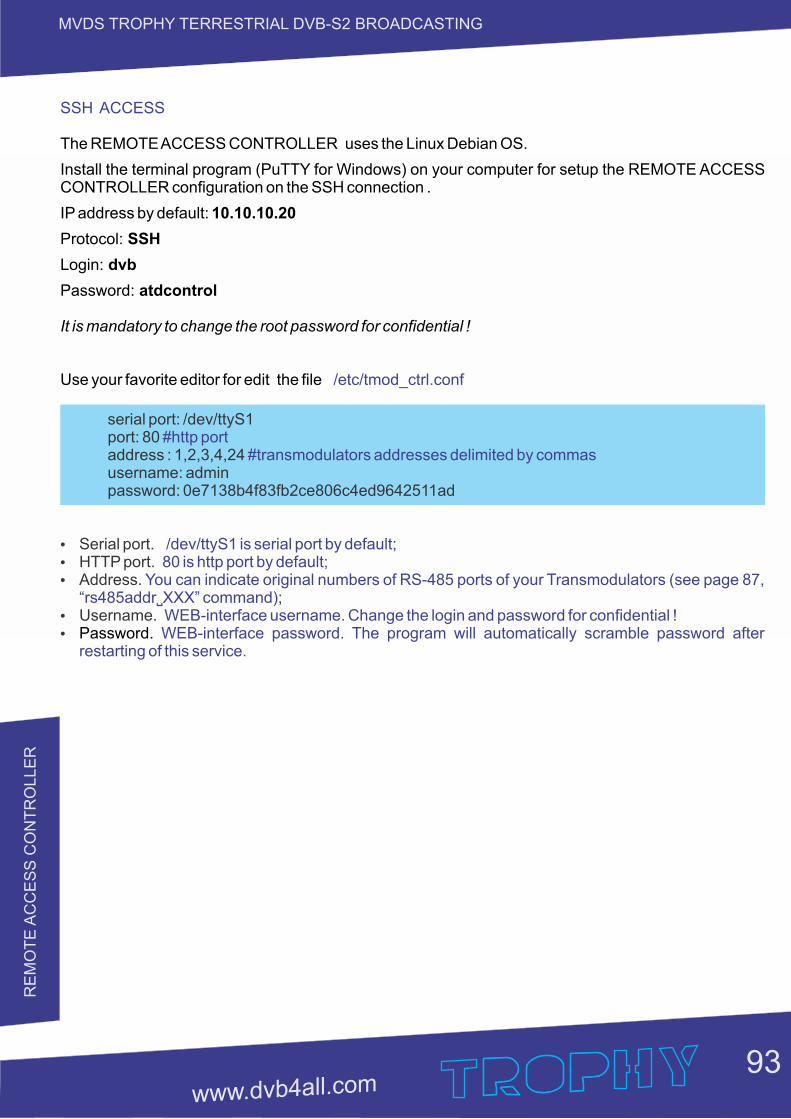
93
MVDS TROPHY TERRESTRIAL DVB-S2 BROADCASTINGR
EM
OT
E A
CC
ES
S C
ON
TR
OLLE
R
SSH ACCESS
The REMOTE ACCESS CONTROLLER uses the Linux Debian OS.
Install the terminal program (PuTTY for Windows) on your computer for setup the REMOTE ACCESS CONTROLLER configuration on the SSH connection .
IP address by default: 10.10.10.20
Protocol: SSH
Login: dvb
Password: atdcontrol
It is mandatory to change the root password for confidential !
Use your favorite editor for edit the file /etc/tmod_ctrl.conf
serial port: /dev/ttyS1 port: 80 #http port address : 1,2,3,4,24 #transmodulators addresses delimited by commas username: admin password: 0e7138b4f83fb2ce806c4ed9642511ad
Ÿ Serial port. /dev/ttyS1 is serial port by default;Ÿ HTTP port. 80 is http port by default;Ÿ Address. You can indicate original numbers of RS-485 ports of your Transmodulators (see page 87,
“rs485addr˽XXX” command);Ÿ Username. WEB-interface username. Change the login and password for confidential !Ÿ Password. WEB-interface password. The program will automatically scramble password after
restarting of this service.
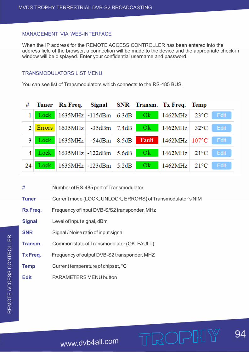
94
MVDS TROPHY TERRESTRIAL DVB-S2 BROADCASTINGR
EM
OT
E A
CC
ES
S C
ON
TR
OLLE
R
MANAGEMENT VIA WEB-INTERFACE
When the IP address for the REMOTE ACCESS CONTROLLER has been entered into the address field of the browser, a connection will be made to the device and the appropriate check-in window will be displayed. Enter your confidential username and password.
TRANSMODULATORS LIST MENU
You can see list of Transmodulators which connects to the RS-485 BUS.
# Number of RS-485 port of Transmodulator
Tuner Current mode (LOCK, UNLOCK, ERRORS) of Transmodulator’s NIM
Rx Freq. Frequency of input DVB-S/S2 transponder, MHz
Signal Level of input signal, dBm
SNR Signal / Noise ratio of input signal
Transm. Common state of Transmodulator (OK, FAULT)
Tx Freq. Frequency of output DVB-S2 transponder, MHZ
Temp Current temperature of chipset, °C
Edit PARAMETERS MENU button
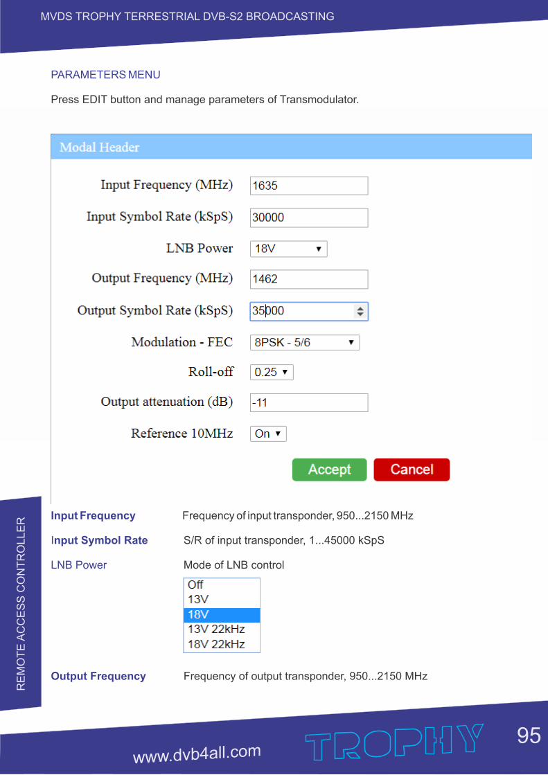
95
MVDS TROPHY TERRESTRIAL DVB-S2 BROADCASTINGR
EM
OT
E A
CC
ES
S C
ON
TR
OLLE
R
PARAMETERS MENU
Press EDIT button and manage parameters of Transmodulator.
Input Frequency Frequency of input transponder, 950...2150 MHz
Input Symbol Rate S/R of input transponder, 1...45000 kSpS
LNB Power Mode of LNB control
Output Frequency Frequency of output transponder, 950...2150 MHz
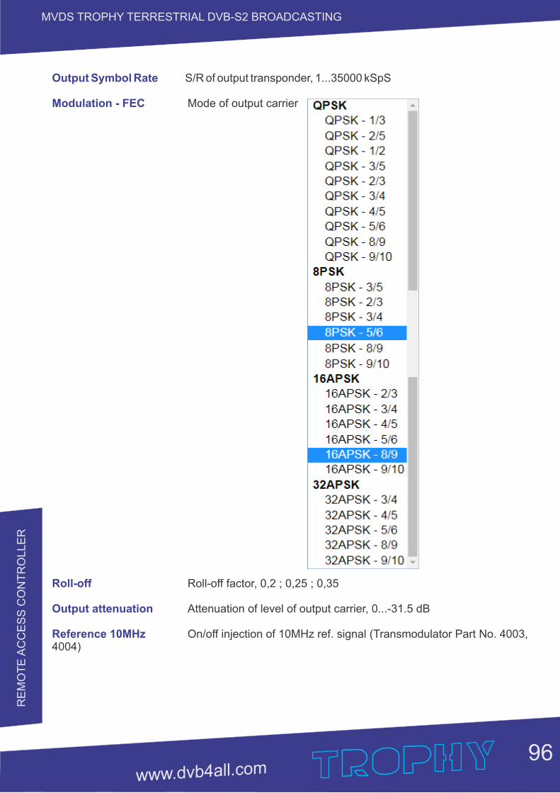
96
MVDS TROPHY TERRESTRIAL DVB-S2 BROADCASTINGR
EM
OT
E A
CC
ES
S C
ON
TR
OLLE
R
Output Symbol Rate S/R of output transponder, 1...35000 kSpS
Modulation - FEC Mode of output carrier
Roll-off Roll-off factor, 0,2 ; 0,25 ; 0,35
Output attenuation Attenuation of level of output carrier, 0...-31.5 dB
Reference 10MHz On/off injection of 10MHz ref. signal (Transmodulator Part No. 4003, 4004)
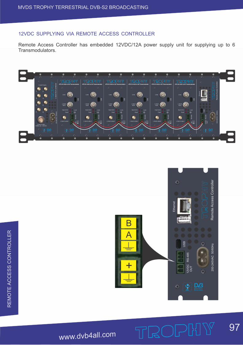
97
MVDS TROPHY TERRESTRIAL DVB-S2 BROADCASTINGR
EM
OT
E A
CC
ES
S C
ON
TR
OLLE
R
12VDC SUPPLYING VIA REMOTE ACCESS CONTROLLER
Remote Access Controller has embedded 12VDC/12A power supply unit for supplying up to 6 Transmodulators.
L-band inputs
L-band output10MHz ref. +24VDC
90-2
64V
AC
50/6
0H
zL-b
and 8
-ch c
om
bin
er
1 2
3 4
5 6
7 8
L-band output
ATD-54 S/S2 to S2 Transmodulator
L-band input
Loop
Input error
Fault
Lock
RS
-48
5
US
B
DC +
ATD-54 S/S2 to S2 Transmodulator
L-band output
ATD-54 S/S2 to S2 Transmodulator
L-band input
Loop
Input error
Fault
Lock
RS
-48
5
US
B
DC +
ATD-54 S/S2 to S2 Transmodulator
L-band output
ATD-54 S/S2 to S2 Transmodulator
L-band input
Loop
Input error
Fault
Lock
RS
-48
5
US
B
DC +
ATD-54 S/S2 to S2 Transmodulator
L-band output
ATD-54 S/S2 to S2 Transmodulator
L-band input
Loop
Input error
Fault
Lock
RS
-48
5
US
B
DC +
ATD-54 S/S2 to S2 Transmodulator
L-band output
ATD-54 S/S2 to S2 Transmodulator
L-band input
Loop
Input error
Fault
Lock
RS
-48
5
US
B
DC +
ATD-54 S/S2 to S2 Transmodulator
L-band output
ATD-54 S/S2 to S2 Transmodulator
L-band input
Loop
Input error
Fault
Lock
RS
-48
5
US
B
DC +
ATD-54 S/S2 to S2 Transmodulator
RS
-48
5
US
B
20
0-2
40
VA
C
50
/60
Hz
Re
mo
te A
cce
ss C
on
tro
ller
12
VD
CO
UT
Eth
ern
et
RS
-485
US
B
200-2
40
VA
C 50/6
0H
zR
em
ote
Acc
ess
Contr
olle
r
12V
DC
OU
T
Eth
ern
et
+
B
A
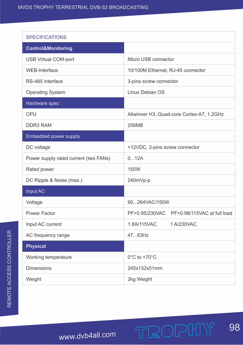
98
MVDS TROPHY TERRESTRIAL DVB-S2 BROADCASTINGR
EM
OT
E A
CC
ES
S C
ON
TR
OLLE
R
SPECIFICATIONS
Control&Monitoring
USB Virtual COM-port
WEB-Interface
RS-485 interface
Operating System
Hardware spec
CPU
DDR3 RAM
Embedded power supply
DC voltage
Power supply rated current (two FANs)
Rated power
DC Ripple & Noise (max.)
Input AC
Voltage
Power Factor
Input AC current
AC frequency range
Physical
Working temperature
Dimensions
Weight
Micro USB connector
10/100M Ethernet, RJ-45 connector
3-pins screw connector
Linux Debian OS
Allwinner H3, Quad-core Cortex-A7, 1.2GHz
256MB
+12VDC, 2-pins screw connector
0...12A
150W
240mVp-p
90...264VAC/150W
PF>0.95/230VAC PF>0.98/115VAC at full load
1.8A/115VAC 1 A/230VAC
47...63Hz
0°C to +70°C
245x132x51mm
2kg Weight
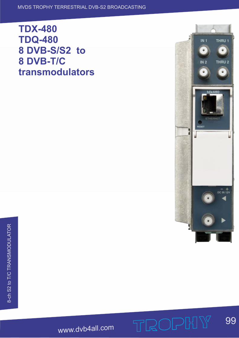
8-c
h S
2 to T
/C T
RA
NS
MO
DU
LA
TO
R
99
MVDS TROPHY TERRESTRIAL DVB-S2 BROADCASTING
TDX-480 TDQ-4808 DVB-S/S2 to 8 DVB-T/C transmodulators
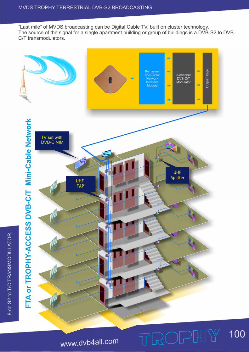
8-c
h S
2 to T
/C T
RA
NS
MO
DU
LA
TO
R
100
MVDS TROPHY TERRESTRIAL DVB-S2 BROADCASTING
“Last mile” of MVDS broadcasting can be Digital Cable TV, built on cluster technology. The source of the signal for a single apartment building or group of buildings is a DVB-S2 to DVB-C/T transmodulators.
TV set withDVB-C NIM
FTA
or
TR
OP
HY
-AC
CE
SS
DV
B-C
/T M
ini-
Cab
le N
etw
ork
8-channelDVB-C/TModulator
8-channelDVB-S/S2 Network Interface Module O
utp
ut
Sta
ge
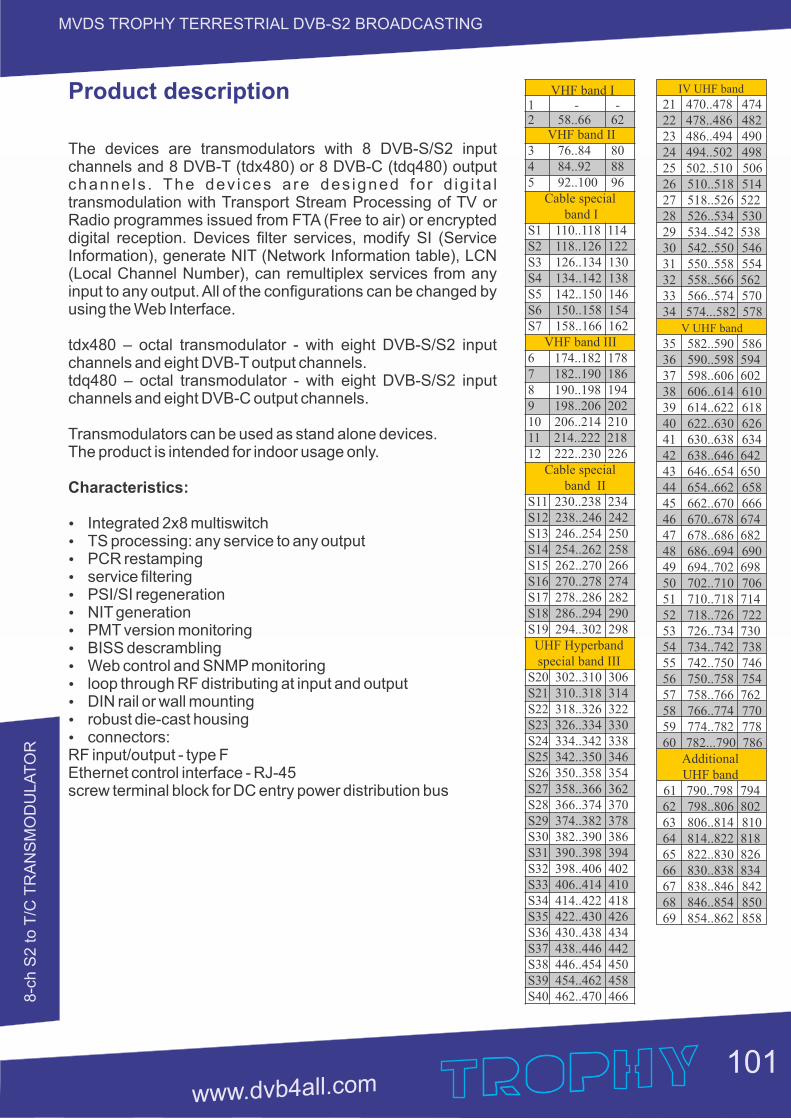
8-c
h S
2 to T
/C T
RA
NS
MO
DU
LA
TO
R
MVDS TROPHY TERRESTRIAL DVB-S2 BROADCASTING
Product description
The devices are transmodulators with 8 DVB-S/S2 input channels and 8 DVB-T (tdx480) or 8 DVB-C (tdq480) output channe ls . The dev ices a re des igned fo r d ig i ta l transmodulation with Transport Stream Processing of TV or Radio programmes issued from FTA (Free to air) or encrypted digital reception. Devices filter services, modify SI (Service Information), generate NIT (Network Information table), LCN (Local Channel Number), can remultiplex services from any input to any output. All of the configurations can be changed by using the Web Interface. tdx480 – octal transmodulator - with eight DVB-S/S2 input channels and eight DVB-T output channels. tdq480 – octal transmodulator - with eight DVB-S/S2 input channels and eight DVB-C output channels. Transmodulators can be used as stand alone devices. The product is intended for indoor usage only.
Characteristics:
Ÿ Integrated 2x8 multiswitch Ÿ TS processing: any service to any output Ÿ PCR restamping Ÿ service filtering Ÿ PSI/SI regeneration Ÿ NIT generation Ÿ PMT version monitoringŸ BISS descramblingŸ Web control and SNMP monitoringŸ loop through RF distributing at input and outputŸ DIN rail or wall mountingŸ robust die-cast housingŸ connectors: RF input/output - type F Ethernet control interface - RJ-45 screw terminal block for DC entry power distribution bus
VHF band I1 - -2 58..66 62 VHF band II3 76..84 804 84..92 885 92..100 96 Cable special band IS1 110..118 114S2 118..126 122S3 126..134 130S4 134..142 138S5 142..150 146S6 150..158 154S7 158..166 162 VHF band III6 174..182 1787 182..190 1868 190..198 1949 198..206 20210 206..214 21011 214..222 21812 222..230 226 Cable special band IIS11 230..238 234S12 238..246 242S13 246..254 250S14 254..262 258S15 262..270 266S16 270..278 274S17 278..286 282S18 286..294 290S19 294..302 298 UHF Hyperband special band IIIS20 302..310 306S21 310..318 314S22 318..326 322S23 326..334 330S24 334..342 338S25 342..350 346S26 350..358 354S27 358..366 362S28 366..374 370S29 374..382 378S30 382..390 386S31 390..398 394S32 398..406 402S33 406..414 410S34 414..422 418S35 422..430 426S36 430..438 434S37 438..446 442 S38 446..454 450 S39 454..462 458 S40 462..470 466
IV UHF band
21 470..478 474 22 478..486 482 23 486..494 490 24 494..502 498 25 502..510 506 26 510..518 514 27 518..526 522 28 526..534 530 29 534..542 538 30 542..550 546 31 550..558 554 32 558..566 562 33 566..574 570 34 574...582 578 V UHF band
35 582..590 586 36 590..598 594 37 598..606 602 38 606..614 610 39 614..622 618 40 622..630 626 41 630..638 634 42 638..646 642 43 646..654 650 44 654..662 658 45 662..670 666 46 670..678 674 47 678..686 682 48 686..694 690 49 694..702 698 50 702..710 706 51 710..718 714 52 718..726 722 53 726..734 730 54 734..742 738 55 742..750 746 56 750..758 754 57 758..766 762 58 766..774 770 59 774..782 778 60 782...790 786 Additional UHF band 61 790..798 794 62 798..806 802 63 806..814 810 64 814..822 818 65 822..830 826 66 830..838 834 67 838..846 842 68 846..854 850 69 854..862 858
101
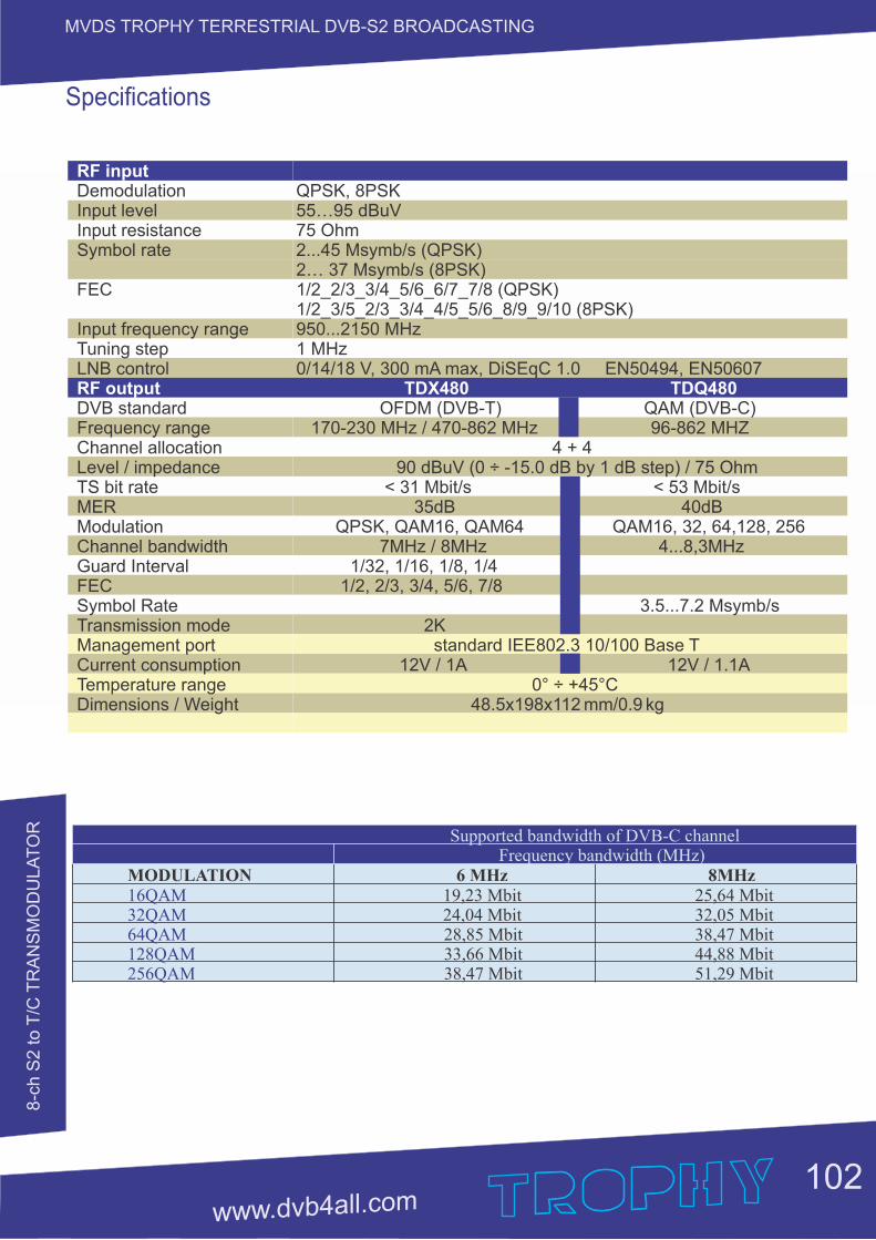
8-c
h S
2 to T
/C T
RA
NS
MO
DU
LA
TO
R
MVDS TROPHY TERRESTRIAL DVB-S2 BROADCASTING
RF inputDemodulationInput levelInput resistanceSymbol rate
FEC
Input frequency rangeTuning stepLNB controlRF outputDVB standardFrequency rangeChannel allocationLevel / impedanceTS bit rateMERModulationChannel bandwidthGuard IntervalFECSymbol RateTransmission modeManagement portCurrent consumptionTemperature rangeDimensions / Weight
QPSK, 8PSK55…95 dBuV75 Ohm2...45 Мsymb/s (QPSK)2… 37 Msymb/s (8PSK)1/2_2/3_3/4_5/6_6/7_7/8 (QPSK)1/2_3/5_2/3_3/4_4/5_5/6_8/9_9/10 (8PSK)950...2150 MHz1 MHz0/14/18 V, 300 mA max, DiSEqC 1.0 EN50494, EN50607 TDX480 TDQ480 OFDM (DVB-T) QAM (DVB-C) 170-230 MHz / 470-862 MHz 96-862 MHZ
4 + 4 90 dBuV (0 ÷ -15.0 dB by 1 dB step) / 75 Ohm
< 31 Mbit/s < 53 Mbit/s 35dB 40dB QPSK, QAM16, QAM64 QAM16, 32, 64,128, 256 7MHz / 8MHz 4...8,3MHz 1/32, 1/16, 1/8, 1/4 1/2, 2/3, 3/4, 5/6, 7/8 3.5...7.2 Msymb/s 2K standard IEE802.3 10/100 Base T 12V / 1A 12V / 1.1A 0° ÷ +45°C 48.5x198x112 mm/0.9 kg
Specifications
Supported bandwidth of DVB-C channel Frequency bandwidth (MHz)MODULATION 6 MHz 8MHz 16QAM 19,23 Mbit 25,64 Mbit32QAM 24,04 Mbit 32,05 Mbit64QAM 28,85 Mbit 38,47 Mbit128QAM 33,66 Mbit 44,88 Mbit256QAM 38,47 51,29 Mbit Mbit
102
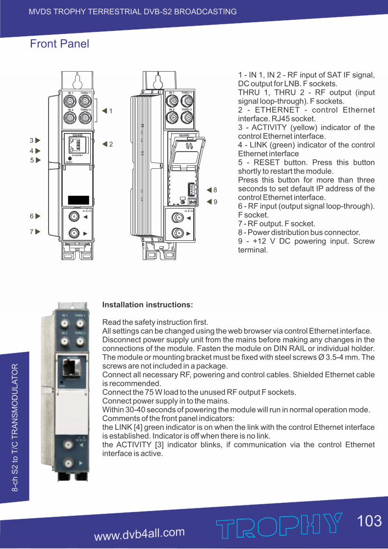
8-c
h S
2 to T
/C T
RA
NS
MO
DU
LA
TO
R
MVDS TROPHY TERRESTRIAL DVB-S2 BROADCASTING
1 - IN 1, IN 2 - RF input of SAT IF signal, DC output for LNB. F sockets. THRU 1, THRU 2 - RF output (input signal loop-through). F sockets. 2 - ETHERNET - control Ethernet interface. RJ45 socket.3 - ACTIVITY (yellow) indicator of the control Ethernet interface.4 - LINK (green) indicator of the control Ethernet interface5 - RESET button. Press this button shortly to restart the module. Press this button for more than three seconds to set default IP address of the control Ethernet interface.6 - RF input (output signal loop-through). F socket.7 - RF output. F socket.8 - Power distribution bus connector.9 - +12 V DC powering input. Screw terminal.
Installation instructions:
Read the safety instruction first. All settings can be changed using the web browser via control Ethernet interface. Disconnect power supply unit from the mains before making any changes in the connections of the module. Fasten the module on DIN RAIL or individual holder. The module or mounting bracket must be fixed with steel screws Ø 3.5-4 mm. The screws are not included in a package.Connect all necessary RF, powering and control cables. Shielded Ethernet cable is recommended.Connect the 75 W load to the unused RF output F sockets. Connect power supply in to the mains. Within 30-40 seconds of powering the module will run in normal operation mode. Comments of the front panel indicators: the LINK [4] green indicator is on when the link with the control Ethernet interface is established. Indicator is off when there is no link.the ACTIVITY [3] indicator blinks, if communication via the control Ethernet interface is active.
3
5
6
7
1
24
8
9
Front Panel
103
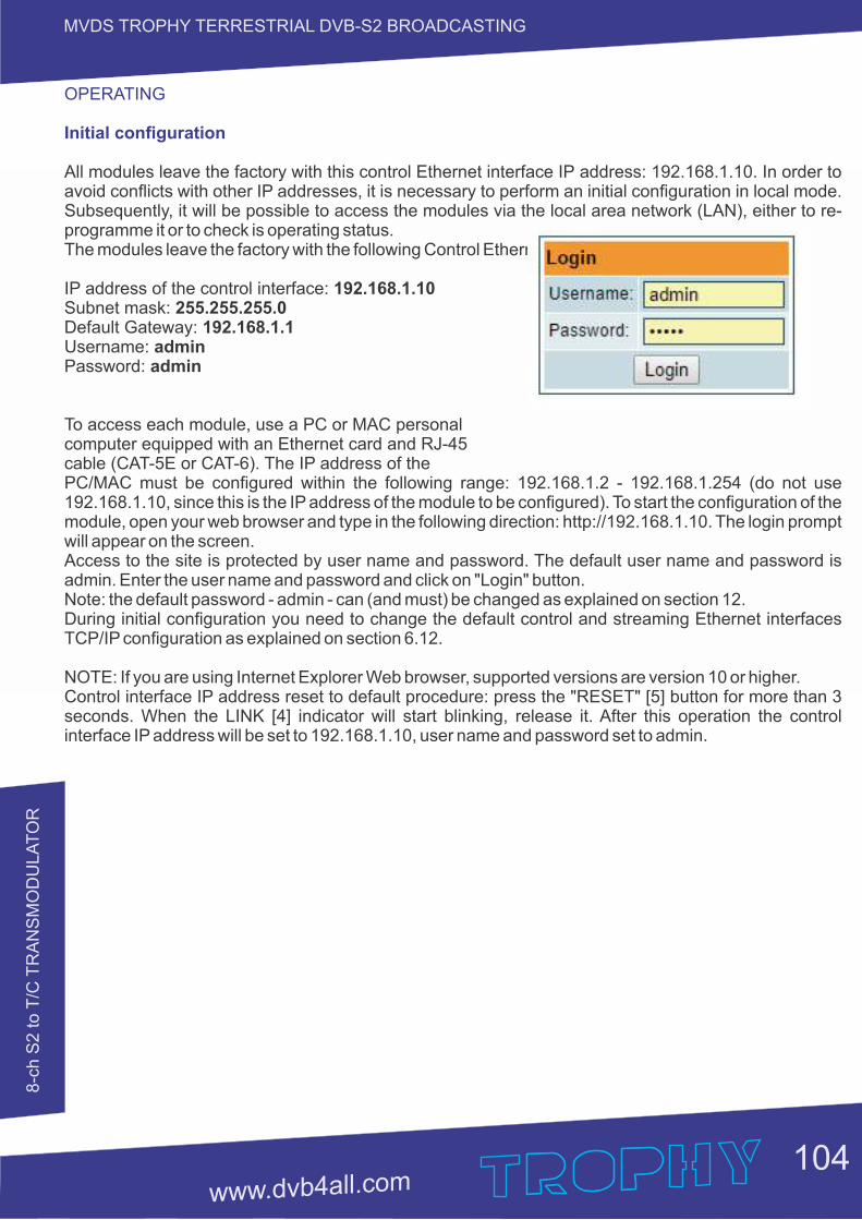
8-c
h S
2 to T
/C T
RA
NS
MO
DU
LA
TO
R
104
MVDS TROPHY TERRESTRIAL DVB-S2 BROADCASTING
OPERATING
Initial configuration
All modules leave the factory with this control Ethernet interface IP address: 192.168.1.10. In order to avoid conflicts with other IP addresses, it is necessary to perform an initial configuration in local mode. Subsequently, it will be possible to access the modules via the local area network (LAN), either to re-programme it or to check is operating status.The modules leave the factory with the following Control Ethernet interface TCP/IP configuration: IP address of the control interface: 192.168.1.10Subnet mask: 255.255.255.0Default Gateway: 192.168.1.1Username: adminPassword: admin
To access each module, use a PC or MAC personal computer equipped with an Ethernet card and RJ-45 cable (CAT-5E or CAT-6). The IP address of the PC/MAC must be configured within the following range: 192.168.1.2 - 192.168.1.254 (do not use 192.168.1.10, since this is the IP address of the module to be configured). To start the configuration of the module, open your web browser and type in the following direction: http://192.168.1.10. The login prompt will appear on the screen.Access to the site is protected by user name and password. The default user name and password is admin. Enter the user name and password and click on "Login" button.Note: the default password - admin - can (and must) be changed as explained on section 12.During initial configuration you need to change the default control and streaming Ethernet interfaces TCP/IP configuration as explained on section 6.12.
NOTE: If you are using Internet Explorer Web browser, supported versions are version 10 or higher.Control interface IP address reset to default procedure: press the "RESET" [5] button for more than 3 seconds. When the LINK [4] indicator will start blinking, release it. After this operation the control interface IP address will be set to 192.168.1.10, user name and password set to admin.
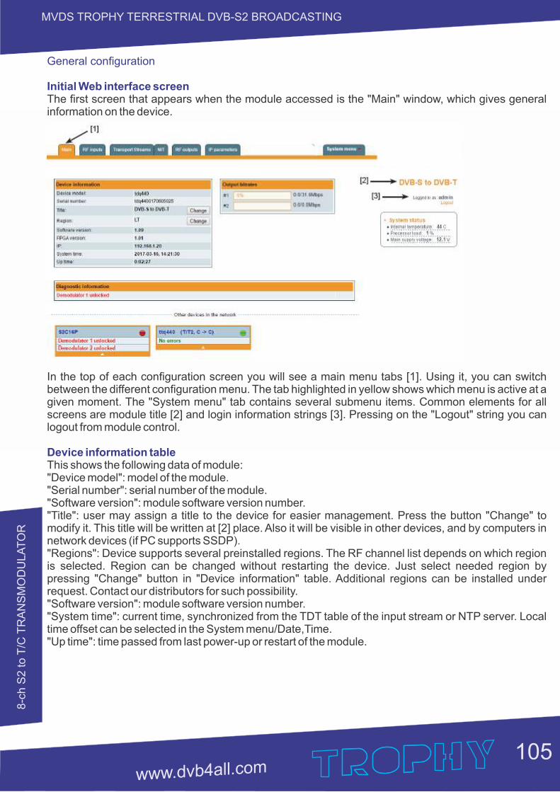
8-c
h S
2 to T
/C T
RA
NS
MO
DU
LA
TO
R
MVDS TROPHY TERRESTRIAL DVB-S2 BROADCASTING
General configuration
Initial Web interface screenThe first screen that appears when the module accessed is the "Main" window, which gives general information on the device.
In the top of each configuration screen you will see a main menu tabs [1]. Using it, you can switch between the different configuration menu. The tab highlighted in yellow shows which menu is active at a given moment. The "System menu" tab contains several submenu items. Common elements for all screens are module title [2] and login information strings [3]. Pressing on the "Logout" string you can logout from module control.
Device information tableThis shows the following data of module:"Device model": model of the module."Serial number": serial number of the module."Software version": module software version number. "Title": user may assign a title to the device for easier management. Press the button "Change" to modify it. This title will be written at [2] place. Also it will be visible in other devices, and by computers in network devices (if PC supports SSDP)."Regions": Device supports several preinstalled regions. The RF channel list depends on which region is selected. Region can be changed without restarting the device. Just select needed region by pressing "Change" button in "Device information" table. Additional regions can be installed under request. Contact our distributors for such possibility."Software version": module software version number. "System time": current time, synchronized from the TDT table of the input stream or NTP server. Local time offset can be selected in the System menu/Date,Time. "Up time": time passed from last power-up or restart of the module.
105
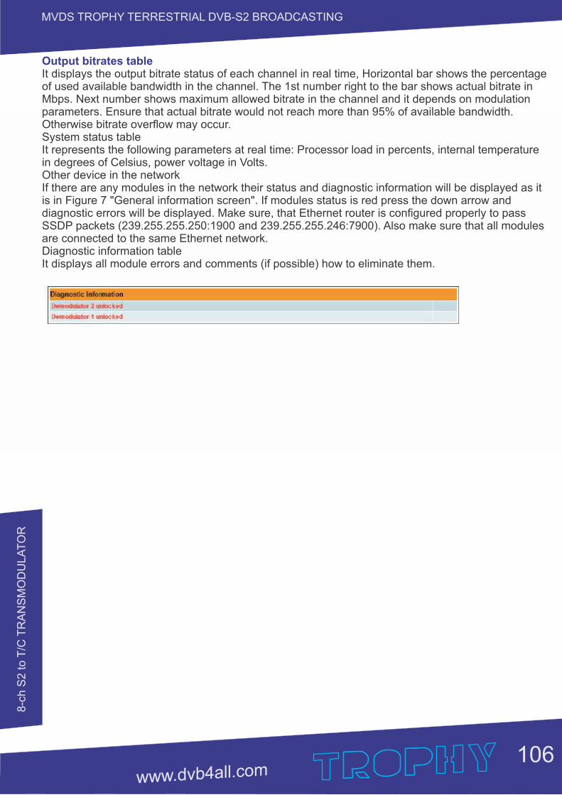
8-c
h S
2 to T
/C T
RA
NS
MO
DU
LA
TO
R
MVDS TROPHY TERRESTRIAL DVB-S2 BROADCASTING
Output bitrates table It displays the output bitrate status of each channel in real time, Horizontal bar shows the percentage of used available bandwidth in the channel. The 1st number right to the bar shows actual bitrate in Mbps. Next number shows maximum allowed bitrate in the channel and it depends on modulation parameters. Ensure that actual bitrate would not reach more than 95% of available bandwidth. Otherwise bitrate overflow may occur.System status table It represents the following parameters at real time: Processor load in percents, internal temperature in degrees of Celsius, power voltage in Volts.Other device in the network If there are any modules in the network their status and diagnostic information will be displayed as it is in Figure 7 "General information screen". If modules status is red press the down arrow and diagnostic errors will be displayed. Make sure, that Ethernet router is configured properly to pass SSDP packets (239.255.255.250:1900 and 239.255.255.246:7900). Also make sure that all modules are connected to the same Ethernet network.Diagnostic information tableIt displays all module errors and comments (if possible) how to eliminate them.
106
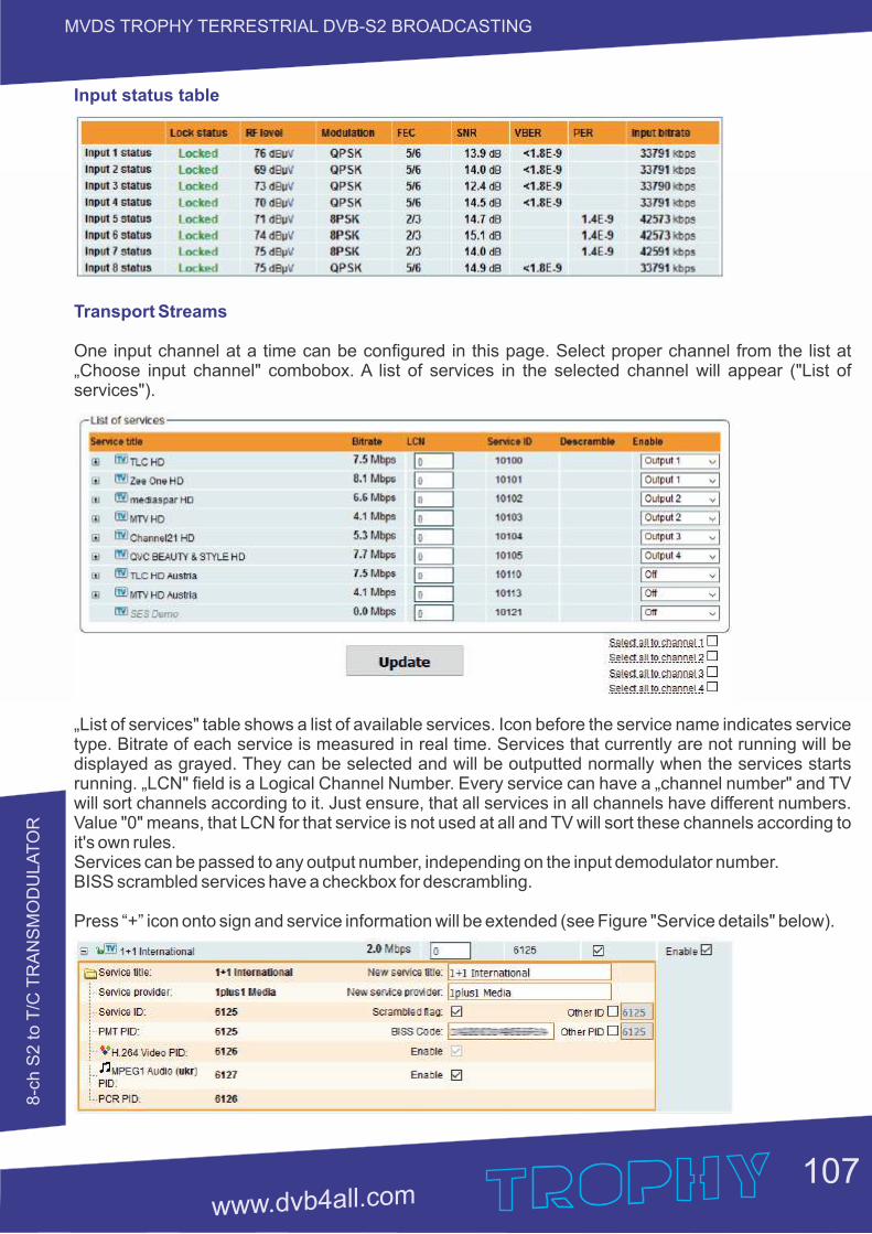
8-c
h S
2 to T
/C T
RA
NS
MO
DU
LA
TO
R
MVDS TROPHY TERRESTRIAL DVB-S2 BROADCASTING
Input status table
Transport Streams
One input channel at a time can be configured in this page. Select proper channel from the list at „Choose input channel" combobox. A list of services in the selected channel will appear ("List of services").
„List of services" table shows a list of available services. Icon before the service name indicates service type. Bitrate of each service is measured in real time. Services that currently are not running will be displayed as grayed. They can be selected and will be outputted normally when the services starts running. „LCN" field is a Logical Channel Number. Every service can have a „channel number" and TV will sort channels according to it. Just ensure, that all services in all channels have different numbers. Value "0" means, that LCN for that service is not used at all and TV will sort these channels according to it's own rules. Services can be passed to any output number, independing on the input demodulator number. BISS scrambled services have a checkbox for descrambling.
Press “+” icon onto sign and service information will be extended (see Figure "Service details" below).
107
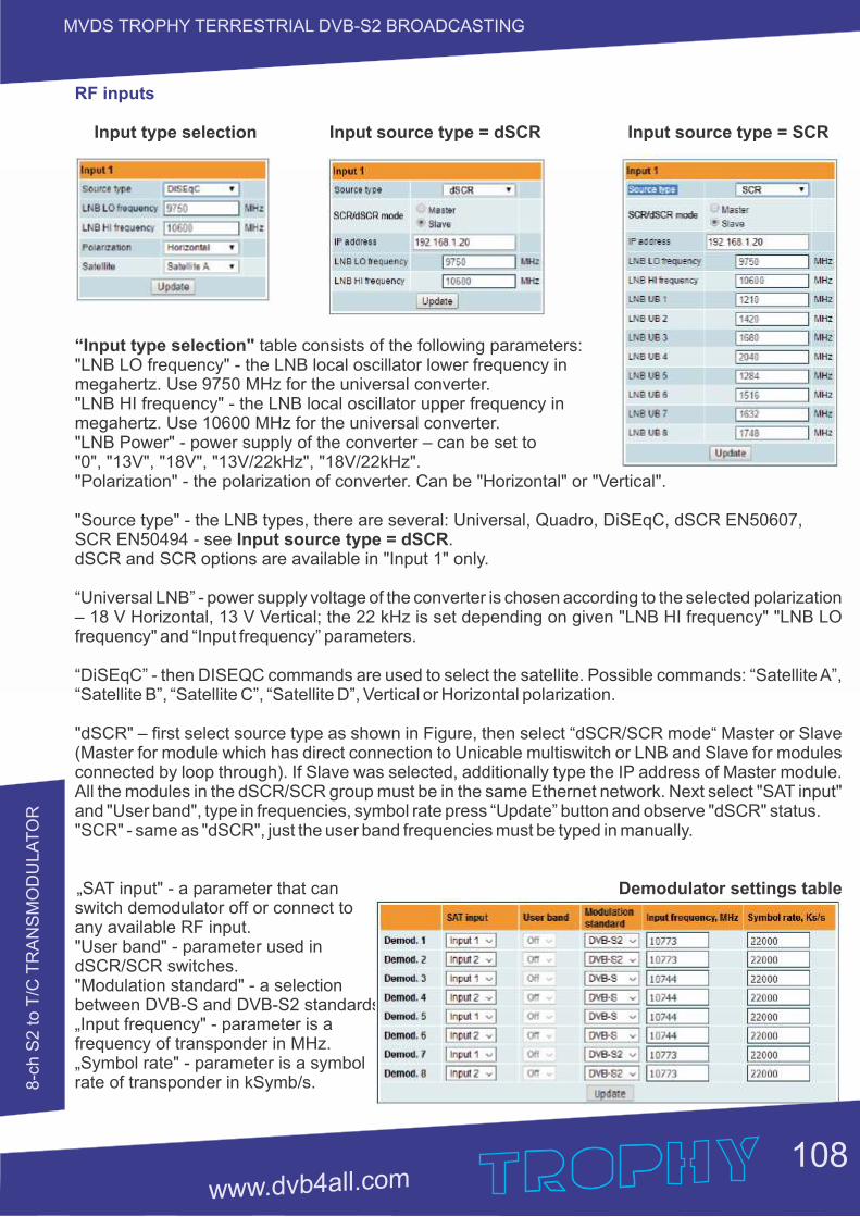
8-c
h S
2 to T
/C T
RA
NS
MO
DU
LA
TO
R
MVDS TROPHY TERRESTRIAL DVB-S2 BROADCASTING
RF inputs
Input type selection Input source type = dSCR Input source type = SCR
“Input type selection" table consists of the following parameters: "LNB LO frequency" - the LNB local oscillator lower frequency in megahertz. Use 9750 MHz for the universal converter. "LNB HI frequency" - the LNB local oscillator upper frequency in megahertz. Use 10600 MHz for the universal converter. "LNB Power" - power supply of the converter – can be set to "0", "13V", "18V", "13V/22kHz", "18V/22kHz". "Polarization" - the polarization of converter. Can be "Horizontal" or "Vertical".
"Source type" - the LNB types, there are several: Universal, Quadro, DiSEqC, dSCR EN50607, SCR EN50494 - see Input source type = dSCR. dSCR and SCR options are available in "Input 1" only.
“Universal LNB” - power supply voltage of the converter is chosen according to the selected polarization – 18 V Horizontal, 13 V Vertical; the 22 kHz is set depending on given "LNB HI frequency" "LNB LO frequency" and “Input frequency” parameters.
“DiSEqC” - then DISEQC commands are used to select the satellite. Possible commands: “Satellite A”, “Satellite B”, “Satellite C”, “Satellite D”, Vertical or Horizontal polarization.
"dSCR" – first select source type as shown in Figure, then select “dSCR/SCR mode“ Master or Slave (Master for module which has direct connection to Unicable multiswitch or LNB and Slave for modules connected by loop through). If Slave was selected, additionally type the IP address of Master module. All the modules in the dSCR/SCR group must be in the same Ethernet network. Next select "SAT input" and "User band", type in frequencies, symbol rate press “Update” button and observe "dSCR" status."SCR" - same as "dSCR", just the user band frequencies must be typed in manually.
„SAT input" - a parameter that can Demodulator settings table switch demodulator off or connect to any available RF input. "User band" - parameter used in dSCR/SCR switches. "Modulation standard" - a selection between DVB-S and DVB-S2 standards.„Input frequency" - parameter is a frequency of transponder in MHz. „Symbol rate" - parameter is a symbol rate of transponder in kSymb/s.
108
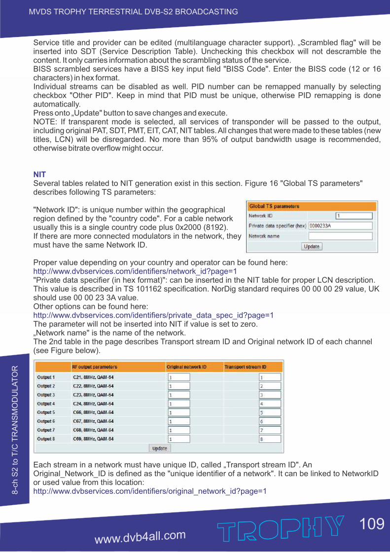
8-c
h S
2 to T
/C T
RA
NS
MO
DU
LA
TO
R
MVDS TROPHY TERRESTRIAL DVB-S2 BROADCASTING
Service title and provider can be edited (multilanguage character support). „Scrambled flag" will be inserted into SDT (Service Description Table). Unchecking this checkbox will not descramble the content. It only carries information about the scrambling status of the service. BISS scrambled services have a BISS key input field "BISS Code". Enter the BISS code (12 or 16 characters) in hex format.Individual streams can be disabled as well. PID number can be remapped manually by selecting checkbox "Other PID". Keep in mind that PID must be unique, otherwise PID remapping is done automatically. Press onto „Update" button to save changes and execute.NOTE: If transparent mode is selected, all services of transponder will be passed to the output, including original PAT, SDT, PMT, EIT, CAT, NIT tables. All changes that were made to these tables (new titles, LCN) will be disregarded. No more than 95% of output bandwidth usage is recommended, otherwise bitrate overflow might occur.
NITSeveral tables related to NIT generation exist in this section. Figure 16 "Global TS parameters" describes following TS parameters:
"Network ID": is unique number within the geographical region defined by the "country code". For a cable network usually this is a single country code plus 0x2000 (8192). If there are more connected modulators in the network, they must have the same Network ID.
Proper value depending on your country and operator can be found here:http://www.dvbservices.com/identifiers/network_id?page=1"Private data specifier (in hex format)": can be inserted in the NIT table for proper LCN description. This value is described in TS 101162 specification. NorDig standard requires 00 00 00 29 value, UK should use 00 00 23 3A value.Other options can be found here:http://www.dvbservices.com/identifiers/private_data_spec_id?page=1The parameter will not be inserted into NIT if value is set to zero.„Network name" is the name of the network.The 2nd table in the page describes Transport stream ID and Original network ID of each channel (see Figure below).
Each stream in a network must have unique ID, called „Transport stream ID". An Original_Network_ID is defined as the "unique identifier of a network". It can be linked to NetworkID or used value from this location: http://www.dvbservices.com/identifiers/original_network_id?page=1
109
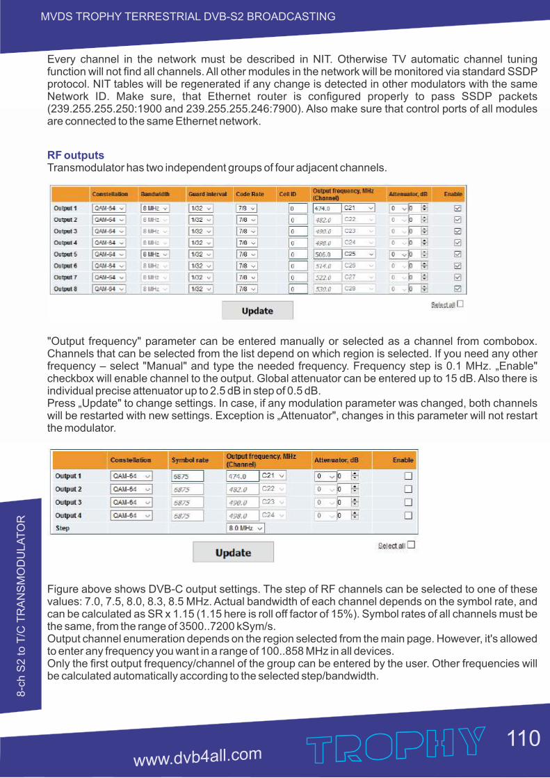
8-c
h S
2 to T
/C T
RA
NS
MO
DU
LA
TO
R
MVDS TROPHY TERRESTRIAL DVB-S2 BROADCASTING
Every channel in the network must be described in NIT. Otherwise TV automatic channel tuning function will not find all channels. All other modules in the network will be monitored via standard SSDP protocol. NIT tables will be regenerated if any change is detected in other modulators with the same Network ID. Make sure, that Ethernet router is configured properly to pass SSDP packets (239.255.255.250:1900 and 239.255.255.246:7900). Also make sure that control ports of all modules are connected to the same Ethernet network.
RF outputsTransmodulator has two independent groups of four adjacent channels.
"Output frequency" parameter can be entered manually or selected as a channel from combobox. Channels that can be selected from the list depend on which region is selected. If you need any other frequency – select "Manual" and type the needed frequency. Frequency step is 0.1 MHz. „Enable" checkbox will enable channel to the output. Global attenuator can be entered up to 15 dB. Also there is individual precise attenuator up to 2.5 dB in step of 0.5 dB.Press „Update" to change settings. In case, if any modulation parameter was changed, both channels will be restarted with new settings. Exception is „Attenuator", changes in this parameter will not restart the modulator.
Figure above shows DVB-C output settings. The step of RF channels can be selected to one of these values: 7.0, 7.5, 8.0, 8.3, 8.5 MHz. Actual bandwidth of each channel depends on the symbol rate, and can be calculated as SR x 1.15 (1.15 here is roll off factor of 15%). Symbol rates of all channels must be the same, from the range of 3500..7200 kSym/s.Output channel enumeration depends on the region selected from the main page. However, it's allowed to enter any frequency you want in a range of 100..858 MHz in all devices. Only the first output frequency/channel of the group can be entered by the user. Other frequencies will be calculated automatically according to the selected step/bandwidth.
110
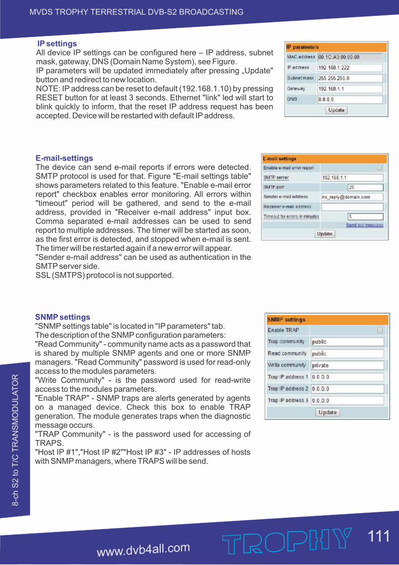
8-c
h S
2 to T
/C T
RA
NS
MO
DU
LA
TO
R
MVDS TROPHY TERRESTRIAL DVB-S2 BROADCASTING
IP settingsAll device IP settings can be configured here – IP address, subnet mask, gateway, DNS (Domain Name System), see Figure.IP parameters will be updated immediately after pressing „Update" button and redirect to new location. NOTE: IP address can be reset to default (192.168.1.10) by pressing RESET button for at least 3 seconds. Ethernet "link" led will start to blink quickly to inform, that the reset IP address request has been accepted. Device will be restarted with default IP address.
E-mail-settingsThe device can send e-mail reports if errors were detected. SMTP protocol is used for that. Figure "E-mail settings table" shows parameters related to this feature. "Enable e-mail error report" checkbox enables error monitoring. All errors within "timeout" period will be gathered, and send to the e-mail address, provided in "Receiver e-mail address" input box. Comma separated e-mail addresses can be used to send report to multiple addresses. The timer will be started as soon, as the first error is detected, and stopped when e-mail is sent. The timer will be restarted again if a new error will appear."Sender e-mail address" can be used as authentication in the SMTP server side. SSL (SMTPS) protocol is not supported.
SNMP settings"SNMP settings table" is located in "IP parameters" tab.The description of the SNMP configuration parameters:"Read Community" - community name acts as a password that is shared by multiple SNMP agents and one or more SNMP managers. "Read Community" password is used for read-only access to the modules parameters. "Write Community" - is the password used for read-write access to the modules parameters. "Enable TRAP" - SNMP traps are alerts generated by agents on a managed device. Check this box to enable TRAP generation. The module generates traps when the diagnostic message occurs. "TRAP Community" - is the password used for accessing of TRAPS. "Host IP #1","Host IP #2""Host IP #3" - IP addresses of hosts with SNMP managers, where TRAPS will be send.
111
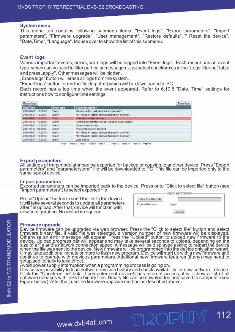
8-c
h S
2 to T
/C T
RA
NS
MO
DU
LA
TO
R
MVDS TROPHY TERRESTRIAL DVB-S2 BROADCASTING
System menu This menu tab contains following submenu items: "Event logs", "Export parameters", "Import parameters", "Firmware upgrade", "User management", "Restore defaults", " Reset the device", "Date,Time", "Language". Mouse over to show the list of this submenu.
Event logs Various important events, errors, warnings will be logged into "Event logs". Each record has an event type, which can be used to filter particular messages. Just select checkboxes in the „Logs filtering" table and press „apply". Other messages will be hidden.„Erase logs" button will erase all logs from the system. "Export logs" button forms the file (log.html) which will be downloaded to PC.Each record has a log time when the event appeared. Refer to 6.10.8 "Date, Time" settings for instructions how to configure time settings.
Export parametersAll settings of transmodulator can be exported for backup or copying to another device. Press "Export parameters" and "parameters.xml" file will be downloaded to PC. This file can be imported only to the same type of device.
Import parametersExported parameters can be imported back to the device. Press onto "Click to select file" button (see "Import parameters") to select exported file.
Press "Upload" button to send the file to the device.It will take several seconds to update all parameters after file upload. After that, device will function with new configuration. No restart is required.
Firmware upgrade Device firmware can be upgraded via web browser. Press the "Click to select file" button and select firmware binary file. If valid file was selected, a version number of new firmware will be displayed. Otherwise an error message will appear. Press the "Upload" button to upload new firmware to the device. Upload progress bar will appear and may take several seconds to upload, depending on the size of a file and a network connection speed. A message will be displayed asking to restart the device when the file was sent to the device. New firmware will be programmed into the device only after restart. It may take additional minute or more to flash new program. Device will start up with a new firmware and continue to operate with previous parameters. Additional new firmware features (if any) may need to setup additionally to take effect.Avoid power supply interruption when a programming process is going on.Device has possibility to load software revision history and check availability for new software release. Click the "Check online" link. If computer (not device!) has internet access, it will show a list of all software releases with links to binary files. Binary file can be downloaded and saved to computer (see Figure below). After that, use the firmware upgrade method as described above.
112
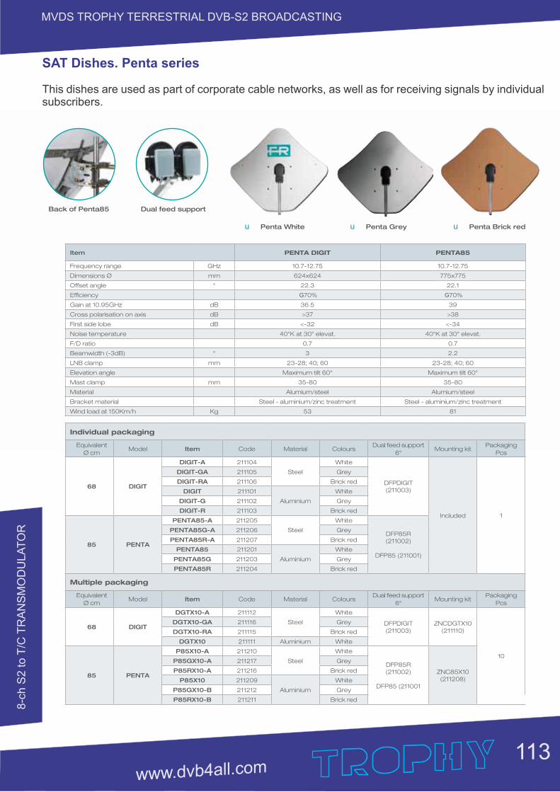
8-c
h S
2 to T
/C T
RA
NS
MO
DU
LA
TO
R
MVDS TROPHY TERRESTRIAL DVB-S2 BROADCASTING
SAT Dishes. Penta series
This dishes are used as part of corporate cable networks, as well as for receiving signals by individual subscribers.
113