compiled multithreaded data paths on fpgas for dynamic workloads
TRANSCRIPT
Compiled Multithreaded Data Paths on FPGAs forDynamic Workloads
Robert J. Halstead and Walid NajjarDept. of Computer Science
University of California, RiversideRiverside, California 92507
[email protected] [email protected]
Abstract—Hardware supported multithreading can maskmemory latency by switching the execution to ready threads,which is particularly effective on irregular applications. FPGAsprovide an opportunity to have multithreaded data paths cus-tomized toeach individual application. In this paper we describethe compiler generation of these hardware structures from a Csubset targeting a Convey HC-2ex machine. We describe how thiscompilation approach differs from other C to HDL compilers. Weuse the compiler to generate a multithreaded sparse matrix vectormultiplication kernel and compare its performance to existingFPGA, and highly optimized software implementations.
I. INTRODUCTION
Because of their poor spatial and temporal locality, irregu-lar applications pose a serious challenge to high performancecomputing: long memory latencies defeat any potential gainsfrom a parallel execution. Hardware supported multithreading,as in the MTA architecture [1], can mask memory latency byswitching to ready threads and without relying on a cachememory architecture. The rapid context switching betweenindependent threads increases the concurrency which is, byLittle’s Law, the product of bandwidth and latency.
In FPGA-based code accelerators a frequently executedcode segment, a loop nest, is expressed as a hardware datapath through which data values are streamed. By customizingthe data path to that specific application, these structureshave been shown to achieve very large speedup. The vastmajority of applications benefiting from FPGA accelerationhave been of regular nature, most of them relying on streamingdata. Two common features of such applications are highspatial (streaming data) and temporal (sliding window) locality.Most of the C to HDL tools that have been developed togenerate FPGA accelerators, from high-level languages, (suchas ImpulseC [2], ROCCC [3], etc.) specifically target suchapplications.
Irregular applications exhibit very poor locality and hencewould not be ideal candidates for FPGA acceleration. How-ever, a multithreaded data path can be implemented on anFPGA with a data path customized to each specific application.Such an execution achieves a high level of efficiency, throughthe customization of the data path, as well as a high level ofparallelism, through the masking of latency. In this paper wedescribe the implementation of a new tool whose objectiveis to generate multithreaded data path on FPGAs from C forirregular applications.
The main contributions of this paper are:
• A taxonomy of irregular applications and the con-straints they pose on the compiler.
• A compiler implementation generating multithreadeddata paths that support irregular applications withdynamic workloads; to our knowledge the first suchcompiler.
• Demonstration of the compiler using sparse matrixvector multiplication (SpMV).
• An experimental evaluation of the compiler on theConvey HC-2ex.
The rest of this paper is organized as follows: Section IIprovides background information on multithreaded architec-tures, irregular applications, and SpMV. Section III shows therelated work. Section IV is a discussion on how irregular ap-plications with dynamic workloads can be compiled from C toVHDL. An explanation of how a SpMV kernel is compiled isgiven in Section V to show the compilers applicability. SectionVI describes a series of experiments and results including acomparison to current FPGA, and Software designs. Finallyconclusions are given in Section VII.
II. BACKGROUND
A. Multithreaded Architectures
Graph and sparse linear algebra algorithms are two ex-amples of a growing category of irregular applications thatexhibit very poor or no spatial or temporal locality and hencecannot benefit from modern cache architectures. Multithreadedarchitectures offers an alternative paradigm for improving theirperformance.
Among the early multithreaded architecture designs is theHorizon architecture [4] which used 256 custom processorsconnected to global memory. Studies showed an average of50 to 80 clock cycles for a memory access, but most allof the requests could be fulfilled within 128 cycles. Withthis knowledge the Horizon’s custom processors were builtto support 128 concurrent threads, and could context switchin one cycle. Whenever a thread made a memory request thelatency could be masked by having the processors handle otherready threads.
In the 1990s the Tera Corporation, later Cray, developedsuch a design as a commercial machine. The Tera MTA[1], [5], [6] again had 256 processors all sharing 64 GBof memory organized as a distributed NUMA architecture

connected to the processors via a sparsely populated regulartopoly interconnection network. To lower network traffic itforced instruction requests through a shared cache. Processorsran at 220 MHz, and could issue one memory request percycle. A later design, the Cray XMT [7] machine, increasedthe number of supported processing cores to 8192, and theclock frequency to 500 MHz.
B. Sparse Matrix Vector Multiplication
Because of its poor locality, Sparse Matrix Vector multi-plication (SpMV) is a memory bound application exhibiting alow Flop/Byte ratio. Its performance depends on architecturescontinually suppling their cores or accelerators with relevantmatrix and vector data. Multiple storage formats were de-veloped to improve cache and memory performance. Someof the more common include: coordinate (COO), compressedsparse row/column (CSR / CSC), and ELLPACK. COO usesthree arrays to store only the non-zero elements (NZEs). Onearray holds the sparse array elements values, another holdstheir row positions, and the last holds the column positions.CSR and CSC improve the memory utilization by compressingeither the row or column array. Using CSR as an example, thecolumn, and value arrays are sorted by row number, and allelements from one row are kept adjacent to each other. Therow array is compressed and points only to the start positionof each row, which reduces the overall memory utilization.ELLPACK was developed for vector machines. It zero padsrows to improve memory accesses, but it is done at the costof extra computations and storage. Other formats have beenexplored and tested. We point the interested reader to [8] forfurther details.
SpMVs importance has created many customized ap-proaches for software architectures and GPUs. Software op-timizations like blocking a matrix at the thread, register andcache levels, or pipelining, or prefetching were explored in[9]. These optimizations were done for five architectures: twoAMD, and one Intel out-of-order superscalar architecture, theSun Niagra2, and the IBM STI Cell machine. The performanceof different sparse matrix formats on GPUs is explored in [10].The impact of memory structures, such as texture memory,played in GPU performance is evaluated. [11] used the ELLformat to block row lengths, which allowed tuning of threadsfor individual GPUs.
III. RELATED WORK
A. Hardware Compilers, and Tools
A number of High Level Synthesis (HLS) tools have beendesigned aimed at compiling high-level languages (HLLs),such as C/C++, to hardware description languages (HDLs),such as VHDL, Verilog, SystemC or SystemVerilog. Theirobjective being to bridge the semantic gap between HLLs andHDLs and make the development of FPGA-based acceleratorsmore accessible to traditionally teained application developers.
HLS compilers such as Impulse C [2], ROCCC [14], andAutoPilot (later Vivado) [12], [15]) work with a subset of Cto create custom IP accelerators. These tools do not specify afull system, but assist in creating the individual components ofa RTL design. Catapult C [13] supports most C++ syntax and
constructs (pointers, classes, templates) when generating cus-tom cores. HLS tools do not need to use established languages.Bluespec [16] uses SystemVerilog to describe hardware at alevel above typical HDL languages.
ROCCC [3] is a C to VHDL compiler that targets streaming(regular) applications that can analyzed and for which it gen-erate optimized data paths. It attempts to minimize a kernelsoutgoing memory requests, minimize its area, and maximizeits clock frequency. Developers write the kernel in C and thecompiler applies optimizations at two levels each with its ownintermediate representation (IR); Hi-CIRRF and Lo-CIRRF[17]. Hi-CIRRF identifies FPGA components, which will beneeded during execution. It marks and inserts these into the IRas C macros. Its also responsible for duplicating the kernelslogic, depending on user specifications, for parallel execution,such as loop unrollng. Lo-CIRRF generates a data flow graph(DFG) as another IR, which becomes the kernels data path.Control systems are built around the DFG to manage executionflow and memory requests.
The CHAT [18], [19] compiler uses the same underlyingtools as ROCCC for Hi-CIRRF and Lo-CIRRF compilation,but it targets irregular applications. Initially, it focused onirregular kernels with a deterministic number of threads, andeach thread has a deterministic workload. In this work weextend these capabilities to kernels where the workload is non-deterministic.
B. SpMV on FPGA
Current FPGA architectures are ideally suited for applica-tions with streaming data. One approach is to locally store thevector and stream in the sparse matrix data. While modernhigh-end FPGAs have large on-chip memories in the form ofBlockRAM (BRAM) [20] these are not sufficient for storinglarge data structures as required by HPC applications. TheFPGA used in this work, the Xilinx Virtex6 LX760, hasabout 26 MBits of BRAM on-chip. However, all the BRAMspace is not available for the user application, some is usedfor interfacing to memory and other support functions. Asheterogeneous architectures, such as the Convey HC-1/HC-2[27], become widely available, research is shifting toward end-to-end implementations. In [28] a SpMV personality is developfor a HC-1. In the design all matrix and vector data is storedin global memory which the FPGA accesses through multiplechannels. The design caches memory requests locally in casedata needs to be reused, but SpMV can be very irregular. Thepaper reports performance results that are up to 40% of theHC-1’s peak. Their design uses 32 individual engines whichcan produce a peak of 9.6 Gflop/sec.
Substantial work, in implementing sparse matrix operationson FPGAs, has focused on the floating-point Multiply Accu-mulate (MAc) engine. Since that engine is heavily pipelined,to achieve a high clock rate, it presents a challenge when anunknown number of values must accumulated. Some of themore common designs are outlined here. Adder tree structures[21], [22] with a feedback loops are used to handle multiplerow elements in one cycle. Here the number of non-zeroelements within the row must be larger than the number ofchannels into the adder tree. If this is not the case zero paddingis typically used to adapt the row size. Other approaches are

Fig. 1. A taxonomy of irregular applications where the number of threadsand the workload size are deterministic or not.
based on statically assigning partial dot-products to multipleprocessing engines [23], [24]. A control unit is used to managethe communication, and ensure proper execution. Here MAcsmay be limited by the number of matrix rows they can manage,typically one or two rows at a time. However, in [25] multipleMAcs are routed onto one FPGA which allows support formore rows in parallel. Research in [26] lead to an accumulationreduction circuit that can handle an arbitrary number of rows.A control unit arbitrates the data flow between the floating-point addition unit and temporary buffers.
IV. COMPILER DESIGN
This section describes the CHAT compiler’s design. Itprovides a taxonomy for parallel irregular applications. Thecompiler’s semantics for non-deterministic workloads is dis-cussed, and data path construction for irregular applicationswith dynamic workloads is explained.
A. A Taxonomy of Irregular Applications
The CHAT compiler builds multithreaded kernels for par-allelizable irregular applications. These parallel irregular ap-plications can be further classified by the hardware structuresneeded for execution. Four classes are proposed as shown inFigure 1. Classes are based on whether or not the numberof threads, and the number of memory requests per thread(workload) are determinable.
Applications with a deterministic number of threads arecompiled to reduce, or eliminate redundant execution. Appli-cations with a non-deterministic number of threads need FPGAconstructs to prevent redundancy. Consider breadth first search.During graph traversal nodes A and B could both point to nodeC. Without synchronization two threads could be generated toprocesses node C. Performance would decrease exponentiallyas each thread then generates more redundant threads.
Applications with a deterministic workload, number ofmemory requests per thread, can assign threads in round robinfashion to Processing Elements (PEs). Applications with non-deterministic workloads can have variable memory requests.Stalls could occur with round-robin assignment because of
(a) Thread with a static workload
(b) Thread with a dynamic workload
Fig. 2. Compilable FPGA kernels with static and dynamic workloads. Thehighlighted region shows a threads workload.
unbalanced threads. A Thread Management Unit (TMU), localto the FPGA, can ensure a balanced execution by dynamicallyassigning threads as PEs become available. This paper exploresthe compilation of custom TMUs for FPGA kernels.
B. Compiler Syntax
In CHAT a for-loop supports a subset of its traditional Cfunctionality. The loop has a very strict purpose, which is todefine how data streams (array) will be accessed. CHAT onlysupports one loop index per for-loop declaration. However,once declared these indices can be read freely in the loop body.Nested for-loops are supported for more complex kernels.
The structure for kennels with static workloads is shownin Figure 2(a). Multiple variables can be used to route logicthrough the data path, but all logic must be defined within theinnermost for-loop’s body. As shown, variables a and b areindices to the out data stream, but they could also be usedto index other streams. Both a and b must start at a staticposition and go to a variable position, which must be set beforethe execution begins. Because this variable cannot change, allthreads will have the same workload though they may havedifferent data.
The new compiler semantics support kernel constructs fordynamic workloads. Kernel logic can be defined outside theinnermost for-loop, and it removes restrictions on a innerfor-loop’s initialization and condition sections as shown inFigure 2(b). Threads can support dynamic workloads becausea loop’s start and end conditions can change during execution.A thread’s body is defined by the lowest for-loop with staticstart and end conditions at runtime. In Figure 2(b) a threadsworkload is defined by the outermost for-loop’s body.
C. Data Path Construction
To support threads with dynamic workloads the compilermust generate additional FPGA constructs. For this purpose aThread Management Unit (TMU) is introduced, and the datapath is broken into two parts; thread management, and pro-cessing. Both are custom generated by the compiler for each

Fig. 3. Compressed Sparse Row (CSR) format for sparse matrix representa-tion with three arrays.
kernel. The TMU maintains threads needing to be processedand dispatches them to aPE. A PE can handle multiple threadsin parallel, which ensures enough request are generated tomask long memory latencies. A PE manages the states forall threads that are assigned to it. Once a thread completes thePE sends its output back to the TMU. The TMU then sendsthe output on to global memory and removes the thread.
Parallelism can be improved by increasing the number ofgenerated PEs, which is tunable to individual architectures byway of compiler arguments. While the number of PEs can beincreased there is one TMU generated. The TMU creates thestart and end conditions for a thread and dynamically assignsit to an available PE. This maintains a balanced execution. AThread with a disproportionally large workload will occupyone PE while the other PEs handle multiple threads. Becausethe workload can be unbalanced the kernel does not guaranteein-order thread completion. Each PEs hold a busy flag high toprevent additionnal threads from being assigned. When all PEsare busy the TMU backloads threads to quickly assign themlater.
Identification of kernels with dynamic workloads is doneduring the compiler’s Hi-CIRRF pass. The compiler uses afor-loop’s initialization, and condition section to make thisdetermination. Consider the inner loop from Figure 2(b). Itis initialized with values from stream C, and its condition isdependent upon stream D. When this happens the compilerinserts a TMU macro into the IR and links it to streams C
and D. Lo-CIRRF takes the macro and build a custom TMUfor the kernel.
V. MULTITHREADED SPMV EXAMPLE
As a proof of concept we use the compiler to generate acustom multithreaded FPGA Sparse Matrix Vector multipli-cation (SpMV) kernel targeting a Convey HC-2ex machine.In this section we outline the sparse matrix data structureused.,one method a kernel developer could use to write theFPGA’s SpMV code, how the code is compiled to an FPGAcircuit, and how each of the FPGA components interact. Thissection also outlines how the TMU creates and managesthreads. This section concludes with how the kernel is inte-grated into the HC-2ex.
Fig. 4. The source code used to generate a custom multithreaded SpMVkernel.
A. Compressed Sparse Row
Multiple matrix formats can be used to store sparse ma-trices to memory, and each has its tradeoffs. CompressedSparse Row (CSR) is a very common representation usedby both FPGA and software developers. The format storesonly relevant matrix information in memory, which limits theunnecessary work done by accelerators and processors. Themain draw for CSR is that independent, and hence parallel,threads can be easily identified and generated.
Figure 3 shows a matrix stored in CSR format. All thematrice’s non-zero elements are kept in the V alue array.Another array, of the same size, is used to store the columnpositions of the values: the Column array. A one-to-onerelationship exists between data points with matching indexpositions. CSR requires a unique data arrangement for boththese arrays. All elements corresponding to the same row mustbe adjacent to each other, and the elements for row i must comebefore elements for row i+ 1. It is not required for elementswithin a row to be sorted by their column values. The thirdarray in CSR, called the RowPtr array, is used to delineate therow elements. Each value in this array represents the startingposition of a row. Two adjacent values can be used by a threadto request and processes all elements within a single row ofthe matrix.
B. SpMV Kernel Code
Sample code for a SpMV kernel is shown in Figure 4. Thisis, line for line, the code used by the compiler. All arrays aretreated as streams of data into the FPGA. Most (row, val,col) are accessed in a streaming (regular) fashion. The vec
array is accessed by the col array and as such is treated asan irregular accesses. Thread workloads are determined by therow stream with the two adjacent elements giving start andend positions. Threads are issued in order, but they are notrequired to have the same workload size. Thus the out arraycan write to memory out-of-order. The kernel writes whenevera thread finishes. The designer can unroll the outer for-loop togenerate multiple PEs yielding higher parallelism.
C. Convey HC-2ex
Convey Computers [27] built the first heterogeneous FPGAmachines with a shared cache coherent virtual memory spacebetween software (CPU execution) and hardware (FPGA ex-ecution). The base HC machines, HC-1 and HC-2, use fourVirtex-5 LX330 FPGAs as coprocessors while the HC-1ex and

Fig. 5. Each PE is assigned a thread. It requests the necessary data (Column,Vector, and Value) from global memory. Returned data values are pushedthrough the multiply pipeline, and summation unit.
HC-2ex machines use four Virtex-6 LX760 FPGAs. The maindraw is the shared global memory space [29], [30]. Memoryallocated by the host processor can be directly accessed by theFPGA. Memory space is divided between the CPU processors,and the FPGA coprocessor, and performance could dependon where the memory is allocated. With 128 GB per region,its large enough that the CPUs can setup new jobs while theFPGA finishes processing others. A coprocessor has four largeFPGAs, which are called Application Engines (AEs). EachAE interfaces to eight Memory Controllers (MCs) via a fullcrossbar, which supports memory request reordering. Each MChas 2 ports (identified as even or odd) that can read or writeeight bytes per cycle at 150 MHz [31]. Thus each AE has 16memory ports which deliver a peak bandwidth of 19.2 GB/s.The coprocessor’s peak bandwidth is about 80 GB/s.
D. Processing Element
The bulk of the SpMV’s work is done by the processingelement (PEs). These engines operate independently and thenumber of PEs is limited by the resources available to theFPGA. Each thread assigned to a PE will generate one output,which is the sum-of-products for the row. One thread isgenerated for each matrix row, and it holds the start and endposition for the memory requests. As requests are fulfilled thedata is sent to a summation unit which produces the final sum-of-products. One PE can manage the requesting, multiplying,and summing of multiple threads (rows) concurrently.
The major components of a PE are shown in Figure 5. EachPE must manages the memory requests to the column, value,and vector arrays. The Convey architecture supports the in-order return of all memory requests. The reordering is done bya crossbar that interfaces the HC-2ex’s FPGAs to the memorymodules. Because memory is returned in-order the kernel canuse FIFO buffers to store data.
When assigned a new thread the PE will raise a busy flag
Fig. 6. Thread Management Unit: the output write data and row requestsare combined into one memory channel. A control unit handles the conflictswhen multiple resources need to use the channel.
and incrementally request memory locations from the columnand value arrays. When all the requests for that thread havebeen issued, the flag is lowered and a new thread is assigned tothe PE. This is done even though all the data of the prior threadhas not yet been returned. Workloads are balanced across PEsbecause they do not accept new threads until all requestsare issued. FIFO buffers within each PE are large enough tosupport the outstanding memory requests. As memory returnsthe data for the column array it is used to generate the memoryrequests for the vector array. The data returned for the valuearray is held in buffer until the corresponding vector requestis fulfilled.
As data is returned from memory it is buffered in the Valueand Vector FIFOs with its thread id. For this kernel a thread idis the row’s index. The summation unit uses the thread ids tomanage concurrent threads. As reported in Section III-B SpMVreductions circuits have been widely studied. Our compileruses a circuit similar to the one described in [26]. It handlesmultiple rows concurrently, and can read a new element everycycle. However, the circuit assumes data for one row is sent,in its entirety, before another row begins. This assumptionholds for the kernel and Convey HC-2ex architecture. Thisreduction circuit is only needed if the kernel is compiled forfloating point operations, which require multiple cycles foreach multiplication-addition.
E. Thread Management
The Convey HC-2ex has 4 Virtex 6 LX760 FPGAs, calledapplication engines (AEs). Figure 7 shows the SpMV kernellayout for one HC-2ex AE. The design can be replicated toall four AEs at runtime. Each AE has 16 memory channels,and each PE requires 3 memory channels; for the column,value, and vector requests. Memory channels are the designsbottleneck, which is limited to 5 PEs per AE.
Control registers in the AE specify the number of threads(rows) needed by the SpMV kernel. The registers also specify

Fig. 7. The MT-FPGA architecture on one AE. Control signals specify the number of jobs (length), and the base addresses of the sparse matrix arrays. Allmemory channels of the AE are utilized.
the base addresses for all streams used by the kernel. Thesevalues can be assigned unique values when multiple AEs areused. Each AE can processes a subset of the overall matrix.
One thread management unit (TMU) communicates withthe 5 PEs. It creates thread workloads with values from the rowpointer array as described in Section V-A. Access to the rowpointer incurs the same memory latency as all other requests.The TMU buffers threads when all PEs are busy. Assignmentis done dynamically in round robin fashion.
As PE threads complete the output value is buffered bythe TMU until it can be written back to global memory. TheTMU manages 5 out streams (one per PE) as well as the row
stream. Reads and writes to these two streams are infrequent,occurring once per thread, compared to the column, value,and vector streams. The TMU uses one memory channel, andinterleaves its read and write requests as shown in Figure 6.Read and write request conflicts are resolved by a control unitin favor of the write data, which prevents a deadlock.
F. FPGA Implementation
Integrating a kernel into the HC-2ex requires all memoryrequests to communicate with Convey’s memory interface.Designs are placed and routed varying the number of kernelPEs. Area utilization (including the wrapper) for a singleAE is shown in Table I. The design uses only one third ofthe available slices and BRAMs because it is limited by thememory channels. As discussed in the above each PE requires3 channels, and the TMU interleaves its requests though theremaining channel.
TABLE I. FPGA UTILIZATION WHEN VARYING THE NUMBER OF PES.
PE(s) Slices (118,560) BRAMs (720)1 25,788 (21%) 107 (14%)2 29,040 (24%) 133 (18%)3 32,638 (27%) 179 (24%)4 36,520 (30%) 209 (29%)5 39,395 (33%) 239 (33%)
VI. EXPERIMENTAL RESULTS
In this section we describe our experimental methodology,and report results for the compiled multithread FPGA kernel
Fig. 8. Sustained Gflop/s on a dense matrix as function of the number ofnon-zero elements.
Fig. 9. Sustained Gflop/s (bar) and sustained % of memory throughput (line),on a 2K x 2K dense matrix, as the number of PEs is increased.
(MT-FPGA) on a Convey HC-2ex. Experiments consider scala-bility, and throughput. MT-FPGA is compared to a cache basedFPGA kernel, and optimized multicore CPU implementations.
A. Experimental Setup
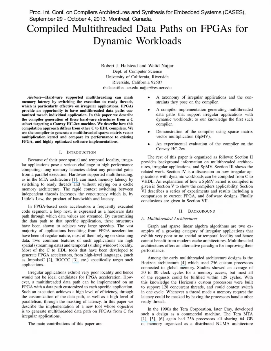
Chosen benchmarks are taken from the University ofFlorida Sparse Matrix Collection [32]. Table II outlines therelevant information about each matrix: its dimension, thenumber of non-zero elements, the ratio of non-zero elementsto the row size, the sustained performance (DP Gflop/s) and
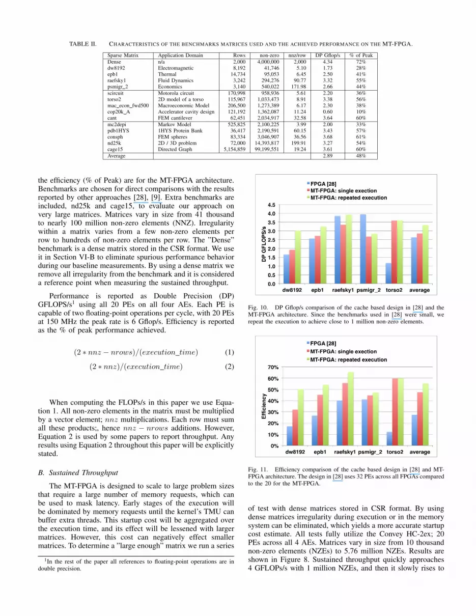
TABLE II. CHARACTERISTICS OF THE BENCHMARKS MATRICES USED AND THE ACHIEVED PERFORMANCE ON THE MT-FPGA.
Sparse Matrix Application Domain Rows non-zero nnz/row DP Gflop/s % of PeakDense n/a 2,000 4,000,000 2,000 4.34 72%dw8192 Electromagnetic 8,192 41,746 5.10 1.73 28%epb1 Thermal 14,734 95,053 6.45 2.50 41%raefsky1 Fluid Dynamics 3,242 294,276 90.77 3.32 55%psmigr 2 Economics 3,140 540,022 171.98 2.66 44%scircuit Motorola circuit 170,998 958,936 5.61 2.20 36%torso2 2D model of a torso 115,967 1,033,473 8.91 3.38 56%mac econ fwd500 Macroeconomic Model 206,500 1,273,389 6.17 2.30 38%cop20k A Accelerator cavity design 121,192 1,362,087 11.24 0.60 10%cant FEM cantilever 62,451 2,034,917 32.58 3.64 60%mc2depi Markov Model 525,825 2,100,225 3.99 2.00 33%pdb1HYS 1HYS Protein Bank 36,417 2,190,591 60.15 3.43 57%consph FEM spheres 83,334 3,046,907 36.56 3.68 61%nd25k 2D / 3D problem 72,000 14,393,817 199.91 3.27 54%cage15 Directed Graph 5,154,859 99,199,551 19.24 3.61 60%Average 2.89 48%
the efficiency (% of Peak) are for the MT-FPGA architecture.Benchmarks are chosen for direct comparisons with the resultsreported by other approaches [28], [9]. Extra benchmarks areincluded, nd25k and cage15, to evaluate our approach onvery large matrices. Matrices vary in size from 41 thousandto nearly 100 million non-zero elements (NNZ). Irregularitywithin a matrix varies from a few non-zero elements perrow to hundreds of non-zero elements per row. The ”Dense”benchmark is a dense matrix stored in the CSR format. We useit in Section VI-B to eliminate spurious performance behaviorduring our baseline measurements. By using a dense matrix weremove all irregularity from the benchmark and it is considereda reference point when measuring the sustained throughput.
Performance is reported as Double Precision (DP)GFLOPS/s1 using all 20 PEs on all four AEs. Each PE iscapable of two floating-point operations per cycle, with 20 PEsat 150 MHz the peak rate is 6 Gflop/s. Efficiency is reportedas the % of peak performance achieved.
(2 ⇤ nnz � nrows)/(execution time) (1)
(2 ⇤ nnz)/(execution time) (2)
When computing the FLOPs/s in this paper we use Equa-tion 1. All non-zero elements in the matrix must be multipliedby a vector element; nnz multiplications. Each row must sumall these products;, hence nnz � nrows additions. However,Equation 2 is used by some papers to report throughput. Anyresults using Equation 2 throughout this paper will be explicitlystated.
B. Sustained Throughput
The MT-FPGA is designed to scale to large problem sizesthat require a large number of memory requests, which canbe used to mask latency. Early stages of the execution willbe dominated by memory requests until the kernel’s TMU canbuffer extra threads. This startup cost will be aggregated overthe execution time, and its effect will be lessened with largermatrices. However, this cost can negatively effect smallermatrices. To determine a ”large enough” matrix we run a series
1In the rest of the paper all references to floating-point operations are indouble precision.
Fig. 10. DP Gflop/s comparison of the cache based design in [28] and theMT-FPGA architecture. Since the benchmarks used in [28] were small, werepeat the execution to achieve close to 1 million non-zero elements.
Fig. 11. Efficiency comparison of the cache based design in [28] and MT-FPGA architecture. The design in [28] uses 32 PEs across all FPGAs comparedto the 20 for the MT-FPGA.
of test with dense matrices stored in CSR format. By usingdense matrices irregularity during execution or in the memorysystem can be eliminated, which yields a more accurate startupcost estimate. All tests fully utilize the Convey HC-2ex; 20PEs across all 4 AEs. Matrices vary in size from 10 thousandnon-zero elements (NZEs) to 5.76 million NZEs. Results areshown in Figure 8. Sustained throughput quickly approaches4 GFLOPs/s with 1 million NZEs, and then it slowly rises to

a peak of 4.5 GFLOPs/s. Overall MT-FPGA sustains 75% ofits peak throughput. Based on these results 1 million NZEs isthe point where matrices are ”large enough” to be unaffectedby the startup costs.
To study how well MT-FPGA scales and how well thememory system copes with a large number of memory re-quests, we run a series of test varying the number of PEs.Starting with a single AE the number of engines is increasedfrom one to five, and once full the number of AEs is increasedup to four. All tests use a dense 4 million element (2000 x2000) matrix. The results are shown in Figure 9. The bar chartreports the sustained GFLOPs/s, and the red line reports thepercentage of peak throughput sustained. The efficiency witha small number of engines is very close to optimal, whichsuggests the number of memory requests is not high enoughto saturate the memory. However, it slowly drops to 80% asone AE is filled with five PEs. The design scales linearly fromone (5 PEs) to three AEs (15 PEs), but drops again slightlywith the fourth AE. These results shows that MT-FPGA willscale well at 80% efficiency so long as the memory systemcan handle the requests.
C. MT-FPGA vs. FPGA caching
The compiled MT-FPGA kernel is compared to the FPGAarchitecture described in [28]. Both use Convey machineswith the same memory system. Peak memory bandwidth (80GB/s), and clock frequency (150 MHz) are identical. The onlydifference is with the FPGA used. [28] use a Convey HC-1(Virtex 5 LX330), and MT-FPGA uses a larger HC-2ex (Virtex6 LX760). SpMV is a memory bound application, and bothFPGAs offer sufficient size for their designs.
MT-FPGA uses memory masking to fully utilize the mem-ory bandwidth. [28] takes a different approach, which relies oncaching matrix and vector data locally to the FPGA. Cachesare structured, with efficient line sizes, for an equal numberof reads to each of the memory’s SGDIMMs. Vector cachesare maintained for each processing element (PE), and a matrixcache is shared across all PEs within an AE.
Throughput comparisons are done with the matrices chosenin [28]. However, these matrices were typically small. Only 2were larger than 500 thousand NZEs, and only one of thosewas above 1 million NZEs. Because of this two sets of testswere run for MT-FPGA. The first test measured throughputon a single execution of the matrix. The second test didrepeated executions to compensate for the smaller sizes. Thenumber of runs were repeated until the number of NZEs wasabove 1 million elements. For example the dw8192 matrix has41,746 NZEs. It was run 24 times resulting in 1,001,904 NZEs.Figure 10 reports the throughput comparison results. Resultsare copied directly in [28] which used Equation 2. For equalcomparison MT-FPGA results use the same equation and areslightly higher than those reported in Table II.
When executing a matrix one time MT-FPGA averages ahigher throughput across all benchmarks, and with multipleruns MT-FPGA delivers a higher throughput for all but onebenchmark. The exception is psmigr 2, which is more denselypacked than the other matrices and benefits more from caching.Because our approach targets large matrices we considertorso2 case (the only one above 1 million elements) most
telling. Here performance drops dramatically for the cachingarchitecture while MT-FPGA sustains 3.4 Gflop/s of 56.7% ofpeak.
MT-FPGA achieves better performance with fewer PEs (20compared to 32 in [28]), which results in much higher effi-ciency. Measurements are shown in Figure 11. Peak throughputfor MT-FPGA is 6 GFLOPs/s while the caching approachpeaks at 9.6 GFLOPS/s. MT-FPGA’s results for the singleexecution case average 47%, and its results for repeated exe-cution average 55%. The best performing benchmark for [28]achieves 41% efficiency, and the average for all benchmarksis 27%.
D. MT-FPGA vs. Multicore
In this section we compare the performance of MT-FPGAwith the multicore architectures reported in [9]. Table IIIreports important architecture information about the multicoremachines. Before running the experiments MT-FPGA was notexpected to outperform the multicore architectures, but resultsare included for comparative purposes. The goal for this paperis compiling custom multithreaded FPGA kernels, and thefocus was not strictly on performance. However, the multicoremachines targeted performance, and were customized for eacharchitecture. They run at much higher clock frequencies (GHzcompared to a FPGA’s MHz), and have more dedicated hard-ware. However, MT-FPGA did fair well with the multicorearchitectures. It beat a few CPUs in raw throughput, andoffered comparable throughput to most of the others.
This was achieved in spite of the CPUs being highlyoptimized. Software optimizations are done at three levels.The first set of optimizations targets kernel parallelization.Execution threads are blocked to ensure an evenly distributedworkload. In the NUMA and Cell architectures threads arestatically assigned to minimize communication. The second setof optimizations target the kernel’s data structures. The sparsematrix vectors, and the result vector are blocked accordingto the cache line. To reduce memory requirements registerblocking is used where adjacent non-zero elements are joinedtogether into one set of coordinates. Heuristics are used toimprove processing time. Matrices with less than 64K columnsuse 16 bit indexes instead of 32, or 64 bits. Finally low-levelkernel optimizations are considered. A custom kernel is usedfor each architecture. The Cell processor’s kernel uses softwarepipelining to mask the instruction latency, and it also usesbranchless execution. Explicit software prefetching is used inthe out-of-order processors. Other common loop optimizationsare also performed.
Sustained throughput is shown in Figure 12. MT-FPGAachieves an average throughput higher than the AMD SantaRosa and Intel Clovertown CPUs. Its throughput is comparableto the AMD Barcelona and the Sun Niagara 2, but could onlysustain about half the throughput of the STI Cell machine.However, with the high clock frequency and dedicated hard-ware those machines sustain a small fraction of their overallthroughput. Peak throughput for the multicore machines re-neges from 17.6 to 74.7 GFLOPs/s while the FPGA peaks atonly 6 GFLOPs/s. Figure 13 shows the percentage of peakperformance each machine achieves. MT-FPGA’s efficiencyis over 30% in seven of the eight benchmarks, over 50% in

TABLE III. ARCHITECTURE SPECIFICATIONS FOR THE CPUS AND GPU COMPARED TO IN THIS PAPER.
Architecture Cores (Sockets) Clock (GHz) Peak (DP GFLOPS/s)AMD - Opteron2214 (Santa Rosa) 4 (2) 2.2 17.6AMD - Opteron 2356 (Barcelona) 8 (2) 2.3 73.6Intel - Xeon E5345 (Clovertown) 8 (2) 2.3 74.7Sun - Niagara 2 16 (2) 1.16 18.7STI - Cell QS20 16 (2) 3.2 29
Fig. 12. Sustained throughput (DP Gflop/s) for multicores CPUs, and MT-FPGA.
Fig. 13. Efficiency (reported as % of peak) for multicores CPUs, and MT-FPGA.
four and averages 48%. The highest efficiencies are achievedby the STI Cell and the Sun Niagara with averages between15% and 25% which are less than half that of MT-FPGA.As heterogeneous FPGA architectures, which are in theirinfancy, improve the efficiency may or may not change, butthe throughput potential likely will.
VII. CONCLUSION
The multithreaded execution model, by rapidly switchingto ready threads, allows the masking of long memory latencies.It can achieve a high degree of concurrency, equal to theproduct of the memory latency and the number of outstandingmemory requests. For irregular applications that suffer fromvery poor spatial and temporal locality, this model can alleviatethe impact of memory latency while increasing parallelism.
FPGAs provide an opportunity to customize a data pathto each individual computation hence achieving a higherefficiency, albeit at a lower clock speed. Traditionally, FPGA-based accelerators have been used for highly regular streamingapplications.
In this paper we presented a compiler that generatescustomized multithreaded data paths on FPGAs for irregularapplications with dynamic workloads. We outline how a threadmanagement unit is created, and how it dynamically balancesthreads across multiple processing elements. Results show thatmultithreading as a FPGA paradigm is valid for irregularapplications. Using a Sparse Matrix Vector multiplication as aproof of concept, we show the MT-FPGA kernel outperformeda cache based FPGA kernel in both overall throughput and ef-ficiency. Compared to highly optimized multicore architecturesthe MT-FPGA kernel has higher or comparable throughput tofour tested architectures, and about half the throughput of theSTI Cell architecture. However, efficiency is more than doublethat of the closest multicore architecture. The multithreadeddesign scales to very large matrices. On matrices over 3million non-zero elements it achieved 50% efficiency and over3 GFLOPs/s throughput for each. However, performance islimited by startup costs on matrices smaller than one millionelements.

ACKNOWLEDGMENTS
This work was supported in part by NSF Awards CCF-1219180 and IIS-1161997
REFERENCES
[1] R. Alverson, D. Callahan, D. Cummings, B. Koblenz, A. Porterfield,and B. Smith, “The tera computer system,” in Proceedings of the 4thInternational Conference on Supercomputing, ser. ICS ’90. New York,NY, USA: ACM, 1990, pp. 1–6.
[2] “Impulse C,” http://www.impulseaccelerated.com/.[3] J. Villarreal, A. Park, W. Najjar, and R. Halstead, “Designing modular
hardware accelerators in C with ROCCC 2.0,” in Field-Prog. CustomComp. Machines (FCCM), 2010 18th IEEE Annual International Sym-posium on, may 2010, pp. 127 –134.
[4] J. T. Kuehnand and B. J. Smith, “The horizon supercomputing system:architecture and software,” in Proceedings of the 1988 ACM/IEEE con-ference on Supercomputing, ser. Supercomputing ’88. Los Alamitos,CA, USA: IEEE Computer Society Press, 1988, pp. 28–34.
[5] G. Alverson, R. Alverson, D. Callahan, B. Koblenz, A. Porterfield, andB. Smith, “Exploiting heterogeneous parallelism on a multithreadedmultiprocessor,” in Proceedings of the 6th International Confonferenceon Supercomputing, ser. ICS ’92. New York, NY, USA: ACM, 1992,pp. 188–197.
[6] A. Snavely, L. Carter, J. Boisseau, A. Majumdar, K. S. Gatlin,N. Mitchell, J. Feo, and B. Koblenz, “Multiprocessor performance onthe Tera MTA,” in Proceedings of the 1998 ACM/IEEE Conference onSupercomputing, ser. Supercomputing ’98. Washington, DC, USA:IEEE Computer Society, 1998, pp. 1–8.
[7] J. Feo, D. Harper, S. Kahan, and P. Konecny, “ELDORADO,” inProceedings of the 2nd Conference on Computing Frontiers, ser. CF’05. New York, NY, USA: ACM, 2005, pp. 28–34.
[8] Y. Saad, SPARSKIT: A basic tool kit for sparse matrix computation.Research Institute for Advanced Computer Science, NASA AmesResearch Center, 1990.
[9] S. Williams, L. Oliker, R. Vuduc, J. Shalf, K. Yelick, and J. Demmel,“Optimization of sparse matrix-vector multiplication on emerging mul-ticore platforms,” Parallel Computing, vol. 35, no. 3, pp. 178 – 194,2009.
[10] N. Bell and M. Garland, “Efficient sparse matrix-vector multiplicationon CUDA,” NVIDIA, Tech. Rep., 2008.
[11] A. Monakov, A. Lokhmotov, and A. Avetisyan, “Automatically tuningsparse matrix-vector multiplication for GPU architectures,” in Proceed-ings of the 5th Int. Conf. on High Performance Embedded Architecturesand Compilers, ser. HiPEAC’10. Springer-Verlag, 2010, pp. 111–125.
[12] Z. Zhang, Y. Fan, W. Jiang, G. Han, C. Yang, and J. Cong, “Autopilot:A platform-based esl synthesis system,” High-Level Synthesis: fromAlgorithm to Digital Circuit, 2008.
[13] “Catapult C,” http://www.mentor.com/.[14] “Riverside Optimizing Compiler for Configurable Computing,”
http://roccc.cs.ucr.edu/, 2012.
[15] “Xilinx Vivado,” http://www.xilinx.com/tools/autoesl instructions.htm,2013.
[16] “Open System C Initiative,” http://www.accellera.org/home/, 2013.[17] Z. Guo and W. Najjar, “A compiler intermediate representation for
reconfigurable fabrics,” in Field Programmable Logic and Applications,2006. FPL ’06. International Conference on, 2006, pp. 1–4.
[18] R. J. Halstead, J. Villarreal, and W. Najjar, “Exploring irregular memoryaccesses on fpgas,” in Proceedings of the first workshop on Irregularapplications: architectures and algorithm, ser. IAAA ’11. New York,NY, USA: ACM, 2011, pp. 31–34.
[19] R. J. Halstead and W. Najjar, “Compiling irregular applciations forreconfigurable systems,” in International Jounal on High PerformanceComputing and Networking, to appear.
[20] “Virtex-6 family overview,” http://www.xilinx.com/support/document-ation/data sheets/ds150.pdf, 2012.
[21] J. Sun, G. Peterson, and O. Storaasli, “Sparse matrix-vector multipli-cation design on FPGAs,” in Proceedings of the 15th Annual IEEESymposium on Field-Programmable Custom Computing Machines, ser.FCCM ’07. Washington, DC, USA: IEEE Computer Society, 2007,pp. 349–352.
[22] L. Zhuo and V. K. Prasanna, “Sparse matrix-vector multiplication onFPGAs,” in Proceedings of the 2005 ACM/SIGDA 13th Int. Symp. onField-Programmable Gate Arrays, ser. FPGA ’05. New York, NY,USA: ACM, 2005, pp. 63–74.
[23] M. deLorimier and A. DeHon, “Floating-point sparse matrix-vectormultiply for FPGAs,” in Proceedings of the 2005 ACM/SIGDA 13th in-ternational symposium on Field-programmable gate arrays, ser. FPGA’05. New York, NY, USA: ACM, 2005, pp. 75–85.
[24] Y. Shan, T. Wu, Y. Wang, B. Wang, Z. Wang, N. Xu, and H. Yang,“FPGA and GPU implementation of large scale SpMV,” in ApplicationSpecific Processors (SASP), 2010 IEEE 8th Symp. on, June 2010, pp.64 –70.
[25] Y. Zhang, Y. Shalabi, R. Jain, K. Nagar, and J. Bakos, “FPGA vs. GPUfor sparse matrix vector multiply,” in Field-Programmable Technology,2009. FPT 2009. Int. Conf. on, December 2009, pp. 255 –262.
[26] M. Gerards, J. Kuper, A. Kokkeler, and B. Molenkamp, “Streamingreduction circuit,” in Digital System Design, Architectures, Methods andTools, 2009. DSD ’09. 12th Euromicro Conference on, August 2009,pp. 287 –292.
[27] T. M. Brewer, “Instruction set innovations for the Convey HC-1computer,” IEEE Micro, vol. 30, pp. 70–79, March 2010.
[28] K. Nagar and J. Bakos, “A sparse matrix personality for the ConveyHC-1,” in Field-Programmable Custom Computing Machines (FCCM),2011 IEEE 19th Ann. Int. Symp. on, may 2011, pp. 1 –8.
[29] Convey Computer Reference Manual, Convey Computer, 2009.[30] Convey Computer Programmer’s Guide, Convey Computer, 2010.[31] Convey Computer PDK Reference Manual, Convey Computer, 2012.[32] “The University of Florida Sparse Matrix Collection,”
http://www.cise.ufl.edu/research/sparse/matrices/, 2012.