circuit breakers for power distribution a1 ordering information
TRANSCRIPT
2.6 - UL FORMULA Molded Case Circuit Breakers
Circuit breakers for power distribution
A1 Ordering information
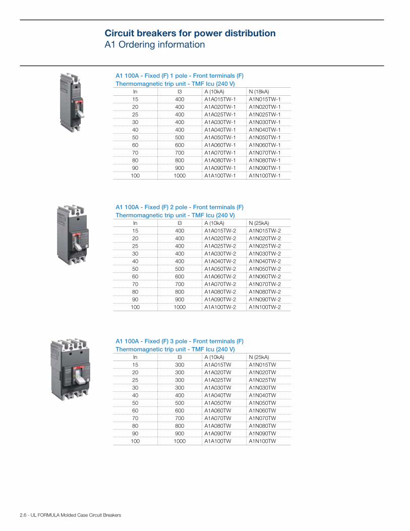
A1 100A - Fixed (F) 1 pole - Front terminals (F)
Thermomagnetic trip unit - TMF Icu (240 V)
In I3 A (10kA) N (18kA)
15 400 A1A015TW-1 A1N015TW-1
20 400 A1A020TW-1 A1N020TW-1
25 400 A1A025TW-1 A1N025TW-1
30 400 A1A030TW-1 A1N030TW-1
40 400 A1A040TW-1 A1N040TW-1
50 500 A1A050TW-1 A1N050TW-1
60 600 A1A060TW-1 A1N060TW-1
70 700 A1A070TW-1 A1N070TW-1
80 800 A1A080TW-1 A1N080TW-1
90 900 A1A090TW-1 A1N090TW-1
100 1000 A1A100TW-1 A1N100TW-1
A1 100A - Fixed (F) 2 pole - Front terminals (F)
Thermomagnetic trip unit - TMF Icu (240 V)
In I3 A (10kA) N (25kA)
15 400 A1A015TW-2 A1N015TW-2
20 400 A1A020TW-2 A1N020TW-2
25 400 A1A025TW-2 A1N025TW-2
30 400 A1A030TW-2 A1N030TW-2
40 400 A1A040TW-2 A1N040TW-2
50 500 A1A050TW-2 A1N050TW-2
60 600 A1A060TW-2 A1N060TW-2
70 700 A1A070TW-2 A1N070TW-2
80 800 A1A080TW-2 A1N080TW-2
90 900 A1A090TW-2 A1N090TW-2
100 1000 A1A100TW-2 A1N100TW-2
A1 100A - Fixed (F) 3 pole - Front terminals (F)
Thermomagnetic trip unit - TMF Icu (240 V)
In I3 A (10kA) N (25kA)
15 300 A1A015TW A1N015TW
20 300 A1A020TW A1N020TW
25 300 A1A025TW A1N025TW
30 300 A1A030TW A1N030TW
40 400 A1A040TW A1N040TW
50 500 A1A050TW A1N050TW
60 600 A1A060TW A1N060TW
70 700 A1A070TW A1N070TW
80 800 A1A080TW A1N080TW
90 900 A1A090TW A1N090TW
100 1000 A1A100TW A1N100TW
4.2 - UL FORMULA Molded Case Circuit Breakers
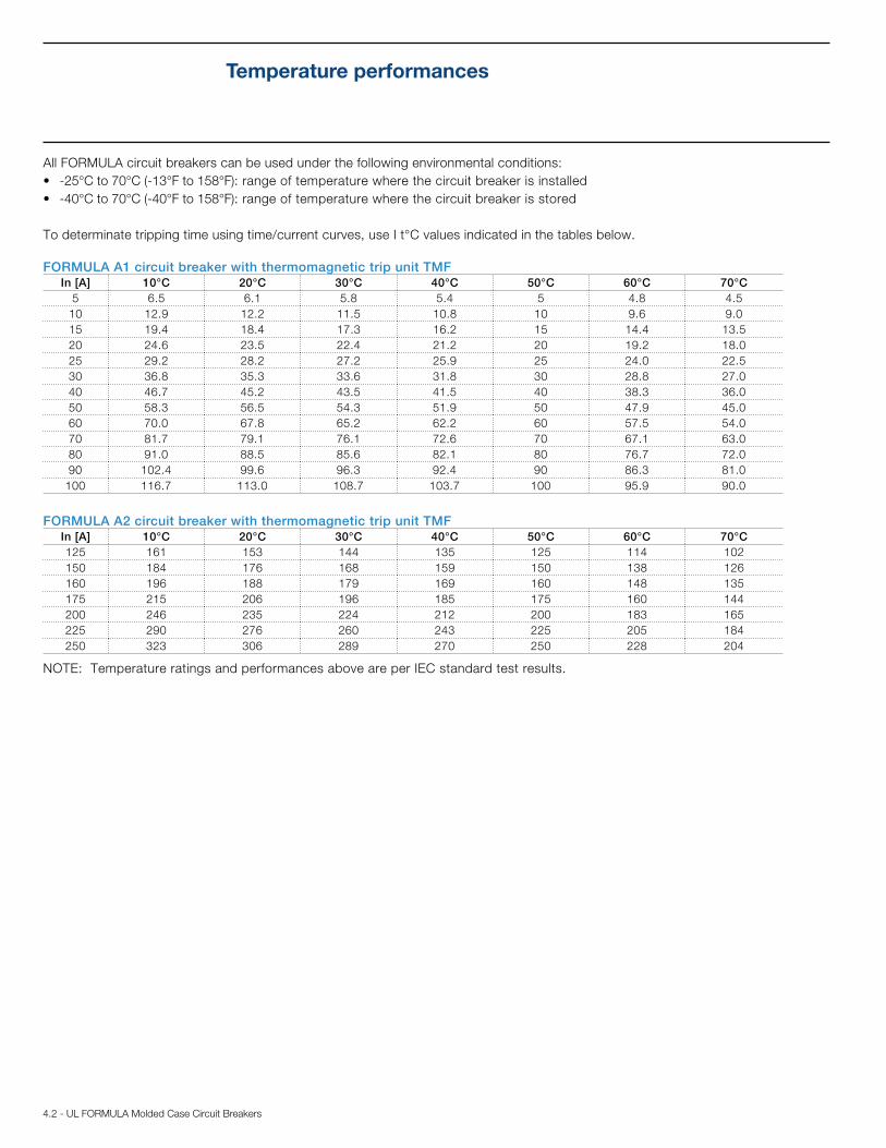
All FORMULA circuit breakers can be used under the following environmental conditions:
-25°C to 70°C (-13°F to 158°F): range of temperature where the circuit breaker is installed
-40°C to 70°C (-40°F to 158°F): range of temperature where the circuit breaker is stored
To determinate tripping time using time/current curves, use I t°C values indicated in the tables below.
Temperature performances
FORMULA A1 circuit breaker with thermomagnetic trip unit TMF In [A] 10°C 20°C 30°C 40°C 50°C 60°C 70°C
5 6.5 6.1 5.8 5.4 5 4.8 4.5
10 12.9 12.2 11.5 10.8 10 9.6 9.0
15 19.4 18.4 17.3 16.2 15 14.4 13.5
20 24.6 23.5 22.4 21.2 20 19.2 18.0
25 29.2 28.2 27.2 25.9 25 24.0 22.5
30 36.8 35.3 33.6 31.8 30 28.8 27.0
40 46.7 45.2 43.5 41.5 40 38.3 36.0
50 58.3 56.5 54.3 51.9 50 47.9 45.0
60 70.0 67.8 65.2 62.2 60 57.5 54.0
70 81.7 79.1 76.1 72.6 70 67.1 63.0
80 91.0 88.5 85.6 82.1 80 76.7 72.0
90 102.4 99.6 96.3 92.4 90 86.3 81.0
100 116.7 113.0 108.7 103.7 100 95.9 90.0
FORMULA A2 circuit breaker with thermomagnetic trip unit TMFIn [A] 10°C 20°C 30°C 40°C 50°C 60°C 70°C
125 161 153 144 135 125 114 102
150 184 176 168 159 150 138 126
160 196 188 179 169 160 148 135
175 215 206 196 185 175 160 144
200 246 235 224 212 200 183 165
225 290 276 260 243 225 205 184
250 323 306 289 270 250 228 204
NOTE: Temperature ratings and performances above are per IEC standard test results.
UL FORMULA Molded Case Circuit Breakers - 4.3
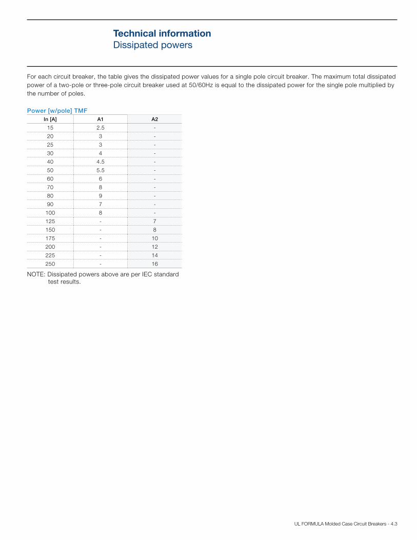
For each circuit breaker, the table gives the dissipated power values for a single pole circuit breaker. The maximum total dissipated
power of a two-pole or three-pole circuit breaker used at 50/60Hz is equal to the dissipated power for the single pole multiplied by
the number of poles.
Technical information
Dissipated powers
Power [w/pole] TMF
In [A] A1 A2
15 2.5 -
20 3 -
25 3 -
30 4 -
40 4.5 -
50 5.5 -
60 6 -
70 8 -
80 9 -
90 7 -
100 8 -
125 - 7
150 - 8
175 - 10
200 - 12
225 - 14
250 - 16
NOTE: Dissipated powers above are per IEC standard
test results.
5.2 - UL FORMULA Molded Case Circuit Breakers
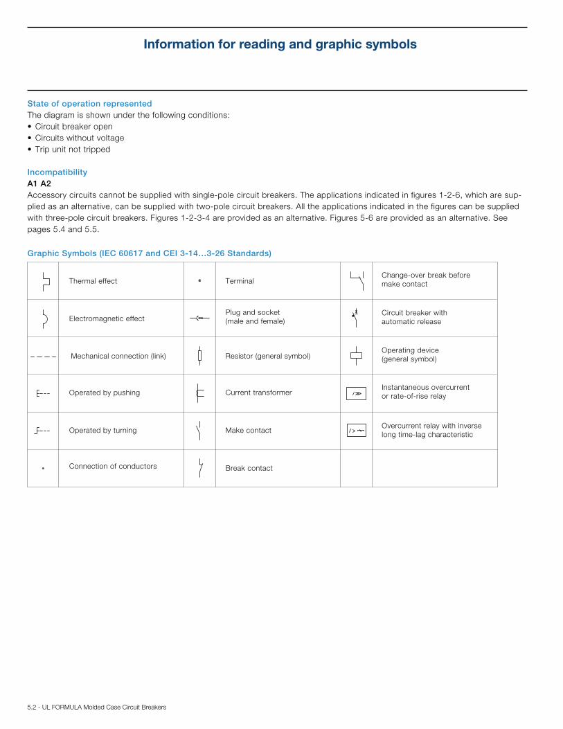
Information for reading and graphic symbols
Graphic Symbols (IEC 60617 and CEI 3-14…3-26 Standards)
Thermal effect
Electromagnetic effect
Mechanical connection (link)
Operated by pushing
Plug and socket
(male and female)
Resistor (general symbol)
Make contact
Break contact
Terminal
Circuit breaker with
automatic release
Operating device
(general symbol)
Change-over break before
make contact
Connection of conductors
State of operation represented
The diagram is shown under the following conditions:
Incompatibility
A1 A2
Accessory circuits cannot be supplied with single-pole circuit breakers. The applications indicated in figures 1-2-6, which are sup-
plied as an alternative, can be supplied with two-pole circuit breakers. All the applications indicated in the figures can be supplied
with three-pole circuit breakers. Figures 1-2-3-4 are provided as an alternative. Figures 5-6 are provided as an alternative. See
pages 5.4 and 5.5.
Operated by turning
Current transformerInstantaneous overcurrent
or rate-of-rise relay
Overcurrent relay with inverse
long time-lag characteristic
UL FORMULA Molded Case Circuit Breakers - 5.3
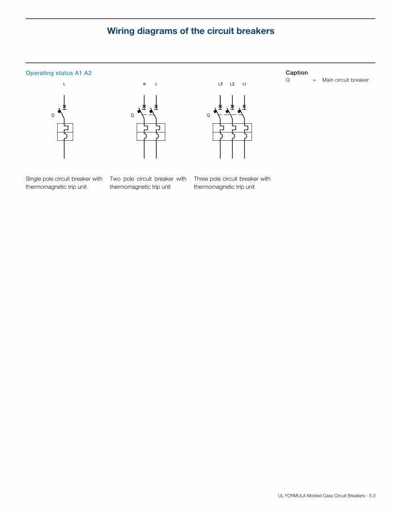
Wiring diagrams of the circuit breakers
Operating status A1 A2
Single pole circuit breaker with
thermomagnetic trip unit
Two pole circuit breaker with
thermomagnetic trip unit
Three pole circuit breaker with
thermomagnetic trip unit
Caption
Q = Main circuit breaker
5.4 - UL FORMULA Molded Case Circuit Breakers
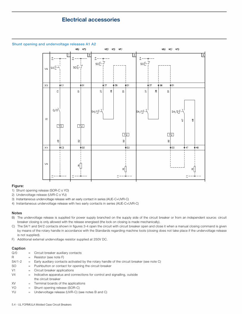
Electrical accessories
Shunt opening and undervoltage releases A1 A2
Figure:
1) Shunt opening release (SOR-C o YO)
2) Undervoltage release (UVR-C o YU)
3) Instantaneous undervoltage release with an early contact in series (AUE-C+UVR-C)
4) Instantaneous undervoltage release with two early contacts in series (AUE-C+UVR-C)
Notes
B) The undervoltage release is supplied for power supply branched on the supply side of the circuit breaker or from an independent source: circuit
breaker closing is only allowed with the release energised (the lock on closing is made mechanically).
C) The S4/1 and S4/2 contacts shown in figures 3-4 open the circuit with circuit breaker open and close it when a manual closing command is given
by means of the rotary handle in accordance with the Standards regarding machine tools (closing does not take place if the undervoltage release
is not supplied).
F) Additional external undervoltage resistor supplied at 250V DC.
Caption
Q/0 = Circuit breaker auxiliary contacts
R = Resistor (see note F)
S4/1-2 = Early auxiliary contacts activated by the rotary handle of the circuit breaker (see note C)
SO = Pushbutton or contact for opening the circuit breaker
V1 = Circuit breaker applications
V4 = Indicative apparatus and connections for control and signalling, outside
the circuit breaker
XV = Terminal boards of the applications
YO = Shunt opening release (SOR-C)
YU = Undervoltage release (UVR-C) (see notes B and C)
6.2 - UL FORMULA Molded Case Circuit Breakers
1.50
38.1
0.98
25
0.98
25
2.56
65
5.12
130
1.26
32
2.80
71
3.00
76.2
2.00
50.8
1.49
37.9
0.98
25
0.92
23.4
5.12
130
2.56
65
2.56
65
5.12
130
1.0
25.4
2.87
73
2.68
68
2.36
60
0.55
14
0.63
16
1.77
45
1.61
41
3.54
90
0.12
3
.08
2
0.92
23.4
2.56
65
5.12
130
1.50
38.1
0.98
25
0.98
25
1.26
32
2.80
71
3.00
76.2
5.12
130
2.56
65
2.00
50.8
1.49
37.9
0.98
25
5.12
130
2.56
65
2.00
50.8
1.0
25.4
0.92
23.4
0.92
23.4
3.54
90
.30
7.5
2.87
73
2.68
68
2.36
60
.06
1.5
1.38
35
0.22
5.5
0.63
16
1.77
45
1.61
41
0.55
14
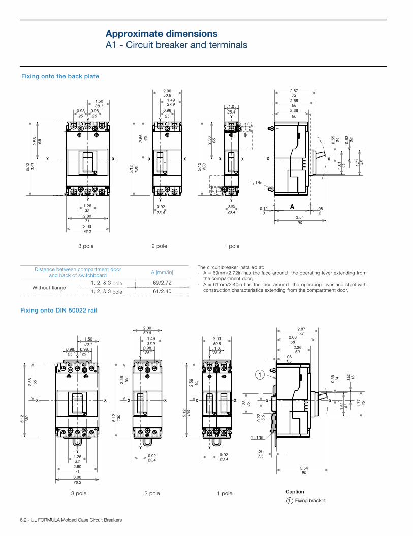
Approximate dimensions
A1 - Circuit breaker and terminals
Fixing onto the back plate
Fixing onto DIN 50022 rail
Distance between compartment door
and back of switchboardA [mm/in]
Without flange1, 2, & 3 pole 69/2.72
1, 2, & 3 pole 61/2.40
Caption
1 Fixing bracket
3 pole 2 pole 1 pole
3 pole 2 pole 1 pole
The circuit breaker installed at:
- A = 69mm/2.72in has the face around the operating lever extending from
the compartment door;
- A = 61mm/2.40in has the face around the operating lever and steel with
construction characteristics extending from the compartment door.
UL FORMULA Molded Case Circuit Breakers - 6.3
0.98
25
0.49
12.5
0.18 - M4
4.5
4.2
1
107
2.1
1
53.5
0.49
12.5 0.18 - M4
4.5
2.1
1
53.5
4.2
1
107
1.34
34
0.5
9
15
1.6
9
43
0.67
17
1.8
5
47
0.6
6
17
2.07
52.5
1.54
39
2.87
73
1.44
36.5
1.8
5
47
0.6
6
17
1.06
27
0.53
13.5
0.6
6
17
1.8
5
47
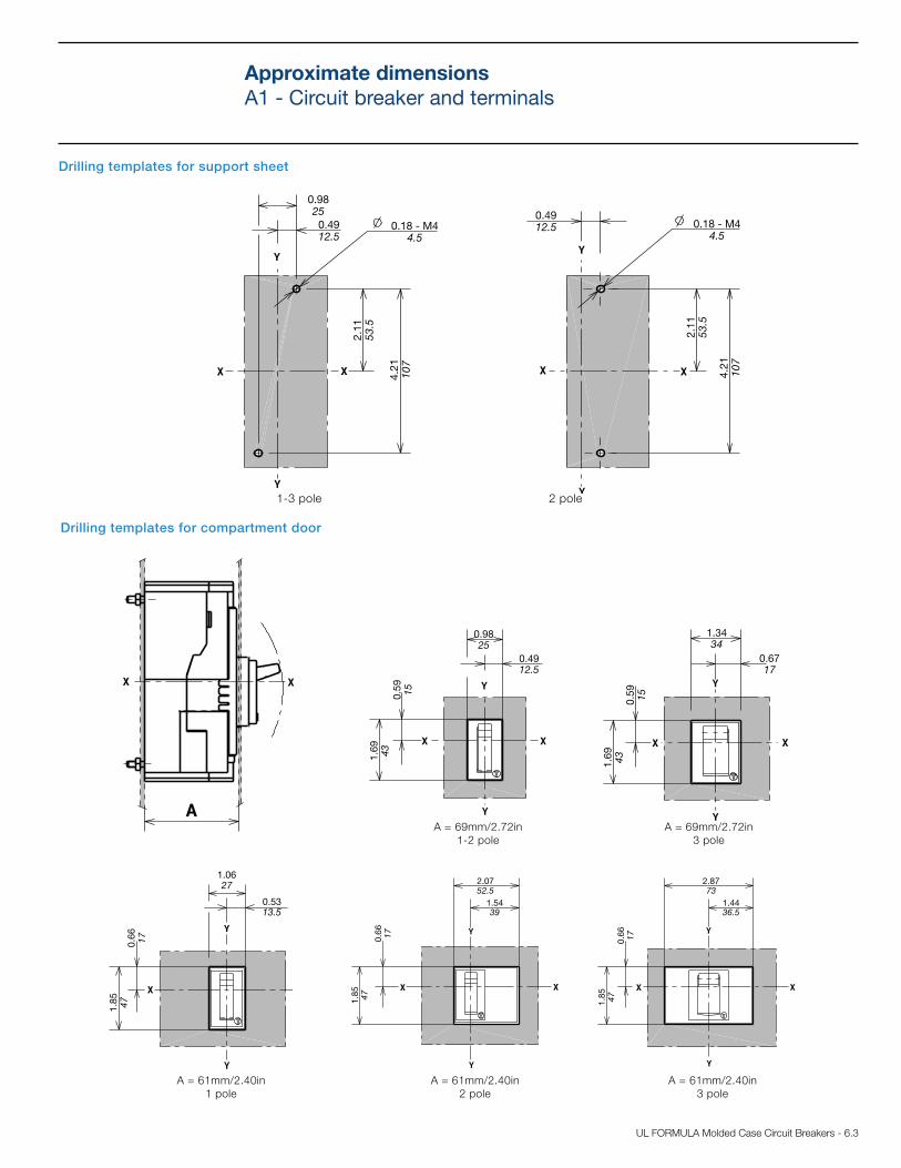
Drilling templates for support sheet
Drilling templates for compartment door
1-3 pole 2 pole
A = 69mm/2.72in
1-2 pole
A = 69mm/2.72in
3 pole
A = 61mm/2.40in
1 pole
A = 61mm/2.40in
2 pole
A = 61mm/2.40in
3 pole
Approximate dimensions
A1 - Circuit breaker and terminals
0.98
25
0.49
12.5
0.5
9
15
1.6
9
43
6.4 - UL FORMULA Molded Case Circuit Breakers
0.55
14
1.9
7
50
2.56
6.5
1.9
7
50
0.55
14
2.56
6.5
0.55
14
2.56
6.5
1.9
7
50
0.98
25
2.2
5
57.25
2.0
5
0.59
15
0.59
15
0.59
15
0.2
4 M
AX
6
0.2
4 M
AX
6
0.2
4 M
AX
6
0.98
25
0.98
25
0.61
15.5
1.9
7
50
5.1
2
130
1.9
7
50
0.33
8.5
0.98
0.98
25
0.12
5
6.0
4
153.5
1.9
7
50
0.61
15.5
0.98
25
0.33
8.5 1.9
7
50
0.61
15.5
1.00
25.4
0.33
8.5
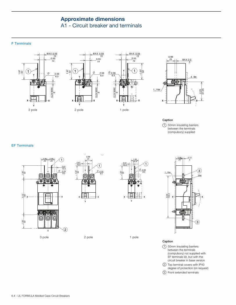
F Terminals
EF Terminals
Caption
1 50mm insulating barriers
between the terminals
(compulsory) not supplied with
EF terminals kit, but with the
circuit breaker in base version
2 Top terminal covers with IP40
degree of protection (on request)
3 Front extended terminals
Caption
1 50mm insulating barriers
between the terminals
(compulsory) supplied
3 pole 2 pole 1 pole
3 pole 2 pole 1 pole
Approximate dimensions
A1 - Circuit breaker and terminals

UL FORMULA Molded Case Circuit Breakers - 6.5
3.94
100
0.79
20
0.79
20
0.79
20
0.33
8.53.79
96.25
4.14
105.25
4.14
105.25
3.79
96.25
0.33
8.5
3.94
100
3.94
100
1.57
40
1.57
40
2.17
55
1.38
350.20
5
0.79
20
0.79
20
0.98
25
0.20
5
Caption
1 Front extended spread terminals
2 100mm insulating barriers
between the terminals
(compulsory) supplied
3 pole 2 pole
ES Terminals
Approximate dimensions
A1 - Circuit breaker and terminals
6.6 - UL FORMULA Molded Case Circuit Breakers
3.00
76.2
2.85
72.5
2.25
57.25
1.38
350.41
10.5
1.97
50
2.56
65
1.00
25.4 2.00
50.8
1.97
50
2.56
65
1.38
352.25
57.25
50.8
2.17
55
2.17
55
1.38
35
1.38
35
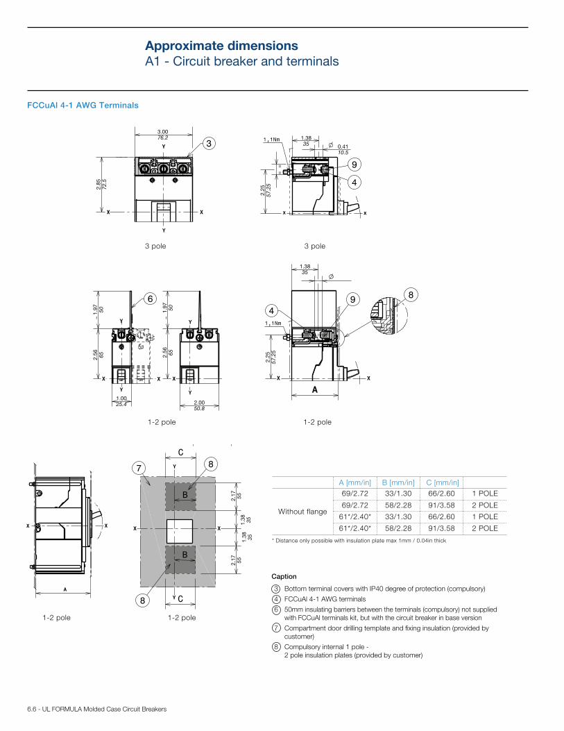
FCCuAl 4-1 AWG Terminals
Caption
3 Bottom terminal covers with IP40 degree of protection (compulsory)
4 FCCuAl 4-1 AWG terminals
6 50mm insulating barriers between the terminals (compulsory) not supplied
with FCCuAl terminals kit, but with the circuit breaker in base version
7 Compartment door drilling template and fixing insulation (provided by
customer)
8 Compulsory internal 1 pole -
2 pole insulation plates (provided by customer)
3 pole 3 pole
1-2 pole 1-2 pole
1-2 pole 1-2 pole
A [mm/in] B [mm/in] C [mm/in]
Without flange
69/2.72 33/1.30 66/2.60 1 POLE
69/2.72 58/2.28 91/3.58 2 POLE
61*/2.40* 33/1.30 66/2.60 1 POLE
61*/2.40* 58/2.28 91/3.58 2 POLE
* Distance only possible with insulation plate max 1mm / 0.04in thick
Approximate dimensions
A1 - Circuit breaker and terminals
UL FORMULA Molded Case Circuit Breakers - 6.7
50.8
2.17
55
2.17
55
1.38
35
1.38
35
3.00
76.2
2.85
72.5
2.25
57.25
0.55
14
0.28
7
1.44
36.5
1.97
50
2.56
65
1.00
25.4 2.00
50.8
1.97
50
2.56
65
1.44
36.50.28
7
2.25
57.25
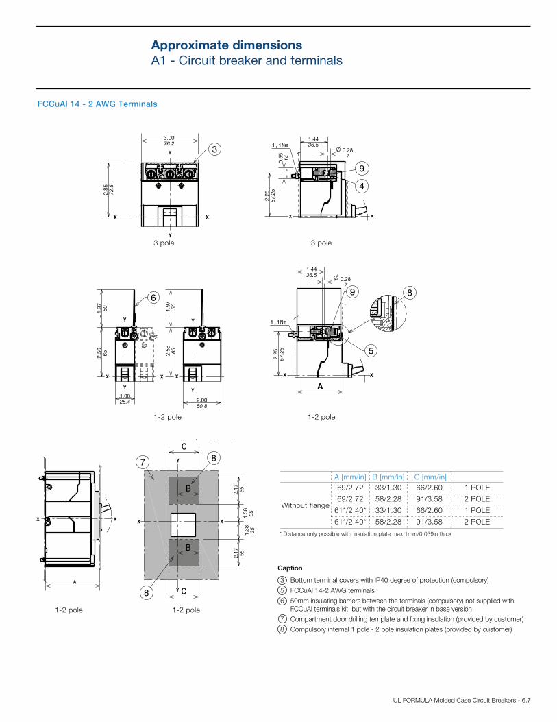
FCCuAl 14 - 2 AWG Terminals
Caption
3 Bottom terminal covers with IP40 degree of protection (compulsory)
5 FCCuAl 14-2 AWG terminals
6 50mm insulating barriers between the terminals (compulsory) not supplied with
FCCuAl terminals kit, but with the circuit breaker in base version
7 Compartment door drilling template and fixing insulation (provided by customer)
8 Compulsory internal 1 pole - 2 pole insulation plates (provided by customer)
3 pole 3 pole
1-2 pole 1-2 pole
1-2 pole 1-2 pole
A [mm/in] B [mm/in] C [mm/in]
Without flange
69/2.72 33/1.30 66/2.60 1 POLE
69/2.72 58/2.28 91/3.58 2 POLE
61*/2.40* 33/1.30 66/2.60 1 POLE
61*/2.40* 58/2.28 91/3.58 2 POLE
* Distance only possible with insulation plate max 1mm/0.039in thick
Approximate dimensions
A1 - Circuit breaker and terminals
6.8 - UL FORMULA Molded Case Circuit Breakers
3.0076.2
1.5038.1
1.8
446.80.5
714.5
5.1
2130
.082
0.9
323.5
7.87200
0.8922.5 0.08
2
0.9
323.5
0.5
714.5
0.205
minimum rotation radius for door fulcrum
22.01559
1.50134.2
5.1
2130
0.123
1.2030.5
2.3660
.57
14.5
1.8146
2.1
354
0.082
5.87149
0.123
1.8146
5.28134.2
2.3660
1.2030.5
0.082
2.1
354
5.1
2130
.57
14.5
heights for door with maximum distance
heights for door with maximum distance
0.205
2.17
55
1.5038.1
1.8
446.8
5.1
2130
0.5
714.5
.082
3.0076.2
5.86149.5
4.09104
2.3660
5.1
2130
3.8698
.082
0.123
0.1
43.5
2.8071
0.5714.5
1.4035.5
0.5514
2.3
459.5
0.143.5
1.8
547
3.0
076
7.87200
minimum rotation radius for door fulcrum
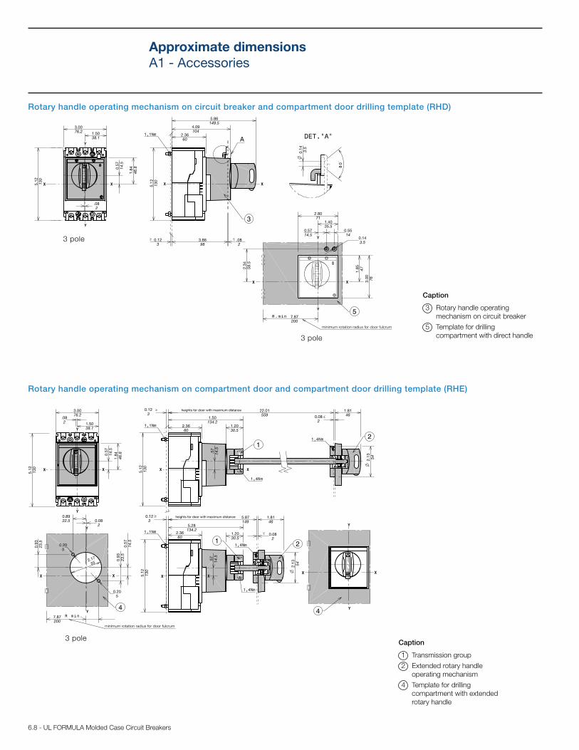
Rotary handle operating mechanism on circuit breaker and compartment door drilling template (RHD)
Rotary handle operating mechanism on compartment door and compartment door drilling template (RHE)
Caption
3 Rotary handle operating
mechanism on circuit breaker
5 Template for drilling
compartment with direct handle
Caption
1 Transmission group
2 Extended rotary handle
operating mechanism
4 Template for drilling
compartment with extended
rotary handle
3 pole
3 pole
3 pole
Approximate dimensions
A1 - Accessories
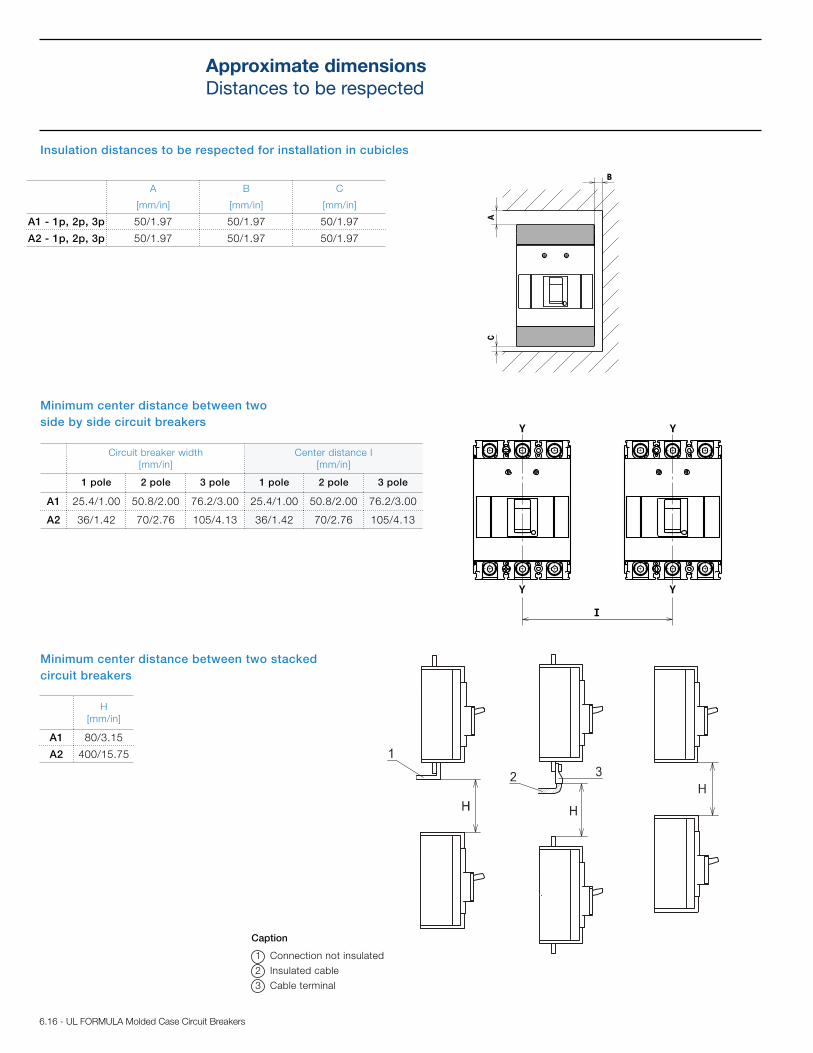
6.16 - UL FORMULA Molded Case Circuit Breakers
Insulation distances to be respected for installation in cubicles
A
[mm/in]
B
[mm/in]
C
[mm/in]
A1 - 1p, 2p, 3p 50/1.97 50/1.97 50/1.97
A2 - 1p, 2p, 3p 50/1.97 50/1.97 50/1.97
Minimum center distance between two
side by side circuit breakers
Circuit breaker width
[mm/in]
Center distance I
[mm/in]
1 pole 2 pole 3 pole 1 pole 2 pole 3 pole
A1 25.4/1.00 50.8/2.00 76.2/3.00 25.4/1.00 50.8/2.00 76.2/3.00
A2 36/1.42 70/2.76 105/4.13 36/1.42 70/2.76 105/4.13
Minimum center distance between two stacked
circuit breakers
H
[mm/in]
A1 80/3.15
A2 400/15.75
Caption
1 Connection not insulated
2 Insulated cable
3 Cable terminal
Approximate dimensions
Distances to be respected