switches & breakers - hitachi industrial equipment (malaysia
TRANSCRIPT

MAGNETIC STARTERS AND CONTACTORS
Types and Models ....................................... 3 Ratings and Specifi cations Magnetic Starters and Contactors ....... 6 Thermal Overload Relays .................... 9 Option ................................................ 11
MOLDED CASE CIRCUIT BREAKERS Types and Models ..................................... 12 Composition of Interrupting Capacity ........ 13 Ratings and Specifi cations .........................14
EARTH LEAKAGE BREAKERS
Types and Models ..................................... 20 Composition of Interrupting Capacity ........ 20 Ratings and Specifi cations ........................ 21
EARTH LEAKAGE RELAYS
Types and Models ..................................... 24 Ratings and Specifi cations Earth Leakage Relays ........................ 24 Zero-Phase-Sequence Current Transformers ......................... 25
AIR CIRCUIT BREAKERS
Types and Models ..................................... 26 Ratings and Specifi cations ........................ 28
SELECTION ........................................................... 32
MINIATURE CIRCUIT BREAKERS ................. 35
2
MAGNETIC STARTERS AND CONTACTORS
3
4
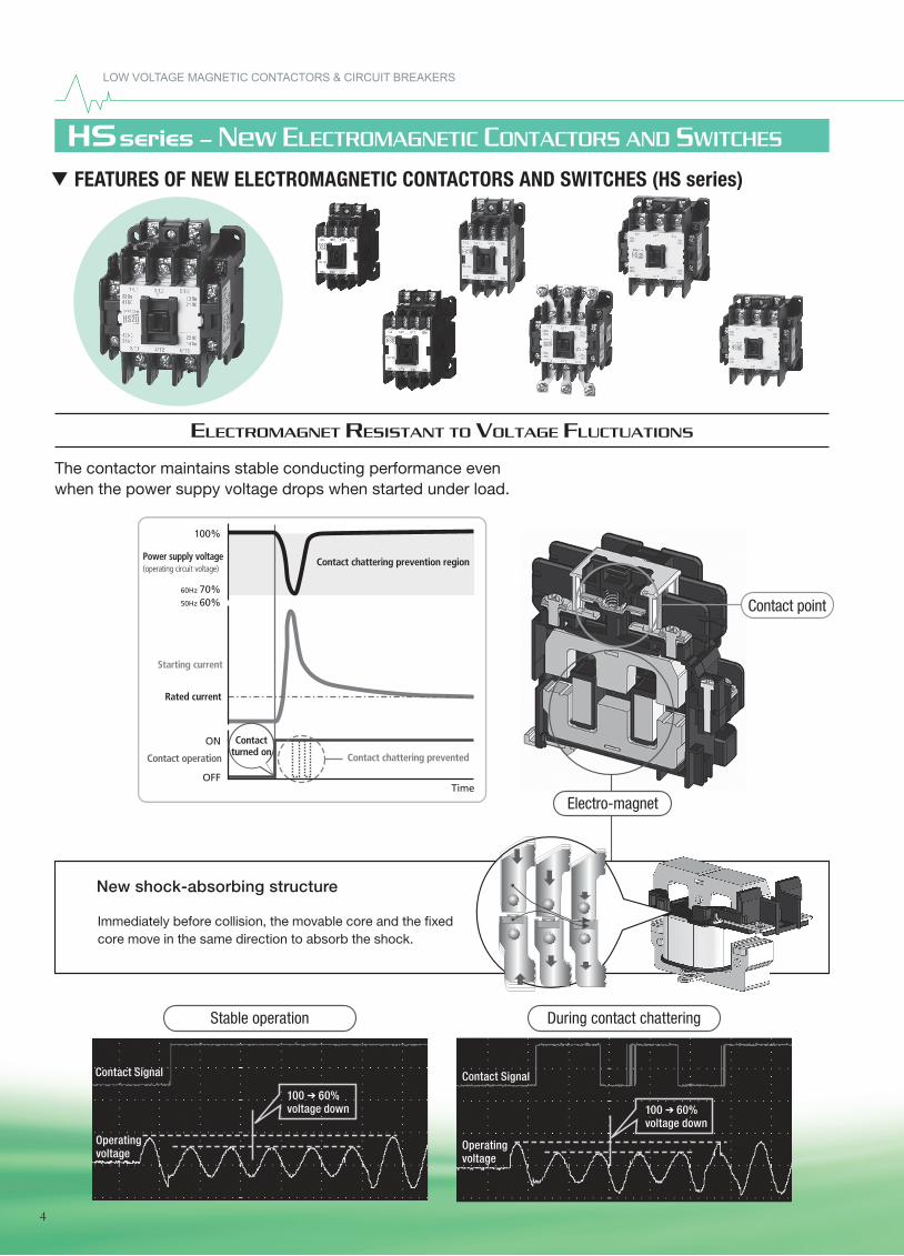
Immediately before collision, the movable core and the �xed core move in the same direction to absorb the shock.
Operatingvoltage
Contact Signal
100 ( 60%voltage down
Operatingvoltage
Contact Signal
100 ( 60%voltage down
Contact point
Electro-magnet
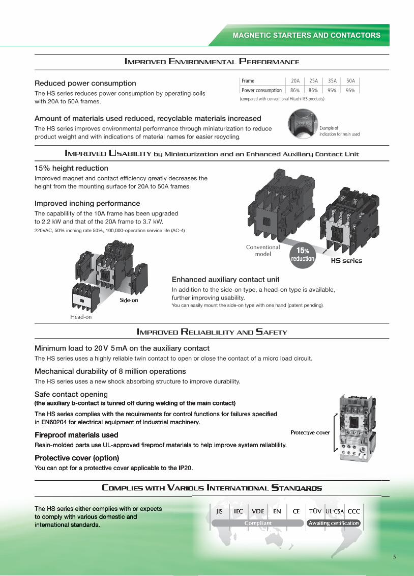
Enhanced auxiliary contact unitIn addition to the side-on type, a head-on type is available, further improving usability.You can easily mount the side-on type with one hand (patent pending).
Reduced power consumptionThe HS series reduces power consumption by operating coilswith 20A to 50A frames.
Amount of materials used reduced, recyclable materials increasedThe HS series improves environmental performance through miniaturization to reduce product weight and with indications of material names for easier recycling.
15% height reductionImproved magnet and contact ef�ciency greatly decreases the height from the mounting surface for 20A to 50A frames.
Improved inching performanceThe capablility of the 10A frame has been upgraded to 2.2 kW and that of the 20A frame to 3.7 kW.220VAC, 50% inching rate 50%, 100,000-operation service life (AC-4)
Minimum load to 20V 5mA on the auxiliary contactThe HS series uses a highly reliable twin contact to open or close the contact of a micro load circuit.
Mechanical durability of 8 million operationsThe HS series uses a new shock absorbing structure to improve durability.
Safe contact opening(the auxiliary b-contact is tunred off during welding of the main contact)
The HS series complies with the requirements for control functions for failures speci�ed in EN60204 for electrical equipment of industrial machinery.
Fireproof materials usedResin-molded parts use UL-approved �reproof materials to help improve system reliablility.
Protective cover (option)You can opt for a protective cover applicable to the IP20.During contact chatteringStable operation
95% 95%
New shock-absorbing structure
The HS series either complies with or expects to comply with various domestic and international standards.
The contactor maintains stable conducting performance even when the power suppy voltage drops when started under load.
ELECTROMAGNET RESISTANT TO VOLTAGE FLUCTUATIONS
IMPROVED ENVIRONMENTAL PERFORMANCE
IMPROVED USABILITY by Miniaturization and an Enhanced Auxiliary Contact Unit
IMPROVED RELIABLILITY AND SAFETY
COMPLIES WITH VARIOUS INTERNATIONAL STANDARDS
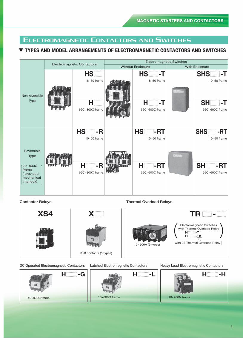
1. TYPES AND MODEL ARRANGEMENTS OF ELECTROMAGNETIC CONTACTORS AND SWITCHES
TR -
12-600A (9 types)
H -L
10 -600C frame
H -G
10 -800C frame
XS4 X
3-8 contacts (5 types)
( )
Contactor Relays
DC Operated Electromagnetic Contactors Latched Electromagnetic Contactors Heavy Load Electromagnetic Contactors
Thermal Overload Relays
Electromagnetic ContactorsElectromagnetic Switches
Without Enclosure With Enclosure
Non-reversible
Type
HS8 -50 frame
HS -T8 -50 frame
SHS -T10 -50 frame
H65C -800C frame
H -T65C -600C frame
SH -T65C -600C frame
Reversible
Type
20-800C frame(:providedmechanicalinterlock)
HS -R10 -50 frame
HS -RT10 -50 frame
SHS -RT10 -50 frame
H -R65C -800C frame
H -RT65C -600C frame
SH -RT65C -600C frame
H -H
10 -200N frame
Electromagnetic Switcheswith Thermal Overload Relay H -T H -TK
with 2E Thermal Overload Relay
ELECTROMAGNETIC CONTACTORS AND SWITCHES
57
(Example 3) Case of H300C—H800CCoil and control unit must be changed at the same time.
Remove the connecting wires (red, white, yellow) between coil and control unit.Remove the control unit.
After loosing screws, remove the holding plate.Remove the coil and replace to prescribed coil.
Replace the control unit which must be suit for the coil, at the same time of coil replacement.Notes: In case of H600C-R and H800C-R (Reversible type), mount the control unit of the contactor for forward on the left side.
Reconnect the wires (red, white, yellow) between coil and control unit.Notes: Bind the wires with the binder (a) packed with the control unit.
H300C, H400C H600C, H800C
Notes:In case of H600C, H800C, connecting wires and coil lead wires have the numbers (1, 2, and 3) at the end of wires.Connect the wires of same number with the terminals.
On mounting the changeover switch (b) on the control unit with screw, projection of movable portion on the changeover swich must be inserted to the hole of crossbar (c) for the auxiliary contact of contactor.Caution: Insert the projection of the changeover switch to the correct hole of auxiliary contact unit
H300C, H400C H600C, H800C
Connect the two blue wires (In case of H600C and H800C, black) with the terminals of changeover switch.Notes:After reassembling, adjust position of the control unit to make distance between the top of the changeover switch with the auxiliary contact unit closer than 1mm.
Notes:1) The changeover switches of H600C and H800C differ from H300C and 400C'S ones. (Their
shapes are the same but parts in it are not the same.)2) There is the white mark on the case of H600C and H800C's changeover switch, but no
mark on H300C and H400C's one.
Connecting holes
A
C
E
B
D
F
56
14. MAINTENANCE! Maintenance of ContactsContacts are sometimes subjected to blackening during usage due to oxide and sulfide films. However, use them as they are because they have absolutely no effect on the performance.
! Maintenance of CoilThe allowable voltage regulation as specified in the standard is 85–110% of the rating.When the voltage is too high, the impulse becomes great in case of closing and not only does it adversely affect each part but the coil becomes overheated and the coil life is shortened.When the voltage is too low, a humming sound emanates from the magnet due to insufficient closing force of the magnet or a melting phenomenon occurs as the contacting force of the contactor weakens. Therefore, care should be taken that it is only used in the allowable voltage range.
! Tightening of ScrewsSince screws will become loosened over a long period of time due to vibrations, etc., be sure to check screws of each section about once a month. When used with the screw loose, the section will overheat and cause troubles.
! Contact Surface of ElectromagnetIt will become the cause of beats when dust accumulates or rust forms on the contact surface.! When dust accumulates on the contact surface:
Clean the surface by wiping with a cloth.! When rust forms on the contact surface:
Place sandpaper on a flat table and rub the rusted contact surface lightly and evenly on the sandpaper with the rusted surface facing downward.
! Replacement Method of Contact(Example 1) Case of H20
Remove the cover.
(Example 2) Case of H150C
Remove the cover and turn the spring holder. Turn the spring holder with fingers or a screwdriver by pushing to the P or O direction.
The moving contact can be removed when turned slightly. Remove the fixed contact with a screwdriver.
Pull out the moving contact with tweezers. Replace the fixed contact with a screwdriver.
Notes: In reassembly, turn the spring holder completely back to its former position.
! Replacement of Coil(Example 1) Case of H20
Remove case.(Example 2) Case of H150C
A1 Loose screws securing Insulating cover to case.
Remove the coil and replace with a new one.
B1 After removing Insulating cover, loose 3 screws of coil terminals.
B2 Remove control unit and return spring.
C1 Replace to prescribed coil.C2 Reassemble in order B2 - B1 - A1C3 Control unit must be suit for replaced coil, and
must be replaced with coil at the same time.C4 Coil terminals for excepting 100/200V coil are
C1 - B2 .C5 Secure transparent dustproof covers on both sides.
5
Immediately before collision, the movable core and the �xed core move in the same direction to absorb the shock.
Operatingvoltage
Contact Signal
100 ( 60%voltage down
Operatingvoltage
Contact Signal
100 ( 60%voltage down
Contact point
Electro-magnet
Enhanced auxiliary contact unitIn addition to the side-on type, a head-on type is available, further improving usability.You can easily mount the side-on type with one hand (patent pending).
Reduced power consumptionThe HS series reduces power consumption by operating coilswith 20A to 50A frames.
Amount of materials used reduced, recyclable materials increasedThe HS series improves environmental performance through miniaturization to reduce product weight and with indications of material names for easier recycling.
15% height reductionImproved magnet and contact ef�ciency greatly decreases the height from the mounting surface for 20A to 50A frames.
Improved inching performanceThe capablility of the 10A frame has been upgraded to 2.2 kW and that of the 20A frame to 3.7 kW.220VAC, 50% inching rate 50%, 100,000-operation service life (AC-4)
Minimum load to 20V 5mA on the auxiliary contactThe HS series uses a highly reliable twin contact to open or close the contact of a micro load circuit.
Mechanical durability of 8 million operationsThe HS series uses a new shock absorbing structure to improve durability.
Safe contact opening(the auxiliary b-contact is tunred off during welding of the main contact)
The HS series complies with the requirements for control functions for failures speci�ed in EN60204 for electrical equipment of industrial machinery.
Fireproof materials usedResin-molded parts use UL-approved �reproof materials to help improve system reliablility.
Protective cover (option)You can opt for a protective cover applicable to the IP20.During contact chatteringStable operation
95% 95%
New shock-absorbing structure
The HS series either complies with or expects to comply with various domestic and international standards.
The contactor maintains stable conducting performance even when the power suppy voltage drops when started under load.
ELECTROMAGNET RESISTANT TO VOLTAGE FLUCTUATIONS
IMPROVED ENVIRONMENTAL PERFORMANCE
IMPROVED USABILITY by Miniaturization and an Enhanced Auxiliary Contact Unit
IMPROVED RELIABLILITY AND SAFETY
COMPLIES WITH VARIOUS INTERNATIONAL STANDARDS
2. FEATURES OF NEW ELECTROMAGNETIC CONTACTORS AND SWITCHES (HS series)
HSseries – New ELECTROMAGNETIC CONTACTORS AND SWITCHES
LOW VOLTAGE MAGNETIC CONTACTORS & CIRCUIT BREAKERS
56
14. MAINTENANCE! Maintenance of ContactsContacts are sometimes subjected to blackening during usage due to oxide and sulfide films. However, use them as they are because they have absolutely no effect on the performance.
! Maintenance of CoilThe allowable voltage regulation as specified in the standard is 85–110% of the rating.When the voltage is too high, the impulse becomes great in case of closing and not only does it adversely affect each part but the coil becomes overheated and the coil life is shortened.When the voltage is too low, a humming sound emanates from the magnet due to insufficient closing force of the magnet or a melting phenomenon occurs as the contacting force of the contactor weakens. Therefore, care should be taken that it is only used in the allowable voltage range.
! Tightening of ScrewsSince screws will become loosened over a long period of time due to vibrations, etc., be sure to check screws of each section about once a month. When used with the screw loose, the section will overheat and cause troubles.
! Contact Surface of ElectromagnetIt will become the cause of beats when dust accumulates or rust forms on the contact surface.! When dust accumulates on the contact surface:
Clean the surface by wiping with a cloth.! When rust forms on the contact surface:
Place sandpaper on a flat table and rub the rusted contact surface lightly and evenly on the sandpaper with the rusted surface facing downward.
! Replacement Method of Contact(Example 1) Case of H20
Remove the cover.
(Example 2) Case of H150C
Remove the cover and turn the spring holder. Turn the spring holder with fingers or a screwdriver by pushing to the P or O direction.
The moving contact can be removed when turned slightly. Remove the fixed contact with a screwdriver.
Pull out the moving contact with tweezers. Replace the fixed contact with a screwdriver.
Notes: In reassembly, turn the spring holder completely back to its former position.
! Replacement of Coil(Example 1) Case of H20
Remove case.(Example 2) Case of H150C
A1 Loose screws securing Insulating cover to case.
Remove the coil and replace with a new one.
B1 After removing Insulating cover, loose 3 screws of coil terminals.
B2 Remove control unit and return spring.
C1 Replace to prescribed coil.C2 Reassemble in order B2 - B1 - A1C3 Control unit must be suit for replaced coil, and
must be replaced with coil at the same time.C4 Coil terminals for excepting 100/200V coil are
C1 - B2 .C5 Secure transparent dustproof covers on both sides.
5
Immediately before collision, the movable core and the �xed core move in the same direction to absorb the shock.
Operatingvoltage
Contact Signal
100 ( 60%voltage down
Operatingvoltage
Contact Signal
100 ( 60%voltage down
Contact point
Electro-magnet
Enhanced auxiliary contact unitIn addition to the side-on type, a head-on type is available, further improving usability.You can easily mount the side-on type with one hand (patent pending).
Reduced power consumptionThe HS series reduces power consumption by operating coilswith 20A to 50A frames.
Amount of materials used reduced, recyclable materials increasedThe HS series improves environmental performance through miniaturization to reduce product weight and with indications of material names for easier recycling.
15% height reductionImproved magnet and contact ef�ciency greatly decreases the height from the mounting surface for 20A to 50A frames.
Improved inching performanceThe capablility of the 10A frame has been upgraded to 2.2 kW and that of the 20A frame to 3.7 kW.220VAC, 50% inching rate 50%, 100,000-operation service life (AC-4)
Minimum load to 20V 5mA on the auxiliary contactThe HS series uses a highly reliable twin contact to open or close the contact of a micro load circuit.
Mechanical durability of 8 million operationsThe HS series uses a new shock absorbing structure to improve durability.
Safe contact opening(the auxiliary b-contact is tunred off during welding of the main contact)
The HS series complies with the requirements for control functions for failures speci�ed in EN60204 for electrical equipment of industrial machinery.
Fireproof materials usedResin-molded parts use UL-approved �reproof materials to help improve system reliablility.
Protective cover (option)You can opt for a protective cover applicable to the IP20.During contact chatteringStable operation
95% 95%
New shock-absorbing structure
The HS series either complies with or expects to comply with various domestic and international standards.
The contactor maintains stable conducting performance even when the power suppy voltage drops when started under load.
ELECTROMAGNET RESISTANT TO VOLTAGE FLUCTUATIONS
IMPROVED ENVIRONMENTAL PERFORMANCE
IMPROVED USABILITY by Miniaturization and an Enhanced Auxiliary Contact Unit
IMPROVED RELIABLILITY AND SAFETY
COMPLIES WITH VARIOUS INTERNATIONAL STANDARDS
2. FEATURES OF NEW ELECTROMAGNETIC CONTACTORS AND SWITCHES (HS series)
HSseries – New ELECTROMAGNETIC CONTACTORS AND SWITCHES
4
Reduced power consumptionThe HS series reduces power consumption by operating coilswith 20A to 50A frames.
Amount of materials used reduced, recyclable materials increasedThe HS series improves environmental performance through miniaturization to reduce product weight and with indications of material names for easier recycling.
95% 95%
IMPROVED ENVIRONMENTAL PERFORMANCE
IMPROVED USABILITY by Miniaturization and an Enhanced Auxiliary Contact Unit
Enhanced auxiliary contact unitIn addition to the side-on type, a head-on type is available, further improving usability.You can easily mount the side-on type with one hand (patent pending).
15% height reductionImproved magnet and contact ef�ciency greatly decreases the height from the mounting surface for 20A to 50A frames.
Improved inching performanceThe capablility of the 10A frame has been upgraded to 2.2 kW and that of the 20A frame to 3.7 kW.220VAC, 50% inching rate 50%, 100,000-operation service life (AC-4)
IMPROVED RELIABLILITY AND SAFETY
Minimum load to 20V 5mA on the auxiliary contactThe HS series uses a highly reliable twin contact to open or close the contact of a micro load circuit.
Mechanical durability of 8 million operationsThe HS series uses a new shock absorbing structure to improve durability.
Safe contact opening(the auxiliary b-contact is tunred off during welding of the main contact)(the auxiliary b-contact is tunred off during welding of the main contact)
The HS series complies with the requirements for control functions for failures speci�ed in EN60204 for electrical equipment of industrial machinery.
Fireproof materials usedResin-molded parts use UL-approved �reproof materials to help improve system reliablility.
Protective cover (option)You can opt for a protective cover applicable to the IP20.
MAGNETIC STARTERS AND CONTACTORS
5
The HS series either complies with or expects to comply with various domestic and international standards.
COMPLIES WITH VARIOUS ARIOUS VARIOUS V INTERNATIONAL NTERNATIONAL NTERNATIONAL NTERNATIONAL NTERNATIONAL NTERNATIONAL SSSTANDARDSTANDARDSTANDARDSTANDARDSTANDARDSTANDARDSTANDARDSTANDARDSTANDARDSTANDARDSTANDARDS
LOW VOLTAGE MAGNETIC CONTACTORS & CIRCUIT BREAKERS
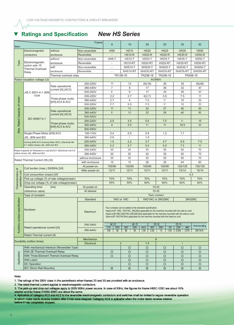
Ratings and Specifi cation New HS SeriesFrame
ItemElectromagnetic without Non-reversible HS8 HS10 HS20 HS25 HS35 HS50contactors enclosure Reversible - HS10-R HS20-R HS25-R HS35-R HS50-R
without Non-reversible HS8-T HS10-T HS20-T HS25-T HS35-T HS50-Tenclosure Reversible - HS10-RT HS20-RT HS25-RT HS35-RT HS50-RTwith Non-reversible - SHS10-T SHS20-T SHS25-T SHS35-T SHS50-Tenclosure Reversible - SHS10-RT SHS20-RT SHS25-RT SHS35-RT SHS50-RTThermal overload relay TR20B-1E TR25B-1E
Rated insulation voltage (Ui)200-220V 11 13 20(18) 26 35 50(48)380-440V 7 9 17 36 32 47500-550V 6 9 17 20 26 37200-220V 2.2 2.7 4(3.7) 5.5 7.5 11380-440V 2.7 4 7.5 11 15 22500-550V 2.7 5.5 7.5 11 15 22200-220V 11 13 22 27 40 50380-440V 9 12 22 26 40 50500-550V - - - - - -200-220V 2.5 3.5 5.5 7.5 11 15380-440V 4 5.5 11 11 18.5 22500-550V - - - - - -
Single-Phase Motor [kW] AC3 100-110V 0.4 0.5 0.9 1.2 1.7 -JIS, JEM and IEC 380-440V 0.8 1 1.8 - - -
200-240V 1.5 2.2 3.7 3.7 5.5 7.5380-440V 2.2 3.7 5.5 5.5 7.5 11200-240V 20 20 32 35 50 70380-440V 20 20 32 35 50 70
without enclosure 20 20 32 35 50 70with enclosure 15 15 26 35 44 60At power-on 100/90 100/90 100/90 100/90 135/125 135/125
After power-on 12/11 12/11 12/11 12/11 15/14 15/14
70% 70% 70% 70% 70% 70%55% 55% 60% 60% 60% 60%
Operating time [ms] At power-on(reference value) At lelease
Standard
200-240V
380-440V
MechanicalElectrical 1.5
-
--
Note:1. The ratings of the 200V class in the parenthesis when frames 20 and 50 are provided with an enclosure.2. The rated thermal current applies to electromagnetic contactors.3. The pick-up and drop-out voltages apply to 200V 60Hz power source. In case of 50Hz, the figures for frame H65C-125C are about 10%smaller and for frame H150C-800C are about the same.4. Aplication of category AC3 and AC2 to the reversible electromagnetic contactors and switches shall be limited to regura reversible operationin which motor starts reverse rotation after it has once stopped. Category AC4 is aplicable when the motor starts reverse rotationbefore it has completely stopped.
App
licat
ion
With mechanical Interlock (Reversible Type)With 2E Thermal Overload RelayWith Three-Element Themal Overload RelayWith LatchDC OperationIEC 35mm Rail Mounting
1NO or 1NC 1NO1NC or 2NO2NC 2NO2NC
-
Durability (million times)8
2 1
AC690V
3
10-2010-35
4.3
Twin contact
35 50
TR12B-1E TR50B-1E
8 10 20 25
Type of constant
Pick-up voltage (% of rate voltage)(mean)Drop-out voltage (% of rate voltage)(mean)
Rated operational current [A]
Rated Thermal current [A]
Aux
iliar
y co
ntac
t spe
cific
atio
n
MaximumNumbers
Rated Capacity for Resistance Load [A] AC1 (Electrical Life 0.5 million times) JIS, JEM and IEC
Rated Thermal Current (Ith) [A]
Three-phase motor [kW] AC3 & AC2
IEC 60947-4-1
Inching [kW] AC4 (Inching Ratio 50%), Electrical life 0.1 million times) JIS, JEM and IEC
Coil burden (max.) 50/60Hz [VA]
Cha
ract
eris
tics
of
oper
atio
n co
il
Coil consumtion (mean) [W]
Three-phase motor [kW] AC3 & AC2
Rate operational current [A] (AC3)
Max
. Rat
ed C
apac
ity o
f mot
orTy
pe
JIS C 8201-4-1 JEM 1038
Electromagnetic switch with 1E Thermal Overload Relay
Rate operational current [A] (AC3)
Four contacts can be added to the standard specification. Head-on2P: 2NO, 1NO1NC, 2NC(Not applicable for the machine mounted with the side-on unit) Head-on4P:4NO,3NO1NC,2NO2NC(Not applicable for the machine mounted with the side-on unit) Side-on2P:1NO1NC(Not applicable for the machine mounted with the head-on unit)
6
MAGNETIC STARTERS AND CONTACTORS
Ratings and Specifi cation Magnetic Starter and Contactors
7
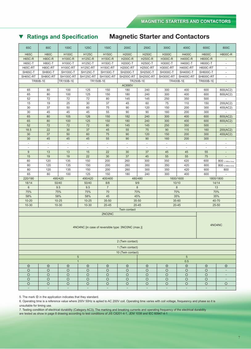
Ratings and Specifications —— Magnetic Starter and Contactors
H65C H80C H100C H125C H150C H200C H250C H300C H400C H600C H800C-RH65C-R H80C-R H100C-R H125C-R H150C-R H200C-R H250C-R H300C-R H400C-R H600C-R -H65C-T H80C-T H100C-T H125C-T H150C-T H200C-T H250C-T H300C-T H400C-T H600C-T -
H65C-RT H80C-RT H100C-RT H125C-RT H150C-RT H200C-RT H250C-RT H300C-RT H400C-RT H600C-RT -SH65C-T SH80C-T SH100C-T SH125C-T SH150C-T SH200C-T SH250C-T SH300C-T SH400C-T SH600C-T -
SH65C-RT SH80C-RT SH100C-RT SH125C-RT SH150C-RT SH200C-RT SH250C-RT SH300C-RT SH400C-RT SH600C-RT -TR150B-1E TR600B-1E -
65 80 100 125 150 180 240 300 400 600 800(AC2)65 80 100 125 150 180 240 300 400 600 800(AC2)52 72 72 72 80 145 145 250 350 500 -15 19 25 30 37 45 60 75 110 150 200(AC2)30 37 50 60 75 90 120 150 200 300 400(AC2)30 45 45 45 55 90 90 160 200 300 -65 80 105 126 150 182 240 300 400 600 800(AC2)65 80 100 125 150 180 240 300 400 600 800(AC2)52 72 72 72 80 145 145 250 350 500 -
18.5 22 30 37 45 55 75 90 115 160 200(AC2)30 37 50 60 75 90 120 150 200 300 400(AC2)30 45 45 45 55 90 90 160 200 300 -- - - - - - - - - - -- - - - - - - - - - -9 13 13 15 22 30 37 45 45 55 -15 19 19 22 30 37 45 55 55 75 -80 120 135 150 200 260 300 350 420 600 800 0.1Million times
80 120 135 150 200 260 300 350 420 600 800 0.1Million times
80 120 135 150 200 260 300 350 420 600 80065 80 100 125 150 180 240 300 400 600 -
220/190 490/420 400/40018/14 50/40 8/8
6 9.5 775% 75% 7058% 58% 4510-20 10-25 35-5010-30 10-30 20-45
5. The mark in the application indicates that they standard.6. Operating time is a reference value where 200V 50Hz is aplied to AC 200V coil. Operating time varies with coil voltage, frequesncy and phase so it isunsuitable for timing use.7. Testing condition of electrical durability (Category AC3); The marking and breaking currents and operating frequency of the electrical durabilityare tested as show in page 8 drawing according to test conditions of JIS C8201-4-1, JEM 1038 and IEC 60947-4-1
2NO2NC
4NO4NC [in case of reversible type: 3NO3NC (max.)]4NO4NC
35-50 35-60 40-7020-45 20-45
70%45% 35% 35%
5
2 (Twin contact)
1 (Twin contact)
10 (Twin contact)5
Twin contact
TR400B-1E
150C 200C 250C 400C
70%
AC690V
100C
TR80B-1E
800C65C 80C 300C 600C125C
TR150B-1E TR250B-1E
0.51
480/480 1600/16009/9 10/108 8
1800/180014/14
13
10-2510-30
490/42050/40
9.575%58%
25-50
70%
7
LOW VOLTAGE MAGNETIC CONTACTORS & CIRCUIT BREAKERS
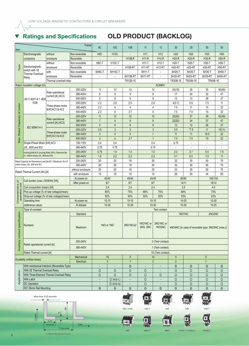
Ratings and Specifi cations OLD PRODUCT (BACKLOG)
H50 H65C-T H80C H100C-T, H125C-T, H150C-T
H8C, H10C H20-T H25 H35 H35-T
Time
Cur
rent
0.75
Ie
6Ie
Seconds
3 Seconds
More than 0.05 seconds
le: Rated Operational Current
8
Ratings and Specifications —— OLD PRODUCT (BACKLOG)Frame
ItemElectromagnetic without Non-reversible H8C H10C - H11 H12 H20 H25 H35 H50contactors enclosure Reversible - - H10B-R H11-R H12-R H20-R H25-R H35-R H50-R
without Non-reversible H8C-T H10C-T - H11-T H12-T H20-T H25-T H35-T H50-Tenclosure Reversible - - H10B-RT H11-RT H12-RT H20-RT H25-RT H35-RT H50-RTwith Non-reversible SH8C-T SH10C-T - SH11-T - SH20-T SH25-T SH35-T SH50-Tenclosure Reversible - - SH10B-RT SH11-RT - SH20-RT SH25-RT SH35-RT SH50-RTThermal overload relay TR20B-1E TR25B-1E
Rated insulation voltage (Ui)200-220V 11 12 12 20(18) 26 35 50(48)380-440V 6 9 9 17 24 32 47500-550V 5 8 6 12 12 26 37200-220V 2.2 2.5 2.5 4(3.7) 5.5 7.5 11380-440V 2.2 4 4 7.5 11 15 22500-550V 2.2 4 3.7 7.5 7.5 15 22200-220V 11 12 12 22(20) 27 39 52(48)380-440V 7 9 9 22(20) 24 37 47500-550V 5 8 6 12 12 26 37200-220V 2.5 3 3 5.5 *7.5 11 15(11)380-440V 3 4 4 11 11 18.5 22500-550V 3 4 3.7 7.5 7.5 15 22
Single-Phase Motor [kW] AC3 100-110V 0.4 0.4 - 0.75 - - -JIS, JEM and IEC 380-440V 0.75 0.75 - - - - -
200-240V 0.75 1.5 1.5 2.2 3.7 5.5 7.5380-440V 1.5 2.2 2.2 3.7 5.5 7.5 11200-240V 20 20 18 32 35 50 70380-440V 20 20 18 32 35 50 70
without enclosure 20 20 18 32 35 50 70with enclosure 15 15 15 26 35 44 60At power-on 45/40
After power-on 9/72.4
75% 68% 75%50% 50% 50%
Operating time At power-on 10-15(reference value) At lelease 10-30
Standard
200-240V
380-440V
Mechanical 5 5Electrical 1 2 1
2 (Twin contact)
1 (Twin contact)
10 (Twin contact)510 10
22
10-25
68%53% 53%
165/15016/124.5
73%
10-2010-35
1NO or 1NC 2NO1NCx2
1NO1NC
90/8014/113.5
10-15
2.4
10-30
1NO1NC or 2NO, 2NC
20
2NO1NC or 1NO2NC
2015
45/409/7
Twin contact
4NO4NC [in case of reversible type: 3NO3NC (max.)]
2NO2NC
10-20
10.40.751.52.220
TR12B-1E TR50B-1E
35 5012 258C 10C 10B 11
129
9831
8
12
65%50%
10-1510-30
45/409/72.4
20
Ap
plic
atio
n
With mechanical Interlock (Reversible Type)With 2E Thermal Overload RelayWith Three-Element Themal Overload Relay
Durability (million times)
Au
xilia
ry c
on
tact
sp
eci
fica
tion
Maximum
With LatchDC OperationIEC 35mm Rail Mounting
Rated operational current [A]
Rated Thermal current [A]
Rated Capacity for Resistance Load [A] AC1 (Electrical Life 0.5 million times) JIS, JEM and IEC
Rated Thermal Current (Ith) [A]
Ch
ara
cte
rist
ics
of
op
era
tion
co
il
Numbers
Coil burden (max.) 50/60Hz [VA]
Coil consumtion (mean) [W]
Type of constant
Pick-up voltage (% of rate voltage)(mean)Drop-out voltage (% of rate voltage)(mean)
Typ
e
JIS C 8201-4-1 JEM 1038
Electromagnetic switch with 1E Thermal Overload Relay
Rate operational current [A] (AC3)
AC690V
Three-phase motor [kW] AC3 & AC2
Rate operational current [A] (AC3)
Ma
x. R
ate
d C
ap
aci
ty o
f m
oto
r
Three-phase motor [kW] AC3 & AC2
IEC 60947-4-1
Inching [kW] AC4 (Inching Ratio 50%), Electrical life 0.1 million times) JIS, JEM and IEC
2.544
8
9
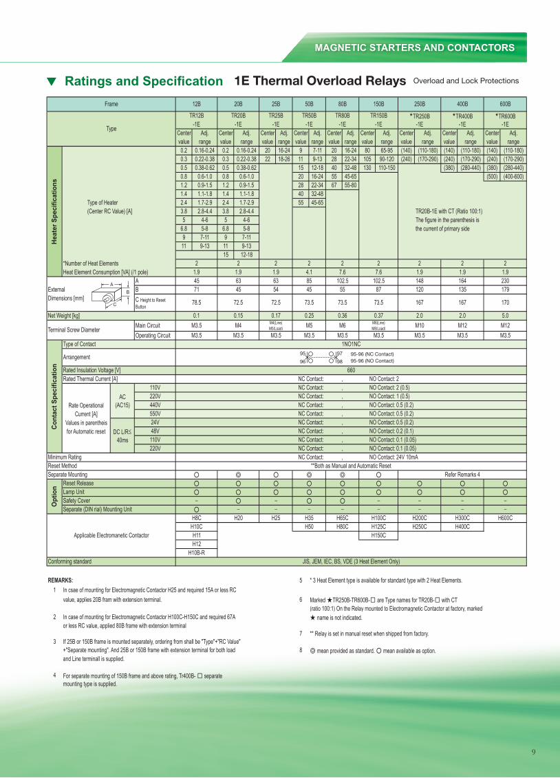
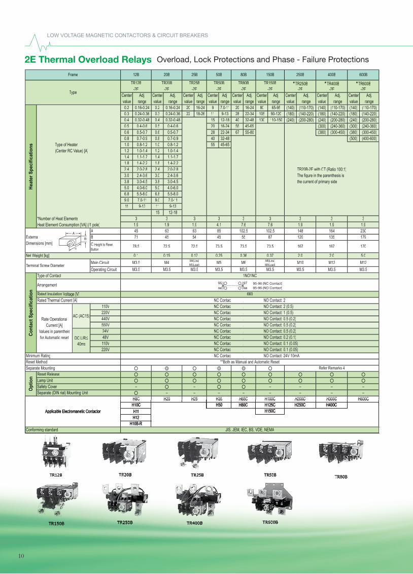
Ratings and Specifications —— 1E Thermal Overload Relays Overload and Lock Protections
Center Adj. Center Adj. Center Adj. Center Adj. Center Adj. Center Adj. Center Adj. Center Adj. Center Adj.value range value range value range value range value range value range value range value range value range0.2 0.16-0.24 0.2 0.16-0.24 20 16-24 9 7-11 20 16-24 80 65-95 (140) (110-180) (140) (110-180) (140) (110-180)0.3 0.22-0.38 0.3 0.22-0.38 22 18-26 11 9-13 28 22-34 105 90-120 (240) (170-290) (240) (170-290) (240) (170-290)0.5 0.38-0.62 0.5 0.38-0.62 15 12-18 40 32-48 130 110-150 (380) (280-440) (380) (280-440)0.8 0.6-1.0 0.8 0.6-1.0 20 16-24 55 45-65 (500) (400-600)1.2 0.9-1.5 1.2 0.9-1.5 28 22-34 67 55-801.4 1.1-1.8 1.4 1.1-1.8 40 32-48
Type of Heater 2.4 1.7-2.9 2.4 1.7-2.9 55 45-65(Center RC Value) [A] 3.8 2.8-4.4 3.8 2.8-4.4 TR20B-1E with CT (Ratio 100:1)
5 4-6 5 4-6 The figure in the parenthesis is6.8 5-8 6.8 5-8 the current of primary side9 7-11 9 7-1111 9-13 11 9-13
15 12-18*Number of Heat ElementsHeat Element Consumption [VA] (/1 pole)
AExternal BDimensions [mm]
Main CircuitOperating Circuit
110V220V440V550V24V48V110V220V
REMARKS: 5 * 3 Heat Element type is available for standard type with 2 Heat Elements.1 In csae of mounting for Electromagnetic Contactor H25 and required 15A or less RC
value, applies 20B fram with extension terminal. 6 Marked TR250B-TR600B- are Type names for TR20B- with CT(ratio 100:1) On the Relay mounted to Electromagnetic Contactor at factory, marked
2 In case of mounting for Electromagnetic Contactor H100C-H150C and required 67A name is not indicated.or less RC value, applied 80B frame with extension terminal
7 ** Relay is set in manual reset when shipped from factory.3 If 25B or 150B frame is mounted separately, ordering from shall be "Type"+"RC Value"
+"Separate mounting". And 25B or 150B frame with extension terminal for both load 8 mean provided as standard. mean available as option.and Line terminall is supplied.
4 For separate mounting of 150B frame and above rating, Tr400B- separatemounting type is supplied.
NC Contact: 0.2 (0.1)
Refer Remarks 4
NC Contact: 3NC Contact: 3 (1)NC Contact: 2 (1)NC Contact: 1 (0.3)NC Contact: 1 (0.3)NC Contact: 1 (0.4)NC Contact: 0.5 (0.2)
NC Contact: 24V 200mA,Minimum RatingReset Method **Both as Manual and Automatic ResetSeparate Mounting
Opt
ion Reset Release
Lamp UnitSafety CoverSeparate (DIN rial) Mounting Unit
H8C H20 H25 H35 H65C H100C
, NO Contact: 2
NO Contact: 0.5 (0.2)NO Contact: 0.5 (0.2)NO Contact: 0.5 (0.2)NO Contact: 0.2 (0.1)
1NO1NC
H250C H400C
,
660
NC Contact: 0.1 (0.05)
NO Contact: 2 (0.5)NO Contact: 1 (0.5)
NO Contact: 0.1 (0.05)NO Contact: 0.1 (0.05)
,,,,
H300C H600CH200C
NO Contact: 24V 10mA
H10B-RH12H11
H10CH150CH125CH80CH50
JIS, JEM, IEC, BS, VDE (3 Heat Element Only)
Applicable Electromanetic Contactor
Conforming standard
M3.5M3.5 M3.5 M3.5 M3.5M3.5 M3.5
2.0 5.0M6(Line)M8(Load) M10M4 M4(Line)
M5(Load) M5 M6
Cont
act S
peci
ficat
ion
Rate OperationalCurrent [A]
Values in parentheisfor Automatic reset
Type of Contact
Rated Insulation Voltage [V]Rated Thermal Current [A]
Arrangement
170
Terminal Screw Diameter
Net Weight [kg] 0.1 0.15 0.17 0.25M12 M12
0.36
13571 45 54 45
72.5 72.5 167 167
120
73.5 73.5C Height to Reset Button
AC (AC15)
DC L/R 40ms
0.37 2.0
,
1.9 1.92
179
,
148 164 23055 87
221.9
2 2 21.9 1.9 4.1 7.6
78.5
,
63 63 85 102.5
73.5
M3.5 M3.5M3.5
102.5
TR80B TR150B
45
2 27.6
Frame
Heat
er S
peci
ficat
ions
Type
2
TR12B TR20B TR25B
1.9
400B12B 20B 25B 50B 80B 150B 250B 600B
TR600B-1E -1E -1E -1E -1E -1E -1E
TR50B TR400B-1E -1E
TR250B
A
B
95
96
97 95-96 (NC Contact)95-96 (NO Contact)98
C
MAGNETIC STARTERS AND CONTACTORS
Ratings and Specifi cation 1E Thermal Overload Relays Overload and Lock Protections
9
Center Adj. Center Adj. Center Adj. Center Adj. Center Adj. Center Adj. Center Adj. Center Adj. Center Adj.value range value range value range value range value range value range value range value range value range0.2 0.16-0.24 0.2 0.16-0.24 20 16-24 9 7.0-11 20 16-24 80 65-95 (140) (110-170) (140) (110-170) (140) (110-170)0.3 0.24-0.36 0.3 0.24-0.36 22 18-26 11 9-13 28 22-34 105 90-120 (180) (140-220) (180) (140-220) (180) (140-220)0.4 0.32-0.48 0.4 0.32-0.48 15 12-18 40 32-48 130 110-150 (240) (200-280) (240) (200-280) (240) (200-280)0.5 0.4-0.6 0.5 0.4-0.6 20 16-24 55 45-65 (300) (240-360) (300) (240-360)0.6 0.5-0.7 0.6 0.5-0.7 28 22-34 67 55-80 (380) (300-450) (380) (300-450)0.8 0.7-0.9 0.8 0.7-0.9 40 32-48 (500) (400-600)
Type of HeaterType of HeaterT 1.0 0.8-1.2 1.0 0.8-1.2 55 45-65(Center RC Value) [A]Value) [A]V 1.2 1.0-1.4 1.2 1.0-1.4
1.4 1.1-1.7 1.4 1.1-1.71.8 1.4-2.2 1.8 1.4-2.22.4 2.0-2.8 2.4 2.0-2.8 TR20B-2E with CT (Ratio 100:1)3.0 2.4-3.6 3.0 2.4-3.6 The figure in the parenthesis is3.8 3.0-4.5 3.8 3.0-4.5 the current of primary side.5.0 4.0-6.0 5.0 4.0-6.06.8 5.5-8.0 6.8 5.5-8.09.0 7.0-11 9.0 7.0-1111 9-13 11 9-13
15 12-18*Number of Heat ElementsHeat Element Consumption [VA] (/1 pole)VA] (/1 pole)V
AExternal BDimensions [mm]
Main CircuitOperating Circuit
110V220V440V550V24V48V110V220V
TR400B-2E -2E
TR250B
600B
TR600B-2E -2E -2E -2E -2E -2E -2E
TR50B
400B12B 20B 25B 50B 80B 150B 250BFrame
Heat
er S
peci
ficat
ions
TypeTypeT
3
TR12B TR20B TR25B
102.5
TR80B TR150B
45
3 3
78.5
,
63 63 85 102.5
73.5
M3.5 M3.5M3.5
3 331.9
3 3
73.5
31.9 1.9 4.1 7.6 7.6 1.9 1.9 1.9
72.5
179
,
148 164 23055 87 120
73.5
M12
C Height to Reset Button
AC (AC15)
DC L/R40ms
13571 45 54 45
72.5
Arrangement
167 167 170
Terminal Screw DiameterTerminal Screw DiameterT
Net Weight [kg] 0.1 0.15 0.17 0.25M6(Line)M8(Load) M10
Cont
act S
peci
ficat
ion
Rate OperationalCurrent [A]
Values in parentheisValues in parentheisVfor Automatic reset
Type of ContactType of ContactT
Rated Insulation Voltage [V]Voltage [V]VRated Thermal Current [A]
M4 M4(Line)M5(Load) M5 M6 M12
0.36 0.37 2.0 2.0 5.0
M3.5M3.5 M3.5 M3.5 M3.5M3.5 M3.5
H10B-RH12H11
H10C
JIS, JEM, IEC, BS, VDE, NEMA
Applicable Electromanetic Contactor
Conforming standard
H150CH125CH80CH50
,,,,,
H600CH600C
1NO1NC
H250C H400C
,
660
NC Contact: 0.1 (0.05)
NO Contact: 2 (0.5)NO Contact: 1 (0.5)
NO Contact: 0.1 (0.05)NO Contact: 0.1 (0.05)
, NO Contact: 2
NO Contact: 0.5 (0.2)NO Contact: 0.5 (0.2)NO Contact: 0.5 (0.2)NO Contact: 0.2 (0.1)
H100CH100C H200CH200C
NO Contact: 24V 10mA
H300CH300C
Opt
ion Reset Release
Lamp UnitSafety CoverSeparate (DIN rial) Mounting Unit
H65CH65CH8CH8C H20H20 H25H25 H35H35
NC Contact: 24V 200mA,Minimum RatingReset Method **Both as Manual and Automatic ResetSeparate Mounting Refer Remarks 4
NC Contact: 3NC Contact: 3 (1)NC Contact: 2 (1)NC Contact: 1 (0.3)NC Contact: 1 (0.3)NC Contact: 1 (0.4)NC Contact: 0.5 (0.2)NC Contact: 0.2 (0.1)
A
B
95
96
97 95-96 (NC Contact)95-96 (NO Contact)98
C
LOW VOLTAGE MAGNETIC CONTACTORS & CIRCUIT BREAKERS
2E Thermal Overload Relays Overload, Lock Protections and Phase - Failure Protections
10
MAGNETIC STARTERS AND CONTACTORS
10
FrameItem
8 10 20 25 35 50 65C 80C 100C 125C 150C 200C 250C 300C 400C 600C 800C
Model
Electromagnetic contactor
without enclosure
Non-reversible HS8 HS10 HS20 HS25 HS35 HS50 H65C H80C H100C H125C H150C H200C H250C H300C H400C H600C H800C
Reversible — HS10-R HS20-R HS25-R HS35-R HS50-R H65C-R H80C-R H100C-R H125C-R H150C-R H200C-R H250C-R H300C-R H400C-R H600C-R H800C-R
Electromagnetic switch with 1E Thermal Overload Relay
without enclosure
Non-reversible HS8-T HS10-T HS20-T HS25-T HS35-T HS50-T H65C-T H80C-T H100C-T H125C-T H150C-T H200C-T H250C-T H300C-T H400C-T H600C-T —
Reversible — HS10-RT HS20-RT HS25-RT HS35-RT HS50-RT H65C-RT H80C-RT H100C-RT H125C-RT H150C-RT H200C-RT H250C-RT H300C-RT H400C-RT H600C-RT —
withenclosure
Non-reversible — SHS10-T SHS20-T SHS25-T SHS35-T SHS50-T SH65C-T SH80C-T SH100C-T SH125C-T SH150C-T SH200C-T SH250C-T SH300C-T SH400C-T SH600C-T —
Reversible — SHS10-RT SHS20-RT SHS25-RT SHS35-RT SHS50-RT SH65C-RT SH80C-RT SH100C-RT SH125C-RT SH150C-RT SH200C-RT SH250C-RT SH300C-RT SH400C-RT SH600C-RT —
Thermal overload relay TR12B-1E TR20B-1E TR25B-1E TR50B-1E TR80B-1E TR150B-1E TR250B-1E TR400B-1E TR600B-1E —
Rated insulation voltage (Ui) 690V 660V
Max. rated capacity of motor
JIS, JEM
( ): with enclosure
Rated operational current (AC3)
200 – 220VAC 11A 13A 20 (18) A 26A 35A 50 (48) A 65A 80A 100A 125A 150A 180A 240A 300A 400A 600A 800A (AC2)
380 – 440VAC 7A 9A 17A 36A 32A 47A 65A 80A 100A 125A 150A 180A 240A 300A 400A 600A 800A (AC2)
500 – 550VAC 6A 9A 17A 20A 26A 37A 52A 72A 72A 72A 80A 145A 145A 250A 350A 500A —
Three-phase motor (AC3)
200 – 220VAC 2.2kW 2.7kW 4 (3.7) kW 5.5kW 7.5kW 11kW 15kW 19kW 25kW 30kW 37kW 45kW 60kW 75kW 110kW 150kW 200kW (AC2)
380 – 440VAC 2.7kW 4kW 7.5kW 11kW 15kW 22kW 30kW 37kW 50kW 60kW 75kW 90kW 120kW 150kW 200kW 300kW 400kW (AC2)
500 – 550VAC 2.7kW 5.5kW 7.5kW 11kW 15kW 22kW 30kW 45kW 45kW 45kW 55kW 90kW 90kW 160kW 200kW 300kW —
IEC
Rated operational current (AC3)
220 – 240VAC 11A 13A 22A 27A 40A 50A 65A 80A 105A 126A 150A 182A 240A 300A 400A 600A 800A (AC2)
380 – 440VAC 9A 12A 22A 26A 40A 50A 65A 80A 100A 125A 150A 180A 240A 300A 400A 600A 800A (AC2)
Three-phase motor (AC3)
200 – 220VAC 2.5kW 3.5kW 5.5kW 7.5kW 11kW 15kW 18.5kW 22kW 30kW 37kW 45kW 55kW 75kW 90kW 115kW 160kW 200kW (AC2)
380 – 440VAC 4kW 5.5kW 11kW 11kW 18.5kW 22kW 30kW 37kW 50kW 60kW 75kW 90kW 120kW 150kW 200kW 300kW 400kW (AC2)
Single-phase motor (AC3)JIS, JEM and IEC
100 – 110VAC 0.4kW 0.5kW 0.9kW 1.2kW 1.7kW — — — — — — — — — — — —
200 – 220VAC 0.8kW 1kW 1.8kW — — — — — — — — — — — — — —
Inching (AC4) (Inching ratio 50%, electrical durability 0.1 million times) JIS, JEM and IEC
200 – 220VAC 1.5kW 2.2kW 3.7kW 3.7kW 5.5kW 7.5kW 9kW 13kW 13kW 13kW 22kW 30kW 37kW 45kW 45kW 55kW —
380 – 440VAC 2.2kW 3.7kW 5.5kW 5.5kW 7.5kW 11kW 15kW 19kW 19kW 19kW 30kW 37kW 45kW 55kW 55kW 75kW —
Rated capacity for resistance load (AC1)(Electrical durability 0.5 million times)JIS, JEM and IEC
200 – 220VAC 20A 20A 32A 35A 50A 70A 80A 120A 135A 150A 200A 260A 300A 350A 420A 600A 800A (0.1 million times)
380 – 440VAC 20A 20A 32A 35A 50A 70A 80A 120A 135A 150A 200A 260A 300A 350A 420A 600A 800A (0.1 million times)
Rated thermal current (Ith) without enclosure 20A 20A 32A 35A 50A 70A 80A 120A 135A 150A 200A 260A 300A 350A 420A 600A 800A
Open thermoelectric current (Ith) with enclosure 15A 15A 26A 35A 44A 60A 65A 80A 100A 125A 150A 180A 240A 300A 400A 600A —
Characteristicsofoperation coil
Coil burden (max.) 50/60Hz
At power-on 100 / 90VA 100 / 90VA 100 / 90VA 100 / 90VA 135 / 125VA 135 / 125VA 220 / 190VA 490 / 420VA 400 / 400VA 480 / 480VA 1600 / 1600VA 1800 / 1800VA
After power-on 12 / 11VA 12 / 11VA 12 / 11VA 12 / 11VA 15 / 14VA 15 / 14VA 18 / 14VA 50 / 40VA 8 / 8VA 9 / 9VA 10 / 10VA 14 / 14VA
Coil consumption (mean) 3W 4.3W 6W 9.5W 7W 8W 8W 13W
Pick-up voltage (% of rated voltage) (mean) 70% 70% 70% 70% 70% 70% 75% 75% 70% 70% 70% 70%
Drop-out voltage (% of rated voltage) (mean) 55% 55% 60% 60% 60% 60% 58% 58% 45% 45% 35% 35%
Operating time(reference value)
At power-on 10–20ms 10–20ms 10–25ms 30–50ms 30–50ms 35–60ms 40–70ms
At release 10–35ms 10–30ms 10–30ms 20–40ms 20–45ms 20–45ms 20–50ms
Auxiliary contact specification
Type of constant Twin contact Twin contact
Numbers
Standard 1NO or 1NC 1NO1NC or 2NO2NC 2NO2NC 2NO2NC 3NO3NC
4NO4NC Maximum
Four contacts can be added to the standard specification.Head-on2P: 2NO, 1NO1NC, 2NC (Not applicable for the machine mounted with the side-on unit)Head-on4P: 4NO, 3NO1NC, 2NO2NC (Not applicable for the machine mounted with the side-on unit)Side-on2P: 1NO1NC (Not applicable for the machine mounted with the head-on unit)
4NO4NC (in case of reversible type: 3NO3NC (max.))
Rated operational current
With mechanical interlock — Provided as standard Provided as standard
IEC 35-mm rail mounting mechanism Provided as standard —
DurabilityMechanical 8 million times 5 million times
Electrical 2 million times 1.5 million times 1 million times 1 million times 0.5 million times
Available voltage range of operational coil 24 – 550V 24 – 550V 100 – 440V
4. RATINGS AND SPECIFICATIONS
4.1 Standard Models
Notes:1) The ratings of the 200V class in the parenthesis when frames 20 and 50 are provided with an enclosure.2) The rated thermal current applies to electromagnetic contactors.3) The pick-up and drop-out voltages apply to 200V 60Hz power source. In case of 50Hz, the figures for frame H65C – 125C are about 10% smaller and for frame H150C – 800C are about the same.4) Application of Category AC3 and AC2 to the reversible electromagnetic contactors and switches shall be limited to regular reversible operation in which a motor starts reverse rotation after it
has once stopped. Category AC4 is applicable when the motor starts reverse rotation before it has completely stopped.5) Operating time is a reference value where 200V 50Hz is applied to AC 200V coil. Operating time varies with coil voltage, frequency and phase so it is unsuitable for timing use.
AC-12 AC-15 DC-12 DC-13Minimum rating
110V 220V 110V 220V 440V 110V 220V 110V 220V 440V
10A 8A 6A 3A 1.5A 2.5A 1A 1.5A 0.55A 0.27A 20V 5mA
HS HS -T SHS -THS -R HS -RT SHS -RT
With enclosure
<Electromagnetic contactor> <Electromagnetic switch> <Electromagnetic switch>
Non-reversible
Reversible
. . .
. . .
51
HS series
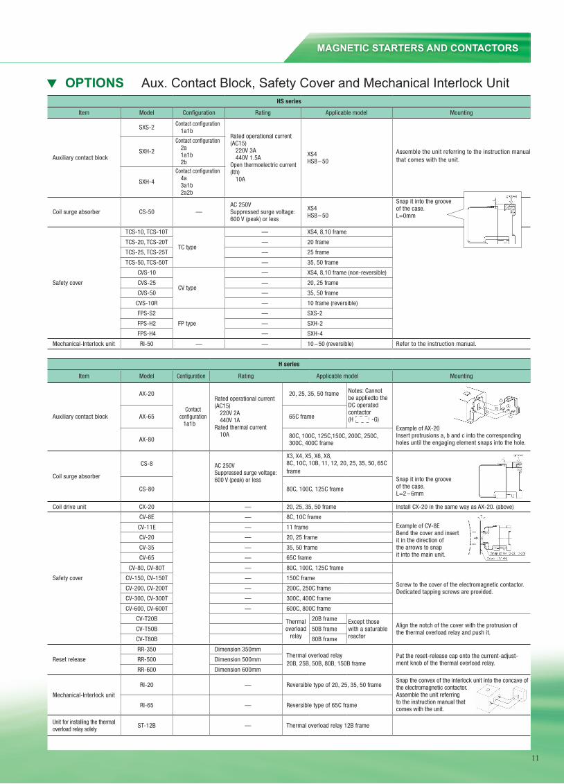
Item Model Configuration Rating Applicable model Mounting
Auxiliary contact block
SXS-2 Contact configuration1a1b
Rated operational current (AC15)
220V 3A440V 1.5A
Open thermoelectric current(Ith)
10A
XS4HS8 – 50
Assemble the unit referring to the instruction manual that comes with the unit.
SXH-2
Contact configuration2a1a1b2b
SXH-4
Contact configuration4a3a1b2a2b
Coil surge absorber CS-50 —AC 250VSuppressed surge voltage:600 V (peak) or less
XS4HS8 – 50
Snap it into the grooveof the case.L=0mm
Safety cover
TCS-10, TCS-10T
TC type
— XS4, 8,10 frame
TCS-20, TCS-20T — 20 frame
TCS-25, TCS-25T — 25 frame
TCS-50, TCS-50T — 35, 50 frame
CVS-10
CV type
— XS4, 8,10 frame (non-reversible)
CVS-25 — 20, 25 frame
CVS-50 — 35, 50 frame
CVS-10R — 10 frame (reversible)
FPS-S2
FP type
— SXS-2
FPS-H2 — SXH-2
FPS-H4 — SXH-4
Mechanical-Interlock unit RI-50 — — 10 – 50 (reversible) Refer to the instruction manual.
H series
Item Model Configuration Rating Applicable model Mounting
Auxiliary contact block
AX-20
Contact configuration
1a1b
Rated operational current(AC15)
220V 2A440V 1A
Rated thermal current10A
20, 25, 35, 50 frame Notes: Cannot be appliedto the DC operated contactor (H -G)
Example of AX-20Insert protrusions a, b and c into the corresponding holes until the engaging element snaps into the hole.
AX-65 65C frame
AX-80 80C, 100C, 125C,150C, 200C, 250C, 300C, 400C frame
Coil surge absorber
CS-8 AC 250VSuppressed surge voltage:600 V (peak) or less
X3, X4, X5, X6, X8, 8C, 10C, 10B, 11, 12, 20, 25, 35, 50, 65C frame
Snap it into the grooveof the case.L=2 – 6mm
CS-80 80C, 100C, 125C frame
Coil drive unit CX-20 — 20, 25, 35, 50 frame Install CX-20 in the same way as AX-20. (above)
Safety cover
CV-8E — 8C, 10C frameExample of CV-8EBend the cover and insertit in the direction of the arrows to snap it into the main unit.
CV-11E — 11 frame
CV-20 — 20, 25 frame
CV-35 — 35, 50 frame
CV-65 — 65C frame
CV-80, CV-80T — 80C, 100C, 125C frame
Screw to the cover of the electromagnetic contactor. Dedicated tapping screws are provided.
CV-150, CV-150T — 150C frame
CV-200, CV-200T — 200C, 250C frame
CV-300, CV-300T — 300C, 400C frame
CV-600, CV-600T — 600C, 800C frame
CV-T20B Thermal overload
relay
20B frame Except those with a saturable reactor
Align the notch of the cover with the protrusion of the thermal overload relay and push it.CV-T50B 50B frame
CV-T80B 80B frame
Reset release
RR-350 Dimension 350mmThermal overload relay20B, 25B, 50B, 80B, 150B frame
Put the reset-release cap onto the current-adjust-ment knob of the thermal overload relay.RR-500 Dimension 500mm
RR-600 Dimension 600mm
Mechanical-Interlock unit
RI-20 — Reversible type of 20, 25, 35, 50 frameSnap the convex of the interlock unit into the concave of the electromagnetic contactor.Assemble the unit referring to the instruction manual thatcomes with the unit.
RI-65 — Reversible type of 65C frame
Unit for installing the thermal overload relay solely ST-12B — Thermal overload relay 12B frame
12. OPTIONS
12.1 Aux. Contact Block, Safety Cover and Mechanical Interlock Unit OPTIONS Aux. Contact Block, Safety Cover and Mechanical Interlock Unit
11
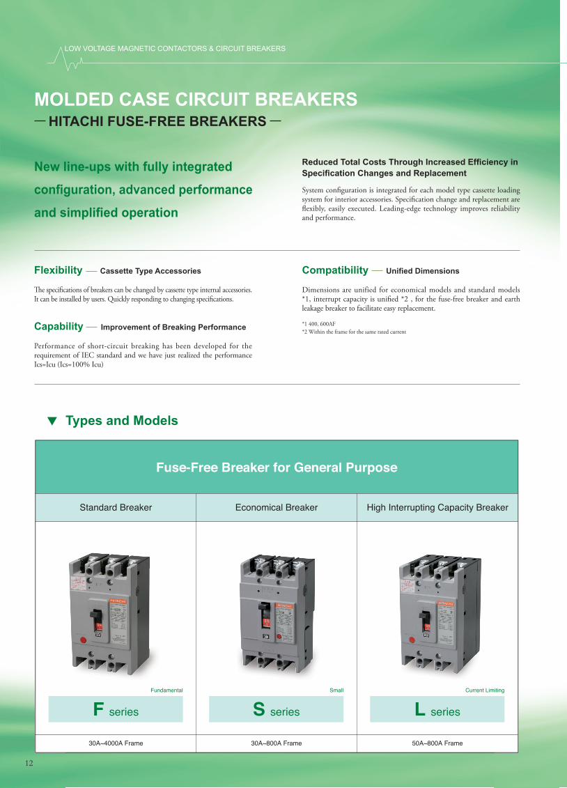
New line-ups with fully integrated
confi guration, advanced performance
and simplifi ed operation
Reduced Total Costs Through Increased Effi ciency in Specifi cation Changes and Replacement
System confi guration is integrated for each model type cassette loading system for interior accessories. Specifi cation change and replacement are fl exibly, easily executed. Leading-edge technology improves reliability and performance.
Fuse-Free Breaker for General Purpose
Standard Breaker Economical Breaker High Interrupting Capacity Breaker
F series S series L series
30A~4000A Frame 30A~800A Frame 50A~800A Frame
Fundamental Small Current Limiting
� e specifi cations of breakers can be changed by cassette type internal accessories. It can be installed by users. Quickly responding to changing specifi cations.
Flexibility Cassette Type Accessories
Dimensions are unified for economical models and standard models *1, interrupt capacity is unifi ed *2 , for the fuse-free breaker and earth leakage breaker to facilitate easy replacement.
Compatibility Unifi ed Dimensions
MOLDED CASE CIRCUIT BREAKERS
*1 400, 600AF*2 Within the frame for the same rated current
Performance of short-circuit breaking has been developed for the requirement of IEC standard and we have just realized the performance Ics=Icu (Ics=100% Icu)
Capability Improvement of Breaking Performance
HITACHI FUSE-FREE BREAKERS
Types and Models
LOW VOLTAGE MAGNETIC CONTACTORS & CIRCUIT BREAKERS
12
Types and Models
MOLDED CASE CIRCUIT BREAKERS
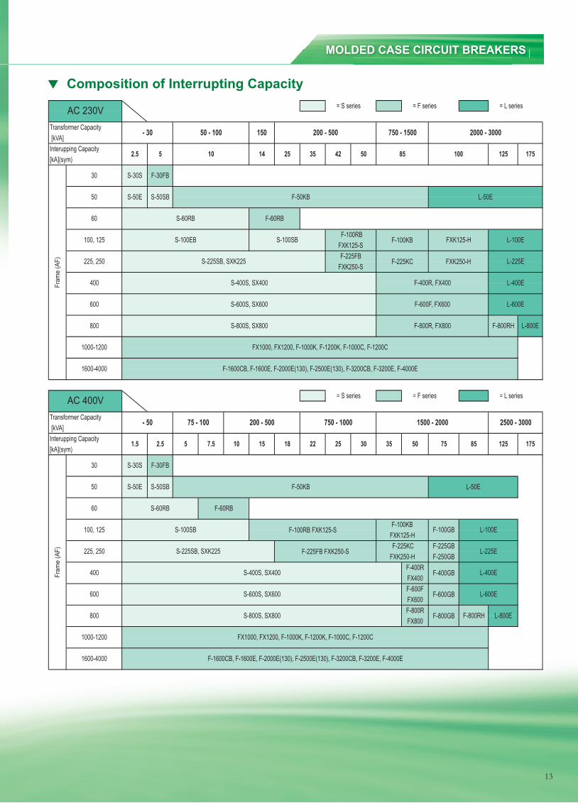
Composition of Interrupting Capacity
13
Composition of Interrupting Capacity
Transformer Capacity[kVA]
Interupping Capacity[kA](sym)
Transformer Capacity[kVA]
Interupping Capacity[kA](sym)
F-225GBF-250GB
F-400RFX400F-600FFX600F-800RFX800
L-600E
100
L-50E
FXK125-H
FXK250-H L-225E
125
S-225SB, SXK225
8575
F-800GB
L-50E
125
S-600S, SX600
FX1000, FX1200, F-1000K, F-1200K, F-1000C, F-1200C
F-1600CB, F-1600E, F-2000E(130), F-2500E(130), F-3200CB, F-3200E, F-4000E
L-100E
L-225E
L-400E
L-600E
F-800RH L-800E
F-100GBS-100SB F-100RB FXK125-SF-100KB
FXK125-H
F-225FB FXK250-S
F-600GB
F-400GB
F-225KCFXK250-H
S-400S, SX400
S-50E S-50SB
F-30FB
F-50KB
S-800S, SX800
F-100RBFXK125-SF-225FB
FXK250-S
S-60RB
2500 - 3000
F-60RB
175
75 - 100 200 - 500 750 - 1000
15 18
S-30S
1.5 2.5
F-100KB
5
F-225KC
1500 - 2000
F-400R, FX400
F-600F, FX600
F-800R, FX800
400
600
800
1000-1200
1600-4000
F-60RB
S-100SB
60
S-100EB
FX1000, FX1200, F-1000K, F-1200K, F-1000C, F-1200C
35 5022 25 30
Fram
e (A
F)
30
50
100, 125
225, 250
50 - 100
5 10
F-50KBS-50SB
F-30FB
35 42 50
107.5
- 50
14
= L series
150 200 - 500 750 - 1500 2000 - 3000
85
= S series = F series
25
= S series = F series = L series
175
L-800EF-800RH
L-400E
L-100E
600
S-225SB, SXK225
S-400S, SX400
S-600S, SX600
60
100, 125
225, 250
400
AC 400V
S-800S, SX800
F-1600CB, F-1600E, F-2000E(130), F-2500E(130), F-3200CB, F-3200E, F-4000E1600-4000
1000-1200
Fram
e (A
F)
800
S-60RB
30
50
AC 230V
2.5
- 30
S-30S
S-50E
13
LOW VOLTAGE MAGNETIC CONTACTORS & CIRCUIT BREAKERS
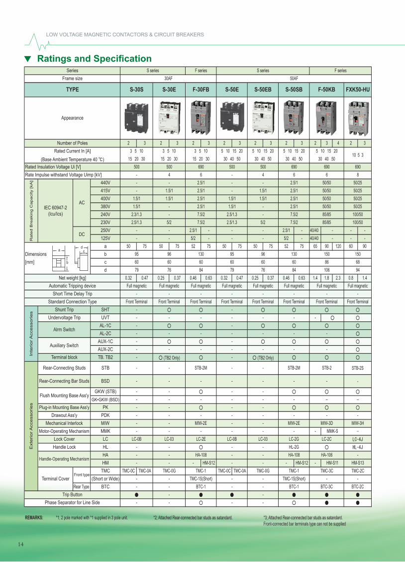
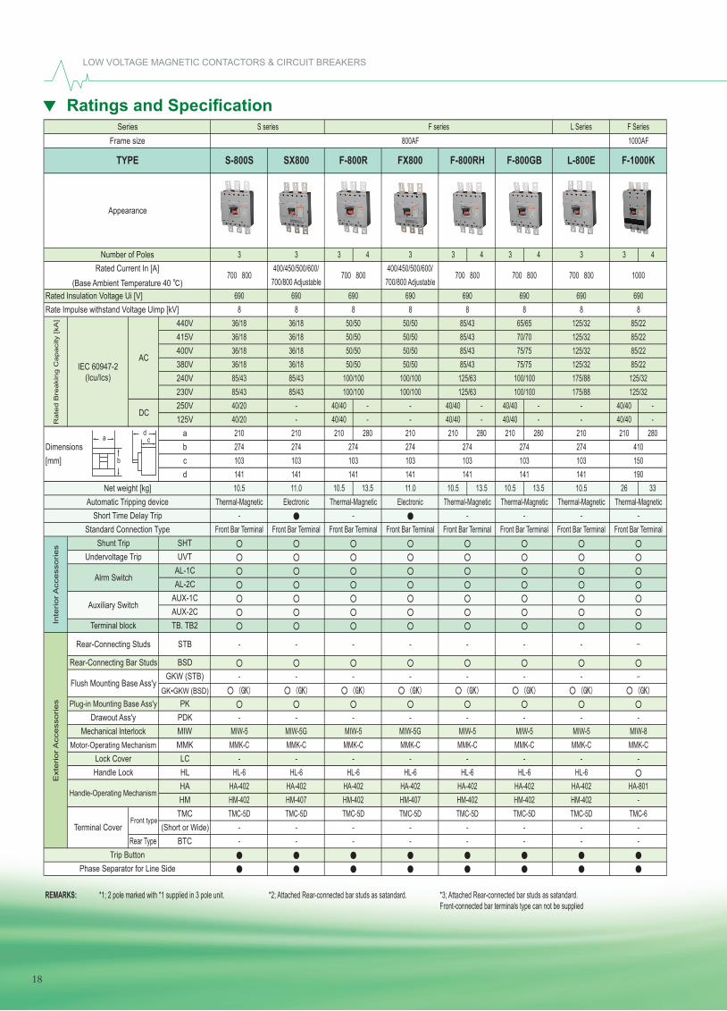
Ratings and Specifi cation
14
Ratings and Specifications
2 3 2 3 2 3 2 3 2 3 2 3 2 3 4 2 3
440V415V400V380V240V230V250V 2.5/1 - 2.5/1 - 40/40 - -125V 5/2 - 5/2 - 40/40 - -
a 50 75 50 75 52 75 50 75 50 75 52 75 65 90 120 60 90Dimensions b[mm] c
d0.32 0.47 0.25 0.37 0.46 0.63 0.32 0.47 0.25 0.37 0.46 0.63 1.4 1.8 2.3 0.8 1.4
SHTUVT -
AL-1CAL-2C
AUX-1CAUX-2CTB. TB2
STB
BSD
GKW (STB)GK•GKW (BSD)
PKPDKMIWMMK -LCHLHAHM - HM-S12 - HM-S12 -
TMC TMC-0C TMC-0A TMC-0C TMC-0A(Short or Wide)
Rear Type BTC
REMARKS: *1; 2 pole marked with *1 supplied in 3 pole unit. *2; Attached Rear-connected bar studs as satandard. *3; Attached Rear-connected bar studs as satandard.Front-connected bar terminals type can not be supplied
F series
-Front Terminal
15068
-HM-S13
-
10 5 3
-MIW-3H
50AF
TMC-2C-
BTC-2C
STB-2S
-
94
Full magnetic
100/50100/50
6908
FXK50-HU
50/2550/2550/2550/25
---
---- -
BTC-3C- - BTC-1 --
TMC-1 TMC-0G
BTC-1TMC-1S(Short)- - TMC-1S(Short) -
LC-2C
TMC-1 TMC-3CHM-S11- - - -
TMC-0G
- HA-108 HA-106--
- HL-2G- - HA-108
LC-0B LC-03 LC-2E- -
MIW-3D
LC-0B- - - - - -
LC-03 LC-2G
- - MIW-2E - - MIW-2E- - - - - - -- - - -
- - -
STB-2
- - - - - - -
- - STB-2M - - STB-2M
- - -- (TB2 Only) - (TB2 Only)
- -- -
Drawout Ass'y
- - - - -
- - - -
Rate
d B
reaki
ng C
apaci
ty [kA
]
Rated Insulation Voltage Ui [V]
Inte
rior
Acc
ess
ories
Handle-Operating Mechanism
Lock CoverHandle LockE
xterior
Acc
ess
ories
Rear-Connecting Studs
Rear-Connecting Bar Studs
Plug-in Mounting Base Ass'y
Auxiliary Switch
Terminal block
Mechanical lnterlockMotor-Operating Mechanism
Series
TYPE
Number of Poles
Net weight [kg]
Rated Current In [A](Base Ambient Temperature 40 )
AC
DC
IEC 60947-2 (Icu/Ics)
Shunt TripUndervoltage Trip
Alrm Switch
Trip ButtonPhase Separator for Line Side
Frame size
Appearance
Rate Impulse withstand Voltage Uimp [kV]
Automatic Tripping deviceShort Time Delay Trip
Standard Connection Type
Front typeTerminal Cover
S-30S S-30E F-30FB S-50E S-50EB S-50SB F-50KB
5 10 15 20 5 10 15 2015 20 30
S series F series S series30AF
15 20 303 5 10 3 5 10 3 5 10 5 10 15 20
500 690 69015 20 30 30 40 50 30 40 50 30 40 50
- 4 6 -
5 10 15 2030 40 50
500 500 690 5004 6 6
- - 2.5/1 - - 2.5/1 50/5050/50
1.5/1 1.5/1 2.5/1 1.5/1 1.5/1 2.5/1 50/50- 1.5/1
1.5/1 -
1.5/1 2.5/12.5/1 -
- 2.5/12.5/1 1.5/1
5/2 7.5/2
50/502.3/1.3 - 7.5/2 2.5/1.3 - 7.5/2 85/85
85/85- - - - -
2.5/1.3 5/2 7.5/2 2.5/1.3
60 60 60
- - - -
MMK-S
95 96 130 95 96 130 15060 60
Full magnetic
8676 84 10679 76 84 79
60
Full magnetic Full magnetic Full magnetic Full magnetic Full magnetic Full magnetic- -
Front Terminal Front Terminal Front Terminal Front Terminal Front Terminal Front Terminal Front Terminal-
-
-- - -
- - - - - --
- -
- - -Flush Mounting Base Ass'y
- - --
a
b
dc
14
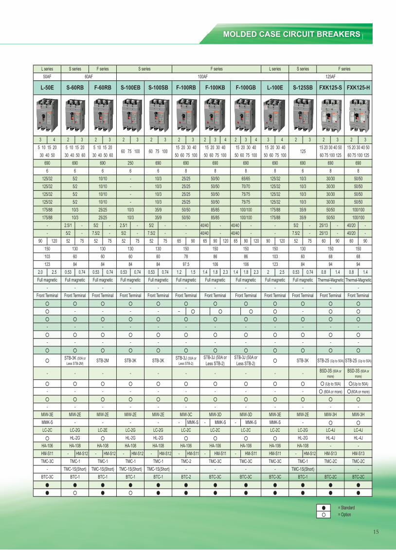
MOLDED CASE CIRCUIT BREAKERS
15
3 4 2 3 2 3 2 3 2 3 2 3 2 3 4 2 3 4 3 4 2 3 2 3 2 3
2.5/1 - 5/2 - 2.5/1 - 5/2 - 40/40 40/40 5/2 - 25/13 - 40/20 -5/2 - 7.5/2 - 5/2 - 7.5/2 - 40/40 40/40 7.5/2 - 25/13 - 40/20 -
90 120 52 75 52 75 52 75 52 75 65 90 65 90 120 65 90 120 90 120 52 75 60 90 60 90
2.0 2.5 0.53 0.74 0.53 0.74 0.53 0.74 0.53 0.74 1.2 1.5 1.4 1.8 2.3 1.4 1.8 2.3 2 2.5 0.53 0.74 0.8 1.4 0.8 1.4
- MMK-S - -
- HM-S12 - HM-S12 - HM-S12 - HM-S12 - HM-S11 - - - HM-S12
L series50AF
BTC-3C
TMC-3C-
HA-106HM-S11
LC-2C
-
MIW-3EMMK-S
-
-Front Terminal
-
-
--
175/88175/88
123
Full magnetic
150103
6906
5 10 15 2030 40 50
125/32125/32
125/32125/32
L-50E
-Front Terminal
TMC-3C
MMK-S
Full magnetic Thermal-Magnetic Thermal-Magnetic
30/30 50/50
30/30 50/50
F series L series F seriesS series125AF
S series
BTC-3C BTC-2C BTC-2CBTC-1
TMC-2C TMC-2C- - -
TMC-1TMC-1S(Short)
HL-4J HL-4J-HA-106 -
HL-2GHA-108
LC-2C LC-4J LC-4J-
LC-2G
- - -MIW-3E MIW-3H MIW-3H
-MIW-2E
(Up to 50A) (Up to 50A)- -
STB-2S (Up to 50A) STB-2S (Up to 50A)
- BSD-3S (60A or more)
BSD-3S (60A or more)
STB-3K
-
- - --
- - --
-
Front Terminal Front Terminal Front Terminal- -
50/50 100/100175/88 50/50 100/100
35/935/9
84
30/30 50/5010/310/3
125/32 30/30 50/5010/310/3
690 6908 8 8
6906
15 20 30 40 50 15 20 30 40 5050 60 75 100 60 75 100 125 60 75 100 125
125
FXK125-S FXK125-HS-125SBL-100E
15 20 30 40
690
125/32
125/32
175/88
Full magnetic
125/32
-
HA-106HM-S11
TMC-3C-
BTC-3C
-MIW-3D
MMK-SLC-2C
-
STB-3J (50A or Less STB-2)
-
-Front Terminal
-
--
15086106
Full magnetic
65/6570/7075/7575/75
100/100100/100
F-100GB
15 20 30 4050 60 75 100
6908
BTC-3CBTC-1 BTC-1
TMC-3CTMC-1S(Short) TMC-1S(Short) TMC-1S(Short) TMC-1S(Short) - -
TMC-1 TMC-1 TMC-1 TMC-2
HA-108 HA-106
BTC-1 BTC-1 BTC-2
LC-2G LC-2G
HA-106HM-S11
HA-108 HA-108 HA-108
LC-2C LC-2CLC-2G LC-2EHL-2G HL-2G HL-2G
- - - -MIW-3C MIW-3D
MMK-SMIW-2E MIW-2E MIW-2E MIW-2E
- - - - - -
- - - -
STB-3J (50A or Less STB-2)
STB-3J (50A or Less STB-2)
- -
STB-3K (50A or Less STB-2M) STB-2M STB-3K STB-3K
- - - -
- -
- -
- - - -
- - - -
Front TerminalFront Terminal Front Terminal Front Terminal-- - -
Full magnetic Full magnetic Full magnetic Full magnetic
Front Terminal Front Terminal
Full magnetic Full magnetic- -
84 84 84 84 97.5 10660
130 130 13078 8660 60
50/50 85/8510/3
---
10/3 25/25 10/3 35/9
10/3
50/50 85/8535/9
50/5010/3 25/25 50/50
25/255/2 10/10 -
25/25 10/3
-
- 10/3 25/25 50/50- 10/3 25/25 50/50
690 6906 6 6 6 8 8
690 250
S-100EB S-100SB F-100RB
50 60 75 10060 75 100 60 75 100
15 20 30 40 15 20 30 4050 60 75 100
690
60AF 100AF
S-60RB F-100KB
30 40 50 60 30 40 50 60
5/2
5/2
690
10/105/2 10/10
10/10
5 10 15 20
F series
F-60RB
5 10 15 20
S series
123
TMC-1
--
HM-S11
-
130 150 15060
150 150103 68
13060
HM-S13
= Standard= Option
15068
94 94
HM-S13
(60A or more) (60A or more)- - - -- - - -
15
Ratings and Specifi cation
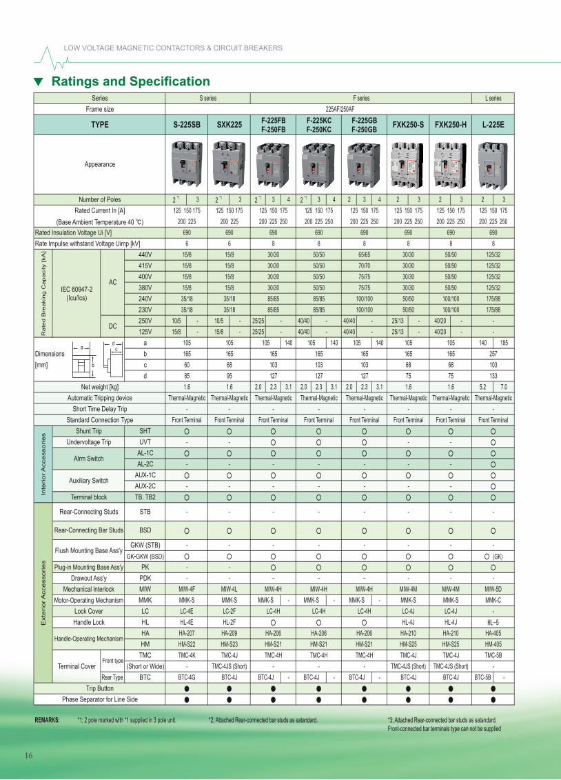
LOW VOLTAGE MAGNETIC CONTACTORS & CIRCUIT BREAKERS
16
Ratings and Specifications
2 *1 3 2 *1 3 2 *1 3 4 2 *1 3 4 2 3 4 2 3 2 3 2 3
440V415V400V380V240V230V250V 10/5 - 10/5 - 25/25 40/40 40/40 25/13 - 40/20 -125V 15/8 - 15/8 - 25/25 40/40 40/40 25/13 - 40/20 -
a 140 140 140 140 185Dimensions b[mm] c
d2.0 2.3 3.1 2.0 2.3 3.1 2.0 2.3 3.1 5.2 7.0
SHTUVT
AL-1CAL-2C
AUX-1CAUX-2CTB. TB2
STB
BSD
GKW (STB)GK•GKW (BSD)
PKPDKMIWMMK - - -LCHLHAHM
TMC(Short or Wide)
Rear Type BTC - - - BTC-5B -
REMARKS: *1; 2 pole marked with *1 supplied in 3 pole unit. *2; Attached Rear-connected bar studs as satandard. *3; Attached Rear-connected bar studs as satandard.Front-connected bar terminals type can not be supplied
HM-S23
-105 105
1.6 1.6
165 165 257
13368
-
-
-
TMC-4K
LC-4H
HA-206
TMC-4J TMC-4H
HA-207 HA-209 HA-206HM-S22
-
165103
105
127
Thermal-Magnetic
-BTC-4J
F-225GB F-250GB
125 150 175200 225 250
6908
65/6570/70
BTC-4JBTC-4J BTC-4J BTC-4J- TMC-4JS (Short) - -
BTC-4G BTC-4J
-
HM-S21HA-210
TMC-4JTMC-4HTMC-4JS (Short)
TMC-4H- TMC-4JS (Short)
TMC-4J
HL-4E HL-2F
TMC-5B
F series225AF/250AF
1.6
105 105
1.6
MIW-5DMMK-S MMK-S MMK-S MMK-SLC-4E LC-2F LC-4H
MIW-4HMIW-4F MIW-4L MIW-4H MIW-4H MIW-4M MIW-4M- - - - -- -
- - - - - -
-- - - - - -
-- - - - - -
- - - - - -
Handle-Operating Mechanism
Lock CoverHandle LockE
xterior
Acc
ess
ories
Rear-Connecting Studs
Rear-Connecting Bar Studs
Plug-in Mounting Base Ass'yDrawout Ass'y
Motor-Operating Mechanism
Series
TYPE
Number of Poles
Net weight [kg]
Rated Current In [A](Base Ambient Temperature 40 )
Rate
d B
reaki
ng C
apaci
ty [kA
]
Rated Insulation Voltage Ui [V]
Frame size
Inte
rior
Acc
ess
ories
Terminal Cover
AC
DC
IEC 60947-2 (Icu/Ics)
Shunt TripUndervoltage Trip
Alrm Switch
Auxiliary Switch
Terminal block
Mechanical lnterlock
F-225KC F-250KC
Trip ButtonPhase Separator for Line Side
Appearance
Rate Impulse withstand Voltage Uimp [kV]
Automatic Tripping deviceShort Time Delay Trip
Standard Connection Type
Front type
200 225 250 200 225 250
L series
FXK250-S FXK250-H L-225E
S series
S-225SB SXK225 F-225FB F-250FB
125 150 175 125 150 175 125 150 175 125 150 175 125 150 175 125 150 175
690 690 690200 225 250 200 225 250200 225 200 225
6 6 8 8
125 150 175200 225 250
690 690 690 6908 8 8
15/8 15/8 30/30 50/50 30/30 50/50 125/32
50/50 125/3215/8 15/8 30/30 50/50
75/7515/8 15/8
30/30 50/50 125/3215/8 15/8 30/30 50/50 30/30
30/30 50/50 125/3235/18 35/18 85/85 85/85 50/50 100/100 175/88
85/85 50/50 100/100-
30/30 50/5075/75100/100100/100
-105
-105
175/8835/18 35/18- -
85/85
60 68 103165 165 165 165
103 103 6885 95 127 127
Thermal-Magnetic Thermal-Magnetic
75 75
-Front Terminal Front Terminal Front Terminal
Thermal-Magnetic Thermal-Magnetic Thermal-Magnetic Thermal-Magnetic Thermal-Magnetic-
Front Terminal Front Terminal Front Terminal- -
Front Terminal-- - -
Front Terminal
- - - -
HM-S21 HM-S21 HM-S25 HM-405HM-S25
MMK-S MMK-CLC-4H
MMK-S MMK-SLC-4J LC-4J -
HA-206HL-4J HL-4J
HA-210 HA-405
Flush Mounting Base Ass'y(GK)
-
a
b
dc
16
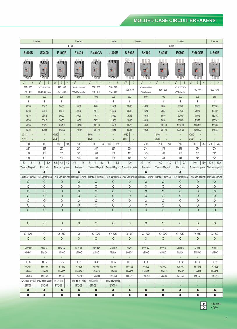
MOLDED CASE CIRCUIT BREAKERS
17
2*1 3 2*1 3 2*1 3 4 2*1 3 2*1 3 4 3 4 2*1 3 2*1 3 2*1 3 4 2*1 3 2*1 3 4 3 4
25/13 - 40/40 40/40 40/20 - 40/40 40/4025/13 - 40/40 40/40 40/20 - 40/40 40/40
185 185 140 185 280 280 210 280
5.3 6.1 5.1 5.9 5.3 6.1 8.2 5.1 5.9 5.3 6.1 8.2 6.1 8.2 8.7 9.7 13.0 8.7 9.7 13.0 10.0 13.0
- -- -
= Standard= Option
103 103
HM-402
274
Thermal-Magnetic-
Front Bar Terminal
Thermal-Magnetic-
Front Bar Terminal
210
HM-407
274274103 103 103
HM-402
274103
141 141
Electronic
50/25
250 300 200/225/250/300/
F-400R
250 300350 400 350/400 Adjustable 350 400
36/18
S-400S SX400
6908 8 8
690 690
S-600SFX400 F-400GB L-400E
10.0141
690
125/32
36/18
36/18125/32
8
125/32 36/18
210
50/50 65/65 125/32
6908 8 8
36/18
690 690
50/50 70/70
250 300350 400
75/75
50/50
36/18 36/18 50/50
50/5036/18
36/18 36/1836/18
50/2550/25
36/1850/50 50/50 75/75
50/50100/100 100/100 100/100
--
175/88 50/2550/25 50/25 100/100 100/100 100/100 175/88
103257 257 257 257
--
257 257
133 133 141103133 133 133 133
103 103
Thermal-Magnetic Thermal-Magnetic Thermal-Magnetic- -
Thermal-Magnetic Electronic Thermal-Magnetic Electronic
Front Bar Terminal Front Bar Terminal-
Front Bar Terminal Front Bar Terminal Front Bar Terminal Front Bar Terminal--
Front Bar Terminal
- - -
- -
- - - - - - -MIW-5D MIW-5F MIW-5D
-
MIW-5D MIW-5MMK-C MMK-C MMK-C MMK-C MMK-CMIW-5D MIW-5F
- - -HL-5 HL-5
TMC-5BTMC-5B
HA-405 HA-405 HA-402HM-405HA-405 HA-406 HA-405 HA-406
MMK-C
HM-407TMC-5D
-TMC-5BW (Wide) TMC-5BW (Wide) TMC-5BW (Wide) TMC-5BW (Wide)TMC-5B
BTC-5B BTC-5B BTC-5B
36/18
BTC-5B -
SX600
300/350/400/500/
600 Adjustable
6908
36/1836/1836/1850/25
--
210
BTC-5B
-140
BTC-5B
210
10.0
MMK-C
HM-402TMC-5B TMC-5B
103141
Electronic
50/25
274
Front Bar Terminal
TMC-5BW (Wide)
HM-405
TMC-5BW (Wide)
MMK-C
HM-405
-
-MIW-5G
-
--
--
--
-
140 140
HM-406
140
HM-405
140
HM-406
- - -
--
HA-402
TMC-5D
L-600EF-600GB
690 690 6908 8 8
6908
75/75
50/50 50/50 125/3250/50 50/50 125/32
65/6570/70
175/88100/100100/100
50/50 50/50 125/3250/50 50/50 125/32
75/75
Front Bar Terminal
100/100 100/100 175/88100/100 100/100
-
- - -MIW-5 MIW-5G MIW-5
-MIW-5
MMK-C MMK-C MMK-C- - -
MMK-C-
HA-402HA-402 HA-402 HA-402
TMC-5D TMC-5D TMC-5D- - -
F-600F FX600
TMC-5B
- - -
--
L series
350/400 Adjustable
250 300350 400
500 600 500 600300/350/400/500/
600 Adjustable
-
141
Thermal-Magnetic-
Front Bar Terminal
10.0
400AF 600AF
200/225/250/300/
HM-402TMC-5D
-
274103
210
500 600500 600
--
S series F series S series F seriesL series
--
-
-
17
LOW VOLTAGE MAGNETIC CONTACTORS & CIRCUIT BREAKERS
Ratings and Specifi cation
18
Ratings and Specifications
3 4 3 4 3 4 3 4
440V415V400V380V240V230V250V 40/40 - 40/40 - 40/40 - 40/40 -125V 40/40 - 40/40 - 40/40 - 40/40 -
a 210 280 210 280 210 280 210 280Dimensions b[mm] c
d10.5 13.5 10.5 13.5 10.5 13.5 26 33
SHTUVT
AL-1CAL-2C
AUX-1CAUX-2CTB. TB2
STB
BSDGKW (STB)
GK•GKW (BSD)PK
PDKMIWMMKLCHLHAHM
TMC(Short or Wide)
Rear Type BTC
REMARKS: *1; 2 pole marked with *1 supplied in 3 pole unit. *2; Attached Rear-connected bar studs as satandard. *3; Attached Rear-connected bar studs as satandard.Front-connected bar terminals type can not be supplied
HM-402
-HL-6
HA-402HL-6 HL-6
HA-402HM-407
Thermal-Magnetic-- -
Front Bar Terminal-
Front Bar Terminal Front Bar Terminal Front Bar Terminal Front Bar Terminal Front Bar Terminal Front Bar Terminal-
141
Electronic Thermal-Magnetic Electronic Thermal-MagneticThermal-Magnetic
103 103274 274
Thermal-Magnetic
141 141141 141 141103 103 103 103
274 274274 274
85/43 85/43 100/100 100/100 100/100 175/88
36/18 36/18 75/75 125/3250/50 50/5085/43 85/43 100/100 100/100 100/100 175/88
36/18 36/18 50/50 50/50 75/75 125/3270/70 125/32
36/18 36/1836/18 36/18 50/50 50/50
50/50 50/50 125/328 8 8 8
690 6908 8
690 690 690 690
85/43 65/65
S series
S-800S SX800 F-800R
F seriesFrame size
Appearance
Rate Impulse withstand Voltage Uimp [kV]
Automatic Tripping device
IEC 60947-2 (Icu/Ics)
AC
DC
Auxiliary Switch
Terminal block
Trip ButtonPhase Separator for Line Side
Front type
Inte
rior
Acc
ess
ories Shunt Trip
Undervoltage Trip
Alrm Switch
Ext
erior
Acc
ess
ories
Short Time Delay TripStandard Connection Type
Series
TYPE
Number of Poles
Net weight [kg]
Rated Current In [A](Base Ambient Temperature 40 )
Ra
ted
Bre
aki
ng
Ca
pa
city
[kA
]
Rated Insulation Voltage Ui [V]
Terminal Cover
Handle-Operating Mechanism
Lock CoverHandle Lock
HM-402
- -Rear-Connecting Studs
Rear-Connecting Bar Studs
Motor-Operating MechanismMechanical lnterlock
Plug-in Mounting Base Ass'yDrawout Ass'y
Flush Mounting Base Ass'y
- -
-
-
-
-
- -
--
MMK-C MMK-C
--
-MIW-5 MIW-5G MIW-5 MIW-5G MIW-5 MIW-5
- -
HA-402 HA-402 HA-402
- - -HL-6 HL-6
-TMC-5D
- -TMC-5D
MMK-C- -
HM-402 HM-402
- -- - -
-- - - -
6908
700 800
-TMC-5DTMC-5D
-
HA-402
-
85/4385/43
125/63125/63
274103
MMK-C
-
-210
11.0141
-
MIW-5
TMC-5D
-HL-6
HA-402
MMK-C MMK-C MMK-C
TMC-5D TMC-5D
FX800 F-800GB L-800E
210
10.5
--
85/43
F-800RH
400/450/500/600/700/800 Adjustable
700 800 700 800
L Series
3 3 3 3
800AF
210 210
11.0
HL-6
700 800 700 800700/800 Adjustable
40/20 -
400/450/500/600/
F-1000K
1000
690
40/20
HM-402
--
HM-407
10.5
85/22125/32125/32
410
885/2285/2285/22
Front Bar Terminal
150190
Thermal-Magnetic-
HA-801-
TMC-6
F Series1000AF
--
-MIW-8MMK-C
-
a
b
dc
18
Ratings and Specifications
3 4 3 4 3 4 3 4
440V415V400V380V240V230V250V 40/40 - 40/40 - 40/40 - 40/40 -125V 40/40 - 40/40 - 40/40 - 40/40 -
a 210 280 210 280 210 280 210 280Dimensions b[mm] c
d10.5 13.5 10.5 13.5 10.5 13.5 26 33
SHTUVT
AL-1CAL-2C
AUX-1CAUX-2CTB. TB2
STB
BSDGKW (STB)
GK•GKW (BSD)PK
PDKMIWMMKLCHLHAHM
TMC(Short or Wide)
Rear Type BTC
REMARKS: *1; 2 pole marked with *1 supplied in 3 pole unit. *2; Attached Rear-connected bar studs as satandard. *3; Attached Rear-connected bar studs as satandard.Front-connected bar terminals type can not be supplied
HM-402
-HL-6
HA-402HL-6 HL-6
HA-402HM-407
Thermal-Magnetic-- -
Front Bar Terminal-
Front Bar Terminal Front Bar Terminal Front Bar Terminal Front Bar Terminal Front Bar Terminal Front Bar Terminal-
141
Electronic Thermal-Magnetic Electronic Thermal-MagneticThermal-Magnetic
103 103274 274
Thermal-Magnetic
141 141141 141 141103 103 103 103
274 274274 274
85/43 85/43 100/100 100/100 100/100 175/88
36/18 36/18 75/75 125/3250/50 50/5085/43 85/43 100/100 100/100 100/100 175/88
36/18 36/18 50/50 50/50 75/75 125/3270/70 125/32
36/18 36/1836/18 36/18 50/50 50/50
50/50 50/50 125/328 8 8 8
690 6908 8
690 690 690 690
85/43 65/65
S series
S-800S SX800 F-800R
F seriesFrame size
Appearance
Rate Impulse withstand Voltage Uimp [kV]
Automatic Tripping device
IEC 60947-2 (Icu/Ics)
AC
DC
Auxiliary Switch
Terminal block
Trip ButtonPhase Separator for Line Side
Front type
Inte
rior A
cces
sorie
s Shunt TripUndervoltage Trip
Alrm Switch
Ext
erio
r Acc
esso
ries
Short Time Delay TripStandard Connection Type
Series
TYPE
Number of Poles
Net weight [kg]
Rated Current In [A](Base Ambient Temperature 40 )
Rat
ed B
reak
ing
Cap
acity
[kA
]
Rated Insulation Voltage Ui [V]
Terminal Cover
Handle-Operating Mechanism
Lock CoverHandle Lock
HM-402
- -Rear-Connecting Studs
Rear-Connecting Bar Studs
Motor-Operating MechanismMechanical lnterlock
Plug-in Mounting Base Ass'yDrawout Ass'y
Flush Mounting Base Ass'y
- -
-
-
-
-
- -
--
MMK-C MMK-C
--
-MIW-5 MIW-5G MIW-5 MIW-5G MIW-5 MIW-5
- -
HA-402 HA-402 HA-402
- - -HL-6 HL-6
-TMC-5D
- -TMC-5D
MMK-C- -
HM-402 HM-402
- -- - -
-- - - -
6908
700 800
-TMC-5DTMC-5D
-
HA-402
-
85/4385/43
125/63125/63
274103
MMK-C
-
-210
11.0141
-
MIW-5
TMC-5D
-HL-6
HA-402
MMK-C MMK-C MMK-C
TMC-5D TMC-5D
FX800 F-800GB L-800E
210
10.5
--
85/43
F-800RH
400/450/500/600/700/800 Adjustable
700 800 700 800
L Series
3 3 3 3
800AF
210 210
11.0
HL-6
700 800 700 800700/800 Adjustable
40/20 -
400/450/500/600/
F-1000K
1000
690
40/20
HM-402
--
HM-407
10.5
85/22125/32125/32
410
885/2285/2285/22
Front Bar Terminal
150190
Thermal-Magnetic-
HA-801-
TMC-6
F Series1000AF
--
-MIW-8MMK-C
-
a
b
dc
18
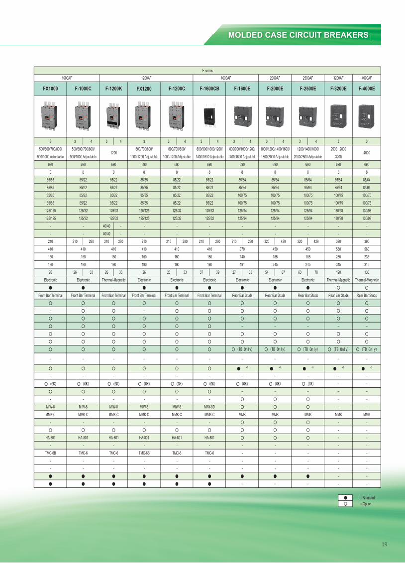
MOLDED CASE CIRCUIT BREAKERS
19
3 4 3 4 3 4 3 4 3 4 3 4 3 4
40/40 -40/40 -
210 280 210 280 210 280 210 280 210 280 320 429 320 429
26 33 26 33 26 33 37 39 27 35 54 67 63 78
= Standard= Option
600/700/800/1000/1200 Adjustable
800/900/1000/1200/1400/1600 Adjustable
--
--
2500 28003200
40001200/1400/1600/
2000/2500 Adjustable800/900/1000/1200/
1400/1600 Adjustable
- -
- - -- -
- - -- - -
- ---
MMK MMK MMK- -
Rear Bar Studs Rear Bar Studs Rear Bar Studs
125/94 130/98 130/98
Electronic Thermal-Magnetic Thermal-Magnetic
100/75 100/75100/75 100/75 100/75125/94 130/98 130/98
8 885/64
85/64 85/64 85/64
F-4000EF-2500E F-3200E
6908
210
- -
Rear Bar Studs
--
6908
85/6485/64
F-2000E
1000/1200/1400/1600/1800/2000 Adjustable
-
MMK
-
--
HA-801--
-- - -
-TMC-6
- - ---
- --
-
-TMC-6
HA-801 HA-801
TMC-6
HA-801
TMC-6B TMC-6B
-- - -
MIW-8 MIW-8-
MIW-8MMK-CMMK-C MMK-C MMKMMK-C
MIW-8 MIW-8D- - - -
450185245
Electronic
390
Front Bar Terminal Rear Bar StudsFront Bar Terminal Front Bar Terminal Front Bar Terminal
Electronic
150
Electronic Thermal-Magnetic-
Electronic
125/125 125/32 125/94125/125
Electronic Electronic
190 190 19026
85/22 85/8585/22
85/22 100/75
125/94
210-
-
85/22125/32
--
125/32125/125 125/32
150 150410 410410
150
85/6485/85 85/22 85/85 85/22 85/64
85/22 85/85 85/2285/22
6908 8 8 8 8
690 690
600/700/800/1000/1200 Adjustable
-
125/32125/32
85/2285/2285/2285/22
690
100/75100/75125/94125/94
----
-
100/7585/8585/85
500/600/700/800/900/1000 Adjustable
85/85
690
410 370150
190
410150
-
560235
315 315120 130
560
-
3200AF
185 235450
390
690 690
85/64 85/64
100/75
4000AF
3 3 3 3
F-1600E
1600AF 2000AF 2500AF1200AF
F-1200C
-
245
--
140190 191
FX1000 FX1200F-1000C F-1600CBF-1200K
85/2285/2285/22
125/12585/85
500/600/700/800/900/1000 Adjustable
6908
1200
410
Electronic
Front Bar TerminalFront Bar Terminal
19026
HA-801-
MMK-C
-MIW-8
-
HA-801-
TMC-6
MMK-C
F series1000AF
--
--
6908
125/32125/32
19
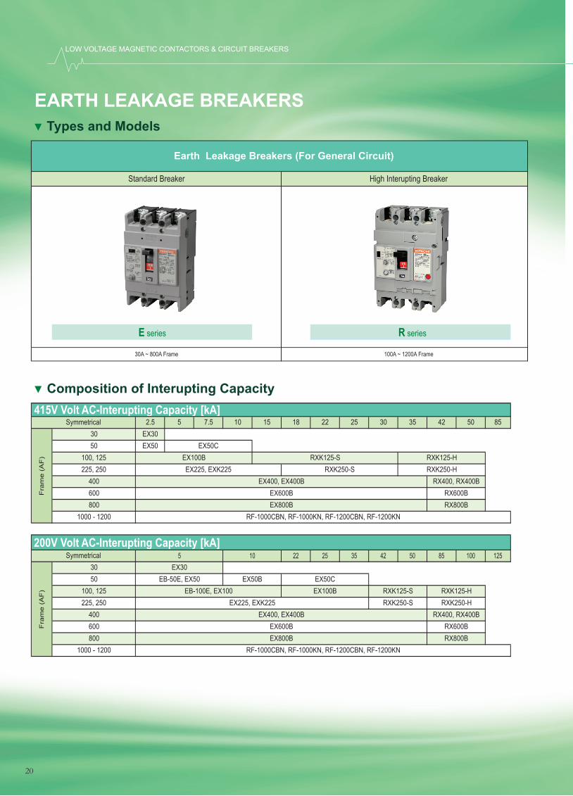
EARTH LEAKAGE BREAKERS
LOW VOLTAGE MAGNETIC CONTACTORS & CIRCUIT BREAKERS
20
EARTH LEAKAGE BREAKER
Types and Models
Composition of Interupting Capacity
2.5 5 7.5 10 15 18 22 25 30 35 42 50 85EX30EX50
22 25 35 42 50 85 100 125
RX600B
100, 125225, 250
400
50
Fra
me
(AF
)
EX50CEX100BEX225, EXK225
EX400, EX400B
415V Volt AC-Interupting Capacity [kA]
RXK125-S RXK125-HRXK250-S RXK250-H
RX400, RX400B
Symmetrical30
EX50C
225, 250EB-100E, EX100
600800
1000 - 1200
EX600BEX800B
RF-1000CBN, RF-1000KN, RF-1200CBN, RF-1200KN
RXK125-HEX225, EXK225 RXK250-S RXK250-H
RX800B
200V Volt AC-Interupting Capacity [kA]Symmetrical
Fra
me
(AF
)
3050
RX800B1000 - 1200 RF-1000CBN, RF-1000KN, RF-1200CBN, RF-1200KN
400 EX400, EX400B RX400, RX400B600 EX600B RX600B
5 10EX30
EB-50E, EX50 EX50B
800 EX800B
EX100B RXK125-S100, 125
Standard Breaker High Interupting Breaker
30A ~ 800A Frame 100A ~ 1200A Frame
E series R series
Earth Leakage Breakers (For General Circuit)
20
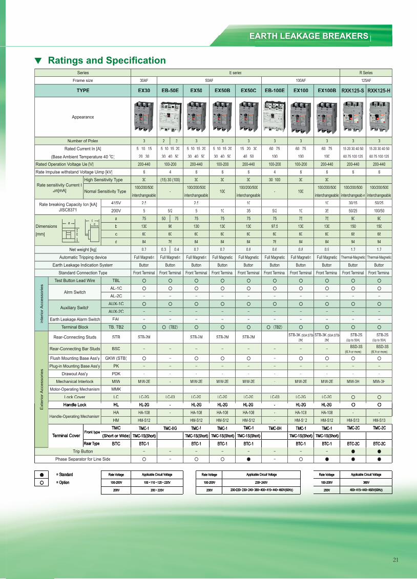
Ratings and Specifi cation
EARTH LEAKAGE BREAKERS
2 3
415V
200V
a 50 75Dimensions b
[mm] c
d
0.3 0.4
TBL
AL-1C
AL-2C
AUX-1C
AUX-2C
EAL
TB. TB2
STB
BSD
GKW (STB)
PK
PDK
MIW
MMK
LC
HLHL
HA
HM
TMC
(Short or Wide)
Rear Type BTC
= Standard Rate Voltage
= Option 100-200V
200V 400• 415• 440• 460V(60Hz)
Applicable Circuit Voltage
230• 240V
Applicable Circuit Voltage
380V
200 • 220V 200V 200V
100 • 110 • 120 • 220V 100-200V 100-200V
200•220• 230• 240• 380• 400• 415• 440• 460V(60Hz)
Applicable Circuit Voltage Rate Voltage Rate Voltage
HM-S12TMC-0G TMC-1 TMC-1
TMC-1S(Short) - TMC-1S(Short)
HM-S13HM-S13
LC-2GHL-2GHL-2GHA-108 -HM-S12
-
ButtonButton Button Button ButtonFront Terminal Front Terminal
ButtonFront Terminal Front Terminal Front Terminal Front Terminal Front Terminal Front Terminal
Button
Thermal-Magnetic
94 9484
Full Magnetic0.8 0.9
Full Magnetic
96
84 76 84 84
Thermal-MagneticFull Magnetic Full Magnetic Full Magnetic Full Magnetic
13075
68 68150 150
10 3575 75 75
60 60130 130 97.5
100/502.5 - 30/15 50/252.5 - - - 10
interchangeable interchangeable100/200/500 100/200/500100/200/500
5 5/2 5 10 50/25
630 (15) 30 (100)
interchangeable interchangeable100/200/500 100/200/500
interchangeable
200-440 100-200 200-440 100-200
30 30
30 40 50
30 10030 30 30
200-4406
30 40 50
EX30 EB-50E EX50
5 10 15 20
Phase Separator for Line Side
Frame size
Appearance
Rate Impulse withstand Voltage Uimp [kV]
Automatic Tripping device
Earth Leakage Indication System
Standard Connection Type
Front type
Inte
rior A
cces
sorie
s
Test Button Lead Wire
Alrm Switch
Auxiliary Switch
Terminal Block
Earth Leakage Alarm Switch
Trip Button
Series
TYPE
Number of Poles
Net weight [kg]
Rated Current In [A]
(Base Ambient Temperature 40 )Rated Operation Voltage Ue [V]
Nomal Sensitivity Type
High Sensitivity Type
Ext
erio
r Acc
esso
ries
Rear-Connecting Studs
Rear-Connecting Bar Studs
Plug-in Mounting Base Ass'y
Drawout Ass'y
Flush Mounting Base Ass'y
Motor-Operating Mechanism
Mechanical lnterlock
Terminal Cover
Handle-Operating Mechanism
STB-2M STB-2M
- - - -
Lock Cover
Handle LockHandle Lock
HM-S12
- STB-3K (50A:STB-2M)
STB-2S (Up to 50A)
BSD-3S (60A or more)A or more)A
BSD-3S (60A or more)A or more)A
STB-2M STB-2M
- -
HL-2GHL-2G
-
-- MIW-2E MIW-2E- -
-MIW-2E - MIW-2E MIW-2E MIW-3H MIW-3H
- - -
-
HA-108 - HA-108
LC-2G LC-03 LC-2GHL-2GHL-2G
-TMC-1
TMC-1S(Short) -TMC-2C
- TMC-1S(Short) TMC-1S(Short)TMC-2C
TMC-1S(Short)BTC-1 - BTC-2CBTC-2CBTC-1 BTC-1 BTC-1 -
STB-2S (Up to 50A)
100/200/500100
0.8
75
0.7
60
interchangeable1035
13075
-MIW-2E
TMC-1
LC-2GHL-2GHL-2GHA-108
- - -
90
1.7
R Series125AF
90
1.7
200-440 200-440
3 3 3
EX50B RXK 125S RXK 125HEX50C
15 20 30 40 50
30 40 50 40 50 100 100 100 60 75 100 125 60 75 100 125
5 10 15 20
HM-S12 -
0.7
75
-
-
60 60130
3 3 3
EB-100E EX100 EX100B
35 10 15
20 305 10 15 20 15 20 30 60 75 60 75 60 75 15 20 30 40 50
3
Rate breaking Capacity Icn [kA] JISC8371
4 6 66 4 6 6
100
5/2
E series30AF 50AF 100AF
6
Rate sensitivity Current I n[mA]
100-200 100-200 200-440
3
0.7
13060 60 6076 84 840.6
STB-3K (50A:STB-2M)
Full Magnetic Full MagneticButton Button Button
-LC-03 LC-2G LC-2G
TMC-1
- HL-2HL-2GG HL-2GHL-2G- HA-108 HA-108
BTC-1 BTC-1
- HM-S12 HM-S12TMC-0H TMC-1
- -
Front Terminal Front Terminal
a
b
dc
RXK125-HRXK125-S
21
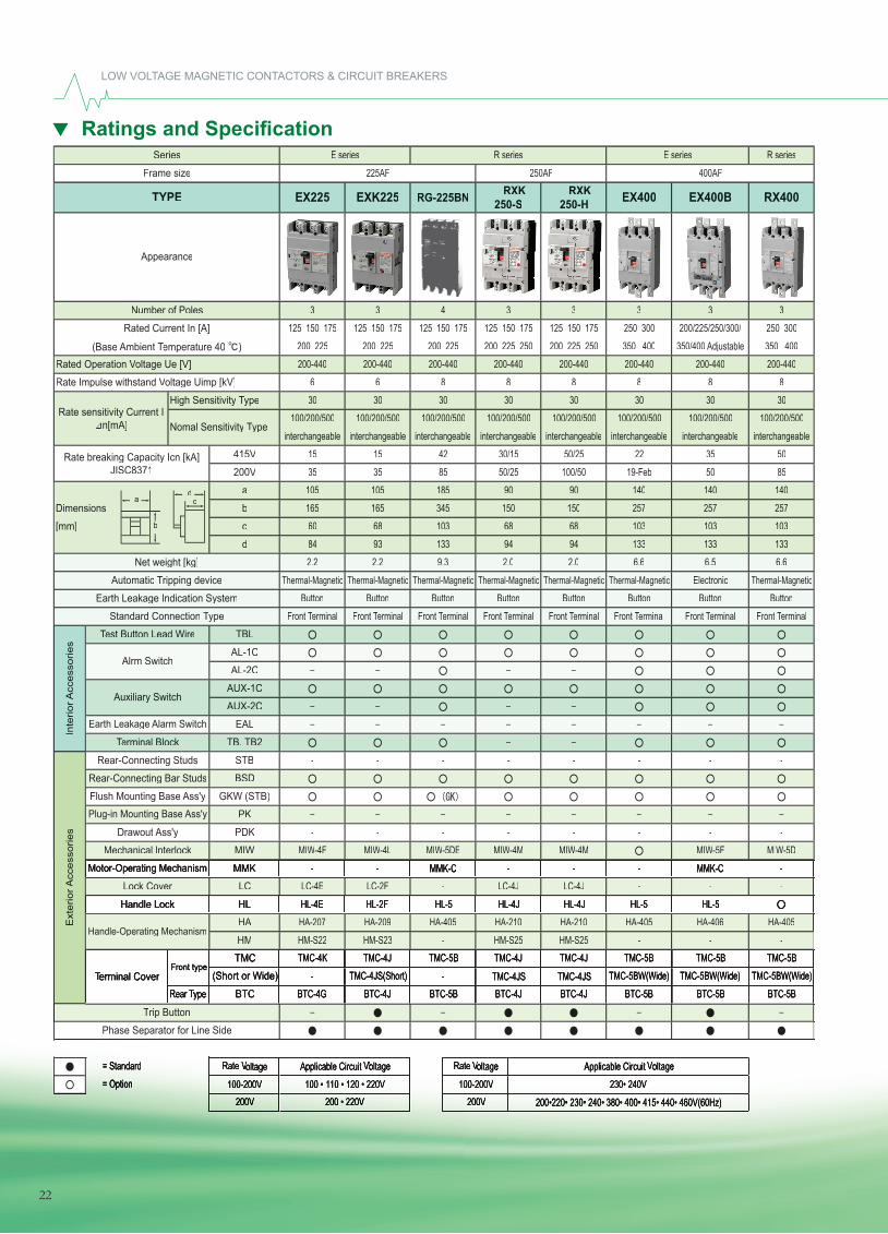
Ratings and Specifi cation
LOW VOLTAGE MAGNETIC CONTACTORS & CIRCUIT BREAKERS
415V
200V
a
Dimensions b
[mm] c
d
TBL
AL-1C
AL-2C
AUX-1C
AUX-2C
EAL
TB. TB2
STB
BSD
GKW (STB)
PK
PDK
MIW
MMK
LC
HL
HA
HM
TMC
(Short or Wide)
Rear TypeTypeT BTC
= Standard Rate VoltageVoltageV= Option 100-200V
200V 200V
EX225
Applicable Circuit VoltageVoltageV230• 240V
200•220• 230• 240• 380• 400• 415• 440• 460V(60Hz)
Applicable Circuit VoltageVoltageV100 • 110 • 120 • 220V
200 • 220V
Rate VoltageVoltageV100-200V
RXK 250-S
225AF 250AF
3
100/200/500
RXK 250-H
Button
E series R series
interchangeable
9.3
200 225
BTC-5BBTC-5B
133
Front TerminalTerminalT Front TerminalTerminalT
-TMC-5B TMC-5B TMC-5B
- -HA-405 HA-406 HA-405
HL-5- -
Button
-- -
400AFE series R series
100/200/500
8200-440 200-440 200-440
RX400EX400 EX400B
Rate breaking Capacity Icn [kA] JISC8371
interchangeable
8 8
interchangeable50/25
105
HL-2F
-
60 68165
105
2.2
165
3 3125 150 175 125 150 175 125 150 175 250 300 200/225/250/300/ 250 300
43 3
200 225 200 225 250200 225
3
200 225 250
94
350/400 Adjustable 350 400
1336.6
257103 103 103
350 400
Button
interchangeable
133
22
140
30100/200/500
TMC-4K
LC-4JHL-4J
HA-210HM-S22 HM-S23
LC-4E LC-2F -HL-4E
Thermal-Magnetic
Front TerminalTerminalTButton
2.0
90
2.0
68150
100/200/500
100/50
-MIW-4M
BTC-4J BTC-4J BTC-5B- TMC-4JS
TMC-4J TMC-5B TMC-4J
BTC-4G BTC-4J- TMC-4JS(Short)
BTC-5BTMC-5BW(Wide)
HA-207 HA-209 HA-405 HA-210HM-S25
TMC-4JTMC-4JS TMC-5BW(Wide) TMC-5BW(Wide)
HL-5 HL-5HL-4J
MMK-C - --- MMK-C -
- -MIW-4F MIW-4L MIW-5DE MIW-4M
- -MIW-5F MIW-5D
-
-
LC-4J
---
-
Handle Lock
-
- - -
Lock Cover
Ext
erio
rAcc
esso
ries
Rear-Connecting Studs
Rear-Connecting Bar Studs
Plug-in Mounting Base Ass'y
Drawout Ass'y
Flush Mounting Base Ass'y
Motor-Operating Mechanism
Mechanical lnterlock
Terminal CoverTerminal CoverT
Handle-Operating Mechanism
Series
TYPE
Number of Poles
Net weight [kg]
Rated Current In [A]
(Base Ambient Temperature 40 Temperature 40 T )Rated Operation Voltage Ue [V]Voltage Ue [V]V
Nomal Sensitivity TypeTypeT
High Sensitivity TypeTypeTRate sensitivity Current I
n[mA]
Phase Separator for Line Side
Frame size
Appearance
Rate Impulse withstand Voltage Uimp [kV]Voltage Uimp [kV]V
Automatic Tripping device
Earth Leakage Indication System
Standard Connection TypeTypeT
Front type
Inte
riorA
cces
sorie
s
Test Button Lead WireTest Button Lead WireT
EXK225 RG-225BN
125 150 175 125 150 1753
Trip Button
Alrm Switch
Auxiliary Switch
Terminal BlockTerminal BlockT
Earth Leakage Alarm Switch
200-440 200-440 200-440 200-440 200-4408
3030 30 30 306 6 8 8
30
interchangeable interchangeable100/200/500 100/200/500
interchangeable
30100/200/500
interchangeable100/200/500
35 35 85 50/2515 15 42 30/15
257 257185
35 5019-Feb 50 85
90
84 93 133 94
140 140
103 68345 150
6.5 6.6Thermal-MagneticThermal-Magnetic Thermal-Magnetic Thermal-Magnetic Thermal-Magnetic
2.2Thermal-MagneticElectronic
Button Button Button ButtonFront TerminalTerminalTFront TerminalTerminalT Front TerminalTerminalT Front TerminalTerminalT Front TerminalTerminalT
HM-S25
a
b
dc
22
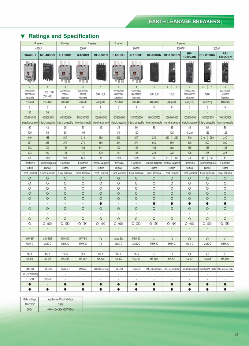
Ratings and Specifi cation
23
Ratings and Specifications
3 4 3 4
210 280 210 280
41 60 41 60
RG-400BN EX600B
440(200)
RX400B RF-1000KN
3
10.2
345
4
100/200/500
300/350/400/
210
10.6
R series
interchangeable
RX600B
100/200/500
10.6
Adjustable
3
185
--
HA-801-
TMC-6B(Line Side) TMC-6(Line Side) TMC-6B(Line Side)
- -
Button Button
-
Front Terminal Front Terminal
185 185 185
ElectronicThermal-Magnetic
225 225 22541 41
interchangeable100/200/500 100/200/500
8440(200) 440(200) 440(200)
-
Adjustable100/1200
interchangeable
8 8
interchangeable
8--
100/200/500
RF-1000CBN RF-1200KN RF-
1200CBN
700 800
4500/600/700/ 600/750/800/
- -
6.5
140
HL-5
-
103 103257
3 3
Adjustable
4300/350/400/ 250 300
350 400
3
500 600Adjustable
3 3200/225/250/
Thermal-Magnetic
Front TerminalButton
-
TMC-5B
-
HA-801
MMK-C MMK-C MMK-C
185225
800
23 12.9 12.9 50
141 103 103
85125
100/200/500 100/200/500 100/200/500interchangeable interchangeable interchangeable interchangeable
100/200/500
- -
MMK-C
- -- - - -BTC-5B BTC-5BTMC-5BW(Wide) -
- --- -
TMC-5B TMC-5D TMC-5D TMC-6(Line Side)
HA-405 HA-402 HA-402
- - -
HA-801 HA-801HL-5
- - - -
-HA-402 HA-402 HA-402HA-406
HL-6 HL-6
- - - -MIW-5G MIW-5G
- - - -
-
MMK-C MMK-CMIW-5F MIW-5DE
- -MMK-C MMK-C
- -- -- - - --
- - -
100-200VApplicable Circuit Voltage
380V200V 400• 415• 440• 460V(60Hz)
300/350/400 500/600 500/600
-
8440(200) 200-440 200-440 440(200)
Rate Voltage
-
-
-
- --
200-440 200-440 200-440 200-4408 8 8
interchangeable interchangeable100/200/500 100/200/500
interchangeable
30 30
interchangeable100/200/500
100 85 50 10050 42 35 50
800 800210
800
85 854-May 125 125
85
133 133 141 141
210 210
103 103274 274
Electronic Thermal-Magnetic Electronic Electronic Electronic ElectronicThermal-Magnetic
Front TerminalFront Terminal Front Terminal Front Terminal Front Terminal
ElectronicThermal-Magnetic
ButtonButton Button Button ButtonFront Terminal Front Terminal Front Terminal Front Terminal
-
RF-600FN EX800B RX800B RF-800KN
400/450/500/ 400/450/500/1200600/700/800 600/700/800 800/900/1000
AdjustableAdjustable Adjustable1000
8 8- - - -8 8
- 50 100 -42 35 50 85
210 210 280580 274 274 800280
Button Button Button Button
185179 141 141 225
MMK-C MMK-C MMK-CMIW-5G MIW-5G
HL-6 HL-6
- - - -HA-801
HL-6
- - - -TMC-5D(Line Side) TMC-5D TMC-5D TMC-6(Line Side)
1200AFE series R series E series R series
400AF 600AF 800AF 1000AF
EARTH LEAKAGE BREAKERS
23
Ratings and Specifications
3 4 3 4
210 280 210 280
41 60 41 60
RG-400BN EX600B
440(200)
RX400B RF-1000KN
3
10.2
345
4
100/200/500
300/350/400/
210
10.6
R series
interchangeable
RX600B
100/200/500
10.6
Adjustable
3
185
--
HA-801-
TMC-6B(Line Side) TMC-6(Line Side) TMC-6B(Line Side)
- -
Button Button
-
Front Terminal Front Terminal
185 185 185
ElectronicThermal-Magnetic
225 225 22541 41
interchangeable100/200/500 100/200/500
8440(200) 440(200) 440(200)
-
Adjustable100/1200
interchangeable
8 8
interchangeable
8--
100/200/500
RF-1000CBN RF-1200KN RF-
1200CBN
700 800
4500/600/700/ 600/750/800/
- -
6.5
140
HL-5
-
103 103257
3 3
Adjustable
4300/350/400/ 250 300
350 400
3
500 600Adjustable
3 3200/225/250/
Thermal-Magnetic
Front TerminalButton
-
TMC-5B
-
HA-801
MMK-C MMK-C MMK-C
185225
800
23 12.9 12.9 50
141 103 103
85125
100/200/500 100/200/500 100/200/500interchangeable interchangeable interchangeable interchangeable
100/200/500
- -
MMK-C
- -- - - -BTC-5B BTC-5BTMC-5BW(Wide) -
- --- -
TMC-5B TMC-5D TMC-5D TMC-6(Line Side)
HA-405 HA-402 HA-402
- - -
HA-801 HA-801HL-5
- - - -
-HA-402 HA-402 HA-402HA-406
HL-6 HL-6
- - - -MIW-5G MIW-5G
- - - -
-
MMK-C MMK-CMIW-5F MIW-5DE
- -MMK-C MMK-C
- -- -- - - --
- - -
100-200VApplicable Circuit Voltage
380V200V 400• 415• 440• 460V(60Hz)
300/350/400 500/600 500/600
-
8440(200) 200-440 200-440 440(200)
Rate Voltage
-
-
-
- --
200-440 200-440 200-440 200-4408 8 8
interchangeable interchangeable100/200/500 100/200/500
interchangeable
30 30
interchangeable100/200/500
100 85 50 10050 42 35 50
800 800210
800
85 854-May 125 125
85
133 133 141 141
210 210
103 103274 274
Electronic Thermal-Magnetic Electronic Electronic Electronic ElectronicThermal-Magnetic
Front TerminalFront Terminal Front Terminal Front Terminal Front Terminal
ElectronicThermal-Magnetic
ButtonButton Button Button ButtonFront Terminal Front Terminal Front Terminal Front Terminal
-
RF-600FN EX800B RX800B RF-800KN
400/450/500/ 400/450/500/1200600/700/800 600/700/800 800/900/1000
AdjustableAdjustable Adjustable1000
8 8- - - -8 8
- 50 100 -42 35 50 85
210 210 280580 274 274 800280
Button Button Button Button
185179 141 141 225
MMK-C MMK-C MMK-CMIW-5G MIW-5G
HL-6 HL-6
- - - -HA-801
HL-6
- - - -TMC-5D(Line Side) TMC-5D TMC-5D TMC-6(Line Side)
1200AFE series R series E series R series
400AF 600AF 800AF 1000AF
23
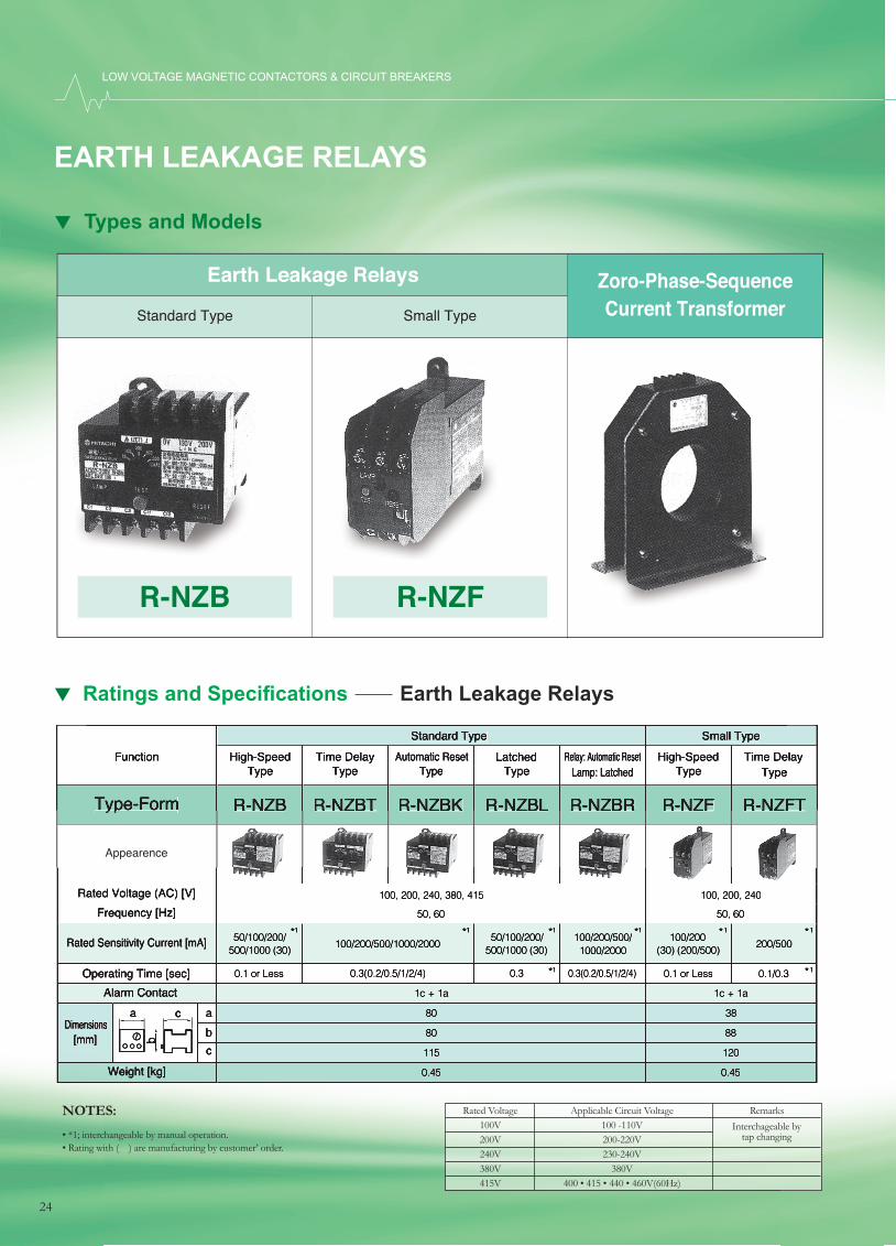
Type-FormType-Form
Function
Appearence
R-NZBR-NZB R-NZBTR-NZBT R-NZBKR-NZBK R-NZBLR-NZBL R-NZBRR-NZBR R-NZFR-NZF R-NZFTR-NZFT
Standard Type
Rated Voltage (AC) [V] 100, 200, 240, 380, 415 100, 200, 240
Weight [kg] 0.45 0.45
Operating Time [sec] 0.3(0.2/0.5/1/2/4) 0.1/0.30.1 or Less0.3(0.2/0.5/1/2/4)0.30.1 or Less
Rated Sensitivity Current [mA] 100/200/500/1000/2000 200/50050/100/200/
500/1000 (30)50/100/200/
500/1000 (30)100/200/500/1000/2000
100/200(30) (200/500)
Frequency [Hz] 50, 60 50, 60
Dimensions[mm]
80 38a80 88b115 120c
Small Type
Relay: Automatic ResetLamp: Latched
High-SpeedType
Time Delay Type
High-SpeedType
Time DelayType
Automatic ResetType
LatchedType
a c
b
Alarm Contact 1c + 1a 1c + 1a
*1 *1 *1 *1 *1 *1
*1*1
LOW VOLTAGE MAGNETIC CONTACTORS & CIRCUIT BREAKERS
Rated Voltage Applicable Circuit Voltage Remarks 100V 100 -110V 200V 200-220V 240V 230-240V 380V 380V 415V 400 • 415 • 440 • 460V(60Hz)
Interchageable by tap changing
EARTH LEAKAGE RELAYS
• *1; interchangeable by manual operation.• Rating with ( ) are manufacturing by customer’ order.
NOTES:
Earth Leakage Relays Zoro-Phase-SequenceCurrent TransformerStandard Type Small Type
R-NZB R-NZF
Types and Models
Ratings and Specifi cations Earth Leakage Relays
24
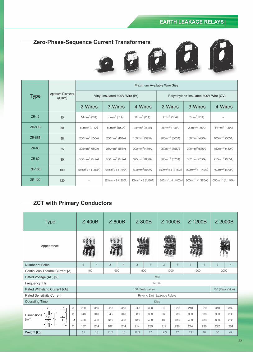
Types and Models
2-Wires 3-Wires 4-Wires 2-Wires 3-Wires 4-Wires
Type Aperture Diameter [mm] Vinyl-Insulated 600V Wire (IV) Polyethylene-Insulated 600V Wire (CV)
15
30
58
65
80
100
120
ZR-15
ZR-30B
ZR-58B
ZR-65
ZR-80
ZR-100
ZR-120
Maximum Available Wire Size
14mm2 88A 8mm2 61A 8mm2 61A 2mm2 33A 2mm2 33A –
60mm2 217A 50mm2 190A 38mm2 162A 38mm2 190A 22mm2 135A 14mm2 105A
250mm2 556A 200mm2 469A 150mm2 395A 200mm2 560A 150mm2 480A 100mm2 365A
325mm2 650A 250mm2 556A 200mm2 469A 250mm2 655A 200mm2 560A 150mm2 480A
500mm2 842A 500mm2 842A 325mm2 650A 500mm2 870A 352mm2 760A 250mm2 655A
500mm2 × 4 1.684A 400mm2 × 6 1.490A 500mm2 842A 600mm2 × 4 1,140A 600mm2 1,140A 400mm2 870A
– 325mm2 × 9 1.950A 400mm2 × 8 1.490A 1,000mm2 × 4 1,600A 800mm2 1,370A 600mm2 1,140A
( )
( ) ( ) ( ) ( ) ( ) ( )
( )( )( )( )( )( )
( )
( )
( ) ( ) ( ) ( ) ( )
( )
( )
( )( )( )
( )
( )
( , )( , ) ( )
( )( , )( , )
( )
( )( )
( ) ( ) ( ) ( )
Z-400B Z-600B Z-800B Z-1000B Z-1200B Z-2000BType
600
50, 60
Refer to Earth Leakage Relays
Ditto
100 (Peak Value) 150 (Peak Value)
400 600 800 1000 1200 2000
3 4 3 4 3 4 3 4 3 4 3 4
220 315 220 315 240 320 240 320 240 320 310 380
348 348 348 348 380 380 380 380 380 380 300 300
400 400 460 460 480 480 480 480 480 480 600 600
187 214 187 214 214 239 214 239 214 239 242 284
11 15 11.2 16 12.3 17 12.3 17 13 18 30 42
A
B
B1
C
Number of Poles
Continuous Thermal Current [A]
Rated Voltage (AC) [V]
Frequency [Hz]
Rated Withstand Current [kA]
Rated Sensitivity Current
Operating Time
Dimensions[mm]
Appearance
Weight [kg]
EARTH LEAKAGE RELAYS
Zero-Phase-Sequence Current Transformers
ZCT with Primary Conductors
25
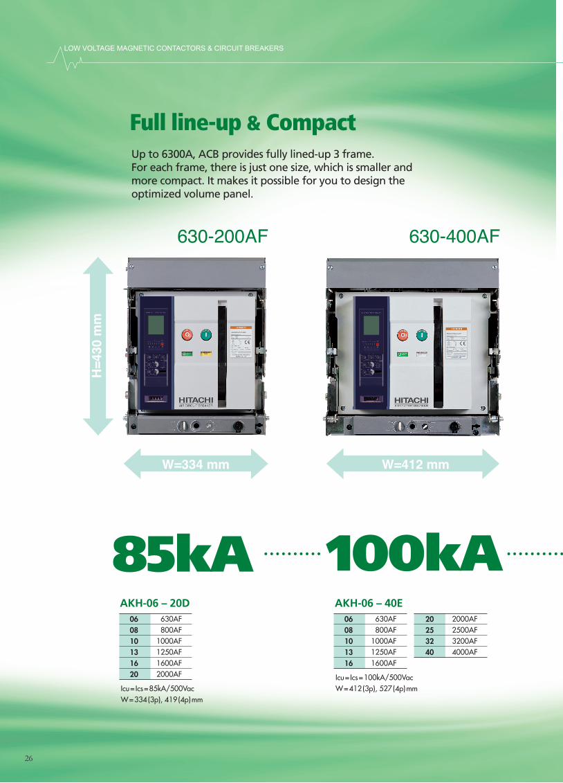
LOW VOLTAGE MAGNETIC CONTACTORS & CIRCUIT BREAKERS
630-200AF 630-400AF 4000-6300AF
H=4
30 m
m
D=375
mm
W=334 mm W=412 mm W=785 mm
26
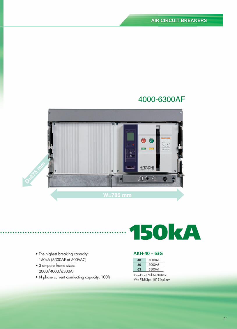
630-200AF 630-400AF 4000-6300AF
H=4
30 m
m
D=375
mm
W=334 mm W=412 mm W=785 mm
AIR CIRCUIT BREAKERS
27
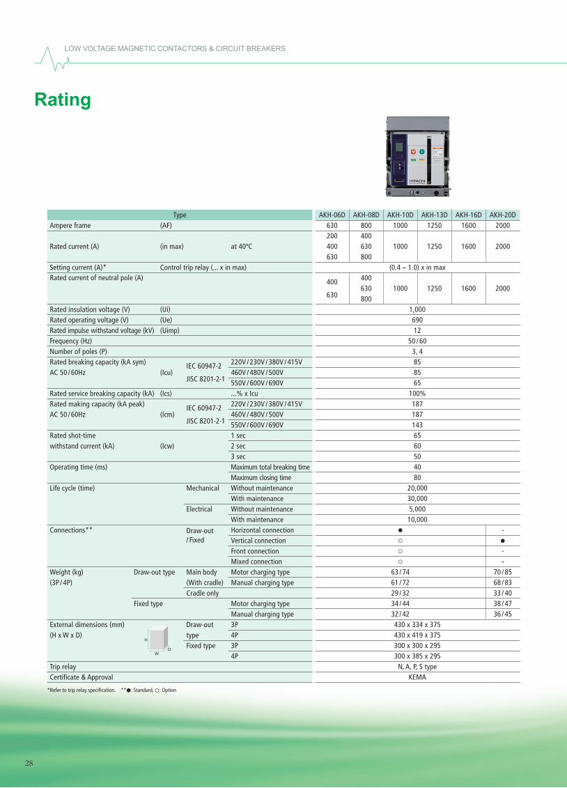
LOW VOLTAGE MAGNETIC CONTACTORS & CIRCUIT BREAKERS
Rating
28
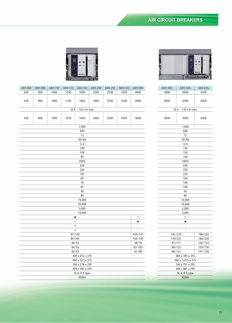
AIR CIRCUIT BREAKERS
29
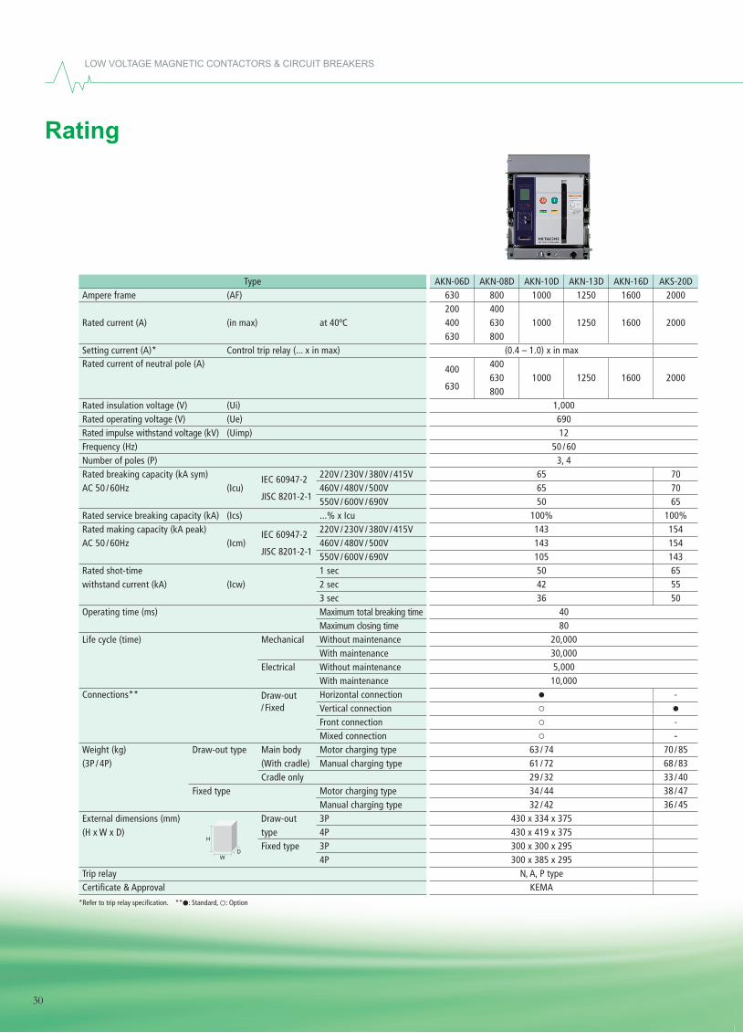
LOW VOLTAGE MAGNETIC CONTACTORS & CIRCUIT BREAKERS
Rating
30
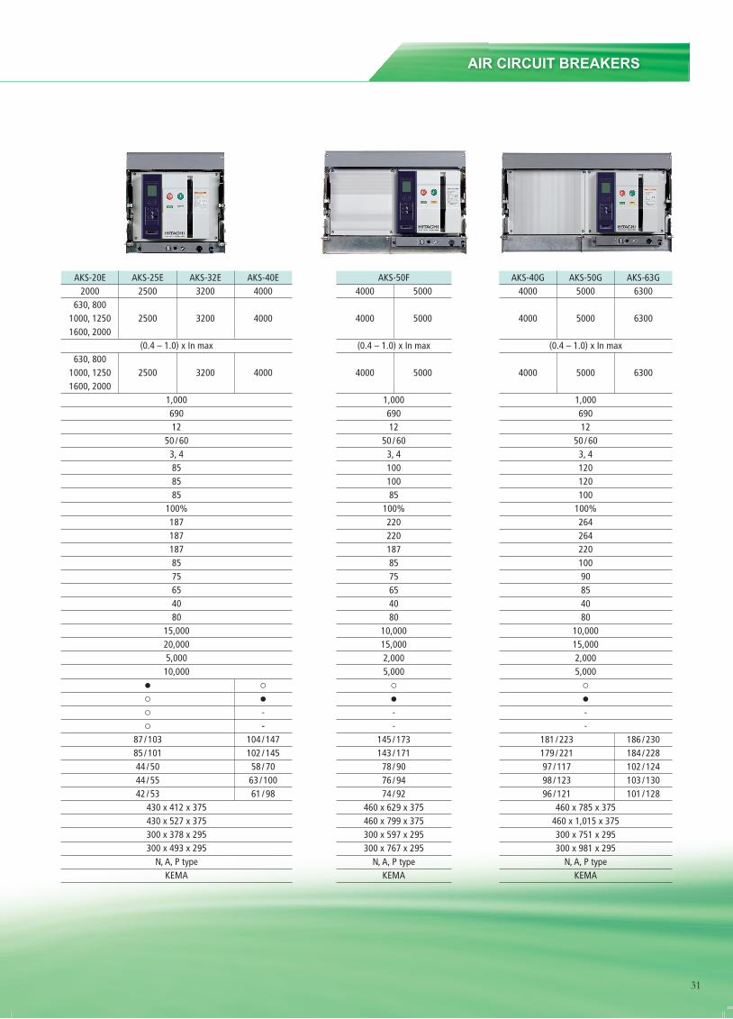
AIR CIRCUIT BREAKERS
31
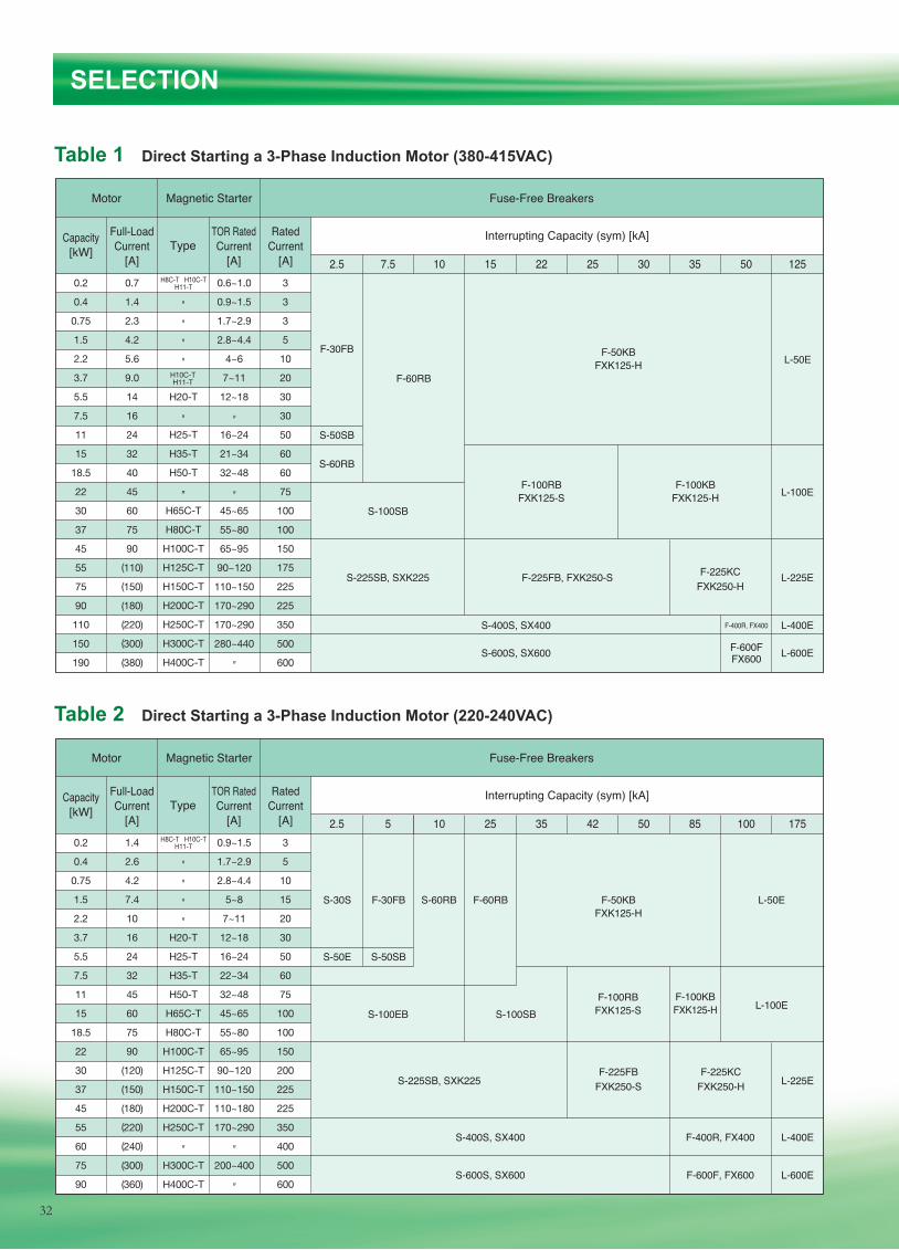
25 30 35 50
Motor
Capacity[kW] Type
Full-LoadCurrent
[A]
TOR RatedCurrent
[A]
RatedCurrent
[A] 2.5
F-30FB
S-50SB
S-60RB
S-100SB
F-100RBFXK125-S
F-100KBFXK125-H
S-400S, SX400
S-600S, SX600
F-400R, FX400
F-600FFX600
L-400E
L-600E
L-225E
L-100E
S-225SB, SXK225 F-225FB, FXK250-S F-225KCFXK250-H
F-60RB
L-50EF-50KBFXK125-H
7.5 10 15 22 125
Magnetic Starter Fuse-Free Breakers
Interrupting Capacity (sym) [kA]
0.2 0.7 0.6~1.0 3
0.4 1.4 0.9~1.5 3
0.75 2.3 1.7~2.9 3
1.5 4.2 2.8~4.4 5
2.2 5.6 4~6 10
3.7 9.0 7~11 20
5.5 14 H20-T 12~18 30
7.5 16 30
11 24 16~24 50
15 32 21~34 60
18.5 40 32~48 60
22 45 75
30 60 45~65 100
37 75 55~80 100
45 90 65~95 150
55 110 90~120 175
75 150 110~150 225
90 180 170~290 225
110 220 170~290 350
150 300 280~440 500
190 380 600
( )
( )
( )
( )
( )
( )
H25-T
H35-T
H50-T
″H65C-T
H80C-T
H100C-T
H125C-T
H150C-T
H200C-T
H250C-T
H300C-T
H400C-T
″″″″
″
″
″
″
H10C-TH11-T
H8C-T H10C-TH11-T
42 50 85 100
Motor
Capacity[kW] Type
Full-LoadCurrent
[A]
TOR RatedCurrent
[A]
RatedCurrent
[A] 2.5
S-30S F-30FB
S-50E S-50SB
S-60RB F-60RB F-50KBFXK125-H
L-50E
S-225SB, SXK225F-225FB
FXK250-SF-225KC
FXK250-H L-225E
L-400E
L-600ES-600S, SX600
S-400S, SX400 F-400R, FX400
F-600F, FX600
S-100EB S-100SBF-100RB
FXK125-S L-100EF-100KBFXK125-H
5 10 25 35 175
Magnetic Starter Fuse-Free Breakers
Interrupting Capacity (sym) [kA]
0.2 1.4 0.9~1.5 3
0.4 2.6 1.7~2.9 5
0.75 4.2 2.8~4.4 10
1.5 7.4 5~8 15
2.2 10 7~11 20
3.7 16 H20-T 12~18 30
5.5 24 H25-T 16~24 50
7.5 32 H35-T 22~34 60
11 45 H50-T 32~48 75
15 60 H65C-T 45~65 100
18.5 75 H80C-T 55~80 100
22 90 H100C-T 65~95 150
30 120 H125C-T 90~120 200
37 150 H150C-T 110~150 225
45 180 H200C-T 110~180 225
55 220 H250C-T 170~290 350
60 240 400
75 300 H300C-T 200~400 500
90 360 H400C-T 600
( )
( )
( )
( )
( )
( )
( )
″″″″
H8C-T H10C-TH11-T
″ ″
″
Table 1 Direct Starting a 3-Phase Induction Motor (380-415VAC)
SELECTION
Table 2 Direct Starting a 3-Phase Induction Motor (220-240VAC)
32
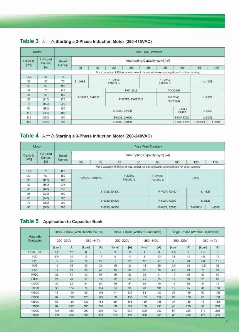
Table 3 Starting a 3-Phase Induction Motor (380-415VAC)
Capacity[kW]
Full-LoadCurrent
[A]
RatedCurrent
10 15 22 25 30 35 50 85 125
Motor Fuse-Free Breakers
Interrupting Capacity (sym) [kA]
Capacity[kW]
MagneticContactor
Full-LoadCurrent
[A]
RatedCurrent
25 35 42 50 85 100 125 175
Motor Fuse-Free Breakers
Three- Phase (With Reactance 6%)
200~220V
[kvar] [A] [kvar] [A] [kvar] [A] [kvar] [A] [kvar] [A] [kvar] [A]
380~440V 200~220V 380~440V 200~220V 380~440V
Three- Phase (Without Reactance) Single-Phase (Without Reactance)
Interrupting Capacity (sym) [kA]
For a capacity of 15 kw or less, select the same breaker among those for direct-starting
For a capacity of 15 kw or less, select the same breaker among those for direct-starting
18.5 40 75
22 45 75
30 60 100
37 75 125
45 90 150
55 110 175
75 150 225
90 180 350
110 220 400
150 300 600
190 380 700
18.5 75 125
22 90 150
30 120 200
37 150 225
45 180 350
55 220 400
60 240 500
75 300 600
90 360 700
H10C, H11 4.2 12 6 9 3 9 4 6 1.8 9 2.4 6
H20 6.9 20 12 17 5 14 8 12 2.8 14 4.8 12
H25 9 26 16 23 7 20 12 17 4 20 6.8 17
H35 12 35 22 32 10 29 18 26 5.5 28 10.5 26
H50 17 49 32 46 13 38 26 38 7.5 38 15 38
H65C 22 64 42 61 18 52 35 51 10 50 20 50
H80C 27 78 51 74 22 64 45 65 12 60 26 65
H100C 32 92 64 92 29 84 55 79 16 80 31 78
H125C 36 104 72 104 34 98 70 101 19 95 40 100
H150C 48 139 96 139 44 127 88 127 25 125 50 125
H200C 62 179 120 173 53 153 105 152 30 150 60 150
H250C 65 188 130 188 65 188 130 188 37 185 75 188
H300C 84 242 180 260 80 231 160 231 46 230 92 230
H400C 109 315 200 289 100 289 200 289 57 285 115 288
H600C 159 459 300 433 150 433 300 433 86 430 173 433
( )
( )
( )
( )
( )
( )
( )
( )
( )
( )
( )
( )
( )
S-100SB
S-225SB, SXK225
S-400S, SX400 F-400R, FX400
F-600F, FX600
L-400E
S-600S, SX600
S-800S, SX800 F-800R, FX800
L-600E
F-800RH L-800E
F-225FBFXK250-S L-225E
F-225KCFXK250-H
S-225SB, SXK225F-225FB, FXK250-S
F-225KCFXK250-H
L-225E
L-400ES-400S, SX400
L-600EF-600F, FX600
F-400RFX400
F-800R, FX800
S-600S, SX600
F-800RH L-800ES-800S, SX800
F-100RBFXK125-S
F-100KBFXK125-H
FXK125-HFXK125-S
L-100E
Table 4 Starting a 3-Phase Induction Motor (200-240VAC)
Table 5 Application to Capacitor Bank
33
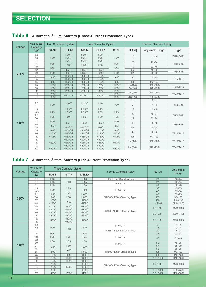
SELECTION
5.5 H20-T H20-T H20 7.5 H25-T H25-T H25 11 H35-T H35-T H35 15 H25 H25 18.5 40 32~48 22 H65C-T H65C-T H65C 55 45~65 30 H50 H80C-T H80C-T H80C H50 67 55~80 37 H100C-T H100C-T H100C 45 H125C-T H125C-T H125C 55 H80C H150C-T H150C-T H150C H80C 105 90~120 75 H125C H200C-T H200C-T H200C H125C 1.4 140 110~180 90 H150C H250C-T H250C-T H250C H150C 2.4 240 170~290 110 H200C H300C-T H300C-T H300C H200C 132 H250C H250C 150 H300C H300C 3.8 380 280~440 5.5 6.8 5~8 7.5 11 15 H25-T H25-T H25 15 12~18 18.5 H25 H35-T H35-T H35 H25 22 30 28 22~34 37 H50 H50 45 55 H80C-T H80C-T H80C 55 45~65 75 H80C H100C-T H100C-T H100C H80C 90 H100C H125C-T H125C-T H125C H100C 110 H125C H150C-T H150C-T H150C H125C 105 90~120 132 H200C-T H200C-T H200C 150 H250C-T H250C-T H250C 190 H300C-T H300C-T H300C 200 H300C H400C-T H400C-T H400C H300C
VoltageTwin Contactor System Three Contactor System Thermal Overload Relay
Adjustable Range TypeRC [A]STARDELTASTAR DELTA MAIN
Max. Motor Capacity
[kW]
230V
415V
5.5 H20 H20 TR25-1E Self-Standing Type 20 16~24 7.5 H25 H25 28 22~34 11 H35 H35 40 32~48 15 H25 55 45~65 18.5 67 55~80 22 H65C H65C 80 65~95 30 H80C H50 H80C 105 90~120 37 H100C H100C 130 110~150 45 H125C H125C 1.4 140 110~180 55 H150C H80C H150C 75 H200C H125C H200C 90 H250C H150C H250C 110 H300C H200C H300C 132 H250C 150 H300C 5.5 9 7~11 7.5 15 12~18 11 TR25B-1E Self-Standing Type 20 16~24 15 H25 H25 28 22~34 18.5 H35 H25 H35 22 30 55 45~65 37 H50 67 55~80 45 80 65~95 55 H80C H80C 105 90~120 75 H100C H80C H100C 130 110~150 90 H125C H100C H125C 1.4 140 110~180 110 H150C H125C H150C 132 H200C H200C 150 H250C H250C 190 H300C H300C 3.8 380 280~440 260 H400C H300C H400C 5.0 500 400~600
VoltageThree Contactor System
Thermal Overload Relay AdjustableRangeRC [A]
MAIN STAR DELTA
Max. Motor Capacity
[kW]
230V
415V
TR20B-1E
TR50B-1E
TR80B-1E
TR150B-1E
TR250B-1E
TR400B-1E
TR20B-1E
TR50B-1E
TR80B-1E
TR150B-1E
TR250B-1E
TR400B-1E
H20 H20 15 12~18
28 22~34
9 7~11
20 16~24
80 65~95
2.4 (240) (170~290)
40 32~48
80 65~95
1.4 (140) (110~180)
2.4 (240) (170~290)
3.8 (380) (280~440)
2.4 (240) (170~290)
40 32~48
5.0 (500) (400~600)
2.4 (240) (170~290)
H50-T
H20-T H20-T H20 H20
H65C
H200C
H400C-T H400C-T H400C
H50-T H50
H65C H65C
H20
H35 H50-T H50-T H50
H65C-T
H20
H35
H65C
H20
H200C
H35 H50
H65C
H65C-T H65C
H35
H65C
H200C
H50
H20 H20
H50
H400CH400C
H50
H65CH65C
H35 H35
( )
( )
( ) ( )( )
( )
TR400B-1E Self-Standing Type
TR150B-1E Self-Standing Type
TR50B-1E
TR50B-1E
TR80B-1E
TR80B-1E
TR20B-1E
TR400B-1E Self-Standing Type
TR150B-1E Self-Standing Type
( ) ( )
( ) ( )
( ) ( )( ) ( )
Table 6 Automatic Starters (Phase-Current Protection Type)
Table 7 Automatic Starters (Line-Current Protection Type)
34
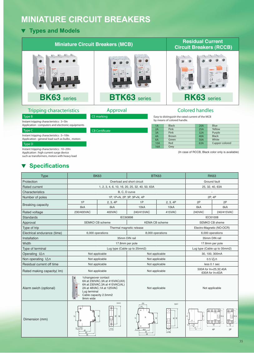
Type BK63 BTK63 RK63Protection Overload and short circuit Ground fault
Rated current 1, 2, 3, 4, 6, 10, 16, 20, 25, 32, 40, 50, 63A 25, 32, 40, 63A
Characteristics B, C, D curve -
Number of poles 1P, 1P+N, 2P, 3P, 3P+N, 4P 2P, 4P
Breaking capacity1P 2, 3, 4P 1P 2, 3, 4P 2P 2P6kA 6kA 10kA 10kA 6kA 6kA
Rated voltage 230/400VAC 400VAC 240/415VAC 415VAC 240VAC 240/415VAC
Standards IEC60898 IEC61008
Approval SEMKO CB scheme KEMA CB scheme SEMKO CB sheme
Type of trip Thermal magnetic release Electro-Magnetic (NO-OCR)
Electrical endurance (time) 6,000 operations 8,000 operations 6,000 operations
Installation 35mm DIN rail 35mm DIN rail
Width 17.8mm per pole 17.8mm per pole
Type of terminal Lug type (Cable up to 25mm2) Lug type (Cable up to 35mm2)
Operating I n Not applicable Not applicable 30, 100, 300mA
Non operating I n Not applicable Not applicable 0.5 I nResidual current off time Not applicable Not applicable less 0.1 sec
Rated making capacity( Im) Not applicable Not applicable 500A for In=25,32,40A630A for In=63A
Alarm swich (optional)
1changeover contact 6A at 230VAC,3A at 415VAC(AX) 6A at 230VAC,3A at 415VAC(AL) 2A at 48VAC,1A at 125VAC Lug terminal Cable capacity 2.5mm2 9mm wide
Not applicable Not applicable
Dimension (mm)
MINIATURE CIRCUIT BREAKERS Types and Models
BK63 series BTK63 series RK63 series
Residual Current Circuit Breakers (RCCB)Miniature Circuit Breakers (MCB)
Easy to distinguish the rated current of the MCB by means of colored handle.
Tripping characteristics Approval Colored handles Type B
Instant tripping characteristics : 3~5InApplication : computers and electronic equipments
Type C Instant tripping characteristics : 5~10InApplication : general load such as bulbs , motors
Type D
CE marking
CB Certi�cate
Instant tripping characteristics : 10~20InApplication : high current surge device such as transformers, motors with heavy load
1A2A3A4A6A10A16A
BlackPinkPinkBrownGreenRedGrey
20A25A32A40A50A63A
BlueYellowPurpleBlackWhiteCupper-colored
Specifi cations
(In case of RCCB, Black color only is available)
4P 2P
35
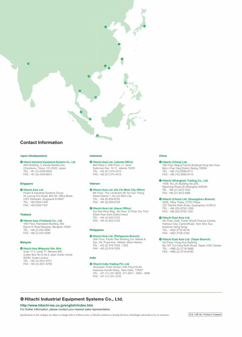
Specifi cations in this catalogue are subject to change with or without notice, as Hitachi continues to develop the latest technologies and products for its customers. SI-E 119P (K) Printed in Thailand
For further information, please contact your nearest sales representative.http://www.hitachi-ies.co.jp/english/index.htm
Contact Information
Japan (Headquarters) Hitachi Industrial Equipment Systems Co., Ltd. AKS Building, 3, Kanda Neribei-cho, Chiyoda-ku, Tokyo, 101-0022, Japan TEL : +81 (3) 4345-6000 FAX : +81 (3) 4345-6914
Singapore Hitachi Asia Ltd. Power & Industrial Systems Group 24 Jurong Port Road, #03-05, Offi ce Block, CWT Distripark, Singapore 619097 TEL : +65 6305-7400 FAX : +65 6305-7401
Thailand Hitachi Asia (Thailand) Co., Ltd. 18th Floor, Ramaland Building, 952 Rama IV Road Bangrak, Bangkok 10500 TEL : +66 (2) 632-9292 FAX : +66 (2) 632-9299
Malaysia Hitachi Asia (Malaysia) Sdn. Bhd. Suite 17.3, Level 17, Menara IMC (Letter Box No.5) No.8 Jalan Sultan Ismail, 50250, Kuala Lumpur TEL : +60 (3) 2031-8751 FAX : +60 (3) 2031-8758
Indonesia Hitachi Asia Ltd. (Jakarta Offi ce) Mid Plaza 2, 24th Floor, J.I. Jend. Sudirman Kav. 10-11, Jakarta 10220 TEL : +62 (21) 574-4313 FAX : +62 (21) 574-4312
Vietnam Hitachi Asia Ltd. (Ho Chi Minh City Offi ce) 8th Floor, The Landmark,5B Ton Duc Thang Street District 1, Ho Chi Minh City TEL : +84 (8) 829-9725 FAX : +84 (8) 829-9729
Hitachi Asia Ltd. (Hanoi Offi ce) Sun Red River Bldg., 6th Floor, 23 Phan Chu Trinh Street Hoan Kiem District Hanoi TEL : +84 (4) 933-3123 FAX : +84 (4) 933-3125
Philippines Hitachi Asia Ltd. (Philippines Branch) 25th Floor, Pacifi c Star Building,Cor. Makati & Sen. Gil. Puyat Ave., Makati, Metro Manila TEL : +63 (2) 819-7528, -7529 FAX : +63 (2) 819-7539
India Hitachi India Trading Pvt. Ltd. Hindustan Times House (10th Floor)18-20, Kasturba Gandhi Marg., New Delhi, 110001 TEL : +91 (11) 331-5635, 371-2817, -3953, -3958 FAX : +91 (11) 331-3742
China Hitachi (China) Ltd. 18th Floor, Beijing Fortune Building5 Dong San Huan BeiLu Chao Yang District, Beijing 100004 TEL : +86 (10) 6590-8111 FAX : +86 (10) 6590-8110
Hitachi (Shanghai) Trading Co., Ltd. 1408, Rui Jin Building No.205, Maoming Road (S) Shanghai 200020 TEL : +86 (21) 6472-1002 FAX : +86 (21) 6472-4990 Hitachi (China) Ltd. (Guangzhou Branch) 3406, Ofi ce Tower, CITIC Plaza 233 TianHe Noth Road, Guangzhou 510613 TEL : +86 (20) 8752-1289 FAX : +86 (20) 8752-1301 Hitachi East Asia Ltd. 4th Floor, Noth Tower World Finance Centre, Harbour City, CantonRoad, Tsim Sha Tsui, Kowloon Hong Kong TEL : +852 2735-9218 FAX : +852 2735-3192 Hitachi East Asia Ltd. (Taipei Branch) 3rd Floor, Hung Kuo Building No.167 Tun-Hwa Noth Road, Taipei (105) Taiwan TEL : +886 (2) 2718-3666 FAX : +886 (2) 2718-8180
01
02
03
04
05
06
07
08
09
10
11
12
13
14
01
02
03
04
05
06
07
08
09
10
11
1213
14