enabling switches
TRANSCRIPT
More than safety.
Enabling Switches
ZSZS
2
Quality, reliability, precision
Quality, reliability and precision are thehallmarks of our corporate philosophy.They represent concepts and valuesto which we feel totally committed. At EUCHNER, quality means that allour employees take personal respon-sibility for the company as a wholeand, in particular, for their own field ofwork. This individual commitment toperfection results in products whichare ideally tailored to the customers’needs and the requirements of themarket. After all: our customers andtheir needs are the focus of all ourefforts. Through efficient and effectiveuse of resources, the promotion ofpersonal initiative and courage in find-ing unusual solutions to the benefit ofour customers, we ensure a high levelof customer satisfaction. We familiar-ize ourselves with their needs, require-ments and products and we learnfrom the experiences of our cus-tomers’ own customers.
EUCHNER – More than safety.
Quality – made by EUCHNER
More than safety.Around the world – the Swabianspecialists in motion sequencecontrol for mechanical and sys-tems engineering.
EUCHNER’s history began in 1940 withthe establishment of an engineeringoffice by Emil Euchner. Since thattime, EUCHNER has been involved inthe design and development of switch-gear for controlling a wide variety ofmotion sequences in mechanical andsystems engineering. In 1953, EmilEuchner founded EUCHNER + Co., amilestone in the company’s history. In1952, he developed the first multiplelimit switch – to this day a symbol ofthe enterprising spirit of this family-owned company.
Automation – Safety – ManMachine
Today, our products range fromelectromechanical and electroniccomponents to complex system solu-tions. With this wide range of productswe can provide the necessary tech-nologies to offer the right solution forspecial requirements – regardless ofwhether these relate to reliable andprecise positioning or to componentsand systems for safety engineering inthe automation sector.EUCHNER products are sold through aworld-wide sales network of compe-tent partners. With our closeness tothe customer and the guarantee ofreliable solutions throughout theglobe, we enjoy the confidence of cus-tomers all over the world.
Emil Euchner, the company’s founder andinventor of the multiple
limit switch, circa 1928.
Safety
3
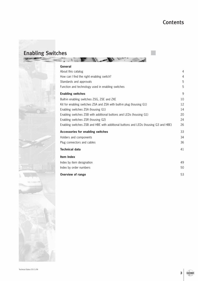
Contents
Technical Status 03-11/06
General
About this catalog 4
How can I find the right enabling switch? 4
Standards and approvals 5
Function and technology used in enabling switches 5
Enabling switches 9
Built-in enabling switches ZSG, ZSE and ZXE 10
Kit for enabling switches ZSA and ZSA with built-in plug (housing G1) 12
Enabling switches ZSA (housing G1) 14
Enabling switches ZSB with additional buttons and LEDs (housing G1) 20
Enabling switches ZSR (housing G2) 24
Enabling switches ZSB and HBE with additional buttons and LEDs (housing G3 and HBE) 26
Accessories for enabling switches 33
Holders and components 34
Plug connectors and cables 36
Technical data 41
Item Index
Index by item designation 49
Index by order numbers 50
Overview of range 53
Enabling Switches
4
General
Subject to technical modifications; no responsibility is accepted for the accuracy of this information.
Select the requiredinformation in the table of contents
General overview
No
Yes
Detailed overview Detailed overview
Find enabling switch
Find the requiredenabling switch in the item index and select in the ordering table
Select the requiredenabling switch in the
ordering table
Refine selectionby selecting the
required product featuresin the selection table
Do you knowthe order number
or the item designation?
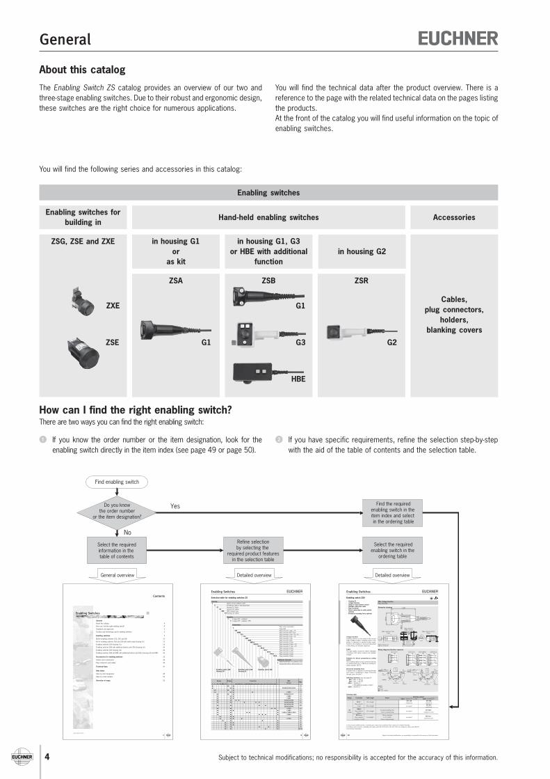
About this catalog
The Enabling Switch ZS catalog provides an overview of our two andthree-stage enabling switches. Due to their robust and ergonomic design,these switches are the right choice for numerous applications.
How can I find the right enabling switch?There are two ways you can find the right enabling switch:
If you know the order number or the item designation, look for theenabling switch directly in the item index (see page 49 or page 50).
If you have specific requirements, refine the selection step-by-stepwith the aid of the table of contents and the selection table.
Enabling switches
Enabling switches forbuilding in
ZSG, ZSE and ZXE in housing G1or
as kit
ZSA
AccessoriesHand-held enabling switches
in housing G1, G3or HBE with additional
functionin housing G2
ZSB ZSR
You will find the technical data after the product overview. There is areference to the page with the related technical data on the pages listingthe products.At the front of the catalog you will find useful information on the topic ofenabling switches.
You will find the following series and accessories in this catalog:
G1
G1
G3
HBE
G2ZSE
ZXECables,
plug connectors,holders,
blanking covers
3
Contents
Technical Status 02-12/05
General
About this catalog 4
How can I find the right enabling switch? 4
Standards and approvals 5
Function and technology used in enabling switches 5
Enabling switches 9
Built-in enabling switches ZSG, ZSE and ZXE 10
Kit for enabling switches ZSA and ZSA with built-in plug (housing G1) 12
Enabling switches ZSA (housing G1) 14
Enabling switches ZSB with additional buttons and LEDs (housing G1) 20
Enabling switches ZSR (housing G2) 24
Enabling switches ZSB and HBE with additional buttons and LEDs (housing G3 and HBE) 26
Accessories for enabling switches 33
Holders and components 34
Plug connectors and cables 36
Technical data 41
Item Index
Index by item designation 49
Index by order numbers 50
Overview of range 53
Enabling Switches
9
Enabling Switches
For
safe
ty in
stru
ctio
ns s
ee p
age
34Fo
r te
chni
cal d
ata
see
page
28
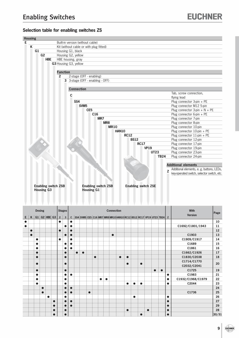
HousingE Built-in version (without cable)
K Kit (without cable or with plug fitted)G1 Housing G1, black
G2 Housing G2, yellowHBE HBE housing, gray
G3 Housing G3, yellow
Function2 2-stage (OFF - enabling)
3 3-stage (OFF - enabling - OFF)
Connection
CTab, screw connection,flying lead
SS4 Plug connector 3-pin + PESVM5 Plug connector M12 5-pin
CE5 Plug connector 3-pin + N + PEC16 Plug connector 6-pin + PE
MR7 Plug connector 7-pinMR8 Plug connector 8-pin
MR10 Plug connector 10-pinHAN10 Plug connector 10-pin + PE
RC12 Plug connector 11-pin + PEBS12 Plug connector 12-pin
RC17 Plug connector 17-pinVP19 Plug connector 19-pin
UT23 Plug connector 23-pinTB24 Plug connector 24-pin
Additional elements
ZAdditional elements, e. g. buttons, LEDs,key-operated switch, selector switch, etc.
Selection table for enabling switches ZS
Enabling switch ZSEEnabling switch ZSBHousing G3
Enabling switch ZSBHousing G1
Desing Stages Connection WithVersion
PageE K G1 G2 HBE G3 2 3 C SS4 SVM5 CE5 C16 MR7 MR8 MR10 HAN10 RC12 BS12 RC17 VP19 UT23 TB24 Z
10 C1692/C1801/1943 11
12 C1903 13
C1909/C1917 14 C1689 15 C1861 16 C1662/C1926 17 C1830/C2038 18
C1714/C1770
20C2032/C2041
C1725 19 C1983 21 C1932/C1968/C1979 22 C2044 23
24 C1736 25
26 27 29 28 30/31
Enabling Switches
Subject to technical modifications; no responsibility is accepted for the accuracy of this information.18
63 29,5
61,5
64,5
6 7 8 9 10
54321
Enabling switch ZSA
Dimension drawings
Wiring diagrams/function sequence
Ordering table
Design Connection Cable length VersionSwitching element
2210: 1 NO/NC 1) + 1 NO 2220: 2 NO/NC 1)
C16-1 2) 10 m straight057 100 070 788
Plug connectorZSA2B2G10B ZSA2B4G10B
(7-pin) 20 m straight on request079 870
ZSA2B4G20B
G1HAN10
Increased actuating force 077 489 3)
3-stagePlug connector 10 m straight
Screen on plug housingon request
ZSA2B2G10CC1830(10-pin)
RC12 plug Direct connection092 141 3)
Plug connector 5 m straight to TZ...C1803 on requestZSA092141C2038
connector (12-pin) Screen on plug housing
Housing G1 3-stage function Single or dual-channel version Straight connection cable Plug connector Direct connection to safety switch
optional Increased actuating force optional
3-stage functionEnabling function is only active in the secondstage (middle position, actuating point). If thebutton is released or pushed further (panicfunction), the enabling is removed (dependenton the wiring, see function sequence).
CableThe high quality connection cables (individualscreening of the safety contacts) are availablestraight.
Suitable for direct connection to safetyswitchThis enabling switch can be connected directlyto a safety switch (TZ…C1803) (see catalog forsafety switches NZ/TZ).
Increased actuating forceA higher force is required on pressing throughfrom stage 2 (enabling) to stage 3 (pressedthrough „panic function“).
Switching elements (see also page 8) 210 2 NO + 1 NC 220 2 NO + 2 NC 2210 1 NO/NC 1)
1 NO (additional auxiliary contact) 2220 2 NO/NC 1)
ZSA, 3-stage functionPlug connector
Male connectorHAN10 (10-pin)
Male connector RC12(12-pin)
Male connector C16-1(7-pin)
Mating connector seepage 36, 37 and 39
1) Only closed in middle position, a normally open contact and a positively driven contact are combined internally.2) Enabling switch connector compatible with safety switch NZ..VZ.C1420 or NZ..VZ.C1701 (see catalog for safety switch NZ/TZ).3) No BG type examination
N
XY9
8
7
6
5 4
3
2
112 10
PO
11
51
∅ 2
6
SW 22
View of connection side
72
∅ 2
9
1
234
5
6
Pg 9
7
1
3
2
3 4E1
1 2
3 4E2
E3
Plug
con
nect
or C
16-1
2210 C16-1
4
1
1 23
2
3 4E1
E4
1 2
3 4E2
E3Plug
con
nect
or C
16-1
2220 C16-1
2
3
5
1 21
SH
3 4E1
E3
1 2
3 4E2
E4
Plug
con
nect
or R
C12
2220 RC12
SH
2
3
1 24
3
3 4E1
E4
1 2
3 4E2
E3
Plug
con
nect
or H
AN10
2220 HAN10
Notactuated
1 1
2 2
3
1
2
33E 1+E 4, E 2+E 3 /E 1+E 3, E 2+E 4
2220
NO/NC NO/NC
NO/NC
Notactuated
Enabling
Actuatingpoint
Panic function
Re-startprotection
Contactopenclosedclosed, enabling
NotactuatedNO/NC
2210
E 1+E 3, E 2+E 3
1 1
2 2
3
1
2
33NO/NC
NO/NC
Notactuated
Enabling
Actuatingpoint
Panic functionRe-startprotection
5
General
Subject to technical modifications; no responsibility is accepted for the accuracy of this information.
Standards and approvals
StandardsEnabling switches that are integrated into safety circuits have a safety function.For this reason they are assessed based on the Machinery directive and theEuropean standards. The Machinery directive has been implemented in nationallaw in the EU member states and, as a result, is binding for all manufacturers.Detailed requirements for switches are defined in EN 60947 Part 5-1 (Specifica-tion for low-voltage switchgear and controlgear. Part 5-1: Control circuit devicesand switching elements. Electromechanical control circuit devices).If the requirements of these standards are met, conformity with the applica-ble laws and therefore with the Machinery directive is assumed. EUCHNERenabling switches comply with the relevant standards for safety switchgearand therefore help you to comply with safety requirements during the de-sign of your machinery.
User standardsAs a user, you should take into consideration the following standards ofrelevance for enabling switches:
European and international standardsStandard TitleEN 60 204 Safety of machinery. Electrical equipment of
machinesEN 775/ Robots for industrial environments - safety require-EN ISO 10218 ments (ISO 10218:1992, modified)VDI 2853 Safety related requirements on design, configuration and
operation of industrial robots (withdrawn)VDI 2854 Safety related requirements on automated manuf-
acturing systems
American standardsStandard TitleANSI B11-TR3-2000 Risk Assessment and Risk Reduction - A Guide to
Estimate, Evaluate and Reduce Risks Associatedwith Machine Tools
NFPA 79 (2002) Electrical Standard for Industrial MachineryOSHA 29 CFR 1910Subpart O Machinery and Machine GuardingSubpart P Hand and Portable Power Tools and Other Hand-
Held EquipmentSubpart S Electrical
Please also observe any existing C standards!
ApprovalsTo demonstrate conformity, the Machinery directive also includes the possibilityof type examination. In addition to taking into account all relevant standards,EUCHNER commissions type examinations by a notified body.Many of the enabling switches listed in this catalog have been tested by an emplo-yers’ liability insurance association (BG) and are given in the lists from the BG.Furthermore, many enabling switches are listed by the Underwriters Laboratories(UL) and the Canadian Standards Association (CSA). These enabling switchescan be used in countries in which this listing is required. The approval symbols onthe individual pages of the catalog indicate which body tested the enablingswitches.With the aid of the approval symbols listed below you can quickly see whichapprovals are available for the related enabling switches:
Function and technology used in enabling switches
Task of enabling switchesEnabling switches are manually operated control devices that, togetherwith other control switches, enable commands related to potentiallyhazardous conditions to be run, as long as the enabling switches areactuated continuously.These switches are used wherever operating personnel must work directlyin the danger area on machines and systems. This is necessary, e. g.during setting up, programming, testing or servicing work. As per annex1 of the Machinery directive, the protective action of movable safetyguards can be disabled in these operating modes. The Machinery directiveplaces the condition that these operating modes must be secured usinga lockable device (e. g. key-operated switch) and machine operation isonly allowed to be triggered by a second, separate action.To enable the operator in the danger area of a machine to trigger amachine movement, an enabling device must additionally be actuated.The operator must also be able to stop the machine movement usingthe enabling device. This task is performed by the enabling switch.Every person who is in the hazardous area must carry an enabling deviceso that suitable action can be taken in case of danger.
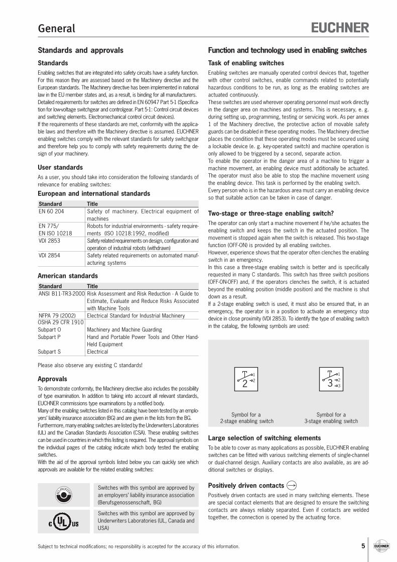
Two-stage or three-stage enabling switch?The operator can only start a machine movement if he/she actuates theenabling switch and keeps the switch in the actuated position. Themovement is stopped again when the switch is released. This two-stagefunction (OFF-ON) is provided by all enabling switches.However, experience shows that the operator often clenches the enablingswitch in an emergency.In this case a three-stage enabling switch is better and is specificallyrequested in many C standards. This switch has three switch positions(OFF-ON-OFF) and, if the operators clenches the switch, it is actuatedbeyond the enabling position (middle position) and the machine is shutdown as a result.If a 2-stage enabling switch is used, it must also be ensured that, in anemergency, the operator is in a position to activate an emergency stopdevice in close proximity (VDI 2853). To identify the type of enabling switchin the catalog, the following symbols are used:
Large selection of switching elementsTo be able to cover as many applications as possible, EUCHNER enablingswitches can be fitted with various switching elements of single-channelor dual-channel design. Auxiliary contacts are also available, as are ad-ditional switches or displays.
Positively driven contacts Positively driven contacts are used in many switching elements. Theseare special contact elements that are designed to ensure the switchingcontacts are always reliably separated. Even if contacts are weldedtogether, the connection is opened by the actuating force.
Symbol for a 2-stage enabling switch
Symbol for a3-stage enabling switch
122
1233
Switches with this symbol are approved byan employers’ liability insurance association(Berufsgenossenschaft, BG)
Switches with this symbol are approved byUnderwriters Laboratories (UL, Canada andUSA)
6
General
Subject to technical modifications; no responsibility is accepted for the accuracy of this information.
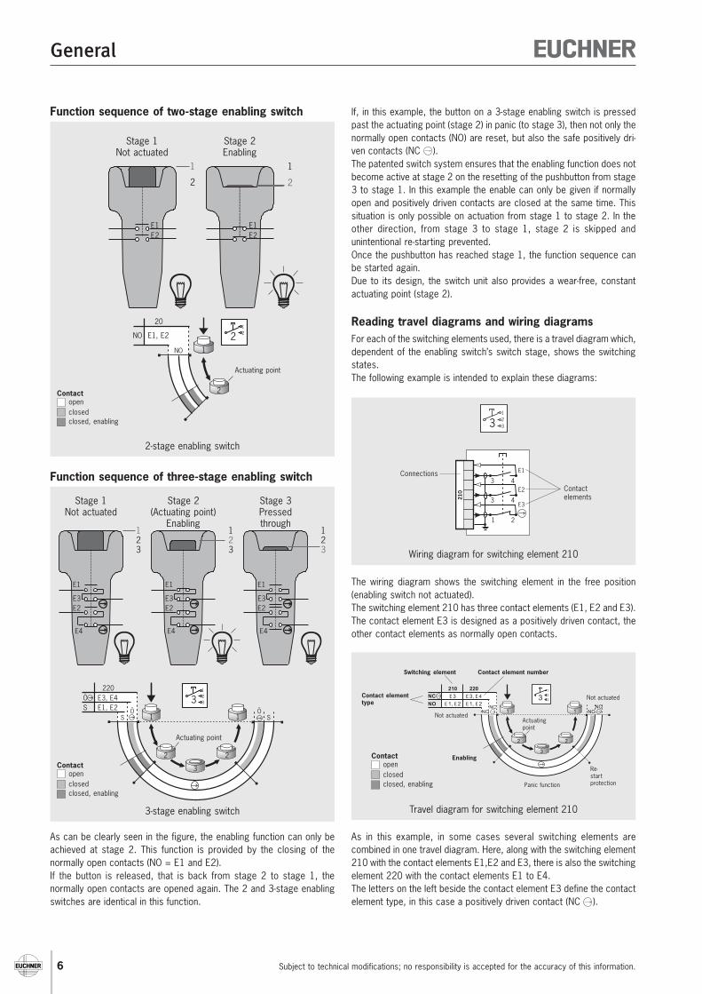
Function sequence of two-stage enabling switch
As can be clearly seen in the figure, the enabling function can only beachieved at stage 2. This function is provided by the closing of thenormally open contacts (NO = E1 and E2).If the button is released, that is back from stage 2 to stage 1, thenormally open contacts are opened again. The 2 and 3-stage enablingswitches are identical in this function.
If, in this example, the button on a 3-stage enabling switch is pressedpast the actuating point (stage 2) in panic (to stage 3), then not only thenormally open contacts (NO) are reset, but also the safe positively dri-ven contacts (NC ).The patented switch system ensures that the enabling function does notbecome active at stage 2 on the resetting of the pushbutton from stage3 to stage 1. In this example the enable can only be given if normallyopen and positively driven contacts are closed at the same time. Thissituation is only possible on actuation from stage 1 to stage 2. In theother direction, from stage 3 to stage 1, stage 2 is skipped andunintentional re-starting prevented.Once the pushbutton has reached stage 1, the function sequence canbe started again.Due to its design, the switch unit also provides a wear-free, constantactuating point (stage 2).
Reading travel diagrams and wiring diagramsFor each of the switching elements used, there is a travel diagram which,dependent of the enabling switch’s switch stage, shows the switchingstates.The following example is intended to explain these diagrams:
The wiring diagram shows the switching element in the free position(enabling switch not actuated).The switching element 210 has three contact elements (E1, E2 and E3).The contact element E3 is designed as a positively driven contact, theother contact elements as normally open contacts.
As in this example, in some cases several switching elements arecombined in one travel diagram. Here, along with the switching element210 with the contact elements E1,E2 and E3, there is also the switchingelement 220 with the contact elements E1 to E4.The letters on the left beside the contact element E3 define the contactelement type, in this case a positively driven contact (NC ).
Function sequence of three-stage enabling switch
2-stage enabling switch
1
2
122
20
E1, E2NO
NO
1
2
1
2
E2E1
E2E1
Stage 1Not actuated
Stage 2Enabling
Wiring diagram for switching element 210
3 4
3 4
1 2
E1
E2
E3
210
1233
Contactelements
Connections
Travel diagram for switching element 210
Not actuatedNO
NC
210 220
E 3
E 1, E 2
E 3, E 4
E 1, E 2
NONC
NCNO
1 1
2 2
3
1
2
33
Not actuated
Enabling
Actuatingpoint
Panic function
Re-startprotection
Contact element numberSwitching element
Contact elementtype
Contactopenclosedclosed, enabling
Contactopenclosedclosed, enabling
Actuating point
3-stage enabling switch
Stage 1Not actuated
Stage 2(Actuating point)
Enabling
SÖ
220E3, E4E1, E2
S S1 1
2 2
3
1233
Ö Ö
123
123
123
E1
E2
E4
E3
E1
E2
E4
E3
E1
E2
E4
E3
Stage 3Pressedthrough
Contactopenclosedclosed, enabling
Actuating point
7
General
Subject to technical modifications; no responsibility is accepted for the accuracy of this information.
The following contact element types are available:
NO normally open contact NC normally closed contact NC positively driven contact NO/NC three-point switch
(3-stage contact element with normally open/normally closed functiondependent on the actuation travel)
NO/NC three-point switch(as NO/NC but with positively driven contact)
The travel diagram shows the switching state of each contact elementfor the three switch stages “Not actuated“, “Enabling“ and “Panic function“(pressed past actuating point). Gray areas mean “switch closed”, whiteareas mean “switch open”.
In the example for switching element 210 the sequence is as follows:
In the not actuated state, the positively driven contact E3 is closed(gray area) and the two normally open contacts E1 and E2 are open.
When the switch has reached stage 2, the normally open contactsE1 and E2 are closed, E3 remains closed. This is the enabling area.
If the switch is released, the contact elements return to their initialstate.
If the switch is pressed beyond the enabling area, all contact elementsare opened. This is the “panic function” area on the travel diagram.
If the switch is now released again, the positively driven contact E3is closed again, the switch system prevents the normally opencontacts E1 and E2 closing again at the same time (restartprotection).
An optimal sequence is provided by the series connection of E1 (normallyopen contact) and E3 (positively driven contact), as then enabling is onlypossible at the actuating point. On pressing through to stage 3, the safepositively driven contact opens the safety circuit. On this switchingelement E2 can be used as an auxiliary contact or 2nd channel.
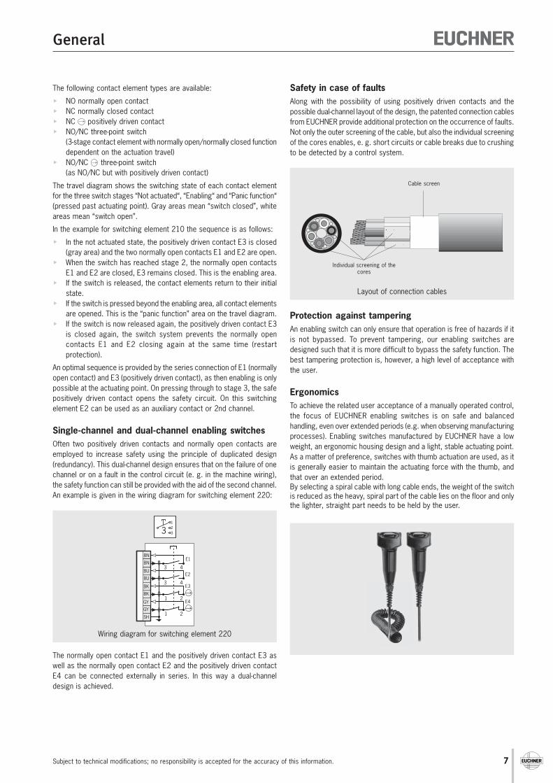
Single-channel and dual-channel enabling switchesOften two positively driven contacts and normally open contacts areemployed to increase safety using the principle of duplicated design(redundancy). This dual-channel design ensures that on the failure of onechannel or on a fault in the control circuit (e. g. in the machine wiring),the safety function can still be provided with the aid of the second channel.An example is given in the wiring diagram for switching element 220:
Wiring diagram for switching element 220
SH
BU
BU3 4
3 4
BN
BN
1 2BK
BK
1 2GY
GY
E1
E2
E3
E4
1233
The normally open contact E1 and the positively driven contact E3 aswell as the normally open contact E2 and the positively driven contactE4 can be connected externally in series. In this way a dual-channeldesign is achieved.
Safety in case of faultsAlong with the possibility of using positively driven contacts and thepossible dual-channel layout of the design, the patented connection cablesfrom EUCHNER provide additional protection on the occurrence of faults.Not only the outer screening of the cable, but also the individual screeningof the cores enables, e. g. short circuits or cable breaks due to crushingto be detected by a control system.
Protection against tamperingAn enabling switch can only ensure that operation is free of hazards if itis not bypassed. To prevent tampering, our enabling switches aredesigned such that it is more difficult to bypass the safety function. Thebest tampering protection is, however, a high level of acceptance withthe user.
ErgonomicsTo achieve the related user acceptance of a manually operated control,the focus of EUCHNER enabling switches is on safe and balancedhandling, even over extended periods (e.g. when observing manufacturingprocesses). Enabling switches manufactured by EUCHNER have a lowweight, an ergonomic housing design and a light, stable actuating point.As a matter of preference, switches with thumb actuation are used, as itis generally easier to maintain the actuating force with the thumb, andthat over an extended period.By selecting a spiral cable with long cable ends, the weight of the switchis reduced as the heavy, spiral part of the cable lies on the floor and onlythe lighter, straight part needs to be held by the user.
Layout of connection cables
Cable screen
Individual screening of thecores
8
General
Subject to technical modifications; no responsibility is accepted for the accuracy of this information.
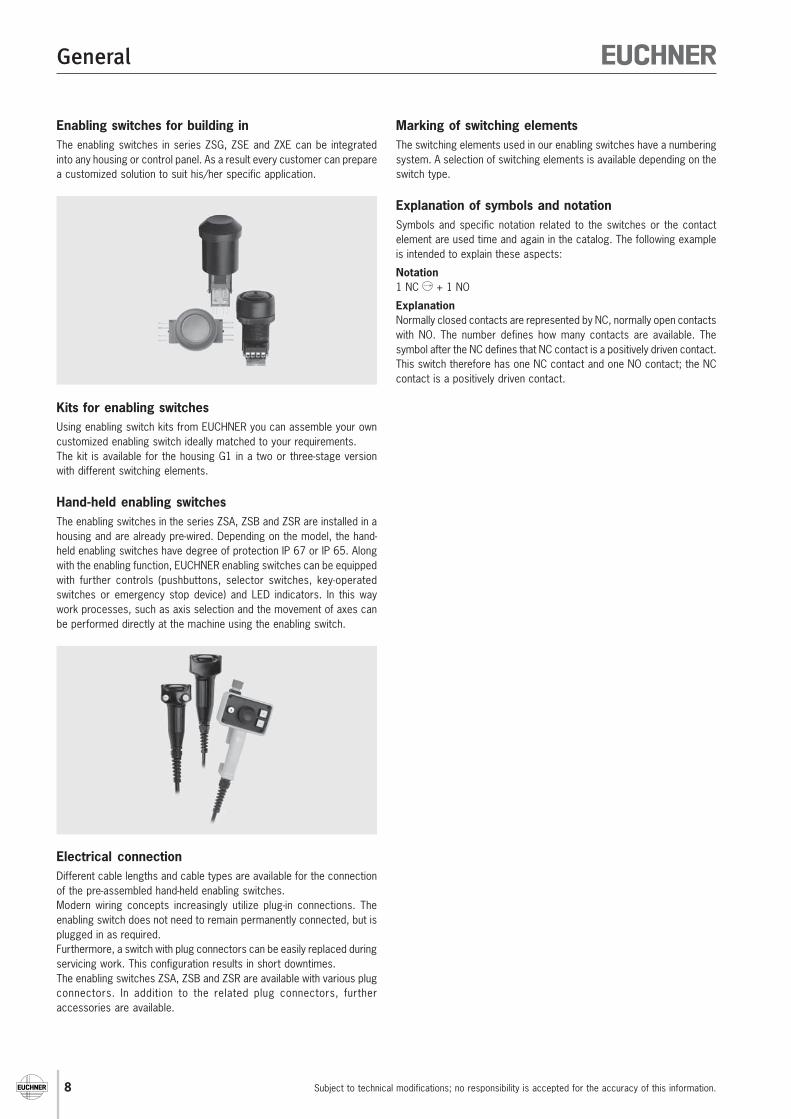
Enabling switches for building inThe enabling switches in series ZSG, ZSE and ZXE can be integratedinto any housing or control panel. As a result every customer can preparea customized solution to suit his/her specific application.
Kits for enabling switchesUsing enabling switch kits from EUCHNER you can assemble your owncustomized enabling switch ideally matched to your requirements.The kit is available for the housing G1 in a two or three-stage versionwith different switching elements.
Hand-held enabling switchesThe enabling switches in the series ZSA, ZSB and ZSR are installed in ahousing and are already pre-wired. Depending on the model, the hand-held enabling switches have degree of protection IP 67 or IP 65. Alongwith the enabling function, EUCHNER enabling switches can be equippedwith further controls (pushbuttons, selector switches, key-operatedswitches or emergency stop device) and LED indicators. In this waywork processes, such as axis selection and the movement of axes canbe performed directly at the machine using the enabling switch.
Electrical connectionDifferent cable lengths and cable types are available for the connectionof the pre-assembled hand-held enabling switches.Modern wiring concepts increasingly utilize plug-in connections. Theenabling switch does not need to remain permanently connected, but isplugged in as required.Furthermore, a switch with plug connectors can be easily replaced duringservicing work. This configuration results in short downtimes.The enabling switches ZSA, ZSB and ZSR are available with various plugconnectors. In addition to the related plug connectors, furtheraccessories are available.
Marking of switching elementsThe switching elements used in our enabling switches have a numberingsystem. A selection of switching elements is available depending on theswitch type.
Explanation of symbols and notationSymbols and specific notation related to the switches or the contactelement are used time and again in the catalog. The following exampleis intended to explain these aspects:
Notation1 NC + 1 NO
ExplanationNormally closed contacts are represented by NC, normally open contactswith NO. The number defines how many contacts are available. Thesymbol after the NC defines that NC contact is a positively driven contact.This switch therefore has one NC contact and one NO contact; the NCcontact is a positively driven contact.
9
Enabling Switches
For
safe
ty in
stru
ctio
ns s
ee p
age
34Fo
r te
chni
cal d
ata
see
page
28
HousingE Built-in version (without cable)
K Kit (without cable or with plug fitted)G1 Housing G1, black
G2 Housing G2, yellowHBE HBE housing, gray
G3 Housing G3, yellow
Function2 2-stage (OFF - enabling)
3 3-stage (OFF - enabling - OFF)
Connection
CTab, screw connection,flying lead
SS4 Plug connector 3-pin + PESVM5 Plug connector M12 5-pin
CE5 Plug connector 3-pin + N + PEC16 Plug connector 6-pin + PE
MR7 Plug connector 7-pinMR8 Plug connector 8-pin
MR10 Plug connector 10-pinHAN10 Plug connector 10-pin + PE
RC12 Plug connector 11-pin + PEBS12 Plug connector 12-pin
RC17 Plug connector 17-pinVP19 Plug connector 19-pin
UT23 Plug connector 23-pinTB24 Plug connector 24-pin
Additional elements
ZAdditional elements, e. g. buttons, LEDs,key-operated switch, selector switch, etc.
Selection table for enabling switches ZS
Enabling switch ZSEEnabling switch ZSBHousing G3
Enabling switch ZSBHousing G1
Desing Stages Connection WithVersion
PageE K G1 G2 HBE G3 2 3 C SS4 SVM5 CE5 C16 MR7 MR8 MR10 HAN10 RC12 BS12 RC17 VP19 UT23 TB24 Z
10 C1692/C1801/1943 11
12 C1903 13
C1909/C1917 14 C1689 15 C1861 16 C1662/C1926 17 C1830/C2038 18
C1714/C1770
20C2032/C2041
C1725 19 C1983 21 C1932/C1968/C1979 22 C2044 23
24 C1736 25
26 27 29 28 30/31
Enabling Switches
Subject to technical modifications; no responsibility is accepted for the accuracy of this information.10
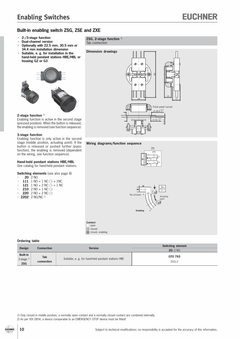
Built-in enabling switch ZSG, ZSE and ZXE 2-/3-stage function Dual-channel version Optionally with 22.5 mm, 30.5 mm or
34.4 mm installation dimension Suitable, e. g. for installation in the
hand-held pendant stations HBE/HBL orhousing G2 or G3
2-stage function 2)
Enabling function is active in the second stage(pressed position). When the button is released,the enabling is removed (see function sequence).
3-stage functionEnabling function is only active in the secondstage (middle position, actuating point). If thebutton is released or pushed further (panicfunction), the enabling is removed (dependenton the wiring, see function sequence).
Hand-held pendant stations HBE/HBLSee catalog for hand-held pendant stations.
Switching elements (see also page 8) 20 2 NO 111 1 NO + 1 NC + 1NC 121 1 NO + 2 NC + 1 NC 210 2 NO + 1 NC 220 2 NO + 2 NC 2202 2 NO/NC 1)
Dimension drawings
Wiring diagrams/function sequence
ZSG, 2-stage function 2)
Tab connection
1) Only closed in middle position, a normally open contact and a normally closed contact are combined internally.2) As per VDI 2854, a device comparable to an EMERGENCY STOP device must be fitted!
Ordering table
Design Connection VersionSwitching element
20: 2 NOBuilt-in
Tab 070 7932-stage 2)
connectionSuitable, e. g. for hand-held pendant stations HBE
ZSG1-2ZSG
3 434
E1
20
3 434
E2
20
±0,
3∅ 32 +0,3 0
∅ 34,4+0,6 0
2
62
19 1110
Front panel cut-out
Contactopenclosedclosed, enabling
1
2
1
22
20
E 1, E 2NO
NONot actuated
Enabling
Actuatingpoint
Enabling Switches
For
tech
nica
l dat
a se
e pa
ge 4
1
Subject to technical modifications; no responsibility is accepted for the accuracy of this information. 11
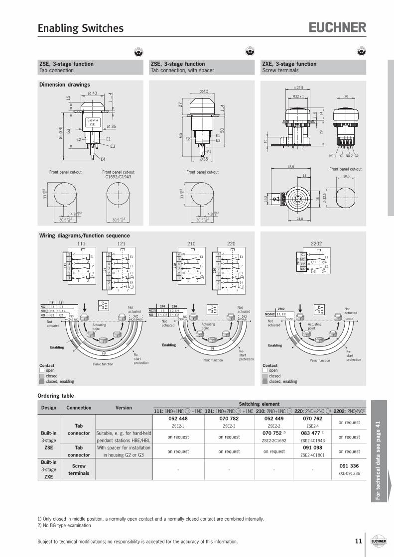
ZSE, 3-stage functionTab connection
ZXE, 3-stage functionScrew terminals
1) Only closed in middle position, a normally open contact and a normally closed contact are combined internally.2) No BG type examination
C2NO2
1/3 2/4
C1E1
2202
1/3 2/4
E2
NO1
2202
14
1 - 5
29
27,5
10
M22 x 1 20
NO 1 C1 C2
43,5
13,2
18
24,8
14 20,5
∅ 2
2,5
NO 2
Front panel cut-out
1 ...
4
E1E2
E3
E4
1563
85 (E
4)
∅ 40
∅ 35
33+
0,5
0
30,5 +0,5 0
4,8 +0,2 0
Front panel cut-out
Dimension drawings
Wiring diagrams/function sequence
ZSE, 3-stage functionTab connection, with spacer
Front panel cut-outC1692/C1943
30,5 +0,5 0
E1E3E2
E4
∅40
27
∅35
65
1..4
50
33+
0,5
0
30,5 +0,5 0
4,8 +0,2 0
Front panel cut-out
Contactopenclosedclosed, enabling
Contactopenclosedclosed, enabling
111
34
1 2
3 4
12
1 212
E1
E2
E3
111
34
1 2
3 4
12
1 21212
1
1 212
E1
E2
E3
E4
121
210
34
3 4
3 4
34
1 212
E1
E2
E3
210
34
3 4
3 4
34
1 21222
0
1 212
E1
E2
E3
E4
220
Notactuated
NO
NC
210 220
E 3
E 1, E 2
E 3, E 4
E 1, E 2
NONC
NCNO
1 1
2 2
3
1
2
33
Notactuated
Enabling
Actuatingpoint
Panic function
Re-startprotection
Re-startprotection
NCNO NC 1 1
2 2
3
1
2
33121
E 1
E 3, E 4
E 2NO
NC
NC
111
E 1
E 3
E 2 NCNONC
Notactuated
Enabling
Actuatingpoint
Panic function
Notactuated
NO/NC NO/NC1 1
2 2
3
1
2
33E 1, E 2
2202
NO/NC
Notactuated
Enabling
Panic function
Actuatingpoint
Notactuated
Re-startprotection
Ordering table
Design Connection VersionSwitching element
111: 1NO+1NC +1NC 121: 1NO+2NC +1NC 210: 2NO+1NC 220: 2NO+2NC 2202: 2NO/NC1)
052 448 070 782 052 449 070 762on request
Tab ZSE2-1 ZSE2-3 ZSE2-2 ZSE2-4
Built-in connector Suitable, e. g. for hand-heldon request on request
070 752 2) 083 477 2)
on request3-stage pendant stations HBE/HBL ZSE2-2C1692 ZSE2-4C1943
ZSE Tab With spacer for installationon request on request on request
091 098on request
connector in housing G2 or G3 ZSE2-4C1801
Built-inScrew 091 336
3-stageterminals
- - - -ZXE-091336
ZXE
Enabling Switches
Subject to technical modifications; no responsibility is accepted for the accuracy of this information.12
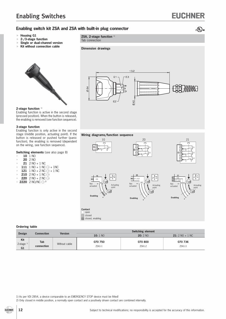
Enabling switch kit ZSA and ZSA with built-in plug connector Housing G1 2-/3-stage function Single or dual-channel version Kit without connection cable
2-stage function 1)
Enabling function is active in the second stage(pressed position). When the button is released,the enabling is removed (see function sequence).
3-stage functionEnabling function is only active in the secondstage (middle position, actuating point). If thebutton is released or pushed further (panicfunction), the enabling is removed (dependenton the wiring, see function sequence).
Switching elements (see also page 8) 10 1 NO 20 2 NO 21 2 NO + 1 NC 111 1 NO + 1 NC + 1NC 121 1 NO + 2 NC + 1 NC 210 2 NO + 1 NC 220 2 NO + 2 NC 2220 2 NO/NC 2)
Dimension drawings
Wiring diagrams/function sequence
ZSA, 2-stage function 1)
Tab connection
Ordering table
Design Connection VersionSwitching element
10: 1 NO 20: 2 NO 21: 2 NO + 1 NCKit
Tab 070 750 070 800 070 7362-stage 1)
connectionWithout cable
ZSA1-1 ZSA1-2 ZSA1-3G1
1) As per VDI 2854, a device comparable to an EMERGENCY STOP device must be fitted!2) Only closed in middle position, a normally open contact and a positively driven contact are combined internally.
1
2
1
22
20
E 1, E 2NO
NONotactuated
Enabling
Actuatingpoint
NO
NC
21
E 3
E 1, E 2
NONC 1
2
1
22
Notactuated
Enabling
Actuatingpoint
NO 1
2
1
22
10
NO E 3
Notactuated
Enabling
Actuatingpoint
3 434
10 E3
10
21
34
3 4
3 4
34
1 212
E1
E2
E3
21
3 434
E1
20
3 434
E2
20
Contactopenclosedclosed, enabling
Enabling Switches
For
tech
nica
l dat
a se
e pa
ge 4
1
Subject to technical modifications; no responsibility is accepted for the accuracy of this information. 13
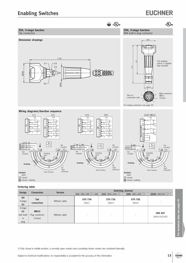
Dimension drawings
Wiring diagrams/function sequence
ZSA, 3-stage functionTab connection
Contactopenclosedclosed, enabling
ZSA, 3-stage functionWith built-in plug connector
111
34
1 2
3 4
12
1 212
E1
E2
E3
111
34
1 2
3 4
12
1 21212
1
1 212
E1
E2
E3
E4
121
NCNO NC 1 1
2 2
3
1
2
33121
E 1
E 3, E 4
E 2NO
NC
NC
111
E 1
E 3
E 2 NCNONC
Notactuated
Enabling
Actuatingpoint
Panic function
Notactuated
Re-startprotection
210
34
3 4
3 4
34
1 212
E1
E2
E3
210
34
3 4
3 4
34
1 21222
0
1 212
E1
E2
E3
E4
220
Notactuated
NO
NC
210 220
E 3
E 1, E 2
E 3, E 4
E 1, E 2
NONC
NCNO
1 1
2 2
3
1
2
33
Notactuated
Enabling
Actuatingpoint
Panic function
Re-startprotection
Notactuated
NO/NC 1 1
2 2
3
1
2
33E 1+E 4E 2+E 3
2220
NO/NC
NO/NCNot
actuated
Enabling
Actuatingpoint
Panic function
Re-startprotection
Contactopenclosedclosed, enabling
1 2
3 4E1
E4
1 2
3 4E2
E3
5
10
3
1
2
4
Plug
con
nect
or M
R10
6
2220 MR10
64
40,5
132
174
1
2
3
87
109
4
6
5
View onconnection side
Male connectorMR10(10-pin)
The enablingswitch is suppliedfully mounted.
1) Only closed in middle position, a normally open contact and a positively driven contact are combined internally.
For mating connectors see page 39
Ordering table
Design Connection VersionSwitching element
111: 1NO+1NC +1NC 210: 2NO+1NC 220: 2NO+2NC 2220: 2NO/NC 1)
KitTab 070 734 070 735 070 792
3-stageconnection
Without cableZSA2-1 ZSA2-2 ZSA2-4
-
G13-stage
G1 MR10095 497
with built- Plug connector Without cable - - -ZSA2-4-10C1903
in (10-pin)plug
Enabling Switches
Subject to technical modifications; no responsibility is accepted for the accuracy of this information.14
7674 15 max.
30M
6M
5
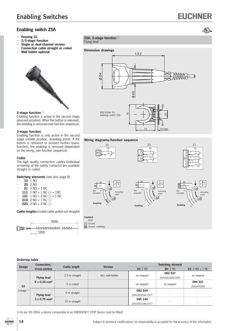
Enabling switch ZSA Housing G1 2/3-stage function Single or dual-channel version Connection cable straight or coiled Wall holder optional
2-stage function 1)
Enabling function is active in the second stage(pressed position). When the button is released,the enabling is removed (see function sequence).
3-stage functionEnabling function is only active in the secondstage (middle position, actuating point). If thebutton is released or pushed further (panicfunction), the enabling is removed (dependenton the wiring, see function sequence).
CableThe high quality connection cables (individualscreening of the safety contacts) are availablestraight or coiled.
Switching elements (see also page 8) 10 1 NO 20 2 NO 21 2 NO + 1 NC 111 1 NO + 1 NC + 1NC 121 1 NO + 2 NC + 1 NC 210 2 NO + 1 NC 220 2 NO + 2 NC
Cable lengths (coiled cable pulled out straight)
Dimension drawings
ZSA, 2-stage function 1)
Flying lead
1) As per VDI 2854, a device comparable to an EMERGENCY STOP device must be fitted!
Ordering table
DesignConnection/
Cable length VersionSwitching element
Cross-section 10: 1 NO 20: 2 NO 21: 2 NO + 1 NC
2.5 m straight Incl. wall holder on request082 557
on requestFlying lead ZSA1A2L25AC1909
6 x 0.34 mm²5 m coiled on request on request
094 321G1 ZSA1A2S05A
2-stage 1)
5 m straight082 524
- -Flying lead ZSA1A5G05AC1917
3 x 0.75 mm²10 m straight
095 144- -
ZSA1A5G10AC1917
Wall holder forenabling switch ZSA
Wiring diagrams/function sequence
1
2
1
22
20
E 1, E 2NO
NONotactuated
Enabling
Actuatingpoint
NO
NC
21
E 3
E 1, E 2
NONC 1
2
1
22
Notactuated
Enabling
Actuatingpoint
NO 1
2
1
22
10
NO E 3
Notactuated
Enabling
Actuatingpoint
3 434
10 E3
10
21
34
3 4
3 4
34
1 212
E1
E2
E3
21
3 434
E1
20
3 434
E2
20
Contactopenclosedclosed, enabling
1200
5000
Enabling Switches
For
tech
nica
l dat
a se
e pa
ge 4
1
Subject to technical modifications; no responsibility is accepted for the accuracy of this information. 15
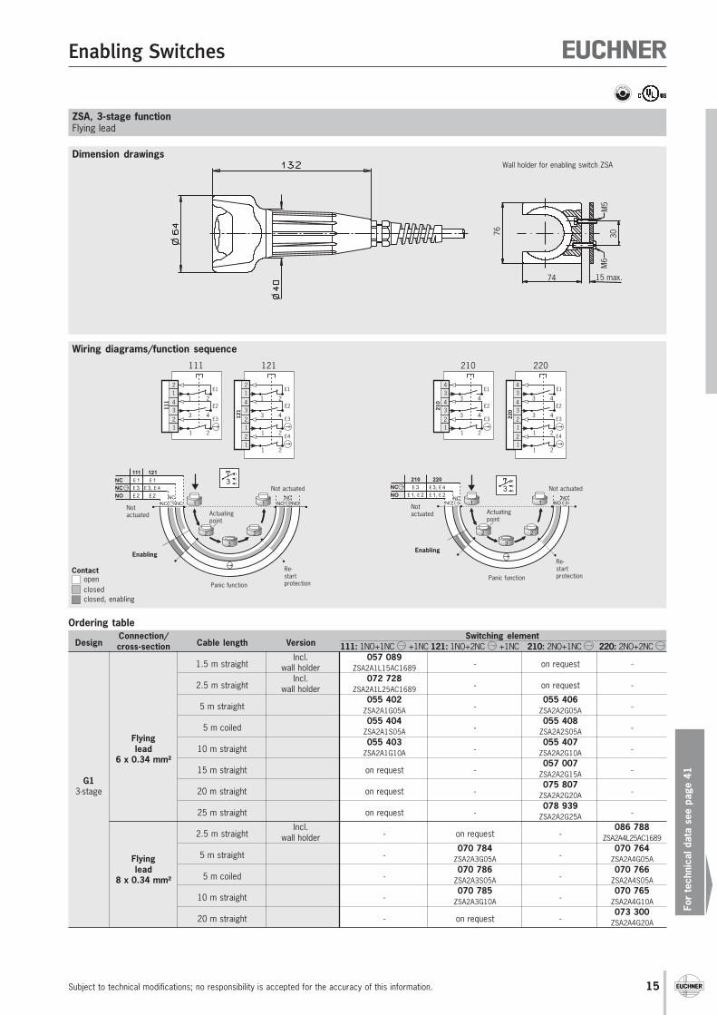
Dimension drawings
Wiring diagrams/function sequence
ZSA, 3-stage functionFlying lead
76
74 15 max.
30M
6M
5
Wall holder for enabling switch ZSA
Contactopenclosedclosed, enabling
111
34
1 2
3 4
12
1 212
E1
E2
E3
111
34
1 2
3 4
12
1 21212
1
1 212
E1
E2
E3
E4
121
210
34
3 4
3 4
34
1 212
E1
E2
E3
210
34
3 4
3 4
34
1 21222
0
1 212
E1
E2
E3
E4
220
Not actuatedNO
NC
210 220
E 3
E 1, E 2
E 3, E 4
E 1, E 2
NONC
NCNO
1 1
2 2
3
1
2
33
Notactuated
Enabling
Actuatingpoint
Panic function
Re-startprotection
NCNO NC 1 1
2 2
3
1
2
33121
E 1
E 3, E 4
E 2NO
NC
NC
111
E 1
E 3
E 2 NCNONC
Notactuated
Enabling
Actuatingpoint
Panic function
Not actuated
Re-startprotection
Ordering table
DesignConnection/
Cable length VersionSwitching element
cross-section 111: 1NO+1NC +1NC 121: 1NO+2NC +1NC 210: 2NO+1NC 220: 2NO+2NC
1.5 m straightIncl. 057 089
- on request -wall holder ZSA2A1L15AC1689
2.5 m straightIncl. 072 728
- on request -wall holder ZSA2A1L25AC1689
5 m straight055 402
-055 406
-ZSA2A1G05A ZSA2A2G05A
5 m coiled055 404
-055 408
-Flying
ZSA2A1S05A ZSA2A2S05A
lead 10 m straight055 403
-055 407
-6 x 0.34 mm²
ZSA2A1G10A ZSA2A2G10A
15 m straight on request -057 007
-G1
ZSA2A2G15A
3-stage 20 m straight on request -075 807
-ZSA2A2G20A
25 m straight on request -078 939
-ZSA2A2G25A
2.5 m straightIncl.
- on request -086 788
wall holder ZSA2A4L25AC1689
5 m straight -070 784
-070 764
Flying ZSA2A3G05A ZSA2A4G05Alead
5 m coiled -070 786
-070 766
8 x 0.34 mm² ZSA2A3S05A ZSA2A4S05A
10 m straight -070 785
-070 765
ZSA2A3G10A ZSA2A4G10A
20 m straight - on request -073 300
ZSA2A4G20A
Enabling Switches
Subject to technical modifications; no responsibility is accepted for the accuracy of this information.16
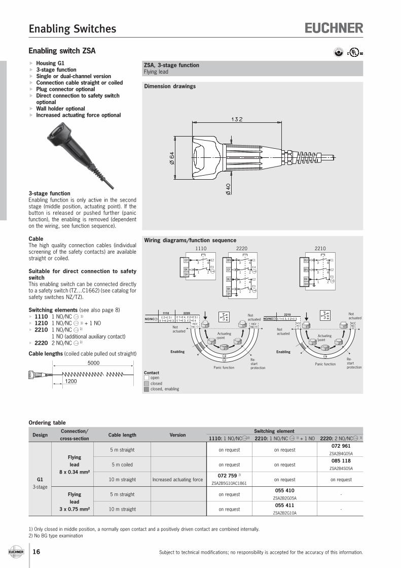
Enabling switch ZSA Housing G1 3-stage function Single or dual-channel version Connection cable straight or coiled Plug connector optional Direct connection to safety switch
optional Wall holder optional Increased actuating force optional
3-stage functionEnabling function is only active in the secondstage (middle position, actuating point). If thebutton is released or pushed further (panicfunction), the enabling is removed (dependenton the wiring, see function sequence).
CableThe high quality connection cables (individualscreening of the safety contacts) are availablestraight or coiled.
Suitable for direct connection to safetyswitchThis enabling switch can be connected directlyto a safety switch (TZ…C1662) (see catalog forsafety switches NZ/TZ).
Switching elements (see also page 8) 1110 1 NO/NC 1)
1210 1 NO/NC 1) + 1 NO 2210 1 NO/NC 1)
1 NO (additional auxiliary contact) 2220 2 NO/NC 1)
Cable lengths (coiled cable pulled out straight)
Dimension drawings
Wiring diagrams/function sequence
ZSA, 3-stage functionFlying lead
Ordering table
DesignConnection/
Cable length VersionSwitching element
cross-section 1110: 1 NO/NC 1) 2210: 1 NO/NC 1) + 1 NO 2220: 2 NO/NC 1)
5 m straight on request on request072 961
FlyingZSA2B4G05A
lead 5 m coiled on request on request085 118
8 x 0.34 mm²ZSA2B4S05A
G1 10 m straight Increased actuating force072 759 2)
on request on request3-stage
ZSA2B5G10AC1861
Flying 5 m straight on request055 410
-lead
ZSA2B2G05A
3 x 0.75 mm² 10 m straight on request055 411
-ZSA2B2G10A
1) Only closed in middle position, a normally open contact and a positively driven contact are combined internally.2) No BG type examination
NotactuatedNO/NC
2210
E 1+E 3, E 2+E 3
1 1
2 2
3
1
2
33NO/NC
NO/NC
Notactuated
Enabling
Actuatingpoint
Panic functionRe-startprotection
SH
BK
BU
BN
3 4E1
1 2
3 4E2
E3
2210
Notactuated
NO/NC1 1
2 2
3
1
2
33E 1+E 4, E 2+E 3 /E 1+E 3, E 2+E 4
2220
NO/NC
1110
E 2+E 3 /E 1+E 2+E 3
NO/NCNot
actuated
Enabling
Actuatingpoint
Panic function
Re-startprotection
Contactopenclosedclosed, enabling
SH
GY
BK1 2
3 4E2
E3
1110
SH
BU
BN
1 2GY
BK
3 4E1
E 4
1 2
3 4E2
E3
2220
1200
5000
Enabling Switches
For
tech
nica
l dat
a se
e pa
ge 4
1
Subject to technical modifications; no responsibility is accepted for the accuracy of this information. 17
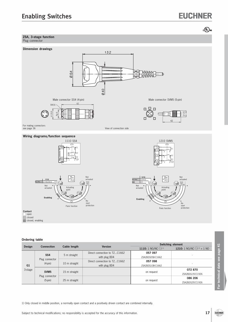
1) Only closed in middle position, a normally open contact and a positively driven contact are combined internally.
Ordering table
Design Connection Cable length VersionSwitching element
1110: 1 NO/NC 1) 1210: 1 NO/NC 1) + 1 NO
SS4 5 m straightDirect connection to TZ...C1662 057 097
-Plug connector
with plug BD4 ZSA2B2G05B-C1662
(4-pin) 10 m straightDirect connection to TZ...C1662 057 098
-G1 with plug BD4 ZSA2B2G10B-C1662
3-stageSVM5 15 m straight on request
072 870
Plug connectorZSA2B2G15CC1926
(5-pin) 25 m straight on request086 206
ZSA2B2G25CC1926
Dimension drawings
Wiring diagrams/function sequence
ZSA, 3-stage functionPlug connector
For mating connectorssee page 36
Male connector SS4 (4-pin) Male connector SVM5 (5-pin)
Pg 9
∅19
,5
62SW16
12
3 4
∅15
421 2
4 35
View of connection side
Contactopenclosedclosed, enabling
Notactuated
NO
1210
E 2+E 3
E 1
NO 1 1
2 2
3
1
2
33
NO
NO/NC
NO/NC
NO/NC
Notactuated
Enabling
Actuatingpoint
Panic function
Re-startprotection
Notactuated
1 1
2 2
3
1
2
331110
E 1+E 2+E 3NO/NC NO/NC
NO/NC
Notactuated
Enabling
Actuatingpoint
Panic function
Re-startprotection
3
4
23 4
E11
Plug
con
nect
or S
VM5
1 2
3 4E2
E3
1210 SVM5
S1
S23 4
E1
1 2
3 4E2
E3
Plug
con
nect
or S
S4
1110 SS4
Enabling Switches
Subject to technical modifications; no responsibility is accepted for the accuracy of this information.18
63 29,5
61,5
64,5
6 7 8 9 10
54321
Enabling switch ZSA
Dimension drawings
Wiring diagrams/function sequence
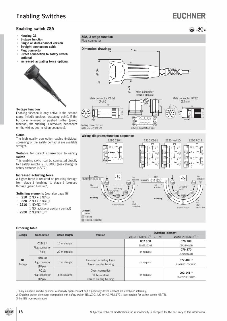
Ordering table
Design Connection Cable length VersionSwitching element
2210: 1 NO/NC 1) + 1 NO 2220: 2 NO/NC 1)
C16-1 2) 10 m straight057 100 070 788
Plug connectorZSA2B2G10B ZSA2B4G10B
(7-pin) 20 m straight on request079 870
ZSA2B4G20B
G1HAN10
Increased actuating force 077 489 3)
3-stagePlug connector 10 m straight
Screen on plug housingon request
ZSA2B2G10CC1830(10-pin)RC12 Direct connection
092 141 3)
Plug connector 5 m straight to TZ...C1803 on requestZSA092141C2038
(12-pin) Screen on plug housing
Housing G1 3-stage function Single or dual-channel version Straight connection cable Plug connector Direct connection to safety switch
optional Increased actuating force optional
3-stage functionEnabling function is only active in the secondstage (middle position, actuating point). If thebutton is released or pushed further (panicfunction), the enabling is removed (dependenton the wiring, see function sequence).
CableThe high quality connection cables (individualscreening of the safety contacts) are availablestraight.
Suitable for direct connection to safetyswitchThis enabling switch can be connected directlyto a safety switch (TZ…C1803) (see catalog forsafety switches NZ/TZ).
Increased actuating forceA higher force is required on pressing throughfrom stage 2 (enabling) to stage 3 (pressedthrough „panic function“).
Switching elements (see also page 8) 210 2 NO + 1 NC 220 2 NO + 2 NC 2210 1 NO/NC 1)
1 NO (additional auxiliary contact) 2220 2 NO/NC 1)
ZSA, 3-stage functionPlug connector
Male connectorHAN10 (10-pin)
Male connector RC12(12-pin)
Male connector C16-1(7-pin)
Mating connector seepage 36, 37 and 39
1) Only closed in middle position, a normally open contact and a positively driven contact are combined internally.2) Enabling switch connector compatible with safety switch NZ..VZ.C1420 or NZ..VZ.C1701 (see catalog for safety switch NZ/TZ).3) No BG type examination
N
XY9
8
7
6
5 4
3
2
112 10
PO
11
51
∅ 2
6
SW 22
View of connection side
72
∅ 2
9
1
234
5
6
Pg 9
7
1
3
2
3 4E1
1 2
3 4E2
E3
Plug
con
nect
or C
16-1
2210 C16-1
4
1
1 23
2
3 4E1
E4
1 2
3 4E2
E3Plug
con
nect
or C
16-1
2220 C16-1
2
3
5
1 21
SH
3 4E1
E3
1 2
3 4E2
E4
Plug
con
nect
or R
C12
2220 RC12
SH
2
3
1 24
1
3 4E1
E4
1 2
3 4E2
E3Pl
ug c
onne
ctor
HAN
10
2220 HAN10
Notactuated
1 1
2 2
3
1
2
33E 1+E 4, E 2+E 3 /E 1+E 3, E 2+E 4
2220
NO/NC NO/NC
NO/NC
Notactuated
Enabling
Actuatingpoint
Panic function
Re-startprotection
Contactopenclosedclosed, enabling
NotactuatedNO/NC
2210
E 1+E 3, E 2+E 3
1 1
2 2
3
1
2
33NO/NC
NO/NC
Notactuated
Enabling
Actuatingpoint
Panic functionRe-startprotection
Enabling Switches
For
tech
nica
l dat
a se
e pa
ge 4
1
Subject to technical modifications; no responsibility is accepted for the accuracy of this information. 19
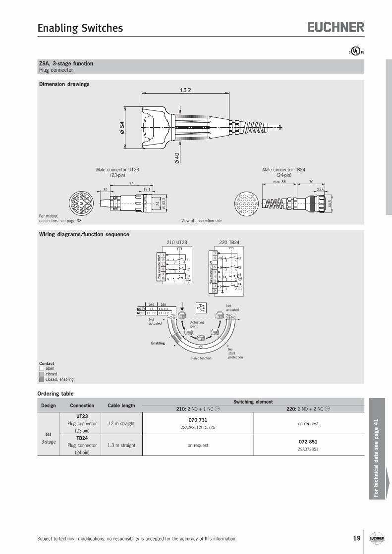
Dimension drawings
Wiring diagrams/function sequence
Ordering table
Design Connection Cable lengthSwitching element
210: 2 NO + 1 NC 220: 2 NO + 2 NC UT23
070 731Plug connector 12 m straight
ZSA2A2L12CC1725on request
G1(23-pin)
3-stageTB24
072 851Plug connector 1.3 m straight on request
ZSA072851(24-pin)
ZSA, 3-stage functionPlug connector
Male connector UT23(23-pin)
Male connector TB24(24-pin)
For matingconnectors see page 38
24
5
3 4
3 4
6
7
1 24
1
1 23
2
E1
E2
E3
E4Plug
con
nect
or T
B24
220 TB24
3 4X
J
3 4K
L
1 2M
N
E1
E2
E3Plug
con
nect
or U
T23
210 UT23
View of connection side
Notactuated
NO
NC
210 220
E 3
E 1, E 2
E 3, E 4
E 1 / E 2
NONC
NO1 1
2 2
3
1
2
33NC
Notactuated
Enabling
Actuatingpoint
Panic function
Re-startprotection
Contactopenclosedclosed, enabling
A
CB
DS
TE
U
GH
V
Z
RP
YN
MX
L
KW
JF
7319,1
24
30
∅43
,3
70max. 86
23,6
1 4
5 9
1510
16
21 24
20
44,5
Enabling Switches
Subject to technical modifications; no responsibility is accepted for the accuracy of this information.20
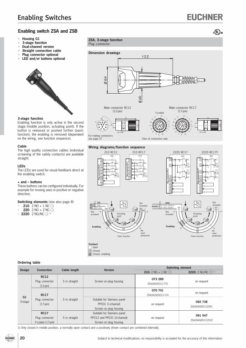
Enabling switch ZSA and ZSB
Dimension drawings
Wiring diagrams/function sequence
Ordering table
Design Connection Cable length VersionSwitching element
210: 2 NO + 1 NC 2220: 2 NO/NC 1)
RC12073 289
Plug connector 5 m straight Screen on plug housingZSA2AG05CC1770
on request(12-pin)
070 741on request
RC17 ZSA2A2G05CC1714G1
Plug connector 5 m straight Suitable for Siemens panel092 7383-stage
(17-pin) PP031 (1-channel) on requestZSA2A4G05C-C2041
Screen on plug housingRC17 Suitable for Siemens panel
091 547Plug connector 5 m straight PPO12 and PP031 (2-channel) on request
ZSA2A4G05C-C2032Y-coded (17-pin) Screen on plug housing
Housing G1 3-stage function Dual-channel version Straight connection cable Plug connector optional LED and/or buttons optional
3-stage functionEnabling function is only active in the secondstage (middle position, actuating point). If thebutton is released or pushed further (panicfunction), the enabling is removed (dependenton the wiring, see function sequence).
CableThe high quality connection cables (individualscreening of the safety contacts) are availablestraight.
LEDsThe LEDs are used for visual feedback direct atthe enabling switch.
+ and – buttonsThese buttons can be configured individually. Forexample for moving axes in positive or negativedirection.
Switching elements (see also page 8) 210 2 NO + 1 NC 220 2 NO + 2 NC 2220 2 NO/NC 1)
1) Only closed in middle position, a normally open contact and a positively driven contact are combined internally.
ZSA, 3-stage functionPlug connector
Male connector RC17(17-pin)
Male connector RC12(12-pin)
For mating connectorssee page 37
N
XY9
8
7
6
5 4
3
2
112 10
PO
11
51
∅ 2
6
SW 22
View of connection side
51
∅ 2
6
SW 22
11112
10
9
7 146
54
3
8
16
17
13
2
15
11112
10
9
7 146
54
3
8
16
17
13
2
15
Y-coded
Contactopenclosedclosed, enabling
Notactuated
210
E 3
E 1, E 2
1 1
2 2
3
1
2
33NO
NC
NONC
NONC
Notactuated
Enabling
Actuatingpoint
Panic function
Re-startprotection
Notactuated
1 1
2 2
3
1
2
33E 1+E 4, E 2+E 3 /E 1+E 3, E 2+E 4
2220
NO/NC NO/NC
NO/NC
Notactuated
Enabling
Actuatingpoint
Panic function
Re-startprotection
SH
5
16
14
1
12
9
10
Plug
con
nect
or R
C17
Y
1 2
3 4E1
E4
1 2
63 4
E2
E3
2220 RC17Y
SH
14
6
1
12
9
10
Plug
con
nect
or R
C17
1 2
3 4E1
E4
1 2
53 4
E2
E3
2220 RC17
17
3 411
10
3 413
12
1 215
14
E1
E2
E3
Plug
con
nect
or R
C17
210 RC17
8
7
SH
3 45
6
3 43
4
1 21
2
E1
E2
E3
Plug
con
ne c
tor
RC12
210 RC12
Enabling Switches
For
tech
nica
l dat
a se
e pa
ge 4
1
Subject to technical modifications; no responsibility is accepted for the accuracy of this information. 21
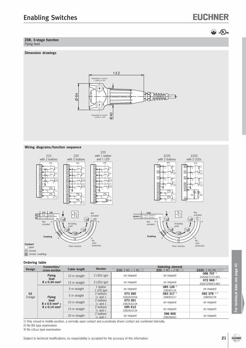
Ordering table
DesignConnection/
Cable length VersionSwitching element
cross-section 210: 2 NO + 1 NC 220: 2 NO + 2 NC 2220: 2 NO/NC 1)
Flying 10 m straight 2 LEDs (gn) on request on request086 707 2)
lead ZSA086707C1983
8 x 0.34 mm² 15 m straight 2 LEDs (gn) on request on request072 969 2)
ZSA072969C1983
5 m straight1 button
on request085 126 2)
on request1 LED (gn) ZSB085126G1
5 m straight2 buttons 073 260 083 317 2) 092 378 2) 3)
3-stage Flying (+ and -) ZSB2A2G05A ZSB083317 ZSB092378lead
10 m straight2 buttons 073 261
on request on request8 x 0.5 mm² + (+ and -) ZSB2A2G10A8 x 0.14 mm²
15 m straight2 buttons 095 612
on request on request(+ and -) ZSB2A2G15A
20 m straight2 buttons
on request096 900
on request(+ and -) ZSB096900
Dimension drawings
Wiring diagrams/function sequence
ZSB, 3-stage functionFlying lead
1) Only closed in middle position, a normally open contact and a positively driven contact are combined internally.2) No BG type examination3) No cULus type examination
Depending on version+ button or LED
Depending on version– button or LED
Contactopenclosedclosed, enabling
Notactuated
1 1
2 2
3
1
2
33E 1+E 4, E 2+E 3 /E 1+E 3, E 2+E 4
2220
NO/NC NO/NC
NO/NC
Notactuated
Enabling
Actuatingpoint
Panic function
Re-startprotection
Notactuated
NO
NC
210 220
E 3
E 1, E 2
E 3, E 4
E 1, E 2
NONC
NCNO
1 1
2 2
3
1
2
33
Notactuated
Enabling
Actuatingpoint
Panic function
Re-startprotection
YE
BU3 4
3 4
GN
PK
1 2WH
RD
1 2BN
GY
E1
E2
E3
E4
RDBU
VT
3 4
BK
GYPK
-T1
SH
GN
220with 1 button
and 1 LED
1 2
3 4E1
E 4
1 2
3 4E2
E3
()
()
()
()1 2
3 4E1
E 4
1 2
3 4E2
E3
GNGN
SH
BU
BN
GY
BK
SH
BU
BN
GY
BK
BU
BN
2220with 2 LEDs
3 4
3 4
-T1
+T2
1 2
3 4E1
E3
1 2
3 4E2
E4
BU
PK
RD
GY
SH
YE
GN
WH
BN
2220with 2 buttons
WH
BU3 4
3 4
BN
PK
1 2YE
RD
E1
E2
E3
3 4RDBU
BK
3 4GYPK
WHYE
-T1
+T2
SH
210with 2 buttons
YE
BU3 4
3 4
GN
PK
1 2WH
RD
1 2BN
GY
E1
E2
E3
E4
3 4RDBU
VT
3 4GYPK
BK
-T1
+T2
SH
220with 2 buttons
Enabling Switches
Subject to technical modifications; no responsibility is accepted for the accuracy of this information.22
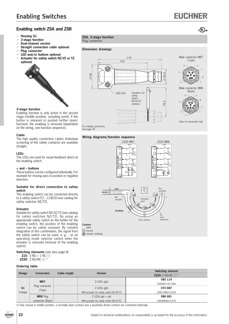
Enabling switch ZSA and ZSB
Dimension drawings
Wiring diagrams/function sequence
Ordering table
Design Connection Cable length VersionSwitching element
2220: 2 NO/NC 1)
MR7 - 2 LEDs (gn)085 114
Plug connectorZSA085114C1968
G1(7-pin) -
2 LEDs (gn) 072 8873-stage With actuator for safety switch NZ.VZ/TZ ZSA072887-C1932
MR8 Plug-
2 LEDs (gn + ye) 086 681connector (8-pin) With actuator for safety switch NZ.VZ/TZ ZSA086681C1979
Housing G1 3-stage function Dual-channel version Straight connection cable optional Plug connector LED and/or buttons optional Actuator for safety switch NZ.VZ or TZ
optional
3-stage functionEnabling function is only active in the secondstage (middle position, actuating point). If thebutton is released or pushed further (panicfunction), the enabling is removed (dependenton the wiring, see function sequence).
CableThe high quality connection cables (individualscreening of the safety contacts) are availablestraight.
LEDsThe LEDs are used for visual feedback direct atthe enabling switch.
+ and – buttonsThese buttons can be configured individually. Forexample for moving axes in positive or negativedirection.
Suitable for direct connection to safetyswitchThis enabling switch can be connected directlyto a safety switch (TZ…C1803) (see catalog forsafety switches NZ/TZ).
ActuatorSuitable for safety switch NZ.VZ/TZ (see catalogfor safety switches NZ/TZ). By using anappropriate safety switch as the holder for theenabling switch, the position of the enablingswitch can be safely sampled. By suitableintegration of this combination, the signal fromthe safety switch can be used, e. g. , as anoperating mode selector switch when theactuator is removed (removal of the enablingswitch).
Switching elements (see also page 8) 210 2 NO + 1 NC 2220 2 NO/NC 1)
ZSA, 3-stage functionPlug connector
1) Only closed in middle position, a normally open contact and a positively driven contact are combined internally.
For mating connectorssee page 39
∅ 6
4
132
LED (2x)
∅ 4
0,5
170
78,2
Actuators forsafetyswitchNZ.VZ/TZoptional
1 2
3 4E1
E4
1 2
3 4E2
E3
GNGN
1
4
3
6
2
5
Plug
con
nect
or M
R7
1
2220 MR7
1 2
3 4E1
E4
1 2
3 4E2
E3
YEGN
6
8
3
1
2
4
Plug
con
nect
or M
R8
7
2220 MR8
Male connector MR7(7-pin)
Male connector MR8(8-pin)
View of connection side
34
5
6
2
1
7
34
5
6
2
1
7
8
Contactopenclosedclosed, enabling
Notactuated
1 1
2 2
3
1
2
33E 1+E 4, E 2+E 3 /E 1+E 3, E 2+E 4
2220
NO/NC NO/NC
NO/NC
Notactuated
Enabling
Actuatingpoint
Panic function
Re-startprotection
Enabling Switches
For
tech
nica
l dat
a se
e pa
ge 4
1
Subject to technical modifications; no responsibility is accepted for the accuracy of this information. 23
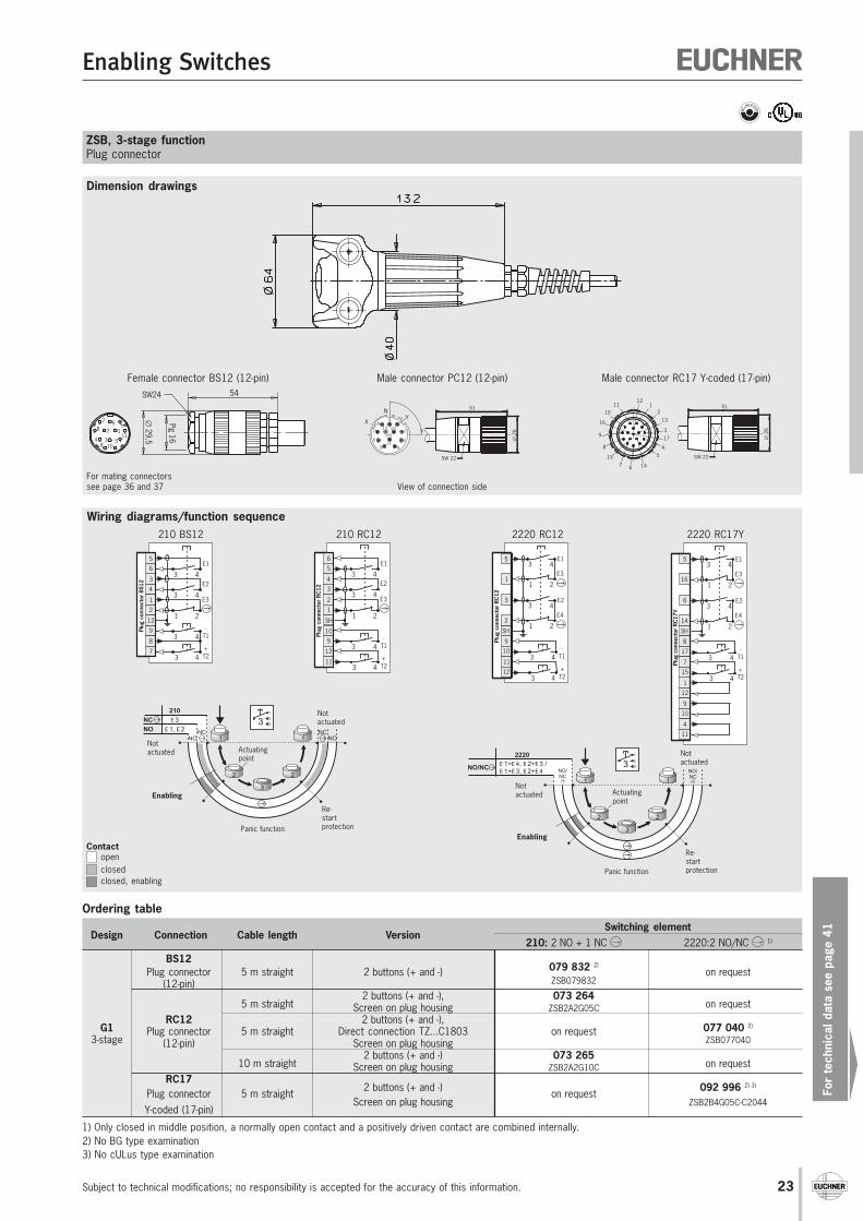
Male connector RC17 Y-coded (17-pin)Male connector PC12 (12-pin)Female connector BS12 (12-pin)
ZSB, 3-stage functionPlug connector
For mating connectorssee page 36 and 37
Ordering table
Design Connection Cable length VersionSwitching element
210: 2 NO + 1 NC 2220:2 NO/NC 1)
BS12079 832 2)
Plug connector 5 m straight 2 buttons (+ and -)ZSB079832
on request(12-pin)
5 m straight2 buttons (+ and -), 073 264
on requestScreen on plug housing ZSB2A2G05C
G1RC12 2 buttons (+ and -),
077 040 2)
3-stagePlug connector 5 m straight Direct connection TZ...C1803 on request
ZSB077040(12-pin) Screen on plug housing
10 m straight2 buttons (+ and -) 073 265
on requestScreen on plug housing ZSB2A2G10CRC17
2 buttons (+ and -) 092 996 2) 3)
Plug connector 5 m straightScreen on plug housing
on requestZSB2B4G05C-C2044
Y-coded (17-pin)
1) Only closed in middle position, a normally open contact and a positively driven contact are combined internally.2) No BG type examination3) No cULus type examination
3 4
3 4
-T1
+T2
1 2
3 4E1
E3
1 2
3 4E2
E4
12
1
10
9
SH
17
8
15
7
6
5
16
14
Plug
con
nect
or R
C17
Y
11
4
2220 RC17Y
3 4
3 4
-T1
+T2
1 2
3 4E1
E3
1 2
3 4E2
E4
10
9
12
11
SH
3
5
1
2
Plug
con
nect
or R
C12
2220 RC12
4
33 4
3 4
6
5
1 22
1
E1
E2
E3
3 49
3 47
8
-T1
+T2
12
Plug
con
nect
or B
S12
210 BS12
3
43 4
3 4
5
6
1 21
2
E1
E2
E3
3 49
10
3 411
12
-T1
+T2
SH
Plug
con
nect
or R
C12
210 RC12
Dimension drawings
Wiring diagrams/function sequence
N
XY9
8
7
6
5 4
3
2
112 10
PO
11
51
∅ 2
6
SW 22
View of connection side
51
∅ 2
6
SW 22
Pg 16
∅29,5
54SW24
7 68 2 1
11534
8 10
Contactopenclosedclosed, enabling
Notactuated
1 1
2 2
3
1
2
33E 1+E 4, E 2+E 3 /E 1+E 3, E 2+E 4
2220
NO/NC NO/NC
NO/NC
Notactuated
Enabling
Actuatingpoint
Panic function
Re-startprotection
Notactuated
210
E 3
E 1, E 2
1 1
2 2
3
1
2
33NO
NC
NONC
NONC
Notactuated
Enabling
Actuatingpoint
Panic function
Re-startprotection
11112
10
9
7 146
54
3
8
16
17
13
2
15
Enabling Switches
Subject to technical modifications; no responsibility is accepted for the accuracy of this information.24
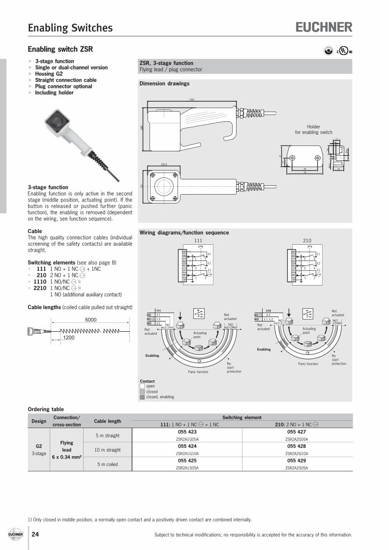
Dimension drawings
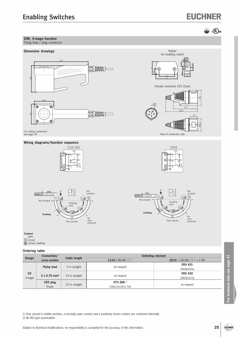
Wiring diagrams/function sequence
Enabling switch ZSR
Ordering table
DesignConnection/
Cable lengthSwitching element
cross-section 111: 1 NO + 1 NC + 1 NC 210: 2 NO + 1 NC
5 m straight055 423 055 427
FlyingZSR2A1G05A ZSR2A2G05A
G2lead 10 m straight
055 424 055 4283-stage
6 x 0.34 mm²ZSR2A1G10A ZSR2A2G10A
5 m coiled055 425 055 429
ZSR2A1S05A ZSR2A2S05A
3-stage function Single or dual-channel version Housing G2 Straight connection cable Plug connector optional Including holder
3-stage functionEnabling function is only active in the secondstage (middle position, actuating point). If thebutton is released or pushed further (panicfunction), the enabling is removed (dependenton the wiring, see function sequence).
CableThe high quality connection cables (individualscreening of the safety contacts) are availablestraight.
Switching elements (see also page 8) 111 1 NO + 1 NC + 1NC 210 2 NO + 1 NC 1110 1 NO/NC 1)
2210 1 NO/NC 1)
1 NO (additional auxiliary contact)
Cable lengths (coiled cable pulled out straight)
ZSR, 3-stage functionFlying lead / plug connector
1) Only closed in middle position, a normally open contact and a positively driven contact are combined internally.
186
70
69,5
190
Notactuated
210
E 3
E 1, E 2
1 1
2 2
3
1
2
33NO
NC
NONC
NONC
Notactuated
Enabling
Actuatingpoint
Panic function
Re-startprotection
Notactuated
1 1
2 2
3
1
2
33
NO
NC
NC
111
E 1
E 3
E 2
NONC
NC NC NONC
Notactuated
Enabling
Actuatingpoint
Panic function
Re-startprotection
SH
WH
RD
BU1 2
3 4
BN
1 2BK
GY
E1
E2
E3
111
SH
WH
RD
BU3 4
3 4
BN
1 2BK
GY
E1
E2
E3
210
Contactopenclosedclosed, enabling
70
4117
50
Ø4.
3
20
16
512
Ø10
Holderfor enabling switch
1200
5000
Enabling Switches
For
tech
nica
l dat
a se
e pa
ge 4
1
Subject to technical modifications; no responsibility is accepted for the accuracy of this information. 25
Dimension drawings
ZSR, 3-stage functionFlying lead / plug connector
For mating connectorssee page 39
˚
153117
75
37
64,3
30
Female connector CE5 (5-pin)
View of connection side
Wiring diagrams/function sequence
Notactuated
NO/NC
2210
E 1+E 3, E 2+E 3
1 1
2 2
3
1
2
33NO/NC
NO/NC
Not actuated
Enabling
Actuatingpoint
Panic function
Re-startprotection
Notactuated
1 1
2 2
3
1
2
331110
E 1+E 2+E 3NO/NC NO/NC
NO/NC
Not actuated
Enabling
Actuatingpoint
Panic function
Re-startprotection
3 4E1
1 2
3 4E2
E3T/L3
R/L1
Plug
con
nect
or C
E5
PE
1110 CE5
3 4E1
1 2
3 4E2
E3
SH
BK
BU
BN
2210
Contactopenclosedclosed, enabling
Ordering table
DesignConnection/
Cable lengthSwitching element
cross-section 1110:1 NO/NC 1) 2210: 1 NO/NC 1) + 1 NO
Flying lead 5 m straight on request055 431
ZSR2B2G05A
G23 x 0.75 mm² 10 m straight on request
055 4323-stage ZSR2B2G10A
CE5 plug10 m straight
073 268 2)
on request(5-pin) ZSR2C2G10CC1736
1) Only closed in middle position, a normally open contact and a positively driven contact are combined internally.2) No BG type examination
186
70
69,5
190
70
4117
50
Ø4.
3
20
16
512
Ø10
Holderfor enabling switch
Enabling Switches
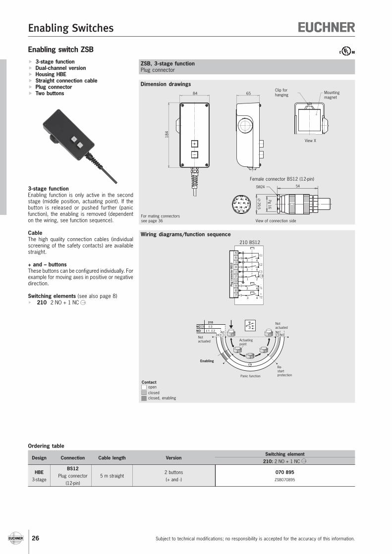
Subject to technical modifications; no responsibility is accepted for the accuracy of this information.26
Ordering table
Design Connection Cable length VersionSwitching element
210: 2 NO + 1 NC
HBEBS12
2 buttons 070 8953-stage
Plug connector 5 m straight(+ and -) ZSB070895
(12-pin)
Dimension drawings
Wiring diagrams/function sequence
Enabling switch ZSB 3-stage function Dual-channel version Housing HBE Straight connection cable Plug connector Two buttons
3-stage functionEnabling function is only active in the secondstage (middle position, actuating point). If thebutton is released or pushed further (panicfunction), the enabling is removed (dependenton the wiring, see function sequence).
CableThe high quality connection cables (individualscreening of the safety contacts) are availablestraight.
+ and – buttonsThese buttons can be configured individually. Forexample for moving axes in positive or negativedirection.
Switching elements (see also page 8) 210 2 NO + 1 NC
ZSB, 3-stage functionPlug connector
4
33 4
3 4
6
5
1 22
1
E1
E2
E3
3 49
3 47
8
-T1
+T2
12
Plug
con
nect
or B
S12
210 BS12
184
84 65Clip forhanging Mounting
magnet
View X
Female connector BS12 (12-pin)
View of connection side
Pg 16
∅29,5
54SW24
7 68 2 1
11534
8 10
Notactuated
210
E 3
E 1, E 2
1 1
2 2
3
1
2
33NO
NC
NONC
NONC
Notactuated
Enabling
Actuatingpoint
Panic function
Re-startprotection
Contactopenclosedclosed, enabling
For mating connectorssee page 36
Enabling Switches
For
tech
nica
l dat
a se
e pa
ge 4
1
Subject to technical modifications; no responsibility is accepted for the accuracy of this information. 27
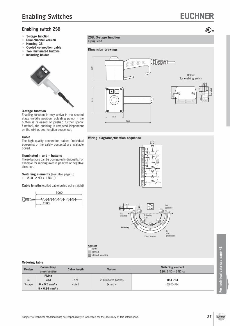
Dimension drawings
Wiring diagrams/function sequence
Enabling switch ZSB 3-stage function Dual-channel version Housing G3 Cooled connection cable Two illuminated buttons Including holder
3-stage functionEnabling function is only active in the secondstage (middle position, actuating point). If thebutton is released or pushed further (panicfunction), the enabling is removed (dependenton the wiring, see function sequence).
CableThe high quality connection cables (individualscreening of the safety contacts) are availablecoiled.
Illuminated + and – buttonsThese buttons can be configured individually. Forexample for moving axes in positive or negativedirection.
Switching elements (see also page 8) 210 2 NO + 1 NC
Cable lengths (coiled cable pulled out straight)
ZSB, 3-stage functionFlying lead
Ordering table
DesignConnection/
Cable length VersionSwitching element
cross-section 210: 2 NO + 1 NC Flying
G3 lead 7 m 2 illuminated buttons 054 7843-stage 8 x 0.5 mm² + coiled (+ and -) ZSB054784
8 x 0.14 mm² +
3 4
+T2
L1
L2
3 4
3 4
1 2
E1
E2
E3
3 4
-T1
GYPK
BNGN
VT
BK
RDBU
SH
PK
YE
BU
GN
BN
WH
GNWH
210
115
79,5
200
100
Notactuated
210
E 3
E 1, E 2
1 1
2 2
3
1
2
33NO
NC
NONC
NONC
Notactuated
Enabling
Actuatingpoint
Panic function
Re-startprotection
Contactopenclosedclosed, enabling
70
4117
50
Ø4.
3
20
16
512
Ø10
Holderfor enabling switch
1200
7000
Enabling Switches
Subject to technical modifications; no responsibility is accepted for the accuracy of this information.28
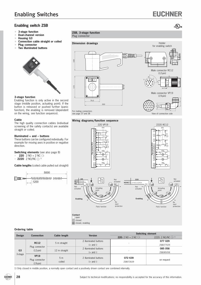
Dimension drawings
Wiring diagrams/function sequence
Enabling switch ZSB 3-stage function Dual-channel version Housing G3 Connection cable straight or coiled Plug connector Two illuminated buttons
3-stage functionEnabling function is only active in the secondstage (middle position, actuating point). If thebutton is released or pushed further (panicfunction), the enabling is removed (dependenton the wiring, see function sequence).
CableThe high quality connection cables (individualscreening of the safety contacts) are availablestraight or coiled.
Illuminated + and – buttonsThese buttons can be configured individually. Forexample for moving axes in positive or negativedirection.
Switching elements (see also page 8) 220 2 NO + 2 NC 2220 2 NO/NC 1)
Cable lengths (coiled cable pulled out straight)
ZSB, 3-stage functionPlug connector
Ordering table
Design Connection Cable length VersionSwitching element
220: 2 NO + 2 NC 2220: 2 NO/NC 1)
RC12 5 m straight2 illuminated buttons
-077 029
Plug connector(+ and -) ZSB077029
G3 (12-pin) 12 m straight2 illuminated buttons
-085 058
3-stage(+ and -) ZSB085058
VP195 m 2 illuminated buttons 072 639
Plug connector coiled (+ and -) ZSB072639
on request(19-pin)
Male connector RC12(12-pin)
Male connector VP19(19-pin)
1) Only closed in middle position, a normally open contact and a positively driven contact are combined internally.
115
79,5
200
100
For mating connectorssee page 37 and 38
N
XY9
8
7
6
5 4
3
2
112 10
PO
11
51
∅ 2
6
SW 22
View of connection side
40
max
. ∅ 1
130
50
AB
C
DE
FGH
J
K
L
M
N P
R
ST
U V
Contactopenclosedclosed, enabling
1 1
2 2
3
1
2
33E 1+E 3, E 2+E 4
2220
NO/NC
NO/NC
NO/NC
Notactuated
Notactuated
Enabling
Actuatingpoint
Panic function
Re-startprotection
Notactuated
NO
NC
220
E 3, E 4
E 1, E 2
NO NO1 1
2 2
3
1
2
33NC NC
Notactuated
Enabling
Actuatingpoint
Panic function
Re-startprotection
1 2
3 4E1
E3
1 2
3 4E2
E4
+T2
L1
L2
3 4
3 4
-T1
3
5
1
2
8
4
6
10
12
11
SH
9
Plug
con
nect
or R
C12
2220 RC12
3 4
+T2
L1
L2
3 4
-T1
3 4
3 4
1 2
1 2
E1
E2
E3
E4
L
N
P
M
J
K
V
C
D
A
B
E
F
G
H
Plug
con
nect
or V
P19
220 VP19
70
4117
50
Ø4.
3
20
16
512
Ø10
Holderfor enabling switch
1200
5000
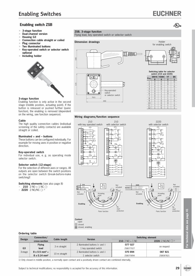
Enabling Switches
For
tech
nica
l dat
a se
e pa
ge 4
1
Subject to technical modifications; no responsibility is accepted for the accuracy of this information. 29
1) Only closed in middle position, a normally open contact and a positively driven contact are combined internally.
Enabling switch ZSB 3-stage function Dual-channel version Housing G3 Connection cable straight or coiled Plug connector Two illuminated buttons Key-operated switch or selector switch
optional Including holder
3-stage functionEnabling function is only active in the secondstage (middle position, actuating point). If thebutton is released or pushed further (panicfunction), the enabling is removed (dependenton the wiring, see function sequence).
CableThe high quality connection cables (individualscreening of the safety contacts) are availablestraight or coiled.
Illuminated + and – buttonsThese buttons can be configured individually. Forexample for moving axes in positive or negativedirection.
Key-operated switchFor individual use, e. g. as operating modeselector switch.
Selector switch (12-stage)For the selection of different axes or ranges. Alloutputs are open between the switch positionson the selector switch (break-before-makeswitching)!
Switching elements (see also page 8) 210 2 NO + 1 NC 2220 2 NO/NC 1)
Dimension drawings
Wiring diagrams/function sequence
ZSB, 3-stage functionFlying lead, key operated switch or selector switch
Ordering table
DesignConnection/
Cable length VersionSwitching element
cross-section 210: 2 NO + 1 NC 2220: 2 NO/NC 1)
Flying3 m straight
2 illuminated buttons (+ and -) 077 027on request
G3 lead 1 key operated switch ZSB077027
3-stage 8 x 0.5 mm² +10 m straight
2 illuminated buttons (+ and -) 070 894 087 8218 x 0.14 mm² 1 selector switch ZSB070894 ZSB087821
115
79,5
200
100
Key-operatedswitchor selector switch
Pos.BNYE YEWH VT BK
8 4 2 11 0 0 0 02 0 0 0 13 0 0 1 04 0 0 1 15 0 1 0 06 0 1 0 17 0 1 1 08 0 1 1 19 1 0 0 0
10 1 0 0 111 1 0 1 012 1 0 1 1
Switching table for selectorswitch (210 and 2220)
1 2
3 4E1
E3
1 2
3 4E2
E4
3 4
+T2
L1
L2
3 4
-T1
12
S
YE
GN
WH
BN
BK
YEWH
BNGN
BNYE
VT
GY
RDBU
GNWH
BU
RD
PK
SH
2220with selector switch
3 4
+T2
3 4
S
L1
L2
3 4
-T1
3 4
3 4
1 2
E1
E2
E3
GYPK
BK
BNGN
GNWH
VT
YEWH
RDBU
SH
PK
YE
BU
GN
BN
WH
210with key operated switch
Contactopenclosedclosed, enabling
1 2
3 4E1
E33 4
3 4
+T2
L1
L2
3 4
-T1
12
E2
S
GN
WH
BN
BK
YEWH
BNGN
BNYE
VT
GY
RDBU
GNWH
BU
RD
PK
SH
YE
210with selector switch
Notactuated
1 1
2 2
3
1
2
33E 1+E 4, E 2+E 3 /E 1+E 3, E 2+E 4
2220
NO/NC NO/NC
NO/NC
Notactuated
Enabling
Actuatingpoint
Panic function
Re-startprotection
Notactuated
210
E 3
E 1, E 2
1 1
2 2
3
1
2
33NO
NC
NONC
NONC
Notactuated
Enabling
Actuatingpoint
Panic function
Re-startprotection
70
4117
50
Ø4.
3
20
16
512
Ø10
Holderfor enabling switch
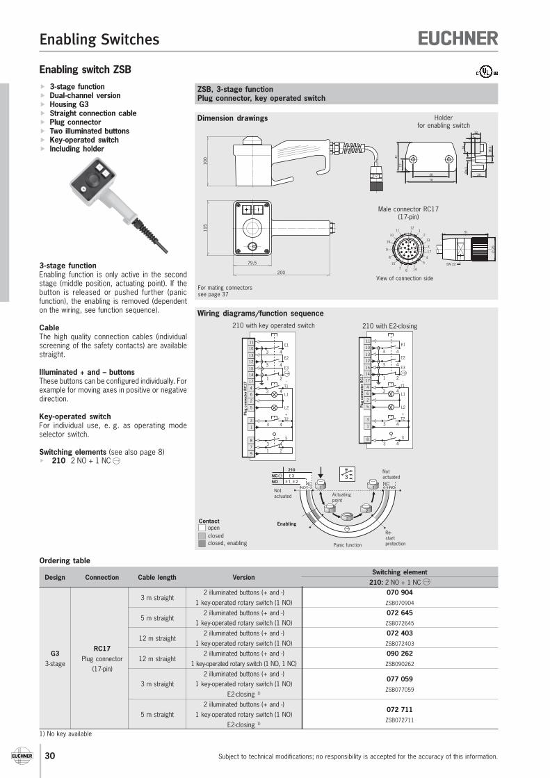
Enabling Switches
Subject to technical modifications; no responsibility is accepted for the accuracy of this information.30
Ordering table
Design Connection Cable length VersionSwitching element
210: 2 NO + 1 NC
3 m straight2 illuminated buttons (+ and -) 070 904
1 key-operated rotary switch (1 NO) ZSB070904
5 m straight2 illuminated buttons (+ and -) 072 645
1 key-operated rotary switch (1 NO) ZSB072645
12 m straight2 illuminated buttons (+ and -) 072 403
RC171 key-operated rotary switch (1 NO) ZSB072403
G3Plug connector 12 m straight
2 illuminated buttons (+ and -) 090 2623-stage
(17-pin)1 key-operated rotary switch (1 NO, 1 NC) ZSB090262
2 illuminated buttons (+ and -)077 059
3 m straight 1 key-operated rotary switch (1 NO)ZSB077059
E2-closing 1)
2 illuminated buttons (+ and -)072 711
5 m straight 1 key-operated rotary switch (1 NO)ZSB072711
E2-closing 1)
1) No key available
Enabling switch ZSB 3-stage function Dual-channel version Housing G3 Straight connection cable Plug connector Two illuminated buttons Key-operated switch Including holder
3-stage functionEnabling function is only active in the secondstage (middle position, actuating point). If thebutton is released or pushed further (panicfunction), the enabling is removed (dependenton the wiring, see function sequence).
CableThe high quality connection cables (individualscreening of the safety contacts) are availablestraight.
Illuminated + and – buttonsThese buttons can be configured individually. Forexample for moving axes in positive or negativedirection.
Key-operated switchFor individual use, e. g. as operating modeselector switch.
Switching elements (see also page 8) 210 2 NO + 1 NC
Dimension drawings
Wiring diagrams/function sequence
ZSB, 3-stage functionPlug connector, key operated switch
115
79,5
200
100
Male connector RC17(17-pin)
For mating connectorssee page 37
View of connection side
Notactuated
210
E 3
E 1, E 2
1 1
2 2
3
1
2
33NO
NC
NONC
NONC
Notactuated
Enabling
Actuatingpoint
Panic function
Re-startprotection
3 4
+T2
3 4S
L1
L2
3 4
-T1
3 4
3 4
1 2
E1
E2
E3
3
1
6
5
2
8
4
17
12
13
10
11
14
15
Plug
con
nect
or R
C17
210 with E2-closing
3 4
3 4
+T2
S
L1
L2
3 4
-T1
3 4
3 4
1 2
E1
E2
E3
1 27
9
3
1
6
5
2
8
4
17
12
13
10
11
14
15
Plug
con
nect
or R
C17
210 with key operated switch
Contactopenclosedclosed, enabling
70
4117
50
Ø4.
3
20
16
512
Ø10
Holderfor enabling switch
51
∅ 2
6
SW 22
11112
10
9
7 146
54
3
8
16
17
13
2
15
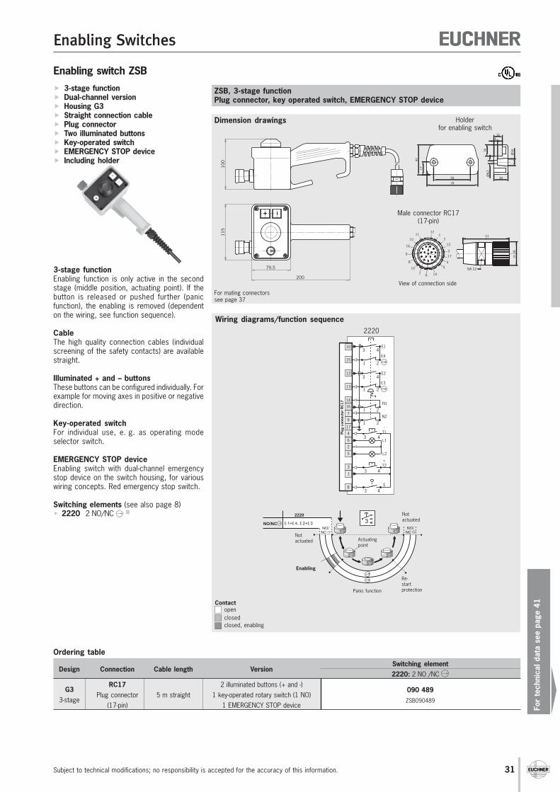
Enabling Switches
For
tech
nica
l dat
a se
e pa
ge 4
1
Subject to technical modifications; no responsibility is accepted for the accuracy of this information. 31
Dimension drawings
Wiring diagrams/function sequence
Ordering table
Design Connection Cable length VersionSwitching element2220: 2 NO /NC
RC17 2 illuminated buttons (+ and -)090 489G3
Plug connector 5 m straight 1 key-operated rotary switch (1 NO)ZSB0904893-stage
(17-pin) 1 EMERGENCY STOP device
ZSB, 3-stage functionPlug connector, key operated switch, EMERGENCY STOP device
1 2
3 4E1
E4
2
3 4E2
E3
3 4
+T2
L1
L2
3 4
-T1
1
3 4S
N1
N2
21
21
12
10
15
3
6
5
2
1
4
13
17
Plug
con
nect
or R
C17
8
9
7
16
14
2220
For mating connectorssee page 37
115
79,5
200
100
Enabling switch ZSB 3-stage function Dual-channel version Housing G3 Straight connection cable Plug connector Two illuminated buttons Key-operated switch EMERGENCY STOP device Including holder
3-stage functionEnabling function is only active in the secondstage (middle position, actuating point). If thebutton is released or pushed further (panicfunction), the enabling is removed (dependenton the wiring, see function sequence).
CableThe high quality connection cables (individualscreening of the safety contacts) are availablestraight.
Illuminated + and – buttonsThese buttons can be configured individually. Forexample for moving axes in positive or negativedirection.
Key-operated switchFor individual use, e. g. as operating modeselector switch.
EMERGENCY STOP deviceEnabling switch with dual-channel emergencystop device on the switch housing, for variouswiring concepts. Red emergency stop switch.
Switching elements (see also page 8) 2220 2 NO/NC 1) Not
actuated
1 1
2 2
3
1
2
33E 1+E 4, E 2+E 3
2220
NO/NC
NO/NC
NO/NC
Notactuated
Enabling
Actuatingpoint
Panic function
Re-startprotection
Contactopenclosedclosed, enabling
70
4117
50
Ø4.
3
20
16
512
Ø10
Holderfor enabling switch
Male connector RC17(17-pin)
View of connection side
51
∅ 2
6
SW 22
11112
10
9
7 146
54
3
8
16
17
13
2
15

32
Enabling Switches
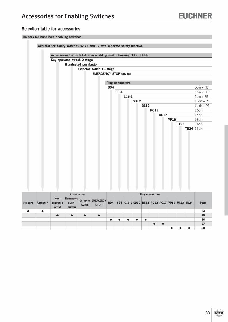
33
Accessories for Enabling Switches
Accessories Plug connectorsKey- Illuminated
Selector EMERGENCYHolders Actuator operated push-
switch STOPBD4 SS4 C16-1 SD12 BS12 RC12 RC17 VP19 UT23 TB24 Page
switch button 34
35 36
37 38
Holders for hand-held enabling switches
Actuator for safety switches NZ.VZ and TZ with separate safety function
Accessories for installation in enabling switch housing G3 and HBEKey-operated switch 2-stage
Illuminated pushbuttonSelector switch 12-stage
EMERGENCY STOP device
Plug connectorsBD4 3-pin + PE
SS4 3-pin + PEC16-1 6-pin + PE
SD12 11-pin + PEBS12 11-pin + PE
RC12 12-pinRC17 17-pin
VP19 19-pinUT23 23-pin
TB24 24-pin
Selection table for accessories
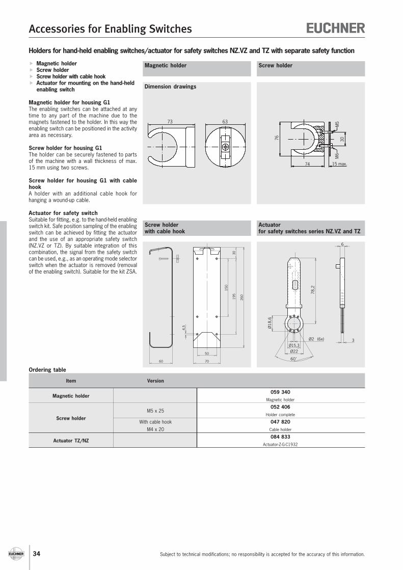
Accessories for Enabling Switches
Subject to technical modifications; no responsibility is accepted for the accuracy of this information.34
Holders for hand-held enabling switches/actuator for safety switches NZ.VZ and TZ with separate safety function
Magnetic holder Screw holder Screw holder with cable hook Actuator for mounting on the hand-held
enabling switch
Magnetic holder for housing G1The enabling switches can be attached at anytime to any part of the machine due to themagnets fastened to the holder. In this way theenabling switch can be positioned in the activityarea as necessary.
Screw holder for housing G1The holder can be securely fastened to partsof the machine with a wall thickness of max.15 mm using two screws.
Screw holder for housing G1 with cablehookA holder with an additional cable hook forhanging a wound-up cable.
Actuator for safety switchSuitable for fitting, e.g. to the hand-held enablingswitch kit. Safe position sampling of the enablingswitch can be achieved by fitting the actuatorand the use of an appropriate safety switch(NZ.VZ or TZ). By suitable integration of thiscombination, the signal from the safety switchcan be used, e.g., as an operating mode selectorswitch when the actuator is removed (removalof the enabling switch). Suitable for the kit ZSA.
Item Version
Magnetic holder059 340
Magnetic holder
M5 x 25052 406
Screw holderHolder complete
With cable hook 047 820M4 x 20 Cable holder
Actuator TZ/NZ084 833
Actuator-Z-G-C1932
Screw holderwith cable hook
Screw holderMagnetic holder
Dimension drawings
Ordering table
76
74 15 max.
30M
6M
573 63
Actuatorfor safety switches series NZ.VZ and TZ
30
150
195
260
60
4,5
50
70
3
6
78,2
Ø22Ø15,3
Ø2 (6x)
60˚
Ø18
,6
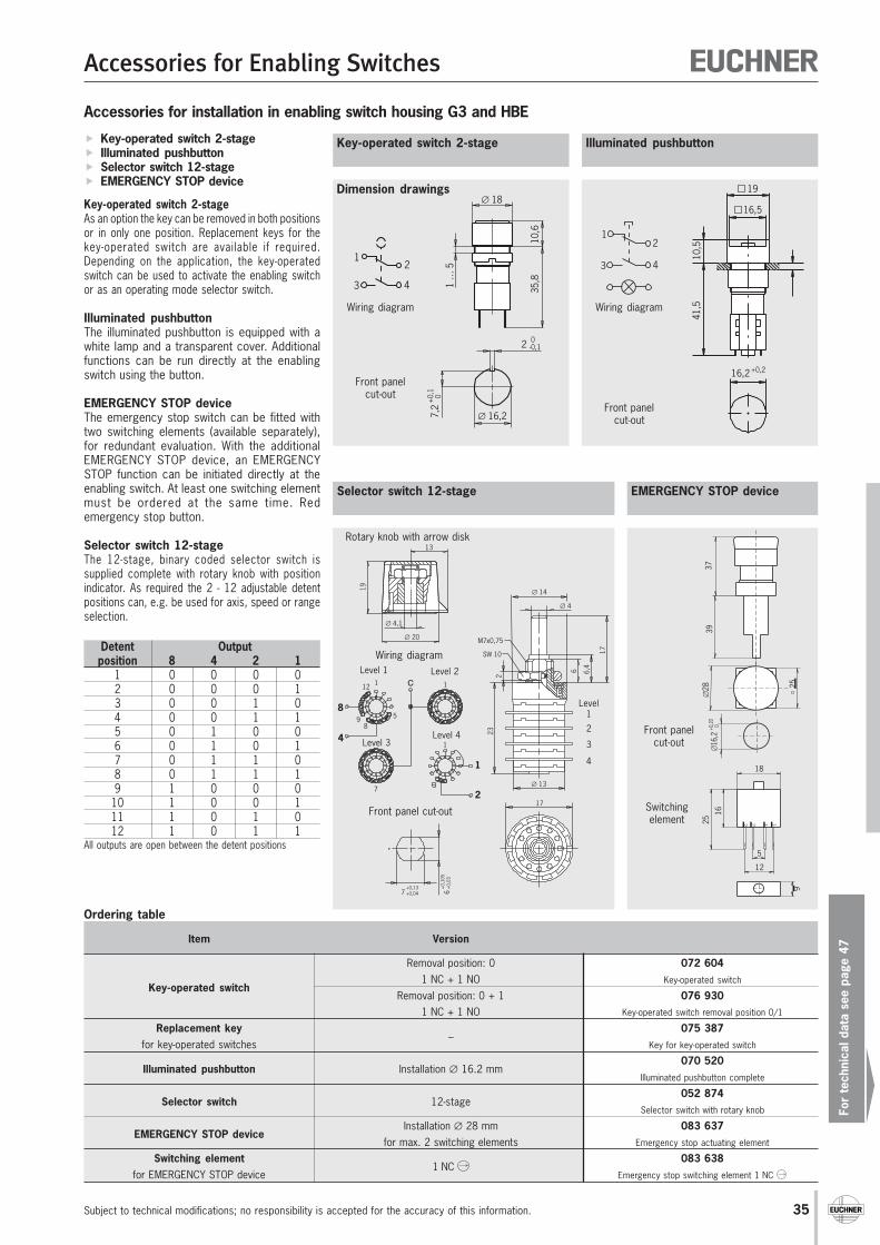
Accessories for Enabling Switches
For
tech
nica
l dat
a se
e pa
ge 4
7
Subject to technical modifications; no responsibility is accepted for the accuracy of this information. 35
Ordering table
Accessories for installation in enabling switch housing G3 and HBE
Key-operated switch 2-stage Illuminated pushbutton Selector switch 12-stage EMERGENCY STOP device
Key-operated switch 2-stageAs an option the key can be removed in both positionsor in only one position. Replacement keys for thekey-operated switch are available if required.Depending on the application, the key-operatedswitch can be used to activate the enabling switchor as an operating mode selector switch.
Illuminated pushbuttonThe illuminated pushbutton is equipped with awhite lamp and a transparent cover. Additionalfunctions can be run directly at the enablingswitch using the button.
EMERGENCY STOP deviceThe emergency stop switch can be fitted withtwo switching elements (available separately),for redundant evaluation. With the additionalEMERGENCY STOP device, an EMERGENCYSTOP function can be initiated directly at theenabling switch. At least one switching elementmust be ordered at the same time. Redemergency stop button.
Selector switch 12-stageThe 12-stage, binary coded selector switch issupplied complete with rotary knob with positionindicator. As required the 2 - 12 adjustable detentpositions can, e.g. be used for axis, speed or rangeselection.
Detent Outputposition 8 4 2 1
1 0 0 0 02 0 0 0 13 0 0 1 04 0 0 1 15 0 1 0 06 0 1 0 17 0 1 1 08 0 1 1 19 1 0 0 0
10 1 0 0 111 1 0 1 012 1 0 1 1
All outputs are open between the detent positions
Item Version
Removal position: 0 072 604
Key-operated switch1 NC + 1 NO Key-operated switch
Removal position: 0 + 1 076 9301 NC + 1 NO Key-operated switch removal position 0/1
Replacement key–
075 387for key-operated switches Key for key-operated switch
Illuminated pushbutton Installation ∅ 16.2 mm070 520
Illuminated pushbutton complete
Selector switch 12-stage052 874
Selector switch with rotary knob
EMERGENCY STOP deviceInstallation ∅ 28 mm 083 637
for max. 2 switching elements Emergency stop actuating element
Switching element1 NC
083 638for EMERGENCY STOP device Emergency stop switching element 1 NC
Selector switch 12-stage
Illuminated pushbuttonKey-operated switch 2-stage
Dimension drawings
EMERGENCY STOP device
∅ 18
10,6
35,8
2 0-0,1
1 …
5
∅ 16,27,2
+0,
10
3
12
4
Wiring diagram
Front panelcut-out
3
12
4
Wiring diagram
Front panelcut-out
19
16,5
10,5
41,5
16,2+0,2
∅ 14
∅ 4
M7x0,75
∅ 13
17
232
6 6,4
17SW 10
7+0,13+0,04 6
+0,
105
+0,
03
C12 1
58
9
8
4
7
1
1
1
2
∅ 20
∅ 4,1
13
19
Rotary knob with arrow disk
Wiring diagram
Front panel cut-out
∅16
,20+0,2
037
39∅
28 25
5
12
18
16
25 .1.1.2.2
6
Switchingelement
Front panelcut-out
Level 1 Level 2
Level 3Level 4
Level1
2
3
4
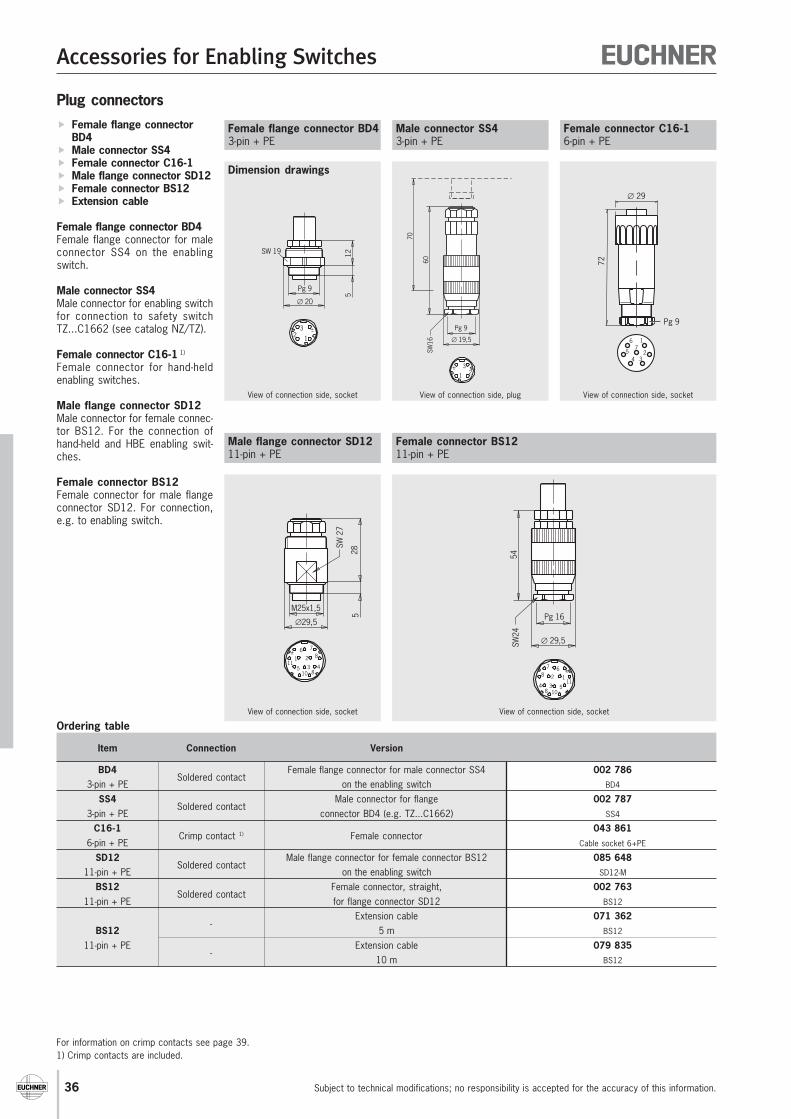
Accessories for Enabling Switches
Subject to technical modifications; no responsibility is accepted for the accuracy of this information.36
Plug connectors Female flange connector
BD4 Male connector SS4 Female connector C16-1 Male flange connector SD12 Female connector BS12 Extension cable
Female flange connector BD4Female flange connector for maleconnector SS4 on the enablingswitch.
Male connector SS4Male connector for enabling switchfor connection to safety switchTZ...C1662 (see catalog NZ/TZ).
Female connector C16-1 1)
Female connector for hand-heldenabling switches.
Male flange connector SD12Male connector for female connec-tor BS12. For the connection ofhand-held and HBE enabling swit-ches.
Female connector BS12Female connector for male flangeconnector SD12. For connection,e.g. to enabling switch.
Item Connection Version
BD4Soldered contact
Female flange connector for male connector SS4 002 7863-pin + PE on the enabling switch BD4
SS4Soldered contact
Male connector for flange 002 7873-pin + PE connector BD4 (e.g. TZ...C1662) SS4
C16-1Crimp contact 1) Female connector
043 8616-pin + PE Cable socket 6+PE
SD12Soldered contact
Male flange connector for female connector BS12 085 64811-pin + PE on the enabling switch SD12-M
BS12Soldered contact
Female connector, straight, 002 76311-pin + PE for flange connector SD12 BS12
-Extension cable 071 362
BS12 5 m BS12
11-pin + PE-
Extension cable 079 83510 m BS12
Ordering table
Male flange connector SD1211-pin + PE
Female flange connector BD43-pin + PE
Dimension drawings
Female connector BS1211-pin + PE
Male connector SS43-pin + PE
Female connector C16-16-pin + PE
View of connection side, socket
125
Pg 9
∅ 20
123
SW 19
Pg 9
∅ 19,5
60SW
16
1 23
70
View of connection side, plug
28
SW 2
7
5
M25x1,5
∅29,5
76821
115 3 4
810
View of connection side, socket
Pg 16
∅ 29,5
54SW
24
7 68 2 1
11534
8 10
View of connection side, socket
72
∅ 29
1
234
5
6
Pg 9
7
View of connection side, socket
For information on crimp contacts see page 39.1) Crimp contacts are included.
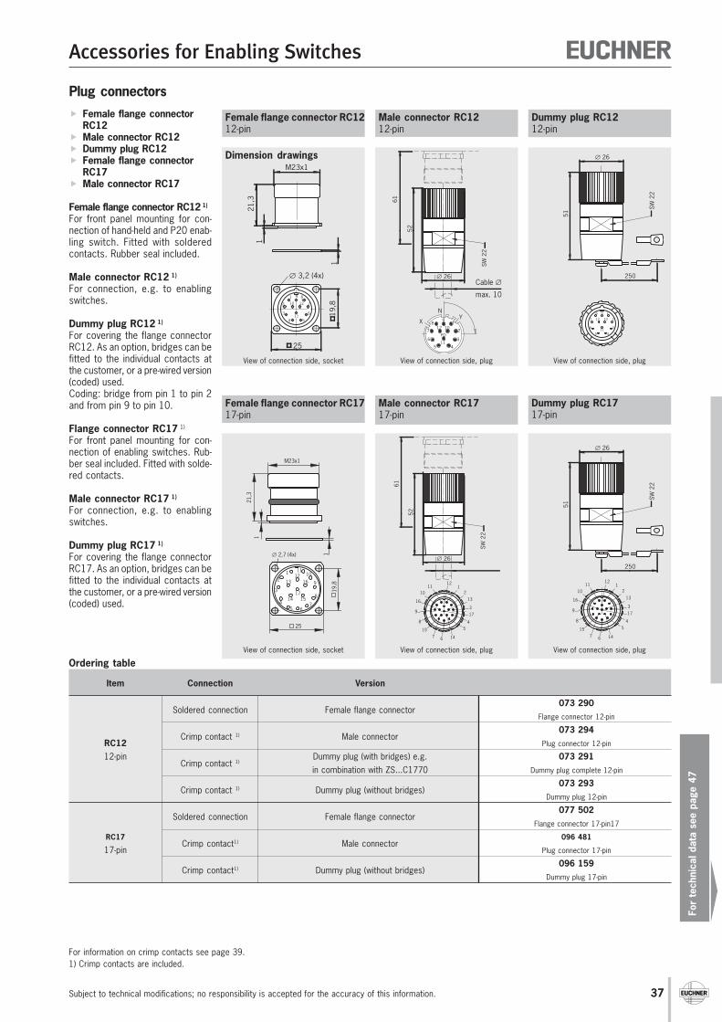
Accessories for Enabling Switches
For
tech
nica
l dat
a se
e pa
ge 4
7
Subject to technical modifications; no responsibility is accepted for the accuracy of this information. 37
Ordering table
Plug connectors Female flange connector
RC12 Male connector RC12 Dummy plug RC12 Female flange connector
RC17 Male connector RC17
Female flange connector RC12 1)
For front panel mounting for con-nection of hand-held and P20 enab-ling switch. Fitted with solderedcontacts. Rubber seal included.
Male connector RC12 1)
For connection, e.g. to enablingswitches.
Dummy plug RC12 1)
For covering the flange connectorRC12. As an option, bridges can befitted to the individual contacts atthe customer, or a pre-wired version(coded) used.Coding: bridge from pin 1 to pin 2and from pin 9 to pin 10.
Flange connector RC17 1)
For front panel mounting for con-nection of enabling switches. Rub-ber seal included. Fitted with solde-red contacts.
Male connector RC17 1)
For connection, e.g. to enablingswitches.
Dummy plug RC17 1)
For covering the flange connectorRC17. As an option, bridges can befitted to the individual contacts atthe customer, or a pre-wired version(coded) used.
Item Connection Version
Soldered connection Female flange connector073 290
Flange connector 12-pin
Crimp contact 1) Male connector073 294
RC12 Plug connector 12-pin
12-pinCrimp contact 1)
Dummy plug (with bridges) e.g. 073 291in combination with ZS...C1770 Dummy plug complete 12-pin
Crimp contact 1) Dummy plug (without bridges)073 293
Dummy plug 12-pin
Soldered connection Female flange connector077 502
Flange connector 17-pin17
RC17Crimp contact1) Male connector
096 481
17-pin Plug connector 17-pin
Crimp contact1) Dummy plug (without bridges)096 159
Dummy plug 17-pin
Male connector RC1212-pin
Female flange connector RC1212-pin
Dimension drawings
Male connector RC1717-pin
N
XY9
8
7
6
5 4
3
2
112 10
PO
11
52
61
∅ 26
SW
22
Cable ∅
max. 10
View of connection side, plug
25
21,3
1
M23x1
19,8
∅ 3,2 (4x)
1
1
2
3
4 5
6
7
89
10
11
12
View of connection side, socket
View of connection side, plug
Female flange connector RC1717-pin
View of connection side, socket
1 111012
2 13 16 9
815
1714
3
45 6
7
M23x1
21,3
1
1∅ 2,7 (4x)
25
19,8
Dummy plug RC1212-pin
198
7
6
5 4
3
21012
11
51
∅ 26
SW
22
250
View of connection side, plug
Dummy plug RC1717-pin
52
61
∅ 26
SW
22
11112
10
9
7 146
54
3
8
16
17
13
2
15
51
∅ 26
SW
22
250
11112
10
9
7 146
54
3
8
16
17
13
2
15
View of connection side, plug
For information on crimp contacts see page 39.1) Crimp contacts are included.
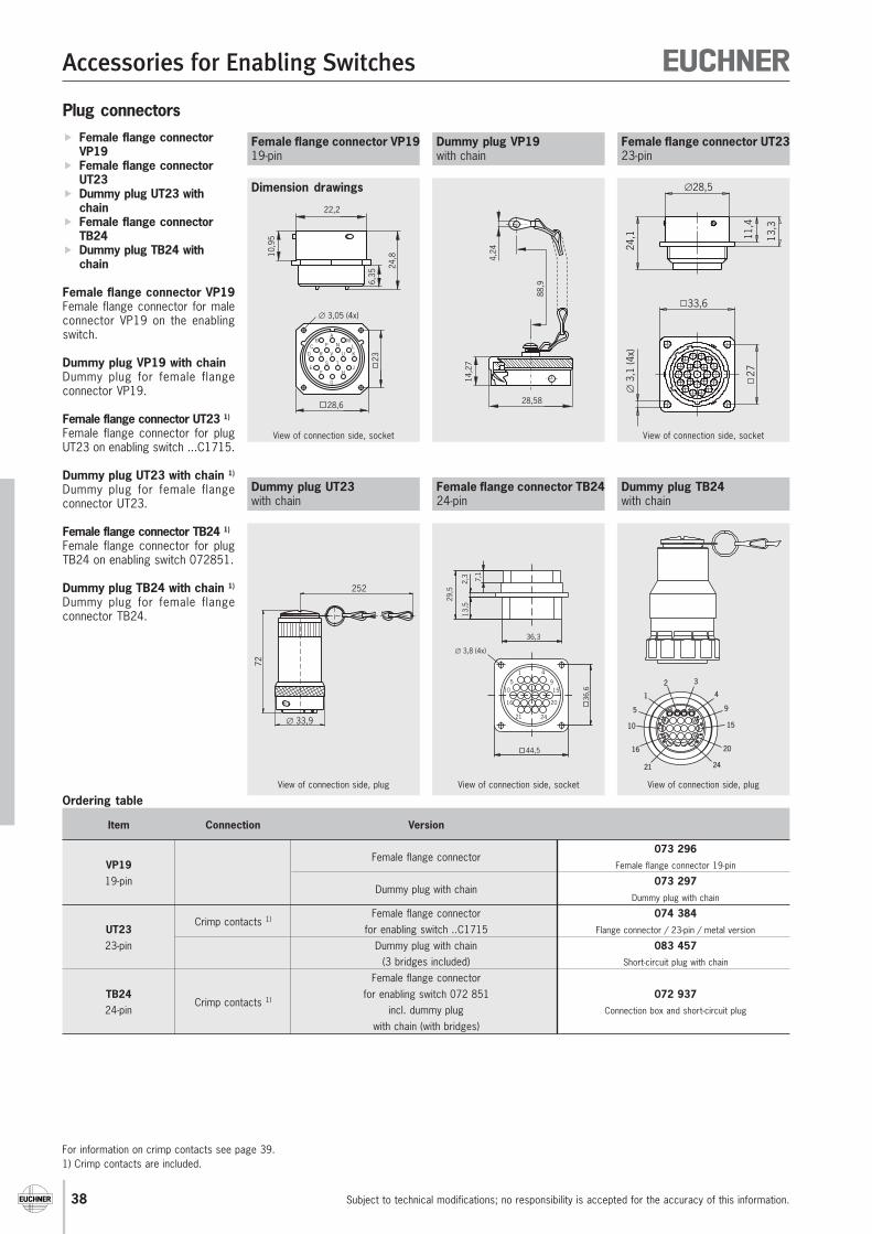
Accessories for Enabling Switches
Subject to technical modifications; no responsibility is accepted for the accuracy of this information.38
Ordering table
Plug connectors Female flange connector
VP19 Female flange connector
UT23 Dummy plug UT23 with
chain Female flange connector
TB24 Dummy plug TB24 with
chain
Female flange connector VP19Female flange connector for maleconnector VP19 on the enablingswitch.
Dummy plug VP19 with chainDummy plug for female flangeconnector VP19.
Female flange connector UT23 1)
Female flange connector for plugUT23 on enabling switch ...C1715.
Dummy plug UT23 with chain 1)
Dummy plug for female flangeconnector UT23.
Female flange connector TB24 1)
Female flange connector for plugTB24 on enabling switch 072851.
Dummy plug TB24 with chain 1)
Dummy plug for female flangeconnector TB24.
Item Connection Version
Female flange connector073 296
VP19 Female flange connector 19-pin
19-pinDummy plug with chain
073 297Dummy plug with chain
Crimp contacts 1)Female flange connector 074 384
UT23 for enabling switch ..C1715 Flange connector / 23-pin / metal version
23-pin Dummy plug with chain 083 457(3 bridges included) Short-circuit plug with chain
Female flange connectorTB24
Crimp contacts 1)for enabling switch 072 851 072 937
24-pin incl. dummy plug Connection box and short-circuit plug
with chain (with bridges)
Dummy plug UT23with chain
Female flange connector VP1919-pin
Dimension drawings
Female flange connector TB2424-pin
Dummy plug VP19with chain
View of connection side, socket
View of connection side, socket
Dummy plug TB24with chain
View of connection side, plug
Female flange connector UT2323-pin
View of connection side, plug
1
2 3
4
5 9
1510
2016
21 24
2,3 7,1
29,5
13,5
36,3
44,5
36,6
1 4
5 910 15
16 20
21 24
∅ 3,8 (4x)
72
∅ 33,9
252
∅28,5
24,1 11
,4
13,3
33,6
27
∅3,
1 (4
x)
View of connection side, socket
24,8
6,35
22,2
10,9
5
28,6
23
∅ 3,05 (4x)
BA
MC P N L
D R V U K
JTS
EF
G
H
14,2
7
28,58
88,9
4,24
For information on crimp contacts see page 39.1) Crimp contacts are included.
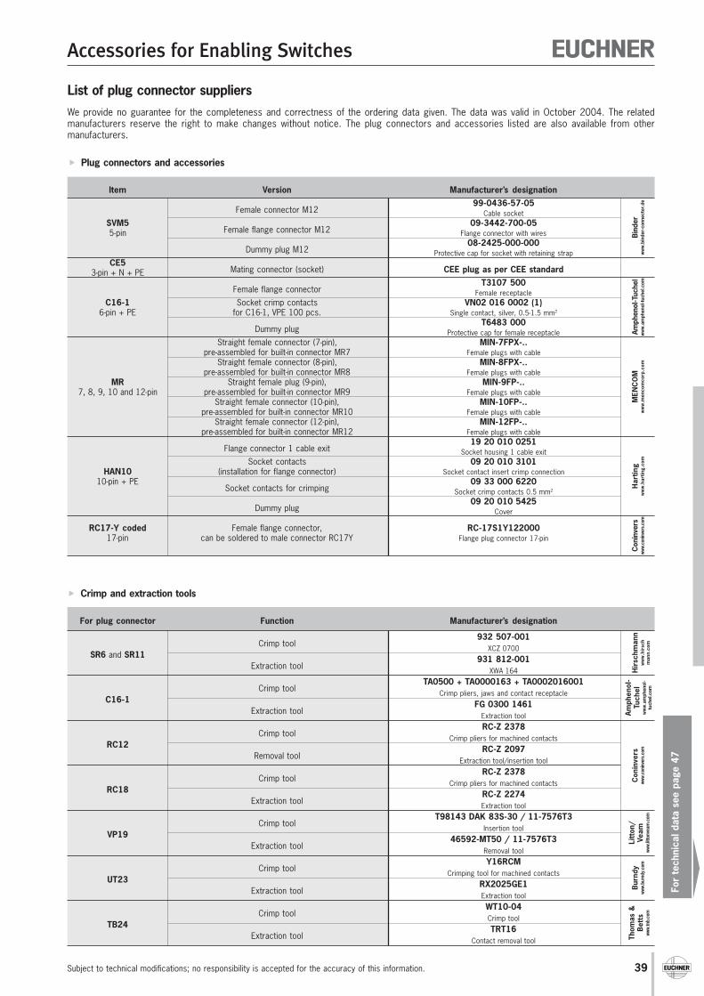
Accessories for Enabling Switches
For
tech
nica
l dat
a se
e pa
ge 4
7
Subject to technical modifications; no responsibility is accepted for the accuracy of this information. 39
For plug connector Function Manufacturer’s designation
Crimp tool932 507-001
SR6 and SR11XCZ 0700
Extraction tool931 812-001
XWA 164
Crimp toolTA0500 + TA0000163 + TA0002016001
C16-1Crimp pliers, jaws and contact receptacle
Extraction toolFG 0300 1461
Extraction tool
Crimp toolRC-Z 2378
RC12Crimp pliers for machined contacts
Removal toolRC-Z 2097
Extraction tool/insertion tool
Crimp toolRC-Z 2378
RC18Crimp pliers for machined contacts
Extraction toolRC-Z 2274Extraction tool
Crimp toolT98143 DAK 83S-30 / 11-7576T3
VP19Insertion tool
Extraction tool46592-MT50 / 11-7576T3
Removal tool
Crimp toolY16RCM
UT23Crimping tool for machined contacts
Extraction toolRX2025GE1Extraction tool
Crimp toolWT10-04
TB24Crimp tool
Extraction toolTRT16
Contact removal tool
Hir
schm
ann
ww
w.h
irsc
hm
ann.
com
Am
phen
ol-
Tuch
elw
ww
.am
phen
ol-
tuch
el.c
om
Con
inve
rsww
w.co
ninv
ers.
com
Litt
on/
Veam
www.
litto
nvea
m.c
om
Bur
ndy
www.
burn
dy.c
om
Plug connectors and accessories
Item Version Manufacturer’s designation
Female connector M1299-0436-57-05
Cable socketSVM5
Female flange connector M1209-3442-700-05
5-pin Flange connector with wires
Dummy plug M1208-2425-000-000
Protective cap for socket with retaining strapCE5
Mating connector (socket) CEE plug as per CEE standard3-pin + N + PE
Female flange connectorT3107 500
Female receptacleC16-1 Socket crimp contacts VN02 016 0002 (1)
6-pin + PE for C16-1, VPE 100 pcs. Single contact, silver, 0.5-1.5 mm2
Dummy plugT6483 000
Protective cap for female receptacleStraight female connector (7-pin), MIN-7FPX-..
pre-assembled for built-in connector MR7 Female plugs with cableStraight female connector (8-pin), MIN-8FPX-..
pre-assembled for built-in connector MR8 Female plugs with cableMR Straight female plug (9-pin), MIN-9FP-..
7, 8, 9, 10 and 12-pin pre-assembled for built-in connector MR9 Female plugs with cableStraight female connector (10-pin), MIN-10FP-..
pre-assembled for built-in connector MR10 Female plugs with cableStraight female connector (12-pin), MIN-12FP-..
pre-assembled for built-in connector MR12 Female plugs with cable
Flange connector 1 cable exit19 20 010 0251
Socket housing 1 cable exitSocket contacts 09 20 010 3101
HAN10 (installation for flange connector) Socket contact insert crimp connection10-pin + PE
Socket contacts for crimping09 33 000 6220
Socket crimp contacts 0.5 mm2
Dummy plug09 20 010 5425
Cover
RC17-Y coded Female flange connector, RC-17S1Y12200017-pin can be soldered to male connector RC17Y Flange plug connector 17-pin
Bind
erw
ww
.bin
der-
conn
ecto
r.de
Amph
enol
-Tuc
hel
ww
w.a
mph
enol
-tuc
hel.c
omM
ENC
OM
ww
w.m
enco
mco
rp.c
omH
artin
gw
ww
.har
ting.
com
Con
inve
rsww
w.co
ninv
ers.
com
List of plug connector suppliersWe provide no guarantee for the completeness and correctness of the ordering data given. The data was valid in October 2004. The relatedmanufacturers reserve the right to make changes without notice. The plug connectors and accessories listed are also available from othermanufacturers.
Crimp and extraction tools
Thom
as &
Bet
tsww
w.tn
b.co
m
Accessories for Enabling Switches
40
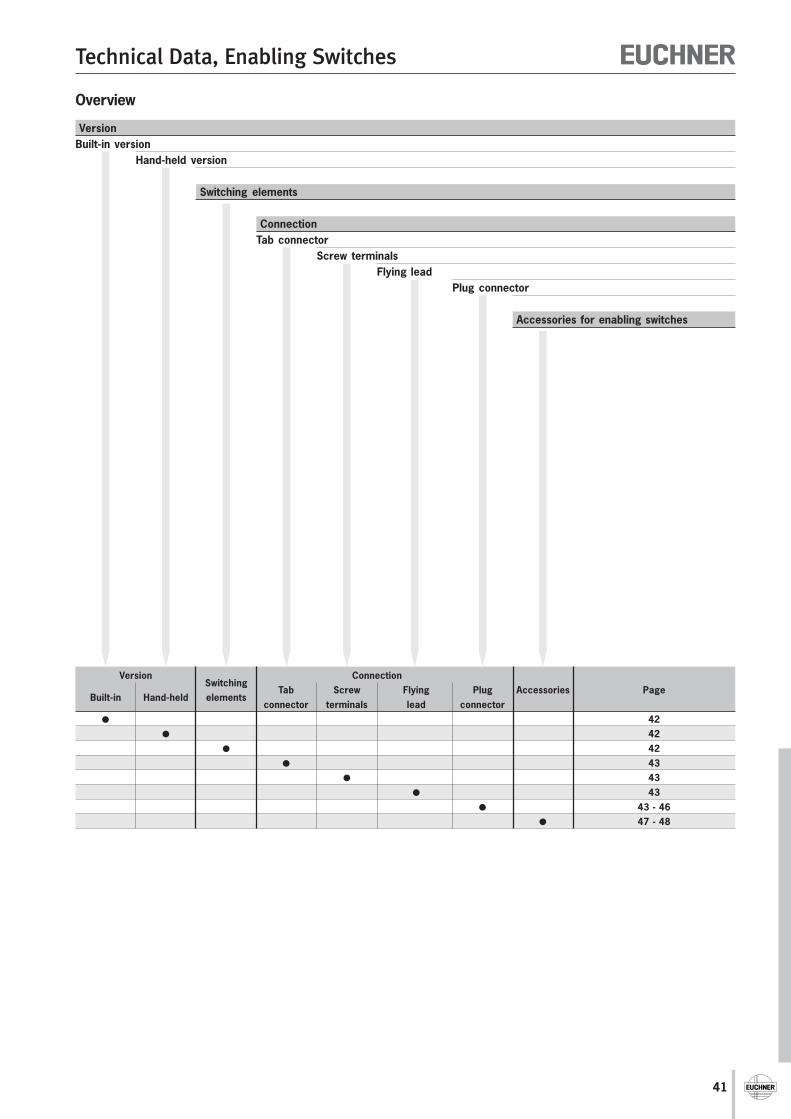
41
Technical Data, Enabling Switches
VersionSwitching
Connection
Built-in Hand-held elementsTab Screw Flying Plug Accessories Page
connector terminals lead connector 42
42 42
43 43
43 43 - 46
47 - 48
Overview
VersionBuilt-in version
Hand-held version
Switching elements
ConnectionTab connector
Screw terminalsFlying lead
Plug connector
Accessories for enabling switches
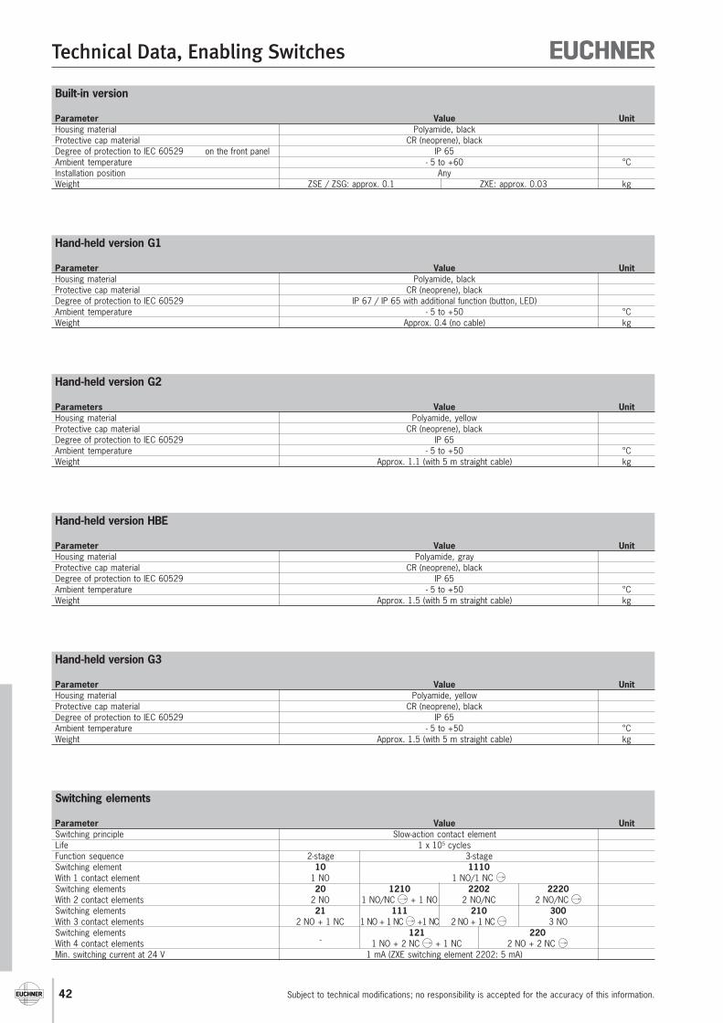
42
Technical Data, Enabling Switches
Subject to technical modifications; no responsibility is accepted for the accuracy of this information.
Hand-held version G2
Parameters Value UnitHousing material Polyamide, yellowProtective cap material CR (neoprene), blackDegree of protection to IEC 60529 IP 65Ambient temperature - 5 to +50 °CWeight Approx. 1.1 (with 5 m straight cable) kg
Hand-held version HBE
Parameter Value UnitHousing material Polyamide, grayProtective cap material CR (neoprene), blackDegree of protection to IEC 60529 IP 65Ambient temperature - 5 to +50 °CWeight Approx. 1.5 (with 5 m straight cable) kg
Hand-held version G3
Parameter Value UnitHousing material Polyamide, yellowProtective cap material CR (neoprene), blackDegree of protection to IEC 60529 IP 65Ambient temperature - 5 to +50 °CWeight Approx. 1.5 (with 5 m straight cable) kg
Switching elements
Parameter Value UnitSwitching principle Slow-action contact elementLife 1 x 10⁵ cyclesFunction sequence 2-stage 3-stageSwitching element 10 1110With 1 contact element 1 NO 1 NO/1 NC Switching elements 20 1210 2202 2220With 2 contact elements 2 NO 1 NO/NC + 1 NO 2 NO/NC 2 NO/NC Switching elements 21 111 210 300With 3 contact elements 2 NO + 1 NC 1 NO + 1 NC +1 NC 2 NO + 1 NC 3 NOSwitching elements
-121 220
With 4 contact elements 1 NO + 2 NC + 1 NC 2 NO + 2 NC Min. switching current at 24 V 1 mA (ZXE switching element 2202: 5 mA)
Hand-held version G1
Parameter Value UnitHousing material Polyamide, blackProtective cap material CR (neoprene), blackDegree of protection to IEC 60529 IP 67 / IP 65 with additional function (button, LED)Ambient temperature - 5 to +50 °CWeight Approx. 0.4 (no cable) kg
Built-in version
Parameter Value UnitHousing material Polyamide, blackProtective cap material CR (neoprene), blackDegree of protection to IEC 60529 on the front panel IP 65Ambient temperature - 5 to +60 °CInstallation position AnyWeight ZSE / ZSG: approx. 0.1 ZXE: approx. 0.03 kg
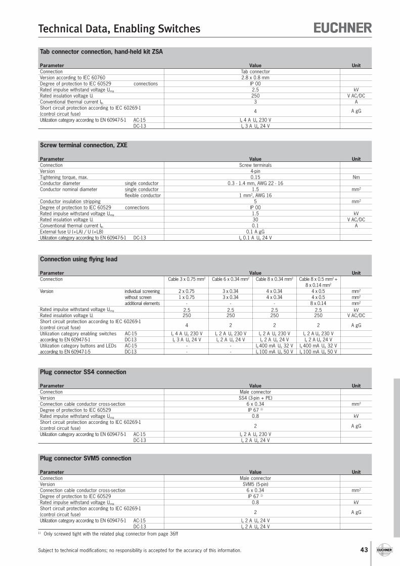
43
Technical Data, Enabling Switches
Subject to technical modifications; no responsibility is accepted for the accuracy of this information.
Screw terminal connection, ZXE
Parameter Value UnitConnection Screw terminalsVersion 4-pinTightening torque, max. 0.15 NmConductor diameter single conductor 0.3 - 1.4 mm, AWG 22 - 16Conductor nominal diameter single conductor 1.5 mm2
flexible conductor 1 mm2, AWG 16Conductor insulation stripping 5 mm2
Degree of protection to IEC 60529 connections IP 00Rated impulse withstand voltage Uimp 1.5 kVRated insulation voltage Ui 30 V AC/DCConventional thermal current Ith 0.1 AExternal fuse U (+LA) / U (+LB) 0.1 A gGUtilization category according to EN 60947-5-1 DC-13 le 0.1 A Ue 24 V
1) Only screwed tight with the related plug connector from page 36ff
Tab connector connection, hand-held kit ZSA
Parameter Value UnitConnection Tab connectorVersion according to IEC 60760 2.8 x 0.8 mmDegree of protection to IEC 60529 connections IP 00Rated impulse withstand voltage Uimp 2.5 kVRated insulation voltage Ui 250 V AC/DCConventional thermal current Ith 3 AShort circuit protection according to IEC 60269-1
A gG(control circuit fuse) 4
Utilization category according to EN 60947-5-1 AC-15 le 4 A Ue 230 VDC-13 le 3 A Ue 24 V
Connection using flying lead
Parameter Value UnitConnection Cable 3 x 0.75 mm2 Cable 6 x 0.34 mm2 Cable 8 x 0.34 mm2 Cable 8 x 0.5 mm2 +
8 x 0.14 mm2
Version individual screening 2 x 0.75 3 x 0.34 4 x 0.34 4 x 0.5 mm2
without screen 1 x 0.75 3 x 0.34 4 x 0.34 4 x 0.5 mm2
additional elements - - - 8 x 0.14 mm2
Rated impulse withstand voltage Uimp 2.5 2.5 2.5 2.5 kVRated insulation voltage Ui 250 250 250 250 V AC/DCShort circuit protection according to IEC 60269-1
4 2 2 2 A gG(control circuit fuse)Utilization category enabling switches AC-15 le 4 A Ue 230 V le 2 A Ue 230 V le 2 A Ue 230 V le 2 A Ue 230 Vaccording to EN 60947-5-1 DC-13 le 3 A Ue 24 V le 2 A Ue 24 V le 2 A Ue 24 V le 2 A Ue 24 VUtilization category buttons and LEDs AC-15 - - le 400 mA Ue 32 V le 400 mA Ue 32 Vaccording to EN 60947-1-5 DC-13 - - le 100 mA Ue 50 V le 100 mA Ue 50 V
Plug connector SVM5 connection
Parameter Value UnitConnection Male connectorVersion SVM5 (5-pin)Connection cable conductor cross-section 6 x 0.34 mm2
Degree of protection to IEC 60529 IP 67 1)
Rated impulse withstand voltage Uimp 0.8 kVShort circuit protection according to IEC 60269-1
2 A gG(control circuit fuse)Utilization category according to EN 60947-5-1 AC-15 le 2 A Ue 24 V
DC-13 le 2 A Ue 24 V
Plug connector SS4 connection
Parameter Value UnitConnection Male connectorVersion SS4 (3-pin + PE)Connection cable conductor cross-section 6 x 0.34 mm2
Degree of protection to IEC 60529 IP 67 1)
Rated impulse withstand voltage Uimp 0.8 kVShort circuit protection according to IEC 60269-1
2 A gG(control circuit fuse)Utilization category according to EN 60947-5-1 AC-15 le 2 A Ue 230 V
DC-13 le 2 A Ue 24 V
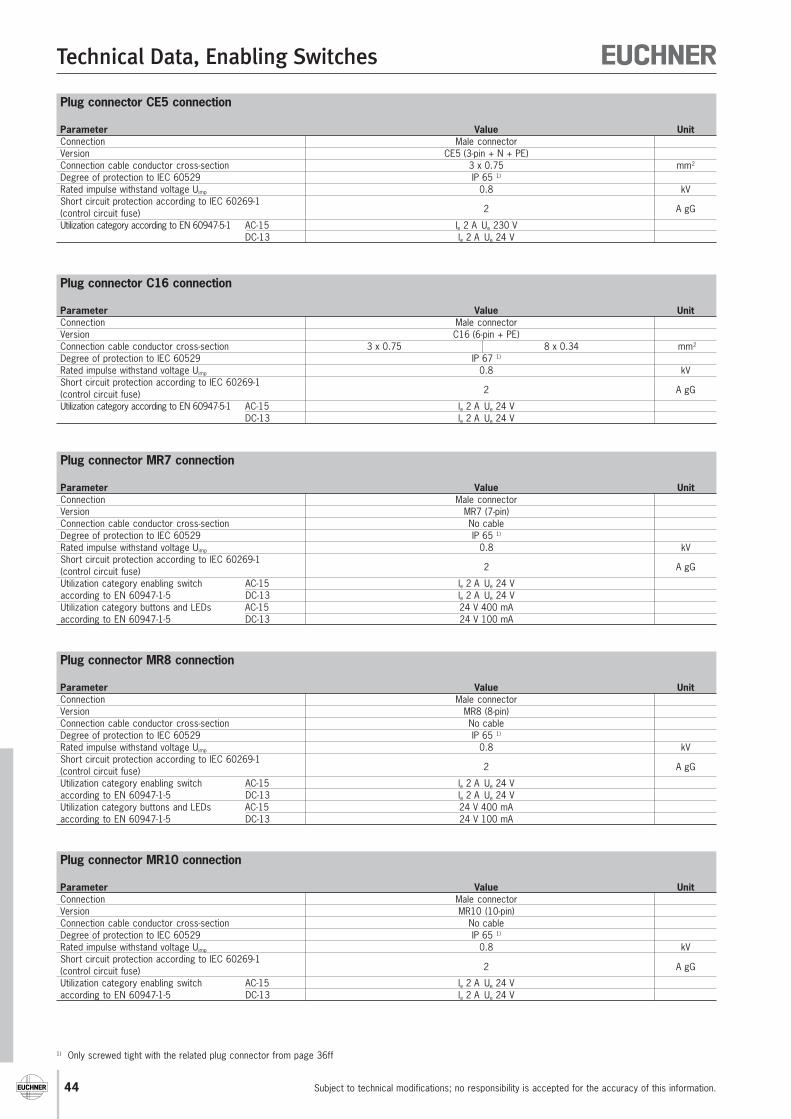
44
Technical Data, Enabling Switches
Subject to technical modifications; no responsibility is accepted for the accuracy of this information.
1) Only screwed tight with the related plug connector from page 36ff
Plug connector CE5 connection
Parameter Value UnitConnection Male connectorVersion CE5 (3-pin + N + PE)Connection cable conductor cross-section 3 x 0.75 mm2
Degree of protection to IEC 60529 IP 65 1)
Rated impulse withstand voltage Uimp 0.8 kVShort circuit protection according to IEC 60269-1
2 A gG(control circuit fuse)Utilization category according to EN 60947-5-1 AC-15 le 2 A Ue 230 V
DC-13 le 2 A Ue 24 V
Plug connector C16 connection
Parameter Value UnitConnection Male connectorVersion C16 (6-pin + PE)Connection cable conductor cross-section 3 x 0.75 8 x 0.34 mm2
Degree of protection to IEC 60529 IP 67 1)
Rated impulse withstand voltage Uimp 0.8 kVShort circuit protection according to IEC 60269-1
2 A gG(control circuit fuse)Utilization category according to EN 60947-5-1 AC-15 le 2 A Ue 24 V
DC-13 le 2 A Ue 24 V
Plug connector MR7 connection
Parameter Value UnitConnection Male connectorVersion MR7 (7-pin)Connection cable conductor cross-section No cableDegree of protection to IEC 60529 IP 65 1)
Rated impulse withstand voltage Uimp 0.8 kVShort circuit protection according to IEC 60269-1
2 A gG(control circuit fuse)Utilization category enabling switch AC-15 le 2 A Ue 24 Vaccording to EN 60947-1-5 DC-13 le 2 A Ue 24 VUtilization category buttons and LEDs AC-15 24 V 400 mAaccording to EN 60947-1-5 DC-13 24 V 100 mA
Plug connector MR8 connection
Parameter Value UnitConnection Male connectorVersion MR8 (8-pin)Connection cable conductor cross-section No cableDegree of protection to IEC 60529 IP 65 1)
Rated impulse withstand voltage Uimp 0.8 kVShort circuit protection according to IEC 60269-1
2 A gG(control circuit fuse)Utilization category enabling switch AC-15 le 2 A Ue 24 Vaccording to EN 60947-1-5 DC-13 le 2 A Ue 24 VUtilization category buttons and LEDs AC-15 24 V 400 mAaccording to EN 60947-1-5 DC-13 24 V 100 mA
Plug connector MR10 connection
Parameter Value UnitConnection Male connectorVersion MR10 (10-pin)Connection cable conductor cross-section No cableDegree of protection to IEC 60529 IP 65 1)
Rated impulse withstand voltage Uimp 0.8 kVShort circuit protection according to IEC 60269-1
2 A gG(control circuit fuse)Utilization category enabling switch AC-15 le 2 A Ue 24 Vaccording to EN 60947-1-5 DC-13 le 2 A Ue 24 V
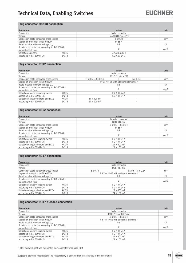
45
Technical Data, Enabling Switches
Subject to technical modifications; no responsibility is accepted for the accuracy of this information.
1) Only screwed tight with the related plug connector from page 36ff
Plug connector HAN10 connection
Parameter Value UnitConnection Male connectorVersion HAN10 (10-pin + PE)Connection cable conductor cross-section 8 x 0.34 mm2
Degree of protection to IEC 60529 IP 65 1)
Rated impulse withstand voltage Uimp 0.8 kVShort circuit protection according to IEC 60269-1
2 A gG(control circuit fuse)Utilization category AC-15 le 2 A Ue 230 Vaccording to EN 60947-1-5 DC-13 le 2 A Ue 24 V
Plug connector RC12 connection
Parameter Value UnitConnection Male connectorVersion RC12 (11-pin + PE)Connection cable conductor cross-section 8 x 0.5 + 8 x 0.14 6 x 0.34 mm2
Degree of protection to IEC 60529 IP 67 / IP 65 with additional elements 1)
Rated impulse withstand voltage Uimp 0.8 kVShort circuit protection according to IEC 60269-1
2 A gG(control circuit fuse)Utilization category enabling switch AC-15 le 2 A Ue 24 Vaccording to EN 60947-1-5 DC-13 le 2 A Ue 24 VUtilization category buttons and LEDs AC-15 24 V 400 mA -according to EN 60947-1-5 DC-13 24 V 100 mA -
Plug connector BS12 connection
Parameter Value UnitConnection Female connectorVersion BS12 (12-pin)Connection cable conductor cross-section 8 x 0.5 + 8 x 0.14 mm2
Degree of protection to IEC 60529 IP 65 1)
Rated impulse withstand voltage Uimp 0.8 kVShort circuit protection according to IEC 60269-1
2 A gG(control circuit fuse)Utilization category enabling switch AC-15 le 2 A Ue 24 Vaccording to EN 60947-1-5 DC-13 le 2 A Ue 24 VUtilization category buttons and LEDs AC-15 24 V 400 mAaccording to EN 60947-1-5 DC-13 24 V 100 mA
Plug connector RC17 connection
Parameter Value UnitConnection Male connectorVersion RC17 (17-pin)Connection cable conductor cross-section 8 x 0.34 8 x 0.5 + 8 x 0.14 mm2
Degree of protection to IEC 60529 IP 67 or IP 65 with additional elements 1)
Rated impulse withstand voltage Uimp 0.8 kVShort circuit protection according to IEC 60269-1
2 A gG(control circuit fuse)Utilization category enabling switch AC-15 le 2 A Ue 24 Vaccording to EN 60947-1-5 DC-13 le 2 A Ue 24 VUtilization category buttons and LEDs AC-15 24 V 400 mAaccording to EN 60947-1-5 DC-13 24 V 100 mA
Plug connector RC17 Y-coded connection
Parameter Value UnitConnection Male connectorVersion RC17 Y-coded (17-pin)Connection cable conductor cross-section 8 x 0.5 + 8 x 0.14 mm2
Degree of protection to IEC 60529 IP 67 or IP 65 with additional elements 1)
Rated impulse withstand voltage Uimp 0.8 kVShort circuit protection according to IEC 60269-1
2 A gG(control circuit fuse)Utilization category enabling switch AC-15 le 2 A Ue 24 Vaccording to EN 60947-1-5 DC-13 le 2 A Ue 24 VUtilization category buttons and LEDs AC-15 24 V 400 mAaccording to EN 60947-1-5 DC-13 24 V 100 mA
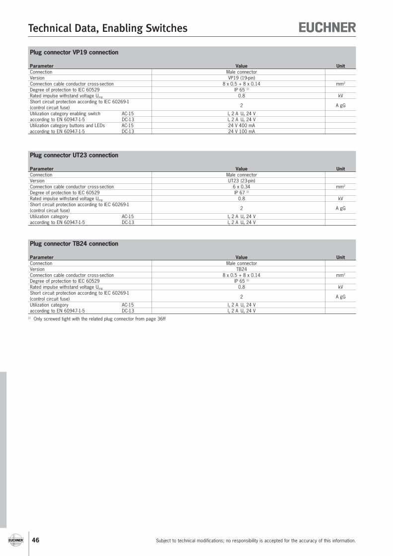
46
Technical Data, Enabling Switches
Subject to technical modifications; no responsibility is accepted for the accuracy of this information.
1) Only screwed tight with the related plug connector from page 36ff
Plug connector TB24 connection
Parameter Value UnitConnection Male connectorVersion TB24Connection cable conductor cross-section 8 x 0.5 + 8 x 0.14 mm2
Degree of protection to IEC 60529 IP 65 1)
Rated impulse withstand voltage Uimp 0.8 kVShort circuit protection according to IEC 60269-1
2 A gG(control circuit fuse)Utilization category AC-15 le 2 A Ue 24 Vaccording to EN 60947-1-5 DC-13 le 2 A Ue 24 V
Plug connector UT23 connection
Parameter Value UnitConnection Male connectorVersion UT23 (23-pin)Connection cable conductor cross-section 6 x 0.34 mm2
Degree of protection to IEC 60529 IP 67 1)
Rated impulse withstand voltage Uimp 0.8 kVShort circuit protection according to IEC 60269-1
2 A gG(control circuit fuse)Utilization category AC-15 le 2 A Ue 24 Vaccording to EN 60947-1-5 DC-13 le 2 A Ue 24 V
Plug connector VP19 connection
Parameter Value UnitConnection Male connectorVersion VP19 (19-pin)Connection cable conductor cross-section 8 x 0.5 + 8 x 0.14 mm2
Degree of protection to IEC 60529 IP 65 1)
Rated impulse withstand voltage Uimp 0.8 kVShort circuit protection according to IEC 60269-1
2 A gG(control circuit fuse)Utilization category enabling switch AC-15 le 2 A Ue 24 Vaccording to EN 60947-1-5 DC-13 le 2 A Ue 24 VUtilization category buttons and LEDs AC-15 24 V 400 mAaccording to EN 60947-1-5 DC-13 24 V 100 mA
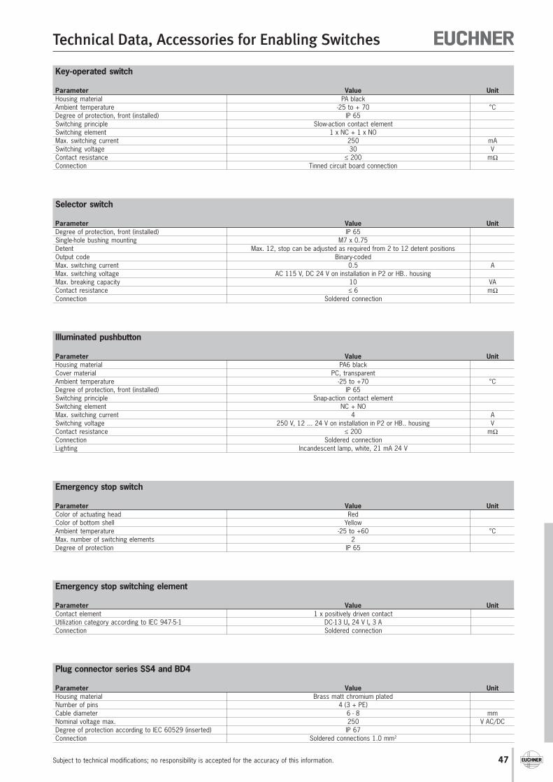
47
Technical Data, Accessories for Enabling Switches
Subject to technical modifications; no responsibility is accepted for the accuracy of this information.
Key-operated switch
Parameter Value UnitHousing material PA blackAmbient temperature -25 to + 70 °CDegree of protection, front (installed) IP 65Switching principle Slow-action contact elementSwitching element 1 x NC + 1 x NOMax. switching current 250 mASwitching voltage 30 VContact resistance ≤ 200 mΩConnection Tinned circuit board connection
Emergency stop switching element
Parameter Value UnitContact element 1 x positively driven contactUtilization category according to IEC 947-5-1 DC-13 Ue 24 V le 3 AConnection Soldered connection
Plug connector series SS4 and BD4
Parameter Value UnitHousing material Brass matt chromium platedNumber of pins 4 (3 + PE)Cable diameter 6 - 8 mmNominal voltage max. 250 V AC/DCDegree of protection according to IEC 60529 (inserted) IP 67Connection Soldered connections 1.0 mm2
Selector switch
Parameter Value UnitDegree of protection, front (installed) IP 65Single-hole bushing mounting M7 x 0.75Detent Max. 12, stop can be adjusted as required from 2 to 12 detent positionsOutput code Binary-codedMax. switching current 0.5 AMax. switching voltage AC 115 V, DC 24 V on installation in P2 or HB.. housingMax. breaking capacity 10 VAContact resistance ≤ 6 mΩConnection Soldered connection
Emergency stop switch
Parameter Value UnitColor of actuating head RedColor of bottom shell YellowAmbient temperature -25 to +60 °CMax. number of switching elements 2Degree of protection IP 65
Illuminated pushbutton
Parameter Value UnitHousing material PA6 blackCover material PC, transparentAmbient temperature -25 to +70 °CDegree of protection, front (installed) IP 65Switching principle Snap-action contact elementSwitching element NC + NOMax. switching current 4 ASwitching voltage 250 V, 12 ... 24 V on installation in P2 or HB.. housing VContact resistance ≤ 200 mΩConnection Soldered connectionLighting Incandescent lamp, white, 21 mA 24 V
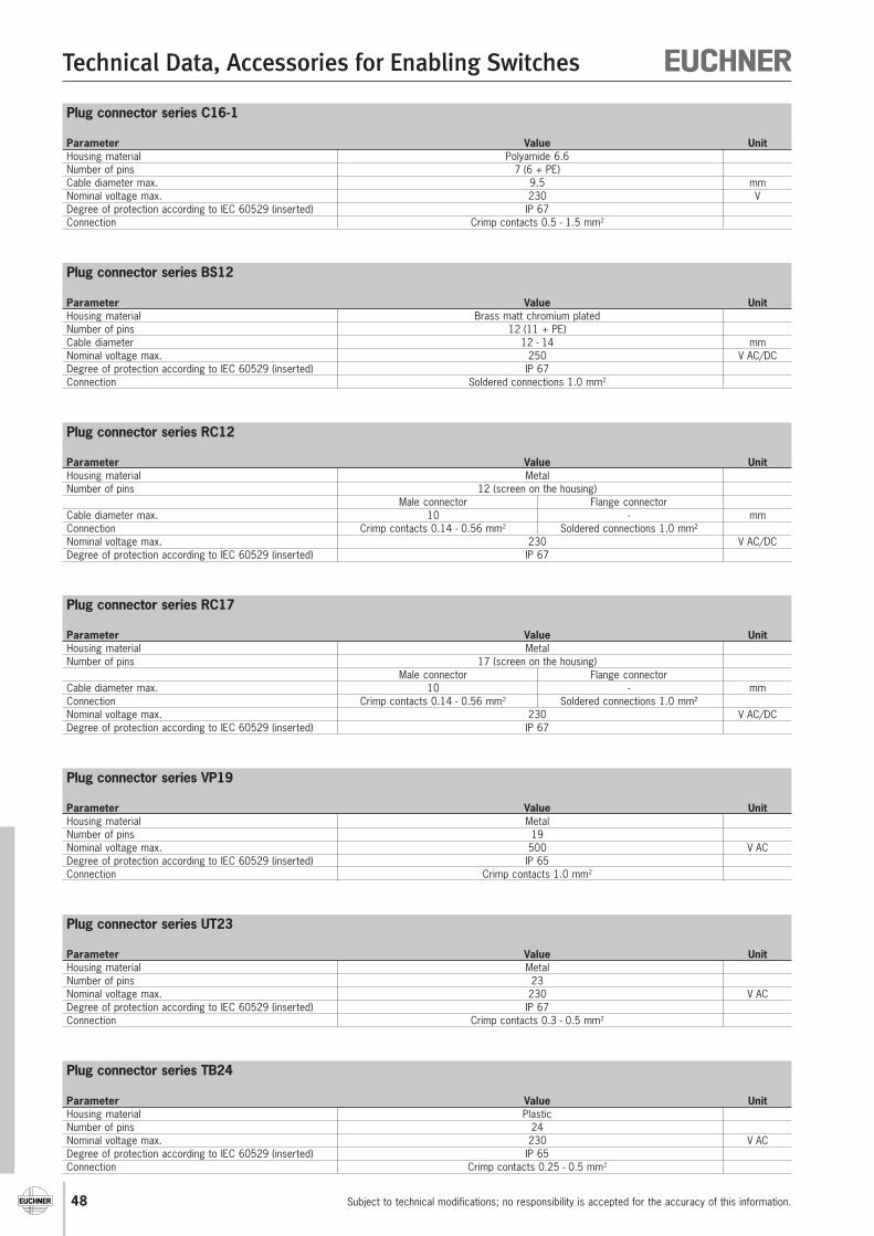
48
Technical Data, Accessories for Enabling Switches
Subject to technical modifications; no responsibility is accepted for the accuracy of this information.
Plug connector series C16-1
Parameter Value UnitHousing material Polyamide 6.6Number of pins 7 (6 + PE)Cable diameter max. 9.5 mmNominal voltage max. 230 VDegree of protection according to IEC 60529 (inserted) IP 67Connection Crimp contacts 0.5 - 1.5 mm2
Plug connector series BS12
Parameter Value UnitHousing material Brass matt chromium platedNumber of pins 12 (11 + PE)Cable diameter 12 - 14 mmNominal voltage max. 250 V AC/DCDegree of protection according to IEC 60529 (inserted) IP 67Connection Soldered connections 1.0 mm2
Plug connector series RC12
Parameter Value UnitHousing material MetalNumber of pins 12 (screen on the housing)
Male connector Flange connectorCable diameter max. 10 - mmConnection Crimp contacts 0.14 - 0.56 mm2 Soldered connections 1.0 mm²Nominal voltage max. 230 V AC/DCDegree of protection according to IEC 60529 (inserted) IP 67
Plug connector series VP19
Parameter Value UnitHousing material MetalNumber of pins 19Nominal voltage max. 500 V ACDegree of protection according to IEC 60529 (inserted) IP 65Connection Crimp contacts 1.0 mm2
Plug connector series UT23
Parameter Value UnitHousing material MetalNumber of pins 23Nominal voltage max. 230 V ACDegree of protection according to IEC 60529 (inserted) IP 67Connection Crimp contacts 0.3 - 0.5 mm2
Plug connector series TB24
Parameter Value UnitHousing material PlasticNumber of pins 24Nominal voltage max. 230 V ACDegree of protection according to IEC 60529 (inserted) IP 65Connection Crimp contacts 0.25 - 0.5 mm2
Plug connector series RC17
Parameter Value UnitHousing material MetalNumber of pins 17 (screen on the housing)
Male connector Flange connectorCable diameter max. 10 - mmConnection Crimp contacts 0.14 - 0.56 mm2 Soldered connections 1.0 mm²Nominal voltage max. 230 V AC/DCDegree of protection according to IEC 60529 (inserted) IP 67
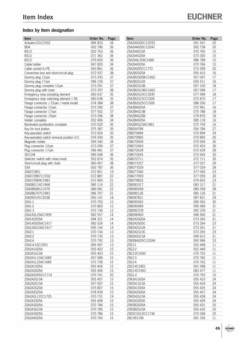
49
Item Index
Item Order No. Page Item Order No. PageZSA2A4G05C-C2032 091 547 20ZSA2A4G05C-C2041 092 738 20ZSA2A4G10A 070 765 15ZSA2A4G20A 073 300 15ZSA2A4L25AC1689 086 788 15ZSA2A4S05A 070 766 15ZSA2AG05CC1770 073 289 20ZSA2B2G05A 055 410 16ZSA2B2G05B-C1662 057 097 17ZSA2B2G10A 055 411 16ZSA2B2G10B 057 100 18ZSA2B2G10B-C1662 057 098 17ZSA2B2G10CC1830 077 489 18ZSA2B2G15CC1926 072 870 17ZSA2B2G25CC1926 086 206 17ZSA2B4G05A 072 961 16ZSA2B4G10B 070 788 18ZSA2B4G20B 079 870 18ZSA2B4S05A 085 118 16ZSA2B5G10AC1861 072 759 16ZSB054784 054 784 27ZSB070894 070 894 29ZSB070895 070 895 26ZSB070904 070 904 30ZSB072403 072 403 30ZSB072639 072 639 28ZSB072645 072 645 30ZSB072711 072 711 30ZSB077027 077 027 29ZSB077029 077 029 28ZSB077040 077 040 23ZSB077059 077 059 30ZSB079832 079 832 23ZSB083317 083 317 21ZSB085058 085 058 28ZSB085126 085 126 21ZSB087821 087 821 29ZSB090262 090 262 30ZSB090489 090 489 31ZSB092378 092 378 21ZSB096900 096 900 21ZSB2A2G05A 073 260 21ZSB2A2G05C 073 264 23ZSB2A2G10A 073 261 21ZSB2A2G10C 073 265 23ZSB2A2G15A 095 612 21ZSB2B4G05C-C2044 092 996 23ZSE2-1 052 448 11ZSE2-2 052 449 11ZSE2-2C1692 070 752 11ZSE2-3 070 782 11ZSE2-4 070 762 11ZSE2-4C1801 091 098 11ZSE2-4C1943 083 477 11ZSG1-2 070 793 10ZSR2A1G05A 055 423 24ZSR2A1G10A 055 424 24ZSR2A1S05A 055 425 24ZSR2A2G05A 055 427 24ZSR2A2G10A 055 428 24ZSR2A2S05A 055 429 24ZSR2B2G05A 055 431 25ZSR2B2G10A 055 432 25ZSR2C2G10CC1736 073 268 25ZXE-091336 091 336 11
Index by item designation
Actuator-Z-G-C1932 084 833 34BD4 002 786 36BS12 002 763 36BS12 071 362 36BS12 079 835 36Cable holder 047 820 34Cable socket 6+PE 043 861 36Connection box and short-circuit plug 072 937 38Dummy plug 12-pin 073 293 37Dummy plug 17-pin 096 159 37Dummy plug complete 12-pin 073 291 37Dummy plug with chain 073 297 38Emergency stop actuating element 083 637 35Emergency stop switching element 1 NC 083 638 35Flange connector / 23-pin / metal model 074 384 38Flange connector 12-pin 073 290 37Flange connector 17-pin 077 502 37Flange connector 19-pin 073 296 38Holder complete 052 406 34Illuminated pushbutton complete 070 520 35Key for lock button 075 387 35Key-operated switch 072 604 35Key-operated switch removal position 0/1 076 930 35Magnetic holder 059 340 34Plug connector 12-pin 073 294 37Plug connector 17-pin 096 481 37SD12-M 085 648 36Selector switch with rotary knob 052 874 35Short-circuit plug with chain 083 457 38SS4 002 787 36ZSA072851 072 851 19ZSA072887-C1932 072 887 22ZSA072969C1983 072 969 21ZSA085114C1968 085 114 22ZSA086681C1979 086 681 22ZSA086707C1983 086 707 21ZSA092141C2038 092 141 18ZSA1-1 070 750 12ZSA1-2 070 800 12ZSA1-3 070 736 12ZSA1A2L25AC1909 082 557 14ZSA1A2S05A 094 321 14ZSA1A5G05AC1917 082 524 14ZSA1A5G10AC1917 095 144 14ZSA2-1 070 734 13ZSA2-2 070 735 13ZSA2-4 070 792 13ZSA2-4-10C1903 095 497 13ZSA2A1G05A 055 402 15ZSA2A1G10A 055 403 15ZSA2A1L15AC1689 057 089 15ZSA2A1L25AC1689 072 728 15ZSA2A1S05A 055 404 15ZSA2A2G05A 055 406 15ZSA2A2G05CC1714 070 741 20ZSA2A2G10A 055 407 15ZSA2A2G15A 057 007 15ZSA2A2G20A 075 807 15ZSA2A2G25A 078 939 15ZSA2A2L12CC1725 070 731 19ZSA2A2S05A 055 408 15ZSA2A3G05A 070 784 15ZSA2A3G10A 070 785 15ZSA2A3S05A 070 786 15ZSA2A4G05A 070 764 15
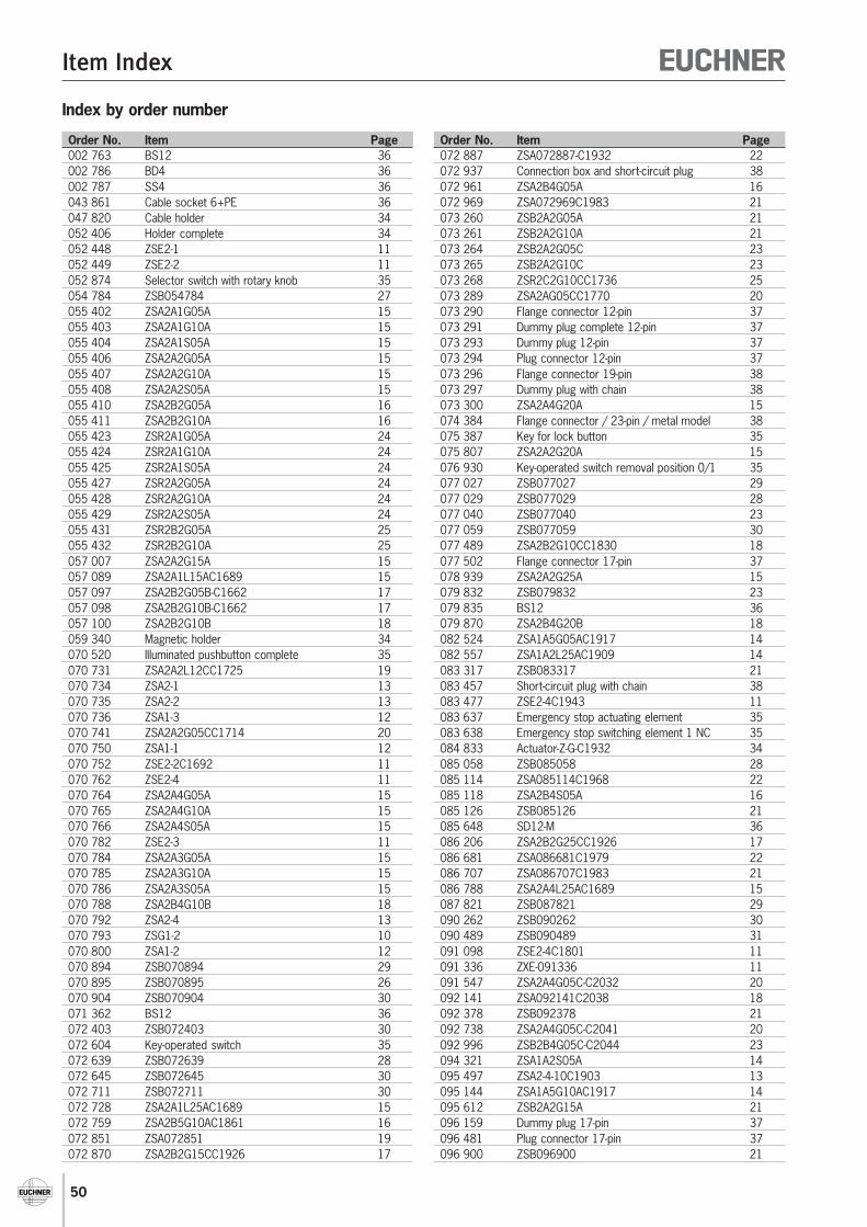
50
Item Index
Order No. Item Page Order No. Item Page002 763 BS12 36002 786 BD4 36002 787 SS4 36043 861 Cable socket 6+PE 36047 820 Cable holder 34052 406 Holder complete 34052 448 ZSE2-1 11052 449 ZSE2-2 11052 874 Selector switch with rotary knob 35054 784 ZSB054784 27055 402 ZSA2A1G05A 15055 403 ZSA2A1G10A 15055 404 ZSA2A1S05A 15055 406 ZSA2A2G05A 15055 407 ZSA2A2G10A 15055 408 ZSA2A2S05A 15055 410 ZSA2B2G05A 16055 411 ZSA2B2G10A 16055 423 ZSR2A1G05A 24055 424 ZSR2A1G10A 24055 425 ZSR2A1S05A 24055 427 ZSR2A2G05A 24055 428 ZSR2A2G10A 24055 429 ZSR2A2S05A 24055 431 ZSR2B2G05A 25055 432 ZSR2B2G10A 25057 007 ZSA2A2G15A 15057 089 ZSA2A1L15AC1689 15057 097 ZSA2B2G05B-C1662 17057 098 ZSA2B2G10B-C1662 17057 100 ZSA2B2G10B 18059 340 Magnetic holder 34070 520 Illuminated pushbutton complete 35070 731 ZSA2A2L12CC1725 19070 734 ZSA2-1 13070 735 ZSA2-2 13070 736 ZSA1-3 12070 741 ZSA2A2G05CC1714 20070 750 ZSA1-1 12070 752 ZSE2-2C1692 11070 762 ZSE2-4 11070 764 ZSA2A4G05A 15070 765 ZSA2A4G10A 15070 766 ZSA2A4S05A 15070 782 ZSE2-3 11070 784 ZSA2A3G05A 15070 785 ZSA2A3G10A 15070 786 ZSA2A3S05A 15070 788 ZSA2B4G10B 18070 792 ZSA2-4 13070 793 ZSG1-2 10070 800 ZSA1-2 12070 894 ZSB070894 29070 895 ZSB070895 26070 904 ZSB070904 30071 362 BS12 36072 403 ZSB072403 30072 604 Key-operated switch 35072 639 ZSB072639 28072 645 ZSB072645 30072 711 ZSB072711 30072 728 ZSA2A1L25AC1689 15072 759 ZSA2B5G10AC1861 16072 851 ZSA072851 19072 870 ZSA2B2G15CC1926 17
Index by order number
072 887 ZSA072887-C1932 22072 937 Connection box and short-circuit plug 38072 961 ZSA2B4G05A 16072 969 ZSA072969C1983 21073 260 ZSB2A2G05A 21073 261 ZSB2A2G10A 21073 264 ZSB2A2G05C 23073 265 ZSB2A2G10C 23073 268 ZSR2C2G10CC1736 25073 289 ZSA2AG05CC1770 20073 290 Flange connector 12-pin 37073 291 Dummy plug complete 12-pin 37073 293 Dummy plug 12-pin 37073 294 Plug connector 12-pin 37073 296 Flange connector 19-pin 38073 297 Dummy plug with chain 38073 300 ZSA2A4G20A 15074 384 Flange connector / 23-pin / metal model 38075 387 Key for lock button 35075 807 ZSA2A2G20A 15076 930 Key-operated switch removal position 0/1 35077 027 ZSB077027 29077 029 ZSB077029 28077 040 ZSB077040 23077 059 ZSB077059 30077 489 ZSA2B2G10CC1830 18077 502 Flange connector 17-pin 37078 939 ZSA2A2G25A 15079 832 ZSB079832 23079 835 BS12 36079 870 ZSA2B4G20B 18082 524 ZSA1A5G05AC1917 14082 557 ZSA1A2L25AC1909 14083 317 ZSB083317 21083 457 Short-circuit plug with chain 38083 477 ZSE2-4C1943 11083 637 Emergency stop actuating element 35083 638 Emergency stop switching element 1 NC 35084 833 Actuator-Z-G-C1932 34085 058 ZSB085058 28085 114 ZSA085114C1968 22085 118 ZSA2B4S05A 16085 126 ZSB085126 21085 648 SD12-M 36086 206 ZSA2B2G25CC1926 17086 681 ZSA086681C1979 22086 707 ZSA086707C1983 21086 788 ZSA2A4L25AC1689 15087 821 ZSB087821 29090 262 ZSB090262 30090 489 ZSB090489 31091 098 ZSE2-4C1801 11091 336 ZXE-091336 11091 547 ZSA2A4G05C-C2032 20092 141 ZSA092141C2038 18092 378 ZSB092378 21092 738 ZSA2A4G05C-C2041 20092 996 ZSB2B4G05C-C2044 23094 321 ZSA1A2S05A 14095 497 ZSA2-4-10C1903 13095 144 ZSA1A5G10AC1917 14095 612 ZSB2A2G15A 21096 159 Dummy plug 17-pin 37096 481 Plug connector 17-pin 37096 900 ZSB096900 21
51
For your notes
52
For your notes
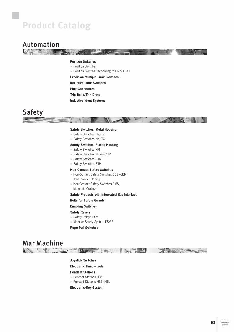
53
Product Catalog
Safety Switches, Metal HousingSafety Switches NZ/TZSafety Switches NX/TX
Safety Switches, Plastic HousingSafety Switches NMSafety Switches NP/GP/TPSafety Switches STMSafety Switches STP
Non-Contact Safety SwitchesNon-Contact Safety Switches CES/CEM,Transponder CodingNon-Contact Safety Switches CMS, Magnetic Coding
Safety Products with integrated Bus Interface
Bolts for Safety Guards
Enabling Switches
Safety RelaysSafety Relays ESMModular Safety System ESM-F
Rope Pull Switches
Joystick Switches
Electronic Handwheels
Pendant StationsPendant Stations HBAPendant Stations HBE/HBL
Electronic-Key-System
Position SwitchesPosition SwitchesPosition Switches according to EN 50 041
Precision Multiple Limit Switches
Inductive Limit Switches
Plug Connectors
Trip Rails/Trip Dogs
Inductive Ident Systems
Automation
Safety
ManMachine
54
ItalyTRITECNICA S.r.l.Viale Lazio 2620135 MilanoTel. +39-02-5419-41Fax [email protected]
JapanSolton Co. Ltd.2-13-7, Shin-YokohamaKohoku-ku, YokohamaJapan 222-0033Tel. +81-(0)45-471-7711Fax +81-(0)[email protected]
KoreaEUCHNER Korea Co., Ltd.RM 810 Daerung Technotown 3rd#448 Gasang-DongKumchon-Gu, SeoulTel. +82-(02)-2107-3500Fax +82-(02)[email protected]
MexicoSEPIA S.A. de C.V.Maricopa # 10302, Col. Napoles.Del. Benito Juarez03810 Mexico D.F.Tel. +52-55-5536-7787Fax [email protected]
New ZealandW Arthur Fisher Limited11 Te Apunga PlaceMt WellingtonAucklandTel. +64-(0)9270-0100Fax +64-(0)[email protected]
NorwayELIS ELEKTRO ASJerikoveien 161067 OsloTel. +47-22-9056-70Fax [email protected]
PolandELTRONPl. Wolnosci 7B50-071 WroclawTel. +48-(0)71-3439-755Fax +48-(0)[email protected]
PortugalPAM Serviços Tecnicos Industriais Lda.Rua de Timor - Pavilhão 2AZona Industrial da Abelheira4785-123 TROFATel. +351-252-418431Fax [email protected]
SingaporeSentronics Automation & Marketing Pte Ltd.Blk 3, Ang Mo Kio Industrial Park 2A#05-06Singapore 568050Tel. +65-6744-8018Fax [email protected]
RRRRRepreprepreprepreeeeesentsentsentsentsentation intation intation intation intation internernernernernationationationationationalalalalal
AustraliaMicromax Pty. Ltd.PO Box 1238Wollongong NSW 2500Tel. +61-(0)2-4271-1300Fax +61-(0)[email protected]
AustriaEUCHNER Ges.mbHSüddruckgasse 42512 TribuswinkelTel. +43-(0)2252-421-91Fax +43-(0)[email protected]
BeneluxEUCHNER (BENELUX) BVPostbus 1193350 AC PapendrechtTel. +31-(0)78-6154-766Fax +31-(0)[email protected]
BrazilEUCHNER LtdaAv. Prof. Luiz Ignácio Anhaia Mello,no. 4387S. LucasSão Paulo - SP - BrasilCEP 03295-000Tel. +55-11-6918-2200Fax [email protected]
CanadaIAC & Associates Inc.1925 Provincial RoadWindsor, OntarioN8W 5V7Tel. +01-519-966-3444Fax [email protected]
ChinaEUCHNER Electric (Shanghai) Ltd.No. 8 High Technology ZoneNo. 503 Meinengda RoadSongjiang, Shanghai, 201613Tel. +86-(0)21-5774-7090Fax +86-(0)[email protected]
KNOWHOW I&C Co.C-2204 Webok Time CenterNo. 17 Zhongguancun NandajieBeijing, 100081Tel. +86-(0)10-8857-8899Fax +86-(0)[email protected]
Czech RepublicAMTEK s.r.o.Videnská 125619 00 BrnoTel. +420-547-125-570Fax [email protected]
DenmarkRobotek El & Teknik A/SBlokken 313460 BirkerødTel. +45-4484-7360Fax [email protected]
Eastern EuropeHera Elektrotechnische ProdukteHandels Ges.mbHHauptstraße 612391 KaltenleutgebenTel. +43-(0)2238-77518Fax +43-(0)[email protected]
FinlandSähkölehto OyHolkkitie 1400880 HelsinkiTel. +358-(0)9-774-6420Fax +358-(0)[email protected]
FranceEUCHNER France S.A.R.L.Parc d'Affaires des BellevuesAllée Rosa LuxembourgBâtiment le Colorado95610 ERAGNY sur OISETel. +33-(0)1-3909-9090Fax +33-(0)[email protected]
Hong KongImperial Engineers & Equipment Co. Ltd.Unit B 12/F Cheung Lee Industrial Building9 Cheung Lee Street Chai WanHong KongTel. +852-2889-0292Fax [email protected]
HungaryEUCHNER Ges.mbHMagyarországi Fióktelep2045 TörökbálintTópark utca 1/a.Tel. +36-2342-8374Fax [email protected]
IndiaTEKNIC CONTROLGEAR PVT. LTD.703, Madhava,Bandra Kurla ComplexBandra (East)Mumbai 400051Tel. +91-(0)22-2659-2392Fax +91-(0)[email protected]
IranINFOCELL IRAN CO.# 84, Manoucheri Ave.P.O. Box 81655-861IsfahanTel. +98-(0)311-2211-358Fax +98-(0)[email protected]
SloveniaSMM d.o.o.Jaskova 182000 MariborTel. +386-(0)2450-2326Fax +386-(0)[email protected]
SpainEUCHNER, S.L.U.Gurutzegi 12 - Local 1Polígono Belartza20018 San SebastianTel. +34-943-316-760Fax [email protected]
SwedenCensit ABBox 33133123 VärnamoTel. +46-(0)370-6910-10Fax +46-(0)[email protected]
SwitzerlandEUCHNER AGGrofstraße 178887 MelsTel. +41-(0)81-720-4590Fax +41-(0)[email protected]
TaiwanDaybreak Int'l (Taiwan) Corp.3F, No. 124, Chung-Cheng RoadShihlin 11145, TaipeiTel. +886-(0)2-8866-1234Fax +886-(0)[email protected]
ThailandAero Automation Co., Ltd.600/441 Moo 14 Phaholyothin Rd.Kukot, LamlukkaPatumthanee 12130Tel. +66-(0)2-536-7660-1Fax +66-(0)[email protected]
TurkeyARI Endustri Urunleri SAN. Ve Tic.Ltd.Sti.Perpa Ticaret MerkeziA Blok Kat 11 No:140634384 Okmeydani/Sisli IstanbulTel. +90-(0)212-3204-334Fax +90-(0)[email protected]
United KingdomEUCHNER (UK) Ltd.Unit 2 Petre Drive,SheffieldSouth YorkshireS4 7PZTel. +44-(0)114-256-0123Fax +44-(0)[email protected]
USAEUCHNER USA Inc.6723 Lyons StreetEast Syracuse, NY 10357Tel. +01-315-7010-315Fax [email protected]
´´
ˆ
55
wwwwwwwwwwwwwww.....euceuceuceuceuchnerhnerhnerhnerhner.....cccccomomomomom
HeHeHeHeHeaaaaad officd officd officd officd officeeeee
EUCHNER GmbH + Co. KGKohlhammerstraße 1670771 Leinfelden-EchterdingenGermanyTel. +49-(0)711-7597-0Fax +49-(0)[email protected]
More than safety. More than safety. Morthan safety. More than safety. More thansafety. More than safety. More than safeMore than safety. More than safety. Morthan safety. More than safety. More thansafety. More than safety. More than safeMore than safety. More than safety. Morthan safety. More than safety. More thansafety. More than safety. More than safeMore than safety. More than safety. Morthan safety. More than safety. More thansafety. More than safety. More than safeMore than safety. More than safety. Morthan safety. More than safety. More thansafety. More than safety. More than safeMore than safety. More than safety. Morthan safety. More than safety. More thansafety. More than safety. More than safeMore than safety. More than safety. Morthan safety. More than safety. More thansafety. More than safety. More than safeMore than safety. More than safety. Morthan safety. More than safety. More thansafety. More than safety. More than safeMore than safety. More than safety. Morthan safety. More than safety. More thansafety. More than safety. More than safeMore than safety. More than safety. Morthan safety. More than safety. More thansafety. More than safety. More than safeMore than safety. More than safety. Morthan safety. More than safety. More thansafety. More than safety. More than safeMore than safety. More than safety. Morthan safety. More than safety. More thansafety. More than safety. More than safeMore than safety. More than safety. Morthan safety. More than safety. More thansafety. More than safety. More than safeMore than safety. More than safety. Morthan safety. More than safety. More thansafety. More than safety. More than safeMore than safety. More than safety. Morthan safety. More than safety. More thansafety. More than safety. More than safeMore than safety. More than safety. Mor
More than safety.than safety. Moresafety. More thanMore than safety.than safety. Moresafety. More thanMore than safety.than safety. Moresafety. More thanMore than safety.than safety. Moresafety. More thanMore than safety.than safety. Moresafety. More thanMore than safety.than safety. Moresafety. More thanMore than safety.than safety. Moresafety. More thanMore than safety.than safety. Moresafety. More thanMore than safety.than safety. Moresafety. More thanMore than safety.than safety. Moresafety. More thanMore than safety.than safety. Moresafety. More thanMore than safety.than safety. Moresafety. More thanMore than safety.than safety. Moresafety. More thanMore than safety.than safety. Moresafety. More thanMore than safety.than safety. Moresafety. More thanMore than safety.
Automation
Safety
ManMachine