3ah3 vacuum circuit-breakers
TRANSCRIPT
3AH3 Vacuum Circuit-Breakers
Medium-Voltage EquipmentSelection and Ordering Data
Catalog HG 11.03 · 2010
Answers for energy.

2 Siemens HG 11.03 · 2010
3AH3 Vacuum Circuit-Breakers
R-HG
11-1
72.ti
f
2
2
1
3
4
3Siemens HG 11.03 · 2010
3AH3 VacuumCircuit-Breakers
Medium-Voltage EquipmentCatalog HG 11.03 · 2010
Invalid: Catalog HG 11.03 · 2008
Contents Page
DescriptionGeneral
Construction and mode of operation, standards,maintenance-free design
Ambient conditions, current carrying capacityand dielectric strength
Product range overview and basic equipment
56
7
9
10
Equipment SelectionOrdering data and configuration example
Selection of basic types, circuit-breakers
Selection of secondary equipment
Selection of additional equipment
Accessories and spare parts
1112
13
17
24
25
Technical DataElectrical data, dimensions and weights
Circuit diagrams
Operating times, short-circuit protectionof motors, consumption data of releases
2728
42
44
AnnexInquiry form
Configuration instructions
Configuration aid
4546
47
3AH3 Vacuum Circuit-Breakers Contents
Foldout page
4 Siemens HG 11.03 · 2010
3AH3 Vacuum Circuit-Breakers
R-HG
11-1
73.ti
f
1
Siemens HG 11.03 · 2010 5
DescriptionContents
Contents Page
Description
General
Construction and mode of operation:
Switching medium
Pole assemblies
Operating mechanism box
Operating mechanism
Trip-free mechanism
Releases
Closing
Circuit-breaker tripping signal
Interlocking
Standards
Maintenance-free design
Ambient conditions
Current carrying capacity
Dielectric strength
Product range overview
Basic equipment
5
6
7
7
7
7
7
8
8
8
8
8
8
9
9
9
10
10
3AH3 Vacuum Circuit-Breakers
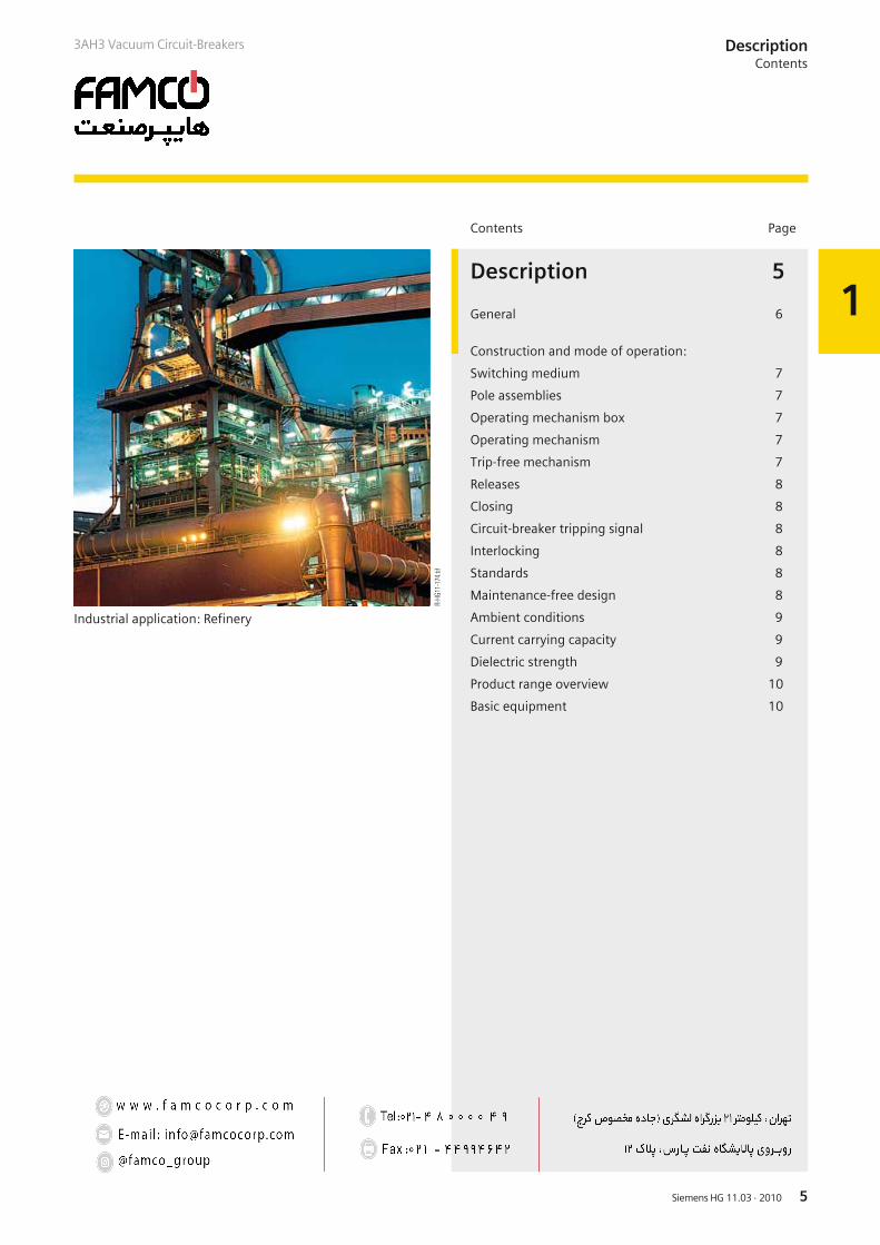
Industrial application: Refinery
R-HG
11-1
74.ti
f
1
Siemens HG 11.03 · 20106
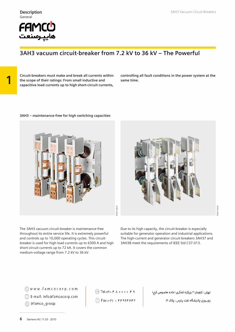
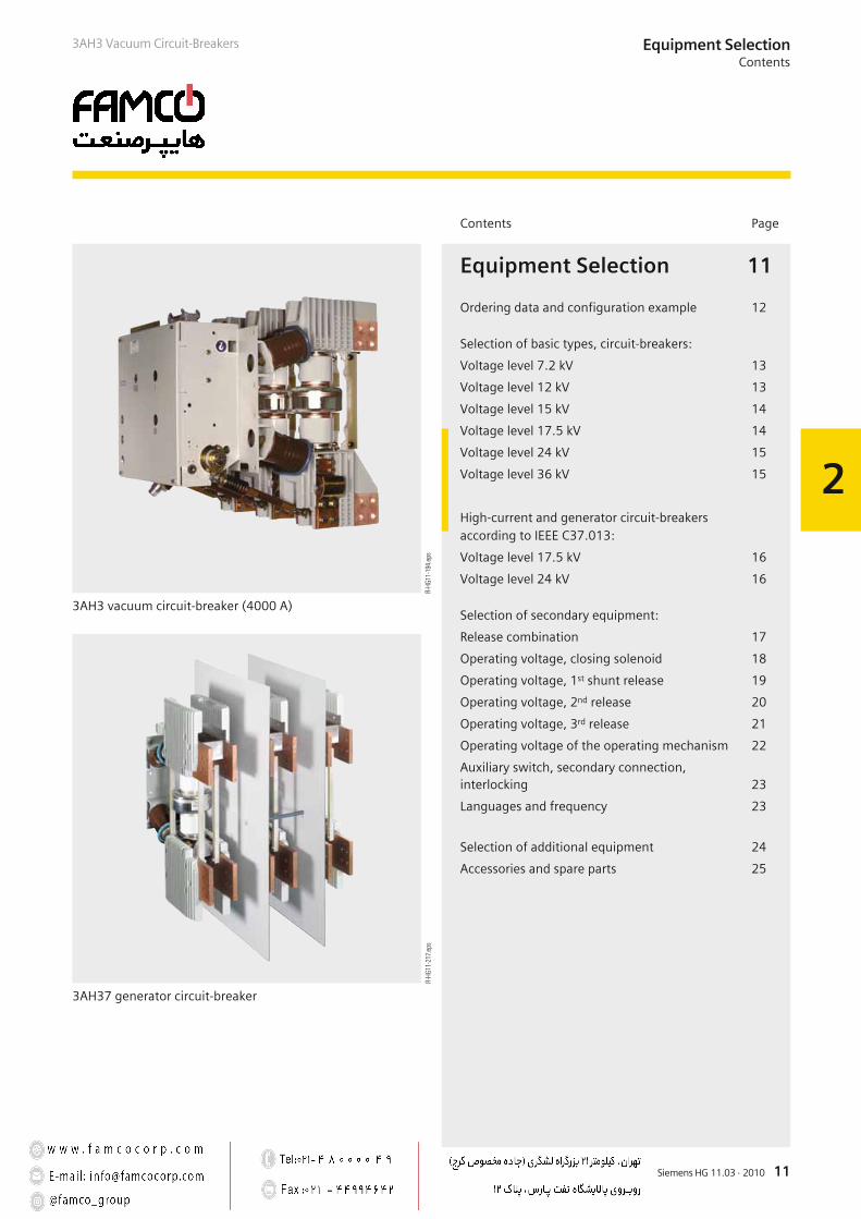
3AH3 vacuum circuit-breaker from 7.2 kV to 36 kV – The Powerful
The 3AH3 vacuum circuit-breaker is maintenance-freethroughout its entire service life. It is extremely powerfuland controls up to 10,000 operating cycles. This circuit-breaker is used for high load currents up to 6300 A and highshort-circuit currents up to 72 kA. It covers the commonmedium-voltage range from 7.2 kV to 36 kV.
Due to its high capacity, the circuit-breaker is especiallysuitable for generator operation and industrial applications.The high-current and generator circuit-breakers 3AH37 and3AH38 meet the requirements of IEEE Std C37.013.
R-HG
11-2
04.ti
f
R-HG
11-2
16.ti
f
DescriptionGeneral
3AH3 Vacuum Circuit-Breakers
Circuit-breakers must make and break all currents withinthe scope of their ratings: From small inductive andcapacitive load currents up to high short-circuit currents,
controlling all fault conditions in the power system at thesame time.
3AH3 – maintenance-free for high switching capacities
1
Siemens HG 11.03 · 2010 7
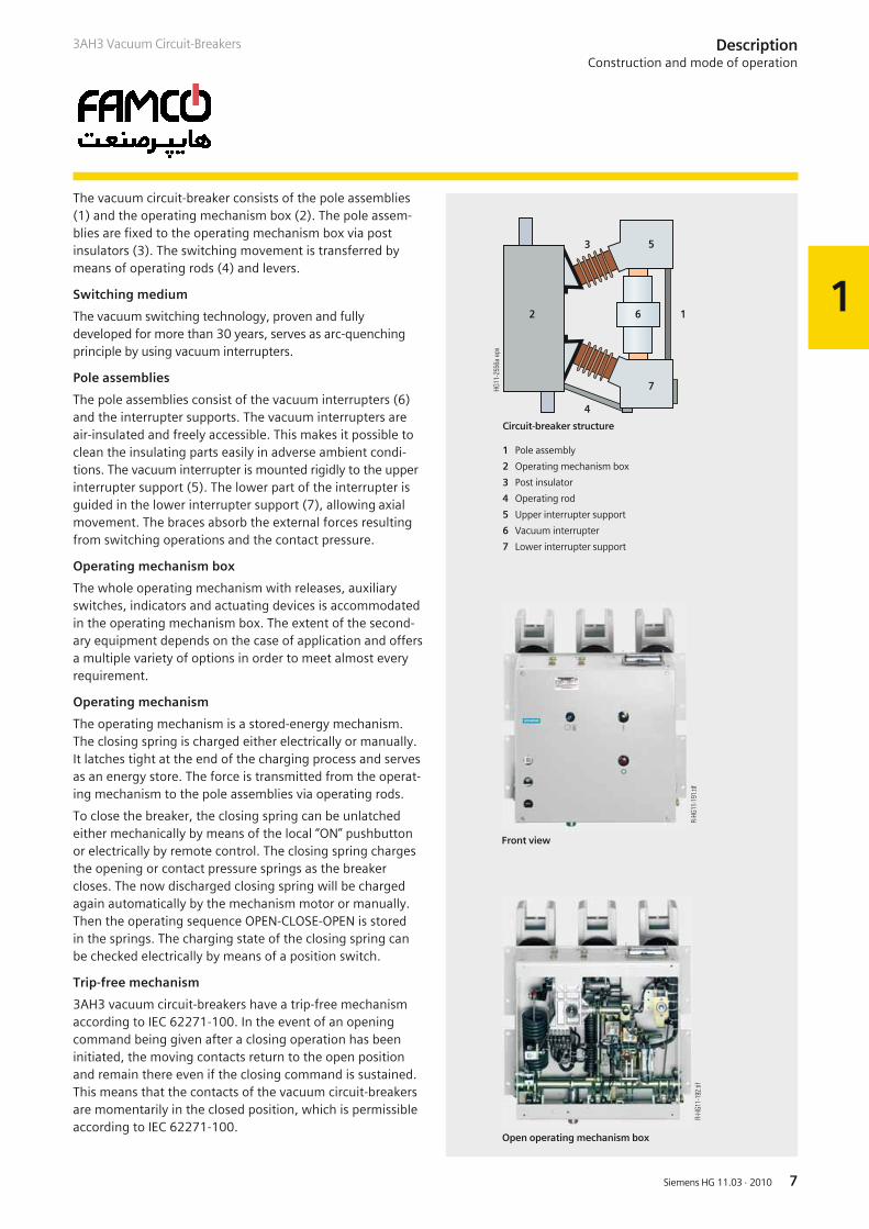
1 Pole assembly
2 Operating mechanism box
3 Post insulator
4 Operating rod
5 Upper interrupter support
6 Vacuum interrupter
7 Lower interrupter support
Circuit-breaker structure
DescriptionConstruction and mode of operation
3AH3 Vacuum Circuit-Breakers
Front view
R-HG
11-1
91.ti
f
Open operating mechanism box
R-HG
11-1
92.ti
f
The vacuum circuit-breaker consists of the pole assemblies(1) and the operating mechanism box (2). The pole assem-blies are fixed to the operating mechanism box via postinsulators (3). The switching movement is transferred bymeans of operating rods (4) and levers.
Switching medium
The vacuum switching technology, proven and fullydeveloped for more than 30 years, serves as arc-quenchingprinciple by using vacuum interrupters.
Pole assemblies
The pole assemblies consist of the vacuum interrupters (6)and the interrupter supports. The vacuum interrupters areair-insulated and freely accessible. This makes it possible toclean the insulating parts easily in adverse ambient condi-tions. The vacuum interrupter is mounted rigidly to the upperinterrupter support (5). The lower part of the interrupter isguided in the lower interrupter support (7), allowing axialmovement. The braces absorb the external forces resultingfrom switching operations and the contact pressure.
Operating mechanism box
The whole operating mechanism with releases, auxiliaryswitches, indicators and actuating devices is accommodatedin the operating mechanism box. The extent of the second-ary equipment depends on the case of application and offersa multiple variety of options in order to meet almost everyrequirement.
Operating mechanism
The operating mechanism is a stored-energy mechanism.The closing spring is charged either electrically or manually.It latches tight at the end of the charging process and servesas an energy store. The force is transmitted from the operat-ing mechanism to the pole assemblies via operating rods.
To close the breaker, the closing spring can be unlatchedeither mechanically by means of the local “ON” pushbuttonor electrically by remote control. The closing spring chargesthe opening or contact pressure springs as the breakercloses. The now discharged closing spring will be chargedagain automatically by the mechanism motor or manually.Then the operating sequence OPEN-CLOSE-OPEN is storedin the springs. The charging state of the closing spring canbe checked electrically by means of a position switch.
Trip-free mechanism
3AH3 vacuum circuit-breakers have a trip-free mechanismaccording to IEC 62271-100. In the event of an openingcommand being given after a closing operation has beeninitiated, the moving contacts return to the open positionand remain there even if the closing command is sustained.This means that the contacts of the vacuum circuit-breakersare momentarily in the closed position, which is permissibleaccording to IEC 62271-100.

1
Siemens HG 11.03 · 20108
DescriptionConstruction and mode of operation, standards, maintenance-free design
3AH3 Vacuum Circuit-Breakers
Releases
A release is a device which transfers electrical commands froman external source, such as a control room, to the latchingmechanism of the vacuum circuit-breaker so that it can beopened or closed. Apart from the closing solenoid, themaximum possible equipment is one shunt release and twoother releases. For release combinations, refer to page 17.
• The closing solenoid unlatches the charged closing springof the vacuum circuit-breaker, closing it by electrical means.It is suitable for DC or AC voltage.
• Shunt releases are used for automatic tripping of vacuumcircuit-breakers by suitable protection relays and for deliber-ate tripping by electrical means. They are intended for con-nection to an external power supply (DC or AC voltage) but,in special cases, may also be connected to a voltage trans-former for manual operation.
• Current-transformer operated releases comprise a stored-energy mechanism, an unlatching mechanism and an electro-magnetic system. They are used when there is no externalsource of auxiliary power (e.g. a battery). Tripping is effectedby means of a protection relay (e.g. overcurrent-time protec-tion) acting on the current-transformer operated release.When the tripping current is exceeded (= 90 % of the ratednormal current of the c.t.-operated release), the latch of theenergy store, and thus opening of the circuit-breaker, isreleased.
• Undervoltage releases comprise a stored-energy mecha-nism, an unlatching mechanism and an electromagnetic systemwhich is permanently connected to the secondary or auxiliaryvoltage while the vacuum circuit-breaker is closed. If thevoltage falls below a predetermined value, unlatching of therelease is enabled and the circuit-breaker is opened via thestored-energy mechanism. The deliberate tripping of theundervoltage release generally takes place via an NC contact inthe tripping circuit or via an NO contact by short-circuiting themagnet coil. With this type of tripping, the short-circuit currentis limited by the built-in resistors. Undervoltage releases canalso be connected to voltage transformers. When the operatingvoltage drops to impermissibly low levels, the circuit-breaker istripped automatically.
For delayed tripping, the undervoltage release can be com-bined with energy stores.
Closing
In the standard version, 3AH3 vacuum circuit-breakers can beremote-closed electrically. They can also be closed locally bymechanical unlatching of the closing spring via pushbutton.
Instead of this “manual mechanical closing”, “manual elec-trical closing” is also available. In this version, the closingcircuit of the circuit-breaker is controlled electrically by apushbutton instead of the mechanical button. In this way,switchgear-related interlocks can also be considered for localoperation in order to prevent involuntary closing.
If constant CLOSE and OPEN commands are present at thecircuit-breaker at the same time, the circuit-breaker will returnto the open position after closing. It remains in this positionuntil a new CLOSE command is given. In this manner,continuous closing and opening (= “pumping”) is prevented.
Circuit-breaker tripping signal
The NO contact makes brief contact while the vacuumcircuit-breaker is opening, and this is often used to operatea hazard-warning system which, however, is only allowed torespond to automatic tripping of the circuit-breaker. There-fore, the signal from the NO contact must be interruptedwhen the circuit-breaker is being opened intentionally. Thisis accomplished under local control with the cut-out switchthat is connected in series with the NO contact.
Interlocking
Electrical interlocking
The circuit-breakers can be integrated in electromagneticfeeder or switchgear interlocks. In case of electrical inter-locking, the disconnector or its operating mechanism isequipped with a magnetic lock-out mechanism. This mecha-nism is controlled by an auxiliary contact of the circuit-breaker,so that the disconnector can only be operated when the circuit-breaker is open. On the other hand, the circuit-breaker is alsocontrolled by the disconnector or its operating mechanism, sothat it can only be closed when the disconnector is in an endposition. For this purpose, manual electrical closing must be pro-vided in the circuit-breaker operating mechanism (see “Closing”).
Mechanical interlocking
To interlock circuit-breaker trucks, withdrawable parts ordisconnectors according to the switch position, the circuit-breakers can be equipped with a mechanical interlocking.A sensor at the switchgear checks the position of the circuit-breaker and prevents the open circuit-breaker in a reliableway from being closed mechanically and electrically.
Standards
3AH3 circuit-breakers conform to the following standards:
• IEC 62271-100 (former IEC 60056)• IEC 62271-1 (former IEC 60694)• VDE 0671 (former VDE 0670)• IEEE Std C37.013 (only generator circuit-breaker)
All 3AH3 vacuum circuit-breakers fulfil the endurance classesE2, M2 and C2 according to IEC 62271-100.
Maintenance-free design
The 3AH3 vacuum circuit-breakers are maintenance-free:
• Under normal ambient conditions according toIEC 62271-1 (former IEC 60694)
• Up to 10,000 operating cycles,– no relubrication, no readjustment required– and within their tolerances, the characteristics are
independent of the switching rate or of standing timeswithout switching operations.
1
Siemens HG 11.03 · 2010 9
DescriptionAmbient conditions, current carrying capacity and dielectric strength
3AH3 Vacuum Circuit-Breakers
!
"
#
# $%
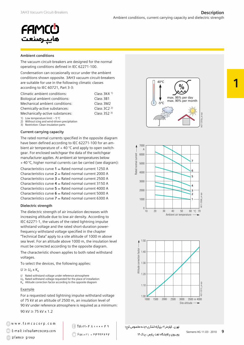
Ambient conditions
The vacuum circuit-breakers are designed for the normaloperating conditions defined in IEC 62271-100.
Condensation can occasionally occur under the ambientconditions shown opposite. 3AH3 vacuum circuit-breakersare suitable for use in the following climatic classesaccording to IEC 60721, Part 3-3:
Climatic ambient conditions: Class 3K4 1)
Biological ambient conditions: Class 3B1Mechanical ambient conditions: Class 3M2Chemically-active substances: Class 3C2 2)
Mechanically-active substances: Class 3S2 3)
1) Low temperature limit: – 5 °C2) Without icing and wind-driven precipitation3) Restriction: Clean insulation parts
Current carrying capacity
The rated normal currents specified in the opposite diagramhave been defined according to IEC 62271-100 for an am-bient air temperature of + 40 °C and apply to open switch-gear. For enclosed switchgear the data of the switchgearmanufacturer applies. At ambient air temperatures below+ 40 °C, higher normal currents can be carried (see diagram):
Characteristics curve 1 = Rated normal current 1250 ACharacteristics curve 2 = Rated normal current 2000 ACharacteristics curve 3 = Rated normal current 2500 ACharacteristics curve 4 = Rated normal current 3150 ACharacteristics curve 5 = Rated normal current 4000 ACharacteristics curve 6 = Rated normal current 5000 ACharacteristics curve 7 = Rated normal current 6300 A
Dielectric strength
The dielectric strength of air insulation decreases withincreasing altitude due to low air density. According toIEC 62271-1, the values of the rated lightning impulsewithstand voltage and the rated short-duration power-frequency withstand voltage specified in the chapter“Technical Data” apply to a site altitude of 1000 m abovesea level. For an altitude above 1000 m, the insulation levelmust be corrected according to the opposite diagram.
The characteristic shown applies to both rated withstandvoltages.
To select the devices, the following applies:
U W U0 x Ka
U Rated withstand voltage under reference atmosphereU0 Rated withstand voltage requested for the place of installationKa Altitude correction factor according to the opposite diagram
Example
For a requested rated lightning impulse withstand voltageof 75 kV at an altitude of 2500 m, an insulation level of90 kV under reference atmosphere is required as a minimum:
90 kV W 75 kV x 1.2
1
Siemens HG 11.03 · 20101010
3AH3 Vacuum Circuit-BreakersDescriptionProduct range overview and basic equipment
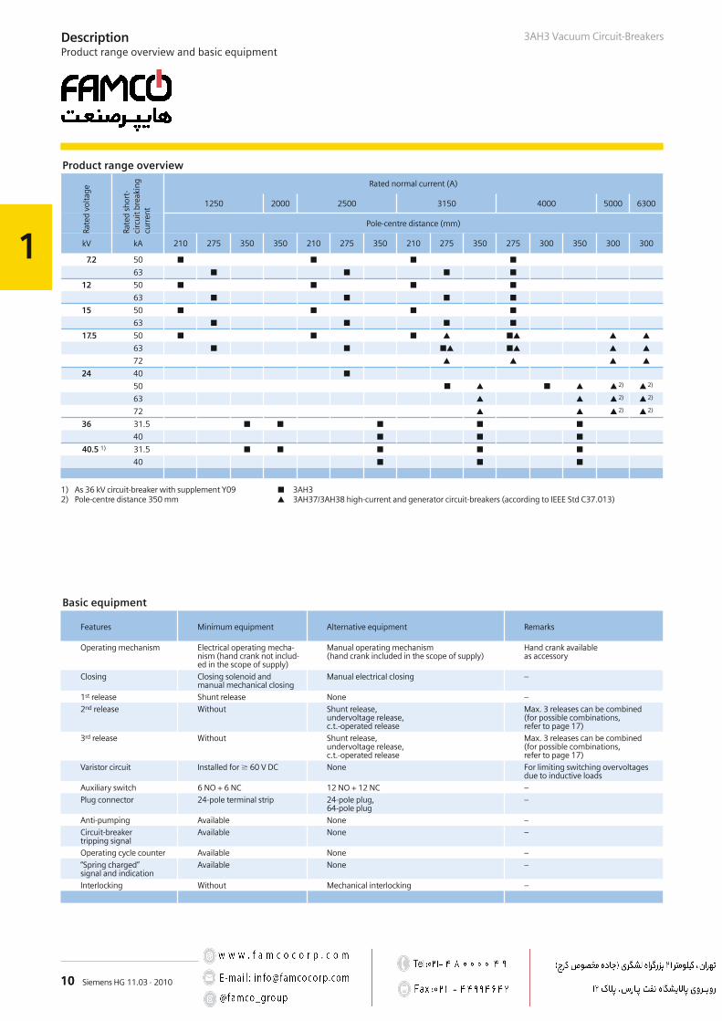
Basic equipment
Features Minimum equipment Alternative equipment Remarks
Operating mechanism Electrical operating mecha-nism (hand crank not includ-ed in the scope of supply)
Manual operating mechanism(hand crank included in the scope of supply)
Hand crank availableas accessory
Closing Closing solenoid andmanual mechanical closing
Manual electrical closing –
1st release Shunt release None –
2nd release Without Shunt release,undervoltage release,c.t.-operated release
Max. 3 releases can be combined(for possible combinations,refer to page 17)
3rd release Without Shunt release,undervoltage release,c.t.-operated release
Max. 3 releases can be combined(for possible combinations,refer to page 17)
Varistor circuit Installed for 60 V DC None For limiting switching overvoltagesdue to inductive loads
Auxiliary switch 6 NO + 6 NC 12 NO + 12 NC –
Plug connector 24-pole terminal strip 24-pole plug,64-pole plug
–
Anti-pumping Available None –
Circuit-breakertripping signal
Available None –
Operating cycle counter Available None –
“Spring charged”signal and indication
Available None –
Interlocking Without Mechanical interlocking –
Product range overview
Rated normal current (A)
1250 2000 2500 3150 4000 5000 6300
Pole-centre distance (mm)
kV kA 210 275 350 350 210 275 350 210 275 350 275 300 350 300 300
7.2 50 63
12 50 63
15 50 63
17.5 50 63 72
24 40 50 2) 2)
63 2) 2)
72 2) 2)
36 31.5 40
40.5 1) 31.5 40
3AH3 3AH37/3AH38 high-current and generator circuit-breakers (according to IEEE Std C37.013)
1) As 36 kV circuit-breaker with supplement Y092) Pole-centre distance 350 mm
Rate
dvo
ltage
Rate
dsh
ort-
circ
uitb
reak
ing
curr
ent
2
11Siemens HG 11.03 · 2010
Contents Page
Equipment Selection
Ordering data and configuration example
Selection of basic types, circuit-breakers:
Voltage level 7.2 kV
Voltage level 12 kV
Voltage level 15 kV
Voltage level 17.5 kV
Voltage level 24 kV
Voltage level 36 kV
High-current and generator circuit-breakersaccording to IEEE C37.013:
Voltage level 17.5 kV
Voltage level 24 kV
Selection of secondary equipment:
Release combination
Operating voltage, closing solenoid
Operating voltage, 1st shunt release
Operating voltage, 2nd release
Operating voltage, 3rd release
Operating voltage of the operating mechanism
Auxiliary switch, secondary connection,interlocking
Languages and frequency
Selection of additional equipment
Accessories and spare parts
11
12
13
13
14
14
15
15
16
16
17
18
19
20
21
22
23
23
24
25
Equipment SelectionContents
3AH3 Vacuum Circuit-Breakers
3AH3 vacuum circuit-breaker (4000 A)
3AH37 generator circuit-breaker
R-HG
11-1
94.e
psR-
HG11
-217
.eps
2
12 Siemens HG 11.03 · 2010
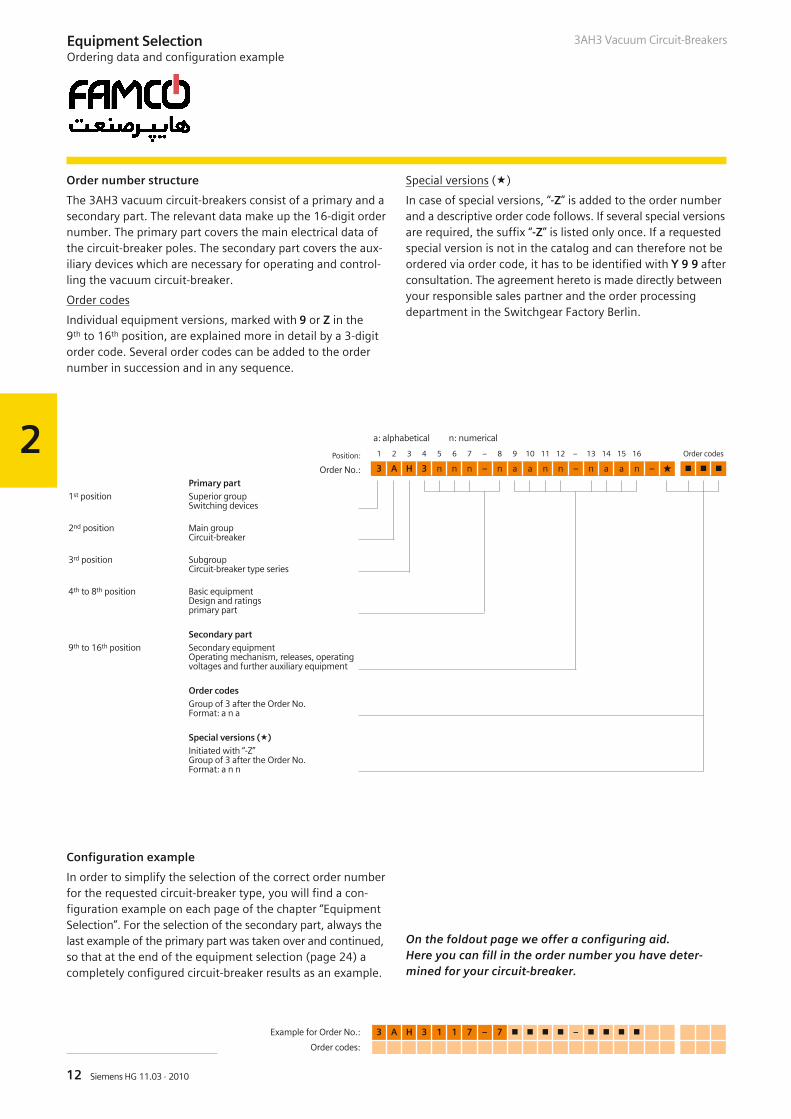
a: alphabetical n: numerical
Position: 1 2 3 4 5 6 7 – 8 9 10 11 12 – 13 14 15 16 Order codes
Order No.: 3 A H 3 n n n – n a a n n – n a a n –
Primary part1st position Superior group
Switching devices
2nd position Main groupCircuit-breaker
3rd position SubgroupCircuit-breaker type series
4th to 8th position Basic equipmentDesign and ratingsprimary part
Secondary part9th to 16th position Secondary equipment
Operating mechanism, releases, operatingvoltages and further auxiliary equipment
Order codesGroup of 3 after the Order No.Format: a n a
Special versions ()Initiated with “-Z”Group of 3 after the Order No.Format: a n n
Equipment SelectionOrdering data and configuration example
Example for Order No.: 3 A H 3 1 1 7 – 7 –
Order codes:
3AH3 Vacuum Circuit-Breakers
Order number structure
The 3AH3 vacuum circuit-breakers consist of a primary and asecondary part. The relevant data make up the 16-digit ordernumber. The primary part covers the main electrical data ofthe circuit-breaker poles. The secondary part covers the aux-iliary devices which are necessary for operating and control-ling the vacuum circuit-breaker.
Order codes
Individual equipment versions, marked with 9 or Z in the9th to 16th position, are explained more in detail by a 3-digitorder code. Several order codes can be added to the ordernumber in succession and in any sequence.
Special versions ()
In case of special versions, “-Z” is added to the order numberand a descriptive order code follows. If several special versionsare required, the suffix “-Z” is listed only once. If a requestedspecial version is not in the catalog and can therefore not beordered via order code, it has to be identified with Y 9 9 afterconsultation. The agreement hereto is made directly betweenyour responsible sales partner and the order processingdepartment in the Switchgear Factory Berlin.
Configuration example
In order to simplify the selection of the correct order numberfor the requested circuit-breaker type, you will find a con-figuration example on each page of the chapter “EquipmentSelection”. For the selection of the secondary part, always thelast example of the primary part was taken over and continued,so that at the end of the equipment selection (page 24) acompletely configured circuit-breaker results as an example.
On the foldout page we offer a configuring aid.Here you can fill in the order number you have deter-mined for your circuit-breaker.
2
13Siemens HG 11.03 · 2010
Example for Order No.: 3 A H 3 1 1 7 – 2 –
Order codes:
3AH3 Vacuum Circuit-Breakers
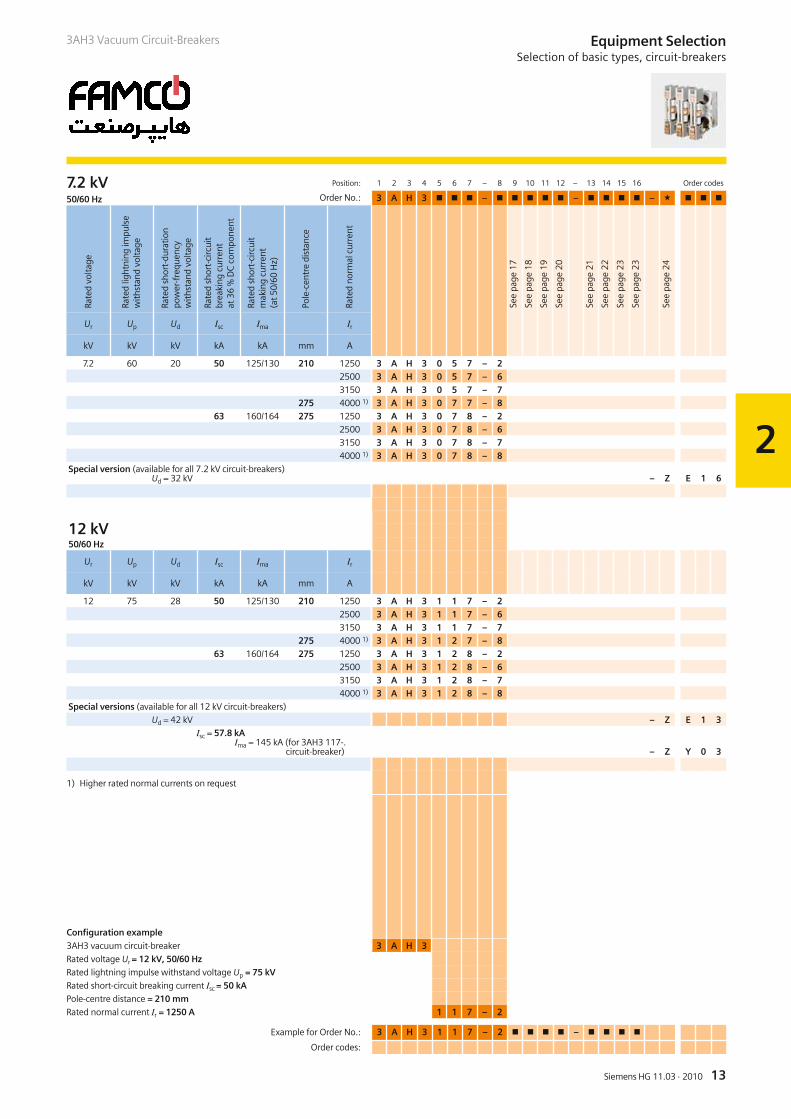
7.2 kV Position: 1 2 3 4 5 6 7 – 8 9 10 11 12 – 13 14 15 16 Order codes
50/60 Hz Order No.: 3 A H 3 – – –
Ur Up Ud Isc Ima Ir
kV kV kV kA kA mm A
7.2 60 20 50 125/130 210 1250 3 A H 3 0 5 7 – 22500 3 A H 3 0 5 7 – 63150 3 A H 3 0 5 7 – 7
275 4000 1) 3 A H 3 0 7 7 – 863 160/164 275 1250 3 A H 3 0 7 8 – 2
2500 3 A H 3 0 7 8 – 63150 3 A H 3 0 7 8 – 74000 1) 3 A H 3 0 7 8 – 8
Special version (available for all 7.2 kV circuit-breakers)Ud = 32 kV – Z E 1 6
12 kV50/60 Hz
Ur Up Ud Isc Ima Ir
kV kV kV kA kA mm A
12 75 28 50 125/130 210 1250 3 A H 3 1 1 7 – 22500 3 A H 3 1 1 7 – 63150 3 A H 3 1 1 7 – 7
275 4000 1) 3 A H 3 1 2 7 – 863 160/164 275 1250 3 A H 3 1 2 8 – 2
2500 3 A H 3 1 2 8 – 63150 3 A H 3 1 2 8 – 74000 1) 3 A H 3 1 2 8 – 8
Special versions (available for all 12 kV circuit-breakers)
Ud = 42 kV – Z E 1 3Isc = 57.8 kA
Ima = 145 kA (for 3AH3 117-.circuit-breaker) – Z Y 0 3
1) Higher rated normal currents on request
Configuration example
3AH3 vacuum circuit-breaker 3 A H 3
Rated voltage Ur = 12 kV, 50/60 Hz
Rated lightning impulse withstand voltage Up = 75 kV
Rated short-circuit breaking current Isc = 50 kA
Pole-centre distance = 210 mm
Rated normal current Ir = 1250 A 1 1 7 – 2
Equipment SelectionSelection of basic types, circuit-breakers
See
page
17
See
page
18
See
page
19
See
page
20
See
page
21
See
page
22
See
page
23
See
page
23
See
page
24
Rate
dvo
ltage
Rate
dlig
htni
ngim
puls
ew
ithst
and
volta
ge
Rate
dsh
ort-
dura
tion
pow
er-f
requ
ency
with
stan
dvo
ltage
Rate
dsh
ort-
circ
uit
brea
king
curr
ent
at36
%D
Cco
mpo
nent
Rate
dsh
ort-
circ
uit
mak
ing
curr
ent
(at5
0/60
Hz)
Pole
-cen
tre
dist
ance
Rate
dno
rmal
curr
ent
2
14 Siemens HG 11.03 · 2010
Example for Order No.: 3 A H 3 2 2 8 – 8 –
Order codes:
Equipment SelectionSelection of basic types, circuit-breakers
3AH3 Vacuum Circuit-Breakers
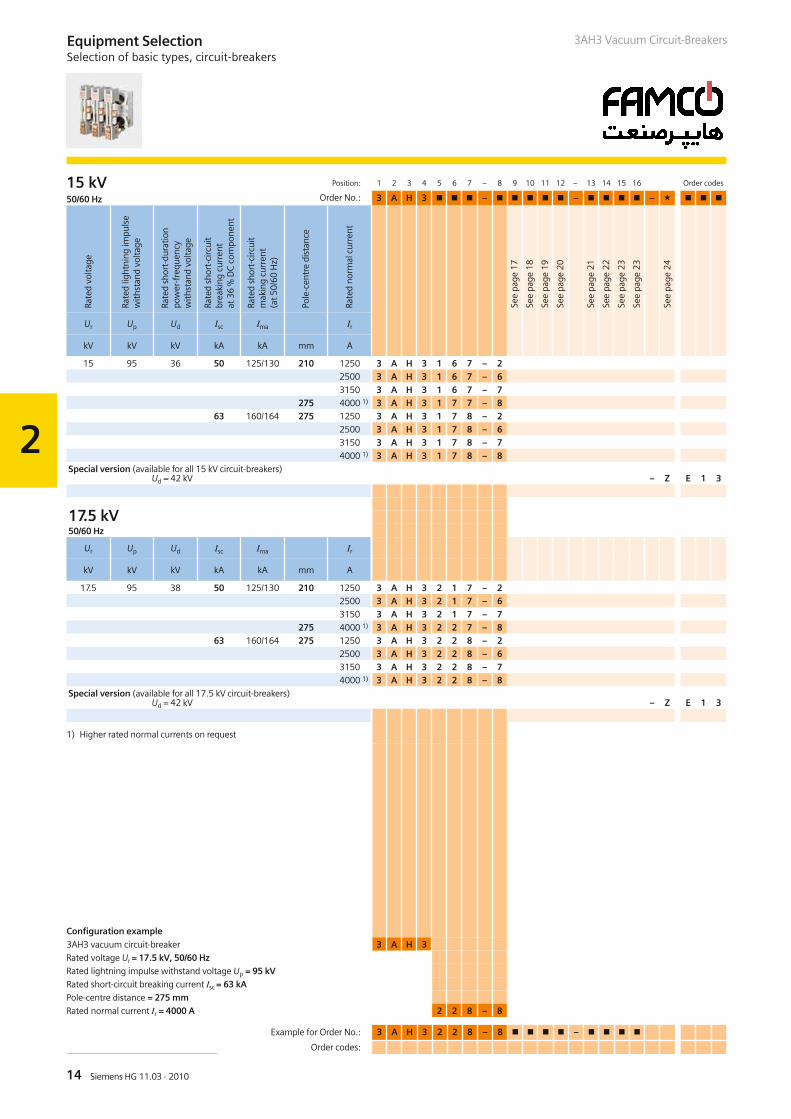
15 kV Position: 1 2 3 4 5 6 7 – 8 9 10 11 12 – 13 14 15 16 Order codes
50/60 Hz Order No.: 3 A H 3 – – –
Ur Up Ud Isc Ima Ir
kV kV kV kA kA mm A
15 95 36 50 125/130 210 1250 3 A H 3 1 6 7 – 22500 3 A H 3 1 6 7 – 63150 3 A H 3 1 6 7 – 7
275 4000 1) 3 A H 3 1 7 7 – 863 160/164 275 1250 3 A H 3 1 7 8 – 2
2500 3 A H 3 1 7 8 – 63150 3 A H 3 1 7 8 – 74000 1) 3 A H 3 1 7 8 – 8
Special version (available for all 15 kV circuit-breakers)Ud = 42 kV – Z E 1 3
17.5 kV50/60 Hz
Ur Up Ud Isc Ima Ir
kV kV kV kA kA mm A
17.5 95 38 50 125/130 210 1250 3 A H 3 2 1 7 – 22500 3 A H 3 2 1 7 – 63150 3 A H 3 2 1 7 – 7
275 4000 1) 3 A H 3 2 2 7 – 863 160/164 275 1250 3 A H 3 2 2 8 – 2
2500 3 A H 3 2 2 8 – 63150 3 A H 3 2 2 8 – 74000 1) 3 A H 3 2 2 8 – 8
Special version (available for all 17.5 kV circuit-breakers)Ud = 42 kV – Z E 1 3
1) Higher rated normal currents on request
Configuration example
3AH3 vacuum circuit-breaker 3 A H 3
Rated voltage Ur = 17.5 kV, 50/60 Hz
Rated lightning impulse withstand voltage Up = 95 kV
Rated short-circuit breaking current Isc = 63 kA
Pole-centre distance = 275 mm
Rated normal current Ir = 4000 A 2 2 8 – 8
See
page
17
See
page
18
See
page
19
See
page
20
See
page
21
See
page
22
See
page
23
See
page
23
See
page
24
Rate
dvo
ltage
Rate
dlig
htni
ngim
puls
ew
ithst
and
volta
ge
Rate
dsh
ort-
dura
tion
pow
er-f
requ
ency
with
stan
dvo
ltage
Rate
dsh
ort-
circ
uit
brea
king
curr
ent
at36
%D
Cco
mpo
nent
Rate
dsh
ort-
circ
uit
mak
ing
curr
ent
(at5
0/60
Hz)
Pole
-cen
tre
dist
ance
Rate
dno
rmal
curr
ent
2
15Siemens HG 11.03 · 2010
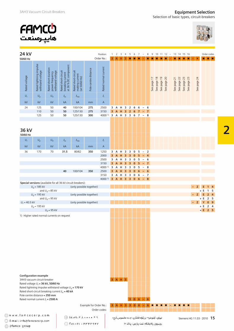
24 kV Position: 1 2 3 4 5 6 7 – 8 9 10 11 12 – 13 14 15 16 Order codes
50/60 Hz Order No.: 3 A H 3 – – –
Ur Up Ud Isc Ima Ir
kV kV kV kA kA mm A
24 125 50 40 100/104 275 2500 3 A H 3 2 6 6 – 6110 50 50 125/130 275 3150 3 A H 3 2 6 7 – 7125 50 50 125/130 300 4000 1) 3 A H 3 3 6 7 – 8
36 kV50/60 Hz
Ur Up Ud Isc Ima Ir
kV kV kV kA kA mm A
36 170 70 31.5 80/82 350 1250 3 A H 3 3 0 5 – 22000 3 A H 3 3 0 5 – 42500 3 A H 3 3 0 5 – 63150 3 A H 3 3 0 5 – 74000 1) 3 A H 3 3 0 5 – 8
40 100/104 350 2500 3 A H 3 3 0 6 – 63150 3 A H 3 3 0 6 – 74000 1) 3 A H 3 3 0 6 – 8
Special versions (available for all 36 kV circuit-breakers):
Up = 185 kV (only possible together) – Z E 1 4and Ud = 85 kV + E 1 5
Up = 195 kV (only possible together) – Z E 2 4and Ud = 95 kV + E 2 5
Ur = 40.5 kV (only possible together) – Z Y 0 9Up = 195 kV + E 2 4
Ud = 95 kV + E 2 5
1) Higher rated normal currents on request
Configuration example
3AH3 vacuum circuit-breaker 3 A H 3
Rated voltage Ur = 36 kV, 50/60 Hz
Rated lightning impulse withstand voltage Up = 170 kV
Rated short-circuit breaking current Isc = 40 kA
Pole-centre distance = 350 mm
Rated normal current Ir = 2500 A 3 0 6 – 6
Example for Order No.: 3 A H 3 3 0 6 – 6 –
Order codes:
Rate
dvo
ltage
Rate
dlig
htni
ngim
puls
ew
ithst
and
volta
ge
Rate
dsh
ort-
dura
tion
pow
er-f
requ
ency
with
stan
dvo
ltage
Rate
dsh
ort-
circ
uit
brea
king
curr
ent
at36
%D
Cco
mpo
nent
Rate
dsh
ort-
circ
uit
mak
ing
curr
ent
(at5
0/60
Hz)
Pole
-cen
tre
dist
ance
Rate
dno
rmal
curr
ent
See
page
17
See
page
18
See
page
19
See
page
20
See
page
21
See
page
22
See
page
23
See
page
23
See
page
24
3AH3 Vacuum Circuit-Breakers Equipment SelectionSelection of basic types, circuit-breakers
2
16 Siemens HG 11.03 · 2010
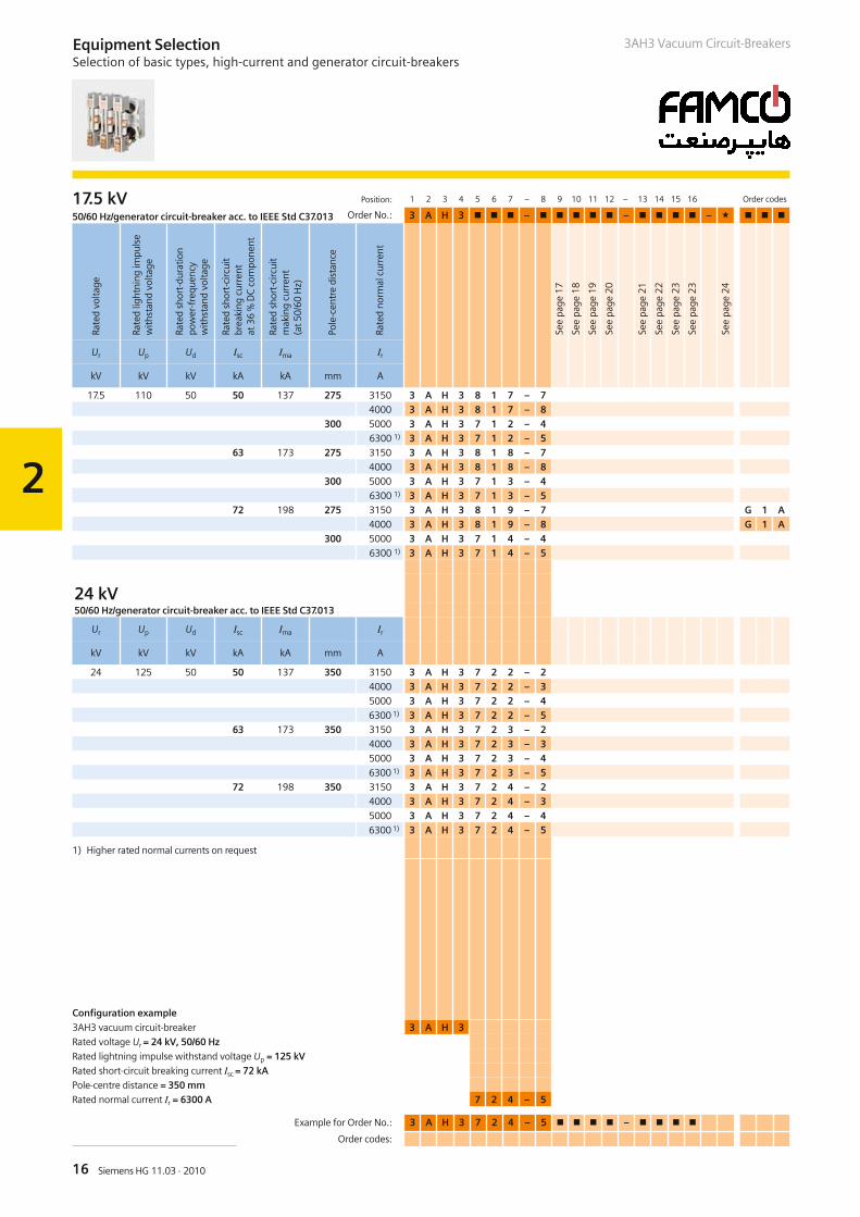
17.5 kV Position: 1 2 3 4 5 6 7 – 8 9 10 11 12 – 13 14 15 16 Order codes
50/60 Hz/generator circuit-breaker acc. to IEEE Std C37.013 Order No.: 3 A H 3 – – –
Ur Up Ud Isc Ima Ir
kV kV kV kA kA mm A
17.5 110 50 50 137 275 3150 3 A H 3 8 1 7 – 74000 3 A H 3 8 1 7 – 8
300 5000 3 A H 3 7 1 2 – 46300 1) 3 A H 3 7 1 2 – 5
63 173 275 3150 3 A H 3 8 1 8 – 74000 3 A H 3 8 1 8 – 8
300 5000 3 A H 3 7 1 3 – 46300 1) 3 A H 3 7 1 3 – 5
72 198 275 3150 3 A H 3 8 1 9 – 7 G 1 A4000 3 A H 3 8 1 9 – 8 G 1 A
300 5000 3 A H 3 7 1 4 – 46300 1) 3 A H 3 7 1 4 – 5
24 kV50/60 Hz/generator circuit-breaker acc. to IEEE Std C37.013
Ur Up Ud Isc Ima Ir
kV kV kV kA kA mm A
24 125 50 50 137 350 3150 3 A H 3 7 2 2 – 24000 3 A H 3 7 2 2 – 35000 3 A H 3 7 2 2 – 46300 1) 3 A H 3 7 2 2 – 5
63 173 350 3150 3 A H 3 7 2 3 – 24000 3 A H 3 7 2 3 – 35000 3 A H 3 7 2 3 – 46300 1) 3 A H 3 7 2 3 – 5
72 198 350 3150 3 A H 3 7 2 4 – 24000 3 A H 3 7 2 4 – 35000 3 A H 3 7 2 4 – 46300 1) 3 A H 3 7 2 4 – 5
1) Higher rated normal currents on request
Configuration example
3AH3 vacuum circuit-breaker 3 A H 3
Rated voltage Ur = 24 kV, 50/60 Hz
Rated lightning impulse withstand voltage Up = 125 kV
Rated short-circuit breaking current Isc = 72 kA
Pole-centre distance = 350 mm
Rated normal current Ir = 6300 A 7 2 4 – 5
Example for Order No.: 3 A H 3 7 2 4 – 5 –
Order codes:
Rate
dvo
ltage
Rate
dlig
htni
ngim
puls
ew
ithst
and
volta
ge
Rate
dsh
ort-
dura
tion
pow
er-f
requ
ency
with
stan
dvo
ltage
Rate
dsh
ort-
circ
uit
brea
king
curr
ent
at36
%D
Cco
mpo
nent
Rate
dsh
ort-
circ
uit
mak
ing
curr
ent
(at5
0/60
Hz)
Pole
-cen
tre
dist
ance
Rate
dno
rmal
curr
ent
See
page
17
See
page
18
See
page
19
See
page
20
See
page
21
See
page
22
See
page
23
See
page
23
See
page
24
Equipment SelectionSelection of basic types, high-current and generator circuit-breakers
3AH3 Vacuum Circuit-Breakers

2
17Siemens HG 11.03 · 2010
Equipment SelectionSelection of secondary equipment
3AH3 Vacuum Circuit-Breakers
9th position Position: 1 2 3 4 5 6 7 – 8 9 10 11 12 – 13 14 15 16 Order codes
Release combination Order No.: 3 A H 3 – – –
M N N – Z F 1 51)
T P P – Z A 4 6 2) Q R S S – Z A 4 6 U U – Z A 4 6 V V – Z A 4 5
1) With 3rd shunt release, voltage according to 13th position
2) Version with two c.t.-operated releases 0.5 A
Configuration example
3AH3 vacuum circuit-breaker 3 A H 3
(Ur = 36 kV, 50/60 Hz, Up = 170 kV, Isc = 40 kA, Ir = 2500 A,
pole-centre distance = 350 mm) 3 0 6 – 6
Closing solenoid, 1st shunt release, undervoltage release and
c.t.-operated release with a rated normal current of 1 A S – Z A 4 6
Example for Order No.: 3 A H 3 3 0 6 – 6 S – – Z
Order codes: A 4 6
Clo
sing
sole
noid
1stsh
untr
elea
se
2nd
shun
trel
ease
Und
ervo
ltage
rele
ase
C.t
.-ope
rate
dre
leas
e0.
5A
C.t
.-ope
rate
dre
leas
e1.
0A
C.t
.-ope
rate
dre
leas
ew
ithtr
ippi
ngpu
lse
0.
1W
s(1
0c
)
C.t
.-ope
rate
dre
leas
ew
ithtr
ippi
ngpu
lse
0.
1W
s(2
0c
)
See
page
18
See
page
19
See
page
20
See
page
21
See
page
22
See
page
23
See
page
23
See
page
24
2
18 Siemens HG 11.03 · 2010
3AH3 Vacuum Circuit-BreakersEquipment SelectionSelection of secondary equipment
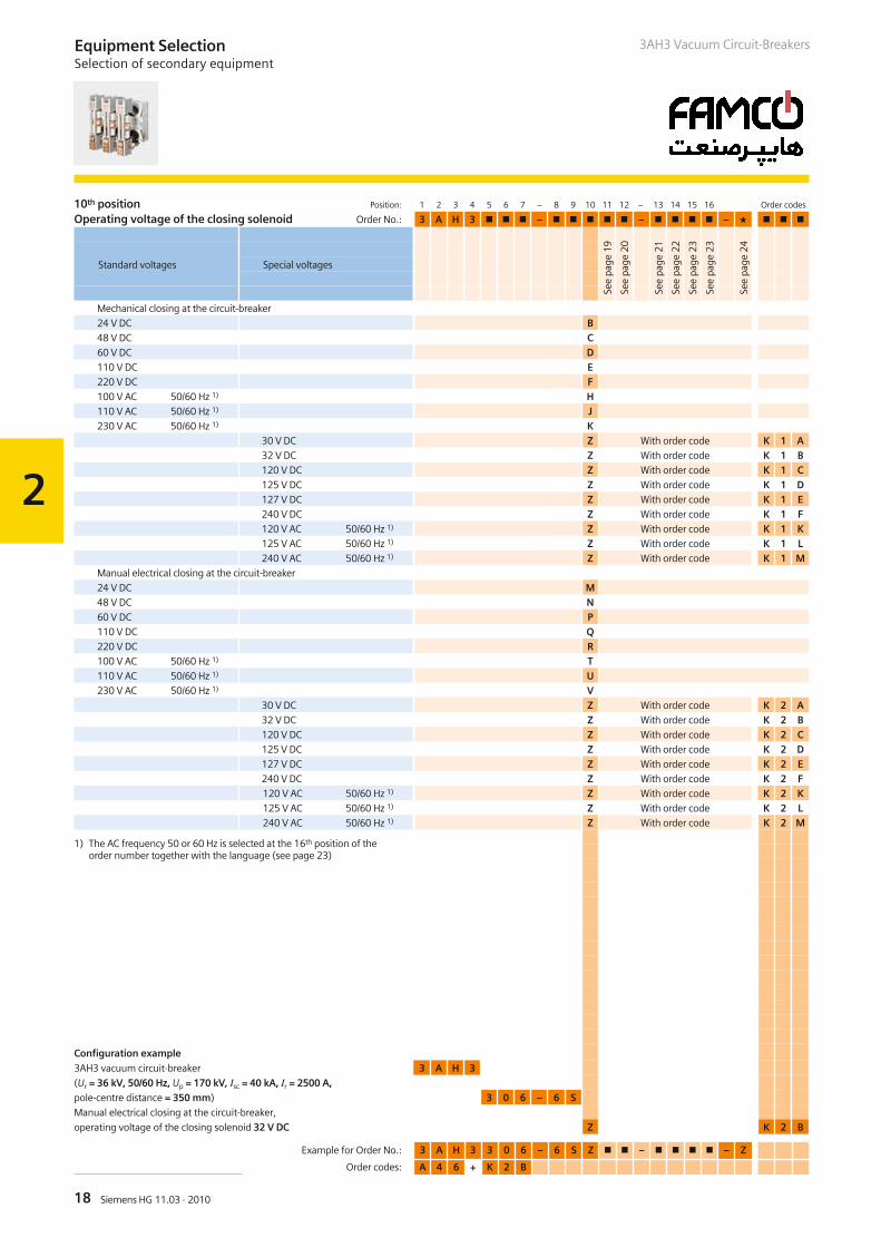
10th position Position: 1 2 3 4 5 6 7 – 8 9 10 11 12 – 13 14 15 16 Order codes
Operating voltage of the closing solenoid Order No.: 3 A H 3 – – –
Mechanical closing at the circuit-breaker
24 V DC B48 V DC C60 V DC D110 V DC E220 V DC F100 V AC 50/60 Hz 1) H110 V AC 50/60 Hz 1) J230 V AC 50/60 Hz 1) K
30 V DC Z With order code K 1 A32 V DC Z With order code K 1 B120 V DC Z With order code K 1 C125 V DC Z With order code K 1 D127 V DC Z With order code K 1 E240 V DC Z With order code K 1 F120 V AC 50/60 Hz 1) Z With order code K 1 K125 V AC 50/60 Hz 1) Z With order code K 1 L240 V AC 50/60 Hz 1) Z With order code K 1 M
Manual electrical closing at the circuit-breaker
24 V DC M48 V DC N60 V DC P110 V DC Q220 V DC R100 V AC 50/60 Hz 1) T110 V AC 50/60 Hz 1) U230 V AC 50/60 Hz 1) V
30 V DC Z With order code K 2 A32 V DC Z With order code K 2 B120 V DC Z With order code K 2 C125 V DC Z With order code K 2 D127 V DC Z With order code K 2 E240 V DC Z With order code K 2 F120 V AC 50/60 Hz 1) Z With order code K 2 K125 V AC 50/60 Hz 1) Z With order code K 2 L240 V AC 50/60 Hz 1) Z With order code K 2 M
1) The AC frequency 50 or 60 Hz is selected at the 16th position of theorder number together with the language (see page 23)
Configuration example
3AH3 vacuum circuit-breaker 3 A H 3
(Ur = 36 kV, 50/60 Hz, Up = 170 kV, Isc = 40 kA, Ir = 2500 A,
pole-centre distance = 350 mm) 3 0 6 – 6 S
Manual electrical closing at the circuit-breaker,
operating voltage of the closing solenoid 32 V DC Z K 2 B
Example for Order No.: 3 A H 3 3 0 6 – 6 S Z – – Z
Order codes: A 4 6 + K 2 B
Standard voltages Special voltages
See
page
19
See
page
20
See
page
21
See
page
22
See
page
23
See
page
23
See
page
24

2
19Siemens HG 11.03 · 2010
3AH3 Vacuum Circuit-Breakers Equipment SelectionSelection of secondary equipment
11th position Position: 1 2 3 4 5 6 7 – 8 9 10 11 12 – 13 14 15 16 Order codes
Operating voltage of the 1st shunt release Order No.: 3 A H 3 – – –
24 V DC 148 V DC 260 V DC 3110 V DC 4220 V DC 5100 V AC 50/60 Hz 1) 6110 V AC 50/60 Hz 1) 7230 V AC 50/60 Hz 1) 8
30 V DC 9 With order code L 1 A32 V DC 9 With order code L 1 B120 V DC 9 With order code L 1 C125 V DC 9 With order code L 1 D127 V DC 9 With order code L 1 E240 V DC 9 With order code L 1 F120 V AC 50/60 Hz 1) 9 With order code L 1 K125 V AC 50/60 Hz 1) 9 With order code L 1 L240 V AC 50/60 Hz 1) 9 With order code L 1 M
1) The AC frequency 50 or 60 Hz is selected at the 16th position of theorder number together with the language (see page 23)
Configuration example
3AH3 vacuum circuit-breaker 3 A H 3
(Ur = 36 kV, 50/60 Hz, Up = 170 kV, Isc = 40 kA, Ir = 2500 A,
pole-centre distance = 350 mm) 3 0 6 – 6 S Z
Operating voltage of the 1st shunt release 48 V DC 2
Example for Order No.: 3 A H 3 3 0 6 – 6 S Z 2 – – Z
Order codes: A 4 6 + K 2 B
See
page
20
See
page
21
See
page
22
See
page
23
See
page
23
See
page
24
Standard voltages Special voltages
2
20 Siemens HG 11.03 · 2010
3AH3 Vacuum Circuit-BreakersEquipment SelectionSelection of secondary equipment
Example for Order No.: 3 A H 3 3 0 6 – 6 S Z 2 9 – – Z
Order codes: A 4 6 + K 2 B + M 1 B
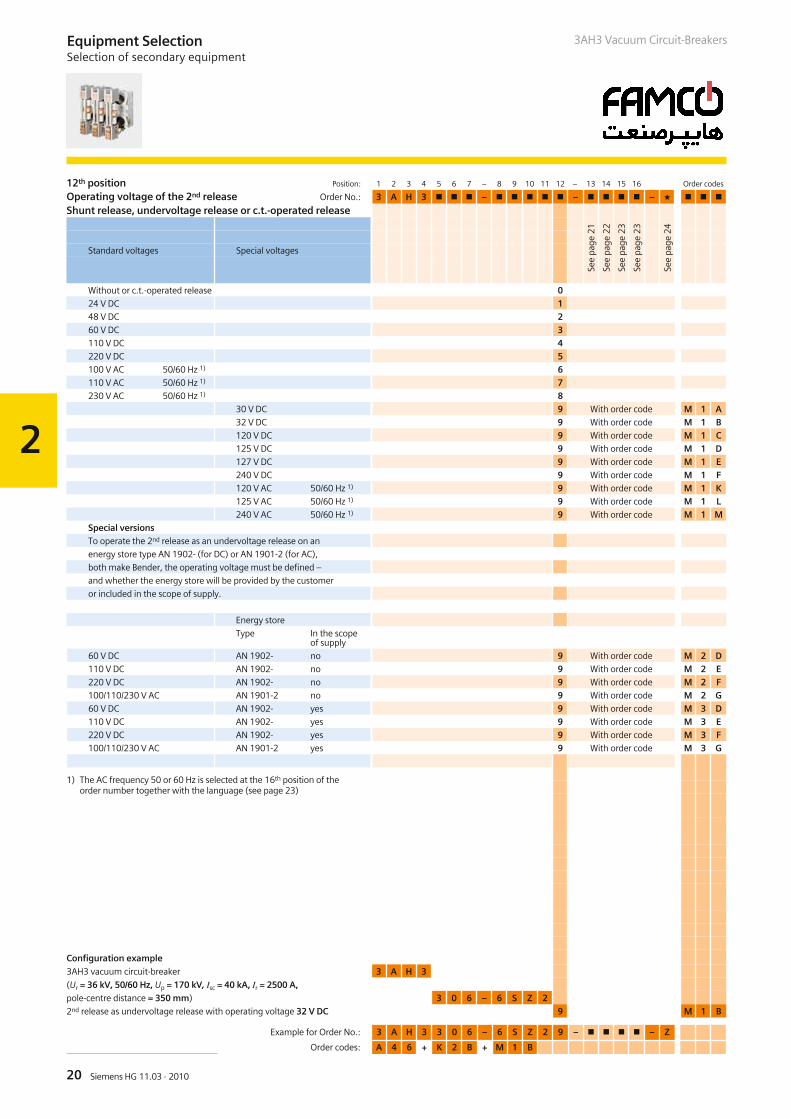
12th position Position: 1 2 3 4 5 6 7 – 8 9 10 11 12 – 13 14 15 16 Order codes
Operating voltage of the 2nd release Order No.: 3 A H 3 – – –
Shunt release, undervoltage release or c.t.-operated release
Without or c.t.-operated release 024 V DC 148 V DC 260 V DC 3110 V DC 4220 V DC 5100 V AC 50/60 Hz 1) 6110 V AC 50/60 Hz 1) 7230 V AC 50/60 Hz 1) 8
30 V DC 9 With order code M 1 A32 V DC 9 With order code M 1 B120 V DC 9 With order code M 1 C125 V DC 9 With order code M 1 D127 V DC 9 With order code M 1 E240 V DC 9 With order code M 1 F120 V AC 50/60 Hz 1) 9 With order code M 1 K125 V AC 50/60 Hz 1) 9 With order code M 1 L240 V AC 50/60 Hz 1) 9 With order code M 1 M
Special versionsTo operate the 2nd release as an undervoltage release on an
energy store type AN 1902- (for DC) or AN 1901-2 (for AC),
both make Bender, the operating voltage must be defined –
and whether the energy store will be provided by the customer
or included in the scope of supply.
Energy store
Type In the scopeof supply
60 V DC AN 1902- no 9 With order code M 2 D110 V DC AN 1902- no 9 With order code M 2 E220 V DC AN 1902- no 9 With order code M 2 F100/110/230 V AC AN 1901-2 no 9 With order code M 2 G60 V DC AN 1902- yes 9 With order code M 3 D110 V DC AN 1902- yes 9 With order code M 3 E220 V DC AN 1902- yes 9 With order code M 3 F100/110/230 V AC AN 1901-2 yes 9 With order code M 3 G
1) The AC frequency 50 or 60 Hz is selected at the 16th position of theorder number together with the language (see page 23)
Configuration example
3AH3 vacuum circuit-breaker 3 A H 3
(Ur = 36 kV, 50/60 Hz, Up = 170 kV, Isc = 40 kA, Ir = 2500 A,
pole-centre distance = 350 mm) 3 0 6 – 6 S Z 2
2nd release as undervoltage release with operating voltage 32 V DC 9 M 1 B
See
page
21
See
page
22
See
page
23
See
page
23
See
page
24
Standard voltages Special voltages
2
21Siemens HG 11.03 · 2010
3AH3 Vacuum Circuit-Breakers Equipment SelectionSelection of secondary equipment
Example for Order No.: 3 A H 3 3 0 6 – 6 S Z 2 9 – 0 – Z
Order codes: A 4 6 + K 2 B + M 1 B
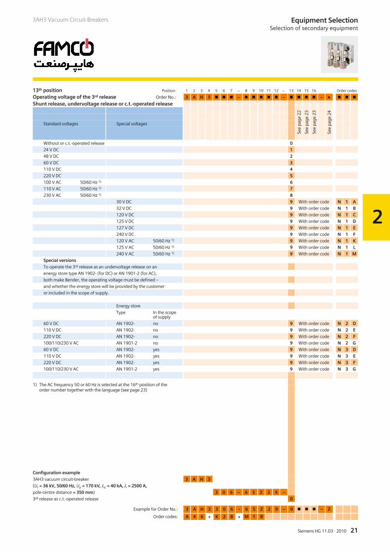
13th position Position: 1 2 3 4 5 6 7 – 8 9 10 11 12 – 13 14 15 16 Order codes
Operating voltage of the 3rd release Order No.: 3 A H 3 – – –
Shunt release, undervoltage release or c.t.-operated release
Without or c.t.-operated release 024 V DC 148 V DC 260 V DC 3110 V DC 4220 V DC 5100 V AC 50/60 Hz 1) 6110 V AC 50/60 Hz 1) 7230 V AC 50/60 Hz 1) 8
30 V DC 9 With order code N 1 A32 V DC 9 With order code N 1 B120 V DC 9 With order code N 1 C125 V DC 9 With order code N 1 D127 V DC 9 With order code N 1 E240 V DC 9 With order code N 1 F120 V AC 50/60 Hz 1) 9 With order code N 1 K125 V AC 50/60 Hz 1) 9 With order code N 1 L240 V AC 50/60 Hz 1) 9 With order code N 1 M
Special versionsTo operate the 3rd release as an undervoltage release on an
energy store type AN 1902- (for DC) or AN 1901-2 (for AC),
both make Bender, the operating voltage must be defined –
and whether the energy store will be provided by the customer
or included in the scope of supply.
Energy store
Type In the scopeof supply
60 V DC AN 1902- no 9 With order code N 2 D110 V DC AN 1902- no 9 With order code N 2 E220 V DC AN 1902- no 9 With order code N 2 F100/110/230 V AC AN 1901-2 no 9 With order code N 2 G60 V DC AN 1902- yes 9 With order code N 3 D110 V DC AN 1902- yes 9 With order code N 3 E220 V DC AN 1902- yes 9 With order code N 3 F100/110/230 V AC AN 1901-2 yes 9 With order code N 3 G
1) The AC frequency 50 or 60 Hz is selected at the 16th position of theorder number together with the language (see page 23)
Configuration example
3AH3 vacuum circuit-breaker 3 A H 3
(Ur = 36 kV, 50/60 Hz, Up = 170 kV, Isc = 40 kA, Ir = 2500 A,
pole-centre distance = 350 mm) 3 0 6 – 6 S Z 2 9 –
3rd release as c.t.-operated release 0
See
page
22
See
page
23
See
page
23
See
page
24
Standard voltages Special voltages
2
22 Siemens HG 11.03 · 2010
Equipment SelectionSelection of secondary equipment
3AH3 Vacuum Circuit-Breakers
Example for Order No.: 3 A H 3 3 0 6 – 6 S Z 2 9 – 0 K – Z
Order codes: A 4 6 + K 2 B + M 1 B
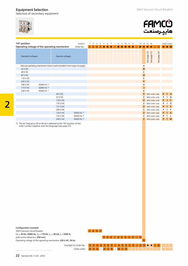
14th position Position: 1 2 3 4 5 6 7 – 8 9 10 11 12 – 13 14 15 16 Order codes
Operating voltage of the operating mechanism Order No.: 3 A H 3 – – –
Manual operating mechanism (hand crank included in the scope of supply) A24 V DC B48 V DC C60 V DC D110 V DC E220 V DC F100 V AC 50/60 Hz 1) H110 V AC 50/60 Hz 1) J230 V AC 50/60 Hz 1) K
30 V DC Z With order code P 1 A32 V DC Z With order code P 1 B120 V DC Z With order code P 1 C125 V DC Z With order code P 1 D127 V DC Z With order code P 1 E240 V DC Z With order code P 1 F120 V AC 50/60 Hz 1) Z With order code P 1 K125 V AC 50/60 Hz 1) Z With order code P 1 L240 V AC 50/60 Hz 1) Z With order code P 1 M
1) The AC frequency 50 or 60 Hz is selected at the 16th position of theorder number together with the language (see page 23)
Configuration example
3AH3 vacuum circuit-breaker 3 A H 3
(Ur = 36 kV, 50/60 Hz, Up = 170 kV, Isc = 40 kA, Ir = 2500 A,
pole-centre distance = 350 mm) 3 0 6 – 6 S Z 2 9 – 0
Operating voltage of the operating mechanism 230 V AC, 50 Hz K
See
page
23
See
page
23
See
page
24
Standard voltages Special voltages
2
23Siemens HG 11.03 · 2010
3AH3 Vacuum Circuit-Breakers Equipment SelectionSelection of secondary equipment
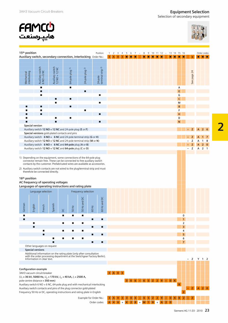
15th position Position: 1 2 3 4 5 6 7 – 8 9 10 11 12 – 13 14 15 16 Order codes
Auxiliary switch, secondary connection, interlocking Order No.: 3 A H 3 – – –
A E G
C M
B F H D N
Special versionAuxiliary switch 12 NO + 12 NC and 24-pole plug (E or F) – Z A 2 6Special versions gold-plated contacts and pins
Auxiliary switch 6 NO + 6 NC and 24-pole terminal strip (G or H) – Z A 1 7Auxiliary switch 12 NO + 12 NC and 24-pole terminal strip (M or N) – Z A 1 8Auxiliary switch 6 NO + 6 NC and 64-pole plug (A or B) – Z A 2 0Auxiliary switch 12 NO + 12 NC and 64-pole plug (C or D) – Z A 2 1
1) Depending on the equipment, some connections of the 64-pole plugconnector remain free. These can be connected to free auxiliary switchcontacts by the customer. Prefabricated wires are available as accessories.
2) Auxiliary switch contacts are not wired to the plug/terminal strip and musttherefore be connected directly.
Example for Order No.: 3 A H 3 3 0 6 – 6 S Z 2 9 – 0 K B 2 – Z
Order codes: A 4 6 + K 2 B + M 1 B + A 2 0
16th positionAC frequency of operating voltagesLanguages of operating instructions and rating plate
0 1
2 3
4 5
6 7
Other languages on request
Special versionsAdditional information on the rating plate (only after consultationwith the order processing department at the Switchgear Factory Berlin).Information in clear text. – Z Y 1 2
Configuration example
3AH3 vacuum circuit-breaker 3 A H 3
(Ur = 36 kV, 50/60 Hz, Up = 170 kV, Isc = 40 kA, Ir = 2500 A,
pole-centre distance = 350 mm) 3 0 6 – 6 S Z 2 9 – 0 K
Auxiliary switch 6 NO + 6 NC, 64-pole plug and with mechanical interlocking B
Auxiliary switch contacts and pins of the plug connector gold-plated – Z A 2 0
Frequency 50 Hz or DC, operating instructions and rating plate in English 2
Ger
man
Engl
ish
Fren
ch
Span
ish
DC
50H
z
50H
zan
dD
C
60H
z
60H
zan
dD
C
Language selection Frequency selection
Mec
hani
cal
inte
rlock
ing
Aux
iliar
ysw
itch
6N
O+
6N
C
Aux
iliar
ysw
itch
12N
O+
12N
C
64-p
ole
plug
1)
24-p
ole
plug
2)
24-p
ole
term
inal
strip
2)
See
page
24
2
24 Siemens HG 11.03 · 2010
Equipment SelectionSelection of additional equipment
3AH3 Vacuum Circuit-Breakers
Example for Order No.: 3 A H 3 3 0 6 – 6 S Z 2 9 – 0 K B 2 – Z
Order codes: A 4 6 + K 2 B + M 1 B + A 2 0 + F 2 0
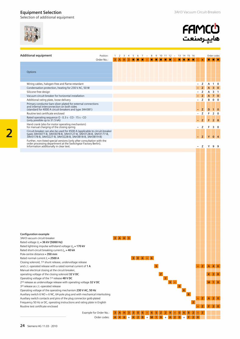
Additional equipment Position: 1 2 3 4 5 6 7 – 8 9 10 11 12 – 13 14 15 16 Order codes
Order No.: 3 A H 3 – – –
Wiring cables, halogen-free and flame-retardant – Z A 1 0Condensation protection, heating for 230 V AC, 50 W – Z A 3 0Silicone-free design – Z A 3 1Vacuum circuit-breaker for horizontal installation – Z A 7 0Additional rating plate, loose delivery – Z B 0 0Primary conductor bars silver-plated for external connectionsand internal interconnection on both sides(standard for 4000 A circuit-breakers and type 3AH381) – Z D 1 0Routine test certificate enclosed – Z F 2 0Rated operating sequence O - 0.3 s - CO - 15 s - CO(only possible up to 31.5 kA) – Z F 2 8Hand crank (also for motor operating mechanism)for manual charging of the closing spring – Z F 3 0Circuit-breaker can also be used for 4500 A (applicable to circuit-breakertypes 3AH3077-8, 3AH3078-8, 3AH3127-8, 3AH3128-8, 3AH3177-8,3AH3178-8, 3AH3227-8, 3AH3228-8, 3AH3818-8, 3AH3819-8) – Z Y 0 4Further, non-listed special versions (only after consultation with theorder processing department at the Switchgear Factory Berlin).Information additionally in clear text. – Z Y 9 9
Configuration example3AH3 vacuum circuit-breaker 3 A H 3Rated voltage Ur = 36 kV (50/60 Hz)Rated lightning impulse withstand voltage Up = 170 kVRated short-circuit breaking current Isc = 40 kAPole-centre distance = 350 mm
Rated normal current Ir = 2500 A 3 0 6 – 6
Closing solenoid, 1st shunt release, undervoltage release
and c.t.-operated release with a rated normal current of 1 A S – Z A 4 6
Manual electrical closing at the circuit-breaker,
operating voltage of the closing solenoid 32 V DC Z K 2 B
Operating voltage of the 1st release 48 V DC 2
2nd release as undervoltage release with operating voltage 32 V DC 9 – M 1 B
3rd release as c.t.-operated release 0
Operating voltage of the operating mechanism 230 V AC, 50 Hz K
Auxiliary switch 6 NO + 6 NC, 64-pole plug and with mechanical interlocking B
Auxiliary switch contacts and pins of the plug connector gold-plated – Z A 2 0
Frequency 50 Hz or DC, operating instructions and rating plate in English 2
Routine test certificate enclosed – Z F 2 0
Options
2
25Siemens HG 11.03 · 2010
Equipment SelectionAccessories and spare parts
3AH3 Vacuum Circuit-Breakers
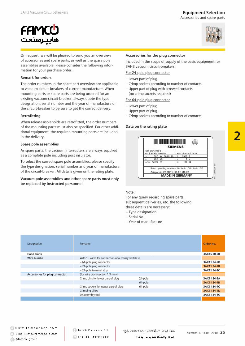
On request, we will be pleased to send you an overviewof accessories and spare parts, as well as the spare poleassemblies available. Please consider the following infor-mation for your purchase order.
Remark for orders
The order numbers in the spare part overview are applicableto vacuum circuit-breakers of current manufacture. Whenmounting parts or spare parts are being ordered for anexisting vacuum circuit-breaker, always quote the typedesignation, serial number and the year of manufacture ofthe circuit-breaker to be sure to get the correct delivery.
Retrofitting
When releases/solenoids are retrofitted, the order numbersof the mounting parts must also be specified. For other addi-tional equipment, the required mounting parts are includedin the delivery.
Spare pole assemblies
As spare parts, the vacuum interrupters are always suppliedas a complete pole including post insulator.
To select the correct spare pole assemblies, please specifythe type designation, serial number and year of manufactureof the circuit-breaker. All data is given on the rating plate.
Vacuum pole assemblies and other spare parts must onlybe replaced by instructed personnel.
Accessories for the plug connector
Included in the scope of supply of the basic equipment for3AH3 vacuum circuit-breakers:
For 24-pole plug connector
– Lower part of plug– Crimp sockets according to number of contacts– Upper part of plug with screwed contacts
(no crimp sockets required)
For 64-pole plug connector
– Lower part of plug– Upper part of plug– Crimp sockets according to number of contacts
""
Data on the rating plate
Note:For any query regarding spare parts,subsequent deliveries, etc. the followingthree details are necessary:– Type designation– Serial No.– Year of manufacture
Designation Remarks Order No.
Hand crank 3AX15 30-2BWire bundle With 10 wires for connection of auxiliary switch to
– 64-pole plug connector 3AX11 34-2D– 24-pole plug connector 3AX11 34-2B– 24-pole terminal strip 3AX11 34-2C
Accessories for plug connector (for wire cross-section 1.5 mm2)
Crimp pins for lower part of plug 24-pole 3AX11 34-3A64-pole 3AX11 34-4B
Crimp sockets for upper part of plug 64-pole 3AX11 34-4CCrimping pliers 3AX11 34-4DDisassembly tool 3AX11 34-4G
26 Siemens HG 11.03 · 201026
R-HG
11-2
05.ti
f
3AH3 Vacuum Circuit-Breakers
27Siemens HG 11.03 · 2010
3
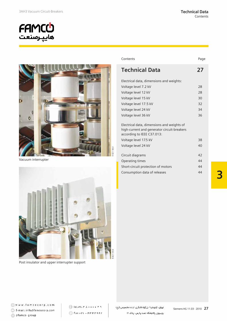
Vacuum interrupter
Post insulator and upper interrupter support
Contents Page
Technical Data
Electrical data, dimensions and weights:
Voltage level 7.2 kV
Voltage level 12 kV
Voltage level 15 kV
Voltage level 17.5 kV
Voltage level 24 kV
Voltage level 36 kV
Electrical data, dimensions and weights ofhigh-current and generator circuit-breakersaccording to IEEE C37.013:
Voltage level 17.5 kV
Voltage level 24 kV
Circuit diagrams
Operating times
Short-circuit protection of motors
Consumption data of releases
27
28
28
30
32
34
36
38
40
42
44
44
44
Technical DataContents
R-HG
11-1
96.ti
fR-
HG11
-197
.tif
3AH3 Vacuum Circuit-Breakers
28 Siemens HG 11.03 · 2010
3
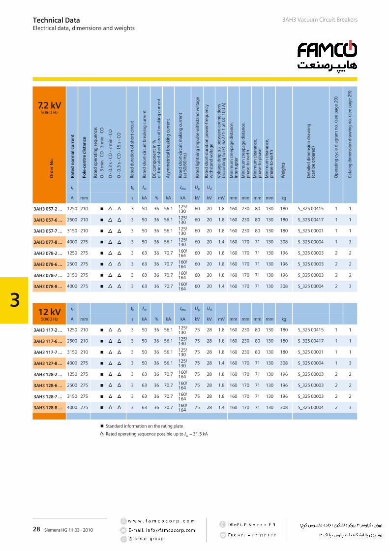
7.2 kV50/60 Hz
Ir tk Isc Ima Up Ud
A mm s kA % kA kA kV kV mV mm mm mm mm kg
3AH3 057-2 … 1250 210 3 50 36 56.1 125/130
60 20 1.8 160 230 80 130 180 S_325 00415 1 1
3AH3 057-6 … 2500 210 3 50 36 56.1 125/130
60 20 1.8 160 230 80 130 180 S_325 00417 1 1
3AH3 057-7 … 3150 210 3 50 36 56.1 125/130
60 20 1.8 160 230 80 130 180 S_325 00001 1 1
3AH3 077-8 … 4000 275 3 50 36 56.1 125/130
60 20 1.4 160 170 71 130 308 S_325 00004 1 3
3AH3 078-2 … 1250 275 3 63 36 70.7 160/164
60 20 1.8 160 170 71 130 196 S_325 00003 2 2
3AH3 078-6 … 2500 275 3 63 36 70.7 160/164
60 20 1.8 160 170 71 130 196 S_325 00003 2 2
3AH3 078-7 … 3150 275 3 63 36 70.7 160/164
60 20 1.8 160 170 71 130 196 S_325 00003 2 2
3AH3 078-8 … 4000 275 3 63 36 70.7 160/164
60 20 1.4 160 170 71 130 308 S_325 00004 2 3
12 kV50/60 Hz
Ir tk Isc Ima Up Ud
A mm s kA % kA kA kV kV mV mm mm mm mm kg
3AH3 117-2 … 1250 210 3 50 36 56.1 125/130
75 28 1.8 160 230 80 130 180 S_325 00415 1 1
3AH3 117-6 … 2500 210 3 50 36 56.1 125/130
75 28 1.8 160 230 80 130 180 S_325 00417 1 1
3AH3 117-7 … 3150 210 3 50 36 56.1 125/130
75 28 1.8 160 230 80 130 180 S_325 00001 1 1
3AH3 127-8 … 4000 275 3 50 36 56.1 125/130
75 28 1.4 160 170 71 130 308 S_325 00004 1 3
3AH3 128-2 … 1250 275 3 63 36 70.7 160/164 75 28 1.8 160 170 71 130 196 S_325 00003 2 2
3AH3 128-6 … 2500 275 3 63 36 70.7 160/164 75 28 1.8 160 170 71 130 196 S_325 00003 2 2
3AH3 128-7 … 3150 275 3 63 36 70.7 160/164 75 28 1.8 160 170 71 130 196 S_325 00003 2 2
3AH3 128-8 … 4000 275 3 63 36 70.7 160/164 75 28 1.4 160 170 71 130 308 S_325 00004 2 3
Standard information on the rating plate
Rated operating sequence possible up to Isc = 31.5 kA
Technical DataElectrical data, dimensions and weights
3AH3 Vacuum Circuit-Breakers
Ord
erN
o.
Rat
edn
orm
alcu
rren
t
Pole
-cen
tre
dis
tan
ce
Rate
dop
erat
ing
sequ
ence
:
O-3
min
-CO
-3m
in-C
O
O-0
.3s
-CO
-3m
in-C
O
O-0
.3s
-CO
-15
s-C
O
Rate
ddu
ratio
nof
shor
t-ci
rcui
t
Rate
dsh
ort-
circ
uitb
reak
ing
curr
ent
DC
com
pone
ntin
%of
the
rate
dsh
ort-
circ
uitb
reak
ing
curr
ent
Asy
mm
etric
albr
eaki
ngcu
rren
t
Rate
dsh
ort-
circ
uitm
akin
gcu
rren
t(a
t50/
60H
z)
Rate
dlig
htni
ngim
puls
ew
ithst
and
volta
ge
Rate
dsh
ort-
dura
tion
pow
er-f
requ
ency
with
stan
dvo
ltage
Vol
tage
drop
ΔUbe
twee
nco
nnec
tions
(acc
ordi
ngto
IEC
6227
1-1
atD
C10
0A
)
Min
imum
cree
page
dist
ance
,in
terr
upte
r
Min
imum
cree
page
dist
ance
,ph
ase-
to-e
arth
Min
imum
clea
ranc
e,ph
ase-
to-p
hase
Min
imum
clea
ranc
e,ph
ase-
to-e
arth
Wei
ghts
Det
aile
ddi
men
sion
draw
ing
(can
beor
dere
d)
Ope
ratin
gcy
cle
diag
ram
no.(
see
page
29)
Cata
log
dim
ensi
ondr
awin
gno
.(se
epa
ge29
)
29Siemens HG 11.03 · 2010
3
& '(
)
#
* )'+, -
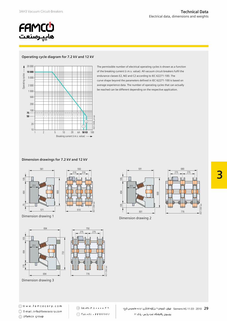
The permissible number of electrical operating cycles is shown as a function
of the breaking current (r.m.s. value). All vacuum circuit-breakers fulfil the
endurance classes E2, M2 and C2 according to IEC 62271-100. The
curve shape beyond the parameters defined in IEC 62271-100 is based on
average experience data. The number of operating cycles that can actually
be reached can be different depending on the respective application.
3AH3 Vacuum Circuit-Breakers Technical DataElectrical data, dimensions and weights
#
.
##"
#
#
Dimension drawing 1
#
.
##"
. #"
##
Dimension drawing 2
Dimension drawings for 7.2 kV and 12 kV
#
.
#.
##.
Dimension drawing 3
Operating cycle diagram for 7.2 kV and 12 kV

30 Siemens HG 11.03 · 2010
3
3AH3 Vacuum Circuit-BreakersTechnical DataElectrical data, dimensions and weights
15 kV50/60 Hz
Ir tk Isc Ima Up Ud
A mm s kA % kA kA kV kV mV mm mm mm mm kg
3AH3 167-2 … 1250 210 3 50 36 56.1 125/130
95 36 1.8 160 230 110 130 184 S_325 00416 3 4
3AH3 167-6 … 2500 210 3 50 36 56.1 125/130
95 36 1.8 160 230 110 130 184 S_325 00418 3 4
3AH3 167-7 … 3150 210 3 50 36 56.1 125/130
95 36 1.8 160 230 110 130 184 S_325 00002 3 4
3AH3 177-8 … 4000 275 3 50 36 56.1 125/130
95 36 1.4 160 170 135 130 310 S_325 00006 3 6
3AH3 178-2 … 1250 275 3 63 36 70.7 160/164
95 36 1.8 160 170 71 130 196 S_325 00005 4 5
3AH3 178-6 … 2500 275 3 63 36 70.7 160/164
95 36 1.8 160 170 71 130 196 S_325 00005 4 5
3AH3 178-7 … 3150 275 3 63 36 70.7 160/164
95 36 1.8 160 170 71 130 196 S_325 00005 4 5
3AH3 178-8 … 4000 275 3 63 36 70.7 160/164
95 36 1.4 160 170 71 130 308 S_325 00006 4 6
Standard information on the rating plate
Rated operating sequence possible up to Isc = 31.5 kA
Ord
erN
o.
Rat
edn
orm
alcu
rren
t
Pole
-cen
tre
dis
tan
ce
Rate
dop
erat
ing
sequ
ence
:
O-3
min
-CO
-3m
in-C
O
O-0
.3s
-CO
-3m
in-C
O
O-0
.3s
-CO
-15
s-C
O
Rate
ddu
ratio
nof
shor
t-ci
rcui
t
Rate
dsh
ort-
circ
uitb
reak
ing
curr
ent
DC
com
pone
ntin
%of
the
rate
dsh
ort-
circ
uitb
reak
ing
curr
ent
Asy
mm
etric
albr
eaki
ngcu
rren
t
Rate
dsh
ort-
circ
uitm
akin
gcu
rren
t(a
t50/
60H
z)
Rate
dlig
htni
ngim
puls
ew
ithst
and
volta
ge
Rate
dsh
ort-
dura
tion
pow
er-f
requ
ency
with
stan
dvo
ltage
Vol
tage
drop
ΔUbe
twee
nco
nnec
tions
(acc
ordi
ngto
IEC
6227
1-1
atD
C10
0A
)
Min
imum
cree
page
dist
ance
,in
terr
upte
r
Min
imum
cree
page
dist
ance
,ph
ase-
to-e
arth
Min
imum
clea
ranc
e,ph
ase-
to-p
hase
Min
imum
clea
ranc
e,ph
ase-
to-e
arth
Wei
ghts
Det
aile
ddi
men
sion
draw
ing
(can
beor
dere
d)
Ope
ratin
gcy
cle
diag
ram
no.(
see
page
31)
Cata
log
dim
ensi
ondr
awin
gno
.(se
epa
ge31
)

31Siemens HG 11.03 · 2010
3
3AH3 Vacuum Circuit-Breakers Technical DataElectrical data, dimensions and weights
Operating cycle diagram for 15 kV
Dimension drawings for 15 kV
)
#
* )'+, -
& '(
#
.
##"
#
#
Dimension drawing 4
#
.
##"
. #"
##
Dimension drawing 5
#
.
#.
##.
Dimension drawing 6
The permissible number of electrical operating cycles is shown as a function
of the breaking current (r.m.s. value). All vacuum circuit-breakers fulfil the
endurance classes E2, M2 and C2 according to IEC 62271-100. The
curve shape beyond the parameters defined in IEC 62271-100 is based on
average experience data. The number of operating cycles that can actually
be reached can be different depending on the respective application.
32 Siemens HG 11.03 · 2010
3
3AH3 Vacuum Circuit-BreakersTechnical DataElectrical data, dimensions and weights
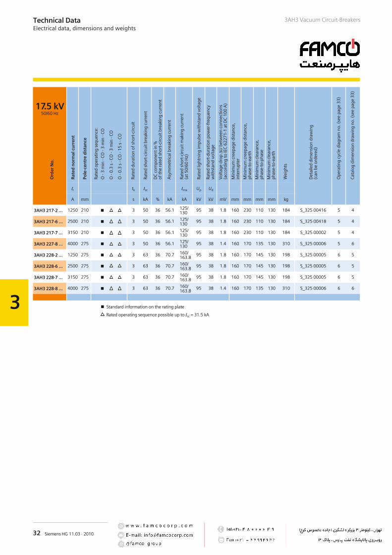
17.5 kV50/60 Hz
Ir tk Isc Ima Up Ud
A mm s kA % kA kA kV kV mV mm mm mm mm kg
3AH3 217-2 … 1250 210 3 50 36 56.1 125/130
95 38 1.8 160 230 110 130 184 S_325 00416 5 4
3AH3 217-6 … 2500 210 3 50 36 56.1 125/130
95 38 1.8 160 230 110 130 184 S_325 00418 5 4
3AH3 217-7 … 3150 210 3 50 36 56.1 125/130
95 38 1.8 160 230 110 130 184 S_325 00002 5 4
3AH3 227-8 … 4000 275 3 50 36 56.1 125/130
95 38 1.4 160 170 135 130 310 S_325 00006 5 6
3AH3 228-2 … 1250 275 3 63 36 70.7 160/163.8
95 38 1.8 160 170 145 130 198 S_325 00005 6 5
3AH3 228-6 … 2500 275 3 63 36 70.7 160/163.8
95 38 1.8 160 170 145 130 198 S_325 00005 6 5
3AH3 228-7 … 3150 275 3 63 36 70.7 160/163.8
95 38 1.8 160 170 145 130 198 S_325 00005 6 5
3AH3 228-8 … 4000 275 3 63 36 70.7 160/163.8
95 38 1.4 160 170 135 130 310 S_325 00006 6 6
Standard information on the rating plate
Rated operating sequence possible up to Isc = 31.5 kA
Ord
erN
o.
Rat
edn
orm
alcu
rren
t
Pole
-cen
tre
dis
tan
ce
Rate
dop
erat
ing
sequ
ence
:
O-3
min
-CO
-3m
in-C
O
O-0
.3s
-CO
-3m
in-C
O
O-0
.3s
-CO
-15
s-C
O
Rate
ddu
ratio
nof
shor
t-ci
rcui
t
Rate
dsh
ort-
circ
uitb
reak
ing
curr
ent
DC
com
pone
ntin
%of
the
rate
dsh
ort-
circ
uitb
reak
ing
curr
ent
Asy
mm
etric
albr
eaki
ngcu
rren
t
Rate
dsh
ort-
circ
uitm
akin
gcu
rren
t(a
t50/
60H
z)
Rate
dlig
htni
ngim
puls
ew
ithst
and
volta
ge
Rate
dsh
ort-
dura
tion
pow
er-f
requ
ency
with
stan
dvo
ltage
Vol
tage
drop
ΔUbe
twee
nco
nnec
tions
(acc
ordi
ngto
IEC
6227
1-1
atD
C10
0A
)
Min
imum
cree
page
dist
ance
,in
terr
upte
r
Min
imum
cree
page
dist
ance
,ph
ase-
to-e
arth
Min
imum
clea
ranc
e,ph
ase-
to-p
hase
Min
imum
clea
ranc
e,ph
ase-
to-e
arth
Wei
ghts
Det
aile
ddi
men
sion
draw
ing
(can
beor
dere
d)
Ope
ratin
gcy
cle
diag
ram
no.(
see
page
33)
Cata
log
dim
ensi
ondr
awin
gno
.(se
epa
ge33
)

33Siemens HG 11.03 · 2010
3
Technical DataElectrical data, dimensions and weights
3AH3 Vacuum Circuit-Breakers
Operating cycle diagram for 17.5 kV
Dimension drawings for 17.5 kV
)
#
#
* )'+, -
#
& '(
#
.
##"
#
#
Dimension drawing 4
#
.
##"
. #"
##
Dimension drawing 5
#
.
#.
##.
Dimension drawing 6
The permissible number of electrical operating cycles is shown as a function
of the breaking current (r.m.s. value). All vacuum circuit-breakers fulfil the
endurance classes E2, M2 and C2 according to IEC 62271-100. The
curve shape beyond the parameters defined in IEC 62271-100 is based on
average experience data. The number of operating cycles that can actually
be reached can be different depending on the respective application.

34 Siemens HG 11.03 · 2010
3
Technical DataElectrical data, dimensions and weights
3AH3 Vacuum Circuit-Breakers
24 kV50/60 Hz
Ir tk Isc Ima Up Ud
A mm s kA % kA kA kV kV mV mm mm mm mm kg
3AH3 266-6 … 2500 275 3 40 36 44.9 100/104
125 50 2.0 360 226 245 173 168 S_325 00007 7 7
3AH3 267-7 … 2500 275 3 50 36 56.1 125/130
110 50 1.5 161 170 228 180 198 S_325 00034 9 8
3AH3 367-8 … 4000 300 3 50 36 56.1 125/130
125 50 1.5 161 207 440 197 350 S_325 00596 9 9
Standard information on the rating plate
Rated operating sequence possible up to Isc = 31.5 kA
Ord
erN
o.
Rat
edn
orm
alcu
rren
t
Pole
-cen
tre
dis
tan
ce
Rate
dop
erat
ing
sequ
ence
:
O-3
min
-CO
-3m
in-C
O
O-0
.3s
-CO
-3m
in-C
O
O-0
.3s
-CO
-15
s-C
O
Rate
ddu
ratio
nof
shor
t-ci
rcui
t
Rate
dsh
ort-
circ
uitb
reak
ing
curr
ent
DC
com
pone
ntin
%of
the
rate
dsh
ort-
circ
uitb
reak
ing
curr
ent
Asy
mm
etric
albr
eaki
ngcu
rren
t
Rate
dsh
ort-
circ
uitm
akin
gcu
rren
t(a
t50/
60H
z)
Rate
dlig
htni
ngim
puls
ew
ithst
and
volta
ge
Rate
dsh
ort-
dura
tion
pow
er-f
requ
ency
with
stan
dvo
ltage
Vol
tage
drop
ΔUbe
twee
nco
nnec
tions
(acc
ordi
ngto
IEC
6227
1-1
atD
C10
0A
)
Min
imum
cree
page
dist
ance
,in
terr
upte
r
Min
imum
cree
page
dist
ance
,ph
ase-
to-e
arth
Min
imum
clea
ranc
e,ph
ase-
to-p
hase
Min
imum
clea
ranc
e,ph
ase-
to-e
arth
Wei
ghts
Det
aile
ddi
men
sion
draw
ing
(can
beor
dere
d)
Ope
ratin
gcy
cle
diag
ram
no.(
see
page
35)
Cata
log
dim
ensi
ondr
awin
gno
.(se
epa
ge35
)
35Siemens HG 11.03 · 2010
3
Technical DataElectrical data, dimensions and weights
3AH3 Vacuum Circuit-Breakers
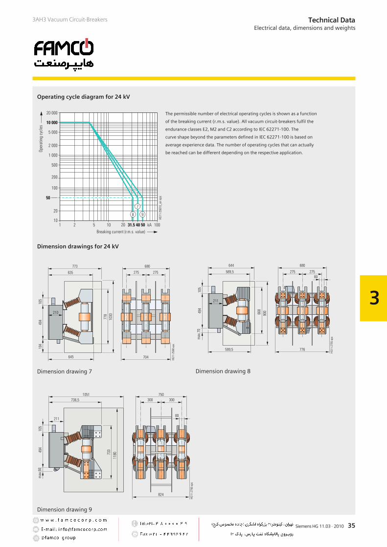
Operating cycle diagram for 24 kV
)
#
* )'+, -
"
& '(
.
.
"
.
#"
#
#"
#
Dimension drawing 7
Dimension drawings for 24 kV
.
##"
.
/
".0
..0
"
# #"
#
Dimension drawing 8
.
/#
#
#0
"
"
"
Dimension drawing 9
The permissible number of electrical operating cycles is shown as a function
of the breaking current (r.m.s. value). All vacuum circuit-breakers fulfil the
endurance classes E2, M2 and C2 according to IEC 62271-100. The
curve shape beyond the parameters defined in IEC 62271-100 is based on
average experience data. The number of operating cycles that can actually
be reached can be different depending on the respective application.
36 Siemens HG 11.03 · 2010
3
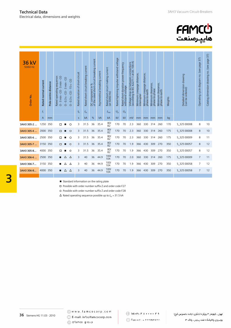
36 kV50/60 Hz
Ir tk Isc Ima Up Ud
A mm s kA % kA kA kV kV mV mm mm mm mm kg
3AH3 305-2 … 1250 350 3 31.5 36 35.4 80/82
170 70 2.3 360 330 314 260 170 S_325 00008 8 10
3AH3 305-4 … 2000 350 3 31.5 36 35.4 80/82
170 70 2.3 360 330 314 260 175 S_325 00008 8 10
3AH3 305-6 … 2500 350 3 31.5 36 35.4 80/82
170 70 2.3 360 330 314 260 175 S_325 00009 8 11
3AH3 305-7 … 3150 350 3 31.5 36 35.4 80/82
170 70 1.9 366 430 309 270 350 S_325 00057 8 12
3AH3 305-8… 4000 350 3 31.5 36 35.4 80/82
170 70 1.9 366 430 309 270 350 S_325 00057 8 12
3AH3 306-6 … 2500 350 3 40 36 44.9 100/104
170 70 2.0 360 330 314 260 175 S_325 00009 7 11
3AH3 306-7… 3150 350 3 40 36 44.9 100/104
170 70 1.9 366 430 309 270 350 S_325 00058 7 12
3AH3 306-8… 4000 350 3 40 36 44.9 100/104
170 70 1.9 366 430 309 270 350 S_325 00058 7 12
Standard information on the rating plate
Possible with order number suffix Z and order code F27
Possible with order number suffix Z and order code F28
Rated operating sequence possible up to Isc = 31.5 kA
Technical DataElectrical data, dimensions and weights
3AH3 Vacuum Circuit-Breakers
Ord
erN
o.
Rat
edn
orm
alcu
rren
t
Pole
-cen
tre
dis
tan
ce
Rate
dop
erat
ing
sequ
ence
:
O-3
min
-CO
-3m
in-C
O
O-0
.3s
-CO
-3m
in-C
O
O-0
.3s
-CO
-15
s-C
O
Rate
ddu
ratio
nof
shor
t-ci
rcui
t
Rate
dsh
ort-
circ
uitb
reak
ing
curr
ent
DC
com
pone
ntin
%of
the
rate
dsh
ort-
circ
uitb
reak
ing
curr
ent
Asy
mm
etric
albr
eaki
ngcu
rren
t
Rate
dsh
ort-
circ
uitm
akin
gcu
rren
t(a
t50/
60H
z)
Rate
dlig
htni
ngim
puls
ew
ithst
and
volta
ge
Rate
dsh
ort-
dura
tion
pow
er-f
requ
ency
with
stan
dvo
ltage
Vol
tage
drop
ΔUbe
twee
nco
nnec
tions
(acc
ordi
ngto
IEC
6227
1-1
atD
C10
0A
)
Min
imum
cree
page
dist
ance
,in
terr
upte
r
Min
imum
cree
page
dist
ance
,ph
ase-
to-e
arth
Min
imum
clea
ranc
e,ph
ase-
to-p
hase
Min
imum
clea
ranc
e,ph
ase-
to-e
arth
Wei
ghts
Det
aile
ddi
men
sion
draw
ing
(can
beor
dere
d)
Ope
ratin
gcy
cle
diag
ram
no.(
see
page
37)
Cata
log
dim
ensi
ondr
awin
gno
.(se
epa
ge37
)

37Siemens HG 11.03 · 2010
3
.
#
.
"
"
"
Dimension drawing 10
.
"
"
".
Dimension drawing 11
"
.
/
#"0#.
."#0
#0
"
.
Dimension drawing 12
Operating cycle diagram for 36 kV
)
#
* )'+, -
"
& '(
.
Dimension drawings for 36 kV
Technical DataElectrical data, dimensions and weights
3AH3 Vacuum Circuit-Breakers
The permissible number of electrical operating cycles is shown as a function
of the breaking current (r.m.s. value). All vacuum circuit-breakers fulfil the
endurance classes E2, M2 and C2 according to IEC 62271-100. The
curve shape beyond the parameters defined in IEC 62271-100 is based on
average experience data. The number of operating cycles that can actually
be reached can be different depending on the respective application.
38 Siemens HG 11.03 · 2010
3
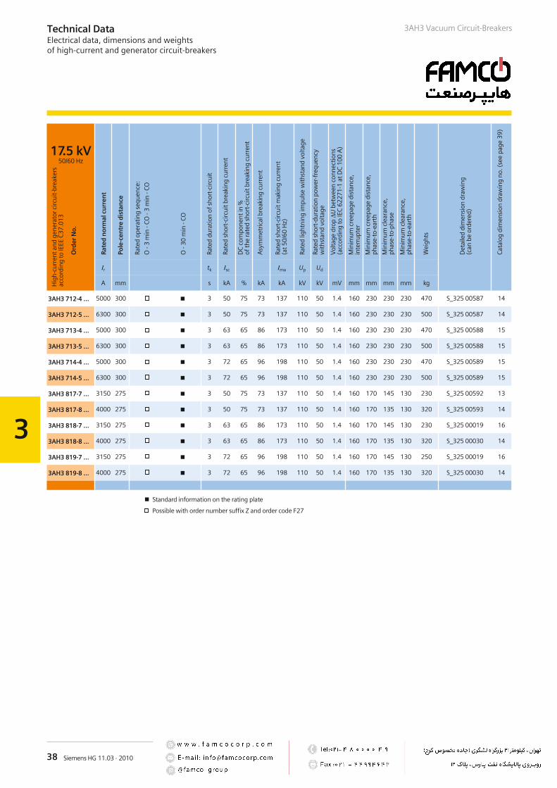
Technical DataElectrical data, dimensions and weightsof high-current and generator circuit-breakers
3AH3 Vacuum Circuit-Breakers
17.5 kV50/60 Hz
Ir tk Isc Ima Up Ud
A mm s kA % kA kA kV kV mV mm mm mm mm kg
3AH3 712-4 … 5000 300 3 50 75 73 137 110 50 1.4 160 230 230 230 470 S_325 00587 14
3AH3 712-5 … 6300 300 3 50 75 73 137 110 50 1.4 160 230 230 230 500 S_325 00587 14
3AH3 713-4 … 5000 300 3 63 65 86 173 110 50 1.4 160 230 230 230 470 S_325 00588 15
3AH3 713-5 … 6300 300 3 63 65 86 173 110 50 1.4 160 230 230 230 500 S_325 00588 15
3AH3 714-4 … 5000 300 3 72 65 96 198 110 50 1.4 160 230 230 230 470 S_325 00589 15
3AH3 714-5 … 6300 300 3 72 65 96 198 110 50 1.4 160 230 230 230 500 S_325 00589 15
3AH3 817-7 … 3150 275 3 50 75 73 137 110 50 1.4 160 170 145 130 230 S_325 00592 13
3AH3 817-8 … 4000 275 3 50 75 73 137 110 50 1.4 160 170 135 130 320 S_325 00593 14
3AH3 818-7 … 3150 275 3 63 65 86 173 110 50 1.4 160 170 145 130 230 S_325 00019 16
3AH3 818-8 … 4000 275 3 63 65 86 173 110 50 1.4 160 170 135 130 320 S_325 00030 14
3AH3 819-7 … 3150 275 3 72 65 96 198 110 50 1.4 160 170 145 130 250 S_325 00019 16
3AH3 819-8 … 4000 275 3 72 65 96 198 110 50 1.4 160 170 135 130 320 S_325 00030 14
Standard information on the rating plate
Possible with order number suffix Z and order code F27
Hig
h-cu
rren
tand
gene
rato
rcirc
uit-
brea
kers
acco
rdin
gto
IEEE
C37
.013
Ord
erN
o.
Rat
edn
orm
alcu
rren
t
Pole
-cen
tre
dis
tan
ce
Rate
dop
erat
ing
sequ
ence
:
O-3
min
-CO
-3m
in-C
O
O-3
0m
in-C
O
Rate
ddu
ratio
nof
shor
t-ci
rcui
t
Rate
dsh
ort-
circ
uitb
reak
ing
curr
ent
DC
com
pone
ntin
%of
the
rate
dsh
ort-
circ
uitb
reak
ing
curr
ent
Asy
mm
etric
albr
eaki
ngcu
rren
t
Rate
dsh
ort-
circ
uitm
akin
gcu
rren
t(a
t50/
60H
z)
Rate
dlig
htni
ngim
puls
ew
ithst
and
volta
ge
Rate
dsh
ort-
dura
tion
pow
er-f
requ
ency
with
stan
dvo
ltage
Vol
tage
drop
ΔUbe
twee
nco
nnec
tions
(acc
ordi
ngto
IEC
6227
1-1
atD
C10
0A
)
Min
imum
cree
page
dist
ance
,in
terr
upte
r
Min
imum
cree
page
dist
ance
,ph
ase-
to-e
arth
Min
imum
clea
ranc
e,ph
ase-
to-p
hase
Min
imum
clea
ranc
e,ph
ase-
to-e
arth
Wei
ghts
Det
aile
ddi
men
sion
draw
ing
(can
beor
dere
d)
Cat
alog
dim
ensi
ondr
awin
gno
.(se
epa
ge39
)
39Siemens HG 11.03 · 2010
3
.
/
.
0#
"
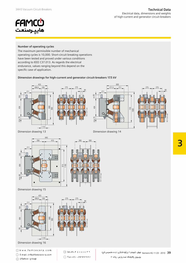
Dimension drawing 14
.
/#
"
.
#
"
Dimension drawing 15
.
.
.
.#.0
.
"
##"
Dimension drawing 16
.
/
.
.#.0
.
"
##"
Dimension drawing 13
Dimension drawings for high-current and generator circuit-breakers 17.5 kV
Number of operating cycles
Technical DataElectrical data, dimensions and weights
of high-current and generator circuit-breakers
3AH3 Vacuum Circuit-Breakers
The maximum permissible number of mechanicaloperating cycles is 10,000. Short-circuit breaking operationshave been tested and proved under various conditionsaccording to IEEE C37.013. As regards the electricalendurance, values ranging beyond this depend on thespecific case of application.

40 Siemens HG 11.03 · 2010
3
24 kV50/60 Hz
Ir tk Isc Ima Up Ud
A mm s kA % kA kA kV kV mV mm mm mm mm kg
3AH3 722-2 … 3150 300 3 50 75 73 137 125 50 1.6 160 220 538 170 350 S_325 00913 9
3AH3 722-3 … 4000 300 3 50 75 73 137 125 50 1.6 160 220 538 170 350 S_325 00597 9
3AH3 722-4 … 5000 300 3 50 75 73 137 125 50 1.6 160 207 293 170 470 S_325 00914 15
3AH3 722-5 … 6300 300 3 50 75 73 137 125 50 1.6 160 207 293 170 500 S_325 00910 15
3AH3 723-2 … 3150 300 3 63 65 86 173 125 50 1.6 160 220 538 170 350 S_325 00915 9
3AH3 723-3 … 4000 300 3 63 65 86 173 125 50 1.6 160 220 538 170 350 S_325 00909 9
3AH3 723-4 … 5000 300 3 63 65 86 173 125 50 1.6 160 207 293 170 470 S_325 00916 15
3AH3 723-5 … 6300 300 3 63 65 86 173 125 50 1.6 160 207 293 170 500 S_325 00911 15
3AH3 724-2 … 3150 300 3 72 65 96 198 125 50 1.6 160 220 538 170 350 S_325 00917 9
3AH3 724-3 … 4000 300 3 72 65 96 198 125 50 1.6 160 220 538 170 350 S_325 00918 9
3AH3 724-4 … 5000 300 3 72 65 96 198 125 50 1.6 160 207 293 170 470 S_325 00919 15
3AH3 724-5 … 6300 300 3 72 65 96 198 125 50 1.6 160 207 293 170 500 S_325 00920 15
Standard information on the rating plate
Possible with order number suffix Z and order code F27
Technical DataElectrical data, dimensions and weightsof high-current and generator circuit-breakers
3AH3 Vacuum Circuit-Breakers
Hig
h-cu
rren
tand
gene
rato
rcirc
uit-
brea
kers
acco
rdin
gto
IEEE
C37
.013
Ord
erN
o.
Rat
edn
orm
alcu
rren
t
Pole
-cen
tre
dis
tan
ce
Rate
dop
erat
ing
sequ
ence
:
O-3
min
-CO
-3m
in-C
O
O-3
0m
in-C
O
Rate
ddu
ratio
nof
shor
t-ci
rcui
t
Rate
dsh
ort-
circ
uitb
reak
ing
curr
ent
DC
com
pone
ntin
%of
the
rate
dsh
ort-
circ
uitb
reak
ing
curr
ent
Asy
mm
etric
albr
eaki
ngcu
rren
t
Rate
dsh
ort-
circ
uitm
akin
gcu
rren
t(a
t50/
60H
z)
Rate
dlig
htni
ngim
puls
ew
ithst
and
volta
ge
Rate
dsh
ort-
dura
tion
pow
er-f
requ
ency
with
stan
dvo
ltage
Vol
tage
drop
ΔUbe
twee
nco
nnec
tions
(acc
ordi
ngto
IEC
6227
1-1
atD
C10
0A
)
Min
imum
cree
page
dist
ance
,in
terr
upte
r
Min
imum
cree
page
dist
ance
,ph
ase-
to-e
arth
Min
imum
clea
ranc
e,ph
ase-
to-p
hase
Min
imum
clea
ranc
e,ph
ase-
to-e
arth
Wei
ghts
Det
aile
ddi
men
sion
draw
ing
(can
beor
dere
d)
Cat
alog
dim
ensi
ondr
awin
gno
.(se
epa
ge41
)
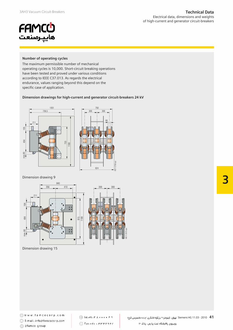
41Siemens HG 11.03 · 2010
3
.
/#
"
.
#
"
Dimension drawing 15
.
/#
#
#0
"
"
"
Dimension drawing 9
Technical DataElectrical data, dimensions and weights
of high-current and generator circuit-breakers
3AH3 Vacuum Circuit-Breakers
Dimension drawings for high-current and generator circuit-breakers 24 kV
Number of operating cycles
The maximum permissible number of mechanicaloperating cycles is 10,000. Short-circuit breaking operationshave been tested and proved under various conditionsaccording to IEEE C37.013. As regards the electricalendurance, values ranging beyond this depend on thespecific case of application.

42 Siemens HG 11.03 · 2010
3
Technical DataCircuit diagrams
3AH3 Vacuum Circuit-Breakers
1
2
3
3
41
Manual closing – manual opening with auxiliary switch 6 NO + 6 NC
#
#
#
#
.
Contacts available for customer with basic circuit-breaker equipment and auxiliary switch 6 NO + 6 NC
Manual Closing andelectrical closing anti-pumping
Motor operating mechanism with manual electrical closing
Additional equipment: Motor operating mechanism and auxiliary switch
2nd shunt release C.t.-operated Low-energy Undervoltage releaserelease 0.5 A c.t.-operatedor 1 A release 0.1 Ws
Circuit diagramsThe circuit diagrams shown here are examples from the manifold possibilities of circuit-breaker wiring.
The available possible combinations are described in the chapter “Selection of secondary equipment”.
"
"
#
"
!
"#
.
"
1
2
3
3
41
Legend see page 43
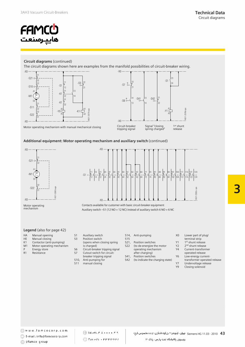
43Siemens HG 11.03 · 2010
3
#
#
#
#
"
"
"
"
.
.
.
.
"
Contacts available for customer with basic circuit-breaker equipment
Auxiliary switch –S1 (12 NO + 12 NC) instead of auxiliary switch 6 NO + 6 NC
.
Motor operating mechanism with manual mechanical closing
#
"
Circuit-breaker Signal “closing 1st shunttripping signal spring charged” release
"
Motor operatingmechanism
Technical DataCircuit diagrams
3AH3 Vacuum Circuit-Breakers
Additional equipment: Motor operating mechanism and auxiliary switch (continued)
Legend (also for page 42)HA Manual openingHE Manual closingK1 Contactor (anti-pumping)M1 Motor operating mechanismP Energy storeR1 Resistance
S1 Auxiliary switchS3 Position switch
(opens when closing springis charged)
S6 Circuit-breaker tripping signalS7 Cutout switch for circuit-
breaker tripping signalS10, Anti-pumping forS11 manual closing
S14, Anti-pumpingS15S21, Position switchesS22 (to de-energize the motor
operating mechanismafter charging)
S41, Position switchesS42 (to indicate the charging state)
X0 Lower part of plug/terminal strip
Y1 1st shunt releaseY2 2nd shunt releaseY4 Current-transformer
operated releaseY6 Low-energy current-
transformer operated releaseY7 Undervoltage releaseY9 Closing solenoid
Circuit diagrams (continued)The circuit diagrams shown here are examples from the manifold possibilities of circuit-breaker wiring.

44 Siemens HG 11.03 · 2010
3
Operating times
Operating times at rated voltageof the secondary circuit
Equipment of circuit-breaker Operating time of circuit-breaker
Closing time – < 75 ms 1)
Opening time 1st shunt release < 60 ms 1)
2nd and 3rd release < 55 ms
Arcing time – < 15 ms
Break time 1st shunt release < 80 ms
2nd and 3rd release < 60 ms
Dead time – 300 ms
CLOSE/OPEN contact time 1st shunt release < 90 ms
2nd and 3rd release < 70 ms
Minimum command duration Closing solenoid 45 ms
1st shunt release 40 ms
2nd and 3rd release 20 ms
Pulse time for circuit-breaker tripping signal 1st shunt release > 15 ms
2nd and 3rd release > 10 ms
Charging time for electrical operation – < 15 s
Synchronism error between the poles – w 2 ms
1) Shorter operating times on request.
Technical DataOperating times, short-circuit protection of motors, consumption data of releases
3AH3 Vacuum Circuit-Breakers
Short-circuit protection of motors (fuse protection of drive motors)
Rated voltageof the motor
Operating voltage Power consumption of the motor Smallest possible ratedcurrent 2) of the m.c.b.(miniature circuit-breaker)with C-characteristic
V max. V min. V W (at DC) VA (at AC) A
24 DC 26 20 500 – 16
48 DC 53 41 500 – 8
60 DC 66 51 500 – 6
110 DC 121 93 500 – 4
220 DC 242 187 500 – 2
110 AC 121 93 – 650 4
230 AC 244 187 – 650 2
2) The current inrush in the drive motor can be neglected due to its very short presence.
Consumption data of releases
Release Power consumption
Operation at
Tripping ranges
DC
approx. W
AC 50/60 Hz
approx. VA
Tripping voltage
at DC
Tripping voltageor tripping current
at AC 50/60 Hz
Closing solenoid 3AY15 10 140 140 85 to 110 % U 85 to 110 % U1st shunt release(without energy store) 3AY15 10
140 140 70 to 110 % U 85 to 110 % U
2nd shunt release(with energy store) 3AY11 01
70 50 70 to 110 % U 85 to 110 % U
Undervoltage release 3AY11 03 20 20 35 to 0 % U 35 to 0 % UCurrent-transformer operated release 3AX11 02(rated normal current 0.5 or 1 A)
– 10 3) – 90 to 110 % Ia
Current-transformer operated release 3AX11 04(tripping pulse W 0.1 Ws)
– – – –
3) Consumption at pickup current (90 % of the rated normal current) and open armature.

45Siemens HG 11.03 · 2010
4
Switchgear Factory in Berlin, Germany
Contents Page
Annex
Inquiry form
Configuration instructions
Configuration aid
45
46
47
AnnexContents
R-HG
11-1
81.ti
f
3AH3 Vacuum Circuit-Breakers
Foldout page
Brandenburg Gate, Berlin, Germany
R-HG
11-1
80.e
ps
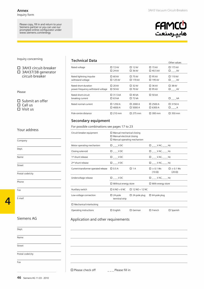
46 Siemens HG 11.03 · 2010
4
AnnexInquiry form
Inquiry concerning
3AH3 circuit-breaker 3AH37/38 generator
circuit-breaker
Please
Submit an offer Call us Visit us
Your address
Company
Dept.
Name
Street
Postal code/city
Phone
Fax
Siemens AG
Dept.
Name
Street
Postal code/city
Fax
Technical DataOther values
Rated voltage 7.2 kV
24 kV
12 kV
36 kV
15 kV
40.5 kV
17.5 kV
_ _ _ kV
Rated lightning impulse
withstand voltage
60 kV
125 kV
75 kV
170 kV
95 kV
195 kV
110 kV
_ _ _ kV
Rated short-duration
power-frequency withstand voltage
20 kV
50 kV
32 kV
70 kV
36 kV
95 kV
38 kV
_ _ _ kV
Rated short-circuit
breaking current
31.5 kA
63 kA
40 kA
72 kA
50 kA
_ _ _ kA
Rated normal current 1250 A
4000 A
2000 A
5000 A
2500 A
6300 A
3150 A
_ _ _ A
Pole-centre distance 210 mm 275 mm 300 mm 350 mm
3AH3 Vacuum Circuit-Breakers
Application and other requirements
Please check off _ _ _ Please fill in
Please copy, fill in and return to yourSiemens partner or you can use ourprompted online configurator underwww.siemens.com/energy
Secondary equipment
For possible combinations see pages 17 to 23
Circuit-breaker equipment Manual mechanical closing
Manual electrical closing
Manual operating mechanism
Motor operating mechanism _ _ _ V DC _ _ _ V AC, _ _ _ Hz
Closing solenoid _ _ _ V DC _ _ _ V AC, _ _ _ Hz
1st shunt release _ _ _ V DC _ _ _ V AC, _ _ _ Hz
2nd shunt release _ _ _ V DC _ _ _ V AC, _ _ _ Hz
Current-transformer operated release 0.5 A 1 A 0.1 Ws
(10 c)
0.1 Ws
(20 c)
Undervoltage release _ _ _ V DC _ _ _ V AC, _ _ _ Hz
Without energy store With energy store
Auxiliary switch 6 NO + 6 NC 12 NO + 12 NC
Low-voltage connection 24-pole
terminal strip
24-pole plug 64-pole plug
Mechanical interlocking
Operating instructions English German French Spanish
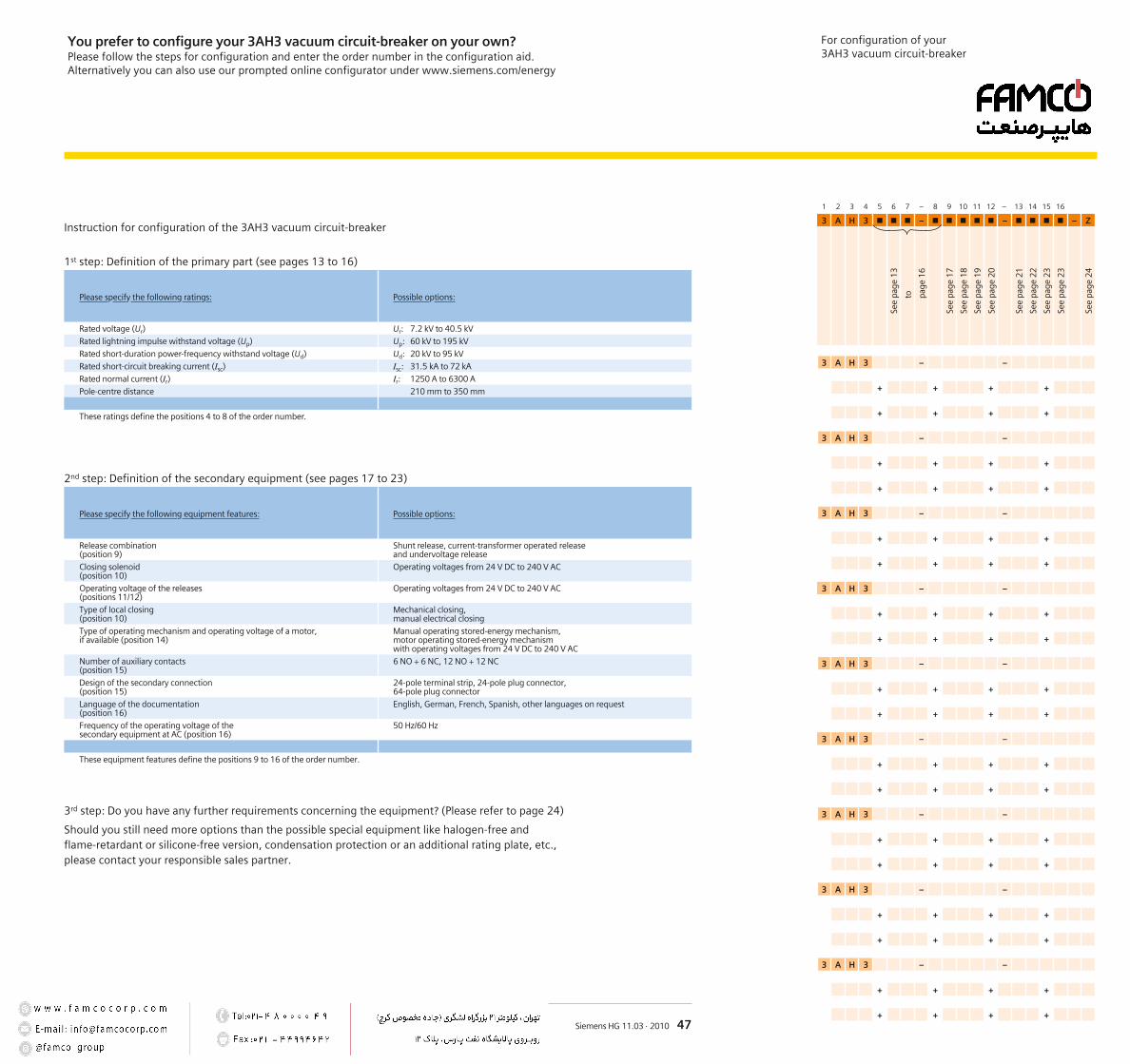
1 2 3 4 5 6 7 – 8 9 10 11 12 – 13 14 15 16
3 A H 3 – – – Z
3 A H 3 – –
+ + + +
+ + + +
3 A H 3 – –
+ + + +
+ + + +
3 A H 3 – –
+ + + +
+ + + +
3 A H 3 – –
+ + + +
+ + + +
3 A H 3 – –
+ + + +
+ + + +
3 A H 3 – –
+ + + +
+ + + +
3 A H 3 – –
+ + + +
+ + + +
3 A H 3 – –
+ + + +
+ + + +
3 A H 3 – –
+ + + +
+ + + +
See
page
17
See
page
18
See
page
19
See
page
20
See
page
21
See
page
22
See
page
23
See
page
23
See
page
24
See
page
13
to page
16
For configuration of your3AH3 vacuum circuit-breaker
Siemens HG 11.03 · 2010 47
You prefer to configure your 3AH3 vacuum circuit-breaker on your own?Please follow the steps for configuration and enter the order number in the configuration aid.Alternatively you can also use our prompted online configurator under www.siemens.com/energy
Instruction for configuration of the 3AH3 vacuum circuit-breaker
1st step: Definition of the primary part (see pages 13 to 16)
Please specify the following ratings: Possible options:
Rated voltage (Ur) Ur: 7.2 kV to 40.5 kV
Rated lightning impulse withstand voltage (Up) Up: 60 kV to 195 kV
Rated short-duration power-frequency withstand voltage (Ud) Ud: 20 kV to 95 kV
Rated short-circuit breaking current (Isc) Isc: 31.5 kA to 72 kA
Rated normal current (Ir) Ir: 1250 A to 6300 A
Pole-centre distance 210 mm to 350 mm
These ratings define the positions 4 to 8 of the order number.
2nd step: Definition of the secondary equipment (see pages 17 to 23)
Please specify the following equipment features: Possible options:
Release combination(position 9)
Shunt release, current-transformer operated releaseand undervoltage release
Closing solenoid(position 10)
Operating voltages from 24 V DC to 240 V AC
Operating voltage of the releases(positions 11/12)
Operating voltages from 24 V DC to 240 V AC
Type of local closing(position 10)
Mechanical closing,manual electrical closing
Type of operating mechanism and operating voltage of a motor,if available (position 14)
Manual operating stored-energy mechanism,motor operating stored-energy mechanismwith operating voltages from 24 V DC to 240 V AC
Number of auxiliary contacts(position 15)
6 NO + 6 NC, 12 NO + 12 NC
Design of the secondary connection(position 15)
24-pole terminal strip, 24-pole plug connector,64-pole plug connector
Language of the documentation(position 16)
English, German, French, Spanish, other languages on request
Frequency of the operating voltage of thesecondary equipment at AC (position 16)
50 Hz/60 Hz
These equipment features define the positions 9 to 16 of the order number.
3rd step: Do you have any further requirements concerning the equipment? (Please refer to page 24)
Should you still need more options than the possible special equipment like halogen-free andflame-retardant or silicone-free version, condensation protection or an additional rating plate, etc.,please contact your responsible sales partner.
R-HG
11-1
82.ti
f
www.siemens.com/energy
Published by and copyright © 2010:Siemens AGEnergy SectorFreyeslebenstrasse 191058 Erlangen, Germany
Siemens AGEnergy SectorPower Distribution DivisionMedium VoltageNonnendammallee 10413623 Berlin, Germany
For more information, please contact ourCustomer Support Center.Phone: +49 180 524 70 00Fax: +49 180 524 24 71(Charges depending on provider)E-mail: [email protected]
Order No. E50001-K1511-A031-A3-7600Printed in GermanyDispo 40402, c4bs 7470KG 05.10 2.0 50 En3600/24904
Printed on elementary chlorine-free bleached paper.
All rights reserved.If not stated otherwise on the individual pages of thiscatalog, we reserve the right to include modifications,especially regarding the stated values, dimensions and weights.Drawings are not binding.All product designations used are trademarks or productnames of Siemens AG or other suppliers.If not stated otherwise, all dimensions in thiscatalog are given in mm.
Subject to change without prior notice.The information in this document contains generaldescriptions of the technical options available, whichmay not apply in all cases. The required technicaloptions should therefore be specified in the contract.
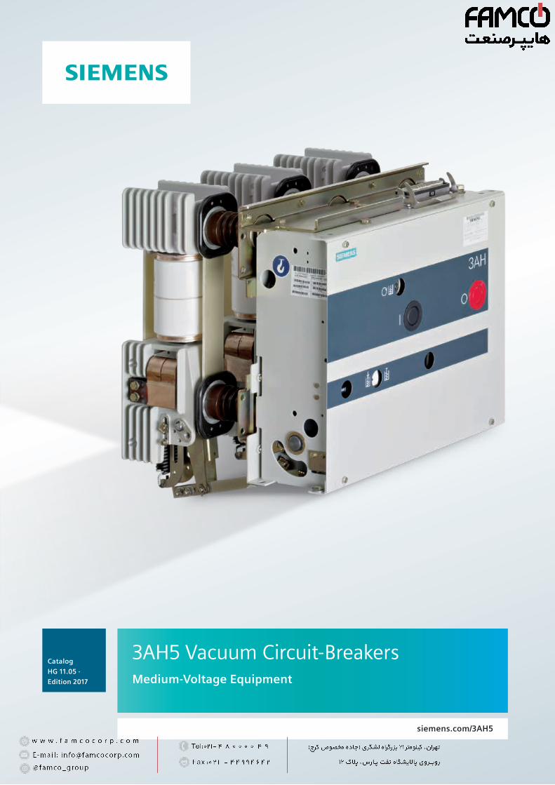
Catalog
HG 11.05 ·
Edition 2017
siemens.com/3AH5
3AH5 Vacuum Circuit-Breakers Medium-Voltage Equipment
2 3AH5 Vacuum Circuit-Breakers · Siemens HG 11.05 · 2017
R-HG
11-3
73.ti
f

1
2
3
4
33AH5 Vacuum Circuit-Breakers · Siemens HG 11.05 · 2017
Description 5General 6
Construction and mode of operation 7
Standards 8
Maintenance-free design, ambient conditions, current carrying capacity and dielectric strength 9
Product range overview and basic equipment 10
Equipment Selection 11Ordering data and configuration example 12
Selection of basic types, circuit-breakers 13
Selection of secondary equipment 15
Selection of additional equipment 20
Accessories and spare parts 21
Technical Data 23Electrical data, dimensions, weights and dimension drawings 24
Operating times, short-circuit protection of motors, consumption data of releases 31
Circuit diagrams 32
Annex 33Inquiry form 34
Configuration instructions 35
Configuration aid Foldout page
Contents Page
3AH5 Vacuum Circuit-Breakers Medium-Voltage EquipmentCatalog HG 11.05 · 2017
Invalid: Catalog HG 11.05 · 2010
Contents
The products and systems described in this catalog are manufactured and sold according to a certified management system (acc. to ISO 9001, ISO 14001 and BS OHSAS 18001).
4 3AH5 Vacuum Circuit-Breakers · Siemens HG 11.05 · 2017
R-HG
11-3
57.ti
f
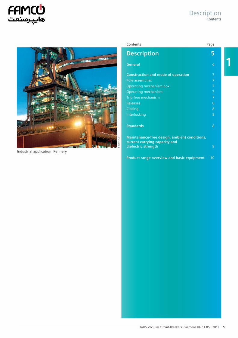
1
53AH5 Vacuum Circuit-Breakers · Siemens HG 11.05 · 2017
Description 5 General 6
Construction and mode of operation 7
Pole assemblies 7
Operating mechanism box 7
Operating mechanism 7
Trip-free mechanism 7
Releases 8
Closing 8
Interlocking 8
Standards 8
Maintenance-free design, ambient conditions, current carrying capacity and dielectric strength 9
Product range overview and basic equipment 10
Contents Page
R-HG
11-1
74.ti
f
Industrial application: Refinery
DescriptionContents
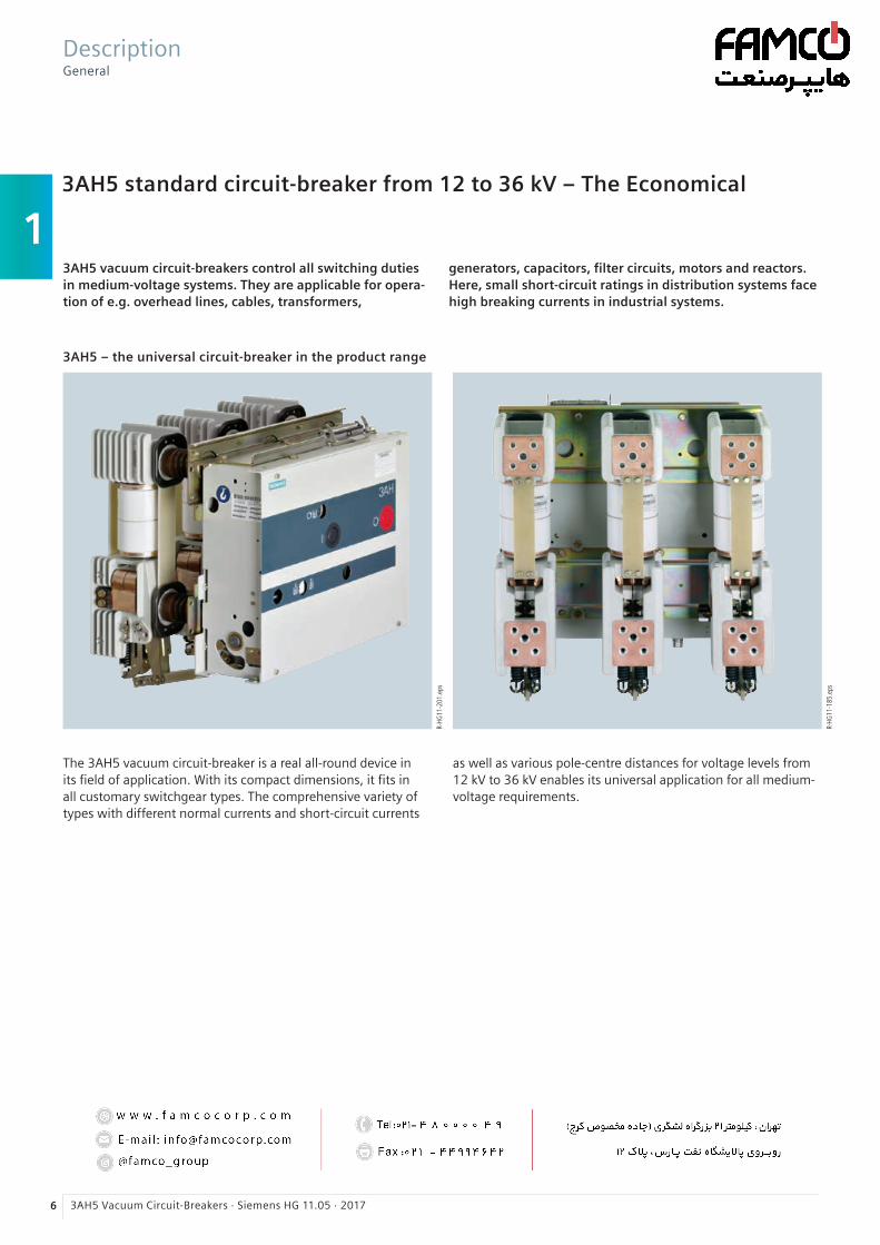
1
6 3AH5 Vacuum Circuit-Breakers · Siemens HG 11.05 · 2017
3AH5 standard circuit-breaker from 12 to 36 kV – The Economical
3AH5 vacuum circuit-breakers control all switching duties in medium-voltage systems. They are applicable for opera-tion of e.g. overhead lines, cables, transformers,
R-HG
11-2
01.e
ps
R-HG
11-1
85.e
ps
3AH5 – the universal circuit-breaker in the product range
generators, capacitors, filter circuits, motors and reactors. Here, small short-circuit ratings in distribution systems face high breaking currents in industrial systems.
The 3AH5 vacuum circuit-breaker is a real all-round device in its field of application. With its compact dimensions, it fits in all customary switchgear types. The comprehensive variety of types with different normal currents and short-circuit currents
DescriptionGeneral
as well as various pole-centre distances for voltage levels from 12 kV to 36 kV enables its universal application for all medium-voltage requirements.

1
73AH5 Vacuum Circuit-Breakers · Siemens HG 11.05 · 2017
The 3AH5 vacuum circuit-breaker consists of the pole assem-blies (1) and the operating mechanism box (2). The pole as-semblies are fixed to the operating mechanism box via post insulators (3). The switching movement is transferred by means of operating rods (4) and levers.
Pole assemblies
The pole assemblies consist of the vacuum interrupters (5) and the interrupter supports. The vacuum interrupters are air-insulated and freely accessible. This makes it possible to clean the insulating parts easily in adverse ambient condi-tions. The vacuum interrupter is rigidly fixed to the upper interrupter support (6). The lower part of the interrupter is guided in the lower interrupter support (7), allowing axial movement. The braces (8) absorb the external forces result-ing from switching operations and the contact pressure.
Operating mechanism box
The whole operating mechanism with releases, auxiliary switches, indicators and actuating devices is accommodated in the operating mechanism box. The extent of the second-ary equipment depends on the case of application and offers a multiple variety of options in order to meet almost every requirement.
Operating mechanism
For circuit-breaker operation, both spring-operated and stored-energy mechanisms are available. With manual spring-operated mechanisms, the closing process takes place automatically after manual charging of the closing spring. The opening or contact springs are charged simultaneously during the closing operation, which means that a stored energy mechanism is available for the opening operation.
With motor or manual operating stored-energy mechanisms, the closing spring is either charged electrically or manually. It latches tight at the end of the charging process and serves as an energy store.
To close the breaker, the closing spring can be unlatched either mechanically by means of the local “ON” pushbutton or electrically by remote control. The closing spring charges the opening or contact pressure springs as the breaker clos-es. The now discharged closing spring will be charged again automatically by the mechanism motor or manually. Then the operating sequence OPEN-CLOSE-OPEN is stored in the springs.
Trip-free mechanism
3AH5 vacuum circuit-breakers have a trip-free mechanism according to IEC 62271-100. In the event of an opening com-mand being given after a closing operation has been initiated, the moving contacts return to the open position and remain there even if the closing command is sustained. This means that the contacts of the vacuum circuit-breakers are momen-tarily in the closed position, which is permissible according to IEC 62271-100.
Circuit-breaker structure
1 Pole assembly
2 Operating mechanism box
3 Post insulator
4 Operating rod
5 Vacuum interrupter
6 Upper interrupter support
7 Lower interrupter support
8 Brace
Front view
Open operating mechanism box
R-HG
11-1
86.ti
fR-
HG11
-187
.tif
DescriptionConstruction and mode of operation
1
8 3AH5 Vacuum Circuit-Breakers · Siemens HG 11.05 · 2017
An electrical closing lock-out prevents unpermissible clos-ing of the circuit-breaker. The closing lock-out releases the operation of the circuit-breaker when auxiliary voltage is available, and blocks both local manual closing and remote electrical closing mechanically when there is no auxiliary voltage available.
The operating voltage of the electrical closing lock-out is the same as that of the closing solenoid. If constant CLOSE and OPEN commands are present at the vacuum circuit-breaker at the same time, the vacuum circuit-breaker will return to the open position after closing. It remains in this position until a new CLOSE command is given. In this manner, continuous closing and opening (= “pumping”) is prevented.
Interlocking
Mechanical interlocking for stored-energy mechanisms
To interlock circuit-breaker trucks, withdrawable parts or dis-connectors according to the switch position, the stored en-ergy mechanisms of 3AH5 circuit-breakers can be equipped with a mechanical interlocking. A sensor at the switchgear checks the position of the circuit-breaker and prevents the open circuit-breaker in a reliable way from being closed me-chanically and electrically.
Electrical interlocking
The vacuum circuit-breakers can be integrated in electro-magnetic feeder or switchgear interlocks. In case of electrical interlocking, the disconnector or its operating mechanism is equipped with a magnetic lock-out mechanism. This mecha-nism is controlled by an auxiliary contact of the circuit-breaker, so that the disconnector can only be operated when the circuit-breaker is open. On the other hand, the vacuum circuit-breaker is also controlled by the disconnector or its operating mechanism, so that it can only be closed when the disconnector is in an end position. For this purpose, the circuit-breaker operating mechanism must be equipped with a closing lock-out (see “Closing”).
Standards
3AH5 vacuum circuit-breakers conform to the following standards:• IEC 62271-100 (former IEC 60056)
• IEC 62271-1 (former IEC 60694)
• VDE 0671(former VDE 0670 Part 100 and VDE 0670 Part 1000)
All 3AH5 vacuum circuit-breakers fulfil the endurance classes E2, M2 and C2 according to IEC 62271-100.
Releases
A release is a device which transfers electrical commands from an external source, such as a control room, to the latch-ing mechanism of the vacuum circuit-breaker so that it can be opened or closed. Apart from the closing solenoid, the maximum possible equipment is one shunt release and an-other release to be selected at will. For release combinations, refer to page 15.
• The closing solenoid unlatches the charged closing spring of the vacuum circuit-breaker, closing it by electrical means. It is suitable for DC or AC voltage.
• Shunt releases are used for automatic tripping of vacuum circuit-breakers by suitable protection relays and for deliber-ate tripping by electrical means. They are intended for con-nection to an external power supply (DC or AC voltage) but, in special cases, may also be connected to a voltage trans-former for manual operation.
• Current-transformer operated releases comprise a stored energy mechanism, an unlatching mechanism and an elec-tromagnetic system. They are used when there is no external source of auxiliary power (e.g. a battery). Tripping is effected by means of a protection relay (e.g. overcurrent time protec-tion) acting on the current-transformer operated release. When the tripping current is exceeded (= 90 % of the rated normal current of the c.t.-operated release), the latch of the energy store, and thus opening of the circuit-breaker, is re-leased.
• Undervoltage releases comprise a stored-energy mecha-nism, an unlatching mechanism and an electromagnetic system which is permanently connected to the secondary or auxiliary voltage while the vacuum circuit-breaker is closed. If the voltage falls below a predetermined value, unlatching of the release is enabled and the circuit-breaker is opened via the stored-energy mechanism.
The deliberate tripping of the undervoltage release generally takes place via an NC contact in the tripping circuit or via an NO contact by short-circuiting the magnet coil. With this type of tripping, the short-circuit current is limited by the built-in resistors. Undervoltage releases can also be connected to voltage transformers. When the operating voltage drops to impermissibly low levels, the circuit-breaker is tripped auto-matically.
For delayed tripping, the undervoltage release can be com-bined with energy stores.
Closing
In the standard version of the stored-energy mechanisms, 3AH5 vacuum circuit-breakers can be remote-closed electri-cally. They can also be closed locally by mechanical unlatch-ing of the closing spring via pushbutton. With spring oper-ated mechanisms, closing obligatory takes place after the charging process.
DescriptionConstruction and mode of operation, standards
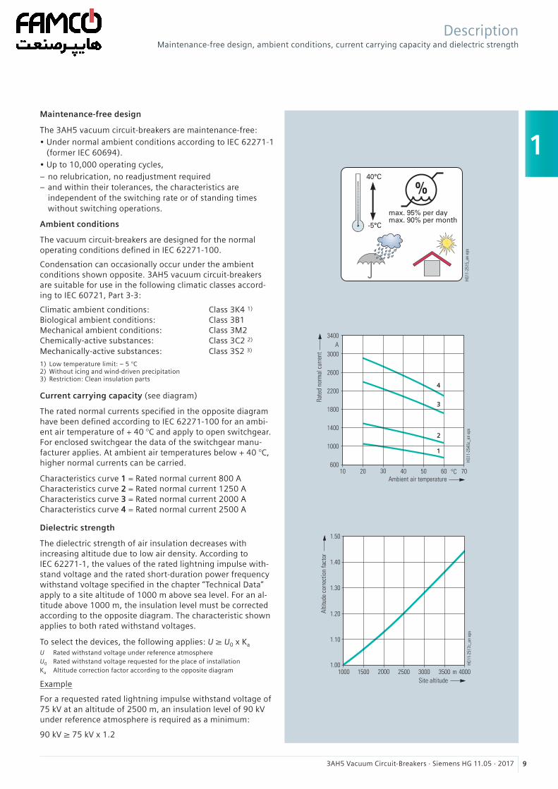
1
93AH5 Vacuum Circuit-Breakers · Siemens HG 11.05 · 2017
Maintenance-free design
The 3AH5 vacuum circuit-breakers are maintenance-free:• Under normal ambient conditions according to IEC 62271-1
(former IEC 60694).• Up to 10,000 operating cycles,
– no relubrication, no readjustment required – and within their tolerances, the characteristics are independent of the switching rate or of standing times without switching operations.
Ambient conditions
The vacuum circuit-breakers are designed for the normal operating conditions defined in IEC 62271-100.
Condensation can occasionally occur under the ambient conditions shown opposite. 3AH5 vacuum circuit-breakers are suitable for use in the following climatic classes accord-ing to IEC 60721, Part 3-3:
Climatic ambient conditions: Class 3K4 1) Biological ambient conditions: Class 3B1 Mechanical ambient conditions: Class 3M2 Chemically-active substances: Class 3C2 2) Mechanically-active substances: Class 3S2 3)
1) Low temperature limit: – 5 °C2) Without icing and wind-driven precipitation3) Restriction: Clean insulation parts
Current carrying capacity (see diagram)
The rated normal currents specified in the opposite diagram have been defined according to IEC 62271-100 for an ambi-ent air temperature of + 40 °C and apply to open switchgear. For enclosed switchgear the data of the switchgear manu-facturer applies. At ambient air temperatures below + 40 °C, higher normal currents can be carried.
Characteristics curve 1 = Rated normal current 800 A Characteristics curve 2 = Rated normal current 1250 A Characteristics curve 3 = Rated normal current 2000 A Characteristics curve 4 = Rated normal current 2500 A
Dielectric strength
The dielectric strength of air insulation decreases with increasing altitude due to low air density. According to IEC 62271-1, the values of the rated lightning impulse with-stand voltage and the rated short-duration power frequency withstand voltage specified in the chapter “Technical Data” apply to a site altitude of 1000 m above sea level. For an al-titude above 1000 m, the insulation level must be corrected according to the opposite diagram. The characteristic shown applies to both rated withstand voltages.
To select the devices, the following applies: U ≥ U0 x Ka
U Rated withstand voltage under reference atmosphereU0 Rated withstand voltage requested for the place of installationKa Altitude correction factor according to the opposite diagram
Example
For a requested rated lightning impulse withstand voltage of 75 kV at an altitude of 2500 m, an insulation level of 90 kV under reference atmosphere is required as a minimum:
90 kV ≥ 75 kV x 1.2
DescriptionMaintenance-free design, ambient conditions, current carrying capacity and dielectric strength
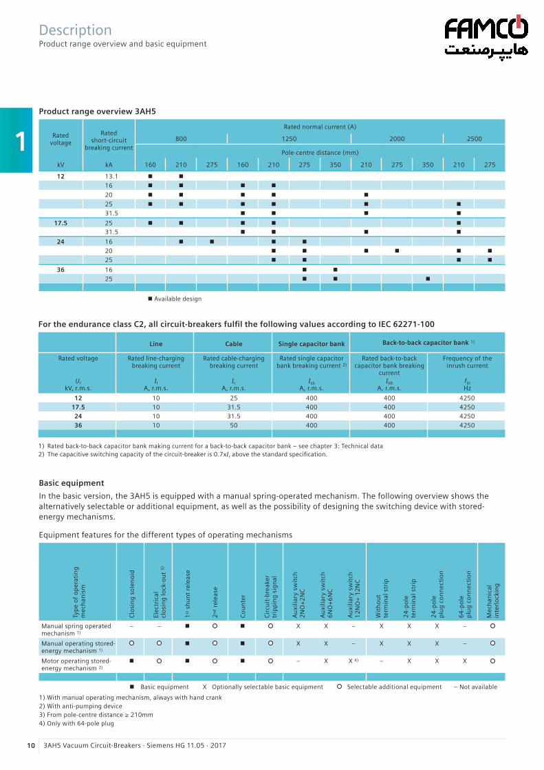
1
10 3AH5 Vacuum Circuit-Breakers · Siemens HG 11.05 · 2017
Product range overview 3AH5
Ratedvoltage
Ratedshort-circuit
breaking current
Rated normal current (A)
800 1250 2000 2500
Pole-centre distance (mm)
kV kA 160 210 275 160 210 275 350 210 275 350 210 275
12 13.1 n n
16 n n n n
20 n n n n n
25 n n n n n n
31.5 n n n n
17.5 25 n n n n n31.5 n n n n
24 16 n n n n
20 n n n n n n
25 n n n n
36 16 n n
25 n n n
n Available design
Basic equipment
In the basic version, the 3AH5 is equipped with a manual spring-operated mechanism. The following overview shows the alternatively selectable or additional equipment, as well as the possibility of designing the switching device with stored- energy mechanisms.
Equipment features for the different types of operating mechanisms
Typ
e o
f o
per
atin
gm
ech
anis
m
Clo
sin
g s
ole
no
id
Elec
tric
alcl
osi
ng
lock
-ou
t 3
)
1st
sh
un
t re
leas
e
2n
d r
elea
se
Co
un
ter
Cir
cuit
-bre
aker
trip
pin
g s
ign
al
Au
xilia
ry s
wit
ch2
NO
+2
NC
Au
xilia
ry s
wit
ch6
NO
+6
NC
Au
xilia
ry s
wit
ch1
2N
O+
12
NC
Wit
ho
ut
term
inal
str
ip
24
-po
lete
rmin
al s
trip
24
-po
lep
lug
co
nn
ecti
on
64
-po
lep
lug
co
nn
ecti
on
Mec
han
ical
inte
rlo
ckin
g
Manual spring operatedmechanism 1)
– – n n X X – X X X –
Manual operating stored-energy mechanism 1)
n n X X – X X X –
Motor operating stored-energy mechanism 2)
n n n – X X 4) – X X X
DescriptionProduct range overview and basic equipment
For the endurance class C2, all circuit-breakers fulfil the following values according to IEC 62271-100
Line Cable Single capacitor bank Back-to-back capacitor bank 1)
Rated voltage Rated line-charging breaking current
Rated cable-charging breaking current
Rated single capacitor bank breaking current 2)
Rated back-to-back capacitor bank breaking
current
Frequency of the inrush current
Ur kV, r.m.s.
Il A, r.m.s.
Ic A, r.m.s.
Isb A, r.m.s.
Ibb A, r.m.s.
fbl Hz
12 10 25 400 400 425017.5 10 31.5 400 400 425024 10 31.5 400 400 425036 10 50 400 400 4250
1) Rated back-to-back capacitor bank making current for a back-to-back capacitor bank – see chapter 3: Technical data2) The capacitive switching capacity of the circuit-breaker is 0.7xIr above the standard specification.
n Basic equipment X Optionally selectable basic equipment Selectable additional equipment – Not available
1) With manual operating mechanism, always with hand crank2) With anti-pumping device3) From pole-centre distance ≥ 210mm4) Only with 64-pole plug
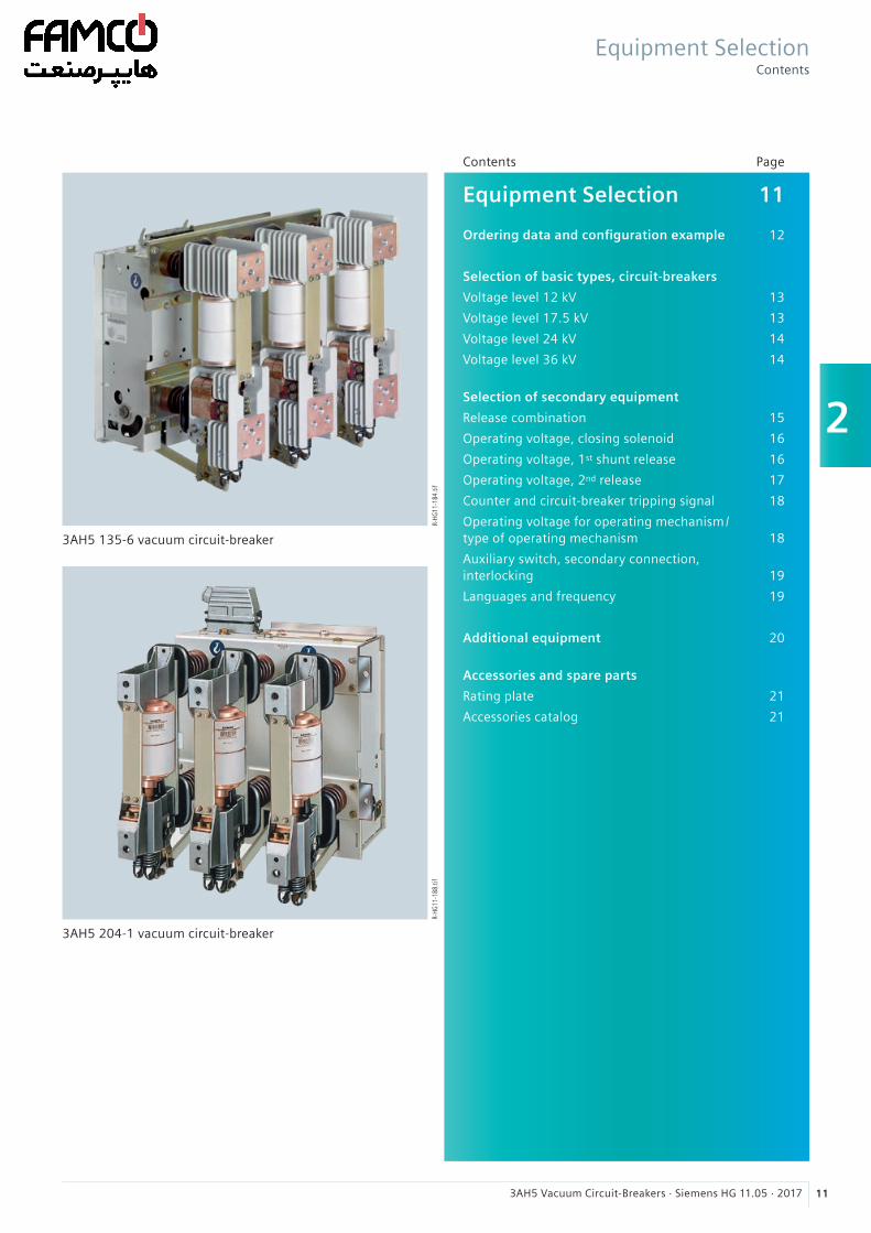
2
113AH5 Vacuum Circuit-Breakers · Siemens HG 11.05 · 2017
Equipment Selection 11 Ordering data and configuration example 12
Selection of basic types, circuit-breakers
Voltage level 12 kV 13
Voltage level 17.5 kV 13
Voltage level 24 kV 14
Voltage level 36 kV 14
Selection of secondary equipment
Release combination 15
Operating voltage, closing solenoid 16
Operating voltage, 1st shunt release 16
Operating voltage, 2nd release 17
Counter and circuit-breaker tripping signal 18
Operating voltage for operating mechanism/ type of operating mechanism 18
Auxiliary switch, secondary connection, interlocking 19
Languages and frequency 19
Additional equipment 20
Accessories and spare parts
Rating plate 21
Accessories catalog 21
Contents Page
R-HG
11-1
84.ti
fR-
HG11
-188
.tif
3AH5 135-6 vacuum circuit-breaker
3AH5 204-1 vacuum circuit-breaker
Equipment SelectionContents
n Basic equipment X Optionally selectable basic equipment Selectable additional equipment – Not available
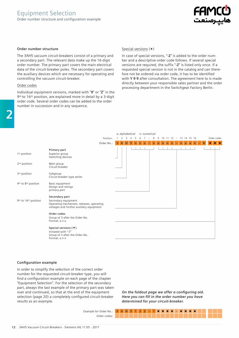
2
12 3AH5 Vacuum Circuit-Breakers · Siemens HG 11.05 · 2017
Order number structure
The 3AH5 vacuum circuit-breakers consist of a primary and a secondary part. The relevant data make up the 16-digit order number. The primary part covers the main electrical data of the circuit-breaker poles. The secondary part covers the auxiliary devices which are necessary for operating and controlling the vacuum circuit-breaker.
Order codes
Individual equipment versions, marked with “9” or “Z” in the 9th to 16th position, are explained more in detail by a 3-digit order code. Several order codes can be added to the order number in succession and in any sequence.
Special versions («)
In case of special versions, “-Z” is added to the order num-ber and a descriptive order code follows. If several special versions are required, the suffix “-Z” is listed only once. If a requested special version is not in the catalog and can there-fore not be ordered via order code, it has to be identified with Y 9 9 after consultation. The agreement here to is made directly between your responsible sales partner and the order processing department in the Switchgear Factory Berlin.
Equipment SelectionOrder number structure and configuration example
a: alphabetical n: numerical
Position: 1 2 3 4 5 6 7 – 8 9 10 11 12 – 13 14 15 16 Order codes
Order No.: 3 A H 5 n n n – n a a n n – n a a n – « n n n
Primary part1st position Superior group
Switching devices
2nd position Main groupCircuit-breaker
3rd position SubgroupCircuit-breaker type series
4th to 8th position Basic equipment Design and ratings primary part
Secondary part9th to 16th position Secondary equipment
Operating mechanism, releases, operating voltages and further auxiliary equipment
Order codesGroup of 3 after the Order No.Format: a n a
Special versions («)Initiated with “-Z”Group of 3 after the Order No.Format: a n n
Configuration example
In order to simplify the selection of the correct order number for the requested circuit-breaker type, you will find a configuration example on each page of the chapter “Equipment Selection”. For the selection of the secondary part, always the last example of the primary part was taken over and continued, so that at the end of the equipment selection (page 20) a completely configured circuit-breaker results as an example.
On the foldout page we offer a configuring aid. Here you can fill in the order number you have determined for your circuit-breaker.
Example for Order No.: 3 A H 5 1 2 2 – 1 n n n n – n n n n
Order codes:
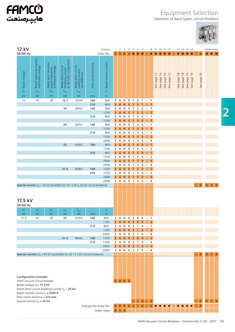
2
133AH5 Vacuum Circuit-Breakers · Siemens HG 11.05 · 2017
Example for Order No.: 3 A H 5 2 1 4 – 6 n n n n – n n n n – Z
Order codes: E 1 3
12 kV50/60 Hz
Position:
Order No.:
1 2 3 4 5 6 7 – 8 9 10 11 12 – 13 14 15 16 Order codes
3 A H 5 n n n – n n n n n – n n n n – « n n n
Rate
d v
olt
age
Rate
d li
gh
tnin
g im
pu
lse
wit
hst
and
vo
ltag
e
Rate
d s
ho
rt-d
ura
tio
np
ow
er-f
req
uen
cyw
ith
stan
d v
olt
age
Rate
d s
ho
rt-c
ircu
itb
reak
ing
cu
rren
tat
36
% D
C c
om
po
nen
t
Rate
d s
ho
rt-c
ircu
itm
akin
g c
urr
ent
(at
50
/60
Hz)
Pole
-cen
tre
dis
tan
ce
Rate
d n
orm
al c
urr
ent
See
pag
e 1
5
See
pag
e 1
6
See
pag
e 1
6
See
pag
e 1
7
See
pag
e 1
8
See
pag
e 1
8
See
pag
e 1
9
See
pag
e 1
9
See
pag
e 2
0
Ur Up Ud ISC Ima Ir
kV kV kV kA kA mm A
12 75 28 13.1 33/34 160 800 3 A H 5 1 2 1 – 1
210 800 3 A H 5 1 3 1 – 1
16 40/42 160 800 3 A H 5 1 2 2 – 1
1250 3 A H 5 1 2 2 – 2
210 800 3 A H 5 1 3 2 – 1
1250 3 A H 5 1 3 2 – 2
20 50/52 160 800 3 A H 5 1 2 3 – 1
1250 3 A H 5 1 2 3 – 2
210 800 3 A H 5 1 3 3 – 1
1250 3 A H 5 1 3 3 – 2
2000 3 A H 5 1 3 3 – 4
25 63/65 160 800 3 A H 5 1 4 4 – 1
1250 3 A H 5 1 4 4 – 2
210 800 3 A H 5 1 5 4 – 1
1250 3 A H 5 1 5 4 – 2
2000 3 A H 5 1 3 4 – 4
2500 3 A H 5 1 3 4 – 6
31.5 80/82 160 1250 3 A H 5 1 2 5 – 2
210 1250 3 A H 5 1 3 5 – 2
2000 3 A H 5 1 3 5 – 4
2500 3 A H 5 1 3 5 – 6
Special version Ud = 42 kV (available for all 12 kV ≥ 25 kA circuit-breakers) – Z E 1 3
17.5 kV50/60 Hz
Ur Up Ud ISC Ima Ir
kV kV kV kA kA mm A
17.5 95 38 25 63/65 160 800 3 A H 5 2 0 4 – 1
1250 3 A H 5 2 0 4 – 2
210 800 3 A H 5 2 1 4 – 1
1250 3 A H 5 2 1 4 – 2
2500 3 A H 5 2 1 4 – 6
31.5 80/82 160 1250 3 A H 5 2 0 5 – 2
210 1250 3 A H 5 2 1 5 – 2
2000 3 A H 5 2 1 5 – 4
2500 3 A H 5 2 1 5 – 6
Special version Ud = 42 kV (available for all 17.5 kV circuit-breakers) – Z E 1 3
Configuration example
3AH5 vacuum circuit-breaker 3 A H 5
Rated voltage Ur= 17.5 kV
Rated short-circuit breaking current Isc = 25 kA
Rated normal current Ir = 2500 A
Pole-centre distance = 210 mm
Special version Ud = 42 kV 2 1 4 – 6 – Z E 1 3
Equipment SelectionSelection of basic types, circuit-breakers
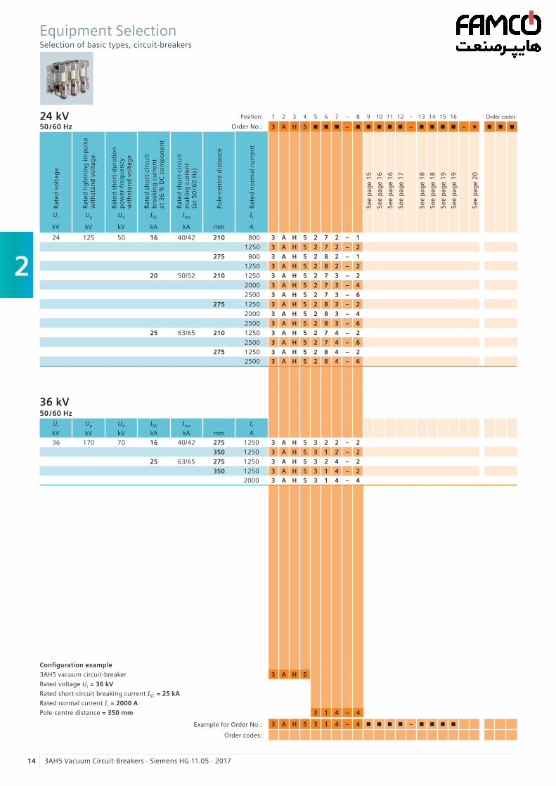
2
14 3AH5 Vacuum Circuit-Breakers · Siemens HG 11.05 · 2017
Example for Order No.: 3 A H 5 3 1 4 – 4 n n n n – n n n n
Order codes:
24 kV50/60 Hz
1 2 3 4 5 6 7 – 8 9 10 11 12 – 13 14 15 16 Order codes
3 A H 5 n n n – n n n n n – n n n n – « n n n
Rate
d v
olt
age
Rate
d li
gh
tnin
g im
pu
lse
wit
hst
and
vo
ltag
e
Rate
d s
ho
rt-d
ura
tio
np
ow
er-f
req
uen
cyw
ith
stan
d v
olt
age
Rate
d s
ho
rt-c
ircu
itb
reak
ing
cu
rren
tat
36
% D
C c
om
po
nen
t
Rate
d s
ho
rt-c
ircu
itm
akin
g c
urr
ent
(at
50
/60
Hz)
Pole
-cen
tre
dis
tan
ce
Rate
d n
orm
al c
urr
ent
See
pag
e 1
5
See
pag
e 1
6
See
pag
e 1
6
See
pag
e 1
7
See
pag
e 1
8
See
pag
e 1
8
See
pag
e 1
9
See
pag
e 1
9
See
pag
e 2
0
Ur Up Ud ISC Ima Ir
kV kV kV kA kA mm A
24 125 50 16 40/42 210 800 3 A H 5 2 7 2 – 1
1250 3 A H 5 2 7 2 – 2
275 800 3 A H 5 2 8 2 – 1
1250 3 A H 5 2 8 2 – 2
20 50/52 210 1250 3 A H 5 2 7 3 – 2
2000 3 A H 5 2 7 3 – 4
2500 3 A H 5 2 7 3 – 6
275 1250 3 A H 5 2 8 3 – 2
2000 3 A H 5 2 8 3 – 4
2500 3 A H 5 2 8 3 – 6
25 63/65 210 1250 3 A H 5 2 7 4 – 2
2500 3 A H 5 2 7 4 – 6
275 1250 3 A H 5 2 8 4 – 22500 3 A H 5 2 8 4 – 6
36 kV50/60 Hz
Ur Up Ud ISC Ima Ir
kV kV kV kA kA mm A
36 170 70 16 40/42 275 1250 3 A H 5 3 2 2 – 2
350 1250 3 A H 5 3 1 2 – 2
25 63/65 275 1250 3 A H 5 3 2 4 – 2
350 1250 3 A H 5 3 1 4 – 22000 3 A H 5 3 1 4 – 4
Configuration example
3AH5 vacuum circuit-breaker 3 A H 5
Rated voltage Ur = 36 kV
Rated short-circuit breaking current ISC = 25 kA
Rated normal current Ir = 2000 A
Pole-centre distance = 350 mm 3 1 4 – 4
Position:
Order No.:
Equipment SelectionSelection of basic types, circuit-breakers
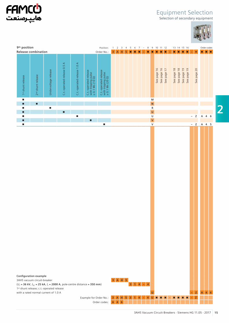
2
153AH5 Vacuum Circuit-Breakers · Siemens HG 11.05 · 2017
Equipment SelectionSelection of secondary equipment
Example for Order No.: 3 A H 5 3 1 4 – 4 U n n n – n n n n – Z
Order codes: A 4 6
9th position Position:
Order No.:
1 2 3 4 5 6 7 – 8 9 10 11 12 13 14 15 16 Order codes
Release combination 3 A H 5 n n n – n n n n n – n n n n – « n n n
1st
sh
un
t re
leas
e
2n
d s
hu
nt
rele
ase
Un
der
volt
age
rele
ase
C.t
.-o
per
ated
rel
ease
0.5
A
C.t
.-o
per
ated
rel
ease
1.0
A
C.t
.-o
per
ated
rel
ease
wit
h t
rip
pin
g p
uls
e≥
0.1
Ws
(10
Ω)
C.t
.-o
per
ated
rel
ease
wit
h t
rip
pin
g p
uls
e≥
0.1
Ws
(20
Ω)
See
pag
e 1
6
See
pag
e 1
6
See
pag
e 1
7
See
pag
e 1
8
See
pag
e 1
8
See
pag
e 1
9
See
pag
e 1
9
See
pag
e 2
0
n M
n n N
n n R
n n U
n n U – Z A 4 6
n n V
n n V – Z A 4 5
Configuration example
3AH5 vacuum circuit-breaker 3 A H 5
(Ur = 36 kV, ISC = 25 kA, Ir = 2000 A, pole-centre distance = 350 mm) 3 1 4 – 4
1st shunt release; c.t.-operated release
with a rated normal current of 1.0 A U – Z A 4 6
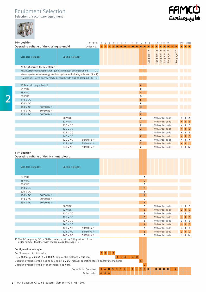
2
16 3AH5 Vacuum Circuit-Breakers · Siemens HG 11.05 · 2017
Equipment SelectionSelection of secondary equipment
Example for Order No.: 3 A H 5 3 1 4 – 4 U C 2 n – n n n n – Z
Order codes: A 4 6
10th position Position: 1 2 3 4 5 6 7 – 8 9 10 11 12 – 13 14 15 16 Order codes
Operating voltage of the closing solenoid Order No.: 3 A H 5 n n n – n n n n n – n n n n – « n n n
Standard voltages Special voltages
See
pag
e 1
7
See
pag
e 1
8
See
pag
e 1
8
See
pag
e 1
9
See
pag
e 1
9
See
pag
e 2
0
To be observed for selection!
• Manual spring-operat.mechan. generally without closing solenoid (A)
• Man. operat. stored-energy mechan. option. with closing solenoid (A – Z)
• Motor op. stored-energy mech. generally with closing solenoid (B – Z)
Without closing solenoid A
24 V DC B
48 V DC C
60 V DC D
110 V DC E
220 V DC F
100 V AC 50 / 60 Hz 1) H
110 V AC 50 / 60 Hz 1) J
230 V AC 50 / 60 Hz 1) K
30 V DC Z With order code K 1 A
32 V DC Z With order code K 1 B
120 V DC Z With order code K 1 C
125 V DC Z With order code K 1 D
127 V DC Z With order code K 1 E
240 V DC Z With order code K 1 F
120 V AC 50 / 60 Hz 1) Z With order code K 1 K
125 V AC 50 / 60 Hz 1) Z With order code K 1 L
240 V AC 50 / 60 Hz 1) Z With order code K 1 M
11th positionOperating voltage of the 1st shunt release
Standard voltages Special voltages
24 V DC 1
48 V DC 2
60 V DC 3
110 V DC 4
220 V DC 5
100 V AC 50 / 60 Hz 1) 6
110 V AC 50 / 60 Hz 1) 7
230 V AC 50 / 60 Hz 1) 8
30 V DC 9 With order code L 1 F
32 V DC 9 With order code L 1 B
120 V DC 9 With order code L 1 C
125 V DC 9 With order code L 1 D
127 V DC 9 With order code L 1 E
240 V DC 9 With order code L 1 F
120 V AC 50 / 60 Hz 1) 9 With order code L 1 K
125 V AC 50 / 60 Hz 1) 9 With order code L 1 L
240 V AC 50 / 60 Hz 1) 9 With order code L 1 M
1) The AC frequency 50 or 60 Hz is selected at the 16th position of the order number together with the language (see page 19)
Configuration example
3AH5 vacuum circuit-breaker 3 A H 5
(Ur = 36 kV, ISC = 25 kA, Ir = 2000 A, pole-centre distance = 350 mm) 3 1 4 – 4 U
Operating voltage of the closing solenoid 48 V DC (manual operating stored-energy mechanism) C
Operating voltage of the 1st shunt release 48 V DC 2
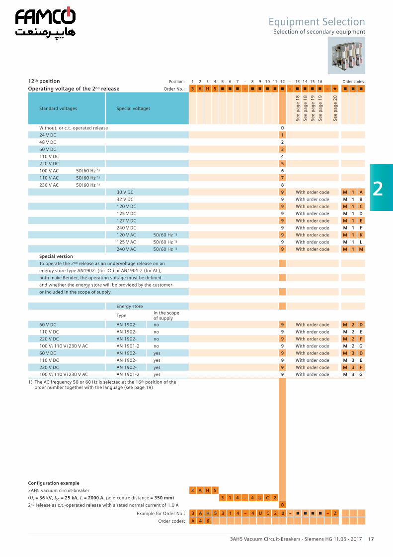
2
173AH5 Vacuum Circuit-Breakers · Siemens HG 11.05 · 2017
12th position Position: 1 2 3 4 5 6 7 – 8 9 10 11 12 – 13 14 15 16 Order codes
Operating voltage of the 2nd release Order No.: 3 A H 5 n n n – n n n n n – n n n n – « n n n
Standard voltages Special voltages
See
pag
e 1
8
See
pag
e 1
8
See
pag
e 1
9
See
pag
e 1
9
See
pag
e 2
0
Without, or c.t.-operated release 0
24 V DC 1
48 V DC 2
60 V DC 3
110 V DC 4
220 V DC 5
100 V AC 50 / 60 Hz 1) 6
110 V AC 50 / 60 Hz 1) 7
230 V AC 50 / 60 Hz 1) 8
30 V DC 9 With order code M 1 A
32 V DC 9 With order code M 1 B
120 V DC 9 With order code M 1 C
125 V DC 9 With order code M 1 D
127 V DC 9 With order code M 1 E
240 V DC 9 With order code M 1 F
120 V AC 50 / 60 Hz 1) 9 With order code M 1 K
125 V AC 50 / 60 Hz 1) 9 With order code M 1 L
240 V AC 50 / 60 Hz 1) 9 With order code M 1 M
Special version
To operate the 2nd release as an undervoltage release on an
energy store type AN1902- (for DC) or AN1901-2 (for AC),
both make Bender, the operating voltage must be defined –
and whether the energy store will be provided by the customer
or included in the scope of supply.
Energy store
TypeIn the scopeof supply
60 V DC AN 1902- no 9 With order code M 2 D
110 V DC AN 1902- no 9 With order code M 2 E
220 V DC AN 1902- no 9 With order code M 2 F
100 V /110 V /230 V AC AN 1901-2 no 9 With order code M 2 G
60 V DC AN 1902- yes 9 With order code M 3 D
110 V DC AN 1902- yes 9 With order code M 3 E
220 V DC AN 1902- yes 9 With order code M 3 F
100 V /110 V /230 V AC AN 1901-2 yes 9 With order code M 3 G
1) The AC frequency 50 or 60 Hz is selected at the 16th position of the order number together with the language (see page 19)
Configuration example
3AH5 vacuum circuit-breaker 3 A H 5
(Ur = 36 kV, ISC = 25 kA, Ir = 2000 A, pole-centre distance = 350 mm) 3 1 4 – 4 U C 2
2nd release as c.t.-operated release with a rated normal current of 1.0 A 0
Example for Order No.: 3 A H 5 3 1 4 – 4 U C 2 0 – n n n n – Z
Order codes: A 4 6
Equipment SelectionSelection of secondary equipment
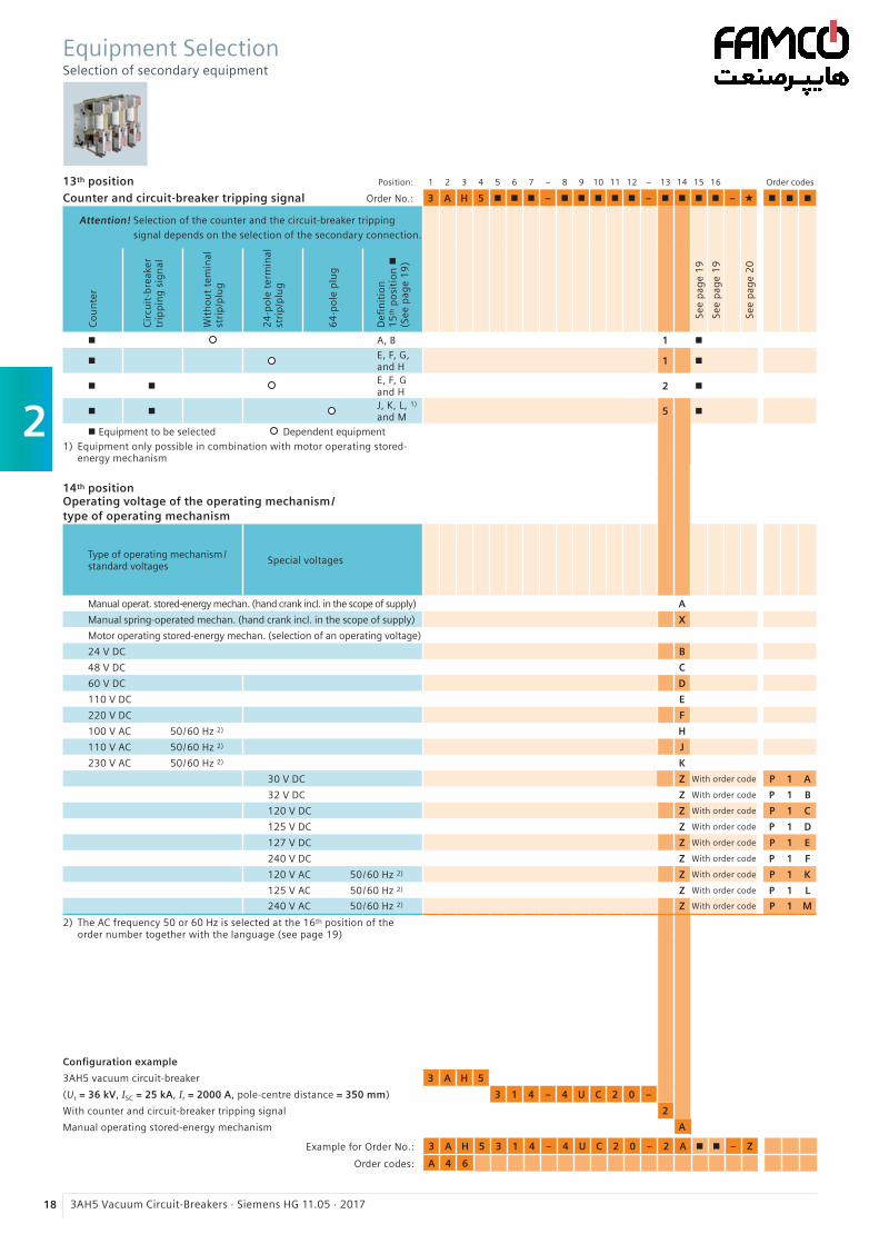
2
18 3AH5 Vacuum Circuit-Breakers · Siemens HG 11.05 · 2017
13th position Position: 1 2 3 4 5 6 7 – 8 9 10 11 12 – 13 14 15 16 Order codes
Counter and circuit-breaker tripping signal Order No.: 3 A H 5 n n n – n n n n n – n n n n – « n n n
Attention! Selection of the counter and the circuit-breaker tripping signal depends on the selection of the secondary connection.
Co
un
ter
Cir
cuit
-bre
aker
trip
pin
g s
ign
al
Wit
ho
ut
tem
inal
stri
p/p
lug
24
-po
le t
erm
inal
stri
p/p
lug
64
-po
le p
lug
Defi
nit
ion
1
5th
po
siti
on
n
(See
pag
e 1
9)
See
pag
e 1
9
See
pag
e 1
9
See
pag
e 2
0
n A, B 1 n
nE, F, G, and H
1 n
n nE, F, G and H
2 n
n nJ, K, L, 1) and M
5 n
n Equipment to be selected Dependent equipment1) Equipment only possible in combination with motor operating stored-
energy mechanism
14th positionOperating voltage of the operating mechanism/ type of operating mechanism
Type of operating mechanism/ standard voltages
Special voltages
Manual operat. stored-energy mechan. (hand crank incl. in the scope of supply) A
Manual spring-operated mechan. (hand crank incl. in the scope of supply) X
Motor operating stored-energy mechan. (selection of an operating voltage)
24 V DC B
48 V DC C
60 V DC D
110 V DC E
220 V DC F
100 V AC 50 / 60 Hz 2) H
110 V AC 50 / 60 Hz 2) J
230 V AC 50 / 60 Hz 2) K
30 V DC Z With order code P 1 A
32 V DC Z With order code P 1 B
120 V DC Z With order code P 1 C
125 V DC Z With order code P 1 D
127 V DC Z With order code P 1 E
240 V DC Z With order code P 1 F
120 V AC 50 / 60 Hz 2) Z With order code P 1 K
125 V AC 50 / 60 Hz 2) Z With order code P 1 L
240 V AC 50 / 60 Hz 2) Z With order code P 1 M
2) The AC frequency 50 or 60 Hz is selected at the 16th position of the order number together with the language (see page 19)
Configuration example
3AH5 vacuum circuit-breaker 3 A H 5
(Ur = 36 kV, ISC = 25 kA, Ir = 2000 A, pole-centre distance = 350 mm) 3 1 4 – 4 U C 2 0 –
With counter and circuit-breaker tripping signal 2
Manual operating stored-energy mechanism A
Example for Order No.: 3 A H 5 3 1 4 – 4 U C 2 0 – 2 A n n – Z
Order codes: A 4 6
Equipment SelectionSelection of secondary equipment
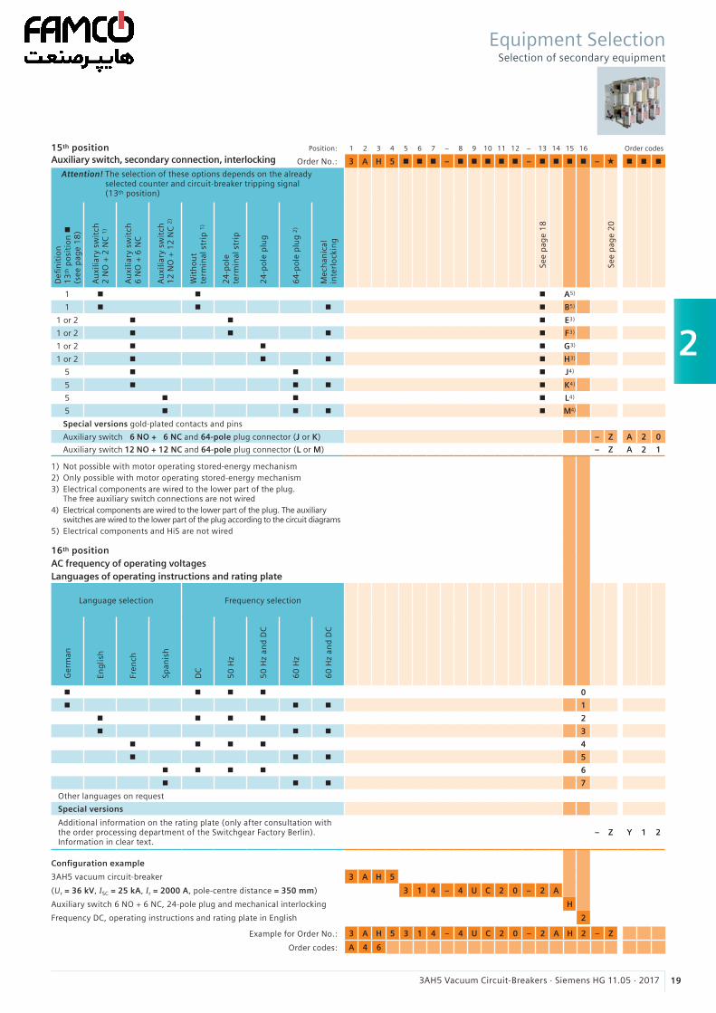
2
193AH5 Vacuum Circuit-Breakers · Siemens HG 11.05 · 2017
Equipment SelectionSelection of secondary equipment
Example for Order No.: 3 A H 5 3 1 4 – 4 U C 2 0 – 2 A H 2 – Z
Order codes: A 4 6
15th position Auxiliary switch, secondary connection, interlocking
Position: 1 2 3 4 5 6 7 – 8 9 10 11 12 – 13 14 15 16 Order codes
Order No.: 3 A H 5 n n n – n n n n n – n n n n – « n n n
Attention! The selection of these options depends on the already selected counter and circuit-breaker tripping signal (13th position)
Defi
nit
ion
1
3th
po
siti
on
n
(see
pag
e 1
8)
Au
xilia
ry s
wit
ch
2 N
O +
2 N
C 1
)
Au
xilia
ry s
wit
ch
6 N
O +
6 N
C
Au
xilia
ry s
wit
ch
12
NO
+ 1
2 N
C 2
)
Wit
ho
ut
term
inal
str
ip 1
)
24
-po
le
term
inal
str
ip
24
-po
le p
lug
64
-po
le p
lug
2)
Mec
han
ical
inte
rlo
ckin
g
See
pag
e 1
8
See
pag
e 2
0
1 n n n A5)
1 n n n n B5)
1 or 2 n n n E3)
1 or 2 n n n n F3)
1 or 2 n n n G3)
1 or 2 n n n n H3)
5 n n n J4)
5 n n n n K4)
5 n n n L4)
5 n n n n M4)
Special versions gold-plated contacts and pins
Auxiliary switch 6 NO + 6 NC and 64-pole plug connector (J or K) – Z A 2 0
Auxiliary switch 12 NO + 12 NC and 64-pole plug connector (L or M) – Z A 2 1
1) Not possible with motor operating stored-energy mechanism2) Only possible with motor operating stored-energy mechanism3) Electrical components are wired to the lower part of the plug.
The free auxiliary switch connections are not wired4) Electrical components are wired to the lower part of the plug. The auxiliary
switches are wired to the lower part of the plug according to the circuit diagrams5) Electrical components and HiS are not wired
16th positionAC frequency of operating voltagesLanguages of operating instructions and rating plate
Language selection Frequency selection
Ger
man
Eng
lish
Fren
ch
Span
ish
DC
50
Hz
50
Hz
and
DC
60
Hz
60
Hz
and
DC
n n n n 0
n n n 1
n n n n 2
n n n 3
n n n n 4
n n n 5
n n n n 6
n n n 7
Other languages on request
Special versions
Additional information on the rating plate (only after consultation withthe order processing department of the Switchgear Factory Berlin).Information in clear text.
– Z Y 1 2
Configuration example
3AH5 vacuum circuit-breaker 3 A H 5
(Ur = 36 kV, ISC = 25 kA, Ir = 2000 A, pole-centre distance = 350 mm) 3 1 4 – 4 U C 2 0 – 2 A
Auxiliary switch 6 NO + 6 NC, 24-pole plug and mechanical interlocking H
Frequency DC, operating instructions and rating plate in English 2
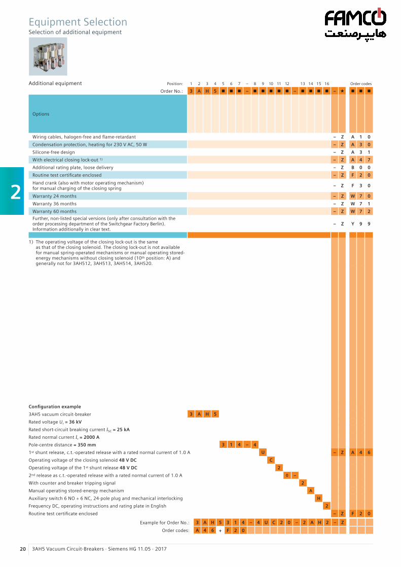
2
20 3AH5 Vacuum Circuit-Breakers · Siemens HG 11.05 · 2017
Additional equipment Position: 1 2 3 4 5 6 7 – 8 9 10 11 12 13 14 15 16 Order codes
Order No.: 3 A H 5 n n n – n n n n n – n n n n – « n n n
Options
Wiring cables, halogen-free and flame-retardant – Z A 1 0
Condensation protection, heating for 230 V AC, 50 W – Z A 3 0
Silicone-free design – Z A 3 1
With electrical closing lock-out 1) – Z A 4 7
Additional rating plate, loose delivery – Z B 0 0
Routine test certificate enclosed – Z F 2 0
Hand crank (also with motor operating mechanism)for manual charging of the closing spring
– Z F 3 0
Warranty 24 months – Z W 7 0
Warranty 36 months – Z W 7 1
Warranty 60 months – Z W 7 2
Further, non-listed special versions (only after consultation with theorder processing department of the Switchgear Factory Berlin).Information additionally in clear text.
– Z Y 9 9
1) The operating voltage of the closing lock-out is the same as that of the closing solenoid. The closing lock-out is not available for manual spring-operated mechanisms or manual operating stored-energy mechanisms without closing solenoid (10th position: A) and generally not for 3AH512, 3AH513, 3AH514, 3AH520.
Configuration example
3AH5 vacuum circuit-breaker 3 A H 5
Rated voltage Ur = 36 kV
Rated short-circuit breaking current ISC = 25 kA
Rated normal current Ir = 2000 A
Pole-centre distance = 350 mm 3 1 4 – 4
1st shunt release, c.t.-operated release with a rated normal current of 1.0 A U – Z A 4 6
Operating voltage of the closing solenoid 48 V DC C
Operating voltage of the 1st shunt release 48 V DC 2
2nd release as c.t.-operated release with a rated normal current of 1.0 A 0 –
With counter and breaker tripping signal 2
Manual operating stored-energy mechanism A
Auxiliary switch 6 NO + 6 NC, 24-pole plug and mechanical interlocking H
Frequency DC, operating instructions and rating plate in English 2
Routine test certificate enclosed – Z F 2 0
Equipment SelectionSelection of additional equipment
Example for Order No.: 3 A H 5 3 1 4 – 4 U C 2 0 – 2 A H 2 – Z
Order codes: A 4 6 + F 2 0
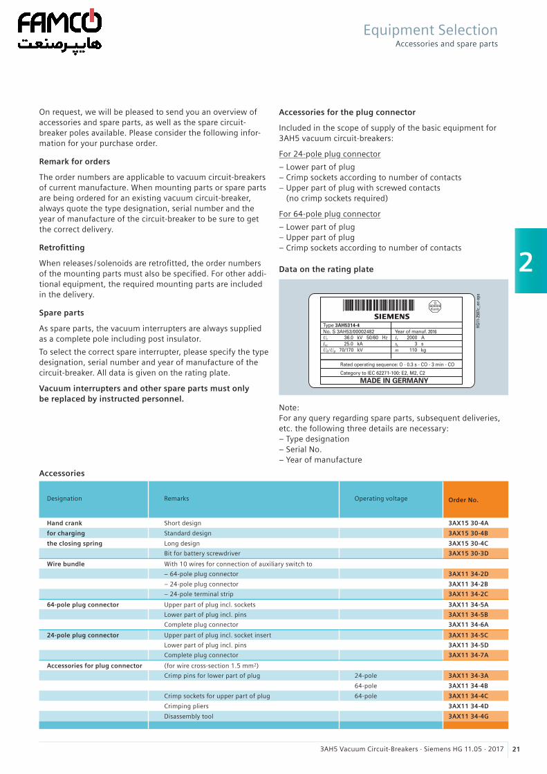
2
213AH5 Vacuum Circuit-Breakers · Siemens HG 11.05 · 2017
On request, we will be pleased to send you an overview of accessories and spare parts, as well as the spare circuit- breaker poles available. Please consider the following infor-mation for your purchase order.
Remark for orders
The order numbers are applicable to vacuum circuit-breakers of current manufacture. When mounting parts or spare parts are being ordered for an existing vacuum circuit-breaker, always quote the type designation, serial number and the year of manufacture of the circuit-breaker to be sure to get the correct delivery.
Retrofitting
When releases / solenoids are retrofitted, the order numbers of the mounting parts must also be specified. For other addi-tional equipment, the required mounting parts are included in the delivery.
Spare parts
As spare parts, the vacuum interrupters are always supplied as a complete pole including post insulator.
To select the correct spare interrupter, please specify the type designation, serial number and year of manufacture of the circuit-breaker. All data is given on the rating plate.
Vacuum interrupters and other spare parts must only be replaced by instructed personnel.
Note: For any query regarding spare parts, subsequent deliveries, etc. the following three details are necessary: – Type designation – Serial No. – Year of manufacture
Data on the rating plate
2016
HG11
-258
7c_e
n ep
s
Accessories for the plug connector
Included in the scope of supply of the basic equipment for 3AH5 vacuum circuit-breakers:
For 24-pole plug connector
– Lower part of plug – Crimp sockets according to number of contacts – Upper part of plug with screwed contacts
(no crimp sockets required)
For 64-pole plug connector
– Lower part of plug – Upper part of plug – Crimp sockets according to number of contacts
Equipment SelectionAccessories and spare parts
Designation Remarks Operating voltage Order No.
Hand crank Short design 3AX15 30-4A
for charging Standard design 3AX15 30-4B
the closing spring Long design 3AX15 30-4C
Bit for battery screwdriver 3AX15 30-3D
Wire bundle With 10 wires for connection of auxiliary switch to
– 64-pole plug connector 3AX11 34-2D
– 24-pole plug connector 3AX11 34-2B
– 24-pole terminal strip 3AX11 34-2C
64-pole plug connector Upper part of plug incl. sockets 3AX11 34-5A
Lower part of plug incl. pins 3AX11 34-5B
Complete plug connector 3AX11 34-6A
24-pole plug connector Upper part of plug incl. socket insert 3AX11 34-5C
Lower part of plug incl. pins 3AX11 34-5D
Complete plug connector 3AX11 34-7A
Accessories for plug connector (for wire cross-section 1.5 mm2)
Crimp pins for lower part of plug 24-pole 3AX11 34-3A
64-pole 3AX11 34-4B
Crimp sockets for upper part of plug 64-pole 3AX11 34-4C
Crimping pliers 3AX11 34-4D
Disassembly tool 3AX11 34-4G
Accessories
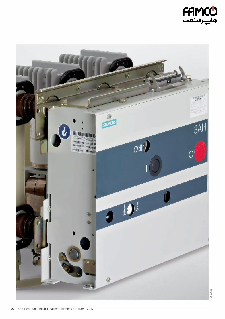
22 3AH5 Vacuum Circuit-Breakers · Siemens HG 11.05 · 2017
R-HG
11-2
01.e
ps
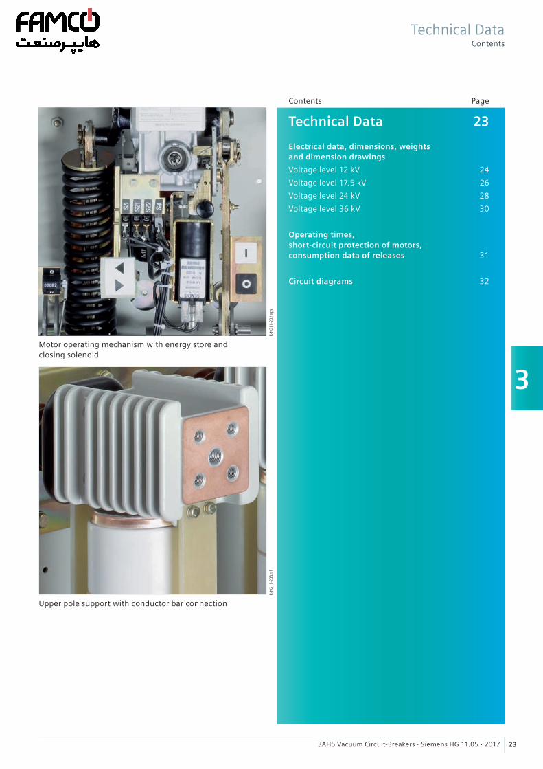
3
233AH5 Vacuum Circuit-Breakers · Siemens HG 11.05 · 2017
Technical Data 23 Electrical data, dimensions, weights and dimension drawings
Voltage level 12 kV 24
Voltage level 17.5 kV 26
Voltage level 24 kV 28
Voltage level 36 kV 30
Operating times, short-circuit protection of motors, consumption data of releases 31
Circuit diagrams 32
Contents Page
R-HG
11-2
02.e
psR-
HG11
-203
.tif
Motor operating mechanism with energy store and closing solenoid
Upper pole support with conductor bar connection
Technical DataContents
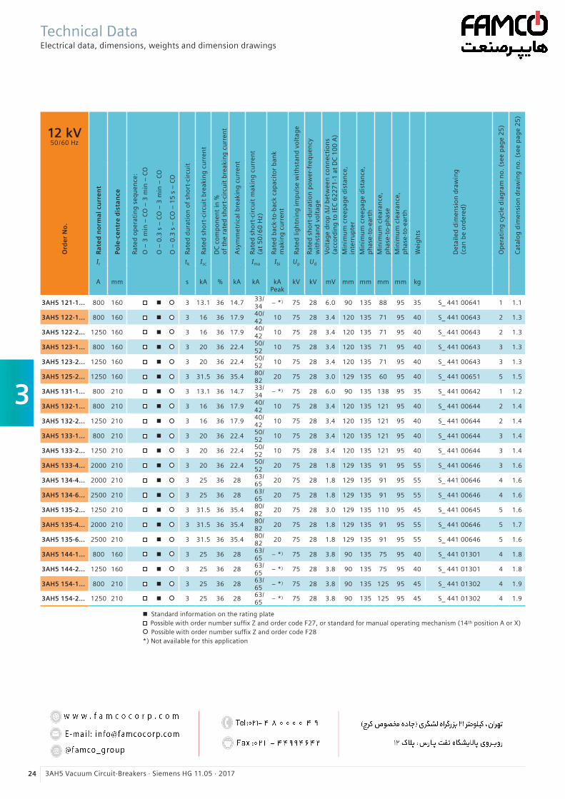
3
24 3AH5 Vacuum Circuit-Breakers · Siemens HG 11.05 · 2017
12 kV50 / 60 Hz
Ra
ted
no
rma
l cu
rre
nt
Pole
-ce
ntr
e d
ista
nce
Rate
d o
per
atin
g s
equ
ence
:
O –
3 m
in –
CO
– 3
min
– C
O
O –
0.3
s –
CO
– 3
min
– C
O
O –
0.3
s –
CO
– 1
5 s
– C
O
Rate
d d
ura
tio
n o
f sh
ort
-cir
cuit
Rate
d s
ho
rt-c
ircu
it b
reak
ing
cu
rren
t
DC
co
mp
on
ent
in %
of
the
rate
d s
ho
rt-c
ircu
it b
reak
ing
cu
rren
t
Asy
mm
etri
cal b
reak
ing
cu
rren
t
Rate
d s
ho
rt-c
ircu
it m
akin
g c
urr
ent
(at
50
/60
Hz)
Rate
d b
ack-
to-b
ack
cap
acit
or
ban
km
akin
g c
urr
ent
Rate
d li
gh
tnin
g im
pu
lse
wit
hst
and
vo
ltag
e
Rate
d s
ho
rt-d
ura
tio
n p
ow
er-f
req
uen
cyw
ith
stan
d v
olt
age
Vo
ltag
e d
rop
∆U
bet
wee
n c
on
nec
tio
ns
(acc
ord
ing
to
IEC
62
27
1-1
at
DC
10
0 A
)
Min
imu
m c
reep
age
dis
tan
ce,
in
terr
up
ter
Min
imu
m c
reep
age
dis
tan
ce,
p
has
e-to
-ear
th
Min
imu
m c
lear
ance
,
ph
ase-
to-p
has
e
Min
imu
m c
lear
ance
,
ph
ase-
to-e
arth
Wei
gh
ts
Det
aile
d d
imen
sio
n d
raw
ing
(can
be
ord
ered
)
Op
erat
ing
cyc
le d
iag
ram
no
. (s
ee p
age
25
)
Cat
alo
g d
imen
sio
n d
raw
ing
no
. (s
ee p
age
25
)
Ord
er
No
.
Ir tk Isc Ima Ibi Up Ud
A mm s kA % kA kA
kA Peak
kV kV mV mm mm mm mm kg
3AH5 121-1... 800 160 n 3 13.1 36 14.733/ 34
– *) 75 28 6.0 90 135 88 95 35 S_ 441 00641 1 1.1
3AH5 122-1... 800 160 n 3 16 36 17.940/ 42
10 75 28 3.4 120 135 71 95 40 S_ 441 00643 2 1.3
3AH5 122-2... 1250 160 n 3 16 36 17.940/ 42
10 75 28 3.4 120 135 71 95 40 S_ 441 00643 2 1.3
3AH5 123-1... 800 160 n 3 20 36 22.450/ 52
10 75 28 3.4 120 135 71 95 40 S_ 441 00643 3 1.3
3AH5 123-2... 1250 160 n 3 20 36 22.450/ 52
10 75 28 3.4 120 135 71 95 40 S_ 441 00643 3 1.3
3AH5 125-2... 1250 160 n 3 31.5 36 35.480/ 82
20 75 28 3.0 129 135 60 95 40 S_ 441 00651 5 1.5
3AH5 131-1... 800 210 n 3 13.1 36 14.733/ 34
– *) 75 28 6.0 90 135 138 95 35 S_ 441 00642 1 1.2
3AH5 132-1... 800 210 n 3 16 36 17.940/ 42
10 75 28 3.4 120 135 121 95 40 S_ 441 00644 2 1.4
3AH5 132-2... 1250 210 n 3 16 36 17.940/ 42
10 75 28 3.4 120 135 121 95 40 S_ 441 00644 2 1.4
3AH5 133-1... 800 210 n 3 20 36 22.450/ 52
10 75 28 3.4 120 135 121 95 40 S_ 441 00644 3 1.4
3AH5 133-2... 1250 210 n 3 20 36 22.450/ 52
10 75 28 3.4 120 135 121 95 40 S_ 441 00644 3 1.4
3AH5 133-4... 2000 210 n 3 20 36 22.450/ 52
20 75 28 1.8 129 135 91 95 55 S_ 441 00646 3 1.6
3AH5 134-4... 2000 210 n 3 25 36 2863/ 65
20 75 28 1.8 129 135 91 95 55 S_ 441 00646 4 1.6
3AH5 134-6... 2500 210 n 3 25 36 2863/ 65
20 75 28 1.8 129 135 91 95 55 S_ 441 00646 4 1.6
3AH5 135-2... 1250 210 n 3 31.5 36 35.480/ 82
20 75 28 3.0 129 135 110 95 45 S_ 441 00645 5 1.6
3AH5 135-4... 2000 210 n 3 31.5 36 35.480/ 82
20 75 28 1.8 129 135 91 95 55 S_ 441 00646 5 1.7
3AH5 135-6... 2500 210 n 3 31.5 36 35.480/ 82
20 75 28 1.8 129 135 91 95 55 S_ 441 00646 5 1.6
3AH5 144-1... 800 160 n 3 25 36 2863/ 65
– *) 75 28 3.8 90 135 75 95 40 S_ 441 01301 4 1.8
3AH5 144-2... 1250 160 n 3 25 36 2863/ 65
– *) 75 28 3.8 90 135 75 95 40 S_ 441 01301 4 1.8
3AH5 154-1... 800 210 n 3 25 36 2863/ 65
– *) 75 28 3.8 90 135 125 95 45 S_ 441 01302 4 1.9
3AH5 154-2... 1250 210 n 3 25 36 2863/ 65
– *) 75 28 3.8 90 135 125 95 45 S_ 441 01302 4 1.9
n Standard information on the rating plate Possible with order number suffix Z and order code F27, or standard for manual operating mechanism (14th position A or X) Possible with order number suffix Z and order code F28
*) Not available for this application
Technical DataElectrical data, dimensions, weights and dimension drawings
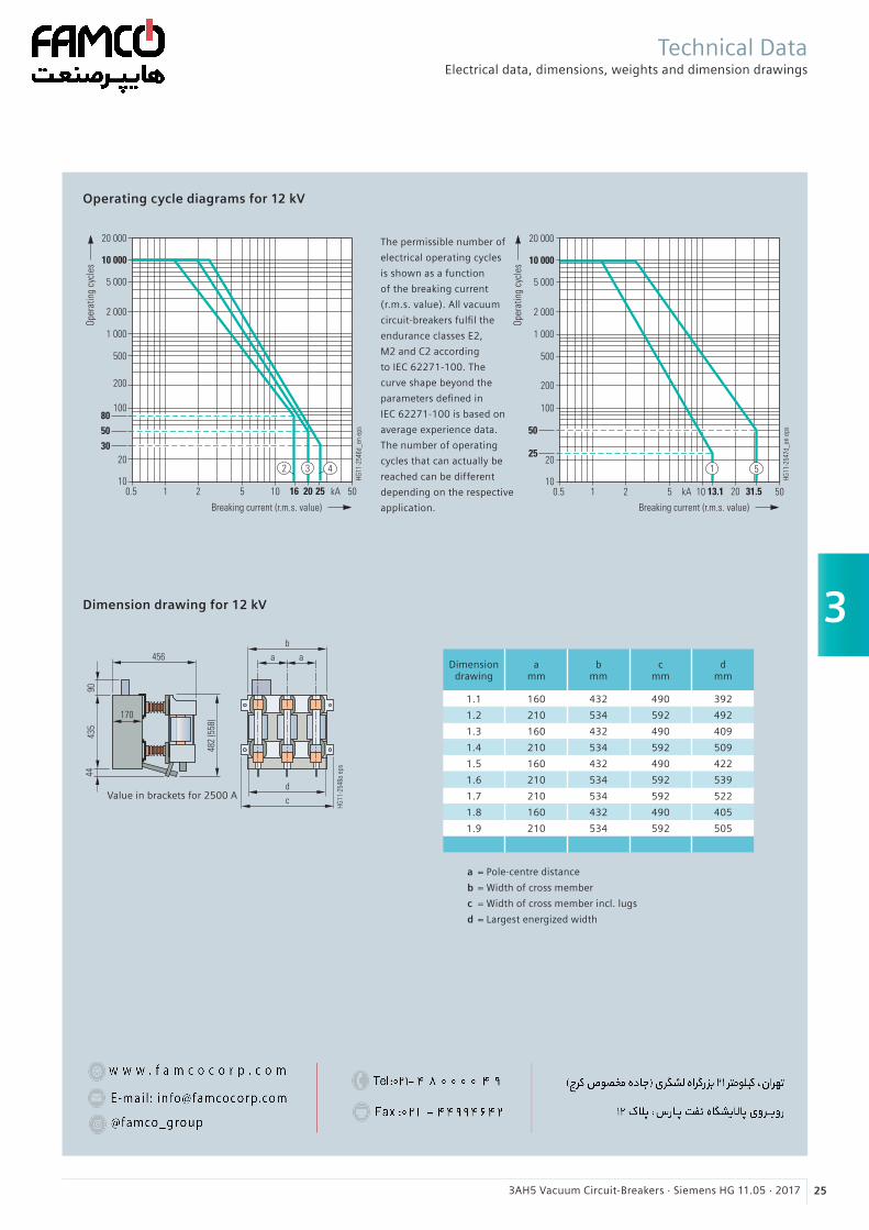
3
253AH5 Vacuum Circuit-Breakers · Siemens HG 11.05 · 2017
Operating cycle diagrams for 12 kV
Dimension drawing for 12 kV
Value in brackets for 2500 A
Technical DataElectrical data, dimensions, weights and dimension drawings
Dimensiondrawing
a mm
b mm
c mm
d mm
1.1 160 432 490 392
1.2 210 534 592 492
1.3 160 432 490 409
1.4 210 534 592 509
1.5 160 432 490 422
1.6 210 534 592 539
1.7 210 534 592 522
1.8 160 432 490 405
1.9 210 534 592 505
a = Pole-centre distance
b = Width of cross member
c = Width of cross member incl. lugs
d = Largest energized width
The permissible number of
electrical operating cycles
is shown as a function
of the breaking current
(r.m.s. value). All vacuum
circuit-breakers fulfil the
endurance classes E2,
M2 and C2 according
to IEC 62271-100. The
curve shape beyond the
parameters defined in
IEC 62271-100 is based on
average experience data.
The number of operating
cycles that can actually be
reached can be different
depending on the respective
application.
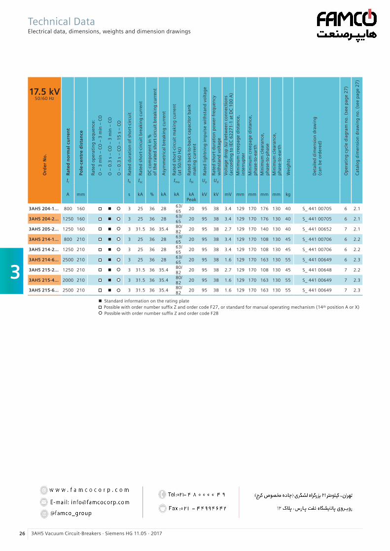
3
26 3AH5 Vacuum Circuit-Breakers · Siemens HG 11.05 · 2017
17.5 kV50 / 60 Hz
Ra
ted
no
rma
l cu
rre
nt
Pole
-ce
ntr
e d
ista
nce
Rate
d o
per
atin
g s
equ
ence
:
O –
3 m
in –
CO
– 3
min
– C
O
O –
0.3
s –
CO
– 3
min
– C
O
O –
0.3
s –
CO
– 1
5 s
– C
O
Rate
d d
ura
tio
n o
f sh
ort
-cir
cuit
Rate
d s
ho
rt-c
ircu
it b
reak
ing
cu
rren
t
DC
co
mp
on
ent
in %
of
the
rate
d s
ho
rt-c
ircu
it b
reak
ing
cu
rren
t
Asy
mm
etri
cal b
reak
ing
cu
rren
t
Rate
d s
ho
rt-c
ircu
it m
akin
g c
urr
ent
(at
50
/60
Hz)
Rate
d b
ack-
to-b
ack
cap
acit
or
ban
km
akin
g c
urr
ent
Rate
d li
gh
tnin
g im
pu
lse
wit
hst
and
vo
ltag
e
Rate
d s
ho
rt-d
ura
tio
n p
ow
er-f
req
uen
cyw
ith
stan
d v
olt
age
Vo
ltag
e d
rop
∆U
bet
wee
n c
on
nec
tio
ns
(acc
ord
ing
to
IEC
62
27
1-1
at
DC
10
0 A
)
Min
imu
m c
reep
age
dis
tan
ce,
in
terr
up
ter
Min
imu
m c
reep
age
dis
tan
ce,
p
has
e-to
-ear
th
Min
imu
m c
lear
ance
,
ph
ase-
to-p
has
e
Min
imu
m c
lear
ance
,
ph
ase-
to-e
arth
Wei
gh
ts
Det
aile
d d
imen
sio
n d
raw
ing
(can
be
ord
ered
)
Op
erat
ing
cyc
le d
iag
ram
no
. (s
ee p
age
27
)
Cat
alo
g d
imen
sio
n d
raw
ing
no
. (s
ee p
age
27
)
Ord
er
No
.
Ir tk Isc Ima Ibi Up Ud
A mm s kA % kA kA
kA Peak
kV kV mV mm mm mm mm kg
3AH5 204-1... 800 160 n 3 25 36 2863/ 65
20 95 38 3.4 129 170 176 130 40 S_ 441 00705 6 2.1
3AH5 204-2... 1250 160 n 3 25 36 2863/ 65
20 95 38 3.4 129 170 176 130 40 S_ 441 00705 6 2.1
3AH5 205-2... 1250 160 n 3 31.5 36 35.480/ 82
20 95 38 2.7 129 170 140 130 40 S_ 441 00652 7 2.1
3AH5 214-1... 800 210 n 3 25 36 2863/ 65
20 95 38 3.4 129 170 108 130 45 S_ 441 00706 6 2.2
3AH5 214-2... 1250 210 n 3 25 36 2863/ 65
20 95 38 3.4 129 170 108 130 45 S_ 441 00706 6 2.2
3AH5 214-6... 2500 210 n 3 25 36 2863/ 65
20 95 38 1.6 129 170 163 130 55 S_ 441 00649 6 2.3
3AH5 215-2... 1250 210 n 3 31.5 36 35.480/ 82
20 95 38 2.7 129 170 108 130 45 S_ 441 00648 7 2.2
3AH5 215-4... 2000 210 n 3 31.5 36 35.480/ 82
20 95 38 1.6 129 170 163 130 55 S_ 441 00649 7 2.3
3AH5 215-6... 2500 210 n 3 31.5 36 35.480/ 82
20 95 38 1.6 129 170 163 130 55 S_ 441 00649 7 2.3
n Standard information on the rating plate Possible with order number suffix Z and order code F27, or standard for manual operating mechanism (14th position A or X) Possible with order number suffix Z and order code F28
Technical DataElectrical data, dimensions, weights and dimension drawings
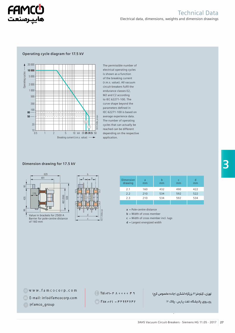
3
273AH5 Vacuum Circuit-Breakers · Siemens HG 11.05 · 2017
Operating cycle diagram for 17.5 kV
Dimension drawing for 17.5 kV
Value in brackets for 2500 A Barrier for pole-centre distance of 160 mm
a = Pole-centre distance
b = Width of cross member
c = Width of cross member incl. lugs
d = Largest energized width
Dimensiondrawing
a mm
b mm
c mm
d mm
2.1 160 432 490 422
2.2 210 534 592 522
2.3 210 534 592 534
Technical DataElectrical data, dimensions, weights and dimension drawings
The permissible number of
electrical operating cycles
is shown as a function
of the breaking current
(r.m.s. value). All vacuum
circuit-breakers fulfil the
endurance classes E2,
M2 and C2 according
to IEC 62271-100. The
curve shape beyond the
parameters defined in
IEC 62271-100 is based on
average experience data.
The number of operating
cycles that can actually be
reached can be different
depending on the respective
application.

3
28 3AH5 Vacuum Circuit-Breakers · Siemens HG 11.05 · 2017
24 kV50 / 60 Hz
Ra
ted
no
rma
l cu
rre
nt
Pole
-ce
ntr
e d
ista
nce
Rate
d o
per
atin
g s
equ
ence
:
O –
3 m
in –
CO
– 3
min
– C
O
O –
0.3
s –
CO
– 3
min
– C
O
O –
0.3
s –
CO
– 1
5 s
– C
O
Rate
d d
ura
tio
n o
f sh
ort
-cir
cuit
Rate
d s
ho
rt-c
ircu
it b
reak
ing
cu
rren
t
DC
co
mp
on
ent
in %
of
the
rate
d s
ho
rt-c
ircu
it b
reak
ing
cu
rren
t
Asy
mm
etri
cal b
reak
ing
cu
rren
t
Rate
d s
ho
rt-c
ircu
it m
akin
g c
urr
ent
(at
50
/60
Hz)
Rate
d b
ack-
to-b
ack
cap
acit
or
ban
km
akin
g c
urr
ent
Rate
d li
gh
tnin
g im
pu
lse
wit
hst
and
vo
ltag
e
Rate
d s
ho
rt-d
ura
tio
n p
ow
er-f
req
uen
cyw
ith
stan
d v
olt
age
Vo
ltag
e d
rop
∆U
bet
wee
n c
on
nec
tio
ns
(acc
ord
ing
to
IEC
62
27
1-1
at
DC
10
0 A
)
Min
imu
m c
reep
age
dis
tan
ce,
in
terr
up
ter
Min
imu
m c
reep
age
dis
tan
ce,
p
has
e-to
-ear
th
Min
imu
m c
lear
ance
,
ph
ase-
to-p
has
e
Min
imu
m c
lear
ance
,
ph
ase-
to-e
arth
Wei
gh
ts
Det
aile
d d
imen
sio
n d
raw
ing
(can
be
ord
ered
)
Op
erat
ing
cyc
le d
iag
ram
no
. (s
ee p
age
29
)
Cat
alo
g d
imen
sio
n d
raw
ing
no
. (s
ee p
age
29
)
Ord
er
No
.
Ir tk Isc Ima Ibi Up Ud
A mm s kA % kA kA
kA Peak
kV kV mV mm mm mm mm kg
3AH5 272-1... 800 210 n 3 16 36 17.940/ 42
10 125 50 3.8 200 190 215 175 55 S_ 441 00660 8 3.1
3AH5 272-2... 1250 210 n 3 16 36 17.940/ 42
10 125 50 3.8 200 190 215 175 55 S_ 441 00660 8 3.1
3AH5 273-2... 1250 210 n 3 20 36 22.450/ 52
20 125 50 3.8 200 190 215 175 55 S_ 441 00662 9 3.2
3AH5 273-4... 2000 210 n 3 20 36 22.450/ 52
20 125 50 2.2 200 190 227 175 80 S_ 441 00663 9 3.3
3AH5 273-6... 2500 210 n 3 20 36 22.450/ 52
20 125 50 2.2 200 190 227 175 80 S_ 441 00663 9 3.3
3AH5 274-2... 1250 210 n 3 25 36 2863/ 65
20 125 50 3.8 200 190 260 175 55 S_ 441 00662 10 3.2
3AH5 274-6... 2500 210 n 3 25 36 2863/ 65
20 125 50 2.2 200 190 227 175 80 S_ 441 00663 10 3.3
3AH5 282-1... 800 275 n 3 16 36 17.940/ 42
10 125 50 3.8 200 190 180 175 55 S_ 441 00661 8 3.4
3AH5 282-2... 1250 275 n 3 16 36 17.940/ 42
10 125 50 3.8 200 190 180 175 55 S_ 441 00661 8 3.4
3AH5 283-2... 1250 275 n 3 20 36 22.450/ 52
20 125 50 3.8 200 190 165 175 55 S_ 441 00664 9 3.5
3AH5 283-4... 2000 275 n 3 20 36 22.450/ 52
20 125 50 2.2 200 190 135 175 80 S_ 441 00668 9 3.6
3AH5 283-6... 2500 275 n 3 20 36 22.450/ 52
20 125 50 2.2 200 190 135 175 80 S_ 441 00668 9 3.6
3AH5 284-2... 1250 275 n 3 25 36 2863/ 65
20 125 50 3.8 200 190 165 175 55 S_ 441 00664 10 3.5
3AH5 284-6... 2500 275 n 3 25 36 2863/ 65
20 125 50 2.2 200 190 135 175 80 S_ 441 00668 10 3.6
n Standard information on the rating plate Possible with order number suffix Z and order code F27, or standard for manual operating mechanism (14th position A or X) Possible with order number suffix Z and order code F28
Technical DataElectrical data, dimensions, weights and dimension drawings
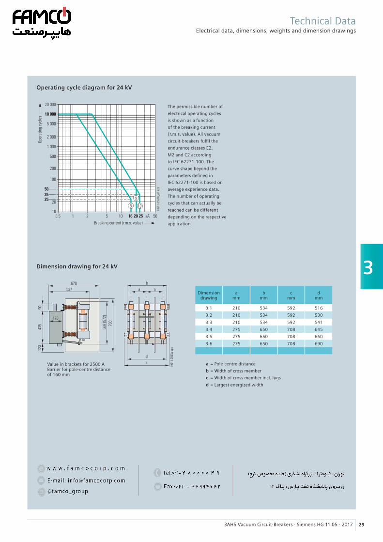
3
293AH5 Vacuum Circuit-Breakers · Siemens HG 11.05 · 2017
Operating cycle diagram for 24 kV
Dimension drawing for 24 kV
Dimensiondrawing
a mm
b mm
c mm
d mm
3.1 210 534 592 516
3.2 210 534 592 530
3.3 210 534 592 541
3.4 275 650 708 645
3.5 275 650 708 660
3.6 275 650 708 690
Value in brackets for 2500 A Barrier for pole-centre distance of 160 mm
a = Pole-centre distance
b = Width of cross member
c = Width of cross member incl. lugs
d = Largest energized width
Technical DataElectrical data, dimensions, weights and dimension drawings
The permissible number of
electrical operating cycles
is shown as a function
of the breaking current
(r.m.s. value). All vacuum
circuit-breakers fulfil the
endurance classes E2,
M2 and C2 according
to IEC 62271-100. The
curve shape beyond the
parameters defined in
IEC 62271-100 is based on
average experience data.
The number of operating
cycles that can actually be
reached can be different
depending on the respective
application.
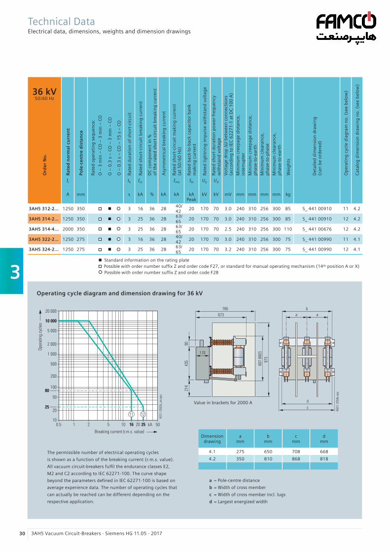
3
30 3AH5 Vacuum Circuit-Breakers · Siemens HG 11.05 · 2017
36 kV50 / 60 Hz
Ra
ted
no
rma
l cu
rre
nt
Pole
-ce
ntr
e d
ista
nce
Rate
d o
per
atin
g s
equ
ence
:
O –
3 m
in –
CO
– 3
min
– C
O
O –
0.3
s –
CO
– 3
min
– C
O
O –
0.3
s –
CO
– 1
5 s
– C
O
Rate
d d
ura
tio
n o
f sh
ort
-cir
cuit
Rate
d s
ho
rt-c
ircu
it b
reak
ing
cu
rren
t
DC
co
mp
on
ent
in %
of
the
rate
d s
ho
rt-c
ircu
it b
reak
ing
cu
rren
t
Asy
mm
etri
cal b
reak
ing
cu
rren
t
Rate
d s
ho
rt-c
ircu
it m
akin
g c
urr
ent
(at
50
/60
Hz)
Rate
d b
ack-
to-b
ack
cap
acit
or
ban
km
akin
g c
urr
ent
Rate
d li
gh
tnin
g im
pu
lse
wit
hst
and
vo
ltag
e
Rate
d s
ho
rt-d
ura
tio
n p
ow
er-f
req
uen
cyw
ith
stan
d v
olt
age
Vo
ltag
e d
rop
∆U
bet
wee
n c
on
nec
tio
ns
(acc
ord
ing
to
IEC
62
27
1-1
at
DC
10
0 A
)
Min
imu
m c
reep
age
dis
tan
ce,
in
terr
up
ter
Min
imu
m c
reep
age
dis
tan
ce,
p
has
e-to
-ear
th
Min
imu
m c
lear
ance
,
ph
ase-
to-p
has
e
Min
imu
m c
lear
ance
,
ph
ase-
to-e
arth
Wei
gh
ts
Det
aile
d d
imen
sio
n d
raw
ing
(can
be
ord
ered
)
Op
erat
ing
cyc
le d
iag
ram
no
. (s
ee b
elo
w)
Cat
alo
g d
imen
sio
n d
raw
ing
no
. (s
ee b
elo
w)
Ord
er
No
.
Ir tk Isc Ima Ibi Up Ud
A mm s kA % kA kA
kA Peak
kV kV mV mm mm mm mm kg
3AH5 312-2... 1250 350 n 3 16 36 2840/ 42
20 170 70 3.0 240 310 256 300 85 S_ 441 00910 11 4.2
3AH5 314-2... 1250 350 n 3 25 36 2863/ 65
20 170 70 3.0 240 310 256 300 85 S_ 441 00910 12 4.2
3AH5 314-4... 2000 350 n 3 25 36 2863/ 65
20 170 70 2.5 240 310 256 300 110 S_ 441 00676 12 4.2
3AH5 322-2... 1250 275 n 3 16 36 2840/ 42
20 170 70 3.0 240 310 256 300 75 S_ 441 00990 11 4.1
3AH5 324-2... 1250 275 n 3 25 36 2863/ 65
20 170 70 3.2 240 310 256 300 75 S_ 441 00990 12 4.1
n Standard information on the rating plate Possible with order number suffix Z and order code F27, or standard for manual operating mechanism (14th position A or X) Possible with order number suffix Z and order code F28
Operating cycle diagram and dimension drawing for 36 kV
The permissible number of electrical operating cycles
is shown as a function of the breaking current (r.m.s. value).
All vacuum circuit-breakers fulfil the endurance classes E2,
M2 and C2 according to IEC 62271-100. The curve shape
beyond the parameters defined in IEC 62271-100 is based on
average experience data. The number of operating cycles that
can actually be reached can be different depending on the
respective application.
Dimensiondrawing
a mm
b mm
c mm
d mm
4.1 275 650 708 668
4.2 350 810 868 818
Value in brackets for 2000 A
a = Pole-centre distance
b = Width of cross member
c = Width of cross member incl. lugs
d = Largest energized width
Technical DataElectrical data, dimensions, weights and dimension drawings
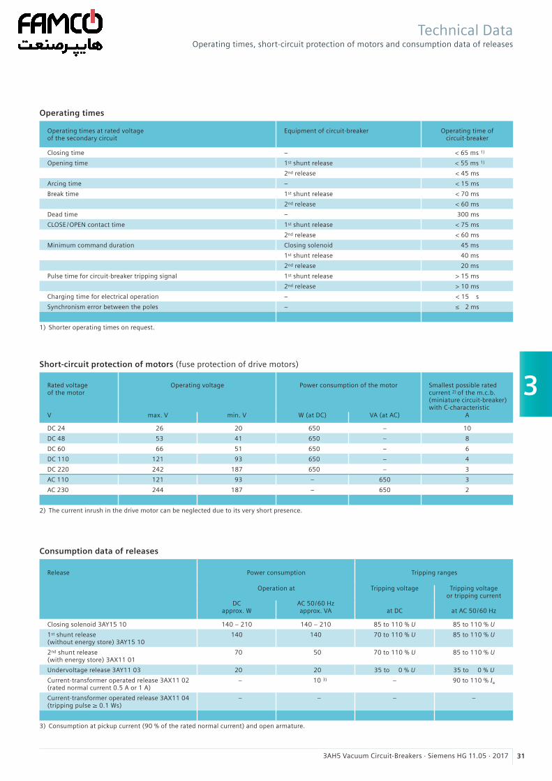
3
313AH5 Vacuum Circuit-Breakers · Siemens HG 11.05 · 2017
Operating times
Operating times at rated voltageof the secondary circuit
Equipment of circuit-breaker Operating time of circuit-breaker
Closing time – < 65 ms 1)
Opening time 1st shunt release < 55 ms 1)
2nd release < 45 ms
Arcing time – < 15 ms
Break time 1st shunt release < 70 ms
2nd release < 60 ms
Dead time – 300 ms
CLOSE /OPEN contact time 1st shunt release < 75 ms
2nd release < 60 ms
Minimum command duration Closing solenoid 45 ms
1st shunt release 40 ms
2nd release 20 ms
Pulse time for circuit-breaker tripping signal 1st shunt release > 15 ms
2nd release > 10 ms
Charging time for electrical operation – < 15 s
Synchronism error between the poles – ≤ 2 ms
1) Shorter operating times on request.
Short-circuit protection of motors (fuse protection of drive motors)
Rated voltageof the motor
Operating voltage
Power consumption of the motor
Smallest possible ratedcurrent 2) of the m.c.b.(miniature circuit-breaker)with C-characteristic
V max. V min. V W (at DC) VA (at AC) A
DC 24 26 20 650 – 10
DC 48 53 41 650 – 8
DC 60 66 51 650 – 6
DC 110 121 93 650 – 4
DC 220 242 187 650 – 3
AC 110 121 93 – 650 3
AC 230 244 187 – 650 2
2) The current inrush in the drive motor can be neglected due to its very short presence.
Consumption data of releases
Release Power consumption Tripping ranges
Operation at Tripping voltage Tripping voltageor tripping current
DC approx. W
AC 50 / 60 Hz approx. VA
at DC
at AC 50 / 60 Hz
Closing solenoid 3AY15 10 140 – 210 140 – 210 85 to 110 % U 85 to 110 % U
1st shunt release (without energy store) 3AY15 10
140 140 70 to 110 % U 85 to 110 % U
2nd shunt release (with energy store) 3AX11 01
70 50 70 to 110 % U 85 to 110 % U
Undervoltage release 3AY11 03 20 20 35 to 0 % U 35 to 0 % U
Current-transformer operated release 3AX11 02 (rated normal current 0.5 A or 1 A)
– 10 3) – 90 to 110 % Ia
Current-transformer operated release 3AX11 04 (tripping pulse ≥ 0.1 Ws)
– – – –
3) Consumption at pickup current (90 % of the rated normal current) and open armature.
Technical DataOperating times, short-circuit protection of motors and consumption data of releases
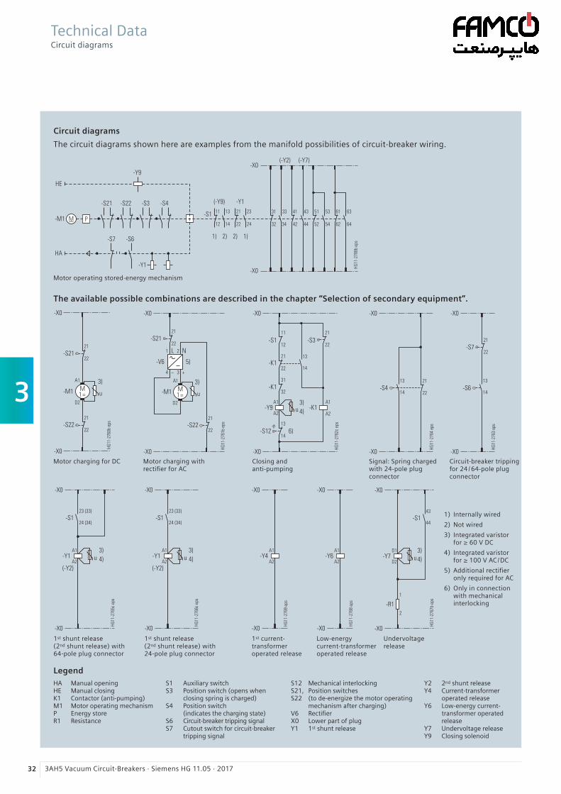
3
32 3AH5 Vacuum Circuit-Breakers · Siemens HG 11.05 · 2017
Circuit diagrams
The circuit diagrams shown here are examples from the manifold possibilities of circuit-breaker wiring.
The available possible combinations are described in the chapter “Selection of secondary equipment”.
Motor charging for DC Motor charging withrectifier for AC
Closing and anti-pumping
Signal: Spring charged with 24-pole plug connector
Circuit-breaker tripping for 24 /64-pole plug connector
1st shunt release (2nd shunt release) with 64-pole plug connector
1st shunt release (2nd shunt release) with 24-pole plug connector
1st current- transformer operated release
Low-energy current-transformer operated release
Undervoltage release
HA Manual openingHE Manual closingK1 Contactor (anti-pumping)M1 Motor operating mechanismP Energy storeR1 Resistance
Legend
Technical DataCircuit diagrams
1) Internally wired
2) Not wired
3) Integrated varistor for ≥ 60 V DC
4) Integrated varistor for ≥ 100 V AC /DC
5) Additional rectifier only required for AC
6) Only in connection with mechanical interlocking
S1 Auxiliary switchS3 Position switch (opens when
closing spring is charged)S4 Position switch (indicates the charging state)S6 Circuit-breaker tripping signalS7 Cutout switch for circuit-breaker
tripping signal
S12 Mechanical interlockingS21, Position switchesS22 (to de-energize the motor operating
mechanism after charging)V6 RectifierX0 Lower part of plugY1 1st shunt release
Y2 2nd shunt releaseY4 Current-transformer
operated releaseY6 Low-energy current-
transformer operated release
Y7 Undervoltage releaseY9 Closing solenoid
Motor operating stored-energy mechanism
4
333AH5 Vacuum Circuit-Breakers · Siemens HG 11.05 · 2017
Annex 33 Inquiry form 34
Configuration instructions 35
Configuration aid Foldout page
Contents Page
R-HG
11-1
81.e
ps
Brandenburg Gate, Berlin, Germany
R-HG
11-1
80.e
ps
Switchgear Factory, Berlin, Germany
AnnexContents

4
34 3AH5 Vacuum Circuit-Breakers · Siemens HG 11.05 · 2017
Inquiry concerning
£ 3AH5 circuit-breaker
Please
£ Submit an offer£ Call us£ Visit us
Your address
Company
Dept.
Name
Street
Postal code /city
Country
Phone
Fax
Siemens AG
Dept.
Name
Street
Postal code /city
Country
Fax
Technical data Other values
Rated voltage £ 12 kV £ 17.5 kV £ 24 kV £ 36 kV £ ___ kV
Rated lightning impulse £ 75 kV £ 95 kV withstand voltage £ 125 kV £ 170 kV £ ___ kV
Rated short-duration £ 28 kV £ 38 kV £ 42 kV power-frequency withstand voltage £ 50 kV £ 70 kV £ ___ kV
Rated short-circuit £ 13.1 kA £ 16 kA £ 20 kA breaking current £ 25 kA £ 31.5 kA £ ___ kA
Rated normal current £ 800 A £ 1250 A £ 2000 A £ 2500 A £ ___ A
Pole-centre distance £ 160 mm £ 210 mm £ 275 mm £ 350 mm
Secondary equipmentFor possible combinations see pages 15 to 19
Circuit-breaker equipment £ Manual spring-operated mechanism £ Manual operating stored-energy mechanism £ Motor operating stored-energy mechanism
Motor operating mechanism £ ___ V DC £ ___ V AC, ___ Hz
Closing solenoid £ ___ V DC £ ___ V AC, ___ Hz
1 shunt release £ ___ V DC £ ___ V AC, ___ Hz
2 shunt release £ ___ V DC £ ___ V AC, ___ Hz
Current-transformer operated release £ 0.5 A £ 1 A £ ≥ 0.1 Ws 10 Ω £ ≥ 0.1 Ws 20 Ω
Undervoltage release £ ___ V DC £ ___ V AC, ___ Hz
Auxiliary switch £ 2 NO + 2 NC £ 6 NO + 6 NC £ 12 NO + 12 NC
Low-voltage connection £ without £ 24-pole £ 24-pole £ 64-pole terminal strip plug plug
£ Mechanical interlocking
£ Counter
£ Circuit-breaker tripping signal
£ Electrical closing lock-out
Operating instructions £ English £ German £ French £ Spanish
Application and other requirements
£ Please check off ___ Please fill in
Please copy, fill in and return to your Siemens partner.
AnnexInquiry form
st
nd

353AH5 Vacuum Circuit-Breakers · Siemens HG 11.05 · 2017
Instruction for configuration of the 3AH5 vacuum circuit-breaker
1st step: Definition of the primary part (see page 13 to 14)
Please specify the following ratings: Possible options:
Rated voltage (Ur) Ur: 12 kV, 17.5 kV, 24 kV, 36 kV
Rated lightning impulse withstand voltage (Up) Up: 75 kV, 95 kV, 125 kV, 170 kV
Rated short-duration power-frequency withstand voltage (Ud) Ud: 28 kV, 38 kV, 42 kV, 50 kV, 70 kV
Rated short-circuit breaking current (Isc) Isc: 13.1 kA, 16 kA, 20 kA, 25 kA, 31.5 kA
Rated normal current (Ir) 160 mm, 210 mm, 275 mm, 350 mm
Pole-centre distance Ir: 800 A, 1250 A, 2000 A, 2500 A
These ratings define the positions 5 to 8 of the order number.
2nd step: Definition of the secondary equipment (see pages 15 to 19)
Please specify the following equipment features: Possible options:
Release combination(position 9)
Shunt release, current-transformer operated releaseand undervoltage release
Closing solenoid(position 10)
Operating voltages from 24 V DC to 240 V AC
Operating voltage of the releases(positions 11 /12)
Operating voltages from 24 V DC to 240 V AC
Equipment with circuit-breaker tripping signal(position 13)
Equipment depends on the selection of thesecondary connection
Type of operating mechanism and operating voltage of a motor, if available(position 14)
Manual spring-operated mechanism,manual operating stored-energy mechanism,motor operating stored-energy mechanismwith operating voltages from 24 V DC to 240 V AC
Number of auxiliary contacts(position 15)
2 NO + 2 NC, 6 NO + 6 NC, 12 NO + 12 NC
Design of the secondary connection(position 15)
24-pole terminal strip, 24-pole plug connector,64-pole plug connector, without plug connector
Language of the documentation(position 16)
English, German, French, Spanish, other languages on request
Frequency of the operating voltage of thesecondary equipment at AC (position 16)
50 Hz /60 Hz
These equipment features define the positions 9 to 16 of the order number.
3rd step: Do you have any further requirements concerning the equipment? (see page 20)
Your Siemens sales partner will be pleased to support you.
You prefer to configure your 3AH5 vacuum circuit-breaker on your own?Follow the steps to the configuration and enter the order number in the configuration aid.
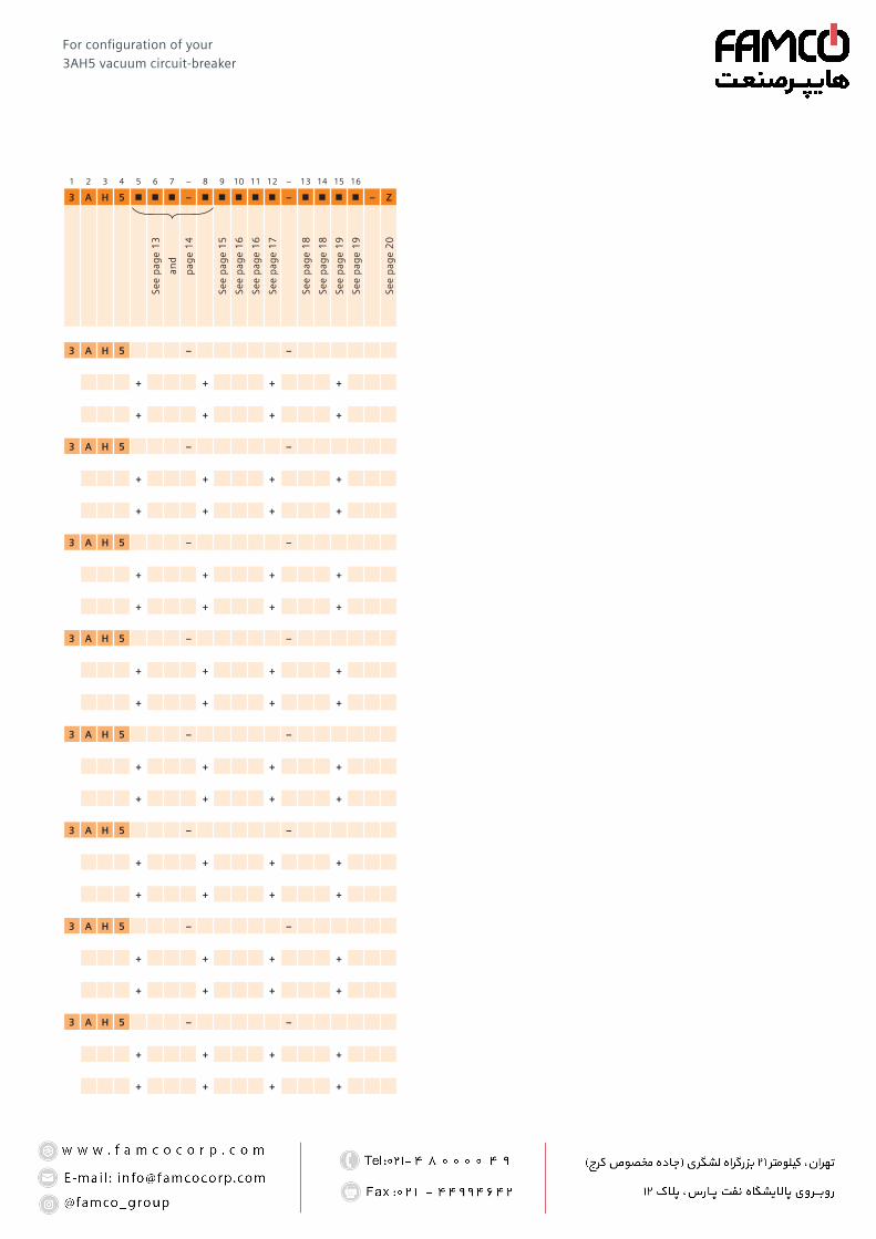
1 2 3 4 5 6 7 – 8 9 10 11 12 – 13 14 15 16
3 A H 5 n n n – n n n n n – n n n n – Z
See
pag
e 1
3
and
pag
e 1
4
See
pag
e 1
5
See
pag
e 1
6
See
pag
e 1
6
See
pag
e 1
7
See
pag
e 1
8
See
pag
e 1
8
See
pag
e 1
9
See
pag
e 1
9
See
pag
e 2
0
3 A H 5 – –
+ + + +
+ + + +
3 A H 5 – –
+ + + +
+ + + +
3 A H 5 – –
+ + + +
+ + + +
3 A H 5 – –
+ + + +
+ + + +
3 A H 5 – –
+ + + +
+ + + +
3 A H 5 – –
+ + + +
+ + + +
3 A H 5 – –
+ + + +
+ + + +
3 A H 5 – –
+ + + +
+ + + +
For configuration of your 3AH5 vacuum circuit-breaker
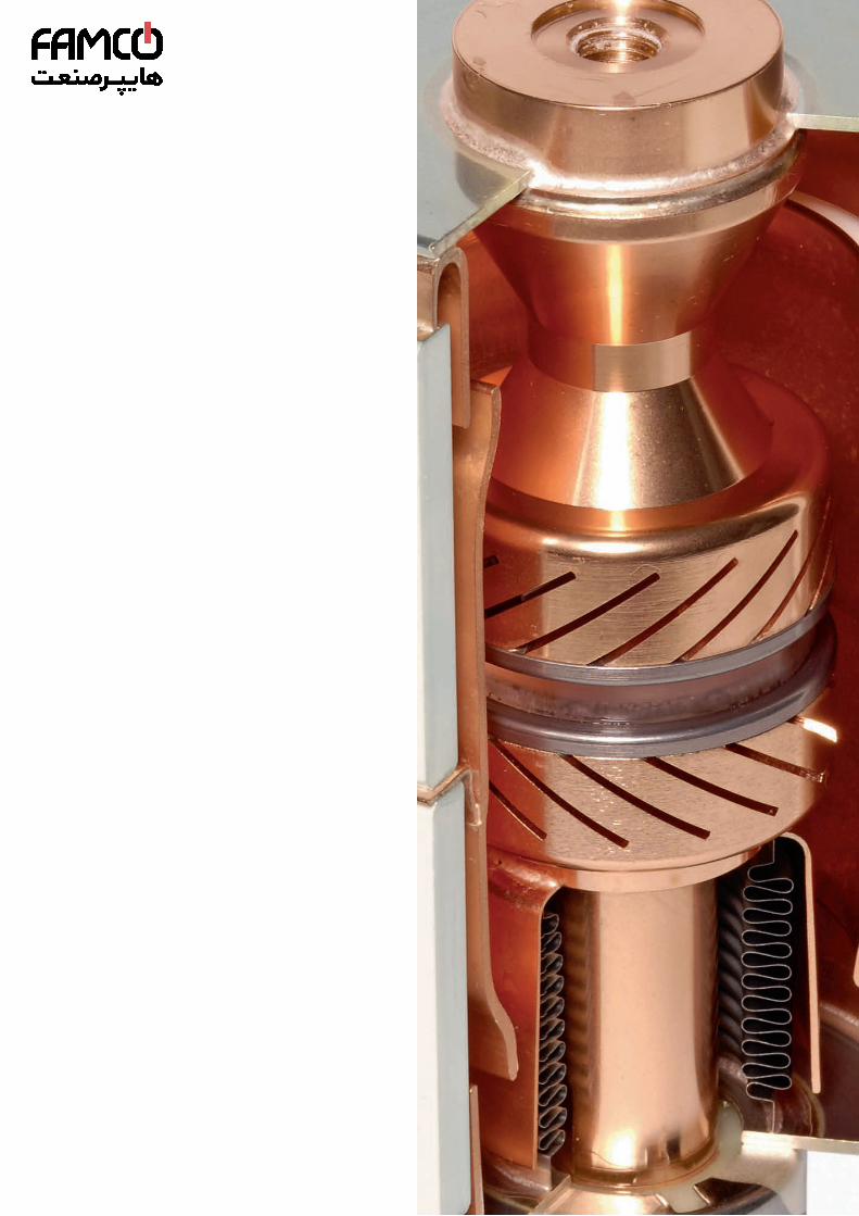
2017
Published by Siemens AG 2017 Energy Management Division Medium Voltage & Systems Nonnendammallee 104 13623 Berlin, Germany
For further information please contact our Customer Support Center Phone: +49 180 524 70 00 Fax: +49 180 524 24 71 E-mail: [email protected]
Article No. EMMS-K1511-A051-A3-7600 Printed in Germany Dispo 18301 PU 184/1406 KG 03.17 0.25
Subject to changes and errors. The information given in this document only contains general descriptions and /or performance features which may not always specifically reflect those described, or which may undergo modification in the course of further development of the products. The requested performance features are binding only when they are expressly agreed upon in the con-cluded contract.