power circuit breakers
TRANSCRIPT

GEK-7303C*
ALowvoltagePower CircuitBreakers
MaintenanceInstructions
'SupersedesGEH-1798AGEH-1799GEH-1823GEl-5021OA
GEI-50211GEI-50212AGEI-57077GEl-74600
Types AK-50/75/100,AKT-50,AKU-50,andAKF-2C/2D/2E
NOTE: To be used in conjunction withGEl-86135 which covers Types AK-75/100breakers with ECS and SST trip devices.
E L E C T R I CG E N E R A L

CONTENTS3INTRODUCTION3OPERATION
MANUAL CLOSING...MANUAL MAINTENANCE CLOSING OF ELECTRICAL BREAKERSELECTRICAL CLOSING.QUICK CLOSE FOR ELECTRICAL BREAKERSELECTRICAL TRIPPING...
34445
5MAINTENANCEINSERTING SAFETY PIN-AK-50, AK-75 AND AK-100INSPECTIONTROUBLE SHOOTINGLUBRICATIONSEPARATION OF FRONT AND REAR FRAMES
55677
7BASIC BREAKER COMPONENTSARC QUENCHERSPOLE UNIT ASSEMBLYOPERATING MECHANISMSQUICK CLOSE BREAKER ADJUSTMENTSAUXILIARY SWITCH
78
131611
23ELECTRICAL CLOSING DEVICES AND CONTROLSCLOSING SWITCHCUT-OFF SWITCHESCONTROL RELAY
232323
23PROTECTIVE DEVICESSTATIC TIME DELAY UNDERVOLTAGE TRnPING DEVICEINSTANTANEOUS UNDER VOLTAGE TRIPPING DEVICE....UNDERVOLTAGE LOCKOUT DEVICE.......DIRECT-ACTING TRIPPING DEVICE-EC-1BSERIES OVERCURRENT TRIPPING DEVICE EC-1SERIES OVERCURRENT TRIPPING DEVICE EC-2/EC-2A...REVERSE CURRENT TRIPPING DEVICE (AK-50 ONLY)POWER SENSOR TRIP....SELECTIVE TRIPPING
232525262931333339
42BREAKER ACCESSORIESPRIMARY DISCONNECTSSECONDARY DISCONNECTSDRAWOUT MECHANISMSSHUNT TRIPPING DEVICEBELL ALARM AND LOCKOUT DEVICEOPEN FUSE LOCKOUT DEVICE
424243444445
47MISCELLANEOUSTOOLSRENEWAL’PARTS
4747
These instructions do not purport to cover all details or variations in equipment nor to provide for every possiblecontingency to be met in connection with installation, operation or maintenance. Should further information be desiredor should particular problems arise which are not covered sufficiently for the purchaser ’s purposes, the matter shouldbe referred to the General Electric Company.

LOW-VOLTAGE POWER CIRCUIT BREAKERSTypes
AK-2/3/2A/3A-50/50S AKT-2/3/50/50SAK-2/3/2A/3A-75/75S AKU-2/3/2A/3A-50/50SAK-2/3/2A/3A-100/100S AKF-2C/2D/2E
OPERATIONINTRODUCTION MANUAL CLOSING
For a description of manual closing, referto the section of these instructions entitled CLOS-ING THE BREAKER - MANUALLY OPERATEDAK-50 and section entitled AK-50-75 AND-100STORED ENERGY MANUAL MECHANISM, bothunder OPERATING MECHANISMS.
The instructions contained herein are intended toaid in the maintenance and repair of basic breakersand accessories for AK-50-75-100 Low VoltagePower Circuit Breakers.
The basic AK-50, AK-75 and AK-100 breakerdesigns have been expanded to include specialdesigns for specific applications. These designextensions have caused variations in the nomen-clature including the following:
AK-2-50, AK-2-75 or AK-2-100 - Basicstandard design of breaker for stationarymounting or for drawout use in AKD typeequipment.AK-2A-50, AK-2A-75, AK-2A-100 - TheA indicates it has mounting features forAKD-5 type equipment.AK-2-50S, AK-2-75S, AK-2-100S - The Sindicates breaker is equipped with a quick-close mechanism which provides closingtimes of approximately 5 cycles (.08 seconds).AKU-2-50fuse breaker combination.
T_.CLOSING |“T SWITCH—— II—11
REMOTECLOSE L
T*‘ F :|= TRIPIG_
IUio o£C < G ±zFz-iooo>
LTRIPCOILXM
LEGEND* CLOSING MOTOR* RELAY COIL
+ * RELAY CONTACTFftG «= MECHANICALLY OPERATED SWITCHES
+ = NORMALLY OPEN SWITCH CONTACTS£ = NORMALLY CLOSED SWITCH CONTACTS
L - AUXILIARY SWITCH CONTACT
®X
The U indicates an internalSIMPLIFIED ELEMENTARY DIAGRAM
INTERNAL WIRING AK—50,75, AND 100AKF-2C, AKF-2D, AKF-2Eswitches for use in controlling shunt fieldsof synchronous motors and generators.AK-2-50Hrupting rating has been increased to the75,000 amp. class.AK-2-50C, AK-2-75C - The C indicatesthe interrupting rating has been increasedto the 100,000 amp. class.AKT-2-50continuous rating of 2000 amps.AK-3-50, AK-3-75, AK-3-100indicates the breaker is equipped with thePower Sensor Overcurrent Trip Device.AK-2-50X - The X indicates the breakerhas very special features or it includestwo or more of the design extensionspreviously described.
When contacting the factory, it is importantto furnish the complete nameplate information.
Are fieldFig. 1.
The H indicates the inter- CLOSINGSWITCH T
J_ REMOTE=F CLOSE
ih-i.v
T -ET -G TD
fi°o<-»>
X ±F=TF
=4= X
WThe T indicates increased \cc <M) rThe 3LEGEND
CC - CLOSING RELAY COILD - CLOSING RELAY CONTACTSE - ANTI-PUMP RELAY CONTACTS
F A G- MECHANICALLY OPERATED SWITCHES- AUXILIARY SWITCH CONTACTS- CLOSING MOTOR- ANTI-PUMP RELAY COIL* -CONTROL RELAY CONTACTSX - CONTROL RELAY COIL4: - NORMALLY OPEN SWITCH CONTACTSf - NORMALLY CLOSED SWITCH CONTACTS
9
SIMPLIFIED ELEMENTARY DIAGRAMINTERNAL WIRING QUICK CLOSE BREAKER
Fig. 1A.3
GEK-7303 Low Voltage Power Circuit Breakers
MANUAL MAINTENANCECLOSING OF ELECTRICAL
BREAKERSAn electrical breaker may be closed manually
by means of the maintenance handle furnishedwith the breaker.
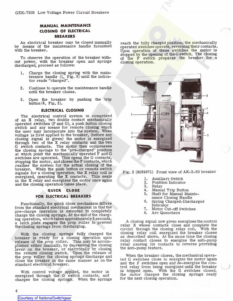
reach the fully charged position, the mechanicallyoperated switches operate, reversing their contacts.Upon operation of these switches the motor isstopped by the opening of the G switch. The closingof the F switch prepares the breaker for aclosing operation.To observe the operation of the breaker with-
out power, with the breaker open and springsdischarged, proceed as follows:
1. Charge the closing spring with the main-tenance handle (1, Fig. 3) until the indica-tor reads "charged”.
2. Continue to operate the maintenance handleuntil the breaker closes.
3. Open the breaker by pushing the tripbutton (4, Fig. 2).
ELECTRICAL CLOSINGThe electrical control system is comprised
of an X relay, two double contact mechanicallyoperated switches (F and G), a push button closingswitch and any means for remote closing whichthe user may incorporate into the system. Whenvoltage is first applied to the breaker, (before anyclosing signal is given) the motor is energizedthrough two of the X relay contacts and the twoG switch contacts. The motor then compressesthe closing springs to the "pre-charged" positionat which point the mechanically operated F and Gswitches are operated. This opens the G contacts,stopping the motor, and closes the F contacts, whichreadies the system for the actual closing of thebreaker. When the push button or remote switchsignals for a closing operation, the X relay coil isenergized, operating the X contacts. This sealsin the X relay and energizes the motor once againand the closing operation takes place.
QUICK CLOSEFOR ELECTRICAL BREAKERS
Functionally, the quick close mechanism differsfrom the standard electrical mechanism in that thepre-charge operation is extended to completelycharge the closing springs. At the end of the charg-ing operation, which takes approximately 5 seconds,a latch plate engages the prop roller to preventthe closing springs from discharging.
With the closing springs fully charged thebreaker is ready for a closing operation uponrelease of the prop roller. This may be accom-plished either manually, by depressing the closinglever on the breaker, or electrically by closingthe remote closing switch. Upon the release ofthe prop roller the closing springs discharge andclose the breaker in the same manner as on thestandard electrical breaker.
Fig. 2 (8039671) Front view of AK-2-50 breaker
1. Auxiliary Switch2. Position Indicator3. Relay4. Manual Trip Button5. Shaft for Manual Mainte-
nance Closing Handle6. Spring Charged-Discharged
Indicator7. Motor Cut-off Switches8. Arc Quenchers
A closing signal now given energizes the controlrelay X whose contacts close and complete thecircuit through the closing relay coil. With theclosing relay coil energized the breaker closesas described above. At the same time the closingrelay contact closes to energize the anti-pumprelay causing its contacts to reverse providingthe anti-pump feature.
When the breaker closes, the mechanical opera-ted G switches close to energize the motor againand the F switches open and de-energize the con-trol relay from being energized until the breakeris tripped open. With the G switches closed,the motor charges the closing springs readyfor the next closing operation.
With control voltage applied, the motor isenergized through the G switch contacts, andcharges the closing springs. When the springs
4

Low Voltage Power Circuit Breakers GEK-7303
ELECTRICAL TRIPPING
The breaker may be tripped electrically by anyof the electrical tripping devices described inthese instructions,tripped by the automatic overcurrent or reversecurrent tripping devices, if so equipped,these devices trip the breaker in a similar manner,i.e. the device trip arm moves against the trippaddles fastened on the trip shaft, thus rotatingthe trip shaft and displacing the trip latch.
The most commonly used tripping device is theshunt trip device connected in the control circuitas shown in Fig. 1. When a tripping signal is given,the shunt trip coil is energized through a norftially-open auxiliary switch "a” contact, thus trippingthe breaker.
The breaker may also be
All
MAINTENANCEBEFORE INSPECTION OR ANY MAINTENANCE
WORK IS DONE BE SURE THAT THE BREAKERIS IN THE OPEN POSITION. ALL ELECTRICALPOWER, BOTH PRIMARY AND CONTROLSOURCES, SHOULD ALSO BE DISCONNECTED. Fig. 3 (8039670) View showing operation of
AK-2-50 breaker with manual maintenancehandle and installation of safety pinWarning:
ergy closing mechanisms, care must be takenwhen the circuit breaker is being installedand when any inspection or maintenance workis being done so that the breaker is in theopen position and the closing springs arebeing restrained by the safety pin. The proce-dure for inserting the safety pin is given below.
INSERTING SAFETY PINAK-50, -75 and -100
(Fig. 3)The closing spring should be charged with the
maintenance handle (1) so that the safety pin (3)can be placed in the hole of the push rod (2).Continue to operate the maintenance handle, clos-ing the breaker. This is done so that the safetypin takes the spring force.
To install the safety pin of the manual stored-energy mechanism refer to the section entitled
STORED-ENERGY MANUAL MECHANISM on page17 of these instructions.
With the safety pin restraining the closingspring force, the contacts will close slowly whenthe breaker is manually operated allowing theoperation of the mechanism and the contact align-ment to be visually observed.
On breakers employing stored-en-1. Manual maintenance Handle2. Push Rod3. Safety Pin
INSPECTION
Periodic inspection of the circuit breaker isrecommended at least once a year. More fre-quent inspections are recommended if severeload conditions, dust, moisture or other unfavorable conditions exist,of the breaker, including contacts and arcquenchers,should always be made after the breaker has in-terrupted a short-circuit.
At regular inspection periods the breaker shouldbe operated manually; (stored energy mechanismswith the safety pin restraining the closing springforce) to observe the contact alignment and tomake sure all mechanism parts move freelywithout binding or excessive friction.
If the breaker remains open or closed for aperiod of six months or more, it is recommendedthat arrangements be made to open and close itseveral times in succession, preferably underload.
A complete inspection
Following the inspection period, the closingsprings must be recharged, the safety pin removedfrom the push rod, and the pin placed in the retain-ing spring clip adjacent to Hie push rod.
If overheating, not caused by overcurrent, isobserved, a complete inspection of the breakershould be made including connections and contacts.
5

GEK-7303 Low Voltage Power Circuit Breakers
TROUBLE SHOOTING1
REMEDYCAUSETROUBLE
Overheating Contacts not aligned.Contacts dirty, greasy or coatedwith dark film.
Adjust contacts.Clean contacts.Replace contacts.Clean surfaces of current-carrying parts.Relocate or provide adequateenclosure.Increase capacity of bus or cable.Tighten, but do not exceed, elasticlimit of bolts or fittings.Check breaker application or modifycircuit by decreasing load.Provide adequate ventilation.Correct bus or cable arrangement.
Contacts badly burned or pitted.Current-carrying surfaces dirty.Corrosive atmosphere.Insufficient bus or cable capacity.Bolts and nuts at terminal connectionsnot tight.Current in excess of breaker rating.Excessive ambient temperature.Inductive heating.
Failure to TripAK-2 Breakers
Travel of tripping device does not providepositive release of tripping latch.Worn or damaged trip unit parts.Binds in overcurrent trip device.
Re-adjust or replace tripping device.Replace trip unit.Replace overcurrent trip device.
Loose or Disconnected Power SensorDisconnect Plugs. Tighten or Reconnect Disconnect
Plugs.Tighten or Reconnect Tap Connections.
Failure to TripAK-3 Breakers
Loose or Broken Power Sensor CoilTap Connections. )
Check application of overcurrenttrip device.Check application of overcurrenttrip device.Replace overcurrent trip device.
False TrippingAK-2 Breakers
Overcurrent pick up too low.Overcurrent time setting too short.Bind in overcurrent trip device.
Tighten Thumb Screw on DesiredSetting.Captive Thumb Screw on Power Sensor
Loose Fail-Safe Circuitry RevertsCharacteristic to Minimum Settingand Maximum Time Delay.Tap Setting Dial on Power SupplyIncorrectly Set.External Ground Sensor CoilImproperly Connected.
Set Dial to Correspond with PowerSensor Coil Tap.Refer to Fig. 40 Page 38 for Polarityand Connections. Check Continuityof Shield and Conductors Connectingthe External Ground Sensor Coil
False TrippingAK-3 Breakers
Failure to Closeand Latch
Re-align and adjust attachments.Binding in attachments preventingresetting of latch.Latch out of adjustment.Latch return spring too weak or broken.Hardened or gummy lubricant.Safety pin left in push rod..Motor burned out.
Adjust latch.Replace spring.Clean bearing and latch surfaces.Remove safety pin.Replace motor.Replace or adjust faulty device.Faulty control circuit component.
Improper contact sequence (main contactsnot sufficiently parted when arcing contactspart).Short-circuit current level above inter-rupting rating of breaker.
Burned MainContacts
Increase arcing contact wipe. Adjustcontact sequence by raising or lower-ing main movable contact pivot block.Requires system study and possiblereplacement with breaker having ade-quate interrupting capacity.Replace stationary contact springsand dress up or replace contacts.
JLoss of contact wipe or pressure.
6

Low Voltage Power Circuit Breakers GEK-7303
5. Remove the auxiliary switch operating rod(&, Fig. 20).At all times it is important not to permit
pencil lines, paint, oil or other foreign mater-ials to remain on the insulating surfaces of thebreaker as they may cause low resistance betweenpoints of different potential and result in eventualelectrical breakdown.
6. Check along the trip shaft for a mech-anical interference or connection between theovercurrent trip device and the trip paddles.Remove mechanical connection if present, orif interference exists, use extreme care whenremoving or re-assembling front and back framesto avoid mechanical breakage of trip devices. Inreassembling the front and rear frames, the twoframes should be positioned vertically so thatthe trip shaft is horizontally aligned.
NOTE:be fastened to a suitable maouting base withthe front frame supported by a sling or hookas the bolts are being installed.
The breaker should be operated several timesat a rated voltage to assure that the controlcircuits are properly connected and that allelectrical attachments are functioning properly.
A complete contact inspection, including con-tact wipe and pressure, should be made at regu-lar inspection periods and always after a knownshort circuit current has been interrupted, todetermine whether the contacts are worn orpitted in which case they should be dressedor replaced. It is necessary to remove the arcquenchers to properly inspect the contacts. Arc-ing contacts and arc quencher barriers should bereplaced when they are eroded to half theiroriginal thickness.
It is recommended that the breaker
BASIC BREAKER COMPONENTSARC QUENCHERS
(Fig. 4 and 5)The arc quenchers should be inspected at the
If the barriers areLUBRICATIONregular inspection period,cracked or eroded to one-half their originalthickness, they should be replaced.In general, the circuit breaker requires mod-
Mechanical bearing pointserate lubrication,and sliding surfaces should be lubricated at theregular inspection periods with a thin film ofG-E Lubricant D50H15 . Slidingsilver plated con-tact surfaces should be lubricated with G-E Lub-ricant D50H47. Hardened grease and dirt shouldbe removed from latch and bearing surfaces byusing kerosene. ALL EXCESS LUBRICANT SHOULDBE REMOVED TO AVOID ANY ACCUMULATIONOF DIRT OR DUST.
REPLACEMENT—AK BREAKERSBe sure the breaker is open.1.
2. Remove the channel-shaped retaining barby removing two screws and two nuts.3. Lift the quenchers clear of the movablearcing contacts.4. During replacement be careful not toovertighten the screw which secure the channel-shaped retaining bar. Overtightening the screwswill bow the bar and leave the center arc quen-cher loose.
The use of cotton waste to wipe bearing surfacesshould be avoided, as the cotton ravelings maybecome entangled under the bearing surfaces anddestroy the surface of the bearing.
On drawout breakers, the contact surface of thedisconnect studs should be greased with G-EGrease Specification D50H47.
SEPARATION OF FRONTAND REAR FRAMES
To repair or replace contacts, operating mech-anism, or the overcurrent devices, the frontframe must be separated from the back frame.To separate the two frames proceed as follows:
1. The breaker contacts must be open withthe safety pin in place. (See MAINTENANCE.)
2. Remove the two opening springs (on lowerpart of the breaker) from the outside pole units.
3. Remove the clevis pin (14, Fig.6) (13, Fig. 7)from the center pole unit.
4. Remove the six nuts from the back frameusing a socket wrench with an extension. Theseinclude the two nuts at the top of the frame.
REPLACEMENT— AKF BREAKERS
The center-pole arc quencher of these breakersis similar to the arc quenchers of the standardbreakers and is replaced in a similar manner,except that the breaker must be closed. Withthe breaker closed the center-pole contacts areopen and the arc quencher can be removed.
Replace the outer-pole arc quenchers of theType AKF breaker as follows:
1. Be sure the breaker is open.2. Remove the two channel-shaped retaining
bars which bear against the front of the arcquenchers by removing four screws, two on eachside.
3. Lift the arc quenchers clear of the movablearcing contacts.
4. Replace arc quenchers and insert the fourscrews holding the retaining bars in position.
7

GEK-7303 Low Voltage Power Circuit Breakers
9876
Fig. 4 (8014830) Disassembly of arc quenchers-standard breaker and AKF center pole.6. Muffler7. Compound Support8. Steel Back Plate9. Spacer Block
1. Stud2. Cap3. Side Barrier4. Pocket Barrier5. Inner BarrierDISASSEMBLY—AK AND AKF
CENTER POLE (Fig. 4)The following instructions apply to both tne
Type AK and AKF breaker center poles. 3. Remove bolt fastening cap (4) and barrierplate assembly.
4. Barrier plates may now be lifted from as-sembly for inspection.5. In reassembling, make sure components
are positioned so that holes for self-tapping hard-ware are in line. Do not strip threads in compoundby overstressing screws.
1. Remove arc quenchers (see REPLACE-MENT).
2. Remove screws holding spacer block (9).3. Remove spacer block, steel back plate
(8), and compound support (7).4. Rock muffler (6) slightly and remove.
The inner barriers (5) can now be removed forinspection.
5. Remove nut and withdraw stud (1).6. Remove cap (2). The side (3) and pocket
(4) barriers should be free.7. Reassemble and replace the arc quencher
in the reverse order. Tighten the fasteningsafter replacement.
POLE UNIT ASSEMBLY (Fig. 6)
NOTE: The text and part identification numberscontained in this section apply to illustrationscovering the AK-50 breaker. The same textis applicable to the AK-75 and 100 breakers byreferring to Fig. 7 and identifying the similarparts. These similar parts may not, in everycase, be identified by the same number.Each pole unit assembly consists of a set of
arcing contacts, a set of main contacts, theactuating linkage and the mounting base.Fig. 8 and 9, pole unit assemblies mounted onback frame assemblies.
SeeDISASSEMBLY— AKF OUTERPOLES (Fig. 5)
1. Remove arc quenchers (see above) and layon sides on a flat surface. The stationary arcing-contact assembly con-
sists of a set of parallel contact fingers (2),pin (3), and compression springs (22), whichprovide continuous contact pressure for the full
2. Remove hardware from one side of arcquencher as indicated in Fig. 5.
8

GEK-7303 Low Voltage Power Circuit Breakers
I
* II J12
a
Figo 5 (8019408) Disassembled arc quencher- AKF outer poles.1. Muffler Assembly2. Spacer Block3o Inner Barrier4. Cap
5. Intermediate Barrier6. Outer Barrier7. Side Plate
Steel springs (5) shunttravel of the contacts,the pivot pin to prevent possible pitting at thepivot point when interrupting high currents. Onearlier model breakers flexible braid leads wereused.
In order to function properly, a definite amountof contact pressure and contact wipe must existbetween the movable and stationary contacts.Table I gives the figures for contact pressure andcontact wipe. Both wipe and pressure should bechecked during the regular inspection period.
MEASURING CONTACT WIPE (Fig. 6)1. Remove arc quenchers (see REPLACEMENT
under ARC QUENCHER).2. With the breaker open, measure the hori-zontal distance from the edge of the stationarycontact to the stationary block behind it. ("B”dim. for arcing contacts, ”C" dim. for maincontacts).
The movable arcing-contact assembly consistsof parallel contact arms (4) carried on two mov-able pivot pins (8) and (19). The arcing contactsinterleave the main contacts and pivot with themabout pin (19). This relative motion is obtained bylinkages from the upper pin (7) to the breakermechanism.
The stationary main contact assembly includesmain and intermediate contacts. The intermediate-contact surface extends beyond the main contactsand will, therefore, make before the main contactsand break after the main contacts. The numberof contacts for each breaker rating is givenin Table I.
Close the breaker and repeat item 2. Thedifference between the readings in items 2 and 3determines the wipe of the contacts. For safetyreasons be extremely careful not to trip thebreaker.
3.
The movable main contacts pivot around astationary pin (18), which holds them to thelower block. Motion is obtained from a secondpin (7), connected by an insulated link (12) to th.ebreaker mechanism. In addition to steel springsshunting the current from the contact directly tothe lower contact block, steel springs (17) forcethe contacts against the pins to prevent pittingat the pivot point. The movable main contactassembly also contains main and intermediatecontacts.
MEASURING CONTACT PRESSURE(Fig. 6)
1. Remove arc quenchers (see REPLACEMENTUNDER ARC QUENCHER).
2. Close the breaker and measure dimension”BTT.
3. Open the breaker. Place a push-type scale
9

Low Voltage Power Circuit Breakers GEK-7303
TABLE I
Intermediate Contacts Arcing ContactsMain Contacts
Pres-sure inLbs.
WipeNo. ofZontactsPer Pole
Wipe No. ofContactsPer Pole
Pres-sure InLbs.
Wipe No. ofin Contacts
Inches /Per Pole
Pres-sure inLbs.Breaker
Typeinin
InchesInches
4/64 to 12/64 to18/64
12/64 to18/64
12/64 to18/64
12/64 to18/64
12/64 to18/64
12/64 to18/64
12/64 to18/64
AK-50 for AC 3 55 to 65 31 to 4355 to 65 21 *7/64
1/16 toAK-50 for DC 3 3 31 to 4355 to 65 55 to 6517/64
1/16 toAK-75 for AC 35 to 45 35 to 45 31 to 435 317/64
1/16 toAK-75 for DC 35 to 455 35 to 45 5 31 to 431 *7/64
1/16 toAK-100 for ACAK-100 for DC
8 25 to 35 25 to 35 31 to 432 57/64
1/16 toAKF-2C 3 55 to 65 55 to 65 2 31 to 431 *7/64(Outside Poles )
25 to 35 1/16 toAKF-2D (OutsideAKF-2E (Poles)
55 to 65 31 to 435 317/64
AKF-2C (FieldAKF-2D Discharge
Contacts)28/64 to40/64
0 10 to 160 2**
* The intermediate contact wipe should be at least 1/16 in. greater than main contact wipe.** Left stationary contact extends approximately 3/32 in. ± 1/32 further than right hand contact.
against the stationary arcing contacts at a pointmeasured in line with the break between the contactstop and the contact pivot block. Push the contactbackward until dimension "B" recorded in item2 is reached.
effect.5. To increase the wipe on either outside pole
individually, move the crossbar adjusting plate ofthat pole to the left; to decrease the wipe movethe adjusting plate to the right.The scale should then be read.
4. If the pressure is not within the require-ments listed on TABLE I, refer to the sectionof these instructions dealing with ADJUSTINGCONTACT WIPE AND PRESSURE.
ADJUSTING CONTACT WIPEAND PRESSURE (Fig. 6)
1. To obtain proper contact wipe and pressureon the center pole, dimension "A" should beincreased to increase wipe and decreased todecrease wipe.
2. To change dimension "A" remove the clevispin (14) and rotate the clevis as necessary.
3. To prevent overstressing the clevis threads(13) dimension ,TAft should not exceed 3/16 in. andspace "A" should be filled with shims to 0.005 in.of being solid.
4. With the proper center pole wipe obtained,moving the crossbar adjusting plate (10A)center pole to the right will simultaneously in-crease the wipe on both outside poles; movingthe adjusting plate to the left will have the reverse
If the proper contact pressureNOTE:does not exist when the contact wipe iswithin its limits, the stationary contactssprings should be replaced.
CONTACT SEQUENCE (Fig. 6)
On the horizontal plane, the difference in themaking of the arcing contacts on the same pole mustbe no greater than 1/32 in.; the difference be-tween arcing contacts on separate poles 1/16 in.If it is desired to advance or retard the closingof the main contacts of a pole, loosen the boltsholding the adjustment plate (10A) of that poleand slide plate to the left to advance contactclosing, or to the right to retard contact closingMake this adjustment on the outer poles, usingthe center pole as a reference. Upon retight-ening adjustment plate bolts, make sure the lock-ing tabs are turned up around bolt heads, lockingthe bolts securely in place.
on theContact sequence in the vertical plane should
be such that when the arcing contacts are justtouching, the intermediate contact gap should be
10

Low Voltage Power Circuit Breakers GEK-7303
1. Screw2. Stationary Arcing Contact3. Pin (Stationary Arcing Contact)4. Movable Arcing Contact5. Spring (Leaf Contact)
5A. Stationary Intermediate Contact6. Movable Main Contact7. Shouldered Pin8. Pin (Arcing Contact Links)9. Insulating Link
10. Pin (Insulating Link)IOA. Adjusting PlateIOB. Buffer Spacers
11. Pin (Side Link)12. Link13. Clevis14. Clevis Pin15. Lower Stud16. Pole Unit Base17. Spring (Main Movable Contact)18. Pin (Main Movable Contact)19. Pin (Movable Arcing Contact)20. Side Link
20A. Contact Stop21. Spring (Stationary Main Contact)22. Spring (Stationary Arcing Contact)23. Upper Stud24. Leaf Spring (Stationary Main Contacts)25. Pin (Stationary Main Contact)26. Stationary Main Contact27. Screw28. Stop
28
27
2625
24
2221
20A
20
19
18
17
16
1512
13
14
Fig. 6 (0107D7517) Pole unit assembly-AK-50at least 3/16 in., the main contacts gap at least1/4 in. spacers on the cross-bar. The locking nuts on
the buffer bolts should be locked in such a posi-tion that the buffer bolt may be rotated freely.This check can best be madeNOTE:
by means of the maintenance handle, withthe safety pin restraining the closing springs. REPLACEMENT OF CONTACTS
(Fig. 6 )
Stationary Arcing Contacts (2, Fig. 6)0, Fig. 7)
1. Remove the upper plate by removing twoscrews (1). On the AK-75 and -100 remove thetop contact block (25, Fig. 7) and remove insulation(3, Fig. 7).
2. Loosen screws holding spring. (5)
3. Remove pin (3) freeing the stationary con-tacts and springs (22).
4. Install new springs and stationary arcingcontacts in reverse order.
If the gap is under the required minimum, it isusually possible to form the arcing contacts andobtain the required dimensions. To form the con-tacts, place a piece of conduit approximatelytwo feet long, over the contact andform the contacteither forward or backward. If the proper dimen-sions are still not obtained the movable arc-ing contacts should be replaced.
If it has been necessary to make any adjust-ments while obtaining proper contact sequence,the contact wipe and pressure must be checked,and adjusted, if necessary.
CONTACT GAP (Fig. 6)
When the breaker is open, the gap betweenthe movable and stationary contacts should bebetween 2 5/8 in. and 2 3/4 in. The gap maybe adjusted by varying the number of buffer
5. Adjust contact wipe and pressure. (SeeADJUSTING CONTACT WIPE AND PRESSURE).
11

GEK-7303 Low Voltage Power Circuit Breakers
l STATIONARY ARCINGCONTACT
2. PIN (STATIONARY ARCINGCONTACT )
3. INSULATION4 MOVABLE ARCING CONTACT4A.STAT INTERMEDIATE
CONTACT5. MOVABLE MAIN CONTACT6 SHOULDERED PIN7 LINKa PIN (ARCING CONTACT
LINK )
9. INSULATING LINKIQ PIN ( INSULATING L I N K )IOA. ADJUSTING PLATE11. PIN (SIDE LINK)12. CLEVIS13. CLEVIS PIN14. LOWER STUD15. POLE UNIT BASE16 SPRING (MAIN MOVABLE
CONTACT )17. PIN ( MOVABLE MAIN
CONTACT )
18 PIN (MOVABLE ARCINGCONTACT)
19. SIDE LINK20. SPRING (STATIONARY
MAIN CONTACT )
21. SPRING (STATIONARYARCING CONTACT)
22. UPPER STUD23. PIN (STATIONARY MAIN
CONTACT )24. STATIONARY MAIN
CONTACT25. TOP CONTACT BLOCK
)
~u
Fig. 7 (215D174) Pole unit assembly - AK-75 and AK-100The movable arcing contacts (4 ) should be
replaced when the stationary arcing contacts arereplaced.
scribed above.2. Remove screws (27) and remove bracket
which holds pin (25) in place.3. Remove main-and intermediate-contact
stop (20A) which holds the lower part of stationarycontact. Removal will be facilitated if the forceon the contact springs (21) is neutralized. Thiscan be accomplished by operating the breakerwith the maintenance handle, with the safety pinin place, until the load on the contact stop isrelieved.
Separate the front frame from the backframe as described under SEPARATION OF FRONTAND REAR FRAMES.
1.
2. Remove pins (8) and (19) and withdrawthe contacts.
3. Reassemble parts in reverse order.Stationary, Intermediate and MainContacts ( Fig. 6)
Remove stationary arcing ctonacts as de- 4 o Loosen the hardware which fastens theupper stud to the pole unit base until the contact1.
12

Low Voltage Power Circuit Breakers GEK-7303
u X]
i —2 —L
93-— j4 i 85-
3^
fVlO,6
Ji...'
3
3
Fig. 8 (8014678) Front view of back frameassembly - AK-2-50
6. Crossbar7. Series Overcurrent
Device8. Movable Inter-
mediate Contact9. Stationary Inter-
mediate Contact
1. Stationary ArcingContact
2. Movable ArcingContact
3. Stationary MainContact
4. Clamp5. Movable Main
Contact
Fig. 9 (8039669) Front view of back frameassembly - AK-3-50
1. Power Sensor Coil Assembly2. Disconnect Plug3. Transformer Taps in Amperes
spring load on pin (25) is relieved.5. Remove pin (25) and screws (27) and
lift out contacts.
ing contact replacement.(See ADJUSTING CONTACT WIPE AND PRESSURE ).
OPERATING MECHANISMSELECTRICALLY OPERATED AK-50, -75and -100; MANUAL AK -50
The electrically operated mechanism includesa motor and a gear reduction unit, which chargesthe closing springs (16, Fig. 10) through a crankshaft (14, Fig. 10). The crank shaft has an armwith a roller (12, Fig. 10) which rides on theclosing cam (2, Fig. 11).closing cam roller is shown in Fig. 11A, 11B,and 11C.center-pole unit through a clevis and through acrossbar it controls the opening and closingof the contacts on all pole units.
Charging the Closing Springs ( Fig. 10)
6o Reassemble contacts in reverse order,being careful to replace the intermediate contactin the proper position.
Movable Intermediate andMain Contacts (Fig. 6)
1. Remove the movable arcing contacts asdescribed above. The position of this
2. Loosen spring (17).3. Remove braid if present by removing screw
at bottom of contact.The closing cam is connected to the
4. Slide link (12 ) to the side and off of pin(7).
The mechanism in position is shown in1.5. Slide pins (7) and (18) far enough to the
side to allow the movable intermediate contactsto be replaced.
Fig. 11A.2. The motor turns the crank (10) which
is mounted on the output shaft of the gear reduc-tion unit. The charging roller, which is on theface of the crank, has paddle arm (11) bearingon it.
6. Reassemble parts in reverse order.Always check contact wipe and pressurefollow-
13

GEK-7303 Low Voltage Power Circuit Breakers
FIG - 1IBMECHAMSM IN RESET P03TICNMECHANISM IN NOTION BEFORE
RESETTING AS SHOWN IN FIG.- 11B
15it
—15
2-
3u
91. Pin2. Bushing3. Bracket4. Indicator5. Bracket6. Frame7. Crank Rol ler8. Gear Reduc-
t ion Uni t9. Motor
10. Crank
11. Paddle12. Clos ing Cam
Roller13. Clos ing Cam
Arm14. Crank Shaf t15. Spr ing Charg-
ing Arm16. Closing Spr ing17. Push Rod18. Cl ip
FIG-11CMECHANISM IN CLOSED POSITION
(CLOSING SPRING DISCHARGED)
1. Spr ing2. Cam3. Link4. Reset Spr ing
4A. Spr ing Adjus t ing Nuts5. Prop6. Adjus t ing Screw7. Adjus t ing Screw Stop Pin8. Prop Return Spr ing9. Rol ler
10. Tr ip Latch11. T r ip Shaf t12 . Clevis Pin13. Clevis14. Latch Buffer Stop
( Bronze Mater ia l )15. Rol ler16. Prop
Fig. 10 (541E304) Closing springand charging mechanism
3. As the crank turns, the roller pushes thepaddle arm upward, thereby charging the closingsprings through the spring charging arm (15)of the crank shaft.
4. As the charging roller approaches deadcenter a cut-off switch opens, de-energizing themotor circuit. Fig. 11 (541E305) Operating mechanism
Closing the Breaker
Electrically Operated (Fig. 10 )
1. With the mechanism in the position describedabove and the closing springs charged, applyinga closing signal will cause the motor to continueto charge the closing springs allowing the mech-anism to reset, if not already reset, to the posi-tion shown in Fig. 11B.
5. The breaker is now ready to close whena closing signal is given.
6. With the breaker resting at the prechargeposition, the trip latch may or may not be in thereset position. This depends on the position ofroller (15, Fig. 11B) with respect to the cam(2, Fig. 11B).
14

t-m
Fig. 12 (8018989) Rear view of front frame-AK-50 showing cam shaft locking plate
being loosened
Fig. 13 (8018984) Rear view of front frame-AK-50 showing cam shaft locking plate
and cam shaft removed
(The mechanism should be reset byFig. 11B.manual operation with the safety pin in placeand with roller (15) clear of cam (2).
2. As the crank roller (7) passes its topdead-center position, (maximum spring chargeposition) the closing springs are free to discharge.Crank (10) can be overdriven independently of themotor so that roller (7) assumes its bottom dead-center position without restraint.
30 As the springs discharge, the rotation ofthe crank shaft (14) causes roller (15, Fig. 11)to rotate cam (2, Fig. 11) and raise clevis (13,Fig. 11). Prop (16, Fig. 11) holds cam (2, Fig.11C ) in this position.
4. Raising clevis (13, Fig. 11C) closes thebreaker contacts through the pole base linkage.Tripping the Breaker ( Fig. 11)
Operation of any of the trip devices rotatesthe trip shaft (11) which allows the trip latch (10)to release the latch prop (5). This allows theforces of the contact and opening springs toreposition the operating mechanism linkage tothe position shown in Fig. 11A. In this position,the operating cycle may be repeated.
Adjustments (Fig. 11 )
All adjustments should be made with the opera-ting mechanism in the reset position as shown in
1. The gap between the trip latch (10) and theroller (9) of the reset latch should be between1/64 in. and 1/32 in. This adjustment can beobtained by turning screw (6).
2. The center line of the trip latch (10)should pass through the center of the roller (9)0 Thelatch buffer stop on the mechanism frame canbe adjusted by loosening the retaining screws toreposition the latch with respect to the roller.
3. The distance between the roller on link(3) and prop (5) should be between 1/64 in. andl/32 in. To obtain this gap, advance or retardthe nuts (4A) on the bottom of the rod usingthe reset spring (4).Replacement
When replacing the operating mechanism, referto the section titled SEPARATION OF FRONTAND BACK FRAMES under MAINTENANCE inthese instructions.
The motor is mounted on the side of the gear-
15

GEK-7303 Low Voltage Power Circuit Breakers
reduction unit and through a worm gear and aplanetary gear train drives the crank (10, Fig. 10)with a reduction 1000:1. To remove the motorand gear-reduction unit, proceed as follows:
1. Remove the front frame (see SEPARATIONOF FRONT AND REAR FRAME.)
2. Remove closing springs and crank-shaftas illustrated in Fig. 12 and 13.
3. Disconnect the leadsfrom motor and removethe wires attached to gear unit housing.
4. Remove four bolts at the bottom of thefront frame and one bolt at top of gear reductionunit. The motor and gear unit may now be removed.
NOTE: If it is desired to replace only themotor unit, disconnect the motor leads andremove only the hardware fastening it to thegear-reduction unit. When removing the motoronly, the front frame should be placed frontside down to prevent the oil escaping from thegear unit.
" B 'A"
O
LATCHROLLER
Fig. 14A
The gear reduction unit contains 4 ounces ofoil similar to Atlantic Refining Company’s GradeHFS No. 3. 'It should not be necessary to addor change oil except when the gear-reductionunit and motor are disassembled.
Quick-Closing Release Latch - Fig. 14A
Adjust the engagement of the roller on the latchto l/8”±l/64” by turning the screw "A”. Afteradjustment is set, lock the bolt with the hex nutTfBTT. Adjust the clearance between the latch andthe roller to 1/32+0-1/64 by turning the screw TTCTT.QUICK CLOSE BREAKER
ADJUSTMENTSThe quick close breaker basically differs from
the standard breaker in that the prechargingoperation is extended to and slightly past the topdead center position of the closing spring assembly.As the springs start to discharge to close thebreaker, the discharge operation is arrested bya prop and latch arrangement. The subsequentclosing operation is accomplished by trippingthe latch to release the prop which in turn allowsthe springs to continue the interrupted dischargingoperation and close the breaker.
The gear reduction unit for the standard breakeris not interchangeable with the gear reductionunit-on the quick close unit because the quickclose gear reduction unit employs a slip clutchto relieve the pressure that would otherwisebe exerted between the output crank plate andthe prop.
After the closing springs have been completelycharged and the prop and latch system are pre-venting closure of the breaker, the closing opera-tion may be accomplished by energizing the closingrelay thru the control relay contacts, or man-ually by depressing the push to close lever whichmechanically displaces the latch to allow thebreaker to close.
MAGNET SPACERjmAROLLER
RELEASE ARMOARMATURE
32^0; GO [*“I
Fig. 14B
Release Arm Adjusting - Fig. 14B
Adjust release arm screw ”D” so that the stroke ofthe armature of the closing solenoid releases theroller from the latch with a minimum of 1/32”over-travel. Check by using 1/32” GO and 3/32”NO GO gauge between armature and magnet.
On drawout breakers an interlock between thebreaker and enclosure requires the springs tobe discharged before the breaker can be removedfrom the enclosure.16

Low Voltage Power Circuit Breakers GEK-7303
used on the AK-50, -75 and -100 electrical breakers.The closing springs (5) are charged by operatingthe manual closing handle (22) on the front of thebreaker, instead of the closing motor as is thecase with the electrical breaker. Closing thisbreaker is accomplished by pumping the operatinghandle four complete cycles,first counterclockwisethrough 120 degrees from its normal verticalposition and then clockwise back through 120degrees from its normal vertical position andthen clockwise back through 120 degrees. Whenapproximately 70 degrees of the fourth clockwisestroke have been completed, the closing springs,which have been charged during the previousstrokes ot the closing handle, are driven over-center and the breaker closes.
t
RELEASEARMo
/ v ARMATURE-3J2
Q°4M 0 G0/LEVERMAGNET This mechanism consists basically of a closing
spring assembly, ratchet wheel and output crankassembly, handle shaft and pawl assembly, andthe closing handle.Fig. 14C
Closing the Breaker (Fig. 15)
The first stroke of the closing handle causesthe ratchet pawls (21) attached to the handle shaft(23), to engage the first tooth of the ratchet wheel(17), thus beginning to charge the closing springs.The subsequent closing handle strokes perform thesame function as the pawls (21) engage the teethin the ratchet wheel (17), thus rotating the ratchetwheel and output crank (32) and completely chargingthe closing springs. This rotation of the ratchetwheel and output crank is in a counterclockwisedirection from the lower position, through slightlymore than 180 degrees, to a position just beyonddead center, In this position the closing springsare free to release their energy, closing the breakerat a high speed.
Release Shaft Stop and Switchette - Fig. 14C
Adjust screw ”E” to 1/32” clearance betweenscrew and lever with clearance on release armtaken up by pressing lever lightly forward.Adjust switchette operation by adding washers”F” under cotter pin, so that contact is madewhen armature is adjusted as shown above.
The control relay or (X) relay is located onthe left side of the front frame channel. It maybe removed by disconnecting the wiring, looseningthe (3) two mounting screws and lifting it slightlyto admit the top mounting screw through thekeyhole mounting, in general, the entire relayshould be replaced rather than changing coilsand contacts.
Inserting the Safety Pin (Fig. 15)
If it is desired to slowly close the breakercontacts to check contact wipe and sequence,operate the closing handle 3 1/2as described above,counterclockwise stroke and before performingthe fourth clockwise stroke, insert the safetypin (3) into the hole (4) in the guide rod (6),thus preventing the closing springs (5) fromreleasing their energy to close the breaker contacts.Replacement (Fig. 15)
If it is necessary to replace any of the mech-anism parts, the following total procedure isrecommended,at the step required to replace any particularpart:
complete cyclesAt the end of the fourth
The anti-pump relay is located on the leftside of the front channel above the control relay.The connections to this relay are soldered. Re-moval of the relay is straight forward. Whenre-installing use extreme care to avoid shortingcontact points of different voltage potential withsolder of flux.
This procedure may be haltedThe closing control relay consists of a strong
box solenoid with sufficient linkages to operatethe remotely located D switches. 1. Install the safety pin (3) as described.
above.Stored-Energy Manual Mechanism (Fig. 15)2.AK-50-75-100 Separate the front and rear frames as
described under REPARATION OF FRONT ANDREAR FRAMES” in the ”MAINTENANCE” sectionof these instructions.This breaker is equipped with a spring-charged
stored-energy mechanism similar to the mechanism
17

GEK-7303 Low Voltage Power Circuit Breakers
\
: j-r-
£13 23 -• /! ; 4
Z.J ii5• — Zlri— ii
i1 ffi i
:
6i
7!
II 'I
1':i ; l
8! I:
.-.J
r10I
12 i
'13 i 321415 I
16 iii17 ii
18 I19 ' 31t' '202122f*3r 23 \2425 \as 2627 rE)
I28 30
29© (
• l
!iii
/i
i •
i \i :/ :
i \NK
• \
NNi
ViewFweoKi~rWITH HANDLE A.ME> e cuTCHECy-i RE^O’/EP
Fig. 15 (669D805) Stored-energy manual closing mechanism charged position AK-21. Upper Spring Pin2. Safety Pin Holder3. Safety Pin and Chain4. Safety Pin Hole5. Closing Springs6. Guide Rod7. Pawl Springs8. Front Escutcheon9. Front Bearing Plate
10. Bearing Plate Mounting Bolts31. Lower Spring Pin
11. Output Crank Roller12. Thrust Bearing13. Shims14. Groove Pin15. Nylok Screw16. Ratchet Wheel Shaft and Asm.17. Ratchet Wheel18. Side Plate Shims19. Side Plate Mounting Bolts20. Bearing Side Plate
21. Ratchet Pawls22. Manual Closing Handle23. Closing Handle Shaft and Pawl Asm.24. Roll Pin25. Main Closing Crank26. Pawl Buffer Stop27. Buffer Stop Shims28. Buffer Stop Support29. Handle Return Spring30. Mechanism Roller
*
32. Output Crank
18

Low Voltage Power Circuit Breakers GEK-7303
3. Remove the closing spring assembly byremoving the upper and lower spring pins (1, 31).
4. Remove the right hand bearing side plate(20), and the side plate shims (18) if present, byremoving four mounting bolts (19), thus allowingthe main closing crank (25) to be removed.
5. Remove the closing handle (22) by removingtwo set screws threaded in same hole.
imum distance from the center of rotation ofthe ratchet wheel (17). This measurement shouldbe made while operating the closing handle duringthe four spring charging operations and beforethe closing springs are reassembled.
3. The ratchet pawls (21) should operateTheyfreely throughout the closing strokes,
should engage the ratchet wheel teeth near theend of each counterclockwise and clockwise strokeof the closing handle with a definite clicking sound,indicating a free non-binding operation,the clicking sound is detected, the closing handleshould have a minimum overtravel of 1/2 in. or3 1/2 degrees, measured at the end of each handlestroke.
6. Remove the front escutcheon by removingfour screws holding it to the front frame centersupport.
7. Remove the handle return spring (29) byunhooking either end of the spring.
8. Disconnect the top end of each pawl spring
After
4. The groove pin (14) in the front of theratchet wheel assembly (16) must be assembledin a manner that will allow Nylok screw (15)to be tightened securely. A clearance of 1/64to 1/32 in. should exist between the front of thegroove pin and the rear surface of the Nylokscrew head.
Other adjustments to the closing and operatingmechanisms, such as complete contact and latchadjustments, may be made by following the pre-viously described instructions for the AK-50, -75and -100 breaker mechanisms.
(7).pin (24), thus allowing(23) and pawl assembly
9. Remove the rollthe closing handle shaft(23) to be removed.
10. Remove the ratchet wheel (17) and itsassembly (16) by removing Nylok* screw (15)and thrust bearing (12). If shims (13) are presentthey must also be removed.
11. Remove front bearing plate (9) by removingthree mounting bolts (10) accessible from thefrontof the breaker. The mechanism is now completelydisassembled,of the subassemblies removed during the aboveoperation be further disassembled in the field.Replacement sub-assemblies should be obtainedfrom the factory.
12. To reassemble the mechanism, reversethe procedure described above.
NOTE: When reassembling the mechanism theadjustments listed below should be checked atthe appropriate time of reassembly,appropriate time for each adjustment is in-dicated in the adjustment text.
Adjustments (Fig. 15)
It is not recommended that any
i) FIELDSWITCH
FIELD DISCHARGECONTACTS DISCHARGE
RESISTORr\The
FIELDWINDINGwvwvwFrequent adjustments to the mechanism should
If the mechanism has beennot be required,disassembled, it will be necessary to check thefollowing adjustments:
Fig. 16 (415A845) Typical connection diagram
AKF MECHANISM (Fig. 17)The Type AKF breakers are two-pole breakers
with field discharge contacts placed in the centerpole. When this breaker is opened, the fielddischarge contacts close, thus connecting an ex-ternal discharge resistor across the field of thegenerator or motor. When the breaker is closed,the field discharge contacts are opened. SeeFig. 16 for a typical circuit connection.
1. It may be necessary to add shims (13)to reduce the end play of the ratchet wheel shaft(16). An end play of 0.010 to 0.020 of an inchis recommended. Shims should be obtained fromthe factory.
2. It may be necessary to add buffer stopshims (27) to the buffer stop (26) to provide aclearance of 1/64 to 1/32 inch between the pawls(21) and the buffer stop, when the pawls aretouching the ratchet wheel teeth extending a max-* Trade-mark of Republic Steel Corp.
19

GEK-7303 Low Voltage Power Circuit Breakers
T1. Springs2. Insulation3. Stationary Contact4. Pin5. Screw6. Movable Contact7. Pin8. Buffer9. Crossbar
10. Adjusting Plate11. Bolt12. Buffer13. Screw14. Shims15. Bolt16. Pin17. Pin
17—16
15
Fig. 17 (227D174) Field discharge contacts (center pole)
and pressure may be made by following the sameprocedure as outlined for the standard pole unitin POLE UNIT ASSEMBLY. Overlap of the center-pole contacts and the outer pole arcing contactsmay be checked by the following procedure:
Remove arc quenchers (see ARC QUEN-
tWhen the breaker is tripped, the opening springs
pull crossbar (9) downward, opening the breaker'souter poles. As the crossbar moves downward, link(A) rotates about a fixed center (17), collapsingtoggle links (B) and (C) upward, therby closingcenter-pole contacts through connecting link (D).Link (C) consists of two links riveted together,forming a single triangular link. 1.
CHER).2. Insert safety pin in push rod. (See Fig. 3
under MAINTENANCE.)Contact Adjustments
Measurements3. Operate closing mechanism with mainten-
ance handle until arcing contacts of outer polesjust touch.
4. Measure distance between forward edge ofleft stationary contact of center pole and surfaceof insulation block behind contact.
For contact measurements and adjustmentsof the two outside poles of the breaker, referto POLE UNIT ASSEMBLY.
Contact measurements of the center-pole fielddischarge contacts should be made on the leftcontact and be within the following limits:
1. Contact wipe, 3/16 in. to 7/16 in.2. Contact pressure, 10 lb. to 16 lb.3. Gap between contacts when center pole is
open, 1 1/2 in. to 1 3/4 in.4. Overlap between the center-pole contacts
and the arcing contacts of the outer poles, 3/16 in.to 7/16 in.
Measurements of the center-pole contact wipe
5. Continue to operate maintenance closinghandle until center-pole contact opens fully.
6. Repeat measurement described in step 4.Difference between measurements indicates amountof overlap.
Adjusting Center- pole Contact Wipeand Overlap (Fig. 17)
If measurements reveal either incorrect center-pole contact wipe or incorrect overlap of contacts,adjustments should be made by the followingprocedure:
j
20

Low Voltage Power Circuit Breakers GEK-7303
1. With outside poles open, loosen adjustmentplate (10) of center pole on crossbar (9) byfreeing bolt locking tab and loosening bolts (11).
2. If center-pole wipe or overlap is to beincreased, move the adjustment plate to the left;if it is to be decreased, move it to the right.
3. After proper adjustment is made, tightenadjustment plate bolts until plate is snug. Thentap adjustment plate in such a way as to bringlower edge of slot in plate to bear against bolt.Tighten bolt until lockwasher is fully compressed.Then form locking tabs over bolt heads so thatbolts are securely held in place.
NOTE: If the above adjustment has been made,it is necessary to recheck the outer-pole wipe.If this is outside the prescribed limits, correctas described in POLE UNIT ASSEMBLY.
contacts.5. Check contact overlap and wipe, and re-
adjust if necessary (see above).Movable Contacts (Fig. 17)
1. Remove arc quencher (see ARC QUEN-CHER^
2. Remove tru-arc retainers on right side ofpins (7) and (16)0
30 Drift pins (7) and (16) to the left far enoughto free movable contacts,,
4. Reassemble in reverse order with newcontacts.
5. Check contact overlap and wipe and re-adjust if necessary (see above).
4. If proper wipe cannot be obtained withinthe range of the adjustment described above, itwill be necessary to obtain further adjustment bymeans of the vertical shims (14) provided for thepurpose,as follows:
9BREAKER OPEN
8
In order to accomplish this, proceed
6a. Separate the front frame from the backframe (see SEPARATION OF FRONT AND REARFRAMES).
b. Loosen screw (13) and remove bolt (15).c. Remove vertical shims (14) to decrease
wipe; add to increase.d. Replace bolt (15) and tighten screw (13).e. Reassemble front and back frame.
Adjusting Center-pole OpenContact Gap (Fig. 17)
Improper open contact gap of the center polemay be adjusted by the following procedure.
1. Loosen screw (13) and bolt (15).2. If gap is to be increased, horizontal shims
(14) should be removed. If it is to be decreased,they should be added. Shims may be removed bysliding them to the front of the breaker. Theyare slotted for easy removal. (Effect of this ad-justment on contact wipe and overlap is negligible.)
3. Tighten hardware.Contact Replacement
Stationary Contacts (Fig. 17)
1. Remove arcquencher (see ARC QUENCHER).2. Remove screw (5) from braid.3. Drift out pin (4) and remove contacts.4. Reassemble in reverse order with new
5CLOSED
OPEN C:
3 41. Frame2. Open & Closed Indicator3. Front Eschutcheon4. Cross Bar5. Operating Rod6. Triangular Link7. Link8. Operating Shaft9. Auxiliary Switch
w'Pj
Fig. 18 (0133C9020) Auxiliary switch linkage-standard breaker
AUXILIARY SWITCH
AK BREAKERS (Fig. 18)
The auxiliary switch is used to make and breakvarious control circuits as the circuit breaker isopened and closed. The auxiliary switch is mountedon the left side of thefrontframe. As the crossbar(4) moves, with the contacts, to the open or closedposition it operates a triangular link (6) throughan operating rod (5). The triangular link rotatesthe operating shaft (8) of the auxiliary switch, which,through cams located on this shaft, opens and closesthe auxiliary switch contacts. The top terminalsof the switch are "a” contacts (open when thebreaker is open) and the bottom terminals are "b"contacts (closed when the breaker is open).Replacement (Fig. 18)
1. Disconnect all leads to auxiliary switch.
21

GEK-7303 Low Voltage Power Circuit Breakers
1. Mounting Bolt2. Tie Bolt3. Shaft4. Screw5. Bottom Cover6. End Plate7. Top Cover8. TaT Contacts9. Contact Spring
10. Rocker Arm11. Pin12. Cam13. V Contacts14. TbT Terminals15. TaT Terminals16. Barrier
I -
3^2
@3 ' * O
4 •r
65
Fig. 19 (242C588) Auxiliary switch - standard breaker
2
3I.PIN
2. SWITCH MOUNTING BOLT3. AUXILIARY SWITCH SHAFT4. CROSSBAR5. OPERATING ROD6. LINK7. BOLT8. LINKSLOCK NUT
10. LINK11. TRIANGULAR LINKia LINK
Fig. 20 (0133C9019) Auxiliary switch linkage --AKF breakers2. Remove two mounting bolts.3. Disengage auxiliary switch shaft (8) from the
triangular link (6).Set arrow on new auxiliary switch shaft.
breaker with the maintenance handle, with the safetypin restraining the closing springs, and with a bellset across the "a” terminals of the auxiliary switch.
The closing of the "a” contacts can be ad-vanced or retarded by extending or reducingthe external length of the operating rod (5).The length of the operating rod (5) should be ad-justed so that the switch TTaTT contacts close whenthe arcing contacts are parted by 1/8 to 1/4 in.The operating rod should also be aligned verticallyso that it is parallel with the sides of the breakerframe center channel and perpendicular with thecrossbar (4). This alignment maybe secured by re-locating the washers on the pin which connectsthe operating rod to the crossbar.
4.5. Push auxiliary switch shaft (8) into square
hole in link (breaker open).6. Replace mounting hardware and wiring.
Adjustment (Fig. 18)
The Tla” contacts of the auxiliary switch shouldclose before the arcing contacts of the breakerclose. This may be checked by slowly closing the
22

Low Voltage Power Circuit Breakers GEK-7303
AKF BREAKERS (Fig. 20)The auxiliary switch mounting and linkage
on the AKF breakers are different from that of thestandard AK breakers. Figures 17 and 19 showthe difference in the mounting positions, withthe AKF switches rotated 90 degrees with respectto the mounting position of the standard breakerswitch. There is also a slight difference betweenthe linkage of the AKF breaker switches, howeverthe principle of operation remains the same.
When the breaker operates, the movement ofthe crossbar (4) rotates triangular link (11) aboutfixed center (1). This rotational motion is trans-mitted to the auxiliary-switch shaft (3) by thelinkage comprised of links (10), (8) and (6). Thebreaker position indicator is also operated bythis mechanism through link (12).Replacement (Fig. 20)
through the operating rod (4), thus opening switcn(1) contacts and closing switch (3) contacts. Thisopens the motor circuit until a closing signalis given. When a closing signal is given the motoris energized through switch (3) contact, furthercharging the closing springs and closing the
When the breaker closes, the cut-offswitch is again mechanically operated, revertingto its original position with switch (1) contact nowclosed and switch (3) open, thereby allowing themotor to charge the closing springs for a sub-sequent closing operation. Most breakers have twonormally open auxiliary contacts in series withthe motor circuit to prevent pre-charging theclosing springs with the breaker closed.
If the switches do not function properly, theyshould be replaced by disconnecting the wiringand removing them from their mounting bracket.
breaker.
1. Disconnect all leads to auxiliary switch.2. Remove mounting bolts (2) and (7).3. Withdraw auxiliary switch.4. Insert new switch with arrow on shaftpoint-
ing up and towards the back of the breaker as inFig. 18.
5. Replace mounting hardware and wiring.Adjustments (Fig. 20)
The auxiliary switch operating rod (5) shouldbe adjusted so that the switch "a" contacts closewhen the arcing contacts of the outer poles areparted by 1/8 to 1/4 in. This dimension may bechecked in the same manner described for thestandard breakers. The length of the operatingrod may be varied by changing dimension "a"(see Fig. 19) and aligning the operating rod asdescribed for the standard breakers.
n conIU3
Lin
2 : :r~K
3
IT— 87m 6; @ // : / •
5
IL.4
ELECTRICAL CLOSING DEVICESAND CONTROLS Fig. 21 (242C599) Motor cut-off switch
5. Retaining Ring6. Lever Bracket7. Mounting Bracket8. Cover
A closing switch and motor mechanism areprovided for closing the breaker electrically. 1. 'G' Switch
2. Insulation3. ’F' Switch4. RodCLOSING SWITCH
The closing button, when provided is mountedon the front frame behind the escutcheon. A hole isprovided in the escutcheon to allow operation of theswitch,to the switch.CUT-OFF SWITCHES (Fig. 21)
The motor cut-off switches are mounted on theside of the front frame. When the breaker controlcircuit is energized the motor circuit is main-tained through the closed contacts of switch (1), thuscharging the closing springs. At the end of thecharging stroke the cut-off switch is mechanicallyoperated by the charging of the springs and
CONTROL RELAY
The control relay is mounted on the left sideof the front frame. It is used to open and close
To replace, remove wiringand holding screws. See item 3, Fig. 2.
Remove the escutcheon to gain accessthe motor circuit.
PROTECTIVE DEVICESSTATIC TIME DELAY UNDER.VOLTAGE TRIPPING DEVICE(Fig. 22)
The Static Time Delay Undervoltage Tripping
23

GEK-7303 Low Voltage Power Circuit Breakers
Device consists of an undervoltage device mountedon the breaker, a static time delay box mountedseparately from the breaker and a control power
transformer if the voltage is other than D. C.,208V AC or 230V, AC. "
0102C3698 (Fig. 23). Refer to wiring diagram
14
13FMI IIM
2 12II43 w. 10
1. SPRING2. BRACKET3. ADJUSTING PLATE AND SCREW4. SHADING RING5. ARMATURE6. COIL7. CLAMP8. MAGNET9. SCREWS10. PIN11. ADJUSTING SCREWS12. LOCKING WIRE13. ADJUSTING SCREWS14. TRIP PADDLE AND CLAMP
4 -9- #/5
^ fr04 9
6
-0 I
8 J
Fig, 22 (0133C9023) Static Time-Delay Undervoltage Tripping Device
The voltage 208V AC or 230V AC, to be moni-tored is connected to Terminals #1 and #2 of thethe time delay box. The undervoltage device onthe breaker is always connected through either itssecondary disconnects or terminal board, to ter-minals #4 and #5 of the time delay box.
The undervoltage device is set to pickup atapproximately 80% of bus voltage and drop outbetween 30% and 60%.
The undervoltage device coil circuit is con-tinuously rated and will remain picked up as longas the voltage remains above the predetermineddrop out voltage. The time delay is field ad-justable between 1 and 5 seconds, it is factoryset at the minimum setting, and once the timedelay is established, it is consistent.
No more than one undervoltage device shouldbe connected to a static time delay box.
The Static Time Delay Undervoltage can alsobe furnished in conjunction with the thermotectorcontrol package, as shown on wiring diagram0102C3699 (Fig. 24 ). Overheating of the motorwindings causes the thermotector, imbedded inthe motor windings, to open and allow the "Z”
TO.;OflI
I rqn* 6 Lb
ii- - 1 1
i veyt- ry ¥_ _ J ' j It. ?ujrt -6uTTsw o**KU»Y cs~TAcrsFo« INJT TS. Bfm;TO Co««tt*eoBY CuiTonta IFIMST .1 NOT rc« oJWMPE6 UHTa TSg
Cuvrcx-**'*TCFNiFe*”’**JJCV ic-ltc.
MlNIHUN tll£IOO V*
II C*i o,
T ' T * •- KIMJHPtt PotZaev•iTBi*- 5 )
A ISOS.OC FCL*YC,.C*,C# C*.CI " .<0* f *<0?. 1O0WYK.C f f S O f t !»WVK.Cj " .' O©0 F# ZOO UII/ BC -ft.Da.Sx.Bo.Oo ' IHSU3 fcOO rv. f Jo'C
iS -n. luJ xf %El - 1500 Jl Sw silt(?» - TfJI. 5" * 5%
e,.&. e, - ESJL '/twCa •t?yo
_T. XOUB t
CH - 0-11,000Jl. Uw«?*•J»o-1 JN > s\
Fig. 23 (0102C3698) Static Time DelayUndervoltage Wiring Diagram
24

Low Voltage Power Circuit Breakers GEK-7303
The resistance of the under voltage coilsare as follows:
C.relay of the control box to instantaneously trip thebreaker through a normally closed ”Z" contactin series with the undervoltage device mountedon the breaker. 1. 6275081 G-59 - 1830 Ohms.
2. 6275081 G-61 - 440 Ohms._> UiCt. fas\CuffaMSa-•ALAST1 REPLACEMENT?BV.Junpr* VOCD CM.Y
¥JStN Thtfpo-TTCrzSCo*7 /aUs£0*/ / 7*SrAftc To
IKOKAT/MG L /isT)nS>CATXS -Tierof Abj A
ratnes iec VOLTACCA<A^AAi / ry. tttrcSSnovxtnvcr Ss— STABnoOsT/t
iit*7 t*o,'C*rea
uFosfJii Zt/ f CUSTOM* »
SAWAO MW*x fa s«Jta/H Scsrsi MTM »r«*0-rtcrtfil 1. Disconnect coil leads.=\
~\2. Remove four mounting screws (21) and
remove device.TsssAfz -rfcrafCOA/rfot.
.Wore- Wtfi/ fG sv'ftf7)<e*ticrr£crofi&STAT* TO Asei/sto reserve* 3. Install new device in reverse order.
HKTCA
ri Coil (15)* A » Sft:i • 3*'i
V-4LJ 1. Disconnect leads to coil.S TB6
C1| 2. Remove two screws (16).3. Remove magnet and coil assembly.4. Straighten laminations around shading ring
CvSTO*C*i I7*AN5TOBM* I
230V &0*- 3tCIMtutftuM 3JZ£
/OOVA T {w- '* Jor*P£S foS70BV. AAAl.
UV.I
7321 L J (D5TAT /C
7i/te-agGAY
ea - S7SC*- 20W 157.#*- o-tsf 25WPq - 3ooA jw «57»
?5 wf - / AnP3PSS PVU 7rPt secT- 7*£P/->o T£CTQB
X- TSAWOT /IS/2SOVFKI -24*S£<L
Z* /2VAC RCIA*
A- 230 vac ftetAv_
coo IVVDC
Cj-JSOAff 356 WVPCCyKX°**O/.O^D djOl- tftSGO
Goo PS* S 30’Cfij - /5* 2W t S %#3 - /360* 5W « 5SfiyTS-a- S W t S l
(5).200 tiVOC
5. Remove shading ring and straighten lowerend of coil clamp (13).
Fig. 24 (102C3699) Thermotector WiringDiagram
6. Remove coil. Install new coil in reverseorder.
"Warning”: Do not use bell set to check con-tinuity of bridge circuit in static time delaybox, only a volt-ohm meter or vacuum tubevolt meter should be used.
INSTANTANEOUS UNDER-VOLTAGE TRIPPING DEVICE
The instantaneousundervotage device is mountedin the same location and manner as thestatic time-delay device and its construction is similar.
The adjustments and replacement of this deviceare the same as those described above for thestatic time-delay undervoltage device.
In the event the device fails to pick-up, thefollowing checks are recommended to determinewhether the magnetic device on the breaker orthe static time delay unit is the faulty component.
Check input voltages across terminals 1 &2 on static box. These voltages should beas follows:
A.UNDERVOLTAGE LOCKOUT DEVICE
(Fig. 25)1. Device 177L316 G-12-208 or 230 voltsA.C.
The undervoltage lockout device holds an openbreaker trip-free when the coil of the device is de-energized.position, linkage operated by the breaker mech-anism cam positions itself to mechanically holdthe undervoltage device armature in the closedair gap position to prevent tripping the breakerin the event the undervoltage device coil is de-energized. This feature when used in conjunctionwith normally-closed auxiliary contacts of analternate breaker presents a convenient methodof mechanically interlocking two or more breakersto assure that no two breakers may be closedat the same time.
The undervoltage lockout device is mounted onthe right side of the mechanism frame (7) (lookingfrom the front). This device is identical to thestandard instantaneous undervoltage trip device*
Device 177L316 G-14-125 volts D.C.2.When the breaker is in the closed
3. Device 177L316 G-15-250 volts D.C.Check output voltages on terminals 4 & 5with the under voltage device connected.The approximate voltages are as follows:
B.
208 Volt A. C.Volts D. C.230 Volt A.C. 177L316 G-12- 120 D. C.Volts D. C.125 Volt D. C. 177L316 G-14 50 VoltsD. C.
177L316 G-12- 1101.
2.
3. 250 Volt D. C.Volts D. C. 177L316 G-15- 100
25

GEK-7303 Low Voltage Power Circuit Breakers
aneous, and they are identified respectively bynumbers 1, 2 and 3. Characteristics are furtherbroken down within each of the first two of thesegeneral classifications into maximum, intermediateand minimum values of the time delayperiod. Theseare coded resDectivelv as AA. BB and CC, Timeand current relationships for the various devicecharacteristics are given by curve drawing 289B198.
The EC-IB is adjustable on high-set instan-taneous tripping. The adjustable setting mechanismof the EC-IB is shown in Fig. 26.
Low-set instantaneous tripping is adjustablefrom faO percent to 250 percent erf the continuouscurrent rating of the device. Whenever this isused, it is the only characteristic of the device.Instantaneous tripping used in conjunction withany other characteristic is always high-set.
When armature (1 or 22) closes against the mag-net (11), motion is transmitted through the mech-anism linkage, rotating tripping link (8) so thatconnecting rod (10) is pulled towards the rear ofthe breaker. By means of trip paddle (14) thisresults in the displacement of the breaker mech-anism trip latch which causes the breaker totrip open. Long and short time delay trippingis achieved through separate timing devices asdescribed below:SHORT TIME-DELAY TRIPPING(Fig. 26)UNDERVOLTAGE LOCKOUT DEVICE
TYPE AK-50, 75 & 100Fig. 25 (8039985) Right side view of mechanism
frame Breaker shown in open position. The short time delay armature (1) is restrain-ed by a calibration spring (6). If the force tendingto close the armature against the magnet (11)is great enough to overcome the spring force,the speed of movement is governed by the mechani-cal escapement mechanism consisting of parts(2), (3), (4) and (5).
)1. Mechanism cam2. Undervoltage lockout arm3. Undervoltage lockout lever4. Undervoltage device armature5. Undervoltage device.6. Undervoltage lockout spring7. Mechanism frame
LONG T I M E DELAY T R I P P I N G (Fig. 26)The long time delay armature (22) is restrained
by the long time delay calibration spring (15) «After the magnetic force produced by the over-current condition overcomes this restraint, thevelocity of the armature movement is governedby the flow of oil through an orifice in the pistonof the dashpot (17). The time required to displacethe piston is inversely proportional to the forcetending to close the magnetic circuit.INSTANTANEOUS TRIPPING (Fig. 26)High-set, Non-adjustable
When an overcurrent is of the magnitude of theinstantaneous trip setting, the magnetic forcegenerated is great enough to extend the instant-eous spring (21), tripping the breaker instantly.If the overcurrent is below this value, the heavyinstantaneous spring acts as a link, transmittingthe force to the other control elements. If thedevice has only the instantaneous characteristic,the front end of spring (21) is hooked onto a pinfastened on the frame.
with the addition of the lockout feature. The lockoutfeature consists of arm (2), lever (3), and spring (6).The lockout linkage is activated by die movement ofthe mechanism cam (1). When the breaker is closed,the undervoltage device is defeated by the lever (3)holding the armature (4) in the closedair gap posi-tion. When the breaker opens, the mechanism cammoves down, allowing spring (6) to rotate arm (2)clockwise which causes lever (3) to rotate counter-clockwise to release armature (4) allowing theundervoltage device to operate normally.D I R E C T A C T I N G T R I P P I N GD E V I C E E C - I B (Fig. 26)(USED ON AK-2-75 AND AK-2-100)
The type EC-IB overcurrent tripping device isa direct-acting device that causes the power circuitbreaker with which it is associated to open withina predetermined time range which depends uponthe magnitude of the current overload.EC-1B tripping device can be constructed tosupplya variety of different types of time-current charac-teristics, either alone or in combination. Theseare long time delay, short time delay, and instant-
TheHigh-set, Adjustable—EC-1B
Adjustable instantaneous tripping is accomplish-ed by varying the amount of tensile force on the
26

Low Voltage Power Circuit Breakers GEK-7303
high-set instantaneous spring (21). When a mag-netic force greater than the restraining springforce is produced by an over-current condition, thearmature (22) is pulled upward against the magnet(24), thus tripping the breaker by the movement ofthe connecting rod (13) against the trip paddle(14).
The pickup value of the device may have one ofthe following ranges: 4 to 9, 6 to 12, or 9 to15 times coil rating. Three calibration marks willappear on the calibration scale (18) and thevalue of these calibration marks will be indicatedby stampings on the scale as follows: (4X -6.5X - 9X) or (6X - 9X - 12X) or (9X - 12X -15X), depending on the desired range. To set thedevice at a particular pickup value, loosen theclamping nut (20) and slide the index pointeron the calibration washer (19) to a position whichlines up horizontally with the desired pickup valueon the calibration scale (18).
2. Remove clamp (19) by loosening lockingnut and unscrewing slotted stud.
3. Remove stud (23).4. Remove two screws fastening magnet (11)
to lower stud.5. Device is now free of breaker. Reassembly
is accomplished by reversing the procedure.When reassembling the magnet to the lower
stud, be sure to replace any spacing washers inthe same location in which they were found duringdisassembly. If this is not done, misalignment andconsequent malfunction may result.ADJUSTMENTS (Fig. 26)
Before the EC-IB overcurrent device is cali-brated at the factory, the air gaps between magnet(11) and armatures (1 and 22 ) are set. Thesegaps are measured at their widest point, betweenthe front edge of the armature and magnet. Thegap for the short time delay armature is 17/64 in.,and for the long time delay armature is 17/64 in.Both have a plus and minus tolerance of l/64in.
Low-set, Adjustable
If the characteristic of the device is low-set,adjustable instantaneous, a link is installed inplace of spring (21) and the instantaneous calibra-tion spring is located where spring (15) is shownin Fig. 26. Dashpot (17) is omittedfrom assembly.REPLACEMENT (Fig. 26)
1. Disconnect trip paddle (14) and connectingrod (10) by taking out cotter pin and removingcoupling pin.
The air gap setting is a factory adjustmentand is not to be attempted in thefield. If any changeoccurs, the calibration of the device will not betrue. If any calibration difficulties are experienced,they may be due to the fact that the air gap setting
24
U-r 4- mr=-ii: ++++ 12
*-II J-+ :13+
A JT:*1410 2221m i9 20—8 \ ' 197 186
15 i < •--jt -5 016 7, 172i
4 L'-Vt2 /
3ECH B a ADJ.
HIGH- SET INST.SHORT TIME
17 DASHPOT18. CALIBRATION SCALE19. CALIBRATION WASHER20. CLAMPING NUT21. INST. CALIBRATION SPRING22. LT D. ARMATURE23. STUD24. MAGNET
9. AIR GAP ADJ.10. CONNECTING ROD11. MAGNET12. LOCK NUT13.CONNECTING ROD14. TRIP PADDLE15. LT D. CALIBRATION SPRING16. CALIBRATION CLAMP NUT
|. S.T. D. ARMATURE2. PALLET3. PINION4. ESCAPE WHEEL5.DRIVING SEGMENT6. S.T.D. CALIBRATION SPRING7. S.T.D. TRIP ADJ.8.TRIP LINK
Fig. 26 (0133C9022) Direct-acting tripping device EC-1B
27

GEK-7303 Low Voltage Power Circuit Breakers
has been altered by rough handling or shipmentdamage. If a check of the air gap measurementreveals that the setting is beyond the tolerance,the device should be returned to the factoryfor recalibration.
a final adjustment that must be made is the lengthof the connecting rod (10). This is made by vary-ing the amount of thread engagement betweenthe connecting rod and the insulated couplingwhich ties onto the trip paddle (14). The approxi-mate distance between the pivot centers on the endsof the connecting rod assembly is six inches.The correct exact distance is that which willjust cause tripping of the breaker when the arm-ature is closed to a point 1/32 in. short of contactwith the magnet. A step-by-step procedure formaking this adjustment follows.
1. Before mounting the trip device, set thecenter distance between the pivot centers of theconnecting rod at six inches.
The adjustment screw (7) is provided so thatthe short-time mechanism will pick up the triplink (8) at the same point at which it is picked upby the long»-time mechanism. This may be checkedbefore the device is mounted by pulling forward onthe connecting link (10) and checking visually tosee that trip link (8) contactsboth theset pin inthe long time linkage and the end of adjustmentscrew (7).
After the device is mounted on the breaker,18 19-'p- /
Hr9& O
D108 !MOo \
12'
1362/ D X 5B) 14o
413N 16O3
\ • .%\
LEFT SICE VI El SHOWINGSHORT TIUE DELAY MECHANISM
RIGHT SIDE VIEW SHOWINGLONG TIME DELAY MECHANISM
STTO LT.0.
17
AMP. LAMP.o o©©\20
FRONT VIEW SHOWINGMOUNTING BRACKET
Fig. 27 (P-6423678) Series overcurrent tripping device- EC-1 (AK-50 only)
8. S.T.D. Calibration Spring9. Trip Paddle Adjusting Screw
10. L.T.D. Armature11. L.T.D. and Low-set Inst. Calibration Spring12. Inst. Trip Spring (High Set)13. Spring Holder14. Calibration Clamp Nut
15. Plunger16. Cylinder17. Calibration Plate18. Trip Paddle19. Trip Arm20. Clamping Bracket
1. Series Coil2. Magnet3. Pallet4. Pinion5. Escape Wheel6. Driving Segment7. S.T.D. Armature
28

Low Voltage Power Circuit Breakers GEK-7303
force of a non-adjustable spring.ADJUSTMENTS (Fig. 27)
Calibration claiqping nuts (14) are used to setthe desired pickup lor the adjustable elements.
To adjust for approximately 1/32 in. over-travel of trip arm (19) after tripping:
1. Check trip latch engagement. See AD-JUSTMENTS - OPERATING MECHANISM.
2. Loosen the locknut * and turn the adjustingscrew (9) on the trip arm (19). The screw shouldnot touch the trip paddle when the breaker is"open". Adjust positive trip same as EC-2A(See page 33).
3. Tighten the adjusting screw locknut* on thetrip arm.
2. Mount the device as described under re-placement and insert the pin which couples theconnecting rod and the trip paddle.
3. Close the breaker and insert a feelergage 1/32 in. thick between the armature andmagnet. This should be done from the rearof the breaker. The feeler gage should be nowider than 1/2 in. and at least 4 inches long.
4. Close the armature against the gage andmagnet.
5. If the breaker does not trip, form paddle14 to obtain positive trip.
6. Check visually to make sure that theconnecting rod does not restrict the engagementof the breaker trip latch when the breaker mech-anism resets. It should always be possible toadjust its length to a DOint where resetting isnot interferred with and yet positive tripping bythe overcurrent device is achieved.SERIES OVERCURRENTTRIPPING DEVICE EC-1 (Fig. 27)
Each series overcurrent tripping device isenclosed in a molded case and mounted by threescrews and a bracket to the lower part of thepole unit base.
* NOTE: In lieu of locknuts, some devices areequipped with self -locking nylon insert nuts.
REPLACEMENT (Fig. 27)
1. Remove front frame (see SEPARATIONOF FRONT AND REAR FRAMES ).
2. Remove the bolts holding the coil to thelower stud.The device can be provided with the same
tripping combinations as the EC-1 direct actingdevice.SHORT TIME-DELAY TRIPPING(Fig. 27)
3. Remove bracket and mounting screws.4. Before installing a new device, check the
travel of the trip arm with a rod or wire andThe armature (7) is restrained by cali-
brating spring (8). After the magnetic forceproduced by an overcurrent condition overcomesthis restraining force, the armature movementis further retarded by an escapement mechan-ism which produces an inverse time delay char-acteristic. The mechanism is shown on Fig. 27.
LONG TIME-DELAY TRIPPING(Fig. 27)
The armature (10) is restrained by the calib-ration spring (11). After the magnetic forceproduced by an overcurrent condition overcomesthis restraining force, the armature movementis further retarded by the flow of silicone oilin a dashpot, which produces an inverse timedelay characteristic. The mechanism is shownon Fig. 27.INSTANTANEOUS TRIPPING (Fig. 27)
(a) Adjustable instantaneous tripping takesplaceafter the magnetic force produced by an over-current condition, overcomes the restrainingforceof the calibration spring which can be adjustedby the calibration clamp nut (14).
(b) Non-adjustable instantaneous tripping takesplace after the magnetic force produced by anovercurrent condition overcomes the restraining Fig. 28 (8016188) Checking travel distance
of series overcurrent tripping device
29

GEK-7303 Low Voltage Power Circuit Breakers
push the armature solidly against the magnet(see Fig, 28). The trip arm should travel at least5/32-in.
6. Adjust device as described above.NOTE:tripping devices are not replaceable. It willbe necessary to install a new device when partsare worn or damaged.
Component parts of any overcurrent5. Replace new device in reverse order.
n
j ]6
G E N E R A L^ E L E C T R I Ciliiiv ovi »tjt*isi rwnwc MVKI
Vm. EC-2«0.17513:66- 2SO CYCLES70 AMP
INSTANTANEOUS TRIP«150 AMP. *BREAKER INTERRUPTING RATINGIS IMITEQ TO 2S.00Q AMP
INSPECTED 5TIME-CURRENTCHARACTERISTIC JC
*=2
3
2 4
3
it?
k
&i 15 -» iii 14
4 ^12-
JFig. 29 (8024843, 801449, 8019485) Overcurrent tripping device - EC-2
30

Low Voltage Power Circuit Breakers GEK-7303
SERIES OVERCURRENT TRIPPING DEVICE EC-2,EC-2A, AK-50case, which may be taken off without disturbingthe trip unit itself .The Type EC-2, EC-2A, (see Fig. 29) over-
current tripping device is available in three forms:
1. Dual overcurrent trip, with long-time delayand high-set instantaneous tripping.
2. Low-set instantaneous tripping.3. High-set instantaneous tripping.The dual trip has adjustable long-time and
instantaneous pick-up settings and adjustable timesettings. Both forms of instantaneous trip have 3adjustable pick-up settings.LONG TIME-DELAYAND HIGH-SET INSTANTANEOUSTRIPPING (Fig. 29)
By means of the adjustment knob (3), whichcan be manipulated by hand, the current pick-uppoint can be varied from 80 to 160 percent of theseries coil rating. The indicator and a calibrationplate (2) on the front of the case provide a meansof indicating the pick-up point setting in terms ofpercentage of coil rating. The calibration plate isindexed at percentage settings of 80, 100, 120,140, and 160.
If the breaker is provided with a shunt tripor undervoltage device, the EC-2, EC-2A, case onthe center pole must be taken off first before thecases on the outer poles can be removed.INSTANTANEOUS LOW-SETTRIPPING (Fig. 29)
The low-set instantaneous pick-up point maybe varied by the adjustment knob (3). The calib-ration in this case usually ranges from 80 percentto 250 percent of the series coil rating, withthe calibration plate indexed at values of 80,100, 150, 200, and 250 percent of the rating.
INSTANTANEOUS HIGH-SETTRIPPING Fig. 29)
The high-set instantaneous pick-up value mayhave one of the following three ranges: 4 to 9 timescoil rating; 6 to 12 times coil rating or 9 to 15time coil rating. The pick-up setting may be variedby turning the instantaneous pick-up adjustingscrew (12).
Three calibration marks (15) will appear onthe operating arm (14) and the value of thesecalibration marks will be indicated by stampingson the arm as follows: (4X - 6.5X - 9X) or (6X -9X - 12X) or (9X - 12X - 15X).
At the factory, the pick-up point has been setat the nameplate value of the instantaneous tripcurrent. (Usually expressed in times the ampererating of the trip coil.) The variation in pick-up setting is accomplished by varying the tensileforce on the instantaneous spring (5). Turningthe adjustment screw changes the position of themovable nut (11) on the screw. The spring isanchored to this movable nut so that when theposition of the nut is changed, there is a corres-ponding change in the spring load. As the springis tightened, the pick-up point is increased.
As in the case of the EC-1 over-current trip,the long-time delay tripping feature can be suppliedwith any one of three time-current characteristicswhich correspond to the NEMA standards max-imum, intermediate and minimum long-time delayoperating bands. These are identified as 1A,IB and 1C characteristics, respectively. Ap-proximate tripping time for each of these, in thesame order are 30, 15, and 5 seconds at 600percent of the pick-up value of current. (Seetime-current characteristic curves, Fig. 42).
The tripping time may be varied within thelimits shown on the characteristic curves by turn-ing the time adjustment screw (4). Turning in aclockwise direction increases the tripping time;counterclockwise motion decreases it. The dashpotarm (8) is indexed at four points, MIN-l/3-2/3-MAX, as indicated in Fig. 30.mark on the connecting link (9) lines up with a markon the dashpot arm, the approximate trippingtime as shown by the characteristic curve isindicated. The 1A and IB characteristic devicesare shipped with this setting at the 2/3 mark andthe 1C characteristic at the 1/3 mark. The stand-ard characteristic curves are plotted at these samesettings.
Time values are inversely proportional to theeffective length of the dashpot arm. Therefore, thelinkage setting that gives the shortest time valueis the one at which dimension "A", Fig. 29, isgreatest. The time adjustment screw (4) may beturned by inserting a Phillips head screwdriverthrough the hole in the front of the case. If it isdesired to relate the linkage setting to the indexmarks on the linkage it will be necessary to re-move the case. This may be done by removingthe two mounting screws, one on each side of the
When the index
N
UaitfiltfllNMMtftfMMliyiillHHHlIilHIUilJiliii
;|l
I ' !s i i
{ MAX3 i j ! , 3
1Ii ,
Fig. 30 (417A464) Time-adjustment indexing
31

i-',iiiiiT •n14
(
TOP OF TRIP ROD(3)
2A13
2B
3
4
125
6
8
1. Trip PaddleSeries CoilAdjusting NutLocking NutTrip RodTrip CrankSetting Sealing ScrewCalibration SpringPotential CoilCalibration NutPole PiecesArmatureCounter WeightStop ScrewMounting ScrewScrew
102.2A.u v2B.93.i+)o4.
ID ! 5.1» in* WfA
6.o i oo 2 oo 3 o0 4 0
V zl K' / *1 Vy y yT 1„ Lv ,lO‘'8
7.L ——AUX. SW 8.uB 9.
o I oo 2 oo 3 oc 4 oc 5 o
(-) O- -0 6 0 S2_
10.11.12.13.— L3 14.
s R.C.L -B6
Fig. 31 (383A691, 215D175) Keverse current tripping device
Replacement of the EC-2, EC-2A device isaccomplished by the same procedure describedfor the EC-1 series trip device: however, in somecases, when replacing an EC-1 device with an EC-2,EC-2A it will be necessary to replace the trippaddles on the trip shaft with ones which are slightlylonger. When required these will be provided withthe replacement trip units „
The top edge of the movable nut (11) servesas an index pointer and should be lined up withthe center of the desired calibration mark (15)to obtain the proper instantaneous trip setting.
The trip screw (6) on the end of the armature(7) should be set so that it does not contact thetrip paddle on the trip shaft until the air gapbetween armature and pole piece is reduced to3/32 in. or less, measured at the rivet in thepole piece. Also, the armature must have aminimum of 1/32 in. of travel beyond the pointin its motion at which the breaker is tripped.
Pickup settings on the cover ofNOTE:the EC-2. EC-2A device are calibrated forthe specific device. When replacing covers,replace on associated device.
32

Low Voltage Power Circuit Breakers GEK-7303
REVERSE CURRENT TRIPPING DEVICEAK-SO ONLY (Fig. 31)
The device is enclosed in a molded case andis mounted on the right pole base similar to theseries overcurrent tripping device.
The reverse current tripping device (see Fig.28)consists of aseries coil (2) with an iron core mount-ed between two pole pieces (9), also a potentialcoil (7) connected across a constant source ofvoltage and mounted around a rotary -type arm-ature (10). Calibration spring (6) determines thearmature pick-up when a reversal of currentoccurs.
REPLACEMENT (Fig. 31)After removing the wiring for the potential
coil the reverse current device can be removedand replaced by following the procedure outlinedfor replacing the series overcurrent device. Forwiring, see Fig. 31).POWER SENSOR TRIP
GENERAL DESCRIPTIONAll AK-3 Type Air Circuit Breakers contain
Power Sensor Overcurrent Trip Devices.Power Sensor Trip functions with solid statecomponents with the exception of the SolenoidTrip which is used to trip the breaker on signalfrom the Power Sensor Unit. The Power SensorOvercurrent Trip Device consists of four majorcomponents.
The
As long as the flow of current through thebreaker is in the normal direction, the magnetic fluxof the series coil and the magnetic flux of thepotential coil produce a torque which tends torotate the armature counterclockwise. The calib-ration spring also tends to rotate the armature inthe same direction. This torque causes thearmature to rest against the stop screw (12)attached to a bearing plate on the right side of thedevice.
If the current through the series coil (2 ) isreversed, the armature (10) tends to move in theclockwise direction against the restraint of thecalibration spring (6). When the current reversalexceeds the calibration setting, the armaturerevolves clockwise causing the trip rod (3) tomove upward engaging the trip paddle (1), there-by tripping the breaker.ADJUSTMENTS (Fig. 31)
The only adjustment to be made on the reversecurrent device is to make sure that the triprod has a minimum overtravel of 1/32 in. beyondthe point of tripping the breaker. This adjustmentshould have to be made only when an old device isbeing replaced by a new one.
The new device will be factory adjusted so thatthe top end of the trip rod (3) will extend 1/2in. above the top of the device case, and no addi-tional adjustments of the trip rod should berequired. To obtain the proper 1/32 in. over-travel, close the breaker and proceed as follows:
1. Loosen the locking nut (2B).2. Manually lift the trip rod and vary the
position of the adjusting nut (2A), this establish-ing the position of the adjusting nut where thebreaker is just tripped.
NOTE: Be sure to keep clear of movingbreaker parts when tripping the breaker.
3. With this position of the adjusting nutestablished, advance the adjusting nut upwardone and one-half turns.
4. Tighten the locking nut and the minimum1/32-in. overtravel of the trip rod should beobtained.
1» The magnetic coils around the breakerconductors (Fig. 32 & 33).
2. The Power Supply which provides boththe tripping energy and the comparison basis forovercurrent detection (Fig. 34).
3. The Power Sensor Unit with the variouspick-up settings and time delay selection taps(Fig. 35).
4. The trip solenoid which physically tripsthe breaker (Fig. 36).
In addition to the phase overcurrent protection,a ground fault sensing feature may be provided.The Ground Sensing Device works on the principlethat the instantaneous value of current flowing inthe three conductors (or; in four conductors onfourwire systems) must add to zero unless groundcurrent is flowing. Therefore, if the electricalsystem is a four wire wye system with the neutralgrounded at the transformer, the fourth sensingcoil Fig. 38 must be included on the neutralconductor with its secondary combined with thesecondaries of the three phase sensors which aremounted on the breaker. On Draw-out breakersthe output of the external neutral sensor must enterthe breaker by a control disconnect which ismounted low and on the centerline on the back ofthe breaker. Refer to Fig. (37) for Power SensorCabling Diagram.
MAINTENANCEWhen mal-functioning of thePower Sensor Trip
is indicated, the trouble should be traced to oneor more of these four components involved, andthat component should be replaced as a unit. Thefollowing steps should be taken to detect a mal-functioning unit.
No adjustment to the taps controllingNOTE:pick-up should be made with the breaker car-rying current.In the event the Power Sensor Device must
be made non-operative to allow the breaker to
33

Fig. 32 (8039647) Magnetic Coil Assembly for AK-3-50 Breakers3. Transformer Taps (In Amperes)4. Disconnect Plug
4, If the breaker is equipped with groundfault protection, determine whether the false trip-ping is the result of falsely answering an over-current trip or a ground trip signal. This may bedetermined by temporarily eliminating thegroundtrip signal by shorting out the ground signal points1 and 5 at the ground signal terminal board on theback frame of the breaker. Terminals 1 and 5can be identified by the 0.15UF capacitor connectedbetween them. (See drawing 138B2454) (Fig. 40).With the breaker restored to service and with theground fault detector deactivated, establish whetherthere is false tripping due to overcurrent.FALSE TRIPPING CAUSED BYFAULTY GROUND FAULT DETECTION
If the breaker, is equipped for four wire service(fourth C. T. remotely (Fig. 37) it is important thatthe shielding be effective by having continuityfromthe disconnect plug at the Power Sensor Unit to theexternal C.T „ andfurther that this shield be isolatedfrom the signal conductors. It is also important thatcontinuity exists through the ground signal circuit.Check these conditions as follows; referring to Fig.
1. Carrying Fixture2. Power Supply Coil, Current Sensor Coil
continue carrying current without overcurrentprotection, it is recommended that the leads tothe tripping solenoid be removed to completelyeliminate the possibility of the breaker tripping.Do not close breaker with power on the maincontacts while the disconnect plug to the magneticcoils is disconnected.1. Check for the existence of overcurrentor ground fault conditions that may be causingthe breaker to trip as a proper response to thesenormal circuit conditions.2. The possibility of the breaker being tripfree by mechanical interferences along the tripshaft or inadvertent shunt trip operations shouldbe positively eliminated before investigating thePower Sensor. Successful operations in the testposition should be obtained before proceedingwith the Power Sensor trouble shooting.3. A PST-1 Power Sensor Test Kit must beavailable. (Fig. 39). Check the Power Sensor Unitfor correct function for each pick up setting andone point on each time delay characteristic. Thencheck for the correct operation of each phase of thePower Supply Unit. This procedure is describedin the instruction manual (GEK-7301) for thePST-1 Test Kit. If the test results for this test donot deviate more than 10% from the publishedcurves- proceed to step 4. If the deviation is morethan 10% contact the factory for possible replace-ment of the Power Sensor Unit.
40.Remove connection plug at Power SensorUnit and check continuity between A and C (Signal).Letters are located on end of plug.
1.
2. Check to be sure no continuity exists be-tween R and C.3. Temporarily connect jumper from shield
34

Low Voltage Power Circuit Breakers GEK-7303
Fig. 33 (8039646) Magnetic Coil Assembly for AK-3 75, 100 Breakers (Only)(Mounted on Assembly Fixture)
1. Power Sensor Coil Assembly2. Transformer Taps in Ampere3. Disconnect Plug
to either terminal at remote C.T. and check toassure the shield is continuous from PowerSensorPlug to remote C.T. by checking for continuitybetween R and A.exist, shield is not continuous and the point ofdiscontinuity must be found. Check the controldisconnect as the possible point of discontinuity.Remove jumper at remote C.T. after shield con-tinuity is established.Note the polarity marks on the ground sensors. Besure the external ground C.T. senses the neutralcurrent associated with the particular breakerload current and that polarity marks are in ac-cordance with Fig. 40. If the breaker bottom studsconnect to the source, the external C.T. must alsohave its polarity mark toward the source.
4. Terminal Board5. External Ground Sensor
Lead
1 and 5 during overcurrent test.The above considerations should indicate which ofthe four major components is faulty and in needof replacement.If continuity does not now
R E P L A C E M E N T O F P O W E R S E N S O RC O M P O N E N T SPower Sensor Unit (Fig. 35)
Loosen screw connecting the unit to the1.front frame.
2. Slide unit forward.3. Remove control plug by alternately loosen-
ing the two retaining screws.4. Replace in reverse order.
Trip Solenoid (Fig. 36)
1„ Remove opening springs
2. Raise cross bar to gain additional access
T E S T I N G M A G N E T I C C O I L SAfter the PST-1 Test Kit has been used to deter-mine the adequacy of performance of the PowerSensor Unit and the Power Supply Unit, it may beadvisable or required to test the magnetic coils bythe use of a Hi-current - Low voltage type test set.In this event only one test per phase need be made.This test should be made at some convenient multi-ple of pick-up setting such as 3X current setting forcomparison with published time-current curves.In the event the breaker is equipped with groundsensor, the ground sensor will cause tripping onsingle pole testing unless the signal is shortedat the terminal board Fig. (40). Short point
room
3. Remove two nuts holding device to bracket
4. Remove wiring cleats and connections toterminal board on Power Supply to free the tripsolenoid for removal
35

GEK-7303 Low Voltage Power Circuit Breakers
!p. c;
1600
* '»T*»HSF0 »»f ( «SCTTIIIS 4 I«SIC*I0U
irN « »em* o*lit BH» SET *u r«»*5F >*««1 J«»f M»IE >» f * «»noictroi MM ** »ou#«s
i. noil* rc* o ttn«J IJH M3CXW "‘I *•***
5rrn»s T»UJI T»«J f l tHTfO SCHKi
I KNO ?( ( [ s««tr TiMt tI6 INST1i
J 4
JV. Ll .
10 i& 11-1 INT - I 1m «2* s-* is-l » it r2 i-im JtT4S" | UNO_ »»1111 » ». I »*•«» I Sir
U»«»sr Ur
4 101MlOfHx1W l•"• >: v
OF
JK
5
Fig, 34 (8039648) Power Supply
1. IndicatorTerminal BlockCapacitor
4. Female Disconnect Plug5. Male Disconnect Plug6. Mounting Brackets
Fig. 35 (8039649) Power Sensor Unit
1. Mounting Screw2. Captive Thumb Screw
Name Plate2.3. 3.
45
6
73
2 8
9* -
Fig. 36 (8039903) Magnet Trip Device
4. Adjusting Screw5. Trip Arm6. Armature
1. Name Plate2. Spring3. Mounting Bracket
7. Clamp8. Coil9. Magnet
36

Low Voltage Power Circuit Breakers GEK-7303
AK-3- 50 / 75/ 100POWER SENSOR TRIP CABLING
OI 32C 90/S
5. Replace in reverse order.6. Check positive trip to obtain approx. 1/32"
overtravel after armature is moved sufficientlyto trip the breaker.Power Supply (Fig. 34)
1. Remove trip solenoid wires from the term-inal board on Power Supply.
2. Remove three bolts holding mounting brack-et to mechanism frame.
Lr"ir r POWER SENSOR l
UNIT0I84 L0373 G-< )
POWER SUPPLYUNIT
OI2IC752I G-lBACK FRAME
MA6NETIC SENSORSiiiii
I ILEFTPOLE uf I I
pt* 'M I1»I
CENTER iB tPOLE 1 I I
f* II
' R lf*
i COMMON NEGATIVERIGHTPOLE * t -<+
• T 4 20 V. ( +)O.C. REF.
<4— TO SCRANOOE
t-w TEST
I * +I NI * T8*II TEST TB L
IIRemove wiring cleats
4. Remove disconnect plug by alternatelyloosening two retaining screws.
5. Remove Power Supply Unit with controlwiring.
3,i- *4-
3 WIRE |A I ;6R0UND , 1SENSOR IB|:4 W I R E A . 1
OlSBBZ43^|c|:
it : jti T"t3WEL0 R' V <4It* i II i iI l I SURGE
SUPPRESSORSI
‘ F I 54« * 0i i
“ I hi i iIit <4iI i
D 10 I<* <T\POWER
SENSOR IB I =->, .OVERCURRENT > [] jH
I
6. Reassemble in reverse order. -i H 1
tTiII
E !
SENSOR Coils (AK-3-50) Only (Fig. 32 )
1. Disconnect plug between the Power SupplyUnit and the sensor coils and remove tappedscrew holding female plug to breaker mechanismframe.
IE <4-+ !ilc! Tl IK= K*I
I V K<4
I II
*IIl TESTII iI P!I U TEST <4i i JJ L LJ
2. Separate front frame from back frame asdescribed under SEPARATION OF FRONT & REARFRAMES. Fig. 37 (0133C9018) Power Sensor Cabling
a-
3
s)
J
Fig. 38. (7612-6-2) Ground Sensor Coil(Remotely Located)
1. Terminal2. External Ground Sensor Coil3. White Polarity Dot Fig. 39 (8039962) Power Sensor Kit
37

GEK-7303 Low Voltage Power Circuit Breakers
nn50URCE
13n £ROUND ATTRANSFORMED NEUTDAL i i
iI i 150
V
left's/S/ALS
v v— ’* 17n(<17 Ihi
01110Oo fl.C L o 1111 O' Tih.3 zO 2*
3(¥ 13h <13XHIIu
h i-HD11
ISIZIIQ\blu hiZ
17U17 8 POWER SENSOR JKiiT
II1« —iGROUND SENSOR
C A RV V V
<£
2121h2 AktsT/ZALZ (rfzac/// j>^S//3Cft
31
POWER SUPPLYuwr TRANSFER « ' aROUND SENbo* ICOIL
a
aisV V Y
C AVY Y V
BLK&LK.BLK.B U C
CAM***/ n&ELOEN OR 1egorf-
3aWHTWOTWUTWHT-
aCABLE 57CIBELDEN OREGJU iV. P
r
* k=StoElO
:*p)SHIELDWHITE DOT
POLARITY M<-5H|fLP| 5UiR.O
3131
r_ •? )1 AMP _LCLAKP Gl; r
T&"1aa
»V
PoW«*SUPPLYCcjiL
00 I* > SOLDER TrfiN„ [^Vy /saL/ZTED
10AD &>*£/-/*/&A/evrau.
\irI •I5*FD f
>-IV-1 a/I L.12 3 4 SI POWER
SENSORCOIL
I 0a i
U- i41*?~K
<3 « KE 5) 43
«ui^
< IN H 0bLK.»Ju2£
?“X> r 47« W|0 r;ii7 <
h-f T II 04IZ l
* 2 I 2«5!? SIU >> iiX
£ 4jJ» <D
•el*.5*5
L4.1BR£A*.Ee 1°OUTUNE I aL-J l —J
I
DII88U 11LZ>£ft
TeHAS- II
* *I
A 57GROUNDSENSOR'
T>/£C£>#* fec.7~(O M / r O/V SrA7VCA/Aftf BREAKS#) vi i
WIRE SYSTEM* T Y P I C A L S P O U M D P f i 'J L T C O N N E C T I O N S
CESREAX6R, CAB'-IMS. ^EOUUD SENSORD I S C O N N E C T A N D E X T E R N A L (S D O U M OSENSOR. COIL)
PART OP' PS- I POWER SENSOR.TRIP
LOADs iJ#nm//9£ /A'BT'/H.Z.#77&tf T bs/eft
s$£-/V50^ 6JA/ /T Z>AS <zc/vs/<£c.yr-CHECK CONTINUITY A TO CCHECK HQ CONTINUITY A ORC TOR (SUIELC}CHECK CONTINUITY R TO SHIELD OP
NEUTRAL CSfcOUND SENSOR COiL.
n0
* 00
00
V* A 0"Ztezvg/z. 71X/?M//V4L^>7171
^ f5/ / /£D ~Z>
. s/A/re 73Cn <>an
CXo/ L-3 0nV-WH /r& f&ijQ /zrt -y IDirr
nn-A
Fig. 40 (0138B2454) Ground Fault System38

Low Voltage Power Circuit Breakers GEK-7303
5. Work coils toward end of stud. Startingwith one outside pole, slip coils off stud andonto your right arm or properly supported cyl-inder, now move to center pole and out side poleuntil coils are removed place coils with resistorboard on clean flat surface. When removing coilsfrom your arm be careful not to break or foulinterconnecting coil wires. Also note locationof spacers. Spaces may vary in thickness theirpurpose is to space coils out for a firm fit.
3. On drawout breakers wired for the fourthground sensor coil, unsolder external sensor coilleads at terminal board on female disconnectplug. On stationary breakers unsolder twistedshielded pair from Terminal Board (Fig. 40).
4. Remove the four bolts connecting eachcoil assembly to the pole unit.
5. Remove the coil assemblies taking carenot to damage the inter-connecting coil wires.
6. No further breakdown of the .coil assem-blies should be made. Do not remove the coilsfrom around their iron core.
SELECTIVE TRIPPINGSelective tripping is obtained when the breakers
in the electrical aistnoution system are arrangedon the basis of a progressive series of time andcurrent pickup. This will allow the breaker havingthe shorter time setting and the lower pickupto trip before the breaker having the longer timesetting and the higher current pickup, providedthe fault is on the part of the line protected bythe breaker having the lower setting. Hence, ifa fault occurs in any part of the electrical system,only the breaker nearest the fault -will trip.
In order to reduce the possibility of damagingthe equipment and to provide maximum safety tothe operator, the overload caused by a fault isremoved in a minimum amount of time by selec-tive tripping. Overloads producing current up tofive or ten times the breaker rating are removedin a matter of a few cycles while currents inexcess of this value are removed instantaneously.
7. Replace coil assemblies in reverse order.Sensor Coils (AK-3-75/100) Only (Fig. 33)
1. Disconnect control plug between PowerSupply Unit and Sensor Coils.
2. If present, disconnect fourth ground sensorcoil lead as described in Step 3 above.
3. Disconnect resistor board from backframeby removing two nuts from studs welded to backframe.bolts and nuts.Remove the two remaining hex head
Lift board from the two studs.4. Remove collar at end of primary dis-
connects by loosening two alien head bolts andsliding off collar.
10001000
I II '"LONG TIME DELAY PICK-UP ADJUSTABLE
— FROM B TO 1.6 TIMES BREAKERM.0NG-TIME DELAY PICK-UP ADJUSTABLE
FROM ,8TO 1.6 TIMES BREAKER RATING RAjl500-V,
500
200 •
200100 ,TIME ADJUSTABLE IN FACTORY-
30,15, OR 5 SECONDS ( IA__IB OR 1C RESPECTIVELY ) AT _ .600% OF LONG TIME DELAYPICK-UR ,
100
A 50
50 Vs \20 \
20 .MAXIMUM BREAKERCLEARING-TIME >10 N N.
10in vLJ
5N oz MAXIMUM BREAKER
CLEARING TIME5 Zo TIME ADJUSTABLEIN FACTORY- 30,15, OR
5 SECOND (IA,IB, OR 1C RE-SPECTIVELY )AT 600% OFLONG TIME DELAY PICK-UP
OSO /
SHORT-TIME DELAY PICK-UP|ADJUSTABLE FROM 2 TO lOiTIMES BREAKER RATI
OLd 2Ldi n ri f )
2Z
. MINIMUM -RESET-TIME.f z
HLd MINIMUMRESET TIME
Ld
h-INSTANTANEOUS PICK-UPSET IN FACTORY-4 TO 15 TIMES
.21- BREAKER RATING
N
N 1TIME ADJUSTABLE IN
FACTORY - 0.399, 0266OR 0.133 SECONDS l 2A.2E'OR 2C RESPECTIVELY ) AT250% OF SHORT TIMEDELAY PICK- UP I I
.1 MAXIMUM BREAKER/OPERATING-TIME :05
.05-1.02
.02 .015 I 2 3 4 56 8 10 20 50 100 200
.012 3 4 5 6 8 » 2 0
CURRENT IN TIMES BREAKER RATING5 0 1 0 0 2 0 0.5 CURRENT IN TIMES BREAKER RATING
Fig. 41 (215D180) Typical time-current characteristics for Magnet Overcurrent Trip Devices
39

GEK-7303 Low Voltage Power Circuit Breakers
•o% eo% iiD%99%H+H H4+-H
MULTIPLES OF TRANSFORMER TAP«i a a a aaaf ||J J i i i i a> I 4 I I M i l l
fa1J J .M J 1 a a a a aaaa1 4 i • 7 • 1 1«s =J J Mil a a a a aaaajX
t 4 • t 7 I N
-fir- ' Ii;ilipmTJkym
1sKI o n§-timo-dolay Units
a*
Maximum TotalClaariMj Tima * iaaaVi'llkVV !
am a
* a-A*« " * aj* \ ss \ 8ss v a\\
Ns tmS'* sss \ ss s Ss / Ns/% S5 -s \ Ss i m in i.1s$ $ 7\
! V
iS 5 i* *
s
!s s I1
4s y
$ 5 : ;/
N»v
Ss- sss
2J ]IP I UI i
P 3 iJ I
o« a om n aM *ni
issi 2-5X -**J JJps7/
r*-4-iox^ .»- <0-4.1OX-**J-L ZLn-4-1OX*- /
1 JT Max.X5i \ 3J
A>
£ s s 7 2 \y\/ >7
J> \ Z:ZV i C l is> \v s>:s w<PInt.* K Maximum TotalClaarinf TimaAK-15 AK-50AIMS AK-75
AK-100
SJ:S /
J/\ 2x S> > >s
/V\ >S 0>
.1Min.M
M -MVx
27 2VX7 - im 'J
7 vShart-timo May Unit /7 77 7
7 777 7 Z/
ApplicationdiUnnlnwan«l of cwrva
7 / Z 7 AaM' 7 / zImtontanoow Unit
77 / |w«* /Ml
7Z V7' 7 A A/a a a a naa
IIJa a a aI 4 I • ? • IN
a a a a a a a a l ]|J J .7 J Jl I S 4 I • 7 aI lj J .1JII 2 a 4 a a 7 a a a a a a a a
TMULTIPLES OF TRANSFORMER TAP
Figure 42A (109HL687) Long-time delay, short-time-delay and instantaneous timecurrent curves for solid-state trip device.40

Low Voltage Power Circuit Breakers GEK-7303
lii 4 i i mu]iU J .7 .iXT ILi .1 .7 .> TT 3 4 t 1 nil]S
a « > i 7 » > i i|L i 0 7 I I I 2i « 7 « I > l 4 M I I m l2
10«
•00780000
MO
400
m300
tm200
100100 oo•0 M•0 71
M•0V)Q 50Z8 « 4#
M X
sUl
I Mn
10 I
7
4
S
1
1 JJ.7MJ
.4J
J
.2M
2oo.1 S.1w s.09.07 1«.00|
.X.09.05
.04
.03.03
.02.02
11U J .7 0 .1 1 3 4 > 0 7 • no|2
3 - 4 • 0 7 0 •lo]|J 0 .7 4 TT 24 1 0 7 0 0 10|
[ j I 7 I t 1Li .0 .7 .0 •1 2 3
3 4 I I I 0 .01112
ICURRENT IN MULTIPLES OF GROUND-TRIP SETTING
Figure 42B (109HL689) Ground fault short-time-delay time-current curves forsolid-state trip device.
41

GEK-7303 Low Voltage Power Circuit Breakers
For the exact characteristics and setting ofeach breaker in a selective system, referenceshould be made to the coordination chart furnishedfor the particular system.
The primary disconnects should always bekept lubricated with G„E 0 Co. D50H47 grease.
SECONDARY DISCONNECTSThe secondary disconnects for all breakers
serve as connections between breaker control cir-cuit elements and external control circuits. Theyare are used only on drawout breakers and aremounted on a horizontal cross-channel at the toprear of the breaker. A terminal board servesthe same purpose on stationary mounted andgeneral purpose enclosure mounted breakers.These secondary disconnects allow removal of thebreaker without the necessity of having to detachexternal connections.
BREAKER ACCESSORIESPRIMARY DISCONNECTS
AK-50 ONLYThe primary disconnects are attached to the
circuit breaker studs at the rear of the breakerbase. Each disconnect assembly consists of fourpairs of opposed contact fingers,fingers are secured to the breaker stud by twobolts which pass through the assembly and thestud of the enclosure, the disconnect fingersexert a set amount of force against the stationarystud through the action of the compression springs.Retainers and spacers hold the contact fingers incorrect alignment for engagement with the stud.The amount of force which the fingers exertagainst the stud is determined by the degree towhich the springs are compressed by the bolt andnut which hold the assembly together.REPLACEMENT
If for any reason the disconnects must bereplaced or removed, the position of the nuts onthe bolts should be carefully noted and the numberof turns of the nuts should be counted, so thatin reassembly the original amount of compressioncan be restored by replacing the nuts to theirformer position on the bolts.
The contact
The movable part of the secondary disconnectsconsists of an insulating body which holds aconducting spring-loaded plunger to which a flex-ible lead is attached,into its enclosure, the plunger is depressed bysliding onto the stationary disconnects of theenclosure.
As the breaker moves
REPLACEMENT
1. Unfasten disconnect body from breakercross-channel.
2. Open tabs which hold wires on inner side.Pull contact tip loose from hollow tube.Remove contact tip by cutting wire at itsbase.
3.4.
42

Low Voltage Power Circuit Breakers GEK-7303
5. Push wire through hollow tube of newdisconnect assembly.
6. Strip insulation off end of wire to about1/4 in. from the end.
7. Place new contact tip on end of wireand crimp.
8. Pull wire through hollow tube until contacttip fits snugly against end of hollow tube.
9. Crimp tab on other side of assembly tohold wire in place.
10. Any hollow tubes which are not used shouldbe pushed into the disconnect body and held inthat position by placing fiber spacers over innerends of tubes and spreading tabs.
11. When all wires have been connected, refastenthe body of the movable disconnect assembly to thebreaker cross-channel. Fig. 43 (8026230) Typical drawout mechanism
1. Racking Handle2. Link3. Pin4. Racking Cam
DRAWOUT MECHANISM(FIG. 43)
Drawout breakers are furnished with a drawoutmechanism which facilitates the inserting andwithdrawing of the breaker from its enclosure.It provides a suitable menas of forcing the breakerthrough the part of the inserting and withdrawaloperations when the stationary and movable halvesof the disconnects engage and disengage. Forcomplete details of inserting and withdrawingthe breaker, such as the number of racking handlestrokes required to install or withdraw the breaker,refer to instruction cJEK-7302 furnished with thebreaker.
The drawout mechanism is equipped with adrawout trip interlock which prevents a rackingoperation from being performed when the breakeris closed. Inserting the breaker into the housingcauses the racking pins on the housing to engagethe semi-circular slot in the racking cam (4).In this position the breaker is ready to be fullyracked-in by operating the racking handle (1).The first upward stroke of the racking handlecauses the racking pin on the housing to engagethe trip interlock link and pin assembly (2, 3),rotating the link (2) and causing the pin (3) tomove upward against the adjusting screw on theinterlock trip paddle. This trips the breaker andholds it trip-free during the entire racking opera-tion. The fifth and final stroke of the rackinghandle releases the trip interlock and allows thebreaker to be closed, since the breaker is nowfully racked-in.ADJUSTMENTS (Fig. 43)
One adjustment on the trip interlock is re-quired. With the breaker mechanism in the re-set position and the racking cam (4) not engagingthe racking pins on the housing, there shouldbe at least l/8in.of the trip interlock pin (3) and the adjustingscrew on the interlock trip.
Fig. 44 (8039672) AK-3A-50
1. Racking Pins
The Drawout Mechanism for AK-2A/3A -50,75, 100 Breakers is located in the equipment.Fourracking pins (1) Fig. 44, two on either side of thebreaker are furnished to facilitate the drawoutmechanism tray in the equipment.
clearance between the top edge
43

GEK-7303 Low Voltage Power Circuit Breakers
12M
L..T7*
2 /1039
1. SPRING2. PIN3. FRAME4. WEIGHT5. SCREWS6. MAGNET7. COIL8. CLAMP9. ARMATURE10. ARMATURE ARM11. TRIP PADDLE12. CLAMP
8l!FH: •iN
4 u
£5 li
'1!iS H E: - - %
j
4>6 I
Fig. 45 (0133C9021) Shunt tripping device
3. Bend lower end of clamp (8) straightand remove.
SHUNT-TRIPPING DEVICE(FIG. 45)
The shunt tripping device is mounted on abracket attached to the left side of the operatingmechanism (looking from the front).
A remote switch or relay contacts are usedto close the circuit of the device causing thearmature (9) to engage the trip paddle (11), therebytripping the breaker. The spring (2) is used toreturn the armature to the neutral position afterthe breaker trips.
To prevent overheating, the coil (7) is cutoff by contacts of the auxiliary switch whichare open when the breaker is open.ADJUSTMENTS
From 1/32 in. to 1/16-in. over-travel of thearmature is required when the breaker is tripped.If any adjustment is necessary to provide thisamount of overtravel, the trip lever is bent inor out accordingly.
REPLACEMENT OF COIL (Fig. 45)
1. Disconnect leads to coil (7).2. Remove magnet (6) and coil from frame
4. Remove coil and install new coil in re-verse order.BELL ALARM ANDLOCKOUT DEVICE
(FIG. 46)The device operating link (2) is engaged with
the breaker crossbar side-link pin (1), therebyoperating the device whenever the breaker istripped by the overcurrent trip devices, the under-voltage device or the drawout trip interlock.The shunt trip device and the manual trip buttonwill defeat the device. The bell alarm and lockoutdevice can be reset only by the manual trip buttonon the front escutcheon,is omitted, the device can be reset by manualtrip button or by closing the breaker, providedthe fault has been eliminated.
If the lockout device
Adjustments
1. Adjust the bell alarm-device latch (4) sothat a clearance of 1/16 in. ± 1/64 in. is main-tained with the catch (15) when the breaker isclosed.
2. With the breaker fully open, adjust thedevice adjusting screw (12), on the operatingarm (13), for an overtravel of 1/16 to 3/32 ofan in. after the device contacts are just touchingThis will assure that the device is operated when the(3).
44

Low Voltage Power Circuit Breakers GEK-7303
•2
1. Crossbar Side-link Pin2. Operating Link3. Lockout Adjusting Screw4. Device Latch5. Lockout Trip Paddle6. Trip Shaft7. Latch Release Strap8. Shunt Trip Armature Lever9. Shunt Trip Armature
10. Shunt Trip Device11. Bell Alarm Plunger12. Device Adjusting Screw13. Operating Arm14. Manual Trip Rod15. Catch16. Trip Rod Release Collar
1634 155 Z 146
89
10
! 3
Fig. 46 (845C278) Bell alarm and lockout device AK-50, AK-75 and AK-100breaker is tripped by an overcurrent or under-voltage condition, and by the drawout trip inter-lock.
This device is furnished on all AKUfuses.breakers, breaker fuse combinations and LB-1protectors furnished after August, 1960.devices are mounted on the left hand side of thebreaker (looking from front). The purpose of thisdevice is to trip the breaker upon the blowingof any one of the breakers fuses.OPERATION
When any one of the breakers fuses blow thecoil (6), in that particular phase, is energizedand tne armature (8) closes. The armature (8)moving to the closed air gap position engages thetrip paddle (1) and trips the breaker,the armature closed, spring (13)discharges, pivot-ing the arm (9) in a clockwise direction and latchesthe armature (9) in the closed position. Thismotion also moves the reset button (10) forwardin the extended position indicating which fusehas blown. The latch closed armature holds thebreaker in the trip free position until it is releasedby operation of the manual reset button(lO). Thecoil (6) is de-energized as soon as the breakeris tripped open.
The
3. The lockout adjusting screw (3) should beadjusted so that it engages the lockout trip paddle(5) and displaces the trip shaft (6) when the breakeris opened. This assures that the breaker is lockedopen until the device is reset as described above.The lockout adjusting screw is furnished onlywith the lockout feature.
4. With the manual trip button fully depressed,position the trip-rod release collar (16) on the triprod (14) so that the latch (4 ) and catch (15) aredisengaged before the breaker opens.
5. This device is equipped with latch releasestrap (7) which is engaged by the shunt trip armaturelever (8) when the shunt trip device is operated.This defeats the device when the shunt trip deviceoperates. The latch release strap (7), which isa part of the device latch (4 ), must be formed tohook around the shunt trip armature lever (8)in a manner that will assure the device latch andcatch are disengaged before the breaker opens.
With
ADJUSTMENTS
From 1/32 inch to 1/16 inch overtravel ofthe armature is required when the breaker istripped. If adjustment is necessary, loosen lock-nut (4) and turn rod (3) in or out to obtain theproper overtravel. Retighten lock nut (4).
A 1/8" Min. dimension should be maintained
OPEN FUSE LOCKOUT DEVICE(Fig. 47)
The open fuse lockout device consists of 2 or3 separately operated devices (one per phase)each wired in parallel to corresponding breaker
45

GEK-7303 Low Voltage Power Circuit Breakers
for the reset button (IQ). To adjust reset button,loosen lock nut ahead of reset button & turnbutton until proper adjustment is made,tighten lock nut.
guide (2). Continue lowering the deviceuntil movement is restricted by the devicewiring harness.
2. Disconnect leads to coil (6).3. Remove two screws holding the trip device
to the device mounting plate.4. Bend lower end of brass clamp straight.5. Remove coil. Install new coil and replace
parts in reverse order.
Re- I
REPLACEMENT
If it becomes necessary to replace coil (6)proceed as follows:
Remove five bolts connecting the deviceto the side plate and front frame. Lowerlockout device, guiding rod (3) thru rod
1.
15 \A1 TRIP PADDLE2 ROD GUIDE3 ROD4 LOCK NUT5 TRIP DEVICE6 COIL7 LINK ASSEMBLY8 ARMATURE9 ARM
10 RESET BUTTON11 ROD,RESET BUTTON12 SPRINGS, RESET ROD13 SPRING, LINK ASSEMBLY14 MOUNTING BRACKET15 TRIP SHAFT
©/4*—4^I
I O2j )8S3
ko3
[ o o413
rTr? 12N
5 IIZilro;
Lll ^ 106 _ Jj M I N.
98
•*—Fig. 47 (0133C9024) Open Fuse Lockout Device
46

Low Voltage Power Circuit Breakers GEK-7303
Allen Wrenches
1/16 in. for No. 6 screw5/64 in. for No. 8 screw3/32 in. for No. 10 screw1/8 in. for 1/4 in. screw5/16 in. for 3/8 in. screw with adapter shank
for 1/2 in. drive ratchet3/8 in. for 1/2 in, screw
Miscellaneous
8 oz. ball peen hammer
1/4 in. Spintite* wrench, long shank3/8 in. Spintite* wrench
NOTE:do not order from, the General Electric
Obtain tools from local hardware
Co.Fig. 48 (8039339) AKU-3-50
RENEWAL PARTSThe following tools are recommendedfor proper
maintenance of the breakers to which this main-tenance manual applies. When ordering renewal parts, address thenearest General Electric Company Sales Officespecifying the quantity required and describingthe parts by the Catalog Number as shown in therenewal parts bulletins.
In the absence of a parts bulletin or breakersfor which no parts bulletin are available, thepart should be fully described and the completenameplate data of the breaker should be given.
ScrewdriversPhillips No. 1Phillips No. 2, 8 in. shankPhillips No. 3Long thin, slotted screwStandard, slotted screwShort shank, slotted screwOffset ratchet screwdriver, slotter (No. 3400)
YankeeOffset ratchet screwdriver, Phillips (No. 3412)
Yankee
Renewal parts which are furnished may not beidentical with the original parts since designimprovements are made from time to time. How-ever, parts which are furnished will be inter-changeable.
Renewal parts bulletins for the various typesof breakers are:
Bulletin
Pliers
Gas pliers, 8 in.Long nose, side cutting, 6 in.Waldes Truarc No. 2, straightWaldes Truarc No. 2, 90 degree angle
Socket Wrench (1/2 in. drive)
5/8 in. socket3/4 in. socket13/16 in. socket15/16 in. socket
Breaker TypeGEF-4150GEF-4151
AK-2-50AK-2-75/100
Ratchet handleExtension, 10 in.Extension, 6 in.7/16 in. socket9/16 in. socket
End Wrenches
8 in. adjustable1/4 in. -5/16 in. open end1/2 in. -9/16 in. open end5/8 in. -3/4 in. open end3/8 in. -7/16 in. open end11/32 in. -5/16 in. open end5/8 in., 6 point open, box
*Trade-mark of Stevens-Walden, Inc.
47

I
For further informationcall or write your localGeneral ElectricSales Office or . . .
General ElectricCompany41 Woodford AvenuePlainville, CT 06062 U.S.A.
E L E C T R I CG E N E R A LGEK-7303C 1086 PSC