circuit breakers - schneider electric buildings iportal
TRANSCRIPT
© 2020 Schneider Electric All Rights Reserved4/15/2020
7-1
H-FrameB-Frame
L-Frame
M-Frame
P-Frame
R-Frame
J-Frame
R-Fram
Table of Contents
Section 7Miniature and Molded Case Circuit BreakersSelection Information 7-1
QO™ and QOU Miniature Circuit Breakers 7-11
Homeline™ Miniature Circuit Breakers 7-20
Multi 9™ Miniature Circuit Breakers 7-24
PowerPact™ Molded Case Circuit Breakers 7-30
Mission Critical Circuit Breakers 7-43
500 Vdc Circuit Breakers 7-44
Automatic Switches 7-45
Motor Circuit Protectors 7-46
PowerPact™ Circuit Breaker Accessories 7-50
MicroLogic™ Electronic Trip Units 7-60
MasterPact™ Power Circuit Breakers 7-65
Enerlin’X Digital Solutions 7-77
Ground-Fault Protection 7-81
Dimensions and Shipping Weights 7-82
Circuit Breaker Enclosures 7-84
7MINIATUREANDMOLDEDCASE
CIRCUIT
BREAKERS
7-2 © 2020 Schneider Electric All Rights Reserved
4/15/2020
Selection Information Miniature Circuit Breakers
www.se.com/us
Class 500, 600
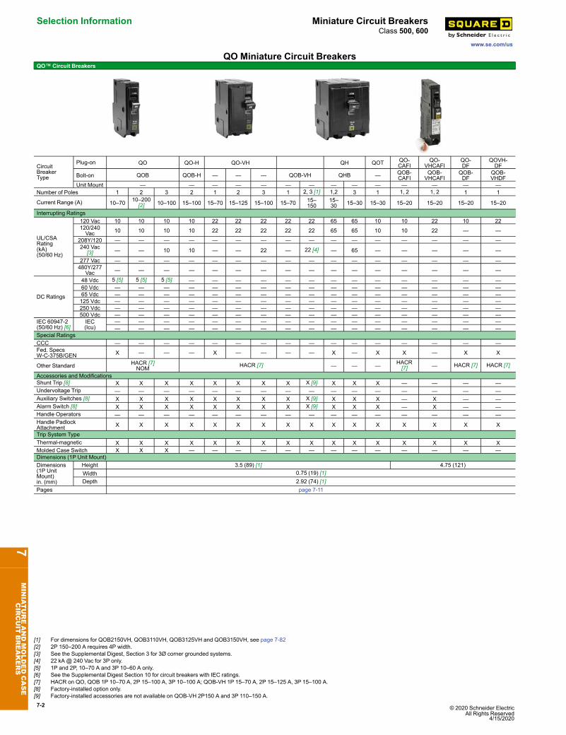
QO Miniature Circuit BreakersQO™ Circuit Breakers
CircuitBreakerType
Plug-on QO QO-H QO-VH QH QOT QO-CAFI
QO-VHCAFI
QO-DF
QOVH-DF
Bolt-on QOB QOB-H — — — QOB-VH QHB — QOB-CAFI
QOB-VHCAFI
QOB-DF
QOB-VHDF
Unit Mount — — — — — — — — — — — — — —Number of Poles 1 2 3 2 1 2 3 1 2, 3 [1] 1,2 3 1 1, 2 1, 2 1 1
Current Range (A) 10–70 10–200[2] 10–100 15–100 15–70 15–125 15–100 15–70 15–
15015–30 15–30 15–30 15–20 15–20 15–20 15–20
Interrupting Ratings
UL/CSARating(kA)(50/60 Hz)
120 Vac 10 10 10 10 22 22 22 22 22 65 65 10 10 22 10 22120/240Vac 10 10 10 10 22 22 22 22 22 65 65 10 10 22 — —
208Y/120 — — — — — — — — — — — — — — — —240 Vac
[3] — — 10 10 — — 22 — 22 [4] — 65 — — — — —
277 Vac — — — — — — — — — — — — — — — —480Y/277
Vac — — — — — — — — — — — — — — — —
DC Ratings
48 Vdc 5 [5] 5 [5] 5 [5] — — — — — — — — — — — — —60 Vdc — — — — — — — — — — — — — — — —65 Vdc — — — — — — — — — — — — — — — —125 Vdc — — — — — — — — — — — — — — — —250 Vdc — — — — — — — — — — — — — — — —500 Vdc — — — — — — — — — — — — — — — —
IEC 60947-2(50/60 Hz) [6]
IEC(Icu)
— — — — — — — — — — — — — — — —— — — — — — — — — — — — — — — —
Special RatingsCCC — — — — — — — — — — — — — — — —Fed. SpecsW-C-375B/GEN X — — — X — — — — X — X X — X X
Other Standard HACR [7]NOM HACR [7] — — — HACR
[7] — HACR [7] HACR [7]
Accessories and ModificationsShunt Trip [8] X X X X X X X X X [9] X X X — — — —Undervoltage Trip — — — — — — — — — — — — — — — —Auxiliary Switches [8] X X X X X X X X X [9] X X X — X — —Alarm Switch [8] X X X X X X X X X [9] X X X — X — —Handle Operators — — — — — — — — — — — — — — — —Handle PadlockAttachment X X X X X X X X X X X X X X X X
Trip System TypeThermal-magnetic X X X X X X X X X X X X X X X XMolded Case Switch X X X — — — — — — — — — — — — —Dimensions (1P Unit Mount)Dimensions(1P UnitMount)in. (mm)
Height 3.5 (89) [1] 4.75 (121)Width 0.75 (19) [1]Depth 2.92 (74) [1]
Pages page 7-11
7MINIATUREANDMOLDEDCASE
CIRCUIT
BREAKERS
[1] For dimensions for QOB2150VH, QOB3110VH, QOB3125VH and QOB3150VH, see page 7-82[2] 2P 150–200 A requires 4P width.[3] See the Supplemental Digest, Section 3 for 3Ø corner grounded systems.[4] 22 kA @ 240 Vac for 3P only.[5] 1P and 2P, 10–70 A and 3P 10–60 A only.[6] See the Supplemental Digest Section 10 for circuit breakers with IEC ratings.[7] HACR on QO, QOB 1P 10–70 A, 2P 15–100 A, 3P 10–100 A; QOB-VH 1P 15–70 A, 2P 15–125 A, 3P 15–100 A.[8] Factory-installed option only.[9] Factory-installed accessories are not available on QOB-VH 2P150 A and 3P 110–150 A.
© 2020 Schneider Electric All Rights Reserved4/15/2020
7-3
www.se.com/us
Miniature Circuit Breakers Selection InformationClass 500, 600
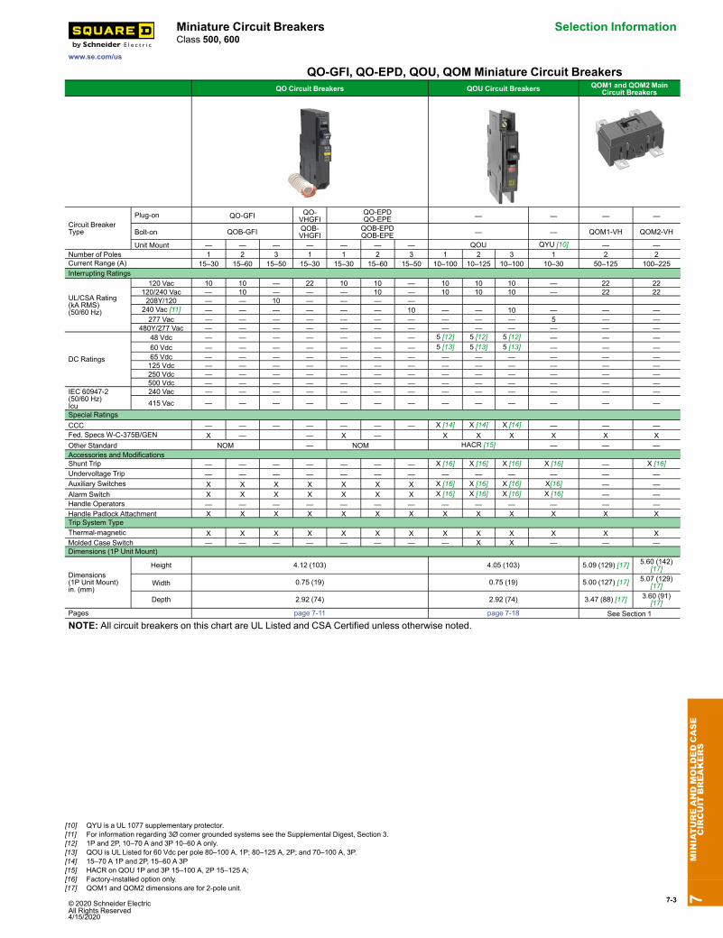
QO-GFI, QO-EPD, QOU, QOM Miniature Circuit BreakersQO Circuit Breakers QOU Circuit Breakers QOM1 and QOM2 Main
Circuit Breakers
Circuit BreakerType
Plug-on QO-GFI QO-VHGFI
QO-EPDQO-EPE — — — —
Bolt-on QOB-GFI QOB-VHGFI
QOB-EPDQOB-EPE — — QOM1-VH QOM2-VH
Unit Mount — — — — — — — QOU QYU [10] — —Number of Poles 1 2 3 1 1 2 3 1 2 3 1 2 2Current Range (A) 15–30 15–60 15–50 15–30 15–30 15–60 15–50 10–100 10–125 10–100 10–30 50–125 100–225Interrupting Ratings
UL/CSA Rating(kA RMS)(50/60 Hz)
120 Vac 10 10 — 22 10 10 — 10 10 10 — 22 22120/240 Vac — 10 — — — 10 — 10 10 10 — 22 22208Y/120 — — 10 — — — —240 Vac [11] — — — — — — 10 — — 10 — — —277 Vac — — — — — — — — — — 5 — —
480Y/277 Vac — — — — — — — — — — — — —
DC Ratings
48 Vdc — — — — — — — 5 [12] 5 [12] 5 [12] — — —60 Vdc — — — — — — — 5 [13] 5 [13] 5 [13] — — —65 Vdc — — — — — — — — — — — — —125 Vdc — — — — — — — — — — — — —250 Vdc — — — — — — — — — — — — —500 Vdc — — — — — — — — — — — — —
IEC 60947-2(50/60 Hz)Icu
240 Vac — — — — — — — — — — — — —415 Vac — — — — — — — — — — — — —
Special RatingsCCC — — — — — — — X [14] X [14] X [14] — — —Fed. Specs W-C-375B/GEN X — — X — X X X X X XOther Standard NOM — NOM HACR [15] — — —Accessories and ModificationsShunt Trip — — — — — — — X [16] X [16] X [16] X [16] — X [16]Undervoltage Trip — — — — — — — — — — — — —Auxiliary Switches X X X X X X X X [16] X [16] X [16] X[16] — —Alarm Switch X X X X X X X X [16] X [16] X [16] X [16] — —Handle Operators — — — — — — — — — — — — —Handle Padlock Attachment X X X X X X X X X X X X XTrip System TypeThermal-magnetic X X X X X X X X X X X X XMolded Case Switch — — — — — — — — X X — — —Dimensions (1P Unit Mount)
Dimensions(1P Unit Mount)in. (mm)
Height 4.12 (103) 4.05 (103) 5.09 (129) [17] 5.60 (142)[17]
Width 0.75 (19) 0.75 (19) 5.00 (127) [17] 5.07 (129)[17]
Depth 2.92 (74) 2.92 (74) 3.47 (88) [17] 3.60 (91)[17]
Pages page 7-11 page 7-18 See Section 1
NOTE: All circuit breakers on this chart are UL Listed and CSA Certified unless otherwise noted.
7MINIATUREANDMOLDEDCASE
CIRCUIT
BREAKERS
[10] QYU is a UL 1077 supplementary protector.[11] For information regarding 3Ø corner grounded systems see the Supplemental Digest, Section 3.[12] 1P and 2P, 10–70 A and 3P 10–60 A only.[13] QOU is UL Listed for 60 Vdc per pole 80–100 A, 1P; 80–125 A, 2P; and 70–100 A, 3P.[14] 15–70 A 1P and 2P, 15–60 A 3P[15] HACR on QOU 1P and 3P 15–100 A, 2P 15–125 A;[16] Factory-installed option only.[17] QOM1 and QOM2 dimensions are for 2-pole unit.
7-4 © 2020 Schneider Electric All Rights Reserved
4/15/2020
Selection Information Miniature Circuit Breakers
www.se.com/us
Class 500, 600
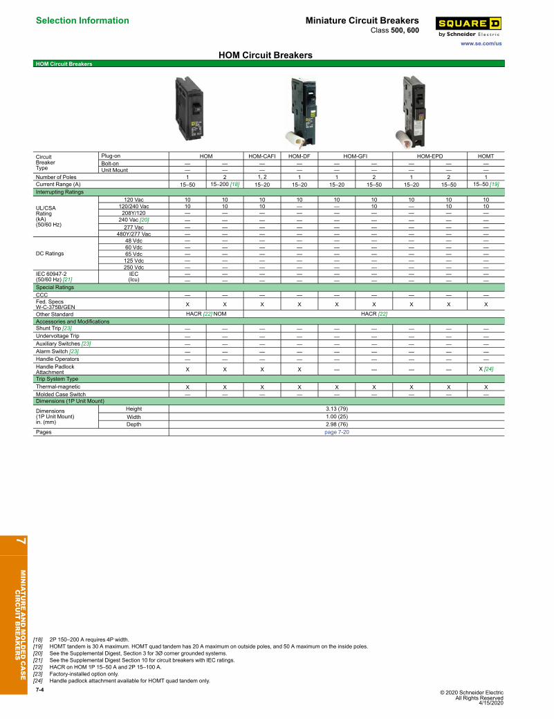
HOM Circuit BreakersHOM Circuit Breakers
CircuitBreakerType
Plug-on HOM HOM-CAFI HOM-DF HOM-GFI HOM-EPD HOMTBolt-on — — — — — — — — —Unit Mount — — — — — — — — —
Number of Poles 1 2 1, 2 1 1 2 1 2 1Current Range (A) 15–50 15–200 [18] 15–20 15–20 15–20 15–50 15–20 15–50 15–50 [19]Interrupting Ratings
UL/CSARating(kA)(50/60 Hz)
120 Vac 10 10 10 10 10 10 10 10 10120/240 Vac 10 10 10 — — 10 — 10 10208Y/120 — — — — — — — — —
240 Vac [20] — — — — — — — — —277 Vac — — — — — — — — —
480Y/277 Vac — — — — — — — — —
DC Ratings
48 Vdc — — — — — — — — —60 Vdc — — — — — — — — —65 Vdc — — — — — — — — —125 Vdc — — — — — — — — —250 Vdc — — — — — — — — —
IEC 60947-2(50/60 Hz) [21]
IEC(Icu)
— — — — — — — — —— — — — — — — — —
Special RatingsCCC — — — — — — — — —Fed. SpecsW-C-375B/GEN X X X X X X X X X
Other Standard HACR [22] NOM HACR [22]Accessories and ModificationsShunt Trip [23] — — — — — — — — —Undervoltage Trip — — — — — — — — —Auxiliary Switches [23] — — — — — — — — —Alarm Switch [23] — — — — — — — — —Handle Operators — — — — — — — — —Handle PadlockAttachment X X X X — — — — X [24]
Trip System TypeThermal-magnetic X X X X X X X X XMolded Case Switch — — — — — — — — —Dimensions (1P Unit Mount)
Dimensions(1P Unit Mount)in. (mm)
Height 3.13 (79)Width 1.00 (25)Depth 2.98 (76)
Pages page 7-20
7MINIATUREANDMOLDEDCASE
CIRCUIT
BREAKERS
[18] 2P 150–200 A requires 4P width.[19] HOMT tandem is 30 A maximum. HOMT quad tandem has 20 A maximum on outside poles, and 50 A maximum on the inside poles.[20] See the Supplemental Digest, Section 3 for 3Ø corner grounded systems.[21] See the Supplemental Digest Section 10 for circuit breakers with IEC ratings.[22] HACR on HOM 1P 15–50 A and 2P 15–100 A.[23] Factory-installed option only.[24] Handle padlock attachment available for HOMT quad tandem only.
© 2020 Schneider Electric All Rights Reserved4/15/2020
7-5
www.se.com/us
Miniature Circuit Breakers Selection InformationClass 500, 600
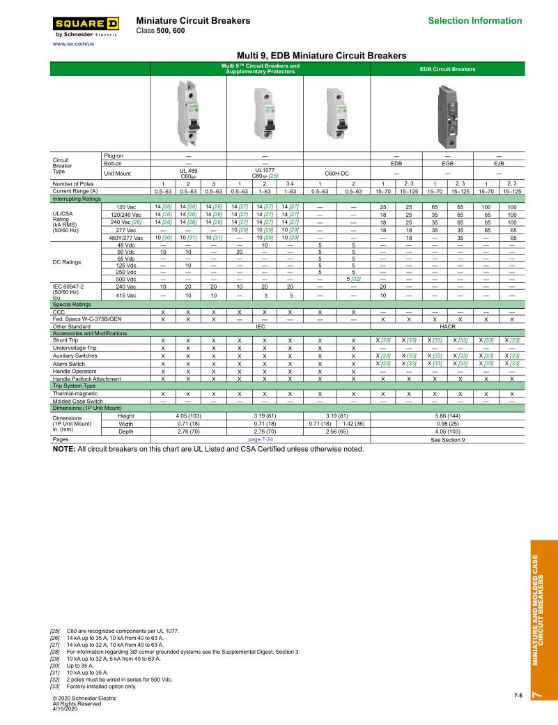
Multi 9, EDB Miniature Circuit BreakersMulti 9™ Circuit Breakers andSupplementary Protectors EDB Circuit Breakers
CircuitBreakerType
Plug-on — — — — —Bolt-on — — EDB EGB EJB
Unit Mount UL 489C60BP
UL1077C60SP [25] C60H-DC — — —
Number of Poles 1 2 3 1 2 3,4 1 2 1 2, 3 1 2, 3 1 2, 3Current Range (A) 0.5–63 0.5–63 0.5–63 0.5–63 1–63 1–63 0.5–63 0.5–63 15–70 15–125 15–70 15–125 15–70 15–125Interrupting Ratings
UL/CSARating(kA RMS)(50/60 Hz)
120 Vac 14 [26] 14 [26] 14 [26] 14 [27] 14 [27] 14 [27] — — 25 25 65 65 100 100120/240 Vac 14 [26] 14 [26] 14 [26] 14 [27] 14 [27] 14 [27] — — 18 25 35 65 65 100240 Vac [28] 14 [26] 14 [26] 14 [26] 14 [27] 14 [27] 14 [27] — — 18 25 35 65 65 100277 Vac — — — 10 [29] 10 [29] 10 [29] — — 18 18 35 35 65 65
480Y/277 Vac 10 [30] 10 [31] 10 [31] — 10 [29] 10 [29] — — — 18 — 35 — 65
DC Ratings
48 Vdc — — — — 10 — 5 5 — — — — — —60 Vdc 10 10 — 20 — — 5 5 — — — — — —65 Vdc — — — — — — 5 5 — — — — — —125 Vdc — 10 — — — — 5 5 — — — — — —250 Vdc — — — — — — 5 5 — — — — — —500 Vdc — — — — — — — 5 [32] — — — — — —
IEC 60947-2(50/60 Hz)Icu
240 Vac 10 20 20 10 20 20 — — 20 — — — — —415 Vac — 10 10 — 5 5 — — 10 — — — — —
Special RatingsCCC X X X X X X X X — — — — — —Fed. Specs W-C-375B/GEN X X X — — — — — X X X X X XOther Standard IEC HACRAccessories and ModificationsShunt Trip X X X X X X X X X [33] X [33] X [33] X [33] X [33] X [33]Undervoltage Trip X X X X X X X X — — — — — —Auxiliary Switches X X X X X X X X X [33] X [33] X [33] X [33] X [33] X [33]Alarm Switch X X X X X X X X X [33] X [33] X [33] X [33] X [33] X [33]Handle Operators X X X X X X X X — — — — — —Handle Padlock Attachment X X X X X X X X X X X X X XTrip System TypeThermal-magnetic X X X X X X X X X X X X X XMolded Case Switch — — — — — — — — — — — — — —Dimensions (1P Unit Mount)
Dimensions(1P Unit Mount)in. (mm)
Height 4.05 (103) 3.19 (81) 3.19 (81) 5.66 (144)Width 0.71 (18) 0.71 (18) 0.71 (18) 1.42 (36) 0.98 (25)Depth 2.76 (70) 2.76 (70) 2.56 (65) 4.05 (103)
Pages page 7-24 See Section 9
NOTE: All circuit breakers on this chart are UL Listed and CSA Certified unless otherwise noted.
7MINIATUREANDMOLDEDCASE
CIRCUIT
BREAKERS
[25] C60 are recognized components per UL 1077.[26] 14 kA up to 35 A, 10 kA from 40 to 63 A.[27] 14 kA up to 32 A, 10 kA from 40 to 63 A.[28] For information regarding 3Ø corner grounded systems see the Supplemental Digest, Section 3.[29] 10 kA up to 32 A, 5 kA from 40 to 63 A.[30] Up to 35 A.[31] 10 kA up to 35 A.[32] 2 poles must be wired in series for 500 Vdc.[33] Factory-installed option only.
7-6 © 2020 Schneider Electric All Rights Reserved
4/15/2020
Selection Information Molded Case Circuit Breakers
www.se.com/us
Class 500, 600, 800
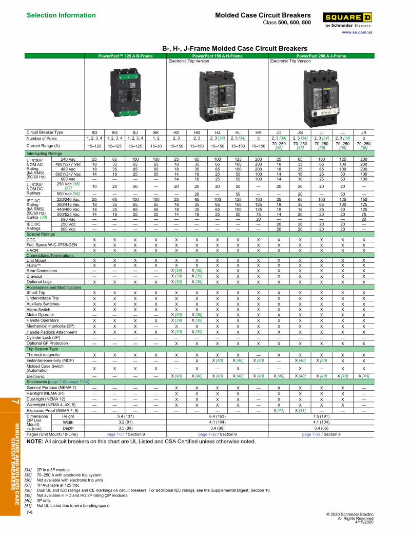
B-, H-, J-Frame Molded Case Circuit BreakersPowerPact™ 125 A B-Frame PowerPact 150 A H-Frame PowerPact 250 A J-Frame
Electronic Trip Version Electronic Trip Version
Circuit Breaker Type BD BG BJ BK HD HG HJ HL HR JD JG JJ JL JRNumber of Poles 1, 2, 3, 4 1, 2, 3, 4 1, 2, 3, 4 1, 2 2, 3 2, 3 2, 3 [34] 2, 3 [34] 3 2, 3 [34] 2, 3 [34] 2, 3 [34] 2, 3 [34] 3
Current Range (A) 15–125 15–125 15–125 15–30 15–150 15–150 15–150 15–150 15–150 70–250[35]
70–250[35]
70–250[35]
70–250[35]
70–250[35]
Interrupting Ratings
UL/CSA/NOM ACRating(kA RMS)(50/60 Hz)
240 Vac 25 65 100 100 25 65 100 125 200 25 65 100 125 200480Y/277 Vac 18 35 65 65 18 35 65 100 200 18 35 65 100 200
480 Vac 18 35 65 65 18 35 65 100 200 18 35 65 100 200600Y/347 Vac 14 18 25 65 14 18 25 50 100 14 18 25 50 100
600 Vac — — — — 14 18 25 50 100 14 18 25 50 100UL/CSA/NOM DCRatings
250 Vdc [36][37] 10 20 50 — 20 20 20 20 — 20 20 20 20 —
500 Vdc [36] — — — — — 20 — 50 — — 20 — 50 —IEC ACRating(kA RMS)(50/60 Hz)Icu/lcs [38]
220/240 Vac 25 65 100 100 25 65 100 125 150 25 65 100 125 150380/415 Vac 18 35 65 65 18 35 65 100 125 18 35 65 100 125440/480 Vac 18 35 65 65 18 35 65 100 125 18 18 25 50 125500/525 Vac 14 18 25 25 14 18 25 50 75 14 20 20 20 75690 Vac — — — — — — — — 20 — — — — 20
IEC DCRatings
250 Vdc — — — — — — — — — 20 20 20 20 —500 Vdc — — — — — — — — — 20 20 20 20 —
Special RatingsCCC X X X X X X X X X X X X X XFed. Specs W-C-375B/GEN X X X X X X X X X X X X X XHACR X X X X X X X X X X X X X XConnections/TerminationsUnit Mount X X X X X X X X X X X X X XI-Line™ X X X X X X X X X X X X X XRear Connection — — — — X [39] X [39] X X X X X X X XDrawout — — — — X [39] X [39] X X X X X X X XOptional Lugs X X X X X [39] X [39] X X X X X X X XAccessories and ModificationsShunt Trip X X X X X X X X X X X X X XUndervoltage Trip X X X X X X X X X X X X X XAuxiliary Switches X X X X X X X X X X X X X XAlarm Switch X X X X X X X X X X X X X XMotor Operator — — — — X [39] X [39] X X X X X X X XHandle Operators X X X X X [39] X [39] X X X X X X X XMechanical Interlocks (3P) X X X — X X X X X X X X X XHandle Padlock Attachment X X X X X [39] X [39] X X X X X X X XCylinder Lock (3P) — — — — — — — — — — — — — —Optional GF Protection — — — — X X X X X X X X X XTrip System TypeThermal-magnetic X X X X X X X X — X X X X XInstantaneous-only (MCP) — — — — — X X [40] X [40] X [40] — X [40] X [40] X XMolded Case Switch(Automatic) X X X X — X — X — — X — X X
Electronic — — — — X [40] X [40] X [40] X [40] X [40] X [40] X [40] X [40] X [40] X [40]Enclosures (page 7-82–page 7-84)General Purpose (NEMA 1) — — — — X X X X — X X X X —Raintight (NEMA 3R) — — — — X X X X — X X X X —Dust-tight (NEMA 12) — — — — X X X X — X X X X —Watertight (NEMA 4, 4X, 5) — — — — X X X X — X X X X —Explosion Proof (NEMA 7, 9) — — — — — — — — — X [41] X [41] — — —Dimensions(3P UnitMount)in. (mm)
Height 5.4 (137) 6.4 (163) 7.5 (191)Width 3.2 (81) 4.1 (104) 4.1 (104)Depth 3.5 (89) 3.4 (86) 3.4 (86)
Pages (Unit Mount) / (I-Line) page 7-31 / Section 9 page 7-32 / Section 9 page 7-32 / Section 9
NOTE: All circuit breakers on this chart are UL Listed and CSA Certified unless otherwise noted.
7MINIATUREANDMOLDEDCASE
CIRCUIT
BREAKERS
[34] 2P in a 3P module.[35] 70–250 A with electronic trip system[36] Not available with electronic trip units[37] 1PAvailable at 125 Vdc[38] Dual UL and IEC ratings and CE markings on circuit breakers. For additional IEC ratings, see the Supplemental Digest, Section 10.[39] Not available in HD and HG 2P rating (2P module).[40] 3P only.[41] Not UL Listed due to wire bending space.

© 2020 Schneider Electric All Rights Reserved4/15/2020
7-7
www.se.com/us
Molded Case Circuit Breakers Selection InformationClass 500, 600, 800
PowerPact™ Q-Frame, Q4, LA, LH, L-Frame Molded Case CircuitBreakers
PowerPact 250 A Q-Frame Q4 400 A LA/LH PowerPact 600 A L-Frame
Circuit Breaker Type QB QD QG QJ Q4 LA LH LD LG LJ LL LRNumber of Poles 2, 3 2, 3 2, 3 2, 3 2, 3 2, 3 2, 3 3, 4 3, 4 3, 4 3, 4 3, 4
Current Range (A) 70–250[42]
70–250[42]
70–250[42]
70–250[42] 250–400 125–400 125–400 70–600 70–600 70–600 70–600 70–600
Interrupting Ratings
UL/CSA/NOM ACRating(kA RMS)(50/60 Hz)
240 Vac 10 25 65 100 25 42 65 25 65 100 125 200480Y/277 Vac — — — — — 30 35 18 35 65 100 200
480 Vac — — — — — 30 35 18 35 65 100 200600Y/347 Vac — — — — — 22 25 14 18 25 50 100
600 Vac — — — — — 22 25 14 18 25 50 100UL/CSA/NOM DCRatings
250 Vdc [43] — — — — — 10 50 — — — — —500 Vdc [44]
[43] — — — — — — 20 — 20 — 50 —
IEC ACRating(kA RMS)(50/60 Hz)Icu/lcs [45]
220/240 Vac 10/5 10/5 10/5 10/5 — — — 25 65 100 125 150380/415 Vac 10/5 10/5 10/5 10/5 — 20/5[46] 20/5[46] 18/18 18 65 100 125440/480 Vac — — — — — — — 18/18 18 65 100 125500/525 Vac — — — — — — — 18/18 14 25 50 75690 Vac — — — — — — — — — — — 20
IEC DCRatings
250 Vdc — — — — — — — — — — — —500 Vdc — — — — — — — — — — — —
Special RatingsCCC — — — — — — — X X X X XFed. Specs W-C-375B/GEN X X X X X X X X X X X XHACR (2P, 3P) X X X — — X X X X X X X
Connections/TerminationsUnit Mount X X X X X X X X X X X XI-Line™ X X X X X X X X X X X XRear Connection — — — — X X X X X X X XDrawout — — — — — — — X X X X XOptional Lugs — — — — X X X X X X X X
Accessories and ModificationsShunt Trip — — — — X X X X X X X XUndervoltage Trip — — — — X X X X X X X XAuxiliary Switches — — — — X X X X X X X XAlarm Switch — — — — X X X X X X X XMotor Operator — — — — X X X X X X X XHandle Operators — — — — X X X X X X X XMechanical Interlocks (3P) X X X X — X [47] X [47] X X X X XHandle Padlock Attachment X X X X X X X X X X X XCylinder Lock (3P[48]) — — — — X X X — — — — —Optional GF Protection[49] — — — — — — — X X X X X
Trip System TypeThermal-magnetic X X X X X X X — — — — —Instantaneous-only (MCP) — — — — — X X — X X X XMolded Case Switch(Automatic) X — — — — — X — X — X X
Electronic — — — — — — — X X X X XEnclosures (page 7-82–page 7-84)General Purpose (NEMA 1) X X X X X X X — — — — —Raintight (NEMA 3R) X X X X X X X — — — — —Dust-tight (NEMA 12) — — — — X X X X [50] X [50] X [50] X [50] X [50]Watertight (NEMA 4, 4X, 5) — — — — X X X — — — — —Explosion Proof (NEMA 7, 9) — — — — — — — — — — — —
Dimensions(3P UnitMount)in. (mm)
Height 6.47 (164) 11 (279) 13.38 (340)Width 4.5 (114) 6 (152) 5.51 (140)Depth 3.93 (100) 5.84 (148) 4.33 (110)
Pages (Unit Mount) / (I-Line) page 7-35 / Supplemental Section 9 page 7-36 / Supplemental Section 9 page 7-37 / Supplemental Section 9
NOTE: All circuit breakers on this chart are UL Listed and CSA Certified unless otherwise noted.
7MINIATUREANDMOLDEDCASE
CIRCUIT
BREAKERS
[42] I-Line Q-frame circuit breakers are available 70–225 A only. 250 A Q-frame unit-mount circuit breakers are limited to Cu conductors only.[43] Not available with electronic trip units[44] Ungrounded UPS systems only. See page 7-44. Special DC J-Frame only.[45] Dual UL and IEC ratings and CE markings on circuit breakers. For additional IEC ratings, see the Supplemental Digest, Section 10.[46] For additional IEC ratings, see the Supplemental Digest Section 10.[47] Requires circuit breaker with WB suffix .[48] Factory-installed option only.[49] Requires factory-installed “G” shunt trip and 3P module.[50] Enclosure rating 1, 3R, 5 and 12.,
7-8 © 2020 Schneider Electric All Rights Reserved
4/15/2020
Selection Information Molded Case Circuit Breakers
www.se.com/us
Class 600, 612, 800
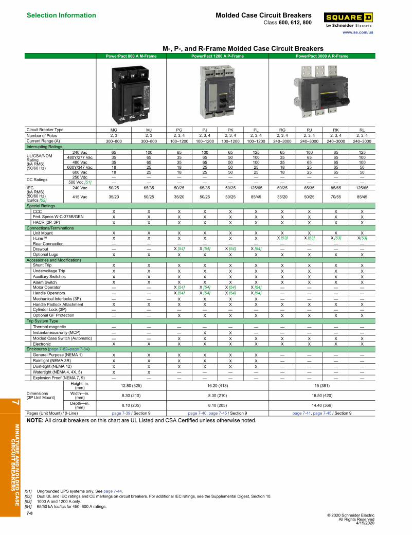
M-, P-, and R-Frame Molded Case Circuit BreakersPowerPact 800 A M-Frame PowerPact 1200 A P-Frame PowerPact 3000 A R-Frame
Circuit Breaker Type MG MJ PG PJ PK PL RG RJ RK RLNumber of Poles 2, 3 2, 3 2, 3, 4 2, 3, 4 2, 3, 4 2, 3, 4 2, 3, 4 2, 3, 4 2, 3, 4 2, 3, 4Current Range (A) 300–800 300–800 100–1200 100–1200 100–1200 100–1200 240–3000 240–3000 240–3000 240–3000Interrupting Ratings
UL/CSA/NOMRating(kA RMS)(50/60 Hz)
240 Vac 65 100 65 100 65 125 65 100 65 125480Y/277 Vac 35 65 35 65 50 100 35 65 65 100
480 Vac 35 65 35 65 50 100 35 65 65 100600Y/347 Vac 18 25 18 25 50 25 18 25 65 50
600 Vac 18 25 18 25 50 25 18 25 65 50
DC Ratings 250 Vdc — — — — — — — — — —500 Vdc [51] — — — — — — — — — —
IEC(kA RMS)(50/60 Hz)Icu/Ics [52]
240 Vac 50/25 65/35 50/25 65/35 50/25 125/65 50/25 65/35 85/65 125/65
415 Vac 35/20 50/25 35/20 50/25 50/25 85/45 35/20 50/25 70/55 85/45
Special RatingsCCC X X X X X X X X X XFed. Specs W-C-375B/GEN X X X X X X X X X XHACR (2P, 3P) X X X X X X X X X X
Connections/TerminationsUnit Mount X X X X X X X X X XI-Line™ X X X X X X X [53] X [53] X [53] X[53]Rear Connection — — — — — — — — — —Drawout — — X [54] X [54] X [54] X [54] — — — —Optional Lugs X X X X X X X X X X
Accessories and ModificationsShunt Trip X X X X X X X X X XUndervoltage Trip X X X X X X X X X XAuxiliary Switches X X X X X X X X X XAlarm Switch X X X X X X X X X XMotor Operator — — X [54] X [54] X [54] X [54] — — — —Handle Operators — — X [54] X [54] X [54] X [54] — — — —Mechanical Interlocks (3P) — — X X X X — — — —Handle Padlock Attachment X X X X X X X X X XCylinder Lock (3P) — — — — — — — — — —Optional GF Protection — — X X X X X X X X
Trip System TypeThermal-magnetic — — — — — — — — — —Instantaneous-only (MCP) — — — X X — — — — —Molded Case Switch (Automatic) — — X X X X X X X XElectronic X X X X X X X X X X
Enclosures (page 7-82–page 7-84)General Purpose (NEMA 1) X X X X X X — — — —Raintight (NEMA 3R) X X X X X X — — — —Dust-tight (NEMA 12) X X X X X X — — — —Watertight (NEMA 4, 4X, 5) X X — — — — — — — —Explosion Proof (NEMA 7, 9) — — — — — — — — — —
Dimensions(3P Unit Mount)
Height–in.(mm) 12.80 (325) 16.20 (413) 15 (381)
Width—in.(mm) 8.30 (210) 8.30 (210) 16.50 (420)
Depth—in.(mm) 8.10 (205) 8.10 (205) 14.40 (366)
Pages (Unit Mount) / (I-Line) page 7-39 / Section 9 page 7-40, page 7-45 / Section 9 page 7-41, page 7-45 / Section 9
NOTE: All circuit breakers on this chart are UL Listed and CSA Certified unless otherwise noted.
7MINIATUREANDMOLDEDCASE
CIRCUIT
BREAKERS
[51] Ungrounded UPS systems only. See page 7-44.[52] Dual UL and IEC ratings and CE markings on circuit breakers. For additional IEC ratings, see the Supplemental Digest, Section 10.[53] 1000 A and 1200 A only.[54] 65/50 kA Icu/Ics for 450–600 A ratings.
© 2020 Schneider Electric All Rights Reserved4/15/2020
7-9
www.se.com/us
Insulated Case Circuit Breakers Selection InformationClass 600, 800
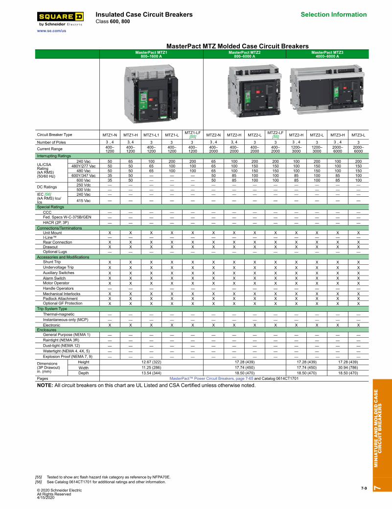
MasterPact MTZ Molded Case Circuit BreakersMasterPact MTZ1
800–1600 AMasterPact MTZ2
800–6000 AMasterPact MTZ34000–6000 A
Circuit Breaker Type MTZ1-N MTZ1-H MTZ1-L1 MTZ1-L MTZ1-LF[55] MTZ2-N MTZ2-H MTZ2-L MTZ2-LF
[55] MTZ2-H MTZ2-L MTZ3-H MTZ3-L
Number of Poles 3 , 4 3, 4 3 3 3 3 , 4 3, 4 3 3 3 , 4 3 3 , 4 3
Current Range 400–1200
400–1200
400–1200
400–1200
400–1200
400–2000
400–2000
400–2000
400–2000
1200–3000
1200–3000
2000–6000
2000–6000
Interrupting Ratings
UL/CSARating(kA RMS)(50/60 Hz)
240 Vac 50 65 100 200 200 65 100 200 200 100 200 100 200480Y/277 Vac 50 50 65 100 100 65 100 150 150 100 150 100 150
480 Vac 50 50 65 100 100 65 100 150 150 100 150 100 150600Y/347 Vac 35 50 — — — 50 85 100 100 85 100 85 100
600 Vac 35 50 — — — 50 85 100 100 85 100 85 100
DC Ratings 250 Vdc — — — — — — — — — — — — —500 Vdc — — — — — — — — — — — — —
IEC [56](kA RMS) Icu/Ics
240 Vac — — — — — — — — — — — — —415 Vac — — — — — — — — — — — — —
Special RatingsCCC — — — — — — — — — — — — —Fed. Specs W-C-375B/GEN — — — — — — — — — — — — —HACR (2P, 3P) — — — — — — — — — — — — —
Connections/TerminationsUnit Mount X X X X X X X X X X X X XI-Line™ — — — — — — — — — — — — —Rear Connection X X X X X X X X X X X X XDrawout X X X X X X X X X X X X XOptional Lugs — — — — — — — — — — — — —
Accessories and ModificationsShunt Trip X X X X X X X X X X X X XUndervoltage Trip X X X X X X X X X X X X XAuxiliary Switches X X X X X X X X X X X X XAlarm Switch X X X X X X X X X X X X XMotor Operator X X X X X X X X X X X X XHandle Operators — — — — — — — — — — — — —Mechanical Interlocks X X X X X X X X X X X X XPadlock Attachment X X X X X X X X X X X X XOptional GF Protection X X X X X X X X X X X X X
Trip System TypeThermal-magnetic — — — — — — — — — — — — —Instantaneous-only (MCP) — — — — — — — — — — — — —Electronic X X X X X X X X X X X X X
EnclosuresGeneral Purpose (NEMA 1) — — — — — — — — — — — — —Raintight (NEMA 3R) — — — — — — — — — — — — —Dust-tight (NEMA 12) — — — — — — — — — — — — —Watertight (NEMA 4, 4X, 5) — — — — — — — — — — — — —Explosion Proof (NEMA 7, 9) — — — — — — — — — — — — —
Dimensions(3P Drawout)in. (mm)
Height 12.67 (322) 17.28 (439) 17.28 (439) 17.28 (439)Width 11.25 (286) 17.74 (450) 17.74 (450) 30.94 (786)Depth 13.54 (344) 18.50 (470) 18.50 (470) 18.50 (470)
Pages MasterPact™ Power Circuit Breakers, page 7-65 and Catalog 0614CT1701
NOTE: All circuit breakers on this chart are UL Listed and CSA Certified unless otherwise noted.7
MINIATUREANDMOLDEDCASE
CIRCUIT
BREAKERS
[55] Tested to show arc flash hazard risk category as reference by NFPA70E.[56] See Catalog 0614CT1701 for additional ratings and other information.
7-10 © 2020 Schneider Electric All Rights Reserved
4/15/2020
Selection Information Insulated Case Circuit Breakers
www.se.com/us
Class 600, 800
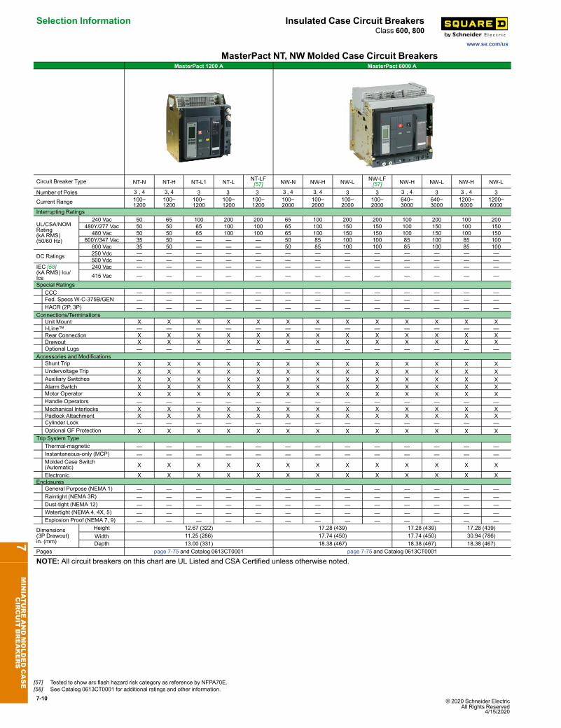
MasterPact NT, NW Molded Case Circuit BreakersMasterPact 1200 A MasterPact 6000 A
Circuit Breaker Type NT-N NT-H NT-L1 NT-L NT-LF[57] NW-N NW-H NW-L NW-LF
[57] NW-H NW-L NW-H NW-L
Number of Poles 3 , 4 3, 4 3 3 3 3 , 4 3, 4 3 3 3 , 4 3 3 , 4 3
Current Range 100–1200
100–1200
100–1200
100–1200
100–1200
100–2000
100–2000
100–2000
100–2000
640–3000
640–3000
1200–6000
1200–6000
Interrupting Ratings
UL/CSA/NOMRating(kA RMS)(50/60 Hz)
240 Vac 50 65 100 200 200 65 100 200 200 100 200 100 200480Y/277 Vac 50 50 65 100 100 65 100 150 150 100 150 100 150
480 Vac 50 50 65 100 100 65 100 150 150 100 150 100 150600Y/347 Vac 35 50 — — — 50 85 100 100 85 100 85 100
600 Vac 35 50 — — — 50 85 100 100 85 100 85 100
DC Ratings 250 Vdc — — — — — — — — — — — — —500 Vdc — — — — — — — — — — — — —
IEC [58](kA RMS) Icu/Ics
240 Vac — — — — — — — — — — — — —415 Vac — — — — — — — — — — — — —
Special RatingsCCC — — — — — — — — — — — — —Fed. Specs W-C-375B/GEN — — — — — — — — — — — — —HACR (2P, 3P) — — — — — — — — — — — — —
Connections/TerminationsUnit Mount X X X X X X X X X X X X XI-Line™ — — — — — — — — — — — — —Rear Connection X X X X X X X X X X X X XDrawout X X X X X X X X X X X X XOptional Lugs — — — — — — — — — — — — —
Accessories and ModificationsShunt Trip X X X X X X X X X X X X XUndervoltage Trip X X X X X X X X X X X X XAuxiliary Switches X X X X X X X X X X X X XAlarm Switch X X X X X X X X X X X X XMotor Operator X X X X X X X X X X X X XHandle Operators — — — — — — — — — — — — —Mechanical Interlocks X X X X X X X X X X X X XPadlock Attachment X X X X X X X X X X X X XCylinder Lock — — — — — — — — — — — — —Optional GF Protection X X X X X X X X X X X X X
Trip System TypeThermal-magnetic — — — — — — — — — — — — —Instantaneous-only (MCP) — — — — — — — — — — — — —Molded Case Switch(Automatic) X X X X X X X X X X X X X
Electronic X X X X X X X X X X X X XEnclosures
General Purpose (NEMA 1) — — — — — — — — — — — — —Raintight (NEMA 3R) — — — — — — — — — — — — —Dust-tight (NEMA 12) — — — — — — — — — — — — —Watertight (NEMA 4, 4X, 5) — — — — — — — — — — — — —Explosion Proof (NEMA 7, 9) — — — — — — — — — — — — —
Dimensions(3P Drawout)in. (mm)
Height 12.67 (322) 17.28 (439) 17.28 (439) 17.28 (439)Width 11.25 (286) 17.74 (450) 17.74 (450) 30.94 (786)Depth 13.00 (331) 18.38 (467) 18.38 (467) 18.38 (467)
Pages page 7-75 and Catalog 0613CT0001 page 7-75 and Catalog 0613CT0001
NOTE: All circuit breakers on this chart are UL Listed and CSA Certified unless otherwise noted.
7MINIATUREANDMOLDEDCASE
CIRCUIT
BREAKERS
[57] Tested to show arc flash hazard risk category as reference by NFPA70E.[58] See Catalog 0613CT0001 for additional ratings and other information.
© 2020 Schneider Electric All Rights Reserved4/15/2020
7-11
www.se.com/us
QO Plug-On Circuit Breakers QO™ and QOU Miniature Circuit BreakersClass 730, 731, 733 / Refer to Catalog: 0730CT9801
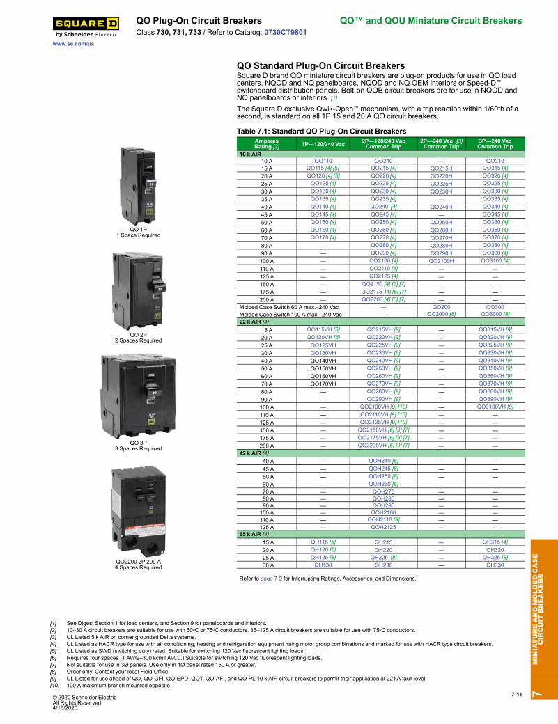
QO Standard Plug-On Circuit BreakersSquare D brand QO miniature circuit breakers are plug-on products for use in QO loadcenters, NQOD and NQ panelboards, NQOD and NQ OEM interiors or Speed-D™
switchboard distribution panels. Bolt-on QOB circuit breakers are for use in NQOD andNQ panelboards or interiors. [1]The Square D exclusive Qwik-Open™ mechanism, with a trip reaction within 1/60th of asecond, is standard on all 1P 15 and 20 A QO circuit breakers.
QO 1P1 Space Required
QO 2P2 Spaces Required
QO 3P3 Spaces Required
QO2200 2P 200 A4 Spaces Required
Table 7.1: Standard QO Plug-On Circuit BreakersAmperesRating [2] 1P—120/240 Vac 2P—120/240 Vac
Common Trip2P—240 Vac [3]Common Trip
3P—240 VacCommon Trip
10 k AIR10 A QO110 QO210 — QO31015 A QO115 [4] [5] QO215 [4] QO215H QO315 [4]20 A QO120 [4] [5] QO220 [4] QO220H QO320 [4]25 A QO125 [4] QO225 [4] QO225H QO325 [4]30 A QO130 [4] QO230 [4] QO230H QO330 [4]35 A QO135 [4] QO235 [4] — QO335 [4]40 A QO140 [4] QO240 [4] QO240H QO340 [4]45 A QO145 [4] QO245 [4] — QO345 [4]50 A QO150 [4] QO250 [4] QO250H QO350 [4]60 A QO160 [4] QO260 [4] QO260H QO360 [4]70 A QO170 [4] QO270 [4] QO270H QO370 [4]80 A — QO280 [4] QO280H QO380 [4]90 A — QO290 [4] QO290H QO390 [4]100 A — QO2100 [4] QO2100H QO3100 [4]110 A — QO2110 [4] — —125 A — QO2125 [4] — —150 A — QO2150 [4] [6] [7] — —175 A — QO2175 [4] [6] [7] — —200 A — QO2200 [4] [6] [7] — —
Molded Case Switch 60 A max.–240 Vac — QO200 QO300Molded Case Switch 100 A max.–240 Vac — QO2000 [8] QO3000 [8]22 k AIR [4]
15 A QO115VH [5] QO215VH [9] — QO315VH [9]20 A QO120VH [5] QO220VH [9] — QO320VH [9]25 A QO125VH QO225VH [9] — QO325VH [9]30 A QO130VH QO230VH [9] — QO330VH [9]40 A QO140VH QO240VH [9] — QO340VH [9]50 A QO150VH QO250VH [9] — QO350VH [9]60 A QO160VH QO260VH [9] — QO360VH [9]70 A QO170VH QO270VH [9] — QO370VH [9]80 A — QO280VH [9] — QO380VH [9]90 A — QO290VH [9] — QO390VH [9]100 A — QO2100VH [9] [10] — QO3100VH [9]110 A — QO2110VH [9] [10] — —125 A — QO2125VH [9] [10] — —150 A — QO2150VH [6] [9] [7] — —175 A — QO2175VH [6] [9] [7] — —200 A — QO2200VH [6] [9] [7] — —
42 k AIR [4] 40 A — QOH240 [8] — — 45 A — QOH245 [8] — — 50 A — QOH250 [8] — — 60 A — QOH260 [8] — — 70 A — QOH270 — — 80 A — QOH280 — — 90 A — QOH290 — —100 A — QOH2100 — —110 A — QOH2110 [8] — —125 A — QOH2125 — —
65 k AIR [4] 15 A QH115 [5] QH215 — QH315 [4] 20 A QH120 [5] QH220 — QH320 25 A QH125 [8] QH225 [8] — QH325 [8] 30 A QH130 QH230 — QH330
Refer to page 7-2 for Interrupting Ratings, Accessories, and Dimensions.
7MINIATUREANDMOLDEDCASE
CIRCUIT
BREAKERS
[1] See Digest Section 1 for load centers, and Section 9 for panelboards and interiors.[2] 10–30 A circuit breakers are suitable for use with 60oC or 75oC conductors. 35–125 A circuit breakers are suitable for use with 75oC conductors.[3] UL Listed 5 k AIR on corner grounded Delta systems.[4] UL Listed as HACR type for use with air conditioning, heating and refrigeration equipment haing motor group combinations and marked for use with HACR type circuit breakers.[5] UL Listed as SWD (switching duty) rated. Suitable for switching 120 Vac fluorescent lighting loads.[6] Requires four spaces (1 AWG–300 kcmil Al/Cu.) Suitable for switching 120 Vac fluorescent lighting loads.[7] Not suitable for use in 3Ø panels. Use only in 1Ø panel rated 150 A or greater.[8] Order only. Contact your local Field Office.[9] UL Listed for use ahead of QO, QO-GFI, QO-EPD, QOT, QO-AFI, and QO-PL 10 k AIR circuit breakers to permit their application at 22 kA fault level.[10] 100 A maximum branch mounted opposite.
7-12 © 2020 Schneider Electric All Rights Reserved
4/15/2020
QO™ and QOU Miniature Circuit Breakers QO Plug-On Circuit Breakers
www.se.com/us
Class 730, 731, 733 / Refer to Catalog: 0730CT9801
QO/QOB Ring TerminalTable 7.2: QO/QOB Ring Terminal—Factory-Installed Only
Ampere Rating Poles Suffix10–30 A 1, 2, 3 523735–60 A 1,2
523835–50 A 3 70–110 A 2 5273 60–100 A 3
Wire Sizes for QO/QOB Circuit BreakersTable 7.3: Wire Sizes for QO/QOB Circuit Breakers
Circuit Breaker Type Ampere Rating[11]
Wire Size(AWG/kcmil)
QO1P
10–30 A 14–8 Al/Cu10–30 A (2) 14–10 Cu35–70 A 8–2 Al/Cu
QO2P
10–30 A 14–8 Al/Cu10–30 A (2) 14–10 Cu35–70 A 8–2 Al/Cu80–125 A 4–2/0 Al/Cu150–200 A 4–300 Al/Cu
QO3P
10–30 A 14–8 Al/Cu, (2) 14-10 Cu35–70 A 8–2 Al/Cu80–125 A 4–2/0 Al/Cu
QOB-VH 110–150 A 4–300 Al/CuQOT 15–20 A 12–8 Al 14–8 Cu
QO-AFI, QO-GFI or QO-EPD 15–30 A 12–8 Al 14–8 Cu40, 50, 60 A 12–4 Al 14–6 Cu
QO-PL 10–60 A 12–2 Al 14–2 Cu
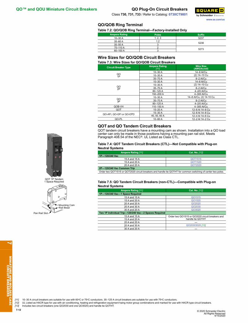
QOTand QO Tandem Circuit Breakers
QOT 1P Tandem1 Space Required
QOT tandem circuit breakers have a mounting cam as shown. Installation into a QO loadcenter can only be made in those positions having a mounting pan rail slot. MeetsParagraph 408.54 of the NEC®. UL Listed as Class CTL.
Table 7.4: QOT Tandem Circuit Breakers (CTL)—Not Compatible with Plug-onNeutral Systems
Ampere Rating [11] Cat. No. [12]1P—120/240 Vac
15 A and 15 A QOT151515 A and 20 A QOT152020 A and 20 A QOT2020
2P—120/240 Vac Common TripOrder two QOT1515 or QOT2020 circuit breakers and handle tie QOTHT for common switching of center two poles.
Pan Rail Slot
Rail BeadMounting Cam
Table 7.5: QO Tandem Circuit Breakers (non-CTL)—Compatible with Plug-onNeutral Systems
Ampere Rating [11] Cat. No. [12]1P—120/240 Vac—1 Space Required
15 A and 15 A QO151515 A and 20 A QO152020 A and 20 A QO202020 A and 30 A QO203030 A and 20 A QO3020
Two 1P Individual Trip—120/240 Vac—2 Spaces Required15 A and 15 A Order two QO1515 or QO2020 circuit breakers and
handle tie QOTHT15 A and 20 A20 A and 20 A —20 A and 30 A QO20303020 [13]30 A and 20 A —
7MINIATUREANDMOLDEDCASE
CIRCUIT
BREAKERS
[11] 10–30 A circuit breakers are suitable for use with 60oC or 75oC conductors. 35–125 A circuit breakers are suitable for use with 75oC conductors.[12] UL Listed as HACR type for use with air conditioning, heating and refrigeration equipment haing motor group combinations and marked for use with HACR type circuit breakers.[13] Includes two circuit breakers (one QO2030 and one QO3020) and handle tie QOTHT.
© 2020 Schneider Electric All Rights Reserved4/15/2020
7-13
www.se.com/us
QO Plug-On Circuit Breakers QO™ and QOU Miniature Circuit BreakersClass 685, 690, 730, 912, 950 / Refer to Catalog: 0730CT9801
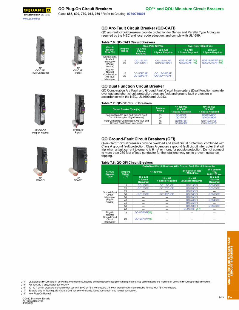
QO Arc-Fault Circuit Breaker (QO-CAFI)
1PQO-CAFI
Plug-On Neutral
1PQO-CAFIPigtail
QO arc-fault circuit breakers provide protection for Series and Parallel Type Arcing asrequired by the NEC and local code adoption, and comply with UL1699.
Table 7.6: QO-CAFI Circuit BreakersCircuitBreakerType [14]
AmpereRating
One–Pole 120 Vac Two–Pole 120/240 Vac10 k AIR1 SpaceRequired
22 k AIR1 Space Required
10 k AIR2 Space Required
22 k AIR2 Space Required
CombinationArc-faultInterrupter(PigtailNeutral)
1520
QO115CAFIQO120CAFI
QO115VHCAFIQO120VHCAFI
QO215CAFI [15]QO220CAFI [15]
QO215VHCAFI [15]QO220VHCAFI [15]
Plug-OnNeutral
CombinationArc-faultInterrupter
1520
QO115PCAFIQO120PCAFI
QO115VHPCAFIQO120VHPCAFI
QO Dual Function Circuit Breaker
1P QO-DFPlug-on Neutral
1P QO-DFPigtail
QO Combination Arc Fault and Ground Fault Circuit Interrupters (Dual Function) provideoverload and short circuit protection, plus arc fault and ground fault protection inaccordance with the NEC, UL1699 and UL943.
Table 7.7: QO-DF Circuit Breakers
Circuit Breaker Type [14] AmpereRating
1P 120 Vac10 k AIR
1 Space Required
1P 120 Vac22 k AIR
1 Space RequiredCombination Arc-fault and Ground Fault
Circuit Interrupter (Pigtail Neutral)1520
QO115DFQO120DF
QO115VHDFQO120VHDF
Plug-On Neutral Combination Arc-fault andGround Fault Circuit Interrupter
1520
QO115PDFQO120PDF
QO115VHPDFQO120VHPDF
QO Ground-Fault Circuit Breakers (GFI)
1PQO-GFI
2PQO-GFI
Qwik-Gard™ circuit breakers provide overload and short circuit protection, combined withClass A ground fault protection. Class A denotes a ground fault circuit interrupter that willtrip when a fault current to ground is 6 mA or more, for people protection. Do not connectto more than 250 feet of load conductor for the total one-way run to prevent nuisancetripping.
Table 7.8: QO-GFI Circuit Breakers
CircuitBreakerType
AmpereRating[16]
Qwik-Gard Circuit Breakers With Ground Fault Circuit Interrupter
1P 120 Vac 2P Common Trip120/240 Vac
3P CommonTrip
208Y/120 Vac10 k AIR1 SpaceRequired
22 k AIR1 Space Required
10 k AIR2 Spaces Required
10 k AIR3 SpacesRequired
Ground-FaultCircuit
Interrupter(PigtailNeutral)
15 QO115GFI QO115VHGFI QO215GFI QO315GFI20 QO120GFI QO120VHGFI QO220GFI QO320GFI25 — — QO225GFI —30 QO130GFI QO130VHGFI QO230GFI QO330GFI35 — — QO235GFI —40 — — QO240GFI QO340GFI45 — — QO245GFI —50 — — QO250GFI QO350GFI60 — — QO260GFI [17] —
Plug-OnNeutral
Ground-FaultCircuit
Interrupter
15 QO115PGFI[18] — — —
20 QO120PGFI[18] — — —
7MINIATUREANDMOLDEDCASE
CIRCUIT
BREAKERS
[14] UL Listed as HACR type for use with air conditioning, heating and refrigeration equipment haing motor group combinations and marked for use with HACR type circuit breakers.[15] For 120/240 V only, not for 208Y/120 V.[16] 10–30 A circuit breakers are suitable for use with 60oC or 75oC conductors. 35–60 A circuit breakers are suitable for use with 75oC conductors.[17] Suitable only for feeding 240 Vac and 208 Vac two-wire loads. Does not contain load neutral connection.[18] New Plug-On Neutral

7-14 © 2020 Schneider Electric All Rights Reserved
4/15/2020
QO™ and QOU Miniature Circuit Breakers QO Plug-On Circuit Breakers
www.se.com/us
Class 685, 690, 730, 912, 950 / Refer to Catalog: 0730CT9801
QO-EPD/EPE Circuit Breakers
QO 1PWith Shunt Trip
QO-EPD/EPE circuit breakers provide overload and short circuit protection combinedwith Class B ground fault protection. They are designed to provide ground faultprotection of equipment at a 30 mA level (EPD) or 100 mA level (EPE). They are notdesigned to protect people from electrical shock.
Table 7.9: QO-EPD Circuit BreakersAmpereRating[19]
1P120 Vac10 k AIR
1 Space Required
2P Common Trip120/240 Vac10 k AIR
2 Spaces Required
3P Common Trip240 Vac10 k AIR
3 Spaces Required15 QO115EPD QO215EPD QO315EPD [20] QO315EPE [20]20 QO120EPD QO220EPD QO320EPD [20] QO320EPE [20]25 QO125EPD QO225EPD — —30 QO130EPD QO230EPD QO330EPD [20] QO330EPE [20]40 — QO240EPD QO340EPD [20] QO340EPE [20]50 — QO250EPD QO350EPD [20] QO350EPE [20]60 — QO260EPD [21] — —
QO Switch Neutral Common Trip Circuit Breakers (QO-SWN)
Two-wireQO-SWN
Three-wireQO-SWN
Switch Neutral Common Trip 2008 NEC® 514.11
Table 7.10: QO-SWN Circuit BreakersAmpere
Rating [22]2 Wire 120 Vac
10 k AIR2 Spaces Required
3 Wire 120/240 Vac10 k AIR
3 Spaces Required10 QO210SWN QO310SWN15 QO215SWN QO315SWN20 QO220SWN QO320SWN25 QO225SWN QO325SWN30 QO230SWN QO330SWN40 QO240SWN QO340SWN50 QO250SWN QO350SWN
QO High Intensity Discharge Circuit Breakers (QO-HID)HID circuit breakers are for use on circuits feeding fluorescent and high intensitydischarge (HID) lighting systems such as mercury vapor, metal halide, or high pressuresodium. These circuit breakers are physically interchangeable with QO circuit breakers.
Table 7.11: QO-HID Circuit Breakers
AmpereRating [22]
1P 120/240 Vac10 k AIR
1 Space Required
2P Common Trip120/240 Vac10 k AIR
2 Spaces Required
3P Common Trip240 Vac10 k AIR
3 Spaces Required15 QO115HID [23] QO215HID QO315HID20 — QO220HID QO320HID25 QO125HID QO225HID QO325HID30 QO130HID QO230HID QO330HID40 QO140HID QO240HID —50 QO150HID QO250HID —
QO Key Operated Circuit Breakers (QO-K)
QO-K Key Operated
Key operated QO circuit breakers are available in single-pole construction and can bemounted in any single-pole space which will accept a standard QO circuit breaker. Thesecircuit breakers can be turned ON or OFF or to RESETwith a special key (catalognumber QOK10) included with the circuit breaker. These circuit breakers are UL Listedand available as shown in the table.
Table 7.12: QO-K Circuit Breakers120 Vac—10 k AIR (1 Space Required)
AmpereRating [22] Cat. No. Ampere
Rating [22] Cat. No.
10 QO110K 25 QO125K15 QO115K 30 QO130K20 QO120K
QO High Magnetic Trip Circuit Breakers (QO-HM)High magnetic trip circuit breakers are recommended for applications where high initialinrush may occur and for individual dimmer applications.
Table 7.13: QO-HM Circuit Breakers120 Vac—10 k AIR
Ampere Rating [22] 1P15 A QO115HM [24] [23]20 A QO120HM [24] [23]
7MINIATUREANDMOLDEDCASE
CIRCUIT
BREAKERS
[19] 10–30 A circuit breakers are suitable for use with 60oC or 75oC conductors. 35–60 A circuit breakers are suitable for use with 75oC conductors.[20] See note in Instruction Bulletin when using in an enclosure with a QO403 or QON prefix.[21] Suitable only for feeding 240 Vac and 208 Vac two-wire loads. Does not contain load neutral connection.[22] 10–30 A circuit breakers are suitable for use with 60oC or 75oC conductors. 35–60 A circuit breakers are suitable for use with 75oC conductors.[23] UL Listed as SWD (switching duty) rated. Suitable for switching 120 Vac fluorescent lighting loads.[24] UL Listed as HACR type for use with air conditioning, heating and refrigeration equipment haing motor group combinations and marked for use with HACR type circuit breakers.
© 2020 Schneider Electric All Rights Reserved4/15/2020
7-15
www.se.com/us
QO Plug-On Circuit Breakers QO™ and QOU Miniature Circuit BreakersClass 685, 690, 730, 912, 950 / Refer to Catalog: 0730CT9801
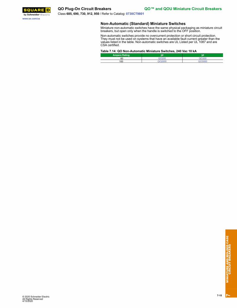
Non-Automatic (Standard) Miniature SwitchesMiniature non-automatic switches have the same physical packaging as miniature circuitbreakers, but open only when the handle is switched to the OFF position.Non-automatic switches provide no overcurrent protection or short circuit protection.They must not be used on systems that have an available fault current greater than thevalues listed in the table. Non-automatic switches are UL Listed per UL 1087 and areCSA certified.
Table 7.14: QO Non-Automatic Miniature Switches, 240 Vac 10 kAAmpere Rating 2P 3P
60 QO200 QO300100 QO2000 QO3000
7MINIATUREANDMOLDEDCASE
CIRCUIT
BREAKERS
7-16 © 2020 Schneider Electric All Rights Reserved
4/15/2020
QO™ and QOU Miniature Circuit Breakers Accessories
www.se.com/us
Class 1130 / Refer to Catalog 1100CT0501
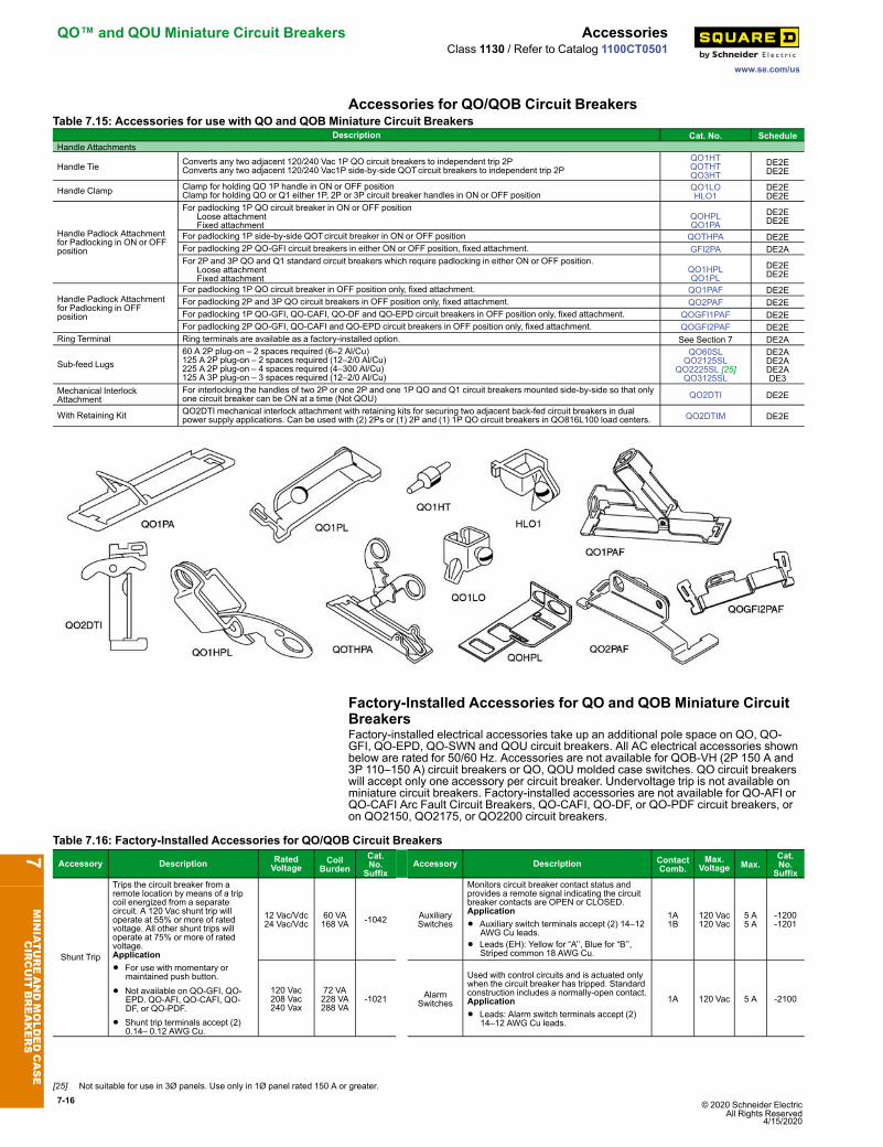
Accessories for QO/QOB Circuit BreakersTable 7.15: Accessories for use with QO and QOB Miniature Circuit Breakers
Description Cat. No. ScheduleHandle Attachments
Handle Tie Converts any two adjacent 120/240 Vac 1P QO circuit breakers to independent trip 2PConverts any two adjacent 120/240 Vac1P side-by-side QOTcircuit breakers to independent trip 2P
QO1HTQOTHTQO3HT
DE2EDE2E
Handle Clamp Clamp for holding QO 1P handle in ON or OFF positionClamp for holding QO or Q1 either 1P, 2P or 3P circuit breaker handles in ON or OFF position
QO1LOHLO1
DE2EDE2E
Handle Padlock Attachmentfor Padlocking in ON or OFFposition
For padlocking 1P QO circuit breaker in ON or OFF position Loose attachment Fixed attachment
QOHPLQO1PA
DE2EDE2E
For padlocking 1P side-by-side QOTcircuit breaker in ON or OFF position QOTHPA DE2EFor padlocking 2P QO-GFI circuit breakers in either ON or OFF position, fixed attachment. GFI2PA DE2AFor 2P and 3P QO and Q1 standard circuit breakers which require padlocking in either ON or OFF position. Loose attachment Fixed attachment
QO1HPLQO1PL
DE2EDE2E
Handle Padlock Attachmentfor Padlocking in OFFposition
For padlocking 1P QO circuit breaker in OFF position only, fixed attachment. QO1PAF DE2EFor padlocking 2P and 3P QO circuit breakers in OFF position only, fixed attachment. QO2PAF DE2EFor padlocking 1P QO-GFI, QO-CAFI, QO-DF and QO-EPD circuit breakers in OFF position only, fixed attachment. QOGFI1PAF DE2EFor padlocking 2P QO-GFI, QO-CAFI and QO-EPD circuit breakers in OFF position only, fixed attachment. QOGFI2PAF DE2E
Ring Terminal Ring terminals are available as a factory-installed option. See Section 7 DE2A
Sub-feed Lugs60 A 2P plug-on – 2 spaces required (6–2 Al/Cu)125 A 2P plug-on – 2 spaces required (12–2/0 Al/Cu)225 A 2P plug-on – 4 spaces required (4–300 Al/Cu)125 A 3P plug-on – 3 spaces required (12–2/0 Al/Cu)
QO60SLQO2125SL
QO2225SL [25]QO3125SL
DE2ADE2ADE2ADE3
Mechanical InterlockAttachment
For interlocking the handles of two 2P or one 2P and one 1P QO and Q1 circuit breakers mounted side-by-side so that onlyone circuit breaker can be ON at a time (Not QOU) QO2DTI DE2E
With Retaining Kit QO2DTI mechanical interlock attachment with retaining kits for securing two adjacent back-fed circuit breakers in dualpower supply applications. Can be used with (2) 2Ps or (1) 2P and (1) 1P QO circuit breakers in QO816L100 load centers. QO2DTIM DE2E
Factory-Installed Accessories for QO and QOB Miniature CircuitBreakersFactory-installed electrical accessories take up an additional pole space on QO, QO-GFI, QO-EPD, QO-SWN and QOU circuit breakers. All AC electrical accessories shownbelow are rated for 50/60 Hz. Accessories are not available for QOB-VH (2P 150 A and3P 110–150 A) circuit breakers or QO, QOU molded case switches. QO circuit breakerswill accept only one accessory per circuit breaker. Undervoltage trip is not available onminiature circuit breakers. Factory-installed accessories are not available for QO-AFI orQO-CAFI Arc Fault Circuit Breakers, QO-CAFI, QO-DF, or QO-PDF circuit breakers, oron QO2150, QO2175, or QO2200 circuit breakers.
Table 7.16: Factory-Installed Accessories for QO/QOB Circuit Breakers
Accessory Description RatedVoltage
CoilBurden
Cat.No.
SuffixAccessory Description Contact
Comb.Max.
Voltage Max.Cat.No.Suffix
Shunt Trip
Trips the circuit breaker from aremote location by means of a tripcoil energized from a separatecircuit. A 120 Vac shunt trip willoperate at 55% or more of ratedvoltage. All other shunt trips willoperate at 75% or more of ratedvoltage.Application
• For use with momentary ormaintained push button.
• Not available on QO-GFI, QO-EPD. QO-AFI, QO-CAFI, QO-DF, or QO-PDF.
• Shunt trip terminals accept (2)0.14– 0.12 AWG Cu.
12 Vac/Vdc24 Vac/Vdc
60 VA168 VA -1042 Auxiliary
Switches
Monitors circuit breaker contact status andprovides a remote signal indicating the circuitbreaker contacts are OPEN or CLOSED.Application
• Auxiliary switch terminals accept (2) 14–12AWG Cu leads.
• Leads (EH): Yellow for “A’’, Blue for “B’’,Striped common 18 AWG Cu.
1A1B
120 Vac120 Vac
5 A5 A
-1200-1201
120 Vac208 Vac240 Vax
72 VA228 VA288 VA
-1021 AlarmSwitches
Used with control circuits and is actuated onlywhen the circuit breaker has tripped. Standardconstruction includes a normally-open contact.Application
• Leads: Alarm switch terminals accept (2)14–12 AWG Cu leads.
1A 120 Vac 5 A -2100
7MINIATUREANDMOLDEDCASE
CIRCUIT
BREAKERS
[25] Not suitable for use in 3Ø panels. Use only in 1Ø panel rated 150 A or greater.
7-17
www.se.com/us
QO™Mounting Bases QO™ and QOU Miniature Circuit BreakersClass 652 / Catalog 0730CT9801, 0860CT0201
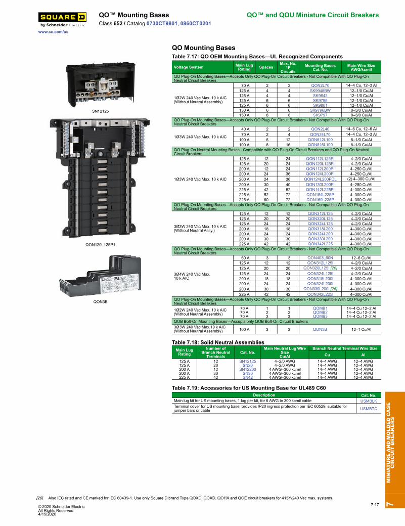
QO Mounting Bases
SN12125
QON120L125P1
QON3B
Table 7.17: QO OEM Mounting Bases—UL Recognized Components
Voltage System Main LugRating Spaces
Max. No.1P
CircuitsMounting Bases
Cat. No.Main Wire SizeAWG/kcmil
QO Plug-On Mounting Bases—Accepts Only QO Plug-On Circuit Breakers - Not Compatible With QO Plug-OnNeutral Circuit Breakers
1Ø2W 240 Vac Max. 10 k AIC(Without Neutral Assembly)
70 A 2 2 QON2L70 14–4 Cu, 12–3 Al125 A 4 4 SK9948BW 12–1/0 Cu/Al125 A 4 4 SK9842 12–1/0 Cu/Al125 A 6 6 SK9795 12–1/0 Cu/Al125 A 6 6 SK9801 12–1/0 Cu/Al150 A 6 6 SK9796BW 8–3/0 Cu/Al150 A 8 8 SK9797 8–3/0 Cu/Al
QO Plug-On Mounting Bases—Accepts Only QO Plug-On Circuit Breakers - Not Compatible With QO Plug-OnNeutral Circuit Breakers
1Ø3W 240 Vac Max. 10 k AIC
40 A 2 2 QON2L40 14–6 Cu, 12–6 Al 70 A 2 4 QON24L70 14–4 Cu, 12–3 Al100 A 6 12 QON612L100 8–1/0 Cu/Al100 A 8 16 QON816L100 8–1/0 Cu/Al
QO Plug-On Neutral Mounting Bases - Compatible with QO Plug-On Circuit Breakers and QO Plug-On NeutralCircuit Breakers
1Ø3W 240 Vac Max. 10 k AIC
125 A 12 24 QON112L125PI 4–2/0 Cu/Al125 A 20 24 QON120L125PI 4–2/0 Cu/Al200 A 12 24 QON112L200PI 4–250 Cu/Al200 A 24 36 QON124L200PI 4–250 Cu/Al200 A 24 36 QON124L200PDL (2) 4–300 Cu/Al200 A 30 40 QON130L200PI 4–250 Cu/Al225 A 42 52 QON142L225PI 4–300 Cu/Al225 A 52 72 QON154L225P 4–300 Cu/Al225 A 60 72 QON160L225P 4–300 Cu/Al
QO Plug-On Mounting Bases—Accepts Only QO Plug-On Circuit Breakers - Not Compatible With QO Plug-OnNeutral Circuit Breakers
3Ø3W 240 Vac Max. 10 k AIC(Without Neutral Assy.)
125 A 12 12 QON312L125 4–2/0 Cu/Al125 A 20 20 QON320L125 4–2/0 Cu/Al125 A 24 24 QON324L125 4–2/0 Cu/Al200 A 18 18 QON318L200 4–300 Cu/Al200 A 24 24 QON324L200 4–300 Cu/Al200 A 30 30 QON330L200 4–300 Cu/Al225 A 42 42 QON342L225 4–300 Cu/Al
QO Plug-On Mounting Bases—Accepts Only QO Plug-On Circuit Breakers - Not Compatible With QO Plug-OnNeutral Circuit Breakers
3Ø4W 240 Vac Max.10 k AIC
60 A 3 3 QON403L60N 12–6 Cu/Al125 A 12 12 QON312L125I 4–2/0 Cu/Al125 A 20 20 QON320L125I [26] 4–2/0 Cu/Al125 A 24 24 QON324L125I 4–2/0 Cu/Al200 A 18 18 QON318L200I 4–300 Cu/Al200 A 24 24 QON324L200I 4–300 Cu/Al200 A 30 30 QON330L200I [26] 4–300 Cu/Al225 A 42 42 QON342L225I 4–300 Cu/Al
QO Plug-On Mounting Bases—Accepts Only QO Plug-On Circuit Breakers - Not Compatible With QO Plug-OnNeutral Circuit Breakers1Ø2W 240 Vac Max. 10 k AIC(Without Neutral Assembly)
70 A70 A70 A
123
123
QOMB1QOMB2QOMB3
14–4 Cu 12–2 Al14–4 Cu 12–2 Al14–4 Cu 12–2 Al
QOB Bolt-On Mounting Bases—Accepts only QOB Bolt-On Circuit Breakers3Ø3W 240 Vac Max.10 k AIC(Without Neutral Assembly) 100 A 3 3 QON3B 12–1 Cu/Al
Table 7.18: Solid Neutral AssembliesMain LugRating
Number ofBranch Neutral
TerminalsCat. No.
Main Neutral Lug WireSizeCu/Al
Branch Neutral Terminal Wire SizeCu Al
125 A125 A200 A200 A225 A
1220123042
SN12125SN20
SN12200SN30SN42
4–2/0 AWG4–2/0 AWG
4 AWG–300 kcmil4 AWG–300 kcmil4 AWG–300 kcmil
14–4 AWG14–4 AWG14–4 AWG14–4 AWG14–4 AWG
12–4 AWG12–4 AWG12–4 AWG12–4 AWG12–4 AWG
Table 7.19: Accessories for US Mounting Base for UL489 C60Description Cat. No.
Main lug kit for US mounting bases, 1 lug per kit, for 6 AWG to 300 kcmil cable USMBLKTerminal cover for US mounting base; provides IP20 ingress protection per IEC 60529; suitable forjumper bars or cable USMBTC
7MINIATUREANDMOLDEDCASE
CIRCUIT
BREAKERS
[26] Also IEC rated and CE marked for IEC 60439-1. Use only Square D brand Type QOXC, QOXD, QOHX and QOE circuit breakers for 415Y/240 Vac max. systems.
© 2020 Schneider ElectricAll Rights Reserved4/15/2020

7-18 © 2020 Schneider Electric All Rights Reserved
4/15/2020
QO™ and QOU Miniature Circuit Breakers QOU Miniature Circuit Breakers / QYUSupplementary Protectors
www.se.com/usClass 720 / Refer to Catalog 0730CT9801
Low Ampere QOU Miniature Circuit Breakers
Low Ampere QOU
QOU unit mount miniature circuit breakers (cable-in/cable-out) are ideal for OEMapplications. They have the Square D™ circuit breaker’s unique Visi-Trip™ feature andcan be DIN rail-mounted or surface- or flush-mounted using mounting feet. Mounting feetnot provided [27].General Specifications Common to All Low Ampere QOU Circuit Breakers• For convenient flush mount, surface mount or DIN mount(symmetrical rail 35 x 7.5 DIN/EN 50 022)
• Single handle with internal common trip• Terminal lug wire size (1) 14–2 AWG Cu or Al• Reversible line and load lugs• Field-installable quick connectors• UL Listed 48 Vdc (5 k AIR)• UL Listed as HACR Type: 10–70 A• High magnetic trip circuit breakers (QOU-HM) are recommended for applicationswhere high initial inrush may occur and for individual dimmer applications.
• For DIN mounting rails, see IEC Starters and Relays, Section 18.
Table 7.20: QOU Low Ampere Miniature Circuit BreakersAmpereRating
Cat. No.1P 120/240 Vac 2P 120/240 Vac 2P 240 Vac [28] 3P 240 Vac
10 k AIR 10 A QOU110 QOU210 — QOU310 15 A QOU115 QOU215 QOU215H QOU315 20 A QOU120 QOU220 QOU220H QOU320 25 A QOU125 QOU225 QOU225H QOU325 30 A QOU130 QOU230 QOU230H QOU330 35 A QOU135 QOU235 — QOU335 40 A QOU140 QOU240 — QOU340 45 A QOU145 QOU245 — QOU345 50 A QOU150 QOU250 — QOU350 60 A QOU160 QOU260 — QOU360 70 A QOU170 QOU270 — QOU370
22 k AIR 15 A QOU115VH QOU215VH — QOU315VH 20 A QOU120VH QOU220VH — QOU320VH 25 A QOU125VH QOU225VH — QOU325VH 30 A QOU130VH QOU230VH — QOU330VH 35 A QOU135VH QOU235VH — — 40 A QOU140VH QOU240VH — — 45 A QOU145VH QOU245VH — — 50 A QOU150VH QOU250VH — — 60 A QOU160VH QOU260VH — —
Table 7.21: QOU-HM Miniature Circuit Breakers (10 k AIR)AmpereRating
Cat. No.1P 120/240 Vac 2P 120/240 Vac 2P 240 Vac 3P 240 Vac
15 A QOU115HM — — — 20 A QOU120HM — — —
Table 7.22: QYU UL1077 Recognized Supplementary Protectors (5 k AIR)AmpereRating
Cat. No.1P 277 Vac 2P 120/240 Vac 2P 240 Vac 3P 240 Vac
10 A QYU110 — — — 15 A QYU115 — — — 20 A QYU120 — — — 25 A QYU125 — — — 30 A QYU130 — — —
7MINIATUREANDMOLDEDCASE
CIRCUIT
BREAKERS
[27] See QOU Accessories, page 7-20.[28] QOU-H interrupting rating is 10 kA at 240 Vac.
© 2020 Schneider Electric All Rights Reserved4/15/2020
7-19
www.se.com/us
QOU Miniature Circuit Breakers / QYUSupplementary Protectors
QO™ and QOU Miniature Circuit Breakers
Class 720 / Refer to Catalog 0730CT9801High Ampere QOU Circuit Breakers
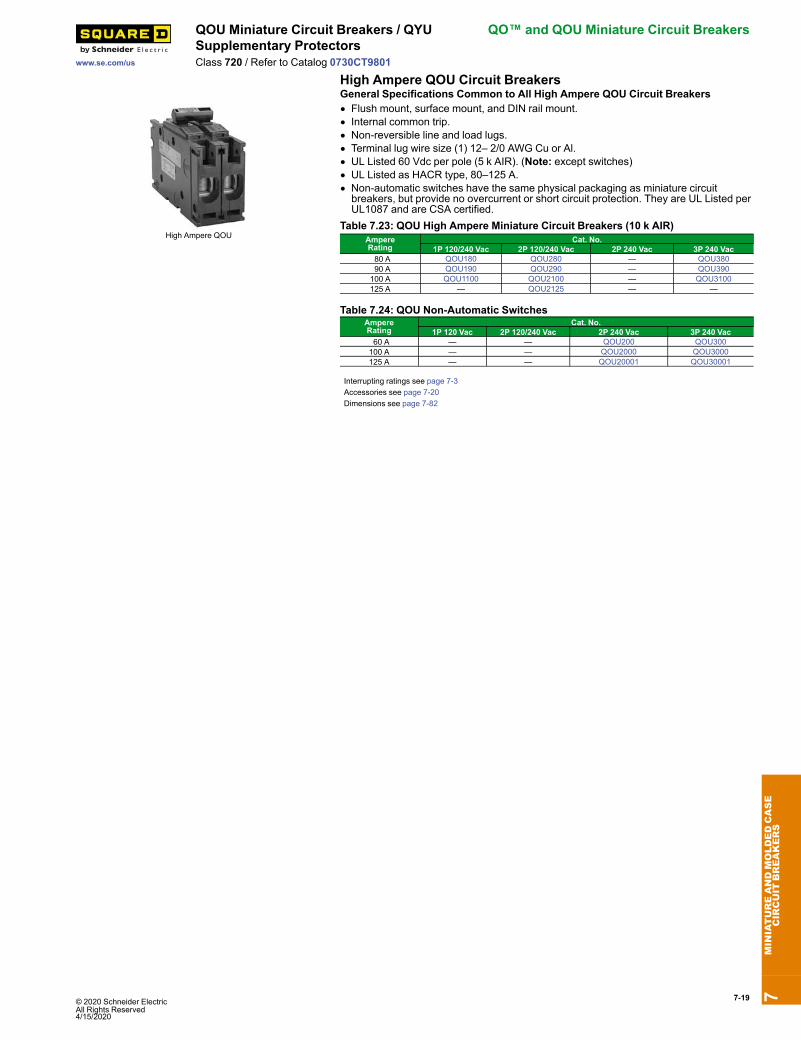
High Ampere QOU
General Specifications Common to All High Ampere QOU Circuit Breakers• Flush mount, surface mount, and DIN rail mount.• Internal common trip.• Non-reversible line and load lugs.• Terminal lug wire size (1) 12– 2/0 AWG Cu or Al.• UL Listed 60 Vdc per pole (5 k AIR). (Note: except switches)• UL Listed as HACR type, 80–125 A.• Non-automatic switches have the same physical packaging as miniature circuitbreakers, but provide no overcurrent or short circuit protection. They are UL Listed perUL1087 and are CSA certified.
Table 7.23: QOU High Ampere Miniature Circuit Breakers (10 k AIR)AmpereRating
Cat. No.1P 120/240 Vac 2P 120/240 Vac 2P 240 Vac 3P 240 Vac
80 A QOU180 QOU280 — QOU380 90 A QOU190 QOU290 — QOU390100 A QOU1100 QOU2100 — QOU3100125 A — QOU2125 — —
Table 7.24: QOU Non-Automatic SwitchesAmpereRating
Cat. No.1P 120 Vac 2P 120/240 Vac 2P 240 Vac 3P 240 Vac
60 A — — QOU200 QOU300100 A — — QOU2000 QOU3000125 A — — QOU20001 QOU30001
Interrupting ratings see page 7-3Accessories see page 7-20Dimensions see page 7-82
7MINIATUREANDMOLDEDCASE
CIRCUIT
BREAKERS
7-20 © 2020 Schneider Electric All Rights Reserved
4/15/2020
Homeline™ Miniature Circuit Breakers QOU Accessories
www.se.com/us
Class 720 / Refer to Catalog 0730CT9801
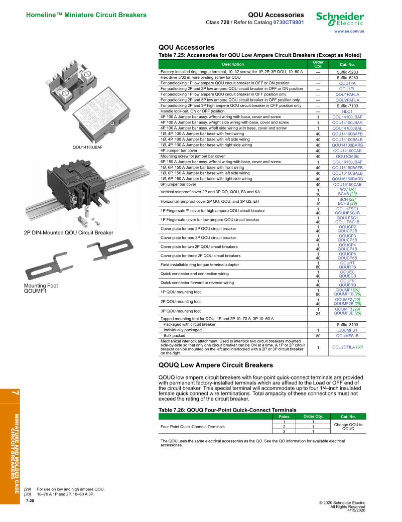
QOU Accessories
QOU14100JBAF
2P DIN-Mounted QOU Circuit Breaker
Mounting FootQOUMF1
Table 7.25: Accessories for QOU Low Ampere Circuit Breakers (Except as Noted)Description Order
Qty. Cat. No.
Factory-installed ring tongue terminal, 10–32 screw, for 1P, 2P, 3P QOU, 10–60 A — Suffix -5283Hex drive 5/32 in. wire binding screw for QOU — Suffix -5280For padlocking 1P low ampere QOU circuit breaker in OFF or ON position — QOU1PAFor padlocking 2P and 3P low ampere QOU circuit breaker in OFF or ON position — QOU1PLFor padlocking 1P low ampere QOU circuit breaker in OFF position only — QOU1PAFLAFor padlocking 2P and 3P low ampere QOU circuit breaker in OFF position only — QOU2PAFLAFor padlocking 2P and 3P high ampere QOU circuit breaker in OFF position only — Suffix -7100Handle lock-out, ON or OFF position — HLO14P 100 A Jumper bar assy. w/front wiring with base, cover and screw 1 QOU14100JBAF4P 100 A Jumper bar assy. w/right side wiring with base, cover and screw 1 QOU14100JBAR4P 100 A Jumper bar assy. w/left side wiring with base, cover and screw 1 QOU14100JBAL1Ø, 4P, 100 A Jumper bar base with front wiring 40 QOU14100BAFB1Ø, 4P, 100 A Jumper bar base with left side wiring 40 QOU14100BALB1Ø, 4P, 100 A Jumper bar base with right side wiring 40 QOU14100BARB4P Jumper bar cover 40 QOU14100CABMounting screw for jumper bar cover 40 QOU1CMSB6P 150 A Jumper bar assy. w/front wiring with base, cover and screw 1 QOU16150JBAF1Ø, 6P, 150 A Jumper bar base with front wiring 40 QOU16150BAFB1Ø, 6P, 150 A Jumper bar base with left side wiring 40 QOU16150BALB1Ø, 6P, 150 A Jumper bar base with right side wiring 40 QOU16150BARB6P jumper bar cover 40 QOU16150CAB
Vertical rainproof cover 2P and 3P QO, QOU, FA and KA 110
BCV [29]BCVB [29]
Horizontal rainproof cover 2P QO, QOU, and 3P Q2, EH 110
BCH [29]BCHB [29]
1P Fingersafe™ cover for high ampere QOU circuit breaker 140
QOUHFSC1QOUHFSC1B
1P Fingersafe cover for low ampere QOU circuit breaker 140
QOULFSC1QOULFSC1B
Cover plate for one 2P QOU circuit breaker 140
QOUCP2QOUCP2B
Cover plate for one 3P QOU circuit breaker 140
QOUCP3QOUCP3B
Cover plate for two 2P QOU circuit breakers 140
QOUCP4QOUCP4B
Cover plate for three 2P QOU circuit breakers 140
QOUCP6QOUCP6B
Field-installable ring tongue terminal adaptor 180
QOURTQOURTB
Quick connector end connection wiring 140
QOUECQOUECB
Quick connector forward or reverse wiring 140
QOUFRQOUFRB
1P QOU mounting foot 180
QOUMF1[29]QOUMF1B [29]
2P QOU mounting foot 140
QOUMF2 [29]QOUMF2B [29]
3P QOU mounting foot 124
QOUMF3 [29]QOUMF3B [29]
Tapped mounting foot for QOU, 1P and 2P 10–70 A, 3P 10–60 APackaged with circuit breaker Suffix -3100Individually packaged 1 QOUMFS1Bulk packed 80 QOUMFS1B
Mechanical interlock attachment: Used to interlock two circuit breakers mountedside-by-side so that only one circuit breaker can be ON at a time. A 1P or 2P circuitbreaker can be mounted on the left and interlocked with a 2P or 3P circuit breakeron the right.
1 QOU2DTILA [30]
QOUQ Low Ampere Circuit Breakers
QOUQ low ampere circuit breakers with four-point quick-connect terminals are providedwith permanent factory-installed terminals which are affixed to the Load or OFF end ofthe circuit breaker. This special terminal will accommodate up to four 1/4-inch insulatedfemale quick connect wire terminations. Total ampacity of these connections must notexceed the rating of the circuit breaker.
Table 7.26: QOUQ Four-Point Quick-Connect TerminalsPoles Order Qty. Cat. No.
Four-Point Quick-Connect Terminals1 1
Change QOU toQOUQ2 1
3 1
The QOU uses the same electrical accessories as the QO. See the QO information for available electricalaccessories.
7MINIATUREANDMOLDEDCASE
CIRCUIT
BREAKERS
[29] For use on low and high ampere QOU.[30] 10–70 A 1P and 2P, 10–60 A 3P.

© 2020 Schneider Electric All Rights Reserved4/15/2020
7-21
www.se.com/us
Plug-On Circuit Breakers Homeline™ Miniature Circuit BreakersClass 1170 / Refer to Catalog 1100CT0501
Homeline Standard Plug-On Circuit Breakers
HOM 1P1 Space Required
HOM 2P2 Spaces Required
HOM2200BBBranch Circuit Breaker4 Spaces Required
The Square D Homeline circuit breakers are in a 1 in. wide format for 1-pole circuitbreakers. They are designed to plug into Homeline load centers.
Table 7.27: Standard HOM Plug-on Circuit BreakersAmpereRating AIR 1P—120 Vac,
1 Space Required2P—120/240 Vac Common Trip
2 Spaces Required. 15 A 10 kA HOM115 [1][2] HOM215 [2] 20 A 10 kA HOM120 [1][2] HOM220 [2] 25 A 10 kA HOM125 [2] HOM225 [2] 30 A 10 kA HOM130 [2] HOM230 [2] 35 A 10 kA — HOM235 [2] 40 A 10 kA HOM140 [2] HOM240 [2] 45 A 10 kA — HOM245 [2] 50 A 10 kA HOM150 [2] HOM250 [2] 60 A 10 kA — HOM260 [2] 70 A 10 kA — HOM270 [2] 80 A 10 kA — HOM280 [2] 90 A 10 kA — HOM290 [2]100 A 10 kA — HOM2100 [2]110 A 10 kA — HOM2110 [2]125 A 10 kA — HOM2125 [2]150 A 10 kA — HOM2150BB [2][3]175 A 10 kA — HOM2175BB [2][3]200 A 10 kA — HOM2200BB [2][3]
Homeline High Magnetic Circuit Breakers (HOM-HM)High magnetic trip circuit breakers are recommended for applications where high initialinrush current may occur.
Table 7.28: HOM-HM Circuit BreakersAmperes 1P—120/240 Vac 2Ps15 A HOM115HM [2] —20 A HOM120HM [2] —
Homeline Combination Arc Fault Circuit Interrupters (HOM-CAFI)
HOM 1P CAFIPlug-on Neutral
HOM 1P CAFIPigtail
Homeline Combination Arc Fault Circuit Interrupters—Provide overload and short circuitprotection, plus arc fault protection in accordance with the NEC and UL1699.
Table 7.29: HOM-CAFI Circuit BreakersCircuit Breaker Type Ampere Rating Poles
120 Vac Cat. No.One-Pole
Combination Arc-Fault CircuitInterrupter with Pigtail Neutral
15 A 1 HOM115CAFI [2]20 A 1 HOM120CAFI [2]
Plug-On Neutral CombinationArc-Fault Interrupter
15 A 1 HOM115PCAFI [2]20 A 1 HOM120PCAFI [2]
Two-PoleCombination Arc-Fault CircuitInterrupter with Pigtail Neutral
15 A 2 HOM215CAFI [2] [4]20 A 2 HOM220CAFI [2] [4]
Homeline Dual Function Circuit Breaker (HOM-DF)
HOM 1P DFPlug-on Neutral
HOM 1P DFPigtail
Homeline Combination Arc Fault and Ground Fault Circuit Interrupters (Dual Function)—Provide overload and short circuit protection, plus arc fault and ground fault protection ina single device in accordance with the NEC, UL1699 and UL943.
Table 7.30: HOM-DF Circuit BreakersCircuit Breaker Type Ampere
RatingPoles120 Vac Cat. No.
Combination Arc-Fault and Ground Fault CircuitInterrupter with Pigtail Neutral
15 A 1 HOM115DF [2]20 A 1 HOM120DF [2]
Plug-On Neutral CombinationArc-Fault and Ground Fault
Circuit Interrupter
15 A 1 HOM115PDF [2]
20 A 1 HOM120PDF [2]7
MINIATUREANDMOLDEDCASE
CIRCUIT
BREAKERS
[1] UL Listed as SWD (switching duty) rated. Suitable for switching 120 Vac fluorescent lighting loads.[2] UL Listed as HACR type for use with air conditioning, heating and refrigeration equipment haing motor group combinations and marked for use with HACR type circuit breakers.[3] Requires four spaces (1 AWG–300 kcmil Al/Cu). Use only in 1Ø panel rated 150 A or greater.[4] For 120/240 V only, not for 208Y/120 V.
7-22 © 2020 Schneider Electric All Rights Reserved
4/15/2020
Homeline™ Miniature Circuit Breakers Plug-On Circuit Breakers
www.se.com/us
Class 1170 / Refer to Catalog 1100CT0501
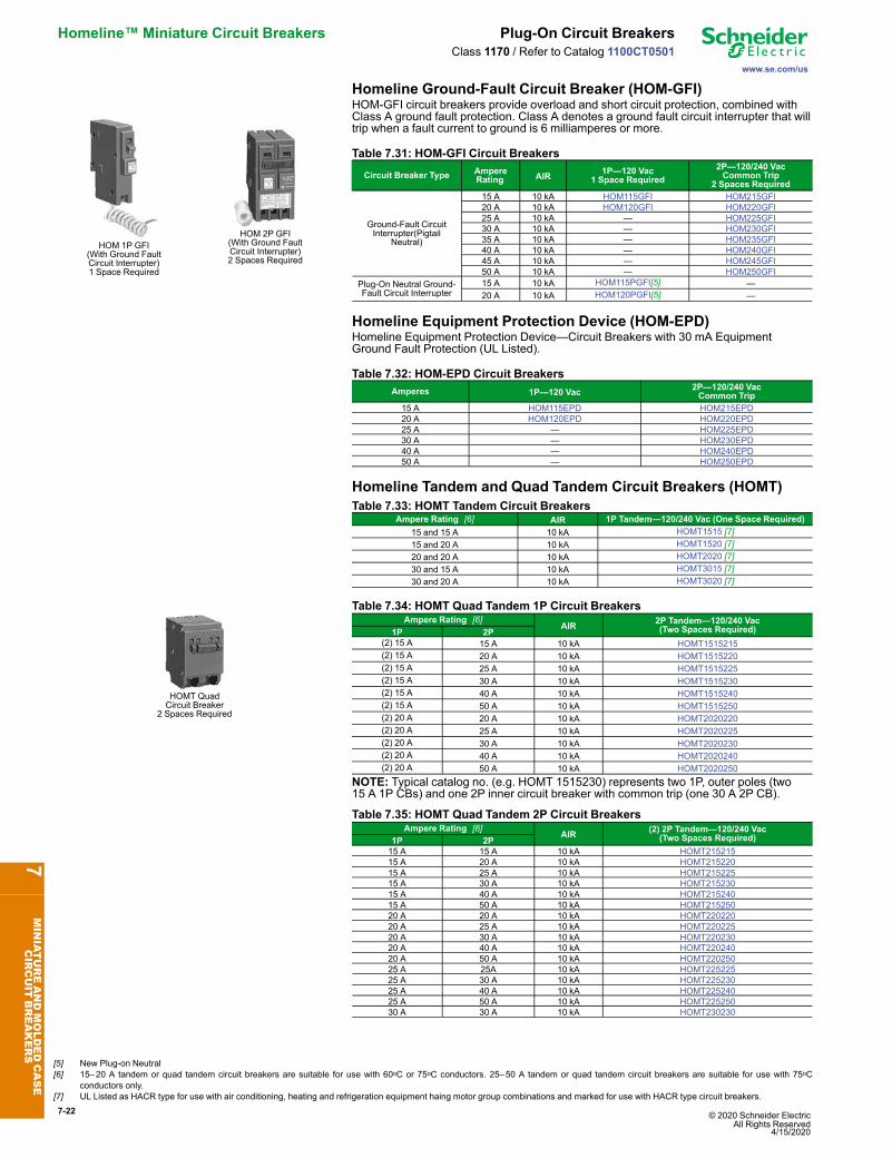
Homeline Ground-Fault Circuit Breaker (HOM-GFI)
HOM 1P GFI(With Ground FaultCircuit Interrupter)1 Space Required
HOM 2P GFI(With Ground FaultCircuit Interrupter)2 Spaces Required
HOM-GFI circuit breakers provide overload and short circuit protection, combined withClass A ground fault protection. Class A denotes a ground fault circuit interrupter that willtrip when a fault current to ground is 6 milliamperes or more.
Table 7.31: HOM-GFI Circuit Breakers
Circuit Breaker Type AmpereRating AIR 1P—120 Vac
1 Space Required2P—120/240 VacCommon Trip
2 Spaces Required
Ground-Fault CircuitInterrupter(Pigtail
Neutral)
15 A 10 kA HOM115GFI HOM215GFI20 A 10 kA HOM120GFI HOM220GFI25 A 10 kA — HOM225GFI30 A 10 kA — HOM230GFI35 A 10 kA — HOM235GFI40 A 10 kA — HOM240GFI45 A 10 kA — HOM245GFI50 A 10 kA — HOM250GFI
Plug-On Neutral Ground-Fault Circuit Interrupter
15 A 10 kA HOM115PGFI[5] —20 A 10 kA HOM120PGFI[5] —
Homeline Equipment Protection Device (HOM-EPD)Homeline Equipment Protection Device—Circuit Breakers with 30 mA EquipmentGround Fault Protection (UL Listed).
Table 7.32: HOM-EPD Circuit BreakersAmperes 1P—120 Vac 2P—120/240 Vac
Common Trip15 A HOM115EPD HOM215EPD20 A HOM120EPD HOM220EPD25 A — HOM225EPD30 A — HOM230EPD40 A — HOM240EPD50 A — HOM250EPD
Homeline Tandem and Quad Tandem Circuit Breakers (HOMT)Table 7.33: HOMT Tandem Circuit Breakers
Ampere Rating [6] AIR 1P Tandem—120/240 Vac (One Space Required)15 and 15 A 10 kA HOMT1515 [7]15 and 20 A 10 kA HOMT1520 [7]20 and 20 A 10 kA HOMT2020 [7]30 and 15 A 10 kA HOMT3015 [7]30 and 20 A 10 kA HOMT3020 [7]
HOMT QuadCircuit Breaker
2 Spaces Required
Table 7.34: HOMT Quad Tandem 1P Circuit BreakersAmpere Rating [6]
AIR 2P Tandem—120/240 Vac(Two Spaces Required)1P 2P
(2) 15 A 15 A 10 kA HOMT1515215(2) 15 A 20 A 10 kA HOMT1515220(2) 15 A 25 A 10 kA HOMT1515225(2) 15 A 30 A 10 kA HOMT1515230(2) 15 A 40 A 10 kA HOMT1515240(2) 15 A 50 A 10 kA HOMT1515250(2) 20 A 20 A 10 kA HOMT2020220(2) 20 A 25 A 10 kA HOMT2020225(2) 20 A 30 A 10 kA HOMT2020230(2) 20 A 40 A 10 kA HOMT2020240(2) 20 A 50 A 10 kA HOMT2020250
NOTE: Typical catalog no. (e.g. HOMT 1515230) represents two 1P, outer poles (two15 A 1P CBs) and one 2P inner circuit breaker with common trip (one 30 A 2P CB).
Table 7.35: HOMT Quad Tandem 2P Circuit BreakersAmpere Rating [6]
AIR (2) 2P Tandem—120/240 Vac(Two Spaces Required)1P 2P
15 A 15 A 10 kA HOMT21521515 A 20 A 10 kA HOMT21522015 A 25 A 10 kA HOMT21522515 A 30 A 10 kA HOMT21523015 A 40 A 10 kA HOMT21524015 A 50 A 10 kA HOMT21525020 A 20 A 10 kA HOMT22022020 A 25 A 10 kA HOMT22022520 A 30 A 10 kA HOMT22023020 A 40 A 10 kA HOMT22024020 A 50 A 10 kA HOMT22025025 A 25A 10 kA HOMT22522525 A 30 A 10 kA HOMT22523025 A 40 A 10 kA HOMT22524025 A 50 A 10 kA HOMT22525030 A 30 A 10 kA HOMT230230
7MINIATUREANDMOLDEDCASE
CIRCUIT
BREAKERS
[5] New Plug-on Neutral[6] 15–20 A tandem or quad tandem circuit breakers are suitable for use with 60oC or 75oC conductors. 25–50 A tandem or quad tandem circuit breakers are suitable for use with 75oC
conductors only.[7] UL Listed as HACR type for use with air conditioning, heating and refrigeration equipment haing motor group combinations and marked for use with HACR type circuit breakers.
© 2020 Schneider Electric All Rights Reserved4/15/2020
7-23
www.se.com/us
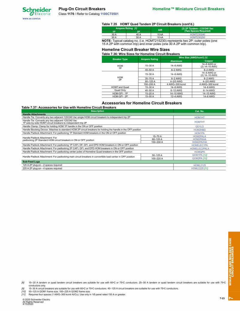
Plug-On Circuit Breakers Homeline™ Miniature Circuit BreakersClass 1170 / Refer to Catalog 1100CT0501
Table 7.35 HOMT Quad Tandem 2P Circuit Breakers (cont'd.)Ampere Rating [8]
AIR (2) 2P Tandem—120/240 Vac(Two Spaces Required)1P 2P
30 A 40 A 10 kA HOMT23024030 A 50 A 10 kA HOMT230250
NOTE: Typical catalog no. (i.e. HOMT215230) represents two 2P; outer poles (one15 A 2P with common trip) and inner poles (one 30 A 2P with common trip).
Homeline Circuit Breaker Wire SizesTable 7.36: Wire Sizes for Homeline Circuit Breakers
Breaker Type Ampere RatingWire Size (AWG/kcmil) [9]
Aluminum Copper
HOM1P
15–30 A 14–8 AWG 14–8 AWG or(2) 14–10 AWG
40–50 A 8–2 AWG 8–2 AWG
HOM2P
15–30 A 14–8 AWG 14–8 AWG or(2) 14–10 AWG
35–70 A 8–2 AWG 8–2 AWG 80–125 A 4–2/0 AWG 4–2/0 AWG150–200 A 4 AWG–300 kcmil 4 AWG–300 kcmil
HOMTand Quad 15–30 A 14–8 AWG 14–8 AWGQuad Only 40–50 A 6–12 AWG 6–14 AWG
HOM-GFI - 1P 15–20 A 14–10 AWG 14–10 AWGHOM-GFI - 2P 15–50 A 12–4 AWG 14–6 AWG
Accessories for Homeline Circuit BreakersTable 7.37: Accessories for Use with Homeline Circuit Breakers
Description Cat. No.Handle AttachmentsHandle Tie: Converts any two adjacent 120/240 Vac single HOM circuit breakers to independent trip 2P HOM1HTHandle Tie: Converts any two adjacent 120/240 Vac1P side-by-side HOMTcircuit breakers to independent trip 2P HOMTHT
Handle Clamp: Clamp for holding HOM 1P handle in the ON or OFF position QO1LOHandle Blocking Device: Attaches to standard HOM 2P circuit breakers for holding the handle in the OFF position HOM2HBDHandle Padlock Attachment: For padlocking 1P Standard HOM breakers in the ON or OFF position HOM1PA
Handle Padlock Attachment: Forpadlocking 2P Standard HOM circuit breakers in ON or OFF position
15–70 A HOM2PALA80–125 A HOM2PAHA150–200 A HOM2PAVHA
Handle Padlock Attachment: For padlocking 1P CAFI, DF, GFI, and EPD HOM breakers in ON or OFF position HOMELEC1PAHandle Padlock Attachment: For padlocking 2P CAFI, GFI, and EPD HOM breakers in ON or OFF position HOMELEC2PALAHandle Padlock Attachment: For padlocking center poles of Homeline Quad breakers in the OFF position HOMQPA
Handle Padlock Attachment: For padlocking main circuit breakers in convertible load center in OFF position 50–125 A QOM1PA [10]100–225 A QOM2PA [10]
Sub-Feed Lugs125 A 2P plug-on—2 spaces required HOML2125225 A 2P plug-on—4 spaces required HOML2225 [11]
7MINIATUREANDMOLDEDCASE
CIRCUIT
BREAKERS
[8] 15–20 A tandem or quad tandem circuit breakers are suitable for use with 60oC or 75oC conductors. 25–50 A tandem or quad tandem circuit breakers are suitable for use with 75oCconductors only.
[9] 15–30 A circuit breakers are suitable for use with 60oC or 75oC conductors. 40–125 A circuit breakers are suitable for use with 75oC conductors.[10] 50–125 A QOM1 frame size; 100–225 A QOM2 frame size.[11] Requires four spaces (1 AWG–300 kcmil Al/Cu). Use only in 1Ø panel rated 150 A or greater.

7-24 © 2020 Schneider Electric All Rights Reserved
4/15/2020
Multi 9™ Miniature Circuit Breakers C60BP and C60BPR Circuit Breakers
www.se.com/us
Class 860 / Refer to Catalog LVCATM9OEM_EN
Multi 9 C60BP and C60BPR Miniature Circuit Breakers
IECUL489 / CSA C22.2 No 5 / IEC/EN 60947-2 / GB14048-2
Miniature Circuit Breakers
C60BP and C60BPR are multi-standard miniature circuit breakers and branch circuitprotection as defined by UL489. They combine the following functions:• circuit protection against short-circuit curves• circuit protection against overload currents• tripping and fault indication by the addition of auxiliary accessories
Number of18 mm(0.71 in.)Poles
Rating (A)25°C/77°F
Breaking Capacity (kA rms)AIR
UL 489 / CSA C22.2 No 5Icu
IEC 60947-2Voltage(Ue) 277 Vac 240 Vac 120 Vac 60 Vdc 440 Vac 415 Vac 240 Vac 60 Vdc
1P 0.5 to 35 10 14 14 10 — 3 10 2040 to 63 — 10 10 10 — 3 10 20Voltage(Ue) 480Y/277 Vac 240 Vac 125 Vdc 440 Vac 415 Vac 240 Vac 125
Vdc
2P 1 to 25 10 14 10 6 10 20 —30 to 35 10 14 — 6 10 20 —
3P 1 to 35 10 14 — 6 10 20 —2P/3P 40 to 63 — 10 — 6 10 20 —
C60BP 1P C60BP 2P C60BP 3P
C60BPR 1P C60BPR 2P C60BPR 3P
Table 7.38: C60BP and C60BPRCatalog NumbersType UL489 and
CSAVoltages
1P 2P 3PRating(In)
Curve Curve CurveZ C D (= K) C D (= K) C D (= K)
C60BP (Tunnel Terminal Connection )0.5
480Y/277 Vand 240 V
M9F44170 M9F42170 M9F43170 — — — —1 M9F44101 M9F42101 M9F43101 M9F42201 M9F43201 M9F42301 M9F433012 M9F44102 M9F42102 M9F43102 M9F42202 M9F43202 M9F42302 M9F433023 M9F44103 M9F42103 M9F43103 M9F42203 M9F43203 M9F42303 M9F433034 M9F44104 M9F42104 M9F43104 M9F42204 M9F43204 M9F42304 M9F433045 M9F44105 M9F42105 M9F43105 M9F42205 M9F43205 M9F42305 M9F433056 M9F44106 M9F42106 M9F43106 M9F42206 M9F43206 M9F42306 M9F433068 M9F44108 M9F42108 M9F43108 M9F42208 M9F43208 M9F42308 M9F4330810 M9F44110 M9F42110 M9F43110 M9F42210 M9F43210 M9F42310 M9F4331015 M9F44115 M9F42115 M9F43115 M9F42215 M9F43215 M9F42315 M9F4331520 M9F44120 M9F42120 M9F43120 M9F42220 M9F43220 M9F42320 M9F4332025 M9F44125 M9F42125 M9F43125 M9F42225 M9F43225 M9F42325 M9F4332530 M9F44130 M9F42130 M9F43130 M9F42230 M9F43230 M9F42330 M9F4333035 M9F44135 M9F42135 M9F43135 M9F42235 M9F43235 M9F42335 M9F4333540
240 V only
M9F44140 M9F42140 M9F43140 M9F42240 M9F43240 M9F42340 M9F4334045 M9F44145 M9F42145 M9F43145 M9F42245 M9F43245 M9F43245 M9F4334550 M9F44150 M9F42150 M9F43150 M9F42250 M9F43250 M9F42350 M9F4335063 M9F44163 M9F42163 M9F43163 M9F42263 M9F43263 M9F42363 M9F43363
C60BPR (Ring Tongue Terminal Connection)1
480Y/277 Vand 240 V
M9F54101 M9F52101 M9F53101 M9F52201 M9F53201 M9F52301 M9F533012 M9F54102 M9F52102 M9F53102 M9F52202 M9F53202 M9F52302 M9F533024 M9F54104 M9F52104 M9F53104 M9F52204 M9F53204 M9F52304 M9F533046 M9F54106 M9F52106 M9F53106 M9F52206 M9F53206 M9F52306 M9F533068 M9F54108 M9F52108 M9F53108 M9F52208 M9F53208 M9F52308 M9F5330810 M9F54110 M9F52110 M9F53110 M9F52210 M9F53210 M9F52310 M9F5331015 M9F54115 M9F52115 M9F53115 M9F52215 M9F53215 M9F52315 M9F5331520 M9F54120 M9F52120 M9F53120 M9F52220 M9F53220 M9F52320 M9F5332025 M9F54125 M9F52125 M9F53125 M9F52225 M9F53225 M9F52325 M9F5332530 M9F54130 M9F52130 M9F53130 M9F52230 M9F53230 M9F52330 M9F5333035 M9F54135 M9F52135 M9F53135 M9F52235 M9F53235 M9F52335 M9F5333540
240 V only
M9F54140 M9F52140 M9F53140 M9F52240 M9F53240 M9F52340 M9F5334045 M9F54145 M9F52145 M9F53145 M9F52245 M9F53245 M9F52345 M9F5334550 M9F54150 M9F52150 M9F53150 M9F52250 M9F53250 M9F52350 M9F5335063 M9F54163 M9F52163 M9F53163 M9F52263 M9F53263 M9F52363 M9F53363
7MINIATUREANDMOLDEDCASE
CIRCUIT
BREAKERS
© 2020 Schneider Electric All Rights Reserved4/15/2020
7-25
www.se.com/us
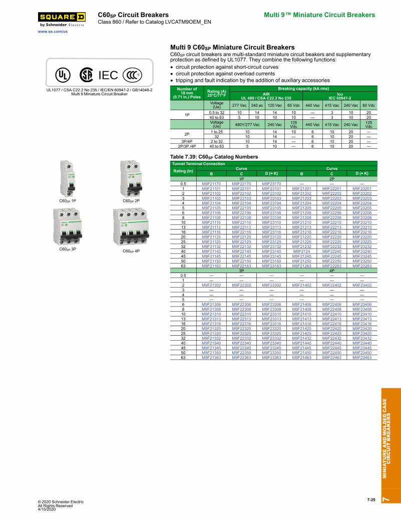
C60SP Circuit Breakers Multi 9™ Miniature Circuit BreakersClass 860 / Refer to Catalog LVCATM9OEM_EN
Multi 9 C60SP Miniature Circuit Breakers
IECUL1077 / CSA C22.2 No 235 / IEC/EN 60947-2 / GB14048-2
Multi 9 Miniature Circuit Breaker
C60SP circuit breakers are multi-standard miniature circuit beakers and supplementaryprotection as defined by UL1077. They combine the following functions:• circuit protection against short-circuit curves• circuit protection against overload currents• tripping and fault indication by the addition of auxiliary accessories
Number of18 mm
(0.71 in.) PolesRating (A)25°C/77°F
Breaking capacity (kA rms)AIR
UL 489 / CSA C22.2 No 235Icu
IEC 60947-2Voltage(Ue) 277 Vac 240 ac 120 Vac 65 Vdc 440 Vac 415 Vac 240 Vac 60 Vdc
1P 0.5 to 32 10 14 14 10 — 3 10 2040 to 63 5 10 10 10 — 3 10 20Voltage(Ue) 480Y/277 Vac 240 Vac 125
Vdc 440 Vac 415 Vac 240 Vac 125Vdc
2P 1 to 25 10 14 10 6 10 20 —32 10 14 — 6 10 20 —
3P/4P 2 to 32 10 14 — 6 10 20 —2P/3P /4P 40 to 63 5 10 — 6 10 20 —
C60SP 1P C60SP 2P
C60SP 3P C60SP 4P
Table 7.39: C60SP Catalog NumbersTunnel Terminal Connection
Rating (In) Curve CurveB C D (= K) B C D (= K)
1P 2P0.5 M9F21170 M9F22170 M9F23170 — — —1 M9F21101 M9F22101 M9F23101 M9F21201 M9F22201 M9F232012 M9F21102 M9F22102 M9F23102 M9F21202 M9F22202 M9F232023 M9F21103 M9F22103 M9F23103 M9F21203 M9F22203 M9F232034 M9F21104 M9F22104 M9F23104 M9F21204 M9F22204 M9F232045 M9F21105 M9F22105 M9F23105 M9F21205 M9F22205 M9F232056 M9F21106 M9F22106 M9F23106 M9F21206 M9F22206 M9F232068 M9F21108 M9F22108 M9F23108 M9F21208 M9F22208 M9F2320810 M9F21110 M9F22110 M9F23110 M9F21210 M9F22210 M9F2321013 M9F21113 M9F22113 M9F23113 M9F21213 M9F22213 M9F2321316 M9F21116 M9F22116 M9F23116 M9F21216 M9F22216 M9F2321620 M9F21120 M9F22120 M9F23120 M9F21220 M9F22220 M9F2322025 M9F21125 M9F22125 M9F23125 M9F21225 M9F22225 M9F2322532 M9F21132 M9F22132 M9F23132 M9F21232 M9F22232 M9F2323240 M9F21140 M9F22140 M9F23140 M9F2124 M9F22240 M9F2324045 M9F21145 M9F22145 M9F23145 M9F21245 M9F22245 M9F2324550 M9F21150 M9F22150 M9F23150 M9F21250 M9F22250 M9F2325063 M9F21163 M9F22163 M9F23163 M9F21263 M9F22263 M9F23263
3P 4P0.5 — — — — — —1 — — — — — —2 M9F21302 M9F22302 M9F23302 M9F21402 M9F22402 M9F234023 — — — — — —4 — — — — — —5 — — — — — —6 M9F21306 M9F22306 M9F23306 M9F21406 M9F22406 M9F234068 M9F21308 M9F22308 M9F23308 M9F21408 M9F22408 M9F2340810 M9F21310 M9F22310 M9F23310 M9F21410 M9F22410 M9F2341013 M9F21313 M9F22313 M9F23313 M9F21413 M9F22413 M9F2341316 M9F21316 M9F22316 M9F23316 M9F21416 M9F22416 M9F2341620 M9F21320 M9F22320 M9F23320 M9F21420 M9F22420 M9F2342025 M9F21325 M9F22325 M9F23325 M9F21425 M9F22425 M9F2342532 M9F21332 M9F22332 M9F23332 M9F21432 M9F22432 M9F2343240 M9F21340 M9F22340 M9F23340 M9F21440 M9F22440 M9F2344045 M9F21345 M9F22345 M9F23345 M9F21445 M9F22445 M9F2344550 M9F21350 M9F22350 M9F23350 M9F21450 M9F22450 M9F2345063 M9F21363 M9F22363 M9F23363 M9F21463 M9F22463 M9F23463
7MINIATUREANDMOLDEDCASE
CIRCUIT
BREAKERS

7-26 © 2020 Schneider Electric All Rights Reserved
4/15/2020
Multi 9™ Miniature Circuit Breakers C60H-DC Circuit Breakers
www.se.com/us
Class 860 / Refer to Catalog LVCATM9OEM_EN
Multi 9 C60H-DC Miniature Circuit Breakers for DC Circuits
IECUL1077, IEC/EN 60947-2, GB14048.2Multi 9 Miniature Circuit Breakers
C60H-DC circuit breakers are multi–standard miniature circuit beakers and supplementaryprotection as defined by UL1077, dedicated to direct current applications. They combinethe following functions:• circuit protection against short-circuit curves• circuit protection against overload currents• tripping and fault indication by the addition of auxiliary accessories
Number of 18 mm(0.71 in.) Poles
Rating (A)25°C/77°F
Breaking capacity (kA rms)AIR
UL 1077SA C22.2 No 5Icu
IEC 60947-2Voltage (Ue) 12–250 Vdc 110 Vdc 220 Vdc 250 Vdc
1P 0.5 to 63 5 20 10 6Voltage (Ue) 12–250 Vdc 220 Vdc 440 Vdc 500 Vdc
2 0.5 to 63 5 — 20 10 6
C60H-DC 1P C60H-DC 2P
Table 7.40: C60H-DC Catalog NumbersRating (In) Curve Curve
B C K (= D) B C K (= D)1P 2P
0.5 — M9U21170 — — M9U21270 —1 — M9U21101 M9U31101 — M9U31201 M9U312012 — M9U21102 M9U31102 — M9U21202 M9U312023 — M9U21103 M9U31103 — M9U21203 M9U312034 — M9U21104 M9U31104 — M9U21204 M9U312046 M9U11106 M9U21106 M9U31106 M9U11206 M9U21206 M9U3120610 M9U11110 M9U21110 M9U31110 M9U11210 M9U21210 M9U3121013 M9U11113 M9U21113 M9U31113 M9U11213 M9U21213 M9U3121316 M9U11116 M9U21116 M9U31116 M9U11216 M9U21216 M9U3121620 M9U11120 M9U21120 M9U31120 M9U11220 M9U21220 M9U3122025 M9U11125 M9U21125 M9U31125 M9U11225 M9U21225 M9U3122532 M9U11132 M9U21132 M9U31132 M9U11232 M9U21232 M9U3123240 M9U11140 M9U21140 M9U31140 M9U11240 M9U21240 M9U3124050 M9U11150 M9U21150 M9U31150 M9U11250 M9U21250 M9U3125063 M9U11163 M9U21163 M9U31163 M9U11263 M9U21263 M9U31263
Multi 9 GFP Ground Fault Protectors
IECUL1053, IEC/EN 61008
Multi 9 Ground Fault Protectors
UL 1053 residual current circuit breakers already protected upstream by a short circuitand overload protection device are used for:• control and disconnection of electric circuits• protection of people against electric shock by direct and indirect contacts• protection of installations against insulation faults• enhanced continuity of supply, during a series of close lightning strokes, ITearthingsystem, equipment including interference suppression filters, variable speedcontrollers, frequency converters, electronic ballasts for lighting
• enhanced earth leakage protection: in presence of harmonics or high frequencyejections.
A-SI type GFPs are ideal for operation in environments with a humid atmosphere and/orpolluted by aggressive agents: swimming pools, marinas, agri-food industries, watertreatment stations, industrial sites, etc.
Multi 9 GFP 2P Multi 9 GFP 4P
Table 7.41: GFP UL 1053 Type A-SI
A-S1 Type Rating (A)
Sensitivity (mA) Catalog No Width inmodules of
9 mm(0.354 in.)UL 1053 IEC/ EN
61008120 or 240 V230 or 240 V
240 V480Y/277 V230/400 or240/415 V
2P
2526 30 M9R81225 M9R41225
4
86 100 M9R12225 M9R44225260 300 M9R84225 —
40 26 30 M9R81240 M9R41240260 300 M9R84240 —
63 26 30 M9R81263 —
4P
2526 30 — M9R81425
8
86 100 — M9R12425260 300 — M9R84425
40 26 30 — M9R81440260 300 — M9R84440
63 26 30 — M9R8146386 100 — M9R12463
100 86 100 — M9R12491260 300 — M9R84491
7MINIATUREANDMOLDEDCASE
CIRCUIT
BREAKERS
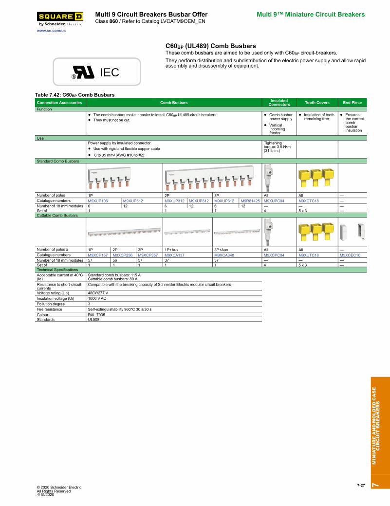
© 2020 Schneider Electric All Rights Reserved4/15/2020
7-27
www.se.com/us
Multi 9 Circuit Breakers Busbar Offer Multi 9™ Miniature Circuit BreakersClass 860 / Refer to Catalog LVCATM9OEM_EN
C60BP (UL489) Comb Busbars
IEC
These comb busbars are aimed to be used only with C60BP circuit-breakers.They perform distribution and subdistribution of the electric power supply and allow rapidassembly and disassembly of equipment.
Table 7.42: C60BP Comb BusbarsConnection Accessories Comb Busbars Insulated
Connectors Tooth Covers End-PieceFunction
• The comb busbars make it easier to install C60BP UL489 circuit breakers.
• They must not be cut.• Comb busbar
power supply
• Verticalincomingfeeder
• Insulation of teethremaining free
• Ensuresthe correctcombbusbarinsulation
UsePower supply by insulated connector
• Use with rigid and flexible copper cable
• 6 to 35 mm2 (AWG #10 to #2):
Tighteningtorque: 3.5 N•m(31 lb.in.)
Standard Comb Busbars
Number of poles 1P 2P 3P All All —Catalogue numbers M9XUP106 M9XUP312 M9XUP312 M9XUP312 M9XUP312 M9R81425 M9XUPC04 M9XCTC18 —Number of 18 mm modules 6 12 6 12 6 12 — — —Set of 1 1 1 4 5 x 3 —Cuttable Comb Busbars
Number of poles x 1P 2P 3P 1P+Aux 3P+Aux All All —Catalogue numbers M9XCP157 M9XCP256 M9XCP357 M9XCA137 M9XCA348 M9XCPC04 M9XUTC18 M9XCEC10Number of 18 mm modules 57 56 57 37 37 — — —Set of 1 1 1 1 1 4 5 x 3 —Technical SpecificationsAcceptable current at 40°C(Ie)
Standard comb busbars: 115 ACuttable comb busbars: 80 A
Resistance to short-circuitcurrents
Compatible with the breaking capacity of Schneider Electric modular circuit breakers
Voltage rating (Ue) 480Y/277 VInsulation voltage (Ui) 1000 VACPollution degree 3Fire resistance Self-extinguishability 960°C 30 s/30 sColour RAL 7035Standards UL508
7MINIATUREANDMOLDEDCASE
CIRCUIT
BREAKERS
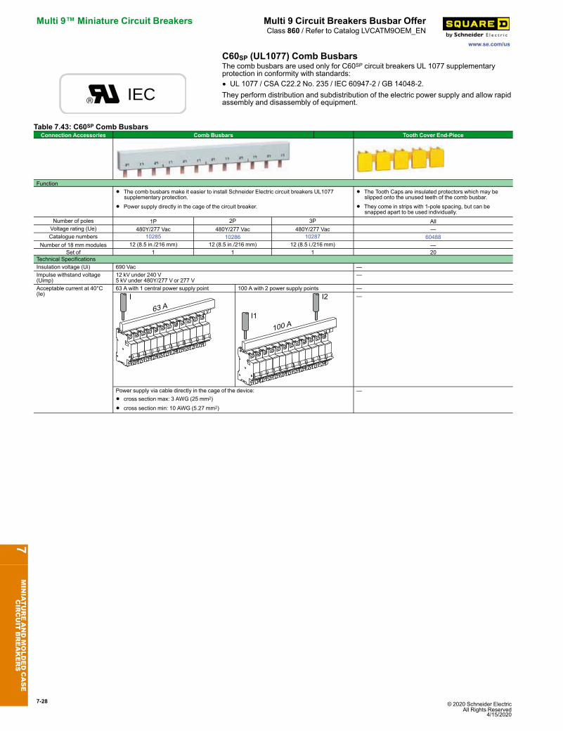
7-28 © 2020 Schneider Electric All Rights Reserved
4/15/2020
Multi 9™ Miniature Circuit Breakers Multi 9 Circuit Breakers Busbar Offer
www.se.com/us
Class 860 / Refer to Catalog LVCATM9OEM_EN
C60SP (UL1077) Comb Busbars
IEC
The comb busbars are used only for C60SP circuit breakers UL 1077 supplementaryprotection in conformity with standards:• UL 1077 / CSA C22.2 No. 235 / IEC 60947-2 / GB 14048-2.They perform distribution and subdistribution of the electric power supply and allow rapidassembly and disassembly of equipment.
Table 7.43: C60SP Comb BusbarsConnection Accessories Comb Busbars Tooth Cover End-Piece
Function
• The comb busbars make it easier to install Schneider Electric circuit breakers UL1077supplementary protection.
• Power supply directly in the cage of the circuit breaker.
• The Tooth Caps are insulated protectors which may beslipped onto the unused teeth of the comb busbar.
• They come in strips with 1-pole spacing, but can besnapped apart to be used individually.
Number of poles 1P 2P 3P AllVoltage rating (Ue) 480Y/277 Vac 480Y/277 Vac 480Y/277 Vac —Catalogue numbers 10285 10286 10287 60488
Number of 18 mm modules 12 (8.5 in./216 mm) 12 (8.5 in./216 mm) 12 (8.5 i./216 mm) —Set of 1 1 1 20
Technical SpecificationsInsulation voltage (Ui) 690 Vac —Impulse withstand voltage(Uimp)
12 kV under 240 V5 kV under 480Y/277 V or 277 V
—
Acceptable current at 40°C(Ie)
63 A with 1 central power supply point 100 A with 2 power supply points ——
Power supply via cable directly in the cage of the device:
• cross section max: 3 AWG (25 mm2)
• cross section min: 10 AWG (5.27 mm2)
—
7MINIATUREANDMOLDEDCASE
CIRCUIT
BREAKERS

© 2020 Schneider Electric All Rights Reserved4/15/2020
7-29
www.se.com/us
C60 Accessories Multi 9™ Miniature Circuit BreakersClass 860 / Refer to Catalog 0860CT0201
Multi 9 C60 Accessories
Ring TongueTerminal Kit Spacer
C60 PadlockAttachment Heavy-Duty Padlock
Attachment
Rotary Handle
Front Mounting Kit for C601P, 2P, 3P, 4P
(1 per circuit breaker)
MGN26380 LockingDevice Left Side Mount
MGN26380 LockingDevice Right Side Mount
Multi-PoleFront Mounting Kit
Electrical Accessories for C60 Circuit Breakers and Supplementary Protectors
Possible CombinationsMounted to the left of the circuit breaker with a maximum width of 54 mm.
Indication Tripping
SDAlarm Switch
OFAuxiliarySwitch
MXShunt trip + Aux
Switch
MNUndervoltageRelease
C60
Table 7.44: Multi 9 C60 Electrical AccessoriesDescriptions Control Voltage Width in 9 mm
ModulesC60 UL/IECCat. No.Vac Vdc
OF Auxiliary Switch (1a1b) 12–277 12–125 1 M9A26924SD Alarm Switch (1a1b) 12–277 12–125 1 M9A26927
MX Shunt Trip + OF AuxiliarySwitch (1a1b)
24 24 2 M9A2694848 48 2 M9A26947
110–240–277 125 2 M9A26946
MN Undervoltage Release
24 24 2 M9A2710848 48 2 M9A26961120 — 2 M9A27107240 — 2 M9A26960
Multi-9 GFP UL 1053 ListedGround Fault Protectors
120 to 480Y/277 Vac; 30, 100, and 300 mA; 2P and 4Ps.See Multi 9 GFP Ground Fault Protectors, page 7-26
or Catalog LVCATM9OEM_EN
Table 7.45: Multi 9 C60 Mechanical AccessoriesDescriptions C60 Cat. No.
Ring tongue terminal kit for UL1077 C60 For one pole M9A17400Spacer for DIN rail, Not UL Recognized 9 mm wide 27062Padlock Attachment (1 per for 1P, 2P, 3P or 4P) 2 per pack 26970Heavy-duty Padlock Attachment for C60, Locks OFF only 2 per pack M9PAFPadlocking Device Left Side Mount, Locks OFF only [1]
1 per pack MGN26380Padlocking Device Right Side Mount, Locks OFF only [2] MGN26381
Front Mounting Kit
1P MG269832P MG269843P MG269854P MG26989
Terminal Screw Shield (Not UL Recognized) Bag of two4P shields 26981
Terminal cover (Not UL Recognized)
1P 269752P 26976
3P 26975 +26976
4P 26978Rotary Handle for C60 (Non UL Recognized)Operating Subassembly
2P/3P/4P27046
Door Interlock Handle 27047Fixed Handle (Front or Lateral) 27048Multi-pole Front Mounting KitRail Support (20 of 9 mm modules) 14211Hinged Transparent Cover 14210
7MINIATUREANDMOLDEDCASE
CIRCUIT
BREAKERS
[1] Left-side mounted padlocking device cannot be used in conjunction with accessories SD, OF, MX or MN. Use right-side mounted padlocking device when accessories are required.[2] Right-side mounted padlocking device cannot be used in conjunction with VIGI module. Use left-side mounted padlocking device when VIGI Module is required.
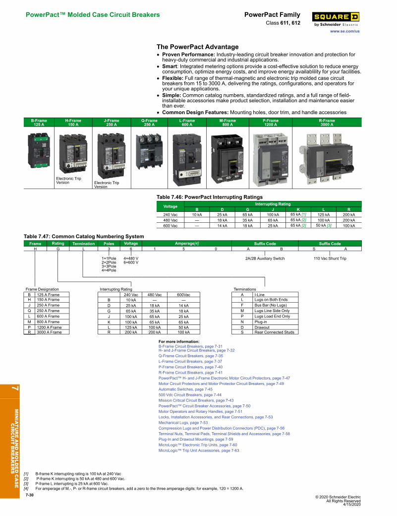
7-30 © 2020 Schneider Electric All Rights Reserved
4/15/2020
PowerPact™ Molded Case Circuit Breakers PowerPact Family
www.se.com/us
Class 611, 612
The PowerPact Advantage• Proven Performance: Industry-leading circuit breaker innovation and protection forheavy-duty commercial and industrial applications.
• Smart: Integrated metering options provide a cost-effective solution to reduce energyconsumption, optimize energy costs, and improve energy availablility for your facilities.
• Flexible: Full range of thermal-magnetic and electronic trip molded case circuitbreakers from 15 to 3000 A, delivering the ratings, configurations, and operators foryour unique applications.
• Simple: Common catalog numbers, standardized ratings, and a full range of field-installable accessories make product selection, installation and maintenance easierthan ever.
• Common Design Features: Mounting holes, door trim, and handle accessoriesB-Frame125 A
H-Frame150 A
J-Frame250 A
Q-Frame250 A
L-Frame600 A
M-Frame800 A
P-Frame1200 A
R-Frame3000 A
Electronic TripVersion Electronic Trip
Version
Table 7.46: PowerPact Interrupting RatingsVoltage Interrupting Rating
B D G J K L R240 Vac 10 kA 25 kA 65 kA 100 kA 65 kA [1] 125 kA 200 kA480 Vac — 18 kA 35 kA 65 kA 65 kA [2] 100 kA 200 kA600 Vac — 14 kA 18 kA 25 kA 65 kA [2] 50 kA [3] 100 kA
Table 7.47: Common Catalog Numbering SystemFrame Rating Termination Poles Voltage Amperage[4] Suffix Code Suffix CodeH G L 3 6 1 5 0 A B S A
1=1Pole2=2Pole3=3Pole4=4Pole
4=480 V6=600 V
2A/2B Auxiliary Switch 110 Vac Shunt Trip
Frame Designation Interrupting Rating TerminationsB 125 A Frame 240 Vac 480 Vac 600Vac A I-LineH 150 A Frame B 10 kA — — L Lugs on Both EndsJ 250 A Frame D 25 kA 18 kA 14 kA F Bus Bar (No Lugs)Q 250 A Frame G 65 kA 35 kA 18 kA M Lugs Line Side OnlyL 600 A Frame J 100 kA 65 kA 25 kA P Lugs Load End OnlyM 800 A Frame K 100 kA 65 kA 65 kA N Plug-inP 1200 A Frame L 125 kA 100 kA 50 kA D DrawoutR 3000 A Frame R 200 kA 200 kA 100 kA S Rear Connected Studs
For more information:B-Frame Circuit Breakers, page 7-31H- and J-Frame Circuit Breakers, page 7-32Q-Frame Circuit Breakers, page 7-35L-Frame Circuit Breakers, page 7-37P-Frame Circuit Breakers, page 7-40R-Frame Circuit Breakers, page 7-41PowerPact™ H- and J-Frame Electronic Motor Circuit Protectors, page 7-47Motor Circuit Protectors and Motor Protector Circuit Breakers, page 7-49Automatic Switches, page 7-45500 Vdc Circuit Breakers, page 7-44Mission Critical Circuit Breakers, page 7-43PowerPact™ Circuit Breaker Accessories, page 7-50Motor Operators and Rotary Handles, page 7-51Locks, Installation Accessories, and Rear Connections, page 7-53Mechanical Lugs, page 7-53Compression Lugs and Power Distribution Connectors (PDC), page 7-56Terminal Nuts, Terminal Pads, Terminal Shields and Accessories, page 7-58Plug-In and Drawout Mountings, page 7-59MicroLogic™ Electronic Trip Units, page 7-60MicroLogic™ Trip Unit Accessories, page 7-63
7MINIATUREANDMOLDEDCASE
CIRCUIT
BREAKERS
[1] B-frame K interrupting rating is 100 kA at 240 Vac[2] P-frame K interrupting is 50 kA at 480 and 600 Vac.[3] P-frame L interrupting is 25 kA at 600 Vac.[4] For amperage of M,-, P- or R-frame circuit breakers, add a zero to the three amperage digits; for example, 120 = 1200 A.
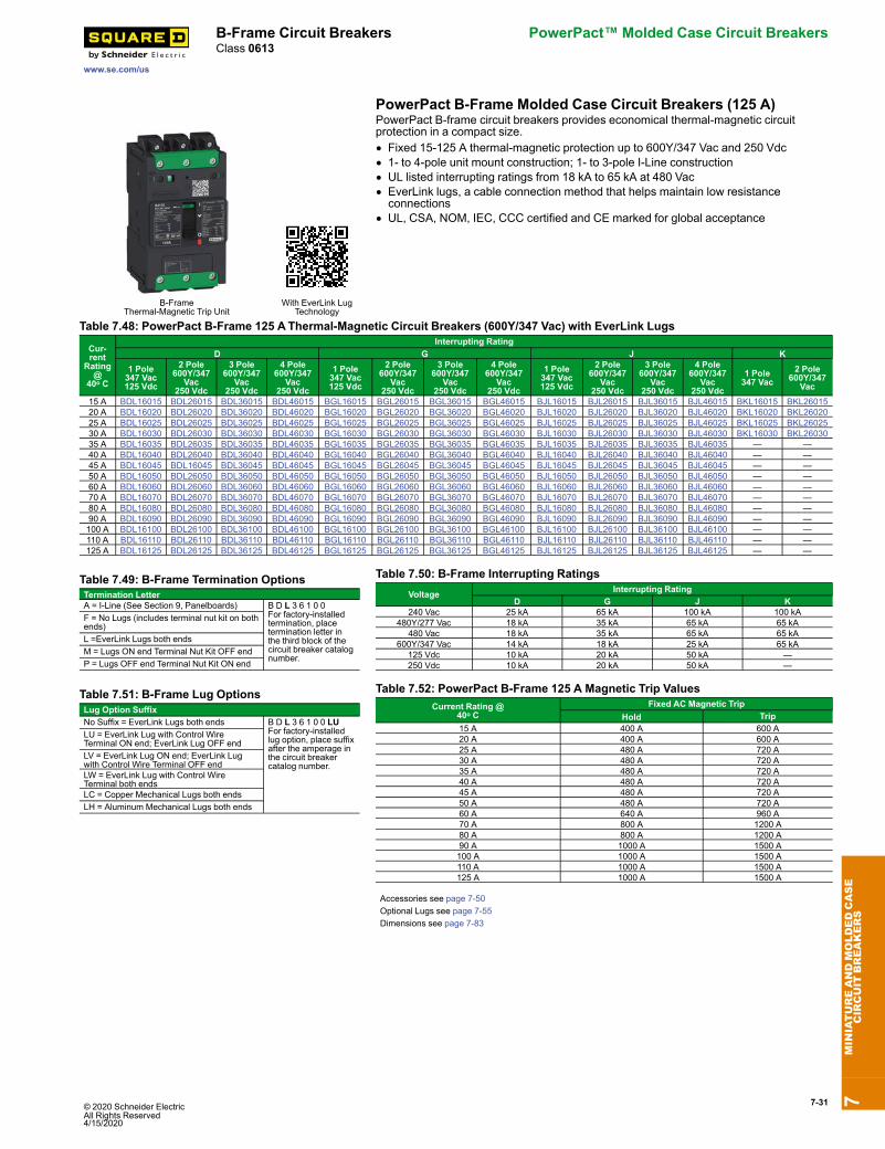
© 2020 Schneider Electric All Rights Reserved4/15/2020
7-31
www.se.com/us
B-Frame Circuit Breakers PowerPact™ Molded Case Circuit BreakersClass 0613
PowerPact B-Frame Molded Case Circuit Breakers (125 A)
B-FrameThermal-Magnetic Trip Unit
With EverLink LugTechnology
PowerPact B-frame circuit breakers provides economical thermal-magnetic circuitprotection in a compact size.• Fixed 15-125 A thermal-magnetic protection up to 600Y/347 Vac and 250 Vdc• 1- to 4-pole unit mount construction; 1- to 3-pole I-Line construction• UL listed interrupting ratings from 18 kA to 65 kA at 480 Vac• EverLink lugs, a cable connection method that helps maintain low resistanceconnections
• UL, CSA, NOM, IEC, CCC certified and CE marked for global acceptance
Table 7.48: PowerPact B-Frame 125 AThermal-Magnetic Circuit Breakers (600Y/347 Vac) with EverLink Lugs
Cur-rent
Rating@
40o C
Interrupting RatingD G J K
1 Pole347 Vac125 Vdc
2 Pole600Y/347
Vac250 Vdc
3 Pole600Y/347
Vac250 Vdc
4 Pole600Y/347
Vac250 Vdc
1 Pole347 Vac125 Vdc
2 Pole600Y/347
Vac250 Vdc
3 Pole600Y/347
Vac250 Vdc
4 Pole600Y/347
Vac250 Vdc
1 Pole347 Vac125 Vdc
2 Pole600Y/347
Vac250 Vdc
3 Pole600Y/347
Vac250 Vdc
4 Pole600Y/347
Vac250 Vdc
1 Pole347 Vac
2 Pole600Y/347
Vac15 A BDL16015 BDL26015 BDL36015 BDL46015 BGL16015 BGL26015 BGL36015 BGL46015 BJL16015 BJL26015 BJL36015 BJL46015 BKL16015 BKL2601520 A BDL16020 BDL26020 BDL36020 BDL46020 BGL16020 BGL26020 BGL36020 BGL46020 BJL16020 BJL26020 BJL36020 BJL46020 BKL16020 BKL2602025 A BDL16025 BDL26025 BDL36025 BDL46025 BGL16025 BGL26025 BGL36025 BGL46025 BJL16025 BJL26025 BJL36025 BJL46025 BKL16025 BKL2602530 A BDL16030 BDL26030 BDL36030 BDL46030 BGL16030 BGL26030 BGL36030 BGL46030 BJL16030 BJL26030 BJL36030 BJL46030 BKL16030 BKL2603035 A BDL16035 BDL26035 BDL36035 BDL46035 BGL16035 BGL26035 BGL36035 BGL46035 BJL16035 BJL26035 BJL36035 BJL46035 — —40 A BDL16040 BDL26040 BDL36040 BDL46040 BGL16040 BGL26040 BGL36040 BGL46040 BJL16040 BJL26040 BJL36040 BJL46040 — —45 A BDL16045 BDL16045 BDL36045 BDL46045 BGL16045 BGL26045 BGL36045 BGL46045 BJL16045 BJL26045 BJL36045 BJL46045 — —50 A BDL16050 BDL26050 BDL36050 BDL46050 BGL16050 BGL26050 BGL36050 BGL46050 BJL16050 BJL26050 BJL36050 BJL46050 — —60 A BDL16060 BDL26060 BDL36060 BDL46060 BGL16060 BGL26060 BGL36060 BGL46060 BJL16060 BJL26060 BJL36060 BJL46060 — —70 A BDL16070 BDL26070 BDL36070 BDL46070 BGL16070 BGL26070 BGL36070 BGL46070 BJL16070 BJL26070 BJL36070 BJL46070 — —80 A BDL16080 BDL26080 BDL36080 BDL46080 BGL16080 BGL26080 BGL36080 BGL46080 BJL16080 BJL26080 BJL36080 BJL46080 — —90 A BDL16090 BDL26090 BDL36090 BDL46090 BGL16090 BGL26090 BGL36090 BGL46090 BJL16090 BJL26090 BJL36090 BJL46090 — —100 A BDL16100 BDL26100 BDL36100 BDL46100 BGL16100 BGL26100 BGL36100 BGL46100 BJL16100 BJL26100 BJL36100 BJL46100 — —110 A BDL16110 BDL26110 BDL36110 BDL46110 BGL16110 BGL26110 BGL36110 BGL46110 BJL16110 BJL26110 BJL36110 BJL46110 — —125 A BDL16125 BDL26125 BDL36125 BDL46125 BGL16125 BGL26125 BGL36125 BGL46125 BJL16125 BJL26125 BJL36125 BJL46125 — —
Table 7.49: B-Frame Termination OptionsTermination LetterA = I-Line (See Section 9, Panelboards) B D L 3 6 1 0 0
For factory-installedtermination, placetermination letter inthe third block of thecircuit breaker catalognumber.
F = No Lugs (includes terminal nut kit on bothends)L =EverLink Lugs both endsM = Lugs ON end Terminal Nut Kit OFF endP = Lugs OFF end Terminal Nut Kit ON end
Table 7.50: B-Frame Interrupting RatingsVoltage Interrupting Rating
D G J K240 Vac 25 kA 65 kA 100 kA 100 kA
480Y/277 Vac 18 kA 35 kA 65 kA 65 kA480 Vac 18 kA 35 kA 65 kA 65 kA
600Y/347 Vac 14 kA 18 kA 25 kA 65 kA125 Vdc 10 kA 20 kA 50 kA —250 Vdc 10 kA 20 kA 50 kA —
Table 7.51: B-Frame Lug OptionsLug Option SuffixNo Suffix = EverLink Lugs both ends B D L 3 6 1 0 0 LU
For factory-installedlug option, place suffixafter the amperage inthe circuit breakercatalog number.
LU = EverLink Lug with Control WireTerminal ON end; EverLink Lug OFF endLV = EverLink Lug ON end; EverLink Lugwith Control Wire Terminal OFF endLW = EverLink Lug with Control WireTerminal both endsLC = Copper Mechanical Lugs both endsLH = Aluminum Mechanical Lugs both ends
Table 7.52: PowerPact B-Frame 125 A Magnetic Trip ValuesCurrent Rating @
40o CFixed AC Magnetic Trip
Hold Trip15 A 400 A 600 A20 A 400 A 600 A25 A 480 A 720 A30 A 480 A 720 A35 A 480 A 720 A40 A 480 A 720 A45 A 480 A 720 A50 A 480 A 720 A60 A 640 A 960 A70 A 800 A 1200 A80 A 800 A 1200 A90 A 1000 A 1500 A100 A 1000 A 1500 A110 A 1000 A 1500 A125 A 1000 A 1500 A
Accessories see page 7-50Optional Lugs see page 7-55Dimensions see page 7-83
7MINIATUREANDMOLDEDCASE
CIRCUIT
BREAKERS
7-32 © 2020 Schneider Electric All Rights Reserved
4/15/2020
PowerPact™ Molded Case Circuit Breakers H- and J-Frame Circuit Breakers
www.se.com/us
Class 611 / Refer to Catalog 0611CT1001
PowerPact H- and J-Frame Molded-Case Circuit Breakers (150 Aand 250 A)
J-FrameMicroLogic™ Trip Unit J-Frame 3–Pole
Thermal-Magnetic Trip Unit
A flexible, high performance offer certified to global standards.• Thermal magnetic or MicroLogic™ trip protection from 15–250 A up to 600 Vac and250 Vdc
• 2 and 3-pole unit mount and I-Line constructions[5]• High performance UL listed interrupting ratings from 18 to 200 kA at 480 Vac• H- and J-Frame have common mounting holes, handle locations and trim dimensionswith many shared accessories and auxiliaries.
• UL, CSA, NOM, IEC, CCC certified and CE marked for global acceptance.
Table 7.53: Lug Kit Wire RangesSensor Rating Standard Lug Kit Terminal Wire Range60–150 A AL150HD 14–3/0 AWG Al or Cu250 A AL250JD. 3/0 AWG–350 kcmil Al or Cu
Table 7.54: H- and J-Frame Interrupting RatingsVoltage Interrupting Rating
D G J L R240 Vac 25 kA 65 kA 100 kA 125 kA 200 kA480 Vac 18 kA 35 kA 65 kA 100 kA 200 kA600 Vac 14 kA 18 kA 25 kA 50 kA 100 kA
250 Vdc[6] 20 kA 20 kA 20 kA 20 kA —
Table 7.55: H- and J-Frame Termination OptionsTermination Letter
A - I-Line (See Section 9—Panelboards) H D L 3 6 0 1 5For factory-installed termination, place terminationletter in the third block of the circuit breaker catalognumber.
F = No Lugs (includes terminal nut kit on both ends)L = Lugs both endsM = Lugs ON end Terminal Nut Kit OFF endP = Lugs OFF end Terminal Nut Kit ON endN = Plug-inD = DrawoutS = Rear Connected
Accessories see page 7-50Optional Lugs see page 7-55Dimensions see page 7-83Enclosures see page 7-84
7MINIATUREANDMOLDEDCASE
CIRCUIT
BREAKERS
[5] H- and J- frame circuit breakers can be used as a main or sub-feed circuit breaker in an NQ or NF panelboard.[6] Not available with electronic trip units.
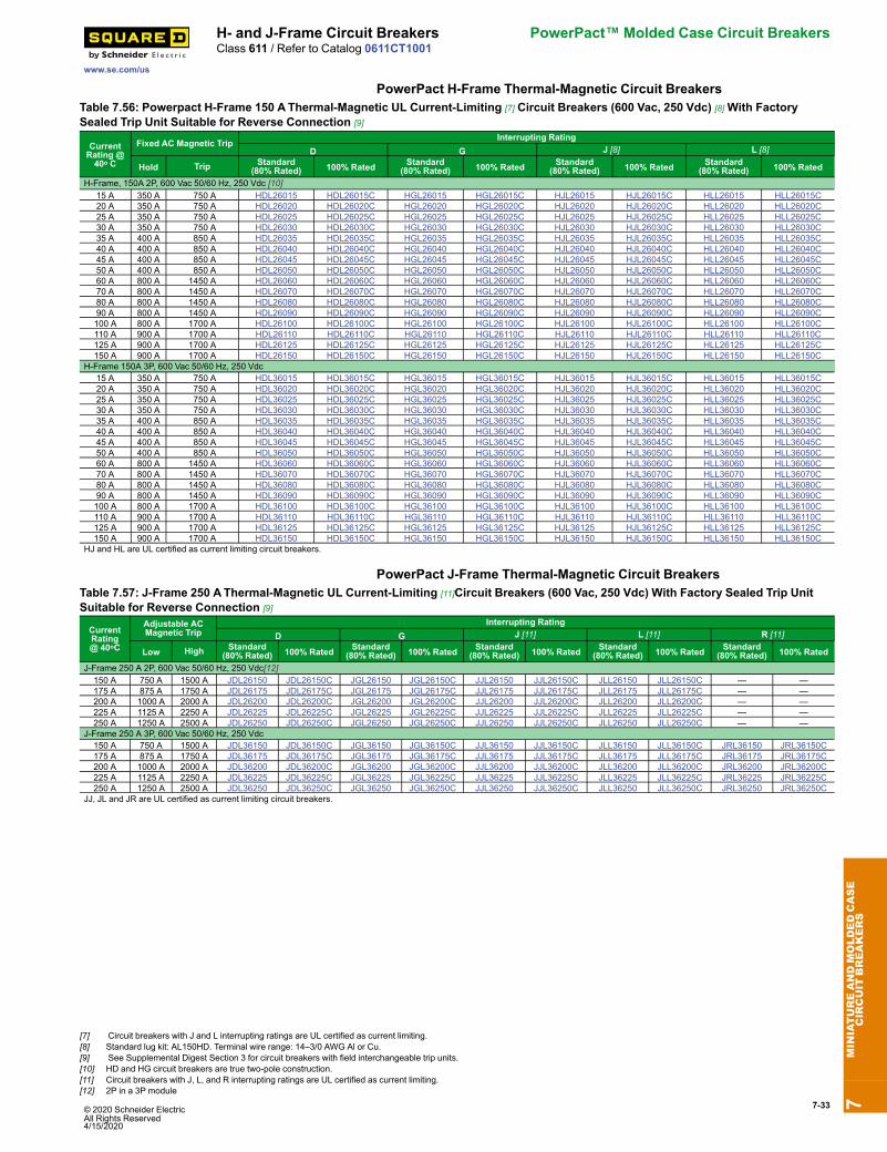
© 2020 Schneider Electric All Rights Reserved4/15/2020
7-33
www.se.com/us
H- and J-Frame Circuit Breakers PowerPact™ Molded Case Circuit BreakersClass 611 / Refer to Catalog 0611CT1001
PowerPact H-Frame Thermal-Magnetic Circuit BreakersTable 7.56: Powerpact H-Frame 150 AThermal-Magnetic UL Current-Limiting [7] Circuit Breakers (600 Vac, 250 Vdc) [8]With FactorySealed Trip Unit Suitable for Reverse Connection [9]
CurrentRating @40o C
Fixed AC Magnetic TripInterrupting Rating
D G J [8] L [8]
Hold Trip Standard(80% Rated) 100% Rated Standard
(80% Rated) 100% Rated Standard(80% Rated) 100% Rated Standard
(80% Rated) 100% Rated
H-Frame, 150A 2P, 600 Vac 50/60 Hz, 250 Vdc [10]15 A 350 A 750 A HDL26015 HDL26015C HGL26015 HGL26015C HJL26015 HJL26015C HLL26015 HLL26015C20 A 350 A 750 A HDL26020 HDL26020C HGL26020 HGL26020C HJL26020 HJL26020C HLL26020 HLL26020C25 A 350 A 750 A HDL26025 HDL26025C HGL26025 HGL26025C HJL26025 HJL26025C HLL26025 HLL26025C30 A 350 A 750 A HDL26030 HDL26030C HGL26030 HGL26030C HJL26030 HJL26030C HLL26030 HLL26030C35 A 400 A 850 A HDL26035 HDL26035C HGL26035 HGL26035C HJL26035 HJL26035C HLL26035 HLL26035C40 A 400 A 850 A HDL26040 HDL26040C HGL26040 HGL26040C HJL26040 HJL26040C HLL26040 HLL26040C45 A 400 A 850 A HDL26045 HDL26045C HGL26045 HGL26045C HJL26045 HJL26045C HLL26045 HLL26045C50 A 400 A 850 A HDL26050 HDL26050C HGL26050 HGL26050C HJL26050 HJL26050C HLL26050 HLL26050C60 A 800 A 1450 A HDL26060 HDL26060C HGL26060 HGL26060C HJL26060 HJL26060C HLL26060 HLL26060C70 A 800 A 1450 A HDL26070 HDL26070C HGL26070 HGL26070C HJL26070 HJL26070C HLL26070 HLL26070C80 A 800 A 1450 A HDL26080 HDL26080C HGL26080 HGL26080C HJL26080 HJL26080C HLL26080 HLL26080C90 A 800 A 1450 A HDL26090 HDL26090C HGL26090 HGL26090C HJL26090 HJL26090C HLL26090 HLL26090C100 A 800 A 1700 A HDL26100 HDL26100C HGL26100 HGL26100C HJL26100 HJL26100C HLL26100 HLL26100C110 A 900 A 1700 A HDL26110 HDL26110C HGL26110 HGL26110C HJL26110 HJL26110C HLL26110 HLL26110C125 A 900 A 1700 A HDL26125 HDL26125C HGL26125 HGL26125C HJL26125 HJL26125C HLL26125 HLL26125C150 A 900 A 1700 A HDL26150 HDL26150C HGL26150 HGL26150C HJL26150 HJL26150C HLL26150 HLL26150C
H-Frame 150A 3P, 600 Vac 50/60 Hz, 250 Vdc15 A 350 A 750 A HDL36015 HDL36015C HGL36015 HGL36015C HJL36015 HJL36015C HLL36015 HLL36015C20 A 350 A 750 A HDL36020 HDL36020C HGL36020 HGL36020C HJL36020 HJL36020C HLL36020 HLL36020C25 A 350 A 750 A HDL36025 HDL36025C HGL36025 HGL36025C HJL36025 HJL36025C HLL36025 HLL36025C30 A 350 A 750 A HDL36030 HDL36030C HGL36030 HGL36030C HJL36030 HJL36030C HLL36030 HLL36030C35 A 400 A 850 A HDL36035 HDL36035C HGL36035 HGL36035C HJL36035 HJL36035C HLL36035 HLL36035C40 A 400 A 850 A HDL36040 HDL36040C HGL36040 HGL36040C HJL36040 HJL36040C HLL36040 HLL36040C45 A 400 A 850 A HDL36045 HDL36045C HGL36045 HGL36045C HJL36045 HJL36045C HLL36045 HLL36045C50 A 400 A 850 A HDL36050 HDL36050C HGL36050 HGL36050C HJL36050 HJL36050C HLL36050 HLL36050C60 A 800 A 1450 A HDL36060 HDL36060C HGL36060 HGL36060C HJL36060 HJL36060C HLL36060 HLL36060C70 A 800 A 1450 A HDL36070 HDL36070C HGL36070 HGL36070C HJL36070 HJL36070C HLL36070 HLL36070C80 A 800 A 1450 A HDL36080 HDL36080C HGL36080 HGL36080C HJL36080 HJL36080C HLL36080 HLL36080C90 A 800 A 1450 A HDL36090 HDL36090C HGL36090 HGL36090C HJL36090 HJL36090C HLL36090 HLL36090C100 A 800 A 1700 A HDL36100 HDL36100C HGL36100 HGL36100C HJL36100 HJL36100C HLL36100 HLL36100C110 A 900 A 1700 A HDL36110 HDL36110C HGL36110 HGL36110C HJL36110 HJL36110C HLL36110 HLL36110C125 A 900 A 1700 A HDL36125 HDL36125C HGL36125 HGL36125C HJL36125 HJL36125C HLL36125 HLL36125C150 A 900 A 1700 A HDL36150 HDL36150C HGL36150 HGL36150C HJL36150 HJL36150C HLL36150 HLL36150C
HJ and HL are UL certified as current limiting circuit breakers.
PowerPact J-Frame Thermal-Magnetic Circuit BreakersTable 7.57: J-Frame 250 AThermal-Magnetic UL Current-Limiting [11]Circuit Breakers (600 Vac, 250 Vdc) With Factory Sealed Trip UnitSuitable for Reverse Connection [9]
CurrentRating@ 40oC
Adjustable ACMagnetic Trip
Interrupting RatingD G J [11] L [11] R [11]
Low High Standard(80% Rated) 100% Rated Standard
(80% Rated) 100% Rated Standard(80% Rated) 100% Rated Standard
(80% Rated) 100% Rated Standard(80% Rated) 100% Rated
J-Frame 250 A 2P, 600 Vac 50/60 Hz, 250 Vdc[12]150 A 750 A 1500 A JDL26150 JDL26150C JGL26150 JGL26150C JJL26150 JJL26150C JLL26150 JLL26150C — —175 A 875 A 1750 A JDL26175 JDL26175C JGL26175 JGL26175C JJL26175 JJL26175C JLL26175 JLL26175C — —200 A 1000 A 2000 A JDL26200 JDL26200C JGL26200 JGL26200C JJL26200 JJL26200C JLL26200 JLL26200C — —225 A 1125 A 2250 A JDL26225 JDL26225C JGL26225 JGL26225C JJL26225 JJL26225C JLL26225 JLL26225C — —250 A 1250 A 2500 A JDL26250 JDL26250C JGL26250 JGL26250C JJL26250 JJL26250C JLL26250 JLL26250C — —
J-Frame 250 A 3P, 600 Vac 50/60 Hz, 250 Vdc150 A 750 A 1500 A JDL36150 JDL36150C JGL36150 JGL36150C JJL36150 JJL36150C JLL36150 JLL36150C JRL36150 JRL36150C175 A 875 A 1750 A JDL36175 JDL36175C JGL36175 JGL36175C JJL36175 JJL36175C JLL36175 JLL36175C JRL36175 JRL36175C200 A 1000 A 2000 A JDL36200 JDL36200C JGL36200 JGL36200C JJL36200 JJL36200C JLL36200 JLL36200C JRL36200 JRL36200C225 A 1125 A 2250 A JDL36225 JDL36225C JGL36225 JGL36225C JJL36225 JJL36225C JLL36225 JLL36225C JRL36225 JRL36225C250 A 1250 A 2500 A JDL36250 JDL36250C JGL36250 JGL36250C JJL36250 JJL36250C JLL36250 JLL36250C JRL36250 JRL36250C
JJ, JL and JR are UL certified as current limiting circuit breakers.
7MINIATUREANDMOLDEDCASE
CIRCUIT
BREAKERS
[7] Circuit breakers with J and L interrupting ratings are UL certified as current limiting.[8] Standard lug kit: AL150HD. Terminal wire range: 14–3/0 AWG Al or Cu.[9] See Supplemental Digest Section 3 for circuit breakers with field interchangeable trip units.[10] HD and HG circuit breakers are true two-pole construction.[11] Circuit breakers with J, L, and R interrupting ratings are UL certified as current limiting.[12] 2P in a 3P module

7-34 © 2020 Schneider Electric All Rights Reserved
4/15/2020
PowerPact™ Molded Case Circuit Breakers H- and J-Frame Circuit Breakers
www.se.com/us
Class 611 / Refer to Catalog 0611CT1001
PowerPact H- and J-Frame Electronic Trip Current Limiting CircuitBreakers (150 A and 250 A)
H-FrameMicroLogic™ Trip Unit J-Frame
MicroLogic Trip Unit
rci
Mci
gol
oE
2.5
rI%A03>
03>
011>
.9
29.
39.
49.
59.
1
89.
79.
69.
Ir)oIx(
5.1
2
5.2
34
01
8
65
dsI)rIx(
H-Frame Circuit BreakerOptional FDM and IFM Module
Table 7.58: H-Frame 150 A and J-Frame 250 A Electronic Trip UL Current-Limiting [13] Standard (80% Rated) Circuit Breakers (600 Vac)With Factory Sealed Trip Unit [14] Suitable for Reverse Connection [15]
Electronic Trip Unit SensorRating
Interrupting Rating (80% Rated)Type Function Trip Unit D G J [13] L [13] R [13]
600 Vac, 50/60 Hz, 3P
MicroLogicStandard LI 3.2 [16]
60 A HDL36060U31X HGL36060U31X HJL36060U31X HLL36060U31X HRL36060U31X100 A HDL36100U31X HGL36100U31X HJL36100U31X HLL36100U31X HRL36100U31X150 A HDL36150U31X HGL36150U31X HJL36150U31X HLL36150U31X HRL36150U31X250 A JDL36250U31X JGL36250U31X JJL36250U31X JLL36250U31X JRL36250U31X
MicroLogicStandard LSI 3.2S [16]
[17]
60 A HDL36060U33X HGL36060U33X HJL36060U33X HLL36060U33X HRL36060U33X100 A HDL36100U33X HGL36100U33X HJL36100U33X HLL36100U33X HRL36100U33X150 A HDL36150U33X HGL36150U33X HJL36150U33X HLL36150U33X HRL36150U33X250 A JDL36250U33X JGL36250U33X JJL36250U33X JLL36250U33X JRL36250U33X
MicroLogicAmmeter LSI 5.2A
60 A HDL36060U43X HGL36060U43X HJL36060U43X HLL36060U43X HRL36060U43X100 A HDL36100U43X HGL36100U43X HJL36100U43X HLL36100U43X HRL36100U43X150 A HDL36150U43X HGL36150U43X HJL36150U43X HLL36150U43X HRL36150U43X250 A JDL36250U43X JGL36250U43X JJL36250U43X JLL36250U43X JRL36250U43X
MicroLogicEnergy LSI 5.2E
60 A HDL36060U53X HGL36060U53X HJL36060U53X HLL36060U53X HRL36060U53X100 A HDL36100U53X HGL36100U53X HJL36100U53X HLL36100U53X HRL36100U53X150 A HDL36150U53X HGL36150U53X HJL36150U53X HLL36150U53X HRL36150U53X250 A JDL36250U53X JGL36250U53X JJL36250U53X JLL36250U53X JRL36250U53X
MicroLogicAmmeter LSIG 6.2A [18]
60 A HDL36060U44X HGL36060U44X HJL36060U44X HLL36060U44X HRL36060U44X100 A HDL36100U44X HGL36100U44X HJL36100U44X HLL36100U44X HRL36100U44X150 A HDL36150U44X HGL36150U44X HJL36150U44X HLL36150U44X HRL36150U44X250 A JDL36250U44X JGL36250U44X JJL36250U44X JLL36250U44X JRL36250U44X
MicroLogicEnergy LSIG 6.2E
60 A HDL36060U54X HGL36060U54X HJL36060U54X HLL36060U54X HRL36060U54X100 A HDL36100U54X HGL36100U54X HJL36100U54X HLL36100U54X HRL36100U54X150 A HDL36150U54X HGL36150U54X HJL36150U54X HLL36150U54X HRL36150U54X250 A JDL36250U54X JGL36250U54X JJL36250U54X JLL36250U54X JRL36250U54X
Table 7.59: H-Frame 150 A and J-Frame 250 A Electronic Trip UL Current-Limiting [13] 100% Rated Circuit Breakers (600 Vac) With FactorySealed Trip Unit [14] Suitable for Reverse Connection [15]
Electronic Trip Unit SensorRating
Interrupting Rating (100% Rated)Type Function Trip Unit D G J [13] L [13] R [13]
600 Vac, 50/60 Hz, 3P[19]
MicroLogicStandard LI 3.2 [16]
60 A HDL36060CU31X HGL36060CU31X HJL36060CU31X HLL36060CU31X HRL36060CU31X100 A HDL36100CU31X HGL36100CU31X HJL36100CU31X HLL36100CU31X HRL36100CU31X150 A HDL36150CU31X HGL36150CU31X HJL36150CU31X HLL36150CU31X HRL36150CU31X250 A JDL36250CU31X JGL36250CU31X JJL36250CU31X JLL36250CU31X JRL36250CU31X
MicroLogicStandard LSI 3.2S [16]
[17]
60 A HDL36060CU33X HGL36060CU33X HJL36060CU33X HLL36060CU33X HRL36060CU33X100 A HDL36100CU33X HGL36100CU33X HJL36100CU33X HLL36100CU33X HRL36100CU33X150 A HDL36150CU33X HGL36150CU33X HJL36150CU33X HLL36150CU33X HRL36150CU33X250 A JDL36250CU33X JGL36250CU33X JJL36250CU33X JLL36250CU33X JRL36250CU33X
MicroLogicAmmeter LSI 5.2A
60 A HDL36060CU43X HGL36060CU43X HJL36060CU43X HLL36060CU43X HRL36060CU43X100 A HDL36100CU43X HGL36100CU43X HJL36100CU43X HLL36100CU43X HRL36100CU43X150 A HDL36150CU43X HGL36150CU43X HJL36150CU43X HLL36150CU43X HRL36150CU43X250 A JDL36250CU43X JGL36250CU43X JJL36250CU43X JLL36250CU43X JRL36250CU43X
MicroLogicEnergy LSI 5.2E
60 A HDL36060CU53X HGL36060CU53X HJL36060CU53X HLL36060CU53X HRL36060CU53X100 A HDL36100CU53X HGL36100CU53X HJL36100CU53X HLL36100CU53X HRL36100CU53X150 A HDL36150CU53X HGL36150CU53X HJL36150CU53X HLL36150CU53X HRL36150CU53X250 A JDL36250CU53X JGL36250CU53X JJL36250CU53X JLL36250CU53X JRL36250CU53X
MicroLogicAmmeter LSIG 6.2A [18]
60 A HDL36060CU44X HGL36060CU44X HJL36060CU44X HLL36060CU44X HRL36060CU44X100 A HDL36100CU44X HGL36100CU44X HJL36100CU44X HLL36100CU44X HRL36100CU44X150 A HDL36150CU44X HGL36150CU44X HJL36150CU44X HLL36150CU44X HRL36150CU44X250 A JDL36250CU44X JGL36250CU44X JJL36250CU44X JLL36250CU44X JRL36250CU44X
MicroLogicEnergy LSIG 6.2E
60 A HDL36060CU54X HGL36060CU54X HJL36060CU54X HLL36060CU54X HRL36060CU54X100 A HDL36100CU54X HGL36100CU54X HJL36100CU54X HLL36100CU54X HRL36100CU54X150 A HDL36150CU54X HGL36150CU54X HJL36150CU54X HLL36150CU54X HRL36150CU54X250 A JDL36250CU54X JGL36250CU54X JJL36250CU54X JLL36250CU54X JRL36250CU54X
Accessories see page 7-50Optional Lugs see page 7-55Dimensions see page 7-83Enclosures see page 7-84
7MINIATUREANDMOLDEDCASE
CIRCUIT
BREAKERS
[13] Circuit breakers with J, L, and R interrupting ratings are UL certified as current limiting.[14] See Supplemental Digest Section 3 for circuit breakers with field interchangeable trip units.[15] For applications requiring communications see page 7-63.[16] 3P circuit breakers with this trip unit can be used for 2P applications.[17] Fixed STand LT delays.[18] 3P circuit breakers with this trip unit can be used for 2P applications requiring ground fault protection. Additional metering capabilities will not work properly on the unconnected phase.[19] 3-pole PowerPact H- and J-frame circuit breakers can be used for 2-pole applications. (For such instances, MicroLogic 6.2 Ammeter and Energy trip units can be used for ground fault
protection. Additional metering capabilities are not guaranteed when using MicroLogic Ammeter and Energy trip units for this type of application.
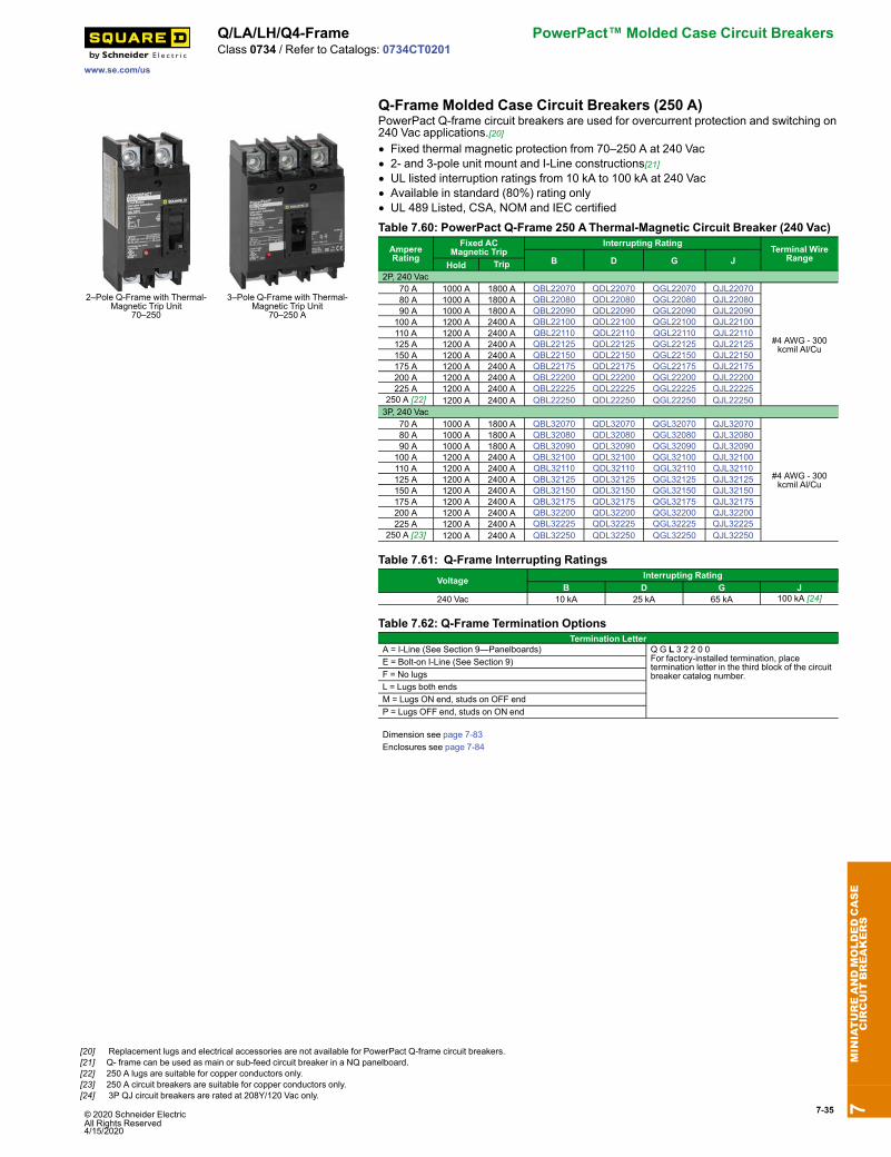
© 2020 Schneider Electric All Rights Reserved4/15/2020
7-35
www.se.com/us
Q/LA/LH/Q4-Frame PowerPact™ Molded Case Circuit BreakersClass 0734 / Refer to Catalogs: 0734CT0201
Q-Frame Molded Case Circuit Breakers (250 A)
2–Pole Q-Frame with Thermal-Magnetic Trip Unit
70–250
3–Pole Q-Frame with Thermal-Magnetic Trip Unit
70–250 A
PowerPact Q-frame circuit breakers are used for overcurrent protection and switching on240 Vac applications.[20]• Fixed thermal magnetic protection from 70–250 A at 240 Vac• 2- and 3-pole unit mount and I-Line constructions[21]• UL listed interruption ratings from 10 kA to 100 kA at 240 Vac• Available in standard (80%) rating only• UL 489 Listed, CSA, NOM and IEC certified
Table 7.60: PowerPact Q-Frame 250 AThermal-Magnetic Circuit Breaker (240 Vac)
AmpereRating
Fixed ACMagnetic Trip
Interrupting RatingTerminal Wire
RangeB D G JHold Trip2P, 240 Vac
70 A 1000 A 1800 A QBL22070 QDL22070 QGL22070 QJL22070
#4 AWG - 300kcmil Al/Cu
80 A 1000 A 1800 A QBL22080 QDL22080 QGL22080 QJL22080 90 A 1000 A 1800 A QBL22090 QDL22090 QGL22090 QJL22090100 A 1200 A 2400 A QBL22100 QDL22100 QGL22100 QJL22100110 A 1200 A 2400 A QBL22110 QDL22110 QGL22110 QJL22110125 A 1200 A 2400 A QBL22125 QDL22125 QGL22125 QJL22125150 A 1200 A 2400 A QBL22150 QDL22150 QGL22150 QJL22150175 A 1200 A 2400 A QBL22175 QDL22175 QGL22175 QJL22175200 A 1200 A 2400 A QBL22200 QDL22200 QGL22200 QJL22200225 A 1200 A 2400 A QBL22225 QDL22225 QGL22225 QJL22225
250 A [22] 1200 A 2400 A QBL22250 QDL22250 QGL22250 QJL222503P, 240 Vac
70 A 1000 A 1800 A QBL32070 QDL32070 QGL32070 QJL32070
#4 AWG - 300kcmil Al/Cu
80 A 1000 A 1800 A QBL32080 QDL32080 QGL32080 QJL32080 90 A 1000 A 1800 A QBL32090 QDL32090 QGL32090 QJL32090100 A 1200 A 2400 A QBL32100 QDL32100 QGL32100 QJL32100110 A 1200 A 2400 A QBL32110 QDL32110 QGL32110 QJL32110125 A 1200 A 2400 A QBL32125 QDL32125 QGL32125 QJL32125150 A 1200 A 2400 A QBL32150 QDL32150 QGL32150 QJL32150175 A 1200 A 2400 A QBL32175 QDL32175 QGL32175 QJL32175200 A 1200 A 2400 A QBL32200 QDL32200 QGL32200 QJL32200225 A 1200 A 2400 A QBL32225 QDL32225 QGL32225 QJL32225
250 A [23] 1200 A 2400 A QBL32250 QDL32250 QGL32250 QJL32250
Table 7.61: Q-Frame Interrupting RatingsVoltage Interrupting Rating
B D G J240 Vac 10 kA 25 kA 65 kA 100 kA [24]
Table 7.62: Q-Frame Termination OptionsTermination Letter
A = I-Line (See Section 9—Panelboards) Q G L 3 2 2 0 0For factory-installed termination, placetermination letter in the third block of the circuitbreaker catalog number.
E = Bolt-on I-Line (See Section 9)F = No lugsL = Lugs both endsM = Lugs ON end, studs on OFF endP = Lugs OFF end, studs on ON end
Dimension see page 7-83Enclosures see page 7-84
7MINIATUREANDMOLDEDCASE
CIRCUIT
BREAKERS
[20] Replacement lugs and electrical accessories are not available for PowerPact Q-frame circuit breakers.[21] Q- frame can be used as main or sub-feed circuit breaker in a NQ panelboard.[22] 250 A lugs are suitable for copper conductors only.[23] 250 A circuit breakers are suitable for copper conductors only.[24] 3P QJ circuit breakers are rated at 208Y/120 Vac only.

7-36 © 2020 Schneider Electric All Rights Reserved
4/15/2020
PowerPact™ Molded Case Circuit Breakers Q/LA/LH/Q4-Frame
www.se.com/us
Class 0734 / Refer to Catalogs: 0734CT0201
Q4-Frame Molded Case Circuit Breaker (400 A)
Q4L2P and 3P250–400 A
• Thermal magnetic protection from 250 A up to 400 A at 240 Vac• 2- and 3-pole unit mount and I-Line constructions• 25 kA at 240 Vac UL interrupting rating• UL, CSA and IEC certifiedNOTE: Consider using PowerPact™ circuit breakers for situations requiring circuitbreaker accessories. See PowerPact Accessories, page 7-50 for more information.
Table 7.63: Q4-Frame, 400 A, Thermal-Magnetic Circuit Breakers, Individually-Mounted, 240 Vac
AmpereRating
Adjustable AC Magnetic Trip [25] StandardInterruptingCat. No.
Terminal Wire RangeLow High
2P, 240 Vac250 1250 A 2500 A Q4L2250 AL400LA
(1) 1 AWG–600 kcmil Alor
(2) 1 AWG–250 kcmil Al
300 1500 A 3000 A Q4L2300350 1750 A 3500 A Q4L2350400 2000 A 4000 A Q4L2400
3P, 240 Vac250 1250 A 2500 A Q4L3250 AL400LA
(1) 1 AWG–600 kcmil Alor
(2) 1 AWG–250 kcmil Al
300 1500 A 3000 A Q4L3300350 1750 A 3500 A Q4L3350400 2000 A 4000 A Q4L3400
Accessories see PowerPact Accessories, page 7-50 through Plug-Inand Drawout Mountings, page 7-59Optional Lugs see Mechanical Lugs, page 7-55Dimensions see Dimensions and Shipping Weights, page 7-82Enclosures see Circuit Breaker Enclosures, page 7-84
LA/LH-Frame Molded Case Circuit Breaker (400 A)
LA/LHL2P and 3P 125–400 A
• Thermal magnetic protection from 125-400 A up to 600 Vac and 250 Vdc• 2- and 3-pole unit mount and I-Line constructions• UL listed interrupting ratings from 30 kA to 35 kA at 480 Vac• UL, CSA and IEC certifiedNOTE: Consider using PowerPact™ circuit breakers for situations requiring circuitbreaker accessories. See PowerPact Accessories, page 7-50 for more information.
Table 7.64: L-Frame, 400 A, Thermal-Magnetic, Individually-Mounted CircuitBreakers, 400 Vac
AmpereRating
Adjustable ACMagnetic Trip Cat. No. Terminal
Wire RangeLow High Standard
Interrupting High Interrupting
2P, 600 Vac, 250 Vdc125 A 625 A 1250 A LAL26125 LHL26125
AL400LA(1) 1 AWG–600 kcmil Alor (2) 1 AWG–250 kcmil Al
150 A 750 A 1500 A LAL26150 LHL26150175 A 875 A 1750 A LAL26175 LHL26175200 A 1000 A 2000 A LAL26200 LHL26200225 A 1125 A 2250 A LAL26225 LHL26225250 A 1250 A 2500 A LAL26250 LHL26250300 A 1500 A 3000 A LAL26300 LHL26300350 A 1750 A 3500 A LAL26350 LHL26350400 A 2000 A 4000 A LAL26400 LHL26400
3P, 600 Vac, 250 Vdc125 A 625 A 1250 A LAL36125 LHL36125
AL400LA(1) 1 AWG–600 kcmil Alor (2) 1 AWG–250 kcmil Al
150 A 750 A 1500 A LAL36150 LHL36150175 A 875 A 1750 A LAL36175 LHL36175200 A 1000 A 2000 A LAL36200 LHL36200225 A 1125 A 2250 A LAL36225 LHL36225250 A 1250 A 2500 A LAL36250 LHL36250300 A 1500 A 3000 A LAL36300 LHL36300350 A 1750 A 3500 A LAL36350 LHL36350400 A 2000 A 4000 A LAL36400 LHL36400
Accessories see PowerPact Accessories, page 7-50 through Plug-Inand Drawout Mountings, page 7-59Optional Lugs see Mechanical Lugs, page 7-55Dimensions see Dimensions and Shipping Weights, page 7-82Enclosures see Circuit Breaker Enclosures, page 7-84
Table 7.65: Interrupting RatingsVoltage LAL LHL240 Vac 42 kA 65 kA480 Vac 30 kA 35 kA600 Vac 22 kA 25 kA
7MINIATUREANDMOLDEDCASE
CIRCUIT
BREAKERS
[25] UL magnetic trip setting tolerances are ±25% for low and ±20% for high from nominal value shown.
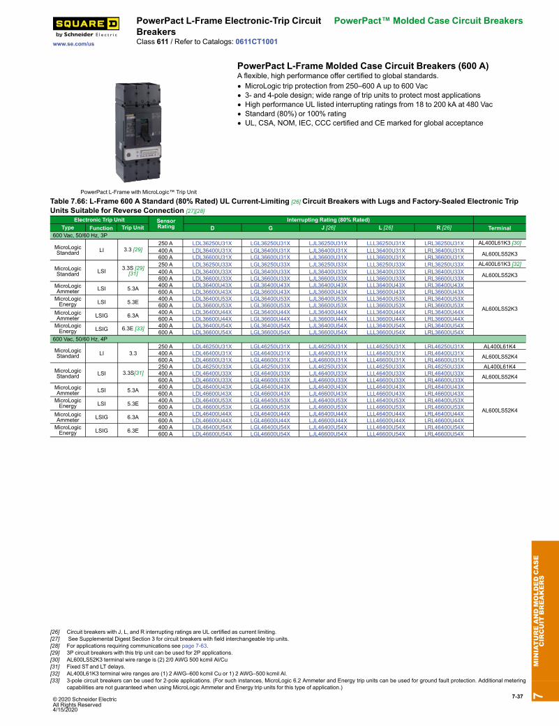
© 2020 Schneider Electric All Rights Reserved4/15/2020
7-37
www.se.com/us
PowerPact L-Frame Electronic-Trip CircuitBreakers
PowerPact™ Molded Case Circuit Breakers
Class 611 / Refer to Catalogs: 0611CT1001
PowerPact L-Frame Molded Case Circuit Breakers (600 A)
PowerPact L-Frame with MicroLogic™ Trip Unit
A flexible, high performance offer certified to global standards.• MicroLogic trip protection from 250–600 A up to 600 Vac• 3- and 4-pole design; wide range of trip units to protect most applications• High performance UL listed interrupting ratings from 18 to 200 kA at 480 Vac• Standard (80%) or 100% rating• UL, CSA, NOM, IEC, CCC certified and CE marked for global acceptance
Table 7.66: L-Frame 600 A Standard (80% Rated) UL Current-Limiting [26] Circuit Breakers with Lugs and Factory-Sealed Electronic TripUnits Suitable for Reverse Connection [27][28]
Electronic Trip Unit SensorRating
Interrupting Rating (80% Rated)D G J [26] L [26] R [26] TerminalType Function Trip Unit
600 Vac, 50/60 Hz, 3P
MicroLogicStandard LI 3.3 [29]
250 A LDL36250U31X LGL36250U31X LJL36250U31X LLL36250U31X LRL36250U31X AL400L61K3 [30]400 A LDL36400U31X LGL36400U31X LJL36400U31X LLL36400U31X LRL36400U31X AL600LS52K3600 A LDL36600U31X LGL36600U31X LJL36600U31X LLL36600U31X LRL36600U31X
MicroLogicStandard LSI 3.3S [29]
[31]250 A LDL36250U33X LGL36250U33X LJL36250U33X LLL36250U33X LRL36250U33X AL400L61K3 [32]400 A LDL36400U33X LGL36400U33X LJL36400U33X LLL36400U33X LRL36400U33X AL600LS52K3600 A LDL36600U33X LGL36600U33X LJL36600U33X LLL36600U33X LRL36600U33X
MicroLogicAmmeter LSI 5.3A 400 A LDL36400U43X LGL36400U43X LJL36400U43X LLL36400U43X LRL36400U43X
AL600LS52K3
600 A LDL36600U43X LGL36600U43X LJL36600U43X LLL36600U43X LRL36600U43XMicroLogicEnergy LSI 5.3E 400 A LDL36400U53X LGL36400U53X LJL36400U53X LLL36400U53X LRL36400U53X
600 A LDL36600U53X LGL36600U53X LJL36600U53X LLL36600U53X LRL36600U53XMicroLogicAmmeter LSIG 6.3A 400 A LDL36400U44X LGL36400U44X LJL36400U44X LLL36400U44X LRL36400U44X
600 A LDL36600U44X LGL36600U44X LJL36600U44X LLL36600U44X LRL36600U44XMicroLogicEnergy LSIG 6.3E [33] 400 A LDL36400U54X LGL36400U54X LJL36400U54X LLL36400U54X LRL36400U54X
600 A LDL36600U54X LGL36600U54X LJL36600U54X LLL36600U54X LRL36600U54X600 Vac, 50/60 Hz, 4P
MicroLogicStandard LI 3.3
250 A LDL46250U31X LGL46250U31X LJL46250U31X LLL46250U31X LRL46250U31X AL400L61K4400 A LDL46400U31X LGL46400U31X LJL46400U31X LLL46400U31X LRL46400U31X AL600LS52K4600 A LDL46600U31X LGL46600U31X LJL46600U31X LLL46600U31X LRL46600U31X
MicroLogicStandard LSI 3.3S[31]
250 A LDL46250U33X LGL46250U33X LJL46250U33X LLL46250U33X LRL46250U33X AL400L61K4400 A LDL46400U33X LGL46400U33X LJL46400U33X LLL46400U33X LRL46400U33X AL600LS52K4600 A LDL46600U33X LGL46600U33X LJL46600U33X LLL46600U33X LRL46600U33X
MicroLogicAmmeter LSI 5.3A 400 A LDL46400U43X LGL46400U43X LJL46400U43X LLL46400U43X LRL46400U43X
AL600LS52K4
600 A LDL46600U43X LGL46600U43X LJL46600U43X LLL46600U43X LRL46600U43XMicroLogicEnergy LSI 5.3E 400 A LDL46400U53X LGL46400U53X LJL46400U53X LLL46400U53X LRL46400U53X
600 A LDL46600U53X LGL46600U53X LJL46600U53X LLL46600U53X LRL46600U53XMicroLogicAmmeter LSIG 6.3A 400 A LDL46400U44X LGL46400U44X LJL46400U44X LLL46400U44X LRL46400U44X
600 A LDL46600U44X LGL46600U44X LJL46600U44X LLL46600U44X LRL46600U44XMicroLogicEnergy LSIG 6.3E 400 A LDL46400U54X LGL46400U54X LJL46400U54X LLL46400U54X LRL46400U54X
600 A LDL46600U54X LGL46600U54X LJL46600U54X LLL46600U54X LRL46600U54X
7MINIATUREANDMOLDEDCASE
CIRCUIT
BREAKERS
[26] Circuit breakers with J, L, and R interrupting ratings are UL certified as current limiting.[27] See Supplemental Digest Section 3 for circuit breakers with field interchangeable trip units.[28] For applications requiring communications see page 7-63.[29] 3P circuit breakers with this trip unit can be used for 2P applications.[30] AL600LS52K3 terminal wire range is (2) 2/0 AWG 500 kcmil Al/Cu[31] Fixed STand LT delays.[32] AL400L61K3 terminal wire ranges are (1) 2 AWG–600 kcmil Cu or 1) 2 AWG–500 kcmil Al.[33] 3-pole circuit breakers can be used for 2-pole applications. (For such instances, MicroLogic 6.2 Ammeter and Energy trip units can be used for ground fault protection. Additional metering
capabilities are not guaranteed when using MicroLogic Ammeter and Energy trip units for this type of application.)
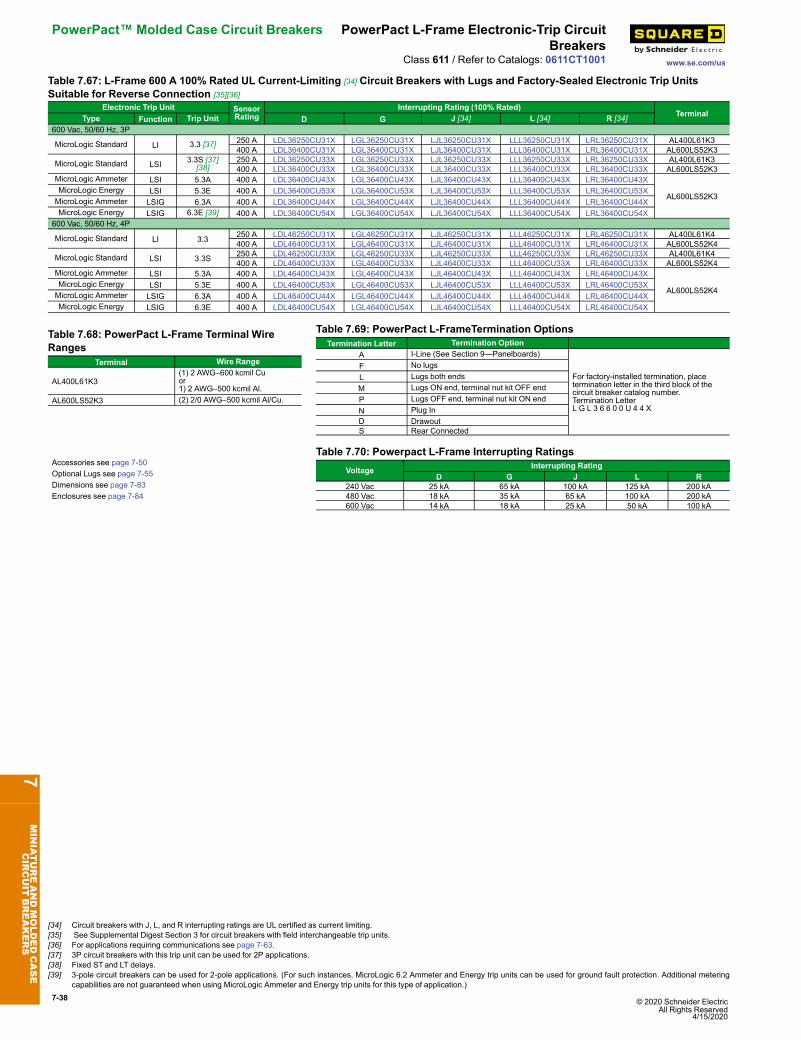
7-38 © 2020 Schneider Electric All Rights Reserved
4/15/2020
PowerPact™ Molded Case Circuit Breakers PowerPact L-Frame Electronic-Trip CircuitBreakers
www.se.com/usClass 611 / Refer to Catalogs: 0611CT1001
Table 7.67: L-Frame 600 A 100% Rated UL Current-Limiting [34] Circuit Breakers with Lugs and Factory-Sealed Electronic Trip UnitsSuitable for Reverse Connection [35][36]
Electronic Trip Unit SensorRating
Interrupting Rating (100% Rated)Terminal
D G J [34] L [34] R [34]Type Function Trip Unit600 Vac, 50/60 Hz, 3P
MicroLogic Standard LI 3.3 [37] 250 A LDL36250CU31X LGL36250CU31X LJL36250CU31X LLL36250CU31X LRL36250CU31X AL400L61K3400 A LDL36400CU31X LGL36400CU31X LJL36400CU31X LLL36400CU31X LRL36400CU31X AL600LS52K3
MicroLogic Standard LSI 3.3S [37][38]
250 A LDL36250CU33X LGL36250CU33X LJL36250CU33X LLL36250CU33X LRL36250CU33X AL400L61K3400 A LDL36400CU33X LGL36400CU33X LJL36400CU33X LLL36400CU33X LRL36400CU33X AL600LS52K3
MicroLogic Ammeter LSI 5.3A 400 A LDL36400CU43X LGL36400CU43X LJL36400CU43X LLL36400CU43X LRL36400CU43X
AL600LS52K3MicroLogic Energy LSI 5.3E 400 A LDL36400CU53X LGL36400CU53X LJL36400CU53X LLL36400CU53X LRL36400CU53XMicroLogic Ammeter LSIG 6.3A 400 A LDL36400CU44X LGL36400CU44X LJL36400CU44X LLL36400CU44X LRL36400CU44XMicroLogic Energy LSIG 6.3E [39] 400 A LDL36400CU54X LGL36400CU54X LJL36400CU54X LLL36400CU54X LRL36400CU54X
600 Vac, 50/60 Hz, 4P
MicroLogic Standard LI 3.3 250 A LDL46250CU31X LGL46250CU31X LJL46250CU31X LLL46250CU31X LRL46250CU31X AL400L61K4400 A LDL46400CU31X LGL46400CU31X LJL46400CU31X LLL46400CU31X LRL46400CU31X AL600LS52K4
MicroLogic Standard LSI 3.3S 250 A LDL46250CU33X LGL46250CU33X LJL46250CU33X LLL46250CU33X LRL46250CU33X AL400L61K4400 A LDL46400CU33X LGL46400CU33X LJL46400CU33X LLL46400CU33X LRL46400CU33X AL600LS52K4
MicroLogic Ammeter LSI 5.3A 400 A LDL46400CU43X LGL46400CU43X LJL46400CU43X LLL46400CU43X LRL46400CU43X
AL600LS52K4MicroLogic Energy LSI 5.3E 400 A LDL46400CU53X LGL46400CU53X LJL46400CU53X LLL46400CU53X LRL46400CU53XMicroLogic Ammeter LSIG 6.3A 400 A LDL46400CU44X LGL46400CU44X LJL46400CU44X LLL46400CU44X LRL46400CU44XMicroLogic Energy LSIG 6.3E 400 A LDL46400CU54X LGL46400CU54X LJL46400CU54X LLL46400CU54X LRL46400CU54X
Table 7.68: PowerPact L-Frame Terminal WireRanges
Terminal Wire Range
AL400L61K3(1) 2 AWG–600 kcmil Cuor1) 2 AWG–500 kcmil Al.
AL600LS52K3 (2) 2/0 AWG–500 kcmil Al/Cu.
Table 7.69: PowerPact L-FrameTermination OptionsTermination Letter Termination Option
A I-Line (See Section 9—Panelboards)
For factory-installed termination, placetermination letter in the third block of thecircuit breaker catalog number.Termination LetterL G L 3 6 6 0 0 U 4 4 X
F No lugsL Lugs both endsM Lugs ON end, terminal nut kit OFF endP Lugs OFF end, terminal nut kit ON endN Plug InD DrawoutS Rear Connected
Accessories see page 7-50Optional Lugs see page 7-55Dimensions see page 7-83Enclosures see page 7-84
Table 7.70: Powerpact L-Frame Interrupting RatingsVoltage Interrupting Rating
D G J L R240 Vac 25 kA 65 kA 100 kA 125 kA 200 kA480 Vac 18 kA 35 kA 65 kA 100 kA 200 kA600 Vac 14 kA 18 kA 25 kA 50 kA 100 kA
7MINIATUREANDMOLDEDCASE
CIRCUIT
BREAKERS
[34] Circuit breakers with J, L, and R interrupting ratings are UL certified as current limiting.[35] See Supplemental Digest Section 3 for circuit breakers with field interchangeable trip units.[36] For applications requiring communications see page 7-63.[37] 3P circuit breakers with this trip unit can be used for 2P applications.[38] Fixed STand LT delays.[39] 3-pole circuit breakers can be used for 2-pole applications. (For such instances, MicroLogic 6.2 Ammeter and Energy trip units can be used for ground fault protection. Additional metering
capabilities are not guaranteed when using MicroLogic Ammeter and Energy trip units for this type of application.)
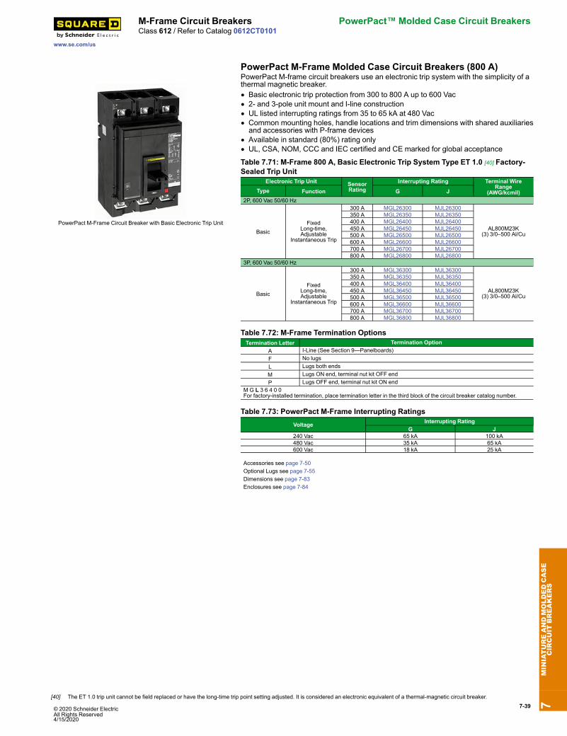
7-39
www.se.com/us
M-Frame Circuit Breakers PowerPact™ Molded Case Circuit BreakersClass 612 / Refer to Catalog 0612CT0101
PowerPact M-Frame Molded Case Circuit Breakers (800 A)
PowerPact M-Frame Circuit Breaker with Basic Electronic Trip Unit
PowerPact M-frame circuit breakers use an electronic trip system with the simplicity of athermal magnetic breaker.• Basic electronic trip protection from 300 to 800 A up to 600 Vac• 2- and 3-pole unit mount and I-line construction• UL listed interrupting ratings from 35 to 65 kA at 480 Vac• Common mounting holes, handle locations and trim dimensions with shared auxiliariesand accessories with P-frame devices
• Available in standard (80%) rating only• UL, CSA, NOM, CCC and IEC certified and CE marked for global acceptance
Table 7.71: M-Frame 800 A, Basic Electronic Trip System Type ET 1.0 [40] Factory-Sealed Trip Unit
Electronic Trip Unit SensorRating
Interrupting Rating Terminal WireRange
(AWG/kcmil)Type Function G J2P, 600 Vac 50/60 Hz
BasicFixed
Long-time,Adjustable
Instantaneous Trip
300 A MGL26300 MJL26300
AL800M23K(3) 3/0–500 Al/Cu
350 A MGL26350 MJL26350400 A MGL26400 MJL26400450 A MGL26450 MJL26450500 A MGL26500 MJL26500600 A MGL26600 MJL26600700 A MGL26700 MJL26700800 A MGL26800 MJL26800
3P, 600 Vac 50/60 Hz
BasicFixed
Long-time,Adjustable
Instantaneous Trip
300 A MGL36300 MJL36300
AL800M23K(3) 3/0–500 Al/Cu
350 A MGL36350 MJL36350400 A MGL36400 MJL36400450 A MGL36450 MJL36450500 A MGL36500 MJL36500600 A MGL36600 MJL36600700 A MGL36700 MJL36700800 A MGL36800 MJL36800
Table 7.72: M-Frame Termination OptionsTermination Letter Termination Option
A I-Line (See Section 9—Panelboards)F No lugsL Lugs both endsM Lugs ON end, terminal nut kit OFF endP Lugs OFF end, terminal nut kit ON end
M G L 3 6 4 0 0For factory-installed termination, place termination letter in the third block of the circuit breaker catalog number.
Table 7.73: PowerPact M-Frame Interrupting RatingsVoltage Interrupting Rating
G J240 Vac 65 kA 100 kA480 Vac 35 kA 65 kA600 Vac 18 kA 25 kA
Accessories see page 7-50Optional Lugs see page 7-55Dimensions see page 7-83Enclosures see page 7-84
7MINIATUREANDMOLDEDCASE
CIRCUIT
BREAKERS
[40] The ET 1.0 trip unit cannot be field replaced or have the long-time trip point setting adjusted. It is considered an electronic equivalent of a thermal-magnetic circuit breaker.
© 2020 Schneider ElectricAll Rights Reserved4/15/2020
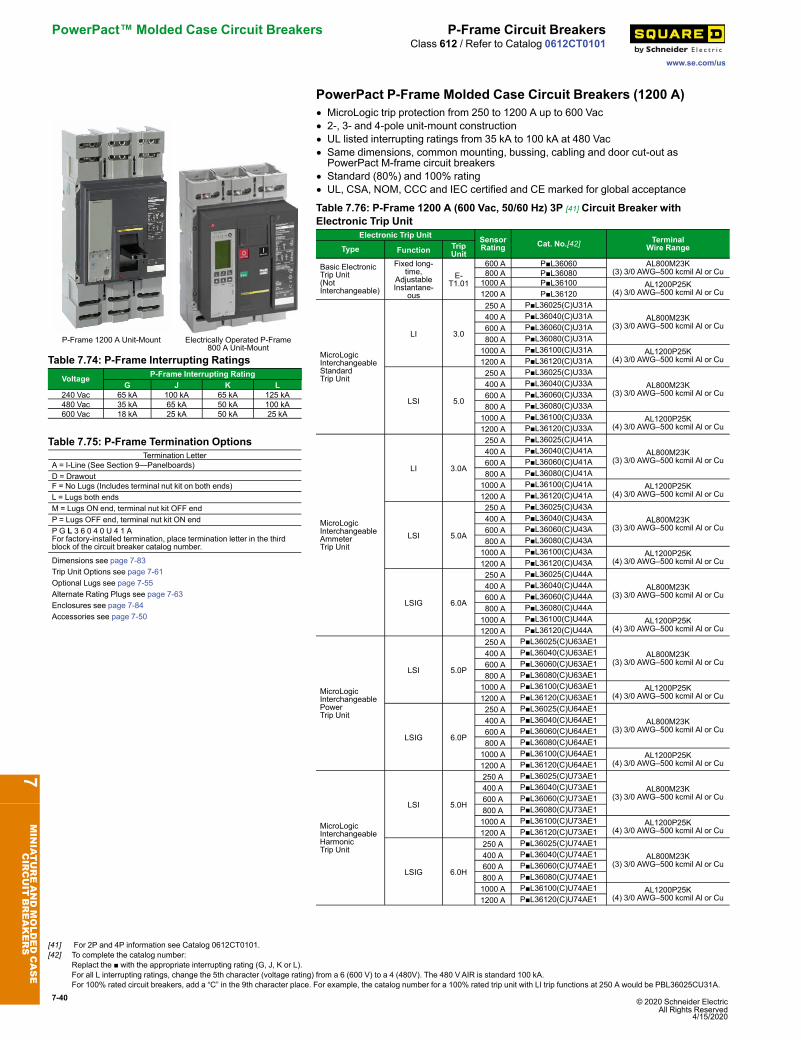
7-40 © 2020 Schneider Electric All Rights Reserved
4/15/2020
PowerPact™ Molded Case Circuit Breakers P-Frame Circuit Breakers
www.se.com/us
Class 612 / Refer to Catalog 0612CT0101
PowerPact P-Frame Molded Case Circuit Breakers (1200 A)
P-Frame 1200 A Unit-Mount Electrically Operated P-Frame800 A Unit-Mount
• MicroLogic trip protection from 250 to 1200 A up to 600 Vac• 2-, 3- and 4-pole unit-mount construction• UL listed interrupting ratings from 35 kA to 100 kA at 480 Vac• Same dimensions, common mounting, bussing, cabling and door cut-out asPowerPact M-frame circuit breakers
• Standard (80%) and 100% rating• UL, CSA, NOM, CCC and IEC certified and CE marked for global acceptance
Table 7.74: P-Frame Interrupting RatingsVoltage P-Frame Interrupting Rating
G J K L240 Vac 65 kA 100 kA 65 kA 125 kA480 Vac 35 kA 65 kA 50 kA 100 kA600 Vac 18 kA 25 kA 50 kA 25 kA
Table 7.75: P-Frame Termination OptionsTermination Letter
A = I-Line (See Section 9—Panelboards)D = DrawoutF = No Lugs (Includes terminal nut kit on both ends)L = Lugs both endsM = Lugs ON end, terminal nut kit OFF endP = Lugs OFF end, terminal nut kit ON endP G L 3 6 0 4 0 U 4 1 AFor factory-installed termination, place termination letter in the thirdblock of the circuit breaker catalog number.
Dimensions see page 7-83Trip Unit Options see page 7-61Optional Lugs see page 7-55Alternate Rating Plugs see page 7-63Enclosures see page 7-84Accessories see page 7-50
Table 7.76: P-Frame 1200 A (600 Vac, 50/60 Hz) 3P [41] Circuit Breaker withElectronic Trip Unit
Electronic Trip Unit SensorRating Cat. No.[42] Terminal
Wire RangeType Function TripUnit
Basic ElectronicTrip Unit(NotInterchangeable)
Fixed long-time,
AdjustableInstantane-
ous
E-T1.01
600 A P■L36060 AL800M23K(3) 3/0 AWG–500 kcmil Al or Cu 800 A P■L36080
1000 A P■L36100 AL1200P25K(4) 3/0 AWG–500 kcmil Al or Cu1200 A P■L36120
MicroLogicInterchangeableStandardTrip Unit
LI 3.0
250 A P■L36025(C)U31AAL800M23K
(3) 3/0 AWG–500 kcmil Al or Cu 400 A P■L36040(C)U31A 600 A P■L36060(C)U31A 800 A P■L36080(C)U31A1000 A P■L36100(C)U31A AL1200P25K
(4) 3/0 AWG–500 kcmil Al or Cu1200 A P■L36120(C)U31A
LSI 5.0
250 A P■L36025(C)U33AAL800M23K
(3) 3/0 AWG–500 kcmil Al or Cu 400 A P■L36040(C)U33A 600 A P■L36060(C)U33A 800 A P■L36080(C)U33A1000 A P■L36100(C)U33A AL1200P25K
(4) 3/0 AWG–500 kcmil Al or Cu1200 A P■L36120(C)U33A
MicroLogicInterchangeableAmmeterTrip Unit
LI 3.0A
250 A P■L36025(C)U41AAL800M23K
(3) 3/0 AWG–500 kcmil Al or Cu 400 A P■L36040(C)U41A 600 A P■L36060(C)U41A 800 A P■L36080(C)U41A1000 A P■L36100(C)U41A AL1200P25K
(4) 3/0 AWG–500 kcmil Al or Cu1200 A P■L36120(C)U41A
LSI 5.0A
250 A P■L36025(C)U43AAL800M23K
(3) 3/0 AWG–500 kcmil Al or Cu 400 A P■L36040(C)U43A 600 A P■L36060(C)U43A 800 A P■L36080(C)U43A1000 A P■L36100(C)U43A AL1200P25K
(4) 3/0 AWG–500 kcmil Al or Cu1200 A P■L36120(C)U43A
LSIG 6.0A
250 A P■L36025(C)U44AAL800M23K
(3) 3/0 AWG–500 kcmil Al or Cu 400 A P■L36040(C)U44A 600 A P■L36060(C)U44A 800 A P■L36080(C)U44A1000 A P■L36100(C)U44A AL1200P25K
(4) 3/0 AWG–500 kcmil Al or Cu1200 A P■L36120(C)U44A
MicroLogicInterchangeablePowerTrip Unit
LSI 5.0P
250 A P■L36025(C)U63AE1AL800M23K
(3) 3/0 AWG–500 kcmil Al or Cu 400 A P■L36040(C)U63AE1 600 A P■L36060(C)U63AE1 800 A P■L36080(C)U63AE11000 A P■L36100(C)U63AE1 AL1200P25K
(4) 3/0 AWG–500 kcmil Al or Cu1200 A P■L36120(C)U63AE1
LSIG 6.0P
250 A P■L36025(C)U64AE1AL800M23K
(3) 3/0 AWG–500 kcmil Al or Cu 400 A P■L36040(C)U64AE1 600 A P■L36060(C)U64AE1 800 A P■L36080(C)U64AE11000 A P■L36100(C)U64AE1 AL1200P25K
(4) 3/0 AWG–500 kcmil Al or Cu1200 A P■L36120(C)U64AE1
MicroLogicInterchangeableHarmonicTrip Unit
LSI 5.0H
250 A P■L36025(C)U73AE1AL800M23K
(3) 3/0 AWG–500 kcmil Al or Cu400 A P■L36040(C)U73AE1600 A P■L36060(C)U73AE1800 A P■L36080(C)U73AE11000 A P■L36100(C)U73AE1 AL1200P25K
(4) 3/0 AWG–500 kcmil Al or Cu1200 A P■L36120(C)U73AE1
LSIG 6.0H
250 A P■L36025(C)U74AE1AL800M23K
(3) 3/0 AWG–500 kcmil Al or Cu400 A P■L36040(C)U74AE1600 A P■L36060(C)U74AE1800 A P■L36080(C)U74AE11000 A P■L36100(C)U74AE1 AL1200P25K
(4) 3/0 AWG–500 kcmil Al or Cu1200 A P■L36120(C)U74AE1
7MINIATUREANDMOLDEDCASE
CIRCUIT
BREAKERS [41] For 2P and 4P information see Catalog 0612CT0101.
[42] To complete the catalog number:Replact the ■ with the appropriate interrupting rating (G, J, K or L).For all L interrupting ratings, change the 5th character (voltage rating) from a 6 (600 V) to a 4 (480V). The 480 VAIR is standard 100 kA.For 100% rated circuit breakers, add a “C” in the 9th character place. For example, the catalog number for a 100% rated trip unit with LI trip functions at 250 A would be PBL36025CU31A.

© 2020 Schneider Electric All Rights Reserved4/15/2020
7-41
www.se.com/us
R-Frame Circuit Breakers PowerPact™ Molded Case Circuit BreakersClass 612 / Refer to Catalog 0612CT0101
PowerPact R-Frame Molded Case Circuit Breakers (3000 A)
R-Frame Unit-Mount
Table 7.77: R-Frame Interrupting RatingsVoltage R-Frame Interrupting Rating
G J K L240 Vac 65 kA 100 kA 65 kA 125 kA480 Vac 35 kA 65 kA 65 kA 100 kA600 Vac 18 kA 25 kA 65 kA 50 kA
Table 7.78: R-Frame Termination OptionsTermination Letter
A = I-Line (See Section 9—Panelboards)F = No Lugs (Includes terminal nut kit on both ends)RJ F 3 6 3 0 0 U 4 1 AFor factory-installed termination, place termination letter in the thirdblock of the circuit breaker catalog number.
Dimensions see page 7-83Trip Unit Options see page 7-61Optional Lugs see page 7-55Alternate Rating Plugs see page 7-63Enclosures see page 7-84Accessories see page 7-50
• MicroLogic electronic trip protection from 600–3000A up to 600 Vac• 2-, 3- and 4-pole construction• UL listed interrupting ratings from 35 to 100 kA at 480Vac• Built-in Modbus protocol• Standard (80%) and 100% rating• UL, CSA, NOM, CCC and IEC certified and CE marked for global acceptance
Table 7.79: R-Frame 3000 A (600 Vac, 50/60 Hz) 3P Circuit Breaker with ElectronicTrip Unit
Electronic Trip Unit [43] SensorRating Cat. No. [44]Type Function Trip Unit
Basic Electronic TripUnit
(Not Interchangeable)
Fixedlong-time,Adjustable
InstantaneousET1.0I
1200 A R■F361201600 A R■F361602000 A R■F362002500 A R■F36250
MicroLogicInterchangeableStandard Trip Unit
LI 3.0
600 A R■F36060(C)U31A800 A R■F36080(C)U31A1000 A R■F36100(C)U31A1200 A R■F36120(C)U31A1600 A R■F36160(C)U31A2000 A R■F36200(C)U31A2500 A R■F36250(C)U31A3000 A R■F36300(C)U31A
LSI 5.0
600 A R■F36060(C)U33A800 A R■F36080(C)U33A1000 A R■F36100(C)U33A1200 A R■F36120(C)U33A1600 A R■F36160(C)U33A2000 A R■F36200(C)U33A2500 A R■F36250(C)U33A3000 A R■F36300(C)U33A
MicroLogicInterchangeableAmmeterTrip Unit
LI 3.0A
600 A R■F36060(C)U41A800 A R■F36080(C)U41A1000 A R■F36100(C)U41A1200 A R■F36120(C)U41A1600 A R■F36160(C)U41A2000 A R■F36200(C)U41A2500 A R■F36250(C)U41A3000 A R■F36300(C)U41A
LSI 5.0A
600 A R■F36060(C)U43A800 A R■F36080(C)U43A1000 A R■F36100(C)U43A1200 A R■F36120(C)U43A1600 A R■F36160(C)U43A2000 A R■F36200(C)U43A2500 A R■F36250(C)U43A3000 A R■F36300(C)U43A
LSIG 6.0A
600 A ■F36060(C)U44A800 A R■F36080(C)U44A1000 A R■F36100(C)U44A1200 A R■F36120(C)U44A1600 A R■F36160(C)U44A2000 A R■F36200(C)U44A2500 A R■F36250(C)U44A3000 A R■F36300(C)U44A
MicroLogicInterchangeable PowerTrip Unit
LSI 5.0P
600 A R■F36060(C)U63AE1800 A R■F36080(C)U63AE11000 A R■F36100(C)U63AE11200 A R■F36120(C)U63AE11600 A R■F36160(C)U63AE12000 A R■F36200(C)U63AE12500 A R■F36250(C)U63AE13000 A R■F36300(C)U63AE1
LSIG 6.0P
600 A R■F36060(C)U64AE1800 A R■F36080(C)U64AE11000 A R■F36100(C)U64AE11200 A R■F36120(C)U64AE11600 A R■F36160(C)U64AE12000 A R■F36200(C)U64AE12500 A R■F36250(C)U64AE13000 A R■F36300(C)U64AE1
MicroLogicInterchangeableHarmonic Trip Unit
LSI 5.0H600 A R■F36060(C)U73AE1
800 A R■F36080(C)U73AE1
7MINIATUREANDMOLDEDCASE
CIRCUIT
BREAKERS
[43] For 2P and 4P information see Catalog 0612CT0101.[44] To complete the catalog number: Replace the ■ with the appropriate interrupting rating (G, J, K or L).; For 100% rated circuit breakers, add a “C” in the 9th character place. For example, the
catalog number for a 100% rated trip unit with LI trip functions at 2500 A would be RGF36025CU31A.
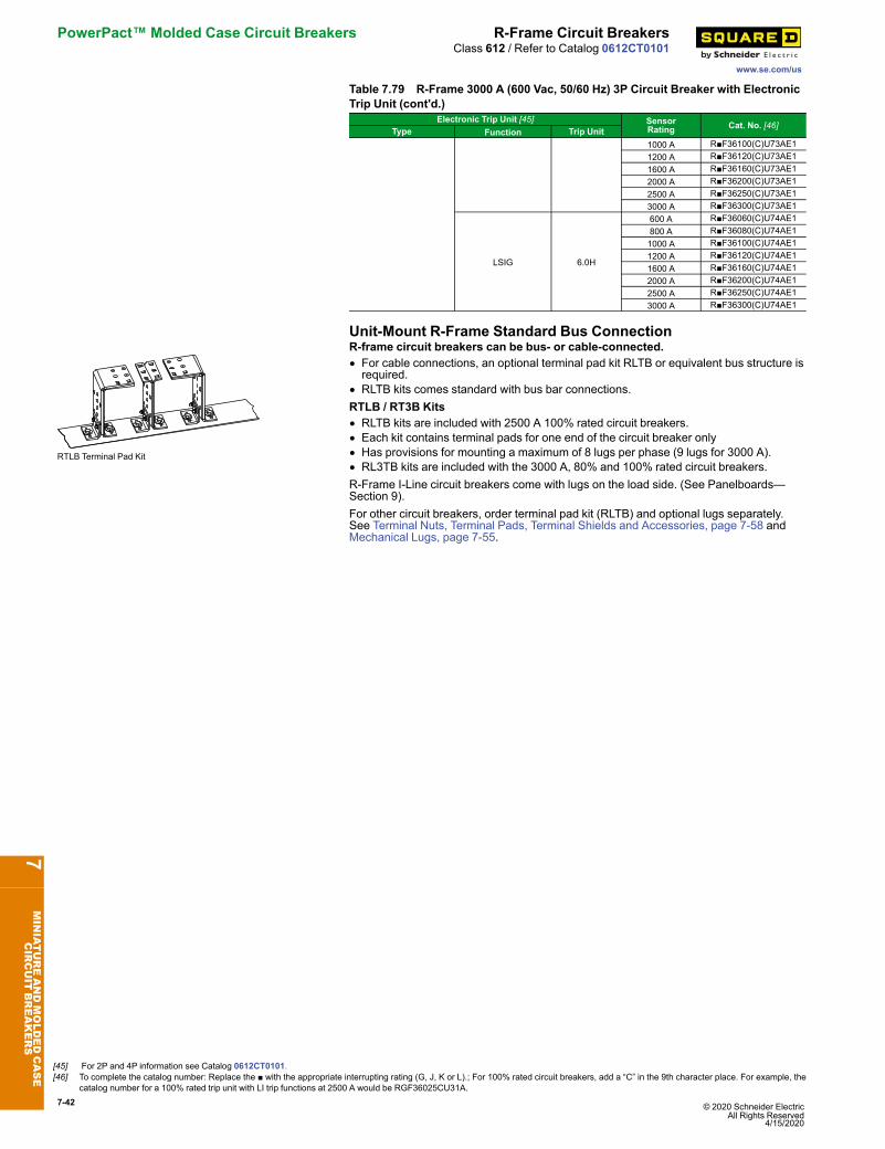
7-42 © 2020 Schneider Electric All Rights Reserved
4/15/2020
PowerPact™ Molded Case Circuit Breakers R-Frame Circuit Breakers
www.se.com/us
Class 612 / Refer to Catalog 0612CT0101
Table 7.79 R-Frame 3000 A (600 Vac, 50/60 Hz) 3P Circuit Breaker with ElectronicTrip Unit (cont'd.)
Electronic Trip Unit [45] SensorRating Cat. No. [46]Type Function Trip Unit1000 A R■F36100(C)U73AE11200 A R■F36120(C)U73AE11600 A R■F36160(C)U73AE12000 A R■F36200(C)U73AE12500 A R■F36250(C)U73AE13000 A R■F36300(C)U73AE1
LSIG 6.0H
600 A R■F36060(C)U74AE1800 A R■F36080(C)U74AE11000 A R■F36100(C)U74AE11200 A R■F36120(C)U74AE11600 A R■F36160(C)U74AE12000 A R■F36200(C)U74AE12500 A R■F36250(C)U74AE13000 A R■F36300(C)U74AE1
Unit-Mount R-Frame Standard Bus Connection
RTLB Terminal Pad Kit
R-frame circuit breakers can be bus- or cable-connected.• For cable connections, an optional terminal pad kit RLTB or equivalent bus structure isrequired.
• RLTB kits comes standard with bus bar connections.RTLB / RT3B Kits• RLTB kits are included with 2500 A 100% rated circuit breakers.• Each kit contains terminal pads for one end of the circuit breaker only• Has provisions for mounting a maximum of 8 lugs per phase (9 lugs for 3000 A).• RL3TB kits are included with the 3000 A, 80% and 100% rated circuit breakers.R-Frame I-Line circuit breakers come with lugs on the load side. (See Panelboards—Section 9).For other circuit breakers, order terminal pad kit (RLTB) and optional lugs separately.See Terminal Nuts, Terminal Pads, Terminal Shields and Accessories, page 7-58 andMechanical Lugs, page 7-55.
7MINIATUREANDMOLDEDCASE
CIRCUIT
BREAKERS
[45] For 2P and 4P information see Catalog 0612CT0101.[46] To complete the catalog number: Replace the ■ with the appropriate interrupting rating (G, J, K or L).; For 100% rated circuit breakers, add a “C” in the 9th character place. For example, the
catalog number for a 100% rated trip unit with LI trip functions at 2500 A would be RGF36025CU31A.
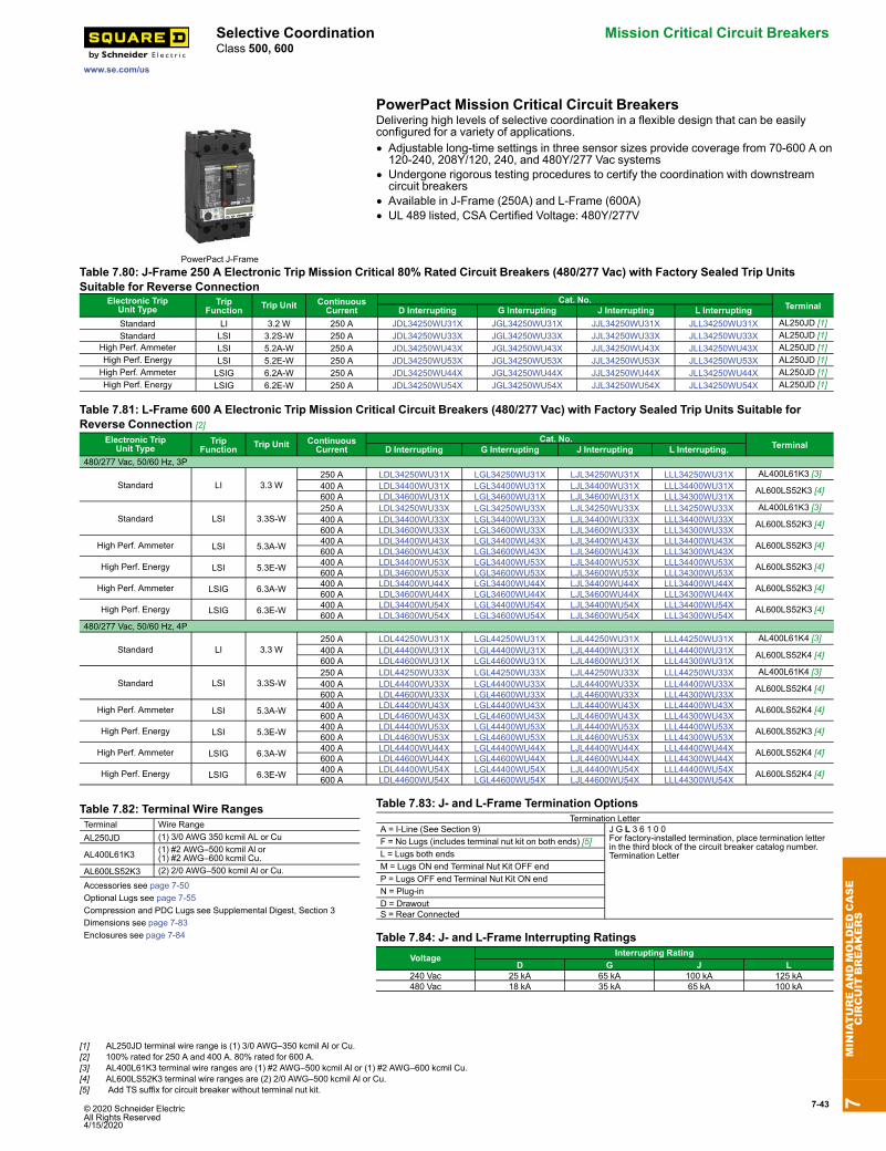
© 2020 Schneider Electric All Rights Reserved4/15/2020
7-43
www.se.com/us
Selective Coordination Mission Critical Circuit BreakersClass 500, 600
PowerPact Mission Critical Circuit Breakers
PowerPact J-Frame
Delivering high levels of selective coordination in a flexible design that can be easilyconfigured for a variety of applications.• Adjustable long-time settings in three sensor sizes provide coverage from 70-600 A on120-240, 208Y/120, 240, and 480Y/277 Vac systems
• Undergone rigorous testing procedures to certify the coordination with downstreamcircuit breakers
• Available in J-Frame (250A) and L-Frame (600A)• UL 489 listed, CSA Certified Voltage: 480Y/277V
Table 7.80: J-Frame 250 A Electronic Trip Mission Critical 80% Rated Circuit Breakers (480/277 Vac) with Factory Sealed Trip UnitsSuitable for Reverse Connection
Electronic TripUnit Type
TripFunction Trip Unit Continuous
CurrentCat. No.
TerminalD Interrupting G Interrupting J Interrupting L InterruptingStandard LI 3.2 W 250 A JDL34250WU31X JGL34250WU31X JJL34250WU31X JLL34250WU31X AL250JD [1]Standard LSI 3.2S-W 250 A JDL34250WU33X JGL34250WU33X JJL34250WU33X JLL34250WU33X AL250JD [1]
High Perf. Ammeter LSI 5.2A-W 250 A JDL34250WU43X JGL34250WU43X JJL34250WU43X JLL34250WU43X AL250JD [1]High Perf. Energy LSI 5.2E-W 250 A JDL34250WU53X JGL34250WU53X JJL34250WU53X JLL34250WU53X AL250JD [1]High Perf. Ammeter LSIG 6.2A-W 250 A JDL34250WU44X JGL34250WU44X JJL34250WU44X JLL34250WU44X AL250JD [1]High Perf. Energy LSIG 6.2E-W 250 A JDL34250WU54X JGL34250WU54X JJL34250WU54X JLL34250WU54X AL250JD [1]
Table 7.81: L-Frame 600 A Electronic Trip Mission Critical Circuit Breakers (480/277 Vac) with Factory Sealed Trip Units Suitable forReverse Connection [2]
Electronic TripUnit Type
TripFunction Trip Unit Continuous
CurrentCat. No.
TerminalD Interrupting G Interrupting J Interrupting L Interrupting.480/277 Vac, 50/60 Hz, 3P
Standard LI 3.3 W250 A LDL34250WU31X LGL34250WU31X LJL34250WU31X LLL34250WU31X AL400L61K3 [3]400 A LDL34400WU31X LGL34400WU31X LJL34400WU31X LLL34400WU31X AL600LS52K3 [4]600 A LDL34600WU31X LGL34600WU31X LJL34600WU31X LLL34300WU31X
Standard LSI 3.3S-W250 A LDL34250WU33X LGL34250WU33X LJL34250WU33X LLL34250WU33X AL400L61K3 [3]400 A LDL34400WU33X LGL34400WU33X LJL34400WU33X LLL34400WU33X AL600LS52K3 [4]600 A LDL34600WU33X LGL34600WU33X LJL34600WU33X LLL34300WU33X
High Perf. Ammeter LSI 5.3A-W 400 A LDL34400WU43X LGL34400WU43X LJL34400WU43X LLL34400WU43X AL600LS52K3 [4]600 A LDL34600WU43X LGL34600WU43X LJL34600WU43X LLL34300WU43X
High Perf. Energy LSI 5.3E-W 400 A LDL34400WU53X LGL34400WU53X LJL34400WU53X LLL34400WU53X AL600LS52K3 [4]600 A LDL34600WU53X LGL34600WU53X LJL34600WU53X LLL34300WU53X
High Perf. Ammeter LSIG 6.3A-W 400 A LDL34400WU44X LGL34400WU44X LJL34400WU44X LLL34400WU44X AL600LS52K3 [4]600 A LDL34600WU44X LGL34600WU44X LJL34600WU44X LLL34300WU44X
High Perf. Energy LSIG 6.3E-W 400 A LDL34400WU54X LGL34400WU54X LJL34400WU54X LLL34400WU54X AL600LS52K3 [4]600 A LDL34600WU54X LGL34600WU54X LJL34600WU54X LLL34300WU54X
480/277 Vac, 50/60 Hz, 4P
Standard LI 3.3 W250 A LDL44250WU31X LGL44250WU31X LJL44250WU31X LLL44250WU31X AL400L61K4 [3]400 A LDL44400WU31X LGL44400WU31X LJL44400WU31X LLL44400WU31X AL600LS52K4 [4]600 A LDL44600WU31X LGL44600WU31X LJL44600WU31X LLL44300WU31X
Standard LSI 3.3S-W250 A LDL44250WU33X LGL44250WU33X LJL44250WU33X LLL44250WU33X AL400L61K4 [3]400 A LDL44400WU33X LGL44400WU33X LJL44400WU33X LLL44400WU33X AL600LS52K4 [4]600 A LDL44600WU33X LGL44600WU33X LJL44600WU33X LLL44300WU33X
High Perf. Ammeter LSI 5.3A-W 400 A LDL44400WU43X LGL44400WU43X LJL44400WU43X LLL44400WU43X AL600LS52K4 [4]600 A LDL44600WU43X LGL44600WU43X LJL44600WU43X LLL44300WU43X
High Perf. Energy LSI 5.3E-W 400 A LDL44400WU53X LGL44400WU53X LJL44400WU53X LLL44400WU53X AL600LS52K3 [4]600 A LDL44600WU53X LGL44600WU53X LJL44600WU53X LLL44300WU53X
High Perf. Ammeter LSIG 6.3A-W 400 A LDL44400WU44X LGL44400WU44X LJL44400WU44X LLL44400WU44X AL600LS52K4 [4]600 A LDL44600WU44X LGL44600WU44X LJL44600WU44X LLL44300WU44X
High Perf. Energy LSIG 6.3E-W 400 A LDL44400WU54X LGL44400WU54X LJL44400WU54X LLL44400WU54X AL600LS52K4 [4]600 A LDL44600WU54X LGL44600WU54X LJL44600WU54X LLL44300WU54X
Table 7.82: Terminal Wire RangesTerminal Wire RangeAL250JD (1) 3/0 AWG 350 kcmil AL or Cu
AL400L61K3 (1) #2 AWG–500 kcmil Al or(1) #2 AWG–600 kcmil Cu.
AL600LS52K3 (2) 2/0 AWG–500 kcmil Al or Cu.
Accessories see page 7-50Optional Lugs see page 7-55Compression and PDC Lugs see Supplemental Digest, Section 3Dimensions see page 7-83Enclosures see page 7-84
Table 7.83: J- and L-Frame Termination OptionsTermination Letter
A = I-Line (See Section 9) J G L 3 6 1 0 0For factory-installed termination, place termination letterin the third block of the circuit breaker catalog number.Termination Letter
F = No Lugs (includes terminal nut kit on both ends) [5]L = Lugs both endsM = Lugs ON end Terminal Nut Kit OFF endP = Lugs OFF end Terminal Nut Kit ON endN = Plug-inD = DrawoutS = Rear Connected
Table 7.84: J- and L-Frame Interrupting RatingsVoltage Interrupting Rating
D G J L240 Vac 25 kA 65 kA 100 kA 125 kA480 Vac 18 kA 35 kA 65 kA 100 kA
7MINIATUREANDMOLDEDCASE
CIRCUIT
BREAKERS
[1] AL250JD terminal wire range is (1) 3/0 AWG–350 kcmil Al or Cu.[2] 100% rated for 250 A and 400 A. 80% rated for 600 A.[3] AL400L61K3 terminal wire ranges are (1) #2 AWG–500 kcmil Al or (1) #2 AWG–600 kcmil Cu.[4] AL600LS52K3 terminal wire ranges are (2) 2/0 AWG–500 kcmil Al or Cu.[5] Add TS suffix for circuit breaker without terminal nut kit.
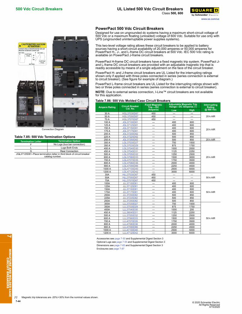
7-44 © 2020 Schneider Electric All Rights Reserved
4/15/2020
500 Vdc Circuit Breakers UL Listed 500 Vdc Circuit Breakers
www.se.com/us
Class 500, 600
PowerPact 500 Vdc Circuit Breakers
CAUTION/PRECAUCION/ATTENTION
Connect only as shown/Conectar solo asi/Brancher seulement comme suit:
oroou
- 600 V MAX.600 V MAX. +
Load/Carga/Charge
+
600 V MAX.-
Load/Carga/Charge
Connection Diagram
Designed for use on ungrounded dc systems having a maximum short-circuit voltage of500 Vdc or a maximum floating (unloaded) voltage of 600 Vdc. Suitable for use only withUPS (ungrounded uninterruptable power supplies systems).
This two-level voltage rating allows these circuit breakers to be applied to batterysources having a short-circuit availability of 20,000 amperes or 50,000 amperes forPowerPact H-, J-, and L-frame DC circuit breakers at 500 Vdc. IEC 500 Vdc rating isavailable on PowerPact J-frame circuit breakers.
PowerPact H-frame DC circuit breakers have a fixed magnetic trip system. PowerPact J-and L-frame DC circuit breakers are provided with an adjustable magnetic trip that isreadily accessible by means of a single adjustment on the face of the circuit breaker.PowerPact H- and J-frame circuit breakers are UL Listed for the interrupting ratingsshown only if applied with three poles connected in series (series connection is externalto circuit breaker). (See figure for example of diagram.)PowerPact L-frame circuit breakers are UL Listed for the interrupting ratings shown withtwo or three poles connected in series (series connection is external to circuit breaker).NOTE: Due to external series connection, I-Line™ circuit breakers are not availablefor this application.
Table 7.85: 500 Vdc Termination OptionsTermination Letter Termination Option
F No Lugs (bus bar connection)L Lugs Both EndsS Rear Connection
JGL37125D81–Place termination letter in third block of circuit breakercatalog number.
Table 7.86: 500 Vdc Molded Case Circuit Breakers
Ampere Rating Circuit BreakerCat. No.
Fixed MagneticTrip —DCAmperes
Adjustable Magnetic TripRange—DC Amperes [1]
InterruptingRating
@ 500 VdcLow High30 A HGL37030D87 450 — —
20 k AIR50 A HGL37050D87 450 — —70 A HGL37070D87 450 — —100 A JGL37100D81 — 400 600
20 k AIR
125 A JGL37125D81 — 400 600150 A JGL37150D81 — 400 600175 A JGL37175D81 — 400 600200 A JGL37200D82 — 500 850225 A JGL37225D82 — 500 850250 A JGL37250D82 — 500 850 20 k AIR300 A LGL37030D27 — 750 1500
20 k AIR
350 A LGL37035D29 — 875 1750400 A LGL37040D30 — 1000 2000450 A LGL37045D31 — 1125 2250500 A LGL37050D32 — 1250 2500600 A LGL37060D33 — 1500 3000700 A LGL47070D35 — 1750 3500800 A LGL47080D36 — 2000 4000900 A LGL47090D86 — 2250 45001000 A LGL47100D40 — 2500 50001200 A LGL47120D42 — 3000 600030A HLL37030D87 450 — —
50 k AIR50A HLL37050D87 450 — —70A HLL37070D87 450 — —100A JLL37100D81 — 400 600
50 k AIR
125A JLL37125D81 — 400 600150A JLL37150D81 — 400 600175A JLL37175D81 — 400 600200A JLL37200D82 — 500 850225A JLL37225D82 — 500 850250A JLL37250D82 — 500 850300A LLL37030D27 — 750 1500
50 k AIR
350A LLL37035D29 — 875 1750400A LLL37040D30 — 1000 200450 A LLL36045D31 — 1125 2250500 A LLL37050D32 — 1250 2500600 A LLL37060D33 — 1500 3000700 A LLL47070D35 — 1750 3500800 A LLL47080D36 — 2000 4000900 A LLL47090D86 — 2250 45001000 A LLL47100D40 — 2500 50001200 A LLL47120D42 — 3000 6000
Accessories see page 7-50 and Supplemental Digest Section 3Optional Lugs see page 7-55 and Supplemental Digest Section 3Dimensions see page 7-83 and Supplemental Digest Section 3Enclosures see page 7-87
7MINIATUREANDMOLDEDCASE
CIRCUIT
BREAKERS
[1] Magnetic trip tolerances are -20%/+30% from the nominal values shown.
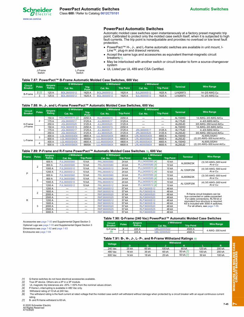
© 2020 Schneider Electric All Rights Reserved4/15/2020
7-45
www.se.com/us
PowerPact Automatic Switches Automatic SwitchesClass 600 / Refer to Catalog 0612CT0101
PowerPact Automatic Switches
J-FrameSwitch
L-FrameSwitch
Automatic molded case switches open instantaneously at a factory preset magnetic trippoint. Calibrated to protect only the molded case switch itself, when it is subjected to highfault currents. The trip point is nonadjustable and provides no overload or low level faultprotection.• PowerPact™ H-, J-, and L-frame automatic switches are available in unit mount, I-Line™, plug-in and drawout versions.
• Accept the same lugs and accessories as equivalent thermal-magnetic circuitbreakers[1].
• May be interlocked with another switch or circuit breaker to form a source-changeoversystem
• UL Listed per UL 489 and CSA Certified.
Table 7.87: PowerPact™ B-Frame Automatic Molded Case Switches, 600 VacCircuitBreaker Poles Ampere
RatingD Withstand G Withstand J Withstand
Terminal Wire RangeCat. No. Trip
Point Cat. No. Trip Point Cat. No. Trip Point
B-Frame2 [2] 125 A BDL26000S12 1625 A BGL26000S12 1625 A BJL26000S12 1625 A LV426973 14–2/0 AWG Cu3 125 A BDL36000S12 1625 A BGL36000S12 1625 A BJL36000S12 1625 A LV426974 14–2/0 AWG Cu
Table 7.88: H-, J-, and L-Frame PowerPact™ Automatic Molded Case Switches, 600 VacCircuitBreaker Poles Ampere
RatingG Withstand LWithstand RWithstand
Terminal Wire RangeCat. No. Trip
Point Cat. No. Trip Point Cat. No. Trip Point
H-FrameJ-Frame
2150 A HGL26000S15 [2] 2250 A HLL26000S15 2250 A — — AL150HD 14 AWG–3/0 AWG Al/Cu175 A JGL26000S17 3125 A JLL26000S17 3125 A — — AL175JD 4–4/0 AWG Al/Cu250 A JGL26000S25 3125 A JLL26000S25 3125 A — — AL250JD 3/0 AWG–350 kcmil Al/Cu
3150 A HGL36000S15 2250 A HLL36000S15 2250 A — — AL150HD 14 AWG–3/0 AWG Al/Cu175 A JGL36000S17 3125 A JLL36000S17 3125 A JRL36000S17 3125 A AL175JD 4–4/0 AWG Al/Cu250 A JGL36000S25 3125 A JLL36000S25 3125 A JRL36000S25 3125 A AL250JD 3/0 AWG–350 kcmil Al/Cu
L-Frame3 400 A LGL36000S40X 4800 A LLL36000S40X 4800 A LRL36000S40X 4800 A AL150HD AL600LS52K3
(2) 2/0 AWG–500 kcmil Al/Cu600 A LGL36000S60X 6600A LLL36000S60X 6600 A LRL36000S60X 6600 A AL250JD
4 400 A LGL46000S40X 4800 A LLL46000S40X 4800 A LRL46000S40X 4800 A AL150HD AL600LS52K4(2) 2/0 AWG–500 kcmil Al/Cu600 A LGL46000S60X 6600A LLL46000S60X 6600 A LRL46000S60X 6600 A AL250JD
Table 7.89: P-Frame and R-Frame PowerPact™ Automatic Molded Case Switches [3], 600 VacFrame Poles Ampere
RatingJ Withstand K Withstand LWithstand
Terminal Wire RangeCat. No. Trip Point Cat. No. Trip Point Cat. No. Trip Point
P
2
600 A PJL26000S60 10 kA PKL26000S60 24 kA PLL24000S60 [4] 10 kAAL800M23K (3) 3/0 AWG–500 kcmil
Al or Cu800 A PJL26000S80 10 kA PKL26000S80 24 kA PLL24000S80 [4] 10 kA1000 A PJL26000S10 10 kA PKL26000S10 24 kA PLL24000S10 [4] 10 kA
AL1200P25K (4) 3/0 AWG–500 kcmilAl or Cu1200 A PJL26000S12 10 kA PKL26000S12 24 kA PLL24000S12 [4] 10 kA
3
600 A PJL36000S60 10 kA PKL36000S60 24 kA PLL34000S60 [4] 10 kAAL800M23K (3) 3/0 AWG–500 kcmil
Al or Cu800 A PJL36000S80 10 kA PKL36000S80 24 kA PLL34000S80 [4] 10 kA1000 A PJL36000S10 10 kA PKL36000S10 24 kA PLL34000S10 [4] 10 kA
AL1200P25K (4) 3/0 AWG–500 kcmilAl or Cu1200 A PJL36000S12 10 kA PKL36000S12 24 kA PLL34000S12 [4] 10 kA
R
2
1200 A — — RKF26000S12 57 kA RLF26000S12 48 kA
R-frame circuit breakers can bebus-connected or cable-connected.For cable connections, RLTB kit orequivalent bus structure is required.Kit is included with 3000 A switches.
For all others, see page 7-58.
1600 A — — RKF26000S16 57 kA RLF26000S16 48 kA2000 A — — RKF26000S20 57 kA RLF26000S20 48 kA2500 A — — RKF26000S25 57 kA RLF26000S25 48 kA
3
1200 A — — RKF36000S12 57 kA RLF36000S12 48 kA1600 A — — RKF36000S16 57 kA RLF36000S16 48 kA2000 A — — RKF36000S20 57 kA RLF36000S20 48 kA2500 A — — RKF36000S25 57 kA RLF36000S25 48 kA3000 A — — RKF36000S30 57 kA RLF36000S30 48 kA
Accessories see page 7-50 and Supplemental Digest Section 3Optional Lugs see page 7-55 and Supplemental Digest Section 3Dimensions see page 7-82 and page 7-83Enclosures see page 7-84
Table 7.90: Q-Frame (240 Vac) PowerPact™ Automatic Molded Case SwitchesCircuitBreaker Poles Ampere
RatingJ Withstand Wire Range
Cat. No. Trip PointQ-Frame
[5]2 225 A QBL22000S22 4500 A 4 AWG–300 kcmil3 225 A QBL32000S22 4500 A
Table 7.91: B-, H-, J-, L- P-, and R-Frame Withstand Ratings [6]
Voltage WithstandD G J K L R
240 Vac 25 kA 65 kA 100 kA 65 kA 125 kA 200 kA480 Vac 18 kA 35 kA 65 kA 50 kA [7] 100 kA 200 kA600 Vac 14 kA 18 kA 25 kA 50 kA [7] 50 kA 100 kA
7MINIATUREANDMOLDEDCASE
CIRCUIT
BREAKERS
[1] Q-frame switches do not have electrical accessories available.[2] True 2P device. Others are a 2P in a 3P module.[3] UL magnetic trip tolerances are -20% / +30% from the nominal values shown.[4] P-frame L-interrupting is available in 480 Vac only.[5] Withstand rating of 10 kA at 240 Vac.[6] The withstand rating is the fault current at rated voltage that the molded case switch will withstand without damage when protected by a circuit breaker with an equal continuous current
rating.[7] B- and R-frame withstand is 65 kA.
7-46 © 2020 Schneider Electric All Rights Reserved
4/15/2020
Motor Circuit Protectors Instantaneous Trip Circuit Breakers
www.se.com/us
Class 600 / Refer to Catalog 0612CT0101
Instantaneous Trip Circuit Breakers for Motor ProtectionApplicationsAdjustable instantaneous-trip circuit breakers are intended for use in combination withmotor starters with overload relays for the protection of motor circuits from short circuits.Other specific applications include rectifiers and resistance welders. These circuitbreakers contain a magnetic trip element in each pole with the trip point adjustable fromthe front. Interrupting ratings are determined by testing the instantaneous-trip circuitbreakers in combination with a contactor and overload relay.Select instantaneous-trip circuit breakers as follows:This selection table is suitable for motors, other than NEMA Design E, with locked-rotorindicating code letters per NEC® Table 430.7 (b) as follows:
Table 7.92: Locked-Rotor Indicating CodesHorsepower Motor Code Letter1/2 or less3/4 to 1-1/2
2 to 35 to 2530 to 125
150 or more
A–LA–KA–JA–HA–GA–F
• For other motors order a special thermal-magnetic circuit breaker with magnetic tripsettings for the specific motor— specify motor horsepower, voltage, frequency, full-load current and code letter or locked rotor current.
• Determine motor hp rating from the motor nameplate.• Refer to the tables and select an instantaneous-trip circuit breaker with an ampererating recommended for the hp and voltage involved.
• Select an adjustable trip setting of at least 800%, not to exceed 1300%, of the motorfull-load amperes (FLA) for other than Design E motors. For Design E motors, selectan adjustable trip setting of at least 1100% not to exceed 1700% of FLA.
• The NEC 1300% maximum setting may be inadequate for instantaneous-trip circuitbreakers to withstand current surges typical of the magnetization current ofautotransformer type reduced voltage starters, or open transition wye-delta startersduring transfer from “start” to “run,” constant hp multi-speed motors, and motorslabeled “high efficiency.” Select thermal-magnetic circuit breakers for thoseapplications.
• Part-winding motors, per NEC 430.4, should have two circuit breakers selected fromthe above at not more than one half the allowable trip setting for the horsepowerrating. The two circuit breakers should operate simultaneously as a disconnectingmeans per NEC 430.103.
• Based on NEC 430.52 and NEC Table 430.250.
7MINIATUREANDMOLDEDCASE
CIRCUIT
BREAKERS
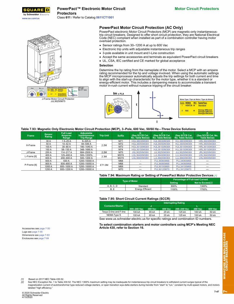
© 2020 Schneider Electric All Rights Reserved4/15/2020
7-47
www.se.com/us
PowerPact™ Electronic Motor CircuitProtectors
Motor Circuit Protectors
Class 611 / Refer to Catalog 0611CT1001
PowerPact Motor Circuit Protection (AC Only)
Standard
Energy EfficientEnergie EfficaceEnergia Eficiente
Standard
Energy Efficie nt
Energie Effi cace
Energia Efici ente
J-Frame Motor Circuit ProtectorJJL36250M75
PowerPact electronic Motor Circuit Protectors (MCP) are magnetic-only instantaneous-trip circuit breakers. Designed to offer short circuit protection, they are National ElectricalCode (NEC) compliant when installed as part of a combination controller having motoroverload protection.• Sensor ratings from 30–1200 A at up to 600 Vac• Electronic trip units with adjustable instantaneous trip ranges• 3-pole available in unit mount and I-Line construction• Accept the same accessories and terminals as equivalent PowerPact circuit breakers• UL, CSA, IEC certified and CE marked for global acceptanceSelectionDetermine the hp rating from the nameplate of the motor. Select a MCP with an ampererating recommended for the hp and voltage involved. When using the automatic settingsthe MCP microprocessor automatically adjusts the trip settings for both current and timeto align with the start-up characteristic for the motor type, whether it is a standard orenergy-efficient motor. This includes a dampening means to accommodate a transientmotor in-rush current without nuisance tripping of the circuit breaker.
I
t Standard
Energy EfficientEnergie Efficace
Motor Type / Tipo de Motor / Type de Moteur
Energia Eficiente
Table 7.93: Magnetic Only Electronic Motor Circuit Protection (MCP), 3–Pole, 600 Vac, 50/60 Hz—Three Device Solutions
Frame SensorRating
Full LoadAmperesRange
AdjustableInstantaneousTrip Range
Trip Unit SuffixG
(See SCCR Cat.No. Table Below)
J(See SCCR Cat.No. Table Below)
L(See SCCR Cat.No. Table Below)
R(See SCCR Cat. No.
Table Below)
H-Frame
30 A 1.5–25 A 9–325 A
2.2M
M71 HGL36030M38X HJL36030M38X HLL36030M38X HRL36030M38X50 A 14–42 A 84–546 A M72 HGL36050M38X HJL36050M38X HLL36050M38X HRL36050M38X100 A 30–80 A 180–1040 A M73 HGL36100M38X HJL36100M38X HJL36100M38X HRL36100M38X150 A 58–130 A 348–1690 A M74 HGL36150M38X HJL36150M38X HLL36150M38X HRL36150M38X
J-Frame 250 A 114–217 A 684–2500 A 2.2M M75 JGL36250M38X JJL36250M38X JLL36250M38X JRL36250M38X
L-Frame [6] 400 A 125–400 A 500–1200% 2.3M M37X LGL36400M38X LJL36400M38X LLL36400M38X LRL36400M38X600 A 200–600 A 500–1200 A M37X LGL36600M38X LJL36600M38X LLL36600M38X LRL36600M38X
P-Frame [6]
600 A 630 A 1200–10000 A
ET1.0M
M68 - PJL36060M68 PLL34060M68 —800 A 600–800 A 1200–10000 A M68 — PJL36080M68 PLL34080M68 —1000 A 600–1000 A 1200–10000 A M69 — PJL36100M69 PLL34100M69 —1200 A 600–1200 A 1200–10000 A M70 — PJL36120M70 PLL34120M70 —
Table 7.94: Maximum Rating or Setting of PowerPact Motor Protective Devices [1]
Type of MotorPercentage of Full-load Current
Setting Not to Exceed[2]A, B, C, D Standard 800% 1300%
B, E Energy Efficient 1100% 1700%
Table 7.95: Short Circuit Current Ratings (SCCR)
Contactor/StarterInterrupting Rating
J L200–240 Vac 480 Vac 600 Vac 200–240 Vac 480 Vac 600 Vac
Tesys D-line and F-line 100 kA 65 kA 25 kA 125 kA 100 kA 50 kANEMAType S 100 kA 65 kA 25 kA 125 kA 100 kA 50 kA
See www.us.schneider-electric.us for specific ratings and combination ID numbers.
Accessories see page 7-50Lugs see page 7-55Dimensions see page 7-83Enclosures see page 7-84
To select combination starters and motor controllers using MCP’s Meeting NECArticle 430, refer to Section 16.
7MINIATUREANDMOLDEDCASE
CIRCUIT
BREAKERS
[1] Based on 2017 NEC Table 430.52.[2] See NEC Exception No. 1 to Table 430.52. The NEC 1300% maximum setting may be inadequate for instantaneous trip circuit breakers to withstand current surges typical of the
magnetization current of autotransformer type reduced voltage starters, or open transition wye-delta starters during transfer from “start” to “run,” constant hp multi-speed motors, and motorslabeled “high efficiency.”
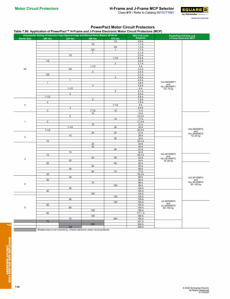
7-48 © 2020 Schneider Electric All Rights Reserved
4/15/2020
Motor Circuit Protectors H-Frame and J-Frame MCP Selector
www.se.com/us
Class 611 / Refer to Catalog 0611CT1001
PowerPact Motor Circuit ProtectorsTable 7.96: Application of PowerPact™ H-Frame and J-Frame Electronic Motor Circuit Protectors (MCP)
Horsepower Rating of Induction-Type Squirrel-Cage and Wound-Rotor Motors 3Ø 60 Hz NEC Full LoadAmperes
PowerPact H-Frame andJ-Frame Electronic MCPStarter Size 200 Vac 230 Vac 480 Vac 575 Vac
00
1/2 0.9 A
HJL36030M71and
HLL36030M711/2–10 hp
1/2 1.1 A3/4 1.3 A
3/4 1 1.7 A1 2.1 A
1/2 2.2 A1-1/2 2.4 A
1/2 2.5 A2 2.7 A
1-1/2 3 A3/4 3.2 A
2 3.4 A3/4 3.7 A
3 3.9 A1 4.2 A
1 4.8 A3 4.8 A
1-1/2 6 A5 6.1 A
2 6.8 A1-1/2 6.9 A
0
5 7.6 A2 7.8 A
7-1/2 9 A3 9.6 A
3 7-1/2 10 11 A
1
10 14 A
HJL36050M72and
HLL36050M7210–25 hp
5 15.2 A15 17 A
5 17.5 A15 21 A
7-1/2 20 22 A7-1/2 25.3 A
2
20 25 27 A10 28 A
30 32 A
HJL36100M73and
HLL36100M7315–50 hp
10 32.2 A
3
25 34 A30 40 A
40 41 A15 42 A
15 48.3 A40 50 52 A
20 54 A20 60 62 A
HJL36150M74and
HLL36150M7430–100 hp
50 65 A25 68 A
60 75 77 A25 78.2 A
4
30 80 A30 92 A
75 96 A100 99 A
40 104 A40 120 A
JJL36250M75and
JLL36250M7550–150 hp
100 124 A
5
125 125 A50 130 A
150 144 A50 150 A
60 154 A125 156 A
60 177.1 A150 180 A
75 200 192 A75 221 A
200 240 A100 248 A
Shaded area is not covered by J-frame electronic motor circuit protector.
7MINIATUREANDMOLDEDCASE
CIRCUIT
BREAKERS
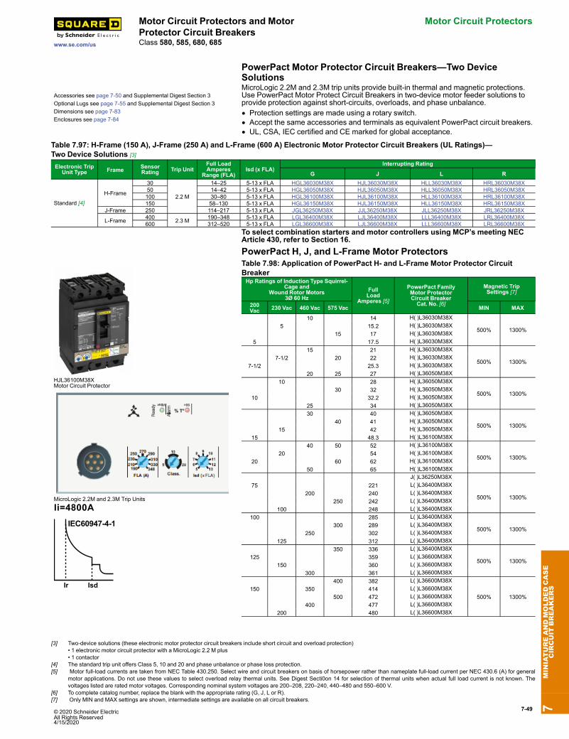
© 2020 Schneider Electric All Rights Reserved4/15/2020
7-49
www.se.com/us
Motor Circuit Protectors and MotorProtector Circuit Breakers
Motor Circuit Protectors
Class 580, 585, 680, 685
PowerPact Motor Protector Circuit Breakers—Two DeviceSolutions
Accessories see page 7-50 and Supplemental Digest Section 3Optional Lugs see page 7-55 and Supplemental Digest Section 3Dimensions see page 7-83Enclosures see page 7-84
MicroLogic 2.2M and 2.3M trip units provide built-in thermal and magnetic protections.Use PowerPact Motor Protect Circuit Breakers in two-device motor feeder solutions toprovide protection against short-circuits, overloads, and phase unbalance.• Protection settings are made using a rotary switch.• Accept the same accessories and terminals as equivalent PowerPact circuit breakers.• UL, CSA, IEC certified and CE marked for global acceptance.
Table 7.97: H-Frame (150 A), J-Frame (250 A) and L-Frame (600 A) Electronic Motor Protector Circuit Breakers (UL Ratings)—Two Device Solutions [3]
Electronic TripUnit Type Frame Sensor
Rating Trip UnitFull LoadAmperes
Range (FLA)Isd (x FLA)
Interrupting Rating
G J L R
Standard [4]
H-Frame
30
2.2 M
14–25 5-13 x FLA HGL36030M38X HJL36030M38X HLL36030M38X HRL36030M38X50 14–42 5-13 x FLA HGL36050M38X HJL36050M38X HLL36050M38X HRL36050M38X100 30–80 5-13 x FLA HGL36100M38X HJL36100M38X HLL36100M38X HRL36100M38X150 58–130 5-13 x FLA HGL36150M38X HJL36150M38X HLL36150M38X HRL36150M38X
J-Frame 250 114–217 5-13 x FLA JGL36250M38X JJL36250M38X JLL36250M38X JRL36250M38X
L-Frame 400 2.3 M 190–348 5-13 x FLA LGL36400M38X LJL36400M38X LLL36400M38X LRL36400M38X600 312–520 5-13 x FLA LGL36600M38X LJL36600M38X LLL36600M38X LRL36600M38X
To select combination starters and motor controllers using MCP’s meeting NECArticle 430, refer to Section 16.PowerPact H, J, and L-Frame Motor Protectors
HJL36100M38XMotor Circuit Protector
MicroLogic 2.2M and 2.3M Trip Units
Table 7.98: Application of PowerPact H- and L-Frame Motor Protector CircuitBreakerHp Ratings of Induction Type Squirrel-
Cage andWound Rotor Motors
3Ø 60 HzFullLoad
Amperes [5]
PowerPact FamilyMotor ProtectorCircuit BreakerCat. No. [6]
Magnetic TripSettings [7]
200Vac 230 Vac 460 Vac 575 Vac MIN MAX
10 14 H( )L36030M38X
500% 1300%5 15.2 H( )L36030M38X
15 17 H( )L36030M38X5 17.5 H( )L36030M38X
15 21 H( )L36030M38X
500% 1300%7-1/2 20 22 H( )L36030M38X
7-1/2 25.3 H( )L36030M38X20 25 27 H( )L36050M38X
10 28 H( )L36050M38X
500% 1300%30 32 H( )L36050M38X
10 32.2 H( )L36050M38X25 34 H( )L36050M38X30 40 H( )L36050M38X
500% 1300%40 41 H( )L36050M38X
15 42 H( )L36050M38X15 48.3 H( )L36100M38X
40 50 52 H( )L36100M38X
500% 1300%20 54 H( )L36100M38X
20 60 62 H( )L36100M38X50 65 H( )L36100M38X
J( )L36250M38X75 221 L( )L36400M38X
500% 1300%200 240 L( )L36400M38X
250 242 L( )L36400M38X100 248 L( )L36400M38X
100 285 L( )L36400M38X
500% 1300%300 289 L( )L36400M38X
250 302 L( )L36400M38X125 312 L( )L36400M38X
350 336 L( )L36400M38X
500% 1300%125 359 L( )L36600M38X
150 360 L( )L36600M38X300 361 L( )L36600M38X
400 382 L( )L36600M38X
500% 1300%150 350 414 L( )L36600M38X
500 472 L( )L36600M38X400 477 L( )L36600M38X
200 480 L( )L36600M38X
7MINIATUREANDMOLDEDCASE
CIRCUIT
BREAKERS
[3] Two-device solutions (these electronic motor protector circuit breakers include short circuit and overload protection)• 1 electronic motor circuit protector with a MicroLogic 2.2 M plus• 1 contactor
[4] The standard trip unit offers Class 5, 10 and 20 and phase unbalance or phase loss protection.[5] Motor full-load currents are taken from NEC Table 430.250. Select wire and circuit breakers on basis of horsepower rather than nameplate full-load current per NEC 430.6 (A) for general
motor applications. Do not use these values to select overload relay thermal units. See Digest Secti0on 14 for selection of thermal units when actual full load current is not known. Thevoltages listed are rated motor voltages. Corresponding nominal system voltages are 200–208, 220–240, 440–480 and 550–600 V.
[6] To complete catalog number, replace the blank with the appropriate rating (G, J, L or R).[7] Only MIN and MAX settings are shown, intermediate settings are available on all circuit breakers.
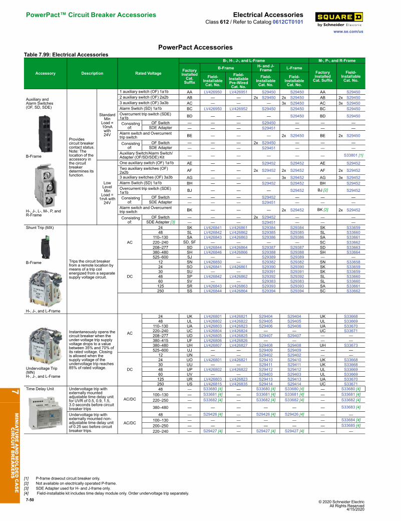
7-50 © 2020 Schneider Electric All Rights Reserved
4/15/2020
PowerPact™ Circuit Breaker Accessories Electrical Accessories
www.se.com/us
Class 612 / Refer to Catalog 0612CT0101
PowerPact AccessoriesTable 7.99: Electrical Accessories
Accessory Description Rated Voltage
B-, H-, J-, and L-Frame M-, P-, and R-Frame
FactoryInstalledCat.Suffix
B-Frame H- and J-Frame L-Frame
FactoryInstalledCat. Suffix
Field-InstallableCat. No.
Field-InstallableCat. No.
Field-InstallablePre-WiredCat. No.
Field-InstallableCat. No.
Field-InstallableCat. No.
Auxiliary andAlarm Switches(OF, SD, SDE)
B-Frame
H-, J-, L-, M-, P, andR-Frame
Providescircuit breakercontact status.Note: Thelocation of theaccessory inthe circuitbreakerdetermines itsfunction.
StandardMin
Load =10mAwith24V
1 auxiliary switch (OF) 1a1b AA LV426950 LV426951 S29450 S29450 AA S294502 auxiliary switch (OF) 2a2b AB — — 2x S29450 2x S29450 AB 2x S294503 auxiliary switch (OF) 3a3b AC — — — 3x S29450 AC 3x S29450Alarm Switch (SD) 1a1b BC LV426950 LV426952 S29450 S29450 BC S29450Overcurrent trip switch (SDE)1a1b BD — — — S29450 BD S29450
Consistingof:
OF Switch — — — S29450 — — —SDE Adapter — — — S29451 — — —
Alarm switch and Overcurrenttrip switch BE — — — 2x S29450 BE 2x S29450
Consistingof:
OF Switch — — — 2x S29450 — — —SDE Adapter — — — S29451 — — —
Auxiliary Switch/Alarm Switch/Adapter (OF/SD/SDE) Kit — — — — — — S33801 [1]
LowLevelMin
Load =1mA with24V
One auxiliary switch (OF) 1a1b AE — — S29452 S29452 AE S29452Two auxiliary switches (OF)2a2b AF — — 2x S29452 2x S29452 AF 2x S29452
3 auxiliary switches (OF) 3a3b AG — — — 3x S29452 AG 3x S29452Alarm Switch (SD) 1a1b BH — — S29452 S29452 BH S29452Overcurrent trip switch (SDE)1a1b BJ — — — S29452 BJ [2] S29452
Consistingof:
OF Switch — — — S29452 — — —SDE Adapter — — — S29451 — — —
Alarm switch and Overcurrenttrip switch BK — — — 2x S29452 BK [2] 2x S29452
Consistingof:
OF Switch — — — 2x S29452 — — —SDE Adapter [3] — — — S29451 — — —
Shunt Trip (MX)
B-Frame
H-, J-, and L-Frame
Trips the circuit breakerfrom a remote location bymeans of a trip coilenergized from a separatesupply voltage circuit.
AC
24 SK LV426841 LV426861 S29384 S29384 SK S3365948 SL LV426842 LV426862 S29385 S29385 SL S33660
110–130 SA LV426843 LV426863 S29386 S29386 SA S33661220–240 SD, SF — — — — SC S33662208–277 SD LV426844 LV426864 S29387 S29387 SD S33663380–480 SH LV426846 LV426866 S29388 S29388 SH S33664525–600 SJ — — S29389 S29389 — —
DC
12 SN LV426850 — S29382 S29382 SN S3365824 SO LV426841 LV426861 S29390 S29390 SK S3365930 SU — — S29391 S29391 SK S3365948 SP LV426842 LV426862 S29392 S29392 SL S3366060 SV — — S29383 S29383 SL S33660125 SR LV426843 LV426863 S29393 S29393 SA S33661250 SS LV426844 LV426864 S29394 S29394 SC S33662
Undervoltage Trip(MN)H-, J-, and L-Frame
Instantaneously opens thecircuit breaker when theunder-voltage trip supplyvoltage drops to a valuebetween 35% and 70% ofits rated voltage. Closingis allowed when thesupply voltage of theundervoltage trip reaches85% of rated voltage.
AC
24 UK LV426801 LV426821 S29404 S29404 UK S3366848 UL LV426802 LV426822 S29405 S29405 UL S33669
110–130 UA LV426803 LV426823 S29406 S29406 UA S33670220–240 UC LV426804 LV426824 — — UC S33671208–277 UD LV426805 LV426825 S29407 S29407 — —380–415 UF LV426806 LV426826 — — — —380–480 UH LV426807 LV426827 S29408 S29408 UH S33673525–600 UJ — — S29409 S29409 — —
DC
12 UN — — S29402 S29402 — —24 UO LV426801 LV426821 S29410 S29410 UK S3366830 UU — — S29411 S29411 UK S3366848 UP LV426802 LV426822 S29412 S29412 UL S3366960 UV — — S29403 S29403 UL S33669125 UR LV426803 LV426823 S29413 S29413 UA S33670250 US LV426815 LV426835 S29414 S29414 UC S33671
Time Delay Unit Undervoltage trip withexternally mountedadjustable time delay unitfor UVR of 0.5, 0.9, 1.5,3.0 seconds before circuitbreaker trips
AC/DC
48 — S33680 [4] — S33680 [4] S33680 [4] — S33680 [4]100–130 — S33681 [4] — S33681 [4] S33681 [4] — S33681 [4]220–250 — S33682 [4] — S33682 [4] S33682 [4] — S33682 [4]
380–480 — — — — — — S33683 [4]
Undervoltage trip withexternally mounted non-adjustable time delay unitof 0.25 sec before circuitbreaker trips.
AC/DC
48 — S29426 [4] — S29426 [4] S29426 [4] — —100–130 — — — — — — S33684 [4]200–250 — — — — — — S33685 [4]220–240 — S29427 [4] — S29427 [4] S29427 [4] — —
7MINIATUREANDMOLDEDCASE
CIRCUIT
BREAKERS
[1] P-frame drawout circuit breaker only.[2] Not available on electrically operated P-frame.[3] SDE Adapter used for H- and J-frame only.[4] Field-installable kit includes time delay module only. Order undervoltage trip separately.
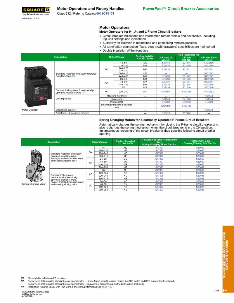
© 2020 Schneider Electric All Rights Reserved4/15/2020
7-51
www.se.com/us
Motor Operators and Rotary Handles PowerPact™ Circuit Breaker AccessoriesClass 612 / Refer to Catalog 0612CT0101
Motor OperatorsMotor Operators for H-, J-, and L-Frame Circuit Breakers• Circuit-breaker indications and information remain visible and accessible, includingtrip-unit settings and indications
• Suitability for isolation is maintained and padlocking remains possible• All termination connection (fixed, plug-in/withdrawable) possibilities are maintained• Double insulation of the front face
Description Rated Voltage Factory InstalledCat. No. Suffix
Field-Installable KitH-Frame [5]Cat. No.
J-FrameCat. No.
L-Frame 600 ACat. No.
Motor Operator
Standard motor for electrically-operatedcircuit breakers [6]
AC
48–60 ML S29440 S31548 S432639110–130 MA S29433 S31540 S432640208–277220–240 MD S29434 S31541 S432641
380–415 MF — — S432642440–480 MH S29435 S31542 S432647
DC
24–30 MO S29436 S31543 S43264348–60 MV S29437 S31544 S432644110–130 MR S29438 S31545 S432645250 MS S29439 S31546 S432646
Communicating motor for electrically-operated circuit breakers [7] AC 220–240 NC S429441 S431549 S432652
Locking deviceMounting hardware — — — S32649
Ronis lock — S41940 S41940 S41940Profalux lock — S42888 S42888 S42888
Mounting hardware plus Ronislock — S429449 S429449 —
Operations counter — — — S32648Adapter for I-Line circuit breaker — S37420 S37420 —
Spring-Charging Motors for Electrically-Operated P-Frame Circuit BreakersAutomatically charges the spring mechanism for closing the P-frame circuit breaker andalso recharges the spring mechanism when the circuit breaker is in the ON position.Instantaneous reclosing of the circuit breaker is thus possible following circuit breakeropening.
Description Rated Voltage Factory InstalledCat. No. Suffix
P-Frame (For Field ReplacementOnly)
Spring Charging Motor Cat. No.Replacement Coils
Opening/Closing Coil Cat. No.
Spring-Charging Motor
Standard motor for electrically-operated circuit breakers.Factory-installed includes motorand opening/closing coils.
AC
48 ML S47391 S33660100–130 MA S47395 S33661220–240 MC S47396 S33662380–415 MF S47398 S33664
DC
24–30 MO S47390 S3365948–60 MV S47391 S33660110–130 MR S47392 S33661200–250 MS S47393 S33662
Communicating motormechanism for electricallyoperated circuit breakers.Factory-installed includes motorand opening/closing coils.
AC
48 NL S47391 S33034100–130 NA S47395 S33035220–240 NC S47396 S33036380–415 NF S47398 S33038
DC
24–30 NO S47390 S3303348–60 NV S47391 S33034110–130 NR S47392 S33035200–250 NS S47393 S33036
7MINIATUREANDMOLDEDCASE
CIRCUIT
BREAKERS
[5] Not available in H-frame 2P modules.[6] Factory and field-installed standard motor operators for H- and J-frame circuit breakers require the SDE switch and SDE adapter (both included).
Factory and field-installed standard motor operators for L-frame circuit breakers require the SDE switch (included).[7] Installation requires BSCM with NSX Cord. For ordering information see page 7-63 .
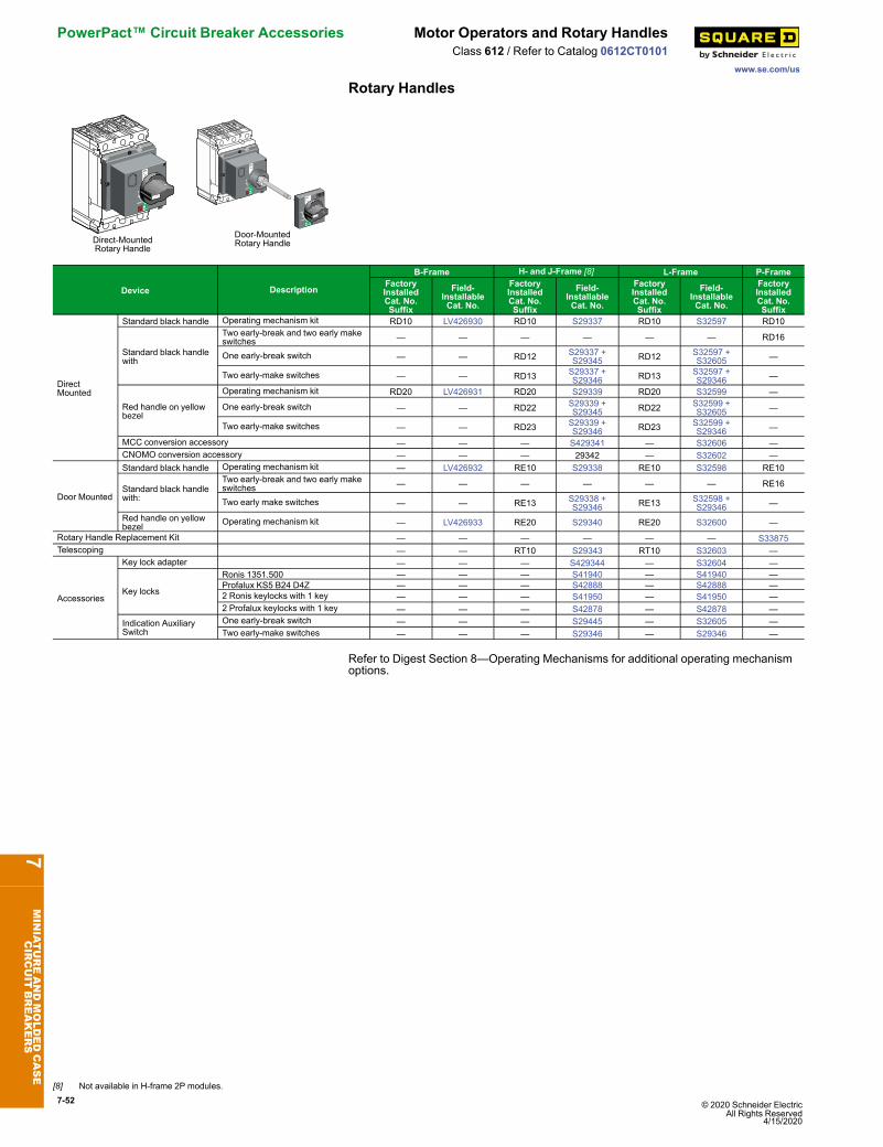
7-52 © 2020 Schneider Electric All Rights Reserved
4/15/2020
PowerPact™ Circuit Breaker Accessories Motor Operators and Rotary Handles
www.se.com/us
Class 612 / Refer to Catalog 0612CT0101
Rotary Handles
Direct-MountedRotary Handle
Door-MountedRotary Handle
Device Description
B-Frame H- and J-Frame [8] L-Frame P-FrameFactoryInstalledCat. No.Suffix
Field-InstallableCat. No.
FactoryInstalledCat. No.Suffix
Field-InstallableCat. No.
FactoryInstalledCat. No.Suffix
Field-InstallableCat. No.
FactoryInstalledCat. No.Suffix
DirectMounted
Standard black handle Operating mechanism kit RD10 LV426930 RD10 S29337 RD10 S32597 RD10
Standard black handlewith
Two early-break and two early makeswitches — — — — — — RD16
One early-break switch — — RD12 S29337 +S29345 RD12 S32597 +
S32605 —
Two early-make switches — — RD13 S29337 +S29346 RD13 S32597 +
S29346 —
Red handle on yellowbezel
Operating mechanism kit RD20 LV426931 RD20 S29339 RD20 S32599 —
One early-break switch — — RD22 S29339 +S29345 RD22 S32599 +
S32605 —
Two early-make switches — — RD23 S29339 +S29346 RD23 S32599 +
S29346 —
MCC conversion accessory — — — S429341 — S32606 —CNOMO conversion accessory — — — 29342 — S32602 —
Door Mounted
Standard black handle Operating mechanism kit — LV426932 RE10 S29338 RE10 S32598 RE10
Standard black handlewith:
Two early-break and two early makeswitches — — — — — — RE16
Two early make switches — — RE13 S29338 +S29346 RE13 S32598 +
S29346 —
Red handle on yellowbezel Operating mechanism kit — LV426933 RE20 S29340 RE20 S32600 —
Rotary Handle Replacement Kit — — — — — — S33875Telescoping — — RT10 S29343 RT10 S32603 —
Accessories
Key lock adapter — — — S429344 — S32604 —
Key locks
Ronis 1351.500 — — — S41940 — S41940 —Profalux KS5 B24 D4Z — — — S42888 — S42888 —2 Ronis keylocks with 1 key — — — S41950 — S41950 —2 Profalux keylocks with 1 key — — — S42878 — S42878 —
Indication AuxiliarySwitch
One early-break switch — — — S29445 — S32605 —Two early-make switches — — — S29346 — S29346 —
Refer to Digest Section 8—Operating Mechanisms for additional operating mechanismoptions.
7MINIATUREANDMOLDEDCASE
CIRCUIT
BREAKERS
[8] Not available in H-frame 2P modules.
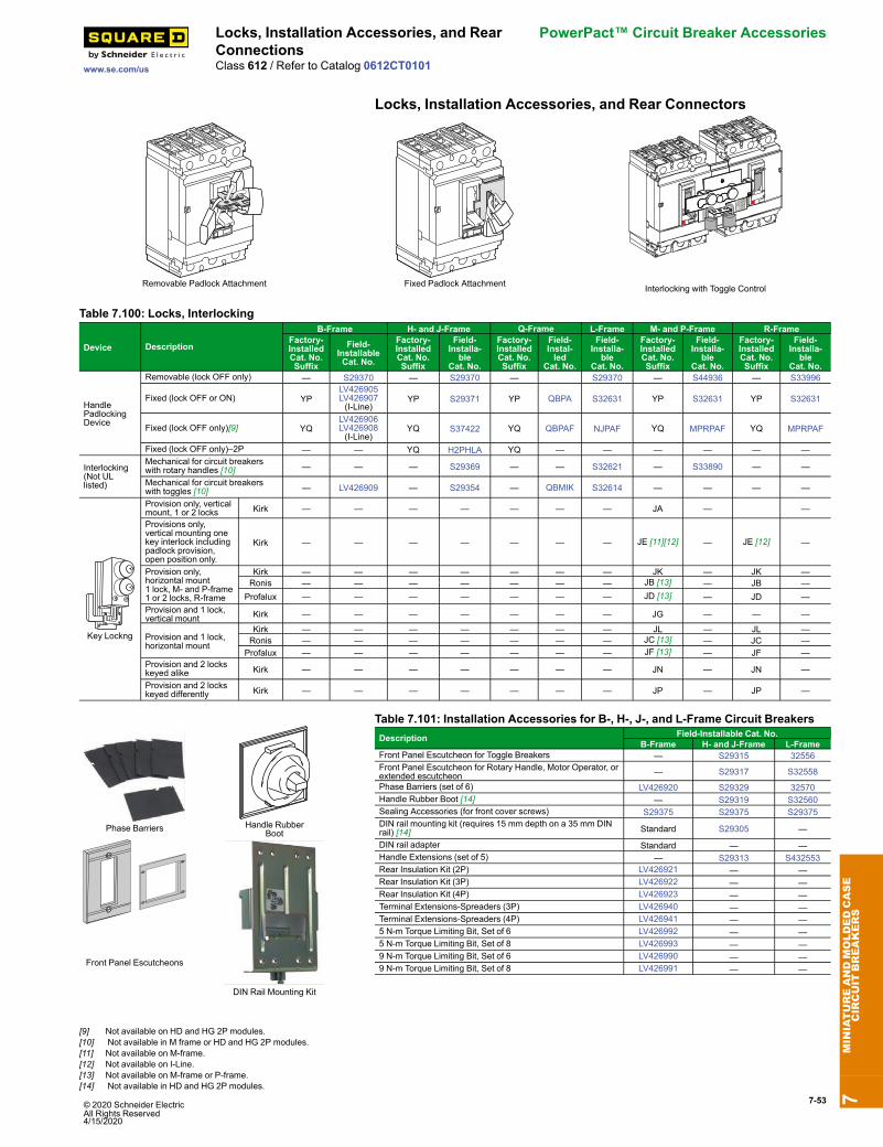
© 2020 Schneider Electric All Rights Reserved4/15/2020
7-53
www.se.com/us
Locks, Installation Accessories, and RearConnections
PowerPact™ Circuit Breaker Accessories
Class 612 / Refer to Catalog 0612CT0101
Locks, Installation Accessories, and Rear Connectors
Removable Padlock Attachment Fixed Padlock Attachment Interlocking with Toggle Control
Table 7.100: Locks, Interlocking
Device Description
B-Frame H- and J-Frame Q-Frame L-Frame M- and P-Frame R-FrameFactory-InstalledCat. No.Suffix
Field-InstallableCat. No.
Factory-InstalledCat. No.Suffix
Field-Installa-ble
Cat. No.
Factory-InstalledCat. No.Suffix
Field-Instal-led
Cat. No.
Field-Installa-ble
Cat. No.
Factory-InstalledCat. No.Suffix
Field-Installa-ble
Cat. No.
Factory-InstalledCat. No.Suffix
Field-Installa-ble
Cat. No.
HandlePadlockingDevice
Removable (lock OFF only) — S29370 — S29370 — S29370 — S44936 — S33996
Fixed (lock OFF or ON) YPLV426905LV426907(I-Line)
YP S29371 YP QBPA S32631 YP S32631 YP S32631
Fixed (lock OFF only)[9] YQLV426906LV426908(I-Line)
YQ S37422 YQ QBPAF NJPAF YQ MPRPAF YQ MPRPAF
Fixed (lock OFF only)–2P — — YQ H2PHLA YQ — — — — — —
Interlocking(Not ULlisted)
Mechanical for circuit breakerswith rotary handles [10] — — — S29369 — — S32621 — S33890 — —
Mechanical for circuit breakerswith toggles [10] — LV426909 — S29354 — QBMIK S32614 — — — —
Key Lockng
Provision only, verticalmount, 1 or 2 locks Kirk — — — — — — — JA — —
Provisions only,vertical mounting onekey interlock includingpadlock provision,open position only.
Kirk — — — — — — — JE [11][12] — JE [12] —
Provision only,horizontal mount1 lock, M- and P-frame1 or 2 locks, R-frame
Kirk — — — — — — — JK — JK —Ronis — — — — — — — JB [13] — JB —Profalux — — — — — — — JD [13] — JD —
Provision and 1 lock,vertical mount Kirk — — — — — — — JG — — —
Provision and 1 lock,horizontal mount
Kirk — — — — — — — JL — JL —Ronis — — — — — — — JC [13] — JC —Profalux — — — — — — — JF [13] — JF —
Provision and 2 lockskeyed alike Kirk — — — — — — — JN — JN —
Provision and 2 lockskeyed differently Kirk — — — — — — — JP — JP —
Phase Barriers Handle RubberBoot
DIN Rail Mounting Kit
Front Panel Escutcheons
Table 7.101: Installation Accessories for B-, H-, J-, and L-Frame Circuit BreakersDescription Field-Installable Cat. No.
B-Frame H- and J-Frame L-FrameFront Panel Escutcheon for Toggle Breakers — S29315 32556Front Panel Escutcheon for Rotary Handle, Motor Operator, orextended escutcheon — S29317 S32558
Phase Barriers (set of 6) LV426920 S29329 32570Handle Rubber Boot [14] — S29319 S32560Sealing Accessories (for front cover screws) S29375 S29375 S29375DIN rail mounting kit (requires 15 mm depth on a 35 mm DINrail) [14] Standard S29305 —
DIN rail adapter Standard — —Handle Extensions (set of 5) — S29313 S432553Rear Insulation Kit (2P) LV426921 — —Rear Insulation Kit (3P) LV426922 — —Rear Insulation Kit (4P) LV426923 — —Terminal Extensions-Spreaders (3P) LV426940 — —Terminal Extensions-Spreaders (4P) LV426941 — —5 N-m Torque Limiting Bit, Set of 6 LV426992 — —5 N-m Torque Limiting Bit, Set of 8 LV426993 — —9 N-m Torque Limiting Bit, Set of 6 LV426990 — —9 N-m Torque Limiting Bit, Set of 8 LV426991 — —
7MINIATUREANDMOLDEDCASE
CIRCUIT
BREAKERS
[9] Not available on HD and HG 2P modules.[10] Not available in M frame or HD and HG 2P modules.[11] Not available on M-frame.[12] Not available on I-Line.[13] Not available on M-frame or P-frame.[14] Not available in HD and HG 2P modules.
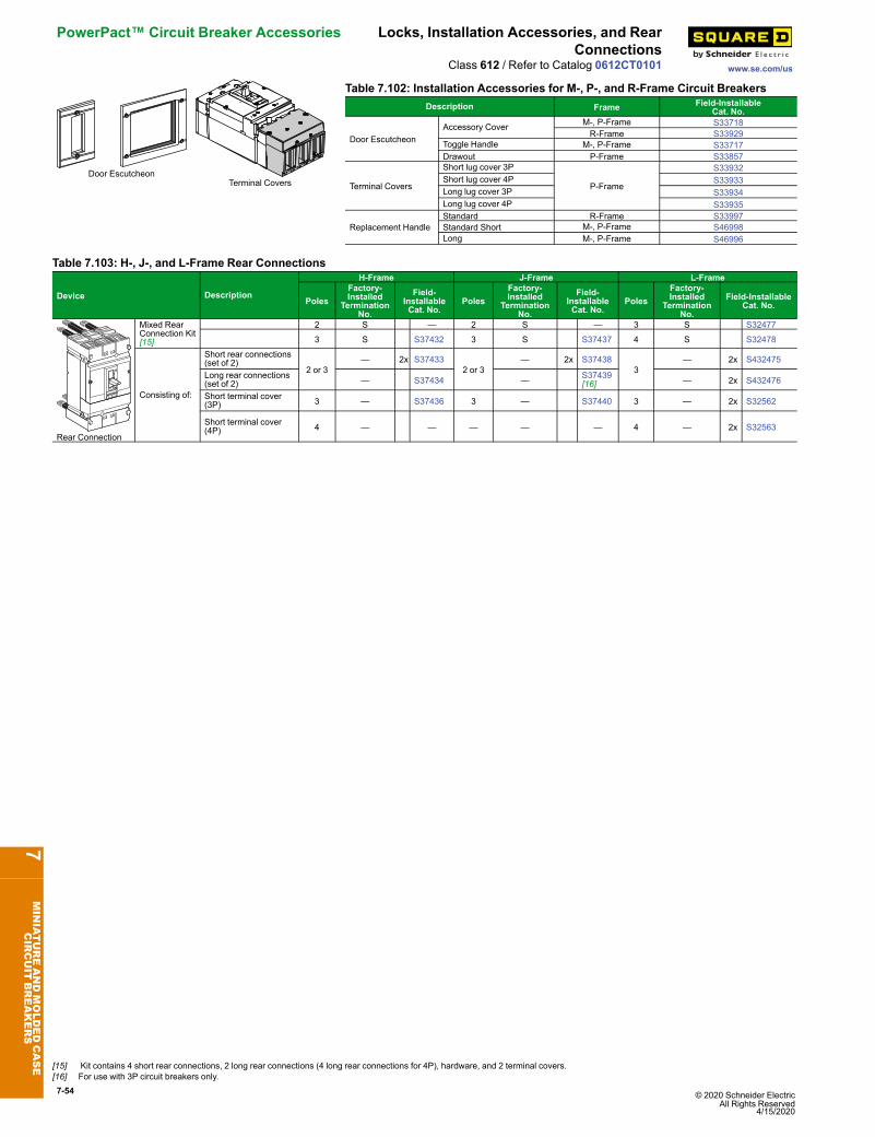
7-54 © 2020 Schneider Electric All Rights Reserved
4/15/2020
PowerPact™ Circuit Breaker Accessories Locks, Installation Accessories, and RearConnections
www.se.com/usClass 612 / Refer to Catalog 0612CT0101
Door EscutcheonTerminal Covers
Table 7.102: Installation Accessories for M-, P-, and R-Frame Circuit BreakersDescription Frame Field-Installable
Cat. No.
Door EscutcheonAccessory Cover M-, P-Frame S33718
R-Frame S33929Toggle Handle M-, P-Frame S33717Drawout P-Frame S33857
Terminal Covers
Short lug cover 3P
P-Frame
S33932Short lug cover 4P S33933Long lug cover 3P S33934Long lug cover 4P S33935
Replacement HandleStandard R-Frame S33997Standard Short M-, P-Frame S46998Long M-, P-Frame S46996
Table 7.103: H-, J-, and L-Frame Rear Connections
Device Description
H-Frame J-Frame L-Frame
PolesFactory-Installed
TerminationNo.
Field-InstallableCat. No.
PolesFactory-Installed
TerminationNo.
Field-InstallableCat. No.
PolesFactory-Installed
TerminationNo.
Field-InstallableCat. No.
t
p
rip
uosht
Rear Connection
Mixed RearConnection Kit[15]
2 S — 2 S — 3 S S32477
3 S S37432 3 S S37437 4 S S32478
Consisting of:
Short rear connections(set of 2)
2 or 3— 2x S37433
2 or 3— 2x S37438
3— 2x S432475
Long rear connections(set of 2) — S37434 — S37439
[16] — 2x S432476
Short terminal cover(3P) 3 — S37436 3 — S37440 3 — 2x S32562
Short terminal cover(4P) 4 — — — — — 4 — 2x S32563
7MINIATUREANDMOLDEDCASE
CIRCUIT
BREAKERS
[15] Kit contains 4 short rear connections, 2 long rear connections (4 long rear connections for 4P), hardware, and 2 terminal covers.[16] For use with 3P circuit breakers only.
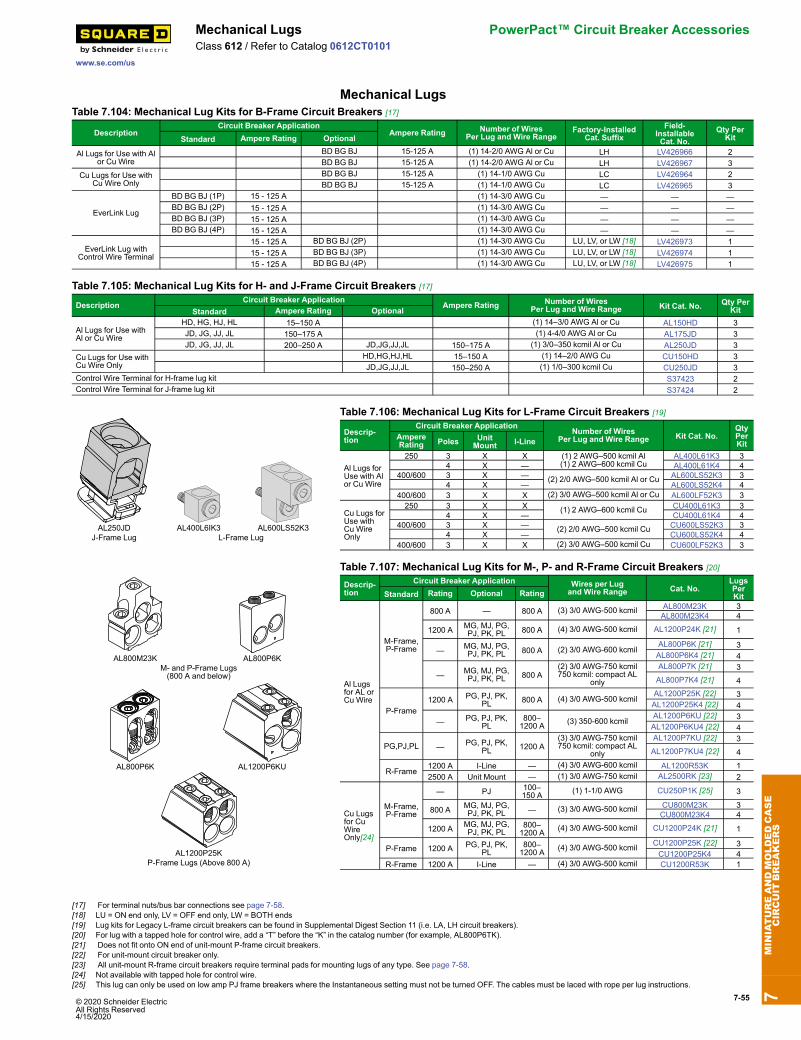
© 2020 Schneider Electric All Rights Reserved4/15/2020
7-55
www.se.com/us
Mechanical Lugs PowerPact™ Circuit Breaker AccessoriesClass 612 / Refer to Catalog 0612CT0101
Mechanical LugsTable 7.104: Mechanical Lug Kits for B-Frame Circuit Breakers [17]
DescriptionCircuit Breaker Application
Ampere Rating Number of WiresPer Lug and Wire Range
Factory-InstalledCat. Suffix
Field-InstallableCat. No.
Qty PerKitStandard Ampere Rating Optional
Al Lugs for Use with Alor Cu Wire
BD BG BJ 15-125 A (1) 14-2/0 AWG Al or Cu LH LV426966 2BD BG BJ 15-125 A (1) 14-2/0 AWG Al or Cu LH LV426967 3
Cu Lugs for Use withCu Wire Only
BD BG BJ 15-125 A (1) 14-1/0 AWG Cu LC LV426964 2BD BG BJ 15-125 A (1) 14-1/0 AWG Cu LC LV426965 3
EverLink Lug
BD BG BJ (1P) 15 - 125 A (1) 14-3/0 AWG Cu — — —BD BG BJ (2P) 15 - 125 A (1) 14-3/0 AWG Cu — — —BD BG BJ (3P) 15 - 125 A (1) 14-3/0 AWG Cu — — —BD BG BJ (4P) 15 - 125 A (1) 14-3/0 AWG Cu — — —
EverLink Lug withControl Wire Terminal
15 - 125 A BD BG BJ (2P) (1) 14-3/0 AWG Cu LU, LV, or LW [18] LV426973 115 - 125 A BD BG BJ (3P) (1) 14-3/0 AWG Cu LU, LV, or LW [18] LV426974 115 - 125 A BD BG BJ (4P) (1) 14-3/0 AWG Cu LU, LV, or LW [18] LV426975 1
Table 7.105: Mechanical Lug Kits for H- and J-Frame Circuit Breakers [17]
DescriptionCircuit Breaker Application
Ampere Rating Number of WiresPer Lug and Wire Range Kit Cat. No. Qty Per
KitStandard Ampere Rating Optional
Al Lugs for Use withAl or Cu Wire
HD, HG, HJ, HL 15–150 A (1) 14–3/0 AWG Al or Cu AL150HD 3JD, JG, JJ, JL 150–175 A (1) 4-4/0 AWG Al or Cu AL175JD 3JD, JG, JJ, JL 200–250 A JD,JG,JJ,JL 150–175 A (1) 3/0–350 kcmil Al or Cu AL250JD 3
Cu Lugs for Use withCu Wire Only
HD,HG,HJ,HL 15–150 A (1) 14–2/0 AWG Cu CU150HD 3JD,JG,JJ,JL 150–250 A (1) 1/0–300 kcmil Cu CU250JD 3
Control Wire Terminal for H-frame lug kit S37423 2Control Wire Terminal for J-frame lug kit S37424 2
AL250JD AL400L6IK3 AL600LS52K3J-Frame Lug L-Frame Lug
Table 7.106: Mechanical Lug Kits for L-Frame Circuit Breakers [19]
Descrip-tion
Circuit Breaker ApplicationNumber of Wires
Per Lug and Wire Range Kit Cat. No.QtyPerKit
AmpereRating Poles Unit
Mount I-Line
Al Lugs forUse with Alor Cu Wire
250 3 X X (1) 2 AWG–500 kcmil Al(1) 2 AWG–600 kcmil Cu
AL400L61K3 34 X — AL400L61K4 4
400/600 3 X — (2) 2/0 AWG–500 kcmil Al or Cu AL600LS52K3 34 X — AL600LS52K4 4
400/600 3 X X (2) 3/0 AWG–500 kcmil Al or Cu AL600LF52K3 3
Cu Lugs forUse withCu WireOnly
250 3 X X (1) 2 AWG–600 kcmil Cu CU400L61K3 34 X — CU400L61K4 4
400/600 3 X — (2) 2/0 AWG–500 kcmil Cu CU600LS52K3 34 X — CU600LS52K4 4
400/600 3 X X (2) 3/0 AWG–500 kcmil Cu CU600LF52K3 3
AL800M23K AL800P6KM- and P-Frame Lugs(800 A and below)
AL800P6K AL1200P6KU
AL1200P25KP-Frame Lugs (Above 800 A)
Table 7.107: Mechanical Lug Kits for M-, P- and R-Frame Circuit Breakers [20]
Descrip-tion
Circuit Breaker Application Wires per Lugand Wire Range Cat. No.
LugsPerKitStandard Rating Optional Rating
Al Lugsfor AL orCu Wire
M-Frame,P-Frame
800 A — 800 A (3) 3/0 AWG-500 kcmil AL800M23K 3AL800M23K4 4
1200 A MG, MJ, PG,PJ, PK, PL 800 A (4) 3/0 AWG-500 kcmil AL1200P24K [21] 1
— MG, MJ, PG,PJ, PK, PL 800 A (2) 3/0 AWG-600 kcmil
AL800P6K [21] 3AL800P6K4 [21] 4
— MG, MJ, PG,PJ, PK, PL 800 A
(2) 3/0 AWG-750 kcmil750 kcmil: compact AL
only
AL800P7K [21] 3AL800P7K4 [21] 4
P-Frame1200 A PG, PJ, PK,
PL 800 A (4) 3/0 AWG-500 kcmilAL1200P25K [22] 3AL1200P25K4 [22] 4
— PG, PJ, PK,PL
800–1200 A (3) 350-600 kcmil
AL1200P6KU [22] 3AL1200P6KU4 [22] 4
PG,PJ,PL — PG, PJ, PK,PL 1200 A
(3) 3/0 AWG-750 kcmil750 kcmil: compact AL
only
AL1200P7KU [22] 3AL1200P7KU4 [22] 4
R-Frame1200 A I-Line — (4) 3/0 AWG-600 kcmil AL1200R53K 12500 A Unit Mount — (1) 3/0 AWG-750 kcmil AL2500RK [23] 2
Cu Lugsfor CuWireOnly[24]
M-Frame,P-Frame
— PJ 100–150 A (1) 1-1/0 AWG CU250P1K [25] 3
800 A MG, MJ, PG,PJ, PK, PL — (3) 3/0 AWG-500 kcmil CU800M23K 3
CU800M23K4 4
1200 A MG, MJ, PG,PJ, PK, PL
800–1200 A (4) 3/0 AWG-500 kcmil CU1200P24K [21] 1
P-Frame 1200 A PG, PJ, PK,PL
800–1200 A (4) 3/0 AWG-500 kcmil CU1200P25K [22] 3
CU1200P25K4 4R-Frame 1200 A I-Line — (4) 3/0 AWG-500 kcmil CU1200R53K 1
7MINIATUREANDMOLDEDCASE
CIRCUIT
BREAKERS
[17] For terminal nuts/bus bar connections see page 7-58.[18] LU = ON end only, LV = OFF end only, LW = BOTH ends[19] Lug kits for Legacy L-frame circuit breakers can be found in Supplemental Digest Section 11 (i.e. LA, LH circuit breakers).[20] For lug with a tapped hole for control wire, add a “T” before the “K” in the catalog number (for example, AL800P6TK).[21] Does not fit onto ON end of unit-mount P-frame circuit breakers.[22] For unit-mount circuit breaker only.[23] All unit-mount R-frame circuit breakers require terminal pads for mounting lugs of any type. See page 7-58.[24] Not available with tapped hole for control wire.[25] This lug can only be used on low amp PJ frame breakers where the Instantaneous setting must not be turned OFF. The cables must be laced with rope per lug instructions.
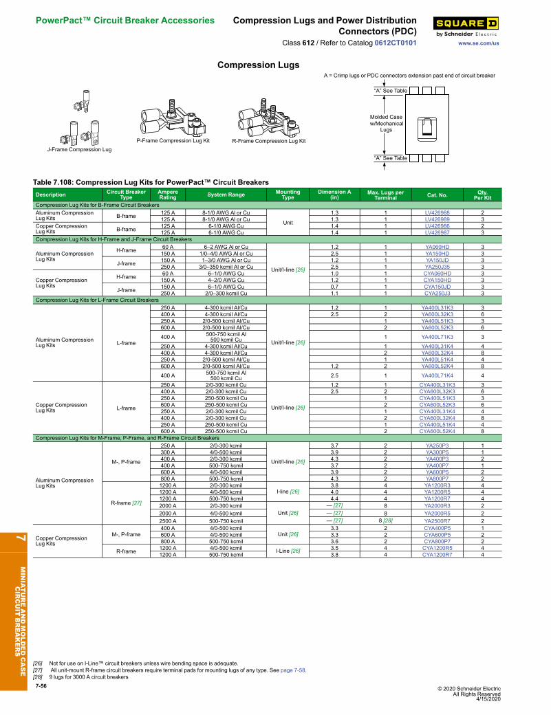
7-56 © 2020 Schneider Electric All Rights Reserved
4/15/2020
PowerPact™ Circuit Breaker Accessories Compression Lugs and Power DistributionConnectors (PDC)
www.se.com/usClass 612 / Refer to Catalog 0612CT0101
Compression Lugs
J-Frame Compression LugP-Frame Compression Lug Kit R-Frame Compression Lug Kit
A = Crimp lugs or PDC connectors extension past end of circuit breaker
“A” See Table
Molded Casew/Mechanical
Lugs
“A” See Table
Table 7.108: Compression Lug Kits for PowerPact™ Circuit BreakersDescription Circuit Breaker
TypeAmpereRating System Range Mounting
TypeDimension A
(in)Max. Lugs per
Terminal Cat. No. Qty.Per Kit
Compression Lug Kits for B-Frame Circuit BreakersAluminum CompressionLug Kits B-frame 125 A 8-1/0 AWG Al or Cu
Unit
1.3 1 LV426988 2125 A 8-1/0 AWG Al or Cu 1.3 1 LV426989 3
Copper CompressionLug Kits B-frame 125 A 6-1/0 AWG Cu 1.4 1 LV426986 2
125 A 6-1/0 AWG Cu 1.4 1 LV426987 3Compression Lug Kits for H-Frame and J-Frame Circuit Breakers
Aluminum CompressionLug Kits
H-frame 60 A 6–2 AWG Al or Cu
Unit/I-line [26]
1.2 1 YA060HD 3150 A 1/0–4/0 AWG Al or Cu 2.5 1 YA150HD 3
J-frame 150 A 1–3/0 AWG Al or Cu 1.2 1 YA150JD 3250 A 3/0–350 kcmil Al or Cu 2.5 1 YA250J35 3
Copper CompressionLug Kits
H-frame 60 A 6–1/0 AWG Cu 1.0 1 CYA060HD 3150 A 4–2/0 AWG Cu 1.2 1 CYA150HD 3
J-frame 150 A 6–1/0 AWG Cu 0.7 1 CYA150JD 3250 A 2/0–300 kcmil Cu 1.1 1 CYA250J3 3
Compression Lug Kits for L-Frame Circuit Breakers
Aluminum CompressionLug Kits L-frame
250 A 4-300 kcmil Al/Cu
Unit/I-line [26]
1.2 1 YA400L31K3 3400 A 4-300 kcmil Al/Cu 2.5 2 YA600L32K3 6250 A 2/0-500 kcmil Al/Cu 1 YA400L51K3 3600 A 2/0-500 kcmil Al/Cu 2 YA600L52K3 6
400 A 500-750 kcmil Al500 kcmil Cu 1 YA400L71K3 3
250 A 4-300 kcmil Al/Cu 1 YA400L31K4 4400 A 4-300 kcmil Al/Cu 2 YA600L32K4 8250 A 2/0-500 kcmil Al/Cu 1 YA400L51K4 4600 A 2/0-500 kcmil Al/Cu 1.2 2 YA600L52K4 8
400 A 500-750 kcmil Al500 kcmil Cu 2.5 1 YA400L71K4 4
Copper CompressionLug Kits L-frame
250 A 2/0-300 kcmil Cu
Unit/I-line [26]
1.2 1 CYA400L31K3 3400 A 2/0-300 kcmil Cu 2.5 2 CYA600L32K3 6250 A 250-500 kcmil Cu 1 CYA400L51K3 3600 A 250-500 kcmil Cu 2 CYA600L52K3 6250 A 2/0-300 kcmil Cu 1 CYA400L31K4 4400 A 2/0-300 kcmil Cu 2 CYA600L32K4 8250 A 250-500 kcmil Cu 1 CYA400L51K4 4600 A 250-500 kcmil Cu 2 CYA600L52K4 8
Compression Lug Kits for M-Frame, P-Frame, and R-Frame Circuit Breakers
Aluminum CompressionLug Kits
M-, P-frame
250 A 2/0-300 kcmil
Unit/I-line [26]
3.7 2 YA250P3 1300 A 4/0-500 kcmil 3.9 2 YA300P5 1400 A 2/0-300 kcmil 4.3 2 YA400P3 2400 A 500-750 kcmil 3.7 2 YA400P7 1600 A 4/0-500 kcmil 3.9 2 YA600P5 2800 A 500-750 kcmil 4.3 2 YA800P7 2
R-frame [27]
1200 A 2/0-300 kcmilI-line [26]
3.8 4 YA1200R3 41200 A 4/0-500 kcmil 4.0 4 YA1200R5 41200 A 500-750 kcmil 4.4 4 YA1200R7 42000 A 2/0-300 kcmil
Unit [26]— [27] 8 YA2000R3 2
2000 A 4/0-500 kcmil — [27] 8 YA2000R5 22500 A 500-750 kcmil — [27] 8 [28] YA2500R7 2
Copper CompressionLug Kits
M-, P-frame400 A 4/0-500 kcmil
Unit [26]3.3 2 CYA400P5 1
600 A 4/0-500 kcmil 3.3 2 CYA600P5 2800 A 500-750 kcmil 3.6 2 CYA800P7 2
R-frame 1200 A 4/0-500 kcmil I-Line [26] 3.5 4 CYA1200R5 41200 A 500-750 kcmil 3.8 4 CYA1200R7 4
7MINIATUREANDMOLDEDCASE
CIRCUIT
BREAKERS
[26] Not for use on I-Line™ circuit breakers unless wire bending space is adequate.[27] All unit-mount R-frame circuit breakers require terminal pads for mounting lugs of any type. See page 7-58.[28] 9 lugs for 3000 A circuit breakers
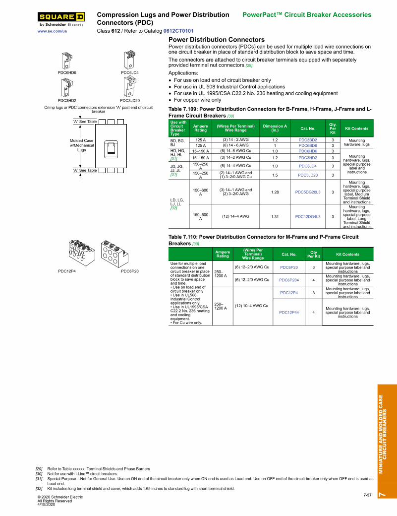
© 2020 Schneider Electric All Rights Reserved4/15/2020
7-57
www.se.com/us
Compression Lugs and Power DistributionConnectors (PDC)
PowerPact™ Circuit Breaker Accessories
Class 612 / Refer to Catalog 0612CT0101Power Distribution Connectors
PDC6HD6 PDC6JD4
PDC3HD2 PDC3JD20
Crimp lugs or PDC connectors extension “A” past end of circuitbreaker
“A” See Table
Molded Casew/Mechanical
Lugs
“A” See Table
Power distribution connectors (PDCs) can be used for multiple load wire connections onone circuit breaker in place of standard distribution block to save space and time.The connectors are attached to circuit breaker terminals equipped with separatelyprovided terminal nut connectors.[29]Applications:• For use on load end of circuit breaker only• For use in UL 508 Industrial Control applications• For use in UL 1995/CSA C22.2 No. 236 heating and cooling equipment• For copper wire only
Table 7.109: Power Distribution Connectors for B-Frame, H-Frame, J-Frame and L-Frame Circuit Breakers [30]Use withCircuitBreakerType
AmpereRating
(Wires Per Terminal)Wire Range
Dimension A(in.) Cat. No.
Qty.PerKit
Kit Contents
BD, BG,BJ
125 A (3) 14 - 2 AWG 1.2 PDC3BD2 3 Mountinghardware, lugs125 A (6) 14 - 6 AWG 1 PDC6BD6 3
HD, HG,HJ, HL[31]
15–150 A (6) 14–6 AWG Cu 1.0 PDC6HD6 3Mounting
hardware, lugs,special purpose
label andinstructions
15–150 A (3) 14–2 AWG Cu 1.2 PDC3HD2 3
JD, JG,JJ, JL[31]
150–250A (6) 14–4 AWG Cu 1.0 PDC6JD4 3
150–250A
(2) 14–1 AWG and(1) 3–2/0 AWG Cu 1.5 PDC3JD20 3
LD, LG,LJ, LL[32]
150–600A
(3) 14–1 AWG and(2) 3–2/0 AWG 1.28 PDC5DG20L3 3
Mountinghardware, lugs,special purposelabel, MediumTerminal Shieldand instructions
150–600A (12) 14–4 AWG 1.31 PDC12DG4L3 3
Mountinghardware, lugs,special purposelabel, Long
Terminal Shieldand instructions
PDC12P4 PDC6P20
Table 7.110: Power Distribution Connectors for M-Frame and P-Frame CircuitBreakers [30]
AmpereRating
(Wires PerTerminal)Wire Range
Cat. No. QtyPer Kit Kit Contents
Use for multiple loadconnections on onecircuit breaker in placeof standard distributionblock to save spaceand time.• Use on load end ofcircuit breaker only• Use in UL508Industrial Controlapplications only.• Use in UL1995/CSAC22.2 No. 236 heatingand coolingequipment.• For Cu wire only.
250–1200 A
(6) 12–2/0 AWG Cu PDC6P20 3Mounting hardware, lugs,special purpose label and
instructions
(6) 12–2/0 AWG Cu PDC6P204 4Mounting hardware, lugs,special purpose label and
instructions
250–1200 A (12) 10–4 AWG Cu
PDC12P4 3Mounting hardware, lugs,special purpose label and
instructions
PDC12P44 4Mounting hardware, lugs,special purpose label and
instructions
7MINIATUREANDMOLDEDCASE
CIRCUIT
BREAKERS
[29] Refer to Table xxxxxx: Terminal Shields and Phase Barriers[30] Not for use with I-Line™ circuit breakers.[31] Special Purpose—Not for General Use. Use on ON end of the circuit breaker only when ON end is used as Load end. Use on OFF end of the circuit breaker only when OFF end is used as
Load end.[32] Kit includes long terminal shield and cover, which adds 1.65 inches to standard lug with short terminal shield.
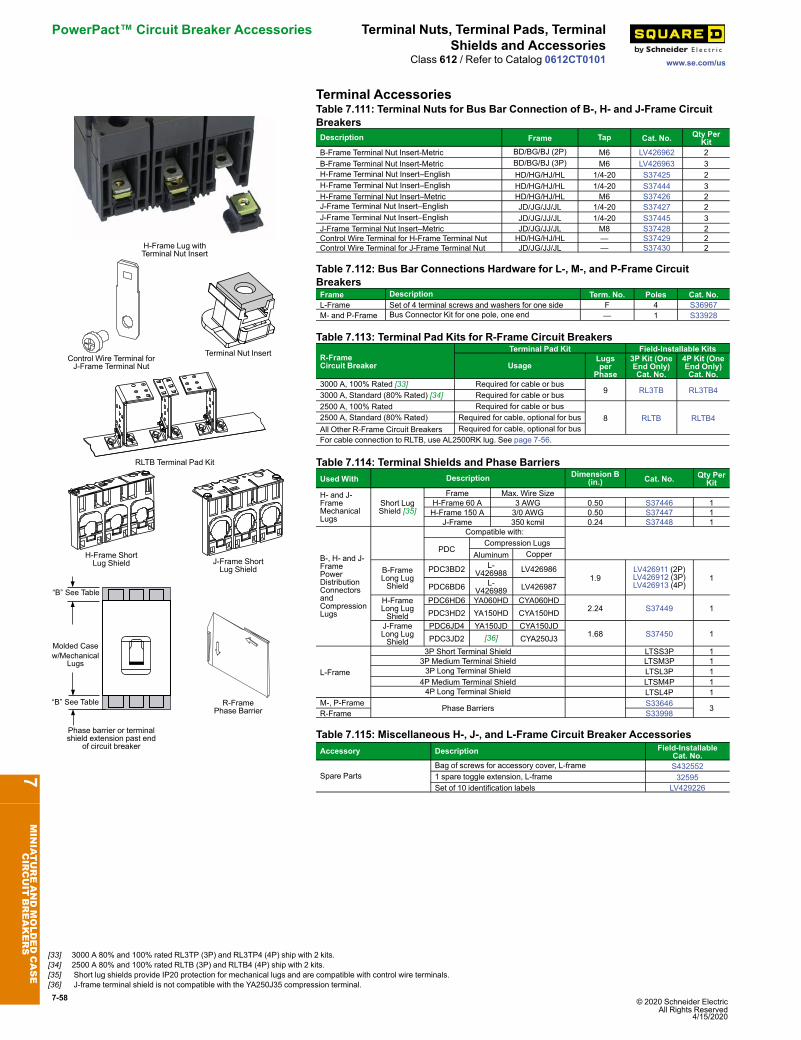
7-58 © 2020 Schneider Electric All Rights Reserved
4/15/2020
PowerPact™ Circuit Breaker Accessories Terminal Nuts, Terminal Pads, TerminalShields and Accessories
www.se.com/usClass 612 / Refer to Catalog 0612CT0101
Terminal Accessories
H-Frame Lug withTerminal Nut Insert
Control Wire Terminal forJ-Frame Terminal Nut
Terminal Nut Insert
RLTB Terminal Pad Kit
Table 7.111: Terminal Nuts for Bus Bar Connection of B-, H- and J-Frame CircuitBreakersDescription Frame Tap Cat. No. Qty Per
KitB-Frame Terminal Nut Insert-Metric BD/BG/BJ (2P) M6 LV426962 2B-Frame Terminal Nut Insert-Metric BD/BG/BJ (3P) M6 LV426963 3H-Frame Terminal Nut Insert–English HD/HG/HJ/HL 1/4-20 S37425 2H-Frame Terminal Nut Insert–English HD/HG/HJ/HL 1/4-20 S37444 3H-Frame Terminal Nut Insert–Metric HD/HG/HJ/HL M6 S37426 2J-Frame Terminal Nut Insert–English JD/JG/JJ/JL 1/4-20 S37427 2J-Frame Terminal Nut Insert–English JD/JG/JJ/JL 1/4-20 S37445 3J-Frame Terminal Nut Insert–Metric JD/JG/JJ/JL M8 S37428 2Control Wire Terminal for H-Frame Terminal Nut HD/HG/HJ/HL — S37429 2Control Wire Terminal for J-Frame Terminal Nut JD/JG/JJ/JL — S37430 2
Table 7.112: Bus Bar Connections Hardware for L-, M-, and P-Frame CircuitBreakersFrame Description Term. No. Poles Cat. No.L-Frame Set of 4 terminal screws and washers for one side F 4 S36967M- and P-Frame Bus Connector Kit for one pole, one end — 1 S33928
Table 7.113: Terminal Pad Kits for R-Frame Circuit Breakers
R-FrameCircuit Breaker
Terminal Pad Kit Field-Installable Kits
UsageLugsper
Phase
3P Kit (OneEnd Only)Cat. No.
4P Kit (OneEnd Only)Cat. No.
3000 A, 100% Rated [33] Required for cable or bus9 RL3TB RL3TB43000 A, Standard (80% Rated) [34] Required for cable or bus
2500 A, 100% Rated Required for cable or bus8 RLTB RLTB42500 A, Standard (80% Rated) Required for cable, optional for bus
All Other R-Frame Circuit Breakers Required for cable, optional for busFor cable connection to RLTB, use AL2500RK lug. See page 7-56.
H-Frame ShortLug Shield J-Frame Short
Lug Shield
Molded Casew/Mechanical
Lugs
“B” See Table
“B” See Table
Phase barrier or terminalshield extension past end
of circuit breaker
R-FramePhase Barrier
Table 7.114: Terminal Shields and Phase BarriersUsed With Description Dimension B
(in.) Cat. No. Qty PerKit
H- and J-FrameMechanicalLugs
Short LugShield [35]
Frame Max. Wire SizeH-Frame 60 A 3 AWG 0.50 S37446 1H-Frame 150 A 3/0 AWG 0.50 S37447 1
J-Frame 350 kcmil 0.24 S37448 1
B-, H- and J-FramePowerDistributionConnectorsandCompressionLugs
Compatible with:
PDCCompression Lugs
Aluminum Copper
B-FrameLong LugShield
PDC3BD2 L-V426988 LV426986
1.9LV426911 (2P)LV426912 (3P)LV426913 (4P)
1PDC6BD6 L-
V426989 LV426987
H-FrameLong LugShield
PDC6HD6 YA060HD CYA060HD2.24 S37449 1PDC3HD2 YA150HD CYA150HD
J-FrameLong LugShield
PDC6JD4 YA150JD CYA150JD1.68 S37450 1PDC3JD2 [36] CYA250J3
L-Frame
3P Short Terminal Shield LTSS3P 13P Medium Terminal Shield LTSM3P 13P Long Terminal Shield LTSL3P 1
4P Medium Terminal Shield LTSM4P 14P Long Terminal Shield LTSL4P 1
M-, P-FramePhase Barriers S33646 3
R-Frame S33998
Table 7.115: Miscellaneous H-, J-, and L-Frame Circuit Breaker AccessoriesAccessory Description Field-Installable
Cat. No.
Spare PartsBag of screws for accessory cover, L-frame S4325521 spare toggle extension, L-frame 32595Set of 10 identification labels LV429226
7MINIATUREANDMOLDEDCASE
CIRCUIT
BREAKERS
[33] 3000 A 80% and 100% rated RL3TP (3P) and RL3TP4 (4P) ship with 2 kits.[34] 2500 A 80% and 100% rated RLTB (3P) and RLTB4 (4P) ship with 2 kits.[35] Short lug shields provide IP20 protection for mechanical lugs and are compatible with control wire terminals.[36] J-frame terminal shield is not compatible with the YA250J35 compression terminal.
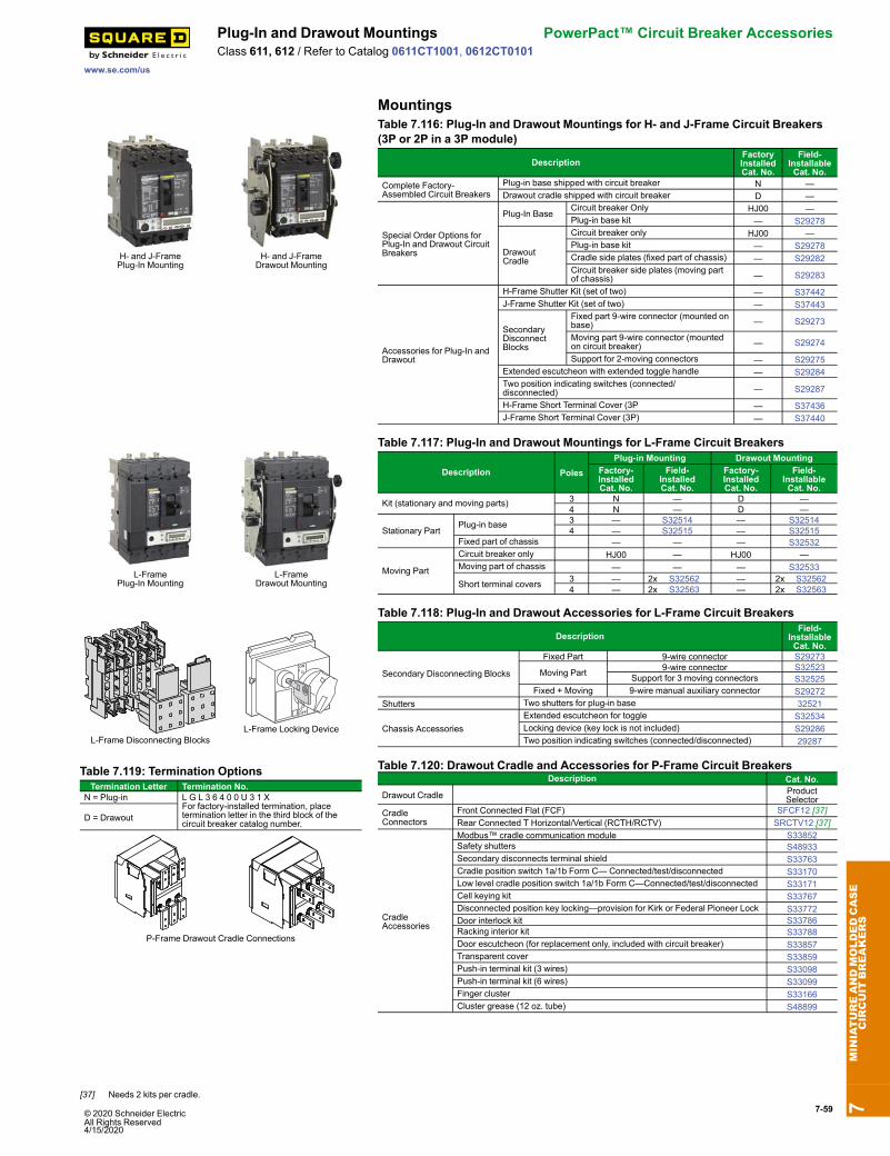
© 2020 Schneider Electric All Rights Reserved4/15/2020
7-59
www.se.com/us
Plug-In and Drawout Mountings PowerPact™ Circuit Breaker AccessoriesClass 611, 612 / Refer to Catalog 0611CT1001, 0612CT0101
Mountings
H- and J-FramePlug-In Mounting
H- and J-FrameDrawout Mounting
Table 7.116: Plug-In and Drawout Mountings for H- and J-Frame Circuit Breakers(3P or 2P in a 3P module)
DescriptionFactoryInstalledCat. No.
Field-InstallableCat. No.
Complete Factory-Assembled Circuit Breakers
Plug-in base shipped with circuit breaker N —Drawout cradle shipped with circuit breaker D —
Special Order Options forPlug-In and Drawout CircuitBreakers
Plug-In BaseCircuit breaker Only HJ00 —Plug-in base kit — S29278
DrawoutCradle
Circuit breaker only HJ00 —Plug-in base kit — S29278Cradle side plates (fixed part of chassis) — S29282Circuit breaker side plates (moving partof chassis) — S29283
Accessories for Plug-In andDrawout
H-Frame Shutter Kit (set of two) — S37442J-Frame Shutter Kit (set of two) — S37443
SecondaryDisconnectBlocks
Fixed part 9-wire connector (mounted onbase) — S29273
Moving part 9-wire connector (mountedon circuit breaker) — S29274
Support for 2-moving connectors — S29275Extended escutcheon with extended toggle handle — S29284Two position indicating switches (connected/disconnected) — S29287
H-Frame Short Terminal Cover (3P — S37436J-Frame Short Terminal Cover (3P) — S37440
L-FramePlug-In Mounting
L-FrameDrawout Mounting
Table 7.117: Plug-In and Drawout Mountings for L-Frame Circuit Breakers
Description PolesPlug-in Mounting Drawout Mounting
Factory-InstalledCat. No.
Field-InstalledCat. No.
Factory-InstalledCat. No.
Field-InstallableCat. No.
Kit (stationary and moving parts) 3 N — D —4 N — D —
Stationary PartPlug-in base 3 — S32514 — S32514
4 — S32515 — S32515Fixed part of chassis — — — S32532
Moving Part
Circuit breaker only HJ00 — HJ00 —Moving part of chassis — — — S32533
Short terminal covers 3 — 2x S32562 — 2x S325624 — 2x S32563 — 2x S32563
L-Frame Disconnecting BlocksL-Frame Locking Device
Table 7.118: Plug-In and Drawout Accessories for L-Frame Circuit Breakers
DescriptionField-
InstallableCat. No.
Secondary Disconnecting Blocks
Fixed Part 9-wire connector S29273
Moving Part 9-wire connector S32523Support for 3 moving connectors S32525
Fixed + Moving 9-wire manual auxiliary connector S29272Shutters Two shutters for plug-in base 32521
Chassis AccessoriesExtended escutcheon for toggle S32534Locking device (key lock is not included) S29286Two position indicating switches (connected/disconnected) 29287
Table 7.119: Termination OptionsTermination Letter Termination No.
N = Plug-in L G L 3 6 4 0 0 U 3 1 XFor factory-installed termination, placetermination letter in the third block of thecircuit breaker catalog number.
D = Drawout
P-Frame Drawout Cradle Connections
Table 7.120: Drawout Cradle and Accessories for P-Frame Circuit BreakersDescription Cat. No.
Drawout Cradle ProductSelector
CradleConnectors
Front Connected Flat (FCF) SFCF12 [37]Rear Connected T Horizontal/Vertical (RCTH/RCTV) SRCTV12 [37]
CradleAccessories
Modbus™ cradle communication module S33852Safety shutters S48933Secondary disconnects terminal shield S33763Cradle position switch 1a/1b Form C— Connected/test/disconnected S33170Low level cradle position switch 1a/1b Form C—Connected/test/disconnected S33171Cell keying kit S33767Disconnected position key locking—provision for Kirk or Federal Pioneer Lock S33772Door interlock kit S33786Racking interior kit S33788Door escutcheon (for replacement only, included with circuit breaker) S33857Transparent cover S33859Push-in terminal kit (3 wires) S33098Push-in terminal kit (6 wires) S33099Finger cluster S33166Cluster grease (12 oz. tube) S48899
7MINIATUREANDMOLDEDCASE
CIRCUIT
BREAKERS
[37] Needs 2 kits per cradle.
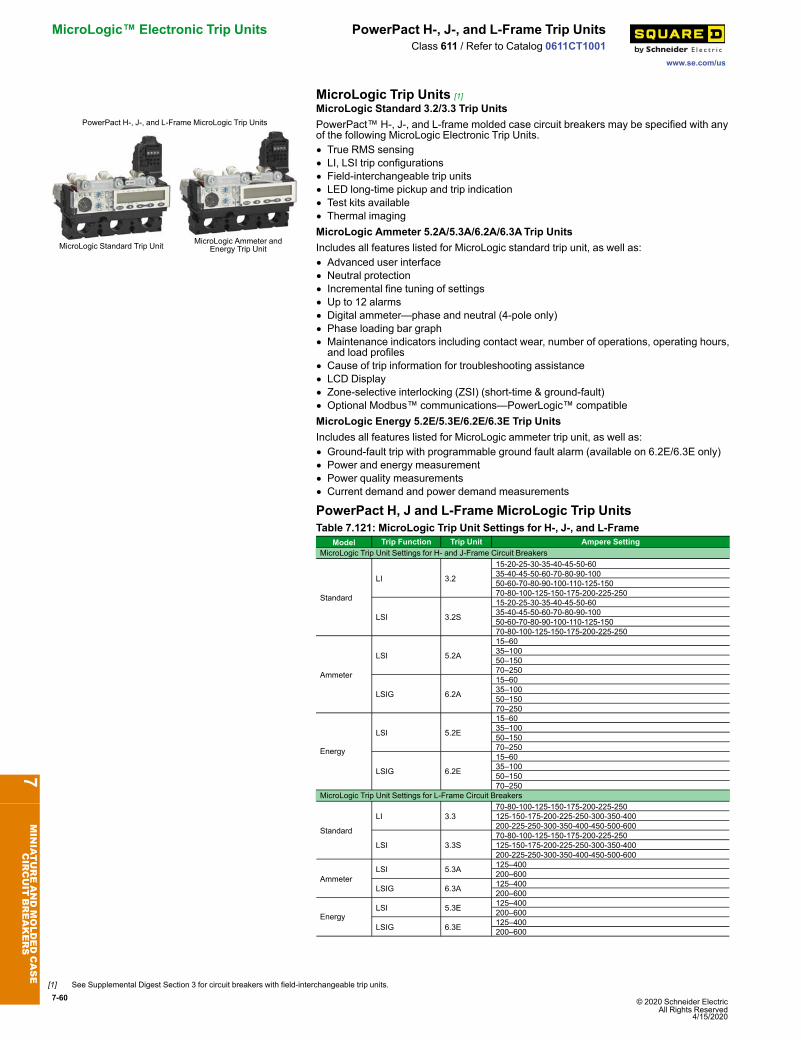
7-60 © 2020 Schneider Electric All Rights Reserved
4/15/2020
MicroLogic™ Electronic Trip Units PowerPact H-, J-, and L-Frame Trip Units
www.se.com/us
Class 611 / Refer to Catalog 0611CT1001
MicroLogic Trip Units [1]
PowerPact H-, J-, and L-Frame MicroLogic Trip Units
MicroLogic Standard Trip Unit MicroLogic Ammeter andEnergy Trip Unit
MicroLogic Standard 3.2/3.3 Trip UnitsPowerPact™ H-, J-, and L-frame molded case circuit breakers may be specified with anyof the following MicroLogic Electronic Trip Units.• True RMS sensing• LI, LSI trip configurations• Field-interchangeable trip units• LED long-time pickup and trip indication• Test kits available• Thermal imagingMicroLogic Ammeter 5.2A/5.3A/6.2A/6.3ATrip UnitsIncludes all features listed for MicroLogic standard trip unit, as well as:• Advanced user interface• Neutral protection• Incremental fine tuning of settings• Up to 12 alarms• Digital ammeter—phase and neutral (4-pole only)• Phase loading bar graph• Maintenance indicators including contact wear, number of operations, operating hours,and load profiles
• Cause of trip information for troubleshooting assistance• LCD Display• Zone-selective interlocking (ZSI) (short-time & ground-fault)• Optional Modbus™ communications—PowerLogic™ compatibleMicroLogic Energy 5.2E/5.3E/6.2E/6.3E Trip UnitsIncludes all features listed for MicroLogic ammeter trip unit, as well as:• Ground-fault trip with programmable ground fault alarm (available on 6.2E/6.3E only)• Power and energy measurement• Power quality measurements• Current demand and power demand measurements
PowerPact H, J and L-Frame MicroLogic Trip UnitsTable 7.121: MicroLogic Trip Unit Settings for H-, J-, and L-Frame
Model Trip Function Trip Unit Ampere SettingMicroLogic Trip Unit Settings for H- and J-Frame Circuit Breakers
Standard
LI 3.2
15-20-25-30-35-40-45-50-6035-40-45-50-60-70-80-90-10050-60-70-80-90-100-110-125-15070-80-100-125-150-175-200-225-250
LSI 3.2S
15-20-25-30-35-40-45-50-6035-40-45-50-60-70-80-90-10050-60-70-80-90-100-110-125-15070-80-100-125-150-175-200-225-250
Ammeter
LSI 5.2A
15–6035–10050–15070–250
LSIG 6.2A
15–6035–10050–15070–250
Energy
LSI 5.2E
15–6035–10050–15070–250
LSIG 6.2E
15–6035–10050–15070–250
MicroLogic Trip Unit Settings for L-Frame Circuit Breakers
Standard
LI 3.370-80-100-125-150-175-200-225-250125-150-175-200-225-250-300-350-400200-225-250-300-350-400-450-500-600
LSI 3.3S70-80-100-125-150-175-200-225-250125-150-175-200-225-250-300-350-400200-225-250-300-350-400-450-500-600
AmmeterLSI 5.3A 125–400
200–600
LSIG 6.3A 125–400200–600
EnergyLSI 5.3E 125–400
200–600
LSIG 6.3E 125–400200–600
7MINIATUREANDMOLDEDCASE
CIRCUIT
BREAKERS
[1] See Supplemental Digest Section 3 for circuit breakers with field-interchangeable trip units.
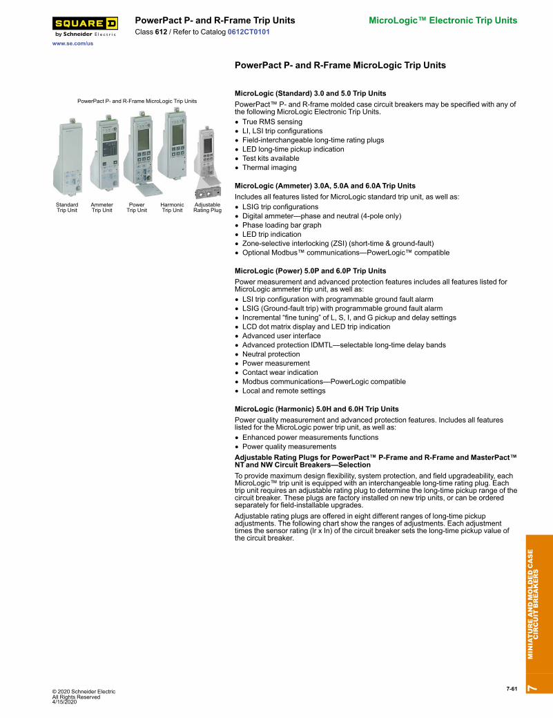
© 2020 Schneider Electric All Rights Reserved4/15/2020
7-61
www.se.com/us
PowerPact P- and R-Frame Trip Units MicroLogic™ Electronic Trip UnitsClass 612 / Refer to Catalog 0612CT0101
PowerPact P- and R-Frame MicroLogic Trip Units
PowerPact P- and R-Frame MicroLogic Trip Units
StandardTrip Unit
AmmeterTrip Unit
PowerTrip Unit
HarmonicTrip Unit
AdjustableRating Plug
MicroLogic (Standard) 3.0 and 5.0 Trip UnitsPowerPact™ P- and R-frame molded case circuit breakers may be specified with any ofthe following MicroLogic Electronic Trip Units.• True RMS sensing• LI, LSI trip configurations• Field-interchangeable long-time rating plugs• LED long-time pickup indication• Test kits available• Thermal imaging
MicroLogic (Ammeter) 3.0A, 5.0A and 6.0ATrip UnitsIncludes all features listed for MicroLogic standard trip unit, as well as:• LSIG trip configurations• Digital ammeter—phase and neutral (4-pole only)• Phase loading bar graph• LED trip indication• Zone-selective interlocking (ZSI) (short-time & ground-fault)• Optional Modbus™ communications—PowerLogic™ compatible
MicroLogic (Power) 5.0P and 6.0P Trip UnitsPower measurement and advanced protection features includes all features listed forMicroLogic ammeter trip unit, as well as:• LSI trip configuration with programmable ground fault alarm• LSIG (Ground-fault trip) with programmable ground fault alarm• Incremental “fine tuning” of L, S, I, and G pickup and delay settings• LCD dot matrix display and LED trip indication• Advanced user interface• Advanced protection IDMTL—selectable long-time delay bands• Neutral protection• Power measurement• Contact wear indication• Modbus communications—PowerLogic compatible• Local and remote settings
MicroLogic (Harmonic) 5.0H and 6.0H Trip UnitsPower quality measurement and advanced protection features. Includes all featureslisted for the MicroLogic power trip unit, as well as:• Enhanced power measurements functions• Power quality measurementsAdjustable Rating Plugs for PowerPact™ P-Frame and R-Frame and MasterPact™NTand NW Circuit Breakers—SelectionTo provide maximum design flexibility, system protection, and field upgradeability, eachMicroLogic™ trip unit is equipped with an interchangeable long-time rating plug. Eachtrip unit requires an adjustable rating plug to determine the long-time pickup range of thecircuit breaker. These plugs are factory installed on new trip units, or can be orderedseparately for field-installable upgrades.Adjustable rating plugs are offered in eight different ranges of long-time pickupadjustments. The following chart show the ranges of adjustments. Each adjustmenttimes the sensor rating (lr x In) of the circuit breaker sets the long-time pickup value ofthe circuit breaker.
7MINIATUREANDMOLDEDCASE
CIRCUIT
BREAKERS
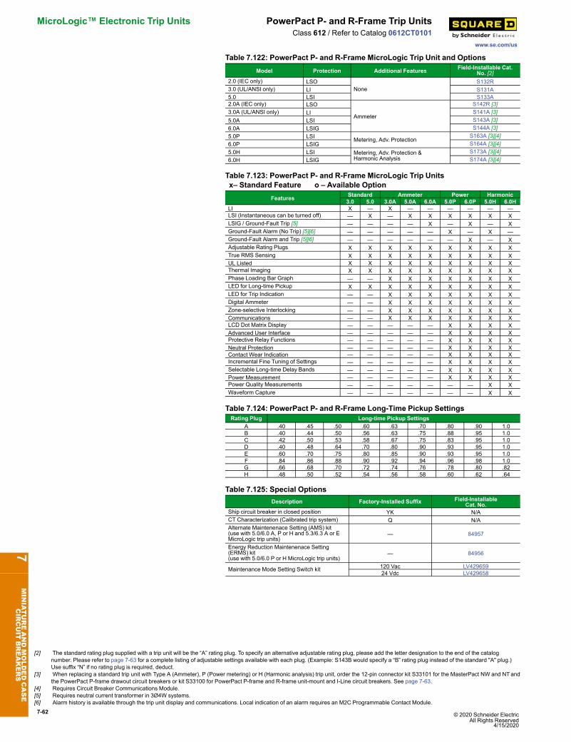
7-62 © 2020 Schneider Electric All Rights Reserved
4/15/2020
MicroLogic™ Electronic Trip Units PowerPact P- and R-Frame Trip Units
www.se.com/us
Class 612 / Refer to Catalog 0612CT0101
Table 7.122: PowerPact P- and R-Frame MicroLogic Trip Unit and OptionsModel Protection Additional Features Field-Installable Cat.
No. [2]2.0 (IEC only) LSO
NoneS132R
3.0 (UL/ANSI only) LI S131A5.0 LSI S133A2.0A (IEC only) LSO
Ammeter
S142R [3]3.0A (UL/ANSI only) LI S141A [3]5.0A LSI S143A [3]6.0A LSIG S144A [3]5.0P LSI Metering, Adv. Protection
S163A [3][4]6.0P LSIG S164A [3][4]5.0H LSI Metering, Adv. Protection &
Harmonic AnalysisS173A [3][4]
6.0H LSIG S174A [3][4]
Table 7.123: PowerPact P- and R-Frame MicroLogic Trip Unitsx– Standard Feature o – Available Option
Features Standard Ammeter Power Harmonic3.0 5.0 3.0A 5.0A 6.0A 5.0P 6.0P 5.0H 6.0H
LI X — X — — — — — —LSI (Instantaneous can be turned off) — X — X X X X X XLSIG / Ground-Fault Trip [5] — — — — X — X — XGround-Fault Alarm (No Trip) [5][6] — — — — — X — X —Ground-Fault Alarm and Trip [5][6] — — — — — — X — XAdjustable Rating Plugs X X X X X X X X XTrue RMS Sensing X X X X X X X X XUL Listed X X X X X X X X XThermal Imaging X X X X X X X X XPhase Loading Bar Graph — — X X X X X X XLED for Long-time Pickup X X X X X X X X XLED for Trip Indication — — X X X X X X XDigital Ammeter — — X X X X X X XZone-selective Interlocking — — X X X X X X XCommunications — — X X X X X X XLCD Dot Matrix Display — — — — — X X X XAdvanced User Interface — — — — — X X X XProtective Relay Functions — — — — — X X X XNeutral Protection — — — — — X X X XContact Wear Indication — — — — — X X X XIncremental Fine Tuning of Settings — — — — — X X X XSelectable Long-time Delay Bands — — — — — X X X XPower Measurement — — — — — X X X XPower Quality Measurements — — — — — — — X XWaveform Capture — — — — — — — X X
Table 7.124: PowerPact P- and R-Frame Long-Time Pickup SettingsRating Plug Long-time Pickup Settings
A .40 .45 .50 .60 .63 .70 .80 .90 1.0B .40 .44 .50 .56 .63 .75 .88 .95 1.0C .42 .50 .53 .58 .67 .75 .83 .95 1.0D .40 .48 .64 .70 .80 .90 .93 .95 1.0E .60 .70 .75 .80 .85 .90 .93 .95 1.0F .84 .86 .88 .90 .92 .94 .96 .98 1.0G .66 .68 .70 .72 .74 .76 .78 .80 .82H .48 .50 .52 .54 .56 .58 .60 .62 .64
Table 7.125: Special OptionsDescription Factory-Installed Suffix Field-Installable
Cat. No.Ship circuit breaker in closed position YK N/ACT Characterization (Calibrated trip system) Q N/AAlternate Maintenenace Setting (AMS) kit(use with 5.0/6.0 A, P or H and 5.3/6.3 A or EMicroLogic trip units)
— 84957
Energy Reduction Maintenenace Setting(ERMS) kit(use with 5.0/6.0 P or H MicroLogic trip units)
— 84956
Maintenance Mode Setting Switch kit 120 Vac LV42965924 Vdc LV429658
7MINIATUREANDMOLDEDCASE
CIRCUIT
BREAKERS
[2] The standard rating plug supplied with a trip unit will be the “A” rating plug. To specify an alternative adjustable rating plug, please add the letter designation to the end of the catalognumber. Please refer to page 7-63 for a complete listing of adjustable settings available with each plug. (Example: S143B would specify a “B” rating plug instead of the standard "A" plug.)Use suffix “N” if no rating plug is required, deduct.
[3] When replacing a standard trip unit with Type A (Ammeter), P (Power metering) or H (Harmonic analysis) trip unit, order the 12-pin connector kit S33101 for the MasterPact NW and NTandthe PowerPact P-frame drawout circuit breakers or kit S33100 for PowerPact P-frame and R-frame unit-mount and I-Line circuit breakers. See page 7-63.
[4] Requires Circuit Breaker Communications Module.[5] Requires neutral current transformer in 3Ø4W systems.[6] Alarm history is available through the trip unit display and communications. Local indication of an alarm requires an M2C Programmable Contact Module.

© 2020 Schneider Electric All Rights Reserved4/15/2020
7-63
www.se.com/us
MicroLogic™ Trip Unit Accessories MicroLogic™ Electronic Trip UnitsClass 612, 612 / Refer to Catalogs 0611CT1001 and 0612CT0101
Trip Unit Accessories
Trip Unit SealSensor Plug
Table 7.126: Rating PlugsRating Plug
[7]Factory Installed
Cat. SuffixField-Installable
Cat. No.A A (standard) S48818B B S48819C C S48820D D S48836E E S48837F F S48838G G S48839H H S48840
Adjustable rating plug "A" is installed as standard on all MicroLogic trip unit orders.However, an alternative selection may be specified from the "Assembled" table below,and factory installed with your trip unit order at no additional charge. To order, pleaseattach the appropriate catalog suffix to the end of the trip unit Cat. No. (after specifyingtrip unit options). Adjustable rating plugs may also be purchased as field-installablecomponents from the table below.For Enerlin’X accessory information, see Enerlin’X Digital Solutions, page 7-77
Table 7.127: Neutral Current TransformersUse With Cat. No. Sensor
H-Frame S429521 60–100S430562 150
J-Frame S430563 250L-Frame S432575 400–600
P-FrameS33575 [8] 250S33576 [8] 400–1600
R-Frame
S48916 [8] 250S34036 [8] 400–1600S48896 [8] 2000S48182 [8] 3000
All NCTWIRING All
Table 7.128: Zone-Selective InterlockingDescription Factory-Installed
Cat. SuffixField-Installable
Cat. No.ZSI Interface Module — S43421224 Vdc Terminal Block EN S434210ZSI Wire Harness, H/JFrame YH3 S434300
ZSI Wire Harness, L-Frame YH3 S434301ENCT & ZSI Wire Harness YH4 —
Table 7.129: Trip Unit AccessoriesDevice Frame Cat. No.
Pocket Tester
H/J/L
S434206UTATester STRV00910Spare UTATester STRV00911Bluetooth/Modbus for UTATester SVW3A8114Spare Power Supply for UTATester (110–120 Vac) TRV00915MicroLogic Cord for UTATester TRV00917MicroLogic 5/6 Cover, Transparent
H/JS429478
MicroLogic 2/3 Cover, Transparent S429481MicroLogic 5/6 Cover, Transparent
LS432459
MicroLogic 2/3 Cover, Transparent S432461LCD Display for MicroLogic 5
H/J/LS429483
LCD Display for MicroLogic 6 S429484Hand-held Test Kit
P/R
S33594Primary Injection Test Adaptor S33937Full-function Adapter Kit S48981Full-function Test Kit S33595Seven-pin Test Cable (for connection between test kit and trip unit) [9] S48907Two-pin Test Cable (for connection between test kit and trip unit) [10] S48908M2CTEST (for isolated trip unit testing) [11] M2CTEST230 Vac Filtered Power Cord [12]
P/RS48856
120 Vac Filtered Power Cord [12] S48855Trip Unit Battery for Trip Indicator Lights S33593
Power supply with:
24–30 Vdc input LV45444048/60 Vdc input LV454441125 Vdc input LV454442110–130 Vac input LV454443200–240 Vac input LV454444
MicroLogic A Trip Unit Cover, clearP/R
S33592MicroLogic P/H Trip Unit Cover, opaque gray S47067Trip Unit Seal (6 pieces) for compliance with NEC 240.6(c) H/J/L/P/R MICROTUSEAL12-pin Trip Unit Connector for NT/NW MasterPact Circuit Breakers
P/RS33101
12-pin Trip Unit Connector for P- and R-Frame Circuit Breakers S33100Battery Back-up (12 Hours) 685831
Table 7.130: Sensor Plugs for P- and R-Frame Circuit Breakers [13]Description Sensor Plug Range Sensor Plug Cat. No. Circuit Breaker Frames Accepting Sensor Plug
P-Frame Circuit Breaker 250 A 400 A 600 A 630 A [14] 800 A 1000 A 1200 A 1250 A[14] 1600 A
UL
250 A S47052 X — — — — — — — —400 A S47053 — X X — X — — — —600 A S48823 — — X — X X X — —800 A S33092 — — — — X X X — —1000 A S33093 — — — — — X X — —1200 A S48824 — — — — — — X — —
IEC
630 A S33091 — — — X X X — X X800 A S33092 — — — — X X — X X1000 A S33093 — — — — — X — X X1250 A S33094 — — — — — — — X X1600 A S33095 — — — — — — — — X
R-Frame Circuit Breaker 600 A 800 A 1000 A 1200 A 1600 A 2000 A 2500 A 3000 A 3200 A
UL
600 A S48823 X X X X — — — — —800 A S33092 — X X X X — — — —1000 A S33093 — — X X X X — — —1200 A S48824 — — — X X X X — —1600 A S33095 — — — — X X X X —2000 A S33982 — — — — — X X X —2500 A S33983 — — — — — — X X —3000 A S48825 — — — — — — — X —
IEC
1600 A S33095 — — — — X X X X X2000 A S33982 — — — — — X X X X2500 A S33983 — — — — — — X X X3200 A S33984 — — — — — — — — X
7MINIATUREANDMOLDEDCASE
CIRCUIT
BREAKERS
[7] Long-time pickup amperes (Ir) = Sensor Rating (In) X Setting of rating plug. “Fine adjustment tuning” is included on MicroLogic Power and Harmonic trip units, allowing for incrementalsettings of 1 A between the plug setting and.40 X Sensor Rating.
[8] Includes NCTWIRING kit.[9] Used for testing MicroLogic trip units. Included in the price of the Hand-held/Full-function Test Kits. Kit for replacement only.[10] Used for testing STR trip units. Included in the price of the Hand-held/Full-function Test Kits. Kit for replacement only.[11] Required for Arc Energy Reduction Performance Testing for Instantaneous setting or Maintenance Mode Switch when using a Full Function Test Kit[12] Included with the Full-function Test Kit. Kit for replacement only.[13] For use only with circuit breakers with date codes later than 07011. For long-time pickup range, See rating plug information at page 7-60.[14] IEC Only.
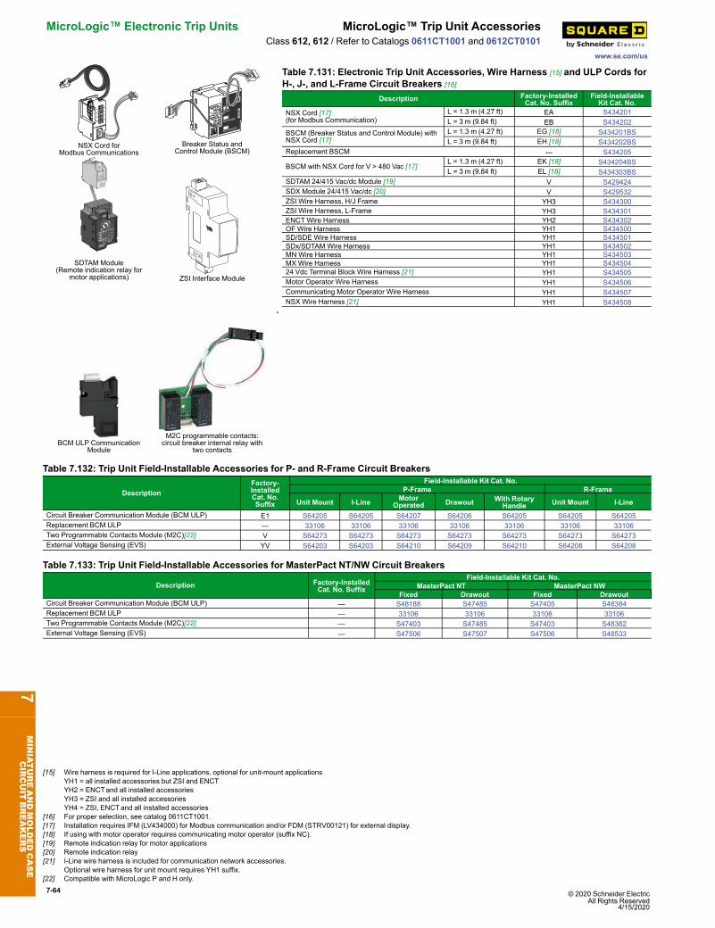
7-64 © 2020 Schneider Electric All Rights Reserved
4/15/2020
MicroLogic™ Electronic Trip Units MicroLogic™ Trip Unit Accessories
www.se.com/us
Class 612, 612 / Refer to Catalogs 0611CT1001 and 0612CT0101
NSX Cord forModbus Communications
Breaker Status andControl Module (BSCM)
SDTAM Module(Remote indication relay for
motor applications) ZSI Interface Module
Table 7.131: Electronic Trip Unit Accessories, Wire Harness [15] and ULP Cords forH-, J-, and L-Frame Circuit Breakers [16]
Description Factory-InstalledCat. No. Suffix
Field-InstallableKit Cat. No.
NSX Cord [17](for Modbus Communication)
L = 1.3 m (4.27 ft) EA S434201L = 3 m (9.84 ft) EB S434202
BSCM (Breaker Status and Control Module) withNSX Cord [17]
L = 1.3 m (4.27 ft) EG [18] S434201BSL = 3 m (9.84 ft) EH [18] S434202BS
Replacement BSCM — S434205
BSCM with NSX Cord for V > 480 Vac [17]L = 1.3 m (4.27 ft) EK [18] S434204BSL = 3 m (9.84 ft) EL [18] S434303BS
SDTAM 24/415 Vac/dc Module [19] V S429424SDX Module 24/415 Vac/dc [20] V S429532ZSI Wire Harness, H/J Frame YH3 S434300ZSI Wire Harness, L-Frame YH3 S434301ENCT Wire Harness YH2 S434302OF Wire Harness YH1 S434500SD/SDE Wire Harness YH1 S434501SDx/SDTAM Wire Harness YH1 S434502MNWire Harness YH1 S434503MX Wire Harness YH1 S43450424 Vdc Terminal Block Wire Harness [21] YH1 S434505Motor Operator Wire Harness YH1 S434506Communicating Motor Operator Wire Harness YH1 S434507NSX Wire Harness [21] YH1 S434508
BCM ULP CommunicationModule
M2C programmable contacts:circuit breaker internal relay with
two contacts
Table 7.132: Trip Unit Field-Installable Accessories for P- and R-Frame Circuit Breakers
DescriptionFactory-InstalledCat. No.Suffix
Field-Installable Kit Cat. No.P-Frame R-Frame
Unit Mount I-Line MotorOperated Drawout With Rotary
Handle Unit Mount I-Line
Circuit Breaker Communication Module (BCM ULP) E1 S64205 S64205 S64207 S64206 S64205 S64205 S64205Replacement BCM ULP — 33106 33106 33106 33106 33106 33106 33106Two Programmable Contacts Module (M2C)[22] V S64273 S64273 S64273 S64273 S64273 S64273 S64273External Voltage Sensing (EVS) YV S64203 S64203 S64210 S64209 S64210 S64208 S64208
Table 7.133: Trip Unit Field-Installable Accessories for MasterPact NT/NW Circuit Breakers
Description Factory-InstalledCat. No. Suffix
Field-Installable Kit Cat. No.MasterPact NT MasterPact NW
Fixed Drawout Fixed DrawoutCircuit Breaker Communication Module (BCM ULP) — S48188 S47485 S47405 S48384Replacement BCM ULP — 33106 33106 33106 33106Two Programmable Contacts Module (M2C)[22] — S47403 S47485 S47403 S48382External Voltage Sensing (EVS) — S47506 S47507 S47506 S48533
7MINIATUREANDMOLDEDCASE
CIRCUIT
BREAKERS
[15] Wire harness is required for I-Line applications, optional for unit-mount applicationsYH1 = all installed accessories but ZSI and ENCTYH2 = ENCTand all installed accessoriesYH3 = ZSI and all installed accessoriesYH4 = ZSI, ENCTand all installed accessories
[16] For proper selection, see catalog 0611CT1001.[17] Installation requires IFM (LV434000) for Modbus communication and/or FDM (STRV00121) for external display.[18] If using with motor operator requires communicating motor operator (suffix NC).[19] Remote indication relay for motor applications[20] Remote indication relay[21] I-Line wire harness is included for communication network accessories.
Optional wire harness for unit mount requires YH1 suffix.[22] Compatible with MicroLogic P and H only.
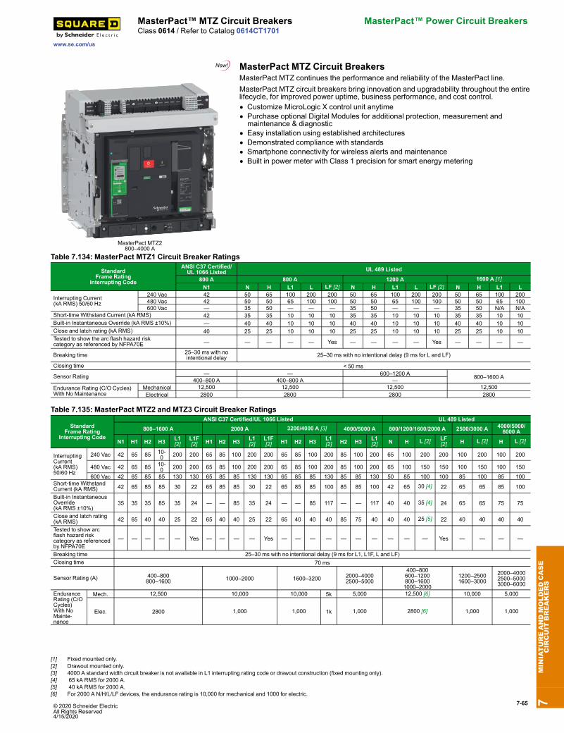
© 2020 Schneider Electric All Rights Reserved4/15/2020
7-65
www.se.com/us
MasterPact™ MTZ Circuit Breakers MasterPact™ Power Circuit BreakersClass 0614 / Refer to Catalog 0614CT1701
MasterPact MTZ Circuit Breakers
MasterPact MTZ2800–4000 A
MasterPact MTZ continues the performance and reliability of the MasterPact line.MasterPact MTZ circuit breakers bring innovation and upgradability throughout the entirelifecycle, for improved power uptime, business performance, and cost control.• Customize MicroLogic X control unit anytime• Purchase optional Digital Modules for additional protection, measurement andmaintenance & diagnostic
• Easy installation using established architectures• Demonstrated compliance with standards• Smartphone connectivity for wireless alerts and maintenance• Built in power meter with Class 1 precision for smart energy metering
Table 7.134: MasterPact MTZ1 Circuit Breaker Ratings
StandardFrame Rating
Interrupting Code
ANSI C37 Certified/UL 1066 Listed UL 489 Listed
800 A 800 A 1200 A 1600 A [1]N1 N H L1 L LF [2] N H L1 L LF [2] N H L1 L
Interrupting Current(kA RMS) 50/60 Hz
240 Vac 42 50 65 100 200 200 50 65 100 200 200 50 65 100 200480 Vac 42 50 50 65 100 100 50 50 65 100 100 50 50 65 100600 Vac — 35 50 — — — 35 50 — — — 35 50 N/A N/A
Short-time Withstand Current (kA RMS) 42 35 35 10 10 10 35 35 10 10 10 35 35 10 10Built-in Instantaneous Override (kA RMS ±10%) — 40 40 10 10 10 40 40 10 10 10 40 40 10 10Close and latch rating (kA RMS) 40 25 25 10 10 10 25 25 10 10 10 25 25 10 10Tested to show the arc flash hazard riskcategory as referenced by NFPA70E — — — — — Yes — — — — Yes — — — —
Breaking time 25–30 ms with nointentional delay 25–30 ms with no intentional delay (9 ms for L and LF)
Closing time < 50 ms
Sensor Rating — — 600–1200 A 800–1600 A400–800 A 400–800 A —Endurance Rating (C/O Cycles)With No Maintenance
Mechanical 12,500 12,500 12,500 12,500Electrical 2800 2800 2800 2800
Table 7.135: MasterPact MTZ2 and MTZ3 Circuit Breaker Ratings
StandardFrame Rating
Interrupting Code
ANSI C37 Certified/UL 1066 Listed UL 489 Listed800–1600 A 2000 A 3200/4000 A [3] 4000/5000 A 800/1200/1600/2000 A 2500/3000 A 4000/5000/
6000 A
N1 H1 H2 H3 L1[2]
L1F[2] H1 H2 H3 L1
[2]L1F[2] H1 H2 H3 L1
[2] H2 H3 L1[2] N H L [2] LF
[2] H L [2] H L [2]
InterruptingCurrent(kA RMS)50/60 Hz
240 Vac 42 65 85 10-0 200 200 65 85 100 200 200 65 85 100 200 85 100 200 65 100 200 200 100 200 100 200
480 Vac 42 65 85 10-0 200 200 65 85 100 200 200 65 85 100 200 85 100 200 65 100 150 150 100 150 100 150
600 Vac 42 65 85 85 130 130 65 85 85 130 130 65 85 85 130 85 85 130 50 85 100 100 85 100 85 100Short-time WithstandCurrent (kA RMS) 42 65 85 85 30 22 65 85 85 30 22 65 85 85 100 85 85 100 42 65 30 [4] 22 65 65 85 100
Built-in InstantaneousOverride(kA RMS ±10%)
35 35 35 85 35 24 — — 85 35 24 — — 85 117 — — 117 40 40 35 [4] 24 65 65 75 75
Close and latch rating(kA RMS) 42 65 40 40 25 22 65 40 40 25 22 65 40 40 40 85 75 40 40 40 25 [5] 22 40 40 40 40
Tested to show arcflash hazard riskcategory as referencedby NFPA70E
— — — — — Yes — — — — Yes — — — — — — — — — — Yes — — — —
Breaking time 25–30 ms with no intentional delay (9 ms for L1, L1F, L and LF)Closing time 70 ms
Sensor Rating (A) 400–800800–1600 1000–2000 1600–3200 2000–4000
2500–5000
400–800600–1200800–16001000–2000
1200–25001600–3000
2000–40002500–50003000–6000
EnduranceRating (C/OCycles)With NoMainte-nance
Mech. 12,500 10,000 10,000 5k 5,000 12,500 [6] 10,000 5,000
Elec. 2800 1,000 1,000 1k 1,000 2800 [6] 1,000 1,000
7MINIATUREANDMOLDEDCASE
CIRCUIT
BREAKERS
[1] Fixed mounted only.[2] Drawout mounted only.[3] 4000 A standard width circuit breaker is not available in L1 interrupting rating code or drawout construction (fixed mounting only).[4] 65 kA RMS for 2000 A.[5] 40 kA RMS for 2000 A.[6] For 2000 A N/H/L/LF devices, the endurance rating is 10,000 for mechanical and 1000 for electric.
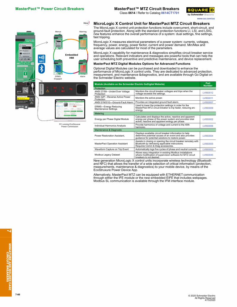
7-66 © 2020 Schneider Electric All Rights Reserved
4/15/2020
MasterPact™ Power Circuit Breakers MasterPact™ MTZ Circuit Breakers
www.se.com/us
Class 0614 / Refer to Catalog 0614CT1701
MicroLogic X Control Unit for MasterPact MTZ Circuit Breakers
In 1600 A
DISCONNECT BEFORE DIELECTRIC TEST
6.0 XID: 1989421527520002LV847604
TR
IP C
AU
SE
Op.IsdIi
IgI n
Ir
OK
Home
OK
!
Quickview
Measures
Alarms & H...
Maintenan...
MICROLOGIC
EmbeddedHMI
TR
IP C
AU
SE
Op.IsdIi
IgI n
Ir
PC running EcoStruxurePower Commission
Menus Warning
Test Reset
In 1600 A
Alarms
OK
Measures
Protection
Quickview
Home
DISCONNECT BEFOREDIELECTRIC TEST
7.0 X
ID: 1989421527520002LV847604
TR
IPC
AU
SE
Op.IsdIi
IgI n
Ir
OK
Home
OK
!
Quickview
Measures
Alarms & H...
Maintenan...
MICROLOGIC
Test Reset
In 1600 A
DISCONNECT BEFOREDIELECTRIC TEST
7.0 X
ID: 1989421527520002LV847604
TR
IPC
AU
SE
Op.IsdIi
IgI n
Ir
MICROLOGIC
Test Reset
In 1600 A
DISCONNECT BEFOREDIELECTRIC TEST
7.0 X
ID: 1989421527520002LV847604
TR
IP C
AU
SE
Op.IsdIi
IgI n
Ir
MICROLOGIC
Alarm
Test Reset
In 1600 A
DISCONNECT BEFOREDIELECTRIC TEST
7.0 X
ID: 1989421527520002LV847604
TR
IP C
AU
SE
Op.IsdIi
IgI n
Ir
MICROLOGIC
ERMSEngaged
NFC
The MicroLogic X control unit protection functions include overcurrent, short-circuit, andground-fault protection. Along with the standard protection functions LI, LSI, and LSIG,new features enhance the overall performance of a system: dual settings, fine settings,fast tripping.MicroLogic X measures electrical parameters of a power system: currents, voltages,frequency, power, energy, power factor, current and power demand. Min/Max andaverage values are calculated for most of the parameters.MicroLogic X capability for maintenance & diagnostics simplifies circuit breaker serviceand operations. Relevant indicators and messages are powerful tools that can help theuser scheduling both preventive and predictive maintenance, and device replacement.MasterPact MTZ Digital Modules Options for Advanced FunctionsOptional Digital Modules can be purchased and downloaded to enhance theperformance of MicroLogic X control units. They are dedicated to advanced protection,measurement, and maintenance &diagnostics, and are available through Go Digital onthe Schneider Electric website.
Module (Available on the Schneider Electric GoDigital Website) PartNumber
ProtectionANSI 27/59—Under/Over VoltageProtection
Monitors the circuit breaker voltages and trips when thevoltage exceeds the settings. LV850012
ANSI 32P—Reverse Active PowerProtection Monitors the active power. LV850011
ANSI 51N/51G—Ground-Fault Alarm Provides an integrated ground fault alarm. LV850007
ERMS—Energy ReducingMaintenance Settings
Used to lower the protection settings in order for theMasterPact MTZ circuit breaker to trip faster, reducing arcenergy.
LV850009
Metering
Energy per Phase Digital ModuleCalculates and displays the active, reactive and apparentenergy per phase of the power system and provides totalactive, reactive and apparent energy per phase.
LV850002
Individual Harmonics Analysis Provide harmonics of voltage and current to the 40thharmonic. LV850006
Maintenance & Diagnostic
Power Restoration Assistant,Displays available circuit breaker information to helpdetermine potential causes of an event and also providesguidance for potential solutions to restore power.
LV850004
MasterPact Operation AssistantAssists in closing or opening the circuit breaker remotely withBluetooth by delivering applicable instructions.Requires Comm & Diag accessories.
LV850005
Waveform Capture on Trip Event Automatically logs five cycles of phase and neutral currents. LV850003
Modbus Legacy DatasetAllows easy integration in existing Modbus installationswhere modification of supervision software for MTZ circuitbreakers is not desired.
LV850045
New generation MicroLogic X control units incorporate wireless technology (Bluetoothand NFC) that allows the transfer of a wide selection of critical information (protection,measurements, maintenance & diagnostics) to your mobile device, by means of theEcoStruxure Power Device App.Alternatively, MasterPact MTZ can be equipped with ETHERNETcommunicationthrough either the IFE module or the new embedded EIFE that includes webpages.Modbus SL communication is available through the IFM interface module.
7MINIATUREANDMOLDEDCASE
CIRCUIT
BREAKERS
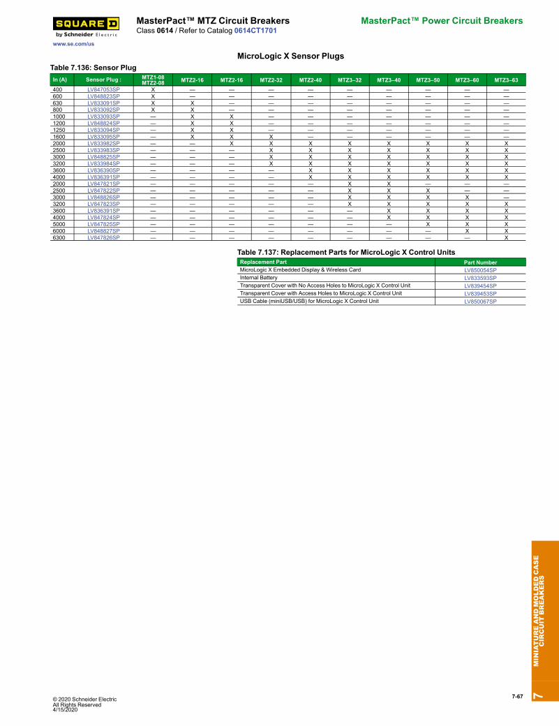
© 2020 Schneider Electric All Rights Reserved4/15/2020
7-67
www.se.com/us
MasterPact™ MTZ Circuit Breakers MasterPact™ Power Circuit BreakersClass 0614 / Refer to Catalog 0614CT1701
MicroLogic X Sensor PlugsTable 7.136: Sensor PlugIn (A) Sensor Plug : MTZ1-08
MTZ2-08 MTZ2-16 MTZ2-16 MTZ2-32 MTZ2-40 MTZ3–32 MTZ3–40 MTZ3–50 MTZ3–60 MTZ3–63400 LV847053SP X — — — — — — — — —600 LV848823SP X — — — — — — — — —630 LV833091SP X X — — — — — — — —800 LV833092SP X X — — — — — — — —1000 LV833093SP — X X — — — — — — —1200 LV848824SP — X X — — — — — — —1250 LV833094SP — X X — — — — — — —1600 LV833095SP — X X X — — — — — —2000 LV833982SP — — X X X X X X X X2500 LV833983SP — — — X X X X X X X3000 LV848825SP — — — X X X X X X X3200 LV833984SP — — — X X X X X X X3600 LV836390SP — — — — X X X X X X4000 LV836391SP — — — — X X X X X X2000 LV847821SP — — — — — X X — — —2500 LV847822SP — — — — — X X X — —3000 LV848826SP — — — — — X X X X —3200 LV847823SP — — — — — X X X X X3600 LV836391SP — — — — — — X X X X4000 LV847824SP — — — — — — X X X X5000 LV847825SP — — — — — — — X X X6000 LV848827SP — — — — — — — — X X6300 LV847826SP — — — — — — — — — X
Table 7.137: Replacement Parts for MicroLogic X Control UnitsReplacement Part Part NumberMicroLogic X Embedded Display & Wireless Card LV850054SPInternal Battery LV833593SPTransparent Cover with No Access Holes to MicroLogic X Control Unit LV839454SPTransparent Cover with Access Holes to MicroLogic X Control Unit LV839453SPUSB Cable (miniUSB/USB) for MicroLogic X Control Unit LV850067SP
7MINIATUREANDMOLDEDCASE
CIRCUIT
BREAKERS
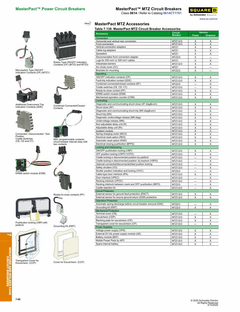
7-68 © 2020 Schneider Electric All Rights Reserved
4/15/2020
MasterPact™ Power Circuit Breakers MasterPact™ MTZ Circuit Breakers
www.se.com/us
Class 0614 / Refer to Catalog 0614CT1701
MasterPact MTZ Accessories
Microswitch Type ON/OFFIndication Contacts (OF) (MTZ1)
Rotary Type ON/OFF IndicationContacts (OF) (MTZ2 and MTZ3)
Additional Overcurrent TripIndication Contacts (SDE) Combined Connected/Closed
Contacts
Connected / Disconnected / TestPositionCradle Switches(CE, CD and CT)
M2C programmable contacts:circuit breaker internal relay withtwo contacts
ERMS switch module (ESM)
Ready-to-close contacts (PF)
Pushbutton locking (VBP) withpadlock Grounding Kit (KMT)
Transparent Cover forEscutcheon. (CCP) Cover for Escutcheon. (CCP)
Table 7.138: MasterPact MTZ Circuit Breaker AccessoriesAccessory Circuit
BreakerVersion
Fixed DrawoutConnectionHorizontal and vertical rear connection MTZ1/2/3 X XFront connection MTZ1/2/3 X XVertical-connection adapters MTZ1 X XCable-lug adapters MTZ1 X XSpreaders MTZ1 X XDisconnectable front connection adapter MTZ2/3 X —Lugs for 240 mm2 or 300 mm2 cables MTZ1 X XInterphase barriers MTZ1/2/3 X XArc chute cover (CC) MTZ1 X —Brackets for mounting MTZ2/3 X —SignallingON/OFF indication contacts (OF) MTZ1/2/3 X XFault-trip indication contact (SDE) MTZ1/2/3 X XCombined connected/closed contacts (EF) MTZ2/3 — XCradle switches (CE, CD, CT) MTZ1/2/3 — XReady-to-close contact (PF) MTZ1/2/3 X XERMS switch module (ESM) MTZ1/2/3 X XMechanical operation counter (CDM) MTZ1/2/3 X XControllingDiagnostic and communicating shunt close (XF diag&com) MTZ1/2/3 X XShunt close (XF) MTZ1/2/3 X XDiagnostic and communicating shunt trip (MX diag&com) MTZ1/2/3 X XShunt trip (MX) MTZ1/2/3 X XDiagnostic undervoltage release (MN diag) MTZ1/2/3 X XUndervoltage release (MN) MTZ1/2/3 X XNon-adjustable delay unit (R) MTZ1/2/3 X XAdjustable delay unit (Rr) MTZ1/2/3 X XIsolation module MTZ1/2/3 X XSpring charging motor (MCH) MTZ1/2/3 X XElectrical reset option (RES) MTZ1/2/3 X XAutomatic reset option (RAR) MTZ1/2/3 X XElectrical closing pushbutton (BPFE) MTZ1/2/3 X XLocking and InterlockingON/OFF pushbutton locking (VBP) MTZ1/2/3 X XOFF position locking (VSPO-VCPO) MTZ1/2/3 X XCradle locking in disconnected position by padlock MTZ1/2/3 — XCradle locking in disconnected position: by keylock (VSPD) MTZ1/2/3 — XOptional connected/disconnected/test position locking MTZ1/2/3 — XSafety shutters (VO) MTZ1/2/3 — XShutter position indication and locking (VIVC) MTZ2/3 — XCable-type door interlock (IPA) MTZ1/2/3 X XDoor interlock (VPEC) MTZ1/2/3 — XRacking interlock (VPOC) MTZ1/2/3 — XRacking interlock between crank and OFF pushbutton (IBPO) MTZ2/3 — XCradle rejection kit MTZ1/2/3 — XCircuit ProtectionExternal sensor for ground-fault protection (ENCT) MTZ1/2/3 X XExternal sensor for source ground-return (SGR) protection MTZ1/2/3 X XOperation ProtectionAutomatic spring discharge before circuit breaker removal (DAE) MTZ2/3 — XGrounding kit (KMT) MTZ2/3 X XMechanical ProtectionTerminal cover (CB) MTZ1/2/3 — XEscutcheon (CDP) MTZ1/2/3 X XBlanking plate for escutcheon (OP) MTZ1/2/3 X XTransparent cover for escutcheon (CP) MTZ1/2/3 — XPower SuppliesVoltage power supply (VPS) MTZ1/2/3 X XExternal 24 Vdc power supply module (AD) MTZ1/2/3 X XBattery module (BAT) MTZ1/2/3 X XMobile Power Pack by APC MTZ1/2/3 X XSpare internal battery MTZ1/2/3 X X
7MINIATUREANDMOLDEDCASE
CIRCUIT
BREAKERS
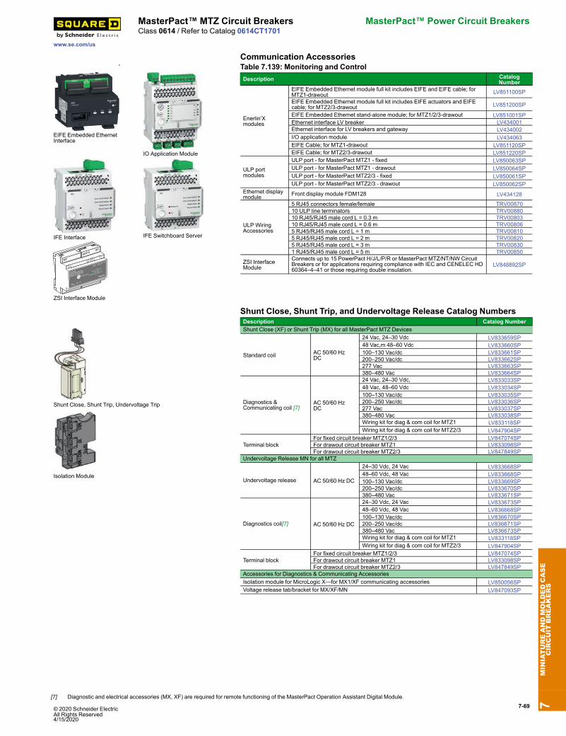
7-69
www.se.com/us
MasterPact™ MTZ Circuit Breakers MasterPact™ Power Circuit BreakersClass 0614 / Refer to Catalog 0614CT1701
Communication Accessories
EIFE Embedded EthernetInterface
IO Application Module
IFE Interface IFE Switchboard Server
9 10
1 2
3 4 5 6
~ ~
LV848892
ZSI Interface Module
Module d’interface ZSI
Módulo de interfaz ZSI
Push-to-testUpstream
ZSI OUT
ZSI IN
Downstream
120 V24 V
6mA max
CB Acc.
Ctrl. No.52H4
60 Hz 41mA max
S1
ZSI Interface Module
Table 7.139: Monitoring and ControlDescription Catalog
Number
Enerlin’Xmodules
EIFE Embedded Ethernet module full kit includes EIFE and EIFE cable; forMTZ1-drawout LV851100SP
EIFE Embedded Ethernet module full kit includes EIFE actuators and EIFEcable; for MTZ2/3-drawout LV851200SP
EIFE Embedded Ethernet stand-alone module; for MTZ1/2/3-drawout LV851001SPEthernet interface LV breaker LV434001Ethernet interface for LV breakers and gateway LV434002I/O application module LV434063EIFE Cable; for MTZ1-drawout LV851120SPEIFE Cable; for MTZ2/3-drawout LV851220SP
ULP portmodules
ULP port - for MasterPact MTZ1 - fixed LV850063SPULP port - for MasterPact MTZ1 - drawout LV850064SPULP port - for MasterPact MTZ2/3 - fixed LV850061SPULP port - for MasterPact MTZ2/3 - drawout LV850062SP
Ethernet displaymodule Front display module FDM128 LV434128
ULP WiringAccessories
5 RJ45 connectors female/female TRV0087010 ULP line terminators TRV0088010 RJ45/RJ45 male cord L = 0.3 m TRV0080310 RJ45/RJ45 male cord L = 0.6 m TRV008065 RJ45/RJ45 male cord L = 1 m TRV008105 RJ45/RJ45 male cord L = 2 m TRV008205 RJ45/RJ45 male cord L = 3 m TRV008301 RJ45/RJ45 male cord L = 5 m TRV00850
ZSI InterfaceModule
Connects up to 15 PowerPact H/J/L/P/R or MasterPact MTZ/NT/NW CircuitBreakers or for applications requiring compliance with IEC and CENELEC HD60364–4–41 or those requiring double insulation.
LV848892SP
Shunt Close, Shunt Trip, and Undervoltage Release Catalog Numbers
Shunt Close, Shunt Trip, Undervoltage Trip
Isolation Module
Description Catalog NumberShunt Close (XF) or Shunt Trip (MX) for all MasterPact MTZ Devices
Standard coil AC 50/60 HzDC
24 Vac, 24–30 Vdc LV833659SP48 Vac,m 48–60 Vdc LV833660SP100–130 Vac/dc LV833661SP200–250 Vac/dc LV833662SP277 Vac LV833663SP380–480 Vac LV833664SP
Diagnostics &Communicating coil [7]
AC 50/60 HzDC
24 Vac, 24–30 Vdc, LV833033SP48 Vac, 48–60 Vdc LV833034SP100–130 Vac/dc LV833035SP200–250 Vac/dc LV833036SP277 Vac LV833037SP380–480 Vac LV833038SPWiring kit for diag & com coil for MTZ1 LV833118SPWiring kit for diag & com coil for MTZ2/3 LV847904SP
Terminal blockFor fixed circuit breaker MTZ1/2/3 LV847074SPFor drawout circuit breaker MTZ1 LV833098SPFor drawout circuit breaker MTZ2/3 LV847849SP
Undervoltage Release MN for all MTZ
Undervoltage release AC 50/60 Hz DC
24–30 Vdc, 24 Vac LV833668SP48–60 Vdc, 48 Vac LV833668SP100–130 Vac/dc LV833669SP200–250 Vac/dc LV833670SP380–480 Vac LV833671SP
Diagnostics coil[7] AC 50/60 Hz DC
24–30 Vdc, 24 Vac LV833673SP48–60 Vdc, 48 Vac LV836668SP100–130 Vac/dc LV836670SP200–250 Vac/dc LV836671SP380–480 Vac LV836673SPWiring kit for diag & com coil for MTZ1 LV833118SPWiring kit for diag & com coil for MTZ2/3 LV847904SP
Terminal blockFor fixed circuit breaker MTZ1/2/3 LV847074SPFor drawout circuit breaker MTZ1 LV833098SPFor drawout circuit breaker MTZ2/3 LV847849SP
Accessories for Diagnostics & Communicating AccessoriesIsolation module for MicroLogic X—for MX1/XF communicating accessories LV850056SPVoltage release tab/bracket for MX/XF/MN LV847093SP
7MINIATUREANDMOLDEDCASE
CIRCUIT
BREAKERS
[7] Diagnostic and electrical accessories (MX, XF) are required for remote functioning of the MasterPact Operation Assistant Digital Module.
© 2020 Schneider ElectricAll Rights Reserved4/15/2020
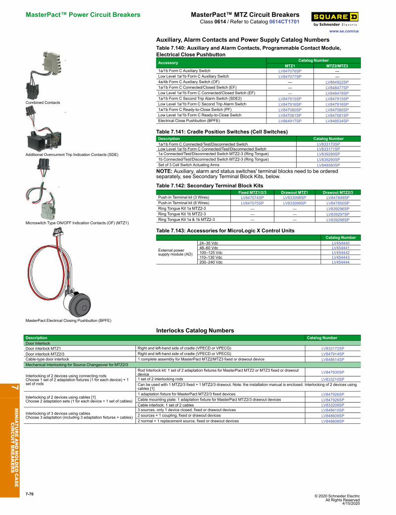
7-70 © 2020 Schneider Electric All Rights Reserved
4/15/2020
MasterPact™ Power Circuit Breakers MasterPact™ MTZ Circuit Breakers
www.se.com/us
Class 0614 / Refer to Catalog 0614CT1701
Auxiliary, Alarm Contacts and Power Supply Catalog Numbers
Combined Contacts
Additional Overcurrent Trip Indication Contacts (SDE)
Microswitch Type ON/OFF Indication Contacts (OF) (MTZ1)
MasterPact Electrical Closing Pushbutton (BPFE)
Table 7.140: Auxiliary and Alarm Contacts, Programmable Contact Module,Electrical Close PushbuttonAccessory Catalog Number
MTZ1 MTZ2/MTZ31a/1b Form C Auxiliary Switch LV847076SP —Low Level 1a/1b Form C Auxiliary Switch LV847077SP —4a/4b Form C Auxiliary Switch (OF) — LV864922SP1a/1b Form C Connected/Closed Switch (EF) — LV848477SPLow Level 1a/1b Form C Connected/Closed Switch (EF) — LV848478SP1a/1b Form C Second Trip Alarm Switch (SDE2) LV847915SP LV847915SPLow Level 1a/1b Form C Second Trip Alarm Switch LV847916SP LV847916SP1a/1b Form C Ready-to-Close Switch (PF) LV847080SP LV847080SPLow Level 1a/1b Form C Ready-to-Close Switch LV847081SP LV847081SPElectrical Close Pushbutton (BPFE) LV864917SP LV848534SP
Table 7.141: Cradle Position Switches (Cell Switches)Description Catalog Number1a/1b Form C Connected/Test/Disconnected Switch LV833170SPLow Level 1a/1b Form C Connected/Test/Disconnected Switch LV833171SP1a Connected/Test/Disconnected Switch MTZ2-3 (Ring Tongue) LV839289SP1b Connected/Test/Disconnected Switch MTZ2-3 (Ring Tongue) LV839290SPSet of 3 Cell Switch Actuating Arms LV848560SPNOTE: Auxiliary, alarm and status switches' terminal blocks need to be orderedseparately, see Secondary Terminal Block Kits, below.
Table 7.142: Secondary Terminal Block KitsFixed MTZ1/2/3 Drawout MTZ1 Drawout MTZ2/3
Push-in Terminal kit (3 Wires) LV847074SP LV833098SP LV847849SPPush-in Terminal kit (6 Wires) LV847075SP LV833099SP LV847850SPRing Tongue Kit 1a MTZ2-3 — — LV839296SPRing Tongue Kit 1b MTZ2-3 — — LV839297SPRing Tongue Kit 1a & 1b MTZ2-3 — — LV839298SP
Table 7.143: Accessories for MicroLogic X Control UnitsCatalog Number
External powersupply module (AD)
24–30 Vdc LV45444048–60 Vdc LV454441100–125 Vdc LV454442110–130 Vdc LV454443200–240 Vdc LV454444
Interlocks Catalog NumbersDescription Catalog NumberDoor InterlockDoor interlock MTZ1 Right and left-hand side of cradle (VPECD or VPECG) LV833172SPDoor interlock MTZ2/3 Right and left-hand side of cradle (VPECD or VPECG) LV847914SPCable-type door interlock 1 complete assembly for MasterPact MTZ2/MTZ3 fixed or drawout device LV848614SPMechanical Interlocking for Source Changeover for MTZ2/3
Interlocking of 2 devices using connecting rodsChoose 1 set of 2 adaptation fixtures (1 for each device) + 1set of rods
Rod Interlock kit: 1 set of 2 adaptation fixtures for MasterPact MTZ2 or MTZ3 fixed or drawoutdevice LV847930SP
1 set of 2 interlocking rods LV833210SPCan be used with 1 MTZ2/3 fixed + 1 MTZ2/3 drawout. Note: the installation manual is enclosed. Interlocking of 2 devices usingcables [1]
Interlocking of 2 devices using cables [1]Choose 2 adaptation sets (1 for each device + 1 set of cables)
1 adaptation fixture for MasterPact MTZ2/3 fixed devices LV847926SPCable mouinting plate: 1 adaptation fixture for MasterPact MTZ2/3 drawout devices LV847926SPCable interlock: 1 set of 2 cables LV833209SP
Interlocking of 3 devices using cablesChoose 3 adaptation (including 3 adaptation fixtures + cables)
3 sources, only 1 device closed, fixed or drawout devices LV848610SP2 sources + 1 coupling, fixed or drawout devices LV848609SP2 normal + 1 replacement source, fixed or drawout devices LV848608SP
7MINIATUREANDMOLDEDCASE
CIRCUIT
BREAKERS
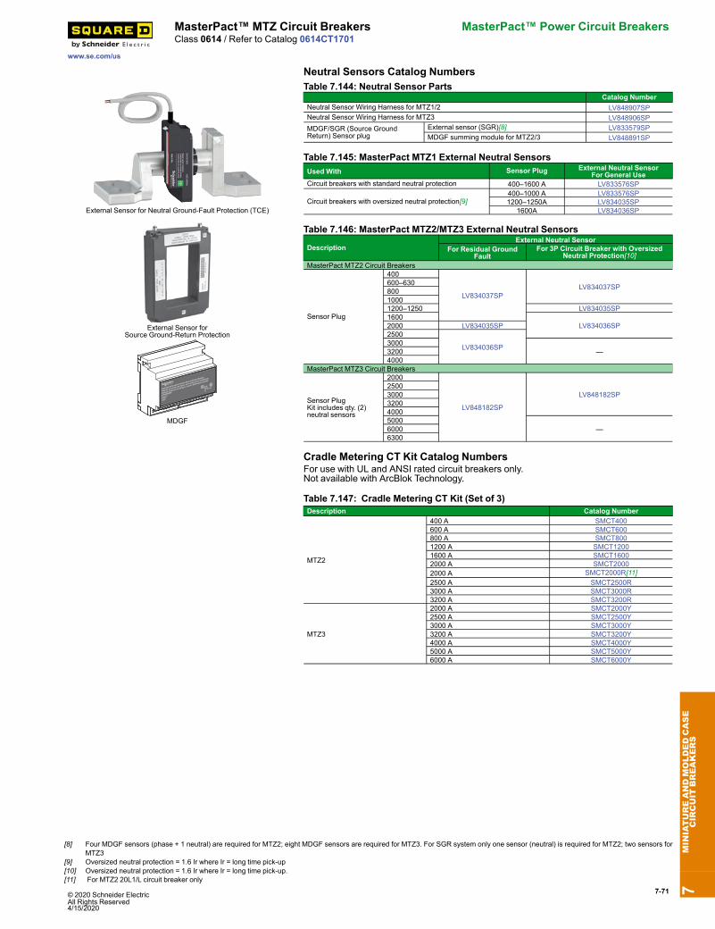
© 2020 Schneider Electric All Rights Reserved4/15/2020
7-71
www.se.com/us
MasterPact™ MTZ Circuit Breakers MasterPact™ Power Circuit BreakersClass 0614 / Refer to Catalog 0614CT1701
Neutral Sensors Catalog Numbers
External Sensor for Neutral Ground-Fault Protection (TCE)
External Sensor forSource Ground-Return Protection
S1
LV848891SP
Replaces
S48891
48891
Modified Different ial Ground Fault Inter face Module
Módulo de interfaz de falla a tierra diferenc ial modif icada
Module d'inter ace de défaut à la terre différentiel modifié
MDGF
Table 7.144: Neutral Sensor PartsCatalog Number
Neutral Sensor Wiring Harness for MTZ1/2 LV848907SPNeutral Sensor Wiring Harness for MTZ3 LV848906SPMDGF/SGR (Source GroundReturn) Sensor plug
External sensor (SGR)[8] LV833579SPMDGF summing module for MTZ2/3 LV848891SP
Table 7.145: MasterPact MTZ1 External Neutral SensorsUsed With Sensor Plug External Neutral Sensor
For General UseCircuit breakers with standard neutral protection 400–1600 A LV833576SP
Circuit breakers with oversized neutral protection[9]400–1000 A LV833576SP1200–1250A LV834035SP
1600A LV834036SP
Table 7.146: MasterPact MTZ2/MTZ3 External Neutral Sensors
DescriptionExternal Neutral Sensor
For Residual GroundFault
For 3P Circuit Breaker with OversizedNeutral Protection[10]
MasterPact MTZ2 Circuit Breakers
Sensor Plug
400
LV834037SPLV834037SP600–630
80010001200–1250 LV834035SP1600
LV834036SP2000 LV834035SP2500
LV834036SP3000—3200
4000MasterPact MTZ3 Circuit Breakers
Sensor PlugKit includes qty. (2)neutral sensors
2000
LV848182SP
LV848182SP25003000320040005000
—60006300
Cradle Metering CT Kit Catalog NumbersFor use with UL and ANSI rated circuit breakers only.Not available with ArcBlok Technology.
Table 7.147: Cradle Metering CT Kit (Set of 3)Description Catalog Number
MTZ2
400 A SMCT400600 A SMCT600800 A SMCT8001200 A SMCT12001600 A SMCT16002000 A SMCT20002000 A SMCT2000R[11]2500 A SMCT2500R3000 A SMCT3000R3200 A SMCT3200R
MTZ3
2000 A SMCT2000Y2500 A SMCT2500Y3000 A SMCT3000Y3200 A SMCT3200Y4000 A SMCT4000Y5000 A SMCT5000Y6000 A SMCT6000Y
7MINIATUREANDMOLDEDCASE
CIRCUIT
BREAKERS
[8] Four MDGF sensors (phase + 1 neutral) are required for MTZ2; eight MDGF sensors are required for MTZ3. For SGR system only one sensor (neutral) is required for MTZ2; two sensors forMTZ3
[9] Oversized neutral protection = 1.6 Ir where Ir = long time pick-up[10] Oversized neutral protection = 1.6 Ir where Ir = long time pick-up.[11] For MTZ2 20L1/L circuit breaker only
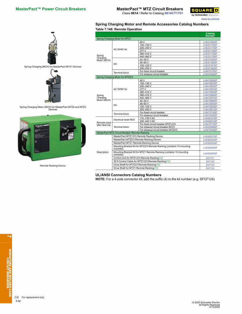
7-72 © 2020 Schneider Electric All Rights Reserved
4/15/2020
MasterPact™ Power Circuit Breakers MasterPact™ MTZ Circuit Breakers
www.se.com/us
Class 0614 / Refer to Catalog 0614CT1701
Spring Charging Motor and Remote Accessories Catalog Numbers
Spring Charging (MCH) for MasterPact MTZ1 Devices
Spring Charging Motor (MCH) for MasterPact MTZ2 and MTZ3Devices
Remote Racking Device
Table 7.148: Remote OperationCatalogNumber
Spring Charging Motor for MTZ1
SpringChargingMotor (MCH)
AC 50/60 Hz
48 V LV833186SP100–130 V LV833176SP200–240 V LV833177SP277 V LV833179SP380–415 V LV833179SP440–480 V LV833179SP
DC
24–30 V LV833185SP48–60 V LV833186SP100–125 V LV833187SP200–250 V LV833188SP
Terminal block For fixed circuit breaker LV847074SPFor drawout circuit breaker LV833098SP
Spring Charging Motor for MTZ2/3
SpringChargingMotor (MCH)
AC 50/60 Hz
48 V LV847889SP100–130 V LV847893SP200–240 V LV847894SP277 V LV847895SP380–415 V LV847895SP380–415 V LV847896SP440–480 V LV847897SP
DC
24–30 V LV847888SP48–60 V LV847889SP100–125 V LV847890SP200–250 V LV847891SP
Terminal block For fixed circuit breaker LV847074SPFor drawout circuit breaker LV847849SP
Remote resetafter fault trip
Electrical reset RES 110–130 VAC LV848202SP220–240 VAC LV848203SP
Terminal blockFor fixed circuit breaker MTZ1/2/3 LV847074SPFor drawout circuit breaker MTZ1 LV833098SPFor drawout circuit breaker MTZ2/3 LV847849SP
MasterPact MTZ Circuit Breaker Remote Racking
Description
MasterPact MTZ1/2/3 Remote Racking Device LV839291SPMasterPact MTZ2/3 Remote Racking Device LV839292SPMasterPact MTZ1 Remote Racking Device LV839293SPMounting Bracket Kit for MTZ2/3 Remote Racking (contains 10 mountingbrackets) LV839294SP
Mounting Bracket Kit for MTZ1 Remote Racking (contains 10 mountingbrackets) LV839295SP
Control Unit for MTZ1/2/3 Remote Racking[12] S4710130 ft Control Cable for MTZ1/2/3 Remote Racking[12] S47102Drive Shaft for MTZ2/3 Remote Racking[12] S47103Drive Shaft for MTZ1 Remote Racking[12] S47105
UL/ANSI Connectors Catalog NumbersNOTE: For a 4-pole connector kit, add the suffix (4) to the kit number (e.g. SFCF124)
7MINIATUREANDMOLDEDCASE
CIRCUIT
BREAKERS
[12] For replacement only
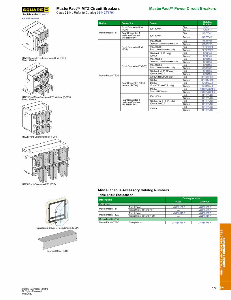
© 2020 Schneider ElectricAll Rights4/15/2020
Reserved7-73
www.se.com/us
MasterPact™ MTZ Circuit Breakers MasterPact™ Power Circuit BreakersClass 0614 / Refer to Catalog 0614CT1701
MTZ1 Drawout Front-Connected Flat (FCF)800 to 1200 A
MTZ1 FixedRear-Connected “T” Vertical (RCTV)800 to 1200 A
MTZ2 Front-Connected Flat (FCF)
MTZ3 Front-Connected “T” (FCT)
Device Connector Frame CatalogNumber
MasterPact MTZ1
Front Connected Flat(FCF) 800–1200A
Top SFCF12Bottom SFCF12
Rear Connected THorizontal/Vertical(RCTH/RCTV)
800–1200ATop SRCTV12
Bottom SRCTV12
MasterPact MTZ2/3
Front Connected Flat(FCF)
800–2000A,Drawout circuit breaker only
Top SFCF20TBottom SFCF20B
800–2000A,Fixed circuit breaker only
Top SFCF20FTBottom SFCF20FB
3200 A (L1/L1F only)4000 A
Top SFCF40Bottom SFCF40
Front Connected T (FCT)
800–2000 ADrawout circuit breaker only
Top SFCT30Bottom SFCT30
800–2000 AFixed circuit breaker only
Top SFCT30Bottom SFCT30B
3200 A (for L1/L1F only),4000 A, 5000 A
Top SFCT50Bottom SFCT50
Rear Connected OffsetVertical (RCOV)
2000 A (for L1/L1F only) Top SRCOV32T3200 A Bottom SRCOV32B4000 A(For MTZ2 4000 A only)
Top SRCOV40Bottom SRCOV40
4000 AFixed MTZ2 only)
Top SRCOV40BFXBottom SRCOV40BFX
Rear Connected THorizontal/Vertical(RCTH/RCTV)
800-2000 ATop SRCTV20Bottom SRCTV20
3200 A ( for L1/L1F only),4000 A, 5000 A
Top SRCTV50Bottom SRCTV50
6000 ATop SRCTV60Bottom SRCTV60
Miscellaneous Accessory Catalog Numbers
Transparent Cover for Escutcheon. (CCP)
Terminal Cover (CB)
Table 7.149: EscutcheonDescription Catalog Number
Fixed DrawoutEscutcheon
MasterPact MTZ1Escutcheon LV833718SP LV833857SPTransparent cover (IP54) — LV833859SP
MasterPact MTZ2/3Escutcheon LV848601SP LV848603SPTransparent cover (IP 54) — LV848604SP
Grounding Kit KTMMasterPact MTZ2/3 Side plate kit LV848556SP LV848557SP
7MINIATUREANDMOLDEDCASE
CIRCUIT
BREAKERS
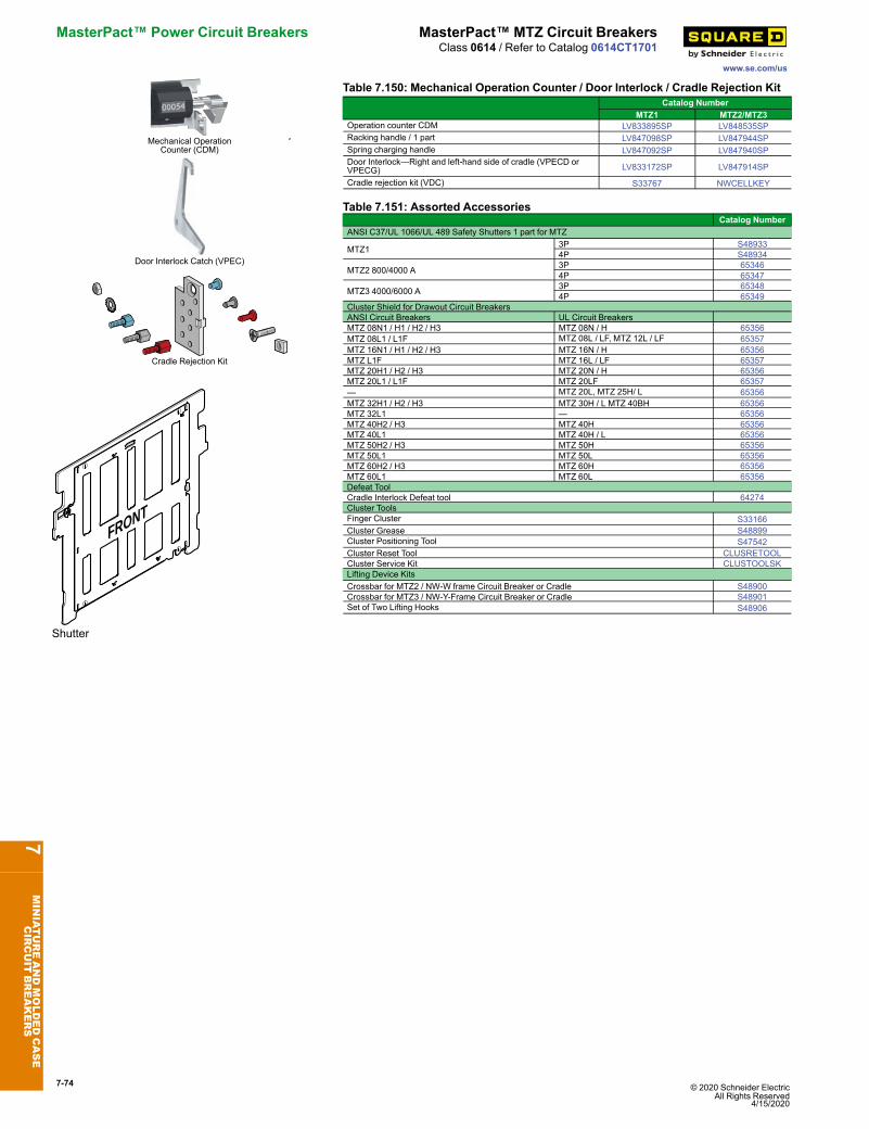
7-74 © 2020 Schneider Electric All Rights Reserved
4/15/2020
MasterPact™ Power Circuit Breakers MasterPact™ MTZ Circuit Breakers
www.se.com/us
Class 0614 / Refer to Catalog 0614CT1701
Mechanical OperationCounter (CDM)
Door Interlock Catch (VPEC)
Cradle Rejection Kit
Table 7.150: Mechanical Operation Counter / Door Interlock / Cradle Rejection KitCatalog Number
MTZ1 MTZ2/MTZ3Operation counter CDM LV833895SP LV848535SPRacking handle / 1 part LV847098SP LV847944SPSpring charging handle LV847092SP LV847940SPDoor Interlock—Right and left-hand side of cradle (VPECD orVPECG) LV833172SP LV847914SP
Cradle rejection kit (VDC) S33767 NWCELLKEY
FRONT
Shutter
Table 7.151: Assorted AccessoriesCatalog Number
ANSI C37/UL 1066/UL 489 Safety Shutters 1 part for MTZ
MTZ1 3P S489334P S48934
MTZ2 800/4000 A 3P 653464P 65347
MTZ3 4000/6000 A 3P 653484P 65349
Cluster Shield for Drawout Circuit BreakersANSI Circuit Breakers UL Circuit BreakersMTZ 08N1 / H1 / H2 / H3 MTZ 08N / H 65356MTZ 08L1 / L1F MTZ 08L / LF, MTZ 12L / LF 65357MTZ 16N1 / H1 / H2 / H3 MTZ 16N / H 65356MTZ L1F MTZ 16L / LF 65357MTZ 20H1 / H2 / H3 MTZ 20N / H 65356MTZ 20L1 / L1F MTZ 20LF 65357— MTZ 20L, MTZ 25H/ L 65356MTZ 32H1 / H2 / H3 MTZ 30H / L MTZ 40BH 65356MTZ 32L1 — 65356MTZ 40H2 / H3 MTZ 40H 65356MTZ 40L1 MTZ 40H / L 65356MTZ 50H2 / H3 MTZ 50H 65356MTZ 50L1 MTZ 50L 65356MTZ 60H2 / H3 MTZ 60H 65356MTZ 60L1 MTZ 60L 65356Defeat ToolCradle Interlock Defeat tool 64274Cluster ToolsFinger Cluster S33166Cluster Grease S48899Cluster Positioning Tool S47542Cluster Reset Tool CLUSRETOOLCluster Service Kit CLUSTOOLSKLifting Device KitsCrossbar for MTZ2 / NW-W frame Circuit Breaker or Cradle S48900Crossbar for MTZ3 / NW-Y-Frame Circuit Breaker or Cradle S48901Set of Two Lifting Hooks S48906
7MINIATUREANDMOLDEDCASE
CIRCUIT
BREAKERS
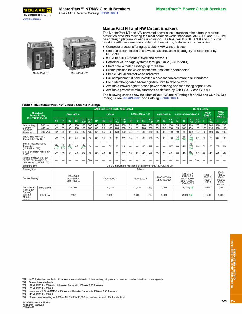
© 2020 Schneider Electric All Rights Reserved4/15/2020
7-75
www.se.com/us
MasterPact™ NT/NW Circuit Breakers MasterPact™ Power Circuit BreakersClass 613 / Refer to Catalog 0613CT0001
MasterPact NT and NW Circuit Breakers
MasterPact NT MasterPact NW
The MasterPact NTand NW universal power circuit breakers offer a family of circuitprotection products meeting the most common world standards, ANSI, UL and IEC. Thebasic design platform for each is common. The final result is UL, ANSI and IEC circuitbreakers with the same basic external dimensions, features and accessories.• Complete product offering up to 200 k AIR without fuses• Circuit breakers tested to show arc flash hazard risk category as referenced byNFPA70E
• 800 A to 6000 A frames, fixed and draw-out• Rated for AC voltage systems through 600 V (635 VANSI)• Short-time withstand ratings up to 100 kA• Cradle position indicator: connected, test and disconnected• Simple, visual contact wear indicators• Full complement of field-installable accessories common to all standards• Four interchangeable MicroLogic trip units to choose from• Available PowerLogic™ based power metering and monitoring capabilities• Available protective relay functions as defined by ANSI C37.2 and C37.90The following charts show the MasterPact NW and NT ratings for ANSI and UL 489. SeePricing Guide 0613PL0001 and Catalog 0613CT0001.
Table 7.152: MasterPact NW Circuit Breaker Ratings
StandardFrame Rating
Interrupting Code
ANSI C37 Certified/UL 1066 Listed UL 489 Listed
800–1600 A 2000 A 3200/4000 A [13] 4000/5000 A 800/1200/1600/2000 A 2500/3000 A
4000/5000/6000 A
N1 H1 H2 H3 L1[14]
L1F[14] H1 H2 H3 L1
[14]L1F[14] H1 H2 H3 L1
[14] H2 H3 L1[14] N H L
[14]LF[14] H L
[14] H L[14]
InterruptingCurrent(kA RMS)50/60 Hz
240 Vac 42 65 85 100 200 200 65 85 100 200 200 65 85 100 200 85 100 200 65 100 200 200 100 200 100 200480 Vac 42 65 85 100 200 200 65 85 100 200 200 65 85 100 200 85 100 200 65 100 150 150 100 150 100 150600 Vac 42 65 85 85 130 130 65 85 85 130 130 65 85 85 130 85 85 130 50 85 100 100 85 100 85 100
Short-time WithstandCurrent (kA RMS) 42 65 85 85 30 22 65 85 85 30 22 65 85 85 100 85 85 100 42
[15]65[15]
30[15][16]
22 65 65 85 100
Built-in InstantaneousOverride(kA RMS ±10%)
35[17]
35[17]
35[17] 85 35
[17] 24 — — 85 35 24 — — 85 117 — — 117 40 4035[15][16]
24 65 65 75 75
Close and latch rating (kARMS) 42 65 40 40 25 22 65 40 40 25 22 65 40 40 40 85 75 40 40 40 25
[18] 22 40 40 40 40
Tested to show arc flashhazard risk category asreferenced by NFPA70E
— — — — — Yes — — — — Yes — — — — — — — — — — Yes — — — —
Breaking time 25–30 ms with no intentional delay (9 ms for L1, L1F, L and LF)Closing time 70 ms
Sensor Rating100–250 A400–800 A800–1600 A
1000–2000 A 1600–3200 A 2000–4000 A2500–5000 A
100–250 A400–800 A600–1200 A800–1600 A1000–2000 A
1200–2500 A1600–3000 A
2000–4000 A2500–5000 A3000–6000 A
EnduranceRating (C/OCycles)With NoMainte-nance
Mechanical 12,500 10,000 10,000 5k 5,000 12,500 [19] 10,000 5,000
Electrical 2800 1,000 1,000 1k 1,000 2800 [19] 1,000 1,000
7MINIATUREANDMOLDEDCASE
CIRCUIT
BREAKERS
[13] 4000 A standard width circuit breaker is not available in L1 interrupting rating code or drawout construction (fixed mounting only).[14] Drawout mounted only.[15] 24 kA RMS for 800 A circuit breaker frame with 100 A or 250 A sensor.[16] 65 kA RMS for 2000 A.[17] None except 24 kA RMS for 800 A circuit breaker frame with 100 A or 250 A sensor.[18] 40 kA RMS for 2000 A.[19] The endurance rating for 2000 A, N/H/L/LF is 10,000 for mechanical and 1000 for electrical.
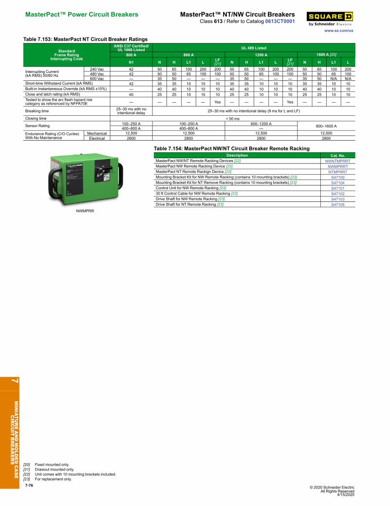
7-76 © 2020 Schneider Electric All Rights Reserved
4/15/2020
MasterPact™ Power Circuit Breakers MasterPact™ NT/NW Circuit Breakers
www.se.com/us
Class 613 / Refer to Catalog 0613CT0001
Table 7.153: MasterPact NT Circuit Breaker Ratings
StandardFrame Rating
Interrupting Code
ANSI C37 Certified/UL 1066 Listed UL 489 Listed
800 A 800 A 1200 A 1600 A [20]
N1 N H L1 L LF[21] N H L1 L LF
[21] N H L1 L
Interrupting Current(kA RMS) 50/60 Hz
240 Vac 42 50 65 100 200 200 50 65 100 200 200 50 65 100 200480 Vac 42 50 50 65 100 100 50 50 65 100 100 50 50 65 100600 Vac — 35 50 — — — 35 50 — — — 35 50 N/A N/A
Short-time Withstand Current (kA RMS) 42 35 35 10 10 10 35 35 10 10 10 35 35 10 10Built-in Instantaneous Override (kA RMS ±10%) — 40 40 10 10 10 40 40 10 10 10 40 40 10 10Close and latch rating (kA RMS) 40 25 25 10 10 10 25 25 10 10 10 25 25 10 10Tested to show the arc flash hazard riskcategory as referenced by NFPA70E — — — — — Yes — — — — Yes — — — —
Breaking time 25–30 ms with nointentional delay 25–30 ms with no intentional delay (9 ms for L and LF)
Closing time < 50 ms
Sensor Rating 100–250 A 100–250 A 600–1200 A 800–1600 A400–800 A 400–800 A —Endurance Rating (C/O Cycles)With No Maintenance
Mechanical 12,500 12,500 12,500 12,500Electrical 2800 2800 2800 2800
NWMPRR
Table 7.154: MasterPact NW/NT Circuit Breaker Remote RackingDescription Cat. No.
MasterPact NW/NT Remote Racking Devices [22] NWNTMPRRTMasterPact NW Remote Racking Device [22] NWMPRRTMasterPact NT Remote Rackign Device [22] NTMPRRTMounting Bracket Kit for NW Remote Racking (contains 10 mounting brackets) [23] S47100Mounting Bracket Kit for NT Remove Racking (contains 10 mounting brackets) [23] S47104Control Unit for NW Remote Racking [23] S4710130 ft Control Cable for NW Remote Racking [23] S47102Drive Shaft for NW Remote Racking [23] S47103Drive Shaft for NT Remote Racking [23] S47105
7MINIATUREANDMOLDEDCASE
CIRCUIT
BREAKERS
[20] Fixed mounted only.[21] Drawout mounted only.[22] Unit comes with 10 mounting brackets included.[23] For replacement only.

© 2020 Schneider Electric All Rights Reserved4/15/2020
7-77
www.se.com/us
Enerlin’X System Enerlin’X Digital SolutionsClass 0614 / Refer to Catalog 0614CT1802
Enerlin’X System for MicroLogic Trip Units
ModbusInterface
Module (IFM)Ethernet Interface (IFE)
Enerlin’X IO
Enerlin’X EIFE
Front DisplayModule
(FDM121) Ethernet LCD ColorTouch Display (FDM128)
Enerlin’X Systems enable network connectivity for MasterPact and PowerPact circuitbreakers to provide remote monitoring, control & alarming features which is central to theSmart Systems Architecture with Square D low voltage distribution equipment.Enerlin’X interface modules support Smart System Applications by facilitating access tocircuit breaker data that provides performance information, circuit breaker status,metering measurements and various maintenance alert indicators such as contact wear,operation counters, load profile etc.
Table 7.155: Communications and IO Interface Modules and Front Display Screensfor MasterPact MTZ/NT/NW and PowerPact H/J/L/P/R Circuit BreakersDescription Part NumberIFM Modbus-SL Interface for LV Circuit Breaker LV434000IFE Interface (Ethernet Module) LV434001IFE Interface + Gateway (Ethernet and ModbuGateway) LV434002EIFE embedded Ethernet interface for drawout MasterPact MTZ LV851001SPEIFE Spare part kit for one MasterPact MTZ1 drawout circuit breaker LV851100SPEIFE Spare part kit for one MasterPact MTZ2/MTZ3 drawout circuit breaker LV851200SPIO Module (Input/Output Programmable Module) LV434063FDM121 (1 Circuit Breaker to 1 Front Display over ULP)[1] STRV00121FDM128 (8 Circuit Breakers to 1 Front Display over Ethernet) LV434128
7MINIATUREANDMOLDEDCASE
CIRCUIT
BREAKERS
[1] The FDM121 is not compatible with MasterPact MTZ circuit breakers.
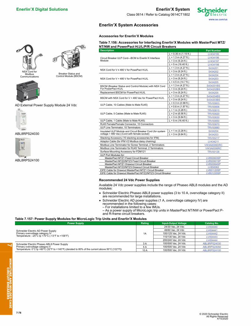
7-78 © 2020 Schneider Electric All Rights Reserved
4/15/2020
Enerlin’X Digital Solutions Enerlin’X System
www.se.com/us
Class 0614 / Refer to Catalog 0614CT1802
Enerlin’X System Accessories
Accessories for Enerlin’X Modules
NSX Cord forModbus
CommunicationsBreaker Status and
Control Module (BSCM)
AD External Power Supply Module 24 Vdc
ABL8RPS24030
ABL8RPS24100
Table 7.156: Accessories for Interfacing Enerlin’X Modules with MasterPact MTZ/NT/NW and PowerPact H/J/L/P/R Circuit BreakersDescription Part Number
Circuit Breaker ULP Cord—BCM to Enerlin’X InterfaceModule
L = 0.35 m (1.15 ft.) LV434195L = 1.3 m (4.27 ft.) LV434196L = 3 m (9.24 ft.) LV434197L = 5 m (16.40 ft.) LV434198
NSX Cord for V ≤ 480 V for PowePact H/J/LL = 1.3 m (4.27 ft.) S434201L = 3 m (9.24 ft.) S434202
NSX Cord for V > 480 V for PowePact H/J/LL = 1.3 m (4.27 ft.) S434204L = 3 m (9.24 ft.) S434203L = 4.5 m (14.7 ft.) S434205
BSCM (Breaker Status and Control Module) with NSX CordFor PowerPact H/J/L
L = 1.3 m (4.27 ft.) S434201BSL = 3 m (9.24 ft.) S434202BS
Replacement BSCM for PowerPact H/J/L L = 3 m (9.24 ft.) S434205
BSCM with NSX Cord for V > 480 Vac for PowerPact H/J/LL = 1.3 m (4.27 ft.) S434204BSL = 3 m (9.24 ft.) S434203BS
ULP Cable, 10 Cables (Male to Male RJ45)L = 0.3 m (0.98 ft.) TRV00803L = 0.6 m (1.97 ft.) TRV00806
ULP Cable, 5 Cables (Male to Male RJ45)L = 1 m (3.28 ft.) TRV00810L = 2 m (6.56 ft.) TRV00820L = 3 m (9.84 ft.) TRV00830
ULP Cable, 1 Cable (Male to Male RJ45) L = 5 m (16.40 ft.) TRV00850RJ45 Female/Female Connector, 10 Connectors TRV00870ULP Line Terminator, 10 Terminators TRV00880Insulated ULP Module and Circuit Breaker Cord (for systemvoltage > 480 Vac) (Cord with female socket)
L = 1 m (3.28 ft.) S434204L = 3 m (9.84 ft.) S434203
Stacking Accessory (10 stacking accessories for IFM) TRV00217Adaptor Cable (for IFM V2 Modbus daisy chaining) LV434211Modbus Line Terminator for Screw Terminal, 2 Terminators VW3A8306DRCModbus Line Terminator for RJ45 Terminal, 2 Terminators VW3A8306RCSurface-Mounting Accessory for FDM121 TRV00128ULP Port Modules for:
MasterPact MTZ1 Fixed Circuit Breaker LV850063SPMasterPact MTZ2/MTZ3 Fixed Circuit Breaker LV850061SPMasterPact MTZ1 Drawout Circuit Breaker LV850064SPMasterPact MTZ2/MTZ3 Drawout Circuit Breaker LV850062
EIFE Cable for Drawout MasterPact MTZ1 Circuit Breaker LV851120SPEIFE Cable for Drawout MasterPact MTZ2/MTZ3 Circuit Breaker LV851220SP
Recommended 24 Vdc Power SuppliesAvailable 24 Vdc power supplies include the range of Phaseo ABL8 modules and the ADmodules:• Schneider Electric Phaseo ABL8 power supplies (3 to 10 A, overvoltage category II)are recommended for large installations.
• Schneider Electric AD power supplies (1 A, overvoltage category IV) arerecommended in the following cases:– For installations limited to a few IMUs.– As a power supply of MicroLogic trip units in MasterPact NT/NW or PowerPact P-and R-frame circuit breakers.
Table 7.157: Power Supply Modules for MicroLogic Trip Units and Enerlin'X ModulesPower Supply Rating Input-Output Voltage Catalog No.
Schneider Electric AD Power SupplyPrimary overvoltage category IVTemperature: –25°C tp +70°C (-13°F to +158°F)
1A
24/30 Vac, 24 Vdc LV45444048/60 Vac, 24 Vdc LV454441100/125 Vac, 24 Vdc LV454442110/130 Vac, 24 Vdc LV454443200/240 Vac, 24 Vdc LV454444
Schneider Electric Phaseo ABL8 Power SupplyPrimary overvoltage category IITemperature: 0°C tp +60°C (32°F to +140°F) (derated to 80% of the current above 50°C [122°F])
3 A 100/500 Vac, 24 Vdc ABL8RPS240305 A 100/500 Vac, 24 Vdc ABL8RPS2405010 A 100/500 Vac, 24 Vdc ABL8RPS24100
7MINIATUREANDMOLDEDCASE
CIRCUIT
BREAKERS
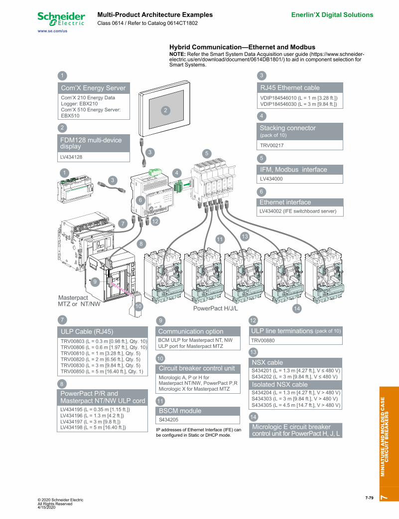
© 2020 Schneider Electric All Rights Reserved4/15/2020
7-79
www.se.com/us
Multi-Product Architecture Examples Enerlin’X Digital SolutionsClass 0614 / Refer to Catalog 0614CT1802
Hybrid Communication—Ethernet and ModbusNOTE: Refer the Smart System Data Acquisition user guide (https://www.schneider-electric.us/en/download/document/0614DB1801/) to aid in component selection forSmart Systems.
PowerPact P/R and Masterpact NT/NW ULP cordLV434195 (L = 0.35 m [1.15 ft.])LV434196 (L = 1.3 m [4.2 ft.]) LV434197 (L = 3 m [9.8 ft.])
8
Communication optionBCM ULP for Masterpact NT, NW ULP port for Masterpact MTZ
9
Eth1
Eth2
+24V
R
0V
138
9
10
ULP line terminations (pack of 10)
TRV00880
12
BSCM moduleS434205
11
NSX cable
13
Micrologic E circuit breaker control unit for PowerPact H, J, L
14
11
14
3
3
RJ45 Ethernet cableVDIP184546010 (L = 1 m [3.28 ft.])VDIP184546030 (L = 3 m [9.84 ft.])
2
FDM128 multi-device display
LV434128
4
6
2
5
10
Circuit breaker control unitMicrologic A, P or H for Masterpact NT/NW, PowerPact P,RMicrologic X for Masterpact MTZ
7
Masterpact MTZ or NT/NW
EBX510
S434201 (L = 1.3 m [4.27 ft.], V ≤ 480 V)S434202 (L = 3 m [9.84 ft.], V ≤ 480 V)
2
IP addresses of Ethernet Interface (IFE) can be configured in Static or DHCP mode.
IFM, Modbus interfaceLV434000
5
1
PowerPact H/J/L
1
Com’X Energy ServerCom’X 210 Energy Data Logger: EBX210Com’X 510 Energy Server: EBX510
3
Isolated NSX cable S434204 (L = 1.3 m [4.27 ft.], V > 480 V)S434303 (L = 3 m [9.84 ft.], V > 480 V) S434305 (L = 4.5 m [14.7 ft.], V > 480 V)
12
Stacking connector
TRV00217
4
(pack of 10)
LV434198 (L = 5 m [16.40 ft.])
6
Ethernet interfaceLV434002 (IFE switchboard server)
ULP Cable (RJ45)TRV00803 (L = 0.3 m [0.98 ft.], Qty. 10)TRV00806 (L = 0.6 m [1.97 ft.], Qty. 10)TRV00810 (L = 1 m [3.28 ft.], Qty. 5)TRV00820 (L = 2 m [6.56 ft.], Qty. 5)TRV00830 (L = 3 m [9.84 ft.], Qty. 5)TRV00850 (L = 5 m [16.40 ft.], Qty. 1)
7
7MINIATUREANDMOLDEDCASE
CIRCUIT
BREAKERS
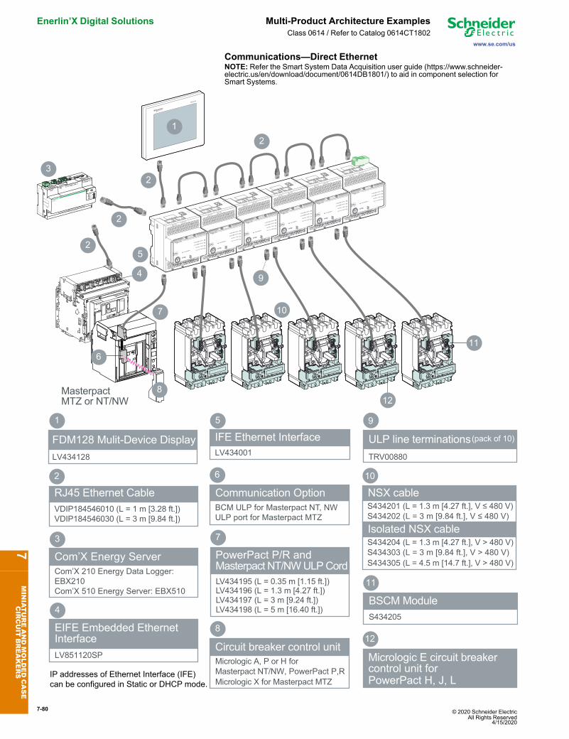
7-80 © 2020 Schneider Electric All Rights Reserved
4/15/2020
Enerlin’X Digital Solutions Multi-Product Architecture Examples
www.se.com/us
Class 0614 / Refer to Catalog 0614CT1802
Communications—Direct EthernetNOTE: Refer the Smart System Data Acquisition user guide (https://www.schneider-electric.us/en/download/document/0614DB1801/) to aid in component selection forSmart Systems.
8
Circuit breaker control unitMicrologic A, P or H for Masterpact NT/NW, PowerPact P,RMicrologic X for Masterpact MTZ
Eth1
Eth2
+24V
R
0V
Eth1
Eth2
+24V
R
0V
Eth1
Eth2
+24V
R
0V
Eth1
Eth2
+24V
R
0V
Eth1
Eth2
+24V
R
0V
Com’X Energy ServerCom’X 210 Energy Data Logger: EBX210Com’X 510 Energy Server: EBX510
3
PowerPact P/R andMasterpact NT/NW ULP Cord
LV434197 (L = 3 m [9.24 ft.])
7
LV434195 (L = 0.35 m [1.15 ft.])LV434196 (L = 1.3 m [4.27 ft.])
10
FDM128 Mulit-Device DisplayLV434128
1
Eth1
Eth2
+24V
R
0V
BSCM ModuleS434205
11
Masterpact MTZ or NT/NW
2
RJ45 Ethernet CableVDIP184546010 (L = 1 m [3.28 ft.])VDIP184546030 (L = 3 m [9.84 ft.])
9
ULP line terminations(pack of 10)
TRV00880
1
2
5
7
12
10
11
9
IP addresses of Ethernet Interface (IFE) can be configured in Static or DHCP mode.
3
2
EIFE Embedded Ethernet InterfaceLV851120SP
4
Communication Option
6
BCM ULP for Masterpact NT, NWULP port for Masterpact MTZ
NSX cable
Micrologic E circuit breaker control unit for PowerPact H, J, L
12
S434201 (L = 1.3 m [4.27 ft.], V ≤ 480 V)S434202 (L = 3 m [9.84 ft.], V ≤ 480 V)
Isolated NSX cable S434204 (L = 1.3 m [4.27 ft.], V > 480 V)S434303 (L = 3 m [9.84 ft.], V > 480 V) S434305 (L = 4.5 m [14.7 ft.], V > 480 V)
2
6
8
2
4
IFE Ethernet InterfaceLV434001
5
LV434198 (L = 5 m [16.40 ft.])
7MINIATUREANDMOLDEDCASE
CIRCUIT
BREAKERS
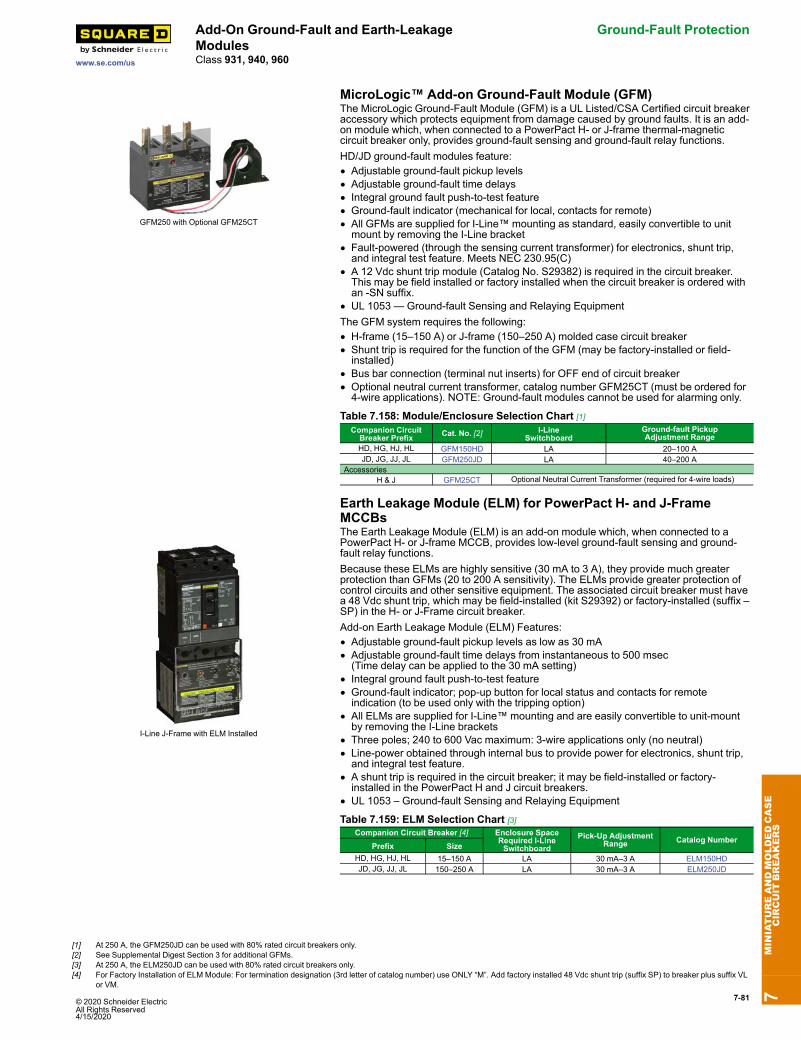
© 2020 Schneider Electric All Rights Reserved4/15/2020
7-81
www.se.com/us
Add-On Ground-Fault and Earth-LeakageModules
Ground-Fault Protection
Class 931, 940, 960
MicroLogic™ Add-on Ground-Fault Module (GFM)
GFM250 with Optional GFM25CT
The MicroLogic Ground-Fault Module (GFM) is a UL Listed/CSA Certified circuit breakeraccessory which protects equipment from damage caused by ground faults. It is an add-on module which, when connected to a PowerPact H- or J-frame thermal-magneticcircuit breaker only, provides ground-fault sensing and ground-fault relay functions.HD/JD ground-fault modules feature:• Adjustable ground-fault pickup levels• Adjustable ground-fault time delays• Integral ground fault push-to-test feature• Ground-fault indicator (mechanical for local, contacts for remote)• All GFMs are supplied for I-Line™ mounting as standard, easily convertible to unitmount by removing the I-Line bracket
• Fault-powered (through the sensing current transformer) for electronics, shunt trip,and integral test feature. Meets NEC 230.95(C)
• A 12 Vdc shunt trip module (Catalog No. S29382) is required in the circuit breaker.This may be field installed or factory installed when the circuit breaker is ordered withan -SN suffix.
• UL 1053 — Ground-fault Sensing and Relaying EquipmentThe GFM system requires the following:• H-frame (15–150 A) or J-frame (150–250 A) molded case circuit breaker• Shunt trip is required for the function of the GFM (may be factory-installed or field-installed)
• Bus bar connection (terminal nut inserts) for OFF end of circuit breaker• Optional neutral current transformer, catalog number GFM25CT (must be ordered for4-wire applications). NOTE: Ground-fault modules cannot be used for alarming only.
Table 7.158: Module/Enclosure Selection Chart [1]Companion CircuitBreaker Prefix Cat. No. [2] I-Line
SwitchboardGround-fault PickupAdjustment Range
HD, HG, HJ, HL GFM150HD LA 20–100 AJD, JG, JJ, JL GFM250JD LA 40–200 A
AccessoriesH & J GFM25CT Optional Neutral Current Transformer (required for 4-wire loads)
Earth Leakage Module (ELM) for PowerPact H- and J-FrameMCCBs
I-Line J-Frame with ELM Installed
The Earth Leakage Module (ELM) is an add-on module which, when connected to aPowerPact H- or J-frame MCCB, provides low-level ground-fault sensing and ground-fault relay functions.Because these ELMs are highly sensitive (30 mA to 3 A), they provide much greaterprotection than GFMs (20 to 200 A sensitivity). The ELMs provide greater protection ofcontrol circuits and other sensitive equipment. The associated circuit breaker must havea 48 Vdc shunt trip, which may be field-installed (kit S29392) or factory-installed (suffix –SP) in the H- or J-Frame circuit breaker.Add-on Earth Leakage Module (ELM) Features:• Adjustable ground-fault pickup levels as low as 30 mA• Adjustable ground-fault time delays from instantaneous to 500 msec(Time delay can be applied to the 30 mA setting)
• Integral ground fault push-to-test feature• Ground-fault indicator; pop-up button for local status and contacts for remoteindication (to be used only with the tripping option)
• All ELMs are supplied for I-Line™ mounting and are easily convertible to unit-mountby removing the I-Line brackets
• Three poles; 240 to 600 Vac maximum: 3-wire applications only (no neutral)• Line-power obtained through internal bus to provide power for electronics, shunt trip,and integral test feature.
• A shunt trip is required in the circuit breaker; it may be field-installed or factory-installed in the PowerPact H and J circuit breakers.
• UL 1053 – Ground-fault Sensing and Relaying Equipment
Table 7.159: ELM Selection Chart [3]Companion Circuit Breaker [4] Enclosure Space
Required I-LineSwitchboard
Pick-Up AdjustmentRange Catalog Number
Prefix SizeHD, HG, HJ, HL 15–150 A LA 30 mA–3 A ELM150HDJD, JG, JJ, JL 150–250 A LA 30 mA–3 A ELM250JD
7MINIATUREANDMOLDEDCASE
CIRCUIT
BREAKERS
[1] At 250 A, the GFM250JD can be used with 80% rated circuit breakers only.[2] See Supplemental Digest Section 3 for additional GFMs.[3] At 250 A, the ELM250JD can be used with 80% rated circuit breakers only.[4] For Factory Installation of ELM Module: For termination designation (3rd letter of catalog number) use ONLY “M”. Add factory installed 48 Vdc shunt trip (suffix SP) to breaker plus suffix VL
or VM.
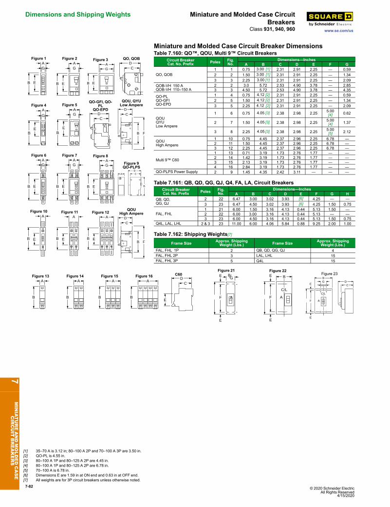
7-82 © 2020 Schneider Electric All Rights Reserved
4/15/2020
Dimensions and Shipping Weights Miniature and Molded Case CircuitBreakers
www.se.com/usClass 931, 940, 960
Miniature and Molded Case Circuit Breaker Dimensions
Figure 1
B E
AG
Figure 2
B E
AG
Figure 3
B E
AG
QO, QOBDC
Figure 4A
BE
G
Figure 5AG
BE
QO-GFI, QO-PL
QO-EPDDC
QOU, QYULow Ampere
CD
FB
Figure 6
B
AG
E
Figure 7AG
B E
Figure 8AG
B E
Figure 9QO-PLPS
ADC
B
Figure 10A
B E
Figure 11A
B E
Figure 12A
B E
QOUHigh Ampere
CD
FB
Table 7.160: QO™, QOU, Multi 9™ Circuit BreakersCircuit BreakerCat. No. Prefix Poles Fig.
No.Dimensions—Inches
A B C D E F G
QO, QOB1 1 0.75 3.00 [1] 2.31 2.91 2.25 — 0.592 2 1.50 3.00 [1] 2.31 2.91 2.25 — 1.343 3 2.25 3.00 [1] 2.31 2.91 2.25 — 2.09
QOB-VH 150 AQOB-VH 110–150 A
2 2 3.0 5.72 2.53 4.90 3.78 — 2.853 3 4.50 5.72 2.53 4.90 3.78 — 4.35
QO-PLQO-GFIQO-EPD
1 4 0.75 4.12 [2] 2.31 2.91 2.25 — 0.592 5 1.50 4.12 [2] 2.31 2.91 2.25 — 1.343 5 2.25 4.12 [2] 2.31 2.91 2.25 — 2.09
QOUQYULow Ampere
1 6 0.75 4.05 [3] 2.38 2.98 2.25 5.00[4] 0.62
2 7 1.50 4.05 [3] 2.38 2.98 2.25 5.00[4] 1.37
3 8 2.25 4.05 [3] 2.38 2.98 2.25 5.00[5] 2.12
QOUHigh Ampere
1 10 0.75 4.45 2.37 2.96 2.25 6.78 —2 11 1.50 4.45 2.37 2.96 2.25 6.78 —3 12 2.25 4.45 2.37 2.96 2.25 6.78 —
Multi 9™ C60
1 13 0.71 3.19 1.73 2.76 1.77 — —2 14 1.42 3.19 1.73 2.76 1.77 — —3 15 2.13 3.19 1.73 2.76 1.77 — —4 16 2.84 3.19 1.73 2.76 1.77 — —
QO-PLPS Power Supply 2 9 1.45 4.35 2.42 3.11 — — —
Table 7.161: QB, QD, QG, QJ, Q4, FA, LA, Circuit BreakersCircuit BreakerCat. No. Prefix Poles Fig.
No.Dimensions—Inches
A B C D E F G HQB, QD,QG, QJ
2 22 6.47 3.00 3.02 3.93 [6] 4.25 — —3 23 6.47 4.50 3.02 3.93 [6] 4.25 1.50 0.75
FAL, FHL1 21 6.00 1.50 3.16 4.13 0.44 5.13 1.50 —2 22 6.00 3.00 3.16 4.13 0.44 5.13 — —3 23 6.00 4.50 3.16 4.13 0.44 5.13 1.50 0.75
Q4L, LAL, LHL 2 & 3 23 11.00 6.00 4.06 5.84 0.88 9.25 2.00 1.00
Table 7.162: Shipping Weights[7]Frame Size Approx. Shipping
Weight (Lbs.) Frame Size Approx. ShippingWeight (Lbs.)
FAL, FHL 1P 2 QB, QD, QG, QJ 4FAL, FHL 2P 3 LAL, LHL 15FAL, FHL 3P 5 Q4L 15
Figure 13A
B
Figure 14A
B
Figure 15A
B
Figure 16A
B
C60
CD
E
Figure 21BE
F A
E
G
Figure 22
C/L
BE
E
F A
Figure 23
C/L
BD
CG
H HE
E
F A
7MINIATUREANDMOLDEDCASE
CIRCUIT
BREAKERS
[1] 35–70 A is 3.12 in; 80–100 A 2P and 70–100 A 3P are 3.50 in.[2] QO-PL is 4.55 in.[3] 80–100 A 1P and 80–125 A 2P are 4.45 in.[4] 80–100 A 1P and 80–125 A 2P are 6.78 in.[5] 70–100 A is 6.78 in.[6] Dimensions E are 1.59 in at ON end and 0.63 in at OFF end.[7] All weights are for 3P circuit breakers unless otherwise noted.
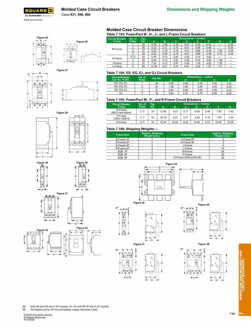
© 2020 Schneider Electric All Rights Reserved4/15/2020
7-83
www.se.com/us
Molded Case Circuit Breakers Dimensions and Shipping WeightsClass 931, 940, 960
Molded Case Circuit Breaker Dimensions
Figure 25
A
B
E
F
Figure 26
C
DA
E
F
B
G
Figure 27
E
G
A
B
C
DF
Figure 28
A
C
D
B
G
F
Figure 29
A
E B
Figure 30
A
B E
Figure 31
A
E B
CD
Table 7.163: PowerPact B-, H-, J-, and L-Frame Circuit BreakersCircuit Breaker
FrameNo. ofPoles
Fig.No.
Dimensions — InchesA B C D E F G H
B-Frame
1 35 6.79 1.06 3.15 4.01 0.20 6.33 — 5.392 36 6.22 2.12 3.15 4.01 0.86 4.48 — 5.393 37 6.22 3.19 3.15 4.01 0.86 4.48 1.06 5.394 38 6.22 4.25 3.15 4.01 0.86 4.48 2.12 5.39
H-Frame2 [8] 25 6.40 2.74 2.87 4.36 0.74 4.92 — —3 26 6.40 4.12 2.87 4.36 0.74 4.92 1.38 —
J-Frame 3 27 7.52 4.12 2.87 5.00 1.30 4.92 1.38 —L-Frame 3 28 13.38 5.51 3.75 6.61 2.22 7.87 1.77 —
Table 7.164: ED, EG, EJ, and GJ Circuit BreakersCircuit BreakerCat. No. Prefix
No. ofPoles Fig. No. Dimensions — Inches
A B C D EED, EG, EJ 1 29 0.98 5.66 3.09 4.05 3.32ED, EG, EJ 2 30 1.96 5.66 3.09 4.05 3.32ED, EG, EJ 3 31 2.94 5.66 3.09 4.05 3.32
GJ 3 32 3.54 4.72 2.76 3.94 2.20
Table 7.165: PowerPact M-, P-, and R-Frame Circuit BreakersCircuit Breaker
FrameNo. ofPoles
Fig.No.
Dimensions — InchesA B C D E F G
M-Frame(800 A and below) 2, 3 33 12.86 8.27 5.77 8.05 2.49 7.87 7.83
P-Frame(1000–1200 A) 2, 3 33 16.16 8.27 5.77 8.05 4.19 7.87 7.83
R-Frame 2, 3 34 16.24 16.54 6.63 14.49 8.73 14.25 15.35
Table 7.166: Shipping Weights [9]
Frame Size Approx. ShippingWeight (Lbs.) Frame Size Approx. Shipping
Weight (Lbs.)B-Frame 1P 1 H-Frame 2P 4B-Frame 2P 2 H-Frame 3P 5B-Frame 3P 3 J-Frame 5B-Frame 4P 4 L-Frame 14EDB 1P 2 M-Frame 29EDB 2P 3 P-Frame 32EDB 3P 4 R-Frame (Without RLTB) 52
Figure 32
A
E B
CD
Figure 33
F
E
E
A
DCG
B
Figure 34
GB
F
EA
DC
Figure 35
1P
CD
B E
A F H
Figure 362P B E
A F
CD
H
Figure 37
3P B E
A
G
F
CD
H
Figure 38
4P
G
B E
A F
CD
H
7MINIATUREANDMOLDEDCASE
CIRCUIT
BREAKERS
[8] Only HD and HG are in 2P module, HJ, HL and HR 2P are in 3P module.[9] All weights are for 3P circuit breakers unless otherwise noted.
7-84 © 2020 Schneider Electric All Rights Reserved
4/15/2020
Circuit Breaker Enclosures Enclosures
www.se.com/us
Class 610
PowerPact Circuit Breaker Enclosures• The enclosures for the family of PowerPact circuit breakers B- through Q-frame arecULus listed unless otherwise noted.
• The enclosures are suitable for service entrance equipment when neutral assembly isinstalled.
• The short circuit current rating of the enclosed circuit breakers is equal to the rating ofthe circuit breaker installed unless otherwise noted.
• All enclosures will accept 100% rated circuit breakers unless otherwise noted.
PowerPact B-Frame Circuit Breaker Enclosures• The enclosures' maximum short circuit ratings are 65 kA at 600Y, 65 kA at 480 Vac,100 kA at 240 Vac and 50 kA at 250 Vdc unless otherwise noted.
• Enclosures accept 100% rated circuit breakers [8].
Table 7.167: PowerPact B-Frame Circuit Breaker EnclosuresCircuit Breaker
Enclosure Catalog NumberAccessory Catalog Number
Cat. No. Prefix Rating Poles Neutral AssemblyKit Service Ground Kit
NEMA 1 Flush NEMA 1 Surface NEMA 3RBDL, BGL, BJL 15–100 A 2, 3
B125F B125S B125RBSN100FA
PKOGTA2BDL, BGL, BJL 110–125 A 2, 3 SN225KABKL 15–30 A 2 SN100FA
NEMA 4, 4X, 5Type 304 Stainless
SteelNEMA 12
With KnockoutsNEMA 12
Without KnockoutsBDL, BGL, BJL 15–100 A 2, 3
B125DS B125A B125AWK[1]SN100FA
PKOGTA2BDL, BGL, BJL 110–125 A 2, 3 SN225KABKL 15–30 A 2 SN100FA
PowerPact H- and J-Frame Circuit Breaker EnclosuresThe enclosures' maximum short circuit ratings are 25 kAIR at 600 Vac, 65 kAIR at 480Vac, 125 kAIR at 240 Vac and 20 kA at 250 Vdc unless otherwise noted. Enclosuresaccept 100% rated circuit breakers [2]. The enclosures are not compatible with earth-leakage or ground-fault modules.H- and J-frame circuit breakers with MicroLogic trip units can be used with theseenclosures, but have the following limitations:• No communication accessories can be mounted in the enclosure (no IFM or FrontDisplay Module, IFE, etc).
• The trip unit will not be accessible or visible without the removal of the cover (exceptJ250F and J250S).
• For LSIG, there is no room for the NCT to mount in the enclosure.
Table 7.168: PowerPact H- and J-Frame Circuit Breaker EnclosuresCircuit Breaker
Enclosure Cat. No. Neutral Assembly KitCat. No.
Service Ground KitCat. No.Cat. No. Prefix Rating Poles
NEMA 1 Flush NEMA 1 Surface NEMA 3RHDL 15–100 A 3 — HD100S [3][4][5] — SN100FA PKOGTA2
HDL, JDL 125–225 A 3 — JD250S [6][4][5] — SN225KA PKOGTA2125–250 SN400LA
HDL, HGL 15–100 A 2 H150F H150S H150R [7] SN100FA PKOGTH150125–150 A 2 SN400LAHJL, HLL 15–100 A 2
J250F J250S [8] J250R [7][9]SN100FA PKOGTH150HDL, HGL, HJL, HLL 15–100 A 3
125–150 A 3 SN400LA[10]JDL, JGL, JJL, JLL 150–250 A 2, 3 PKOGTJ250
NEMA 4, 4X, 5 [11] Type304 Stainless Steel [12]
NEMA 4, 4x, 5 [11]Type 316 Stainless
Steel [12]NEMA 12/3R Without
Knockouts [12]
HDL, HGL, HJL, HLL 15–100 A 2, 3J250DS [13] J250SS [13] J250AWK [13]
SN100FAPKOGTH150125–150 A 2, 3 SN400LA[10]
JDL, JGL, JJL, JLL 150–250 A 2, 3 PKOGTJ250
7MINIATUREANDMOLDEDCASE
CIRCUIT
BREAKERS
[1] For NEMA 3R applications, remove drain scerw from bottom end well.[2] Use only 90°C (minimum) rated wire sized per ampacity of 75°C rated conductors for 100% rated circuit breakers.[3] Rated for 240 Vac maximum. Short circuit current rating is 25 kAIR at 240 Vac.[4] Accepts standard 80% rated circuit breakers only. Not rated for 100% rated circuit breakers.[5] Use copper conductors only.[6] Rated 480 Vac maximum. Short circuit current rating is 18 kAIR at 480 V.[7] For conduit entry through the top end wall use one of the following Square D conduit hubs: A200L for 2.00 in., A250L for 2.50 in., A300L for 3.00 in., A350L for 3.50 in. or A400L for 4.00 in.[8] Add suffix BE if no knockouts are required on the end walls.[9] For access to the circuit breaker’s standard, ammeter or energy trip unit panel/LCD, add suffix T.[10] For 200% neutral use copper wire only.[11] Complete rating is NEMA 3, 3R, 4, 4X, 5, and 12.[12] For NEMA 3R applications, remove drain screw from bottom endwall.[13] Add suffix VW for visibility to the standard, ammeter or energy trip unit of the PowerPact circuit breaker.
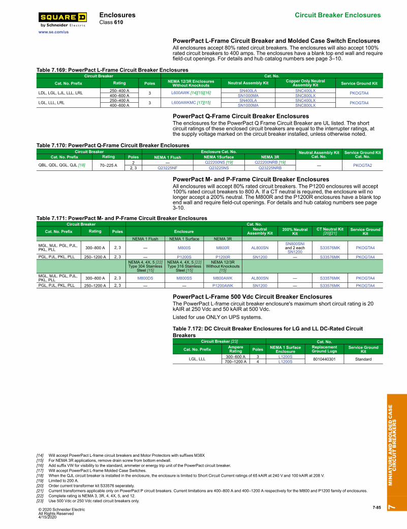
© 2020 Schneider Electric All Rights Reserved4/15/2020
7-85
www.se.com/us
Enclosures Circuit Breaker EnclosuresClass 610
PowerPact L-Frame Circuit Breaker and Molded Case Switch EnclosuresAll enclosures accept 80% rated circuit breakers. The enclosures will also accept 100%rated circuit breakers to 400 amps. The enclosures have a blank top end wall and requirefield-cut openings. For details and hub catalog numbers see page 3–10.
Table 7.169: PowerPact L-Frame Circuit Breaker EnclosuresCircuit Breaker Cat. No.
NEMA 12/3R EnclosuresWithout Knockouts Neutral Assembly Kit Copper Only Neutral
Assembly Kit Service Ground KitCat. No. Prefix Rating Poles
LDL, LGL, LJL, LLL, LRL 250–400 A 3 L600AWK [14][15][16] SN400LA SNC400LX PKOGTA4400–600 A SN1000MA SNC800LX
LGL, LLL, LRL 250–400 A 3 L600AWKMC [17][15] SN400LA SNC400LX PKOGTA4400–600 A SN1000MA SNC800LX
PowerPact Q-Frame Circuit Breaker EnclosuresThe enclosures for the PowerPact Q Frame Circuit Breaker are UL listed. The shortcircuit ratings of these enclosed circuit breakers are equal to the interrupter ratings, atthe supply voltage marked on the circuit breaker installed, unless otherwise noted.
Table 7.170: PowerPact Q-Frame Circuit Breaker EnclosuresCircuit Breaker Enclosure Cat. No. Neutral Assembly Kit
Cat. No.Service Ground Kit
Cat. No.Cat. No. Prefix Rating Poles NEMA 1 Flush NEMA 1Surface NEMA 3R
QBL, QDL, QGL, QJL [18] 70–225 A 2 — Q22200NS [19] Q22200NRB [19]— PKOGTA22, 3 Q23225NF Q23225NS Q23225NRB
PowerPact M- and P-Frame Circuit Breaker EnclosuresAll enclosures will accept 80% rated circuit breakers. The P1200 enclosures will accept100% rated circuit breakers to 800 A. If a CT neutral is required, the enclosure will nolonger accept a 200% neutral. The M800R and the P1200R enclosures have a blank topend wall and require field-cut openings. For details and hub catalog numbers see page3-10.
Table 7.171: PowerPact M- and P-Frame Circuit Breaker EnclosuresCircuit Breaker Cat. No.
Cat. No. Prefix Rating Poles Enclosure NeutralAssembly Kit
200% NeutralKit
CT Neutral Kit[20][21]
Service GroundKit
NEMA 1 Flush NEMA 1 Surface NEMA 3RMGL, MJL. PGL, PJL,PKL, PLL 300–800 A 2, 3 — M800S M800R AL800SN
SN800SNIand 2 eachSN1200
S33576MK PKOGTA4
PGL, PJL, PKL, PLL 250–1200 A 2, 3 — P1200S P1200R SN1200 — S33576MK PKOGTA4NEMA 4, 4X, 5 [22]Type 304 Stainless
Steel [15]
NEMA 4, 4X, 5 [22]Type 316 Stainless
Steel [15]
NEMA 12/3RWithout Knockouts
[15]MGL, MJL. PGL, PJL,PKL, PLL 300–800 A 2, 3 M800DS M800SS M800AWK AL800SN — S33576MK PKOGTA4
PGL, PJL, PKL, PLL 250–1200 A 2, 3 — — P1200AWK SN1200 — S33576MK PKOGTA4
PowerPact L-Frame 500 Vdc Circuit Breaker EnclosuresThe PowerPact L-frame circuit breaker enclosure's maximum short circuit rating is 20kAIR at 250 Vdc and 50 kAIR at 500 Vdc.Listed for use ONLYon UPS systems.
Table 7.172: DC CIrcuit Breaker Enclosures for LG and LL DC-Rated CircuitBreakers
Circuit Breaker [23] Cat. No.
Cat. No. Prefix AmpereRating Poles NEMA 1 Surface
EnclosureReplacementGround Lugs
Service GroundKit
LGL, LLL 300–600 A 3 L1200S 8010440301 Standard700–1200 A 4 L1200S
7MINIATUREANDMOLDEDCASE
CIRCUIT
BREAKERS
[14] Will accept PowerPact L-frame circuit breakers and Motor Protectors with suffixes M38X[15] For NEMA 3R applications, remove drain screw from bottom endwall.[16] Add suffix VW for visibility to the standard, ammeter or energy trip unit of the PowerPact circuit breaker.[17] Will accept PowerPact L-frame Molded Case Switches.[18] When the QJL circuit breaker is installed in the enclosure, the enclosure is limited to Short Circuit Current ratings of 65 kAIR at 240 V and 100 kAIR at 208 V.[19] Limited to 200 A.[20] Order current transformer kit S33576 seperately.[21] Current transformers applicable only on PowerPact P circuit breakers. Current limitations are 400–800 A and 400–1200 A respectively for the M800 and P1200 family of enclosures.[22] Complete rating is NEMA 3, 3R, 4, 4X, 5, and 12.[23] Use 500 Vdc or 250 Vdc rated circuit breakers only.

7-86 © 2020 Schneider Electric All Rights Reserved
4/15/2020
Circuit Breaker Enclosures Enclosures
www.se.com/us
Class 610
LA/LH/Q4 Circuit Breaker EnclosuresLA/LH/Q4 Thermal-Magnetic Circuit Breaker Enclosures
LA400AWK
LA400S LA400R
The enclosures for the LA/LH/Q4 thermal-magnetic circuit breakers are UL listed andCSA certified. The enclosures are suitable for service entrance equipment when neutralassembly is installed. The short circuit ratings of these enclosed circuit breakers areequal to the interrupter rating, at the supply voltage marked on the circuit breakerinstalled.The LA400R enclosure has a blank top end wall and requires field cut openings. Fordetails and hub catalog numbers see Digest Section 3.
Table 7.173: LA/LH/Q4 Thermal-Magnetic Circuit Breaker EnclosuresCircuit Breaker Enclosure Neutral
Assembly KitService
Ground KitCat. No.Prefix Rating Poles Cat. No. Cat. No. Cat. No. Cat. No. Cat. No.
NEMA 1Flush
NEMA 1Surface NEMA 3R
LAL, LHL,Q4L
125–225 A 2, 3 LA400F [24] LA400S [24] LA400R SN225KA
PKOGTA2225–400 A 400SN
LAL 125–400 3 — LA400LS [25][26][27][28] — SN400LA
NEMA 4, 4X,5 [29] Type304 StainlessSteel [30]
NEMA 12KWith
Knockouts
NEMA 12/3RWithout
Knockouts[30]
LAL, LHL,Q4L
125–225 A 2, 3 LA400DS[27] — LA400AWK
[27]SN225KA PKOGTA2225–400 A SN400LA
Enclosures for Special Applications
Hazardous Locations: NEMA 7 And NEMA 9 Circuit Breaker EnclosuresThe NEMA 7 and 9 enclosures are cULus listed unless otherwise noted. They are ratedfor use in hazardous locations as defined in NEC Article 500. The short circuit currentrating of the enclosed circuit breakers is equal to the rating of the circuit breaker installedunless otherwise noted. They are suitable for use as service entrance equipment whenneutral is installed. Enclosures require the use of 75°C copper wire only. The NEMA 7enclosures are suitable for rainproof applications when the included PKDB1 breatherand drain kit is installed.
Table 7.174: NEMA 7 and NEMA 9 Circuit Breaker Enclosures;Thermal-Magnetic B-Frame and PowerPact J-Frame Cicuit Breakers
Circuit Breaker Enclosure Catalog NumberNeutral
AssemblyKit Cat. No.
ServiceGround KitCat. No.
ThreadedConduit
Provisions,Inches
Cat. No.Prefix Rating Poles
NEMA 7/9Cast
Aluminum[31][32]
NEMA 9 CastAluminum
[32]
BKL 15–30 A 2B100X — 100SNA Included 1 1//4 in.BDL, BGL,
BJL 15–100 A 2, 3
JDL, JGL 150–225 A 2, 3 J225X [33][34] J225Y [33][34] 225SNA Included 2 1/2 in.
Enclosed Molded Case SwitchesFor information on enclosed molded case switches, see Supplemental Digest Section 3.
7MINIATUREANDMOLDEDCASE
CIRCUIT
BREAKERS
[24] Enclosures are provided with the Handle Padlock Attachment (HPALM) for field installation to lock the circuit breaker in the “ON” or “OFF” positions.[25] Use copper conductors only.[26] Maximum short circuit and voltage is 30 kAIR at 480 Vac.[27] LAL or LHL circuit breakers with an MB or MTsuffix are not compatible with these enclosures: LA400DS, LA400AWK, and LA400LS.[28] Enclosure cover has an integral padlock provision to provide a means to lock the circuit breaker in the “ON” or “OFF” position.[29] Complete rating is NEMA 3, 3R, 4, 4X, 5, and 12.[30] For NEMA 3R applications, remove drain screw from bottom endwall.[31] NEMA 7 — Indoor Hazardous Locations — Division 1 and 2, Class I, Groups C and D; Class II, Groups E, F and G; Class III[32] NEMA 9 — Indoor Hazardous Locations — Division 1 and 2, Class ii, Groups E, F and G; Class iii[33] Short circuit current rating: 65 kAIR at 240 Vac, 25 kAIR at 480 Vac, and 18 kAIR at 600 Vac[34] Not cULus listed due to wire bending space.
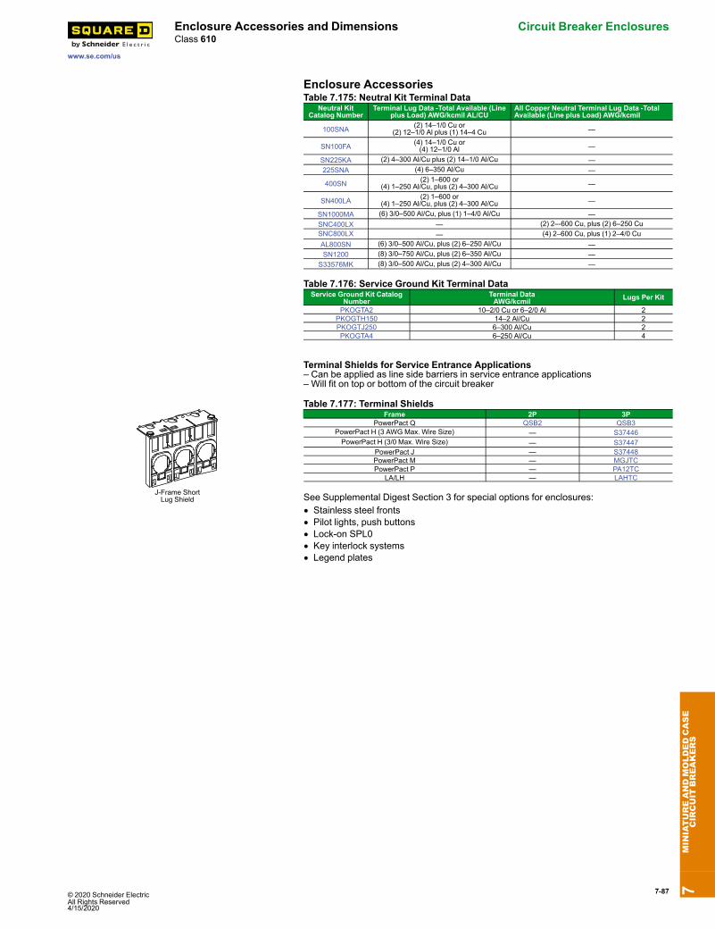
© 2020 Schneider Electric All Rights Reserved4/15/2020
7-87
www.se.com/us
Enclosure Accessories and Dimensions Circuit Breaker EnclosuresClass 610
Enclosure AccessoriesTable 7.175: Neutral Kit Terminal Data
Neutral KitCatalog Number
Terminal Lug Data -Total Available (Lineplus Load) AWG/kcmil AL/CU
All Copper Neutral Terminal Lug Data -TotalAvailable (Line plus Load) AWG/kcmil
100SNA (2) 14–1/0 Cu or(2) 12–1/0 Al plus (1) 14–4 Cu —
SN100FA (4) 14–1/0 Cu or(4) 12–1/0 Al —
SN225KA (2) 4–300 Al/Cu plus (2) 14–1/0 Al/Cu —225SNA (4) 6–350 Al/Cu —
400SN (2) 1–600 or(4) 1–250 Al/Cu, plus (2) 4–300 Al/Cu —
SN400LA (2) 1–600 or(4) 1–250 Al/Cu, plus (2) 4–300 Al/Cu —
SN1000MA (6) 3/0–500 Al/Cu, plus (1) 1–4/0 Al/Cu —SNC400LX — (2) 2–-600 Cu, plus (2) 6–250 CuSNC800LX — (4) 2–600 Cu, plus (1) 2–4/0 CuAL800SN (6) 3/0–500 Al/Cu, plus (2) 6–250 Al/Cu —SN1200 (8) 3/0–750 Al/Cu, plus (2) 6–350 Al/Cu —
S33576MK (8) 3/0–500 Al/Cu, plus (2) 4–300 Al/Cu —
Table 7.176: Service Ground Kit Terminal DataService Ground Kit Catalog
NumberTerminal DataAWG/kcmil Lugs Per Kit
PKOGTA2 10–2/0 Cu or 6–2/0 Al 2PKOGTH150 14–2 Al/Cu 2PKOGTJ250 6–300 Al/Cu 2PKOGTA4 6–250 Al/Cu 4
Terminal Shields for Service Entrance Applications– Can be applied as line side barriers in service entrance applications– Will fit on top or bottom of the circuit breaker
J-Frame ShortLug Shield
Table 7.177: Terminal ShieldsFrame 2P 3P
PowerPact Q QSB2 QSB3PowerPact H (3 AWG Max. Wire Size) — S37446PowerPact H (3/0 Max. Wire Size) — S37447
PowerPact J — S37448PowerPact M — MGJTCPowerPact P — PA12TC
LA/LH — LAHTC
See Supplemental Digest Section 3 for special options for enclosures:• Stainless steel fronts• Pilot lights, push buttons• Lock-on SPL0• Key interlock systems• Legend plates
7MINIATUREANDMOLDEDCASE
CIRCUIT
BREAKERS
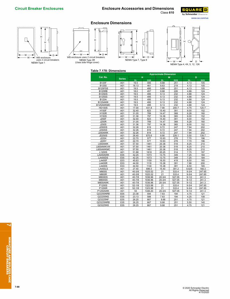
7-88 © 2020 Schneider Electric All Rights Reserved
4/15/2020
Circuit Breaker Enclosures Enclosure Accessories and Dimensions
www.se.com/us
Class 610
Enclosure Dimensions
WW
D
H
H
WB enclosureuses 2 circuit breakers
NEMAType 1
W D
H
WB enclosure uses 2 circuit breakersNEMAType 3R
(Uses side hinge cover)
W
H
DNEMAType 7, Type 9
W
H
DNEMAType 4, 4X, 5, 12, 12K
Table 7.178: Dimensions
Cat. No.Approximate Dimension
Series H W Din. mm in. mm in. mm
B125F A01 19.5 495 9.88 251 4.13 105B125S A01 18.13 461 8.63 219 4.13 105
B125FSS A01 19.5 495 9.88 251 4.13 105B125RB A01 18.0 457 8.88 226 4.88 124B125DS A01 19.5 495 9.13 232 4.88 124B125SS A01 19.5 495 9.13 232 4.88 124B125A A01 19.5 495 9.13 232 4.88 124
B125AWK A01 19.5 495 9.13 232 4.88 124B125AWKMC A01 19.5 495 9.13 232 4.88 124
HD100S A01 17.00 431.8 7.90 200.7 4.75 120.7H150F A01 32.40 823 15.40 391 6.00 152H150R A01 31.05 789 14.47 368 6.28 160H150S A01 31.36 797 14.36 365 6.00 152J250F A01 32.40 823 15.40 391 6.00 152J250R A01 31.05 789 14.47 368 6.28 160J250S A01 31.36 797 14.36 365 6.00 152J250DS A01 32.26 819 9.72 247 7.94 202J250SS A01 32.26 819 9.72 247 7.94 202J250AWK A01 32.26 819 9.72 247 7.94 202JD250S A01 26.40 670.6 8.90 226.1 5.50 139.7J225X A01 22.70 577 10.93 278 7.70 196J225Y A01 22.70 577 10.93 278 7.70 196
L600AWK A01 57.50 1461 20.38 518 8.25 210L600AWKVW A01 57.50 1461 20.38 518 8.25 210L600AWKMC A01 57.50 1461 20.38 518 8.25 210
L1200S A01 51.88 1818 20.25 514 7.75 197LA400AWK E05 42.25 1073 13.75 349 7.25 184LA400DS E05 42.25 1073 13.75 349 7.25 184LA400F E03 45.63 1159 16.50 419 6.50 165LA400R E03 44.00 1118 15.38 391 7.88 200LA400S E03 44.50 1130 15.38 391 6.50 165LA400LS A01 27.40 696.0 15.40 391.2 6.625 168.3M800S A01 40-3/8 1025.52 21 533.4 9-3/4 247.65M800R A01 40-3/8 1025.52 21 533.4 9-3/4 247.65M800DS A01 40-7/8 1036.96 20-3/4 527.05 9-1/2 241.3M800SS A01 40-7/8 1036.96 20-3/4 527.05 9-1/2 241.3M800AWK A01 40-7/8 1036.96 20-3/4 527.05 9-1/2 241.3P1200S A01 52-1/8 1323.98 21 533.4 9-3/4 247.65P1200R A01 52-1/8 1323.98 21 533.4 9-3/4 247.65
P1200AWK A01 53 1346.20 20-3/4 527.05 9-1/2 241.3Q22200NRB E05 23.38 594 7.63 194 4.75 121Q22200NS E05 23.13 588 7.63 194 4.25 108Q23225NF E05 26.25 667 9.88 251 4.75 121Q23225NRB E05 26.25 667 9.88 251 5.50 140Q23225NS E05 26.25 667 9.88 251 4.75 121
7MINIATUREANDMOLDEDCASE
CIRCUIT
BREAKERS