chassis services - right foot performance products inc
TRANSCRIPT

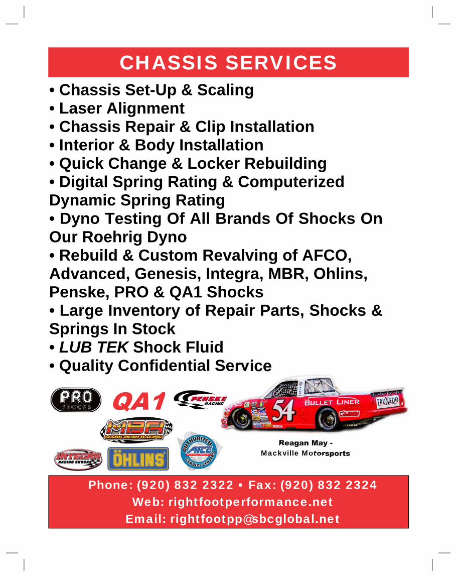
Phone: (920) 832 2322 • Fax: (920) 832 2324�Web: rightfootperformance.net�
Email: [email protected]�
• Chassis Set-Up & Scaling�• Laser Alignment�• Chassis Repair & Clip Installation�• Interior & Body Installation�• Quick Change & Locker Rebuilding�• Digital Spring Rating & Computerized�Dynamic Spring Rating�• Dyno Testing Of All Brands Of Shocks On�Our Roehrig Dyno�• Rebuild & Custom Revalving of AFCO,�Advanced, Genesis, Integra, MBR, Ohlins,�Penske, PRO & QA1 Shocks�• Large Inventory of Repair Parts, Shocks &�Springs In Stock�•�LUB TEK� Shock Fluid�• Quality Confidential Service�
Reagan May -�Mackville Motorsports�
CHASSIS SERVICES�
Dear Right Foot Customers,�
Right Foot has been in business since 1995 and we remain committed to designing, building and distributing high quality,�innovative, race-winning components. All of our components are designed with the objective of making a race car faster,�more tunable and easier to set up more precisely. Many thanks to the friends, customers, chassis builders and racers�who work with us to develop new products. Their ideas, feed back and testing are invaluable. Without them we could not�stay at the forefront of short track racing technology. We plan to continue to develop and refine new race-winning prod-�ucts so hopefully we can continue to earn your business. Thanks for reviewing this catalog.�
Dave & Rhonda Schneider�
PAGE� COMPONENT� PAGE� COMPONENT�
1� Freewheeler & Engine Mount� 23� Roller Skate Wheel (RSW) Bump Stops�
2� Modular Bird Cages� 24� Polyurethane Bushings�
3� Custom Bird Cages & MBR Bird Cages� 25� Stackable Poly Traction Bushings�
4� Bird Cage Parts & Spacers� 26� Wire Spring Torque Links�
5� IMCA Sport Mod Rear Suspension Components� 27� Secondary Spring Torque Links�
6� Two Link Suspension Brackets� 28� Small Poly Spring Torque Links�
7� Brake Floaters & Trailing Arm Mounts� 29� Large Diameter Poly Spring Torque Links�
8� Ball Joint Components� 30� Stackable Bushing Torque Links�
9� Spindle Nuts & Spring Accessories� 31� Positive Stop Poly Spring Torque Links�
10� Sway Bar Adjusters� 32� 5535 Third Link & 9100 Trailing Arm Bushings�
11� Left Side Sway Bar Adjusters� 33� Torque Link Mounting Brackets�
12� Sway Bar Arms� 34� Suspension Limiters & Weight Jacks�
13� Sway Bar Components� 35� Asphalt Tracking Controllers�
14� Fabricated Splined Sway Bars & MBR Springs� 36� AC/DC System & Coil Over Height Adjusters�
15� Panhard Bars & Mounts� 37� Modular Upper Control Arms�
16� Panhard Bars� 38� Intergral Ball Joint Upper Control Arms�
17� Sliders� 39� Lower Control Arms�
18� Swivlers & Jack Screws� 40� Bump Stick Lower & Rander Car Control Arms�
19� Quik Sticks� 41� Front Clips�
20� Bump Stop Kits� 42� Cage & Body Mounting�
21� Poly Bump Stop Pucks� 43� Chassis & Fab Parts�
22� Progressive Bump Stops�
TABLE OF CONTENTS�
Right Foot Apparel�Right Foot T-Shirt� Orange Camo Hat�
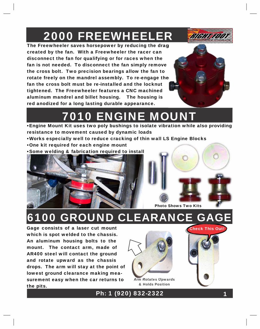
2000 FREEWHEELER�The Freewheeler saves horsepower by reducing the drag�created by the fan. With a Freewheeler the racer can�disconnect the fan for qualifying or for races when the�fan is not needed. To disconnect the fan simply remove�the cross bolt. Two precision bearings allow the fan to�rotate freely on the mandrel assembly. To re-engage the�fan the cross bolt must be re-installed and the locknut�tightened. The Freewheeler features a CNC machined�aluminum mandrel and billet housing. The housing is�red anodized for a long lasting durable appearance.�
•Engine Mount Kit uses two poly bushings to isolate vibration while also providing�resistance to movement caused by dynamic loads�•Works especially well to reduce cracking of thin wall LS Engine Blocks�•One kit required for each engine mount�•Some welding & fabrication required to install�
7010 ENGINE MOUNT�
Photo Shows Two Kits�
Ph: 1 (920) 832-2322� 1�
Check This Out!�
Arm Rotates Upwards�& Holds Position�
Gage consists of a laser cut mount�which is spot welded to the chassis.�An aluminum housing bolts to the�mount. The contact arm, made of�AR400 steel will contact the ground�and rotate upward as the chassis�drops. The arm will stay at the point of�lowest ground clearance making mea-�surement easy when the car returns to�the pits.�
6100 GROUND CLEARANCE GAGE�
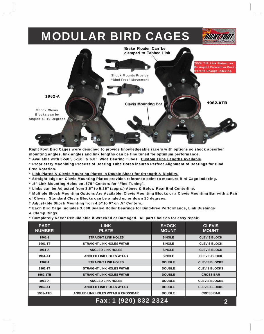
PART�NUMBER�
LINK�PLATE�
SHOCK�MOUNT�
CLEVIS�MOUNT�
1961-1� STRAIGHT LINK HOLES� SINGLE� CLEVIS BLOCK�
1961-1T� STRAIGHT LINK HOLES W/TAB� SINGLE� CLEVIS BLOCK�
1961-A� ANGLED LINK HOLES� SINGLE� CLEVIS BLOCK�
1961-AT� ANGLED LINK HOLES W/TAB� SINGLE� CLEVIS BLOCK�
1962-1� STRAIGHT LINK HOLES� DOUBLE� CLEVIS BLOCKS�
1962-1T� STRAIGHT LINK HOLES W/TAB� DOUBLE� CLEVIS BLOCKS�
1962-1TB� STRAIGHT LINK HOLES W/TAB� DOUBLE� CROSS BAR�
1962-A� ANGLED LINK HOLES� DOUBLE� CLEVIS BLOCKS�
1962-AT� ANGLED LINK HOLES W/TAB� DOUBLE� CLEVIS BLOCKS�
1962-ATB� ANGLED LINK HOLES W/TAB & CROSSBAR� DOUBLE� CROSS BAR�
MODULAR BIRD CAGES�
1962-ATB�
Fax: 1 (920) 832 2324� 2�
Right Foot Bird Cages were designed to provide knowledgeable racers with options so shock absorber�mounting angles, link angles and link lengths can be fine tuned for optimum performance.�* Available with 3-5/8”, 5-1/8” & 6.0” Wide Bearing Tubes.�Custom Tube Lengths Available�.�* Proprietary Machining Process of Bearing Tube Bores insures Perfect Alignment of Bearings for Bind�Free Rotation.�*�Link Plates & Clevis Mounting Plates in Double Shear for Strength & Rigidity.�* Straight edge on Clevis Mounting Plates provides reference point to measure Bird Cage Indexing.�* .5” Link Mounting Holes on .375” Centers for “Fine-Tuning”.�* Links can be Adjusted from 3.5” to 5.25” (apprx.) Above & Below Rear End Centerline.�* Multiple Shock Mounting Options Are Available: Clevis Mounting Blocks or a Clevis Mounting Bar with a Pair�of Clevis. Standard Clevis Blocks can be angled up or down 10 degrees.�* Adjustable Shock Mounting from 4.5” to 6” on .5” Centers.�* Each Bird Cage Includes 3.008 Sealed Roller Bearings for Bind-Free Performance, Link Bushings�& Clamp Rings.�* Completely Racer Rebuild able if Wrecked or Damaged. All parts bolt on for easy repair.�
Brake Floater Can be�clamped to Tabbed Link�
Clevis Mounting Bar�
1962-A�
TECH TIP: Link Plates can�Be Angled Forward or Back-�ward to Change Indexing.�
Shock Clevis�Blocks can be�
Angled +/- 10 Degrees�
Shock Mounts Provide�“Bind-Free” Movement�
CUSTOM BIRD CAGES�
These bird cages were designed for Mark�Bush to his exacting requirements. The�bird cages have some unique features for�improved performance.�* 6.0” Long Bearing Tube for additional�stability.�* Gusseted Link Plates & Shock Mount�Plates to resist bending.�* Custom Chain Hanger Bird Cages to�prevent binding (Chain Hanger Bird Cages�are not� IMCA legal.�
2160MBR�
2180�Chain�
Hanger�
MBR BIRD CAGES�
Web:�www.rightfootperformance.net� 3�
Our modular bird cage design makes it easy to custom�build bird cages to a customer’s request. We can build�bird cages with custom bearing tube widths, alternate�link and shock mounting plates and custom link plate�spacing. The P/N 2170-AC bird cage shown in the photo�has a 9.0” barrel and a bolt-on caliper bracket. Give us a�call if you need custom built, high performance�bird cages.�
HEAVY LR BIRD CAGES�Do you need more left rear bite? We can help. Our modular�“stock appearing” heavy bird cages are as much as 3 times�heavier then standard bird cages. The bird cage in the photo�weighs 30 lbs. The bird cages are available in a variety of�tube lengths with straight and angled link plates and a variety�of shock clevis mounting blocks. Our modular design makes�it easy to custom build bird cages to a customer’s request.�Heavy weight bird cages have also been successfully used to�add bite to the right rear. Give us a call if your car needs�more bite.�
2160�Jason Brookover�
Gun Slinger 2 Chassis� 2170-AC�
AXLE TUBE SPACERS & LOCK RINGS�
BIRD CAGE PARTS�
2140�
2123� 1.0” W, AXLE TUBE SPACER�
2171� 5/8” W, AXLE TUBE SPACER�
2172� 3/4” W, AXLE TUBE SPACER�
2149� AXLE TUBE SPACER, 1-7/8” W, 3.008” ID, UN PLATED�
2167� SPACER/ CLAMP RING W/ TAPPED HOLES, 1-7/8” W�
2135� OFFSET CLAMP RING, 1.0” W�
2119� TAPERED ROD END SPACER, 1/2” TO 5/8”�
2133� TAPERED ROD END SPACER, 1/2” TO 3/4”�
PW0003� SPACER, 1.77”L� 4�
2110�2110-2�
2118�
2111�2106-90� 2106-45�
2107-1�
2103�2104�
2107�
PW0003�
2167�2149�
2133�2119�
2135�
2123�
2172�2171�
Chad Kinder - MBR Chassis�
2106�
1904�
1907� 1907-1�
1903-T�1903�
1904-T�
2107-1� SHOCK MOUNT PLATE, SINGLE� 2110-2� SHOCK MOUNT CLEVIS, SHORT�
2107� SHOCK MOUNT PLATE, DOUBLE� 2110-MB� CLEVIS, FIT 2106-MB CLEVIS BLOCK�
2104� LINK PLATE, SINGLE ROW , STRAIGHT HOLES� 2111� DOUBLE SHOCK MOUNT CROSSBAR�
2103� LINK PLATE, SINGLE ROW, ANGLED HOLES� 2118� BEARING, 3.008 ID�
2103-T� TABBED LINK PLATE, ANGLED HOLES� 1904� LINK PLATE, STRAIGHT HOLES�
2106� ADJUSTABLE CLEVIS MOUNTING BLOCK� 1904-T� LINK PLATE W/ TAB, STRAIGHT HOLES�
2106-45� ANGLED CLEVIS BLOCK, 1.0” DROP� 1903� LINK PLATE, ANGLED HOLES�
2106-90� EXTRA DROP CLEVIS BLOCK, 2.0” DROP� 1903-T� LINK PLATE W/ TAB, ANGLED HOLES�
2106-MB� CLEVIS BLOCK, 2-5/8” L� 1907-1� SINGLE SHOCK MOUNT PLATE�
2110� SHOCK MOUNTING CLEVIS� 1907� DOUBLE SHOCK MOUNT PLATE�
2185-275� BILLET SHOCK CLEVIS, 2.75” STUD� 2185-40� BILLET SHOCK CLEVIS, 4.00” STUD�
2185-45� BILLET SHOCK CLEVIS, 4.50” STUD� 2185-55� BILLET SHOCK CLEVIS,5.50” STUD�
2103-T�
2106-MB�
2110-MB�
2185-275�2185-40�
2185-55�
Email - [email protected]�
IMCA SPORT MOD�REAR SUSPENSION COMPONENTS�
2245 -�Clamp On Trailing Arm�Bracket - Bolt-On Side Plates�can be replaced if damaged.�.5” Link Holes at 3.75” to�
5.25” below axle CL w/ .375”�spacing. Clamp Ring should be�spot welded to axle housing.�
Includes two rod end spacers.�
2250 -�Clamp On�Shock Mounting�
Bracket - Mounts�shock 3.875” from axle�CL. Clamp Ring should�be spot welded to axle�
housing.�
3110 -�Clamp�On Spring Cup�
3110-XL -�Clamp On Extended�Spring Seat - Meets IMCA�spring height rule. Spring�
guide is 4” tall to help retain�LR spring when “hiked up”.�
3120-11 -�Extended Spring�Seat with 11” Jack Screw�
4” tall Spring Guide to retain�spring during “hike up”.�
Includes 11” long 1”-8 Jack�Screw.�
3115 -�Upper�Spring Cup�
3130 -�Light Weight Spring�Seat - Can be bolted on or�
welded on to position�spring seat as needed.�Has .5” ID center hole.�
3125 -�Offset Extended�Spring Cup - Clamp is offset�
1.0” from centerline.�
2250-XL -�Clamp On�Shock Mounting�
Bracket - Mounts�shock 5.875” from axle�CL. Clamp Ring should�be spot welded to axle�
housing.�
5�
Ph: 1 (920) 832 2322�
TWO LINK SUSPENSION BRACKETS�These clamp-on two link suspension brackets are�designed for use on B Mods. The brackets are available�with single shock mounts for IMCA cars and double�shock mounts for WISSOTA, USRA and UMP cars.�Brackets are double shear for strength and are modular�so if damaged the mounting plates can be easily�removed and replaced. Standard clamp brackets are�3.25” wide however the modular design makes it easy�to provide clamp brackets in other widths. Two link�brackets have these product features:�
3200 Single Shock Mount Bracket�
3205 Double Shock Mount Bracket�
• Trailing link holes centered on 16.0” radius.�• Six intersecting .50” trailing link holes on�.375” centers for “fine tuning” link angles.�• Links can be adjusted from 3.75” to 5.625”�below the rear end centerline.�• Pinion angle can be set by using straight�edges of clevis mounting plates.�• Two misalignment spacers for .625” rod ends�included.�• Shock clevis mounting blocks can be�adjusted from 4.56” to 6.06” below the rear�end centerline.�• Shock clevis mounting blocks can also be�angled upward or downward 10 degrees.�• Clevis designed to provide full articulation of�shock rod end.�• Optional clevis mounting blocks available�(�see Page 4�)�• All parts are powder coated or zinc plated�for appearance.�• Completely racer rebuildable if damaged in a�wreck.�
3207 Replacement�
6�
Ph: 1 (920) 832 2322�
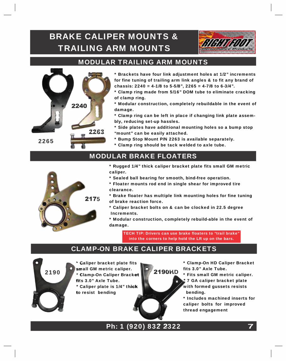
BRAKE CALIPER MOUNTS &�TRAILING ARM MOUNTS�
MODULAR TRAILING ARM MOUNTS�* Brackets have four link adjustment holes at 1/2” increments�for fine tuning of trailing arm link angles & to fit any brand of�chassis: 2240 = 4-1/8 to 5-5/8”, 2265 = 4-7/8 to 6-3/4”.�* Clamp ring made from 5/16” DOM tube to eliminate cracking�of clamp ring.�* Modular construction, completely rebuildable in the event of�damage.�* Clamp ring can be left in place if changing link plate assem-�bly, reducing set-up hassles.�* Side plates have additional mounting holes so a bump stop�“mount” can be easily attached.�* Bump Stop Mount P/N 2263 is available separately.�* Clamp ring should be tack welded to axle tube.�
MODULAR BRAKE FLOATERS�* Rugged 1/4” thick caliper bracket plate fits small GM metric�caliper.�* Sealed ball bearing for smooth, bind-free operation.�* Floater mounts rod end in single shear for improved tire�clearance.�* Brake floater has multiple link mounting holes for fine tuning�of brake reaction force.�* Caliper bracket bolts on & can be clocked in 22.5 degree� Increments.�* Modular construction, completely rebuild-able in the event of�damage.�
2240�
2175�
2263�
CLAMP-ON BRAKE CALIPER BRACKETS�
* Caliper bracket plate fits�small GM metric caliper.�* Clamp-On Caliper Bracket�fits 3.0” Axle Tube.�* Caliper plate is 1/4” thick�to resist bending�
7�
2265�
2190HD�* Clamp-On HD Caliper Bracket�fits 3.0” Axle Tube.�* Fits small GM metric caliper.�* 7 GA caliper bracket plate�with formed gussets resists� bending.�* Includes machined inserts for�caliper bolts for improved�thread engagement�
2190�
TECH TIP: Drivers can use brake floaters to “trail brake”�into the corners to help hold the LR up on the bars.�
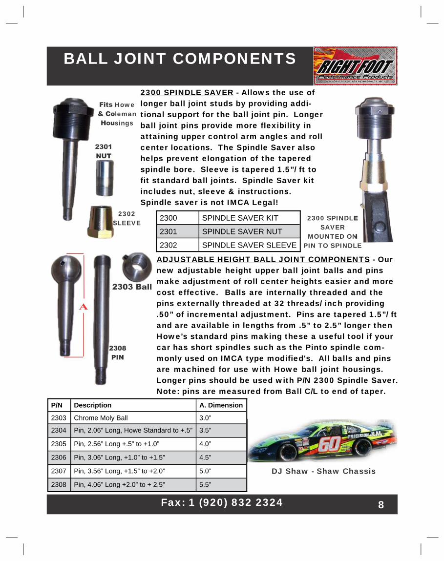
BALL JOINT COMPONENTS�
2300 SPINDLE SAVER� - Allows the use of�longer ball joint studs by providing addi-�tional support for the ball joint pin. Longer�ball joint pins provide more flexibility in�attaining upper control arm angles and roll�center locations. The Spindle Saver also�helps prevent elongation of the tapered�spindle bore. Sleeve is tapered 1.5”/ ft to�fit standard ball joints. Spindle Saver kit�includes nut, sleeve & instructions.�Spindle saver is not IMCA Legal!�
2300� SPINDLE SAVER KIT�
2301� SPINDLE SAVER NUT�
2302� SPINDLE SAVER SLEEVE�
2300 SPINDLE�SAVER�
MOUNTED ON�PIN TO SPINDLE�
ADJUSTABLE HEIGHT BALL JOINT COMPONENTS� - Our�new adjustable height upper ball joint balls and pins�make adjustment of roll center heights easier and more�cost effective. Balls are internally threaded and the�pins externally threaded at 32 threads/ inch providing�.50” of incremental adjustment. Pins are tapered 1.5”/ ft�and are available in lengths from .5” to 2.5” longer then�Howe’s standard pins making these a useful tool if your�car has short spindles such as the Pinto spindle com-�monly used on IMCA type modified's. All balls and pins�are machined for use with Howe ball joint housings.�Longer pins should be used with P/N 2300 Spindle Saver.�Note: pins are measured from Ball C/L to end of taper.�
2301�NUT�
2302�SLEEVE�
P/N� Description� A. Dimension�
2303� Chrome Moly Ball� 3.0”�
2304� Pin, 2.06” Long, Howe Standard to +.5”� 3.5”�
2305� Pin, 2.56” Long +.5” to +1.0”� 4.0”�
2306� Pin, 3.06” Long, +1.0” to +1.5”� 4.5”�
2307� Pin, 3.56” Long, +1.5” to +2.0”� 5.0”�
2308� Pin, 4.06” Long +2.0” to + 2.5”� 5.5”�
2303 Ball�
Fits Howe�& Coleman�Housings�
2308�PIN�
DJ Shaw - Shaw Chassis�
A�
Fax: 1 (920) 832 2324� 8�
Web:�www.rightfootperformance.com�
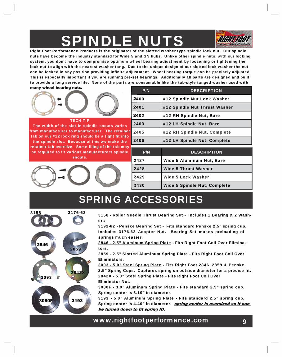
Right Foot Performance Products is the originator of the slotted washer type spindle lock nut. Our spindle�nuts have become the industry standard for Wide 5 and GN hubs. Unlike other spindle nuts, with our locking�system, you don’t have to compromise optimum wheel bearing adjustment by loosening or tightening the�lock nut to align with the nearest washer tang. Due to the unique design of our slotted lock washer the nut�can be locked in any position providing infinite adjustment. Wheel bearing torque can be precisely adjusted.�This is especially important if you are running pre-set bearings. Additionally all parts are designed and built�to provide a long service life. None of the parts are consumable like the tab-style tanged washer used with�many wheel bearing nuts.�
SPINDLE NUTS�
P/N� DESCRIPTION�
2427� Wide 5 Aluminum Nut, Bare�
2428� Wide 5 Thrust Washer�
2429� Wide 5 Lock Washer�
2430� Wide 5 Spindle Nut, Complete�
P/N� DESCRIPTION�
2400� #12 Spindle Nut Lock Washer�
2401� #12 Spindle Nut Thrust Washer�
2402� #12 RH Spindle Nut, Bare�
2403� #12 LH Spindle Nut, Bare�
2405� #12 RH Spindle Nut, Complete�
2406� #12 LH Spindle Nut, Complete�
3158 - Roller Needle Thrust Bearing Set� - Includes 1 Bearing & 2 Wash-�ers�3192-62 - Penske Bearing Set� - Fits standard Penske 2.5” spring cup.�Includes 3176-62 Adapter Nut. Bearing Set makes preloading of�springs much easier.�2846 - 2.5” Aluminum Spring Plate� - Fits Right Foot Coil Over Elimina-�tors.�2859 - 2.5” Slotted Aluminum Spring Plate� - Fits Right Foot Coil Over�Eliminators.�3093 - 5.0” Steel Spring Plate� - Fits Right Foot 2846, 2859 & Penske�2.5” Spring Cups. Captures spring on outside diameter for a precise fit.�2842X - 5.0” Steel Spring Plate� - Fits Right Foot Coil Over�Eliminator Nut.�3080F - 3.0” Aluminum Spring Plate�- Fits standard 2.5” spring cup.�Spring center is 3.10” in diameter.�3193 - 5.0” Aluminum Spring Plate�- Fits standard 2.5” spring cup.�Spring center is 4.40” in diameter.�
3158� 3176-62�
SPRING ACCESSORIES�
2846�2859�
2842X�3093�
3080F� 3193�
9�
TECH TIP�The width of the slot in spindle snouts varies�
from manufacturer to manufacturer. The retainer�tab on our #12 lock ring should be a tight fit into�the spindle slot. Because of this we make the�
retainer tab oversize. Some filing of the tab may�be required to fit various manufacturers spindle�
snouts.�
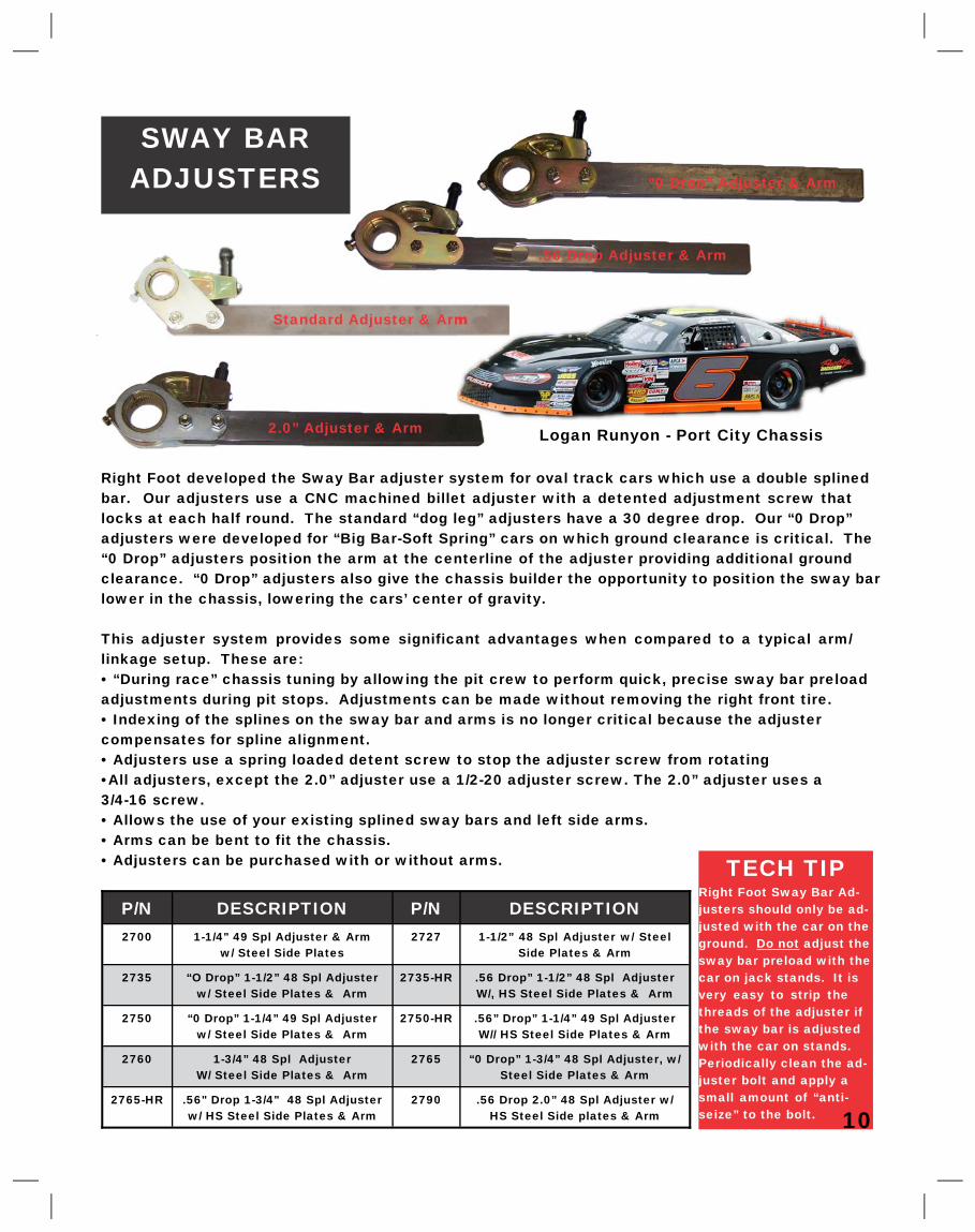
SWAY BAR�ADJUSTERS�
Right Foot developed the Sway Bar adjuster system for oval track cars which use a double splined�bar. Our adjusters use a CNC machined billet adjuster with a detented adjustment screw that�locks at each half round. The standard “dog leg” adjusters have a 30 degree drop. Our “0 Drop”�adjusters were developed for “Big Bar-Soft Spring” cars on which ground clearance is critical. The�“0 Drop” adjusters position the arm at the centerline of the adjuster providing additional ground�clearance. “0 Drop” adjusters also give the chassis builder the opportunity to position the sway bar�lower in the chassis, lowering the cars’ center of gravity.�
This adjuster system provides some significant advantages when compared to a typical arm/�linkage setup. These are:�• “During race” chassis tuning by allowing the pit crew to perform quick, precise sway bar preload�adjustments during pit stops. Adjustments can be made without removing the right front tire.�• Indexing of the splines on the sway bar and arms is no longer critical because the adjuster�compensates for spline alignment.�• Adjusters use a spring loaded detent screw to stop the adjuster screw from rotating�•All adjusters, except the 2.0” adjuster use a 1/2-20 adjuster screw. The 2.0” adjuster uses a�3/4-16 screw.�• Allows the use of your existing splined sway bars and left side arms.�• Arms can be bent to fit the chassis.�• Adjusters can be purchased with or without arms.�
P/N� DESCRIPTION� P/N� DESCRIPTION�2700� 1-1/4" 49 Spl Adjuster & Arm�
w/ Steel Side Plates�2727� 1-1/2” 48 Spl Adjuster w/ Steel�
Side Plates & Arm�
2735� “O Drop” 1-1/2” 48 Spl Adjuster�w/ Steel Side Plates & Arm�
2735-HR� .56 Drop” 1-1/2” 48 Spl Adjuster�W/, HS Steel Side Plates & Arm�
2750� “0 Drop” 1-1/4” 49 Spl Adjuster�w/ Steel Side Plates & Arm�
2750-HR� .56” Drop” 1-1/4” 49 Spl Adjuster�W// HS Steel Side Plates & Arm�
2760� 1-3/4” 48 Spl Adjuster�W/ Steel Side Plates & Arm�
2765� “0 Drop” 1-3/4” 48 Spl Adjuster, w/�Steel Side Plates & Arm�
2765-HR� .56" Drop 1-3/4" 48 Spl Adjuster�w/ HS Steel Side Plates & Arm�
2790� .56 Drop 2.0” 48 Spl Adjuster w/�HS Steel Side plates & Arm�
TECH TIP�Right Foot Sway Bar Ad-�justers should only be ad-�justed with the car on the�ground.�Do not� adjust the�sway bar preload with the�car on jack stands. It is�very easy to strip the�threads of the adjuster if�the sway bar is adjusted�with the car on stands.�Periodically clean the ad-�juster bolt and apply a�small amount of “anti-�seize” to the bolt.� 10�
“0 Drop” Adjuster & Arm�
.56 Drop Adjuster & Arm�
Standard Adjuster & Arm�
Logan Runyon - Port City Chassis�2.0” Adjuster & Arm�
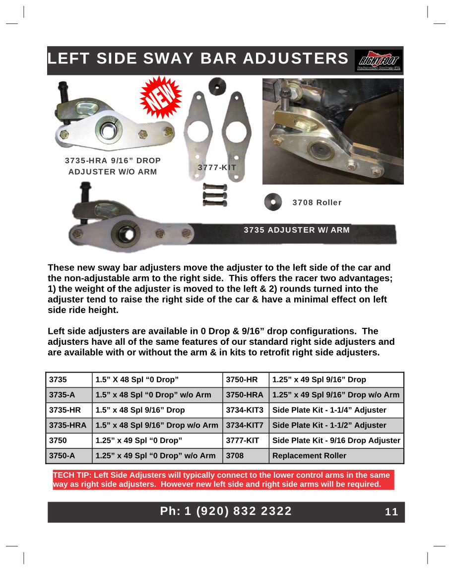
LEFT SIDE SWAY BAR ADJUSTERS�
3735� 1.5” X 48 Spl “0 Drop”� 3750-HR� 1.25” x 49 Spl 9/16” Drop�
3735-A� 1.5” x 48 Spl “0 Drop” w/o Arm� 3750-HRA� 1.25” x 49 Spl 9/16” Drop� w/o Arm�
3735-HR� 1.5” x 48 Spl 9/16” Drop� 3734-KIT3� Side Plate Kit - 1-1/4” Adjuster�
3735-HRA� 1.5” x 48 Spl 9/16” Drop� w/o Arm� 3734-KIT7� Side Plate Kit - 1-1/2” Adjuster�
3750� 1.25” x 49 Spl “0 Drop”� 3777-KIT� Side Plate Kit - 9/16 Drop Adjuster�
3750-A� 1.25” x 49 Spl “0 Drop” w/o Arm� 3708� Replacement Roller�
These new sway bar adjusters move the adjuster to the left side of the car and�the non-adjustable arm to the right side. This offers the racer two advantages;�1) the weight of the adjuster is moved to the left & 2) rounds turned into the�adjuster tend to raise the right side of the car & have a minimal effect on left�side ride height.�
Left side adjusters are available in 0 Drop & 9/16” drop configurations. The�adjusters have all of the same features of our standard right side adjusters and�are available with or without the arm & in kits to retrofit right side adjusters.�
TECH TIP: Left Side Adjusters will typically connect to the lower control arms in the same�way as right side adjusters. However new left side and right side arms will be required.�
Ph: 1 (920) 832 2322�
3735 ADJUSTER W/ ARM�
3735-HRA 9/16” DROP�ADJUSTER W/O ARM� 3777-KIT�
3708 Roller�
11�
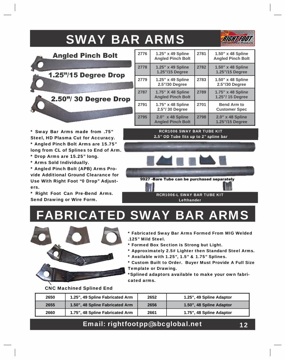
SWAY BAR ARMS�
* Sway Bar Arms made from .75”�Steel, HD Plasma Cut for Accuracy.�* Angled Pinch Bolt Arms are 15.75”�long from CL of Splines to End of Arm.�* Drop Arms are 15.25” long.�* Arms Sold Individually.�* Angled Pinch Bolt (APB) Arms Pro-�vide Additional Ground Clearance for�Use With Right Foot “0 Drop” Adjust-�ers.�* Right Foot Can Pre-Bend Arms.�Send Drawing or Wire Form.�
Angled Pinch Bolt�
1.25”/15�Degree Drop�
2.50”/ 30 Degree Drop�
2776� 1.25” x 49 Spline�Angled Pinch Bolt�
2781� 1.50” x 48 Spline�Angled Pinch Bolt�
2778� 1.25” x 49 Spline�1.25”/15 Degree�
2782� 1.50” x 48 Spline�1.25”/15 Degree�
2779� 1.25” x 49 Spline�2.5”/30 Degree�
2783� 1.50” x 48 Spline�2.5”/30 Degree�
2787� 1.75” X 48 Spline�Angled Pinch Bolt�
2789� 1.75” x 48 Spline�1.25”/ 15 Degree�
2791� 1.75” x 48 Spline�2.5”/ 30 Degree�
2701� Bend Arm to�Customer Spec�
2795� 2.0” x 48 Spline�Angled Pinch Bolt�
2798� 2.0” x 48 Spline�1.25”/15 Degree�
FABRICATED SWAY BAR ARMS�* Fabricated Sway Bar Arms Formed From MIG Welded�.125” Mild Steel.�* Formed Box Section is Strong but Light.�* Approximately 2.5# Lighter then Standard Steel Arms.�* Available with 1.25”, 1.5” & 1.75” Splines.�* Custom Built to Order. Buyer Must Provide A Full Size�Template or Drawing.�*Splined adaptors available to make your own fabri-�cated arms.�
2650� 1.25”, 49 Spline Fabricated Arm� 2652� 1.25”, 49 Spline Adaptor�
2655� 1.50”, 48 Spline Fabricated Arm� 2656� 1.50”, 48 Spline Adaptor�
2660� 1.75”, 48 Spline Fabricated Arm� 2661� 1.75”, 48 Spline Adaptor�
CNC Machined Splined End�
RCR1006 SWAY BAR TUBE KIT�2.5” OD Tube fits up to 2” spline bar�
RCR1006-L SWAY BAR TUBE KIT�Lefthander�
9927 -Bare Tube can be purchased separately�
Email: [email protected]� 12�
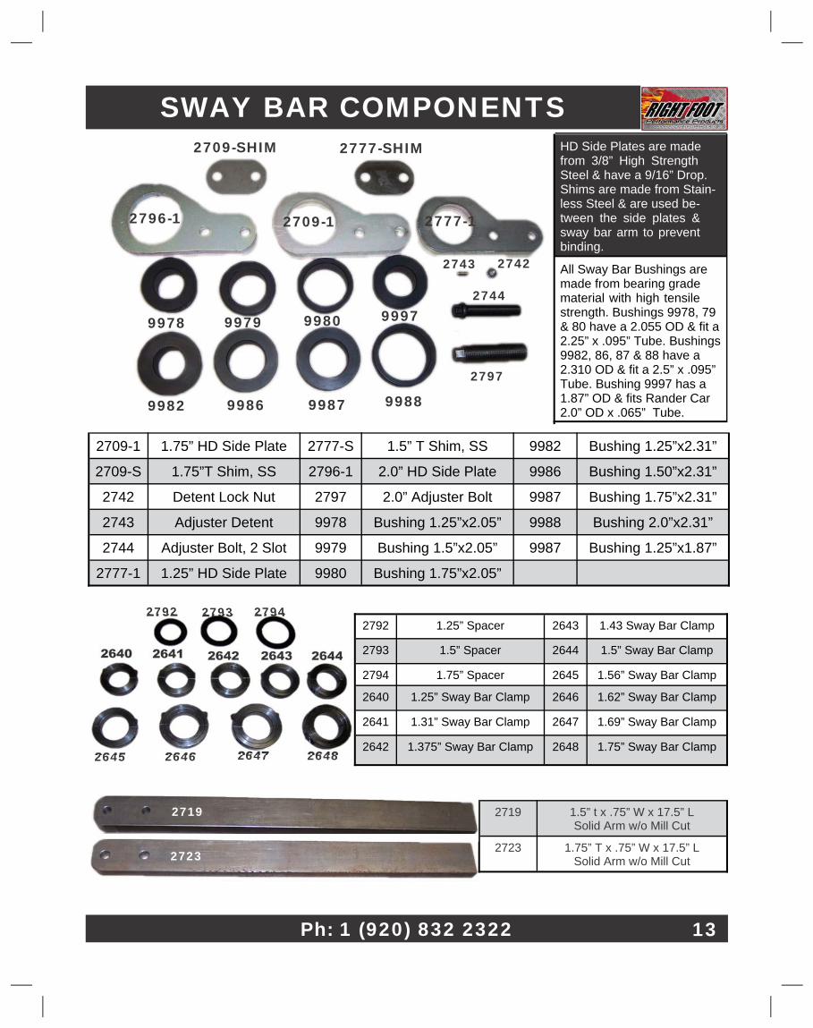
2719� 1.5” t x .75” W x 17.5” L�Solid Arm w/o Mill Cut�
2723� 1.75” T x .75” W x 17.5” L�Solid Arm w/o Mill Cut�
2792� 1.25” Spacer� 2643� 1.43 Sway Bar Clamp�
2793� 1.5” Spacer� 2644� 1.5” Sway Bar Clamp�
2794� 1.75” Spacer� 2645� 1.56” Sway Bar Clamp�
2640� 1.25” Sway Bar Clamp� 2646� 1.62” Sway Bar Clamp�
2641� 1.31” Sway Bar Clamp� 2647� 1.69” Sway Bar Clamp�
2642� 1.375” Sway Bar Clamp� 2648� 1.75” Sway Bar Clamp�
2792� 2793� 2794�
2640� 2641� 2642� 2643� 2644�
2645� 2646� 2647� 2648�
2709-1� 1.75” HD Side Plate� 2777-S� 1.5” T Shim, SS� 9982� Bushing 1.25”x2.31”�
2709-S� 1.75”T Shim, SS� 2796-1� 2.0” HD Side Plate� 9986� Bushing 1.50”x2.31”�
2742� Detent Lock Nut� 2797� 2.0” Adjuster Bolt� 9987� Bushing 1.75”x2.31”�
2743� Adjuster Detent� 9978� Bushing 1.25”x2.05”� 9988� Bushing 2.0”x2.31”�
2744� Adjuster Bolt, 2 Slot� 9979� Bushing 1.5”x2.05”� 9987� Bushing 1.25”x1.87”�
2777-1� 1.25” HD Side Plate� 9980� Bushing 1.75”x2.05”�
HD Side Plates are made�from 3/8” High Strength�Steel & have a 9/16” Drop.�Shims are made from Stain-�less Steel & are used be-�tween the side plates &�sway bar arm to prevent�binding.�
All Sway Bar Bushings are�made from bearing grade�material with high tensile�strength. Bushings 9978, 79�& 80 have a 2.055 OD & fit a�2.25” x .095” Tube. Bushings�9982, 86, 87 & 88 have a�2.310 OD & fit a 2.5” x .095”�Tube. Bushing 9997 has a�1.87” OD & fits Rander Car�2.0” OD x .065” Tube.�
SWAY BAR COMPONENTS�2777-SHIM�2709-SHIM�
9979� 9980� 9997�
9982� 9986� 9987� 9988�
2742�
2744�
2797�
2743�
Ph: 1 (920) 832 2322� 13�
9978�
2777-1�2796-1� 2709-1�
2719�
2723�
Fax: 1 (920) 832 2324�
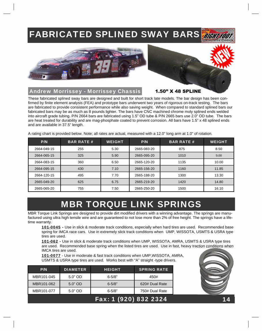
FABRICATED SPLINED SWAY BARS�
These fabricated splined sway bars are designed and built for short track late models. The bar design has been con-�firmed by finite element analysis (FEA) and prototype bars underwent two years of rigorous on-track testing. The bars�are fabricated to provide consistent performance while also saving weight. When compared to standard splined bars our�fabricated bars may be as much as 8 pounds lighter. The bars have CNC machined chrome moly splined ends welded�into aircraft grade tubing. P/N 2664 bars are fabricated using 1.5” OD tube & P/N 2665 bars use 2.0” OD tube. The bars�are heat treated for durability and are mag-phosphate coated to prevent corrosion. All bars have 1.5” x 48 splined ends�and are available in 37.5” length.�
A rating chart is provided below. Note; all rates are actual, measured with a 12.0” long arm at 1.0” of rotation.�
P/N� BAR RATE #� WEIGHT� P/N� BAR RATE #� WEIGHT�
2664-049-15� 255� 5.30� 2665-083-20� 875� 8.50�
2664-065-15� 325� 5.90� 2665-095-20� 1010� 9.00�
2664-083-15� 360� 6.50� 2665-120-20� 1135� 10.00�
2664-095-15� 430� 7.10� 2665-156-20� 1160� 11.85�
2664-120-15� 495� 7.70� 2665-188-20� 1300� 13.30�
2665-049-20� 625� 6.75� 2665-219-20� 1420� 14.80�
2665-065-20� 755� 7.50� 2665-250-20� 1500� 16.10�
1.50” X 48 SPLINE�Andrew Morrissey - Morrissey Chassis�
14�
MBR Torque Link Springs are designed to provide dirt modified drivers with a winning advantage. The springs are manu-�factured using ultra high tensile wire and are guaranteed to not lose more than 2% of free height. The springs have a life-�time warranty.�
101-0045� -�Use in slick & moderate track conditions, especially when hard tires are used. Recommended base� spring for IMCA race cars. Use in extremely slick track conditions when UMP, WISSOTA, USMTS & USRA type� tires are used.�
101-062� -�Use in slick & moderate track conditions when UMP, WISSOTA, AMRA, USMTS & USRA type tires� are used. Recommended base spring when the listed tires are used. Use in fast, heavy traction conditions when� IMCA tires are used.�
101-0077� - Use in moderate & fast track conditions when UMP,WISSOTA, AMRA,� USMTS & USRA type tires are used. Works best with “A” straight -type drivers.�
MBR TORQUE LINK SPRINGS�
P/N� DIAMETER� HEIGHT� SPRING RATE�
MBR101-045� 5.0” OD� 6-5/8”� 450#�
MBR101-062� 5.0” OD� 6-5/8”� 620# Dual Rate�
MBR101-077� 5.0” OD� 6-5/8”� 750# Dual Rate�
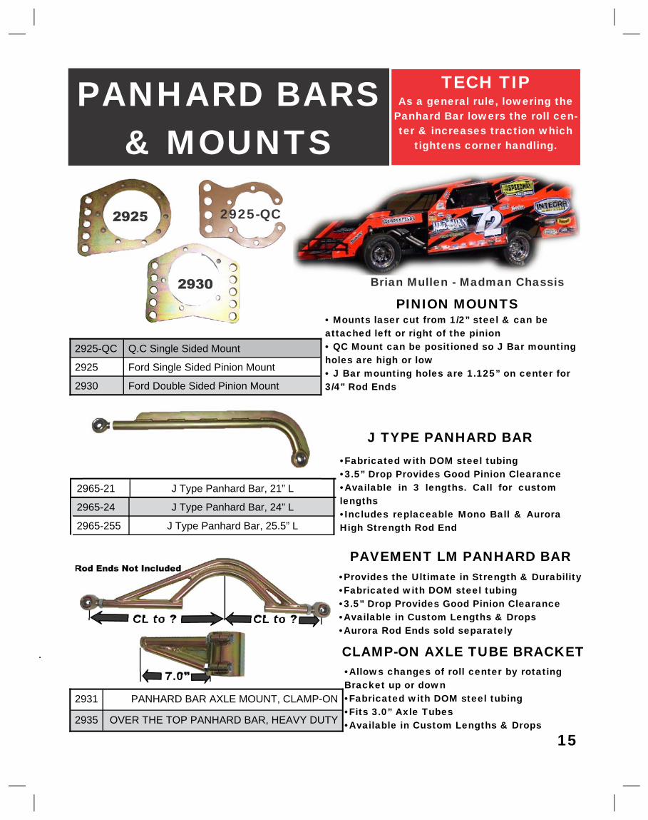
PANHARD BARS�& MOUNTS�
PINION MOUNTS�• Mounts laser cut from 1/2” steel & can be�attached left or right of the pinion�• QC Mount can be positioned so J Bar mounting�holes are high or low�• J Bar mounting holes are 1.125” on center for�3/4” Rod Ends�
2925-QC� Q.C Single Sided Mount�
2925� Ford Single Sided Pinion Mount�
2930� Ford Double Sided Pinion Mount�
2965-21� J Type Panhard Bar, 21” L�
2965-24� J Type Panhard Bar, 24” L�
2965-255� J Type Panhard Bar, 25.5” L�
2925�
2930�
J TYPE PANHARD BAR�•Fabricated with DOM steel tubing�•3.5” Drop Provides Good Pinion Clearance�•Available in 3 lengths. Call for custom�lengths�•Includes replaceable Mono Ball & Aurora�High Strength Rod End�
2925-QC�
PAVEMENT LM PANHARD BAR�
2931� PANHARD BAR AXLE MOUNT, CLAMP-ON�
2935� OVER THE TOP PANHARD BAR, HEAVY DUTY�
•Provides the Ultimate in Strength & Durability�•Fabricated with DOM steel tubing�•3.5” Drop Provides Good Pinion Clearance�•Available in Custom Lengths & Drops�•Aurora Rod Ends sold separately�
Rod Ends Not Included�
CL to ?� CL to ?�
7.0”�
CLAMP-ON AXLE TUBE BRACKET�•Allows changes of roll center by rotating�Bracket up or down�•Fabricated with DOM steel tubing�•Fits 3.0” Axle Tubes�•Available in Custom Lengths & Drops�
TECH TIP�As a general rule, lowering the�
Panhard Bar lowers the roll cen-�ter & increases traction which�
tightens corner handling.�
15�
Brian Mullen - Madman Chassis�
Web:�www.rightfootperformance.net�
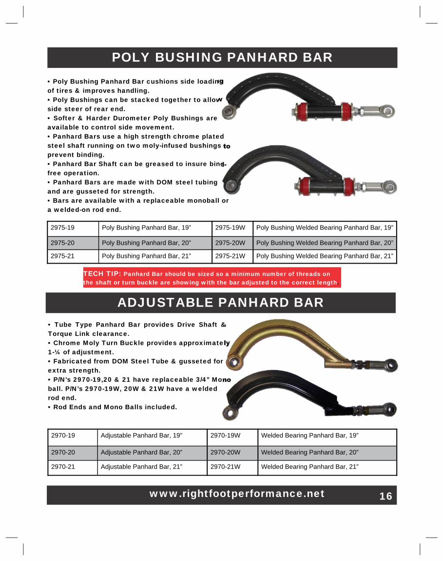
ADJUSTABLE PANHARD BAR�
2970-19� Adjustable Panhard Bar, 19”� 2970-19W� Welded Bearing Panhard Bar, 19”�
2970-20� Adjustable Panhard Bar, 20”� 2970-20W� Welded Bearing Panhard Bar, 20”�
2970-21� Adjustable Panhard Bar, 21”� 2970-21W� Welded Bearing Panhard Bar, 21”�
• Tube Type Panhard Bar provides Drive Shaft &�Torque Link clearance.�• Chrome Moly Turn Buckle provides approximately�1-¼ of adjustment.�• Fabricated from DOM Steel Tube & gusseted for�extra strength.�• P/N’s 2970-19,20 & 21 have replaceable 3/4” Mono�ball. P/N’s 2970-19W, 20W & 21W have a welded�rod end.�• Rod Ends and Mono Balls included.�
TECH TIP:�Panhard Bar should be sized so a minimum number of threads on�the shaft or turn buckle are showing with the bar adjusted to the correct length�.�
POLY BUSHING PANHARD BAR�
2975-19� Poly Bushing Panhard Bar, 19”� 2975-19W� Poly Bushing Welded Bearing Panhard Bar, 19”�
2975-20� Poly Bushing Panhard Bar, 20”� 2975-20W� Poly Bushing Welded Bearing Panhard Bar, 20”�
2975-21� Poly Bushing Panhard Bar, 21”� 2975-21W� Poly Bushing Welded Bearing Panhard Bar, 21”�
• Poly Bushing Panhard Bar cushions side loading�of tires & improves handling.�• Poly Bushings can be stacked together to allow�side steer of rear end.�• Softer & Harder Durometer Poly Bushings are�available to control side movement.�• Panhard Bars use a high strength chrome plated�steel shaft running on two moly-infused bushings to�prevent binding.�• Panhard Bar Shaft can be greased to insure bind-�free operation.�• Panhard Bars are made with DOM steel tubing�and are gusseted for strength.�• Bars are available with a replaceable monoball or�a welded-on rod end.�
16�
Email - [email protected]�
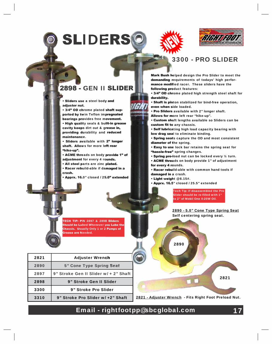
SLIDERS�
• Sliders use a steel body and�adjuster nut.�• 3/4” OD chrome plated shaft sup-�ported by twin Teflon impregnated�bearings provides free movement.�• High quality seals & built-in grease�cavity keeps dirt out & grease in,�providing durability and reduced�maintenance.�• Sliders available with 2” longer�shaft. Allows for more left rear�“hike-up”.�• ACME threads on body provide 1” of�adjustment for every 4 rounds.�• All steel parts are zinc plated.�• Racer rebuild-able if damaged in a�crash.�• Apprx. 16.0” closed / 25.0” extended�
2821� Adjuster Wrench�
2890� 5” Cone Type Spring Seat�
2897� 9” Stroke Gen II Slider w/ + 2” Shaft�
2898� 9” Stroke Gen II Slider�
3300� 9” Stroke Pro Slider�
3310� 9” Stroke Pro Slider w/ +2” Shaft�
TECH TIP: P/N 2897 & 2898 Sliders�Should be Lubed Whenever you Lube the�Chassis. Usually Only 1 or 2 Pumps of�Grease are Needed.�
2898 - GEN II SLIDER�
17�
3300 - PRO SLIDER�
Mark Bush helped design the Pro Slider to meet the�demanding requirements of todays’ high perfor-�mance modified racer. These sliders have the�following product features:�• 3/4” OD chrome plated high strength steel shaft for�durability.�• Shaft is piston stabilized for bind-free operation,�even when side loaded.�• Pro Sliders available with 2” longer shaft.�Allows for more left rear “hike-up”.�• Custom shaft lengths available so Sliders can be�custom fit to any chassis.�• Self lubricating high load capacity bearing with�low drag seal to eliminate binding.�• Spring seats capture the OD and most consistent�diameter of the spring.�• Easy to use lock bar retains the spring seat for�“hassle-free” spring changes.�• Spring pre-load nut can be locked every ½ turn.�• ACME threads on body provide 1” of adjustment�for every 4 rounds.�• Racer rebuild-able with common hand tools if�damaged in a crash.�• Light weight @ 6.15#.�• Apprx. 16.5” closed / 25.5” extended�
2821�
2821 - Adjuster Wrench� - Fits Right Foot Preload Nut.�
2890�
Tech Tip�: If disassembled the Pro�Slider should be re-filled with 1“�to 2” of Mobil One 0-20W Oil.�
2890 - 5.0” Cone Type Spring Seat�Self centering spring seat.�
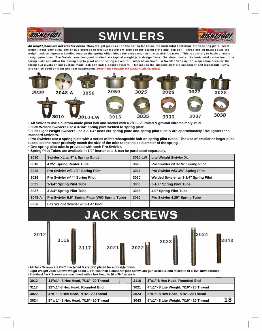
Many weight jacks act on the spring far below the horizontal centerline of the spring plate. Most�weight jacks only allow one or two degrees of relative movement between the spring plate and jack bolt. These design flaws cause the�weight jack to impose a bending load on the spring which binds the suspension as it arcs thru it’s travel. This is contrary to basic chassis�design principles. The Swivler was designed to eliminate typical weight jack design flaws. Swivlers pivot at the horizontal centerline of the�spring plate and allow the spring cup to pivot as the spring moves thru suspension travel. A Swivler frees up the suspension because the�spring cup pivots on our custom-made jack bolt ball & socket system. This makes the suspension more consistent and repeatable. Swiv-�lers can be used on front and rear suspension.�
SWIVLERS�
• All Swivlers use a custom-made pivot ball and socket with a 7/16 - 20 rolled & ground chrome moly stud.�• 3030 Welded Swivlers use a 3-1/4” spring pilot welded to spring plate.�• 3056 Light Weight Swivlers use a 3-1/4” laser cut spring plate and spring pilot tube & are approximately 1/4# lighter then�standard Swivlers.�• Pro Swivlers use a spring plate with a series of interchangeable bolt-on spring pilot tubes. The use of smaller or larger pilot�tubes lets the racer precisely match the size of the tube to the inside diameter of the spring.�• One spring pilot tube is provided with each Pro Swivler.�• Spring Pilot Tubes are available in 1/4” increments & can be purchased separately.�
3010� Swivler XL w/ 4" L Spring Guide� 3010-LW� Lite Weight Swivler XL�
3016� 4.25" Spring Center Tube� 3025� Pro Swivler w/ 3-1/4” Spring Pilot�
3026� Pro Swivler w/3-1/2” Spring Pilot� 3027� Pro Swivler w/3-3/4” Spring Pilot�
3028� Pro Swivler w/ 4” Spring Pilot� 3030� Welded Swivler w/ 3-1/4” Spring Pilot�
3035� 3-1/4” Spring Pilot Tube� 3036� 3-1/2” Spring Pilot Tube�
3037� 3-3/4” Spring Pilot Tube� 3038� 4.0” Spring Pilot Tube�
3048-A� Pro Swivler 5.5” Spring Plate (W/O Spring Tube)� 3050� Pro Swivler 4.25” Spring Tube�
3056� Lite Weight Swivler w/ 3-1/4” Pilot�
JACK SCREWS�
•� All Jack Screws are CNC machined & are zinc plated for a durable finish.�• Light Weight Jack Screws weigh about 1/3 # less then a standard jack screw, are gun drilled & end milled to fit a 1/2” drive ratchet.�• Standard Jack Screws are machined with a hex head to fit a 3/4” wrench.�
3012� 11”x1”- 8 Hex Head, 7/16”- 20 Thread� 3116� 8”x1”-8 Hex Head, Rounded End�
3117� 11”x1”-8 Hex Head, Rounded End� 3021� 4”x1”- 8 Lite Weight, 7/16”- 20 Thread�
3022� 4”x1”- 8 Hex Head, 7/16”- 20 Thread� 3023� 6”x1”- 8 Hex Head, 7/16”- 20 Thread�
3024� 8” x 1”- 8 Hex Head, 7/16”- 20 Thread� 3043� 6”x1”- 8 Lite Weight, 7/16”- 20 Thread� 18�
3030� 3056� 3025�
3035�
3026�
3036�
3027�
3037�
3028�
3038�
3012�
3021� 3022�3023�
3024�3043�3116�
3117�
3010-LW� 3010�
3050�3048-A�
3016�
Quik Sticks make it easy to use bump stops. The compact design lets the�racer mount the Quik Stick inside the control arm next to the coil over. The�bump stop adjuster nut has a detent so the Quik Stick can be adjusted by�hand without tools. Other advantages of the Quik Stick are:�• Depending on the mounting points in the car the Quik Stick can be�mounted so it is operating at the same motion ratio as the coil over.�• A travel indicator is provided making it easy to calculate the loaded spring�rate of the bump stops.�• The adjuster nut is threaded so each half turn equals 1/16”. This eliminates�the need for packer shims. The adjuster nut is hard coated for durability.�• 6055 Quik Sticks are sold with two 75 durometer puck type bump stops.�6255 Quik Sticks are sold with two 75 durometer RSW type bump stops.�However any bump stop with a 5/8” ID can be used. Quik Sticks can also�be purchased without bump stops when using bump springs.�• Light Weight, only weighs apprx 2.35#. The standard tubes are 9” long and�the XL tubes 12” long.�
QUIK STICKS�
19�
6055-XL�6055�
Detented Adjuster�Nut can be turned on�
Rod End to adjust�engagement�
TECH TIP: It’s easy to determine the load number for a corner of the car. Measure Bump Stick�travel. Then find the bump stop combination in our website tech pages for the spring rate at the�measured amount of travel. Then add that number to the spring load number from your coil over�rater.�
6016 Coil Over Mount & 9948 Fixed�Rod End are recommended for use�when mounting a bump stick to the�lower control arm strut rod.�
6016� 9948�
6255� 6255-XL� 6055-B/�6255-B�
6055-XL-B/�6255-XL-B�
Ph: 1 (920) 832-2322� 20�
BUMP STOP KITS�
Different drivers and different tracks require different bump stop set-ups. Testing is required to�determine the best bump stop, spring, sway bar and roll center combinations. These kits make it�easy to start bump stopping and go testing and racing. All of the kits include a selection of high�quality polyurethane bump stops, packer shims and backing washers and are packaged in a handy�carrying case.�
The bump stop pucks provide a fast rising linear spring rate while the RSW bump stops provide a�more progressive spring rate. All of the parts in the kits are available separately.�
6090 Standard Puck Style Kit� Includes 1 ea. 1/2”, 2 ea. 3/4” & 2 ea. 1”.� Pucks in 50, 55, 60 & 75 durometer.� All pucks have a 2” OD & 5/8” ID.� Also includes 8 ea. Spacer washers,� 1/16” & 1/8” Packer Shims & Case.�
6091 Deluxe Puck Style Kit� Includes 1 ea. 1/2”, 2 ea. 3/4” & 2 ea. 1”.� Pucks in 40, 50, 55, 60, 65 & 75 durometer.� All pucks have a 2” OD & 5/8” ID.� Also includes 8 ea. Spacer washers,� 1/16” & 1/8” Packer Shims & Case.�
6190 Puck Style Kit, 1/2” ID� Includes 1 ea. 1/2”, 2 ea. 3/4” & 2 ea. 1”.� Pucks in 40, 50, 55, 60 & 75 durometer.� All pucks have a 2” OD & 1/2” ID.� Also includes 8 ea. Spacer washers,� 1/16” & 1/8” Packer Shims & Case.�
6290 RSW Style Kit� Includes 2 ea. 1/2” & 2 ea. 1”.� RSW style in 50, 60, 70 & 80 durometer.� Also includes 8 ea. Spacer washers,� 1/16” & 1/8” Packer Shims & Case.�
P/N� COLOR�HEIGHT�DUROMETER�6075BR� Brown� .50� 40 - Soft�
6075G� Green� .50� 50�
6075O� Orange� .50� 55�
6075P� Purple� .50� 60�
6075BK� Black� .50� 65�
6075Y� Yellow� .50� 75�
6075B� Blue� .50� 80�
6075R� Red� .50� 87 - Hard�
6076BR� Brown� .75� 40 - Soft�
6076G� Green� .75� 50�
6076O� Orange� .75� 55�
6076P� Purple� .75� 60�
6076BK� Black� .75� 65�
6076Y� Yellow� .75� 75�
6076B� Blue� .75� 80�
6076R� Red� .75� 87 - Hard�
6077BR� Brown� 1.0� 40 - Soft�
6077G� Green� 1.0� 50�
6077O� Orange� 1.0� 55�
6077P� Purple� 1.0� 60�
6077BK� Black� 1.0� 65�
6077Y� Yellow� 1.0� 75�
6077B� Blue� 1.0� 80�
6077R� Red� 1.0� 87 - Hard�
POLY BUMP STOP PUCKS�
21�
2.0” OD X 5/8” ID� 2.0” OD X 1/2” ID�
Bump Stop Pucks are made from high quality polyurethane and are available in a variety of durom-�eters from 40A to 87A. Pucks are available with a .50” ID or a .625” ID to provide a good fit on�shock absorber rods. Three heights are available at .50”, .75” and 1.0” tall. The combination of�different durometers and heights gives the racer a wide range of bump stop tuning options. These�pucks are designed to work with Right Foot Performance bump stop packer shims and washers.�
TECH TIP�To obtain consistent results bump stop pucks should�be backed up by hard washers. If you need to soften�your bump stop package and don’t have softer pucks�available, removing the washers from between the�pucks will have the effect of reducing the spring rate�of the pucks.�
P/N� COLOR�HEIGHT�DUROMETER�6175BR� Brown� .50� 40 - Soft�
6175G� Green� .50� 50�
6175O� Orange� .50� 55�
6175P� Purple� .50� 60�
6175BK� Black� .50� 65�
6175Y� Yellow� .50� 75�
6176BR� Brown� .75� 40 - Soft�
6176G� Green� .75� 50�
6176O� Orange� .75� 55�
6176P� Purple� .75� 60�
6176BK� Black� .75� 65�
6176Y� Yellow� .75� 75�
6177BR� Brown� 1.0� 40 - Soft�
6177G� Green� 1.0� 50�
6177O� Orange� 1.0� 55�
6177P� Purple� 1.0� 60�
6177BK� Black� 1.0� 65�
6177Y� Yellow� 1.0� 75�
PROGRESSIVE BUMP STOPS�
P/N� DESCRIPTION� COLOR� DUROMETER� DIMENSIONS�
6070-35� 3 Section Bump Stop� Blue� 35 Gr Foam Soft� 1.94” x 2.25” x .625”�
6070-45� 3 Section Bump Stop� Tan� 45 Gr Foam Medium� 1.94” x 2.25” x .625”�
6070-55� 3 Section Bump Stop� Black� 55 Gr Foam Hard� 1.94” x 2.25” x .625”�
6170-35� 3 Section Bump Stop� Blue� 35 Gr Foam Soft� 1.94” x 2.25” x .50”�
6170-45� 3 Section Bump Stop� Tan� 45 Gr Foam Medium� 1.94” x 2.25” x .50”�
6170-55� 3 Section Bump Stop� Black� 55 Gr Foam Hard� 1.94” x 2.25” x .50”�
6071-35� 4 Section Bump Stop� Blue� 35 Gr Foam Soft� 1.95” x 3.0” x .625”�
6071-45� 4 Section Bump Stop� Tan� 45 Gr Foam Medium� 1.95” x 3.0” x .625”�
6071-55� 4 Section Bump Stop� Black� 55 Gr Foam Hard� 1.95” x 3.0” x .625”�
Three and four section bump stops provide a smooth progressive spring rate. The bushings are�available in 3 durometers of high density foam. This provides a wide range of options for fine tuning�spring rate and chassis drop.�
Bump stops are made from very high quality urethanes so the spring rate will remain consistent on�long runs. The bump stops have a solid core for durability and will fit most oval track shock absorb-�ers. 6070 and 6071 bump stops have a 5/8” ID and 6170 bump stops a 1/2” ID.�Use of a bump�stop cup, such as P/N 6072, is recommended to stabilize the bump stop.�
Foam bump stops have a softer spring rate than our other polyurethane bump stops and are�designed for use on sprint cars, dirt late models and dirt modifieds.�
Scotty Neitzel - R&H Motorsports�6071-35� 6071-45� 6071-55�
6070-35� 6070-45� 6070-55�
Ph: 1 (920) 832 2322� 22�
Fax: 1 (920) 832 2324�
P/N� DESCRIPTION� P/N� DESCRIPTION�
6042� Bump Stop Shim, Black, 2.0” OD, .062” T� 6022� Steel Washer, 2.25” OD, .125” T, .5” ID�
6043� Bump Stop Shim, Tan, 2.0” OD, .125” T� 4523-A� Alum. Washer, 2.25” OD, .625” ID, .188” T�
6044� Bump Stop Shim, Black, 2.25” OD, .062” T� 6123-A� Alum. Washer, 2.25” OD, .5” ID, .188” T�
6045� Bump Stop Shim, Tan, 2.25” OD, .125” T� 6048-A� Polished Alum. Washer, 2.625” OD, .625” ID, .188” T�
6143� Bump Stop Shim, Black, 2.0” OD x .5” ID, .06” T� 4511-A� Alum. Washer, 2.25” OD, .75” ID, .188” T�
6144� Bump Stop Shim, Tan, 2.0” OD x .5” ID, .125” T� 4511� Steel Washer, 2.25” OD, .75” ID�
6072� Bump Stop Cup (Shown w/Optional Bump Stop)� 4578-A� AFCO Bump Washer - Fits inside AFCO Cup�
4540-A� Milled Alum. Spacer, 2.25” OD, .625” ID, .50” T� 4578-P� Penske Bump Washer - Fits inside Penske Cup�
6048-A�6123-A� 4511�
4540-A�
4578-A� 4578-P�
6043�6042� 6045�6044� 6143� 6144�
6022� 4523-A� 4511-A�
23�
BUMP PACKER SHIMS & WASHERS�
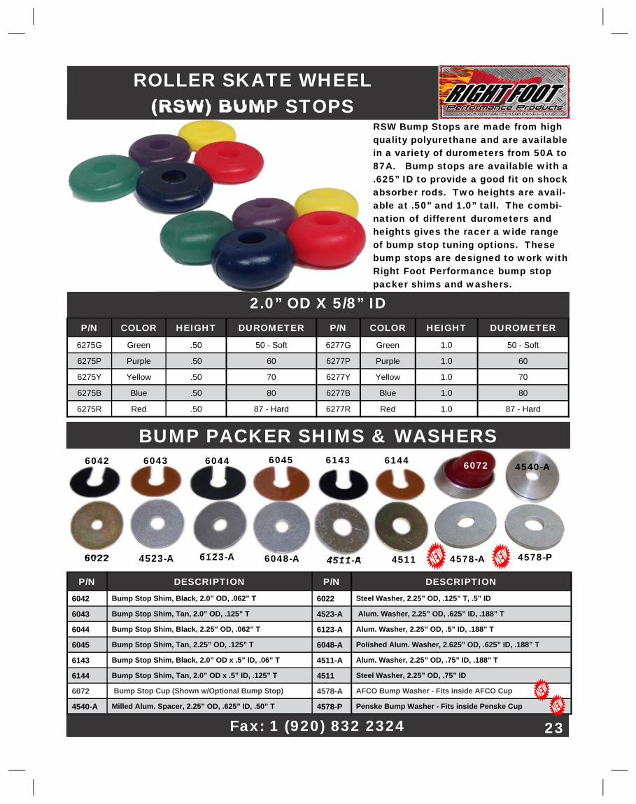
ROLLER SKATE WHEEL�(RSW) BUMP STOPS�
RSW Bump Stops are made from high�quality polyurethane and are available�in a variety of durometers from 50A to�87A. Bump stops are available with a�.625” ID to provide a good fit on shock�absorber rods. Two heights are avail-�able at .50” and 1.0” tall. The combi-�nation of different durometers and�heights gives the racer a wide range�of bump stop tuning options. These�bump stops are designed to work with�Right Foot Performance bump stop�packer shims and washers.�
2.0” OD X 5/8” ID�P/N� COLOR� HEIGHT� DUROMETER� P/N� COLOR� HEIGHT� DUROMETER�
6275G� Green� .50� 50 - Soft� 6277G� Green� 1.0� 50 - Soft�
6275P� Purple� .50� 60� 6277P� Purple� 1.0� 60�
6275Y� Yellow� .50� 70� 6277Y� Yellow� 1.0� 70�
6275B� Blue� .50� 80� 6277B� Blue� 1.0� 80�
6275R� Red� .50� 87 - Hard� 6277R� Red� 1.0� 87 - Hard�
6072�
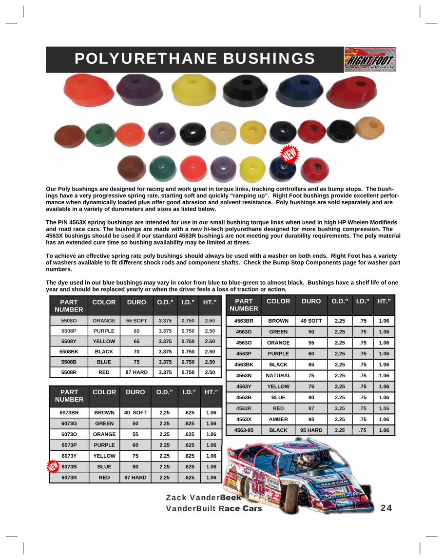
Our Poly bushings are designed for racing and work great in torque links, tracking controllers and as bump stops. The bush-�ings have a very progressive spring rate, starting soft and quickly “ramping up”. Right Foot bushings provide excellent perfor-�mance when dynamically loaded plus offer good abrasion and solvent resistance. Poly bushings are sold separately and are�available in a variety of durometers and sizes as listed below.�
The P/N 4563X spring bushings are intended for use in our small bushing torque links when used in high HP Whelen Modifieds�and road race cars. The bushings are made with a new hi-tech polyurethane designed for more bushing compression. The�4563X bushings should be used if our standard 4563R bushings are not meeting your durability requirements. The poly material�has an extended cure time so bushing availability may be limited at times.�
To achieve an effective spring rate poly bushings should always be used with a washer on both ends. Right Foot has a variety�of washers available to fit different shock rods and component shafts. Check the Bump Stop Components page for washer part�numbers.�
The dye used in our blue bushings may vary in color from blue to blue-green to almost black. Bushings have a shelf life of one�year and should be replaced yearly or when the driver feels a loss of traction or action.�
PART�NUMBER�
COLOR� DURO� O.D.”� I.D.”� HT.”�
4563BR� BROWN� 40 SOFT� 2.25� .75� 1.06�
4563G� GREEN� 50� 2.25� .75� 1.06�
4563O� ORANGE� 55� 2.25� .75� 1.06�
4563P� PURPLE� 60� 2.25� .75� 1.06�
4563BK� BLACK� 65� 2.25� .75� 1.06�
4563N� NATURAL� 75� 2.25� .75� 1.06�
4563Y� YELLOW� 75� 2.25� .75� 1.06�
4563B� BLUE� 80� 2.25� .75� 1.06�
4563R� RED� 87� 2.25� .75� 1.06�
4563X� AMBER� 93� 2.25� .75� 1.06�
4563-95� BLACK� 95 HARD� 2.25� .75� 1.06�
PART�NUMBER�
COLOR� DURO� O.D.”� I.D.”� HT.”�
6073BR� BROWN� 40 SOFT� 2,25� .625� 1.06�
6073G� GREEN� 50� 2.25� .625� 1.06�
6073O� ORANGE� 55� 2.25� .625� 1.06�
6073P� PURPLE� 60� 2.25� .625� 1.06�
6073Y� YELLOW� 75� 2.25� .625� 1.06�
6073B� BLUE� 80� 2.25� .625� 1.06�
6073R� RED� 87 HARD� 2.25� .625� 1.06�
PART�NUMBER�
COLOR� DURO� O.D.”� I.D.”� HT.”�
5508O� ORANGE� 55 SOFT� 3.375� 0.750� 2.50�
5508P� PURPLE� 60� 3.375� 0.750� 2.50�
5508Y� YELLOW� 65� 3.375� 0.750� 2.50�
5508BK� BLACK� 70� 3.375� 0.750� 2.50�
5508B� BLUE� 75� 3.375� 0.750� 2.50�
5508R� RED� 87 HARD� 3.375� 0.750� 2.50�
Zack VanderBeek�VanderBuilt Race Cars� 24�
POLYURETHANE BUSHINGS�
Web:�www.rightfootperformance.com�
STACKABLE POLY TRACTION BUSHINGS�
P/N� DURO-�METER�
DESCRIPTION� P/N� DURO-�METER�
DESCRIPTION�
5546G� 50� POLY BUSHING, GRAY, 3.38”� 5547Y� 75� POLY BUSHING, YELLOW,�3.38”�
5546O� 55� POLY BUSHING, ORANGE�3.38”� 5547B� 80� POLY BUSHING, BLUE, 3.38”�
5546P� 60� POLY BUSHING, PURPLE,�3.38”� 5547R� 87� POLY BUSHING, RED,�3.38”�
5546BK� 65� POLY BUSHING, BLACK, 3.38”� 5548G� 50� POLY BUSHING, GRAY, 3.38”�
5546Y� 75� POLY BUSHING, YELLOW,�3.38”� 5548O� 55� POLY BUSHING, ORANGE,�3.38”�
5546B� 80� POLY BUSHING, BLUE, 3.38”� 5548P� 60� POLY BUSHING, PURPLE,�3.38”�
5546R� 87� POLY BUSHING, RED,�3.38”� 5548BK� 65� POLY BUSHING, BLACK,� 3.38”�
5547G� 50� POLY BUSHING, GRAY, 3.38”� 5548Y� 75� POLY BUSHING, YELLOW,�3.38”�
5547O� 55� POLY BUSHING, ORANGE,�3.38”� 5548B� 80� POLY BUSHING, BLUE, 3.38”�
5547P� 60� POLY BUSHING, PURPLE,�3.38”� 5548R� 87� POLY BUSHING, RED, 3.38”�
5547BK� 65� POLY BUSHING, BLACK,�3.38”�
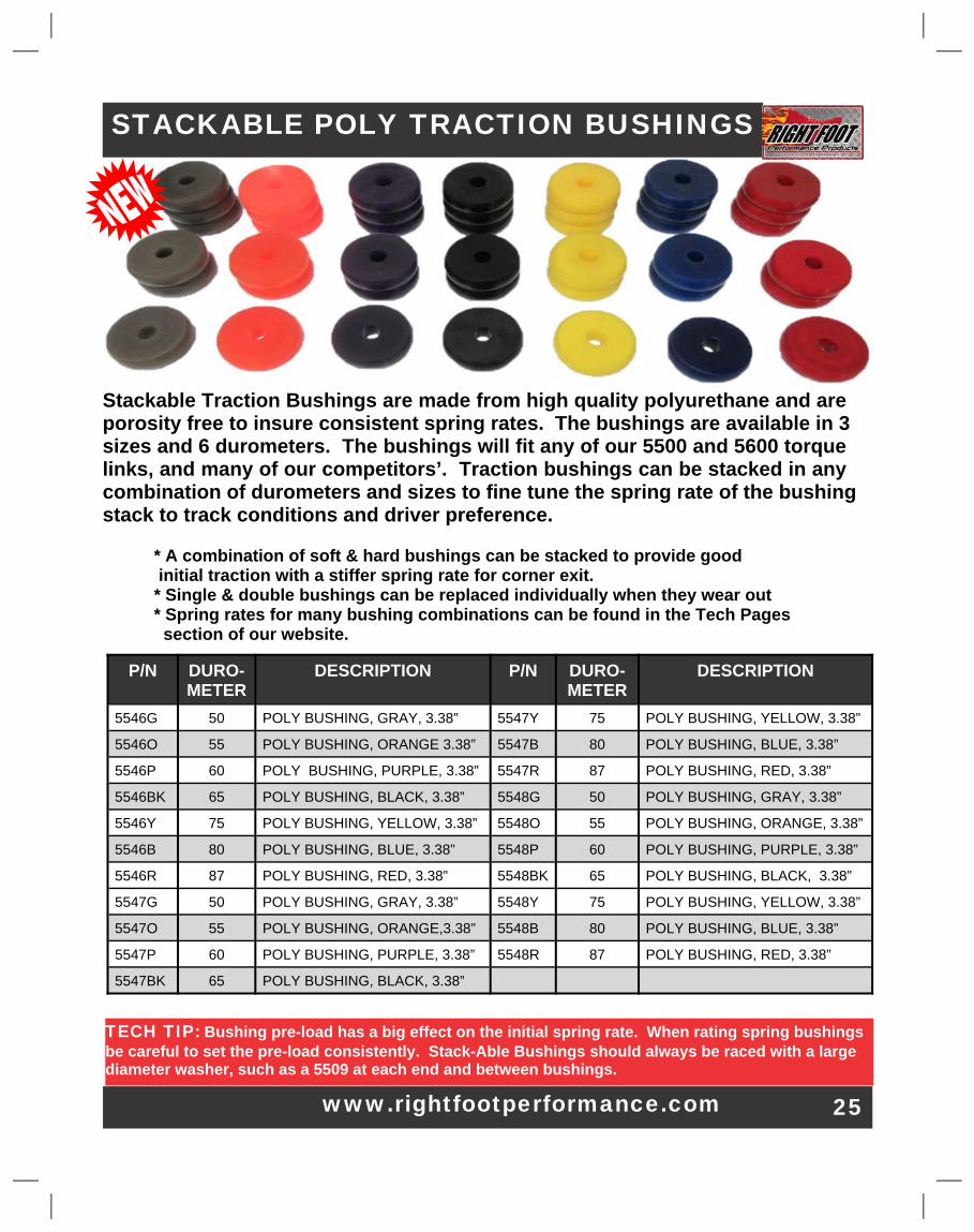
Stackable Traction Bushings are made from high quality polyurethane and are�porosity free to insure consistent spring rates. The bushings are available in 3�sizes and 6 durometers. The bushings will fit any of our 5500 and 5600 torque�links, and many of our competitors’. Traction bushings can be stacked in any�combination of durometers and sizes to fine tune the spring rate of the bushing�stack to track conditions and driver preference.�
* A combination of soft & hard bushings can be stacked to provide good� initial traction with a stiffer spring rate for corner exit.� * Single & double bushings can be replaced individually when they wear out� * Spring rates for many bushing combinations can be found in the Tech Pages� section of our website.�
TECH TIP:�Bushing pre-load has a big effect on the initial spring rate. When rating spring bushings�be careful to set the pre-load consistently. Stack-Able Bushings should always be raced with a large�diameter washer, such as a 5509 at each end and between bushings.�
25�
Email - [email protected]�
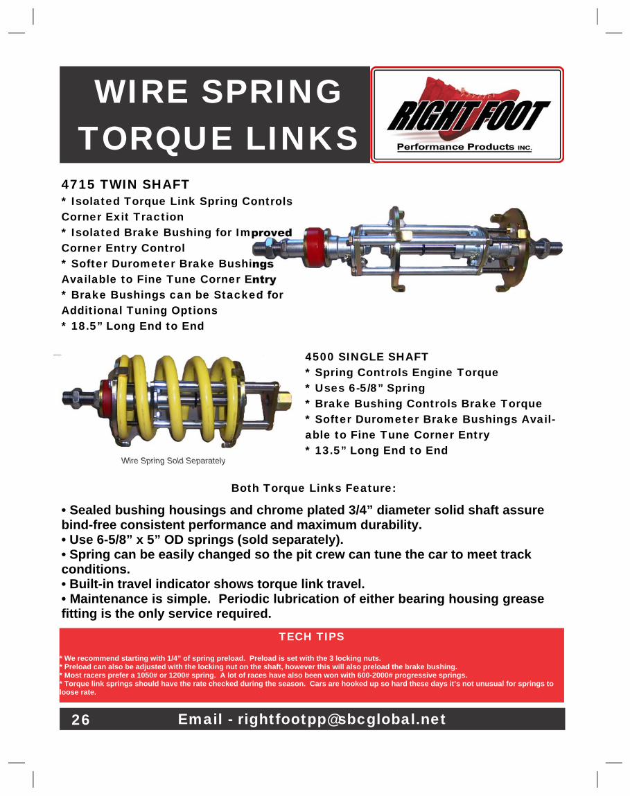
WIRE SPRING�TORQUE LINKS�
4500 SINGLE SHAFT�* Spring Controls Engine Torque�* Uses 6-5/8” Spring�* Brake Bushing Controls Brake Torque�* Softer Durometer Brake Bushings Avail-�able to Fine Tune Corner Entry�* 13.5” Long End to End�
4715 TWIN SHAFT�* Isolated Torque Link Spring Controls�Corner Exit Traction�* Isolated Brake Bushing for Improved�Corner Entry Control�* Softer Durometer Brake Bushings�Available to Fine Tune Corner Entry�* Brake Bushings can be Stacked for�Additional Tuning Options�* 18.5” Long End to End�
Both Torque Links Feature:�
• Sealed bushing housings and chrome plated 3/4” diameter solid shaft assure�bind-free consistent performance and maximum durability.�• Use 6-5/8” x 5” OD springs (sold separately).�• Spring can be easily changed so the pit crew can tune the car to meet track�conditions.�• Built-in travel indicator shows torque link travel.�• Maintenance is simple. Periodic lubrication of either bearing housing grease�fitting is the only service required.�
TECH TIPS�
* We recommend starting with 1/4” of spring preload. Preload is set with the 3 locking nuts.�* Preload can also be adjusted with the locking nut on the shaft, however this will also preload the brake bushing.�* Most racers prefer a 1050# or 1200# spring. A lot of races have also been won with 600-2000# progressive springs.�* Torque link springs should have the rate checked during the season. Cars are hooked up so hard these days it’s not unusual for springs to�loose rate.�
Wire Spring Sold Separately�
26�
SECONDARY SPRING�TORQUE LINKS�
• Sealed bearing housings and chrome plated 3/4” diameter solid shaft assure bind-free� consistent performance and maximum durability.�• Polyurethane brake bushing aids corner entry handling.�• Comes standard with 2 traction bushings & 1 red braking bushing.�• Two piece poly bushing design allows you to mix various hardness combinations providing additional spring�rate selection & tune-ability. Seven hardnesses of poly bushings are available.�• Maintenance is simple. Periodic lubrication of either bearing housing grease fitting is the only service required.�
•� Secondary Spring Torque Links provide the ultimate in tune-ability. Torque links can be adjusted for�changing track conditions by adjusting the engagement of the poly bushings.�• The engagement of the poly spring bushings is adjusted using the internal adjuster nut (as shown in the�photo).�• Floating front spring plate allows simple preload adjustment of main spring & permits quick & easy spring�changes.�• The 4590 is approximately 13.25” long and works great on cars where space is a consideration.�• The 4590XL torque link is approximately 16.0” long and allows more main (wire) spring travel then our�standard 4590 torque link. The additional travel has proven to provide superior traction.�• The 4750 is a 3 stage torque link and is very similar to the 4590XL. However the torque link has separate�traction and brake shafts. This allows the action of the brake bushing to be adjusted without affecting�acceleration tuning. The 4750 torque link is 17.50” long.�
4590 Torque Link�
4590XL Torque Link�
Internal Adjuster Nut allows quick�adjustment of bushing engagement.�
TECH TIP�1050# &1200# linear springs & 600 to 2000#�progressive springs have proven to work very�well in these torque links. Typically the ad-�juster nut for the spring bushings should be�backed off as the track slicks up.�
4750 Torque Link�
4716 Travel Indicator Rod Kit�
27�Josh Harris - MBR Chassis�
Ph: 1 (920) 832 2322�
SMALL POLY SPRING TORQUE LINKS�
•Small Poly Spring Torque Links use the same race-winning design as our 5500 Series Torque�Links. These torque links are designed to cushion the tire contact patch under acceleration�and under braking. They also allow some roll steer. Their compact size and light weight are�perfect for asphalt late models and modifieds. The torque links are great replacements for�solid 3rd links or for cars using 3rd links with old fashion rubber bushings.�
The 4780-A is a twin shaft torque link. The twin shaft design offers some advantages;�1) traction bushings and brake bushing can be preloaded individually so corner entry and exit�can be tuned separately and 2) the transition from accel to decel is immediate.�• 4580 uses steel components and weighs 5.85#. 4580-A and 4780-A use many aluminum�components. The 4580 weighs 4.40# and the 4780-A weighs 5.5#.�• Polyurethane bushings provide a progressive consistent spring rate.�• Bushings can be purchased separately & are listed separately in the catalog.�• Poly bushings can be mixed & stacked to change the spring rate.�• All torque Links include a travel indicator to measure bushing compression.�• Sealed bronze bushings and chrome plated 3/4” diameter solid shaft assure bind-free con-�sistent performance and maximum durability.�• Maintenance is simple. Periodic lubrication of either bushing grease fitting is the only ser-�vice required. Poly bushings should be replaced at least once a year.�• End to end length of the torque links: 4580 & 4580-A = 14.75” & 4780-A = 17.25”�
4580 Torque Link�
4580-A Torque Link�
4780-A Twin Shaft Torque Link�
28�
Doug Coby - LFR Chassis�
5600 Twin Shaft Torque�Link -�Twin Shafts let engine�and brake bushings work inde-�pendently. Corner entry and�exit can be tuned separately.�Approximately 19.5” long.�
• Large diameter polyurethane bushings provide smooth spring rate progression & superior torque control. The�spring bushings provide excellent forward bite under all track conditions.�• Small polyurethane brake bushing aids corner entry handling.�• All torque links come standard with 1 red (hard) brake bushing.�• Two piece poly spring design allows you to mix various hardness combinations providing the ultimate in spring�rate selection & tune-ability.�• All poly spring torque links have heavy duty stand off rods and rod end plates to handle the power of today’s�open class motors�.�• 5600 Twin Shaft design provides several advantages. Corner exit & entry can be tuned separately. Brake bushing�can be stacked and works sooner because it’s not preloaded from engine bushing preload. Car turns better and�comes off the bars smoother because there’s less wrap-up.�• Sealed bearing housings and chrome plated 3/4” diameter solid shaft assure bind-free consistent performance�and maximum durability.�• Built-in travel indicator shows axle movement in both directions.�• Maintenance is simple. Periodic lubrication of either bearing housing grease fitting is the only service required.�
5500 Torque Link -�This is a great�torque link for any A mod; compact and�easy to adjust. Comes with choice of�poly spring bushings. Approximately�15.5” long.�
LARGE DIAMETER�POLY SPRING�TORQUE LINKS�
TECH TIP�As a general rule poly spring bushings should only be compressed about 1/3 of their static height. Compress-�ing poly bushings more then this may improve your cars’ traction but will decrease bushing life. For a 2-bush-�ing pull rod 1-1/2” of bushing compression normally provides good traction and good bushing life.�
5600�
www.rightfootperformance.net� 29�
5500-BY�
P/N� DESCRIPTION�
5500� Single Shaft Torque Link w/ 2 Blue Traction Bushings�
5500-B� Single Shaft Torque Link w/ o Traction Bushings�
5500-BY� Single Shaft Torque Link w/ Blue & Yellow Traction Bushings�
5500-YY� Single Shaft Torque Link w/ 2 Yellow Traction Bushings�
5600� Twin Shaft Torque Link w/ Blue & Yellow Traction Bushings�
5600-B� Twin Shaft Torque Link w/ o Traction Bushings�
Kelly Shryock - Skyrocket Chassis�
STACKABLE BUSHING TORQUE LINK�
These torque links lets the racer MAXIMIZE forward bite. Stackable poly spring bushings give the�racer the advantage of inter-changing traction bushings to adjust for track conditions. Bushings can�be installed in 2, 3, 4, 5 or 6 bushing combinations to achieve the optimum spring rate. A wide range of�poly traction bushings is available (see page 25).�
5575 Twin Shaft design provides several advantages.� Corner entry & exit can be tuned separately.�Brake bushing works sooner because it’s not preloaded from engine bushing preload. Car turns better�and comes off the bars sooner because there’s less wrap up.�• Loaded torque links have 5546B, 5547P & 5548O traction bushings.�• Torque links can be ordered without bushings & racer can mix & match bushings.�• Right Foot 5508 Series bushings can also be use in these torque links.�• Large 3-3/8” OD traction bushings are much more durable then small poly bushings. All bushings�use the highest quality polyurethane for consistent spring rate & durability.�• Spring rate charts for many bushing combinations can be found on the Right Foot website.�• A travel indicator is provided for each bushing for tuning purposes.�• Shafts are chrome plated, high strength steel running on grease-able bronze oilite bushings to�eliminate binding.�• 3 tabbed thrust washers are provided with each torque link. Additional washers P/N 5528 can be�purchased separately. There should be a washer between each traction bushing.�• All parts are zinc plated to provide a long lasting durable finish.�• 5550 torque link weighs 9.5# & is 13” long. 5575 torque link weighs 10.85# & is 16.75” long.�
5550� Torque Link Loaded w/ Traction Bushings�
5550-B� Torque Link w/o Traction Bushings�
5528� Tabbed Thrust Washer�
5575� Twin Shaft Torque Link w/ Traction Bushings�
5575-B� Twin Shaft Torque Link w/o Traction Bushings�
Ph: 1 (920) 832 2322� 30�
5528�Tabbed Washer�
5550�Single Shaft�Torque Link�
5575�Twin Shaft�Torque Link�
Zach Fair - Zach Fair Racing�
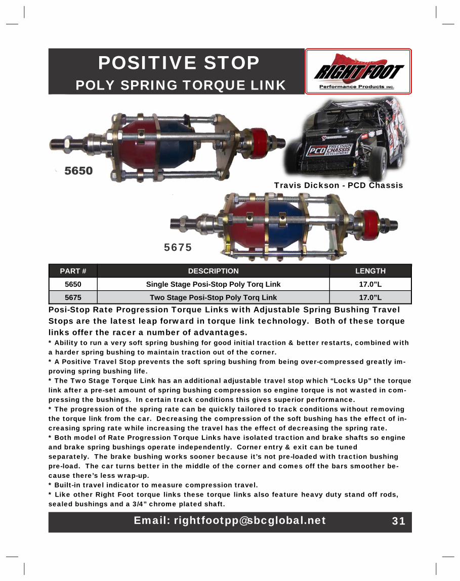
POSITIVE STOP� POLY SPRING TORQUE LINK�
Posi-Stop Rate Progression Torque Links with Adjustable Spring Bushing Travel�Stops are the latest leap forward in torque link technology. Both of these torque�links offer the racer a number of advantages.�* Ability to run a very soft spring bushing for good initial traction & better restarts, combined with�a harder spring bushing to maintain traction out of the corner.�* A Positive Travel Stop prevents the soft spring bushing from being over-compressed greatly im-�proving spring bushing life.�* The Two Stage Torque Link has an additional adjustable travel stop which “Locks Up” the torque�link after a pre-set amount of spring bushing compression so engine torque is not wasted in com-�pressing the bushings. In certain track conditions this gives superior performance.�* The progression of the spring rate can be quickly tailored to track conditions without removing�the torque link from the car. Decreasing the compression of the soft bushing has the effect of in-�creasing spring rate while increasing the travel has the effect of decreasing the spring rate.�* Both model of Rate Progression Torque Links have isolated traction and brake shafts so engine�and brake spring bushings operate independently. Corner entry & exit can be tuned�separately. The brake bushing works sooner because it’s not pre-loaded with traction bushing�pre-load. The car turns better in the middle of the corner and comes off the bars smoother be-�cause there’s less wrap-up.�* Built-in travel indicator to measure compression travel.�* Like other Right Foot torque links these torque links also feature heavy duty stand off rods,�sealed bushings and a 3/4” chrome plated shaft.�
PART #� DESCRIPTION� LENGTH�
5650� Single Stage Posi-Stop Poly Torq Link� 17.0”L�
5675� Two Stage Posi-Stop Poly Torq Link� 17.0”L�
5675�
5650�
Email: [email protected]� 31�
Travis Dickson - PCD Chassis�
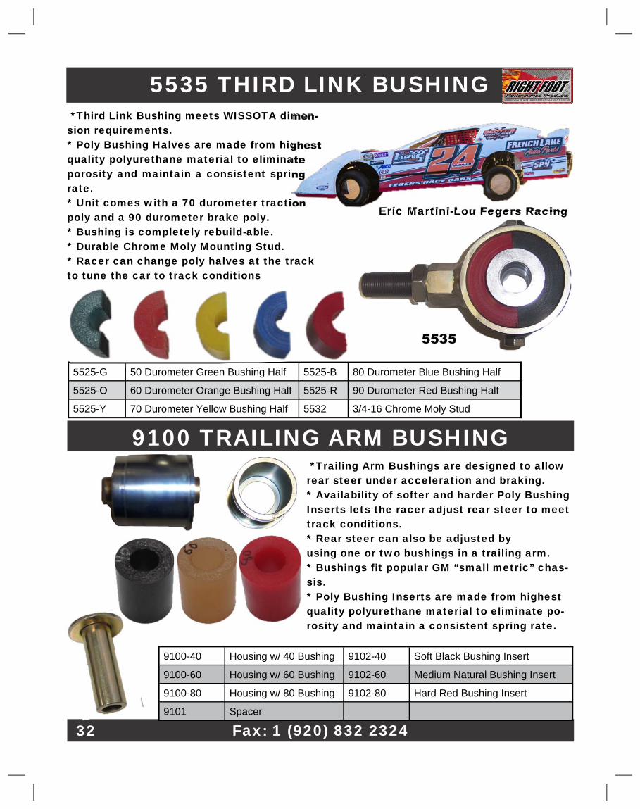
5535 THIRD LINK BUSHING�
5525-G� 50 Durometer Green Bushing Half� 5525-B� 80 Durometer Blue Bushing Half�
5525-O� 60 Durometer Orange Bushing Half� 5525-R� 90 Durometer Red Bushing Half�
5525-Y� 70 Durometer Yellow Bushing Half� 5532� 3/4-16 Chrome Moly Stud�
9100 TRAILING ARM BUSHING� *Trailing Arm Bushings are designed to allow�rear steer under acceleration and braking.�* Availability of softer and harder Poly Bushing�Inserts lets the racer adjust rear steer to meet�track conditions.�* Rear steer can also be adjusted by�using one or two bushings in a trailing arm.�* Bushings fit popular GM “small metric” chas-�sis.�* Poly Bushing Inserts are made from highest�quality polyurethane material to eliminate po-�rosity and maintain a consistent spring rate.�
Fax: 1 (920) 832 2324�32�
9100-40� Housing w/ 40 Bushing� 9102-40� Soft Black Bushing Insert�
9100-60� Housing w/ 60 Bushing� 9102-60� Medium Natural Bushing Insert�
9100-80� Housing w/ 80 Bushing� 9102-80� Hard Red Bushing Insert�
9101� Spacer�
5535�
*Third Link Bushing meets WISSOTA dimen-�sion requirements.�* Poly Bushing Halves are made from highest�quality polyurethane material to eliminate�porosity and maintain a consistent spring�rate.�* Unit comes with a 70 durometer traction�poly and a 90 durometer brake poly.�* Bushing is completely rebuild-able.�* Durable Chrome Moly Mounting Stud.�* Racer can change poly halves at the track�to tune the car to track conditions�
Eric Martini-Lou Fegers Racing�
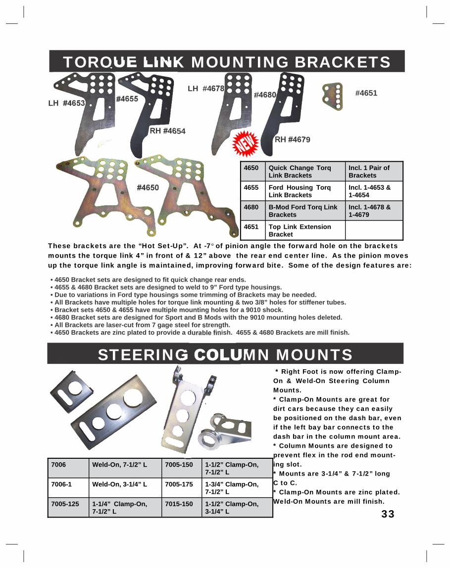
TORQUE LINK MOUNTING BRACKETS�
• 4650 Bracket sets are designed to fit quick change rear ends.�• 4655 & 4680 Bracket sets are designed to weld to 9” Ford type housings.�• Due to variations in Ford type housings some trimming of Brackets may be needed.�• All Brackets have multiple holes for torque link mounting & two 3/8” holes for stiffener tubes.�• Bracket sets 4650 & 4655 have multiple mounting holes for a 9010 shock.�• 4680 Bracket sets are designed for Sport and B Mods with the 9010 mounting holes deleted.�• All Brackets are laser-cut from 7 gage steel for strength.�• 4650 Brackets are zinc plated to provide a durable finish. 4655 & 4680 Brackets are mill finish.�
These brackets are the “Hot Set-Up”. At -7�°�of pinion angle the forward hole on the brackets�mounts the torque link 4” in front of & 12” above the rear end center line. As the pinion moves�up the torque link angle is maintained, improving forward bite. Some of the design features are:�
#4651�
#4650�
#4655�
RH #4654�
LH #4653�
STEERING COLUMN MOUNTS� * Right Foot is now offering Clamp-�On & Weld-On Steering Column�Mounts.�* Clamp-On Mounts are great for�dirt cars because they can easily�be positioned on the dash bar, even�if the left bay bar connects to the�dash bar in the column mount area.�* Column Mounts are designed to�prevent flex in the rod end mount-�ing slot.�* Mounts are 3-1/4” & 7-1/2” long�C to C.�* Clamp-On Mounts are zinc plated.�Weld-On Mounts are mill finish.�
7006� Weld-On, 7-1/2” L� 7005-150� 1-1/2” Clamp-On,�7-1/2” L�
7006-1� Weld-On, 3-1/4” L� 7005-175� 1-3/4” Clamp-On,�7-1/2” L�
7005-125� 1-1/4” Clamp-On,�7-1/2” L�
7015-150� 1-1/2” Clamp-On,�3-1/4” L� 33�
LH #4678�
RH #4679�
4650� Quick Change Torq�Link Brackets�
Incl. 1 Pair of�Brackets�
4655� Ford Housing Torq�Link Brackets�
Incl. 1-4653 &�1-4654�
4680� B-Mod Ford Torq Link�Brackets�
Incl. 1-4678 &�1-4679�
4651� Top Link Extension�Bracket�
#4680�
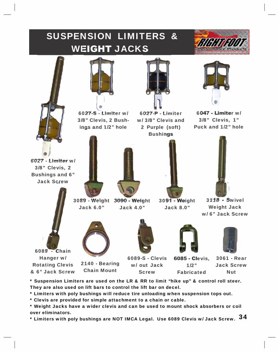
SUSPENSION LIMITERS &�WEIGHT JACKS�
* Suspension Limiters are used on the LR & RR to limit “hike up” & control roll steer.�They are also used on lift bars to control the lift bar on decel.�* Limiters with poly bushings will reduce tire unloading when suspension tops out.�* Clevis are provided for simple attachment to a chain or cable.�* Weight Jacks have a wider clevis and can be used to mount shock absorbers or coil�over eliminators.�* Limiters with poly bushings are NOT IMCA Legal. Use 6089 Clevis w/ Jack Screw.�34�
6027 - Limiter w/�3/8” Clevis, 2�
Bushings and 6”�Jack Screw�
6027-S - Limiter w/�3/8” Clevis, 2 Bush-�ings and 1/2” hole�
6027-P - Limiter�w/ 3/8” Clevis and�
2 Purple (soft)�Bushings�
6047 - Limiter w/�3/8” Clevis, 1”�
Puck and 1/2” hole�
3061 - Rear�Jack Screw�
Nut�
3090 - Weight�Jack 4.0”�
3089 - Weight�Jack 6.0”�
3091 - Weight�Jack 8.0”�
6089 - Chain�Hanger w/�
Rotating Clevis�& 6” Jack Screw�
6089-S - Clevis�w/ out Jack�
Screw�
6085 - Clevis,�1/2”�
Fabricated�
3118 - Swivel�Weight Jack�
w/ 6” Jack Screw�
2140 - Bearing�Chain Mount�
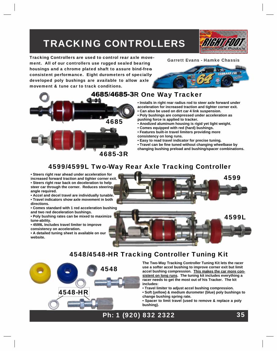
4685/4685-3R One Way Tracker�
4599/4599L Two-Way Rear Axle Tracking Controller�
Tracking Controllers are used to control rear axle move-�ment. All of our controllers use rugged sealed bearing�housings and a chrome plated shaft to assure bind-free�consistent performance. Eight durometers of specially�developed poly bushings are available to allow axle�movement & tune car to track conditions.�
TRACKING CONTROLLERS�
• Installs in right rear radius rod to steer axle forward under�acceleration for increased traction and tighter corner exit.�• Can also be used on dirt car 4 link suspension.�• Poly bushings are compressed under acceleration as�pushing force is applied to tracker.�• Anodized aluminum housing is rigid yet light weight.�• Comes equipped with red (hard) bushings.�• Features built-in travel limiters providing more�consistency on long runs.�• Easy to read travel indicator for precise tuning.�• Travel can be fine tuned without changing wheelbase by�changing bushing preload and bushing/spacer combinations.�
The Two-Way Tracking Controller Tuning Kit lets the racer�use a softer accel bushing to improve corner exit but limit�accel bushing compression.�This makes the car more con-�sistent on long runs�. The tuning kit includes everything a�racer needs to get the most out of his Tracker. The kit�includes:�• Travel limiter to adjust accel bushing compression.�• Soft (yellow) & medium durometer (blue) poly bushings to�change bushing spring rate.�• Spacer to limit travel (used to remove & replace a poly�bushing).�
4548/4548-HR Tracking Controller Tuning Kit�
Garrett Evans - Hamke Chassis�
Ph: 1 (920) 832 2322� 35�
4548-HR�
• Steers right rear ahead under acceleration for�increased forward traction and tighter corner exit.�• Steers right rear back on deceleration to help�steer car through the corner. Reduces steering�angle required.�• Accel and decel travel are individually tunable.�• Travel indicators show axle movement in both�directions.�• Comes standard with 1 red acceleration bushing�and two red deceleration bushings.�• Poly bushing rates can be mixed to maximize�tune-ability.�• 4599L Includes travel limiter to improve�consistency on acceleration.�• A detailed tuning sheet is available on our�website.�
4599�
4599L�
4548�
4685�
4685-3R�
Web:�www.rightfootperformance.com�
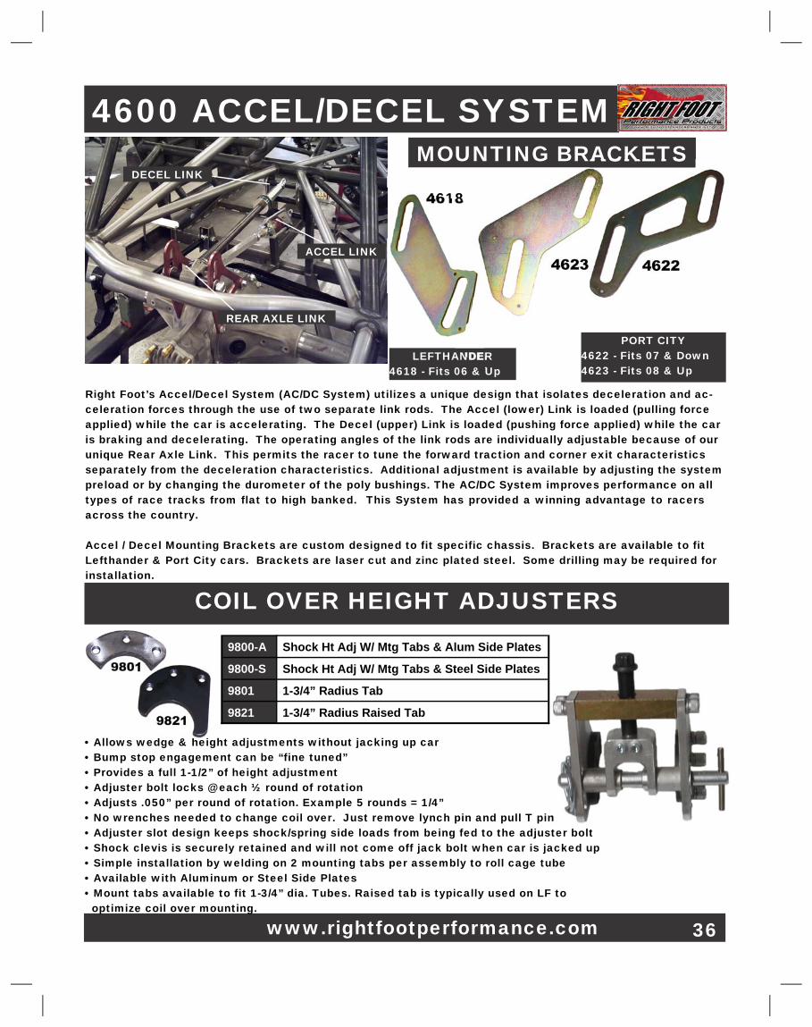
4600 ACCEL/DECEL SYSTEM�DECEL LINK�
Right Foot’s Accel/Decel System (AC/DC System) utilizes a unique design that isolates deceleration and ac-�celeration forces through the use of two separate link rods. The Accel (lower) Link is loaded (pulling force�applied) while the car is accelerating. The Decel (upper) Link is loaded (pushing force applied) while the car�is braking and decelerating. The operating angles of the link rods are individually adjustable because of our�unique Rear Axle Link. This permits the racer to tune the forward traction and corner exit characteristics�separately from the deceleration characteristics. Additional adjustment is available by adjusting the system�preload or by changing the durometer of the poly bushings. The AC/DC System improves performance on all�types of race tracks from flat to high banked. This System has provided a winning advantage to racers�across the country.�
Accel / Decel Mounting Brackets are custom designed to fit specific chassis. Brackets are available to fit�Lefthander & Port City cars. Brackets are laser cut and zinc plated steel. Some drilling may be required for�installation.�
ACCEL LINK�
REAR AXLE LINK�
MOUNTING BRACKETS�
4618�
4622�4623�
LEFTHANDER�4618 - Fits 06 & Up�
PORT CITY�4622 - Fits 07 & Down�4623 - Fits 08 & Up�
COIL OVER HEIGHT ADJUSTERS�
• Allows wedge & height adjustments without jacking up car�• Bump stop engagement can be “fine tuned”�• Provides a full 1-1/2” of height adjustment�• Adjuster bolt locks @ each ½ round of rotation�• Adjusts .050” per round of rotation. Example 5 rounds = 1/4”�• No wrenches needed to change coil over. Just remove lynch pin and pull T pin�• Adjuster slot design keeps shock/spring side loads from being fed to the adjuster bolt�• Shock clevis is securely retained and will not come off jack bolt when car is jacked up�• Simple installation by welding on 2 mounting tabs per assembly to roll cage tube�• Available with Aluminum or Steel Side Plates�• Mount tabs available to fit 1-3/4” dia. Tubes. Raised tab is typically used on LF to� optimize coil over mounting.�
9800-A� Shock Ht Adj W/ Mtg Tabs & Alum Side Plates�
9800-S� Shock Ht Adj W/ Mtg Tabs & Steel Side Plates�
9801� 1-3/4” Radius Tab�
9821� 1-3/4” Radius Raised Tab�
9801�
9821�
36�
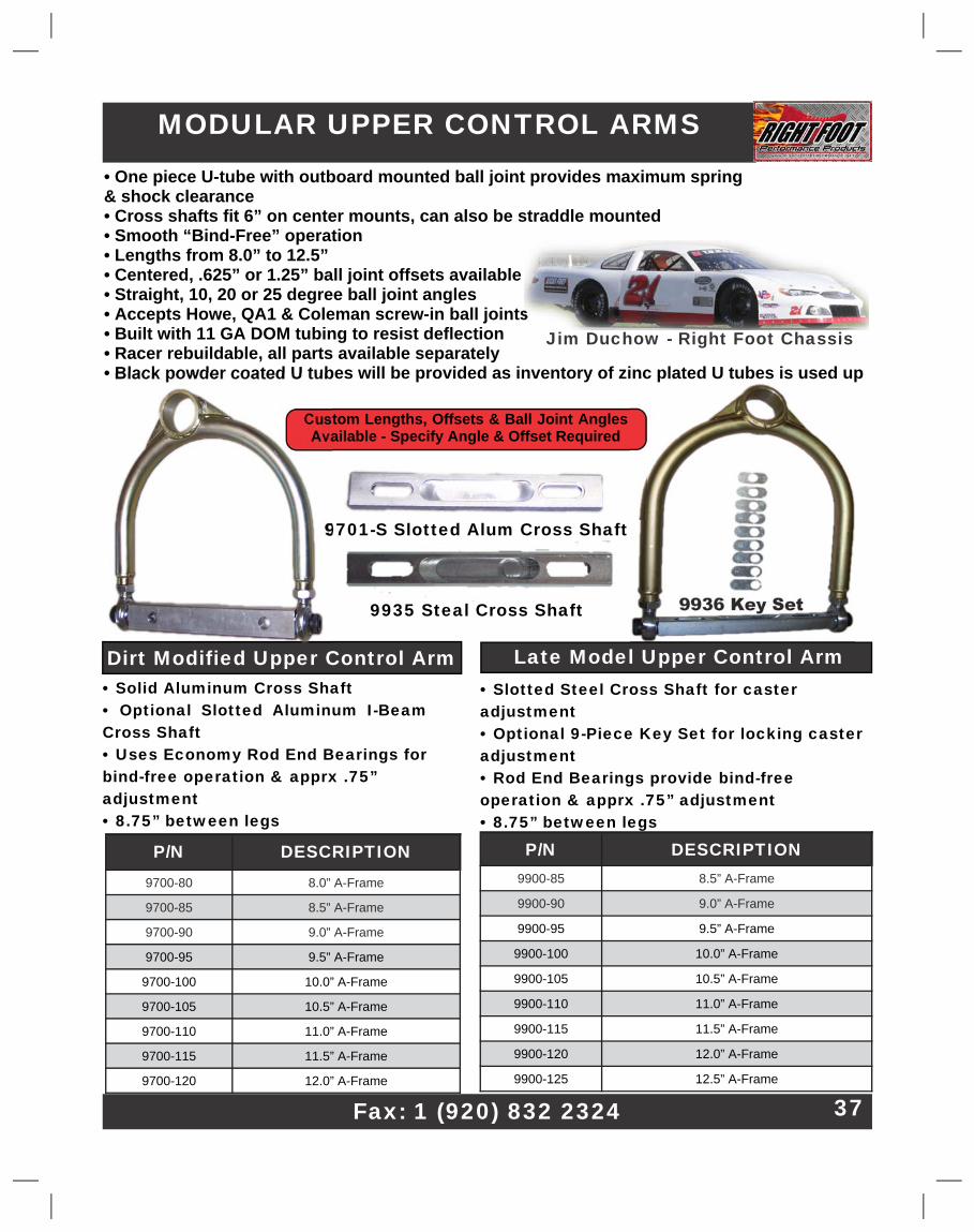
MODULAR UPPER CONTROL ARMS�• One piece U-tube with outboard mounted ball joint provides maximum spring�& shock clearance�• Cross shafts fit 6” on center mounts, can also be straddle mounted�• Smooth “Bind-Free” operation�• Lengths from 8.0” to 12.5”�• Centered, .625” or 1.25” ball joint offsets available�• Straight, 10, 20 or 25 degree ball joint angles�• Accepts Howe, QA1 & Coleman screw-in ball joints�• Built with 11 GA DOM tubing to resist deflection�• Racer rebuildable, all parts available separately�• Black powder coated U tubes will be provided as inventory of zinc plated U tubes is used up�
P/N� DESCRIPTION�9700-80� 8.0” A-Frame�
9700-85� 8.5” A-Frame�
9700-90� 9.0” A-Frame�
9700-95� 9.5” A-Frame�
9700-100� 10.0” A-Frame�
9700-105� 10.5” A-Frame�
9700-110� 11.0” A-Frame�
9700-115� 11.5” A-Frame�
9700-120� 12.0” A-Frame�
Jim Duchow - Right Foot Chassis�
Fax: 1 (920) 832 2324� 37�
P/N� DESCRIPTION�9900-85� 8.5” A-Frame�
9900-90� 9.0” A-Frame�
9900-95� 9.5” A-Frame�
9900-100� 10.0” A-Frame�
9900-105� 10.5” A-Frame�
9900-110� 11.0” A-Frame�
9900-115� 11.5” A-Frame�
9900-120� 12.0” A-Frame�
9900-125� 12.5” A-Frame�
• Slotted Steel Cross Shaft for caster�adjustment�• Optional 9-Piece Key Set for locking caster�adjustment�• Rod End Bearings provide bind-free�operation & apprx .75” adjustment�• 8.75” between legs�
9936 Key Set�
• Solid Aluminum Cross Shaft�• Optional Slotted Aluminum I-Beam�Cross Shaft�• Uses Economy Rod End Bearings for�bind-free operation & apprx .75”�adjustment�• 8.75” between legs�
Custom Lengths, Offsets & Ball Joint Angles�Available - Specify Angle & Offset Required�
Late Model Upper Control Arm�Dirt Modified Upper Control Arm�
9701-S Slotted Alum Cross Shaft�
9935 Steal Cross Shaft�
INTEGRAL UPPER CONTROL ARM�
PH: 1 (920) 832 2322�
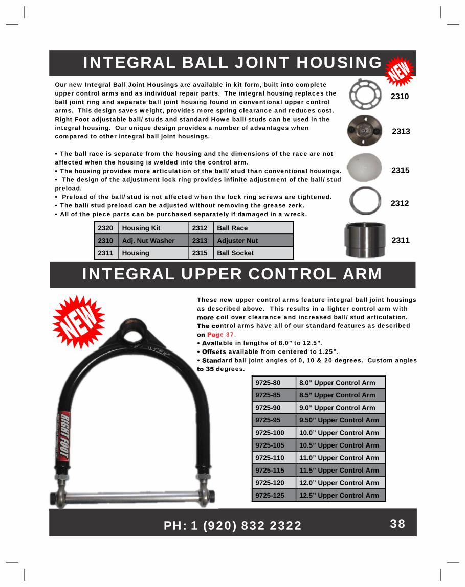
INTEGRAL BALL JOINT HOUSING�Our new Integral Ball Joint Housings are available in kit form, built into complete�upper control arms and as individual repair parts. The integral housing replaces the�ball joint ring and separate ball joint housing found in conventional upper control�arms. This design saves weight, provides more spring clearance and reduces cost.�Right Foot adjustable ball/ studs and standard Howe ball/ studs can be used in the�integral housing. Our unique design provides a number of advantages when�compared to other integral ball joint housings.�
• The ball race is separate from the housing and the dimensions of the race are not�affected when the housing is welded into the control arm.�• The housing provides more articulation of the ball/ stud than conventional housings.�• The design of the adjustment lock ring provides infinite adjustment of the ball/ stud�preload.�• Preload of the ball/ stud is not affected when the lock ring screws are tightened.�• The ball/ stud preload can be adjusted without removing the grease zerk.�• All of the piece parts can be purchased separately if damaged in a wreck.�
2320� Housing Kit� 2312� Ball Race�
2310� Adj. Nut Washer� 2313� Adjuster Nut�
2311� Housing� 2315� Ball Socket�
2311�
2315�
2310�
2313�
2312�
These new upper control arms feature integral ball joint housings�as described above. This results in a lighter control arm with�more coil over clearance and increased ball/ stud articulation.�The control arms have all of our standard features as described�on�Page 37.�• Available in lengths of 8.0” to 12.5”.�• Offsets available from centered to 1.25”.�• Standard ball joint angles of 0, 10 & 20 degrees. Custom angles�to 35 degrees.�
9725-80� 8.0” Upper Control Arm�
9725-85� 8.5” Upper Control Arm�
9725-90� 9.0” Upper Control Arm�
9725-95� 9.50” Upper Control Arm�
9725-100� 10.0” Upper Control Arm�
9725-105� 10.5” Upper Control Arm�
9725-110� 11.0” Upper Control Arm�
9725-115� 11.5” Upper Control Arm�
9725-120� 12.0” Upper Control Arm�
9725-125� 12.5” Upper Control Arm�
38�
LOWER CONTROL ARMS�
LEFT� PART #� RIGHT� PART #�13.5”� 9945-135� 15.5”� 9947-155�
14.0”� 9945-140� 16.0”� 9947-160�
14.5”� 9945-145� 16.5”� 9947-165�
15.0”� 9945-150� 17.0”� 9947-170�
15.5”� 9945-155� 17.5”� 9947-175�
16.0”� 9945-160� 18.0”� 9947-180�
16.5”� 9945-165� 18.5”� 9947-185�
13.5”� 9990-135� 15.5”� 9995-155�
14.0”� 9990-140� 16.0”� 9995-160�
14.5”� 9990-145� 16.5”� 9995-165�
15.0”� 9990-150� 17.0”� 9995-170�
15.5”� 9990-155� 17.5”� 9995-175�
16.0”� 9990-160� 18.0”� 9995-180�
16.5”� 9990-165� 18.5”� 9995-185�
* Control arms fabricated with 1.25” sq tube & weld in 3/4-16 rod end spud to eliminates stress risers & cracking.�* Spot drilled ball joint boss defines ball joint centerline. Ball joint centerline is in line with control arm tube centerline.�Makes verifying front end geometry accuracy much easier.�* Ball joint boss is threaded for Howe #22410 ball joint.�* Rugged double shear strut rod attaching brackets will withstand bump stop “spike loads”.�Dropped Shock Mount provides some unique competitive advantages.�* Dropped design provides more room for shock travel when running bump stops.�* Coil over is mounted in line with ball joint centerline so the coil over moves at the same angle as the ball joint providing�a more linear spring rate.�* Double shock mount lets racer move shock & change it’s motion ratio & the spring rate the car feels.�
Single Shock Mount�
13.5”� 9998-135� 15.5”� 9999-155�
14.0”� 9998-140� 16.0”� 9999-160�
14.5”� 9998-145� 16.5”� 9999-165�
15.0”� 9998-150� 17.0”� 9999-170�
15.5”� 9998-155� 17.5”� 9999-175�
16.0”� 9998-160� 18.0”� 9999-180�
16.5”� 9998-165� 18.5”� 9999-185�
Double Drop Shock Mount�
Single Drop Shock Mount�
Shock is Dropped�into Contro�l�Arm�for Bump Stop�
Clearance�
Double Shock�Mount for�
Fast Motion Ratio�Changes�
Right Side�
Left Side�
Aurora & Economy� Rod Ends�
Sold Separately.�
Roller is Angled so Sway Bar�Rides Squarely on Arm When�
Front End Drops.�
Ball Joint C/L Indicated�
Single Drop Shock Mount�
Double Drop Shock Mount�
All lower control arm lengths are based on the measurement taken from the centerline of the�ball joint to the centerline of the ¾” rod end.�
www.rightfootperformance.net� 39�
All lower control arm lengths are based on the measurement taken from the centerline�of the ball joint to the centerline of the ¾” rod end. Custom lengths are available.�
RANDERCAR CONTROL ARMS�* Standard Lower Control Arms fabricated from 1” X 2” X�.083 Tube�* Available with screw-in or weld-in Ball Joint Collar�* Strut Mounts in double shear tabs. Requires 3/4” X 1/2”�fixed Rod End�* LaCrosse Lower Control Arms fit RanderCar Big Spring�Cars�* Requires 3/4”-16 RH Male and 3/4”-16 Female Rod Ends�* Ball Joint Collar fits weld-in Ball Joint. Stud is�5/8-18 RH Thread�RCR1040-L� Left Lower, 16.5” L, Weld-In�RCR1040-R� Right Lower, 17.5” L, Weld-In�RCR1040-LS� Left Lower, 16.0” L, Screw-In�RCR1040-RS� Right Lower, 17.5” L, Screw-In�RCR1041-L� LaCrosse Lower Left, Weld-In�RCR1040-R� LaCRrosse Lower Right, Weld-In�RCR1044� Upper Ball Joint Mount�
BUMP STICK LOWER�CONTROL ARMS�
* Bump Stick Lower Control Arms are designed for use with our�P/N 6055 & 6060 Bump Sticks.�* Bump Stick & Coil Over are mounted in line. This provides the�same motion ratio which simplifies load number calculations.�* Bump Stick & Coil Over are mounted at the vertical center line of�the tube which simplifies motion ratio calculations.�* Lower Control Arms have the same features as our Single Drop�Lower Control Arms found on Page 41.�* Control Arms include a steel strut with a 3/4”-16 RH male thread.�Aluminum hex tube & rod ends required�
RCR1040-L�
RCR1040-R�
RC
R1041-R
�
RCR1041-L�
RCR1044�
40�
13.5”� 9998-135-BS� 15.5”� 9999-155-BS�
14.0”� 9998-140-BS� 16.0”� 9999-160-BS�
14.5”� 9998-145-BS� 16.5”� 9999-165-BS�
15.0”� 9998-150-BS� 17.0”� 9999-170-BS�
15.5”� 9998-155-BS� 17.5”� 9999-175-BS�
16.0”� 9998-160-BS� 18.0”� 9999-180-BS�
16.5”� 9998-165-BS� 18.5”� 9999-185-BS�
FRONT CLIPS�
•� Clip is 34” wide and attaches to main frame�24” behind the front wheel centerline.�• 2”x 3”x .095” main rails w/ .083 frame horns�to act as a “crush zone”.�• Large 2.5” OD x .095 sway bar tube to maxi-�mize torsional rigidity and run up to a 2”�spline bar.�• Raised cross member/ rack plate to allow�the car to attain the lowest possible dynamic�center of gravity. Cross member/ rack plate�bolts in so it can be changed if damaged.�• Front engine mounts located to permit max-�imum engine offset. Rear engine mounts are�slotted for 2” to 4” setback.�• Bolt-In upper control arm mounts so con-�trol arm mounting can be adjusted & mounts�easily replaced if damaged.�• Extended rack plate bolts to sway bar tube�to reduce rack plate flex & make front clip�more rigid.�• Strut rods mounted on an adjustment stud�allowing infinite and easily measurable verti-�cal adjustment.�• Adjustable lower control arm mounts use a�unique adjuster bolt arrangement. The con-�trol arms mounts are behind the cross mem-�ber for oil pan clearance.�• Available options include .083 & .120 main�tubes, extended sway bar tube, upper control�arm mounts for increased caster & more.�
• NEW - Revised for 2012 Rander Car Front�Clip available with 2”x 3”x .083, .095 or .125”�main rails.�• Clip is 33.5” wide and attaches to main�frame 24” behind the front wheel centerline.�• Upgraded 2.5” OD x .095 sway bar tube to�maximize torsional rigidity and run up to a 2”�spline bar.�• Raised cross member/ rack plate to allow�the car to attain the lowest possible dynamic�center of gravity.�• Front engine mounts are slotted to adjust�engine setback.�• Welded-on upper control arm mounts use�Port City slugs to adjust mounting height.�• 5” Spring mounts for LaCrosse available.�
RCR 1010 FRONT CLIP�
41�
NOTE: Photo shows shipping�braces tacked in place.�
9902 FRONT CLIP�
Lowell Bennett - Right Foot� “Ultra” Chassis�
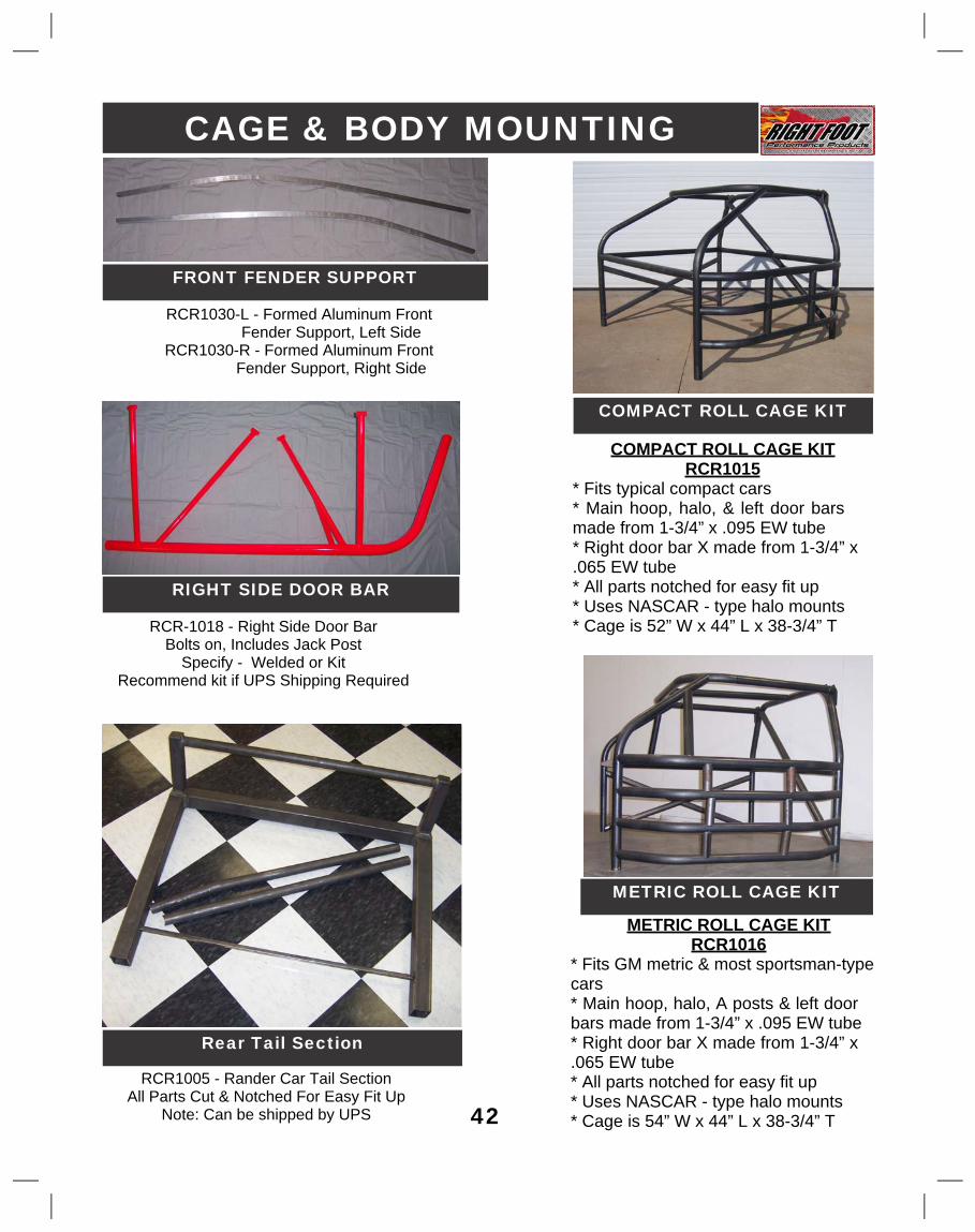
CAGE & BODY MOUNTING�
COMPACT ROLL CAGE KIT�
METRIC ROLL CAGE KIT�
COMPACT ROLL CAGE KIT�RCR1015�
* Fits typical compact cars�* Main hoop, halo, & left door bars�made from 1-3/4” x .095 EW tube�* Right door bar X made from 1-3/4” x�.065 EW tube�* All parts notched for easy fit up�* Uses NASCAR - type halo mounts�* Cage is 52” W x 44” L x 38-3/4” T�
METRIC ROLL CAGE KIT�RCR1016�
* Fits GM metric & most sportsman-type�cars�* Main hoop, halo, A posts & left door�bars made from 1-3/4” x .095 EW tube�* Right door bar X made from 1-3/4” x�.065 EW tube�* All parts notched for easy fit up�* Uses NASCAR - type halo mounts�* Cage is 54” W x 44” L x 38-3/4” T�
FRONT FENDER SUPPORT�
RCR1030-L - Formed Aluminum Front� Fender Support, Left Side�
RCR1030-R - Formed Aluminum Front� Fender Support, Right Side�
42�
RIGHT SIDE DOOR BAR�
RCR-1018 - Right Side Door Bar�Bolts on, Includes Jack Post�
Specify - Welded or Kit�Recommend kit if UPS Shipping Required�
Rear Tail Section�
RCR1005 - Rander Car Tail Section�All Parts Cut & Notched For Easy Fit Up�
Note: Can be shipped by UPS�
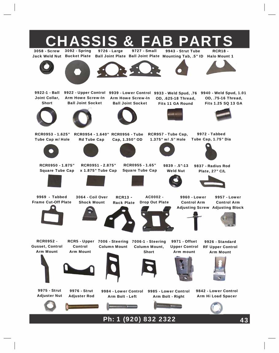
CHASSIS & FAB PARTS�
RCR5 - Upper�Control�
Arm Mount�
3064 - Coil Over�Shock Mount�
7006 - Steering�Column Mount�
RCR13� -�Rack�Plate�
AC0002 -�Drop Out Plate�
9922 - Upper Control�Arm Howe Screw-In�
Ball Joint Socket�
RCR0953 - 1.625”�Tube Cap w/ Hole�
9933 - Weld Spud, .76�OD, .625-18 Thread,�
Fits 11 GA Round�
9943 - Strut Tube�Mounting Tab, .5” ID�
9922-1 - Ball�Joint Collar,�
Short�
7006-1 - Steering�Column Mount,�
Short�
9939 - Lower Control�Arm Howe Screw-In�
Ball Joint Socket�
9837 - Radius Rod�Plate, 27” C/L�
RCR0955 - 1.65”�Square Tube�Cap�
RCR0951 - 2.875”�x 1.875” Tube Cap�
RCR0950 - 1.875”�Square�Tube Cap�
RCR957 - Tube Cap,�1.375” w/ .5” Hole�
9971 - Offset�Upper Control�
Arm mount�
9926 - Standard�RF Upper Control�
Arm Mount�
9957 - Lower�Control Arm�
Adjusting Block�
9960 - Lower�Control Arm�
Adjusting Screw�
9975 - Strut�Adjuster Nut�
9984 - Lower Control�Arm Bolt - Left�
9976 - Strut�Adjuster Rod�
9842 - Lower Control�Arm Hi Load Spacer�
RCR0954 - 1.640”�Rd Tube Cap�
RCR0952 -�Gusset, Control�
Arm Mount�
RCR18 -�Halo Mount 1�
9969 - Tabbed�Frame Cut-Off Plate�
9972 - Tabbed�Tube�Cap, 1.75” Dia�
9726 - Large�Ball Joint Plate�
9727 - Small�Ball Joint�Plate�
RCR0956 - Tube�Cap, 1.350” OD�
9839 - .5”-13�Weld Nut�
3058 - Screw�Jack Weld Nut�
3092 - Spring�Bucket Plate�
9940 - Weld Spud, 1.01�OD, .75-16 Thread,�Fits 1.25 SQ 13 GA�
9985 - Lower Control�Arm Bolt - Right�
Ph: 1 (920) 832 2322� 43�
ORDERING TERMS & CONDITIONS
ORDER PLACEMENT
Our staff is available from 8:00 AM to 5:00 PM (CST) Monday thru Thursday and from 8:00 AM to 4:00 PM on Friday. Orders can be faxed to (920) 832-2324 or can be emailed to [email protected] twenty four hours a day, seven days a week. We strive to ship small quantity orders on the same day or next day basis. Larger quantity orders may take longer to ship. When ordering please provide complete part numbers and descriptions of the parts needed. Also provide your name, address and phone number for shipping purposes. Note; we cannot ship to a Post Office Box.
SPECIAL ORDERS
Please consult our staff if you have a requirement for specialized parts. When requesting special parts please have dimensions or a sketch available. Special orders may not be cancelled once the order is placed.
BACKORDERS
We try to avoid backorders however they occasionally occur. We will inform you of any delays or backorders and the expected shipping date.
TERMS
All accounts are C.O.D, Certified Check, Money Order or Credit Card (Master Card, Visa or Discover) until proper credit information has been provided, verified and approved to accept personal checks or be open account. Any check returned for insufficient funds will be charged a $25.00 service fee and the account will be returned to C.O.D., Certified Check, Money Order or Credit Card. If an “Open Account” customer is consistently late with payment the account will be returned to C.O.D. status.
SHIPPING
Orders are typically shipped by U.P.S. ground or Spee-Dee with shipping costs charged to the parts invoice. Expedited shipment by U.P.S. is available upon request.
RETURNS
Please call ahead for a Returned Goods Authorization (RGA) Number before returning any part for credit, exchange or refund. All returns must be accompanied by a copy of the original invoice. Returns must be shipped pre-paid and may be subject to a 15% restocking charge. No returns after 30 days.
Special orders are not returnable. No credits, exchanges or refunds will be provided for parts that have been altered, painted or changed in any way.
WARRANTY
There is no warranty, guarantee, or liability either expressed or implied, written or oral, applicable to Right Foot Performance Products, Inc. The User assumes all responsibility and liability arising from malfunction, damage or misuse. Right Foot Performance Products are for racing purposes only!