workhorse chassis--body electrical wiring manual - utilimaster
TRANSCRIPT

BodyWiring
Manual
Aeromaster on
Workhorse Chassis
Aeromaster on
Workhorse Chassis
BodyWiring
Manual
2 Aeromaster on Workhorse Chassis�Body Wiring Manual
Read First: Top Tips on Using This Online Manual
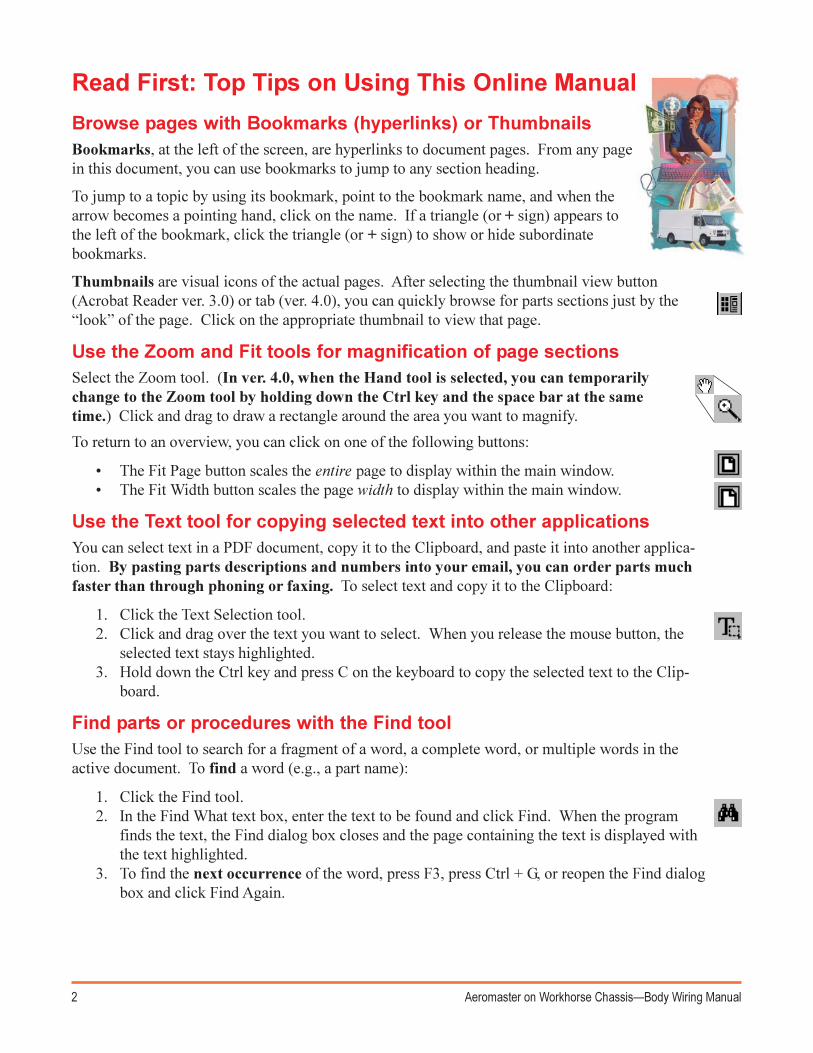
Browse pages with Bookmarks (hyperlinks) or ThumbnailsBookmarks, at the left of the screen, are hyperlinks to document pages. From any pagein this document, you can use bookmarks to jump to any section heading.
To jump to a topic by using its bookmark, point to the bookmark name, and when thearrow becomes a pointing hand, click on the name. If a triangle (or + sign) appears tothe left of the bookmark, click the triangle (or + sign) to show or hide subordinatebookmarks.
Thumbnails are visual icons of the actual pages. After selecting the thumbnail view button(Acrobat Reader ver. 3.0) or tab (ver. 4.0), you can quickly browse for parts sections just by the�look� of the page. Click on the appropriate thumbnail to view that page.
Use the Zoom and Fit tools for magnification of page sectionsSelect the Zoom tool. (In ver. 4.0, when the Hand tool is selected, you can temporarilychange to the Zoom tool by holding down the Ctrl key and the space bar at the sametime.) Click and drag to draw a rectangle around the area you want to magnify.
To return to an overview, you can click on one of the following buttons:
� The Fit Page button scales the entire page to display within the main window.� The Fit Width button scales the page width to display within the main window.
Use the Text tool for copying selected text into other applicationsYou can select text in a PDF document, copy it to the Clipboard, and paste it into another applica-tion. By pasting parts descriptions and numbers into your email, you can order parts muchfaster than through phoning or faxing. To select text and copy it to the Clipboard:
1. Click the Text Selection tool.2. Click and drag over the text you want to select. When you release the mouse button, the
selected text stays highlighted.3. Hold down the Ctrl key and press C on the keyboard to copy the selected text to the Clip-
board.
Find parts or procedures with the Find toolUse the Find tool to search for a fragment of a word, a complete word, or multiple words in theactive document. To find a word (e.g., a part name):
1. Click the Find tool.2. In the Find What text box, enter the text to be found and click Find. When the program
finds the text, the Find dialog box closes and the page containing the text is displayed withthe text highlighted.
3. To find the next occurrence of the word, press F3, press Ctrl + G, or reopen the Find dialogbox and click Find Again.
3Aeromaster on Workhorse Chassis�Body Wiring Manual
Important Notices©2003, Utilimaster.®
Printed in U.S.A.
Title: Aeromaster on Workhorse Chassis�Body Wiring Manual
Utilimaster Corporation attempts to provide information that is accurate, complete, and useful. Allinformation contained in this manual is based on the latest product information available at the time ofpublication. However, because of the Utilimaster policy of continual product improvement, Utilimasterreserves the right to amend the information in this document at any time without prior notice. Shouldyou find inadequacies in the text, please send your comments to the following address:
UtilimasterAttn: Designer of Technical Publications65906 State Road 19, P.O. Box 585Wakarusa, Indiana, 46573-0585 U.S.A.
This material is confidential and the property of Utilimaster. It is shared with your company for the solepurpose of helping you with the operation of the described equipment.
Utilimaster makes no warranty of any kind with regard to this material, including, but not limited to, theimplied warranties of merchantability and fitness for a particular purpose. Utilimaster shall not be liablefor errors contained herein or for incidental or consequential damages in connection with the furnishing,performance, or use of this material.
Utilimaster expressly disclaims all responsibility and liability for the installation, use, performance,maintenance, and support of third-party products. Customers are advised to make their independentevaluation of such products.
No part of this document may be photocopied, reproduced, or translated to another language without theprior written consent of Utilimaster.
Utilimaster® and Aeromaster® are registered trademarks of Utilimaster Corporation. All other trade-marks are products of their respective companies.
Browse the web site www.utilimaster.com for more information about Utilimaster and its products.
Revision ControlRevision Print Date
Rev. A April 2003
Part Number: 03102354-WY00EN
NOTE: When phoning Utilimaster, be aware that our219 telephone area code changed to 574 in January2002. The 800 numbers were unaffected.
4 Aeromaster on Workhorse Chassis�Body Wiring Manual
Contents
Introduction ................................................................................................................................ 6
Finding Information..................................................................................................................... 7
VIN Number................................................................................................................................ 7
Body Serial Number ................................................................................................................... 7
Safety Considerations ................................................................................................................8
General Warnings .................................................................................................................8
Disconnecting the Battery .....................................................................................................9
Reporting Safety Defects (U.S. Only) .........................................................................................9
More Information ...................................................................................................................... 10
Utilimaster Quick Reference Parts Guide ...........................................................................10
Utilimaster Body on Workhorse Chassis Parts Manual....................................................... 10
Utilimaster Glossary of Terms ............................................................................................. 10
Utilimaster Body Service Manual ........................................................................................10
Download Files ................................................................................................................... 10
Contact Utilimaster ..............................................................................................................10
Wiring Diagrams ....................................................................................................................... 11
1�Wire Color Code and Symbol Key................................................................................. 11
2�Connectors .................................................................................................................... 12
Cummins ISB4 Diesel Only ........................................................................................... 12
Standard ........................................................................................................................ 13
3�Harness Layout (Connector Locations) ......................................................................... 18
4�Power Distribution ......................................................................................................... 19
5�Grounding System......................................................................................................... 20
6�Switches ........................................................................................................................ 21
7�Cargo Lamps .................................................................................................................22
Standard ........................................................................................................................ 22
Switch on Dash .............................................................................................................23
Three-Way Switch ......................................................................................................... 24
8�Wiper System ................................................................................................................25
Standard and Cummins ISB4 Intermittent ..................................................................... 25
Intermittent Option (Non-Cummins ISB4) ...................................................................... 26
5Aeromaster on Workhorse Chassis�Body Wiring Manual
9�Heater Only System ...................................................................................................... 27
Cable Controls ...............................................................................................................27
Electronic Controls ........................................................................................................ 28
9�HVAC System................................................................................................................29
Cable Controls ...............................................................................................................29
Electronic Controls ........................................................................................................ 30
10�Chassis Supplied A/C Prep .........................................................................................31
11�Front Light Wiring ........................................................................................................ 32
With Cummins ISB4 Diesel Engines .............................................................................32
Without Daytime Running Lights ...................................................................................33
Daytime Running Lights (Domestic) .............................................................................. 34
Daytime Running Lights (Canadian) .............................................................................. 35
12�Rear Light Wiring.........................................................................................................36
Standard ........................................................................................................................36
Routed through Interior ..................................................................................................37
Split Taillights .................................................................................................................38
Split Taillights Routed through Interior ...........................................................................39
13�Roof Wiring .................................................................................................................40
14�Clearance Lights .........................................................................................................41
15�Panel Lights (HVAC Control Panel) .............................................................................42
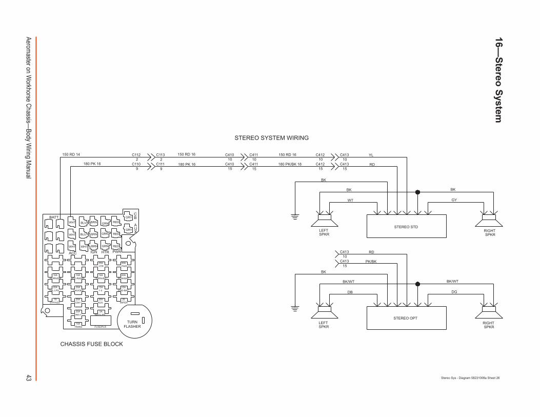
16�Stereo System .............................................................................................................43
17�Door Ajar System ........................................................................................................ 44
18�Supplemental High Mount Stop Lamp (SHMSL) .........................................................45
19�Accessory Outlet (Cigarette Lighter) ...........................................................................46
20�Cab Dome Light ..........................................................................................................47
21�Dash Fan .....................................................................................................................48
22�Power Vent ..................................................................................................................49
23�Heated Mirrors .............................................................................................................50
24�Auxiliary Heater ...........................................................................................................51
25�Spotlight or Strobe Light ..............................................................................................52
Index ........................................................................................................................................53
6 Aeromaster on Workhorse Chassis�Body Wiring Manual
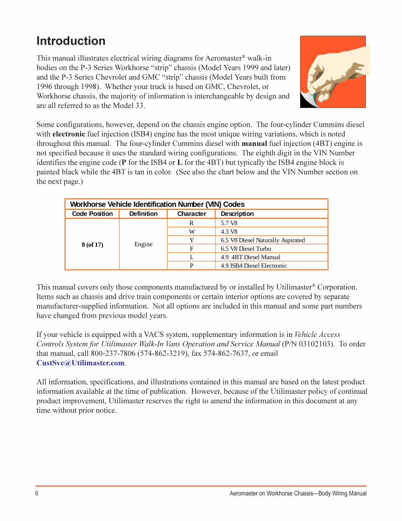
IntroductionThis manual illustrates electrical wiring diagrams for Aeromaster® walk-inbodies on the P-3 Series Workhorse �strip� chassis (Model Years 1999 and later)and the P-3 Series Chevrolet and GMC �strip� chassis (Model Years built from1996 through 1998). Whether your truck is based on GMC, Chevrolet, orWorkhorse chassis, the majority of information is interchangeable by design andare all referred to as the Model 33.
Some configurations, however, depend on the chassis engine option. The four-cylinder Cummins dieselwith electronic fuel injection (ISB4) engine has the most unique wiring variations, which is notedthroughout this manual. The four-cylinder Cummins diesel with manual fuel injection (4BT) engine isnot specified because it uses the standard wiring configurations. The eighth digit in the VIN Numberidentifies the engine code (P for the ISB4 or L for the 4BT) but typically the ISB4 engine block ispainted black while the 4BT is tan in color. (See also the chart below and the VIN Number section onthe next page.)
Workhorse Vehicle Identification Number (VIN) CodesCode Position Definition Character Description
R 5.7 V8W 4.3 V8Y 6.5 V8 Diesel Naturally AspiratedF 6.5 V8 Diesel TurboL 4.9 4BT Diesel ManualP 4.9 ISB4 Diesel Electronic
8 (of 17) Engine
This manual covers only those components manufactured by or installed by Utilimaster® Corporation.Items such as chassis and drive train components or certain interior options are covered by separatemanufacturer-supplied information. Not all options are included in this manual and some part numbershave changed from previous model years.
If your vehicle is equipped with a VACS system, supplementary information is in Vehicle AccessControls System for Utilimaster Walk-In Vans Operation and Service Manual (P/N 03102103). To orderthat manual, call 800-237-7806 (574-862-3219), fax 574-862-7637, or [email protected].
All information, specifications, and illustrations contained in this manual are based on the latest productinformation available at the time of publication. However, because of the Utilimaster policy of continualproduct improvement, Utilimaster reserves the right to amend the information in this document at anytime without prior notice.
7Aeromaster on Workhorse Chassis�Body Wiring Manual
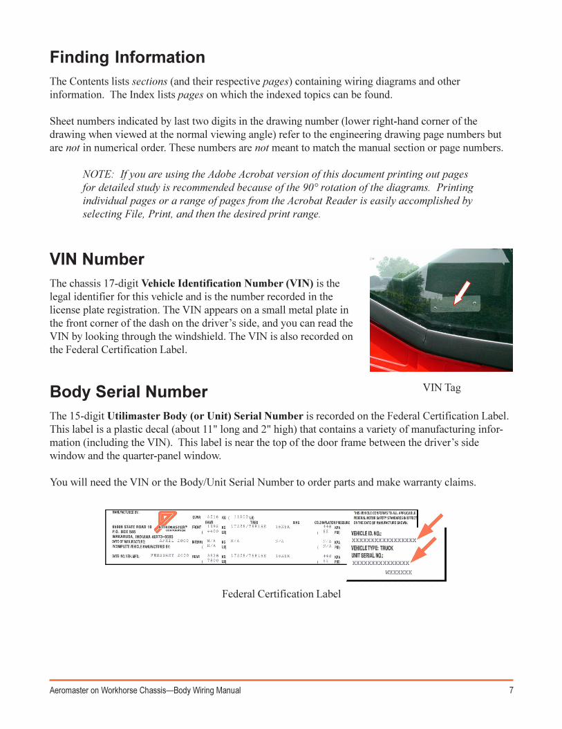
VIN NumberThe chassis 17-digit Vehicle Identification Number (VIN) is thelegal identifier for this vehicle and is the number recorded in thelicense plate registration. The VIN appears on a small metal plate inthe front corner of the dash on the driver�s side, and you can read theVIN by looking through the windshield. The VIN is also recorded onthe Federal Certification Label.
Body Serial NumberThe 15-digit Utilimaster Body (or Unit) Serial Number is recorded on the Federal Certification Label.This label is a plastic decal (about 11" long and 2" high) that contains a variety of manufacturing infor-mation (including the VIN). This label is near the top of the door frame between the driver�s sidewindow and the quarter-panel window.
You will need the VIN or the Body/Unit Serial Number to order parts and make warranty claims.
VIN Tag
Federal Certification Label
Finding InformationThe Contents lists sections (and their respective pages) containing wiring diagrams and otherinformation. The Index lists pages on which the indexed topics can be found.
Sheet numbers indicated by last two digits in the drawing number (lower right-hand corner of thedrawing when viewed at the normal viewing angle) refer to the engineering drawing page numbers butare not in numerical order. These numbers are not meant to match the manual section or page numbers.
NOTE: If you are using the Adobe Acrobat version of this document printing out pagesfor detailed study is recommended because of the 90° rotation of the diagrams. Printingindividual pages or a range of pages from the Acrobat Reader is easily accomplished byselecting File, Print, and then the desired print range.
8 Aeromaster on Workhorse Chassis�Body Wiring Manual
Safety ConsiderationsGeneral Warnings
The following list contains some general WARNINGS that you should follow when you work on avehicle.
· Be sure that the ignition switch is always in the OFF position, unless otherwise required by theprocedure. For circuits that are not controlled by the ignition switch (e.g., lights), disconnectthe negative terminal on the battery. (See instructions on the next page.)
· Even though the ignition is in the OFF position, an electric radiator fan can start to operate atany time by an increase in under-hood temperatures. Make sure the radiator fan is completelydisconnected when working under the hood.
· Always wear safety glasses for eye protection.
· Use safety stands whenever a procedure requires you to be under the vehicle.
· Set the parking brake when working on the vehicle and if the vehicle has an automatic trans-mission, put the transmission in PARK.
· Operate the engine only in a well-ventilated area to avoid the danger of carbon monoxide.
· Keep yourself and your clothing away from moving parts when the engine is running, espe-cially the fan and belts.
· To prevent serious burns, avoid contact with hot metal parts such as the radiator, exhaustmanifold, tail pipe, catalytic converter, and muffler.
· Do not smoke while working on the vehicle.
· To avoid injury, always remove rings, watches, loose hanging jewelry, and loose clothingbefore beginning to work on a vehicle. Tie long hair securely behind your head.
· Avoid breathing A/C refrigerant and lubricant vapor or mist. Exposure may irritate eyes, nose,and throat. To remove R-134a from the A/C system use service equipment certified to meet therequirements of SAE J2210 (R-134a recycling equipment). IF accidental system dischargeoccurs, ventilate work area BEFORE resuming service. Additional health and safety informa-tion may be obtained from refrigerant and lubricant manufacturers.
9Aeromaster on Workhorse Chassis�Body Wiring Manual
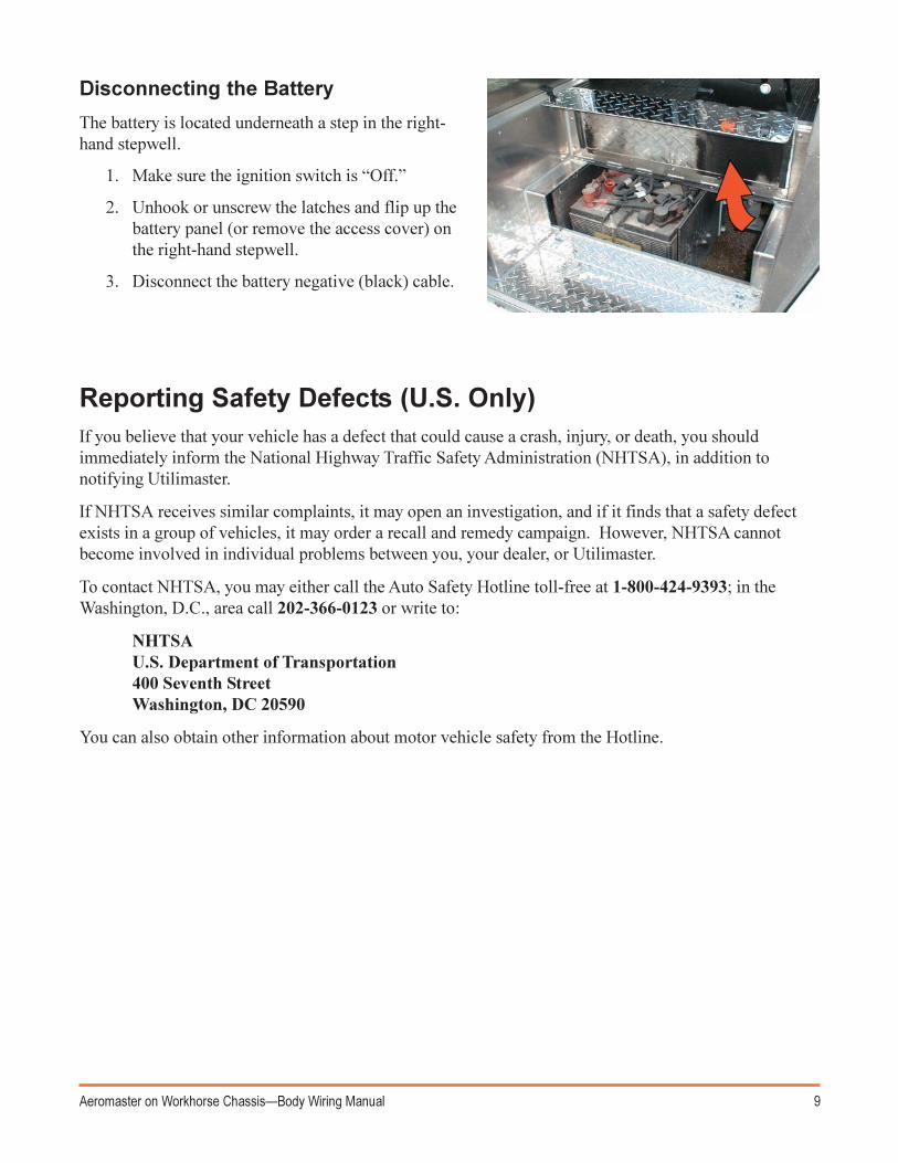
Disconnecting the Battery
The battery is located underneath a step in the right-hand stepwell.
1. Make sure the ignition switch is �Off.�
2. Unhook or unscrew the latches and flip up thebattery panel (or remove the access cover) onthe right-hand stepwell.
3. Disconnect the battery negative (black) cable.
Reporting Safety Defects (U.S. Only)If you believe that your vehicle has a defect that could cause a crash, injury, or death, you shouldimmediately inform the National Highway Traffic Safety Administration (NHTSA), in addition tonotifying Utilimaster.
If NHTSA receives similar complaints, it may open an investigation, and if it finds that a safety defectexists in a group of vehicles, it may order a recall and remedy campaign. However, NHTSA cannotbecome involved in individual problems between you, your dealer, or Utilimaster.
To contact NHTSA, you may either call the Auto Safety Hotline toll-free at 1-800-424-9393; in theWashington, D.C., area call 202-366-0123 or write to:
NHTSAU.S. Department of Transportation400 Seventh StreetWashington, DC 20590
You can also obtain other information about motor vehicle safety from the Hotline.
10 Aeromaster on Workhorse Chassis�Body Wiring Manual
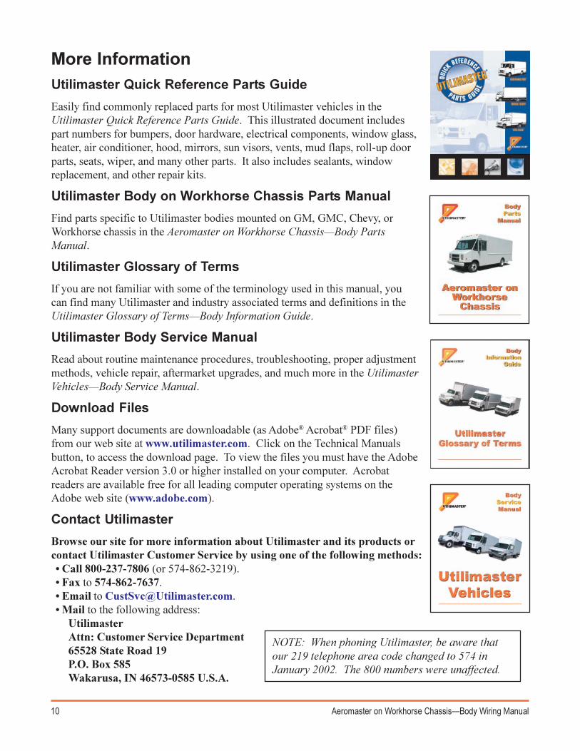
More InformationUtilimaster Quick Reference Parts Guide
Easily find commonly replaced parts for most Utilimaster vehicles in theUtilimaster Quick Reference Parts Guide. This illustrated document includespart numbers for bumpers, door hardware, electrical components, window glass,heater, air conditioner, hood, mirrors, sun visors, vents, mud flaps, roll-up doorparts, seats, wiper, and many other parts. It also includes sealants, windowreplacement, and other repair kits.
Utilimaster Body on Workhorse Chassis Parts Manual
Find parts specific to Utilimaster bodies mounted on GM, GMC, Chevy, orWorkhorse chassis in the Aeromaster on Workhorse Chassis�Body PartsManual.
Utilimaster Glossary of Terms
If you are not familiar with some of the terminology used in this manual, youcan find many Utilimaster and industry associated terms and definitions in theUtilimaster Glossary of Terms�Body Information Guide.
Utilimaster Body Service Manual
Read about routine maintenance procedures, troubleshooting, proper adjustmentmethods, vehicle repair, aftermarket upgrades, and much more in the UtilimasterVehicles�Body Service Manual.
Download Files
Many support documents are downloadable (as Adobe® Acrobat® PDF files)from our web site at www.utilimaster.com. Click on the Technical Manualsbutton, to access the download page. To view the files you must have the AdobeAcrobat Reader version 3.0 or higher installed on your computer. Acrobatreaders are available free for all leading computer operating systems on theAdobe web site (www.adobe.com).
Contact Utilimaster
Browse our site for more information about Utilimaster and its products orcontact Utilimaster Customer Service by using one of the following methods:� Call 800-237-7806 (or 574-862-3219).� Fax to 574-862-7637.� Email to [email protected].� Mail to the following address:
UtilimasterAttn: Customer Service Department65528 State Road 19P.O. Box 585Wakarusa, IN 46573-0585 U.S.A.
NOTE: When phoning Utilimaster, be aware thatour 219 telephone area code changed to 574 inJanuary 2002. The 800 numbers were unaffected.
11Aerom
aster on Workhorse C
hassis�Body W
iring Manual
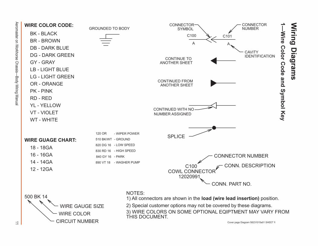
BK - BLACK
GY - GRAY
PK - PINKRD - RED
18 - 18GA16 - 16GA14 - 14GA12 - 12GA
500 BK 14
Cover page Diagram 58231015a01 SHEET 1
NOTES:1) All connectors are shown in the load (wire lead insertion) position.2) Special customer options may not be covered by these diagrams.
WT - WHITEVT - VIOLET
DG - DARK GREENDB - DARK BLUEBR - BROWN
OR - ORANGELG - LIGHT GREENLB - LIGHT BLUE
YL - YELLOW
WIRE GUAGE CHART:
WIRE GAUGE SIZE
CIRCUIT NUMBER
WIRE COLOR
WIRE COLOR CODE:
CONTINUED FROMANOTHER SHEET
CONTINUE TOANOTHER SHEET
CONTINUED WITH NONUMBER ASSIGNED
A
C100
A
C101
CAVITYIDENTIFICATION
CONNECTORNUMBER
CONNECTORSYMBOL
SPLICE
C100COWL CONNECTOR
12020991
CONNECTOR NUMBER
CONN. PART NO.
CONN. DESCRIPTION
3) WIRE COLORS ON SOME OPTIONAL EQIPTMENT MAY VARY FROMTHIS DOCUMENT.
GROUNDED TO BODY
120 OR
510 BK/WT
820 DG 16
830 RD 16
840 GY 16
890 VT 18
- WIPER POWER
- GROUND
- LOW SPEED
- HIGH SPEED
- PARK
- WASHER PUMP
Wirin
g D
iagram
s1�
Wire C
olo
r Co
de an
d S
ymb
ol K
ey
12Aerom
aster on Workhorse C
hassis�Body W
iring Manual
840 GY 16120A OR 16
820 DG 16
830 RD 16
DC
E
B
A
C207WIPER MOTORP/N 12065158
NOTE: If the eighth digit in the VIN number is �P�, the vehicle has the Cummins ISB4 diesel engine. These connectors replace those of the equivalent standard connectors. ISB4 Connectors - Diagram 16513321b Sheet 2
170 RD 12
700 DB/WT 12
A B C D E F
130 RD 14
180 PK 16
A B
234 RD 16
A B C D E F
280 LB/RD 18
230 BN 18
500 BK 14
110 PK/BK 12
170 RD 12
180B PK 18
500C BK 18
4
2
1
35
ACCESSORYPOWER
6 9INTERIORLIGHTING
IGNITIONRELAY
108HIGH
MOUNTSTOPLIGHT
(No equivalent exists inthe standard wiring)7
180A PK 16
9 8 76 5 43 2 1
200 DB 16890 VT 18
830 RD 16
120 OR 16
840 GY 16
820 DG 16
520 BK 16
500B BK 16
C110CHASSISPOWERFEED
2
110 PK/BK 12
1514 131211 109 8 76 5 43 2 1
230 BN 18
280 LB/RD 18
150 RD 14
130A RD 14
234 RD 16
700 DB/WT 12
350 BK/PK 18
130B RD 14
500A BK 16
1C112
CHASSISPOWERFEED
3BATTERYPOWER
A
150 RD 14
DOMELIGHT
4
A B
200 DB 16520 BK 16
5DOORAJAR
A B
350 BK/PK 18
G E
A B C DF
830 RD 16
820 DG 16840 GY 16
120 OR 16
890 VT 18
C108WIPER
2�C
on
necto
rs
Cu
mm
ins IS
B4 D
iesel On
ly
NO
TE: These connectors
are specific to vehiclesw
ith the Cum
mins ISB
4diesel engine. Thesereplace the standardconnectors on the follow
-ing pages (see largecircled num
bers). For
vehicles without the ISB
4engine, see only thefollow
ing pages. Toidentify the engine of avehicle, see page 6.
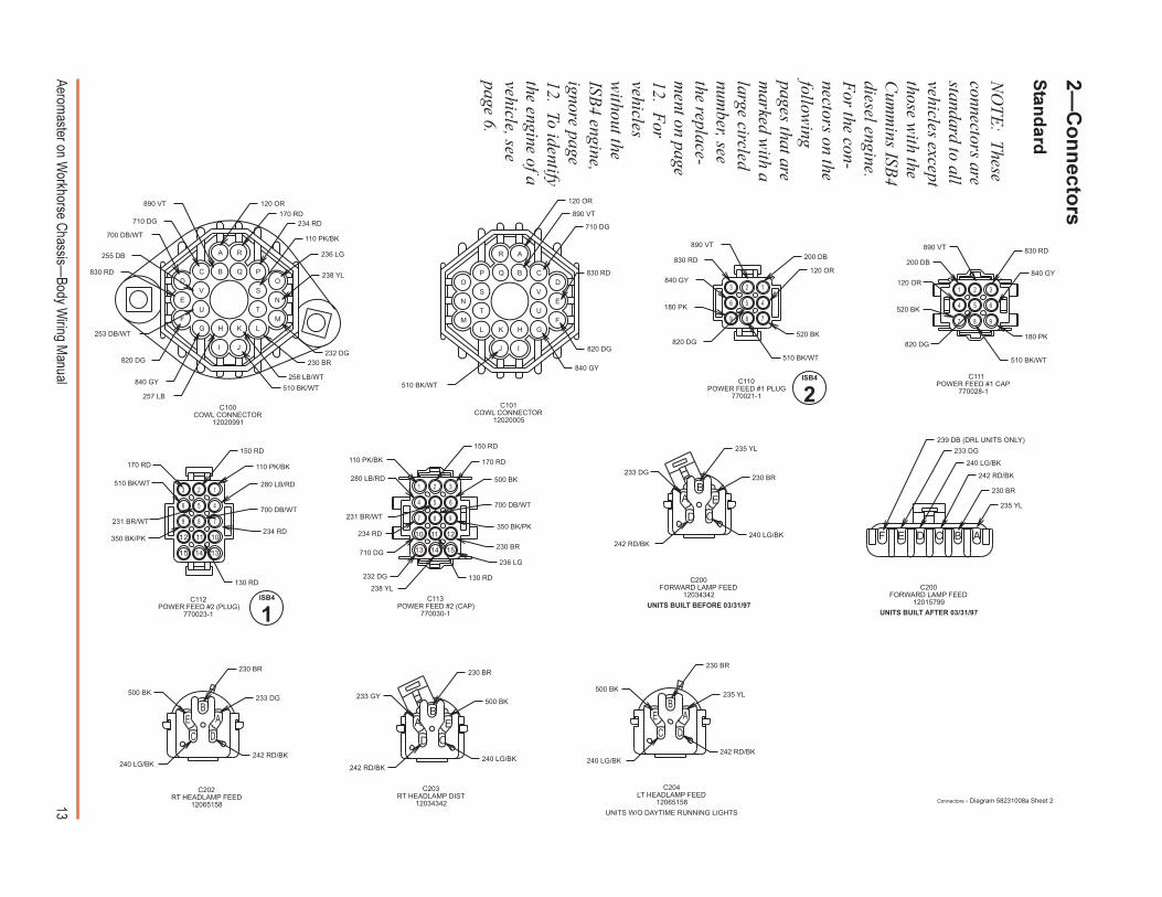
13Aerom
aster on Workhorse C
hassis�Body W
iring Manual
C200FORWARD LAMP FEED
12034342UNITS BUILT BEFORE 03/31/97
UNITS BUILT AFTER 03/31/97
C203RT HEADLAMP DIST
12034342UNITS W/O DAYTIME RUNNING LIGHTS
C204LT HEADLAMP FEED
12065158
C202RT HEADLAMP FEED
12065158
C111POWER FEED #1 CAP
770028-1C110
POWER FEED #1 PLUG770021-1
C101COWL CONNECTOR
12020005
235 YL
230 BR
242 RD/BK
240 LG/BK
233 DG
239 DB (DRL UNITS ONLY)
C113POWER FEED #2 (CAP)
770030-1
C112POWER FEED #2 (PLUG)
770023-1
C200FORWARD LAMP FEED
12015799
F E D C B A
C100COWL CONNECTOR
12020991
120 OR
890 VT
710 DG
830 RD
820 DG
840 GY
510 BK/WT
A
B CD
E
FGH
IJ
KLM
N
OP Q
R
S
T U
V
830 RD
255 DB
253 DB/WT
170 RD
700 DB/WT
120 OR
234 RD
110 PK/BK
236 LG
238 YL
232 DG230 BR
258 LB/WT
510 BK/WT257 LB
840 GY
820 DG
710 DG
890 VT
V
U T
S
R
Q PO
N
MLK
JI
HGF
E
DC B
A
180 PK
200 DB
120 OR
520 BK
510 BK/WT
820 DG
840 GY
830 RD
890 VT
9 8 7
6 5 4
3 2 1
180 PK
120 OR
510 BK/WT
840 GY
830 RD890 VT
200 DB
520 BK
820 DG
9
6
3
8
5
2
4
1
7
510 BK/WT
700 DB/WT
280 LB/RD
130 RD
234 RD
110 PK/BK
150 RD
350 BK/PK
231 BR/WT
170 RD
15 14 13
12 11 10
9 8 7
6 5 4
3 2 1
170 RD
700 DB/WT
280 LB/RD
150 RD
500 BK
350 BK/PK
230 BR
236 LG
130 RD
238 YL
232 DG
710 DG
234 RD
231 BR/WT
110 PK/BK
6
151413
121110
9
3
8
5
2
4
1
7
240 LG/BK
230 BR
235 YL
233 DG
242 RD/BK
CD
AB
E
242 RD/BK
233 DG
230 BR
240 LG/BK
500 BK
DC
EB
A
233 GY
230 BR
500 BK
240 LG/BK242 RD/BK
CD
AB
E
240 LG/BK242 RD/BK
235 YL500 BK
230 BR
DC
EB
A
Connectors - Diagram 58231008a Sheet 2
ISB4
2
ISB4
1
2�C
on
necto
rs
Stan
dard
NO
TE: These
connectors arestandard to allvehicles exceptthose w
ith theC
umm
ins ISB4
diesel engine.F
or the con-nectors on thefollow
ingpages that arem
arked with a
large circlednum
ber, seethe replace-m
ent on page12. F
orvehiclesw
ithout theISB
4 engine,ignore page12. To identifythe engine of avehicle, seepage 6.
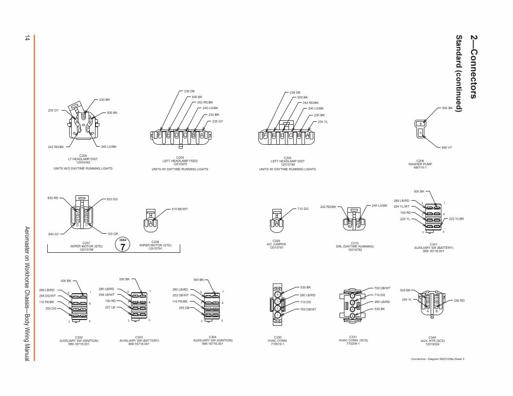
14Aerom
aster on Workhorse C
hassis�Body W
iring Manual
CD
AB
E
240 LG/BK242 RD/BK
500 BK235 GY
230 BR
F E D C B A
235 GY
230 BR
240 LG/BK
242 RD/BK
500 BK
239 DB
F E D C B A
235 YL
230 BR
240 LG/BK
242 RD/BK
500 BK
239 DB
A
B
890 VT
500 BK
222 YL/BK
C301AUXILIARY SW (BATTERY)
999-16716.001
220 YL
150 RD
224 YL/WT
280 LB/RD
500 BK
41
7
63
8
110 PK/BK
254 DG
256 DG/WT
280 LB/RD
500 BK
41
7
63
8
257 LB
258 LB/WT
280 LB/RD
150 RD
500 BK
41
7
63
8
255 DB
110 PK/BK
253 DB/WT
500 BK
280 LB/RD
41
7
63
8
700 DB/WT
710 DG
280 LB/RD
530 BK
4
3
2
1
C331HVAC CONN. (SCS)
770209-1
700 DB/WT
710 DG
280 LB/RD
530 BK
4
3
2
1D C
BA
254 YL
500 BK
256 RD
C304AUXILIARY SW (IGNITION)
999-16716.001
C340AUX. HTR (SCS)
12015024
C302AUXILIARY SW (IGNITION)
999-16716.001
C303AUXILIARY SW (BATTERY)
999-16716.001
C205LEFT HEADLAMP DIST
12015799
C205LT HEADLAMP DIST
12034342
C204LEFT HEADLAMP FEED
12010975
C330HVAC CONN.
770019-1
C206WASHER PUMP
480115-1UNITS W/ DAYTIME RUNNING LIGHTSUNITS W/ DAYTIME RUNNING LIGHTSUNITS W/O DAYTIME RUNNING LIGHTS
Connectors - Diagram 58231008a Sheet 3
BA
240 LG/BK242 RD/BK
C210DRL (DAYTIME RUNNING)
12015792
A
710 DG
C209A/C JUMPER
12015791
D C
BA
820 DG
120 OR840 GY
830 RD
C207WIPER MOTOR (STD)
12015798
A
510 BK/WT
C208WIPER MOTOR (STD)
12015791
ISB4
7
2�C
on
necto
rs
Stan
dard
(con
tinu
ed)
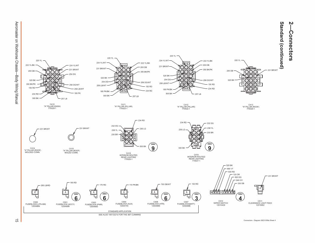
15Aerom
aster on Workhorse C
hassis�Body W
iring Manual
6
151413
121110
9
3
8
5
2
4
1
7
180 PK
254 DG
500 BK
234 RD
258 LB/WT
257 LB
150 RD
256 DG/WT350 BK/PK
520 BK
231 BR/WT200 DB
222 YL/BK 224 YL/WT
220 YL
15 14 13
12 11 10
9 8 7
6 5 4
3 2 1
254 DG
180 PK/BK
C411"A" PILLAR (PILLAR)
770022-1
234 RD
150 RD258 LB/WT
350 BK/PK
200 DB231 BR/WT
224 YL/WT 222 YL/BK
220 YL
520 BK
256 DG/WT
257 LB500 BK
15 14 13
12 11 10
9 8 7
6 5 4
3 2 1
254 DG
180 PK/BK
222 YL/BK
200 DB
350 BK/PK
256 DG/WT
150 RD
234 RD
500 BK
258 LB/WT
231 BR/WT
224 YL/WT
257 LB
520 BK
220 YL
6
151413
121110
9
3
8
5
2
4
1
7
231 BR/WT200 DB
220 YL
520 BK
231 BR/WT 231 BR/WT
63
52
41
234 RD
500 BK
232 DG
238 YL
230 BR
236 LG
6 3
5 2
4 1
234 RD
500 BK
230 BR
238 YL
232 DG
236 LG
A B C D E F G
520 BK
200 DB
840 GY
820 DG120 OR
830 RD
890 VT
A
231 BR/WT
C410"A" PILLAR (DASH)
770029-1
C419INTERIOR ROUTED
REAR LIGHTING770027-1
C418INTERIOR ROUTED
REAR LIGHTING770020-1
C412"A" PILLAR (PILLAR)
770022-1
C510WIPER SWITCH
12010429
C511CLEARANCE LIGHT FEED
12015952
C414"A" PILLAR (ROOF)MOLDED CONN.
C413"A" PILLAR (ROOF)
770029-1
C415"A" PILLAR (ROOF)
MOLED CONN.
Connectors - Diagram 58231008a Sheet 4
A
280 LB/RD180 RD
A A
170 RD
A
110 PK/BK 700 DB/WT
A A
150 RD
C506FUSEBLOCK (HTR)
12004885
C507FUSEBLOCK(BATT)
12004886
C504FUSEBLOCK (AUX)
12004740
C503FUSEBLOCK (PWR)
12004883
C500FUSEBLOCK (LPS-GM)
12004884
C501FUSEBLOCK (ACCY)
12004888
STANDARD APPLICATION
SEE ALSO 16513321b FOR THE 4BT CUMMINS
ISB4
6ISB4
6ISB4
3ISB4
6ISB4
4
ISB4
9ISB4
9
2�C
on
necto
rs
Stan
dard
(con
tinu
ed)
16Aerom
aster on Workhorse C
hassis�Body W
iring Manual
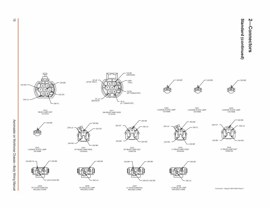
C623LICENCE PLATE LAMP
12010996
C622LICENSE PLATE LAMP
12010996
230 BR
232 DG
238 YL
236 LG
234 RD
C611GM REAR LAMP FEED
12110753
C610REAR LAMP DIST
12110751
DE
F CA
BG
236 LG
234 RD230 BR
238 YL
500 BK
C634LT REAR LAMP DIST
12065158
C632RT REAR LAMP DIST
12065158
C620LICENSE PLATE LAMP
12010996
CD
A
B
E
C638LT BACK-UP LAMP
MOLDED CONN.
C637LT STOP/TURN/TAIL
MOLDED CONN.
C636RT BACK-UP LAMP
MOLDED CONN.
C635RT STOP/TURN/TAIL
MOLDED CONN.
C633LT REAR LAMP FEED
12034342
C631RT REAR LAMP FEED
12034342
C621LICENSE PLATE LAMP
12010996
24 LG(BACKUP) 18 YL
(LT TURN/STOP)
19 DG(RT TURN/STOP)
9 BR(TAIL)
150 BK(GROUND)
20 LB(STOP ONLY)
DE
F CA
BG
230 BR
A
230 BR
A A
230 BR
230 BR
A
234 RD
236 LG
230 BR
232 DG
500 BK
CD
A
B
E
234 RD
232 GY
230 BR
236 LG
500 BK
C
E
B
D
A
230 BR
238 GY
500 BK
236 LG
234 RD
C
E
B
D
A
C
B
236 LG
500 BK
232 GY/234 RD
500 BK230 BR 18
C
BA
236 LG
500 BK
C
B
238 GY/ 234 RD
230 BR 500 BK
C
BA
Connectors - Diagram 58231008a Sheet 5
2�C
on
necto
rs
Stan
dard
(con
tinu
ed)
17Aerom
aster on Workhorse C
hassis�Body W
iring Manual
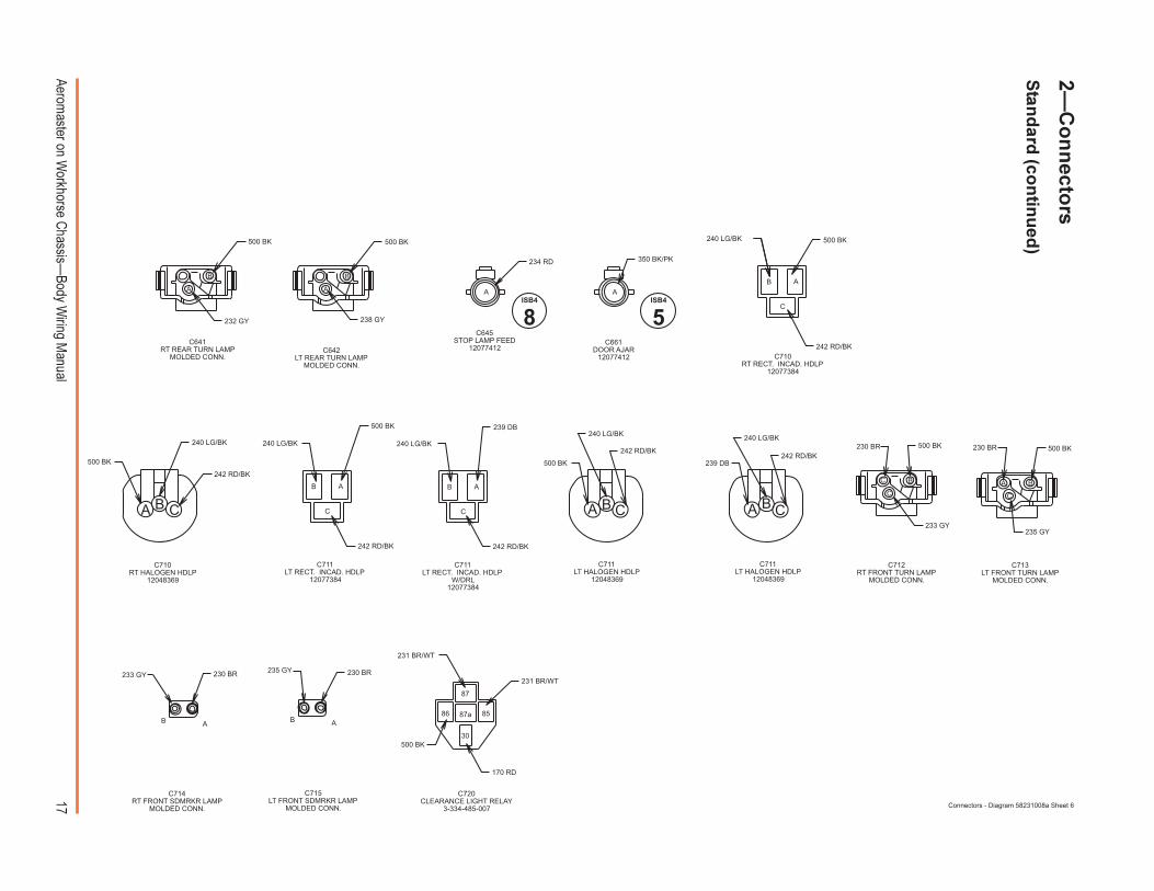
C661DOOR AJAR
12077412
C645STOP LAMP FEED
12077412
C713LT FRONT TURN LAMP
MOLDED CONN.
C712RT FRONT TURN LAMP
MOLDED CONN.
C711LT HALOGEN HDLP
12048369
C711LT HALOGEN HDLP
12048369
C710RT RECT. INCAD. HDLP
12077384
C642LT REAR TURN LAMP
MOLDED CONN.
C641RT REAR TURN LAMP
MOLDED CONN.
C711LT RECT. INCAD. HDLP
W/DRL12077384
C720CLEARANCE LIGHT RELAY
3-334-485-007
C710RT HALOGEN HDLP
12048369
C714RT FRONT SDMRKR LAMP
MOLDED CONN.
C711LT RECT. INCAD. HDLP
12077384
232 GY
500 BK
B
A
238 GY
500 BK
B
A
234 RD
A
350 BK/PK
A
242 RD/BK
240 LG/BK 500 BK
C
B A
240 LG/BK
500 BK
242 RD/BK
A B C
242 RD/BK
500 BK
240 LG/BK
C
B A
239 DB
C
B A
240 LG/BK
242 RD/BK
242 RD/BK
240 LG/BK
500 BK
A B C
239 DB242 RD/BK
240 LG/BK
A B C
230 BR 500 BK
233 GY
B
C
C
235 GY
230 BR 500 BK
A B
C
B A
230 BR235 GY
AB
230 BR233 GY
C715LT FRONT SDMRKR LAMP
MOLDED CONN.
231 BR/WT
170 RD
500 BK
231 BR/WT
30
87
8587a86
Connectors - Diagram 58231008a Sheet 6
ISB4
8ISB4
5
2�C
on
necto
rs
Stan
dard
(con
tinu
ed)
18Aerom
aster on Workhorse C
hassis�Body W
iring Manual
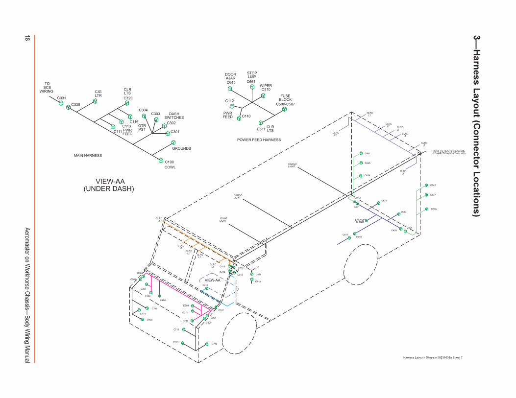
3�H
arness L
ayou
t (Co
nn
ector L
ocatio
ns)
BACKUPALARM
C418
C419C412
C413
CLRCLT
C641
C642
C611
C210
CLRCLT
C638
C637
C636
C635
CLRCLT
C631
CLRCLT
CLRCLT
CLRCLT
CLRCLT
CLRCLT
CLRCLT
CLRCLT
CLRCLT
CLRCLT
VIEW-AA
C101
CARGOLIGHT
CARGOLIGHT
DOMELIGHT
ROOF TO REAR STRUCTURECONNECTION(NO CONN. #'S)
C715
C714
C713
C712
C711
C710
C634C633
C632C621
C620
C610
C415
C411
C414
C205
C204C200
C209
C208
C207
C206
C203
C202
C661
C510
C645
C500-C507
POWER FEED HARNESS
C511
C110
C112
STOPLMP
WIPER
FUSEBLOCK
CLRLTS
DOORAJAR
PWRFEED
C116
C111C113
C720
C304
MAIN HARNESS
CIGLTR
GROUNDS
VIEW-AA(UNDER DASH)
TOSCS
WIRING
C331
C330
C303
C302
C301
C100
CLRLTS
QTRPSTPWR
FEED
DASHSWITCHES
COWL
Harness Layout - Diagram 58231008a Sheet 7
19Aerom
aster on Workhorse C
hassis�Body W
iring Manual
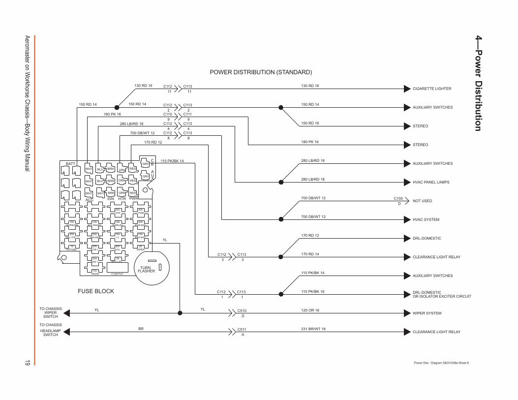
POWER DISTRIBUTION (STANDARD)
180 PK 16
130 RD 16
150 RD 14
231 BR/WT 18
170 RD 12
180 PK 16
CLEARANCE LIGHT RELAY
AUXILIARY SWITCHES
CLEARANCE LIGHT RELAY
HVAC PANEL LAMPS
AUXILIARY SWITCHES
STEREO
STEREO
AUXILIARY SWITCHES
CIGARETTE LIGHTER130 RD 16
WIPER SYSTEM
DRL-DOMESTICOR ISOLATOR EXCITER CIRCUIT
DRL-DOMESTIC
HVAC SYSTEM
DC100
NOT USED
8
4
9
2
1111
2
9
4
8
C113
C113C112
C112
C110 C111
C113C112
C113C112
33C113C112
1 1C113C112 110 PK/BK 16
700 DB/WT 12
280 LB/RD 18
280 LB/RD 18
150 RD 16
150 RD 14
700 DB/WT 12
280 LB/RD 18
170 RD 12
110 PK/BK 14
150 RD 14
YL
170 RD 14
FUSE BLOCK
700 DB/WT 12
AC511
DC510
BR
YLYL
CBBATT
BRNWHT BLU GRN AU
GRN REDBLUWHT BRNX
WHTWHT
PWRIGN HTRACC
30APWR
25AHTR
10AACC-RADIO
20AECM-BAT
15AHORN/DM
15ATURN-BU
15A1-3
15AENG-BAT
20ATAIL LPS
20AGAUGES
30AAUX.
25WIPER
15STP/HZD
20AECM-1
5AINST-LPS
20AENG-1
10ATRANS FUSE/PLR
120 OR 16
110 PK/BK 14
HEADLAMPSWITCH
TO CHASSISWIPER
SWITCH
GRY
GRY
TURNFLASHER
RED
REDGRNBRN
TO CHASSIS
Power Dist - Diagram 58231008a Sheet 8
4�P
ow
er Distrib
utio
n
20Aerom
aster on Workhorse C
hassis�Body W
iring Manual
510 BK/WT 16WIPER SYSTEM
C11088
C111
500 BK 18CLEARANCE LIGHT RELAY
CIGARETTE LIGHTER
500 BK 18PANEL LAMPS
HVAC SYSTEM
AUXILIARY HEATER(SCS ONLY)
INTERMITTENT WIPER MODULE500 BR 16
WASHER PUMP
FORWARD LAMPS
DRL-DOMESTICS
ROOF CENTRALGROUND
500 BK 16
AUXILIARY SWITCHES
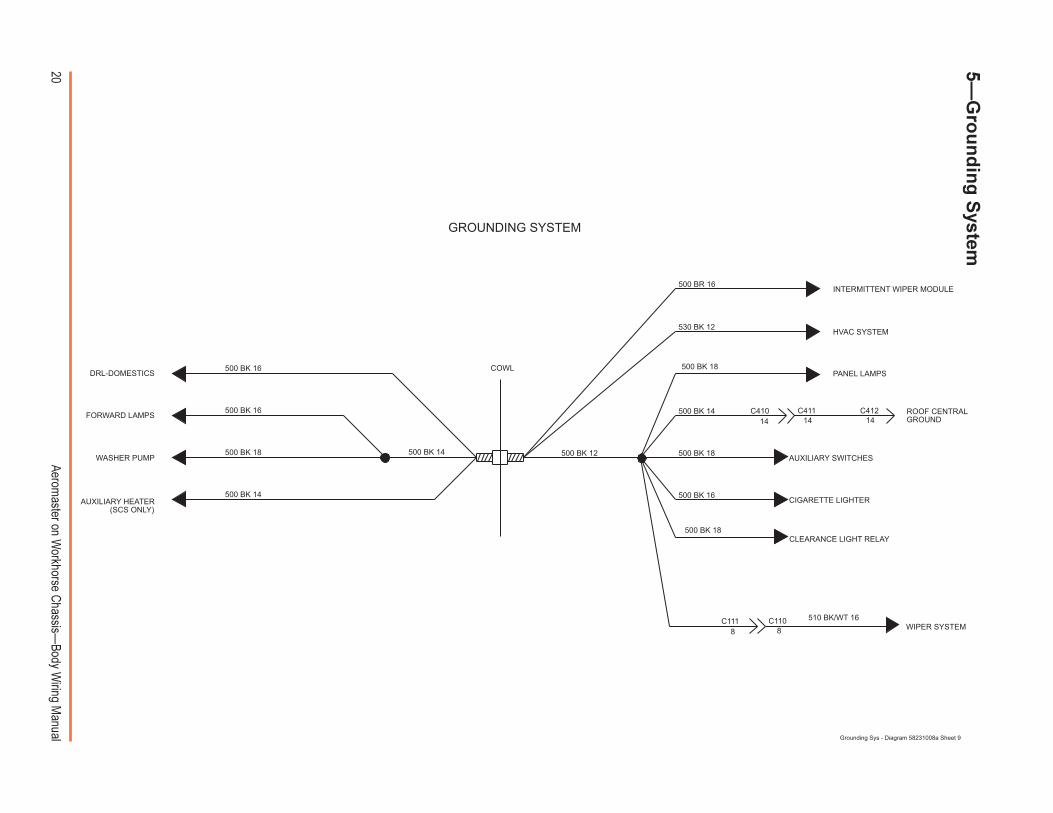
GROUNDING SYSTEM
500 BK 16
500 BK 14 500 BK 16
C412C411141414
C410500 BK 14
COWL
500 BK 18 500 BK 14 500 BK 12 500 BK 18
530 BK 12
Grounding Sys - Diagram 58231008a Sheet 9
5�G
rou
nd
ing
System

21Aerom
aster on Workhorse C
hassis�Body W
iring Manual
8
2
7
ON/OFF
3
UC100
VC100255 DB 14
110 PK/BK 14
253 DB/WT 14
C304
C304
C304
C304
C304
AUXILIARYSWITCH 4(IGNITIONPOWER)
SWITCHES SHOWN ARE FOR VISUAL FUNCTIONALREASONS ONLY. THEY ARE NOT NECESSARILYMATCHED TO THE CONNECTOR NUMBERSHOWN.
1
2
3
7
8
500 BK 18
280 LB/RD 18
WIRE COLOR TO LOAD FUNCTION MAY VARY, BASEDON OPTIONS CHOSEN AND NUMBER OF SWITCHEDOPTIONS CHOSEN.
SPECIAL REQUESTED OPTIONS MAY BE WIRED DIFFERENTLYTHAN SHOWN ON THIS OR OTHER SHEETS.
PANEL LAMPS GROUND
150 RD 14
AUXILiARYSWITCH 1(BATTERYPOWER)
AUXILiARYSWITCH 2(IGNITIONPOWER)
AUXILIARYSWITCH 3(BATTERYPOWER)
TYPICAL SWITCH USAGES:� ON/OFF � LIGHTING, HTD MIRRORS, POWER VENTS� ON/ON � 3-WAY CARGO LIGHT SWITCHING ONLY� ON/OFF/ON � AUX. HEATERS, DASH FANS, (2 SPEED LOADS)
POWERDISTRIBUTION
11
12
C412
C412258 LB/WT 14
257 LB 14257 LB 14
150 RD 14
258 LB/WT 14
11
12
C411C410
C411C41012
11
H
K
9
8
9254 DG 14
256 DG/WT 14
C100
C100
C411 C412
8
9
8
254 DG 14
110 PK/BK 14
256 DG/WT 14
C302
C302
C302
C302
C302
222 YL/BK 18111
222 YL/BK 186
C301 C411C410 C412
224 YL/WT 14
220 YL 142
33
22
3
220 YL 14
150 RD 14
224 YL/WT 14
6
6
ON/ON
3
C410
C412C410
C412C411C410
C412C410
C411
C411
500 BK 18
110 PK/BK 14
280 LB/RD 18
280 LB/RD 18
500 BK 18
280 LB/RD 18
500 BK 18
280 LB/RD 18
500 BK 18
C303
C303
C303
C303
C303
1
2
3
7
8
8
7
3
2
1
8
7
3
2
C301
C301
C301
C301
1C301
ON/OFF/ON
ON/OFF
3
8
1
2
3
7
2
1
88
1
2
7
7
2
8
SWITCHES
Switches - Diagram 58231008a Sheet 10
6�S
witch
es
22Aerom
aster on Workhorse C
hassis�Body W
iring Manual
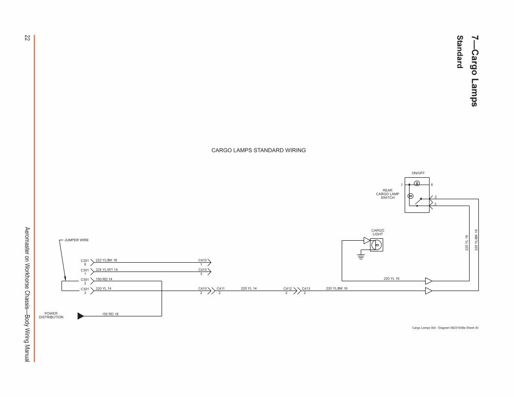
7�C
argo
Lam
ps
Stan
dard
220
YL/
BK
16
220
YL
16
220 YL 16
220 YL/BK 16
REARCARGO LAMP
SWITCH
CARGOLIGHT
JUMPER WIRE
C4132
POWERDISTRIBUTION
1222 YL/BK 18
6C301 C410
220 YL 14222
3
220 YL 14
150 RD 14
224 YL/WT 14
3
C412C411C410
C410
150 RD 18
3
2
C301
C301
1C301
ON/OFF
7
2
8
CARGO LAMPS STANDARD WIRING
Cargo Lamps Std - Diagram 58231008a Sheet 30
23Aerom
aster on Workhorse C
hassis�Body W
iring Manual
7�C
argo
Lam
ps
Sw
itch o
n D
ash
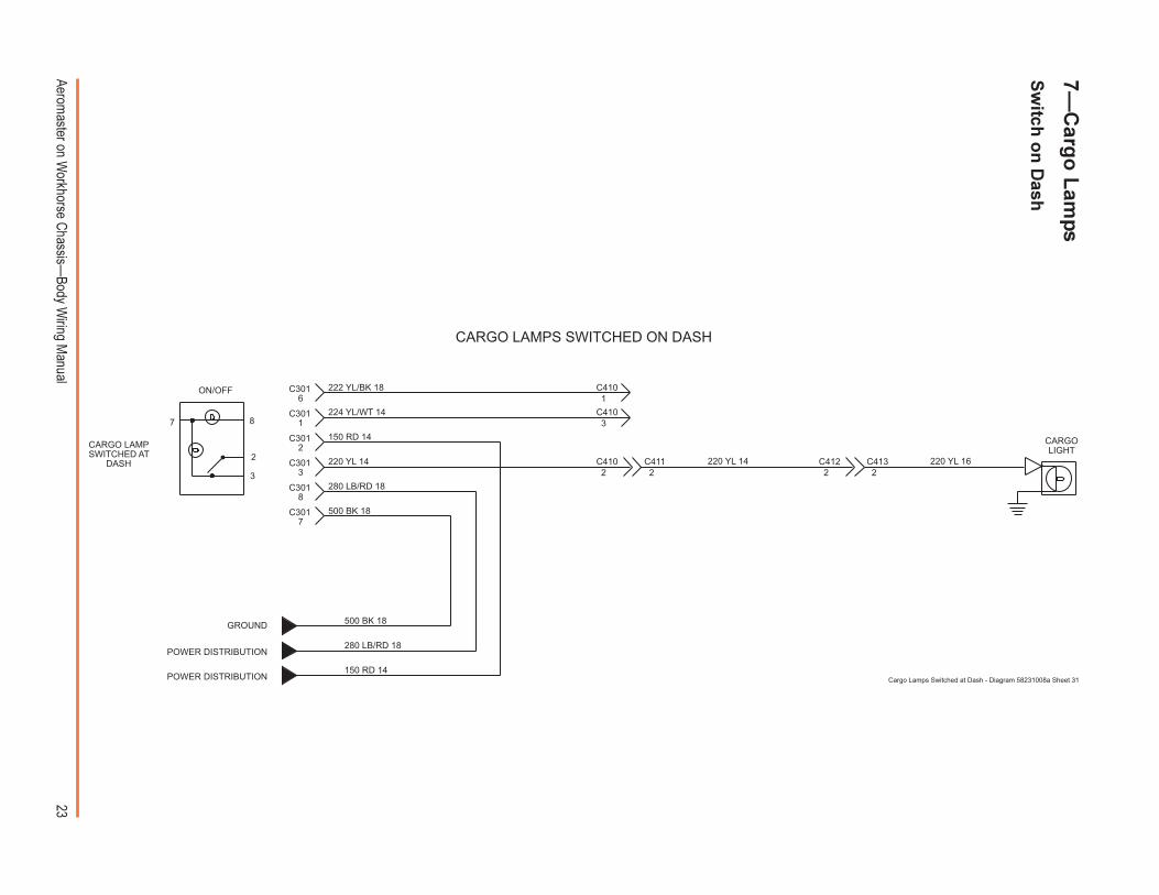
150 RD 14
CARGO LAMPSWITCHED AT
DASH 220 YL 16
7
8
GROUND 500 BK 18
500 BK 18
280 LB/RD 18
280 LB/RD 18
POWER DISTRIBUTION
POWER DISTRIBUTION
C301
C301
CARGOLIGHT
C4132
1222 YL/BK 18
6C301 C410
220 YL 14222
3
220 YL 14
150 RD 14
224 YL/WT 14
3
C412C411C410
C410
3
2
C301
C301
1C301
ON/OFF
7
2
8
CARGO LAMPS SWITCHED ON DASH
Cargo Lamps Switched at Dash - Diagram 58231008a Sheet 31
24Aerom
aster on Workhorse C
hassis�Body W
iring Manual
7�C
argo
Lam
ps
Th
ree-Way S
witch
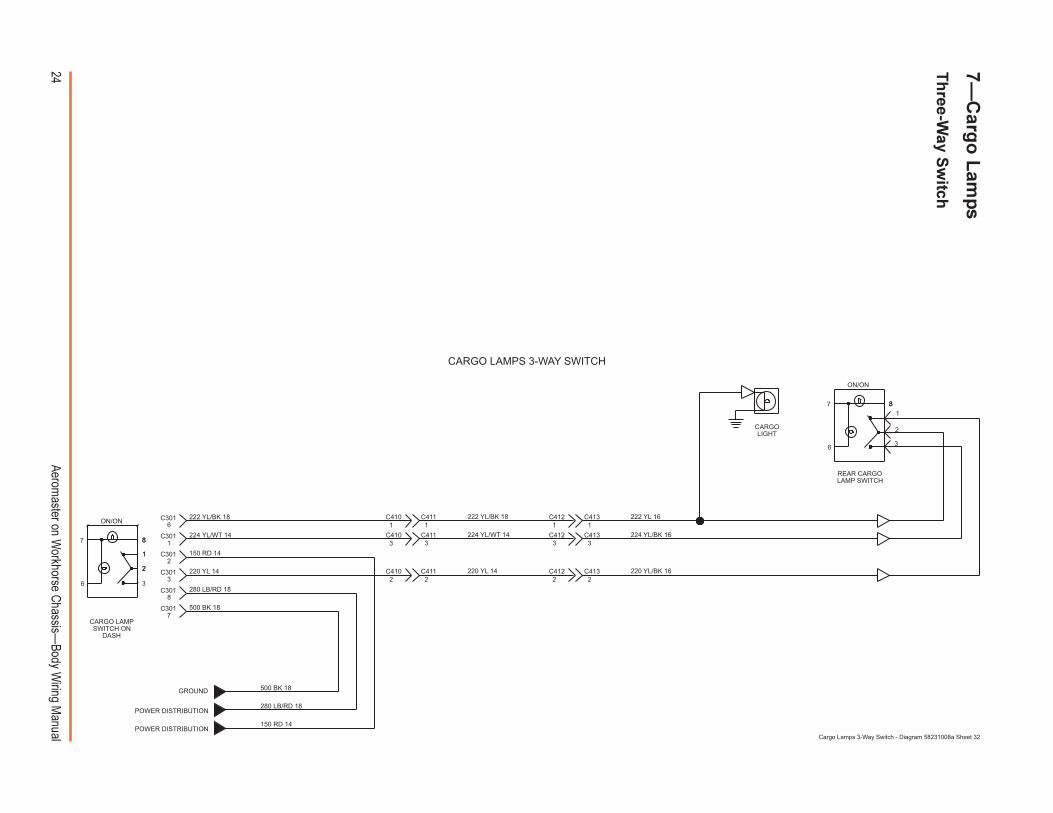
150 RD 14
222 YL 16
224 YL/BK 16
220 YL/BK 16
CARGO LAMPSWITCH ON
DASH
REAR CARGOLAMP SWITCH
7
2
1
88
1
2
3
ON/ON
6
6
ON/ON
1887
1
33
1222 YL/BK 18
224 YL/WT 141
3
C413C412C411
C411 C412 C413
CARGOLIGHT
3
2
7
8
GROUND 500 BK 18
500 BK 18
280 LB/RD 18
280 LB/RD 18
POWER DISTRIBUTION
POWER DISTRIBUTION
C301
C301
C4132
1222 YL/BK 18
6C301 C410
220 YL 14222
3
220 YL 14
150 RD 14
224 YL/WT 14
C412C411C410
C410
3
2
C301
C301
1C301
CARGO LAMPS 3-WAY SWITCH
Cargo Lamps 3-Way Switch - Diagram 58231008a Sheet 32
25Aerom
aster on Workhorse C
hassis�Body W
iring Manual
8�W
iper S
ystem
Stan
dard
and
Cu
mm
ins IS
B4 In
termitten
t
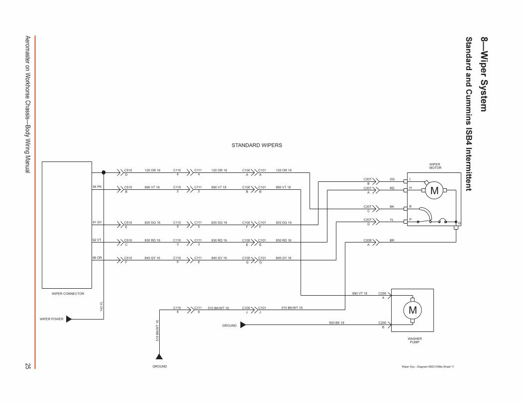
143
YL
510 BK/WT 1688
C111C110
120 OR 16
890 VT 18
820 DG 16
830 RD 16
840 GY 16
2
5
3
66
3
5
2
44
C111
C111
C111
C111C110
C110
C110
C110
C111C110
GROUND
GROUND
510
BK
/WT
16
C101J
510 BK/WT 16
F
C
E
B
D
WIPERMOTOR
RD
BK
YL
BR
DG
B
A
C206
C206
500 BK 18
890 VT 18
C101
C101
C101
C101
C101
840 GY 16
830 RD 16
820 DG 16
890 VT 18
120 OR 16A
B
F
E
G840 GY 16
830 RD 16
820 DG 16
890 VT 18
120 OR 16
P
B
H
G
L
A
C
A
B
C208
C207
C207
C207
C207
C100J
G
E
F
B
A
C100
C100
C100
C100
C100
D
C510
C510
C510
C510
C510
WASHERPUMP
M
M
96 OR
92 VT
91 GY
94 PK
WIPER POWER
Wiper Sys - Diagram 58231008a Sheet 11
STANDARD WIPERS
WIPER CONNECTOR
26Aerom
aster on Workhorse C
hassis�Body W
iring Manual
8�W
iper S
ystem
Interm
ittent O
ptio
n (N
on
-Cu
mm
ins IS
B4)
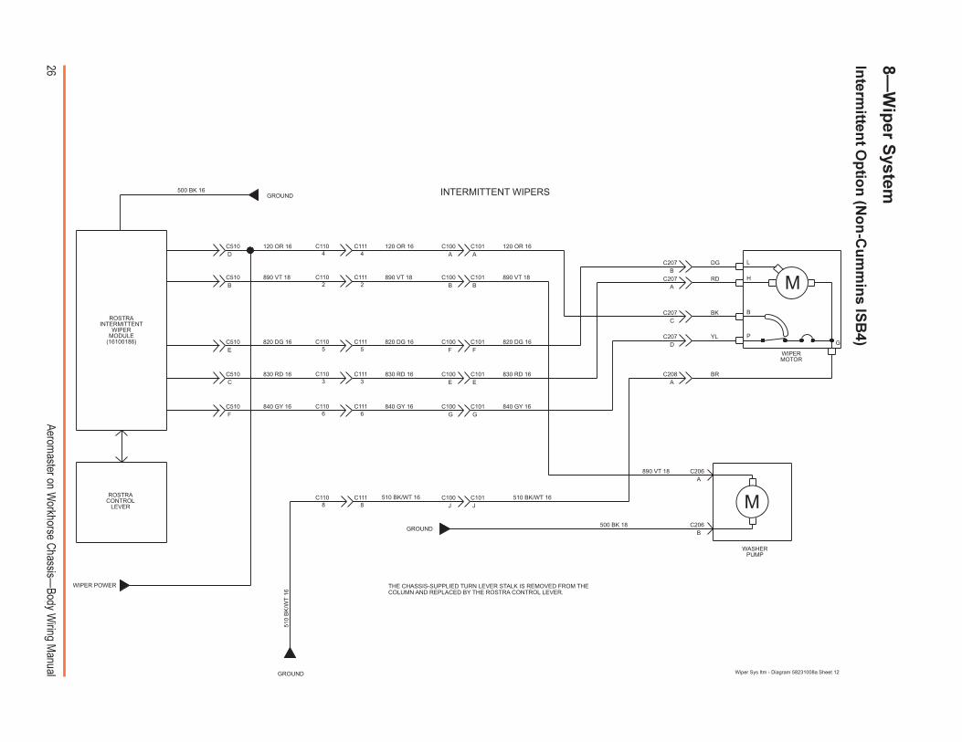
THE CHASSIS-SUPPLIED TURN LEVER STALK IS REMOVED FROM THECOLUMN AND REPLACED BY THE ROSTRA CONTROL LEVER.
88C111C110
120 OR 16
890 VT 18
820 DG 16
830 RD 16
840 GY 16
2
5
3
66
3
5
2
44
C111
C111
C111
C111C110
C110
C110
C110
C111C110
GROUND
GROUND
510
BK
/WT
16
C101J
510 BK/WT 16
F
C
E
B
D
RD
BK
YL
BR
DG
B
A
C206
C206
500 BK 18
890 VT 18
C101
C101
C101
C101
C101
840 GY 16
830 RD 16
820 DG 16
890 VT 18
120 OR 16A
B
F
E
G840 GY 16
830 RD 16
820 DG 16
890 VT 18
120 OR 16
P
B
H
G
L
A
C
A
B
C208
C207
C207
C207
C207
C100J
G
E
F
B
A
C100
C100
C100
C100
C100
D
C510
C510
C510
C510
C510
M
M510 BK/WT 16
500 BK 16GROUND
WIPER POWER
Wiper Sys Itm - Diagram 58231008a Sheet 12
INTERMITTENT WIPERS
WIPERMOTOR
WASHERPUMP
ROSTRACONTROL
LEVER
ROSTRAINTERMITTENT
WIPERMODULE
(16100186)
27Aerom
aster on Workhorse C
hassis�Body W
iring Manual
280 LB/RD 18
GROUND
POWERDISTRIBUTION
HEATER ONLY SYSTEM
C330
C330
C3301
3
4C331
C331
C331
DB 16
BN 16
YL 16
OR 16
BK 12
DB/WT 12
LB 1
6
BK
16
LB 1
6
BK
16
BK
16
OR
/WT
12
DB
16
OR
16
BK
12
OR
/WT
12
DB
/WT
14
530 BK 12
700 DB/WT 12
BK 12
LB 16
DB/WT 12
4
3
1
BLOWERMOTOR
BLOWERMOTOR
RESISTORBLOWERSWITCH
HMLBC
BLOWERMOTORRELAY
87a
87
86
30
85
ILLUMINATION
M
POWERDISTRIBUTION
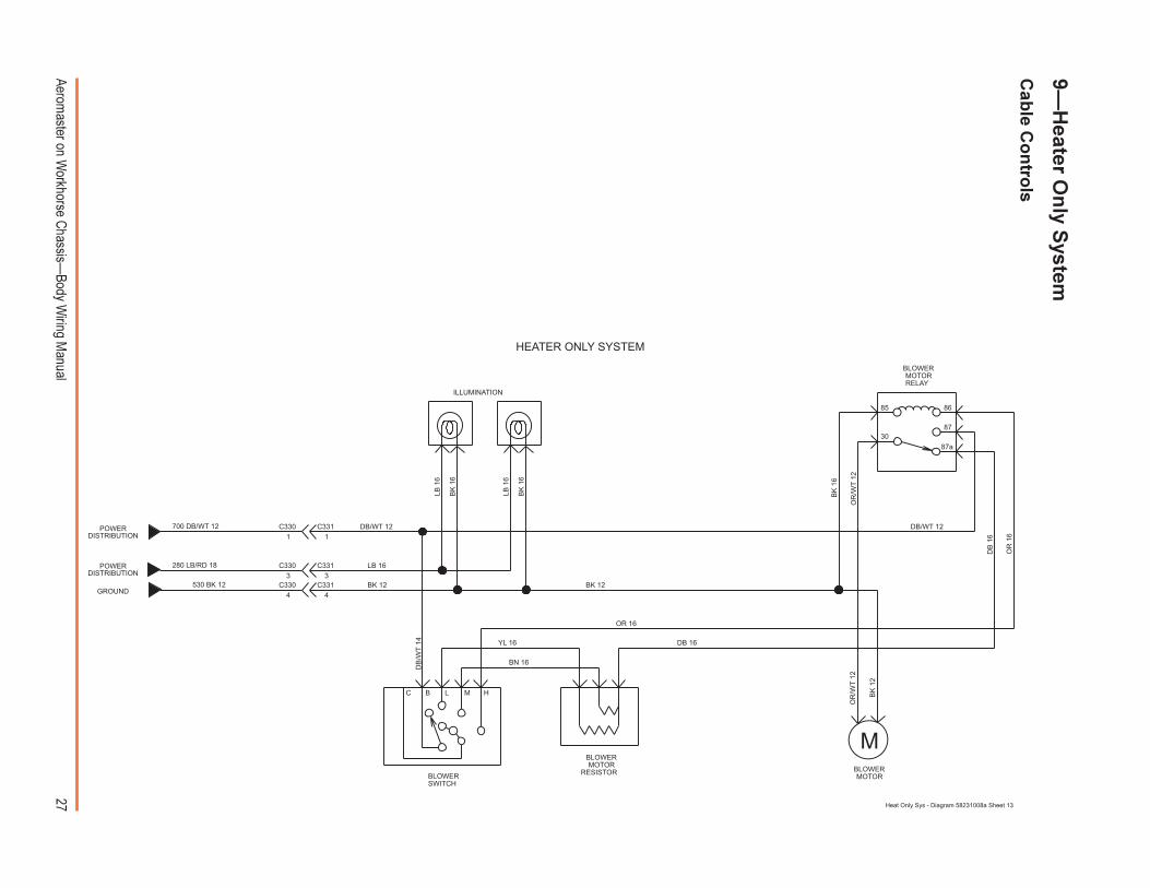
Heat Only Sys - Diagram 58231008a Sheet 13
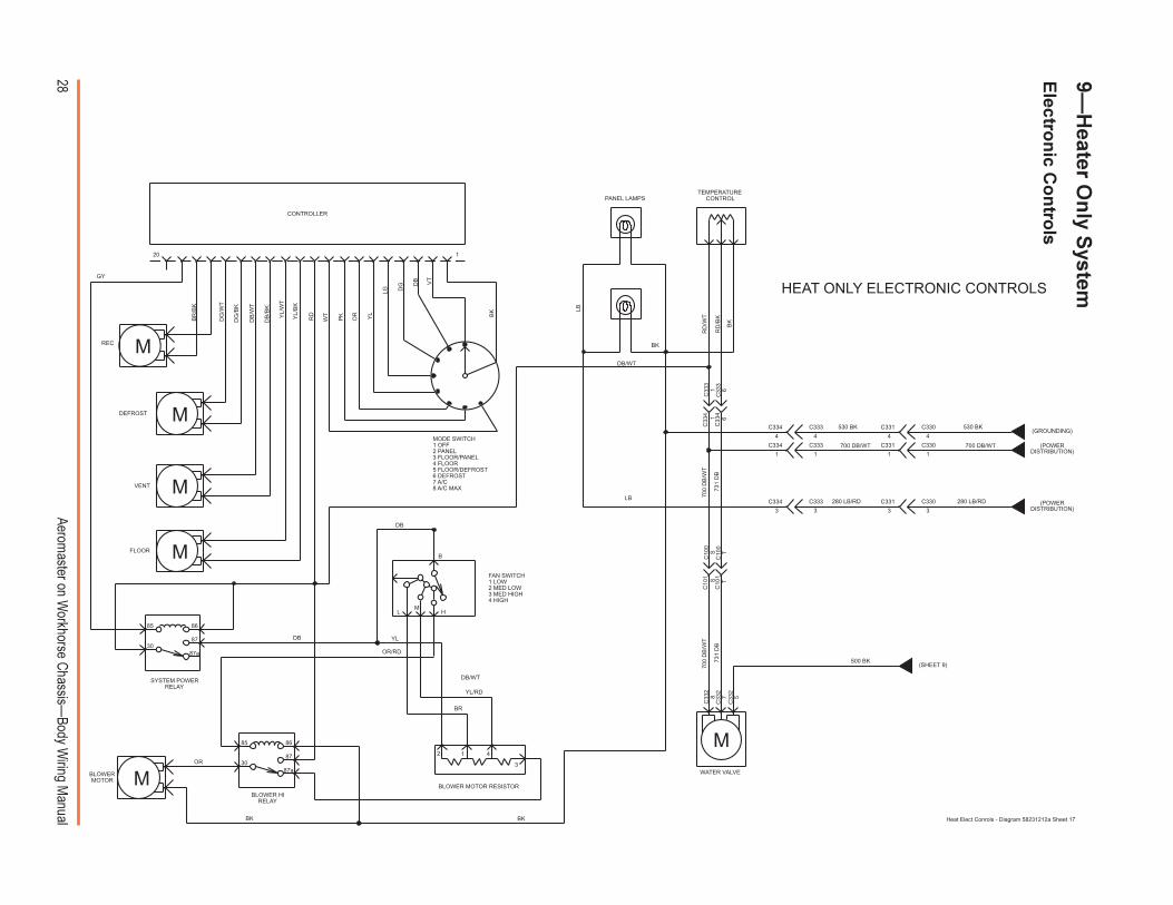
9�H
eater On
ly System
Cab
le Co
ntro
ls
28Aerom
aster on Workhorse C
hassis�Body W
iring Manual
LM
H
B
HEAT ONLY ELECTRONIC CONTROLS
C33
3
C33
3
C33
4
C33
4
4
280 LB/RD
700 DB/WT
530 BK
(POWERDISTRIBUTION)
(GROUNDING)
11
33
C330C331
C330C331
C331 C330
4 4
280 LB/RD
700 DB/WT
530 BK
731
DB
700
DB
/WT
700
DB
/WT
731
DB
500 BK
C334 C333
C334 C333
C334 C333
(SHEET 9)
578
PANEL LAMPSTEMPERATURE
CONTROL
MODE SWITCH1 OFF2 PANEL3 FLOOR/PANEL4 FLOOR5 FLOOR/DEFROST6 DEFROST7 A/C8 A/C MAX
BLOWER HIRELAY
DB
DB
/BK
DB
/WT
DG
/BK
DG
/WT
BLOWER MOTOR RESISTOR
DB/WT
SYSTEM POWERRELAY
M
M
M
M
M
M
66
11
C33
2
C33
2
C33
2
DG
BR
/BK
REC
RD
/BK
11
SS
TT
WATER VALVEBLOWERMOTOR
120
BK
DB/WT
LB
33
C10
0
C10
0
C10
1
C10
1
CONTROLLER
VENT
DEFROST
FLOOR
BK
2 1 4
3OR
GYY
L/W
T
YL/
BK
RD
WT
PK
OR YL
LG
VT
BK
RD
/WT
BK
YL/RD
BR
YL
BK
LB
85
30
86
87
87a
85
30
86
87
87a
DB
OR/RD
DB
4
FAN SWITCH1 LOW2 MED LOW3 MED HIGH4 HIGH
Heat Elect Conrols - Diagram 58231212a Sheet 17
(POWERDISTRIBUTION)
9�H
eater On
ly System
Electro
nic C
on
trols
29Aerom
aster on Workhorse C
hassis�Body W
iring Manual
TO COMPRESSOR
GROUND
POWERDIST
GY 18DG 18C209
C10
1C
C330
C330
C330
C3301
2
3
4C331
C331
C331
C331
710
DG
18
DB 16
BN 16
YL 16
OR 16
DG 16
BK 12
DB/WT 12
LB 1
6
BK
16
LB 1
6
BK
16
DG
16
DG
16
DG
16
DG
16
BK
16
BK
16
OR
/WT
12
DB
16
OR
16
BK
12
OR
/WT
12
DB
/WT
14
CC
100
A
530 BK 12
280 LB/RD 16
700 DB/WT 12
BK 12
LB 16
DG 18
DB/WT 12
4
3
2
1
BLOWERMOTOR
BLOWERMOTOR
RESISTORBLOWERSWITCH
A/CSWITCH
THERMOSWITCH
HMLBC
HI/LO PRESSURESWITCH
BLOWERMOTORRELAY
87a
87
86
30
85
ILLUMINATION
M
HVAC SYSTEM
POWERDIST
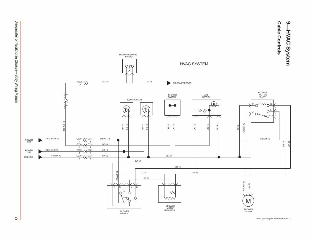
HVAC Sys - Diagram 58231008a Sheet 14
9�H
VA
C S
ystem
Cab
le Co
ntro
ls
30Aerom
aster on Workhorse C
hassis�Body W
iring Manual
LM
H
B
715 OR/WT
280 LB/RD
700 DB/WT
530 BK
55
C331 C330
11
33
C330C331
C330C331
C331 C330
4 4(GROUND)
(POWERDISTRIBUTION)
731
DB
700
DB
/WT
731
DB
700
DB
/WT
C33
4
C33
4
C33
3
C33
3
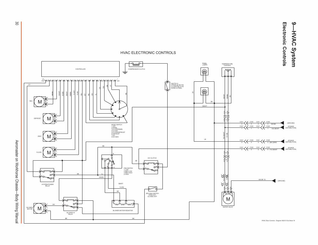
HVAC ELECTRONIC CONTROLS
578
PANEL LAMPS
SWITCH AOPENS @ 460 PSICLOSES @ 22 PSINORM CLOSED
TEMPERATURECONTROL
MODE SWITCH1 OFF2 PANEL3 FLOOR/PANEL4 FLOOR5 FLOOR/DEFROST6 DEFROST7 A/C8 A/C MAX
87a
87
86
30
85
BLOWER HIRELAY
DB
DB
/BK
DB
/WT
DG
/BK
DG
/WT
BLOWER MOTOR RESISTOR
DB/WT
COMPRESSOR CLUTCH
SYSTEM POWERRELAY
M
M
M
M
M
M
55
C331 C330
A/C CLUTCH
66
11
C33
2
C33
2
C33
2
DE-ICING SWITCHOPEN 29°F
CLOSED 35°F
DG
BR
/BK
REC
DB
RD
/BK
11
500 BK 18
SS
TT
WATER VALVEBLOWERMOTOR
120
BK
DB/WT
LB
33
C330C331
C10
0
C10
0
C10
1
C10
1
CONTROLLER
VENT
DEFROST
FLOOR
BK
2 1 4
3OR
GY
YL/
WT
YL/
BK
RD
WT
PK
OR YL
LG
VT
BK
RD
/WT
BK
YL/RD
BR
YL
BK
LB
85
30
86
87
87a
85
30
86
87
87a
DB
OR/RD
DB
C330C331
C331 C330
4 4
(POWERDISTRIBUTION)
(POWERDISTRIBUTION)
(GROUND)
FAN SWITCH1 LOW2 MED LOW3 MED HIGH4 HIGH
HVAC Elect Controls - Diagram 58231212a Sheet 18
9�H
VA
C S
ystem
Electro
nic C
on
trols

31Aerom
aster on Workhorse C
hassis�Body W
iring Manual
A/C CMPR HIGH PRESSCUTOFF SW
203
LT BLU 0.8
762762
450
459
C119
BODY BUILDERCONNECTOR
(L57/NB6)
BODY BUILDERCONNECTOR
(SHEET 14)(L31/L35)
603 (L31/L35)DK GRN 0.8
250
BLK .08TO VCM J3-30 (L31/L35)
A/C CMPRREFRIG PRESS
SWITCH
A B
C118 C118
DENOTES MECHANICAL DIESEL ONLY
E.D. DENOTES ELECTRONIC DIESEL
C118C118
C115
C115C115
C119
C119
C119
C119
C119
A/C CMPRCLU COIL
BLK .08
250
59
DK GRN 0.8
B
C166
C166
A
899
899
250
BLK .08
250 (L57)
BLK 0.8
59DK GRN 0.8
86
86
85
85
8730
A/C CMPRRELAY
39 (L31/L35)
PINK 0.8
540
ORN 0.8
DK GRN/WHT 0.8
762 (L57)
DK GRN/WHT 0.8
DK GRN/WHT 0.8
1.1 K OHM (L31/L35).75 W
899899
BLK 0.8
B
B
DK GRN/WHT 0.8
922GRA 0.8
B AA
A/C CMPRREFRIG PRESS
SWITCH
15A "ENG-BAT" FUSE
20A "GAUGE" FUSE
TO VCM J3-1(L31/L35)J3-5(E.D. L57/NB6)
TO VCM J3-25 (L31/L35)J1-2 (E.D. L57/NB6)
(GM FORMAT)
CHASSIS SUPPIED A/C PREP PACKAGE
Chasis Prep AC - Diagram 58231008a Sheet 15
10�C
hassis S
up
plied
A/C
Prep

32Aerom
aster on Workhorse C
hassis�Body W
iring Manual
11�F
ron
t Lig
ht W
iring
With
Cu
mm
ins IS
B4 D
iesel En
gin
es
HEADLAMPFEED CONNECTION
B
C
FORWARD LAMP WIRING (W/DRL CANADA)
FF
F
E
D
C
B
A
239 DB 16239 DB 16D
242 RD/BK 16D
C204 C205
239 DB 16C200
GROUNDING
A
B
A
LEFTHEADLAMPA
235 GY 18
235 GY 18
C711
233 GY 18
233 GY 18
C710
233 GY 18
C203
C203
C203
C203
C203
B
E
A
C
D
C202
C202
C202
C202
C202
235 GY 18
C205
C205
C205
C205
C205
C204
C204
C204
C204
C204B
E
A
C
C711
C711
C710
C710
230 BR 18
230 BR 18
500 BK 18
240 LG/BK 16
242 RD/BK 16
242 RD/BK 16
240 LG/BK 18
500 BK 18
230 BR 18
500 BK 16
230 BR 18
500 BK 16C
A
B
C
AC714
C714
C712
C712
C712
CC713
C713
C713
AC715
C715
B
B
B
500 BK 16
230 BR 18
500 BK 16
240 LG/BK 18
242 RD/BK 16
240 LG/BK 18
230 BR 18
D
C
A
E
B
C
A
E
B
230 BR 18
233 DG 18
240 LG/BK 18
242 RD/BK 16
C200
C200
C200
C200
C200 235 YL 18
RIGHTSIDEMARKER
RIGHTTURN SIGNAL
RIGHTHEADLAMP
LEFTTURN SIGNAL
LEFTSIDEMARKER
Forward Lamp Wiring (Canadian DRL) - Diagram 58231008a Sheet 17
NO
TE: This schem
atic is for all vehiclesw
ith the Cum
mins ISB
4 diesel engine.F
or domestic vehicles w
ithout the ISB-4
engine, see the following pages. To
identify the engine of a vehicle, see page6. (This is schem
atic is also the same
one used in all Canadian vehicles.)
33Aerom
aster on Workhorse C
hassis�Body W
iring Manual
11�F
ron
t Lig
ht W
iring
With
ou
t Daytim
e Ru
nn
ing
Lig
hts
B
C
FORWARD LAMP WIRING (W/O DRL)
GROUNDING
HEADLAMPFEED CONNECTION
A
B
A
LEFTHEADLAMPA
235 GY 18
235 GY 18
C711
233 GY 18
233 GY 18
C710
233 GY 18
C203
C203
C203
C203
C203
B
E
A
C
D
C202
C202
C202
C202
C202
235 GY 18
C205
C205
C205
C205
C205
C204
C204
C204
C204
C204B
E
A
C
D
C711
C711
C710
C710
230 BR 18
230 BR 18
500 BK 18
240 LG/BK 16
242 RD/BK 16
242 RD/BK 16
500 BK 16
240 LG/BK 18
500 BK 18
230 BR 18
500 BK 16
230 BR 18
500 BK 16C
A
B
C
AC714
C714
C712
C712
C712
CC713
C713
C713
AC715
C715
B
B
B
500 BK 16
230 BR 18
500 BK 16
240 LG/BK 18
242 RD/BK 16
240 LG/BK 18
242 RD/BK 16
230 BR 18
D
C
A
E
B
D
C
A
E
B
230 BR 18
233 DG 18
240 LG/BK 18
242 RD/BK 16
C200
C200
C200
C200
C200 235 YL 18
RIGHTSIDEMARKER
RIGHTTURN SIGNAL
RIGHTHEADLAMP
LEFTTURN SIGNAL
LEFTSIDEMARKER
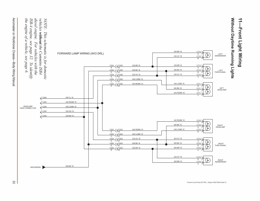
Forward Lamp Wiring W/O DRL - Diagram 58231008a Sheet 16
NO
TE: This schem
atic is for domestic
vehicles without the C
umm
ins ISB4
diesel engine. For vehicles w
ith theISB
-4 engine, see page 32. To identifythe engine of a vehicle, see page 6.
34Aerom
aster on Workhorse C
hassis�Body W
iring Manual
11�F
orw
ard L
igh
t Wirin
g
Daytim
e Ru
nn
ing
Lig
hts (D
om
estic)
DD
GROUND
BATT PWR
IGN PWR
C
B
FORWARD LAMP WIRING (W/DRL-DOMESTIC)
BK
DGS S
C101
C101
C100
C100
WT
OR
BAC
210
C21
0
RDDRL
MODULE(16511938)
GROUNDING
HEADLAMPFEED CONNECTION
A
B
A
LEFTHEADLAMPA
235 GY 18
235 GY 18
C711
233 GY 18
233 GY 18
C710
233 GY 18
C203
C203
C203
C203
C203
B
E
A
C
D
C202
C202
C202
C202
C202
235 GY 18
C205
C205
C205
C205
C205
C204
C204
C204
C204
C204B
E
A
C
D
C711
C711
C710
C710
230 BR 18
230 BR 18
500 BK 18
240 LG/BK 16
242 RD/BK 16
242 RD/BK 16
500 BK 16
240 LG/BK 18
500 BK 18
230 BR 18
500 BK 16
230 BR 18
500 BK 16C
A
B
C
AC714
C714
C712
C712
C712
CC713
C713
C713
AC715
C715
B
B
B
500 BK 16
230 BR 18
500 BK 16
240 LG/BK 18
242 RD/BK 16
240 LG/BK 18
242 RD/BK 16
230 BR 18
D
C
A
E
B
D
C
A
E
B
230 BR 18
233 DG 18
240 LG/BK 18
242 RD/BK 16
C200
C200
C200
C200
C200 235 YL 18
RIGHTSIDEMARKER
RIGHTTURN SIGNAL
RIGHTHEADLAMP
LEFTTURN SIGNAL
LEFTSIDEMARKER
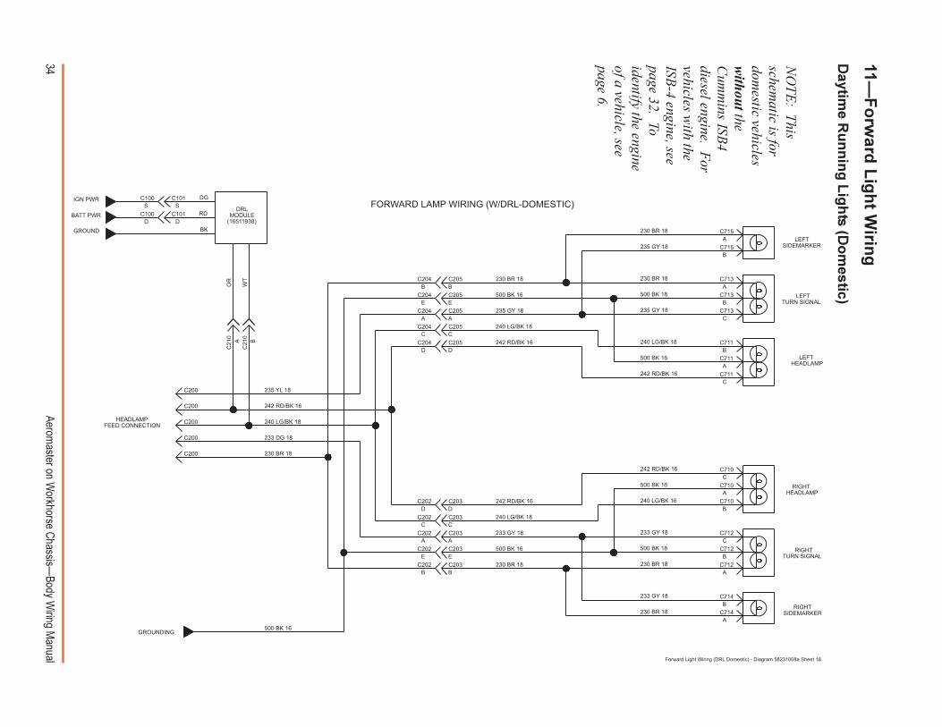
Forward Light Wiring (DRL Domestic) - Diagram 58231008a Sheet 18
NO
TE: This
schematic is for
domestic vehicles
without the
Cum
mins ISB
4diesel engine. F
orvehicles w
ith theISB
-4 engine, seepage 32. Toidentify the engineof a vehicle, seepage 6.
35Aerom
aster on Workhorse C
hassis�Body W
iring Manual
11�F
orw
ard L
igh
t Wirin
g
Daytim
e Ru
nn
ing
Lig
hts (C
anad
ian)
HEADLAMPFEED CONNECTION
B
C
FORWARD LAMP WIRING (W/DRL CANADA)
FF
F
E
D
C
B
A
239 DB 16239 DB 16D
242 RD/BK 16D
C204 C205
239 DB 16C200
GROUNDING
A
B
A
LEFTHEADLAMPA
235 GY 18
235 GY 18
C711
233 GY 18
233 GY 18
C710
233 GY 18
C203
C203
C203
C203
C203
B
E
A
C
D
C202
C202
C202
C202
C202
235 GY 18
C205
C205
C205
C205
C205
C204
C204
C204
C204
C204B
E
A
C
C711
C711
C710
C710
230 BR 18
230 BR 18
500 BK 18
240 LG/BK 16
242 RD/BK 16
242 RD/BK 16
240 LG/BK 18
500 BK 18
230 BR 18
500 BK 16
230 BR 18
500 BK 16C
A
B
C
AC714
C714
C712
C712
C712
CC713
C713
C713
AC715
C715
B
B
B
500 BK 16
230 BR 18
500 BK 16
240 LG/BK 18
242 RD/BK 16
240 LG/BK 18
230 BR 18
D
C
A
E
B
C
A
E
B
230 BR 18
233 DG 18
240 LG/BK 18
242 RD/BK 16
C200
C200
C200
C200
C200 235 YL 18
RIGHTSIDEMARKER
RIGHTTURN SIGNAL
RIGHTHEADLAMP
LEFTTURN SIGNAL
LEFTSIDEMARKER
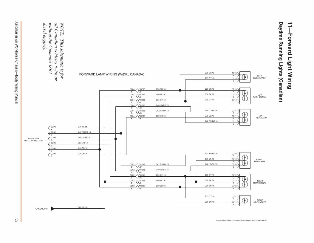
Forward Lamp Wiring (Canadian DRL) - Diagram 58231008a Sheet 17
NO
TE: This schem
atic is forall C
anadian vehicles (with or
without the C
umm
ins ISB4
diesel engine).
36Aerom
aster on Workhorse C
hassis�Body W
iring Manual
500
BK
18
230
BR
18
LICENSE PLATELAMP(OPTION)
LICENSE PLATELAMP(OPTION)
BACK-UPALARM
(OPTION)
AC623
230 BR 18
LICENSEPLATELAMP
C622
C621
C620
LICENSEPLATELAMP
A230 BR 18
500 BK 16
500 BK 18
REAR LAMP WIRING - STANDARD
C
A
B
C
C
B
A
C
C638
C638
C637
C637
C637238 GY 18
C636
C636
C635
C635
C635232 GY 18C632
C632
C632
C632A
C
B
E232 GY 18C631
C631
C631
C631
C631
238 GY 18
C634
C634
C634
C634E
B
C
AC633
C633
C633
C633
C633
C610
C610
C610
C610
C610
RIGHTSTOP/TURN/TAIL
LAMP
C
F
A
G
B
REAR LAMPFEED CONNECTION
238 YL 18
500 BK 18
230 BR 18
236 LG 18
234 RD 18A
C
B
E
236 LG 18
230 BR 18
500 BK 18B
236 LG 18
500 BK 18
230 BR 18
230 BR 18
230 BR 18
230 BR 18
500 BK 18
236 LG 18
A
A
500 BK 18
230 BR 18
236 LG 18
E
B
C
A
232 DG 18
500 BK 18
230 BR 18
236 LG 18
234 RD 18
232 DG 18
234 RD 16
230 BR 16
236 LG 16
238 YL 18
GROUNDTO FRAME
RAIL
RIGHTBACK-UP
LAMP
LEFTBACK-UP
LAMP
LEFTSTOP/TURN/TAIL
LAMP
500 BK 18
500 BK 18
B
D
D
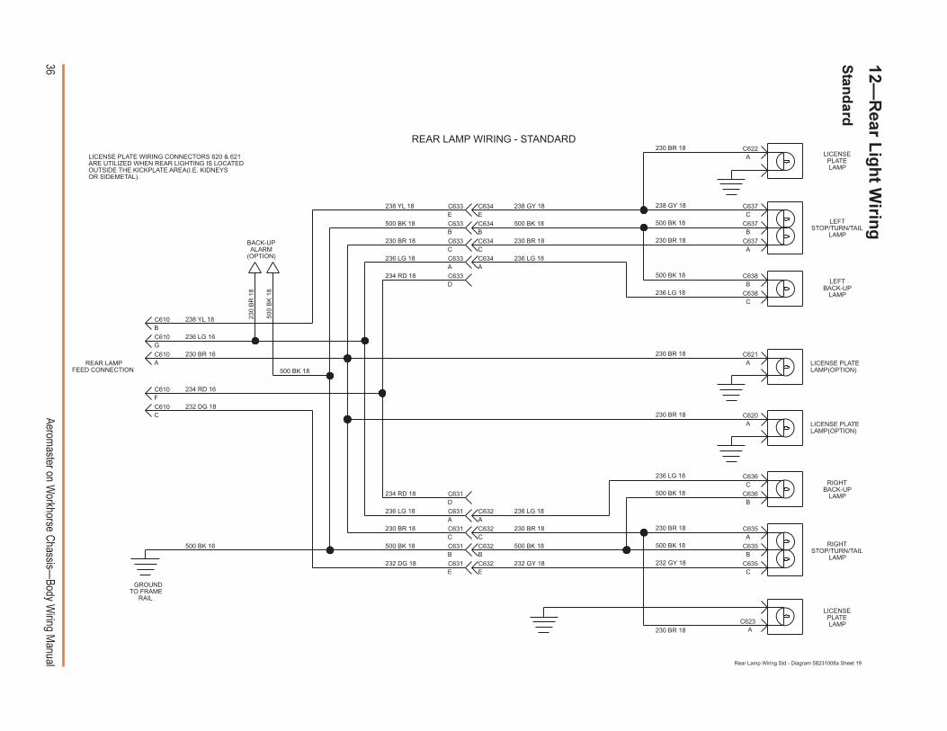
LICENSE PLATE WIRING CONNECTORS 620 & 621ARE UTILIZED WHEN REAR LIGHTING IS LOCATEDOUTSIDE THE KICKPLATE AREA(I.E. KIDNEYSOR SIDEMETAL).
Rear Lamp Wiring Std - Diagram 58231008a Sheet 19
12�R
ear Lig
ht W
iring
Stan
dard

37Aerom
aster on Workhorse C
hassis�Body W
iring Manual
234 RD 16 CHMSL LAMP(OPTIONAL)
238 YL 18
232 DG 18
500 BK 16
232 DG 16
500 BK 16
238 YL 16
SEE SHMSL
CHASSIS COWLCONNECTOR
238 YL 16
232 DG 16
18 YL
19 DG
9 BR
236 LG 16
238 YL 18
236 LG 16
230 BR 16
234 RD 16
232 DG 18
C412
C418
C418
C418
C418
C418
13
2
5
3
6
1 1
6
3
5
2
C419
C419
C419
C419
C419
LICENSE PLATE LOCATEDIN KICK PLATE
J
K
L
M
N
P
A
B
C
D
E
F
G
H
123654
CHASSIS IPHARNESS
C101C100
O OTRANSMISSION
SWITCH
230 BR
16
230 BR 16
GROUNDTO BODY
13C413
500 BK
230 BR 16
234 RD 16
230 BR 16
236 LG 16
REAR LAMP WIRING (ROUTED THROUGH INTERIOR)
HIGH MOUNTLICENSE PLATE
GROUND
C621C620
500 BK 18
C
A
B
C
C
B
A
C
C638
C638
C637
C637
C637
C636
C636
C635
C635
C635
RIGHTSTOP/TURN/TAIL
LAMP
238 YL 18
500 BK 18
230 BR 18
236 LG 18
B
236 LG 18
500 BK 18
230 BR 18
230 BR 18
500 BK 18
236 LG 18
232 DG 18
500 BK 18
230 BR 18
236 LG 18
232 DG 18
234 RD 16
230 BR 16
236 LG 16
238 YL 18
RIGHTBACK-UP
LAMP
LEFTBACK-UP
LAMP
LEFTSTOP/TURN/TAIL
LAMP
500 BK 18
500 BK 18
B
Rear Lamps Thru Interior - Diagram 58231008a Sheet 20
12�R
ear Lig
ht W
iring
Ro
uted
thro
ug
h In
terior
38Aerom
aster on Workhorse C
hassis�Body W
iring Manual
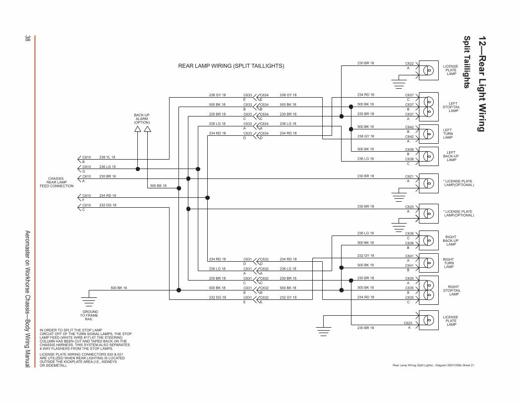
REAR LAMP WIRING (SPLIT TAILLIGHTS)
* LICENSE PLATELAMP(OPTIONAL)
* LICENSE PLATELAMP(OPTIONAL)
C641
C641
C642
C642
234 RD 18
232 GY 18
234 RD 18
238 GY 18E
D
E
D234 RD 18
238 GY 18
238 GY 18
234 RD 18
236 LG 18
C634
LEFTSTOP/TAIL
LAMP
LEFTTURNLAMP
A
LEFTBACK-UP
LAMP
500 BK 18 C638
C638C
B
234 RD 18DC632 A
B
RIGHTSTOP/TAIL
LAMP
RIGHTTURNLAMP
RIGHTBACK-UP
LAMP
236 LG 18
500 BK 18 C636
C636
B
C
BACK-UPALARM
(OPTION)
AC623
230 BR 18
LICENSEPLATELAMP
C622
C621
C620
LICENSEPLATELAMP
A230 BR 18
500 BK 16
500 BK 18
C
A
B
A
C
C637
C637
C637
C635
C635
C635C632
C632
C632
C632A
C
B
E232 GY 18C631
C631
C631
C631
C631
C634
C634
C634
C634
B
C
AC633
C633
C633
C633
C633
C610
C610
C610
C610
C610
C
F
A
G
B
500 BK 18
230 BR 18
236 LG 18A
C
B
236 LG 18
230 BR 18
500 BK 18B
500 BK 18
230 BR 18
230 BR 18
230 BR 18
230 BR 18
500 BK 18
A
A
500 BK 18
230 BR 18
236 LG 18
E
B
C
A
232 DG 18
500 BK 18
230 BR 18
236 LG 18
234 RD 18
232 DG 18
234 RD 16
230 BR 16
236 LG 16
238 YL 18
GROUNDTO FRAME
RAIL
500 BK 18
500 BK 18
B
D
LICENSE PLATE WIRING CONNECTORS 620 & 621ARE UTILIZED WHEN REAR LIGHTING IS LOCATEDOUTSIDE THE KICKPLATE AREA (I.E., KIDNEYSOR SIDEMETAL).
IN ORDER TO SPLIT THE STOP LAMPCIRCUIT OFF OF THE TURN SIGNAL LAMPS, THE STOPLAMP FEED (WHITE WIRE #17) AT THE STEERINGCOLUMN HAS BEEN CUT AND TAPED BACK ON THECHASSIS HARNESS. THIS SYSTEM ALSO SEPARATES4-WAY FLASHERS FROM THE STOP LAMPS.
CHASSISREAR LAMP
FEED CONNECTION
Rear Lamp Wiring (Split Lights) - Diagram 58231008a Sheet 21
12�R
ear Lig
ht W
iring
Sp
lit Tailligh
ts
39Aerom
aster on Workhorse C
hassis�Body W
iring Manual
232 DG 18
238 YL 18
238 YL 18
500 BK 16
CHASSIS COWLCONNECTOR
18 YL
19 DG
9 BR
238 YL 16
232 DG 16
236 LG 16
238 YL 16
500 BK 16
232 DG 16
SHMSL
238 YL 18
236 LG 16
230 BR 16
234 RD 16
232 DG 18
C412
C418
C418
C418
C418
C418
234 RD 16
13
2
5
3
6
1 1
6
3
5
2
C419
C419
C419
C419
C419
CHASSIS
IP HARNESS
J
K
L
M
N
P
A
B
C
D
E
F
G
H
123654
C101C100
O OTRANSMISSION
SWITCH
230 BR 16
500 BK
230 BR 16
234 RD
16
SHMSL LAMP(OPTION)
13C413
230 BR 16
230 BR 16
236 LG 16
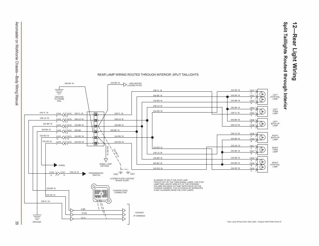
REAR LAMP WIRING ROUTED THROUGH INTERIOR -SPLIT TAILLIGHTS
GROUND
LICENSE PLATE LOCATEDIN KICK PLATE
HIGH MOUNTLICENSE PLATE
C621C620
500 BK 18
GROUNDTO FRAME
RAIL
232 DG 18
234 RD 16
230 BR 16
236 LG 16
238 YL 18
C641
C641
C642
C642
234 RD 18
234 RD 18
234 RD 18
236 LG 18
LEFTSTOP/TAIL
LAMP
LEFTTURNLAMP
A
LEFTBACK-UP
LAMP
500 BK 18 C638
C638C
B
A
B
RIGHTSTOP/TAIL
LAMP
RIGHTTURNLAMP
RIGHTBACK-UP
LAMP
236 LG 18
500 BK 18 C636
C636
B
C
C
A
B
A
C
C637
C637
C637
C635
C635
C635
500 BK 18
230 BR 18
236 LG 18
B
500 BK 18
230 BR 18
230 BR 18
500 BK 18
232 DG 18
500 BK 18
230 BR 18
236 LG 18
234 RD 18
500 BK 18
500 BK 18
B
IN ORDER TO SPLIT THE STOP LAMPCIRCUIT OFF OF THE TURN SIGNAL LAMPS, THE STOPLAMP FEED (WHITE WIRE #17) AT THE STEERINGCOLUMN HAS BEEN CUT AND TAPED BACK ON THECHASSIS HARNESS. THIS SYSTEM ALSO SEPARATES4-WAY FLASHERS FROM THE STOP LAMPS.
Rear Lamp Wiring Interior Split Lights - Diagram 58231008a Sheet 22
12�R
ear Lig
ht W
iring
Sp
lit Tailligh
ts Ro
uted
thro
ug
h In
terior
40Aerom
aster on Workhorse C
hassis�Body W
iring Manual
13�R
oo
f Wirin
g
6
220 YL/BK 16
220
YL/
BK
16
220
YL
1613
350 BK 167
8
5
4
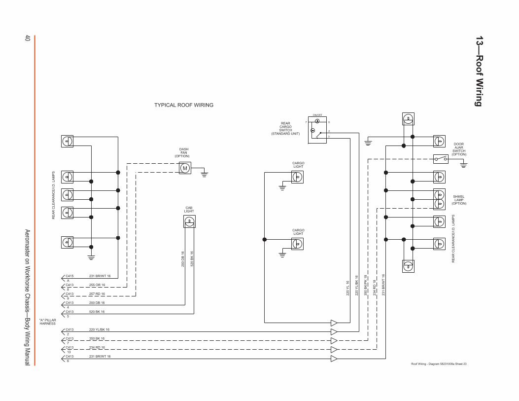
TYPICAL ROOF WIRING
REARCARGOSWITCH
(STANDARD UNIT)
8
2
7
ON/OFF
3
520
BK
16
200
DB
16
520 BK 16
200 DB 16
C413
C413
DASHFAN
(OPTION)
SHMSLLAMP
(OPTION)
DOORAJAR
SWITCH(OPTION)
234 RD 16
257 RD 16
255 OR 16
C413
C413
C413
C413
C413
C413
C415
231
BR
/WT
16
234
RD
18
350
BK
/PK
18
"A" PILLARHARNESS
231 BR/WT 16
231 BR/WT 16
M
2
9
A
RE
AR
CLE
AR
AN
CE
/I.D
. LA
MP
S
RE
AR
CLE
AR
AN
CE
/I.D
. LA
MP
S
CARGOLIGHT
CABLIGHT
CARGOLIGHT
Roof Wiring - Diagram 58231008a Sheet 23
41Aerom
aster on Workhorse C
hassis�Body W
iring Manual
231 BR
/WT 14
231 BR/WT 18
170 RD 14
231 BR/WT 18
GROUND
CLEARANCELIGHT
SIGNAL
ROOF WIRING
55C112C113
C410C4116 66
231 BR/WT 14
500 BK 18
AC414
C412
POWERDISTRIBUTION
86 87a 85
87
30
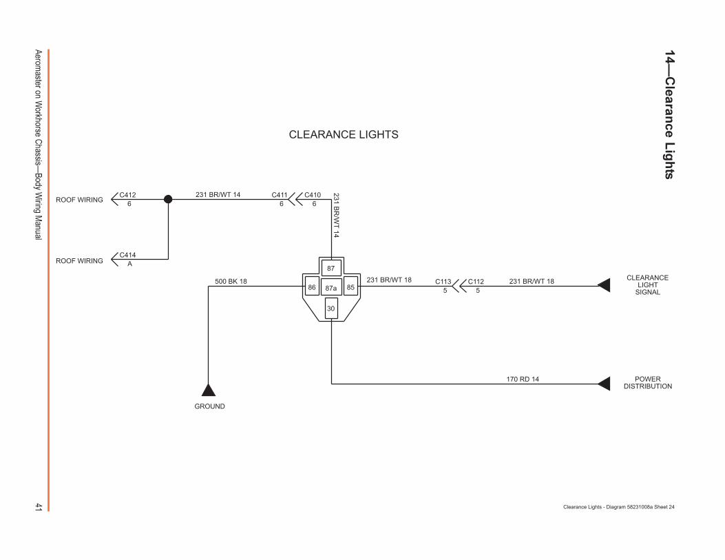
CLEARANCE LIGHTS
ROOF WIRING
Clearance Lights - Diagram 58231008a Sheet 24
14�C
learance L
igh
ts

42Aerom
aster on Workhorse C
hassis�Body W
iring Manual
PANEL LAMPSC301
4
C3304
C331
500 BK
18
C303
C3313
C330
3
8
8
8
4C112
4C113280 LB/RD 18
(AUX. SW #1)
(AUX. SW #2)
(AUX. SW #3)
GROUND
280 LB/RD 18
280 LB/RD 18
280 LB/RD 18
C302
C301
C302
C303
7
7
7
530 BK 18
HVAC PANELILLUMINATION
GROUND
Panel Lamps - Diagram 58231008a Sheet 25
PANEL LAMPS15�
Pan
el Lig
hts (H
VA
C C
on
trol P
anel)
43Aerom
aster on Workhorse C
hassis�Body W
iring Manual
180 PK 16
STEREO OPT
BKBK
GY
180 PK/BK 18
BK/WT
DB
BK/WT
DG
RD
PK/BK
LEFTSPKR
RIGHTSPKR
LEFTSPKR
RIGHTSPKR
STEREO STD
C413
C41315
10
BK
WT
150 RD 16 YL
RD
BK
C111C1101010
151515
10C411
15
10C412 C413
C413C412C411
C410
C410
180 PK 16
150 RD 16
99
22C113C112150 RD 14
CHASSIS FUSE BLOCK
CBBATT
BRNWHT BLU GRN AU
GRN REDBLUWHT BRNX
WHTWHT
PWRIGN HTRACC
30APWR
25AHTR
10AACC-RADIO
20AECM-BAT
15AHORN/DM
15ATURN-BU
15A1-3
15AENG-BAT
20ATAIL LPS
20AGAUGES
30AAUX.
25WIPER
15STP/HZD
20AECM-1
5AINST-LPS
20AENG-1
10ATRANS FUSE/PLR
GRY
GRY
TURNFLASHER
RED
REDGRNBRN
STEREO SYSTEM WIRING
Stereo Sys - Diagram 58231008a Sheet 26
16�S
tereo S
ystem
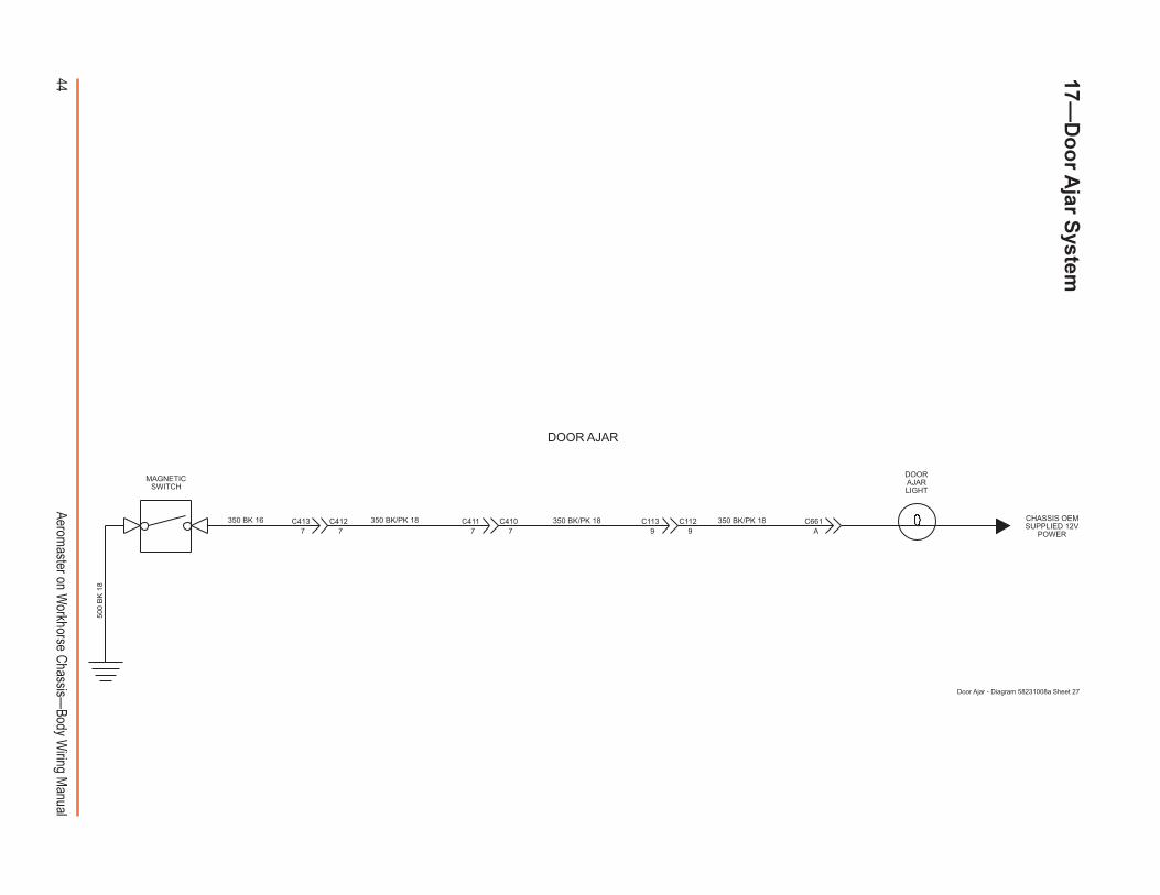
44Aerom
aster on Workhorse C
hassis�Body W
iring Manual
17�D
oo
r Ajar S
ystem
350 BK/PK 18A
C66199
C112C1137 7 7 7
350 BK/PK 18350 BK 16 C412C413 C410C411 CHASSIS OEMSUPPLIED 12V
POWER
DOORAJARLIGHT
350 BK/PK 18
500
BK
18
MAGNETICSWITCH
Door Ajar - Diagram 58231008a Sheet 27
DOOR AJAR
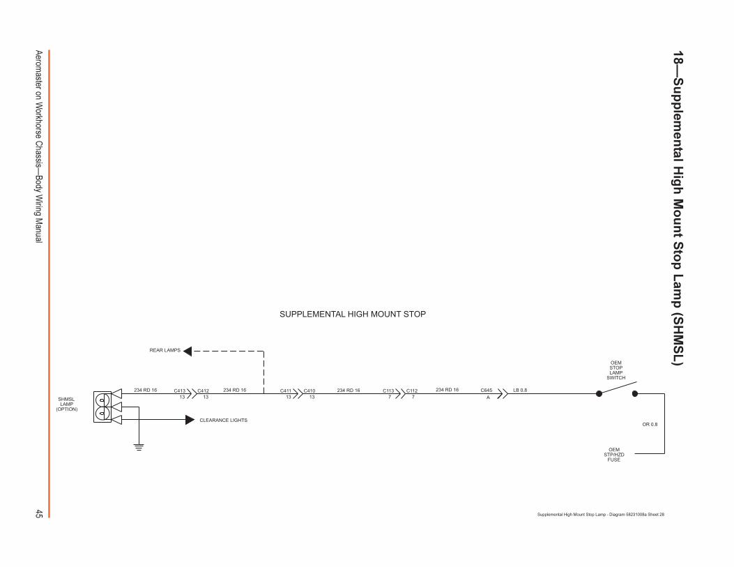
45Aerom
aster on Workhorse C
hassis�Body W
iring Manual
18�S
up
plem
ental H
igh
Mo
un
t Sto
p L
amp
(SH
MS
L)
LB 0.8
OR 0.8
OEMSTP/HZD
FUSE
OEMSTOPLAMP
SWITCH
A
CLEARANCE LIGHTS
C645234 RD 16234 RD 16713 7131313
234 RD 16234 RD 16
SHMSLLAMP
(OPTION)
C112C113C412C413 C410C411
REAR LAMPS
SUPPLEMENTAL HIGH MOUNT STOP
Supplemental High Mount Stop Lamp - Diagram 58231008a Sheet 28

46Aerom
aster on Workhorse C
hassis�Body W
iring Manual
19�A
ccessory O
utlet (C
igarette L
igh
ter)
500 BK 16GROUND
ACCESSORYOUTLET
130 RD 1611
C113C11211
130 RD 162
C112150 RD 14
CHASSIS FUSE BLOCK
CBBATT
BRNWHT BLU GRN AU
GRN REDBLUWHT BRNX
WHTWHT
PWRIGN HTRACC
30APWR
25AHTR
10AACC-RADIO
20AECM-BAT
15AHORN/DM
15ATURN-BU
15A1-3
15AENG-BAT
20ATAIL LPS
20AGAUGES
30AAUX.
25WIPER
15STP/HZD
20AECM-1
5AINST-LPS
20AENG-1
10ATRANS FUSE/PLR
GRY
GRY
TURNFLASHER
RED
REDGRNBRN
150
RD
14
ACCESSORY OUTLET
Accessory Outlet - Diagram 58231008a Sheet 29
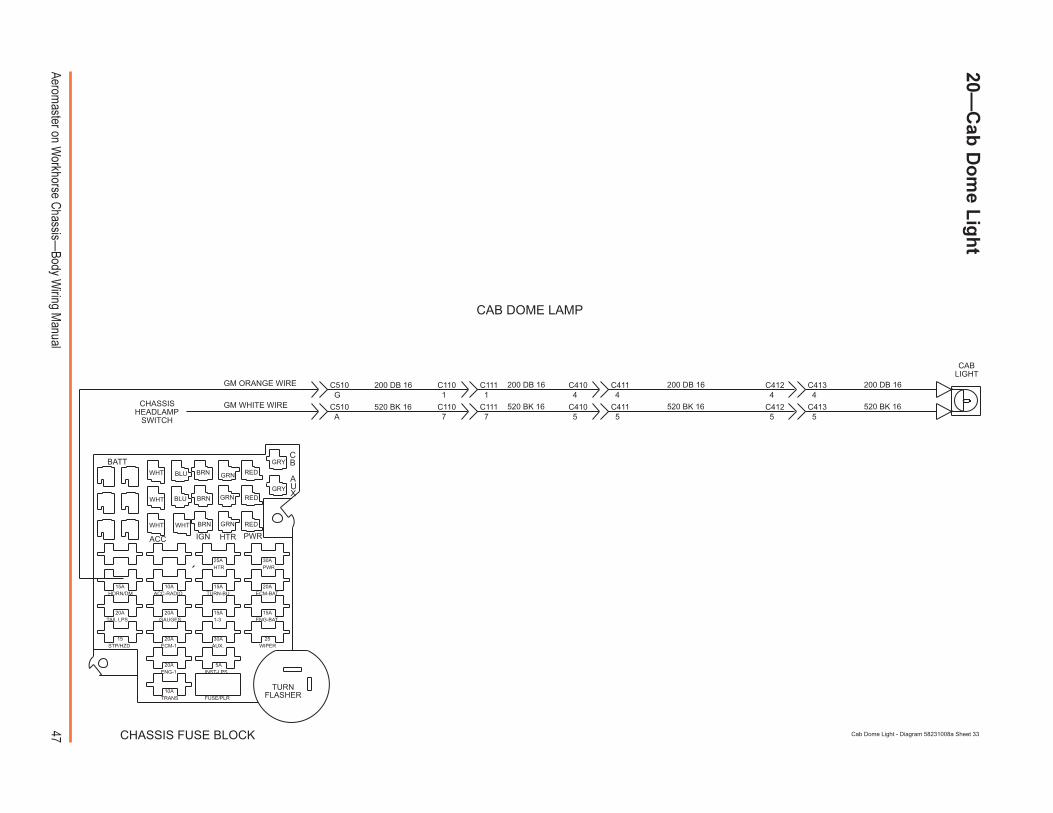
47Aerom
aster on Workhorse C
hassis�Body W
iring Manual
20�C
ab D
om
e Lig
ht
200 DB 16 200 DB 16 200 DB 16 200 DB 16
CHASSISHEADLAMP
SWITCH
GM WHITE WIRE
GM ORANGE WIRE
A
G
C510
C510
7 7
1 1
C110 C111
C111C110
520 BK 16520 BK 16 520 BK 16 520 BK 16
CABLIGHT
WHT
WHT
WHT WHT BRN
BRN
BRN
GRN
GRN
GRN
RED
RED
RED
BATT
IGNACC HTR
15AHORN/DM
20ATAIL LPS
15STP/HZD
FUSE/PLR
AUX
PWR
CB
30APWR
30AAUX.
25WIPER
CHASSIS FUSE BLOCK
TURNFLASHER
GRY
GRY
BLU
BLU
20AGAUGES
10AACC-RADIO
20AECM-1
20AENG-1
15ATURN-BU
10ATRANS
5AINST-LPS
15A1-3
20AECM-BAT
15AENG-BAT
25AHTR
5 5
4 4
C4115
4
5
4C413C412C411
C412 C413
C410
C410
CAB DOME LAMP
Cab Dome Light - Diagram 58231008a Sheet 33
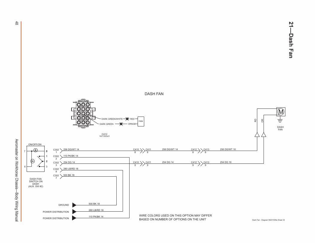
48Aerom
aster on Workhorse C
hassis�Body W
iring Manual
21�D
ash F
an
DASH FANSWITCH ON
DASH(AUX. SW #2)
DASHFAN
OR
RD
254 DG 16
256 DG/WT 16
999
888
9
8256 DG/WT 14
254 DG 14254 DG 14
256 DG/WT 14
M
WIRE COLORS USED ON THIS OPTION MAY DIFFERBASED ON NUMBER OF OPTIONS ON THE UNIT
C302
C302
C302
C302
C302
110 PK/BK 14
110 PK/BK 14
ON/OFF/ON
7
2
1
88
1
2
36
C411 C412 C413
7
8
GROUND 500 BK 18
500 BK 18
280 LB/RD 18
280 LB/RD 18
POWER DISTRIBUTION
POWER DISTRIBUTION
C413C412C411C410
C410
3
2
1
DASH FAN
Dash Fan - Diagram 58231008a Sheet 34
FANORNGE
REDDARK GREEN/WHITE
DARK GREEN
987
10 11 12
151413
4 5 6
321
C41216511952a01
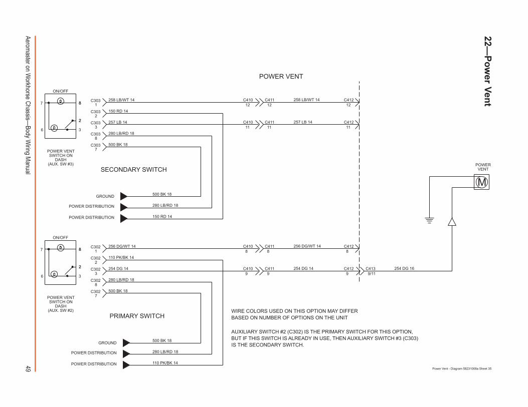
49Aerom
aster on Workhorse C
hassis�Body W
iring Manual
254 DG 16
POWER VENTSWITCH ON
DASH(AUX. SW #2)
POWER VENTSWITCH ON
DASH(AUX. SW #3)
9/11
11
1212
150 RD 14
150 RD 14
PRIMARY SWITCH
SECONDARY SWITCH
C303
C303
C303
C303
C303
1111
12
257 LB 14
258 LB/WT 14 258 LB/WT 14
257 LB 14
1
2
3
C410
C410 C411 C412
POWER DISTRIBUTION
POWER DISTRIBUTION
280 LB/RD 18
280 LB/RD 18
500 BK 18
500 BK 18GROUND
8
7
C412C411
ON/OFF
7
2
88
2
36
POWERVENT
99
88
9
8256 DG/WT 14
254 DG 14254 DG 14
256 DG/WT 14
M
C302
C302
C302
C302
C302
110 PK/BK 14
110 PK/BK 14
ON/OFF
7
2
88
2
36
C411 C412
7
8
500 BK 18
500 BK 18
280 LB/RD 18
280 LB/RD 18
C413C412C411C410
C410
3
2
1
POWER DISTRIBUTION
POWER DISTRIBUTION
GROUND
AUXILIARY SWITCH #2 (C302) IS THE PRIMARY SWITCH FOR THIS OPTION,BUT IF THIS SWITCH IS ALREADY IN USE, THEN AUXILIARY SWITCH #3 (C303)IS THE SECONDARY SWITCH.
WIRE COLORS USED ON THIS OPTION MAY DIFFERBASED ON NUMBER OF OPTIONS ON THE UNIT
POWER VENT
Power Vent - Diagram 58231008a Sheet 35
22�P
ow
er Ven
t
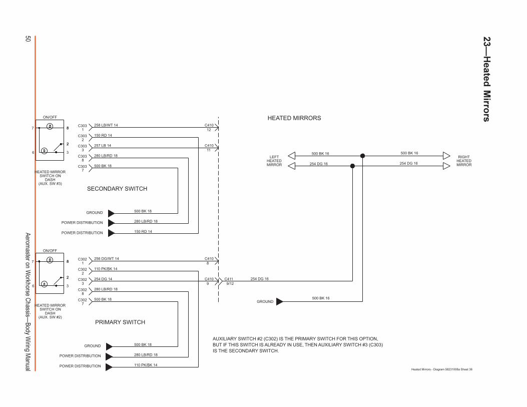
50Aerom
aster on Workhorse C
hassis�Body W
iring Manual
23�H
eated M
irrors
HEATED MIRRORSWITCH ON
DASH(AUX. SW #2)
HEATED MIRRORSWITCH ON
DASH(AUX. SW #3)
GROUND
RIGHTHEATEDMIRROR
LEFTHEATEDMIRROR
9/12
254 DG 16
500 BK 16 500 BK 16
254 DG 16
500 BK 16
254 DG 16
150 RD 14
150 RD 14
PRIMARY SWITCH
SECONDARY SWITCH
C303
C303
C303
C303
C303
11
12
257 LB 14
258 LB/WT 141
2
3
C410
C410
POWER DISTRIBUTION
POWER DISTRIBUTION
280 LB/RD 18
280 LB/RD 18
500 BK 18
500 BK 18GROUND
8
7
ON/OFF
7
2
88
2
36
9
8
254 DG 14
256 DG/WT 14
C302
C302
C302
C302
C302
110 PK/BK 14
110 PK/BK 14
ON/OFF
7
2
88
2
36
7
8
500 BK 18
500 BK 18
280 LB/RD 18
280 LB/RD 18
C411C410
C410
3
2
1
POWER DISTRIBUTION
POWER DISTRIBUTION
GROUND
AUXILIARY SWITCH #2 (C302) IS THE PRIMARY SWITCH FOR THIS OPTION,BUT IF THIS SWITCH IS ALREADY IN USE, THEN AUXILIARY SWITCH #3 (C303)IS THE SECONDARY SWITCH.
HEATED MIRRORS
Heated Mirrors - Diagram 58231008a Sheet 36
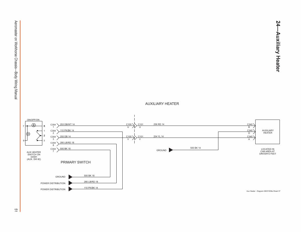
51Aerom
aster on Workhorse C
hassis�Body W
iring Manual
24�A
uxiliary H
eater
255 DB 14
253 DB/WT 14
C304
C304
C304
C304
C304
V
U
AUX HEATERSWITCH ON
DASH(AUX. SW #2)
500 BK 14
A
D
B
C340
C340
C340
AUXILIARYHEATER
254 YL 14
256 RD 14
GROUND
C101
V
U
C101C100
C100
PRIMARY SWITCH
110 PK/BK 14
110 PK/BK 14
1
ON/OFF/ON
7
2
88
2
36
7
8
GROUND 500 BK 18
500 BK 18
280 LB/RD 18
280 LB/RD 18
POWER DISTRIBUTION
POWER DISTRIBUTION
3
2
1
LOCATED INCAB AREA AT
DRIVER�S FEET
AUXILIARY HEATER
Aux Heater - Diagram 58231008a Sheet 37
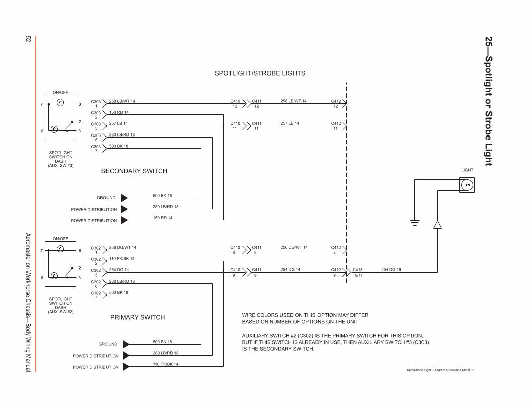
52Aerom
aster on Workhorse C
hassis�Body W
iring Manual
25�S
po
tligh
t or S
trob
e Lig
ht
SPOTLIGHT/STROBE LIGHTS
254 DG 16
SPOTLIGHTSWITCH ON
DASH(AUX. SW #2)
SPOTLIGHTSWITCH ON
DASH(AUX. SW #3)
9/11
LIGHT
11
1212
150 RD 14
150 RD 14
PRIMARY SWITCH
SECONDARY SWITCH
C303
C303
C303
C303
C303
1111
12
257 LB 14
258 LB/WT 14 258 LB/WT 14
257 LB 14
1
2
3
C410
C410 C411 C412
POWER DISTRIBUTION
POWER DISTRIBUTION
280 LB/RD 18
280 LB/RD 18
500 BK 18
500 BK 18GROUND
8
7
C412C411
ON/OFF
7
2
88
2
36
99
88
9
8256 DG/WT 14
254 DG 14254 DG 14
256 DG/WT 14
C302
C302
C302
C302
C302
110 PK/BK 14
110 PK/BK 14
ON/OFF
7
2
88
2
36
C411 C412
7
8
500 BK 18
500 BK 18
280 LB/RD 18
280 LB/RD 18
C413C412C411C410
C410
3
2
1
POWER DISTRIBUTION
POWER DISTRIBUTION
GROUND
AUXILIARY SWITCH #2 (C302) IS THE PRIMARY SWITCH FOR THIS OPTION,BUT IF THIS SWITCH IS ALREADY IN USE, THEN AUXILIARY SWITCH #3 (C303)IS THE SECONDARY SWITCH.
WIRE COLORS USED ON THIS OPTION MAY DIFFERBASED ON NUMBER OF OPTIONS ON THE UNIT
Spot/Strobe Light - Diagram 58231008a Sheet 38
53Aeromaster on Workhorse Chassis�Body Wiring Manual
Index
A
A/C. See HVACAccessory outlet 46Address
National Highway Traffic Safety Administra-tion 9
U.S. Department of Transportation 9Utilimaster
Customer Service 10Technical Publications 3
Air conditioning. See HVACAlarm, back-up 36, 38Auxiliary heater. See Heater
B
Back-up. See Alarm and LightBattery 9Body serial number 7Bumpers 10
C
Chevrolet chassis 6, 10CHMSL (Center High Mount Stop Light). See
Light: Supplemental High Mount StopLight
Cigarette lighter. See Accessory outletColor code 11Connectors 12, 13, 14, 15, 16, 17, 18Cummins diesel 6, 14, 15, 16, 17, 25, 32Cummins diesel ISB4 12Customer service 10
D
Door ajar system 44DRL 34, 35
E
Electrical components 10Email 10
F
Fan, dash 40, 48Federal Certification Label 7Finding information 7
G
Glossary of terms 10GM and GMC chassis 6, 10Grounding system 20
H
Harness layout 18Heated mirrors 50Heater 10. See also HVAC
Auxiliary 51System (no A/C) 27, 28
HVAC 29, 30, 31. See also Heater
L
LightBack-up 36, 37, 38, 39Cab 40Cargo 23, 24, 40, 47Center High Mount Stop Light
(CHMSL). See Light: Supplemen-tal High Mount Stop Light
Clearance 40, 41Daytime running (DRL) 34, 35Forward 35Front 32, 33, 34Head light 32, 33, 34, 35License plate 36, 37, 38, 39Master three-way switch
22, 23, 24, 47Panel 42Rear 36, 37, 38, 39Roof 40Side marker 32, 33, 34, 35Spot 52Stop 36, 37, 38, 39Strobe 52Supplemental High Mount Stop Light
40Tail 36, 37, 38, 39Turn signal
32, 33, 34, 35, 36, 37, 38
54 Aeromaster on Workhorse Chassis�Body Wiring Manual
M
Mirrors, heated 50
N
NumbersBody serial number 7Index 7Phone 9, 10Section 7VIN 7
O
Outlet. See Accessory outlet
P
PartsGuide 10Manual 10
Phone numbers 9, 10Power distribution 19
R
Revision 3
S
Safety 8, 9Sections 7Service manual 10Spotlight 52Stereo system 43Strobe light 52Switches
A/C 29, 30, 31Auxiliary 21Auxiliary heater 51Blower 27, 28, 29, 30, 31Dash 48Heated mirror 50Hi/Lo (A/C) 29, 30, 31Master light switch 21Master three-way (cargo) 23, 24, 47Power vent 49Spotlight 52Strobe 52Thermo (A/C) 29, 30, 31
U
Unit serial number 7Utilimaster Body Parts Manual 10Utilimaster body serial number 7Utilimaster Body Service Manual 10Utilimaster Glossary of Terms 10Utilimaster Quick Reference Parts
Guide 10
V
VACS 6Vent, powered 49VIN 7
W
Web site 3, 10Wiper system 10
Intermittent 26Standard 25
Workhorse chassis 6, 10


Utilim
aste
r Body W
iring M
anual
Aero
maste
r on W
ork
hors
e C
hassis
©Utilimaster Corporation, 65906 State Road 19, P.O. Box 585, Wakarusa, Indiana, 46573�0585, USA
Part Number: 03102354-WY00EN