powerdrive md smart md3 ip00 chassis serie
TRANSCRIPT

Powerdrive MD SmartMD3 IP00 Chassis serie
Integration Guide
Reference: 5751 en - 2021.10 / e

2
Powerdrive MD Smart Integration Guide5751 en - 2021.10 / e
Nidec Leroy-Somer reserves the right to modify the characteristics of its products at any time to incorporate the latest technological developments. The information contained in this document may therefore be changed without notice.
CAUTION
For the user’s safety, the Powerdrive MD Smart variable speed drive made by the integrator must be connected to a statutory ground (terminal ).If an inadvertent start to the installation presents a risk to the persons or the machines being driven, it is essential to comply with the power connection diagrams recommended in this manual.
The Powerdrive MD Smart variable speed drive is fitted with safety devices which, in the event of a problem, control stopping and thus stop the motor. The motor itself can become jammed for mechanical reasons. Voltage fluctuations, in particular power cuts, may also cause the motor to stop. The removal of the causes of the shutdown can lead to restarting, which may be dangerous for certain machines or installations, in particular those which must comply with Appendix 1 of Decree 92.767 of 29 July 1992 on safety.In such cases, it is essential that the user takes appropriate precautions against the motor restarting after an unscheduled stop.
The Powerdrive MD Smart variable speed drive is designed to be able to supply a motor and the driven machine above its rated speed.If the motor or the machine are not mechanically designed to withstand such speeds, the user may be exposed to serious danger resulting from their mechanical deterioration.Before programming a high speed, it is important that the user checks that the installation can withstand it.
The Powerdrive MD Smart variable speed drive, made from the components described in this manual, is designed to be integrated in an installation or an electrical machine, and can under no circumstances be considered a safety device It is therefore the responsibility of the machine manufacturer, the designer of the installation or the user to take all necessary precautions to ensure that the system complies with current standards, and to provide any devices required to ensure the safety of equipment and personnel.
In the event of non-compliance with the above provisions, Leroy-Somer disclaims any and all liability.This manual describes all the steps required for a system integrator to integrate Powerdrive MD Smart variable speed drive components into an enclosure, as well as its connection and installation. For commissioning and configuring the drive, refer to commissioning guide ref. 5641.
This guide addresses versions of variable speed drives greater than or equal to V5.80
NOTE
3
Powerdrive MD Smart Integration Guide5751 en - 2021.10 / e
Throughout the manual, this symbol warns of consequences which may arise from inappropriate use of the drive, since electrical risks may lead to material or physical damage as well as constituting a fire hazard.
(In accordance with the low voltage directive 2014/35/EU)
1 - General informationThe integrator is responsible for the selection of the components for the variable speed drive. All work related to the installation of the variable speed drive in an enclosure, such as handling, assembly, installation, cabling and testing of the finished product, shall be performed by qualified and authorised personnel. For these basic safety instructions, qualified personnel shall mean competent persons who possess the relevant qualifications.The security instructions described in this document shall be followed carefullyThe variable speed drive produced by the integrator must be tested to ensure its proper functioning, but it must also be certified to the standards of the place of use.Depending on their degree of protection, variable speed drives may contain unprotected live parts, which may be moving or rotating, as well as hot surfaces, during operation.Unjustified removal of protection devices, incorrect use, faulty installation or inappropriate operation could represent a serious risk to personnel and equipmentFor more information, consult the data sheet for each of the components described in this document.
2 - UseVariable speed drives are components designed for integration in electrical installations or machines.They shall comply with standard EN 60204, which stipulates in particular that electrical actuators (which include variable speed drives) cannot be considered as circuit breaking devices and certainly not as isolating switches.Commissioning of variable speed drives can take place only if the requirements of the Electromagnetic Compatibility Directive (EMC 2014/30/CE) are met.The integrator shall ensure the variable speed drives meet the requirements of the Low Voltage Directive 2014/35/CE. The harmonised standards of the DIN VDE 0160 series in connection with standard VDE 0660, part 500 and EN 60146/VDE 0558 are also applicableThe technical characteristics and instructions concerning the connection conditions shall be specified on the nameplate of the variable speed drive and in the documentation provided.
3 - Transportation, storageAll instructions concerning transportation, storage and correct handling must be observed.The climatic conditions specified in the technical manual must be observed.
4 - Installation, cabling The installation and cabling of variable speed drive components in an enclosure shall meet the specifications of the documentation provided.The variable speed drive components must be protected against any excessive stress. In particular, there must be no damage to parts and/or modification of the clearance between components during transportation and handling. Avoid touching the electronic components and contact parts.The variable speed drive components contain parts which are sensitive to electrostatic stresses and may be easily damaged if handled incorrectly. Electrical components must
not be exposed to mechanical damage or destruction (may result in risks to health!).
5 - Electrical connectionWhen work is performed on variable speed drives which are powered up, the national accident prevention regulations must be observed.The electrical installation must comply with the relevant specifications (for example conductor cross-sections, protection via fused circuit-breaker, connection of protective conductor). More detailed information can be found in the documentation.Instructions for an installation which meets the requirements for electromagnetic compatibility, such as screening, earthing, presence of filters and correct insertion of cables and conductors, are given in the documentation supplied with the variable speed drives. These instructions must be followed in all cases, even if the variable speed drive carries the CE mark. Adherence to the limits given in the EMC legislation is the responsibility of the manufacturer of the installation or the machine.
6 - OperationInstallations in which variable speed drives are to be integrated must be fitted with additional protection and monitoring devices as laid down in the current relevant safety regulations, such as the law on technical equipment, accident prevention regulations, etc. Modifications to variable speed drives using control software are permitted.Active parts of the device and the live power connections must not be touched immediately after the variable speed drive is powered down as the capacitors may still be charged. In view of this, warnings must be fixed to the affected areas of the variable speed drive’s enclosure.Permanent magnet motors generate electrical power if they are rotated, even when the supply to the drive is disconnected. In this case, the variable speed drive is powered by the motor terminals. If the load is capable of running the motor, a cut-off device upstream of the motor must be provided to isolate the variable speed drive during maintenance operations.During operation, all doors and protective covers must be kept closed.
7 - Servicing and maintenanceRefer to the manufacturer's documentation.See the Maintenance chapter of this document. This manual is to be given to the end user.
SAFETY AND OPERATING INSTRUCTIONS FOR VARIABLE SPEED DRIVES

4
Powerdrive MD Smart Integration Guide5751 en - 2021.10 / e
This manual describes the integration of the various IP00 components (chassis) of the Powerdrive MD Smart in an electrical enclosure. It also gives details of all its options and extensions which the user may choose to suit their requirements.The installation of a Powerdrive MD Smart speed variator in a enclosure is carried out by the combination of the different components offered (rectifier frame and inverter, control module, etc.) which allows the realization of multiple solutions in terms of architecture and cooling of the final enclosure.
FOREWORD
Powerdrive MD Smart components Options
Power chassis Network side
Motor side
User interface
Control Module Options
Braking
Control
Cable Kits
Sine filter
Sinus filterDV/DT Filter
RFI Filter Line reactor for AFE
Braking resistor
Preload module
Parallelisation module
Braking transistor
Three-phase, single or dual rectifier chassis
Three-phase inverter chassis
Primary Control Module
LITE

5
Powerdrive MD Smart Integration Guide5751 en - 2021.10 / e
Thanks to its modular structure, the components of the Powerdrive MD Smart make it possible to assemble all kinds of architecture: 6,12,18, or 24 Pulse, Active Front-End (AFE), DC Bus systems, DC/DC converters).
Multiple cooling choices Power components on chassis are available in 2 variants to provide maximum cooling flexibility:- air cooling with integrated ventilation- cold plate cooling for external liquid cooling
POWERDRIVE MD Smart: MULTIPLE ARCHITECTURES
Chassis with internal ventilationCold plate chassis
Liquid cooling
6 Pulse Version(standard variable speed drive)
1 single rectifierBOXES:
THDI>40%THDI=5% with active filter option
18 Pulse Version3 single rectifiers
BOXES:THDI=8%
Active Front EndBOXES:THDI=3%
Passive DC Bus System AFE DC Bus System(Active Front End)
DC/DC Converter
DC In
DC Out
12 Pulse Version2 single rectifiers
BOXES:THDI=12%
24-pulse version4 single rectifiers
BOXES:THDI=5%

6
Powerdrive MD Smart Integration Guide5751 en - 2021.10 / e
STRUCTURE OF THE MANUAL
1 - GENERAL INFORMATION
2 - HARDWARE SELECTION
3 - MECHANICAL INSTALLATION
4 - CONNECTIONS - CABLING
5 - TEST
6 - MAINTENANCE
7 - UL
8 - APPENDICES
7
Powerdrive MD Smart Integration Guide5751 en - 2021.10 / e
SUMMARY
1 - GENERAL INFORMATION ................................................................................................................................ 101.1 - Working principle of a variable speed drive ................................................................................................ 101.2 - Key components of the Powerdrive MD Smart ........................................................................................... 11
1.2.1 - Filtering elements .................................................................................................................................................111.2.2 - Rectifiers ............................................................................................................................................................. 12
1.2.2.1 - Passive rectifiers ..................................................................................................................................... 121.2.2.2 - Active rectifiers ........................................................................................................................................ 14
1.2.3 - Preload module ................................................................................................................................................... 161.2.4 - Inverters .............................................................................................................................................................. 161.2.5 - Parallelisation module ......................................................................................................................................... 171.2.6 - The braking module ............................................................................................................................................. 171.2.7 - The control module .............................................................................................................................................. 18
1.2.7.1 - General information ................................................................................................................................. 181.2.7.2 - Systemiz ................................................................................................................................................. 20
1.2.8 - Cable kit .............................................................................................................................................................. 201.3 - Associating components according to architecture .................................................................................... 211.4 - Cooling methods ........................................................................................................................................ 25
1.4.1 - Air cooling............................................................................................................................................................ 251.4.1.1 - Ventilated power components ................................................................................................................. 25
1.4.2 - Liquid cooling (CL version) .................................................................................................................................. 261.4.3 - Internal loss management ................................................................................................................................... 27
2 - HARDWARE SELECTION ................................................................................................................................. 282.1 - General characteristics .............................................................................................................................. 282.2 - Determination of the continuous output current (Isp) .................................................................................. 28
2.2.1 - Aid for determining Isp variator current under non-standard conditions ............................................................... 292.2.2 - Setting the design temperature............................................................................................................................ 302.2.3 - Determination of the Isp continuous output current.............................................................................................. 322.2.4 - Low frequency (Lf) correction factor .................................................................................................................... 332.2.5 - Choosing the chopping frequency ....................................................................................................................... 33
2.3 - Hardware selection ................................................................................................................................... 342.3.1 - 6-PULSE Variable speed drive ........................................................................................................................... 34
2.3.1.1 - Composition ............................................................................................................................................ 342.3.1.2 - Example of component selection ............................................................................................................. 352.3.1.3 - 6-PULSE variable speed drive, 400V -10% to 480V +10% ...................................................................... 362.3.1.4 - 6-PULSE variable speed drive, 525V -10% to 690V +10% ...................................................................... 382.3.1.5 - Composition ............................................................................................................................................ 402.3.1.6 - Example of component selection ............................................................................................................. 412.3.1.7 - AFE variable speed drive, 400V -10% to 480V +10% .............................................................................. 422.3.1.8 - AFE variable speed drive, 525V -10% at 690V +10% .............................................................................. 44
2.4 - Standards .................................................................................................................................................. 462.5 - Environmental specifications ..................................................................................................................... 46
2.5.1 - Environmental specifications during transportation and storage ......................................................................... 462.5.2 - Environmental conditions during operation.......................................................................................................... 46
2.6 - Resistance to acids and corrosive gases ................................................................................................... 462.7 - Electrical characteristics of components .................................................................................................... 46
2.7.1 - Passive rectifier chassis ..................................................................................................................................... 462.7.1.1 - Cables and fuses .................................................................................................................................... 472.7.1.2 - UR fuse, line reactor and RFI filter options .............................................................................................. 50
2.7.2 - MD3INV Active rectifier chassis .......................................................................................................................... 522.7.2.1 - Cables and fuses .................................................................................................................................... 532.7.2.2 - Filtering options ....................................................................................................................................... 56
2.7.3 - Preload module MD3PRG ................................................................................................................................... 592.7.4 - Inverter chassis MD3INV .................................................................................................................................... 602.7.5 - Fan modules........................................................................................................................................................ 632.7.6 - MD3TF Braking modules and resistors................................................................................................................ 64
2.7.6.1 - Braking transistor .................................................................................................................................... 642.7.6.2 - Braking resistor ....................................................................................................................................... 65
2.7.7 - Control module MD3CTL ..................................................................................................................................... 652.7.8 - Parallelisation module MD3PRL .......................................................................................................................... 702.7.9 - Customisation card ............................................................................................................................................. 72

8
Powerdrive MD Smart Integration Guide5751 en - 2021.10 / e
SUMMARY
3 - MECHANICAL INSTALLATION ......................................................................................................................... 733.1 - Checks upon receipt ................................................................................................................................. 733.2 - Handling .................................................................................................................................................... 733.3 - Dimensions and weights ............................................................................................................................ 74
3.3.1 - Single rectifier chassis MD3REC1 ....................................................................................................................... 743.3.2 - Preload module MD3PRG ................................................................................................................................... 763.3.3 - Inverter chassis (motor and network) MD3INV size1 ........................................................................................... 773.3.4 - Braking module MD3TF....................................................................................................................................... 863.3.5 - Control module MD3CTL and parallelisation module MD3PRL ........................................................................... 873.3.6 - HMI and console ................................................................................................................................................. 88
3.3.6.1 - MD3SUI .................................................................................................................................................. 883.3.6.2 - MD3KEYPAD .......................................................................................................................................... 88
3.4 - Installation ................................................................................................................................................. 893.4.1 - General information ............................................................................................................................................. 89
3.4.1.1 - AF chassis installation ............................................................................................................................. 893.4.1.2 - Installation in enclosure: .......................................................................................................................... 903.4.1.3 - CL chassis installation ............................................................................................................................. 933.4.1.4 - Installation in enclosure .......................................................................................................................... 93
3.4.2 - Minimum installation distances ............................................................................................................................ 943.4.2.1 - Rectifier chassis MD3REC1 .................................................................................................................... 943.4.2.2 - Inverter chassis MD3INV ......................................................................................................................... 963.4.2.3 - Preload module MD3PRG ....................................................................................................................... 993.4.2.4 - Control module MD3CTL and parallelisation module MD3PRL ............................................................. 100
3.4.3 - Air flow management ......................................................................................................................................... 1023.5 - Liquid cooling management ..................................................................................................................... 103
3.5.1 - Flow rate............................................................................................................................................................ 1033.5.2 - Recommendations ............................................................................................................................................ 1043.5.3 - Drainage and maintenance ............................................................................................................................... 104
3.6 - Variable speed drive losses ..................................................................................................................... 1053.7 - Ventilation flow rates ................................................................................................................................ 1083.8 - Noise levels ............................................................................................................................................. 110
4 - CONNECTIONS - CABLING ........................................................................................................................... 1124.1 - Power network ......................................................................................................................................... 112
4.1.1 - Neutral IT point connection .................................................................................................................................1124.1.2 - Ground connections ...........................................................................................................................................113
4.1.2.1 - Equipotential protection or EP circuit ......................................................................................................1134.1.2.2 - Shielding ................................................................................................................................................1144.1.2.3 - Cable routing ..........................................................................................................................................115
4.2 - Electromagnetic Compatibility (EMC) ...................................................................................................... 1164.3 - Special cabling ......................................................................................................................................... 1174.4 - Electrical diagrams .................................................................................................................................. 118
4.4.1 - 6-PULSE version ≤ 500 kW ................................................................................................................................1184.4.2 - 6-PULSE version up to 2,500 kW .......................................................................................................................119
4.5 - AFE electrical diagrams ........................................................................................................................... 1214.5.1 - AFE Version <500 kW ....................................................................................................................................... 1214.5.2 - AFE Version > 500 kW ....................................................................................................................................... 122
4.6 - 12, 18, 24-PULSE electrical diagrams ..................................................................................................... 1244.7 - Location of terminal blocks ....................................................................................................................... 125
4.7.1 - Control module MD3CTL ................................................................................................................................... 1254.7.2 - Parallelisation module MD3PRL ........................................................................................................................ 1264.7.3 - Rectifier chassis MD3REC and preload module MD3PRG ................................................................................ 1274.7.4 - Rectifier chassis MD3INV .................................................................................................................................. 1284.7.5 - HMI AND CONSOLE ......................................................................................................................................... 130
4.7.5.1 - MD3SUI ................................................................................................................................................ 1304.7.5.2 - MD3KEYPAD ........................................................................................................................................ 130
4.8 - Strands between terminal blocks ............................................................................................................. 1314.9 - Brake module cabling .............................................................................................................................. 145
9
Powerdrive MD Smart Integration Guide5751 en - 2021.10 / e
SUMMARY
4.10 - DC Bus cabling ...................................................................................................................................... 1464.10.1 - Cabling connections ....................................................................................................................................... 147
4.11 - Control terminal cabling ......................................................................................................................... 1484.11.1 - Remote control ................................................................................................................................................ 1484.11.2 - Changing the Start/Stop command logic .......................................................................................................... 1494.11.3 - Systemiz wizard details (pre-set internal settings) ........................................................................................... 1494.11.4 - STO-1 / STO-2 inputs: safe torque off function ................................................................................................. 151
4.11.4.1 - Single channel lockout (SIL1 - PLb) ..................................................................................................... 1524.11.4.2 - Dual channel lockout (SIL3 - Ple) ......................................................................................................... 152
5 - TESTING ......................................................................................................................................................... 1535.1 - Self-testing and diagnostics .................................................................................................................... 153
5.1.1 - Control module MD3CTL ................................................................................................................................... 1535.1.2 - Power ................................................................................................................................................................ 153
5.2 - Operating test .......................................................................................................................................... 1545.2.1 - Necessary hardware: ........................................................................................................................................ 1545.2.2 - Test preparation................................................................................................................................................. 1555.2.3 - Functional Testing ............................................................................................................................................. 155
6 - MAINTENANCE ............................................................................................................................................... 157
7 - UL LISTING INFORMATION ............................................................................................................................ 1577.1 - UL file reference ....................................................................................................................................... 1577.2 - Mounting .................................................................................................................................................. 1577.3 - Environment ............................................................................................................................................ 1577.4 - Maximum continuous current ................................................................................................................... 1577.5 - Electrical installation ................................................................................................................................ 157
7.5.1 - Terminal torque.................................................................................................................................................. 1577.5.2 - Cabling terminals............................................................................................................................................... 1577.5.3 - Branch circuit protection .................................................................................................................................... 1577.5.4 - Line reactors...................................................................................................................................................... 159
7.6 - AC supply specification ............................................................................................................................ 1597.7 - Motor overload protection and overspeed protection ............................................................................... 1597.8 - PX1, PX2, PX3 and P2 customer interface .............................................................................................. 159
8 - APPENDICES .................................................................................................................................................. 160

10
GENERAL INFORMATION
Powerdrive MD Smart Integration Guide5751 en - 2021.10 / e
GENE
RAL
INFO
RMAT
ION
1 - GENERAL INFORMATION1.1 - Working principle of a variable speed driveAn electronic variable speed drive allows an electric motor to be supplied with a variable voltage and frequency by drawing energy from a fixed voltage and frequency electrical network.
Schematic diagram of a variable speed drive:
A variable speed drive essentially consists of:• A filtering element to limit harmonic pollution. - DC Bus reactor or line reactor
• A Passif or Active rectifier:- Passive: connected to a three-phase power supply (the network), it generates continuous voltage. This rectifier is composed of 3
thyristors and 3 diodes (combined bridge rectifier).- Active: connected to a three-phase power supply (the network), it generates continuous voltage. This rectifier is composed of
IGBTs which are driven according to the PWM (Pulse Width Modulation) principle and capacitors which act mainly by "smoothing" the voltage of the DC Bus.
• An inverter that generates the power signal at varying voltages and/or frequencies. This inverter is composed of a DC Bus acting mainly on “smoothing” the output voltage of the rectifier via capacitors and IGBT which are controlled according to the principle of Pulse Width Modulation (PWM).
• Control electronics, i.e. a control module which controls (transmission and reception of signals) the rectifier and the inverter. The power components of the Powerdrive MD Smart variable power drive are available up to 500 kW. Beyond that, the rectifier
and inverter chassis shall be parallelised to achieve the required power levels (> 2.5 MW).
(*) 3 solutions are possible: • a network filtering: - line reactor - low harmonic active filter• filtering on the DC Bus circuit: -continuous reactor
11
GENERAL INFORMATION
Powerdrive MD Smart Integration Guide5751 en - 2021.10 / e
GENE
RAL
INFO
RMAT
ION
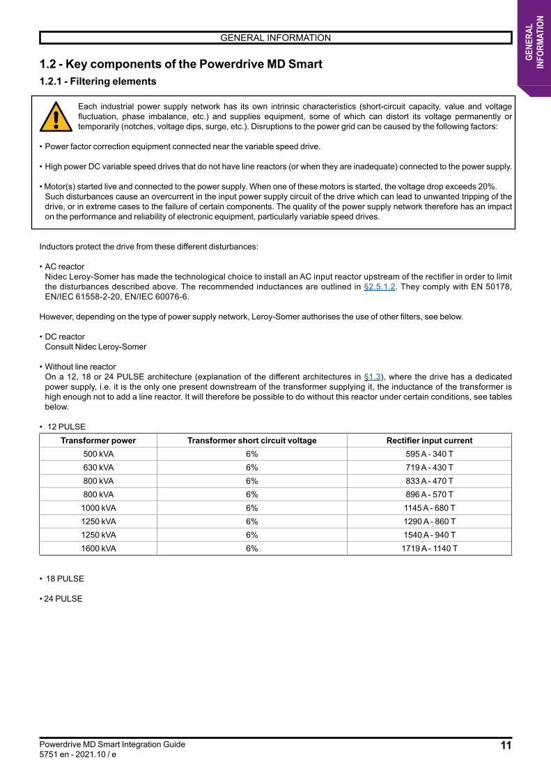
1.2 - Key components of the Powerdrive MD Smart1.2.1 - Filtering elements
Each industrial power supply network has its own intrinsic characteristics (short-circuit capacity, value and voltage fluctuation, phase imbalance, etc.) and supplies equipment, some of which can distort its voltage permanently or temporarily (notches, voltage dips, surge, etc.). Disruptions to the power grid can be caused by the following factors:
• Power factor correction equipment connected near the variable speed drive.
• High power DC variable speed drives that do not have line reactors (or when they are inadequate) connected to the power supply.
• Motor(s) started live and connected to the power supply. When one of these motors is started, the voltage drop exceeds 20%. Such disturbances cause an overcurrent in the input power supply circuit of the drive which can lead to unwanted tripping of the
drive, or in extreme cases to the failure of certain components. The quality of the power supply network therefore has an impact on the performance and reliability of electronic equipment, particularly variable speed drives.
Inductors protect the drive from these different disturbances:
• AC reactor Nidec Leroy-Somer has made the technological choice to install an AC input reactor upstream of the rectifier in order to limit
the disturbances described above. The recommended inductances are outlined in §2.5.1.2. They comply with EN 50178, EN/IEC 61558-2-20, EN/IEC 60076-6.
However, depending on the type of power supply network, Leroy-Somer authorises the use of other filters, see below.
• DC reactor Consult Nidec Leroy-Somer
• Without line reactor On a 12, 18 or 24 PULSE architecture (explanation of the different architectures in §1.3), where the drive has a dedicated
power supply, i.e. it is the only one present downstream of the transformer supplying it, the inductance of the transformer is high enough not to add a line reactor. It will therefore be possible to do without this reactor under certain conditions, see tables below.
• 12 PULSETransformer power Transformer short circuit voltage Rectifier input current
500 kVA 6% 595 A - 340 T630 kVA 6% 719 A - 430 T800 kVA 6% 833 A - 470 T800 kVA 6% 896 A - 570 T
1000 kVA 6% 1145 A - 680 T1250 kVA 6% 1290 A - 860 T1250 kVA 6% 1540 A - 940 T1600 kVA 6% 1719 A - 1140 T
• 18 PULSE
• 24 PULSE

12
GENERAL INFORMATION
Powerdrive MD Smart Integration Guide5751 en - 2021.10 / e
GENE
RAL
INFO
RMAT
ION
1.2.2 - Rectifiers
POWERDRIVE MD Smart rectifiers are elements offered on an IP00 chassis. They generate a DC voltage from the voltage of the three-phase AC power supply network that supplies them. They are AC/DC converters.
The offer includes 2 types of rectifiers:- Passive rectifier: used with basic power supplies (three-phase network), operating in 2 quadrants.
- Active rectifier: used with installations requiring the reinjection of current into the network in the case of driving loads or energy generation (operation in 4 quadrants) or to limit the harmonic rate to a low level (THDI ≤ 3%).
Rectifiers can be used as stand-alone devices to generate a common DC bus for several drives with reduced capacity. This is called a common DC Bus system. This solution is widely used in multi-axis applications such as cranes and travelling gantries or in industrial production lines. In fact, this makes it possible to facilitate energy exchanges between the various axes, thus generating energy savings.
1.2.2.1 - Passive rectifiersThe passive rectifiers of the Powerdrive MD Smart designated MD3REC operate in 2 quadrants, that is, the energy can only flow from the network power supply to the DC Bus (capacitors). In the case of driving loads or load decelerations that are too fast, the energy produced cannot be discharged, DC Bus overvoltage phenomena may occur. To avoid any risk of unwanted tripping, this energy must be dissipated in resistors via a braking module (see chapter §1.2.6).
NoteThe rectifier bridge is composed of switching electronics (thyristors and diode) responsible for the production of harmonics.These elements are not linear elements, the current conduction only takes place for a short time, at each sine wave peak to recharge the DC Bus (capacitors).These harmonics can cause the overheating of transformers, cables, motors, generators and capacitors connected to the same power supply. If the network is too polluted, the lights and displays of the electronic devices start to flicker, circuit breakers may trip, computers malfunction and measuring instruments give erroneous values.
The amplitude of the harmonics is linked to the impedance of the network upstream of the rectifier bridge, and to the structure of the DC Bus downstream of the rectifier bridge The more inductive the mains supply and the motor are, the more these harmonics are reduced. They only have an impact on the quality of the network for capacities installed in frequency converters of a few hundred kVA or in the case where these same capacities are greater than a quarter of the total power installed on a site.
Test ClauseIEC 18000-5-1 Referenced standard
Electrostatic discharge immunity 5.3.3 IEC61000-4-2Radio frequency field immunity 5.3.3 IEC61000-4-3Fast transient burst immunity to power terminals and control terminals
5.3.3 IEC61000-4-5
Common mode radio frequency immunity to power terminals and control terminals
5.3.3 IEC61000-4-6
Generic immunity standards for the industrial environment
5.3.3 IEC61000-6-2
NoteA THD harmonic distortion rate of 30% is equivalent to 5% less RMS current on the line.
13
GENERAL INFORMATION
Powerdrive MD Smart Integration Guide5751 en - 2021.10 / e
GENE
RAL
INFO
RMAT
ION
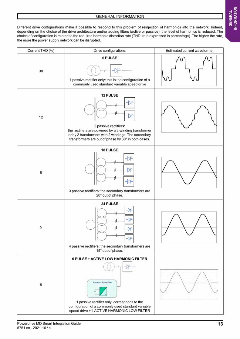
Different drive configurations make it possible to respond to this problem of reinjection of harmonics into the network. Indeed, depending on the choice of the drive architecture and/or adding filters (active or passive), the level of harmonics is reduced. The choice of configuration is related to the required harmonic distortion rate (THD, rate expressed in percentage). The higher the rate, the more the power supply network can be disrupted.
Current THD (%) Drive configurations Estimated current waveforms
30
6 PULSE
1 passive rectifier only: this is the configuration of a
commonly used standard variable speed drive
12
12 PULSE
2 passive rectifiers:the rectifiers are powered by a 3-winding transformer or by 2 transformers with 2 windings. The secondary transformers are out of phase by 30° in both cases.
8
18 PULSE
3 passive rectifiers: the secondary transformers are 20° out of phase.
5
24 PULSE
4 passive rectifiers: the secondary transformers are
15° out of phase.
5
6 PULSE + ACTIVE LOW HARMONIC FILTER
1 passive rectifier only: corresponds to the configuration of a commonly used standard variable speed drive + 1 ACTIVE HARMONIC LOW FILTER
14
GENERAL INFORMATION
Powerdrive MD Smart Integration Guide5751 en - 2021.10 / e
GENE
RAL
INFO
RMAT
ION
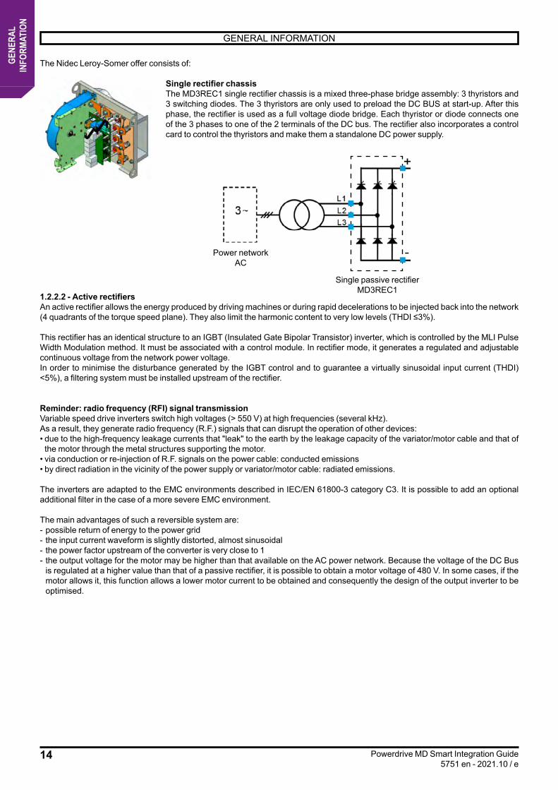
The Nidec Leroy-Somer offer consists of:
Single rectifier chassisThe MD3REC1 single rectifier chassis is a mixed three-phase bridge assembly: 3 thyristors and 3 switching diodes. The 3 thyristors are only used to preload the DC BUS at start-up. After this phase, the rectifier is used as a full voltage diode bridge. Each thyristor or diode connects one of the 3 phases to one of the 2 terminals of the DC bus. The rectifier also incorporates a control card to control the thyristors and make them a standalone DC power supply.
1.2.2.2 - Active rectifiersAn active rectifier allows the energy produced by driving machines or during rapid decelerations to be injected back into the network (4 quadrants of the torque speed plane). They also limit the harmonic content to very low levels (THDI ≤3%).
This rectifier has an identical structure to an IGBT (Insulated Gate Bipolar Transistor) inverter, which is controlled by the MLI Pulse Width Modulation method. It must be associated with a control module. In rectifier mode, it generates a regulated and adjustable continuous voltage from the network power voltage. In order to minimise the disturbance generated by the IGBT control and to guarantee a virtually sinusoidal input current (THDI) <5%), a filtering system must be installed upstream of the rectifier.
Reminder: radio frequency (RFI) signal transmissionVariable speed drive inverters switch high voltages (> 550 V) at high frequencies (several kHz).As a result, they generate radio frequency (R.F.) signals that can disrupt the operation of other devices:• due to the high-frequency leakage currents that "leak" to the earth by the leakage capacity of the variator/motor cable and that of the motor through the metal structures supporting the motor.
• via conduction or re-injection of R.F. signals on the power cable: conducted emissions• by direct radiation in the vicinity of the power supply or variator/motor cable: radiated emissions.
The inverters are adapted to the EMC environments described in IEC/EN 61800-3 category C3. It is possible to add an optional additional filter in the case of a more severe EMC environment.
The main advantages of such a reversible system are:- possible return of energy to the power grid- the input current waveform is slightly distorted, almost sinusoidal- the power factor upstream of the converter is very close to 1- the output voltage for the motor may be higher than that available on the AC power network. Because the voltage of the DC Bus
is regulated at a higher value than that of a passive rectifier, it is possible to obtain a motor voltage of 480 V. In some cases, if the motor allows it, this function allows a lower motor current to be obtained and consequently the design of the output inverter to be optimised.
Power networkAC
Single passive rectifierMD3REC1

15
GENERAL INFORMATION
Powerdrive MD Smart Integration Guide5751 en - 2021.10 / e
GENE
RAL
INFO
RMAT
ION
Absorbed line current, MDRTHDI (*) <5%
The active rectifier is incorporated into an MD3INV inverter chassis.Since the DC output of an active rectifier consists of a high value of capacitors, it is imperative, when powering on, to gradually raise the voltage of the DC bus before unlocking the rectifier. This preload operation is possible with the MD3PRG module (for details, see §1.2.3).
For normal conditions of use, the active rectifier shall incorporate:- Filtering: an RFI filter, a Regen reactor and a LC sine filter, - an MD3INV inverter,- an MD3PRG preload module.
Filtering
MD3PRG
RectifierMD3INV
16
GENERAL INFORMATION
Powerdrive MD Smart Integration Guide5751 en - 2021.10 / e
GENE
RAL
INFO
RMAT
ION
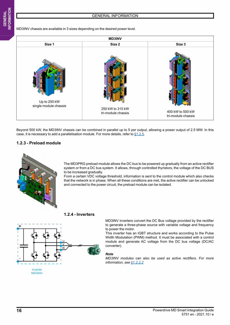
MD3INV chassis are available in 3 sizes depending on the desired power level.
MD3INVSize 1 Size 2 Size 3
Up to 200 kWsingle module chassis
250 kW to 315 kWtri-module chassis 400 kW to 500 kW
tri-module chassis
Beyond 500 kW, the MD3INV chassis can be combined in parallel up to 5 per output, allowing a power output of 2.5 MW. In this case, it is necessary to add a parallelisation module. For more details, refer to §1.2.5.
1.2.3 - Preload module
The MD3PRG preload module allows the DC bus to be powered up gradually from an active rectifier system or from a DC bus system. It allows, through controlled thyristors, the voltage of the DC BUS to be increased gradually.From a certain VDC voltage threshold, information is sent to the control module which also checks that the network is in phase. When all these conditions are met, the active rectifier can be unlocked and connected to the power circuit, the preload module can be isolated.
1.2.4 - InvertersMD3INV inverters convert the DC Bus voltage provided by the rectifier to generate a three-phase source with variable voltage and frequency to power the motor.This inverter has an IGBT structure and works according to the Pulse Width Modulation (PWM) method. It must be associated with a control module and generate AC voltage from the DC bus voltage (DC/AC converter).
NoteMD3INV modules can also be used as active rectifiers. For more information, see §1.2.2.2
InverterMD3INV
17
GENERAL INFORMATION
Powerdrive MD Smart Integration Guide5751 en - 2021.10 / e
GENE
RAL
INFO
RMAT
ION
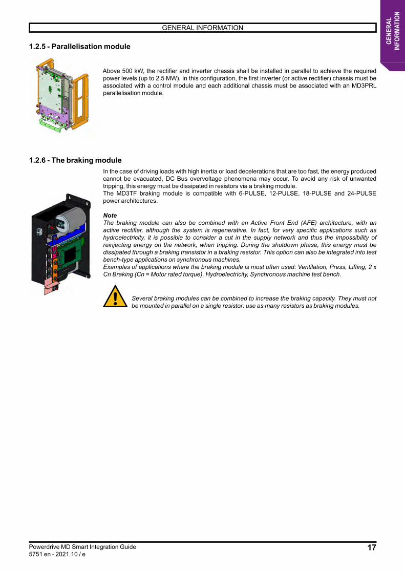
1.2.5 - Parallelisation module
Above 500 kW, the rectifier and inverter chassis shall be installed in parallel to achieve the required power levels (up to 2.5 MW). In this configuration, the first inverter (or active rectifier) chassis must be associated with a control module and each additional chassis must be associated with an MD3PRL parallelisation module.
1.2.6 - The braking moduleIn the case of driving loads with high inertia or load decelerations that are too fast, the energy produced cannot be evacuated, DC Bus overvoltage phenomena may occur. To avoid any risk of unwanted tripping, this energy must be dissipated in resistors via a braking module.The MD3TF braking module is compatible with 6-PULSE, 12-PULSE, 18-PULSE and 24-PULSE power architectures.
NoteThe braking module can also be combined with an Active Front End (AFE) architecture, with an active rectifier, although the system is regenerative. In fact, for very specific applications such as hydroelectricity, it is possible to consider a cut in the supply network and thus the impossibility of reinjecting energy on the network, when tripping. During the shutdown phase, this energy must be dissipated through a braking transistor in a braking resistor. This option can also be integrated into test bench-type applications on synchronous machines.Examples of applications where the braking module is most often used: Ventilation, Press, Lifting, 2 x Cn Braking (Cn = Motor rated torque), Hydroelectricity, Synchronous machine test bench.
Several braking modules can be combined to increase the braking capacity. They must not be mounted in parallel on a single resistor: use as many resistors as braking modules.
18
GENERAL INFORMATION
Powerdrive MD Smart Integration Guide5751 en - 2021.10 / e
GENE
RAL
INFO
RMAT
ION
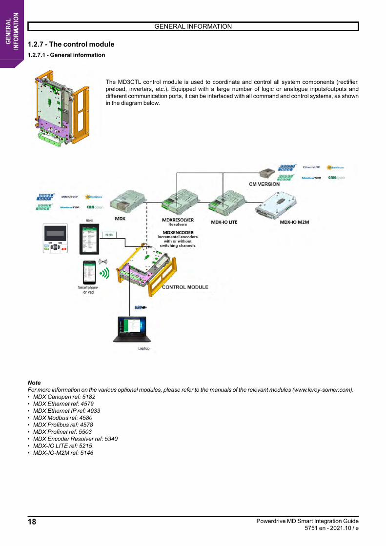
1.2.7 - The control module1.2.7.1 - General information
The MD3CTL control module is used to coordinate and control all system components (rectifier, preload, inverters, etc.). Equipped with a large number of logic or analogue inputs/outputs and different communication ports, it can be interfaced with all command and control systems, as shown in the diagram below.
NoteFor more information on the various optional modules, please refer to the manuals of the relevant modules (www.leroy-somer.com).• MDX Canopen ref: 5182• MDX Ethernet ref: 4579• MDX Ethernet IP ref: 4933• MDX Modbus ref: 4580• MDX Profibus ref: 4578• MDX Profinet ref: 5503• MDX Encoder Resolver ref: 5340• MDX-IO LITE ref: 5215• MDX-IO-M2M ref: 5146
19
GENERAL INFORMATION
Powerdrive MD Smart Integration Guide5751 en - 2021.10 / e
GENE
RAL
INFO
RMAT
ION
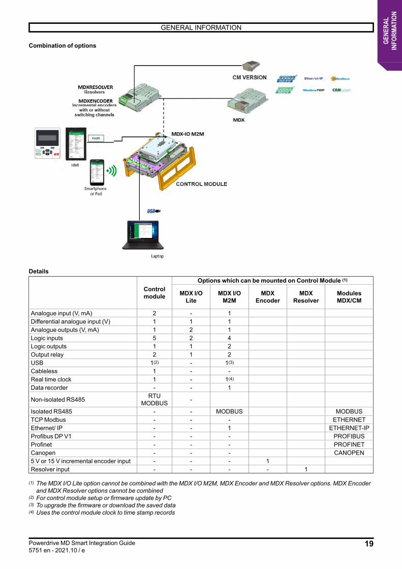
Combination of options
Details
Control module
Options which can be mounted on Control Module (1)
MDX I/OLite
MDX I/OM2M
MDXEncoder
MDXResolver
ModulesMDX/CM
Analogue input (V, mA) 2 - 1Differential analogue input (V) 1 1 1Analogue outputs (V, mA) 1 2 1Logic inputs 5 2 4Logic outputs 1 1 2Output relay 2 1 2USB 1(2) - 1(3)
Cableless 1 - -Real time clock 1 - 1(4)
Data recorder - - 1
Non-isolated RS485 RTU MODBUS -
Isolated RS485 - - MODBUS MODBUSTCP Modbus - - - ETHERNETEthernet/ IP - - 1 ETHERNET-IPProfibus DP V1 - - - PROFIBUSProfinet - - - PROFINETCanopen - - - CANOPEN5 V or 15 V incremental encoder input - - - 1Resolver input - - - - 1
(1) The MDX I/O Lite option cannot be combined with the MDX I/O M2M, MDX Encoder and MDX Resolver options. MDX Encoder and MDX Resolver options cannot be combined
(2) For control module setup or firmware update by PC(3) To upgrade the firmware or download the saved data (4) Uses the control module clock to time stamp records

20
GENERAL INFORMATION
Powerdrive MD Smart Integration Guide5751 en - 2021.10 / e
GENE
RAL
INFO
RMAT
ION
1.2.7.2 - SystemizSystemiz is a unique application that offers a multitude of services to support our ranges of motors and variable speed drives.
The Systemiz application offers 3 features:
For more informations, visit
leroy-somer.frDownloads Brochures
VARIABLESPEED
CONTROL
POWERDRIVE MD Smart & SYSTEMIZREF. 5688
Document libraryThis feature provides access to all product documentation or related services. Product identification is obtained by scanning the QR code or by entering the numerical code available on the nameplate.
Powerdrive MD Smart setup interfaceEnables simplified, intuitive and interactive setup of the Powerdrive MD Smart.- Motor parameter information is automatically generated by scanning the QR code or by entering the numerical identification code on the motor’s nameplate.- The operator interface becomes fully configurable as per the client’s wish or application.- Innovative diagnostic tools.
Motor dataThis feature allows you to obtain the motor parameters to be set in a variable speed drive other than the Powerdrive MD Smart from the QR code or the numerical identification code on the motor’s nameplate.
The Systemiz application is available on:• Smartphone or tablet via secure cableless connection. In this version, the app is available for download on Google Play platforms
(Android version).• Cabled PC connected to USB port of variable speed drive control module. The Systemiz application can be downloaded from the
Leroy-Somer website.• By HMI installed locally on the enclosure’s facade for example. This HMI, available as an option, comes with the application
loaded and ready to use (please note that it is only compatible with the Powerdrive MD Smart, and should not be connected to other hardware).
1.2.8 - Cable kitthe KITCxxyy cable kit consists of different cables that provide an electrical connection between the different components of the Powerdrive MD Smart.There are different cable kits according to their length (xx = 12 or 20, for 1.2 m or 2 m), and their composition (yy = INV for inverter, REC for rectifier). See §4.9.
21
GENERAL INFORMATION
Powerdrive MD Smart Integration Guide5751 en - 2021.10 / e
GENE
RAL
INFO
RMAT
ION
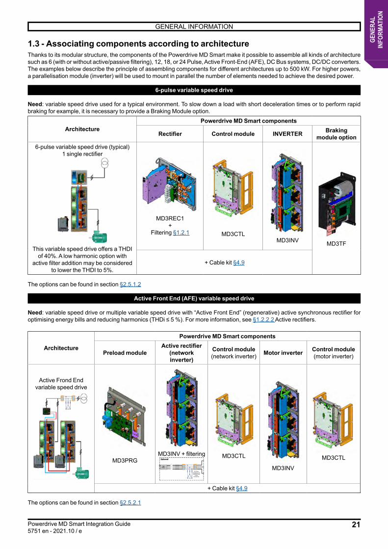
1.3 - Associating components according to architectureThanks to its modular structure, the components of the Powerdrive MD Smart make it possible to assemble all kinds of architecture such as 6 (with or without active/passive filtering), 12, 18, or 24 Pulse, Active Front-End (AFE), DC Bus systems, DC/DC converters.The examples below describe the principle of assembling components for different architectures up to 500 kW. For higher powers, a parallelisation module (inverter) will be used to mount in parallel the number of elements needed to achieve the desired power.
6-pulse variable speed drive
Need: variable speed drive used for a typical environment. To slow down a load with short deceleration times or to perform rapid braking for example, it is necessary to provide a Braking Module option.
ArchitecturePowerdrive MD Smart components
Rectifier Control module INVERTER Braking module option
6-pulse variable speed drive (typical)1 single rectifier
This variable speed drive offers a THDI of 40%. A low harmonic option with
active filter addition may be considered to lower the THDI to 5%.
MD3REC1+
Filtering §1.2.1 MD3CTLMD3INV MD3TF
+ Cable kit §4.9
The options can be found in section §2.5.1.2
Active Front End (AFE) variable speed drive
Need: variable speed drive or multiple variable speed drive with “Active Front End” (regenerative) active synchronous rectifier for optimising energy bills and reducing harmonics (THDi ≤ 5 %). For more information, see §1.2.2.2 Active rectifiers.
Architecture
Powerdrive MD Smart components
Preload moduleActive rectifier
(network inverter)
Control module(network inverter) Motor inverter Control module
(motor inverter)
Active Frond End variable speed drive
MD3PRGMD3INV + filtering MD3CTL
MD3INV
MD3CTL
+ Cable kit §4.9
The options can be found in section §2.5.2.1

22
GENERAL INFORMATION
Powerdrive MD Smart Integration Guide5751 en - 2021.10 / e
GENE
RAL
INFO
RMAT
ION
12-pulse variable speed drive
Need: 12-pulse variable speed drive for a reduction of harmonics on the network (THDi <12%). If it is necessary to slow down a load with short deceleration times or to perform rapid braking for example, it is necessary to provide a Braking Module option.
ArchitecturePowerdrive MD Smart components
Rectifier Control module INVERTER Braking module option
12-pulse variable speed drive
2 single rectifiers
MD3REC1+
MD3REC1+
2 filtering §1.2.1
MD3CTL
MD3INV
MD3TF
+ Cable kit §4.9
The options can be found in sections §2.5.1.2 and 2.5.1.4
23
GENERAL INFORMATION
Powerdrive MD Smart Integration Guide5751 en - 2021.10 / e
GENE
RAL
INFO
RMAT
ION
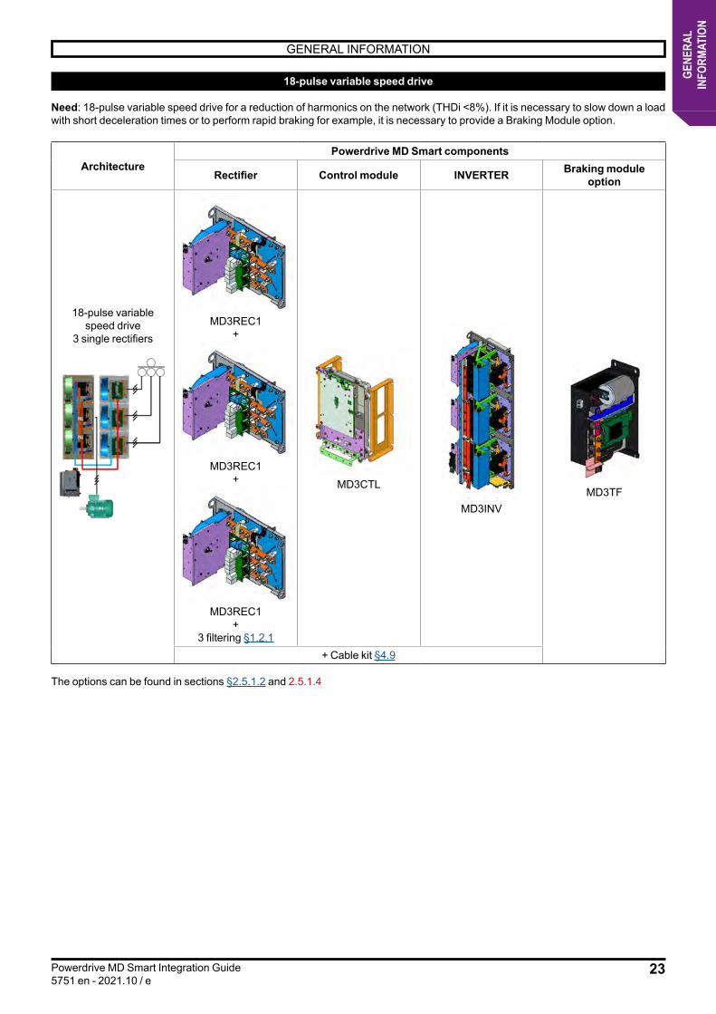
18-pulse variable speed drive
Need: 18-pulse variable speed drive for a reduction of harmonics on the network (THDi <8%). If it is necessary to slow down a load with short deceleration times or to perform rapid braking for example, it is necessary to provide a Braking Module option.
ArchitecturePowerdrive MD Smart components
Rectifier Control module INVERTER Braking module option
18-pulse variable speed drive
3 single rectifiers MD3REC1
+
MD3REC1+
MD3REC1+
3 filtering §1.2.1
MD3CTL
MD3INVMD3TF
+ Cable kit §4.9
The options can be found in sections §2.5.1.2 and 2.5.1.4

24
GENERAL INFORMATION
Powerdrive MD Smart Integration Guide5751 en - 2021.10 / e
GENE
RAL
INFO
RMAT
ION
24-pulse variable speed drive
Need: 24-pulse variable speed drive for a reduction of harmonics on the network (THDi <5%). If it is necessary to slow down a load with short deceleration times or to perform rapid braking for example, it is necessary to provide a Braking Module option.
ArchitecturePowerdrive MD Smart components
Rectifier Control module INVERTER Braking module option
24-pulse variable speed drive
4 single rectifiers
MD3REC1+
MD3REC1+
MD3REC1+
+MD3REC1
+2 filtering §1.2.1
MD3CTL
MD3INV
MD3TF
+ Cable kit §4.9
The options can be found in sections §2.5.1.2 and 2.5.1
DC Bus variable speed drive
Please consult Leroy-Somer

25
GENERAL INFORMATION
Powerdrive MD Smart Integration Guide5751 en - 2021.10 / e
GENE
RAL
INFO
RMAT
ION
1.4 - Cooling methodsPowerdrive MD Smart components generate thermal losses during operation. If these are not evacuated, they lead to temperature rises that may cause the product to trip or components to age prematurely.
Two types of losses will be distinguished:
• Power component losses (rectifier and inverter semiconductors)These losses represent about 80% of the total losses of the variable speed drive that are dissipated by radiators. In order to reduce the losses to be dissipated in the electrical enclosure, the Powerdrive MD Smart has been developed so that its power components’ radiators are located in an exhaust channel (optional accessory). Two types of radiator cooling have been developed to meet the constraints of the installation and the environment: air cooling and liquid cooling.
• Internal lossesThese losses correspond to the total losses generated by the components located inside the enclosure, i.e. the losses of the variable speed drive components (except the power components) but also those of the components needed for the installation (transformer, options, power supplies, relay, etc.). These losses should be evacuated using traditional enclosure cooling methods depending on the temperature and environmental conditions imposed by the components used.
1.4.1 - Air cooling1.4.1.1 - Ventilated power componentsAir cooling is forced convection on the Powerdrive MD Smart. It is carried out by means of fans mounted on each power module. Losses are directly discharged through an air channel mounted on the radiators of the power modules. This air channel is provided as an option.
• Ventilated rectifiers or inverters: AF version
Ventilations Ventilation
Example: an MD3INVAF inverter Example: an MD3RECxAF rectifier MD3TUNyyTx
Note: The MD3TUNyyTx fan tunnels provide a good cooling of the components of the Powerdrive MD Smart (inverter and rectifier).There are different ventilation tunnels depending on the size of the power module to be cooled (x=1,2,3), and their composition (yy=R(regen), 6P(6 pulse)). See §3.4.
Ventilation tunnel accessory
26
GENERAL INFORMATION
Powerdrive MD Smart Integration Guide5751 en - 2021.10 / e
GENE
RAL
INFO
RMAT
ION
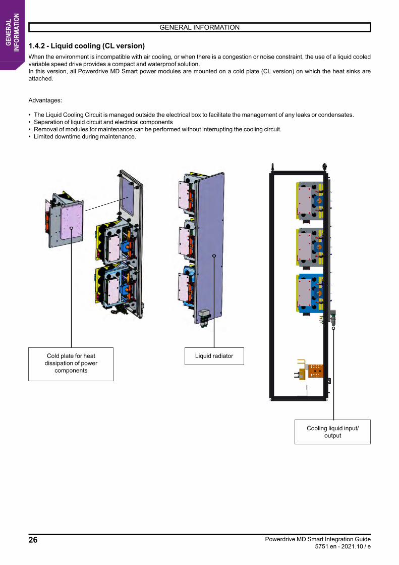
1.4.2 - Liquid cooling (CL version)When the environment is incompatible with air cooling, or when there is a congestion or noise constraint, the use of a liquid cooled variable speed drive provides a compact and waterproof solution. In this version, all Powerdrive MD Smart power modules are mounted on a cold plate (CL version) on which the heat sinks are attached.
Advantages: • The Liquid Cooling Circuit is managed outside the electrical box to facilitate the management of any leaks or condensates.• Separation of liquid circuit and electrical components• Removal of modules for maintenance can be performed without interrupting the cooling circuit.• Limited downtime during maintenance.
Cold plate for heat dissipation of power
components
Liquid radiator
Cooling liquid input/output
27
GENERAL INFORMATION
Powerdrive MD Smart Integration Guide5751 en - 2021.10 / e
GENE
RAL
INFO
RMAT
ION
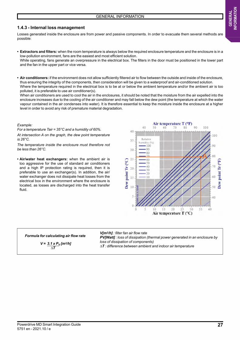
1.4.3 - Internal loss managementLosses generated inside the enclosure are from power and passive components. In order to evacuate them several methods are possible:
• Extractors and filters: when the room temperature is always below the required enclosure temperature and the enclosure is in a low-pollution environment, fans are the easiest and most efficient solution.
While operating, fans generate an overpressure in the electrical box. The filters in the door must be positioned in the lower part and the fan in the upper part or vice versa.
• Air conditioners: if the environment does not allow sufficiently filtered air to flow between the outside and inside of the enclosure, thus ensuring the integrity of the components, then consideration will be given to a waterproof and air-conditioned solution.
Where the temperature required in the electrical box is to be at or below the ambient temperature and/or the ambient air is too polluted, it is preferable to use air conditioner(s).
When air conditioners are used to cool the air in the enclosures, it should be noted that the moisture from the air expelled into the enclosure increases due to the cooling of the air conditioner and may fall below the dew point (the temperature at which the water vapour contained in the air condenses into water). It is therefore essential to keep the moisture inside the enclosure at a higher level in order to avoid any risk of premature material degradation.
Example:For a temperature Tair = 35°C and a humidity of 60%.At intersection A on the graph, the dew point temperature is 26°C.The temperature inside the enclosure must therefore not be less than 26°C.
• Air/water heat exchangers: when the ambient air is too aggressive for the use of standard air conditioners and a high IP protection rating is required, then it is preferable to use an exchanger(s). In addition, the air/water exchanger does not dissipate heat losses from the electrical box in the environment where the enclosure is located, as losses are discharged into the heat transfer fluid.
Formula for calculating air flow rate
V = 3.1 x PV [m3/h] ∆T
V[m3/h] : filter fan air flow ratePV[Watt] : loss of dissipation (thermal power generated in an enclosure by loss of dissipation of components)∆T : difference between ambient and indoor air temperature
A
28
HARDWARE SELECTION
Powerdrive MD Smart Integration Guide5751 en - 2021.10 / e
HARD
WAR
ESE
LECT
ION
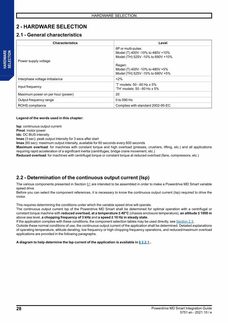
2 - HARDWARE SELECTION2.1 - General characteristics
Characteristics Level
Power supply voltage
6P or multi-pulse:Model (T) 400V -10% to 480V +10% Model (TH) 525V -10% to 690V +10%
Regen:Model (T) 400V -10% to 480V +5% Model (TH) 525V -10% to 690V +5%
Interphase voltage imbalance <2%
Input frequency ‘T’ models: 50 - 60 Hz ± 5%‘TH’ models: 50 - 60 Hz ± 5%
Maximum power on per hour (power) 20Output frequency range 0 to 590 HzROHS compliance Complies with standard 2002-95-EC
Legend of the words used in this chapter:
Isp: continuous output currentPmot: motor powerIdc: DC BUS intensityImax (3 sec): peak output intensity for 3 secs after startImax (60 sec): maximum output intensity, available for 60 seconds every 600 secondsMaximum overload: for machines with constant torque and high overload (presses, crushers, lifting, etc.) and all applications requiring rapid acceleration of a significant inertia (centrifuges, bridge crane movement, etc.)Reduced overload: for machines with centrifugal torque or constant torque at reduced overload (fans, compressors, etc.)
2.2 - Determination of the continuous output current (Isp)The various components presented in Section §1 are intended to be assembled in order to make a Powerdrive MD Smart variable speed drive.Before you can select the component references, it is necessary to know the continuous output current (Isp) required to drive the motor.
This requires determining the conditions under which the variable speed drive will operate.The continuous output current Isp of the Powerdrive MD Smart shall be determined for optimal operation with a centrifugal or constant torque machine with reduced overload, at a temperature ≤ 40°C (chassis enclosure temperature), an altitude ≤ 1000 m above sea level, a chopping frequency of 3 kHz and a speed ≥ 10 Hz in steady state.If the application complies with these conditions, the component selection tables may be used directly, see Section 2.3.Outside these normal conditions of use, the continuous output current of the application shall be determined. Detailed explanations of operating temperature, altitude derating, low frequency or high chopping frequency operations, and reduced/maximum overload applications are provided in the following paragraphs.
A diagram to help determine the Isp current of the application is available in § 2.2.1..
29
HARDWARE SELECTION
Powerdrive MD Smart Integration Guide5751 en - 2021.10 / e
HARD
WAR
ESE
LECT
ION
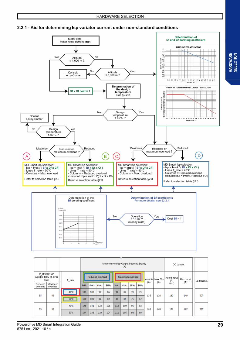
2.2.1 - Aid for determining Isp variator current under non-standard conditions
A B C D
Yes
YesNo
Yes
No
No
ReducedMaximum
Operation≥ 10 Hz ?
(steady state)
Reduced ormaximum overload ?
Altitude≤ 3,000 m ?
ReducedMaximum Reduced ormaximum overload ?
Designtemperature≤ 40°C ?
Designtemperature≤ 50°C ?
Determination ofthe design
temperatureSee §2.2.2
Determination of theBf derating coefficent
ConsultLeroy-Somer
NoConsultLeroy-Somer
Motor data:Motor rated current Imot
MD Smart Isp selection:- Isp = Imot / ( Bf x Df x Cf )- Lines T_rate = 40°C- Columns = Reduced overload- Reduced ISp = Imot/1.1*(Bf x Df x Cf)
Refer to selection table §2.3
MD Smart Isp selection:- Isp = Imot / ( Bf x Df x Cf )- Lines T_rate = 40°C- Columns = Max. overload
Refer to selection table §2.3
Yes
MD Smart Isp selection:- Isp = Imot / ( Bf x Df x Cf ) - Lines T_rate = 50°C- Columns = Reduced overload- Reduced ISp = Imot/1.1*(Bf x Df x Cf)Refer to selection table §2.3
Coef Bf = 1
Yes NoAltitude≤ 1,000 m ?
Determination ofDf and Cf derating coefficient
Determination of Bf coefficientsFor more details, see §2.2.4
Df x Cf coef.= 1
MD Smart Isp selection:- Isp = Imot / ( Bf x Df x Cf )- Lines T_rate = 50°C- Columns = Max. overload
Refer to selection table §2.3
Frequency
or
T_rateReduced overload Maximum overload
Max. input(A)
Rated input(A)
40°C
P_MOTOR 4PA 3 kHz 400V at 40°C
(kW) Imax.60s(A)
Reducedoverload
Maximumoverload
Imax.3s(A) LS MODEL
DC currentMotor current Isp Output Intensity Steady(A)
30
HARDWARE SELECTION
Powerdrive MD Smart Integration Guide5751 en - 2021.10 / e
HARD
WAR
ESE
LECT
ION
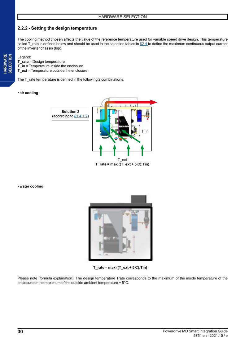
2.2.2 - Setting the design temperature
The cooling method chosen affects the value of the reference temperature used for variable speed drive design. This temperature called T_rate is defined below and should be used in the selection tables in §2.4 to define the maximum continuous output current of the inverter chassis (Isp).
Legend:T_rate = Design temperatureT_in = Temperature inside the enclosure.T_ext = Temperature outside the enclosure.
The T_rate temperature is defined in the following 2 combinations:
• air cooling
• water cooling
T_extT_rate = max ((T_ext + 5 C);Tin)
T_rate = max ((T_ext + 5 C);Tin)
T_in
Solution 2(according to §1.4.1.2)
Please note (formula explanation): The design temperature Trate corresponds to the maximum of the inside temperature of the enclosure or the maximum of the outside ambient temperature + 5°C.

31
HARDWARE SELECTION
Powerdrive MD Smart Integration Guide5751 en - 2021.10 / e
HARD
WAR
ESE
LECT
ION
If the calculated T_rate is less than or equal to 40°C, take the Isp current values of the variable speed drive corresponding to 40°C in the selection tables in § 2.3:
T_rateReduced overload Maximum overload
Max. input(A)
Rated input(A)
40°C
P_MOTOR 4PA 3 kHz 400V at 40°C
(kW) Imax.60s(A)
Reducedoverload
Maximumoverload
Imax.3s(A) LS MODEL
DC currentMotor current Isp Output Intensity Steady(A)
If the calculated T_rate is equal to 50°C, take the Isp current values of the variable speed drive corresponding to 50°C in the selection tables in § 2.3:
T_rateReduced overload Maximum overload
Max. input(A)
Rated input(A)
40°C
P_MOTOR 4PA 3 kHz 400V at 40°C
(kW) Imax.60s(A)
Reducedoverload
Maximumoverload
Imax.3s(A) LS MODEL
DC currentMotor current Isp Output Intensity Steady(A)
If the calculated T_rate is greater than 50°C, apply the derating with ambient temperature correction factor Tf in Section §2.2.3.

32
HARDWARE SELECTION
Powerdrive MD Smart Integration Guide5751 en - 2021.10 / e
HARD
WAR
ESE
LECT
ION
2.2.3 - Determination of the Isp continuous output currentWhen altitude is > 1000 m, air pressure and density decrease. As a result, the speed of the air entering the electrical box is reduced, thus affecting the cooling of the components.
It is therefore necessary to derate the Isp current:Isp = (Isp_40°C) x Af x TfWhere:Isp_40°C = ISP continuous output current of the Powerdrive MD Smart determined for a T_rate at 40°C, indicated in the selection tables in § 2.3.Af = Derating coefficient determined from the derating curve for the following altitude.Tf = Derating coefficient determined from the derating curve for the following ambient temperature.
• Derating curve for altitude (Af coefficient)
Note: For applications over 3000 m, contact Leroy-Somer.
• Derating curve according to ambient temperature (Tf coefficient)
NoteIf the variable speed drive is to operate above 40 °C, the derating at 50 °C shall be carried out: Isp = (Isp_50°C) x Af
33
HARDWARE SELECTION
Powerdrive MD Smart Integration Guide5751 en - 2021.10 / e
HARD
WAR
ESE
LECT
ION
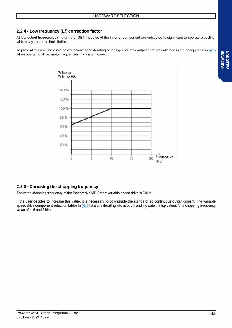
2.2.4 - Low frequency (Lf) correction factorAt low output frequencies (motor), the IGBT modules of the inverter component are subjected to significant temperature cycling, which may decrease their lifetime.
To prevent this risk, the curve below indicates the derating of the Isp and Imax output currents indicated in the design table in §2.3 when operating at low motor frequencies in constant speed.
2.2.5 - Choosing the chopping frequencyThe rated chopping frequency of the Powerdrive MD Smart variable speed drive is 3 kHz.
If the user decides to increase this value, it is necessary to downgrade the standard Isp continuous output current. The variable speed drive component selection tables in §2.3 take this derating into account and indicate the Isp values for a chopping frequency value of 4, 6 and 8 kHz.
34
HARDWARE SELECTION
Powerdrive MD Smart Integration Guide5751 en - 2021.10 / e
HARD
WAR
ESE
LECT
ION
2.3 - Hardware selection For general information on the various components described in this paragraph, see §1 - General information. For electrical characteristics, see section §2.5.
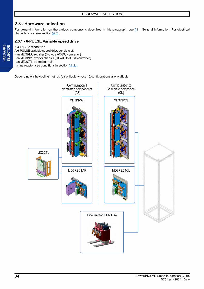
2.3.1 - 6-PULSE Variable speed drive 2.3.1.1 - CompositionA 6-PULSE variable speed drive consists of:- an MD3REC rectifier (6-diode AC/DC converter).- an MD3INV inverter chassis (DC/AC to IGBT converter). - an MD3CTL control module- a line reactor, see conditions in section §1.2.1
Depending on the cooling method (air or liquid) chosen 2 configurations are available.
Configuration 1Ventilated components
(AF)
Configuration 2Cold plate component
(CL)
MD3INVAF MD3INVCL
MD3CTL
MD3REC1AF MD3REC1CL
Line reactor + UR fuse
35
HARDWARE SELECTION
Powerdrive MD Smart Integration Guide5751 en - 2021.10 / e
HARD
WAR
ESE
LECT
ION
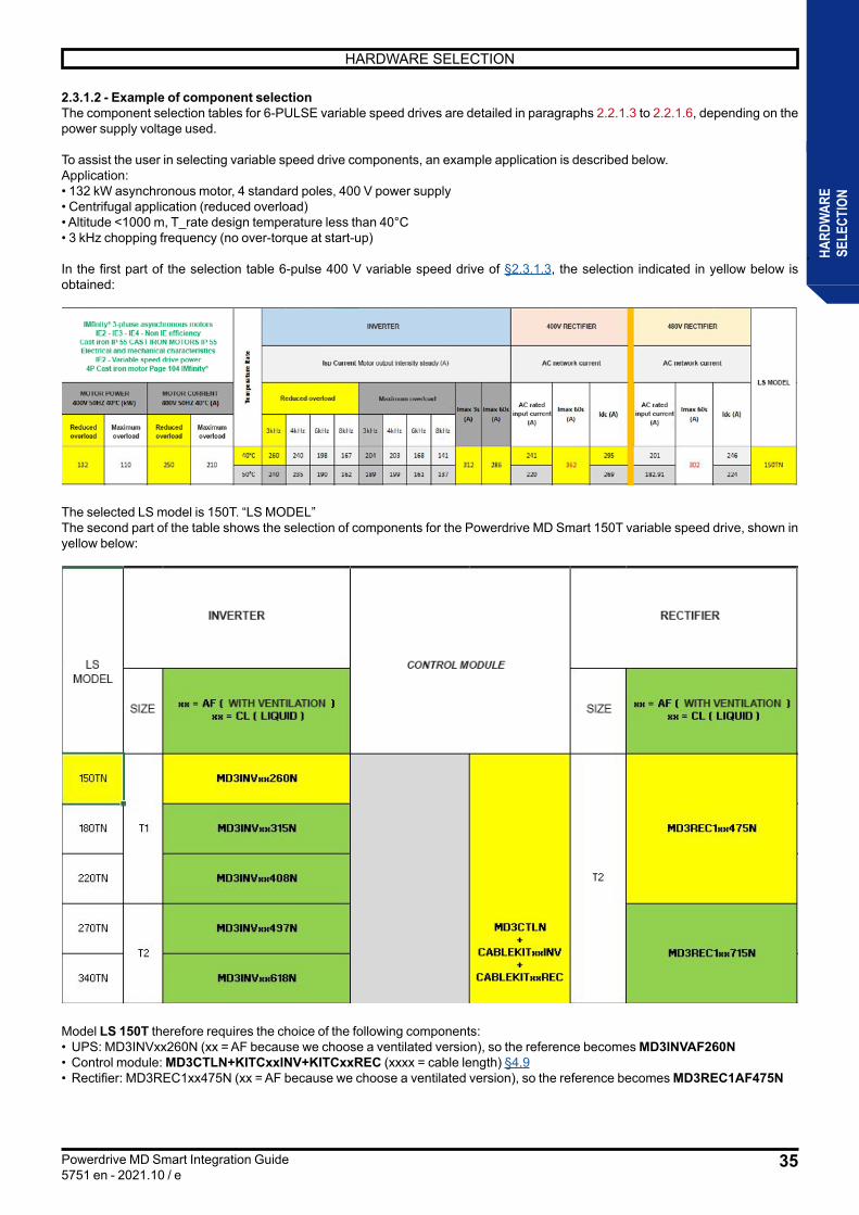
2.3.1.2 - Example of component selectionThe component selection tables for 6-PULSE variable speed drives are detailed in paragraphs 2.2.1.3 to 2.2.1.6, depending on the power supply voltage used.
To assist the user in selecting variable speed drive components, an example application is described below.Application:• 132 kW asynchronous motor, 4 standard poles, 400 V power supply• Centrifugal application (reduced overload)• Altitude <1000 m, T_rate design temperature less than 40°C• 3 kHz chopping frequency (no over-torque at start-up)
In the first part of the selection table 6-pulse 400 V variable speed drive of §2.3.1.3, the selection indicated in yellow below is obtained:
The selected LS model is 150T. “LS MODEL”The second part of the table shows the selection of components for the Powerdrive MD Smart 150T variable speed drive, shown in yellow below:
Model LS 150T therefore requires the choice of the following components:• UPS: MD3INVxx260N (xx = AF because we choose a ventilated version), so the reference becomes MD3INVAF260N• Control module: MD3CTLN+KITCxxINV+KITCxxREC (xxxx = cable length) §4.9• Rectifier: MD3REC1xx475N (xx = AF because we choose a ventilated version), so the reference becomes MD3REC1AF475N

36
HARDWARE SELECTION
Powerdrive MD Smart Integration Guide5751 en - 2021.10 / e
HARD
WAR
ESE
LECT
ION
2.3.1.3 - 6-PULSE variable speed drive, 400V -10% to 480V +10%
For a different chopping frequency value than those present in the table, please consult Nidec Leroy-Somer
IMfinity® three-phase asynchronous motors Outputs IE2 - IE3 - IE4 - No IE
Cast Iron IP 55 CAST IRON MOTORS IP55 Electrical and mechanical characteristics
IE2 - variable speed drive power 4P cast iron motor Page 104 IMfinity®
Tem
pera
ture
Rat
e
INVERTER 400V RECTIFIER 480V RECTIFIER
LS MODEL
ISP Current Motor Output Intensity Permanent (A) AC network current AC network current
MOTOR POWER 400V 50HZ 40°C (kW)
MOTOR CURRENT 400V 50HZ 40°C (A) Reduced overload Maximum overload Imax
3s (A)
Imax 60s (A)
AC current rated input
(A)(10%)
Imax 60s (A)
Idc (A)
AC current rated
input (A)
Imax 60s (A)
Idc (A)Overload Reduced
Overload Maximum
Overload Reduced
Overload Maximum 3 kHz 4 kHz 6 kHz 8 kHz 3 kHz 4 kHz 6 kHz 8 kHz
132 110 250 210 40 °C 260 240 198 167 204 203 168 141
312 286246
369295 225
338276
150TN 50 °C 240 235 190 162 189 199 161 137 220 269 205 251
160 132 303 250 40 °C 315 292 240 203 248 241 198 168
378 347295
443361 275
413337
180TN 50 °C 305 273 224 190 240 225 185 157 290 355 250 306
200 160 374 303 40 °C 408 385 340 300 321 309 272 241
490 449395
593484 326
489399
220TN 50 °C 400 365 323 285 314 293 259 229 380 465 297 363
250 200 465 374 40 °C 497 455 390 337 391 358 307 265
596 547479
719563 384
576470
270TN 50 °C 452 412 353 305 355 324 277 240 419 513 349 428
315 250 594 465 40 °C 618 555 458 387 486 436 360 304
742 680595
893710 477
716584
340TN 50 °C 575 516 426 360 452 406 335 283 533 653 434 532
400 315 720 594 40 °C 747 685 587 507 587 538 461 398
896 822701
1052838 570
855698
430TN 50 °C 680 632 542 468 534 496 426 368 620 759 519 635
450 355 858 670 40 °C 865 792 670 575 680 622 527 452
1038 952833
1250970 660
990808
470TN 50 °C 802 734 621 533 630 577 488 419 734 900 601 736
500 400 943 720 40 °C 931 855 690 595 732 672 542 468
1117 1024896
13441057 719
1079881
570TN 50 °C 846 789 635 549 665 620 499 431 784 960 654 801
630 500 1155 943 40 °C 1199 1077 889 751 942 846 698 590
1439 13191111
16671307 926
13891134
680TN 50 °C 1116 1001 826 698 876 788 650 549 1011 1189 843 1032
800 630 1478 1155 40 °C 1449 1329 1139 984 1139 1044 894 772
1739 15941342
20131644 1120
16801372
860TN 50 °C 1319 1226 1051 908 1037 962 826 714 1221 1496 1019 1248
900 675 1666 1268 40 °C 1678 1536 1300 1116 1319 1207 1022 877
2014 18461551
23271900 1295
19431586
940TN 50 °C 1556 1424 1205 1034 1222 1119 947 813 1411 1729 1178 1443
1000 850 1804 1517 40 °C 1806 1659 1339 1154 1419 1304 1051 908
2167 19871673
25102049 1394
20911707
1140TN 50 °C 1641 1531 1232 1065 1290 1203 968 836 1522 1865 1269 1554
1200 1000 2189 1804 40 °C 2151 1973 1691 1460 1690 1549 1328 1146
2582 23661993
29902441 1661
24922034
1290TN 50 °C 1958 1820 1561 1348 1539 1428 1227 1060 1814 2221 1512 1851
1350 1200 2492 2189 40 °C 2491 2281 1930 1656 1957 1791 1518 1302
2989 27402308
34622827 1923
28852355
1410TN 50 °C 2310 2114 1788 1535 1815 1662 1405 1207 2100 2572 1750 2143
1500 1350 2529 2492 40 °C 2681 2462 1987 1714 2107 1935 1561 1348
3218 29492455
36833007 2046
30692506
1710TN 50 °C 2436 2272 1829 1581 1914 1786 1437 1241 2234 2736 1862 2280
2000 1600 3600 2880 40 °C 3538 3249 2622 2261 2780 2554 2060 1778
4245 38923240
48603968 2700
40503307
2280TN 50 °C 3215 2998 2413 2086 2526 2356 1896 1638 2948 3611 2457 3009
2500 2000 4500 3600 40 °C 4422 4061 3278 2826 3475 3192 2575 2223
5307 48644097
61465018 3414
51214181
2850TN 50 °C 4019 3748 3016 2608 3157 2945 2370 2047 3728 4566 3107 3805
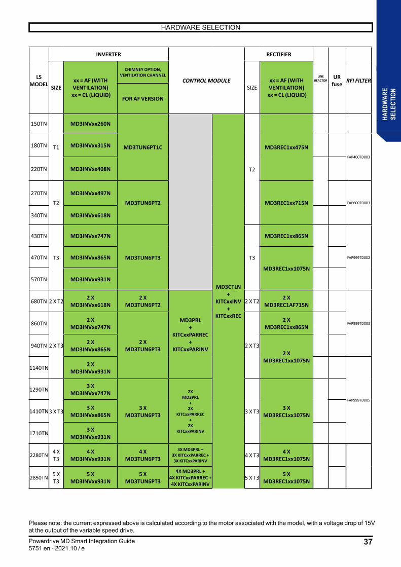
37
HARDWARE SELECTION
Powerdrive MD Smart Integration Guide5751 en - 2021.10 / e
HARD
WAR
ESE
LECT
ION
Please note: the current expressed above is calculated according to the motor associated with the model, with a voltage drop of 15V at the output of the variable speed drive.
LS MODEL
INVERTER
CONTROL MODULE
RECTIFIER
LINE REACTOR
UR fuse RFI FILTER
SIZExx = AF (WITH VENTILATION)
xx = CL (LIQUID)
CHIMNEY OPTION, VENTILATION CHANNEL
SIZExx = AF (WITH VENTILATION)
xx = CL (LIQUID)FOR AF VERSION
150TN
T1
MD3INVxx260N
MD3TUN6PT1C
MD3CTLN +
KITCxxINV +
KITCxxREC
T2
MD3REC1xx475N180TN MD3INVxx315N
FAP400TD003
220TN MD3INVxx408N
270TN
T2
MD3INVxx497N
MD3TUN6PT2 MD3REC1xx715N FAP600TD003
340TN MD3INVxx618N
430TN
T3
MD3INVxx747N
MD3TUN6PT3 T3
MD3REC1xx865N
FAP999TD002470TN MD3INVxx865N
MD3REC1xx1075N
570TN MD3INVxx931N
680TN 2 X T2 2 X MD3INVxx618N
2 X MD3TUN6PT2
MD3PRL +
KITCxxPARREC +
KITCxxPARINV
2 X T2 2 X MD3REC1AF715N
FAP999TD003860TN
2 X T3
2 X MD3INVxx747N
2 X MD3TUN6PT3 2 X T3
2 X MD3REC1xx865N
940TN 2 X MD3INVxx865N
2 X MD3REC1xx1075N
1140TN 2 X MD3INVxx931N
FAP999TD005
1290TN
3 X T3
3 X MD3INVxx747N
3 X MD3TUN6PT3
2X MD3PRL
+ 2X
KITCxxPARREC +
2X KITCxxPARINV
3 X T3 3 X MD3REC1xx1075N1410TN 3 X
MD3INVxx865N
1710TN 3 X MD3INVxx931N
2280TN 4 X T3
4 X MD3INVxx931N
4 X MD3TUN6PT3
3X MD3PRL + 3X KITCxxPARREC + 3X KITCxxPARINV
4 X T3 4 X MD3REC1xx1075N
2850TN 5 X T3
5 X MD3INVxx931N
5 X MD3TUN6PT3
4X MD3PRL + 4X KITCxxPARREC + 4X KITCxxPARINV
5 X T3 5 X MD3REC1xx1075N
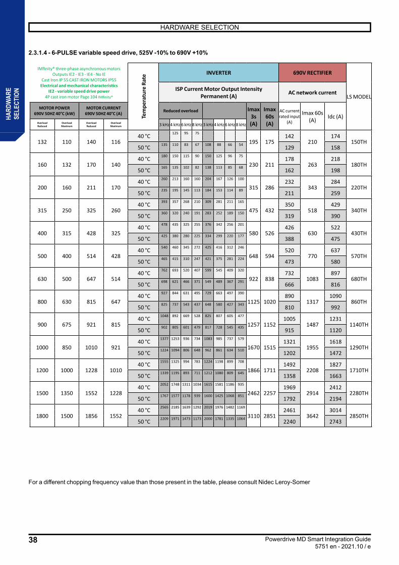
38
HARDWARE SELECTION
Powerdrive MD Smart Integration Guide5751 en - 2021.10 / e
HARD
WAR
ESE
LECT
ION
2.3.1.4 - 6-PULSE variable speed drive, 525V -10% to 690V +10%
For a different chopping frequency value than those present in the table, please consult Nidec Leroy-Somer
IMfinity® three-phase asynchronous motors Outputs IE2 - IE3 - IE4 - No IE
Cast Iron IP 55 CAST IRON MOTORS IP55 Electrical and mechanical characteristics
IE2 - variable speed drive power 4P cast iron motor Page 104 IMfinity®
Tem
pera
ture
Rat
e INVERTER 690V RECTIFIER
LS MODELISP Current Motor Output Intensity
Permanent (A) AC network current
MOTOR POWER 690V 50HZ 40°C (kW)
MOTOR CURRENT 690V 50HZ 40°C (A) Reduced overload Imax
3s (A)
Imax 60s (A)
AC current rated input
(A)
Imax 60s (A) Idc (A)
Overload Reduced
Overload Maximum
Overload Reduced
Overload Maximum 3 kHz 4 kHz 6 kHz 8 kHz 3 kHz 4 kHz 6 kHz 8 kHz
132 110 140 116 40 °C
150 125 95 75 120 100 76 60
195 175142
210174
150TH 50 °C 135 110 83 67 108 88 66 54 129 158
160 132 170 140 40 °C 180 150 115 90 150 125 96 75
230 211178
263218
180TH 50 °C 165 135 102 82 138 113 85 68 162 198
200 160 211 170 40 °C 260 213 160 160 204 167 126 100
315 286232
343284
220TH 50 °C 235 195 145 113 184 153 114 89 211 259
315 250 325 260 40 °C 393 357 268 210 309 281 211 165
475 432350
518429
340TH 50 °C 360 320 240 191 283 252 189 150 319 390
400 315 428 325 40 °C 478 435 325 255 376 342 256 201
580 526426
630522
430TH 50 °C 425 380 280 225 334 299 220 177 388 475
500 400 514 428 40 °C 540 460 345 272 425 416 312 246
648 594520
770637
570TH 50 °C 465 415 310 247 421 375 281 224 473 580
630 500 647 514 40 °C 762 693 520 407 599 545 409 320
922 838732
1083897
680TH 50 °C 698 621 466 371 549 489 367 291 666 816
800 630 815 647 40 °C 927 844 631 495 729 663 497 390
1125 1020890
13171090
860TH 50 °C 825 737 543 437 648 580 427 343 810 992
900 675 921 815 40 °C 1048 892 669 528 825 807 605 477
1257 11521005
14871231
1140TH 50 °C 902 805 601 479 817 728 545 435 915 1120
1000 850 1010 921 40 °C 1377 1253 936 734 1083 985 737 579
1670 15151321
19551618
1290TH 50 °C 1224 1094 806 648 962 861 634 510 1202 1472
1200 1000 1228 1010 40 °C 1555 1325 994 783 1224 1198 899 708
1866 17111492
22081827
1710TH 50 °C 1339 1195 893 711 1212 1080 809 645 1358 1663
1500 1350 1552 1228 40 °C 2052 1748 1311 1034 1615 1581 1186 935
2462 22571969
29142412
2280TH 50 °C 1767 1577 1178 939 1600 1425 1068 851 1792 2194
1800 1500 1856 1552 40 °C 2565 2185 1639 1292 2019 1976 1482 1169
3110 28512461
36423014
2850TH 50 °C 2209 1971 1473 1173 2000 1781 1335 1064 2240 2743
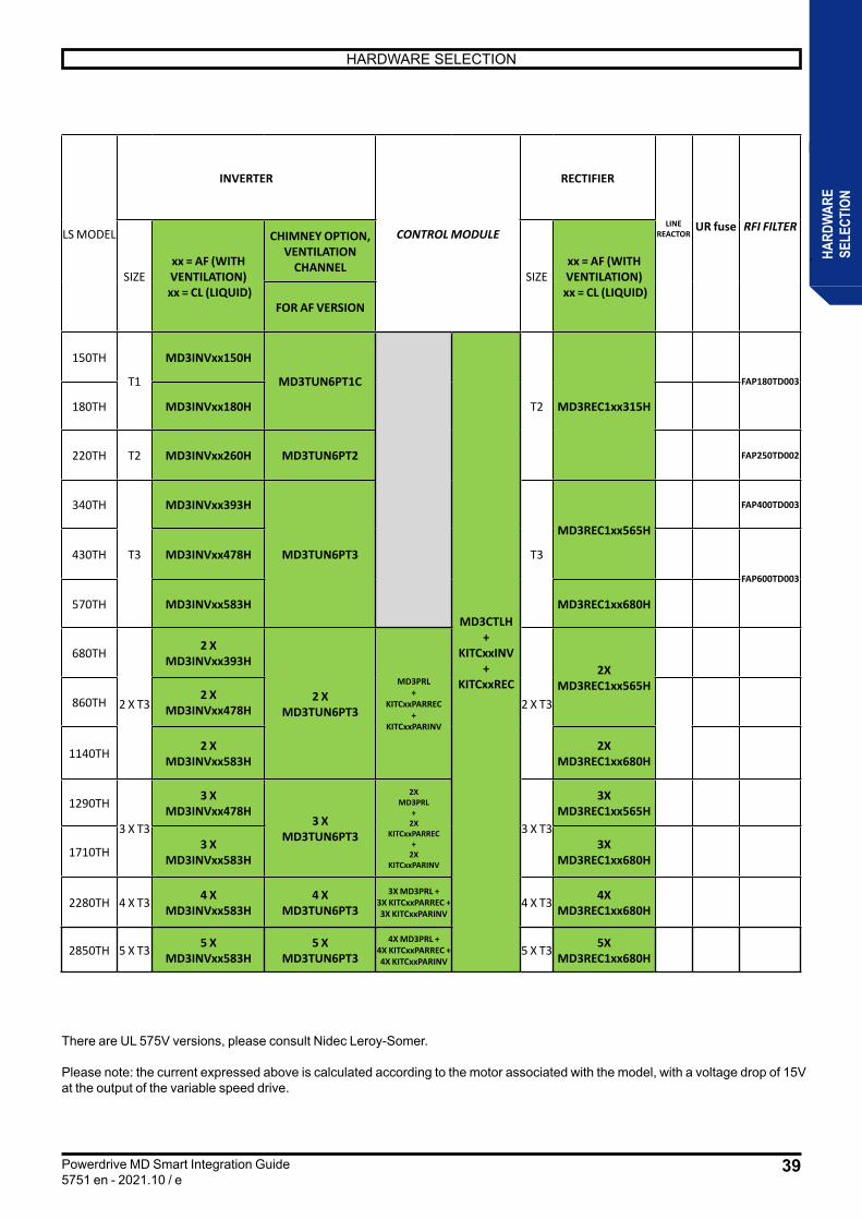
39
HARDWARE SELECTION
Powerdrive MD Smart Integration Guide5751 en - 2021.10 / e
HARD
WAR
ESE
LECT
ION
There are UL 575V versions, please consult Nidec Leroy-Somer.
Please note: the current expressed above is calculated according to the motor associated with the model, with a voltage drop of 15V at the output of the variable speed drive.
LS MODEL
INVERTER
CONTROL MODULE
RECTIFIER
LINE REACTOR
UR fuse RFI FILTER
SIZExx = AF (WITH VENTILATION)
xx = CL (LIQUID)
CHIMNEY OPTION, VENTILATION
CHANNELSIZE
xx = AF (WITH VENTILATION)
xx = CL (LIQUID)FOR AF VERSION
150TH
T1
MD3INVxx150H
MD3TUN6PT1C
MD3CTLH +
KITCxxINV +
KITCxxREC
T2 MD3REC1xx315H
FAP180TD003
180TH MD3INVxx180H
220TH T2 MD3INVxx260H MD3TUN6PT2 FAP250TD002
340TH
T3
MD3INVxx393H
MD3TUN6PT3 T3
MD3REC1xx565H
FAP400TD003
430TH MD3INVxx478H
FAP600TD003
570TH MD3INVxx583H MD3REC1xx680H
680TH
2 X T3
2 X MD3INVxx393H
2 X MD3TUN6PT3
MD3PRL +
KITCxxPARREC +
KITCxxPARINV
2 X T3
2X MD3REC1xx565H
860TH 2 X MD3INVxx478H
1140TH 2 X MD3INVxx583H
2X MD3REC1xx680H
1290TH
3 X T3
3 X MD3INVxx478H
3 X MD3TUN6PT3
2X MD3PRL
+ 2X
KITCxxPARREC +
2X KITCxxPARINV
3 X T3
3X MD3REC1xx565H
1710TH 3 X MD3INVxx583H
3X MD3REC1xx680H
2280TH 4 X T3 4 X MD3INVxx583H
4 X MD3TUN6PT3
3X MD3PRL + 3X KITCxxPARREC + 3X KITCxxPARINV
4 X T3 4X MD3REC1xx680H
2850TH 5 X T3 5 X MD3INVxx583H
5 X MD3TUN6PT3
4X MD3PRL + 4X KITCxxPARREC + 4X KITCxxPARINV
5 X T3 5X MD3REC1xx680H
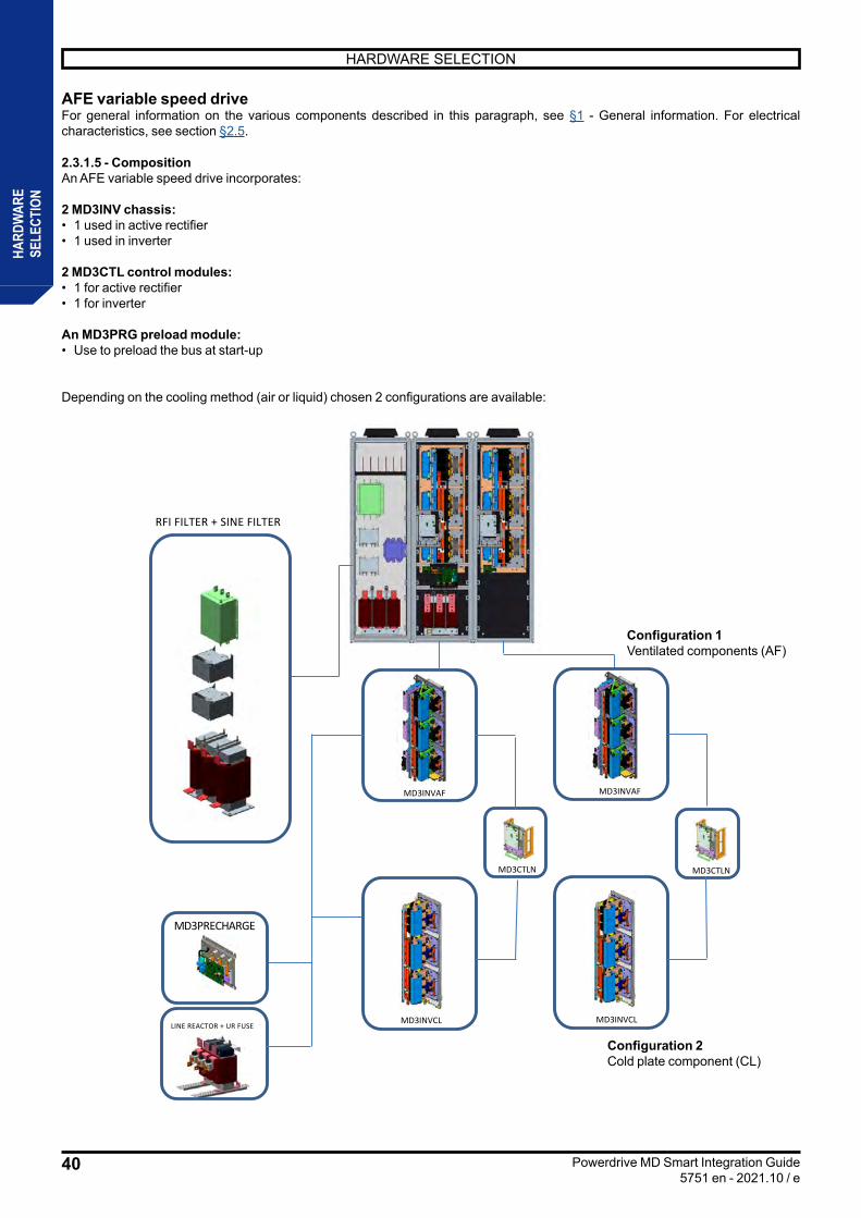
40
HARDWARE SELECTION
Powerdrive MD Smart Integration Guide5751 en - 2021.10 / e
HARD
WAR
ESE
LECT
ION
RFI FILTER + SINE FILTER
MD3PRECHARGE
LINE REACTOR + UR FUSE
MD3CTLN MD3CTLN
MD3INVAF MD3INVAF
MD3INVCL MD3INVCL
AFE variable speed driveFor general information on the various components described in this paragraph, see §1 - General information. For electrical characteristics, see section §2.5.
2.3.1.5 - CompositionAn AFE variable speed drive incorporates: 2 MD3INV chassis:• 1 used in active rectifier• 1 used in inverter
2 MD3CTL control modules:• 1 for active rectifier• 1 for inverter
An MD3PRG preload module:• Use to preload the bus at start-up
Depending on the cooling method (air or liquid) chosen 2 configurations are available:
Configuration 1Ventilated components (AF)
Configuration 2Cold plate component (CL)
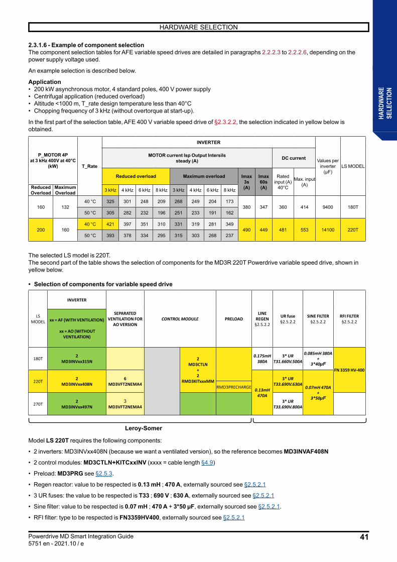
41
HARDWARE SELECTION
Powerdrive MD Smart Integration Guide5751 en - 2021.10 / e
HARD
WAR
ESE
LECT
ION
2.3.1.6 - Example of component selectionThe component selection tables for AFE variable speed drives are detailed in paragraphs 2.2.2.3 to 2.2.2.6, depending on the power supply voltage used.
An example selection is described below.
Application• 200 kW asynchronous motor, 4 standard poles, 400 V power supply• Centrifugal application (reduced overload)• Altitude <1000 m, T_rate design temperature less than 40°C• Chopping frequency of 3 kHz (without overtorque at start-up).
In the first part of the selection table, AFE 400 V variable speed drive of §2.3.2.2, the selection indicated in yellow below is obtained.
P_MOTOR 4P at 3 kHz 400V at 40°C
(kW) T_Rate
INVERTER
Values per inverter
(µF)LS MODEL
MOTOR current Isp Output Intersils steady (A) DC current
Reduced overload Maximum overload Imax 3s (A)
Imax 60s (A)
Rated input (A)
40°C
Max. input (A)Reduced
OverloadMaximum Overload 3 kHz 4 kHz 6 kHz 8 kHz 3 kHz 4 kHz 6 kHz 8 kHz
160 132 40 °C 325 301 248 209 268 249 204 173
380 347 360 414 9400 180T 50 °C 305 282 232 196 251 233 191 162
200 160 40 °C 421 397 351 310 331 319 281 349
490 449 481 553 14100 220T 50 °C 393 378 334 295 315 303 268 237
The selected LS model is 220T.The second part of the table shows the selection of components for the MD3R 220T Powerdrive variable speed drive, shown in yellow below.
• Selection of components for variable speed drive
LS MODEL
INVERTER
SEPARATED VENTILATION FOR
AO VERSIONCONTROL MODULE PRELOAD
LINE REGEN
§2.5.2.2
UR fuse §2.5.2.2
SINE FILTER §2.5.2.2
RFI FILTER §2.5.2.2xx = AF (WITH VENTILATION)
xx = AO (WITHOUT
VENTILATION)
180T 2 MD3INVxx315N 2
MD3CTLN + 2
RMD3KITxxxMM
0.175mH380A
3* URT31.660V.500A
0.085mH 380A+
3*40µFFN 3359 HV-400
220T 2 MD3INVxx408N
6 MD3VFT2NEMA4
0.13mH470A
3* URT33.690V.630A
0.07mH 470A+
3*50µF
RMD3PRECHARGE
270T 2 MD3INVxx497N
3MD3VFT2NEMA4
3* URT33.690V.800A
Leroy-Somer
Model LS 220T requires the following components:
• 2 inverters: MD3INVxx408N (because we want a ventilated version), so the reference becomes MD3INVAF408N
• 2 control modules: MD3CTLN+KITCxxINV (xxxx = cable length §4.9)
• Preload: MD3PRG see §2.5.3.
• Regen reactor: value to be respected is 0.13 mH ; 470 A, externally sourced see §2.5.2.1
• 3 UR fuses: the value to be respected is T33 ; 690 V ; 630 A, externally sourced see §2.5.2.1
• Sine filter: value to be respected is 0.07 mH ; 470 A + 3*50 µF, externally sourced see §2.5.2.1.
• RFI filter: type to be respected is FN3359HV400, externally sourced see §2.5.2.1
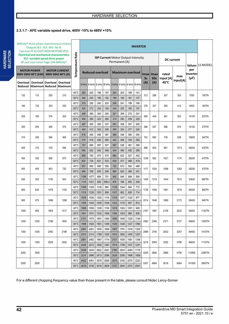
42
HARDWARE SELECTION
Powerdrive MD Smart Integration Guide5751 en - 2021.10 / e
HARD
WAR
ESE
LECT
ION
2.3.1.7 - AFE variable speed drive, 400V -10% to 480V +10%
For a different chopping frequency value than those present in the table, please consult Nidec Leroy-Somer
IMfinity® three-phase asynchronous motors Outputs IE2 - IE3 - IE4 - No IE
Cast Iron IP 55 CAST IRON MOTORS IP55 Electrical and mechanical characteristics
IE2 - variable speed drive power 4P cast iron motor Page 104 IMfinity®
Tem
pera
ture
Rat
e
INVERTER
LS MODEL
ISP Current Motor Output Intensity Permanent (A) DC current
Values per
inverter (µF)
MOTOR POWER 400V 50HZ 40°C (kW)
MOTOR CURRENT 400V 50HZ 40°C (A) Reduced overload Maximum overload Imax
3s (A)
Imax 60s (A)
rated input (A)
40°C
max input(A)
Overload Reduced
Overload Maximum
Overload Reduced
Overload Maximum 3 kHz 4 kHz 6 kHz 8 kHz 3 kHz 4 kHz 6 kHz 8 kHz
132 110 250 210 40°C 260 240 198 167 204 203 168 141
312 286 307 353 7050 150TN 50°C 240 235 190 162 189 199 161 137
160 132 303 250 40°C 315 292 240 203 248 241 198 168
378 347 360 414 9400 180TN 50°C 305 273 224 190 240 225 185 157
200 160 374 303 40°C 408 385 340 300 321 309 272 241
490 449 481 553 14100 220TN 50°C 400 365 323 285 314 293 259 229
250 200 465 374 40°C 497 455 390 337 391 358 307 265
596 547 586 674 14100 270TN 50°C 452 412 353 305 355 324 277 240
315 250 594 465 40°C 618 555 458 387 486 436 360 304
742 680 729 838 16800 340TN 50°C 575 516 426 360 452 406 335 283
400 315 720 594 40°C 747 685 587 507 587 538 461 398
896 822 881 1013 28200 430TN 50°C 680 632 542 468 534 496 426 368
450 355 858 670 40°C 865 792 670 575 680 622 527 452
1038 952 1021 1174 28200 470TN 50°C 802 734 621 533 630 577 488 419
500 400 943 720 40°C 931 855 690 595 732 672 542 468
1117 1024 1098 1263 28200 570TN 50°C 846 789 635 549 665 620 499 431
630 500 1155 943 40°C 1199 1077 889 751 942 846 698 590
1439 1319 1404 1615 33600 680TN 50°C 1116 1001 826 698,4 876 788 650 549
800 630 1478 1155 40°C 1449 1329 1139 984 1139 1044 894 772
1739 1594 1581 1818 56400 860TN 50°C 1319 1226 1051 908 1037 962 826 714
900 675 1666 1268 40°C 1678 1536 1300 1116 1319 1207 1022 877
2014 1846 1889 2172 56400 940TN 50°C 1556 1424 1205 1034 1222 1119 947 813
1000 850 1804 1517 40°C 1806 1659 1339 1154 1419 1304 1051 908
2167 1987 2106 2422 56400 1140TN 50°C 1641 1531 1232 1065 1290 1203 968 836
1200 1000 2189 1804 40°C 2151 1973 1691 1460 1690 1549 1328 1146
2582 2366 2371 2727 84600 1290TN 50°C 1958 1820 1561 1348 1539 1428 1227 1060
1350 1200 2492 2189 40°C 2491 2281 1930 1656 1957 1791 1518 1302
2989 2740 2832 3257 84600 1410TN 50°C 2310 2114 1788 1535 1815 1662 1405 1207
1500 1350 2529 2492 40°C 2681 2462 1987 1714 2107 1935 1561 1348
3218 2949 3292 3786 84600 1710TN 50°C 2436 2272 1829 1581 1914 1786 1437 1241
2000 1600 40°C 3538 3249 2622 2261 2780 2554 2060 1778
4245 3892 3968 4795 112800 2280TN 50°C 3215 2998 2413 2086 2526 2356 1896 1638
2500 2000 40°C 4422 4061 3278 2826 3475 3192 2575 2223
5307 4864 5018 6064 141000 2850TN 50°C 4019 3748 3016 2608 3157 2945 2370 2047

43
HARDWARE SELECTION
Powerdrive MD Smart Integration Guide5751 en - 2021.10 / e
HARD
WAR
ESE
LECT
ION
Please note: the current expressed above is calculated according to the motor associated with the model, with a voltage drop of 15V at the output of the variable speed drive.
LS MODEL
INVERTER
CONTROL MODULE PRELOAD MODULE
LINE REGEN SINE FILTER UR fuse RFI FILTER
SIZExx = AF (WITH VENTILATION)
xx = CL (LIQUID)
CHIMNEY OPTION, VENTILATION
CHANNEL
FOR AF VERSION
150TN
T1
2X MD3INVxx260N
2X MD3TUNRT1C
2XMD3CTLN
+2X
KITCxxINV+
KITCxxREG
MD3PRG
SEL245NT007 SEL245NT006 + RCAPBLOCK33MFN FAP250TD002
180TN 2X MD3INVxx315N
SEL380NT007 SEL380NT006 + RCAPBLOCK40MFN FAP400TD003
220TN 2X MD3INVxx408N
270TN
T2
2X MD3INVxx497N
2X MD3TUNRT2
SEL470NT006SEL470NT005 +
2x RCAPBLOCK40MFN
FAP600TD003
340TN 2X MD3INVxx618N 40039810
SEL650NT005 + 2x
RCAPBLOCK40MFN
430TN
T3
2X MD3INVxx747N
2X MD3TUNRT3
SEL750NT001SEL912NT001 +
2x RCAPBLOCK50MFN
FAP999TD002470TN 2X MD3INVxx865N
570TN 2X MD3INVxx931N 40035943
SEL990NT006 + 2x
RCAPBLOCK66MFN
680TN 2 X T2 4 X MD3INVxx618N
4X MD3TUNRT2
2XMD3PRL
+2X
KITCxxPARINV
2 X 40039810
2X SEL650NT005 + 4x
RCAPBLOCK40MFN
FAP999TD003860TN
2 X T3
4 X MD3INVxx747N
4X MD3TUNRT3
2 X SEL750NT001
2X SEL912NT001 +
4x RCAPBLOCK50MFN940TN 4 X
MD3INVxx865N
1140TN 4 X MD3INVxx931N
2 X 40035943
2X SEL990NT006 + 4x
RCAPBLOCK66MFN
FAP999TD005
1290TN
3 X T3
6 X MD3INVxx747N
6X MD3TUNRT3
4XMD3PRL
+4X
KITCxxPARINV
3 X SEL750NT001
3X SEL912NT001 +
6x RCAPBLOCK50MFN1410TN 6 X
MD3INVxx865N
1710TN 6 X MD3INVxx931N
3 X 40035943
3X SEL990NT006 + 6x
RCAPBLOCK66MFN
2280TN 4 X T3 8 X MD3INVxx931N
8X MD3TUNRT3
6X MD3PRL + 6X KITCxxPARINV
4 X 40035943
2850TN 5 X T3 10 X MD3INVxx865N
10X MD3TUNRT3
8X MD3PRL + 8X KITCxxPARINV
5 X 40035943
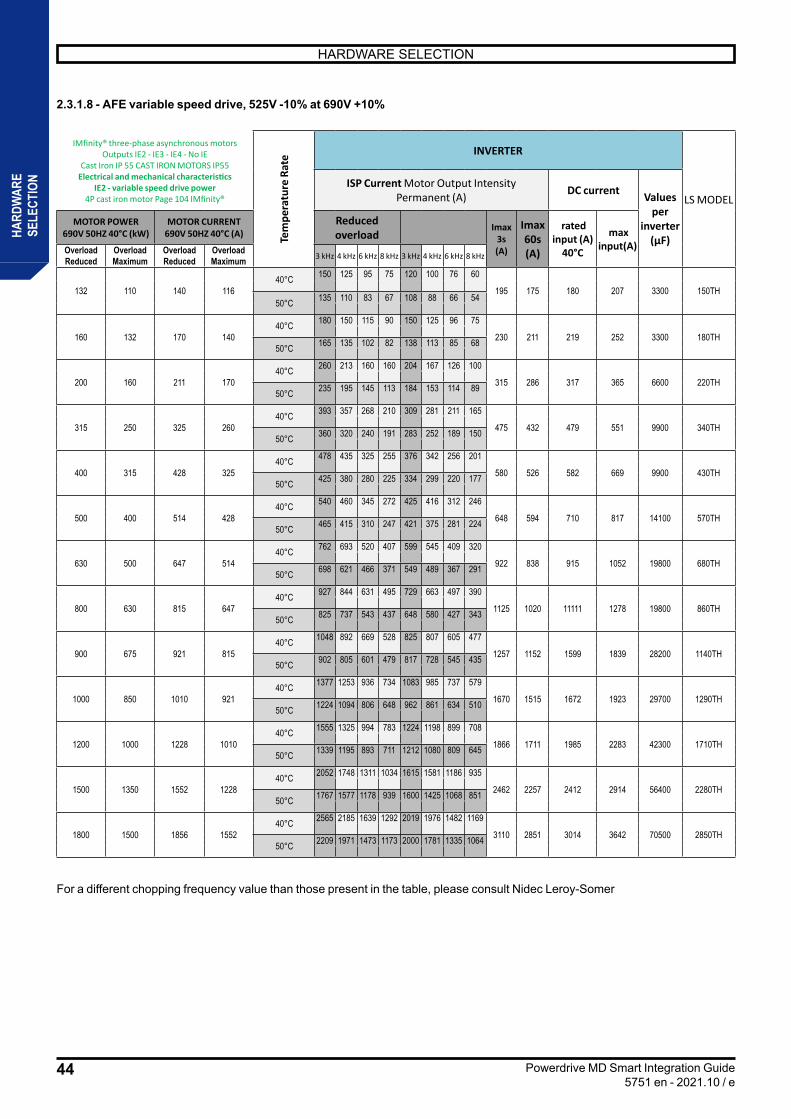
44
HARDWARE SELECTION
Powerdrive MD Smart Integration Guide5751 en - 2021.10 / e
HARD
WAR
ESE
LECT
ION
2.3.1.8 - AFE variable speed drive, 525V -10% at 690V +10%
For a different chopping frequency value than those present in the table, please consult Nidec Leroy-Somer
IMfinity® three-phase asynchronous motors Outputs IE2 - IE3 - IE4 - No IE
Cast Iron IP 55 CAST IRON MOTORS IP55 Electrical and mechanical characteristics
IE2 - variable speed drive power 4P cast iron motor Page 104 IMfinity®
Tem
pera
ture
Rat
e INVERTER
LS MODELISP Current Motor Output Intensity
Permanent (A) DC current Values per
inverter (µF)
MOTOR POWER 690V 50HZ 40°C (kW)
MOTOR CURRENT 690V 50HZ 40°C (A)
Reduced overload
Imax 3s (A)
Imax 60s (A)
rated input (A)
40°C
max input(A)Overload
ReducedOverload Maximum
Overload Reduced
Overload Maximum 3 kHz 4 kHz 6 kHz 8 kHz 3 kHz 4 kHz 6 kHz 8 kHz
132 110 140 116 40°C 150 125 95 75 120 100 76 60
195 175 180 207 3300 150TH 50°C 135 110 83 67 108 88 66 54
160 132 170 140 40°C 180 150 115 90 150 125 96 75
230 211 219 252 3300 180TH 50°C 165 135 102 82 138 113 85 68
200 160 211 170 40°C 260 213 160 160 204 167 126 100
315 286 317 365 6600 220TH 50°C 235 195 145 113 184 153 114 89
315 250 325 260 40°C 393 357 268 210 309 281 211 165
475 432 479 551 9900 340TH 50°C 360 320 240 191 283 252 189 150
400 315 428 325 40°C 478 435 325 255 376 342 256 201
580 526 582 669 9900 430TH 50°C 425 380 280 225 334 299 220 177
500 400 514 428 40°C 540 460 345 272 425 416 312 246
648 594 710 817 14100 570TH 50°C 465 415 310 247 421 375 281 224
630 500 647 514 40°C 762 693 520 407 599 545 409 320
922 838 915 1052 19800 680TH 50°C 698 621 466 371 549 489 367 291
800 630 815 647 40°C 927 844 631 495 729 663 497 390
1125 1020 11111 1278 19800 860TH 50°C 825 737 543 437 648 580 427 343
900 675 921 815 40°C 1048 892 669 528 825 807 605 477
1257 1152 1599 1839 28200 1140TH 50°C 902 805 601 479 817 728 545 435
1000 850 1010 921 40°C 1377 1253 936 734 1083 985 737 579
1670 1515 1672 1923 29700 1290TH 50°C 1224 1094 806 648 962 861 634 510
1200 1000 1228 1010 40°C 1555 1325 994 783 1224 1198 899 708
1866 1711 1985 2283 42300 1710TH 50°C 1339 1195 893 711 1212 1080 809 645
1500 1350 1552 1228 40°C 2052 1748 1311 1034 1615 1581 1186 935
2462 2257 2412 2914 56400 2280TH 50°C 1767 1577 1178 939 1600 1425 1068 851
1800 1500 1856 1552 40°C 2565 2185 1639 1292 2019 1976 1482 1169
3110 2851 3014 3642 70500 2850TH 50°C 2209 1971 1473 1173 2000 1781 1335 1064
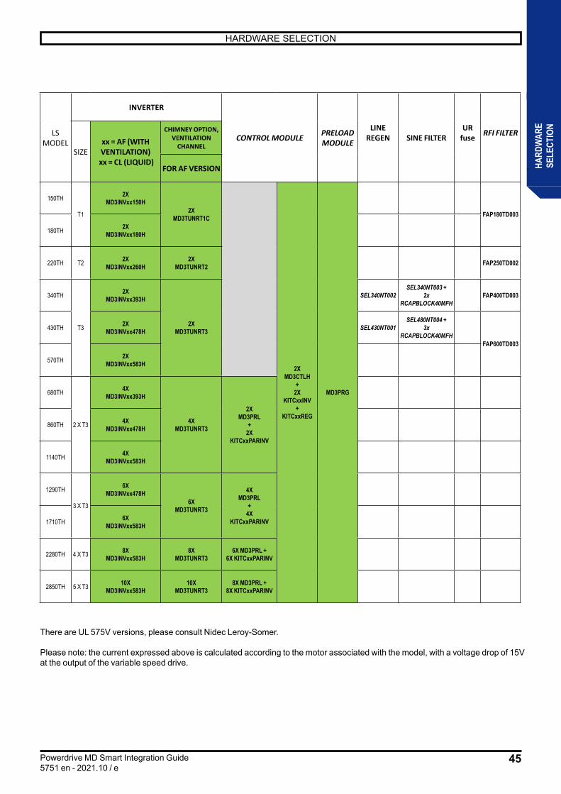
45
HARDWARE SELECTION
Powerdrive MD Smart Integration Guide5751 en - 2021.10 / e
HARD
WAR
ESE
LECT
ION
There are UL 575V versions, please consult Nidec Leroy-Somer.
Please note: the current expressed above is calculated according to the motor associated with the model, with a voltage drop of 15V at the output of the variable speed drive.
LS MODEL
INVERTER
CONTROL MODULE PRELOAD MODULE
LINE REGEN SINE FILTER
UR fuse RFI FILTER
SIZExx = AF (WITH VENTILATION)
xx = CL (LIQUID)
CHIMNEY OPTION, VENTILATION
CHANNEL
FOR AF VERSION
150TH
T1
2X MD3INVxx150H
2X MD3TUNRT1C
2XMD3CTLH
+2X
KITCxxINV+
KITCxxREG
MD3PRG
FAP180TD003
180TH 2X MD3INVxx180H
220TH T2 2X MD3INVxx260H
2X MD3TUNRT2 FAP250TD002
340TH
T3
2X MD3INVxx393H
2X MD3TUNRT3
SEL340NT002SEL340NT003 +
2xRCAPBLOCK40MFH
FAP400TD003
430TH 2X MD3INVxx478H SEL430NT001
SEL480NT004 + 3x
RCAPBLOCK40MFHFAP600TD003
570TH 2X MD3INVxx583H
680TH
2 X T3
4X MD3INVxx393H
4X MD3TUNRT3
2XMD3PRL
+2X
KITCxxPARINV
860TH 4X MD3INVxx478H
1140TH 4X MD3INVxx583H
1290TH
3 X T3
6X MD3INVxx478H
6X MD3TUNRT3
4XMD3PRL
+4X
KITCxxPARINV1710TH 6X MD3INVxx583H
2280TH 4 X T3 8X MD3INVxx583H
8X MD3TUNRT3
6X MD3PRL +6X KITCxxPARINV
2850TH 5 X T3 10X MD3INVxx583H
10X MD3TUNRT3
8X MD3PRL +8X KITCxxPARINV

46
HARDWARE SELECTION
Powerdrive MD Smart Integration Guide5751 en - 2021.10 / e
HARD
WAR
ESE
LECT
ION
2.4 - StandardsHarmonised Standard:EN 61800-5-1:2007 + A1:2017 Adjustable speed electrical power systems. Part 5-1: Safety requirements – Electrical, thermal and energy.EN 60204-1:2018 Safety of machinery – Electrical equipment of machines. Part 1 General RequirementsEN61800-5-2:2017 Adjustable speed electrical power systems. Functional safety requirements, Safe Torque Off (STO)EN61800-3:2018: Adjustable speed Electrical power drive systems. Part3: EMC requirements and specific test methods.
US and Canadian StandardsStandard Edition TitleUL 61800-5-1 2007+A1: 2017 Standard for Safety: Adjustable speed electrical Power Drive SystemsCSA 22.2 No.274-17 March 2017 Adjustable speed drives
2.5 - Environmental specifications2.5.1 - Environmental specifications during transportation and storageParameter Standard Limiting valuesStorage temperature Class 1K5 of EN60721-3-1 -40°C to +70°CStorage humidity Class 1K3 of EN60721-3-1 5% to 95% HRTemperature cycle during transportation Class 2K4 of EN60721-3-2 5 cycles -40°C/+30°C 95%HRVibrations during transportation Class 2M2 of EN60721-3-2 3.5 mm 2 to 9Hz
10 ms-2 from 9 to 200HzShocks during transportation Class 2M2 of EN60721-3-2 10g peak, 11ms pulse duration, half sine
100 shocks in each directionFree Fall during Transportation Class 2M2 of EN60721-3-2 1m(20to100kg) 0.25m(>100kg)
2.5.2 - Environmental conditions during operationParameter Standard Limiting values
Protection IP00
Ambient operating temperature -10°C to 40°C without deratingUp to 70°C with derating
Humidity <90% non-condensing
Altitude 1000m without deratingUp to 3000m with derating
Pollution Degree Dry non-conductive pollution only(pollution degree 2 according to IEC60664-1)
Vibrations Class 3M1 of EN60721-3-3
0.6 mm peak displacement from 2- 9 Hz2 m/s² peak acceleration from 9 - 200 Hz
Atmospheric pressure 700 to 1060 hPa
2.6 - Resistance to acids and corrosive gasesThe drive’s exposure to acids and corrosive gases must not exceed level given in• Class 3C2 of IEC 60721-3-3
2.7 - Electrical characteristics of componentsThis chapter provides the electrical characteristics of each of the components that can be integrated into an Powerdrive MD Smart enclosure.
2.7.1 - Passive rectifier chassis • Description
The rectifier chassis areavailable up to 500 kW,with possibility of mounting in parallelto reach powers ofup to 2.5 MW.
MD 3 REC1 AF 475 N
Modular variable speed drive
Idc current (DC BUS) with reduced overload ND
Three-phase power supply N: 400V to 480VH: 525V to 690V
Generation 3
AF: AIR COOLING WITH VENTILATIONCL: LIQUID COOLING COLD PLATE
REC1: SINGLE RECTIFIER

47
HARDWARE SELECTION
Powerdrive MD Smart Integration Guide5751 en - 2021.10 / e
HARD
WAR
ESE
LECT
ION
• Nameplate
Rated mains voltagesNetwork frequency
Rated AC input currentInput rated power
Rated bus voltages according to mains voltagesOutput frequency
Rated DC bus current
DC bus rated power
- -
-
Number of phases
Number of phases
• Simple passive rectifier chassis MD3RECSingle passive rectifier AF version (ventilated chassis) CL version (liquid chassis)
2.7.1.1 - Cables and fuses
• It is the user’s responsibility to connect and protect the POWERDRIVE MD Smart according to the legislation and rules in use in the country in which it is used. This is particularly important for cable size, fuse type and model, ground or ground connection, power off, security clearance, isolation and surge protection.
• The installation must have an Icc > 20 IL at the connection point of the variable speed drives.
• This table is given as an indication, in no case is it a substitute for the current standards.
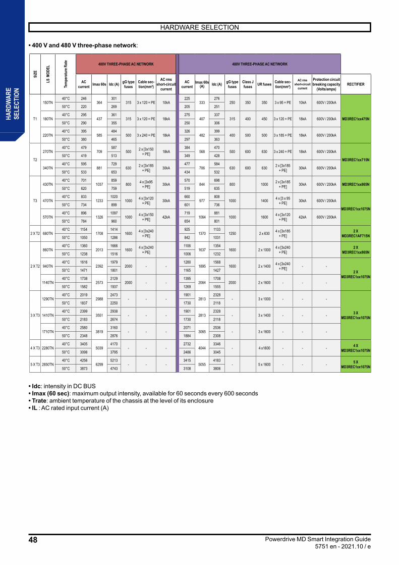
48
HARDWARE SELECTION
Powerdrive MD Smart Integration Guide5751 en - 2021.10 / e
HARD
WAR
ESE
LECT
ION
• 400 V and 480 V three-phase network:
• Idc: intensity in DC BUS• Imax (60 sec): maximum output intensity, available for 60 seconds every 600 seconds• Trate: ambient temperature of the chassis at the level of its enclosure• IL : AC rated input current (A)
SIZE
LS M
ODEL
Tem
pera
ture
Rat
e 400V THREE-PHASE AC NETWORK 480V THREE-PHASE AC NETWORK
AC current Imax 60s Idc (A) gG type
fusesCable sec-tion(mm²)
AC rms short-circuit
current
AC current
Imax 60s(A) Idc (A) gG type
fusesClass J fuses UR fuses Cable sec-
tion(mm²)AC rms
short-circuit current
Protection circuit breaking capacity
(Volts/amps)RECTIFIER
T1
150TN 40°C 246
364301
315 3 x 120 + PE 10kA225
333276
250 350 350 3 x 95 + PE 10kA 600V / 200kA
MD3REC1xx475N
50°C 220 269 205 251
180TN 40°C 295
437361
315 3 x 120 + PE 18kA275
407337
315 400 450 3 x 120 + PE 18kA 600V / 200kA 50°C 290 355 250 306
220TN 40°C 395
585484
500 3 x 240 + PE 18kA326
482399
400 500 500 3 x 185 + PE 18kA 600V / 200kA 50°C 380 465 297 363
T2
270TN 40°C 479
709587
500 2 x [3x150 + PE] 18kA
384568
470500 600 630 3 x 240 + PE 18kA 600V / 200kA
MD3REC1xx715N 50°C 419 513 349 428
340TN 40°C 595
881729
630 2 x [3x185 + PE] 30kA
477706
584630 600 630 2 x [3x185
+ PE] 30kA 600V / 200kA 50°C 533 653 434 532
T3
430TN 40°C 701
1037859
800 4 x [3x95 + PE] 30kA
570844
698800 1000 2 x [3x185
+ PE] 30kA 600V / 200kA MD3REC1xx865N 50°C 620 759 519 635
470TN 40°C 833
12331020
1000 4 x [3x120 + PE] 30kA
660977
8081000 1400 4 x [3 x 95
+ PE] 30kA 600V / 200kA
MD3REC1xx1075N 50°C 734 899 601 736
570TN 40°C 896
13261097
1000 4 x [3x150 + PE] 42kA
7191064
8811000 1600 4 x [3x120
+ PE] 42kA 600V / 200kA 50°C 784 960 654 801
2 X T2 680TN 40°C 1154
17081414
1600 4 x [3x240 + PE]
9251370
11331250 2 x 630 4 x [3x185
+ PE]2 X
MD3REC1AF715N 50°C 1050 1286 842 1031
2 X T2
860TN 40°C 1360
20131666
1600 4 x [3x240 + PE]
11061637
13541600 2 x 1000 4 x [3x240
+ PE]2 X
MD3REC1xx865N 50°C 1238 1516 1006 1232
940TN 40°C 1616
23921979
2000 - -1280
18951568
1600 2 x 1400 4 x [3x240 + PE] - -
2 X MD3REC1xx1075N
50°C 1471 1801 1165 1427
1140TN 40°C 1738
25732129
2000 - -1395
20641708
2000 2 x 1600 - - - 50°C 1582 1937 1269 1555
3 X T3
1290TN 40°C 2019
29882473
- - -1901
28132328
- 3 x 1000 - - -
3 X MD3REC1xx1075N
50°C 1837 2250 1730 2118
1410TN 40°C 2399
35512938
- - -1901
28132328
- 3 x 1400 - - - 50°C 2183 2674 1730 2118
1710TN 40°C 2580
38193160
- - -2071
30652536
- 3 x 1600 - - - 50°C 2348 2876 1884 2308
4 X T3 2280TN 40°C 3405
50394170
- - -2732
40443346
- 4 x1600 - - - 4 X MD3REC1xx1075N 50°C 3098 3795 2486 3045
5 X T3 2850TN 40°C 4256
62995213
- - -3415
50554183
- 5 x 1600 - - - 5 X MD3REC1xx1075N 50°C 3873 4743 3108 3806
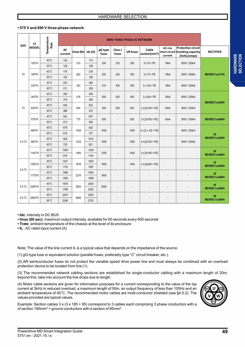
49
HARDWARE SELECTION
Powerdrive MD Smart Integration Guide5751 en - 2021.10 / e
HARD
WAR
ESE
LECT
ION
• 575 V and 690 V three-phase network:
• Idc: intensity in DC BUS• Imax (60 sec): maximum output intensity, available for 60 seconds every 600 seconds• Trate: ambient temperature of the chassis at the level of its enclosure• IL : AC rated input current (A)
Note: The value of the line current IL is a typical value that depends on the impedance of the source.
(1) gG-type fuse or equivalent solution (parallel fuses, preferably type “C” circuit breaker, etc.).
(2) AR semiconductor fuses do not protect the variable speed drive power line and must always be combined with an overload protection device to be located from line (1).
(3) The recommended network cabling sections are established for single-conductor cabling with a maximum length of 20m, beyond this, take into account the line drops due to length.
(4) Motor cable sections are given for information purposes for a current corresponding to the value of the Isp current at 3kHz in reduced overload, a maximum length of 50m, an output frequency of less than 100Hz and an ambient temperature of 40°C. The recommended motor cables are multi-conductor shielded (see §4.5.2). The values provided are typical values.
Example: Section cables 3 x (3 x 185 + 95) correspond to 3 cables each comprising 3 phase conductors with a of section 185mm² + ground conductors with a section of 95mm².
SIZE LS MODEL
Tem
pera
ture
Ra
te 690V THREE-PHASE AC NETWORK
AC current Imax 60s Idc (A) gG type
fusesClass J fuses UR fuses Cable
section(mm²)
AC rms short-circuit
current
Protection circuit breaking capacity
(Volts/amps)RECTIFIER
T2
150TH 40°C 142
210174
200 225 350 3 x 70 + PE 18kA 600V / 200kA
MD3REC1xx315H
50°C 129 158
180TH 40°C 178
263218
200 225 350 3 x 70 + PE 18kA 600V / 200kA 50°C 162 198
220TH 40°C 232
343284
315 350 350 3 x 120 + PE 18kA 600V / 200kA 50°C 211 259
T3
340TH 40°C 350
518429
500 500 450 3 x 240 + PE 30kA 600V / 200kA
MD3REC1xx565H 50°C 319 390
430TH 40°C 426
630522
500 600 630 2 x [3x150 + PE] 30kA 600V / 200kA 50°C 388 475
570TH 40°C 520
770637
630 - 630 2 x [3x185 + PE] 42kA 600V / 200kA MD3REC1xx680H 50°C 473 580
2 X T3
680TH 40°C 679
1005832
1000 - 1000 4 x [3 x 120 + PE] 600V / 200kA2X
MD3REC1xx565H 50°C 618 757
860TH 40°C 826
12231012
1000 - 1000 4 x [3x150 + PE] 600V / 200kA 50°C 752 921
1140TH 40°C 1009
14931236
1250 - 1400 4 x [3x185 + PE] 2X MD3REC1xx680H 50°C 918 1124
3 X T3
1290TH 40°C 1227
18161503
1600 - 1400 4 x [3x240 + PE] 3X MD3REC1xx565H 50°C 1116 1367
1710TH 40°C 1498
22161834
1600 - - - - - 3X MD3REC1xx680H 50°C 1363 1669
4 X T3 2280TH 40°C 1976
29242420
2000 - - - - - 4X MD3REC1xx680H 50°C 1798 2202
5 X T3 2850TH 40°C 2470
36563025
- - - - - - 5X MD3REC1xx680H 50°C 2248 2753
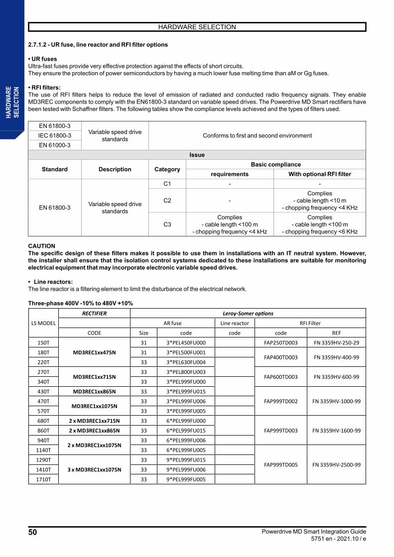
50
HARDWARE SELECTION
Powerdrive MD Smart Integration Guide5751 en - 2021.10 / e
HARD
WAR
ESE
LECT
ION
2.7.1.2 - UR fuse, line reactor and RFI filter options
• UR fusesUltra-fast fuses provide very effective protection against the effects of short circuits.They ensure the protection of power semiconductors by having a much lower fuse melting time than aM or Gg fuses.
• RFI filters: The use of RFI filters helps to reduce the level of emission of radiated and conducted radio frequency signals. They enable MD3REC components to comply with the EN61800-3 standard on variable speed drives. The Powerdrive MD Smart rectifiers have been tested with Schaffner filters. The following tables show the compliance levels achieved and the types of filters used.
EN 61800-3Variable speed drive
standards Conforms to first and second environmentIEC 61800-3EN 61000-3
Issue
Standard Description CategoryBasic compliance
requirements With optional RFI filter
EN 61800-3 Variable speed drive standards
C1 - -
C2 -Complies
- cable length <10 m- chopping frequency <4 KHz
C3Complies
- cable length <100 m- chopping frequency <4 kHz
Complies- cable length <100 m
- chopping frequency <6 KHz
CAUTION The specific design of these filters makes it possible to use them in installations with an IT neutral system. However, the installer shall ensure that the isolation control systems dedicated to these installations are suitable for monitoring electrical equipment that may incorporate electronic variable speed drives.
• Line reactors: The line reactor is a filtering element to limit the disturbance of the electrical network.
Three-phase 400V -10% to 480V +10%
LS MODEL
RECTIFIER Leroy-Somer options
AR fuse Line reactor RFI Filter
CODE Size code code code REF
150T
MD3REC1xx475N
31 3*PEL450FU000 FAP250TD003 FN 3359HV-250-29
180T 31 3*PEL500FU001FAP400TD003 FN 3359HV-400-99
220T 33 3*PEL630FU004
270TMD3REC1xx715N
33 3*PEL800FU003FAP600TD003 FN 3359HV-600-99
340T 33 3*PEL999FU000
430T MD3REC1xx865N 33 3*PEL999FU015
FAP999TD002 FN 3359HV-1000-99470TMD3REC1xx1075N
33 3*PEL999FU006
570T 33 3*PEL999FU005
680T 2 x MD3REC1xx715N 33 6*PEL999FU000
FAP999TD003 FN 3359HV-1600-99860T 2 x MD3REC1xx865N 33 6*PEL999FU015
940T2 x MD3REC1xx1075N
33 6*PEL999FU006
1140T 33 6*PEL999FU005
FAP999TD005 FN 3359HV-2500-991290T
3 x MD3REC1xx1075N
33 9*PEL999FU015
1410T 33 9*PEL999FU006
1710T 33 9*PEL999FU005

51
HARDWARE SELECTION
Powerdrive MD Smart Integration Guide5751 en - 2021.10 / e
HARD
WAR
ESE
LECT
ION
Three-phase 525V -10% to 690V +10%
LS MODELRECTIFIER Leroy-Somer option
CODE aR fuse Line reactor RFI Filter
150THMD3REC1xx265H FAP180TD003 - 34W
180TH
220TH MD3REC1xx315H FAP250TD002 - 49W
340THMD3REC1xx565H
FAP400TD003 - 29W
430THFAP600TD003 - 44W
570TH MD3REC1xx680H680TH
2 x MD3REC1xx565H860TH1140TH 2 x MD3REC1xx680H1290TH 3 x MD3REC1xx565H1710TH 3 x MD3REC1xx680H
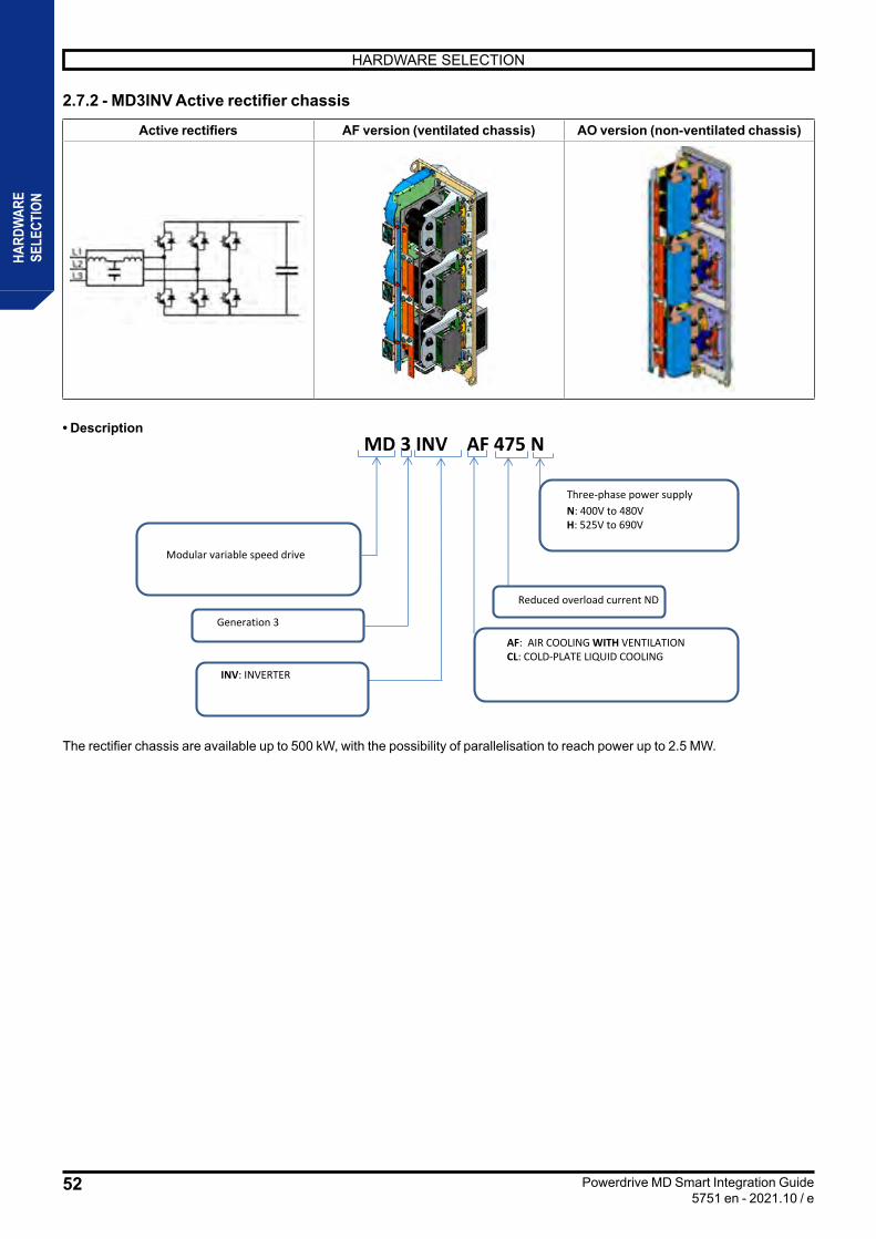
52
HARDWARE SELECTION
Powerdrive MD Smart Integration Guide5751 en - 2021.10 / e
HARD
WAR
ESE
LECT
ION
2.7.2 - MD3INV Active rectifier chassis
Active rectifiers AF version (ventilated chassis) AO version (non-ventilated chassis)
• DescriptionMD 3 INV AF 475 N
Modular variable speed drive
Reduced overload current ND
Three-phase power supplyN: 400V to 480VH: 525V to 690V
Generation 3
AF: AIR COOLING WITH VENTILATIONCL: COLD-PLATE LIQUID COOLING
INV: INVERTER
The rectifier chassis are available up to 500 kW, with the possibility of parallelisation to reach power up to 2.5 MW.
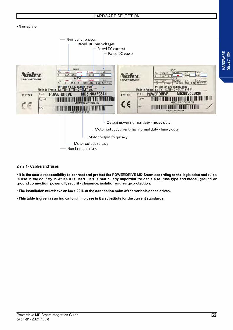
53
HARDWARE SELECTION
Powerdrive MD Smart Integration Guide5751 en - 2021.10 / e
HARD
WAR
ESE
LECT
ION
• Nameplate
2.7.2.1 - Cables and fuses
• It is the user’s responsibility to connect and protect the POWERDRIVE MD Smart according to the legislation and rules in use in the country in which it is used. This is particularly important for cable size, fuse type and model, ground or ground connection, power off, security clearance, isolation and surge protection.
• The installation must have an Icc > 20 IL at the connection point of the variable speed drives.
• This table is given as an indication, in no case is it a substitute for the current standards.
Number of phasesRated DC bus voltages
- -
Rated DC currentRated DC power
Motor output voltage Number of phases
Output power normal duty - heavy duty
Motor output current (Isp) normal duty - heavy duty
Motor output frequency

54
HARDWARE SELECTION
Powerdrive MD Smart Integration Guide5751 en - 2021.10 / e
HARD
WAR
ESE
LECT
ION
Three-phase 400V -10% to 480V +10%
Idc: DC BUS intensityImax (3 sec) : peak output intensity for 3 secs after start-upImax (60 sec): maximum output intensity, available for 60 seconds every 600 secondsTrate: ambient temperature of the chassis at the level of its enclosure• IL : AC rated input current (A)
Tem
pera
ture
Rat
e
ACTIVE RECTIFIER
LS MODEL
module
Input current Permanent A @ 5kHz Switching Frequency
DC current
Valu
es p
er in
vert
er (µ
F)
Cabl
e se
ction
(mm
²)
gG ty
pe fu
ses
Clas
s J fu
ses
UR
fuse
s
AC rm
s sho
rt-c
ircui
t cur
rent
Prot
ectio
n ci
rcui
t bre
akin
g ca
paci
ty (V
olts
/am
ps)
rated input (A)
40°C
max input(A) SIZE
xx = AF (WITH VENTILATION)
xx = CL (LIQUID)
40°C 260307 353 7050 3 x 150 + PE 250 350 350 10kA 600V /
200kA 150TN
T1
MD3INVxx260N 50°C 240
40°C 315360 414 9400 3 x 185 + PE 315 400 450 18kA 600V /
200kA 180TN MD3INVxx315N 50°C 305
40°C 408481 553 14100 3 x 240 + PE 400 500 500 18kA 600V /
200kA 220TN MD3INVxx408N 50°C 400
40°C 497586 674 14100 2 x [3x150
+ PE] 500 600 630 18kA 600V / 200kA 270TN
T2
MD3INVxx497N 50°C 452
40°C 618729 838 16800 2 x [3 x 185
+ PE] 630 600 630 30kA 600V / 200kA 340TN MD3INVxx618N
50°C 575
40°C 747881 1013 28200 4 x [3x120
+ PE] 800 1000 1000 30kA 600V / 200kA 430TN
T3
MD3INVxx747N 50°C 680
40°C 8651021 1174 28200 4 x [3x120
+ PE] 1000 1000 1000 30kA 600V / 200kA 470TN MD3INVxx865N
50°C 802
40°C 9311098 1263 28200 4 x [3x150
+ PE] 1000 1000 1400 42kA 600V / 200kA 570TN MD3INVxx931N
50°C 846
40°C 11991404 1615 33600 4 x [3x185
+ PE] 1250 - - - - 680TN 2 X T2 2 X MD3INVxx618N 50°C 1116
40°C 14491581 1818 56400 - 1600 - - - - 860TN
2 X T3
2 X MD3INVxx747N 50°C 1319
40°C 16781889 2172 56400 - 1600 - - - - 940TN 2 X
MD3INVxx865N 50°C 1556
40°C 18062106 2422 56400 - 2000 - - - - 1140TN 2 X
MD3INVxx931N 50°C 1641
40°C 21512371 2727 84600 - - - - - - 1290TN
3 X T3
3 X MD3INVxx747N 50°C 1958
40°C 24912832 3257 84600 - - - - - - 1410TN 3 X
MD3INVxx865N 50°C 2310
40°C 26813292 3786 84600 - - - - - - 1710TN 3 X
MD3INVxx931N 50°C 2436
40°C 35383968 4795 112800 - - - - - - 2280TN 4 X T3 4 X
MD3INVxx931N 50°C 3215
40°C 44225018 6064 141000 - - - - - - 2850TN 5 X T3 5 X
MD3INVxx931N 50°C 4019
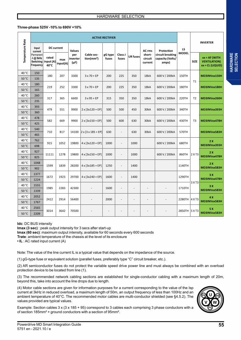
55
HARDWARE SELECTION
Powerdrive MD Smart Integration Guide5751 en - 2021.10 / e
HARD
WAR
ESE
LECT
ION
Three-phase 525V -10% to 690V +10%
Idc: DC BUS intensityImax (3 sec) : peak output intensity for 3 secs after start-upImax (60 sec): maximum output intensity, available for 60 seconds every 600 secondsTrate: ambient temperature of the chassis at the level of its enclosure• IL : AC rated input current (A)
Note: The value of the line current IL is a typical value that depends on the impedance of the source.
(1) gG-type fuse or equivalent solution (parallel fuses, preferably type “C” circuit breaker, etc.).
(2) AR semiconductor fuses do not protect the variable speed drive power line and must always be combined with an overload protection device to be located from line (1).
(3) The recommended network cabling sections are established for single-conductor cabling with a maximum length of 20m, beyond this, take into account the line drops due to length.
(4) Motor cable sections are given for information purposes for a current corresponding to the value of the Isp current at 3kHz in reduced overload, a maximum length of 50m, an output frequency of less than 100Hz and an ambient temperature of 40°C. The recommended motor cables are multi-conductor shielded (see §4.5.2). The values provided are typical values.
Example: Section cables 3 x (3 x 185 + 95) correspond to 3 cables each comprising 3 phase conductors with a of section 185mm² + ground conductors with a section of 95mm².
Tem
pera
ture
Rat
e
ACTIVE RECTIFIER
LS MODEL
INVERTER
Input current
Permanent A @ 5kHz Switching Frequency
DC currentValues
per inverter
(µF)
Cable sec-tion(mm²)
gG type fuses
Class J fuses UR fuses
AC rms short-circuit
current
Protection circuit breaking capacity (Volts/
amps) rated
input (A) 40°C
max input(A) SIZE
xx = AF (WITH VENTILATION)
xx = CL (LIQUID)
40 °C 150 180 207 3300 3 x 70 + EP 200 225 350 18kA 600 V / 200kA 150TH
T1
MD3INVxx150H 50 °C 135
40 °C 180219 252 3300 3 x 70 + EP 200 225 350 18kA 600 V / 200kA 180TH MD3INVxx180H
50 °C 165
40 °C 260317 365 6600 3 x 95 + EP 315 350 350 18kA 600 V / 200kA 220TH T2 MD3INVxx260H
50 °C 235
40 °C 393479 551 9900 2 x [3x120 + EP] 500 500 450 30kA 600 V / 200kA 340TH
T3
MD3INVxx393H 50 °C 360
40 °C 478582 669 9900 2 x [3x150 + EP] 500 600 630 30kA 600 V / 200kA 430TH MD3INVxx478H
50 °C 425
40 °C 540710 817 14100 2 x [3 x 185 + EP] 630 - 630 30kA 600 V / 200kA 570TH MD3INVxx583H
50 °C 465
40 °C 762915 1052 19800 4 x [3x120 + EP] 1000 - 1000 600 V / 200kA 680TH
2 X T3
2 X MD3INVxx393H 50 °C 698
40 °C 92711111 1278 19800 4 x [3x150 + EP] 1000 - 1000 600 V / 200kA 860TH 2 X
MD3INVxx478H 50 °C 825
40 °C 10481599 1839 28200 4 x [3x185 + EP] 1250 - 1400 1140TH 2 X
MD3INVxx583H 50 °C 902
40 °C 13771672 1923 29700 4 x [3x240 + EP] 1600 - 1400 1290TH
3 X T3
3 X MD3INVxx478H 50 °C 1224
40 °C 15551985 2283 42300 - 1600 - - - - 1710TH 3 X
MD3INVxx583H 50 °C 1339
40 °C 20522412 2914 56400 - 2000 - - - - 2280TH 4 X T3 4 X
MD3INVxx583H 50 °C 1767
40 °C 25653014 3642 70500 - - - - - - 2850TH 5 X T3 5 X
MD3INVxx583H 50 °C 2209

56
HARDWARE SELECTION
Powerdrive MD Smart Integration Guide5751 en - 2021.10 / e
HARD
WAR
ESE
LECT
ION
2.7.2.2 - Filtering options
Basic diagram of filtering required by active rectifier.
RFI Filter UR fuse
Regeninput reactor
Active rectifierMD3INV
Fuses
Capacitors
Sinefilter
Maincontactor
RFI Filter UR fuse
Regeninput reactor
Activerectifier
Fuse
Capacitor
Sinefilter
Maincontactor
Fuse
Preloadcontactor
Inverter
MD3PRG
PRELOAD CIRCUIT
1
2 4
5 63
These options can be used with an MD3INV active rectifier. It is therefore necessary to know their characteristics so that they can be supplied by the variable speed drive integrator from the supplier of his choice.However, these options can be ordered at Leroy-Somer. In this case, refer to the Appendices to this document.
• RFI filterThe use of RFI filters helps to reduce the level of emission of radiated and conducted radio frequency signals. They enable MD3INV components to comply with the EN61800-3 standard on variable speed drives. The Powerdrive MD Smart rectifiers have been tested with Schaffner filters. The following tables show the compliance levels achieved and the types of filters used.
EN 61800-3Variable speed drive
standards Conforms to first and second environmentIEC 61800-3EN 61000-3
Issue
Standard Description CategoryBasic compliance
requirements With optional RFI filter
EN 61800-3 Variable speed drive standards
C1 - -
C2 -Complies
- cable length <10 m- chopping frequency <4 KHz
C3Complies
- cable length <100 m- chopping frequency <4 kHz
Complies- cable length <100 m
- switching frequency <6 KHz
Main contactorThe line contactor is a necessary device to ensure the connection / disconnection of the power system’s active rectifiers. It is also used for the implementation of the "EMERGENCY STOP" safety function, which is used to electrically and automatically isolate the active rectifier from the power supply network.It is a switching device only, it does not provide any protection function during a short circuit or a line surge It is therefore the responsibility of the integrator to ensure this protection by adding equipment for this function (circuit breaker, switch-splitter-fuse, etc.).The line connector performs the switching and protection role.In general, the line current and the breaking capacity are the main criteria for choosing a contactor. In addition, the rated current of the contactor shall be greater than or equal to the rated input current of the active rectifier chassis.The contactors to be used are of category AC-1 (resistive switching) which have a maximum breaking capacity equal to approximately 1.5 times their rated load.When shutting down the converter or tripping (default), the sequence to follow is:• Locking the STO inputs of the active rectifier control module to lock the power stages (IGBT)• Opening of the line contactor for electrical insulation of the power supply system.See section §4.5.1 for the power and control cabling diagram.
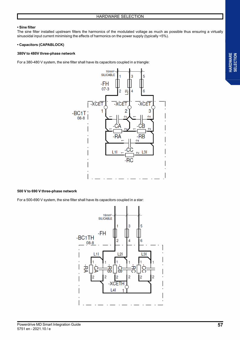
57
HARDWARE SELECTION
Powerdrive MD Smart Integration Guide5751 en - 2021.10 / e
HARD
WAR
ESE
LECT
ION
• Sine filterThe sine filter installed upstream filters the harmonics of the modulated voltage as much as possible thus ensuring a virtually sinusoidal input current minimising the effects of harmonics on the power supply (typically <5%).
• Capacitors (CAPABLOCK)
380V to 480V three-phase network
For a 380-480 V system, the sine filter shall have its capacitors coupled in a triangle:
500 V to 690 V three-phase network
For a 500-690 V system, the sine filter shall have its capacitors coupled in a star:
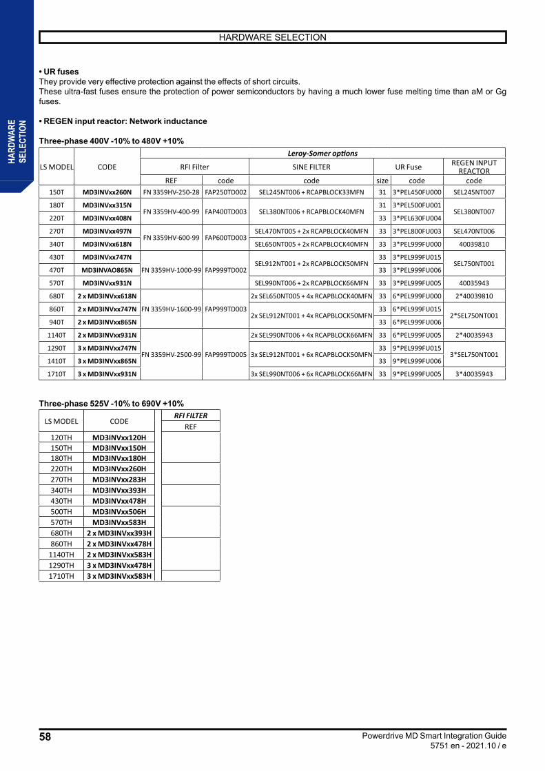
58
HARDWARE SELECTION
Powerdrive MD Smart Integration Guide5751 en - 2021.10 / e
HARD
WAR
ESE
LECT
ION
• UR fusesThey provide very effective protection against the effects of short circuits.These ultra-fast fuses ensure the protection of power semiconductors by having a much lower fuse melting time than aM or Gg fuses.
• REGEN input reactor: Network inductance
Three-phase 400V -10% to 480V +10%
LS MODEL CODE
Leroy-Somer options
RFI Filter SINE FILTER UR Fuse REGEN INPUT REACTOR
REF code code size code code150T MD3INVxx260N FN 3359HV-250-28 FAP250TD002 SEL245NT006 + RCAPBLOCK33MFN 31 3*PEL450FU000 SEL245NT007
180T MD3INVxx315NFN 3359HV-400-99 FAP400TD003 SEL380NT006 + RCAPBLOCK40MFN
31 3*PEL500FU001SEL380NT007
220T MD3INVxx408N 33 3*PEL630FU004
270T MD3INVxx497NFN 3359HV-600-99 FAP600TD003
SEL470NT005 + 2x RCAPBLOCK40MFN 33 3*PEL800FU003 SEL470NT006
340T MD3INVxx618N SEL650NT005 + 2x RCAPBLOCK40MFN 33 3*PEL999FU000 40039810
430T MD3INVxx747N
FN 3359HV-1000-99 FAP999TD002SEL912NT001 + 2x RCAPBLOCK50MFN
33 3*PEL999FU015SEL750NT001
470T MD3INVAO865N 33 3*PEL999FU006
570T MD3INVxx931N SEL990NT006 + 2x RCAPBLOCK66MFN 33 3*PEL999FU005 40035943
680T 2 x MD3INVxx618N
FN 3359HV-1600-99 FAP999TD003
2x SEL650NT005 + 4x RCAPBLOCK40MFN 33 6*PEL999FU000 2*40039810
860T 2 x MD3INVxx747N2x SEL912NT001 + 4x RCAPBLOCK50MFN
33 6*PEL999FU0152*SEL750NT001
940T 2 x MD3INVxx865N 33 6*PEL999FU006
1140T 2 x MD3INVxx931N
FN 3359HV-2500-99 FAP999TD005
2x SEL990NT006 + 4x RCAPBLOCK66MFN 33 6*PEL999FU005 2*40035943
1290T 3 x MD3INVxx747N3x SEL912NT001 + 6x RCAPBLOCK50MFN
33 9*PEL999FU0153*SEL750NT001
1410T 3 x MD3INVxx865N 33 9*PEL999FU006
1710T 3 x MD3INVxx931N 3x SEL990NT006 + 6x RCAPBLOCK66MFN 33 9*PEL999FU005 3*40035943
Three-phase 525V -10% to 690V +10%
LS MODEL CODERFI FILTER
REF120TH MD3INVxx120H150TH MD3INVxx150H180TH MD3INVxx180H220TH MD3INVxx260H270TH MD3INVxx283H340TH MD3INVxx393H430TH MD3INVxx478H500TH MD3INVxx506H570TH MD3INVxx583H680TH 2 x MD3INVxx393H860TH 2 x MD3INVxx478H
1140TH 2 x MD3INVxx583H1290TH 3 x MD3INVxx478H1710TH 3 x MD3INVxx583H
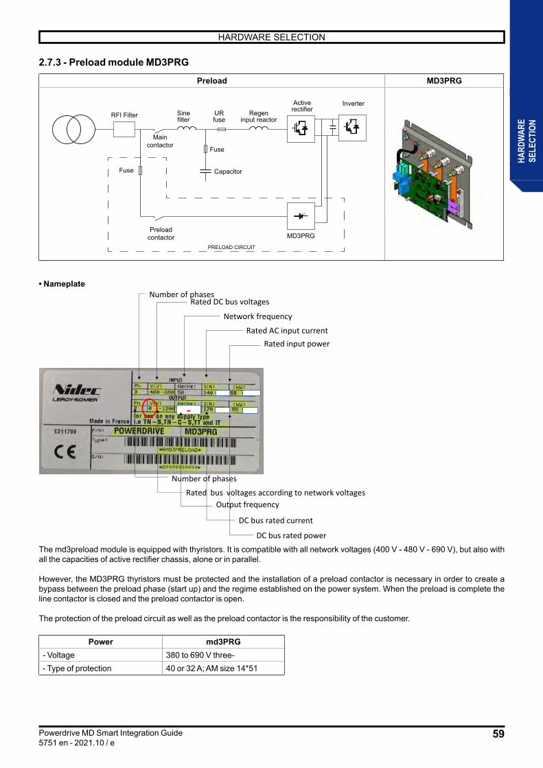
59
HARDWARE SELECTION
Powerdrive MD Smart Integration Guide5751 en - 2021.10 / e
HARD
WAR
ESE
LECT
ION
2.7.3 - Preload module MD3PRG
Preload MD3PRG
RFI Filter UR fuse
Regeninput reactor
Active rectifierMD3INV
Fuses
Capacitors
Sinefilter
Maincontactor
RFI Filter UR fuse
Regeninput reactor
Activerectifier
Fuse
Capacitor
Sinefilter
Maincontactor
Fuse
Preloadcontactor
Inverter
MD3PRG
PRELOAD CIRCUIT
1
2 4
5 63
• Nameplate
-
Rated DC bus voltages
Network frequency
Rated AC input currentRated input power
Rated bus voltages according to network voltagesOutput frequency
DC bus rated current
DC bus rated power
Number of phases
Number of phases
The md3preload module is equipped with thyristors. It is compatible with all network voltages (400 V - 480 V - 690 V), but also with all the capacities of active rectifier chassis, alone or in parallel.
However, the MD3PRG thyristors must be protected and the installation of a preload contactor is necessary in order to create a bypass between the preload phase (start up) and the regime established on the power system. When the preload is complete the line contactor is closed and the preload contactor is open.
The protection of the preload circuit as well as the preload contactor is the responsibility of the customer.
Power md3PRG- Voltage 380 to 690 V three-- Type of protection 40 or 32 A; AM size 14*51
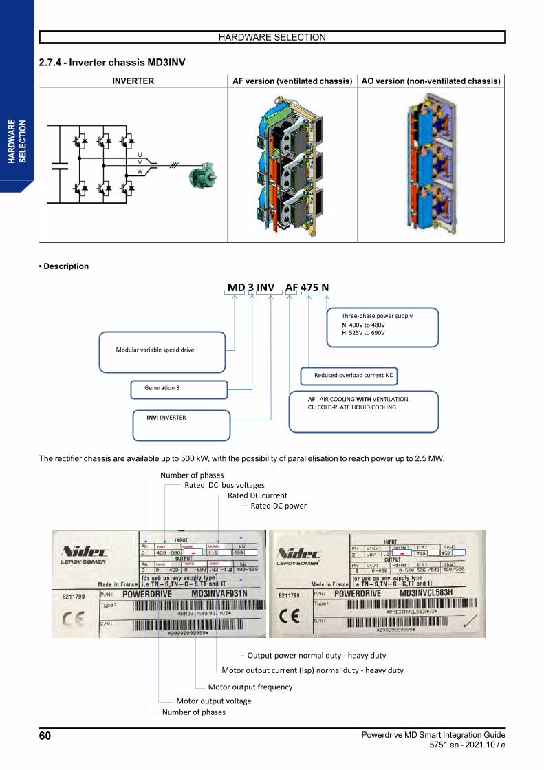
60
HARDWARE SELECTION
Powerdrive MD Smart Integration Guide5751 en - 2021.10 / e
HARD
WAR
ESE
LECT
ION
2.7.4 - Inverter chassis MD3INV
INVERTER AF version (ventilated chassis) AO version (non-ventilated chassis)
• Description
MD 3 INV AF 475 N
Modular variable speed drive
Reduced overload current ND
Three-phase power supplyN: 400V to 480VH: 525V to 690V
Generation 3
AF: AIR COOLING WITH VENTILATIONCL: COLD-PLATE LIQUID COOLING
INV: INVERTER
The rectifier chassis are available up to 500 kW, with the possibility of parallelisation to reach power up to 2.5 MW.
• Nameplate Number of phasesRated DC bus voltages
- -
Rated DC currentRated DC power
Motor output voltage Number of phases
Output power normal duty - heavy duty
Motor output current (Isp) normal duty - heavy duty
Motor output frequency
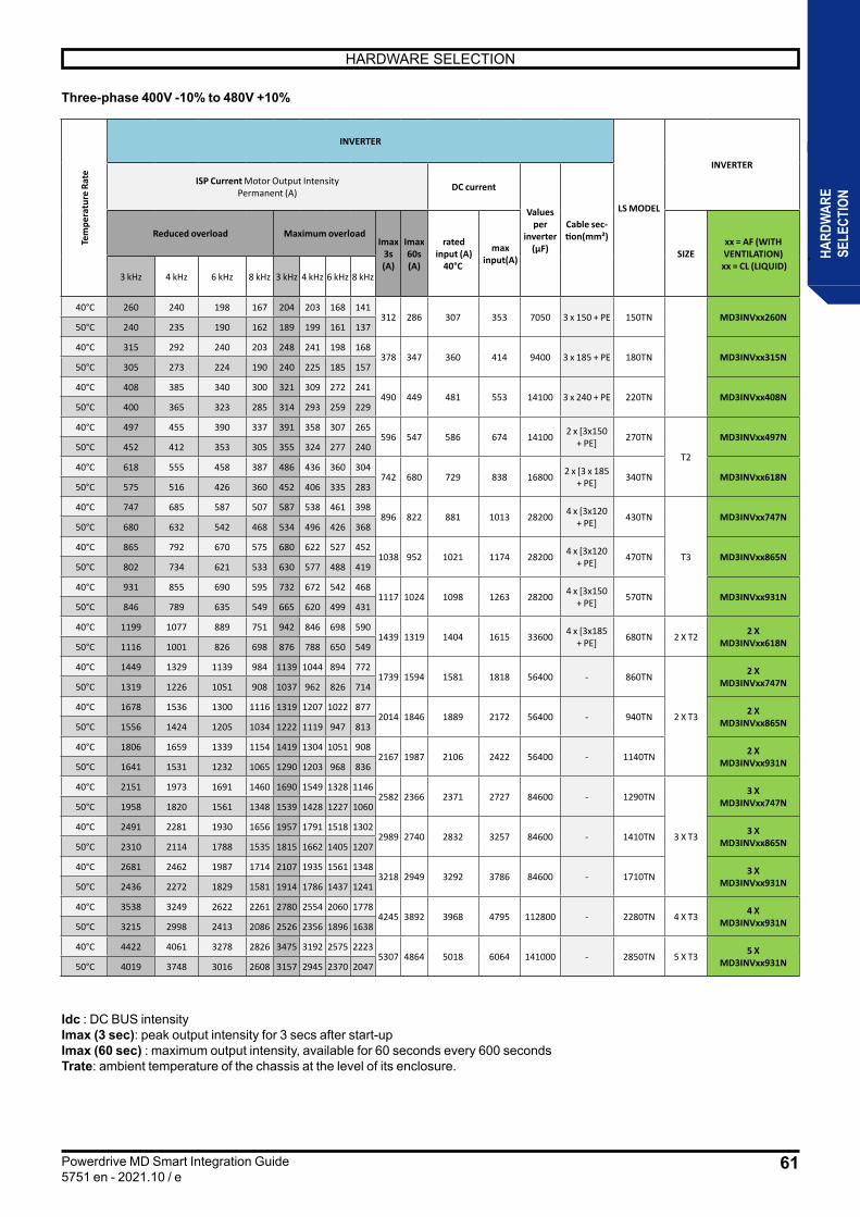
61
HARDWARE SELECTION
Powerdrive MD Smart Integration Guide5751 en - 2021.10 / e
HARD
WAR
ESE
LECT
ION
Three-phase 400V -10% to 480V +10%
Idc : DC BUS intensityImax (3 sec): peak output intensity for 3 secs after start-upImax (60 sec) : maximum output intensity, available for 60 seconds every 600 secondsTrate: ambient temperature of the chassis at the level of its enclosure.
Tem
pera
ture
Rat
e
INVERTER
LS MODEL
INVERTER
ISP Current Motor Output Intensity Permanent (A) DC current
Values per
inverter (µF)
Cable sec-tion(mm²)Reduced overload Maximum overload
Imax 3s (A)
Imax 60s (A)
rated input (A)
40°C
max input(A) SIZE
xx = AF (WITH VENTILATION)
xx = CL (LIQUID)3 kHz 4 kHz 6 kHz 8 kHz 3 kHz 4 kHz 6 kHz 8 kHz
40°C 260 240 198 167 204 203 168 141312 286 307 353 7050 3 x 150 + PE 150TN MD3INVxx260N
50°C 240 235 190 162 189 199 161 137
40°C 315 292 240 203 248 241 198 168378 347 360 414 9400 3 x 185 + PE 180TN MD3INVxx315N
50°C 305 273 224 190 240 225 185 157
40°C 408 385 340 300 321 309 272 241490 449 481 553 14100 3 x 240 + PE 220TN MD3INVxx408N
50°C 400 365 323 285 314 293 259 229
40°C 497 455 390 337 391 358 307 265596 547 586 674 14100 2 x [3x150
+ PE] 270TN
T2
MD3INVxx497N 50°C 452 412 353 305 355 324 277 240
40°C 618 555 458 387 486 436 360 304742 680 729 838 16800 2 x [3 x 185
+ PE] 340TN MD3INVxx618N 50°C 575 516 426 360 452 406 335 283
40°C 747 685 587 507 587 538 461 398896 822 881 1013 28200 4 x [3x120
+ PE] 430TN
T3
MD3INVxx747N 50°C 680 632 542 468 534 496 426 368
40°C 865 792 670 575 680 622 527 4521038 952 1021 1174 28200 4 x [3x120
+ PE] 470TN MD3INVxx865N 50°C 802 734 621 533 630 577 488 419
40°C 931 855 690 595 732 672 542 4681117 1024 1098 1263 28200 4 x [3x150
+ PE] 570TN MD3INVxx931N 50°C 846 789 635 549 665 620 499 431
40°C 1199 1077 889 751 942 846 698 5901439 1319 1404 1615 33600 4 x [3x185
+ PE] 680TN 2 X T2 2 X MD3INVxx618N 50°C 1116 1001 826 698 876 788 650 549
40°C 1449 1329 1139 984 1139 1044 894 7721739 1594 1581 1818 56400 - 860TN
2 X T3
2 X MD3INVxx747N 50°C 1319 1226 1051 908 1037 962 826 714
40°C 1678 1536 1300 1116 1319 1207 1022 8772014 1846 1889 2172 56400 - 940TN 2 X
MD3INVxx865N 50°C 1556 1424 1205 1034 1222 1119 947 813
40°C 1806 1659 1339 1154 1419 1304 1051 9082167 1987 2106 2422 56400 - 1140TN 2 X
MD3INVxx931N 50°C 1641 1531 1232 1065 1290 1203 968 836
40°C 2151 1973 1691 1460 1690 1549 1328 11462582 2366 2371 2727 84600 - 1290TN
3 X T3
3 X MD3INVxx747N 50°C 1958 1820 1561 1348 1539 1428 1227 1060
40°C 2491 2281 1930 1656 1957 1791 1518 13022989 2740 2832 3257 84600 - 1410TN 3 X
MD3INVxx865N 50°C 2310 2114 1788 1535 1815 1662 1405 1207
40°C 2681 2462 1987 1714 2107 1935 1561 13483218 2949 3292 3786 84600 - 1710TN 3 X
MD3INVxx931N 50°C 2436 2272 1829 1581 1914 1786 1437 1241
40°C 3538 3249 2622 2261 2780 2554 2060 17784245 3892 3968 4795 112800 - 2280TN 4 X T3 4 X
MD3INVxx931N 50°C 3215 2998 2413 2086 2526 2356 1896 1638
40°C 4422 4061 3278 2826 3475 3192 2575 22235307 4864 5018 6064 141000 - 2850TN 5 X T3 5 X
MD3INVxx931N 50°C 4019 3748 3016 2608 3157 2945 2370 2047

62
HARDWARE SELECTION
Powerdrive MD Smart Integration Guide5751 en - 2021.10 / e
HARD
WAR
ESE
LECT
ION
Three-phase 525V -10% to 690V +10%
Idc : DC BUS intensityImax (3 sec) : peak output intensity for 3 secs after start-upImax (60 sec): maximum output intensity, available for 60 seconds every 600 secondsTrate: ambient temperature of the chassis at the level of its enclosure.
Tem
pera
ture
Rat
e
INVERTER
LS MODEL
INVERTERISP Current Motor Output Intensity
Permanent (A) DC current
Values per inverter
(µF)Cable sec-tion(mm²)Reduced overload Imax
3s (A)
Imax 60s (A)
rated input (A) 40°C
max input(A) SIZE xx = AF (WITH VENTILATION)
xx = CL (LIQUID)3 kHz 4 kHz 6 kHz 8 kHz 3 kHz 4 kHz 6 kHz 8 kHz
40°C 150 125 95 75 120 100 76 60
195 175 180 207 3300 3 x 70 + PE 150TH
T1
MD3INVxx150H 50°C 135 110 83 67 108 88 66 54
40°C 180 150 115 90 150 125 96 75
230 211 219 252 3300 3 x 70 + PE 180TH MD3INVxx180H 50°C 165 135 102 82 138 113 85 68
40°C 260 213 160 160 204 167 126 100
315 286 317 365 6600 3 x 95 + PE 220TH T2 MD3INVxx260H 50°C 235 195 145 113 184 153 114 89
40°C 393 357 268 210 309 281 211 165
475 432 479 551 9900 2 x [3x120 + PE] 340TH
T3
MD3INVxx393H 50°C 360 320 240 191 283 252 189 150
40°C 478 435 325 255 376 342 256 201
580 526 582 669 9900 2 x [3x150 + PE] 430TH MD3INVxx478H
50°C 425 380 280 225 334 299 220 177
40°C 540 460 345 272 425 416 312 246
648 594 710 817 14100 2 x [3 x 185 + PE] 570TH MD3INVxx583H
50°C 465 415 310 247 421 375 281 224
40°C 762 693 520 407 599 545 409 320
922 838 915 1052 19800 4 x [3x120 + PE] 680TH
2 X T3
2 X MD3INVxx393H 50°C 698 621 466 371 549 489 367 291
40°C 927 844 631 495 729 663 497 390
1125 1020 11111 1278 19800 4 x [3x150 + PE] 860TH 2 X
MD3INVxx478H 50°C 825 737 543 437 648 580 427 343
40°C 1048 892 669 528 825 807 605 477
1257 1152 1599 1839 28200 4 x [3x185 + PE] 1140TH 2 X
MD3INVxx583H 50°C 902 805 601 479 817 728 545 435
40°C 1377 1253 936 734 1083 985 737 579
1670 1515 1672 1923 29700 4 x [3x240 + PE] 1290TH
3 X T3
3 X MD3INVxx478H 50°C 1224 1094 806 648 962 861 634 510
40°C 1555 1325 994 783 1224 1198 899 708
1866 1711 1985 2283 42300 - 1710TH 3 X MD3INVxx583H 50°C 1339 1195 893 711 1212 1080 809 645
40°C 2052 1748 1311 1034 1615 1581 1186 935
2462 2257 2412 2914 56400 - 2280TH 4 X T3 4 X MD3INVxx583H 50°C 1767 1577 1178 939 1600 1425 1068 851
40°C 2565 2185 1639 1292 2019 1976 1482 1169
3110 2851 3014 3642 70500 - 2850TH 5 X T3 5 X MD3INVxx583H 50°C 2209 1971 1473 1173 2000 1781 1335 1064
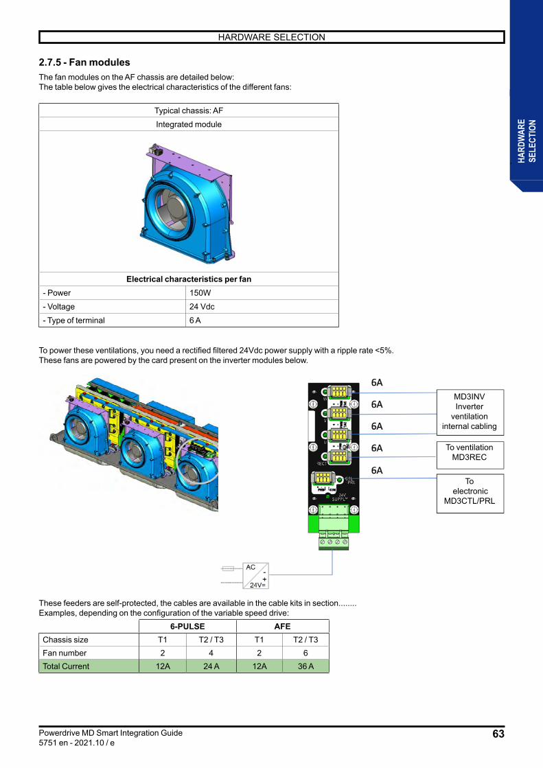
63
HARDWARE SELECTION
Powerdrive MD Smart Integration Guide5751 en - 2021.10 / e
HARD
WAR
ESE
LECT
ION
2.7.5 - Fan modulesThe fan modules on the AF chassis are detailed below:The table below gives the electrical characteristics of the different fans:
Typical chassis: AF
Integrated module
Electrical characteristics per fan- Power 150W
- Voltage 24 Vdc
- Type of terminal 6 A
To power these ventilations, you need a rectified filtered 24Vdc power supply with a ripple rate <5%.These fans are powered by the card present on the inverter modules below.
These feeders are self-protected, the cables are available in the cable kits in section........Examples, depending on the configuration of the variable speed drive:
6-PULSE AFEChassis size T1 T2 / T3 T1 T2 / T3Fan number 2 4 2 6Total Current 12A 24 A 12A 36 A
MD3INV Inverter
ventilation internal cabling
To ventilation MD3REC
To electronic
MD3CTL/PRL

64
HARDWARE SELECTION
Powerdrive MD Smart Integration Guide5751 en - 2021.10 / e
HARD
WAR
ESE
LECT
ION
2.7.6 - MD3TF Braking modules and resistors2.7.6.1 - Braking transistor
• Description
MD 3 TF 400
Modular variable speed drive
Braking transistor's peak current400: 400A available only in 400V330: 330A available only in 690V
Generation 3
TF: 400V braking transistorTHF: 690V braking transistor
An MD3TF braking module incorporates an IGBT transistor and a control circuit. In order to increase the braking capacity, several modules can be mounted in parallel, provided that each module flows its energy in its own resistor. A thermal relay must be installed in series in the power circuit as thermal protection
Voltage range 380 V - 480 V 500 V - 690 VBrake transistor reference MD3TF400 MD3THF330Peak current (A) 400 330
Continuous current (A) 250 110
Minimum value of the associated resistor (Ω) 1.8 3.5Trip threshold (Vdc BUS) 735 1100
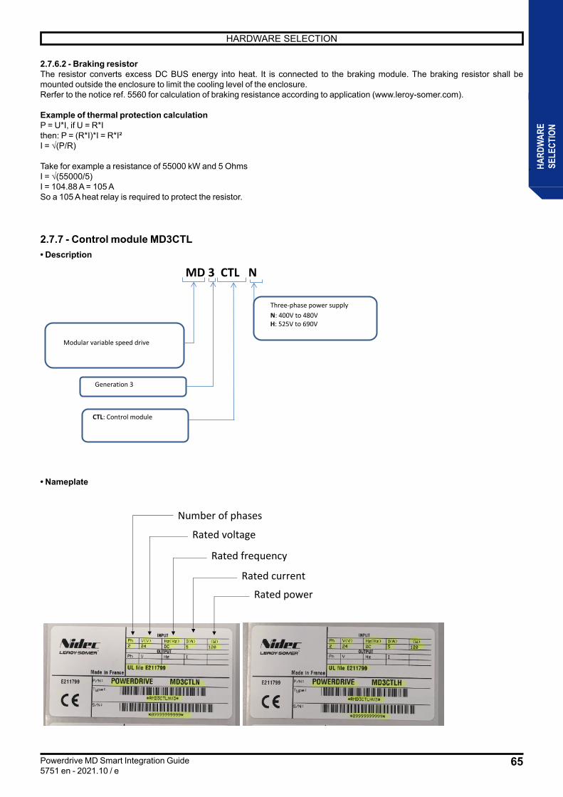
65
HARDWARE SELECTION
Powerdrive MD Smart Integration Guide5751 en - 2021.10 / e
HARD
WAR
ESE
LECT
ION
2.7.6.2 - Braking resistorThe resistor converts excess DC BUS energy into heat. It is connected to the braking module. The braking resistor shall be mounted outside the enclosure to limit the cooling level of the enclosure.Rerfer to the notice ref. 5560 for calculation of braking resistance according to application (www.leroy-somer.com).
Example of thermal protection calculationP = U*I, if U = R*Ithen: P = (R*I)*I = R*I²I = √(P/R)
Take for example a resistance of 55000 kW and 5 OhmsI = √(55000/5)I = 104.88 A = 105 ASo a 105 A heat relay is required to protect the resistor.
2.7.7 - Control module MD3CTL• Description
MD 3 CTL N
Modular variable speed drive
Three-phase power supplyN: 400V to 480VH: 525V to 690V
Generation 3
CTL: Control module
• Nameplate
Number of phases
Rated current
Rated voltage
Rated frequency
Rated power
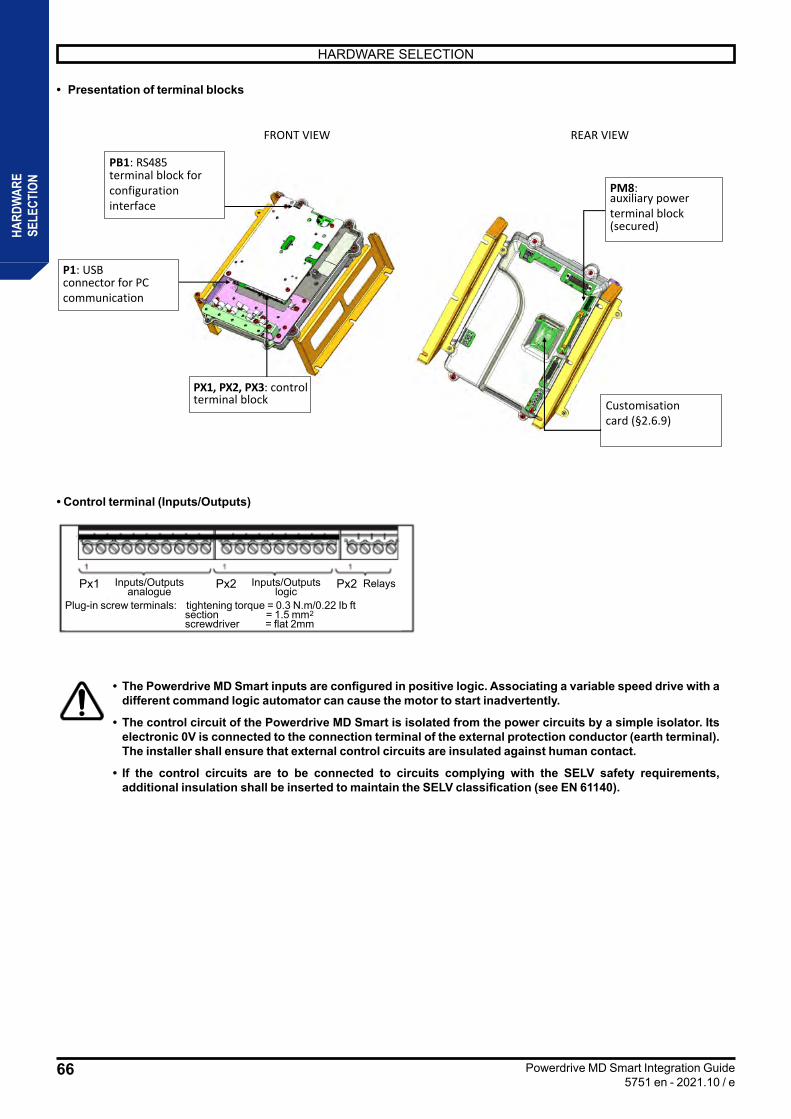
66
HARDWARE SELECTION
Powerdrive MD Smart Integration Guide5751 en - 2021.10 / e
HARD
WAR
ESE
LECT
ION
• Presentation of terminal blocks
PX1, PX2, PX3: control terminal block
P1: USBconnector for PC communication
PB1: RS485 terminal block for configuration interface
FRONT VIEW REAR VIEW
PM8:auxiliary power terminal block(secured)
Customisation card (§2.6.9)
• Control terminal (Inputs/Outputs)
• The Powerdrive MD Smart inputs are configured in positive logic. Associating a variable speed drive with a different command logic automator can cause the motor to start inadvertently.
• The control circuit of the Powerdrive MD Smart is isolated from the power circuits by a simple isolator. Its electronic 0V is connected to the connection terminal of the external protection conductor (earth terminal). The installer shall ensure that external control circuits are insulated against human contact.
• If the control circuits are to be connected to circuits complying with the SELV safety requirements, additional insulation shall be inserted to maintain the SELV classification (see EN 61140).
Px1 Px2 Px2Inputs/Outputsanalogue
Plug-in screw terminals: tightening torque = 0.3 N.m/0.22 Ib ft section = 1.5 mm2 screwdriver = flat 2mm
Inputs/Outputslogic
Relays
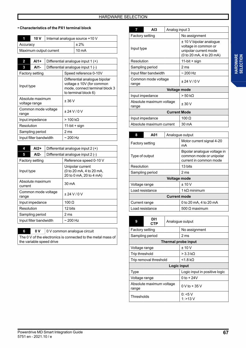
67
HARDWARE SELECTION
Powerdrive MD Smart Integration Guide5751 en - 2021.10 / e
HARD
WAR
ESE
LECT
ION
• Characteristics of the PX1 terminal block
1 10 V Internal analogue source +10 VAccuracy ± 2%Maximum output current 10 mA
2 AI1+ Differential analogue input 1 (+)3 AI1- Differential analogue input 1 (-)
Factory setting Speed reference 0-10V
Input type
Differential analogue bipolar voltage ± 10V (for common mode, connect terminal block 3 to terminal block 6)
Absolute maximum voltage range ± 36 V
Common mode voltage range ± 24 V / 0 V
Input impedance > 100 kΩResolution 11-bit + signSampling period 2 msInput filter bandwidth ~ 200 Hz
4 AI2+ Differential analogue input 2 (+)5 AI2- Differential analogue input 2 (-)
Factory setting Reference speed 0-10 V
Input typeUnipolar current(0 to 20 mA, 4 to 20 mA,20 to 0 mA, 20 to 4 mA)
Absolute maximum current 30 mA
Common mode voltage range ± 24 V / 0 V
Input impedance 100 ΩResolution 12 bitsSampling period 2 msInput filter bandwidth ~ 200 Hz
6 0 V 0 V common analogue circuitThe 0 V of the electronics is connected to the metal mass of the variable speed drive
7 AI3 Analog input 3Factory setting No assignment
Input type
± 10 V bipolar analogue voltage in common or unipolar current mode(0 to 20 mA, 4 to 20 mA)
Resolution 11-bit + signSampling period 2 msInput filter bandwidth ~ 200 HzCommon mode voltage range ± 24 V / 0 V
Voltage modeInput impedance > 50 kΩAbsolute maximum voltage range ± 30 V
Current ModeInput impedance 100 ΩAbsolute maximum current 30 mA
8 A01 Analogue output
Factory setting Motor current signal 4-20 mA
Type of outputBipolar analogue voltage in common mode or unipolar current in common mode
Resolution 13 bitsSampling period 2 ms
Voltage modeVoltage range ± 10 VLoad resistance 1 kΩ minimum
Current modeCurrent range 0 to 20 mA, 4 to 20 mALoad resistance 500 Ω maximum
9 DI1CTP Analogue output
Factory setting No assignmentSampling period 2 ms
Thermal probe inputVoltage range ± 10 VTrip threshold > 3.3 kΩTrip removal threshold <1.8 kΩ
Logic inputType Logic input in positive logicVoltage range 0 to + 24VAbsolute maximum voltage range 0 V to + 35 V
Thresholds 0: <5 V1: >13 V
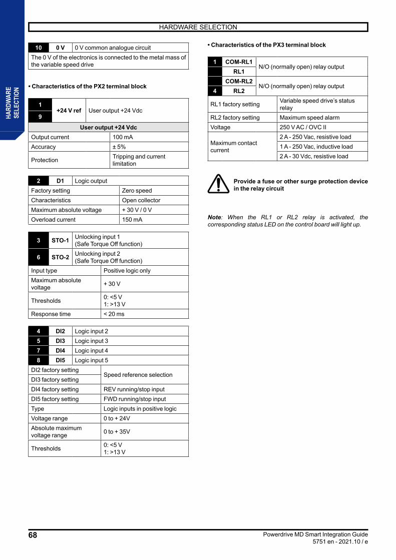
68
HARDWARE SELECTION
Powerdrive MD Smart Integration Guide5751 en - 2021.10 / e
HARD
WAR
ESE
LECT
ION
10 0 V 0 V common analogue circuitThe 0 V of the electronics is connected to the metal mass of the variable speed drive
• Characteristics of the PX2 terminal block
1+24 V ref User output +24 Vdc
9
User output +24 VdcOutput current 100 mAAccuracy ± 5%
Protection Tripping and current limitation
2 D1 Logic outputFactory setting Zero speedCharacteristics Open collectorMaximum absolute voltage + 30 V / 0 VOverload current 150 mA
3 STO-1 Unlocking input 1(Safe Torque Off function)
6 STO-2 Unlocking input 2(Safe Torque Off function)
Input type Positive logic onlyMaximum absolute voltage + 30 V
Thresholds 0: <5 V1: >13 V
Response time < 20 ms
4 DI2 Logic input 25 DI3 Logic input 37 DI4 Logic input 48 DI5 Logic input 5
DI2 factory settingSpeed reference selection
DI3 factory settingDI4 factory setting REV running/stop inputDI5 factory setting FWD running/stop inputType Logic inputs in positive logicVoltage range 0 to + 24VAbsolute maximum voltage range 0 to + 35V
Thresholds 0: <5 V1: >13 V
• Characteristics of the PX3 terminal block
1 COM-RL1N/O (normally open) relay output
RL1COM-RL2
N/O (normally open) relay output4 RL2
RL1 factory setting Variable speed drive’s status relay
RL2 factory setting Maximum speed alarmVoltage 250 V AC / OVC II
Maximum contact current
2 A - 250 Vac, resistive load1 A - 250 Vac, inductive load2 A - 30 Vdc, resistive load
Provide a fuse or other surge protection device in the relay circuit
Note: When the RL1 or RL2 relay is activated, the corresponding status LED on the control board will light up.

69
HARDWARE SELECTION
Powerdrive MD Smart Integration Guide5751 en - 2021.10 / e
HARD
WAR
ESE
LECT
ION
• P1 connector (for PC communication)
The USB-B connector allows communication via PC using SYSTEMIZ software. This connector also allows the firmware version of the control module to be updated (Contact Leroy-Somer).
In accordance with the requirements of EN 60950, the USB link can only be used through a device that provides 4 kV insulation.
• PB1 connector (for a setup interface)
• Connection
Terminals Description1 0V2 Rx\, Tx\3 Rx, Tx4 24 V
It is a standard RS485 terminal that allows the connection of a setup interface or to communicate in Modbus RTU, under certain conditions:
• Operation with an HMI + Cableless- If Cableless is enabled, the HMI is no longer in use.- The HMI will resume when the Cableless connection is disabled
• Operation without an HMI + Cableless- If the Cableless function is enabled then the PB1 RS485 port cannot be used in Modbus. The MDX MODBUS option must be
added to communicate with the MODBUS variable speed drive.- If the Cableless function is disabled then the PB1 RS485 port can be used in Modbus provided the transmission speed is 115200
baud
Note: for info, the speed 115200 baud of this port prohibits the use of an MDX keypad option.
PB1
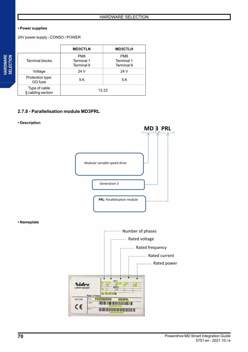
70
HARDWARE SELECTION
Powerdrive MD Smart Integration Guide5751 en - 2021.10 / e
HARD
WAR
ESE
LECT
ION
• Power supplies
24V power supply - CONSO / POWER
MD3CTLN MD3CTLH
Terminal blocksPM8
Terminal 1Terminal 9
PM8Terminal 1Terminal 9
Voltage 24 V 24 VProtection type:
GG fuse 5 A 5 A
Type of cable§ cabling section 12.23
2.7.8 - Parallelisation module MD3PRL
• DescriptionMD 3 PRL N
Modular variable speed drive
Three-phase power supply N: 400V to 480VH: 525V to 690V
Generation 3
PRL: Parallelisation module
• Nameplate
Number of phases
Rated current
Rated voltage
Rated frequency
Rated power

71
HARDWARE SELECTION
Powerdrive MD Smart Integration Guide5751 en - 2021.10 / e
HARD
WAR
ESE
LECT
ION
• Presentation of terminal blocks
• Power supplies
MD3PRLN
Terminal blocksPM8
Terminal 1Terminal 9
Voltage 24 VProtection type:
GG fuse 2 A
Type of cable§ cabling section 12.23
Please note that the 24Vdc power supply must have a fuse. This is the case when it comes from an MD3INV chassis. It is up to the user to install a fuse if not.
FRONT VIEW REAR VIEW
Customisation card
§2.5.9
PM8: power terminal block
auxiliary (secured)

72
HARDWARE SELECTION
Powerdrive MD Smart Integration Guide5751 en - 2021.10 / e
HARD
WAR
ESE
LECT
ION
2.7.9 - Customisation card The customisation card is delivered systematically with the inverter chassis, it allows the current returns of the inverter to be calibrated and indicates to the control module the “LS model” of the solution created. The basic control module and the parallelisation module come with a "neutral" customisation card. This card is only available for transport so as not to damage the connection. When the control module and the parallelisation module are connected, it will of course be necessary to replace it with the customisation card delivered with the MD3INV inverter chassis, in order to ensure proper operation.
• Number of customisation cards based on LS model and MD3INV inverter type
Three-phase 400V -10% to 480V +10%
LS MODEL POWER IN kWCustomisation card number and reference
MD3INVxx260N MD3INVxx315N MD3INVxx408N MD3INVxx497N MD3INVxx618N MD3INVxx747N MD3INVxx865N MD3INVxx931N150TN 132 PEF170NG038A180TN 160 PEF170NG035A220TN 200 PEF170NG040A270TN 250 PEF170NG036A340TN 315 PEF170NG031A430TN 400 PEF170NG041A470TN 450 PEF170NG037A570TN 500 PEF170NG032A680TN 630 PEF170NG055A860TN 800 PEF170NG056A940TN 900 PEF170NG057A
1140TN 1000 PEF170NG058A1290TN 1200 PEF170NG059A1410TN 1350 PEF170NG060A1710TN 1500 PEF170NG061A2280TN 2000 TBD2850TN 2500 TBD
Three-phase 525V -10% to 690V +10%
LS MODEL POWER IN kWCustomisation card number and reference
MD3INVxx150H MD3INVxx180H MD3INVxx260H MD3INVxx393H MD3INVxx478H MD3INVxx583H
150TH 132 PEF170NG063A
180TH 160 PEF170NG027A
220TH 200 PEF170NG042A
340TH 315 PEF170NG043A
430TH 400 PEF170NG044A
570TH 500 PEF170NG029A
680TH 630 PEF170NG046A
860TH 800 PEF170NG039A
1140TH 900 PEF170NG047A
1290TH 1000 PEF170NG048A
1710TH 1200 PEF170NG049A
2280TH 1500 TBD
2850TH 1800 TBD

73
MECHANICAL INSTALLATION
Powerdrive MD Smart Integration Guide5751 en - 2021.10 / e
MECH
ANIC
ALIN
STAL
LATI
ON
3 - MECHANICAL INSTALLATION
• It is the owner or user’s responsibility to ensure that the assembly, installation, cabling and testing of the Powerdrive MD Smart variable speed drive and its options are carried out in accordance with the property and personal safety legislation and regulations in use in the country in which it is installed.
• Variable speed drives must be installed in an environment free of conductive, smoked, corrosive and condensing dust, gas and fluids (Class 2 according to IEC 664.1). The variable speed drive shall not be installed in risk areas except in an appropriate enclosure. In this case, the installation must be certified.
• In atmospheres subject to condensation, install a heating system (to be turned off when the variable speed drive is in operation). It is preferable to order the heating system automatically.
3.1 - Checks upon receipt
Before installing the various components of the POWERDRIVE MD Smart, ensure that: - the component has not been damaged during transportation, - the information on the nameplate is compatible with the supply network.
3.2 - Handling
• Ensure that the handling means are suitable for the mass to be handled.
• Some elements are equipped with 4 lifting rings.
• Most chassis in the range weigh more than 15 kg.
For handling, use a lifting beam that complies with the characteristics shown in the diagram below. RECTIFIER AND INVERTER chassis must be handled horizontally.
≥ 500 mm
90º
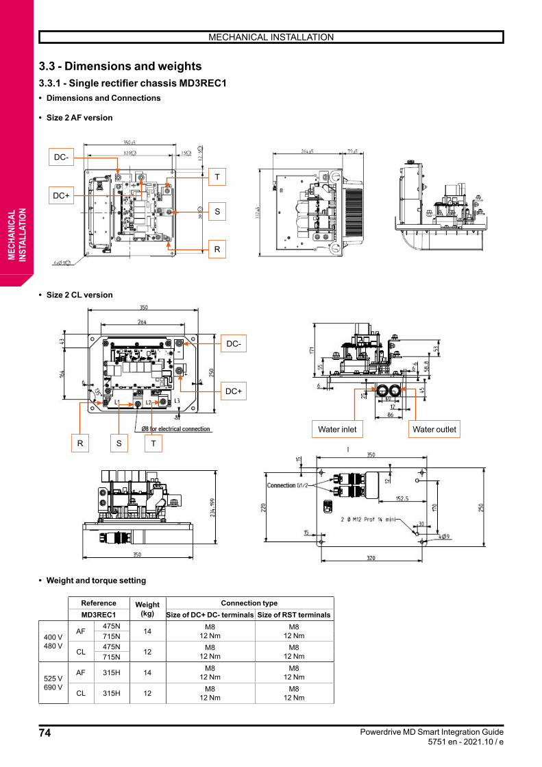
74
MECHANICAL INSTALLATION
Powerdrive MD Smart Integration Guide5751 en - 2021.10 / e
MECH
ANIC
ALIN
STAL
LATI
ON
3.3 - Dimensions and weights3.3.1 - Single rectifier chassis MD3REC1• Dimensions and Connections
• Size 2 AF version
• Size 2 CL version
• Weight and torque setting
Reference Weight (kg)
Connection typeMD3REC1 Size of DC+ DC- terminals Size of RST terminals
400 V480 V
AF475N
14 M812 Nm
M812 Nm715N
CL475N
12 M812 Nm
M812 Nm715N
525 V690 V
AF 315H 14 M812 Nm
M812 Nm
CL 315H 12 M812 Nm
M812 Nm
DC-
DC-
T
R
Water inlet Water outlet
R
T
S
S
DC+
DC+
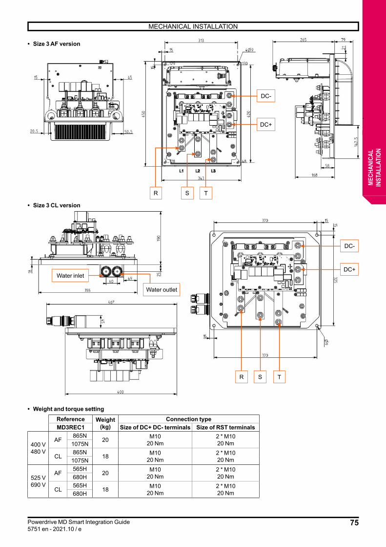
75
MECHANICAL INSTALLATION
Powerdrive MD Smart Integration Guide5751 en - 2021.10 / e
MECH
ANIC
ALIN
STAL
LATI
ON
• Size 3 AF version
• Size 3 CL version
• Weight and torque settingReference Weight
(kg)Connection type
MD3REC1 Size of DC+ DC- terminals Size of RST terminals
400 V480 V
AF865N
20 M1020 Nm
2 * M1020 Nm1075N
CL865N
18 M1020 Nm
2 * M1020 Nm1075N
525 V690 V
AF565H
20 M1020 Nm
2 * M1020 Nm680H
CL565H
18 M1020 Nm
2 * M1020 Nm680H
R TS
DC-
DC+
R TS
DC-
DC+Water inlet
Water outlet
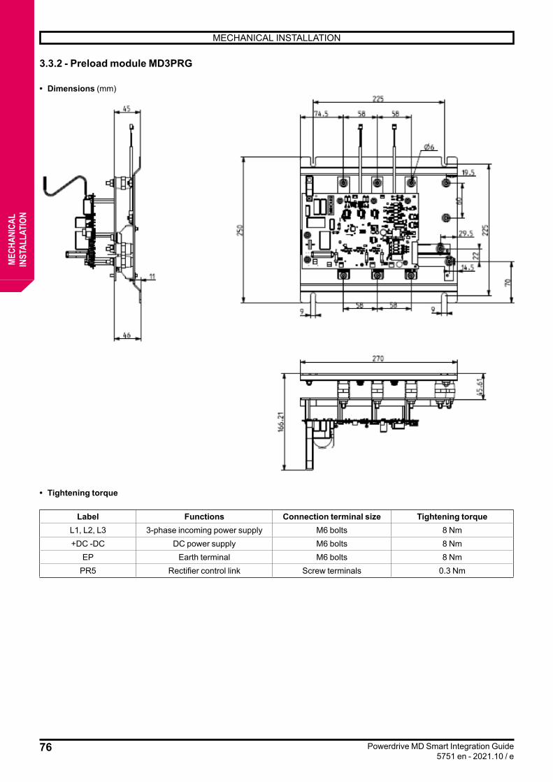
76
MECHANICAL INSTALLATION
Powerdrive MD Smart Integration Guide5751 en - 2021.10 / e
MECH
ANIC
ALIN
STAL
LATI
ON
3.3.2 - Preload module MD3PRG
• Dimensions (mm)
• Tightening torque
Label Functions Connection terminal size Tightening torqueL1, L2, L3 3-phase incoming power supply M6 bolts 8 Nm+DC -DC DC power supply M6 bolts 8 Nm
EP Earth terminal M6 bolts 8 NmPR5 Rectifier control link Screw terminals 0.3 Nm
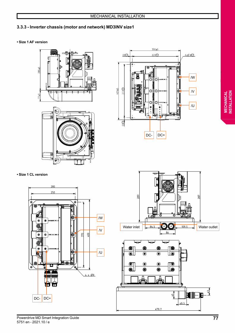
77
MECHANICAL INSTALLATION
Powerdrive MD Smart Integration Guide5751 en - 2021.10 / e
MECH
ANIC
ALIN
STAL
LATI
ON
3.3.3 - Inverter chassis (motor and network) MD3INV size1
• Size 1 AF version
• Size 1 CL version
DC- DC+
/W
/V
/U
DC- DC+
/W
/V
/U
Water inlet Water outlet
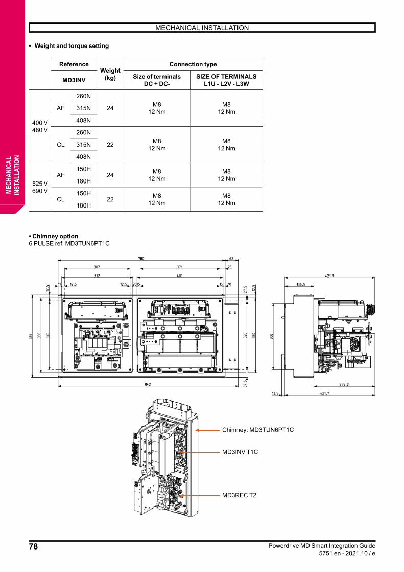
78
MECHANICAL INSTALLATION
Powerdrive MD Smart Integration Guide5751 en - 2021.10 / e
MECH
ANIC
ALIN
STAL
LATI
ON
• Weight and torque setting
ReferenceWeight
(kg)
Connection type
MD3INV Size of terminalsDC + DC-
SIZE OF TERMINALSL1U - L2V - L3W
400 V480 V
AF
260N
24 M812 Nm
M812 Nm315N
408N
CL
260N
22 M812 Nm
M812 Nm315N
408N
525 V690 V
AF150H
24 M812 Nm
M812 Nm180H
CL150H
22 M812 Nm
M812 Nm180H
• Chimney option6 PULSE ref: MD3TUN6PT1C
Chimney: MD3TUN6PT1C
MD3INV T1C
MD3REC T2

79
MECHANICAL INSTALLATION
Powerdrive MD Smart Integration Guide5751 en - 2021.10 / e
MECH
ANIC
ALIN
STAL
LATI
ON
AFE ref: MD3TUNRT1C
Chimney: MD3TUNRT1C
MD3INV T1C
MD3INVT1C
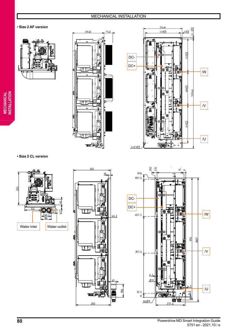
80
MECHANICAL INSTALLATION
Powerdrive MD Smart Integration Guide5751 en - 2021.10 / e
MECH
ANIC
ALIN
STAL
LATI
ON
• Size 2 AF version
• Size 2 CL version
DC-
DC+
/W
/V
/U
DC-
DC+
/W
/V
/U
Water inlet Water outlet
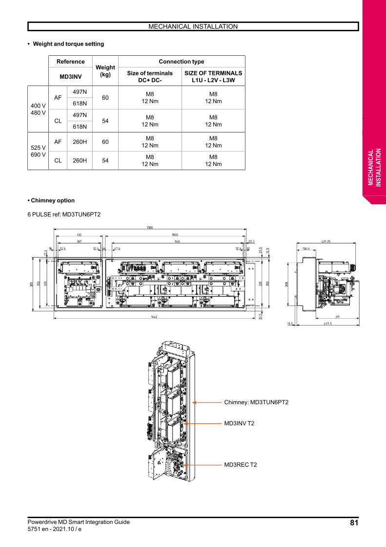
81
MECHANICAL INSTALLATION
Powerdrive MD Smart Integration Guide5751 en - 2021.10 / e
MECH
ANIC
ALIN
STAL
LATI
ON
• Weight and torque setting
ReferenceWeight
(kg)
Connection type
MD3INV Size of terminalsDC+ DC-
SIZE OF TERMINALSL1U - L2V - L3W
400 V480 V
AF497N
60 M812 Nm
M812 Nm618N
CL497N
54 M812 Nm
M812 Nm618N
525 V690 V
AF 260H 60 M812 Nm
M812 Nm
CL 260H 54 M812 Nm
M812 Nm
• Chimney option
6 PULSE ref: MD3TUN6PT2
Chimney: MD3TUN6PT2
MD3INV T2
MD3REC T2
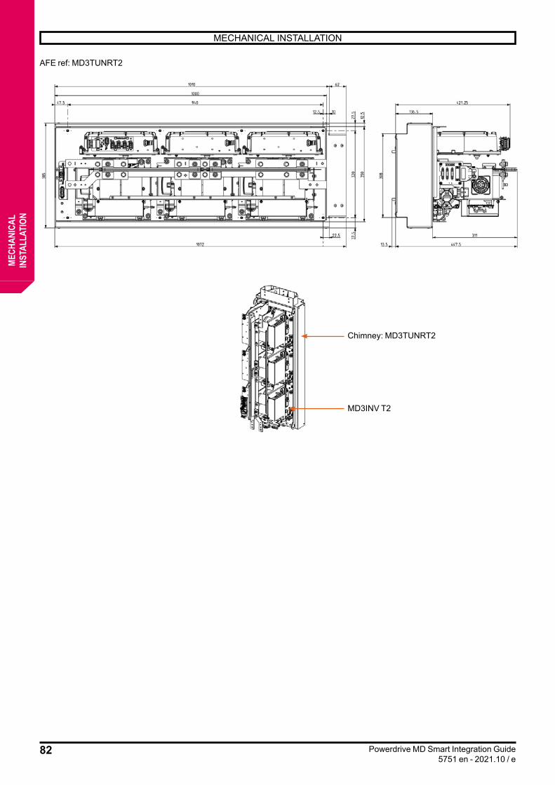
82
MECHANICAL INSTALLATION
Powerdrive MD Smart Integration Guide5751 en - 2021.10 / e
MECH
ANIC
ALIN
STAL
LATI
ON
AFE ref: MD3TUNRT2
Chimney: MD3TUNRT2
MD3INV T2
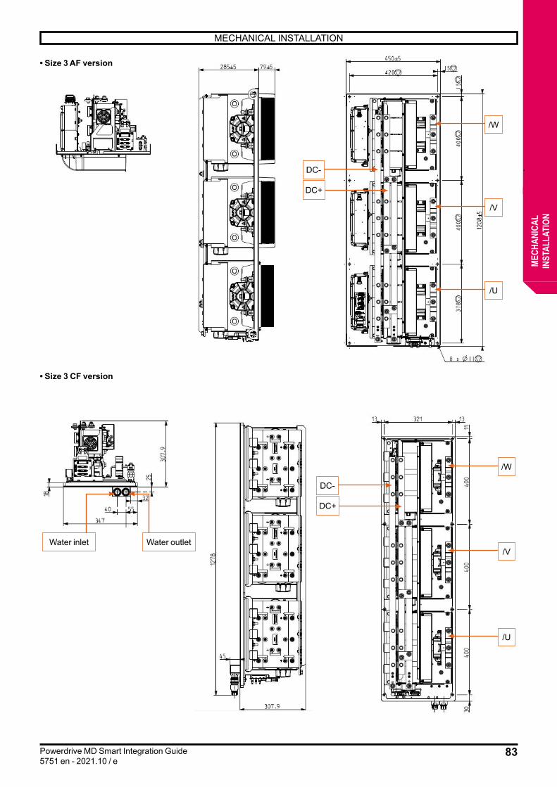
83
MECHANICAL INSTALLATION
Powerdrive MD Smart Integration Guide5751 en - 2021.10 / e
MECH
ANIC
ALIN
STAL
LATI
ON
• Size 3 AF version
• Size 3 CF version
DC-
DC-
DC+
DC+
/W
/W
/V
/V
/U
/U
Water inlet Water outlet
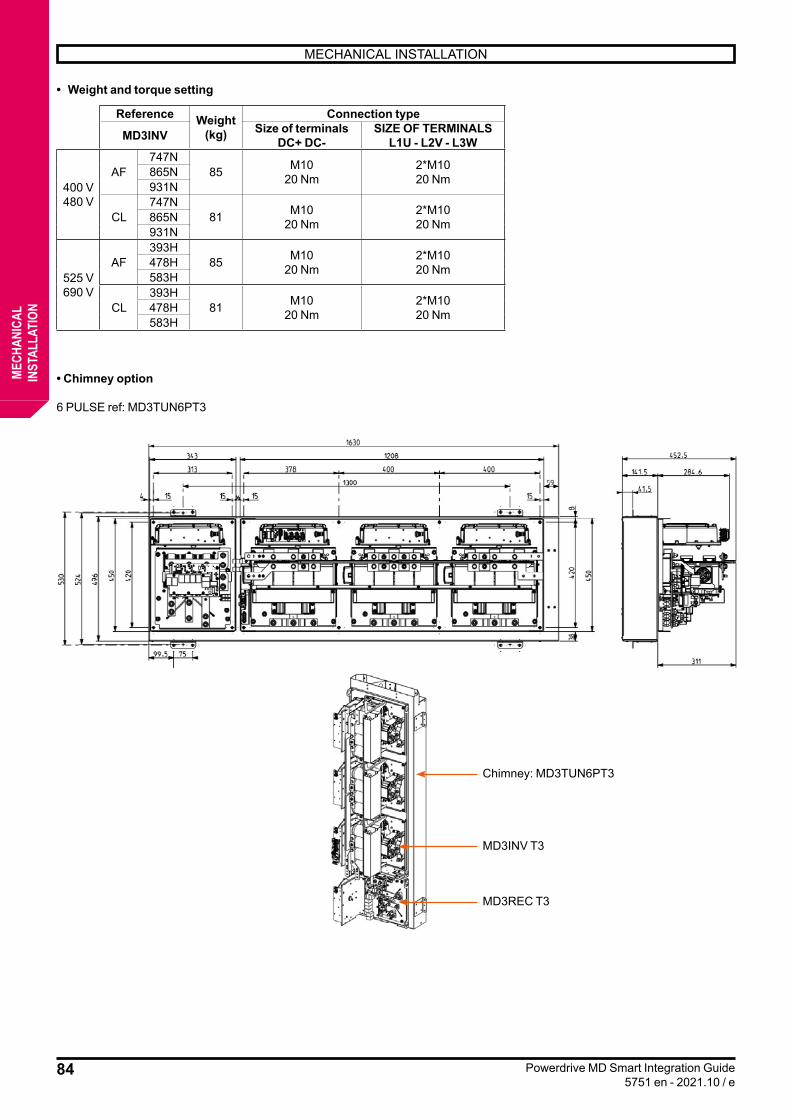
84
MECHANICAL INSTALLATION
Powerdrive MD Smart Integration Guide5751 en - 2021.10 / e
MECH
ANIC
ALIN
STAL
LATI
ON
• Weight and torque setting
Reference Weight (kg)
Connection type
MD3INV Size of terminalsDC+ DC-
SIZE OF TERMINALSL1U - L2V - L3W
400 V480 V
AF747N
85 M1020 Nm
2*M1020 Nm865N
931N
CL747N
81 M1020 Nm
2*M1020 Nm865N
931N
525 V690 V
AF393H
85 M1020 Nm
2*M1020 Nm478H
583H
CL393H
81 M1020 Nm
2*M1020 Nm478H
583H
• Chimney option
6 PULSE ref: MD3TUN6PT3
Chimney: MD3TUN6PT3
MD3INV T3
MD3REC T3

85
MECHANICAL INSTALLATION
Powerdrive MD Smart Integration Guide5751 en - 2021.10 / e
MECH
ANIC
ALIN
STAL
LATI
ON
AFE ref: MD3TUNRT3
CHEMINEE : MD3TUNRT3
MD3INV T3
CHIMNEY: MD3TUNRT3

86
MECHANICAL INSTALLATION
Powerdrive MD Smart Integration Guide5751 en - 2021.10 / e
MECH
ANIC
ALIN
STAL
LATI
ON
3.3.4 - Braking module MD3TF
• Dimensions (mm)
• Tightening torque
Label Functions Connection terminal size Tightening torqueBR1 BR2 incoming resistor M8 bolts 12 NmBR3 BR4 Incoming thermal relay M8 bolts 12 Nm
EP Earth terminal M8 bolts 12 Nm230 V AC Rectifier control link Spring terminals
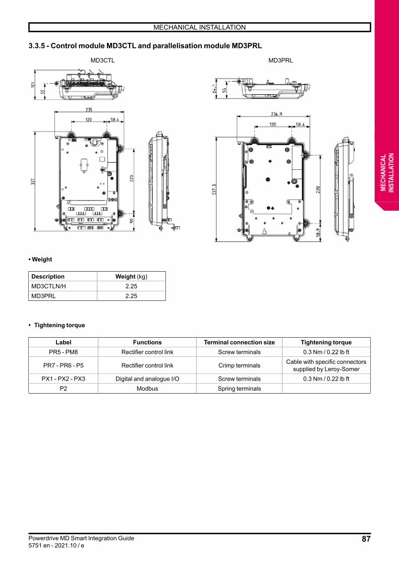
87
MECHANICAL INSTALLATION
Powerdrive MD Smart Integration Guide5751 en - 2021.10 / e
MECH
ANIC
ALIN
STAL
LATI
ON
3.3.5 - Control module MD3CTL and parallelisation module MD3PRL
• Weight
Description Weight (kg)MD3CTLN/H 2.25MD3PRL 2.25
• Tightening torque
Label Functions Terminal connection size Tightening torquePR5 - PM8 Rectifier control link Screw terminals 0.3 Nm / 0.22 lb ft
PR7 - PR6 - P5 Rectifier control link Crimp terminals Cable with specific connectors supplied by Leroy-Somer
PX1 - PX2 - PX3 Digital and analogue I/O Screw terminals 0.3 Nm / 0.22 lb ftP2 Modbus Spring terminals
MD3CTL MD3PRL
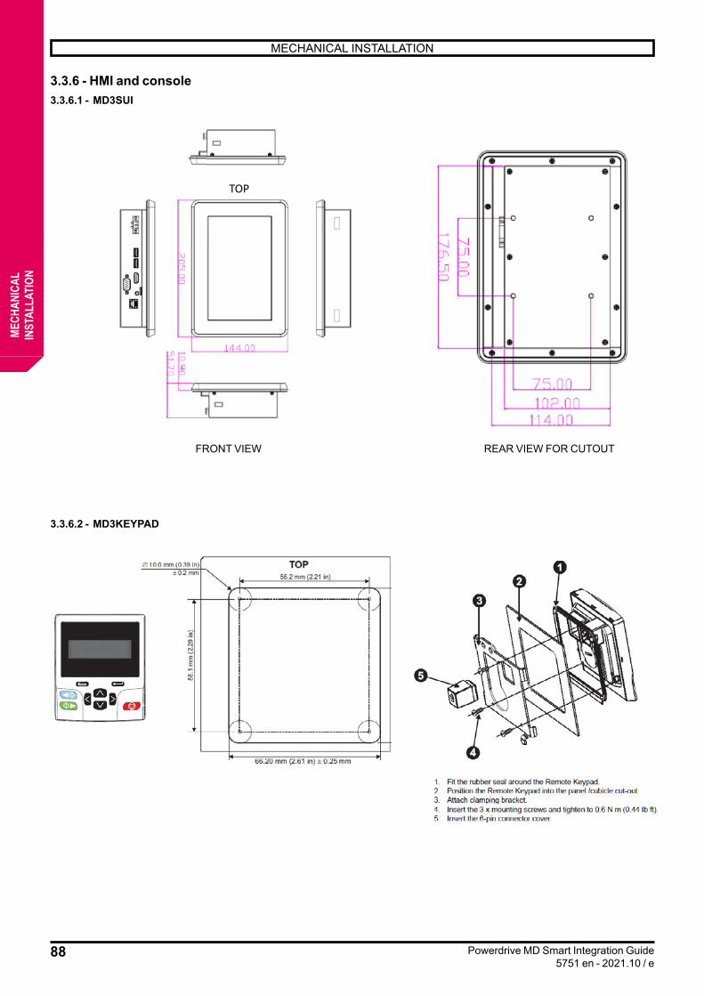
88
MECHANICAL INSTALLATION
Powerdrive MD Smart Integration Guide5751 en - 2021.10 / e
MECH
ANIC
ALIN
STAL
LATI
ON
3.3.6 - HMI and console 3.3.6.1 - MD3SUI
VUE DE FACE VUE ARRIERE POUR DECOUPE
TOP
3.3.6.2 - MD3KEYPAD
FRONT VIEW REAR VIEW FOR CUTOUT
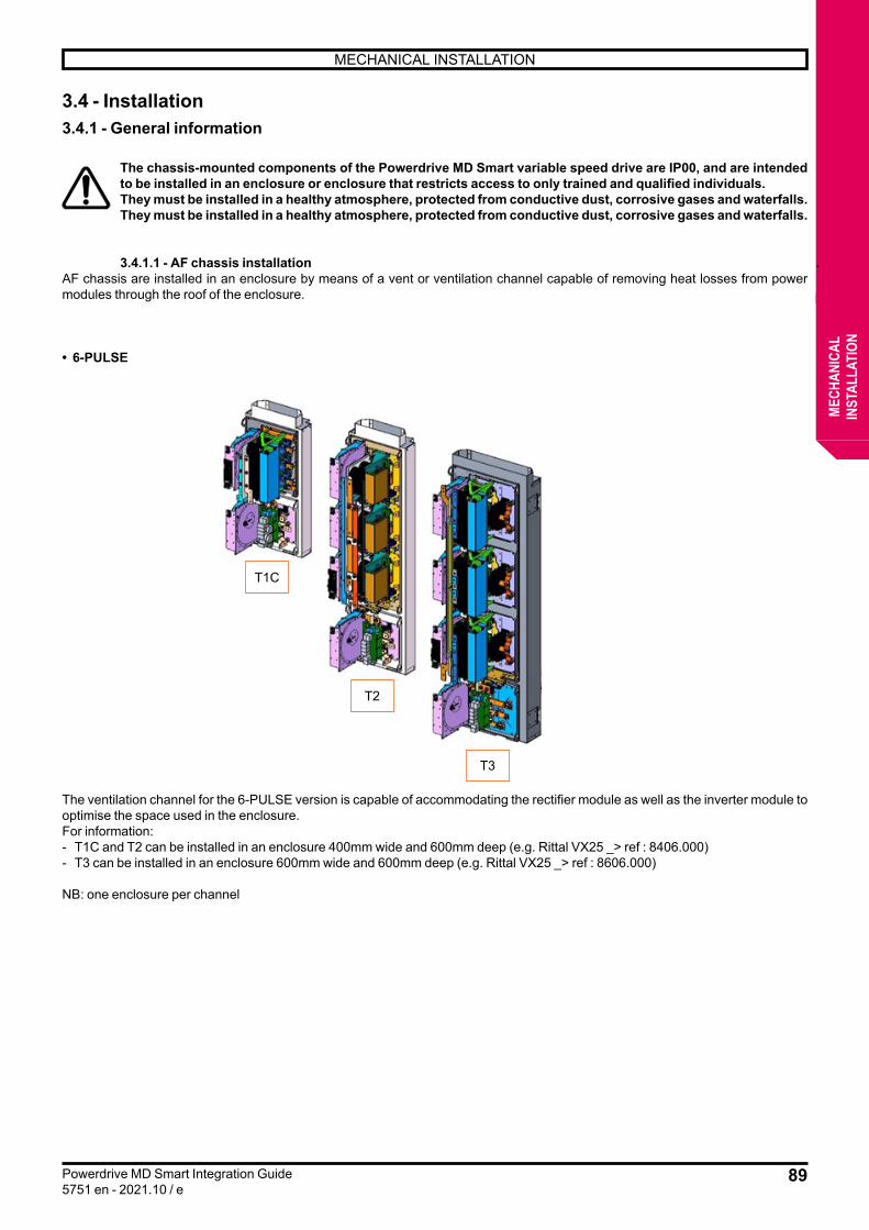
89
MECHANICAL INSTALLATION
Powerdrive MD Smart Integration Guide5751 en - 2021.10 / e
MECH
ANIC
ALIN
STAL
LATI
ON
3.4 - Installation3.4.1 - General information
The chassis-mounted components of the Powerdrive MD Smart variable speed drive are IP00, and are intended to be installed in an enclosure or enclosure that restricts access to only trained and qualified individuals.They must be installed in a healthy atmosphere, protected from conductive dust, corrosive gases and waterfalls.They must be installed in a healthy atmosphere, protected from conductive dust, corrosive gases and waterfalls.
3.4.1.1 - AF chassis installationAF chassis are installed in an enclosure by means of a vent or ventilation channel capable of removing heat losses from power modules through the roof of the enclosure.
• 6-PULSE
The ventilation channel for the 6-PULSE version is capable of accommodating the rectifier module as well as the inverter module to optimise the space used in the enclosure.For information:- T1C and T2 can be installed in an enclosure 400mm wide and 600mm deep (e.g. Rittal VX25 _> ref : 8406.000)- T3 can be installed in an enclosure 600mm wide and 600mm deep (e.g. Rittal VX25 _> ref : 8606.000)
NB: one enclosure per channel
T1C
T2
T3
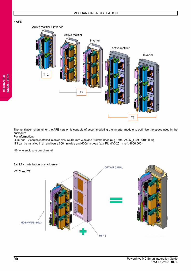
90
MECHANICAL INSTALLATION
Powerdrive MD Smart Integration Guide5751 en - 2021.10 / e
MECH
ANIC
ALIN
STAL
LATI
ON
• AFE
The ventilation channel for the AFE version is capable of accommodating the inverter module to optimise the space used in the enclosure.For information:-T1C and T2 can be installed in an enclosure 400mm wide and 600mm deep (e.g. Rittal VX25 _> ref : 8406.000)-T3 can be installed in an enclosure 600mm wide and 600mm deep (e.g. Rittal VX25 _> ref : 8606.000)
NB: one enclosure per channel
3.4.1.2 - Installation in enclosure:
• T1C and T2
T1C
Active rectifier + inverter
Active rectifier
Active rectifier
Inverter
Inverter
T2
T3
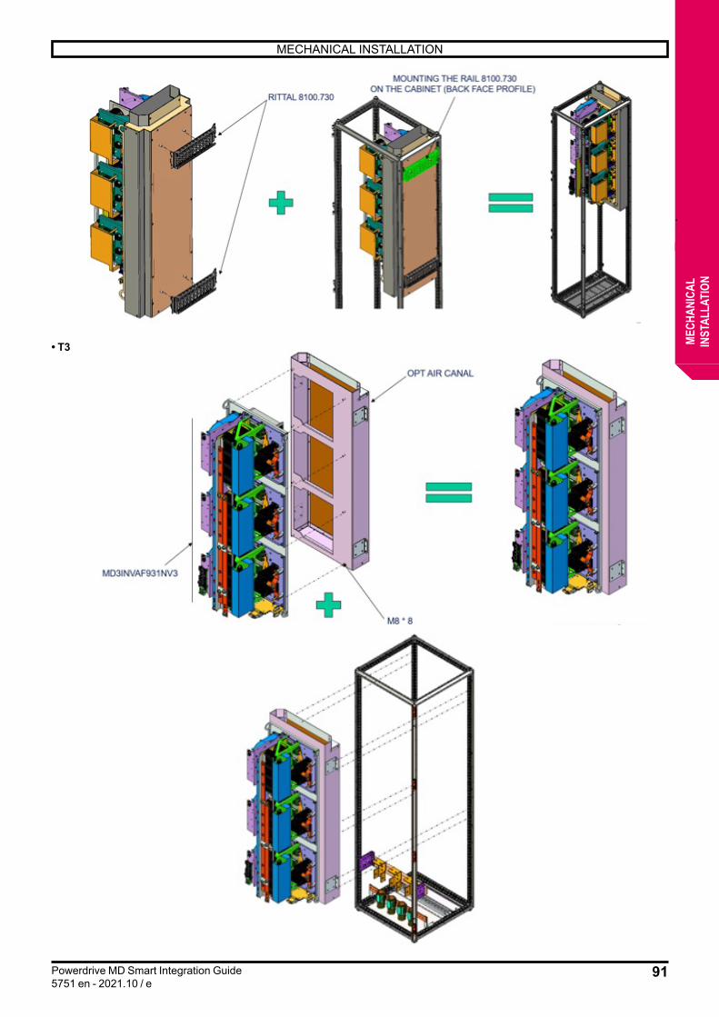
91
MECHANICAL INSTALLATION
Powerdrive MD Smart Integration Guide5751 en - 2021.10 / e
MECH
ANIC
ALIN
STAL
LATI
ON
• T3

92
MECHANICAL INSTALLATION
Powerdrive MD Smart Integration Guide5751 en - 2021.10 / e
MECH
ANIC
ALIN
STAL
LATI
ON
View from below, horizontal enclosure Side view, horizontal enclosure
• Step 2
View from below, horizontal enclosure
• Step 3
Fixings
Front view, upright enclosure
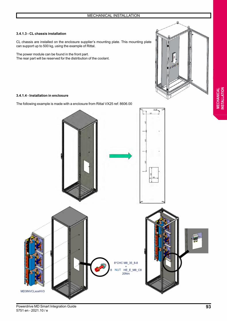
93
MECHANICAL INSTALLATION
Powerdrive MD Smart Integration Guide5751 en - 2021.10 / e
MECH
ANIC
ALIN
STAL
LATI
ON
3.4.1.3 - CL chassis installation
CL chassis are installed on the enclosure supplier’s mounting plate. This mounting plate can support up to 500 kg, using the example of Rittal.
The power module can be found in the front part.The rear part will be reserved for the distribution of the coolant.
3.4.1.4 - Installation in enclosure
The following example is made with a enclosure from Rittal VX25 ref: 8606.00
NUT

94
MECHANICAL INSTALLATION
Powerdrive MD Smart Integration Guide5751 en - 2021.10 / e
MECH
ANIC
ALIN
STAL
LATI
ON
3.4.2 - Minimum installation distancesInstalling a chassis in an enclosure requires special precautions in terms of the volume of the enclosure. It must be verified that the heat dissipation is sufficient and that each component of the enclosure has sufficient space for the correct operation of the assembly.
This paragraph gives the different distances to be respected between components and between components and enclosure panels, thus ensuring a good circulation of the air flow around the different chassis.For thermal losses see paragraph 3.7.
3.4.2.1 - Rectifier chassis MD3REC1
• 1 chassis per enclosure
Dimensions (mm)H1 H2 L1* L2 P1 P2
Min. 10** 10 50 30 40 20
* L1 is the distance between the fan and the wall.** If there is a heat source below the rectifier (e.g. reactor) the minimum distance is 200 mm.
Note: with an optional ventilation channel (chimney) assembly, only dimensions L1, H1, L2 and P1 must be respected.
L1 P1L2 P2
H1
H2
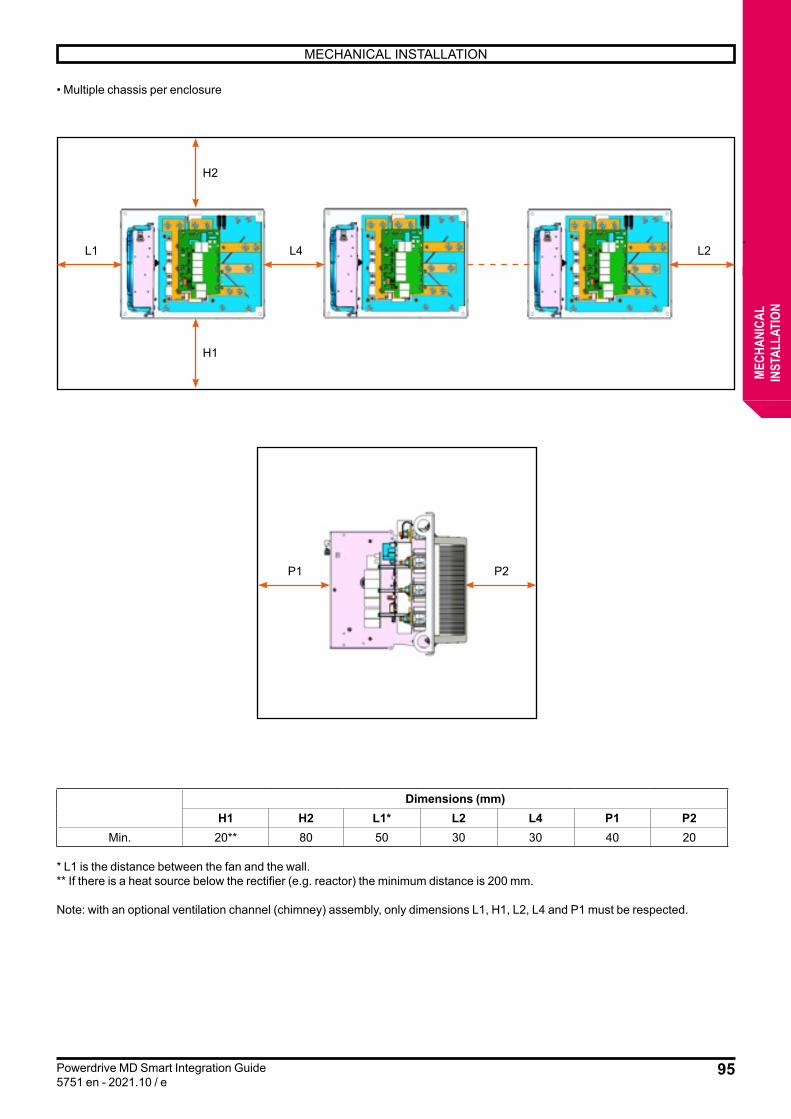
95
MECHANICAL INSTALLATION
Powerdrive MD Smart Integration Guide5751 en - 2021.10 / e
MECH
ANIC
ALIN
STAL
LATI
ON
• Multiple chassis per enclosure
Dimensions (mm)H1 H2 L1* L2 L4 P1 P2
Min. 20** 80 50 30 30 40 20
* L1 is the distance between the fan and the wall.** If there is a heat source below the rectifier (e.g. reactor) the minimum distance is 200 mm.
Note: with an optional ventilation channel (chimney) assembly, only dimensions L1, H1, L2, L4 and P1 must be respected.
L1 L4 L2
H1
H2
P1 P2

96
MECHANICAL INSTALLATION
Powerdrive MD Smart Integration Guide5751 en - 2021.10 / e
MECH
ANIC
ALIN
STAL
LATI
ON
3.4.2.2 - Inverter chassis MD3INV
• Size 1
Dimensions (mm)H1 H2 L1* L2 P1 P2
Min. 20** 80*** 50 30 40 20
* L1 is the distance between the fan and the wall.** If there is a heat source below the rectifier (e.g. reactor) the minimum distance is 200 mm.
Note: with an optional ventilation channel (chimney) assembly, only dimensions L1, H1, L2 and P1 must be respected.
H1
H2
L2L1 P1 P2
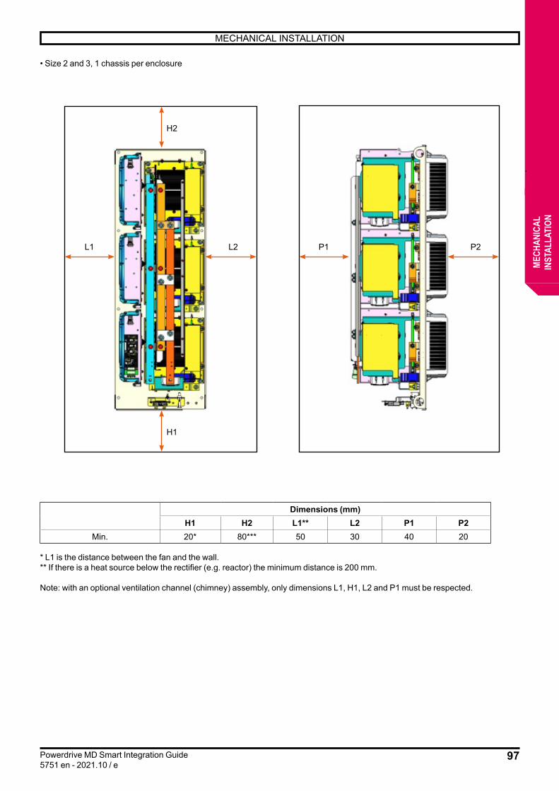
97
MECHANICAL INSTALLATION
Powerdrive MD Smart Integration Guide5751 en - 2021.10 / e
MECH
ANIC
ALIN
STAL
LATI
ON
• Size 2 and 3, 1 chassis per enclosure
Dimensions (mm)H1 H2 L1** L2 P1 P2
Min. 20* 80*** 50 30 40 20
* L1 is the distance between the fan and the wall.** If there is a heat source below the rectifier (e.g. reactor) the minimum distance is 200 mm.
Note: with an optional ventilation channel (chimney) assembly, only dimensions L1, H1, L2 and P1 must be respected.
H1
H2
L2 P2P1L1
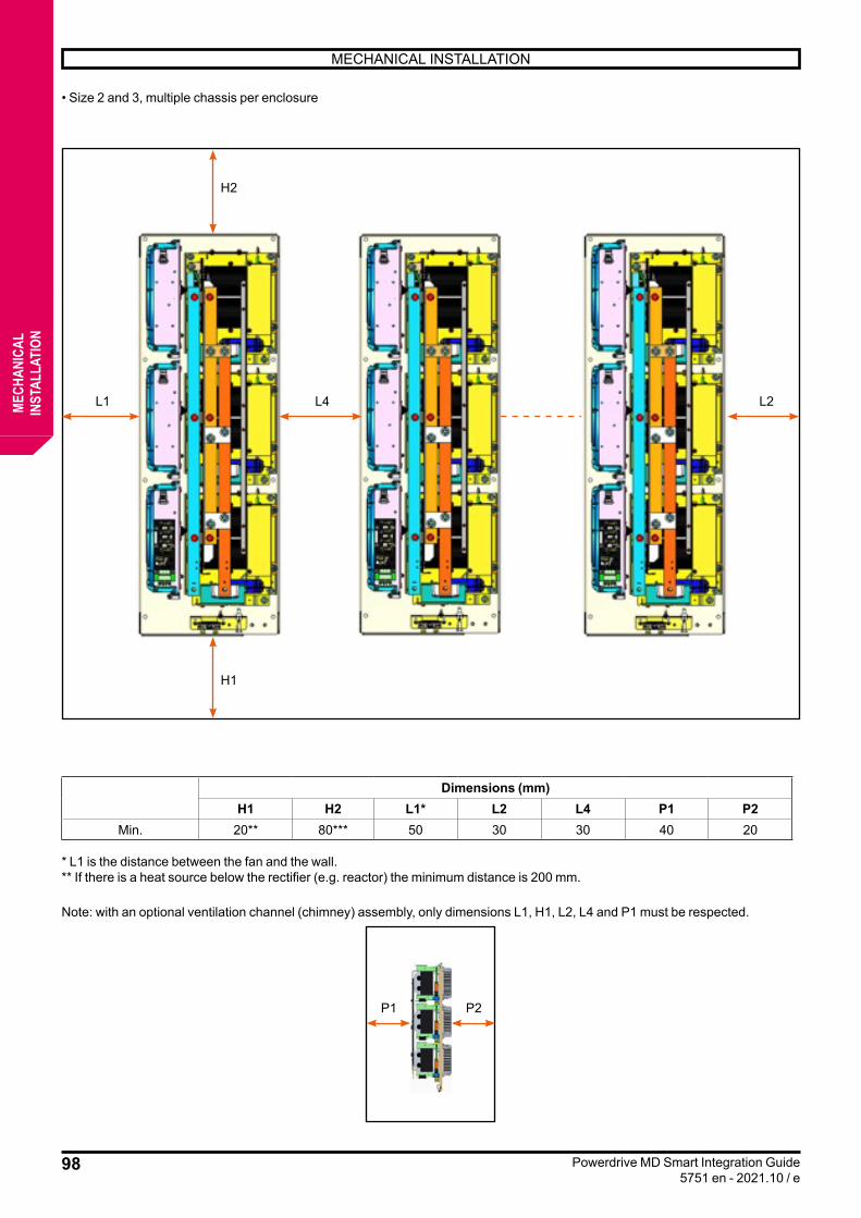
98
MECHANICAL INSTALLATION
Powerdrive MD Smart Integration Guide5751 en - 2021.10 / e
MECH
ANIC
ALIN
STAL
LATI
ON
• Size 2 and 3, multiple chassis per enclosure
Dimensions (mm)H1 H2 L1* L2 L4 P1 P2
Min. 20** 80*** 50 30 30 40 20
* L1 is the distance between the fan and the wall.** If there is a heat source below the rectifier (e.g. reactor) the minimum distance is 200 mm.
Note: with an optional ventilation channel (chimney) assembly, only dimensions L1, H1, L2, L4 and P1 must be respected.
L1
P1 P2
L4 L2
H1
H2

99
MECHANICAL INSTALLATION
Powerdrive MD Smart Integration Guide5751 en - 2021.10 / e
MECH
ANIC
ALIN
STAL
LATI
ON
3.4.2.3 - Preload module MD3PRG
Dimensions (mm)H1 H2 L1 L2 P1
Min. 20 20 20 20 50
H1
H2
L2
P1
L1

100
MECHANICAL INSTALLATION
Powerdrive MD Smart Integration Guide5751 en - 2021.10 / e
MECH
ANIC
ALIN
STAL
LATI
ON
3.4.2.4 - Control module MD3CTL and parallelisation module MD3PRL
Dimensions (mm)H1 H2 L1 L2 P1 P2
Min. 20 20 20 20 20* 0
* P1 is the distance between the control card without options and an obstacle (if there are options mounted on it, add 45 mm per option).** The maximum cable length between the control board and the MD3INV module is 3 m.*** The maximum cable length between the control board and the MD3REC module is 3 m.*** The maximum cable length between the control board is 3 m (for AFE and parallelisation modules)
H1
H2
L2L1 L2L1

101
MECHANICAL INSTALLATION
Powerdrive MD Smart Integration Guide5751 en - 2021.10 / e
MECH
ANIC
ALIN
STAL
LATI
ON
Installation example
MD3INVAFXXXN
MD3CTLN
LINE REACTOR
UR FUSE
SUPPLY 24VDC
MD3RECAFXXXN
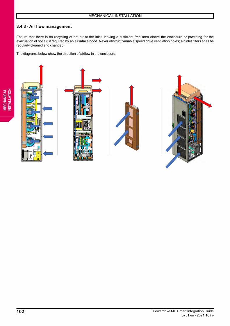
102
MECHANICAL INSTALLATION
Powerdrive MD Smart Integration Guide5751 en - 2021.10 / e
MECH
ANIC
ALIN
STAL
LATI
ON
3.4.3 - Air flow management
Ensure that there is no recycling of hot air at the inlet, leaving a sufficient free area above the enclosure or providing for the evacuation of hot air, if required by an air intake hood. Never obstruct variable speed drive ventilation holes; air inlet filters shall be regularly cleaned and changed.
The diagrams below show the direction of airflow in the enclosure.
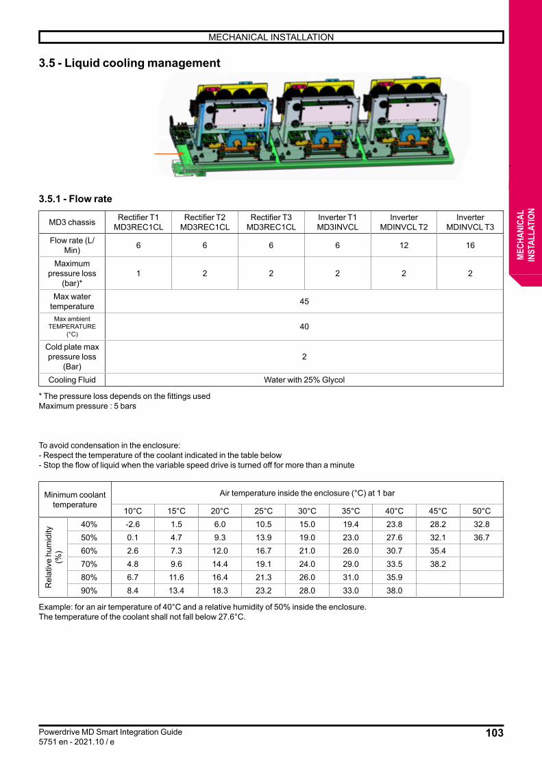
103
MECHANICAL INSTALLATION
Powerdrive MD Smart Integration Guide5751 en - 2021.10 / e
MECH
ANIC
ALIN
STAL
LATI
ON
3.5 - Liquid cooling management
3.5.1 - Flow rate
MD3 chassis Rectifier T1MD3REC1CL
Rectifier T2MD3REC1CL
Rectifier T3MD3REC1CL
Inverter T1 MD3INVCL
Inverter MDINVCL T2
Inverter MDINVCL T3
Flow rate (L/Min) 6 6 6 6 12 16
Maximum pressure loss
(bar)*1 2 2 2 2 2
Max water temperature 45
Max ambient TEMPERATURE
(°C)40
Cold plate max pressure loss
(Bar)2
Cooling Fluid Water with 25% Glycol
* The pressure loss depends on the fittings usedMaximum pressure : 5 bars
To avoid condensation in the enclosure:- Respect the temperature of the coolant indicated in the table below- Stop the flow of liquid when the variable speed drive is turned off for more than a minute
Minimum coolant temperature
Air temperature inside the enclosure (°C) at 1 bar
10°C 15°C 20°C 25°C 30°C 35°C 40°C 45°C 50°C
Rel
ativ
e hu
mid
ity
(%)
40% -2.6 1.5 6.0 10.5 15.0 19.4 23.8 28.2 32.850% 0.1 4.7 9.3 13.9 19.0 23.0 27.6 32.1 36.760% 2.6 7.3 12.0 16.7 21.0 26.0 30.7 35.470% 4.8 9.6 14.4 19.1 24.0 29.0 33.5 38.280% 6.7 11.6 16.4 21.3 26.0 31.0 35.990% 8.4 13.4 18.3 23.2 28.0 33.0 38.0
Example: for an air temperature of 40°C and a relative humidity of 50% inside the enclosure.The temperature of the coolant shall not fall below 27.6°C.

104
MECHANICAL INSTALLATION
Powerdrive MD Smart Integration Guide5751 en - 2021.10 / e
MECH
ANIC
ALIN
STAL
LATI
ON
To ensure the temperature of the above coolant, a 3-way valve or variable speed pump must be installed.
Note: - The recommended fluid is glycolated water, mix at 25%, the maximum temperature is 40°C.- Salt water is prohibited.- We recommend the use of an external cooling loop so that the fluid is used in closed circuit.- A controlled heating system must be installed to keep the minimum temperature of 5° C inside the enclosure at start-up (to be
disabled when the variable speed drive is in running order).
3.5.2 - Recommendations• Characteristics of the cooling liquid :Since the most stressed components of the drive are completely cooled by liquid, The characteristics of the liquid directly affect the quality of the cooling and therefore the lifetime of the variable speed drive. Prevent electrochemical corrosion and sediment obstruction by ensuring that the cooling agent used meets the following criteria:• pH 7.5 to 8.5• CaCO3 alkalinity: 100 to 400 mg/l• chloride Cl-: <200 mg/l• conductivity: 1000 to 1500 μS/cm• Liquid temperature increase :At steady speed The maximum heating of the coolant at the variable speed drive outlet with the recommended minimum flow is 8°C.• Protection against electrochemical corrosion:When an external coolant loop is used, it is recommended to add an inhibitor to prevent electrochemical corrosion. If there is no external loop, this corrosion shall be avoided by using materials compatible with the materials used in the cooling circuit of the variable speed drive: question to be asked.• Protection against sediment obstructions:A coolant with too many particles can speed up the sediment-induced blockage of radiators, so it is recommended that filters be installed upstream of the drive fluid system.• Protection against stopping the circulation of liquid: To avoid harmful overheating, a liquid circulation monitoring relay must be cabled to the variable speed drive’s safety chain.
3.5.3 - Drainage and maintenanceThe frequency of drainage and maintenance cycles depends on the quality of the coolant. These cycles must therefore be determined based on the quality of the fluid used and designed according to the installation. Temperature elevations caused by passive components and circuit boards can create condensation on heat sinks or pipe fittings, depending on the humidity in the air and the temperature difference between the interior of the enclosure and the cooling circuit.It is therefore advisable to have a coolant temperature as close as possible to the internal temperature of the enclosure, depending on the use of the variable speed drive. This can be achieved by reducing the ambient temperature or increasing the temperature of the fluid (respect the maximum temperatures described in section 3.5.2).
3-way valve
View from behind
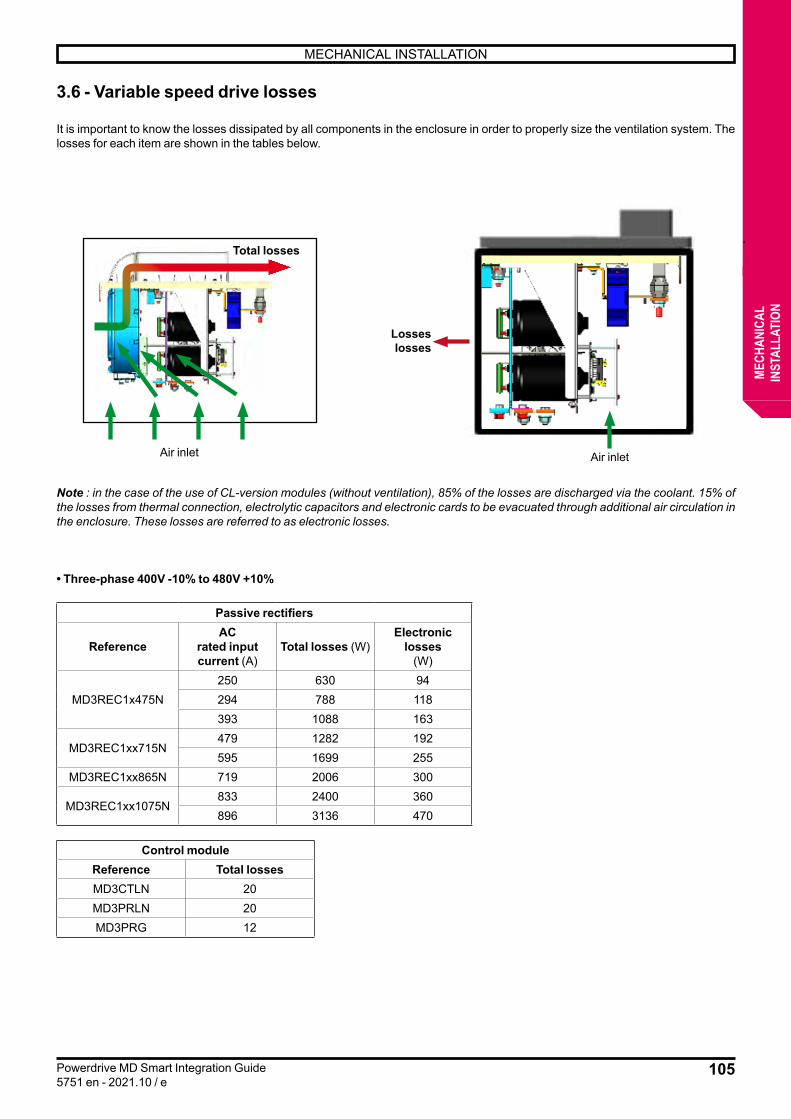
105
MECHANICAL INSTALLATION
Powerdrive MD Smart Integration Guide5751 en - 2021.10 / e
MECH
ANIC
ALIN
STAL
LATI
ON
3.6 - Variable speed drive losses
It is important to know the losses dissipated by all components in the enclosure in order to properly size the ventilation system. The losses for each item are shown in the tables below.
Air inlet
Total losses
Air inlet
Losseslosses
Note : in the case of the use of CL-version modules (without ventilation), 85% of the losses are discharged via the coolant. 15% of the losses from thermal connection, electrolytic capacitors and electronic cards to be evacuated through additional air circulation in the enclosure. These losses are referred to as electronic losses.
• Three-phase 400V -10% to 480V +10%
Passive rectifiers
ReferenceAC
rated input current (A)
Total losses (W)Electronic
losses(W)
MD3REC1x475N250 630 94294 788 118393 1088 163
MD3REC1xx715N479 1282 192595 1699 255
MD3REC1xx865N 719 2006 300
MD3REC1xx1075N833 2400 360896 3136 470
Control moduleReference Total lossesMD3CTLN 20MD3PRLN 20MD3PRG 12

106
MECHANICAL INSTALLATION
Powerdrive MD Smart Integration Guide5751 en - 2021.10 / e
MECH
ANIC
ALIN
STAL
LATI
ON
REFERENCE
T_ra
te
ACTIVE RECTIFIER INVERTER
SWITCHING FREQUENCY
5 kHz
ELECTRONIC LOSSES(W)
TOTAL LOSSES (W)
ELECTRONIC LOSSES(W)
Reduced overload Maximum Overload
2.5 kHz 2 kHz 3 kHz 4 kHz 6 kHz 8 kHz 2.5
kHz 2 kHz 3 kHz 4 kHz 6 kHz 8 kHz
MD3INVxx110N40°C 914
110856 856 817 724 654 701 701 643 591 537 115
15350°C 873 817 818 779 693 623 670 670 638 568 506
MD3INVxx142N40°C 1181
1421106 1106 1067 934 818 856 856 825 724 630 153
28150°C 1164 1090 1090 1028 903 786 840 840 794 700 607
MD3INVxx172N40°C 1430
1721339 1339 1238 1129 973 1129 1129 1043 950 817 230
40850°C 1388 1300 1300 1183 996 856 1091 1091 997 841 724
MD3INVxx195N40°C 1621
1951518 1518 1401 1183 1020 1362 1362 1253 1059 919 281
63550°C 1563 1464 1464 1339 1129 973 1316 1316 1199 1012 872
MD3INVxx260N40°C 2161
2592024 2024 1868 1541 1300 1712 1712 1580 1308 1097 335
90550°C 2120 1985 1985 1830 1479 1261 1681 1681 1549 1253 1067
MD3INVxx315N40°C 2619
3142452 2452 2273 1869 1581 2024 2024 1870 1541 1308 408
127550°C 2452 2297 2297 2126 1744 1479 1892 1892 1751 1440 1222
MD3INVxx408N40°C 3325
3993114 3114 2997 2647 2335 2499 2499 2405 2118 1876 510
15350°C 3159 2958 2958 2841 2514 2219 2374 2374 2281 2017 1783
MD3INVxx497N40°C 4131
4963870 3870 3542 3036 2623 3044 3044 2787 2390 2063 635
28150°C 3741 3503 3503 3207 2748 2374 2756 2756 2522 2156 1869
MD3INVxx618N40°C 5138
6174811 4811 4321 3566 3013 3784 3784 3395 2802 2366 805
40850°C 4780 4476 4476 4018 3316 2803 3519 3519 3161 2608 2203
MD3INVxx747N40°C 6210
7455816 5816 5333 4570 3947 4570 4570 4189 3589 3098 905
63550°C 5736 5372 5372 4921 4220 3643 4220 4220 3862 3316 2865
MD3INVxx865N40°C 7191
8636734 6734 6166 5216 4477 5294 5294 4842 4103 3519 1020
90550°C 6668 6244 6244 5714 4835 4150 4913 4913 4492 3799 3262
MD3INVxx931N40°C 7740
9297248 7248 6657 5372 4632 5699 5699 5232 4220 3643 1275
127550°C 7150 6696 6696 6143 4944 4274 5263 5263 4827 3885 3355
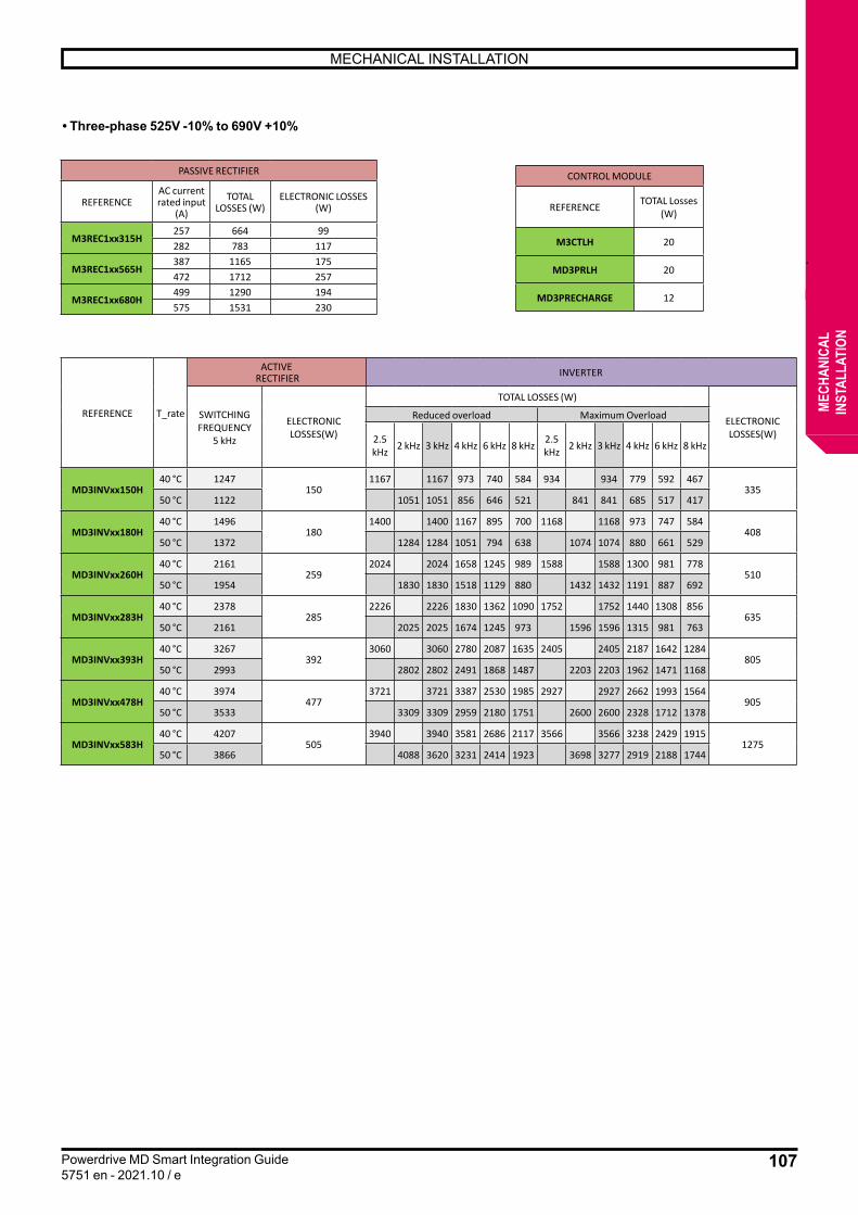
107
MECHANICAL INSTALLATION
Powerdrive MD Smart Integration Guide5751 en - 2021.10 / e
MECH
ANIC
ALIN
STAL
LATI
ON
• Three-phase 525V -10% to 690V +10%
PASSIVE RECTIFIER
REFERENCEAC current rated input
(A)
TOTAL LOSSES (W)
ELECTRONIC LOSSES(W)
M3REC1xx315H257 664 99282 783 117
M3REC1xx565H387 1165 175472 1712 257
M3REC1xx680H499 1290 194575 1531 230
CONTROL MODULE
REFERENCE TOTAL Losses (W)
M3CTLH 20
MD3PRLH 20
MD3PRECHARGE 12
REFERENCE T_rate
ACTIVE RECTIFIER INVERTER
SWITCHING FREQUENCY
5 kHz
ELECTRONIC LOSSES(W)
TOTAL LOSSES (W)
ELECTRONIC LOSSES(W)
Reduced overload Maximum Overload
2.5 kHz 2 kHz 3 kHz 4 kHz 6 kHz 8 kHz 2.5
kHz 2 kHz 3 kHz 4 kHz 6 kHz 8 kHz
MD3INVxx150H40 °C 1247
1501167 1167 973 740 584 934 934 779 592 467
33550 °C 1122 1051 1051 856 646 521 841 841 685 517 417
MD3INVxx180H40 °C 1496
1801400 1400 1167 895 700 1168 1168 973 747 584
40850 °C 1372 1284 1284 1051 794 638 1074 1074 880 661 529
MD3INVxx260H40 °C 2161
2592024 2024 1658 1245 989 1588 1588 1300 981 778
51050 °C 1954 1830 1830 1518 1129 880 1432 1432 1191 887 692
MD3INVxx283H40 °C 2378
2852226 2226 1830 1362 1090 1752 1752 1440 1308 856
63550 °C 2161 2025 2025 1674 1245 973 1596 1596 1315 981 763
MD3INVxx393H40 °C 3267
3923060 3060 2780 2087 1635 2405 2405 2187 1642 1284
80550 °C 2993 2802 2802 2491 1868 1487 2203 2203 1962 1471 1168
MD3INVxx478H40 °C 3974
4773721 3721 3387 2530 1985 2927 2927 2662 1993 1564
90550 °C 3533 3309 3309 2959 2180 1751 2600 2600 2328 1712 1378
MD3INVxx583H40 °C 4207
5053940 3940 3581 2686 2117 3566 3566 3238 2429 1915
127550 °C 3866 4088 3620 3231 2414 1923 3698 3277 2919 2188 1744
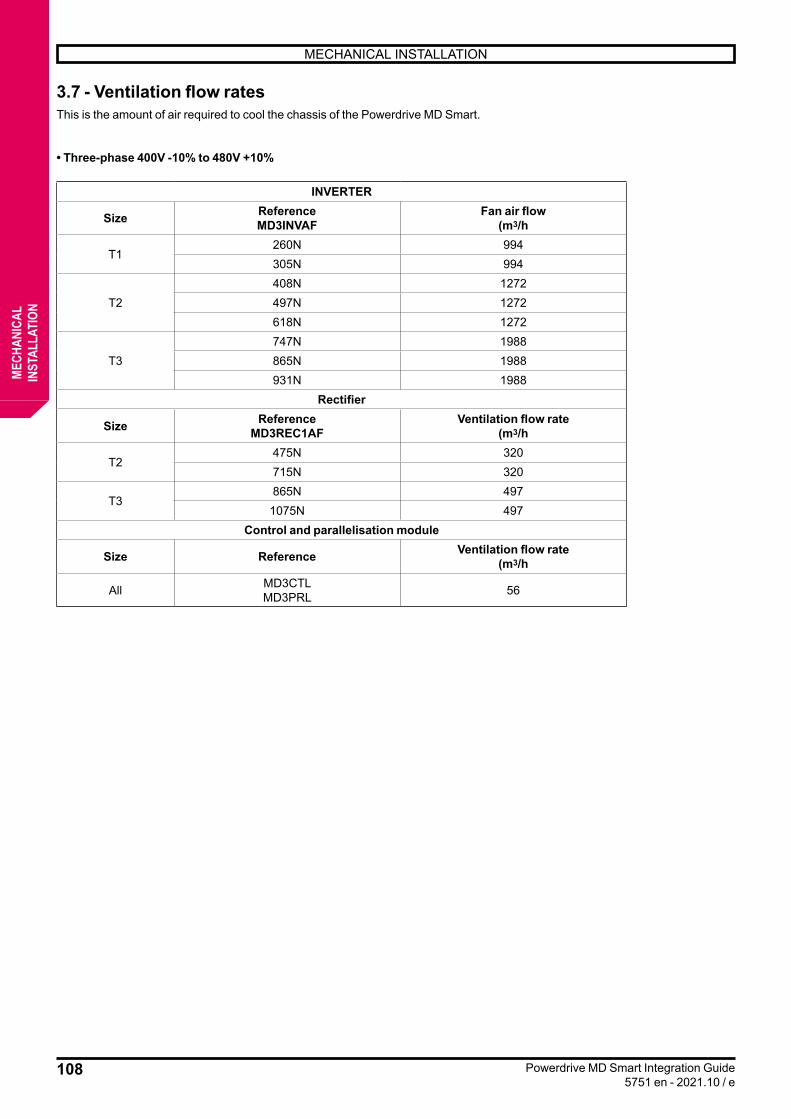
108
MECHANICAL INSTALLATION
Powerdrive MD Smart Integration Guide5751 en - 2021.10 / e
MECH
ANIC
ALIN
STAL
LATI
ON
3.7 - Ventilation flow ratesThis is the amount of air required to cool the chassis of the Powerdrive MD Smart.
• Three-phase 400V -10% to 480V +10%
INVERTER
Size ReferenceMD3INVAF
Fan air flow(m3/h
T1260N 994305N 994
T2408N 1272497N 1272618N 1272
T3747N 1988865N 1988931N 1988
Rectifier
Size ReferenceMD3REC1AF
Ventilation flow rate(m3/h
T2475N 320715N 320
T3865N 497
1075N 497Control and parallelisation module
Size Reference Ventilation flow rate(m3/h
All MD3CTLMD3PRL 56

109
MECHANICAL INSTALLATION
Powerdrive MD Smart Integration Guide5751 en - 2021.10 / e
MECH
ANIC
ALIN
STAL
LATI
ON
• Three-phase 525V -10% to 690V +10%
INVERTER
Size ReferenceMD3INVAF
Fan air flow(m3/h)
T1150H 994180H 994
T2260H 1272283H 1272
T3393H 1272478H 1988583H 1988
Rectifier
Size ReferenceMD3REC1AF
Ventilation flow rate(m3/h
T2 315H 320
T3565H 320680H 497
Control and parallelisation module
Size Reference Ventilation flow rate(m3/h
All MD3CTHMD3PRL 56

110
MECHANICAL INSTALLATION
Powerdrive MD Smart Integration Guide5751 en - 2021.10 / e
MECH
ANIC
ALIN
STAL
LATI
ON
3.8 - Noise levels
The radiator fan is responsible for most of the noise produced by the variable speed drive at 1 m. The radiator fan on the variable speed drives is a variable speed fan. The variable speed drive controls the fan speed based on the radiator temperature and the thermal modelling of the variable speed drive.
• Three-phase 400V -10% to 480V +10%
INVERTER
Size ReferenceMD3INVAF
Noise level at max speed (dBA)
Noise level at 25% of max speed (dBA)
T1260N 76 53315N 76 53
T2408N 78 55497N 78 55618N 78 55
T3747N 78 55865N 78 55931N 78 55
Rectifier
Size ReferenceMD3REC1AF
Noise level at max speed (dBA)
Noise level at 25% of max speed (dBA)
T1170N 76 53230N 76 53
T2475N 76 53715N 76 53
T3865N 78 55
1075N 78 55Control and parallelisation module
Size Reference Ventilation flow rate(m3/h
Noise level at 25% of max speed (dBA)
All MD3CTLMD3PRL 41 -

111
MECHANICAL INSTALLATION
Powerdrive MD Smart Integration Guide5751 en - 2021.10 / e
MECH
ANIC
ALIN
STAL
LATI
ON
• Three-phase 525V -10% to 690V +10%
INVERTER
Size ReferenceMD3INVAF
Noise level at max speed (dBA)
Noise level at 25% of max speed (dBA)
T1150H 76 53180H 76 53
T2260H 78 55283H 78 55
T3393H 78 55478H 78 55583H 78 55
Rectifier
Size ReferenceMD3REC1AF
Noise level at max speed (dBA)
Noise level at 25% of max speed (dBA)
T2 315H 76 53
T3565H 76 55680H 78 55
Control and parallelisation module
Size Reference Noise level at max speed (dBA)
Noise level at 25% of max speed (dBA)
All MD3CTHMD3PRL 56 -
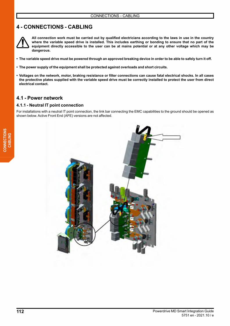
112
CONNECTIONS - CABLING
Powerdrive MD Smart Integration Guide5751 en - 2021.10 / e
CONN
ECTI
ONS
CABL
ING
4 - CONNECTIONS - CABLING
All connection work must be carried out by qualified electricians according to the laws in use in the country where the variable speed drive is installed. This includes earthing or bonding to ensure that no part of the equipment directly accessible to the user can be at mains potential or at any other voltage which may be dangerous.
• The variable speed drive must be powered through an approved breaking device in order to be able to safely turn it off.
• The power supply of the equipment shall be protected against overloads and short circuits.
• Voltages on the network, motor, braking resistance or filter connections can cause fatal electrical shocks. In all cases the protective plates supplied with the variable speed drive must be correctly installed to protect the user from direct electrical contact.
4.1 - Power network4.1.1 - Neutral IT point connectionFor installations with a neutral IT point connection, the link bar connecting the EMC capabilities to the ground should be opened as shown below. Active Front End (AFE) versions are not affected.
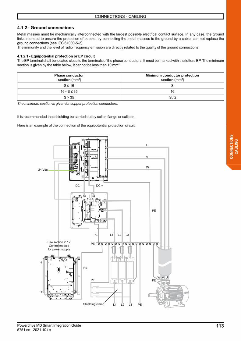
113
CONNECTIONS - CABLING
Powerdrive MD Smart Integration Guide5751 en - 2021.10 / e
CONN
ECTI
ONS
CABL
ING
4.1.2 - Ground connectionsMetal masses must be mechanically interconnected with the largest possible electrical contact surface. In any case, the ground links intended to ensure the protection of people, by connecting the metal masses to the ground by a cable, can not replace the ground connections (see IEC 61000-5-2).The immunity and the level of radio frequency emission are directly related to the quality of the ground connections.
4.1.2.1 - Equipotential protection or EP circuitThe EP terminal shall be located close to the terminals of the phase conductors. It must be marked with the letters EP. The minimum section is given by the table below, it cannot be less than 10 mm².
Phase conductor section (mm²)
Minimum conductor protectionsection (mm²)
S ≤ 16 S16 <S ≤ 35 16
S > 35 S / 2
The minimum section is given for copper protection conductors.
It is recommended that shielding be carried out by collar, flange or calliper.
Here is an example of the connection of the equipotential protection circuit:
V
U
W
PE
L1 L2 L3 PE
L1 L2 L3PE
UVW
PE
DC +DC -
PE
* * *
PE
24 Vdc
PE
See section 2.7.7Control modulefor power supply
Shielding clamp

114
CONNECTIONS - CABLING
Powerdrive MD Smart Integration Guide5751 en - 2021.10 / e
CONN
ECTI
ONS
CABL
ING
4.1.2.2 - ShieldingShielding is necessary to mitigate (dampen) magnetic, electric or electromagnetic disturbance fields. Use dense-braided shielded cables where possible (coverage rate) > 80%). Avoid using shielded ribbon cables.
Generally:• Separate the control and power cables as much as possible (do not run them through the same pins).• Signal cables integrated into the motor cable (i.e., the motor’s thermal probe, the motor’s brake) receive significant disruptions
through the cable capacity. The shielding of these signal cables shall be connected to the ground near the motor cable to prevent the propagation of this parasitic current in the control system.
• The shielding of power conductors provides a preferred path for common mode currents to return to their original point of origin without dispersing into other possible paths (equipotential conductors, piping, building structures, etc.). It significantly reduces the levels of electromagnetic emissions conducted and radiated. For this reason, the use of shielded cables between variable speed drive and motor is imperative to ensure compliance with EMC emission standards (IEC 61800-3, etc.). Shielded cables also limit the shaft tension and the risk of bearing damage.
• the cable shielding must be connected to ground potential at both ends. Only a connection at both ends allows a good immunity in the high frequency range. In exceptional cases, shielding can only be connected to the ground potential at one end. Only low frequencies will be amortized. The connection of one end of the shielding may be useful when:
- It is not possible to install an equipotentiality cable. - It is not necessary to transmit analogue signals (a few mVs or μA).
The disruptive currents are derived to the ground through the shielding bar connected by a conductive connection to the housing. In order to prevent these derived currents from becoming sources of disturbance themselves, it is essential to make a low impedance connection to the protection conductor.
For more details, please refer to the Guide to Good Practices ref.5626, which can be downloaded from www.leroy-somer.com.
- For control cables, use shielded twisted cables and connect the shielding to the collar of the MD3CTL shielding module.
A shielding connection calliper comes with each option. To secure it, screw the calliper over the shielding collars of the control cables (the rightmost shielding collar must be removed).
115
CONNECTIONS - CABLING
Powerdrive MD Smart Integration Guide5751 en - 2021.10 / e
CONN
ECTI
ONS
CABL
ING
4.1.2.3 - Cable routing
Sensitive cables should preferably be routed through a metal chute, separate from the power cables or remote control.
This can be simply a U-shaped support of the chassis (connected in several points to the enclosure’s grounding).
Shielded or sensitive cables must avoid running along power cables or bars or disruptive cables. However, a sensitive or shielded cable may cross a disruptive cable at a right-angle.
In the enclosure, it is possible to place a ground bar, connected to the EP point of the enclosure (without specific request of the specification of the case), on which it will be easier to make mass braid connections.
In case of parallel routing of sensitive cables and power cables or bar, a distance of 20 cm shall be respected.
Non-exhaustive list of sensitive signals:
Class or Group Type of signal
1Very sensitive
- Low-level circuit, analogue input or output- Measurement circuit, variable speed drive cabling, driver control panel, quick
link between control card, on-the-fly recovery cable, bus measurement cable, etc...
2Sensitive
- Digital circuit, field bus cable, CAN OPEN, Profibus, etc.- All-or-nothing output circuit, encoder signals- Low level continuous power supplies
3Disruptive
- Inductive load control circuit (coils)- Main power supplies connected to power devices- Relaying
4Very disruptive
- Switched power circuit (frequency variable speed drives, switched-mode power supply)
- Power circuit
The following rules must be observed:
- Ensure an equipotentiality of low and high frequency masses between equipment (in particular between variable speed drive chassis and RFI filters and between all chassis connected by shielded cables)
- Separate disruptive components from sensitive components in enclosures.
- Separate energy cables from low-level cables.
- Treat connections, ground connections, ground continuity.
- Equip all inductive loads with a pest control product.
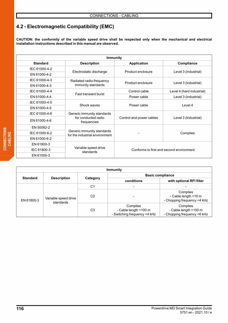
116
CONNECTIONS - CABLING
Powerdrive MD Smart Integration Guide5751 en - 2021.10 / e
CONN
ECTI
ONS
CABL
ING
4.2 - Electromagnetic Compatibility (EMC)
CAUTION: the conformity of the variable speed drive shall be respected only when the mechanical and electrical installation instructions described in this manual are observed.
ImmunityStandard Description Application Compliance
IEC 61000-4-2Electrostatic discharge Product enclosure Level 3 (industrial)
EN 61000-4-2IEC 61000-4-3 Radiated radio-frequency
immunity standards Product enclosure Level 3 (industrial)EN 61000-4-3IEC 61000-4-4
Fast transient burstControl cable Level 4 (hard industrial)
EN 61000-4-4 Power cable Level 3 (industrial)IEC 61000-4-5
Shock waves Power cable Level 4EN 61000-4-5IEC 61000-4-6 Generic immunity standards
for conducted radio frequencies
Control and power cables Level 3 (Industrial)EN 61000-4-6
EN 50082-2Generic immunity standards for the industrial environment - CompliesIEC 61000-6-2
EN 61000-6-2EN 61800-3
Variable speed drive standards Conforms to first and second environmentIEC 61800-3
EN 61000-3
Immunity
Standard Description CategoryBasic compliance
conditions with optional RFI filter
EN 61800-3 Variable speed drive standards
C1 - -
C2 -Complies
- Cable length <10 m- Chopping frequency <4 kHz
C3Complies
- Cable length <100 m- Switching frequency <4 kHz
Complies- Cable length <100 m
- Chopping frequency <6 kHz

117
CONNECTIONS - CABLING
Powerdrive MD Smart Integration Guide5751 en - 2021.10 / e
CONN
ECTI
ONS
CABL
ING
4.3 - Special cablingIn a situation where several inverter modules are used in parallel to power a single high-power motor, if no balancing reactor is added to balance currents, parallelisation shall be carried out in the motor’s terminal box. It is imperative that the cables of each U/V/W phase of the motor be distributed symmetrically on the ranges of the U/V/W connections of the inverter modules.
Variable speed drive with multiple inverter modules
Shielding
Motorterminal box
Earthbar
Power wires
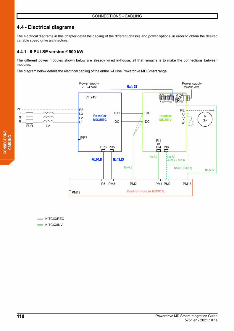
118
CONNECTIONS - CABLING
Powerdrive MD Smart Integration Guide5751 en - 2021.10 / e
CONN
ECTI
ONS
CABL
ING
4.4 - Electrical diagramsThe electrical diagrams in this chapter detail the cabling of the different chassis and power options, in order to obtain the desired variable speed drive architecture.
4.4.1 - 6-PULSE version ≤ 500 kW
The different power modules shown below are already wired in-house, all that remains is to make the connections between modules.
The diagram below details the electrical cabling of the entire 6-Pulse Powerdrive MD Smart range.
RectifierMD3REC
Power supplyVF 24 Vdc
KITCXXREC
KITCXXINV
PE+DC
-DC
+DC
-DC
L3
VF 24V
L2L1
PEUVW
PETSR
FUR LA
PR7
PR6 PR5
PM13P5 PM8
No.10,11
No.4,8
No.3,7 No.5,9(Sizes 2 and3)
No.5,9 (Size 1)
InverterMD3INV
Control module MD3CTLPM12
PI1or
PI4 PI8
PM2 PM1 PM9
Power supply24Vdc ext.
M3~
No.12,23
No.1, 21
No.6,22
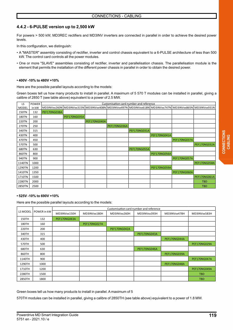
119
CONNECTIONS - CABLING
Powerdrive MD Smart Integration Guide5751 en - 2021.10 / e
CONN
ECTI
ONS
CABL
ING
4.4.2 - 6-PULSE version up to 2,500 kW
For powers > 500 kW, MD3REC rectifiers and MD3INV inverters are connected in parallel in order to achieve the desired power levels.
In this configuration, we distinguish:
• A "MASTER" assembly consisting of rectifier, inverter and control chassis equivalent to a 6-PULSE architecture of less than 500 kW. The control card controls all the power modules.
• One or more "SLAVE" assemblies consisting of rectifier, inverter and parallelisation chassis. The parallelisation module is the element that permits the installation of the different power chassis in parallel in order to obtain the desired power.
• 400V -10% to 480V +10%
Here are the possible parallel layouts according to the models:
Green boxes tell us how many products to install in parallel. A maximum of 5 570 T modules can be installed in parallel, giving a calibre of 2850 T (see table above) equivalent to a power of 2.5 MW.
LS MODEL
POWER in kW
Customisation card number and referenceMD3INVxx260N MD3INVxx315N MD3INVxx408N MD3INVxx497N MD3INVxx618N MD3INVxx747N MD3INVxx865N MD3INVxx931N
150TN 132 PEF170NG038A180TN 160 PEF170NG035A220TN 200 PEF170NG040A270TN 250 PEF170NG036A340TN 315 PEF170NG031A430TN 400 PEF170NG041A470TN 450 PEF170NG037A570TN 500 PEF170NG032A680TN 630 PEF170NG055A860TN 800 PEF170NG056A940TN 900 PEF170NG057A
1140TN 1000 PEF170NG058A1290TN 1200 PEF170NG059A1410TN 1350 PEF170NG060A1710TN 1500 PEF170NG061A2280TN 2000 TBD2850TN 2500 TBD
• 525V -10% to 690V +10%
Here are the possible parallel layouts according to the models:
LS MODEL POWER in kWCustomisation card number and reference
MD3INVxx150H MD3INVxx180H MD3INVxx260H MD3INVxx393H MD3INVxx478H MD3INVxx583H
150TH 132 PEF170NG063A
180TH 160 PEF170NG027A
220TH 200 PEF170NG042A
340TH 315 PEF170NG043A
430TH 400 PEF170NG044A
570TH 500 PEF170NG029A
680TH 630 PEF170NG046A
860TH 800 PEF170NG039A
1140TH 900 PEF170NG047A
1290TH 1000 PEF170NG048A
1710TH 1200 PEF170NG049A
2280TH 1500 TBD
2850TH 1800 TBD
Green boxes tell us how many products to install in parallel. A maximum of 5
570TH modules can be installed in parallel, giving a calibre of 2850TH (see table above) equivalent to a power of 1.8 MW.

120
CONNECTIONS - CABLING
Powerdrive MD Smart Integration Guide5751 en - 2021.10 / e
CONN
ECTI
ONS
CABL
ING
The diagram below details the electrical cabling of the parallel installation of a “MASTER” and 2 “SLAVES” 6-PULSE Powerdrive MD Smart.
KITCXXREC
KITCXXINV
KITCXXPARINV
M3~
KITCXXPARREC
PE R, S, T
FUR LA
Powersupply24Vdcext
FUR LA
FUR LA
Powersupply24Vdc ext
Powersupply24Vdcext
No.5,9No.12,23No.10,11
No.16
No.4,8
No.14,17
No.16No.14,17
No.12,23
No.3,7
No.3,7
No.6,22
No.1,21
No.1,21
No.1,21
No.3,7
No.12,23 No.1,21
No.1,21
+DC
-DC
PEUVW
PEUVW
PEUVW
InverterMD3INV
PI4 PI8
+DC
-DCInverterMD3INV
PI4
+DC
-DC
InverterMD3INV
PI4
RectifierMD3REC
PE
-DC
L3L2L1
PR7
PR5PR6
24V
VF 24V
PEL3L2L1
RectifierMD3REC
+DC
+DC
-DC
PR6
PR7
PR5
VF 24V
PEL3L2L1
RectifierMD3REC
+DC
-DC
PR6
PR7
PR5
VF 24V
Control moduleMD3PRL
PM/S1PM/S13
PM/S8 PM/S7
PM/S12
P5 PM8
Control module MD3CTLMaster
PM12 PM2 PM1 PM9
Control moduleMD3PRL
PM/S1PM/S8 PM/S7
PM/S12
Slave 1
Slave 2
PM13
PM/S13
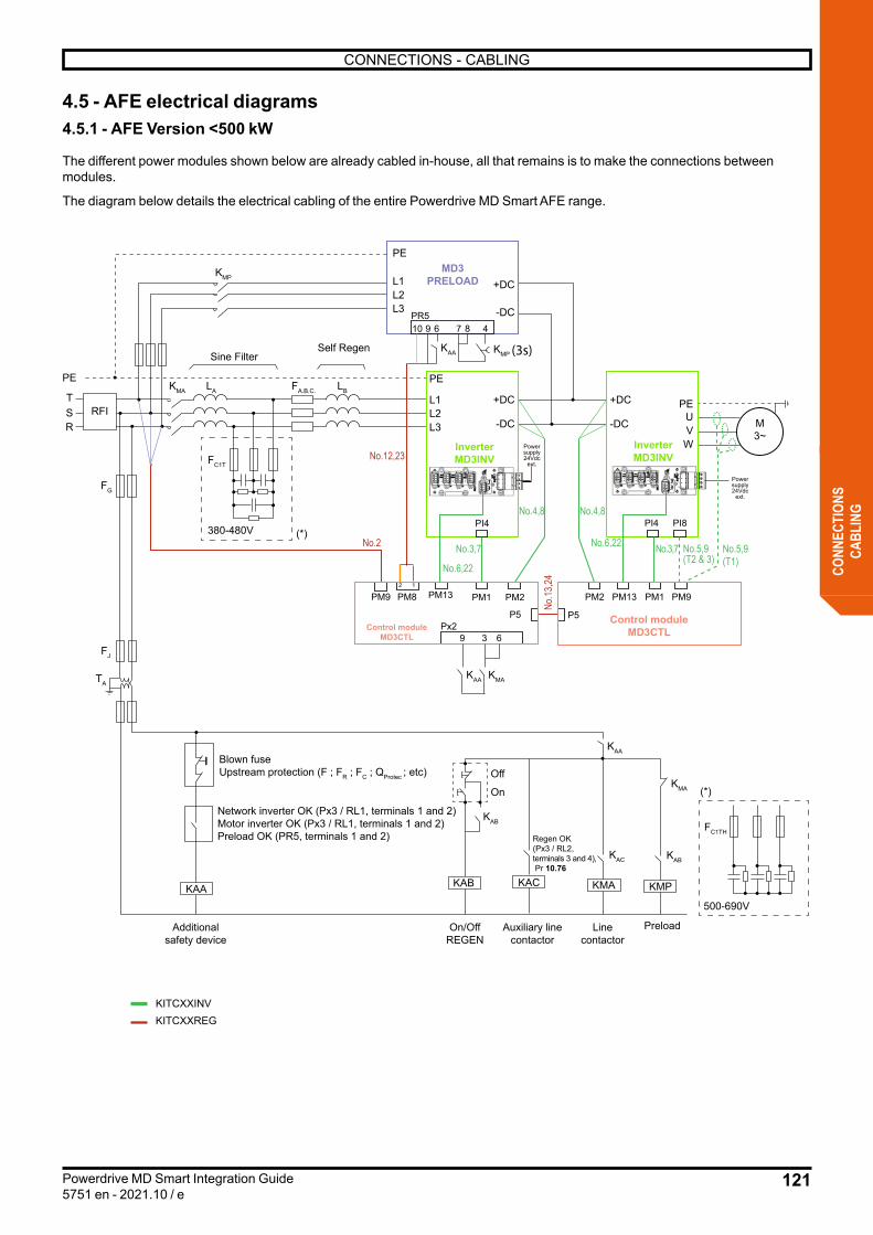
121
CONNECTIONS - CABLING
Powerdrive MD Smart Integration Guide5751 en - 2021.10 / e
CONN
ECTI
ONS
CABL
ING
4.5 - AFE electrical diagrams4.5.1 - AFE Version <500 kW
The different power modules shown below are already cabled in-house, all that remains is to make the connections between modules.
The diagram below details the electrical cabling of the entire Powerdrive MD Smart AFE range.
M3~
PEFA.B.C.
FC1T
FG
TSR
LBLAKMA
KMA
KMP
KMP
RFI
FJ
KAB
KAC
KMA
Off
Additionalsafety device
On/OffREGEN
Auxiliary linecontactor
Linecontactor
Preload
On
Blown fuseUpstream protection (F ; FR ; FC ; QProtec ; etc)
Regen OK (Px3 / RL2,terminals 3 and 4), Pr 10.76
Network inverter OK (Px3 / RL1, terminals 1 and 2)Motor inverter OK (Px3 / RL1, terminals 1 and 2)Preload OK (PR5, terminals 1 and 2)
TA
FC1TH
380-480V (*)
(*)
500-690VKAA KAB KMA KMP
Sine FilterSelf Regen
KITCXXINVKITCXXREG
KAB
KAC
+DC
-DC
+DC
-DC
PE
L1L2L3
PE
L1L2L3
InverterMD3INV
MD3PRELOAD
PI4No.4,8
No.3,7No
.13,24
No.2 No.3,7
No.4,8
+DC
-DC
PEUVWInverter
MD3INV
PI4
Px29 3 6
PI8
PR5910 6 87 4
No.5,9(T2 & 3)
No.5,9(T1)
12
No.12,23
No.6,22
No.6,22
PM13
P5 P5
PM8
Control moduleMD3CTL
PM2PM1PM9 PM13
Control moduleMD3CTL
PM2 PM1 PM9
KAA
KAA
KAA
Powersupply24Vdc
ext.
Powersupply24Vdc
ext.
(3s)
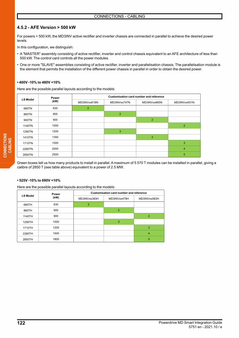
122
CONNECTIONS - CABLING
Powerdrive MD Smart Integration Guide5751 en - 2021.10 / e
CONN
ECTI
ONS
CABL
ING
4.5.2 - AFE Version > 500 kW
For powers > 500 kW, the MD3INV active rectifier and inverter chassis are connected in parallel to achieve the desired power levels.
In this configuration, we distinguish:
• A "MASTER" assembly consisting of active rectifier, inverter and control chassis equivalent to an AFE architecture of less than 500 kW. The control card controls all the power modules.
• One or more "SLAVE" assemblies consisting of active rectifier, inverter and parallelisation chassis. The parallelisation module is the element that permits the installation of the different power chassis in parallel in order to obtain the desired power.
• 400V -10% to 480V +10%
Here are the possible parallel layouts according to the models:
LS Model Power(kW)
Customisation card number and reference
MD3INVxx618N MD3INVxx747N MD3INVxx865N MD3INVxx931N
680TN 630 2
860TN 800 2
940TN 900 2
1140TN 1000 2
1290TN 1200 3
1410TN 1350 3
1710TN 1500 3
2280TN 2000 4
2850TN 2500 5
Green boxes tell us how many products to install in parallel. A maximum of 5 570 T modules can be installed in parallel, giving a calibre of 2850 T (see table above) equivalent to a power of 2.5 MW.
• 525V -10% to 690V +10%
Here are the possible parallel layouts according to the models:
LS Model Power(kW)
Customisation card number and reference
MD3INVxx393H MD3INVxx478H MD3INVxx583H
680TH 630 2
860TH 800 2
1140TH 900 2
1290TH 1000 3
1710TH 1200 3
2280TH 1500 4
2850TH 1800 5

123
CONNECTIONS - CABLING
Powerdrive MD Smart Integration Guide5751 en - 2021.10 / e
CONN
ECTI
ONS
CABL
ING
The diagram below details the electrical cabling of the parallel installation of a “MASTER” and 2 “SLAVES” AFE Powerdrive MD Smart.
M3~
Master
PEFA.B.C.
FC1T
TSR
LBLAKMA
KMP
RFI
380-480V (*)
Sine FilterSelf Regen
FA.B.C.
FC1T
LBLA
380-480V (*)
Sine Filter Self Regen
FA.B.C.
FC1T
LBLA
380-480V (*)
Sine Filter Self Regen
FJ
KAB
KAC
KMA
Off
Additionalsafety device
On/OffREGEN
Auxiliary linecontactor
Linecontactor
Preload
On
Blown fuseUpstream protection (F ; FR ; FC ; QProtec ; etc)
Regen OK (Px3 / RL2,bornes 3 et 4), Pr 10.76
Network inverter OK (Px3 / RL1, terminals 1 and 2)Motor inverter OK (Px3 / RL1, terminals 1 and 2)Preload OK (PR5, terminals 1 and 2)
TA
FC1TH
(*)
500-690VKAA KAB KMA KMP
KAB
KAC
KAA
FG
Slave 1
Slave 2
No.4,8
No.3,7No.3,7
No.4,8
No.5,9
KAA
No.3,7No.3,7
KMAKAA
No.3,7No.3,7
KMP
+DC
-DC
+DC
-DC
PE
L1L2L3
PE
L1L2L3
InverterMD3INV
MD3PRELOAD
PI4
+DC
-DC
PEUVWInverter
MD3INV
PI4
Px29 3 6
PI8
PR5910 6 87 4
12
+DC
-DC
PE
L1L2L3
InverterMD3INV
PI4
+DC
-DC
PEUVWInverter
MD3INV
PI4
+DC
-DC
PE
L1L2L3
InverterMD3INV
PI4
+DC
-DC
PEUVWInverter
MD3INV
PI4
Powersupply24Vdc
ext.
KITCXXINV
KITCXXPARINVKITCXXREG
P5 P5
PM8Control modul
MD3CTL
PM2PM1PM9
Control modulMD3CTL
PM2 PM1 PM9
Control moduleMD3PRL
PM/S1PM/S7
Control moduleMD3PRL
PM/S13 PM/S1 PM/S7
PM12
PM/S12
Control moduleMD3PRL
PM/S1PM/S7
Control moduleMD3PRL
PM/S13 PM/S1 PM/S7
PM/S12
No.2 No.6,22
PM13
No.13
,24
PM13
Powersupply24Vdc
ext.
No.6,22
No.12,23
Powersupply24Vdc
ext.
No.1,21
Powersupply24Vdc
ext.
No.1,21
Powersupply24Vdc
ext.
No.1,21
Powersupply24Vdc
ext.
No.1,21
PM/S13
No.16
No.16
PM/S13
No.16
PM12
No.16
(3s)

124
CONNECTIONS - CABLING
Powerdrive MD Smart Integration Guide5751 en - 2021.10 / e
CONN
ECTI
ONS
CABL
ING
4.6 - 12, 18, 24-PULSE electrical diagrams
Contact Nidec Leroy-Somer

125
CONNECTIONS - CABLING
Powerdrive MD Smart Integration Guide5751 en - 2021.10 / e
CONN
ECTI
ONS
CABL
ING
4.7 - Location of terminal blocks
4.7.1 - Control module MD3CTL
Terminal block
Variable speed drive architecture
Cable no. Function1200 mm 2000 mm
P56-PULSE 10 11 Serial link for the MD3REC rectifier module
REGEN 13 24 Serial link between control modules (active rectifiers and inverters)
PM1All
3 7 Connector for the MASTER link (inverter module to control module)
PM2 4 8 DC BUS voltage read connector
PM8 All 12 23 24Vdc power to the MD3REC rectifier module or MD3PRELOAD preload module
PM96-PULSE 5 9 Connector for on-the-fly recovery management
REGEN 2 18 Connector for power network synchronisation management
PM12
All
- 16 Connector for parallelisation link (MD3PRL parallelisation module to MASTER module)
PM13 1 21 Connector for MD3INV and MD3REC fan speed control
PX1Remote control
clientControl terminals with logic, analogue and relay inputs and outputs.PX2
PX3PB1 HMI IHM connector
PM11 - Product model identification card
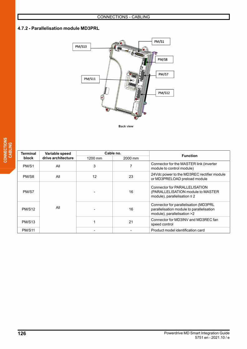
126
CONNECTIONS - CABLING
Powerdrive MD Smart Integration Guide5751 en - 2021.10 / e
CONN
ECTI
ONS
CABL
ING
4.7.2 - Parallelisation module MD3PRL
Terminal block
Variable speed drive architecture
Cable no. Function1200 mm 2000 mm
PM/S1 All 3 7 Connector for the MASTER link (inverter module to control module)
PM/S8 All 12 23 24Vdc power to the MD3REC rectifier module or MD3PRELOAD preload module
PM/S7
All
- 16Connector for PARALLELISATION (PARALLELISATION module to MASTER module), parallelisation ≤ 2
PM/S12 - 16Connector for parallelisation (MD3PRL parallelisation module to parallelisation module), parallelisation >2
PM/S13 1 21 Connector for MD3INV and MD3REC fan speed control
PM/S11 - - Product model identification card
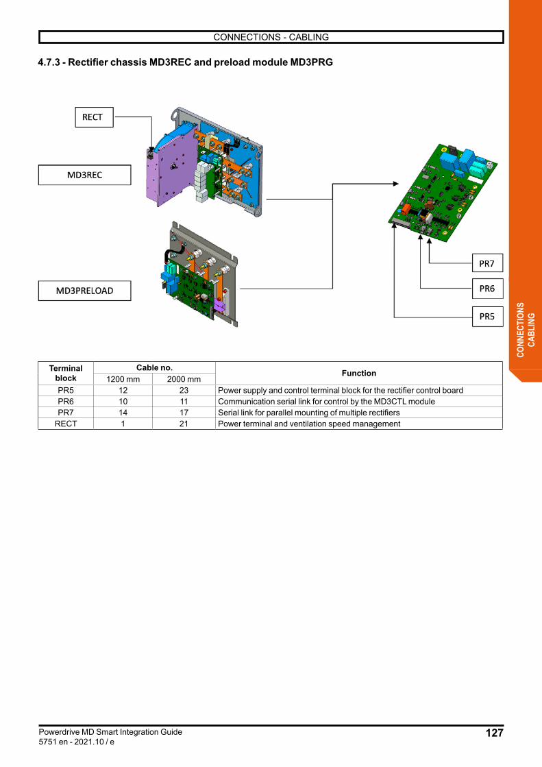
127
CONNECTIONS - CABLING
Powerdrive MD Smart Integration Guide5751 en - 2021.10 / e
CONN
ECTI
ONS
CABL
ING
4.7.3 - Rectifier chassis MD3REC and preload module MD3PRG
Terminal block
Cable no. Function1200 mm 2000 mm
PR5 12 23 Power supply and control terminal block for the rectifier control boardPR6 10 11 Communication serial link for control by the MD3CTL modulePR7 14 17 Serial link for parallel mounting of multiple rectifiers
RECT 1 21 Power terminal and ventilation speed management
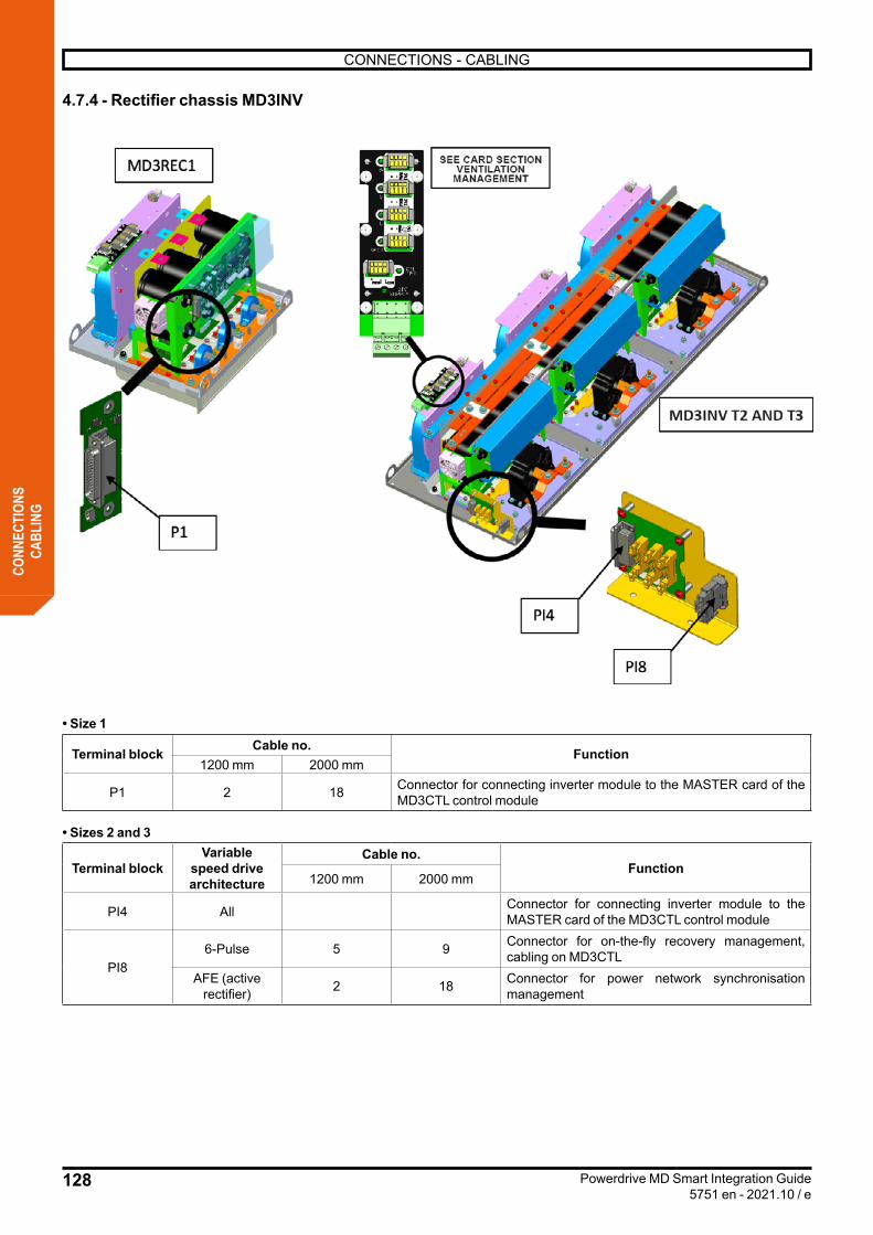
128
CONNECTIONS - CABLING
Powerdrive MD Smart Integration Guide5751 en - 2021.10 / e
CONN
ECTI
ONS
CABL
ING
4.7.4 - Rectifier chassis MD3INV
• Size 1
Terminal block Cable no. Function1200 mm 2000 mm
P1 2 18 Connector for connecting inverter module to the MASTER card of the MD3CTL control module
• Sizes 2 and 3
Terminal blockVariable
speed drive architecture
Cable no.Function
1200 mm 2000 mm
PI4 All Connector for connecting inverter module to the MASTER card of the MD3CTL control module
PI86-Pulse 5 9 Connector for on-the-fly recovery management,
cabling on MD3CTLAFE (active
rectifier) 2 18 Connector for power network synchronisation management
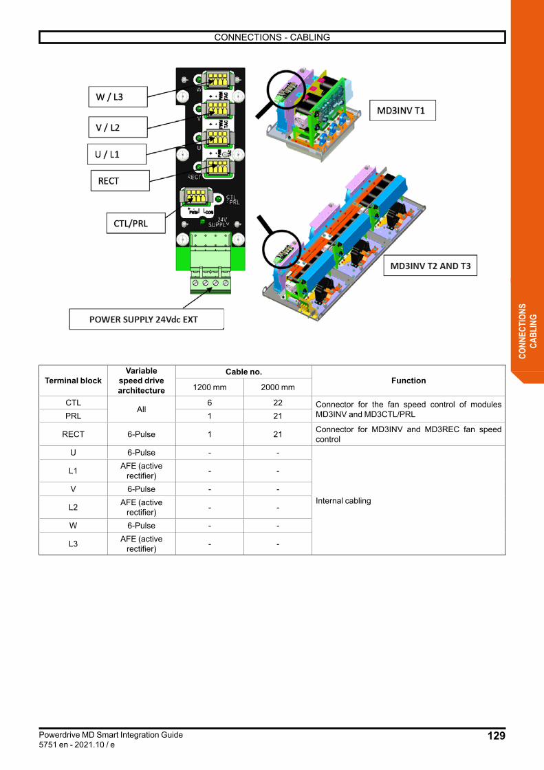
129
CONNECTIONS - CABLING
Powerdrive MD Smart Integration Guide5751 en - 2021.10 / e
CONN
ECTI
ONS
CABL
ING
Terminal blockVariable
speed drive architecture
Cable no.Function
1200 mm 2000 mm
CTLAll
6 22 Connector for the fan speed control of modules MD3INV and MD3CTL/PRLPRL 1 21
RECT 6-Pulse 1 21 Connector for MD3INV and MD3REC fan speed control
U 6-Pulse - -
Internal cabling
L1 AFE (active rectifier) - -
V 6-Pulse - -
L2 AFE (active rectifier) - -
W 6-Pulse - -
L3 AFE (active rectifier) - -
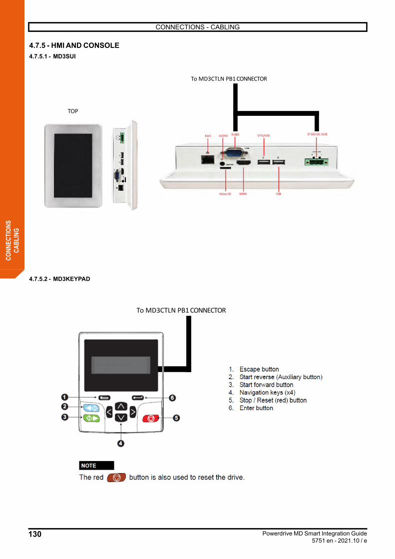
130
CONNECTIONS - CABLING
Powerdrive MD Smart Integration Guide5751 en - 2021.10 / e
CONN
ECTI
ONS
CABL
ING
4.7.5 - HMI AND CONSOLE4.7.5.1 - MD3SUI
TOP
To MD3CTLN PB1 CONNECTOR
4.7.5.2 - MD3KEYPAD
To MD3CTLN PB1 CONNECTOR
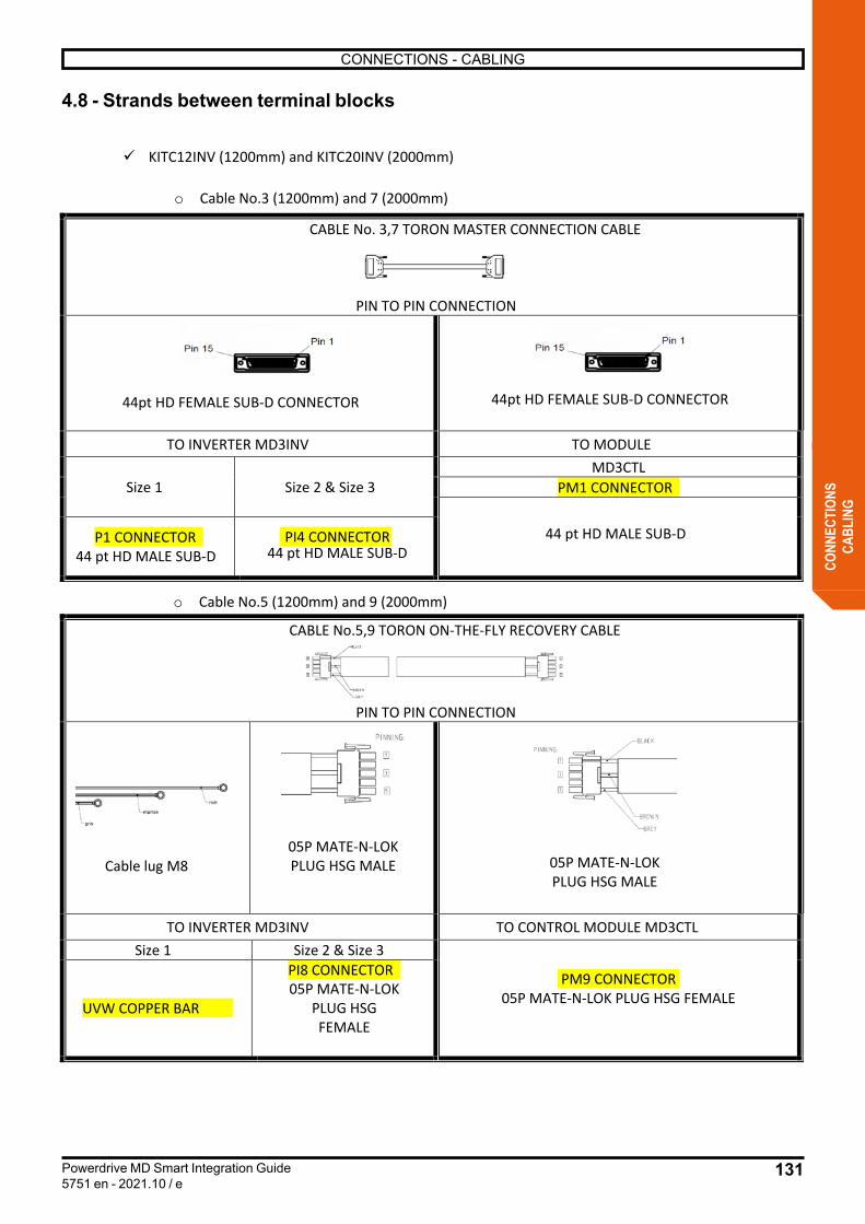
131
CONNECTIONS - CABLING
Powerdrive MD Smart Integration Guide5751 en - 2021.10 / e
CONN
ECTI
ONS
CABL
ING
ü KITC12INV (1200mm) and KITC20INV (2000mm)
o Cable No.3 (1200mm) and 7 (2000mm)
CABLE No. 3,7 TORON MASTER CONNECTION CABLE
PIN TO PIN CONNECTION
44pt HD FEMALE SUB-D CONNECTOR 44pt HD FEMALE SUB-D CONNECTOR
TO INVERTER MD3INV TO MODULE
Size 1 Size 2 & Size 3 MD3CTL
PM1 CONNECTOR
44 pt HD MALE SUB-DP1 CONNECTOR44 pt HD MALE SUB-D
PI4 CONNECTOR44 pt HD MALE SUB-D
o Cable No.5 (1200mm) and 9 (2000mm)
CABLE No.5,9 TORON ON-THE-FLY RECOVERY CABLE
PIN TO PIN CONNECTION
Cable lug M8 05P MATE-N-LOK PLUG HSG MALE 05P MATE-N-LOK
PLUG HSG MALE
TO INVERTER MD3INV TO CONTROL MODULE MD3CTL Size 1 Size 2 & Size 3
PM9 CONNECTOR05P MATE-N-LOK PLUG HSG FEMALE
UVW COPPER BAR
PI8 CONNECTOR 05P MATE-N-LOK
PLUG HSG FEMALE
4.8 - Strands between terminal blocks

132
CONNECTIONS - CABLING
Powerdrive MD Smart Integration Guide5751 en - 2021.10 / e
CONN
ECTI
ONS
CABL
ING
o Cable No.4 (1200mm) and 8 (2000mm)
CABLE No.4 ,8 TORON BUS DC CONNECTION CABLE
PIN TO PIN CONNECTION
MATE-N-LOCK MK1 MALE 1200V 105°C -
COSSE M4- brass - tined - allowing nut with external Ø10
TO MODULE TO MD3INV INVERTER
MD3CTL
COPPER BAR DC BUS
PM2 CONNECTOR
MATE-N-LOCK MK1 FEMELLE-
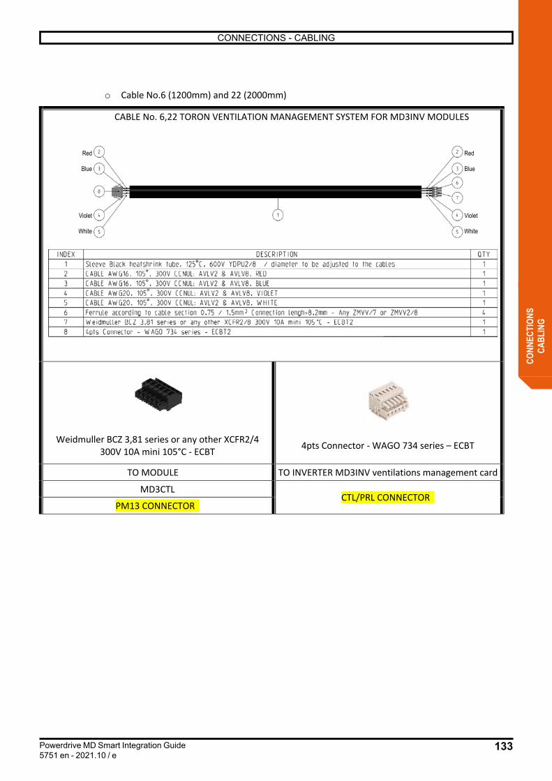
133
CONNECTIONS - CABLING
Powerdrive MD Smart Integration Guide5751 en - 2021.10 / e
CONN
ECTI
ONS
CABL
ING
o Cable No.6 (1200mm) and 22 (2000mm)
CABLE No. 6,22 TORON VENTILATION MANAGEMENT SYSTEM FOR MD3INV MODULES
Weidmuller BCZ 3,81 series or any other XCFR2/4 300V 10A mini 105°C - ECBT 4pts Connector - WAGO 734 series – ECBT
TO MODULE TO INVERTER MD3INV ventilations management card
MD3CTL CTL/PRL CONNECTOR
PM13 CONNECTOR
Red
Blue
Violet
White
Red
Blue
Violet
White
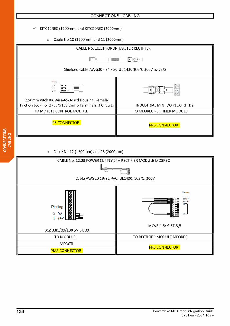
134
CONNECTIONS - CABLING
Powerdrive MD Smart Integration Guide5751 en - 2021.10 / e
CONN
ECTI
ONS
CABL
ING
ü KITC12REC (1200mm) and KITC20REC (2000mm)
o Cable No.10 (1200mm) and 11 (2000mm)
CABLE No. 10,11 TORON MASTER RECTIFIER
Shielded cable AWG30 - 24 x 3C UL 1430 105°C 300V avlv2/8
2.50mm Pitch KK Wire-to-Board Housing, Female, Friction Lock, for 2759/5159 Crimp Terminals, 3 Circuits INDUSTRIAL MINI I/O PLUG KIT D2
TO MD3CTL CONTROL MODULE TO MD3REC RECTIFIER MODULE
P5 CONNECTOR PR6 CONNECTOR
o Cable No.12 (1200mm) and 23 (2000mm)
CABLE No. 12,23 POWER SUPPLY 24V RECTIFIER MODULE MD3REC
Cable AWG20 19/32 PVC. UL1430. 105°C. 300V
BCZ 3.81/09/180 SN BK BX MCVR 1,5/ 9-ST-3,5
TO MODULE TO RECTIFIER MODULE MD3REC
MD3CTL PR5 CONNECTOR
PM8 CONNECTOR
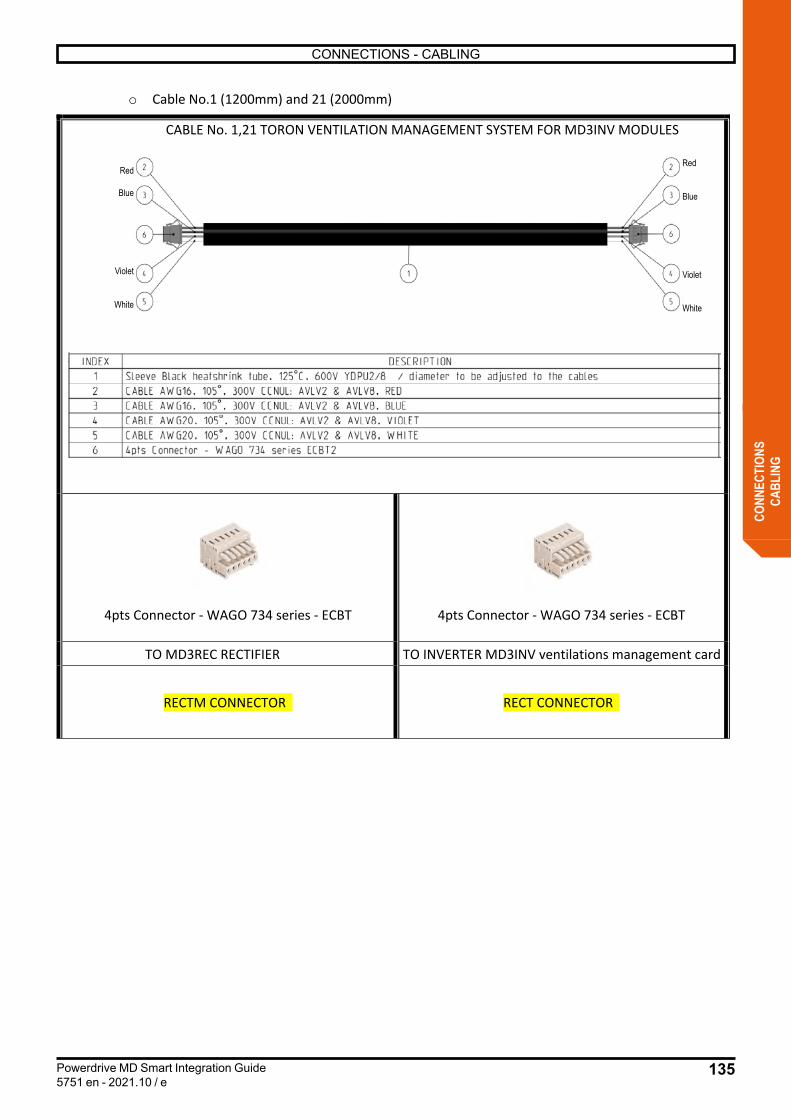
135
CONNECTIONS - CABLING
Powerdrive MD Smart Integration Guide5751 en - 2021.10 / e
CONN
ECTI
ONS
CABL
ING
o Cable No.1 (1200mm) and 21 (2000mm)
CABLE No. 1,21 TORON VENTILATION MANAGEMENT SYSTEM FOR MD3INV MODULES
4pts Connector - WAGO 734 series - ECBT 4pts Connector - WAGO 734 series - ECBT
TO MD3REC RECTIFIER TO INVERTER MD3INV ventilations management card
RECTM CONNECTOR RECT CONNECTOR
Red
Blue
Violet
White
Red
Blue
Violet
White

136
CONNECTIONS - CABLING
Powerdrive MD Smart Integration Guide5751 en - 2021.10 / e
CONN
ECTI
ONS
CABL
ING
ü KITC12REG (1200mm) and KITC20REG (2000mm)
o Cable No.13 (1200mm) and 24 (2000mm)
CABLE No.13, 24 TORON CONNECTION BETWEEN MD3CTL CONTROL MODULES
Shielded cable 1 pair(no taxation on colors) AWG22
3 points Connector 5051-N, 105° ,250V 3 points Connector 5051-N, 105° ,250V TO CONTROL MODUL MD3CTL
ACTIVE RECTIFIER TO CONTROL MODULE MD3CTL INVERTER
P5 CONNECTOR P5 CONNECTOR
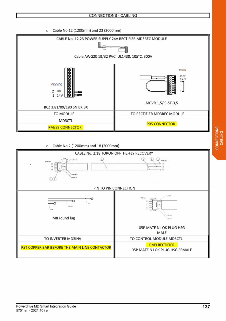
137
CONNECTIONS - CABLING
Powerdrive MD Smart Integration Guide5751 en - 2021.10 / e
CONN
ECTI
ONS
CABL
ING
o Cable No.2 (1200mm) and 18 (2000mm)
CABLE No. 2,18 TORON ON-THE-FLY RECOVERY
.
PIN TO PIN CONNECTION
M8 round lug
05P MATE N LOK PLUG HSG MALE
TO INVERTER MD3INV TO CONTROL MODULE MD3CTL
RST COPPER BAR BEFORE THE MAIN LINE CONTACTOR PM9 RECTIFIER05P MATE N LOK PLUG HSG FEMALE
CABLE No. 12,23 POWER SUPPLY 24V RECTIFIER MD3REC MODULE
Cable AWG20 19/32 PVC. UL1430. 105°C. 300V
BCZ 3.81/09/180 SN BK BX MCVR 1,5/ 9-ST-3,5
TO MODULE TO RECTIFIER MD3REC MODULE
MD3CTL PR5 CONNECTOR
PM/S8 CONNECTOR
o Cable No.12 (1200mm) and 23 (2000mm)
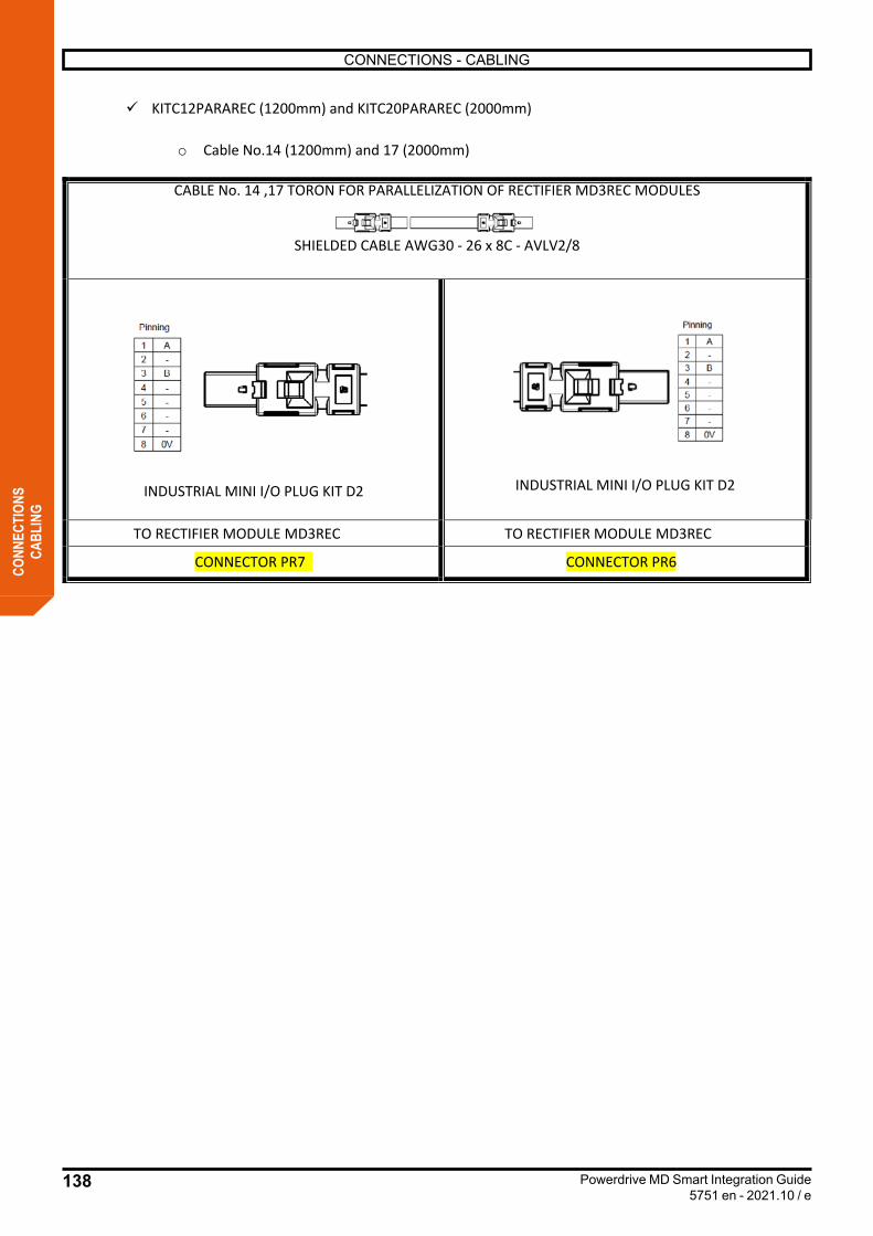
138
CONNECTIONS - CABLING
Powerdrive MD Smart Integration Guide5751 en - 2021.10 / e
CONN
ECTI
ONS
CABL
ING
ü KITC12PARAREC (1200mm) and KITC20PARAREC (2000mm)
o Cable No.14 (1200mm) and 17 (2000mm)
CABLE No. 14 ,17 TORON FOR PARALLELIZATION OF RECTIFIER MD3REC MODULES
SHIELDED CABLE AWG30 - 26 x 8C - AVLV2/8
INDUSTRIAL MINI I/O PLUG KIT D2 INDUSTRIAL MINI I/O PLUG KIT D2
TO RECTIFIER MODULE MD3REC TO RECTIFIER MODULE MD3REC
CONNECTOR PR7 CONNECTOR PR6
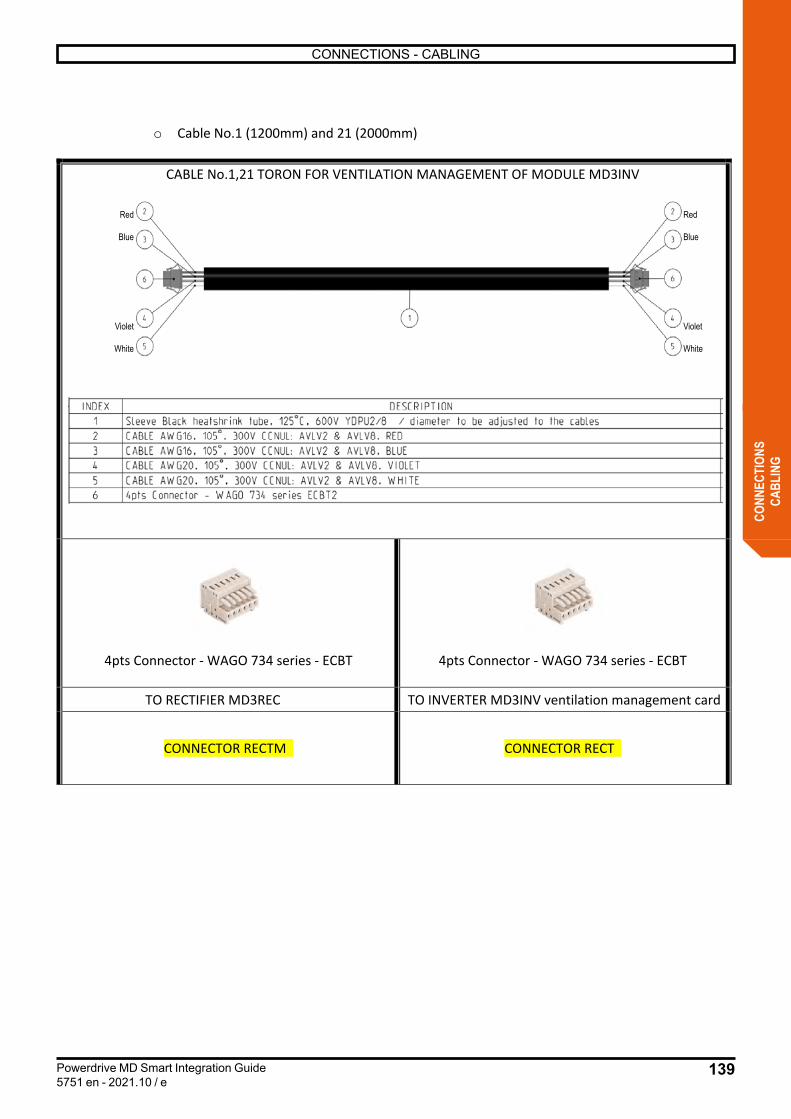
139
CONNECTIONS - CABLING
Powerdrive MD Smart Integration Guide5751 en - 2021.10 / e
CONN
ECTI
ONS
CABL
ING
CABLE No.1,21 TORON FOR VENTILATION MANAGEMENT OF MODULE MD3INV
4pts Connector - WAGO 734 series - ECBT 4pts Connector - WAGO 734 series - ECBT
TO RECTIFIER MD3REC TO INVERTER MD3INV ventilation management card
CONNECTOR RECTM CONNECTOR RECT
o Cable No.1 (1200mm) and 21 (2000mm)
Red
Blue
Violet
White
Red
Blue
Violet
White
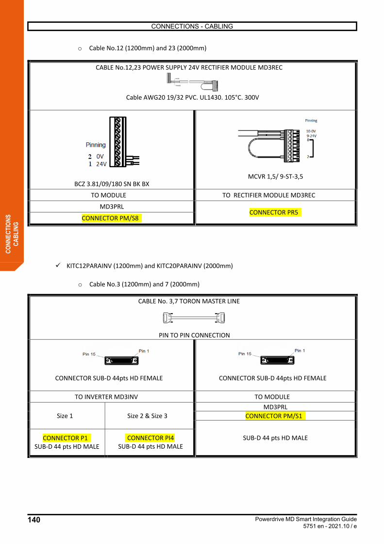
140
CONNECTIONS - CABLING
Powerdrive MD Smart Integration Guide5751 en - 2021.10 / e
CONN
ECTI
ONS
CABL
ING
o Cable No.12 (1200mm) and 23 (2000mm)
CABLE No.12,23 POWER SUPPLY 24V RECTIFIER MODULE MD3REC
Cable AWG20 19/32 PVC. UL1430. 105°C. 300V
BCZ 3.81/09/180 SN BK BX MCVR 1,5/ 9-ST-3,5
TO MODULE TO RECTIFIER MODULE MD3REC
MD3PRL CONNECTOR PR5
CONNECTOR PM/S8
ü KITC12PARAINV (1200mm) and KITC20PARAINV (2000mm)
o Cable No.3 (1200mm) and 7 (2000mm)
CABLE No. 3,7 TORON MASTER LINE
PIN TO PIN CONNECTION
CONNECTOR SUB-D 44pts HD FEMALE CONNECTOR SUB-D 44pts HD FEMALE
TO INVERTER MD3INV TO MODULE
Size 1 Size 2 & Size 3 MD3PRL
CONNECTOR PM/S1
SUB-D 44 pts HD MALE CONNECTOR P1 SUB-D 44 pts HD MALE
CONNECTOR PI4SUB-D 44 pts HD MALE
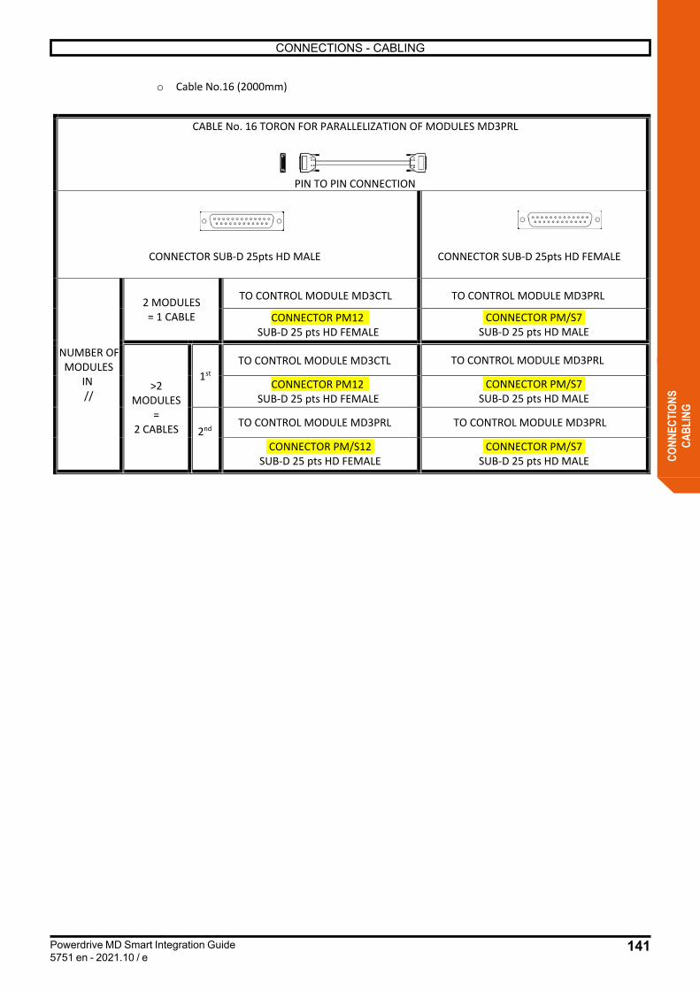
141
CONNECTIONS - CABLING
Powerdrive MD Smart Integration Guide5751 en - 2021.10 / e
CONN
ECTI
ONS
CABL
ING
o Cable No.16 (2000mm)
CABLE No. 16 TORON FOR PARALLELIZATION OF MODULES MD3PRL
PIN TO PIN CONNECTION
CONNECTOR SUB-D 25pts HD MALE CONNECTOR SUB-D 25pts HD FEMALE
NUMBER OF MODULES
IN //
2 MODULES = 1 CABLE
TO CONTROL MODULE MD3CTL TO CONTROL MODULE MD3PRL
CONNECTOR PM12 SUB-D 25 pts HD FEMALE
CONNECTOR PM/S7 SUB-D 25 pts HD MALE
>2MODULES
= 2 CABLES
1stTO CONTROL MODULE MD3CTL TO CONTROL MODULE MD3PRL
CONNECTOR PM12 SUB-D 25 pts HD FEMALE
CONNECTOR PM/S7 SUB-D 25 pts HD MALE
2nd TO CONTROL MODULE MD3PRL TO CONTROL MODULE MD3PRL
CONNECTOR PM/S12 SUB-D 25 pts HD FEMALE
CONNECTOR PM/S7 SUB-D 25 pts HD MALE

142
CONNECTIONS - CABLING
Powerdrive MD Smart Integration Guide5751 en - 2021.10 / e
CONN
ECTI
ONS
CABL
ING
o Cable No.1 (1200mm) and 21 (2000mm)
CABLE No. 1,21 TORON FOR VENTILATION MANAGEMENT OF MODULE MD3INV
4pts Connector - WAGO 734 series - ECBT 4pts Connector - WAGO 734 series - ECBT
TO MODULE TO INVERTER MD3INV ventilation management card
MD3CTL CONNECTOR CTL/PRL
CONNECTOR PM/S13

143
CONNECTIONS - CABLING
Powerdrive MD Smart Integration Guide5751 en - 2021.10 / e
CONN
ECTI
ONS
CABL
ING
Details of various cable kits
The different strands seen above are delivered in KIT form according to the product you wish to manufacture. The different kits are available in 2 lenghts: 1200mm and 2000mm.
ü For inverter chassis MD3INV:
KITC12INV (1200mm) KITC20INV (2000mm) DESCRIPTION No.OF CABLE LS PART NUMBER No. OF CABLE LS PART NUMBER
TORON MASTER LINE
No.3 40038767 No.7 40039603
TORON ON-THE-FLYRECOVERY
No.5 40038902 No.5 40038902
TORON BUS DC No.4 40038901 No.8 40039606 TORON GESTION VF No.6 40050130 No.22 40051304
ü For rectifier chassis MD3REC:
KITC12REC (1200mm) KITC20REC (2000mm) DESCRIPTION No. OF CABLE LS PART NUMBER No. OF CABLE LS PART NUMBER
TORON MASTER RECTIFIER No.10 40040217 No.11 40040212
RECTIFIER CONTROL No.12 40050131 No.23 40051302 TORON GESTION VF No.1 40046768 No.21 40051305
ü For the AFE function:
KITC12REG (1200mm) KITC20REG (2000mm) DESCRIPTION No. OF CABLE LS PART NUMBER No. OF CABLE LS PART NUMBER
TORON MASTER RECTIFIER No.13 40050132 No.24 40051303
RECTIFIER CONTROL No.12 40050131 No.23 40051302 TORON GESTION VF No.2 40051306 No.18 40051307
Details of various cable kits
The different strands seen above are delivered in KIT form according to the product you wish to manufacture. The different kits are available in 2 lengths : 1200 mm and 2000 mm.
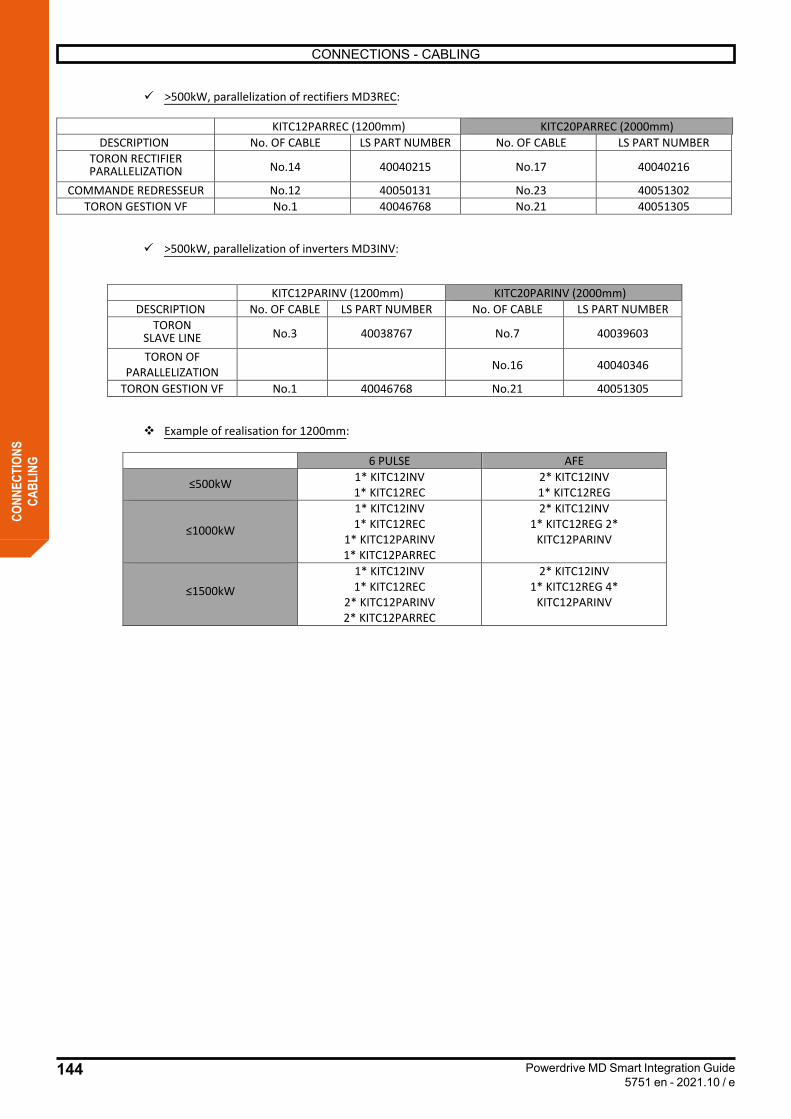
144
CONNECTIONS - CABLING
Powerdrive MD Smart Integration Guide5751 en - 2021.10 / e
CONN
ECTI
ONS
CABL
ING
ü >500kW, parallelization of rectifiers MD3REC:
KITC12PARREC (1200mm) KITC20PARREC (2000mm) DESCRIPTION No. OF CABLE LS PART NUMBER No. OF CABLE LS PART NUMBER
TORON RECTIFIER PARALLELIZATION No.14 40040215 No.17 40040216
COMMANDE REDRESSEUR No.12 40050131 No.23 40051302 TORON GESTION VF No.1 40046768 No.21 40051305
ü >500kW, parallelization of inverters MD3INV:
KITC12PARINV (1200mm) KITC20PARINV (2000mm) DESCRIPTION No. OF CABLE LS PART NUMBER No. OF CABLE LS PART NUMBER
TORONSLAVE LINE No.3 40038767 No.7 40039603
TORON OF PARALLELIZATION No.16 40040346
TORON GESTION VF No.1 40046768 No.21 40051305
v Example of realisation for 1200mm:
6 PULSE AFE
≤500kW 1* KITC12INV 1* KITC12REC
2* KITC12INV 1* KITC12REG
≤1000kW
1* KITC12INV 1* KITC12REC
1* KITC12PARINV 1* KITC12PARREC
2* KITC12INV 1* KITC12REG 2*
KITC12PARINV
≤1500kW 1* KITC12INV 1* KITC12REC
2* KITC12PARINV 2* KITC12PARREC
2* KITC12INV 1* KITC12REG 4*
KITC12PARINV
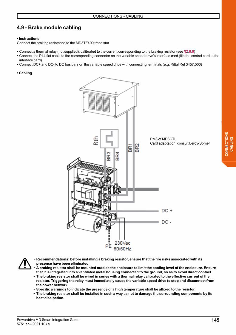
145
CONNECTIONS - CABLING
Powerdrive MD Smart Integration Guide5751 en - 2021.10 / e
CONN
ECTI
ONS
CABL
ING
4.9 - Brake module cabling
• InstructionsConnect the braking resistance to the MD3TF400 transistor. • Connect a thermal relay (not supplied), calibrated to the current corresponding to the braking resistor (see §2.6.6) • Connect the P14 flat cable to the corresponding connector on the variable speed drive’s interface card (flip the control card to the
interface card) • Connect DC+ and DC- to DC bus bars on the variable speed drive with connecting terminals (e.g. Rittal Ref 3457.500)
• Cabling
• Recommendations: before installing a braking resistor, ensure that the fire risks associated with its presence have been eliminated.
• A braking resistor shall be mounted outside the enclosure to limit the cooling level of the enclosure. Ensure that it is integrated into a ventilated metal housing connected to the ground, so as to avoid direct contact.
• The braking resistor shall be wired in series with a thermal relay calibrated to the effective current of the resistor. Triggering the relay must immediately cause the variable speed drive to stop and disconnect from the power network.
• Specific warnings to indicate the presence of a high temperature shall be affixed to the resistor. • The braking resistor shall be installed in such a way as not to damage the surrounding components by its
heat dissipation.
PM8 of MD3CTL Card adaptation, consult Leroy-Somer

146
CONNECTIONS - CABLING
Powerdrive MD Smart Integration Guide5751 en - 2021.10 / e
CONN
ECTI
ONS
CABL
ING
4.10 - DC Bus cablingThis chapter describes the DC BUS power connection.
• For the 6-PULSE configuration, this is the connection between the output of the MD3REC rectifier module and the input of the MD3INV inverter module.
• For AFE configuration, it is the DC BUS connection between MD3INV inverter modules.
• 6 PULSE
• AFE
DC Bus
DC Bus
Sine filter+
Line reactor
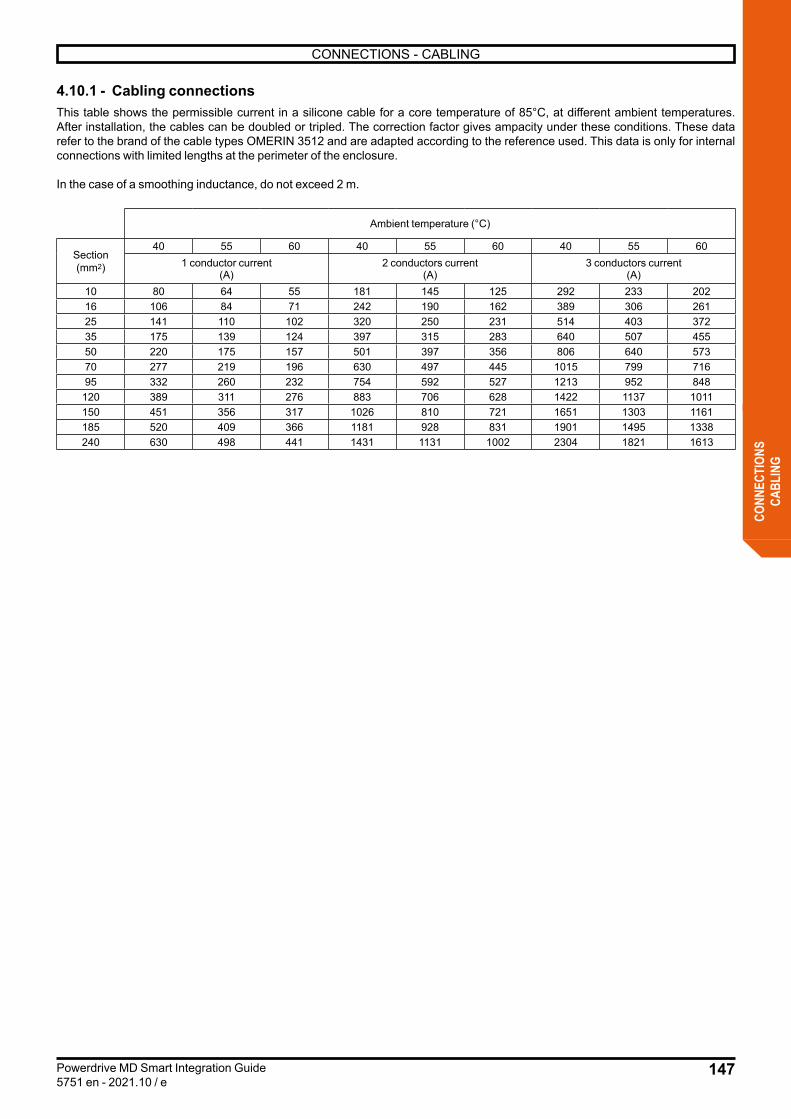
147
CONNECTIONS - CABLING
Powerdrive MD Smart Integration Guide5751 en - 2021.10 / e
CONN
ECTI
ONS
CABL
ING
4.10.1 - Cabling connectionsThis table shows the permissible current in a silicone cable for a core temperature of 85°C, at different ambient temperatures. After installation, the cables can be doubled or tripled. The correction factor gives ampacity under these conditions. These data refer to the brand of the cable types OMERIN 3512 and are adapted according to the reference used. This data is only for internal connections with limited lengths at the perimeter of the enclosure.
In the case of a smoothing inductance, do not exceed 2 m.
Ambient temperature (°C)
Section(mm2)
40 55 60 40 55 60 40 55 601 conductor current
(A)2 conductors current
(A)3 conductors current
(A)10 80 64 55 181 145 125 292 233 20216 106 84 71 242 190 162 389 306 26125 141 110 102 320 250 231 514 403 37235 175 139 124 397 315 283 640 507 45550 220 175 157 501 397 356 806 640 57370 277 219 196 630 497 445 1015 799 71695 332 260 232 754 592 527 1213 952 848
120 389 311 276 883 706 628 1422 1137 1011150 451 356 317 1026 810 721 1651 1303 1161185 520 409 366 1181 928 831 1901 1495 1338240 630 498 441 1431 1131 1002 2304 1821 1613
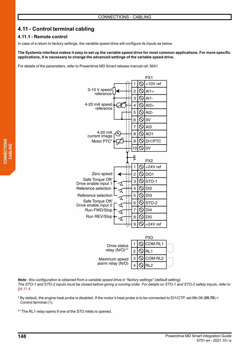
148
CONNECTIONS - CABLING
Powerdrive MD Smart Integration Guide5751 en - 2021.10 / e
CONN
ECTI
ONS
CABL
ING
4.11 - Control terminal cabling4.11.1 - Remote controlIn case of a return to factory settings, the variable speed drive will configure its inputs as below.
The Systemiz interface makes it easy to set up the variable speed drive for most common applications. For more specific applications, it is necessary to change the advanced settings of the variable speed drive.
For details of the parameters, refer to Powerdrive MD Smart release manual ref. 5641.
+10V ref
AI1+
AI1-
AI2+
AI2-
0V
COM-RL1
RL1
COM-RL2
RL2
AO1
AI3
+24V ref
DO1
STO-1
DI2
DI3
STO-2
DI5
DI4
+24V ref
1
2
3
4
5
6
1
2
3
4
8
7
0V
DI1/PTC
10
9
1
2
3
4
5
6
8
7
9
4-20 mA speedreference
Motor PTC*
Drive statusrelay (N/O)**
Maximum speedalarm relay (N/O)
4-20 mAcurrent image
Zero speed
Reference selection
Reference selection
Run FWD/Stop
Run REV/Stop
Safe Torque Off/Drive enable input 1
Safe Torque Off/Drive enable input 2
PX1
PX2
PX3
0-10 V speedreference
Note : this configuration is obtained from a variable speed drive in “factory settings” (default setting).The STO-1 and STO-2 inputs must be closed before giving a running order. For details on STO-1 and STO-2 safety inputs, refer to §4.11.4.
* By default, the engine heat probe is disabled. If the motor’s heat probe is to be connected to DI1/CTP, set Mtr.06 (05.70) = Control terminal (1).
** The RL1 relay opens if one of the STO inlets is opened.

149
CONNECTIONS - CABLING
Powerdrive MD Smart Integration Guide5751 en - 2021.10 / e
CONN
ECTI
ONS
CABL
ING
• Selection of reference via logic inputs:
DI2 DI3 Selection
0 0 Reference voltage speed (0-10 V) on the analogue input AI1+,AI1-
0 1 Reference current speed (4-20 mA) on analogue input AI2+,AI2-
1 0 Pre-set reference 2 (RP2)Spd.05 (01.22) to be configured1 1
4.11.2 - Changing the Start/Stop command logic
- For “3-cable” control (Pulse start/stop):
List of parameters to be adjusted:Ctr.06 (06.04) = Pulse S/S (1),I/O.10 (08.25) = 06 39 Stop (DI5 terminal).
- For Start/Stop with direction reversal:
List of parameters to be adjusted:Ctr.06 (06.04) = S/S + direction reversal (2),I/O.09 (08.24) = 06 34 Start/Stop (DI4 terminal),I/O.10 (08.25) = 06 33 Forward/backward reversal (DI5 terminal).
4.11.3 - Systemiz wizard details (pre-set internal settings)The Systemiz application gives us the possibility of having support for a faster commissioning. 6 macros make it easier to set the variable speed drive for the most popular applications.
Analogue ref. and 3 pre-set speeds
Local/Remote analogue Local/Fieldbus ± fast Torque/speed
control PID/speed control
• Selection of reference via logic inputs:
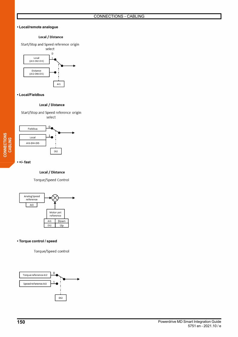
150
CONNECTIONS - CABLING
Powerdrive MD Smart Integration Guide5751 en - 2021.10 / e
CONN
ECTI
ONS
CABL
ING
• Local/remote analogue
• Local/Fieldbus
• +/- fast
• Torque control / speed
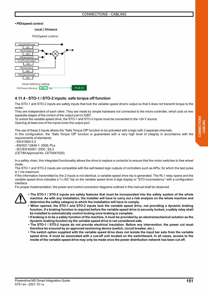
151
CONNECTIONS - CABLING
Powerdrive MD Smart Integration Guide5751 en - 2021.10 / e
CONN
ECTI
ONS
CABL
ING
• PID/speed control
4.11.4 - STO-1 / STO-2 inputs: safe torque off functionThe STO-1 and STO-2 inputs are safety inputs that lock the variable speed drive's output so that it does not transmit torque to the motor.They are independent of each other. They are made by simple hardware not connected to the micro-controller, which acts on two separate stages of the control of the output port to IGBT.To unlock the variable speed drive, the STO-1 and STO-2 inputs must be connected to the +24 V source.Opening at least one of the inputs locks the output port.
The use of these 2 inputs allows the "Safe Torque Off" function to be activated with a logic with 2 separate channels.In this configuration, the “Safe Torque Off" function is guaranteed with a very high level of integrity in accordance with the requirements of standards:- EN 61800-5-2- EN/ISO 13849-1: 2006; PLe- IEC/EN 62061: 2005 ; SIL3(CETIM Approval No. CET0047520)
In a safety chain, this integrated functionality allows the drive to replace a contactor to ensure that the motor switches to free wheel mode.The STO-1 and STO-2 inputs are compatible with the self-tested logic outputs of controllers such as APIs, for which the test pulse is 1 ms maximum.If the information transmitted by the 2 inputs is not identical, a variable speed drive trip is generated. The RL1 relay opens and the variable speed drive indicates a “t.r./63” trip on the variable speed drive 2-digit display or “STO inconsistency” with a configuration interface.For proper implementation, the power and control connection diagrams outlined in this manual shall be observed.
• The STO-1 / STO-2 inputs are safety features that must be incorporated into the safety system of the whole machine. As with any installation, the installer will have to carry out a risk analysis on the whole machine and determine the safety category to which the installation will have to comply.
• When opened, the STO-1 and STO-2 inputs lock the variable speed drive, not providing a dynamic braking function. If a braking function is required before the variable speed drive is securely locked, a safety relay shall be installed to automatically control locking once braking is complete.
• If braking is to be a safety function of the machine, it must be provided by an electromechanical solution as the dynamic braking function by the variable speed drive is not considered safe.
• The STO-1 / STO-2 inputs do not provide electrical insulation. Before any intervention, the power cut must therefore be ensured by an approved sectioning device (switch, circuit breaker, etc.).
• The switch option supplied with the variable speed drive does not isolate the input bar sets from the variable speed drive. It must be associated with a cut-off unit located on the switchboard. In all cases, access to the inside of the variable speed drive may only be made once the power distribution network has been cut off.
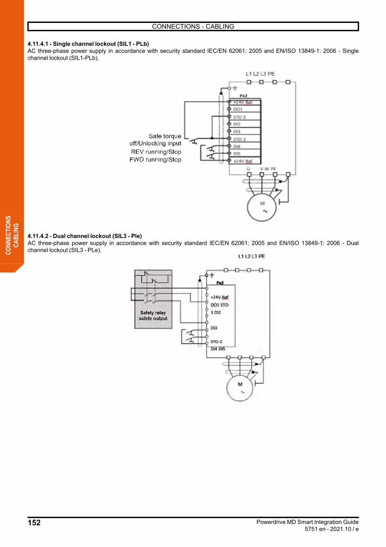
152
CONNECTIONS - CABLING
Powerdrive MD Smart Integration Guide5751 en - 2021.10 / e
CONN
ECTI
ONS
CABL
ING
4.11.4.1 - Single channel lockout (SIL1 - PLb)AC three-phase power supply in accordance with security standard IEC/EN 62061: 2005 and EN/ISO 13849-1: 2006 - Single channel lockout (SIL1-PLb).
4.11.4.2 - Dual channel lockout (SIL3 - Ple)AC three-phase power supply in accordance with security standard IEC/EN 62061: 2005 and EN/ISO 13849-1: 2006 - Dual channel lockout (SIL3 - PLe).

153
TESTING
Powerdrive MD Smart Integration Guide5751 en - 2021.10 / e
TEST
5 - TESTING For commissioning and configuring the Powerdrive MD Smart variable speed drive, refer to manual 5641, available on www.leroy-somer.com.
Once the various components of the Powerdrive MD Smart variable speed drive have been integrated into the enclosure, the installer must ensure that the unit functions properly.
All installation, commissioning and maintenance work shall be performed by qualified and authorised personnel.• When a variable speed drive-detected safety warning causes the motor to shut down, residual fatal voltages are still present on
the terminal blocks and in the variable speed drive.• The variable speed drive shutdown function does not protect against the high voltage on the terminal blocks.• Do not work on the variable speed drive or motor without opening and padlocking the control panel.• Optional integrated variable speed drive network severing equipment does not isolate the variable speed drive’s input bar sets.
During installation and maintenance, ensure that the power line is open.• When the variable speed drive is operating a permanent magnet motor, the interlocking device between the variable speed drive
and the motor must be opened to prevent the risk of a return of motor voltage. If there are no sectioning devices present, it is necessary to ensure that the machine shaft is blocked while work is carried out.
• After the variable speed drive is turned off, the external control circuits may maintain a dangerous voltage level. Verify that these circuits are powered off before working on control cables.
• Wait 15 minutes and then ensure that the voltage of the continuous bus is less than 40V.• After drive operation, the radiator may be very hot, keep away from it (70°C).• After drive operation, check that the sequence of phases is correct when re-connecting the motor cables.• During testing, all protective covers must remain in place.• Before conducting dielectric or power-on tests, power off the variable speed drive and disconnect the motor.
5.1 - Self-testing and diagnostics 5.1.1 - Control module MD3CTLThis test consists of checking the proper functioning of the MD3CTL module.
Before validating the test: - In the case of an external power supply, cut off the power and leave only the power supply of the electronics (MD3CTL terminal
block PM6). - In the case of an internal power supply to the electronics, disconnect the internal cabling and connect an external power supply, in
order to cut off the power and leave only the electronic power supply (MD3CTL terminal block PM6). 1) Disconnect the PX1 and PX3 connectors from the control card2) The safe torque inputs of the STO-1 and STO-2 torque shall be closed3) Turn on the auxiliary power supply, the test only starts if the bus voltage is less than 50 V4) Initiate the card’s self-test procedure with parameter 17.015) Check the result of the self test in parameter 17.05
At the end of the test, an automatic reset is performed (equivalent to a reset when the variable speed drive is turned off and on), in particular, a reset of parameters 17.33 to 17.39, 17.42 to 17.49, 17.52 to 17.59). In the event of an error, follow the instructions in the Powerdrive MD Smart commissioning manual ref. 5641
6) Cut the power to the electronics
After testing, reconnect everything.
5.1.2 - PowerThis test consists of checking the proper functioning of the power circuits.
During this test, current is circulating in the motor.
Power on the variable speed drive, power supply and start the power test with parameter 17.02.The power test is validated. If the bus voltage is greater than 70 V, the variable speed drive waits for the natural discharge of the bus (the wait may take longer than 5 minutes). In order for the test to work, the safe torque off inputs must be closed. Otherwise, a “Diagnostic” trip is generated and the test result 17.06 indicates “Open STO Failure”.
The results are displayed in 17.06 following the instructions outlined in the Powerdrive MD Smart commissioning manual ref. 5641.

154
TESTING
Powerdrive MD Smart Integration Guide5751 en - 2021.10 / e
TEST
Note: this self-test can be performed every time the variable speed drive is powered on, to check the power elements. It lasts less than 5 seconds since in this case the bus is not loaded. This self-test is adjustable in 17.03..If the 2 tests are successful and without defect then an operation test can be performed.
5.2 - Operating testThis involves running a motor and checking the waveform of the current in and out of the variable speed drive.
5.2.1 - Necessary hardware:- A test platform suitable for the size of the variable speed drive.- A current clamp.- Two oscilloscope current clamps- An oscilloscope.- A button box.

155
TESTING
Powerdrive MD Smart Integration Guide5751 en - 2021.10 / e
TEST
5.2.2 - Test preparation1) Wire the 400 Vac three-phase network to terminals L1, L2, L3 and wire the ground to the equipotential protection bar2) Wire the motor to the U, V, W terminals (in sequence)3) Wire the button box on the corresponding terminal blocks (see section §4.11) and ensure that the "STO-1 and STO-2" inputs are
opened (variable speed drive lockout)
5.2.3 - Functional Testing1) Perform the following test set-up:
Example of test set-upAddress: Label Settings02.11 acceleration ramp 1 25 s02.21 deceleration ramp 1 25 s05.06 motor rated frequency see motor plate05.07 motor rated current see motor plate05.08 motor rated speed see motor plate05.09 motor rated voltage see motor plate05.10 motor PHI cos see motor plate02.04 Stop mode Free wheel06.03 Mains loss management Delayed shutdown06.09 On-the-fly recovery selection Validated6.62 Micro-cut time delay 3 s6.63 Time delay before on-the-fly recovery 5 s10.75 continuous bus power NO
2) Change the "STO-1 and STO-2” inputs to 1, then give a running order (forward or reverse).3) Set the potentiometer to 100% so that the motor starts at its rated speed. 4) Test for on-the-fly recovery: give a stop order, wait about 3 seconds and return to a running order. The variable speed drive must
return to the engine on-the-fly.5) Set parameter 02.04 (Stop mode) to ramp.6) Micro-cut test: cut the network for less than 3 seconds. The variable speed drive must not trip.7) Load the motor at half of the variable speed drive’s intensity. Models 60 T to 570 T: place the oscilloscope clamp on a motor phase and check the waveform. Models 570 T to 1710 T: place an oscilloscope clamp on each motor and network phase inlet and check the waveform and
balance for each motor and network phase. Balancing shall not be less than 7% of full load on the motor side and 10% on the network side.
8) Using the current clamp, check the balance per phase on the network side, on the motor side and check the measurement concordance between the clamp and the console (parameter 4.01: motor current).
9) Check the waveform below for other motor phases:
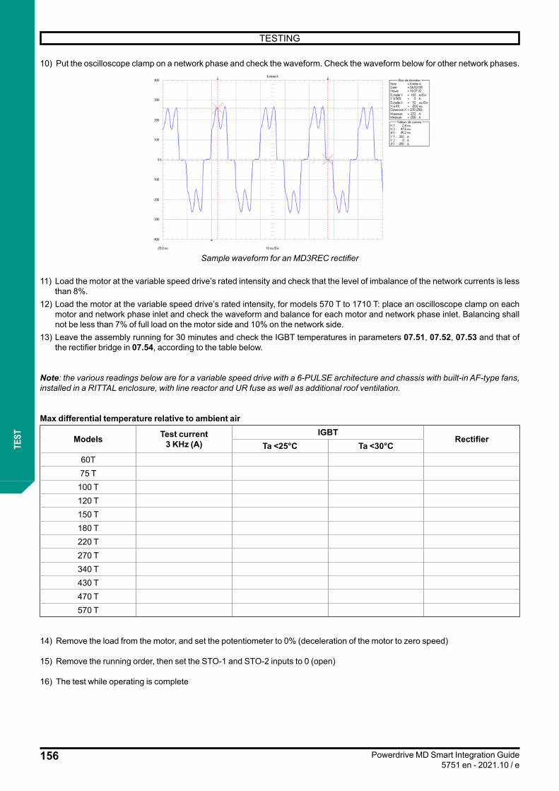
156
TESTING
Powerdrive MD Smart Integration Guide5751 en - 2021.10 / e
TEST
10) Put the oscilloscope clamp on a network phase and check the waveform. Check the waveform below for other network phases.
Sample waveform for an MD3REC rectifier
11) Load the motor at the variable speed drive’s rated intensity and check that the level of imbalance of the network currents is less than 8%.
12) Load the motor at the variable speed drive’s rated intensity, for models 570 T to 1710 T: place an oscilloscope clamp on each motor and network phase inlet and check the waveform and balance for each motor and network phase inlet. Balancing shall not be less than 7% of full load on the motor side and 10% on the network side.
13) Leave the assembly running for 30 minutes and check the IGBT temperatures in parameters 07.51, 07.52, 07.53 and that of the rectifier bridge in 07.54, according to the table below.
Note: the various readings below are for a variable speed drive with a 6-PULSE architecture and chassis with built-in AF-type fans, installed in a RITTAL enclosure, with line reactor and UR fuse as well as additional roof ventilation.
Max differential temperature relative to ambient air
Models Test current3 KHz (A)
IGBTRectifier
Ta <25°C Ta <30°C60T75 T
100 T120 T150 T180 T220 T270 T340 T430 T470 T570 T
14) Remove the load from the motor, and set the potentiometer to 0% (deceleration of the motor to zero speed)
15) Remove the running order, then set the STO-1 and STO-2 inputs to 0 (open)
16) The test while operating is complete

157
MAINTENANCE
Powerdrive MD Smart Integration Guide5751 en - 2021.10 / e
MAIN
TENA
NCE
6 - MAINTENANCEUser maintenance and troubleshooting of Powerdrive MD Smart variable speed drives is extremely low. The routine maintenance operations are as follows:
• MaintenancePrinted circuit boards and variable speed drive components do not normally require maintenance. Contact your nearest authorised dealer or repairer if there is a problem.
CAUTION:Do not disassemble the printed circuit boards during the warranty period. This would immediately invalidate the warranty.Do not touch the integrated circuits or microprocessor with your fingers.Periodically check the tightening of the powered down power connections. Port filters should be checked, cleaned (washable) and changed regularly according to their condition.
• Preventive maintenanceSystem action recurrenceCheck tightening torque of power connections after 1 yearReplace internal ventilation after 5 years
• StorageThe Powerdrive MD Smart incorporates aluminium electrolytic capacitors.After 12 months of storage, it is therefore necessary to turn on the variable speed drive for 5 hours at the rated operating voltage, then redo the operation every 6 months.After 36 months of storage, a capacitor reforming operation is required.This involves applying a continuous voltage progressively on the capacitor benches, until voltage values close to the rated values are achieved, while ensuring that the dissipated powers do not exceed the maximum values allowed by the manufacturers.A procedure is available upon request from your usual Nidec Leroy-Somer contact.
7 - UL LISTING INFORMATION7.1 - UL file referenceThe Powerdrive MD Smart file number is E211799. Confirmation of UL listing can be found on the UL website: www.ul.com
7.2 - MountingThe drive must be installed in a type 1 enclosure, or better, as defined by UL50.
7.3 - EnvironmentDrives must be installed in a Pollution Degree 2 environment or better (dry, non-conductive pollution only). All drives are capable of delivering full rated output current at surrounding air temperatures up to 50°C (122°F).
7.4 - Maximum continuous currentThe Powerdrive MD Smart models are listed as having the maximum continuous output currents (Ico) described in section 1.4.2.
7.5 - Electrical installation7.5.1 - Terminal torqueTerminals must be tightened to the rated torque as specified in the Installation instructions. Refer to section 3.1.2 Characteristics of terminals.
7.5.2 - Cabling terminals- Drives must be installed using cables rated for 75°C operation, copper cable only.- UL listed closed-loop connectors sized according to the field cabling shall be used for all field cabling.- Input supply ground (PE Rectifier) and motor output ground (PE motor) shall be connected.
7.5.3 - Branch circuit protectionIntegral solid state short circuit protection does not provide branch circuit protection. Branch circuit protection must be provided in accordance with the National Electrical Code and any additional local “codes”, or the equivalent.The fuse ratings for branch circuit protection are contained in section 3.1.4 Fusing and cabling.
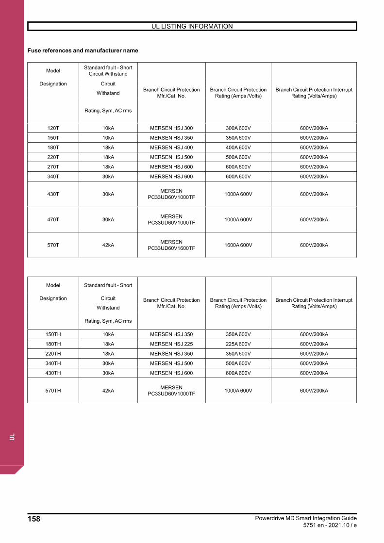
158
UL LISTING INFORMATION
Powerdrive MD Smart Integration Guide5751 en - 2021.10 / e
UL
Fuse references and manufacturer name
Model Standard fault - Short Circuit Withstand
Branch Circuit Protection Mfr./Cat. No.
Branch Circuit Protection Rating (Amps /Volts)
Branch Circuit Protection Interrupt Rating (Volts/Amps)
Designation Circuit
Withstand
Rating, Sym, AC rms
120T 10kA MERSEN HSJ 300 300A 600V 600V/200kA
150T 10kA MERSEN HSJ 350 350A 600V 600V/200kA
180T 18kA MERSEN HSJ 400 400A 600V 600V/200kA
220T 18kA MERSEN HSJ 500 500A 600V 600V/200kA
270T 18kA MERSEN HSJ 600 600A 600V 600V/200kA
340T 30kA MERSEN HSJ 600 600A 600V 600V/200kA
430T 30kA MERSEN PC33UD60V1000TF 1000A 600V 600V/200kA
470T 30kA MERSEN PC33UD60V1000TF 1000A 600V 600V/200kA
570T 42kA MERSEN PC33UD60V1600TF 1600A 600V 600V/200kA
Model Standard fault - Short
Branch Circuit Protection Mfr./Cat. No.
Branch Circuit Protection Rating (Amps /Volts)
Branch Circuit Protection Interrupt Rating (Volts/Amps)
Designation Circuit
Withstand
Rating, Sym, AC rms
150TH 10kA MERSEN HSJ 350 350A 600V 600V/200kA
180TH 18kA MERSEN HSJ 225 225A 600V 600V/200kA
220TH 18kA MERSEN HSJ 350 350A 600V 600V/200kA
340TH 30kA MERSEN HSJ 500 500A 600V 600V/200kA
430TH 30kA MERSEN HSJ 600 600A 600V 600V/200kA
570TH 42kA MERSEN PC33UD60V1000TF 1000A 600V 600V/200kA

159
UL LISTING INFORMATION
Powerdrive MD Smart Integration Guide5751 en - 2021.10 / e
UL
7.5.4 - Line reactorsA choke (as described in the table below) shall be installed on the line supply with installation instructions.The cable length between the line reactor and drive shall be in accordance with the following table. The UL Tests for the certification had been performed with the following line reactor characteristics:
Drive model Choke Section / Length(from choke to product)
75TIR 350µH 145A 1x70mm2 length <1.2m120TIR 220µH 225A 1x150mm2 length <1.2m120TMIR 350µH 200A 1x70mm2 length <1.2m180TIR 90mH 444A 2x95mm2 length <1.45m
220TIR 90mH 444A 2x185mm2 or equivalent,length <1.45m
220TMIR 160mH 291A 1x185mm2 or equivalentlength <1.45m
430TIR 37mH 918A 4x150mm2 or equivalent,length <1.45m
570TIR 37mH 918A 4x185mm2 or equivalent,length <1.45m
570TMIR 58mH 566A 4x95mm2 or equivalent,length <1.45m
7.6 - AC supply specificationEquipment suitable for use on a circuit capable of delivering not more than the values listed in the table of section 8.5.3.
7.7 - Motor overload protection and overspeed protectionThe drive does not incorporate solid state overload protection for the motor load. The drive provides overspeed protection. However, it does not provide the level of protection afforded by an independent high integrity over-speed protection device.
7.8 - PX1, PX2, PX3 and P2 customer interface• The Powerdrive MD Smart inputs have a positive logic configuration. Using a drive with a control system which has different control logic may cause unexpected starting of the motor.
• The Powerdrive MD Smart control circuit is isolated from the power circuits by single insulation. Its electronic 0V is connected to the connection terminal on the outer protective conductor (earth terminal).• The installer must ensure that the external control circuits are isolated against any human contact.• If the serial link port (P2) or the control terminals (PX1, PX2) need to be connected to circuits complying with SELV safety requirements, additional 4kV insulation barrier must be inserted to maintain the SELV classification (see EN 61140). • USB port (P1): Use restricted to Cat. No. MDX-USB isolator option by Nidec Leroy-Somer (ordering code 4808979) for ensuring a supplemental insulation for at least 600 V between the 24V circuits and user.The PX3 output relay is limited for OVCII (Overvoltage Category 2) use (RL1 and RL2 must have the same polarity). The voltage rating between two consecutive terminals must not exceed 150Vrms.
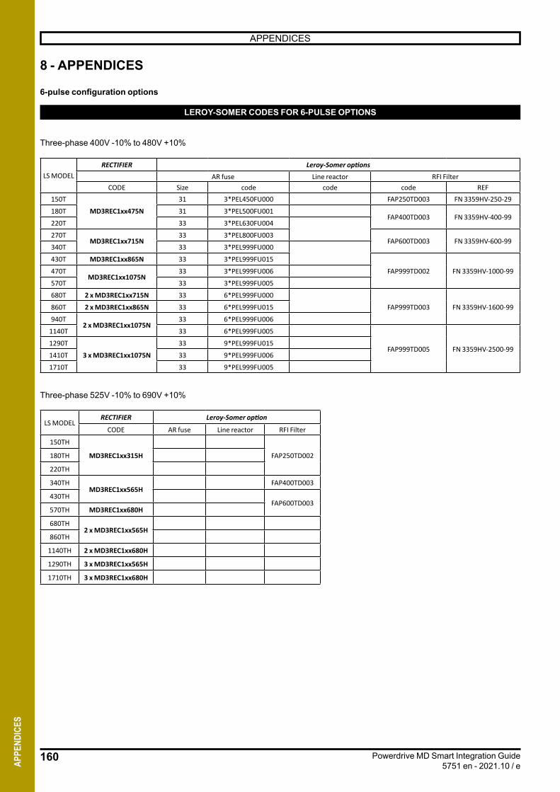
160
APPENDICES
Powerdrive MD Smart Integration Guide5751 en - 2021.10 / eAP
PEND
ICES
8 - APPENDICES
6-pulse configuration options
LEROY-SOMER CODES FOR 6-PULSE OPTIONS
Three-phase 400V -10% to 480V +10%
LS MODELRECTIFIER Leroy-Somer options
AR fuse Line reactor RFI FilterCODE Size code code code REF
150T
MD3REC1xx475N
31 3*PEL450FU000 FAP250TD003 FN 3359HV-250-29
180T 31 3*PEL500FU001FAP400TD003 FN 3359HV-400-99
220T 33 3*PEL630FU004
270TMD3REC1xx715N
33 3*PEL800FU003FAP600TD003 FN 3359HV-600-99
340T 33 3*PEL999FU000
430T MD3REC1xx865N 33 3*PEL999FU015
FAP999TD002 FN 3359HV-1000-99470TMD3REC1xx1075N
33 3*PEL999FU006
570T 33 3*PEL999FU005
680T 2 x MD3REC1xx715N 33 6*PEL999FU000
FAP999TD003 FN 3359HV-1600-99860T 2 x MD3REC1xx865N 33 6*PEL999FU015
940T2 x MD3REC1xx1075N
33 6*PEL999FU006
1140T 33 6*PEL999FU005
FAP999TD005 FN 3359HV-2500-991290T
3 x MD3REC1xx1075N
33 9*PEL999FU015
1410T 33 9*PEL999FU006
1710T 33 9*PEL999FU005
Three-phase 525V -10% to 690V +10%
LS MODELRECTIFIER Leroy-Somer option
CODE AR fuse Line reactor RFI Filter
150TH
MD3REC1xx315H FAP250TD002180TH
220TH
340THMD3REC1xx565H
FAP400TD003
430THFAP600TD003
570TH MD3REC1xx680H
680TH2 x MD3REC1xx565H
860TH
1140TH 2 x MD3REC1xx680H
1290TH 3 x MD3REC1xx565H
1710TH 3 x MD3REC1xx680H
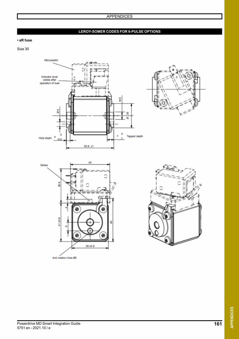
161
APPENDICES
Powerdrive MD Smart Integration Guide5751 en - 2021.10 / e AP
PEND
ICES
LEROY-SOMER CODES FOR 6-PULSE OPTIONS
• aR fuse
Size 30
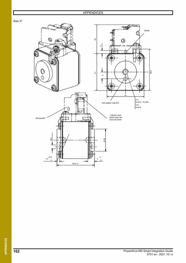
162
APPENDICES
Powerdrive MD Smart Integration Guide5751 en - 2021.10 / eAP
PEND
ICES
Size 31
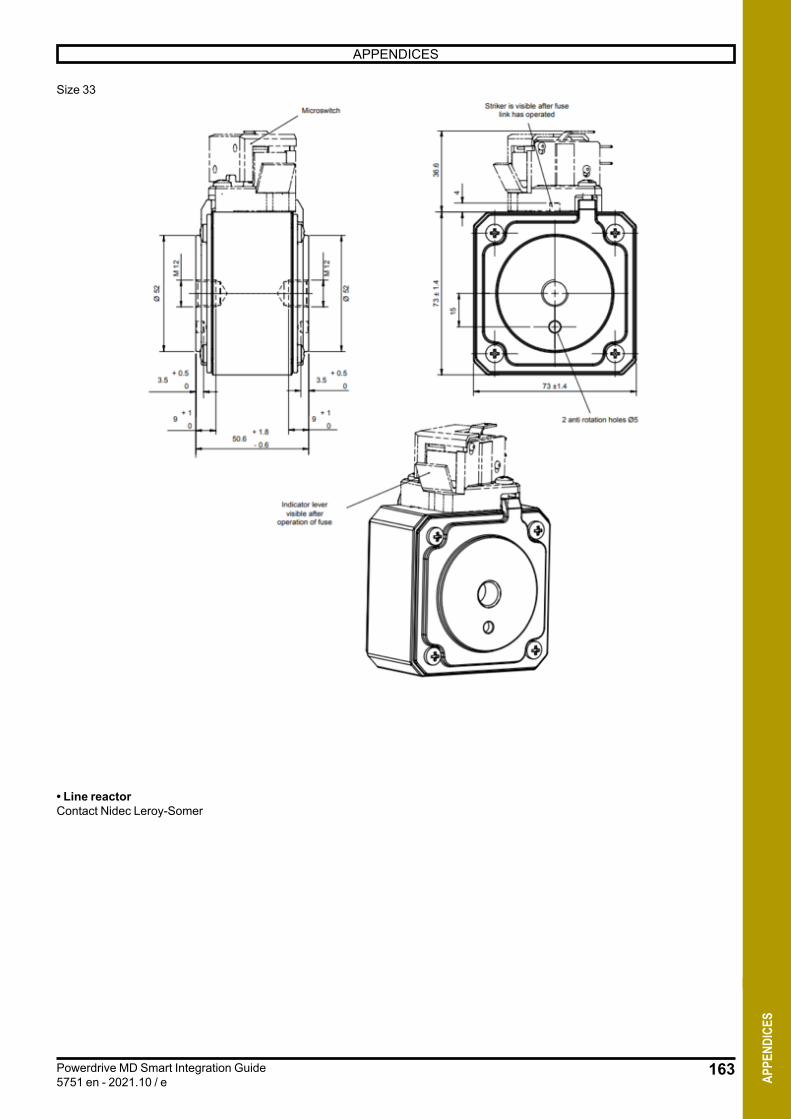
163
APPENDICES
Powerdrive MD Smart Integration Guide5751 en - 2021.10 / e AP
PEND
ICES
Size 33
• Line reactorContact Nidec Leroy-Somer
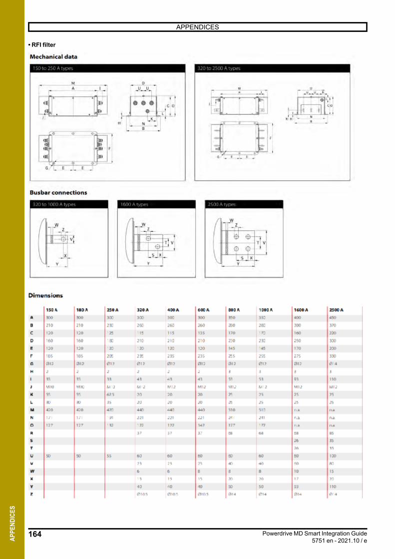
164
APPENDICES
Powerdrive MD Smart Integration Guide5751 en - 2021.10 / eAP
PEND
ICES
• RFI filter
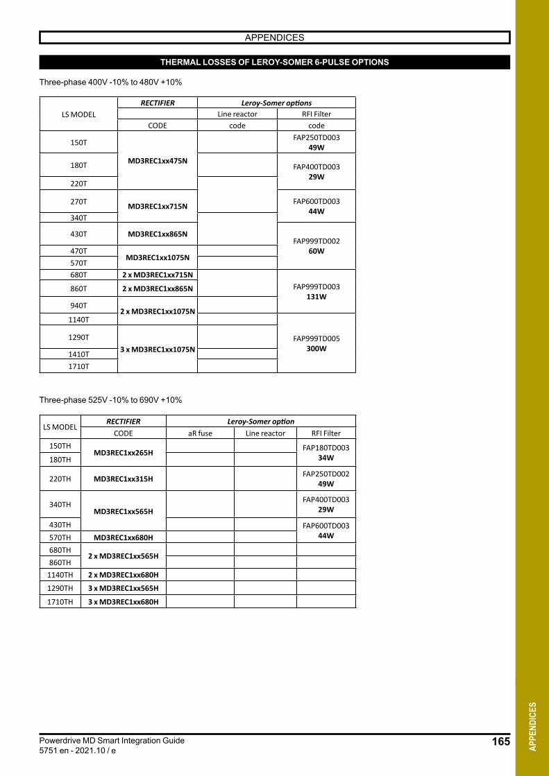
165
APPENDICES
Powerdrive MD Smart Integration Guide5751 en - 2021.10 / e AP
PEND
ICES
THERMAL LOSSES OF LEROY-SOMER 6-PULSE OPTIONS
Three-phase 400V -10% to 480V +10%
LS MODELRECTIFIER Leroy-Somer options
Line reactor RFI FilterCODE code code
150T
MD3REC1xx475N
FAP250TD003 49W
180T FAP400TD003 29W
220T
270T MD3REC1xx715N FAP600TD003 44W
340T
430T MD3REC1xx865NFAP999TD002
60W470TMD3REC1xx1075N
570T680T 2 x MD3REC1xx715N
FAP999TD003 131W
860T 2 x MD3REC1xx865N
940T2 x MD3REC1xx1075N
1140T
FAP999TD005 300W
1290T3 x MD3REC1xx1075N1410T
1710T
Three-phase 525V -10% to 690V +10%
LS MODELRECTIFIER Leroy-Somer option
CODE aR fuse Line reactor RFI Filter150TH
MD3REC1xx265H FAP180TD003 34W180TH
220TH MD3REC1xx315H FAP250TD002 49W
340THMD3REC1xx565H
FAP400TD003 29W
430TH FAP600TD003 44W570TH MD3REC1xx680H
680TH2 x MD3REC1xx565H
860TH1140TH 2 x MD3REC1xx680H
1290TH 3 x MD3REC1xx565H
1710TH 3 x MD3REC1xx680H
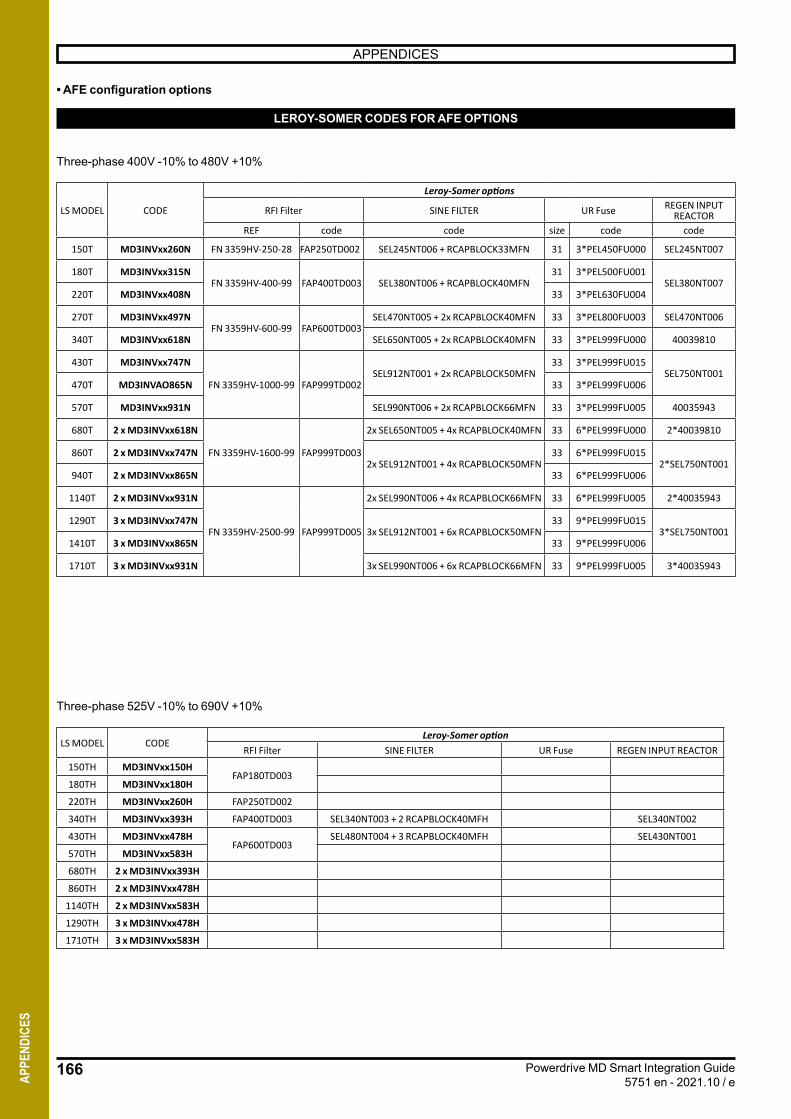
166
APPENDICES
Powerdrive MD Smart Integration Guide5751 en - 2021.10 / eAP
PEND
ICES
• AFE configuration options
LEROY-SOMER CODES FOR AFE OPTIONS
Three-phase 400V -10% to 480V +10%
LS MODEL CODE
Leroy-Somer options
RFI Filter SINE FILTER UR Fuse REGEN INPUT REACTOR
REF code code size code code
150T MD3INVxx260N FN 3359HV-250-28 FAP250TD002 SEL245NT006 + RCAPBLOCK33MFN 31 3*PEL450FU000 SEL245NT007
180T MD3INVxx315NFN 3359HV-400-99 FAP400TD003 SEL380NT006 + RCAPBLOCK40MFN
31 3*PEL500FU001SEL380NT007
220T MD3INVxx408N 33 3*PEL630FU004
270T MD3INVxx497NFN 3359HV-600-99 FAP600TD003
SEL470NT005 + 2x RCAPBLOCK40MFN 33 3*PEL800FU003 SEL470NT006
340T MD3INVxx618N SEL650NT005 + 2x RCAPBLOCK40MFN 33 3*PEL999FU000 40039810
430T MD3INVxx747N
FN 3359HV-1000-99 FAP999TD002SEL912NT001 + 2x RCAPBLOCK50MFN
33 3*PEL999FU015SEL750NT001
470T MD3INVAO865N 33 3*PEL999FU006
570T MD3INVxx931N SEL990NT006 + 2x RCAPBLOCK66MFN 33 3*PEL999FU005 40035943
680T 2 x MD3INVxx618N
FN 3359HV-1600-99 FAP999TD003
2x SEL650NT005 + 4x RCAPBLOCK40MFN 33 6*PEL999FU000 2*40039810
860T 2 x MD3INVxx747N2x SEL912NT001 + 4x RCAPBLOCK50MFN
33 6*PEL999FU0152*SEL750NT001
940T 2 x MD3INVxx865N 33 6*PEL999FU006
1140T 2 x MD3INVxx931N
FN 3359HV-2500-99 FAP999TD005
2x SEL990NT006 + 4x RCAPBLOCK66MFN 33 6*PEL999FU005 2*40035943
1290T 3 x MD3INVxx747N3x SEL912NT001 + 6x RCAPBLOCK50MFN
33 9*PEL999FU0153*SEL750NT001
1410T 3 x MD3INVxx865N 33 9*PEL999FU006
1710T 3 x MD3INVxx931N 3x SEL990NT006 + 6x RCAPBLOCK66MFN 33 9*PEL999FU005 3*40035943
Three-phase 525V -10% to 690V +10%
LS MODEL CODELeroy-Somer option
RFI Filter SINE FILTER UR Fuse REGEN INPUT REACTOR150TH MD3INVxx150H
FAP180TD003180TH MD3INVxx180H
220TH MD3INVxx260H FAP250TD002
340TH MD3INVxx393H FAP400TD003 SEL340NT003 + 2 RCAPBLOCK40MFH SEL340NT002
430TH MD3INVxx478HFAP600TD003
SEL480NT004 + 3 RCAPBLOCK40MFH SEL430NT001
570TH MD3INVxx583H
680TH 2 x MD3INVxx393H
860TH 2 x MD3INVxx478H
1140TH 2 x MD3INVxx583H
1290TH 3 x MD3INVxx478H
1710TH 3 x MD3INVxx583H
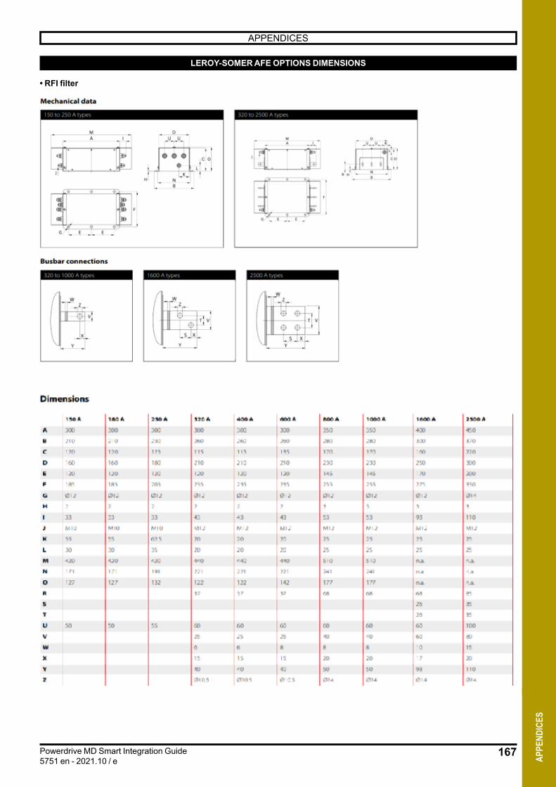
167
APPENDICES
Powerdrive MD Smart Integration Guide5751 en - 2021.10 / e AP
PEND
ICES
LEROY-SOMER AFE OPTIONS DIMENSIONS
• RFI filter

168
APPENDICES
Powerdrive MD Smart Integration Guide5751 en - 2021.10 / eAP
PEND
ICES
•• Sine reactor
SEL145NT006
SEL180NT0006
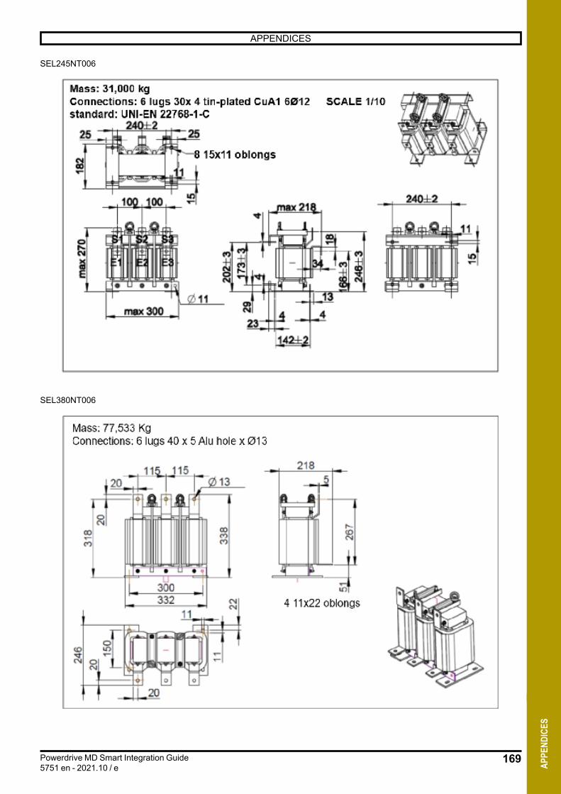
169
APPENDICES
Powerdrive MD Smart Integration Guide5751 en - 2021.10 / e AP
PEND
ICES
SEL245NT006
SEL380NT006
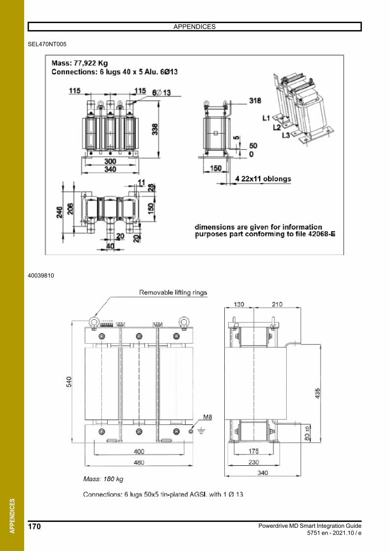
170
APPENDICES
Powerdrive MD Smart Integration Guide5751 en - 2021.10 / eAP
PEND
ICES
SEL470NT005
40039810

171
APPENDICES
Powerdrive MD Smart Integration Guide5751 en - 2021.10 / e AP
PEND
ICES
SEL800NT002
SEL912NT001
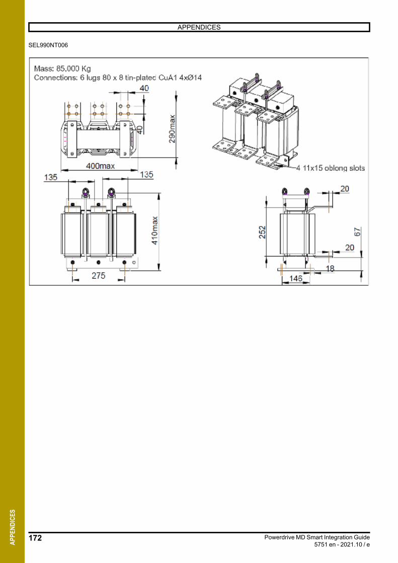
172
APPENDICES
Powerdrive MD Smart Integration Guide5751 en - 2021.10 / eAP
PEND
ICES
SEL990NT006
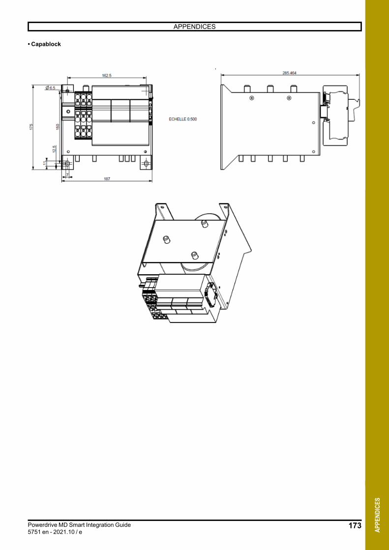
173
APPENDICES
Powerdrive MD Smart Integration Guide5751 en - 2021.10 / e AP
PEND
ICES
• Capablock
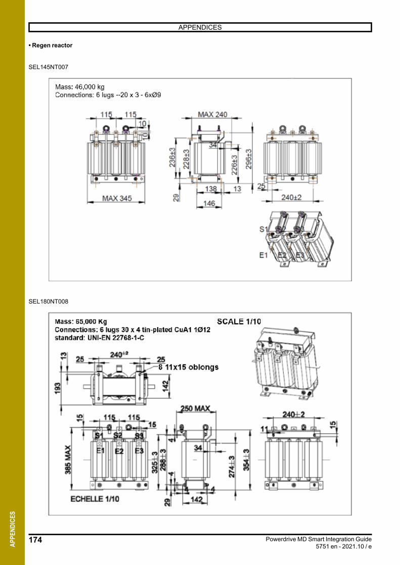
174
APPENDICES
Powerdrive MD Smart Integration Guide5751 en - 2021.10 / eAP
PEND
ICES
• Regen reactor
SEL145NT007
SEL180NT008

175
APPENDICES
Powerdrive MD Smart Integration Guide5751 en - 2021.10 / e AP
PEND
ICES
SEL245NT007
SEL380NT007
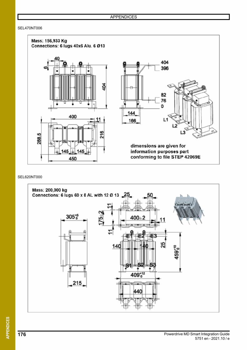
176
APPENDICES
Powerdrive MD Smart Integration Guide5751 en - 2021.10 / eAP
PEND
ICES
SEL470NT006
SEL620NT000
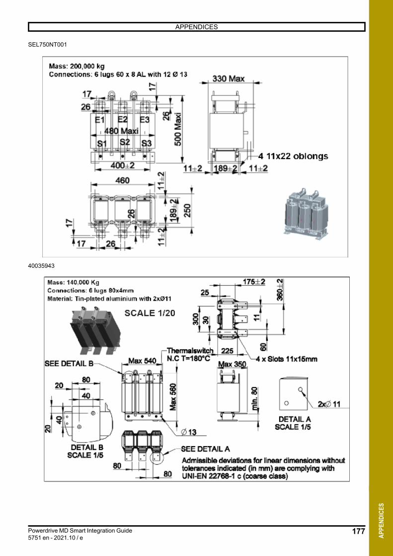
177
APPENDICES
Powerdrive MD Smart Integration Guide5751 en - 2021.10 / e AP
PEND
ICES
40035943
SEL750NT001

178
APPENDICES
Powerdrive MD Smart Integration Guide5751 en - 2021.10 / eAP
PEND
ICES
• AR fuse
Size 30

179
APPENDICES
Powerdrive MD Smart Integration Guide5751 en - 2021.10 / e AP
PEND
ICES
Size 31
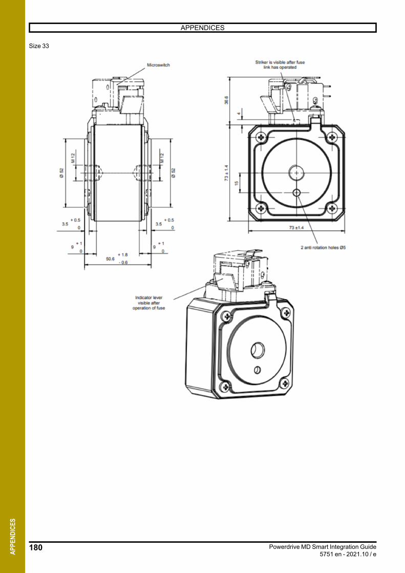
180
APPENDICES
Powerdrive MD Smart Integration Guide5751 en - 2021.10 / eAP
PEND
ICES
Size 33

181
APPENDICES
Powerdrive MD Smart Integration Guide5751 en - 2021.10 / e AP
PEND
ICES
THERMAL LOSSES OF LEROY-SOMER AFE OPTIONS
Three-phase 400V -10% to 480V +10%
LS MODEL CODELeroy-Somer options
RFI Filter SINE FILTER REGEN INPUT REACTORcode code code
150T MD3INVxx260N FAP250TD002 49W
SEL245NT006 + RCAPBLOCK33MFN 300W SEL245NT007
180T MD3INVxx315N FAP400TD003 29W
SEL380NT006 + RCAPBLOCK40MFN 455W
SEL380NT007 897W220T MD3INVxx408N
270T MD3INVxx497NFAP600TD003
44W
SEL470NT005 + 2x RCAPBLOCK40MFN 611W
SEL470NT006 1125W
340T MD3INVxx618N SEL650NT005 + 2x RCAPBLOCK40MFN 716W
40039810 1413W
430T MD3INVxx747N
FAP999TD002 60W
SEL912NT001 + 2x RCAPBLOCK50MFN 1023W
SEL750NT001 2018W470T MD3INVAO865N
570T MD3INVxx931N SEL990NT006 + 2x RCAPBLOCK66MFN 1136W
40035943 2243W
680T 2 x MD3INVxx618N 2x SEL650NT005 + 4x RCAPBLOCK40MFN 1432W
2*40039810 2826W
860T 2 x MD3INVxx747N FAP999TD003 131W
2x SEL912NT001 + 4x RCAPBLOCK50MFN 2046W
2*SEL750NT001 4036W940T 2 x MD3INVxx865N
1140T 2 x MD3INVxx931N
FAP999TD005 300W
2x SEL990NT006 + 4x RCAPBLOCK66MFN 2272W
2*40035943 4486W
1290T 3 x MD3INVxx747N 3x SEL912NT001 + 6x RCAPBLOCK50MFN 3069W
3*SEL750NT001 6054W1410T 3 x MD3INVxx865N
1710T 3 x MD3INVxx931N 3x SEL990NT006 + 6x RCAPBLOCK66MFN 3408W
3*40035943 6729W
Three-phase 525V -10% to 690V +10%
LS MODEL CODELeroy-Somer option
RFI Filter SINE FILTER REGEN INPUT REACTOR
150TH MD3INVxx150H FAP180TD003 34W180TH MD3INVxx180H
220TH MD3INVxx260H FAP250TD002 49W
340TH MD3INVxx393H FAP400TD003 29W SEL340NT003 + 2 RCAPBLOCK40MFH SEL340NT002
430TH MD3INVxx478H FAP600TD003 44W
SEL480NT004 + 3 RCAPBLOCK40MFH SEL430NT001
570TH MD3INVxx583H
680TH 2 x MD3INVxx393H
860TH 2 x MD3INVxx478H
1140TH 2 x MD3INVxx583H
1290TH 3 x MD3INVxx478H
1710TH 3 x MD3INVxx583H


Moteurs Leroy-SomerHeadquarter: Boulevard Marcellin Leroy - CS 10015
16915 ANGOULÊME Cedex 9
Limited company with capital of €38,679,664RCS Angoulême 338 567 258
www.leroy-somer.com