sony kdl 40r470b chassis itc3-me repair manual
TRANSCRIPT

HISTORY INFORMATION FOR THE FOLLOWING MANUAL:
SERVICE MANUAL (COMMON)
ITC3 CHASSIS
Version Date Subject1 01/2014 1st Issue.
Segment: ME
0 / 0 ssue
LCD TV
9-888-148-01For SM - Unique , please refer :
9-888-148-A1 ( America )9-888-148-C1 ( China)
9-888-148-E1 ( Europe )9-888-148-P1 ( Pan Asia )
SERVICE MANUAL (COMMON)
ITC3 CHASSISSegment: ME
LCD TV
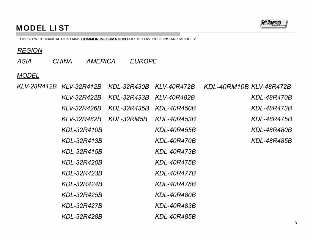
MODEL LISTTHIS SERVICE MANUAL CONTAINS COMMON INFORMATION FOR BELOW REGIONS AND MODELSTHIS SERVICE MANUAL CONTAINS COMMON INFORMATION FOR BELOW REGIONS AND MODELS:
REGION
ASIA CHINA AMERICA EUROPE
MODEL
KLV-28R412B KLV-32R412B KDL-32R430B KLV-40R472B KDL-40RM10B KLV-48R472B
KLV-32R422B KDL-32R433B KLV-40R482B KDL-48R470B
KLV-32R426B KDL-32R435B KDL-40R450B KDL-48R473B
KLV-32R482B KDL-32RM5B KDL-40R453B KDL-48R475BKLV 32R482B KDL 32RM5B KDL 40R453B KDL 48R475B
KDL-32R410B KDL-40R455B KDL-48R480B
KDL-32R413B KDL-40R470B KDL-48R485B
KDL-32R415B KDL-40R473B
KDL-32R420B KDL-40R475B
KDL-32R423B KDL-40R477B
KDL-32R424B KDL-40R478B
KDL-32R425B KDL-40R480B
KDL 32R42 B KDL 40R483B
3
KDL-32R427B KDL-40R483B
KDL-32R428B KDL-40R485B

TABLE OF CONTENTS
Section Title Page
1. SAFETY NOTES 1-1. Warnings and Caution………………………………………………………. 51-2. Caution Handling of LCD Panel ......…………….................................... 51-3. Caution About the Lithium Battery……………......................................... 6
Section Title Page
4. SERVICE ADJUSTMENTS 4-1. Accessing Service Mode ..................................................................... 554-2. Accessing Software Version....................……….……………………… 554-3. Accessing Self Diagnostic History………………………………..…….. 564 4 A i S lf Di ti M 56
y1-4. Safety Check Out ........................……………......................................... 61-5. Leakage Test .......................................................................................... 61-6. How to Find a Good Earth Ground………………………………………… 61-7. Lead Free Information….…………………………………………………… 71-8. Handling the Flexible Flat Cable (FFC)……………………………………. 7
4-4. Accessing Self Diagnostic Menu………………………………………... 564-5. Accessing Serial Number Edit……………….………………………….. 574-6. Accessing Model Name Edit................................................................ 58
5. DIAGRAMS 5-1. Circuit Board Location ......................................................................... 605 2 Bl k Di 62
2. SELF DIAGNOSTIC FUNCTION 2-1. Overview of Control Buttons ................................................................... 82-2. LED Display Control ………..................................................................... 82-3. LED Pattern………………........................................................................ 82 4 Standby LED Error Display 8
5-2. Block Diagram...................................................................................... 625-3. Connector Diagram ………………………………………...................... 70
2-4. Standby LED Error Display…………………………………………………. 82-5. Triage Chart ............................................................................................ 9
3. TROUBLE SHOOTING 3-1. General..................................................................................................... 103-2. No Power…….……………………………………………………………….. 103-3. Standby LED Blinking....…………............................................................ 133-4. No Picture................................................................................................. 213-5. Audio.............................…………………………………………................. 233-6. Video Problem.......................................................................................... 313-7. HDMI……………..……...……………………………………………………. 383-8. MHL…………………………………………………………………………. 393-9. Tuner…………………………………..……………………………………… 423-10. Ethernet………………………………………………………………………. 593-11. IR………………………………………………………………………………. 503-12. Switch Unit Buttons…………….……………………………………………. 513-13. Wifi…………………………………………………………………………….. 52
Please refer Service Manual – Unique for below information :
-Safety Warnings
-Wire Dressing
4
-Circuit Board Location
-Disassembly and Exploded View.
ITC3 CHASSISR410/412/413/420/422/423/424/425/426/427/428/430/433/435/450/453/455/470/472/473/475/477/478/480/483/485/M5/M10B
SAFETY NOTESSECTION 1
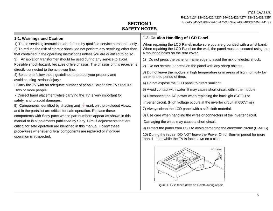
1-2. Caution Handling of LCD PanelWhen repairing the LCD Panel, make sure you are grounded with a wrist band.When repairing the LCD Panel on the wall, the panel must be secured using the 4 mounting holes on the rear cover.
1-1. Warnings and Caution1) These servicing instructions are for use by qualified service personnel only.2) To reduce the risk of electric shock, do not perform any servicing other thanthat contained in the operating instructions unless you are qualified to do so.
1) Do not press the panel or frame edge to avoid the risk of electric shock.
2) Do not scratch or press on the panel with any sharp objects.
3) Do not leave the module in high temperature or in areas of high humidity for an extended period of time.
3) An isolation transformer should be used during any service to avoidPossible shock hazard, because of live chassis. The chassis of this receiver isdirectly connected to the ac power line.4) Be sure to follow these guidelines to protect your property andavoid causing serious injury :
4) Do not expose the LCD panel to direct sunlight.
5) Avoid contact with water. It may cause short circuit within the module.
6) Disconnect the AC power when replacing the backlight (CCFL) or
inverter circuit. (High voltage occurs at the inverter circuit at 650Vrms)
g j y• Carry the TV with an adequate number of people; larger size TVs requiretwo or more people.• Correct hand placement while carrying the TV is very important forsafety and to avoid damages.5) Components identified by shading and mark on the exploded views!
7) Always clean the LCD panel with a soft cloth material.
8) Use care when handling the wires or connectors of the inverter circuit.
Damaging the wires may cause a short circuit.
9) Protect the panel from ESD to avoid damaging the electronic circuit (C-MOS).
5) Components identified by shading and mark on the exploded views,and in the parts list are critical for safe operation. Replace thesecomponents with Sony parts whose part numbers appear as shown in thismanual or in supplements published by Sony. Circuit adjustments that arecritical for safe operation are identified in this manual. Follow these
!
) p g g ( )
10) During the repair, DO NOT leave the Power On or Burn-in period for more than 1 hour while the TV is face down on a cloth.
procedures whenever critical components are replaced or improperoperation is suspected.
5
Figure 1. TV is faced down on a cloth during repair.

ITC3 CHASSISR410/412/413/420/422/423/424/425/426/427/428/430/433/435/450/453/455/470/472/473/475/477/478/480/483/485/M5/M10B
Safety Notes
1 3 C ti Ab t th Lithi B tt3) Measuring the voltage drop across a resistor by means of a VOM or battery operated AC voltmeter. The 'limit' indication is 0.75V so analog meters must have an accurate low voltage scale. The SIMPSON'S 250 and SANWA SH-63TRD are examples of passive VOMs that are suitable. Nearly all battery operated digital multimeter that have a 2 VAC range are suitable. 1-4. Safety Check-Out
1-3. Caution About the Lithium Battery1) Danger of explosion if battery is incorrectly replaced. Replace only with the same or equivalent type.2) Outer case broken battery should not contact to water.
(see Figure 2.)After correcting the original service problem, perform the followingsafety checks before releasing the set to the customer:-1) Check the area of your repair for unsoldered or poorly solderedconnections. Check the entire board surface for solder splashes and bridges.2) Check the inter board wiring to ensure that no wires are pinched or) g pcontact high-wattage resistors.3)Check all control knobs, shields, covers, ground straps and mountinghardware have been replaced. Be absolutely certain you have replaced allthe insulators.4) Look for unauthorized replacement parts, particularly transistors that
i t ll d d i i i P i t th t t th t dFigure 2. AC voltmeter to check AC leakage
1 6 H t Fi d G d E th G dwere installed during a previous repair. Point them out to the customer andrecommend their replacement.5) Look for parts which, though functioning show obvious signs ofdeterioration. Point them out to the customer and recommend theirreplacement.6) Check the line cords for cracks and abrasion. Recommend the
1-6. How to Find a Good Earth Ground1) A cold-water pipe is a guaranteed earth ground; the cover-plate retaining screw on most AC outlet boxes is also at earth ground.2) If the retaining screw is to be used as your earth ground, verify that it is at ground by measuring the resistance between it and a cold-water pipe with an ohmmeter The reading should be zero ohms)
replacement of any such line cord to the customer.7) Check the antenna terminals, metal trim, metalized knobs, screws and allother exposed metal parts for AC leakage. Check leakage test as describednext.8. For safety reasons, repairing the Power board and/or Inverter board isprohibited
ohmmeter. The reading should be zero ohms.3) If a cold-water pipe is not accessible, connect a 60- to 100-watt trouble-light (not a neon lamp) between the hot side of the receptacle and the retaining screw. Try both slots, if necessary, to locate the hot side on the line; the lamp should light at normal brilliance if the screw is at ground potential (see Figure 3).
prohibited.1-5.Leakage TestThe AC leakage from any exposed metal part to earth ground and from all exposed metal parts to any exposed metal part having a return to chassis must not exceed 0.5mA (500 microamperes).Leakage current can be measured by any one of the three methods:-
Figure 3. Checking for earth ground.
6
g y y1) A commercial leakage tester such as the SIMPSON 229 or RCA WT540A.Follow the manufacturers instructions to use those instructions.2) A battery-operated AC milliampmeter The DATA PRECISION 245 digital multimeter is suitable for this job.
ITC3 CHASSISR410/412/413/420/422/423/424/425/426/427/428/430/433/435/450/453/455/470/472/473/475/477/478/480/483/485/M5/M10B
Safety Notes
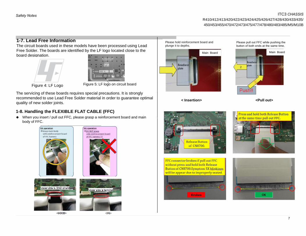
1-7. Lead Free InformationThe circuit boards used in these models have been processed using Lead Free Solder. The boards are identified by the LF logo located close to the board designation.
Main Board Main Board
Please hold reinforcement board and plunge it to depths.
Please pull out FFC while pushing the button of both ends at the same time.
Figure 4: LF Logo Figure 5: LF logo on circuit board
The servicing of these boards requires special precautions. It is strongly recommended to use Lead Free Solder material in order to guarantee optimal quality of new solder joints.
1-8. Handling the FLEXIBLE FLAT CABLE (FFC) When you insert / pull out FFC please grasp a reinforcement board and main
< Insertion> <Pull out>
When you insert / pull out FFC, please grasp a reinforcement board and main body of FFC.
7
ITC3 CHASSISR410/412/413/420/422/423/424/425/426/427/428/430/433/435/450/453/455/470/472/473/475/477/478/480/483/485/M5/M10BSECTION 2
SELF DIAGNOSTIC FUNCTION
Self Diagnostic Function
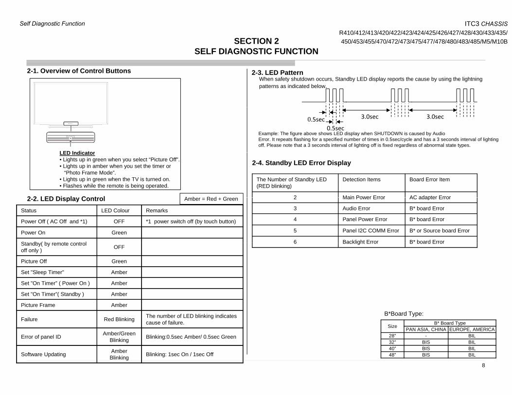
2-1. Overview of Control ButtonsWhen safety shutdown occurs, Standby LED display reports the cause by using the lightningpatterns as indicated below.
2-3. LED Pattern
3.0sec 3.0sec
0.5sec0.5sec
Example: The figure above shows LED display when SHUTDOWN is caused by Audio Error. It repeats flashing for a specified number of times in 0.5sec/cycle and has a 3 seconds interval of lighting off. Please note that a 3 seconds interval of lighting off is fixed regardless of abnormal state types.
LED Indicator
2 2 LED Display Control
LED Indicator• Lights up in green when you select “Picture Off”.• Lights up in amber when you set the timer or
“Photo Frame Mode”.• Lights up in green when the TV is turned on. • Flashes while the remote is being operated.
A b R d + G
2-4. Standby LED Error Display
The Number of Standby LED (RED blinking)
Detection Items Board Error Item
2 Main Power Error AC adapter Error
Status LED Colour Remarks
Power Off ( AC Off and *1) OFF *1 power switch off (by touch button)
Power On Green
Standby( by remote control
2-2. LED Display Control Amber = Red + Green 2 Main Power Error AC adapter Error
3 Audio Error B* board Error
4 Panel Power Error B* board Error
5 Panel I2C COMM Error B* or Source board Error
6 Backlight Error B* board ErrorStandby( by remote control off only ) OFF
Picture Off Green
Set "Sleep Timer" Amber
Set "On Timer” ( Power On ) Amber
6 Backlight Error B board Error
Set "On Timer”( Standby ) Amber
Picture Frame Amber
Failure Red Blinking The number of LED blinking indicates cause of failure.
Amber/GreenSize B* Board Type
PAN ASIA, CHINA EUROPE, AMERICA
B*Board Type:
Error of panel ID Amber/Green Blinking Blinking:0.5sec Amber/ 0.5sec Green
Software Updating AmberBlinking Blinking: 1sec On / 1sec Off
6
8
28” - BIL32” BIS BIL40” BIS BIL48” BIS BIL
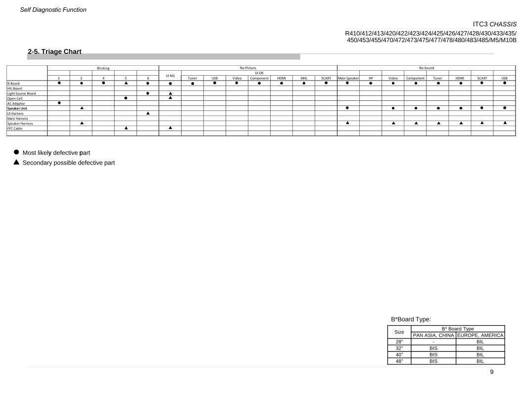
2-5. Triage Chart
2 3 4 5 6 Tuner USB Video Component HDMI MHL SCART Main Speaker HP Video Component Tuner HDMI SCART USBB‐BoardHIL BoardLight Source BoardOpen CellAC AdaptorSpeaker Unit
Blinking No SoundNo PictureUI OK
UI NG
Most likely defective part
Speaker UnitLS HarnessMain HarnessSpeaker HarnessFFC Cable
Secondary possible defective party p
Size B* Board TypePAN ASIA, CHINA EUROPE, AMERICA
B*Board Type:
9
28” - BIL32” BIS BIL40” BIS BIL48” BIS BIL
ITC3 CHASSISR410/412/413/420/422/423/424/425/426/427/428/430/433/435/450/453/455/470/472/473/475/477/478/480/483/485/M5/M10B
Self Diagnostic Function

ITC3 CHASSISR410/412/413/420/422/423/424/425/426/427/428/430/433/435/450/453/455/470/472/473/475/477/478/480/483/485/M5/M10BSECTION 3
TROUBLESHOOTING3 1 General 3 2 No Power3-1. General
STARTSTART
3-2. No Power
No PowerNo Power
Does the Power Led
stay on when the
TV is switched on ?
Does the Power Led
stay on when the
TV is switched on ?
Open Detail
- No PowerB-Board
Check DC voltage at
JL6001
B-Board
Check DC voltage at
JL6001
Yes •See DDCON
Sheet
No
Is the Standby Led
blink ?
Is the Standby Led
blink ?
Open Detail
- Standby LED Blink
JL6001
19V - 19.5V?
JL6001
19V - 19.5V?
No
Adaptor
T k t d t
Adaptor
T k t d t
Green & Amber Green & Amber - Panel ID Error
Take out adaptor
and check the output voltage.
19V – 19.5V?
(Refer Figure 1)
Take out adaptor
and check the output voltage.
19V – 19.5V?
(Refer Figure 1)
B-boardYes
Noblink?blink? - Panel Not Supported
No
AdaptorYes
Adaptor
Change adaptor
and recheck the output voltage.
19V – 19.5V?
Adaptor
Change adaptor
and recheck the output voltage.
19V – 19.5V?Is the Picture and
Sound OK ?
Is the Picture and
Sound OK ?
Open Detail
- Picture/Audio/Video
AC source
No
(Refer Figure 1)(Refer Figure 1)
Size B* Board TypePAN ASIA, CHINA EUROPE, AMERICA
B*Board Type:
10
ENDEND28” - BIL32” BIS BIL40” BIS BIL48” BIS BIL

ITC3 CHASSISR410/412/413/420/422/423/424/425/426/427/428/430/433/435/450/453/455/470/472/473/475/477/478/480/483/485/M5/M10B
3 2 No Po er
StartStart DDCON
3-2. No Power3-2-1. DD Con
Size B* Board TypePAN ASIA, CHINA EUROPE, AMERICA
28” - BIL32” BIS BIL40” BIS BIL
B*Board Type:
OK
B-Board
Check fuse.
F6001 & F6002
B-Board
Check fuse.
F6001 & F6002
NoNoFuse
B-Board
Check voltage at JL6003
3.3V?
B-Board
Check voltage at JL6003
3.3V?
40 BIS BIL48” BIS BIL
Yes
NoChange B-board
DDCON
B-Board
Check voltage at JL6000
1.2V?
B-Board
Check voltage at JL6000
1.2V?
B-Board
Check voltage at :
B-Board
Check voltage at : B-BoardB-BoardNo
Yes OK
NoB-Board
Check voltage at JL6002
B-Board
Check voltage at JL6002BIS JL6012.
BIL JL6007.
12V?
BIS JL6012.
BIL JL6007.
12V?
Check Fuse.
F6003
Check Fuse.
F6003
Yes No
Change B-boardCheck voltage at JL6002
1.5V?
Check voltage at JL6002
1.5V?
NoChange B-board
FuseB-Board
Check voltage at JL6005
5V?
B-Board
Check voltage at JL6005
5V?
Yes After checking, take note of
NG condition & change B board
11
Troubleshooting

ITC3 CHASSISR410/412/413/420/422/423/424/425/426/427/428/430/433/435/450/453/455/470/472/473/475/477/478/480/483/485/M5/M10B
JL6001
BIL BOARD Size B* Board TypePAN ASIA, CHINA EUROPE, AMERICA
28” - BIL32” BIS BIL40” BIS BIL
B*Board Type:
JL6003
JL6002
JL60
F6002
F6001
40 BIS BIL48” BIS BIL
JL6000JL
6005
06
JL6007
F6003
BIS BOARD
JL6001JL
6003
F6002 F
6001
JL6000
JL6002
0
JL6005
JL6006
JL
F6003
12
JL6012
Troubleshooting

ITC3 CHASSISR410/412/413/420/422/423/424/425/426/427/428/430/433/435/450/453/455/470/472/473/475/477/478/480/483/485/M5/M10B
3 3 Standb LED Blinking3-3. Standby LED Blinking3-3-1. 2 times blinking
2 times Blinking
B-Board
Check DC voltage at
JL6001
19V - 19.5V?
B-Board
Check DC voltage at
JL6001
19V - 19.5V?
Yes
Change B-board+ve
-ve
No
Yes
Adaptor
Take out adaptor
Adaptor
Take out adaptor
Ensure that +ve probe is touching the
needle.
Change B-board
No
YesTake out adaptor
and check the output voltage.
19V – 19.5V?
(Refer Figure 2)
Take out adaptor
and check the output voltage.
19V – 19.5V?
(Refer Figure 2)
Change adaptor
Figure 1: How to check adaptor’s output voltage.
Size B* Board TypePAN ASIA, CHINA EUROPE, AMERICA
B*Board Type:
13
28” - BIL32” BIS BIL40” BIS BIL48” BIS BIL
Troubleshooting

ITC3 CHASSISR410/412/413/420/422/423/424/425/426/427/428/430/433/435/450/453/455/470/472/473/475/477/478/480/483/485/M5/M10B
3 3 Standb LED Blinking
Remove N 3 bli kiSpeaker impedance
START
3x blinking
3-3. Standby LED Blinking3-3-2. 3 times blinking
Remove
Speaker Connector
at CN4500 & perform
AC OFF - ON
No 3x blinking
3x blinking
Check Speaker harness
and Speaker impedance
≠ 6~8 Ω
No connectivity
for speaker harness
Change Speaker
Change Speaker Harness
Connect back
F4500 brokenCheck connectivity
of F4500.
No connectivity
of F4000
Connect back
Speaker Connector to CN4500
& perform AC OFF - ON
3x blinking
No 3x blinking
3x blinking
& F4000 OK
Audio IC problem,
IC4500 damage
Change B board
Size B* Board TypePAN ASIA, CHINA EUROPE, AMERICA
B*Board Type:
DONE
14
28” - BIL32” BIS BIL40” BIS BIL48” BIS BIL
Troubleshooting

ITC3 CHASSISR410/412/413/420/422/423/424/425/426/427/428/430/433/435/450/453/455/470/472/473/475/477/478/480/483/485/M5/M10B
BIL_BoardSize B* Board Type
PAN ASIA, CHINA EUROPE, AMERICA28” - BIL32” BIS BIL40” BIS BIL
B*Board Type:
IC4500
40 BIS BIL48” BIS BIL
F4500
CN4500CN4500
BIS_Board
IC4500
F4500
15
CN4500
Troubleshooting
ITC3 CHASSISR410/412/413/420/422/423/424/425/426/427/428/430/433/435/450/453/455/470/472/473/475/477/478/480/483/485/M5/M10B
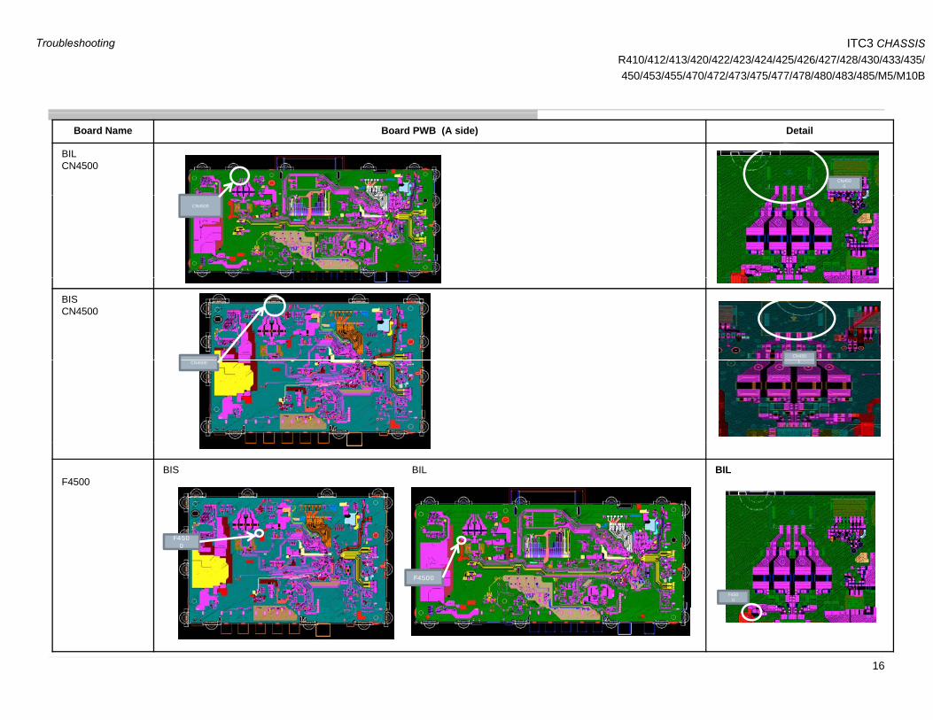
Board Name Board PWB (A side) Detail
BILCN4500
CN4500
CN4500
BISCN4500
CN4500CN4500 0
F4500BIS BIL BIL
F4500
F4500
F4500
16
Troubleshooting
ITC3 CHASSISR410/412/413/420/422/423/424/425/426/427/428/430/433/435/450/453/455/470/472/473/475/477/478/480/483/485/M5/M10B
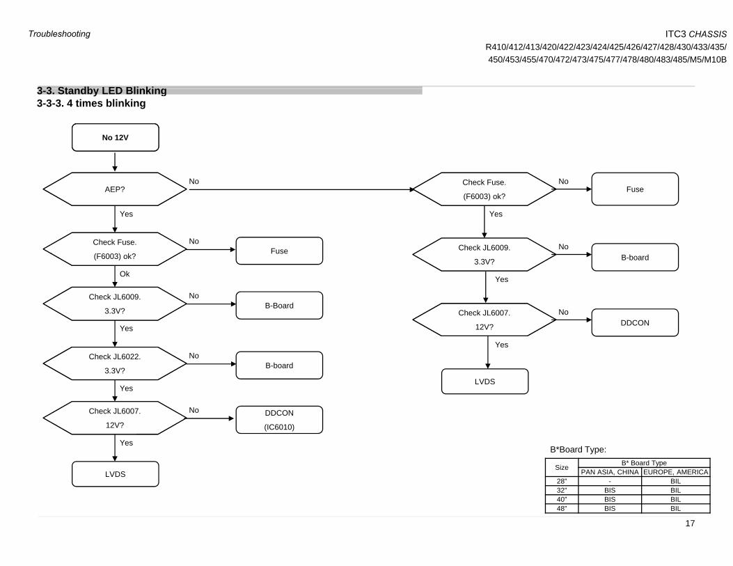
3 3 Standb LED Blinking
No 12V
3-3. Standby LED Blinking3-3-3. 4 times blinking
Yes
NoAEP?
Yes
NoFuse
Check Fuse.
(F6003) ok?
Ok
FuseNoCheck Fuse.
(F6003) ok? B-boardNo
Yes
Check JL6009.
3.3V?
Yes
B-BoardNoCheck JL6009.
3.3V?DDCON
No
Yes
Check JL6007.
12V?
NoCheck JL6022.
3.3V?B-board
No
Yes
DDCONCheck JL6007
LVDS
LVDS
DDCON
(IC6010)
Yes
Check JL6007.
12V?
Size B* Board TypePAN ASIA, CHINA EUROPE, AMERICA
B*Board Type:
17
28” - BIL32” BIS BIL40” BIS BIL48” BIS BIL
Troubleshooting

ITC3 CHASSISR410/412/413/420/422/423/424/425/426/427/428/430/433/435/450/453/455/470/472/473/475/477/478/480/483/485/M5/M10B
BILSize B* Board Type
PAN ASIA, CHINA EUROPE, AMERICA28” - BIL32” BIS BIL40” BIS BIL
B*Board Type:
F6003
48” BIS BIL
JL6007
LVDS FFC CONNECTOR
3
JL6009
BIS
LVDS FFC CONNECTO
R
F6003
18
JL6012
JL6009
Troubleshooting

ITC3 CHASSISR410/412/413/420/422/423/424/425/426/427/428/430/433/435/450/453/455/470/472/473/475/477/478/480/483/485/M5/M10B
3 3 Standb LED Blinking3-3. Standby LED Blinking3-3-4. 5 times blinking
STARTSTART
Remove and reinsert LVDS Flat
Flexible Cable (FFC) at B-Board and
Panel Side
Remove and reinsert LVDS Flat
Flexible Cable (FFC) at B-Board and
Panel Side
Replace B-BoardReplace B-Board B-Board IssueIncorrect FFC
Insertion
TV Boots Up
Normally
TV Boots Up
Normally
ReplaceReplace
5x Blinking is Still Observed
TV Boots Up TV Boots Up
5x Blinking is Still Observed
Replace LVDS Flat Flexible
Cable (FFC)
Replace LVDS Flat Flexible
Cable (FFC)
LVDS
Cable Issue
Replace
*O-Cell or *Panel Module
Replace
*O-Cell or *Panel ModuleO-Cell IssueNormally Normally
* O-Cell or Panel Module replacement depends on service capabilities p
5x Blinking is Still Observed
ENDEND
Size B* Board TypePAN ASIA, CHINA EUROPE, AMERICA
B*Board Type:
19
28” - BIL32” BIS BIL40” BIS BIL48” BIS BIL
Troubleshooting

ITC3 CHASSISR410/412/413/420/422/423/424/425/426/427/428/430/433/435/450/453/455/470/472/473/475/477/478/480/483/485/M5/M10B
3 3 Standb LED Blinking
6x blinking6x blinking
3-3. Standby LED Blinking3-3-5. 6 times blinking
CN9000
CN9000
Location of CN9000
Check if LED harness/FFC (CN9000)
is connected properly
Check if LED harness/FFC (CN9000)
is connected properly
NGConnect LED harnessConnect LED harness
CN9000
Change B BoardChange B Board
Symptom gone
B board
6x blinking
Yes
Able to repair Panel Module
NoChange Panel ModuleChange Panel Module
Symptom gone
BIL Board
Replace LS Bar*Replace LS Bar*
Change HarnessChange Harness HarnessSymptom gone
6x blinking
*To avoid changing all LS bar, please follow steps below
(1) Turn off AC
(2) Unplug DC adaptor from DC jack
CN9000
(2) Unplug DC adaptor from DC jack
(3) Plug in DC adaptor to DC jack
(4) Turn on AC
(5) LS bar will turn on for ~4s before 6x blinking
(6) Observe which LS bar cannot turn on during power on
(7) Replace LS bar that failed to turn on CN9000Size B* Board TypePAN ASIA, CHINA EUROPE, AMERICA
B*Board Type:
20
BIS Board28” - BIL32” BIS BIL40” BIS BIL48” BIS BIL
Troubleshooting

ITC3 CHASSISR410/412/413/420/422/423/424/425/426/427/428/430/433/435/450/453/455/470/472/473/475/477/478/480/483/485/M5/M10B
3 4 No Pict re
No PictureNo Picture
3-4. No Picture3-4-1. General
Check Input Source:
-Tuner
- MHL/HDMI
Check Input Source:
-Tuner
- MHL/HDMI
Replace LVDS FFC
Harness
Replace LVDS FFC
Harness
Check
PANEL_VCC_SW at
JL6007 on
Check
PANEL_VCC_SW at
JL6007 on
Input
OK
Still No Picture
BL_ON
OKCHECK BL_ON on
B-Board at JL9012.
HIGH (+3.3V): OK
CHECK BL_ON on
B-Board at JL9012.
HIGH (+3.3V): OK
+12V
OK
-Video/Component-Video/ComponentB-Board
(12V±0.8V)
B-Board
(12V±0.8V)
Picture OK
( )
LOW (0V): NG
( )
LOW (0V): NG
BL_ON NG+12V NGInput NG
LVDS FFC
Harness
Problem
Adaptor
or +12V DDCON Problem
Backlight or LED Driver Problem
Replace Input Source
Replace B-BoardReplace B-Board*Panel Module
or *O-Cell Problem
*Panel Module or *O-Cell Problem
Still No
Picture
ENDEND
Picture OK
* O-Cell or Panel Module replacementP l O C ll
Picture OK
Size B* Board TypePAN ASIA, CHINA EUROPE, AMERICA
B*Board Type:
B-Board IssueModule replacement depends on service capabilities
Panel or O-Cell Issue
21
28” - BIL32” BIS BIL40” BIS BIL48” BIS BIL
Troubleshooting

ITC3 CHASSISR410/412/413/420/422/423/424/425/426/427/428/430/433/435/450/453/455/470/472/473/475/477/478/480/483/485/M5/M10B
“NO PICTURE” Probing Points
BL_ON PANEL_VCC
JL6007
JL9012
Note :
PANEL_VCC_SW = 12V±0.8V
Note :
BL_ON = +3.3V (OK)
BL_ON = 0V (NG)
BIL Board
PANEL_VCCBL_ON
JL9012 JL6007
__
Note :
PANEL_VCC_SW = 12V±0.8V
Note :
BL_ON = +3.3V (OK)
BL ON = 0V (NG)
SizeB* Board Type
PAN ASIA, CHINA
EUROPE, AMERICA
28” BIL
B*Board Type:
22BIS Board
_O 0 ( G) 28” - BIL32” BIS BIL40” BIS BIL48” BIS BIL
Troubleshooting
ITC3 CHASSISR410/412/413/420/422/423/424/425/426/427/428/430/433/435/450/453/455/470/472/473/475/477/478/480/483/485/M5/M10B
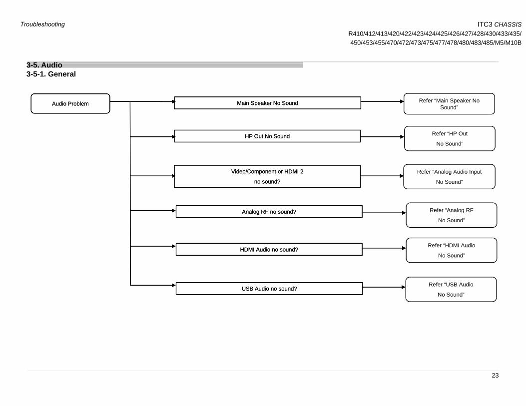
3 5 A dio
Audio ProblemAudio Problem Main Speaker No SoundMain Speaker No Sound Refer “Main Speaker No Sound”
3-5. Audio3-5-1. General
HP Out No SoundHP Out No Sound Refer “HP Out
No Sound”
Video/Component or HDMI 2
no sound?
Video/Component or HDMI 2
no sound?
Refer “Analog Audio Input
No Sound”
Analog RF no sound?Analog RF no sound?
HDMI Audio no sound?HDMI Audio no sound?
Refer “Analog RF
No Sound”
Refer “HDMI Audio HDMI Audio no sound?HDMI Audio no sound?
USB Audio no sound?USB Audio no sound?
No Sound”
Refer “USB Audio
No Sound”No Sound
23
Troubleshooting

ITC3 CHASSISR410/412/413/420/422/423/424/425/426/427/428/430/433/435/450/453/455/470/472/473/475/477/478/480/483/485/M5/M10B
3 5 A dio
SoundSound
STARTSTART Main Speaker No Sound
3-5. Audio3-5-2. Main Speaker No Sound
No SoundNo Sound
Do a Factory SettingDo a Factory Setting
Check Speaker Harness Check Speaker Harness
No connectivity for speaker
harnessSoundSound
Change Speaker HarnessChange Speaker Harness
Speaker Impedance
≠ 6~8 Ω
connectivityconnectivity
Ch k S k I dCh k S k I d
No SoundNo Sound
SoundSound
No SoundNo Sound
Change Speaker HarnessChange Speaker Harness
Ch S kCh S k Check Speaker Impedance Check Speaker Impedance
Check fuse connectivityCheck fuse connectivity
No SoundNo Sound
No connectivity
of F4000
No SoundNo Sound
Change SpeakerChange Speaker
F4500 brokenCheck fuse connectivity
at F4000
Check fuse connectivity
at F4000
Audio IC problem
No SoundNo SoundF4000 OK
Change B-Board
IC4000 damage
Size B* Board TypePAN ASIA, CHINA EUROPE, AMERICA
B*Board Type:
DONEDONE24
28” - BIL32” BIS BIL40” BIS BIL48” BIS BIL
Troubleshooting

ITC3 CHASSISR410/412/413/420/422/423/424/425/426/427/428/430/433/435/450/453/455/470/472/473/475/477/478/480/483/485/M5/M10B
BIL_BoardSize B* Board Type
PAN ASIA, CHINA EUROPE, AMERICA28” - BIL32” BIS BIL40” BIS BIL
B*Board Type:
IC4500
48” BIS BIL
F4500
CN4500
BIS Board00
_
IC4500
F4500
25
CN4500
Troubleshooting
ITC3 CHASSISR410/412/413/420/422/423/424/425/426/427/428/430/433/435/450/453/455/470/472/473/475/477/478/480/483/485/M5/M10B
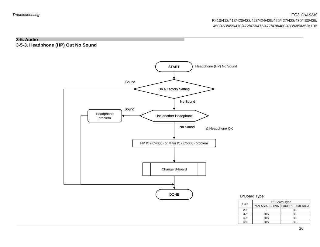
3 5 A dio
STARTSTART Headphone (HP) No Sound
3-5. Audio3-5-3. Headphone (HP) Out No Sound
Do a Factory SettingDo a Factory Setting
STARTSTART
SoundSound
Headphone (HP) No Sound
Use another HeadphoneUse another HeadphoneHeadphone problem
No SoundNo Sound
SoundSound
HP IC (IC4000) or Main IC (IC5000) problem
No SoundNo Sound & Headphone OK
Change B-board
DONEDONE
Size B* Board TypePAN ASIA, CHINA EUROPE, AMERICA
B*Board Type:
26
28” - BIL32” BIS BIL40” BIS BIL48” BIS BIL
Troubleshooting
ITC3 CHASSISR410/412/413/420/422/423/424/425/426/427/428/430/433/435/450/453/455/470/472/473/475/477/478/480/483/485/M5/M10B
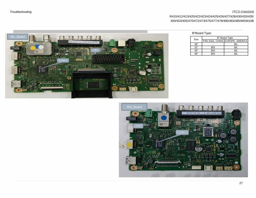
IC4000
BIL_BoardSize B* Board Type
PAN ASIA, CHINA EUROPE, AMERICA28” - BIL32” BIS BIL40” BIS BIL48” BIS BIL
B*Board Type:
IC5000
48 BIS BIL
BIS_Board
IC4000
IC5000
27
Troubleshooting

ITC3 CHASSISR410/412/413/420/422/423/424/425/426/427/428/430/433/435/450/453/455/470/472/473/475/477/478/480/483/485/M5/M10B
3 5 A dio
STARTSTART
SoundSound
3-5. Audio3-5-4. HDMI Audio No Sound
HDMI cable, HDMI cable, Change HDMI
NG
Do a Factory SettingDo a Factory SettingSoundSound
ok?ok?
HDMI source, HDMI source,
cable
Change HDMI source
NG
No SoundNo Sound & HDMI cable OKSoundSound
ok?ok?Change HDMI source
*HDMI sound*HDMI soundChange to supported
NGSoundSound
No SoundNo Sound & HDMI source OK
HDMI sound
format ok?
HDMI sound
format ok?Change to supported
format
* Please refer to IM for supported HDMI
No SoundNo Sound & HDMI format OK
audio format.
Change B-board
Main IC (IC5000) or Audio IC (IC4500) problem
Size B* Board TypePAN ASIA, CHINA EUROPE, AMERICA
B*Board Type:
DONEDONE
g
28
28” - BIL32” BIS BIL40” BIS BIL48” BIS BIL
Troubleshooting

ITC3 CHASSISR410/412/413/420/422/423/424/425/426/427/428/430/433/435/450/453/455/470/472/473/475/477/478/480/483/485/M5/M10B
3 5 A dio
Analog RF input noAnalog RF input no
3-5. Audio3-5-5. Analog RF No Sound
Analog RF input no sound
Analog RF input no sound
RF cable, RF cable, Change RF cableNG
NGok?ok?
RF source, RF source,
g
Change RF
UI setting, ok?
(TV System, AFT, Audio Filter)
UI setting, ok?
(TV System, AFT, Audio Filter)Correct UI
OK
NG
NG
ok?ok?Change RF
source/channel
R t dR t dRefer “Speaker No
OK
NG
OK
Raster sound,
ok?
Raster sound,
ok?
Refer Speaker No Sound”
Change B-boardOK
OKTuning,
ok?
Tuning,
ok?Refer “Tuner
Problem”
NG OK
Size B* Board TypePAN ASIA, CHINA EUROPE, AMERICA
B*Board Type:
29
28” - BIL32” BIS BIL40” BIS BIL48” BIS BIL
Troubleshooting

ITC3 CHASSISR410/412/413/420/422/423/424/425/426/427/428/430/433/435/450/453/455/470/472/473/475/477/478/480/483/485/M5/M10B
3 5 A dio
STARTSTART
3-5. Audio3-5-6. USB No Sound
Do a Factory SettingDo a Factory Setting
SoundSoundNo SoundNo Sound
SoundSound
*Confirm USB audio
format
*Confirm USB audio
formatChange to supported
format
NG
No SoundNo Sound
Check USB thumbdrive
Condition
Check USB thumbdrive
ConditionChange USB thumbdrive
NG
No SoundNo Sound & USB format OKSoundSound
*Confirm with OSD on bottom panel,
if playback not support.
*Please refer to IM for detail supported USB
No SoundNo Sound & USB condition OK
Main IC (IC5000) or Audio IC (IC4500) problem
pp
audio format.
DONEDONE
Change B-board
Size B* Board TypePAN ASIA, CHINA EUROPE, AMERICA
B*Board Type:
DONEDONE
30
28” - BIL32” BIS BIL40” BIS BIL48” BIS BIL
Troubleshooting
ITC3 CHASSISR410/412/413/420/422/423/424/425/426/427/428/430/433/435/450/453/455/470/472/473/475/477/478/480/483/485/M5/M10B
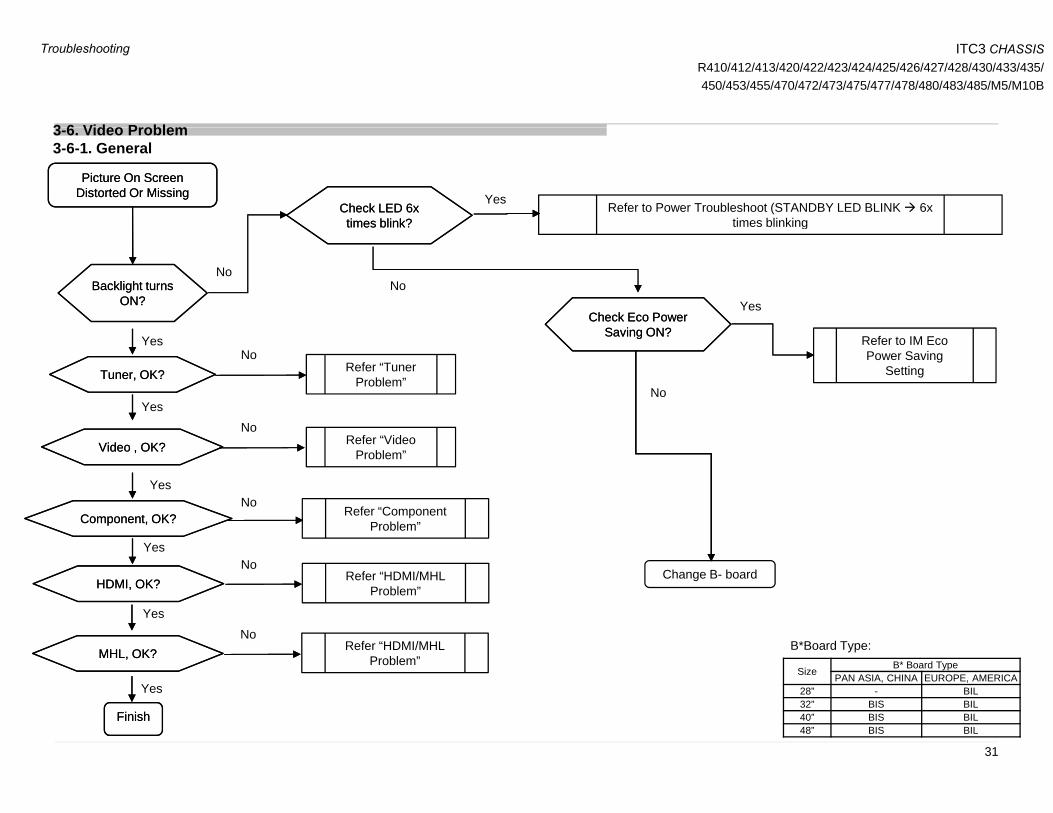
3 6 Video Problem3-6. Video Problem3-6-1. General
Picture On Screen Distorted Or MissingPicture On Screen
Distorted Or MissingCheck LED 6x ti bli k?
Check LED 6x ti bli k?
Refer to Power Troubleshoot (STANDBY LED BLINK 6x times blinking
Yes
Backlight turns ON?
Backlight turns ON?
times blink?times blink? times blinking
NoNo
Ch k E PCh k E PYes
Tuner, OK?Tuner, OK? Refer “Tuner Problem”
Yes
Yes
No
Check Eco Power Saving ON?
Check Eco Power Saving ON?
Refer to IM Eco Power Saving
Setting
No
Video , OK?Video , OK? Refer “Video Problem”
Yes
Yes
No
No
Change B- boardHDMI, OK?HDMI, OK? Refer “HDMI/MHL
Problem”
YesNo
Component, OK?Component, OK? Refer “Component Problem”
No
Problem
MHL, OK?MHL, OK? Refer “HDMI/MHL Problem”
Yes
Yes
No
Size B* Board TypePAN ASIA, CHINA EUROPE, AMERICA
B*Board Type:
FinishFinish
Yes
31
28” - BIL32” BIS BIL40” BIS BIL48” BIS BIL
Troubleshooting
ITC3 CHASSISR410/412/413/420/422/423/424/425/426/427/428/430/433/435/450/453/455/470/472/473/475/477/478/480/483/485/M5/M10B
3 6 Video Problem
5V5V
Input detection
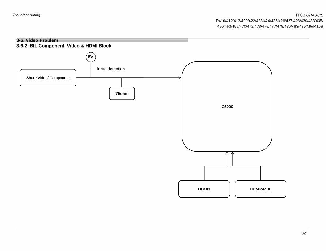
3-6. Video Problem3-6-2. BIL Component, Video & HDMI Block
Share Video/ ComponentShare Video/ Component
Input detection
75ohm75ohm
IC5000IC5000
HDMI1HDMI1 HDMI2/MHLHDMI2/MHL
32
Troubleshooting

ITC3 CHASSISR410/412/413/420/422/423/424/425/426/427/428/430/433/435/450/453/455/470/472/473/475/477/478/480/483/485/M5/M10B
3 6 Video Problem
PG3 PG6
3-6. Video Problem
BIL Video/Component Schematic Diagram
33
Troubleshooting

ITC3 CHASSISR410/412/413/420/422/423/424/425/426/427/428/430/433/435/450/453/455/470/472/473/475/477/478/480/483/485/M5/M10B
3 6 Video ProblemNo Picture
Video NG Component
3-6. Video Problem3-6-3. BIL Video (No Picture)
Video NG No Picture
Check signal source or cable
Video Signal Source problem
NG
ComponentNo Picture
Check signal source or cable
Video Signal Source problem
NG
or cable. or cable problem
Check Input jack‘J3000’ connection
Make sure jack proper connection
to board
NG
OK
or cable. or cable problem
Check Input jack‘J3000’ connection
Make sure jack proper connection
to board
NG
OK
to board
OK
Check input signal1.0Vp-p at R3029
R3029 connection/defect
NG
to board
OK
Check input signal 1.0Vp-p
at R3029_Y0P line , R3031_PB0P line &
R3032 PR0P line
R3029, R3031, R3032
connection/defect
NG
OK
Confirm waveform at C3020 (face to IC5000)
same as Ref5(CB input pattern)
Confirm R3029 &C3020 connection
and value
NG
303 _ 0 e
OK Confirm waveform at
C3020 (face to IC5000) same as Ref6.
Confirm waveform atC3022 (face to IC5000)
Confirm R3010, C3009, R3029, C3020 (Y0P line)
connection and value
NG Confirm R3011, C3010,
OK
Ref5
C3022 (face to IC5000) same as Ref7.
Confirm waveform at C3023 (face to IC5000)
same as Ref8.Input CB pattern.
OK
Ref6 Ref7
Ref8
Confirm R3012, C3011, R3032, C3023 (PR0P line)
connection and value
Confirm R3011, C3010, R3031, C3022 (PB0P line)
connection and value
IC5000 defect
IC5000 defect
Ref8
34
Troubleshooting
ITC3 CHASSISR410/412/413/420/422/423/424/425/426/427/428/430/433/435/450/453/455/470/472/473/475/477/478/480/483/485/M5/M10B
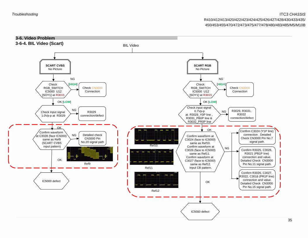
3 6 Video ProblemBIL Video
SCART CVBS SCART RGB
3-6. Video Problem3-6-4. BIL Video (Scart)
SCART CVBSNo Picture
Check RGB_SWITCHIC5000 U12
Check CN3000Connection
SCART RGBNo Picture
Check RGB_SWITCHIC5000 U12
Check CN3000Connection
NG
[HIGH]
NG
[HIGH]
IC5000 U12[SOY1] at R3015
Connection
Check input signal1.0Vp-p at R3029
R3029 connection/defect
NG
IC5000 U12[SOY1] at R3015
Connection
Check input signal 0.7Vp-p
at R3029_Y0P line , R3031 PB0P line &
R3029, R3031, R3032
connection/defect
NG
OK [LOW] OK [LOW]
OK Confirm waveform
at C3028 (face IC5000) same as Ref9(SCART CVBSinput pattern)
Detailed checkCN3000 Pin
No.20 signal path
NG
R3031_PB0P line & R3032_PR0P line
OK
Confirm waveform atC3024 (face to IC5000)
same as Ref10.Confirm waveform at
Confirm C3024 (Y1P line) connection . Detailed
Check CN3000 Pin No.7 signal path.
Ref10input pattern)
OK Ref9
Confirm waveform atC3026 (face to IC5000)
same as Ref11. Confirm waveform at
C3027 (face to IC5000)same as Ref12.
Input CB pattern.
NG Ref10
Ref11
Confirm R3026, C3027,
Confirm R3025, C3026, R3021 (PB1P line)
connection and value. Detailed Check CN3000
Pin No.11 signal path.
IC5000 defect OK
Ref12
Confirm R3026, C3027, R3022, C3016 (PR1P line)
connection and value.Detailed Check CN3000
Pin No.15 signal path.
IC5000 defect
35
Troubleshooting

ITC3 CHASSISR410/412/413/420/422/423/424/425/426/427/428/430/433/435/450/453/455/470/472/473/475/477/478/480/483/485/M5/M10B
3 6 Video ProblemBIL FOR VIDEO NG (NO PICTURE)
3-6. Video Problem
Size B* Board TypePAN ASIA, CHINA EUROPE, AMERICA
28” - BIL32” BIS BIL40” BIS BIL48” BIS BIL
B*Board Type:
C3020
48 BIS BIL
R3029
J3000 BIS FOR VIDEO NG (NO PICTURE)
C3016
R3029
36
J3000
Troubleshooting

ITC3 CHASSISR410/412/413/420/422/423/424/425/426/427/428/430/433/435/450/453/455/470/472/473/475/477/478/480/483/485/M5/M10B
3 6 Video Problem
BIL FOR COMPONENT NG (NO PICTURE)
3-6. Video Problem
Size B* Board TypePAN ASIA, CHINA EUROPE, AMERICA
28” - BIL32” BIS BIL40” BIS BIL48” BIS BIL
B*Board Type:
C3020
C3023
C3022
48 BIS BIL
R3029
R3031
R3032
R3010
C3009
R3011
C3011
C3010
R3012
J3000
C3018
C3017
C3016
BIS FOR COMPONENT NG (NO PICTURE)
R3032
R3031
R3029
R3015
R3013
R3014
C3011
C3012
C3010
37
Troubleshooting
ITC3 CHASSISR410/412/413/420/422/423/424/425/426/427/428/430/433/435/450/453/455/470/472/473/475/477/478/480/483/485/M5/M10B
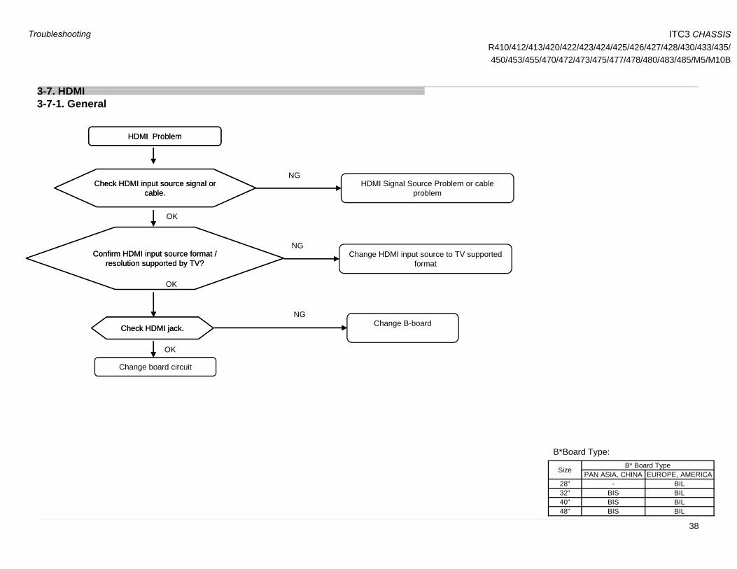
3 7 HDMI
HDMI ProblemHDMI Problem
3-7. HDMI3-7-1. General
Check HDMI input source signal or cable.
Check HDMI input source signal or cable.
OK
NGHDMI Signal Source Problem or cable
problem
OK
Confirm HDMI input source format / resolution supported by TV?
Confirm HDMI input source format / resolution supported by TV?
Change HDMI input source to TV supported format
NG
NG
Check HDMI jack.Check HDMI jack.
OK
OK
Change B-board
OK
Change board circuit
Size B* Board TypePAN ASIA, CHINA EUROPE, AMERICA
B*Board Type:
38
28” - BIL32” BIS BIL40” BIS BIL48” BIS BIL
Troubleshooting

ITC3 CHASSISR410/412/413/420/422/423/424/425/426/427/428/430/433/435/450/453/455/470/472/473/475/477/478/480/483/485/M5/M10B
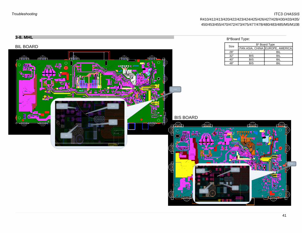
3 8 MHL
No pictureNo picture
3-8-1. No Picture3-8. MHL
NOChange phone or source
Phone or source supported MHL (phone spec and OS support etc)
YES
Change MHL cable
NOUse supported MHL cable
YES
Ch B b dCh B b dChange B-boardChange B-board
39
Troubleshooting
ITC3 CHASSISR410/412/413/420/422/423/424/425/426/427/428/430/433/435/450/453/455/470/472/473/475/477/478/480/483/485/M5/M10B
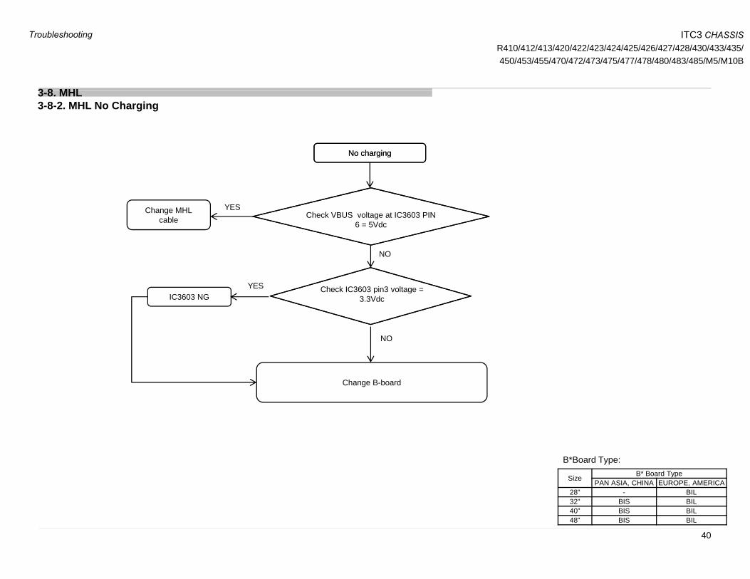
3 8 MHL
No chargingNo charging
3-8-2. MHL No Charging3-8. MHL
g gg g
Check VBUS voltage at IC3603 PIN 6 5Vdc
Change MHL cable
YES
YES
6 = 5Vdc
Check IC3603 pin3 voltage =
NO
IC3603 NG
NO
Check IC3603 pin3 voltage = 3.3Vdc
Change B-board
Size B* Board TypePAN ASIA, CHINA EUROPE, AMERICA
B*Board Type:
40
28” - BIL32” BIS BIL40” BIS BIL48” BIS BIL
Troubleshooting
ITC3 CHASSISR410/412/413/420/422/423/424/425/426/427/428/430/433/435/450/453/455/470/472/473/475/477/478/480/483/485/M5/M10B
3 8 MHL
BIL BOARD
3-8. MHL
Size B* Board TypePAN ASIA, CHINA EUROPE, AMERICA
28” - BIL32” BIS BIL40” BIS BIL48” BIS BIL
B*Board Type:
IC3603
48 BIS BIL
IC3603CL3605
BIS BOARDPin1
Pin6
BIS BOARD
IC360CL360
IC3603
3
Pin1
Pin6
CL3605
41
Troubleshooting
ITC3 CHASSISR410/412/413/420/422/423/424/425/426/427/428/430/433/435/450/453/455/470/472/473/475/477/478/480/483/485/M5/M10B
3 9 T ner
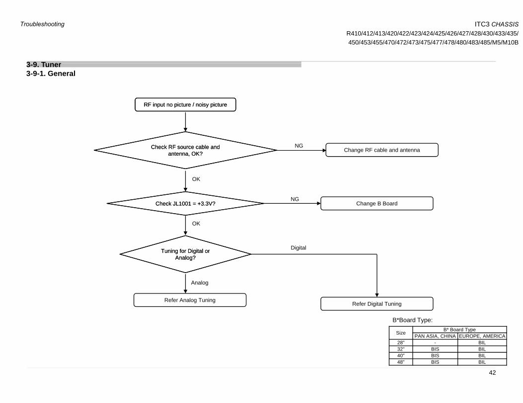
RF input no picture / noisy pictureRF input no picture / noisy picture
3-9. Tuner3-9-1. General
Change RF cable and antennaCheck RF source cable and antenna, OK?
Check RF source cable and antenna, OK?
NGantenna, OK?antenna, OK?
Ch k JL1001 3 3V?Ch k JL1001 3 3V? Ch B B d
OK
NGCheck JL1001 = +3.3V? Check JL1001 = +3.3V? Change B Board
OK
DigitalTuning for Digital or Analog?
Tuning for Digital or Analog?
Analog
Digital
Refer Analog TuningRefer Digital Tuning
Size B* Board TypePAN ASIA, CHINA EUROPE, AMERICA
B*Board Type:
42
28” - BIL32” BIS BIL40” BIS BIL48” BIS BIL
Troubleshooting
ITC3 CHASSISR410/412/413/420/422/423/424/425/426/427/428/430/433/435/450/453/455/470/472/473/475/477/478/480/483/485/M5/M10B
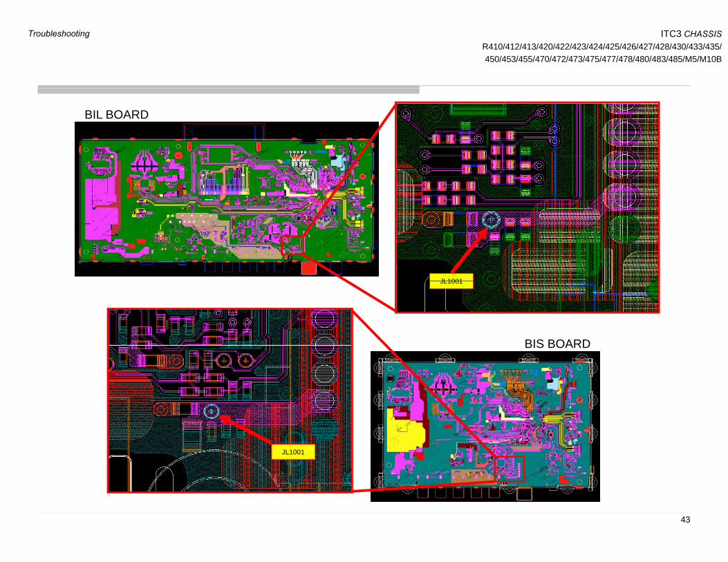
BIL BOARD
JL1001JL1001
BIS BOARDBIS BOARD
JL1001
43
Troubleshooting
ITC3 CHASSISR410/412/413/420/422/423/424/425/426/427/428/430/433/435/450/453/455/470/472/473/475/477/478/480/483/485/M5/M10B
3 9 T ner
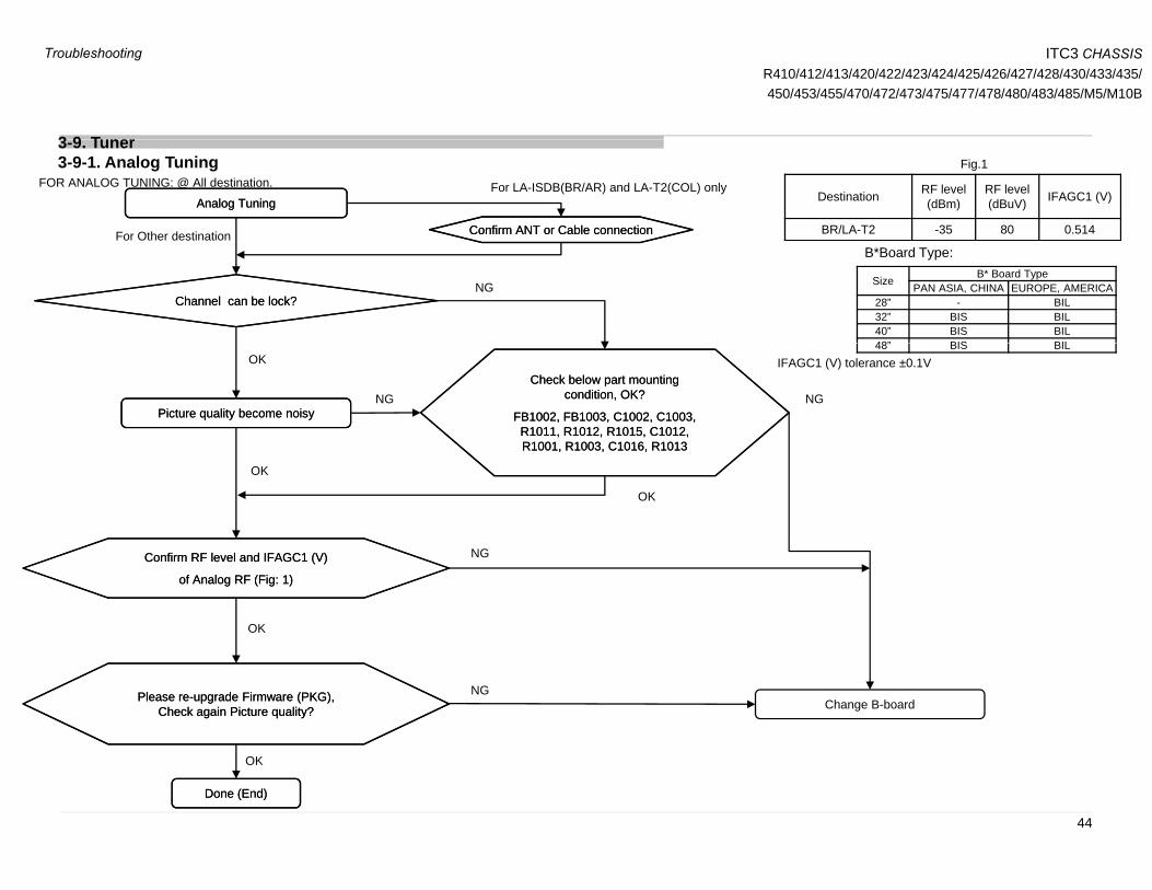
Destination RF level (dBm)
RF level(dBuV) IFAGC1 (V)
BR/LA-T2 -35 80 0.514
Analog TuningAnalog Tuning
Fig.1FOR ANALOG TUNING: @ All destination.
Confirm ANT or Cable connectionConfirm ANT or Cable connection
For LA-ISDB(BR/AR) and LA-T2(COL) only
For Other destination
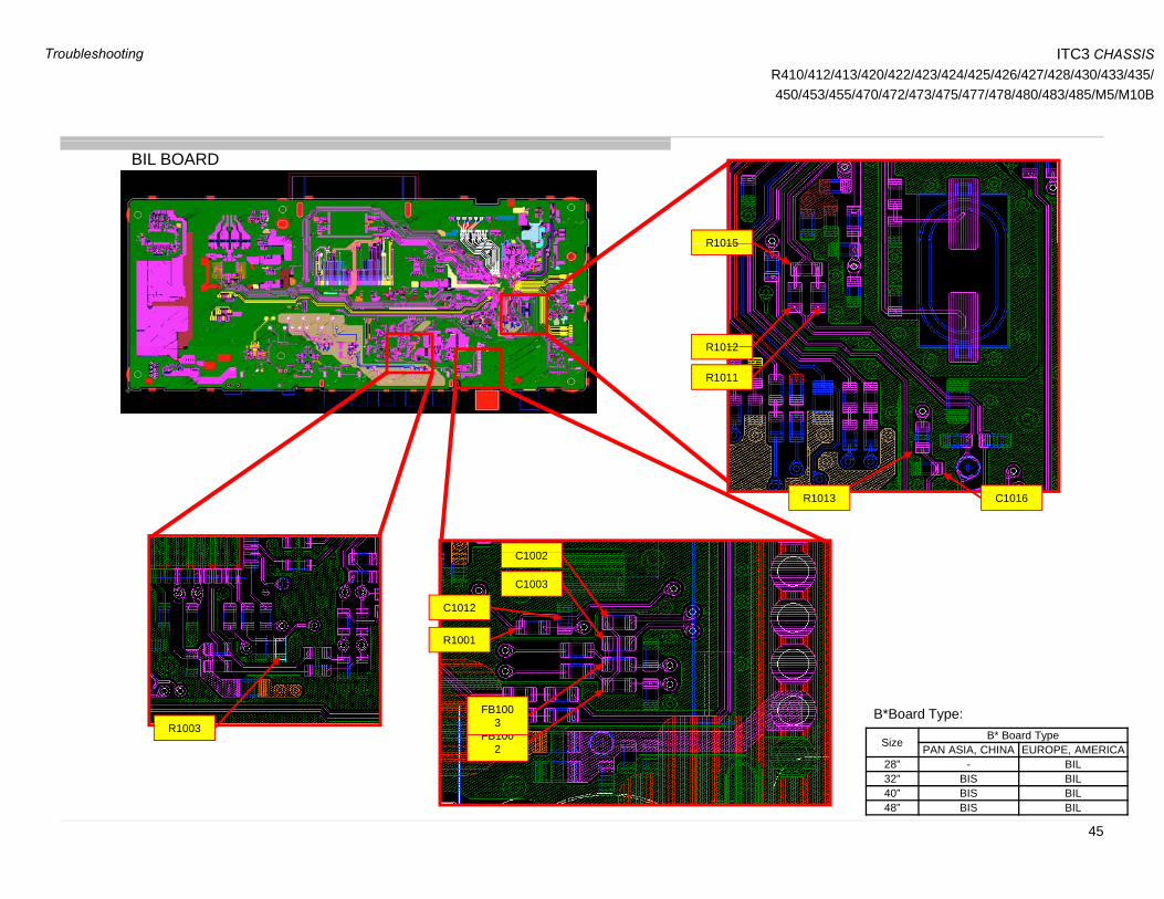
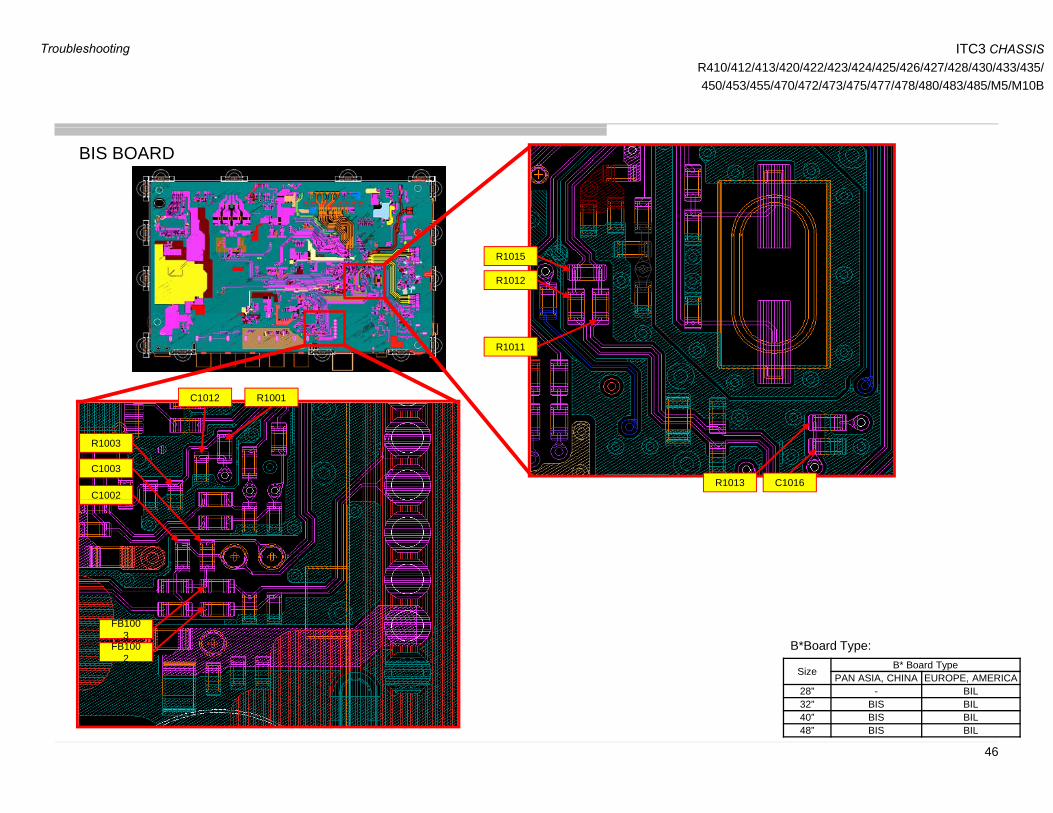
3-9. Tuner3-9-1. Analog Tuning
Channel can be lock?Channel can be lock?NG Size B* Board Type
PAN ASIA, CHINA EUROPE, AMERICA28” - BIL32” BIS BIL40” BIS BIL48” BIS BIL
B*Board Type:
OK
Picture quality become noisyPicture quality become noisy
Check below part mounting condition, OK?
FB1002, FB1003, C1002, C1003, R1011, R1012, R1015, C1012, R1001 R1003 C1016 R1013
Check below part mounting condition, OK?
FB1002, FB1003, C1002, C1003, R1011, R1012, R1015, C1012, R1001 R1003 C1016 R1013
IFAGC1 (V) tolerance ±0.1V
NGNG
48” BIS BIL
OK
R1001, R1003, C1016, R1013 R1001, R1003, C1016, R1013
OK
OK
NGConfirm RF level and IFAGC1 (V)
of Analog RF (Fig: 1)
Confirm RF level and IFAGC1 (V)
of Analog RF (Fig: 1)
Change B-boardPlease re-upgrade Firmware (PKG), Check again Picture quality?
Please re-upgrade Firmware (PKG), Check again Picture quality?
NG
Done (End)Done (End)
OK
44
Troubleshooting
ITC3 CHASSISR410/412/413/420/422/423/424/425/426/427/428/430/433/435/450/453/455/470/472/473/475/477/478/480/483/485/M5/M10B
BIL BOARD
R1015R1015
R1012R1012
R1011
R1013 C1016
C1002C1002
C1003
R1001
C1012
FB1002
FB1003R1003
Size B* Board TypePAN ASIA, CHINA EUROPE, AMERICA
B*Board Type:
45
28” - BIL32” BIS BIL40” BIS BIL48” BIS BIL
Troubleshooting
ITC3 CHASSISR410/412/413/420/422/423/424/425/426/427/428/430/433/435/450/453/455/470/472/473/475/477/478/480/483/485/M5/M10B
BIS BOARD
R1015
R1012
R1011
R1001C1012
R1013 C1016C1002
C1003
R1003
FB1002
FB1003
Size B* Board TypePAN ASIA, CHINA EUROPE, AMERICA
B*Board Type:
46
28” - BIL32” BIS BIL40” BIS BIL48” BIS BIL
Troubleshooting
ITC3 CHASSISR410/412/413/420/422/423/424/425/426/427/428/430/433/435/450/453/455/470/472/473/475/477/478/480/483/485/M5/M10B
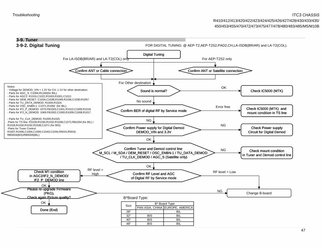
3 9 T nerFOR DIGITAL TUNING: @ AEP-T2,AEP-T2S2,PAD2,CH,LA-ISDB(BR/AR) and LA-T2(COL).
Digital TuningDigital TuningFor LA-ISDB(BR/AR) and LA-T2(COL) only For AEP-T2S2 only
3-9. Tuner3-9-2. Digital Tuning
Sound is normal?Sound is normal? Check IC5000 (MTK)Check IC5000 (MTK)OK
Confirm ANT or Cable connectionConfirm ANT or Cable connection Confirm ANT or Satellite connectionConfirm ANT or Satellite connection
For Other destinationNotes:- Voltage for DEMOD_VIN = 1.2V for CH, 1.1V for other destination.- Parts for AGC_S: C1094,R1160(for BIL).
Parts for AGC2: R1016 C1022 R1003 R1001 C1012
No sound
NG
Error freeConfirm BER of digital RF by Service modeConfirm BER of digital RF by Service mode Check IC5000 (MTK) and
mount condition in TS lineCheck IC5000 (MTK) and mount condition in TS line
NG
- Parts for AGC2: R1016,C1022,R1003,R1001,C1012.- Parts for DEM_RESET: C1034,C1038,R1049,R1036,C1030,R1057.- Parts for TU_DATA_DEMOD: R1004,R1024.- Parts for OSC_ENBN-1: C1071,R1050 (for BIL).- Parts for IF2_P_DEMOD: 1070,FB1003,C1001,R1010,C1009,R1018.- Parts for IF2_N_DEMOD: 1069,FB1002,C1000,R1009,C1008,R1017.
- Parts for TU_CLK_DEMOD: R1005,R1025.-Parts for TS line: R1028,R1030,R1032,R1038,C1072,RB1004 (for BIL) / R1028 R1030 R1032 R1038 C1071 (f BIS)
Confirm Power supply for Digital DemodDEMOD_VIN and 3.3V
Confirm Power supply for Digital DemodDEMOD_VIN and 3.3V
Confirm Tuner and Demod control line M SCL / M SDA / DEM RESET / OSC ENBN-1 / TU DATA DEMOD
Confirm Tuner and Demod control line M SCL / M SDA / DEM RESET / OSC ENBN-1 / TU DATA DEMOD
OK
Check Power supplyCircuit for Digital Demod
Check Power supplyCircuit for Digital Demod
Check mount conditionCheck mount conditionNG
NGR1028,R1030,R1032,R1038,C1071 (for BIS).-Parts for Tuner Control: R1007,R1006,C1004,C1005,C1043,C1044,R5015,R5016, RB5004(BIS)/RB5005(BIL).
M_SCL / M_SDA / DEM_RESET / OSC_ENBN-1 / TU_DATA_DEMOD / TU_CLK_DEMOD / AGC_S (Satellite only)
M_SCL / M_SDA / DEM_RESET / OSC_ENBN-1 / TU_DATA_DEMOD / TU_CLK_DEMOD / AGC_S (Satellite only)
OK
in Tuner and Demod control linein Tuner and Demod control line
Check M’t conditionin AGC2/IF2_N_DEMOD/
IF2 P DEMOD line
Check M’t conditionin AGC2/IF2_N_DEMOD/
IF2 P DEMOD line
Confirm RF Level and AGCof Digital RF by Service modeConfirm RF Level and AGC
of Digital RF by Service mode
RF level = LowRF level = High
_ __ _OK
Change B-board
Done (End)Done (End)
Please re-upgrade Firmware (PKG),
Check again Picture quality?
Please re-upgrade Firmware (PKG),
Check again Picture quality?OK
NG
Size B* Board TypePAN ASIA, CHINA EUROPE, AMERICA
B*Board Type:
Done (End)Done (End)
47
28” - BIL32” BIS BIL40” BIS BIL48” BIS BIL
Troubleshooting

ITC3 CHASSISR410/412/413/420/422/423/424/425/426/427/428/430/433/435/450/453/455/470/472/473/475/477/478/480/483/485/M5/M10B
BIL BOARDRB5004
RB10
R1015
RB1004
R1012
R1011
RB5005
R1013C1016
C1094
R1160
C1043
C1044
C1002
C1003
R1001
C1012
C1094
C1034
C1030
R1057 C1071
R1050 C1070
R1028
R1030
R1032
R1038 C1072
R1007 R5015
R5016
FB1002
FB1003
R1016
C1022C1038
R1049
R1036C1069
C1000
C1001R1017
R1018
C1008
C1009
R1028
R1003C1004
C1005R1006R1025 R1024R1010 R1009
48
Troubleshooting
ITC3 CHASSISR410/412/413/420/422/423/424/425/426/427/428/430/433/435/450/453/455/470/472/473/475/477/478/480/483/485/M5/M10B
3 10 Ethernet
Check if TV has good
cable connection
Set-up Network setup
OK
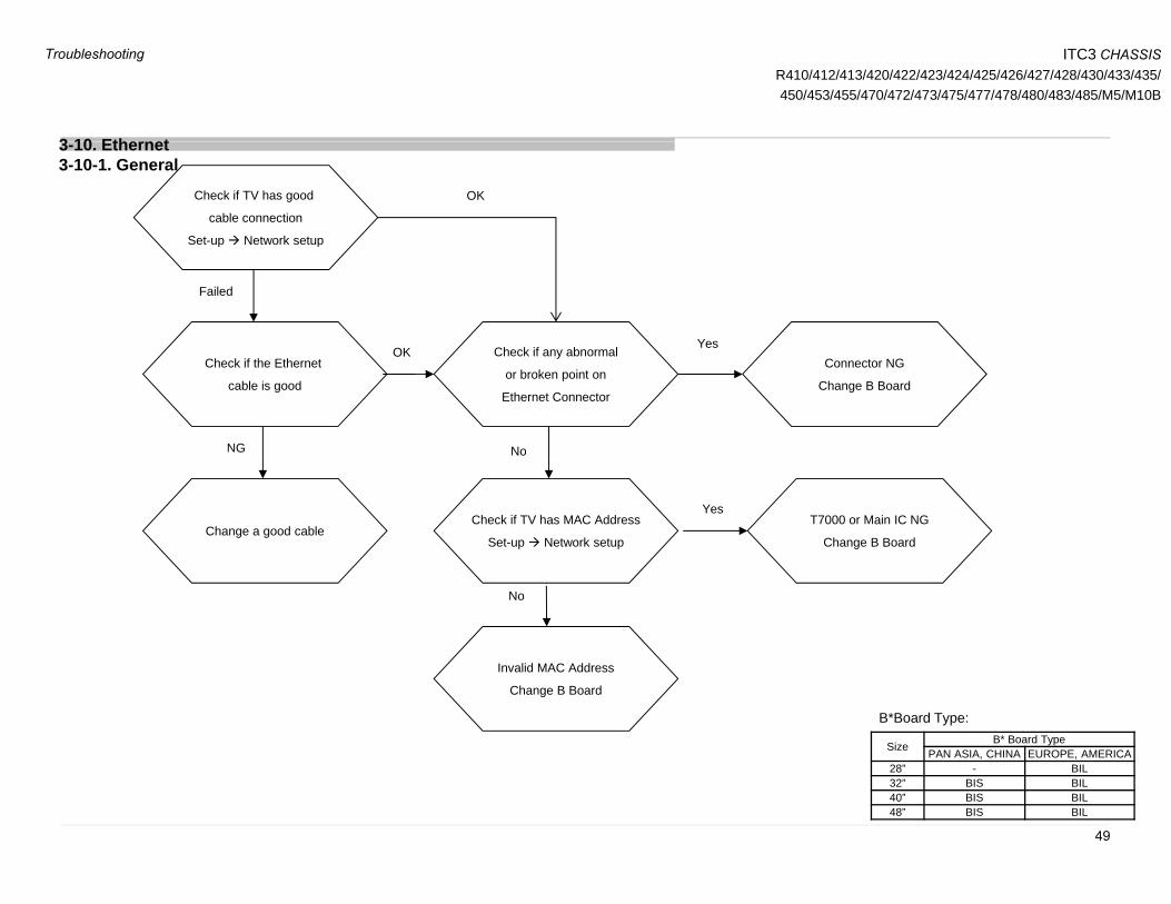
3-10. Ethernet3-10-1. General
Ch k if b lOKYes
p p
Failed
Check if the Ethernet
cable is good
Check if any abnormal
or broken point on
Ethernet Connector
OKConnector NG
Change B Board
NoNG
Check if TV has MAC Address
Set-up Network setup
T7000 or Main IC NG
Change B Board
Yes
No
Change a good cable
G
No
Invalid MAC Address
Change B Board
Size B* Board TypePAN ASIA, CHINA EUROPE, AMERICA
B*Board Type:
49
28” - BIL32” BIS BIL40” BIS BIL48” BIS BIL
Troubleshooting
ITC3 CHASSISR410/412/413/420/422/423/424/425/426/427/428/430/433/435/450/453/455/470/472/473/475/477/478/480/483/485/M5/M10B
3 11 IR
TV cannot be controlled
by remote commander
TV cannot be controlled
by remote commander
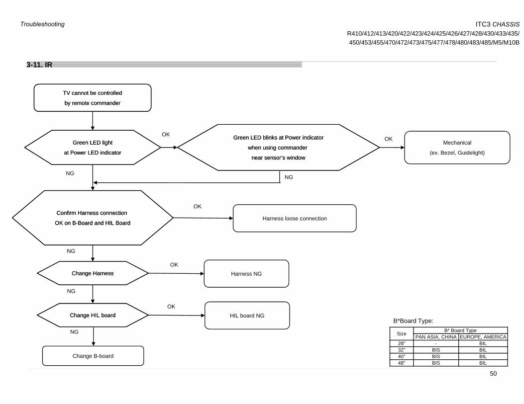
3-11. IR
OKGreen LED light
at Power LED indicator
Green LED light
at Power LED indicator
Green LED blinks at Power indicator
when using commander
’ i d
Green LED blinks at Power indicator
when using commander
’ i d
OKMechanical
(ex. Bezel, Guidelight)
NG
near sensor’s windownear sensor’s window
NG
Confirm Harness connection
OK on B-Board and HIL Board
Confirm Harness connection
OK on B-Board and HIL BoardHarness loose connection
OK
Change HarnessChange Harness Harness NG
NG
NG
OK
NG
Change HIL boardChange HIL board HIL board NGOK
Size B* Board TypePAN ASIA, CHINA EUROPE, AMERICA
B*Board Type:
Change B-board
50
28” - BIL32” BIS BIL40” BIS BIL48” BIS BIL
Troubleshooting

ITC3 CHASSISR410/412/413/420/422/423/424/425/426/427/428/430/433/435/450/453/455/470/472/473/475/477/478/480/483/485/M5/M10B
3 12 S itch Unit B ttons
Switch Unit NOT FUNCTIONINGSwitch Unit NOT FUNCTIONING
*VOLTAGE LEVEL FOR EACH PRESSED BUTTON
3-12. Switch Unit Buttons
NGCheck Wire Harness
A d C t
Check Wire Harness
A d C tChange Wire Harness
VOLTAGE LEVEL FOR EACH PRESSED BUTTON
KEY Voltage (average)
Voltage range
- 0.000 0.00000 – 0.82353
OK
And Connector
Connectivity?
And Connector
Connectivity?
g
And connect properly + 1.114 0.83451 – 1.37255
CH/Input 1.693 1.383529 – 2.03137
No Input 2.420 2.04235 – 2.80000
Check 3.3V
in Pin2, CN1
(Switch Unit)
Check 3.3V
in Pin2, CN1
(Switch Unit)
NG Check 3.3V in Pin 7,
CN9900 on
B-board
Check 3.3V in Pin 7,
CN9900 on
B-board
OK
Change Switch UnitNG*Check
Pin 1 Voltage Level
*Check
Pin 1 Voltage Level
OK
g
in CN1
g
in CN1
OK
NG
Size B* Board TypePAN ASIA, CHINA EUROPE, AMERICA
B*Board Type:
Change B-boardNG
51
28” - BIL32” BIS BIL40” BIS BIL48” BIS BIL
Troubleshooting
ITC3 CHASSISR410/412/413/420/422/423/424/425/426/427/428/430/433/435/450/453/455/470/472/473/475/477/478/480/483/485/M5/M10B
3 13 Wifi 3 13 Wifi
START
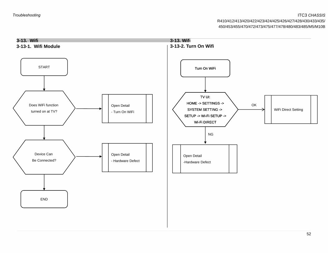
3-13. Wifi3-13-1. Wifi Module
Turn On WiFiTurn On WiFi
3-13. Wifi3-13-2. Turn On Wifi
Turn On WiFiTurn On WiFi
TV UI:TV UI:
Does WiFi function
turned on at TV?
Open Detail
- Turn On WiFi
TV UI:
HOME -> SETTINGS ->
SYSTEM SETTING ->
SETUP -> Wi-Fi SETUP ->
Wi-Fi DIRECT
TV UI:
HOME -> SETTINGS ->
SYSTEM SETTING ->
SETUP -> Wi-Fi SETUP ->
Wi-Fi DIRECT
WiFi Direct SettingOK
Device Can Open Detail Open Detail
NG
Be Connected?
Open Detail
- Hardware DefectOpen Detail
-Hardware Defect
END
52
Troubleshooting

ITC3 CHASSISR410/412/413/420/422/423/424/425/426/427/428/430/433/435/450/453/455/470/472/473/475/477/478/480/483/485/M5/M10B
3 13 Wifi
Hardware DefectHardware Defect
3-13. Wifi3-13-3-Hardware Defect
Connect properlyConnect properly Loose harness
OKNGCheck harness
connection insertion
is OK
between WiFi
Check harness
connection insertion
is OK
between WiFi
OK
between WiFi
and Bxx
between WiFi
and Bxx
OK
Change harness
between B- board
and WiFi
Change harness
between B- board
and WiFi
Main Harness
NG
NO
Check Input Power,
is it 5V?
TP: VCC
Check Input Power,
is it 5V?
TP: VCC
Change Bxxboard
YES
NG
Change
Wi Fi mod le
Change
Wi Fi mod leWi-Fi module
YES
OK
Wi-Fi moduleWi-Fi module
53
Troubleshooting

ITC3 CHASSISR410/412/413/420/422/423/424/425/426/427/428/430/433/435/450/453/455/470/472/473/475/477/478/480/483/485/M5/M10B
3 13 Wifi3-13. Wifi
Input Power
TP: Vcc = 5V
54
Troubleshooting

ITC3 CHASSISR410/412/413/420/422/423/424/425/426/427/428/430/433/435/450/453/455/470/472/473/475/477/478/480/483/485/M5/M10BSECTION 4
SERVICE ADJUSTMENTS
4-1. Accessing Service Mode1) Go to TV standby condition by remote commander.2) Press “i+ (info)”, “5”, “Volume +” then “TV power” on remote.3) You can see Service Mode on display.
4-2. Accessing Software Version1) Press (Enter) or button on Remote to enter status information.
4
1
2
Remote Commander
Remote Commander
3
Screen Sample
2) Press (Enter) button on Remote to back to Service Mode.
Remote Commander
55
Service Mode Screen Sample Screen Sample

ITC3 CHASSISR410/412/413/420/422/423/424/425/426/427/428/430/433/435/450/453/455/470/472/473/475/477/478/480/483/485/M5/M10B
Service Adjustment
4-3. Accessing Self Diagnostic History
1) Press (Enter) button on Remote to enter Self Check Mode.
4-4. Accessing Self Diagnostic Menu1) Go to TV standby condition by remote commander.2) Press “i+ (info)”, “5”, “Volume -” then “TV power” on remote.3) To Exit – Press Power Off & On.
Error countNumber of Standby
LED flashings Error name
Screen Sample
Remote Commander
0- indicates no error was detected.
1- indicates an error was detected.
2) Press Enter button on Remote to back to Service Mode Total Operation Time [h] – Boot Count – Panel Operation Time [h]
(max 65535) (max 65535) (max 65535)
Screen Sample
•Total Operation Time and Panel Operation Time and is recorded every 1 h.
Remote function:
Error history clear : <8> -> <0>
Panel operation time clear: <7> > <0>
p p y
56
Screen Sample
Panel operation time clear: <7> -> <0>
ITC3 CHASSISR410/412/413/420/422/423/424/425/426/427/428/430/433/435/450/453/455/470/472/473/475/477/478/480/483/485/M5/M10B
Service Adjustment
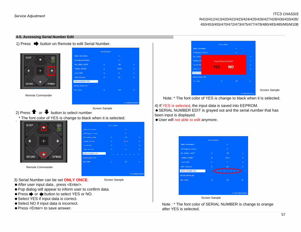
4 5 Accessing Serial Number Edit4-5. Accessing Serial Number Edit
1) Press button on Remote to edit Serial Number.
Screen Sample
Remote Commander
2) Press or button to select numberScreen Sample
Note: * The font color of YES is change to black when it is selected.
Screen Sample
4) If YES is selected, the input data is saved into EEPROM. SERIAL NUMBER EDIT is grayed out and the serial number that hasbeen input is displayed.
.been input is displayed.User will not able to edit anymore.* The font color of YES is change to black when it is selected.
Remote Commander
3) Serial Number can be set ONLY ONCE.After user input data , press <Enter>. Pop dialog will appear to inform user to confirm data.Press or button to select YES or NO.
Screen Sample
57
Select YES if input data is correct. Select NO if input data is incorrect. Press <Enter> to save answer.
Screen Sample
Note : * The font color of SERIAL NUMBER is change to orange after YES is selected.

ITC3 CHASSISR410/412/413/420/422/423/424/425/426/427/428/430/433/435/450/453/455/470/472/473/475/477/478/480/483/485/M5/M10B
Service Adjustment
5) If NO is selected, the input data is not saved into EEPROM.The serial number that has been input is displayed. User can still edit the Serial Number. 1) Press button on Remote to edit Model Name.
4-6. Accessing Model Name Edit
Remote Commander
Note : * The font color of NO is change to black when it is selected.
Screen Sample
2) Press or button on Remote to select character.
Screen Sample
Remote Commander
58
Screen Sample
Screen Sample
Note : * The font color of SERIAL NUMBER is white after NO is selected.

ITC3 CHASSISR410/412/413/420/422/423/424/425/426/427/428/430/433/435/450/453/455/470/472/473/475/477/478/480/483/485/M5/M10B
Service Adjustment
3) Model Name can be set ONLY ONCE. After user input data , press <Enter>. Pop dialog will appear to inform user to confirm data. Press or button to select YES or NO. Select YES if input data is correct. pSelect NO if input data is incorrect. Press <Enter> to save answer.
Screen Sample
5) If NO is selected, the input data is not saved into EEPROM. The model name that has been input is displayed.
Note : *The font color of MODEL NAME is change to orange after YES is selected.
Screen Sample
Note :* The font color of YES is change to black when it is selected.
User can still edit the Model Name.
4) If YES is selected, the input data is saved into EEPROM.Model Name EDIT is grayed out and the model name that has beenModel Name EDIT is grayed out and the model name that has been input is displayed. User will not able to edit anymore
59
Note: *The font color of NO is change to black when it is selected.
Note :* The font color of MODEL NAME is white after NO is selected.

5-1.CIRCUIT BOARD LOCATION
D
SECTION 5DIAGRAMS
5-1-1. KDL-28”BIS BOARD (PAN ASIA, CHINA)
SWITCH UNIT
HIL BOARD
5-1-2. KDL-32”BIL BOARD (EUROPE, AMERICA) BIS BOARD (PAN ASIA, CHINA)
HIL BOARD
HTL4 BOARD
(For Hotel Model Only)
60
SWITCH UNIT
SWITCH UNIT
HIL BOARD HIL BOARD
CARD, WIRELESS LAN
CARD, WIRELESS LAN
ITC3 CHASSISR410/412/413/420/422/423/424/425/426/427/428/430/433/435/450/453/455/470/472/473/475/477/478/480/483/485/M5/M10B
Diagrams

5-1.CIRCUIT BOARD LOCATION 5-1-3. KDL-40”
BIL BOARD (EUROPE, AMERICA) BIS BOARD (PAN ASIA, CHINA)
HTL4 BOARD
(For Hotel Model Only)
SWITCH UNIT HIL BOARD
SWITCH UNIT HIL BOARD
CARD, WIRELESS LAN
CARD, WIRELESS LAN
5-1-4. KDL-48”
BIL BOARD (EUROPE, AMERICA) BIS BOARD (PAN ASIA, CHINA)
61
SWITCH UNIT
HIL BOARDSWITCH
UNIT HIL BOARD
CARD, WIRELESS LAN
ITC3 CHASSISR410/412/413/420/422/423/424/425/426/427/428/430/433/435/450/453/455/470/472/473/475/477/478/480/483/485/M5/M10B
Diagrams

ITC3 CHASSISR410/412/413/420/422/423/424/425/426/427/428/430/433/435/450/453/455/470/472/473/475/477/478/480/483/485/M5/M10B
Diagrams
5-2. Block Diagram 5-2-1. AR – BIL BOARD
USB2 0 Wi Fi M d l
USB2.0
HDMI2 (ARC)
USB2.0 Wi-Fi Module
Indicator LED/SIRCS
60Hz60HzLED
backlight
Switch Unit
HDMI1 (MHL)
LVDS
LED Driver
BD9276EFV
Switch Unit (4keys)
EtherMT5561GUHT
NAND FlashNAND Flash(8bit ECC required)(8bit ECC required)
2Gb 2Gb
HP/
A-OUT
I2SIFIF P TS
HP AMPHP AMP
TPA6138A2TPA6138A2
8bit
EtherEther
PHYPHYEmbedded Embedded
MHL2.0MHL2.0
Embedded Embedded DDR3 2GbDDR3 2Gb
Audio AMPAudio AMP
YDA178YDA178
2Gb 2Gb
IFIF
IFIF
DemodDemodCXD2838ER (DJIN6)
P-TS
19.5V from AC adapter A3 T M d l
Component/CompositeDC-IN
p A3 Tuner Module
SUT-RB231(LA/COL/BR/AR)
62
ITC3 CHASSISR410/412/413/420/422/423/424/425/426/427/428/430/433/435/450/453/455/470/472/473/475/477/478/480/483/485/M5/M10B
Diagrams
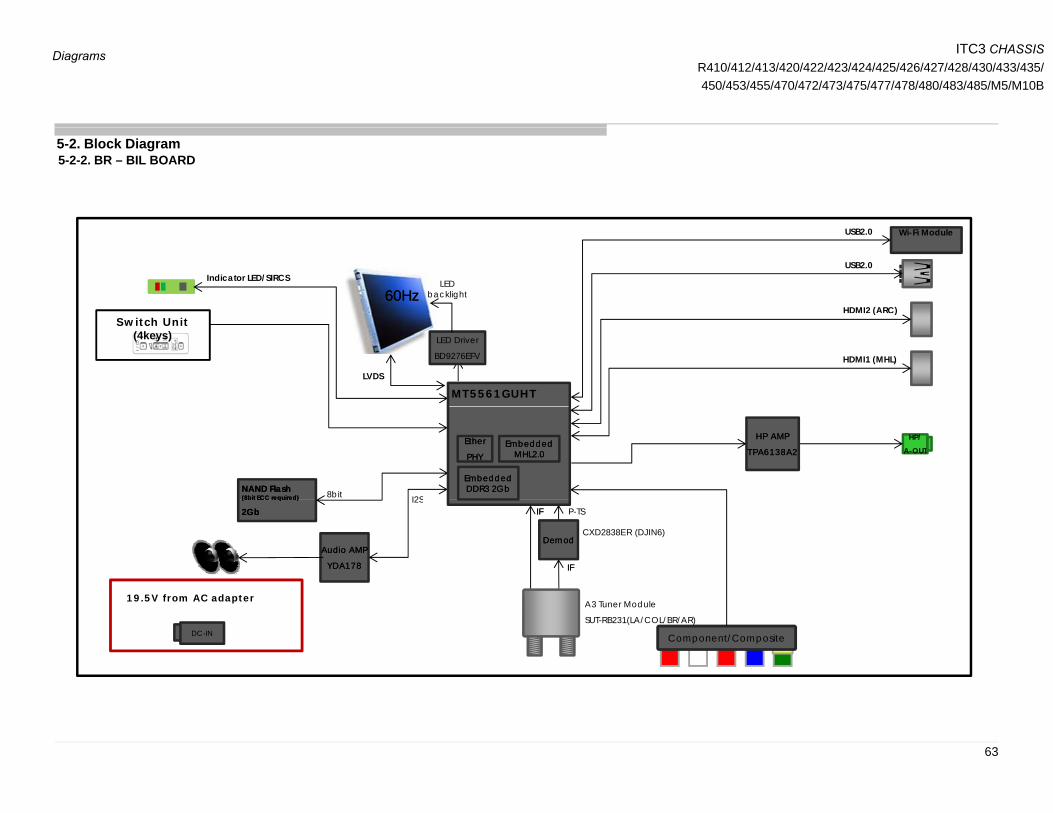
5-2. Block Diagram 5-2-2. BR – BIL BOARD
USB2.0
HDMI2 (ARC)
USB2.0 Wi-Fi Module
Indicator LED/SIRCS
60Hz60HzLED
backlight
( )
HDMI1 (MHL)
LVDS
LED Driver
BD9276EFV
Switch Unit (4keys)
MT5561GUHT
NAND FlashNAND Flash(8bit ECC required)(8bit ECC required)
HP/
A-OUT
I2S
HP AMPHP AMP
TPA6138A2TPA6138A2
8bit
EtherEther
PHYPHYEmbedded Embedded
MHL2.0MHL2.0
Embedded Embedded DDR3 2GbDDR3 2Gb
Audio AMPAudio AMP
YDA178YDA178
(8b CC equ ed)(8b CC equ ed)
2Gb 2Gb
IFIF
I2SIFIF
DemodDemodCXD2838ER (DJIN6)
P-TS
Component/CompositeDC-IN
19.5V from AC adapter A3 Tuner Module
SUT-RB231(LA/COL/BR/AR)
63
ITC3 CHASSISR410/412/413/420/422/423/424/425/426/427/428/430/433/435/450/453/455/470/472/473/475/477/478/480/483/485/M5/M10B
Diagrams
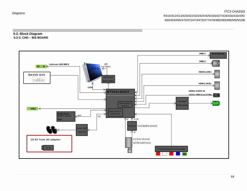
5-2. Block Diagram 5-2-3. CHD – BIS BOARD
USB2.0
HDMI2 (ARC)
USB2.0 Wi-Fi Module
Indicator LED/SIRCS
60HzLED
backlight
S i h i
A-INMT5561MAHT
HDMI1 (MHL)
LVDS
LED Driver
BD9276EFV
Switch Unit (4keys)
HDMI2 AUDIO IN
*(DVI) *SIRCS out (CBX)
NAND Flash(8bit ECC required)
HP/
A-OUT
A-IN
Embedded MHL2.0
Embedded DDR3 2Gb
I2S8bit
HP AMP
TPA6138A2
HTL4
( ) ( )
Audio AMP
YDA178
2Gb
IF
19 5V from AC adapter
IF
Demod CXD2840ER (ZHUI2)
P-TS
A3 Tuner Module
Component/CompositeDC-IN
19.5V from AC adapter A3 Tuner Module
SUT-RC232(China)
64

ITC3 CHASSISR410/412/413/420/422/423/424/425/426/427/428/430/433/435/450/453/455/470/472/473/475/477/478/480/483/485/M5/M10B
Diagrams
5-2. Block Diagram 5-2-4. COL- BIL BOARD
USB2.0
HDMI2 (ARC)
USB2.0 Wi-Fi Module
Indicator LED/SIRCS
60Hz60HzLED
backlight
MT5561GUHT
HDMI1 (MHL)
LVDS
LED Driver
BD9276EFV
Switch Unit (4keys)
NAND FlashNAND Flash(8bit ECC required)(8bit ECC required)
HP/
A-OUTEtherEther
PHYPHYEmbedded Embedded
MHL2.0MHL2.0
Embedded Embedded DDR3 2GbDDR3 2Gb
I2S
OptS/FPDIF
HP AMPHP AMP
TPA6138A2TPA6138A2
8bit
Audio AMPAudio AMP
YDA178YDA178
2Gb2Gb
IFIF
I2SIFIF
DemodDemodCXD2837ER (GAIA3)
P-TS
19 5V f AC d t
Component/CompositeDC-IN
19.5V from AC adapter A3 Tuner Module
SUT-RB231(LA/COL/BR/AR)
65

ITC3 CHASSISR410/412/413/420/422/423/424/425/426/427/428/430/433/435/450/453/455/470/472/473/475/477/478/480/483/485/M5/M10B
Diagrams
5-2. Block Diagram 5-2-5 EU – BIL BOARD
USB2.0
HDMI2 (ARC)
USB2.0 Wi-Fi Module
Indicator LED/SIRCS
60Hz60HzLED
backlightPCMCIA
Switch Unit
MT5561TUHT
HDMI1 (MHL)
LVDS
LED Driver
BD9276EFV PP--TSTS
PP--TSTS
Ether
*for UK only
Switch Unit (4keys)
NAND FlashNAND Flash(8bit ECC required)(8bit ECC required)
HP/
A-OUTEtherEther
PHYPHY
DemodDemod
DVBDVB--T/CT/C
Embedded Embedded MHL2.0MHL2.0
Embedded Embedded DDR3 2GbDDR3 2Gb
I2S
OptS/FPDIF
HP AMPHP AMP
TPA6138A2TPA6138A2
8bit
Audio AMPAudio AMP
YDA178YDA178
2Gb : Others2Gb : Others
IFIF
I2CI2C
IFIF
DemodDemodCXD2837ER (GAIA3)
P-TS
19.5V from AC adapter A3 Tuner Module
CXD2843ER (LEDA)
*No Demod for DVB-T and DVB-C
Component/CompositeEEPROMEEPROM
128Kb128Kb
SCART
DC-IN
19.5V from AC adapter SUT-RE231(EU-T, EU-T2)
SUT-PE231(EU-S2)
66

ITC3 CHASSISR410/412/413/420/422/423/424/425/426/427/428/430/433/435/450/453/455/470/472/473/475/477/478/480/483/485/M5/M10B
Diagrams
5-2. Block Diagram 5-2-6 PAA – BIS BOARD
USB2.0
HDMI2 (ARC)
USB2.0 Wi-Fi Module
Indicator LED/SIRCS
60Hz
*Not applicable in some PAA models
LED backlight
Switch Unit
A-INMT5309SUHT
HDMI1 (MHL)
LVDS
LED Driver
BD9276EFV
Switch Unit (4keys)
HDMI2 AUDIO IN
(DVI) SIRCS out (CBX)
S
NAND Flash(8bit ECC required)
HP/
A-OUTEmbedded
MHL2.0
Embedded DDR3 2Gb
I2S8bit
HP AMP
TPA6138A2
Audio AMP
YDA178
2Gb
19.5V from AC adapter /
IF
A3 Tuner Module
Component/CompositeDC-IN
19.5V from AC adapter /
12V from Car Battery (for some PAA)
SUT-RE231
67

ITC3 CHASSISR410/412/413/420/422/423/424/425/426/427/428/430/433/435/450/453/455/470/472/473/475/477/478/480/483/485/M5/M10B
Diagrams
USB2.0 Wi-Fi Module
5-2. Block Diagram 5-2-7. PAD – BIS BOARD
USB2.0
HDMI2 (ARC)
USB2.0 Wi Fi Module
Indicator LED/SIRCS
60HzLED
backlight
Switch Unit
A-INMT5561TUHT
HDMI1 (MHL)
LVDS
LED Driver
BD9276EFV(4keys)
HDMI2 AUDIO IN
(DVI)SIRCS out (CBX)
NAND Flash(8bit ECC required)
2Gb
HP/
A-OUT
DVB-T/C
Embedded MHL2.0
Embedded DDR3 2Gb
I2S8bit
IF P-TS
HP AMP
TPA6138A2Opt
S/FPDIF
HTL4
Audio AMP
YDA178
2Gb
IF
19.5V from AC adapter / I2C
IF
Demod
CXD2837ER (GAIA3)P TS
A3 Tuner Module
Component/CompositeEEPROM
128KbDC-IN
12V from Car Battery (for some PAD)
SUT-RE231(PAD)
For PA-D
68

ITC3 CHASSISR410/412/413/420/422/423/424/425/426/427/428/430/433/435/450/453/455/470/472/473/475/477/478/480/483/485/M5/M10B
Diagrams
USB2.0 Wi-Fi Module
5-2. Block Diagram 5-2-8. UC – BIS BOARD
USB2.0
HDMI2 (ARC)
US .0 Wi Fi Module
Indicator LED/SIRCS
60HzLED
backlight
Switch Unit
MT5560SUHT
HDMI1 (MHL)
LVDS
LED Driver
BD9276EFV(4keys)
S/FPDIF
NAND Flash(8bit ECC required)
2Gb
HP/
A-OUT
Demod
ATSC
Embedded MHL2.0
Embedded DDR3 2Gb
I2S8bit
IF
HP AMP
TPA6138A2Opt
S/FPDIF
Audio AMP
YDA178
2Gb
19.5V from AC adapter
IF
Component/CompositeDC-IN
A3 Tuner Module
SUT-PA231(ATSC)
69

5-3. Connector Diagram5 3 1 28” (PA A l O l )5-3-1. 28” (PA Analog Only)
70
ITC3 CHASSISR410/412/413/420/422/423/424/425/426/427/428/430/433/435/450/453/455/470/472/473/475/477/478/480/483/485/M5/M10B
Diagrams

5-3. Connector Diagram5 3 2 32” (WXGA)5-3-2. 32” (WXGA)
71
ITC3 CHASSISR410/412/413/420/422/423/424/425/426/427/428/430/433/435/450/453/455/470/472/473/475/477/478/480/483/485/M5/M10B
Diagrams
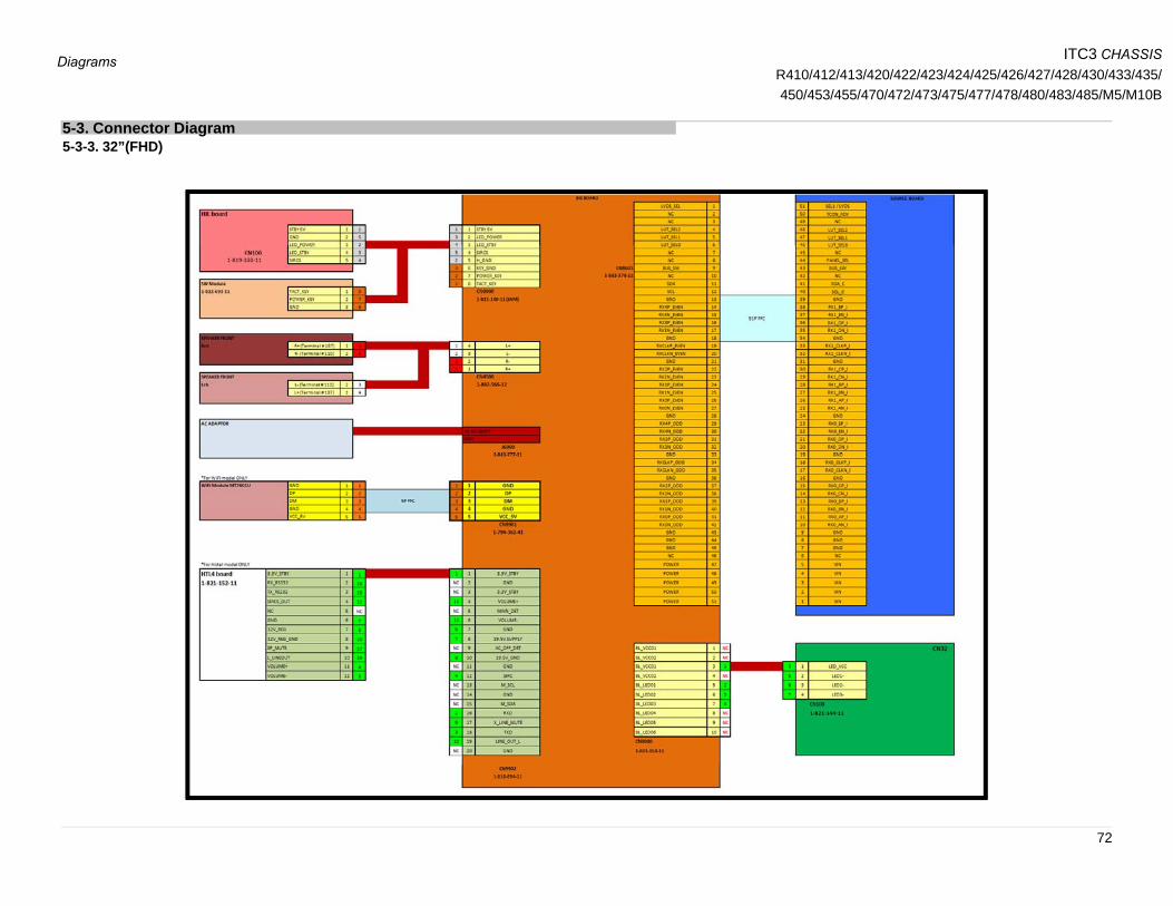
5-3. Connector Diagram5 3 3 32”(FHD)5-3-3. 32”(FHD)
72
ITC3 CHASSISR410/412/413/420/422/423/424/425/426/427/428/430/433/435/450/453/455/470/472/473/475/477/478/480/483/485/M5/M10B
Diagrams
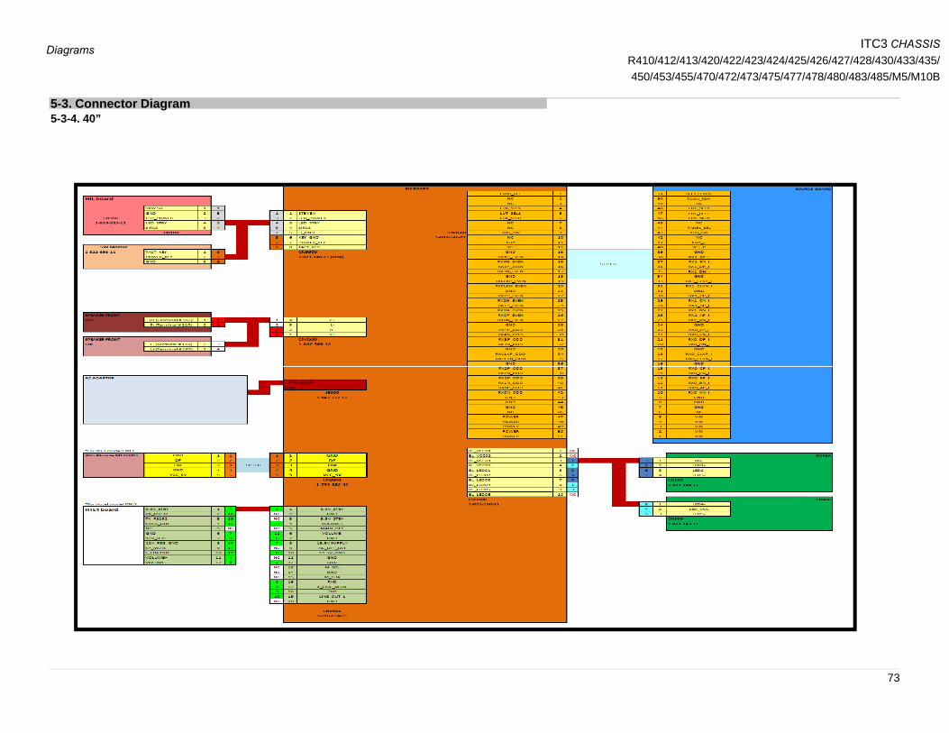
5-3. Connector Diagram5 3 4 40”5-3-4. 40”
73
ITC3 CHASSISR410/412/413/420/422/423/424/425/426/427/428/430/433/435/450/453/455/470/472/473/475/477/478/480/483/485/M5/M10B
Diagrams

5-3. Connector Diagram5 3 5 48”5-3-5. 48”
74
ITC3 CHASSISR410/412/413/420/422/423/424/425/426/427/428/430/433/435/450/453/455/470/472/473/475/477/478/480/483/485/M5/M10B
Diagrams
75
English© 2014. 01
Sony CorporationSony EMCS (Malaysia) Sdn. Bhd.
HESRDM9-888-148-01