ce 313 5 filtration
TRANSCRIPT
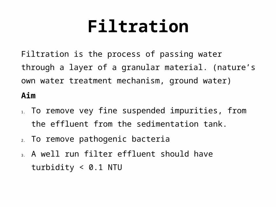
FiltrationFiltration is the process of passing water through a layer of a granular material. (nature’s own water treatment mechanism, ground water)Aim1. To remove vey fine suspended impurities, from
the effluent from the sedimentation tank.2. To remove pathogenic bacteria3. A well run filter effluent should have
turbidity < 0.1 NTU
Filtration Odour free water Colourless water Free from pathogenic organism
Theory of Filtration Mechanical straining Sedimentation and flocculation ImpactionInterception Biological metabolism
Filtration mechanismsMechanical straining (according to aperture size) → The water gets filtered by arresting the impurities present as the fluid particles pass through the granular space between the filter media Sedimentation and flocculation →Acts as tiny sedimentation tank → The impurities in the effluent water from coagulation sedimentation tank is a gelatinous material and will collect within the voids of sand particles as it passes through the media under gravity or pressure. These voids with gelatinous material will act as minute flocculation sedimentation tank attracting and depositing particles smaller than the void space, improving its performance as a filter again and again.

Filtration mechanism• Biological Metabolism The living organism/bacteria present in sand particles use the organic matters for their survival and convert them in to harmless compound. These compounds form a layer known as dirty skin and which again absorb and strain the impurities. This process is known as biological metabolism and the dirty layer which assists and enhances the process of filtration is called the dirty skin or schmutzdecke
Classification of filters
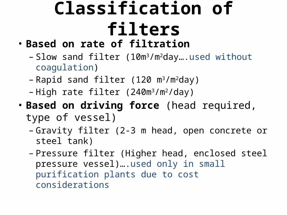
• Based on rate of filtration– Slow sand filter (10m3/m2day….used without coagulation)
– Rapid sand filter (120 m3/m2day)– High rate filter (240m3/m2/day)
• Based on driving force (head required, type of vessel)– Gravity filter (2-3 m head, open concrete or steel tank)
– Pressure filter (Higher head, enclosed steel pressure vessel)….used only in small purification plants due to cost considerations
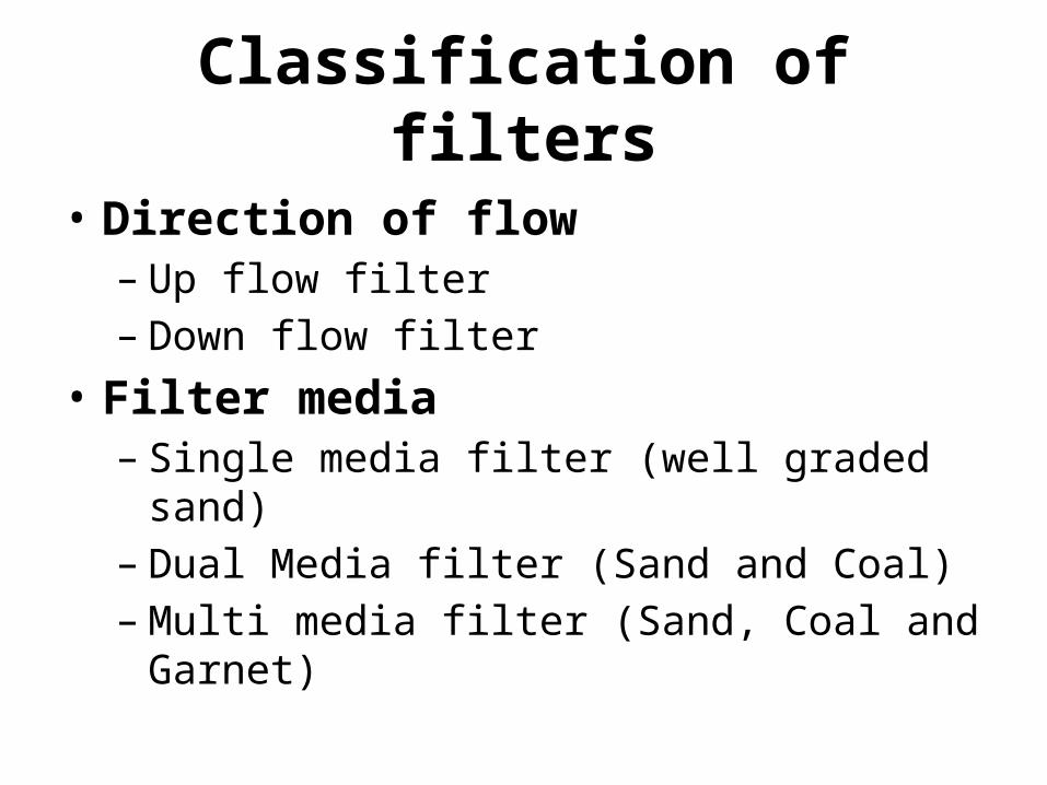
• Direction of flow– Up flow filter– Down flow filter
• Filter media– Single media filter (well graded sand)
– Dual Media filter (Sand and Coal)– Multi media filter (Sand, Coal and Garnet)
Classification of filters
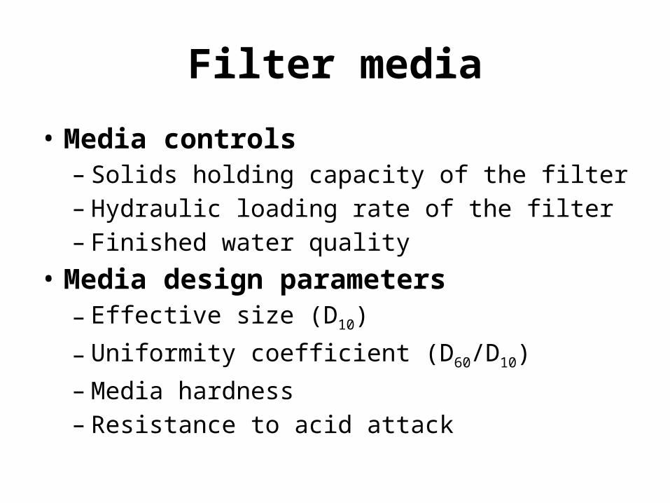
Filter media• Media controls
– Solids holding capacity of the filter– Hydraulic loading rate of the filter– Finished water quality
• Media design parameters– Effective size (D10)– Uniformity coefficient (D60/D10)– Media hardness– Resistance to acid attack
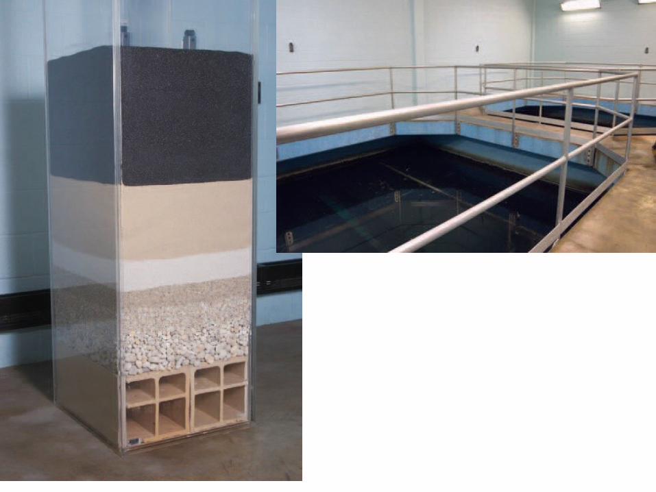
Filter components• Filter box• Media• Supporting media• Under drain system• Influent piping• Effluent piping• Wash water piping• Waste wash water piping
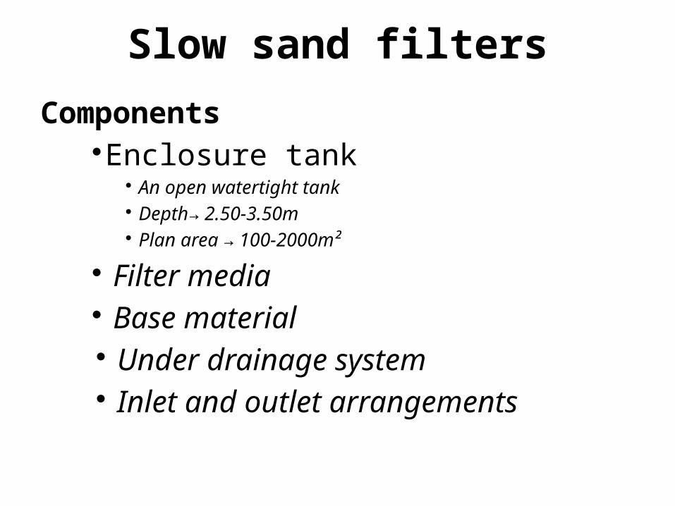
Slow sand filtersComponents
Enclosure tank An open watertight tank Depth 2.50-3.50m → Plan area 100-2000m² →
Filter media Base material Under drainage system Inlet and outlet arrangements

Slow sand filter
Under drainage system

Slow sand filterFilter Media•Sand layer of 90-120 cm height4-5 such layer•Fine particles at top•Top 15 cm, uniformly graded•Uniformity coefficient At top 1.8Mid level-2.5At bottom 3.0
Effective size (D 10) 0.2 to 0.4 mm
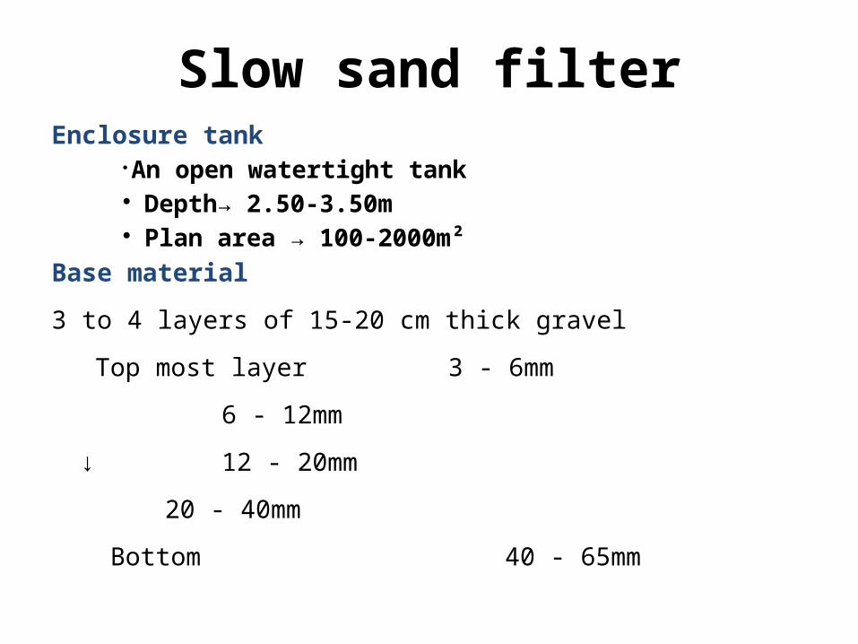
Slow sand filterEnclosure tank
An open watertight tank Depth→ 2.50-3.50m Plan area → 100-2000m²
Base material3 to 4 layers of 15-20 cm thick gravel Top most layer 3 - 6mm 6 - 12mm↓ 12 - 20mm 20 - 40mm Bottom 40 - 65mm
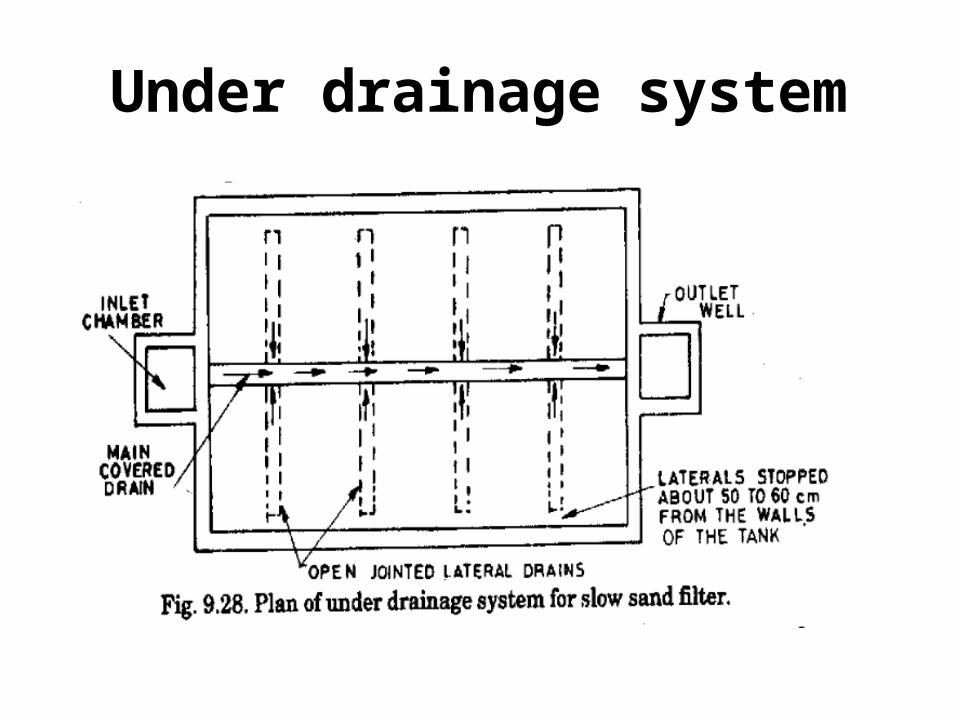
Slow sand filterUnder drainage system
A sloped floor to collect the water in the central width wise drain
Open jointed laterals are placed 3 - 4 m c/c
Central drain collects the water from laterals and delivers to the outlet chamber.
Slow sand filterInlet and outlet arrangements Inlet should allow the entering water to distribute uniformly on filter bed In order to maintain constant head, a telescopic (adjustable) pipe is fitted
Note: The loss of head is minimum possible → 15-30cm The maximum → 0.70 -1.20m, above which cleaning is required The water treated with coagulants should not be permitted to enter the slow sand filters The depth of water on the filter bed should not vary much, normally kept equal to the depth of sand bed.
Slow sand filterThe loss of head called filter head is kept approximately equal to 0.70-0.80 times the depth of sand, to put it out of service for cleaningCleaning of slow sand filters are done by scrapping and removing 1.50-3cm, top layerGenerally cleaning depends on the impurities presents →1-2 monthsEfficient against bacteria removal as high as 98-99%Remove odour and taste, by removing organic impuritiesColour removal →up to 50mg/lUses →For small water supply schemesUneconomical, due to small rate of filtration and large area requirements

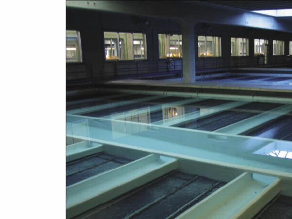
Rapid sand filter
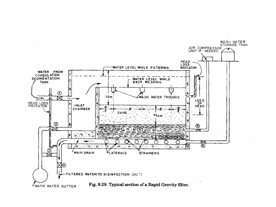
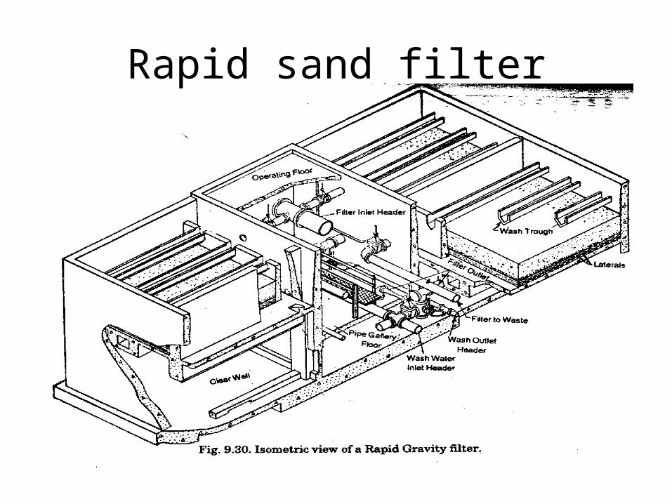
Rapid sand filter
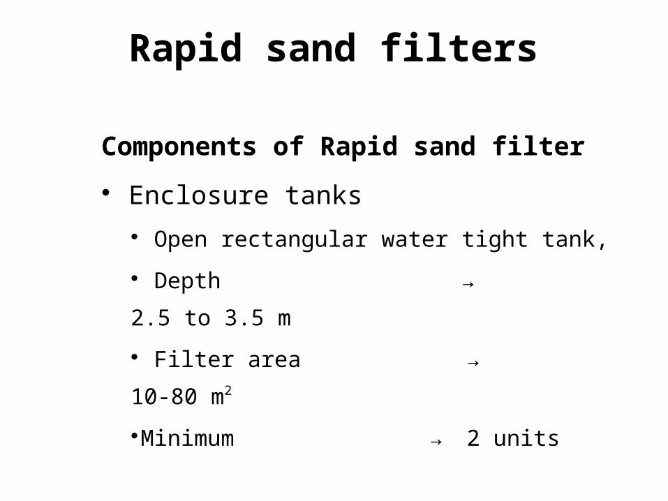
Components of Rapid sand filter Enclosure tanks
Open rectangular water tight tank, Depth → 2.5 to 3.5 m Filter area → 10-80 m2
Minimum → 2 units
Rapid sand filters
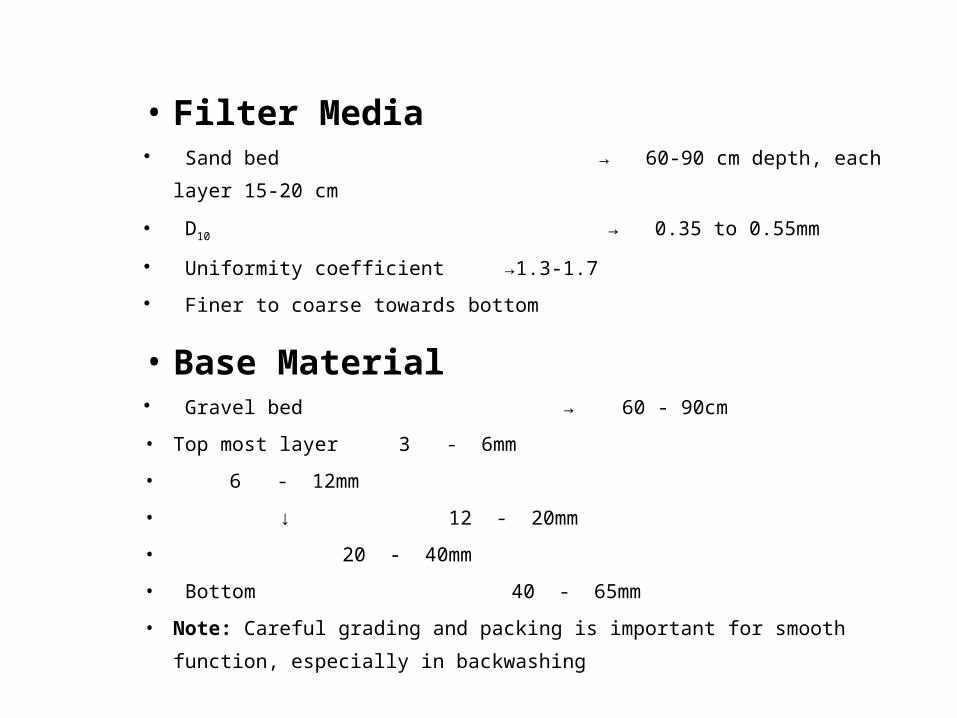
• Filter Media Sand bed → 60-90 cm depth, each
layer 15-20 cm D10 → 0.35 to 0.55mm Uniformity coefficient →1.3-1.7 Finer to coarse towards bottom
• Base Material Gravel bed → 60 - 90cm• Top most layer 3 - 6mm• 6 - 12mm• ↓ 12 - 20mm• 20 - 40mm• Bottom 40 - 65mm• Note: Careful grading and packing is important for smooth
function, especially in backwashing
Head Loss in Clean Filters
hL (“head loss”) refers to the loss of total energy per volume of water between the top of the filter bed and some other point (usually the bottom)
In a filter, the main contributions to fluid energy or head are elevation and pressure; the contribution of velocity is negligible
hel
hP
htot
Top of media
Water Level
Head
Depth
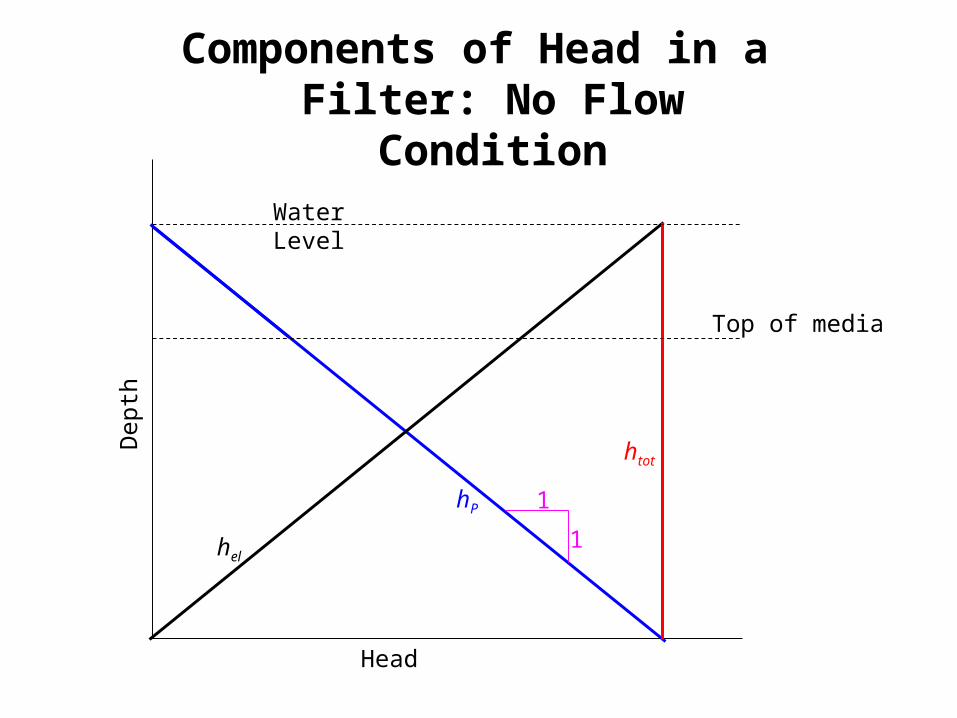
Components of Head in a Filter: No Flow
Condition
11
hel
hP
htot
Top of media
Water Level
Head
Depth
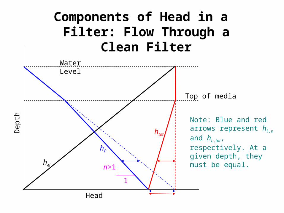
Components of Head in a Filter: Flow Through a
Clean Filter
1n>1
Note: Blue and red arrows represent hL,p and hL,tot, respectively. At a given depth, they must be equal.
hel
hP
htot
Top of media
Water Level
Head
Depth
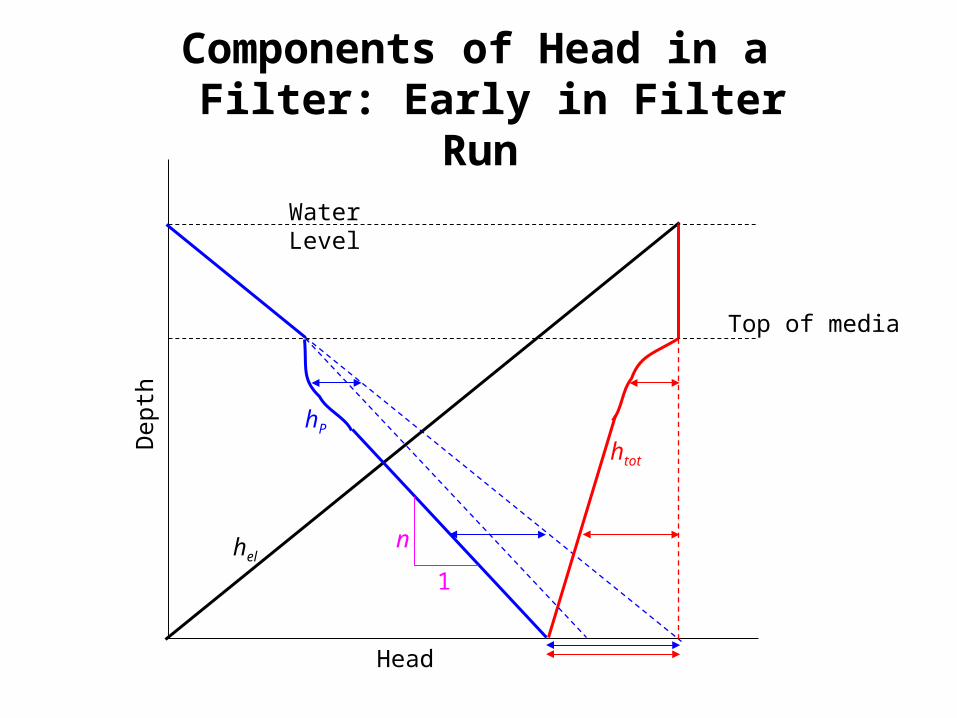
Components of Head in a Filter: Early in Filter
Run
n1
Top of media
Water Level
Head
Dept
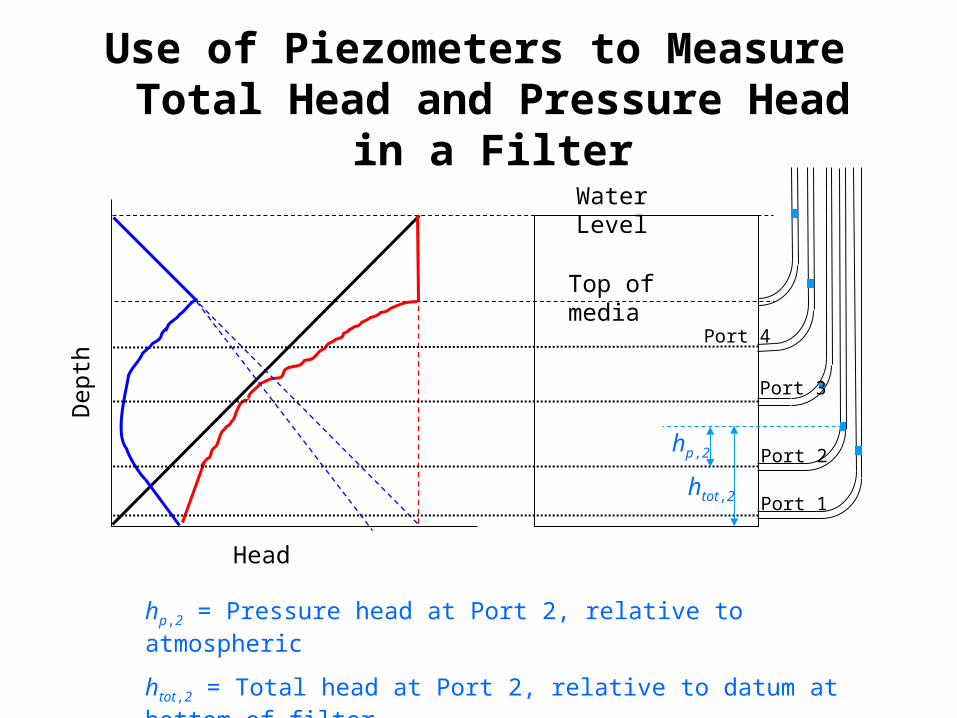
hUse of Piezometers to Measure Total Head and Pressure Head
in a Filter
Port 1
Port 2
Port 3
Port 4
hp,2
htot,2
hp,2 = Pressure head at Port 2, relative to atmospherichtot,2 = Total head at Port 2, relative to datum at bottom of filter
0.00
0.25
0.50
0.75
1.00
1.25
1.50
1.75
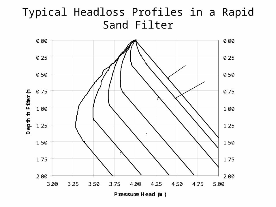
2.003.00 3.25 3.50 3.75 4.00 4.25 4.50 4.75 5.00
Pressure Head (m )
Depth in Filter (m
)
0.00
0.25
0.50
0.75
1.00
1.25
1.50
1.75
2.00
t = 1 hr
2 hr
4 hr
8 hr
12 hr16 hr
t = 0 hr
Typical Headloss Profiles in a Rapid Sand Filter
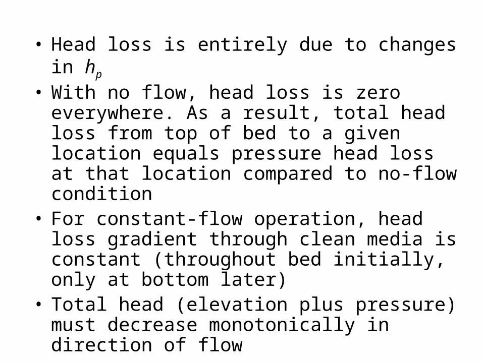
• Head loss is entirely due to changes in hp
• With no flow, head loss is zero everywhere. As a result, total head loss from top of bed to a given location equals pressure head loss at that location compared to no-flow condition
• For constant-flow operation, head loss gradient through clean media is constant (throughout bed initially, only at bottom later)
• Total head (elevation plus pressure) must decrease monotonically in direction of flow
• Pressure head is universally reported based on gage pressure; it can be negative (vacuum relative to atmosphere), but such a situation is undesirable

Filtration Complexity
•Two dependent variables of importance–Head Loss–Effluent Quality
•Never at Steady State•Two different modes of operation (filtration and backwashing)
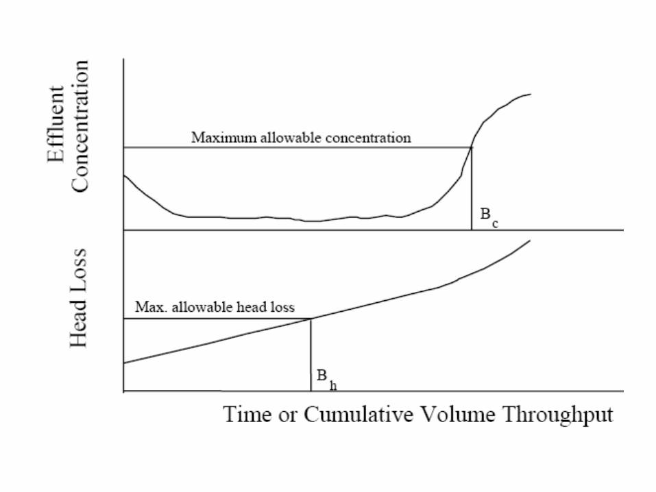

Filter cleaning• When??
– Head loss exceeds the design value– Effluent quality is unacceptable– Pre selected maximum filter run (time)
• Slow sand filter– Scraping of the top layer
• Rapid sand filter– Back washing
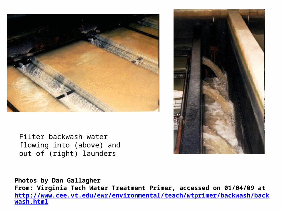
Photos by Dan GallagherFrom: Virginia Tech Water Treatment Primer, accessed on 01/04/09 at http://www.cee.vt.edu/ewr/environmental/teach/wtprimer/backwash/backwash.html
Filter backwash water flowing into (above) and out of (right) launders
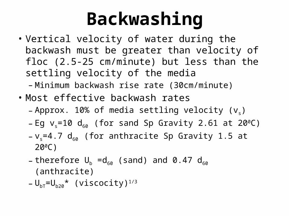
Backwashing• Vertical velocity of water during the backwash must be greater than velocity of floc (2.5-25 cm/minute) but less than the settling velocity of the media– Minimum backwash rise rate (30cm/minute)
• Most effective backwash rates– Approx. 10% of media settling velocity (vs)– Eg vs=10 d60
(for sand Sp Gravity 2.61 at 200C)– vs=4.7 d60
(for anthracite Sp Gravity 1.5 at 200C)
– therefore Ub =d60 (sand) and 0.47 d60 (anthracite)
– UbT=Ub20* (viscocity)1/3

Operational troubles in filters
Air binding and negative headThe head loss immediately after commissioning of the filter unit will be as low as about 10-15 cm. But as the time increases, the deposition of impurities within the voids of sand particles may increase and correspondingly the head loss may also increase even up to 2.5 to 3.5 m max. Due to the increase of friction, a negative head is formed just below the top of layer of 10-15 cm thick and is called the negative head. The negative head causes to releases, air bubbles, which stick on sand particles resulting problems on efficient and proper working of the filter unit. The air binding may be due to the development of negative head, growth of algae, rising temperature etc.
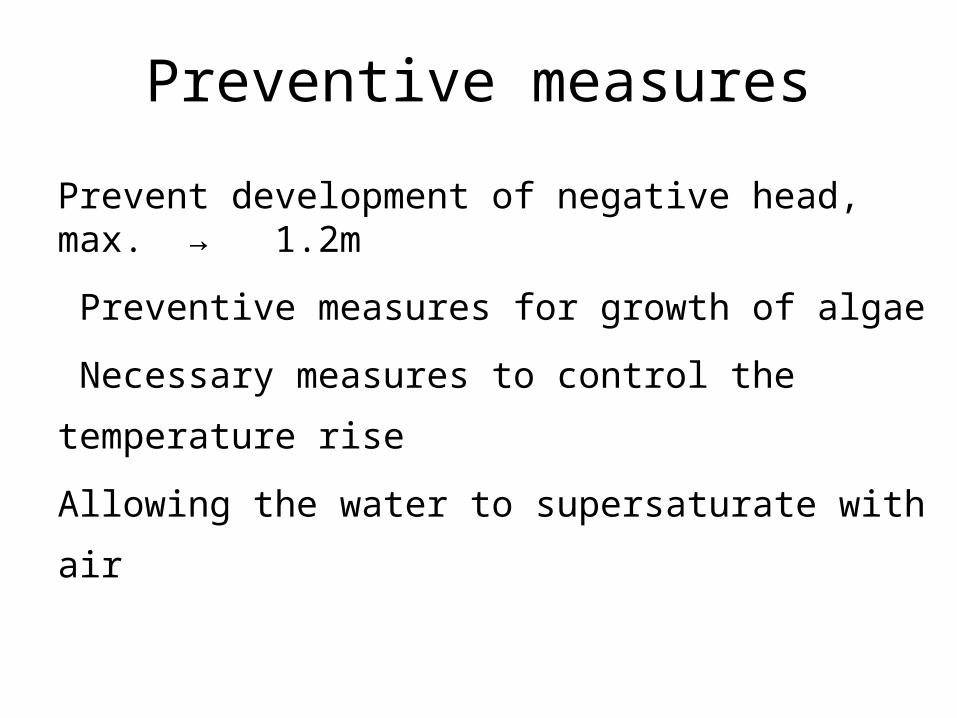
Preventive measuresPrevent development of negative head, max. → 1.2m Preventive measures for growth of algae Necessary measures to control the temperature rise Allowing the water to supersaturate with air
Operational troubles in filters
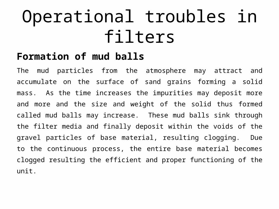
Formation of mud ballsThe mud particles from the atmosphere may attract and accumulate on the surface of sand grains forming a solid mass. As the time increases the impurities may deposit more and more and the size and weight of the solid thus formed called mud balls may increase. These mud balls sink through the filter media and finally deposit within the voids of the gravel particles of base material, resulting clogging. Due to the continuous process, the entire base material becomes clogged resulting the efficient and proper functioning of the unit.
Remedial measures
Mechanical racking of mud balls and back washing Backwashing with high pressure at the initial stages Backwashing with manual breaking Total replacement
Operational troubles in filters
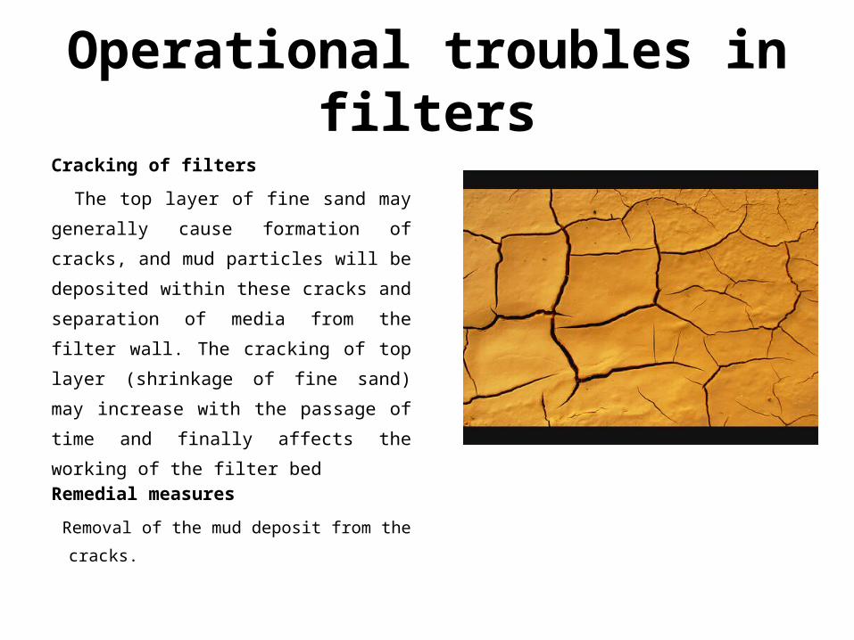
Cracking of filtersThe top layer of fine sand may
generally cause formation of cracks, and mud particles will be deposited within these cracks and separation of media from the filter wall. The cracking of top layer (shrinkage of fine sand) may increase with the passage of time and finally affects the working of the filter bedRemedial measures Removal of the mud deposit from the cracks.
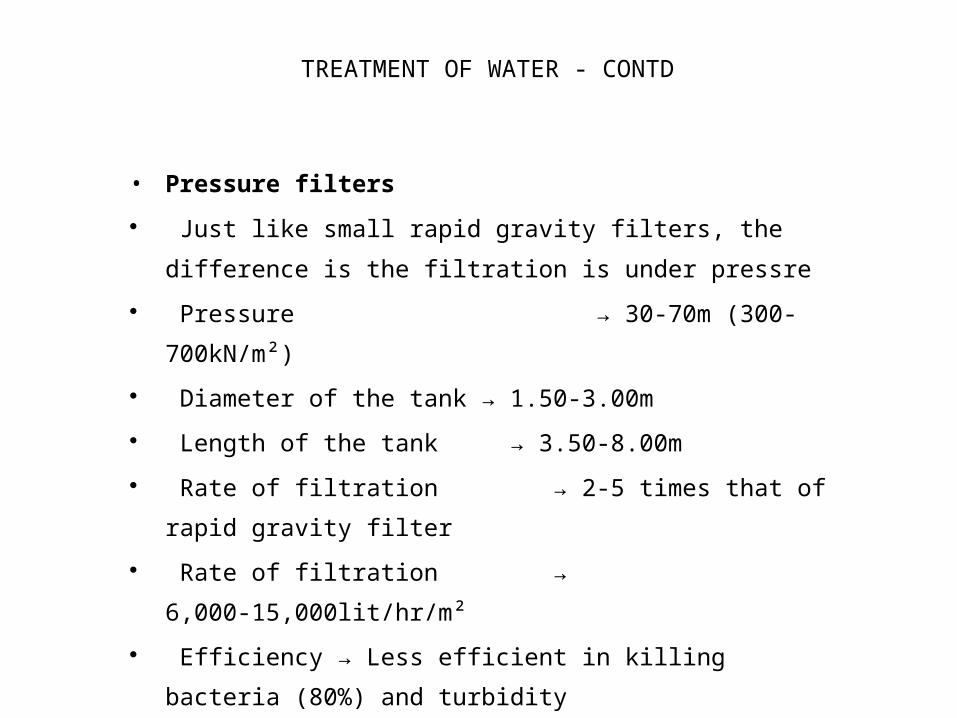
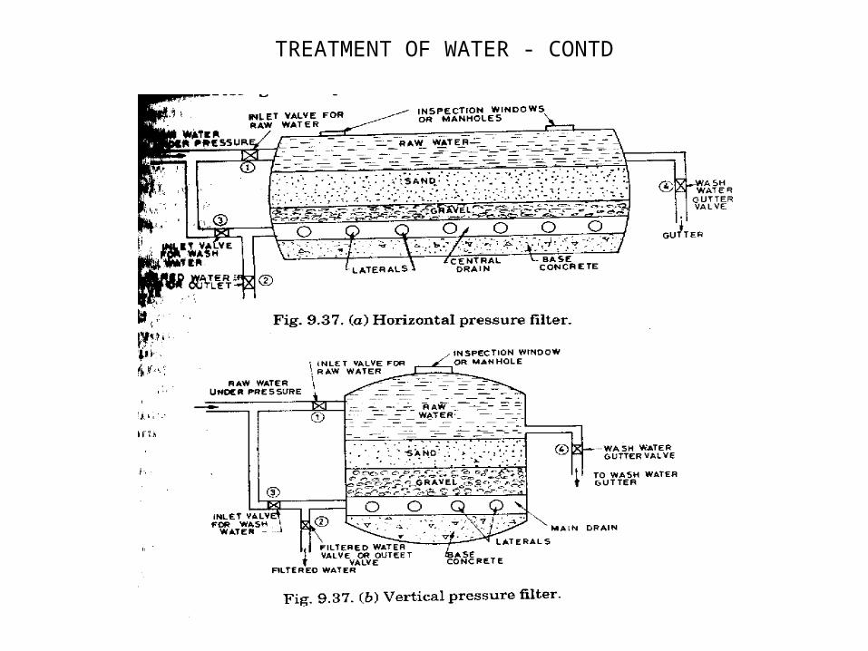
• Pressure filters Just like small rapid gravity filters, the
difference is the filtration is under pressre Pressure → 30-70m (300-
700kN/m²) Diameter of the tank → 1.50-3.00m Length of the tank → 3.50-8.00m Rate of filtration → 2-5 times that of
rapid gravity filter Rate of filtration →
6,000-15,000lit/hr/m² Efficiency → Less efficient in killing
bacteria (80%) and turbidity removal, than rapid gravity
Uses → Not recommended for large water supply schemes
TREATMENT OF WATER - CONTD
TREATMENT OF WATER - CONTD
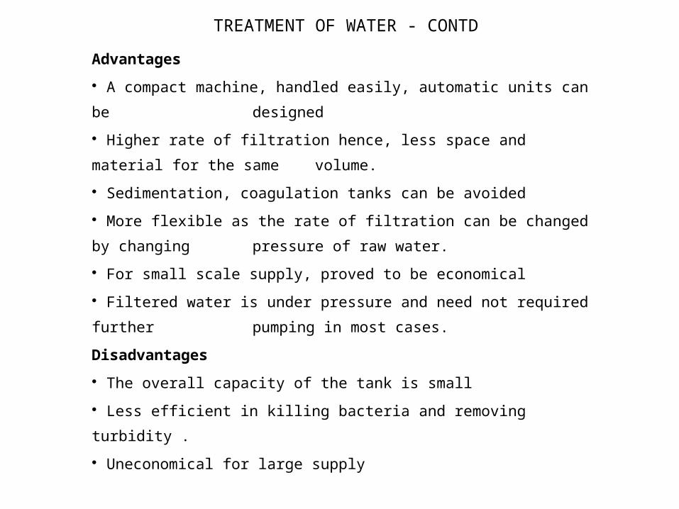
TREATMENT OF WATER - CONTDAdvantages A compact machine, handled easily, automatic units can be designed Higher rate of filtration hence, less space and material for the same volume. Sedimentation, coagulation tanks can be avoided More flexible as the rate of filtration can be changed by changing pressure of raw water. For small scale supply, proved to be economical Filtered water is under pressure and need not required further pumping in most cases.Disadvantages The overall capacity of the tank is small Less efficient in killing bacteria and removing turbidity . Uneconomical for large supply
TREATMENT OF WATER - CONTD
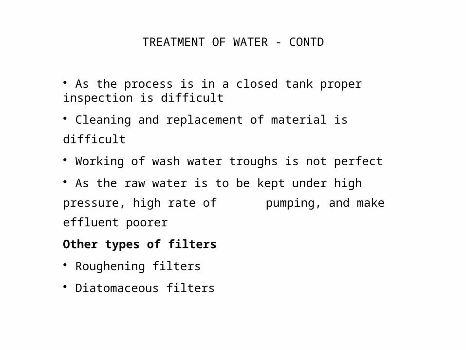
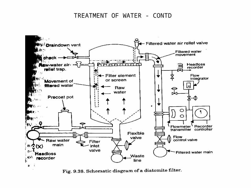
As the process is in a closed tank proper inspection is difficult Cleaning and replacement of material is difficult Working of wash water troughs is not perfect As the raw water is to be kept under high pressure, high rate of pumping, and make effluent poorerOther types of filters Roughening filters Diatomaceous filters
TREATMENT OF WATER - CONTD