hydraulic filtration - mp filtri usa
TRANSCRIPT

HYDRAULIC FILTRATIONPRODUCTS
TO PERFORMPASSION
STAINLESS STEEL HIGH PRESSURE FILTERS


1
A WORLDWIDE LEADER IN THE FIELD OF HYDRAULIC FILTRATION EQUIPMENT.
Our company started life in 1964, when Bruno Pasotto decided to attempt to cater for the requests of a market still to be fully explored, with the study, design, development, production and marketing of a vast range of fi lters for hydraulic equipment, capable of satisfying the needs of manufacturers in all sectors.The quality of our products, our extreme competitiveness compared with major international producers and our constant activities of research, design and development has made us a worldwide leader in the fi eld of hydraulic circuit fi ltering.Present for over 50 years in the market, we have played a truly decisive role in defi ning our sector, and by now we are a group capable of controlling our entire chain of production, monitoring all manufacturing processes to guarantee superior quality standards and to provide concrete solutions for the rapidly evolving needs of customers and the market.

Our customer-oriented philosophy, which enables us to satisfy all customer requests rapidly and with personalized products, makes us a dynamic and fl exible enterprise.The possibility of constantly controlling and monitoring the entire production process is essential to allow us to guarantee the quality of our products.
Our work is based on a skillful interaction between advanced technology and fi ne workmanship, customizing products according to specifi c market requests, focusing strongly on innovation and quality, and following every step in the manufacturing of both standard and special products, fully respecting customer expectations.
Introduction 2
LEADERMARKET

USA
CANADAUNITED KINGDOM
FRANCE
ITALY
GERMANY
INDIA
RUSSIA
P.R. CHINA
WORLDWIDE PRESENCE
8The Group boasts business branches
Our foreign Branches enable us to offer a diversified range of products that allow us to successfully face the aggressive challenge of international competition, and also to maintain a stable presence at a local level.
Introduction3
Introduction 4
TECHNOLOGY
Our constant quest for excellence in quality and technological innovation allows us to offer only the best solutions and services for applications in many fields, including general industry, test rigs, l u b r i c a t i o n , h e a v y e ng i n e e r i n g, r e n ewab l e energ ies, nava l engineering, offshore engineering, aviation systems, emerging technologies and mobile plant (i.e. tractors, excavators, concrete pumps, platforms).

Introduction5
AND PRODUCTION
Our high level of technological expertise means we can rely entirely on our own resources, without resorting to external providers. This in turn enables us to satisfy a growing number of customer requests, also exploiting our constantly updated range of machines and equ ipmen t , f ea tu r i ng fu l ly-automated workstations capable of 24-hour production.
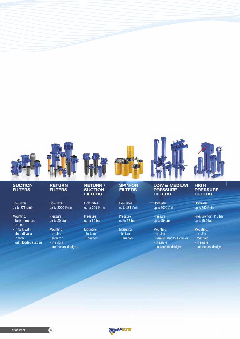
Flow rates up to 3000 l/min
Pressure up to 20 bar
Mounting:- In-Line- Tank top- In single and duplex designs
Flow rates up to 300 l/min
Pressure up to 80 bar
Mounting:- In-Line- Tank top
Flow rates up to 875 l/min
Mounting:- Tank immersed- In-Line- In tank with shut off valve- In tank with fl ooded suction
Flow rates up to 750 l/min
Pressure from 110 bar up to 560 bar
Mounting:- In-Line- Manifold- In single and duplex designs
Flow rates up to 3000 l/min
Pressure up to 80 bar
Mounting:- In-Line- Parallel manifold version- In single and duplex designs
LOW & MEDIUM PRESSURE FILTERS
HIGH PRESSURE FILTERS
SPIN-ON FILTERS
Flow rates up to 365 l/min
Pressure up to 35 bar
Mounting:- In-Line- Tank top
SUCTION FILTERS
RETURN FILTERS
RETURN /SUCTIONFILTERS
Introduction 6

Flow rates up to 125 l/min
Pressure from 320 bar up to 1000 bar
Mounting:- In-Line- Manifold- In single and duplex designs
Flow rates from 15 l/min up to 200 l/min
MOBILE FILTRATION UNITS
- Oil fi ller and air breather plugs- Optical and electrical level gauges- Pressure gauge valve selectors- Pipe fi xing brackets- Pressure gauges
POWER TRANSMISSIONPRODUCTS
TANKACCESSORIES
CONTAMINATION MONITORING PRODUCTS
STAINLESS STEEL HIGH PRESSURE FILTERS
- Aluminium bell-housings for motors from 0.12 kW to 400 kW- Couplings in Aluminium Cast Iron - Steel- Damping rings- Foot bracket- Aluminium tanks- Cleaning covers
- Online, in-line particle counters- Off-line bottle sampling products- Fully calibrated using relevant ISO standards- A wide range of variants to support fl uid types and communication protocols
PRODUCT RANGEMP Filtri can offer a vast and articulated range of products for the global market, suitable for all industrial sectors using hydraulic equipment.
This includes filters (suction, return, return/suction, spin-on, pressure, stainless steel pressure) and structural components (motor/pump bell-housings, transmission couplings, damping rings, foot brackets, aluminium tanks, cleaning covers).
We can provide all the skills and solutions required by the modern hydraulics industry to monitor contamination levels and other fl uid conditions.
Mobile fi ltration units and a full range of accessories allow us to supply everything necessary for a complete service in the hydraulic circuits.
Introduction7

COMPANY
PRODUCT RANGE
CONTAMINATION MANAGEMENT
FILTER SIZING
CORRECTIVE FACTOR
INTRODUCTION
1
6
11
22
24
page1
STR & MPA - MPM
SF2 250 - 350
SF2 500
CLOGGING INDICATORS
Submerged suction filter, with bypass or magnetic filter
Semi-submerged positive head suction filter, low flow rate
Semi-submerged positive head suction filter, high flow rate
1000 264
160 42
700 185
l/min gpmSUCTION FILTERS
31
39
47
57
page
up to Qmax
28
psi
MPFX
MPLX
MPTX
MFBX
MPF
MPT
MFB
MPH
MPI
FRI
RF2
CLOGGING INDICATORS
ACCESSORIES
Tank top semi-immersed filter, standard filter element disassembly
Tank top semi-immersed filter, standard filter element disassembly
Tank top semi-immersed filter, easy filter element disassembly
Bowl assembly
Tank top semi-immersed filter, standard filter element disassembly
Tank top semi-immersed filter, easy filter element disassembly
Bowl assembly
Tank top semi-immersed filter, standard filter element disassembly
Tank top semi-immersed filter, standard filter element disassembly
Tank top semi-immersed filter, easy filter element disassembly, it can be used also as in-line filter
Semi-immersed under-head filter, easy filter element disassembly
900 238
1800 476
300 79
700 185
900 238
300 79
700 185
3500 925
3500 925
2500 660
615 162
8 116
10 145
8 116
8 116
8 116
8 116
8 116
10 145
10 145
20 290
20 290
l/min gpmRETURN FILTERS
63
91
99
117
125
153
171
179
203
215
231
238
248
page
up to Pmax up to Qmax
60 bar
psi
MRSX
LMP 124 MULTIPORT
CLOGGING INDICATORS
Unique TANK TOP filter for mobile machinery, with combined filtration on
return and suction to the inlet at the hydrostatic transmissions in closed circuit
Unique IN-LINE filter for mobile machinery, with combined filtration on return
and suction to the inlet at the hydrostatic transmissions in closed circuit
250 66
120 32
10 145
80 1160
l/min gpmRETURN / SUCTION FILTERS
253
265
273
page
up to Pmax up to Qmax
250 bar
psi
MPS
MSH
CLOGGING INDICATORS
Low pressure filter, available with single cartridge (CS) for in-line or flange
mounting or with two cartridge on the same axis on the opposite sides
In-line low and medium pressure filter available with single cartridge (CH)
365 96
195 52
12 174
35 508
l/min gpmSPIN-ON FILTERS
289
305
311
page
up to Pmax up to Qmax
286 bar
HYDRAULIC FILTRATION PRODUCTS
Introduction 8

INDEX
QUICK REFERENCE GUIDE
CLOGGING INDICATORS
649
page646
psi l/min gpm
up to Qmax
FZP
FZH
FZX
FZM
FZB
FZD
CLOGGING INDICATORS
In-line pressure filter with threaded mount
In-line pressure filter with threaded mount for higher pressure
In-line pressure filter with threaded mount up to 1000 bar
Manifold top mounting
Manifold side mounting
Duplex pressure filter for continuous operation requirements
420 6092
700 10153
1000 14504
320 4641
320 4641
350 5076
STAINLESS STEEL HIGH PRESSURE FILTERS
587
597
607
615
623
631
641
page
up to Pmax
584 bar
160 42
80 21
10 3
70 18
70 18
60 16
up to Pmax up to Qmax
LMP 110 - 120 - 123 MULTIPORT
LMP 210 - 211
LMP 400 - 401 & 430 - 431
LMP 950 - 951
LMP 952 - 953 - 954
LMD 211
LMD 400 - 401 & 431
LMD 951
In-line filter with Multiport design for multiple choice connection
In-line low & medium pressure filter, low flow rate
In-line low & medium pressure filter, high flow rate
In-line filter, available with 2 and up to 6 different heads
In-line low pressure filter specifically designed to be mounted in series
In-line duplex medium pressure filter
In-line duplex low pressure filter
In-line duplex filter, available with 2 up to 6 different heads
175 46
365 96
780 206
2400 634
4500 1189
200 53
600 159
1200 317
80 1160
60 870
60 870
30 435
25 363
60 870
16 232
16 232
LDP - LDD
LMP 900 - 901
LMP 902 - 903
Filter elements designed according to DIN 24550
In-line and duplex medium pressure filter
In-line low pressure filter
In-line filter specifically designed to be mounted in series
360 95
2000 528
3000 793
60 870
30 435
20 290
psi l/min gpmLOW & MEDIUM PRESSURE FILTERS
325
341
351
363
371
383
391
407
415
417
427
435
CLOGGING INDICATORS
ACCESSORIES
444
450
page322 bar
psi
FMP 039
FMP
FHP
FMM
HPB
FHA 051
FHM
FHB
FHF 325
FHD
CLOGGING INDICATORS
Filter high pressure, low flow rate applications
Filter high pressure, high flow rate applications
Typical high pressure filter for mobile applications, high flow rate
Typical high pressure filter for mobile applications, low flow rate
Pressure filter kits for integration in control manifolds
Filter optimized for use in high pressure operating systems, low flow rate
High pressure filter with intermediate manifold construction
High pressure for block mounting
In-line manifold top mounting
In-line duplex high pressure filter
80 21
500 132
630 166
300 79
300 79
150 40
400 106
485 128
550 145
250 66
110 1595
320 4641
420 6092
420 6092
420 6092
560 8122
320 4641
320 4641
350 5076
350 5076
l/min gpmHIGH PRESSURE FILTERS
455
463
475
493
503
513
521
539
553
563
576
page
up to Pmax up to Qmax
452 bar
Introduction9
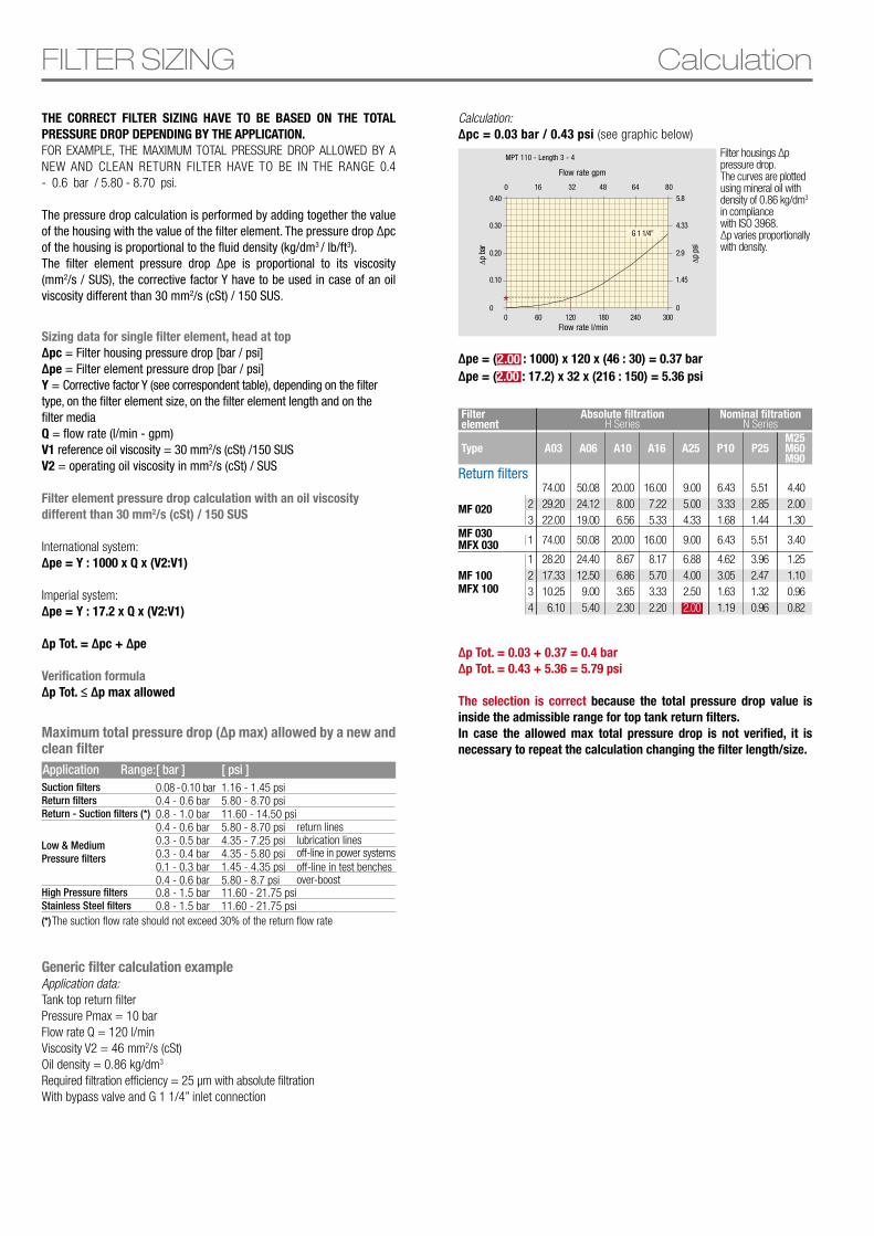
THE CORRECT FILTER SIZING HAVE TO BE BASED ON THE TOTAL PRESSURE DROP DEPENDING BY THE APPLICATION. FOR EXAMPLE, THE MAXIMUM TOTAL PRESSURE DROP ALLOWED BY A NEW AND CLEAN RETURN FILTER HAVE TO BE IN THE RANGE 0.4 - 0.6 bar / 5.80 - 8.70 psi.
The pressure drop calculation is performed by adding together the value of the housing with the value of the filter element. The pressure drop ∆pc of the housing is proportional to the fluid density (kg/dm3 / lb/ft3).The filter element pressure drop ∆pe is proportional to its viscosity (mm2/s / SUS), the corrective factor Y have to be used in case of an oil viscosity different than 30 mm2/s (cSt) / 150 SUS.
Generic filter calculation exampleApplication data:Tank top return filterPressure Pmax = 10 barFlow rate Q = 120 l/minViscosity V2 = 46 mm2/s (cSt)Oil density = 0.86 kg/dm3
Required filtration efficiency = 25 μm with absolute filtrationWith bypass valve and G 1 1/4” inlet connection
Filter housings ∆p pressure drop.The curves are plotted using mineral oil with density of 0.86 kg/dm3 in compliance with ISO 3968. ∆p varies proportionally with density.
Filter element
Absolute filtration Nominal filtration
Type A03 A16A06 A25A10 P10 P25M25M60M90
H Series N Series
123
MF 020
74.0029.2022.00
50.0824.1219.00
20.008.006.56
16.007.225.33
6.433.331.68
5.512.851.44
4.402.001.30
9.005.004.33
1MF 030MFX 030 74.00 50.08 20.00 16.00 6.43 5.51 3.409.00
1234
MF 100MFX 100
28.2017.3310.256.10
24.4012.509.005.40
8.676.863.652.30
8.175.703.332.20
4.623.051.631.19
3.962.471.320.96
1.251.100.960.82
6.884.002.502.00
Return filters
Sizing data for single filter element, head at top∆pc = Filter housing pressure drop [bar / psi]∆pe = Filter element pressure drop [bar / psi]Y = Corrective factor Y (see correspondent table), depending on the filter type, on the filter element size, on the filter element length and on the filter mediaQ = flow rate (l/min - gpm)V1 reference oil viscosity = 30 mm2/s (cSt) /150 SUSV2 = operating oil viscosity in mm2/s (cSt) / SUS
Filter element pressure drop calculation with an oil viscosity different than 30 mm2/s (cSt) / 150 SUS
International system:∆pe = Y : 1000 x Q x (V2:V1)
Imperial system: ∆pe = Y : 17.2 x Q x (V2:V1)
∆p Tot. = ∆pc + ∆pe
Verification formula∆p Tot. ≤ ∆p max allowed
FILTER SIZING Calculation
Maximum total pressure drop (∆p max) allowed by a new and clean filter
Suction filtersReturn filtersReturn - Suction filters (*)
High Pressure filtersStainless Steel filters
0.08 - 0.10 bar0.4 - 0.6 bar0.8 - 1.0 bar0.4 - 0.6 bar0.3 - 0.5 bar0.3 - 0.4 bar0.1 - 0.3 bar0.4 - 0.6 bar
1.16 - 1.45 psi5.80 - 8.70 psi 11.60 - 14.50 psi5.80 - 8.70 psi4.35 - 7.25 psi4.35 - 5.80 psi1.45 - 4.35 psi5.80 - 8.7 psi
0.8 - 1.5 bar0.8 - 1.5 bar
11.60 - 21.75 psi11.60 - 21.75 psi
return lineslubrication lines
over-boost
off-line in power systemsoff-line in test benches
Application Range: [ psi ][ bar ]
(*) The suction flow rate should not exceed 30% of the return flow rate
Low & MediumPressure filters
Calculation:∆pc = 0.03 bar / 0.43 psi (see graphic below)
*
0.40
0.30
0.20
0.10
0
MPT 110 - Length 3 - 4
Δp
bar
0 60 120 180 240 300Flow rate l/min
G 1 1/4”
5.8
4.33
2.9
1.45
0
Δp
psi
0 16 32 48 64 80
Flow rate gpm
∆pe = (2.00 : 1000) x 120 x (46 : 30) = 0.37 bar∆pe = (2.00 : 17.2) x 32 x (216 : 150) = 5.36 psi
∆p Tot. = 0.03 + 0.37 = 0.4 bar∆p Tot. = 0.43 + 5.36 = 5.79 psi
The selection is correct because the total pressure drop value is inside the admissible range for top tank return filters.In case the allowed max total pressure drop is not verified, it is necessary to repeat the calculation changing the filter length/size.
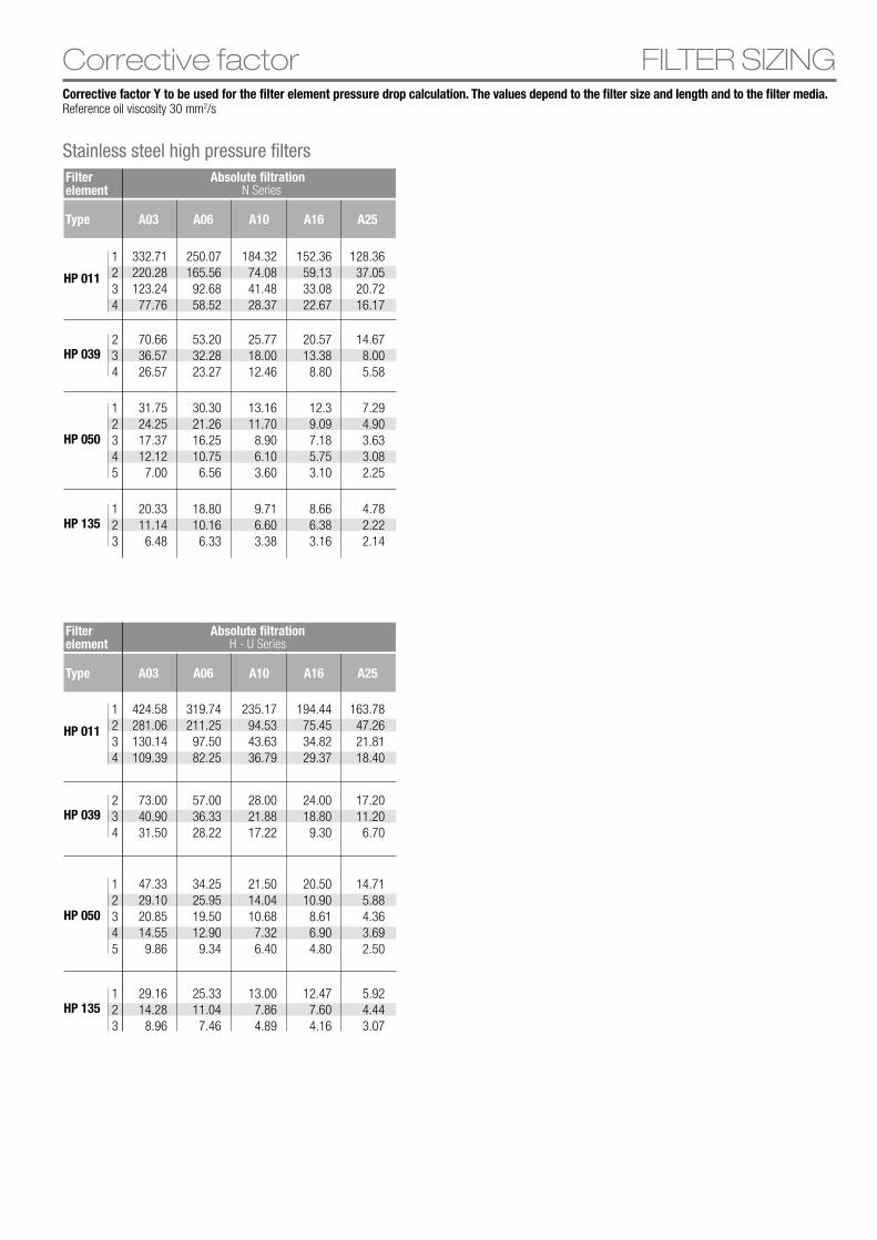
FILTER SIZINGCorrective factorCorrective factor Y to be used for the filter element pressure drop calculation. The values depend to the filter size and length and to the filter media.Reference oil viscosity 30 mm2/s
Type A03 A16A06 A25A10
Stainless steel high pressure filtersFilter element
Filter element
Absolute filtration
Absolute filtration
Type A03 A16A06 A25A10
N Series
H - U Series
1234
HP 011
128.3637.0520.7216.17
152.3659.1333.0822.67
184.3274.0841.4828.37
250.07165.5692.6858.52
332.71220.28123.2477.76
1234
HP 011
163.7847.2621.8118.40
194.4475.4534.8229.37
235.1794.5343.6336.79
319.74211.2597.5082.25
424.58281.06130.14109.39
12345
HP 050
7.294.903.633.082.25
12.39.097.185.753.10
13.1611.70
8.906.103.60
30.3021.2616.2510.756.56
31.7524.2517.3712.127.00
12345
HP 050
14.715.884.363.692.50
20.5010.908.616.904.80
21.5014.0410.68
7.326.40
34.2525.9519.5012.909.34
47.3329.1020.8514.559.86
234
HP 03914.67
8.005.58
20.5713.388.80
25.7718.0012.46
53.2032.2823.27
70.6636.5726.57
234
HP 03917.2011.20
6.70
24.0018.809.30
28.0021.8817.22
57.0036.3328.22
73.0040.9031.50
123
HP 1354.782.222.14
8.666.383.16
9.716.603.38
18.8010.166.33
20.3311.146.48
123
HP 1355.924.443.07
12.477.604.16
13.007.864.89
25.3311.047.46
29.1614.288.96
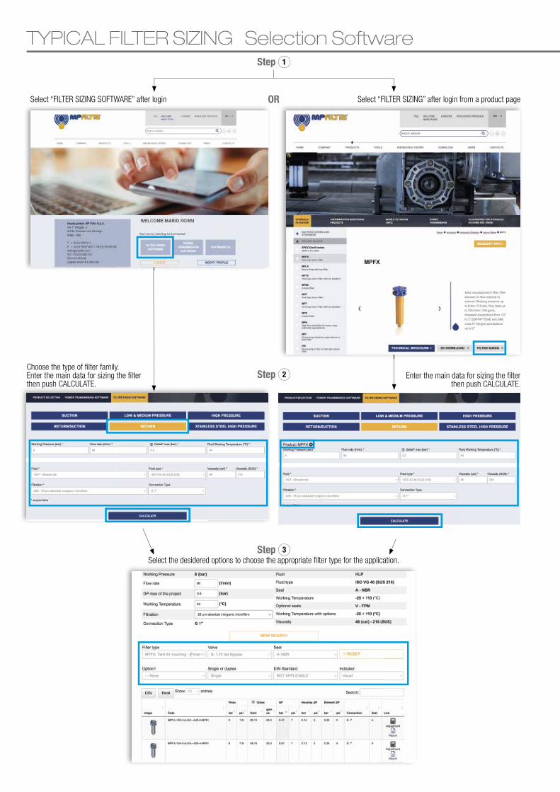
TYPICAL FILTER SIZING Selection Software
Select “FILTER SIZING SOFTWARE” after login Select “FILTER SIZING” after login from a product pageOR
Step 1
Step 2
Step 3
Choose the type of � lter family.Enter the main data for sizing the � lterthen push CALCULATE.
Enter the main data for sizing the � lterthen push CALCULATE.
Select the desidered options to choose the appropriate � lter type for the application.
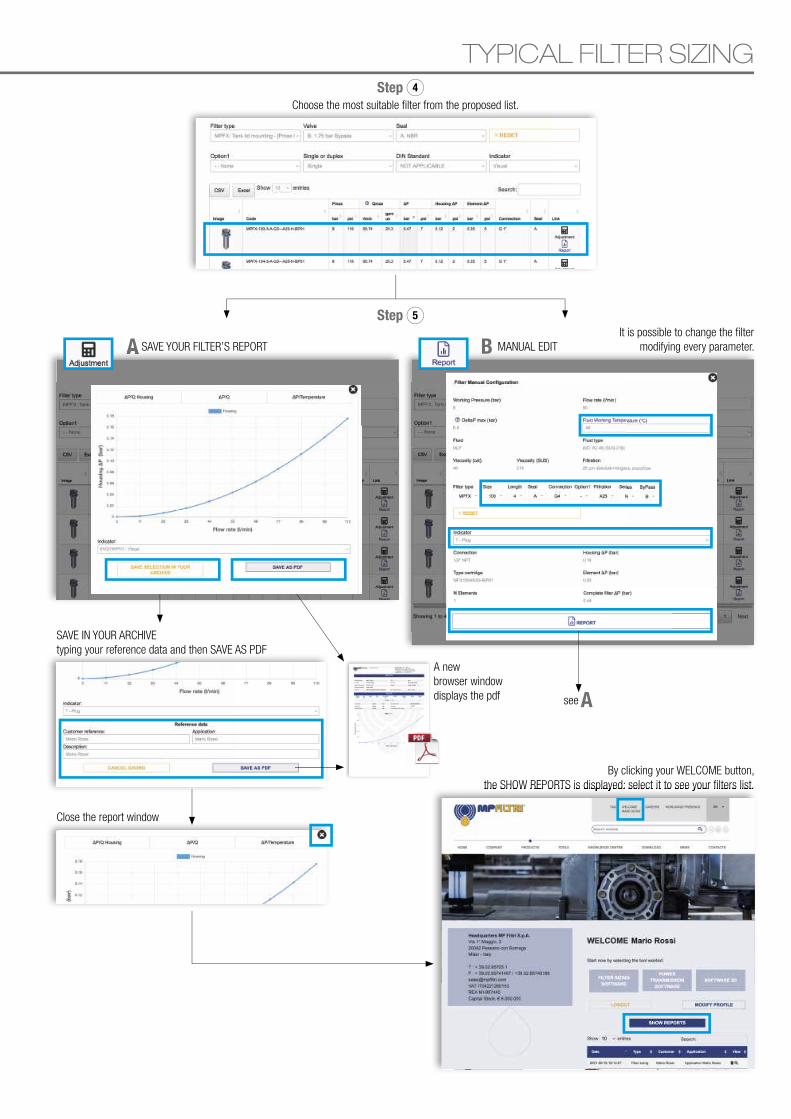
TYPICAL FILTER SIZING
A B
Step 4
Step 5
Choose the most suitable � lter from the proposed list.
A SAVE YOUR FILTER’S REPORT
A
It is possible to change the � lter modifying every parameter.MANUAL EDIT
see
A new browser window displays the pdf
SAVE IN YOUR ARCHIVEtyping your reference data and then SAVE AS PDF
By clicking your WELCOME button,the SHOW REPORTS is displayed: select it to see your � lters list.
Close the report window
the SHOW REPORTS is displayed: select it to see your � lters list.

Stainless steel high pressure filters are used as process filters to protect individual valves or the entire hydraulic circuit from contamination as per ISO 4406. 6 versions are available with operating pressures ranging from 320 bar up to 1000 bar.
A range of products is available to resolve all filtermounting problems, in the following configurations:- FZP In-line pressure filter with threaded mount- FZH In-line pressure filter with threaded mount for higher pressure- FZX In-line pressure filter with threaded mount up to 1000 bar- FZB Manifold side mounting- FZM Manifold top mounting- FZD Duplex pressure filter for continuous operation requirements
FZ stainless steel filters are specifically designed for applications in the:- Process engineering- Water hydraulics- Offshore technology- Marine technology- High pressure hydraulics- Any application in harsh or aggressive environment
FILTER SIZINGFor the proper corrective factor Y see chapter at page 25
Stainless steel high pressure filters 584

Stainless steel high pressure fi lters
FZPFZHFZXFZMFZBFZDINDICATORS
587597607615623631641
page
Stainless steel high pressure fi lters585

Stainless steel high pressure filters 586

Maximum working pressure up to 42 Mpa (420 bar) - Flow rate up to 160 l/min
Stainless steel high pressure fi lters
FZP series
Stainless steel high pressure fi lters587
GENERAL INFORMATIONFZP
Stainless steel high pressure fi lters
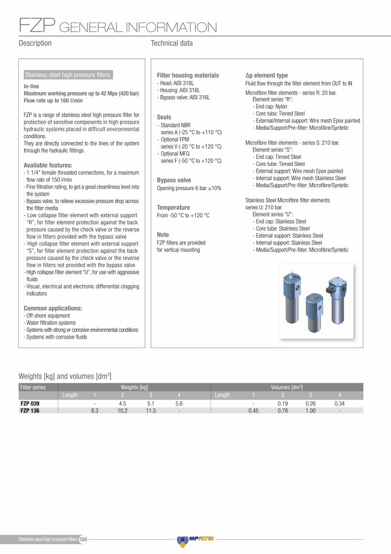
Microfi bre fi lter elements - series S: 210 bar.
Stainless Steel Microfi bre fi lter elementsseries U: 210 bar.
Microfi bre fi lter elements - series R: 20 bar.Element series “R”:- End cap: Nylon- Core tube: Tinned Steel- External/Internal support: Wire mesh Epox painted- Media/Support/Pre-fi lter: Microfi bre/Syntetic
Element series “S”:- End cap: Tinned Steel- Core tube: Tinned Steel- External support: Wire mesh Epox painted- Internal support: Wire mesh Stainless Steel- Media/Support/Pre-fi lter: Microfi bre/Syntetic
Element series “U”:- End cap: Stainless Steel- Core tube: Stainless Steel- External support: Stainless Steel- Internal support: Stainless Steel- Media/Support/Pre-fi lter: Microfi bre/Syntetic
Fluid fl ow through the fi lter element from OUT to IN∆p element type
- Head: AISI 316L- Housing: AISI 316L- Bypass valve: AISI 316L
Filter housing materials
From -50 °C to +120 °CTemperature
Opening pressure 6 bar ±10%Bypass valve
- Standard NBR series A (-25 °C to +110 °C)- Optional FPM series V (-20 °C to +120 °C)- Optional MFQ series F (-50 °C to +120 °C)
Seals
FZP fi lters are provided for vertical mounting
Note
Weights [kg] and volumes [dm3]Weights [kg]
FZP 039FZP 136
Volumes [dm3]Length Length
-0.45
0.34-
0.190.78
0.261.00
1 42 3
-8.3
5.6-
4.510.2
5.111.5
1 42 3 Filter series
In-lineMaximum working pressure up to 42 Mpa (420 bar)Flow rate up to 160 l/min
FZP is a range of stainless steel high pressure fi lter for protection of sensitive components in high pressure hydraulic systems placed in difficult environmental conditions.They are directly connected to the lines of the system through the hydraulic fi ttings.
Available features:- 1 1/4” female threaded connections, for a maximum fl ow rate of 150 l/min- Fine fi ltration rating, to get a good cleanliness level into the system- Bypass valve, to relieve excessive pressure drop across the fi lter media- Low collapse filter element with external support “R”, for filter element protection against the back pressure caused by the check valve or the reverse flow in filters provided with the bypass valve- High collapse filter element with external support “S”, for filter element protection against the back pressure caused by the check valve or the reverse flow in filters not provided with the bypass valve- High collapse fi lter element “U”, for use with aggressive fl uids- Visual, electrical and electronic differential clogging indicators
Common applications:- Off-shore equipment- Water fi ltration systems- Systems with strong or corrosive environmental conditions- Systems with corrosive fl uids
Description Technical data
Stainless steel high pressure fi lters 588
GENERAL INFORMATION FZP
Style SFZP 039FZP 136
Filter series Style B Style V Style ZStyle T Style D
Hydraulic symbols
••
• •••
• •
OUT
D.I.
IN
OUT
D.I.
IN
OUT
D.I.
IN
OUT
D.I.
IN
OUT
D.I.
IN
OUT
D.I.
IN
Pressure drop
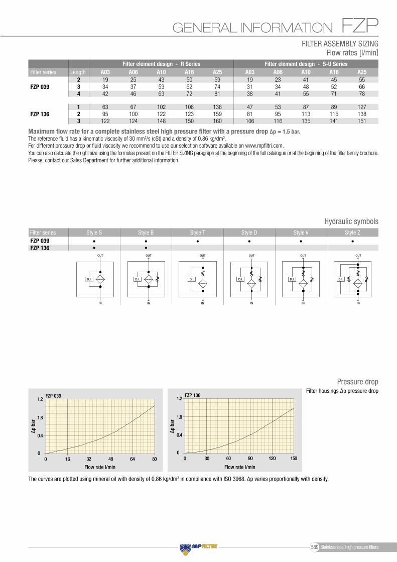
The curves are plotted using mineral oil with density of 0.86 kg/dm3 in compliance with ISO 3968. ∆p varies proportionally with density.
Filter housings ∆p pressure drop
1.2
1.8
0.4
00 30 60 90 120 150
Δp
bar
Flow rate l/min
FZP 1362.1
1.4
0.7
00 10 20 30 40 50
FZH 010 - 011
FZH 010
FZH 011
1.2
1.8
0.4
00 16 32 48 64 80
FZP 039 - FZH 039
1.2
1.8
0.4
00 30 60 90 120 150
FZP 136
1.2
1.8
0.4
00 16 32 48 64 80
FZB 039
4.2
2.8
1.4
00 8 16 24 32 40
FZD 010 - 021
FZD 010
FZD 021
1.2
0.8
0.4
00 16 32 48 64 80
FZM 039
9
6
3
00 2 4 6 8 10
FZX 0113
2
1
00 16 32 48 64 80
0 20 40 60 80 100
FZD 051
1.2
1.8
0.4
00 30 60 90 120 150
Δp
bar
Flow rate l/min
FZP 1362.1
1.4
0.7
00 10 20 30 40 50
FZH 010 - 011
FZH 010
FZH 011
1.2
1.8
0.4
00 16 32 48 64 80
FZP 039 - FZH 039
1.2
1.8
0.4
00 30 60 90 120 150
FZP 136
1.2
1.8
0.4
00 16 32 48 64 80
FZB 039
4.2
2.8
1.4
00 8 16 24 32 40
FZD 010 - 021
FZD 010
FZD 021
1.2
0.8
0.4
00 16 32 48 64 80
FZM 039
9
6
3
00 2 4 6 8 10
FZX 0113
2
1
00 16 32 48 64 80
0 20 40 60 80 100
FZD 051
Flow rate l/min Flow rate l/min
∆p b
ar
∆p b
ar
Filter series234
FZP 039
FZP 136
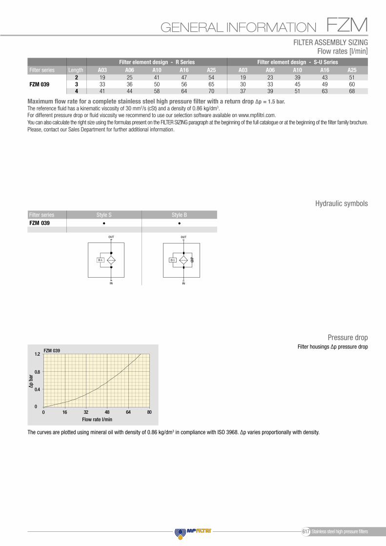
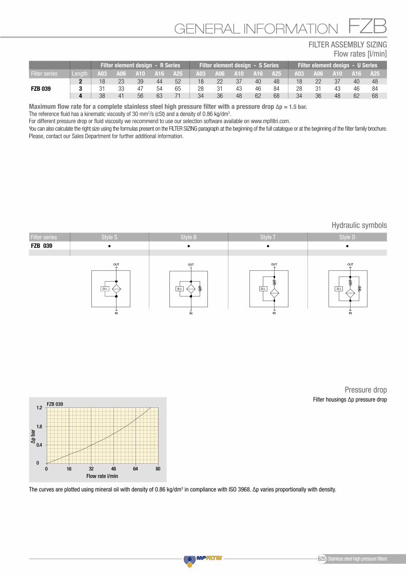
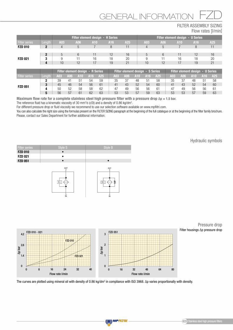
Maximum flow rate for a complete stainless steel high pressure filter with a pressure drop ∆p = 1.5 bar.The reference fluid has a kinematic viscosity of 30 mm2/s (cSt) and a density of 0.86 kg/dm3.For different pressure drop or fluid viscosity we recommend to use our selection software available on www.mpfiltri.com.You can also calculate the right size using the formulas present on the FILTER SIZING paragraph at the beginning of the full catalogue or at the beginning of the filter family brochure.Please, contact our Sales Department for further additional information.
Length
123
Filter element design - R Series A03 A06 A10 A16 A25 19 25 43 50 59 34 37 53 62 74 42 46 63 72 81
63 67 102 108 136 95 100 122 123 159 122 124 148 150 160
Filter element design - S-U Series A03 A06 A10 A16 A25 19 23 41 45 55 31 34 48 52 66 38 41 55 71 78
47 53 87 89 127 81 95 113 115 138 106 116 135 141 151
FILTER ASSEMBLY SIZINGFlow rates [l/min]
Stainless steel high pressure filters589

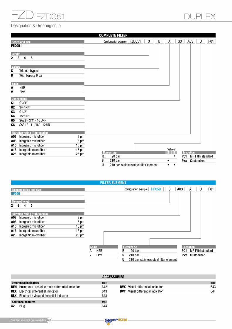
Designation & Ordering code
COMPLETE FILTER
IN-LINEFZP039
ACCESSORIES
Additional features page
X2 Plug 644
Differential indicators page page
DEHDEXDLX
DVYDVXHazardous area electronic differential indicator 642
Electrical differential indicatorElectrical / visual differential indicator
643643
Visual differential indicator 644Visual differential indicator 643
Configuration example:
ExecutionP01Pxx
MP Filtri standardCustomized
HP039 F2 UA03 P01
SealsAVF
NBRFPMMFQ
ValvesD ZT VBS• •
••• •• •
••
•
•
Element ∆pRSU
20 bar210 bar210 bar, stainless steel filter element
Filtration rating (filter media)
Filtration rating (filter media)
A03
A03
A10
A10
A06
A06
A16
A16
A25
A25
Inorganic microfiber
Inorganic microfiber
3 µm
3 µm
Inorganic microfiber
Inorganic microfiber
10 µm
10 µm
Inorganic microfiber
Inorganic microfiber
6 µm
6 µm
Inorganic microfiber
Inorganic microfiber
16 µm
16 µm
Inorganic microfiber
Inorganic microfiber
25 µm
25 µm
FILTER ELEMENT
Element length2 3 4
Element series and sizeHP039
ExecutionP01Pxx
MP Filtri standardCustomized
ValvesD ZT VBS• •
••• •• •
••
•
•
Element ∆pRSU
20 bar210 bar210 bar, stainless steel filter element
SBT
Without bypassWith bypass 6 barWith check valve, without bypass
DVZ
With check valve, with bypass 6 barWith reverse flow, without bypassWith reverse flow, with bypass 6 bar
Valves
Series and size Configuration example: FZP039 F2 2 UBB A03 P01FZP039
Length2 3 4
SealsA NBRV FPMF MFQ
Connections for differential indicators12
WithoutWith connection
ConnectionsA
CB
G 1/2”
SAE 8 - 3/4” - 16 UNF1/2” NPT
FZP
Stainless steel high pressure filters 590
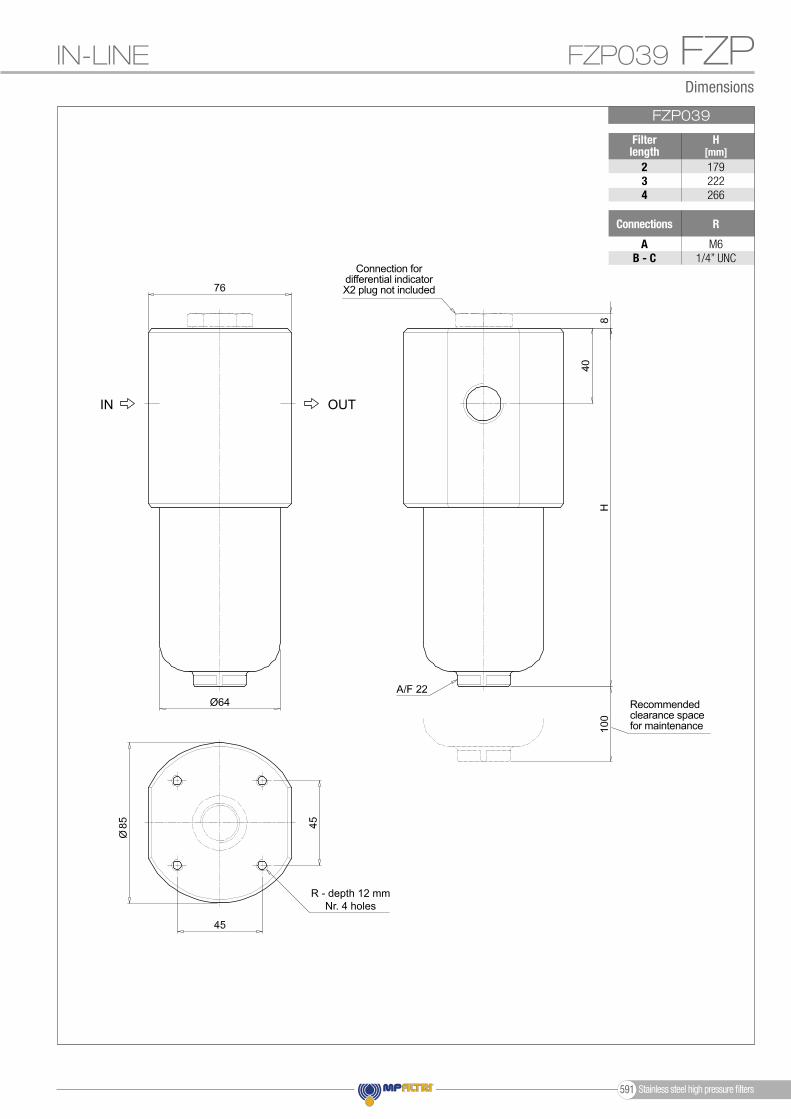
IN-LINE FZP039
Ø64
FZP039
Filter length
H[mm]
234
179222266
Connections R
AB - C
M61/4” UNC
FZPDimensions
OUTIN
Recommended clearance space for maintenance
Connection for differential indicatorX2 plug not included
R - depth 12 mmNr. 4 holes
Stainless steel high pressure filters591
Designation & Ordering code
COMPLETE FILTER
Configuration example:
ExecutionP01Pxx
MP Filtri standardCustomized
HP135 A1 RA03 P01
SealsAVF
NBRFPMMFQ
ValvesBS
••
•
•
Element ∆pRSU
20 bar210 bar210 bar, stainless steel filter element
BS
••
•
•
Element ∆pRSU
20 bar210 bar210 bar, stainless steel filter element
Filtration rating (filter media)A03
A10A06
A16A25
Inorganic microfiber 3 µm
Inorganic microfiber 10 µmInorganic microfiber 6 µm
Inorganic microfiber 16 µmInorganic microfiber 25 µm
FILTER ELEMENT
Element length1 2 3
Element series and sizeHP135
Filtration rating (filter media)A03
A10A06
A16A25
Inorganic microfiber 3 µm
Inorganic microfiber 10 µmInorganic microfiber 6 µm
Inorganic microfiber 16 µmInorganic microfiber 25 µm
ExecutionP01Pxx
MP Filtri standardCustomized
Valves
SB
Without bypassWith bypass 6 bar
Valves
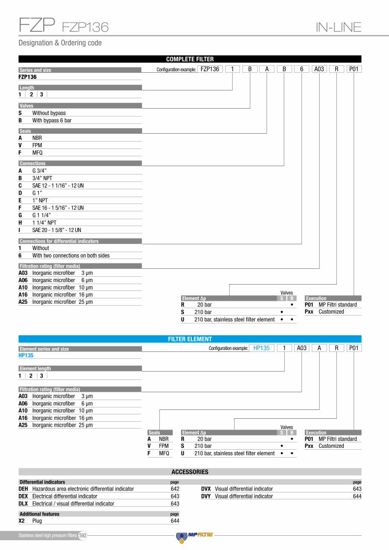
Series and size Configuration example: FZP136 A1 6 RBB A03 P01FZP136
Length1 2 3
SealsA NBRV FPMF MFQ
Connections for differential indicators16
WithoutWith two connections on both sides
ConnectionsA
D
G
C
F
I
B
E
H
G 3/4”
G 1”
G 1 1/4”
SAE 12 - 1 1/16” - 12 UN
SAE 16 - 1 5/16” - 12 UN
SAE 20 - 1 5/8” - 12 UN
3/4” NPT
1” NPT
1 1/4” NPT
FZP IN-LINEFZP136
ACCESSORIES
Additional features page
X2 Plug 644
Differential indicators page page
DEHDEXDLX
DVYDVXHazardous area electronic differential indicator 642
Electrical differential indicatorElectrical / visual differential indicator
643643
Visual differential indicator 644Visual differential indicator 643
Stainless steel high pressure filters 592

Ø80
FZP136
Filter length
H[mm]
123
222335410
Connections R
AB - C
DE - F
GH - I
M103/8” UNC
M103/8” UNC
M103/8” UNC
FZPDimensions
IN-LINE FZP136
OUTIN
Recommended clearance space for maintenance
Connection for differential indicator
X2 plug
The position of the X2 plug is reversible
Connection for differential indicatorX2 plug not included
R - depth 12 mmNr. 4 holes
Stainless steel high pressure filters593

FZP 136
3d
3a
3b
3c
2
4
3e 3d
4
3g
3c
Item:
Filter series
Seal Kit code numberFilterelement NBR FPM
Seeorder table
2Q.ty: 1 pc. Q.ty: 1 pc.Q.ty: 1 pc.
(3a ÷ 3g)3 4
Indicator connection plugNBR FPM
X2H X2V0205029902050636
0205030002050637
FZP 039FZP 136
FZP 039
3d
3a
3b
3c
2
4
3e
Order number for spare parts
FZP SPARE PARTS
Stainless steel high pressure fi lters 594

FZP
Stainless steel high pressure filters595

Stainless steel high pressure filters 596
Stainless steel high pressure fi lters
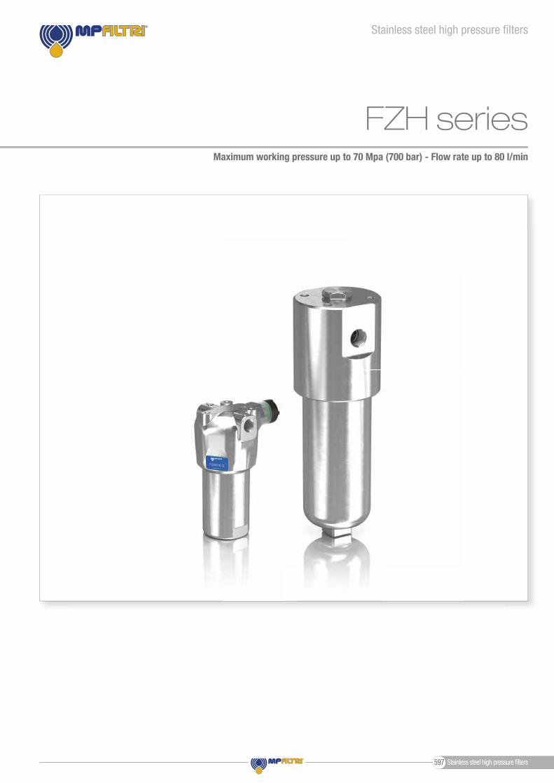
FZH seriesMaximum working pressure up to 70 Mpa (700 bar) - Flow rate up to 80 l/min
Stainless steel high pressure fi lters597
FZH GENERAL INFORMATION
Weights [kg] and volumes [dm3]
Weights [kg]
FZH 010-011FZH 039
Volumes [dm3]
0.10-
0.200.34
0.120.19
0.150.26
2.1-
3.310.1
2.27.8
2.78.9
Length Length 1 42 31 42 3 Filter series
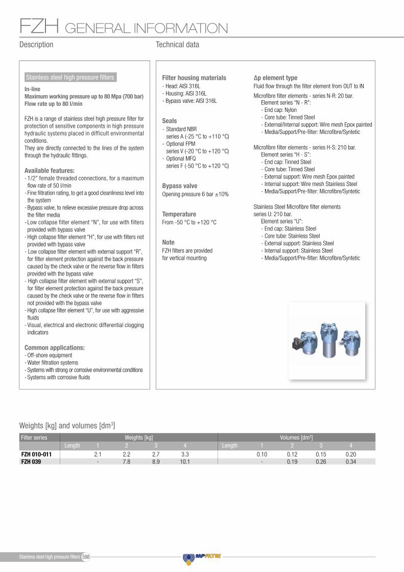
From -50 °C to +120 °CTemperature
Opening pressure 6 bar ±10%Bypass valve
Micro� bre � lter elements - series H-S: 210 bar.
Stainless Steel Micro� bre � lter elementsseries U: 210 bar.
Micro� bre � lter elements - series N-R: 20 bar.Element series “N - R”:- End cap: Nylon- Core tube: Tinned Steel- External/Internal support: Wire mesh Epox painted- Media/Support/Pre-� lter: Micro� bre/Syntetic
Element series “H - S”:- End cap: Tinned Steel- Core tube: Tinned Steel- External support: Wire mesh Epox painted- Internal support: Wire mesh Stainless Steel- Media/Support/Pre-� lter: Micro� bre/Syntetic
Element series “U”:- End cap: Stainless Steel- Core tube: Stainless Steel- External support: Stainless Steel- Internal support: Stainless Steel- Media/Support/Pre-� lter: Micro� bre/Syntetic
Fluid � ow through the � lter element from OUT to IN∆p element type
- Standard NBR series A (-25 °C to +110 °C)- Optional FPM series V (-20 °C to +120 °C)- Optional MFQ series F (-50 °C to +120 °C)
Seals
FZH � lters are provided for vertical mounting
Note
- Head: AISI 316L- Housing: AISI 316L- Bypass valve: AISI 316L
Filter housing materials
Description Technical data
Stainless steel high pressure � lters
In-lineMaximum working pressure up to 80 Mpa (700 bar)Flow rate up to 80 l/min
FZH is a range of stainless steel high pressure � lter for protection of sensitive components in high pressure hydraulic systems placed in difficult environmental conditions.They are directly connected to the lines of the system through the hydraulic � ttings.
Available features:- 1/2” female threaded connections, for a maximum � ow rate of 50 l/min- Fine � ltration rating, to get a good cleanliness level into the system- Bypass valve, to relieve excessive pressure drop across the � lter media- Low collapse filter element “N”, for use with filters provided with bypass valve- High collapse � lter element “H”, for use with � lters not provided with bypass valve- Low collapse � lter element with external support “R”, for � lter element protection against the back pressure caused by the check valve or the reverse � ow in � lters provided with the bypass valve- High collapse � lter element with external support “S”, for � lter element protection against the back pressure caused by the check valve or the reverse � ow in � lters not provided with the bypass valve- High collapse � lter element “U”, for use with aggressive � uids- Visual, electrical and electronic differential clogging indicators
Common applications:- Off-shore equipment- Water � ltration systems- Systems with strong or corrosive environmental conditions- Systems with corrosive � uids
Stainless steel high pressure � lters 598

FZHGENERAL INFORMATION
FZH 010-011FZH 039
Style S Filter series Style B Style V Style ZStyle T Style D
Hydraulic symbols
•• •
••
•• •
••
OUT
D.I.
IN
OUT
D.I.
IN
OUT
D.I.
IN
OUT
D.I.
IN
OUT
D.I.
IN
OUT
D.I.
IN
Pressure drop
The curves are plotted using mineral oil with density of 0.86 kg/dm3 in compliance with ISO 3968. ∆p varies proportionally with density.
Filter housings ∆p pressure drop1.2
1.8
0.4
00 30 60 90 120 150
Δp
bar
Flow rate l/min
FZP 1362.1
1.4
0.7
00 10 20 30 40 50
FZH 010 - 011
FZH 010
FZH 011
1.2
1.8
0.4
00 16 32 48 64 80
FZP 039 - FZH 039
1.2
1.8
0.4
00 30 60 90 120 150
FZP 136
1.2
1.8
0.4
00 16 32 48 64 80
FZB 039
4.2
2.8
1.4
00 8 16 24 32 40
FZD 010 - 021
FZD 010
FZD 021
1.2
0.8
0.4
00 16 32 48 64 80
FZM 039
9
6
3
00 2 4 6 8 10
FZX 0113
2
1
00 16 32 48 64 80
0 20 40 60 80 100
FZD 051
1.2
1.8
0.4
00 30 60 90 120 150
Δp
bar
Flow rate l/min
FZP 1362.1
1.4
0.7
00 10 20 30 40 50
FZH 010 - 011
FZH 010
FZH 011
1.2
1.8
0.4
00 16 32 48 64 80
FZP 039 - FZH 039
1.2
1.8
0.4
00 30 60 90 120 150
FZP 136
1.2
1.8
0.4
00 16 32 48 64 80
FZB 039
4.2
2.8
1.4
00 8 16 24 32 40
FZD 010 - 021
FZD 010
FZD 021
1.2
0.8
0.4
00 16 32 48 64 80
FZM 039
9
6
3
00 2 4 6 8 10
FZX 0113
2
1
00 16 32 48 64 80
0 20 40 60 80 100
FZD 051
Flow rate l/min Flow rate l/min
∆p b
ar
∆p b
ar
Filter series
1234
1234
FZH 011
FZH 010
Length
234
FZH 039
Maximum flow rate for a complete stainless steel high pressure filter with a pressure drop ∆p = 1.5 bar.The reference fluid has a kinematic viscosity of 30 mm2/s (cSt) and a density of 0.86 kg/dm3.For different pressure drop or fluid viscosity we recommend to use our selection software available on www.mpfiltri.com.You can also calculate the right size using the formulas present on the FILTER SIZING paragraph at the beginning of the full catalogue or at the beginning of the filter family brochure.Please, contact our Sales Department for further additional information.
A03 A06 A10 A16 A25 4 6 8 9 11 7 9 17 20 26 11 14 25 27 32 17 20 29 31 34
4 6 8 9 11 7 9 17 21 28 11 14 26 30 37 17 21 32 36 40
19 25 43 50 59 34 37 53 62 74 42 46 63 72 81
Filter element design - R Series A03 A06 A10 A16 A25 4 5 6 7 9 5 7 14 17 23 11 14 24 27 32 13 16 26 29 33
3 5 6 7 9 5 7 14 17 24 11 14 25 29 36 12 16 28 32 38
19 23 41 45 55 31 34 48 52 66 38 41 55 71 78
Filter element design - S-U Series
FILTER ASSEMBLY SIZINGFlow rates [l/min]
Stainless steel high pressure filters599
Designation & Ordering code
COMPLETE FILTER
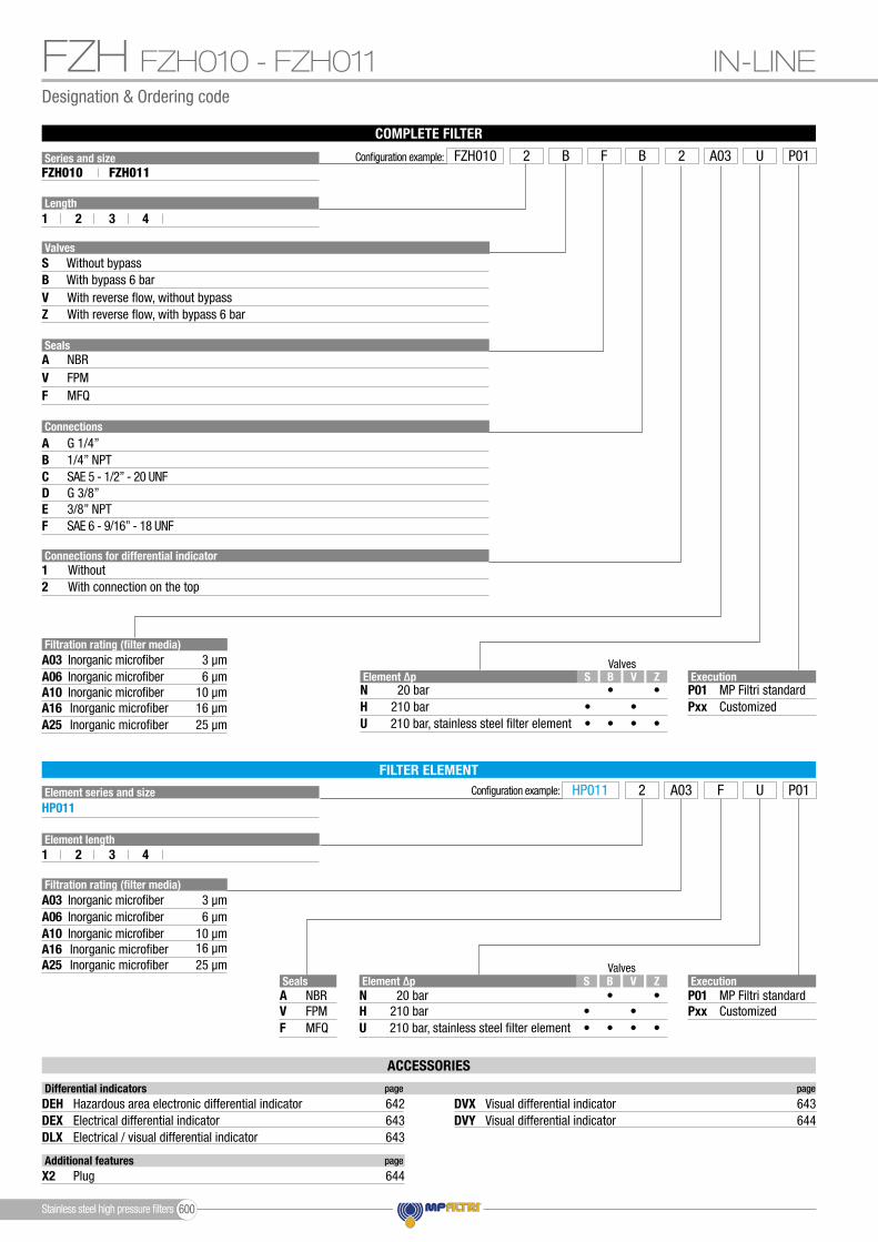
FZH FZH010 - FZH011
Configuration example:
Execution
Execution
P01
P01
Pxx
Pxx
MP Filtri standard
MP Filtri standard
Customized
Customized
HP011 F2 UA03 P01
SealsAVF
NBRFPMMFQ
Element length
Element series and sizeHP011
FILTER ELEMENT
Valves
Valves
ZVBS•
•••
••
•
•
Element ∆pNHU
20 bar210 bar210 bar, stainless steel filter element
ZVBS•
•••
••
•
•
Element ∆pNHU
20 bar210 bar210 bar, stainless steel filter element
Filtration rating (filter media)A03
A10A06
A16A25
Inorganic microfiber 3 µm
Inorganic microfiber 10 µmInorganic microfiber 6 µm
Inorganic microfiber 16 µmInorganic microfiber 25 µm
Filtration rating (filter media)A03
A10A06
A16A25
Inorganic microfiber 3 µm
Inorganic microfiber 10 µmInorganic microfiber 6 µm
Inorganic microfiber 16 µmInorganic microfiber 25 µm
Series and size Configuration example: FZH010 F2 U2B B A03 P01FZH010 FZH011
Length1
1
2
2
3
3
4
4
SB
Without bypassWith bypass 6 bar
VZ
With reverse flow, without bypassWith reverse flow, with bypass 6 bar
Valves
SealsA NBRV FPMF MFQ
ConnectionsA
DC
F
B
E
G 1/4”
G 3/8”SAE 5 - 1/2” - 20 UNF
SAE 6 - 9/16” - 18 UNF
1/4” NPT
3/8” NPT
Connections for differential indicator12
WithoutWith connection on the top
IN-LINE
ACCESSORIES
Additional features page
X2 Plug 644
Differential indicators page page
DEHDEXDLX
DVYDVXHazardous area electronic differential indicator 642
Electrical differential indicatorElectrical / visual differential indicator
643643
Visual differential indicator 644Visual differential indicator 643
Stainless steel high pressure filters 600

1313
Ø55
Ø55
1313
Ø55
Ø55
Dimensions
FZHFZH010 - FZH011
FZH010
Filter length
Filter length
H[mm]
H[mm]
1234
1234
92103153203
92103153203
Connections
Connections
R
R
AB - C
DE - F
AB - C
DE - F
M61/4” UNC
M61/4” UNC
M61/4” UNC
M61/4” UNC
FZH011
IN-LINE
OUT
OUT
IN
IN
Recommended clearance space for maintenance
Recommended clearance space for maintenance
Connection for differential indicatorX2 plug not included
Connection for differential indicatorX2 plug not included
R - depth 12 mmNr. 3 holes
R - depth 12 mmNr. 3 holes
Stainless steel high pressure filters601

Designation & Ordering code
COMPLETE FILTER
FZH FZH039
Configuration example:
Execution
Execution
P01
P01
Pxx
Pxx
MP Filtri standard
MP Filtri standard
Customized
Customized
HP039 A2 SA03 P01
SealsAVF
NBRFPMMFQ
Element length
Element series and sizeHP039
FILTER ELEMENT
Valves
Valves
D ZT VBS• •
••• •• •
••
•
•
Element ∆pRSU
20 bar210 bar210 bar, stainless steel filter element
D ZT VBS• •
••• •• •
••
•
•
Element ∆pRSU
20 bar210 bar210 bar, stainless steel filter element
Filtration rating (filter media)A03
A10A06
A16A25
Inorganic microfiber 3 µm
Inorganic microfiber 10 µmInorganic microfiber 6 µm
Inorganic microfiber 16 µmInorganic microfiber 25 µm
Filtration rating (filter media)A03
A10A06
A16A25
Inorganic microfiber 3 µm
Inorganic microfiber 10 µmInorganic microfiber 6 µm
Inorganic microfiber 16 µmInorganic microfiber 25 µm
Series and size Configuration example: FZH039 A2 S2T A A03 P01FZH039
Length
SBT
Without bypassWith bypass 6 barWith check valve, without bypass
DVZ
With check valve, with bypass 6 barWith reverse flow, without bypassWith reverse flow, with bypass 6 bar
Valves
SealsA NBRV FPMF MFQ
ConnectionsA
CB
G 1/2”1/2” NPTSAE 8 - 3/4” - 16 UNF
Connections for differential indicator12
WithoutWith connection on the top
IN-LINE
2 3 4
2 3 4
ACCESSORIES
Additional features page
X2 Plug 644
Differential indicators page page
DEHDEXDLX
DVYDVXHazardous area electronic differential indicator 642
Electrical differential indicatorElectrical / visual differential indicator
643643
Visual differential indicator 644Visual differential indicator 643
Stainless steel high pressure filters 602
Dimensions
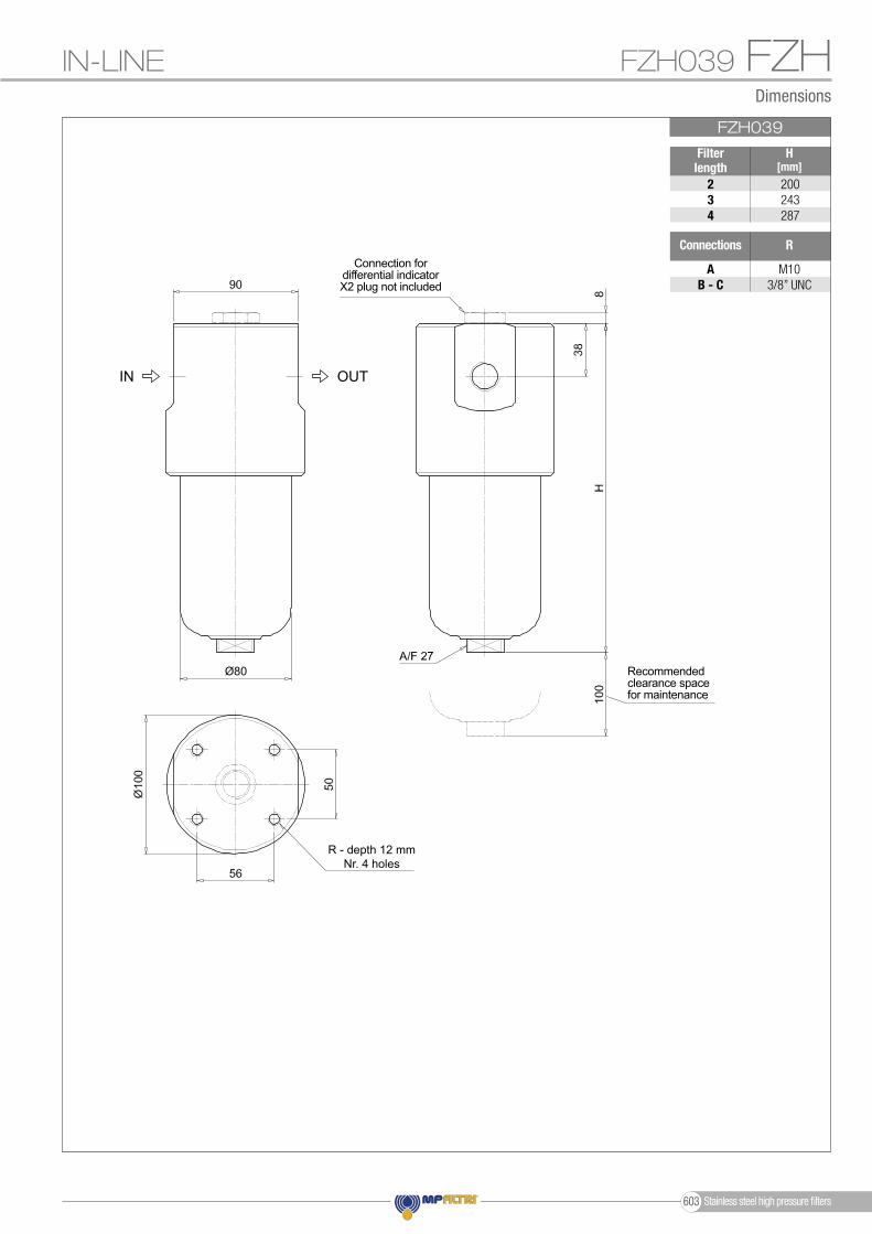
FZHFZH039IN-LINE
Ø80
FZH039
Filter length
H[mm]
234
200243287
Connections R
AB - C
M103/8” UNC
OUTIN
Recommended clearance space for maintenance
Connection for differential indicatorX2 plug not included
R - depth 12 mmNr. 4 holes
Stainless steel high pressure filters603

FZHOrder number for spare parts
FZH 010 - 011
3d
3a
3b
3c
2
4 3e
Item:
Filter series
Seal Kit code numberFilterelement NBR FPM
Seeorder table
2Q.ty: 1 pc. Q.ty: 1 pc.Q.ty: 1 pc.
(3a ÷ 3e)3 4
Indicator connection plugNBR FPM
X2H X2V0205050102050335
0205049202050336
FZH 010-011FZH 039
FZH 039
3d
3a
3b
3c
2
4
3e
SPARE PARTS
Stainless steel high pressure fi lters 604

FZH
Stainless steel high pressure filters605

Stainless steel high pressure filters 606

Stainless steel high pressure fi lters
FZX seriesMaximum working pressure up to 100 Mpa (1000 bar) - Flow rate up to 10 l/min
Stainless steel high pressure fi lters607

FZX GENERAL INFORMATION
Weights [kg] and volumes [dm3]
Weights [kg]
FZX 011
Volumes [dm3]
- -- 0.15- -- 6.5
Length Length 1 42 31 42 3 Filter series
From -50 °C to +120 °CTemperature
Opening pressure 6 bar ±10%Bypass valve
Microfi bre fi lter elements - series H: 210 bar.
Stainless Steel Microfi bre fi lter elementsseries U: 210 bar.
Element series “H”:- End cap: Tinned Steel- Core tube: Tinned Steel- External support: Wire mesh Epox painted- Internal support: Wire mesh Stainless Steel- Media/Support/Pre-fi lter: Microfi bre/Syntetic
Element series “U”:- End cap: Stainless Steel- Core tube: Stainless Steel- External support: Stainless Steel- Internal support: Stainless Steel- Media/Support/Pre-fi lter: Microfi bre/Syntetic
Fluid fl ow through the fi lter element from OUT to IN∆p element type
- Standard NBR series A (-25 °C to +110 °C)- Optional FPM series V (-20 °C to +120 °C)- Optional MFQ series F (-50 °C to +120 °C)
Seals
FZX fi lters are provided for vertical mounting
Note
- Head: AISI 316L- Housing: AISI 316L- Bypass valve: AISI 316L
Filter housing materials
Description Technical data
Stainless steel high pressure fi lters
In-lineMaximum working pressure up to 100 Mpa (1000 bar)Flow rate up to 10 l/min
FZX is a range of stainless steel high pressure fi lter for protection of sensitive components in high pressure hydraulic systems placed in difficult environmental conditions.They are directly connected to the lines of the system through the hydraulic fi ttings.
Available features:- 1/2” female threaded connections, for a maximum fl ow rate of 10 l/min- Fine fi ltration rating, to get a good cleanliness level into the system- High collapse fi lter element “H”, for use with fi lters not provided with bypass valve- High collapse fi lter element “U”, for use with aggressive fl uids- Visual, electrical and electronic differential clogging indicators
Common applications:- Off-shore equipment- Water fi ltration systems- Systems with strong or corrosive environmental conditions- Systems with corrosive fl uids
Stainless steel high pressure fi lters 608

FZXGENERAL INFORMATION
OUT
D.I.
IN
Style S Filter seriesFZX 011 •
Hydraulic symbols
Filter housings ∆p pressure drop
Pressure drop
The curves are plotted using mineral oil with density of 0.86 kg/dm3 in compliance with ISO 3968. ∆p varies proportionally with density.
1.2
1.8
0.4
00 30 60 90 120 150
Δp
bar
Flow rate l/min
FZP 1362.1
1.4
0.7
00 10 20 30 40 50
FZH 010 - 011
FZH 010
FZH 011
1.2
1.8
0.4
00 16 32 48 64 80
FZP 039 - FZH 039
1.2
1.8
0.4
00 30 60 90 120 150
FZP 136
1.2
1.8
0.4
00 16 32 48 64 80
FZB 039
4.2
2.8
1.4
00 8 16 24 32 40
FZD 010 - 021
FZD 010
FZD 021
1.2
0.8
0.4
00 16 32 48 64 80
FZM 039
9
6
3
00 2 4 6 8 10
FZX 0113
2
1
00 16 32 48 64 80
0 20 40 60 80 100
FZD 051
Flow rate l/min
∆p b
ar
FZX 011 3 1.57 1.63 1.73 1.74 1.77
Maximum flow rate for a complete stainless steel high pressure filter with a pressure drop ∆p = 1.5 bar.The reference fluid has a kinematic viscosity of 30 mm2/s (cSt) and a density of 0.86 kg/dm3.For different pressure drop or fluid viscosity we recommend to use our selection software available on www.mpfiltri.com.You can also calculate the right size using the formulas present on the FILTER SIZING paragraph at the beginning of the full catalogue or at the beginning of the filter family brochure.Please, contact our Sales Department for further additional information.
Filter element design - H-U SeriesFilter series A03 A06 A10 A16 A25Length
FILTER ASSEMBLY SIZINGFlow rates [l/min]
Stainless steel high pressure filters609
Designation & Ordering code
COMPLETE FILTER
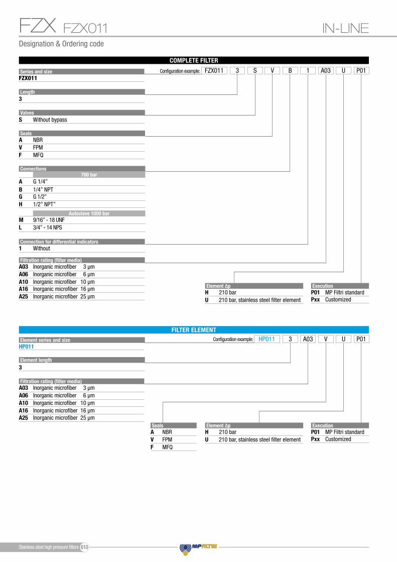
FZX
Configuration example:
ExecutionP01Pxx
MP Filtri standardCustomized
HP011 V3 UA03 P01
SealsAVF
NBRFPMMFQ
Element ∆pHU
210 bar210 bar, stainless steel filter element
Element ∆pHU
210 bar210 bar, stainless steel filter element
Filtration rating (filter media)A03
A10A06
A16A25
Inorganic microfiber 3 µm
Inorganic microfiber 10 µmInorganic microfiber 6 µm
Inorganic microfiber 16 µmInorganic microfiber 25 µm
FILTER ELEMENT
Element length3
Element series and sizeHP011
Filtration rating (filter media)A03
A10A06
A16A25
Inorganic microfiber 3 µm
Inorganic microfiber 10 µmInorganic microfiber 6 µm
Inorganic microfiber 16 µmInorganic microfiber 25 µm
ExecutionP01Pxx
MP Filtri standardCustomized
S Without bypass Valves
Series and size Configuration example: FZX011 V3 1 UBS A03 P01FZX011
Length3
SealsA NBRV FPMF MFQ
Connection for differential indicators1 Without
Connections
A
H
L
G
M
BG 1/4”
1/2” NPT”
3/4” - 14 NPS
G 1/2”
9/16” - 18 UNF
1/4” NPT
700 bar
Autoclave 1000 bar
IN-LINEFZX011
Stainless steel high pressure filters 610

Ø75
Ø75
Ø75
Ø75
FZXFZX011
FZX011
Connections
Connections
R
R
AB GH
ML
M85/16” UNC
M85/16” UNC
M8M8
Connection A - B - G - H
Connection M - L
Dimensions
IN-LINE FZX011
OUT
OUT
IN
IN
Recommended clearance space for maintenance
Recommended clearance space for maintenance
R - depth 15 mmNr. 4 holes
R - depth 15 mmNr. 4 holes
Stainless steel high pressure filters611

Item:
Filter series
Filterelement
FZX 011
NBR
02050643
FPM
02050644See
order table
2Q.ty: 1 pc.
Seal Kit code number
Q.ty: 1 pc.(3a ÷ 3c)3
FZX 011
3a
3b
3c
2
Order number for spare parts
FZX SPARE PARTS
Stainless steel high pressure fi lters 612

FZX
Stainless steel high pressure filters613

Stainless steel high pressure filters 614
Stainless steel high pressure fi lters
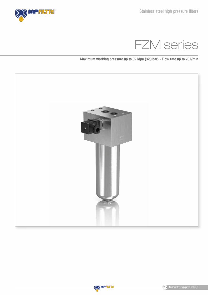
FZM seriesMaximum working pressure up to 32 Mpa (320 bar) - Flow rate up to 70 l/min
Stainless steel high pressure fi lters615

FZM GENERAL INFORMATION
Weights [kg] and volumes [dm3]
Weights [kg]
FZM 039
Volumes [dm3]
- 0.340.19 0.26- 6.15.0 5.6
Length Length 1 42 31 42 3 Filter series
From -50 °C to +120 °CTemperature
Opening pressure 6 bar ±10%Bypass valve
Microfi bre fi lter elements - series S: 210 bar.
Stainless Steel Microfi bre fi lter elementsseries U: 210 bar.
Microfi bre fi lter elements - series R: 20 bar.Element series “R”:- End cap: Nylon- Core tube: Tinned Steel- External/Internal support: Wire mesh Epox painted- Media/Support/Pre-fi lter: Microfi bre/Syntetic
Element series “S”:- End cap: Tinned Steel- Core tube: Tinned Steel- External support: Wire mesh Epox painted- Internal support: Wire mesh Stainless Steel- Media/Support/Pre-fi lter: Microfi bre/Syntetic
Element series “U”:- End cap: Stainless Steel- Core tube: Stainless Steel- External support: Stainless Steel- Internal support: Stainless Steel- Media/Support/Pre-fi lter: Microfi bre/Syntetic
Fluid fl ow through the fi lter element from OUT to IN∆p element type
- Standard NBR series A (-25 °C to +110 °C)- Optional FPM series V (-20 °C to +120 °C)- Optional MFQ series F (-50 °C to +120 °C)
Seals
FZM fi lters are provided for vertical mounting
Note
- Head: AISI 316L- Housing: AISI 316L- Bypass valve: AISI 316L
Filter housing materials
Description Technical data
Stainless steel high pressure fi lters
ManifoldMaximum working pressure up to 32 Mpa (320 bar)Flow rate up to 70 l/min
FZM is a range of stainless steel high pressure fi lter for protection of sensitive components in high pressure hydraulic systems placed in difficult environmental conditions.They are directly connected to the top of the manifold, through the proper fl anged interface.
Available features:- Manifold connections up to Ø15 mm, for a maximum fl ow rate of 70 l/min- ISO 4401 CETOP 3 and CETOP 5 interface, for direct mounting on the CETOP valves.- Fine fi ltration rating, to get a good cleanliness level into the system- Bypass valve, to relieve excessive pressure drop across the fi lter media- Low collapse filter element with external support “R”, for filter element protection against the back pressure caused by the check valve or the reverse flow in filters provided with the bypass valve- High collapse filter element with external support “S”, for filter element protection against the back pressure caused by the check valve or the reverse flow in filters not provided with the bypass valve- High collapse fi lter element “U”, for use with aggressive fl uids- Visual, electrical and electronic differential clogging indicators
Common applications:- Off-shore equipment- Water fi ltration systems- Systems with strong or corrosive environmental conditions- Systems with corrosive fl uids
Stainless steel high pressure fi lters 616
FZMGENERAL INFORMATION
Pressure drop
The curves are plotted using mineral oil with density of 0.86 kg/dm3 in compliance with ISO 3968. ∆p varies proportionally with density.
Filter housings ∆p pressure drop
1.2
1.8
0.4
00 30 60 90 120 150
Δp
bar
Flow rate l/min
FZP 1362.1
1.4
0.7
00 10 20 30 40 50
FZH 010 - 011
FZH 010
FZH 011
1.2
1.8
0.4
00 16 32 48 64 80
FZP 039 - FZH 039
1.2
1.8
0.4
00 30 60 90 120 150
FZP 136
1.2
1.8
0.4
00 16 32 48 64 80
FZB 039
4.2
2.8
1.4
00 8 16 24 32 40
FZD 010 - 021
FZD 010
FZD 021
1.2
0.8
0.4
00 16 32 48 64 80
FZM 039
9
6
3
00 2 4 6 8 10
FZX 0113
2
1
00 16 32 48 64 80
0 20 40 60 80 100
FZD 051
Flow rate l/min
∆p b
ar
OUT
D.I.
IN
Style S Style B Filter seriesFZM 039 • •
OUT
D.I.
IN
Hydraulic symbols
Maximum flow rate for a complete stainless steel high pressure filter with a return drop ∆p = 1.5 bar.The reference fluid has a kinematic viscosity of 30 mm2/s (cSt) and a density of 0.86 kg/dm3.For different pressure drop or fluid viscosity we recommend to use our selection software available on www.mpfiltri.com.You can also calculate the right size using the formulas present on the FILTER SIZING paragraph at the beginning of the full catalogue or at the beginning of the filter family brochure.Please, contact our Sales Department for further additional information.
Filter series234
FZM 039
LengthFilter element design - R Series
A03 A06 A10 A16 A25 19 25 41 47 54 33 36 50 56 65 41 44 58 64 70
Filter element design - S-U Series A03 A06 A10 A16 A25 19 23 39 43 51 30 33 45 49 60 37 39 51 63 68
FILTER ASSEMBLY SIZINGFlow rates [l/min]
Stainless steel high pressure filters617
Designation & Ordering code
COMPLETE FILTER
FZM MANIFOLD
Configuration example:
ExecutionP01Pxx
MP Filtri standardCustomized
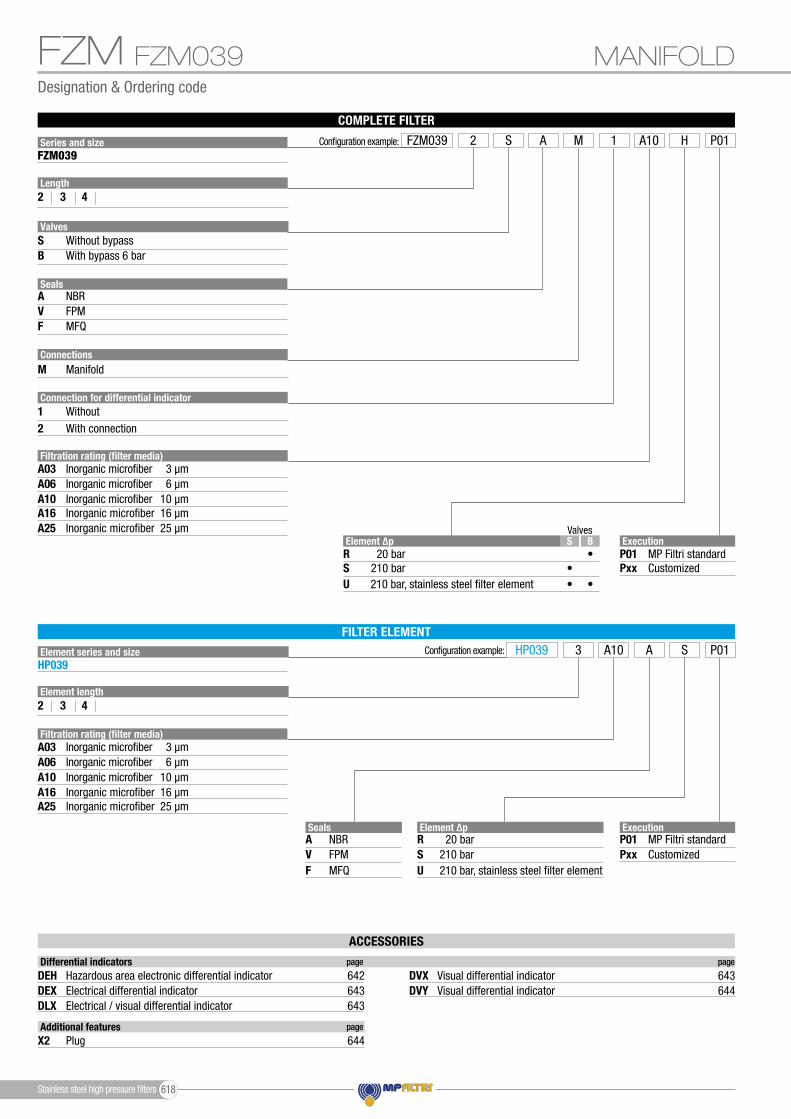
HP039 A3 SA10 P01
Element ∆pRSU
20 bar210 bar210 bar, stainless steel filter element
Filtration rating (filter media)A03
A10A06
A16A25
Inorganic microfiber 3 µm
Inorganic microfiber 10 µmInorganic microfiber 6 µm
Inorganic microfiber 16 µmInorganic microfiber 25 µm
SealsAVF
NBRFPMMFQ
FILTER ELEMENT
Element length2 3 4
Element series and sizeHP039
Filtration rating (filter media)A03
A10A06
A16A25
Inorganic microfiber 3 µm
Inorganic microfiber 10 µmInorganic microfiber 6 µm
Inorganic microfiber 16 µmInorganic microfiber 25 µm Valves
BS
••
•
•
Element ∆pRSU
20 bar210 bar210 bar, stainless steel filter element
Series and size Configuration example: FZM039 A2 HM 1S A10 P01FZM039
Valves
Length2 3 4
SealsAVF
NBRFPMMFQ
Connections
Connection for differential indicator
M
12
Manifold
WithoutWith connection
SB
Without bypassWith bypass 6 bar
ExecutionP01Pxx
MP Filtri standardCustomized
FZM039
ACCESSORIES
Additional features page
X2 Plug 644
Differential indicators page page
DEHDEXDLX
DVYDVXHazardous area electronic differential indicator 642
Electrical differential indicatorElectrical / visual differential indicator
643643
Visual differential indicator 644Visual differential indicator 643
Stainless steel high pressure filters 618

Dimensions
FZMMANIFOLD
FZM039
Filter length
H[mm]
234
160203247
Ø64
FZM039
OUT IN
Recommended clearance space for maintenance
Bypass plug
Connection for differential indicatorX2 plug not included
Nr. 4 holes
Stainless steel high pressure filters619

Order number for spare parts
FZM
3h3n
3e3d
4
3a
3b
3c
2
Item:
Filter series
Seal Kit code numberFilterelement NBR FPM
Seeorder table
2Q.ty: 1 pc. Q.ty: 1 pc.Q.ty: 1 pc.
(3a ÷ 3n)3 4
Indicator connection plugNBR
X2H
FPM
X2V02050651 02050652FZM 039
FZM 039
SPARE PARTS
Stainless steel high pressure fi lters 620

FZM
Stainless steel high pressure filters621

Stainless steel high pressure filters 622
Stainless steel high pressure fi lters
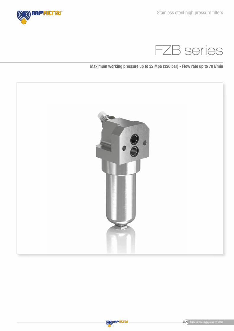
FZB seriesMaximum working pressure up to 32 Mpa (320 bar) - Flow rate up to 70 l/min
Stainless steel high pressure fi lters623
FZB GENERAL INFORMATION
Weights [kg] and volumes [dm3]
Weights [kg]
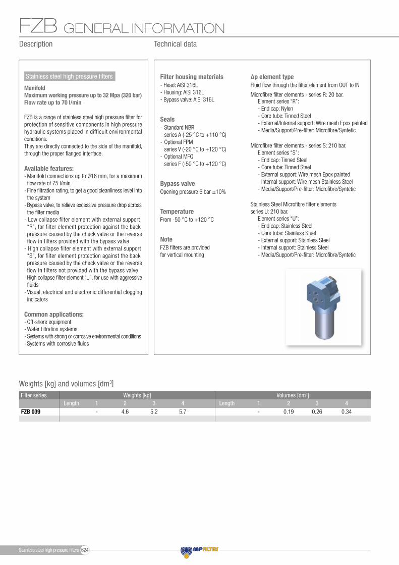
FZB 039
Volumes [dm3]
- 0.340.19 0.26- 5.74.6 5.2Length Length 1 42 31 42 3
Filter series
From -50 °C to +120 °CTemperature
Opening pressure 6 bar ±10%Bypass valve
Microfi bre fi lter elements - series S: 210 bar.
Stainless Steel Microfi bre fi lter elementsseries U: 210 bar.
Microfi bre fi lter elements - series R: 20 bar.Element series “R”:- End cap: Nylon- Core tube: Tinned Steel- External/Internal support: Wire mesh Epox painted- Media/Support/Pre-fi lter: Microfi bre/Syntetic
Element series “S”:- End cap: Tinned Steel- Core tube: Tinned Steel- External support: Wire mesh Epox painted- Internal support: Wire mesh Stainless Steel- Media/Support/Pre-fi lter: Microfi bre/Syntetic
Element series “U”:- End cap: Stainless Steel- Core tube: Stainless Steel- External support: Stainless Steel- Internal support: Stainless Steel- Media/Support/Pre-fi lter: Microfi bre/Syntetic
Fluid fl ow through the fi lter element from OUT to IN∆p element type
- Standard NBR series A (-25 °C to +110 °C)- Optional FPM series V (-20 °C to +120 °C)- Optional MFQ series F (-50 °C to +120 °C)
Seals
FZB fi lters are provided for vertical mounting
Note
- Head: AISI 316L- Housing: AISI 316L- Bypass valve: AISI 316L
Filter housing materials
Description Technical data
Stainless steel high pressure fi lters
ManifoldMaximum working pressure up to 32 Mpa (320 bar)Flow rate up to 70 l/min
FZB is a range of stainless steel high pressure fi lter for protection of sensitive components in high pressure hydraulic systems placed in difficult environmental conditions.They are directly connected to the side of the manifold, through the proper fl anged interface.
Available features:- Manifold connections up to Ø16 mm, for a maximum fl ow rate of 75 l/min- Fine fi ltration rating, to get a good cleanliness level into the system- Bypass valve, to relieve excessive pressure drop across the fi lter media- Low collapse filter element with external support “R”, for filter element protection against the back pressure caused by the check valve or the reverse flow in filters provided with the bypass valve- High collapse filter element with external support “S”, for filter element protection against the back pressure caused by the check valve or the reverse flow in filters not provided with the bypass valve- High collapse fi lter element “U”, for use with aggressive fl uids- Visual, electrical and electronic differential clogging indicators
Common applications:- Off-shore equipment- Water fi ltration systems- Systems with strong or corrosive environmental conditions- Systems with corrosive fl uids
Stainless steel high pressure fi lters 624
FZB
Pressure drop
GENERAL INFORMATION
The curves are plotted using mineral oil with density of 0.86 kg/dm3 in compliance with ISO 3968. ∆p varies proportionally with density.
Filter housings ∆p pressure drop1.2
1.8
0.4
00 30 60 90 120 150
Δp
bar
Flow rate l/min
FZP 1362.1
1.4
0.7
00 10 20 30 40 50
FZH 010 - 011
FZH 010
FZH 011
1.2
1.8
0.4
00 16 32 48 64 80
FZP 039 - FZH 039
1.2
1.8
0.4
00 30 60 90 120 150
FZP 136
1.2
1.8
0.4
00 16 32 48 64 80
FZB 039
4.2
2.8
1.4
00 8 16 24 32 40
FZD 010 - 021
FZD 010
FZD 021
1.2
0.8
0.4
00 16 32 48 64 80
FZM 039
9
6
3
00 2 4 6 8 10
FZX 0113
2
1
00 16 32 48 64 80
0 20 40 60 80 100
FZD 051
Flow rate l/min
∆p b
ar
OUT
D.I.
IN
OUT
D.I.
IN
OUT
D.I.
IN
Style S Style TStyle B Style D Filter seriesFZB 039 • •• •
OUT
D.I.
IN
Hydraulic symbols
Maximum flow rate for a complete stainless steel high pressure filter with a pressure drop ∆p = 1.5 bar.The reference fluid has a kinematic viscosity of 30 mm2/s (cSt) and a density of 0.86 kg/dm3.For different pressure drop or fluid viscosity we recommend to use our selection software available on www.mpfiltri.com.You can also calculate the right size using the formulas present on the FILTER SIZING paragraph at the beginning of the full catalogue or at the beginning of the filter family brochure.Please, contact our Sales Department for further additional information.
Filter element design - R Series Filter element design - S Series Filter element design - U SeriesFilter series A03 A06 A10 A16 A25 A03 A06 A10 A16 A25 A03 A06 A10 A16 A25
234
FZB 039
Length 18 23 39 44 52 31 33 47 54 65 38 41 56 63 71
18 22 37 40 48 28 31 43 46 84 34 36 48 62 68
18 22 37 40 48 28 31 43 46 84 34 36 48 62 68
FILTER ASSEMBLY SIZINGFlow rates [l/min]
Stainless steel high pressure filters625

Designation & Ordering code
COMPLETE FILTER
FZB MANIFOLDFZB039
Configuration example:
ExecutionP01Pxx
MP Filtri standardCustomized
HP039 A2 SA06 P01
Element ∆pRSU
20 bar210 bar210 bar, stainless steel filter element
Filtration rating (filter media)
Filtration rating (filter media)
A03
A03
A10
A10
A06
A06
A16
A16
A25
A25
Inorganic microfiber
Inorganic microfiber
3 µm
3 µm
Inorganic microfiber
Inorganic microfiber
10 µm
10 µm
Inorganic microfiber
Inorganic microfiber
6 µm
6 µm
Inorganic microfiber
Inorganic microfiber
16 µm
16 µm
Inorganic microfiber
Inorganic microfiber
25 µm
25 µm
SealsAVF
NBRFPMMFQ
FILTER ELEMENT
Element length2 3 4
Element series and sizeHP039
ValvesDTBS•
•••
••
•
•
Element ∆pRSU
20 bar210 bar210 bar, stainless steel filter element
Series and size Configuration example: FZB039 A2 SF 2T A06 P01FZB039
Valves
Length2 3 4
Seals
Connections for differential indicator
A
1
V
2
F
NBR
Without
FPM
With connection on the top
MFQ
ConnectionsF Manifold
SBT
Without bypassWith bypass 6 barWith check valve, without bypass
D With check valve, with bypass 6 bar
ExecutionP01Pxx
MP Filtri standardCustomized
ACCESSORIES
Additional features page
X2 Plug 644
Differential indicators page page
DEHDEXDLX
DVYDVXHazardous area electronic differential indicator 642
Electrical differential indicatorElectrical / visual differential indicator
643643
Visual differential indicator 644Visual differential indicator 643
Stainless steel high pressure filters 626

Dimensions
FZBMANIFOLD FZB039
Ø64
FZB039
Filter length
H[mm]
234
190233277
OUT
IN
Recommended clearance space for maintenance
Connection for differential indicatorX2 plug not included
Nr. 2 holes
Stainless steel high pressure filters627
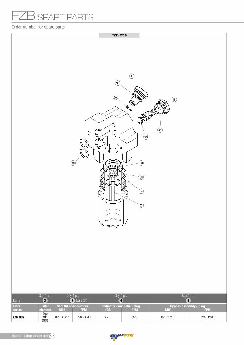
Order number for spare parts
FZB
Item:
Filter series
Seal Kit code numberFilterelement NBR FPM
Seeorder table
2Q.ty: 1 pc. Q.ty: 1 pc. Q.ty: 1 pc.Q.ty: 1 pc.
(3a ÷ 3n)3 4 5
Indicator connection plug Bypass assembly / plugNBR FPMNBR
X2H
FPM
X2V02050647 0200128602050648 02001295FZB 039
3h
3a
3b
3n
2
53e
3d
4
3c
3m
FZB 039
SPARE PARTS
Stainless steel high pressure fi lters 628

FZB
Stainless steel high pressure filters629

Stainless steel high pressure filters 630
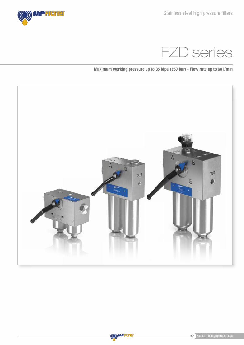
Stainless steel high pressure fi lters
FZD seriesMaximum working pressure up to 35 Mpa (350 bar) - Flow rate up to 60 l/min
Stainless steel high pressure fi lters631
FZD GENERAL INFORMATION
Weights [kg] and volumes [dm3]
Weights [kg]
FZD 010FZD 021FZD 051
Volumes [dm3]Length Length
---
-0.220.53
--
0.83
0.100.060.31
-0.120.41
1 4 42 3---
-10.319.0
--
20.3
7.99.6
17.4
-9.8
18.0
1 4 52 3 Filter series
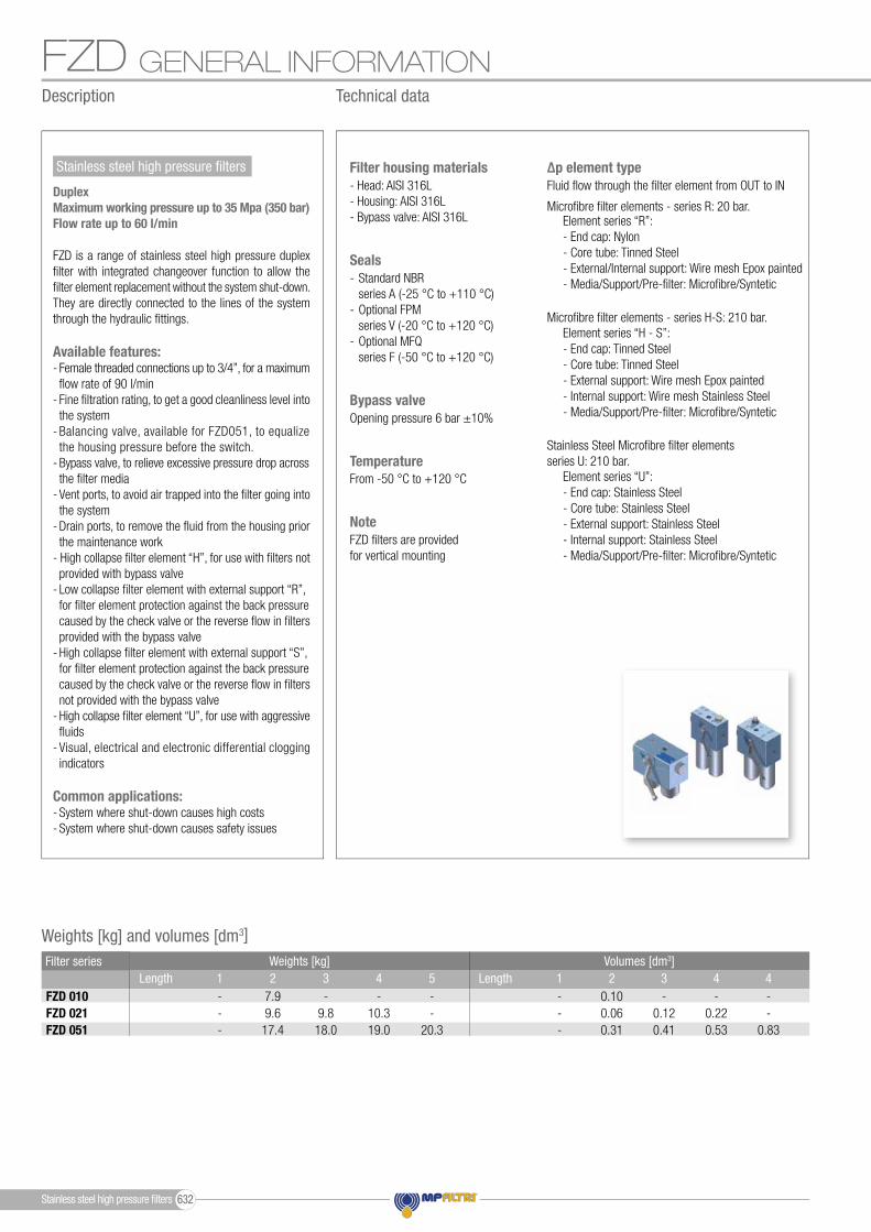
From -50 °C to +120 °CTemperature
Opening pressure 6 bar ±10%Bypass valve
Microfi bre fi lter elements - series H-S: 210 bar.
Stainless Steel Microfi bre fi lter elementsseries U: 210 bar.
Microfi bre fi lter elements - series R: 20 bar.Element series “R”:- End cap: Nylon- Core tube: Tinned Steel- External/Internal support: Wire mesh Epox painted- Media/Support/Pre-fi lter: Microfi bre/Syntetic
Element series “H - S”:- End cap: Tinned Steel- Core tube: Tinned Steel- External support: Wire mesh Epox painted- Internal support: Wire mesh Stainless Steel- Media/Support/Pre-fi lter: Microfi bre/Syntetic
Element series “U”:- End cap: Stainless Steel- Core tube: Stainless Steel- External support: Stainless Steel- Internal support: Stainless Steel- Media/Support/Pre-fi lter: Microfi bre/Syntetic
Fluid fl ow through the fi lter element from OUT to IN∆p element type
- Standard NBR series A (-25 °C to +110 °C)- Optional FPM series V (-20 °C to +120 °C)- Optional MFQ series F (-50 °C to +120 °C)
Seals
FZD fi lters are provided for vertical mounting
Note
- Head: AISI 316L- Housing: AISI 316L- Bypass valve: AISI 316L
Filter housing materials
Description Technical data
Stainless steel high pressure fi lters
DuplexMaximum working pressure up to 35 Mpa (350 bar)Flow rate up to 60 l/min
FZD is a range of stainless steel high pressure duplex fi lter with integrated changeover function to allow the fi lter element replacement without the system shut-down.They are directly connected to the lines of the system through the hydraulic fi ttings.
Available features:- Female threaded connections up to 3/4”, for a maximum fl ow rate of 90 l/min- Fine fi ltration rating, to get a good cleanliness level into the system- Balancing valve, available for FZD051, to equalize the housing pressure before the switch.- Bypass valve, to relieve excessive pressure drop across the fi lter media- Vent ports, to avoid air trapped into the fi lter going into the system- Drain ports, to remove the fl uid from the housing prior the maintenance work- High collapse fi lter element “H”, for use with fi lters not provided with bypass valve- Low collapse fi lter element with external support “R”, for fi lter element protection against the back pressure caused by the check valve or the reverse fl ow in fi lters provided with the bypass valve- High collapse fi lter element with external support “S”, for fi lter element protection against the back pressure caused by the check valve or the reverse fl ow in fi lters not provided with the bypass valve- High collapse fi lter element “U”, for use with aggressive fl uids- Visual, electrical and electronic differential clogging indicators
Common applications:- System where shut-down causes high costs- System where shut-down causes safety issues
Stainless steel high pressure fi lters 632
FZDGENERAL INFORMATION
FZD 010FZD 021FZD 051
OUT
D.I.
IN
Hydraulic symbolsStyle S Style B Filter series
••• •
OUT
D.I.
IN
The curves are plotted using mineral oil with density of 0.86 kg/dm3 in compliance with ISO 3968. ∆p varies proportionally with density.
Filter housings ∆p pressure dropPressure drop
1.2
1.8
0.4
00 30 60 90 120 150
Δp
bar
Flow rate l/min
FZP 1362.1
1.4
0.7
00 10 20 30 40 50
FZH 010 - 011
FZH 010
FZH 011
1.2
1.8
0.4
00 16 32 48 64 80
FZP 039 - FZH 039
1.2
1.8
0.4
00 30 60 90 120 150
FZP 136
1.2
1.8
0.4
00 16 32 48 64 80
FZB 039
4.2
2.8
1.4
00 8 16 24 32 40
FZD 010 - 021
FZD 010
FZD 021
1.2
0.8
0.4
00 16 32 48 64 80
FZM 039
9
6
3
00 2 4 6 8 10
FZX 0113
2
1
00 16 32 48 64 80
0 20 40 60 80 100
FZD 051
1.2
1.8
0.4
00 30 60 90 120 150
Δp
bar
Flow rate l/min
FZP 1362.1
1.4
0.7
00 10 20 30 40 50
FZH 010 - 011
FZH 010
FZH 011
1.2
1.8
0.4
00 16 32 48 64 80
FZP 039 - FZH 039
1.2
1.8
0.4
00 30 60 90 120 150
FZP 136
1.2
1.8
0.4
00 16 32 48 64 80
FZB 039
4.2
2.8
1.4
00 8 16 24 32 40
FZD 010 - 021
FZD 010
FZD 021
1.2
0.8
0.4
00 16 32 48 64 80
FZM 039
9
6
3
00 2 4 6 8 10
FZX 0113
2
1
00 16 32 48 64 80
0 20 40 60 80 100
FZD 051
Flow rate l/min Flow rate l/min
∆p b
ar
∆p b
ar
234
2FZD 010
FZD 021
Maximum flow rate for a complete stainless steel high pressure filter with a pressure drop ∆p = 1.5 bar.The reference fluid has a kinematic viscosity of 30 mm2/s (cSt) and a density of 0.86 kg/dm3.For different pressure drop or fluid viscosity we recommend to use our selection software available on www.mpfiltri.com.You can also calculate the right size using the formulas present on the FILTER SIZING paragraph at the beginning of the full catalogue or at the beginning of the filter family brochure.Please, contact our Sales Department for further additional information.
2345
FZD 051
Filter element design - H Series Filter element design - U SeriesFilter series
Filter series
A03 A06 A10 A16 A25
5 6 11 12 16 9 11 16 18 20 10 12 17 19 21
4 5 7 8 11 A03 A06 A10 A16 A25 4 5 7 8 11
5 6 11 12 16 9 11 16 18 20 10 12 17 19 21
Length
LengthFilter element design - S SeriesFilter element design - R Series Filter element design - U Series
35 37 48 51 58 41 43 52 54 60 47 49 56 56 61 53 53 57 59 63
39 41 51 54 59 45 46 54 56 61 50 52 58 58 62 56 57 61 62 63
35 37 48 51 58 41 43 52 54 60 47 49 56 56 61 53 53 57 59 63
A03 A06 A10 A16 A25 A03 A06 A10 A16 A25 A03 A06 A10 A16 A25
FILTER ASSEMBLY SIZINGFlow rates [l/min]
Stainless steel high pressure filters633
Designation & Ordering code
COMPLETE FILTER
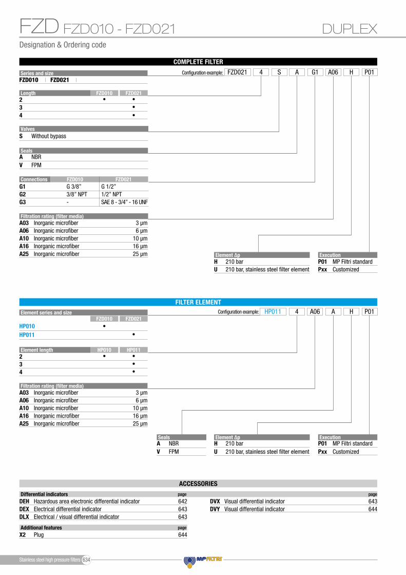
FZD DUPLEXFZD010 - FZD021
Configuration example:
ExecutionP01Pxx
MP Filtri standardCustomized
HP011 A4 HA06 P01
Element ∆pHU
210 bar210 bar, stainless steel filter element
Element ∆pHU
210 bar210 bar, stainless steel filter element
Filtration rating (filter media)A03
A10A06
A16A25
Inorganic microfiber 3 µm
Inorganic microfiber 10 µmInorganic microfiber 6 µm
Inorganic microfiber 16 µmInorganic microfiber 25 µm
SealsAV
NBRFPM
Element length234
HP011HP010••••
Element series and size
HP010HP011
FZD021FZD010
••
FILTER ELEMENT
Series and size Configuration example: FZD021 A4 HG1S A06 P01FZD010 FZD021
Length234
FZD021FZD010•
••
•
ValvesS Without bypass
SealsAV
NBRFPM
ConnectionsG1
G3G2
G 3/8”
-3/8” NPT
G 1/2”
SAE 8 - 3/4” - 16 UNF1/2” NPT
FZD021FZD010
Filtration rating (filter media)A03
A10A06
A16A25
Inorganic microfiber 3 µm
Inorganic microfiber 10 µmInorganic microfiber 6 µm
Inorganic microfiber 16 µmInorganic microfiber 25 µm Execution
P01Pxx
MP Filtri standardCustomized
ACCESSORIES
Additional features page
X2 Plug 644
Differential indicators page page
DEHDEXDLX
DVYDVXHazardous area electronic differential indicator 642
Electrical differential indicatorElectrical / visual differential indicator
643643
Visual differential indicator 644Visual differential indicator 643
Stainless steel high pressure filters 634
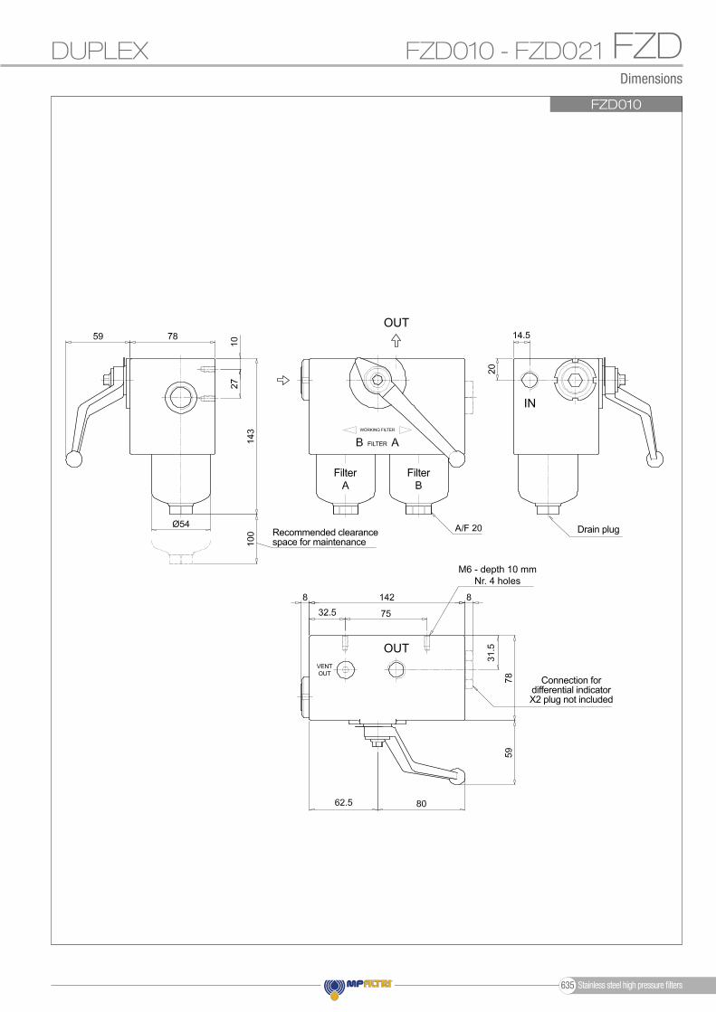
Dimensions
FZDDUPLEX FZD010 - FZD021
FZD010
Ø54
OUT
OUT
IN
Recommended clearance space for maintenance
Filter Filter
Connection for differential indicatorX2 plug not included
M6 - depth 10 mmNr. 4 holes
VENTOUT
FILTER
WORKING FILTER
Drain plug
Stainless steel high pressure filters635
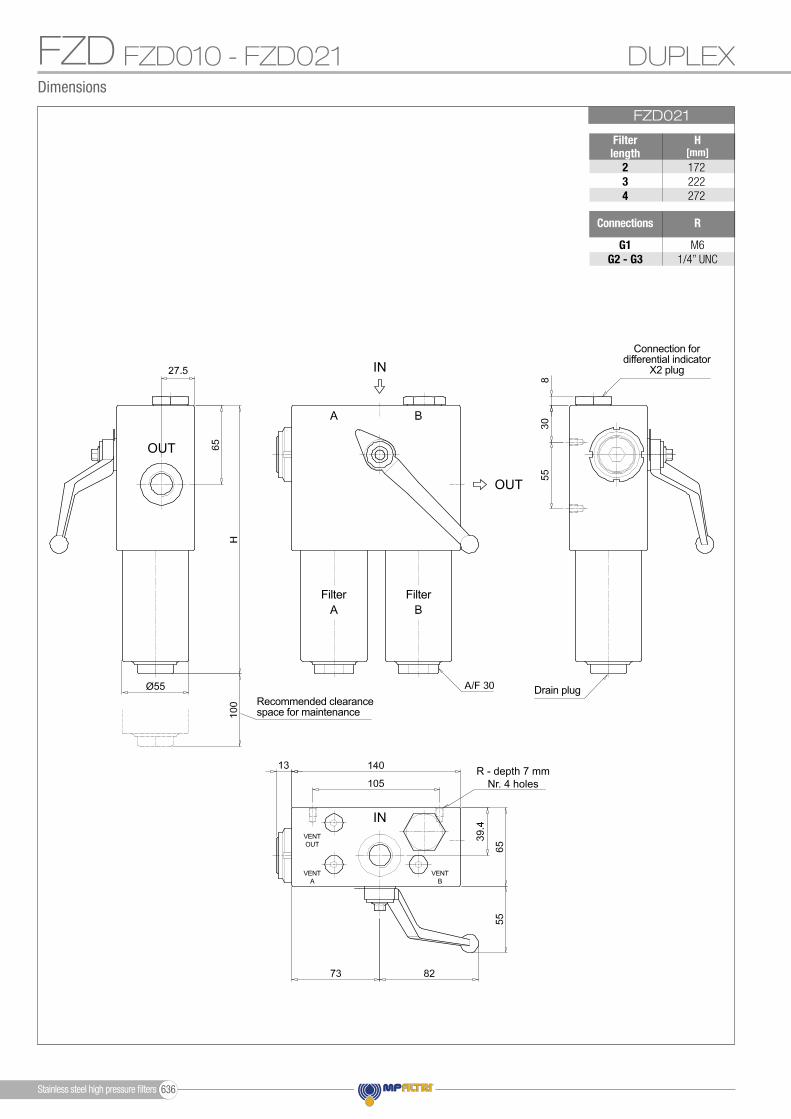
Dimensions
FZDFZD021
H[mm]
234
172222272
Ø55
R
G1G2 - G3
M61/4” UNC
Filter length
Connections
DUPLEXFZD010 - FZD021
OUT
OUT
IN
IN
Recommended clearance space for maintenance
Filter Filter
Connection for differential indicator
X2 plug
R - depth 7 mmNr. 4 holes
VENTOUT
VENTA
VENTB
Drain plug
Stainless steel high pressure filters 636

FZD
Stainless steel high pressure filters637
Designation & Ordering code
FZD
Element series and sizeHP050
Configuration example: HP050 A3 UA03 P01
Element length2 3 4 5
FILTER ELEMENT
Filtration rating (filter media)A03
A10A06
A16A25
Inorganic microfiber 3 µm
Inorganic microfiber 10 µmInorganic microfiber 6 µm
Inorganic microfiber 16 µmInorganic microfiber 25 µm
ExecutionP01Pxx
MP Filtri standardCustomized
Element ∆pRSU
20 bar210 bar210 bar, stainless steel filter element
SealsAV
NBRFPM
Series and size Configuration example: FZD051 A3 UG3B A03 P01FZD051
Valves
Length2 3 4 5
SealsAV
NBRFPM
SB
Without bypassWith bypass 6 bar
ExecutionP01Pxx
MP Filtri standardCustomized
COMPLETE FILTER
Filtration rating (filter media)A03
A10A06
A16A25
Inorganic microfiber 3 µm
Inorganic microfiber 10 µmInorganic microfiber 6 µm
Inorganic microfiber 16 µmInorganic microfiber 25 µm
ConnectionsG1
G4G3G2
G5G6
G 3/4”
1/2” NPTG 1/2”3/4” NPT
SAE 8 - 3/4” - 16 UNFSAE 12 - 1 1/16” - 12 UN
ValvesBS
••
•
•
Element ∆pRSU
20 bar210 bar210 bar, stainless steel filter element
DUPLEXFZD051
ACCESSORIES
Additional features page
X2 Plug 644
Differential indicators page page
DEHDEXDLX
DVYDVXHazardous area electronic differential indicator 642
Electrical differential indicatorElectrical / visual differential indicator
643643
Visual differential indicator 644Visual differential indicator 643
Stainless steel high pressure filters 638

Dimensions
FZD
Ø68
FZD051
Filter length
H[mm]
2345
253295343465
Connections R
G1G2G3
G4-G5-G6
M61/4” UNC
M61/4” UNC
Valves
SB
L[mm]168182.5
138152.5
M[mm]
L1[mm]
8498.5
DUPLEX FZD051
OUT
OUT
IN
IN
Recommended clearance space for maintenance
Drain plug
Filter Filter
Connection for differential indicator
X2 plug
R - depth 7 mmNr. 4 holes
VENTOUT
VENTA
VENTB
BALANCING
Stainless steel high pressure filters639
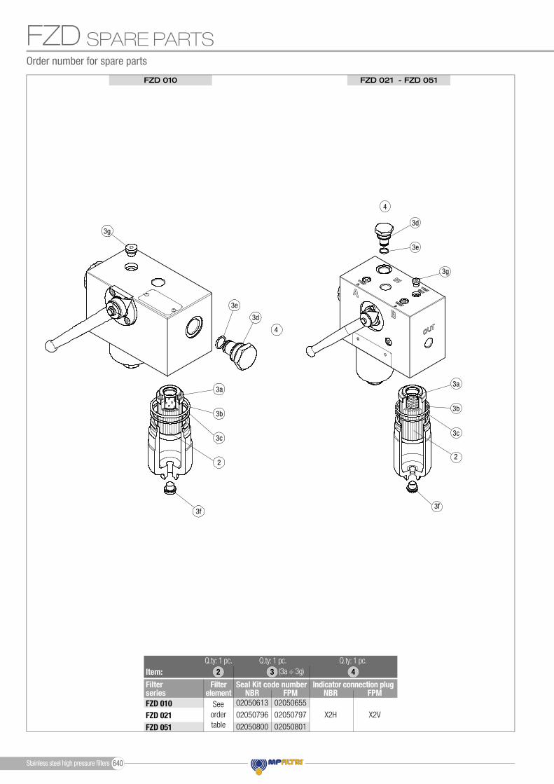
FZD SPARE PARTSOrder number for spare parts
FZD 010 FZD 021 - FZD 051
3f
3a
3b
2
3e
3d
4
3g
3c
3f
3a
3b
2
3e
3d
4
3g
3c
Item:
Filter series
Seal Kit code numberFilterelement NBR FPM
Seeorder table
2Q.ty: 1 pc. Q.ty: 1 pc.Q.ty: 1 pc.
(3a ÷ 3g)3 4
Indicator connection plugNBR FPM
X2H X2V
02050613
02050796
02050800
02050655
02050797
02050801
FZD 010FZD 021FZD 051
Stainless steel high pressure fi lters 640

Differential indicators
Introduction
- Vacuum switches and gauges- Pressure switches and gauges- Differential pressure indicators
These type of devices can be provided with a visual, electrical or both signals.
Filter elements are efficient only if their Dirt Holding Capacity is fully exploited.This is achieved by using filter housings equipped with clogging indicators.
These devices trip when the clogging of the filter element causes an increase in pressure drop across the filter element.
The indicator is set to alarm before the element becomes fully clogged.
MP Filtri can supply indicators of the following designs:
Suitable indicator types
DIFFERENTIAL INDICATORS
Differential indicators are used on the Pressure line to check the efficiency of the filter element.They measure the pressure upstream and downstream of the filter element (differential pressure).Standard items are produced with special connection G 1/2” size.Also available in Stainless Steel models.
23
1
IN
OUT
IN
OUT
IN
OUT
IN
OUT
IN
OUT
IN
OUT
IN
OUT
IN
OUT
IN
OUT
IN
OUT
23
1
23
123
1
2
31
2
31
2
31
Quick reference guide
Filter seriesVisual
indicatorElectricalindicator
Electrical / Visualindicator
FZH 010 - 011 - 039FZP 039 - 136FZX 011FZB 039FZM 039FZD 051
FZH 010 - 011 - 039FZP 039 - 136FZB 039FZM 039FZD 010 - 021 - 051
With bypass valve
Without bypass valve
DLX50xA51P01DLX50xA52P01
DLX70xA51P01DLX70xA52P01
DVX50xP01DVY50xP01
DVX70xP01DVY70xP01
DEX50xA50P01
DEX70xA50P01
Clogging indicators
DEH50xA48P01DEH50xA49P01DEH50xA70P01DEH70xA48P01DEH70xA49P01DEH70xA70P01
DEH50xA48P01DEH50xA49P01DEH50xA70P01DEH70xA48P01DEH70xA49P01DEH70xA70P01
NEWHazardous
area electronicindicator
Stainless steel high pressure filters641
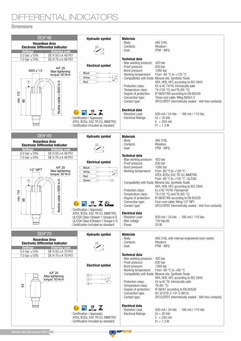
Dimensions
DIFFERENTIAL INDICATORS
M20 x 1.5A/F 25
Max tighteningtorque: 50 N∙m
A/F 25Max tighteningtorque: 50 N∙m
A/F 25Max tighteningtorque: 50 N∙m
min
. 110
min
. 110
8888
63
DE H 50 x A 48 P01DE H 70 x A 48 P01
DE H 50 x A 49 P01DE H 70 x A 49 P01
DE H 50 x A 70 P01DE H 70 x A 70 P01
Settings
Settings
Settings
Ordering code
Ordering code
Ordering code
Hazardous Area Electronic Differential Indicator
DEH*48 Materials- Body: AISI 316L- Contacts: Rhodium- Seal: FPM - MFQ
Technical data- Max working pressure: 420 bar- Proof pressure: 630 bar- Burst pressure: 1260 bar- Working temperature: From -60 °C to +125 °C- Compatibility with � uids: Mineral oils, Synthetic � uids HFA, HFB, HFC according to ISO 2943- Protection class: EX ia IIC T4/T6: Intrinsically safe- Temperature class: T4 (135 °C) and T6 (85 °C)- Degree of protection: IP 66/67/68 according to EN 60529- Connection type: Three-core cable, � tting M20x1.5 - Contact type: SPCO/SPDT (Hermetically sealed - Volt-free contacts)
Electrical data- Resistive Load: 830 mA / 24 Vdc - 180 mA / 110 Vac- Electrical Ratings: Ui = 30 Vdc li = 250 mA Pi = 1.3 W
Hydraulic symbol
Hydraulic symbol
Hydraulic symbol
Electrical symbol
Electrical symbol
Electrical symbol
Red
RedGreen
White
White
Black
Black1/2” NPT
Hazardous Area Electronic Differential Indicator
DEH*49 Materials- Body: AISI 316L- Contacts: Rhodium- Seal: FPM - MFQ
Technical data- Max working pressure: 420 bar- Proof pressure: 630 bar- Burst pressure: 1260 bar- Working temperature: From -60 °C to +120 °C : ATEX, IECEx, EAC TR CU, INMETRO From -60 °C to +105 °C : UL/CSA- Compatibility with � uids: Mineral oils, Synthetic � uids HFA, HFB, HFC according to ISO 2943- Protection class: Ex d IIC T4/T6: Flameproof- Temperature class: T4 (135 °C) and T6 (85 °C)- Degree of protection: IP 66/67/68 according to EN 60529- Connection type: Four-core cable, � tting 1/2” NPT- Contact type: SPCO/SPDT (Hermetically sealed - Volt-free contacts)
Electrical data- Resistive Load: 830 mA / 24 Vdc - 180 mA / 110 Vac- Max voltage 150 Vac/dc- Power 20 W
- Certi� cation / Approvals: ATEX, IECEx, EAC TR CU, INMETRO, UL/CSA Class I Division 1 Groups A-D, UL/CSA Class II Division 1 Groups E-G- Certi� cation included as standard
- Certi� cation / Approvals: ATEX, IECEx, EAC TR CU, INMETRO- Certi� cation included as standard
Materials- Body: AISI 316L with internal engineered resin switch- Contacts: Rhodium- Seal: FPM - MFQ
Technical data- Max working pressure: 420 bar- Proof pressure: 630 bar- Burst pressure: 1260 bar- Working temperature: From -60 °C to +80 °C- Compatibility with � uids: Mineral oils, Synthetic � uids HFA, HFB, HFC according to ISO 2943- Protection class: EX ia IIC T6: Intrinsically safe- Temperature class: T6 (85 °C)- Degree of protection: IP 66/67 according to EN 60529- Connection type: IEC 61076-2-101 D (M12) - Contact type: SPCO/SPDT (Hermetically sealed - Volt-free contacts)
Electrical data- Resistive Load: 830 mA / 24 Vdc - 180 mA / 110 Vdc- Electrical Ratings: Ui = 30 Vdc li = 250 mA Pi = 1.3 W
DEH*70Hazardous Area
Electronic Differential Indicator
- Certi� cation / Approvals: ATEX, IECEx, EAC TR CU, INMETRO- Certi� cation included as standard
fl exib
le c
able
5
000
to A
fl exib
le c
able
5
000
to A
bar ±10%bar ±10%
bar ±10%bar ±10%
bar ±10%bar ±10%
5.07.0
5.07.0
5.07.0
Stainless steel high pressure � lters 642

Dimensions
DIFFERENTIAL INDICATORS
DE X 50 x A 50 P01DE X 70 x A 50 P01DE X 95 x A 50 P01
5.0 bar ±10%7.0 bar ±10%9.5 bar ±10%
Settings Ordering code
Electrical Differential Indicator
DEX*50 Materials- Body: AISI 316L- Base: Black Nylon- Contacts: Silver- Seal: HNBR - MFQ
Technical data- Max working pressure: 420 bar- Proof pressure: 630 bar- Burst pressure: 1260 bar- Working temperature: From -25 °C to +110 °C- Compatibility with fluids: Mineral oils, Synthetic fluids HFA, HFB, HFC according to ISO 2943- Degree protection: IP66 according to EN 60529 IP69K according to ISO 20653
Electrical data- Electrical connection: EN 175301-803- Resistive load: 0.2 A / 115 Vdc
1
2
3
1
2
3
1
2
3
1
2
3
4
5
1 2
Hydraulic symbol
Electrical symbol
3
2
1
3
2
1
3
1
2
5
44
505353
3
2
1
3
2
1
3
1
2
5
44
505353
A/F 30Max tighteningtorque: 65 N∙m
DL X 50 x A x x P01DL X 70 x A x x P01DL X 95 x A x x P01
5.0 bar ±10%7.0 bar ±10%9.5 bar ±10%
Settings Ordering code
3
2
1
3
2
1
3
1
2
5
44
505353
Electrical/Visual Differential Indicator
DLX*51 - DLX*52 Materials- Body: AISI 316L- Base: Transparent Nylon- Contacts: Silver- Seal: HNBR - MFQ
Technical data- Max working pressure: 420 bar- Proof pressure: 630 bar- Burst pressure: 1260 bar- Working temperature: From -25 °C to +110 °C- Compatibility with fluids: Mineral oils, Synthetic fluids HFA, HFB, HFC according to ISO 2943- Degree protection: IP66 according to EN 60529 IP69K according to ISO 20653
Electrical data- Electrical connection: EN 175301-803- Type 51 52 - Lamps 24 Vdc 110 Vdc - Resistive load: 1 A / 24 Vdc 1 A / 110 Vdc
1
2
3
1
2
3
1
2
3
1
2
3
4
5
1 2
Hydraulic symbol
Electrical symbol
3
2
1
3
2
1
3
1
2
5
44505353
A/F 30Max tighteningtorque: 65 N∙m
DV X 50 x P01DV X 70 x P01DV X 95 x P01
5.0 bar ±10%7.0 bar ±10%9.5 bar ±10%
Settings Ordering code
Visual Differential Indicator
DVX Materials- Body: AISI 316L- Internal parts: AISI 316L - Nylon- Contacts: Silver- Seal: HNBR - MFQ
Technical data- Reset: Automatic reset- Max working pressure: 420 bar- Proof pressure: 630 bar- Burst pressure: 1260 bar- Working temperature: From -25 °C to +110 °C- Compatibility with fluids: Mineral oils, Synthetic fluids HFA, HFB, HFC according to ISO 2943- Degree protection: IP65 according to EN 60529
Hydraulic symbol
1
2
3
1
2
3
1
2
3
1
2
3
4
5
1 2
3
4
2
5
1 +24 Vdc
4 20 mA
75% - N.O.
100% - N.O.
0 Vdc
÷
47
39 34
A/F 28Max tighteningtorque: 65 N∙m
Green / Redclogging indicator
GREENLAMP
REDLAMP
Stainless steel high pressure filters643
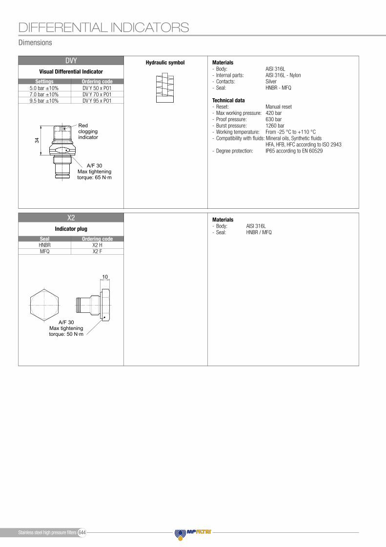
Dimensions
DIFFERENTIAL INDICATORS
X2 HX2 F
HNBRMFQ
Seal Ordering code
Indicator plug
X2 Materials- Body: AISI 316L- Seal: HNBR / MFQ
10A/F30
A/F 30Max tighteningtorque: 50 N∙m
DV Y 50 x P01DV Y 70 x P01DV Y 95 x P01
5.0 bar ±10%7.0 bar ±10%9.5 bar ±10%
Settings Ordering code
Visual Differential Indicator
DVY Materials- Body: AISI 316L- Internal parts: AISI 316L - Nylon- Contacts: Silver- Seal: HNBR - MFQ
Technical data- Reset: Manual reset- Max working pressure: 420 bar- Proof pressure: 630 bar- Burst pressure: 1260 bar- Working temperature: From -25 °C to +110 °C- Compatibility with fluids: Mineral oils, Synthetic fluids HFA, HFB, HFC according to ISO 2943- Degree protection: IP65 according to EN 60529
Hydraulic symbol
1
2
3
1
2
3
1
2
3
1
2
3
4
5
1 2
3
4
2
5
1 +24 Vdc
4 20 mA
75% - N.O.
100% - N.O.
0 Vdc
÷
47
39 34
A/F 30Max tighteningtorque: 65 N∙m
Redclogging indicator
Stainless steel high pressure filters 644
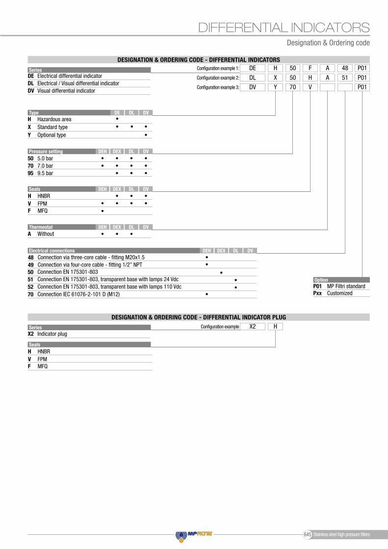
DIFFERENTIAL INDICATORS
Series
Series
DE
X2
DLDV
OptionP01Pxx
MP Filtri standardCustomized
Configuration example 1: DE FH 48A50 P01
Configuration example X2 H
Configuration example 2: DL HX 51A50 P01Configuration example 3: DV VY 70 P01
Type
XH
Y
Pressure setting
7050
957.0 bar5.0 bar
9.5 bar
Standard typeHazardous area
Electrical differential indicator
Indicator plug
Optional type
Electrical / Visual differential indicatorVisual differential indicator
DESIGNATION & ORDERING CODE - DIFFERENTIAL INDICATORS
DESIGNATION & ORDERING CODE - DIFFERENTIAL INDICATOR PLUG
Seals
Seals
••
•
• •
Electrical connections
50
5270
51
DL
DEX
DEX
DEH
DEH
DE DV
DL
DL
DV
DEXDEH DL DV
DEXDEH DL DV
DV
•
••
•
•
•
••
•
••
•
••
• • • •• • • •
• • •
•
••
ThermostatA Without
Connection EN 175301-803
Connection EN 175301-803, transparent base with lamps 110 VdcConnection IEC 61076-2-101 D (M12)
Connection EN 175301-803, transparent base with lamps 24 Vdc
Designation & Ordering code
F
F
H
H
V
V
MFQ
MFQ
HNBR
HNBR
FPM
FPM
4849
Connection via three-core cable - fitting M20x1.5Connection via four-core cable - fitting 1/2” NPT
Stainless steel high pressure filters645

Clogging indicators are devices that check the life time of the filter elements.They measure the pressure drop through the filter element directly connected to the filter housing.These devices trip when the clogging of the filter element causes a pressure drop increasing across the filter element.Filter elements are efficient only if their Dirt Holding Capacity is fully exploited.This is achieved by using filter housings equipped with clogging indicators.The indicator is set to alarm before the element becomes fully clogged.
MP Filtri can supply indicators of the following designs: - Vacuum switches and gauges - Pressure switches and gauges - Differential pressure indicators
These type of devices can be provided with a visual, electrical or both signals.The electronic differential pressure clogging indicator is also available. It provides both analogical 4-20 mA output and digital warning (75% of clogging) and alarm (clogging) outputs.
Clogging Indicators 646

Clogging Indicators
Clogging Indicators647

Clogging indicators
Clogging indicators
Suitable indicator types
BAROMETRIC INDICATORSPressure indicators are used on the Return line to check the effi ciency of the fi lter element.They measure the pressure upstream of the fi lter element.Standard items are produced with R 1/8” EN 10226 connection.
23
1
IN
OUT
IN
OUT
IN
OUT
IN
OUT
IN
OUT
IN
OUT
IN
OUT
IN
OUT
IN
OUT
IN
OUT
23
1
23
123
1
2
31
2
31
2
31
DIFFERENTIAL INDICATORSDifferential indicators are used on the Pressure line to check the effi ciency of the fi lter element.They measure the pressure upstream and downstream of the fi lter element (differential pressure).Standard items are produced with special connection G 1/2” size.Also available in Stainless Steel models.
23
1
IN
OUT
IN
OUT
IN
OUT
IN
OUT
IN
OUT
IN
OUT
IN
OUT
IN
OUT
IN
OUT
IN
OUT
23
1
23
123
1
2
31
2
31
2
31
VACUUM INDICATORSVacuum indicators are used on the Suction line to check the effi ciency of the fi lter element.They measure the pressure downstream of the fi lter element.Standard items are produced with R 1/4” EN 10226 connection.Available products with R 1/8” EN 10226 to be fi tted on MPS series.
23
1
IN
OUT
IN
OUT
IN
OUT
IN
OUT
IN
OUT
IN
OUT
IN
OUT
IN
OUT
IN
OUT
IN
OUT
23
1
23
123
1
2
31
2
31
2
31
Clogging Indicators 648
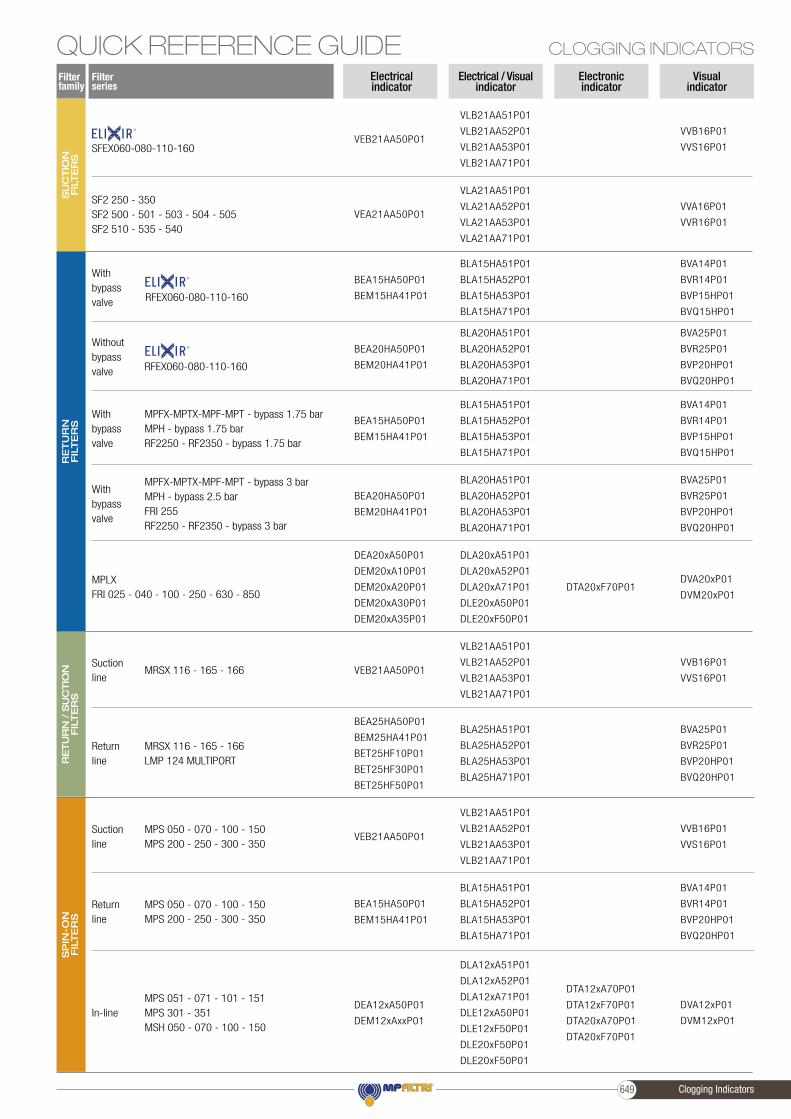
QUICK REFERENCE GUIDE CLOGGING INDICATORS
Filter series
Filter family
RE
TU
RN
FIL
TE
RS
RE
TU
RN
/ S
UC
TIO
N
FIL
TE
RS
SP
IN-O
N
FIL
TE
RS
SU
CTIO
N
FIL
TE
RS
Electronicindicator
Visualindicator
Electrical / Visualindicator
Electricalindicator
SF2 250 - 350SF2 500 - 501 - 503 - 504 - 505SF2 510 - 535 - 540
MPLXFRI 025 - 040 - 100 - 250 - 630 - 850
MPFX-MPTX-MPF-MPT - bypass 1.75 barMPH - bypass 1.75 barRF2250 - RF2350 - bypass 1.75 bar
MPFX-MPTX-MPF-MPT - bypass 3 barMPH - bypass 2.5 barFRI 255RF2250 - RF2350 - bypass 3 bar
MRSX 116 - 165 - 166Suctionline
MPS 050 - 070 - 100 - 150MPS 200 - 250 - 300 - 350
Suctionline
MPS 050 - 070 - 100 - 150MPS 200 - 250 - 300 - 350
Returnline
DTA20xF70P01
DTA12xA70P01
DTA12xF70P01
DTA20xA70P01
DTA20xF70P01
MPS 051 - 071 - 101 - 151MPS 301 - 351MSH 050 - 070 - 100 - 150
In-line
MRSX 116 - 165 - 166LMP 124 MULTIPORT
Returnline
SFEX060-080-110-160
VLA21AA51P01
VLA21AA52P01
VLA21AA53P01
VLA21AA71P01
DLA20xA51P01
DLA20xA52P01
DLA20xA71P01
DLE20xA50P01
DLE20xF50P01
BLA15HA51P01
BLA15HA52P01
BLA15HA53P01
BLA15HA71P01
BLA20HA51P01
BLA20HA52P01
BLA20HA53P01
BLA20HA71P01
VLB21AA51P01
VLB21AA52P01
VLB21AA53P01
VLB21AA71P01
VLB21AA51P01
VLB21AA52P01
VLB21AA53P01
VLB21AA71P01
BLA15HA51P01
BLA15HA52P01
BLA15HA53P01
BLA15HA71P01
DLA12xA51P01
DLA12xA52P01
DLA12xA71P01
DLE12xA50P01
DLE12xF50P01
DLE20xF50P01
DLE20xF50P01
BLA25HA51P01
BLA25HA52P01
BLA25HA53P01
BLA25HA71P01
VLB21AA51P01
VLB21AA52P01
VLB21AA53P01
VLB21AA71P01
BLA15HA51P01
BLA15HA52P01
BLA15HA53P01
BLA15HA71P01
BLA20HA51P01
BLA20HA52P01
BLA20HA53P01
BLA20HA71P01
VEA21AA50P01
DEA20xA50P01
DEM20xA10P01
DEM20xA20P01
DEM20xA30P01
DEM20xA35P01
BEA15HA50P01
BEM15HA41P01
BEA20HA50P01
BEM20HA41P01
VEB21AA50P01
VEB21AA50P01
BEA15HA50P01
BEM15HA41P01
DEA12xA50P01
DEM12xAxxP01
BEA25HA50P01
BEM25HA41P01
BET25HF10P01
BET25HF30P01
BET25HF50P01
VEB21AA50P01
BEA20HA50P01
BEM20HA41P01
BEA15HA50P01
BEM15HA41P01
VVA16P01
VVR16P01
DVA20xP01
DVM20xP01
BVA14P01
BVR14P01
BVP15HP01
BVQ15HP01
BVA25P01
BVR25P01
BVP20HP01
BVQ20HP01
VVB16P01
VVS16P01
VVB16P01
VVS16P01
BVA14P01
BVR14P01
BVP20HP01
BVQ20HP01
DVA12xP01
DVM12xP01
BVA25P01
BVR25P01
BVP20HP01
BVQ20HP01
VVB16P01
VVS16P01
BVA14P01
BVR14P01
BVP15HP01
BVQ15HP01
BVA25P01
BVR25P01
BVP20HP01
BVQ20HP01
RFEX060-080-110-160
RFEX060-080-110-160
With bypass valve
With bypass valve
With bypass valve
Without bypass valve
Clogging Indicators649

QUICK REFERENCE GUIDECLOGGING INDICATORS
Filter series
Filter family
LO
W &
ME
DIU
MP
RE
SS
UR
E F
ILTE
RS
HIG
H P
RE
SS
UR
EFIL
TE
RS
STA
INLE
SS
STE
EL
HIG
H P
RE
SS
UR
E F
ILTE
RS
LMP 110 - 112 - 116 - 118 - 119 MULTIPORTLMP 120 - 122 - 123 MULTIPORTLMP 210 - 211 - LDPLMP 400 - 401 & 430 - 431LMP 900 - 901LMP 902 - 903LMP 950 - 951LMP 952 - 953 - 954LMD 211 - 400 - 401 - 431 - 951 - LDD
With bypass valve
DTA20xF70P01DVA20xP01
DVM20xP01
DLA20xA51P01
DLA20xA52P01
DLA20xA71P01
DLE20xA50P01
DLE20xF50P01
LMP 110 - 112 - 116 - 118 - 119 MULTIPORTLMP 120 - 122 - 123 MULTIPORTLMP 210 - 211 - LDPLMP 400 - 401 & 430 - 431LMP 900 - 901LMP 902 - 903LMP 950 - 951LMP 952 - 953 - 954LMD 211 - 400 - 401 - 431 - 951 - LDD
Without bypass valve
DTA50xF70P01DVA50xP01
DVM50xP01
DLA50xA51P01
DLA50xA52P01
DLA50xA71P01
DLE50xA50P01
DLE50xF50P01
DTA50xF70P01
FMP 039 - 065 - 135 - 320FHP 010 - 011 - 065 - 135 - 350 - 500FMM 050 - 150FHA 051FHM 006 - 007 - 010 - 050 - 065 - 135 - 320 - 500FHB 050 - 065 - 135 - 320FHF 325FHD 021 - 051 - 326 - 333
With bypass valve
DVA50xP01
DVM50xP01
DLA50xA51P01
DLA50xA52P01
DLA50xA71P01
DLE50xA50P01
DLE50xF50P01
DEH50xA48P01
DEH50xA49P01
DEH50xA70P01
DEH70xA48P01
DEH70xA49P01
DEH70xA70P01
DTA70xF70P01
DTA95xF70P01
FMP 039 - 065 - 135 - 320FHP 010 - 011 - 065 - 135 - 350 - 500FMM 050 - 150FHA 051FHM 006 - 007 - 010 - 050 - 065 - 135 - 320 - 500FHB 050 - 065 - 135 - 320FHF 325FHD 021 - 051 - 326 - 333
Without bypass valve
DVA70xP01
DVM70xP01
DVA95xP01
DVM95xP01
DLA70xA51P01
DLA70xA52P01
DLA70xA71P01
DLE70xA50P01
DLE70xF50P01
DLA95xA51P01
DLA95xA52P01
DLE95xA50P01
DLE95xF50P01
DEH50xA48P01
DEH50xA49P01
DEH50xA70P01
DEH70xA48P01
DEH70xA49P01
DEH70xA70P01
DVX50xP01
DVY50xP01
FZH 010 - 011 - 039FZP 039 - 136FZX 011FZB 039FZM 039FZD 051
With bypass valve
DLX50xA51P01
DLX50xA52P01
DEH50xA48P01
DEH50xA49P01
DEH50xA70P01
DEH70xA48P01
DEH70xA49P01
DEH70xA70P01
DVX70xP01
DVY70xP01
DVX95xP01
DVY95xP01
FZH 010 - 011 - 039FZP 039 - 136FZB 039FZM 039FZD 010 - 021 - 051
Without bypass valve
DLX70xA51P01
DLX70xA52P01
DLX95xA51P01
DEH50xA48P01
DEH50xA49P01
DEH50xA70P01
DEH70xA48P01
DEH70xA49P01
DEH70xA70P01
Hazardous area electronic
indicatorElectronicindicator
Visualindicator
Electrical / Visualindicator
Electricalindicator
DVS25HP01
DVS40HP01
DVS25HP01
DVS40HP01
DEA20xA50P01
DEM20xAxxP01
DEA50xA50P01
DEM50xAxxP01
DEA50xA50P01
DEM50xAxxP01
DEA70xA50P01
DEM70xAxxP01
DEA95xA50P01
DEM95xAxxP01
DEX50xA50P01
DEX70xA50P01
DEX95xA50P01
DES25HA10P01
DES25HA30P01
DES25HA80P01
DES40HA10P01
DES40HA30P01
DES40HA80P01
LFEX060-080-110-160
With bypass valve
Without bypass valve LFEX060-080-110-160
Clogging Indicators 650

NOTES
Clogging Indicators651

NOTES
656
All data, details and words contained in this publication are provided for information purposes only.MP Filtri reserves the right to make modifications to the models and versions of the described products at any time
for both technical and / or commercial reasons.The colors and the pictures of the products are purely indicative.
Any reproduction, partial or total, of this document is strictly forbidden.All rights are strictly reserved.

EN
- R
ev. 0
9-20
21C
MP
EN
001G
mpfiltri.com
WORLDWIDE
TO PERFORM
NETWORK
PASSION
HEADQUARTERS
ITALFILTRI LLCMoscowRussia [email protected]
MP Filtri Canada Inc.Concord, [email protected]
MP Filtri France [email protected]
MP Filtri Germany GmbHSt. [email protected]
MP Filtri India Pvt. [email protected]
MP Filtri (Shanghai) Co., Ltd.ShanghaiP.R. [email protected]
MP Filtri U.K. Ltd.Bourton on the WaterGloucestershireUnited [email protected]
MP Filtri U.S.A. Inc.Quakertown, [email protected]
BRANCH OFFICES
MP Filtri S.p.A.Pessano con [email protected]