automatic meshing and remeshing in the simultaneous engineering context
TRANSCRIPT

Automatic Meshing and Remeshing in the Simultaneous Engineering Context
Vincent Franc¸ois1, Jean Christophe Cuillie`re1 and Michel Gueury2
1Laboratoire de Productique, Universite´ du Quebec aTrois-Rivieres, Trois Rivieres, Que´bec, Canada;2Equipes de Rechercheen Interfaces Nume´riques, Universite´ Henri Poincare, Nancy, Vandoeuvre, France
Abstract. This paper presents a method to integrate in abetter way the finite element method in the CAD/CAM processfor two-dimensional problems, through efficient and automaticmeshing and remeshing procedures. During the design step,the lack of integration between geometric modeling andnumerical analysis remains a crucial problem and it still tendsto restrain the use of finite element methods to a small numberof engineers. Here we tackle the problem of the automaticremeshing of an object in the context of minor changes in itsgeometry and topology without restarting the mesh generationfrom the beginning. We have developed a mesh generator thatis able to adapt a previous mesh, through two complementarystrategies (for 2D cases) to a new geometry without destroyingthe whole initial discretization. We also present the possibleextension of these concepts to three-dimensional problems.
Keywords: Advancing front techniques; CAD/CAM;Mesh generation; Nodal density; Remeshing
1. Introduction
Mesh generation plays an important role in engineer-ing analysis, particularly in finite element analysis. Incurrent applications, the domain that has to be studiedpresents a complex three-dimensional shape. Manydifferent approaches (Yerry and Shepard 1984;Cavendish 1985; Lo¨hner and Parikh 1988; Peraire etal. 1988; Chae and Bathe 1989; Cuillie`re 1993;Boender et al. 1994; Mo¨ller and Hansbo 1995; Lewiset al. 1996; Rassineux 1998) have been proposed todiscretize or to mesh a three-dimensional solidgeometry, but the introduction of mesh generationand analysis procedures in the simultaneous engineer-ing context requires a very close integration betweenthe geometry and the finite element model.
The proper integration between the geometry andthe FE mesh can be obtained combining an efficientmesh construction with an adaptive refinementmethod based ona priori geometric analysis of the3D model. In this context, the close relationshipbetween geometric and topologic entities (vertices,surfaces, curves, etc.) and discretization entities(elements, nodes, . . .) must appear clearly.
Among the different techniques that have beenproposed to model a 3D solid object, ConstructiveSolid Geometry (CSG) and Boundary Representation(B-Rep) are seen to be the most efficient at this point.The mesh or the discretization of a 3D solid object forFE needs can usually be seen as an approximation ofthe solid geometry. Thus, the solution obtained usingnumerical analysis can usually be a satisfyingapproximation of the analytic or exact solution ifthe mesh itself is a good approximation of the solidgeometry. This emphasizes the need for a directinteraction and integration between the geometricmodel and its associated FE mesh.
Among CAD/CAM systems available on themarket, there are only a very small number of systemsthat truly integrate geometry and numerical analysis.We can also argue that usually the mesh density iscompletely user driven instead of system driven,which means that there is no automation available atthis level. Moreover, even if these systems are nowable to automatically produce a tetrahedral mesh froma solid model, a change in dimension or shape of asmall detail on the solid implies the generation of acompletely new mesh from a new solid model. Thepresent work aims at building a mesh generationsystem featuring the ability for the user to modify anexisting solid and its associated mesh recreating as fewmesh entities as possible.
The algorithm and the solution are proposed herefor two-dimensional problems. The eventual pro-blems remaining to be solved for their three-dimensional version are also mentioned herein.
Research in Engineering Design (1999)11:55–66ß 1999 Springer-Verlag London Limited
Research in
EngineeringDesign
Correspondenceand offprint requeststo: J. C. Cuilliere, UQTR,Departementdegeniemecanique,CP500,TroisRivieres,Quebec,CanadaG9A 5H7. Email: [email protected]

2. Problem Definition
The purposesof the work presentedhere are thefollowing (Fig. 1):
. to generatea meshof a modifiedsolid modelgiventhe original solid model and its associateddis-cretization;
. both the original and the modified discretizationsmustbe well adaptedto the geometriesof the oldand new solid models. This means that ourproceduremust take into account density con-straints related to the minimization of the solidmodel’sdiscretizationerror.
Indeed,usinga meshthat is a goodapproximationofthe geometryis usuallynecessary(but not sufficient)to ensurethat analysisresultswill be satisfying.
Thus, after the automatic ‘remeshing’ process,thenew triangulation must satisfy the followingrequirements:
. should be topologically and geometricallycorrect.
. Thequality factor (quantifyingelementshapes)for shouldbe as high as possible(the quality of equalsthe quality of the worst element).
. Theobject’sboundaryandits discretizationshouldbe ascloseaspossible.
Fig. 1. Automaticmeshingandremeshingfrom a solid model.
56 V. Francois et al.

. To be ableto optimizethe remeshingprocedureofthe new geometry, the initial discretization shouldalsobe a goodapproximationof the initialsolid model,anda local constrainton thegeometryshouldlocally influencethe triangulation.
Thefirst,secondandthird requirementscanbefoundinthe definition of a traditional efficient triangulation.The last requirementis the most important in thecontextof thiswork. A functionhasto begeneratedinorderto describethedensityvariationacrossthespaceand, during a further step, to adapt the local tri-angulationto thelocalgeometry.Thissolutionrequirestheuseof meshgenerationprocedureswhich areableto respectdensityconstraints(anodaldensityfunctionalso called a nodal density map). The local shapevariationsaretranslatedaslocal densitychanges.So,the meshdensity function is directly controlling theaccuracy of the solid geometry approximation. Inaddition, quality constraintson elementsgenerated(minimum distortion) requirea densityfunction mapwith limited gradients.It also makesthe remeshingprocesseasieraswe will seelater.
We also have to choose the standardused todescribegeometryandtopology.Weaimatbuildingageneralpurposemeshgenerationsystem.The idea isto use a standardsupportedby most CAD/CAMsystemsavailableon the market,evenif it is obviousthata lot of problemsstill remainwhenusingthis typeof solution for geometry exchanges.For example,even if the idea supportingIGES (Initial GraphicsExchangeStandard)is theoreticallyveryattractive,itsimplementationhasbeenless than ideal. Supportisgenerallybetterfor simplergeometricentities,a littleworse for more complex geometric entities, andalmost non-existentor illogical for concepts likegrouping and shapeswith holes. Nevertheless,wehave chosenthe IGES standardformat for our 2Dimplementations.For the 3D extensionof our work,we are currently using ACIS solid modeling kernelandits associatedstandardSAT format.
Of course,usingtheIGESandSAT formatscanbeconsidered as interfacing rather than integratingCAD/CAM applications.Nevertheless,theseformatshave only be used here for convenienceand theextensionof our work to the true integrationwith aCAD/CAM systemdatabaseis not a real problem.
We could alsoconsidera CSGbasedsolution,butits inherent non-uniquenessseemsto be in strongoppositionwith the ability to automaticallyremesha3D domain; such a remeshingnecessarilyimpliesgeometriccomparisonsbetweenthe initial and themodifiedsolid models.
Thus, our work is focused on the followingindependentaspects:
. Definition of a nodaldensitymap.
. Meshgenerationwith theability to respecta priori(beforeanyanalysis)a nodaldensitymap.This canbe seen as a complementaryapproach to theclassicaliterative schemefeaturinganalysis,errorevaluation, and mesh refinement techniques.Infact,we aim at providinganinitial discretizationtothis iterativeprocessthat presentsan optimization.
. Two strategies for automatic remeshing areproposedhere for different typesof modificationsin theinitial part(Fig. 2): thefirst oneapplieswhenthe initial part is modified without changing itstopological Brep structure (geometric modifica-tion). The second one applies for any type ofmodificationin theBrepstructure(topologicor/andgeometricmodifications).
3. Quadtree
A quadtreestructureis often consideredas a veryuseful tool for meshgenerationpurposes.In fact, weneeda spacedecompositionstructurein order:
Fig. 2. (a) A sampleinitial part, (b) topologicmodificationof theinitial part, (c) geometricmodificationof the initial part.
(a)
(b)
(c)
AutomaticMeshingandRemeshing 57

. to define a neighboring context (George 1991;Rassineux1998)
. to definea local geometricreferencefor remeshingoperations.
For spatialdecompositionpurposeswe canbothusearegulargrid or a quadtree(Yerry andShepard1984;George 1991; Rassineux1991) (an octree for 3Dproblems).We areusinga quadtreetechniquefor theimplementationpresentedin this paper.Thereasonisthatour meshgeneratormustbeableto handlea non-uniform densityconstraint.Consequently,theuseof aquadtreeis absolutelynecessaryaswe needto haveanon-uniform tail distribution for the decompositioncells. Let us note that, in this work, our meshgenerationalgorithmsare basedon advancingfronttechniquesand, we do not directly use this spacedecompositionstructurefor elementgeneration.Themain purposeof this structureis to detectgeometricand topologic changes between the initial andmodifieddesignsolutions.
The spaceis divided into a set of squareswithvarying tails. The object is placed in an enclosingsquarethatwill belocatedat theroot of a hierarchicaltree data structureand the spatial decompositionismadeof the endleavesof the tree(Fig. 3).
Thequadtreedatastructureis built following thesesteps:
. generation of the initial quadrant (root of thestructure);
. recursivedivision (four quadrantsfor 2D casesand8 octantsfor 3D problems)of the root.
During the recursive division process, a givenquadrantis subdividedif it containsmore than twogeometricentities or more than one loop. Thus, the
final spatialdecompositionis madeof a set of cellscontainingthe samequantity of geometricinforma-tion.
The determinationof the owning cell for a givenlocation (x,y) is made by a recursive algorithm(Algorithm 1) starting from the root of the datastructure.
Algorithm 1. Insertionof an object into the quadtree
insert_object(object,cell)
if object is into the cellif the cell is not a leaf
insert_object(object,son1)insert_object(object,son2)insert_object(object,son3)insert_object(object,son4)
elseinsertobject into the cell
end
The algorithmis initialized with cell = root
As mentionedearlier, the quadtreeis usedfor thefollowing purposes:
. the searchfor a neighboringentity can be easilymadeby applyinga searchprocedurein neighbor-ing cells if all the entitiesare insertedin the griddatastructure(neighboringcontext);
. the useof the grid for remeshingoperations(seeSection6).
4. Density Map Calculations
The destructionof a minimal numberof trianglesinthe remeshingprocesscanbe obtainedwith an initialmesh that is as close as possible to the initialgeometry. This is achievedusing a nodal densitymap that is automatically driven by the object’sshape.We also take into accountthe nodal densitygradientin orderto makethemapsmoother.Theonlyinput thathasto beenteredby theuserin this processis theglobaldensity(dg), that is to say,thedensityinnon-refinementzones.
The object boundarycurvesare first meshedwithrespectto a curvilinear densityfunction (seeSection5). Thenthe densityfor any location (x,y) inside thedomainis computedusingthe previousdiscretizationof the boundary.Thus,we mustboth define:
. a densityfunction for the edgesof the boundaries;
. a processto computethe density function at anylocation insidethe boundaries.
Fig. 3. An exampleof a spatialdecompositionusingthe quadtreetechnique.
58 V. Francois et al.

Theprocessconsistsof defininga densitymapthat isconstant (equal to the global density) everywhereexcept in refinementzones.Theserefinementzonesare based on geometry and density gradientsconsiderationsin order to discretizethe domainwithwell shaped triangles while approximating theboundariesaspreciselyaspossible.
4.1. Definition of a Density Function for EachBoundary Curve
Let C(s) bea boundarycurvedefinedby thevertexA(curvilinear coordinatesa and the vertex B (curvi-linear coordinatesb).
4.1.1.First StepA first discretizationof theboundarycurvesis appliedwith a density function that generatesintermediatenodeswith respectto a tolerance" betweenthecurveandthe setof linear segmentsapproximatingit. Thisfirst discretizationis refined,thougha secondstep,toobtain a new discretization that presentsa lowerdensity gradientwhile respectingthe global densityfactor.
Calculation of the first density function (Lohnerand Parikh 1988): The numberof segmentsn to begeneratedto approximatethegivencurveC(s) with atolerance" is
n�j sb ÿ sa j�����������������������������
supsa�s�sb
k C00�s� k8"
s�1�
Thus, the first density function DF1(s) (nodalspacing)usedfor the curve to be meshedis definedasfollows:
DF1�s� ������������������������������
8"sup
around sk C00�s� k
s�2�
Algorithm 2. Seconddensityfunction.
For all nodes,each node is linked with two curvesegments(curve segment1 and curve segment2)densityat node= min(dg,11,12), wheredg = densityglobal, 11 = curvilinear length of curve segment1,and12 = curvilinear lengthof curvesegment2.
For all curve segments,each curve segmentisdefinedby two nodes(node1andnode2)
if l<dgif dn1 = dn2 DF2(s) = dn1 = dn2
else DF2�s� � sÿ s2
s1ÿ s2dn1� sÿ s1
s2 ÿ s1dn2
elseif dn1 = dn2 = dg DF2(s) = dn1 = dn2
else DF2�s� � �sÿ s1��sÿ s2��smÿ s1��smÿ s2� dg�
�sÿ sm��sÿ s2��s1ÿ sm��s1ÿ s2� dn1 � �sÿ s1��sÿ sm�
�s2 ÿ s1��s2ÿ sm� dn2
wherel = curvilinear lengthof curvesegmentdn1 = densityat node1dn2 = densityat node2s1 = curvilinearcoordinateof node1s2 = curvilinearcoordinateof node2
sm � dn1s1� dn2s2
dn1� dn2
4.1.2.SecondStepThen this first discretizationis refined via a secondfunction DF2(s) in order to obtain a lower densitygradient(seeAlgorithm 2).
4.2. Definition of a Density Function for anyPoint Inside the Domain
The density DF3(x,y) at any location inside thedomain is calculated from the density at theboundariesthroughthe Algorithm 3 (Fig. 4).
Algorithm 3. Density function insidethe domain.
If the point is outsidethe domainDF3(s) = 0elseThe neighboring zone (square with side equal to8*global density)of the point(x,y) is created.Then,the four segmentscloserto thepoint insidetheneighboringzoneareresearched.Thus,k (k� 4) segmentsarefoundandthedensityatlocation (x,y) is given by:
DF3�x; y� �dismin � dg�Pk
n�1�4dgÿ disn�dnn
dismin �Pkn�1�4dgÿ disn�
if k > 0
DF3(x,y) = dg if k = 0wheredisn = distancebetweenthe points(x,y) and the nthsegmentdismin = min(disn)
1�n�k
dnn = densityassociedwith the nth segment
AutomaticMeshingandRemeshing 59

5. Mesh Generation by Advancing FrontProcedure
5.1. Advancing Front Procedures
The basicprinciplesof this type of methodare verysimple(LohnerandParikh1988;Peraireet al. 1988;Chae and Bathe 1989; Cuilliere 1993; Moller andHansbo1995; Lewis et al. 1996; Rassineux1998).The processstartsfrom the boundaryof the domainthat has to be discretized.Thus, an initial front isgeneratedand oriented on the boundariesof theobject.This initial front is composedof straightlinesegmentsfor 2D and surfacemesh generationandtrianglesfor solid modelsdiscretization.At eachstep,anelementis createdfrom asegment(or a triangle)ofthe front and the front is updated.Consequently,thefront is advancingacrossthe spacethat has to bemeshedandthisprocessgoesonaslongasthefront isnot empty(Fig. 5).
The successof advancingfront methodsin thegenerationof 2D or 3D meshesis very muchrelatedto the strategyappliedat eachstepwhenchoosingacandidate segment (or triangle) in the advancingfront. In fact, the crucial issue(particularly for 3Dproblems) is to assureconvergence(emptying thefront), and it is, of course,directly related to therobustnessof the mesh generation process. Thismatter can’t be basedon any mathematicaltheory;it canonly be solvedusingexperienceandintuition.
Nevertheless,the major interestsof this techniquearethe following:
. it is quite simple to compute;
. it can be applied to any type of meshgenerationproblem(2D, surfaces,solids) following the samestrategies;
. it features a great potential to be extendedtovarying densityandanisotropicmeshgeneration.
Among the different approachesthat have beenpublished,we candistinguishtwo main strategies:
. the creation of interior nodes first and theconnectionof thesenodesthrough an advancingfront technique(Rassineux1998);
. the simultaneouscreation of nodesand elements(Peraireetal. 1988;ChaeandBathe1989;Cuilliere1993).
As we are going to seein the following paragraphs,our meshgeneratoris basedon the secondstrategyand it meetsthe requirementsof an isotropic nodaldensityfunction.
5.2. Boundary Curve Discretization
Let C(s) be a curve, with curvilinear length s0 andDF(s) the associateddensity function, its discretiza-tion with linearsegmentsis givenby (Cuilliere 1997):
Fig. 4. The nodaldensityfunction associatedwith the initial part.
Fig. 5. Generalschemeof an advancingfront method.
60 V. Francois et al.

. Calculatingthenumberof segmentsN (N+1 nodes)that haveto be createdalongC(s).
. N equalsthe nearestintegerto A with
A�Z s0
0
dsDF�s� �3�
. GeneratingN–1 nodesalong the curveC(s) using(si–1 and si are the curvilinear coordinatesforconsecutivenodesi–1 and i)Z si
siÿ1
dsDF�s� �
AN
1� i � N ÿ 2 �4�
5.3. Domain Triangulation
The initial front (set of linear segments) fortriangulation (Cuilliere 1993) using the advancingfront method is createdfrom the boundarycurvesdiscretizationresult. The segmentsof the boundarydiscretization are arranged according to theirincreasing lengths. In fact, at each recursive stepof theadvancingfront procedure,the first segmentinthe list (the smallest) is processedas long as thefront is not empty. We also compute from thiscandidatesegmentthe angleswith the previousandthe next segmentsalong the front.
5.4. Optimization
For 2D cases,therearevery few trianglesthatpresentabadquality factor(lessthan0.1)(George1991;DariandBuscaglia1994).Nevertheless,the meshgenera-tion proceduresareusually followed by optimization
algorithms(moving nodesiteratively, diagonaltrans-pose,etc)in orderto improvetheoverallmeshquality(Fig. 6). For automatictetrahedralmeshgeneration(3D parts), these mesh smoothing algorithms arecrucial in orderto obtainsatisfyingquality factors.
The adaptationof advancingfront methodsin thecaseof 3D parts(surfaceandsolid meshgeneration)is much more difficult. In fact, the convergenceofthesealgorithmsthat is very simple to obtain for 2Dcasesis not an obviousmatter in three dimensions.Nevertheless,this hasbeentackledquite successfullyby severalauthors,proving the efficiency of advan-cing front techniquesin variouscontexts(LohnerandParikh1988;Peraire1988;Moller andHansbo1995;Lewis et al. 1996;Rassineux1998).
6. Automatic RemeshingProcedures
6.1. First Strategy
As mentionedabove,the first strategyapplieswhenthe initial part is modified without changing itstopologicalBrep structure.As an example,this typeof modification frequently occurs when modifyingdimensionsin a parametricsolid modeler.The basicprinciple appliedhereis to keepthe samenumberofnodes and triangles and the same mesh topology.Thus, the initial mesh is directly fitted to the newgeometryby a setof changesin the nodalpositions.
Theold meshis fitted to thenewgeometrythroughthe two following steps:
. moving the boundarynodes;
. moving the interior nodes.
Fig. 6. Meshof the initial part with respectof the densitymapandafter an optimizationprocess
AutomaticMeshingandRemeshing 61

Fitting boundarynodesis achievedby discretizingthenew boundariesthroughthe sameprocedureusedfortheinitial partwith aconstraintonthenumberof nodeson eachcurve(thesameasfor the initial curves).
Fitting interior nodesconsistsof calculatingnewpositionsfor all the interior nodesthat are basedonthe new positionsof boundarynodes.
Let A be an interior node to move at location A'(unknown)and Ni the boundarynodesof the initialpart with their new positionsN
0i ; 1� i � n (n is the
numberof boundarynodes).The calculationof thenew positionA' is basedon Fig. 7
�ANi�==�A0N 0i � for 1� i � n
This expressesthat the relative position of A (toboundarynodes)is kept the same.This leads to asystemwith two unknowns(A' coordinates)and nequations.This systemis solvedusinga leastsquarestechniquewith normalequations.
The results obtained with this method are verygood (see Fig. 8, the two diameters have beenchanged)when the geometricmodificationsare notvery important (less than 25% of a length, radius,etc.), and the CPU time requirementis insignificant(less than one second on a PC). When thesemodificationsaremoresignificant,the new geometryis sodifferentthat it is very difficult to fit in theinitialmeshwithout obtainingbadly shapedelements.
The extensionof this techniqueto three dimen-sional parts can be led very easily, through thefollowing steps:
. moving edgenodes;
. moving surfacenodes(surfaceby surface);
. moving interior nodes.
This strategydoesnot theoreticallyensureto obtainavalid mesheven if the validity is testedduring theprocess.With practical 2D parts we do not obtaininvalid mesheswhenthe geometricmodificationsarenot very important.
6.2. SecondStrategy
The second strategy applies for any type ofmodification in the initial part’s geometry ortopology.The basicideaof this remeshingprocedure(appliedwhenthe geometryhasbeenmodified) is to
Fig. 7. (a) An initial mesh,(b) theboundaryis discretizedwith thesamenumberof nodes,(c) the interior nodesaremovedto fit withthe new geometry.
Fig. 8. Meshregenerationwith the first strategy.The initial meshis shownin Fig. 6.
62 V. Francois et al.
keep as many trianglesas possiblefrom the initialmesh.Consequently,we mustfirst detectthechangesbetweenthe two parts,then destroysetsof triangleslocatedaroundgeometricchanges,andfinally, rebuilda set of fronts for the advancing front meshregenerationprocess.
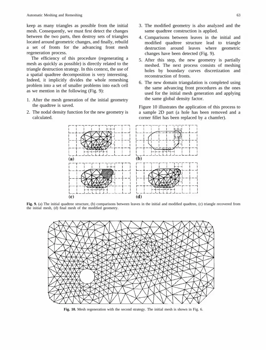
The efficiency of this procedure(regeneratingameshasquickly aspossible)is directly relatedto thetriangledestructionstrategy.In thiscontext,theuseofa spatialquadtreedecompositionis very interesting.Indeed, it implicitly divides the whole remeshingprobleminto a setof smallerproblemsinto eachcellaswe mentionin the following (Fig. 9):
1. After the meshgenerationof the initial geometrythe quadtreeis saved.
2. Thenodaldensityfunctionfor thenewgeometryiscalculated.
3. The modified geometryis also analyzedand thesamequadtreeconstructionis applied.
4. Comparisonsbetween leaves in the initial andmodified quadtree structure lead to triangledestruction around leaves where geometricchangeshavebeendetected(Fig. 9).
5. After this step, the new geometry is partiallymeshed.The next processconsistsof meshingholes by boundary curves discretization andreconstructionof fronts.
6. The new domaintriangulationis completedusingthe sameadvancingfront proceduresas the onesusedfor the initial meshgenerationand applyingthe sameglobal densityfactor.
Figure10 illustratesthe applicationof this processtoa sample2D part (a hole has beenremovedand acornerfillet hasbeenreplacedby a chamfer).
Fig. 9. (a) The initial quadtreestructure,(b) comparisonsbetweenleavesin the initial andmodifiedquadtree,(c) triangle recoveredfromthe initial mesh,(d) final meshof the modified geometry.
Fig. 10. Meshregenerationwith the secondstrategy.The initial meshis shownin Fig. 6.
AutomaticMeshingandRemeshing 63

The samemethodcan be applied in the caseofthreedimensionalparts.The quadtreestructuremustbe replacedby an octree structureand the processfeaturesthe following steps:
. building new fronts on surfaceswhere elementshavebeendestroyedand remeshingsurfaceholes(surfaceby surface);
. building newtrianglefrontsandremeshingvolumeholes.
7. Results
We illustrate the two remeshingstrategieson a 2Dsamplepart (Figs11 and12). As mentionedabove,anodaldensityfunction is first computedon the initialgeometry.After generatingthe initial meshusingthisnodal density function, we apply two types ofmodificationson the initial part: geometricmodifica-tions and; both geometric and topologic modifica-
Fig. 11. Shafthanger.(a) Initial part, (b) geometricmodification,(c) generalmodification.
(a) (b) (c)
(a)
(b)
Fig. 12. (a) Densitymapof this initial part, (b) meshof this initial part, (c) meshregenerationwith thefirst strategy,(d) meshregenerationwith the secondstrategy.
(c)
(d)
64 V. Francois et al.

tions. The modified partsare remeshedapplying thetwo strategies described above and the resultsobtainedaresummarizedin Table1.
The theoretical number of triangles (Cuilliere1998)N to meettherequirementsof thenodaldensityfunction DF(x,y) equalsthe closestintegerto:
A� 4���3pZ Z
s
dx:dyDF2�x; y�
The quality of a triangle is calculated with thecriterionQ = a r/h, whereh is the longestsideof thetriangle,r is the circumcircle radiusof the triangle,anda is a normalizationfactor(Q=1 for anequilateraltriangle).
Of course,for a meshobtainedfollowing both ofthe remeshingstrategies,the resulting meshdensitydoesnot strictly correspondto the theoreticaldensityfunction associatedwith the new geometry as the
great majority of the discretizationelementshavebeen computedfrom a previous discretizationthatwas based on a different geometry. This remarkillustrates the fact that theseremeshingproceduresshouldbe consideredasa complementaryalternativeto a complete remeshing of the structure usingconventionalapproaches.Indeed, remeshingproce-duresas presentedin this work aim at obtaining aconformalmeshfitted to a modifiedgeometrywithoutspendingtoo muchCPU time.
8. Conclusion
A fully automatic remeshing process for two-dimensionalproblemshasbeenpresentedhere,withan efficient and automaticalgorithm to calculatethenodal density function. With this technique, themodification and re-analysisof an initial designforany 2D part doesnot requirea completereconstruc-tion of the discretization. It can be regarded asparticularly interestingfor very largemodels.Conse-quently,themaininterestof this work is obviouslyitspotential extension to three-dimensionalmodels,which is being implementedin our currentresearch.Figure 13 illustrates one of the preliminary resultsobtainedwith the 3D implementationof our work(strategy 2 has been applied and the initial meshfeatures24000tetrahedralelements).On this samplepart, the time to remeshusing our proceduresis 13times lower than the time required to remeshtheentirepart.
Table 1. Resultsfor shafthanger
Part Initial Firststrategy
Secondstrategy
Numberof nodes 665 665 732Numberof triangles 1095 1095 1233Theoreticalnumberof
triangles1123 1411
Destroyednodes 67Destroyedtriangles 127Minimum quality 0.5 0.37 0.37Maximum quality 1 1 1Meanquality 0.85 0.84 0.84CPU (s) 12 3 11
Fig. 13. (a) Initial meshof an ejectorbase,(b) elementsrecoveredafter topologicmodifications,(c) remeshedzone,(d) final meshof themodifiedejectorbase.
AutomaticMeshingandRemeshing 65

Acknowledgements
This work was carried out in a project supportedbyresearchfunding from the Universite du Quebec a Trois-Rivieres and the Natural Sciences and EngineeringResearchCouncil of Canada.
References
BoenderE, BronsvoortWF, Post FH (1994) Finite-elementmeshgenerationfront constructive-solid-geometrymodels.Computer-AidedDesign26:379–392
Cavendish JC (1985) An approch to automatic three-dimensionalfinite elementmeshgeneration.InternationalJournalfor NumericalMethodsEngineering21:329–347
ChaeSW, BatheKJ (1989) On automaticmeshconstructionandmeshrefinementin finite elementanalysis.Computers& Structures32:911–936.
Cuilliere JC (1993) Pre-optimisation de maillages auto-matiquestridimensionnelspour les methodesnumeriquesapplication a l’ingenierie simultanee. PhD Thesis,InstitutNationalPolytechniquede Lorraine,INPL, December
Cuilliere JC (1997) A direct and optimal method for theautomatic discretizationof 3D parametriccurves in thecontext of steepnodal density gradients.Computer-AidedDesign29:639–647
Cuilliere JC (1998)A nearoptimal andadaptativemethodforthe automatic triangulation of 3D parametric surfaces.ComputerAided Design30:139–149
Dari EA, BuscagliaGC (1994) Mesh optimisation: how toobtaingoodunstructured3D finite elmentmesheswith not-so-goodmesh generators.Structural Optimisation 8:181–188
GeorgePL (1991)AutomaticMeshGeneration.Application tofinite elementmethods.Wiley
Lewis RW, Zheng Y, Gethin DT (1996) Three-dimentionalunstructuredmesh generation: Part 3. Volume meshes.ComputerMethodsin Applied MechanicsandEngineering134: 285–310
Lohner R, Parikh P (1988) Generationof three-dimentionalunstructuredgrids by the advancing-frontmethod.Interna-tional Journal for Numerical Methods in Fluids 8:1135–1149
Moller P, Hansbo P (1995) On advancing front meshgenerationin three dimensions.International Journal forNumericalMethodsin Engineering38:3551–3569
PeraireJ, Peiro J, FormaggiaF, Morgan K, Zienkiewicz OC(1988) Finite elementeuler computationsin three dimen-sions. International Journal for Numerical Methods En-gineering26:2135–2159
RassineuxA (1991) An automaticmeshgeneratorfor planardomains.StruCome,Paris91:519–531
RassineuxA (1998)Generationandoptimizationof tetrahedralmeshesby advancingfront technique.InternationalJournalfor NumericalMethodsin Engineering41:651–674
Yerry MA, ShepardMS (1984) Automatic three-dimensionalmeshgenerationby the modified-octreetechnique.Interna-tional Journal for Numerical Methods in Engineering20:1965–1990
66 V. Francois et al.