11.1 remeshing - hao li
TRANSCRIPT
CSCI 621: Digital Geometry Processing
Hao Lihttp://cs621.hao-li.com
1
Spring 2017
11.1 Remeshing
Outline
2
• What is remeshing?
• Why remeshing?
• How to do remeshing?

Outline
3
• What is remeshing?
• Why remeshing?
• How to do remeshing?
Definition
4
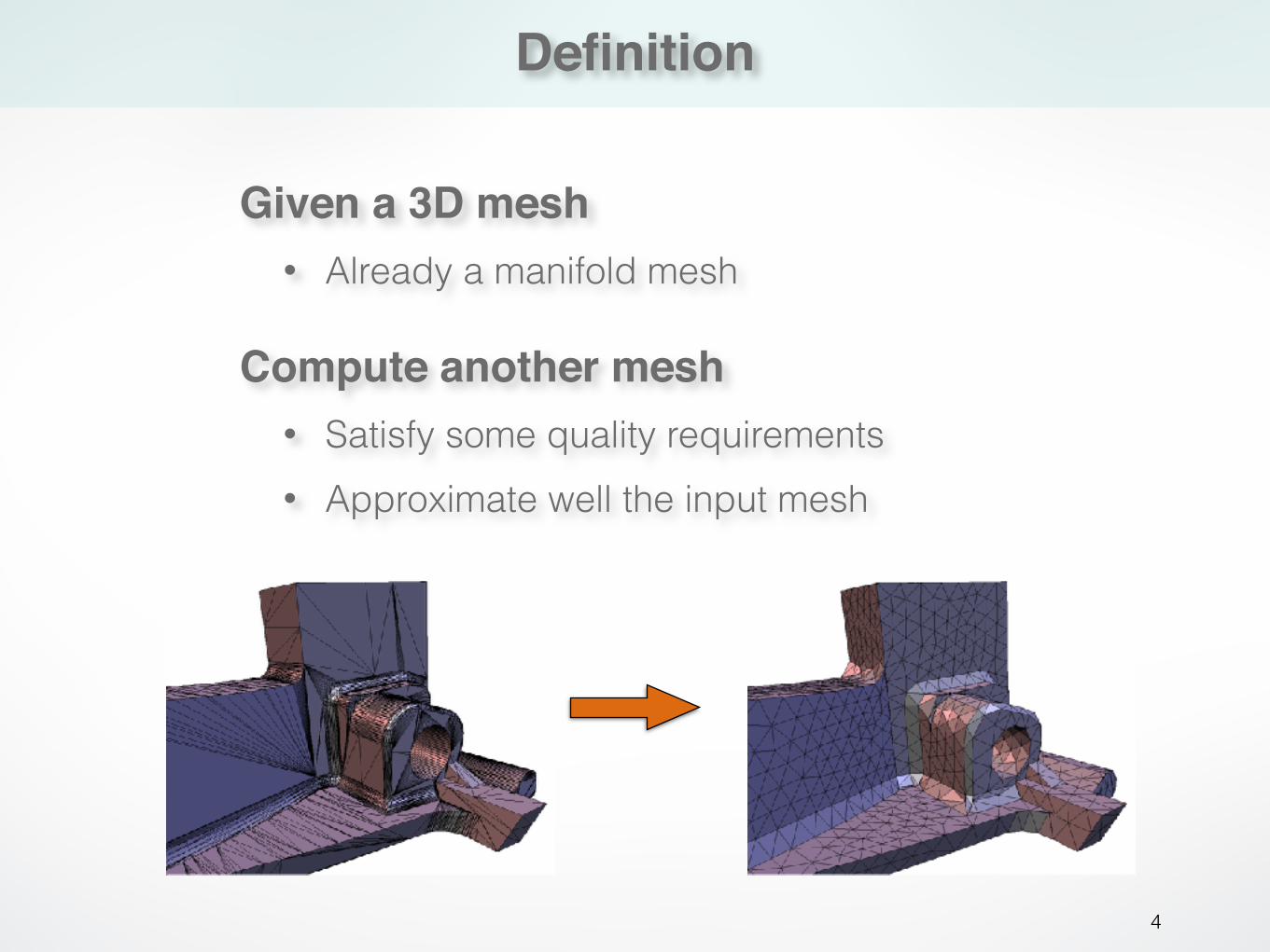
Compute another mesh• Satisfy some quality requirements • Approximate well the input mesh
Given a 3D mesh• Already a manifold mesh

Outline
5
• What is remeshing?
• Why remeshing?
• How to do remeshing?
Motivation
6
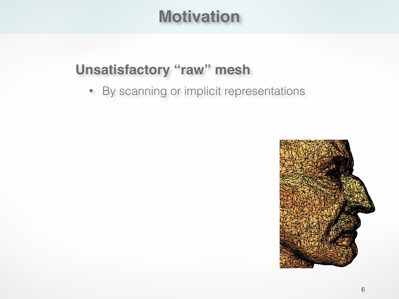
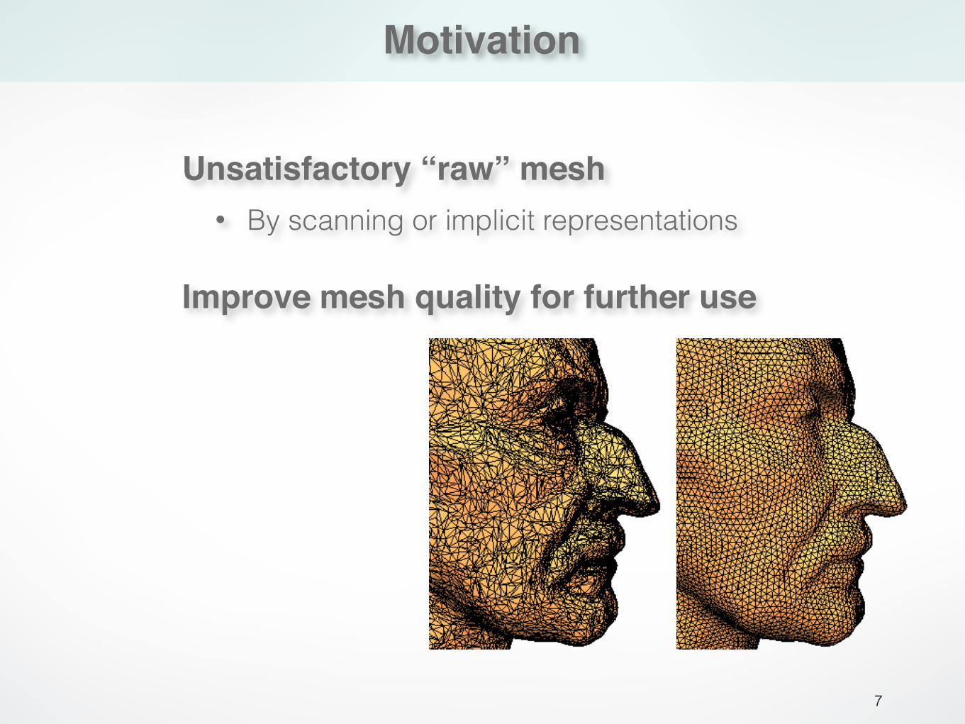
Unsatisfactory “raw” mesh• By scanning or implicit representations
Motivation
7
Improve mesh quality for further use
Unsatisfactory “raw” mesh• By scanning or implicit representations
Motivation
8
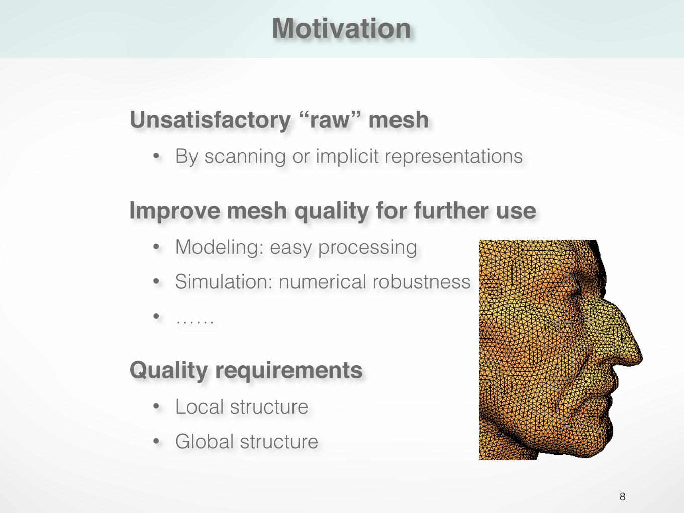
Improve mesh quality for further use• Modeling: easy processing • Simulation: numerical robustness • ……
Unsatisfactory “raw” mesh• By scanning or implicit representations
Quality requirements• Local structure • Global structure
Local structure
9
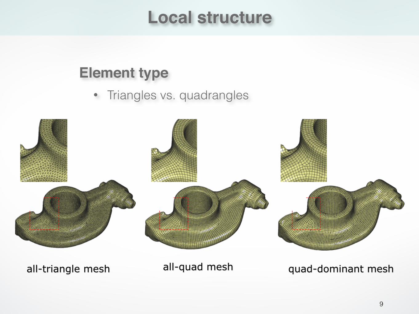
Element type• Triangles vs. quadrangles
all-triangle mesh all-quad mesh quad-dominant mesh
Local structure
10
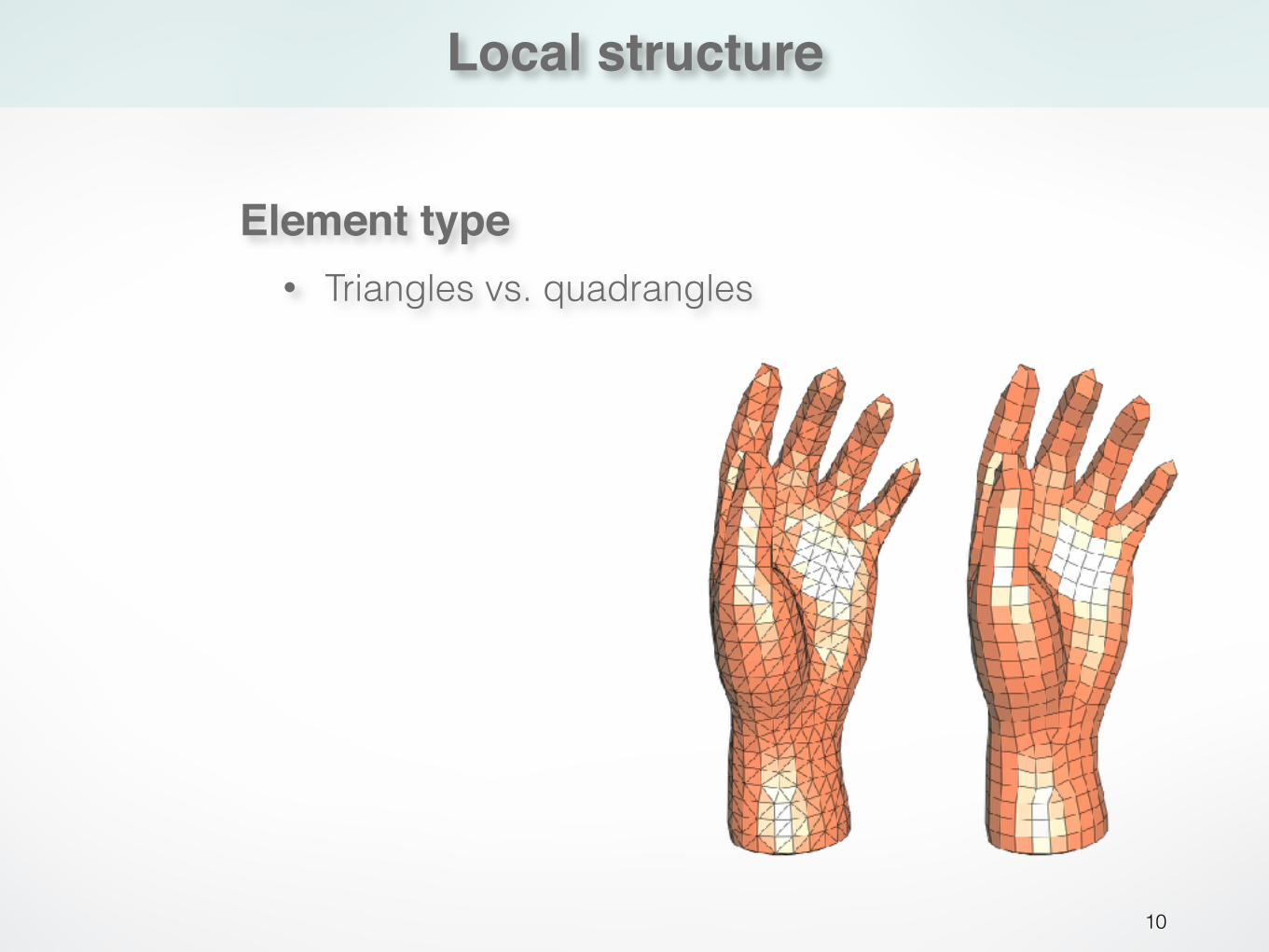
Element type• Triangles vs. quadrangles
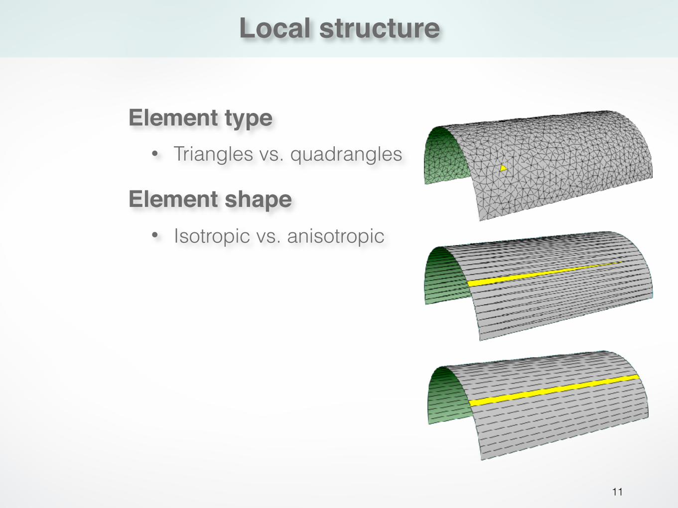
Local structure
11
Element shape• Isotropic vs. anisotropic
Element type• Triangles vs. quadrangles
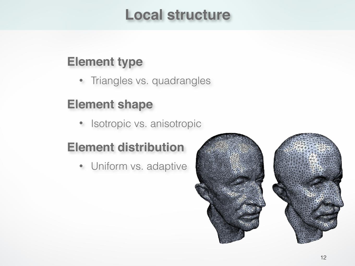
Local structure
12
Element shape• Isotropic vs. anisotropic
Element type• Triangles vs. quadrangles
Element distribution• Uniform vs. adaptive
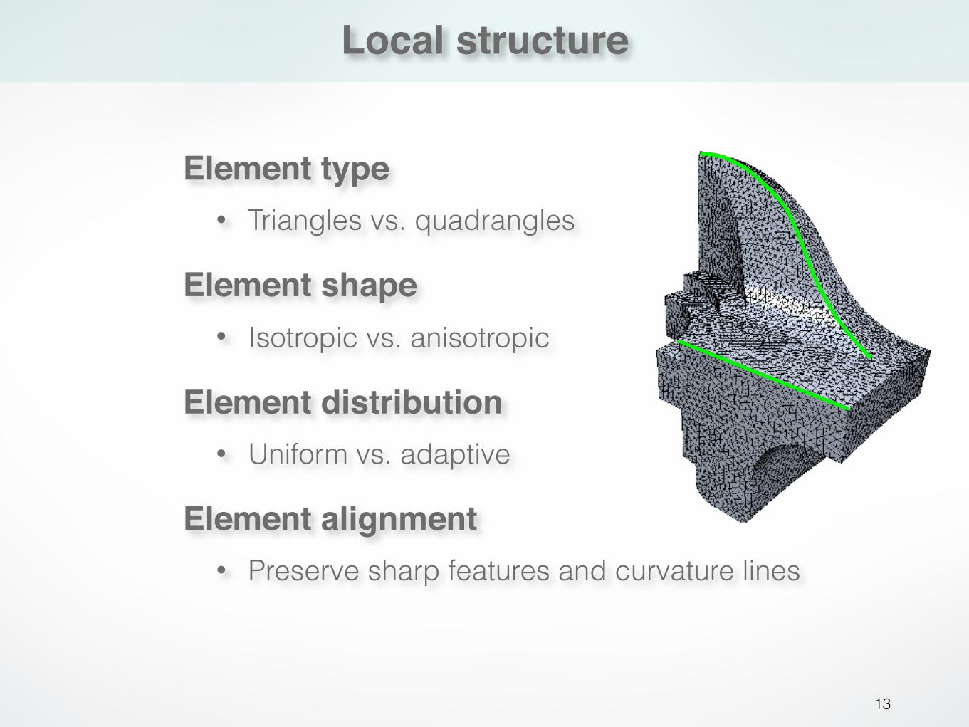
Local structure
13
Element shape• Isotropic vs. anisotropic
Element type• Triangles vs. quadrangles
Element alignment• Preserve sharp features and curvature lines
Element distribution• Uniform vs. adaptive
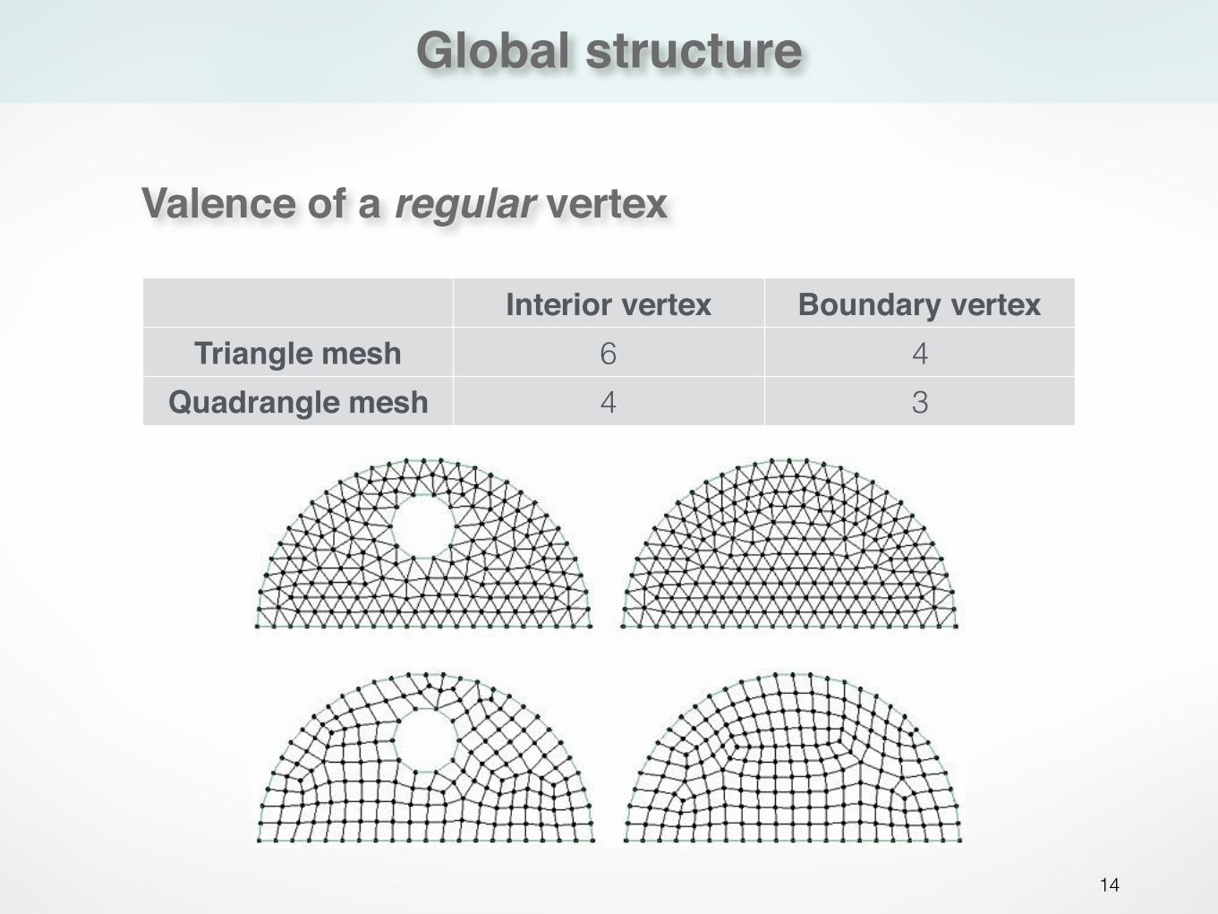
Global structure
14
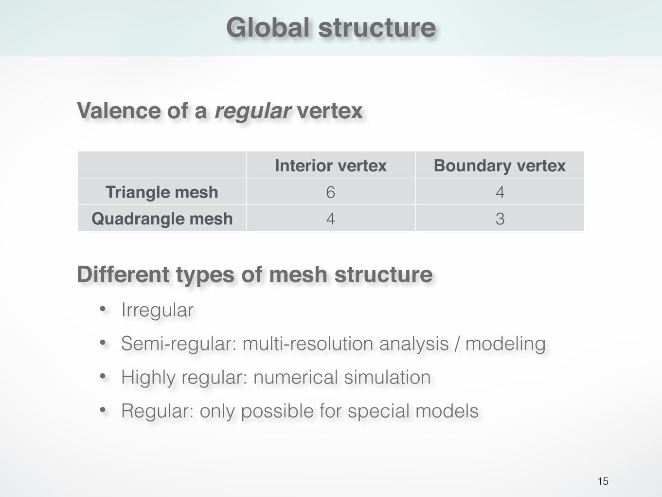
Valence of a regular vertex
Interior vertex Boundary vertexTriangle mesh 6 4
Quadrangle mesh 4 3
Global structure
15
Valence of a regular vertex
Different types of mesh structure• Irregular • Semi-regular: multi-resolution analysis / modeling • Highly regular: numerical simulation • Regular: only possible for special models
Interior vertex Boundary vertexTriangle mesh 6 4
Quadrangle mesh 4 3

Outline
16
• What is remeshing?
• Why remeshing?
• How to do remeshing?
Outline
17
• What is remeshing?
• Why remeshing?
• How to do remeshing?- Isotropic remeshing - Anisotropic remeshing
Outline
18
• What is remeshing?
• Why remeshing?
• How to do remeshing? - Isotropic remeshing- Anisotropic remeshing
Isotropic remeshing
19
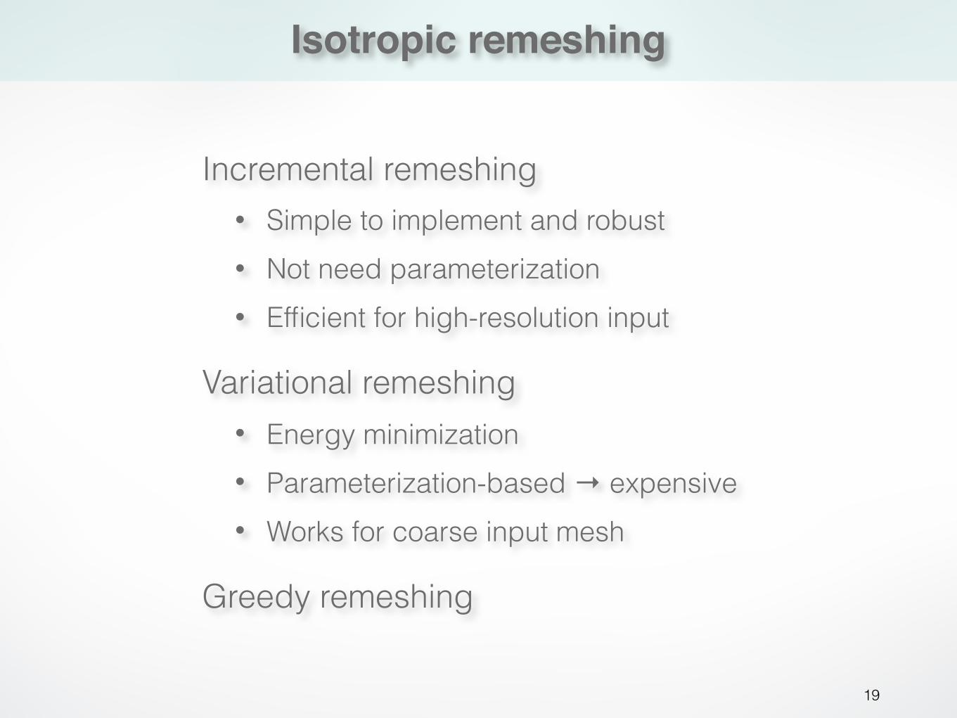
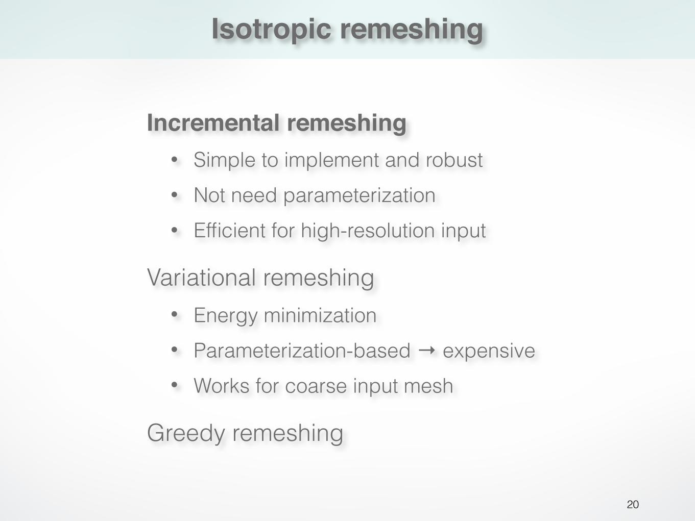
Variational remeshing • Energy minimization • Parameterization-based → expensive • Works for coarse input mesh
Greedy remeshing
Incremental remeshing • Simple to implement and robust • Not need parameterization • Efficient for high-resolution input
Isotropic remeshing
20
Variational remeshing • Energy minimization • Parameterization-based → expensive • Works for coarse input mesh
Greedy remeshing
Incremental remeshing• Simple to implement and robust • Not need parameterization • Efficient for high-resolution input
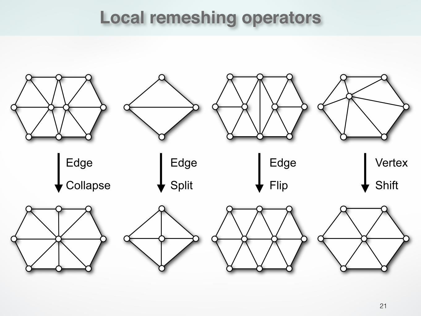
Local remeshing operators
21
Edge
Split
Vertex
Shift
Edge
Collapse
Edge
Flip
Incremental remeshing
22
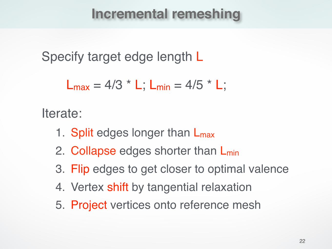
Specify target edge length L
Lmax = 4/3 * L; Lmin = 4/5 * L;
Iterate:1. Split edges longer than Lmax
2. Collapse edges shorter than Lmin
3. Flip edges to get closer to optimal valence4. Vertex shift by tangential relaxation5. Project vertices onto reference mesh
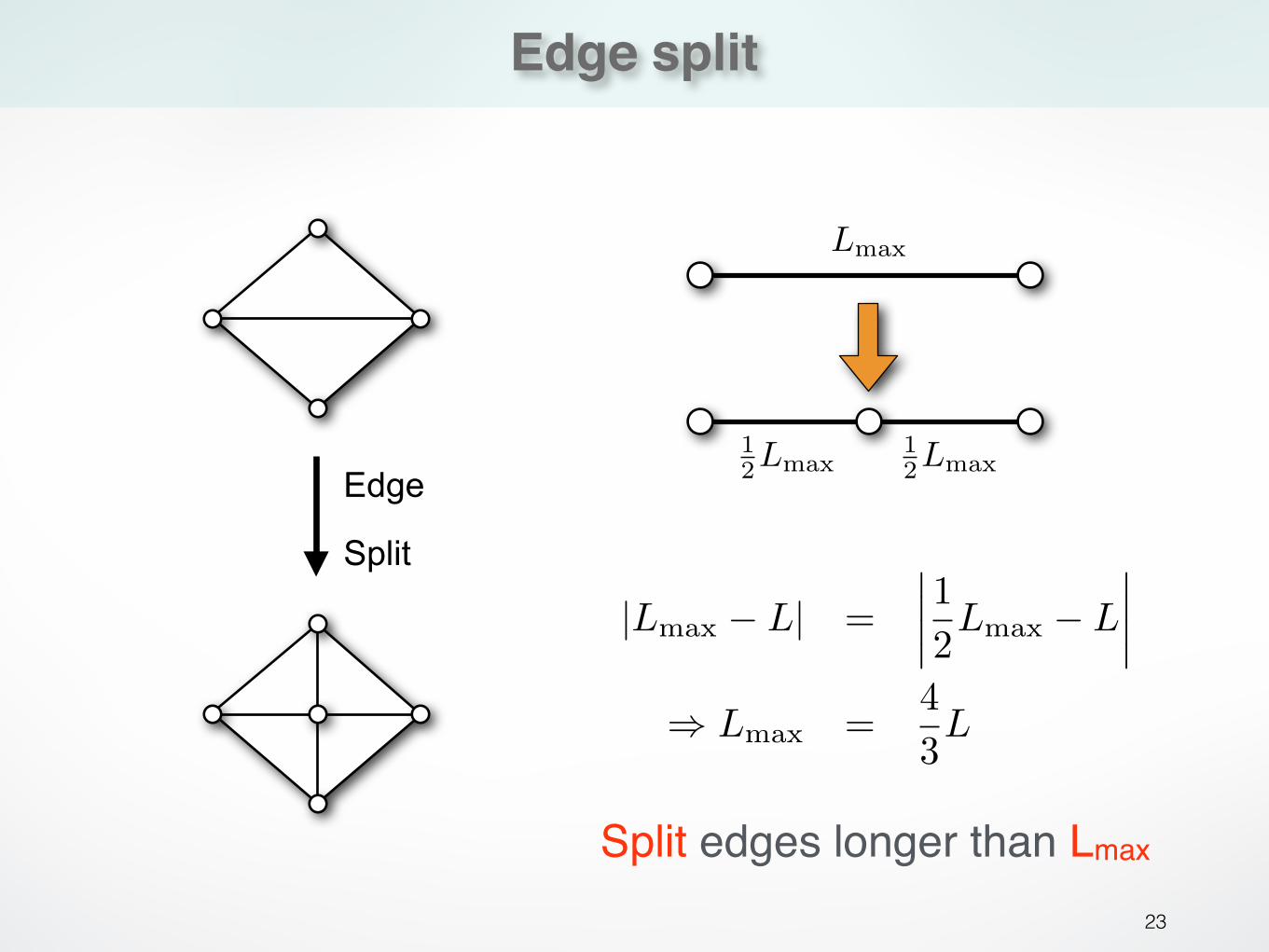
Edge split
23
|Lmax � L| =����12Lmax � L
����
⇥ Lmax =43L
Lmax
12Lmax
12Lmax
Edge
Split
Split edges longer than Lmax
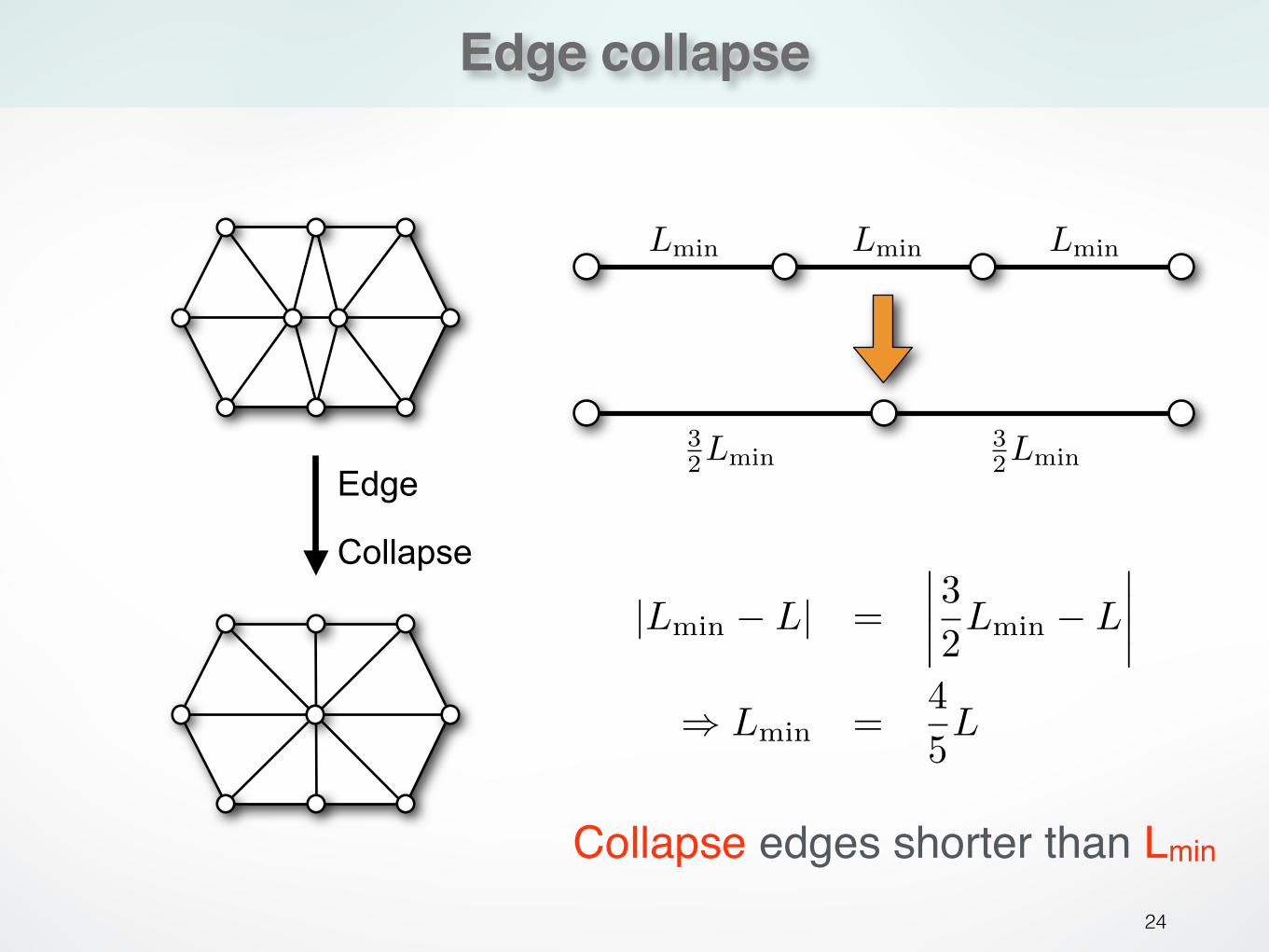
Edge collapse
24
|Lmin � L| =����32Lmin � L
����
⇥ Lmin =45L
32Lmin
32Lmin
Lmin Lmin Lmin
Edge
Collapse
Collapse edges shorter than Lmin
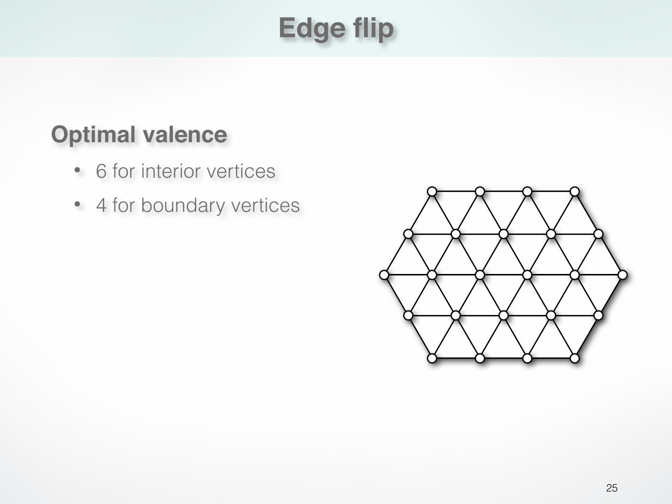
Edge flip
25
Optimal valence• 6 for interior vertices • 4 for boundary vertices
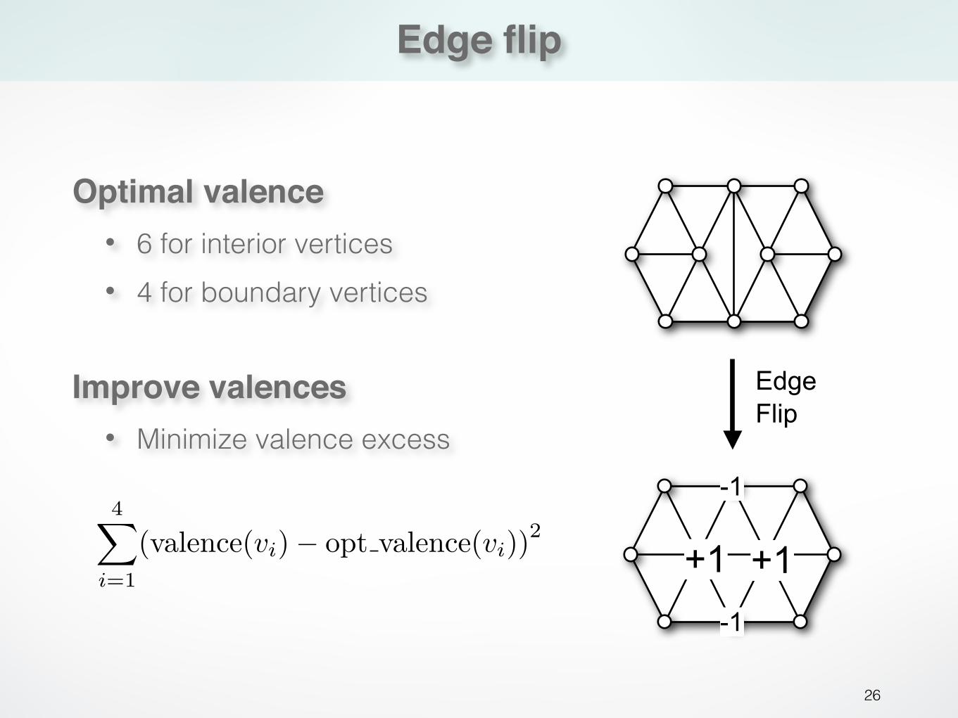
Edge flip
26
Edge Flip
+1 +1
-1
-1
4�
i=1
(valence(vi)� opt valence(vi))2
Optimal valence• 6 for interior vertices • 4 for boundary vertices
Improve valences• Minimize valence excess
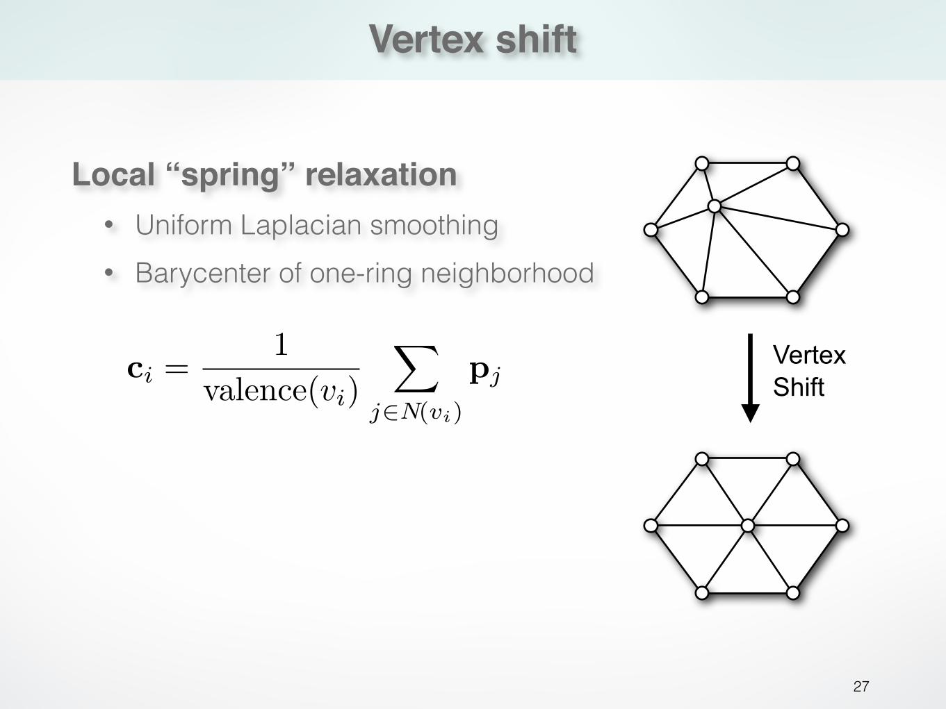
Vertex shift
27
Vertex Shift
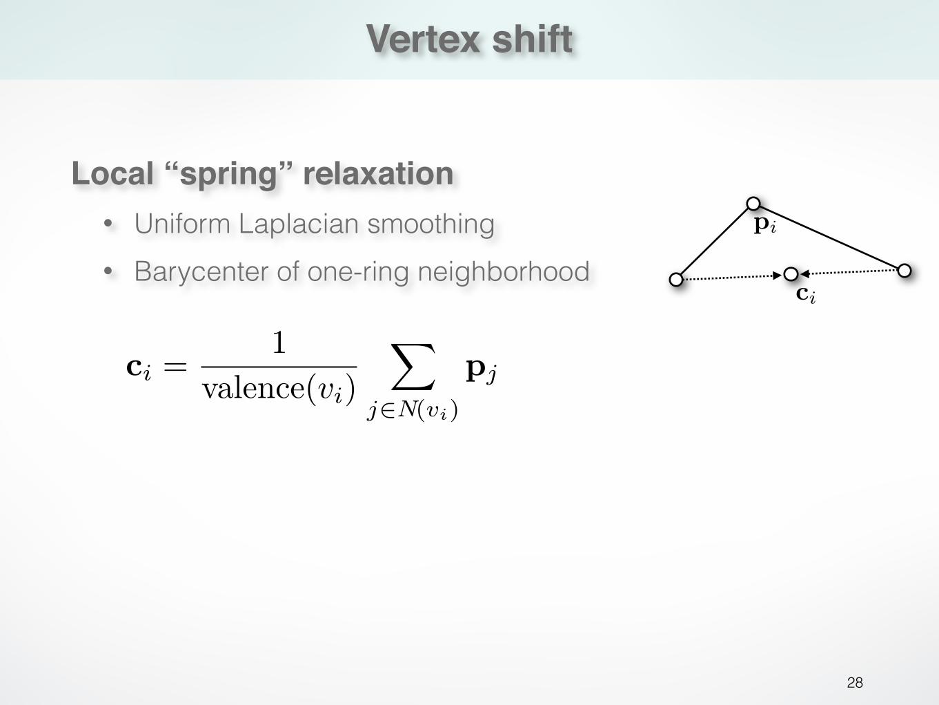
Local “spring” relaxation• Uniform Laplacian smoothing • Barycenter of one-ring neighborhood
ci =1
valence(vi)
�
j�N(vi)
pj
Vertex shift
28
pi
ci
Local “spring” relaxation• Uniform Laplacian smoothing • Barycenter of one-ring neighborhood
ci =1
valence(vi)
�
j�N(vi)
pj
Vertex shift
29
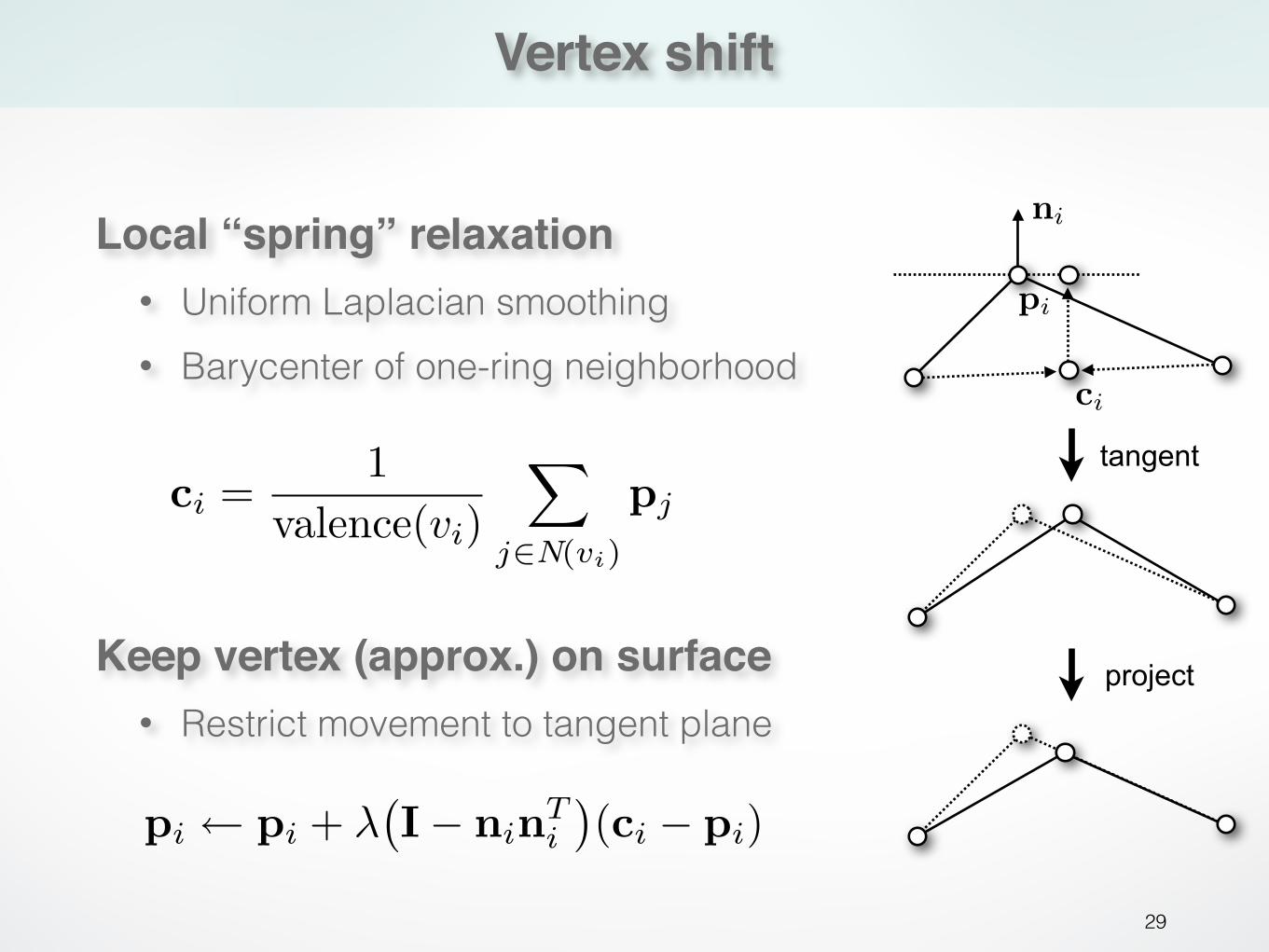
Local “spring” relaxation• Uniform Laplacian smoothing • Barycenter of one-ring neighborhood
Keep vertex (approx.) on surface• Restrict movement to tangent plane
pi ⇥ pi + ��I� ninT
i
⇥(ci � pi)
ci =1
valence(vi)
�
j�N(vi)
pj
project
tangent
ni
pi
ci
Vertex projection
30
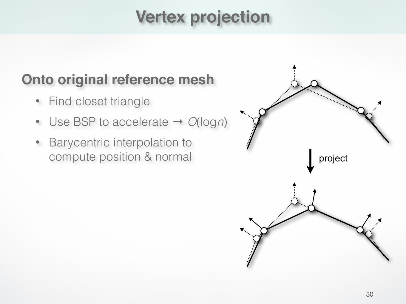
Onto original reference mesh• Find closet triangle • Use BSP to accelerate → O(logn) • Barycentric interpolation to
compute position & normal project
Incremental remeshing
31
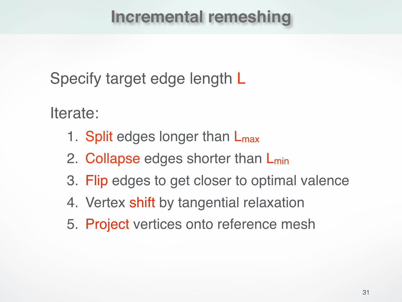
Specify target edge length L
Iterate:1. Split edges longer than Lmax
2. Collapse edges shorter than Lmin
3. Flip edges to get closer to optimal valence4. Vertex shift by tangential relaxation5. Project vertices onto reference mesh
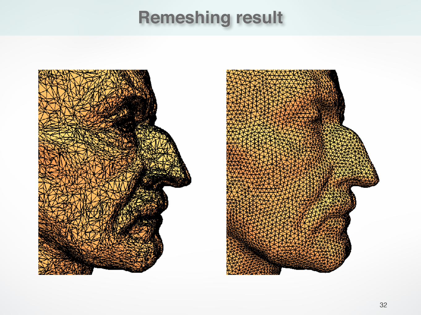
Remeshing result
32
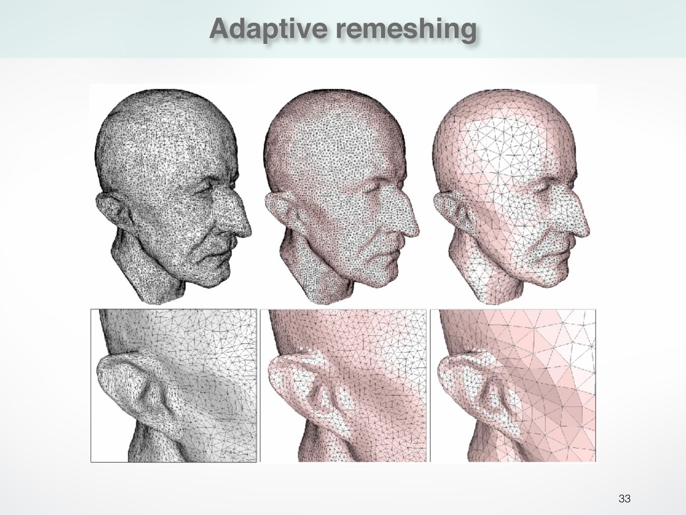
Adaptive remeshing
33
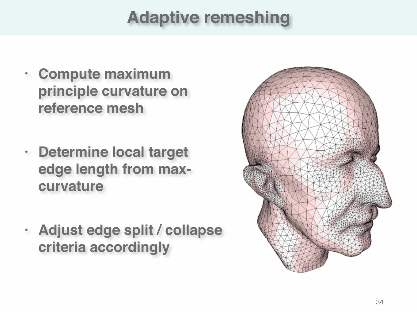
Adaptive remeshing
34
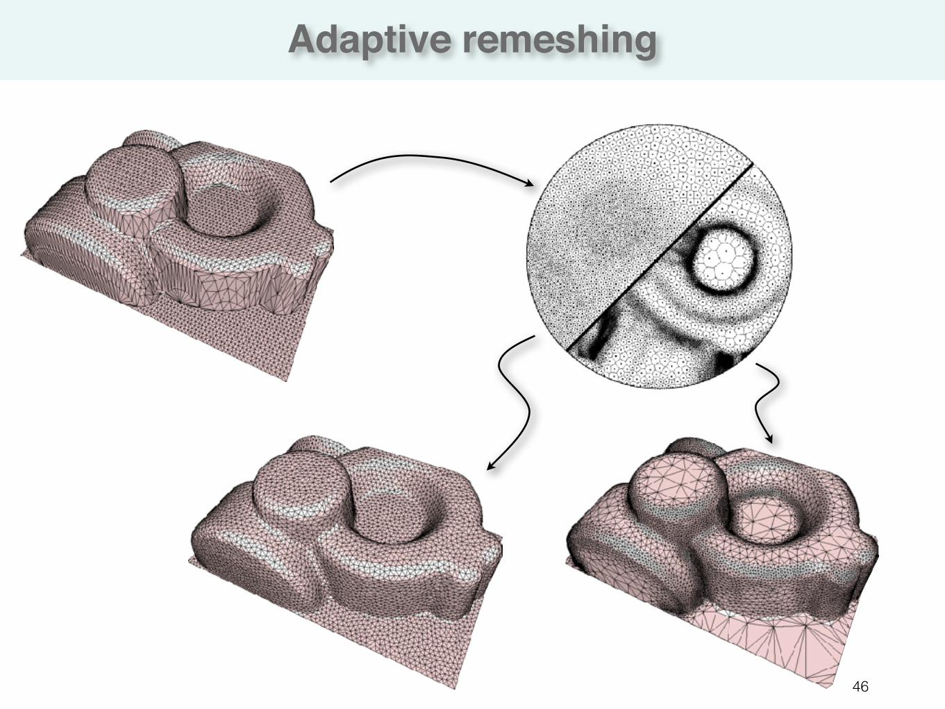
• Compute maximum principle curvature on reference mesh
• Determine local target edge length from max-curvature
• Adjust edge split / collapse criteria accordingly
Feature preservation
35
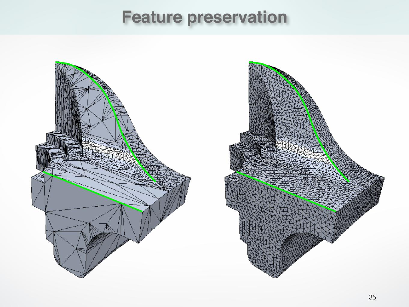
Feature preservation
36
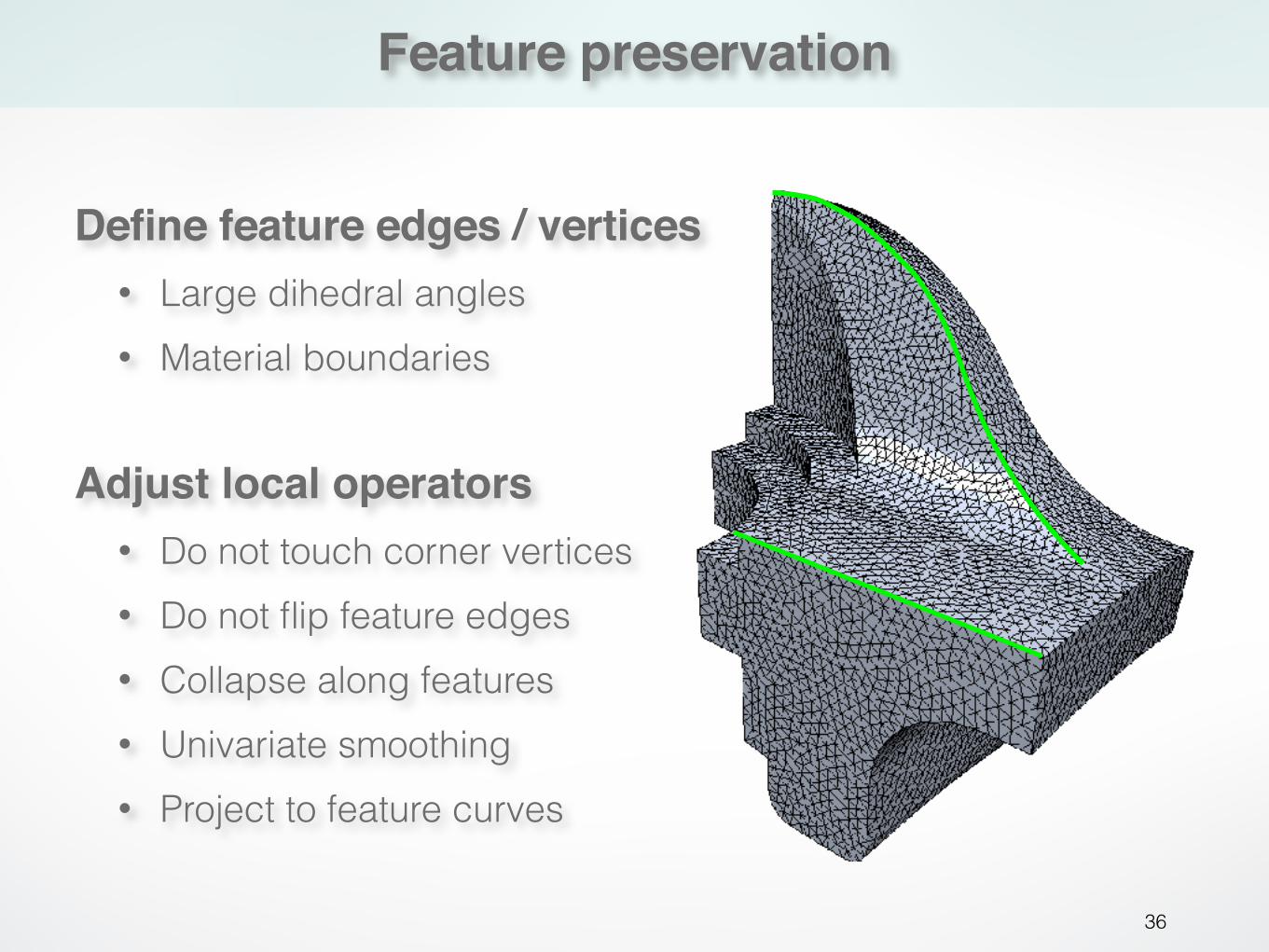
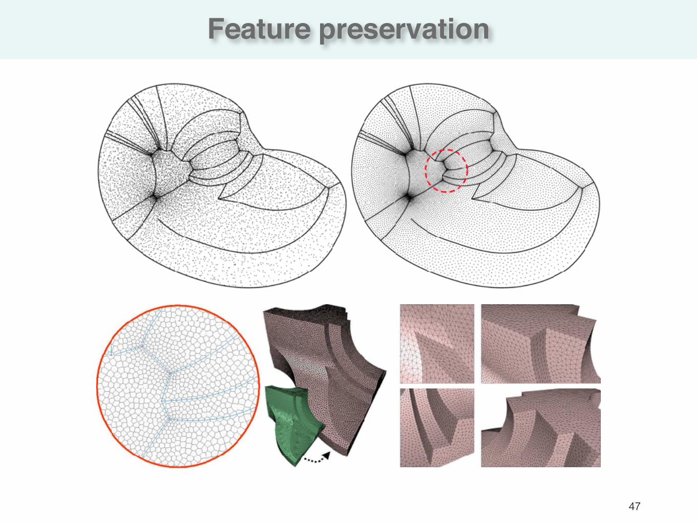
Define feature edges / vertices• Large dihedral angles • Material boundaries
Adjust local operators• Do not touch corner vertices • Do not flip feature edges • Collapse along features • Univariate smoothing • Project to feature curves
Isotropic remeshing
37
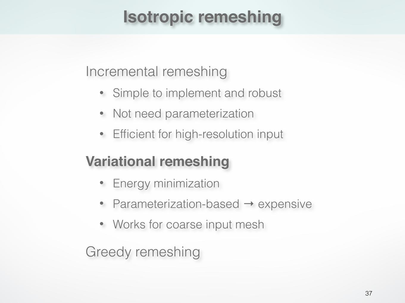
Variational remeshing• Energy minimization • Parameterization-based → expensive • Works for coarse input mesh
Greedy remeshing
Incremental remeshing • Simple to implement and robust • Not need parameterization • Efficient for high-resolution input
Voronoi Diagram
38
Voronoi Diagram
39
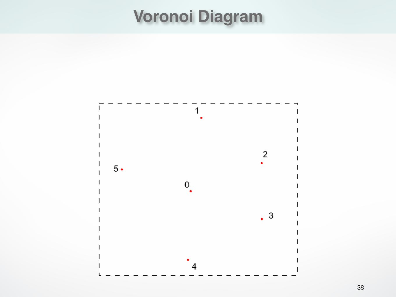
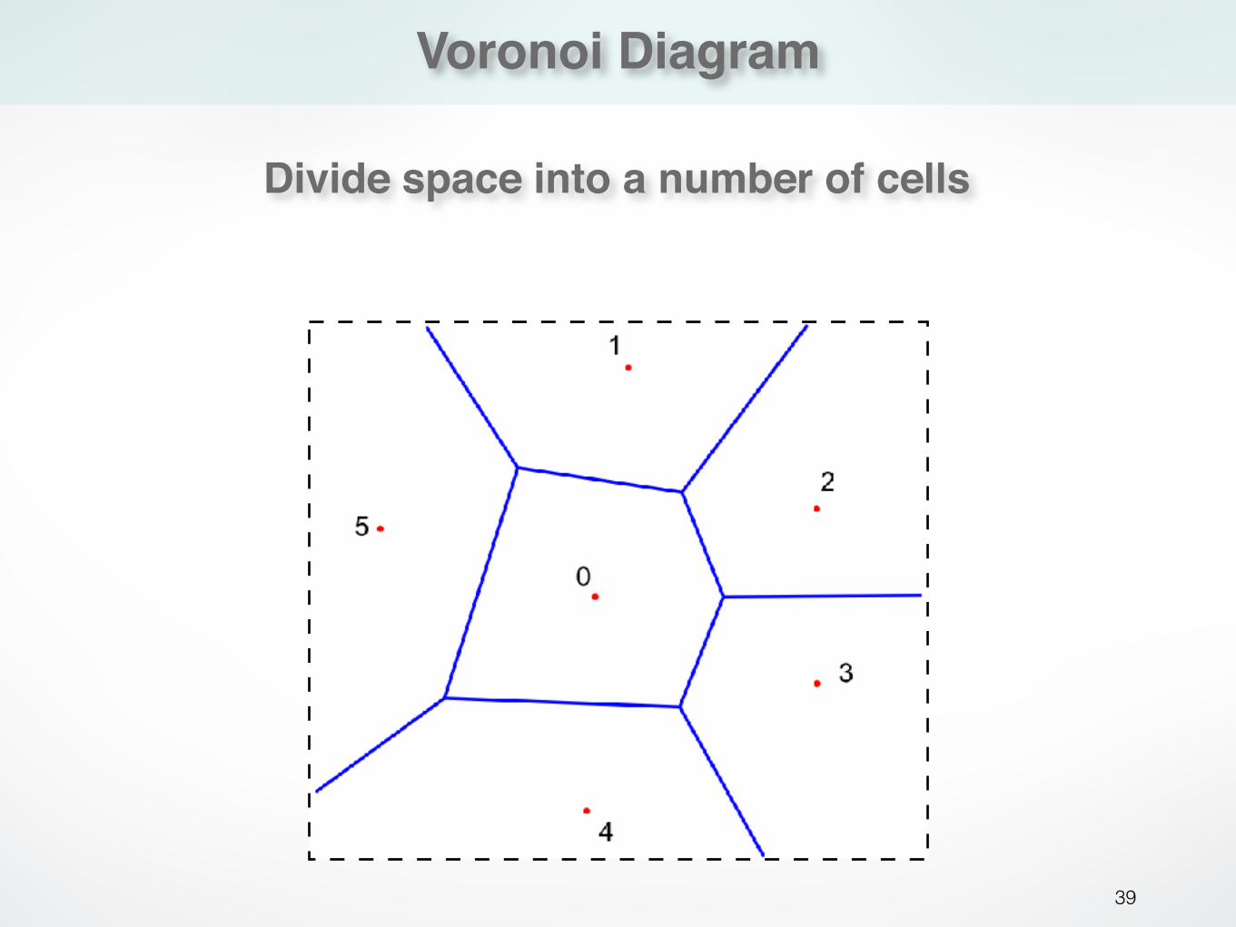
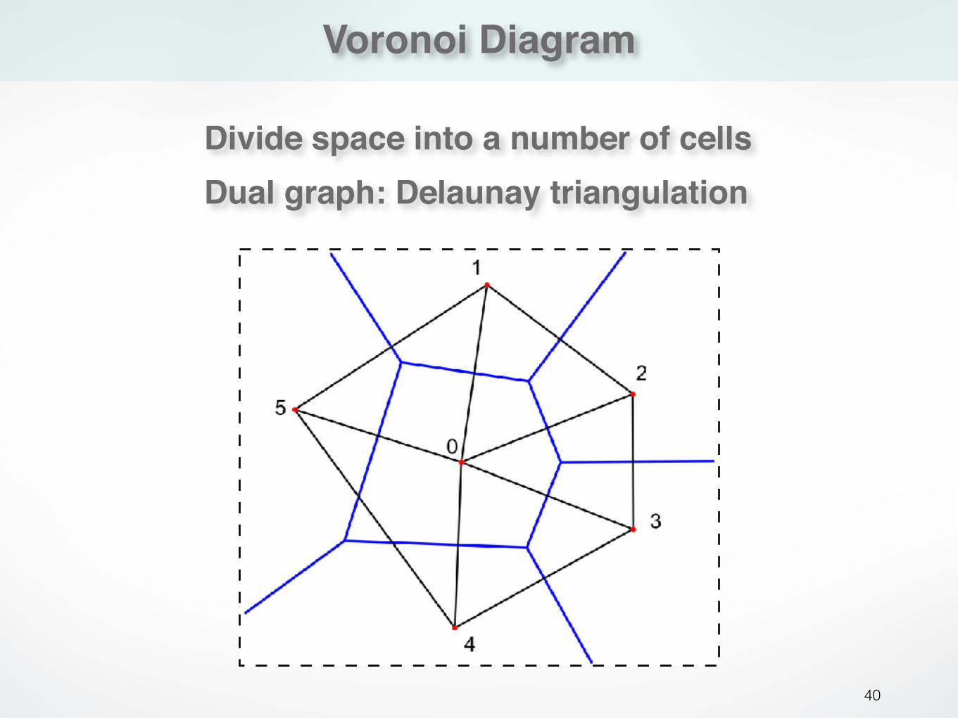
Divide space into a number of cells
Voronoi Diagram
40
Divide space into a number of cellsDual graph: Delaunay triangulation
Centroidal Voronoi Diagram
41
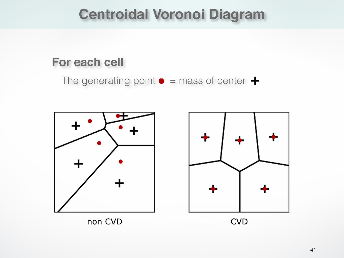
For each cellThe generating point = mass of center
CVDnon CVD
Centroidal Voronoi Diagram
42
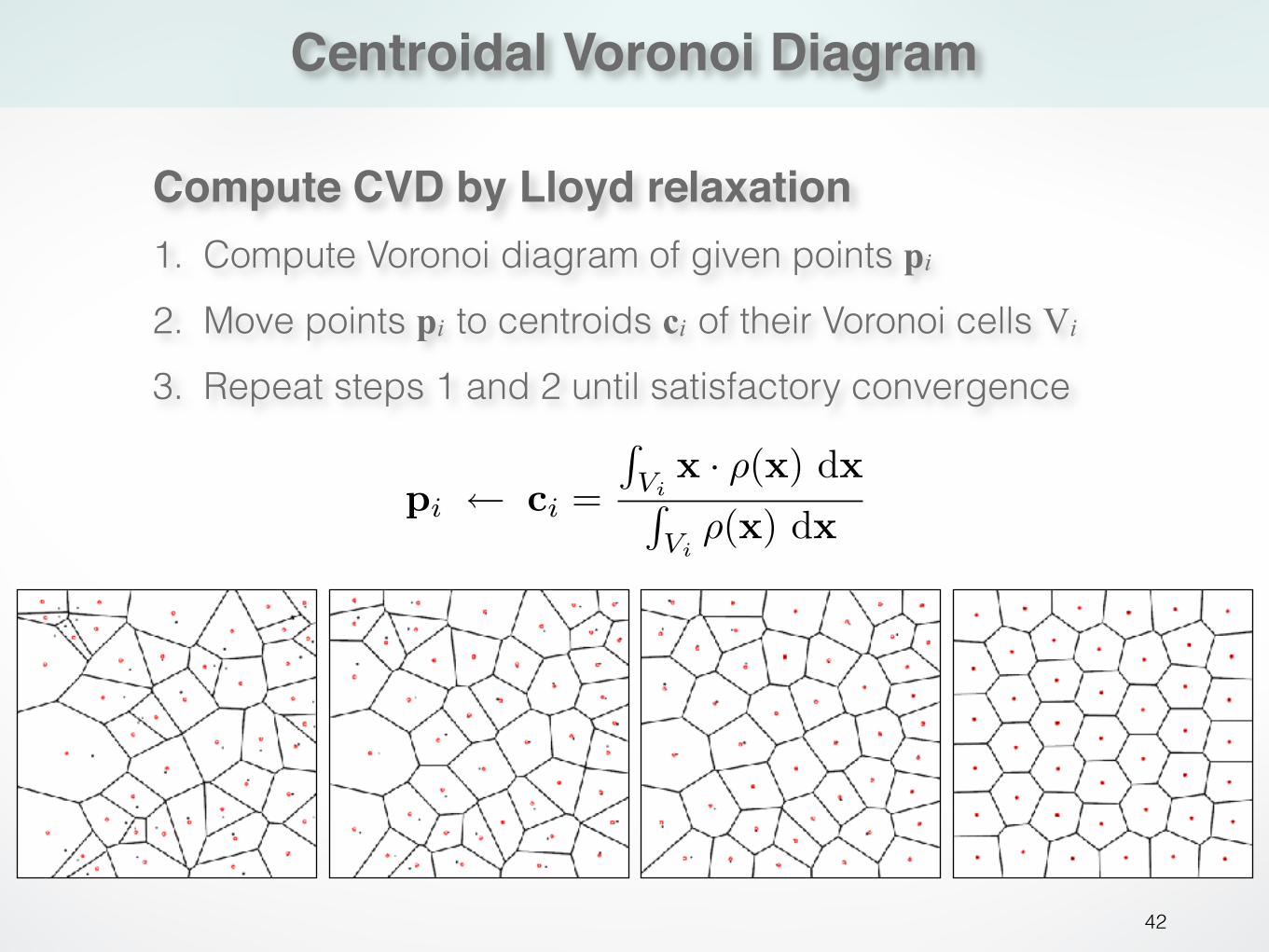
Compute CVD by Lloyd relaxation1. Compute Voronoi diagram of given points pi 2. Move points pi to centroids ci of their Voronoi cells Vi 3. Repeat steps 1 and 2 until satisfactory convergence
pi ⇥ ci =
�Vi
x · �(x) dx�
Vi�(x) dx
Centroidal Voronoi Diagram
43
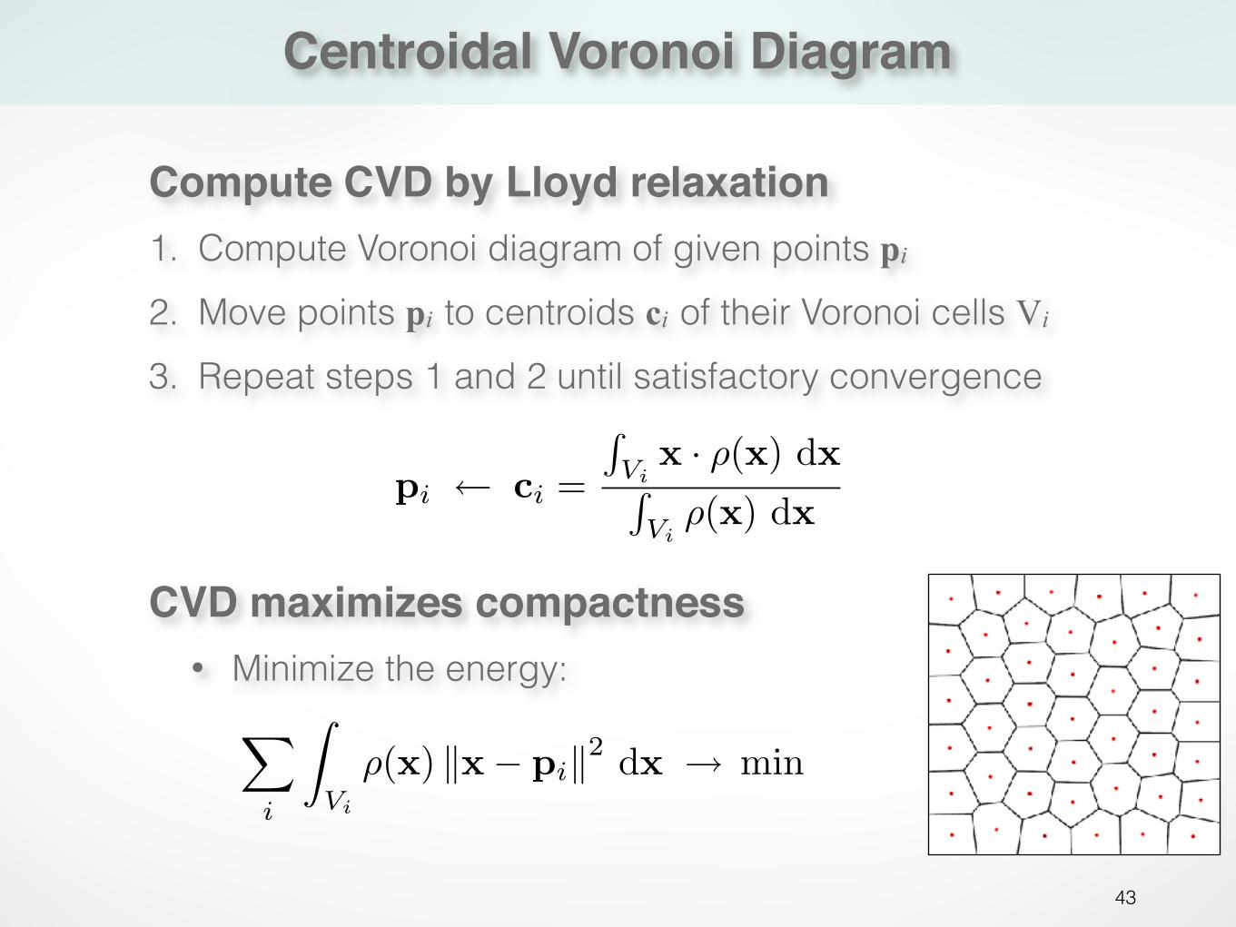
Compute CVD by Lloyd relaxation1. Compute Voronoi diagram of given points pi 2. Move points pi to centroids ci of their Voronoi cells Vi 3. Repeat steps 1 and 2 until satisfactory convergence
pi ⇥ ci =
�Vi
x · �(x) dx�
Vi�(x) dx
CVD maximizes compactness• Minimize the energy:
�
i
⇥
Vi
�(x) ⇤x� pi⇤2 dx ⇥ min
Variational remeshing
44
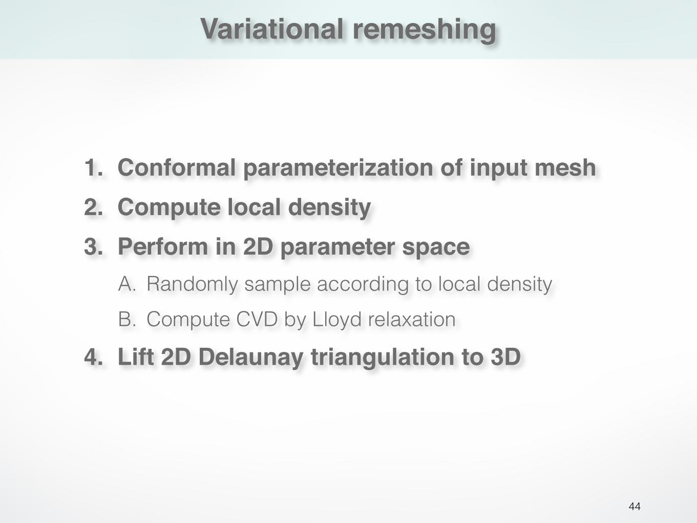
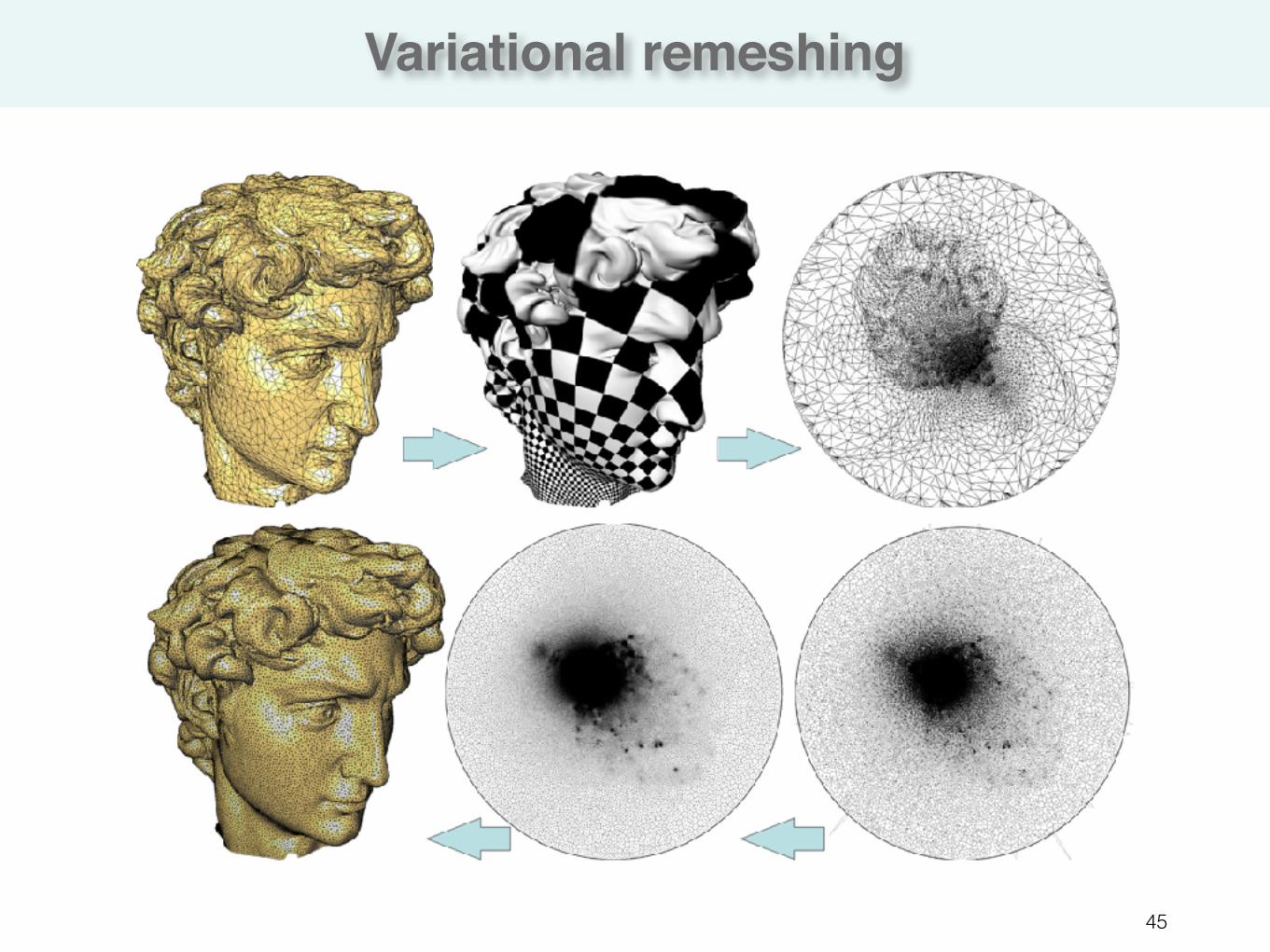
1. Conformal parameterization of input mesh2. Compute local density3. Perform in 2D parameter space
A. Randomly sample according to local density B. Compute CVD by Lloyd relaxation
4. Lift 2D Delaunay triangulation to 3D
Variational remeshing
45
Adaptive remeshing
46
Feature preservation
47
Outline
48
• What is remeshing?
• Why remeshing?
• How to do remeshing? - Isotropic remeshing - Anisotropic remeshing
Anisotropic remeshing
49
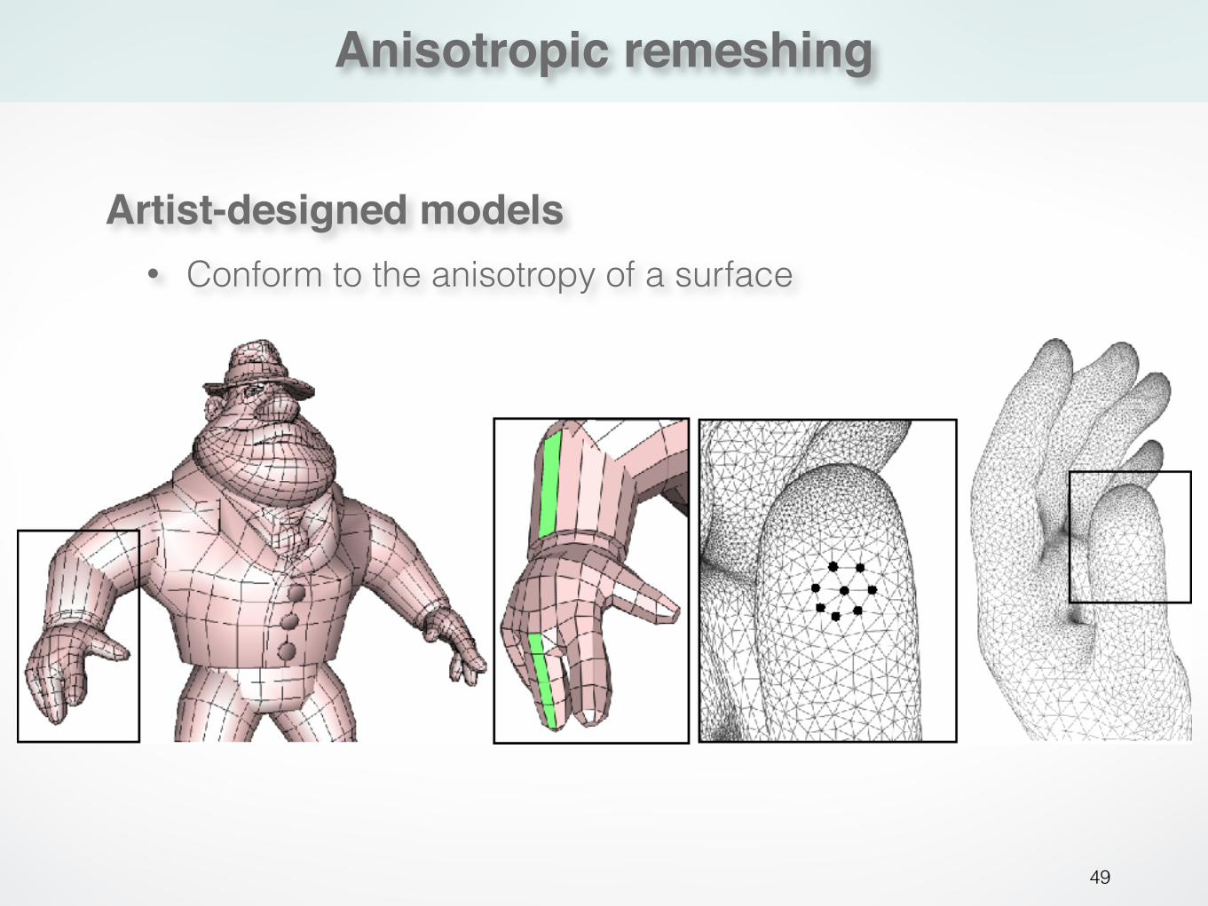
Artist-designed models• Conform to the anisotropy of a surface
Anisotropic remeshing
50
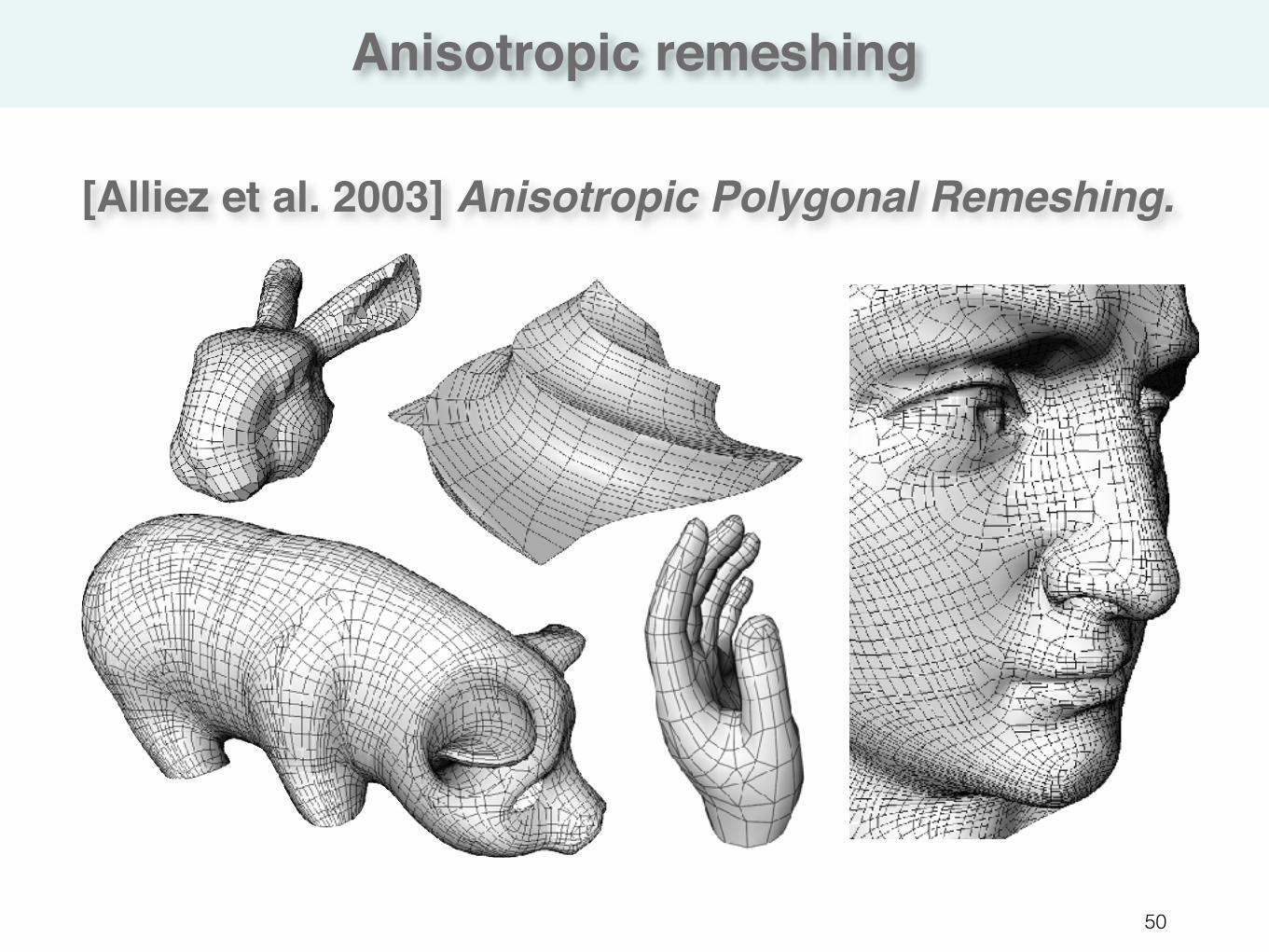
[Alliez et al. 2003] Anisotropic Polygonal Remeshing.
Anisotropic remeshing
51
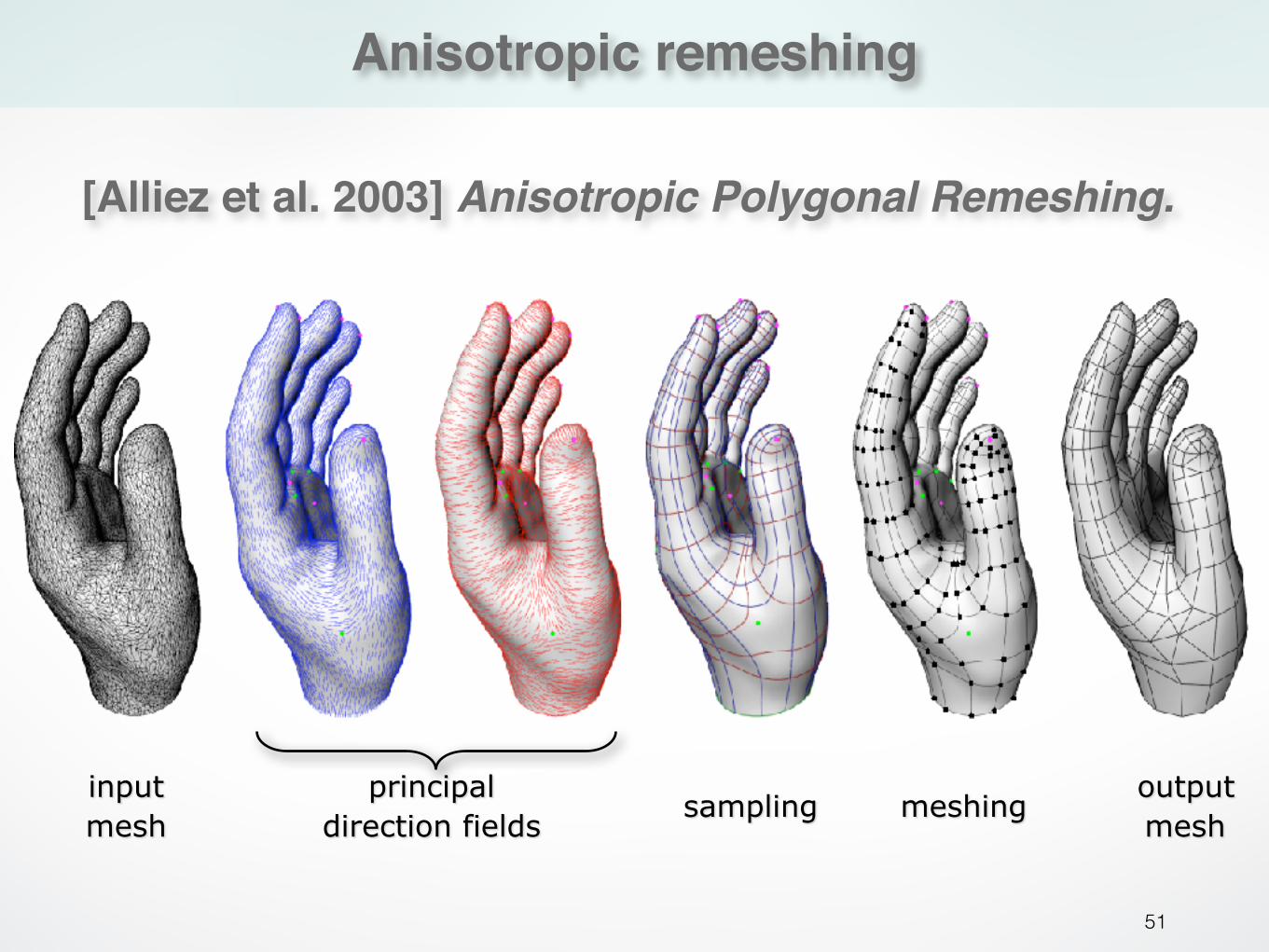
input mesh
principal direction fields
sampling meshingoutput mesh
[Alliez et al. 2003] Anisotropic Polygonal Remeshing.
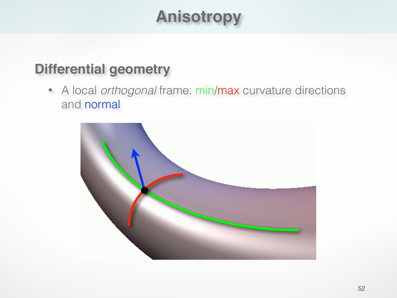
Anisotropy
52
Differential geometry• A local orthogonal frame: min/max curvature directions
and normal
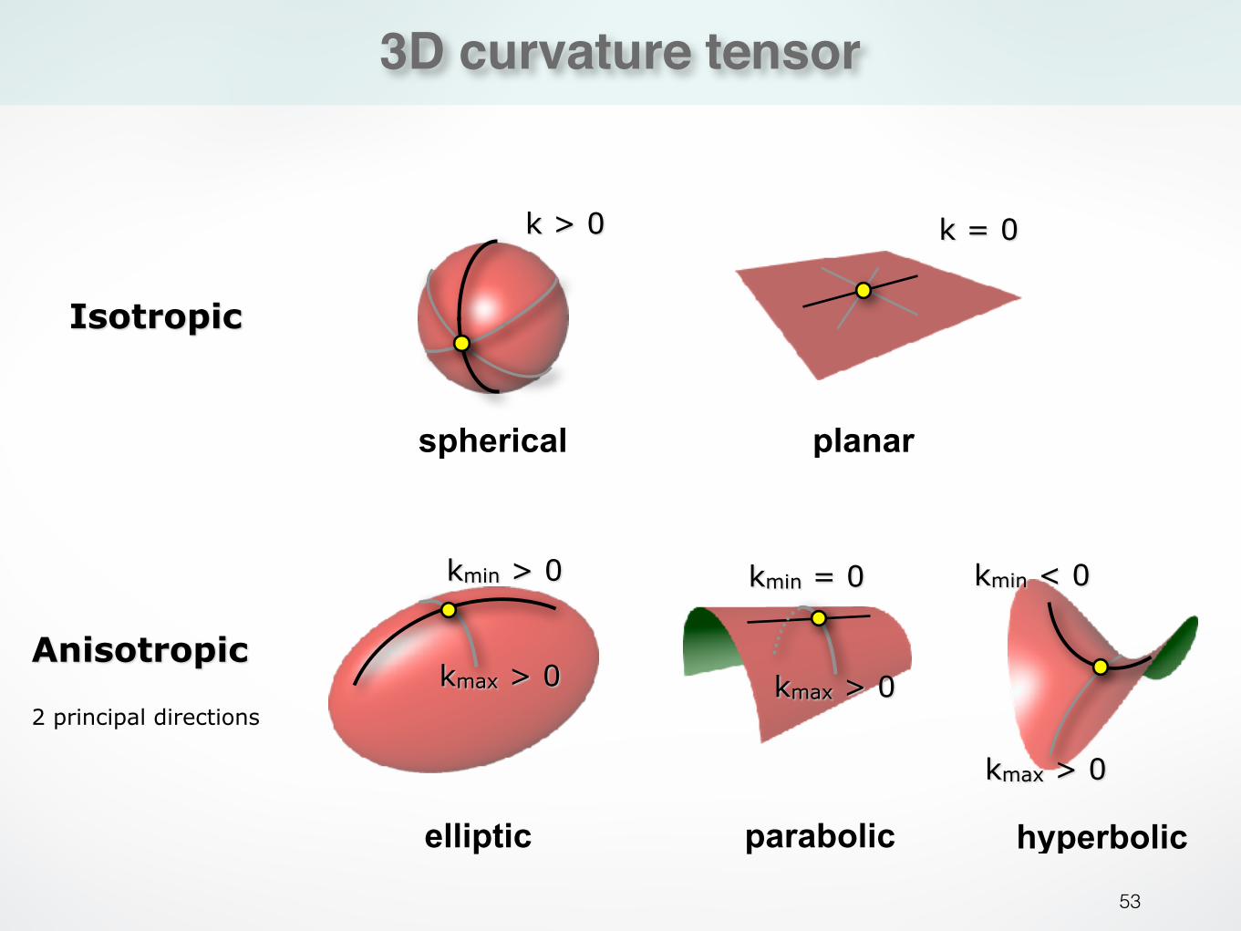
3D curvature tensor
53
Isotropic
spherical planar
k > 0 k = 0
Anisotropic
2 principal directions
elliptic parabolic hyperbolic
kmax > 0
kmin > 0 kmin = 0
kmax > 0
kmin < 0
kmax > 0
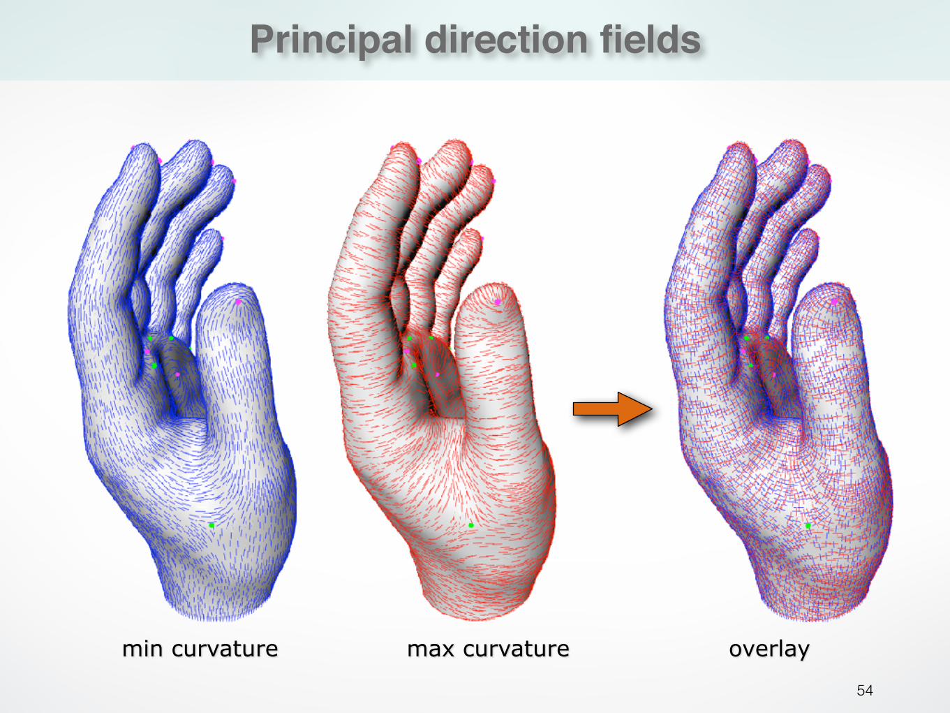
Principal direction fields
54
min curvature max curvature overlay
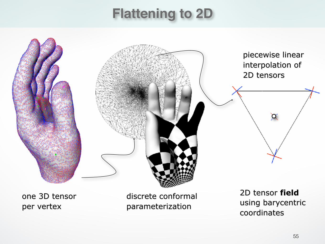
Flattening to 2D
55
one 3D tensor per vertex
discrete conformal parameterization
2D tensor field using barycentric coordinates
piecewise linear interpolation of 2D tensors
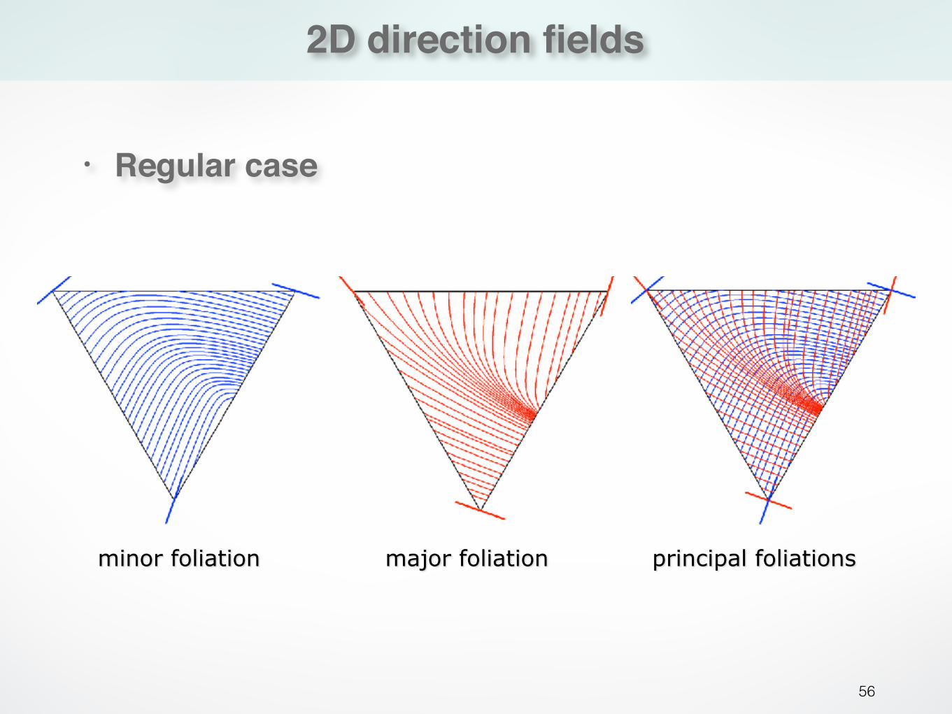
2D direction fields
56
major foliation principal foliationsminor foliation
• Regular case
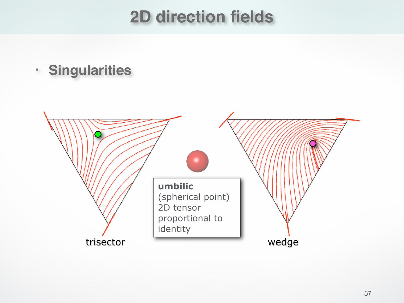
2D direction fields
57
• Singularities
trisector wedge
umbilic (spherical point) 2D tensor proportional to identity
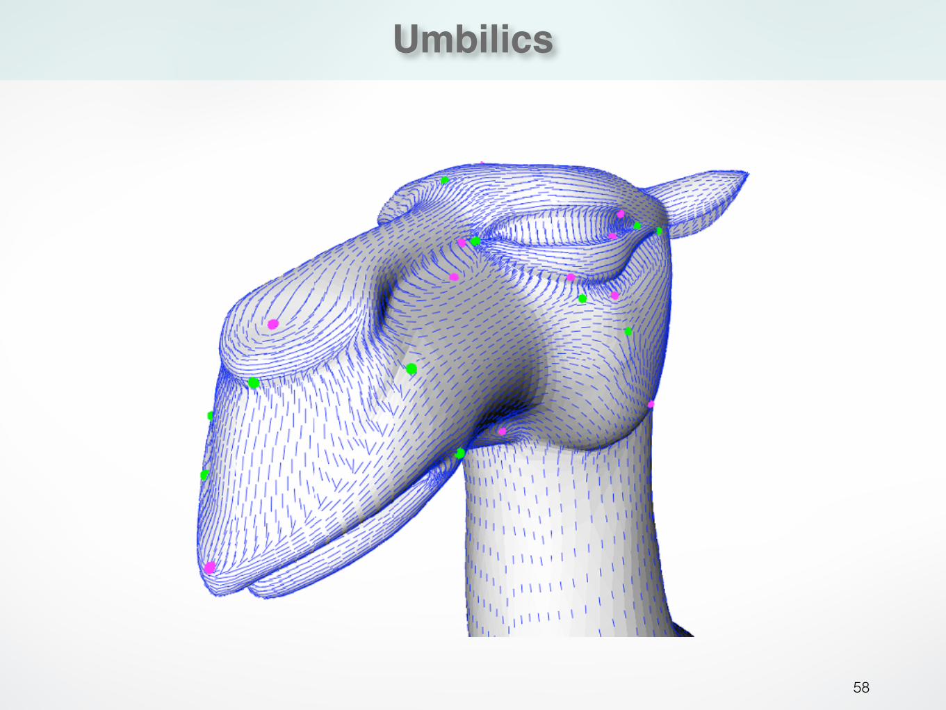
Umbilics
58
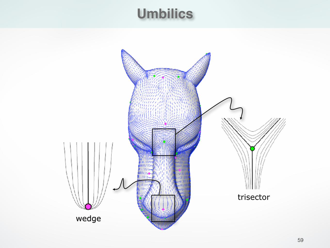
Umbilics
59
wedge
trisector
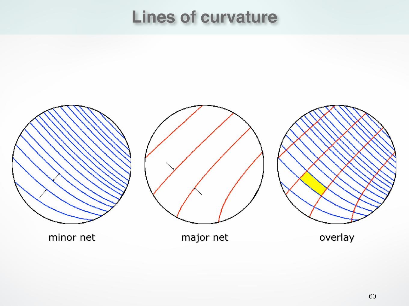
Lines of curvature
60
minor net major net overlay
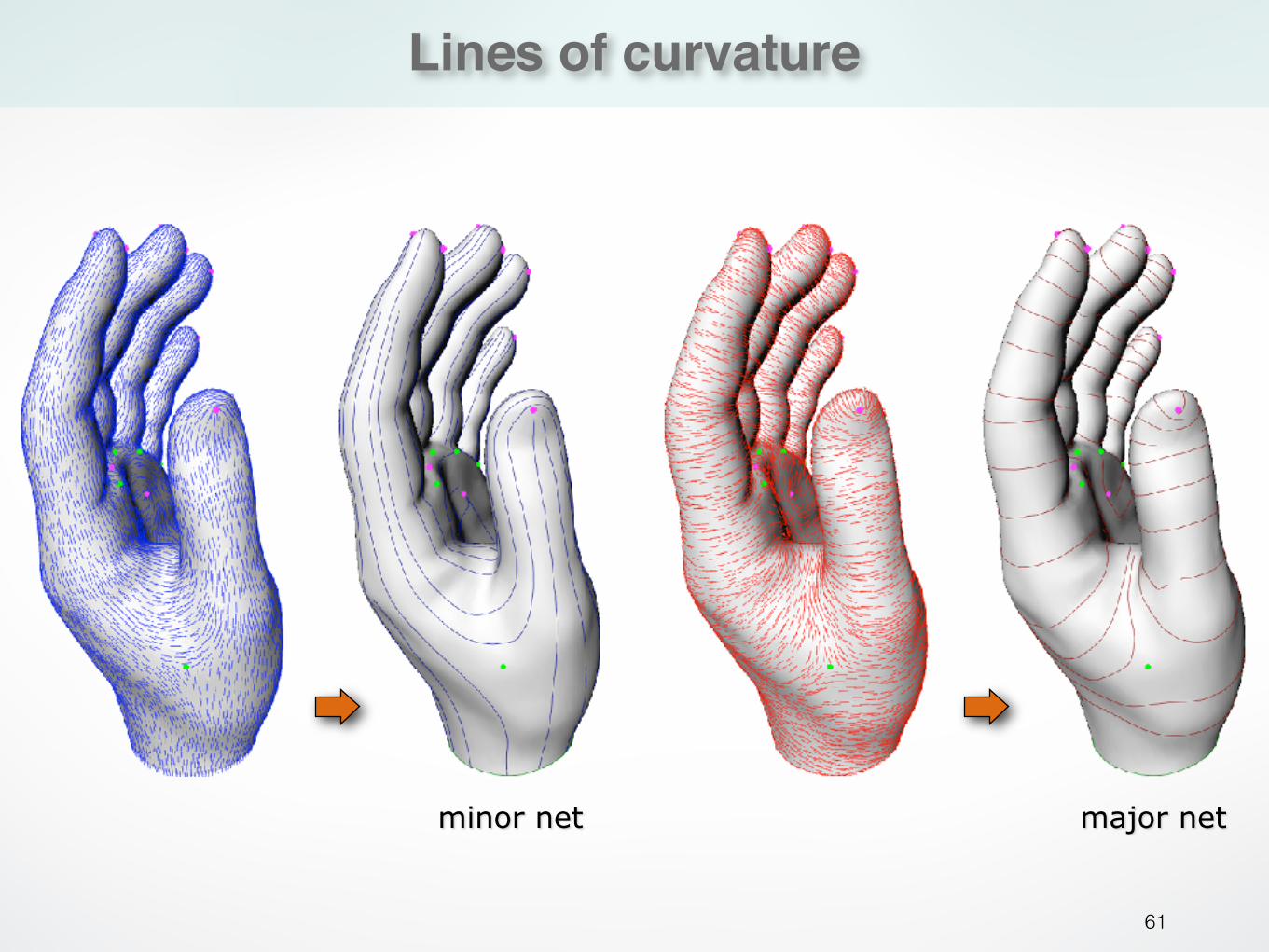
Lines of curvature
61
major netminor net
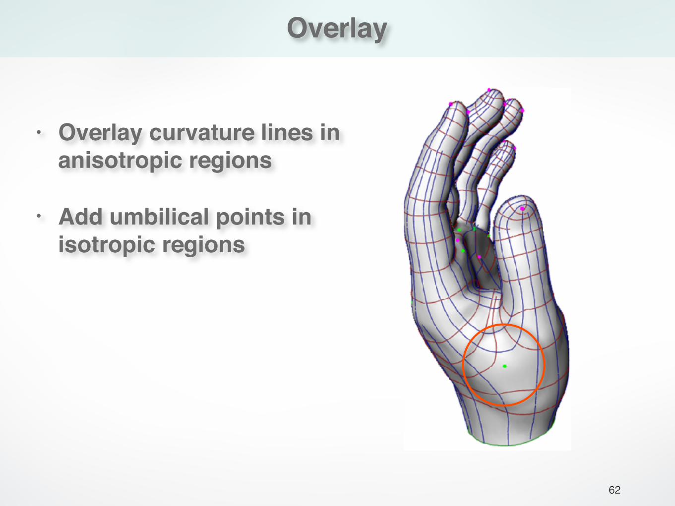
Overlay
62
• Overlay curvature lines in anisotropic regions
• Add umbilical points in isotropic regions
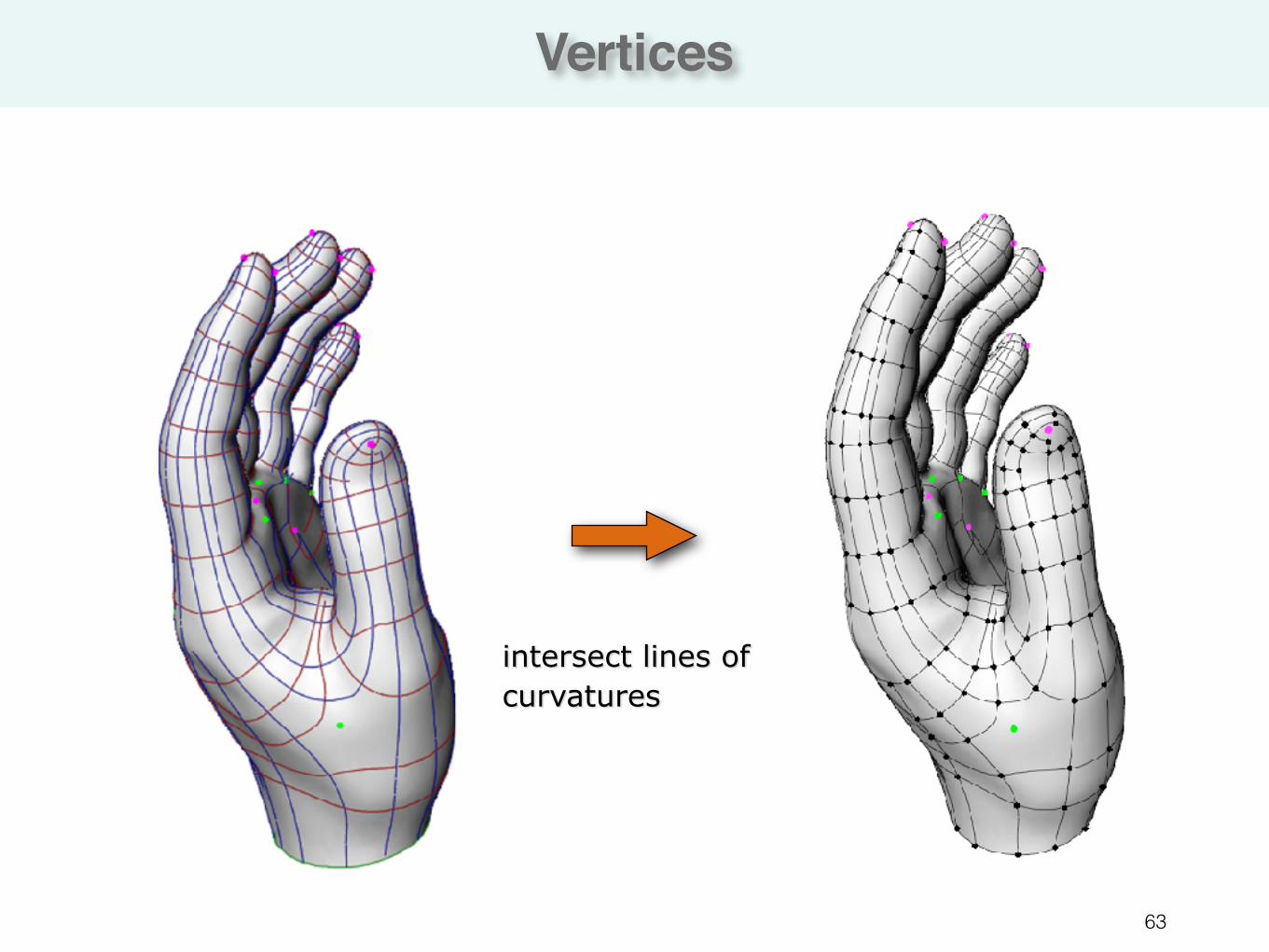
Vertices
63
intersect lines of curvatures
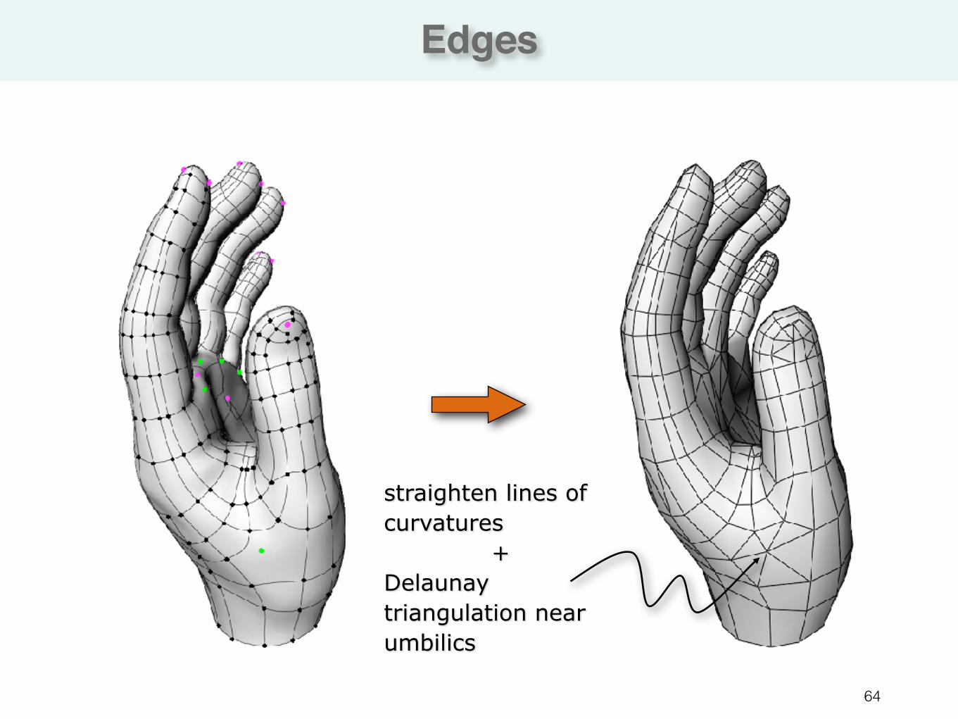
Edges
64
straighten lines of curvatures
+ Delaunay triangulation near umbilics
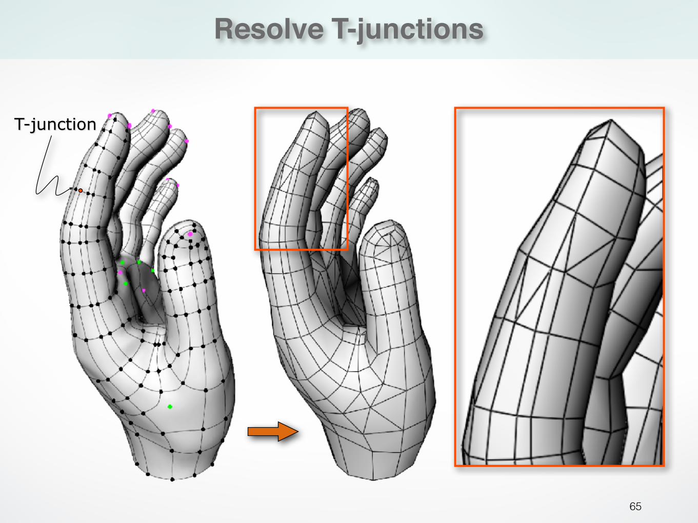
Resolve T-junctions
65
T-junction
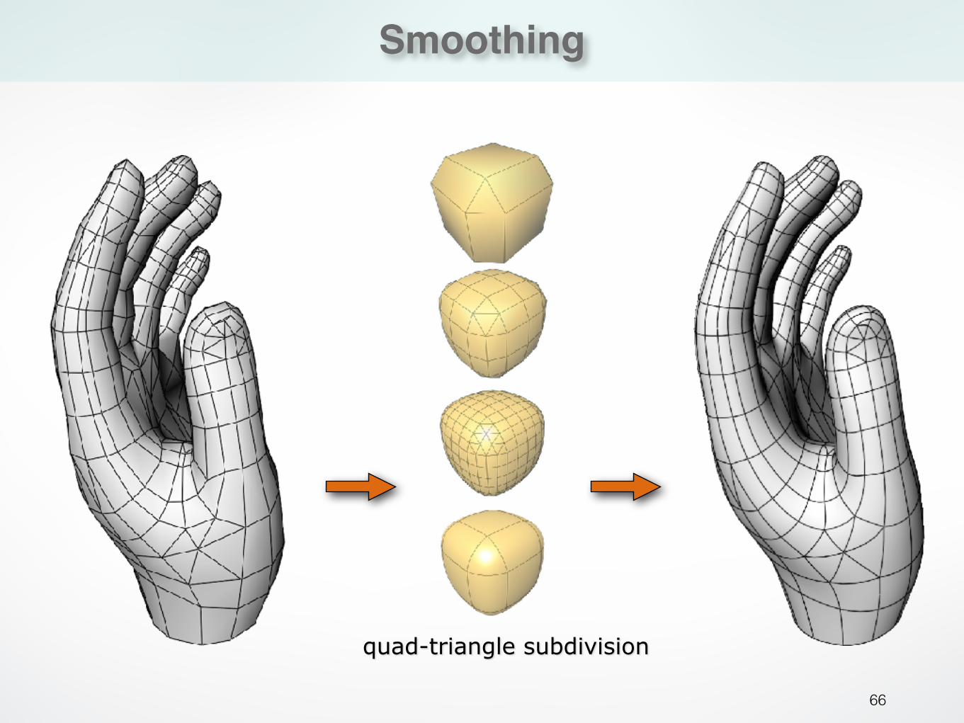
Smoothing
66
quad-triangle subdivision

Anisotropic remeshing
67
input mesh
principal direction fields
sampling meshingoutput mesh
[Alliez et al. 2003] Anisotropic Polygonal Remeshing.
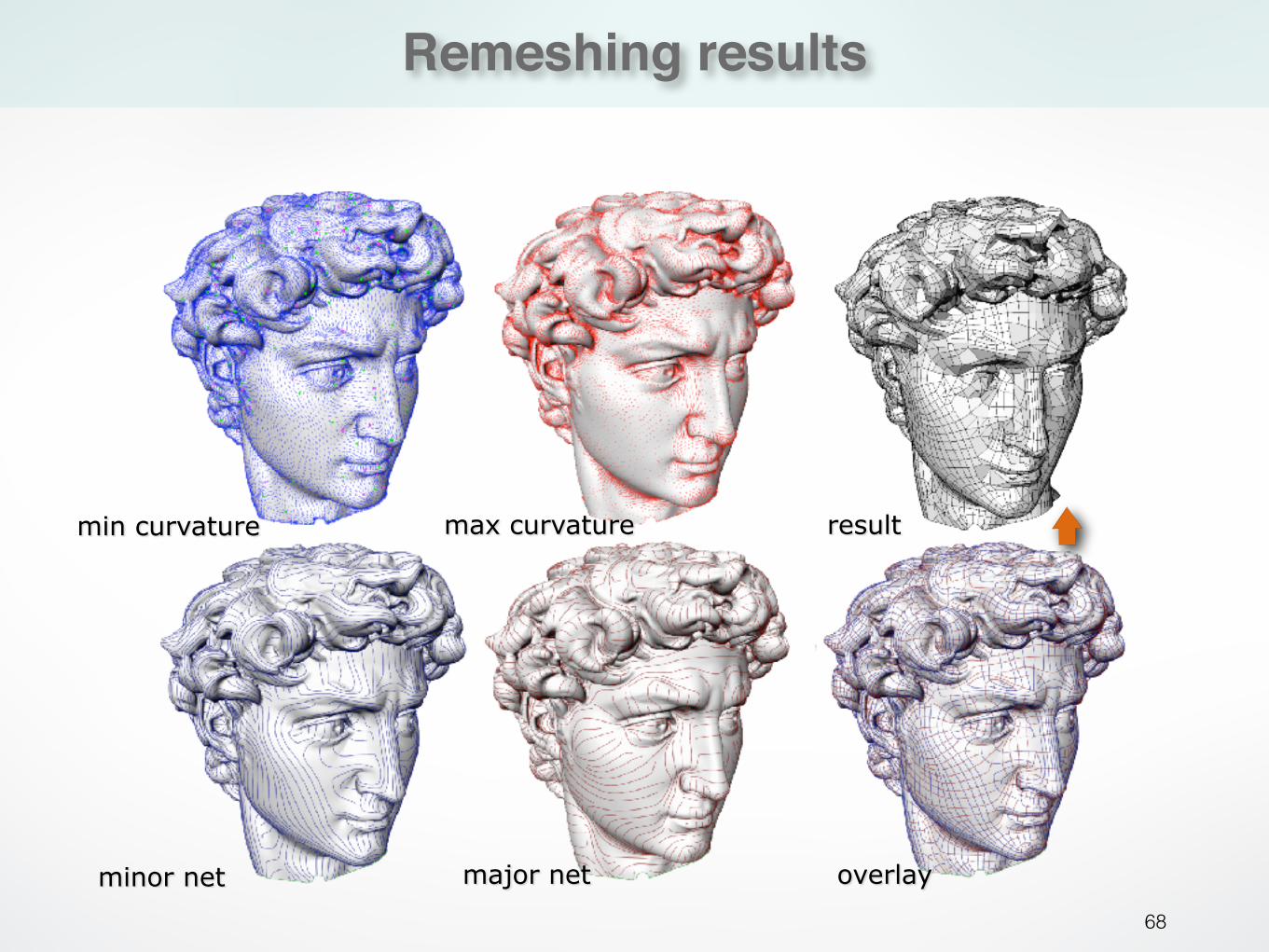
Remeshing results
68
min curvature
minor net
max curvature
major net overlay
result
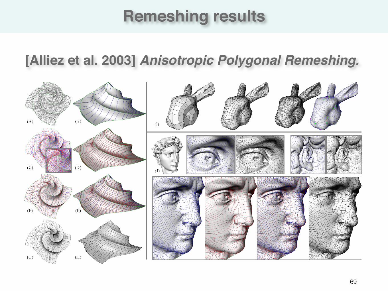
Remeshing results
69
[Alliez et al. 2003] Anisotropic Polygonal Remeshing.

Tools
70
MeshLab• meshlab.sourceforge.net • open source • available for Windows, MacOSX, and Linux
Graphite• http://alice.loria.fr/index.php/software/3-platform/22-
graphite.html • available for Windows • MacOSX or Linux?
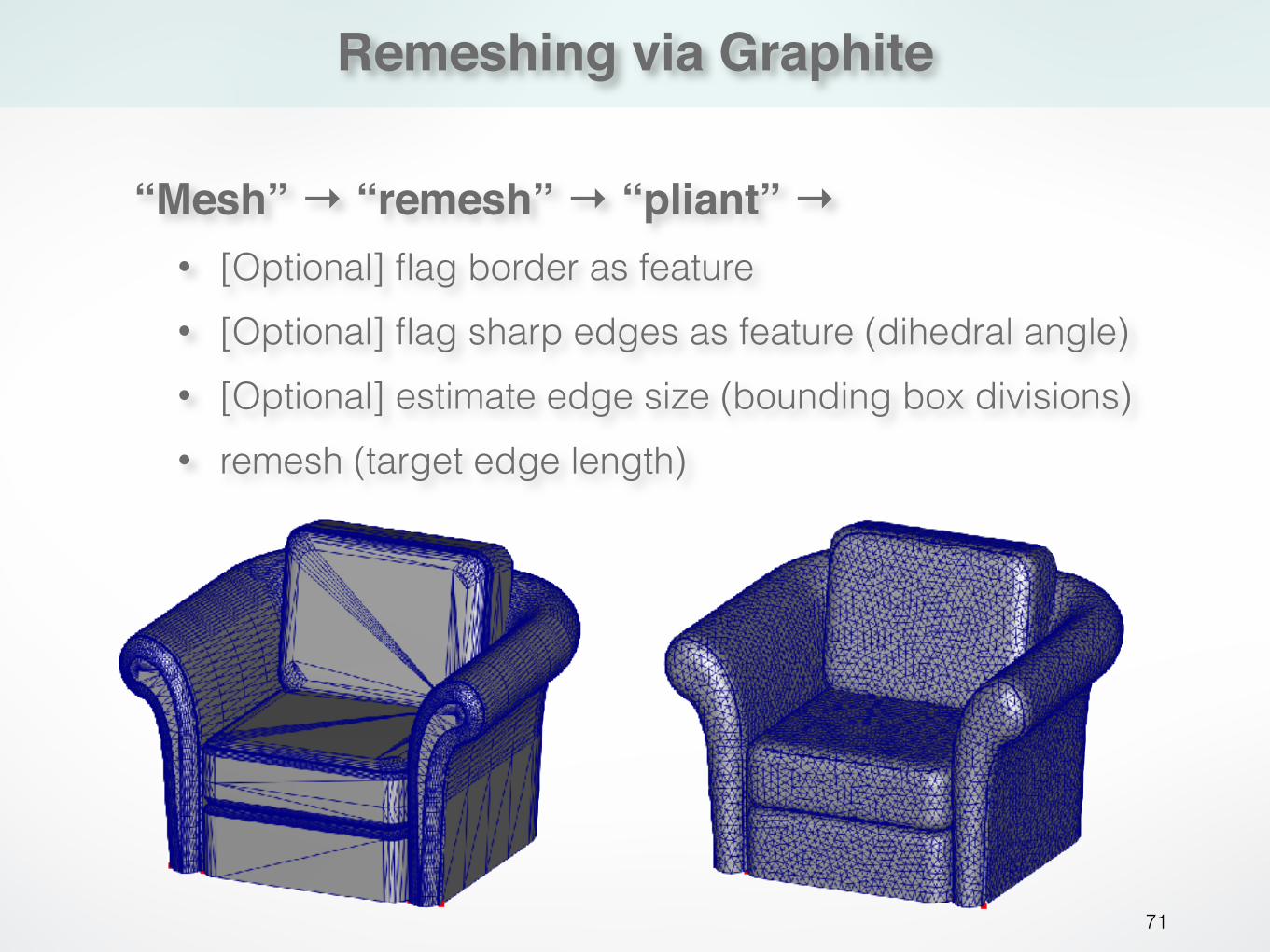
Remeshing via Graphite
71
“Mesh” → “remesh” → “pliant” →• [Optional] flag border as feature • [Optional] flag sharp edges as feature (dihedral angle) • [Optional] estimate edge size (bounding box divisions) • remesh (target edge length)
Literature
72
• Textbook: Chapter 6 • Alliez et al, “Interactive geometry remeshing”, SIGGRAPH 2002 • Alliez et al, “Isotropic surface remeshing”, SMI 2003 • Alliez et al, “Anisotropic polygonal remeshing”, SIGGRAPH 2003 • Vorsatz et al, “Dynamic remeshing and applications”, Solid Modeling 2003 • Botsch & Kobbelt, “A remeshing approach to multiresolution modeling”,
Symp. on Geometry Processing 2004 • Marinov et al, “Direct anisotropic quad-dominant remeshing”, Pacific
Graphics 2004 • Alliez et al, “Recent advances in remeshing of surfaces”, AIM@Shape
state of the art report, 2006