simulation of a two-slope pyramid made by spif using an adaptive remeshing method with solid-shell...
TRANSCRIPT

THEMATIC ISSUE: FLEXIBLE FORMING - INCREMENTAL SHEET FORMING & ROLL FORMING
Simulation of a two-slope pyramid made by SPIFusing an adaptive remeshing method with solid-shellfinite element
J. I. V. de Sena & C. F. Guzmán & L. Duchêne &
A. M. Habraken & A. K. Behera & J. Duflou &
R. A. F. Valente & R. J. Alves de Sousa
Received: 11 August 2014 /Accepted: 28 December 2014# Springer-Verlag France 2015
Abstract Single point incremental forming (SPIF) is anemerging application in sheet metal prototyping and smallbatch production, which enables dieless production of sheetmetal parts. This research area has grown in the last years,both experimentally and numerically. However, numerical in-vestigations into SPIF process need further improvement topredict the formed shape correctly and faster than current ap-proaches. The current work aims the use of an adaptiveremeshing technique, originally developed for shell and later
extended to 3D “brick” elements, leading to a ReducedEnhanced Solid-Shell formulation. The CPU time reductionis a demanded request to perform the numerical simulations.A two-slope pyramid shape is used to carry out the numericalsimulation and modelling. Its geometric difficulty on thenumerical shape prediction and the through thicknessstress behaviour are the main analysis targets in thepresent work. This work confirmed a significant CPUtime reduction and an acceptable shape prediction accu-racy using an adaptive remeshing method combinedwith the selected solid-shell element. The stress distri-bution in thickness direction revealed the occurrence ofbending/unbending plus stretching and plastic deforma-tion in regions far from the local deformation in thetool vicinity.
Keywords Adaptive remeshing . Solid shell finite element .
Single point incremental forming
Introduction
The research interest in Incremental Sheet Forming (ISF) pro-cesses has been growing in the last years, both experimentallyand numerically, in the context of sheet metal forming pro-cesses. The designation of incremental forming processescovers several techniques with common features. A re-view on technical developments of ISF variants in thelast years can be found in the work of Emmens et al.[12]. In the present work, particular attention will bededicated to the Single Point Incremental Forming(SPIF) variant as shown in Fig. 1.
SPIF process reveals itself as an interesting application dueto its flexibility, where symmetrical or asymmetrical shapes
J. I. V. de Sena (*) :R. A. F. Valente :R. J. A. de SousaGRIDS Research Group, TEMA Research Unity,Department of Mechanical Engineering, University of Aveiro,3810 Aveiro, Portugale-mail: [email protected]
R. A. F. Valentee-mail: [email protected]
R. J. A. de Sousae-mail: [email protected]
J. I. V. de Sena :C. F. Guzmán : L. Duchêne :A. M. HabrakenUniversité de Liège, ArGEnCo Department, MS²F division,Chemin des Chevreuils 1, 4000 Liège, Belgium
C. F. Guzmáne-mail: [email protected]
L. Duchênee-mail: [email protected]
A. M. Habrakene-mail: [email protected]
A. K. Behera : J. DuflouKatholieke Universiteit Leuven, Department of MechanicalEngineering, Celestijnenlaan 300B, B-3001 Leuven, Belgium
A. K. Beherae-mail: [email protected]
J. Dufloue-mail: [email protected]
Int J Mater FormDOI 10.1007/s12289-014-1213-8

can be built. This process flexibility is given by the motion ofa single spherical tool without any type of die or mould need-ed. This means that the sheet side opposite to the tool does notcontact with any mould or support. The dieless nature of SPIFprocess was first envisioned by Leszak [22]. The use of thismethod was possible with the advance of technology, morespecifically with the appearance of numerical control ma-chines. The tool path can be controlled by using CAD/CAMsoftware, where a change in the final shape can be quickly andinexpensively done. The pre-programmed contour combinescontinuous contact of the tool along the sheet surface withsuccessive small vertical increments. After each vertical incre-ment, a contour in the next horizontal plane starts, with thefinal component being constructed layer by layer. The sheet ispreviously clamped along its edges using a clamping frame(blank holder). A backing plate can be needed with the objec-tive to decrease springback effect during the forming progress.Springback phenomena can also be avoided using a compen-satory algorithm [1].
Due to the vast number of new topics to explore, manyworks have been carried out. A number of authors have ex-perimentally and numerically studied the final product geom-etry in order to analyse the influence of several parametersinvolved in the SPIF process. From the numerical standpoint,force prediction and geometric inaccuracy on SPIF simulationcan be provided by Finite Element Method (FEM). In previ-ous academic research works, Rabahallaha et al. [24] andGuzmán et al. [14] the force prediction and shape predictionwere studied. In both works a special focus was given to atwo-slope pyramid which is a challenge in terms of computa-tion time and prediction of force and shape accuracy. Bothauthors have used a shell finite element in their FEM analysis.However, Duchêne et al. [11] have used a solid-shell finiteelement in order to investigate the influence of EnhancedAssumed Strain (EAS) formulation in the accuracy of theshape.
The numerical simulations consist in the use of an adaptiveremeshing as strategy to reduce the CPU time. The numericalshape prediction is compared with experimental measure-ments along the middle section of the sheet. The selection ofthree finite elements on distinct regions of the sheet meshalong the middle section is used to analyse the stress
behaviour in thickness direction. The analysis of the stresscomponents can allow the understanding of the main defor-mation mechanisms responsible for the formability withinSPIF process.
Numerical simulations
The numerical simulations include an adaptive remeshing al-gorithm combined with a hexahedral finite element, which is asolid-shell finite element. It is worth noting that no previouswork has been carried out using remeshing strategies withsolid elements for SPIF, which makes this work innovative.
Adaptive remeshing technique
The adaptive remeshing method was implemented within anin-house implicit FEM code called LAGAMINE, developedat the University of Liège [21] and initially applied to a shellelement COQJ4 finite element (Jetteur and Cescotto 1991; Li1995). In the present work, this technique was extended to beused with solid-shell finite element, with a RESS formulation[2–4]. The main principle of this numerical technique is basedon the fact that only a portion of the blank mesh is dynami-cally refined in the tool vicinity, following its motion. Doingso, the requirement of initially refined meshes can be avoidedand consequently, the global CPU time can be reduced(Fig. 2).
The adopted remeshing criterion is based on the shortestdistance between the centre of the spherical tool and the nodesof the finite element. The size of the tool vicinity is defined bythe user through the expression:
D2≤α L2þR2� �
; ð1Þ
where D is the shortest distance between the center of thespherical tool and the nodes of the element, L is the longestdiagonal of the element, R is the radius of the tool and α is aneighborhood coefficient also chosen by the user.
Following this idea, the coarse elements respecting the cri-terion (Eq. 1) are deactivated and become a “refined cell”which contains all information about new smaller elements.
Clamping frame Tool
Backing Plate
Die
Sheet
Fig. 1 Single point incrementalforming setup
Int J Mater Form
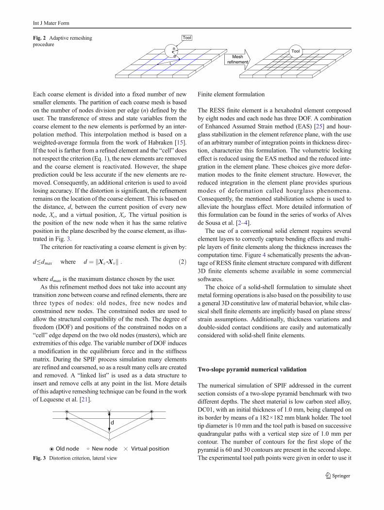
Each coarse element is divided into a fixed number of newsmaller elements. The partition of each coarse mesh is basedon the number of nodes division per edge (n) defined by theuser. The transference of stress and state variables from thecoarse element to the new elements is performed by an inter-polation method. This interpolation method is based on aweighted-average formula from the work of Habraken [15].If the tool is farther from a refined element and the “cell” doesnot respect the criterion (Eq. 1), the new elements are removedand the coarse element is reactivated. However, the shapeprediction could be less accurate if the new elements are re-moved. Consequently, an additional criterion is used to avoidlosing accuracy. If the distortion is significant, the refinementremains on the location of the coarse element. This is based onthe distance, d, between the current position of every newnode, Xc, and a virtual position, Xv. The virtual position isthe position of the new node when it has the same relativeposition in the plane described by the coarse element, as illus-trated in Fig. 3.
The criterion for reactivating a coarse element is given by:
d≤dmax where d ¼ X c‐X vk k : ð2Þ
where dmax is the maximum distance chosen by the user.As this refinement method does not take into account any
transition zone between coarse and refined elements, there arethree types of nodes: old nodes, free new nodes andconstrained new nodes. The constrained nodes are used toallow the structural compatibility of the mesh. The degree offreedom (DOF) and positions of the constrained nodes on a“cell” edge depend on the two old nodes (masters), which areextremities of this edge. The variable number of DOF inducesa modification in the equilibrium force and in the stiffnessmatrix. During the SPIF process simulation many elementsare refined and coarsened, so as a result many cells are createdand removed. A “linked list” is used as a data structure toinsert and remove cells at any point in the list. More detailsof this adaptive remeshing technique can be found in the workof Lequesne et al. [21].
Finite element formulation
The RESS finite element is a hexahedral element composedby eight nodes and each node has three DOF. A combinationof Enhanced Assumed Strain method (EAS) [25] and hour-glass stabilization in the element reference plane, with the useof an arbitrary number of integration points in thickness direc-tion, characterize this formulation. The volumetric lockingeffect is reduced using the EAS method and the reduced inte-gration in the element plane. These choices give more defor-mation modes to the finite element structure. However, thereduced integration in the element plane provides spuriousmodes of deformation called hourglass phenomena.Consequently, the mentioned stabilization scheme is used toalleviate the hourglass effect. More detailed information ofthis formulation can be found in the series of works of Alvesde Sousa et al. [2–4].
The use of a conventional solid element requires severalelement layers to correctly capture bending effects and multi-ple layers of finite elements along the thickness increases thecomputation time. Figure 4 schematically presents the advan-tage of RESS finite element structure compared with different3D finite elements scheme available in some commercialsoftwares.
The choice of a solid-shell formulation to simulate sheetmetal forming operations is also based on the possibility to usea general 3D constitutive law of material behavior, while clas-sical shell finite elements are implicitly based on plane stress/strain assumptions. Additionally, thickness variations anddouble-sided contact conditions are easily and automaticallyconsidered with solid-shell finite elements.
Two-slope pyramid numerical validation
The numerical simulation of SPIF addressed in the currentsection consists of a two-slope pyramid benchmark with twodifferent depths. The sheet material is low carbon steel alloy,DC01, with an initial thickness of 1.0 mm, being clamped onits border by means of a 182×182 mm blank holder. The tooltip diameter is 10 mm and the tool path is based on successivequadrangular paths with a vertical step size of 1.0 mm percontour. The number of contours for the first slope of thepyramid is 60 and 30 contours are present in the second slope.The experimental tool path points were given in order to use it
L
D
R
Tool
ToolMesh
refinement
Fig. 2 Adaptive remeshingprocedure
d
Old node New node Virtual position
Fig. 3 Distortion criterion, lateral view
Int J Mater Form

in the numerical simulations. These SPIF experiments as wellas the shape measurements were performed by the team at KULeuven [11] who provided all the required data for the numer-ical simulations and their validation. The dimensions of anideal design are schematically shown in Fig. 5.
The shape analysis is divided in four sections (A, B, C, D),in order to analyse them separately in the middle section of themesh model (see Fig. 6), to avoid the influence of BoundaryConditions (BC). The material behaviour is elastically de-scribed by E=142,800 MPa and ν=0.33. The hardening typeadopted is a mixed one, with an isotropic constitutive model.The kinematic part of the hardening is introduced by a back-stress tensor described by non-linear Armstrong-Fredrickmodel [11]. The plastic domain is described by a von Misesyield surface and the isotropic hardening behaviour is definedbymeans of a Swift’s law. The chosen parameters are listed onTable 1. The initial yield stress (σ0 ) is 144.916 MPa.
Figure 6 illustrates two distinct meshes refinements. Due tothe square geometry in XY plane (see Fig. 5a) and to benefitthe computation time reduction, only half of the sheet ismodelled. This simplification also can provide a similar resultas a full mesh [18]. The initial refined mesh (reference mesh)is composed by 2048 elements disposed in one layer of RESSfinite element in thickness direction. The coarse mesh usedwith adaptive remeshing method is modelled by 128 elementson the sheet plane with one layer of RESS finite element in
thickness direction. However, the nodes at the top layer ofboth meshes define the contact element layer at the surface.The contact modelling is based on a penalty approach and on aCoulomb law [16]. So, both meshes have two layers of ele-ments (solid-shell + contact element) in thickness direction,and the spherical tool was modelled as a rigid body. Finally,Coulomb friction coefficient between the tool and sheet is setto 0.05 [19] and the penalty coefficient is equal to 1000[N.mm−3].
The numerical shape prediction is extracted from the mid-dle section of the half mesh used within the FE model. Toavoid inaccuracy due to BC effect, each pyramid wall sectionis analysed separately.
Displacement BC was imposed (see Fig. 6) in order tominimize the effect of missing material at both central edgesalong the symmetric axis. This type of BC is introduced by afinite element called BINDS and it is a link between the nodedisplacements of both edges [10, 19]. The absence of backingplate and blank holder in the numerical model was replaced bythe clamped BC at the borders of both meshes. The absence ofclamping devices avoids more contact interactions during thenumerical computation, beyond the tool contact motion, de-creasing CPU time.
Different values for each parameter were tested forderefinement distance (dmax) as well for the number of nodesper edge (n): dmax values were 0.1 and 0.2 mm; n values were
a) b) c)
Fig. 4 Comparison between fullyintegrated (a), reduced integrated(b) and RESS finite elements (c)
Y
X
182 mm
182
mm
A
B
CD
a) Plane view.
abc
Y
Z
Z
X
35 52 6 52 35
35 52 3 55 35
60
90
30º 30º
60º60º
30º 35º
60º60º
b) Y cut (X=0), non symmetric shape.
c) X cut (Y=0), symmetric shape.
AB
CD a
bc
30º
Fig. 5 Component nominaldimensions
Int J Mater Form

2 and 3 nodes. The value used for α coefficient is equal to 1.0.These values used for each remeshing parameter were chosenbased on a previous sensitivity analysis using the line-testbenchmark simulation [9]. The total number of elements inboth meshes includes the number of all finite elements of themodel (RESS+CFI3D+BINDS). The number of integrationpoints through the thickness used in RESS finite element is5 Gauss Points (GP).
Table 2 presents the adaptive remeshing procedure perfor-mance. It is possible to confirm the adaptive remeshing ad-vantages even when the final number of elements is higherthan the reference mesh.
The application of the adaptive remeshing with n equal to 3allows a CPU time reduction of 50 % when negligible differ-ence for different values of dmax parameter is observed. TheCPU time reduction using n equal to 2 is considerably largerthan for n equal to 3. However the accuracy obtained withdifferent refinement levels are analysed in the followingsection.
The main numerical outputs presented in the next sectionsare the final shape of the sheet, in a middle-section along thesymmetric axis in different directions (see Fig. 5b and c) andstress state behaviour. The deformed shape evolution is alsoanalysed for different tool depths.
Shape prediction
In the current section, the deformed shape predictions from thebottom nodes are compared to the available experimental re-sults. The experimental shape measurements were extractedusing Digital Image Correlation (DIC) throughout the SPIFprocess [14]. Figure 7 exhibits the shape prediction in Y di-rection using the adaptive remeshing procedure in simulta-neous comparison with the reference mesh and experimentalmeasurements. Different adaptive remeshing parameters aretested in order to assess their influence in the numerical shapeaccuracy.
It can be observed in Fig. 7 that an acceptable accuracy isachieved between the numerical results and the experimentalmeasurements. The derefinement criterion occurs with morefrequency using dmax equal to 0.2 mm than for dmax equal to0.1 mm. A low value of dmax parameter means that the refine-ment is kept increasing the mesh flexibility. In this case, at thetransition region of wall-angle on section A, the adaptiveremeshing using n equal to 3 combined with dmax equal to0.2 mm seems more accurate than the others numerical simu-lations results. Figure 8 exhibits a zoom at wall-angle change
Clamped BC
Clam
ped
BCC
lam
ped
BC
Cla
mp
ed B
C
Clam
ped
BC
Clamped BC
BINDS elements
BINDS elements
Middle section
Mid
dle
sect
ion
n = 3n = 2
1)
2)
Tool motion
Tool motion
Fig. 6 Reference mesh (a) andcoarse mesh used with adaptiveremeshing (b)
Table 1 Material parameters
Name and hardeningtype
Swift parameters Back-stress
Swift Isotropichardening
K=472.19 MPa; n=0.171;ε0=0.001
Cx=51.65;Xsat=5.3
Table 2 Adaptive remeshing technique performance
Mesh type CPU time CPU timeReduction(%)
Initialn° ofelements
Finaln° ofelements
n=2 dmax=0.1 mm 6 h:28 m:25 s 76.67 298 2602
n=3 dmax=0.1 mm 13 h:38 m:43 s 50.8 4394
dmax=0.2 mm 13 h:18 m:2 s 52.1 4394
Reference 27 h:44 m:27 s – 4282 4282
Int J Mater Form

of section A, which evidence a better shape prediction using nequal to 3 combined with dmax equal to 0.2 mm.
In the following, the average relative and absolute errorsare computed and presented in Table 3 for each refinementlevel. The difference between the numerical result along the
middle section on the meshes and the experimental measure-ments is computed for the common values in the correspond-ing axis. Previously, the numerical values along of middlecross section were linearly interpolated for the correspondingvalues of experimental measurements. The average relativeerror is computed using the following expression:
Error %ð Þ¼XNi¼1
ffiffiffiffiffiffiffiffiffiffiffiffiffiffiffiffiffiffiffiffiffiffiffiffiffiffiffiffiffiffiffiffiffiffiNum: ‐ Exp:ð Þ2
.Exp:2
r� � !=N
" #*100 ð3Þ
where Num. is the numerical value, Exp. is the experimentalvalue and N is the number of points in X axis.
In general, the refinement level using adaptive remeshingmethod with n equal to 3 nodes per edge presents better ap-proximation to the experimental results than the referencemesh and n equal to 2 nodes per edge. However, an improve-ment was obtained using n equal to 3 combined with dmaxequal to 0.2 mm at the wall-angle transition region. Its abso-lute error at wall-angle change is equal to 0.12 mm whileusing n equal to 3 and dmax equal to 0.1 mm the absolute errorat wall-angle change is 2 mm.
The section B of Y cut presents a similar behavior as thesection A, as can be seen in Table 4). However, the absoluteerror at the wall-angle change is more noticeable on section B
-100
-90
-80
-70
-60
-50
-40
-30
-20
-10
0
10
-100 -90 -80 -70 -60 -50 -40 -30 -20 -10 0 10 20 30 40 50 60 70 80 90 100
Y cut [mm]
Dep
th [m
m]
Experimental Y cutReference meshRemeshing (n=3; dmax=0.1mm)Remeshing (n=3; dmax=0.2mm)Remeshing (n=2; dmax=0.1mm)
B A
Fig. 7 Final shape prediction inY cut for different refinementlevels after the tool unload
Fig. 8 Zoom of shape prediction at wall-angle change on section A in Ycut for different refinement levels
Table 3 Average error for Y cut section A
Y cut (A) Remeshing mesh Reference meshError Relative (%)
n=3; dmax =0.1 mm 5.95 6,37n=3; dmax =0.2 mm 5.32
n=2; dmax =0.1 mm 9,22
Int J Mater Form

for n equal to 3 nodes per edge with different values of dmax. Itpresents an absolute error of 3.53 mm using dmax equal to0.1 mm and the error decrease to 2.49 mm using dmax equalto 0.2 mm.
In this first cut analysis, the section A has better shapeaccuracy than the cut B. However, for both sections a bettershape accuracy was achieved using a dmax value equal to0.2 mm. Probably, this fact occurred due to a derefinementat some regions of the wall angle mesh during the simulationforming, which leads to an improvement at the wall-anglestransition area.
Figure 9 exhibits the shape predictions in X direction usingthe adaptive remeshing procedure after tool unload. The nu-merical result below was obtained using the adaptiveremeshing parameters n equal to 3 nodes per edge with differ-ent dmax values of 0.1 and 0.2 mm.
The numerical results on the X cut are considered symmet-ric, once the wall-angles of sections C and D are similar.Table 5 presents the average error in X direction, at the middlesection.
The average relative error analysis of X cut using dmaxequal to 0.1 mm is negligibly smaller than the use of dmaxequal to 0.2 mm. However, at transition region of wall-anglechange, and it is visible that for dmax equal to 0.1 mm the shapeaccuracy is better than for dmax equal to 0.2 mm.
Figure 10 exhibits the comparison between the experimen-tal measurements and the numerical results of four differentcontours. The numerical curves are intentionally shifted to
coincide with experimental at similar depth value. The miss-ing data of the experimental measurements near the backingplate and near of X equal to 0 mm are difficult to extract withthe use of DIC [14]. The numerical results were obtainedusing the adaptive remeshing method with n equal to 3 nodesper edge and dmax equal to 0.1 mm.
The numerical results follow the overall shape of the ex-perimental measurements for the contours 20 to 60 mm.However, there is a difference at the central region of the meshdue to non-refined area of contours 40 and 60 mm. This dif-ference occurs when the refinement and derefinement criteriawere not achieved in the finite elements near the central areaof the mesh. Firstly, due to distance between the tool and thenodes in the tool vicinity (see Fig. 12. 1) and secondly, due tono significant deformation happening in mesh plane (seeFig. 3). To understand the deviation occurrence at the centralregion of the mesh for contours 40 and 60 mm using theadaptive remeshing method, a new analysis was carried out.Thanks to a simulation using the reference mesh of Fig. 6a andanother one with adaptive remeshing method and a new valueof α coefficient equal to 3 combined with dmax equal to0.1 mm, accuracy at the central area of the meshes has beenfurther analysed. Figure 11 presents the obtained results withboth refinement topologies.
The obtained results using the reference mesh provesthat the refinement at the central region avoids the nu-merical deviation error. However, even with a high val-ue of α coefficient the deviation using the adaptiveremeshing the deviation continues, due to fulfil thederefinement criterion. The refinement at the central
Table 4 Average error for Y cut section B
Y cut (B) Remeshing mesh Reference meshError Relative (%)
n=3; dmax =0.1 mm 6.63 6.94n=3; dmax =0.2 mm 6.37
n=2; dmax =0.1 mm 9.93
Fig. 9 Final shape prediction inX cut for refinement n equal to 3nodes per edge, after tool unload
Table 5 Average errorfor Y cut section C or D X cut (C and D) Remeshing mesh
Error Relative (%)
n=3; dmax =0.1 mm 4.72
n=3; dmax =0.2 mm 4.77
Int J Mater Form

area remains if a significant distortion occurs and if thedmax value is higher than the value chosen by the user.Once the forming tool does not move on the referredregion, the refinement due to a high value of α coeffi-cient is deleted and the coarse elements are reactivated.
At 80 mm depth, Fig. 10 presents a visible error inthe transition zone of the wall-angle. This shape errorwas mentioned by Guzmán et al. [14] (see Fig. 12 in[14]) as the “tent” effect. In order to understand theorigin of this shape inaccuracy after wall-angle transi-tion, the following section will present a stress analysisin the thickness direction.
Through thickness stress
The main interest of the current section is the analysis of stressstate in thickness direction in different wall regions of themesh at the middle section. The stress state is obtained usingthe adaptive remeshing technique at the end of two differentforming stages. Figure 12 exhibits the mesh plane view andthe elements selected.
The stress analysis behaviour of each Gauss Point (GP)through thickness is performed at different forming depthsfor three selected elements. The GP positions are such thatGP1 is near the sheet external surface (the one not in contactwith the tool) and GP5 near the internal surface. The orienta-tion of the local stress components in plane are σ11 and σ22
can be recovered by their projections in Fig. 12. The compo-nent σ33 is the stress state in thickness direction.
Figure 13 presents the relative stress (σ/σ0) values (σ0 be-ing the initial yield stress 144.916MPa) at the 60th contour (atthe beginning of the forming of the second slope pyramidwhen the tool has already had contact with the sheet and goingdeeper). The associated mesh and the tool position is shown inFig. 12.1.
The cyclic strain path associated to SPIF, checked by Heet al. [17], confirms the bending/unbending type of load asso-ciated to a stretch forming. The σ11 and σ22 stress components(Fig. 13) of the element a) at middle position on the 60° wallhas a typical scheme resulting from such stress state. Guzmánet al. [14] used a shell finite element to analyse a two slopepyramid made in Aluminum AA3003, similar to the DC01pyramid studied in the present work. As expected, the stressstates computed by shell and solid-shell approaches presentboth similarities and discrepancies. The results from [14] werebased on the shallow shell theory, thus they assumed that themid-plane coincides with the neutral plane. The solid-shellelement formulation allows a greater flexibility and takes intoaccount through thickness shear stresses and normal stress inthickness direction in addition to the membrane stresses. Thedeformation characteristics of SPIF during the tool contactcould induce a strong element deflection (as probed by thechoice of dmax equal to 0.2 mm in the previous section).Hence, the shell hypothesis of the mid/neutral plane couldbe considered as somewhat severe. The membrane stress dis-tribution in Fig. 13 for element (a) and (b) could be consideredas the sum of bending/unbending plus stretching, as previous-ly observed by [13]. The typical stress distribution is depictedschematically in Fig. 14 assuming for simplicity elastic behav-iour. Indeed true behaviour is more complex as plasticity oc-curs in both bending and unbending processes (see equivalentplastic strain values in Table 6) and local contact generatingσ33 as well as through thickness shear stresses justifies aslightly higher plastic strain near internal surface. The stressprofile of σ33 related to element a) in the wall middle sectionpresents the typical gradient expected due to tool contact. TheFig. 11 Shape prediction for X cut at 40 and 60 mm of depth
Fig. 10 Shape prediction for X cut at different depth steps using theadaptive remeshing method
Int J Mater Form

GP near the internal surface (GP 5) is associated to the toolcompression effect during the forming path and zero stress onthe external surface (GP 1). For element b) at change ofslope, a more complex pattern of σ33 is observed due tofurther plasticity increase at this location during theforming of the second pyramid, however higher numberof GP computation confirms a null stress at externalsurface.
Figure 15 presents the relative stress (σ/σ0) values at90 mm depth for each GP through the sheet thickness.Figure 12.2 is its corresponding mesh, note that the tool hasbeen removed, it is an unloaded configuration.
The elements a) and b) at the end of contour 90 have asimilar stress profile to the pattern of contour 60, however,they present identical or higher values stress values. Thestrong increase of membrane stresses of GP 5 compared to
Fig. 13 Stress componentsthrough the thickness for the threeelements at depth stage 60 mm
Fig. 12 Position of three selectedelements after contour 60 mm (1)and after contour 90 mmunloading step (2)
Int J Mater Form

Fig. 13 as well as the values of equivalent plastic strain inTable 6 confirm that additional plastic deformation appearedat depth 60 (change of pyramid slope) during further forming(increased value from 0.599 to 0.855). Already mentioned inthe work of Guzmán et al. [14], the “tent” effect [5–8] calledfrom displacement of the material at depth 60 mm duringsecond pyramid forming (see Fig. 11) happens. As explainedin Fig. 12 of Guzmán et al. [14], structural bending effect farfrom the tool location induces this displacement as the smallerslope angle increases the lever arm of the tool force and gen-erates high moment in this transition zone. [14] showed that itoccurs only as an elastic effect for their case, however in thepresent work a different material is used and plastic strain inelement b) clearly increases between contour at 60 and 90mmdepth. Comparing element b) at contour depth 60 mm(Fig. 13) and element c) at contour depth 90 mm in Fig. 15and in Table 6, one can observed typical differences of stressstates in SPIF formed shapes with high and low slopes respec-tively. Plastic strain levels in all GP as well as the normal stressand shear stress components in thickness direction of elementc) are smaller. The thickness profile of σ11 and σ22 stress
components of element c) in Fig. 15 is associated to one mo-ment and a stretching stress suggesting that plasticity did notoccurred in both bending and unbending events.
Final considerations
The present work discusses the application of an adaptiveremeshing procedure in the numerical simulation of a two-slope pyramid shape, using solid-shell elements. In general,the shape prediction and the stress analysis in thickness direc-tion were the main contributions of this work. An acceptableaccuracy was obtained when comparing the numerical resultsin different stages with experimental DIC measurements. Theadaptive remeshing procedure using the RESS finite elementwas compared with a reference mesh (without remeshing),being able to accurate reproduce the results but reducing theCPU time considerably. It has shown the advantage to strong-ly decrease the number of nodes and elements during the FEMsimulation of SPIF. The comparisons made between meshestopologies with different refinement levels have showed theirinfluence in the shape accuracy and CPU time. Most of nu-merical shape error comes from transitions areas, as near thebacking plate edge and at the wall-angle change. However, theerror near the backing plate is only noticeable at the end of thesimulation. The adaptive remeshing parameter dmax showednegligible influence on CPU time. The increase of dmax valueimproved the shape accuracy at the wall-angle change on sec-tion A and B but the same improvement was not verified forsections C and D. However, concerning the relative shapeerror found for different dmax values used, the error difference
Fig. 14 Simple elastic schematic representation of bending/unbendingplus stretching associated to elements a) and b)
Table 6 Relative values of σ13/σ0 and σ23/σ0, εeq
p , yield strengthand σeq at contours 60 and 90
Element Contour 60 mm Contour 90 mm
a b c a b c
σ13/σ0 GP 5 −0.379 −0.146 0.006 −0.344 −0.096 −0.160GP 3 0.112 −0.271 −0.002 −0.026 0.158 0.181
GP 1 0.668 0.270 −0.002 0.538 0.3273 0.495
σ23/σ0 GP 5 −1.145 0.080 −0.000 −1.027 −1.585 0.005
GP 3 0.554 0.076 0.001 0.429 0.658 0.031
GP 1 0.598 −0.136 0.001 0.593 1.264 0.193
εeqp GP 5 1.251 0.599 0.000 1.251 0.855 0.483
GP 3 0.873 0.356 0.000 0.873 0.571 0.283
GP 1 1.077 0.581 0.000 1.077 0.869 0.491
Yield strength [MPa] GP 5 490.677 432.721 144.916 490.719 459.828 417.064
GP 3 461.408 395.8978 144.916 461.408 429.186 380.753
GP 1 478.321 430.4598 144.9161 478.321 461.061 418.199
σeq [MPa] (Von Mises) GP 5 464.132 398.134 20.720 462.506 425.074 329.010
GP 3 262.035 382.365 11.043 223.949 93.438 270.531
GP 1 232.149 425.234 34.809 256.896 458.994 305.779
Int J Mater Form

between both shapes sections can be considered negligible.The adaptive remeshing parameter which has exhibited a sig-nificant influence in the shape accuracy was the number ofnodes per edge (n).
The stress analysis through the thickness of the sheetexhibited a bending/unbending plus stretching, alreadydocumented in previous publications, while the shearstresses remain very small. The combination of mem-brane under tension with bending behaviour was alsofound at different levels of depth. The elastic stressstate affects the geometrical shape accuracy, mainly, af-ter the wall angle transition. Future research can befocused in the relation between the stress state analysedhere and the deformation mechanisms documented inliterature.
Compared to shell simulations, the solid-shell ap-proach allows prediction of detailed through thicknessstress behaviour. For the studied case (DC01 steel ma-terial and a 2 slopes, non symmetrical pyramid withangles 60/30° and 60/35° and respective depths 60/90 mm), one can confirm that the change of slope zoneis plastically affected by the second pyramid formingprocess. Note that only elastic effect was predicted inthis zone for a similar pyramid (AA3003 aluminum ma-terial and a 2 slopes, symmetrical pyramid with angles65/30° and respective depths 63/90 mm).
From the results obtained and the analysis performed, it isclear that the combination between a 3D finite element and aremeshing strategy becomes appropriate to perform futureSPIF simulations. Besides the drastic CPU time reductionwhile keeping accuracy, the use of the presented frameworkinto further studies will allow for a deeper understanding of
SPIF mechanisms, as could be shown in the presentmanuscript.
Acknowledgments The authors would like to gratefully acknowledgethe support given by Portuguese Science Foundation (FCT) under thegrant SFRH/BD/71269/2010 (J. I. V. Sena) and EXPL/EMS-TEC/0539/2013.
As Research director, A.M. Habraken would like to thank the Fund forScientific Research (F.R.S - FNRS, Belgium) for its support.
References
1. Allwood JM, Braun D,Music O (2010) The effect of partially cut-outblanks on geometric accuracy in incremental sheet forming. J MaterProcess Technol 210:1501–1510
2. Alves de Sousa RJ, Cardoso RPR, Fontes Valente RA, Yoon JW,Grácio JJ, Natal Jorge RM (2005) A new one-point quadratureEnhanced Assumed Strain (EAS) solid-shell element with multipleintegration points along thickness: part I−geometrically linear appli-cations. Int J Numer Methods Eng 62:952–977
3. Alves de Sousa RJ, Cardoso RPR, Fontes Valente RA, Yoon JW,Grácio JJ, Natal Jorge RM (2006) A new one-point quadratureEnhanced Assumed Strain (EAS) solid-shell element with multipleintegration points along thickness: part II−nonlinear problems. Int JNumer Methods Eng 67:160–188
4. Alves de Sousa RJ, Yoon JW, Cardoso RPR, Fontes Valente RA,Grácio JJ (2007) On the use of a reduced enhanced solid-shell finiteelement for sheet metal forming applications. Int J Plast 23:490–515
5. Behera AK, Vanhove H, Lauwers B, Duflou J (2011) Accuracy im-provement in single point incremental forming through systematicstudy of feature interactions. Key Eng Mater 473:881–888
6. Behera A, Gu J, Lauwers B, Duflou J (2012) Influence of materialproperties on accuracy response surfaces in single point incrementalforming. Key Eng Mater 504–506:919–924
7. Behera A, Verbert J, Lauwers B, Duflou J (2013) Tool path compen-sation strategies for single point incremental sheet forming using
Fig. 15 Relative stresscomponents in thickness directionfor the three elements at the end of90 mm, after tool unloaded
Int J Mater Form

multivariate adaptive regression splines. Comput Aided Des 45:575–590
8. Behera A, Lauwers B, Duflou J (2014) Tool path generation frame-work for accurate manufacture of complex 3D sheet metal parts usingsingle point incremental forming. Comput Ind 65(4):563–584
9. Bouffioux C, Eyckens P, Henrard C, Aerens R, Van Bael A, Sol H,Duflou JR, Habraken AM (2008) Identification of material parame-ters to predict single point incremental forming forces. Int J MaterForm 1:147–1150
10. Bouffioux C, Pouteau P, Duchêne L, Vanhove H, Duflou JR,Habraken AM (2010) Material data identification to model the singlepoint incremental sheet forming. Int J Mater Form 3:979–982
11. Duchêne L, GuzmánCF, Behera AK, Duflou J, HabrakenAM (2013)Numerical simulation of a pyramid steel sheet formed by single pointincremental forming using solid-shell finite elements. Key EngMater549:180–188
12. Emmens WC, Sebastiani G, Van Den Boogaard AH (2010) Thetechnology of incremental sheet forming−a brief review of the histo-ry. J Mater Process Technol 210:981–997
13. Eyckens P, Belkassem B, Henrard C, Gu J, Sol H, Habraken AM,Duflou J, Bael A, van Houtte P (2010) Strain evolution in the singlepoint incremental forming process: digital image correlation mea-surement and finite element prediction. Int J Mater Form 4:55–71
14. Guzmán CF, Guc J, Duflou J, Vanhoved H, Flores P, Habraken AM(2012) Study of the geometrical inaccuracy on a SPIF two-slopepyramid by finite element simulations. Int J Solids Struct 49:3594–3604
15. Habraken AM (1989) Contribution to the modelling of metal formingby finite element model, PhD Thesis, Université de Liège, Belgium
16. Habraken AM, Cescotto S (1998) Contact between deformablesolids, the fully coupled approach. Math Comput Model 28(4–8):153–169
17. He S, Van Bael A, Van Houtte P, Tunckol Y, Duflou J, Habraken AM(2006) An FEM-aided investigation of the deformation during singlepoint incremental forming. Modeling & Simulation in MaterialsScience & Engineering, Institute of Physics
18. Henrard C (2008) Numerical Simulations of the Single PointIncremental Forming Process, PhD Thesis, Université de Liège,Belgium
19. Henrard C, Bouffioux C, Eyckens P, Sol H, Duflou JR, VanHoutte P, Van Bael A, Duchêne L, Habraken AM (2010)Forming forces in single point incremental forming: predictionby finite element simulations, validation and sensitivity.Comput Mech 47:573–590
20. Jetteur P, Cescotto S (1991) AMixed Finite Element for the Analysisof Large Inelastic Strains. International Journal for NumericalMethods in Engineering; 31(2), pp. 229–239. doi:doi:10.1002/nme.1620310203
21. Lequesne C, Henrard C, Bouffioux C, Duflou J, Habraken AMAdaptive Remeshing for Incremental Forming Simulation.Proceedings of the NUMISHEET 2008 7th InternationalConference and workshop on numerical simulation of 3D sheet metalforming processes, September 1–5, Interlaken, Switzerland
22. Leszak E, Patent US3342051A1, published 1967-09-19. Apparatusand Process for Incremental Dieless Forming
23. Li K. (1995) Contribution to the finite element simulation of three-dimensional sheet metal forming. PhD Thesis, Université de Liège,Belgium
24. Rabahallaha M, Bouffioux C, Duchêne L, Lequesne C, Vanhoveb H,Duflou JR, Habraken AM (2010) Optimized remeshing for incre-mental forming simulation. Advances in Materials and ProcessingTechnologies (AMPT), Paris
25. Simo JC, Rifai MS (1990) A class of mixed assumed strain methodsand the method of incompatible modes. Int J Numer Methods Eng29:1595–1638
Int J Mater Form