sculpting: an improved inside-out scheme for all-hexahedral meshing
TRANSCRIPT

SCULPTING: AN IMPROVED INSIDE OUT SCHEME FOR ALL HEXAHEDRAL MESHING
Kirk S. Walton1, Steven E. Benzley2, Jason Shepherd3 1Brigham Young University, Provo, UT, U.S.A. [email protected]
2 Brigham Young University, Provo, UT, U.S.A. [email protected] 3Sandia National Laboratories, Albuquerque, NM, U.S.A. [email protected]
ABSTRACT
Inside-out algorithms provide the ability to generate all hexahedral meshes by first introducing a structured mesh that bounds the complete body modeled, then secondly by manipulating the exterior of this structured mesh to fit the specific boundary of the body. Such algorithms generally provide high quality meshes on the interior of the body but suffer with lower quality elements on the boundary. The sculpting algorithm as presented here, addresses the difficulty in forming quality near boundary elements in two ways. The algorithm first introduces new methods to define an initial structured mesh and second uses collapsing templates to reposition boundary elements to conform to the geometric topology prior to smoothing elements to the boundary. The algorithm also provides the ability to subdivide the original object into sub-regions such that complex geometries can be meshed.
Keywords: mesh generation, hexahedral meshing,
3 [email protected]. Jason Shepherd was supported by the Mathematical, Information and Computational Sciences Division of the U.S. Department of Energy, Office of Energy Research.
1. INTRODUCTION
Automatic all-hexahedral meshing of arbitrary three-dimensional geometries continues to receive significant attention. Over the past few years meshing efforts have developed numerous algorithms to produce a conformal all-hexahedral mesh. These methods include generalized sweeping [1,2], block decomposition [3], tetrahedral based [4,5], whisker weaving [6] and inside-out grid based [7,8,9].
None of these methods have proven to be an all-encompassing algorithm and each has drawbacks to their use. Generalized sweeping schemes are very versatile and fast, and can have arbitrarily meshed source and target surfaces. However acceptable geometries must have a generalized axis of symmetry that defines a major sweeping direction. Schemes to add minor sweep axes have enhanced this method [10,11]. Block decomposition methods produce high quality meshes but often are not very automated and require many hours of user interaction. The tetrahedral based schemes produce all-hexahedral meshes from an initial all-tetrahedral mesh. The resulting all-hexahedral meshes often suffer from poor quality. Whisker-woven meshes can be very compute intensive and also often generate unacceptable interior
elements. Grid based algorithms while robust, often generate poor quality elements at the boundary often because the elements are not generally aligned with the volume boundary. The lack of a single hexahedral-meshing algorithm that can mesh all the volumes of a given model has spurred the development of a new grid based algorithm. The goal of the sculpting algorithm is to provide an automated all-hexahedral mesh.
2. BOUNDING BOX GENERATION
Grid based, superposition, or inside-out methods all refer to a class of algorithms that generate a mesh that is easy to create and which covers a sufficient volume of the object with a structured mesh. The initial mesh often comes from using a simple mapping algorithm to mesh a volumetric bounding box. Once the bounding box has been defined and the mesh has been created, multiple steps are then needed to fit the mesh precisely to the volume. Schneider’s initially proposed to eliminate elements from the initial grid that are not contained entirely within the volume and then project edges from the remaining hexes to the surface of the volume [7,8,9]. Others [12] have proposed using all the available elements moving the nodes from elements nearest to the
volume boundary to produce an interior and exterior meshes and discarding the unwanted meshed area. In either of the above mentioned cases the element edges are generally parallel to one of the coordinate axis, which is often the reason for jagged or uneven elements along the volume boundary when the volume is not oriented with a global coordinate axis. Figure 1 provides an example how slightly rotating a volume away from its orientation with a global coordinate axis will alter the volume mesh dramatically.
Figure 1. Distortion of a volumetric meshed used in supper position methods once the meshing volume is no longer oriented with the coordinate axis [Mesh generated with GAMBIT a mesh generation code from Fluent Inc.]
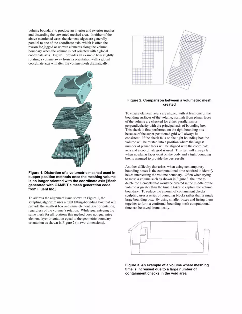
To address the alignment issue shown in Figure 1, the sculpting algorithm uses a tight fitting-bounding box that will provide the smallest box and same element layer orientation, regardless of the volume’s rotation. While guaranteeing the same mesh for all rotations this method does not guarantee element layer orientation equal to the geometric boundary orientation as shown in Figure 2 (in two-dimensions).
Figure 2. Comparison between a volumetric mesh created
To ensure element layers are aligned with at least one of the bounding surfaces of the volume, normals from planar faces of the volume are checked for either parallelism or perpendicularity with the principal axis of bounding box. This check is first performed on the tight bounding box because of the super-positioned grid will always be consistent. If the check fails on the tight bounding box the volume will be rotated into a position where the largest number of planar faces will be aligned with the coordinate axis and a coordinate grid is used. This test will always fail when no planar faces exist on the body and a tight bounding box is assumed to provide the best results. Another difficulty that arises when using contemporary bounding boxes is the computational time required to identify hexes intersecting the volume boundary. Often when trying to mesh a volume such as shown in Figure 3, the time to delete the elements that would be created in the middle of the volume is greater than the time it takes to capture the volume boundary. To reduce the amount of containment checks sculpting uses a series of bounding blocks rather than a single large bounding box. By using smaller boxes and fusing them together to form a conformal bounding mesh computational time can be saved dramatically.
Figure 3. An example of a volume where meshing time is increased due to a large number of containment checks in the void area

Figure 4. Sub bounding boxes used to capture the
geometry of Figure 3.
3. HEX COLLAPSING
Original inside-out meshing routines projected element faces onto the boundary whereas sculpting provides a new approach to attempt to provide higher quality elements along these crucial boundary regions. For example, Schneider’s [7] approach is to initially remove any element that intersects a geometry boundary and then project edges to the geometric surface to create the boundary elements. On the other hand, sculpting leaves the elements that intersect the volume boundary and removes only elements that have no contact to the geometry surface. Sculpting then invokes a process of hexahedral collapsing followed by repositioning the collapsed nodes to the geometry and completing the process by high fidelity smoothing [12]. Figure 4 provides a simple comparison between the traditional inside-out algorithm that projects edges and sculpting's hex collapsing and node smoothing scheme.
Figure 4. A comparison between projecting
algorithms and sculpting
Hex collapsing does inherently invoke some risks that poor elements might be created and propagated though the mesh. To avoid this a method of intelligent collapsing has been implemented to identify collapsible edges. A collapsible
edge is defined as a series of boundary edges not included in the same element and that each has three hexes and two boundary faces attached. Collapsible edges are found by searching the boundary faces for an acceptable edge. Once a starting edge is found, this edge’s neighbors are recursively checked to find linkable available edges. This process proceeds until suitable end points are found. Suitable end points are defined as points where the advancing collapsible edge cannot find a continuing advancing edge or where the next advancing edge remains part of the same element as the current edge. Figure 5 illustrates examples of free end points, where no advancing edge is found, and intersecting end points, both open and closed. The left example shows three collapsible edges that each have a free end point and an open intersection end point. The right example shows three collapsible edges that each have a free end point and a closed intersection end point. In both examples the edges are restricted from interacting one with the other to provide independence when collapsing. While in the left example, as shown there would be no problem if all three collapsible edges were combined and acted together. If one of these edges represented a curve between two planar surfaces, sculpting would not allow the collapse because it would disrupt the elements used to capture the geometric curve. For this reason they are kept independent. In the case on the right, they are also kept independent, though there currently is no useful way of collapsing even one of the edges without producing knife elements.
Figure 5. Example endpoints for collapsible edges
Figure 6 helps to describe collapsing on a mechanical part. Each of the useful collapsible edges has been highlighted for clarity. All of the selected edges for collapsing in this case only have free end points. There are edges at the front of the part where a cylinder protrudes from the surface that has open and closed intersections that have not been highlighted. If hex collapsing occurred in these regions poor element quality would be introduced or element layers would be disrupted.
Figure 6. Possible edges available for hex
collapsing on a mechanical part

Once all the collapsing edges are found, their interaction between each other is compared to avoid conflicts and then collapsing continues. Figure 7 shows how the mesh appears after collapsible edges have been chosen and the collapsing has taken place. As seen at the top of the part, there are edges that were identified as valid that were not used because it would have disrupted the collapsing of a neighboring edge.
Figure 7. Collapsed hexes on a mechanical part
Figure 8. Sculpted all hex mesh on a mechanical part
For various exposed hexes collapsing templates have been introduced to provide an intelligent collapsing method. These templates are shown in Figure 9, where the hex primitive is to the left of possible hex collapses.
Figure 9. Hex collapsing templates
4. FINALIZING BOUNDARY CAPTURE
Once hex collapsing has produced acceptable surface elements, node repositioning is the final sculpting step required to capture the complete volume boundary. Node repositioning is a simple step provided that the node in question can be moved to only one surface. However, if there are multiple surfaces to which the node can be moved, difficulties arise and logical decisions must be imposed. We begin by introducing the two-dimensional situation. As depicted in Figure 10, only nodes outside the volume boundary move to the closest point on the nearest surface or curve of the volume. Figure 10 provides a simple example of a corner cut out of a two dimensional square. In general, boundary nodes should be moved to the nearest geometric surface. Because the rectangular surface is relatively simple and easily contained in a box, most nodes can be aligned along the boundary and do not need any adjustment. However, along the cutout section there exists one layer of elements (i.e. the horizontal row) that matches the surface boundary, whereas a vertical layer intersects the boundary edge and the respective nodes of these elements must be moved to the boundary. This example demonstrates how node movement cannot be simply based on placement to the nearest surface. The node at the re-entrant corner must lie on both boundary edges.

Figure 10. Node movement when a node lies on a
boundary yet needs to move because of neighboring node movement
The three-dimensional situation is significantly more complex. Figure 11 shows a cylindrical surface extruded from the side of a flat surface. Note the boundary curve that defines the intersection of the cylinder and the flat surface. This boundary curve must be matched with the boundary nodes that currently lie on the flat surface as a result of element layer orientation. The nodes that will be used to capture the boundary curve are shown bolded in Figure 11 and the solid arrows show the movement that will ensure proper nodal alignment. The curve can be captured in a similar manner as was done previously for Figure 10, once the elements along the curved surface have properly moved to this surface. Capturing the curved surface correctly is not difficult away from the boundary curve, but whenever elements near the curve need to be adjusted, node movement becomes more involved. There is one bolded node in Figure 11 that does not lie on the flat surface and has two potential movements shown by a solid and a dashed arrow. The dashed arrow describes the shortest distance to the volume boundary from the current node location. As seen, moving the node to the closest surface would move the node to the same location as an existing node and would interfere with neighboring nodes on the surface as well as distort the elements that contain the node in question. The more correct move is shown with a solid arrow and yet this distance to the proposed node location is nearly 125% greater than the distance needed to move the node to the closer surface. To properly move nodes, there needs to be a method to consider global effects of node movement rather than simply local effects.
Figure 11. Desired node movement (solid arrow) and improper movement (dashed arrow) of a
cylinder extrude from a flat plane
Currently the sculpting algorithm resolves ambiguous edge boundary moves as follows.
1. An optimum (allowable) element size, h, is determined.
2. The distance from each node to all nearby
surfaces is computed. The closest (i.e. minimum) distance is stored as d, and all other distances are saved an ordered array, t.
3. The distance d is compared to h. If it is
roughly equal to h, the distances in array t are used to find a more suitable placement for the node.
4. Alternative moves are assessed by determining if the distance to a surface, d, is less than
3 h, (i.e. 3 h is the maximum distance a node could possibly move if a portion of the element is contained inside the volume). If no such move is found, then the node is moved as in the previous case.
5. If there is such a move, the neighboring nodes
are checked to see which surface they have moved to. If none of these neighbors has been moved to the boundary, nodes are selected to find one that can move to a surface with a d less than h.
6. When this fails the original move is used.

This simple heuristic algorithm has worked for many cases but is obviously not valid for all cases. Addition work in resolving edge ambiguities is in progress.
5. EXAMPLES
Shown below are examples of geometries meshed using the sculpting algorithm. Figure 12 shows the geometry model and bounding boxes of an object that has proven to be difficult to mesh. Figure 13 shows the sculpted all hexahedral mesh of the object. Figure 14 shows the geometry model of a dumbbell shape that has cylindrical cuts made into its end with its defining bounding box. Figure 15 shows the sculpted all hexahedral mesh.
6. CONCLUSIONS
This paper has presented some initial work on a new automatic all hexahedral-meshing algorithm named sculpting. There still is a large amount of work to do to make this scheme totally robust. Only a few collapsing templates have been introduced in this paper and more may be needed to avoid possible knife element creation. Sculpting does however provided a reasonable alternative to common inside-out meshing techniques and can create high quality boundary elements.
Figure 12. Geometry and bounding boxes of hook
object
Figure 13. Sculpted mesh of hook object
Figure 14. Geometry and bounding box of a dumbbell shape with cylindrical intrusions
Figure 15. Sculpted all hexahedral mesh of
dumbbell shape

REFERENCES
[1] Blacker, T. , “The Cooper Tool,” Proceedings, 5th International Meshing Roundtable, Sandia National Laboratories, 96, October 1996, pp. 205-21513-30. [2] Mingwu, L., Benzley, S.E., and White, D.R.., “Automated Hexahedral Mesh Generation by Generalized Multiple Source to Multiple Target Sweeping,” IJNME, 49, September, 2000. [3] Hohmeyer, M.E., and Christopher, W., “Full-Automatic Object-Based Generation of Hexahedral Meshes,” Proceedings, 4th International Meshing Roundtable, Sandia National Laboratories, October 1995, pp 129-138. [4] CUBIT, Version 7.0, Sandia National Laboratories (2002), URL: http://endo.sandia.gov/cubit. [5] Owen, S.J., “Constrained Triangulation: Application to Hex-Dominant Mesh Generation,” Proceedings, 8th International Meshing Roundtable, SNL, South Lake Tahoe, CA., Oct 1999, pp. 31-41. [6] Tautges, Timothy J., Ted Blacker, Scott A. Mitchell, "The Whisker Weaving Algorithm: A Connectivity-Based Method for Constructing All-Hexahedral Finite Element Meshes", International Journal for Numerical Methods in Engineering, Wiley, Vol 39, 1996, pp.3327-3349. [7] Schneiders, R., “ Automatic Generation of Hexahedral Finite Element Meshes,” Proceedings, 4th International Meshing Roundtable, Sandia National Laboratories, October 1995, pp. 103-114. [8] Schneiders, R., Schindler, R., and Weiler, F., “Octree-based Generation of Hexahedral Element Meshes,” Proceedings, 5th International Meshing Roundtable, Sandia National Laboratories, 96, October 1996, pp. 205-215. [9] Schneiders, R., “ An Algorithm for the Generation of Hexahedral Element Meshes based on an Octree Technique,” Proceedings, 6th International Meshing Roundtable, Sandia National Laboratories, October 1997, pp. 195-196. 10] Jankovich, S.R., Benzley, S.E., Shepherd, J., and Mitchell S “The Graft Tool: An All-Hexahedral Transition Algorithm for Creating a Multi-Directional Swept Volume Mesh,” Proceedings, 8th International Meshing Roundtable, SNL, South Lake Tahoe, CA., Oct 1999, pp. 387-394. [11] Miyoshi, K., and Blacker, T., “Hexahedral Mesh Generation Using Multi-Axis Cooper Algorithm,” Proceedings, 10th International Meshing Roundtable, SNL, New Orleans, LA., Sep. 2000, pp. 89-100. [12] Knupp, P.M., “Matrix Norms & The Condition Number,” Proceedings, 8th International Meshing Roundtable, SNL, South Lake Tahoe, CA., Oct 1999, pp. 387-394.