adjusting system relief pressure
TRANSCRIPT
TEREX UTILITIES TECHNICAL SUPPORT TEAMPHONE: 1-844-TEREX4U (1-844-837-3948) | EMAIL: [email protected]
MODEL(S): TOOLS NEEDED:SERVICE CALL:
NO.
ADJUSTING SYSTEM RELIEF PRESSURE
C4000, C5000, C6000, GENERAL HYDRAULIC PRESSURE GAUGE (0-5000 PSI)
9/16” OR ¾” WRENCHSET OF STANDARD ALLEN
WRENCHES
ADJUSTING SYSTEM RELIEF PRESSURE 02
DANGERFailure to obey the instructions and safety rules in the appropriate Operator’s Manual and Service Manual for your machine will result in death or serious injury.
Many of the hazards identified in the Operator’s Manual are also safety hazards when maintenance and repair procedures are performed.
DO NOT PERFORM MAINTENANCE UNLESS:
√ You are trained and qualified to perform maintenance on this machine.
√ You read, understand and obey: • manufacturer’s instructions and safety rules • employer’s safety rules and worksite
regulations • applicable governmental regulations
.
√ You have the appropriate tools, lifting equipment and a suitable workshop.
The information contained in this Tech Tip is a supplement to the Service Manual. Consult the appropriate Service Manual of your machine for safety rules and hazards.
PAGE 2 OF 7
TECH TIP 02 | RELEASED 02.07.2022 | VERSION 1.0
TECH TIP 02 | RELEASED 02.07.2022 | VERSION 1.0
©TEREX UTILITIES. ALL RIGHTS RESERVED
PAGE 3 OF 7
CONTENTSTECH TIP#02
TOC
4 | Determine gauge installation location
INTRODUCTIONSTEP 1
5 | Test Ports | Install the gauge
STEP 2 - STEP 3
6 | Verify pressure setting and adjustment
STEP 4
TECH TIP 02 | RELEASED 02.07.2022 | VERSION 1.0
TECH TIP 02 | RELEASED 02.07.2022 | VERSION 1.0
When setting system relief, it must be verified that system pressure is present at the base of the lift cylinders. If system pressure is not present or improperly set, the unit may not be able to lift the capacities shown on the load chart. This is the reason why pressure is checked at the base of the lift cylinders or by hooking into Hydraulic Overload Protection (HOP).
INTRODUCTION• Repair procedures shall be completed by a person trained and qualified on the repair of this machine.
• Immediately tag and remove from service a damaged or malfunctioning machine.
• Read this procedure completely and adhere to the instructions. Attempting shortcuts may produce hazardous conditions.
• Consult your unit specific maintenance manual
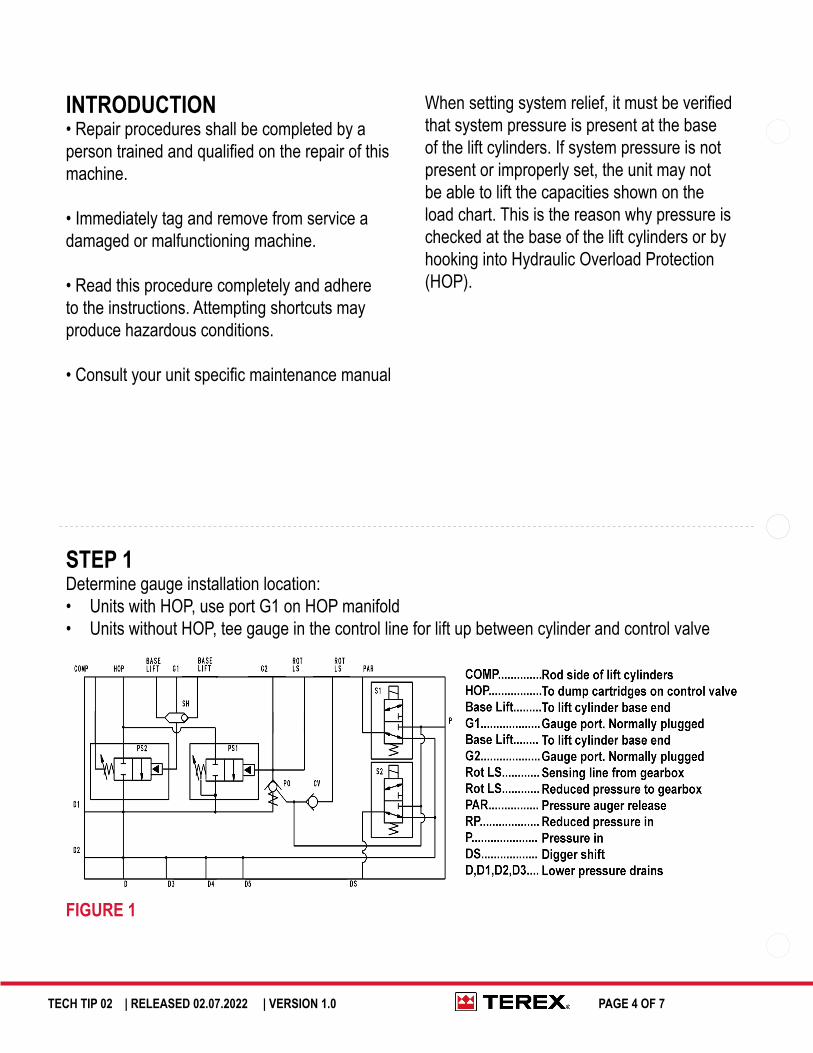
STEP 1Determine gauge installation location:• Units with HOP, use port G1 on HOP manifold• Units without HOP, tee gauge in the control line for lift up between cylinder and control valve
FIGURE 1
PAGE 4 OF 7
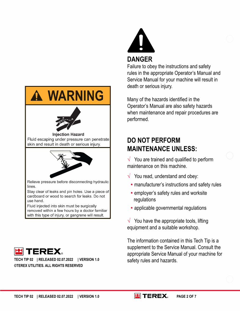
Escaping fluid under pressure can penetrate skin causing serious injury.
Relieve pressure before disconnecting hydraulic lines. Keep away from leaks and pin holes. Use a piece of cardboard or paper to search for leaks. DO NOT use your hand.
TECH TIP 02 | RELEASED 02.07.2022 | VERSION 1.0
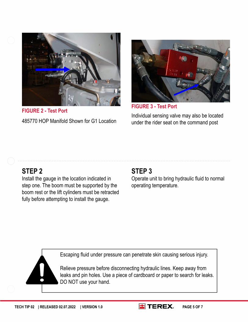
STEP 2Install the gauge in the location indicated in step one. The boom must be supported by the boom rest or the lift cylinders must be retracted fully before attempting to install the gauge.
FIGURE 2 - Test PortFIGURE 3 - Test Port
485770 HOP Manifold Shown for G1 LocationIndividual sensing valve may also be located under the rider seat on the command post
STEP 3Operate unit to bring hydraulic fluid to normal operating temperature.
PAGE 5 OF 7
TECH TIP 02 | RELEASED 02.07.2022 | VERSION 1.0
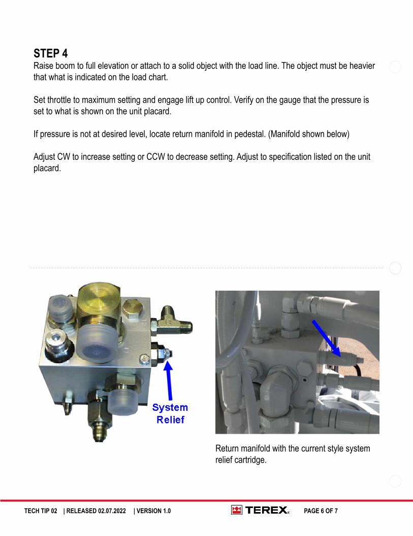
STEP 4Raise boom to full elevation or attach to a solid object with the load line. The object must be heavier that what is indicated on the load chart.
Set throttle to maximum setting and engage lift up control. Verify on the gauge that the pressure is set to what is shown on the unit placard.
If pressure is not at desired level, locate return manifold in pedestal. (Manifold shown below)
Adjust CW to increase setting or CCW to decrease setting. Adjust to specification listed on the unit placard.
Return manifold with the current style system relief cartridge.
PAGE 6 OF 7

FOR FURTHER ASSISTANCE, CONTACT THE TEREX UTILITIES TECHNICAL SUPPORT TEAM
PHONE: 1-844-TEREX4U (1-844-837-3948) | EMAIL: [email protected]