sizing pressure- relief valves
TRANSCRIPT

February 2013
www.che.com
Centrifugal
Pumps
Process
and Product
Development
Environmental
Permitting for
Dryers and Kilns
Facts at Your Fingertips:
Steam-System
Water Preparation
PAGE 35
PAGE 33
Propylene Production via Propane
Dehydrogenation
NEW DEPARTMENT
Recovering
Phosphorus
Energy-Effi cient
Motors
Sizing Pressure-Relief Valves
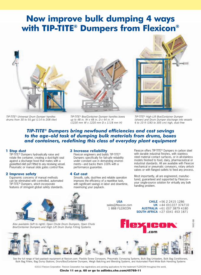
TIP-TITE® Universal Drum Dumper handles drums from 30 to 55 gal (114 to 208 liter)
TIP-TITE® Box/Container Dumper handles boxes up to 48 in. W x 48 in. D x 44 in. H (1220 mm W x 1220 mm D x 1118 mm H)
TIP-TITE® High-Lift Box/Container Dumper (shown) and Drum Dumper discharge into vessels 6 to 10 ft (183 to 305 cm) high, dust-free
Now improve bulk dumping 4 ways with TIP-TITE® Dumpers from Flexicon®
BB
-0366
.com
See the full range of fast-payback equipment at flexicon.com: Flexible Screw Conveyors, Pneumatic Conveying Systems, Bulk Bag Unloaders, Bulk Bag Conditioners, Bulk Bag Fillers, Bag Dump Stations, Drum/Box/Container Dumpers, Weigh Batching and Blending Systems, and Automated Plant-Wide Bulk Handling Systems
©2013 Flexicon Corporation. Flexicon Corporation has registrations and pending applications for the trademark FLEXICON throughout the world.
CHILE
UK
AUSTRALIA
SOUTH AFRICA
+56 2 2415 1286+44 (0)1227 374710+61 (0)7 3879 4180+27 (0)41 453 1871
USA
[email protected] 1 888 FLEXICON
TIP-TITE® Dumpers bring newfound efficiencies and cost savings to the age-old task of dumping bulk materials from drums, boxes and containers, redefining this class of everyday plant equipment
Also available (left to right): Open Chute Drum Dumpers, Open ChuteBox/Container Dumpers and High Lift Drum Dump Filling Systems
1 Stop dustTIP-TITE® Dumpers hydraulically raise androtate the container, creating a dust-tight sealagainst a discharge hood that mates with a gasketted inlet port fitted to any receiving vessel.Pneumatic or manual slide gates control flow.
2 Improve safetyErgonomic concerns of manual methods can be eliminated with controlled, automated TIP-TITE® Dumpers, which incorporate features of stringent global safety standards.
3 Increase reliabilityFlexicon engineers and builds TIP-TITE®
Dumpers specifically for fail-safe reliabilityunder constant use in demanding environ-ments—and backs them 100% with a performance guarantee.
4 Cut costSmooth, safe, dust-free and reliable operationimproves the efficiency of a repetitive task, with significant savings in labor and downtime,maximizing your payback.
Flexicon offers TIP-TITE® Dumpers in carbon steelwith durable industrial finishes, with stainless steel material contact surfaces, or in all-stainless models finished to food, dairy, pharmaceutical orindustrial standards. All are available with Flexiconmechanical or pneumatic conveyors, rotary airlockvalves or with flanged outlets to feed any process.
Most importantly, all are engineered, manufac-tured, guaranteed and supported by Flexicon—your single-source solution for virtually any bulkhandling problem.
Circle 11 on p. 60 or go to adlinks.che.com/45769-11
CHEMICAL ENGINEERING WWW.CHE.COM FEBRUARY 2013 1
FEBRUARY 2013 VOLUME 120, NO. 2
COVER STORY
35 Cover Story Sizing Calculations for Pressure-Relief Valves
A universal mass-flux equation can improve sizing calculations for pres-
sure-relief valves with non-ideal fluids
NEWS
11 Chementator This pipe-cladding process applies corrosion-resistant
coatings faster; A process for recovering rare-earth metals from mag-
net scrap; Oxidation-based water-reuse technology that improves mass
transfer; Spun carbon-nanotube fibers; and more
17 Newsfront Phosphorus Recovery on the Move
Instead of removing phosphates from waste streams, technology is now
emerging to recover this vital resource
23 Newsfront Taming the CPI’s Energy Beast
Motors are notorious energy users, but advanced motor and drive tech-
nologies can help increase efficiency in the plant
ENGINEERING
32a Facts at Your Fingertips Steam-System Water Preparation
This one-page reference sheet outlines water-treatment
requirements for various steam pressures
33 Technology Profile Propylene Production via Propane
Dehydrogenation The newest addition to Chemical Engineering
— this one-page profile describes the technology for propane
dehydrogenation (PDH)
40 Feature Report Environmental Permitting for Dryers and Kilns
Production of shale gas proppants is one area fueling installation of
these units. Understand the equipment selection and regulatory hurdles
43 Engineering Practice Sizing, Specifying and Selecting
Centrifugal Pumps Follow these tips to determine preliminary
pump sizing to support cost-estimation efforts
48 Engineering Practice Accelerating Process and Product
Development These simple strategies can be used to speed up
and increase the success rates of R&D projects
www.che.com
35
17
23

Eclipse.magnetrol.com•1-800-624-8765•[email protected]

The dawn of a new standard
in level control.Prepare for a total ECLIPSE® of current level and interface control
solutions. With superior signal performance, powerful diagnostics and
a full line of overfill capable probes, Magnetrol’s ECLIPSE Model 706
guided wave radar transmitter delivers unprecedented reliability.
From routine water storage applications to process media exhibiting
corrosive vapors, foam, steam, buildup, agitation, bubbling or boiling,
the ECLIPSE Model 706 will take your operation to a new level of
safety and process performance.
Contact Magnetrol – the guided wave radar innovator
and level control expert – to learn more about the
ECLIPSE Model 706.
Eclipse.magnetrol.com•1-800-624-8765•[email protected]
Circle 15 on p. 60 or go to adlinks.che.com/45769-15
4 CHEMICAL ENGINEERING WWW.CHE.COM FEBRUARY 2013
EQUIPMENT & SERVICES
26 Focus on Software
This process software’s new version includes solids modeling; Com-
bine equipment modeling and reaction engineering; This valve-sizing
software has new calculations modules; A workflow approach guides
non-experts with this software; Performance monitoring added to this
sorting software; and more
28 New Products This little valve has a zirconia ball and seat; A compact
flowmeter that has no moving parts; Slash silo mixing times with this
open mixing screw; PES nanofleece prefilters for the biopharmaceutical
industry; Increasing the sensitivity of trace-element analysis; A tempera-
ture sensor designed for pipe surfaces; This syringe pump delivers con-
tinuous, smooth flow; This vibrating switch handles extreme conditions;
and more
COMMENTARY
7 Editor’s Page A partnership for process understanding Chemical
Engineering introduces a new section in this month’s issue — Technology
Profile
56 The Fractionation Column
Opportunities for recent grads Referencing the Plant Managers’ Round-
table held at ChemInnovations this past November, the author discusses op-
portunities for chemical engineers
DEPARTMENTS
8 Letters
9 Calendar
62 Who’s Who
60 Reader Service
63 Economic Indicators
ADVERTISERS
58 Product Showcase
59 Classified Advertising
61 Advertiser Index
COMING IN MARCH
Look for: Feature Reports on Corrosion; and Heat Transfer Fluids; an Engi-
neering Practice article on Turbines; an Environmental Manager article on
Responding to a Regulatory Agency Inspection; a Focus on Pumps; and a sec-
ond Focus on Bins, Silos and Storage; News articles on Polymer Processing;
and Professional Engineer Requirements; and more
Cover: David Whitcher
*ONLY ON CHE.COM
Look for Latest News; additional
New Products; and more
40
28
26

P.O.Box151027•Dallas,TX75315-1027•1.800.527.2116•www.sssdynamics.com
Findoutwhat’sinitforyou
atwww.sssdynamics.comor
1-800-527-2116.
The New Longhorn Fine Mesh ScreenerfromTriple/SDynamicsisbasedonasimpledesign.
Lessismore.
No large spare parts investment.
Mechanicallysimplewithveryfewmovingparts.
Really.
Very low vibration transmission.
Onlythescreenclothvibrates.
Very low energy consumption.
TheLonghornispoweredbytwomotors
typically1/3HPeach.
No screening blinding.
Innovativeburstcyclekeeps
thescreenfreefromblinding.
The Longhorn Fine Mesh Screener
can screen down to 325 mesh.
Typical applications include
screening frac sand, foundry
sand, glass cullet, salt, sugar,
lime, dry clay, fertilizer, fly ash,
iron powders, and flours.
20131888 CELEBRATING 125 YEARS
Circle 20 on p. 60 or go to adlinks.che.com/45769-20

What Bear discovered:
Detailed consultation in preliminary stages
of production ensures that steel belts from
Berndorf Band meet all requirements set
by the customer, e.g.
• excellent mechanical, physical and
geometric properties
• high corrosion resistance, even in
extremely aggressive atmosphere
• perfect adhesion of vee-ropes Berndorf Band GmbHA-2560 BerndorfAustriaPhone: (+43)2672-800-0Fax: (+43)[email protected]
Detailed information at
www.berndorf-band.at
Berndorf Band offers customized steel belts for each application
Circle 5 on p. 60 or go to adlinks.che.com/45769-05
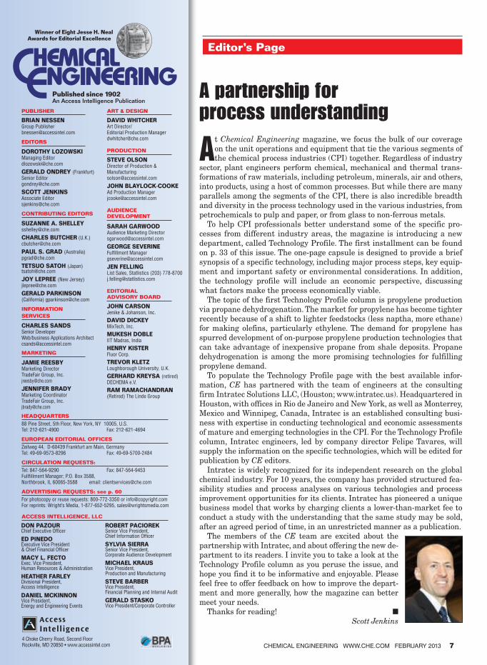
Editor’s Page
At Chemical Engineering magazine, we focus the bulk of our coverage
on the unit operations and equipment that tie the various segments of
the chemical process industries (CPI) together. Regardless of industry
sector, plant engineers perform chemical, mechanical and thermal trans-
formations of raw materials, including petroleum, minerals, air and others,
into products, using a host of common processes. But while there are many
parallels among the segments of the CPI, there is also incredible breadth
and diversity in the process technology used in the various industries, from
petrochemicals to pulp and paper, or from glass to non-ferrous metals.
To help CPI professionals better understand some of the specific pro-
cesses from different industry areas, the magazine is introducing a new
department, called Technology Profile. The first installment can be found
on p. 33 of this issue. The one-page capsule is designed to provide a brief
synopsis of a specific technology, including major process steps, key equip-
ment and important safety or environmental considerations. In addition,
the technology profile will include an economic perspective, discussing
what factors make the process economically viable.
The topic of the first Technology Profile column is propylene production
via propane dehydrogenation. The market for propylene has become tighter
recently because of a shift to lighter feedstocks (less naptha, more ethane)
for making olefins, particularly ethylene. The demand for propylene has
spurred development of on-purpose propylene production technologies that
can take advantage of inexpensive propane from shale deposits. Propane
dehydrogenation is among the more promising technologies for fulfilling
propylene demand.
To populate the Technology Profile page with the best available infor-
mation, CE has partnered with the team of engineers at the consulting
firm Intratec Solutions LLC, (Houston; www.intratec.us). Headquartered in
Houston, with offices in Rio de Janeiro and New York, as well as Monterrey,
Mexico and Winnipeg, Canada, Intratec is an established consulting busi-
ness with expertise in conducting technological and economic assessments
of mature and emerging technologies in the CPI. For the Technology Profile
column, Intratec engineers, led by company director Felipe Tavares, will
supply the information on the specific technologies, which will be edited for
publication by CE editors.
Intratec is widely recognized for its independent research on the global
chemical industry. For 10 years, the company has provided structured fea-
sibility studies and process analyses on various technologies and process
improvement opportunities for its clients. Intratec has pioneered a unique
business model that works by charging clients a lower-than-market fee to
conduct a study with the understanding that the same study may be sold,
after an agreed period of time, in an unrestricted manner as a publication.
The members of the CE team are excited about the
partnership with Intratec, and about offering the new de-
partment to its readers. I invite you to take a look at the
Technology Profile column as you peruse the issue, and
hope you find it to be informative and enjoyable. Please
feel free to offer feedback on how to improve the depart-
ment and more generally, how the magazine can better
meet your needs.
Thanks for reading! ■ Scott Jenkins
A partnership for process understanding
Winner of Eight Jesse H. Neal Awards for Editorial Excellence
Published since 1902An Access Intelligence Publication
PUBLISHER
BRIAN NESSEN Group [email protected]
EDITORS
DOROTHY LOZOWSKIManaging [email protected]
GERALD ONDREY (Frankfurt)Senior [email protected]
SCOTT JENKINSAssociate [email protected]
CONTRIBUTING EDITORS
SUZANNE A. [email protected]
CHARLES BUTCHER (U.K.)[email protected]
PAUL S. GRAD (Australia)[email protected]
TETSUO SATOH (Japan)[email protected]
JOY LEPREE (New Jersey)[email protected]
GERALD PARKINSON (California) [email protected]
INFORMATION
SERVICES
CHARLES SANDSSenior DeveloperWeb/business Applications [email protected]
MARKETING
JAMIE REESBYMarketing DirectorTradeFair Group, [email protected]
JENNIFER BRADYMarketing Coordinator TradeFair Group, Inc. [email protected]
ART & DESIGN
DAVID WHITCHERArt Director/Editorial Production [email protected]
PRODUCTION
STEVE OLSONDirector of Production & [email protected]
JOHN BLAYLOCK-COOKEAd Production [email protected]
AUDIENCE DEVELOPMENT
SARAH GARWOODAudience Marketing [email protected]
GEORGE SEVERINE Fulfillment [email protected]
JEN FELLING List Sales, Statlistics (203) [email protected]
EDITORIAL ADVISORY BOARD
JOHN CARSONJenike & Johanson, Inc.
DAVID DICKEYMixTech, Inc.
MUKESH DOBLEIIT Madras, India
HENRY KISTERFluor Corp.
TREVOR KLETZLoughborough University, U.K.
GERHARD KREYSA (retired)DECHEMA e.V.
RAM RAMACHANDRAN (Retired) The Linde Group
CHEMICAL ENGINEERING WWW.CHE.COM FEBRUARY 2013 7
HEADQUARTERS
88 Pine Street, 5th Floor, New York, NY 10005, U.S.Tel: 212-621-4900 Fax: 212-621-4694
EUROPEAN EDITORIAL OFFICES
Zeilweg 44, D-60439 Frankfurt am Main, GermanyTel: 49-69-9573-8296 Fax: 49-69-5700-2484
CIRCULATION REQUESTS:
Tel: 847-564-9290 Fax: 847-564-9453Fullfillment Manager; P.O. Box 3588, Northbrook, IL 60065-3588 email: [email protected]
ADVERTISING REQUESTS: see p. 60
For photocopy or reuse requests: 800-772-3350 or [email protected] reprints: Wright’s Media, 1-877-652-5295, [email protected]
ACCESS INTELLIGENCE, LLC
DON PAZOURChief Executive Officer
ED PINEDOExecutive Vice President & Chief Financial Officer
MACY L. FECTOExec. Vice President, Human Resources & Administration
HEATHER FARLEYDivisional President, Access Intelligence
DANIEL MCKINNON Vice President, Energy and Engineering Events
ROBERT PACIOREKSenior Vice President, Chief Information Officer
SYLVIA SIERRASenior Vice President, Corporate Audience Development
MICHAEL KRAUSVice President, Production and Manufacturing
STEVE BARBERVice President, Financial Planning and Internal Audit
GERALD STASKOVice President/Corporate Controller
4 Choke Cherry Road, Second FloorRockville, MD 20850 • www.accessintel.com
Honoring pump users
ITT Goulds Pumps is now accepting nominations for the
Heart of Industry Award and the Pulse of Industry Honor
Roll. These recognition programs were developed as part
of Pump Appreciation Day — a worldwide celebration of
pumps as the heart of industry that will take place Tues-
day, April 9.
“Pumps function as the heart of industry, and it’s a plea-
sure for ITT Goulds Pumps to honor the talented people
and organizations that keep pumps running smoothly and
efficiently,” says Robert J. Pagano Jr., president of the ITT
Industrial Process business, which includes ITT Goulds
Pumps. “We hope to recognize as many of these hard-
working organizations and individuals as we can, and look
forward to celebrating honorees as part of the second an-
nual Pump Appreciation Day.”
The Heart of Industry Award recognizes industrial
operations for excellence in using pump technology to
improve plant processing, satisfy customers and enhance
our modern way of life. Honors will go to companies or
plants nominated by ITT Goulds Pumps sales offices and
distributors, with a limit of one award-winner per office.
Organizations using ITT Goulds Pumps products and
services are encouraged to contact their distributors to
learn more.
Anyone in a pump-related industry has the opportunity
to submit nominations for the Pulse of Industry Honor
Roll. This individual recognition program is intended for
people who want to commend co-workers and colleagues
for their exceptional work in pump operations, mainte-
nance or optimization.
A brief online nomination form is available at www.
pumpappreciationday.com. Nominators have the option to
include a photo and a short story about the nominee. Cri-
teria for being honored include:
• Improving pump efficiency• Providing outstanding maintenance• Solving engineering or manufacturing challenges• Exceeding expectations and providing extra effort to keep pumps running
• Exemplifying high-quality customer serviceNominations must be submitted by Friday, March 1. Fol-
lowing an internal review process, officials at ITT Goulds
Pumps will add honorees’ names to the Honor Roll on
www.pumpappreciationday.com. Chosen nominees for the
Heart of Industry Award and the Pulse of Industry Honor
Roll will be notified by email and will also receive special
recognition on Pump Appreciation Day.
Margaret GanDirector of Communications for ITT Industrial Process
Letters
Do you have — • Ideas to air? • Feedback about our articles?• Comments about today’s engineering practice or education?• Job-related problems or gripes to share?If so — Send them, for our Letters column, to
Dorothy Lozowski Chemical Engineering, Access Intelligence, 88 Pine St., 5th floorNew York, NY 10005; [email protected]
8 CHEMICAL ENGINEERING WWW.CHE.COM FEBRUARY 2013
The �rst high performance rupture disc
manufactured with the newest technology
FIND OUT OUR NEW GENERATION RUPTURE DISCS!
SCR/ - SCD/ - Y90/
Circle 9 on p. 60 or go to adlinks.che.com/45769-09

CHEMICAL ENGINEERING WWW.CHE.COM FEBRUARY 2013 9
Calendar
NORTH AMERICADCAT Week 2013. Drug, Chemical and Associated
Technologies Assn. (Robbinsville, N.J.). Phone: 609-448-
1000; Web: dcat.org
New York, N.Y. March 11–14
Corrosion 2013. National Assn. of Corrosion Engineers
(Houston). Phone: 800-797-6223; Web: events.nace.org
Orlando, Fla. March 17–21
AFPM Annual Meeting. American Fuel and
Petrochemical Manufacturers (AFPM; Washington, D.C.).
Phone: 202-457-0480; Web: afpm.org
San Antonio, Tex. March 17–19
American Chemical Soc. (ACS) National Meeting
and Exposition. ACS (Washington, D.C.). Phone:
202-872-4600 Web: acs.org
New Orleans, La. April 7–11
Interphex 2013. Reed Exhibitions (Norwalk, Conn.).
Phone: 203-840-5648; Web: interphex.com
New York, N.Y. April 23–25
AIChE 2013 Spring Meeting and 9th Global
Congress on Process Safety. AIChE (New York, N.Y.).
Phone: 800-242-4363; Web: aiche.org
San Antonio, Tex. April 28–May 2
International Refinery Energy Power (IREP)
Conference. Hydrocarbon Publishing Co. (Philadelphia,
Pa.). Phone: 610-408-0116; Web: irepconference.com
Houston May 1–3
AspenTech Optimize 2013 Global Conference.
Aspen Technology (Burlington, Mass.). Phone: 855-882-
7736; Web: aspentech.com/agc/
Boston, Mass. May 6–8
7th Annual ACEEE Energy Efficiency Finance
Forum. American Council for an Energy-Efficient
Economy (ACEEE; Washington, D.C.). Phone:
202-507-4000; Web: aceee.org/conferences/2013/eeff
Portland, Ore. May 13–15
15th Annual Electric Power Conference and
Exhibition. Tradefair Group, an Access Intelligence LLC
Co. (Houston). Phone: 832-242-1969; Web:
electricpowerexpo.com
Chicago, Ill. May 14–16
Circle 1 on p. 60 or go to adlinks.che.com/45769-01
10 CHEMICAL ENGINEERING WWW.CHE.COM FEBRUARY 2013
AFPM Reliability & Maintenance Conference and
Exibition 2013 . American Fuel and Petrochemical
Manufacturers (AFPM; Washington, D.C.). Phone:
202-457-0480; Web: afpm.org
Chicago, Ill. May 14–16
AWMA Annual Conference. Air & Waste Management
Assn. (Pittsburgh, Pa.). Phone: 412-232-3450; Web:
awma.org
Chicago, Ill. June 25–28
EUROPEGlobal ManuChem Strategies 2013. We-Conect
Global Leaders GmbH (Berlin, Germany). Phone:
+49-30-5210-703; Web: we-conect.com
Berlin, Germany February 25–26
PVC Formulation 2013. Applied Market Information
LLC (Wyomissing, Pa.). Phone: 610-478-0800;
Web: amiplastics-na.com
Düsseldorf, Germany March 12–14
Powtech. Nuremberg Messe (Nuremberg, Germany).
Phone: +49-911-8606-8355; Web: powtech.de/en/
Nuremberg, Germany April 23–25
11th Workshop on Polymer Reaction Engineering.
Dechema e.V. (Frankfurt am Main, Germany). Phone:
+ 49-69-7564-0; Web: dechema.de/pre2013
Hamburg, Germany May 21–24
21st European Biomass Conference and
Exhibition. ETA Florence Renewable Energies (Florence,
Italy). Phone: +39-55-500-2280, ext. 221; Web:
conference-biomass.com
Copenhagen, Denmark June 3–7
ASIA & ELSEWHERE MasterBatch Asia 2013. Applied Market Information
LLC (Wyomissing, Pa.). Phone: 610-478-0800; Web:
amiplastics-na.com
Singapore March 18–20
World Coal-to-Liquids (CTL) 2013. World CTL
(Paris). Phone: +33-607-28-5247; Web: world-ctl.com
Shanghai, China April 16–19
AchemAsia 2013. Dechema e.V. (Frankfurt am Main,
Germany). Phone: +49-69-7564-277; Web: achemasia.de
Beijing, China May 13–16 ■
Suzanne Shelley
Calendar
Cashco, Inc.
P.O. Box 6, Ellsworth, KS 67439-0006
Ph. (785) 472-4461, Fax: (785) 472-3539
Think Product Innovation. Think Cashco Control
Valves.Whether specifying new or
searching for a replacement,
Cashco control valves and regulators
define industry standards for quality,
d e p e n d a b i l i t y a n d e n v i r o n m e n t a l
responsibility. The 2296 features the new
C27 actuator that can be coupled to any one
of several assemblies or valve body models.
This allows you to use a “single” actuator
design for multiple products. This in turn
helps customers reduce inventory levels and
ultimately lower costs.
Call today and ask for
one of our sales
representatives.
Learn irst hand
why we say our
quality is only
surpassed by the
service we provide.
www.cashco comInnovative Solutions
Model 2296
Circle 6 on p. 60 or go to adlinks.che.com/45769-06
Researchers at the U.S. Dept. of Energy’s
(DOE) Ames Laboratory (Ames, Iowa;
www.ameslab.gov) led by Ryan Ott have
developed a process for recovering rare-
earth (RE) metals from magnet scraps.
The process involves fi rst crushing neo-
dymium-iron-boron magnet scraps and
placing the pieces in a stainless steel
crucible, to which chunks of magnesium
metal are added. The apparatus is heated
in a specially modifi ed radio-frequency
furnace, which melts the magnesium and
promotes stirring, thereby speeding dif-
fusion. Ames Laboratory’s Ott explains
that since RE metals have good solubility
in molten magnesium, they diffuse out of
the magnet material and into the molten
magnesium, while iron and boron, which
have negligible solubility in magnesium,
remain behind. Following the casting of
the Mg-RE alloy, the magnesium is re-
moved by vacuum distillation so that it
can be used for another round of melting,
and the rare-earth metal is isolated.
The team reports that permanent mag-
nets made with recycled RE metals have in-
trinsic properties similar to permanent mag-
nets synthesized from RE metal ore. Ott’s
current project builds on knowledge gained
in a 1990s-era Ames Laboratory project for
using RE metals in magnesium alloys.
Ott says his team of researchers has dem-
onstrated the process on 2 kg of scrap at a
time, and is working on optimizing the ex-
traction by experimenting with Mg-to-scrap
ratios, processing time and temperatures.
The team is also working on scaling up the
process by an order of magnitude.
A process for recovering rare-earth metals from magnet scrap
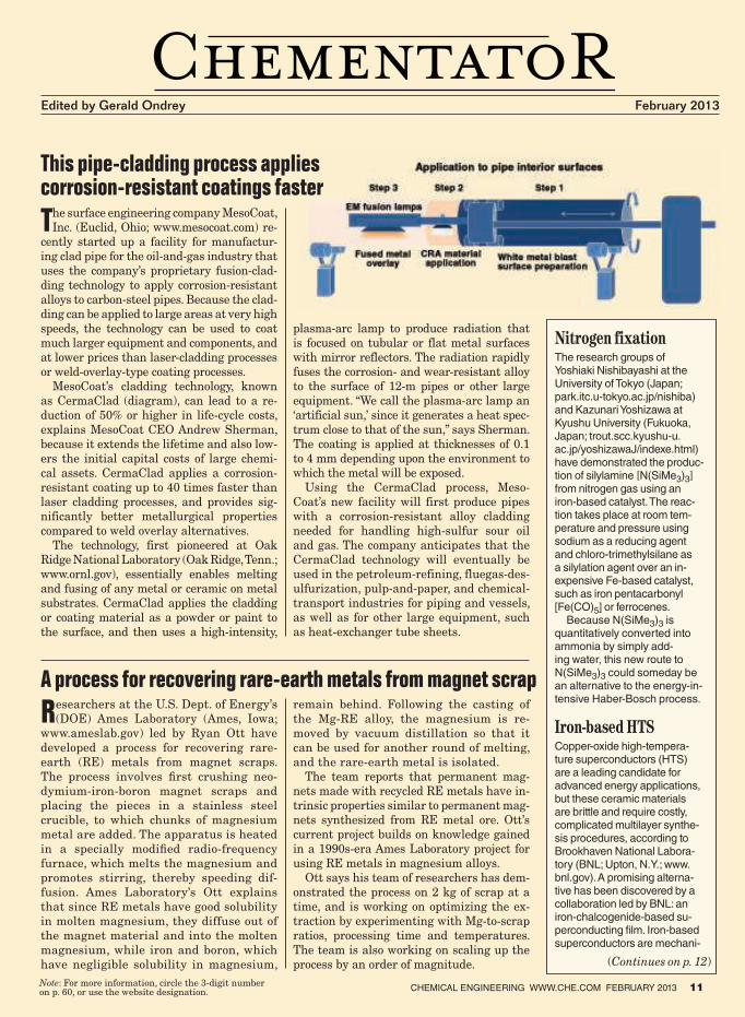
The surface engineering company MesoCoat,
Inc. (Euclid, Ohio; www.mesocoat.com) re-
cently started up a facility for manufactur-
ing clad pipe for the oil-and-gas industry that
uses the company’s proprietary fusion-clad-
ding technology to apply corrosion-resistant
alloys to carbon-steel pipes. Because the clad-
ding can be applied to large areas at very high
speeds, the technology can be used to coat
much larger equipment and components, and
at lower prices than laser-cladding processes
or weld-overlay-type coating processes.
MesoCoat’s cladding technology, known
as CermaClad (diagram), can lead to a re-
duction of 50% or higher in life-cycle costs,
explains MesoCoat CEO Andrew Sherman,
because it extends the lifetime and also low-
ers the initial capital costs of large chemi-
cal assets. CermaClad applies a corrosion-
resistant coating up to 40 times faster than
laser cladding processes, and provides sig-
nificantly better metallurgical properties
compared to weld overlay alternatives.
The technology, first pioneered at Oak
Ridge National Laboratory (Oak Ridge, Tenn.;
www.ornl.gov), essentially enables melting
and fusing of any metal or ceramic on metal
substrates. CermaClad applies the cladding
or coating material as a powder or paint to
the surface, and then uses a high-intensity,
plasma-arc lamp to produce radiation that
is focused on tubular or flat metal surfaces
with mirror reflectors. The radiation rapidly
fuses the corrosion- and wear-resistant alloy
to the surface of 12-m pipes or other large
equipment. “We call the plasma-arc lamp an
‘artificial sun,’ since it generates a heat spec-
trum close to that of the sun,” says Sherman.
The coating is applied at thicknesses of 0.1
to 4 mm depending upon the environment to
which the metal will be exposed.
Using the CermaClad process, Meso-
Coat’s new facility will first produce pipes
with a corrosion-resistant alloy cladding
needed for handling high-sulfur sour oil
and gas. The company anticipates that the
CermaClad technology will eventually be
used in the petroleum-refining, fluegas-des-
ulfurization, pulp-and-paper, and chemical-
transport industries for piping and vessels,
as well as for other large equipment, such
as heat-exchanger tube sheets.
Note: For more information, circle the 3-digit number on p. 60, or use the website designation.
Edited by Gerald Ondrey February 2013
Nitrogen fixationThe research groups of Yoshiaki Nishibayashi at the University of Tokyo (Japan; park.itc.u-tokyo.ac.jp/nishiba) and Kazunari Yoshizawa at Kyushu University (Fukuoka, Japan; trout.scc.kyushu-u.ac.jp/yoshizawaJ/indexe.html) have demonstrated the produc-tion of silylamine [N(SiMe3)3] from nitrogen gas using an iron-based catalyst. The reac-tion takes place at room tem-perature and pressure using sodium as a reducing agent and chloro-trimethylsilane as a silylation agent over an in-expensive Fe-based catalyst, such as iron pentacarbonyl [Fe(CO)5] or ferrocenes.
Because N(SiMe3)3 is quantitatively converted into ammonia by simply add-ing water, this new route to N(SiMe3)3 could someday be an alternative to the energy-in-tensive Haber-Bosch process.
Iron-based HTSCopper-oxide high-tempera-ture superconductors (HTS) are a leading candidate for advanced energy applications, but these ceramic materials are brittle and require costly, complicated multilayer synthe-sis procedures, according to Brookhaven National Labora-tory (BNL; Upton, N.Y.; www.bnl.gov). A promising alterna-tive has been discovered by a collaboration led by BNL: an iron-chalcogenide-based su-perconducting � lm. Iron-based superconductors are mechani-
CHEMICAL ENGINEERING WWW.CHE.COM FEBRUARY 2013 11
(Continues on p. 12)
This pipe-cladding process applies corrosion-resistant coatings faster
CHEMENTATOR
For the first time, it has become pos-
sible to spin carbon nanotubes (CNTs)
into a fiber that looks and acts like textile
threads, yet has the electrical conductivity
and strength of a metal. The breakthrough,
which came after more than ten years of
research, was published in the January 11
issue of Science by scientists from Rice Uni-
versity (Houston; www.rice.edu), Teijin Ar-
amid B.V. (Arnhem, The Netherlands; www.
teijnaramid.com), the Air Force Research
Laboratory (Dayton, Ohio, www.afrl.af.mil)
and Technion-Israel Institute of Technology
(Haifa; www1.technion.ac.il).
The spinning process to make the CNT
fibers is similar to that used by Teijin for
making its Twaron aramid fibers. One key
to the achievement was finding the right
solvent for making concentrated solutions
of dissolved CNTs. To make the CNT fibers,
a concentrated solution of CNTs in the
superacid chlorosulfonic acid is extruded
through 19 tiny holes into a bath, where
the CNTs precipitate. Another key was en-
suring that the CNTs are perfectly aligned
and packed as they form the thread. Spools
of the fibers with 50-m length have been
produced and can be seen in a video on Rice
University’s website. Because the process
is based on industrially proven technology,
it is readily scalable.
The new fibers have about ten times the
tensile strength and electrical and thermal
conductivity of the best previously reported
wet-spun CNT fibers, according to Matteo
Pasquali, Rice professor of chemical and
biomolecular engineering and chemistry. The
fibers’ electrical conductivity is “on par with
copper, gold and aluminum.” “We finally have
a nanotube fiber with properties that don’t
exist in any other material,” he says.
The research was funded by Teijin Aramid
and its parent company, Teijin Ltd. Teijin
Aramid is currently trialing samples of CNT
fiber on a small scale with prospective cus-
tomers. The fiber is expected to have many
applications in aerospace, automotive, medi-
cal and “smart” clothing industries.
12 ChemiCal engineering www.Che.Com February 2013
cally semi-metallic, and thus considerably less fragile than the copper-based ceramic ilms, and can be more readily shaped into long wires needed for devices, says bnl.
The ilms — composed of iron, selenium and tellurium — are made by pulsed-laser deposition, which uses a high-power laser to vaporize materi-als that are collected in layers on a substrate. adding layers of cesium oxide in between the ilms and substrates was found to greatly enhance the hTS’ critical current density, as well as increase the critical tem-perature at which the material becomes superconducting.
Nuclear-waste sponge?Chemists from rice univer-sity and lomonosov moscow State university (russia; www.msu.ru) have shown that thin lakes of graphene oxide quickly adsorb radionuclides from wastewater and co-agulates into solids. The high surface area of the graphene oxide combined with gra-phene’s unique properties not only gives the material a high adsorption capacity for toxins, but also very fast reaction kinetics. with these superior properties, graphene oxide could be a better alternative than the bentonite clays and granulated activated carbon commonly used in nuclear cleanup. The researchers say the material could cut the cost of hydraulic fracturing for oil-and-gas recovery, as well as for treating wastewater from rare-earths and other mines.
Methane-to-dieselmotivating microbes to metabo-lize more methane into lipids, which can be processed into liquid diesel fuels, is the goal of a new research project led by the Doe’s national renewable research energy laboratory (nrel; golden, Colo.; www.nrel.gov). Participants in the $4.8-million arPa-e project (see also story on p. 15) include the university of washington (Seattle; www.washington.edu), Johnson matthey (london, u.K.; www.matthey.com) and lanzaTech (roselle, ill.; www.
(Continues on p. 14)
Spun carbon-nanotube fibers with unmatched properties of any other material
A water-recycling system for the oil-and-
gas industries developed by Ecosphere
Technologies Inc. (Stuart, Fla.; www.Eco-
sphereTech.com) is designed to destroy
bacteria and control corrosion in high-vol-
ume wastewater-treatment applications
using a proprietary oxidation process.
The technology, called Ozonix, improves
the mass-transfer efficiency of ozone with
a Venturi system in which negative pres-
sure created by high-velocity feed water
passing through the Venturi tube draws
ozone into the water more efficiently than
bubble diffusion. Once the O3 is drawn into
the water, the Ozonix system uses hydro-
dynamic and acoustic cavitation to create
tiny collapsing bubbles that convert the
O3 to hydroxyl radicals. Inside the Ozonix
reactor, the hydroxyl radicals destroy bac-
terial cell walls, and oxidize contaminants,
returning water that is ready for reuse in
future operations. The imploding bubble
phenomena cause localized heating of the
water to over 900°F. The Ozonix system
also has a specially designed electrochemi-
cal cell that precipitates metal salts and
removes scale-forming compounds.
Covered by multiple patents, the Ozo-
nix system is integrated into a custom-
designed, 53-ft trailer that can be trans-
ported onto an oil-and-gas hydraulic
fracturing site or to the site of another
industrial water application, such as min-
ing, agriculture, municipal wastewater
and renewable energy.
By eliminating the need for liquid chem-
icals, the Ozonix technology reduces op-
erating costs, since no secondary waste is
created, explains George Chapas, director
of business development at Ecosphere. The
Ozonix system processes water in realtime
(no significant residence time) at flowrates
up to 5,000 gal/min. It has been used in
all major shale plays in the U.S. on over 2
billion gallons of water, with chemistries
typical of hydraulic-fracturing flowback
water and produced water from more than
600 oil and natural gas wells.
Oxidation-based water-reuse technology that improves mass transfer
(Continued from p. 11)
PERFORMANCEH ig
h-Con t ras t V isua l Ind ica t ion +
Integrated Guided Wave Radar
THE ORIGINAL INNOVATORS
The patented Aurora® magnetic level indicator from Orion Instruments®
provides high-visibility local indication while supplying real-time Guided Wave Radar digital feedback to the control room.
This combination of application-proven technologies relies on completely different properties
of the liquid (density and dielectric), therefore providing
you a safety net of redundancy...all in a single device.
Magnetic Float
GWR Probe
Perforated Bafle
┘┘┘くラヴキラミキミゲデヴ┌マWミデゲくIラマ ひ ヲヱヰヵ O;ニ Vキノノ; Bラ┌ノW┗;ヴS ひ B;デラミ Rラ┌ェWが Lラ┌キゲキ;ミ; ひ ΑヰΒヱヵ ひ ΒヶヶどヵヵどORIONHARTイ キゲ ; ヴWェキゲデWヴWS デヴ;SWマ;ヴニ ラa デエW HART Cラママ┌ミキI;ピラミ Fラ┌ミS;ピラミく づ FOUNDATION gWノSH┌ゲゥ キゲ ; デヴ;SWマ;ヴニ ラa FキWノSH┌ゲ Fラ┌ミS;ピラミくOヴキラミ Iミゲデヴ┌マWミデゲが Oヴキラミ ノラェラデ┞ヮWが M;ェミWデヴラノ ノラェラデ┞ヮWが EIノキヮゲWが RW┗W;ノが ;ミS A┌ヴラヴ; ;ヴW ヴWェキゲデWヴWS デヴ;SWマ;ヴニゲ ラa M;ェミWデヴラノ IミデWヴミ;ピラミ;ノが IミIく
NOW
CエWマキI;ノ PヴラIWゲゲキミェPラ┘Wヴ GWミWヴ;ピラミOキノ わ G;ゲ PヴラS┌IピラミOキノ わ G;ゲ RWgミキミェ
W;ゲデW┘;デWヴ TヴW;デマWミデP┌ノヮ わ P;ヮWヴMキミキミェMキノキデ;ヴ┞
┘キS
W ┗キ
W┘ キ
ミSキI
;デラ
ヴaW
;デ┌ヴ
キミェ
Circle 22 on p. 60 or go to adlinks.che.com/45769-22
Composite liquid and slurry boiler fuels
have been produced from mixtures of var-
ious waste materials, such as biomass, coal-
and crude-oil-processing residues, wood and
other combustible substances, in a collabo-
ration between researchers at the Univer-
sity of Rhode Island (Kingston, R.I.) and
Podgorny Institute (Kharkov, Ukraine). The
researchers have formed a company, InEn-
ergy LLC (Naples, Fla.; www.inenergycorp.
com) and are seeking partners to scale up
the process. The technology promises to be
a low-cost source of composite fuels, as well
as a way to clean up the environment, says
Harold Knickle, vice president of InEnergy
and a professor of chemical engineering at
the University of Rhode Island.
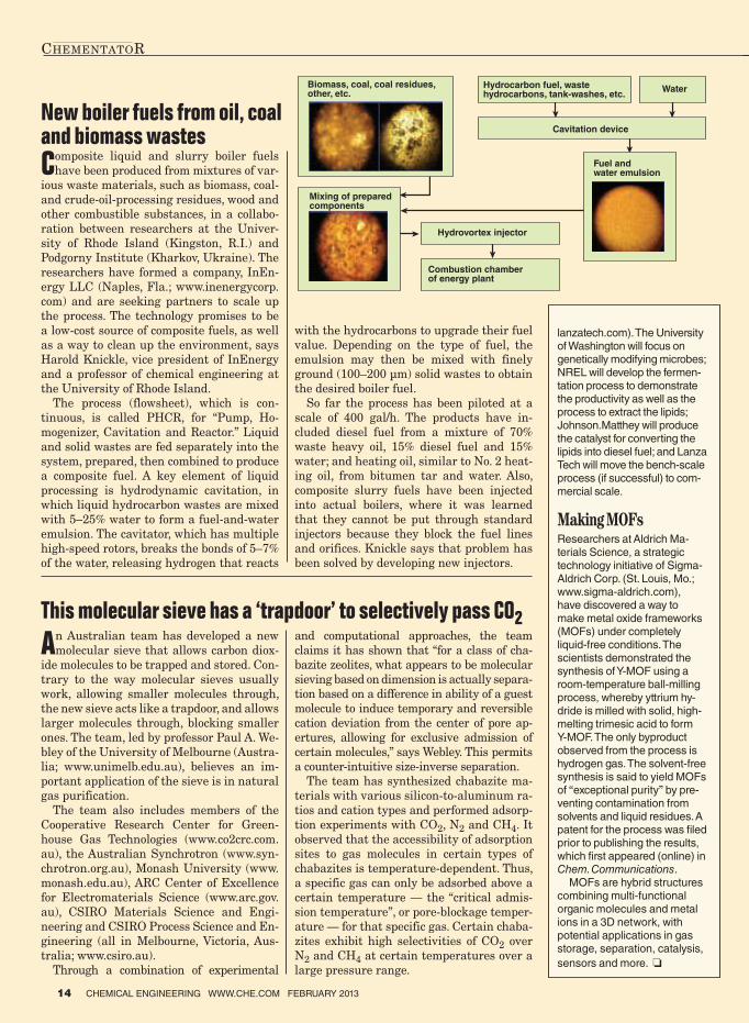
The process (flowsheet), which is con-
tinuous, is called PHCR, for “Pump, Ho-
mogenizer, Cavitation and Reactor.” Liquid
and solid wastes are fed separately into the
system, prepared, then combined to produce
a composite fuel. A key element of liquid
processing is hydrodynamic cavitation, in
which liquid hydrocarbon wastes are mixed
with 5–25% water to form a fuel-and-water
emulsion. The cavitator, which has multiple
high-speed rotors, breaks the bonds of 5–7%
of the water, releasing hydrogen that reacts
with the hydrocarbons to upgrade their fuel
value. Depending on the type of fuel, the
emulsion may then be mixed with finely
ground (100–200 µm) solid wastes to obtain
the desired boiler fuel.
So far the process has been piloted at a
scale of 400 gal/h. The products have in-
cluded diesel fuel from a mixture of 70%
waste heavy oil, 15% diesel fuel and 15%
water; and heating oil, similar to No. 2 heat-
ing oil, from bitumen tar and water. Also,
composite slurry fuels have been injected
into actual boilers, where it was learned
that they cannot be put through standard
injectors because they block the fuel lines
and orifices. Knickle says that problem has
been solved by developing new injectors.
An Australian team has developed a new
molecular sieve that allows carbon diox-
ide molecules to be trapped and stored. Con-
trary to the way molecular sieves usually
work, allowing smaller molecules through,
the new sieve acts like a trapdoor, and allows
larger molecules through, blocking smaller
ones. The team, led by professor Paul A. We-
bley of the University of Melbourne (Austra-
lia; www.unimelb.edu.au), believes an im-
portant application of the sieve is in natural
gas purification.
The team also includes members of the
Cooperative Research Center for Green-
house Gas Technologies (www.co2crc.com.
au), the Australian Synchrotron (www.syn-
chrotron.org.au), Monash University (www.
monash.edu.au), ARC Center of Excellence
for Electromaterials Science (www.arc.gov.
au), CSIRO Materials Science and Engi-
neering and CSIRO Process Science and En-
gineering (all in Melbourne, Victoria, Aus-
tralia; www.csiro.au).
Through a combination of experimental
and computational approaches, the team
claims it has shown that “for a class of cha-
bazite zeolites, what appears to be molecular
sieving based on dimension is actually separa-
tion based on a difference in ability of a guest
molecule to induce temporary and reversible
cation deviation from the center of pore ap-
ertures, allowing for exclusive admission of
certain molecules,” says Webley. This permits
a counter-intuitive size-inverse separation.
The team has synthesized chabazite ma-
terials with various silicon-to-aluminum ra-
tios and cation types and performed adsorp-
tion experiments with CO2, N2 and CH4. It
observed that the accessibility of adsorption
sites to gas molecules in certain types of
chabazites is temperature-dependent. Thus,
a specific gas can only be adsorbed above a
certain temperature — the “critical admis-
sion temperature”, or pore-blockage temper-
ature — for that specific gas. Certain chaba-
zites exhibit high selectivities of CO2 over
N2 and CH4 at certain temperatures over a
large pressure range.
This molecular sieve has a ‘trapdoor’ to selectively pass CO2
14 CHEMICAL ENGINEERING WWW.CHE.COM FEBRUARY 2013
CHEMENTATOR
lanzatech.com). The University of Washington will focus on genetically modifying microbes; NREL will develop the fermen-tation process to demonstrate the productivity as well as the process to extract the lipids; Johnson.Matthey will produce the catalyst for converting the lipids into diesel fuel; and Lanza Tech will move the bench-scale process (if successful) to com-mercial scale.
Making MOFsResearchers at Aldrich Ma-terials Science, a strategic technology initiative of Sigma-Aldrich Corp. (St. Louis, Mo.; www.sigma-aldrich.com), have discovered a way to make metal oxide frameworks (MOFs) under completely liquid-free conditions. The scientists demonstrated the synthesis of Y-MOF using a room-temperature ball-milling process, whereby yttrium hy-dride is milled with solid, high-melting trimesic acid to form Y-MOF. The only byproduct observed from the process is hydrogen gas. The solvent-free synthesis is said to yield MOFs of “exceptional purity” by pre-venting contamination from solvents and liquid residues. A patent for the process was � led prior to publishing the results, which � rst appeared (online) in Chem. Communications.
MOFs are hybrid structures combining multi-functional organic molecules and metal ions in a 3D network, with potential applications in gas storage, separation, catalysis,
sensors and more. ❏
New boiler fuels from oil, coal and biomass wastes
Biomass, coal, coal residues, other, etc.
Mixing of prepared components
Hydrocarbon fuel, waste hydrocarbons, tank-washes, etc.
Water
Cavitation device
Fuel and water emulsion
Hydrovortex injector
Combustion chamber of energy plant

An electrochemical process that could cut the energy and cost requirements for stripping carbon dioxide from
stack gases by half is being developed at Arizona State Uni-versity (ASU, Tempe; www.asu.edu). At present the only commercially viable technology is CO2 absorption by mo-noethanolamine (MEA), says Dan Buttry, chair of ASU’s De-partment of Chemistry and Biochemistry. However, he notes that a recent report from the U.S. Dept. of Energy (DOE; Washington, D.C.; www.energy.gov) says the thermal energy to regenerate MEA consumes roughly 40% of total power plant output and increases the cost of electricity by 85%.
In contrast, ASU’s system — which has similarities to a fuel cell — uses only a small voltage difference (about 0.5 V) to capture and release CO2, with no temperature cycle. The system consists of two porous carbon electrodes, separated by a polymer membrane. Gases are fed through a serpentine channel across the face of the cathode, which is impregnated with an ionic liquid containing reagent precursors. These are reduced to nucleophiles at the cath-ode and react with CO2 to form adducts. The adducts pass through the membrane and are oxidized at the anode to recover CO2, while the precursor returns to the cathode.
A novel element in the process is that the adduct is a type of thiocarbonate that “is barely known in the litera-ture,” says Buttry. So far, he says, the process has been tested in the laboratory, using “clean” gas that contains CO2. Now the university is planning to start tests using flue gas under a $612,000 grant from DOE’s Advanced Re-search Projects Agency-Energy (ARPA-E).
Electrochemistry may have a future in CO2 cleanup
Continuous production of ‘Bio-cokes’
Kinki University (www.kindai.ac.jp) and Naniwa Roki Co. (both Osaka, Japan; www.naniwaroki.co.jp) have devel-
oped a continuous process for producing a next-generation solid fuel, called Bio-cokes. The process is being used at a new production facility located at Kinki University Re-search Institute of Bio-cokes (Eniwa City, Hokkaido), estab-lished last December. The new facility has four times the capacity and requires one fifth the energy as the existing batch-type production facility, which started up in 2011.
The previous production method required many steps, including filling and compressing of raw materials into the cylindrical reactor, heating and cooling of the compressed materials within the cylinder, removing and then cutting the Bio-cokes products into pieces. Now, the researchers have adopted a piston-flow process that performs all the steps continuously. The continuous process has improved heating capabilities for reducing the energy consumption. The facility, with 36 cylindrical reactors, can produce 28 ton/d of Bio-cokes.
The process converts biomass, such as waste coffee grain and tea leaves into Bio-cokes, which can be used as re-placements for coal-derived coke. Using Kinki University technology, Osaka Prefecture Forest Owners Assn. already started the world’s first commercial production of Bio-cokes
A01
120
EN
Partner with
the Best
With over 50 independent subsidiar-ies and more than 220 engineering and sales offi ces spread across the world, SAMSON ensures the safety and environmental compatibility of your plants on any continent.
To offer the full range of high-quality control equipment used in industrial processes, SAMSON has brought together highly specialized compa-nies to form the SAMSON GROUP.
SAMSON AG · MESS- UND REGELTECHNIK Weismüllerstraße 360314 Frankfurt am Main · GermanyPhone: +49 69 4009-0 · Fax: +49 69 4009-1507 E-mail: [email protected] · www.samson.deSAMSON GROUP · www.samsongroup.net
Cir
cle
19
on
p. 6
0 o
r g
o t
o a
dlin
ks.c
he
.co
m/4
57
69
-19
(Continues on p. 16)
CHEMENTATOR
One of the current methods for dealing
with oil spills is through the use of
dispersants. These dispersants, however,
break oil into small globules that sink
into the water, spreading the oil into a
wider area, and they have toxic effects
on the local marine ecosystem. Now,
researchers, led by professor Moses O.
Tade at the Dept. of Chemical Engineer-
ing at Curtin University (Perth, Western
Australia; www.curtin.edu.au), have de-
veloped a cleaner method for treating oil
spills — the “floating droplet solution”.
The researchers studied (theoretically
and experimentally) the floatability of
water on an oil surface. Their numerical
model was developed from the Young-
Laplace equation on three interfaces
(water/oil, water/air and oil/air) to calcu-
late the theoretical equilibrium. Accord-
ing to the researchers, the model com-
pared well with experimental data of a
water/vegetable-oil system.
They showed that water droplets can
float on an oil surface due to a combina-
tion of interfacial tensions and buoyancy,
up to a certain volume. The equilibrium
contact angle should be greater than 5
deg. in order for a water droplet to float.
A potential application of the phenom-
enon involves using small water droplets
on oil spills floating in the ocean to fa-
cilitate aerobic biodegradation. The effi-
ciency of oil biodegradation depends on
the level of dissolved oxygen, water-oil
interfacial area, and bacterial/nutrient
availability. Since most oils are lighter
than water, these tend to cover the water
surface and prevent atmospheric oxygen
from dissolving into the water. Small
water droplets can have a large water-oil
contact area as well as concentrated, se-
lected bacterial populations. Also, these
surface droplets can maintain a high
level of dissolved oxygen due to direct ex-
posure to air. The three interface tensions
can be easily manipulated with the wide
range of available surfactants to stabilize
the water droplets in any oil.
The proof-of-concept has been demon-
strated in the laboratory using fuel oil.
Now, the researchers are working on a
simulation of ocean conditions and test-
ing with crude oil samples. The university
is seeking partners and licensees to com-
plete testing and develop a product. ■
CHEMENTATOR
Physical chemistry principles point to a better way to clean up oil spills
Good thinking.Feedback from our users is what inspires us to keep making CHEMCAD better. Many features, like this one, were added to the software as a direct response to user need. That’s why we consider every CHEMCAD user part of our development team.
Get the whole story behind this user-inspired feature and learn more about how CHEMCAD advances engineering at chemstations.com/spreadsheets.
Engineering advanced
CHE
MCAD 6.5
NO
W AVAILABLE
Use spreadsheets to power customized simulation fl owsheets
© 2013 Chemstations, Inc. All rights reserved. | CMS-2142 1/13
Circle 7 on p. 60 or go to adlinks.che.com/45769-07
in April 2011 (Chem. Eng., June 2011, p.
14) using forest thinning as raw materi-
als, and the products are being used as
a partial supplement for coal-derived
cokes in a cupola furnace for the produc-
tion of automobile engine parts by Toy-
ota Industries Corp. Kinki University
technology is also used as an alternative
to coal-based coke in a high-temperature
gasification furnace for treating waste.
BIO-COKES (Continued from p. 15)
Unlike fossil fuels or precious
metals, phosphorus has no al-
ternatives — we (and all other
life forms on the planet) need
phosphorus; it’s in our DNA, our bones
and our energy-producing chemicals
(ATP). We get it from our food — meat,
grains and vegetables — so it’s not
surprising that phosphorus is a key
ingredient in fertilizer, as well as a
component of sewage, manure and
slaughterhouse waste (bone meal).
Sewage, for example, contains about
1–2% phosphorus. Although some
of this phosphorus can be “recycled”
by land application of sewage sludge
on farmland, plant uptake is limited
because the phosphorus is bound as
compounds that can’t be metabolized.
As a result, the unused phosphates
find their way into waterways (run-
off), causing eutrophication of rivers
and lakes.
In addition, the practice of spreading
manure and sewage sludge is coming
under scrutiny for health and safety
reasons due to the presence of other
pollutants, such as organic compounds
and heavy metals. In Germany, for ex-
ample, about half of the sewage sludge
generated is still used for land appli-
cation, but the practice is now forbid-
den in two states (Bavaria and Baden-
Württemberg); and environmental
legislation tends to be one directional
— more stringent, never less.
More critical than environmental
concerns, perhaps, is the realization
that phosphorus supplies are not only
limited (some experts predict “peak
phosphorus” occurring in 2030, and a
depletion of phosphorus-rock mines oc-
curring in the next 50–100 years), but
are also in the hands of a few. Phos-
phate rock reserves (as P2O5) are esti-
mated to be 71 billion tons, with 70%
coming from Morocco and the Western
Sahara region, according to U.S. Geo-
logical Survey (USGS; Reston, Va.;
www.usgs.gov). Global mining produc-
tion in 2011 was 191 million tons, ac-
cording to the USGS.
The E.U. is particularly hard
pressed, with only one phosphate mine
(in Finland). As a result, efforts have
been underway in recent years to de-
velop technologies to recycle phospho-
rus, especially from sewage and other
waste streams. Last May, these efforts
also received a political impetus when
the European Parliament adopted “A
Resource-efficient Europe,” a resolu-
tion that includes, among other things,
a call to the Commission and Member
States for “achieving virtually 100%
reuse [of phosphorus] by 2020, and op-
timizing [its] use and recycling.” E.U.
funding for research into pilot projects
was also emphasized.
Industry leadsMeanwhile, companies in the chemical
process industries (CPI) have already
developed technologies for removing
phosphates from wastewater, not only
for environmental reasons, but also
to prevent fouling during the opera-
tion of wastewater treatment plants
(WWTPs). These technologies are now
being adapted — and new technolo-
gies are emerging — to recover, rather
than simply remove, the phosphates in
a form that can make money, namely
as fertilizers.
Already two years ago in a presen-
tation at the International Confer-
ence on Nutrient Recovery and Man-
agement (Miami, Fla.; January 9–12,
2011), Christian Sartorious, project
leader at the Fraunhofer Institute
for Systems and Innovation Research
(Karlsruhe, Germany; www.isi.fraun
hofer.de) identified 22 phosphorus
recovery (P-recovery) technologies at
all stages of commercial development
— from laboratory and pilot to full-
scale implementation. These P-recov-
ery methods can be broadly grouped
into two categories: wet methods, in
which the phosphorus is recovered
at the WWTP; or thermo-chemical
routes, which recover phosphorus
from the ash left behind after sludge
incineration. Some of these technolo-
gies are presented below.
Wet methodsConventional phosphorus-treatment
technology relies on chemicals (typi-
cally ferric chloride or alum) to convert
dissolved phosphorus into an insoluble
precipitate that can be settled and
removed from the liquid stream as a
sludge, explains Steve Wirtel, senior
vice president for Nutrient Recovery
at Ostara Nutrient Recovery Tech-
CHEMICAL ENGINEERING WWW.CHE.COM FEBRUARY 2013 17
Newsfront
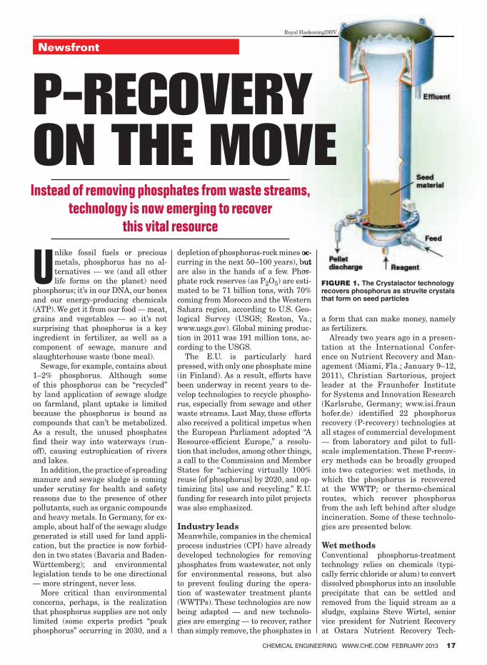
FIGURE 1. The Crystalactor technology recovers phosphorus as struvite crystals that form on seed particles
Royal HaskoningDHV
P-RECOVERY ON THE MOVEInstead of removing phosphates from waste streams,
technology is now emerging to recover
this vital resource
18 CHEMICAL ENGINEERING WWW.CHE.COM FEBRUARY 2013
Newsfront
nologies Inc. (Ostara; Vancouver, B.C.,
Canada; www.ostara.com). Chemical
addition is a simple process that re-
quires minimal equipment, so it has a
low capital cost. But, the process has
a high operating cost because substan-
tial amounts of chemicals are required.
Chemical addition also falls short be-
cause the process binds the phospho-
rus into a chemical sludge where it
cannot be recovered for its nutrient
value as a fertilizer, says Wirtel. “And
it is not environmentally friendly.”
Instead of creating a chemical
sludge, Ostara has developed its Pearl
process, which converts dissolved
phosphorus into pure (99.5%) struvite
(MgNH4PO4. 6H2O) crystals. “The pro-
cess has virtually no carbon footprint
and sustainably recovers a precious
resource,” says Wirtel. The struvite
crystals are created and bagged onsite
and marketed as a slow-release, en-
hanced-efficiency fertilizer to blenders
that sell to nurseries, golf courses, and
specialty agricultural growers under
the brand name Crystal Green.
Ostara’s proprietary Pearl process
is based on the initiation and precise
control of a chemical-precipitation re-
action in a fluidized-bed reactor. The
typical feedstreams in the process are
sludge liquids produced at municipal
WWTPs and “high strength” indus-
trial used-water streams, says Wirtel.
Pearl’s chemical process removes phos-
phorus and other nutrients from the
feedstreams, with phosphorus removal
performance typically averaging ap-
proximately 90%, he says. The capital
cost of a nutrient recovery system is
recovered through the avoided cost of
adding chemicals needed to precipi-
tate phosphorus. The typical payback
period range is 2–7 yr, says Wirtel.
The Pearl process was first scaled
up in 2006, with the commissioning
of a 500,000-L/d demonstration plant
at the Edmonton Gold Bar sewage-
treatment works (CE, November
2006, p. 13). The first commercial nu-
trient-recovery facility was launched
with Clean Water Services (Hillsboro,
Ore.) in 2009 at its Durham Advanced
Wastewater Treatment Plant. Since
then, Ostara has built facilities in
Suffolk, Va.; York, Pa.; and a second
facility with Clean Water Services at
its Rock Creek Wastewater Treatment
Facility in Hillsboro, Ore. In 2013, Os-
tara will launch three additional nu-
trient-recovery facilities: at Thames
Water in the U.K., in Saskatoon — the
first commercial facility in Canada —
and in Madison, Wisc.
Another “wet” process for phosphorus
recovery is the Crystalactor technol-
ogy offered by Royal HaskoningDHV
(Amersfoort, The Netherlands; www.
royalhaskoningdhv.com). The process
is based on the selective crystallization
of targeted compounds, such calcium
from water for water softening. Other
pollutants can be crystallized as well,
such as heavy metals or fluorides from
Circle 2 on p. 60 or go to adlinks.che.com/45769-02
CHEMICAL ENGINEERING WWW.CHE.COM FEBRUARY 2013 19
the semiconductor industry or specific ions in the concentrate from desali-nation plants. The company has also adapted the Crystalactor technology for P-recovery from wastewater.
The heart of the patented Crysta-lactor process is a fluidized-bed pellet reactor (Figure 1). Wastewater is fed to the bottom of the reactor and flows upwards, fluidizing the bed of seed particles, such as sand or crushed and classified crystals. By adjusting the pH and dosing of reagents, phosphates from the waste stream crystallize as struvite or calcium phosphate onto the seed particles. As the pellets grow, they travel downwards to be discharged at the bottom of the reactor. The four steps commonly required in conven-tional phosphorus treatment processes — coagulation, flocculation, separation and dewatering — are combined in one by the Crystalactor, says the company.
One of the applications of the Crys-talactor for P-removal is running at a
dairy in Waupun, Wisc., where U.S.-licensee Procorp Enterprises (Milwau-kee, Wisc.; www.procorp.com) installed a Crystalactor unit in 2005. The unit, with a 3-m dia. reactor, handles 125 m3/h of wastewater with a phosphorus concentration of 25 mg/L, and uses quartz sand as seed. By adding lime, calcium phosphate is crystallized, and the pellets are dried for recycling.
Since the early 1990s, eight Crys-talactor units have been built specifi-cally for P-recovery, says the company.
Last August, pilot testing began on an electrochemical P-recovery process being developed at the Fraunhofer In-stitute for Interfacial Engineering and Biotechnology (IGB; Stuttgart, Ger-many; www.igb.fraunhofer.de). Unlike conventional precipitation methods, which require the addition of mag-nesium salts (for struvite formation) along with NaOH for adjusting the pH, the patented process uses a sacrificial magnesium electrode that generates
the required Mg+2 ions, as well as raises the pH to 9 by the water-splitting reac-tion that occurs at the other electrode (2H2O –> H2 + 2OH–1). The Mg+2 ions react with phosphates in the wastewa-ter and precipitate out of solution as struvite crystals that can be dried and used directly as fertilizer. Plant yield and plant nutrient-uptake with the struvite were found to be up to four-times higher than with commercially available mineral fertilizers, says IGB.
The 1-m3 pilot plant is mobile, en-abling tests to be performed at a va-riety of wastewater treatment plants. The first tests have commenced at an agricultural biogas plant that pro-cesses corn, manure and some waste from the food-processsing industry. IGB’s commercial partners are Geltz Umwelt-Technologie GmbH (Niefern-Öschelbronn; www.geltz.de), E.R.S. GmbH & Co. KG (Osterburken; ers-gmbh.de) and Bamo IER (Mannhein; all Germany; www.bamo.de). All com-
“Which static mixer is rightfor you? Let me show you.”
Ross offers expert support and the world’s broadest selection
of static mixers for applications involving turbulent or laminar
flow. With no moving parts, our heavy duty LPD, LLPD and
ISG designs are ideal for sanitary and non-sanitary mixing,
with choices for ultra-low ∆P and unlimited viscosity.
For a free white paper, visit StaticMixers.com/Learn
Or call Christine Banaszek today: 1-800-243-ROSS
Christine Banaszek
Applications Engineer
Employee Owner
Scan to learn more.
Free Tag Reader: http://gettag.mobi
Circle 18 on p. 60 or go to adlinks.che.com/45769-18
mercialization of the technology will
be promoted within this consortium.
Meanwhile, an initiative to recover
phosphorus from flyash was initiated
in May 2011 between the phosphate-
technology company, EcoPhos S.A.
(Louvain-la-Neuve, Belgium; www.
ecophos.com), the sludge-processing
company Silbverwerking Noord-
Brant N.V. (SNB; Moerdijk; www.
snb.nl) and the utility company HVC
(www.hvcgroep.nl). The two Dutch
companies process more than half of
the sewage sludge in The Netherlands
at incineration plants in Dordrecht
and Moerdijk, which generate flyash
residue with a phosphorus content
comparable to low-quality ore.
The companies have developed a
hydrometallurgical method for recov-
ering the phosphorus in the flyash,
which is expected to yield up to 250
metric tons (m.t.) of phosphate from
every 1,000 m.t. of flyash.
A commercial-scale plant is
planned to go onstream in 2014,
which will co-process phosphate rock
supplemented with about 20% flyash.
The product will then be used for the
production of fertilizer. In the past,
flyash has been used as filler in as-
phalt for roads and surfaces.
Thermo-chemical methods
Although wet P-recovery methods
have the advantages of maturity (due
to the need to remove phosphates to
avoid scaling issues) and feasibility
at the relatively small scales typical
of municipal WWTPs, dairies and so
on, they all have the disadvantage of
recovering only the dissolved phos-
phates, says Ludwig Hermann, senior
consultant, Energy at Outotec GmbH
(Oberursel, Germany; www.outotec.
com). Dissolved phosphorus is typi-
cally about 25% of the total phospho-
rus content in sewage, and sometimes
much less, he says. The rest remains
in the sludge, which must be treated
by other methods. With the increasing
use of sludge incineration, especially
in Europe, the unrecovered phospho-
rus has typically found its final resting
place in the discharged flyash, which
ends up as supplements to road pave-
ment and concrete. In developed coun-
tries, some few hundred incinerators
are producing around 3 million m.t./yr
of ash every year with phosphorus con-
centrations up to 25 wt.% (dry). With-
out treatment, such ash is unsuitable
as fertilizer because of high heavy-
metal content and limited plant avail-
ability, says Hermann. Now, methods
to recover the phosphorus from the ash
— so-called urban mining — are now
slated for commercialization.
One such process is the Ash Dec tech-
nology, which Outotec acquired in 2011
from Ash Dec Umwelt AG (Vienna,
Austria). The process recovers almost
100% of the phosphorus, as well as
other metals present in the ash, while
producing a marketable fertilizer.
20 CHEMICAL ENGINEERING WWW.CHE.COM FEBRUARY 2013
Newsfront
WHY MONITOR POWER INSTEAD OF JUST AMPS?
NO LOAD NO LOAD
Power is Linear-Equal Sensitivity
at Both Low and High Loads
No Sensitivity
For Low Loads
FULL LOAD FULL LOAD
PO
WER
AM
PS
WWW.LOADCONTROLS.COM
CALL NOW FOR YOUR FREE 30-DAY TRIAL 888-600-3247
PROTECT PUMPSDRYRUNNING•CAVITATION•BEARINGFAILURE•OVERLOAD
MONITOR PUMP POWER
•BestSensitivity•DigitalDisplay
TWO ADJUSTABLE SET POINTS
•RelayOutputs•AdjustableDelayTimers
4-20 MILLIAMP ANALOG OUTPUT
COMPACT EASY MOUNTING
Only3.25"x6.25"x2"•StarterDoor •Panel•Raceway •Wall
UNIQUE RANGE FINDER SENSOR
•WorksonWide-rangeofMotors•SimplifiesInstallation
PUMP POWER
PUMPING
VALVE CLOSING
VALVE OPENINGNO FLUID
Circle 14 on p. 60 or go to adlinks.che.com/45769-14
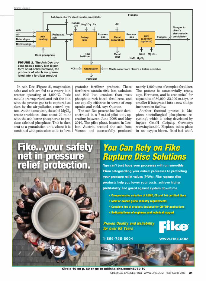
In Ash Dec (Figure 2), magnesium
salts and ash are fed to a rotary kiln
reactor operating at 1,000°C. Toxic
metals are vaporized, and exit the kiln
with the process gas to be captured as
dust by the air-pollution control sys-
tem. At the same time, the solid MgCl2
reacts (residence time about 20 min)
with the ash-borne phosphorus to pro-
duce calcined phosphate. This is then
sent to a granulation unit, where it is
combined with potassium salts to form
granular fertilizer products. These
fertilizers contain 99% less cadmium
and 90% less uranium than most
phosphate-rock-based fertilizers, and
are equally effective in terms of crop
uptake and yield, says Outotec.
The Ash Dec process has been dem-
onstrated in a 7-m.t./d pilot unit op-
erating between June 2008 and May
2010. The pilot plant, located in Leo-
ben, Austria, treated the ash from
Vienna and successfully produced
nearly 1,000 tons of complex fertilizer.
The process is commercially ready,
says Hermann, and is economical for
capacities of 30,000–32,000 m.t./yr, or
smaller if integrated into a new sludge
incineration facility.
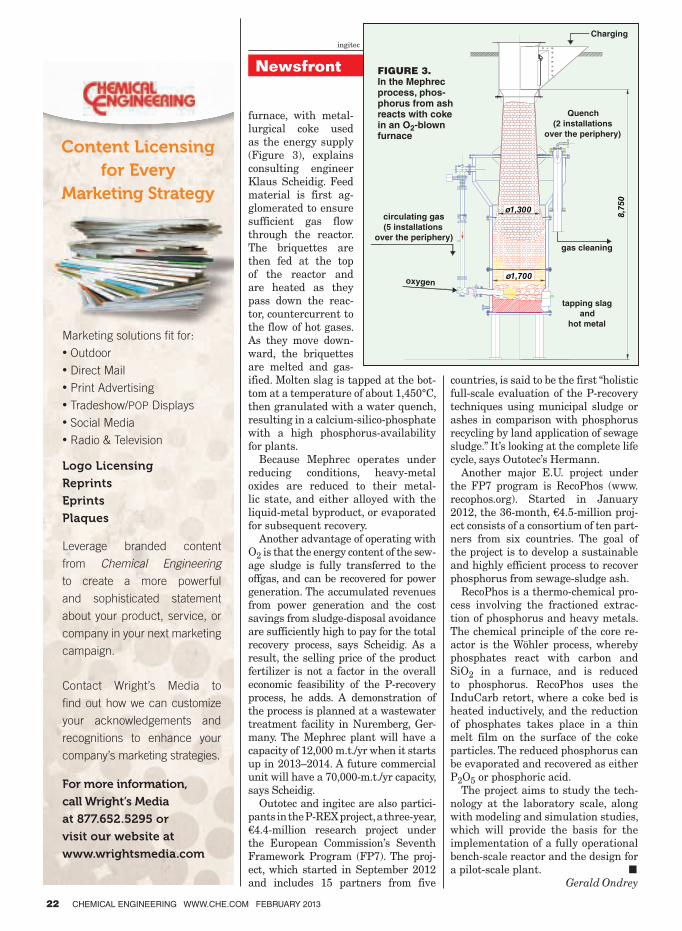
Another thermal process is Me-
phrec (metallurgical phosphorus re-
cycling), which is being developed by
ingitec GmbH (Leipzig, Germany;
www.ingitec.de). Mephrec takes place
in an oxygen-blown, fixed-bed shaft
CHEMICAL ENGINEERING WWW.CHE.COM FEBRUARY 2013 21
You Can Rely on Fike Rupture Disc Solutions
1-866-758-6004 WWW.FIKE.COM
•ComprehensiveselectionofASME,CEand3-Acertifieddiscs
•Meetorexceedglobalindustryrequirements
•CompletelineofproductsdesignedforCIP/SIPapplications
•Dedicatedteamofengineersandtechnicalsupport
Proven Quality and Reliability
for over 65 Years
You can’t just hope your processes will run smoothly.
From safeguarding your critical processes to protecting
your pressure relief valves (PRVs), Fike rupture disc
products help you lower your costs, achieve higher
profitability and guard against system downtime.
Fike...your safetynet in pressure relief protection.
Circle 10 on p. 60 or go to adlinks.che.com/45769-10
Waste water from client’s alkaline scrubberGranulation
Fertilizer
Ash
Air
Natural gas
Dried sludge
Rock phosphate
Preheated
ash
Ash from client’s electrostatic precipitator
Naturalgas
Process gas
Process gas
Fluegas
FluegasHClrecovery(optional)
Fluegas to
client’s
electrostatic
precipitator
Na2CO3 Air Air
Ash heating
Rotarykiln
Metalseparation
Metaldust
Rawfertilizer
KCl
NaCl, MgCl2
NaCl MgCO3
FIGURE 2. The Ash Dec pro-cess uses a rotary kiln to per-form solid-solid reactions, the products of which are granu-lated into a fertilizer product
Source: Outotec
22 CHEMICAL ENGINEERING WWW.CHE.COM FEBRUARY 2013
Newsfront
furnace, with metal-
lurgical coke used
as the energy supply
(Figure 3), explains
consulting engineer
Klaus Scheidig. Feed
material is first ag-
glomerated to ensure
sufficient gas flow
through the reactor.
The briquettes are
then fed at the top
of the reactor and
are heated as they
pass down the reac-
tor, countercurrent to
the flow of hot gases.
As they move down-
ward, the briquettes
are melted and gas-
ified. Molten slag is tapped at the bot-
tom at a temperature of about 1,450°C,
then granulated with a water quench,
resulting in a calcium-silico-phosphate
with a high phosphorus-availability
for plants.
Because Mephrec operates under
reducing conditions, heavy-metal
oxides are reduced to their metal-
lic state, and either alloyed with the
liquid-metal byproduct, or evaporated
for subsequent recovery.
Another advantage of operating with
O2 is that the energy content of the sew-
age sludge is fully transferred to the
offgas, and can be recovered for power
generation. The accumulated revenues
from power generation and the cost
savings from sludge-disposal avoidance
are sufficiently high to pay for the total
recovery process, says Scheidig. As a
result, the selling price of the product
fertilizer is not a factor in the overall
economic feasibility of the P-recovery
process, he adds. A demonstration of
the process is planned at a wastewater
treatment facility in Nuremberg, Ger-
many. The Mephrec plant will have a
capacity of 12,000 m.t./yr when it starts
up in 2013–2014. A future commercial
unit will have a 70,000-m.t./yr capacity,
says Scheidig.
Outotec and ingitec are also partici-
pants in the P-REX project, a three-year,
€4.4-million research project under
the European Commission’s Seventh
Framework Program (FP7). The proj-
ect, which started in September 2012
and includes 15 partners from five
countries, is said to be the first “holistic
full-scale evaluation of the P-recovery
techniques using municipal sludge or
ashes in comparison with phosphorus
recycling by land application of sewage
sludge.” It’s looking at the complete life
cycle, says Outotec’s Hermann.
Another major E.U. project under
the FP7 program is RecoPhos (www.
recophos.org). Started in January
2012, the 36-month, €4.5-million proj-
ect consists of a consortium of ten part-
ners from six countries. The goal of
the project is to develop a sustainable
and highly efficient process to recover
phosphorus from sewage-sludge ash.
RecoPhos is a thermo-chemical pro-
cess involving the fractioned extrac-
tion of phosphorus and heavy metals.
The chemical principle of the core re-
actor is the Wöhler process, whereby
phosphates react with carbon and
SiO2 in a furnace, and is reduced
to phosphorus. RecoPhos uses the
InduCarb retort, where a coke bed is
heated inductively, and the reduction
of phosphates takes place in a thin
melt film on the surface of the coke
particles. The reduced phosphorus can
be evaporated and recovered as either
P2O5 or phosphoric acid.
The project aims to study the tech-
nology at the laboratory scale, along
with modeling and simulation studies,
which will provide the basis for the
implementation of a fully operational
bench-scale reactor and the design for
a pilot-scale plant. ■Gerald Ondrey
For more information,
call Wright’s Media
at 877.652.5295 or
visit our website at
www.wrightsmedia.com
Logo Licensing
Reprints
Eprints
Plaques
Leverage branded content
from Chemical Engineering
to create a more powerful
and sophisticated statement
about your product, service, or
company in your next marketing
campaign.
Contact Wright’s Media to
find out how we can customize
your acknowledgements and
recognitions to enhance your
company’s marketing strategies.
Content Licensing for Every
Marketing Strategy
Marketing solutions fit for:
• Outdoor
• Direct Mail
• Print Advertising
• Tradeshow/POP Displays
• Social Media
• Radio & Television
gas cleaning
tapping slag
and
hot metal
Charging
oxygen
circulating gas
(5 installations
over the periphery)
Quench
(2 installations
over the periphery)
"
ø1,300
8,750
ø1,700
FIGURE 3. In the Mephrec process, phos-phorus from ash reacts with coke in an O2-blown furnace
ingitec
CHEMICAL ENGINEERING WWW.CHE.COM FEBRUARY 2013 23
Newsfront
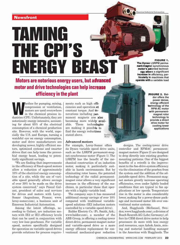
Whether for pumping, mixing,
compression or ventilation,
motors are used everywhere
in the chemical process in-
dustries (CPI). Unfortunately, they are
notoriously energy intensive, account-
ing for about 65% of the electrical
consumption of a chemical production
site. However, with the world, espe-
cially the U.S. and Europe, turning a
watchful eye on energy consumption,
motor and drive manufacturers are
developing newer, highly efficient mo-
tors, optimized systems and smarter
drives that can help tame the prover-
bial energy beast, leading to poten-
tially significant savings.
“We are finding that improvements
in the efficiency of fixed-speed motors
allow a reduction of approximately
10% of the electrical energy consump-
tion of a site, while the use of vari-
able speed generally allows savings
of over 30% to be made on the drive
system concerned,” says Pascal Gal-
ant, president of sales and services
for drives and motors with Leroy-
Somer (Angouleme, France; www.
leroy-somer.com), a business unit of
Emerson Industrial Automation.
Among the latest offerings, ac-
cording to Galant, are induction mo-
tors with IE2 or IE3 efficiency levels
that can be used in conjunction with
very low-loss gearboxes. For variable
speed, motors specifically designed
for operation on variable speed drives
provide solutions for process require-
ments such as high effi-
ciencies and operation at
constant torque. And in-
novations including per-
manent magnets are also
becoming more widely avail-
able. These technologies
are making it possible to
find the energy reductions
stated above.
Advanced motors
For example, Leroy-Somer offers
its Dyneo variable speed drive units,
such as the LSRPM permanent-mag-
net synchronous motor (Figure 1). The
LSRPM has the benefit of the me-
chanical construction of an induction
motor, making it particularly suit-
able in harsh environments. But by
eliminating rotor losses, the patented
technology of the radial permanent-
magnet rotor allows a very significant
increase in the efficiency of the ma-
chines, in particular those that oper-
ate with a highly variable load.
The company says it has measured
additional energy savings of over 10%
compared with traditional variable-
speed solutions (IE2 induction motors
controlled by a variable speed drive).
Baldor Electric Co. (Ft. Smith, Ark.;
www.baldor.com), a member of the
ABB Group, is offering a cooling-tower
direct-drive, permanent-magnet motor
and variable-speed drive as a more
energy efficient replacement for con-
ventional mechanical-gear reduction
designs. The cooling-tower drive
controller and RPMAC permanent-
magnet motors (Figure 2) are designed
to drop directly into existing gearbox-
mounting patterns. One of the biggest
benefits of a retrofit is the improve-
ment to the fan-drive-system efficiency
via the elimination of the gearbox from
the system and the addition of the ad-
justable-speed drive. Permanent-mag-
net motors greatly increase operating
efficiencies, even under lightly loaded
conditions that are typical in fan ap-
plications at low speeds. Temperature
rise in the motor is also considerably
lower, making for a power-dense pack-
age and increased motor life over con-
ventional motor systems.
And, Hagglunds (Mellansel, Swe-
den; www.hagglunds.com), a division of
Bosch Rexroth AG (Lohr, Germany), of-
fers its CBM direct drive motor to help
processors do more with less energy
and resources, says Ashok Amin, min-
ing and material handling manager
in the Americas with Hagglands. The
Motors are notorious energy users, but advanced
motor and drive technologies can help increase
efficiency in the plant
Emerson Industrial Automation
FIGURE 2. Bal-dor offers the power dense,
energy efficient technology of the
RPM AC motor with permanent-
magnet rotor technology to
provide a direct drive motor for
cooling tower applications
FIGURE 1. The Dyneo LSRPM perma-nent-magnet synchronous motor’s patented technol-
ogy allows a signi� cant increase in efficiency, par-ticularly in machines that
operate with a variable load
Baldor Motor
TAMING THE CPI’S ENERGY BEAST
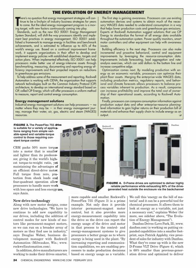
24 CHEMICAL ENGINEERING WWW.CHE.COM FEBRUARY 2013
CBM packs 50% more torque
into a motor that is smaller
and lighter than its predeces-
sor, giving it the world’s high-
est torque-to-weight ratio, yet
maintaining the advantages of
an efficient direct-drive motor.
Full torque from zero, pro-
tection from shock loads and
four-quadrant operation allow
processors to handle more work
with less space and less energy use,
says Amin.
New drive technologyAlong with new motor designs, come
new drive technologies. “We have to
continue to add new capability to
our drives, including the addition of
control modes for new kinds of mo-
tors like permanent-magnet motors,
so we can run on a broader array of
motors as they find use in industry,”
says Douglas Weber, business de-
velopment manager with Rockwell
Automation (Milwaukee, Wis.; www.
rockwellautomation.com).
In addition, drive manufacturers are
working to make their drives smarter,
more capable and smaller. Rockwell’s
PowerFlex 755 (Figure 3) is a prime
example. Not only does it provide
interior permanent-magnet motor
control, but it also provides more
energy-measurement capability into
the drive so the drive can report the
energy usage of the drive and motor
in that process to the control- and
energy-management systems to give
processors a better gauge as to where
energy is being used in the plant. “By
increasing reporting and communica-
tion capabilities, we are enabling pro-
cessors to make production decisions
based on energy usage as a variable.
We call this ‘energy on the bill of ma-
terial’ and it can be a powerful tool for
chemical processors. It allows them to
look at energy as a variable, not just
a necessary cost,” explains Weber (for
more, see sidebar above, “The Evolu-
tion of Energy Management”).
Danfoss Drives (Love Park, Ill.; www.
danfoss.com) is working on putting ex-
panded capabilities into a smaller foot-
print, says Patrick Appleby, vice presi-
dent of sales for industry with Danfoss.
What they’ve come up with is the new
D-Frame VLT Drive (Figure 4), which
is 68% smaller than previous-gener-
ation drives and optimized to deliver
FIGURE 4. D-Frame drives are optimized to deliver highly reliable performance while exhausting 90% of the drive-
generated heat outside the enclosure via the backchannel
FIGURE 3. The PowerFlex 755 drive is suitable for a variety of applica-tions ranging from simple vari-able-speed and variable-torque control to those requiring con-stant torque control
Rockwell Automation
Danfoss
THE EVOLUTION OF ENERGY MANAGEMENT
There’s no question that energy management strategies will con-tinue to be a linchpin of industry business strategies for years to come. But the ideal energy management program is a mov-
ing target, with new factors continuously coming into play.Standards, such as the new ISO 50001 Energy Management
System Standard, will shift the way processors identify and imple-ment best practices in energy management. ISO 50001 estab-lished a framework to manage energy in facilities and benchmark achievements, and is estimated to influence up to 60% of the world’s energy use. Based on a continual improvement frame-work, it supports organizations in their effort to develop and implement energy policies with established objectives, targets and action plans. When implemented effectively, ISO 50001 can help processors make better use of energy-intensive assets through benchmarking, measuring, documenting and reporting energy ef-ficiency improvements and their projected impacts on reductions in greenhouse gas emissions.
To help address some of the measurement and reporting, Rockwell Automation is working with ODVA, the organization that supports network technologies built on the Common Industry Protocol (CIP) architecture, to develop an international energy standard based on CIP, called CIP Energy, which will offer processors a uniform method to measure, report and control energy consumption.
Energy management solutionsIndustrial energy management solutions can help processors — no matter where they may be — in their energy management jour-ney, manage their water, air, gas, electric and steam (WAGES) resources.
The first step is gaining awareness. Processors can use existing automation devices and systems to obtain much of the neces-sary WAGES data needed to understand consumption in a way that helps lower production costs and greenhouse gas emissions. Experts at Rockwell Automation suggest solutions that use CIP Energy to standardize the format of all energy data available throughout the automation system. Power quality monitors, smart motor controllers and other equipment can help with awareness issues.
Building efficiency is the next step. Processors can also make incremental and proactive behavioral, control and equipment improvements by leveraging the resource-consumption data. Improvements include forecasting, load aggregation and rate-analysis exercises, which can add dollars to the bottom line and increase competitive edge.
Optimization comes next. By modeling production with en-ergy as an economic variable, processors can optimize their plant-floor assets. Merging the enterprise-wide WAGES data, including production metrics, regulatory reports, and behav-ioral and climate forecasts allows processors to balance pro-cess variables inherent to production. As a result, companies can increase profitability and improve the total cost of owner-ship of their operational assets, according to Rockwell Auto-mation.
Finally, processors can compare consumption information against production output data and other enterprise-resource planning-level information to gain higher returns on their production bill of materials and enhance their supply chain to include energy as an output. ❏
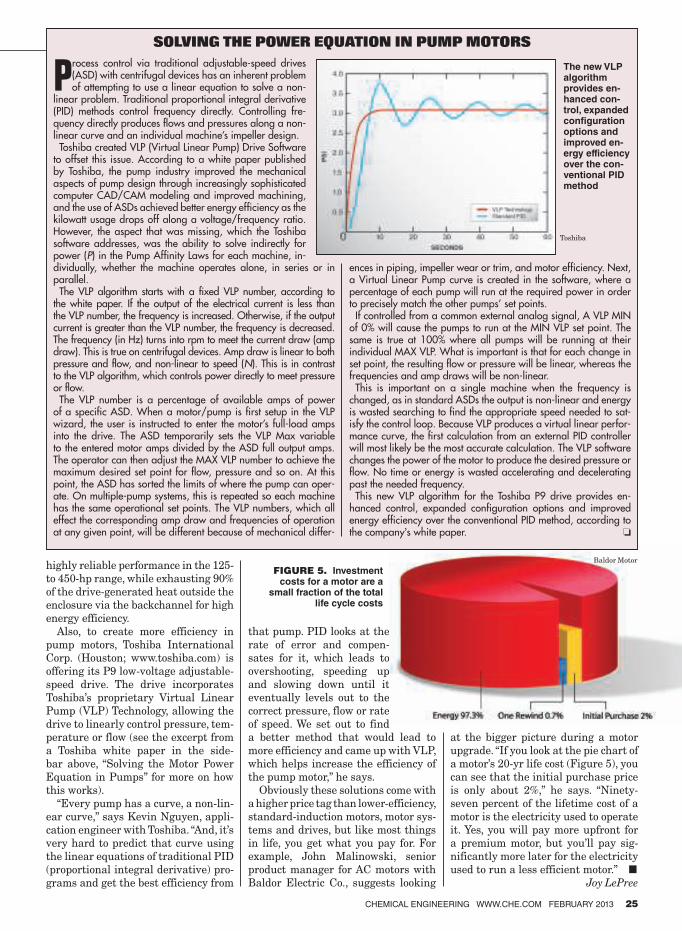
CHEMICAL ENGINEERING WWW.CHE.COM FEBRUARY 2013 25
highly reliable performance in the 125-
to 450-hp range, while exhausting 90%
of the drive-generated heat outside the
enclosure via the backchannel for high
energy efficiency.
Also, to create more efficiency in
pump motors, Toshiba International
Corp. (Houston; www.toshiba.com) is
offering its P9 low-voltage adjustable-
speed drive. The drive incorporates
Toshiba’s proprietary Virtual Linear
Pump (VLP) Technology, allowing the
drive to linearly control pressure, tem-
perature or flow (see the excerpt from
a Toshiba white paper in the side-
bar above, “Solving the Motor Power
Equation in Pumps” for more on how
this works).
“Every pump has a curve, a non-lin-
ear curve,” says Kevin Nguyen, appli-
cation engineer with Toshiba. “And, it’s
very hard to predict that curve using
the linear equations of traditional PID
(proportional integral derivative) pro-
grams and get the best efficiency from
that pump. PID looks at the
rate of error and compen-
sates for it, which leads to
overshooting, speeding up
and slowing down until it
eventually levels out to the
correct pressure, flow or rate
of speed. We set out to find
a better method that would lead to
more efficiency and came up with VLP,
which helps increase the efficiency of
the pump motor,” he says.
Obviously these solutions come with
a higher price tag than lower-efficiency,
standard-induction motors, motor sys-
tems and drives, but like most things
in life, you get what you pay for. For
example, John Malinowski, senior
product manager for AC motors with
Baldor Electric Co., suggests looking
at the bigger picture during a motor
upgrade. “If you look at the pie chart of
a motor’s 20-yr life cost (Figure 5), you
can see that the initial purchase price
is only about 2%,” he says. “Ninety-
seven percent of the lifetime cost of a
motor is the electricity used to operate
it. Yes, you will pay more upfront for
a premium motor, but you’ll pay sig-
nificantly more later for the electricity
used to run a less efficient motor.” ■Joy LePree
SOLVING THE POWER EQUATION IN PUMP MOTORS
Process control via traditional adjustable-speed drives (ASD) with centrifugal devices has an inherent problem of attempting to use a linear equation to solve a non-
linear problem. Traditional proportional integral derivative (PID) methods control frequency directly. Controlling fre-quency directly produces flows and pressures along a non-linear curve and an individual machine’s impeller design.
Toshiba created VLP (Virtual Linear Pump) Drive Software to offset this issue. According to a white paper published by Toshiba, the pump industry improved the mechanical aspects of pump design through increasingly sophisticated computer CAD/CAM modeling and improved machining, and the use of ASDs achieved better energy efficiency as the kilowatt usage drops off along a voltage/frequency ratio. However, the aspect that was missing, which the Toshiba software addresses, was the ability to solve indirectly for power (P) in the Pump Affinity Laws for each machine, in-dividually, whether the machine operates alone, in series or in parallel.
The VLP algorithm starts with a fixed VLP number, according to the white paper. If the output of the electrical current is less than the VLP number, the frequency is increased. Otherwise, if the output current is greater than the VLP number, the frequency is decreased. The frequency (in Hz) turns into rpm to meet the current draw (amp draw). This is true on centrifugal devices. Amp draw is linear to both pressure and flow, and non-linear to speed (N). This is in contrast to the VLP algorithm, which controls power directly to meet pressure or flow.
The VLP number is a percentage of available amps of power of a specific ASD. When a motor/pump is first setup in the VLP wizard, the user is instructed to enter the motor’s full-load amps into the drive. The ASD temporarily sets the VLP Max variable to the entered motor amps divided by the ASD full output amps. The operator can then adjust the MAX VLP number to achieve the maximum desired set point for flow, pressure and so on. At this point, the ASD has sorted the limits of where the pump can oper-ate. On multiple-pump systems, this is repeated so each machine has the same operational set points. The VLP numbers, which all effect the corresponding amp draw and frequencies of operation at any given point, will be different because of mechanical differ-
FIGURE 5. Investment costs for a motor are a
small fraction of the total life cycle costs
Baldor Motor
The new VLP algorithm provides en-hanced con-trol, expanded coniguration options and improved en-ergy efficiency over the con-ventional PID method
Toshiba
ences in piping, impeller wear or trim, and motor efficiency. Next, a Virtual Linear Pump curve is created in the software, where a percentage of each pump will run at the required power in order to precisely match the other pumps’ set points.
If controlled from a common external analog signal, A VLP MIN of 0% will cause the pumps to run at the MIN VLP set point. The same is true at 100% where all pumps will be running at their individual MAX VLP. What is important is that for each change in set point, the resulting flow or pressure will be linear, whereas the frequencies and amp draws will be non-linear.
This is important on a single machine when the frequency is changed, as in standard ASDs the output is non-linear and energy is wasted searching to find the appropriate speed needed to sat-isfy the control loop. Because VLP produces a virtual linear perfor-mance curve, the first calculation from an external PID controller will most likely be the most accurate calculation. The VLP software changes the power of the motor to produce the desired pressure or flow. No time or energy is wasted accelerating and decelerating past the needed frequency.
This new VLP algorithm for the Toshiba P9 drive provides en-hanced control, expanded configuration options and improved energy efficiency over the conventional PID method, according to the company’s white paper. ❏
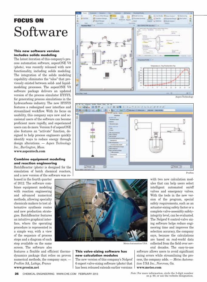
This new software version
includes solids modeling
The latest iteration of this company’s pro-
cess automation software, aspenONE V8
(photo), was recently released with new
functionality, including solids modeling.
The integration of the solids modeling
capability eliminates the “silos” that pre-
viously existed between solid- and liquid-
modeling processes. The aspenONE V8
software package delivers an updated
version of the process simulator HYSYS,
for generating process simulations in the
hydrocarbons industry. The new HYSYS
features a redesigned user interface and
streamlined workflow. With its focus on
usability, this company says new and oc-
casional users of the software can become
proficient more rapidly, and experienced
users can do more. Version 8 of aspenONE
also features an “activate” function, de-
signed to help process engineers quickly
identify ways to reduce energy through
design alterations. — Aspen Technology
Inc., Burlington, Mass.
www.aspentech.com
Combine equipment modeling
and reaction engineering
BatchReactor (photo) is designed for the
simulation of batch chemical reactors,
and a new version of the software was re-
leased in the fourth quarter
of 2012. The software com-
bines equipment modeling
with reaction engineering
and advanced numerical
methods, allowing specialty
chemicals makers to test al-
ternative synthesis routes
and new production strate-
gies. BatchReactor features
an intuitive graphical inter-
face, where the operating
procedure is represented in
a simple way, with a view
of the sequence of process
steps and a diagram of each
step available on the same
screen. The software also
features a flexible and efficient thermo-
dynamics package that relies on proven
numerical methods, the company says. —
ProSim SA, Labège, France
www.prosim.net
This valve-sizing software has
new calculation modules
The new version of this company’s Nelprof
6 expert valve-sizing software (photo) that
has been released extends earlier versions
with two new calculation mod-
ules that can help users select
intelligent automated on/off
valves and emergency valves.
With the tools in the new ver-
sion of the program, special
safety requirements, such as an
actuator-sizing safety factor or a
complete valve-assembly safety-
integrity level, can be evaluated.
The Nelprof 6 control-valve siz-
ing software helps reduce engi-
neering time and improves the
selection accuracy, the company
says, because the calculations
are based on real-world data
collected from the field over sev-
eral decades. The easy-to-use
software allows users to avoid significant
sizing errors while streamlining the pro-
cess, the company adds. — Metso Automa-
tion USA Inc., Norcross, Ga.
www.metso.com
26 CHEMICAL ENGINEERING WWW.CHE.COM FEBRUARY 2013 Note : For more information, circle the 3-digit number on p. 60, or use the website designation.
FOCUS ON
Software
Aspen Technology
ProSim
Metso Automation USA
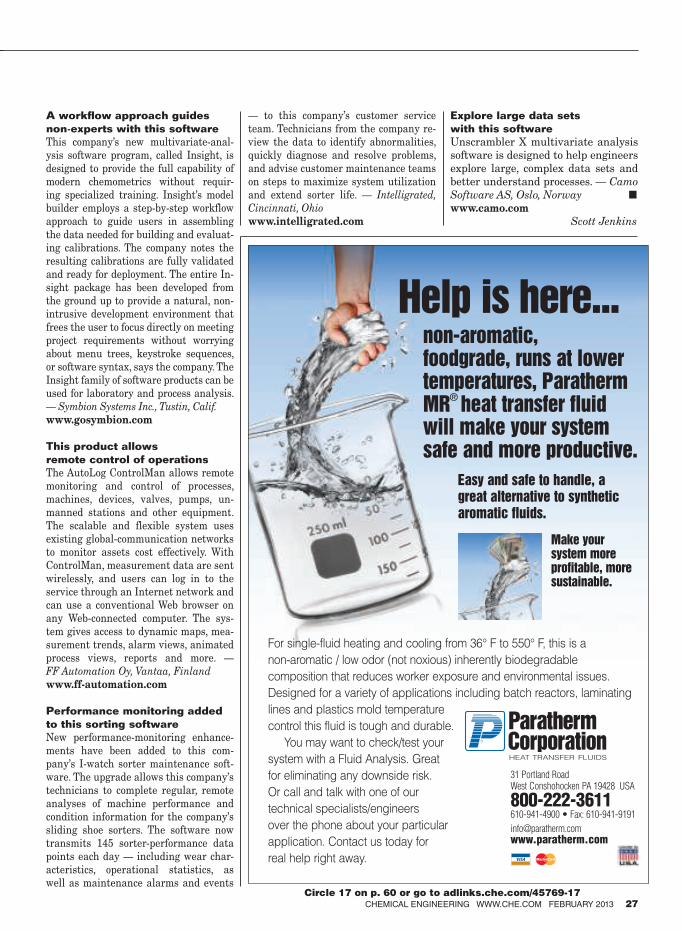
A workflow approach guides
non-experts with this software
This company’s new multivariate-anal-
ysis software program, called Insight, is
designed to provide the full capability of
modern chemometrics without requir-
ing specialized training. Insight’s model
builder employs a step-by-step workflow
approach to guide users in assembling
the data needed for building and evaluat-
ing calibrations. The company notes the
resulting calibrations are fully validated
and ready for deployment. The entire In-
sight package has been developed from
the ground up to provide a natural, non-
intrusive development environment that
frees the user to focus directly on meeting
project requirements without worrying
about menu trees, keystroke sequences,
or software syntax, says the company. The
Insight family of software products can be
used for laboratory and process analysis.
— Symbion Systems Inc., Tustin, Calif.
www.gosymbion.com
This product allows
remote control of operations
The AutoLog ControlMan allows remote
monitoring and control of processes,
machines, devices, valves, pumps, un-
manned stations and other equipment.
The scalable and flexible system uses
existing global-communication networks
to monitor assets cost effectively. With
ControlMan, measurement data are sent
wirelessly, and users can log in to the
service through an Internet network and
can use a conventional Web browser on
any Web-connected computer. The sys-
tem gives access to dynamic maps, mea-
surement trends, alarm views, animated
process views, reports and more. —
FF Automation Oy, Vantaa, Finland
www.ff-automation.com
Performance monitoring added
to this sorting software
New performance-monitoring enhance-
ments have been added to this com-
pany’s I-watch sorter maintenance soft-
ware. The upgrade allows this company’s
technicians to complete regular, remote
analyses of machine performance and
condition information for the company’s
sliding shoe sorters. The software now
transmits 145 sorter-performance data
points each day — including wear char-
acteristics, operational statistics, as
well as maintenance alarms and events
— to this company’s customer service
team. Technicians from the company re-
view the data to identify abnormalities,
quickly diagnose and resolve problems,
and advise customer maintenance teams
on steps to maximize system utilization
and extend sorter life. — Intelligrated,
Cincinnati, Ohio
www.intelligrated.com
Explore large data sets
with this software
Unscrambler X multivariate analysis
software is designed to help engineers
explore large, complex data sets and
better understand processes. — Camo
Software AS, Oslo, Norway ■www.camo.com
Scott Jenkins
CHEMICAL ENGINEERING WWW.CHE.COM FEBRUARY 2013 27
For single-fluid heating and cooling from 36° F to 550° F, this is a
non-aromatic / low odor (not noxious) inherently biodegradable
composition that reduces worker exposure and environmental issues.
Designed for a variety of applications including batch reactors, laminating
lines and plastics mold temperature
control this fluid is tough and durable.
You may want to check/test your
system with a Fluid Analysis. Great
for eliminating any downside risk.
Or call and talk with one of our
technical specialists/engineers
over the phone about your particular
application. Contact us today for
real help right away.
HEAT TRANSFER FLUIDS
31 Portland RoadWest Conshohocken PA 19428 USA
800-222-3611610-941-4900 • Fax: [email protected]
Help is here...non-aromatic, foodgrade, runs at lowertemperatures, ParathermMR
®
heat transfer fluidwill make your systemsafe and more productive.
Easy and safe to handle, a
great alternative to synthetic
aromatic fluids.
®
Make your system more profitable, more sustainable.
Circle 17 on p. 60 or go to adlinks.che.com/45769-17
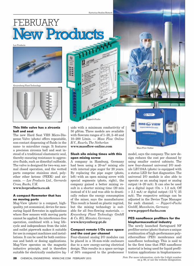
This little valve has a zirconia
ball and seat
The new Hard Seat VHS Micro-Dis-
pense Valve (photo) offers repeatable,
non-contact dispensing of fluids in the
nano- to microliter range. It features
a precision zirconia ball and seat in-
stead of a traditional elastomeric seal,
thereby ensuring resistance to aggres-
sive fluids, such as dimethyl sulfoxide.
The valve is designed for two-way, nor-
mal closed operation, and the wetted
parts comprise stainless steel, poly-
ether ether ketone (PEEK) and zir-
conia. — Lee Products Ltd., Gerrards
Cross, Bucks, U.K.
www.leeproducts.co.uk
A compact fl owmeter that has
no moving parts
Mag-View (photo) is a compact, high-
quality, yet economical, device for mea-
suring liquid flowrates in applications
where flow sensors with moving parts
cannot be applied. Its interference-free
operation, combined with a long life-
cycle and independence from the inlet
and outlet pipework makes it suitable
for use in compact machines and instal-
lations. It can be used for both continu-
ous and batch or dosing applications.
Mag-View operates on the magnetic
inductive principle, and is therefore
suitable for electrically conductive liq-
uids with a minimum conductivity of
50 µS/cm. Three models are available
with flowrate ranges of 1–20, 2–40 and
10–200 L/min. — Mass Flow Online
B.V., Ruurlo, The Netherlan
www.massflow-online.com
Slash silo mixing times with this
open mixing screw
A company in Hamburg, Germany
had been using a 20-m3 mixing silo
with internal pipe auger for 20 years.
By replacing the pipe auger (photo,
left) with an open mixing screw with
special segments (photo, right), the
company gained a better mixing re-
sult in a shorter mixing time (20 min
instead of 4 h) and was able to drasti-
cally reduce the energy consumption
of the mixer, says the manufacturer.
This result is based on plastic regrind,
but the mixing technology is suit-
able for all free-flowing materials. —
Kreyenborg Plant Technology GmbH
& Co. KG, Münster, Germany
www.kreyenborg-pt.de
Compact remote I/Os save space
and the cost per channel
Four-channel analog I/O modules can
be placed in a 16-mm-wide enclosure
due to a new energy-saving electrical
design. This results in a space savings
of 50% compared to the predecessor
model, says the company. The new de-
sign reduces the cost per channel by
using smaller control cabinets. The
new four-channel universal I/O mod-
ule LB7104A (photo) is equipped with
a status LED for fast diagnostics. The
universal I/O module is also able to
operate as an analog input or analog
output (4–20 mA). It can also be used
as a digital input (On > 1.2 mA; Off
> 2.1 mA) or digital output (12 V; 25
mA). The respective settings can be
adjusted in the Device Type Manager
for each channel. — Pepperl+Fuchs
GmbH, Mannheim, Germany
www.pepperl-fuchs.com
PES nanofl eece prefi lters for the
biopharmaceutical industry
The newly launched Sartoguard NF
prefilter series (photo) feature a unique
combination of high-performance poly-
ethersulfone (PES) membranes and
nanofleece technology. This is said to
be the first time that PES nanofleece
material is being used for liquid prefil-
tration applications in biopharmaceu-
28 CHEMICAL ENGINEERING WWW.CHE.COM FEBRUARY 2013 Note : For more information, circle the 3-digit number
on p. 60, or use the website designation.
Lee Products
Kreyenborg Plant Technology
Mass Flow Online
Pepperl+Fuchs
Sartorius Stedim Biotech
CHEMICAL ENGINEERING WWW.CHE.COM FEBRUARY 2013 29
tical manufacturing. The nanofleece
technology provides an ultrafine fleece
structure based on small (120–150-
nm dia.) nanofibers compared with
conventional fleece materials of more
than 500-nm dia. The resulting fleece
structure offers enhanced clarification
capabilities, even for extremely fine
contaminants, along with a high dirt-
holding capacity, fast flowrates and
high total throughput performance,
says the company. — Sartorius Ste-
dim Biotech, Göttingen, Germany and
Aubagne, France
www.sartorius.com
Increasing the sensitivity of
trace-element analysis
By using electrothermal vaporization
(ETV) for sample introduction, this
company has greatly improved the
sensitivity of its Arcos ICP-OES spec-
trometer (photo) for material-anal-
ysis applications. Trials verify that
detection limits can be improved by
an order of magnitude. At much lower
cost, ICP-OES penetrates the sensi-
tivity range of glow-discharge sector
field mass spectrometers, opening a
new application area in solid material
analysis for ICP-OES. Typically, ICP-
OES samples are first dissolved and
then introduced into the instrument
using a nebulizer. With ETV, however,
the solid samples are vaporized in an
oven at temperatures of up to 3,000°C.
The graphite vaporization chamber
uses argon as the inert gas. After va-
porization, the analyte is transported
as a dry aerosol to the ICP instru-
ment with an Ar/reaction-gas stream.
Sample vapor-
ization takes just
2 min. — Spectro Ana-
lytical Instruments GmbH,
Kleve, Germany
www.spectro.com
A temperature sensor designed
for pipe surfaces
The TF44 sensor (photo) is designed
for measuring the temperature on
pipe surfaces. The small design of the
protective sleeve enables optimized
mounting of the sensors and the insu-
lation above them, even on pipelines
with a small nominal width. The ther-
mowell material is aluminum, which
provides the best possible thermal
transfer from the medium to the mea-
suring element, says the company.
The choice of measuring elements is
between Pt1000 and Pt100, in addi-
tion to NTCs and other custom-made
solutions. Connection cables, from sili-
cone or polyvinyl chloride (PVC) are
Spectro Analytical Instruments
and take the recommendation of ASME, DIN, ISO and
EN into consideration to place a washer underneath the
nut to eliminate galling and great frictional variation…
HERE IS WHAT YOUR HYTORC WILL DO FOR YOU:
* Supreme Safety: You inally operate your HYTORC
without a hazardous reaction arm and backup wrench
and without holding the tool on vertical or inverted
applications
* Top Joint Reliability: You avoid joint-failure and
leakage with precise and even, circumferential joint
compression, which we guaranty
* Top Tool Reliability: You drastically improve your
HYTORC’s longevity and warranty
* Always on Time: You cut the number of passes in half
to avoid delayed startups
* Better Handling: You simplify tool handling to reduce
human error
www.hytorc.com
Being # 1… is no coincidence!
When you own aSince 1968
Circle 13 on p. 60 or go to adlinks.che.com/45769-13
WIKA Alexander Wiegand

New Products
assembled in user-specified lengths.
— WIKA Alexander Wiegand SE & Co.
KG, Klingenberg, Germany
www.wika.com
This syringe pump delivers con-
tinuous, smooth flow
Designed for flow chemistry applica-
tions, the patented Asia Syringe Pump
(photo, p. 31) is said to give users a tool
for performing flow reactions not pos-
sible using HPLC pumps or “single-
shot” syringe pumps. Used in combina-
tion with the Asia Pressurized Input
Store, the Asia Syringe Pump takes
advantage of positive input pressure to
deliver continuous, extremely smooth
flow — from 1 to 10 µL/min — at pres-
sures of between 0 and 20 bars, while
minimizing outgassing and cavitation,
says the company. The pump can be
used independently, or as a component
of the Asia Flow Chemistry system. —
Syrris Ltd., Royston, U.K.
www.syrris.com
See more with this new genera-
tion of spectroscopy software
AvaSoft 8.0 is the latest generation of
this company’s spectroscopy software.
This totally new application features
multi-monitor displays and multiple
simultaneous measurements. The
Windows-based software for minia-
ture, fiber-optic spectrometers also
includes a completely redesigned,
more user-friendly graphic-user in-
terface. Users of previous versions
of AvaSoft can upgrade to 8.0 free of
charge until March 31st. — Avantes
B.V., Apeldoorn, The Netherlands
www.avantes.com
Three new digital displays
for your measured values
The Afriso DA 10, 12 and 14 digital
display units (photo, p. 30) are suit-
able for displaying measured values
and evaluating and controlling stan-
dard signals (4–20 mA, 0–1 and 0–10
V) from electronic transducers, espe-
cially in level applications. The con-
nected transducer is supplied with
galvanically isolated 20-V d.c., while
the measuring input can be configured
as a current or a voltage input. The
user interface with selectable display
languages (English, French, German
or Italian) ensures fast commission-
ing, says the company. Bearing charts
for all cylindrical, horizontal and
spherical tanks are preprogrammed.
Depending on the device version,
the units handle up to four voltage-
free relay outputs as limit switches
(for pumps and valves, for example)
and two galvanically isolated analog
30 CHEMICAL ENGINEERING WWW.CHE.COM FEBRUARY 2013
Afro-Euro-Index
The Chemical Engineering bookstore
offers a variety of industry topics
you will come to rely on.
•EnvironmentalManagement:Air-PollutionControl
• EnvironmentalManagement:WastewaterandGroundwaterTreatment
• FluidHandling•Gas-SolidandLiquid-SolidSeparation• Liquid-LiquidandGas-LiquidSeparation•ManagingBulkSolids
For a complete list of products, visit the
Chemical Engineering bookstore now.
http://store.che.com/product/book
17792
Circle 3 on p. 60 or go to adlinks.che.com/45769-03
CHEMICAL ENGINEERING WWW.CHE.COM FEBRUARY 2013 31
outputs. — Afro-Euro-Index GmbH,
Güglingen, Germany
www.afriso.de
This vibrating level switch
handles extreme conditions
Until now, the principle of a vibrating
level switch has been limited to pro-
cess conditions up to a maximum of
280°C and 100 bars. By using a new
drive for the tuning fork of its Veg-
aswing 66 (photo), this company has
made it possible to operate over the
temperature range from –196 to 450°C
and pressures from 0 to 160 bars. The
integrated analysis and monitoring ca-
pabilities allow cer-
tification according
to SIL2 and steam
boiler regulations.
The application
range extends from
distillation columns
in the oil-and-gas in-
dustry, to high- and
low-water limits in steam boilers, and
cryogenic applications in gas tanks for
LNG and nitrogen. — Vega Grieshaber
KG, Schiltach, Germany
www.vega.com
A new anionic
surface-sizing agent
Basoplast 450 P is a new and highly
cost-efficient polymeric surface-sizing
agent (PSA) for the packaging sector.
The product is suited for linerboard
grades and complements the manu-
facturer’s range of anionic PSA in the
graphical paper market. By replacing
cationic PSA in packaging with Baso-
plast 450 P, paper manufacturers can
now adjust the desired coloration on
the surface with direct dyes, which
can provide a more cost-efficient solu-
tion than incumbent systems, says the
company. The new anionic PSA shows
no foaming tendency nor sensitivity
to pH or starch type, and can be used
in both size or film press. — BASF SE,
Ludwigshafen, Germany
www.basf.com
Control valves operate four times
faster with this volume booster
With the newly developed, high-preci-
sion 4090 pneumatic volume booster
(photo, p. 32) it is possible to amplify
the air strength of the set point sig-
nal from the positioner to the actua-
tor such that these control valves
(depending on the nominal valve
size) operate up to four times faster
without further modification. The
pneumatic volume booster is based
on a diaphragm system with which
Vega Grieshaber Syrris
Chemical
MineARC Chemical Safe Havens offer a safe, eficient and cost effective muster point alternative
in cases of emergency, such as a ires, explosions or hazardous chemical releases.
Fully custom engineered to site requirements
Solid steel structure with optional blast resistance
Self sustaining for up to 100hrs
Fully transportable by crane or fork-lift
Guaranteed 100% sealed environment (zero external ACH)
A cost effective muster point alternative to site building modiication
Suitable for a range of CPI applications
Safe Havens
For more info, call or visit the website +1 (214) 337 5100 www.minearc.com/chemsolutions
MineARCChemical Safe Haven
Circle 16 on p. 60 or go to adlinks.che.com/45769-16
32 CHEMICAL ENGINEERING WWW.CHE.COM FEBRUARY 2013
New Products
the pressure and volumetric flow of
the control air are increased up to 6
bars through the controlled input of
supply air. In the volume booster, the
control air is fed through an adjust-
able bypass to the actuator. By con-
trolling the flowrate in the bypass,
the switching threshold for activating
the amplifying air can be controlled
precisely. The 4090 pneumatic vol-
ume booster enables significant re-
ductions in switching times. — Schu-
bert & Salzer Control Systems GmbH,
Ingolstadt, Germany
www.schubert-salzer.com
Accurate RH & temperature mea-
surement in harsh environments
To best meet specific application
needs, the DT722 relative humidity
(RH) and temperature transmitter
(photo) is available in digital (DT722)
and analog (DT722-X18) models. The
digital version gives high performance
measurement with “excellent” RH ac-
curacy and delivers reliable, consis-
tent and accurate results, even over
changing ambient conditions, says
the company. The DT722-X18 is an
analog through-path measurement
device with exceptional mechanical
toughness. DT722 transmitters have
stainless-steel housings for protection
against rough handling or accidental
damage, IP65 (NEMA 4) ingress pro-
tection and a probe that can withstand
temperatures up to 150°C. — Michell
Instruments Ltd., Ely, U.K.
www.michell.com
Phthalate-free tubing for food
and beverage applications
Tygon S3 (safe, smart and sustain-
able) is said to be the first bio-based
and phthalate-free tubing, and is the
next generation of flexible tubing from
this company for food and beverage
manufacturers. Tygon S3 complies
with FDA, NSF and 3-A requirements
for food-and-beverage applications, as
well as with Japan Food Sanitation
Law # 370/1959. It also complies with
European regulations (10/2011/EU)
for many food-and-beverage applica-
tions when used as instructed. Tygon
S3 uses a bio-based plasticizer instead
of phthalates to provide “exceptional
durability and longevity,” says the
company. — Saint-Gobain Perfor-
mance Plastics, Akron, Ohio
www.processsystems.saint-gobain
.com ■Gerald Ondrey
SUBSCRIBE SUBSCRIBE SUBSCRIBE SUBSCRIBE SUBSCRIBE SUBSCRIBE SUBSCRIBE SUBSCRIBE SUBSCRIBE
SUBSCRIBE SUBSCRIBE SUBSCRIBE SUBSCRIBE SUBSCRIBE SUBSCRIBE SUBSCRIBE SUBSCRIBE SUBSCRIBE
SUBSCRIBE SUBSCRIBE SUBSCRIBE SUBSCRIBE SUBSCRIBE SUBSCRIBE SUBSCRIBE SUBSCRIBE SUBSCRIBE
SUBSCRIBE SUBSCRIBE SUBSCRIBE SUBSCRIBE SUBSCRIBE SUBSCRIBE SUBSCRIBE SUBSCRIBE SUBSCRIBE
SUBSCRIBE SUBSCRIBE SUBSCRIBE SUBSCRIBE SUBSCRIBE SUBSCRIBE SUBSCRIBE SUBSCRIBE SUBSCRIBE S U B S C R I B E T O
Written for engineers, by engineers
More and more, business in the Chemical Process Industries (CPI) is not
local, it’s global. To keep up with this rapidly evolving marketplace, you
need a magazine that covers it all, not just one country or region, not just
one vertical market, but the whole CPI.
With editorial offices in Europe, Asia, and North America, CHEMICAL
ENGINEERING is well-positioned to keep abreast of all the latest innovations
in the equipment, technology, materials, and services used by process
plants worldwide. No other publication even comes close.
To subscribe, please call 1-847-564-9290
or visit [email protected]
www.che.com
The #1 choice
of worldwideCPI organizations
July 2008
www.che.com
6
Incorporating Solids Into Liquids
Focus on Gas DetectionNew Engineering MaterialsClosed Liquid Dispensing Finding the Right Gloves
To Fit the ApplicationFacts at Your Fingertips:
Vacuum PumpsFlowmeter News
PAGE 34
August 2008
www.che.com
8Sterilization
Reverse OsmosisHeat Transfer
FluidsHydrocarbon Properties
PAGE 34
Focus on FiltrationFacts at Your Fingertips:
ValvesPreventing Caking
Lessons-Learned Systems
Michell Instruments
Schubert & Salzer Control Systems
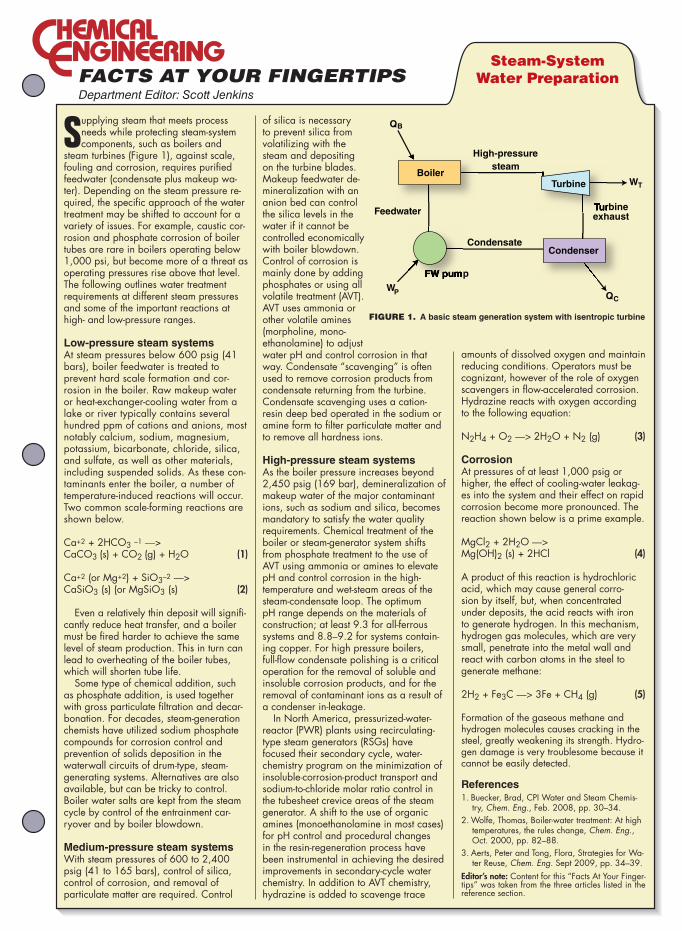
Department Editor: Scott Jenkins
Supplying steam that meets process needs while protecting steam-system components, such as boilers and
steam turbines (Figure 1), against scale, fouling and corrosion, requires purifi ed feedwater (condensate plus makeup wa-ter). Depending on the steam pressure re-quired, the specifi c approach of the water treatment may be shifted to account for a variety of issues. For example, caustic cor-rosion and phosphate corrosion of boiler tubes are rare in boilers operating below 1,000 psi, but become more of a threat as operating pressures rise above that level. The following outlines water treatment requirements at different steam pressures and some of the important reactions at high- and low-pressure ranges.
Low-pressure steam systemsAt steam pressures below 600 psig (41 bars), boiler feedwater is treated to prevent hard scale formation and cor-rosion in the boiler. Raw makeup water or heat-exchanger-cooling water from a lake or river typically contains several hundred ppm of cations and anions, most notably calcium, sodium, magnesium, potassium, bicarbonate, chloride, silica, and sulfate, as well as other materials, including suspended solids. As these con-taminants enter the boiler, a number of temperature-induced reactions will occur. Two common scale-forming reactions are shown below.
Ca+2 + 2HCO3 –1 —> CaCO3 (s) + CO2 (g) + H2O (1)
Ca+2 (or Mg+2) + SiO3–2 —> CaSiO3 (s) (or MgSiO3 (s) (2)
Even a relatively thin deposit will signifi -cantly reduce heat transfer, and a boiler must be fi red harder to achieve the same level of steam production. This in turn can lead to overheating of the boiler tubes, which will shorten tube life.
Some type of chemical addition, such as phosphate addition, is used together with gross particulate fi ltration and decar-bonation. For decades, steam-generation chemists have utilized sodium phosphate compounds for corrosion control and prevention of solids deposition in the waterwall circuits of drum-type, steam-generating systems. Alternatives are also available, but can be tricky to control. Boiler water salts are kept from the steam cycle by control of the entrainment car-ryover and by boiler blowdown.
Medium-pressure steam systemsWith steam pressures of 600 to 2,400 psig (41 to 165 bars), control of silica, control of corrosion, and removal of particulate matter are required. Control
of silica is necessary to prevent silica from volatilizing with the steam and depositing on the turbine blades. Makeup feedwater de-mineralization with an anion bed can control the silica levels in the water if it cannot be controlled economically with boiler blowdown. Control of corrosion is mainly done by adding phosphates or using all volatile treatment (AVT). AVT uses ammonia or other volatile amines (morpholine, mono-ethanolamine) to adjust water pH and control corrosion in that way. Condensate “scavenging” is often used to remove corrosion products from condensate returning from the turbine. Condensate scavenging uses a cation-resin deep bed operated in the sodium or amine form to fi lter particulate matter and to remove all hardness ions.
High-pressure steam systemsAs the boiler pressure increases beyond 2,450 psig (169 bar), demineralization of makeup water of the major contaminant ions, such as sodium and silica, becomes mandatory to satisfy the water quality requirements. Chemical treatment of the boiler or steam-generator system shifts from phosphate treatment to the use of AVT using ammonia or amines to elevate pH and control corrosion in the high-temperature and wet-steam areas of the steam-condensate loop. The optimum pH range depends on the materials of construction; at least 9.3 for all-ferrous systems and 8.8–9.2 for systems contain-ing copper. For high pressure boilers, full-fl ow condensate polishing is a critical operation for the removal of soluble and insoluble corrosion products, and for the removal of contaminant ions as a result of a condenser in-leakage.
In North America, pressurized-water-reactor (PWR) plants using recirculating-type steam generators (RSGs) have focused their secondary cycle, water-chemistry program on the minimization of insoluble-corrosion-product transport and sodium-to-chloride molar ratio control in the tubesheet crevice areas of the steam generator. A shift to the use of organic amines (monoethanolamine in most cases) for pH control and procedural changes in the resin-regeneration process have been instrumental in achieving the desired improvements in secondary-cycle water chemistry. In addition to AVT chemistry, hydrazine is added to scavenge trace
amounts of dissolved oxygen and maintain reducing conditions. Operators must be cognizant, however of the role of oxygen scavengers in fl ow-accelerated corrosion. Hydrazine reacts with oxygen according to the following equation:
N2H4 + O2 —> 2H2O + N2 (g) (3)
Corrosion At pressures of at least 1,000 psig or higher, the effect of cooling-water leakag-es into the system and their effect on rapid corrosion become more pronounced. The reaction shown below is a prime example.
MgCl2 + 2H2O —> Mg(OH)2 (s) + 2HCl (4)
A product of this reaction is hydrochloric acid, which may cause general corro-sion by itself, but, when concentrated under deposits, the acid reacts with iron to generate hydrogen. In this mechanism, hydrogen gas molecules, which are very small, penetrate into the metal wall and react with carbon atoms in the steel to generate methane:
2H2 + Fe3C —> 3Fe + CH4 (g) (5)
Formation of the gaseous methane and hydrogen molecules causes cracking in the steel, greatly weakening its strength. Hydro-gen damage is very troublesome because it cannot be easily detected.
References
1. Buecker, Brad, CPI Water and Steam Chemis-try, Chem. Eng., Feb. 2008, pp. 30–34.
2. Wolfe, Thomas, Boiler-water treatment: At high temperatures, the rules change, Chem. Eng., Oct. 2000, pp. 82–88.
3. Aerts, Peter and Tong, Flora, Strategies for Wa-ter Reuse, Chem. Eng. Sept 2009, pp. 34–39.
Editor’s note: Content for this “Facts At Your Finger-tips” was taken from the three articles listed in the reference section.
Steam-System
Water Preparation
Boiler
Condenser
FW pump
QB
QC
WT
WP
High-pressure
steam
Turbineexhaust
Condensate
Feedwater
Turbine
FIGURE 1. A basic steam generation system with isentropic turbine
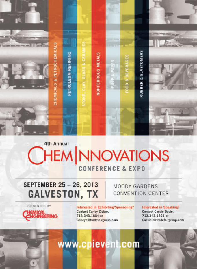
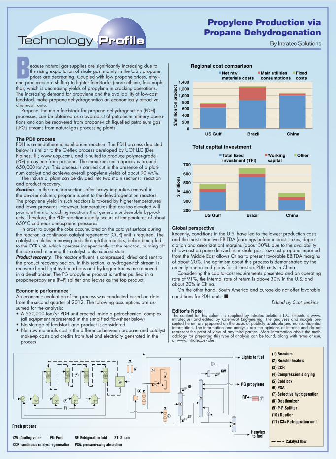
Propylene Production via
Propane Dehydrogenation
Because natural gas supplies are significantly increasing due to the rising exploitation of shale gas, mainly in the U.S., propane prices are decreasing. Coupled with low propane prices, ethyl-
ene producers are shifting to lighter feedstocks (more ethane, less naph-tha), which is decreasing yields of propylene in cracking operations. The increasing demand for propylene and the availability of low-cost feedstock make propane dehydrogenation an economically attractive chemical route.
Propane, the main feedstock for propane dehydrogenation (PDH) processes, can be obtained as a byproduct of petroleum refinery opera-tions and can be recovered from propane-rich liquefied petroleum gas (LPG) streams from natural-gas processing plants.
The PDH processPDH is an endothermic equilibrium reaction. The PDH process depicted below is similar to the Oleflex process developed by UOP LLC (Des Plaines, Ill.; www.uop.com), and is suited to produce polymer-grade (PG) propylene from propane. The maximum unit capacity is around 650,000 ton/yr. This process is carried out in the presence of a plati-num catalyst and achieves overall propylene yields of about 90 wt.%.
The industrial plant can be divided into two main sections: reaction and product recovery.Reaction. In the reaction section, after heavy impurities removal in the de-oiler column, propane is sent to the dehydrogenation reactors. The propylene yield in such reactors is favored by higher temperatures and lower pressures. However, temperatures that are too elevated will promote thermal cracking reactions that generate undesirable byprod-ucts. Therefore, the PDH reaction usually occurs at temperatures of about 650°C and near atmospheric pressures.
In order to purge the coke accumulated on the catalyst surface during the reaction, a continuous catalyst regenerator (CCR) unit is required. The catalyst circulates in moving beds through the reactors, before being fed to the CCR unit, which operates independently of the reaction, burning off the coke and returning the catalyst to its reduced state.Product recovery. The reactor effluent is compressed, dried and sent to the product recovery section. In this section, a hydrogen-rich stream is recovered and light hydrocarbons and hydrogen traces are removed in a de-ethanizer. The PG propylene product is further purified in a propane-propylene (P–P) splitter and leaves as the top product.
Economic performanceAn economic evaluation of the process was conducted based on data from the second quarter of 2012. The following assumptions are as-sumed for the analysis:•A550,000ton/yrPDHuniterectedinsideapetrochemicalcomplex
(all equipment represented in the simplified flowsheet below) •Nostorageoffeedstockandproductisconsidered•Netrawmaterialscostisthedifferencebetweenpropaneandcatalyst
make-up costs and credits from fuel and electricity generated in the process
Global perspectiveRecently, conditions in the U.S. have led to the lowest production costs and the most attractive EBITDA (earnings before interest, taxes, depre-ciation and amortization) margins (about 30%), due to the availability of low-cost propane derived from shale gas. Low-cost propane imported from the Middle East allows China to present favorable EBITDA margins of about 20%. The optimism about this process is demonstrated by the recently announced plans for at least six PDH units in China.
Considering the capital-cost requirements presented and an operating rate of 91%, the internal rate of return is above 30% in the U.S. and about 20% in China.
On the other hand, South America and Europe do not offer favorable conditions for PDH units. ■
Edited by Scott Jenkins
Editor’s Note:The content for this column is supplied by Intratec Solutions LLC. (Houston; www.intratec.us) and edited by Chemical Engineering. The analyses and models pre-sented herein are prepared on the basis of publicly available and non-confidential information. The information and analysis are the opinions of Intratec and do not represent the point of view of any third parties. More information about the meth-odology for preparing this type of analysis can be found, along with terms of use, at www.intratec.us/che.
0
200
400
600
800
1,000
1,200
1,400
US Gulf Brazil China
Regional cost comparison
Net raw materials costs
Main utilities consumptions
Fixed costs
200
300
400
500
600
700
US Gulf Brazil China
$,
mil
lio
ns
$
/mil
lio
n t
on
pro
du
ct
Total capital investment
Total fixed investment (TFI)
Working capital
Other
Catalyst flow
(1) Reactors
(2) Reactor heaters
(3) CCR
(4) Compression & drying
(5) Cold box
(6) PSA
(7) Selective hydrogenation
(8) Deethanizer
(9) P-P Splitter
(10) Deoiler
(11) C3= Refrigeration unitFresh propane
PG propylene
Heavies to fuel
Lights to fuel
1
3
4
5
7
8
9
6
ST
RF
RF: Refrigeration fluid
112
10
FU
CW
CCR: continuous catalyst regeneration PSA: pressure-swing absorption
: Cooling water ST: SteamFU: Fuel
CW
RF
By Intratec Solutions

CONTINENTAL DISC CORPORATION //3160 W. Heartland DriveLiberty, MO 64068 USAPh (816) 792 1500 | Fax (816) 792 [email protected]
THE NETHERLANDSEnergieweg 202382 NJ Zoeterwoude-RijndijkThe NetherlandsPh +(31) 71 5412221 | Fax +(31) 71 [email protected]
CHINARoom 910, Tower B, COFCO PlazaNo. 8 JianGuoMenNei AvenueBeijing (100005), P.R. China Ph +(86) 10 522 4885 | Fax +(86) 10 6522 [email protected]
INDIA423/P/11, Mahagujarat Industrial Estate, Moraiya,Sarkhej-Bavla Road, Ahmedabad (GJ) 382213 INDIA Ph +(91) 2717 619 333 | Fax +(86) 10 6522 [email protected]
GROTH CORPORATION //13650 N. Promenade Blvd.Stafford, TX 77477 USAPh (281) 295-6800 | Fax (281) [email protected]
CHOOSE THE
#1 QUALITY PROVIDER
FOR ALL YOUR
ENGINEERED SAFETY PRODUCTS
THAT PROTECT EQUIPMENT, LIVES
& THE ENVIRONMENT!
Industrial & Sanitary Rupture Discs & Holders
Customized Pressure Relief Products
B.D.I. Alarm Systems Hose Valves
Relief ValvesPilot Operated ValvesFlame/Detonation ArrestersBlanket Gas RegulatorsGas Control EquipmentTest Stands
Circle 8 on p. 60 or go to adlinks.che.com/45769-08
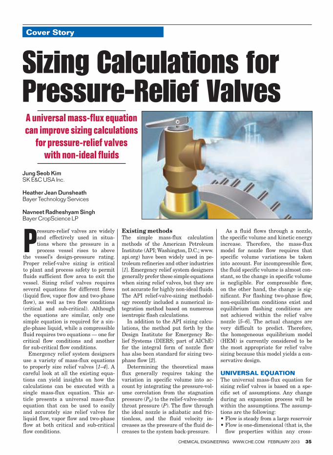
Cover Story
CHEMICAL ENGINEERING WWW.CHE.COM FEBRUARY 2013 35
Pressure-relief valves are widely
and effectively used in situa-
tions where the pressure in a
process vessel rises to above
the vessel’s design-pressure rating.
Proper relief-valve sizing is critical
to plant and process safety to permit
fluids sufficient flow area to exit the
vessel. Sizing relief valves requires
several equations for different flows
(liquid flow, vapor flow and two-phase
flow), as well as two flow conditions
(critical and sub-critical). Although
the equations are similar, only one
simple equation is required for a sin-
gle-phase liquid, while a compressible
fluid requires two equations — one for
critical flow conditions and another
for sub-critical flow conditions.
Emergency relief system designers
use a variety of mass-flux equations
to properly size relief valves [1–4]. A
careful look at all the existing equa-
tions can yield insights on how the
calculations can be executed with a
single mass-flux equation. This ar-
ticle presents a universal mass-flux
equation that can be used to easily
and accurately size relief valves for
liquid flow, vapor flow and two-phase
flow at both critical and sub-critical
flow conditions.
Existing methodsThe simple mass-flux calculation
methods of the American Petroleum
Institute (API; Washington, D.C.; www.
api.org) have been widely used in pe-
troleum refineries and other industries
[1]. Emergency relief system designers
generally prefer these simple equations
when sizing relief valves, but they are
not accurate for highly non-ideal fluids.
The API relief-valve-sizing methodol-
ogy recently included a numerical in-
tegration method based on numerous
isentropic flash calculations.
In addition to the API sizing calcu-
lations, the method put forth by the
Design Institute for Emergency Re-
lief Systems (DIERS; part of AIChE)
for the integral form of nozzle flow
has also been standard for sizing two-
phase flow [2].
Determining the theoretical mass
flux generally requires taking the
variation in specific volume into ac-
count by integrating the pressure-vol-
ume correlation from the stagnation
pressure (P0) to the relief-valve-nozzle
throat pressure (P). The flow through
the ideal nozzle is adiabatic and fric-
tionless, and the fluid velocity in-
creases as the pressure of the fluid de-
creases to the system back-pressure.
As a fluid flows through a nozzle,
the specific volume and kinetic energy
increase. Therefore, the mass-flux
model for nozzle flow requires that
specific volume variations be taken
into account. For incompressible flow,
the fluid specific volume is almost con-
stant, so the change in specific volume
is negligible. For compressible flow,
on the other hand, the change is sig-
nificant. For flashing two-phase flow,
non-equilibrium conditions exist and
equilibrium flashing conditions are
not achieved within the relief valve
nozzle [5–6]. The actual changes are
very difficult to predict. Therefore,
the homogeneous equilibrium model
(HEM) is currently considered to be
the most appropriate for relief valve
sizing because this model yields a con-
servative design.
UNIVERSAL EQUATIONThe universal mass-flux equation for
sizing relief valves is based on a spe-
cific set of assumptions. Any change
during an expansion process will be
within the assumptions. The assump-
tions are the following:
• Flow is steady from a large reservoir• Flow is one-dimensional (that is, the
flow properties within any cross-
Sizing Calculations for Pressure-Relief Valves
Jung Seob KimSK E&C USA Inc.
Heather Jean DunsheathBayer Technology Services
Navneet Radheshyam SinghBayer CropScience LP
A universal mass-flux equation
can improve sizing calculations
for pressure-relief valves
with non-ideal fluids
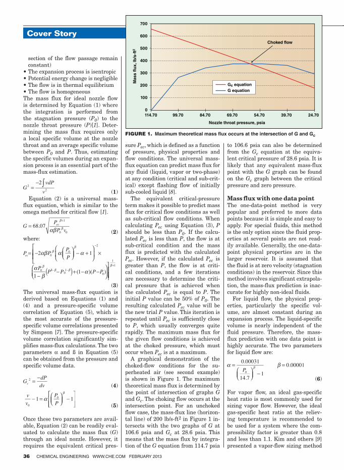
Cover Story
36 CHEMICAL ENGINEERING WWW.CHE.COM FEBRUARY 2013
section of the flow passage remain
constant)
• The expansion process is isentropic• Potential energy change is negligible• The flow is in thermal equilibrium• The flow is homogeneousThe mass flux for ideal nozzle flow is determined by Equation (1) where the integration is performed from the stagnation pressure (P0) to the
nozzle throat pressure (P)[1]. Deter-
mining the mass flux requires only a local specific volume at the nozzle throat and an average specific volume between P0 and P. Thus, estimating the specific volumes during an expan-sion process is an essential part of the
mass-flux estimation.
(1)
Equation (2) is a universal mass-flux equation, which is similar to the omega method for critical flow [1].
(2)
where:
(3)
The universal mass-flux equation is derived based on Equations (1) and (4) and a pressure-specific volume correlation of Equation (5), which is the most accurate of the pressure-specific volume correlations presented by Simpson [7]. The pressure-specific volume correlation significantly sim-plifies mass-flux calculations. The two parameters α and ß in Equation (5) can be obtained from the pressure and specific volume data.
(4)
(5)
Once these two parameters are avail-
able, Equation (2) can be readily eval-uated to calculate the mass flux (G)
through an ideal nozzle. However, it requires the equivalent critical pres-
sure Pec, which is defined as a function of pressure, physical properties and flow conditions. The universal mass-flux equation can predict mass flux for any fluid (liquid, vapor or two-phase) at any condition (critical and sub-crit-ical) except flashing flow of initially sub-cooled liquid [8].
The equivalent critical-pressure term makes it possible to predict mass flux for critical flow conditions as well as sub-critical flow conditions. When calculating Pec using Equation (3), P
should be less than P0. If the calcu-lated Pec is less than P, the flow is at sub-critical condition and the mass flux is predicted with the calculated Pec. However, if the calculated Pec is
greater than P, the flow is at criti-cal conditions, and a few iterations are necessary to determine the criti-cal pressure that is achieved when the calculated Pec is equal to P. The initial P value can be 50% of P0. The resulting calculated Pec value will be the new trial P value. This iteration is repeated until Pec is sufficiently close to P, which usually converges quite rapidly. The maximum mass flux for the given flow conditions is achieved at the choked pressure, which must occur when Pec is at a maximum.
A graphical demonstration of the choked-flow conditions for the su-perheated air (see second example) is shown in Figure 1. The maximum theoretical mass flux is determined by the point of intersection of graphs G
and Gc. The choking flow occurs at the intersection point. For an unchoked flow case, the mass-flux line (horizon-tal line) of 200 lb/s-ft2 in Figure 1 in-tersects with the two graphs of G at
106.6 psia and Gc at 28.6 psia. This means that the mass flux by integra-tion of the G equation from 114.7 psia
to 106.6 psia can also be determined from the Gc equation at the equiva-lent critical pressure of 28.6 psia. It is likely that any equivalent mass-flux point with the G graph can be found on the Gc graph between the critical pressure and zero pressure.
Mass flux with one data pointThe one-data-point method is very popular and preferred to more data points because it is simple and easy to apply. For special fluids, this method is the only option since the fluid prop-erties at several points are not read-ily available. Generally, the one-data-point physical properties are in the larger reservoir. It is assumed that the fluid is at zero velocity (stagnation conditions) in the reservoir. Since this method involves significant extrapola-tion, the mass-flux prediction is inac-curate for highly non-ideal fluids.
For liquid flow, the physical prop-erties, particularly the specific vol-ume, are almost constant during an expansion process. The liquid-specific volume is nearly independent of the fluid pressure. Therefore, the mass-flux prediction with one data point is highly accurate. The two parameters for liquid flow are:
(6)
For vapor flow, an ideal gas-specific heat ratio is most commonly used for sizing vapor flow. However, the ideal gas-specific heat ratio at the reliev-
ing temperature is recommended to be used for a system where the com-pressibility factor is greater than 0.8 and less than 1.1. Kim and others [9]
presented a vapor-flow sizing method
FIGURE 1. Maximum theoretical mass � ux occurs at the intersection of G and Gc
700
600
500
400
300
200
100
0
114.70 99.70 84.70 69.70 54.70 39.70 24.70
Choked flow
Mass f
lux, lb
/s-f
t2
Nozzle throat pressure, psia
Gc equation
G equation
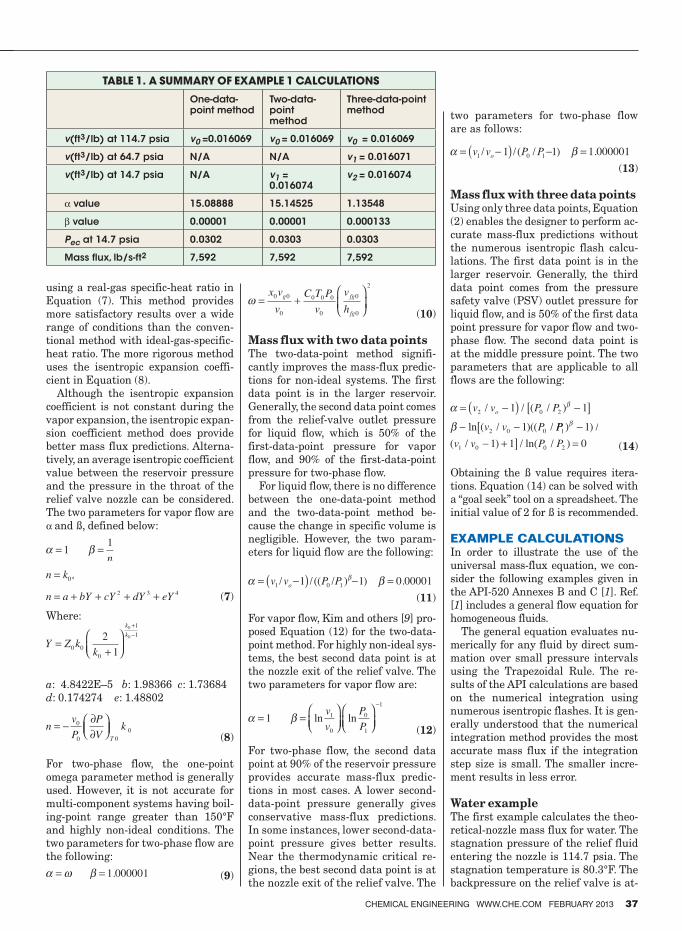
CHEMICAL ENGINEERING WWW.CHE.COM FEBRUARY 2013 37
using a real-gas specific-heat ratio in
Equation (7). This method provides
more satisfactory results over a wide
range of conditions than the conven-
tional method with ideal-gas-specific-
heat ratio. The more rigorous method
uses the isentropic expansion coeffi-
cient in Equation (8).
Although the isentropic expansion
coefficient is not constant during the
vapor expansion, the isentropic expan-
sion coefficient method does provide
better mass flux predictions. Alterna-
tively, an average isentropic coefficient
value between the reservoir pressure
and the pressure in the throat of the
relief valve nozzle can be considered.
The two parameters for vapor flow are
α and ß, defined below:
(7)
Where:
a: 4.8422E–5 b: 1.98366 c: 1.73684
d: 0.174274 e: 1.48802
(8)
For two-phase flow, the one-point
omega parameter method is generally
used. However, it is not accurate for
multi-component systems having boil-
ing-point range greater than 150°F
and highly non-ideal conditions. The
two parameters for two-phase flow are
the following:
(9)
(10)
Mass flux with two data points The two-data-point method signifi-
cantly improves the mass-flux predic-
tions for non-ideal systems. The first
data point is in the larger reservoir.
Generally, the second data point comes
from the relief-valve outlet pressure
for liquid flow, which is 50% of the
first-data-point pressure for vapor
flow, and 90% of the first-data-point
pressure for two-phase flow.
For liquid flow, there is no difference
between the one-data-point method
and the two-data-point method be-
cause the change in specific volume is
negligible. However, the two param-
eters for liquid flow are the following:
(11)
For vapor flow, Kim and others [9] pro-
posed Equation (12) for the two-data-
point method. For highly non-ideal sys-
tems, the best second data point is at
the nozzle exit of the relief valve. The
two parameters for vapor flow are:
(12)
For two-phase flow, the second data
point at 90% of the reservoir pressure
provides accurate mass-flux predic-
tions in most cases. A lower second-
data-point pressure generally gives
conservative mass-flux predictions.
In some instances, lower second-data-
point pressure gives better results.
Near the thermodynamic critical re-
gions, the best second data point is at
the nozzle exit of the relief valve. The
two parameters for two-phase flow
are as follows:
(13)
Mass flux with three data pointsUsing only three data points, Equation
(2) enables the designer to perform ac-
curate mass-flux predictions without
the numerous isentropic flash calcu-
lations. The first data point is in the
larger reservoir. Generally, the third
data point comes from the pressure
safety valve (PSV) outlet pressure for
liquid flow, and is 50% of the first data
point pressure for vapor flow and two-
phase flow. The second data point is
at the middle pressure point. The two
parameters that are applicable to all
flows are the following:
(14)
Obtaining the ß value requires itera-
tions. Equation (14) can be solved with
a “goal seek” tool on a spreadsheet. The
initial value of 2 for ß is recommended.
EXAMPLE CALCULATIONS
In order to illustrate the use of the
universal mass-flux equation, we con-
sider the following examples given in
the API-520 Annexes B and C [1]. Ref.
[1] includes a general flow equation for
homogeneous fluids.
The general equation evaluates nu-
merically for any fluid by direct sum-
mation over small pressure intervals
using the Trapezoidal Rule. The re-
sults of the API calculations are based
on the numerical integration using
numerous isentropic flashes. It is gen-
erally understood that the numerical
integration method provides the most
accurate mass flux if the integration
step size is small. The smaller incre-
ment results in less error.
Water exampleThe first example calculates the theo-
retical-nozzle mass flux for water. The
stagnation pressure of the relief fluid
entering the nozzle is 114.7 psia. The
stagnation temperature is 80.3°F. The
backpressure on the relief valve is at-
TABLE 1. A SUMMARY OF EXAMPLE 1 CALCULATIONS
One-data-point method
Two-data-point method
Three-data-point method
v(ft3/lb) at 114.7 psia v0 =0.016069 v0 = 0.016069 v0 = 0.016069
v(ft3/lb) at 64.7 psia N/A N/A v1 = 0.016071
v(ft3/lb) at 14.7 psia N/A v1 = 0.016074
v2 = 0.016074
α value 15.08888 15.14525 1.13548
β value 0.00001 0.00001 0.000133
Pec at 14.7 psia 0.0302 0.0303 0.0303
Mass flux, lb/s-ft2 7,592 7,592 7,592
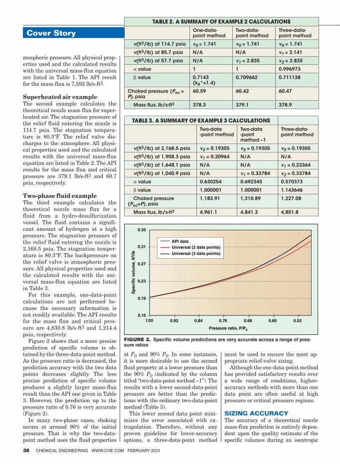
Cover Story
38 CHEMICAL ENGINEERING WWW.CHE.COM FEBRUARY 2013
mospheric pressure. All physical prop-
erties used and the calculated results
with the universal mass-flux equation
are listed in Table 1. The API result
for the mass flux is 7,592 lb/s-ft2.
Superheated air example The second example calculates the
theoretical nozzle mass flux for super-
heated air. The stagnation pressure of
the relief fluid entering the nozzle is
114.7 psia. The stagnation tempera-
ture is 80.3°F. The relief valve dis-
charges to the atmosphere. All physi-
cal properties used and the calculated
results with the universal mass-flux
equation are listed in Table 2. The API
results for the mass flux and critical
pressure are 379.1 lb/s-ft2 and 60.7
psia, respectively.
Two-phase fluid example The third example calculates the
theoretical nozzle mass flux for a
fluid from a hydro-desulfurization
vessel. The fluid contains a signifi-
cant amount of hydrogen at a high
pressure. The stagnation pressure of
the relief fluid entering the nozzle is
2,168.5 psia. The stagnation temper-
ature is 80.3°F. The backpressure on
the relief valve is atmospheric pres-
sure. All physical properties used and
the calculated results with the uni-
versal mass-flux equation are listed
in Table 3.
For this example, one-data-point
calculations are not performed be-
cause the necessary information is
not readily available. The API results
for the mass flux and critical pres-
sure are 4,830.8 lb/s-ft2 and 1,214.4
psia, respectively.
Figure 2 shows that a more precise
prediction of specific volume is ob-
tained by the three-data-point method.
As the pressure ratio is decreased, the
prediction accuracy with the two data
points decreases slightly. The less
precise prediction of specific volume
produces a slightly larger mass-flux
result than the API one given in Table
3. However, the prediction up to the
pressure ratio of 0.76 is very accurate
(Figure 2).
In many two-phase cases, choking
occurs at around 90% of the initial
pressure. That is why the two-data-
point method uses the fluid properties
at P0 and 90% P0. In some instances,
it is more desirable to use the second
fluid property at a lower pressure than
the 90% P0 (indicated by the column
titled “two-data-point method –1”). The
results with a lower second-data-point
pressure are better than the predic-
tions with the ordinary two-data-point
method (Table 3).
This lower second data point mini-
mizes the error associated with ex-
trapolation. Therefore, without any
proven guideline for lower-accuracy
options, a three-data-point method
must be used to ensure the most ap-
propriate relief-valve sizing.
Although the one-data-point method
has provided satisfactory results over
a wide range of conditions, higher-
accuracy methods with more than one
data point are often useful at high
pressure or critical pressure regions.
SIZING ACCURACYThe accuracy of a theoretical nozzle
mass-flux prediction is entirely depen-
dent upon the quality estimate of the
specific volumes during an isentropic
Pressure ratio, P/P0
0.15
0.19
0.23
0.27
0.31
0.35
1.00
Sp
ecif
ic v
olu
me
, ft
3/lb
API data
Universal (2 data points)
Universal (3 data points)
0.92 0.84 0.76 0.68 0.60 0.52
TABLE 2. A SUMMARY OF EXAMPLE 2 CALCULATIONS
One-data-point method
Two-data-point method
Three-data-point method
v(ft3/lb) at 114.7 psia v0 = 1.741 v0 = 1.741 v0 = 1.741
v(ft3/lb) at 85.7 psia N/A N/A v1 = 2.141
v(ft3/lb) at 57.7 psia N/A v1 = 2.835 v2 = 2.835
α value 1 1 0.996973
β value 0.7143 (k0*=1.4)
0.709662 0.711138
Choked pressure (Pec = P), psia
60.59 60.42 60.47
Mass flux, lb/s-ft2 378.3 379.1 378.9
TABLE 3. A SUMMARY OF EXAMPLE 3 CALCULATIONS
Two-data -point method
Two-data -point method –1
Three-data-point method
v(ft3/lb) at 2,168.5 psia v0 = 0.19305 v0 = 0.19305 v0 = 0.19305
v(ft3/lb) at 1,908.3 psia v1 = 0.20964 N/A N/A
v(ft3/lb) at 1,648.1 psia N/A N/A v1 = 0.23364
v(ft3/lb) at 1,040.9 psia N/A v1 = 0.33784 v2 = 0.33784
α value 0.630254 0.692345 0.570373
β value 1.000001 1.000001 1.143646
Choked pressure (Pec=P), psia
1,183.91 1,210.89 1,227.08
Mass flux, lb/s-ft2 4,961.1 4,841.3 4,851.8
FIGURE 2. Speci� c volume predictions are very accurate across a range of pres-sure ratios
CHEMICAL ENGINEERING WWW.CHE.COM FEBRUARY 2013 39
expansion process. The universal
mass-flux equation clearly illustrates
why using good specific volume data is
important for proper relief-valve sizing.
One-data-point calculations involve as-
sumptions that generally restrict the
quality of the calculation results. How-
ever, the calculation results are still
satisfactory and commonly used within
the verified limits of applicability.
The calculations with more than
one data point will definitely improve
the mass-flux prediction. Therefore,
the current trend of relief valve sizing
is changing to use more than one data
point. The one-data-point method is
more likely to be inaccurate for han-
dling fluids that depart significantly
from ideality. As the number of data
points increases, the mass-flux quality
will increase accordingly.
The universal mass-flux equation
can be used to check the specific vol-
ume estimates actually used in the
sizing calculations. Therefore, it is nec-
essary to compare the specific volume
estimation at the nozzle exit pressure
with the correct physical property
data if only one or two data points are
used in the sizing calculations. If they
are significantly different, the calcu-
lations should be repeated with more
data points or using the correct physi-
cal property as a second data point. As
demonstrated in the example calcula-
tions, the universal mass-flux equa-
tion is a simple, flexible and powerful
tool for sizing relief valves. ■Edited by Scott Jenkins
References 1. American Petroleum Institute. “Sizing, Selec-
tion, and Installation of Pressure-relieving Devices in Refineries,” API Standard 520, Part I — Sizing and Selection, December 2008.
2. Center for Chemical Process Safety (CCPS). “Guidelines for Pressure Relief and Effluent Handling Systems,” AIChE, New York, 1998.
3. Leung, J. C., Easily Size Relief Devices and Piping for Two-Phase Flow, Chem. Eng. Prog., pp. 28–50, December 1996.
4. Darby, R., Size Safety-Relief Valves for Any Conditions, Chem. Eng., pp. 42–50, Sept. 2005.
5. Crowl, D. A. and Louvar, J. F., “Chemical Process Safety: Fundamentals with Appli-cations,” Prentice-Hall, Englewood Cliffs, NJ, 1990.
6. Diener, R., Schmidt, J., Sizing of Throttling Device for Gas/Liquid Two-Phase Flow, Pro-cess Safety Progress, 23 (4), pp. 335–344, 2004.
7. Simpson, L. L., “Navigating the Two-Phase Maze,” in International Symposium on Run-away Reactions and Pressure Relief Design, G. A. Melhem and H. G. Fisher, eds., Design Institute for Emergency Relief Systems (DIERS), AIChE, meeting held in Boston, pp. 394–417, Aug. 2–4, 1995.
8. Leung, J.C., Grolmes M, A Generalized cor-relation for flashing choked flow of initially subcooled liquid, AIChE J, 34(4), April 1988.
9. Kim, J. S., Dunsheath, H.J., and Singh, N. R., “Proper Relief-valve Sizing Requires Equa-tion Mastery,” Hydrocarbon Processing, pp. 77–80, December 2011.
NOMENCLATURE
C liquid specific heat at constant pressure, Btu/lb-°F
G theoretical mass flux, lb/s-ft2h enthalpy, Btu/lbk gas or vapor specific heat ratioM gas or vapor molecular weightn isentropic expansion coefficient P absolute pressure, psia T absolute temperature, Rv specific volume, ft3/lbZ gas or vapor compressibility factorα, β,ω parameters for a pressure- specific volume correlation
Subscripts0,1,2 physical property data states c choked (critical) conditionsec equivalent choked (critical) condi-
tionsf liquid fg difference between vapor and
liquid propertiesg vapor* ideal conditions
Authors Jung Seob Kim is a senior process engineer at SK E&C USA Inc. (1401 Enclave Park-way Suite 100, Houston, TX 77077; Phone: 281-258-2619; Email: [email protected]) where he is responsible for design-ing petrochemical and pe-troleum refinery plants. He has more than 25 years of experience in different roles with the petrochemical pro-
cess industry including with Bayer Technology Services, Samsung BP Chemicals and Samsung Engineering. He holds a B.S.Ch.E. from the Uni-versity of Seoul, is a member of AIChE, and is a registered professional engineer in the State
of Texas.
Heather Jean Dunsheath is a pressure safety specialist at Bayer Technology Services (8500 West Bay Road MS 52, Baytown, TX 77523; Phone: 281-383-6879; Email: [email protected]) where she is responsible for design-ing emergency pressure relief systems and participates in process hazard analysis stud-
ies. She holds a B.S.Ch.E. from Rice University.
Navneet R. Singh is a senior process engineer at Bayer CropScience LP (8400 Haw-thorne Road, Kansas City, MO 64120; Phone: 816-242-2738; email: [email protected]) where he has experience with process design, process modeling, environmental and utility services, and emer-gency relief-system design. He holds M.S. and Ph.D. degrees
from Purdue University, and B.S.Ch.E. from the Institute of Chemical Technology, Mumbai, is a senior member of AIChE and a professional engi-neer in West Virginia.
for example:
Tall oil distillationLecithin dryingMonoglyceride
Glycerin recovery
Fatty Acid Industry
Liquids to m Liquids Liquids Liquids Liquids Liquids Liquids Liquids Liquids Liquids Liquids Liquids Liquids Liquids Liquids Liquids Liquids Liquids Liquids Liquids Liquids Liquids Liquids Liquids Liquids Liquids Liquids Liquids Liquids Liquids Liquids Liquids Liquids Liquids Liquids to money to money to money to money to money to money to m to m to m to m to m to m to m to m to m to m to m to m
Processing Partners:
www.gigkarasek.atwww.incontech.com
system solutions for evaporation and biopharma
Circle 12 on p. 60 or go to adlinks.che.com/45769-12
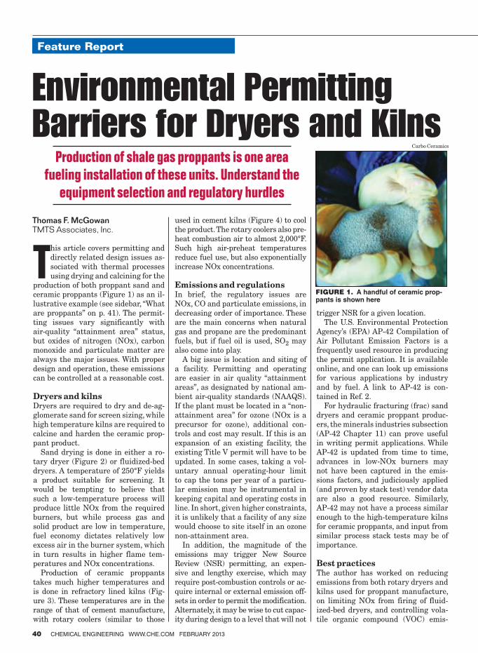
This article covers permitting and
directly related design issues as-
sociated with thermal processes
using drying and calcining for the
production of both proppant sand and
ceramic proppants (Figure 1) as an il-
lustrative example (see sidebar, “What
are proppants” on p. 41). The permit-
ting issues vary significantly with
air-quality “attainment area” status,
but oxides of nitrogen (NOx), carbon
monoxide and particulate matter are
always the major issues. With proper
design and operation, these emissions
can be controlled at a reasonable cost.
Dryers and kilnsDryers are required to dry and de-ag-
glomerate sand for screen sizing, while
high temperature kilns are required to
calcine and harden the ceramic prop-
pant product.
Sand drying is done in either a ro-
tary dryer (Figure 2) or fluidized-bed
dryers. A temperature of 250°F yields
a product suitable for screening. It
would be tempting to believe that
such a low-temperature process will
produce little NOx from the required
burners, but while process gas and
solid product are low in temperature,
fuel economy dictates relatively low
excess air in the burner system, which
in turn results in higher flame tem-
peratures and NOx concentrations.
Production of ceramic proppants
takes much higher temperatures and
is done in refractory lined kilns (Fig-
ure 3). These temperatures are in the
range of that of cement manufacture,
with rotary coolers (similar to those
used in cement kilns (Figure 4) to cool
the product. The rotary coolers also pre-
heat combustion air to almost 2,000°F.
Such high air-preheat temperatures
reduce fuel use, but also exponentially
increase NOx concentrations.
Emissions and regulationsIn brief, the regulatory issues are
NOx, CO and particulate emissions, in
decreasing order of importance. These
are the main concerns when natural
gas and propane are the predominant
fuels, but if fuel oil is used, SO2 may
also come into play.
A big issue is location and siting of
a facility. Permitting and operating
are easier in air quality “attainment
areas”, as designated by national am-
bient air-quality standards (NAAQS).
If the plant must be located in a “non-
attainment area” for ozone (NOx is a
precursor for ozone), additional con-
trols and cost may result. If this is an
expansion of an existing facility, the
existing Title V permit will have to be
updated. In some cases, taking a vol-
untary annual operating-hour limit
to cap the tons per year of a particu-
lar emission may be instrumental in
keeping capital and operating costs in
line. In short, given higher constraints,
it is unlikely that a facility of any size
would choose to site itself in an ozone
non-attainment area.
In addition, the magnitude of the
emissions may trigger New Source
Review (NSR) permitting, an expen-
sive and lengthy exercise, which may
require post-combustion controls or ac-
quire internal or external emission off-
sets in order to permit the modification.
Alternately, it may be wise to cut capac-
ity during design to a level that will not
trigger NSR for a given location.
The U.S. Environmental Protection
Agency’s (EPA) AP-42 Compilation of
Air Pollutant Emission Factors is a
frequently used resource in producing
the permit application. It is available
online, and one can look up emissions
for various applications by industry
and by fuel. A link to AP-42 is con-
tained in Ref. 2.
For hydraulic fracturing (frac) sand
dryers and ceramic proppant produc-
ers, the minerals industries subsection
(AP-42 Chapter 11) can prove useful
in writing permit applications. While
AP-42 is updated from time to time,
advances in low-NOx burners may
not have been captured in the emis-
sions factors, and judiciously applied
(and proven by stack test) vendor data
are also a good resource. Similarly,
AP-42 may not have a process similar
enough to the high-temperature kilns
for ceramic proppants, and input from
similar process stack tests may be of
importance.
Best practicesThe author has worked on reducing
emissions from both rotary dryers and
kilns used for proppant manufacture,
on limiting NOx from firing of fluid-
ized-bed dryers, and controlling vola-
tile organic compound (VOC) emis-
Feature Report
40 CHEMICAL ENGINEERING WWW.CHE.COM FEBRUARY 2013
Feature Report
Thomas F. McGowan
TMTS Associates, Inc.
Production of shale gas proppants is one area
fueling installation of these units. Understand the
equipment selection and regulatory hurdles
FIGURE 1. A handful of ceramic prop-pants is shown here
Environmental Permitting Barriers for Dryers and Kilns
Carbo Ceramics
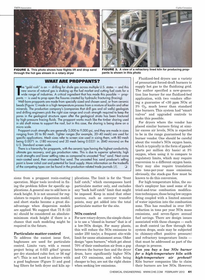
sions from a proppant resin-coating
operation. Major tools involved in fix-
ing the problem follow for specific ap-
plications. A general one to add here is
stack height. It is not unusual for reg-
ulators to require a dispersion model,
and short stacks become a great dis-
advantage when dispersion models
are applied. We suggest that 75 ft (23
m) should be considered an absolute-
minimum stack height if there is a
chance that such modeling might be
required in the future.
Particulate matter control
To address the easiest issue first,
baghouses are used for particulate
control. Limits vary, with a recent
project being at 0.025 g/dscf (grams
per dry standard cubic feet; or 56 mg/
m3). This is not hard to achieve with
a good baghouse (Figure 5) and good
bag filters for both dryer and kiln ap-
plications. The limit is for the “front
half catch,” which encompasses hard
particulate matter only, and excludes
any “back half catch” limit that might
be imposed. Keep in mind that other
sources, such as conveyor transfer
points, may get added into the total
particulate matter for the site.
NOx control
For new rotary dryers, the simple choice
is to use a “closed-in burner” that is of
a low-NOx design. For many plants,
this will reduce the NOx emissions to
under 250 ton/yr, a frequent site-wide
limit for ozone attainment areas. Older
design “open burners,” which get about
70% of their combustion air from a gap
between the burner face and the dryer
drum, have significantly higher NOx
and CO emissions, and while being
cheaper to buy, are not the right choice
when seeking low emissions.
Fluidized-bed dryers use a variety
of pressurized forced-draft burners to
supply hot gas to the fluidizing grid.
The author specified a new-genera-
tion line burner for one fluidized-bed
application, with two vendors offer-
ing a guarantee of <30 ppm NOx at
3% O2, much lower than standard
line burners. This system had “smart
valves” and upgraded controls to
make this possible.
For dryers where the vendor has
placed similar burners firing at simi-
lar excess air levels, NOx is expected
to be in the range guaranteed by the
burner vendor. One should be careful
about the vendor’s NOx oxygen basis,
which is typically in the form of ppmdv
(parts per million dry basis) at 3%
oxygen, when using it to compare to
regulatory limits, which may require
conversion to a different oxygen basis.
They may also require translation
into tons-per-year mass emissions;
obviously, the stack-gas flow must be
known to do this conversion.
For high-temperature kilns, the au-
thor’s employer has used some of its
tried-and-true combustion modifica-
tion techniques, those being low oxygen
firing coupled with a limited amount
of water injection into the combustion
zone. This has resulted in over 50%
reduction in tons per year NOx mass
emissions, and seven-figure annual
fuel savings. There are design issues
associated with these changes — such
as draft control (as flow through the
system drops, seals may be subjected
to chimney-effect positive pressure)
and refractory temperature limits —
that must be addressed as part of the
change in process.
Can you buy a low NOx burner
for a high-temperature kiln with
high-temperature air preheat?
Kiln burner companies like to claim
their burners are low NOx. However,
CHEMICAL ENGINEERING WWW.CHE.COM FEBRUARY 2013 41
WHAT ARE PROPPANTS?
The “gold rush” is on — drilling for shale gas across multiple U.S. states — and this new source of natural gas is shaking up the fuel market and cutting fuel costs for a wide range of industries. A critical ingredient that has made this possible — prop-
pants — is used to prop open the fissures created by hydraulic fracturing (fracing).Well-bore proppants are made from specially sized and chosen sand, or from ceramic
beads (Figure 1) made in a high-temperature process from a mixture of kaolin and other minerals. The production company’s (companies that drill gas and oil wells) geologists and drilling engineers pick the right size range and crush strength required to keep the pores in the geological structure open after the geological strata has been fractured by high-pressure fracing fluids. The proppant works much like the timber shoring used in old shaft mines to support the roof, but in this case, the shoring is being done on a micro scale.
Proppant crush strengths are generally 5,000 to 9,000 psi, and they are made in sizes ranging from 20 to 80 mesh. Tighter ranges (for example, 20–40 mesh) are used for specific applications. Mesh sizes refer to screen size used in sizing them, with 80 mesh being 0.0071 in. (180 microns) and 20 mesh being 0.0331 in. (840 microns) on the U.S. Standard screen scale.
There is a hierarchy for proppants, with the ceramic type having the highest conductivity, ultimate gas recovery, and gas production rates. This is due to superior sphericity, high crush strengths and lower settling rates as compared to uncoated “frac” sand. Next come resin-coated sand, then uncoated frac sand. The uncoated frac sand producer’s selling point is lower initial cost and potential for local supply. More information on the tradeoffs of the competing types can be found in the production-related trade journals [1]. ❏
FIGURE 2. This photo shows how � ights lift and drop sand through the hot gas stream in a rotary dryer
TMTS Associates Carbo Ceramics
FIGURE 3. A view of a refractory lined kiln for producing prop-pants is shown in this photo
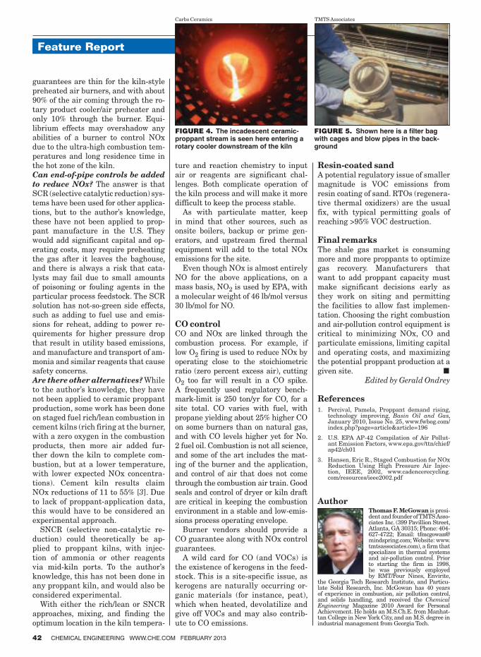
Feature Report
42 CHEMICAL ENGINEERING WWW.CHE.COM FEBRUARY 2013
guarantees are thin for the kiln-style
preheated air burners, and with about
90% of the air coming through the ro-
tary product cooler/air preheater and
only 10% through the burner. Equi-
librium effects may overshadow any
abilities of a burner to control NOx
due to the ultra-high combustion tem-
peratures and long residence time in
the hot zone of the kiln.
Can end-of-pipe controls be added
to reduce NOx? The answer is that
SCR (selective catalytic reduction) sys-
tems have been used for other applica-
tions, but to the author’s knowledge,
these have not been applied to prop-
pant manufacture in the U.S. They
would add significant capital and op-
erating costs, may require preheating
the gas after it leaves the baghouse,
and there is always a risk that cata-
lysts may fail due to small amounts
of poisoning or fouling agents in the
particular process feedstock. The SCR
solution has not-so-green side effects,
such as adding to fuel use and emis-
sions for reheat, adding to power re-
quirements for higher pressure drop
that result in utility based emissions,
and manufacture and transport of am-
monia and similar reagents that cause
safety concerns.
Are there other alternatives? While
to the author’s knowledge, they have
not been applied to ceramic proppant
production, some work has been done
on staged fuel rich/lean combustion in
cement kilns (rich firing at the burner,
with a zero oxygen in the combustion
products, then more air added fur-
ther down the kiln to complete com-
bustion, but at a lower temperature,
with lower expected NOx concentra-
tions). Cement kiln results claim
NOx reductions of 11 to 55% [3]. Due
to lack of proppant-application data,
this would have to be considered an
experimental approach.
SNCR (selective non-catalytic re-
duction) could theoretically be ap-
plied to proppant kilns, with injec-
tion of ammonia or other reagents
via mid-kiln ports. To the author’s
knowledge, this has not been done in
any proppant kiln, and would also be
considered experimental.
With either the rich/lean or SNCR
approaches, mixing, and finding the
optimum location in the kiln tempera-
ture and reaction chemistry to input
air or reagents are significant chal-
lenges. Both complicate operation of
the kiln process and will make it more
difficult to keep the process stable.
As with particulate matter, keep
in mind that other sources, such as
onsite boilers, backup or prime gen-
erators, and upstream fired thermal
equipment will add to the total NOx
emissions for the site.
Even though NOx is almost entirely
NO for the above applications, on a
mass basis, NO2 is used by EPA, with
a molecular weight of 46 lb/mol versus
30 lb/mol for NO.
CO control
CO and NOx are linked through the
combustion process. For example, if
low O2 firing is used to reduce NOx by
operating close to the stoichiometric
ratio (zero percent excess air), cutting
O2 too far will result in a CO spike.
A frequently used regulatory bench-
mark-limit is 250 ton/yr for CO, for a
site total. CO varies with fuel, with
propane yielding about 25% higher CO
on some burners than on natural gas,
and with CO levels higher yet for No.
2 fuel oil. Combustion is not all science,
and some of the art includes the mat-
ing of the burner and the application,
and control of air that does not come
through the combustion air train. Good
seals and control of dryer or kiln draft
are critical in keeping the combustion
environment in a stable and low-emis-
sions process operating envelope.
Burner vendors should provide a
CO guarantee along with NOx control
guarantees.
A wild card for CO (and VOCs) is
the existence of kerogens in the feed-
stock. This is a site-specific issue, as
kerogens are naturally occurring or-
ganic materials (for instance, peat),
which when heated, devolatilize and
give off VOCs and may also contrib-
ute to CO emissions.
Resin-coated sand
A potential regulatory issue of smaller
magnitude is VOC emissions from
resin coating of sand. RTOs (regenera-
tive thermal oxidizers) are the usual
fix, with typical permitting goals of
reaching >95% VOC destruction.
Final remarks
The shale gas market is consuming
more and more proppants to optimize
gas recovery. Manufacturers that
want to add proppant capacity must
make significant decisions early as
they work on siting and permitting
the facilities to allow fast implemen-
tation. Choosing the right combustion
and air-pollution control equipment is
critical to minimizing NOx, CO and
particulate emissions, limiting capital
and operating costs, and maximizing
the potential proppant production at a
given site. ■Edited by Gerald Ondrey
References
1. Percival, Pamela, Proppant demand rising, technology improving, Basin Oil and Gas, January 2010, Issue No. 25, www.fwbog.com/index.php?page=article&article=196
2. U.S. EPA AP-42 Compilation of Air Pollut-ant Emission Factors, www.epa.gov/ttn/chief/ap42/ch01
3. Hansen, Eric R., Staged Combustion for NOx Reduction Using High Pressure Air Injec-tion, IEEE, 2002, www.cadencerecycling.com/resources/ieee2002.pdf
FIGURE 4. The incadescent ceramic-proppant stream is seen here entering a rotary cooler downstream of the kiln
FIGURE 5. Shown here is a ilter bag with cages and blow pipes in the back-ground
Carbo Ceramics TMTS Associates
Author
Thomas F. McGowan is presi-dent and founder of TMTS Asso-ciates Inc. (399 Pavillion Street, Atlanta, GA 30315; Phone: 404-627-4722; Email: [email protected]; Website: www. tmtsassociates.com), a firm that specializes in thermal systems and air-pollution control. Prior to starting the firm in 1998, he was previously employed by RMT/Four Nines, Envirite,
the Georgia Tech Research Institute, and Particu-late Solid Research, Inc. McGowan has 40 years of experience in combustion, air pollution control, and solids handling, and received the Chemical Engineering Magazine 2010 Award for Personal Achievement. He holds an M.S.Ch.E. from Manhat-tan College in New York City, and an M.S. degree in industrial management from Georgia Tech.
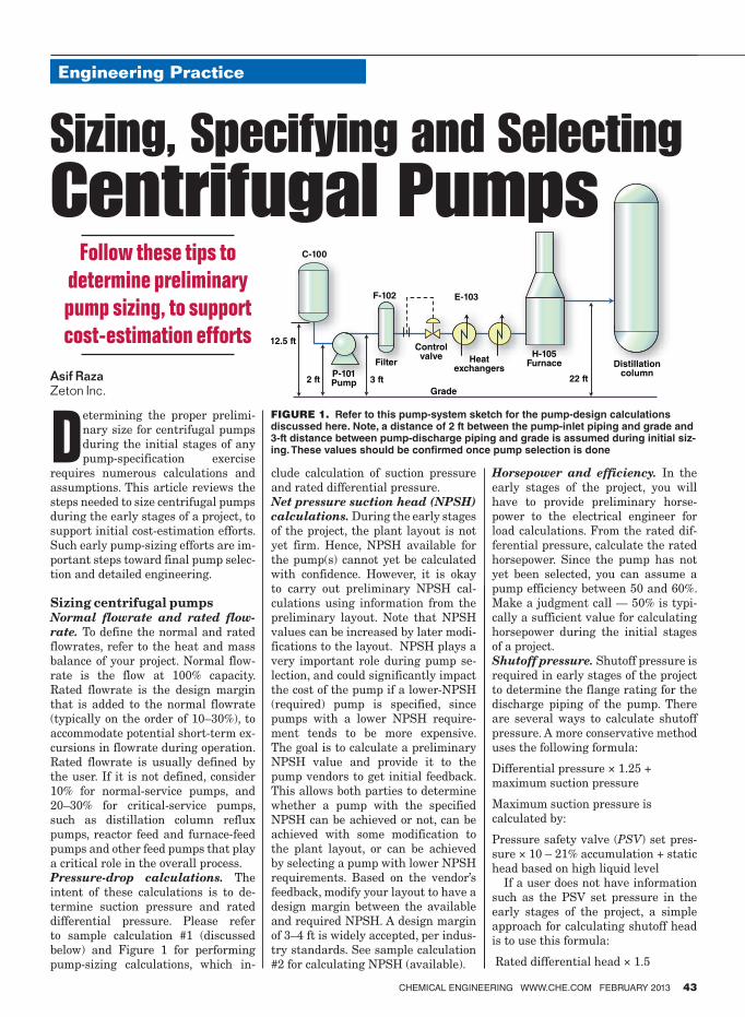
Engineering Practice
CHEMICAL ENGINEERING WWW.CHE.COM FEBRUARY 2013 43
Determining the proper prelimi-
nary size for centrifugal pumps
during the initial stages of any
pump-specification exercise
requires numerous calculations and
assumptions. This article reviews the
steps needed to size centrifugal pumps
during the early stages of a project, to
support initial cost-estimation efforts.
Such early pump-sizing efforts are im-
portant steps toward final pump selec-
tion and detailed engineering.
Sizing centrifugal pumpsNormal flowrate and rated flow-
rate. To define the normal and rated
flowrates, refer to the heat and mass
balance of your project. Normal flow-
rate is the flow at 100% capacity.
Rated flowrate is the design margin
that is added to the normal flowrate
(typically on the order of 10–30%), to
accommodate potential short-term ex-
cursions in flowrate during operation.
Rated flowrate is usually defined by
the user. If it is not defined, consider
10% for normal-service pumps, and
20–30% for critical-service pumps,
such as distillation column reflux
pumps, reactor feed and furnace-feed
pumps and other feed pumps that play
a critical role in the overall process.
Pressure-drop calculations. The
intent of these calculations is to de-
termine suction pressure and rated
differential pressure. Please refer
to sample calculation #1 (discussed
below) and Figure 1 for performing
pump-sizing calculations, which in-
clude calculation of suction pressure
and rated differential pressure.
Net pressure suction head (NPSH)
calculations. During the early stages
of the project, the plant layout is not
yet firm. Hence, NPSH available for
the pump(s) cannot yet be calculated
with confidence. However, it is okay
to carry out preliminary NPSH cal-
culations using information from the
preliminary layout. Note that NPSH
values can be increased by later modi-
fications to the layout. NPSH plays a
very important role during pump se-
lection, and could significantly impact
the cost of the pump if a lower-NPSH
(required) pump is specified, since
pumps with a lower NPSH require-
ment tends to be more expensive.
The goal is to calculate a preliminary
NPSH value and provide it to the
pump vendors to get initial feedback.
This allows both parties to determine
whether a pump with the specified
NPSH can be achieved or not, can be
achieved with some modification to
the plant layout, or can be achieved
by selecting a pump with lower NPSH
requirements. Based on the vendor’s
feedback, modify your layout to have a
design margin between the available
and required NPSH. A design margin
of 3–4 ft is widely accepted, per indus-
try standards. See sample calculation
#2 for calculating NPSH (available).
Horsepower and efficiency. In the
early stages of the project, you will
have to provide preliminary horse-
power to the electrical engineer for
load calculations. From the rated dif-
ferential pressure, calculate the rated
horsepower. Since the pump has not
yet been selected, you can assume a
pump efficiency between 50 and 60%.
Make a judgment call — 50% is typi-
cally a sufficient value for calculating
horsepower during the initial stages
of a project.
Shutoff pressure. Shutoff pressure is
required in early stages of the project
to determine the flange rating for the
discharge piping of the pump. There
are several ways to calculate shutoff
pressure. A more conservative method
uses the following formula:
Differential pressure × 1.25 +
maximum suction pressure
Maximum suction pressure is
calculated by:
Pressure safety valve (PSV) set pres-
sure × 10 – 21% accumulation + static
head based on high liquid level
If a user does not have information
such as the PSV set pressure in the
early stages of the project, a simple
approach for calculating shutoff head
is to use this formula:
Rated differential head × 1.5
Feature ReportEngineering Practice
C-106
F-102
C-100
E-103
P-101Pump 3 ft2 ft
12.5 ft
Filter
Controlvalve Heat
exchangers22 ft
Distillationcolumn
Grade
H-105Furnace
FIGURE 1. Refer to this pump-system sketch for the pump-design calculations discussed here. Note, a distance of 2 ft between the pump-inlet piping and grade and 3-ft distance between pump-discharge piping and grade is assumed during initial siz-ing. These values should be con� rmed once pump selection is done
Sizing, Specifying and Selecting
Centrifugal Pumps Follow these tips to
determine preliminary
pump sizing, to support
cost-estimation efforts
Asif Raza
Zeton Inc.
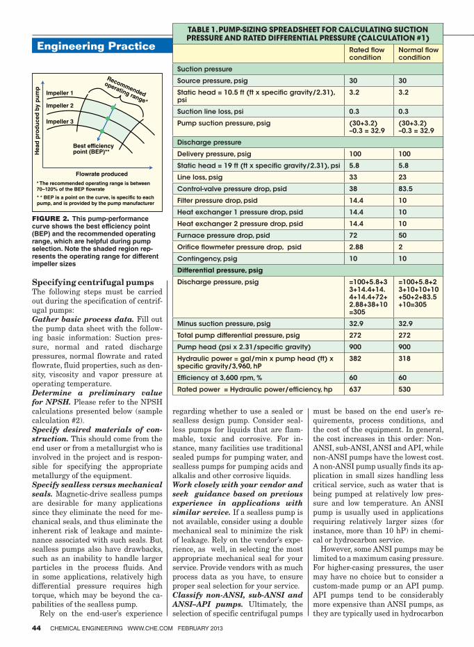
Engineering Practice
44 CHEMICAL ENGINEERING WWW.CHE.COM FEBRUARY 2013
Specifying centrifugal pumpsThe following steps must be carried
out during the specification of centrif-
ugal pumps:
Gather basic process data. Fill out
the pump data sheet with the follow-
ing basic information: Suction pres-
sure, normal and rated discharge
pressures, normal flowrate and rated
flowrate, fluid properties, such as den-
sity, viscosity and vapor pressure at
operating temperature.
Determine a preliminary value
for NPSH. Please refer to the NPSH
calculations presented below (sample
calculation #2).
Specify desired materials of con-
struction. This should come from the
end user or from a metallurgist who is
involved in the project and is respon-
sible for specifying the appropriate
metallurgy of the equipment.
Specify sealless versus mechanical
seals. Magnetic-drive sealless pumps
are desirable for many applications
since they eliminate the need for me-
chanical seals, and thus eliminate the
inherent risk of leakage and mainte-
nance associated with such seals. But
sealless pumps also have drawbacks,
such as an inability to handle larger
particles in the process fluids. And
in some applications, relatively high
differential pressure requires high
torque, which may be beyond the ca-
pabilities of the sealless pump.
Rely on the end-user’s experience
regarding whether to use a sealed or
sealless design pump. Consider seal-
less pumps for liquids that are flam-
mable, toxic and corrosive. For in-
stance, many facilities use traditional
sealed pumps for pumping water, and
sealless pumps for pumping acids and
alkalis and other corrosive liquids.
Work closely with your vendor and
seek guidance based on previous
experience in applications with
similar service. If a sealless pump is
not available, consider using a double
mechanical seal to minimize the risk
of leakage. Rely on the vendor’s expe-
rience, as well, in selecting the most
appropriate mechanical seal for your
service. Provide vendors with as much
process data as you have, to ensure
proper seal selection for your service.
Classify non-ANSI, sub-ANSI and
ANSI–API pumps. Ultimately, the
selection of specific centrifugal pumps
must be based on the end user’s re-
quirements, process conditions, and
the cost of the equipment. In general,
the cost increases in this order: Non-
ANSI, sub-ANSI, ANSI and API, while
non-ANSI pumps have the lowest cost.
A non-ANSI pump usually finds its ap-
plication in small sizes handling less
critical service, such as water that is
being pumped at relatively low pres-
sure and low temperature. An ANSI
pump is usually used in applications
requiring relatively larger sizes (for
instance, more than 10 hP) in chemi-
cal or hydrocarbon service.
However, some ANSI pumps may be
limited to a maximum casing pressure.
For higher-casing pressures, the user
may have no choice but to consider a
custom-made pump or an API pump.
API pumps tend to be considerably
more expensive than ANSI pumps, as
they are typically used in hydrocarbon
Flowrate produced
Best efficiency point (BEP)**
* The recommended operating range is between70–120% of the BEP flowrate
* * BEP is a point on the curve, is specific to each pump, and is provided by the pump manufacturer
Impeller 3
Impeller 2
Impeller 1
Recommended
operating range*
Head
pro
du
ced
by p
um
pTABLE 1. PUMP-SIZING SPREADSHEET FOR CALCULATING SUCTION PRESSURE AND RATED DIFFERENTIAL PRESSURE (CALCULATION #1)
Rated flow condition
Normal flow condition
Suction pressure
Source pressure, psig 30 30
Static head = 10.5 ft (ft x specific gravity/2.31), psi
3.2 3.2
Suction line loss, psi 0.3 0.3
Pump suction pressure, psig (30+3.2) –0.3 = 32.9
(30+3.2) –0.3 = 32.9
Discharge pressure
Delivery pressure, psig 100 100
Static head = 19 ft (ft x specific gravity/2.31), psi 5.8 5.8
Line loss, psig 33 23
Control-valve pressure drop, psid 38 83.5
Filter pressure drop, psid 14.4 10
Heat exchanger 1 pressure drop, psid 14.4 10
Heat exchanger 2 pressure drop, psid 14.4 10
Furnace pressure drop, psid 72 50
Orifice flowmeter pressure drop, psid 2.88 2
Contingency, psig 10 10
Differential pressure, psig
Discharge pressure, psig =100+5.8+33+14.4+14.4+14.4+72+2.88+38+10=305
=100+5.8+23+10+10+10+50+2+83.5+10=305
Minus suction pressure, psig 32.9 32.9
Total pump differential pressure, psig 272 272
Pump head (psi x 2.31/specific gravity) 900 900
Hydraulic power = gal/min x pump head (ft) x specific gravity/3,960, hP
382 318
Efficiency at 3,600 rpm, % 60 60
Rated power = Hydraulic power/efficiency, hp 637 530
FIGURE 2. This pump-performance curve shows the best efficiency point (BEP) and the recommended operating range, which are helpful during pump selection. Note the shaded region rep-resents the operating range for different impeller sizes
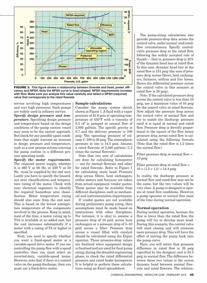
CHEMICAL ENGINEERING WWW.CHE.COM FEBRUARY 2013 45
service involving high temperatures
and very high pressures. Such pumps
are widely used in refinery service.
Specify design pressure and tem-
perature. Specifying design pressure
and temperature based on the design
conditions of the pump suction vessel
may seem to be the easiest approach.
But check for any possible upset condi-
tions that might warrant an increase
in design pressure and temperature,
such as a new process stream entering
the pump suction in a different pro-
cess operating mode.
Specify the motor requirements.
The required power supply, whether
it is 460 V at 60 Hz, or 230 V at 50
Hz, must be supplied by the end user.
Lastly you have to specify the hazard-
ous area classifications and tempera-
ture rating of the motor. Check with
your electrical engineers to identify
the required hazardous area classi-
fication. Motor temperature rating
should also come from the end user.
This is based on the lowest autoigni-
tion temperature of the components
involved in the process. Keep in mind,
most of the time, a motor rating up to
T3A is available at no added cost, but
the cost increases substantially if a
motor with a rating of T4 or higher is
specified.
Next, you need to specify whether
you want a fixed-speed motor or a
variable-speed drive motor. If you are
controlling the pump flow with a speed
controller, then you must select an
inverted-duty, variable-speed motor.
However, note that if there is a control
valve on the pump discharge, then you
must use a fixed-drive motor.
Sample calculationsConsider the pump system sketch
shown in Figure 1. A fluid with a vapor
pressure of 45.9 psia at operating tem-
perature of 430°F with a viscosity of
0.5 cP is pumped at normal flow of
2,000 gal/min. The specific gravity is
0.7 and the delivery pressure is 100
psig. The operating pressure of col-
umn C-100 is 30 psig. The atmospheric
pressure at site is 14.5 psia. Assume
a rated flowrate of 2,400 gal/min (1.2
times the normal flowrate).
Note that two sets of calculations
are done for calculating horsepower
— one for normal flowrate and other
for rated flowrate. Refer to Figure 1
for calculating static head. Pressure
drop across filters, heat exchangers,
orifice meters and furnaces are taken
from actual equipment vendor quotes.
These quotes may be available from
different disciplines, such as mechani-
cal and instrumentation departments.
If vendor quotes are not available
during preliminary pump sizing, then
assumptions must be made based on
interactions with other disciplines.
For instance, it is okay to assume a
pressure drop of 10 psid across heat
exchangers or a pressure drop of 5–10
psid across a filter. Pressure drop
across a vessel filled with catalyst
should be calculated using the Ergun
equation. These pressure-drop values
are finalized when equipment design
is finalized and are used for final pump
sizing, during the detailed engineering
phase, to check the rated differential
pressure and rated brake horsepower.
It is helpful to perform these calcula-
tions using an Excel spreadsheet.
The pump-sizing calculations also
provide pressure-drop data across the
control valve, under normal- and rated-
flow circumstances. Specify control-
valve pressure drop at the rated flow,
following the widely accepted rule of
thumb — that is, pressure drop is 25%
of the dynamic head loss at rated flow.
In this case, dynamic head loss at the
rated flow is 151 psig (the sum of pres-
sure drop across filters, heat exchang-
ers, furnaces, orifices and line losses.
Hence the differential pressure across
the control valve in this scenario at
rated flow is 38 psig).
Note: If the calculated pressure drop
across the control valve is less than 10
psig, use a minimum value of 10 psig
for the control valve at rated flowrate.
Now adjust the pressure drop across
the control valve at normal flow and
try to match the discharge pressure
until it is equal at normal and rated
flow. Pressure drop is directly propor-
tional to the square of the flow, hence
pressure drop across rated flow is cal-
culated using the following formula
(Note that the rated flow is 1.2 times
the normal flow):
Filter pressure drop at normal flow =
10 psig
Filter pressure drop at rated flow =
10 × (1.2 × 1.2) = 14.4 psig
In reality, the discharge pressure at
normal flow and rated flow may not be
the same, but the two values will be
very close. A pump is designed to oper-
ate at rated flow conditions. However,
a pump operates at normal flow most
of the time during normal operation.
Normal operationDuring normal operation, because the
flow is lower than the rated flow, the
pump will try to develop more head.
During this scenario, the control valve
will start closing and will consume
more pressure drop. This will have the
effect of moving the pump back onto
the pump curve.
Here, you will notice that pressure
difference in rated flow is 38 psig
(specified by the designer) and is 83.5
psig in normal flow. The difference be-
tween these two values is the excess
dynamic head between normal flow-
rate and rated flowrate. The relation-
240
260
280
300
Head
Power
Preferredoperating region
Allowableoperating region
BEP
40
20
0Efficiency
NPSH-required
NP
SH
– re
qu
ired
, ft0
50
100
150 Po
wer, B
HP
0 100 200 300 400 500
Flowrate, U.S. gal/m
600 700 800 900 1,000 1,100 1,200 1,300
320
340
360
380
90
80
70
60
50
40
Eff
icie
ncy,
% Head
, ft
30
20
10
0
Rated flow
FIGURE 3. This igure shows a relationship between lowrate and head, power, effi-ciency and NPSH. Note the NPSH curve is bowl-shaped. NPSH requirements increase with low. Make sure you analyze this value carefully and select a NPSH (required) value that corresponds to the rated lowrate
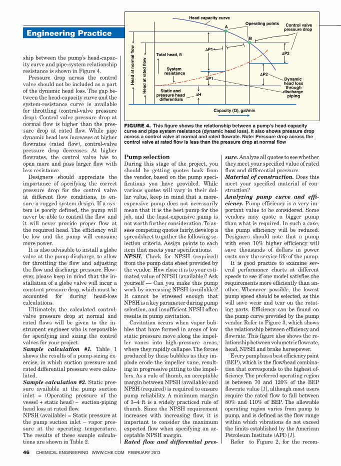
Engineering Practice
46 CHEMICAL ENGINEERING WWW.CHE.COM FEBRUARY 2013
ship between the pump’s head-capac-
ity curve and pipe-system relationship
resistance is shown in Figure 4.
Pressure drop across the control
valve should not be included as a part
of the dynamic head loss. The gap be-
tween the head-capacity curve and the
system-resistance curve is available
for throttling (control-valve pressure
drop). Control valve pressure drop at
normal flow is higher than the pres-
sure drop at rated flow. While pipe
dynamic head loss increases at higher
flowrates (rated flow), control-valve
pressure drop decreases. At higher
flowrates, the control valve has to
open more and pass larger flow with
less resistance.
Designers should appreciate the
importance of specifying the correct
pressure drop for the control valve
at different flow conditions, to en-
sure a rugged system design. If a sys-
tem is poorly defined, the pump will
never be able to control the flow and
it will never provide proper flow at
the required head. The efficiency will
be low and the pump will consume
more power.
It is also advisable to install a globe
valve at the pump discharge, to allow
for throttling the flow and adjusting
the flow and discharge pressure. How-
ever, please keep in mind that the in-
stallation of a globe valve will incur a
constant pressure drop, which must be
accounted for during head-loss
calculations.
Ultimately, the calculated control-
valve pressure drop at normal and
rated flows will be given to the in-
strument engineer who is responsible
for specifying and sizing the control
valves for your project.
Sample calculation #1. Table 1
shows the results of a pump-sizing ex-
ercise, in which suction pressure and
rated differential pressure were calcu-
lated.
Sample calculation #2. Static pres-
sure available at the pump suction
inlet = (Operating pressure of the
vessel + static head) – suction-piping
head loss at rated flow.
NPSH (available) = Static pressure at
the pump suction inlet – vapor pres-
sure at the operating temperature.
The results of these sample calcula-
tions are shown in Table 2.
Pump selectionDuring this stage of the project, you
should be getting quotes back from
the vendor, based on the pump speci-
fications you have provided. While
various quotes will vary in their dol-
lar value, keep in mind that a more-
expensive pump does not necessarily
mean that it is the best pump for the
job, and the least-expensive pump is
not worth further consideration. To as-
sess competing quotes fairly, develop a
spreadsheet to gather the following se-
lection criteria. Assign points to each
item that meets your specifications.
NPSH. Check for NPSH (required)
from the pump data sheet provided by
the vendor. How close it is to your esti-
mated value of NPSH (available)? Ask
yourself — Can you make this pump
work by increasing NPSH (available)?
It cannot be stressed enough that
NPSH is a key parameter during pump
selection, and insufficient NPSH often
results in pump cavitation.
Cavitation occurs when vapor bub-
bles that have formed in areas of low
static pressure move along the impel-
ler vanes into high-pressure areas,
where they rapidly collapse. The forces
produced by these bubbles as they im-
plode erode the impeller vane, result-
ing in progressive pitting to the impel-
lers. As a rule of thumb, an acceptable
margin between NPSH (available) and
NPSH (required) is required to ensure
pump reliability. A minimum margin
of 3–4 ft is a widely practiced rule of
thumb. Since the NPSH requirement
increases with increasing flow, it is
important to consider the maximum
expected flow when specifying an ac-
ceptable NPSH margin.
Rated flow and differential pres-
sure. Analyze all quotes to see whether
they meet your specified value of rated
flow and differential pressure.
Material of construction. Does this
meet your specified material of con-
struction?
Analyzing pump curve and effi-
ciency. Pump efficiency is a very im-
portant value to be considered. Some
vendors may quote a bigger pump
than what is required. In such a case,
the pump efficiency will be reduced.
Designers should note that a pump
with even 10% higher efficiency will
save thousands of dollars in power
costs over the service life of the pump.
It is good practice to examine sev-
eral performance charts at different
speeds to see if one model satisfies the
requirements more efficiently than an-
other. Whenever possible, the lowest
pump speed should be selected, as this
will save wear and tear on the rotat-
ing parts. Efficiency can be found on
the pump curve provided by the pump
vendor. Refer to Figure 3, which shows
the relationship between efficiency and
flowrate. This figure also shows the re-
lationship between volumetric flowrate,
head, NPSH and brake horsepower.
Every pump has a best efficiency point
(BEP), which is the flow/head combina-
tion that corresponds to the highest ef-
ficiency. The preferred operating region
is between 70 and 120% of the BEP
flowrate value [1], although most users
require the rated flow to fall between
80% and 110% of BEP. The allowable
operating region varies from pump to
pump, and is defined as the flow range
within which vibrations do not exceed
the limits established by the American
Petroleum Institute (API) [1].
Refer to Figure 2, for the recom-
Head
at
no
rmal fl
ow
Total head, ft
Head capacity curve
Operating points Control valvepressure drop
Dynamic head lossthrough
discharge piping
Static and pressure head
differentials
A
B
System resistance
Capacity (Q), gal/min
∆P1
∆P1
∆H
Head
at
rate
d f
low
∆P2
∆P2
FIGURE 4. This igure shows the relationship between a pump's head-capacity curve and pipe system resistance (dynamic head loss). It also shows pressure drop across a control valve at normal and rated lowrate. Note: Pressure drop across the control valve at rated low is less than the pressure drop at normal low
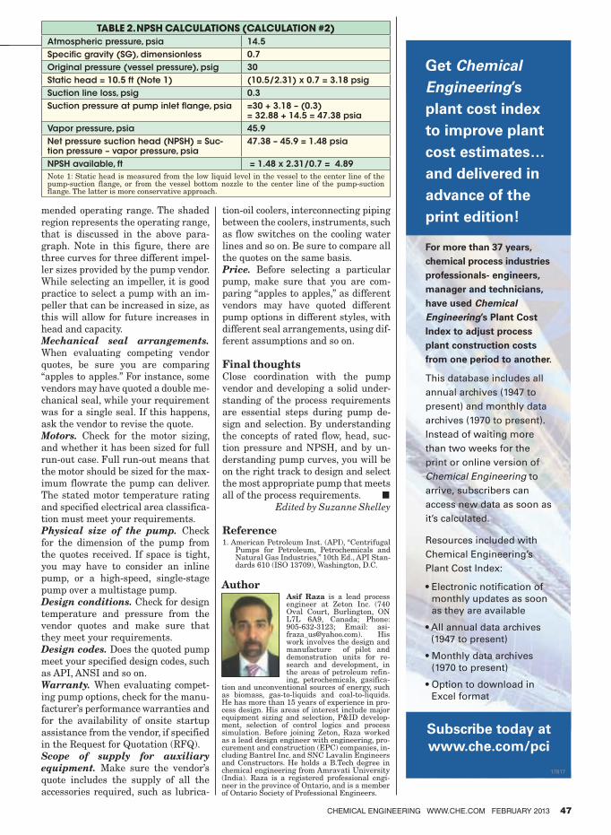
CHEMICAL ENGINEERING WWW.CHE.COM FEBRUARY 2013 47
mended operating range. The shaded
region represents the operating range,
that is discussed in the above para-
graph. Note in this figure, there are
three curves for three different impel-
ler sizes provided by the pump vendor.
While selecting an impeller, it is good
practice to select a pump with an im-
peller that can be increased in size, as
this will allow for future increases in
head and capacity.
Mechanical seal arrangements.
When evaluating competing vendor
quotes, be sure you are comparing
“apples to apples.” For instance, some
vendors may have quoted a double me-
chanical seal, while your requirement
was for a single seal. If this happens,
ask the vendor to revise the quote.
Motors. Check for the motor sizing,
and whether it has been sized for full
run-out case. Full run-out means that
the motor should be sized for the max-
imum flowrate the pump can deliver.
The stated motor temperature rating
and specified electrical area classifica-
tion must meet your requirements.
Physical size of the pump. Check
for the dimension of the pump from
the quotes received. If space is tight,
you may have to consider an inline
pump, or a high-speed, single-stage
pump over a multistage pump.
Design conditions. Check for design
temperature and pressure from the
vendor quotes and make sure that
they meet your requirements.
Design codes. Does the quoted pump
meet your specified design codes, such
as API, ANSI and so on.
Warranty. When evaluating compet-
ing pump options, check for the manu-
facturer’s performance warranties and
for the availability of onsite startup
assistance from the vendor, if specified
in the Request for Quotation (RFQ).
Scope of supply for auxiliary
equipment. Make sure the vendor’s
quote includes the supply of all the
accessories required, such as lubrica-
tion-oil coolers, interconnecting piping
between the coolers, instruments, such
as flow switches on the cooling water
lines and so on. Be sure to compare all
the quotes on the same basis.
Price. Before selecting a particular
pump, make sure that you are com-
paring “apples to apples,” as different
vendors may have quoted different
pump options in different styles, with
different seal arrangements, using dif-
ferent assumptions and so on.
Final thoughtsClose coordination with the pump
vendor and developing a solid under-
standing of the process requirements
are essential steps during pump de-
sign and selection. By understanding
the concepts of rated flow, head, suc-
tion pressure and NPSH, and by un-
derstanding pump curves, you will be
on the right track to design and select
the most appropriate pump that meets
all of the process requirements. ■Edited by Suzanne Shelley
Reference1. American Petroleum Inst. (API), “Centrifugal
Pumps for Petroleum, Petrochemicals and Natural Gas Industries,” 10th Ed., API Stan-dards 610 (ISO 13709), Washington, D.C.
AuthorAsif Raza is a lead process engineer at Zeton Inc. (740 Oval Court, Burlington, ON L7L 6A9, Canada; Phone: 905-632-3123; Email: [email protected]). His work involves the design and manufacture of pilot and demonstration units for re-search and development, in the areas of petroleum refin-ing, petrochemicals, gasifica-
tion and unconventional sources of energy, such as biomass, gas-to-liquids and coal-to-liquids. He has more than 15 years of experience in pro-cess design. His areas of interest include major equipment sizing and selection, P&ID develop-ment, selection of control logics and process simulation. Before joining Zeton, Raza worked as a lead design engineer with engineering, pro-curement and construction (EPC) companies, in-cluding Bantrel Inc. and SNC Lavalin Engineers and Constructors. He holds a B.Tech degree in chemical engineering from Amravati University (India). Raza is a registered professional engi-neer in the province of Ontario, and is a member of Ontario Society of Professional Engineers.
Get Chemical
Engineering’s
plant cost index
to improve plant
cost estimates…
and delivered in
advance of the
print edition!
For more than 37 years,
chemical process industries
professionals- engineers,
manager and technicians,
have used Chemical
Engineering’s Plant Cost
Index to adjust process
plant construction costs
from one period to another.
This database includes all
annual archives (1947 to
present) and monthly data
archives (1970 to present).
Instead of waiting more
than two weeks for the
print or online version of
Chemical Engineering to
arrive, subscribers can
access new data as soon as
it’s calculated.
• Electronic notiication of monthly updates as soon
as they are available
• All annual data archives (1947 to present)
• Monthly data archives (1970 to present)
• Option to download in Excel format
Resources included with
Chemical Engineering’s Plant Cost Index:
Subscribe today at
www.che.com/pci
17817
TABLE 2. NPSH CALCULATIONS (CALCULATION #2)
Atmospheric pressure, psia 14.5
Specific gravity (SG), dimensionless 0.7
Original pressure (vessel pressure), psig 30
Static head = 10.5 ft (Note 1) (10.5/2.31) x 0.7 = 3.18 psig
Suction line loss, psig 0.3
Suction pressure at pump inlet flange, psia =30 + 3.18 – (0.3)= 32.88 + 14.5 = 47.38 psia
Vapor pressure, psia 45.9
Net pressure suction head (NPSH) = Suc-tion pressure – vapor pressure, psia
47.38 – 45.9 = 1.48 psia
NPSH available, ft = 1.48 x 2.31/0.7 = 4.89
Note 1: Static head is measured from the low liquid level in the vessel to the center line of the pump-suction flange, or from the vessel bottom nozzle to the center line of the pump-suction flange. The latter is more conservative approach.
Research and development (R&D)
projects usually require signifi-
cant time, effort and manpower
to become successful. Despite
the significant resources spent on
R&D projects, only 5–10% of the proj-
ects are statistically believed to be
successfully commercialized, in terms
of both timing and technological ad-
vances. Many projects fail because
they cannot achieve the desired re-
sults on timing of commercialization
and licensing.
This article is focused on providing
systematic strategies to speed up both
technical and non-technical aspects of
R&D projects — especially new pro-
cess development. It addresses certain
aspects that have not been mentioned
in previous technical references [1–5],
such as basing R&D project manage-
ment on manpower resource charac-
teristics. It also presents strategies to
speed up process development projects
visually in a diagram (Figure 1) that
is easy to follow and use.
OVERVIEWTypes of R&D projects Research and Development projects
can generally be classified into the
four types listed below [1]:
•Basicresearch•Newapplicationresearch•Newproductdevelopment—Inthis
article, new products are limited to
those that are an intrinsic part of
new process development, such as
new catalysts and solvents
•New process development — Asmentioned above, this can some-
times incorporate new products,
suchascatalystsandsolvents.Newprocess development is the focus of
this article
Basic research and new-applicationR&D generally require less time and
manpower, and involve a smaller group
of people than do the development of
new products and processes. This is
because the goal of basic research is to
develop fundamental knowledge that
might be applicable for further devel-
opment and commercialization in the
future, and new application research
focuses only on finding and developing
new applications for existing products
and processes, thus allowing much of
the existing knowledge on existing
products and processes to be utilized.
The most time-consuming part of
R&D is often new process and product
development on pilot and commercial
scales.Accelerating new process andproduct development gives earlier
and higher overall project-life benefits
(Figure 2).
Newprocessdevelopmentoften in-
volves development of new products
such as new catalysts, solvents and
chemicals to be used in the new pro-
cess. Thus, we define the scope of this
article to also include development
of new products that are an intrinsic
part of the new process development,
though not final products per se.
For example, a new butadiene ex-
tractive distillation process develop-
ment requires the development of a
new butadiene extraction solvent,
but the solvent is not a final product
of this process. Later in the article,
we will refer to our new products as
new catalysts and solvents (C&S) to
avoid confusion.
Typical development stepsNewproduct andnewprocess devel-opment typically include the following
steps toward commercialization. Fig-
ure 1 shows a flow chart visualizing
all steps and strategies to speed up de-
velopment projects during each step.
1. Laboratory-scale new product
(C&S) development and valida-
tion. Consider using special tools to
speed up screening of C&S; Consider
outsourced laboratory-scale product
development and validation, or sub-
licensing of C&S from outside sources
2. Conceptual design of the envi-
sioned commercial process. Uti-
lize available laboratory data from
the developed C&S to conceptualize
a desired commercial process. Involve
chemical process engineers early at
this stage
3. Pilot and commercial scale
product (C&S) manufacturing.
Consider outsourced manufacturing
of the developed C&S
4. Pilot-plant process development
and basic design. Use a pilot plant
as a scale-down of the envisioned com-
mercial plant — the primary objective
is to collect sufficient data for scaleup.
Also,considerskippingpilotplants5. Pilot-plant detailed design and
construction. Consider outsourcing
pilot-plant design and construction
6. Pilot-plant process validation.
Involve not only engineers but also re-
searchers directly. Consider outsourc-
ing pilot plant validation
7. Commercial-process develop-
ment and basic design. Scaleup
to a commercial plant based on data
from the pilot plant, and re-check
scaleup issues
8. Commercial-process detailed
design and construction. Consider
outsourcing commercial-process de-
sign and construction
9. Commercial process demon-
stration and validation. Con-
Feature Report
48 CHEMICAL ENGINEERING WWW.CHE.COM FEBRUARY 2013
Engineering Practice
Accelerating Process and Product Development
These simple strategies can be used to speed up
and increase the success rates of R&D projects
Wiroon TanthapanichakoonSCG Chemicals Co.
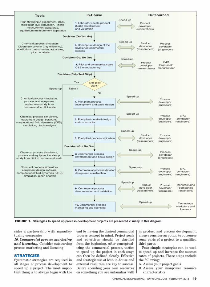
sider a partnership with manufac-
turing companies
10. Commercial process marketing
and licensing. Consider outsourcing
process marketing and licensing
STRATEGIES
Systematic strategies are required in
all stages of process development to
speed up a project. The most impor-
tant thing is to always begin with the
end by having the desired commercial
process concept in mind. Project goals
and objectives should be clarified
from the beginning. After conceptual-
izing the commercial process, tactics
to speed up the project in each stage
can then be defined clearly. Effective
and strategic use of both in-house and
external resources are key to success.
Before spending your own resources
on something you are unfamiliar with
in product and process development,
always consider an option to outsource
some parts of a project to a qualified
third party.
Four simple strategies can be used
to speed up and increase the success
rates of projects. These steps include
the following:
A. Assess your project goals
B. Assess your manpower resource
characteristics
CHEMICAL ENGINEERING WWW.CHE.COM FEBRUARY 2013 49
High-throughput experiment, DOE,
molecular-level simulation, kinetic
measurement apparatus,
equilibrium measurement apparatus
1. Laboratory-scale product
(C&S) development
and validation
2. Conceptual design of the
envisioned commercial
process
3. Pilot and commercial scale
C&S manufacturing
6. Pilot plant process validation
5. Pilot plant detailed design
and construction
7. Commercial process
development and basic design
8. Commercial process detailed
design and construction
9. Commercial process
demonstration and validation
10. Commercial process
marketing and licensing
4. Pilot plant process
development and basic design
Skip pilot
plant?
Chemical process simulators,
Oldershaw column (tray efficiency),
equilibrium measurement apparatus,
pinch analysis
Chemical process simulators,
process and equipment
scale-down study from
commercial to pilot scale
Chemical process simulators,
equipment design software,
computational fluid dynamics (CFD)
simulation, pinch analysis
Chemical process simulators,
process and equipment scale-up
study from pilot to commercial scale
Chemical process simulators,
equipment design software,
computational fluid dynamics (CFD)
simulation, pinch analysis
FIGURE 1. Strategies to speed up process development projects are presented visually in this diagram
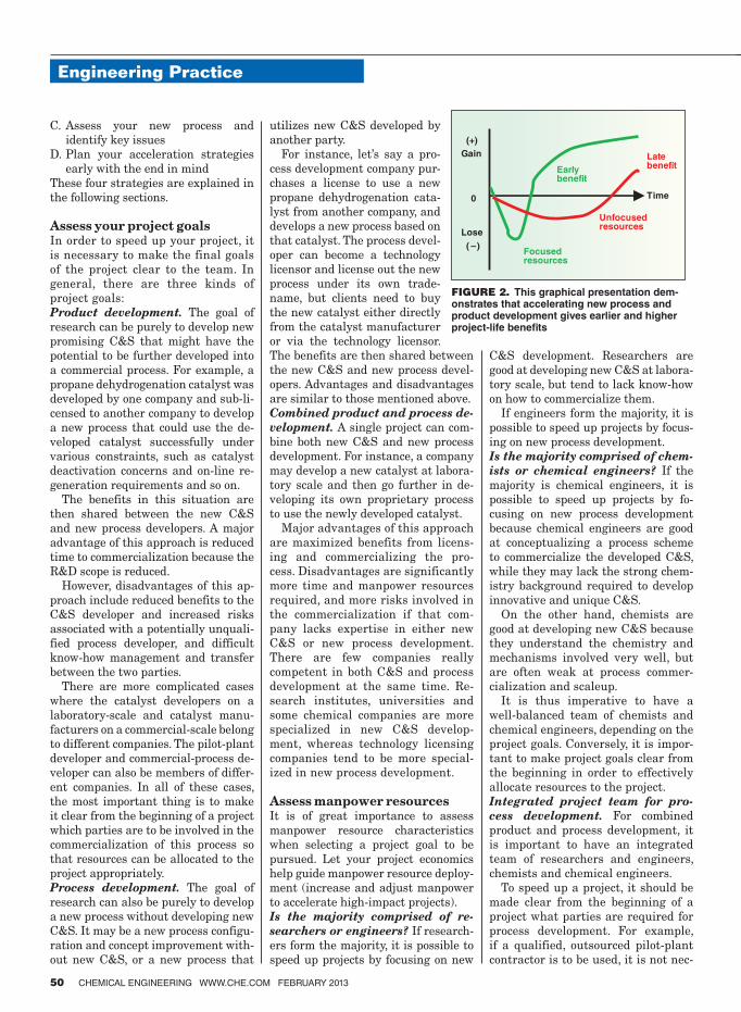
Engineering Practice
50 CHEMICAL ENGINEERING WWW.CHE.COM FEBRUARY 2013
C. Assess your new process and
identify key issues
D. Plan your acceleration strategies
early with the end in mind
These four strategies are explained in
the following sections.
Assess your project goalsIn order to speed up your project, it
is necessary to make the final goals
of the project clear to the team. In
general, there are three kinds of
project goals:
Product development. The goal of
research can be purely to develop new
promising C&S that might have the
potential to be further developed into
a commercial process. For example, a
propane dehydrogenation catalyst was
developed by one company and sub-li-
censed to another company to develop
a new process that could use the de-
veloped catalyst successfully under
various constraints, such as catalyst
deactivation concerns and on-line re-
generation requirements and so on.
The benefits in this situation are
then shared between the new C&S
and new process developers. A major
advantage of this approach is reduced
time to commercialization because the
R&D scope is reduced.
However, disadvantages of this ap-
proach include reduced benefits to the
C&S developer and increased risks
associated with a potentially unquali-
fied process developer, and difficult
know-how management and transfer
between the two parties.
There are more complicated cases
where the catalyst developers on a
laboratory-scale and catalyst manu-
facturers on a commercial-scale belong
to different companies. The pilot-plant
developer and commercial-process de-
veloper can also be members of differ-
ent companies. In all of these cases,
the most important thing is to make
it clear from the beginning of a project
which parties are to be involved in the
commercialization of this process so
that resources can be allocated to the
project appropriately.
Process development. The goal of
research can also be purely to develop
a new process without developing new
C&S. It may be a new process configu-
ration and concept improvement with-
out new C&S, or a new process that
utilizes new C&S developed by
another party.
For instance, let’s say a pro-
cess development company pur-
chases a license to use a new
propane dehydrogenation cata-
lyst from another company, and
develops a new process based on
that catalyst. The process devel-
oper can become a technology
licensor and license out the new
process under its own trade-
name, but clients need to buy
the new catalyst either directly
from the catalyst manufacturer
or via the technology licensor.
The benefits are then shared between
the new C&S and new process devel-
opers. Advantages and disadvantages
are similar to those mentioned above.
Combined product and process de-
velopment. A single project can com-
bine both new C&S and new process
development. For instance, a company
may develop a new catalyst at labora-
tory scale and then go further in de-
veloping its own proprietary process
to use the newly developed catalyst.
Major advantages of this approach
are maximized benefits from licens-
ing and commercializing the pro-
cess. Disadvantages are significantly
more time and manpower resources
required, and more risks involved in
the commercialization if that com-
pany lacks expertise in either new
C&S or new process development.
There are few companies really
competent in both C&S and process
development at the same time. Re-
search institutes, universities and
some chemical companies are more
specialized in new C&S develop-
ment, whereas technology licensing
companies tend to be more special-
ized in new process development.
Assess manpower resourcesIt is of great importance to assess
manpower resource characteristics
when selecting a project goal to be
pursued. Let your project economics
help guide manpower resource deploy-
ment (increase and adjust manpower
to accelerate high-impact projects).
Is the majority comprised of re-
searchers or engineers? If research-
ers form the majority, it is possible to
speed up projects by focusing on new
C&S development. Researchers are
good at developing new C&S at labora-
tory scale, but tend to lack know-how
on how to commercialize them.
If engineers form the majority, it is
possible to speed up projects by focus-
ing on new process development.
Is the majority comprised of chem-
ists or chemical engineers? If the
majority is chemical engineers, it is
possible to speed up projects by fo-
cusing on new process development
because chemical engineers are good
at conceptualizing a process scheme
to commercialize the developed C&S,
while they may lack the strong chem-
istry background required to develop
innovative and unique C&S.
On the other hand, chemists are
good at developing new C&S because
they understand the chemistry and
mechanisms involved very well, but
are often weak at process commer-
cialization and scaleup.
It is thus imperative to have a
well-balanced team of chemists and
chemical engineers, depending on the
project goals. Conversely, it is impor-
tant to make project goals clear from
the beginning in order to effectively
allocate resources to the project.
Integrated project team for pro-
cess development. For combined
product and process development, it
is important to have an integrated
team of researchers and engineers,
chemists and chemical engineers.
To speed up a project, it should be
made clear from the beginning of a
project what parties are required for
process development. For example,
if a qualified, outsourced pilot-plant
contractor is to be used, it is not nec-
Early benefit
Late benefit
Focused resources
Unfocused resources
Time0
(+)
( –)
Gain
Lose
FIGURE 2. This graphical presentation dem-onstrates that accelerating new process and product development gives earlier and higher project-life beneits
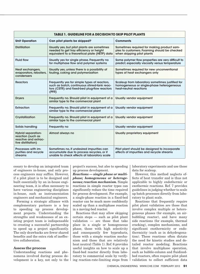
CHEMICAL ENGINEERING WWW.CHE.COM FEBRUARY 2013 51
essary to develop an integrated team
of engineers in-house, and only pro-
cess engineers may suffice. However,
if a pilot plant is to be designed and
built essentially by an in-house engi-
neering team, it is often necessary to
have various engineering disciplines
in-house, such as instrumentation
engineers and mechanical engineers.
Forming a strategic alliance with
complementary partners is a key
to speeding up process develop-
ment projects. Understanding the
strengths and weaknesses of an ex-
isting project team is indispensable
to creating a successful partnership
to speed up a project significantly.
The only drawbacks are fewer shared
benefits and the extra risk of ineffec-
tive collaboration.
Assess the process Understanding reactions and phe-
nomena involved during process de-
velopment is a key, not only to the
project’s success, but also to speeding
up process development.
Reactions — single phase or multi-
phase; homogeneous or heteroge-
neous; reaction mechanism. Simple
reactions in simple reactor types can
significantly reduce the time required
for process development. For example,
a single-phase reaction in a fixed-bed
reactor can be much more confidently
scaled up than a multiphase reaction
in a moving-bed reactor.
Reactions that may allow skipping
certain steps — such as pilot plant
validation — are those that take
place in a single or homogeneous
phase, those with high selectivity
and consequently few byproducts,
those with a simple reaction mecha-
nism and those that are relatively
heat neutral (Table 1). Ref. 6 provides
useful insights on how to scale up a
fixed-bed reactor directly from labo-
ratory to commercial scale by verify-
ing reaction-rate-limiting steps from
laboratory experiments and use those
data for scaleup.
However, this method neglects ef-
fects of heat transfer and is thus not
applicable to highly endothermic or
exothermic reactions. Ref. 7 provides
guidelines in judging whether to scale
up batch processes directly from labo-
ratory to plant scale.
Reactions that frequently require
pilot plant validation are those that
involve complex multiple or hetero-
geneous phases (for example, an air-
bubbling reactor), and have many
side reactions (for example, thermal
cracking), complex mechanisms, and
significant exothermicity or endo-
thermicity (such as in dehydrogena-
tion). These reactions often dictate
the need for kinetic studies and de-
tailed reactor modeling. Reactions
that involve multiphase operation,
such as bubble-column and fluidized-
bed reactors, often require pilot plant
validation to collect sufficient data
TABLE 1. GUIDELINE FOR A DECISION TO SKIP PILOT PLANTS
Unit Operation Can pilot plants be skipped? Comments
Distillation Usually yes, but pilot plants are sometimes needed to get tray efficiency or height equivalent to a theoretical plate (HETP) data
Sometimes required for making product sam-ples to customers. Foaming should be checked when skipping pilot plants
Fluid flow Usually yes for single phase. Frequently no for multiphase flow and polymer systems
Some polymer flow properties are very difficult to predict, especially viscosity versus temperature
Heat exchangers, evaporators, reboilers, condensers
Usually yes, unless there is a possibility of fouling, coking and polymerization
Sometimes required for new unconventional types of heat exchangers only
Reactors Frequently yes for simple types of reactors, such as batch, continuous stirred-tank reac-tors (CSTR) and fixed-bed plug-flow reactors (PFR)
Scaleup from laboratory sometimes justified for homogeneous or single-phase heterogeneous heat-neutral reactions
Dryers Frequently no. Should pilot in equipment of a similar type to the commercial plant
Usually vendor equipment
Extraction Frequently no. Should pilot in equipment of a similar type to the commercial plant
Usually vendor equipment
Crystallization Frequently no. Should pilot in equipment of a similar type to the commercial plant
Usually vendor equipment
Solids handling Frequently no Usually vendor equipment
Hybrid separation-reaction (such as reactive and extrac-tive distillation)
Almost always no Usually proprietary equipment
Processes with im-purities and recycle streams
Sometimes no, if undesired impurities can accumulate due to process recycles, or if unable to check effects at laboratory scale
Pilot plant should be designed to incorporate effects of impurities and recycle streams
Engineering Practice
52 CHEMICAL ENGINEERING WWW.CHE.COM FEBRUARY 2013
for scaleup to a commercial process.
Separations — single phase or
multiphase. Chemical processes
generally require numerous sepa-
rations to purify the final products.
Most separation operations separate
desired products based on equilib-
rium conditions. Thus, accurate ther-
modynamic-equilibrium data are nec-
essary for scaling up the separation
operations correctly and confidently.
Some conventional separation op-
erations, such as distillation, allow
skipping pilot plant validation. Vapor-
liquid equilibrium (VLE) and tray
efficiency data can be obtained from
laboratory scale experiments, and
heat-and-material balance models
can be developed from those labora-
tory data. The number of trays, reflux
rates, and vapor-liquid loading for
tray hydraulics calculations can be
obtained from the models and used to
scale up.
However, other separation opera-
tions, such as extraction, drying, crys-
tallization, solids handling and most
hybrid operations (such as reactive
distillation) almost always require
pilot plants unless well-proven ven-
dor equipment for a similar service is
used (Table 1).
One of the most powerful concepts
in separation design is the residue
curve. This curve describes the equi-
librium relationships for ternary
mixtures and the change of the liquid
residue composition in a one-stage
batch distillation of the mixture. Mul-
tiple curves for a single system, called
residue curve maps, provide a rapid,
graphical means to visualize separa-
tion possibilities and constraints of
azeotropic ternary systems. To accel-
erate process development, it is help-
ful to have an expert on the residue
curve who can conceptually design
the separation operations.
Combined reactions and sepa-
rations. It is wise to consider reac-
tions and separations together, since
total investment and operating costs
(termed “combined costs”) are the
sum of total costs from both reaction
and separation sections. Separately
optimizing reaction and separation
sections tends to lead to suboptimal
solutions. For example, increasing re-
actor size and energy consumption to
achieve higher conversion and thus
higher purity of desired products can
sometimes significantly reduce com-
bined costs of the downstream sepa-
ration section [2].
Heat transfer — single phase or
multiphase. Heat transfer is one of
the most common unit operations in
both reactions and separations. Con-
ventional heat-transfer-equipment
design (for example evaporators, re-
boilers and condensers) is usually
well understood, thereby allowing
pilot plant validation to be skipped.
For example, shell-and-tube heat
exchangers and double-pipe heat ex-
changers are well understood, and
only thermodynamic and properties
data are needed to design and scale
them up. Commercial software, such
as that from Heat Transfer Research
Inc. (HTRI) called HTRI Xchanger
Suite, is also rigorous enough to de-
sign them confidently.
However, unconventional types of
heat transfer equipment often re-
quire pilot plant validation for the
first unit of its kind. For example, a
heat transfer operation that involves
simultaneous mass transfer (for ex-
ample, an ethylene-plant quench oil
tower), unconventional types of heat
exchangers, and unfamiliar multi-
phase flow regimes frequently re-
quire a pilot plant to collect data for
commercial scaleup.
Materials transfer — fluids or sol-
ids; single-phase or multiphase.
In general, solids handling and trans-
fer are more problematic than fluids
transport. In contrast to fluids, which
are typically transferred through
pipelines with pumps or blowers, sol-
ids are carried or pushed along by
various kinds of conveyer equipment.
Solids in granular form are also trans-
ported as slurries in inert liquids, or
as suspensions in air (pneumatic con-
veying) or another gas.
Multiphase transfer poses more
challenges than single-phase trans-
fer. In multiphase flow, it is typically
desirable to design a flow regime
to be annular and avoid a slug-flow
regime. Unit operations involving
solid and multiphase transport tend
to require pilot plant validation due
to their complexity. During the con-
ceptual design stage of a commercial
process, the type of materials trans-
fer to be used in the process should
be addressed.
Safety. Safety aspects must be con-
sidered in as early a stage as possible,
even before the Hazop (hazard and
operability) review. Failure to do so
may result in project delays.
For example, a hydrocracking pro-
cess requires special high-pressure
and high-temperature safety consid-
erations, such as breech-lock type
heat exchangers, and emergency re-
actor quenching and depressuring be-
cause of highly exothermic hydroge-
nation reactions taking place at high
pressure and temperature (up to 200
barg and over 400°C). Low-density
polyethylene (LDPE) plants operate
the polymerization reactor at 2,500
barg pressure or more, thus requir-
ing a special concrete enclosure built
around the LDPE reactor.
Environmental. One of the most
common mistakes is to ignore envi-
ronmental aspects of a project in an
early stage. Byproducts from a reac-
tion are potential wastes that need
treatment and disposal. Effluent
waste streams should be considered
at an early stage of a project. An
environmental impact assessment
(EIA) process can significantly delay
projects when process developers fail
to foresee or predict environmental
impacts before they are addressed by
the EIA approval committee. Thus,
considering environmental aspects
of both pilot and commercial plants
as early as possible in a project can
speed up a project and avoid unneces-
sary delays.
Metallurgy. Special metallurgy re-
quirements can sometimes delay pro-
cess development projects. Inappro-
priate specification of the materials
of construction from the beginning
can later increase project costs and
even invalidate the process design.
For example, special metallurgy (such
as specific grades of stainless steels
and alloys) often requires particular
welding procedures and expertise
that may make it too expensive or dif-
ficult to find a fabricator locally.
Over-specifying materials of con-
struction can also make a promis-
ing process seem economically in-
feasible. It is thus recommended to
CHEMICAL ENGINEERING WWW.CHE.COM FEBRUARY 2013 53
have a metallurgy consultant either
in-house or outsourced to consult on
metallurgy issues.
Additional potential issues in pro-
cess development. Other potential
issues that may need to be considered
are mentioned here:
•Unclear or unachievable productspecifications
•Sophisticated process control strategies
•Lackofprocesssimulationcapability•Lackofkeyphysicalproperties•Identification of “black boxes” orunknowns
•High pressure and temperaturesystems
•Sophisticatedmechanicaldesign
Plan strategies earlyCompanies that plan acceleration
strategiesearlywiththeendinmindhave greater chances of success.
Earlyplanningallowsonetoforeseepotential problems along the waytoward process commercializationmoreclearly,anditallowsonetouti-lize internal and external resourcesmore effectively.
Laboratory-scale new product
(C&S) development and valida-
tion. To speed up new C&S devel-opment, two major tools are recom-
mended: high-throughput screening
and design-of-experiments (DOE).When it is inevitable to investigate
various combinations of catalysts
(suchascatalyticelementtypes,com-
positions or morphology) to screenand select for further testing, high-
throughput screening is an efficient
tool to help. Although the accuracy
of how closely the high-throughputscreening apparatus simulates the
real commercial reactor conditions
may be arguable, the technique nev-
ertheless provides useful preliminary
comparisons for different composi-
tions and formulas of catalysts.
DOEisanothertooltospeedupnewC&Sdevelopmentbecauseitprovidesasystematicmethodtominimizethenumberofexperimentsneededtoob-
tainthesameresultswiththesamelevel of confidence and coverage that
onemightobtainfrommanymoreex-
perimentswithoutusingDOE.NotallresearchersneedtobespecializedinDOE,but it ishelpfultohavesome-
onewhoisknowledgeableaboutDOEandcanadviseresearchershowtode-
signexperimentsefficiently.Inaddi-tion, smart use of other tools, such as
computer molecular simulation and
commercialkinetic-measurementap-
paratus can also help accelerate the
process development.
AnotherwaytospeedupnewC&Sdevelopment is by outsourcing or
purchasing a product license directly
from product developers. Numerousresearch institutes and universities
have developed promisingC&S thatprocess developers can adopt to a
commercial process using available
laboratory and pilot plant data.
Inmostcases,however,processde-
velopers may not obtain enough in-
formation from the C&S developersbecause of know-how secrecy issues,thus making it difficult for processdevelopers to scale up the process
confidently. To avoid this issue, pro-
cess developers must understand pa-
rametersthatarekeytothesuccessofscaleupandconvincetheC&Sdevel-opers to conduct additional tests that
willanswerthosescaleupissues.Conceptual design of the envi-
sioned commercial process. C&Sdevelopers (researchers) often havechemistryormaterials-scienceback-
grounds,andmaynotbeknowledge-
able about process scaleup. One of
themostcommonmistakesistostartthe conceptual design of the envi-
sioned commercial process too late in
aproject.Forexample,aresearchermaytest
anewcatalyst’sperformanceandop-
timize operating conditions (such astemperatureandpressure)inabatchlaboratory reactor, without realizingthat the commercial scale reactor
will not be batch. If the commercialprocesswilluseafluidizedbedreac-tor,forexample,theflowregimesandrate-limiting steps are different from
a batch reactor, and the generated
laboratory data may be misleading
or irrelevant to the design of the pilot
plant and commercial process.
To speed up this step, it is a good
practice to involve chemical process
engineers early and encourage an
engineering study between theC&Sinnovator and process developer [11]
inordertoconceptualizethecommer-
cial process early so that laboratory
and pilot-plant validation strategies
can be adjusted to bettermatch theenvisioned commercial process.
Pilot- and commercial-scale prod-
uct (C&S) manufacturing.Majoris-sues related to this step are mass pro-
duction in tons instead of kilograms,lower-purity startingmaterials, cata-
lyst attrition and crush strength.
To speed up this step, if catalyst de-
velopers(formulators)lacktheknow-how to manufacture catalysts on alarge scale, it is a good strategy to
formapartnershipwithawell-provencatalyst manufacturer to scale up the
catalyst production.
Pilot-plant process development
and basic design (scale-down from
commercial to pilot plants). A pilot
plant is an important tool to obtain
technical data and investigate effects
of feed impurities and process recycle
for a confident scaleup. Thus, pilot
plants should be a scale-down of theenvisioned commercial plants instead
of a scaleup of the laboratory scale [5,
11]. It ismorepractical to save timeandmoneybyselectingonlykeycriti-cal equipment systems to pilot, rather
than including all commercial process
equipment into a pilot plant.
To speed up this step, it should be
carefully assessed whether a pilotplant is really necessary or can be
skipped (Table 1). Pilot plants areoccasionally used just for producingproduct samples for clients to test and
evaluate.Pilotplantsaresometimesneedlessly used for some purposes
that can be achieved at laboratory
scale or by good process modeling. For
example,reactorkineticscanbedoneby laboratory kinetic measurement,and heat-and-material balances can
be obtained using reliable thermody-
namic data and properties from labo-
ratoryexperimentsorliteraturedatawithoutusingpilotplants.Pilot-plant detailed design and
construction. Apart from previously
published strategies to fast-trackpilotplantprojects[8–10],keystrate-
gies to speed up pilot plant design and
constructionincludethefolowing:•Haveanintegratedprojectteamin-
house that includes all necessary
engineering disciplines
•Hire a pilot plant contractor that
Engineering Practice
54 CHEMICAL ENGINEERING WWW.CHE.COM FEBRUARY 2013
has abundant experience in design-
ing and commissioning similar pilot-
plant processes. For example, do not
hire a pilot plant contractor who has
designed only fixed bed reactors to
design fluidized bed reactors
•Letthedesignteamworkunderthesame roof with a pilot plant fabrica-
tor in order to be able to respond to
unplanned design and fabrication
issues without delays
•Make as small and simple a pilotplant as is practical for scaleup
purposes. For example, some com-
panies build their pilot plants using
simple tubing as lines and large-di-
ameter pipes as vessels, which are
then supported by nuts and bolts on
vertical grating walls. Instruments
are connected by tube fittings, thus
simplifying the construction and
allowing easy assembly and disas-
sembly.Multi-tubular reactors aretypically scaled up from only a sin-
gle “show tube” representing actual
operating conditions of thousands
of tubes in the commercial reactor
Pilot-plant process validation. It
is important to clearly identify and
communicate pilot-plant testing ob-
jectives to the project team to elimi-
naterepeatedandunnecessarywork.To speed up this step, it is desirable
to educate pilot plant operators well
in advance on the commissioning and
testing plan, as well as continue to
involve product developers (research-
ers) in process troubleshooting and
important decisions during the pilot-
plant testing program.
Commercial process development
and basic design (scaleup from
pilot to commercial plants). This
step can be accelerated considerably
if the pilot plant has been scaled
down properly to collect valid nec-
essary data for scaleup and if there
have been no major changes to the
conceptualized commercial process
design. To further speed up this step,
consider use of an outsourced process
developerwhohasprovenknow-howon scaleup of similar processes, espe-
cially when experienced in-house re-
sources are unavailable. The greater
the quality and the larger the quan-
tity of the scaleup data collected dur-
ing the pilot-plant process validation,
the faster the progress of this step and
the higher the chances of success.
Commercial-process detailed de-
sign and construction. The con-
siderations to speed up this step are
similar to those in pilot-plant design
and construction.
Commercial-process demonstra-
tion and validation. For the first
processof itskind, it isoftenneces-
sary for process developers to build
their own demonstration plants to
convince potential customers that
the process can be operated com-
mercially and successfully without
unforeseen troubles. To speed up this
step, process developers may form
a partnership with manufacturing
companies who have similar types of
processes and equipment that can be
used for the demonstration plants,
or those who are willing to share the
benefits if the process can be success-
fully commercialized.
Commercial-process marketing
and licensing. Marketing and li-censing of the commercial process
can be a problem for inexperienced
product and process developers, espe-
cially for manufacturing companies
carrying out their own in-house R&D.
It is worth considering a partnership
with a company that has considerable
experiences in commercial-process
marketingandlicensingtosavemar-ketingandlicensingcostsandreducerisks.Bycollaboratingwithanexpe-
rienced,technologymarketingandli-censing company, a process-developer
company can learnwhat the key is-
sues for marketing and licensingare.Moreover, the process-developercompany can hire fewer people and
still be successful inmarketing andlicensing. However, major disadvan-
tagesarebenefitsharingandrisksofknow-howlossesdespiteawell-writ-ten confidentiality agreement.
Concluding remarksAll strategies above have been ex-
tracted from validated technical ref-
erences and years of the author’s ex-
perience in process development. The
ideas of conceptualizing commercial
process design early and designing a
pilot plant based on a scale-down of a
commercial plant are in good agree-
ment with references [5,11] and also
with actual observations of the im-
portance of beginning with the end
in mind. There was a real case where
commercialization of an olefins po-
lymerization reactor was significantly
delayed because pilot plant data and
collected laboratory data were inap-
plicable as they did not represent
or reflect the real phenomena well
enough to be used as valid data for
reactor scaleup. The researchers and
pilot plant developers failed to thinkbeforehand about how the commercial
polymerizationreactorwouldlookandwhat the commercial reactor size and
internal flow regime would be. ■ Edited by Dorothy Lozowski
References
1. Sinclair, G., Allocate R&D Resources Effec-tively, Chem. Eng. Prog., February 1999.
2. Kelkar,V.V.,others,Astrategyforexcellencein process development, Chem. Eng. Prog., October 2008.
3. Mueller,J.,others,Integratedproductteamsfor process development, Chem. Eng. Prog., July2005.
4. Mukesh, D., Succeed at Process Develop-ment, Chem. Eng. Prog., February 1999.
5. Bisio,A.,others,“Scale-UpofChemicalPro-cesses,”JohnWileyandSons,1985.
6. Worstell, J. H., others, Improve Fixed BedReactor Performance without Expenditure,Chem. Eng. Prog., January2004.
7. Leng, R. B., Scale-Up Specialty ChemicalProcessesDirectly,Chem. Eng. Prog., Novem-ber 2004.
8. Kenat,T.A.,UseYourPilotPlantasaPro-cess Design Tool, Chem. Eng. Prog., February 1999.
9. Martin, P., others, Fast-Track Your PilotPlant Projects (Part 1), Chem. Eng. Prog., January2005.
10.Lalla,L.D.,Don’tApplyCommercialPlantSpecificationstoPilotPlants(Part2),”Chem. Eng. Prog., February2005.
11.Boundy,R.H.andAmos,J.L.,“AHistoryofDowChemicalPhysicsLab,”MarcelDekkerInc., 1990.
AuthorWiroon Tanthapanichak-oon is a process design engi-neer working for the olefinsResearch and Technology (R&T) office of SCG Chemi-cals, Co. Ltd. (Thailand;Email: [email protected] or [email protected]; Phone:+66-38-911-240 or +66-83-177-8108). He is involved mainly in process and equip-ment design, as well as basic
engineering for research and development proj-ectsforSCGChemicals.Hehasseveralyearsofexperience as a process engineer with an Exxon MobilsubsidiaryrefineryinThailand,andasaprocess design and energy improvement engi-neerwithSCGChemicals.HeobtainedhisB.E.andM.E.degreesinchemicalengineeringfromKyotoUniversity,Japan.Heisaprofessionalli-censed engineer in Thailand and has authored several technical articles.

Don’t miss out
on the industry’s
most important
event of 2013
Marriott Rivercenter
San Antonio, Texas
March 17 – 19, 2013
The AFPM Annual
Meeting brings
together the refining
industry’s most
important players
each year. Don’t miss
this opportunity to be
a part of the action.
The 2013 program has something
for everyone from process
and operations engineers to
senior management. Keynote
sessions feature top government
officials and corporate CEOs.
Breakout sessions cover nearly
every facet of refining technology,
as well as public policy
issues impacting the industry.
Don’t miss the networking
opportunities at our receptions
and affiliate-hosted events.
Be there and be sure to extend
your reach within the industry.
Register at www.afpm.org.
afpm.org
EXTEND YOUR REACH ATTEND THE 2013 AFPM ANNUAL MEETING
Circle 8 on p. 60 or go to adlinks.che.com/45769-08
56 CHEMICAL ENGINEERING WWW.CHE.COM FEBRUARY 2013
Environmental Manager
There was genuine excitement at the
November 14 and 15 ChemInnova-
tions event held in New Orleans.
This was especially true at the Plant
Managers Roundtable that was moder-
ated by Rebekkah Marshall. On stage with
Rebekkah were Jim Armstrong of Rhodia,
Inc., Paresh Bhakta of Celanese Ltd. and
Jim Hull of Georgia Gulf Chemicals and
Vinyls, LLC. All three gentlemen are very
experienced plant managers, all with in-
ternational experience. All three seemed
to be in agreement regarding the answers
to the questions that were posed to them.
Low natural gas prices, now and in
the near future, have changed every-
thing — especially in the U.S.! Person-
ally, I have not seen anything like it in
my 38 years as a practicing engineer.
Natural gas is both a feedstock and
an energy source and therefore, low
natural-gas prices provide a two-fold
benefit to U.S. chemical producers.
Chemical plant expansions are being
planned for many states, especially
those on the Gulf Coast. Engineers of
all disciplines are in great demand,
especially considering that the mass
baby-boomer retirement exodus has al-
ready begun. According to the on-stage
plant managers, engineers with five
years of experience are particularly
valuable right now and receive two or
three telephone calls from headhunt-
ers every day. In Baton Rouge, there
are highway billboards looking for en-
gineers. (Where I live, most of the bill-
boards state something like “LaQuinta
Inns & Suites are Pet Friendly!”)
Regarding the next crop of B.S.
graduates in May, the plant manag-
ers had comments and advice. A GPA
(grade point average) of 2.5 is very ac-
ceptable. An M.S. degree is of marginal
value to a plant engineering position;
likewise a P.E. license. Engineering
companies often feel very differently
about P.E. licenses. Military experi-
ence augments a resume, and the
managers appreciate the “Yes, sir, can
do” attitudes of veteran applicants,
but those applicants must understand
that those words are rarely spoken to
freshman engineers by senior opera-
tion technicians. Similarly, those tech-
nicians respond poorly to arrogance
(and self-confidence that grossly ex-
ceeds successful job experiences). For
those technicians, engineers of all
experience levels need to be effective
communicators. In and out of control
rooms, text messages are not as effec-
tive as telephoning, which is not as
effective as face-to-face conversations.
The plant managers were unhappy
with the writing abilities of the last
few batches of B.S. graduates; this ap-
plies to both emails and reports.
Regarding the resumes of recent
B.S. recipients, the plant managers
stated that they look favorably on
work experience — for instance, sum-
mer jobs and part-time jobs during
school years. Such experience provides
invaluable lessons regarding working
for and with people. School laboratory
group experiences do not suffice.
The plant managers’ enthusiasm
was excessively infectious. I dyed my
gray hair. I moved to Louisiana. I en-
rolled in LSU’s chemical engineering
B.S. program. I am taking an online
class entitled Resume Writing and
Interview Skills for septegenarians.
My wife Jacky is not as excited about
my new career path as I am. She says,
“There’s a certain Déjà vu to it — don’t
ya think?” ■Mike Resetarits
Fractionation Column
Opportunities for Recent Grads
Mike Resetarits is the technical director at Fractionation Research, Inc. (FRI; Still-water, Okla.; www.fri.org), a distillation research consortium. Each month, Mike shares his irst-hand experience with CE readers
Interested?
For more information
on classified advertising,
please contact:
Diane Hammes
Email: [email protected]
Advertise in the ClassifiedAdvertise in the Classified
CLASSIF IED ADVERTIS ING THAT WORKS
Tel: 512.250.9555 • Fax: 512.213.4855

Order your copy today by visiting store.che.com
This guidebook contains how-to engineering articles formerly published in Chemical Engineering. The
articles in Volume 2 provide practical engineering recommendations for process operators faced with the
challenge of treating inlet water for process use, and treating industrial wastewater to make it suitable for
discharge or reuse.
There is a focus on the importance of closed-loop or zero-discharge plant design, as well as the selection,
operation and maintenance of membrane-based treatment systems; treating water for use in recirculated-
water cooling systems; managing water treatment to ensure trouble-free steam service; designing stripping
columns for water treatment; and more.
Table of Contents
� Process Water Treatment – Challenges and Solutions
� Water Reuse and Conservation in the CPI
� Strategies to Minimize Wastewater Discharge
� Strategies for Water Reuse
� Wastewater: A Reliable Water Resource
� Membranes for Process Water Reuse
� Strategies for Controlling Membrane Fouling
� Fact at Your Fingertips: Membranes
� Facts at Your Fingertips: Membrane Configurations
� Facts at Your Fingertips: Controlling Membrane Fouling
� Biodegradation and Testing of Scale Inhibitors
� Keeping Cooling Water Clean
� Caring for Cooling Water Systems
� Purifying Coke-Cooling Wastewater
� Non-Chemical Water Treatment
� CPI Water and Steam Chemistry
� Designing Steam Stripping Columns for Wastewater
Process Water and Wastewater Treatment
and Reuse Guidebook- Volume 2
Now Available in the Chemical Engineering Store:
20611

PRODUCT SHOWCASE
• PTFE or FKMdiaphragms.
• PVC, Polypro orPVDF bodies.
• Available with or withoutgauges.
• GaugeShields forharsh environments.
PLAST-O-MATIC VALVES, INC.CEDAR GROVE, NJ 07009
(973) 256-3000 • Fax: (973) 256-4745www.plastomatic.com • [email protected]
Compact and Economical, Plast-O-MaticGauge Guards prevent dangerous leaks andallow dependable instrument readings fromfull vacuum to 250 psi.
Protect pressure or vacuuminstruments from clogging, corrosion and damage.
Circle 202 on p. 60 or go toadlinks.che.com/45769-202
Circle 201 on p. 60 or go toadlinks.che.com/45769-201
Advertise in the Buyers' Guide
Buyers'Guide 2014Contact:
Diane Hammes
Tel: 512-250-9555
Fax: 512-213-4855
Email: dhammes@ac-
cessintel.com
Circle 244 on p. 60 or go to adlinks.che.com/45769-244
SOFTWARE
58 CHEMICAL ENGINEERING WWW.CHE.COM FEBRUARY 2013
Circle 241 on p. 60 or go toadlinks.che.com/45769-241
www.akahl.de
Process
Technology
Pelleting
Process
Technology
Pelleting
www.akahl.de
CONSULTING
Circle 245 on p. 60 or go toadlinks.che.com/45769-245
HFP
NOISE MEASUREMENT, ASSESSMENT, AND CONTROL • COMPUTER NOISE MODELING
NOISE CONTROL ENGINEERING
ACOUSTICAL CONSULTANTS
HOUSTON, TEXAS(713) 789-9400
CALGARY, AB(403) 259-6600
INDUSTRIAL AND ENVIRONMENTAL SOUND LEVEL SURVEYS • REGULATORY COMPLIANCE STUDIES FER
C, E
UB,
OSH
A, N
EPA
• P
LAN
T N
OIS
E C
ON
TOU
RS
AC
OU
STICA
L BUILD
ING
DESIG
N • C
OM
MISSIO
NIN
G TESTS
www.HFPacoustical.com/CE

CHEMICAL ENGINEERING WWW.CHE.COM FEBRUARY 2013 59
Circle 246 on p. 60 or go toadlinks.che.com/45769-246
Circle 248 on p. 60 or go toadlinks.che.com/45769-248
WABASH SELLS & RENTSBoilers
20,000 - 400,000 #/Hr.
Diesel & Turbine Generators50 - 25,000 KW
Gears & Turbines25 - 4000 HP
We stock large inventories of:Air Pre-Heaters • Economizers • Deaerators
Pumps • Motors • Fuel Oil Heating and Pump SetsValves • Tubes • Controls • CompressorsPulverizers • Rental Boilers & Generators24/7 Fast Emergency Service
800-704-2002Phone: 847-541-5600 Fax: 847-541-1279
www.wabashpower.com
POWER EQUIPMENT CO.
444 Carpenter Ave., Wheeling, IL 60090
wabash
NEW & USED EQUIPMENT
Circle 249 on p. 60 or go toadlinks.che.com/45769-249
HEAT EXCHANGERS
Liquid Cooled
Air Cooled
▼▼
FOR GASES & LIQUIDS!Talk Directly with Design Engineers!Blower Cooling Vent Condensing
(952) 933-2559 [email protected]
GET CONNECTED TODAY
www.che.com
GET CONNECTED TODAY
www.che.com
RECRUITMENT
Circle 247 on p. 60 or go toadlinks.che.com/45769-247
1-800-243-ROSSwww.DualShaftMixers.com
Scan to learn more & get a free quote.
Free Tag Reader: http://gettag.mobi
DUAL SHAFTMIXERS
New 50, 100 & 200 gal. mixers in stock!
Circle 250 on p. 60 or go to adlinks.che.com/45769-250
• SEM • LC • TEM • Fluorescent Micro • GC • www.ascanalytical.com
•Design/Scale-up •Purity
•SizeDistribution •Caking
•LaboratoryInvestigations •Drying
•Filtration •ParticleHabit
•Troubleshooting •Polymorphism
•ProductMicro-Analysis •KineticsStudies
◆◆◆IndustrialSeminars◆◆◆
DickowPumpCo.1738 Sands Pl. SE #200, Marietta, GA 30067 USA
770-952-7903 770-933-8846 [email protected] www.dickow.com
Pumps: centrifugal, multistage;Pumps: magnetically driven; Pumps: leakproof;
Pumps: nickel-based alloy; Pumps: stainless steel
ProductionManager/PlantSupervisor••
••••
•
for a medium sized manufacturer of specialty chemicals.
Function: Coordination of all production, maintenance, safety and
compliance activities; Management of the 24/7 team;
Reporting (KPI’s) directly to the CEO.
Requirements: BS in Chemical / mechanical engineering;
min. 5+ (10+) years experience in chemical production environment.
Location: Alabama Gulf Coast
Please forward Resumé, availability and Salary history to:[email protected]
ProductionManager/PlantSupervisor
Circle 243 on p. 60 or go toadlinks.che.com/45769-243
Remove Tramp Metals
Grates from
$110
ProGrade MagnetsLow Cost • High Power
FF5Metal Separator• Detects & Rejects: - Aluminum - Brass/Copper - Steel - Stainless
call 888-300-3743visit www.eriez.com
RemoveTrampAd-ChemEng_Layout 1 1/9/13 2:07
Circle 242 on p. 60 or go toadlinks.che.com/45769-242
• SEM • LC • TEM • Fluorescent Micro • GC • www.ascanalytical.com
•Design/Scale-up •Troubleshooting •ParticleHabit •SizeDistribution •Purity •ProductMicro-Analysis •LaboratoryInvestigations •Caking •Polymorphism •Filtration •Drying •KineticsStudies
◆◆◆IndustrialSeminars◆◆◆
•Design/Scale-up •Purity
•SizeDistribution •Caking
•LaboratoryInvestigations •Drying
•Filtration •ParticleHabit
•Troubleshooting •Polymorphism
•ProductMicro-Analysis •KineticsStudies
◆◆◆IndustrialSeminars◆◆◆
BUYER’S GUIDE LISTING:DickowPumpCo.
1738 Sands Pl. SE #200, Marietta, GA 30067 USAPhone: 770-952-7903 Fax: 770-933-8846
Email: [email protected] Web: www.dickow.comPumps: centrifugal, multistage;
Pumps: magnetically driven; Pumps: leakproof; Pumps: nickel-based alloy; Pumps: stainless steel

60 ChemiCal engineering www.Che.Com February 2013
FREE PRODUCT INFO (please answer all the questions)
YOUR INDUSTRY
01 Food & beverages
02 wood, Pulp & Paper
03 inorganic Chemicals
04 Plastics, Synthetic resins
05 Drugs & Cosmetics
06 Soaps & Detergents
07 Paints & allied Products
08 organic Chemicals
09 agricultural Chemicals
10 Petroleum reining,
Coal Products
11 rubber & misc. Plastics
12 Stone, Clay, glass, Ceramics
13 metallurgical & metal Products
14 engineering, Design & Construc-
tion Firms
15 engineering/environmental Ser-
vices
16 equipment manufacturer
17 energy incl. Co-generation
18 other————————————
JOB FUNCTION
20 Corporate management
21 Plant operations incl. mainte-
nance
22 engineering
23 research & Development
24 Safety & environmental
26 other————————————
EMPLOYEE SIZE
28 less than 10 employees
29 10 to 49 employees
30 50 to 99 employees
31 100 to 249 employees
32 250 to 499 employees
33 500 to 999 employees
34 1,000 or more employees
YOU RECOMMEND, SPECIFY, PURCHASE (please circle all that apply)
40 Drying equipment
41 Filtration/Separation equipment
42 heat Transfer/energy Conserva-
tion equipment
43 instrumentation & Control Sys-
tems
44 mixing, blending equipment
45 motors, motor Controls
46 Piping, Tubing, Fittings
47 Pollution Control equipment
& Systems
48 Pumps
49 Safety equipment & Services
50 Size reduction & agglomeration
equipment
51 Solids handling equipment
52 Tanks, Vessels, reactors
53 Valves
54 engineering Computers/Soft-
ware/Peripherals
55 water Treatment Chemicals
& equipment
56 hazardous waste management
Systems
57 Chemicals & raw materials
58 materials of Construction
59 Compressors
Fax this page back to 800-571-7730
New Product Information February 2013
JustFAXit! or go toFill out the form and circle or write in the number(s) below, cut it out, and fax it to 800-571-7730.
www.che.com/adlinksgo on the web and ill out the online reader service card.
1
2
3
4
5
6
7
8
9
10
11
12
13
14
15
16
17
18
19
20
21
22
23
24
25
26
27
28
29
30
31
32
33
34
35
36
37
38
39
40
41
42
43
44
45
46
47
48
49
50
51
52
53
54
55
56
57
58
59
60
61
62
63
64
65
66
67
68
69
70
71
72
73
74
75
76
77
78
79
80
81
82
83
84
85
86
87
88
89
90
91
92
93
94
95
96
97
98
99
100
101
102
103
104
105
106
107
108
109
110
111
112
113
114
115
116
117
118
119
120
121
122
123
124
125
126
127
128
129
130
131
132
133
134
135
136
137
138
139
140
141
142
143
144
145
146
147
148
149
150
151
152
153
154
155
156
157
158
159
160
161
162
163
164
165
166
167
168
169
170
171
172
173
174
175
176
177
178
179
180
181
182
183
184
185
186
187
188
189
190
191
192
193
194
195
196
197
198
199
200
201
202
203
204
205
206
207
208
209
210
211
212
213
214
215
216
217
218
219
220
221
222
223
224
225
226
227
228
229
230
231
232
233
234
235
236
237
238
239
240
241
242
243
244
245
246
247
248
249
250
251
252
253
254
255
256
257
258
259
260
261
262
263
264
265
266
267
268
269
270
271
272
273
274
275
276
277
278
279
280
281
282
283
284
285
286
287
288
289
290
291
292
293
294
295
296
297
298
299
300
301
302
303
304
305
306
307
308
309
310
311
312
313
314
315
316
317
318
319
320
321
322
323
324
325
326
327
328
329
330
331
332
333
334
335
336
337
338
339
340
341
342
343
344
345
346
347
348
349
350
351
352
353
354
355
356
357
358
359
360
361
362
363
364
365
366
367
368
369
370
371
372
373
374
375
376
377
378
379
380
381
382
383
384
385
386
387
388
389
390
391
392
393
394
395
396
397
398
399
400
401
402
403
404
405
406
407
408
409
410
411
412
413
414
415
416
417
418
419
420
421
422
423
424
425
426
427
428
429
430
431
432
433
434
435
436
437
438
439
440
441
442
443
444
445
446
447
448
449
450
451
452
453
454
455
456
457
458
459
460
461
462
463
464
465
466
467
468
469
470
471
472
473
474
475
476
477
478
479
480
481
482
483
484
485
486
487
488
489
490
491
492
493
494
495
496
497
498
499
500
501
502
503
504
505
506
507
508
509
510
511
512
513
514
515
516
517
518
519
520
521
522
523
524
525
526
527
528
529
530
531
532
533
534
535
536
537
538
539
540
541
542
543
544
545
546
547
548
549
550
551
552
553
554
555
556
557
558
559
560
561
562
563
564
565
566
567
568
569
570
571
572
573
574
575
576
577
578
579
580
581
582
583
584
585
586
587
588
589
590
591
592
593
594
595
596
597
598
599
600
if number(s) do not appear above, please write them here and circle:
name Title
Company
address
City State/Province Zip/Postal Code
Country\ Telephone Fax
email | | | | | | | | | | | | | | | | | | | | | | | | | | | | | | | | | | | | | | | | | | |
✁
ADVERTISING SALES REPRESENTATIVES
North America
Eric Freer, District Sales ManagerChemical Engineering
11000 richmond ave, Suite 690, houston, TX 77042
Tel: 713-343-1904 E-mail: [email protected]
Alabama, Alaska, Canada, Connecticut, Delaware, Florida,
Hawaii, Idaho, Kentucky, Maine, Maryland, Massachusetts,
Michigan, Mississippi, Montana, Nebraska, New Hampshire,
New Jersey, New York, North & South Carolina, North & South
Dakota, Ohio, Oregon, Pennsylvania, Rhode Island, Tennessee,
Utah, Vermont, Virginia, Washington, D.C., West Virginia,
Wyoming, Latin America
International
Petra Trautes
Chemical Engineering
Zeilweg 44
D-60439 Frankfurt am main
germany
Phone: +49-69-58604760
Fax: +49-69-5700-2484
email: [email protected]
Austria, Czech Republic, Benelux,
Eastern Europe, Germany, Scandinavia,
Switzerland, United Kingdom
Jason Bullock,
District Sales Manager
Chemical Engineering
8325 broadway, Ste. 202/Pmb 261
Pearland, TX 77581
Tel: 281-485-4077; Fax: 281-485-1285
E-mail: [email protected];
Arkansas, Arizona, California,
Colorado, Georgia, Kansas,
Louisiana, Missouri, New Mexico,
Nevada, Oklahoma, Texas,
Washington
Diane Hammes
Inside Sales Manager
Chemical Engineering;
11000 richmond ave, Suite 690,
houston, TX 77042
Tel: 713-444-9939
E-mail: [email protected]
Product Showcase,
Literature Reviews,
Classiied Display
Advertising
Dipali Dhar
Chemical Engineering
88 Pine Street, 5th loor, new york, ny 10005
Tel: 718-263-1162
E-mail: [email protected]
India
Katshuhiro Ishii
Chemical Engineering
ace media Service inc., 12-6, 4-chome
nishiiko, adachi-ku, Tokyo 121, Japan
Tel: 81-3-5691-3335; Fax: 81-3-5691-3336
e-mail: [email protected]
Japan
Ferruccio Silvera
Chemical Engineering
Silvera Pubblicita
Viale monza, 24 milano 20127, italy
Tel: 39-02-284-6716;
Fax: 39-02-289-3849
E-mail: [email protected]/www.
silvera.it
Andorra, France, Gibraltar, Greece,
Israel, Italy, Portugal, Spain
Rudy Teng
Sales Represntative
Chemical Engineering;
room 1102 #20 aly 199 baiyang road
Pudong Shanghai 201204
China
Tel: +86 21 50592439
Fax: +86 21 50592442
mP: +86 13818181202
E-mail: [email protected]
Asia-Paciic, Hong Kong, People’s
Republic of China, Taiwan
Dan Gentile
District Sales Manager
Tel: 512-918-8075
E-mail: [email protected]
Indiana, Illinois, Iowa,
Minnesota, Wisconsin
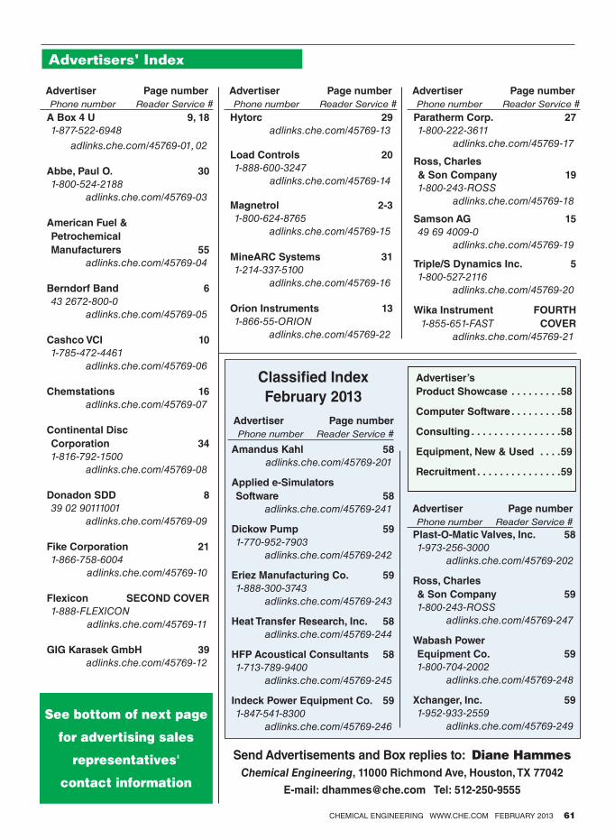
✁
CHEMICAL ENGINEERING WWW.CHE.COM FEBRUARY 2013 61
Advertisers’ Index
A Box 4 U 9, 18
1-877-522-6948
adlinks.che.com/45769-01, 02
Abbe, Paul O. 30
1-800-524-2188
adlinks.che.com/45769-03
American Fuel &
Petrochemical
Manufacturers 55
adlinks.che.com/45769-04
Berndorf Band 6
43 2672-800-0
adlinks.che.com/45769-05
Cashco VCI 10
1-785-472-4461
adlinks.che.com/45769-06
Chemstations 16
adlinks.che.com/45769-07
Continental Disc
Corporation 34
1-816-792-1500
adlinks.che.com/45769-08
Donadon SDD 8
39 02 90111001
adlinks.che.com/45769-09
Fike Corporation 21
1-866-758-6004
adlinks.che.com/45769-10
Flexicon SECOND COVER
1-888-FLEXICON
adlinks.che.com/45769-11
GIG Karasek GmbH 39
adlinks.che.com/45769-12
Hytorc 29
adlinks.che.com/45769-13
Load Controls 20
1-888-600-3247
adlinks.che.com/45769-14
Magnetrol 2-3
1-800-624-8765
adlinks.che.com/45769-15
MineARC Systems 31
1-214-337-5100
adlinks.che.com/45769-16
Orion Instruments 13
1-866-55-ORION
adlinks.che.com/45769-22
Paratherm Corp. 27
1-800-222-3611
adlinks.che.com/45769-17
Ross, Charles
& Son Company 19
1-800-243-ROSS
adlinks.che.com/45769-18
Samson AG 15
49 69 4009-0
adlinks.che.com/45769-19
Triple/S Dynamics Inc. 5
1-800-527-2116
adlinks.che.com/45769-20
Wika Instrument FOURTH
1-855-651-FAST COVER
adlinks.che.com/45769-21
Advertiser Page number
Phone number Reader Service #
Advertiser Page number
Phone number Reader Service #
Advertiser Page number
Phone number Reader Service #
Amandus Kahl 58
adlinks.che.com/45769-201
Applied e-Simulators
Software 58
adlinks.che.com/45769-241
Dickow Pump 59
1-770-952-7903
adlinks.che.com/45769-242
Eriez Manufacturing Co. 59
1-888-300-3743
adlinks.che.com/45769-243
Heat Transfer Research, Inc. 58
adlinks.che.com/45769-244
HFP Acoustical Consultants 58
1-713-789-9400
adlinks.che.com/45769-245
Indeck Power Equipment Co. 59
1-847-541-8300
adlinks.che.com/45769-246
Plast-O-Matic Valves, Inc. 58
1-973-256-3000
adlinks.che.com/45769-202
Ross, Charles
& Son Company 59
1-800-243-ROSS
adlinks.che.com/45769-247
Wabash Power
Equipment Co. 59
1-800-704-2002
adlinks.che.com/45769-248
Xchanger, Inc. 59
1-952-933-2559
adlinks.che.com/45769-249
Classiied Index
February 2013
Advertiser Page number
Phone number Reader Service #
Advertiser’s
Product Showcase . . . . . . . . .58
Computer Software . . . . . . . . .58
Consulting . . . . . . . . . . . . . . . .58
Equipment, New & Used . . . .59
Recruitment . . . . . . . . . . . . . . .59
Send Advertisements and Box replies to: Diane Hammes
Chemical Engineering, 11000 Richmond Ave, Houston, TX 77042
E-mail: [email protected] Tel: 512-250-9555
See bottom of next page
for advertising sales
representatives'
contact information
Advertiser Page number
Phone number Reader Service #

62 CHEMICAL ENGINEERING WWW.CHE.COM FEBRUARY 2013
People
Bruno Morel becomes CEO, and
Frédéric Raynal becomes chief tech-
nology officer and vice president of
engineering, at Alchimer SA (Massy,
France), a provider of nanometric
deposition technologies for advanced
3D packaging.
Philip Tilston becomes chief
financial officer of Wall Colmonoy
Ltd. (Madison Heights, Mich.), a
maker of surfacing alloys and
precision components.
Steven Winchester is named CEO of
MaxWest Environmental Systems
(Sanford, Fla.), a maker of biogasifica-
tion systems for wastewater treatment.
SmartKem Ltd. (Manchester, U.K.),
a developer of high-performance
organic semiconductor materials
makes several appointments: Hugh
Williamson becomes chief operating
officer, Muhammad Raza and Keith
Lumbard join the company as scien-
tists, Bill Freer is chairman and Gary
Tam is business development director.
Brooks Instrument (Hatfield, Pa.),
a provider of flow, pressure, vacuum
and level solutions, appoints Scott
Amsbaugh general manager.
Specialty chemicals maker Sartomer
USA LLC (Exton, Pa.) names Nikola
Juhasz senior director of research
and development, and Ken Earle
global supply chain director.
Engineering, construction and com-
missioning specialist Integrated
Project Services (IPS; Lafayette
Hill, Pa.) names John Panebianco
director of process engineering. ■Suzanne Shelley
Williamson JuhaszLumbardRaza
FEBRUARY WHO’S WHO
Amsbaugh
❯❯EACH INFORMATION PACKED PDF ARTICLE includes
graphs, charts, tables, equations and columns on the full
chemical engineering processes you deal with on a daily basis.
This is the tool you will come to rely on, referring back to the
information again and again with just the click of a mouse.
Facts at Your Fingertips Topics Include:
Conservation Economics:
Carbon Pricing Impacts
Distillation Tray Design
Burner Operating
Characteristics
Measurement Guide for
Replacement Seals
Steam Tracer Lines and Traps
Positive Displacement Pumps
Low-Pressure Measurement
for Control Valves
Creating Installed Gain Graphs
Aboveground and
Underground Storage Tanks
Chemical Resistance of
Thermoplastics
Heat Transfer: System
Design II
Adsorption
Flowmeter Selection
Specialty Metals
Plus much, much more…
RECEIVE FULL ACCESS
Receive full access today by visiting www.omeda.com/cbm/facts
17872
to ALL of Chemical Engineering’s Facts at Your Fingertips articles in one convenient location.
Receive full access today by visiting http://store.che.com/product/
Economic Indicators
February 2013; VOL. 120; NO. 2Chemical Engineering copyright @ 2013 (ISSN 0009-2460) is published monthly, with an additional issue in October, by Access Intelligence, LLC, 4 Choke Cherry Road, 2nd Floor, Rockville, MD, 20850. Chemical Engineering Executive, Editorial, Advertising and Publication Offices: 88 Pine Street, 5th Floor, New York, NY 10005; Phone: 212-621-4674, Fax: 212-621-4694. Subscription rates: $149.97 U.S. and U.S. possessions, $166.97 Canada, and $269 International. $20.00 Back issue & Single copy sales. Periodicals postage paid at Rockville, MD and additional mailing offices. Postmaster: Send address changes to Chemical Engineering, Fulfillment Manager, P.O. Box 3588, Northbrook, IL 60065-3588. Phone: 847-564-9290, Fax: 847-564-9453, email: [email protected]. Change of address, two to eight week notice requested. For information regarding article reprints, please contact Wright’s Media, 1-877-652-5295, [email protected]. Contents may not be reproduced in any form without written permission. Canada Post 40612608. Return undeliverable Canadian Addresses to: PitneyBowes, P.O. BOX 25542, LONDON, ON N6C 6B2
FOR ADDITIONAL NEWS AS IT DEVELOPS, PLEASE VISIT WWW.CHE.COM
PLANT WATCH
Lonza to expand ADC
manufacturing capacity
January 8,2013 —Lonza (Basel, Switzerland; www.lonza.com) plans to invest 14 million Swiss francs (CHF; about $15 million) to expand antibody drug conjugate (ADC) manufacturing capacity in Visp, Switzerland. Oncology therapeutics including ADCs represent one of the fastest growing segments of the pharma and biotech industry. The expansion of the ADC facility, which is expected to be complete in the second quarter of 2014, will double the existing large-scale manufacturing capacity in Visp.
Technip awarded FEED contract for
ammonia plant in Louisiana
January 3, 2013 — Technip (Paris, France; www.technip.com) was awarded by The Mosaic Co. (www.mosaicco.com) the front-end engineering and design (FEED) contract, as well as preparation of the corresponding engineering, procurement and construction (EPC) proposal, for a new ammonia plant under consideration by the global crop-nutrient company. Mosaic’s preference is to locate the proposed plant adjacent to the company’s existing Faustina fertilizer manufacturing operations in St. James Parish, La. It would have a capacity of 2,200 metric tons (m.t.) per day. The proposed design would feature Haldor Topsøe A/S’ (Lyngby, Denmark; www.topsoe.com) proprietary ammonia-process technology that Technip has successfully engineered and constructed. The FEED and corresponding EPC are targeted for completion by mid-2013.
BASF increases global capacity
for hexanediol
January 3, 2013 — BASF SE (Ludwigshafen, Germany; www.basf.com) will increase its global capacity for manufacturing the chemical intermediate 1,6-hexanediol (HDO) by more than 20% to more than 50,000 ton/yr by 2014. For this purpose, the company will invest more than €30 million to further optimize its production processes, carry out various infrastructure projects and enhance its logistical processes. BASF operates HDO production facilities at its sites in Freeport, Tex., and Ludwigshafen, Germany.
Evonik expands U.S. production of
precipitated silica
December 20, 2012 — Evonik Industries AG (Essen, Germany; www.evonik.com) plans to increase its production capacities for precipitated silica at its site in Chester, Pa. by around 20,000 m.t./yr. The new facility, which received an investment
in the lower double-digit million euros range, is scheduled to become operational in 2014. The capacity expansion in Chester underscores the plans of the Evonik Group to expand its global silica capacities by about 30% over the level of 2010 by 2014.
New acrylic acid plant planned in the
Republic of Bashkortostan
December 19, 2012 — Mitsubishi Heavy Industries, Ltd. (MHI; Tokyo, Japan; www.mhi.co.jp) and Sojitz Corp., jointly with Renaissance Construction (RC), have received an order from JSC Gazprom Neftekhim Salavat (GNS) of the Republic of Bashkortostan, Russian Federation, for a project to construct a new acrylic acid plant with process technology licensed by Mitsubishi Chemical Corp. (MCC). The plant is planned to produce 80,000 m.t./yr of acrylic acid, 80,000 m.t./yr of butyl acrylate and 35,000 m.t./yr of glacial acrylic acid, and it is expected to reach its projected capacity in 2015.
Caloric to supply hydrogen-generating
plant to the Czech Republic
December 19, 2012 — Caloric Anlagenbau GmbH (Gräfelfing, Germany; www.caloric.com) has won a contract for a hydrogen-generating plant with a capacity of 2,000 Nm³/h based on naphtha feed stock. The hydrogen unit will be located in the Czech Republic and will provide hydrogen to a benzene production unit. The plant design will follow Caloric’s expertise in highly efficient and customized concepts. The operation of the plant will start in mid-2013.
Toyo wins fertilizer plant order
in Indonesia
December 18, 2012 —The consortium of Toyo Engineering Corp. (Toyo; Chiba, Japan; www.toyo-eng.co.jp) and PT Rekayasa Industri (Rekind) has been awarded a fertilizer project from the Indonesian fertilizer company, PT Pupuk Sriwidjaja Palembang (PUSRI). The project, named “PUSRI IIB,” is to be constructed in Palembang of South Sumatra, Indonesia. The contract is for EPC services for the facilities to produce 2,000 ton/d of ammonia and 2,750 ton/d of urea, plus utility facilities. The ammonia plant and utility facilities are provided by Rekind and urea plant together with urea technology by Toyo.
CP Kelco announces CMC capacity
expansion plans
December 12, 2012 — CP Kelco (Atlanta, Ga.; www.cpkelco.com) has announced plans to increase the carboxymethyl cellulose (CMC) capacity at its production facility in Äänekoski, Finland. CP Kelco will be expanding purified
CMC capacity up to 25% at this facility over the next 12 to 18 months. The Äänekoski plant is already said to be the largest purified CMC manufacturing facility in the world.
MERGERS AND ACQUISITIONS
Clariant divests several businesses
to SK Capital
January 2, 2013 — Clariant AG (Muttenz, Switzerland; www.clariant.com) has signed an agreement to divest its textile chemicals, paper specialties and emulsions businesses to SK Capital, a U.S.-based private investment firm with a focus on the specialty materials, chemicals and healthcare sectors. The divestment has been approved by the Boards of both companies. Subject to regulatory approvals, the transaction is expected to close by the end of the second quarter of 2013. The total consideration of the sale amounts to approximately CHF 502 million.
BASF to sell Meyco Equipment business
to Atlas Copco
December 21, 2012 — BASF SE has signed a contract with Atlas Copco to sell its Meyco Equipment business, which provides concrete spraying machines to the mining industries. The machinery manufacturer, which is based in Stockholm, Sweden, will continue operations at the production site of Meyco Equipment in Winterthur, Switzerland. Both parties have agreed to not disclose financial details of the transaction.
AkzoNobel to divest its North American
Decorative Paints business
December 14, 2012 —AkzoNobel (Amsterdam, The Netherlands; www.akzonobel.com) has announced the divestment of its North American Decorative Paints business to PPG Industries, Inc. (PPG; Pittsburgh, Pa.; www.ppg.com), for the value of $1.05 billion. In 2011, the North American Decorative Paints business had revenues of $1.5 billion.
Altana acquires the business of the wax
additive manufacturer ChemCor
December 7, 2012 — The specialty chemicals group Altana (Wesel, Germany; www.altana.com) has signed a contract to acquire the business of Chemical Corporation of America Inc. (ChemCor), a U.S. manufacturer of wax additives. Altana will acquire the production site in Chester, N.Y. The business will be integrated into BYK USA Inc., which is based in Wallingford, Conn. and belongs to the Altana Additives & Instruments div. ■
Dorothy Lozowski
BUSINESS NEWS
FOR MORE ECONOMIC INDICATORS, SEE NEXT PAGE CHEMICAL ENGINEERING WWW.CHE.COM FEBRUARY 2013 63
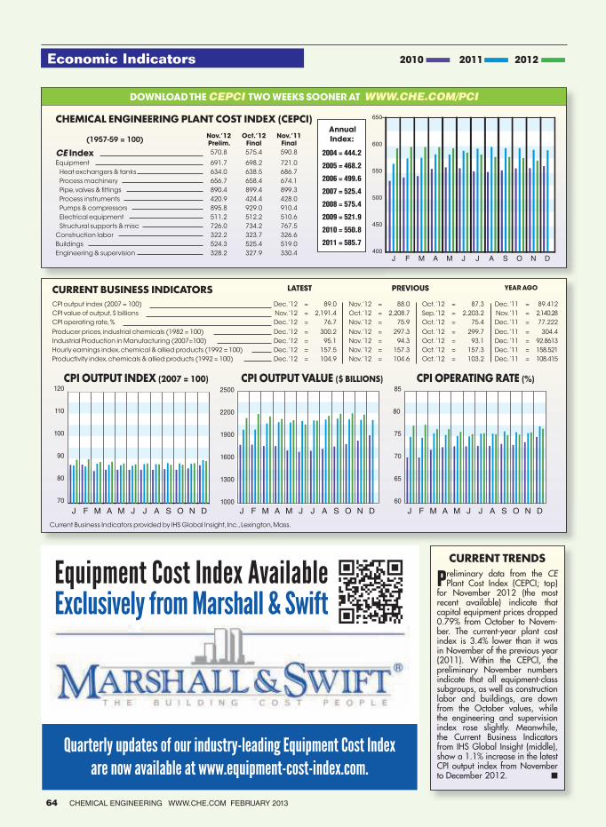
Economic Indicators
400
450
500
550
600
650
J F M A M J J A S O N D
DOWNLOAD THE CEPCI TWO WEEKS SOONER AT WWW.CHE.COM/PCI
CURRENT TRENDS
Preliminary data from the CE Plant Cost Index (CEPCI; top)
for November 2012 (the most recent available) indicate that capital equipment prices dropped 0.79% from October to Novem-ber. The current-year plant cost index is 3.4% lower than it was in November of the previous year (2011). Within the CEPCI, the preliminary November numbers indicate that all equipment-class subgroups, as well as construction labor and buildings, are down from the October values, while the engineering and supervision index rose slightly. Meanwhile, the Current Business Indicators from IHS Global Insight (middle), show a 1.1% increase in the latest CPI output index from November to December 2012. ■
2010 2011 2012
CHEMICAL ENGINEERING PLANT COST INDEX (CEPCI)
(1957-59 = 100)Nov. ’12
Prelim.
Oct. ’12
Final
Nov. ’11
Final
CE Index 570.8 575.4 590.8
Equipment 691.7 698.2 721.0
Heat exchangers & tanks 634.0 638.5 686.7
Process machinery 656.7 658.4 674.1
Pipe, valves & fittings 890.4 899.4 899.3
Process instruments 420.9 424.4 428.0
Pumps & compressors 895.8 929.0 910.4
Electrical equipment 511.2 512.2 510.6
Structural supports & misc 726.0 734.2 767.5
Construction labor 322.2 323.7 326.6
Buildings 524.3 525.4 519.0
Engineering & supervision 328.2 327.9 330.4
CURRENT BUSINESS INDICATORS LATEST PREVIOUS YEAR AGO
CPI output index (2007 = 100) Dec. ’12 = 89.0 Nov. ’12 = 88.0 Oct. ’12 = 87.3 Dec. ’11 = 89.412
CPI value of output, $ billions Nov. ’12 = 2,191.4 Oct. ’12 = 2,208.7 Sep. ’12 = 2,203.2 Nov. ’11 = 2,140.28
CPI operating rate, % Dec. ’12 = 76.7 Nov. ’12 = 75.9 Oct. ’12 = 75.4 Dec. ’11 = 77.222
Producer prices, industrial chemicals (1982 = 100) Dec. ’12 = 300.2 Nov. ’12 = 297.3 Oct. ’12 = 299.7 Dec. ’11 = 304.4
Industrial Production in Manufacturing (2007=100) Dec. ’12 = 95.1 Nov. ’12 = 94.3 Oct. ’12 = 93.1 Dec. ’11 = 92.8613
Hourly earnings index, chemical & allied products (1992 = 100) Dec. ’12 = 157.5 Nov. ’12 = 157.3 Oct. ’12 = 157.3 Dec. ’11 = 158.521
Productivity index, chemicals & allied products (1992 = 100) Dec. ’12 = 104.9 Nov. ’12 = 104.6 Oct. ’12 = 103.2 Dec. ’11 = 108.415
60
65
70
75
80
85
1000
1300
1600
1900
2200
2500
J F M A M J J A S O N D J F M A M J J A S O N D J F M A M J J A S O N D
70
80
90
100
110
120
CPI OUTPUT INDEX (2007 = 100) CPI OUTPUT VALUE ($ BILLIONS) CPI OPERATING RATE (%)
Current Business Indicators provided by IHS Global Insight, Inc., Lexington, Mass.
are now available at www.equipment-cost-index.com.
Quarterly updates of our industry-leading Equipment Cost Index
Equipment Cost Index AvailableExclusively from Marshall & Swift
Annual
Index:
2004 = 444.2
2005 = 468.2
2006 = 499.6
2007 = 525.4
2008 = 575.4
2009 = 521.9
2010 = 550.8
2011 = 585.7
64 CHEMICAL ENGINEERING WWW.CHE.COM FEBRUARY 2013
Do you have what it takes?
WINNERSWINNERSWINNERS
WILLWILLWILL BE RECOGNIZEDOGNIZEDOGNIZED
Company awarDs
Unit Operations Awards
Innovative Energy Use Award
Best Process Plant Facility Improvement Award
The Safety Investment Award
Community Service Award
Early Adopter Award
Process Control and Automation Award
inDiviDual awarDs
“Jack of all trades” Award
Next Generation Award (fewer than 15 year’s experience)
Plant Manager of the Year
PRESENTED BY:
2013 Chemical Engineering & ChemInnovations Awards
Nominations are now being accepted
for the 2013 Chemical Engineering and
ChemInnovations Awards. Winners will
be announced during the 2013 Chemical
Engineering & ChemInnovations Awards
Banquet on Tuesday, September 24,
2013 at the Moody Gardens Hotel and
Convention Center.
submission DeaDline - July 22, 2013
Join the list of prestigious companies to
have previously won: BASF, Braskem S.A,
Formox AB, LyondellBasell, JR Johanson,
Inc. The Dow Chemical Company, UOP LLC,
A Honeywell Company
For additional information and/or to submit
a nomination for consideration visit
www.cpievent.com/award_nomination.

25% of your pressure gauges
are failing—how much will a
media leak cost you?
SM
Did you know that an average of 8 failing gauges are within 20 feet of every
employee working in your plant? These ticking time bombs make your team
unsafe, less productive and can even lead to serious disasters.
WIKA can take the worry out of instrumentation with our Full Service Audit Team
(FAST). Using our proven process, WIKA’s experts can lower your costs, make you safer and reduce downtime with our FAST Total Care Program.
Let us show you how today by downloading our free eBook at
www.WIKA-FAST.com/ebook or by calling us at 855-651-FAST (3278).
Instrument Audit Turnaround Instrument Planning Instrument Failure Analysis Instrument Safety Training
Circle 21 on p. 60 or go to adlinks.che.com/45769-21