abstract software-oriented memory
TRANSCRIPT

ABSTRACT
SOFTWARE-ORIENTED MEMORY-MANAGEMENT DESIGN
by
Bruce Ledley Jacob
Chair: Trevor N. Mudge
Changing trends in technologies, notably cheaper and faster memory hierarchies, have
made it worthwhile to revisit many hardware-oriented design decisions made in previous decades.
Hardware-oriented designs, in which one uses special-purpose hardware to perform some dedi-
cated function, are a response to a high cost of executing instructions out of memory; when caches
are expensive, slow, and/or in scarce supply, it is a perfectly reasonable reaction to build hardware
state machines that do not compete with user applications for cache space and do not rely on the
performance of the caches. In contrast, when the caches are large enough to withstand competition
between the application and operating system, the cost of executing operating system functions out
of the memory subsystem decreases significantly, and software-oriented designs become viable.
Software-oriented designs, in which one dispenses with special-purpose hardware and instead per-
forms the same function entirely in software, offer dramatically increased flexibility over hardware
state machines at a modest cost in performance.
This dissertation explores a software-oriented design for a virtual memory management
system. It shows not only that a software design is more flexible than hardware designs, but that a
software scheme can perform as well as most hardware schemes. Eliminating dedicated special-
purpose hardware from processor design saves chip area and reduces power consumption, thus
lowering the overall system cost. Moreover, a flexible design aids in the portability of system soft-
ware. A software-oriented design methodology should therefore benefit architects of many differ-
ent microprocessor designs, from general-purpose processors in PC-class and workstation-class
computers, to embedded processors where cost tends to have a higher priority than performance.
The particular implementation described in the following chapters, which is centered around a vir-
tual cache hierarchy managed by the operating system, is shown to be useful for real-time systems,
shared-memory multiprocessors, and architecture emulation.
SOFTWARE-ORIENTED
MEMOR Y-MAN AGEMENT DESIGN
by
Bruce Ledley Jacob
A dissertation submitted in partial fulfillmentof the requirements for the degree of Doctor of Philosophy
(Computer Science and Engineering)in the University of Michigan
1997
Doctoral Committee:
Professor Trevor Mudge, ChairAdjunct Assistant Professor Charles AntonelliProfessor Richard BrownAssistant Professor Peter ChenAssociate Professor Farnam Jahanian

This book is merely a personal narrative, and not a pretentioushistory or a philosophical dissertation. It is a record of severalyears of variegated vagabondizing, and its object is rather to helpthe resting reader while away an idle hour than afflict him withmetaphysics, or goad him with science.
Still, there is quite a good deal of information in the book. Iregret this very much; but really it could not be helped:information appears to stew out of me naturally, like the preciousottar of roses out of the otter. Sometimes it has seemed that Iwould give worlds if I could retain my facts; but it cannot be. Themore I caulk up the sources, and the tighter I get, the more I leakwisdom. Therefore, I can only claim indulgence at the hands ofthe reader, not justification.
Excerpted from Prefatory, Roughing It— Mark Twain
© 1997Bruce Ledley Jacob
All Rights Reserved
ii
For my Family
(my family, my family-in-law,and most especially my truly adorable wife)
iii
ACKNOWLEDGMENTS
Thanks to the members of my thesis committee, who have given me good advice and per-
spective over the last few years in the classroom, at informal hallway meetings, and at various
local restaurants. Thanks especially to my thesis chair, whose dogged question-asking indirectly
unearthed much found herein.
iv
PREFACE
In the fall of 1995 we began a project to build a 1GHz PowerPC processor in gallium ars-
enide (GaAs); my duties included the design of the memory management system, both software
and hardware. The problem to solve initially was threefold:
1. Reduce transistor count
2. Reduce complexity
3. Increase performance
These could be restated as:
1. Make itsmall
2. Make itsimple
3. Make it fast
These goals may appear over-simplistic; I believe that they are not. What is not immedi-
ately obvious is that they are in order of priority, and that when viewed as requirements and not
simply good engineering advice, they define a clear path to achieving our performance goals. To
explain their rationale: if we could not make our design small, we would almost certainly not be
able to build it at all—GaAs does not allow one the luxury of a large design. If it could not be
made simple, we would probably not be able to debug it. If it could not be made fast, we would
lose face but the design would still work. Therefore, we considered it worthwhile to sacrifice a
small amount of performance if doing so would make the design smaller or simpler.
One maxim that can be drawn from these requirements is:whenever it is possible to imple-
ment a given function in software it is worthwhile to do so, unless the performance cost of doing so
is prohibitive. The thesis work presented in this dissertation is the result of investigating the valid-
ity and implications of that maxim in the domain of memory management.
The memory-management design that adheres to this maxim is a software-oriented one. A
software-oriented design is one in which the designer eliminates a piece of special-purpose hard-
ware that performs some dedicated function and instead performs the same function entirely in
software. For instance, thetranslation lookaside buffer (TLB) is a specialized hardware structure
v
that performs a dedicated function; it provides protection and address translation for physically
indexed or physically tagged caches. It is not needed if one uses virtually addressed caches (except
for the protection function, which can be ignored or supported by keeping protection information
in each cache line). We eliminated the traditional TLB structure and replaced it with virtually
indexed, virtually tagged caches that are managed by the operating system—in such a scheme,
address translation is performed not in hardware but entirely in software by system-level software
routines.
A hardware-oriented PowerPC memory-management architecture has essentially three
TLBs: the segment registers, the traditional page-oriented TLB, and the superpage-oriented BAT
registers (Block-Address Translation). The segment registers are required to implement the Pow-
erPC’s segmented address space. With a software-oriented design, we were able to eliminate the
remaining two TLB structures at virtually no performance cost.
Once our investigations showed the scheme to be viable (its performance is roughly that of
a system with a TLB), it occurred to us that we had designed a system that could potentially com-
pete in performance with any memory-management scheme, but which offered dramatically
increased flexibility over traditional designs. Thus, this memory-management organization might
be useful even if one is not building a processor in a resource-poor technology such as GaAs. This
dissertation explores the possibilities for such a design, comparing the performance and physical
requirements (e.g. chip area) of a hardware-oriented scheme against the requirements of a soft-
ware-oriented one. We discuss the flexibility of a software-oriented design and, briefly, its benefits
for multiprocessor systems, real-time systems, architecture emulation, and reconfigurable comput-
ing.
vi
DEDICATION ................................................................................................................................ ii
ACKNOWLEDGMENTS ............................................................................................................. iii
PREFACE...................................................................................................................................... iv
TABLE OF CONTENTS.............................................................................................................. vi
LIST OF FIGURES....................................................................................................................... xi
LIST OF TABLES........................................................................................................................ xv
CHAPTER 1
INTRODUCTION: VIRTUAL MEMORY,THREE DECADES LATER............................................................................................. 1
1.1 ...... Motivation ........................................................................................................... 11.2 ...... Background and Previous Work in Memory Management Design..................... 51.3 ...... Dissertation Overview......................................................................................... 71.4 ...... Scope of the Thesis.............................................................................................. 9
CHAPTER 2
A VIRTUAL MEMORY PRIMER ................................................................................. 10
2.1 ...... Introduction ....................................................................................................... 102.2 ...... What Is Virtual Memory?.................................................................................. 11
2.2.1 ... Three Models of Addressing: Physical, Base+Offset, and Virtual...... 132.2.2 ... The Virtual Addressing Continuum..................................................... 172.2.3 ... Choices for a Fully-Associative Main Memory Organization............. 202.2.4 ... Further Memory-Management Research.............................................. 23
2.3 ...... Virtual Memory Mechanisms and Nomenclature............................................. 242.3.1 ... Hierarchical Page Tables...................................................................... 262.3.2 ... Inverted Page Tables............................................................................ 292.3.3 ... The Translation Lookaside Buffer....................................................... 312.3.4 ... Page Table Perspective......................................................................... 32
2.4 ...... Conclusions....................................................................................................... 34
TABLE OF CONTENTS
vii
CHAPTER 3
MEMORY MANAGEMENT HARDWARE AND ITSSUPPORT FOR OPERATING SYSTEMS FUNCTIONS............................................. 36
3.1 ...... Introduction ....................................................................................................... 363.2 ...... Operating System Requirements....................................................................... 37
3.2.1 ... Address Space Protection..................................................................... 373.2.2 ... Shared Memory.................................................................................... 373.2.3 ... Large Address Spaces.......................................................................... 383.2.4 ... Fine-Grained Protection....................................................................... 383.2.5 ... Sparse Address Spaces......................................................................... 383.2.6 ... Superpages............................................................................................ 393.2.7 ... Direct Memory Access......................................................................... 39
3.3 ...... Memory Management Units.............................................................................. 403.3.1 ... MIPS ..................................................................................................... 403.3.2 ... Alpha .................................................................................................... 433.3.3 ... PowerPC............................................................................................... 443.3.4 ... PA-RISC 2.0......................................................................................... 463.3.5 ... SPARC V9 ........................................................................................... 483.3.6 ... Pentium Pro.......................................................................................... 503.3.7 ... SPUR.................................................................................................... 533.3.8 ... SOFTVM .............................................................................................. 54
3.4 ...... A Taxonomy of Address Space Organizations................................................. 553.4.1 ... Single-Owner, No ID (SONI).............................................................. 583.4.2 ... Single-Owner, Single-ID (SOSI)......................................................... 593.4.3 ... Single-Owner, Multiple-ID (SOMI)..................................................... 603.4.4 ... Multiple-Owner, No ID (MONI).......................................................... 603.4.5 ... Multiple-Owner, Single-ID (MOSI)..................................................... 613.4.6 ... Multiple-Owner, Multiple-ID (MOMI) ................................................ 61
3.5 ...... Conclusions....................................................................................................... 62
CHAPTER 4
EXPERIMENTAL METHODOLOGY .......................................................................... 64
4.1 ...... Introduction ....................................................................................................... 644.2 ...... PUMAmm: Memory Management Simulation................................................. 65
4.2.1 ... SOFTVM Virtual Memory................................................................... 674.2.2 ... Ultrix/MIPS Virtual Memory............................................................... 684.2.3 ... Mach/MIPS Virtual Memory............................................................... 694.2.4 ... BSD/Intel Virtual Memory................................................................... 704.2.5 ... PA-RISC Virtual Memory.................................................................... 72
4.3 ...... Benchmark Measurements................................................................................ 734.3.1 ... Setup on PowerPC................................................................................ 774.3.2 ... Setup on Alpha..................................................................................... 77
4.4 ...... Conclusions....................................................................................................... 77
viii
CHAPTER 5
SOFTWARE-MANAGED ADDRESS TRANSLATION.............................................. 78
5.1 ...... Introduction ....................................................................................................... 785.2 ...... Background and Previous Work........................................................................ 80
5.2.1 ... Problems with Virtual Caches.............................................................. 805.2.2 ... Segmented Translation......................................................................... 815.2.3 ... MIPS: A Simple 32-bit Page Table Design.......................................... 815.2.4 ... SPUR: In-Cache Address Translation.................................................. 825.2.5 ... VMP: Software-Controlled Caches...................................................... 83
5.3 ...... Software-Managed Address Translation........................................................... 835.3.1 ... Handling the Cache-Miss Exception.................................................... 845.3.2 ... An Example of softvm and Its Use...................................................... 855.3.3 ... Memory System Requirements, Revisited........................................... 88
5.4 ...... Discussion......................................................................................................... 905.4.1 ... Performance Overview......................................................................... 905.4.2 ... Baseline Overhead................................................................................ 915.4.3 ... Writebacks............................................................................................ 935.4.4 ... Fine-Grained Protection....................................................................... 935.4.5 ... Sensitivity to Cache Organization—Preliminary Results.................... 95
5.5 ...... Conclusions....................................................................................................... 96
CHAPTER 6
PERFORMANCE COMPARISONS,IMPLICATIONS, AND REPERCUSSIONS................................................................. 98
6.1 ...... Introduction ....................................................................................................... 986.2 ...... Detailed Performance Comparisons.................................................................. 99
6.2.1 ... Memory System Overhead................................................................. 1006.2.2 ... Virtual Memory Overhead................................................................. 1066.2.3 ... Cost per Invocation of the Handler.................................................... 115
6.3 ...... Sensitivity to System Characteristics.............................................................. 1266.3.1 ... The Cost of Interrupts......................................................................... 1266.3.2 ... Long Access Times to Memory and Level-2 Caches......................... 1346.3.3 ... The Effects of Cold-Cache Start-Up.................................................. 135
6.4 ...... Die Area Tradeoffs.......................................................................................... 1446.4.1 ... The Register-Bit Equivalent............................................................... 1446.4.2 ... Performance as a Function of Die Area............................................. 146
6.5 ...... The Bottom Line on Performance................................................................... 1646.6 ...... Usefulness of the Software-Oriented Scheme................................................. 179
6.6.1 ... Support for Multiprocessor Systems.................................................. 1796.6.2 ... Support for Real-Time Systems......................................................... 1816.6.3 ... Support for Architecture Emulation................................................... 1826.6.4 ... Support for Reconfigurable Computing, Jr........................................ 182
6.7 ...... Comparison to Other Addressing Schemes..................................................... 183
ix
6.7.1 ... Large (e.g. 64-bit) Addressing Schemes............................................ 1836.7.2 ... Single Address Space Operating Systems.......................................... 183
6.8 ...... Compatibility with Different Cache Organizations......................................... 1856.8.1 ... Write-Back Caches............................................................................. 1856.8.2 ... Write-Through Caches....................................................................... 185
6.9 ...... Conclusions..................................................................................................... 1866.9.1 ... Performance Recapitulation............................................................... 1866.9.2 ... The Good News.................................................................................. 1886.9.3 ... The Bad News.................................................................................... 188
CHAPTER 7
THE PROBLEMS WITH VIRTUAL CACHESAND A SOLUTION USING HARDWARE SEGMENTATION................................ 189
7.1 ...... Introduction ..................................................................................................... 1897.2 ...... Background and Perspective........................................................................... 190
7.2.1 ... Requirements...................................................................................... 1917.2.2 ... Segmented Architectures.................................................................... 1917.2.3 ... The Consistency Problem of Virtual Caches..................................... 194
7.3 ...... Shared Memory vs. the Virtual Cache............................................................ 1977.3.1 ... The Problems with Virtual-Address Aliasing.................................... 1977.3.2 ... The Problems with Address-Space Identifiers................................... 199
7.4 ...... The “Virtue” of Segmentation......................................................................... 2007.5 ...... Discussion....................................................................................................... 203
7.5.1 ... Global Page Table.............................................................................. 2037.5.2 ... Page Table Efficiency........................................................................ 2057.5.3 ... Portability ........................................................................................... 206
7.6 ...... Conclusions..................................................................................................... 210
CHAPTER 8
THE PROBLEMS WITH INTERRUPTSAND A SOLUTION BY REDEFINING THEIR PRECISION.................................... 211
8.1 ...... Introduction ..................................................................................................... 2118.2 ...... Precise Interrupts and Pipelined Processors.................................................... 2148.3 ...... Relaxed-Precision Interrupts........................................................................... 215
8.3.1 ... Definition ............................................................................................ 2168.3.2 ... A Model for Relaxed-Precision Interrupts......................................... 2188.3.3 ... The Performance Benefits of Relaxed-Precision Interrupts............... 229
8.4 ...... Conclusions..................................................................................................... 233
x
CHAPTER 9
THE PROBLEMS WITH MULTIMEDIA SUPPORTAND A SOLUTION USING SEGMENTATION........................................................ 235
9.1 ...... Introduction ..................................................................................................... 2359.2 ...... Superpage Support.......................................................................................... 2369.3 ...... Performance Measurements............................................................................ 2389.4 ...... Conclusions..................................................................................................... 241
CHAPTER 10
THE PROBLEMS WITH LARGE OFF-CHIP CACHESAND A SOLUTION USING PHYSICAL MEMORY................................................. 242
10.1 .... Introduction ..................................................................................................... 24210.2 .... Main Memory as a Virtual Cache................................................................... 243
10.2.1. Fully Associative Designs.................................................................. 24610.2.2. Set-Associative Designs..................................................................... 24710.2.3. Direct-Mapped Designs...................................................................... 247
10.3 .... Experiments..................................................................................................... 24810.4 .... Conclusions..................................................................................................... 249
CHAPTER 11
CONCLUSIONS........................................................................................................... 250
APPENDIX ................................................................................................................................ 255
BIBLIOGRAPHY ...................................................................................................................... 262
xi
Figure 2.1: Memory management models................................................................................ 11
Figure 2.2: The Physical Addressing model of program creation and execution.................... 12
Figure 2.3: The Base+Offset Addressing model of program creation and execution.............. 12
Figure 2.4: The Virtual Addressing model of program creation and execution...................... 13
Figure 2.5: Comparison of the three models............................................................................ 14
Figure 2.6: Caching the process address space........................................................................ 18
Figure 2.7: Associative organizations of main memory.......................................................... 19
Figure 2.8: An idealized fully associative cache lookup.......................................................... 21
Figure 2.9: Alternative designs for associative cache lookup.................................................. 22
Figure 2.10: Mapping virtual pages into physical page frames................................................. 24
Figure 2.11: A logical Page Table Entry.................................................................................... 26
Figure 2.12: Classical two-level hierarchical page table............................................................ 27
Figure 2.13: Top-down access method for hierarchical page table............................................ 28
Figure 2.14: Bottom-up algorithm for hierarchical page table................................................... 29
Figure 2.15: Classical inverted page table structure.................................................................. 30
Figure 2.16: Lookup algorithm for inverted page table............................................................. 31
Figure 2.17: Inverted page table and shared memory................................................................ 33
Figure 2.18: Possible locations of the translation point............................................................. 35
Figure 3.1: Sparse address spaces............................................................................................ 39
Figure 3.2: The MIPS R10000 address translation mechanism............................................... 41
Figure 3.3: The Alpha 21164 address translation mechanism................................................. 43
Figure 3.4: The PowerPC 604 address translation mechanism................................................ 45
Figure 3.5: The PA-8000 address translation mechanism........................................................ 47
Figure 3.6: The UltraSPARC address translation mechanism................................................. 49
Figure 3.7: The Pentium Pro address translation mechanism.................................................. 51
Figure 3.8: The SPUR address translation mechanism............................................................ 53
LIST OF FIGURES
xii
Figure 3.9: The SOFTVM address translation mechanism...................................................... 55
Figure 3.10: The difference between ASIDs and a multiple-owner address space.................... 57
Figure 4.1: The SOFTVM page table organization.................................................................. 68
Figure 4.2: The Ultrix/MIPS page table organization.............................................................. 69
Figure 4.3: The Mach/MIPS page table organization.............................................................. 70
Figure 4.4: The BSD/Intel page table organization.................................................................. 71
Figure 4.5: The PA-RISC page table organization.................................................................. 72
Figure 5.1: The MIPS 32-bit hierarchical page table............................................................... 82
Figure 5.2: SpecifyVTAG and Load&Map.............................................................................. 85
Figure 5.3: The example address translation mechanism........................................................ 86
Figure 5.4: An example page table organization...................................................................... 87
Figure 5.5: An example cache miss algorithm......................................................................... 87
Figure 5.6: The effect of cache size and linesize on software-managed address translation... 96
Figure 6.1: MCPI variations in response to differing page table organizations..................... 100
Figure 6.2: GCC/alpha — MCPI break-downs...................................................................... 102
Figure 6.3: VORTEX/powerpc — MCPI break-downs......................................................... 103
Figure 6.4: IJPEG/alpha — MCPI break-downs.................................................................... 104
Figure 6.5: IJPEG/alpha — MCPI break-downs, cont’d....................................................... 105
Figure 6.6: GCC/alpha — VMCPI vs. cache size.................................................................. 107
Figure 6.7: VORTEX/powerpc — VMCPI vs. cache size..................................................... 108
Figure 6.8: GCC/alpha — VMCPI break-downs................................................................... 111
Figure 6.9: VORTEX/powerpc — VMCPI break-downs...................................................... 112
Figure 6.10: Mean time between handlers for GCC/alpha and VORTEX/powerpc................ 117
Figure 6.11: The cost of using smaller TLBs........................................................................... 118
Figure 6.12: GCC/alpha — Per-invocation costs of the handlers............................................ 121
Figure 6.13: GCC/alpha — Break-downs for handler invocations.......................................... 123
Figure 6.14: GCC/alpha — Break-downs for handler invocations, cont’d.............................. 124
Figure 6.15: GCC/alpha recalculations for low-overhead interrupts....................................... 128
Figure 6.16: GCC/alpha recalculations for medium-overhead interrupts................................ 129
Figure 6.17: GCC/alpha recalculations for high-overhead interrupts...................................... 130
Figure 6.18: VORTEX/powerpc recalculations for low-overhead interrupts.......................... 131
Figure 6.19: VORTEX/powerpc recalculations for medium-overhead interrupts................... 132
Figure 6.20: VORTEX/powerpc recalculations for high-overhead interrupts......................... 133
Figure 6.21: The high-performance-1 memory-hierarchy access-time model......................... 136
xiii
Figure 6.22: The high-performance-2 memory-hierarchy access-time model......................... 137
Figure 6.23: The medium-performance-1 memory-hierarchy access-time model................... 138
Figure 6.24: The medium-performance-2 memory-hierarchy access-time model................... 139
Figure 6.25: The low-performance memory-hierarchy access-time model............................. 140
Figure 6.26: Cold-cache measurements for GCC/alpha........................................................... 142
Figure 6.27: Cold-cache measurements for VORTEX/powerpc............................................. 143
Figure 6.28: GCC/alpha — VM overhead as a function of die area........................................ 147
Figure 6.29: VORTEX/powerpc — VM overhead as a function of die area........................... 148
Figure 6.30: GCC/alpha — VM overhead vs. die-area, restricted design............................... 150
Figure 6.31: GCC/alpha — VM overhead vs. die-area, restricted design, cont’d................... 151
Figure 6.32: VORTEX/powerpc — VM overhead vs. die-area, restricted design.................. 152
Figure 6.33: VORTEX/powerpc — VM overhead vs. die-area, restricted design, cont’d...... 153
Figure 6.34: GCC/alpha — Total overhead vs. die-area, restricted design............................. 154
Figure 6.35: VORTEX/powerpc — Total overhead vs. die-area, restricted design................ 155
Figure 6.36: IJPEG/alpha — Total overhead vs. die-area, low-power design......................... 156
Figure 6.37: GCC/alpha — Total overhead vs. die-area, low-power design........................... 158
Figure 6.38: VORTEX/powerpc — Total overhead vs. die-area, low-power design.............. 159
Figure 6.39: IJPEG/alpha — Total overhead vs. die-area, low-power design......................... 160
Figure 6.40: GCC/alpha — TOTAL overhead vs. die-area, all cache sizes............................ 161
Figure 6.41: VORTEX/powerpc — TOTAL overhead vs. die-area, all cache sizes............... 162
Figure 6.42: IJPEG/alpha — TOTAL overhead vs. die-area, all cache sizes.......................... 163
Figure 6.43: GCC/alpha — split 128/128-entry TLBs and a 10-cycle interrupt...................... 165
Figure 6.44: VORTEX/powerpc — split 128/128-entry TLBs and a 10-cycle interrupt........ 166
Figure 6.45: IJPEG/alpha — split 128/128-entry TLBs and a 10-cycle interrupt................... 167
Figure 6.46: GCC/alpha — split 128/128-entry TLBs and a 50-cycle interrupt...................... 168
Figure 6.47: VORTEX/powerpc — split 128/128-entry TLBs and a 50-cycle interrupt........ 169
Figure 6.48: IJPEG/alpha — split 128/128-entry TLBs and a 50-cycle interrupt................... 170
Figure 6.49: GCC/alpha — split 64/64-entry TLBs and a 10-cycle interrupt.......................... 171
Figure 6.50: VORTEX/powerpc — split 64/64-entry TLBs and a 10-cycle interrupt............ 172
Figure 6.51: IJPEG/alpha — split 64/64-entry TLBs and a 10-cycle interrupt....................... 173
Figure 6.52: GCC/alpha — split 64/64-entry TLBs and a 50-cycle interrupt.......................... 175
Figure 6.53: VORTEX/powerpc — split 64/64-entry TLBs and a 50-cycle interrupt............ 176
Figure 6.54: IJPEG/alpha — split 64/64-entry TLBs and a 50-cycle interrupt....................... 177
Figure 6.55: Shared-memory multiprocessor organization...................................................... 180
xiv
Figure 7.1: The single indirection of traditionalmemory-management organizations.................................................................... 192
Figure 7.2: Multiple levels of indirection in a segmentedmemory-management organization..................................................................... 192
Figure 7.3: The synonym problem of virtual caches.............................................................. 194
Figure 7.4: Simple hardware solutions to page aliasing......................................................... 195
Figure 7.5: Synonym problem solved by operating system policy........................................ 196
Figure 7.6: The problem with allowing processes to map shared dataat different virtual addresses................................................................................ 198
Figure 7.7: The use of segments to provide virtual address aliasing..................................... 201
Figure 7.8: Copy-on-write in a segmented architecture......................................................... 202
Figure 7.9: An alternate implementation of copy-on-write.................................................... 203
Figure 7.10: Segmentation mechanism used in Discussion..................................................... 204
Figure 7.11: A global page table organization......................................................................... 205
Figure 7.12: Comparison of page table space requirements.................................................... 207
Figure 8.1: Simple and complex boundaries in the dynamic instruction stream................... 212
Figure 8.2: Instantaneous pipeline contents in an out-of-order machine............................... 213
Figure 8.3: Example of relaxed-precision interrupt handling................................................ 216
Figure 8.4: Sequential operation of the reorder buffer and re-execute buffer........................ 220
Figure 8.5: The problem with short interrupt handlers and large reorder buffers.................. 222
Figure 8.6: Parallel operation of the reorder buffer and re-execute buffer............................ 224
Figure 8.7: Merged reorder buffer and re-execute buffer...................................................... 226
Figure 8.8: Register-register & memory-memory dependencies for VORTEX/alpha.......... 230
Figure 8.9: Dependence of instructions on the head of the reorder buffer............................. 231
Figure 9.1: Superpage support in a SOFTVM-like architecture............................................ 237
Figure 9.2: Memory-system performance on STREAM/alpha.............................................. 238
Figure 9.3: Virtual memory performance on STREAM/alpha.............................................. 239
Figure 9.4: VM performance on STREAM/alpha, using superpages.................................... 240
Figure 10.1: Main memory as a cache..................................................................................... 243
Figure 10.2: Alternative cache-like organizations for physical memory................................. 246
Figure 10.3: Modulo-N and hashing organizations for direct-mapped cache.......................... 248
Figure 10.4: The VM-overhead of the DRAM cache: GCC/alpha.......................................... 249
Figure 11.1: Total overhead: split 64/64-entry TLBs and a 50-cycle interrupt....................... 252
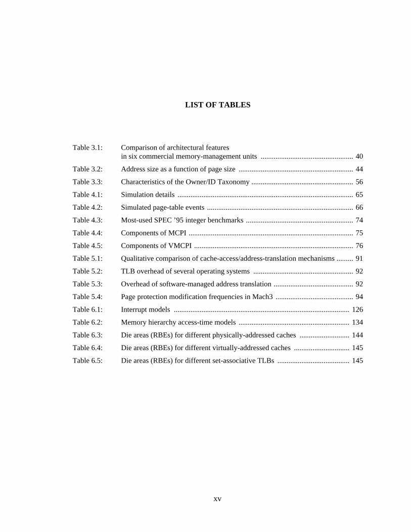
xv
Table 3.1: Comparison of architectural featuresin six commercial memory-management units.................................................. 40
Table 3.2: Address size as a function of page size.............................................................. 44
Table 3.3: Characteristics of the Owner/ID Taxonomy....................................................... 56
Table 4.1: Simulation details............................................................................................... 65
Table 4.2: Simulated page-table events............................................................................... 66
Table 4.3: Most-used SPEC ’95 integer benchmarks.......................................................... 74
Table 4.4: Components of MCPI......................................................................................... 75
Table 4.5: Components of VMCPI...................................................................................... 76
Table 5.1: Qualitative comparison of cache-access/address-translation mechanisms......... 91
Table 5.2: TLB overhead of several operating systems...................................................... 92
Table 5.3: Overhead of software-managed address translation........................................... 92
Table 5.4: Page protection modification frequencies in Mach3.......................................... 94
Table 6.1: Interrupt models............................................................................................... 126
Table 6.2: Memory hierarchy access-time models............................................................ 134
Table 6.3: Die areas (RBEs) for different physically-addressed caches........................... 144
Table 6.4: Die areas (RBEs) for different virtually-addressed caches.............................. 145
Table 6.5: Die areas (RBEs) for different set-associative TLBs....................................... 145
LIST OF TABLES
1
CHAPTER 1
INTRODUCTION: VIRTUAL MEMORY,THREE DECADES LATER
This is a study of memory management design in the face of changing technology charac-
teristics. Our current model of memory management, virtual memory, was defined over three
decades ago when memory was expensive and in short supply. The cost of executing a single
instruction was high relative to the cost of performing the same function entirely in hardware, and
so our definition of the virtual memory model reflects a hardware-oriented perspective. However,
despite the fact that technology has changed drastically, the current designs of virtual memory sys-
tems and the hardware structures that support virtual memory remain largely as they were three
decades ago. As we will see in this dissertation, the current model could use rethinking; doing so
can buy one flexibility , performance, and simplicity of design.
1.1 Moti vation
There are several obvious trends guiding the design and implementation of today’s micro-
processors: faster clock speeds, larger and cheaper memories, more on-chip devices, increased
flexibility , and an increased focus on testability and reliability.
Most of these are a result of shrinking feature sizes. Shrinking feature sizes allows shorter
cycle times; microprocessor clock speeds are increasing toward and beyond the 1GHz milepost,
and Digital has announced a 533MHz Alpha processor while rumored to be testing a fabbed
800MHz part. The increasing capacities and decreasing prices of both physical memory and cache
memory have reached the point where the home computer typically has 16MB or more of physical
memory and 512KB of Level-2 cache; workstation-class machines have roughly an order of mag-
nitude more of each. This is arguably enough to run several programs at once in memory, and the
cost of doubling one’s Level-2 cache or physical memory size is roughly 10% of the cost of the
base machine; for instance, today’s personal computers come with 16MB and cost around $2000,
2
while DRAM runs $5-10 per megabyte. More devices available per die make it worthwhile to cre-
ate simple on-processor memories to speed up computations—examples include large caches,
stream buffers, and branch prediction tables. There are also trends unrelated to shrinking feature
sizes; one is the demand for increased flexibility , as evidenced by the rise of the software-walked
page table seen in most major commercial microprocessors today, and an increased attention paid
to architecture emulation and (re)configurable computing. There is also an enormous emphasis
placed on testability and reliability, especially in the wake of the Intel FDIV debacle.
These trends seem to suggest a design philosophy:
1. Make it simple
2. Do it in software
A simpler design implies less hardware in the critical path and would therefore allow one
to better exploit the processor speeds available; it might also lead to reduced power requirements.
Complex designs such as large, fully-associative memory structures wreak havoc with both clock
speed and power consumption. The increased availability of on-chip real estate can be used for
storage areas for small programs that are executed very frequently and should not run the risk of
eviction from the cache—in essence, on-chip firmware. Performing as many functions in software
as is reasonable certainly increases the flexibility of the system, and it also benefits testability and
reliability; less logic hardware should result in (statistically) fewer hardware bugs, and though
software is no easier to verify than hardware, it is far easier to repair in the field.
On the down side, moving features out of hardware and into software increases code size
and thus places more stress on instruction caches, but this may be offset somewhat by increased
cache and physical memory sizes. This is a question that we will address in this dissertation.
This thesis investigates the design philosophy stated above as it applies to memory man-
agement: which functions of memory management should be performed in hardware and which
should be performed in software? For instance, traditional systems have used a hardware structure
designed to aid memory management, thetranslation lookaside buffer (TLB). The TLB is an
example ofhardware-oriented design; it is a specialized hardware structure that performs some
dedicated function. In the case of the TLB, the dedicated function is virtual-address translation; the
TLB translates virtual addresses to physical ones. The problem that this hardware feature can pose
is its effect on memory-system performance; address translation is linked to cache access in that
one must have the correct translation resident in the TLB before one can access the contents of the
cache. As long as the TLB maps an appreciable amount of the cache, it is not a bottleneck. How-
ever, as soon as the cache is significantly larger than the amount of memory that the TLB can map
3
(called theTLB reach [Talluri & Hill 1994]), managing the contents of the TLB begins to dominate
memory-management costs. Previous studies show that typical well-behaved TLB overheads are
on the order of 10% of a system’s execution time [Bala et al. 1994, Chen et al. 1992, Nagle et al.
1993, Talluri & Hill 1994, Clark & Emer 1985, Anderson et al. 1991, Huck & Hays 1993, Rosen-
blum et al. 1995]. Several of these studies have also shown that systems less well-behaved can
exhibit much larger TLB overheads—on the order of 50% of total execution time [Anderson et al.
1991, Huck & Hays 1993, Rosenblum et al. 1995]. Like it or not, we have to pay more attention to
the TLB.
There is a question begging to be asked: why is this happening? Why does the TLB
account forany of the memory overhead? The TLB does not come for free; it is a cache for the
operating system’s mapping information and as such needs to be loaded with more current or more
relevant information from time to time. It is not stateless but rather state-full and its state must be
kept consistent with the rest of the processor. This requires management and thus overhead.
Today’s large working-set sizes require large caches, which in turn require large TLBs; if the TLB
is not large enough to map the cache, it can become a performance drain. If the TLB could scale to
large sizes as easily as caches, there would be no problem. However, TLBs do not tend to scale as
well as caches; it is difficult to make a TLB large without significantly slowing down processor
speed or increasing power consumption. One may choose a set-associative organization rather than
a fully associative organization; this would address the speed and power consumption problems,
but such a design would have a significantly lower hit-rate than a fully associative organization of
the same size. One could always increase the size of the set-associative design to obtain a better
hit-rate. For example, for exceptionally good performance we would like a split TLB arrangement
equivalent in hit-rate to two 128-entry fully associative TLBs [Nagle et al. 1993]. As shown by
Nagle et al., this is more or less equivalent to two 4-way set-associative 512-entry TLBs. The chip
area required to build this equals the size of a small L1 cache, and if we simply double the L1
cache we can eliminate more overhead than if we increase the size of the TLB; it is not worthwhile
to increase the TLB in this way (we will discuss this in more detail in Chapter 6). Another simple
solution is to increase the page size, thus increasing the TLB reach by the same factor that one
increases the page size. However, Talluri and Hill have shown that this increases working-set size,
it is difficult to reconcile with the operating system, and it is less effective at reducing overhead
than supporting multiple page sizes [Talluri et al. 1992, Talluri & Hill 1994].
There is another solution. One useful feature of large caches is that they make viable
implementation choices that are not viable with small caches. In particular, software-oriented
4
design becomes viable, in which we eliminate special-purpose hardware that performs some dedi-
cated function and instead perform the same function entirely in software. Software-oriented
designs were not in fashion previously, for example three decades ago when virtual memory was
developed, since caches and physical memories were not large enough to withstand the competi-
tion between the data and instructions needed for the program and the data and instructions needed
for the software design. However, now that caches are both large and inexpensive this competition
is reduced considerably, and software-oriented design is worth reconsidering.
This dissertation looks at the viability of a software-oriented design for memory manage-
ment. It shows that one can remove the TLB and the rest of the memory-management unit and per-
form their equivalent functions efficiently in software. Doing so makes the memory-management
design simpler, smaller, and more flexible without a significant impact on performance. We have
found that the TLB is unnecessary if one uses large virtually-addressed caches, and it is even pos-
sible to increase performance by eliminating the TLB if the caches are large enough. For example,
a system with a split 4MB Level-2 cache and a split 256-entry TLB has the same virtual-memory
performance as a software scheme with no TLB. Reducing the size of the TLBs by 50% increases
the overhead of the hardware scheme by a factor of five.
This makes a software-oriented memory management design a competitive alternative to a
hardware-oriented design; it is generally worth paying a small price in performance to get
increased flexibility (for example, a hardware-walked page table will always yield better perfor-
mance than a software-walked page table of similar design, yet most microprocessors today walk
the page table in software for increased flexibility). The fact that such flexibility can come without
a significant cost in performance is very good news.
Eliminating dedicated special-purpose hardware from processor design saves chip area
and reduces power consumption, lowering the overall system cost. Moreover, a flexible design
should aid in the portability of system software. A software-oriented design methodology would
likely benefit many different microprocessor designs, from general-purpose processors in PC-class
and workstation-class computers, to embedded processors where cost tends to have a higher prior-
ity than performance. The particular implementation described in the following chapters, which is
centered around a virtual cache hierarchy managed by the operating system, is shown to be useful
in the areas of real-time systems, shared-memory multiprocessors, architecture emulation, and
reconfigurable computing.
5
1.2 Background and Previous Work in Memory Management Design
Virtual memory is a technique for managing the resource of physical memory. It provides
to the application an illusion of a very large amount of memory—typically much larger than is
actually available. Its chief advantage is that it supports the execution of processes only partially
resident in memory. In a virtual memory system, only the most-often used portions of a process’s
address space actually occupy physical memory; the rest of the address space is stored on disk
until needed.
Most processors support virtual memory through a hardwarememory management unit
(MMU) that translates virtual addresses to physical addresses. The classic MMU design, as seen in
the DEC VAX, GE 645, and Intel x86 architectures [Clark & Emer 1985, Organick 1972, Intel
1993], is comprised of two parts: the translation lookaside buffer and a finite state machine. The
TLB is an on-chip memory structure that caches the page table; it holds only page table entries. Its
job is to speed address translation. If the necessary translation information is on-chip in the TLB,
the system can translate a virtual address to a physical address without requiring an access to the
page table. In the event that the translation information is not found in the TLB (an event called a
TLB miss), one must search the page table for the translation and insert it into the TLB before pro-
cessing can continue. Early designs provided a hardware state machine to perform this activity; in
the event of a TLB miss, the state machine would walk the page table, locate the translation infor-
mation, insert it into the TLB, and restart the computation.
Translation lookaside buffers are fairly large; they usually have on the order of 100 entries,
making them several times larger than a register file. They are typically fully associative, and they
are often accessed every clock cycle. In that clock cycle they must translate both the I-stream and
the D-stream. They can constrain the chip’s clock cycle as they tend to be fairly slow, and they are
also power-hungry (both are a function of the TLB’s high degree of associativity). The finite state
machine tends to be a very efficient design as it does not affect the state of the machine. When the
system takes a TLB miss, the state of the machine freezes; as opposed to the consequences of tak-
ing an interrupt, the contents of the pipeline are unaffected and the reorder buffer need not be
flushed. The I-cache is not affected and the D-cache is only affected if the page table is located in
cacheable space. So at the very worst, the execution of the state machine will impact a few lines in
the D-cache. Otherwise, the system is not penalized at all. Some designs do not even freeze the
pipeline; for instance, the Intel Pentium Pro allows instructions that are independent of the faulting
instruction to continue processing while the TLB miss is being serviced [Upton 1997]. The pri-
6
mary disadvantage of the state machine is that the page table organization is effectively etched in
stone; the system has little flexibility in choosing a design suited to its needs if it is different than
the organization expected by the hardware.
Clearly, there are advantages and disadvantages to the classical hardware-oriented design
of the memory management unit, which implies that there is room for alternatives. There have
been several such alternative designs in the past decade, in which all or part of the memory man-
agement unit is replaced by an equivalent software design. The following are a few of the prece-
dents set for software-oriented memory management design.
MIPS
The MIPS was one of the first commercial architectures to offer a software-managed TLB
[Kane & Heinrich 1992], though the Astronautics Corporation of America holds a patent for a
software-managed design [Smith et al. 1988]. The MIPS designers noticed that the general-pur-
pose exception mechanism could be used to handle TLB misses, which would eliminate the need
for the on-chip hardware implementing the finite state machine. The MIPS design showed that
with reasonably large instruction caches, the finite state machine could be removed without a sub-
stantial performance hit. With large caches, the cache competition between the operating system’s
TLB-miss handler and normal application code did not affect performance significantly.
SPUR
The Berkeley SPUR project [Ritchie 1985, Hill et al. 1986, Wood et al. 1986] took a dif-
ferent tack on the design of their memory management unit. The designers noticed that when one
caches the operating system’s page table, there would often be times when a particular page table
entry in the TLB would also be present in the on-chip cache. This suggests a waste of on-chip
resources, and so the designers decided to eliminate the TLB. They retained the finite state
machine. They used a large virtual cache, and in the event that a reference missed the cache, the
finite state machine walked the page tables in the virtual cache, performed the translation, and
brought the missing datum in from main memory. The SPUR design showed that with a reason-
ably large data cache, the TLB could be removed without a substantial performance hit. With large
caches, the cache competition between the operating system’s page table and normal application
data did not affect performance significantly.
VMP
The VMP multiprocessor [Cheriton et al. 1989, Cheriton et al. 1988, Cheriton et al. 1986]
did away with both the TLB and the state machine. The VMP was a bus-based shared-memory
7
multiprocessor organization, with each processor controlling a large virtual cache. The flexibility
of the software-managed cache allowed the designers to test cache-coherency protocols in soft-
ware. In the event of a cache miss, the operating system handled the cache-refill by performing the
translation and loading the missing datum off the bus from shared memory, possibly invalidating
copies in the caches of other processors. The VMP design showed that with reasonably large
caches, the MMU could be eliminated without a substantial performance hit. With large caches,
the cache competition between the operating system and normal application instructions and data
did not affect performance significantly.
1.3 Dissertation Overview
There have been several precedents set for eliminating part or all of the hardware memory
management unit. In this thesis we quantify the performance effects of executing its function
entirely in software, and we discuss many of the ramifications of doing so.
Chapters 2 and 3 provide a high-level look at memory management. The chapters first
paint virtual memory as merely one possible memory management organization out of many via-
ble alternatives. The chapters describe the methods and goals of virtual memory, including typical
operating system functions and their implementations, support required of the hardware by the
operating system, and examples of how today’s processors provide that support.
Chapter 4 presents the experimental methodology used to obtain the performance mea-
surements in this dissertation. Trace-driven simulation of a memory hierarchy is used, with traces
taken from the SPEC’95 benchmark suite. The traces include application references and all operat-
ing system activity related to TLB-miss handling or cache-miss handling (analogous to TLB-miss
handling for a software-managed TLB).
Chapter 5 discusses the details of eliminating the memory management unit and presents
some preliminary measurements. The chapter shows that address translation can be performed
entirely in software if the operating system handles all Level-2 cache misses. The chapter also dis-
cusses how a software-oriented scheme supports the operating system requirements detailed in
earlier chapters.
Chapter 6 presents much more detailed performance measurements and compares and
contrasts the software-oriented mechanism with other schemes, including contemporary address-
ing schemes, different cache organizations, and existing multiprocessor organizations. It concludes
with The Good News and The Bad News: eliminating memory management hardware can increase
8
system flexibility , but the proposed alternative mechanisms have problems of their own to solve.
These include the virtual-cache synonym problem, the overhead of the exception mechanism, the
performance hit of multimedia-type applications, and the cost of off-chip Level-2 caches. Chapters
7 through 10 deal with each of these problems in turn.
Chapter 7 describes the problems inherent in using large virtually-addressed caches and
provides a simple hardware/software solution that is low-overhead and flexible. The problems
arise from the use ofaddress-space-identifier (ASID) aliasing andvirtual-address aliasing, two
techniques used to support shared virtual memory that cause increased overhead and possible data
inconsistencies in virtual caches. Hardware segmentation is a simple mechanism that, properly
used, allows aliasing without the possibility of introducing data inconsistencies. The chapter also
discusses how the solution could benefit general systems with memory management units and
TLBs.
Chapter 8 provides a first-order cost analysis of the handling of an interrupt and describes
a method to allow the hardware to handle certain interrupts specially (including the cache-miss
exception required by Chapter 5). It argues that the classic definition of precise interrupts is too
restrictive, that a precise interrupt should reflect the ordering of the application’s implicit depen-
dency graph (which can have many different partial orders), not necessarily the sequential partial
order represented by the static program code. Redefining precise interrupts in this way can reduce
the cost of an exception by an order of magnitude.
Chapter 9 addresses the problem of supporting multimedia-type applications—those that
show poor temporal locality but good spatial locality. These will cause a cache-miss exception
every time a new cache line is touched, whereas a processor with a TLB will take a TLB miss
every time a new page is touched. This could potentially result in an overhead several orders of
magnitude larger than that of a hardware-oriented scheme. Solutions include prefetching and
direct but secure access to physical memory.
Chapter 10 describes several alternative organizations for main memory that allow one to
do away with the Level-2 cache. This would be important for a low-cost or embedded system.
These cache-like main memory organizations were hinted at in Chapter 2 while discussing alterna-
tive designs for virtual memory.
Chapter 11 concludes.
9
1.4 Scope of the Thesis
The primary contributions of this thesis are the following:
1. A detailed discussion of the design of a software-oriented memory-management
architecture, including both software and hardware components
2. An in-depth performance comparison of five very different memory-management
systems: a software-oriented scheme, Mach as implemented on MIPS, Ultrix as
implemented on MIPS, an Intel x86 page table and MMU, and the inverted page table
of HP-UX
3. The presentation of a low-overhead interrupt mechanism for handling memory-
management-related interrupts
The focus of this thesis is on the design of virtual memory management subsystems
(including both hardware and software structures) for very fast uniprocessors. Virtual memory is a
programming model that has proven its worth over the last thirty years; it provides an abstraction
for addressing memory that simplifies the design and creation of applications at a modest cost in
run-time overhead. Though alternatives to virtual memory look promising, we should continue to
provide virtual address translation even as clock speeds increase dramatically, placing structures
such as the translation lookaside buffer on the list of potentially performance-limiting critical
paths. One possible design, as already mentioned, is to eliminate the TLB altogether, providing the
abstraction of virtual memory through the combination of virtually-addressed caches and software
support in the operating system. This dissertation looks at the relationships between the TLB and
structures found in both the architecture and the operating system, explains their purpose, and
offers alternative designs. It compares the performance of several very different memory-manage-
ment designs through trace-driven simulations; the hardware-oriented schemes are given simulated
fully-associative TLBs that are extremely large (128 entries in both the I-TLB and the D-TLB,
which is as large or larger than any commercially-available TLBs as of this writing), so as to com-
pare a software-oriented scheme to the best hardware schemes possible. The simulations show that
the software-oriented scheme performs similarly to the hardware-oriented schemes, and at a
reduced cost in die area for Level-1 cache sizes less than 128KB.
10
CHAPTER 2
A VIRTUAL MEMORY PRIMER
This chapter provides definitions and descriptions of the terms and mechanisms used in
memory management in general, and virtual memory in particular. It begins with a high-level
description of virtual memory as one of many possible techniques of memory management.
2.1 Intr oduction
In the ideal world programs are written once, need little help to start running, and while
running need little management. As frequently happens when designing a system, not all the
desired characteristics can be accommodated at the same time. This results in many different mod-
els for organizing a computer system, each of which makes different tradeoffs for different rea-
sons. For example, it is simpler to write an operating system if programs need little management
once they are running. Though intuitively straightforward, it typically puts more responsibility on
the shoulders of the compiler and programmer. It is simpler to write a compiler if it needs to know
very little about the hardware or operating system, which typically makes the operating system
more complex. It is simpler for the user if he or she needs to write a program only once to cover
many different hardware/operating-system organizations. This also tends to make the operating
system and runtime support system (including the microarchitecture) more complex.
Each of these models represents a different priority, a different tradeoff of complexity for
ease of use or ease of design. Virtual memory is simply one of many possible models—one in
which the tradeoff buys simplicity in the design of applications at a reasonably low overhead in
performance (time) and memory (space).
11
2.2 What Is Virtual Memory?
There are many different models for managing physical memory; what exactly do these
different models look like? The simplest model of program creation and execution is perhaps to
determine what memory is available, reserve it so that no other process uses it, and write a pro-
gram to use the memory locations reserved. This allows the process to execute without any man-
agement from the operating system and is therefore very low-overhead. However, this requires one
to rewrite the program every time it is run—a tedious task, but one that can be left to the operating
system. At process start-up, the operating system can modify every pointer reference in the appli-
cation (including loads, stores, and absolute jumps) to reflect the address at which the program is
loaded. The program as it resides in main memory references itself directly, and so contains
MEMORY MANAGEMENT MODELS
PHYSICALADDRESSING
BASE+OFFSETADDRESSING
VIRTUAL ADDRESSING CONTINUUM
Direct-Mapped ... Set-Associative ... Full y Associative
FULLY ASSOCIATIVEVIRTUAL ADDDRESSING
Special Cac he Organizationsof Main Memor y
Traditional Vir tualMemor y Mechanisms
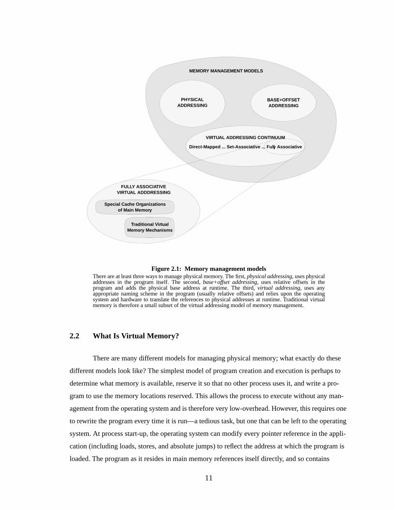
Figure 2.1: Memory management modelsThere are at least three ways to manage physical memory. The first,physical addressing, uses physicaladdresses in the program itself. The second,base+offset addressing, uses relative offsets in theprogram and adds the physical base address at runtime. The third,virtual addressing, uses anyappropriate naming scheme in the program (usually relative offsets) and relies upon the operatingsystem and hardware to translate the references to physical addresses at runtime. Traditional virtualmemory is therefore a small subset of the virtual addressing model of memory management.
12
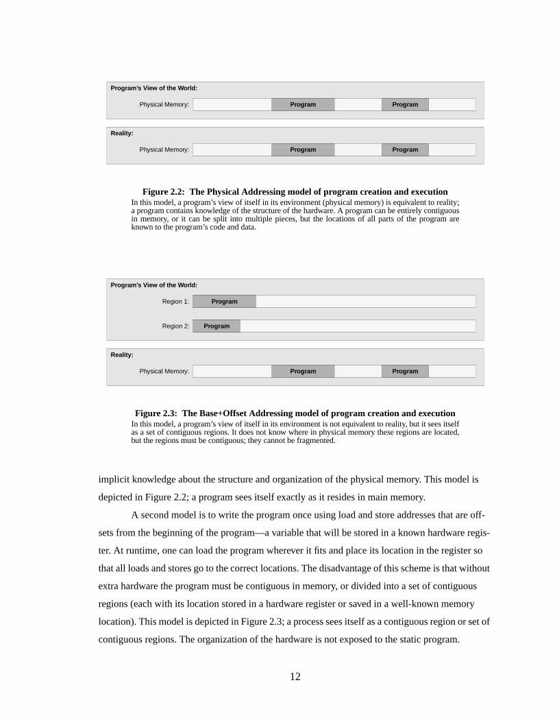
implicit knowledge about the structure and organization of the physical memory. This model is
depicted in Figure 2.2; a program sees itself exactly as it resides in main memory.
A second model is to write the program once using load and store addresses that are off-
sets from the beginning of the program—a variable that will be stored in a known hardware regis-
ter. At runtime, one can load the program wherever it fits and place its location in the register so
that all loads and stores go to the correct locations. The disadvantage of this scheme is that without
extra hardware the program must be contiguous in memory, or divided into a set of contiguous
regions (each with its location stored in a hardware register or saved in a well-known memory
location). This model is depicted in Figure 2.3; a process sees itself as a contiguous region or set of
contiguous regions. The organization of the hardware is not exposed to the static program.
Program
Figure 2.2: The Physical Addressing model of program creation and executionIn this model, a program’s view of itself in its environment (physical memory) is equivalent to reality;a program contains knowledge of the structure of the hardware. A program can be entirely contiguousin memory, or it can be split into multiple pieces, but the locations of all parts of the program areknown to the program’s code and data.
Reality:
Program’ s View of the W orld:
Physical Memory:
ProgramPhysical Memory:
Program
Program
Program
Figure 2.3: The Base+Offset Addressing model of program creation and executionIn this model, a program’s view of itself in its environment is not equivalent to reality, but it sees itselfas a set of contiguous regions. It does not know where in physical memory these regions are located,but the regions must be contiguous; they cannot be fragmented.
Reality:
Program’ s View of the W orld:
Region 1:
ProgramPhysical Memory: Program
ProgramRegion 2:

13
A third model is to write the program as if it is loaded at physical memory location zero,
load the program wherever it fits (not necessarily location zero), and use some as yet undefined
mechanism to translate the program’s addresses to the equivalent physical addresses while it is
running. This model is depicted in Figure 2.4. The program is completely independent of the hard-
ware organization. The advantage of this scheme is that one never needs to rewrite the program,
and it can be fragmented in main memory—bits and pieces of the program can lie scattered
throughout main memory, and the program need not be entirely resident to execute. The disadvan-
tage is the potential overhead of the translation mechanism.
2.2.1 Thr ee Models of Addressing: Physical, Base+Offset, and Virtual
The three models can be calledphysical addressing, base+offset addressing, andvirtual
addressing. Their structure is compared in Figure2.5. The primary difference between the three is
whether or not the hardware organization is exposed to either the program or the process. We have
made a distinction between the two to clarify the differences between the three models: aprogram
is a static file on disk or in memory, and aprocess is a running (dynamic) program. The first sce-
nario,physical addressing, has the program using physical addresses to reference memory loca-
tions in its address space, and thus the program contains some knowledge of the underlying
hardware organization. The dynamic execution of the program uses these same addresses, so the
process also contains knowledge of the underlying hardware. The second scenario,base+offset
addressing, has the program using relative addresses from a variable base, which represents little
knowledge of the underlying hardware except support in the form of an addressing mode or trans-
Program
Figure 2.4: The Virtual Addr essing model of program creation and executionIn this model, a program’s view of itself in its environment has virtually nothing to do with reality; aprogram can consider itself a collection of contiguous regions or a set of fragments, or one largemonolithic program. The operating system considers the program nothing more than a set of uniformvirtual pages, and loads them as necessary into physical memory. The entire program need not beresident in memory, and it need not be contiguous.
Reality:
Program’ s View of the W orld:
“Virtual” Memory:
Physical Memory:
Program
14
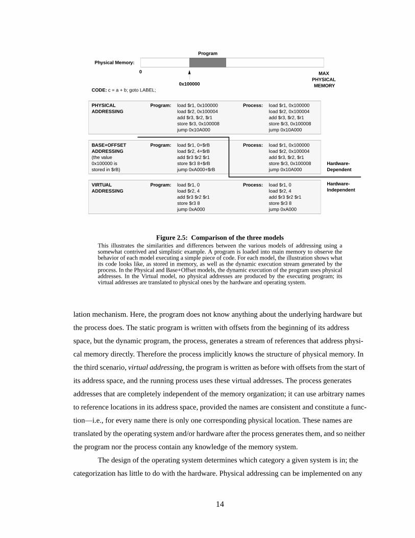
lation mechanism. Here, the program does not know anything about the underlying hardware but
the process does. The static program is written with offsets from the beginning of its address
space, but the dynamic program, the process, generates a stream of references that address physi-
cal memory directly. Therefore the process implicitly knows the structure of physical memory. In
the third scenario,virtual addressing, the program is written as before with offsets from the start of
its address space, and the running process uses these virtual addresses. The process generates
addresses that are completely independent of the memory organization; it can use arbitrary names
to reference locations in its address space, provided the names are consistent and constitute a func-
tion—i.e., for every name there is only one corresponding physical location. These names are
translated by the operating system and/or hardware after the process generates them, and so neither
the program nor the process contain any knowledge of the memory system.
The design of the operating system determines which category a given system is in; the
categorization has little to do with the hardware. Physical addressing can be implemented on any
Figure 2.5: Comparison of the three modelsThis illustrates the similarities and differences between the various models of addressing using asomewhat contrived and simplistic example. A program is loaded into main memory to observe thebehavior of each model executing a simple piece of code. For each model, the illustration shows whatits code looks like, as stored in memory, as well as the dynamic execution stream generated by theprocess. In the Physical and Base+Offset models, the dynamic execution of the program uses physicaladdresses. In the Virtual model, no physical addresses are produced by the executing program; itsvirtual addresses are translated to physical ones by the hardware and operating system.
0
0x100000
MAXPHYSICAL MEMORY
CODE: c = a + b; goto LABEL;
load $r1, 0x100000load $r2, 0x100004add $r3, $r2, $r1store $r3, 0x100008jump 0x10A000
load $r1, 0x100000load $r2, 0x100004add $r3, $r2, $r1store $r3, 0x100008jump 0x10A000
PHYSICALADDRESSING
Program: Process:
load $r1, 0+$rBload $r2, 4+$rBadd $r3 $r2 $r1store $r3 8+$rBjump 0xA000+$rB
load $r1, 0x100000load $r2, 0x100004add $r3, $r2, $r1store $r3, 0x100008jump 0x10A000
BASE+OFFSETADDRESSING(the value0x100000 isstored in $rB)
Program: Process:
load $r1, 0load $r2, 4add $r3 $r2 $r1store $r3 8jump 0xA000
VIRTUALADDRESSING
Program: Process: load $r1, 0load $r2, 4add $r3 $r2 $r1store $r3 8jump 0xA000
Hardware-Dependent
Hardware-Independent
Physical Memor y:
Program
15
architecture, base+offset addressing can be implemented on any architecture that has the appropri-
ate addressing mode or address translation hardware, and virtual addressing can be implemented
on any architecture including those that do not explicitly support virtual addressing. The following
sections discuss the relative merits of the three models.
Physical Addressing. In physical addressing, process execution behaves differently (from the
point of view of the process) every time the program is executed on a machine with a differ-
ent memory organization, and is likely to behave differently every time it is executed on the
same machine with the same organization, since the program is likely to be loaded at a dif-
ferent location every time. Physical addressing systems outnumber virtual addressing sys-
tems: an example is the operating system for the original Macintosh, which did not have the
benefit of a memory-management unit [Apple Computer, Inc. 1992]. Though newer Macin-
tosh systems have an optional virtual memory implementation, many applications require
that the option be disabled during their execution.
The advantages of the physically-addressed scheme are its simplicity and performance. The
disadvantages include slow process start-up and decreased flexibility. At process start-up,
the entire text area (and possibly the data area, if it contains self-referential pointers at com-
pile time) must be edited to reflect the location of the process in main memory. While this is
easily amortized over the runtime of a long-running process, it is not clear whether the
speed advantages outweigh this initial cost for short-running programs. Decreased flexibil-
ity also can lead to performance loss; since the program cannot be fragmented or partially
loaded, the entire program file must be read into main memory for the program to execute.
This can create problems for systems with too little memory to hold all the active processes;
entire processes will be swapped in and out, whether their working set is large or small.
Clearly, it does not benefit performance if pages that the process never touches are con-
stantly swapped in and out of memory.
Base+Offset Addressing. In base+offset addressing, like physical addressing, process execu-
tion behaves differently every time the program is executed on a machine with a different
memory organization, and it is likely to behave differently every time it is executed on the
same machine with the same organization, since the program is likely to be loaded at a dif-
ferent location every time. Base+offset systems far outweigh all other systems combined: an
example is the DOS/Windows system [Duncan et al. 1994]. The Intel architecture has a

16
combined memory management architecture that places a base+offset design on top of a
virtual addressing design. The base+offset design is built into the addressing mechanism, so
the program file need not explicitly reference any base register: the Intel architecture pro-
vides several registers to hold “segment” offsets, so a program can be composed of several
regions, each of which must be complete and contiguous, but that need not touch each other.
The advantages of this scheme are that the code needs no editing at process start-up and the
performance is equal to that of the physical addressing model. The disadvantages of the
scheme are similar to physical addressing: a region must not be fragmented in main mem-
ory, though the Intel design mitigates this somewhat by allowing a program to be frag-
mented into several smaller pieces, by adding an orthogonal paged memory management
subsystem.
Virtual Addr essing. In virtual addressing, process execution behaves identically every time
the program is executed, even if the machine’s organization changes, and even if the pro-
gram is run on different machines with wildly different memory organizations. Virtual
addressing systems include nearly all academic systems, most Unix-based systems, and
many Unix-influenced systems such as Windows NT, OS/2, and Spring [Custer 1993, Deitel
1990, Hamilton & Kougiouris 1993, Mitchell et al. 1994].
The advantages of the system are that the code need not be edited on loading, one can run
programs on systems with very little memory, and one can easily juggle many programs in
physical memory because fragmentation of a program is allowed. In contrast, systems that
require process regions to remain contiguous in physical memory might end up unable to
execute processes because no single unused region is large enough to hold the process, even
if many scattered unused areas together would be large enough. Indeed, this is the advan-
tage of adding a virtual-addressing layer to the Intel memory management architecture: it
allows programs to be fragmented at the page level, a benefit large enough to overcome the
performance overhead of a second level of address translation in the x86. The disadvantage
of the virtual addressing scheme is the increased amount of space required to hold the trans-
lation information, and the increased path length between address generation and data avail-
ability. These figures have traditionally been no more than a few percent in time and space.
Now that the cost of memory has decreased significantly, it is quite possible the schemes
that waste memory for better performance (physical and base+offset addressing) are the best
17
choices. Memory is cheap, and perhaps the best design is one that simply loads every program
entirely into memory and assumes that any memory shortage will be fixed by the addition of more
DRAM. However, the general consensus is that virtual addressing is more flexible than the other
schemes, and we have come to accept its overhead as reasonable. It (arguably) provides a more
intuitive and bug-free paradigm for programming and process management than schemes which
rely on the organization of the hardware. This thesis work therefore only delves into virtual mem-
ory; it does not consider designs that fall into other categories.
2.2.2 The Virtual Addr essing Continuum
In the virtual addressing model, processes execute in imaginary address spaces that are
mapped onto physical memory by the operating system, therefore the processes generate instruc-
tion fetches and loads and stores using imaginary or “virtual” names for their instructions and data.
The ultimate home for the process’s address space isbacking store, usually a disk drive; this is
where the process’s instructions and data come from and where all of its permanent changes go to.
Every hardware memory structure between the CPU and the backing store is a cache for the
instructions and data in the process’s address space. This includes main memory—main memory
is really nothing more than a cache for a process’s virtual address space. A cache operates on the
principle that a small, fast storage device can hold the most important data found on a larger,
slower storage device, effectively making the slower device look fast. The large storage area in this
case is the process address space, which can range from kilobytes to gigabytes or more in size.
Everything in the address space initially comes from the program file stored on disk, or is created
on demand and defined to be zero. Figure 2.6 illustrates.
In Figure 2.6(a) the process view is shown; a process simply makes loads and stores and
implicit instruction fetches to its virtual address space. The address space, as far as the process is
concerned, is contiguous and all held in main memory, and any unused holes between objects in
the space are simply unused memory. Figure 2.6(b) shows a slightly more realistic picture; pro-
cesses reference locations in their address space indirectly though a series of caches interposed
between the processor and the address space. A process’s address space is not likely to fit entirely
into any of the caches, but it is not necessary that it fit, as only the process’sworking set—the most
often used data and instructions at any given moment—need occupy the caches. The cache con-
tents will therefore be constantly changing and will likely never contain the entire process at any
given moment. In Figure 2.6(c) we see an even more realistic picture; there is no linear storage
structure that contains a process’s address space, especially since every address space is at least
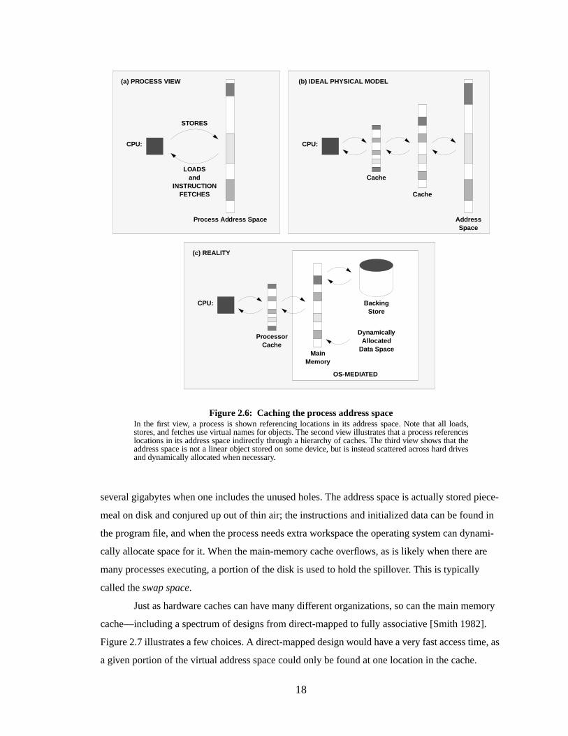
18
several gigabytes when one includes the unused holes. The address space is actually stored piece-
meal on disk and conjured up out of thin air; the instructions and initialized data can be found in
the program file, and when the process needs extra workspace the operating system can dynami-
cally allocate space for it. When the main-memory cache overflows, as is likely when there are
many processes executing, a portion of the disk is used to hold the spillover. This is typically
called theswap space.
Just as hardware caches can have many different organizations, so can the main memory
cache—including a spectrum of designs from direct-mapped to fully associative [Smith 1982].
Figure 2.7 illustrates a few choices. A direct-mapped design would have a very fast access time, as
a given portion of the virtual address space could only be found at one location in the cache.
Figure 2.6: Caching the process address spaceIn the first view, a process is shown referencing locations in its address space. Note that all loads,stores, and fetches use virtual names for objects. The second view illustrates that a process referenceslocations in its address space indirectly through a hierarchy of caches. The third view shows that theaddress space is not a linear object stored on some device, but is instead scattered across hard drivesand dynamically allocated when necessary.
STORES
CPU:
LOADSand
INSTRUCTIONFETCHES
Process Ad dress Space
(a) PROCESS VIEW
CPU:
AddressSpace
(b) IDEAL PHYSICAL MODEL
Cache
Cache
CPU: BackingStore
(c) REALITY
MainMemor y
ProcessorCache
Dynamicall yAllocated
Data Space
OS-MEDIATED
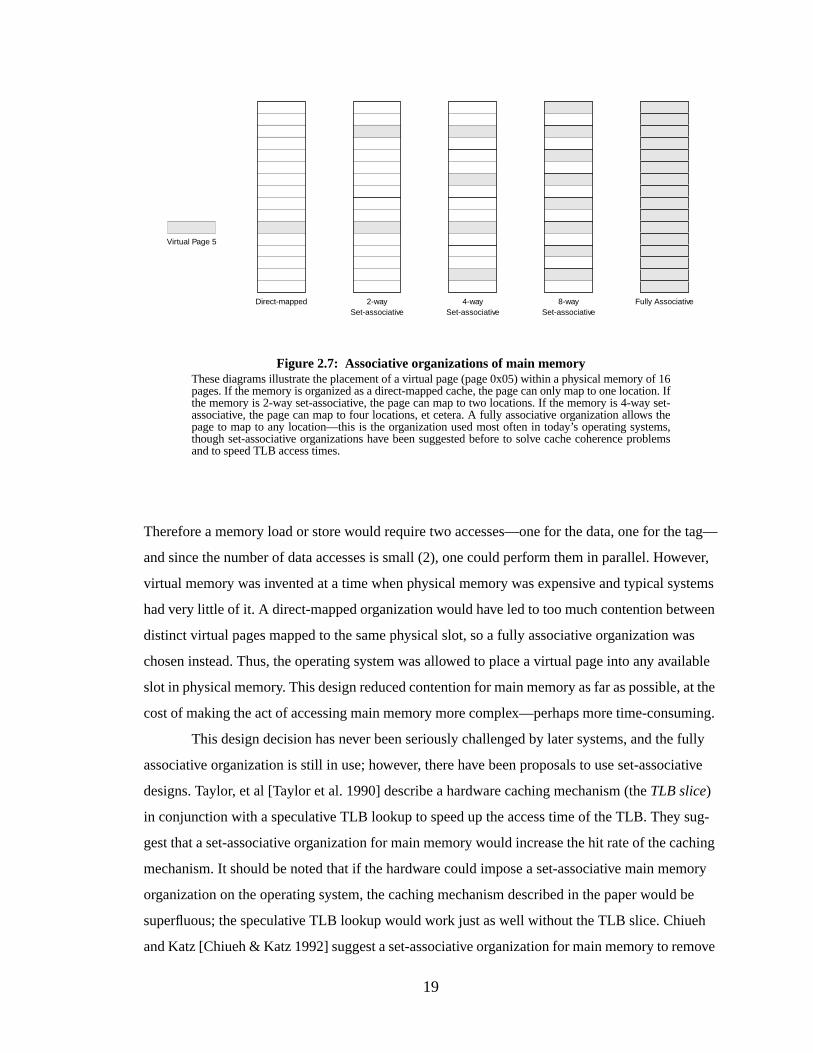
19
Therefore a memory load or store would require two accesses—one for the data, one for the tag—
and since the number of data accesses is small (2), one could perform them in parallel. However,
virtual memory was invented at a time when physical memory was expensive and typical systems
had very little of it. A direct-mapped organization would have led to too much contention between
distinct virtual pages mapped to the same physical slot, so a fully associative organization was
chosen instead. Thus, the operating system was allowed to place a virtual page into any available
slot in physical memory. This design reduced contention for main memory as far as possible, at the
cost of making the act of accessing main memory more complex—perhaps more time-consuming.
This design decision has never been seriously challenged by later systems, and the fully
associative organization is still in use; however, there have been proposals to use set-associative
designs. Taylor, et al [Taylor et al. 1990] describe a hardware caching mechanism (theTLB slice)
in conjunction with a speculative TLB lookup to speed up the access time of the TLB. They sug-
gest that a set-associative organization for main memory would increase the hit rate of the caching
mechanism. It should be noted that if the hardware could impose a set-associative main memory
organization on the operating system, the caching mechanism described in the paper would be
superfluous; the speculative TLB lookup would work just as well without the TLB slice. Chiueh
and Katz [Chiueh & Katz 1992] suggest a set-associative organization for main memory to remove
Figure 2.7: Associative organizations of main memoryThese diagrams illustrate the placement of a virtual page (page 0x05) within a physical memory of 16pages. If the memory is organized as a direct-mapped cache, the page can only map to one location. Ifthe memory is 2-way set-associative, the page can map to two locations. If the memory is 4-way set-associative, the page can map to four locations, et cetera. A fully associative organization allows thepage to map to any location—this is the organization used most often in today’s operating systems,though set-associative organizations have been suggested before to solve cache coherence problemsand to speed TLB access times.
Direct-mapped 2-waySet-associative
4-waySet-associative
8-waySet-associative
Fully Associative
Virtual Page 5
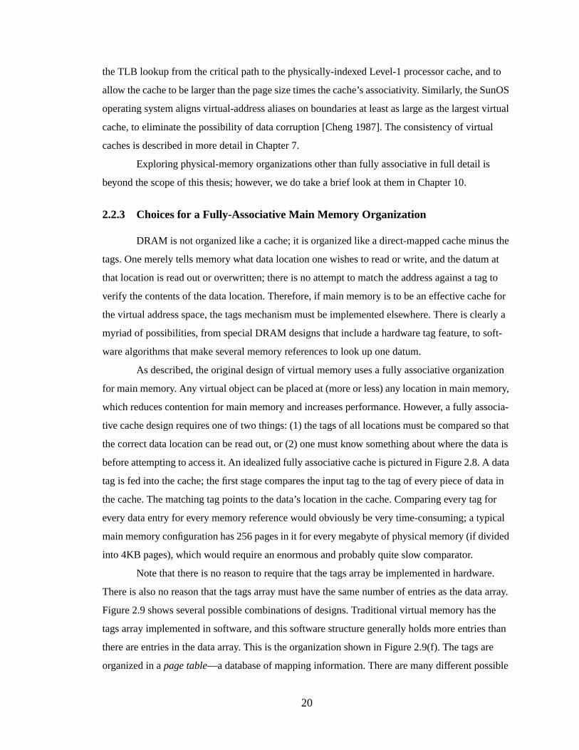
20
the TLB lookup from the critical path to the physically-indexed Level-1 processor cache, and to
allow the cache to be larger than the page size times the cache’s associativity. Similarly, the SunOS
operating system aligns virtual-address aliases on boundaries at least as large as the largest virtual
cache, to eliminate the possibility of data corruption [Cheng 1987]. The consistency of virtual
caches is described in more detail in Chapter 7.
Exploring physical-memory organizations other than fully associative in full detail is
beyond the scope of this thesis; however, we do take a brief look at them in Chapter 10.
2.2.3 Choices for a Fully-Associative Main Memory Organization
DRAM is not organized like a cache; it is organized like a direct-mapped cache minus the
tags. One merely tells memory what data location one wishes to read or write, and the datum at
that location is read out or overwritten; there is no attempt to match the address against a tag to
verify the contents of the data location. Therefore, if main memory is to be an effective cache for
the virtual address space, the tags mechanism must be implemented elsewhere. There is clearly a
myriad of possibilities, from special DRAM designs that include a hardware tag feature, to soft-
ware algorithms that make several memory references to look up one datum.
As described, the original design of virtual memory uses a fully associative organization
for main memory. Any virtual object can be placed at (more or less) any location in main memory,
which reduces contention for main memory and increases performance. However, a fully associa-
tive cache design requires one of two things: (1) the tags of all locations must be compared so that
the correct data location can be read out, or (2) one must know something about where the data is
before attempting to access it. An idealized fully associative cache is pictured in Figure 2.8. A data
tag is fed into the cache; the first stage compares the input tag to the tag of every piece of data in
the cache. The matching tag points to the data’s location in the cache. Comparing every tag for
every data entry for every memory reference would obviously be very time-consuming; a typical
main memory configuration has 256 pages in it for every megabyte of physical memory (if divided
into 4KB pages), which would require an enormous and probably quite slow comparator.
Note that there is no reason to require that the tags array be implemented in hardware.
There is also no reason that the tags array must have the same number of entries as the data array.
Figure 2.9 shows several possible combinations of designs. Traditional virtual memory has the
tags array implemented in software, and this software structure generally holds more entries than
there are entries in the data array. This is the organization shown in Figure 2.9(f). The tags are
organized in apage table—a database of mapping information. There are many different possible
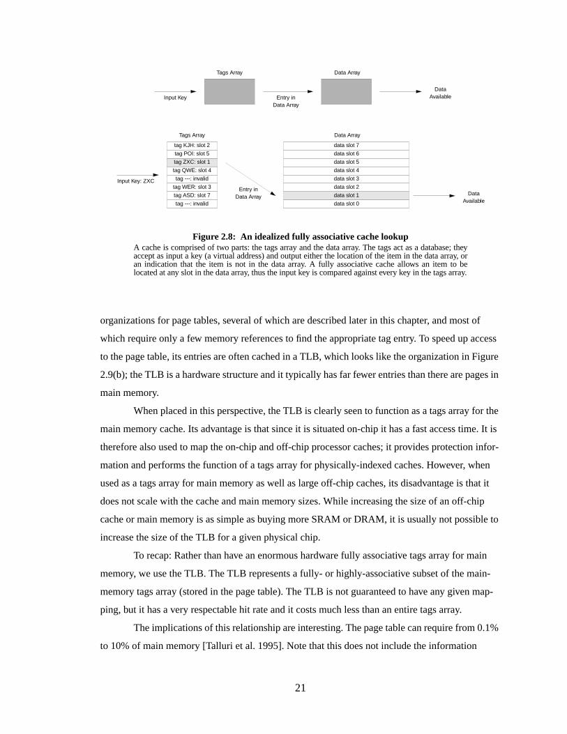
21
organizations for page tables, several of which are described later in this chapter, and most of
which require only a few memory references to find the appropriate tag entry. To speed up access
to the page table, its entries are often cached in a TLB, which looks like the organization in Figure
2.9(b); the TLB is a hardware structure and it typically has far fewer entries than there are pages in
main memory.
When placed in this perspective, the TLB is clearly seen to function as a tags array for the
main memory cache. Its advantage is that since it is situated on-chip it has a fast access time. It is
therefore also used to map the on-chip and off-chip processor caches; it provides protection infor-
mation and performs the function of a tags array for physically-indexed caches. However, when
used as a tags array for main memory as well as large off-chip caches, its disadvantage is that it
does not scale with the cache and main memory sizes. While increasing the size of an off-chip
cache or main memory is as simple as buying more SRAM or DRAM, it is usually not possible to
increase the size of the TLB for a given physical chip.
To recap: Rather than have an enormous hardware fully associative tags array for main
memory, we use the TLB. The TLB represents a fully- or highly-associative subset of the main-
memory tags array (stored in the page table). The TLB is not guaranteed to have any given map-
ping, but it has a very respectable hit rate and it costs much less than an entire tags array.
The implications of this relationship are interesting. The page table can require from 0.1%
to 10% of main memory [Talluri et al. 1995]. Note that this does not include the information
Figure 2.8: An idealized fully associative cache lookupA cache is comprised of two parts: the tags array and the data array. The tags act as a database; theyaccept as input a key (a virtual address) and output either the location of the item in the data array, oran indication that the item is not in the data array. A fully associative cache allows an item to belocated at any slot in the data array, thus the input key is compared against every key in the tags array.
Tags Array Data Array
tag ---: invalid
tag WER: slot 3
tag ASD: slot 7
tag ---: invalid
tag KJH: slot 2
tag POI: slot 5
tag ZXC: slot 1
tag QWE: slot 4
data slot 7
data slot 6
data slot 5
data slot 4
data slot 3
data slot 2
data slot 1
data slot 0
Input Key: ZXC
Entry inData Array
DataAvailable
Tags Array Data Array
Input Key Entry inData Array
DataAvailable
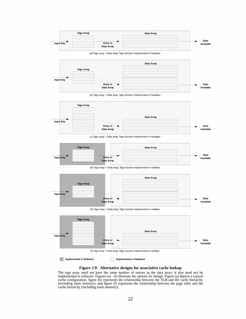
22
Figure 2.9: Alter native designs for associative cache lookupThe tags array need not have the same number of entries as the data array; it also need not beimplemented in software. Figures (a) - (f) illustrate the options for design. Figure (a) depicts a typicalcache configuration, figure (b) represents the relationship between the TLB and the cache hierarchy(including main memory), and figure (f) represents the relationship between the page table and thecache hierarchy (including main memory).
Tags Arra y
Data Arra y
Input K ey
Entr y inData Arra y
DataAvailab le
Tags Arra y
Data Array
Input K ey
Entr y inData Arra y
DataAvailab le
Tags Arra y
Data Array
Input K ey
Entr y inData Arra y
DataAvailab le
Tags Arra y
Data Array
Input K ey
Entr y inData Arra y
DataAvailab le
Implemented in Software Implemented in Har dware
(f) Tags array > Data array, Tags function implemented in software
(e) Tags array < Data array, Tags function implemented in software
(c) Tags array > Data array, Tags function implemented in hardware
(b) Tags array < Data array, Tags function implemented in hardware
Tags Arra y Data Array
Input K ey Entr y inData Arra y
DataAvailab le
(a) Tags array = Data array, Tags function implemented in hardware
Tags Arra y Data Array
Input K ey Entr y inData Arra y
DataAvailab le
(d) Tags array = Data array, Tags function implemented in software
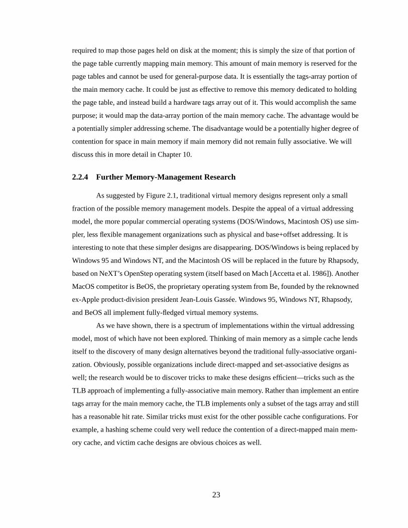
23
required to map those pages held on disk at the moment; this is simply the size of that portion of
the page table currently mapping main memory. This amount of main memory is reserved for the
page tables and cannot be used for general-purpose data. It is essentially the tags-array portion of
the main memory cache. It could be just as effective to remove this memory dedicated to holding
the page table, and instead build a hardware tags array out of it. This would accomplish the same
purpose; it would map the data-array portion of the main memory cache. The advantage would be
a potentially simpler addressing scheme. The disadvantage would be a potentially higher degree of
contention for space in main memory if main memory did not remain fully associative. We will
discuss this in more detail in Chapter 10.
2.2.4 Further Memory-Management Research
As suggested by Figure 2.1, traditional virtual memory designs represent only a small
fraction of the possible memory management models. Despite the appeal of a virtual addressing
model, the more popular commercial operating systems (DOS/Windows, Macintosh OS) use sim-
pler, less flexible management organizations such as physical and base+offset addressing. It is
interesting to note that these simpler designs are disappearing. DOS/Windows is being replaced by
Windows 95 and Windows NT, and the Macintosh OS will be replaced in the future by Rhapsody,
based on NeXT’s OpenStep operating system (itself based on Mach [Accetta et al. 1986]). Another
MacOS competitor is BeOS, the proprietary operating system from Be, founded by the reknowned
ex-Apple product-division president Jean-Louis Gassée. Windows 95, Windows NT, Rhapsody,
and BeOS all implement fully-fledged virtual memory systems.
As we have shown, there is a spectrum of implementations within the virtual addressing
model, most of which have not been explored. Thinking of main memory as a simple cache lends
itself to the discovery of many design alternatives beyond the traditional fully-associative organi-
zation. Obviously, possible organizations include direct-mapped and set-associative designs as
well; the research would be to discover tricks to make these designs efficient—tricks such as the
TLB approach of implementing a fully-associative main memory. Rather than implement an entire
tags array for the main memory cache, the TLB implements only a subset of the tags array and still
has a reasonable hit rate. Similar tricks must exist for the other possible cache configurations. For
example, a hashing scheme could very well reduce the contention of a direct-mapped main mem-
ory cache, and victim cache designs are obvious choices as well.
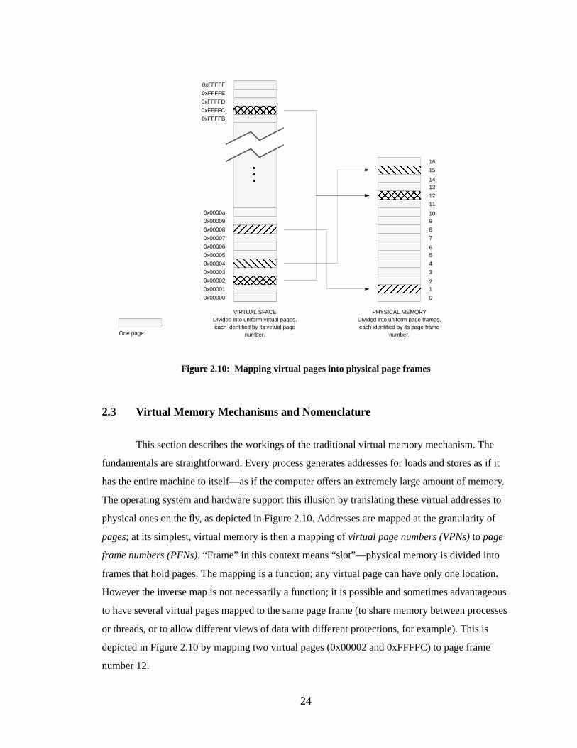
24
2.3 Virtual Memory Mechanisms and Nomenclature
This section describes the workings of the traditional virtual memory mechanism. The
fundamentals are straightforward. Every process generates addresses for loads and stores as if it
has the entire machine to itself—as if the computer offers an extremely large amount of memory.
The operating system and hardware support this illusion by translating these virtual addresses to
physical ones on the fly, as depicted in Figure 2.10. Addresses are mapped at the granularity of
pages; at its simplest, virtual memory is then a mapping ofvirtual page numbers (VPNs)to page
frame numbers (PFNs).“Frame” in this context means “slot”—physical memory is divided into
frames that hold pages. The mapping is a function; any virtual page can have only one location.
However the inverse map is not necessarily a function; it is possible and sometimes advantageous
to have several virtual pages mapped to the same page frame (to share memory between processes
or threads, or to allow different views of data with different protections, for example). This is
depicted in Figure 2.10 by mapping two virtual pages (0x00002 and 0xFFFFC) to page frame
number 12.
���
VIRTUAL SPACEDivided into uniform virtual pages,each identified by its virtual page
number.
PHYSICAL MEMORYDivided into uniform page frames,each identified by its page frame
number.
Figure 2.10: Mapping virtual pages into physical page frames
0
12
3
4
56
7
8
910
11
12
1314
15
16
0x00000
0x00001
0x00002
0x00003
0x00004
0x00005
0x00006
0x00007
0x00008
0x00009
0x0000a
0xFFFFB
0xFFFFC
0xFFFFD
0xFFFFE
0xFFFFF
One page
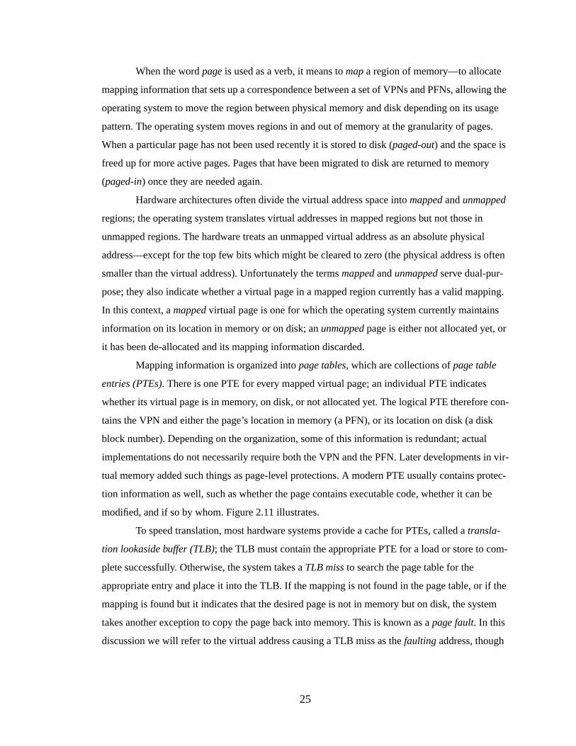
25
When the wordpage is used as a verb, it means tomap a region of memory—to allocate
mapping information that sets up a correspondence between a set of VPNs and PFNs, allowing the
operating system to move the region between physical memory and disk depending on its usage
pattern. The operating system moves regions in and out of memory at the granularity of pages.
When a particular page has not been used recently it is stored to disk (paged-out) and the space is
freed up for more active pages. Pages that have been migrated to disk are returned to memory
(paged-in) once they are needed again.
Hardware architectures often divide the virtual address space intomapped andunmapped
regions; the operating system translates virtual addresses in mapped regions but not those in
unmapped regions. The hardware treats an unmapped virtual address as an absolute physical
address—except for the top few bits which might be cleared to zero (the physical address is often
smaller than the virtual address). Unfortunately the termsmapped andunmapped serve dual-pur-
pose; they also indicate whether a virtual page in a mapped region currently has a valid mapping.
In this context, amapped virtual page is one for which the operating system currently maintains
information on its location in memory or on disk; anunmapped page is either not allocated yet, or
it has been de-allocated and its mapping information discarded.
Mapping information is organized intopage tables, which are collections ofpage table
entries (PTEs). There is one PTE for every mapped virtual page; an individual PTE indicates
whether its virtual page is in memory, on disk, or not allocated yet. The logical PTE therefore con-
tains the VPN and either the page’s location in memory (a PFN), or its location on disk (a disk
block number). Depending on the organization, some of this information is redundant; actual
implementations do not necessarily require both the VPN and the PFN. Later developments in vir-
tual memory added such things as page-level protections. A modern PTE usually contains protec-
tion information as well, such as whether the page contains executable code, whether it can be
modified, and if so by whom. Figure 2.11 illustrates.
To speed translation, most hardware systems provide a cache for PTEs, called atransla-
tion lookaside buffer (TLB); the TLB must contain the appropriate PTE for a load or store to com-
plete successfully. Otherwise, the system takes aTLB miss to search the page table for the
appropriate entry and place it into the TLB. If the mapping is not found in the page table, or if the
mapping is found but it indicates that the desired page is not in memory but on disk, the system
takes another exception to copy the page back into memory. This is known as apage fault. In this
discussion we will refer to the virtual address causing a TLB miss as thefaulting address, though
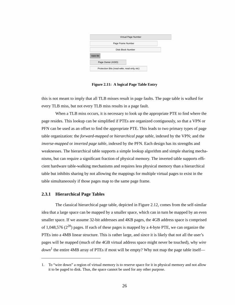
26
this is not meant to imply that all TLB misses result in page faults. The page table is walked for
every TLB miss, but not every TLB miss results in a page fault.
When a TLB miss occurs, it is necessary to look up the appropriate PTE to find where the
page resides. This lookup can be simplified if PTEs are organized contiguously, so that a VPN or
PFN can be used as an offset to find the appropriate PTE. This leads to two primary types of page
table organization: theforward-mapped or hierarchical page table, indexed by the VPN; and the
inverse-mapped or inverted page table, indexed by the PFN. Each design has its strengths and
weaknesses. The hierarchical table supports a simple lookup algorithm and simple sharing mecha-
nisms, but can require a significant fraction of physical memory. The inverted table supports effi-
cient hardware table-walking mechanisms and requires less physical memory than a hierarchical
table but inhibits sharing by not allowing the mappings for multiple virtual pages to exist in the
table simultaneously if those pages map to the same page frame.
2.3.1 Hierar chical Page Tables
The classical hierarchical page table, depicted in Figure 2.12, comes from the self-similar
idea that a large space can be mapped by a smaller space, which can in turn be mapped by an even
smaller space. If we assume 32-bit addresses and 4KB pages, the 4GB address space is comprised
of 1,048,576 (220) pages. If each of these pages is mapped by a 4-byte PTE, we can organize the
PTEs into a 4MB linear structure. This is rather large, and since it is likely that not all the user’s
pages will be mapped (much of the 4GB virtual address space might never be touched), why wire
down1 the entire 4MB array of PTEs if most will be empty? Why not map the page table itself—
1. To “wire down” a region of virtual memory is to reserve space for it in physical memory and not allowit to be paged to disk. Thus, the space cannot be used for any other purpose.
Page Frame Number
Virtual Page Number
Page Owner (ASID)
Valid Bit
Figure 2.11: A logical Page Table Entry
Disk Block Number
Protection Bits (read-write, read-only, etc)
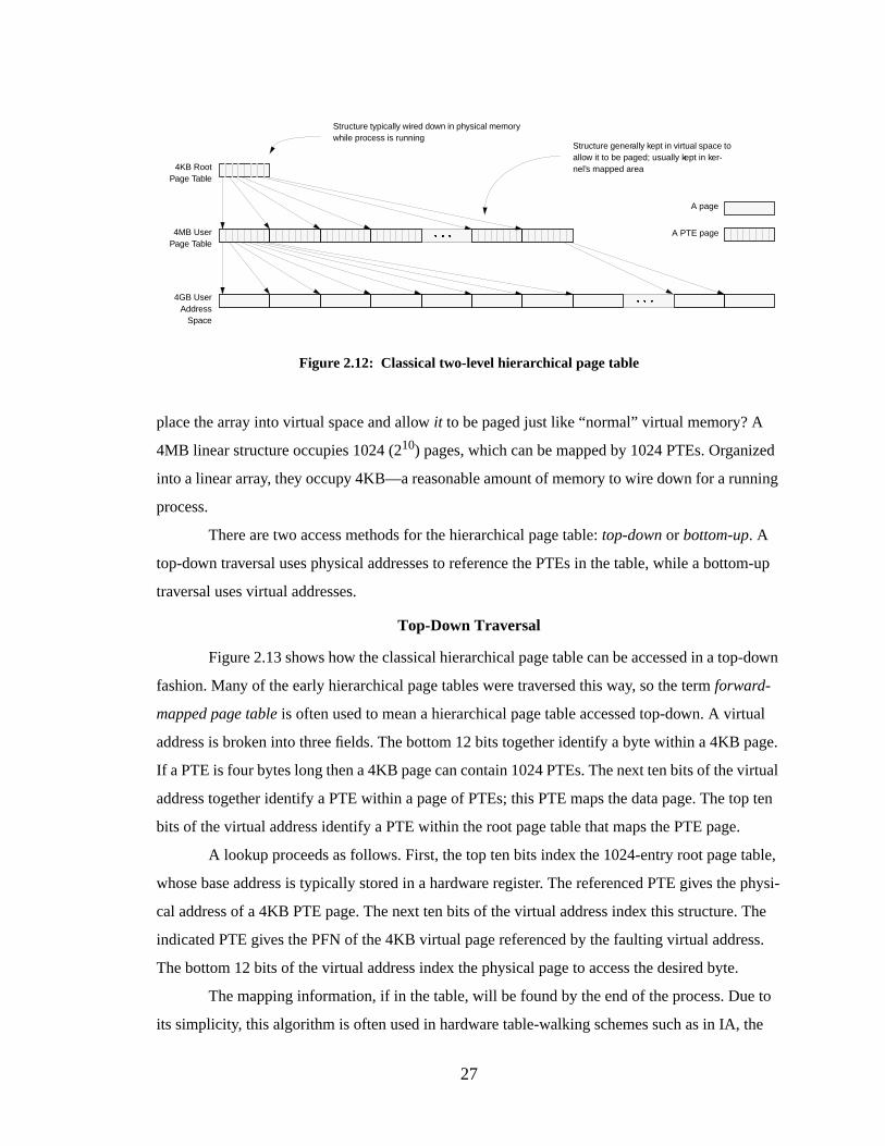
27
place the array into virtual space and allow it to be paged just like “normal” virtual memory? A
4MB linear structure occupies 1024 (210) pages, which can be mapped by 1024 PTEs. Organized
into a linear array, they occupy 4KB—a reasonable amount of memory to wire down for a running
process.
There are two access methods for the hierarchical page table:top-down or bottom-up. A
top-down traversal uses physical addresses to reference the PTEs in the table, while a bottom-up
traversal uses virtual addresses.
Top-Down Traversal
Figure 2.13 shows how the classical hierarchical page table can be accessed in a top-down
fashion. Many of the early hierarchical page tables were traversed this way, so the termforward-
mapped page table is often used to mean a hierarchical page table accessed top-down. A virtual
address is broken into three fields. The bottom 12 bits together identify a byte within a 4KB page.
If a PTE is four bytes long then a 4KB page can contain 1024 PTEs. The next ten bits of the virtual
address together identify a PTE within a page of PTEs; this PTE maps the data page. The top ten
bits of the virtual address identify a PTE within the root page table that maps the PTE page.
A lookup proceeds as follows. First, the top ten bits index the 1024-entry root page table,
whose base address is typically stored in a hardware register. The referenced PTE gives the physi-
cal address of a 4KB PTE page. The next ten bits of the virtual address index this structure. The
indicated PTE gives the PFN of the 4KB virtual page referenced by the faulting virtual address.
The bottom 12 bits of the virtual address index the physical page to access the desired byte.
The mapping information, if in the table, will be found by the end of the process. Due to
its simplicity, this algorithm is often used in hardware table-walking schemes such as in IA, the
4KB RootPage Table
4MB UserPage Table
4GB UserAddress
Space
� � �
� � �
Figure 2.12: Classical two-level hierarchical page table
Structure typically wired down in physical memorywhile process is running
Structure generally kept in virtual space toallow it to be paged; usually kept in ker-nel’s mapped area
A page
A PTE page
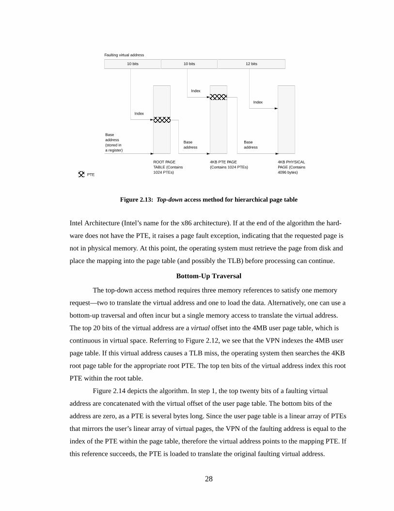
28
Intel Architecture (Intel’s name for the x86 architecture). If at the end of the algorithm the hard-
ware does not have the PTE, it raises a page fault exception, indicating that the requested page is
not in physical memory. At this point, the operating system must retrieve the page from disk and
place the mapping into the page table (and possibly the TLB) before processing can continue.
Bottom-Up Traversal
The top-down access method requires three memory references to satisfy one memory
request—two to translate the virtual address and one to load the data. Alternatively, one can use a
bottom-up traversal and often incur but a single memory access to translate the virtual address.
The top 20 bits of the virtual address are avirtual offset into the 4MB user page table, which is
continuous in virtual space. Referring to Figure 2.12, we see that the VPN indexes the 4MB user
page table. If this virtual address causes a TLB miss, the operating system then searches the 4KB
root page table for the appropriate root PTE. The top ten bits of the virtual address index this root
PTE within the root table.
Figure 2.14 depicts the algorithm. In step 1, the top twenty bits of a faulting virtual
address are concatenated with the virtual offset of the user page table. The bottom bits of the
address are zero, as a PTE is several bytes long. Since the user page table is a linear array of PTEs
that mirrors the user’s linear array of virtual pages, the VPN of the faulting address is equal to the
index of the PTE within the page table, therefore the virtual address points to the mapping PTE. If
this reference succeeds, the PTE is loaded to translate the original faulting virtual address.
4KB PHYSICALPAGE (Contains4096 bytes)
4KB PTE PAGE(Contains 1024 PTEs)
ROOT PAGETABLE (Contains1024 PTEs)
10 bits 10 bits 12 bits
Faulting virtual address
Index
Index
Baseaddress
Baseaddress
Index
Figure 2.13: Top-down access method for hierarchical page table
PTE
Baseaddress(stored ina register)
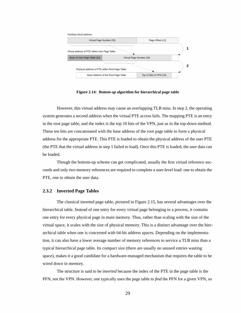
29
However, this virtual address may cause an overlapping TLB miss. In step 2, the operating
system generates a second address when the virtual PTE access fails. The mapping PTE is an entry
in the root page table, and the index is the top 10 bits of the VPN, just as in the top-down method.
These ten bits are concatenated with the base address of the root page table to form a physical
address for the appropriate PTE. This PTE is loaded to obtain the physical address of the user PTE
(the PTE that the virtual address in step 1 failed to load). Once this PTE is loaded, the user data can
be loaded.
Though the bottom-up scheme can get complicated, usually the first virtual reference suc-
ceeds and only two memory references are required to complete a user-level load: one to obtain the
PTE, one to obtain the user data.
2.3.2 Inverted Page Tables
The classical inverted page table, pictured in Figure 2.15, has several advantages over the
hierarchical table. Instead of one entry for every virtual page belonging to a process, it contains
one entry for every physical page in main memory. Thus, rather than scaling with the size of the
virtual space, it scales with the size of physical memory. This is a distinct advantage over the hier-
archical table when one is concerned with 64-bit address spaces. Depending on the implementa-
tion, it can also have a lower average number of memory references to service a TLB miss than a
typical hierarchical page table. Its compact size (there are usually no unused entries wasting
space), makes it a good candidate for a hardware-managed mechanism that requires the table to be
wired down in memory.
The structure is said to beinverted because the index of the PTE in the page table is the
PFN, not the VPN. However, one typically uses the page table tofind the PFN for a given VPN, so
Page Offset (12)Virtual Page Number (20)
Virtual Page Number (20)Base of User Page Table (10)
1
2
Top 10 Bits of VPN (10)Base Address of the Root Page Table
Faulting virtual address:
Figure 2.14: Bottom-up algorithm for hierarchical page table
Virtual address of PTE within User Page Table:
Physical address of PTE within Root Page Table:
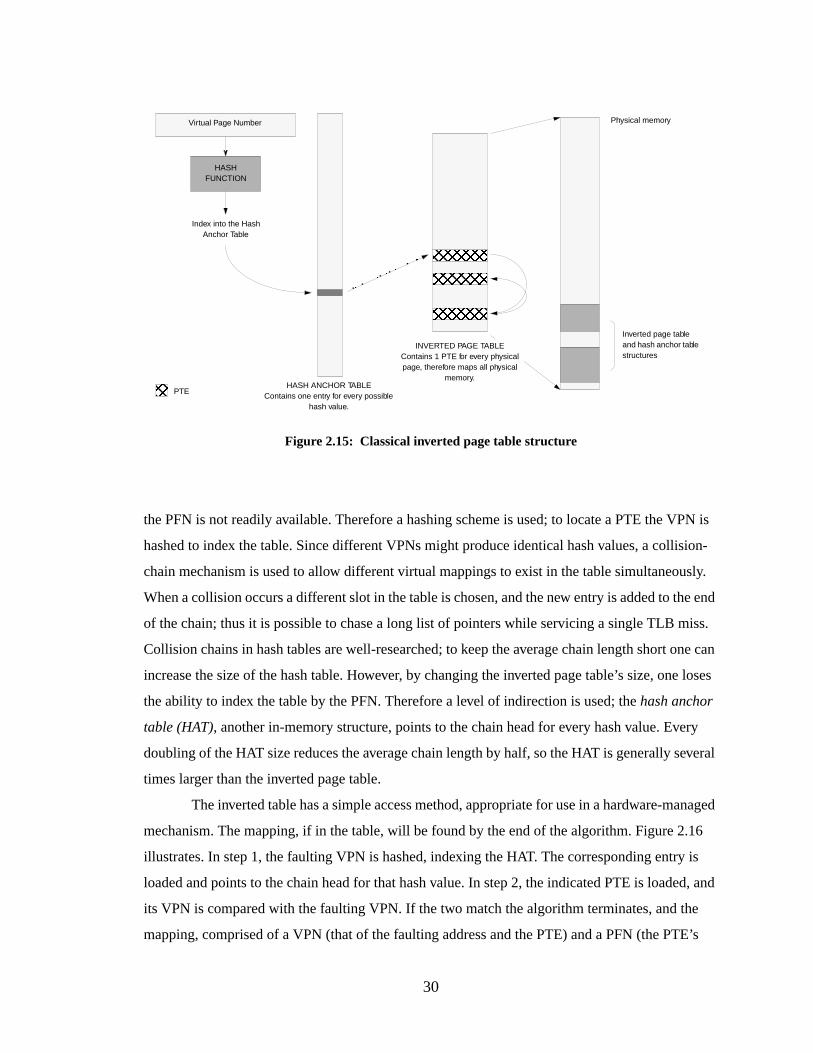
30
the PFN is not readily available. Therefore a hashing scheme is used; to locate a PTE the VPN is
hashed to index the table. Since different VPNs might produce identical hash values, a collision-
chain mechanism is used to allow different virtual mappings to exist in the table simultaneously.
When a collision occurs a different slot in the table is chosen, and the new entry is added to the end
of the chain; thus it is possible to chase a long list of pointers while servicing a single TLB miss.
Collision chains in hash tables are well-researched; to keep the average chain length short one can
increase the size of the hash table. However, by changing the inverted page table’s size, one loses
the ability to index the table by the PFN. Therefore a level of indirection is used; thehash anchor
table (HAT), another in-memory structure, points to the chain head for every hash value. Every
doubling of the HAT size reduces the average chain length by half, so the HAT is generally several
times larger than the inverted page table.
The inverted table has a simple access method, appropriate for use in a hardware-managed
mechanism. The mapping, if in the table, will be found by the end of the algorithm. Figure 2.16
illustrates. In step 1, the faulting VPN is hashed, indexing the HAT. The corresponding entry is
loaded and points to the chain head for that hash value. In step 2, the indicated PTE is loaded, and
its VPN is compared with the faulting VPN. If the two match the algorithm terminates, and the
mapping, comprised of a VPN (that of the faulting address and the PTE) and a PFN (the PTE’s
Virtual Page Number
HASHFUNCTION
Index into the HashAnchor Table
HASH ANCHOR TABLEContains one entry for every possible
hash value.
Physical memory
Inverted page tableand hash anchor tablestructures
INVERTED PAGE TABLEContains 1 PTE for every physicalpage, therefore maps all physical
memory.
Figure 2.15: Classical inverted page table structure
PTE
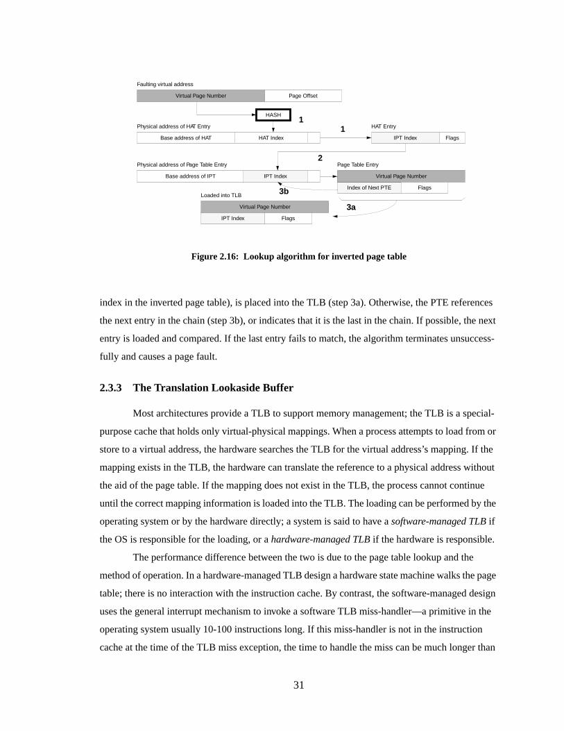
31
index in the inverted page table), is placed into the TLB (step 3a). Otherwise, the PTE references
the next entry in the chain (step 3b), or indicates that it is the last in the chain. If possible, the next
entry is loaded and compared. If the last entry fails to match, the algorithm terminates unsuccess-
fully and causes a page fault.
2.3.3 The Translation Lookaside Buffer
Most architectures provide a TLB to support memory management; the TLB is a special-
purpose cache that holds only virtual-physical mappings. When a process attempts to load from or
store to a virtual address, the hardware searches the TLB for the virtual address’s mapping. If the
mapping exists in the TLB, the hardware can translate the reference to a physical address without
the aid of the page table. If the mapping does not exist in the TLB, the process cannot continue
until the correct mapping information is loaded into the TLB. The loading can be performed by the
operating system or by the hardware directly; a system is said to have asoftware-managed TLB if
the OS is responsible for the loading, or ahardware-managed TLB if the hardware is responsible.
The performance difference between the two is due to the page table lookup and the
method of operation. In a hardware-managed TLB design a hardware state machine walks the page
table; there is no interaction with the instruction cache. By contrast, the software-managed design
uses the general interrupt mechanism to invoke a software TLB miss-handler—a primitive in the
operating system usually 10-100 instructions long. If this miss-handler is not in the instruction
cache at the time of the TLB miss exception, the time to handle the miss can be much longer than
Page OffsetVirtual Page Number
HAT IndexBase address of HAT
1
2
Faulting virtual address
HASH
IPT IndexBase address of IPT
IPT Index Flags
HAT EntryPhysical address of HAT Entry
Physical address of Page Table Entry
Index of Next PTE
Virtual Page Number
Page Table Entry
Flags
Virtual Page Number
IPT Index
Loaded into TLB
3a
1
Flags
Figure 2.16: Lookup algorithm f or inverted page table
3b
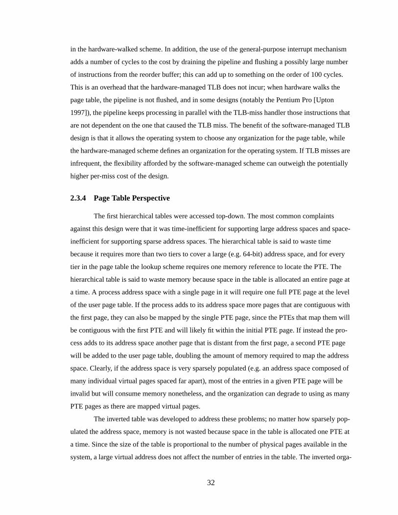
32
in the hardware-walked scheme. In addition, the use of the general-purpose interrupt mechanism
adds a number of cycles to the cost by draining the pipeline and flushing a possibly large number
of instructions from the reorder buffer; this can add up to something on the order of 100 cycles.
This is an overhead that the hardware-managed TLB does not incur; when hardware walks the
page table, the pipeline is not flushed, and in some designs (notably the Pentium Pro [Upton
1997]), the pipeline keeps processing in parallel with the TLB-miss handler those instructions that
are not dependent on the one that caused the TLB miss. The benefit of the software-managed TLB
design is that it allows the operating system to choose any organization for the page table, while
the hardware-managed scheme defines an organization for the operating system. If TLB misses are
infrequent, the flexibility afforded by the software-managed scheme can outweigh the potentially
higher per-miss cost of the design.
2.3.4 Page Table Perspective
The first hierarchical tables were accessed top-down. The most common complaints
against this design were that it was time-inefficient for supporting large address spaces and space-
inefficient for supporting sparse address spaces. The hierarchical table is said to waste time
because it requires more than two tiers to cover a large (e.g. 64-bit) address space, and for every
tier in the page table the lookup scheme requires one memory reference to locate the PTE. The
hierarchical table is said to waste memory because space in the table is allocated an entire page at
a time. A process address space with a single page in it will require one full PTE page at the level
of the user page table. If the process adds to its address space more pages that are contiguous with
the first page, they can also be mapped by the single PTE page, since the PTEs that map them will
be contiguous with the first PTE and will likely fit within the initial PTE page. If instead the pro-
cess adds to its address space another page that is distant from the first page, a second PTE page
will be added to the user page table, doubling the amount of memory required to map the address
space. Clearly, if the address space is very sparsely populated (e.g. an address space composed of
many individual virtual pages spaced far apart), most of the entries in a given PTE page will be
invalid but will consume memory nonetheless, and the organization can degrade to using as many
PTE pages as there are mapped virtual pages.
The inverted table was developed to address these problems; no matter how sparsely pop-
ulated the address space, memory is not wasted because space in the table is allocated one PTE at
a time. Since the size of the table is proportional to the number of physical pages available in the
system, a large virtual address does not affect the number of entries in the table. The inverted orga-
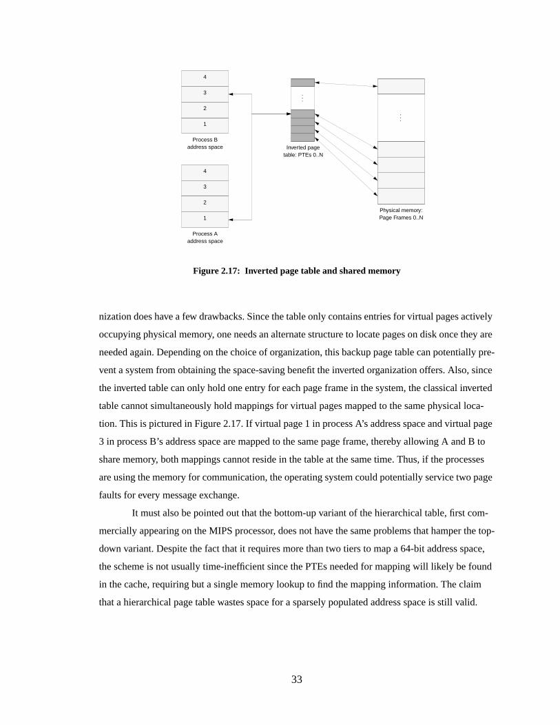
33
nization does have a few drawbacks. Since the table only contains entries for virtual pages actively
occupying physical memory, one needs an alternate structure to locate pages on disk once they are
needed again. Depending on the choice of organization, this backup page table can potentially pre-
vent a system from obtaining the space-saving benefit the inverted organization offers. Also, since
the inverted table can only hold one entry for each page frame in the system, the classical inverted
table cannot simultaneously hold mappings for virtual pages mapped to the same physical loca-
tion. This is pictured in Figure 2.17. If virtual page 1 in process A’s address space and virtual page
3 in process B’s address space are mapped to the same page frame, thereby allowing A and B to
share memory, both mappings cannot reside in the table at the same time. Thus, if the processes
are using the memory for communication, the operating system could potentially service two page
faults for every message exchange.
It must also be pointed out that the bottom-up variant of the hierarchical table, first com-
mercially appearing on the MIPS processor, does not have the same problems that hamper the top-
down variant. Despite the fact that it requires more than two tiers to map a 64-bit address space,
the scheme is not usually time-inefficient since the PTEs needed for mapping will likely be found
in the cache, requiring but a single memory lookup to find the mapping information. The claim
that a hierarchical page table wastes space for a sparsely populated address space is still valid.
. . .
Figure 2.17: Inverted page table and shared memory
. . .
1
4
3
2
4
3
2
1
Process Aaddress space
Process Baddress space
Physical memory:Page Frames 0..N
Inverted pagetable: PTEs 0..N
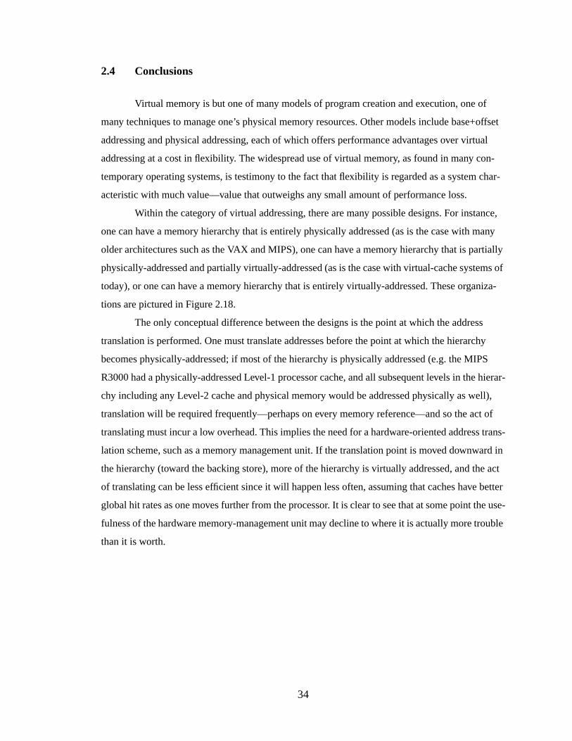
34
2.4 Conclusions
Virtual memory is but one of many models of program creation and execution, one of
many techniques to manage one’s physical memory resources. Other models include base+offset
addressing and physical addressing, each of which offers performance advantages over virtual
addressing at a cost in flexibility . The widespread use of virtual memory, as found in many con-
temporary operating systems, is testimony to the fact that flexibility is regarded as a system char-
acteristic with much value—value that outweighs any small amount of performance loss.
Within the category of virtual addressing, there are many possible designs. For instance,
one can have a memory hierarchy that is entirely physically addressed (as is the case with many
older architectures such as the VAX and MIPS), one can have a memory hierarchy that is partially
physically-addressed and partially virtually-addressed (as is the case with virtual-cache systems of
today), or one can have a memory hierarchy that is entirely virtually-addressed. These organiza-
tions are pictured in Figure 2.18.
The only conceptual difference between the designs is the point at which the address
translation is performed. One must translate addresses before the point at which the hierarchy
becomes physically-addressed; if most of the hierarchy is physically addressed (e.g. the MIPS
R3000 had a physically-addressed Level-1 processor cache, and all subsequent levels in the hierar-
chy including any Level-2 cache and physical memory would be addressed physically as well),
translation will be required frequently—perhaps on every memory reference—and so the act of
translating must incur a low overhead. This implies the need for a hardware-oriented address trans-
lation scheme, such as a memory management unit. If the translation point is moved downward in
the hierarchy (toward the backing store), more of the hierarchy is virtually addressed, and the act
of translating can be less efficient since it will happen less often, assuming that caches have better
global hit rates as one moves further from the processor. It is clear to see that at some point the use-
fulness of the hardware memory-management unit may decline to where it is actually more trouble
than it is worth.
35
Figure 2.18: Possible locations of the translation pointThe translation point is the point at which the virtual address must be translated to a physical addressin order to reference a memory location. The point is shown in each diagram by using thick lines torepresent the transfer of data between cache levels. As the point moves toward backing store (whichwill always require a translation, since the disk subsystem typically uses a different naming schemefrom that of main memory or process address spaces), the act of translating can become less efficientsince translation will be needed less frequently.
CPU:
Cache
CacheCache
BackingStore
Vir tuall y-Ad dressed Physicall y-Ad dressed
MainMemor y
CPU:
Cache
CacheCache
BackingStore
MainMemor y
CPU:
Cache
CacheCache
BackingStore
MainMemor y
Location of the T ranslation P oint
Translation happens late .Here, the act of translating can berelativel y inefficient since it willhappen infrequentl y.
Translation happens earl y.Here, the act of translating
must be efficient since it willhappen often.
Entirely physically-addressed:
Partially virtually-addressed, partially physically-addressed:
Entirely virtually-addressed:
36
CHAPTER 3
MEMORY MANAGEMENT HARDWARE AND ITSSUPPORT FOR OPERATING SYSTEMS FUNCTIONS
This chapter defines a set of requirements for a memory management system, applicable
to both hardware and software sides of the interface. It provides a survey of commercial and aca-
demic designs for memory management units, in the context of these requirements. Lastly, it
defines a taxonomy of addressing schemes, categorized as to how the hardware organizes and pro-
tects its address spaces.
3.1 Intr oduction
The virtual memory interface is defined differently for every microarchitecture. More
often than not, the operating system running on a microprocessor was not initially designed for
that particular hardware interface. Sometimes there is a substantial performance penalty to be paid,
sometimes not. Generally, hardware is designed with little regard to the system software that will
control it. Generally, operating systems outlast the hardware design they were designed and built
on. Hardware Abstraction Layers [Rashid et al. 1988, Custer 1993] exacerbate the problem by hid-
ing hardware particulars from most of the operating system, allowing system designers to write an
operating system for no hardware in particular. Though it makes the job of writing an operating
system easier, this mismatch between operating system and microarchitecture has been shown
many times over to cause significant performance problems [Liedtke 1995b]. Often, simple reor-
ganizations of the system software that are intended to better take advantage of hardware features
result in order-of-magnitude speedups [Liedtke 1993]. Thus an operating system that is not tuned
to the hardware on which it operates is not likely to demonstrate excellent performance.
This is a survey of hardware interfaces existent for operating systems. The memory man-
agement systems of several processors are described in terms of today’s software requirements.
We have chosen current examples within the most visible commercial architecture families: MIPS
37
R10000, Alpha 21164, PowerPC 604, PA-8000, UltraSPARC, and Pentium Pro. We also present
two academic designs: SPUR and SOFTVM.
3.2 Operating System Requirements
There is a core set of functional mechanisms associated with memory management that
computer users have come to expect. These are found in nearly every modern microarchitecture
and operating system (e.g., UNIX [Bach 1986], Windows NT [Custer 1993], OS/2 [Deitel 1990],
4.3 BSD [Leffler et al. 1989], DEC Alpha [Digital 1994, Sites 1992], MIPS [Heinrich 1995, Kane
& Heinrich 1992], PA-RISC [Hewlett-Packard 1990, Kane 1996], PowerPC [IBM & Motorola
1993, May et al. 1994], Pentium [Intel 1993], and SPARC [Weaver & Germand 1994]), and
include the following:
3.2.1 Addr ess Space Protection
User-level applications should not have direct access to the data of other applications or
the operating system. A common hardware assist usesaddress space identifiers (ASIDs), which
extend virtual addresses and distinguish them from those generated by different processes. Alter-
natively, protection can be provided by software means [Bershad et al. 1994, Engler et al. 1994,
Wahbe et al. 1993].
3.2.2 Shared Memory
Shared memory allows multiple processes to reference the same physical data through
(potentially) different virtual addresses. When multiple instances of a program run, sharing the
program code reduces physical memory requirements. When processes are communicating, shared
memory avoids the data copying of traditional message-passing mechanisms. Since page-size cop-
ies are typically an order of magnitude slower than system calls, one can implement zero-copy
shared-memory schemes in which the operating system unmaps pages from the sender’s address
space and re-maps them into the receiver’s address space [Tzou & Anderson 1991, Druschel &
Peterson 1993, Garrett et al. 1993, Liedtke 1993]. Shared memory acts in opposition to most
address space protection schemes. If every page is tagged with a single identifier and every process
is tagged with a single identifier, the only way to allow more than one process to access a given
page is to circumvent the protection mechanism. This is often done by explicitly duplicating map-
38
ping information across page tables, or by marking a shared page as globally visible and flushing
its mapping whenever a process runs that should not have access to the page.
3.2.3 Lar ge Address Spaces
Virtual address spaces continue to grow and the industry is moving toward 64-bit
machines. However, a large address space is not the same thing as a large address; large addresses
are simply one way to implement large address spaces. Another is to provide each process a win-
dow into a larger global virtual address space, the approach used by the PA-RISC and PowerPC
architectures [Kane 1996, Hewlett-Packard 1990, May et al. 1994]. Here, an application generates
addresses that are mapped by the hardware onto a larger virtual space—for example: the PowerPC
supports a 32-bit window onto a 52-bit space, the PA-RISC 1.0 supports a 32-bit window onto a
64-bit space, and the PA-RISC 2.0 supports a 64-bit window onto a 96-bit space. The application
has access to the larger space, but can only access a fixed amount at any given moment.
3.2.4 Fine-Grained Protection
Fine-grained protection marks objects asread-only, read-write, execute-only, etc. The
granularity is usually a page, though a larger or smaller granularity is sometimes desirable. Many
systems have used protection to implement various memory-system support functions, from copy-
on-write to garbage collection to distributed shared virtual memory [Appel & Li 1991]. Protection
is implemented by setting bits in the page table entry, which correspond to bits in the TLB entry. If
a process attempts to use a page incorrectly (e.g. write to a page markedread-only), the hardware
raises an exception.
3.2.5 Sparse Address Spaces
Dynamically loaded shared libraries and multithreaded processes are becoming common-
place, but these designs require support for sparse address spaces. This simply means that holes
are left in the address space between different objects to leave room for dynamic growth. In con-
trast, 4.3BSD Unix [Leffler et al. 1989] had an address space composed of two continuous regions,
depicted in Figure 3.1. This design allowed the user page tables to occupy as little space as possi-
ble. Saving space was important, given that the original BSD virtual memory implementation did
not allow page tables to be paged. The numerous holes in a sparse address space leave numerous
holes within a page table mapping that space; thus the wired-down, linearly-indexed page table of

39
4.3BSD would not be practical, as it would require 4MB of physical memory to map a 32-bit
address space regardless of how much or little of the virtual space is actually used.
3.2.6 Superpages
Reflecting a trend toward larger data sets, many objects can be found that need to be
mapped for virtual access and yet are larger than a single virtual page. These include commonly
used structures such as large arrays, memory-mapped files, and buffers holding graphical images
(or portions thereof) for processing. The numerous PTEs required to map these structures flood the
TLB and crowd out other entries. Systems have addressed this problem by supporting “blocks” or
“superpages” that are multiples of the hardware page size mapped by a single entry in either the
TLB or a specialized Block TLB. For example, the Pentium and the MIPS R4000 allow mappings
for 4MB pages to reside in the TLB alongside normal mappings, and the PowerPC and PA-RISC
1.0 define Block TLBs which are accessed in parallel with the normal TLB. Studies have shown
that large performance gains are made when the number of TLB entries to cover the current work-
ing set is reduced through the support of superpages [Khalidi et al. 1993, Talluri & Hill 1994, Tal-
luri et al. 1992].
3.2.7 Dir ect Memory Access
Direct memory access (DMA) allows asynchronous copying of data from I/O devices
directly to main memory. It is difficult to implement with virtual caches, as the I/O space is usually
physically mapped. The I/O controller has no access to the virtual-physical mappings, and so can-
not tell when a transaction should first invalidate data in the processor cache. A simple solution
performs DMA transfers only to uncached physical memory, but this could reduce performance by
requiring the processor to go to main memory too often.
Figure 3.1: Sparse address spacesThe top address space is that of a traditional 4.3BSD process, with contiguous text, data, and heapsegments and a continuous stack segment. The bottom address space contains modern features likedynamically loaded libraries and multiple threads of control, which leave holes within the addressspace, and thus would leave holes within a linear page table. A wired-down linear page table (as in4.3BSD) would not be practical.
Text Data Heap StackDLL1 DLL2 Thread1 DLL3Thread2
Text Data Heap Stack
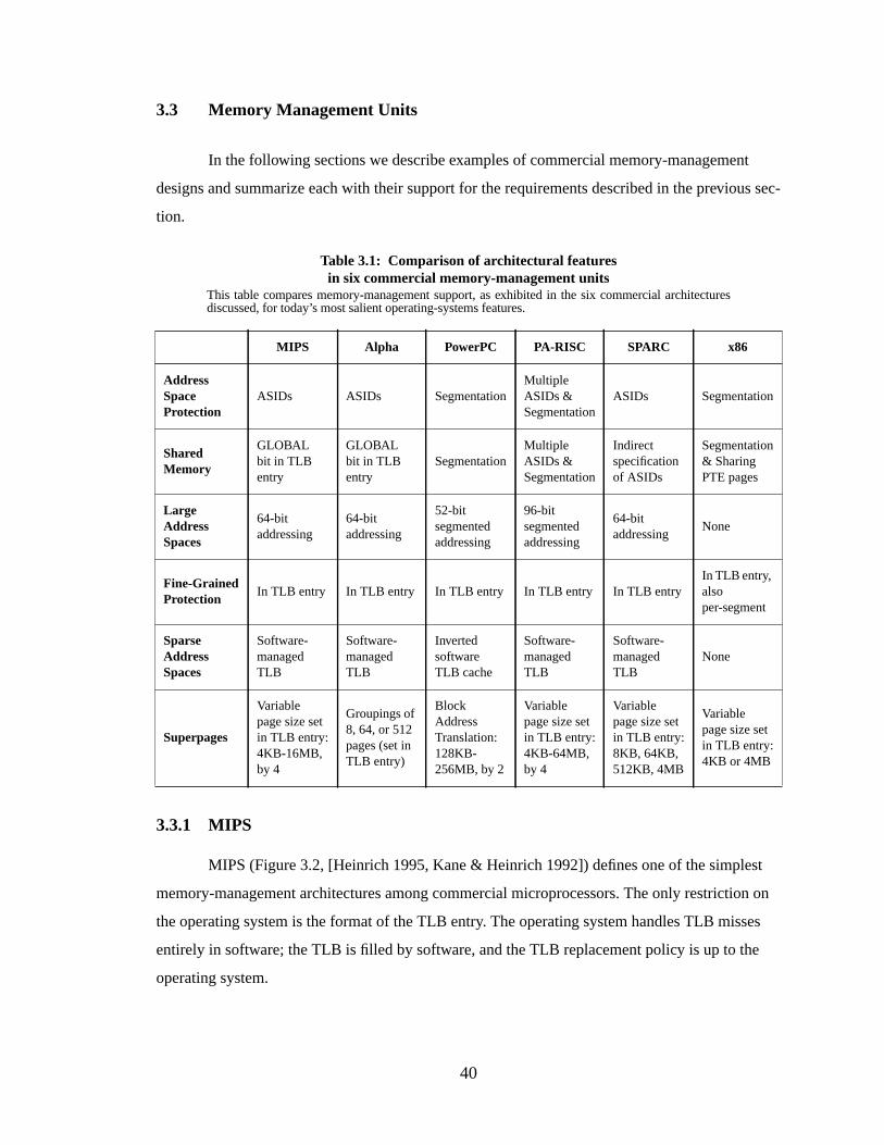
40
3.3 Memory Management Units
In the following sections we describe examples of commercial memory-management
designs and summarize each with their support for the requirements described in the previous sec-
tion.
3.3.1 MIPS
MIPS (Figure 3.2, [Heinrich 1995, Kane & Heinrich 1992]) defines one of the simplest
memory-management architectures among commercial microprocessors. The only restriction on
the operating system is the format of the TLB entry. The operating system handles TLB misses
entirely in software; the TLB is filled by software, and the TLB replacement policy is up to the
operating system.
Table 3.1: Comparison of architectural featuresin six commercial memory-management units
This table compares memory-management support, as exhibited in the six commercial architecturesdiscussed, for today’s most salient operating-systems features.
MIPS Alpha PowerPC PA-RISC SPARC x86
Addr essSpaceProtection
ASIDs ASIDs SegmentationMultipleASIDs &Segmentation
ASIDs Segmentation
SharedMemory
GLOBALbit in TLBentry
GLOBALbit in TLBentry
SegmentationMultipleASIDs &Segmentation
Indirectspecificationof ASIDs
Segmentation& SharingPTE pages
Lar geAddr essSpaces
64-bitaddressing
64-bitaddressing
52-bitsegmentedaddressing
96-bitsegmentedaddressing
64-bitaddressing
None
Fine-GrainedProtection
In TLB entry In TLB entry In TLB entry In TLB entry In TLB entryIn TLB entry,alsoper-segment
SparseAddr essSpaces
Software-managedTLB
Software-managedTLB
InvertedsoftwareTLB cache
Software-managedTLB
Software-managedTLB
None
Superpages
Variablepage size setin TLB entry:4KB-16MB,by 4
Groupings of8, 64, or 512pages (set inTLB entry)
BlockAddressTranslation:128KB-256MB, by 2
Variablepage size setin TLB entry:4KB-64MB,by 4
Variablepage size setin TLB entry:8KB, 64KB,512KB, 4MB
Variablepage size setin TLB entry:4KB or 4MB
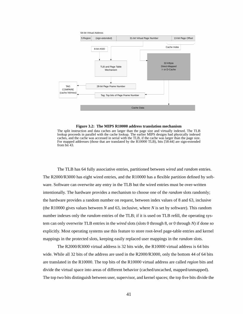
41
The TLB has 64 fully associative entries, partitioned betweenwired andrandom entries.
The R2000/R3000 has eight wired entries, and the R10000 has a flexible partition defined by soft-
ware. Software can overwrite any entry in the TLB but the wired entries must be over-written
intentionally. The hardware provides a mechanism to choose one of therandom slots randomly;
the hardware provides a random number on request, between index values of 8 and 63, inclusive
(the R10000 gives values betweenN and 63, inclusive, whereN is set by software). This random
number indexes only therandom entries of the TLB; if it is used on TLB refill, the operating sys-
tem can only overwrite TLB entries in thewired slots (slots 0 through 8, or 0 throughN) if done so
explicitly. Most operating systems use this feature to store root-level page-table entries and kernel
mappings in the protected slots, keeping easily replaced user mappings in therandom slots.
The R2000/R3000 virtual address is 32 bits wide, the R10000 virtual address is 64 bits
wide. While all 32 bits of the address are used in the R2000/R3000, only the bottom 44 of 64 bits
are translated in the R10000. The top bits of the R10000 virtual address are calledregion bits and
divide the virtual space into areas of different behavior (cached/uncached, mapped/unmapped).
The top two bits distinguish between user, supervisor, and kernel spaces; the top five bits divide the
Figure 3.2: The MIPS R10000 address translation mechanismThe split instruction and data caches are larger than the page size and virtually indexed. The TLBlookup proceeds in parallel with the cache lookup. The earlier MIPS designs had physically indexedcaches, and the cache was accessed in serial with the TLB, if the cache was larger than the page size.For mapped addresses (those that are translated by the R10000 TLB), bits [58:44] are sign-extendedfrom bit 43.
32-KByteDirect-MappedI- or D-Cache
TLB and Page TableMechanism
31-bit Virtual Page Number
64-bit Virtual Address
8-bit ASID
13-bit Page Offset
28-bit Page Frame Number
Cache Index
Tag: Top bits of Page Frame Number
Cache Data
(sign-extended)5:Region
TAGCOMPARE
(cache hit/miss)
42
kernel space into different regions of behavior, and one of the unmapped kernel regions is further
subdivided by the top seven bits of the address. Virtual addresses are extended with an address
space identifier (R2000/R3000: 6 bits, R10000: 8 bits) to distinguish between contexts. The TLB
translates virtual page numbers to physical page numbers, the high-end bits of which are used to
match against the cache tags. The top two bits of the region are kept in the TLB entry to distin-
guish between VPNs from user, supervisor, and kernel spaces. In the R2000/R3000, the top bit
divides the 4GB address space into user and kernel regions, and the next two bits further divide the
kernel’s space into regions of cached/uncached and mapped/unmapped behavior.
Pages are shared by setting theglobal bit in the TLB entry; this is a per-entry bit that indi-
cates the ASID match should be ignored for that page. When sharing user pages, entries with the
global bit set must be flushed on context switches else address space protection can become com-
promised. Kernel pages are off-limits to user-level processes through hardware enforcement—the
top half of the virtual address space is accessible in kernel-mode only.
Periodic cache and TLB flushes are unavoidable in the MIPS architecture, as there are 64
unique context identifiers in the R2000/R3000 and 256 in the R10000. Many systems have more
active processes than this, requiring ASID sharing and periodic remapping. When a new process is
mapped to an old ASID, it is necessary to flush TLB entries with that ASID. It is possible to avoid
flushing the cache by flushing the TLB; since the caches are physically tagged the new process
will not be able to read or overwrite the old process’s data.
Summary
The MIPS architecture implements address space protection with 6-bit or 8-bit ASIDs. As
noted earlier, the ASIDs protect contexts from one another, but their small numbers necessitate
periodic remapping and thus TLB flushing. The software-managed TLB helps solve the sparse
address space problem by allowing the operating system to choose an appropriate page table orga-
nization. Shared memory is supported through theglobal bit in each TLB entry, but this mecha-
nism provides no direct support of sharing memory between a small number contexts. The R10000
architecture provides 64-bit addressing for support of large address spaces. The R2000 and R3000
designs provide 32-bit addressing which was a large address space for their time. The R10000 sup-
ports a variable page size from 4KB to 16MB by multiples of four; each TLB entry contains a
value that identifies its page size.
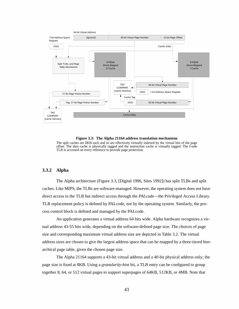
43
3.3.2 Alpha
The Alpha architecture (Figure 3.3, [Digital 1996, Sites 1992]) has split TLBs and split
caches. Like MIPS, the TLBs are software-managed. However, the operating system does not have
direct access to the TLB but indirect access through thePALcode—the Privileged Access Library.
TLB replacement policy is defined by PALcode, not by the operating system. Similarly, the pro-
cess control block is defined and managed by the PALcode.
An application generates a virtual address 64 bits wide. Alpha hardware recognizes a vir-
tual address 43-55 bits wide, depending on the software-defined page size. The choices of page
size and corresponding maximum virtual address size are depicted in Table 3.2. The virtual
address sizes are chosen to give the largest address space that can be mapped by a three-tiered hier-
archical page table, given the chosen page size.
The Alpha 21164 supports a 43-bit virtual address and a 40-bit physical address only; the
page size is fixed at 8KB. Using agranularity-hint bit, a TLB entry can be configured to group
together 8, 64, or 512 virtual pages to support superpages of 64KB, 512KB, or 4MB. Note that
Figure 3.3: The Alpha 21164 address translation mechanismThe split caches are 8KB each and so are effectively virtually indexed by the virtual bits of the pageoffset. The data cache is physically tagged and the instruction cache is virtually tagged. The I-sideTLB is accessed on every reference to provide page protection.
8-KByteDirect-Mapped
D-Cache
Split TLBs, and PageTable Mechanism
30-bit Virtual Page Number
64-bit Virtual Address
ASID
13-bit Page Offset
27-bit Page Frame Number
Cache Index
Cache Data
7-bit Address SpaceRegister
Tag: 27-bit Page Frame Number
(ignored)
8-KByteDirect-Mapped
I-Cache
ASID 7-bit Address Space Register
ASID
Cache Tag
30-bit Virtual Page Number
30-bit Virtual Page Number
TAGCOMPARE
(cache hit/miss)
TAGCOMPARE
(cache hit/miss)
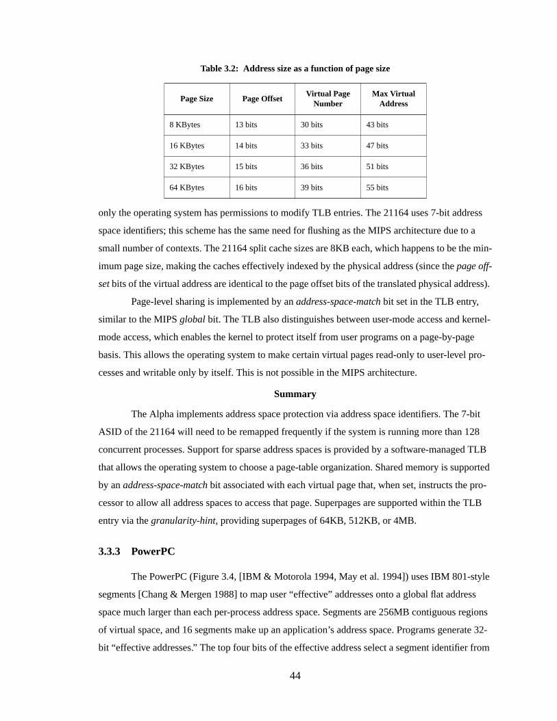
44
only the operating system has permissions to modify TLB entries. The 21164 uses 7-bit address
space identifiers; this scheme has the same need for flushing as the MIPS architecture due to a
small number of contexts. The 21164 split cache sizes are 8KB each, which happens to be the min-
imum page size, making the caches effectively indexed by the physical address (since thepage off-
set bits of the virtual address are identical to the page offset bits of the translated physical address).
Page-level sharing is implemented by anaddress-space-match bit set in the TLB entry,
similar to the MIPSglobal bit. The TLB also distinguishes between user-mode access and kernel-
mode access, which enables the kernel to protect itself from user programs on a page-by-page
basis. This allows the operating system to make certain virtual pages read-only to user-level pro-
cesses and writable only by itself. This is not possible in the MIPS architecture.
Summary
The Alpha implements address space protection via address space identifiers. The 7-bit
ASID of the 21164 will need to be remapped frequently if the system is running more than 128
concurrent processes. Support for sparse address spaces is provided by a software-managed TLB
that allows the operating system to choose a page-table organization. Shared memory is supported
by anaddress-space-match bit associated with each virtual page that, when set, instructs the pro-
cessor to allow all address spaces to access that page. Superpages are supported within the TLB
entry via thegranularity-hint, providing superpages of 64KB, 512KB, or 4MB.
3.3.3 PowerPC
The PowerPC (Figure 3.4, [IBM & Motorola 1994, May et al. 1994]) uses IBM 801-style
segments [Chang & Mergen 1988] to map user “effective” addresses onto a global flat address
space much larger than each per-process address space. Segments are 256MB contiguous regions
of virtual space, and 16 segments make up an application’s address space. Programs generate 32-
bit “effective addresses.” The top four bits of the effective address select a segment identifier from
Table 3.2: Addr ess size as a function of page size
Page Size Page OffsetVirtual Page
NumberMax Virtual
Addr ess
8 KBytes 13 bits 30 bits 43 bits
16 KBytes 14 bits 33 bits 47 bits
32 KBytes 15 bits 36 bits 51 bits
64 KBytes 16 bits 39 bits 55 bits
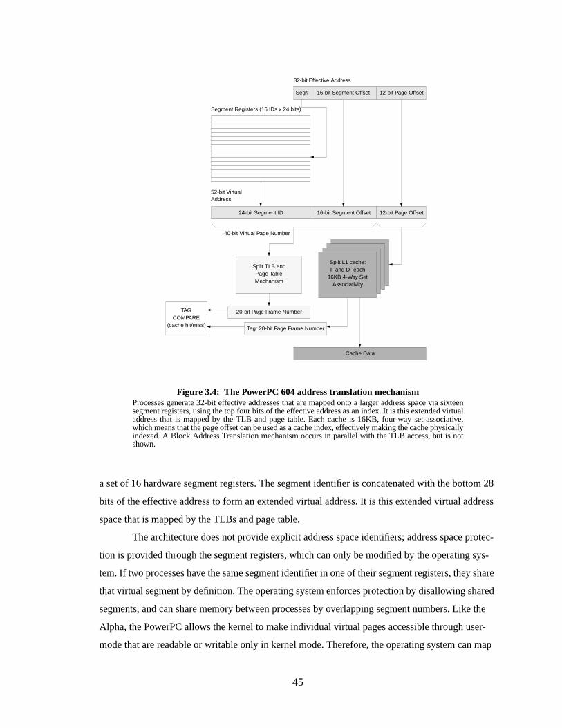
45
a set of 16 hardware segment registers. The segment identifier is concatenated with the bottom 28
bits of the effective address to form an extended virtual address. It is this extended virtual address
space that is mapped by the TLBs and page table.
The architecture does not provide explicit address space identifiers; address space protec-
tion is provided through the segment registers, which can only be modified by the operating sys-
tem. If two processes have the same segment identifier in one of their segment registers, they share
that virtual segment by definition. The operating system enforces protection by disallowing shared
segments, and can share memory between processes by overlapping segment numbers. Like the
Alpha, the PowerPC allows the kernel to make individual virtual pages accessible through user-
mode that are readable or writable only in kernel mode. Therefore, the operating system can map
16-bit Segment Offset
Figure 3.4: The PowerPC 604 address translation mechanismProcesses generate 32-bit effective addresses that are mapped onto a larger address space via sixteensegment registers, using the top four bits of the effective address as an index. It is this extended virtualaddress that is mapped by the TLB and page table. Each cache is 16KB, four-way set-associative,which means that the page offset can be used as a cache index, effectively making the cache physicallyindexed. A Block Address Translation mechanism occurs in parallel with the TLB access, but is notshown.
32-bit Effective Address
12-bit Page Offset
Cache Data
Seg#
Segment Registers (16 IDs x 24 bits)
16-bit Segment Offset 12-bit Page Offset24-bit Segment ID
52-bit VirtualAddress
Split TLB andPage TableMechanism
20-bit Page Frame Number
40-bit Virtual Page Number
Tag: 20-bit Page Frame Number
Split L1 cache:I- and D- each
16KB 4-Way SetAssociativity
TAGCOMPARE
(cache hit/miss)
46
portions of itself into the address spaces of user processes without compromising its integrity. The
segment identifiers are 24 bits wide, which guarantees over a million unique processes on a system
(the lower bound, which assumes no sharing between processes). Therefore, flushing of the caches
or TLBs will be required very infrequently, assuming shared memory is implemented through the
segment registers.
The PowerPC defines for the operating system a hashed page table that is partially hard-
ware-managed. A variation on the inverted page table, it is used as an eight-way set-associative
software cache for PTEs. On TLB misses, the page table is walked by hardware. The advantage is
that it scales well to a 64-bit implementation. However, since the PTE cache is not guaranteed to
hold all active mappings, the operating system will have to create and manage a backup page table
as well.
To support superpages, the PowerPC defines ablock address translation (BAT) mechanism
that operates in parallel with the TLB and takes precedence over the TLB if the BAT registers sig-
nal a “hit” on any given translation. The BAT registers translate virtual addresses at the granularity
of blocks, which can range from 128KB to 256MB in size by multiples of two.
Summary
The PowerPC architecture implements address space protection through segment IDs,
which map the 16 segments of a 4GB address space onto the 4-petabyte (4096TB) global space.
An address space is uniquely defined by a set of 16 segment IDs, and sets with null intersections
are protected from each other. Noglobal bit is necessary in the TLB, as sharing segment IDs
implies shared memory. Flushing of the TLB and caches is not necessary on context switches if
memory is shared through global addresses. Sparse address spaces are supported by a hashed page
table, a variant of the inverted page table. The architecture supports large address spaces; a process
could extend its address space by having the operating system move new values into its segment
registers, giving every process access to the entire 52-bit virtual space. Superpages are supported
through the block address translation registers (BAT registers), which map contiguous regions of
memory of size 128KB to 256MB. The drawback is that since the architecture does not use
ASIDs, there is no protection for these superpages; the BAT registers must be reloaded on context
switches, else they become visible to all processes.
3.3.4 PA-RISC 2.0
The PA-RISC 2.0 (Figure 3.5, [Kane 1996]) is a 64-bit design that uses a “space register”
mechanism very similar to PowerPC-style segments. User-level applications generate 64-bit
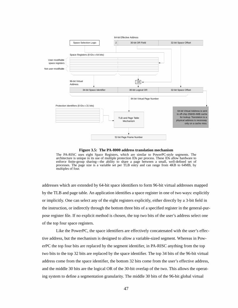
47
addresses which are extended by 64-bit space identifiers to form 96-bit virtual addresses mapped
by the TLB and page table. An application identifies a space register in one of two ways: explicitly
or implicitly. One can select any of the eight registers explicitly, either directly by a 3-bit field in
the instruction, or indirectly through the bottom three bits of a specified register in the general-pur-
pose register file. If no explicit method is chosen, the top two bits of the user’s address select one
of the top four space registers.
Like the PowerPC, the space identifiers are effectively concatenated with the user’s effec-
tive address, but the mechanism is designed to allow a variable-sized segment. Whereas in Pow-
erPC the top four bits are replaced by the segment identifier, in PA-RISC anything from the top
two bits to the top 32 bits are replaced by the space identifier. The top 34 bits of the 96-bit virtual
address come from the space identifier, the bottom 32 bits come from the user’s effective address,
and the middle 30 bits are the logical OR of the 30-bit overlap of the two. This allows the operat-
ing system to define a segmentation granularity. The middle 30 bits of the 96-bit global virtual
Figure 3.5: The PA-8000 address translation mechanismThe PA-RISC uses eight Space Registers, which are similar to PowerPC-style segments. Thearchitecture is unique in its use of multiple protection IDs per process. These IDs allow hardware toenforce finite-group sharing—the ability to share a page between a small, well-defined set ofprocesses. The page size is a variable set per TLB entry and can range from 4KB to 64MB, bymultiples of four.
30-bit OR Field
64-bit Effective Address
32-bit Space OffsetSpace Selection Logic
Space Registers (8 IDs x 64 bits)
32-bit Space Offset34-bit Space Identifier
96-bit VirtualAddress
TLB and Page TableMechanism
Protection Identifiers (8 IDs x 31 bits)
52-bit Page Frame Number
User-modifiablespace registers
Not user-modifiable
84-bit Virtual Page Number
30-bit Logical OR
2
64-bit Virtual Address is sentto off-chip 256KB-4MB cache
for lookup. Translation to aphysical address is necessary
only on a cache miss.
OR
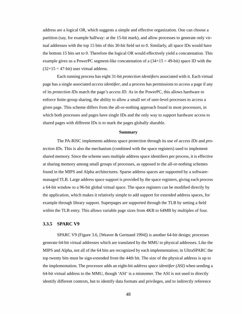
48
address are a logical OR, which suggests a simple and effective organization. One can choose a
partition (say, for example halfway: at the 15-bit mark), and allow processes to generate only vir-
tual addresses with the top 15 bits of this 30-bit field set to 0. Similarly, all space IDs would have
the bottom 15 bits set to 0. Therefore the logical OR would effectively yield a concatenation. This
example gives us a PowerPC segment-like concatenation of a (34+15 = 49-bit) space ID with the
(32+15 = 47-bit) user virtual address.
Each running process has eight 31-bitprotection identifiers associated with it. Each virtual
page has a single associatedaccess identifier, and a process has permissions to access a page if any
of its protection IDs match the page’s access ID. As in the PowerPC, this allows hardware to
enforce finite-group sharing, the ability to allow a small set of user-level processes to access a
given page. This scheme differs from the all-or-nothing approach found in most processors, in
which both processes and pages have single IDs and the only way to support hardware access to
shared pages with different IDs is to mark the pages globally sharable.
Summary
The PA-RISC implements address space protection through its use ofaccess IDs andpro-
tection IDs. This is also the mechanism (combined with the space registers) used to implement
shared memory. Since the scheme uses multiple address space identifiers per process, it is effective
at sharing memory among small groups of processes, as opposed to the all-or-nothing schemes
found in the MIPS and Alpha architectures. Sparse address spaces are supported by a software-
managed TLB. Large address space support is provided by the space registers, giving each process
a 64-bit window to a 96-bit global virtual space. The space registers can be modified directly by
the application, which makes it relatively simple to add support for extended address spaces, for
example through library support. Superpages are supported through the TLB by setting a field
within the TLB entry. This allows variable page sizes from 4KB to 64MB by multiples of four.
3.3.5 SPARC V9
SPARC V9 (Figure 3.6, [Weaver & Germand 1994]) is another 64-bit design; processes
generate 64-bit virtual addresses which are translated by the MMU to physical addresses. Like the
MIPS and Alpha, not all of the 64 bits are recognized by each implementation; in UltraSPARC the
top twenty bits must be sign-extended from the 44th bit. The size of the physical address is up to
the implementation. The processor adds an eight-bitaddress space identifier (ASI)when sending a
64-bit virtual address to the MMU, though ‘ASI’ is a misnomer. The ASI is not used to directly
identify different contexts, but to identify data formats and privileges, and to indirectly reference
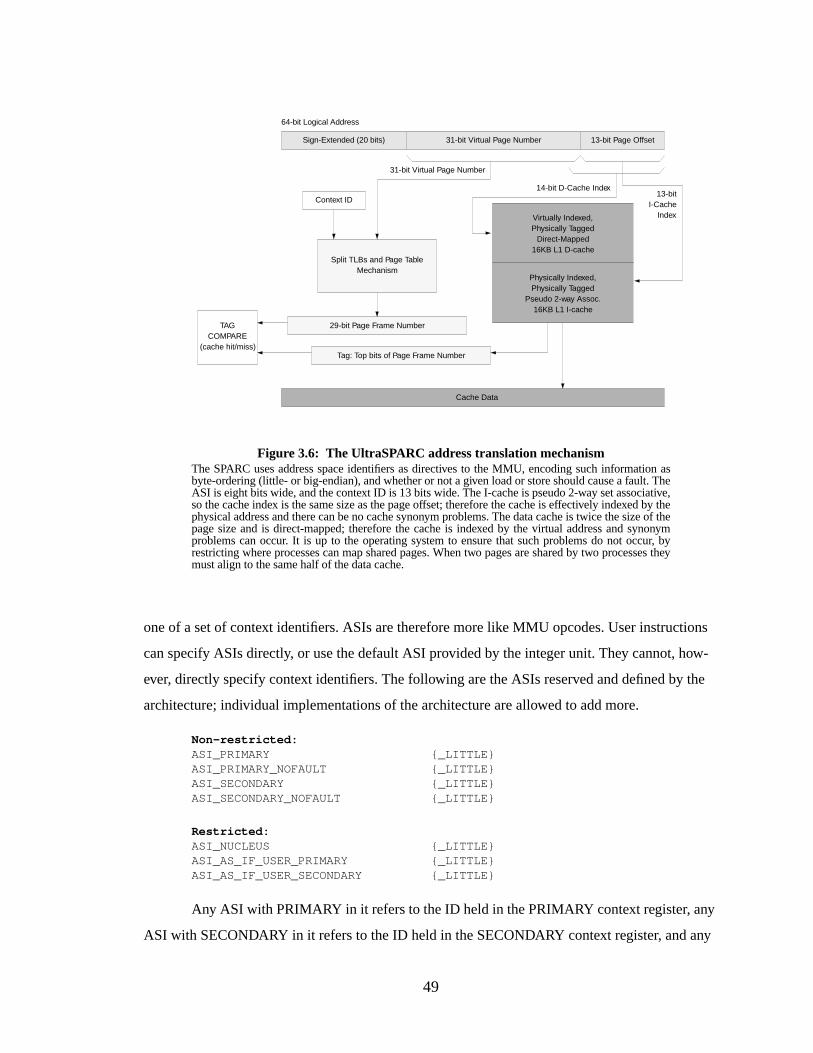
49
one of a set of context identifiers. ASIs are therefore more like MMU opcodes. User instructions
can specify ASIs directly, or use the default ASI provided by the integer unit. They cannot, how-
ever, directly specify context identifiers. The following are the ASIs reserved and defined by the
architecture; individual implementations of the architecture are allowed to add more.
Non-restricted:ASI_PRIMARY {_LITTLE}ASI_PRIMARY_NOFAULT {_LITTLE}ASI_SECONDARY {_LITTLE}ASI_SECONDARY_NOFAULT {_LITTLE}
Restricted:ASI_NUCLEUS {_LITTLE}ASI_AS_IF_USER_PRIMARY {_LITTLE}ASI_AS_IF_USER_SECONDARY {_LITTLE}
Any ASI with PRIMARY in it refers to the ID held in the PRIMARY context register, any
ASI with SECONDARY in it refers to the ID held in the SECONDARY context register, and any
Figure 3.6: The UltraSPARC address translation mechanismThe SPARC uses address space identifiers as directives to the MMU, encoding such information asbyte-ordering (little- or big-endian), and whether or not a given load or store should cause a fault. TheASI is eight bits wide, and the context ID is 13 bits wide. The I-cache is pseudo 2-way set associative,so the cache index is the same size as the page offset; therefore the cache is effectively indexed by thephysical address and there can be no cache synonym problems. The data cache is twice the size of thepage size and is direct-mapped; therefore the cache is indexed by the virtual address and synonymproblems can occur. It is up to the operating system to ensure that such problems do not occur, byrestricting where processes can map shared pages. When two pages are shared by two processes theymust align to the same half of the data cache.
Sign-Extended (20 bits)
64-bit Logical Address
31-bit Virtual Page Number
Physically Indexed,Physically Tagged
Pseudo 2-way Assoc.16KB L1 I-cache
Split TLBs and Page TableMechanism
Context ID
29-bit Page Frame Number
14-bit D-Cache Index
Tag: Top bits of Page Frame Number
Cache Data
31-bit Virtual Page Number
Virtually Indexed,Physically Tagged
Direct-Mapped16KB L1 D-cache
13-bitI-Cache
Index
13-bit Page Offset
TAGCOMPARE
(cache hit/miss)
50
ASI with NUCLEUS in it refers to the ID held in the NUCLEUS context register. The {_LITTLE}
suffixes, if used, indicate that the target of the load or store is to be interpreted as a little-endian
object, otherwise the MMU is to treat referenced data types as big-endian. The NOFAULT direc-
tives tell the MMU to load the data to cache without generating a page fault if the data is not actu-
ally in memory. This function is used for prefetching.
The default ASI is ASI_PRIMARY; this identifier indicates to the MMU that the current
user-level process is executing. Only processes operating in privileged mode are allowed to gener-
ate the restricted ASIs; user-level processes can generate non-restricted ASIs. When the operating
system executes, it runs under ASI_NUCLEUS, and can peek into the user’s address space by gen-
erating PRIMARY or SECONDARY ASIs (the AS_IF_USER ASIs). The ASI_SECONDARY
identifier can be used for user-level operating system servers that sometimes need to peek into the
address spaces of normal processes. For example, a server implementing a particular operating
system API, as in Mach or Windows NT, would need to set up and manage the address space of
processes running under its environment. It would run as PRIMARY and move the context ID of
the child process into the SECONDARY context register. It could explicitly use SECONDARY
ASIs to load and store values to the child’s address space, and use PRIMARY to execute its own
instructions and reference data in its own address space.
Summary
The SPARC architecture implements address space protection through context identifiers.
Frequent cache flushing is avoided, as the context ID is thirteen bits wide. The scheme does have
the same problems as in the MIPS; ID mapping will eventually occur, necessitating flushing of
memory structures—however, this only needs to happen after 8192 processes execute. A SPARC
implementation with software-managed TLBs will support sparse address spaces, as the operating
system is free to choose its page table organization. Shared memory is implemented by indirectly
specifying an alternate context identifier while executing, therefore referencing data in an alternate
address space. There is direct support for large address spaces, as processes have free run of a 64-
bit space. Superpages are supported in the UltraSPARC by a variable page size of 8KB, 64KB,
512KB, or 4MB, set in the TLB entry.
3.3.6 Pentium Pro
The Pentium Pro (Figure 3.7, [Intel 1995]) does not provide address space protection
directly; there are no address space identifiers and the TLBs are typically flushed on context
switch. The caches are physically tagged, and therefore do not need flushing. Protection is usually
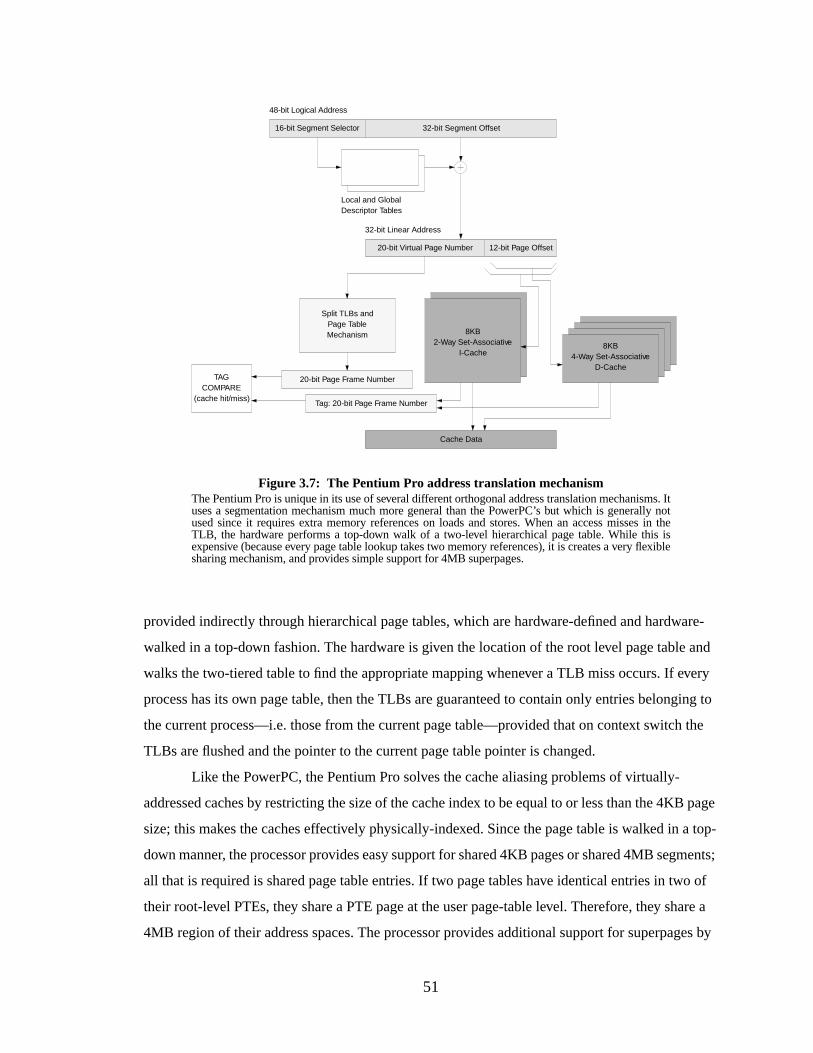
51
provided indirectly through hierarchical page tables, which are hardware-defined and hardware-
walked in a top-down fashion. The hardware is given the location of the root level page table and
walks the two-tiered table to find the appropriate mapping whenever a TLB miss occurs. If every
process has its own page table, then the TLBs are guaranteed to contain only entries belonging to
the current process—i.e. those from the current page table—provided that on context switch the
TLBs are flushed and the pointer to the current page table pointer is changed.
Like the PowerPC, the Pentium Pro solves the cache aliasing problems of virtually-
addressed caches by restricting the size of the cache index to be equal to or less than the 4KB page
size; this makes the caches effectively physically-indexed. Since the page table is walked in a top-
down manner, the processor provides easy support for shared 4KB pages or shared 4MB segments;
all that is required is shared page table entries. If two page tables have identical entries in two of
their root-level PTEs, they share a PTE page at the user page-table level. Therefore, they share a
4MB region of their address spaces. The processor provides additional support for superpages by
Figure 3.7: The Pentium Pro address translation mechanismThe Pentium Pro is unique in its use of several different orthogonal address translation mechanisms. Ituses a segmentation mechanism much more general than the PowerPC’s but which is generally notused since it requires extra memory references on loads and stores. When an access misses in theTLB, the hardware performs a top-down walk of a two-level hierarchical page table. While this isexpensive (because every page table lookup takes two memory references), it is creates a very flexiblesharing mechanism, and provides simple support for 4MB superpages.
16-bit Segment Selector
48-bit Logical Address
32-bit Segment Offset
Local and GlobalDescriptor Tables
12-bit Page Offset20-bit Virtual Page Number
32-bit Linear Address
Split TLBs andPage TableMechanism
Cache Data
8KB2-Way Set-Associative
I-Cache
20-bit Page Frame Number
Tag: 20-bit Page Frame Number
TAGCOMPARE
(cache hit/miss)
8KB4-Way Set-Associative
D-Cache
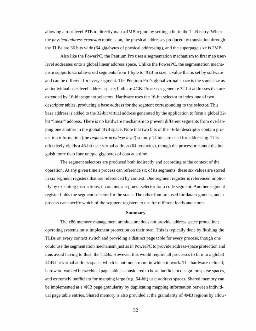
52
allowing a root-level PTE to directly map a 4MB region by setting a bit in the TLB entry. When
thephysical address extension mode is on, the physical addresses produced by translation through
the TLBs are 36 bits wide (64 gigabytes of physical addressing), and the superpage size is 2MB.
Also like the PowerPC, the Pentium Pro uses a segmentation mechanism to first map user-
level addresses onto a global linear address space. Unlike the PowerPC, the segmentation mecha-
nism supports variable-sized segments from 1 byte to 4GB in size, a value that is set by software
and can be different for every segment. The Pentium Pro’s global virtual space is the same size as
an individual user-level address space; both are 4GB. Processes generate 32-bit addresses that are
extended by 16-bit segment selectors. Hardware uses the 16-bit selector to index one of two
descriptor tables, producing a base address for the segment corresponding to the selector. This
base address is added to the 32-bit virtual address generated by the application to form a global 32-
bit “linear” address. There is no hardware mechanism to prevent different segments from overlap-
ping one another in the global 4GB space. Note that two bits of the 16-bit descriptor contain pro-
tection information (therequestor privilege level) so only 14 bits are used for addressing. This
effectively yields a 46-bit user virtual address (64 terabytes), though the processor cannot distin-
guish more than four unique gigabytes of data at a time.
The segment selectors are produced both indirectly and according to the context of the
operation. At any given time a process can reference six of its segments; these six values are stored
in six segment registers that are referenced by context. One segment register is referenced implic-
itly by executing instructions; it contains a segment selector for a code segment. Another segment
register holds the segment selector for the stack. The other four are used for data segments, and a
process can specify which of the segment registers to use for different loads and stores.
Summary
The x86 memory management architecture does not provide address space protection;
operating systems must implement protection on their own. This is typically done by flushing the
TLBs on every context switch and providing a distinct page table for every process, though one
could use the segmentation mechanism just as in PowerPC to provide address-space protection and
thus avoid having to flush the TLBs. However, this would require all processes to fit into a global
4GB flat virtual address space, which is not much room in which to work. The hardware-defined,
hardware-walked hierarchical page table is considered to be an inefficient design for sparse spaces,
and extremely inefficient for mapping large (e.g. 64-bit) user address spaces. Shared memory can
be implemented at a 4KB page granularity by duplicating mapping information between individ-
ual page table entries. Shared memory is also provided at the granularity of 4MB regions by allow-
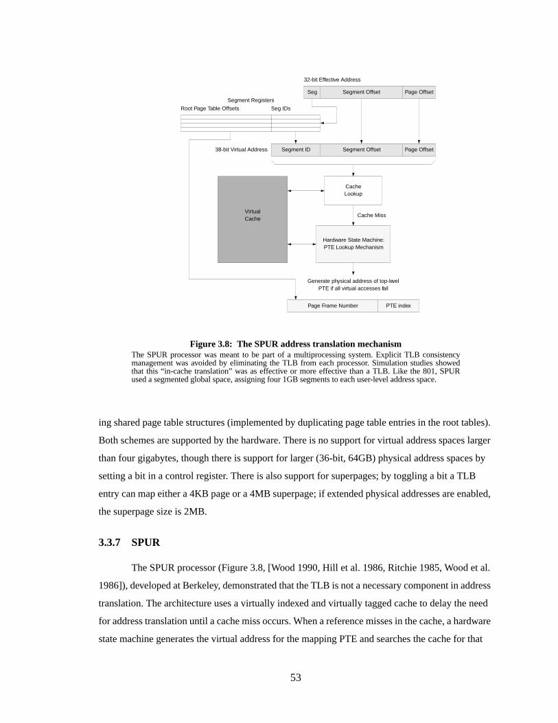
53
ing shared page table structures (implemented by duplicating page table entries in the root tables).
Both schemes are supported by the hardware. There is no support for virtual address spaces larger
than four gigabytes, though there is support for larger (36-bit, 64GB) physical address spaces by
setting a bit in a control register. There is also support for superpages; by toggling a bit a TLB
entry can map either a 4KB page or a 4MB superpage; if extended physical addresses are enabled,
the superpage size is 2MB.
3.3.7 SPUR
The SPUR processor (Figure 3.8, [Wood 1990, Hill et al. 1986, Ritchie 1985, Wood et al.
1986]), developed at Berkeley, demonstrated that the TLB is not a necessary component in address
translation. The architecture uses a virtually indexed and virtually tagged cache to delay the need
for address translation until a cache miss occurs. When a reference misses in the cache, a hardware
state machine generates the virtual address for the mapping PTE and searches the cache for that
Figure 3.8: The SPUR address translation mechanismThe SPUR processor was meant to be part of a multiprocessing system. Explicit TLB consistencymanagement was avoided by eliminating the TLB from each processor. Simulation studies showedthat this “in-cache translation” was as effective or more effective than a TLB. Like the 801, SPURused a segmented global space, assigning four 1GB segments to each user-level address space.
Segment Offset
32-bit Effective Address
Page Offset
Hardware State Machine:PTE Lookup Mechanism
Page Frame Number
VirtualCache
Seg
Seg IDsRoot Page Table Offsets
Segment Registers
Segment Offset Page OffsetSegment ID
CacheLookup
Cache Miss
38-bit Virtual Address
Generate physical address of top-levelPTE if all virtual accesses fail
PTE index
54
address. If this misses, the hardware continues until the topmost level of the hierarchical page table
is reached, and the hardware requests the mapping PTE from memory.
One can see that the SPUR design is an experiment in alternative address translation
mechanisms; the user-level application generates virtual addresses which are translated by hard-
ware into physical addresses, but without a TLB. The design uses a hardware-defined, hardware-
walked page table. There are no explicit address space identifiers; 801-style segments are used for
address space protection and sharing as well. Unlike the 801 and PowerPC, SPUR has four seg-
ments, one each for the code, heap, stack, and system segments. Each segment has its own root
page table, and the page frame number for each RPT is kept in the segment registers. The segmen-
tation mechanism has the advantage of reducing the need for cache flushes on context switch or
process exit.
3.3.8 SOFTVM
The PUMA processor, in design at the University of Michigan, is a high clock-rate 32-bit
PowerPC implementation and an example ofsoftware-managed address translation, orsoftvm
(Figure 5.3, [Jacob & Mudge 1996, Jacob & Mudge 1997]). It is similar to SPUR in its lack of
TLBs but unlike the SPUR processor it does not use a hardware state machine to walk the page
table. Instead, software handles the L2 cache misses, translates the virtual addresses that missed
the L2 cache, and loads the data into the cache for the application process. It uses a split, virtual,
two-level cache hierarchy that delays the need for address translation until a reference misses in
the large L2 cache. A portion of the 16TB global virtual address space is mapped directly onto
physical memory, to allow the operating system to perform main memory lookups on behalf of
user processes. The top twelve bits of the virtual address determine whether an address is virtual or
physical, and whether it is cacheable or not. If the top twelve bits are 0x001 the address is mapped
directly onto physical memory and the data is cacheable. If the top twelve bits are 0x000 the
address is mapped directly onto physical memory and the data is not cacheable. Other bit patterns
represent virtual, cacheable addresses. Therefore the maximum physical address is 32 bits wide.
As described earlier, 801-style segments provide address space protection and access to a
large virtual space. Since there is no TLB, there is no hardware-defined page size; software is free
to define any protection granularity it desires as well as any translation granularity it desires. In
particular, the two sizes (translation granularity and protection granularity) need not be identical.
The operating system is also unrestricted in its choice of a page table organization. The scheme
provides the operating system with a high degree of flexibility .
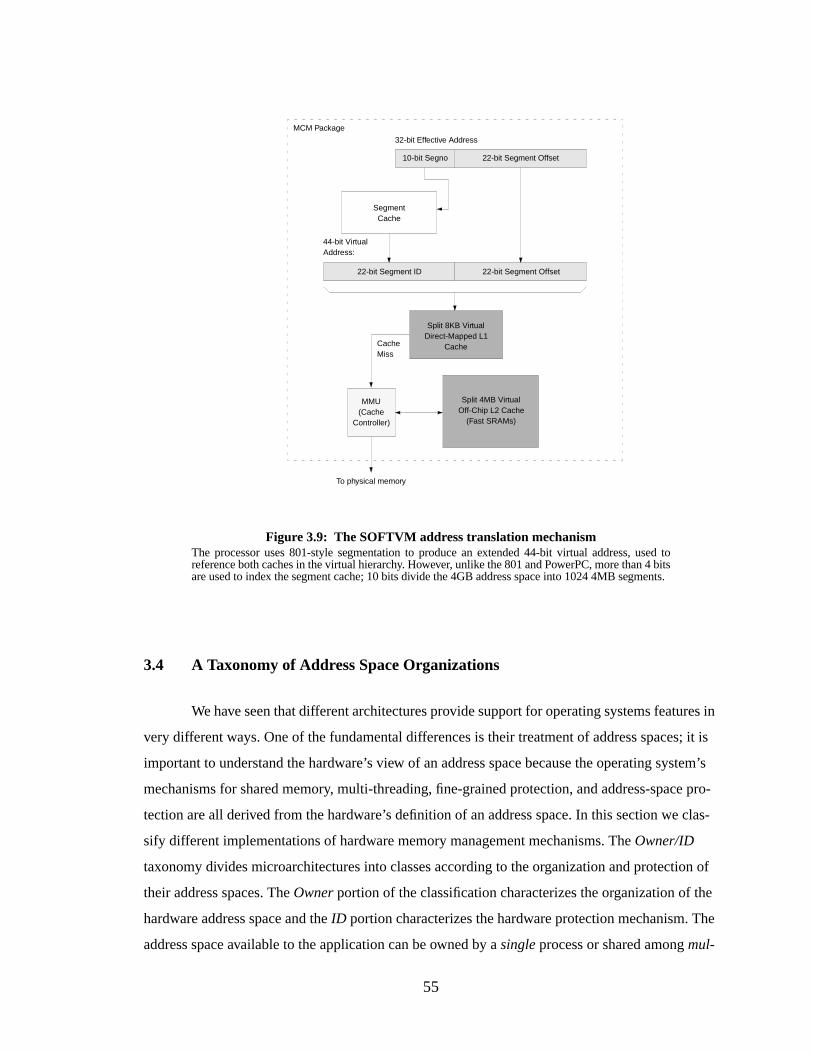
55
3.4 A Taxonomy of Address Space Organizations
We have seen that different architectures provide support for operating systems features in
very different ways. One of the fundamental differences is their treatment of address spaces; it is
important to understand the hardware’s view of an address space because the operating system’s
mechanisms for shared memory, multi-threading, fine-grained protection, and address-space pro-
tection are all derived from the hardware’s definition of an address space. In this section we clas-
sify different implementations of hardware memory management mechanisms. TheOwner/ID
taxonomy divides microarchitectures into classes according to the organization and protection of
their address spaces. TheOwner portion of the classification characterizes the organization of the
hardware address space and theID portion characterizes the hardware protection mechanism. The
address space available to the application can be owned by asingle process or shared amongmul-
Figure 3.9: The SOFTVM address translation mechanismThe processor uses 801-style segmentation to produce an extended 44-bit virtual address, used toreference both caches in the virtual hierarchy. However, unlike the 801 and PowerPC, more than 4 bitsare used to index the segment cache; 10 bits divide the 4GB address space into 1024 4MB segments.
22-bit Segment Offset
32-bit Effective Address
10-bit Segno
22-bit Segment ID
44-bit VirtualAddress:
MMU(Cache
Controller)
Split 4MB VirtualOff-Chip L2 Cache
(Fast SRAMs)
Split 8KB VirtualDirect-Mapped L1
CacheCacheMiss
To physical memory
SegmentCache
22-bit Segment Offset
MCM Package
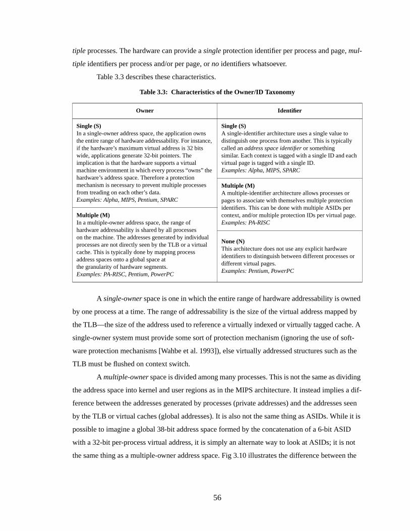
56
tiple processes. The hardware can provide asingle protection identifier per process and page,mul-
tiple identifiers per process and/or per page, orno identifiers whatsoever.
Table 3.3 describes these characteristics.
A single-owner space is one in which the entire range of hardware addressability is owned
by one process at a time. The range of addressability is the size of the virtual address mapped by
the TLB—the size of the address used to reference a virtually indexed or virtually tagged cache. A
single-owner system must provide some sort of protection mechanism (ignoring the use of soft-
ware protection mechanisms [Wahbe et al. 1993]), else virtually addressed structures such as the
TLB must be flushed on context switch.
A multiple-owner space is divided among many processes. This is not the same as dividing
the address space into kernel and user regions as in the MIPS architecture. It instead implies a dif-
ference between the addresses generated by processes (private addresses) and the addresses seen
by the TLB or virtual caches (global addresses). It is also not the same thing as ASIDs. While it is
possible to imagine a global 38-bit address space formed by the concatenation of a 6-bit ASID
with a 32-bit per-process virtual address, it is simply an alternate way to look at ASIDs; it is not
the same thing as a multiple-owner address space. Fig 3.10 illustrates the difference between the
Table 3.3: Characteristics of the Owner/ID Taxonomy
Owner Identifier
Single (S)In a single-owner address space, the application ownsthe entire range of hardware addressability. For instance,if the hardware’s maximum virtual address is 32 bitswide, applications generate 32-bit pointers. Theimplication is that the hardware supports a virtualmachine environment in which every process “owns” thehardware’s address space. Therefore a protectionmechanism is necessary to prevent multiple processesfrom treading on each other’s data.Examples: Alpha, MIPS, Pentium, SPARC
Single (S)A single-identifier architecture uses a single value todistinguish one process from another. This is typicallycalled anaddress space identifier or somethingsimilar. Each context is tagged with a single ID and eachvirtual page is tagged with a single ID.Examples: Alpha, MIPS, SPARC
Multiple (M)A multiple-identifier architecture allows processes orpages to associate with themselves multiple protectionidentifiers. This can be done with multiple ASIDs percontext, and/or multiple protection IDs per virtual page.Examples: PA-RISC
Multiple (M)In a multiple-owner address space, the range ofhardware addressability is shared by all processeson the machine. The addresses generated by individualprocesses are not directly seen by the TLB or a virtualcache. This is typically done by mapping processaddress spaces onto a global space atthe granularity of hardware segments.Examples: PA-RISC, Pentium, PowerPC
None (N)This architecture does not use any explicit hardwareidentifiers to distinguish between different processes ordifferent virtual pages.Examples: Pentium, PowerPC
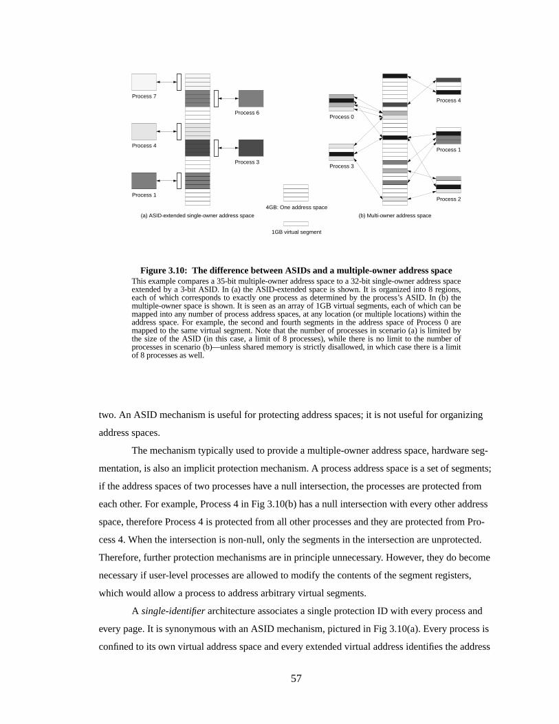
57
two. An ASID mechanism is useful for protecting address spaces; it is not useful for organizing
address spaces.
The mechanism typically used to provide a multiple-owner address space, hardware seg-
mentation, is also an implicit protection mechanism. A process address space is a set of segments;
if the address spaces of two processes have a null intersection, the processes are protected from
each other. For example, Process 4 in Fig 3.10(b) has a null intersection with every other address
space, therefore Process 4 is protected from all other processes and they are protected from Pro-
cess 4. When the intersection is non-null, only the segments in the intersection are unprotected.
Therefore, further protection mechanisms are in principle unnecessary. However, they do become
necessary if user-level processes are allowed to modify the contents of the segment registers,
which would allow a process to address arbitrary virtual segments.
A single-identifier architecture associates a single protection ID with every process and
every page. It is synonymous with an ASID mechanism, pictured in Fig 3.10(a). Every process is
confined to its own virtual address space and every extended virtual address identifies the address
(b) Multi-owner address space
Process 0
Process 1
Process 2
Process 4
Process 3
Figure 3.10: The difference between ASIDs and a multiple-owner address spaceThis example compares a 35-bit multiple-owner address space to a 32-bit single-owner address spaceextended by a 3-bit ASID. In (a) the ASID-extended space is shown. It is organized into 8 regions,each of which corresponds to exactly one process as determined by the process’s ASID. In (b) themultiple-owner space is shown. It is seen as an array of 1GB virtual segments, each of which can bemapped into any number of process address spaces, at any location (or multiple locations) within theaddress space. For example, the second and fourth segments in the address space of Process 0 aremapped to the same virtual segment. Note that the number of processes in scenario (a) is limited bythe size of the ASID (in this case, a limit of 8 processes), while there is no limit to the number ofprocesses in scenario (b)—unless shared memory is strictly disallowed, in which case there is a limitof 8 processes as well.
(a) ASID-extended single-owner address space
4GB: One address space
Process 3
Process 1
Process 4
Process 7
Process 6
1GB virtual segment
58
space to which it belongs. The implication is that the only way to share pages is to circumvent the
protection mechanism—to make pages globally available by marking them with a special flag that
turns off protection on a page basis. For example, this is seen in the GLOBAL bits of the MIPS and
Alpha TLB designs.
A multiple-identifier architecture is designed to support sharing of pages across address
spaces by associating more than one ID with every process and/or every page. Therefore, address
spaces can belong to multiple protection domains, and pages can belong to multiple process
address spaces. There is no need for a GLOBAL bit mechanism, and the multiple-ID mechanism
goes beyond the all-or-nothing sharing of the single-ID mechanism; a multiple-ID mechanism sup-
ports finite-group ownership, where a shared page can be accessed by a small, well-defined group
of processes—but not by processes outside the group. Note that we have made the deliberate
choice to place segmentation mechanisms into the organization category (owner) and not into the
protection category (identifier), though they could be appropriately placed in the latter. This is
done to cleanly delineate architectures, otherwise it would not be clear whether the PowerPC
would be amultiple-owner no-identifier system, or amultiple-owner multiple-identifier system.
The choice was made because the segmentation mechanism is an address space organizing func-
tion that can also be used for protection, not a protection function that can be used to organize
address spaces.
A no-identifier architecture provides no hardware protection IDs of any kind. The operat-
ing system must provide protection by flushing virtually indexed structures (for example, TLBs)
on context switch and/or by using software protection mechanisms.
The following sections describe the behaviors of the different classifications of memory
management hardware.
3.4.1 Single-Owner, No ID (SONI)
This architecture makes the entire range of hardware addressability available to the appli-
cation but does not distinguish between addresses generated by different processes. Therefore, any
structure that is dependent on virtual addresses—e.g. the TLB and any virtually-addressed
cache—must be flushed on context switch. Also, pages must be shared through the page tables; the
hardware offers no explicit support for sharing.
The Pentium falls into this category when its segmentation mechanism is bypassed, or if it
is used without treating the 4GB “linear” address space as a global shared space. When the seg-
mentation mechanism is bypassed, the Pentium allows system software to map the addresses of
59
different processes to the same locations in the linear space, but to different regions of the physical
memory. This is accomplished by maintaining a different page table for every process. This cir-
cumvents themultiple-owner aspect of the Pentium’s segmentation mechanism, and also fails to
take advantage of the implicit protection function of segmentation.
3.4.2 Single-Owner, Single-ID (SOSI)
Most microarchitectures today, including Alpha, MIPS, and SPARC, fall into this cate-
gory. The user-level application generates virtual addresses that, augmented by a single ASID, are
used to address all virtual structures, including caches and TLBs. The scheme is simple and effec-
tive. Processes are protected from each other by identifiers, and an entry in a TLB or a line in a
cache explicitly identifies its owner. The advantage of this is that address 0x00000000 from several
different processes can be stored in the cache at the same time without fear of conflict. When a
process generates an address, the ID match guarantees that the correct datum is read or written.
The disadvantage is that the protection method makes sharing difficult. When all refer-
ences are tagged with a single owner, the system implicitly requires multiple mappings to the same
physical page. This takes up extra memory to hold the mappings and the TLB is often crowded
with multiple PTEs for the same physical page—each a mapping for a different process sharing
the page. Intuitively this reduces the effectiveness of the TLB, and Khalidi & Talluri have shown
that it doubles the TLB miss rate [Khalidi & Talluri 1995]. It is also a problem with inverted page
tables; when a system requires multiple mappings to a single page, only one of those mappings can
be in the inverted page table at a time. Solutions to this problem have been to subvert the protec-
tion mechanism using GLOBAL bits in the TLB, or to vary the structure of the inverted page table,
like the 8-way PTE cache of the PowerPC architecture.
The problem with using GLOBAL bits in the TLB is that when a virtual page is marked as
globally-visible, it is no longer protected. Therefore, mappings for shared memory must not exist
in the TLB during the execution of processes that are not supposed to read or write the shared
regions. This requires TLB flushing on context switch, and the operating system can either flush
all shared mappings or just those relevant to the current process. The operating system has several
choices: it can maintain a single list of all shared mappings and flush all these mappings on every
context switch, or it can maintain a per-process list of mappings that each process shares and only
flush these on context switch. For the latter approach, the operating system will also need to main-
tain integrity between lists. Clearly, this is a non-optimal solution to supporting shared memory.
60
3.4.3 Single-Owner, Multiple-ID (SOMI)
A SOMI architecture, for example the PA-RISC whenever a process uses only one space
register, is not segmented but has multiple protection IDs associated with each process and/or each
page. If multiple IDs are associated with each page, each TLB entry could be shared by all the pro-
cesses with which the page is associated. A TLB entry would have several available slots for pro-
tection IDs, requiring more chip area but alleviating the problem of multiple TLB entries per
physical page. If a set of protection bits were also associated with each ID, every process could
share the region with different protections.
Alternatively, if there were multiple IDs associated with each process and not with each
page (this is like the scheme used in PA-RISC), a different ID could be created for every instance
of a shared region. This ID would indicate the “identity” of the group that collectively owns the
region. Therefore, a process would have a set of IDs: one to uniquely represent itself, and one for
each of its shared regions. Multiple copies of mapping information would not be necessary for
shared regions, which would eliminate redundant entries in the TLB. However, processes would
not be able to share the regions using different protections. In order to share physical pages with
different protections, the operating system would still need to duplicate TLB entries. However,
there would not need to be as many entries as processes sharing the page, as all processes desiring
the same protection could use the same ID.
3.4.4 Multiple-Owner , No ID (MONI)
This is the basic segmented architecture that maps user addresses onto a global address
space at the granularity of segments. This allows one to think of a process address space as a set of
segments. Wherever two sets intersect, the address spaces share segments between them. Where
two sets do not intersect, the process address spaces are protected by definition. This is how the
PowerPC architecture is designed, and it is how the Pentium segmentation mechanismcan be
used; if the Pentium’s 4GB linear address space were treated as a global space to be shared a seg-
ment at a time, the segmentation mechanism would be an effective protection mechanism, obviat-
ing the need to flush the TLB on context switch. If the segment registers are protected from
modification by user-level processes, no protection identifiers are necessary. However, as in the
PA-RISC, processes might be allowed to change the contents of the segment registers. In this case,
processes can access arbitrary segments, and therefore an additional protection mechanism is
required.
61
PowerPC makes loading a segment register a privileged action, thus no user-level process
may reorganize its own address space. A process cannot peek at the contents of another process’s
address space unless the operating system has allowed the two to share a segment. Even in this
scenario, the processes are restricted to only being able to see the portion of the other’s address
space defined by the shared segment ID.
3.4.5 Multiple-Owner , Single-ID (MOSI)
The MOSI architecture, for which we can find no example, is an extension of the MONI
architecture by a single protection ID. The result is multiple global spaces—each multiple-owner,
and each protected from each other. Each process would have a window onto a larger multiple-
owner address space. There is no reason that a single process would have to have a unique ID; sev-
eral processes could share the same ID and be protected from each other by the segmentation
mechanism. Alternatively, multiple threads within a process could coexist safely in a single multi-
ple-owner address space, all identified by the same ASID. Each could have its own window onto
the (large) process address space, and they would only overlap at specified points.
If the segmentation mechanism were not secure, i.e. if a process could manipulate its seg-
ment register (but presumably not its ASID register), then this would not be suitable to allow mul-
tiple heavyweight processes to share an ASID. However, it would certainly be an appropriate
environment for multiple threads to share an ASID, executing within one enormous address space.
3.4.6 Multiple-Owner , Multiple-ID (MOMI)
The PA-RISC is an example of this architecture. A MOMI architecture defines a global
shared virtual address space and multiple protection IDs as well. In the case of the PA-RISC, the
protection IDs are necessary because the PA-RISC segmentation mechanism (space registers) is
not secure from user-level modification. This allows a user-level process to organize its own
address space; the user-level process may extend its address space at will without fear of protec-
tion violations.
It is also possible to combine a secure segmentation mechanism with a multiple-ID protec-
tion mechanism. Like the MOSI architecture, this would offer a hierarchy of address spaces; each
process address space would be mapped onto a global address space, of which many would exist
simultaneously. This could be used for maintaining process hierarchies and/or supporting many
threads within large address spaces. The difference between this and the MOSI architecture is that
62
this allows each process address space to span many different global address spaces at once; a pro-
cess address space could be composed of regions from several different global spaces.
3.5 Conclusions
There is tremendous diversity among today’s commercial processors in their support for
memory management. This incompatibility contributes significantly to the problems in porting
system software between processors. The issues in porting an operating system simply from one
processor to another within the same architecture has been shown to be challenging [Liedtke
1995b]; portingbetween architecture families is much more difficult because choices available
within one family are not often available in another. Software-managed TLBs, as seen in the
MIPS, Alpha, SPARC, and PA-RISC architectures, allow an operating system to choose its organi-
zation for a page table. Hardware-managed TLBs, as in the Intel and PowerPC, force the operating
system to use a certain organization. However, some software-managed designs are less flexible
than others; for instance, the Alpha’s TLB placement algorithm is performed in PALcode, not by
the operating system. The Intel architecture is likely limited to a 32-bit implementation unless its
page-table organization is to be re-defined. The Alpha’s virtual address size is restricted so that the
virtual address space can be mapped by a three-tiered hierarchical page table; should the architec-
ture support larger virtual addresses, a different page table organization could be necessary. The
PowerPC’s hardware-defined hashed page table may limit the flexibility of the operating system,
but it should scale to 64-bit implementations. Moreover, the segmentation mechanism of the Pow-
erPC, like the x86 segmentation mechanism and the multiple address-space identifiers of the PA-
RISC, is well-suited to supporting finite-group shared memory—the ability to safely share a page
between a small number of processes.
When faced with such diversity in high-performance architectures, it seems that the design
of one’s memory-management subsystem is not likely to lend one a clear performance advantage
over one’s competitors. Why then the wildly incompatible designs? They only serve to make the
porting of applications and operating systems more difficult. With increasing cache sizes (espe-
cially the multi-megabyte L2 caches of today’s workstations), a simple solution may be to elimi-
nate memory-management hardware completely. If systems used large virtually-indexed,
virtually-tagged cache hierarchies, hardware address translation would be unnecessary; virtual
caches require no address translation, and if the caches are large enough one will rarely need to go
to main memory. Address translation would be performed only on the rare cache miss, and it there-

63
fore could afford to be expensive. Instead of hardware, the operating system could perform address
translation, resulting in increased flexibility and making the job of porting system software easier.
64
CHAPTER 4
EXPERIMENTAL METHODOLOGY
This chapter describes the experimental setup used to obtain the performance measure-
ments presented in this dissertation for different memory management organizations. We use
trace-driven simulation of executing the SPECint ’95 benchmarks on two different machine archi-
tectures, Alpha and PowerPC, and we simulate the cache effects of system-level virtual-memory
code from several different operating systems.
4.1 Intr oduction
The technique used in this thesis to obtain performance measurements is calledtrace-
driven simulation. In trace-driven simulation one obtains address traces generated by real pro-
grams and approximates the behavior of a given system organization by passing the traces through
a simulated model of the organization. Its advantages are that it is simple and therefore less prone
to error, it is deterministic and so allows one to revisit sections of an address trace that have inter-
esting behavior (possibly in more detail), and it is very accurate since the address traces are taken
from real programs (as opposed to toy benchmarks or synthetic benchmarks). Its primary disad-
vantage is that the traces generally represent the execution of a single application rather than the
true address stream seen by a real system, which would include the application’s address stream
intermingled with that of the operating system and any other programs executing at the same time.
This tends to result in discrepancies between measurements of simulated systems and real sys-
tems. However, while the absolute performance numbers derived from trace-driven simulation can
differ from those derived from measuring real systems, the trends revealed by trace-driven simula-
tion are typically accurate, and since the characteristics of physical systems (e.g., their size, their
speed, their configuration) tend to change drastically over even short periods of time, it is the
trends that interest us and not the absolute performance numbers. We intend to show that the per-

65
formance of the software-managed scheme is limited only by the size of the cache and not by addi-
tional cache-independent structures such as the TLB; therefore the overhead of the software-
managed system should decrease in future systems as caches become inevitably larger.
4.2 PUMAmm: Memory Management Simulation
All of the performance numbers presented in this thesis were obtained by feeding program
traces through PUMAmm, a program that simulates the SOFTVM memory management system
of the PUMA processor as well as that of systems with traditional hardware- and software-man-
aged TLBs. PUMAmm can simulate fully associative TLBs of any size; virtually- or physically-
addressed caches of any size, linesize, and set associativity; one- and two-level cache hierarchies;
stream buffers; victim caches; and several lookahead/prefetch algorithms. The range of cache
organizations, TLB sizes, architectures, and operating systems simulated is listed in Table 4.1.
This dissertation presents the effective cross-product of these characteristics. Note that the TLB
size simulated is very large, in fact twice the size of virtually all contemporary microprocessors.
This is intended to put the software-oriented scheme up against the best possible hardware-ori-
ented designs. If the software-oriented mechanism produces similar results, we will consider it
competitive with the best hardware mechanisms available in the present and near future.
Table 4.1: Simulation details
Characteristic Range of Simulations
Cache organizationsAll caches are split into I-cache/D-cache, direct-mapped,virtually-addressed
Level-1 cache size1KB, 2KB, 4KB, 8KB, 16KB, 32KB, 64KB, 128KB(per side)
Level-2 cache size 512KB, 1MB, 2MB (per side)
Cache linesizes 16, 32, 64, 128 bytes
TLB organizationsAll TLBs are fully associative. Some simulations (MIPS-like) reserve 16 slots for “protected” entries containing root-level PTEs, other simulations (INTEL, PA-RISC) do not.
TLB sizes 128-entry I-TLB, 128-entry D-TLB
Architecture/Operating systemcombinations
SOFTVM, Ultrix (BSD-like) on MIPS, Mach on MIPS,BSD on Intel x86, HP-UX hashed page table on PA-RISC
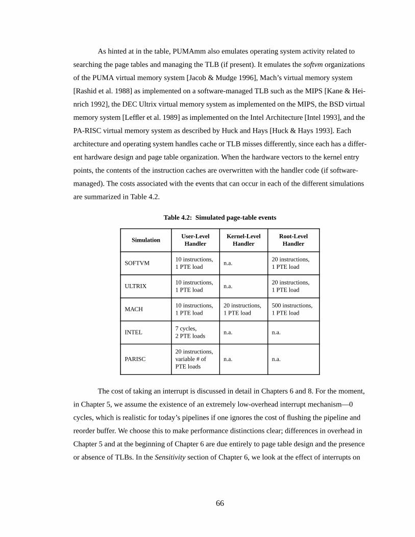
66
As hinted at in the table, PUMAmm also emulates operating system activity related to
searching the page tables and managing the TLB (if present). It emulates thesoftvm organizations
of the PUMA virtual memory system [Jacob & Mudge 1996], Mach’s virtual memory system
[Rashid et al. 1988] as implemented on a software-managed TLB such as the MIPS [Kane & Hei-
nrich 1992], the DEC Ultrix virtual memory system as implemented on the MIPS, the BSD virtual
memory system [Leffler et al. 1989] as implemented on the Intel Architecture [Intel 1993], and the
PA-RISC virtual memory system as described by Huck and Hays [Huck & Hays 1993]. Each
architecture and operating system handles cache or TLB misses differently, since each has a differ-
ent hardware design and page table organization. When the hardware vectors to the kernel entry
points, the contents of the instruction caches are overwritten with the handler code (if software-
managed). The costs associated with the events that can occur in each of the different simulations
are summarized in Table 4.2.
The cost of taking an interrupt is discussed in detail in Chapters 6 and 8. For the moment,
in Chapter 5, we assume the existence of an extremely low-overhead interrupt mechanism—0
cycles, which is realistic for today’s pipelines if one ignores the cost of flushing the pipeline and
reorder buffer. We choose this to make performance distinctions clear; differences in overhead in
Chapter 5 and at the beginning of Chapter 6 are due entirely to page table design and the presence
or absence of TLBs. In theSensitivity section of Chapter 6, we look at the effect of interrupts on
Table 4.2: Simulated page-table events
SimulationUser-LevelHandler
Kernel-LevelHandler
Root-LevelHandler
SOFTVM10 instructions,1 PTE load
n.a.20 instructions,1 PTE load
ULTRIX10 instructions,1 PTE load
n.a.20 instructions,1 PTE load
MACH10 instructions,1 PTE load
20 instructions,1 PTE load
500 instructions,1 PTE load
INTEL7 cycles,2 PTE loads
n.a. n.a.
PARISC20 instructions,variable # ofPTE loads
n.a. n.a.
67
the designs by adding 10-cycle, 50-cycle, and 200-cycle overheads for each interrupt, and in Chap-
ter 8 we discuss a method to decrease the interrupt overhead by 90%.
In order to place the different OS/architecture simulations on even footing, we assume that
in each system the cost of initializing the process address space will be the same. This cost
includes the demand-paging of data from disk and the initialization of the page tables; a realistic
measurement is likely to be extremely dependent on implementation, therefore this cost is not fac-
tored into the simulations or the measurements given. We assume that the memory system is large
enough to hold all the pages used by an application and all the pages required to hold the page
tables. All systems should see the same number of page initializations—corresponding to the first
time each page is touched. Including this cost, which would be the same for every simulation,
would only serve to blur distinctions. The simulations are intended to highlight only the differ-
ences between the page table organizations, the TLB implementations (hardware- or software-
managed), and the presence or absence of memory-management hardware.
The following sections discuss the details the various simulated hardware/software sys-
tems. The SOFTVM system and the ULTRIX system have very similar page table structures with
identical overheads. Any performance difference between the two simulations should be due to the
presence or absence of a TLB; SOFTVM uses software-managed address translation (detailed in
Chapter 5), ULTRIX uses a TLB. The MACH simulation is similar to the ULTRIX simulation
except that there is an additional level in the page table with a significantly higher overhead for
handling misses at that level. The INTEL simulation has a TLB but a hardware-walked page table.
Its page table design is similar to the ULTRIX simulation; however, the page table is walked in a
top-down fashion so every TLB miss will result in two additional memory references, whereas the
SOFTVM, MACH, and ULTRIX simulations will often satisfy the page-table lookup with a single
memory reference. The PARISC simulation is unique in its use of an inverted page table.
4.2.1 SOFTVM Virtual Memory
The SOFTVM page table is a two-tiered table similar to a MIPS page table, except that the
lower tier is a 2MB subset of a global table that is large enough to map the entire 44-bit segmented
virtual address space. Only 2MB of this global table is needed at any given time to map a 2GB
user-process address space, and this 2MB table can be mapped by a 2KB root table. Therefore a
memory reference will require at most two additional lookups to find the appropriate mapping
information. The page table is illustrated in Figure 4.1 and is described in more detail by Jacob and
Mudge [Jacob & Mudge 1996]; a very similar design is described in Chapter 5 of this dissertation.

68
The simulated hardware is a two-level virtual hierarchy that causes an interrupt when a virtual ref-
erence misses in the Level-2 cache.
The cache-miss handler is comprised of two code segments that are located in unmapped
space (executing them cannot cause cache-miss exceptions). The first is ten instructions long, the
second is twenty. The first code segment is called to handle normal user-level misses, the second
code segment handles the case when a page-table reference misses the virtual cache hierarchy. The
start of the handler code is page-aligned.
4.2.2 Ultrix/MIPS V irtual Memory
The Ultrix page table as implemented on the MIPS processor is a two-tiered table [Nagle
et al. 1993], illustrated in Figure 4.2. The 2GB user address space is mapped by a 2MB linear table
in virtual kernel space, which is in turn mapped by a 2KB array of PTEs. Therefore a memory ref-
erence will require at most two additional lookups to find the appropriate mapping information.
The cache hierarchy is identical to that of the SOFTVM system except that cache misses do not
interrupt the operating system. The TLB (256-entry, split into 128-entry fully-associative I-TLB
and 128-entry fully-associative D-TLB; each TLB has 16 protected lower slots to hold kernel-level
Figure 4.1: The SOFTVM page table organizationThe page table in the SOFTVM simulation resembles an Ultrix/MIPS page table, but since thearchitecture is segmented, the user address space and the user page table are not necessarilycontiguous in the global virtual address space. The user page table and the user address space are thusshown as sets of non-contiguous segments. The segments that make up user address spaces are in thebottom 99.9% of the global space; the smaller segments that make up user page tables are located inthe top 0.1% of the global virtual space. The user-page-table segments are numbered sequentially,matching the user-address-space segments, therefore indexing the user page table is as simple aswalking the MIPS user page table. The cost of the virtual memory organizations should be verysimilar.
2GB User Virtual Address Space
2MB User Page Table
Unmapped Physical Memory
Mapped Virtual Memory
2KB Root Page Table
16TB Global Virtual Address Space Segments that make upthe user page tables
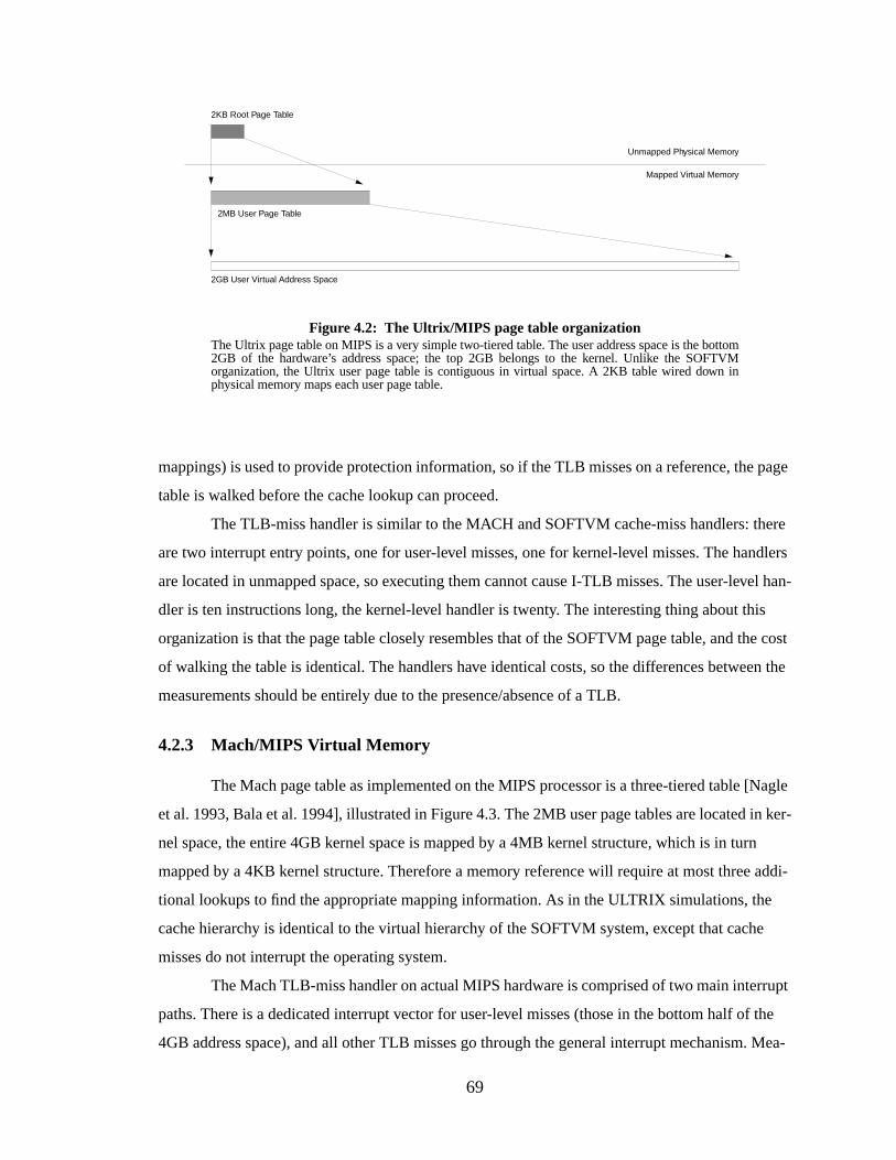
69
mappings) is used to provide protection information, so if the TLB misses on a reference, the page
table is walked before the cache lookup can proceed.
The TLB-miss handler is similar to the MACH and SOFTVM cache-miss handlers: there
are two interrupt entry points, one for user-level misses, one for kernel-level misses. The handlers
are located in unmapped space, so executing them cannot cause I-TLB misses. The user-level han-
dler is ten instructions long, the kernel-level handler is twenty. The interesting thing about this
organization is that the page table closely resembles that of the SOFTVM page table, and the cost
of walking the table is identical. The handlers have identical costs, so the differences between the
measurements should be entirely due to the presence/absence of a TLB.
4.2.3 Mach/MIPS Virtual Memory
The Mach page table as implemented on the MIPS processor is a three-tiered table [Nagle
et al. 1993, Bala et al. 1994], illustrated in Figure 4.3. The 2MB user page tables are located in ker-
nel space, the entire 4GB kernel space is mapped by a 4MB kernel structure, which is in turn
mapped by a 4KB kernel structure. Therefore a memory reference will require at most three addi-
tional lookups to find the appropriate mapping information. As in the ULTRIX simulations, the
cache hierarchy is identical to the virtual hierarchy of the SOFTVM system, except that cache
misses do not interrupt the operating system.
The Mach TLB-miss handler on actual MIPS hardware is comprised of two main interrupt
paths. There is a dedicated interrupt vector for user-level misses (those in the bottom half of the
4GB address space), and all other TLB misses go through the general interrupt mechanism. Mea-
Figure 4.2: The Ultrix/MIPS page table organizationThe Ultrix page table on MIPS is a very simple two-tiered table. The user address space is the bottom2GB of the hardware’s address space; the top 2GB belongs to the kernel. Unlike the SOFTVMorganization, the Ultrix user page table is contiguous in virtual space. A 2KB table wired down inphysical memory maps each user page table.
2GB User Virtual Address Space
2MB User Page Table
Unmapped Physical Memory
Mapped Virtual Memory
2KB Root Page Table
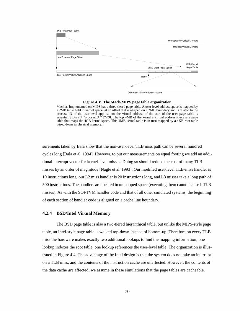
70
surements taken by Bala show that the non-user-level TLB miss path can be several hundred
cycles long [Bala et al. 1994]. However, to put our measurements on equal footing we add an addi-
tional interrupt vector for kernel-level misses. Doing so should reduce the cost of many TLB
misses by an order of magnitude [Nagle et al. 1993]. Our modified user-level TLB-miss handler is
10 instructions long, our L2 miss handler is 20 instructions long, and L3 misses take a long path of
500 instructions. The handlers are located in unmapped space (executing them cannot cause I-TLB
misses). As with the SOFTVM handler code and that of all other simulated systems, the beginning
of each section of handler code is aligned on a cache line boundary.
4.2.4 BSD/Intel Virtual Memory
The BSD page table is also a two-tiered hierarchical table, but unlike the MIPS-style page
table, an Intel-style page table is walked top-down instead of bottom-up. Therefore on every TLB
miss the hardware makes exactly two additional lookups to find the mapping information; one
lookup indexes the root table, one lookup references the user-level table. The organization is illus-
trated in Figure 4.4. The advantage of the Intel design is that the system does not take an interrupt
on a TLB miss, and the contents of the instruction cache are unaffected. However, the contents of
the data cacheare affected; we assume in these simulations that the page tables are cacheable.
Figure 4.3: The Mach/MIPS page table organizationMach as implemented on MIPS has a three-tiered page table. A user-level address space is mapped bya 2MB table held in kernel space, at an offset that is aligned on a 2MB boundary and is related to theprocess ID of the user-level application: the virtual address of the start of the user page table isessentiallyBase + (processID * 2MB). The top 4MB of the kernel’s virtual address space is a pagetable that maps the 4GB kernel space. This 4MB kernel table is in turn mapped by a 4KB root tablewired down in physical memory.
2GB User Virtual Address Space
4GB Kernel Virtual Address Space
2MB User Page Tables
4MB KernelPage Table
4MB Kernel Page Table
Unmapped Physical Memory
Mapped Virtual Memory
4KB Root Page Table
Base
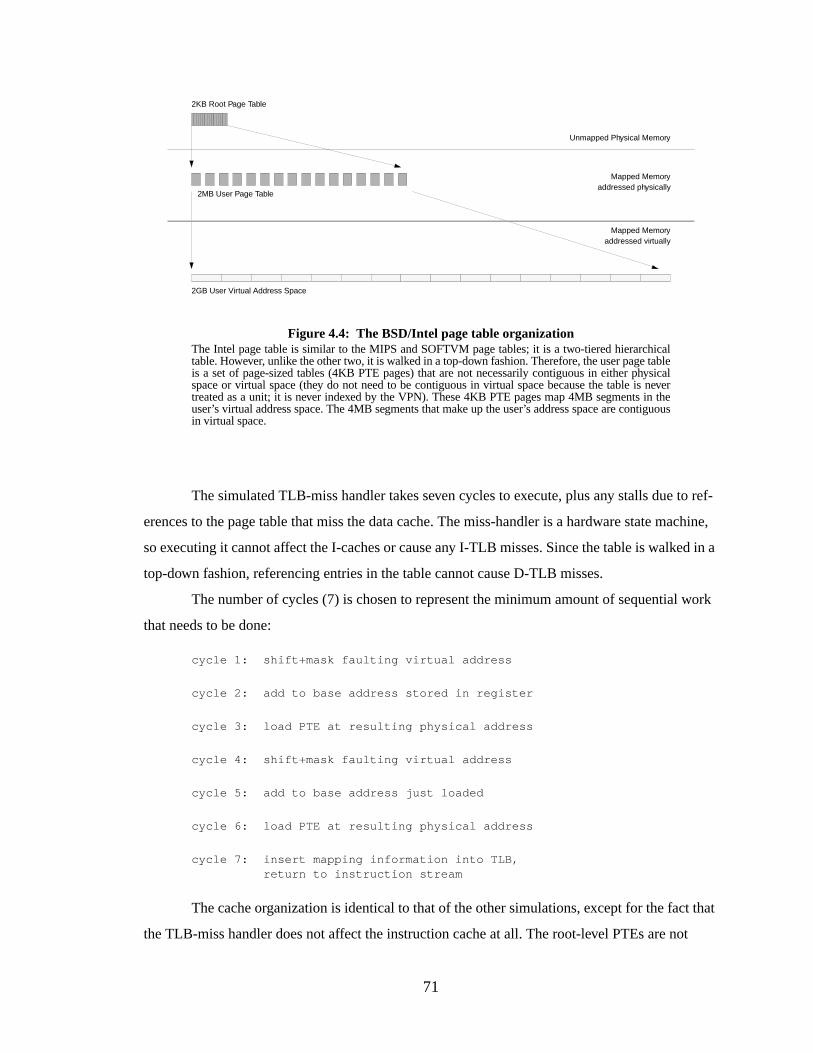
71
The simulated TLB-miss handler takes seven cycles to execute, plus any stalls due to ref-
erences to the page table that miss the data cache. The miss-handler is a hardware state machine,
so executing it cannot affect the I-caches or cause any I-TLB misses. Since the table is walked in a
top-down fashion, referencing entries in the table cannot cause D-TLB misses.
The number of cycles (7) is chosen to represent the minimum amount of sequential work
that needs to be done:
cycle 1: shift+mask faulting virtual address
cycle 2: add to base address stored in register
cycle 3: load PTE at resulting physical address
cycle 4: shift+mask faulting virtual address
cycle 5: add to base address just loaded
cycle 6: load PTE at resulting physical address
cycle 7: insert mapping information into TLB,return to instruction stream
The cache organization is identical to that of the other simulations, except for the fact that
the TLB-miss handler does not affect the instruction cache at all. The root-level PTEs are not
Figure 4.4: The BSD/Intel page table organizationThe Intel page table is similar to the MIPS and SOFTVM page tables; it is a two-tiered hierarchicaltable. However, unlike the other two, it is walked in a top-down fashion. Therefore, the user page tableis a set of page-sized tables (4KB PTE pages) that are not necessarily contiguous in either physicalspace or virtual space (they do not need to be contiguous in virtual space because the table is nevertreated as a unit; it is never indexed by the VPN). These 4KB PTE pages map 4MB segments in theuser’s virtual address space. The 4MB segments that make up the user’s address space are contiguousin virtual space.
2GB User Virtual Address Space
2MB User Page Table
Unmapped Physical Memory
Mapped Memoryaddressed physically
2KB Root Page Table
Mapped Memoryaddressed virtually
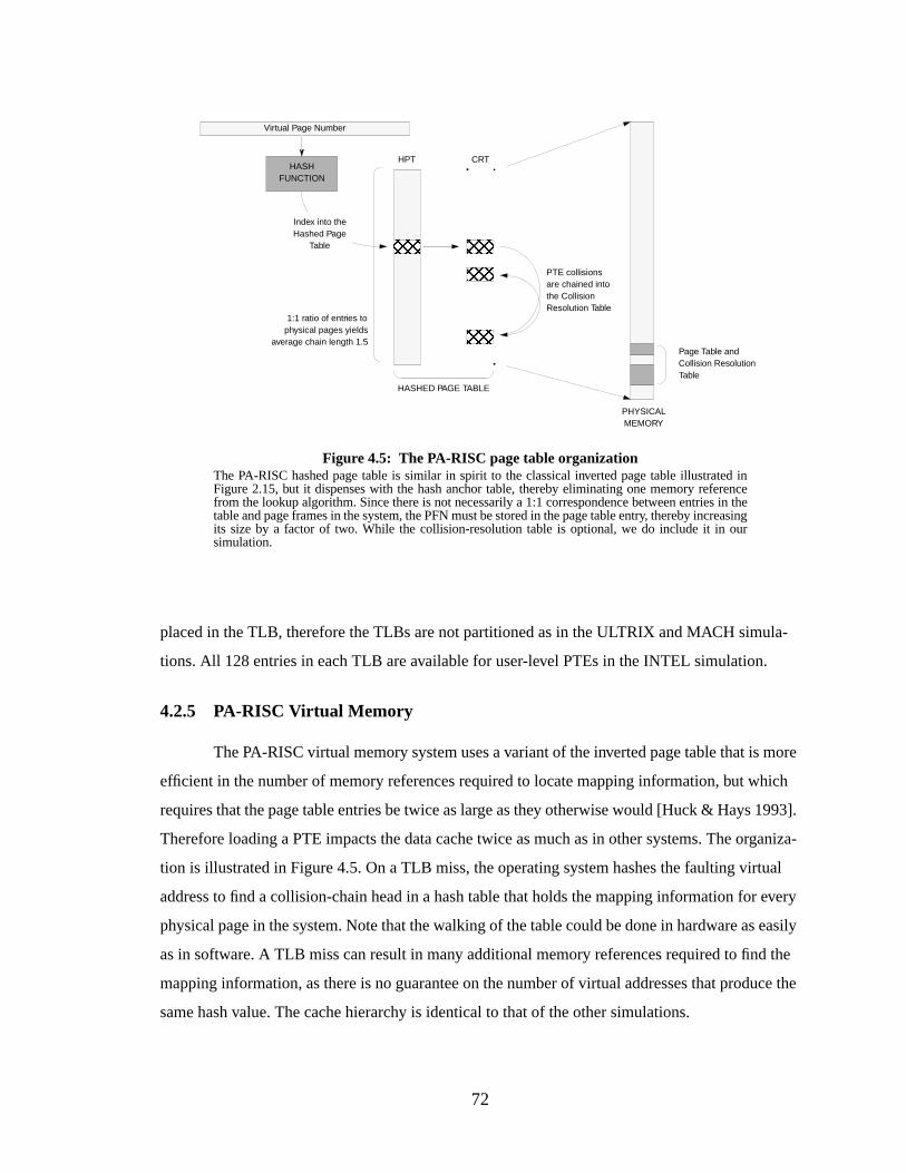
72
placed in the TLB, therefore the TLBs are not partitioned as in the ULTRIX and MACH simula-
tions. All 128 entries in each TLB are available for user-level PTEs in the INTEL simulation.
4.2.5 PA-RISC Virtual Memory
The PA-RISC virtual memory system uses a variant of the inverted page table that is more
efficient in the number of memory references required to locate mapping information, but which
requires that the page table entries be twice as large as they otherwise would [Huck & Hays 1993].
Therefore loading a PTE impacts the data cache twice as much as in other systems. The organiza-
tion is illustrated in Figure 4.5. On a TLB miss, the operating system hashes the faulting virtual
address to find a collision-chain head in a hash table that holds the mapping information for every
physical page in the system. Note that the walking of the table could be done in hardware as easily
as in software. A TLB miss can result in many additional memory references required to find the
mapping information, as there is no guarantee on the number of virtual addresses that produce the
same hash value. The cache hierarchy is identical to that of the other simulations.
Page Table andCollision ResolutionTable
HPT CRT
PTE collisionsare chained intothe CollisionResolution Table
HASHED PAGE TABLE
Index into theHashed Page
Table
HASHFUNCTION
Virtual Page Number
PHYSICALMEMORY
1:1 ratio of entries tophysical pages yields
average chain length 1.5
Figure 4.5: The PA-RISC page table organizationThe PA-RISC hashed page table is similar in spirit to the classical inverted page table illustrated inFigure 2.15, but it dispenses with the hash anchor table, thereby eliminating one memory referencefrom the lookup algorithm. Since there is not necessarily a 1:1 correspondence between entries in thetable and page frames in the system, the PFN must be stored in the page table entry, thereby increasingits size by a factor of two. While the collision-resolution table is optional, we do include it in oursimulation.
73
Simulating the PA-RISC is more difficult than simulating the other architectures; since the
page table is dependent on the size of physical memory, our simulation must make some choices
about the organization of physical memory. We define our simulated physical memory to be 8MB
in size, which is small for the average workstation but several times larger than the physical mem-
ory requirements of any one benchmark. Since we are simulating a single process at a time and not
a multiprogramming environment, this is equivalent to using a hash table that contains several
times the number of entries as physical pages and so it will result in a short average collision-chain
length. An 8MB physical memory has 2,048 pages; we choose a 2:1 ratio to get 4,096 entries in
the page table, which should result in an average collision-chain length of 1.25 entries [Knuth
1973]. GCC, for example, produced an average collision-chain length of a little over 1.3. We place
no restriction on the size of the collision resolution table. We do not attempt to emulate the operat-
ing system’s page placement policy, since the cache hierarchy is entirely virtually-addressed and
the placement of a PTE within the hashed page table is dependent on the virtual page number, not
the page frame number. We use the same hashing function as described by Huck & Hays [Huck &
Hays 1993]: “a single XOR of the upper virtual address bits and the lower virtual page number
bits.”
There is one TLB-miss handler entry point since the handler itself cannot cause a D-TLB
miss (as with the Intel page table, the handler uses physical but cacheable addresses to access the
page table). The handler is twenty instructions long, located in unmapped space, so executing it
cannot cause misses in the I-TLB. There is no distinction made between user-level PTEs and ker-
nel-level PTEs, therefore the simulated TLBs are like those in the INTEL simulations—all 128
entries in each of the TLBs are available for user-level PTEs.
4.3 Benchmark Measurements
We use the SPEC’95 integer benchmark suite for the measurements. The SPEC bench-
marks are chosen because of their widespread use for measuring architecture features. We chose
data sets for the worst-performing benchmarks (therefore the ones that we used most often: gcc,
vortex, perl and ijpeg) so that the programs would each run to completion in roughly 100 million
instructions; this makes the total running time feasible since the number of simulations is
extremely large. The four most-often benchmarks are shown in Table 4.3 with their descriptions
and input sets. Note that some of the input files have been modified slightly to get shorter running
times (by reducing the number of loops, etc.).
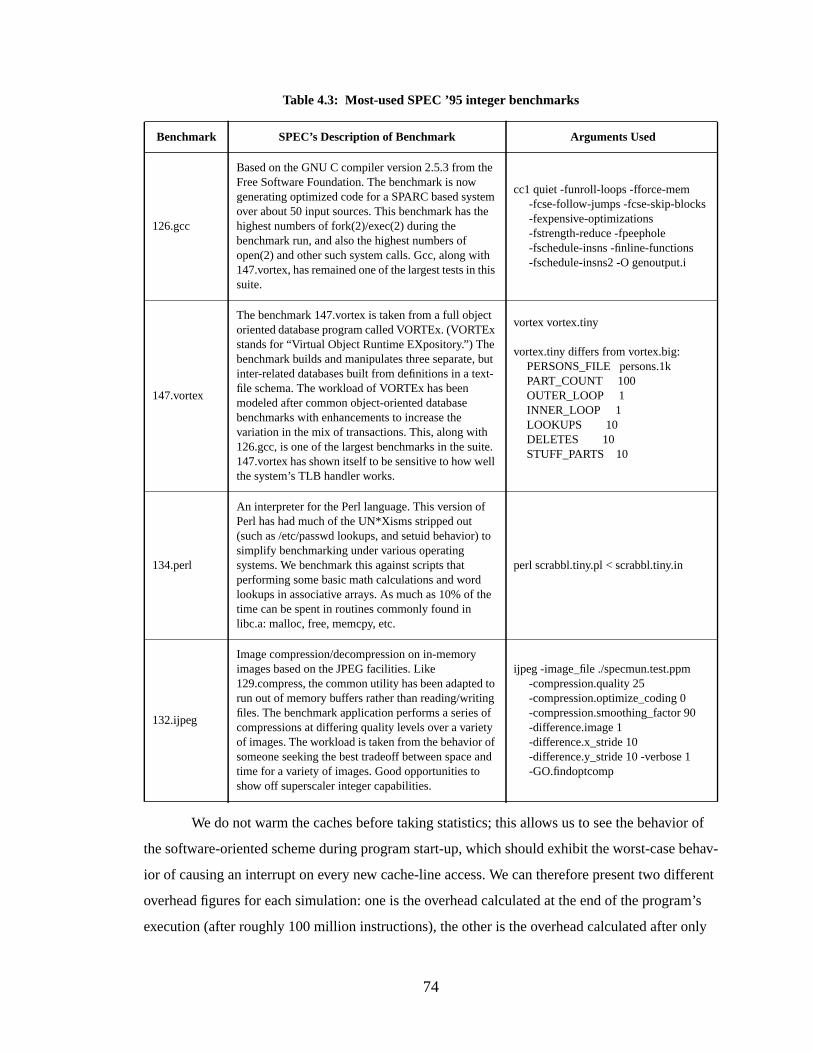
74
We do not warm the caches before taking statistics; this allows us to see the behavior of
the software-oriented scheme during program start-up, which should exhibit the worst-case behav-
ior of causing an interrupt on every new cache-line access. We can therefore present two different
overhead figures for each simulation: one is the overhead calculated at the end of the program’s
execution (after roughly 100 million instructions), the other is the overhead calculated after only
Table 4.3: Most-used SPEC ’95 integer benchmarks
Benchmark SPEC’s Description of Benchmark Arguments Used
126.gcc
Based on the GNU C compiler version 2.5.3 from theFree Software Foundation. The benchmark is nowgenerating optimized code for a SPARC based systemover about 50 input sources. This benchmark has thehighest numbers of fork(2)/exec(2) during thebenchmark run, and also the highest numbers ofopen(2) and other such system calls. Gcc, along with147.vortex, has remained one of the largest tests in thissuite.
cc1 quiet -funroll-loops -fforce-mem-fcse-follow-jumps -fcse-skip-blocks-fexpensive-optimizations-fstrength-reduce -fpeephole-fschedule-insns -finline-functions-fschedule-insns2 -O genoutput.i
147.vortex
The benchmark 147.vortex is taken from a full objectoriented database program called VORTEx. (VORTExstands for “Virtual Object Runtime EXpository.”) Thebenchmark builds and manipulates three separate, butinter-related databases built from definitions in a text-file schema. The workload of VORTEx has beenmodeled after common object-oriented databasebenchmarks with enhancements to increase thevariation in the mix of transactions. This, along with126.gcc, is one of the largest benchmarks in the suite.147.vortex has shown itself to be sensitive to how wellthe system’s TLB handler works.
vortex vortex.tiny
vortex.tiny differs from vortex.big:PERSONS_FILE persons.1kPART_COUNT 100OUTER_LOOP 1INNER_LOOP 1LOOKUPS 10DELETES 10STUFF_PARTS 10
134.perl
An interpreter for the Perl language. This version ofPerl has had much of the UN*Xisms stripped out(such as /etc/passwd lookups, and setuid behavior) tosimplify benchmarking under various operatingsystems. We benchmark this against scripts thatperforming some basic math calculations and wordlookups in associative arrays. As much as 10% of thetime can be spent in routines commonly found inlibc.a: malloc, free, memcpy, etc.
perl scrabbl.tiny.pl < scrabbl.tiny.in
132.ijpeg
Image compression/decompression on in-memoryimages based on the JPEG facilities. Like129.compress, the common utility has been adapted torun out of memory buffers rather than reading/writingfiles. The benchmark application performs a series ofcompressions at differing quality levels over a varietyof images. The workload is taken from the behavior ofsomeone seeking the best tradeoff between space andtime for a variety of images. Good opportunities toshow off superscaler integer capabilities.
ijpeg -image_file ./specmun.test.ppm-compression.quality 25-compression.optimize_coding 0-compression.smoothing_factor 90-difference.image 1-difference.x_stride 10-difference.y_stride 10 -verbose 1-GO.findoptcomp
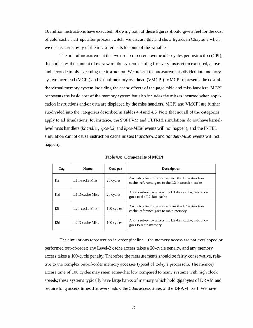
75
10 million instructions have executed. Showing both of these figures should give a feel for the cost
of cold-cache start-ups after process switch; we discuss this and show figures in Chapter 6 when
we discuss sensitivity of the measurements to some of the variables.
The unit of measurement that we use to represent overhead is cycles per instruction (CPI);
this indicates the amount of extra work the system is doing for every instruction executed, above
and beyond simply executing the instruction. We present the measurements divided into memory-
system overhead (MCPI) and virtual-memory overhead (VMCPI). VMCPI represents the cost of
the virtual memory system including the cache effects of the page table and miss handlers. MCPI
represents the basic cost of the memory system but also includes the misses incurred when appli-
cation instructions and/or data are displaced by the miss handlers. MCPI and VMCPI are further
subdivided into the categories described in Tables 4.4 and 4.5. Note that not all of the categories
apply to all simulations; for instance, the SOFTVM and ULTRIX simulations do not have kernel-
level miss handlers (khandler, kpte-L2, andkpte-MEM events will not happen), and the INTEL
simulation cannot cause instruction cache misses (handler-L2 andhandler-MEM events will not
happen).
The simulations represent an in-order pipeline—the memory access are not overlapped or
performed out-of-order; any Level-2 cache access takes a 20-cycle penalty, and any memory
access takes a 100-cycle penalty. Therefore the measurements should be fairly conservative, rela-
tive to the complex out-of-order memory accesses typical of today’s processors. The memory
access time of 100 cycles may seem somewhat low compared to many systems with high clock
speeds; these systems typically have large banks of memory which hold gigabytes of DRAM and
require long access times that overshadow the 50ns access times of the DRAM itself. We have
Table 4.4: Components of MCPI
Tag Name Cost per Description
l1i L1 I-cache Miss 20 cyclesAn instruction reference misses the L1 instructioncache; reference goes to the L2 instruction cache
l1d L1 D-cache Miss 20 cyclesA data reference misses the L1 data cache; referencegoes to the L2 data cache
l2i L2 I-cache Miss 100 cyclesAn instruction reference misses the L2 instructioncache; reference goes to main memory
l2d L2 D-cache Miss 100 cyclesA data reference misses the L2 data cache; referencegoes to main memory
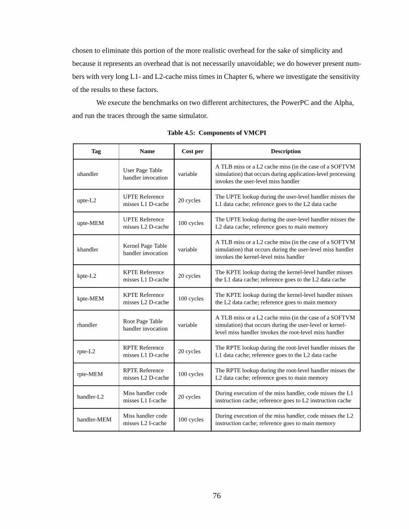
76
chosen to eliminate this portion of the more realistic overhead for the sake of simplicity and
because it represents an overhead that is not necessarily unavoidable; we do however present num-
bers with very long L1- and L2-cache miss times in Chapter 6, where we investigate the sensitivity
of the results to these factors.
We execute the benchmarks on two different architectures, the PowerPC and the Alpha,
and run the traces through the same simulator.
Table 4.5: Components of VMCPI
Tag Name Cost per Description
uhandlerUser Page Tablehandler invocation
variableA TLB miss or a L2 cache miss (in the case of a SOFTVMsimulation) that occurs during application-level processinginvokes the user-level miss handler
upte-L2UPTE Referencemisses L1 D-cache
20 cyclesThe UPTE lookup during the user-level handler misses theL1 data cache; reference goes to the L2 data cache
upte-MEMUPTE Referencemisses L2 D-cache
100 cyclesThe UPTE lookup during the user-level handler misses theL2 data cache; reference goes to main memory
khandlerKernel Page Tablehandler invocation
variableA TLB miss or a L2 cache miss (in the case of a SOFTVMsimulation) that occurs during the user-level miss handlerinvokes the kernel-level miss handler
kpte-L2KPTE Referencemisses L1 D-cache
20 cyclesThe KPTE lookup during the kernel-level handler missesthe L1 data cache; reference goes to the L2 data cache
kpte-MEMKPTE Referencemisses L2 D-cache
100 cyclesThe KPTE lookup during the kernel-level handler missesthe L2 data cache; reference goes to main memory
rhandlerRoot Page Tablehandler invocation
variableA TLB miss or a L2 cache miss (in the case of a SOFTVMsimulation) that occurs during the user-level or kernel-level miss handler invokes the root-level miss handler
rpte-L2RPTE Referencemisses L1 D-cache
20 cyclesThe RPTE lookup during the root-level handler misses theL1 data cache; reference goes to the L2 data cache
rpte-MEMRPTE Referencemisses L2 D-cache
100 cyclesThe RPTE lookup during the root-level handler misses theL2 data cache; reference goes to main memory
handler-L2Miss handler codemisses L1 I-cache
20 cyclesDuring execution of the miss handler, code misses the L1instruction cache; reference goes to L2 instruction cache
handler-MEMMiss handler codemisses L2 I-cache
100 cyclesDuring execution of the miss handler, code misses the L2instruction cache; reference goes to main memory
77
4.3.1 Setup on PowerPC
On PowerPC, we use AIX as an operating system andxtrace as an instrumentation tool
[Nair , Nair 1996]. Xtrace annotates the benchmark binary so that as the program runs, it delivers
to the operating system the addresses of the instructions and data that it touches. The benchmarks
were all compiled with GCC.
4.3.2 Setup on Alpha
On Alpha, we use OSF/1 as an operating system and ATOM as an instrumentation tool
[Eustace & Srivastava 1994, Srivastava & Eustace 1994]. Like xtrace, ATOM annotates the bina-
ries of benchmarks to produce a trace of application behavior, including the addresses of all
instructions and data it touches. The benchmarks were all compiled with Digital’s C compiler dis-
tributed with OSF/1; this native C compiler is recommended for use with ATOM over GCC by
ATOM documentation.
4.4 Conclusions
The performance figures in this thesis are generated by trace-driven simulation. The
benchmarks used to produce the traces are from the SPEC ’95 integer suite. The four worst-per-
forming benchmarks are used as examples almost exclusively. These are GCC, IJPEG, PERL, and
VORTEX. We generate traces on both Alpha and PowerPC platforms; ATOM is used on Alpha,
xtrace is used on PowerPC. We run the traces through a simulation of five different combinations
of operating systems and architectures. The memory-management organizations simulated are the
SOFTVM system, Ultrix as ported to MIPS, Mach as ported to MIPS, a BSD-like page table on
the Intel Architecture, and the HP-UX hashed page table on PA-RISC. The simulator emulates the
page table, the TLB, the TLB-miss handler (whether implemented in hardware or software), and a
virtual cache hierarchy. It does not simulate disk activity; measurements of memory management
functions in real systems will certainly be higher than those presented here.
78
CHAPTER 5
SOFTWARE-MANAGED ADDRESS TRANSLATION
In this chapter we describe software-managed address translation, the central mechanism
in a software-oriented memory-management design. We show that software-managed address
translation can be just as efficient as hardware-managed address translation, and it is much more
flexible. Previous studies have shown that operating systems such as OSF/1 and Mach charge
between 0.10 and 0.28 cycles per instruction (CPI) for address translation using dedicated mem-
ory-management hardware. Our initial simulations suggest that software-managed translation
requires 0.05 CPI. The advantage of software translation is that mechanisms to support such fea-
tures as shared memory, superpages, sub-page protection, and sparse address spaces can be defined
completely in software, allowing much more flexibility than in hardware-defined mechanisms.
5.1 Intr oduction
In many commercial architectures the hardware support for memory management is
unnecessarily complicated, places constraints on the operating system, and often frustrates porting
efforts [Liedtke 1995b]. For example, the IntelPentium Processor User’s Manual devotes 100 of
its 700+ pages to memory-management structures [Intel 1993], most of which exist for backward
compatibility and are unused by today’s system software. Typical virtual memory systems exact a
run-time overhead of 5-10% [Bala et al. 1994, Chen et al. 1992, Nagle et al. 1993, Talluri & Hill
1994], an apparently acceptable cost that has changed little in ten years [Clark & Emer 1985],
despite significant changes in cache sizes and organizations. However, several recent studies have
found that the handling overhead of memory management hardware can get as high as 50% of
application execution time [Anderson et al. 1991, Huck & Hays 1993, Rosenblum et al. 1995].
Taken together these trends beg the question,is dedicated memory-management hardware buying
us anything—do its benefits outweigh its overhead?
79
In this chapter we demonstrate a memory management design that stays within an accept-
able performance overhead and that does not require complex hardware. It places few constraints
on the operating system but still provides all the features of systems with more hardware support.
The design issoftware-managed address translation, orsoftvm for short. It dispenses with hard-
ware such as the translation lookaside buffers found in every modern microarchitecture and the
page-table-walking state machines found in x86 and PowerPC architectures. It uses a software-
handled cache miss, as in the VMP multiprocessor [Cheriton et al. 1989, Cheriton et al. 1988,
Cheriton et al. 1986], except that VMP used the mechanism to explore cache coherence in a multi-
processor, while we use it to simplify memory management hardware in a uniprocessor. It also
resembles the in-cache address translation mechanism of SPUR [Hill et al. 1986, Ritchie 1985,
Wood et al. 1986] in its lack of TLBs, but takes the design one step further by eliminating table-
walking hardware.
Software-managed address translation supports common operating systems features such
as address space protection, fine-grained protection, sparse address spaces, and superpages. Com-
pared to more orthodox designs, it reduces hardware complexity without requiring unduly com-
plex software. Its primary component is a virtually indexed, virtually tagged cache hierarchy with
a software-managed cache miss at the lowest level (L2, for example). Virtual caches do not require
address translation when requested data is found in the cache and so obviate the need for a TLB. A
miss in the L2 cache invokes the operating system’s memory manager, allowing the operating sys-
tem to implement any type of page table, protection scheme, or replacement policy, as well as a
software-defined page size. The migration of address-translation support from hardware to soft-
ware increases flexibility significantly.
We show the efficiency of software-managed address translation by analyzing a specific
implementation, thereby finding an upper bound on overhead. The example adds software-man-
aged translation to a conventional PowerPC memory management organization. It forms the basis
of the memory management design of the PUMA processor.
The example implementation combines PowerPC segments [May et al. 1994] with the
softvm design; these support address space protection, shared memory, and provide access to a
large virtual address space. They are not an essential component of software-managed address
translation—for example, they could be replaced by long address space identifiers or a 64-bit
address space. However, the use of segments in conjunction with a virtual cache organization can
solve the consistency problems associated with virtual caches, as will be shown in Chapter 7.
80
5.2 Background and Previous Work
5.2.1 Problems with Virtual Caches
Virtual caches complicate support for virtual-address aliasing and protection-bit modifica-
tion. Aliasing can give rise to thesynonym problem when memory is shared by different processes
and/or at different virtual addresses [Goodman 1987], and this has been shown to cause significant
overhead [Wheeler & Bershad 1992]; protection-bit modification is used to implement such fea-
tures as copy-on-write [Anderson et al. 1991, Rashid et al. 1988], and can also cause significant
overhead when used frequently.
The synonym problem has been solved in hardware using schemes such as dual tag sets
[Goodman 1987] or back-pointers [Wang et al. 1989], but these require complex control logic that
can impede high clock rates. Synonyms can be avoided by setting policy in the operating system—
for example, OS/2 requires all shared segments to be located at identical virtual addresses in all
processes so that processes use the same address for the same data [Deitel 1990]. SunOS requires
shared pages to be aligned in virtual space on extremely large boundaries (at least the size of the
largest cache) so that aliases will map to the same cache line [Cheng 1987, Hennessy & Patterson
1990]2. Single address space operating systems such as Opal [Chase et al. 1992a, Chase et al.
1992b] or Psyche [Scott et al. 1988] solve the problem by eliminating the need for virtual-address
aliasing entirely. In a single address space all shared data is referenced through global addresses;
as in OS/2, this allows pointers to be shared freely across process boundaries.
The synonym problem and its solutions are described in more detail in Chapter 7.
Protection-bit modification in virtual caches can also be problematic. A virtual cache
allows one to “lazily” access the TLB only on a cache miss; if so, protection bits must be stored
with each cache line or in an associated page-protection structure accessed every cycle, or else
protection is ignored. When one replicates protection bits for a page across several cache lines,
changing the page’s protection can be costly. Obvious but expensive solutions include flushing the
entire cache or sweeping through the entire cache and modifying the affected lines.
2. Note that the SunOS scheme only solves the problem for direct-mapped virtual caches or set-associativevirtual caches with physical tags; shared data can still exist in two different blocks of the same set in anassociative, virtually-indexed, virtually-tagged cache.
81
5.2.2 Segmented Translation
The IBM 801 introduced a segmented design that persisted through the POWER and Pow-
erPC architectures [Chang & Mergen 1988, IBM & Motorola 1993, May et al. 1994, Weiss &
Smith 1994]; see Figure 3.4. Applications generate 32-bit “effective” addresses that are mapped
onto a larger “virtual” address space at the granularity ofsegments, 256MB virtual regions. Six-
teen segments comprise an application’s address space. The top four bits of the effective address
select a segment identifier from a set of 16 registers. This segment ID is concatenated with the bot-
tom 28 bits of the effective address to form an extended virtual address. This extended address is
used in the TLB and page table. The operating system performs data movement and relocation at
the granularity of pages, not segments.
The architecture does not use explicit address space identifiers; the segment registers
ensure address space protection. If two processes duplicate an identifier in their segment registers
they share that virtual segment by definition; similarly, protection is guaranteed if identifiers are
not duplicated. If memory is shared through global addresses, no aliasing (and therefore no virtual-
cache synonyms) can occur and the TLB and cache need not be flushed on context switch3. This
solution to the virtual cache synonym problem is similar to that of single address space operating
systems—global addresses cause no synonym problems.
5.2.3 MIPS: A Simple 32-bit Page Table Design
MIPS [Heinrich 1995, Kane & Heinrich 1992] eliminated the page-table-walking hard-
ware found in traditional memory management units, and in doing so demonstrated that software
can table-walk with reasonable efficiency. It also presented a simple hierarchical page table design,
shown in Figure 5.1. On a TLB miss, the hardware creates a virtual address for the mapping PTE
in the user page table. The virtual page number (VPN) of the address that missed the TLB is used
as an index into the user page table, which must be aligned on a 2MB virtual boundary. The base
pointer, calledPTEBase, is stored in a hardware register and is usually changed on context switch.
This is illustrated as part of Figure 5.2. The advantage of this page table organization is that a
small amount of wired-down memory (2KB) can map an entire user address space efficiently; in
3. Flushing is avoided until the system runs out of identifiers and must reuse them. For example, theaddress space identifiers on the MIPS R3000 and Alpha 21064 are six bits wide, with a maximum of 64active processes [Digital 1994, Kane & Heinrich 1992]. If more processes are desired, identifiers mustbe constantly reassigned, requiring TLB & virtual-cache flushes.
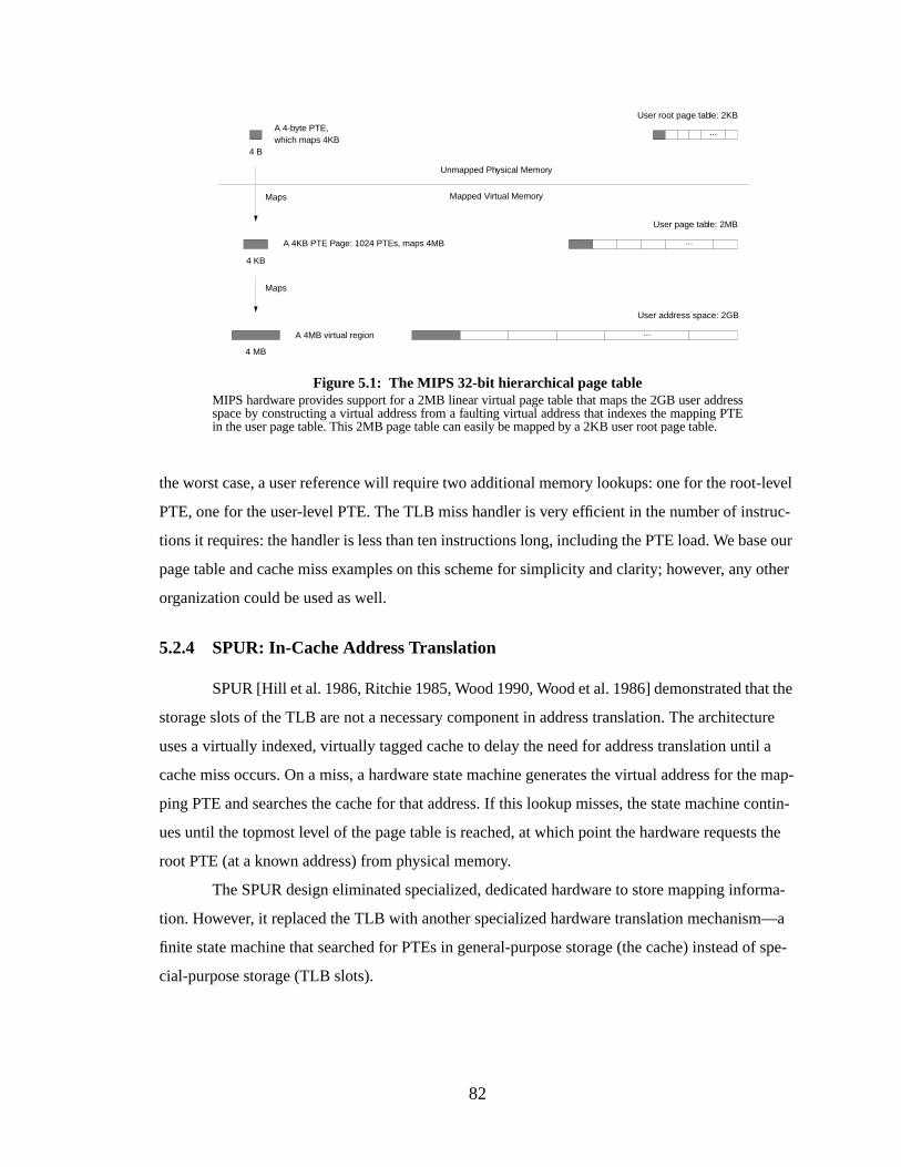
82
the worst case, a user reference will require two additional memory lookups: one for the root-level
PTE, one for the user-level PTE. The TLB miss handler is very efficient in the number of instruc-
tions it requires: the handler is less than ten instructions long, including the PTE load. We base our
page table and cache miss examples on this scheme for simplicity and clarity; however, any other
organization could be used as well.
5.2.4 SPUR: In-Cache Address Translation
SPUR [Hill et al. 1986, Ritchie 1985, Wood 1990, Wood et al. 1986] demonstrated that the
storage slots of the TLB are not a necessary component in address translation. The architecture
uses a virtually indexed, virtually tagged cache to delay the need for address translation until a
cache miss occurs. On a miss, a hardware state machine generates the virtual address for the map-
ping PTE and searches the cache for that address. If this lookup misses, the state machine contin-
ues until the topmost level of the page table is reached, at which point the hardware requests the
root PTE (at a known address) from physical memory.
The SPUR design eliminated specialized, dedicated hardware to store mapping informa-
tion. However, it replaced the TLB with another specialized hardware translation mechanism—a
finite state machine that searched for PTEs in general-purpose storage (the cache) instead of spe-
cial-purpose storage (TLB slots).
...
...
...
User page table: 2MB
User address space: 2GB
User root page table: 2KB
Figure 5.1: The MIPS 32-bit hierarchical page tableMIPS hardware provides support for a 2MB linear virtual page table that maps the 2GB user addressspace by constructing a virtual address from a faulting virtual address that indexes the mapping PTEin the user page table. This 2MB page table can easily be mapped by a 2KB user root page table.
A 4-byte PTE,which maps 4KB
A 4KB PTE Page: 1024 PTEs, maps 4MB
4 B
4 KB
A 4MB virtual region
4 MB
Maps
Maps
Unmapped Physical Memory
Mapped Virtual Memory
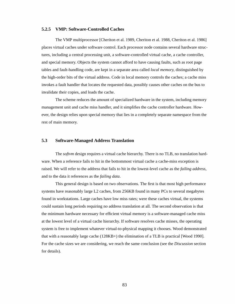
83
5.2.5 VMP: Software-Controlled Caches
The VMP multiprocessor [Cheriton et al. 1989, Cheriton et al. 1988, Cheriton et al. 1986]
places virtual caches under software control. Each processor node contains several hardware struc-
tures, including a central processing unit, a software-controlled virtual cache, a cache controller,
and special memory. Objects the system cannot afford to have causing faults, such as root page
tables and fault-handling code, are kept in a separate area calledlocal memory, distinguished by
the high-order bits of the virtual address. Code in local memory controls the caches; a cache miss
invokes a fault handler that locates the requested data, possibly causes other caches on the bus to
invalidate their copies, and loads the cache.
The scheme reduces the amount of specialized hardware in the system, including memory
management unit and cache miss handler, and it simplifies the cache controller hardware. How-
ever, the design relies upon special memory that lies in a completely separate namespace from the
rest of main memory.
5.3 Software-Managed Address Translation
Thesoftvm design requires a virtual cache hierarchy. There is no TLB, no translation hard-
ware. When a reference fails to hit in the bottommost virtual cache a cache-miss exception is
raised. We will refer to the address that fails to hit in the lowest-level cache as thefailing address,
and to the data it references as thefailing data.
This general design is based on two observations. The first is that most high performance
systems have reasonably large L2 caches, from 256KB found in many PCs to several megabytes
found in workstations. Large caches have low miss rates; were these caches virtual, the systems
could sustain long periods requiring no address translation at all. The second observation is that
the minimum hardware necessary for efficient virtual memory is a software-managed cache miss
at the lowest level of a virtual cache hierarchy. If software resolves cache misses, the operating
system is free to implement whatever virtual-to-physical mapping it chooses. Wood demonstrated
that with a reasonably large cache (128KB+) the elimination of a TLB is practical [Wood 1990].
For the cache sizes we are considering, we reach the same conclusion (see theDiscussion section
for details).
84
5.3.1 Handling the Cache-Miss Exception
On a cache-miss exception, the miss handler loads the data at the failing address on behalf
of another thread. The operating system must therefore be able to load a datum using one address
and place it in the cache tagged with a different address. It must also be able to reference memory
virtually or physically, cached or uncached. For instance, to avoid causing a cache-miss exception,
the cache-miss handler must execute using physical addresses. For good performance these should
be cacheable, provided that a cacheable-physical address that misses the cache causes no excep-
tion, and that a portion of the virtual space can be directly mapped onto physical memory.
When a virtual address misses the cache, the failing data, once loaded, must be placed in
the cache at an index derived from the failing address and tagged with the failing address’s virtual
tag, otherwise the original thread will not be able to reference its own data. We define a two-part
load, in which the operating system first specifies a virtual tag and set of protection bits to apply to
the incoming data, then loads the data with a physical address. The incoming data is inserted into
the caches with the specified tag and protection information. This scheme requires two privileged
instructions to be added to the instruction set architecture (ISA)4: SPECIFYVTAG and
LOAD&M AP, depicted in Figure 5.2.
SPECIFYVTAG instructs the cache to insert future incoming data at a specific offset in the
cache, tagged with a specific label. Its operand has two parts: the virtual tag (VTAG) comes from
the failing virtual address; the protection bits come from the mapping PTE. The bottom half of the
VTAG identifies a block within the cache, the top half is the tag. Note that the VTAG is larger than
the virtual page number; the hardware should not assumeany overlap between virtual and physical
addresses beyond the cache line offset. This is essential to allow a software-defined page size.
The operand of aLOAD&M AP is a physical or virtual address. The datum identified by the
operand is loaded from the cache or memory and then (re-) inserted into the cache at the cache
block determined by the previously executedSPECIFYVTAG, and tagged with the specified virtual
tag. Thus an operating system can translate data that misses the cache, load it from memory (or
even another location in the cache), and place it in any cache block, tagged with any value. When
the original thread is restarted, its data is in the cache at the correct line, with the correct tag. Note
the operations can be performed out of order for performance reasons, as long as the tag arrives at
4. Many ISAs leave room for such management instructions, e.g. the PowerPC ISAmtspr andmfsprinstructions (move to/from special purpose register) would allow implementations of both functions.
85
the cache/s before the data arrives. Note also that without hardware support, the two-part load must
not be interrupted by another two-part load.
5.3.2 An Example of softvm and Its Use
A PowerPC implementation is shown in Figure 5.3, with a two-level cache hierarchy. Both
caches in the hierarchy are virtual and split, to make the cost analysis clearer. Modification and
protection bits are kept with each cache line, which should give a conservative cost estimate. In the
cost analysis we vary the L1 cache from 2KB to 256KB (1K to 128K per side), and the L2 cache
between 1MB and 2MB.
We assume for the sake of argument a 4GB maximum physical memory. To parallel the
MIPS design, the top bits of the virtual address space (in this case, 20 of 52 bits) determine
whether an address is physical and/or cacheable; this is to allow physical addresses to be cached in
the virtually indexed, virtually tagged caches. Also like MIPS, a user process owns the bottom
2GB of the 4GB effective address space. Therefore only the bottom 8 of the 16 segment registers
are used by applications; the user address space is composed of 8 256MB virtual segments.
To demonstrate the use ofsoftvm, we need also define a page table and cache-miss han-
dler. We would like something similar to the MIPS page table organization, as it maps a 32-bit
address space with a minimum of levels and supports sparse address spaces easily. A global virtual
address space, however, suggests the use of a global page table, whichcannot be mapped by a
Line Off.Failing Virtual Address Virtual Tag
Prot. BitsSPECIFYVTAG operand Virtual Tag
Page OffsetFailing Virtual Address Virtual Page Number
0Virtual Page NumberPTEBase
Virtual address for PTE
LOAD
Page Frame Number
Page OffsetLOAD&MAP operand Page Frame Number
Page Table Entry
Figure 5.2: SPECIFYVTAG and LOAD&M APThe top figure illustratesSPECIFYVTAG, the bottom figure illustratesLOAD&M AP. TheLOAD&M APexample assumes a MIPS-like page table.
Prot. Bits
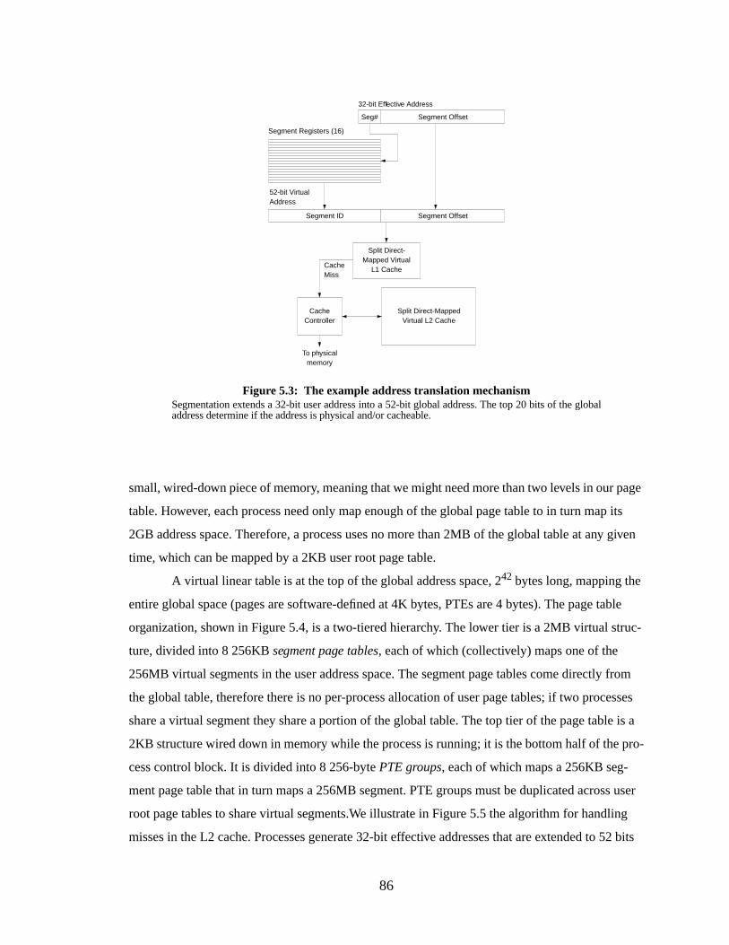
86
small, wired-down piece of memory, meaning that we might need more than two levels in our page
table. However, each process need only map enough of the global page table to in turn map its
2GB address space. Therefore, a process uses no more than 2MB of the global table at any given
time, which can be mapped by a 2KB user root page table.
A virtual linear table is at the top of the global address space, 242 bytes long, mapping the
entire global space (pages are software-defined at 4K bytes, PTEs are 4 bytes). The page table
organization, shown in Figure 5.4, is a two-tiered hierarchy. The lower tier is a 2MB virtual struc-
ture, divided into 8 256KBsegment page tables, each of which (collectively) maps one of the
256MB virtual segments in the user address space. The segment page tables come directly from
the global table, therefore there is no per-process allocation of user page tables; if two processes
share a virtual segment they share a portion of the global table. The top tier of the page table is a
2KB structure wired down in memory while the process is running; it is the bottom half of the pro-
cess control block. It is divided into 8 256-bytePTE groups, each of which maps a 256KB seg-
ment page table that in turn maps a 256MB segment. PTE groups must be duplicated across user
root page tables to share virtual segments.We illustrate in Figure 5.5 the algorithm for handling
misses in the L2 cache. Processes generate 32-bit effective addresses that are extended to 52 bits
Figure 5.3: The example address translation mechanismSegmentation extends a 32-bit user address into a 52-bit global address. The top 20 bits of the globaladdress determine if the address is physical and/or cacheable.
CacheController
Split Direct-MappedVirtual L2 Cache
Split Direct-Mapped Virtual
L1 CacheCacheMiss
To physicalmemory
Segment Registers (16)
Segment Offset
32-bit Effective Address
Seg#
Segment OffsetSegment ID
52-bit VirtualAddress
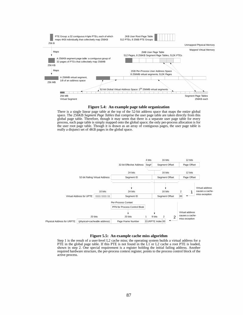
87
Figure 5.4: An example page table organizationThere is a single linear page table at the top of the 52-bit address space that maps the entire globalspace. The 256KBSegment Page Tablesthat comprise the user page table are taken directly from thisglobal page table. Therefore, though it may seem that there is a separate user page table for everyprocess, each page table is simply mapped onto the global space; the only per-process allocation is forthe user root page table. Though it is drawn as an array of contiguous pages, the user page table isreally a disjunct set of 4KB pages in the global space.
2KB User Root Page Table512 PTEs, 8 256B PTE Groups
2MB User Page Table512 Pages, 8 256KB Segment Page Tables, 512K PTEs
2GB Per-Process User Address Space8 256MB virtual segments, 512K Pages
Unmapped Physical Memory
Mapped Virtual Memory
PTE Group: a 32 contiguous 4-byte PTEs, each of whichmaps 4KB individually, that collectively map 256KB
A 256KB segment page table: a contiguous group of32 pages of PTEs that collectively map 256MB
256 B
256 KB
52-bit Global Virtual Address Space: 224 256MB virtual segments
256 MBVirtual Segment
A 256MB virtual segment,1/8 of an address space
Segment Page Tables256KB each
256 MB
Maps
Maps
Segment Offset Page OffsetSeg#
Segment Offset Page OffsetSegment ID
Segment Offset 00Segment ID1111 1111 11
URPTE Index 00
PFN for Process Control Block
Page Frame Number
16 bits 12 bits4 bits
16 bits 12 bits24 bits
16 bits 224 bits10 bits
9 bits 220 bits
Per-Process Context
52-bit Failing Virtual Address
32-bit Effective Address
1
2Physical Address for URPTE
Virtual Address for UPTE
0
1
Figure 5.5: An example cache miss algorithmStep 1 is the result of a user-level L2 cache miss; the operating system builds a virtual address for aPTE in the global page table. If this PTE is not found in the L1 or L2 cache a root PTE is loaded,shown in step 2. One special requirement is a register holding the initial failing address. Anotherrequired hardware structure, the per-process context register, points to the process control block of theactive process.
Virtual addresscauses a cache-miss exception
Virtual addresscauses a cache-miss exception
(physical+cacheable address)
20 bits
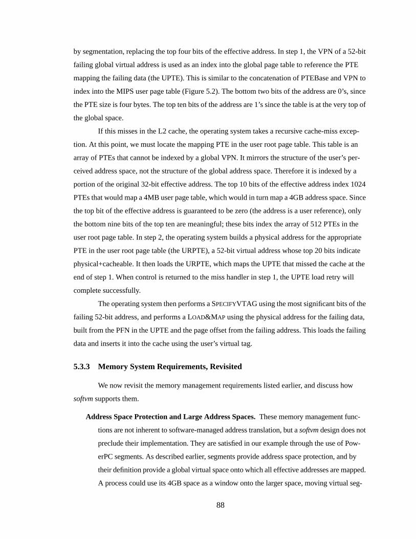
88
by segmentation, replacing the top four bits of the effective address. In step 1, the VPN of a 52-bit
failing global virtual address is used as an index into the global page table to reference the PTE
mapping the failing data (the UPTE). This is similar to the concatenation of PTEBase and VPN to
index into the MIPS user page table (Figure 5.2). The bottom two bits of the address are 0’s, since
the PTE size is four bytes. The top ten bits of the address are 1’s since the table is at the very top of
the global space.
If this misses in the L2 cache, the operating system takes a recursive cache-miss excep-
tion. At this point, we must locate the mapping PTE in the user root page table. This table is an
array of PTEs that cannot be indexed by a global VPN. It mirrors the structure of the user’s per-
ceived address space, not the structure of the global address space. Therefore it is indexed by a
portion of the original 32-bit effective address. The top 10 bits of the effective address index 1024
PTEs that would map a 4MB user page table, which would in turn map a 4GB address space. Since
the top bit of the effective address is guaranteed to be zero (the address is a user reference), only
the bottom nine bits of the top ten are meaningful; these bits index the array of 512 PTEs in the
user root page table. In step 2, the operating system builds a physical address for the appropriate
PTE in the user root page table (the URPTE), a 52-bit virtual address whose top 20 bits indicate
physical+cacheable. It then loads the URPTE, which maps the UPTE that missed the cache at the
end of step 1. When control is returned to the miss handler in step 1, the UPTE load retry will
complete successfully.
The operating system then performs aSPECIFYVTAG using the most significant bits of the
failing 52-bit address, and performs aLOAD&M AP using the physical address for the failing data,
built from the PFN in the UPTE and the page offset from the failing address. This loads the failing
data and inserts it into the cache using the user’s virtual tag.
5.3.3 Memory System Requirements, Revisited
We now revisit the memory management requirements listed earlier, and discuss how
softvm supports them.
Addr ess Space Protection and Large Address Spaces.These memory management func-
tions are not inherent to software-managed address translation, but asoftvm design does not
preclude their implementation. They are satisfied in our example through the use of Pow-
erPC segments. As described earlier, segments provide address space protection, and by
their definition provide a global virtual space onto which all effective addresses are mapped.
A process could use its 4GB space as a window onto the larger space, moving virtual seg-
89
ments in and out of its working set as necessary. This type of windowing mechanism is used
on the PA-RISC [Huck 1996].
Shared Memory. The sharing mechanism is defined by the page table. One can simplify vir-
tual cache management by sharing memory via global addresses, a scheme used in many
systems [Chase et al. 1992a, Chase et al. 1992b, Deitel 1990, Druschel & Peterson 1993,
Garrett et al. 1993, Garrett et al. 1992, Scott et al. 1988], and shown to have good perfor-
mance. Alternatively, one could share memory through virtual-address aliasing.
Fine-Grained Protection. One can maintain protection bits in the cache, or in an associated
structure like a TLB. If one could live with protection on a per-segment basis, one could
maintain protection bits in the segment registers. For our discussion we maintain protection
bits in the cache line. Protection granularity therefore becomes a software issue; the page
size can be anything from the entire address space down to a single cache line. Note the
choice of this granularity does not preclude one from implementing segment-level protec-
tion as well. The disadvantage is that if one chooses a page size larger than a single cache
line, protection information must be replicated across multiple cache lines and the operating
system must manage its consistency. We analyze this later.
Sparse Address Spaces.Sparse address space support is largely a page table issue. Hardware
can either get out of the way of the operating system and allow any type of page table orga-
nization, or it can inhibit support for sparse address spaces by defining a page table organi-
zation that is not necessarily suitable. By eliminating translation hardware, one frees the
operating system to choose the most appropriate structure.
Superpages.By removing the TLB one removes hardware support for superpages, but as with
sparse address spaces one also frees the operating system to provide support through the
page table. For instance, a top-down hierarchical page table (as in the x86 [Intel 1993])
would provide easy support for superpages. A guarded page table [Liedtke 1995a, Liedtke
& Elphinstone 1996] would also provide support, and would map a large address space
more efficiently, as would the inverted page table variant described by Talluri, et al. [Talluri
et al. 1995].
Dir ect Memory Access.While software-managed address translation provides no explicit
support for DMA, and actually makes DMA more difficult by requiring a virtual cache,
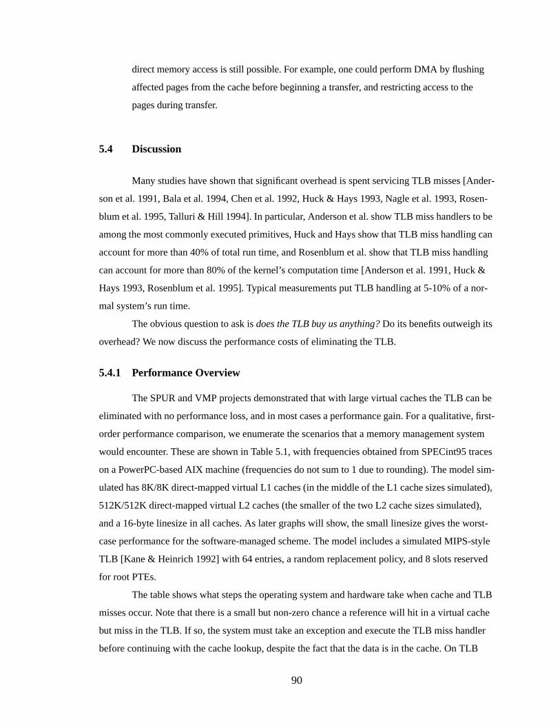
90
direct memory access is still possible. For example, one could perform DMA by flushing
affected pages from the cache before beginning a transfer, and restricting access to the
pages during transfer.
5.4 Discussion
Many studies have shown that significant overhead is spent servicing TLB misses [Ander-
son et al. 1991, Bala et al. 1994, Chen et al. 1992, Huck & Hays 1993, Nagle et al. 1993, Rosen-
blum et al. 1995, Talluri & Hill 1994]. In particular, Anderson et al. show TLB miss handlers to be
among the most commonly executed primitives, Huck and Hays show that TLB miss handling can
account for more than 40% of total run time, and Rosenblum et al. show that TLB miss handling
can account for more than 80% of the kernel’s computation time [Anderson et al. 1991, Huck &
Hays 1993, Rosenblum et al. 1995]. Typical measurements put TLB handling at 5-10% of a nor-
mal system’s run time.
The obvious question to ask isdoes the TLB buy us anything? Do its benefits outweigh its
overhead? We now discuss the performance costs of eliminating the TLB.
5.4.1 Performance Overview
The SPUR and VMP projects demonstrated that with large virtual caches the TLB can be
eliminated with no performance loss, and in most cases a performance gain. For a qualitative, first-
order performance comparison, we enumerate the scenarios that a memory management system
would encounter. These are shown in Table5.1, with frequencies obtained from SPECint95 traces
on a PowerPC-based AIX machine (frequencies do not sum to 1 due to rounding). The model sim-
ulated has 8K/8K direct-mapped virtual L1 caches (in the middle of the L1 cache sizes simulated),
512K/512K direct-mapped virtual L2 caches (the smaller of the two L2 cache sizes simulated),
and a 16-byte linesize in all caches. As later graphs will show, the small linesize gives the worst-
case performance for the software-managed scheme. The model includes a simulated MIPS-style
TLB [Kane & Heinrich 1992] with 64 entries, a random replacement policy, and 8 slots reserved
for root PTEs.
The table shows what steps the operating system and hardware take when cache and TLB
misses occur. Note that there is a small but non-zero chance a reference will hit in a virtual cache
but miss in the TLB. If so, the system must take an exception and execute the TLB miss handler
before continuing with the cache lookup, despite the fact that the data is in the cache. On TLB
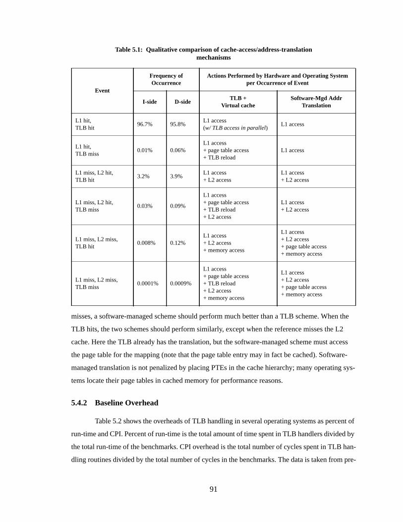
91
misses, a software-managed scheme should perform much better than a TLB scheme. When the
TLB hits, the two schemes should perform similarly, except when the reference misses the L2
cache. Here the TLB already has the translation, but the software-managed scheme must access
the page table for the mapping (note that the page table entry may in fact be cached). Software-
managed translation is not penalized by placing PTEs in the cache hierarchy; many operating sys-
tems locate their page tables in cached memory for performance reasons.
5.4.2 Baseline Overhead
Table 5.2 shows the overheads of TLB handling in several operating systems as percent of
run-time and CPI. Percent of run-time is the total amount of time spent in TLB handlers divided by
the total run-time of the benchmarks. CPI overhead is the total number of cycles spent in TLB han-
dling routines divided by the total number of cycles in the benchmarks. The data is taken from pre-
Table 5.1: Qualitati ve comparison of cache-access/address-translationmechanisms
Event
Frequency ofOccurrence
Actions Performed by Hardware and Operating Systemper Occurrence of Event
I-side D-sideTLB +
Virtual cacheSoftware-Mgd Addr
Translation
L1 hit,TLB hit
96.7% 95.8%L1 access(w/ TLB access in parallel)
L1 access
L1 hit,TLB miss
0.01% 0.06%L1 access+ page table access+ TLB reload
L1 access
L1 miss, L2 hit,TLB hit
3.2% 3.9%L1 access+ L2 access
L1 access+ L2 access
L1 miss, L2 hit,TLB miss
0.03% 0.09%
L1 access+ page table access+ TLB reload+ L2 access
L1 access+ L2 access
L1 miss, L2 miss,TLB hit
0.008% 0.12%L1 access+ L2 access+ memory access
L1 access+ L2 access+ page table access+ memory access
L1 miss, L2 miss,TLB miss
0.0001% 0.0009%
L1 access+ page table access+ TLB reload+ L2 access+ memory access
L1 access+ L2 access+ page table access+ memory access
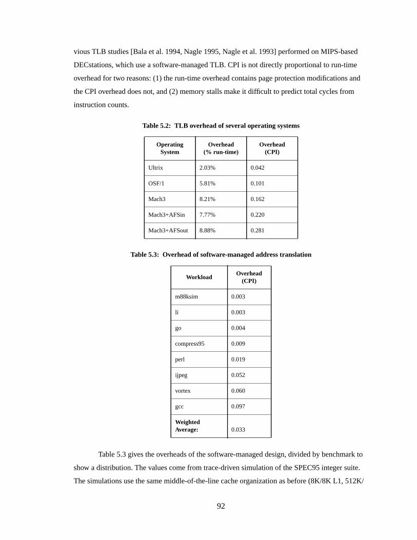
92
vious TLB studies [Bala et al. 1994, Nagle 1995, Nagle et al. 1993] performed on MIPS-based
DECstations, which use a software-managed TLB. CPI is not directly proportional to run-time
overhead for two reasons: (1) the run-time overhead contains page protection modifications and
the CPI overhead does not, and (2) memory stalls make it difficult to predict total cycles from
instruction counts.
Table 5.3 gives the overheads of the software-managed design, divided by benchmark to
show a distribution. The values come from trace-driven simulation of the SPEC95 integer suite.
The simulations use the same middle-of-the-line cache organization as before (8K/8K L1, 512K/
Table 5.2: TLB overhead of several operating systems
OperatingSystem
Overhead(% run-time)
Overhead(CPI)
Ultrix 2.03% 0.042
OSF/1 5.81% 0.101
Mach3 8.21% 0.162
Mach3+AFSin 7.77% 0.220
Mach3+AFSout 8.88% 0.281
Table 5.3: Overhead of software-managed address translation
WorkloadOverhead
(CPI)
m88ksim 0.003
li 0.003
go 0.004
compress95 0.009
perl 0.019
ijpeg 0.052
vortex 0.060
gcc 0.097
WeightedAverage: 0.033
93
512K L2, 16-byte linesize throughout), but replace the TLB with software address translation. In
these simulations, unlike those in the rest of this dissertation, the caches were warmed (for 100,000
cycles) before taking statistics. The average overhead of the scheme is 0.033 CPI. This is about the
overhead measured of Ultrix on MIPS, considered to be an example of an efficient match between
OS and architecture. This CPI is several times better than that of Mach, which should result in a
run-time savings of at least 5% over Mach. However, the number does not take into account the
effect of writebacks.
5.4.3 Writebacks
When a cache miss occurs in a writeback cache, a common rule of thumb says that half the
time the line expelled from the cache will be dirty, requiring it to be written back to main memory.
This case must be dealt with at the time of our cache-miss exception. There are two obvious solu-
tions. The translation is available at the time a cache line is brought into the cache; one can either
discard this information or store it in hardware. If discarded, the translation must be performed
again at the time of the writeback. If one wishes to throw hardware at the problem one can keep the
translation with the cache line, simplifying writeback enormously but increasing the size of the
cache without increasing its capacity. This also introduces the possibility of having stale transla-
tion information in the cache. We do not discuss the hardware-oriented solution further, as the pur-
pose of this chapter is to investigate reducing address translation hardware to its simplest.
If writebacks happen in 50% of all cache misses, then 50% of the time we will need to per-
form two address translations: one for the data to be written back, one for the data to be brought
into the cache. This should increase our overhead by roughly 50%, from 0.033 CPI to 0.050 CPI,
which is about the overhead of Ultrix and still far less than that of OSF/1 or Mach. The problem
this introduces is that the writeback handler can itself cause another writeback if it touches data in
cacheable space, or if the handler code is in cacheable space and the caches are unified.
5.4.4 Fine-Grained Protection
As mentioned earlier, managing protection information can be inefficient if we store pro-
tection bits with each cache line. If the protection granularity is larger than a cache line, the bits
must be replicated across multiple lines. Keeping the protection bits consistent across the cache
lines can cause significant overhead if page protection is modified frequently. The advantage of
this scheme is that the choice of protection granularity is completely up to the operating system. In
this section, we determine the overhead.
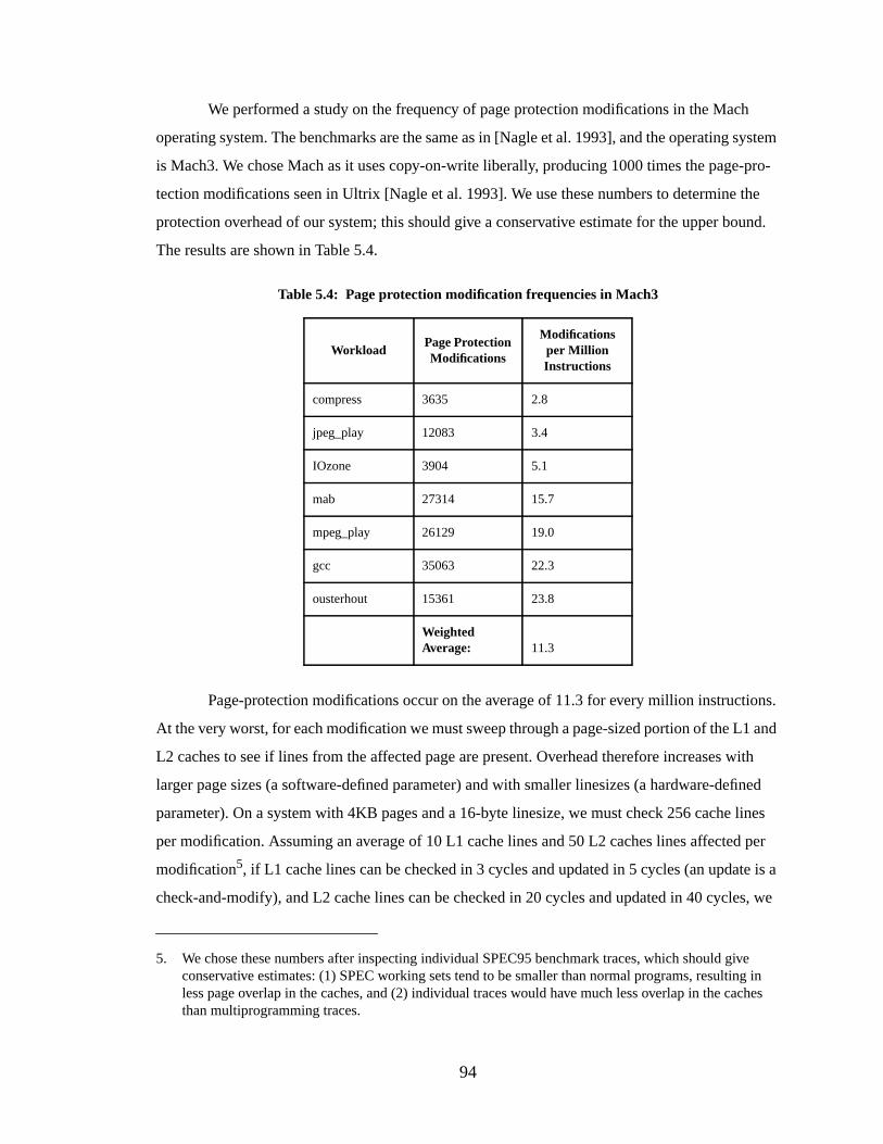
94
We performed a study on the frequency of page protection modifications in the Mach
operating system. The benchmarks are the same as in [Nagle et al. 1993], and the operating system
is Mach3. We chose Mach as it uses copy-on-write liberally, producing 1000 times the page-pro-
tection modifications seen in Ultrix [Nagle et al. 1993]. We use these numbers to determine the
protection overhead of our system; this should give a conservative estimate for the upper bound.
The results are shown in Table 5.4.
Page-protection modifications occur on the average of 11.3 for every million instructions.
At the very worst, for each modification we must sweep through a page-sized portion of the L1 and
L2 caches to see if lines from the affected page are present. Overhead therefore increases with
larger page sizes (a software-defined parameter) and with smaller linesizes (a hardware-defined
parameter). On a system with 4KB pages and a 16-byte linesize, we must check 256 cache lines
per modification. Assuming an average of 10 L1 cache lines and 50 L2 caches lines affected per
modification5, if L1 cache lines can be checked in 3 cycles and updated in 5 cycles (an update is a
check-and-modify), and L2 cache lines can be checked in 20 cycles and updated in 40 cycles, we
5. We chose these numbers after inspecting individual SPEC95 benchmark traces, which should giveconservative estimates: (1) SPEC working sets tend to be smaller than normal programs, resulting inless page overlap in the caches, and (2) individual traces would have much less overlap in the cachesthan multiprogramming traces.
Table 5.4: Page protection modification frequencies in Mach3
WorkloadPage ProtectionModifications
Modificationsper MillionInstructions
compress 3635 2.8
jpeg_play 12083 3.4
IOzone 3904 5.1
mab 27314 15.7
mpeg_play 26129 19.0
gcc 35063 22.3
ousterhout 15361 23.8
WeightedAverage: 11.3
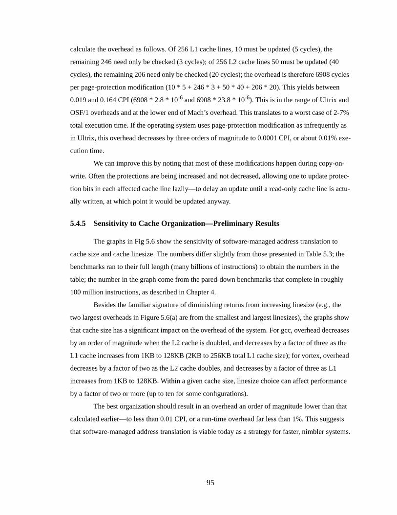
95
calculate the overhead as follows. Of 256 L1 cache lines, 10 must be updated (5 cycles), the
remaining 246 need only be checked (3 cycles); of 256 L2 cache lines 50 must be updated (40
cycles), the remaining 206 need only be checked (20 cycles); the overhead is therefore 6908 cycles
per page-protection modification (10 * 5 + 246 * 3 + 50 * 40 + 206 * 20). This yields between
0.019 and 0.164 CPI (6908 * 2.8 * 10-6 and 6908 * 23.8 * 10-6). This is in the range of Ultrix and
OSF/1 overheads and at the lower end of Mach’s overhead. This translates to a worst case of 2-7%
total execution time. If the operating system uses page-protection modification as infrequently as
in Ultrix, this overhead decreases by three orders of magnitude to 0.0001 CPI, or about 0.01% exe-
cution time.
We can improve this by noting that most of these modifications happen during copy-on-
write. Often the protections are being increased and not decreased, allowing one to update protec-
tion bits in each affected cache line lazily—to delay an update until a read-only cache line is actu-
ally written, at which point it would be updated anyway.
5.4.5 Sensitivity to Cache Organization—Preliminary Results
The graphs in Fig 5.6 show the sensitivity of software-managed address translation to
cache size and cache linesize. The numbers differ slightly from those presented in Table 5.3; the
benchmarks ran to their full length (many billions of instructions) to obtain the numbers in the
table; the number in the graph come from the pared-down benchmarks that complete in roughly
100 million instructions, as described in Chapter 4.
Besides the familiar signature of diminishing returns from increasing linesize (e.g., the
two largest overheads in Figure 5.6(a) are from the smallest and largest linesizes), the graphs show
that cache size has a significant impact on the overhead of the system. For gcc, overhead decreases
by an order of magnitude when the L2 cache is doubled, and decreases by a factor of three as the
L1 cache increases from 1KB to 128KB (2KB to 256KB total L1 cache size); for vortex, overhead
decreases by a factor of two as the L2 cache doubles, and decreases by a factor of three as L1
increases from 1KB to 128KB. Within a given cache size, linesize choice can affect performance
by a factor of two or more (up to ten for some configurations).
The best organization should result in an overhead an order of magnitude lower than that
calculated earlier—to less than 0.01 CPI, or a run-time overhead far less than 1%. This suggests
that software-managed address translation is viable today as a strategy for faster, nimbler systems.
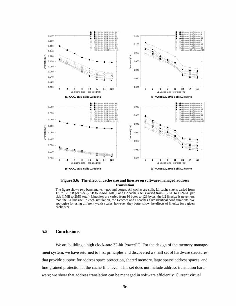
96
5.5 Conclusions
We are building a high clock-rate 32-bit PowerPC. For the design of the memory manage-
ment system, we have returned to first principles and discovered a small set of hardware structures
that provide support for address space protection, shared memory, large sparse address spaces, and
fine-grained protection at the cache-line level. This set does not include address-translation hard-
ware; we show that address translation can be managed in software efficiently. Current virtual
1�
2�
4�
8�
16� 32�
64�
128�
L1 Cache Size − per side (KB)
0.000
0.020
0.040
0.060
0.080
0.100
0.120
Ove
rhea
d (C
PI)
�
L1 Linesize 16, L2 Linesize 16L1 Linesize 16, L2 Linesize 32L1 Linesize 16, L2 Linesize 64L1 Linesize 16, L2 Linesize 128L1 Linesize 32, L2 Linesize 32L1 Linesize 32, L2 Linesize 64L1 Linesize 32, L2 Linesize 128L1 Linesize 64, L2 Linesize 64L1 Linesize 64, L2 Linesize 128L1 Linesize 128, L2 Linesize 128
1� 2
4
8�
16� 32
64
128
L1 Cache Size − per side (KB)
0.000
0.010
0.020
0.030
0.040
0.050
0.060
Ove
rhea
d (C
PI)
L1 Linesize 16, L2 Linesize 16L1 Linesize 16, L2 Linesize 32L1 Linesize 16, L2 Linesize 64L1 Linesize 16, L2 Linesize 128L1 Linesize 32, L2 Linesize 32L1 Linesize 32, L2 Linesize 64L1 Linesize 32, L2 Linesize 128L1 Linesize 64, L2 Linesize 64L1 Linesize 64, L2 Linesize 128L1 Linesize 128, L2 Linesize 128
1� 2
4
8�
16� 32
64
128
L1 Cache Size − per side (KB)
0.000
0.010
0.020
0.030
0.040
0.050
0.060
0.070
0.080
Ove
rhea
d (C
PI)
L1 Linesize 16, L2 Linesize 16L1 Linesize 16, L2 Linesize 32L1 Linesize 16, L2 Linesize 64L1 Linesize 16, L2 Linesize 128L1 Linesize 32, L2 Linesize 32L1 Linesize 32, L2 Linesize 64L1 Linesize 32, L2 Linesize 128L1 Linesize 64, L2 Linesize 64L1 Linesize 64, L2 Linesize 128L1 Linesize 128, L2 Linesize 128
1�
2�
4�
8�
16� 32�
64�
128�
L1 Cache Size − per side (KB)
0.000
0.020
0.040
0.060
0.080
0.100
0.120
0.140
0.160
0.180
0.200
Ove
rhea
d (C
PI)
�
L1 Linesize 16, L2 Linesize 16L1 Linesize 16, L2 Linesize 32L1 Linesize 16, L2 Linesize 64L1 Linesize 16, L2 Linesize 128L1 Linesize 32, L2 Linesize 32L1 Linesize 32, L2 Linesize 64L1 Linesize 32, L2 Linesize 128L1 Linesize 64, L2 Linesize 64L1 Linesize 64, L2 Linesize 128L1 Linesize 128, L2 Linesize 128
Figure 5.6: The effect of cache size and linesize on software-managed addresstranslation
The figure shows two benchmarks—gcc and vortex. All caches are split. L1 cache size is varied from1K to 128KB per side (2KB to 256KB total), and L2 cache size is varied from 512KB to 1024KB perside (1MB to 2MB total). Linesizes are varied from 16 bytes to 128 bytes; the L2 linesize is never lessthan the L1 linesize. In each simulation, the I-caches and D-caches have identical configurations. Weapologize for using different y-axis scales; however, they better show the effects of linesize for a givencache size.
(b) VORTEX, 1MB split L2 cac he(a) GCC, 1MB split L2 cac he
(c) GCC, 2MB split L2 cac he (d) VORTEX, 2MB split L2 cac he
97
memory systems such as Mach exact an overhead of 0.16 to 0.28 cycles per instruction to provide
address translation6. By contrast, a software scheme requires 0.05 CPI (approximately 2% run-
time overhead, with a 16KB L1 cache and 1MB L2 cache), about the same as the overhead of
Ultrix on MIPS. If copy-on-write and other page-protection modifications are used as frequently as
in Mach, protection-bit management can increase this overhead to that of OSF/1 or Mach. How-
ever, the number of page-protection modifications in Ultrix represent a negligible overhead. With
slightly larger caches (2MB L2, common in today’s systems), the overhead of software-managed
address translation should reduce to far less than 1% of run-time. Therefore software-managed
address translation is a viable strategy for high-end computing today, achieving better performance
with less hardware.
Beyond the performance gains suggested by these simulations, the benefits of a minimal
hardware design are three-fold. First, moving address translation into software creates a simpler
and more flexible interface; as such it supports much more innovation in the operating system than
would a fixed design. Second, a reduction in hardware will leave room for more cache structures,
increasing performance. Last, simpler hardware should be easier to design and debug, cutting
down on development time.
6. Note that in this chapter we are comparing apples to oranges; we compare very detailed measurementsof a simulated software-oriented design (with many different cache sizes) to far less-detailedmeasurements of real systems (with fixed cache sizes and TLB sizes). Therefore the real systems willhave overheads that are very implementation-dependent and are likely to be pessimistic. Most ofMach’s overhead is due to excess code in the kernel—it is implementation-dependent and not aninherent weakness of the Mach page table organization. The next section rectifies this; it compares a setof simulated results for many different VM organizations—placing them all on equal footing—andshows (among other things) that there is no reason for the Mach VM system to perform significantlydifferent from the Ultrix VM system.
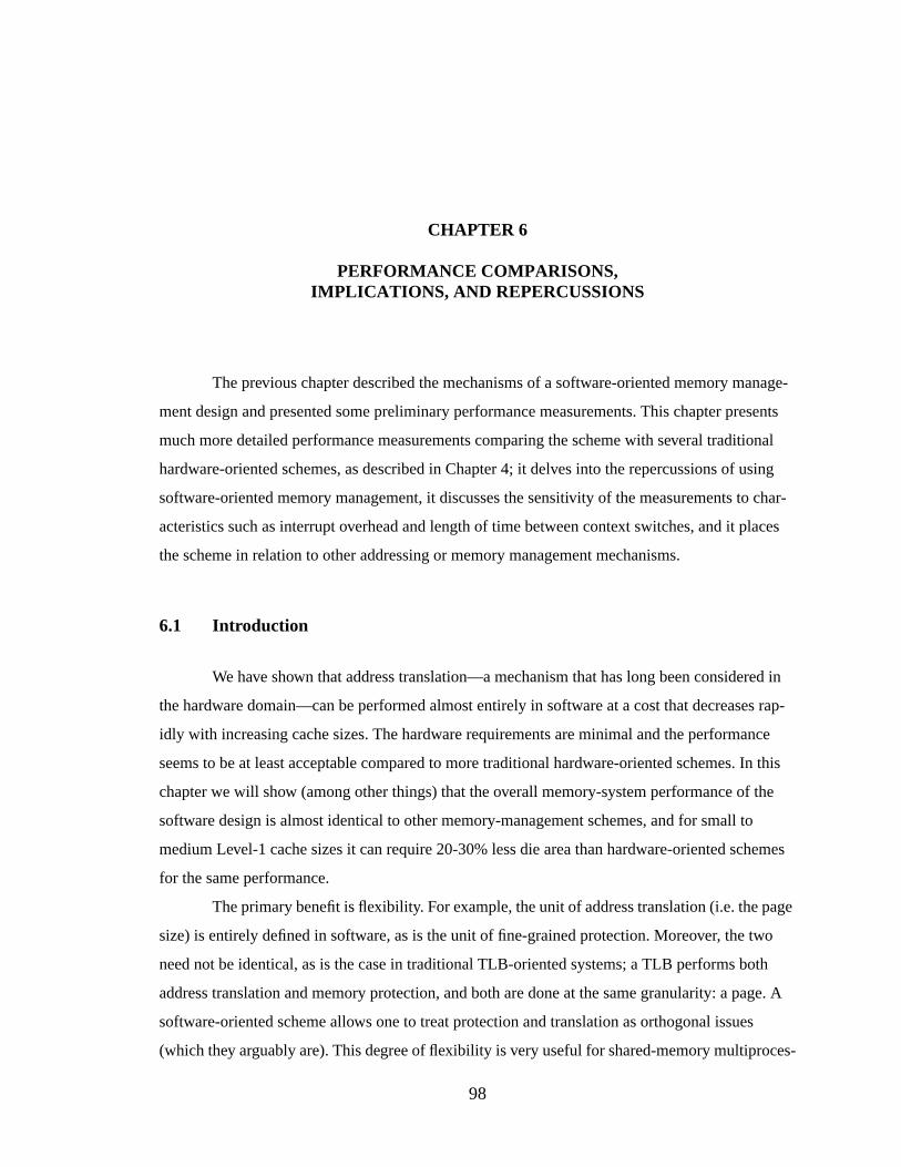
98
CHAPTER 6
PERFORMANCE COMPARISONS,IMPLICATIONS, AND REPERCUSSIONS
The previous chapter described the mechanisms of a software-oriented memory manage-
ment design and presented some preliminary performance measurements. This chapter presents
much more detailed performance measurements comparing the scheme with several traditional
hardware-oriented schemes, as described in Chapter 4; it delves into the repercussions of using
software-oriented memory management, it discusses the sensitivity of the measurements to char-
acteristics such as interrupt overhead and length of time between context switches, and it places
the scheme in relation to other addressing or memory management mechanisms.
6.1 Intr oduction
We have shown that address translation—a mechanism that has long been considered in
the hardware domain—can be performed almost entirely in software at a cost that decreases rap-
idly with increasing cache sizes. The hardware requirements are minimal and the performance
seems to be at least acceptable compared to more traditional hardware-oriented schemes. In this
chapter we will show (among other things) that the overall memory-system performance of the
software design is almost identical to other memory-management schemes, and for small to
medium Level-1 cache sizes it can require 20-30% less die area than hardware-oriented schemes
for the same performance.
The primary benefit is flexibility . For example, the unit of address translation (i.e. the page
size) is entirely defined in software, as is the unit of fine-grained protection. Moreover, the two
need not be identical, as is the case in traditional TLB-oriented systems; a TLB performs both
address translation and memory protection, and both are done at the same granularity: a page. A
software-oriented scheme allows one to treat protection and translation as orthogonal issues
(which they arguably are). This degree of flexibility is very useful for shared-memory multiproces-
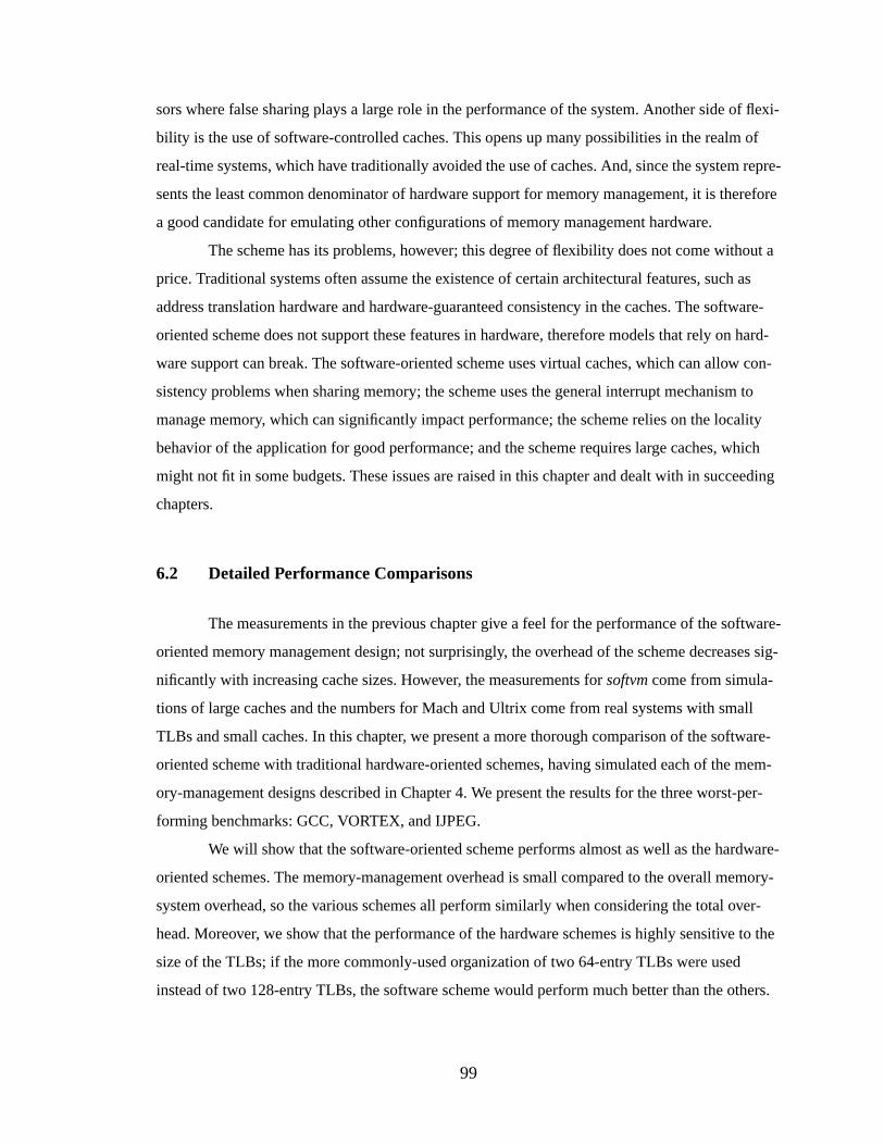
99
sors where false sharing plays a large role in the performance of the system. Another side of flexi-
bility is the use of software-controlled caches. This opens up many possibilities in the realm of
real-time systems, which have traditionally avoided the use of caches. And, since the system repre-
sents the least common denominator of hardware support for memory management, it is therefore
a good candidate for emulating other configurations of memory management hardware.
The scheme has its problems, however; this degree of flexibility does not come without a
price. Traditional systems often assume the existence of certain architectural features, such as
address translation hardware and hardware-guaranteed consistency in the caches. The software-
oriented scheme does not support these features in hardware, therefore models that rely on hard-
ware support can break. The software-oriented scheme uses virtual caches, which can allow con-
sistency problems when sharing memory; the scheme uses the general interrupt mechanism to
manage memory, which can significantly impact performance; the scheme relies on the locality
behavior of the application for good performance; and the scheme requires large caches, which
might not fit in some budgets. These issues are raised in this chapter and dealt with in succeeding
chapters.
6.2 Detailed Performance Comparisons
The measurements in the previous chapter give a feel for the performance of the software-
oriented memory management design; not surprisingly, the overhead of the scheme decreases sig-
nificantly with increasing cache sizes. However, the measurements forsoftvm come from simula-
tions of large caches and the numbers for Mach and Ultrix come from real systems with small
TLBs and small caches. In this chapter, we present a more thorough comparison of the software-
oriented scheme with traditional hardware-oriented schemes, having simulated each of the mem-
ory-management designs described in Chapter 4. We present the results for the three worst-per-
forming benchmarks: GCC, VORTEX, and IJPEG.
We will show that the software-oriented scheme performs almost as well as the hardware-
oriented schemes. The memory-management overhead is small compared to the overall memory-
system overhead, so the various schemes all perform similarly when considering the total over-
head. Moreover, we show that the performance of the hardware schemes is highly sensitive to the
size of the TLBs; if the more commonly-used organization of two 64-entry TLBs were used
instead of two 128-entry TLBs, the software scheme would perform much better than the others.
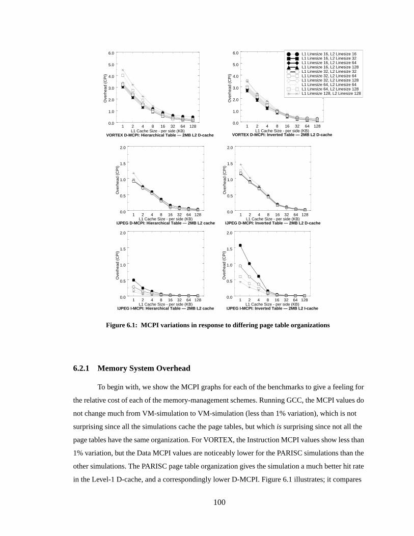
100
6.2.1 Memory System Overhead
To begin with, we show the MCPI graphs for each of the benchmarks to give a feeling for
the relative cost of each of the memory-management schemes. Running GCC, the MCPI values do
not change much from VM-simulation to VM-simulation (less than 1% variation), which is not
surprising since all the simulations cache the page tables, but whichis surprising since not all the
page tables have the same organization. For VORTEX, the Instruction MCPI values show less than
1% variation, but the Data MCPI values are noticeably lower for the PARISC simulations than the
other simulations. The PARISC page table organization gives the simulation a much better hit rate
in the Level-1 D-cache, and a correspondingly lower D-MCPI. Figure 6.1 illustrates; it compares
Figure 6.1: MCPI variations in response to differing page table organizations
1 2 4 8 16 32 64 128L1 Cache Size - per side (KB)
0.0
1.0
2.0
3.0
4.0
5.0
6.0
Ove
rhea
d (C
PI)
VORTEX D-MCPI: Inverted Table — 2MB L2 D-cache
1 2 4 8 16 32 64 128L1 Cache Size - per side (KB)
0.0
1.0
2.0
3.0
4.0
5.0
6.0
Ove
rhea
d (C
PI)
VORTEX D-MCPI: Hierarchical Table — 2MB L2 D-cache
L1 Linesize 16, L2 Linesize 16L1 Linesize 16, L2 Linesize 32L1 Linesize 16, L2 Linesize 64L1 Linesize 16, L2 Linesize 128L1 Linesize 32, L2 Linesize 32L1 Linesize 32, L2 Linesize 64L1 Linesize 32, L2 Linesize 128L1 Linesize 64, L2 Linesize 64L1 Linesize 64, L2 Linesize 128L1 Linesize 128, L2 Linesize 128
1 2 4 8 16 32 64 128L1 Cache Size - per side (KB)
0.0
0.5
1.0
1.5
2.0
Ove
rhea
d (C
PI)
1 2 4 8 16 32 64 128L1 Cache Size - per side (KB)
0.0
0.5
1.0
1.5
2.0
Ove
rhea
d (C
PI)
IJPEG D-MCPI: Hierarchical Table — 2MB L2 cache IJPEG D-MCPI: Inverted Table — 2MB L2 D-cache
1 2 4 8 16 32 64 128L1 Cache Size - per side (KB)
0.0
0.5
1.0
1.5
2.0
Ove
rhea
d (C
PI)
1 2 4 8 16 32 64 128L1 Cache Size - per side (KB)
0.0
0.5
1.0
1.5
2.0
Ove
rhea
d (C
PI)
IJPEG I-MCPI: Hierarchical Table — 2MB L2 cache IJPEG I-MCPI: Inverted Table — 2MB L2 I-cache
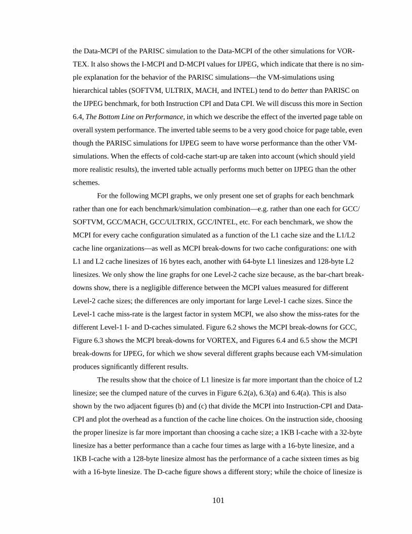
101
the Data-MCPI of the PARISC simulation to the Data-MCPI of the other simulations for VOR-
TEX. It also shows the I-MCPI and D-MCPI values for IJPEG, which indicate that there is no sim-
ple explanation for the behavior of the PARISC simulations—the VM-simulations using
hierarchical tables (SOFTVM, ULTRIX, MACH, and INTEL) tend to dobetter than PARISC on
the IJPEG benchmark, for both Instruction CPI and Data CPI. We will discuss this more in Section
6.4,The Bottom Line on Performance, in which we describe the effect of the inverted page table on
overall system performance. The inverted table seems to be a very good choice for page table, even
though the PARISC simulations for IJPEG seem to have worse performance than the other VM-
simulations. When the effects of cold-cache start-up are taken into account (which should yield
more realistic results), the inverted table actually performs much better on IJPEG than the other
schemes.
For the following MCPI graphs, we only present one set of graphs for each benchmark
rather than one for each benchmark/simulation combination—e.g. rather than one each for GCC/
SOFTVM, GCC/MACH, GCC/ULTRIX, GCC/INTEL, etc. For each benchmark, we show the
MCPI for every cache configuration simulated as a function of the L1 cache size and the L1/L2
cache line organizations—as well as MCPI break-downs for two cache configurations: one with
L1 and L2 cache linesizes of 16 bytes each, another with 64-byte L1 linesizes and 128-byte L2
linesizes. We only show the line graphs for one Level-2 cache size because, as the bar-chart break-
downs show, there is a negligible difference between the MCPI values measured for different
Level-2 cache sizes; the differences are only important for large Level-1 cache sizes. Since the
Level-1 cache miss-rate is the largest factor in system MCPI, we also show the miss-rates for the
different Level-1 I- and D-caches simulated. Figure 6.2 shows the MCPI break-downs for GCC,
Figure 6.3 shows the MCPI break-downs for VORTEX, and Figures 6.4 and 6.5 show the MCPI
break-downs for IJPEG, for which we show several different graphs because each VM-simulation
produces significantly different results.
The results show that the choice of L1 linesize is far more important than the choice of L2
linesize; see the clumped nature of the curves in Figure 6.2(a), 6.3(a) and 6.4(a). This is also
shown by the two adjacent figures (b) and (c) that divide the MCPI into Instruction-CPI and Data-
CPI and plot the overhead as a function of the cache line choices. On the instruction side, choosing
the proper linesize is far more important than choosing a cache size; a 1KB I-cache with a 32-byte
linesize has a better performance than a cache four times as large with a 16-byte linesize, and a
1KB I-cache with a 128-byte linesize almost has the performance of a cache sixteen times as big
with a 16-byte linesize. The D-cache figure shows a different story; while the choice of linesize is
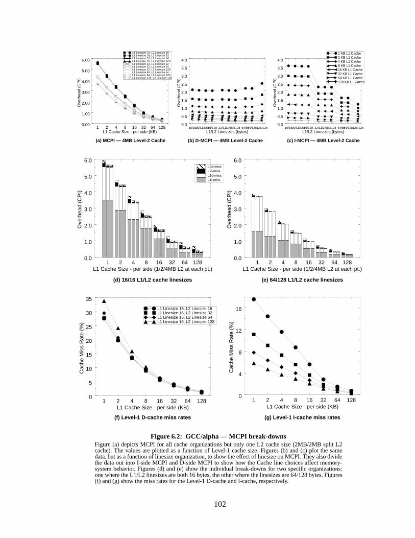
102
16/1616/3216/6416/128 32/3232/6432/128 64/6464/128128/128L1/L2 Linesizes (bytes)
0.0
0.5
1.0
1.5
2.0
2.5
3.0
3.5
4.0
Ove
rhea
d (C
PI)
Figure 6.2: GCC/alpha — MCPI break-downsFigure (a) depicts MCPI for all cache organizations but only one L2 cache size (2MB/2MB split L2cache). The values are plotted as a function of Level-1 cache size. Figures (b) and (c) plot the samedata, but as a function of linesize organization, to show the effect of linesize on MCPI. They also dividethe data out into I-side MCPI and D-side MCPI to show how the Cache line choices affect memory-system behavior. Figures (d) and (e) show the individual break-downs for two specific organizations:one where the L1/L2 linesizes are both 16 bytes, the other where the linesizes are 64/128 bytes. Figures(f) and (g) show the miss rates for the Level-1 D-cache and I-cache, respectively.
(d) 16/16 L1/L2 cache linesizes
1 KB L1 Cache2 KB L1 Cache4 KB L1 Cache8 KB L1 Cache16 KB L1 Cache32 KB L1 Cache64 KB L1 Cache128 KB L1 Cache
(a) MCPI — 4MB Level-2 Cache (b) D-MCPI — 4MB Level-2 Cache
1 2 4 8 16 32 64 128L1 Cache Size - per side (1/2/4MB L2 at each pt.)
0.0
1.0
2.0
3.0
4.0
5.0
6.0
Ove
rhea
d (C
PI)
1 2 4 8 16 32 64 128L1 Cache Size - per side (1/2/4MB L2 at each pt.)
0.0
1.0
2.0
3.0
4.0
5.0
6.0
Ove
rhea
d (C
PI)
L1i-missL1d-missL2i-missL2d-miss
(e) 64/128 L1/L2 cache linesizes
1 2 4 8 16 32 64 128L1 Cache Size - per side (KB)
0.00
1.00
2.00
3.00
4.00
5.00
6.00
Ove
rhea
d (C
PI)
L1 Linesize 16, L2 Linesize 16L1 Linesize 16, L2 Linesize 32L1 Linesize 16, L2 Linesize 64L1 Linesize 16, L2 Linesize 128L1 Linesize 32, L2 Linesize 32L1 Linesize 32, L2 Linesize 64L1 Linesize 32, L2 Linesize 128L1 Linesize 64, L2 Linesize 64L1 Linesize 64, L2 Linesize 128L1 Linesize 128, L2 Linesize 128
(c) I-MCPI — 4MB Level-2 Cache
(f) Level-1 D-cache miss rates (g) Level-1 I-cache miss rates
16/1616/3216/6416/128 32/3232/6432/128 64/6464/128128/128L1/L2 Linesizes (bytes)
0.0
0.5
1.0
1.5
2.0
2.5
3.0
3.5
4.0
Ove
rhea
d (C
PI)
1 2 4 8 16 32 64 128L1 Cache Size - per side (KB)
0
4
8
12
16
Cac
he M
iss
Rat
e (%
)
1 2 4 8 16 32 64 128L1 Cache Size - per side (KB)
0
5
10
15
20
25
30
35
Cac
he M
iss
Rat
e (%
)
L1 Linesize 16, L2 Linesize 16L1 Linesize 16, L2 Linesize 32L1 Linesize 16, L2 Linesize 64L1 Linesize 16, L2 Linesize 128
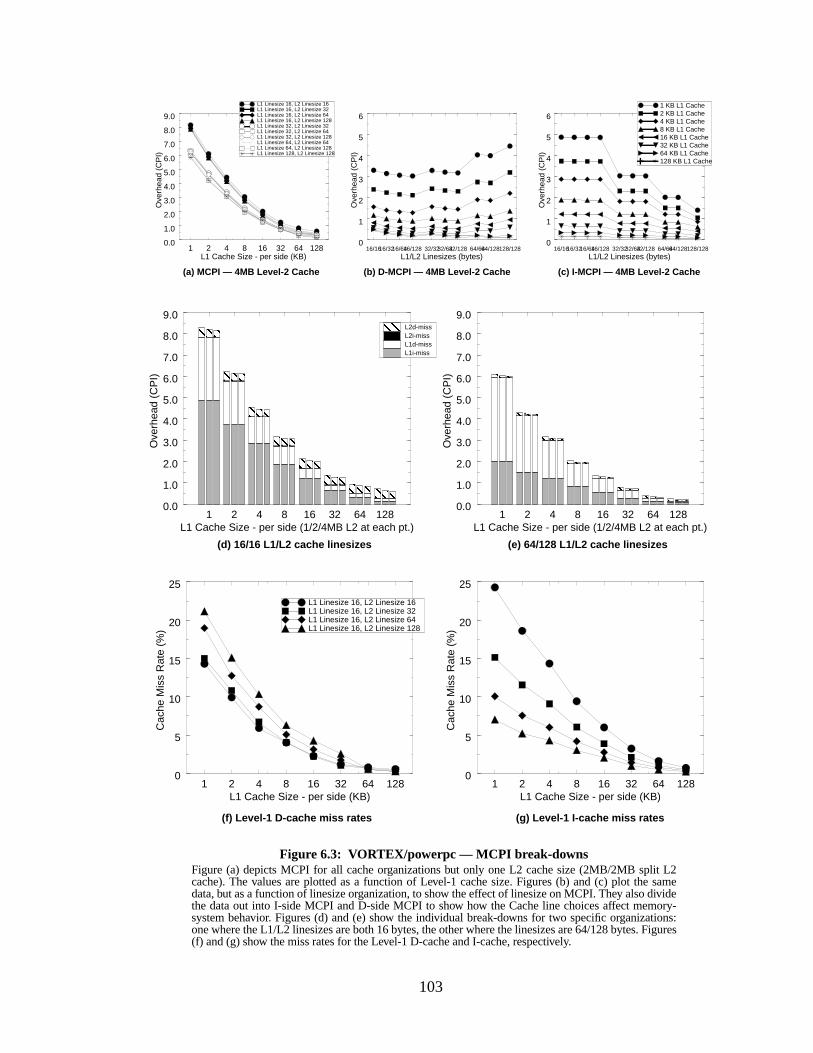
103
1 2 4 8 16 32 64 128L1 Cache Size - per side (KB)
0
5
10
15
20
25
Cac
he M
iss
Rat
e (%
)
16/1616/3216/6416/128 32/3232/6432/128 64/6464/128128/128L1/L2 Linesizes (bytes)
0
1
2
3
4
5
6
Ove
rhea
d (C
PI)
1 2 4 8 16 32 64 128L1 Cache Size - per side (1/2/4MB L2 at each pt.)
0.0
1.0
2.0
3.0
4.0
5.0
6.0
7.0
8.0
9.0
Ove
rhea
d (C
PI)
1 2 4 8 16 32 64 128L1 Cache Size - per side (1/2/4MB L2 at each pt.)
0.0
1.0
2.0
3.0
4.0
5.0
6.0
7.0
8.0
9.0
Ove
rhea
d (C
PI)
1 2 4 8 16 32 64 128L1 Cache Size - per side (KB)
0.0
1.0
2.0
3.0
4.0
5.0
6.0
7.0
8.0
9.0
Ove
rhea
d (C
PI)
Figure 6.3: VORTEX/powerpc — MCPI break-downsFigure (a) depicts MCPI for all cache organizations but only one L2 cache size (2MB/2MB split L2cache). The values are plotted as a function of Level-1 cache size. Figures (b) and (c) plot the samedata, but as a function of linesize organization, to show the effect of linesize on MCPI. They also dividethe data out into I-side MCPI and D-side MCPI to show how the Cache line choices affect memory-system behavior. Figures (d) and (e) show the individual break-downs for two specific organizations:one where the L1/L2 linesizes are both 16 bytes, the other where the linesizes are 64/128 bytes. Figures(f) and (g) show the miss rates for the Level-1 D-cache and I-cache, respectively.
1 KB L1 Cache2 KB L1 Cache4 KB L1 Cache8 KB L1 Cache16 KB L1 Cache32 KB L1 Cache64 KB L1 Cache128 KB L1 Cache
L1 Linesize 16, L2 Linesize 16L1 Linesize 16, L2 Linesize 32L1 Linesize 16, L2 Linesize 64L1 Linesize 16, L2 Linesize 128L1 Linesize 32, L2 Linesize 32L1 Linesize 32, L2 Linesize 64L1 Linesize 32, L2 Linesize 128L1 Linesize 64, L2 Linesize 64L1 Linesize 64, L2 Linesize 128L1 Linesize 128, L2 Linesize 128
(d) 16/16 L1/L2 cache linesizes
(a) MCPI — 4MB Level-2 Cache (b) D-MCPI — 4MB Level-2 Cache
(e) 64/128 L1/L2 cache linesizes
(c) I-MCPI — 4MB Level-2 Cache
(f) Level-1 D-cache miss rates (g) Level-1 I-cache miss rates
L1i-missL1d-missL2i-missL2d-miss
16/1616/3216/6416/128 32/3232/6432/128 64/6464/128128/128L1/L2 Linesizes (bytes)
0
1
2
3
4
5
6
Ove
rhea
d (C
PI)
L1 Linesize 16, L2 Linesize 16L1 Linesize 16, L2 Linesize 32L1 Linesize 16, L2 Linesize 64L1 Linesize 16, L2 Linesize 128
1 2 4 8 16 32 64 128L1 Cache Size - per side (KB)
0
5
10
15
20
25
Cac
he M
iss
Rat
e (%
)
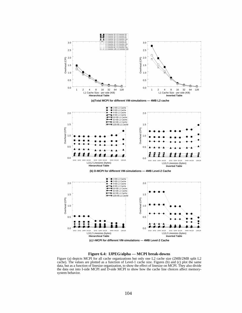
104
1 2 4 8 16 32 64 128L1 Cache Size - per side (KB)
0.0
0.5
1.0
1.5
2.0
2.5
3.0
Ove
rhea
d (C
PI)
1 2 4 8 16 32 64 128L1 Cache Size - per side (KB)
0.0
0.5
1.0
1.5
2.0
2.5
3.0
Ove
rhea
d (C
PI)
16/16 16/32 16/64 16/128 32/32 32/64 32/128 64/64 64/128 128/128
L1/L2 Linesizes (bytes)
0.0
0.5
1.0
1.5
2.0
Ove
rhea
d (C
PI)
Figure 6.4: IJPEG/alpha — MCPI br eak-downsFigure (a) depicts MCPI for all cache organizations but only one L2 cache size (2MB/2MB split L2cache). The values are plotted as a function of Level-1 cache size. Figures (b) and (c) plot the samedata, but as a function of linesize organization, to show the effect of linesize on MCPI. They also dividethe data out into I-side MCPI and D-side MCPI to show how the cache line choices affect memory-system behavior.
1 KB L1 Cache2 KB L1 Cache4 KB L1 Cache8 KB L1 Cache16 KB L1 Cache32 KB L1 Cache64 KB L1 Cache128 KB L1 Cache
L1 Linesize 16, L2 Linesize 16L1 Linesize 16, L2 Linesize 32L1 Linesize 16, L2 Linesize 64L1 Linesize 16, L2 Linesize 128L1 Linesize 32, L2 Linesize 32L1 Linesize 32, L2 Linesize 64L1 Linesize 32, L2 Linesize 128L1 Linesize 64, L2 Linesize 64L1 Linesize 64, L2 Linesize 128L1 Linesize 128, L2 Linesize 128
(a)Total MCPI for different VM-simulations — 4MB L2 cache
(b) D-MCPI for different VM-simulations — 4MB Level-2 Cache
(c) I-MCPI for different VM-simulations — 4MB Level-2 Cache
16/16 16/32 16/64 16/128 32/32 32/64 32/128 64/64 64/128 128/128
L1/L2 Linesizes (bytes)
0.0
0.5
1.0
1.5
2.0
Ove
rhea
d (C
PI)
Hierarchical Table Inverted Table
16/16 16/32 16/64 16/128 32/32 32/64 32/128 64/64 64/128 128/128
L1/L2 Linesizes (bytes)
0.0
0.5
1.0
1.5
2.0
Ove
rhea
d (C
PI)
16/16 16/32 16/64 16/128 32/32 32/64 32/128 64/64 64/128 128/128
L1/L2 Linesizes (bytes)
0.0
0.5
1.0
1.5
2.0
Ove
rhea
d (C
PI)
Hierarchical Table
1 KB L1 Cache2 KB L1 Cache4 KB L1 Cache8 KB L1 Cache16 KB L1 Cache32 KB L1 Cache64 KB L1 Cache128 KB L1 Cache
Inverted Table
Hierarchical Table Inverted Table
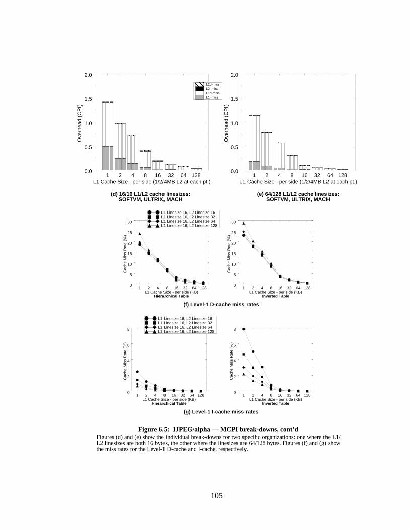
105
1 2 4 8 16 32 64 128L1 Cache Size - per side (KB)
0
5
10
15
20
25
30
Cac
he M
iss
Rat
e (%
)
Inverted Table
1 2 4 8 16 32 64 128L1 Cache Size - per side (1/2/4MB L2 at each pt.)
0.0
0.5
1.0
1.5
2.0O
verh
ead
(CP
I)
L1i-missL1d-missL2i-missL2d-miss
Figure 6.5: IJPEG/alpha — MCPI br eak-downs, cont’dFigures (d) and (e) show the individual break-downs for two specific organizations: one where the L1/L2 linesizes are both 16 bytes, the other where the linesizes are 64/128 bytes. Figures (f) and (g) showthe miss rates for the Level-1 D-cache and I-cache, respectively.
(d) 16/16 L1/L2 cache linesizes: (e) 64/128 L1/L2 cache linesizes:
(f) Level-1 D-cache miss rates
(g) Level-1 I-cache miss rates
1 2 4 8 16 32 64 128L1 Cache Size - per side (1/2/4MB L2 at each pt.)
0.0
0.5
1.0
1.5
2.0
Ove
rhea
d (C
PI)
SOFTVM, ULTRIX, MACHSOFTVM, ULTRIX, MACH
1 2 4 8 16 32 64 128L1 Cache Size - per side (KB)
0
5
10
15
20
25
30
Cac
he M
iss
Rat
e (%
)
Hierarchical Table
L1 Linesize 16, L2 Linesize 16L1 Linesize 16, L2 Linesize 32L1 Linesize 16, L2 Linesize 64L1 Linesize 16, L2 Linesize 128
1 2 4 8 16 32 64 128L1 Cache Size - per side (KB)
0
2
4
6
8
Cac
he M
iss
Rat
e (%
)
1 2 4 8 16 32 64 128L1 Cache Size - per side (KB)
0
2
4
6
8
Cac
he M
iss
Rat
e (%
)
L1 Linesize 16, L2 Linesize 16L1 Linesize 16, L2 Linesize 32L1 Linesize 16, L2 Linesize 64L1 Linesize 16, L2 Linesize 128
Hierarchical Table Inverted Table
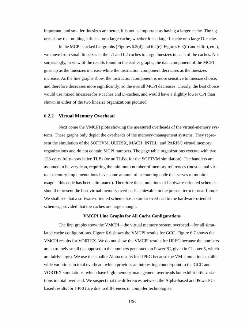
106
important, and smaller linesizes are better, it is not as important as having a larger cache. The fig-
ures show that nothing suffices for a large cache, whether it is a large I-cache or a large D-cache.
In the MCPI stacked bar graphs (Figures 6.2(d) and 6.2(e), Figures 6.3(d) and 6.3(e), etc.),
we move from small linesizes in the L1 and L2 caches to large linesizes in each of the caches. Not
surprisingly, in view of the results found in the earlier graphs, the data component of the MCPI
goes up as the linesizes increase while the instruction component decreases as the linesizes
increase. As the line graphs show, the instruction component is more sensitive to linesize choice,
and therefore decreases more significantly; so the overall MCPI decreases. Clearly, the best choice
would use mixed linesizes for I-caches and D-caches, and would have a slightly lower CPI than
shown in either of the two linesize organizations pictured.
6.2.2 Virtual Memory Ov erhead
Next come the VMCPI plots showing the measured overheads of the virtual-memory sys-
tems. These graphs only depict the overheads of the memory-management systems. They repre-
sent the simulation of the SOFTVM, ULTRIX, MACH, INTEL, and PARISC virtual memory
organizations and do not contain MCPI numbers. The page table organizations execute with two
128-entry fully-associative TLBs (or no TLBs, for the SOFTVM simulation). The handlers are
assumed to be very lean, requiring the minimum number of memory references (most actual vir-
tual-memory implementations have some amount of accounting code that serves to monitor
usage—this code has been eliminated). Therefore the simulations of hardware-oriented schemes
should represent the best virtual memory overheads achievable in the present term or near future.
We shall see that a software-oriented scheme has a similar overhead to the hardware-oriented
schemes, provided that the caches are large enough.
VMCPI Line Graphs for All Cache Configurations
The first graphs show the VMCPI—the virtual memory system overhead—for all simu-
lated cache configurations. Figure 6.6 shows the VMCPI results for GCC. Figure 6.7 shows the
VMCPI results for VORTEX. We do not show the VMCPI results for IJPEG because the numbers
are extremely small (as opposed to the numbers generated on PowerPC, given in Chapter 5, which
are fairly large). We use the smaller Alpha results for IJPEG because the VM-simulations exhibit
wide variations in total overhead, which provides an interesting counterpoint to the GCC and
VORTEX simulations, which have high memory-management overheads but exhibit little varia-
tions in total overhead. We suspect that the differences between the Alpha-based and PowerPC-
based results for IJPEG are due to differences in compiler technologies.
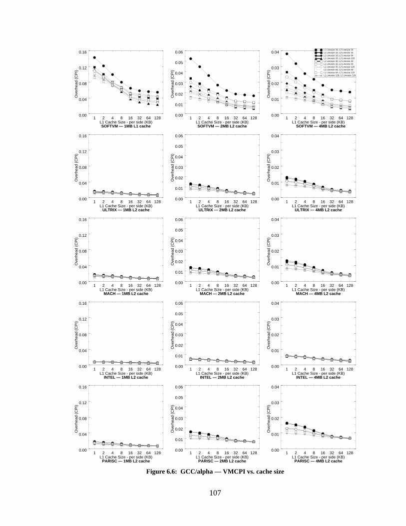
107
1 2 4 8 16 32 64 128L1 Cache Size - per side (KB)
0.00
0.04
0.08
0.12
0.16
Ove
rhea
d (C
PI)
SOFTVM — 1MB L1 cache
1 2 4 8 16 32 64 128L1 Cache Size - per side (KB)
0.00
0.01
0.02
0.03
0.04
0.05
0.06
Ove
rhea
d (C
PI)
SOFTVM — 2MB L2 cache
1 2 4 8 16 32 64 128L1 Cache Size - per side (KB)
0.00
0.01
0.02
0.03
0.04
Ove
rhea
d (C
PI)
SOFTVM — 4MB L2 cache
Figure 6.6: GCC/alpha — VMCPI vs. cache size
L1 Linesize 16, L2 Linesize 16L1 Linesize 16, L2 Linesize 32L1 Linesize 16, L2 Linesize 64L1 Linesize 16, L2 Linesize 128L1 Linesize 32, L2 Linesize 32L1 Linesize 32, L2 Linesize 64L1 Linesize 32, L2 Linesize 128L1 Linesize 64, L2 Linesize 64L1 Linesize 64, L2 Linesize 128L1 Linesize 128, L2 Linesize 128
1 2 4 8 16 32 64 128L1 Cache Size - per side (KB)
0.00
0.04
0.08
0.12
0.16
Ove
rhea
d (C
PI)
INTEL — 1MB L2 cache
1 2 4 8 16 32 64 128L1 Cache Size - per side (KB)
0.00
0.01
0.02
0.03
0.04
0.05
0.06
Ove
rhea
d (C
PI)
INTEL — 2MB L2 cache
1 2 4 8 16 32 64 128L1 Cache Size - per side (KB)
0.00
0.01
0.02
0.03
0.04
Ove
rhea
d (C
PI)
INTEL — 4MB L2 cache
1 2 4 8 16 32 64 128L1 Cache Size - per side (KB)
0.00
0.04
0.08
0.12
0.16
Ove
rhea
d (C
PI)
MACH — 1MB L2 cache
1 2 4 8 16 32 64 128L1 Cache Size - per side (KB)
0.00
0.01
0.02
0.03
0.04
0.05
0.06
Ove
rhea
d (C
PI)
MACH — 2MB L2 cache
1 2 4 8 16 32 64 128L1 Cache Size - per side (KB)
0.00
0.01
0.02
0.03
0.04
Ove
rhea
d (C
PI)
MACH — 4MB L2 cache
1 2 4 8 16 32 64 128L1 Cache Size - per side (KB)
0.00
0.04
0.08
0.12
0.16
Ove
rhea
d (C
PI)
PARISC — 1MB L2 cache
1 2 4 8 16 32 64 128L1 Cache Size - per side (KB)
0.00
0.01
0.02
0.03
0.04
0.05
0.06
Ove
rhea
d (C
PI)
PARISC — 2MB L2 cache
1 2 4 8 16 32 64 128L1 Cache Size - per side (KB)
0.00
0.01
0.02
0.03
0.04
Ove
rhea
d (C
PI)
PARISC — 4MB L2 cache
1 2 4 8 16 32 64 128L1 Cache Size - per side (KB)
0.00
0.04
0.08
0.12
0.16
Ove
rhea
d (C
PI)
ULTRIX — 1MB L2 cache
1 2 4 8 16 32 64 128L1 Cache Size - per side (KB)
0.00
0.01
0.02
0.03
0.04
0.05
0.06
Ove
rhea
d (C
PI)
ULTRIX — 2MB L2 cache
1 2 4 8 16 32 64 128L1 Cache Size - per side (KB)
0.00
0.01
0.02
0.03
0.04
Ove
rhea
d (C
PI)
ULTRIX — 4MB L2 cache
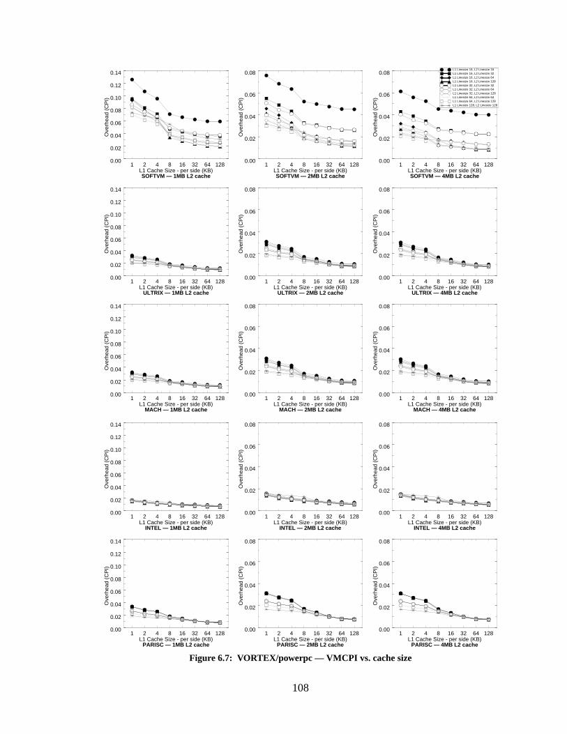
108
1 2 4 8 16 32 64 128L1 Cache Size - per side (KB)
0.00
0.02
0.04
0.06
0.08
Ove
rhea
d (C
PI)
Figure 6.7: VORTEX/powerpc — VMCPI vs. cache size
L1 Linesize 16, L2 Linesize 16L1 Linesize 16, L2 Linesize 32L1 Linesize 16, L2 Linesize 64L1 Linesize 16, L2 Linesize 128L1 Linesize 32, L2 Linesize 32L1 Linesize 32, L2 Linesize 64L1 Linesize 32, L2 Linesize 128L1 Linesize 64, L2 Linesize 64L1 Linesize 64, L2 Linesize 128L1 Linesize 128, L2 Linesize 128
1 2 4 8 16 32 64 128L1 Cache Size - per side (KB)
0.00
0.02
0.04
0.06
0.08
0.10
0.12
0.14
Ove
rhea
d (C
PI)
1 2 4 8 16 32 64 128L1 Cache Size - per side (KB)
0.00
0.02
0.04
0.06
0.08
Ove
rhea
d (C
PI)
SOFTVM — 1MB L2 cache SOFTVM — 2MB L2 cache SOFTVM — 4MB L2 cache
1 2 4 8 16 32 64 128L1 Cache Size - per side (KB)
0.00
0.02
0.04
0.06
0.08
Ove
rhea
d (C
PI)
1 2 4 8 16 32 64 128L1 Cache Size - per side (KB)
0.00
0.02
0.04
0.06
0.08
Ove
rhea
d (C
PI)
1 2 4 8 16 32 64 128L1 Cache Size - per side (KB)
0.00
0.02
0.04
0.06
0.08
0.10
0.12
0.14
Ove
rhea
d (C
PI)
ULTRIX — 1MB L2 cache ULTRIX — 2MB L2 cache ULTRIX — 4MB L2 cache
1 2 4 8 16 32 64 128L1 Cache Size - per side (KB)
0.00
0.02
0.04
0.06
0.08
0.10
0.12
0.14
Ove
rhea
d (C
PI)
1 2 4 8 16 32 64 128L1 Cache Size - per side (KB)
0.00
0.02
0.04
0.06
0.08
Ove
rhea
d (C
PI)
1 2 4 8 16 32 64 128L1 Cache Size - per side (KB)
0.00
0.02
0.04
0.06
0.08
Ove
rhea
d (C
PI)
MACH — 4MB L2 cacheMACH — 2MB L2 cacheMACH — 1MB L2 cache
1 2 4 8 16 32 64 128L1 Cache Size - per side (KB)
0.00
0.02
0.04
0.06
0.08
Ove
rhea
d (C
PI)
1 2 4 8 16 32 64 128L1 Cache Size - per side (KB)
0.00
0.02
0.04
0.06
0.08
Ove
rhea
d (C
PI)
1 2 4 8 16 32 64 128L1 Cache Size - per side (KB)
0.00
0.02
0.04
0.06
0.08
0.10
0.12
0.14
Ove
rhea
d (C
PI)
INTEL — 1MB L2 cache INTEL — 2MB L2 cache INTEL — 4MB L2 cache
1 2 4 8 16 32 64 128L1 Cache Size - per side (KB)
0.00
0.02
0.04
0.06
0.08
0.10
0.12
0.14
Ove
rhea
d (C
PI)
1 2 4 8 16 32 64 128L1 Cache Size - per side (KB)
0.00
0.02
0.04
0.06
0.08
Ove
rhea
d (C
PI)
1 2 4 8 16 32 64 128L1 Cache Size - per side (KB)
0.00
0.02
0.04
0.06
0.08
Ove
rhea
d (C
PI)
PARISC — 1MB L2 cache PARISC — 2MB L2 cache PARISC — 4MB L2 cache
109
It is immediately obvious that the software-oriented memory-management scheme, as rep-
resented by the SOFTVM simulation, is much more sensitive to cache line choices and Level-2
cache size than the other virtual memory organizations. It is also much more sensitive to both L1
cache size and L2 cache size. This is not surprising; the software-oriented scheme places a much
larger dependence on the cache system than the other virtual memory organizations, which are
much more dependent on the performance of the TLBs. The advantage of being so dependent on
the cache hierarchy is that the software scheme has much more to gain than the other schemes as
the cache sizes increase. Whereas the software-oriented scheme is between a factor of five and ten
worse than the other organizations for the smallest Level-2 cache size (512KB per side), it has
identical performance for most of the cache line organizations at the larger Level-2 cache sizes;
when the caches get larger, the software-oriented scheme catches up in performance.
One surprising result is that the graphs for ULTRIX are virtually identical to the graphs for
MACH, despite the enormous cost of managing the root-level table in MACH. This shows that
even fairly complicated page tables can have low overheads provided that the common-case por-
tions of the structure are efficient. Even if one increases the overhead of managing the root-level
table in ULTRIX or the kernel-level table in MACH to more realistic values (from 20 cycles to
300-400 cycles [Nagle et al. 1993, Bala et al. 1994]), the total overheads increase by less than 1%.
The higher levels in the page tables are accessed so infrequently that doing so can be relatively
inefficient without harming the overall performance. This result, however, is based purely on sim-
ulations of the virtual memory systems; it does not take into account that the real systems perform
many extra loads and stores (between 10 and 100 extra memory operations) during the manage-
ment of the higher-level page tables. These memory references keep accounting records, deter-
mine whether addresses are within dynamically-set bounds, and check possible error conditions.
They are largely the result of forcing all but user-level TLB misses to go through the general
exception vector [Nagle et al. 1993]. If one were to include these extra loads and stores in the sim-
ulations, the total overheads would be much higher.
We can make a tentative conclusion at this point: the primary overhead of memory-man-
agement is the execution of the first-level handler. Higher-level handlers can afford to be expensive
without significantly increasing overall cost, provided that the handlers do not reference memory
more than a few times. This tentative conclusion will be supported by the stacked bar graphs show-
ing VMCPI break-downs.
The performance of the INTEL scheme is almost completely insensitive to cache organi-
zation; the cost decreases by about a factor of two from a 1K/1K Level-1 cache to a 128K/128K
110
Level-1 cache, but the choice of linesize within a given cache size plays almost no role. This is not
surprising, since the INTEL scheme does not impact the I-cache at all; the choice of instruction-
cache organizations should not play a significant factor in the memory-management overhead.
An interesting result is that the TLB-oriented schemes (ULTRIX, MACH, INTEL, and
PARISC) change very little when the Level-2 cache size increases from 2MB to 4MB. This is the
point at which the negative effect of the TLB becomes noticeable. Each 128-entry TLB maps a
512KB portion of the cache hierarchy; once the Level-2 caches increase beyond 2MB (1MB per
side), there are apparent decreasing returns because the decrease in the virtual-memory overhead is
not commensurate with the increase in cache size. This is the point where the TLB can no longer
map the caches effectively and so even though the data is in the cache, the mapping might not be in
the TLB. Note that the software-oriented scheme does not have the same problem; as the cache
sizes increase, the virtual-memory overhead decreases noticeably.
VMCPI Stacked Bar Charts for Best Cache Configurations
To get a better feel for what is happening, we present the VMCPI overheads broken down
into their subcomponents as described in Chapter 4, and plotted as stacked bar charts. We only
show these break-downs for one linesize configurations, roughly corresponding to the best config-
uration for all simulations: L1/L2 linesizes of 64/128 bytes. Figure 6.8 shows the VMCPI break-
downs for GCC; Figure 6.9 shows the VMCPI break-downs for VORTEX. For each of the figures,
we show the overhead of the SOFTVM simulation in a large enough scale to see the entire graph,
and a smaller scale that matches the other simulations.
The SOFTVM simulation shows evidence that a small Level-2 cache size (1MB total size)
is not quite large enough. Though the overheads become reasonable for larger Level-1 cache sizes,
the overheads are still much larger than the other memory-management schemes. Note that the
cost of the root-level handler shows up on the stacked bars for the 1MB Level-2 cache results (in
rhandlers, rpte-L2, andrpte-MEM); this is the only cache organization to exhibit this overhead in
significant amounts. It suggests that the smaller Level-2 cache is having trouble caching the pro-
gram data and the page tables.
When we concentrate on just the two larger Level-2 cache sizes (2MB and 4MB, shown in
the closeup graph), the overheads begin to look like those of the other simulations. For small to
medium Level-1 caches, equal time is spent in the execution of theuhandler code, going to the
Level-2 cache to get the UPTE, and missing the Level-1 I-cache during theuhandler. Increasing
the Level-1 cache reduces all but the frequency of executing the handler itself, which is dependent
almost entirely on the size of the Level-2 cache.
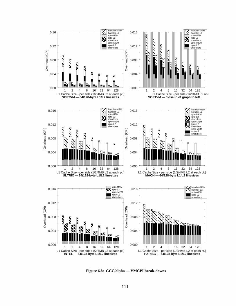
111
1 2 4 8 16 32 64 128L1 Cache Size - per side (1/2/4MB L2 at each pt.)
0.000
0.004
0.008
0.012
0.016
Ove
rhea
d (C
PI)
1 2 4 8 16 32 64 128L1 Cache Size - per side (1/2/4MB L2 at each pt.)
0.000
0.004
0.008
0.012
0.016
Ove
rhea
d (C
PI)
INTEL — 64/128-byte L1/L2 linesizes PARISC — 64/128-byte L1/L2 linesizes
1 2 4 8 16 32 64 128L1 Cache Size - per side (1/2/4MB L2 at each pt.)
0.000
0.004
0.008
0.012
0.016
Ove
rhea
d (C
PI)
1 2 4 8 16 32 64 128L1 Cache Size - per side (1/2/4MB L2 at each pt.)
0.000
0.004
0.008
0.012
0.016
Ove
rhea
d (C
PI)
1 2 4 8 16 32 64 128L1 Cache Size - per side (1/2/4MB L2 at each pt.)
0.00
0.04
0.08
0.12
0.16
Ove
rhea
d (C
PI)
SOFTVM — 64/128-byte L1/L2 linesizes
Figure 6.8: GCC/alpha — VMCPI br eak-downs
1 2 4 8 16 32 64 128L1 Cache Size - per side (1/2/4MB L2 at each pt.)
0.000
0.004
0.008
0.012
0.016
Ove
rhea
d (C
PI)
SOFTVM — closeup of graph to left
uhandlersupte-L2upte-MEMrhandlersrpte-L2rpte-MEMhandler-L2handler-MEM
uhandlersupte-L2upte-MEMrhandlersrpte-L2rpte-MEMhandler-L2handler-MEM
uhandlersupte-L2upte-MEMkhandlerskpte-L2kpte-MEMrhandlersrpte-L2rpte-MEMhandler-L2handler-MEM
uhandlersupte-L2upte-MEMrpte-L2rpte-MEM
uhandlersupte-L2upte-MEMrhandlersrpte-L2rpte-MEMhandler-L2handler-MEM
uhandlersupte-L2upte-MEMhandler-L2handler-MEM
ULTRIX — 64/128-byte L1/L2 linesizes MACH — 64/128-byte L1/L2 linesizes
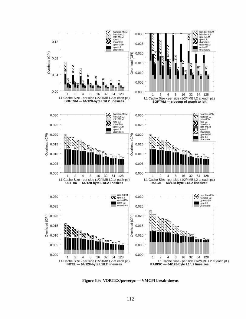
112
1 2 4 8 16 32 64 128L1 Cache Size - per side (1/2/4MB L2 at each pt.)
0.000
0.005
0.010
0.015
0.020
0.025
0.030
Ove
rhea
d (C
PI)
1 2 4 8 16 32 64 128L1 Cache Size - per side (1/2/4MB L2 at each pt.)
0.000
0.005
0.010
0.015
0.020
0.025
0.030
Ove
rhea
d (C
PI)
1 2 4 8 16 32 64 128L1 Cache Size - per side (1/2/4MB L2 at each pt.)
0.000
0.005
0.010
0.015
0.020
0.025
0.030
Ove
rhea
d (C
PI)
1 2 4 8 16 32 64 128L1 Cache Size - per side (1/2/4MB L2 at each pt.)
0.000
0.005
0.010
0.015
0.020
0.025
0.030
Ove
rhea
d (C
PI)
1 2 4 8 16 32 64 128L1 Cache Size - per side (1/2/4MB L2 at each pt.)
0.000
0.005
0.010
0.015
0.020
0.025
0.030
Ove
rhea
d (C
PI)
1 2 4 8 16 32 64 128L1 Cache Size - per side (1/2/4MB L2 at each pt.)
0.00
0.04
0.08
0.12
Ove
rhea
d (C
PI)
Figure 6.9: VORTEX/powerpc — VMCPI br eak-downs
uhandlersupte-L2upte-MEMrhandlersrpte-L2rpte-MEMhandler-L2handler-MEM
uhandlersupte-L2upte-MEMrhandlersrpte-L2rpte-MEMhandler-L2handler-MEM
uhandlersupte-L2upte-MEMkhandlerskpte-L2kpte-MEMrhandlersrpte-L2rpte-MEMhandler-L2handler-MEM
uhandlersupte-L2upte-MEMrpte-L2rpte-MEM
uhandlersupte-L2upte-MEMrhandlersrpte-L2rpte-MEMhandler-L2handler-MEM
uhandlersupte-L2upte-MEMhandler-L2handler-MEM
SOFTVM — 64/128-byte L1/L2 linesizes SOFTVM — closeup of graph to left
ULTRIX — 64/128-byte L1/L2 linesizes MACH — 64/128-byte L1/L2 linesizes
INTEL — 64/128-byte L1/L2 linesizes PARISC — 64/128-byte L1/L2 linesizes
113
The SOFTVM measurements indicate a software-oriented scheme spends more time han-
dling the root-level tables than the other schemes, evidenced by the small but noticeable values for
rhandlers, rpte-L2, andrpte-MEM, which are not large enough in the other simulations to register
on the graphs. Note that these appear despite the increased Level-2 cache size. The reason for the
traffic to the root-level table is due to the lack of TLBs in the software-managed scheme. The hard-
ware-oriented schemes are shielded from having to access the root-level tables by the TLB. Con-
sider a scenario where a user-level PTE needed by the user-level handler is not found in the caches.
There are often times when the corresponding root-level PTE has been displaced from the cache
but not from the TLB. In such cases, a hardware-oriented scheme will perform a cache lookup for
the user-level PTE; the reference misses the cache, but the mapping root-level PTE that is still in
the TLB indicates where in main memory to find the user-level PTE. However, the software-ori-
ented scheme does not have the benefit of the TLB; if the root-level PTE is not in the cache the
software scheme has no choice but to take another cache-miss exception to handle the reference.
When looking at the hardware-oriented schemes, it is immediately obvious that theuhan-
dler cost is a constant for all cache organizations, whereas it decreases with increasing Level-2
cache sizes for the SOFTVM simulations. This is because the frequency of executing theuhandler
is dependent entirely on the TLB performance for the hardware-oriented schemes, whereas it is
dependent on the Level-2 I-cache and D-cache miss rates for the software-oriented scheme. For all
schemes, theuhandlers cost (the base overhead of the handler in terms of the number of instruc-
tions cycles required to execute it given perfect caches) becomes dominant as the cache sizes
increase.
The ULTRIX and MACH simulations produce nearly identical overheads; the MACH
numbers are slightly higher. These graphs serve to support the earlier tentative conclusion that the
main cost of the virtual-memory system is the management of the first-level page table, repre-
sented by the instructions executed in the handler (uhandler), the cost of going to the Level-2
cache during the handler for PTEs and handler code (upte-L2 andhandler-L2, respectively), and
the cost of going to physical memory during the handler for PTEs and handler code (upte-MEM
andhandler-MEM, respectively). We see that the higher-level handlers (rhandler andkhandler)
are almost completely unrepresented; their costs are lost in the noise. Therefore it is not surprising
that ULTRIX and MACH produce similar results, as the simulated organizations differ only by the
addition of a third page-table tier in MACH.
The INTEL measurements produce something unseen in the other simulations: the over-
head of having to go to the Level-2 cache and physical memory for the root-level PTE (rpte-L2 and
114
rpte-MEM). This occurs so infrequently in the other simulations that it does not register in the bar
charts; however, it is very prominent in the INTEL measurements. This is because of the structure
of the page table in the Intel Architecture; it is a hierarchical page table walked in a top-down man-
ner, so the root-level is accessed every time the TLB-miss handler is executed. The graphs show
that for small Level-1 caches, one will miss the Level-1 cache equally often when referencing the
root-level and user-level PTEs (rpte-L2 andupte-L2 are roughly the same size). If one PTE refer-
ence is likely to miss the cache, the other is likely to miss the cache as well. However, as one
increases the size of the Level-1 cache, therpte-L2 overhead grows smaller; this is expected, since
a single root-level PTE maps many user-level PTEs.
When looking at the GCC results, the measurements of the PARISC simulation appear
very similar to those of the ULTRIX and MACH simulations at first glance. However, the behavior
is slightly different. Unlike the other hardware-oriented schemes (including the INTEL simula-
tion), the PARISC simulation seems to be relatively insensitive to the size of the Level-2 cache for
GCC. The other simulations have a large drop-off from a 1MB Level-2 cache to a 2MB Level-2
cache; PARISC does not exhibit this behavior. The difference is that where theupte-MEM mea-
surements for the other simulations are large for a 1MB L2 cache, they are small for PARISC. This
is due to the different page table organization; the ULTRIX, MACH, and INTEL page tables are
hierarchical and are allocated a page at a time. Therefore the linear extent of the hierarchical page
table is proportional to the size of the virtual address space, which simply means that the hierarchi-
cal page table is likely to spread itself across a large portion of the cache, if not across the entire
cache. In contrast, the PARISC simulations use a hashed page table which clusters the PTEs
together densely; therefore the page table is likely to be spread across a smaller portion of the
cache. The two page table organizations have exactly the same number of page table entries (equal
to the number of unique pages in the application), and so should exhibit statistically the same
degree of contention with the user program’s data. The PARISC hashed page table, however,
shows that it is less likely to hit cache hotspots in the Level-2 cache than is the hierarchical page
table. This is not the end of the story, though; whereas in the other simulations theupte-L2 values
decrease by roughly half from small L1 caches to large L1 caches, suggesting that the larger Level-
1 caches are better at caching the page tables, these values decrease by only 25% for the PARISC
simulations. This suggests that though the hashed page table may fit better in the Level-2 cache, it
actually fits worse in the Level-1 cache than the other page table organizations. This is likely due
to the fact that each PTE for the hashed page table is twice the size of the PTEs for the other
schemes.
115
When looking at the VORTEX results we see quite different behavior; the PARISC mea-
surements suggest that the inverted table fits better in both Level-1 and Level-2 caches than the
hierarchical table. The frequency of missing the Level-1 cache on PTE loads decreases by roughly
80% as the Level-1 cache size increases (upte-L2), as opposed to decreases of 50% for the other
hardware-oriented schemes, and the frequency of missing the Level-2 cache on PTE loads is much
lower than any other VM-simulation (upte-MEM). The bars for large Level-1 cache sizes show that
very little of the time in the handler is spent stalling for cache misses.
At first glance, this seems very similar to the SOFTVM results for large Level-1 and
Level-2 caches; the bulk of the time in these simulations is spent executing the handler, not waiting
for cache-miss stalls. However, as we will discuss in the next section, the reason for SOFTVM’s
behavior is due to the frequency with which the SOFTVM handler is executed, and not due to the
organization of its page table.
6.2.3 Cost per Invocation of the Handler
This section takes a look at the average costs of executing the TLB-miss and cache-miss
handlers. These numbers represent the same data as in previous graphs, but rather than normaliz-
ing by the number of instructions executed (to obtain CPI values), we normalize by the number of
times the handler is executed. We would expect that as cache size increases, the per-miss cost of
executing a handler should decrease, for two reasons: first, the page tables are more likely to fit
into a larger D-cache and contend less with program data; second, if the handler is executed out of
the I-cache (as opposed to the hardware state machine in the INTEL simulations), larger I-caches
are more likely to keep the handler resident between successive invocations of the handler. It is
also likely that larger cache linesizes will be better for the software-managed schemes, as the soft-
ware handler can be fetched in fewer cache-fill steps.
Frequency of Handler Invocation
We begin with an illustration of how often the handlers are executed. This is not the same
for all of the simulations; moreover, it is not the same for all of the TLB-based simulations, as one
might expect. In this section, we only discuss GCC and VORTEX for the sake of brevity. The cho-
sen metric is themean free path—the average number of application instructions executed
between successive calls to the handler (either TLB-miss handler or cache-miss handler, depend-
ing on the VM-simulation). We calculate the mean free path individually for both the instruction
stream and the data stream. The mean free instruction-path is the total number of application
instructions executed divided by the number of times the handler is executed to resolve an instruc-
116
tion miss; the mean free data-path is the total number of application instructions executed divided
by the number of times the handler is executed to resolve a data miss.
The mean-time-between-handlers for both GCC and VORTEX is shown in Figure 6.10.
For the software-oriented scheme, this is proportional to the hit rates for the Level-2 I-cache and
D-cache. For the hardware-oriented schemes, this is proportional to the hit rates for the I-TLB and
D-TLB. The SOFTVM numbers represent large Level-1 caches, and the numbers for the hard-
ware-oriented schemes are averages (since the values are independent of simulated cache size).
Each individual simulation may vary from these numbers by a relatively small margin.
One very interesting result is the extreme differences between the instruction-path lengths
and the data-path lengths for VORTEX. Whereas the paths for GCC are in the same range (the
GCC instruction-path lengths are roughly 50% longer than the data-path lengths), the instruction-
path lengths in VORTEX are roughly two orders of magnitude longer than the data-path lengths.
This is surprising, given the high I-cache miss-rates for VORTEX, shown in Figure 6.3(g). The
miss-rates suggest that the instruction-stream footprint is relatively large (perhaps larger than
GCC). However, the extremely long mean free paths between I-TLB misses suggest that the foot-
print is easily mapped by a 128-entry I-TLB, which maps 512KB of space. The instruction foot-
print of GCC is likely much larger than this, given the smaller instruction-path lengths.
To get a feeling for how sensitive the simulations are to the size of the TLBs, we measured
the mean free-paths for two other TLB sizes, running GCC on an ULTRIX-lik e VM-simulation
with a hierarchical page table and 1/8 of the TLB entries reserved for “protected” PTEs. The sin-
gle-level cache is 4MB. The results are shown in Figure 6.11. This graph is very important; it dem-
onstrates a significant sensitivity to the TLB size. This explains why there can be such a difference
between the ULTRIX/MACH free paths and the INTEL/PARISC free paths (this behavior is dis-
cussed in detail later). This figure suggests that were the hardware-oriented schemes to use 64-
entry TLBs rather than 128-entry TLBs, the virtual-memory overheads would be roughly five
times worse. Since the software-oriented scheme has been shown to have a performance at worst
five times greater than the hardware schemes, if it were compared to hardware schemes using 64-
entry TLBs it should prove to be several times better than them. Similarly, it should prove to be
many times worse than hardware schemes using 256-entry TLBs, but these are unrealistically large
sizes at this point in time: 64 is the current typical size.
mean free path instructions executednumber of times handler invoked� � � � � � � � � � � � � � � � � � � � � � � � � � � � � � � � � � � � � � � � � � � � � � � � � � � � � � � � � � � � � � � � � � � � � � � � � � � � � � �=
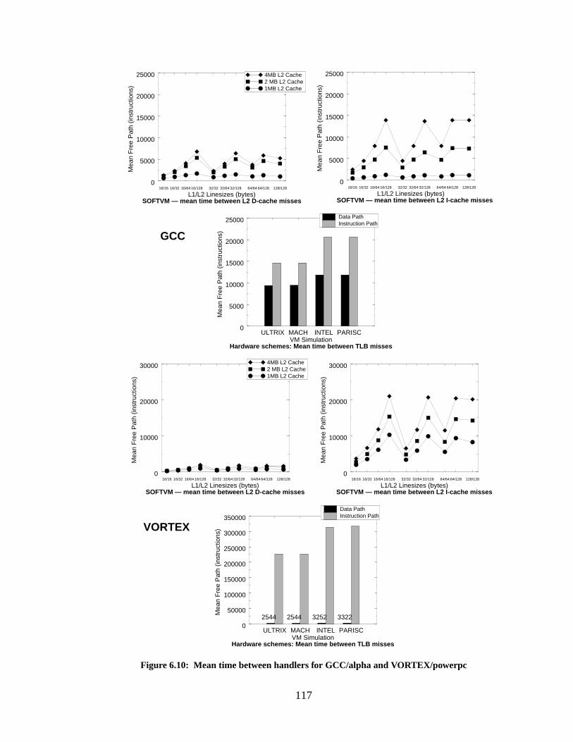
117
Figure 6.10: Mean time between handlers for GCC/alpha and VORTEX/powerpc
16/16 16/32 16/64 16/128 32/32 32/64 32/128 64/64 64/128 128/128
L1/L2 Linesizes (bytes)
0
5000
10000
15000
20000
25000
Mea
n F
ree
Pat
h (in
stru
ctio
ns) 1MB L2 Cache
2 MB L2 Cache4MB L2 Cache
SOFTVM — mean time between L2 D-cache misses
16/16 16/32 16/64 16/128 32/32 32/64 32/128 64/64 64/128 128/128
L1/L2 Linesizes (bytes)
0
5000
10000
15000
20000
25000
Mea
n F
ree
Pat
h (in
stru
ctio
ns)
SOFTVM — mean time between L2 I-cache misses
ULTRIX MACH INTEL PARISCVM Simulation
0
5000
10000
15000
20000
25000M
ean
Fre
e P
ath
(inst
ruct
ions
)Data PathInstruction Path
Hardware schemes: Mean time between TLB misses
ULTRIX MACH INTEL PARISCVM Simulation
0
50000
100000
150000
200000
250000
300000
350000
Mea
n F
ree
Pat
h (in
stru
ctio
ns)
2544 2544 3252 3322
Data PathInstruction Path
16/16 16/32 16/64 16/128 32/32 32/64 32/128 64/64 64/128 128/128
L1/L2 Linesizes (bytes)
0
10000
20000
30000
Mea
n F
ree
Pat
h (in
stru
ctio
ns)
16/16 16/32 16/64 16/128 32/32 32/64 32/128 64/64 64/128 128/128
L1/L2 Linesizes (bytes)
0
10000
20000
30000
Mea
n F
ree
Pat
h (in
stru
ctio
ns)
SOFTVM — mean time between L2 D-cache misses SOFTVM — mean time between L2 I-cache misses
Hardware schemes: Mean time between TLB misses
1MB L2 Cache2 MB L2 Cache4MB L2 Cache
GCC
VORTEX
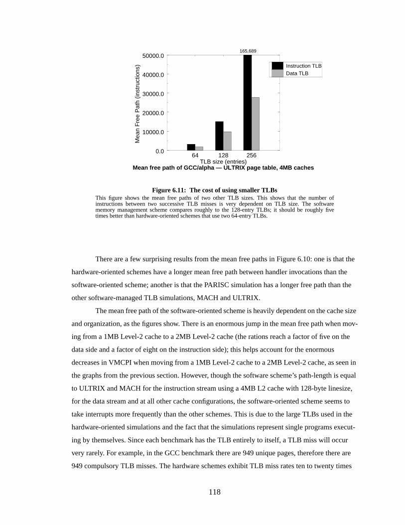
118
There are a few surprising results from the mean free paths in Figure 6.10: one is that the
hardware-oriented schemes have a longer mean free path between handler invocations than the
software-oriented scheme; another is that the PARISC simulation has a longer free path than the
other software-managed TLB simulations, MACH and ULTRIX.
The mean free path of the software-oriented scheme is heavily dependent on the cache size
and organization, as the figures show. There is an enormous jump in the mean free path when mov-
ing from a 1MB Level-2 cache to a 2MB Level-2 cache (the rations reach a factor of five on the
data side and a factor of eight on the instruction side); this helps account for the enormous
decreases in VMCPI when moving from a 1MB Level-2 cache to a 2MB Level-2 cache, as seen in
the graphs from the previous section. However, though the software scheme’s path-length is equal
to ULTRIX and MACH for the instruction stream using a 4MB L2 cache with 128-byte linesize,
for the data stream and at all other cache configurations, the software-oriented scheme seems to
take interrupts more frequently than the other schemes. This is due to the large TLBs used in the
hardware-oriented simulations and the fact that the simulations represent single programs execut-
ing by themselves. Since each benchmark has the TLB entirely to itself, a TLB miss will occur
very rarely. For example, in the GCC benchmark there are 949 unique pages, therefore there are
949 compulsory TLB misses. The hardware schemes exhibit TLB miss rates ten to twenty times
64 128 256TLB size (entries)
0.0
10000.0
20000.0
30000.0
40000.0
50000.0
Mea
n F
ree
Pat
h (in
stru
ctio
ns) Instruction TLB
Data TLB
Mean free path of GCC/alpha — ULTRIX page table, 4MB caches
Figure 6.11: The cost of using smaller TLBsThis figure shows the mean free paths of two other TLB sizes. This shows that the number ofinstructions between two successive TLB misses is very dependent on TLB size. The softwarememory management scheme compares roughly to the 128-entry TLBs; it should be roughly fivetimes better than hardware-oriented schemes that use two 64-entry TLBs.
165,689
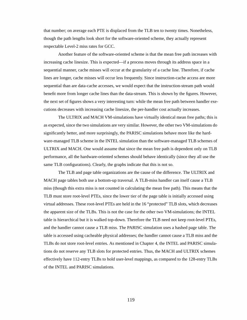
119
that number; on average each PTE is displaced from the TLB ten to twenty times. Nonetheless,
though the path lengths look short for the software-oriented scheme, they actually represent
respectable Level-2 miss rates for GCC.
Another feature of the software-oriented scheme is that the mean free path increases with
increasing cache linesize. This is expected—if a process moves through its address space in a
sequential manner, cache misses will occur at the granularity of a cache line. Therefore, if cache
lines are longer, cache misses will occur less frequently. Since instruction-cache access are more
sequential than are data-cache accesses, we would expect that the instruction-stream path would
benefit more from longer cache lines than the data-stream. This is shown by the figures. However,
the next set of figures shows a very interesting turn: while the mean free path between handler exe-
cutions decreases with increasing cache linesize, the per-handler cost actually increases.
The ULTRIX and MACH VM-simulations have virtually identical mean free paths; this is
as expected, since the two simulations are very similar. However, the other two VM-simulations do
significantly better, and more surprisingly, the PARISC simulations behave more like the hard-
ware-managed TLB scheme in the INTEL simulation than the software-managed TLB schemes of
ULTRIX and MACH. One would assume that since the mean free path is dependent only on TLB
performance, all the hardware-oriented schemes should behave identically (since they all use the
same TLB configurations). Clearly, the graphs indicate that this is not so.
The TLB and page table organizations are the cause of the difference. The ULTRIX and
MACH page tables both use a bottom-up traversal. A TLB-miss handler can itself cause a TLB
miss (though this extra miss is not counted in calculating the mean free path). This means that the
TLB must store root-level PTEs, since the lower tier of the page table is initially accessed using
virtual addresses. These root-level PTEs are held in the 16 “protected” TLB slots, which decreases
the apparent size of the TLBs. This is not the case for the other two VM-simulations; the INTEL
table is hierarchical but it is walked top-down. Therefore the TLB need not keep root-level PTEs,
and the handler cannot cause a TLB miss. The PARISC simulation uses a hashed page table. The
table is accessed using cacheable physical addresses; the handler cannot cause a TLB miss and the
TLBs do not store root-level entries. As mentioned in Chapter 4, the INTEL and PARISC simula-
tions do not reserve any TLB slots for protected entries. Thus, the MACH and ULTRIX schemes
effectively have 112-entry TLBs to hold user-level mappings, as compared to the 128-entry TLBs
of the INTEL and PARISC simulations.
120
Average Cycles per Invocation
As mentioned in the previous section, an invocation of the handler is considered to be a
response to application activity. Therefore if a handler causes a TLB miss or cache miss that needs
to be handled by another handler invocation, this is still counted as part of the first handler’s invo-
cation. The costs of the handlers are graphed as a function of the cache sizes and cache linesizes;
this will be followed by break-downs of several specific configurations to show where the time is
spent per handler. For brevity, we only show the results for the smallest and largest (1MB and
4MB) Level-2 caches—these are shown in the first two columns. The graphs in the third column
are a re-organization of the data in the second column to highlight the effect of changing linesize
within a given cache size: these represent only the 4MB Level-2 cache size. The difference that the
Level-2 cache makes is between 10% and 50% depending on the VM-simulation and the cache
organization. Since for the hardware-oriented schemes, the graphs are essentially identical to those
in Section 6.2.2 only scaled by the mean free path (which is a constant for the TLB-based sys-
tems), we only show the results for GCC. Figure 6.12 shows the per-invocation costs of the handler
under GCC.
The SOFTVM simulations produce three surprising results: the per-invocation cost of the
handler is actually smaller than most of the other handler costs (including the INTEL handler for
many linesize configurations), the per-invocation handler cost seems to be relatively unaffected by
the size of the Level-2 cache, and the handler cost increases with increasing cache linesize. The
following set of bar graphs illustrate the effect more clearly; as the linesize of the Level-2 cache
increases, the frequency of going to the Level-2 cache for both handler instructions (handler-L2)
and page table entries (upte-L2and rpte-L2) increases. This provides an interesting counterpoint to
the total VMCPI overhead, which generally decreases with increasing linesize. We will address
this later.
The other VM-simulations behave as expected. Moving from a 1MB L2 cache to a 4MB
L2 cache lowers the per-invocation handler overhead by roughly one-third. For a given Level-1
linesize, a larger Level-2 linesize yields a lower overhead. For the INTEL scheme, larger Level-1
linesizes are worse than smaller Level-1 linesizes—this makes sense because the INTEL scheme
does not cache the handler. This makes the data cache the performance bottleneck, and the data
cache has been shown to perform better with smaller linesizes. For the other VM-simulations,
which all have a software-managed TLB, a larger Level-1 linesize yields a lower overhead, up to
the 128-byte linesize for the MACH and ULTRIX simulations. In these VM-simulations, the 128-
byte linesize is slightly worse than the 64-byte linesize for small caches (32KB and smaller). The
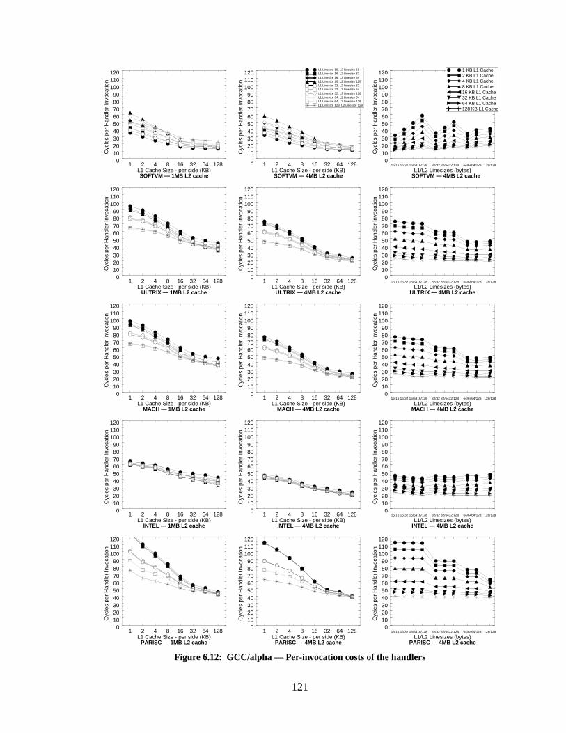
121
Figure 6.12: GCC/alpha — Per-invocation costs of the handlers
1 2 4 8 16 32 64 128L1 Cache Size - per side (KB)
0102030405060708090
100110120
Cyc
les
per
Han
dler
Invo
catio
n
SOFTVM — 1MB L2 cache
1 2 4 8 16 32 64 128L1 Cache Size - per side (KB)
0102030405060708090
100110120
Cyc
les
per
Han
dler
Invo
catio
n
SOFTVM — 4MB L2 cache
16/16 16/32 16/6416/128 32/32 32/6432/128 64/6464/128 128/128
L1/L2 Linesizes (bytes)
0102030405060708090
100110120
Cyc
les
per
Han
dler
Invo
catio
n
SOFTVM — 4MB L2 cache
16/16 16/32 16/6416/128 32/32 32/6432/128 64/6464/128 128/128
L1/L2 Linesizes (bytes)
0102030405060708090
100110120
Cyc
les
per
Han
dler
Invo
catio
n
ULTRIX — 4MB L2 cache
1 2 4 8 16 32 64 128L1 Cache Size - per side (KB)
0102030405060708090
100110120
Cyc
les
per
Han
dler
Invo
catio
n
ULTRIX — 4MB L2 cache
1 2 4 8 16 32 64 128L1 Cache Size - per side (KB)
0102030405060708090
100110120
Cyc
les
per
Han
dler
Invo
catio
n
ULTRIX — 1MB L2 cache
1 2 4 8 16 32 64 128L1 Cache Size - per side (KB)
0102030405060708090
100110120
Cyc
les
per
Han
dler
Invo
catio
n
MACH — 1MB L2 cache
1 2 4 8 16 32 64 128L1 Cache Size - per side (KB)
0102030405060708090
100110120
Cyc
les
per
Han
dler
Invo
catio
n
MACH — 4MB L2 cache
16/16 16/32 16/6416/128 32/32 32/6432/128 64/6464/128 128/128
L1/L2 Linesizes (bytes)
0102030405060708090
100110120
Cyc
les
per
Han
dler
Invo
catio
n
MACH — 4MB L2 cache
16/16 16/32 16/6416/128 32/32 32/6432/128 64/6464/128 128/128
L1/L2 Linesizes (bytes)
0102030405060708090
100110120
Cyc
les
per
Han
dler
Invo
catio
n
INTEL — 4MB L2 cache
1 2 4 8 16 32 64 128L1 Cache Size - per side (KB)
0102030405060708090
100110120
Cyc
les
per
Han
dler
Invo
catio
n
INTEL — 4MB L2 cache
1 2 4 8 16 32 64 128L1 Cache Size - per side (KB)
0102030405060708090
100110120
Cyc
les
per
Han
dler
Invo
catio
n
INTEL — 1MB L2 cache
1 2 4 8 16 32 64 128L1 Cache Size - per side (KB)
0102030405060708090
100110120
Cyc
les
per
Han
dler
Invo
catio
n
PARISC — 1MB L2 cache
1 2 4 8 16 32 64 128L1 Cache Size - per side (KB)
0102030405060708090
100110120
Cyc
les
per
Han
dler
Invo
catio
n
PARISC — 4MB L2 cache
16/16 16/32 16/6416/128 32/32 32/6432/128 64/6464/128 128/128
L1/L2 Linesizes (bytes)
0102030405060708090
100110120
Cyc
les
per
Han
dler
Invo
catio
n
PARISC — 4MB L2 cache
L1 Linesize 16, L2 Linesize 16L1 Linesize 16, L2 Linesize 32L1 Linesize 16, L2 Linesize 64L1 Linesize 16, L2 Linesize 128L1 Linesize 32, L2 Linesize 32L1 Linesize 32, L2 Linesize 64L1 Linesize 32, L2 Linesize 128L1 Linesize 64, L2 Linesize 64L1 Linesize 64, L2 Linesize 128L1 Linesize 128, L2 Linesize 128
1 KB L1 Cache2 KB L1 Cache4 KB L1 Cache8 KB L1 Cache16 KB L1 Cache32 KB L1 Cache64 KB L1 Cache128 KB L1 Cache
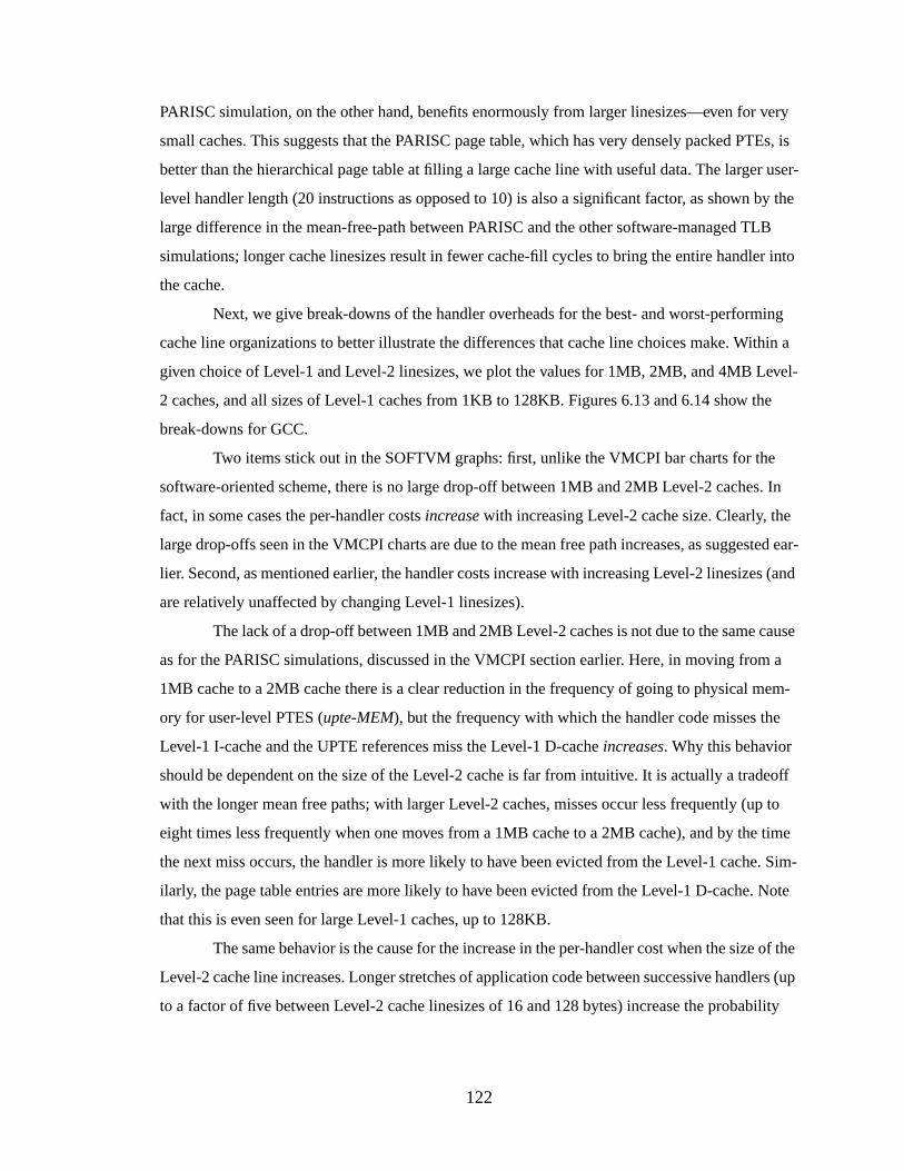
122
PARISC simulation, on the other hand, benefits enormously from larger linesizes—even for very
small caches. This suggests that the PARISC page table, which has very densely packed PTEs, is
better than the hierarchical page table at filling a large cache line with useful data. The larger user-
level handler length (20 instructions as opposed to 10) is also a significant factor, as shown by the
large difference in the mean-free-path between PARISC and the other software-managed TLB
simulations; longer cache linesizes result in fewer cache-fill cycles to bring the entire handler into
the cache.
Next, we give break-downs of the handler overheads for the best- and worst-performing
cache line organizations to better illustrate the differences that cache line choices make. Within a
given choice of Level-1 and Level-2 linesizes, we plot the values for 1MB, 2MB, and 4MB Level-
2 caches, and all sizes of Level-1 caches from 1KB to 128KB. Figures 6.13 and 6.14 show the
break-downs for GCC.
Two items stick out in the SOFTVM graphs: first, unlike the VMCPI bar charts for the
software-oriented scheme, there is no large drop-off between 1MB and 2MB Level-2 caches. In
fact, in some cases the per-handler costsincrease with increasing Level-2 cache size. Clearly, the
large drop-offs seen in the VMCPI charts are due to the mean free path increases, as suggested ear-
lier. Second, as mentioned earlier, the handler costs increase with increasing Level-2 linesizes (and
are relatively unaffected by changing Level-1 linesizes).
The lack of a drop-off between 1MB and 2MB Level-2 caches is not due to the same cause
as for the PARISC simulations, discussed in the VMCPI section earlier. Here, in moving from a
1MB cache to a 2MB cache there is a clear reduction in the frequency of going to physical mem-
ory for user-level PTES (upte-MEM), but the frequency with which the handler code misses the
Level-1 I-cache and the UPTE references miss the Level-1 D-cacheincreases. Why this behavior
should be dependent on the size of the Level-2 cache is far from intuitive. It is actually a tradeoff
with the longer mean free paths; with larger Level-2 caches, misses occur less frequently (up to
eight times less frequently when one moves from a 1MB cache to a 2MB cache), and by the time
the next miss occurs, the handler is more likely to have been evicted from the Level-1 cache. Sim-
ilarly, the page table entries are more likely to have been evicted from the Level-1 D-cache. Note
that this is even seen for large Level-1 caches, up to 128KB.
The same behavior is the cause for the increase in the per-handler cost when the size of the
Level-2 cache line increases. Longer stretches of application code between successive handlers (up
to a factor of five between Level-2 cache linesizes of 16 and 128 bytes) increase the probability
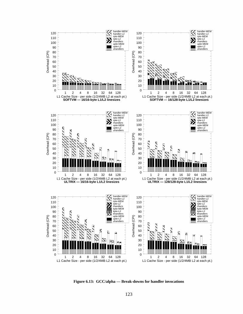
123
1 2 4 8 16 32 64 128L1 Cache Size - per side (1/2/4MB L2 at each pt.)
0
10
20
30
40
50
60
70
80
90
100
110
120
Ove
rhea
d (C
PI)
1 2 4 8 16 32 64 128L1 Cache Size - per side (1/2/4MB L2 at each pt.)
0
10
20
30
40
50
60
70
80
90
100
110
120
Ove
rhea
d (C
PI)
1 2 4 8 16 32 64 128L1 Cache Size - per side (1/2/4MB L2 at each pt.)
0
10
20
30
40
50
60
70
80
90
100
110
120
Ove
rhea
d (C
PI)
SOFTVM — 16/128-byte L1/L2 linesizes
1 2 4 8 16 32 64 128L1 Cache Size - per side (1/2/4MB L2 at each pt.)
0
10
20
30
40
50
60
70
80
90
100
110
120
Ove
rhea
d (C
PI)
1 2 4 8 16 32 64 128L1 Cache Size - per side (1/2/4MB L2 at each pt.)
0
10
20
30
40
50
60
70
80
90
100
110
120
Ove
rhea
d (C
PI)
uhandlersupte-L2upte-MEMkhandlerskpte-L2kpte-MEMrhandlersrpte-L2rpte-MEMhandler-L2handler-MEM
uhandlersupte-L2upte-MEMkhandlerskpte-L2kpte-MEMrhandlersrpte-L2rpte-MEMhandler-L2handler-MEM
Figure 6.13: GCC/alpha — Break-downs for handler invocations
1 2 4 8 16 32 64 128L1 Cache Size - per side (1/2/4MB L2 at each pt.)
0
10
20
30
40
50
60
70
80
90
100
110
120
Ove
rhea
d (C
PI)
SOFTVM — 16/16-byte L1/L2 linesizes
uhandlersupte-L2upte-MEMrhandlersrpte-L2rpte-MEMhandler-L2handler-MEM
uhandlersupte-L2upte-MEMrhandlersrpte-L2rpte-MEMhandler-L2handler-MEM
uhandlersupte-L2upte-MEMrhandlersrpte-L2rpte-MEMhandler-L2handler-MEM
uhandlersupte-L2upte-MEMrhandlersrpte-L2rpte-MEMhandler-L2handler-MEM
ULTRIX — 16/16-byte L1/L2 linesizes ULTRIX — 128/128-byte L1/L2 linesizes
124
1 2 4 8 16 32 64 128L1 Cache Size - per side (1/2/4MB L2 at each pt.)
0
10
20
30
40
50
60
70
80
90
100
110
120
Ove
rhea
d (C
PI)
INTEL — 16/128-byte L1/L2 linesizes
1 2 4 8 16 32 64 128L1 Cache Size - per side (1/2/4MB L2 at each pt.)
0
10
20
30
40
50
60
70
80
90
100
110
120
Ove
rhea
d (C
PI)
1 2 4 8 16 32 64 128L1 Cache Size - per side (1/2/4MB L2 at each pt.)
0
10
20
30
40
50
60
70
80
90
100
110
120
Ove
rhea
d (C
PI)
1 2 4 8 16 32 64 128L1 Cache Size - per side (1/2/4MB L2 at each pt.)
0
10
20
30
40
50
60
70
80
90
100
110
120
Ove
rhea
d (C
PI)
Figure 6.14: GCC/alpha — Break-downs for handler invocations, cont’d
uhandlersupte-L2upte-MEMrpte-L2rpte-MEM
uhandlersupte-L2upte-MEMhandler-L2handler-MEM
uhandlersupte-L2upte-MEMrpte-L2rpte-MEM
uhandlersupte-L2upte-MEMhandler-L2handler-MEM
INTEL — 128/128-byte L1/L2 linesizes
PARISC — 128/128-byte L1/L2 linesizesPARISC — 16/16-byte L1/L2 linesizes
125
that the handler code and page table entries have been displaced from the Level-1 caches by the
time the handler is re-executed.
There is a similar explanation for why the cost of the SOFTVM handler is lower than the
handlers of the other simulations. The SOFTVM handler is executed more frequently than the oth-
ers, therefore it is more likely to have cache-resident instructions and data on its succeeding re-
execution.This is evidenced by the values forupte-L2 andupte-MEM, which are significantly
lower for the SOFTVM simulations than for the other VM-simulations. Also, the SOFTVM values
for handler-L2 andhandler-MEM are slightly lower than for the other VM-simulations.
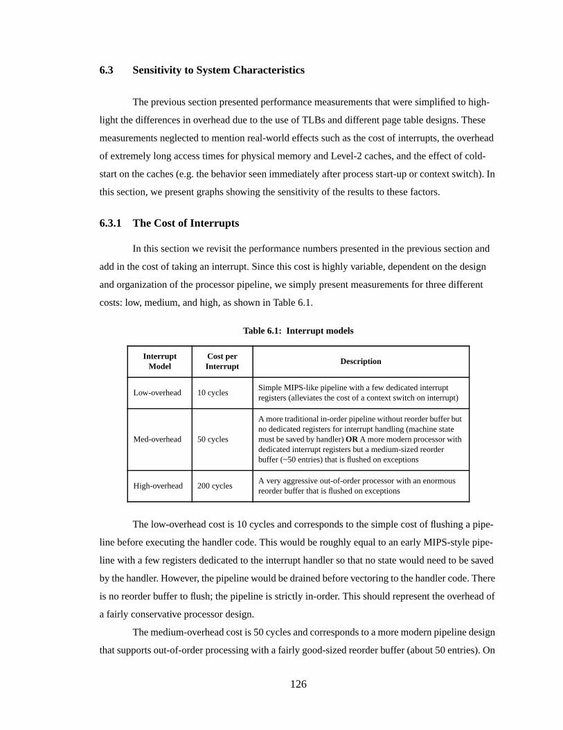
126
6.3 Sensitivity to System Characteristics
The previous section presented performance measurements that were simplified to high-
light the differences in overhead due to the use of TLBs and different page table designs. These
measurements neglected to mention real-world effects such as the cost of interrupts, the overhead
of extremely long access times for physical memory and Level-2 caches, and the effect of cold-
start on the caches (e.g. the behavior seen immediately after process start-up or context switch). In
this section, we present graphs showing the sensitivity of the results to these factors.
6.3.1 The Cost of Interrupts
In this section we revisit the performance numbers presented in the previous section and
add in the cost of taking an interrupt. Since this cost is highly variable, dependent on the design
and organization of the processor pipeline, we simply present measurements for three different
costs: low, medium, and high, as shown in Table 6.1.
The low-overhead cost is 10 cycles and corresponds to the simple cost of flushing a pipe-
line before executing the handler code. This would be roughly equal to an early MIPS-style pipe-
line with a few registers dedicated to the interrupt handler so that no state would need to be saved
by the handler. However, the pipeline would be drained before vectoring to the handler code. There
is no reorder buffer to flush; the pipeline is strictly in-order. This should represent the overhead of
a fairly conservative processor design.
The medium-overhead cost is 50 cycles and corresponds to a more modern pipeline design
that supports out-of-order processing with a fairly good-sized reorder buffer (about 50 entries). On
Table 6.1: Interrupt models
InterruptModel
Cost perInterrupt
Description
Low-overhead 10 cyclesSimple MIPS-like pipeline with a few dedicated interruptregisters (alleviates the cost of a context switch on interrupt)
Med-overhead 50 cycles
A more traditional in-order pipeline without reorder buffer butno dedicated registers for interrupt handling (machine statemust be saved by handler)OR A more modern processor withdedicated interrupt registers but a medium-sized reorderbuffer (~50 entries) that is flushed on exceptions
High-overhead 200 cyclesA very aggressive out-of-order processor with an enormousreorder buffer that is flushed on exceptions
127
interrupt, the entire reorder buffer is flushed, but no state would be saved by the handler due to a
set of registers dedicated for the handler’s use. This should represent the overhead of most of
today’s commercial processors.
The high-overhead model has a cost of 200 cycles and represents a very aggressive out-of-
order design with a reorder buffer several times larger than those of contemporary processors. This
should represent the overhead of near-future processors. Hopefully, by the time that reorder buffers
grow substantially larger than 200 entries (as they doubtlessly will), the problem of flushing the
entire buffer on exceptions will be solved.
For each interrupt model, we present graphs for the best-case cache organizations as
shown in the VMCPI break-downs of the previous chapter: L1/L2 linesizes of 64/128 bytes, 4MB
Level-2 caches. In the recalculations we have increased the value ofuhandlers, rhandlers, and
khandlers by the appropriate interrupt cost. Note that even increased,khandlers andrhandlers are
still lost in the noise. In the interest of space we only show the benchmarks GCC and VORTEX.
Note that the INTEL scheme is unaffected by the cost of interrupts; it has a hardware-managed
TLB that does not impact the state of the machine when the TLB-miss handler executes. Figures
6.15, 6.16 and 6.17 show the low-overhead, medium-overhead, and high-overhead recalculations
for GCC; Figures 6.18, 6.19 and 6.20 show the recalculations for VORTEX.
It is immediately clear that large caches are important for the software-oriented memory-
management scheme; without Level-2 caches of 2MB or more (split 1MB/1MB I/D), the cost of
the high-overhead interrupt model is intolerable and even the low-overhead interrupt model is sig-
nificant. However, with large caches, the overheads become reasonable, even for the extremely
high overhead of 200 cycles per interrupt.
There is little difference between the low-overhead interrupt model and the earlier VMCPI
graphs of Section 6.2.2. The VM-simulations still have very low overheads (provided that large
Level-2 caches are used), as 0.01 CPI should represent at most a few percent of run-time overhead.
The medium-overhead interrupt model is only a little worse, but it is clear that the cost of inter-
rupts is becoming the dominant factor. The low-overhead interrupt model is still a viable solution
for a system, especially since the handler itself would not need to be particularly efficient—one
could implement a complex page table or vector all interrupts through the same entry point and the
increased cost would be negligible. However, it is obvious that such high interrupt costs are dam-
aging to system performance and must be addressed.
Note that a hardware-managed TLB (as in the INTEL simulation) is a simple and
extremely effective solution to the problem, as it is completely unaffected by the interrupt cost.
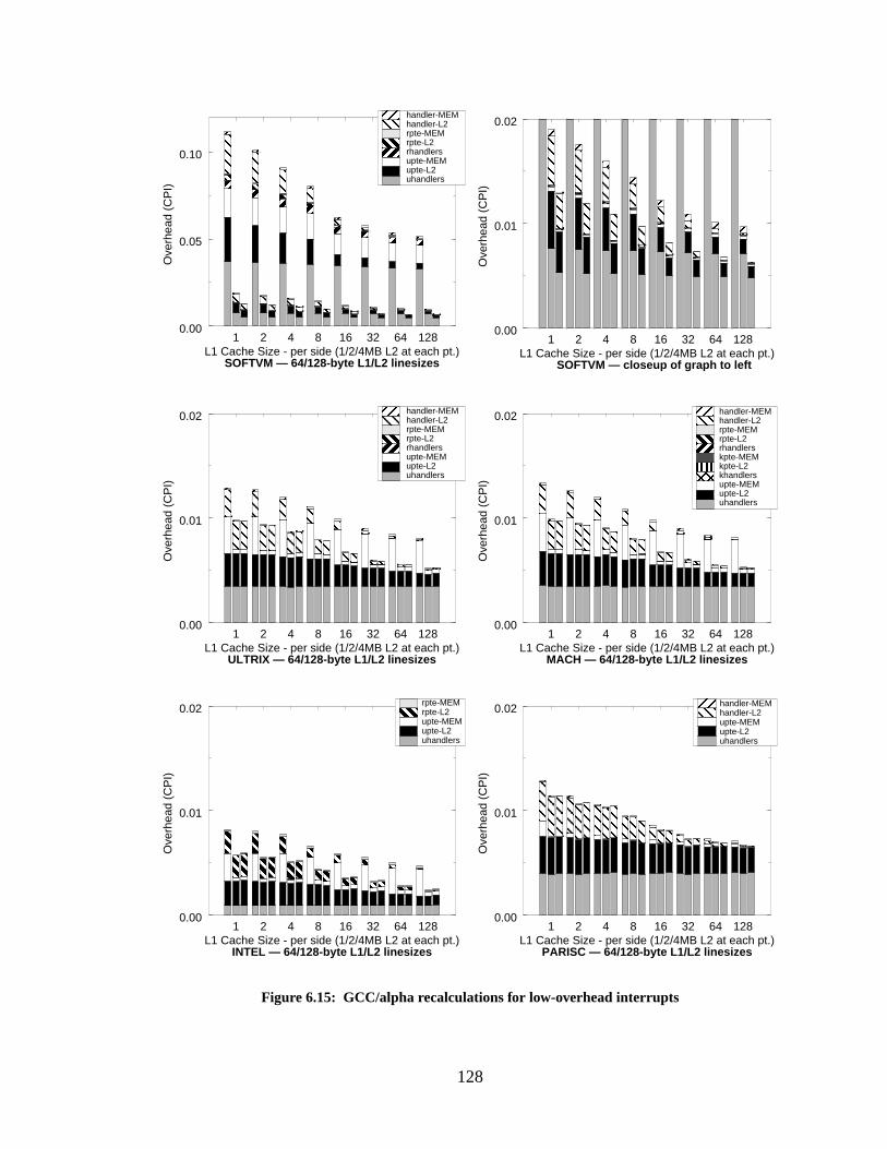
128
1 2 4 8 16 32 64 128L1 Cache Size - per side (1/2/4MB L2 at each pt.)
0.00
0.01
0.02
Ove
rhea
d (C
PI)
1 2 4 8 16 32 64 128L1 Cache Size - per side (1/2/4MB L2 at each pt.)
0.00
0.01
0.02
Ove
rhea
d (C
PI)
1 2 4 8 16 32 64 128L1 Cache Size - per side (1/2/4MB L2 at each pt.)
0.00
0.05
0.10O
verh
ead
(CP
I)uhandlersupte-L2upte-MEMrhandlersrpte-L2rpte-MEMhandler-L2handler-MEM
Figure 6.15: GCC/alpha recalculations for low-overhead interrupts
SOFTVM — 64/128-byte L1/L2 linesizes
uhandlersupte-L2upte-MEMkhandlerskpte-L2kpte-MEMrhandlersrpte-L2rpte-MEMhandler-L2handler-MEM
1 2 4 8 16 32 64 128L1 Cache Size - per side (1/2/4MB L2 at each pt.)
0.00
0.01
0.02
Ove
rhea
d (C
PI)
uhandlersupte-L2upte-MEMrpte-L2rpte-MEM
INTEL — 64/128-byte L1/L2 linesizes
1 2 4 8 16 32 64 128L1 Cache Size - per side (1/2/4MB L2 at each pt.)
0.00
0.01
0.02
Ove
rhea
d (C
PI)
SOFTVM — closeup of graph to left
1 2 4 8 16 32 64 128L1 Cache Size - per side (1/2/4MB L2 at each pt.)
0.00
0.01
0.02
Ove
rhea
d (C
PI)
ULTRIX — 64/128-byte L1/L2 linesizes MACH — 64/128-byte L1/L2 linesizes
uhandlersupte-L2upte-MEMrhandlersrpte-L2rpte-MEMhandler-L2handler-MEM
uhandlersupte-L2upte-MEMhandler-L2handler-MEM
PARISC — 64/128-byte L1/L2 linesizes
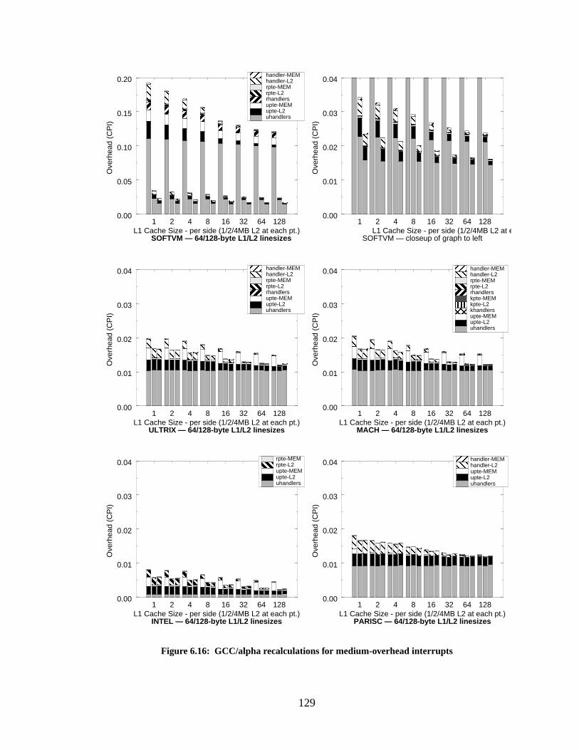
129
1 2 4 8 16 32 64 128L1 Cache Size - per side (1/2/4MB L2 at each pt.)
0.00
0.01
0.02
0.03
0.04
Ove
rhea
d (C
PI)
1 2 4 8 16 32 64 128L1 Cache Size - per side (1/2/4MB L2 at each pt.)
0.00
0.05
0.10
0.15
0.20
Ove
rhea
d (C
PI)
1 2 4 8 16 32 64 128L1 Cache Size - per side (1/2/4MB L2 at each pt.)
0.00
0.01
0.02
0.03
0.04
Ove
rhea
d (C
PI)
1 2 4 8 16 32 64 128L1 Cache Size - per side (1/2/4MB L2 at each pt.)
0.00
0.01
0.02
0.03
0.04
Ove
rhea
d (C
PI)
1 2 4 8 16 32 64 128L1 Cache Size - per side (1/2/4MB L2 at each pt.)
0.00
0.01
0.02
0.03
0.04
Ove
rhea
d (C
PI)
Figure 6.16: GCC/alpha recalculations for medium-overhead interrupts
uhandlersupte-L2upte-MEMrhandlersrpte-L2rpte-MEMhandler-L2handler-MEM
uhandlersupte-L2upte-MEMkhandlerskpte-L2kpte-MEMrhandlersrpte-L2rpte-MEMhandler-L2handler-MEM
uhandlersupte-L2upte-MEMrpte-L2rpte-MEM
uhandlersupte-L2upte-MEMrhandlersrpte-L2rpte-MEMhandler-L2handler-MEM
uhandlersupte-L2upte-MEMhandler-L2handler-MEM
INTEL — 64/128-byte L1/L2 linesizes
ULTRIX — 64/128-byte L1/L2 linesizes MACH — 64/128-byte L1/L2 linesizes
1 2 4 8 16 32 64 128L1 Cache Size - per side (1/2/4MB L2 at each pt.)
0.00
0.01
0.02
0.03
0.04
Ove
rhea
d (C
PI)
SOFTVM — closeup of graph to leftSOFTVM — 64/128-byte L1/L2 linesizes
PARISC — 64/128-byte L1/L2 linesizes
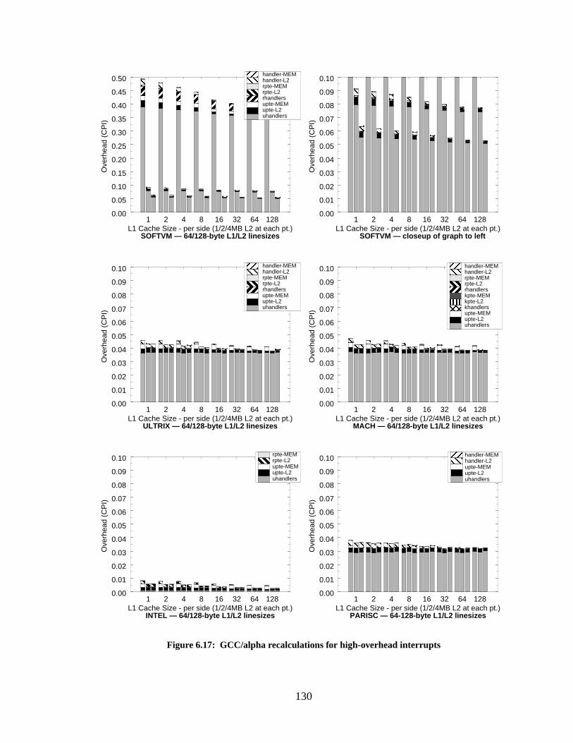
130
1 2 4 8 16 32 64 128L1 Cache Size - per side (1/2/4MB L2 at each pt.)
0.00
0.01
0.02
0.03
0.04
0.05
0.06
0.07
0.08
0.09
0.10
Ove
rhea
d (C
PI)
1 2 4 8 16 32 64 128L1 Cache Size - per side (1/2/4MB L2 at each pt.)
0.00
0.01
0.02
0.03
0.04
0.05
0.06
0.07
0.08
0.09
0.10
Ove
rhea
d (C
PI)
1 2 4 8 16 32 64 128L1 Cache Size - per side (1/2/4MB L2 at each pt.)
0.00
0.01
0.02
0.03
0.04
0.05
0.06
0.07
0.08
0.09
0.10
Ove
rhea
d (C
PI)
1 2 4 8 16 32 64 128L1 Cache Size - per side (1/2/4MB L2 at each pt.)
0.00
0.01
0.02
0.03
0.04
0.05
0.06
0.07
0.08
0.09
0.10
Ove
rhea
d (C
PI)
1 2 4 8 16 32 64 128L1 Cache Size - per side (1/2/4MB L2 at each pt.)
0.00
0.05
0.10
0.15
0.20
0.25
0.30
0.35
0.40
0.45
0.50
Ove
rhea
d (C
PI)
Figure 6.17: GCC/alpha recalculations for high-overhead interrupts
uhandlersupte-L2upte-MEMrhandlersrpte-L2rpte-MEMhandler-L2handler-MEM
uhandlersupte-L2upte-MEMkhandlerskpte-L2kpte-MEMrhandlersrpte-L2rpte-MEMhandler-L2handler-MEM
uhandlersupte-L2upte-MEMrpte-L2rpte-MEM
uhandlersupte-L2upte-MEMrhandlersrpte-L2rpte-MEMhandler-L2handler-MEM
uhandlersupte-L2upte-MEMhandler-L2handler-MEM
SOFTVM — 64/128-byte L1/L2 linesizes
1 2 4 8 16 32 64 128L1 Cache Size - per side (1/2/4MB L2 at each pt.)
0.00
0.01
0.02
0.03
0.04
0.05
0.06
0.07
0.08
0.09
0.10
Ove
rhea
d (C
PI)
SOFTVM — closeup of graph to left
ULTRIX — 64/128-byte L1/L2 linesizes MACH — 64/128-byte L1/L2 linesizes
INTEL — 64/128-byte L1/L2 linesizes PARISC — 64-128-byte L1/L2 linesizes
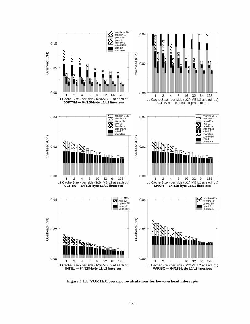
131
1 2 4 8 16 32 64 128L1 Cache Size - per side (1/2/4MB L2 at each pt.)
0.00
0.02
0.04
Ove
rhea
d (C
PI)
1 2 4 8 16 32 64 128L1 Cache Size - per side (1/2/4MB L2 at each pt.)
0.00
0.02
0.04
Ove
rhea
d (C
PI)
1 2 4 8 16 32 64 128L1 Cache Size - per side (1/2/4MB L2 at each pt.)
0.00
0.02
0.04
Ove
rhea
d (C
PI)
1 2 4 8 16 32 64 128L1 Cache Size - per side (1/2/4MB L2 at each pt.)
0.00
0.02
0.04
Ove
rhea
d (C
PI)
1 2 4 8 16 32 64 128L1 Cache Size - per side (1/2/4MB L2 at each pt.)
0.00
0.05
0.10O
verh
ead
(CP
I)uhandlersupte-L2upte-MEMrhandlersrpte-L2rpte-MEMhandler-L2handler-MEM
Figure 6.18: VORTEX/powerpc recalculations for low-overhead interrupts
uhandlersupte-L2upte-MEMkhandlerskpte-L2kpte-MEMrhandlersrpte-L2rpte-MEMhandler-L2handler-MEM
uhandlersupte-L2upte-MEMrpte-L2rpte-MEM
uhandlersupte-L2upte-MEMrhandlersrpte-L2rpte-MEMhandler-L2handler-MEM
uhandlersupte-L2upte-MEMhandler-L2handler-MEM
1 2 4 8 16 32 64 128L1 Cache Size - per side (1/2/4MB L2 at each pt.)
0.00
0.02
0.04
Ove
rhea
d (C
PI)
SOFTVM — 64/128-byte L1/L2 linesizes SOFTVM — closeup of graph to left
ULTRIX — 64/128-byte L1/L2 linesizes MACH — 64/128-byte L1/L2 linesizes
INTEL — 64/128-byte L1/L2 linesizes PARISC — 64/128-byte L1/L2 linesizes
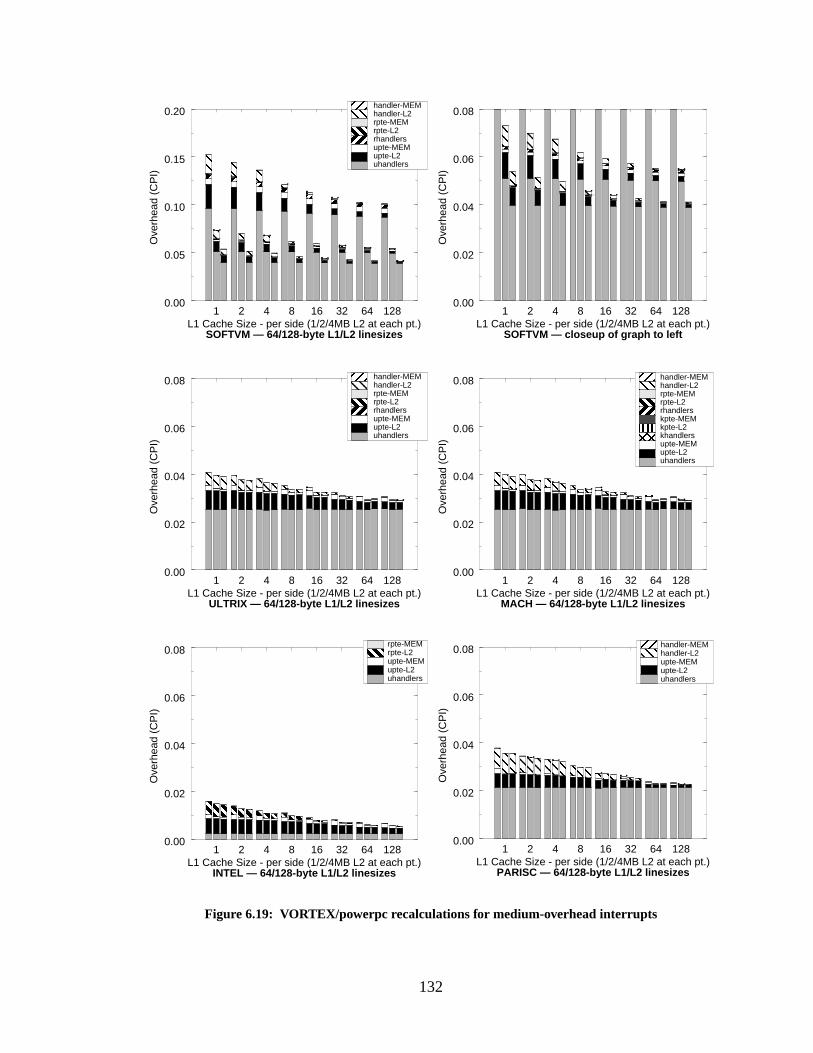
132
1 2 4 8 16 32 64 128L1 Cache Size - per side (1/2/4MB L2 at each pt.)
0.00
0.02
0.04
0.06
0.08
Ove
rhea
d (C
PI)
1 2 4 8 16 32 64 128L1 Cache Size - per side (1/2/4MB L2 at each pt.)
0.00
0.02
0.04
0.06
0.08
Ove
rhea
d (C
PI)
1 2 4 8 16 32 64 128L1 Cache Size - per side (1/2/4MB L2 at each pt.)
0.00
0.02
0.04
0.06
0.08
Ove
rhea
d (C
PI)
1 2 4 8 16 32 64 128L1 Cache Size - per side (1/2/4MB L2 at each pt.)
0.00
0.02
0.04
0.06
0.08
Ove
rhea
d (C
PI)
1 2 4 8 16 32 64 128L1 Cache Size - per side (1/2/4MB L2 at each pt.)
0.00
0.05
0.10
0.15
0.20
Ove
rhea
d (C
PI)
Figure 6.19: VORTEX/powerpc recalculations for medium-overhead interrupts
uhandlersupte-L2upte-MEMrhandlersrpte-L2rpte-MEMhandler-L2handler-MEM
uhandlersupte-L2upte-MEMkhandlerskpte-L2kpte-MEMrhandlersrpte-L2rpte-MEMhandler-L2handler-MEM
uhandlersupte-L2upte-MEMrpte-L2rpte-MEM
uhandlersupte-L2upte-MEMrhandlersrpte-L2rpte-MEMhandler-L2handler-MEM
uhandlersupte-L2upte-MEMhandler-L2handler-MEM
1 2 4 8 16 32 64 128L1 Cache Size - per side (1/2/4MB L2 at each pt.)
0.00
0.02
0.04
0.06
0.08
Ove
rhea
d (C
PI)
SOFTVM — 64/128-byte L1/L2 linesizes SOFTVM — closeup of graph to left
ULTRIX — 64/128-byte L1/L2 linesizes MACH — 64/128-byte L1/L2 linesizes
INTEL — 64/128-byte L1/L2 linesizes PARISC — 64/128-byte L1/L2 linesizes
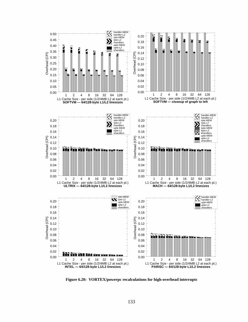
133
1 2 4 8 16 32 64 128L1 Cache Size - per side (1/2/4MB L2 at each pt.)
0.00
0.02
0.04
0.06
0.08
0.10
0.12
0.14
0.16
0.18
0.20
Ove
rhea
d (C
PI)
1 2 4 8 16 32 64 128L1 Cache Size - per side (1/2/4MB L2 at each pt.)
0.00
0.02
0.04
0.06
0.08
0.10
0.12
0.14
0.16
0.18
0.20
Ove
rhea
d (C
PI)
1 2 4 8 16 32 64 128L1 Cache Size - per side (1/2/4MB L2 at each pt.)
0.00
0.02
0.04
0.06
0.08
0.10
0.12
0.14
0.16
0.18
0.20
Ove
rhea
d (C
PI)
1 2 4 8 16 32 64 128L1 Cache Size - per side (1/2/4MB L2 at each pt.)
0.00
0.02
0.04
0.06
0.08
0.10
0.12
0.14
0.16
0.18
0.20
Ove
rhea
d (C
PI)
1 2 4 8 16 32 64 128L1 Cache Size - per side (1/2/4MB L2 at each pt.)
0.00
0.05
0.10
0.15
0.20
0.25
0.30
0.35
0.40
0.45
0.50
Ove
rhea
d (C
PI)
Figure 6.20: VORTEX/powerpc recalculations for high-overhead interrupts
uhandlersupte-L2upte-MEMrhandlersrpte-L2rpte-MEMhandler-L2handler-MEM
uhandlersupte-L2upte-MEMkhandlerskpte-L2kpte-MEMrhandlersrpte-L2rpte-MEMhandler-L2handler-MEM
uhandlersupte-L2upte-MEMrpte-L2rpte-MEM
uhandlersupte-L2upte-MEMrhandlersrpte-L2rpte-MEMhandler-L2handler-MEM
uhandlersupte-L2upte-MEMhandler-L2handler-MEM
1 2 4 8 16 32 64 128L1 Cache Size - per side (1/2/4MB L2 at each pt.)
0.00
0.02
0.04
0.06
0.08
0.10
0.12
0.14
0.16
0.18
0.20
Ove
rhea
d (C
PI)
SOFTVM — 64/128-byte L1/L2 linesizes SOFTVM — closeup of graph to left
ULTRIX — 64/128-byte L1/L2 linesizes MACH — 64/128-byte L1/L2 linesizes
INTEL — 64/128-byte L1/L2 linesizes PARISC — 64/128-byte L1/L2 linesizes
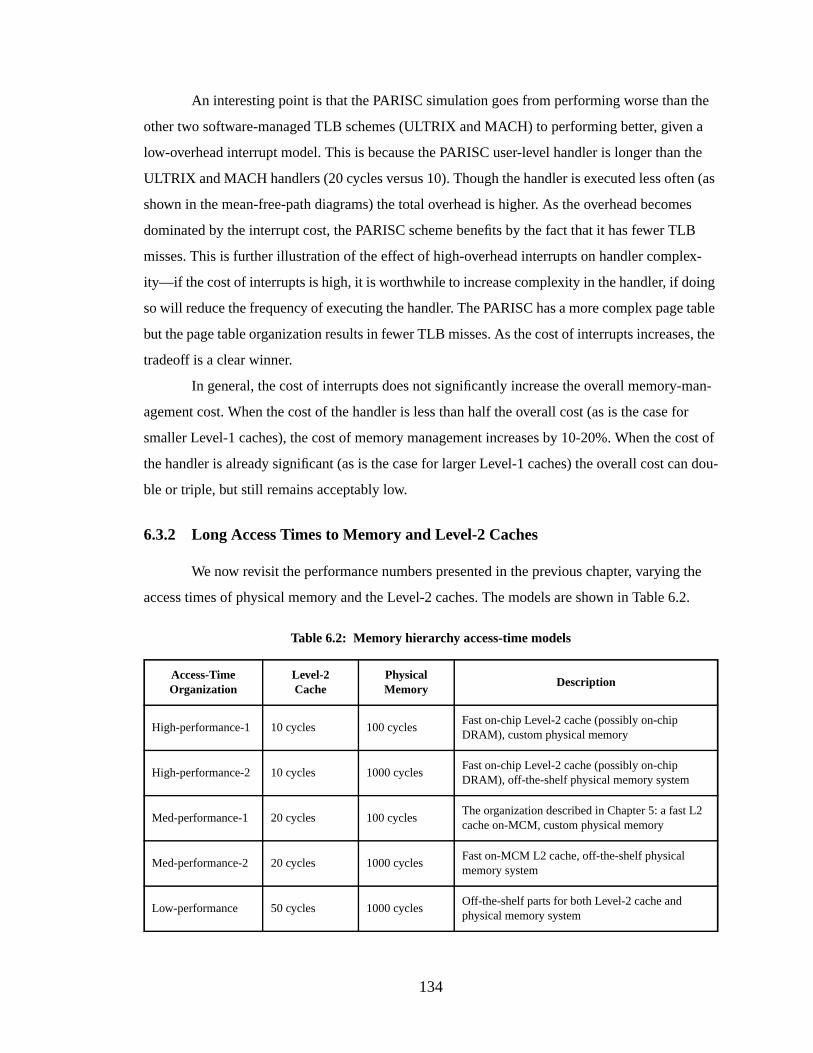
134
An interesting point is that the PARISC simulation goes from performing worse than the
other two software-managed TLB schemes (ULTRIX and MACH) to performing better, given a
low-overhead interrupt model. This is because the PARISC user-level handler is longer than the
ULTRIX and MACH handlers (20 cycles versus 10). Though the handler is executed less often (as
shown in the mean-free-path diagrams) the total overhead is higher. As the overhead becomes
dominated by the interrupt cost, the PARISC scheme benefits by the fact that it has fewer TLB
misses. This is further illustration of the effect of high-overhead interrupts on handler complex-
ity—if the cost of interrupts is high, it is worthwhile to increase complexity in the handler, if doing
so will reduce the frequency of executing the handler. The PARISC has a more complex page table
but the page table organization results in fewer TLB misses. As the cost of interrupts increases, the
tradeoff is a clear winner.
In general, the cost of interrupts does not significantly increase the overall memory-man-
agement cost. When the cost of the handler is less than half the overall cost (as is the case for
smaller Level-1 caches), the cost of memory management increases by 10-20%. When the cost of
the handler is already significant (as is the case for larger Level-1 caches) the overall cost can dou-
ble or triple, but still remains acceptably low.
6.3.2 Long Access Times to Memory and Level-2 Caches
We now revisit the performance numbers presented in the previous chapter, varying the
access times of physical memory and the Level-2 caches. The models are shown in Table 6.2.
Table 6.2: Memory hierarchy access-time models
Access-TimeOrganization
Level-2Cache
PhysicalMemory
Description
High-performance-1 10 cycles 100 cyclesFast on-chip Level-2 cache (possibly on-chipDRAM), custom physical memory
High-performance-2 10 cycles 1000 cyclesFast on-chip Level-2 cache (possibly on-chipDRAM), off-the-shelf physical memory system
Med-performance-1 20 cycles 100 cyclesThe organization described in Chapter 5: a fast L2cache on-MCM, custom physical memory
Med-performance-2 20 cycles 1000 cyclesFast on-MCM L2 cache, off-the-shelf physicalmemory system
Low-performance 50 cycles 1000 cyclesOff-the-shelf parts for both Level-2 cache andphysical memory system
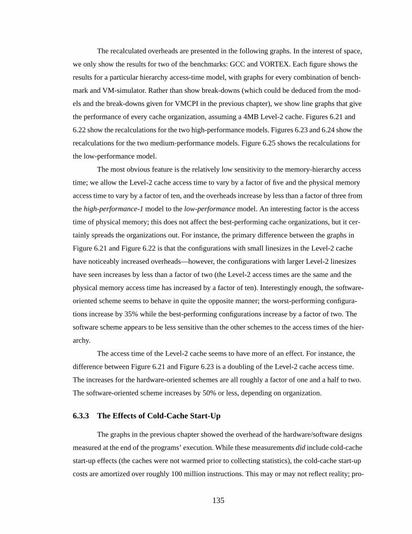
135
The recalculated overheads are presented in the following graphs. In the interest of space,
we only show the results for two of the benchmarks: GCC and VORTEX. Each figure shows the
results for a particular hierarchy access-time model, with graphs for every combination of bench-
mark and VM-simulator. Rather than show break-downs (which could be deduced from the mod-
els and the break-downs given for VMCPI in the previous chapter), we show line graphs that give
the performance of every cache organization, assuming a 4MB Level-2 cache. Figures 6.21 and
6.22 show the recalculations for the two high-performance models. Figures 6.23 and 6.24 show the
recalculations for the two medium-performance models. Figure 6.25 shows the recalculations for
the low-performance model.
The most obvious feature is the relatively low sensitivity to the memory-hierarchy access
time; we allow the Level-2 cache access time to vary by a factor of five and the physical memory
access time to vary by a factor of ten, and the overheads increase by less than a factor of three from
thehigh-performance-1 model to thelow-performance model. An interesting factor is the access
time of physical memory; this does not affect the best-performing cache organizations, but it cer-
tainly spreads the organizations out. For instance, the primary difference between the graphs in
Figure 6.21 and Figure 6.22 is that the configurations with small linesizes in the Level-2 cache
have noticeably increased overheads—however, the configurations with larger Level-2 linesizes
have seen increases by less than a factor of two (the Level-2 access times are the same and the
physical memory access time has increased by a factor of ten). Interestingly enough, the software-
oriented scheme seems to behave in quite the opposite manner; the worst-performing configura-
tions increase by 35% while the best-performing configurations increase by a factor of two. The
software scheme appears to be less sensitive than the other schemes to the access times of the hier-
archy.
The access time of the Level-2 cache seems to have more of an effect. For instance, the
difference between Figure 6.21 and Figure 6.23 is a doubling of the Level-2 cache access time.
The increases for the hardware-oriented schemes are all roughly a factor of one and a half to two.
The software-oriented scheme increases by 50% or less, depending on organization.
6.3.3 The Effects of Cold-Cache Start-Up
The graphs in the previous chapter showed the overhead of the hardware/software designs
measured at the end of the programs’ execution. While these measurementsdid include cold-cache
start-up effects (the caches were not warmed prior to collecting statistics), the cold-cache start-up
costs are amortized over roughly 100 million instructions. This may or may not reflect reality; pro-
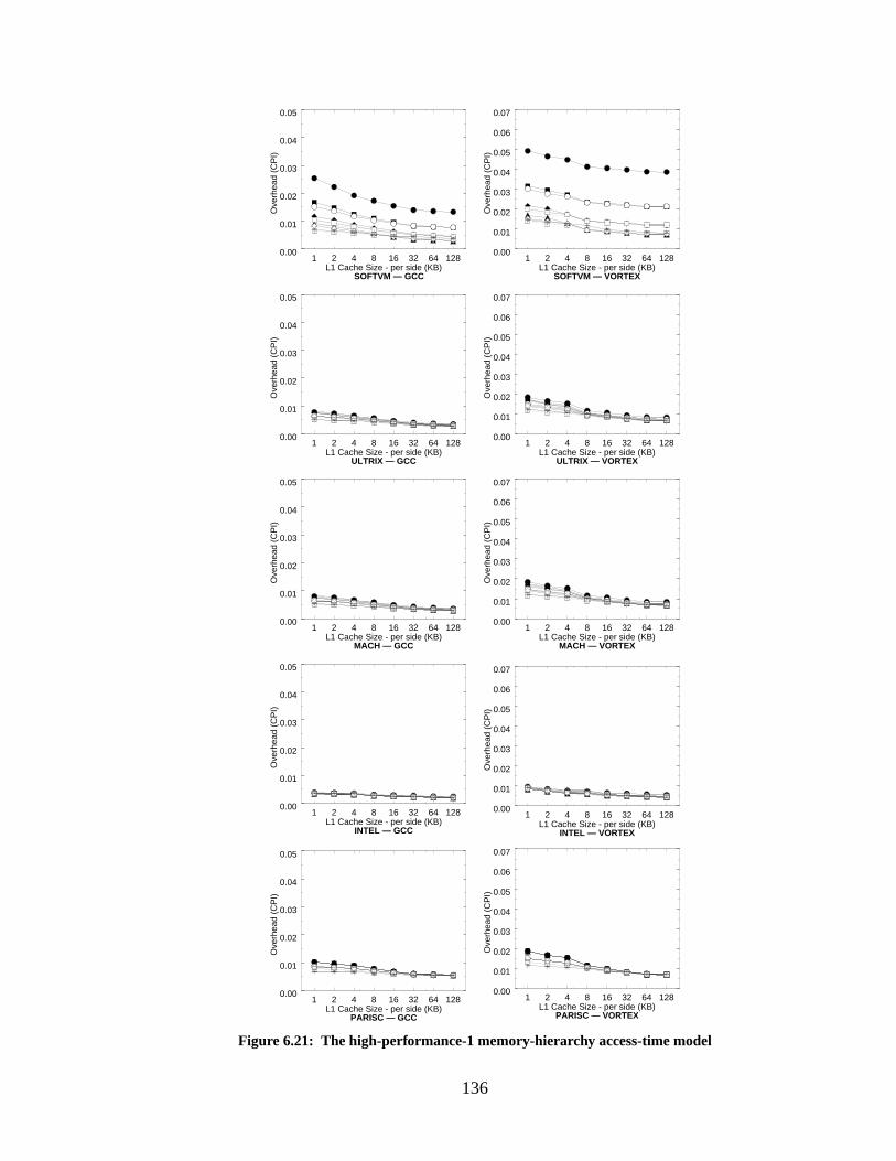
136
Figure 6.21: The high-performance-1 memory-hierarchy access-time model
1 2 4 8 16 32 64 128L1 Cache Size - per side (KB)
0.00
0.01
0.02
0.03
0.04
0.05
Ove
rhea
d (C
PI)
SOFTVM — GCC
1 2 4 8 16 32 64 128L1 Cache Size - per side (KB)
0.00
0.01
0.02
0.03
0.04
0.05
Ove
rhea
d (C
PI)
ULTRIX — GCC
1 2 4 8 16 32 64 128L1 Cache Size - per side (KB)
0.00
0.01
0.02
0.03
0.04
0.05
Ove
rhea
d (C
PI)
MACH — GCC
1 2 4 8 16 32 64 128L1 Cache Size - per side (KB)
0.00
0.01
0.02
0.03
0.04
0.05
Ove
rhea
d (C
PI)
INTEL — GCC
1 2 4 8 16 32 64 128L1 Cache Size - per side (KB)
0.00
0.01
0.02
0.03
0.04
0.05
Ove
rhea
d (C
PI)
PARISC — GCC
1 2 4 8 16 32 64 128L1 Cache Size - per side (KB)
0.00
0.01
0.02
0.03
0.04
0.05
0.06
0.07
Ove
rhea
d (C
PI)
INTEL — VORTEX
1 2 4 8 16 32 64 128L1 Cache Size - per side (KB)
0.00
0.01
0.02
0.03
0.04
0.05
0.06
0.07
Ove
rhea
d (C
PI)
SOFTVM — VORTEX
1 2 4 8 16 32 64 128L1 Cache Size - per side (KB)
0.00
0.01
0.02
0.03
0.04
0.05
0.06
0.07
Ove
rhea
d (C
PI)
1 2 4 8 16 32 64 128L1 Cache Size - per side (KB)
0.00
0.01
0.02
0.03
0.04
0.05
0.06
0.07O
verh
ead
(CP
I)
1 2 4 8 16 32 64 128L1 Cache Size - per side (KB)
0.00
0.01
0.02
0.03
0.04
0.05
0.06
0.07
Ove
rhea
d (C
PI)
ULTRIX — VORTEX
MACH — VORTEX
PARISC — VORTEX
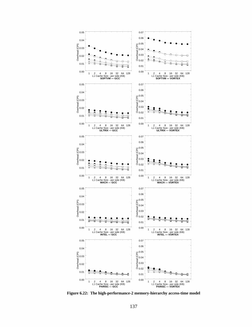
137
Figure 6.22: The high-performance-2 memory-hierarchy access-time model
1 2 4 8 16 32 64 128L1 Cache Size - per side (KB)
0.00
0.01
0.02
0.03
0.04
0.05
Ove
rhea
d (C
PI)
PARISC — GCC
1 2 4 8 16 32 64 128L1 Cache Size - per side (KB)
0.00
0.01
0.02
0.03
0.04
0.05
Ove
rhea
d (C
PI)
SOFTVM — GCC
1 2 4 8 16 32 64 128L1 Cache Size - per side (KB)
0.00
0.01
0.02
0.03
0.04
0.05
Ove
rhea
d (C
PI)
ULTRIX — GCC
1 2 4 8 16 32 64 128L1 Cache Size - per side (KB)
0.00
0.01
0.02
0.03
0.04
0.05
Ove
rhea
d (C
PI)
MACH — GCC
1 2 4 8 16 32 64 128L1 Cache Size - per side (KB)
0.00
0.01
0.02
0.03
0.04
0.05
Ove
rhea
d (C
PI)
INTEL — GCC
1 2 4 8 16 32 64 128L1 Cache Size - per side (KB)
0.00
0.01
0.02
0.03
0.04
0.05
0.06
0.07
Ove
rhea
d (C
PI)
1 2 4 8 16 32 64 128L1 Cache Size - per side (KB)
0.00
0.01
0.02
0.03
0.04
0.05
0.06
0.07
Ove
rhea
d (C
PI)
1 2 4 8 16 32 64 128L1 Cache Size - per side (KB)
0.00
0.01
0.02
0.03
0.04
0.05
0.06
0.07O
verh
ead
(CP
I)
1 2 4 8 16 32 64 128L1 Cache Size - per side (KB)
0.00
0.01
0.02
0.03
0.04
0.05
0.06
0.07
Ove
rhea
d (C
PI)
1 2 4 8 16 32 64 128L1 Cache Size - per side (KB)
0.00
0.01
0.02
0.03
0.04
0.05
0.06
0.07
Ove
rhea
d (C
PI)
SOFTVM — VORTEX
ULTRIX — VORTEX
MACH — VORTEX
INTEL — VORTEX
PARISC — VORTEX
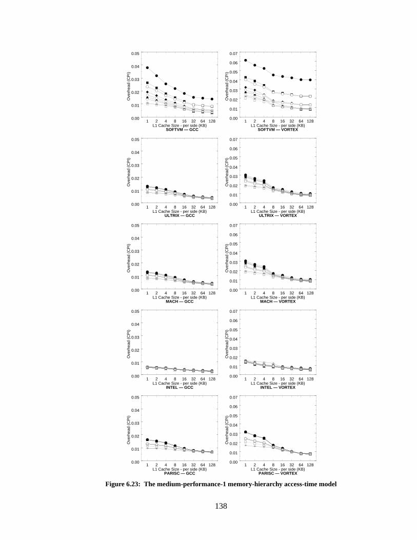
138
Figure 6.23: The medium-performance-1 memory-hierarchy access-time model
1 2 4 8 16 32 64 128L1 Cache Size - per side (KB)
0.00
0.01
0.02
0.03
0.04
0.05
Ove
rhea
d (C
PI)
INTEL — GCC
1 2 4 8 16 32 64 128L1 Cache Size - per side (KB)
0.00
0.01
0.02
0.03
0.04
0.05
Ove
rhea
d (C
PI)
SOFTVM — GCC
1 2 4 8 16 32 64 128L1 Cache Size - per side (KB)
0.00
0.01
0.02
0.03
0.04
0.05
Ove
rhea
d (C
PI)
ULTRIX — GCC
1 2 4 8 16 32 64 128L1 Cache Size - per side (KB)
0.00
0.01
0.02
0.03
0.04
0.05
Ove
rhea
d (C
PI)
MACH — GCC
1 2 4 8 16 32 64 128L1 Cache Size - per side (KB)
0.00
0.01
0.02
0.03
0.04
0.05
Ove
rhea
d (C
PI)
PARISC — GCC
1 2 4 8 16 32 64 128L1 Cache Size - per side (KB)
0.00
0.01
0.02
0.03
0.04
0.05
0.06
0.07
Ove
rhea
d (C
PI)
SOFTVM — VORTEX
1 2 4 8 16 32 64 128L1 Cache Size - per side (KB)
0.00
0.01
0.02
0.03
0.04
0.05
0.06
0.07
Ove
rhea
d (C
PI)
ULTRIX — VORTEX
1 2 4 8 16 32 64 128L1 Cache Size - per side (KB)
0.00
0.01
0.02
0.03
0.04
0.05
0.06
0.07O
verh
ead
(CP
I)
MACH — VORTEX
1 2 4 8 16 32 64 128L1 Cache Size - per side (KB)
0.00
0.01
0.02
0.03
0.04
0.05
0.06
0.07
Ove
rhea
d (C
PI)
INTEL — VORTEX
1 2 4 8 16 32 64 128L1 Cache Size - per side (KB)
0.00
0.01
0.02
0.03
0.04
0.05
0.06
0.07
Ove
rhea
d (C
PI)
PARISC — VORTEX
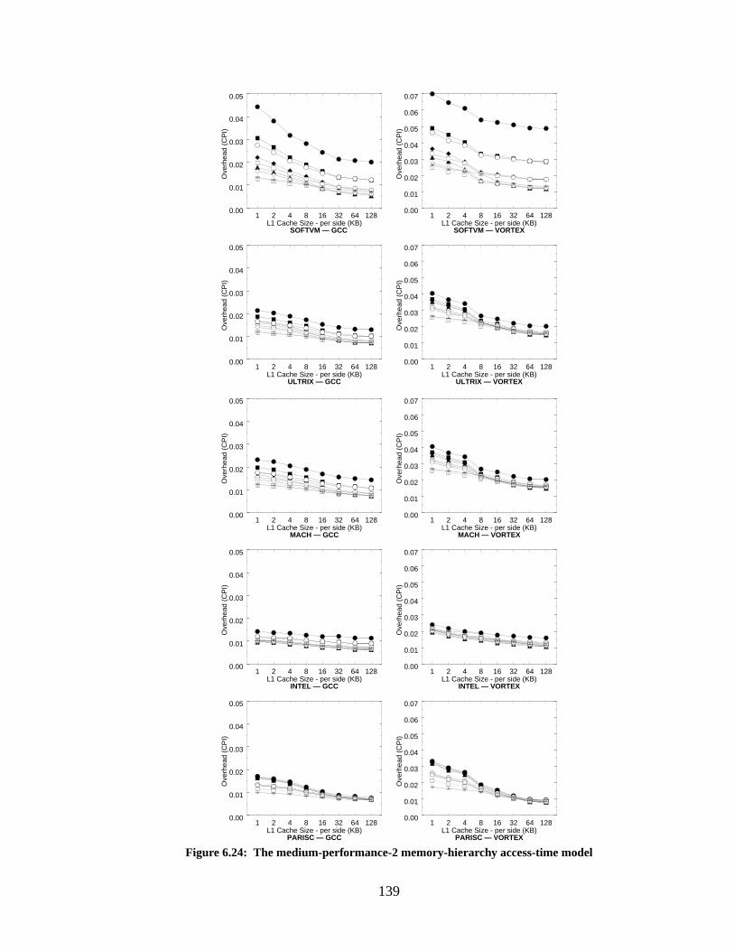
139
Figure 6.24: The medium-performance-2 memory-hierarchy access-time model
1 2 4 8 16 32 64 128L1 Cache Size - per side (KB)
0.00
0.01
0.02
0.03
0.04
0.05
Ove
rhea
d (C
PI)
SOFTVM — GCC
1 2 4 8 16 32 64 128L1 Cache Size - per side (KB)
0.00
0.01
0.02
0.03
0.04
0.05
Ove
rhea
d (C
PI)
ULTRIX — GCC
1 2 4 8 16 32 64 128L1 Cache Size - per side (KB)
0.00
0.01
0.02
0.03
0.04
0.05
Ove
rhea
d (C
PI)
MACH — GCC
1 2 4 8 16 32 64 128L1 Cache Size - per side (KB)
0.00
0.01
0.02
0.03
0.04
0.05
Ove
rhea
d (C
PI)
INTEL — GCC
1 2 4 8 16 32 64 128L1 Cache Size - per side (KB)
0.00
0.01
0.02
0.03
0.04
0.05
Ove
rhea
d (C
PI)
PARISC — GCC
1 2 4 8 16 32 64 128L1 Cache Size - per side (KB)
0.00
0.01
0.02
0.03
0.04
0.05
0.06
0.07
Ove
rhea
d (C
PI)
SOFTVM — VORTEX
1 2 4 8 16 32 64 128L1 Cache Size - per side (KB)
0.00
0.01
0.02
0.03
0.04
0.05
0.06
0.07
Ove
rhea
d (C
PI)
ULTRIX — VORTEX
1 2 4 8 16 32 64 128L1 Cache Size - per side (KB)
0.00
0.01
0.02
0.03
0.04
0.05
0.06
0.07O
verh
ead
(CP
I)
MACH — VORTEX
1 2 4 8 16 32 64 128L1 Cache Size - per side (KB)
0.00
0.01
0.02
0.03
0.04
0.05
0.06
0.07
Ove
rhea
d (C
PI)
INTEL — VORTEX
1 2 4 8 16 32 64 128L1 Cache Size - per side (KB)
0.00
0.01
0.02
0.03
0.04
0.05
0.06
0.07
Ove
rhea
d (C
PI)
PARISC — VORTEX
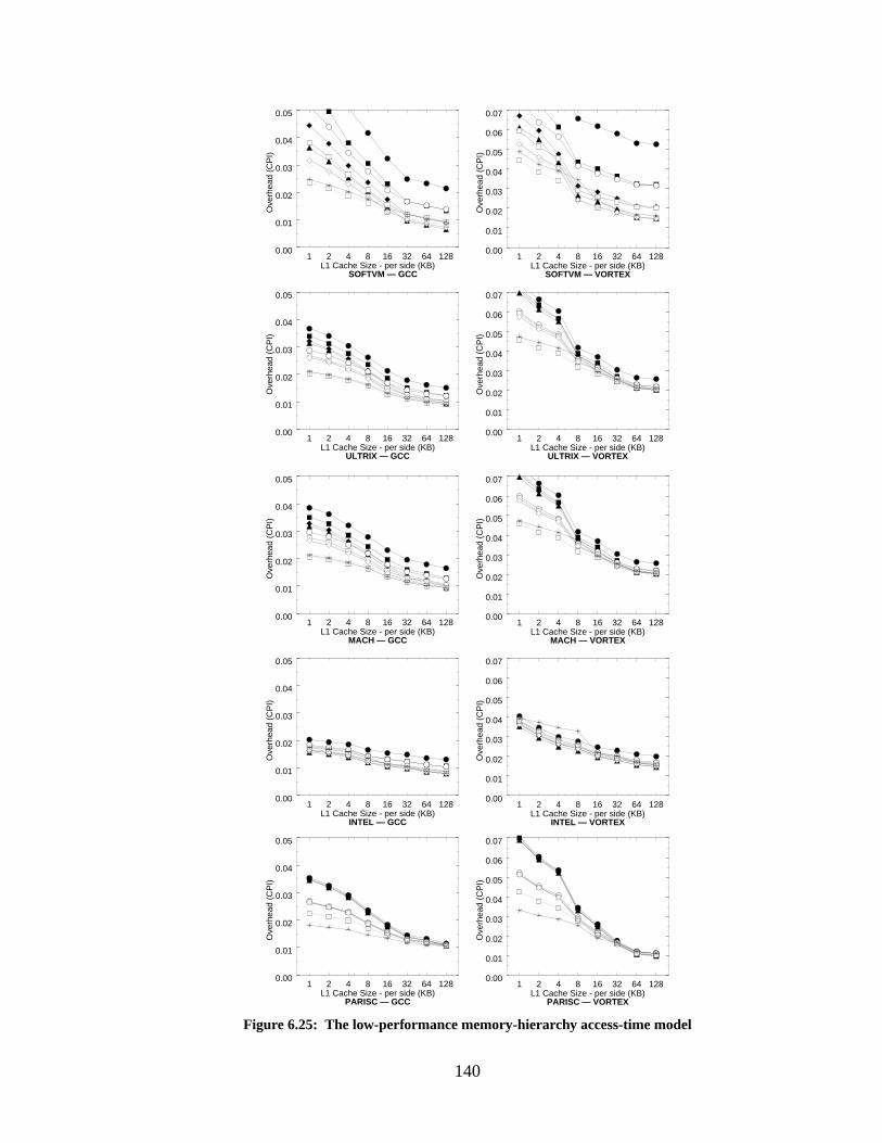
140
Figure 6.25: The low-performance memory-hierarchy access-time model
1 2 4 8 16 32 64 128L1 Cache Size - per side (KB)
0.00
0.01
0.02
0.03
0.04
0.05
Ove
rhea
d (C
PI)
SOFTVM — GCC
1 2 4 8 16 32 64 128L1 Cache Size - per side (KB)
0.00
0.01
0.02
0.03
0.04
0.05
Ove
rhea
d (C
PI)
ULTRIX — GCC
1 2 4 8 16 32 64 128L1 Cache Size - per side (KB)
0.00
0.01
0.02
0.03
0.04
0.05
Ove
rhea
d (C
PI)
MACH — GCC
1 2 4 8 16 32 64 128L1 Cache Size - per side (KB)
0.00
0.01
0.02
0.03
0.04
0.05
Ove
rhea
d (C
PI)
INTEL — GCC
1 2 4 8 16 32 64 128L1 Cache Size - per side (KB)
0.00
0.01
0.02
0.03
0.04
0.05
Ove
rhea
d (C
PI)
PARISC — GCC
1 2 4 8 16 32 64 128L1 Cache Size - per side (KB)
0.00
0.01
0.02
0.03
0.04
0.05
0.06
0.07
Ove
rhea
d (C
PI)
SOFTVM — VORTEX
1 2 4 8 16 32 64 128L1 Cache Size - per side (KB)
0.00
0.01
0.02
0.03
0.04
0.05
0.06
0.07
Ove
rhea
d (C
PI)
ULTRIX — VORTEX
1 2 4 8 16 32 64 128L1 Cache Size - per side (KB)
0.00
0.01
0.02
0.03
0.04
0.05
0.06
0.07O
verh
ead
(CP
I)
MACH — VORTEX
1 2 4 8 16 32 64 128L1 Cache Size - per side (KB)
0.00
0.01
0.02
0.03
0.04
0.05
0.06
0.07
Ove
rhea
d (C
PI)
INTEL — VORTEX
1 2 4 8 16 32 64 128L1 Cache Size - per side (KB)
0.00
0.01
0.02
0.03
0.04
0.05
0.06
0.07
Ove
rhea
d (C
PI)
PARISC — VORTEX
141
cesses tend to get switched out more often than once every 100 million instructions. By contrast,
this section presents graphs of measurements taken after only 10 million instructions have exe-
cuted, to show the effects of cold-cache start-up. In modern microprocessors with clock frequen-
cies of 500MHz to 1GHz, this would represent 1 to 2 hundredths of a second of execution, which
should be fairly representative of an operating system’s timeslice.
We present cost break-downs for each of the VM-simulations, for the GCC and VORTEX
benchmarks, and one cache configuration: 64-byte L1 linesize, 128-byte L2 linesize, 4MB L2
cache. Figure 6.26 shows the cold-cache results for GCC. Figure 6.27 shows the cold-cache results
for VORTEX.
Not surprisingly, the software-oriented memory-management scheme is a bit more sensi-
tive to the effects of cold-cache start-up; whereas the other schemes perform about 100% worse,
relative to the figures in Section 6.2.2, the software scheme is about 150% worse (that figure is for
2MB and 4MB L2 cache sizes—the increase for 1MB L2 cache sizes is only 33%). To get the con-
tents of a program into the caches the operating system must fault on the access of every new
cache line, whereas a hardware-oriented scheme faults on a page granularity. Nonetheless, the dif-
ference between the software-oriented scheme and the hardware-oriented schemes is not as large
as the difference between a cache line and a page. This suggests that the software-oriented scheme
is better at doing useful work; while the software-oriented scheme does more work by faulting at
the granularity of a cache line, more of the work it does is useful because a high percentage of the
data in the cache line is actually used.
Note that while the hardware-oriented schemes retain roughly the same proportions for the
various break-downs, the bulk of the increase for the software-oriented scheme at medium to large
cache Level-1 sizes comes from an increased value foruhandlers. This has a very interesting inter-
pretation: the effect of cold-cache start-up is only that the handler is executed more often. One
does not see commensurate increases in the number of cache misses (except at small cache sizes).
Thus, the handler is being executed repeatedly for contiguous sections of virtual memory; the han-
dler is still in the I-cache and the page table entries loaded into the D-cache are still resident and
are likely to map several consecutive failing cache lines.
Another interesting point is that there is now a larger difference between the ULTRIX and
MACH simulations; the MACH simulations exhibit a higher occurrence of root-level page table
activity (rhandlers, rpte-L2, andrpte-MEM). Thus, the total overhead tends to be as much as 10%
higher than the ULTRIX simulations.
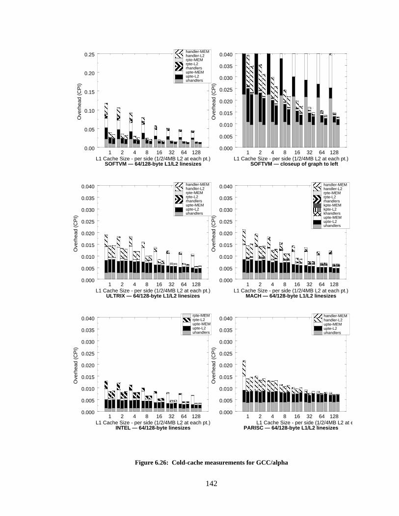
142
Figure 6.26: Cold-cache measurements for GCC/alpha
1 2 4 8 16 32 64 128L1 Cache Size - per side (1/2/4MB L2 at each pt.)
0.00
0.05
0.10
0.15
0.20
0.25
Ove
rhea
d (C
PI)
SOFTVM — 64/128-byte L1/L2 linesizes
1 2 4 8 16 32 64 128L1 Cache Size - per side (1/2/4MB L2 at each pt.)
0.000
0.005
0.010
0.015
0.020
0.025
0.030
0.035
0.040
Ove
rhea
d (C
PI)
SOFTVM — closeup of graph to left
1 2 4 8 16 32 64 128L1 Cache Size - per side (1/2/4MB L2 at each pt.)
0.000
0.005
0.010
0.015
0.020
0.025
0.030
0.035
0.040
Ove
rhea
d (C
PI)
ULTRIX — 64/128-byte L1/L2 linesizes
1 2 4 8 16 32 64 128L1 Cache Size - per side (1/2/4MB L2 at each pt.)
0.000
0.005
0.010
0.015
0.020
0.025
0.030
0.035
0.040
Ove
rhea
d (C
PI)
MACH — 64/128-byte L1/L2 linesizes
1 2 4 8 16 32 64 128L1 Cache Size - per side (1/2/4MB L2 at each pt.)
0.000
0.005
0.010
0.015
0.020
0.025
0.030
0.035
0.040
Ove
rhea
d (C
PI)
INTEL — 64/128-byte linesizes
1 2 4 8 16 32 64 128L1 Cache Size - per side (1/2/4MB L2 at each pt.)
0.000
0.005
0.010
0.015
0.020
0.025
0.030
0.035
0.040
Ove
rhea
d (C
PI)
PARISC — 64/128-byte L1/L2 linesizes
uhandlersupte-L2upte-MEMrhandlersrpte-L2rpte-MEMhandler-L2handler-MEM
uhandlersupte-L2upte-MEMkhandlerskpte-L2kpte-MEMrhandlersrpte-L2rpte-MEMhandler-L2handler-MEM
uhandlersupte-L2upte-MEMrpte-L2rpte-MEM
uhandlersupte-L2upte-MEMrhandlersrpte-L2rpte-MEMhandler-L2handler-MEM
uhandlersupte-L2upte-MEMhandler-L2handler-MEM
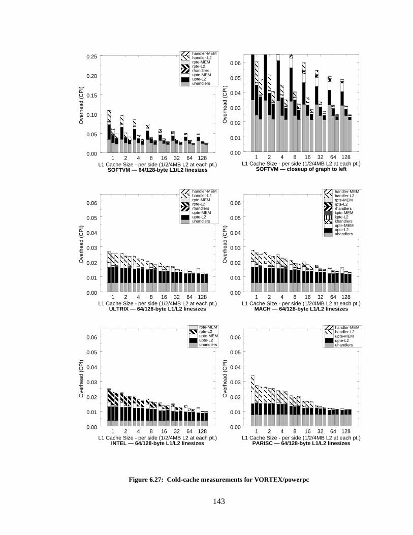
143
1 2 4 8 16 32 64 128L1 Cache Size - per side (1/2/4MB L2 at each pt.)
0.00
0.01
0.02
0.03
0.04
0.05
0.06
Ove
rhea
d (C
PI)
1 2 4 8 16 32 64 128L1 Cache Size - per side (1/2/4MB L2 at each pt.)
0.00
0.01
0.02
0.03
0.04
0.05
0.06
Ove
rhea
d (C
PI)
1 2 4 8 16 32 64 128L1 Cache Size - per side (1/2/4MB L2 at each pt.)
0.00
0.01
0.02
0.03
0.04
0.05
0.06
Ove
rhea
d (C
PI)
SOFTVM — closeup of graph to left
1 2 4 8 16 32 64 128L1 Cache Size - per side (1/2/4MB L2 at each pt.)
0.00
0.01
0.02
0.03
0.04
0.05
0.06
Ove
rhea
d (C
PI)
1 2 4 8 16 32 64 128L1 Cache Size - per side (1/2/4MB L2 at each pt.)
0.00
0.01
0.02
0.03
0.04
0.05
0.06
Ove
rhea
d (C
PI)
1 2 4 8 16 32 64 128L1 Cache Size - per side (1/2/4MB L2 at each pt.)
0.00
0.05
0.10
0.15
0.20
0.25
Ove
rhea
d (C
PI)
Figure 6.27: Cold-cache measurements for VORTEX/powerpc
uhandlersupte-L2upte-MEMrhandlersrpte-L2rpte-MEMhandler-L2handler-MEM
uhandlersupte-L2upte-MEMkhandlerskpte-L2kpte-MEMrhandlersrpte-L2rpte-MEMhandler-L2handler-MEM
uhandlersupte-L2upte-MEMrpte-L2rpte-MEM
uhandlersupte-L2upte-MEMrhandlersrpte-L2rpte-MEMhandler-L2handler-MEM
uhandlersupte-L2upte-MEMhandler-L2handler-MEM
SOFTVM — 64/128-byte L1/L2 linesizes
ULTRIX — 64/128-byte L1/L2 linesizes MACH — 64/128-byte L1/L2 linesizes
INTEL — 64/128-byte L1/L2 linesizes PARISC — 64/128-byte L1/L2 linesizes
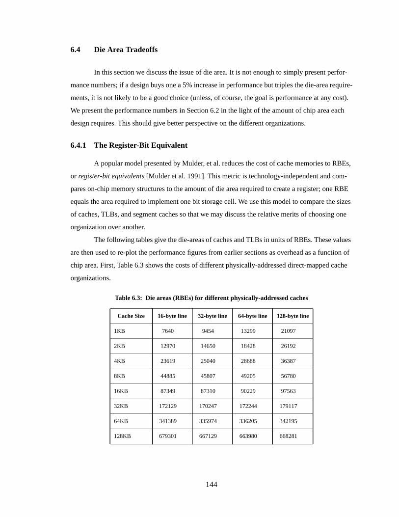
144
6.4 Die Area Tradeoffs
In this section we discuss the issue of die area. It is not enough to simply present perfor-
mance numbers; if a design buys one a 5% increase in performance but triples the die-area require-
ments, it is not likely to be a good choice (unless, of course, the goal is performance at any cost).
We present the performance numbers in Section 6.2 in the light of the amount of chip area each
design requires. This should give better perspective on the different organizations.
6.4.1 The Register-Bit Equivalent
A popular model presented by Mulder, et al. reduces the cost of cache memories to RBEs,
or register-bit equivalents [Mulder et al. 1991]. This metric is technology-independent and com-
pares on-chip memory structures to the amount of die area required to create a register; one RBE
equals the area required to implement one bit storage cell. We use this model to compare the sizes
of caches, TLBs, and segment caches so that we may discuss the relative merits of choosing one
organization over another.
The following tables give the die-areas of caches and TLBs in units of RBEs. These values
are then used to re-plot the performance figures from earlier sections as overhead as a function of
chip area. First, Table 6.3 shows the costs of different physically-addressed direct-mapped cache
organizations.
Table 6.3: Die areas (RBEs) for differ ent physically-addressed caches
Cache Size 16-byte line 32-byte line 64-byte line 128-byte line
1KB 7640 9454 13299 21097
2KB 12970 14650 18428 26192
4KB 23619 25040 28688 36387
8KB 44885 45807 49205 56780
16KB 87349 87310 90229 97563
32KB 172129 170247 172244 179117
64KB 341389 335974 336205 342195
128KB 679301 667129 663980 668281
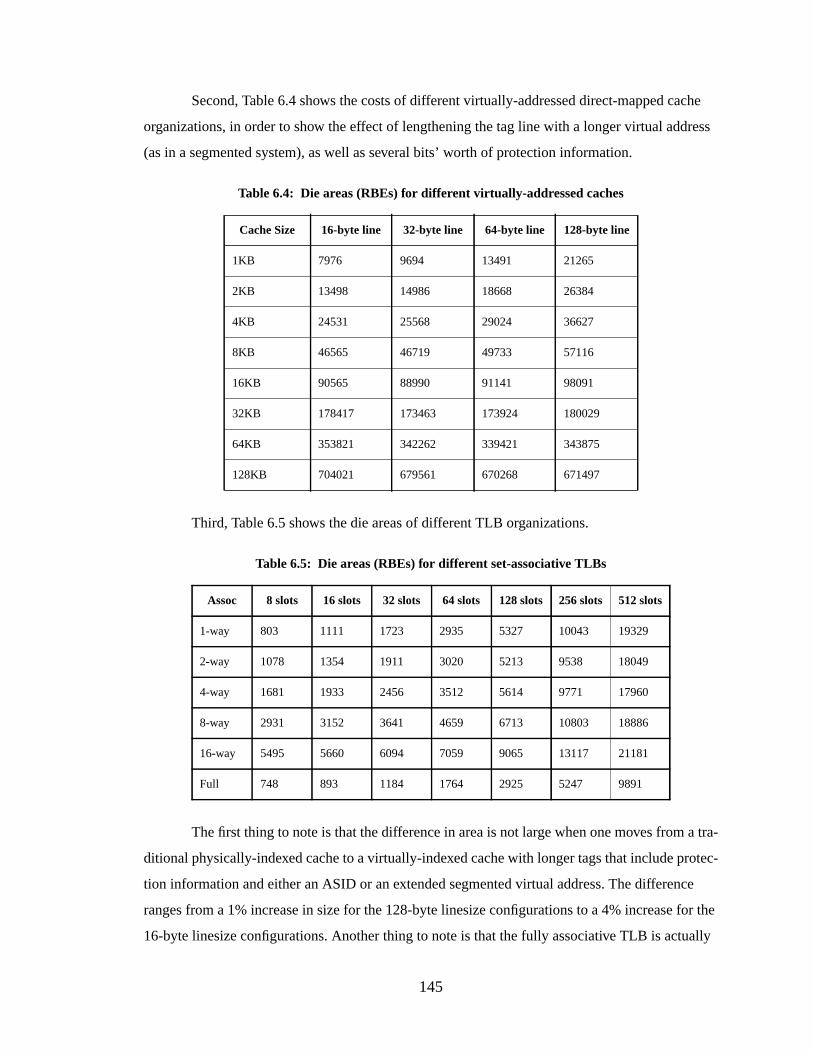
145
Second, Table 6.4 shows the costs of different virtually-addressed direct-mapped cache
organizations, in order to show the effect of lengthening the tag line with a longer virtual address
(as in a segmented system), as well as several bits’ worth of protection information.
Third, Table 6.5 shows the die areas of different TLB organizations.
The first thing to note is that the difference in area is not large when one moves from a tra-
ditional physically-indexed cache to a virtually-indexed cache with longer tags that include protec-
tion information and either an ASID or an extended segmented virtual address. The difference
ranges from a 1% increase in size for the 128-byte linesize configurations to a 4% increase for the
16-byte linesize configurations. Another thing to note is that the fully associative TLB is actually
Table 6.4: Die areas (RBEs) for differ ent virtually-addr essed caches
Cache Size 16-byte line 32-byte line 64-byte line 128-byte line
1KB 7976 9694 13491 21265
2KB 13498 14986 18668 26384
4KB 24531 25568 29024 36627
8KB 46565 46719 49733 57116
16KB 90565 88990 91141 98091
32KB 178417 173463 173924 180029
64KB 353821 342262 339421 343875
128KB 704021 679561 670268 671497
Table 6.5: Die areas (RBEs) for differ ent set-associative TLBs
Assoc 8 slots 16 slots 32 slots 64 slots 128 slots 256 slots 512 slots
1-way 803 1111 1723 2935 5327 10043 19329
2-way 1078 1354 1911 3020 5213 9538 18049
4-way 1681 1933 2456 3512 5614 9771 17960
8-way 2931 3152 3641 4659 6713 10803 18886
16-way 5495 5660 6094 7059 9065 13117 21181
Full 748 893 1184 1764 2925 5247 9891
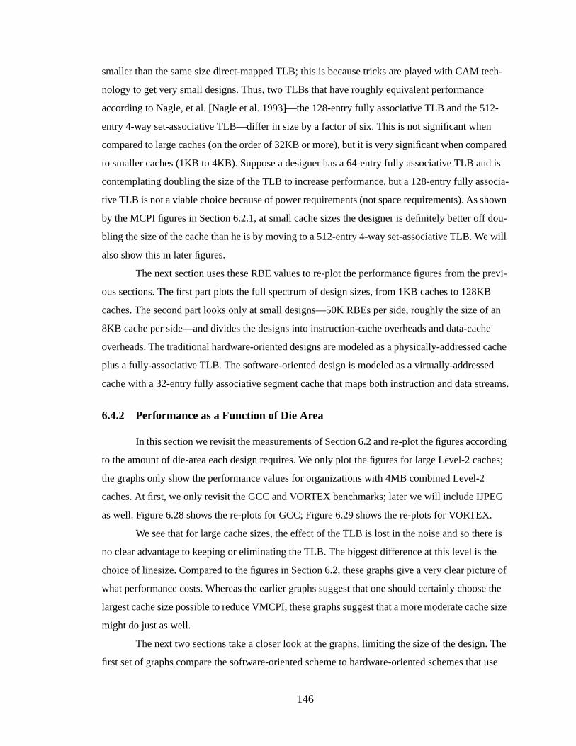
146
smaller than the same size direct-mapped TLB; this is because tricks are played with CAM tech-
nology to get very small designs. Thus, two TLBs that have roughly equivalent performance
according to Nagle, et al. [Nagle et al. 1993]—the 128-entry fully associative TLB and the 512-
entry 4-way set-associative TLB—differ in size by a factor of six. This is not significant when
compared to large caches (on the order of 32KB or more), but it is very significant when compared
to smaller caches (1KB to 4KB). Suppose a designer has a 64-entry fully associative TLB and is
contemplating doubling the size of the TLB to increase performance, but a 128-entry fully associa-
tive TLB is not a viable choice because of power requirements (not space requirements). As shown
by the MCPI figures in Section 6.2.1, at small cache sizes the designer is definitely better off dou-
bling the size of the cache than he is by moving to a 512-entry 4-way set-associative TLB. We will
also show this in later figures.
The next section uses these RBE values to re-plot the performance figures from the previ-
ous sections. The first part plots the full spectrum of design sizes, from 1KB caches to 128KB
caches. The second part looks only at small designs—50K RBEs per side, roughly the size of an
8KB cache per side—and divides the designs into instruction-cache overheads and data-cache
overheads. The traditional hardware-oriented designs are modeled as a physically-addressed cache
plus a fully-associative TLB. The software-oriented design is modeled as a virtually-addressed
cache with a 32-entry fully associative segment cache that maps both instruction and data streams.
6.4.2 Performance as a Function of Die Area
In this section we revisit the measurements of Section 6.2 and re-plot the figures according
to the amount of die-area each design requires. We only plot the figures for large Level-2 caches;
the graphs only show the performance values for organizations with 4MB combined Level-2
caches. At first, we only revisit the GCC and VORTEX benchmarks; later we will include IJPEG
as well. Figure 6.28 shows the re-plots for GCC; Figure 6.29 shows the re-plots for VORTEX.
We see that for large cache sizes, the effect of the TLB is lost in the noise and so there is
no clear advantage to keeping or eliminating the TLB. The biggest difference at this level is the
choice of linesize. Compared to the figures in Section 6.2, these graphs give a very clear picture of
what performance costs. Whereas the earlier graphs suggest that one should certainly choose the
largest cache size possible to reduce VMCPI, these graphs suggest that a more moderate cache size
might do just as well.
The next two sections take a closer look at the graphs, limiting the size of the design. The
first set of graphs compare the software-oriented scheme to hardware-oriented schemes that use
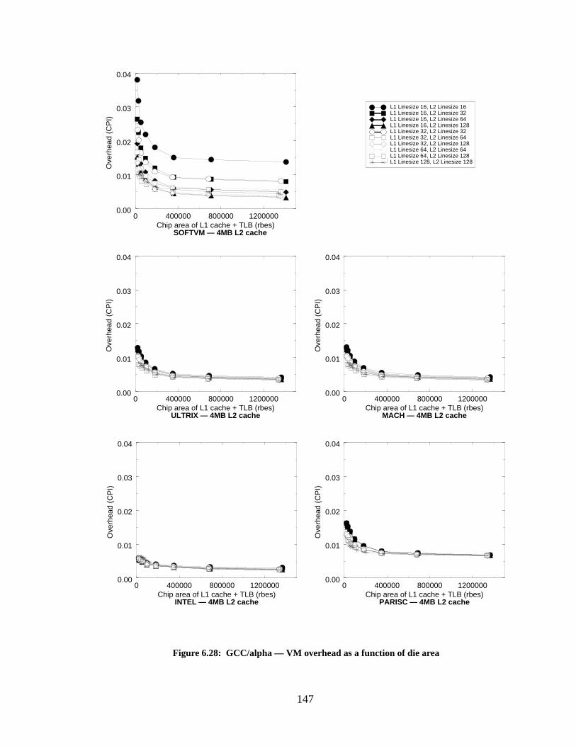
147
Figure 6.28: GCC/alpha — VM overhead as a function of die area
0 400000 800000 1200000Chip area of L1 cache + TLB (rbes)
0.00
0.01
0.02
0.03
0.04
Ove
rhea
d (C
PI)
0 400000 800000 1200000Chip area of L1 cache + TLB (rbes)
0.00
0.01
0.02
0.03
0.04
Ove
rhea
d (C
PI)
ULTRIX — 4MB L2 cache
SOFTVM — 4MB L2 cache
0 400000 800000 1200000Chip area of L1 cache + TLB (rbes)
0.00
0.01
0.02
0.03
0.04
Ove
rhea
d (C
PI)
MACH — 4MB L2 cache
0 400000 800000 1200000Chip area of L1 cache + TLB (rbes)
0.00
0.01
0.02
0.03
0.04
Ove
rhea
d (C
PI)
INTEL — 4MB L2 cache
0 400000 800000 1200000Chip area of L1 cache + TLB (rbes)
0.00
0.01
0.02
0.03
0.04
Ove
rhea
d (C
PI)
L1 Linesize 16, L2 Linesize 16L1 Linesize 16, L2 Linesize 32L1 Linesize 16, L2 Linesize 64L1 Linesize 16, L2 Linesize 128L1 Linesize 32, L2 Linesize 32L1 Linesize 32, L2 Linesize 64L1 Linesize 32, L2 Linesize 128L1 Linesize 64, L2 Linesize 64L1 Linesize 64, L2 Linesize 128L1 Linesize 128, L2 Linesize 128
PARISC — 4MB L2 cache
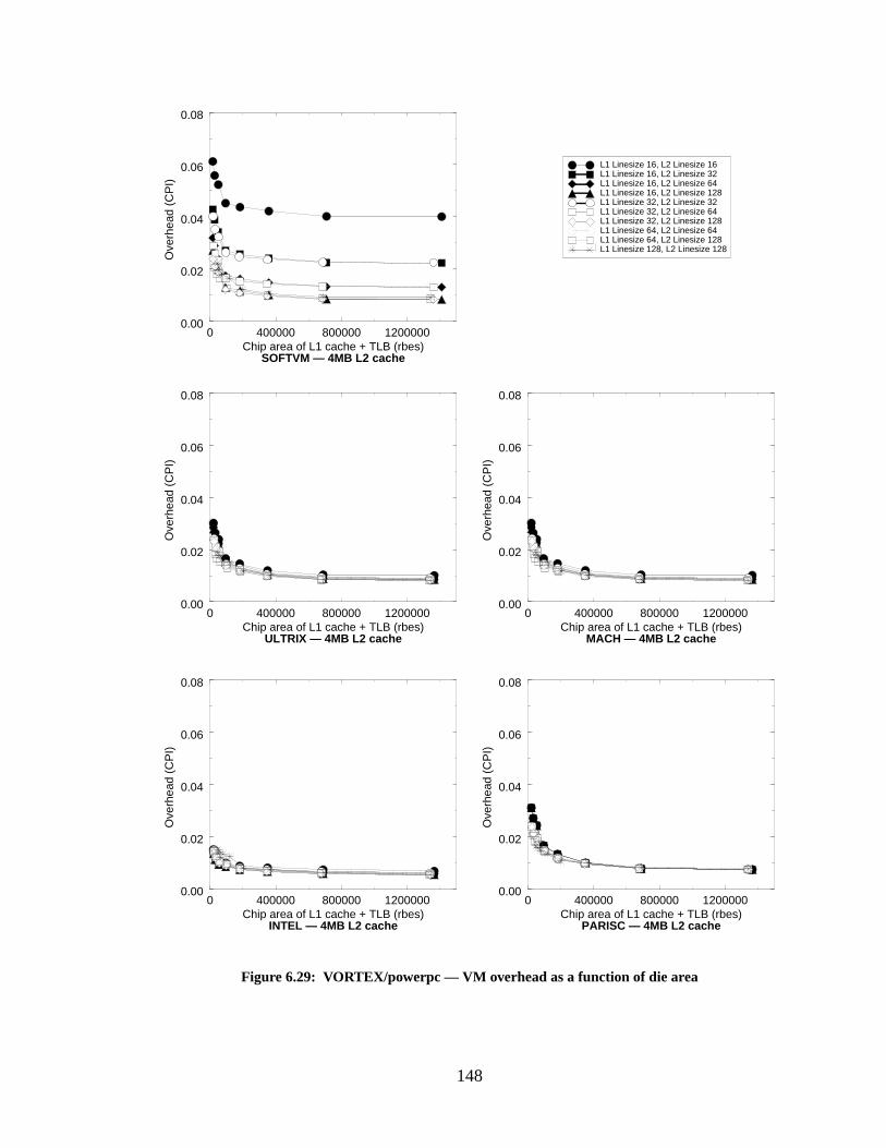
148
Figure 6.29: VORTEX/powerpc — VM overhead as a function of die area
L1 Linesize 16, L2 Linesize 16L1 Linesize 16, L2 Linesize 32L1 Linesize 16, L2 Linesize 64L1 Linesize 16, L2 Linesize 128L1 Linesize 32, L2 Linesize 32L1 Linesize 32, L2 Linesize 64L1 Linesize 32, L2 Linesize 128L1 Linesize 64, L2 Linesize 64L1 Linesize 64, L2 Linesize 128L1 Linesize 128, L2 Linesize 128
0 400000 800000 1200000Chip area of L1 cache + TLB (rbes)
0.00
0.02
0.04
0.06
0.08
Ove
rhea
d (C
PI)
0 400000 800000 1200000Chip area of L1 cache + TLB (rbes)
0.00
0.02
0.04
0.06
0.08
Ove
rhea
d (C
PI)
SOFTVM — 4MB L2 cache
ULTRIX — 4MB L2 cache
0 400000 800000 1200000Chip area of L1 cache + TLB (rbes)
0.00
0.02
0.04
0.06
0.08
Ove
rhea
d (C
PI)
0 400000 800000 1200000Chip area of L1 cache + TLB (rbes)
0.00
0.02
0.04
0.06
0.08
Ove
rhea
d (C
PI)
MACH — 4MB L2 cache
0 400000 800000 1200000Chip area of L1 cache + TLB (rbes)
0.00
0.02
0.04
0.06
0.08
Ove
rhea
d (C
PI)
INTEL — 4MB L2 cache PARISC — 4MB L2 cache
149
128-entry fully associative TLBs. The graphs show that for small design sizes (equal to two 8KB
caches) there is not much difference in the VMCPI of the different designs. The INTEL simulation
produces an extremely low I-side VM overhead, but this is because the scheme walks the page
tables in hardware; the only VM-overhead contributed by the instruction-caches is due to I-TLB
misses. When the MCPI overhead is added to the VMCPI overhead, one sees that the software
scheme actually buys us die area. The VMCPI overhead is a small fraction of the total overhead
and since the software scheme has a similar VMCPI overhead to the other schemes, one can
achieve the same overall performance with as much as a 20% reduction in die area.
The second section compares the software scheme to hardware schemes that use set-asso-
ciative TLBs, to compare against a lower-power hardware approach. Here, we assume that fully
associative 128-entry TLBs perform similarly to 4-way set-associative 512-entry TLBs. These
graphs show that the software scheme yields the same overall performance with as much as a 35%
reduction in die area.
The Performance of Small Designs
In this section, we place an arbitrary limit on the size of the design: 50K RBEs per side.
This allows us a closer look at the earlier graphs, where the cache sizes are very small and do not
overwhelm the effect of the TLB sizes. 50K RBEs is roughly equivalent to an 8KB cache. We also
split the graphs into instruction-side and data-side for calculating the effects of memory-manage-
ment overhead. The graphs represent the overhead of a 4MB Level-2 cache. Figures 6.30 and 6.31
show the re-plots for GCC. Figures 6.32 and 6.33 show the re-plots for VORTEX.
Each curve plots three or four different cache sizes; the left-most data point in a curve is a
1KB cache, the next to the right is a 2KB cache, and so on up to 8KB. Some curves—those repre-
senting long linesizes—do not plot an 8KB cache because it is larger than 50K RBEs.
We see that the software-oriented scheme is much more sensitive to the choice of linesize
than the other schemes, but with appropriate linesize choices it performs similarly. What is more
important is the total MCPI overhead of each design. If the designs have similar VM overheads,
they should have very similar total overheads. We calculate these values and plot them in the fol-
lowing graphs as a function of die area. Figure 6.34 shows the total MCPI + VMCPI overhead for
GCC. Figure 6.35 shows the total MCPI + VMCPI overhead for VORTEX. Figure 6.36 shows the
total MCPI + VMCPI overhead for IJPEG. In each graph, all of the hardware-oriented schemes are
represented by one graph, since their individual graphs are indistinguishable from each other—the
configurations use identical hardware and have very similar performance.
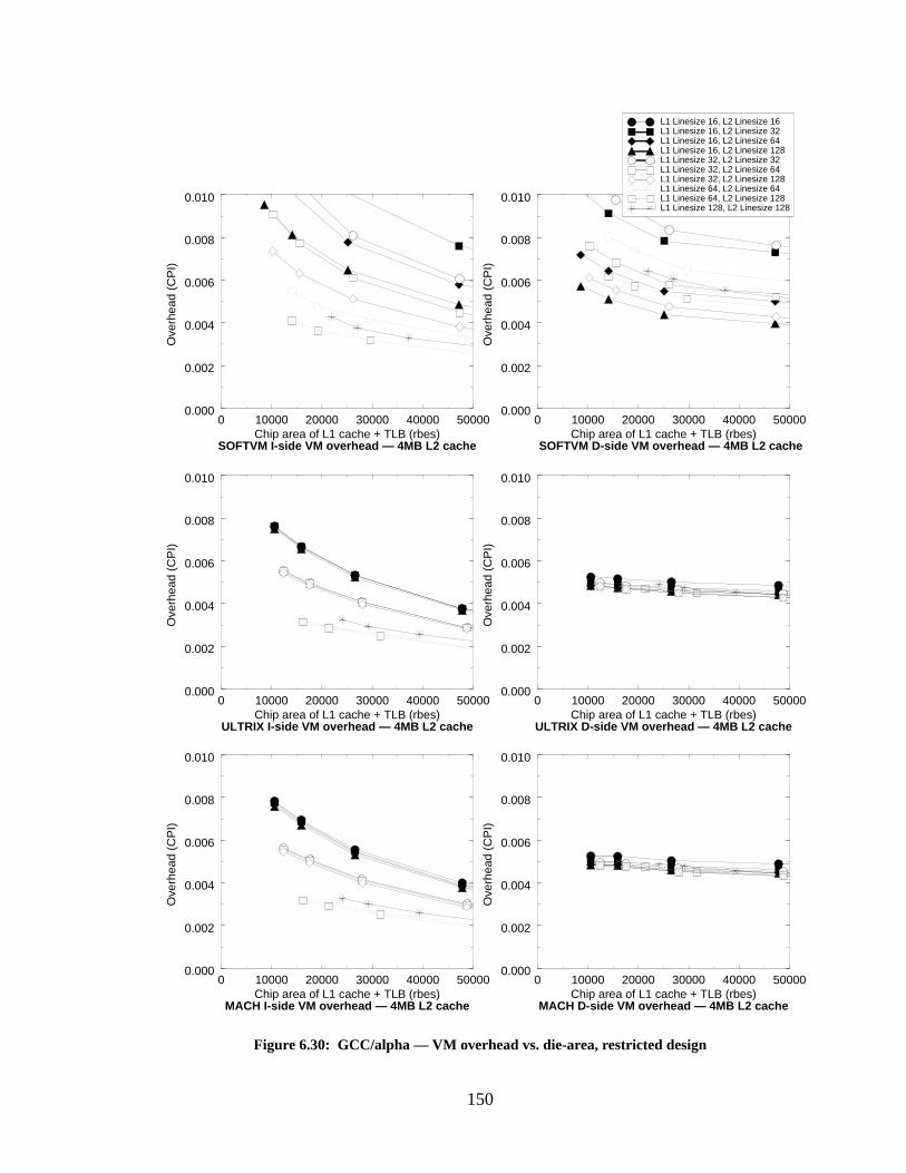
150
0 10000 20000 30000 40000 50000Chip area of L1 cache + TLB (rbes)
0.000
0.002
0.004
0.006
0.008
0.010
Ove
rhea
d (C
PI)
SOFTVM D-side VM overhead — 4MB L2 cache
Figure 6.30: GCC/alpha — VM overhead vs. die-area, restricted design
L1 Linesize 16, L2 Linesize 16L1 Linesize 16, L2 Linesize 32L1 Linesize 16, L2 Linesize 64L1 Linesize 16, L2 Linesize 128L1 Linesize 32, L2 Linesize 32L1 Linesize 32, L2 Linesize 64L1 Linesize 32, L2 Linesize 128L1 Linesize 64, L2 Linesize 64L1 Linesize 64, L2 Linesize 128L1 Linesize 128, L2 Linesize 128
0 10000 20000 30000 40000 50000Chip area of L1 cache + TLB (rbes)
0.000
0.002
0.004
0.006
0.008
0.010
Ove
rhea
d (C
PI)
SOFTVM I-side VM overhead — 4MB L2 cache
0 10000 20000 30000 40000 50000Chip area of L1 cache + TLB (rbes)
0.000
0.002
0.004
0.006
0.008
0.010O
verh
ead
(CP
I)
ULTRIX D-side VM overhead — 4MB L2 cache
0 10000 20000 30000 40000 50000Chip area of L1 cache + TLB (rbes)
0.000
0.002
0.004
0.006
0.008
0.010
Ove
rhea
d (C
PI)
ULTRIX I-side VM overhead — 4MB L2 cache
0 10000 20000 30000 40000 50000Chip area of L1 cache + TLB (rbes)
0.000
0.002
0.004
0.006
0.008
0.010
Ove
rhea
d (C
PI)
MACH I-side VM overhead — 4MB L2 cache
0 10000 20000 30000 40000 50000Chip area of L1 cache + TLB (rbes)
0.000
0.002
0.004
0.006
0.008
0.010
Ove
rhea
d (C
PI)
MACH D-side VM overhead — 4MB L2 cache
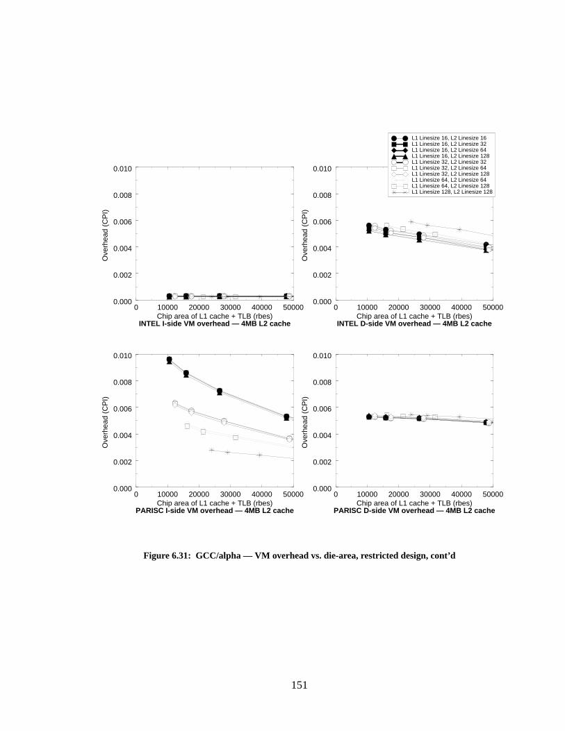
151
0 10000 20000 30000 40000 50000Chip area of L1 cache + TLB (rbes)
0.000
0.002
0.004
0.006
0.008
0.010
Ove
rhea
d (C
PI)
Figure 6.31: GCC/alpha — VM overhead vs. die-area, restricted design, cont’d
L1 Linesize 16, L2 Linesize 16L1 Linesize 16, L2 Linesize 32L1 Linesize 16, L2 Linesize 64L1 Linesize 16, L2 Linesize 128L1 Linesize 32, L2 Linesize 32L1 Linesize 32, L2 Linesize 64L1 Linesize 32, L2 Linesize 128L1 Linesize 64, L2 Linesize 64L1 Linesize 64, L2 Linesize 128L1 Linesize 128, L2 Linesize 128
INTEL D-side VM overhead — 4MB L2 cache
0 10000 20000 30000 40000 50000Chip area of L1 cache + TLB (rbes)
0.000
0.002
0.004
0.006
0.008
0.010
Ove
rhea
d (C
PI)
INTEL I-side VM overhead — 4MB L2 cache
0 10000 20000 30000 40000 50000Chip area of L1 cache + TLB (rbes)
0.000
0.002
0.004
0.006
0.008
0.010
Ove
rhea
d (C
PI)
0 10000 20000 30000 40000 50000Chip area of L1 cache + TLB (rbes)
0.000
0.002
0.004
0.006
0.008
0.010
Ove
rhea
d (C
PI)
PARISC D-side VM overhead — 4MB L2 cachePARISC I-side VM overhead — 4MB L2 cache
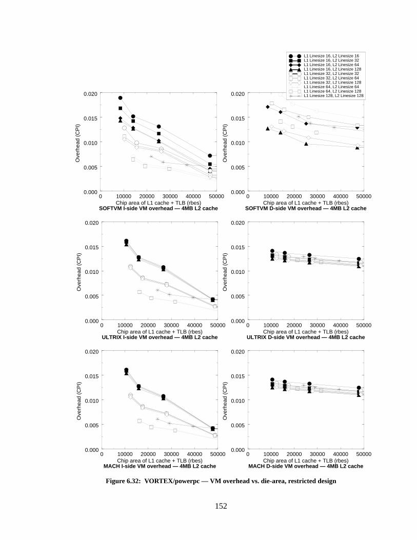
152
0 10000 20000 30000 40000 50000Chip area of L1 cache + TLB (rbes)
0.000
0.005
0.010
0.015
0.020
Ove
rhea
d (C
PI)
Figure 6.32: VORTEX/powerpc — VM overhead vs. die-area, restricted design
L1 Linesize 16, L2 Linesize 16L1 Linesize 16, L2 Linesize 32L1 Linesize 16, L2 Linesize 64L1 Linesize 16, L2 Linesize 128L1 Linesize 32, L2 Linesize 32L1 Linesize 32, L2 Linesize 64L1 Linesize 32, L2 Linesize 128L1 Linesize 64, L2 Linesize 64L1 Linesize 64, L2 Linesize 128L1 Linesize 128, L2 Linesize 128
0 10000 20000 30000 40000 50000Chip area of L1 cache + TLB (rbes)
0.000
0.005
0.010
0.015
0.020
Ove
rhea
d (C
PI)
0 10000 20000 30000 40000 50000Chip area of L1 cache + TLB (rbes)
0.000
0.005
0.010
0.015
0.020O
verh
ead
(CP
I)
0 10000 20000 30000 40000 50000Chip area of L1 cache + TLB (rbes)
0.000
0.005
0.010
0.015
0.020
Ove
rhea
d (C
PI)
SOFTVM I-side VM overhead — 4MB L2 cache SOFTVM D-side VM overhead — 4MB L2 cache
ULTRIX I-side VM overhead — 4MB L2 cache ULTRIX D-side VM overhead — 4MB L2 cache
0 10000 20000 30000 40000 50000Chip area of L1 cache + TLB (rbes)
0.000
0.005
0.010
0.015
0.020
Ove
rhea
d (C
PI)
MACH I-side VM overhead — 4MB L2 cache
0 10000 20000 30000 40000 50000Chip area of L1 cache + TLB (rbes)
0.000
0.005
0.010
0.015
0.020
Ove
rhea
d (C
PI)
MACH D-side VM overhead — 4MB L2 cache
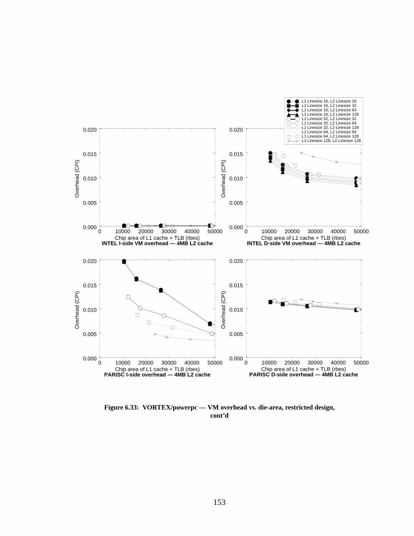
153
0 10000 20000 30000 40000 50000Chip area of L1 cache + TLB (rbes)
0.000
0.005
0.010
0.015
0.020
Ove
rhea
d (C
PI)
Figure 6.33: VORTEX/powerpc — VM overhead vs. die-area, restricted design,cont’d
L1 Linesize 16, L2 Linesize 16L1 Linesize 16, L2 Linesize 32L1 Linesize 16, L2 Linesize 64L1 Linesize 16, L2 Linesize 128L1 Linesize 32, L2 Linesize 32L1 Linesize 32, L2 Linesize 64L1 Linesize 32, L2 Linesize 128L1 Linesize 64, L2 Linesize 64L1 Linesize 64, L2 Linesize 128L1 Linesize 128, L2 Linesize 128
0 10000 20000 30000 40000 50000Chip area of L1 cache + TLB (rbes)
0.000
0.005
0.010
0.015
0.020
Ove
rhea
d (C
PI)
0 10000 20000 30000 40000 50000Chip area of L1 cache + TLB (rbes)
0.000
0.005
0.010
0.015
0.020
Ove
rhea
d (C
PI)
0 10000 20000 30000 40000 50000Chip area of L1 cache + TLB (rbes)
0.000
0.005
0.010
0.015
0.020
Ove
rhea
d (C
PI)
INTEL D-side VM overhead — 4MB L2 cacheINTEL I-side VM overhead — 4MB L2 cache
PARISC I-side overhead — 4MB L2 cache PARISC D-side overhead — 4MB L2 cache
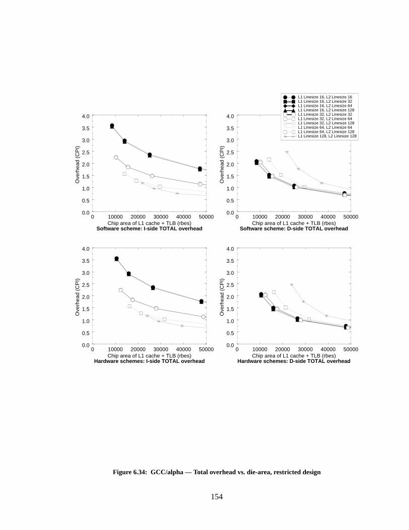
154
0 10000 20000 30000 40000 50000Chip area of L1 cache + TLB (rbes)
0.0
0.5
1.0
1.5
2.0
2.5
3.0
3.5
4.0
Ove
rhea
d (C
PI)
Figure 6.34: GCC/alpha — Total overhead vs. die-area, restricted design
L1 Linesize 16, L2 Linesize 16L1 Linesize 16, L2 Linesize 32L1 Linesize 16, L2 Linesize 64L1 Linesize 16, L2 Linesize 128L1 Linesize 32, L2 Linesize 32L1 Linesize 32, L2 Linesize 64L1 Linesize 32, L2 Linesize 128L1 Linesize 64, L2 Linesize 64L1 Linesize 64, L2 Linesize 128L1 Linesize 128, L2 Linesize 128
0 10000 20000 30000 40000 50000Chip area of L1 cache + TLB (rbes)
0.0
0.5
1.0
1.5
2.0
2.5
3.0
3.5
4.0
Ove
rhea
d (C
PI)
0 10000 20000 30000 40000 50000Chip area of L1 cache + TLB (rbes)
0.0
0.5
1.0
1.5
2.0
2.5
3.0
3.5
4.0
Ove
rhea
d (C
PI)
Hardware schemes: D-side TOTAL overheadHardware schemes: I-side TOTAL overhead
Software scheme: D-side TOTAL overhead
0 10000 20000 30000 40000 50000Chip area of L1 cache + TLB (rbes)
0.0
0.5
1.0
1.5
2.0
2.5
3.0
3.5
4.0
Ove
rhea
d (C
PI)
Software scheme: I-side TOTAL overhead
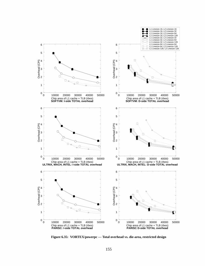
155
0 10000 20000 30000 40000 50000Chip area of L1 cache + TLB (rbes)
0
1
2
3
4
5
6
Ove
rhea
d (C
PI)
Figure 6.35: VORTEX/powerpc — Total overhead vs. die-area, restricted design
L1 Linesize 16, L2 Linesize 16L1 Linesize 16, L2 Linesize 32L1 Linesize 16, L2 Linesize 64L1 Linesize 16, L2 Linesize 128L1 Linesize 32, L2 Linesize 32L1 Linesize 32, L2 Linesize 64L1 Linesize 32, L2 Linesize 128L1 Linesize 64, L2 Linesize 64L1 Linesize 64, L2 Linesize 128L1 Linesize 128, L2 Linesize 128
0 10000 20000 30000 40000 50000Chip area of L1 cache + TLB (rbes)
0
1
2
3
4
5
6
Ove
rhea
d (C
PI)
0 10000 20000 30000 40000 50000Chip area of L1 cache + TLB (rbes)
0
1
2
3
4
5
6
Ove
rhea
d (C
PI)
ULTRIX, MACH, INTEL: D-side TOTAL overheadULTRIX, MACH, INTEL: I-side TOTAL overhead
0 10000 20000 30000 40000 50000Chip area of L1 cache + TLB (rbes)
0
1
2
3
4
5
6
Ove
rhea
d (C
PI)
SOFTVM: I-side TOTAL overhead SOFTVM: D-side TOTAL overhead
0 10000 20000 30000 40000 50000Chip area of L1 cache + TLB (rbes)
0
1
2
3
4
5
6
Ove
rhea
d (C
PI)
0 10000 20000 30000 40000 50000Chip area of L1 cache + TLB (rbes)
0
1
2
3
4
5
6
Ove
rhea
d (C
PI)
PARISC: I-side TOTAL overhead PARISC D-side TOTAL overhead
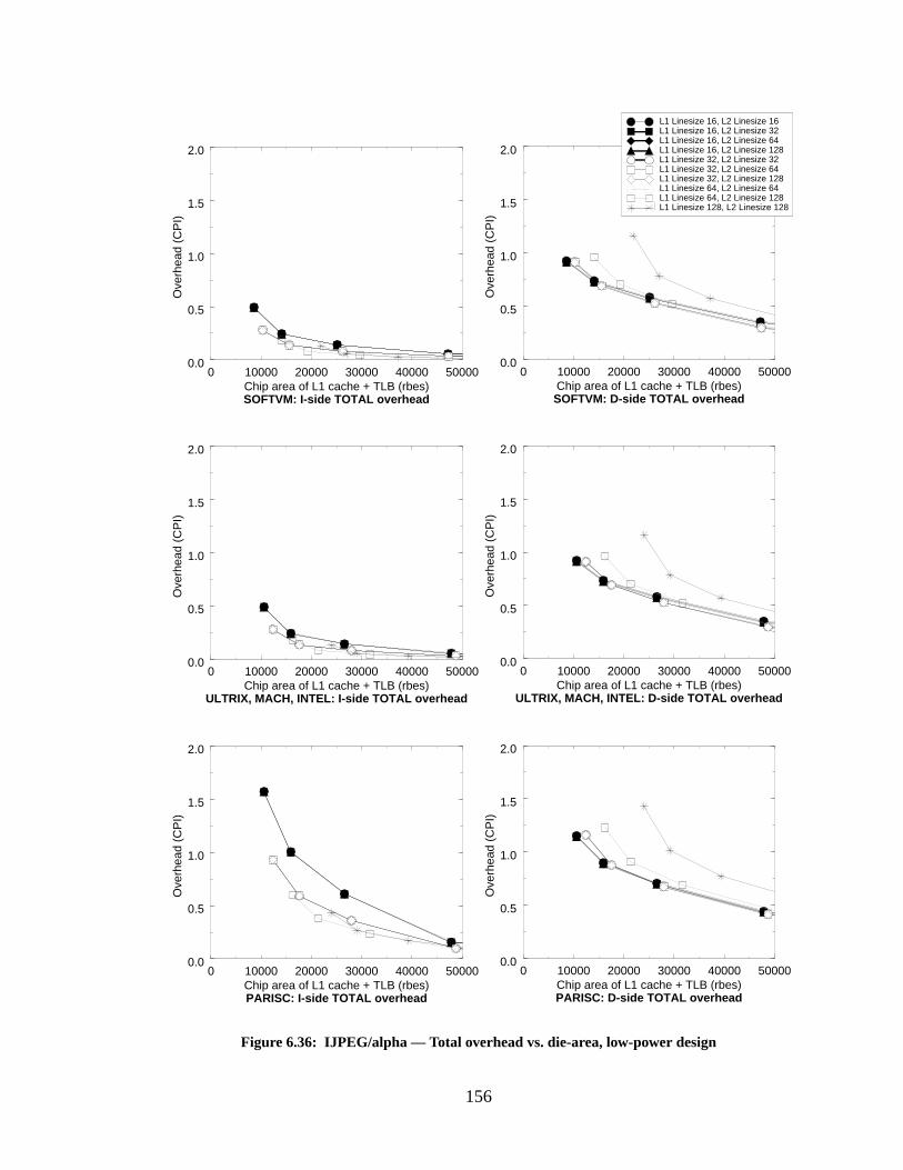
156
0 10000 20000 30000 40000 50000Chip area of L1 cache + TLB (rbes)
0.0
0.5
1.0
1.5
2.0
Ove
rhea
d (C
PI)
Figure 6.36: IJPEG/alpha — Total overhead vs. die-area, low-power design
L1 Linesize 16, L2 Linesize 16L1 Linesize 16, L2 Linesize 32L1 Linesize 16, L2 Linesize 64L1 Linesize 16, L2 Linesize 128L1 Linesize 32, L2 Linesize 32L1 Linesize 32, L2 Linesize 64L1 Linesize 32, L2 Linesize 128L1 Linesize 64, L2 Linesize 64L1 Linesize 64, L2 Linesize 128L1 Linesize 128, L2 Linesize 128
0 10000 20000 30000 40000 50000Chip area of L1 cache + TLB (rbes)
0.0
0.5
1.0
1.5
2.0
Ove
rhea
d (C
PI)
SOFTVM: D-side TOTAL overheadSOFTVM: I-side TOTAL overhead
0 10000 20000 30000 40000 50000Chip area of L1 cache + TLB (rbes)
0.0
0.5
1.0
1.5
2.0
Ove
rhea
d (C
PI)
0 10000 20000 30000 40000 50000Chip area of L1 cache + TLB (rbes)
0.0
0.5
1.0
1.5
2.0
Ove
rhea
d (C
PI)
0 10000 20000 30000 40000 50000Chip area of L1 cache + TLB (rbes)
0.0
0.5
1.0
1.5
2.0
Ove
rhea
d (C
PI)
0 10000 20000 30000 40000 50000Chip area of L1 cache + TLB (rbes)
0.0
0.5
1.0
1.5
2.0
Ove
rhea
d (C
PI)
ULTRIX, MACH, INTEL: I-side TOTAL overhead ULTRIX, MACH, INTEL: D-side TOTAL overhead
PARISC: I-side TOTAL overhead PARISC: D-side TOTAL overhead
157
Here the benefit of the software-oriented scheme is seen very clearly. It performs similarly
to most of the hardware schemes, but at a reduced cost in die area. The PARISC simulations
require the same die area as the other VM-simulations, but have better performance on VORTEX
and worse performance on IJPEG. The difference in die area for these small designs ranges from
20% to less than 5%, but the software scheme is always smaller. For large Level-1 cache sizes the
cost is actually greater than the hardware schemes, but at this point there are decreasing perfor-
mance returns in doubling the cache size.
The Performance of Low-Power Designs
It is entirely possible that one desires the performance of a 128-entry fully-associative
TLB without incurring the power consumption of a 128-entry fully-associative TLB. In this sec-
tion, we look at the result of choosing a set-associative TLB versus a software-oriented scheme.
This should yield an even greater difference in die-area, since, as we mentioned earlier, the set-
associative TLB is roughly six times larger than the fully-associative TLB with the same perfor-
mance. The graphs represent the die area requirements of 512-entry 4-way set-associative TLBs.
We show the total MCPI + VMCPI overheads for each of the designs, and as in the previous sec-
tion, we represent all of the hardware schemes with one graph, since their individual graphs are
indistinguishable. Figure 6.37 shows the total MCPI + VMCPI overhead for GCC. Figure 6.38
shows the total MCPI + VMCPI overhead for VORTEX. Figure 6.39 shows the total MCPI +
VMCPI overhead for IJPEG.
In these graphs, the difference between the software and hardware schemes is even more
striking. For one thing, there is no 8KB cache organization pictured for the hardware-oriented
schemes; the cost of the large TLB drives the design out of the range. The software scheme is as
much as 35% smaller than the equivalent hardware schemes and there are several points where the
software scheme allows caches that are twice as big as the hardware scheme, for the same total
cost in die area. As before, once one looks at the largest Level-1 cache sizes, the software scheme
is actually several percent larger. This is shown in Figure 6.40, which plots the total overhead for
GCC, Figure 6.41, which plots the total overhead for VORTEX, and Figure 6.42, which plots the
total overhead for IJPEG. When the Level-1 cache sizes become large, the software scheme actu-
ally consumes several percent more die area. However, at these cache sizes one has already hit
decreasing returns in the overall system overhead as a function of increasing cache size.
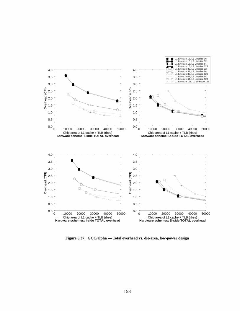
158
Figure 6.37: GCC/alpha — Total overhead vs. die-area, low-power design
0 10000 20000 30000 40000 50000Chip area of L1 cache + TLB (rbes)
0.0
0.5
1.0
1.5
2.0
2.5
3.0
3.5
4.0
Ove
rhea
d (C
PI)
0 10000 20000 30000 40000 50000Chip area of L1 cache + TLB (rbes)
0.0
0.5
1.0
1.5
2.0
2.5
3.0
3.5
4.0
Ove
rhea
d (C
PI)
Software scheme: I-side TOTAL overhead Software scheme: D-side TOTAL overhead
0 10000 20000 30000 40000 50000Chip area of L1 cache + TLB (rbes)
0.0
0.5
1.0
1.5
2.0
2.5
3.0
3.5
4.0
Ove
rhea
d (C
PI)
0 10000 20000 30000 40000 50000Chip area of L1 cache + TLB (rbes)
0.0
0.5
1.0
1.5
2.0
2.5
3.0
3.5
4.0
Ove
rhea
d (C
PI)
Hardware schemes: I-side TOTAL overhead Hardware schemes: D-side TOTAL overhead
L1 Linesize 16, L2 Linesize 16L1 Linesize 16, L2 Linesize 32L1 Linesize 16, L2 Linesize 64L1 Linesize 16, L2 Linesize 128L1 Linesize 32, L2 Linesize 32L1 Linesize 32, L2 Linesize 64L1 Linesize 32, L2 Linesize 128L1 Linesize 64, L2 Linesize 64L1 Linesize 64, L2 Linesize 128L1 Linesize 128, L2 Linesize 128
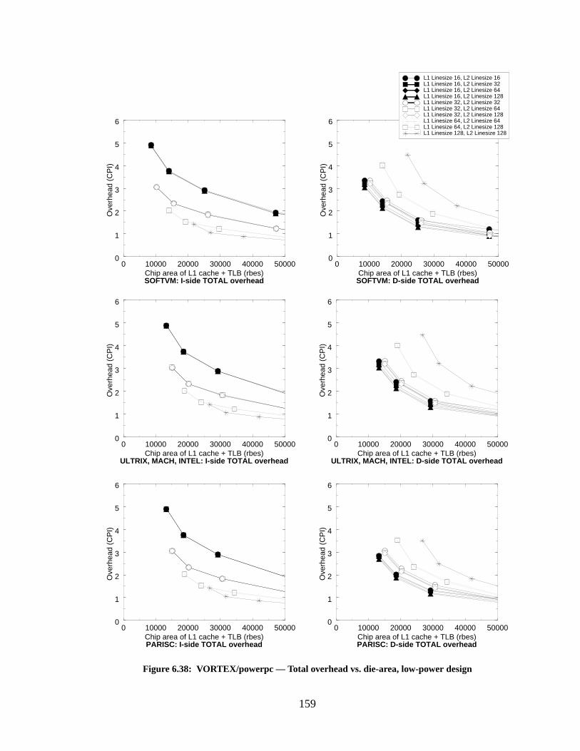
159
0 10000 20000 30000 40000 50000Chip area of L1 cache + TLB (rbes)
0
1
2
3
4
5
6
Ove
rhea
d (C
PI)
0 10000 20000 30000 40000 50000Chip area of L1 cache + TLB (rbes)
0
1
2
3
4
5
6
Ove
rhea
d (C
PI)
Figure 6.38: VORTEX/powerpc — Total overhead vs. die-area, low-power design
L1 Linesize 16, L2 Linesize 16L1 Linesize 16, L2 Linesize 32L1 Linesize 16, L2 Linesize 64L1 Linesize 16, L2 Linesize 128L1 Linesize 32, L2 Linesize 32L1 Linesize 32, L2 Linesize 64L1 Linesize 32, L2 Linesize 128L1 Linesize 64, L2 Linesize 64L1 Linesize 64, L2 Linesize 128L1 Linesize 128, L2 Linesize 128
0 10000 20000 30000 40000 50000Chip area of L1 cache + TLB (rbes)
0
1
2
3
4
5
6
Ove
rhea
d (C
PI)
0 10000 20000 30000 40000 50000Chip area of L1 cache + TLB (rbes)
0
1
2
3
4
5
6
Ove
rhea
d (C
PI)
SOFTVM: D-side TOTAL overheadSOFTVM: I-side TOTAL overhead
ULTRIX, MACH, INTEL: I-side TOTAL overhead ULTRIX, MACH, INTEL: D-side TOTAL overhead
0 10000 20000 30000 40000 50000Chip area of L1 cache + TLB (rbes)
0
1
2
3
4
5
6
Ove
rhea
d (C
PI)
0 10000 20000 30000 40000 50000Chip area of L1 cache + TLB (rbes)
0
1
2
3
4
5
6
Ove
rhea
d (C
PI)
PARISC: I-side TOTAL overhead PARISC: D-side TOTAL overhead
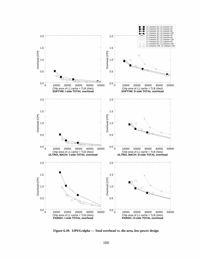
160
0 10000 20000 30000 40000 50000Chip area of L1 cache + TLB (rbes)
0.0
0.5
1.0
1.5
2.0
Ove
rhea
d (C
PI)
Figure 6.39: IJPEG/alpha — Total overhead vs. die-area, low-power design
L1 Linesize 16, L2 Linesize 16L1 Linesize 16, L2 Linesize 32L1 Linesize 16, L2 Linesize 64L1 Linesize 16, L2 Linesize 128L1 Linesize 32, L2 Linesize 32L1 Linesize 32, L2 Linesize 64L1 Linesize 32, L2 Linesize 128L1 Linesize 64, L2 Linesize 64L1 Linesize 64, L2 Linesize 128L1 Linesize 128, L2 Linesize 128
0 10000 20000 30000 40000 50000Chip area of L1 cache + TLB (rbes)
0.0
0.5
1.0
1.5
2.0O
verh
ead
(CP
I)
SOFTVM: D-side TOTAL overheadSOFTVM: I-side TOTAL overhead
0 10000 20000 30000 40000 50000Chip area of L1 cache + TLB (rbes)
0.0
0.5
1.0
1.5
2.0
Ove
rhea
d (C
PI)
0 10000 20000 30000 40000 50000Chip area of L1 cache + TLB (rbes)
0.0
0.5
1.0
1.5
2.0
Ove
rhea
d (C
PI)
0 10000 20000 30000 40000 50000Chip area of L1 cache + TLB (rbes)
0.0
0.5
1.0
1.5
2.0
Ove
rhea
d (C
PI)
0 10000 20000 30000 40000 50000Chip area of L1 cache + TLB (rbes)
0.0
0.5
1.0
1.5
2.0
Ove
rhea
d (C
PI)
ULTRIX, MACH: I-side TOTAL overhead ULTRIX, MACH: D-side TOTAL overhead
PARISC: I-side TOTAL overhead PARISC: D-side TOTAL overhead
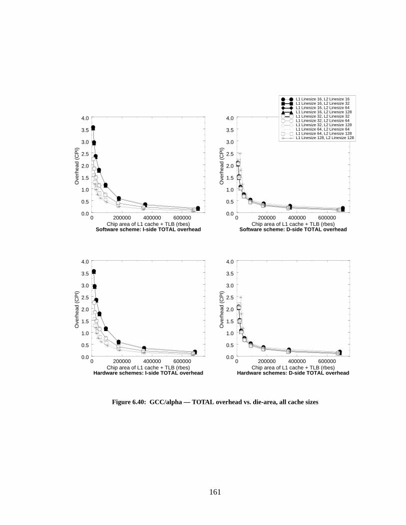
161
0 200000 400000 600000Chip area of L1 cache + TLB (rbes)
0.0
0.5
1.0
1.5
2.0
2.5
3.0
3.5
4.0
Ove
rhea
d (C
PI)
Software scheme: D-side TOTAL overhead
0 200000 400000 600000Chip area of L1 cache + TLB (rbes)
0.0
0.5
1.0
1.5
2.0
2.5
3.0
3.5
4.0
Ove
rhea
d (C
PI)
Hardware schemes: D-side TOTAL overhead
Figure 6.40: GCC/alpha — TOTAL overhead vs. die-area, all cache sizes
L1 Linesize 16, L2 Linesize 16L1 Linesize 16, L2 Linesize 32L1 Linesize 16, L2 Linesize 64L1 Linesize 16, L2 Linesize 128L1 Linesize 32, L2 Linesize 32L1 Linesize 32, L2 Linesize 64L1 Linesize 32, L2 Linesize 128L1 Linesize 64, L2 Linesize 64L1 Linesize 64, L2 Linesize 128L1 Linesize 128, L2 Linesize 128
0 200000 400000 600000Chip area of L1 cache + TLB (rbes)
0.0
0.5
1.0
1.5
2.0
2.5
3.0
3.5
4.0
Ove
rhea
d (C
PI)
Software scheme: I-side TOTAL overhead
0 200000 400000 600000Chip area of L1 cache + TLB (rbes)
0.0
0.5
1.0
1.5
2.0
2.5
3.0
3.5
4.0
Ove
rhea
d (C
PI)
Hardware schemes: I-side TOTAL overhead
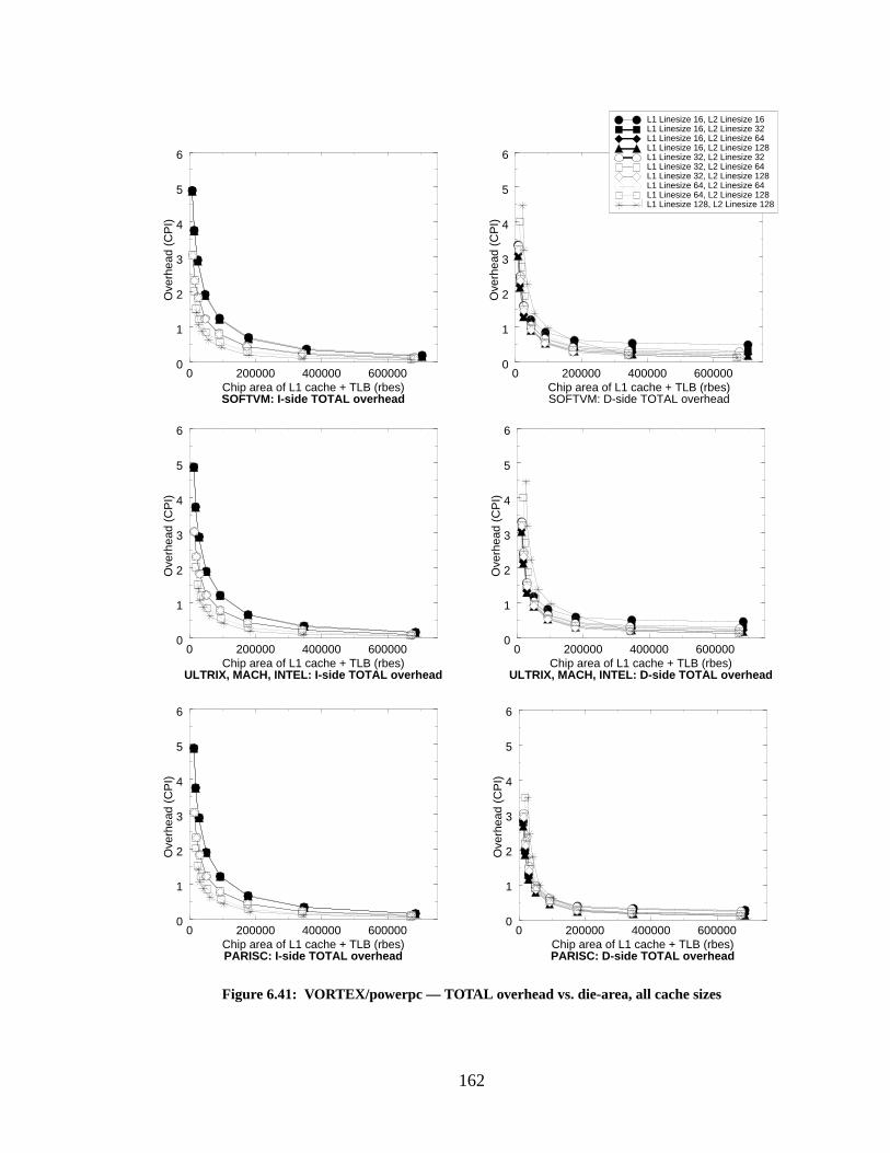
162
0 200000 400000 600000Chip area of L1 cache + TLB (rbes)
0
1
2
3
4
5
6
Ove
rhea
d (C
PI)
0 200000 400000 600000Chip area of L1 cache + TLB (rbes)
0
1
2
3
4
5
6
Ove
rhea
d (C
PI)
ULTRIX, MACH, INTEL: I-side TOTAL overhead ULTRIX, MACH, INTEL: D-side TOTAL overhead
0 200000 400000 600000Chip area of L1 cache + TLB (rbes)
0
1
2
3
4
5
6
Ove
rhea
d (C
PI)
Figure 6.41: VORTEX/powerpc — TOTAL overhead vs. die-area, all cache sizes
L1 Linesize 16, L2 Linesize 16L1 Linesize 16, L2 Linesize 32L1 Linesize 16, L2 Linesize 64L1 Linesize 16, L2 Linesize 128L1 Linesize 32, L2 Linesize 32L1 Linesize 32, L2 Linesize 64L1 Linesize 32, L2 Linesize 128L1 Linesize 64, L2 Linesize 64L1 Linesize 64, L2 Linesize 128L1 Linesize 128, L2 Linesize 128
0 200000 400000 600000Chip area of L1 cache + TLB (rbes)
0
1
2
3
4
5
6O
verh
ead
(CP
I)
SOFTVM: I-side TOTAL overhead SOFTVM: D-side TOTAL overhead
0 200000 400000 600000Chip area of L1 cache + TLB (rbes)
0
1
2
3
4
5
6
Ove
rhea
d (C
PI)
0 200000 400000 600000Chip area of L1 cache + TLB (rbes)
0
1
2
3
4
5
6
Ove
rhea
d (C
PI)
PARISC: I-side TOTAL overhead PARISC: D-side TOTAL overhead
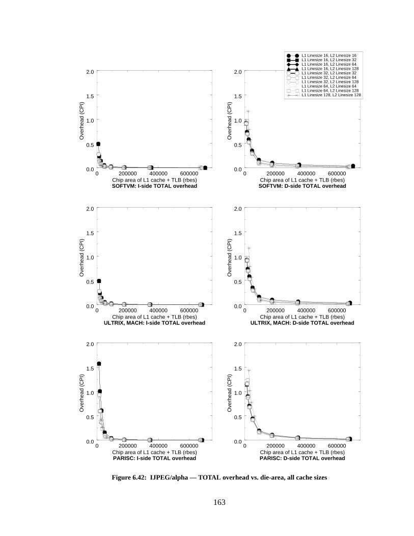
163
0 200000 400000 600000Chip area of L1 cache + TLB (rbes)
0.0
0.5
1.0
1.5
2.0
Ove
rhea
d (C
PI)
0 200000 400000 600000Chip area of L1 cache + TLB (rbes)
0.0
0.5
1.0
1.5
2.0
Ove
rhea
d (C
PI)
0 200000 400000 600000Chip area of L1 cache + TLB (rbes)
0.0
0.5
1.0
1.5
2.0
Ove
rhea
d (C
PI)
Figure 6.42: IJPEG/alpha — TOTAL overhead vs. die-area, all cache sizes
L1 Linesize 16, L2 Linesize 16L1 Linesize 16, L2 Linesize 32L1 Linesize 16, L2 Linesize 64L1 Linesize 16, L2 Linesize 128L1 Linesize 32, L2 Linesize 32L1 Linesize 32, L2 Linesize 64L1 Linesize 32, L2 Linesize 128L1 Linesize 64, L2 Linesize 64L1 Linesize 64, L2 Linesize 128L1 Linesize 128, L2 Linesize 128
0 200000 400000 600000Chip area of L1 cache + TLB (rbes)
0.0
0.5
1.0
1.5
2.0
Ove
rhea
d (C
PI)
0 200000 400000 600000Chip area of L1 cache + TLB (rbes)
0.0
0.5
1.0
1.5
2.0
Ove
rhea
d (C
PI)
0 200000 400000 600000Chip area of L1 cache + TLB (rbes)
0.0
0.5
1.0
1.5
2.0
Ove
rhea
d (C
PI)
SOFTVM: I-side TOTAL overhead SOFTVM: D-side TOTAL overhead
ULTRIX, MACH: I-side TOTAL overhead ULTRIX, MACH: D-side TOTAL overhead
PARISC: I-side TOTAL overhead PARISC: D-side TOTAL overhead
164
6.5 The Bottom Line on Performance
In this section, we bring together the topics all of the previous sections of this chapter and
present graphs that combine the effects that we had earlier treated in isolation. For the sake of
brevity, we fix several parameters: the Level-2 cache size is 4MB, and the L1/L2 cache line organi-
zation is 64 bytes in the L1 cache line, 128 bytes in the L2 cache line. We only look at the first 10
million instructions, as in the section on cold-cache start-up (as shown earlier, this should affect
the software scheme much more than the other schemes). We tag each simulation with the amount
of chip area it requires (in RBEs), to better judge the systems. We present two interrupt models,
corresponding to the low- and medium-overhead models in the interrupt section: one has a 10-
cycle penalty, the other has a 50-cycle penalty. We also approximate the effects of using 64-entry
TLBs as well as 128-entry TLBs, since 64-entry TLBs are more commonly found in today’s
microprocessors. Each figure presents graphs for four different Level-1 cache sizes: 4KB, 16KB,
64KB, and 256KB, where each cache is split into I- and D-caches with identical cache line config-
urations. The total MCPI+VMCPI overhead is represented; the figures include the cost of taking
L1 cache misses, the cost of L2 cache misses, the overhead of taking interrupts on either TLB
misses or L2 cache misses (depending on the VM-simulation), and the virtual-memory overhead.
This places the memory-management overhead in the appropriate relation to the total system over-
head.
The first group of figures represents 128/128-entry TLBs and a 10-cycle interrupt over-
head, corresponding to a near-future MMU design with an extremely low interrupt cost. Figure
6.43 depicts the GCC results, Figure 6.44 depicts the VORTEX results, and Figure 6.45 depicts the
IJPEG results.
The second group of figures represents 128/128-entry TLBs and a 50-cycle interrupt over-
head, corresponding to a near-future MMU design and an interrupt cost typical of today’s out-of-
order processors. Figure 6.46 depicts the GCC results, Figure 6.47 depicts the VORTEX results,
and Figure 6.48 depicts the IJPEG results.
The third group of figures represents 64/64-entry TLBs and a 10-cycle interrupt overhead,
corresponding to a typical MMU design for today’s processors and a typical interrupt cost for an
in-order pipeline. Figure 6.49 depicts the GCC results, Figure 6.50 depicts the VORTEX results,
and Figure 6.51 depicts the IJPEG results.
The fourth group of figures represents 64/64-entry TLBs and a 50-cycle interrupt over-
head, corresponding to a typical MMU design for today’s processors, as well as a typical interrupt
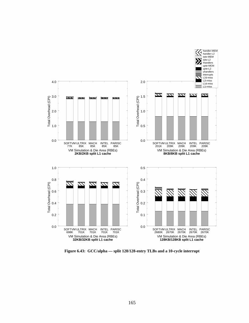
165
SOFTVM ULTRIX MACH INTEL PARISC0.0
0.5
1.0
1.5
2.0
Tot
al O
verh
ead
(CP
I)
Figure 6.43: GCC/alpha — split 128/128-entry TLBs and a 10-cycle interrupt
SOFTVM ULTRIX MACH INTEL PARISC0.0
0.1
0.2
0.3
0.4
0.5
Tot
al O
verh
ead
(CP
I)
SOFTVM ULTRIX MACH INTEL PARISC0.0
0.2
0.4
0.6
0.8
1.0
Tot
al O
verh
ead
(CP
I)
SOFTVM ULTRIX MACH INTEL PARISC0.0
1.0
2.0
3.0
4.0
Tot
al O
verh
ead
(CP
I)
VM Simulation & Die Area (RBEs)2KB/2KB split L1 cache
77K 85K 85K 85K 85K
VM Simulation & Die Area (RBEs)8KB/8KB split L1 cache
209K209K209K209K201K
VM Simulation & Die Area (RBEs)32KB/32KB split L1 cache
701K701K701K701K698K
VM Simulation & Die Area (RBEs)128KB/128KB split L1 cache
2670K2670K2670K2670K2680K
L1i-missL1d-missL2i-missL2d-missinterruptsuhandlersupte-L2upte-MEMrhandlersrpte-L2rpte-MEMhandler-L2handler-MEM
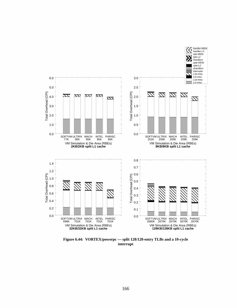
166
0.0
0.5
1.0
1.5
2.0
2.5
3.0
Tot
al O
verh
ead
(CP
I)
Figure 6.44: VORTEX/powerpc — split 128/128-entry TLBs and a 10-cycleinterrupt
SOFTVM ULTRIX MACH INTEL PARISC
SOFTVM ULTRIX MACH INTEL PARISCSOFTVM ULTRIX MACH INTEL PARISC
SOFTVM ULTRIX MACH INTEL PARISC
VM Simulation & Die Area (RBEs)2KB/2KB split L1 cache
77K 85K 85K 85K 85K
VM Simulation & Die Area (RBEs)8KB/8KB split L1 cache
209K209K209K209K201K
VM Simulation & Die Area (RBEs)32KB/32KB split L1 cache
701K701K701K701K698K
VM Simulation & Die Area (RBEs)128KB/128KB split L1 cache
2670K2670K2670K2670K2680K
0.0
1.0
2.0
3.0
4.0
5.0
6.0
Tot
al O
verh
ead
(CP
I)
0.0
0.2
0.4
0.6
0.8
1.0
1.2
1.4
Tot
al O
verh
ead
(CP
I)
0.0
0.1
0.2
0.3
0.4
0.5
0.6
0.7
0.8
Tot
al O
verh
ead
(CP
I)
L1i-missL1d-missL2i-missL2d-missinterruptsuhandlersupte-L2upte-MEMrhandlersrpte-L2rpte-MEMhandler-L2handler-MEM
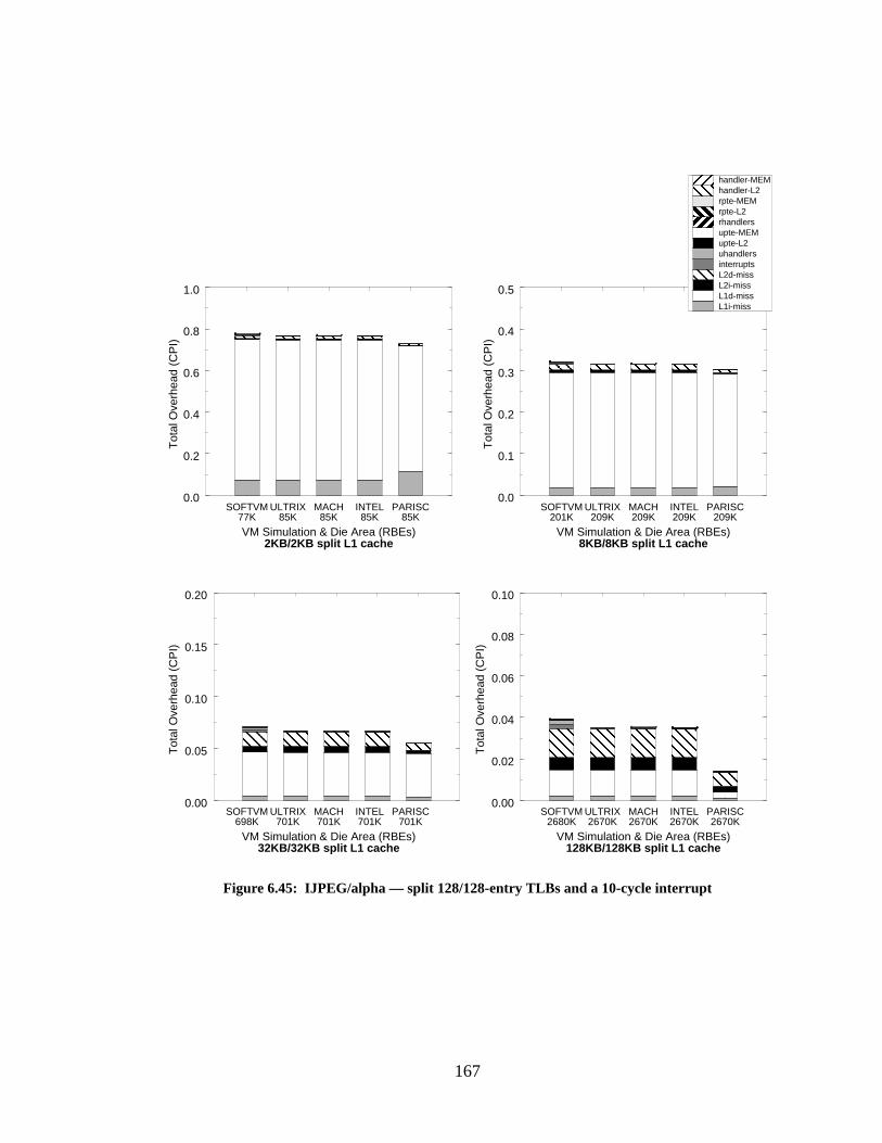
167
0.0
0.1
0.2
0.3
0.4
0.5
Tot
al O
verh
ead
(CP
I)
Figure 6.45: IJPEG/alpha — split 128/128-entry TLBs and a 10-cycle interrupt
SOFTVM ULTRIX MACH INTEL PARISC
SOFTVM ULTRIX MACH INTEL PARISCSOFTVM ULTRIX MACH INTEL PARISC
SOFTVM ULTRIX MACH INTEL PARISC
VM Simulation & Die Area (RBEs)2KB/2KB split L1 cache
77K 85K 85K 85K 85K
VM Simulation & Die Area (RBEs)8KB/8KB split L1 cache
209K209K209K209K201K
VM Simulation & Die Area (RBEs)32KB/32KB split L1 cache
701K701K701K701K698K
VM Simulation & Die Area (RBEs)128KB/128KB split L1 cache
2670K2670K2670K2670K2680K
L1i-missL1d-missL2i-missL2d-missinterruptsuhandlersupte-L2upte-MEMrhandlersrpte-L2rpte-MEMhandler-L2handler-MEM
0.0
0.2
0.4
0.6
0.8
1.0
Tot
al O
verh
ead
(CP
I)
0.00
0.05
0.10
0.15
0.20
Tot
al O
verh
ead
(CP
I)
0.00
0.02
0.04
0.06
0.08
0.10
Tot
al O
verh
ead
(CP
I)

168
0.0
0.5
1.0
1.5
2.0
Tot
al O
verh
ead
(CP
I)
Figure 6.46: GCC/alpha — split 128/128-entry TLBs and a 50-cycle interrupt
SOFTVM ULTRIX MACH INTEL PARISC
SOFTVM ULTRIX MACH INTEL PARISCSOFTVM ULTRIX MACH INTEL PARISC
SOFTVM ULTRIX MACH INTEL PARISC
VM Simulation & Die Area (RBEs)2KB/2KB split L1 cache
77K 85K 85K 85K 85K
VM Simulation & Die Area (RBEs)8KB/8KB split L1 cache
209K209K209K209K201K
VM Simulation & Die Area (RBEs)32KB/32KB split L1 cache
701K701K701K701K698K
VM Simulation & Die Area (RBEs)128KB/128KB split L1 cache
2670K2670K2670K2670K2680K
0.0
1.0
2.0
3.0
4.0
Tot
al O
verh
ead
(CP
I)
0.0
0.2
0.4
0.6
0.8
1.0
Tot
al O
verh
ead
(CP
I)
0.0
0.1
0.2
0.3
0.4
0.5
Tot
al O
verh
ead
(CP
I)
L1i-missL1d-missL2i-missL2d-missinterruptsuhandlersupte-L2upte-MEMrhandlersrpte-L2rpte-MEMhandler-L2handler-MEM
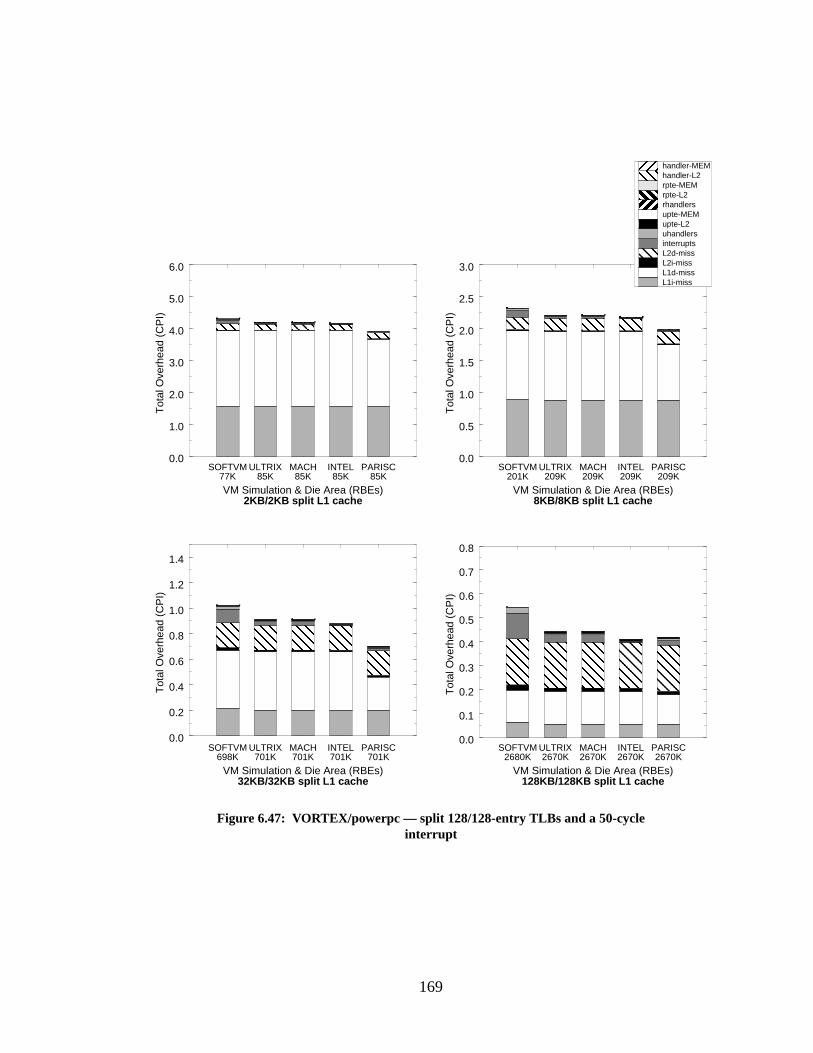
169
0.0
0.5
1.0
1.5
2.0
2.5
3.0
Tot
al O
verh
ead
(CP
I)
Figure 6.47: VORTEX/powerpc — split 128/128-entry TLBs and a 50-cycleinterrupt
SOFTVM ULTRIX MACH INTEL PARISC
SOFTVM ULTRIX MACH INTEL PARISCSOFTVM ULTRIX MACH INTEL PARISC
SOFTVM ULTRIX MACH INTEL PARISC
VM Simulation & Die Area (RBEs)2KB/2KB split L1 cache
77K 85K 85K 85K 85K
VM Simulation & Die Area (RBEs)8KB/8KB split L1 cache
209K209K209K209K201K
VM Simulation & Die Area (RBEs)32KB/32KB split L1 cache
701K701K701K701K698K
VM Simulation & Die Area (RBEs)128KB/128KB split L1 cache
2670K2670K2670K2670K2680K
0.0
1.0
2.0
3.0
4.0
5.0
6.0
Tot
al O
verh
ead
(CP
I)
0.0
0.2
0.4
0.6
0.8
1.0
1.2
1.4
Tot
al O
verh
ead
(CP
I)
0.0
0.1
0.2
0.3
0.4
0.5
0.6
0.7
0.8
Tot
al O
verh
ead
(CP
I)
L1i-missL1d-missL2i-missL2d-missinterruptsuhandlersupte-L2upte-MEMrhandlersrpte-L2rpte-MEMhandler-L2handler-MEM
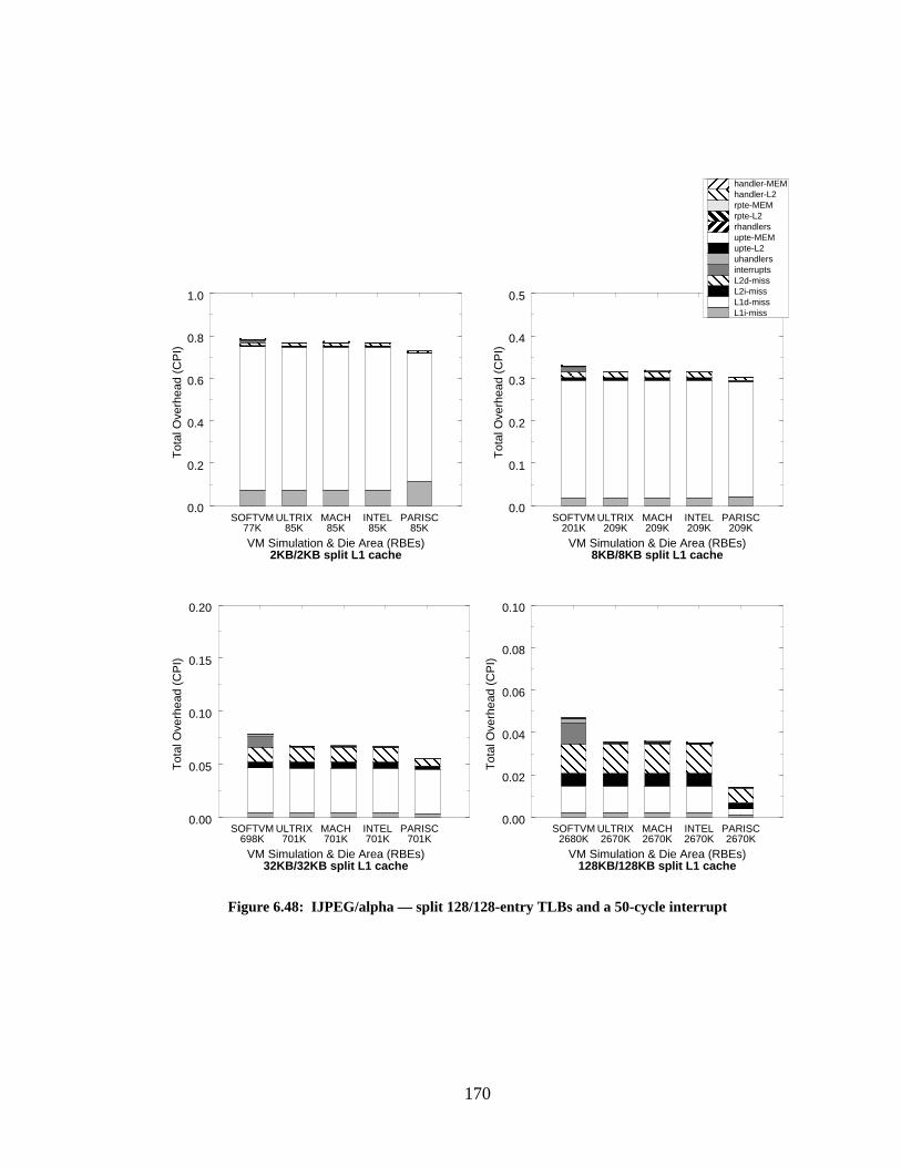
170
0.0
0.1
0.2
0.3
0.4
0.5
Tot
al O
verh
ead
(CP
I)
Figure 6.48: IJPEG/alpha — split 128/128-entry TLBs and a 50-cycle interrupt
SOFTVM ULTRIX MACH INTEL PARISC
SOFTVM ULTRIX MACH INTEL PARISCSOFTVM ULTRIX MACH INTEL PARISC
SOFTVM ULTRIX MACH INTEL PARISC
VM Simulation & Die Area (RBEs)2KB/2KB split L1 cache
77K 85K 85K 85K 85K
VM Simulation & Die Area (RBEs)8KB/8KB split L1 cache
209K209K209K209K201K
VM Simulation & Die Area (RBEs)32KB/32KB split L1 cache
701K701K701K701K698K
VM Simulation & Die Area (RBEs)128KB/128KB split L1 cache
2670K2670K2670K2670K2680K
L1i-missL1d-missL2i-missL2d-missinterruptsuhandlersupte-L2upte-MEMrhandlersrpte-L2rpte-MEMhandler-L2handler-MEM
0.00
0.02
0.04
0.06
0.08
0.10
Tot
al O
verh
ead
(CP
I)
0.00
0.05
0.10
0.15
0.20
Tot
al O
verh
ead
(CP
I)
0.0
0.2
0.4
0.6
0.8
1.0
Tot
al O
verh
ead
(CP
I)
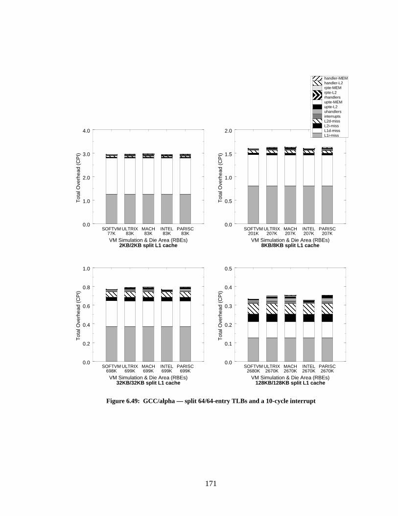
171
0.0
0.5
1.0
1.5
2.0
Tot
al O
verh
ead
(CP
I)
Figure 6.49: GCC/alpha — split 64/64-entry TLBs and a 10-cycle interrupt
SOFTVM ULTRIX MACH INTEL PARISC
SOFTVM ULTRIX MACH INTEL PARISCSOFTVM ULTRIX MACH INTEL PARISC
SOFTVM ULTRIX MACH INTEL PARISC
VM Simulation & Die Area (RBEs)2KB/2KB split L1 cache
77K 83K 83K 83K 83K
VM Simulation & Die Area (RBEs)8KB/8KB split L1 cache
207K207K207K207K201K
VM Simulation & Die Area (RBEs)32KB/32KB split L1 cache
699K699K699K699K698K
VM Simulation & Die Area (RBEs)128KB/128KB split L1 cache
2670K2670K2670K2670K2680K
0.0
1.0
2.0
3.0
4.0
Tot
al O
verh
ead
(CP
I)
0.0
0.2
0.4
0.6
0.8
1.0
Tot
al O
verh
ead
(CP
I)
0.0
0.1
0.2
0.3
0.4
0.5
Tot
al O
verh
ead
(CP
I)
L1i-missL1d-missL2i-missL2d-missinterruptsuhandlersupte-L2upte-MEMrhandlersrpte-L2rpte-MEMhandler-L2handler-MEM

172
0.0
0.5
1.0
1.5
2.0
2.5
3.0
Tot
al O
verh
ead
(CP
I)
Figure 6.50: VORTEX/powerpc — split 64/64-entry TLBs and a 10-cycle interrupt
SOFTVM ULTRIX MACH INTEL PARISC
SOFTVM ULTRIX MACH INTEL PARISCSOFTVM ULTRIX MACH INTEL PARISC
SOFTVM ULTRIX MACH INTEL PARISC
VM Simulation & Die Area (RBEs)2KB/2KB split L1 cache
77K 83K 83K 83K 35K
VM Simulation & Die Area (RBEs)8KB/8KB split L1 cache
207K207K207K207K201K
VM Simulation & Die Area (RBEs)32KB/32KB split L1 cache
699K699K699K699K698K
VM Simulation & Die Area (RBEs)128KB/128KB split L1 cache
2670K2670K2670K2670K2680K
0.0
1.0
2.0
3.0
4.0
5.0
6.0
Tot
al O
verh
ead
(CP
I)
0.0
0.2
0.4
0.6
0.8
1.0
1.2
1.4
Tot
al O
verh
ead
(CP
I)
0.0
0.1
0.2
0.3
0.4
0.5
0.6
0.7
0.8
Tot
al O
verh
ead
(CP
I)
L1i-missL1d-missL2i-missL2d-missinterruptsuhandlersupte-L2upte-MEMrhandlersrpte-L2rpte-MEMhandler-L2handler-MEM
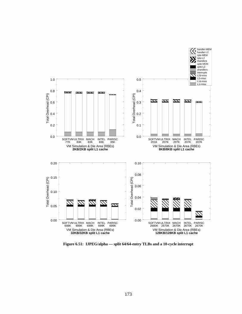
173
0.0
0.1
0.2
0.3
0.4
0.5
Tot
al O
verh
ead
(CP
I)
Figure 6.51: IJPEG/alpha — split 64/64-entry TLBs and a 10-cycle interrupt
SOFTVM ULTRIX MACH INTEL PARISC
SOFTVM ULTRIX MACH INTEL PARISCSOFTVM ULTRIX MACH INTEL PARISC
SOFTVM ULTRIX MACH INTEL PARISC
VM Simulation & Die Area (RBEs)2KB/2KB split L1 cache
77K 83K 83K 83K 35K
VM Simulation & Die Area (RBEs)8KB/8KB split L1 cache
207K207K207K207K201K
VM Simulation & Die Area (RBEs)32KB/32KB split L1 cache
699K699K699K699K698K
VM Simulation & Die Area (RBEs)128KB/128KB split L1 cache
2670K2670K2670K2670K2680K
L1i-missL1d-missL2i-missL2d-missinterruptsuhandlersupte-L2upte-MEMrhandlersrpte-L2rpte-MEMhandler-L2handler-MEM
0.0
0.2
0.4
0.6
0.8
1.0
Tot
al O
verh
ead
(CP
I)
0.00
0.05
0.10
0.15
0.20
Tot
al O
verh
ead
(CP
I)
0.00
0.02
0.04
0.06
0.08
0.10
Tot
al O
verh
ead
(CP
I)
174
cost for today’s out-of-order pipelines. Figure 6.52 depicts the GCC results, Figure 6.53 depicts
the VORTEX results, Figure 6.54 depicts the IJPEG results
To begin with, the VORTEX and IJPEG graphs illustrate the effect of the inverted page
table on overall performance. The PARISC VM-simulations exhibit performance that ranges from
roughly the same as the other VM-simulations, to as much as 50% less. Since the bulk of the dif-
ference comes fromL1d-miss, one can conclude that the difference is due to the page table design.
This is very interesting because it seems to go against intuition; the PTEs in the PARISC inverted
page table are twice as large as the PTEs from the other page tables and so should result in ahigher
overhead in the D-cache than the other VM-simulations. It also goes against earlier figures that
showed the PARISC simulation had ahigher overall MCPI value than the other simulations for
IJPEG. The difference between these measurements and the previous ones that put the PARISC
scheme at a higher overhead is that the earlier measurements were taken over entire application
executions; these measurements represent only the first 10 million instructions in the benchmark,
when the address space is effectively being initialized.
There are two factors working for the inverted table. The first is that the inverted page
table has a reduced impact on the cache because its entries are more closely packed; there is less
likelihood that any given cache line holding PTEs has unused space in it (this was described ear-
lier). The second factor builds on the first. Remember that these graphs represent only the first 10
million instructions in each benchmark; in these graphs, cache misses are not amortized over the
entire program execution. This is the region of program execution where the effect of the densely
packed page table is most strongly felt. In this region of cold-cache start-up, PTEs are being
brought in for the first time, increasing the likelihood that entire cache lines will be allocated to
hold but a single page table entry. This is especially true if the accesses tend to exhibit a low degree
of spatial locality, which is certainly true for VORTEX; it is a database application whose data
accesses have poor spatial locality. If a page table organization tends to result in sparsely populated
PTE pages (as is the case with hierarchical page tables), much of the cache will be uninitialized
PTEs in this cold-start region. A densely-packed page table will come closer to packing cache
lines full of PTEs.
The following paragraphs discuss each of the individual graphs; note that the graphs are
loosely ordered from designs likely to be seen in the near future, to designs available today. Thus,
they are loosely ordered from less realistic to more realistic in today’s terms.
Figures 6.43, 6.44, and 6.45 depict optimistic designs—extremely large TLBs and a very
low-overhead interrupt mechanism. These graphs show that when the memory system is very
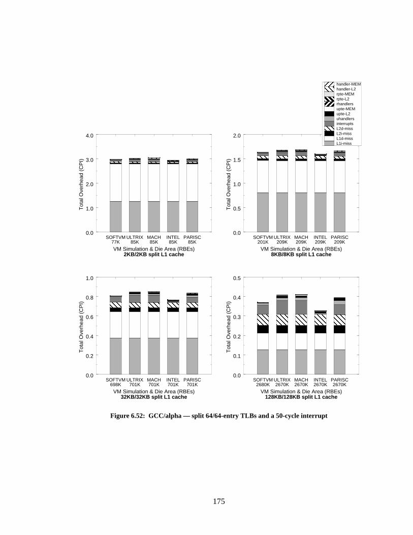
175
0.0
0.5
1.0
1.5
2.0
Tot
al O
verh
ead
(CP
I)
Figure 6.52: GCC/alpha — split 64/64-entry TLBs and a 50-cycle interrupt
SOFTVM ULTRIX MACH INTEL PARISC
SOFTVM ULTRIX MACH INTEL PARISCSOFTVM ULTRIX MACH INTEL PARISC
SOFTVM ULTRIX MACH INTEL PARISC
VM Simulation & Die Area (RBEs)2KB/2KB split L1 cache
77K 85K 85K 85K 85K
VM Simulation & Die Area (RBEs)8KB/8KB split L1 cache
209K209K209K209K201K
VM Simulation & Die Area (RBEs)32KB/32KB split L1 cache
701K701K701K701K698K
VM Simulation & Die Area (RBEs)128KB/128KB split L1 cache
2670K2670K2670K2670K2680K
0.0
1.0
2.0
3.0
4.0
Tot
al O
verh
ead
(CP
I)
0.0
0.2
0.4
0.6
0.8
1.0
Tot
al O
verh
ead
(CP
I)
0.0
0.1
0.2
0.3
0.4
0.5
Tot
al O
verh
ead
(CP
I)
L1i-missL1d-missL2i-missL2d-missinterruptsuhandlersupte-L2upte-MEMrhandlersrpte-L2rpte-MEMhandler-L2handler-MEM
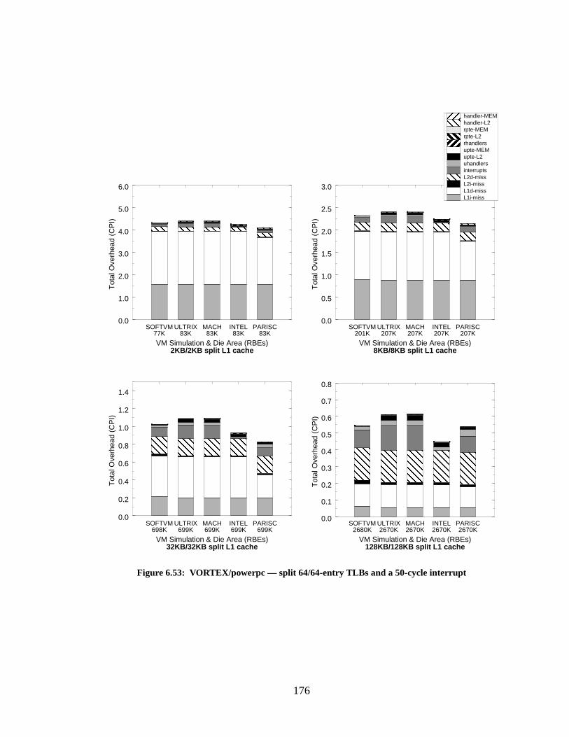
176
0.0
0.5
1.0
1.5
2.0
2.5
3.0
Tot
al O
verh
ead
(CP
I)
Figure 6.53: VORTEX/powerpc — split 64/64-entry TLBs and a 50-cycle interrupt
SOFTVM ULTRIX MACH INTEL PARISC
SOFTVM ULTRIX MACH INTEL PARISCSOFTVM ULTRIX MACH INTEL PARISC
SOFTVM ULTRIX MACH INTEL PARISC
VM Simulation & Die Area (RBEs)2KB/2KB split L1 cache
77K 83K 83K 83K 83K
VM Simulation & Die Area (RBEs)8KB/8KB split L1 cache
207K207K207K207K201K
VM Simulation & Die Area (RBEs)32KB/32KB split L1 cache
699K699K699K699K698K
VM Simulation & Die Area (RBEs)128KB/128KB split L1 cache
2670K2670K2670K2670K2680K
0.0
1.0
2.0
3.0
4.0
5.0
6.0
Tot
al O
verh
ead
(CP
I)
0.0
0.2
0.4
0.6
0.8
1.0
1.2
1.4
Tot
al O
verh
ead
(CP
I)
0.0
0.1
0.2
0.3
0.4
0.5
0.6
0.7
0.8
Tot
al O
verh
ead
(CP
I)
L1i-missL1d-missL2i-missL2d-missinterruptsuhandlersupte-L2upte-MEMrhandlersrpte-L2rpte-MEMhandler-L2handler-MEM

177
0.0
0.1
0.2
0.3
0.4
0.5
Tot
al O
verh
ead
(CP
I)
Figure 6.54: IJPEG/alpha — split 64/64-entry TLBs and a 50-cycle interrupt
L1i-missL1d-missL2i-missL2d-missinterruptsuhandlersupte-L2upte-MEMrhandlersrpte-L2rpte-MEMhandler-L2handler-MEM
SOFTVM ULTRIX MACH INTEL PARISC
SOFTVM ULTRIX MACH INTEL PARISCSOFTVM ULTRIX MACH INTEL PARISC
SOFTVM ULTRIX MACH INTEL PARISC
VM Simulation & Die Area (RBEs)2KB/2KB split L1 cache
77K 83K 83K 83K 83K
VM Simulation & Die Area (RBEs)8KB/8KB split L1 cache
207K207K207K207K201K
VM Simulation & Die Area (RBEs)32KB/32KB split L1 cache
699K699K699K699K698K
VM Simulation & Die Area (RBEs)128KB/128KB split L1 cache
2670K2670K2670K2670K2680K
0.00
0.02
0.04
0.06
0.08
0.10
Tot
al O
verh
ead
(CP
I)
0.00
0.05
0.10
0.15
0.20
Tot
al O
verh
ead
(CP
I)
0.0
0.2
0.4
0.6
0.8
1.0
Tot
al O
verh
ead
(CP
I)
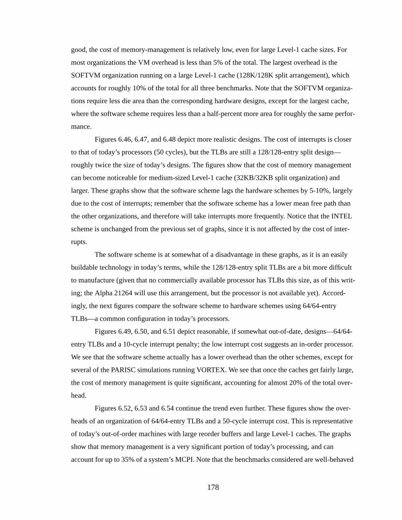
178
good, the cost of memory-management is relatively low, even for large Level-1 cache sizes. For
most organizations the VM overhead is less than 5% of the total. The largest overhead is the
SOFTVM organization running on a large Level-1 cache (128K/128K split arrangement), which
accounts for roughly 10% of the total for all three benchmarks. Note that the SOFTVM organiza-
tions require less die area than the corresponding hardware designs, except for the largest cache,
where the software scheme requires less than a half-percent more area for roughly the same perfor-
mance.
Figures 6.46, 6.47, and 6.48 depict more realistic designs. The cost of interrupts is closer
to that of today’s processors (50 cycles), but the TLBs are still a 128/128-entry split design—
roughly twice the size of today’s designs. The figures show that the cost of memory management
can become noticeable for medium-sized Level-1 cache (32KB/32KB split organization) and
larger. These graphs show that the software scheme lags the hardware schemes by 5-10%, largely
due to the cost of interrupts; remember that the software scheme has a lower mean free path than
the other organizations, and therefore will take interrupts more frequently. Notice that the INTEL
scheme is unchanged from the previous set of graphs, since it is not affected by the cost of inter-
rupts.
The software scheme is at somewhat of a disadvantage in these graphs, as it is an easily
buildable technology in today’s terms, while the 128/128-entry split TLBs are a bit more difficult
to manufacture (given that no commercially available processor has TLBs this size, as of this writ-
ing; the Alpha 21264 will use this arrangement, but the processor is not available yet). Accord-
ingly, the next figures compare the software scheme to hardware schemes using 64/64-entry
TLBs—a common configuration in today’s processors.
Figures 6.49, 6.50, and 6.51 depict reasonable, if somewhat out-of-date, designs—64/64-
entry TLBs and a 10-cycle interrupt penalty; the low interrupt cost suggests an in-order processor.
We see that the software scheme actually has a lower overhead than the other schemes, except for
several of the PARISC simulations running VORTEX. We see that once the caches get fairly large,
the cost of memory management is quite significant, accounting for almost 20% of the total over-
head.
Figures 6.52, 6.53 and 6.54 continue the trend even further. These figures show the over-
heads of an organization of 64/64-entry TLBs and a 50-cycle interrupt cost. This is representative
of today’s out-of-order machines with large reorder buffers and large Level-1 caches. The graphs
show that memory management is a very significant portion of today’s processing, and can
account for up to 35% of a system’s MCPI. Note that the benchmarks considered are well-behaved
179
and do not represent pathological or worst-case behavior; they represent average programs that a
typical user might execute. The cost of interrupts is one of the largest factors in the memory-man-
agement overhead; this suggests that a scheme to reduce the interrupt overhead might be useful.
We address exactly this topic in Chapter 8.
In all the graphs, the software scheme performs admirably compared to the hardware
schemes. Our initial goal was to design a system that is more flexible and requires less die area
than traditional hardware-oriented schemes, at little to no performance cost. We have shown that
the software scheme, under the worst circumstances of cold-cache start-up (where a software
scheme should perform nearly as bad as the worst-case scenario of interrupting on almost every
cache-line access), is able to perform similarly to hardware schemes. For many configurations, the
software scheme performs even better. For all cache configurations but the largest Level-1 cache
sizes (256KB split cache), the software scheme also requires less die area—up to 10% less for the
cache sizes shown here.
6.6 Usefulness of the Software-Oriented Scheme
The software-oriented scheme supports software-defined granularities for address transla-
tion and fine-grained protection, uses software-controlled virtually-addressed caches, provides the
least-common-denominator support for memory management, and demonstrates that traditionally
hardware-oriented functions such as address translation and cache management can be performed
efficiently in software. These features should be useful for multiprocessor systems, real-time sys-
tems, architecture emulation, and an abridged form of reconfigurable computing, respectively.
6.6.1 Support for Multipr ocessor Systems
Typical shared-memory multiprocessors manage their virtual memory locally and share
their physical memory globally. Thus, the physical address is placed on the shared bus and
snooped in the caches of the processors. Virtual caches have long been considered inappropriate
for shared-memory multiprocessors for exactly this reason. This would seem to preclude the use of
a software-oriented memory-management scheme in a multiprocessor setting.
However, the problem is easily solved by widening the shared bus. The arrangement is
illustrated in Figure 6.55; if both physical and virtual addresses are placed on the bus at the same
time, the processor caches can snoop the virtual bus and the memory system can respond to the
physical bus. A segmented architecture, as has been described, is very convenient for this organi-
180
zation if the global segmented address space is shared across all processors; for instance, such an
arrangement could simplify the common case of snooping if memory were shared at a segment
granularity—to handle the common case of not sharing, one could use fewer bits for the snooping
hardware to match against. This would allow the virtual address bus to be only as wide as a seg-
ment identifier. If a match were discovered, one could then revert to a higher-overhead snooping
protocol that sent over the entire address (perhaps on the data bus).
Note that the elimination of the TLB simplifies inter-processor TLB coherency—it elimi-
nates the need for hardware or software coherency mechanisms entirely. Many studies have shown
that maintaining TLB consistency across multiple processors is a significant problem [Balan &
Gollhardt 1992, Torrellas et al. 1992]. For example, according to Rosenblum et al., UTLB misses
happen several million times per second in a multiprocessor setting, roughly an order of magnitude
more than the rate for a uniprocessor [Rosenblum et al. 1995].
There is also the issue of false sharing; this is the behavior seen when two processors write
to two different data structures that happen to lie on the same shared page. Even though the proces-
sors do not write to the same data locations, the granularity of sharing is too large; each processor
has to take turns locking, writing, and freeing the shared region, though they write to different
locations in the shared region. When this behavior occurs, performance of the system declines pre-
Figure 6.55: Shared-memory multiprocessor organizationVirtual caches can work in a multiprocessor setting, provided that the virtual space is shared betweenthe processors. In this case, both the virtual address and the physical address are placed on the bus; thevirtual address is snooped by the virtual caches of the other processors, the physical address is read bythe physical memory system. Note that the organization generalizes to a networked environment.
SHAREDPHYSICALMEMORY
VIRTUAL ADDRESS BUS (snooped)
PHYSICAL ADDRESS BUS (not snooped)
PROCESSORwith
V-CACHES
PROCESSORwith
V-CACHES
PROCESSORwith
V-CACHES� � �
181
cipitously. The advantage of a software-oriented memory management scheme is that the page size
is determined entirely by software; it can be different for different processes, and it can even be
different for different regions within a single process, ranging from the size of an entire address
space down to the size of a cacheline.
As mentioned in the figure’s caption, note that the bus-based multiprocessor organization
(using two address busses: one that is snooped, one that is used by the shared memory) generalizes
beyond a bus-based multiprocessor. In a distributed shared memory environment, a message
packet requesting a page of shared memory would simply contain both physical and virtual
addresses.
6.6.2 Support for Real-Time Systems
Real-time systems have traditionally forgone the use of caches to better determine the
exact length of time it takes to perform a function. Caches do not make the measurements non-
deterministic, but they do make the calculations extremely complicated. One way to look at this is
that designers of real-time systems have been willing to sacrifice performance for precision.
However, if the operating system managed the cache hierarchy as it manages main mem-
ory, it would be possible for a real-time operating system to decide at a cacheline-sized granularity
whether or not to cache portions of an address space. Thus it would be possible to load a critical
region of code or data into the cache without the fear that the cache’s automatic replacement policy
will evict any of it. The decision to cache or not-cache a particular region of memory would be
dynamic and could change many times over the course of an application’s execution.
Such is the case with the software-oriented memory-management scheme; it uses caches
that are fully under the control of the operating system. Code and data are brought into the cache
hierarchy from main memory only under the control of the operating system. Therefore the OS can
make precise guarantees about the access time of code and data by maintaining information (either
static or dynamic) on whether or not the locations are cached. The use of cached/uncached virtual
addresses, as described in the SOFTVM architecture in Chapter 5, allows the operating system to
manage application-level address spaces transparently. The top bits of the virtual address are cho-
sen by the operating system; therefore the operating system can choose to cache or not cache seg-
ments.
182
6.6.3 Support for Ar chitecture Emulation
There has been much work done lately in the area of architecture emulation; examples
include Digital’s FX!32 and Sun’s WABI [Digital 1997, Sun 1997]. The goal of both these envi-
ronments is to execute Windows/x86 applications transparently on non-Intel platforms running
non-Windows operating systems. Another example is IBM’s DAISY [Ebcioglu & Altman 1997],
which provides 100% architectural compatibility between disparate processor architectures to the
extent that it can execute both applications and operating systems written for the emulated archi-
tecture.
Making software independent of the platform for which is was originally intended is
clearly big business and it is becoming increasingly important. Producing a hardware platform that
offers the least-common-denominator support for memory management should help that cause; it
should be possible to emulate the memory management units of virtually any hardware on a
SOFTVM-like architecture.
6.6.4 Support for Reconfigurable Computing, Jr.
The flexibility provided by moving functions from hardware into software allows one to
tailor the behavior of the hardware to suit the particular needs of applications, on an application-
by-application basis. In a software-oriented memory management scheme the software manage-
ment of the cache is an important factor, as it allows the operating system to decide cacheability on
a per-cacheline granularity. Previous studies by Tyson et al. [Tyson et al. 1995] have shown that
effective cache management transcends the simple demand-fetch paradigm implemented in most
caches; cacheability should be determined by use. This result has been reproduced by Johnson and
Hwu [Johnson & Hwu 1997].
Our work has demonstrated that software management of the Level-2 cache is feasible,
given a large enough cache. Therefore it should be relatively simple for the operating system to
emulate these hardware cacheability algorithms entirely in software, achieving better performance
than a regular cache, with a more flexible interface than the hardware schemes of Tyson and
Johnson.. This flexibility would also allow the operating system to explore other cacheability algo-
rithms. While this is a far cry from truly reconfigurable computing where hardware datapaths and
logic can be re-defined on a cycle-by-cycle basis to exploit peculiarities in the needs of different
algorithms, it nonetheless is a step in the same direction.
183
6.7 Comparison to Other Addressing Schemes
What the software-oriented scheme buys us is flexibility . When coupled with hardware
segmentation, it allows us to use large virtually-addressed caches without fear of synonym prob-
lems (discussed in much more detail in Chapter 7). There are several other unconventional virtual
addressing schemes that distinguish themselves from the traditional 32-bit virtual memory mecha-
nism, among them large addressing schemes—i.e. larger than 32 bits—and single address space
operating systems (SASOS). How do these compare with the software-oriented scheme?
6.7.1 Lar ge (e.g. 64-bit) Addressing Schemes
Large addressing schemes are not important in and of themselves, except for the fact that
they offer processes the opportunity to map into their address spaces extremely large files, data-
bases, and numerous objects located on remote hosts. Whereas this much data would likely swamp
a 4-gigabyte address space, a 16-exabyte address space as provided by a 64-bit machine would
comfortably hold most of what is addressable on the planet (see Appendix A). Thus a 64-bit
addressing scheme would allow programs to use loads and stores to access every piece of data they
need, as opposed to the present scheme where loads and stores only work for data in a process’s
address space; data in files and databases and remote objects and in the address spaces of other
processes must be obtained by file I/O, network I/O, and other protocols like RPC.
Large addressing schemes and software-managed address translation are largely orthogo-
nal issues; one can have large addressing schemes that perform address translation in either hard-
ware or software. The main benefit of a large addressing scheme is the significant increase in the
number and amount of objects and data that a program can address; as described, this can be used
to support a simplified programming paradigm. The software-managed scheme is similar in that its
main draw is flexibility and simplicity of design, but they are in no way competitive ideas.
6.7.2 Single Address Space Operating Systems
The concept of asingle address space operating system (SASOS) has been proposed
recently to take advantage of the large address spaces available on today’s machines [Chase et al.
1992a, Chase et al. 1992b, Garrett et al. 1992, Garrett et al. 1993, Roscoe 1994, Scott et al. 1988].
A SASOS organizes process address spaces as subsets of the total addressable extent available to
the hardware; if the hardware can address a 64-bit address space, a SASOS places all process
address spaces into the flat 16 EB space. Whereas a traditional virtual memory system supports the
184
illusion that an individual process has the entire machine to itself, a SASOS allows processes to be
aware that other processes are inhabiting the same global space at the same time.
There are several advantages to such an organization, centered largely around shared
memory; compared to a traditional virtual memory implementation, a SASOS can support shared
memory more easily and efficiently. The traditional virtual memory model, in which the existence
of other address spaces is hidden from processes, makes sharing memory difficult by definition. If
a process cannot construct an address that references a location outside of its own address space, it
will be hard put to reference data in another process’s space; traditional virtual memory systems
have relied upon this fact to provide address space protection between processes. The techniques
used to circumvent this protection and provide shared memory have had one major shortcoming:
they do not support pointers well. In order to share memory between two processes, the virtual
memory system will map a portion of each process’s address space to the same physical memory;
in effect, each process is “tricked” into believing that it owns the memory. As long as the two pro-
cesses use the same virtual address to reference the shared location, there is likely to be no prob-
lem. However, if the two processes use different virtual addresses to reference the shared location,
and if they store those virtual addresses in the shared location, there is a likelihood of confusion
resulting in memory corruption. This scenario is described in more detail in Chapter 7. The advan-
tage of the SASOS organization is that all processes use the same virtual address to reference the
same location. Confusion and data corruption due to shared pointers are therefore impossible.
Therefore SASOS systems are typically employed to provide efficient shared memory
schemes. For instance, the Nemesis operating system uses a single address space organization to
implement multimedia data transfers very efficiently [Roscoe 1995]. This organization also leads
to another benefit: if all processes use the same virtual address to reference the same datum, then
no virtual-address aliasing exists to cause potential synonym problems in the cache [Goodman
1987]. Therefore a SASOS can use a large virtual cache without fear of data inconsistencies and
without resorting to expensive cache management mechanisms. This is also described in more
detail in Chapter 7.
The software-oriented scheme as described in this dissertation is very similar to a SASOS,
as it uses the global virtual space, provided by the segmentation mechanism, much as a SASOS
uses its space; it is a flat space shared by all processes. The primary difference between the two is
that in the software scheme (a segmented scheme), processes do not reference the global space
directly, therefore they are not aware of other address spaces. The segmentation mechanism pro-
vides the benefits of a single address space, but retains the illusion that a process owns the machine
185
while it is executing; this is advantageous, as the virtual-machine illusion is a very useful program-
ming paradigm. The use of segmentation to share memory and eliminate virtual-cache synonym
problems is described in excruciating detail in Chapter 7.
6.8 Compatibility with Differ ent Cache Organizations
The following sections discuss the interaction of a software-oriented scheme with differ-
ent cache organizations.
6.8.1 Write-Back Caches
In a write-back cache, the cache buffers the main memory system from the effects of
writes; a written cache line goes to the cache and remains there until it is explicitly flushed or until
another cache line that maps to the same cache location is read or written. Writes in a writeback
cache go to main memory infrequently, therefore it is possible to perform a software translation for
every writeback; it will happen infrequently, therefore the cost will not be outrageous. Moreover, if
most of the writebacks are due to cache conflicts and not explicit flushes, the operating system will
already have taken an interrupt to locate the incoming line; it is not much more work to look up a
second line (the line being written back) at the same time. A hardware assist would be to notify the
exception-handling routine whether the cache line being replaced is dirty or not (i.e. whether it
needs a translation or not).
6.8.2 Write-Thr ough Caches
Write-through caches do not buffer the physical memory system from writes; writes then
frequently go to main memory. Since roughly 10% of a given instruction stream are likely to be
writes, performing a software lookup of the translation for each and every write would be prohibi-
tively expensive. Therefore if one is to use a write-through cache, it will probably be necessary to
store the translation in the cache line with the data and tag. Similarly, if one were to use a write
buffer or write cache, each entry would also have to hold the translation in case the line in the
cache is overwritten before the entry in the write buffer or write cache is sent to main memory,
making the translation unavailable at the moment it is needed.
186
6.9 Conclusions
There is good news and there is bad news. The good news is that a software-oriented sys-
tem appears to perform well and offer dramatically increased flexibility . The bad news is that sev-
eral models that depend on physical addressing or hardware-management of caches are broken.
6.9.1 Performance Recapitulation
First, we need to recap some of the points brought up in the performance sections, since
there was so much going on.
There was much evidence that virtual memory functions off the critical path can be high-
cost and still yield low overall VM-system overheads. This was demonstrated by the fact that the
ULTRIX and MACH simulations produce such similar results, despite the fact that the MACH’s
root-level handler costs at least 500 cycles per invocation. It was supported by the PARISC simula-
tion’s performance in the face of expensive interrupts, where the page table organization is more
complex and requires a higher per-handler cost than the simpler ULTRIX and MACH organiza-
tions, but when the cost of interrupts becomes high the scheme does better than the other two
because it reduces the number of TLB misses.
The INTEL scheme is shown to be a good memory-management organization, despite the
fact that the page table is walked in a top-down fashion; like the PARISC simulation, the INTEL
simulation stores only user-level PTEs in the TLBs and therefore has a lower TLB miss rate than
the ULTRIX and MACH simulations. The scheme is also insensitive to the cost of interrupts,
which becomes increasingly important as the cost of interrupts increases.
There seems to be a point around the 2MB-4MB Level-2 cache size where an increase in
cache size does not result in a decrease in VM overhead. This is the point where the TLB no longer
maps an appreciable fraction of the Level-2 caches, and so one is not likely to see further VM ben-
efits from increasing the Level-2 caches. The software-oriented scheme, on the other hand, sees
reduced VM overheads for all increases in cache size. Note, however, that at this point the over-
head of the VM system is still a small fraction of the total memory-system overhead.
The software-oriented scheme performs similarly to the various hardware-oriented
schemes, and has very similar overall performance numbers (including total MCPI). When the
schemes are compared on the basis of die area requirements, the software scheme produces the
same overall performance at a reduced die area, for small to medium Level-1 cache sizes. The sav-
ings in die area can be as high as 35%. For very large Level-1 cache sizes, the software scheme

187
requires several percent more die area, but at these large cache sizes there are decreasing returns on
die area investment—the overall performance benefits are not as large as the increased chip area.
The software-oriented scheme is understandably very sensitive to cache size and organiza-
tion. Once the proper configuration is chosen, the scheme will perform well, and does not appear
that it will plateau with increasing Level-2 cache sizes (as do the hardware-managed schemes).
The software scheme appears to be less sensitive than the others to the access times of the cache
hierarchy, but is more sensitive to the cost of taking an interrupt, and to the effects of cold-cache
start-up.
The hashed page table of the PARISC scheme seems to fit better within the Level-2 caches
than the hierarchical page tables of the other schemes. This is likely due to the fact that its PTEs
are more densely packed than PTEs in a hierarchical page table—the hashed page table is there-
fore less likely to overlap cache hotspots. On the other hand, the hashed table seems to fit less well
in the Level-1 caches than the page tables of the other schemes, probably because each PTE is
twice as large as the PTEs of the other schemes.
There is a significant reduction in the mean free path between TLB misses when one
moves from a 128-entry TLB to a 112-entry TLB (as in the case of the ULTRIX and MACH simu-
lations that reserve 16 of their 128 TLB entries for “protected” kernel-level and root-level PTEs).
This is supported by a study of mean free paths for different TLB sizes. This TLB study shows that
the average number of instructions between TLB misses is highly sensitive to TLB size; doublings
of the TLB size produce more than double the time-between-TLB-misses. The software-oriented
scheme, which has been shown to have roughly the same performance as other VM schemes at a
smaller die area (assuming small to medium Level-1 caches), should therefore perform much bet-
ter than hardware-oriented schemes that use two 64-entry TLBs.
Lastly, when all effects are taken into account, including cold-cache start-up (which
should better represent the performance of real programs that time-share the processor) and inter-
rupt overheads, memory management is seen to represent up to 35% of a system’s total overhead
(excluding any disk activity). The software scheme holds its own against the hardware-oriented
schemes, and out-performs many of them while requiring less die area for its implementation. The
inverted table of the PARISC simulations is a clear winner, since its densely-packed page tables
seem to better utilize cache lines during the cold-cache period of program execution when PTEs
are brought in at a furious pace.
188
6.9.2 The Good News
As mentioned, a software-oriented scheme exhibits a large degree of flexibility . Freedom
in selecting page size can help reduce effects such as false sharing; software-controlled caches can
benefit real-time systems; and performing as much as possible in software allows the system to
emulate other architectures or adapt itself to the particular needs of different applications. The sys-
tem also performs well, as shown in previous chapters as well as this chapter. It is not TLB-lim-
ited; as systems use larger caches, the performance should scale with the caches. This is in stark
contrast to hardware-oriented schemes that are limited by the size of the TLB; as long as the TLB
maps the entire cache hierarchy no performance is lost, however today’s large caches require sub-
stantially larger TLBs than exist today, as it is difficult to make a TLB that is large without it
severely impacting cycle time or power consumption. Therefore a software-oriented scheme seems
to be a very good bargain: increased flexibility at no cost in performance, or even a performance
boost.
6.9.3 The Bad News
Despite the advantages to the system, there are several problems. (1) The scheme uses
large virtually-indexed caches, which are known to cause problems when sharing memory through
address aliasing. (2) The scheme relies on the general interrupt mechanism; every Level-2 cache
miss generates an interrupt. This could be potentially very expensive. (3) The scheme is a potential
problem for streaming data, where one will take a cache-miss exception every time a new cache
line is touched. Compared to a traditional TLB-based system, which would take a TLB miss every
time a new page is touched, this scheme would suffer an interrupt 10 to 100 times as often; this is
a potential show-stopper. (4) The scheme also requires large Level-2 caches which might not be an
option for inexpensive (e.g. hand-held, portable) systems.
Each of these problems has a number of solutions. In the following four chapters we dis-
cuss each problem in detail and present several solutions.
189
CHAPTER 7
THE PROBLEMS WITH VIRTUAL CACHESAND A SOLUTION USING HARDWARE SEGMENTATION
If one is to eliminate memory-management hardware, one must use virtually-indexed, vir-
tually-tagged caches. The traditional purported weakness of virtual caches is their inability to sup-
port shared memory. Many implementations of shared memory are at odds with virtual caches—
ASID aliasing andvirtual-address aliasing (techniques used to provide shared memory) can cause
false cache misses and/or give rise to data inconsistencies in a virtual cache, but are necessary fea-
tures of many virtual memory implementations. By appropriately using a segmented architecture
one can solve these problems. In this chapter we describe a virtual memory system developed for a
segmented microarchitecture and present the following benefits derived from such an organization:
(a) the need to flush virtual caches can be eliminated, (b) virtual cache consistency management
can be eliminated, (c) page table space requirements can be cut in half by eliminating the need to
replicate page table entries for shared pages, and (d) the virtual memory system can be made less
complex because it does not have to deal with the virtual-cache synonym problem.
7.1 Intr oduction
Virtual caches allow faster processing in the common case because they do not require
address translation when requested data is found in the caches. They are not used in many architec-
tures despite their apparent simplicity because they have several potential pitfalls that need careful
management [Goodman 1987, Inouye et al. 1992, Wheeler & Bershad 1992]. We are building a
high clock-rate PowerPC; we chose a virtual cache organization to meet the memory requirements
of a high clock-rate processor, and to avoid the potential slowdown of address translation. We dis-
covered that the segmented memory-management architecture of the PowerPC works extremely
well with a virtual cache organization and an appropriate virtual memory organization, eliminating
the need for virtual-cache management and allowing the operating system to minimize the space
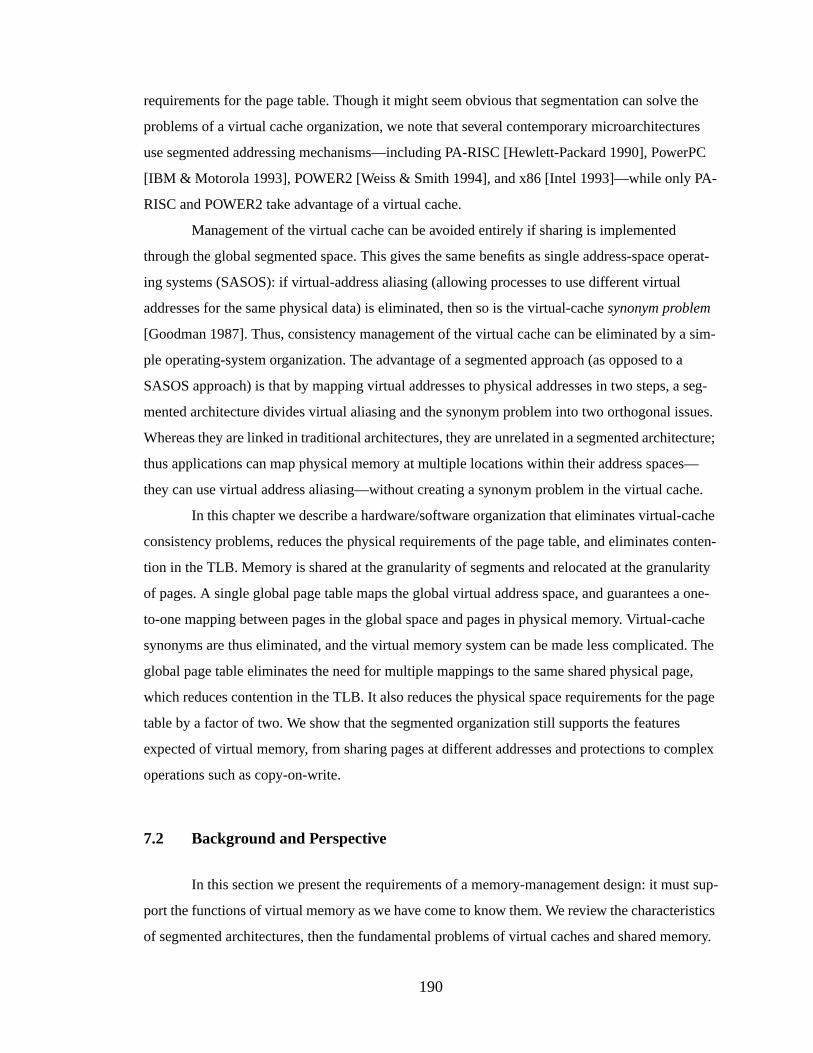
190
requirements for the page table. Though it might seem obvious that segmentation can solve the
problems of a virtual cache organization, we note that several contemporary microarchitectures
use segmented addressing mechanisms—including PA-RISC [Hewlett-Packard 1990], PowerPC
[IBM & Motorola 1993], POWER2 [Weiss & Smith 1994], and x86 [Intel 1993]—while only PA-
RISC and POWER2 take advantage of a virtual cache.
Management of the virtual cache can be avoided entirely if sharing is implemented
through the global segmented space. This gives the same benefits as single address-space operat-
ing systems (SASOS): if virtual-address aliasing (allowing processes to use different virtual
addresses for the same physical data) is eliminated, then so is the virtual-cachesynonym problem
[Goodman 1987]. Thus, consistency management of the virtual cache can be eliminated by a sim-
ple operating-system organization. The advantage of a segmented approach (as opposed to a
SASOS approach) is that by mapping virtual addresses to physical addresses in two steps, a seg-
mented architecture divides virtual aliasing and the synonym problem into two orthogonal issues.
Whereas they are linked in traditional architectures, they are unrelated in a segmented architecture;
thus applications can map physical memory at multiple locations within their address spaces—
they can use virtual address aliasing—without creating a synonym problem in the virtual cache.
In this chapter we describe a hardware/software organization that eliminates virtual-cache
consistency problems, reduces the physical requirements of the page table, and eliminates conten-
tion in the TLB. Memory is shared at the granularity of segments and relocated at the granularity
of pages. A single global page table maps the global virtual address space, and guarantees a one-
to-one mapping between pages in the global space and pages in physical memory. Virtual-cache
synonyms are thus eliminated, and the virtual memory system can be made less complicated. The
global page table eliminates the need for multiple mappings to the same shared physical page,
which reduces contention in the TLB. It also reduces the physical space requirements for the page
table by a factor of two. We show that the segmented organization still supports the features
expected of virtual memory, from sharing pages at different addresses and protections to complex
operations such as copy-on-write.
7.2 Background and Perspective
In this section we present the requirements of a memory-management design: it must sup-
port the functions of virtual memory as we have come to know them. We review the characteristics
of segmented architectures, then the fundamental problems of virtual caches and shared memory.
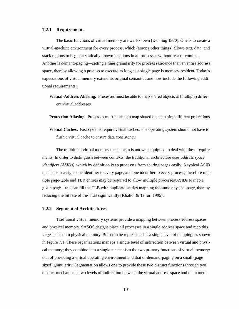
191
7.2.1 Requirements
The basic functions of virtual memory are well-known [Denning 1970]. One is to create a
virtual-machine environment for every process, which (among other things) allows text, data, and
stack regions to begin at statically known locations in all processes without fear of conflict.
Another is demand-paging—setting a finer granularity for process residence than an entire address
space, thereby allowing a process to execute as long as a single page is memory-resident. Today’s
expectations of virtual memory extend its original semantics and now include the following addi-
tional requirements:
Virtual-Addr ess Aliasing. Processes must be able to map shared objects at (multiple) differ-
ent virtual addresses.
Protection Aliasing. Processes must be able to map shared objects using different protections.
Virtual Caches. Fast systems require virtual caches. The operating system should not have to
flush a virtual cache to ensure data consistency.
The traditional virtual memory mechanism is not well equipped to deal with these require-
ments. In order to distinguish between contexts, the traditional architecture usesaddress space
identifiers (ASIDs), which by definition keep processes from sharing pages easily. A typical ASID
mechanism assigns one identifier to every page, and one identifier to every process; therefore mul-
tiple page-table and TLB entries may be required to allow multiple processes/ASIDs to map a
given page—this can fill the TLB with duplicate entries mapping the same physical page, thereby
reducing the hit rate of the TLB significantly [Khalidi & Talluri 1995].
7.2.2 Segmented Architectures
Traditional virtual memory systems provide a mapping between process address spaces
and physical memory. SASOS designs place all processes in a single address space and map this
large space onto physical memory. Both can be represented as a single level of mapping, as shown
in Figure 7.1. These organizations manage a single level of indirection between virtual and physi-
cal memory; they combine into a single mechanism the two primary functions of virtual memory:
that of providing a virtual operating environment and that of demand-paging on a small (page-
sized) granularity. Segmentation allows one to provide these two distinct functions through two
distinct mechanisms: two levels of indirection between the virtual address space and main mem-
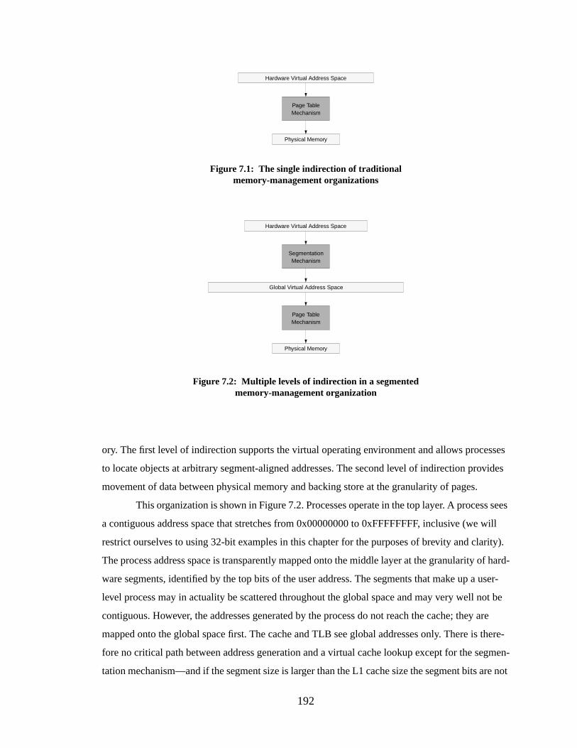
192
ory. The first level of indirection supports the virtual operating environment and allows processes
to locate objects at arbitrary segment-aligned addresses. The second level of indirection provides
movement of data between physical memory and backing store at the granularity of pages.
This organization is shown in Figure 7.2. Processes operate in the top layer. A process sees
a contiguous address space that stretches from 0x00000000 to 0xFFFFFFFF, inclusive (we will
restrict ourselves to using 32-bit examples in this chapter for the purposes of brevity and clarity).
The process address space is transparently mapped onto the middle layer at the granularity of hard-
ware segments, identified by the top bits of the user address. The segments that make up a user-
level process may in actuality be scattered throughout the global space and may very well not be
contiguous. However, the addresses generated by the process do not reach the cache; they are
mapped onto the global space first. The cache and TLB see global addresses only. There is there-
fore no critical path between address generation and a virtual cache lookup except for the segmen-
tation mechanism—and if the segment size is larger than the L1 cache size the segment bits are not
Hardware Virtual Address Space
Physical Memory
Page TableMechanism
Figure 7.1: The single indirection of traditionalmemory-management organizations
Hardware Virtual Address Space
Physical Memory
Page TableMechanism
Global Virtual Address Space
SegmentationMechanism
Figure 7.2: Multiple levels of indirection in a segmentedmemory-management organization
193
used in the cache lookup, thus the segmentation mechanism can run in parallel with the cache
access.
Segmented systems have a long history. Multics, one of the earliest segmented operating
systems, used a segmented/paged architecture, the GE 645 [Organick 1972]. This architecture was
similar to the Intel Pentium memory management organization [Intel 1993] in that both the GE
645 and the Intel Pentium support segments of variable size. The Pentium memory management
hardware is illustrated in Figure 3.7. An important point is that the Pentium’s global space is no
larger than an individual user-level address space; processes generate 32-bit addresses that are
extended by 16-bit segment selectors. The selectors are used by hardware to index into one of two
descriptor tables that produce a base address for the segment corresponding to the segment selec-
tor. This base address is added to the 32-bit virtual address produced by the application to form a
global 32-bit virtual address. The segments can range from a single byte to 4GB in size. There is
no mechanism to prevent different segments from overlapping one another in the global 4GB
space. The segment selectors are produced indirectly. At any given time a process can reference
six of its segments; selectors for these six segments are stored in six segment registers that are ref-
erenced by context. One segment register is referenced implicitly by executing instructions; it con-
tains a segment selector for the current code segment. Another segment register holds the segment
selector for the stack. The other four are used for data segments, and a process can specify which
of the segment registers to use for different loads and stores. One of the data segment registers is
implicitly referenced for all string instructions, unless explicitly over-ridden.
In contrast, the IBM 801 [Chang & Mergen 1988] introduced a fixed-size segmented
architecture that continued through to the POWER and PowerPC architectures [IBM & Motorola
1993, May et al. 1994, Weiss & Smith 1994]. The PowerPC memory management design is illus-
trated in Figure 3.4. It maps user addresses onto a global flat address space much larger than each
per-process address space. Segments are 256MB contiguous regions of virtual space, and 16 seg-
ments make up an application’s address space. Programs generate 32-bit “effective addresses.” The
top four bits of the effective address select a segment identifier from a set of 16 hardware segment
registers. The segment identifier is concatenated with the bottom 28 bits of the effective address to
form an extended virtual address. It is this extended virtual address space that is mapped by the
TLBs and page table. For brevity and clarity, we will restrict ourselves to using fixed-size segmen-
tation for examples throughout this chapter.
Segmented architectures need not use address space identifiers; address space protection is
guaranteed by the segmentation mechanism.1 If two processes have the same segment identifier,
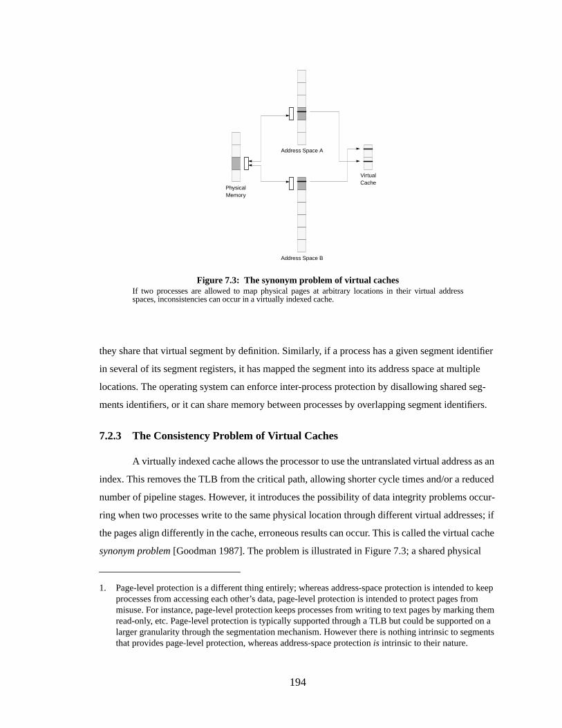
194
they share that virtual segment by definition. Similarly, if a process has a given segment identifier
in several of its segment registers, it has mapped the segment into its address space at multiple
locations. The operating system can enforce inter-process protection by disallowing shared seg-
ments identifiers, or it can share memory between processes by overlapping segment identifiers.
7.2.3 The Consistency Problem of Virtual Caches
A virtually indexed cache allows the processor to use the untranslated virtual address as an
index. This removes the TLB from the critical path, allowing shorter cycle times and/or a reduced
number of pipeline stages. However, it introduces the possibility of data integrity problems occur-
ring when two processes write to the same physical location through different virtual addresses; if
the pages align differently in the cache, erroneous results can occur. This is called the virtual cache
synonym problem [Goodman 1987]. The problem is illustrated in Figure 7.3; a shared physical
1. Page-level protection is a different thing entirely; whereas address-space protection is intended to keepprocesses from accessing each other’s data, page-level protection is intended to protect pages frommisuse. For instance, page-level protection keeps processes from writing to text pages by marking themread-only, etc. Page-level protection is typically supported through a TLB but could be supported on alarger granularity through the segmentation mechanism. However there is nothing intrinsic to segmentsthat provides page-level protection, whereas address-space protectionis intrinsic to their nature.
Figure 7.3: The synonym problem of virtual cachesIf two processes are allowed to map physical pages at arbitrary locations in their virtual addressspaces, inconsistencies can occur in a virtually indexed cache.
Address Space A
Address Space B
PhysicalMemory
VirtualCache
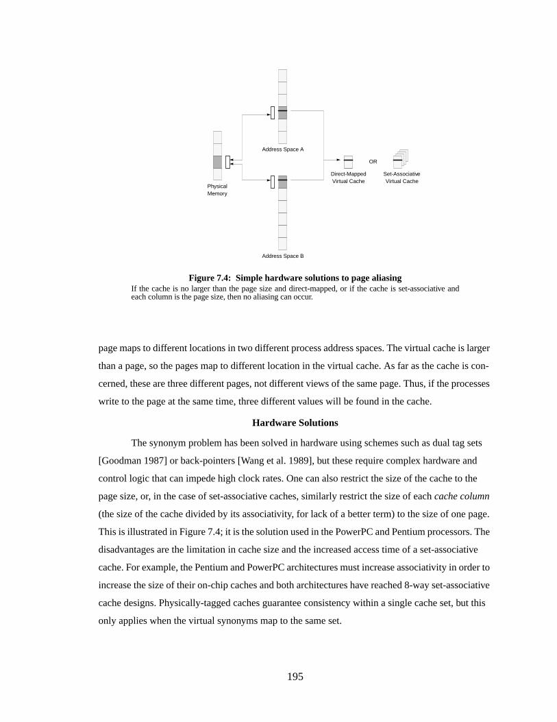
195
page maps to different locations in two different process address spaces. The virtual cache is larger
than a page, so the pages map to different location in the virtual cache. As far as the cache is con-
cerned, these are three different pages, not different views of the same page. Thus, if the processes
write to the page at the same time, three different values will be found in the cache.
Hardware Solutions
The synonym problem has been solved in hardware using schemes such as dual tag sets
[Goodman 1987] or back-pointers [Wang et al. 1989], but these require complex hardware and
control logic that can impede high clock rates. One can also restrict the size of the cache to the
page size, or, in the case of set-associative caches, similarly restrict the size of eachcache column
(the size of the cache divided by its associativity, for lack of a better term) to the size of one page.
This is illustrated in Figure 7.4; it is the solution used in the PowerPC and Pentium processors. The
disadvantages are the limitation in cache size and the increased access time of a set-associative
cache. For example, the Pentium and PowerPC architectures must increase associativity in order to
increase the size of their on-chip caches and both architectures have reached 8-way set-associative
cache designs. Physically-tagged caches guarantee consistency within a single cache set, but this
only applies when the virtual synonyms map to the same set.
Address Space A
Address Space B
PhysicalMemory
Direct-MappedVirtual Cache
Set-AssociativeVirtual Cache
OR
Figure 7.4: Simple hardware solutions to page aliasingIf the cache is no larger than the page size and direct-mapped, or if the cache is set-associative andeach column is the page size, then no aliasing can occur.
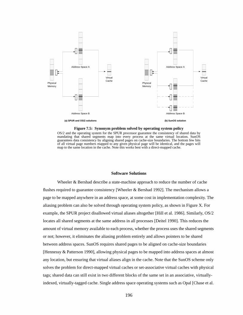
196
Software Solutions
Wheeler & Bershad describe a state-machine approach to reduce the number of cache
flushes required to guarantee consistency [Wheeler & Bershad 1992]. The mechanism allows a
page to be mapped anywhere in an address space, at some cost in implementation complexity. The
aliasing problem can also be solved through operating system policy, as shown in Figure X. For
example, the SPUR project disallowed virtual aliases altogether [Hill et al. 1986]. Similarly, OS/2
locates all shared segments at the same address in all processes [Deitel 1990]. This reduces the
amount of virtual memory available to each process, whether the process uses the shared segments
or not; however, it eliminates the aliasing problem entirely and allows pointers to be shared
between address spaces. SunOS requires shared pages to be aligned on cache-size boundaries
[Hennessy & Patterson 1990], allowing physical pages to be mapped into address spaces at almost
any location, but ensuring that virtual aliases align in the cache. Note that the SunOS scheme only
solves the problem for direct-mapped virtual caches or set-associative virtual caches with physical
tags; shared data can still exist in two different blocks of the same set in an associative, virtually-
indexed, virtually-tagged cache. Single address space operating systems such as Opal [Chase et al.
Address Space A
Address Space B
PhysicalMemory
VirtualCache
Address Space A
Address Space B
PhysicalMemory
VirtualCache
Figure 7.5: Synonym problem solved by operating system policyOS/2 and the operating system for the SPUR processor guarantee the consistency of shared data bymandating that shared segments map into every process at the same virtual location. SunOSguarantees data consistency by aligning shared pages on cache-size boundaries. The bottom few bitsof all virtual page numbers mapped to any given physical page will be identical, and the pages willmap to the same location in the cache. Note this works best with a direct-mapped cache.
(a) SPUR and OS/2 solutions (b) SunOS solution
197
1992a, Chase et al. 1992b] or Psyche [Scott et al. 1988] solve the problem by eliminating the con-
cept of individual per-process address spaces entirely. Like OS/2, they define a one-to-one corre-
spondence of virtual to physical addresses and in doing so allow pointers to be freely shared across
process boundaries.
7.3 Shared Memory vs. the Virtual Cache
This section describes some of the higher-level problems that arise when implementing
shared memory on virtual cache organizations. As described above, virtual caches have an inherent
consistency problem; this problem tends to conflict with the mechanisms used to implement
shared memory.
7.3.1 The Problems with Virtual-Addr ess Aliasing
Virtual-address aliasing is a necessary evil; it is useful, yet it breaks many simple models.
Its usefulness outweighs its problems, therefore future memory management systems must con-
tinue to support it.
Virtual-Address Aliasing is Necessary
Most of the software solutions for the virtual-cache synonym problem address the consis-
tency problem by limiting the choices where a process can map a physical page in its virtual space.
In some cases, the number of choices is reduced to one; the page is mapped at one globally unique
location or it is not mapped at all. While disallowing virtual aliases would seem to be a simple and
elegant way to solve the virtual cache consistency problem, it creates another headache for operat-
ing systems—virtual fragmentation.
When a global shared region is garbage-collected, the region cannot help but become frag-
mented. This is a problem: whereas de-fragmentation (compaction) of disk space or physically-
addressed memory is as simple as relocating pages or blocks, virtually addressed regions cannot be
easily relocated. They are location-dependent; all pointers referencing the locations must also be
changed. This is not a trivial task and it is not clear that it can be done at all. Thus, a system that
forces all processes to use the same virtual address for the same physical data will have a frag-
mented shared region that cannot be de-fragmented without enormous effort. Depending on the
amount of sharing this could mean a monotonically increasing shared region, which would be
inimical to a 24x7 environment, i.e. one that is intended to be operative 24 hours a day, seven days
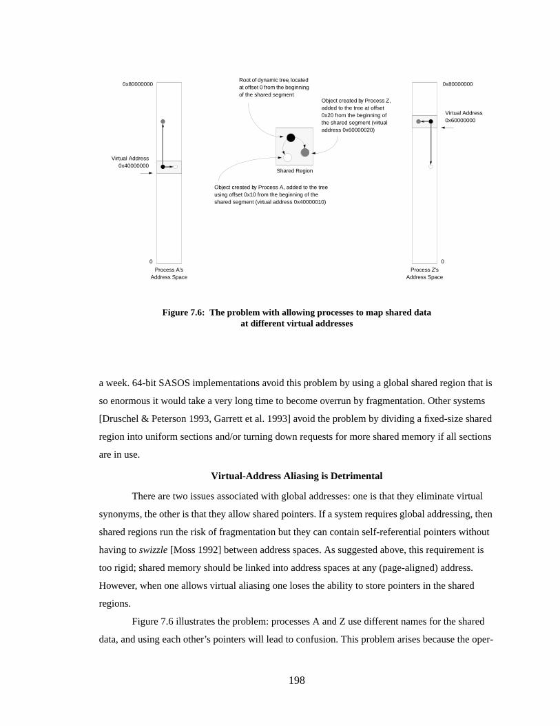
198
a week. 64-bit SASOS implementations avoid this problem by using a global shared region that is
so enormous it would take a very long time to become overrun by fragmentation. Other systems
[Druschel & Peterson 1993, Garrett et al. 1993] avoid the problem by dividing a fixed-size shared
region into uniform sections and/or turning down requests for more shared memory if all sections
are in use.
Virtual-Address Aliasing is Detrimental
There are two issues associated with global addresses: one is that they eliminate virtual
synonyms, the other is that they allow shared pointers. If a system requires global addressing, then
shared regions run the risk of fragmentation but they can contain self-referential pointers without
having toswizzle [Moss 1992] between address spaces. As suggested above, this requirement is
too rigid; shared memory should be linked into address spaces at any (page-aligned) address.
However, when one allows virtual aliasing one loses the ability to store pointers in the shared
regions.
Figure 7.6 illustrates the problem: processes A and Z use different names for the shared
data, and using each other’s pointers will lead to confusion. This problem arises because the oper-
Figure 7.6: The problem with allowing processes to map shared dataat different virtual addr esses
Process Z’sAddress Space
Process A’sAddress Space
Shared Region
Virtual Address0x40000000
Virtual Address0x60000000
Root of dynamic tree, locatedat offset 0 from the beginningof the shared segment
Object created by Process Z,added to the tree at offset0x20 from the beginning ofthe shared segment (virtualaddress 0x60000020)
Object created by Process A, added to the treeusing offset 0x10 from the beginning of theshared segment (virtual address 0x40000010)
0
0x800000000x80000000
0
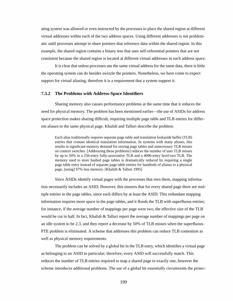
199
ating system was allowed or even instructed by the processes to place the shared region at different
virtual addresses within each of the two address spaces. Using different addresses is not problem-
atic until processes attempt to share pointers that reference data within the shared region. In this
example, the shared region contains a binary tree that uses self-referential pointers that are not
consistent because the shared region is located at different virtual addresses in each address space.
It is clear that unless processes use the same virtual address for the same data, there is little
the operating system can do besides swizzle the pointers. Nonetheless, we have come to expect
support for virtual aliasing, therefore it is a requirement that a system support it.
7.3.2 The Problems with Address-Space Identifiers
Sharing memory also causes performance problems at the same time that it reduces the
need for physical memory. The problem has been mentioned earlier—the use of ASIDs for address
space protection makes sharing difficult, requiring multiple page table and TLB entries for differ-
ent aliases to the same physical page. Khalidi and Talluri describe the problem:
Each alias traditionally requires separate page table and translation lookaside buffer (TLB)entries that contain identical translation information. In systems with many aliases, thisresults in significant memory demand for storing page tables and unnecessary TLB misseson context switches. [Addressing these problems] reduces the number of user TLB missesby up to 50% in a 256-entry fully-associative TLB and a 4096-entry level-two TLB. Thememory used to store hashed page tables is dramatically reduced by requiring a singlepage table entry instead of separate page table entries for hundreds of aliases to a physicalpage, [using] 97% less memory. [Khalidi & Talluri 1995]
Since ASIDs identify virtual pages with the processes that own them, mapping informa-
tion necessarily includes an ASID. However, this ensures that for every shared page there are mul-
tiple entries in the page tables, since each differs by at least the ASID. This redundant mapping
information requires more space in the page tables, and it floods the TLB with superfluous entries;
for instance, if the average number of mappings per page were two, the effective size of the TLB
would be cut in half. In fact, Khalidi & Talluri report the average number of mappings per page on
an idle system to be 2.3, and they report a decrease by 50% of TLB misses when the superfluous-
PTE problem is eliminated. A scheme that addresses this problem can reduce TLB contention as
well as physical memory requirements.
The problem can be solved by a global bit in the TLB entry, which identifies a virtual page
as belonging to no ASID in particular; therefore, every ASID will successfully match. This
reduces the number of TLB entries required to map a shared page to exactly one, however the
scheme introduces additional problems. The use of a global bit essentially circumvents the protec-

200
tion mechanism and thus requires flushing the TLB of shared entries on context switch, as the
shared regions are unprotected. Moreover, it does not allow a shared page to be mapped at differ-
ent virtual addresses, or with different protections. Using a global-bit mechanism is clearly unsuit-
able for supporting sharing if shared memory is to be used often.
If we eliminate the TLB, the ASID, or something equivalent to distinguish between differ-
ent contexts, will be required in the cache line. The use of ASIDs for protection causes the same
problem but in a new setting. Now, if two processes share the same region of data, the data will be
tagged by one ASID and if the wrong process tries to access the data that is in the cache, it will see
an apparent cache miss simply because the data is tagged by the ASID of the other process. Again,
using a global-bit to marked shared cache lines makes them unprotected against other processes
and so the cache lines must be flushed on context switch. This is potentially much more expensive
than flushing mappings from the TLB because the granularity for flushing the cache is usually a
cache line, requiring many operations to flush an entire page.
7.4 The “Virtue” of Segmentation
One obvious solution to the synonym and shared memory problems is to use global nam-
ing, as in a SASOS implementation, so that every physical address corresponds to exactly one vir-
tual location. This eliminates redundancy of page table entries for any given physical page, with
significant performance and space savings. However, it does not allow processes to map objects at
multiple locations within their address spaces—all processes must use the same name for the same
data, which conflicts with our stated requirement of allowing processes to map objects at different
virtual addresses, and at multiple locations within their address space.
A segmented architecture avoids this conflict; segmentation divides virtual aliasing and
the synonym problem into two orthogonal issues. A one-to-one mapping from global space to
physical space can be maintained—thereby eliminating the synonym problem—while supporting
virtual aliases by independently mapping segments in process address spaces onto segments in the
global space. Such an organization is illustrated in Figure 7.7. In the figure, three processes share
two different segments, and have mapped the segments into arbitrary segment slots. Two of the
processes have mapped the same segment at multiple locations in their address spaces. The page
table maps the segments onto physical memory at the granularity of pages. If the mapping of glo-
bal pages to physical pages is one-to-one, there are no virtual-cache synonym problems.

201
When the synonym problem is eliminated, there is no longer a need to flush a virtual cache
or a TLB for consistency reasons. The only time flushing is required is when virtual segments are
re-mapped to new physical pages, such as when the operating system runs out of unused segment
identifiers and needs to re-use old ones; if there is any data left in the caches or TLB tagged by the
old virtual address, data inconsistencies can occur. Direct Memory Access (DMA) also requires
flushing of the affected region before a transaction, as an I/O controller does not know whether the
data it overwrites is currently in a virtual cache.
Applications may map objects using different protections; the same object can be mapped
into different address spaces with different segment-level protections, or mapped into the same
address space at different locations with different protections. To illustrate, Figure 7.8 shows an
example of one possible copy-on-write implementation. It assumes hardware support for protec-
tion in both the segmentation mechanism (segment granularity) and the TLB (page granularity), as
in the Pentium [Intel 1993]. In the first step, a process maps an object with read-write permissions.
The object is located in a single segment, and the permissions are associated with the segment. In
the second step, the process grants access to another process, which maps the object into its
address space at another virtual address. The two share the object read-only, copy-on-write. In the
third step, Process B has written to the object and the written page has been copied. At this point
there are two choices. One is to copy the entire object, which could be many pages, into a new set
of page frames. This would allow both processes to map their copies of the object read-write.
Alternately, one could stop after the first page (the written page) to delay copying the rest until
absolutely necessary, maintaining reference pointers until the entire object is copied; this scenario
Global Virtual Space
Figure 7.7: The use of segments to provide virtual addr ess aliasing
Process A Process B Process C
Physical Memory
NULL(segment onlypartially-used)
PagedSegment
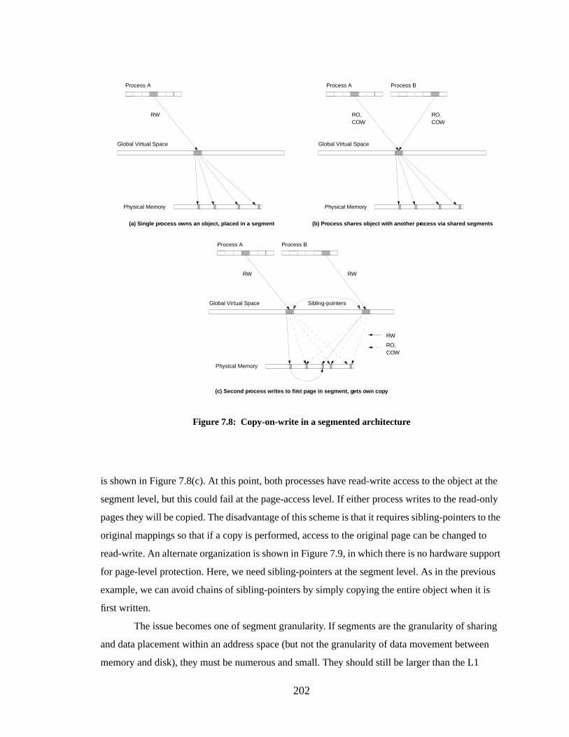
202
is shown in Figure 7.8(c). At this point, both processes have read-write access to the object at the
segment level, but this could fail at the page-access level. If either process writes to the read-only
pages they will be copied. The disadvantage of this scheme is that it requires sibling-pointers to the
original mappings so that if a copy is performed, access to the original page can be changed to
read-write. An alternate organization is shown in Figure 7.9, in which there is no hardware support
for page-level protection. Here, we need sibling-pointers at the segment level. As in the previous
example, we can avoid chains of sibling-pointers by simply copying the entire object when it is
first written.
The issue becomes one of segment granularity. If segments are the granularity of sharing
and data placement within an address space (but not the granularity of data movement between
memory and disk), they must be numerous and small. They should still be larger than the L1
Global Virtual Space
Process A Process B
Physical Memory
RO,COW
Global Virtual Space
Process A
Physical Memory
Global Virtual Space
Process A Process B
Physical Memory
Figure 7.8: Copy-on-write in a segmented architecture
RW RO,COW
RO,COW
RW RW
(a) Single pr ocess o wns an object, placed in a segment (b) Process shares object with another pr ocess via shared segments
(c) Second pr ocess writes to fir st page in segment, g ets own cop y
RW
Sibling-pointers
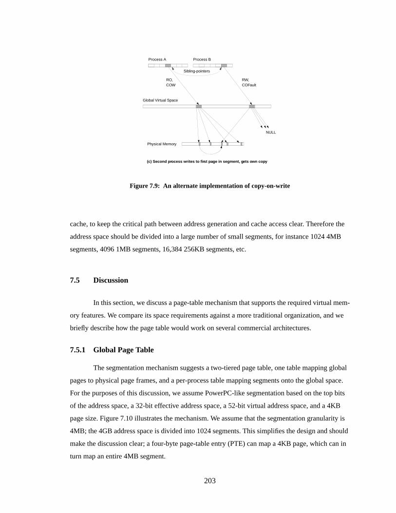
203
cache, to keep the critical path between address generation and cache access clear. Therefore the
address space should be divided into a large number of small segments, for instance 1024 4MB
segments, 4096 1MB segments, 16,384 256KB segments, etc.
7.5 Discussion
In this section, we discuss a page-table mechanism that supports the required virtual mem-
ory features. We compare its space requirements against a more traditional organization, and we
briefly describe how the page table would work on several commercial architectures.
7.5.1 Global Page Table
The segmentation mechanism suggests a two-tiered page table, one table mapping global
pages to physical page frames, and a per-process table mapping segments onto the global space.
For the purposes of this discussion, we assume PowerPC-like segmentation based on the top bits
of the address space, a 32-bit effective address space, a 52-bit virtual address space, and a 4KB
page size. Figure 7.10 illustrates the mechanism. We assume that the segmentation granularity is
4MB; the 4GB address space is divided into 1024 segments. This simplifies the design and should
make the discussion clear; a four-byte page-table entry (PTE) can map a 4KB page, which can in
turn map an entire 4MB segment.
Global Virtual Space
Process A Process B
Physical Memory
NULL
RO,COW
RW,COFault
(c) Second pr ocess writes to fir st page in segment, g ets own cop y
Figure 7.9: An alternate implementation of copy-on-write
Sibling-pointers
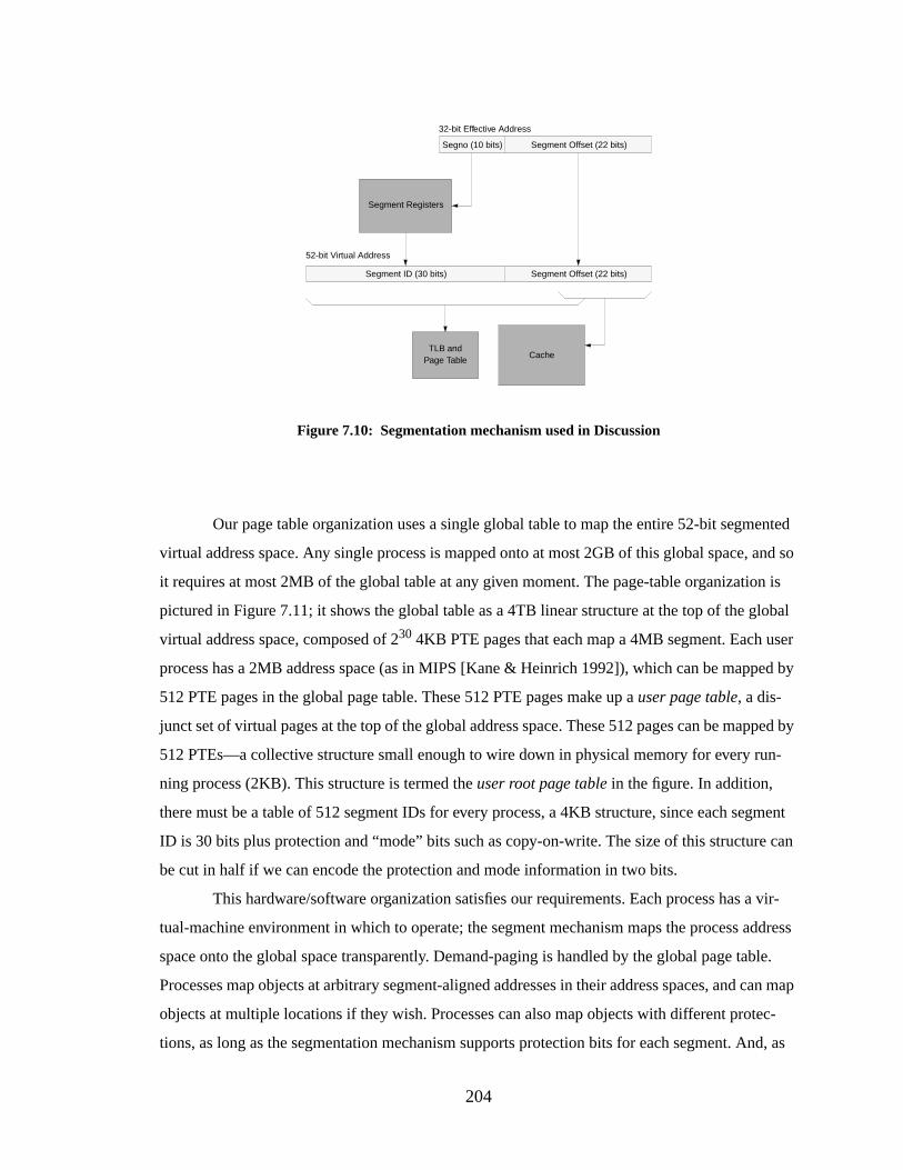
204
Our page table organization uses a single global table to map the entire 52-bit segmented
virtual address space. Any single process is mapped onto at most 2GB of this global space, and so
it requires at most 2MB of the global table at any given moment. The page-table organization is
pictured in Figure 7.11; it shows the global table as a 4TB linear structure at the top of the global
virtual address space, composed of 230 4KB PTE pages that each map a 4MB segment. Each user
process has a 2MB address space (as in MIPS [Kane & Heinrich 1992]), which can be mapped by
512 PTE pages in the global page table. These 512 PTE pages make up auser page table, a dis-
junct set of virtual pages at the top of the global address space. These 512 pages can be mapped by
512 PTEs—a collective structure small enough to wire down in physical memory for every run-
ning process (2KB). This structure is termed theuser root page table in the figure. In addition,
there must be a table of 512 segment IDs for every process, a 4KB structure, since each segment
ID is 30 bits plus protection and “mode” bits such as copy-on-write. The size of this structure can
be cut in half if we can encode the protection and mode information in two bits.
This hardware/software organization satisfies our requirements. Each process has a vir-
tual-machine environment in which to operate; the segment mechanism maps the process address
space onto the global space transparently. Demand-paging is handled by the global page table.
Processes map objects at arbitrary segment-aligned addresses in their address spaces, and can map
objects at multiple locations if they wish. Processes can also map objects with different protec-
tions, as long as the segmentation mechanism supports protection bits for each segment. And, as
TLB andPage Table
Segment Offset (22 bits)
32-bit Effective Address
Segno (10 bits)
Segment Registers
Segment Offset (22 bits)Segment ID (30 bits)
52-bit Virtual Address
Figure 7.10: Segmentation mechanism used in Discussion
Cache
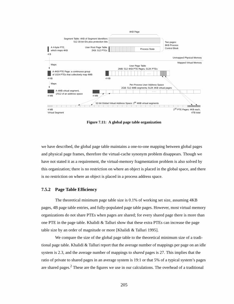
205
we have described, the global page table maintains a one-to-one mapping between global pages
and physical page frames, therefore the virtual-cache synonym problem disappears. Though we
have not stated it as a requirement, the virtual-memory fragmentation problem is also solved by
this organization; there is no restriction on where an object is placed in the global space, and there
is no restriction on where an object is placed in a process address space.
7.5.2 Page Table Efficiency
The theoretical minimum page table size is 0.1% of working set size, assuming 4KB
pages, 4B page table entries, and fully-populated page table pages. However, most virtual memory
organizations do not share PTEs when pages are shared; for every shared page there is more than
one PTE in the page table. Khalidi & Talluri show that these extra PTEs can increase the page
table size by an order of magnitude or more [Khalidi & Talluri 1995].
We compare the size of the global page table to the theoretical minimum size of a tradi-
tional page table. Khalidi & Talluri report that the average number of mappings per page on an idle
system is 2.3, and the average number of mappings toshared pages is 27. This implies that the
ratio of private to shared pages in an average system is 19:1 or that 5% of a typical system’s pages
are shared pages.2 These are the figures we use in our calculations. The overhead of a traditional
User Root Page Table2KB: 512 PTEs
User Page Table2MB: 512 4KB PTE Pages, 512K PTEs
Per-Process User Address Space2GB: 512 4MB segments, 512K 4KB virtual pages
Unmapped Physical Memory
Mapped Virtual Memory
Figure 7.11: A global page table organization
A 4-byte PTE,which maps 4KB
A 4KB PTE Page: a continuous groupof 1024 PTEs that collectively map 4MB
4 B
4 KB
Two pages:8KB ProcessControl Block
52-bit Global Virtual Address Space: 230 4MB virtual segments
4 MBVirtual Segment
A 4MB virtual segment,1/512 of an address space
230 PTE Pages: 4KB each,4TB total
4 MB
4 KB
4 MB
Segment Table: 4KB of Segment Identifiers512 30-bit IDs plus protection bits
Process State
. . .
. . .
4KB Page
Maps
Maps
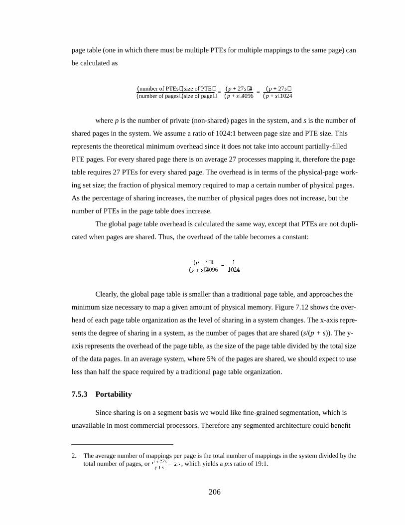
206
page table (one in which there must be multiple PTEs for multiple mappings to the same page) can
be calculated as
wherep is the number of private (non-shared) pages in the system, ands is the number of
shared pages in the system. We assume a ratio of 1024:1 between page size and PTE size. This
represents the theoretical minimum overhead since it does not take into account partially-filled
PTE pages. For every shared page there is on average 27 processes mapping it, therefore the page
table requires 27 PTEs for every shared page. The overhead is in terms of the physical-page work-
ing set size; the fraction of physical memory required to map a certain number of physical pages.
As the percentage of sharing increases, the number of physical pages does not increase, but the
number of PTEs in the page table does increase.
The global page table overhead is calculated the same way, except that PTEs are not dupli-
cated when pages are shared. Thus, the overhead of the table becomes a constant:
Clearly, the global page table is smaller than a traditional page table, and approaches the
minimum size necessary to map a given amount of physical memory. Figure 7.12 shows the over-
head of each page table organization as the level of sharing in a system changes. The x-axis repre-
sents the degree of sharing in a system, as the number of pages that are shared (s/(p + s)). The y-
axis represents the overhead of the page table, as the size of the page table divided by the total size
of the data pages. In an average system, where 5% of the pages are shared, we should expect to use
less than half the space required by a traditional page table organization.
7.5.3 Portability
Since sharing is on a segment basis we would like fine-grained segmentation, which is
unavailable in most commercial processors. Therefore any segmented architecture could benefit
2. The average number of mappings per page is the total number of mappings in the system divided by thetotal number of pages, or , which yields ap:s ratio of 19:1.
� � � ��� ��� � � � � � � � � � � � � � � � � � � � ��
number of PTEs( ) size of PTE( )number of pages( ) size of page( )
� � � � � � � � � � � � � � � � � � � � � � � � � � � � � � � � � � � � � � � � � � � � � � � � � � � � � � � � � � � � � � � � � � � � � � � � � � � � � � p 27s+( )4p s+( )4096
----------------------------- p 27s+( )p s+( )1024
-----------------------------= =
� ��( )4� ��( )4096
� � � � � � � � � � � � � � � � � � � � � � � � � � � � ��
� � � � � � � � � � � � � ��!
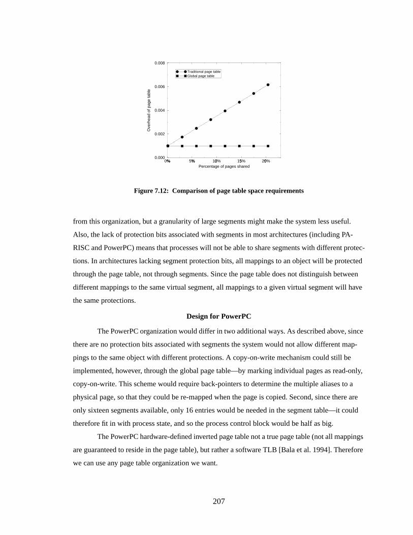
207
from this organization, but a granularity of large segments might make the system less useful.
Also, the lack of protection bits associated with segments in most architectures (including PA-
RISC and PowerPC) means that processes will not be able to share segments with different protec-
tions. In architectures lacking segment protection bits, all mappings to an object will be protected
through the page table, not through segments. Since the page table does not distinguish between
different mappings to the same virtual segment, all mappings to a given virtual segment will have
the same protections.
Design for PowerPC
The PowerPC organization would differ in two additional ways. As described above, since
there are no protection bits associated with segments the system would not allow different map-
pings to the same object with different protections. A copy-on-write mechanism could still be
implemented, however, through the global page table—by marking individual pages as read-only,
copy-on-write. This scheme would require back-pointers to determine the multiple aliases to a
physical page, so that they could be re-mapped when the page is copied. Second, since there are
only sixteen segments available, only 16 entries would be needed in the segment table—it could
therefore fit in with process state, and so the process control block would be half as big.
The PowerPC hardware-defined inverted page table not a true page table (not all mappings
are guaranteed to reside in the page table), but rather a software TLB [Bala et al. 1994]. Therefore
we can use any page table organization we want.
0%" 5%" 10%# 15%$ 20%#Percentage of pages shared
0.000
0.002
0.004
0.006
0.008
Ove
rhea
d of
pag
e ta
ble
Traditional page tableGlobal page table
Figure 7.12: Comparison of page table space requirements
208
Design for PA-RISC
The PA-RISC architecture [Hewlett-Packard 1990] has a facility similar to PowerPC seg-
ments, a set of 8space registers, that maps a 32-bit address onto a larger (64-bit) virtual address
space. User applications may load values into the space registers at will. Protection is guaranteed
by restricting access to some of the registers and by the use of protection IDs, similar to ASIDs.
The processor maintains four protection IDs per process and if any protection ID matches the
access ID of a page, access is granted. Note that a process may not alter the contents of the protec-
tion-ID registers.
PA-RISC supports the concept of a global address space and a global page table though
the space registers. In fact, researchers at Hewlett-Packard have stressed that this is the best way to
share memory on PA-RISC:
[One can] take advantage of the global virtual address space provided by the PA-RISC toeliminate all remapping of text pages shared between tasks. The idea is to map the textobject to a single range of virtual addresses in the global virtual address space, and to haveall tasks sharing the text object to access it using that same range of virtual addresses. Thisnot only eliminates virtual address aliasing at the hardware level, it eliminates it at alllevels. This is the “right” way to share memory on PA-RISC. [Chao et al. 1990]
Unlike PowerPC, PA-RISC does not specify a page table organization for the operating
system, though HP-UX has traditionally used an inverted page table [Huck & Hays 1993]. One can
therefore use a global page table organization. The difference is that the user root page tables
would not be as simple as in our generic design, in which a process only has access to a 2GB win-
dow at any time and so the maximum size of the user root page table is 2KB. PA-RISC allows pro-
cesses to extend their address space at will without operating system intervention, by placing space
IDs into the space registers—subject to the access-ID constraints. This allows the process to swap
globalspaces in and out of its address space at will, implying that the size of the wired-down user
root page table can grow without bounds. This can be solved by another level of indirection, where
the user root page table is a dynamic data structure; the disadvantage is that user root page table
access becomes slower.
Design for Pentium
The Pentium [Intel 1993] memory management architecture corresponds very closely to
the needs of our generic design. It maps 32-bit addresses onto a global 4GB “linear” address space.
Besides the limitation of a small global address space, the architecture is very nearly identical to
the hardware described in this section. The mapping from user address space to global linear space
209
is made before cache access. The segments have associated protection independent of the underly-
ing page protection. Every feature of our addressing scheme is supported.
However, the architecture does not take full advantage of its own design. The cache is
effectively virtually indexed, but only by constraining the cache index to be identical to the 4KB
page size. There are six segment registers and they are addressed according to the context in which
they are used—there is only one register for code segments, one register for stack segments, etc.
The segment registers are therefore much less flexible than PowerPC segments, and could have a
lower hit rate. The segmentation mechanism is not used by many systems because a process
requiring numerous segments will frequently reference memory to reload segment registers. Pen-
tium performance and flexibility could improve dramatically if the caches were virtual and larger
(allow the cache index to be larger than the page size) and if the segment registers were less con-
text-oriented and more numerous.
The Pentium segment registers include one for the stack, one for code, and four for data—
one of which is used by string instructions. An application can reference 8192 local (per-process)
segments, and 8191 global segments. Segment sizes are software-defined and can range from 1
byte to 4 gigabytes. Each segment has a four-bit protection ID associated with it encodingread-
only, read/write, execute-only, etc. The protection ID also encodes information such as whether the
segment size is allowed to change.
The system supports a global 4MB page table that maps the 4GB shared linear address
space. The main problem is the relatively small global address space. Four gigabytes is not much
room in which to work, which could cause the memory allocation logic to become complicated.
On the other hand, a benefit is that the segmentation mechanism would become an address space
protection mechanism. This is similar to the use of segments in the PowerPC architecture. A set of
segments uniquely identifies a process address space; full protection is guaranteed by not overlap-
ping segments. Any segment that is not shared by another process is protected from all other pro-
cesses. The advantage is that one classical argument against the Intel architecture—that its lack of
ASIDs is a performance drag by requiring TLB flushes on context switch—disappears. Since the
TLB maps addresses from the global linear space, no flushing would be necessary.
Design for 64-bit Architectures
The virtual-cache synonym problem does not automatically go away with 64-bit address-
ing, unless one uses the 64-bit address space for a SASOS organization. As described earlier, this
has some disadvantages and does not support all the required virtual memory features. A segmen-
210
tation mechanism is still necessary in a 64-bit architecture in order to satisfy all of our stated
requirements.
The primary difference when moving to a 64-bit machine is the structure of the page table.
The page table need not be linear, or even hierarchical; it simply must map the global space and
provide a guarantee that global pages map one-to-one onto the physical memory. Therefore several
organizations are possible, including the hierarchical table of OSF/1 on Alpha [Sites 1992], a
guarded page table [Liedtke 1995a], or an inverted page table, including the variant described by
Talluri, et al. [Talluri et al. 1995].
7.6 Conclusions
One can employ a virtual cache in order to meet the memory requirements of a high-speed
processor and avoid the potential slowdown of address translation. However, virtual caches do not
appear in the majority of today’s processors. Virtual caches help achieve fast clock speeds but have
traditionally been left out of microprocessor architectures because the naming dichotomy between
the cache and main memory creates the potential for data inconsistencies, requiring significant
management overhead. A segmented architecture adds another level of naming and allows a sys-
tem to use a virtual cache organization without explicit consistency management, as long as the
operating system ensures a one-to-one mapping of pages between the segmented address space
and physical memory.
211
CHAPTER 8
THE PROBLEMS WITH INTERRUPTSAND A SOLUTION BY REDEFINING THEIR PRECISION
This chapter addresses the issue of interrupts. A software-oriented memory management
scheme, like a software-managed TLB, uses the interrupt mechanism to react to events that require
memory management. Whereas the software-managed TLB causes an interrupt for every TLB
miss, the software-oriented memory management scheme causes an interrupt for every cache miss.
In today’s microprocessors an interrupt results in the flushing of at least part of the reorder buffer,
if not all of it; the cost is on the order of 100 cycles lost per interrupt. (Today’s processors typically
have one or more dedicated sets of registers for interrupt-handling so that there is no longer a con-
text-switch overhead involved in handling an interrupt) This chapter shows that it is possible to
reduce this overhead by an order of magnitude if one redefines precise interrupts to allow indepen-
dent partially-completed instructions to commit, even though an instruction occurring before them
in the sequential instruction stream has caused an interrupt.
8.1 Intr oduction
Memory-management interrupts must be handled precisely to guarantee program correct-
ness. Supporting precise interrupts requires a system to cleanly distinguish between the instruc-
tions that have finished executing and those that have not. Most contemporary pipelines allow
instructions to become rearranged dynamically, thereby taking advantage of idle hardware and fin-
ishing earlier than they otherwise would have—thus increasing overall performance. Exceptional
events therefore wreak havoc in pipelined processors with out-of-order execution; one must ensure
that the state of the processor (register file, caches, main memory) is modified in the sequential
instruction order so that one can easily determine what has finished and what has not. Such support
typically requires a reorder buffer [Smith & Pleszkun 1988, Sohi & Vajapeyam 1987], often a
multi-ported, associative structure that is accessed on every cycle [Case 1994a, Case 1994b, Slater
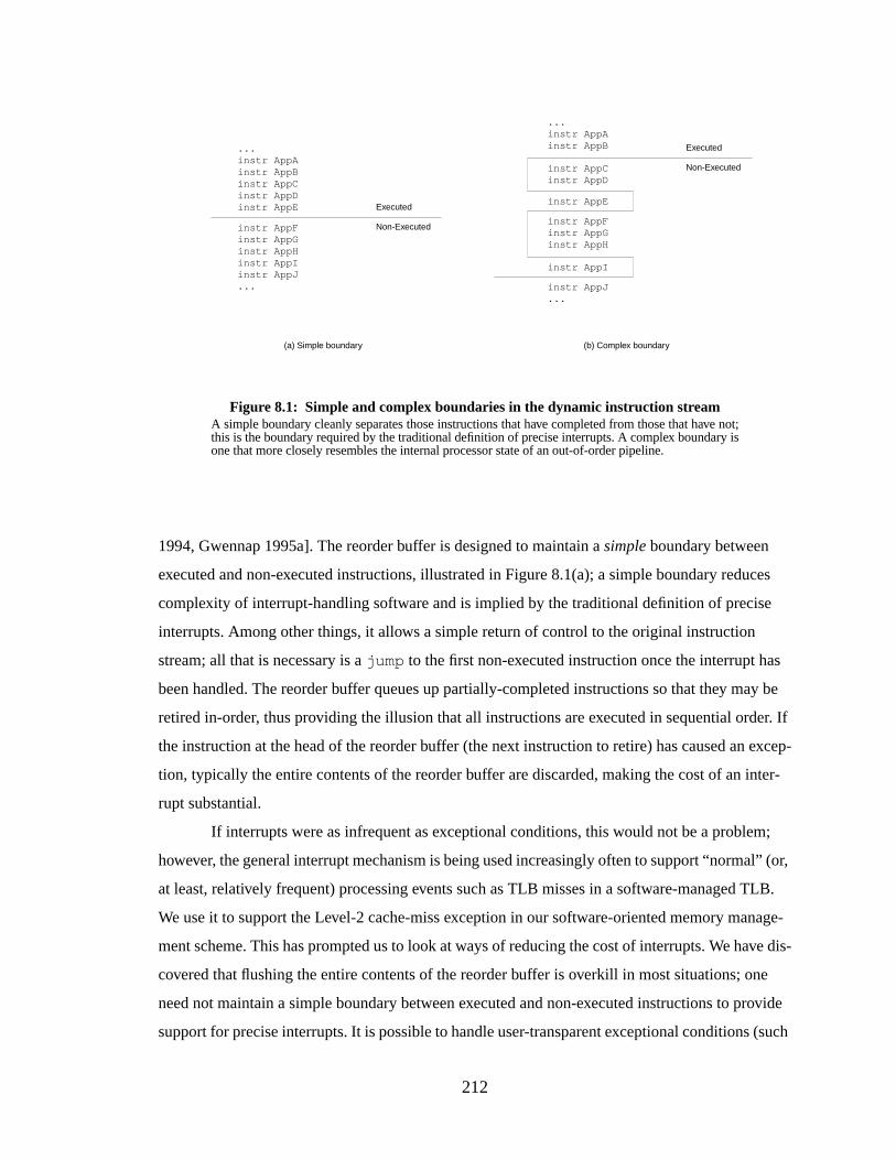
212
1994, Gwennap 1995a]. The reorder buffer is designed to maintain asimple boundary between
executed and non-executed instructions, illustrated in Figure 8.1(a); a simple boundary reduces
complexity of interrupt-handling software and is implied by the traditional definition of precise
interrupts. Among other things, it allows a simple return of control to the original instruction
stream; all that is necessary is ajump to the first non-executed instruction once the interrupt has
been handled. The reorder buffer queues up partially-completed instructions so that they may be
retired in-order, thus providing the illusion that all instructions are executed in sequential order. If
the instruction at the head of the reorder buffer (the next instruction to retire) has caused an excep-
tion, typically the entire contents of the reorder buffer are discarded, making the cost of an inter-
rupt substantial.
If interrupts were as infrequent as exceptional conditions, this would not be a problem;
however, the general interrupt mechanism is being used increasingly often to support “normal” (or,
at least, relatively frequent) processing events such as TLB misses in a software-managed TLB.
We use it to support the Level-2 cache-miss exception in our software-oriented memory manage-
ment scheme. This has prompted us to look at ways of reducing the cost of interrupts. We have dis-
covered that flushing the entire contents of the reorder buffer is overkill in most situations; one
need not maintain a simple boundary between executed and non-executed instructions to provide
support for precise interrupts. It is possible to handle user-transparent exceptional conditions (such
Figure 8.1: Simple and complex boundaries in the dynamic instruction streamA simple boundary cleanly separates those instructions that have completed from those that have not;this is the boundary required by the traditional definition of precise interrupts. A complex boundary isone that more closely resembles the internal processor state of an out-of-order pipeline.
...instr AppAinstr AppBinstr AppCinstr AppDinstr AppE
instr AppFinstr AppGinstr AppHinstr AppIinstr AppJ...
Executed
Non-Executed
...instr AppAinstr AppB
instr AppCinstr AppD
instr AppE
instr AppFinstr AppGinstr AppH
instr AppI
instr AppJ...
Executed
Non-Executed
(a) Simple boundary (b) Complex boundary

213
as TLB misses or cache misses in the SOFTVM memory management system) even if the hard-
ware only supports acomplex boundary between executed and non-executed instructions, as
shown in Figure 8.1(b). This chapter discusses therelaxed-precision interrupt, which provides
enough of the guarantees of a precise interrupt to handle our cache-miss exception but with a neg-
ligible overhead compared to that of a traditional precise interrupt. In many situations, an interrupt
can be handled precisely despite the fact that nosimple boundary exists between executed and
non-executed instructions. Provided that hardware can recognize and flag every instruction that is
directly or indirectly dependent on an exceptional instruction, one can cleanly resolve an interrupt
where there is acomplex boundary between executed and non-executed instructions.
Another illustration of the concept is shown in Figure 8.2. Here, we have shown the
instantaneous contents of an out-of-order pipeline at the moment an instruction (instruction ‘I’ —
the darkened circle) causes an interrupt. The example represents a 16-entry reorder buffer; at the
moment instruction ‘I’ causes the interrupt, instructions ‘A’ through ‘P’ are in flight. Instructions
‘Q’ through ‘X’ have not yet entered the pipeline. The shaded circles represent instructions that are
dependent on the offending instruction, either directly or indirectly. All other instructions could
Figure 8.2: Instantaneous pipeline contents in an out-of-order machineAt the moment an instruction causes an exception, there are many instructions in flight, generallylimited by the size of the reorder buffer. In this example we show a 16-entry reorder buffer, holdinginstructions ‘A” through ‘P.’ The entry in the reorder buffer corresponding to the offending instructionis flagged and execution continues. Only when the instruction is about to commit (when it is at thehead of the reorder buffer’s queue) does the system take action. All instructions in the reorder bufferare squashed and the interrupt handler takes over. By this time, instructions ‘A’ through ‘H’ haveexited the pipe, to be replaced by instructions ‘Q’ through ‘X.’ From the diagram, it is clear that apotentially large number of instructions are squashed that are neither directly nor indirectly dependenton the offending instruction; nonetheless, these instructions must all be re-executed.
SimpleBoundary
I
AB
C D E F G
HJK
L M N O P
U T S R Q
W X
V
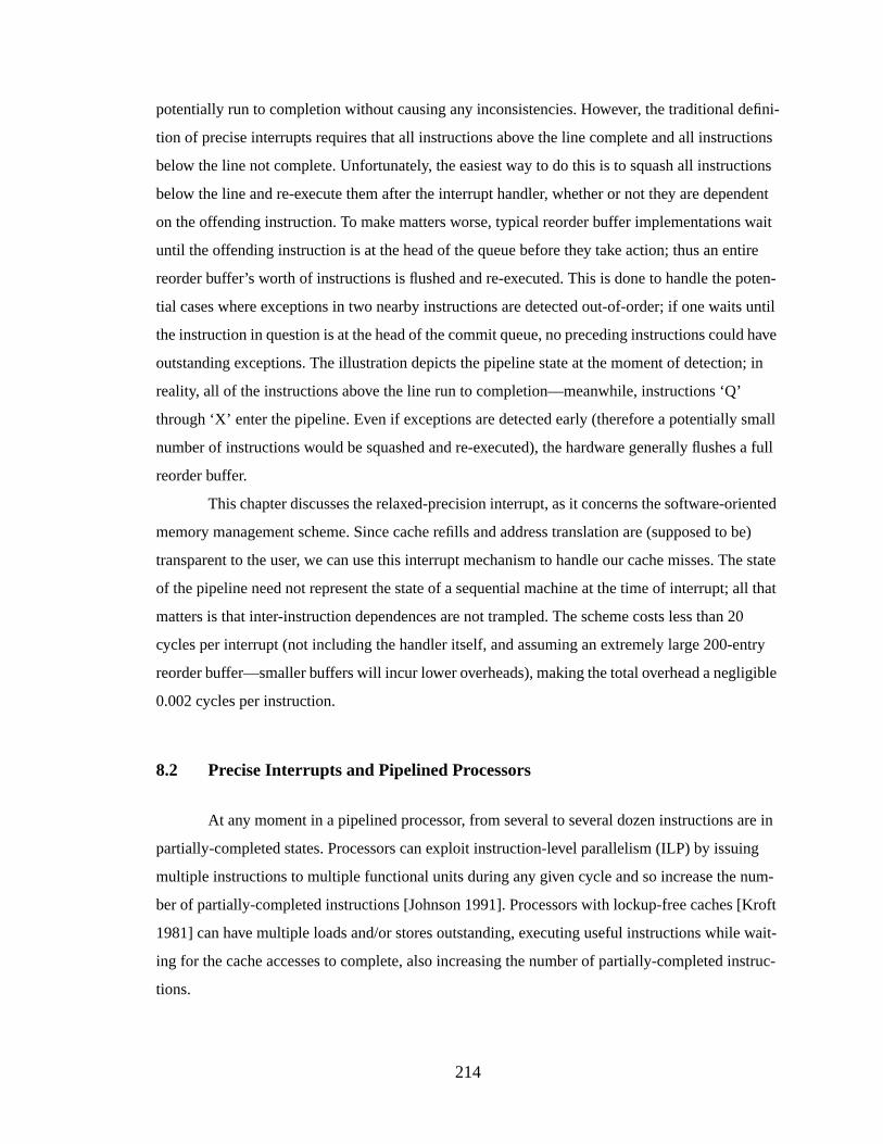
214
potentially run to completion without causing any inconsistencies. However, the traditional defini-
tion of precise interrupts requires that all instructions above the line complete and all instructions
below the line not complete. Unfortunately, the easiest way to do this is to squash all instructions
below the line and re-execute them after the interrupt handler, whether or not they are dependent
on the offending instruction. To make matters worse, typical reorder buffer implementations wait
until the offending instruction is at the head of the queue before they take action; thus an entire
reorder buffer’s worth of instructions is flushed and re-executed. This is done to handle the poten-
tial cases where exceptions in two nearby instructions are detected out-of-order; if one waits until
the instruction in question is at the head of the commit queue, no preceding instructions could have
outstanding exceptions. The illustration depicts the pipeline state at the moment of detection; in
reality, all of the instructions above the line run to completion—meanwhile, instructions ‘Q’
through ‘X’ enter the pipeline. Even if exceptions are detected early (therefore a potentially small
number of instructions would be squashed and re-executed), the hardware generally flushes a full
reorder buffer.
This chapter discusses the relaxed-precision interrupt, as it concerns the software-oriented
memory management scheme. Since cache refills and address translation are (supposed to be)
transparent to the user, we can use this interrupt mechanism to handle our cache misses. The state
of the pipeline need not represent the state of a sequential machine at the time of interrupt; all that
matters is that inter-instruction dependences are not trampled. The scheme costs less than 20
cycles per interrupt (not including the handler itself, and assuming an extremely large 200-entry
reorder buffer—smaller buffers will incur lower overheads), making the total overhead a negligible
0.002 cycles per instruction.
8.2 Precise Interrupts and Pipelined Processors
At any moment in a pipelined processor, from several to several dozen instructions are in
partially-completed states. Processors can exploit instruction-level parallelism (ILP) by issuing
multiple instructions to multiple functional units during any given cycle and so increase the num-
ber of partially-completed instructions [Johnson 1991]. Processors with lockup-free caches [Kroft
1981] can have multiple loads and/or stores outstanding, executing useful instructions while wait-
ing for the cache accesses to complete, also increasing the number of partially-completed instruc-
tions.
215
Any of these instructions can cause an interrupt. When this occurs, a portion of the CPU’s
state is saved while the interrupt is resolved, and is restored upon completion of the interrupt han-
dler [Smith & Pleszkun 1988]. The problem becomes complicated when an instruction that comes
after the offending instruction in the dynamic stream completes its executionbefore the offending
instruction causes the interrupt. Such scenarios happen frequently in processors supporting out-of-
order execution or speculative execution [Hwu & Patt 1987]. Most processors use a reorder buffer
to maintain consistent state [Smith & Pleszkun 1988], only committing an instruction (sending its
results to the register file or main memory) when all instructions before it have been committed.
The mechanisms required to support out-of-order processing [Hwu & Patt 1986, Pleszkun
et al. 1987, Colwell et al. 1987] are often similar to interrupt-handling hardware [Weiss & Smith
1984]; many designs provide both functions (precise-interrupt support and out-of-order support)
with the same hardware [Sohi & Vajapeyam 1987].
Reorder buffers can require appreciable chip area, even in microprocessors with transistor
budgets in the millions. They also constrain clock speed, typically being multi-ported, fully-asso-
ciative structures that are accessed every clock. For example, the AMD 29000 has a 10-entry reor-
der buffer with 10 read ports and 3 write ports; the operand buses connected to the reorder buffer
plus the buffer itself occupy the equivalent of 4K of cache (the chip has 8K/8K split on-chip
caches) [Case 1994a]. The AMD K5 has a 16-entry reorder buffer that is even more complex than
the 29000’s because it must support 8- and 16-bit writes to fields in registers (an artifact of the
x86) [Slater 1994]. Intel’s P6 has a 40-entry reorder buffer [Gwennap 1995a], and from the die
photo it appears to be almost as large as either of the two on-chip 8K caches. The R10000 has a 32-
entry buffer with 12 read and 4 write ports [Gwennap 1994a], and the PA-8000 has a 56-entry reor-
der buffer that uses 850K transistors and consumes 20% of the die area [Gwennap 1994b, Gwen-
nap 1995b, Kumar 1996].
8.3 Relaxed-Precision Interrupts
This section describes how relaxed-precision interrupts work, gives a rough model for how
hardware would support them, and presents some measurements on their effectiveness at reducing
the cost of handling interrupts.
216
8.3.1 Definition
The pseudo-code in Figure 8.3 illustrates relaxed-precision interrupt handling and builds
on the example in Figure 8.2. Even thoughAppI causes an interrupt, the instructions already in
the pipeline could successfully complete. It should be clear that the state of the machine need not
reflect a simple boundary, wherein all instructions fromAppA up to and includingAppH have
completed, but instructions fromAppI on have not; the processor state can reflect a complex
boundary between executed and non-executed instructions, and the interrupt can nonetheless be
handled simply and without error.
What we require is knowledge of exactly where the boundary is. Since all instructions in a
typical RISC processor depend directly on at most two preceding instructions, we can build a
directed acyclic graph (DAG) of instructions and their dependencies, with no more than two arcs
entering each node. Of course, there can be many more than two arcsleaving each node, represent-
ing many dependencies on one instruction. From the DAG, we can create a partial order of instruc-
tions that depend directly or indirectly on the offending instruction and therefore have not
executed—this ordering will not tread on any data dependencies. Note that this includes register-
register dependencies as well as memory-memory dependencies; a load or store instruction
Figure 8.3: Example of relaxed-precision interrupt handlingInstruction AppI causes an interrupt. By the time AppI reaches the head of the commit queue,instructions up to and including AppX have entered the pipeline. At this point, control moves to theinterrupt handler, which begins flowing down the pipe. The hardware saves the PC of AppY (the firstsequential instructionnot to have entered the pipe) as well as the instructions dependent on AppI thathave entered the pipe. Once the interrupt handler is finished, AppI and all dependent instructions arere-executed, followed by a jump to AppY.
instr AppA // application begins executinginstr AppB...instr AppG // has already completedinstr AppH // still in pipe - could run to completion without errorinstr AppI // CAUSES AN INTERRUPTinstr AppJ // has completed out of orderinstr AppK // still in pipe - could run to completion without error...instr AppX // instructions up to and including AppX are in pipe[instr AppY] // first instruction not in pipe instr EH0 // interrupt handler begins instr EH1 ... instr EHN // last instruction in handler ... return to user-modeinstr AppI // re-execute instr AppI... // re-execute all instructions dependent on AppIjump AppY // return to non-executed instruction streaminstr AppYinstr AppZ...
217
depends on at most two previous instructions (one for the register value, one for the memory
address). The difference is that while the register dependencies can be detected during the decode
stage and easily handled by register renaming, the memory dependencies can only be handled once
the target addresses have been computed, which is typically late in the pipeline. We will discuss
the memory-dependency issues further when we discuss hardware implementations of the scheme.
We patch in the handler code and then re-execute the offending instruction and the DAG of
dependent instructions, followed by a jump to the first instruction that had not entered the pipe as
of the exception. The reorder buffer effectively performs an act of self-modifying code; it writes
these instructions in program order (although they could be written in any partial ordering derived
from the dependency-DAG) to an associated on-chip memory structure, followed by a jump to the
next-to-execute instruction. At the end of the interrupt handler, instructions begin executing from
this buffer and control returns to the program’s code once the jump is encountered.
The problem with this scheme occurs when the taking of an interrupt is intended to convey
information to an asynchronous thread on the same processor. In other words, if there is a high-
level dependency between instructions that the hardware cannot see, we have problems. To illus-
trate, take for example the following stream of instructions:
...store Ainterruptstore B...
It is a requirement that the second store (store B) not complete if its operands depend
on the output of the exceptional instruction. But what if the operands ofstore B are unrelated to
the exceptional instruction but the state thatstore B modifies is read by the interrupt-handler or
a thread that the interrupt-handler invokes? There are several systems that use such a facility; for
example, both Tapeworm-II [Uhlig et al. 1994] and the Wisconsin Wind Tunnel [Reinhardt et al.
1993] use memory-parity errors to simulate caches and parallel machines. Tapeworm sets memory
parity correctly for data in the simulated cache, and incorrectly for data not in the simulated cache.
A parity exception invokes the simulator, therefore the simulator only runs when simulated cache
misses occur. The Wisconsin Wind Tunnel uses a similar technique to model parallel organiza-
tions. Other systems [Talluri & Hill 1994, Nagle et al. 1994] use the TLB-miss handler to simulate
TLB organizations. The technique is not restricted to the operating system; even user-level uses for
page faults have been described, from copy-on-write to garbage collection to distributed shared
virtual memory [Appel & Li 1991].
218
If store B modifies data read by the interrupt handler or a thread the handler invokes,
inconsistencies could result. As a solution, one could disable writes as soon as an exception is
detected, but there is always the chance thatstore B completes before the exception is detected,
or thatstore A completes after the exception is detected. Either case could cause an error.
This is a strong argument against relaxing the precision constraints, however a counter-
argument is that these applications are unusual cases and systems should not impede the perfor-
mance of normal applications just to satisfy the occasional unusual requirement. In any case, one
could always revert to the normal method of handling interrupts when a bit in the processor is
set—thus allowing special-case applications to turn off relaxed-precision interrupt-handling dur-
ing critical regions of code.
8.3.2 A Model for Relaxed-Precision Interrupts
The following model supports relaxed-precision interrupts for the case of the cache-miss
exception (all other interrupts should be handled the “normal” way):
• An exceptional instruction causes an interrupt and must not complete.
• An instruction that depends on the output of an exceptional instruction is itself an excep-
tional instruction; it is tagged as such and must not complete.
• When the hardware decides to handle the interrupt, it saves the PCs of the exceptional
instruction and the first instruction in the sequential stream of non-executed instructions (the
next-to-execute instruction) in special registers.
• The hardware must make available to the interrupt handler the state of the exceptional
instruction: the instruction’s PC, the instruction itself, and its operands or an indication that
any specific operand is unavailable.
• The pipeline must be drained before vectoring to a software handler if the user-mode bit is
global—i.e., if all instructions run as privileged when the user-mode bit is clear. If every
instruction keeps its own personal copy of the user-mode bit, then the pipeline need not be
drained. This applies to any implementation of precise interrupts, not just relaxed-precision
interrupts. Clearly, since we desire to eliminate the overhead of draining the entire pipeline
(flushing the entire reorder buffer), every instruction must keep its own copy of the user-
mode bit or privilege level.
219
• Hardware must recognize read-after-write memory dependencies of the form
st $r1 -> addrld $r2 <- addr
whether the addresses are immediate values, or obtained via register computations. Clearly
if addr were held in a register the dependency would be detected by normal operand
checking. However, the following might not normally be detected:
mv $r4 <- 0x00001000mv $r5 <- 0x00001000st $r1 -> ($r4)ld $r2 <- ($r5)
This is a real dependency that will break the model if the store causes an interrupt and its
execution is delayed while the load is allowed to complete. Fortunately, both hardware and
software solutions to this problem have been studied [Gallagher et al. 1994, Nicolau 1989,
Huang et al. 1994].
• The hardware sends the DAG of instructions dependent on the offending instruction to an
on-chip buffer, followed by an unconditional jump to the next-to-execute instruction. A
return-from-exception starts execution at the head of this buffer.
Building on the previous examples shown in Figures 8.2 and 8.3, we illustrate this model
in Figure 8.4. This implementation moves instructions from the reorder buffer to are-execute
buffer as the instructions reach the head of the commit queue. We show the contents of a 16-entry
reorder buffer and its associated re-execute buffer at eight points in time: (a) the point at which the
exception is detected, as illustrated in Figure 8.2; (b) the point at which the offending instruction
‘I’ reaches the head of the commit queue; (c) the next cycle, where the reorder buffer has begun
transferring instructions to the re-execute buffer; (d) the point at which the last instruction in the
exception handler enters the pipeline (we assume a 10-instruction cache-miss exception handler, as
described in earlier chapters); (e) the following cycle, where the pipeline begins executing instruc-
tions from the re-execute buffer; (f) the point at which the last application instruction before the
exception handler leaves the commit queue (in the example, it goes to the re-execute buffer since it
is indirectly dependent on the offending instruction); (g) the following cycle, where the instruction
stream in the re-execute buffer is appended with a jump to the next-to-execute instruction; and (h)
the point at which control returns to the normal flow of instructions. We show the dependencies of
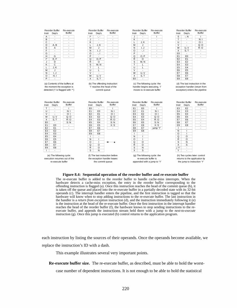
220
each instruction by listing the sources of their operands. Once the operands become available, we
replace the instruction’s ID with a dash.
This example illustrates several very important points.
Re-execute buffer size. The re-execute buffer, as described, must be able to hold the worst-
case number of dependent instructions. It is not enough to be able to hold the statistical
Re-executeBuffer
Figure 8.4: Sequential operation of the reorder buffer and re-execute bufferThe re-execute buffer is added to the reorder buffer to handle cache-miss interrupts. When thehardware detects a cache-miss exception, the entry in the reorder buffer corresponding to theoffending instruction is flagged (a). Once this instruction reaches the head of the commit queue (b), itis taken off the queue and placed into the re-execute buffer in a partially decoded state with its 32-bitoperands (c). The interrupt handler enters the pipeline, and the first instruction is tagged so that thehardware will know when to stop adding instructions to the re-execute buffer. The last instruction inthe handler is areturn from exception instruction (d), and the instruction immediately following it (e)is the instruction at the head of the re-execute buffer. Once the first instruction in the interrupt handlerreaches the head of the reorder buffer (f), the hardware knows to stop sending instructions to the re-execute buffer, and appends the instruction stream held there with a jump to thenext-to-executeinstruction (g). Once this jump is executed (h) control returns to the application program.
Dep’s
A--G
---
A, B
--------
(a) Contents of the buffers atthe moment the exception is
detected (‘I’ is flagged with ‘*’)
Instr
EFGH
ABCD
Reorder Buffer
JI, JH, I
-
E, FDC
J, KMNOP
I*JKL
Dep’s
L-
U, VS, T
O, PO
M, NL
--------
(b) The offending instruction‘I’ reaches the head of the
commit queue
Instr
UVWX
QRST
Reorder Buffer
JI, J-, I-
-, ---
J, KMNOP
I*JKL
Dep’s
L-
U, VS, T
O, PO
M, NL
I-------
(c) The following cycle: thehandler begins executing, ‘I’moves to re-execute buffer
Instr
UVWX
QRST
Reorder Buffer
JI, J-, I-
-
--
J, KMNOP
E0
JKL
Dep’s
IN: IO: IQ: OR: O
---
(d) The last instruction in theexception handler (return fromexception) enters the pipeline
InstrReorder Buffer
Dep’s
IN: IO: IQ: OR: OS: N
--
(e) The following cycle:execution resumes out of the
re-execute buffer
InstrReorder Buffer
Dep’s
(f) The last instruction beforethe exception handler leaves
the commit queue
InstrReorder Buffer
--
U, VS, T
E8
-, N-
UVWX
E9
ST
-E0
E3E4E5E6
E0E1E2
E4E5E6E7
E1E2E3
E7E8
--
U, VS, T
E8-
-UVWX
E9I
T
-E0
E3E4E5E6
E0E1E2
E4E5E6E7
E1E2E3
E7E8
IN: IO: IQ: OR: OS: NX: S
-
IOON
E8-I
OQRS
E9IN
-E0
E3E4E5E6
E0E1E2
E4E5E6E7
E1E2E3
E7E8
Dep’s
(g) The following cycle: there-execute buffer is
appended with a jump to ‘Y’
InstrReorder Buffer
IN: IO: IQ: OR: OS: NX: S
jump ‘Y’
IOON
E8-I
OQRS
E9IN
SX
E3E4E5E6
E0E1E2
E4E5E6E7
E1E2E3
E7E8
(h) Two cycles later: controlreturns to the application bythe jump to instruction ‘Y’
Dep’sInstrReorder Buffer
--------
IOON
E8-I
OQRS
E9IN
SX
E3E4E5E6
--
E2E4E5E6E7
j ‘Y’Y
E3
E7E8
Re-executeBuffer
Re-executeBuffer
Re-executeBuffer
Re-executeBuffer
Re-executeBuffer
Re-executeBuffer
Re-executeBuffer
*
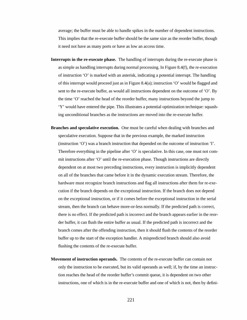
221
average; the buffer must be able to handle spikes in the number of dependent instructions.
This implies that the re-execute buffer should be the same size as the reorder buffer, though
it need not have as many ports or have as low an access time.
Interrupts in the r e-execute phase.The handling of interrupts during the re-execute phase is
as simple as handling interrupts during normal processing. In Figure 8.4(f), the re-execution
of instruction ‘O’ is marked with an asterisk, indicating a potential interrupt. The handling
of this interrupt would proceed just as in Figure 8.4(a); instruction ‘O’ would be flagged and
sent to the re-execute buffer, as would all instructions dependent on the outcome of ‘O’. By
the time ‘O’ reached the head of the reorder buffer, many instructions beyond the jump to
‘Y’ w ould have entered the pipe. This illustrates a potential optimization technique: squash-
ing unconditional branches as the instructions are moved into the re-execute buffer.
Branches and speculative execution.One must be careful when dealing with branches and
speculative execution. Suppose that in the previous example, the marked instruction
(instruction ‘O’) was a branch instruction that depended on the outcome of instruction ‘I’.
Therefore everything in the pipeline after ‘O’ is speculative. In this case, one must not com-
mit instructions after ‘O’ until the re-execution phase. Though instructions are directly
dependent on at most two preceding instructions, every instruction is implicitly dependent
on all of the branches that came before it in the dynamic execution stream. Therefore, the
hardware must recognize branch instructions and flag all instructions after them for re-exe-
cution if the branch depends on the exceptional instruction. If the branch does not depend
on the exceptional instruction, or if it comes before the exceptional instruction in the serial
stream, then the branch can behave more-or-less normally. If the predicted path is correct,
there is no effect. If the predicted path is incorrect and the branch appears earlier in the reor-
der buffer, it can flush the entire buffer as usual. If the predicted path is incorrect and the
branch comes after the offending instruction, then it should flush the contents of the reorder
buffer up to the start of the exception handler. A mispredicted branch should also avoid
flushing the contents of the re-execute buffer.
Movement of instruction operands.The contents of the re-execute buffer can contain not
only the instruction to be executed, but its valid operands as well; if, by the time an instruc-
tion reaches the head of the reorder buffer’s commit queue, it is dependent on two other
instructions, one of which is in the re-execute buffer and one of which is not, then by defini-
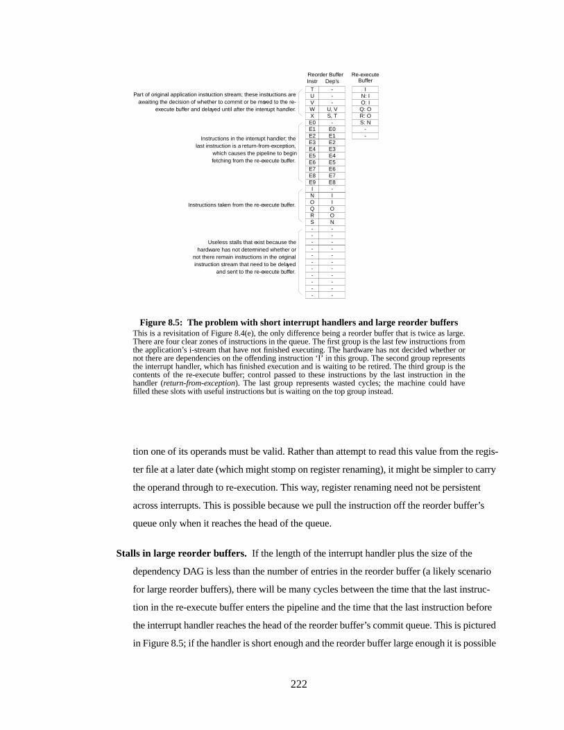
222
tion one of its operands must be valid. Rather than attempt to read this value from the regis-
ter file at a later date (which might stomp on register renaming), it might be simpler to carry
the operand through to re-execution. This way, register renaming need not be persistent
across interrupts. This is possible because we pull the instruction off the reorder buffer’s
queue only when it reaches the head of the queue.
Stalls in large reorder buffers. If the length of the interrupt handler plus the size of the
dependency DAG is less than the number of entries in the reorder buffer (a likely scenario
for large reorder buffers), there will be many cycles between the time that the last instruc-
tion in the re-execute buffer enters the pipeline and the time that the last instruction before
the interrupt handler reaches the head of the reorder buffer’s commit queue. This is pictured
in Figure 8.5; if the handler is short enough and the reorder buffer large enough it is possible
Re-executeBuffer
Figure 8.5: The problem with short interrupt handlers and large reorder buffersThis is a revisitation of Figure 8.4(e), the only difference being a reorder buffer that is twice as large.There are four clear zones of instructions in the queue. The first group is the last few instructions fromthe application’s i-stream that have not finished executing. The hardware has not decided whether ornot there are dependencies on the offending instruction ‘I’ in this group. The second group representsthe interrupt handler, which has finished execution and is waiting to be retired.The third group is thecontents of the re-execute buffer; control passed to these instructions by the last instruction in thehandler (return-from-exception). The last group represents wasted cycles; the machine could havefilled these slots with useful instructions but is waiting on the top group instead.
Dep’sInstrReorder Buffer
IN: IO: IQ: OR: OS: N
--
E5E6E7E8
E2E3E4
E6E7E8E9
E3E4E5
-I
U, VS, T
-E0
---
WXE0E1
TUV
E1E2
----
---
----
---
--
ON--
IIO
RS--
NOQ
--
Part of original application instruction stream; these instructions areawaiting the decision of whether to commit or be moved to the re-
execute buffer and delayed until after the interrupt handler.
Instructions in the interrupt handler; thelast instruction is a return-from-exception,
which causes the pipeline to beginfetching from the re-execute buffer.
Instructions taken from the re-execute buffer.
Useless stalls that exist because thehardware has not determined whether or
not there remain instructions in the originalinstruction stream that need to be delayed
and sent to the re-execute buffer.
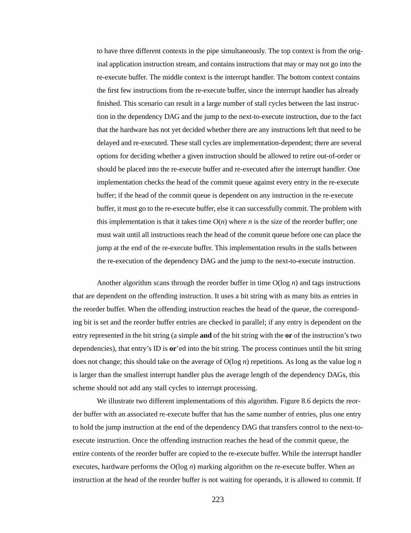
223
to have three different contexts in the pipe simultaneously. The top context is from the orig-
inal application instruction stream, and contains instructions that may or may not go into the
re-execute buffer. The middle context is the interrupt handler. The bottom context contains
the first few instructions from the re-execute buffer, since the interrupt handler has already
finished. This scenario can result in a large number of stall cycles between the last instruc-
tion in the dependency DAG and the jump to the next-to-execute instruction, due to the fact
that the hardware has not yet decided whether there are any instructions left that need to be
delayed and re-executed. These stall cycles are implementation-dependent; there are several
options for deciding whether a given instruction should be allowed to retire out-of-order or
should be placed into the re-execute buffer and re-executed after the interrupt handler. One
implementation checks the head of the commit queue against every entry in the re-execute
buffer; if the head of the commit queue is dependent on any instruction in the re-execute
buffer, it must go to the re-execute buffer, else it can successfully commit. The problem with
this implementation is that it takes time O(n) wheren is the size of the reorder buffer; one
must wait until all instructions reach the head of the commit queue before one can place the
jump at the end of the re-execute buffer. This implementation results in the stalls between
the re-execution of the dependency DAG and the jump to the next-to-execute instruction.
Another algorithm scans through the reorder buffer in time O(logn) and tags instructions
that are dependent on the offending instruction. It uses a bit string with as many bits as entries in
the reorder buffer. When the offending instruction reaches the head of the queue, the correspond-
ing bit is set and the reorder buffer entries are checked in parallel; if any entry is dependent on the
entry represented in the bit string (a simpleand of the bit string with theor of the instruction’s two
dependencies), that entry’s ID isor’ed into the bit string. The process continues until the bit string
does not change; this should take on the average of O(logn) repetitions. As long as the value logn
is larger than the smallest interrupt handler plus the average length of the dependency DAGs, this
scheme should not add any stall cycles to interrupt processing.
We illustrate two different implementations of this algorithm. Figure 8.6 depicts the reor-
der buffer with an associated re-execute buffer that has the same number of entries, plus one entry
to hold the jump instruction at the end of the dependency DAG that transfers control to the next-to-
execute instruction. Once the offending instruction reaches the head of the commit queue, the
entire contents of the reorder buffer are copied to the re-execute buffer. While the interrupt handler
executes, hardware performs the O(logn) marking algorithm on the re-execute buffer. When an
instruction at the head of the reorder buffer is not waiting for operands, it is allowed to commit. If
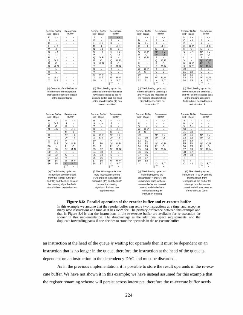
224
an instruction at the head of the queueis waiting for operands then it must be dependent on an
instruction that is no longer in the queue, therefore the instruction at the head of the queue is
dependent on an instruction in the dependency DAG and must be discarded.
As in the previous implementation, it is possible to store the result operands in the re-exe-
cute buffer. We have not shown it in this example; we have instead assumed for this example that
the register renaming scheme will persist across interrupts, therefore the re-execute buffer needs
I, J-, I
-, -
S, T
O, PO
M, N
S, Tj ‘Y’
Figure 8.6: Parallel operation of the reorder buffer and re-execute bufferIn this example we assume that the reorder buffer can retire two instructions at a time, and accept asmany new instructions at a time as it has room for. The primary difference between this example andthat in Figure 8.4 is that the instructions in the re-execute buffer are available for re-execution farsooner in this implementation. The disadvantage is the additional space requirements, and theduplicate forwarding paths if one decides to store the operands in the re-execute buffer.
Dep’s
--------
(a) Contents of the buffers atthe moment the exceptionalinstruction reaches the head
of the reorder buffer
InstrReorder Buffer Re-execute
Buffer
--------
----------------
L-
U, VS, T
O, PO
M, NL
UVWX
QRST
JI, J-, I-
-, ---
J, KMNOP
I*JKL
Dep’s
(b) The following cycle: thecontents of the reorder bufferhave been copied to the re-execute buffer, and the headof the reorder buffer (‘I’) has
been committed
InstrReorder Buffer Re-execute
Buffer
L-
U, VS, T
O, PO
M, NL
UVWX
QRST
JI, J-, I-
-
--
J, KMNOP
E0
JKL
L-
U, VS, T
O, PO
M, NL
UVWX
QRST
JI, J-, I-
--
J, KMNOP
I*JKL
Dep’s
(c) The following cycle: twomore instructions commit (‘J’and ‘K’) and the first pass ofthe marking algorithm finds
direct dependencies oninstruction ‘I’
InstrReorder Buffer Re-execute
Buffer
L-
U, VS, T
O, PO
M, NL
UVWX
QRST
-I, --, I-
-E0E1
-, -MNOP
E0E1E2
L
L-
U, VS, T
O, PO
M, NL
UVWX
QRST
J
-
-, ---
J, KMN*O*P
I*JKL
Dep’s
(e) The following cycle: twoinstructions are discardedfrom the reorder buffer (‘N’
and ‘O’) and the third pass ofthe marking algorithm findsmore indirect dependencies
InstrReorder Buffer Re-execute
Buffer
Dep’s
(d) The following cycle: twomore instructions commit (‘L’and ‘M’) and the second pass
of the marking algorithmfinds indirect dependencies
on instruction ‘I’
InstrReorder Buffer Re-execute
Buffer
--
U, VS, T
O, PO
-, N-
UVWX
QRST
E3
I, --, I-
-E0E1E2
E4
NOP
E0E1E2E3
L-
U, VS, T
LUVWX
Q*R*S*T
JI, J-, I-
-, ---
J, KMN*O*P
I*JKL
--
U, VS, T
O, PO
-, N-
UVWX
QRST
E3E4E5
-
-E0E1E2
E4E5E6
P
E0E1E2E3 L
-U, V
O, PO
M, NL
UVWX*
Q*R*S*T
JI, J-, I-
-, ---
J, KMN*O*P
I*JKL
-
j ‘Y’ -j ‘Y’ -j ‘Y’ -- -
j ‘Y’
Dep’s
(f) The following cycle: onemore instruction commits(‘O’) and one instruction is
discarded (‘P’) and the fourthpass of the marking
algorithm finds no newdependencies
InstrReorder Buffer Re-execute
Buffer
--
U, VS, T
E7
O-, N
-UVWX
E8
RST
E3E4E5E6
-E0E1E2
E4E5E6E7
E0E1E2E3
L-
U, V
O, PO
M, NL
UVWX*
Q*R*S*T
JI, J-, I-
-, ---
J, KMN*O*P
I*JKL
-S, T
j ‘Y’
Dep’s
(g) The following cycle: twomore instructions are
discarded (‘R’ and ‘S’), theunmarked entries in the re-execute buffer are markedinvalid, and the buffer is
marked as ready forinstruction fetching
InstrReorder Buffer Re-execute
Buffer
--
U, VS, T
E7E8-
-UVWX
E8E9-
T
E3E4E5E6
-E0E1E2
E4E5E6E7
E0E1E2E3
---
O, PO
M, N-
---
X*
Q*R*S*-
-I, J-, I-
-, ----
-N*O*-
I*---
-S, T
j ‘Y’
Dep’s
(h) The following cycle:instructions ‘T’ & ‘U’ commit,
and the return-from-exception at the end of theinterrupt handler passes
control to the instructions inthe re-execute buffer.
InstrReorder Buffer Re-execute
Buffer
-, I
--, VS, -
E7E8-, -I, -
O
VWX
E8E9IN
E3E4E5E6
-E0E1E2
E4E5E6E7
E0E1E2E3
---
O, PO
M, N-
---
X*
Q*R*S*-
-I, J-, I-
-, ----
-N*O*-
I*---
-
225
only maintain information on dependencies and register usage. The example illustrates a very
important point; it is very possible that two instances of the same instruction are in the pipeline at
the same time. If the reorder buffer had been larger, at the end of the example, instruction ‘X’
would have been fetched into the tail of the reorder buffer, even though it would still have been up
near the head of the reorder buffer. This is an interesting side-effect that illustrates the importance
of discarding instructions from the reorder buffer if they depend on an instruction no longer in the
buffer.
Figure 8.7 depicts an alternative organization in which a separate re-execute buffer is not
needed. The marking algorithm is performed in place in the reorder buffer. The disadvantage of
this scheme is that it effectively reduces the commit bandwidth of the pipeline; the reorder buffer
must limit its intake of instructions because it cannot empty the buffer as fast as normal. The
instructions in the dependency DAG hang around in the reorder buffer until they are re-executed.
This scheme uses a temporary HEAD pointer and a SAFE pointer. The HEAD pointer skips over
instructions that are slated for re-execution. The SAFE pointer indicates how far the HEAD pointer
can move to. Every pass of the marking algorithm, the SAFE pointer moves to the first newly-
uncovered dependent instruction. Since the instructions are in the reorder buffer in a partial order-
ing of the DAG, we know that successive passes of the algorithm uncover dependencies in a mono-
tonic fashion; if instructionsi andx (i precedesx) are uncovered on successive passes of the
algorithm and no instructions betweeni andx were uncovered by the time x was uncovered, then
no dependency-DAG instructions exist betweeni andx. Therefore this region is “safe” and the
instructions in it can be committed once they finish executing.
Handling Memory-Memory Conflicts
Memory-memory conflicts can be handled easily, if expensively. By the time a load or
store operation following the offending instruction comes to the head of the reorder buffer, its tar-
get address is either available or unavailable. If it is unavailable due to a register-register depen-
dency on an instruction in the re-execute buffer, then this is handled in the manner already
described. If the target address has been computed, one must compare the address to the addresses
used by whatever memory operations are in the re-execute buffer. This is potentially expensive.
Moreover, if any of the target addresses in the re-execute buffer are unavailable, the hardware will
have to hold off all further memory operations and place them into the re-execute buffer on the off-
chance that they conflict with memory operations that are to be re-executed.
The three designs interact well with memory-disambiguation mechanisms. For example,
in the scheme described by Gallagher, et al.[Gallagher et al. 1994], the hardware implements a
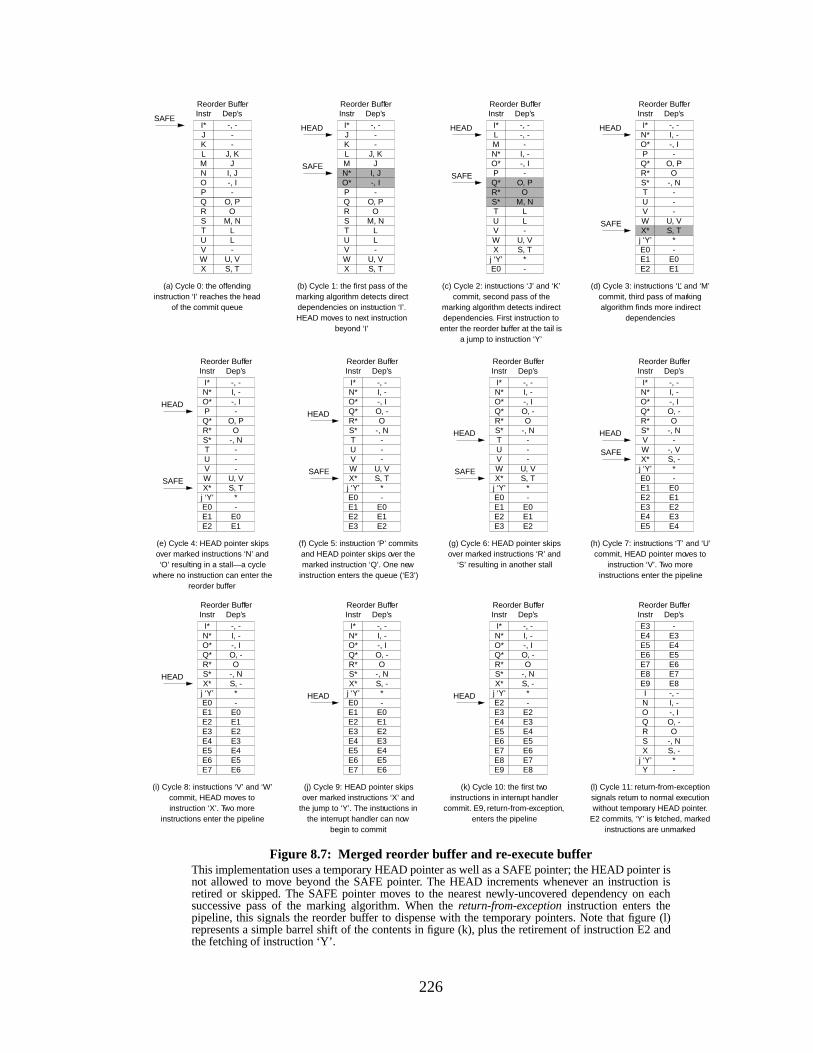
226
Figure 8.7: Merged reorder buffer and re-execute bufferThis implementation uses a temporary HEAD pointer as well as a SAFE pointer; the HEAD pointer isnot allowed to move beyond the SAFE pointer. The HEAD increments whenever an instruction isretired or skipped. The SAFE pointer moves to the nearest newly-uncovered dependency on eachsuccessive pass of the marking algorithm. When thereturn-from-exception instruction enters thepipeline, this signals the reorder buffer to dispense with the temporary pointers. Note that figure (l)represents a simple barrel shift of the contents in figure (k), plus the retirement of instruction E2 andthe fetching of instruction ‘Y’.
Dep’s
L-
U, VS, T
O, PO
M, NL
(a) Cycle 0: the offendinginstruction ‘I’ reaches the head
of the commit queue
Instr
UVWX
QRST
Reorder Buffer
JI, J-, I-
-, ---
J, KMNOP
I*JKL
SAFEDep’s
L-
U, VS, T
O, PO
M, NL
(b) Cycle 1: the first pass of themarking algorithm detects directdependencies on instruction ‘I’.HEAD moves to next instruction
beyond ‘I’
Instr
UVWX
QRST
Reorder Buffer
JI, J-, I-
-, ---
J, KMN*O*P
I*JKL I, -
-, I
Dep’s
L-
U, VS, T
O, PO
M, NL
(c) Cycle 2: instructions ‘J’ and ‘K’commit, second pass of the
marking algorithm detects indirectdependencies. First instruction to
enter the reorder buffer at the tail isa jump to instruction ‘Y’
Instr
UVWX
Q*R*S*T
Reorder Buffer
-
-
-, -
*-
-, -MN*O*P
I*
j ‘Y’E0
L
SAFESAFE
(d) Cycle 3: instructions ‘L’ and ‘M’commit, third pass of markingalgorithm finds more indirect
dependencies
O, P
I, --, I
Dep’s
--
U, VS, T
O-, N
-
Instr
UVWX*
Q*R*S*T
Reorder Buffer
E1
-
-, -
*-
E0E2
N*O*P
I*
j ‘Y’E0E1
SAFE
(e) Cycle 4: HEAD pointer skipsover marked instructions ‘N’ and‘O’ resulting in a stall—a cycle
where no instruction can enter thereorder buffer
HEAD HEAD HEAD
S, T
O, P
I, --, I
Dep’s
--
U, V
O-, N
-
Instr
UVWX*
Q*R*S*T
Reorder Buffer
E1
-
-, -
*-
E0E2
N*O*P
I*
j ‘Y’E0E1
SAFE
HEAD
(f) Cycle 5: instruction ‘P’ commitsand HEAD pointer skips over themarked instruction ‘Q’. One new
instruction enters the queue (‘E3’)
S, T
O, -
I, --, I
Dep’s
--
U, V
O-, N
-
Instr
UVWX*
Q*R*S*T
Reorder Buffer
E1E2
-, -
*-
E0E2
N*O*
E3
I*
j ‘Y’E0E1
SAFE
HEAD
(g) Cycle 6: HEAD pointer skipsover marked instructions ‘R’ and
‘S’ resulting in another stall
S, T
O, -
I, --, I
Dep’s
--
U, V
O-, N
-
Instr
UVWX*
Q*R*S*T
Reorder Buffer
E1E2
-, -
*-
E0E2
N*O*
E3
I*
j ‘Y’E0E1
SAFE
HEAD
(h) Cycle 7: instructions ‘T’ and ‘U’commit, HEAD pointer moves to
instruction ‘V’. Two moreinstructions enter the pipeline
S, -
O, -
I, --, I
Dep’s
E4
--, V
O-, N
E3
Instr
E5
VWX*
Q*R*S*
E4
Reorder Buffer
E1E2
-, -
*-
E0E2
N*O*
E3
I*
j ‘Y’E0E1
SAFE
HEAD
(i) Cycle 8: instructions ‘V’ and ‘W’commit, HEAD moves toinstruction ‘X’. Two more
instructions enter the pipeline
S, -
O, -
I, --, I
Dep’s
E4E5E6
O-, N
E3
Instr
E5E6E7
X*
Q*R*S*
E4
Reorder Buffer
E1E2
-, -
*-
E0E2
N*O*
E3
I*
j ‘Y’E0E1
HEAD
(l) Cycle 11: return-from-exceptionsignals return to normal executionwithout temporary HEAD pointer.
E2 commits, ‘Y’ is fetched, markedinstructions are unmarked
S, -
O, -
I, --, I
Dep’s
E4E5E6
O-, N
E3
Instr
E5E6E7
X
QRS
E4
Reorder Buffer
-
-
-, -
*
E7E8
Y
NO
E3
I
j ‘Y’
E8E9
(j) Cycle 9: HEAD pointer skipsover marked instructions ‘X’ and
the jump to ‘Y’. The instructions inthe interrupt handler can now
begin to commit
S, -
O, -
I, --, I
Dep’s
E4E5E6
O-, N
E3
Instr
E5E6E7
X*
Q*R*S*
E4
Reorder Buffer
E1E2
-, -
*-
E0E2
N*O*
E3
I*
j ‘Y’E0E1
HEAD
(k) Cycle 10: the first twoinstructions in interrupt handler
commit. E9, return-from-exception,enters the pipeline
S, -
O, -
I, --, I
Dep’s
E4E5E6
O-, N
E3
Instr
E5E6E7
X*
Q*R*S*
E4
Reorder Buffer
-E2
-, -
*
E7E8
E2
N*O*
E3
I*
j ‘Y’
E8E9
HEAD
227
memory conflict buffer that detects possible conflicts between memory operations, and it provides
a check mechanism for the software to determine if any of its aggressively-scheduled loads used
the same target address as a preceding store that the compiler scheduled out of order (the aggres-
sively-scheduled load should have actually been executedafter the preceding store). If the hard-
ware registers a conflict, the instruction stream provides its own correction code to re-execute the
memory operations in-order.
If none of the instructions involved cause an interrupt, the memory conflict buffer scheme
should perform as normal. If an instructiondoes cause an interrupt, even if the loads and stores are
completed out of order and a conflict is noticed by the conflict buffer, the application’s patch-up
code will recompute the results from scratch.
Interaction with Precise Interrupts
If an instruction causes an event that requires true precise interrupts while the instruction
is in the reorder buffer at the same time as the offending instruction, the problem actually becomes
very easy. If the precise-interrupt is requiredbefore the relaxed-precision interrupt is required (the
instruction causing the precise interrupt occurs before the instruction causing the relaxed-precision
interrupt), then the entire reorder buffer is flushed before the offending instruction gets to the head
of the reorder buffer. If the precise interrupt is requiredafter, then we can either simply revert to
precise interrupts to handle both cases (since the entire buffer will be flushed at least once any-
way), or when the precise-interrupt instruction reaches the head of the reorder buffer the hardware
can send it and every other instruction in the reorder buffer to the re-execute buffer. This way,
when the precise-interrupt-causing instruction re-executes, none of the instructions that come after
it in the sequential instruction stream will have committed.
The problem occurs when a re-executed instruction (for example, one that is dependent on
the original exceptional instruction) causes an exception during its re-execution that in turn
requires precise interrupts. This could easily happen in normal code; suppose we have the follow-
ing section of code representing an indirect load (e.g. pointer-chasing):
load r1 <- addrload r2 <- r1
Suppose the first load instruction causes a cache-miss interrupt. The second load is re-exe-
cuted with the first because it depends on the value loaded. By the time it is re-executed, many
instructions after the second load instruction in the sequential stream could have committed. If this
second load references an illegal address, instructions past the load have committed by the time the
SEGFAULT is detected. Such a situation could require that the committed instructions be uncom-
228
mitted. This can be solved fairly easily with a checkpoint/repair mechanism, in which the state of
the processor is saved periodically [Hwu & Patt 1987], allowing the processor to return to a known
good state in the case of problems. The processor would then turn off relaxed-precision interrupts
until after the precise interrupt is handled.
Interaction with Register Renaming
The scheme has an implicit contract with the register-renaming mechanism: a register is
live until all the instructions that reference it are committed. If an instruction is sent to the re-exe-
cute buffer, its physical register should not be re-assigned until the instruction re-executes and
commits successfully. Many register-renaming mechanisms assume the in-order retirement of
instructions. For instance, the MIPS R10000 assigns logical registerl to physical registerp until a
new instruction (call it instructioni) targets logical registerl; at this point, the processor pulls a
new physical registerq from a pool of available physical registers and assigns this instruction and
all subsequent instructions sourcing logical registerl to physical registerq. The MIPS R10000
waits until instructioni graduates before it frees physical registerp [Yeager 1996]. This implicitly
assumes that by the time instructioni is ready to commit, all previous instructions that used thel-p
mapping have committed, and therefore no other instructions in the pipeline are using physical
registerp.
In our scheme, we allow instructions to be committed out-of-order. Therefore it is impos-
sible to use the same sort of mechanism. One possible implementation would use link counters; a
counter associated with the physical register would be incremented for every instruction using the
register, and decremented for every instruction that commits. When the counter reaches zero, the
register could be freed. An alternative could be to perform register mapping at the granularity of a
group of instructions, as described by Nair and Hopkins [Nair & Hopkins 1997]. In this scheme,
blocks of instructions are dynamically scheduled, and with each block is kept information that
helps the hardware unmap registers when the block is exited. This way, more work is done at a
time, but it is done much less frequently than in a traditional renaming scheme. In the re-execute
buffer scheme, information on a group would be held until every instruction in the group commit-
ted; thus, one could be sure about the liveness of any physical register.
An important point to remember is that the interrupt handler might need to query the state
of the instruction causing the interrupt (since we are only concerning ourselves with cache-miss
interrupts at this point, it is not clear what additional information one might need beyond the load/
store address; we discuss this point merely for the sake of completeness). In the case that instruc-
tions have committed out of order, the architected register file will not necessarily represent an
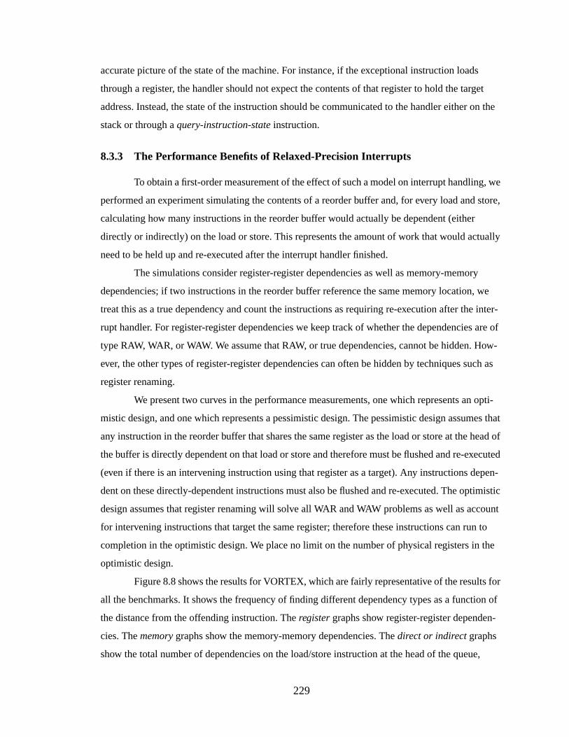
229
accurate picture of the state of the machine. For instance, if the exceptional instruction loads
through a register, the handler should not expect the contents of that register to hold the target
address. Instead, the state of the instruction should be communicated to the handler either on the
stack or through aquery-instruction-state instruction.
8.3.3 The Performance Benefits of Relaxed-Precision Interrupts
To obtain a first-order measurement of the effect of such a model on interrupt handling, we
performed an experiment simulating the contents of a reorder buffer and, for every load and store,
calculating how many instructions in the reorder buffer would actually be dependent (either
directly or indirectly) on the load or store. This represents the amount of work that would actually
need to be held up and re-executed after the interrupt handler finished.
The simulations consider register-register dependencies as well as memory-memory
dependencies; if two instructions in the reorder buffer reference the same memory location, we
treat this as a true dependency and count the instructions as requiring re-execution after the inter-
rupt handler. For register-register dependencies we keep track of whether the dependencies are of
type RAW, WAR, or WAW. We assume that RAW, or true dependencies, cannot be hidden. How-
ever, the other types of register-register dependencies can often be hidden by techniques such as
register renaming.
We present two curves in the performance measurements, one which represents an opti-
mistic design, and one which represents a pessimistic design. The pessimistic design assumes that
any instruction in the reorder buffer that shares the same register as the load or store at the head of
the buffer is directly dependent on that load or store and therefore must be flushed and re-executed
(even if there is an intervening instruction using that register as a target). Any instructions depen-
dent on these directly-dependent instructions must also be flushed and re-executed. The optimistic
design assumes that register renaming will solve all WAR and WAW problems as well as account
for intervening instructions that target the same register; therefore these instructions can run to
completion in the optimistic design. We place no limit on the number of physical registers in the
optimistic design.
Figure 8.8 shows the results for VORTEX, which are fairly representative of the results for
all the benchmarks. It shows the frequency of finding different dependency types as a function of
the distance from the offending instruction. Theregister graphs show register-register dependen-
cies. Thememory graphs show the memory-memory dependencies. Thedirect or indirect graphs
show the total number of dependencies on the load/store instruction at the head of the queue,
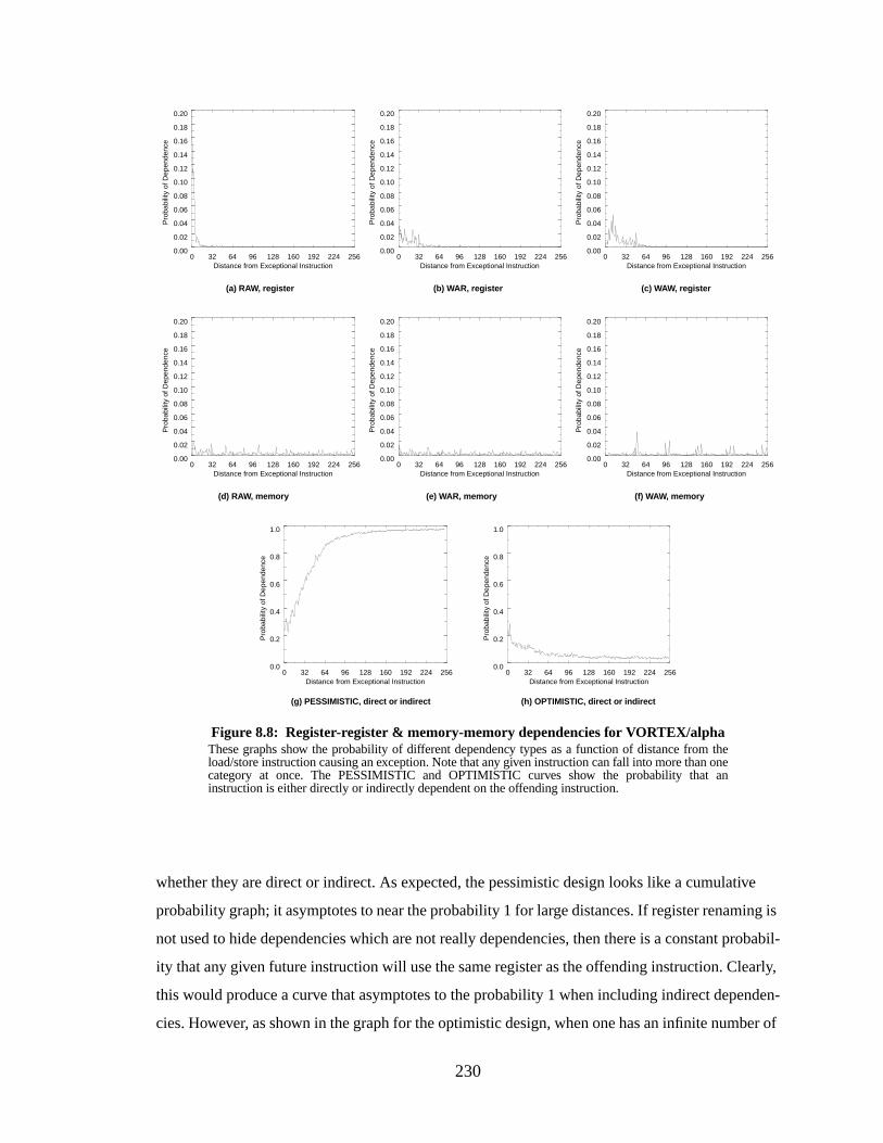
230
whether they are direct or indirect. As expected, the pessimistic design looks like a cumulative
probability graph; it asymptotes to near the probability 1 for large distances. If register renaming is
not used to hide dependencies which are not really dependencies, then there is a constant probabil-
ity that any given future instruction will use the same register as the offending instruction. Clearly,
this would produce a curve that asymptotes to the probability 1 when including indirect dependen-
cies. However, as shown in the graph for the optimistic design, when one has an infinite number of
Figure 8.8: Register-register & memory-memory dependencies for VORTEX/alphaThese graphs show the probability of different dependency types as a function of distance from theload/store instruction causing an exception. Note that any given instruction can fall into more than onecategory at once. The PESSIMISTIC and OPTIMISTIC curves show the probability that aninstruction is either directly or indirectly dependent on the offending instruction.
(a) RAW, register (c) WAW, register(b) WAR, register
(d) RAW, memor y (f) WAW, memor y(e) WAR, memor y
(g) PESSIMISTIC, direct or indirect (h) OPTIMISTIC, direct or indirect
0 32 64 96 128 160 192 224 256Distance from Exceptional Instruction
0.00
0.02
0.04
0.06
0.08
0.10
0.12
0.14
0.16
0.18
0.20
Pro
babi
lity
of D
epen
denc
e
0 32 64 96 128 160 192 224 256Distance from Exceptional Instruction
0.00
0.02
0.04
0.06
0.08
0.10
0.12
0.14
0.16
0.18
0.20
Pro
babi
lity
of D
epen
denc
e
0 32 64 96 128 160 192 224 256Distance from Exceptional Instruction
0.00
0.02
0.04
0.06
0.08
0.10
0.12
0.14
0.16
0.18
0.20
Pro
babi
lity
of D
epen
denc
e
0 32 64 96 128 160 192 224 256Distance from Exceptional Instruction
0.00
0.02
0.04
0.06
0.08
0.10
0.12
0.14
0.16
0.18
0.20
Pro
babi
lity
of D
epen
denc
e
0 32 64 96 128 160 192 224 256Distance from Exceptional Instruction
0.00
0.02
0.04
0.06
0.08
0.10
0.12
0.14
0.16
0.18
0.20
Pro
babi
lity
of D
epen
denc
e
0 32 64 96 128 160 192 224 256Distance from Exceptional Instruction
0.00
0.02
0.04
0.06
0.08
0.10
0.12
0.14
0.16
0.18
0.20
Pro
babi
lity
of D
epen
denc
e
0 32 64 96 128 160 192 224 256Distance from Exceptional Instruction
0.0
0.2
0.4
0.6
0.8
1.0
Pro
babi
lity
of D
epen
denc
e
0 32 64 96 128 160 192 224 256Distance from Exceptional Instruction
0.0
0.2
0.4
0.6
0.8
1.0
Pro
babi
lity
of D
epen
denc
e
231
registers the number of dependent instructionsdecreases as one moves farther from the offending
instruction. This makes more intuitive sense; instructions further out tend to be less related.
The graphs in Figure 8.9 show that if one allows the independent instructions to run to
completion when an interrupt occurs, rather than flushing them and re-executing them after the
interrupt handler, one can save more than 90% of the traditional interrupt overhead. The optimistic
curves (on top) show that a medium-sized reorder buffer is a bit better than a small reorder buffer,
Figure 8.9: Dependence of instructions on the head of the reorder bufferThese graphs illustrate how much interdependence exists between the instruction at the head of thereorder buffer (the next instruction to commit) and the rest of the instructions in the buffer. Themeasurements are only taken when a load or store is at the head of the buffer (only a load or storecould cause a cache-miss exception). Each graph depicts two measurements, corresponding tooptimistic and pessimistic designs. A pessimistic design (the bottom curve in each graph) counts alldependencies, many of which could be hidden by register renaming; the top curve in each graph is theoptimistic measurement that assumes dependencies of the form WAW and WAR are handled byregister renaming. The graphs show that most of the contents of a reorder buffer, especially large ones,are completely independent of the head entry.
(c) PERL/alpha
(a) GCC/alpha (b) IJPEG/alpha
(d) VORTEX/alpha
0 32 64 96 128 160 192 224 256Distance from Exceptional Instruction
0.0
0.2
0.4
0.6
0.8
1.0
Inde
pend
ent I
nstr
uctio
ns a
s %
of W
indo
w S
ize
0 32 64 96 128 160 192 224 256Distance from Exceptional Instruction
0.0
0.2
0.4
0.6
0.8
1.0
Inde
pend
ent I
nstr
uctio
ns a
s %
of W
indo
w S
ize
0 32 64 96 128 160 192 224 256Distance from Exceptional Instruction
0.0
0.2
0.4
0.6
0.8
1.0
Inde
pend
ent I
nstr
uctio
ns a
s %
of W
indo
w S
ize
0 32 64 96 128 160 192 224 256Distance from Exceptional Instruction
0.0
0.2
0.4
0.6
0.8
1.0
Inde
pend
ent I
nstr
uctio
ns a
s %
of W
indo
w S
ize

232
as a higher percentage of the instructions in a smaller buffer will be dependent on the load or store
at the head of the buffer. This makes intuitive sense; generally the results of a computation are con-
sumed shortly after the results are produced. The dips in the curves near the y-axis (most notable
for IJPEG and PERL) represent the compiler’s efforts to place some distance between the produc-
tion and consumption of a result for better performance; often the instructions immediately follow-
ing a load or store will be independent of the load or store. Therefore the frequency of finding
independent instructions immediately after the head instruction will often be higher than finding
them a few instructions later. A few instructions further out than that, one finds independent
instructions again. The pessimistic curves (the bottom curves) show that a smaller reorder buffer is
better. This also makes intuitive sense, as the pessimistic scheme receives no benefit from register
renaming. These curves show the decreasing returns from widening the reorder buffer if renaming
cannot separate out the true dependencies; if the buffer is large enough, virtually all instructions
will be related either directly or indirectly.
Clearly, the use of register renaming can buy one an enormous amount of breathing room.
Whereas the pessimistic scheme indicates that there are diminishing returns on widening the
instruction window (the size of the reorder buffer), the optimistic scheme shows otherwise; as the
window grows larger, a larger percentage of the instructions are completely independent of the
instruction at the head of the queue. Therefore when an interrupt occurs, more and more of the
instructions can be allowed to commit even though they appear after the offending instruction in
the sequential stream.
Design Optimizations
It is certainly possible to increase the performance of the design. Note that, like traditional
reorder buffer implementations, we wait until the instruction in question becomes the head of the
commit queue to respond to the exceptional condition. Thus, even though the exception might be
detected earlier in the pipeline, the hardware waits until the end stages of the pipeline to handle the
exception. This potentially wastes cycles; for example, in Figure 8.2, at the moment of detection
there are three instructions that would need to be squashed and re-executed: the offending instruc-
tion ‘I’ as well as instructions ‘N’ and ‘O’ that are dependent on ‘I.’ By the time instruction ‘I’ has
reached the head of the commit queue, there are 7 instructions that need to be squashed and re-exe-
cuted, doubling the overhead.
Rather than waiting until the offending instruction reaches the head of the queue, one can
begin executing the interrupt handler as soon as the exceptional condition is detected. This is a
clear win; the interrupt handler begins execution potentially many cycles earlier. Also, the set of
233
instructions at the head of the queue (closer to the head than the offending instruction) contain
absolutely no dependencies on the offending instruction and therefore none will need re-execution.
By contrast, those at the tail of the queue and those that are about to enter the queue have a non-
zero probability of being dependent on the offending instruction and so might require re-execu-
tion. Therefore, by not letting more instructions in at the tail of the reorder buffer, we decrease the
average number of instructions that will require re-execution, thereby decreasing overhead.
The problem to solve is the case in which an instructionpreceding the exceptional instruc-
tion causes an interrupt that is detectedafter the handler enters the pipeline. This can actually be
handled in software; if the hardware provides an instruction to the handler that indicates whether
or not such an overlap occurred, the handler can check at the end of its execution to see whether a
problem occurred, and if so, execute patch-up code as in the Memory Conflict Buffer [Gallagher et
al. 1994]. If the interrupt is for a Level-2 cache miss, there is no harm in loading the cache out of
order (provided that the two instructions are not dependent through their memory addresses). If the
interrupt is of a different type, then it can be handled as described earlier in the section onInterac-
tion with Precise Interrupts.
8.4 Conclusions
The general-purpose interrupt mechanism, which has long been used to handle excep-
tional conditions that occur infrequently, is being used increasingly often to handle conditions that
are neither exceptional nor infrequent. One example is the increased use of the interrupt mecha-
nism to perform memory management—to handle TLB misses in today’s microprocessors. This is
putting pressure on the interrupt mechanism to become more lightweight.
The software-oriented memory-management described in this thesis causes an interrupt
for every Level-2 cache miss, which can happen frequently for some applications. We therefore
propose a handling mechanism for these events that is lightweight in terms of run-time overhead, if
possibly heavyweight in terms of hardware requirements. Since memory management is intended
to be transparent to the application, it is possible to handle the interrupt imprecisely but still retain
the semantics of the application. In particular, in an out-of-order pipeline it is possible to let many
of the in-flight instructions run to completion before handling the cache-miss interrupt, even
though many of these instructions came after the offending instruction in the original sequential
instruction stream. If these instructions are truly independent of the offending instruction, there is
no harm in letting them commit out-of-order.
234
Our measurements show that more than 90% of the instructions in a reorder buffer are
completely independent of the load or store at the head of the queue. Thus, while a traditional
interrupt mechanism will flush these instructions and re-execute them after handling the interrupt,
wasting perhaps hundreds of machine cycles, our mechanism retains any completed work that is
independent of the offending instruction. Therefore the overhead of taking an interrupt is reduced
by more than an order of magnitude. For an extremely large reorder buffer (200 entries) the over-
head should be less than 20 cycles per interrupt.
235
CHAPTER 9
THE PROBLEMS WITH MULTIMEDIA SUPPORTAND A SOLUTION USING SEGMENTATION
This chapter addresses the issue of streaming data. Previous chapters have described a sys-
tem that relies on large, virtually-addressed caches to obtain good performance; the system is thus
limited by the performance of the caches. Applications that stream data will exhibit excellent spa-
tial locality but poor temporal locality. This will result in poor performance on a software-oriented
memory management system, compared to the performance of a hardware-oriented system that
uses a TLB. In this chapter, we discuss a solution using segmentation and superpages that
improves the performance of both types of system.
9.1 Intr oduction
Multimedia is a class of applications that is in widespread use but exhibits poor cache per-
formance because of its data-access behavior. Applications in this class tend to stream data
through the system and so tend to access any given datum a small number of times (little more than
once). Multimedia applications therefore exhibit little temporal locality; by definition, however,
they tend to exhibit a high degree of spatial locality.
Solving the general problem of streaming data efficiently is beyond the scope of this the-
sis; what concerns us is the potentially large performance difference between a software-oriented
system and a TLB-oriented system. When an application streams through its address space it will
very possibly touch each data location only once (some applications, such as mpeg decode, might
touch data locations several times to uncompress or interpolate). If the memory management sys-
tem uses a TLB, the system will have to walk the page table and load the TLB on every page
boundary—after the application has streamed through a few kilobytes of data. A software-oriented
system, on the other hand, will have to walk the page table and load the cache on behalf of the
application on every cache line boundary—after the application has streamed through a few dozen
236
bytes of data. The cache-miss handler of the software-oriented scheme will be invoked 10 to 100
times more often than the TLB-miss handler of the hardware-oriented scheme. If the cost of han-
dling the cache miss is roughly equal to the cost of handling the TLB miss, this should result in a
performance difference between the two memory management systems of two to three orders of
magnitude.
Our goal is to reduce the frequency of cache-miss interrupts when an application streams
through a large amount of data. There is a simple solution: the use of superpages for streamed data.
One can determine at compile time whether an application will access its data serially or other-
wise, therefore one can provide hooks in the operating system that will allow an application to
request a superpage for the data it will access serially. A superpage by definition is contiguous in
both virtual and physical space; the hardware can easily perform the mapping from virtual to phys-
ical space without intervention from the operating system. Therefore, an application can stream
through its entire superpage without causing a single TLB-miss interrupt or cache-miss interrupt.
Note that this does not solve the fundamental problem of data-streaming, which as men-
tioned is beyond the scope of this thesis. This problem has been addressed by many researchers,
with most solutions falling along the lines of prefetching [Jouppi 1990]. These would work very
well in a software-oriented system; since the operating system is responsible for loading the data
on behalf of the user-level process, the operating system can perform some intelligent prefetching,
as in [Horowitz et al. 1995]. For instance, a very simple intelligent prefetching scheme would have
the operating system recognize that the application’s data accesses are serial and almost entirely
read-only, then prefetch large blocks of data directly into the Level-2 cache. We will not discuss
schemes such as this in this thesis, as they are truly independent of whether the memory manage-
ment system uses a TLB or not.
9.2 Superpage Support
As shown in Chapter 3, there are many different ways to support superpages. Some sys-
tems, such as the MIPS, Alpha, Intel Architecture, and SPARC, allow a single TLB entry to map a
superpage. The PowerPC and some versions of the PA-RISC define additional TLBs that map only
superpages; the PowerPC has a set of BAT registers, the PA-RISC defines a Block TLB [May et al.
1994, Hewlett-Packard 1990]. The advantage of using regular TLB entries to map superpages is a
simple interface; the advantage to using a separate structure to map superpages is that its entries
are typically only replaced intentionally or on context switch. By contrast, unless TLB entries that
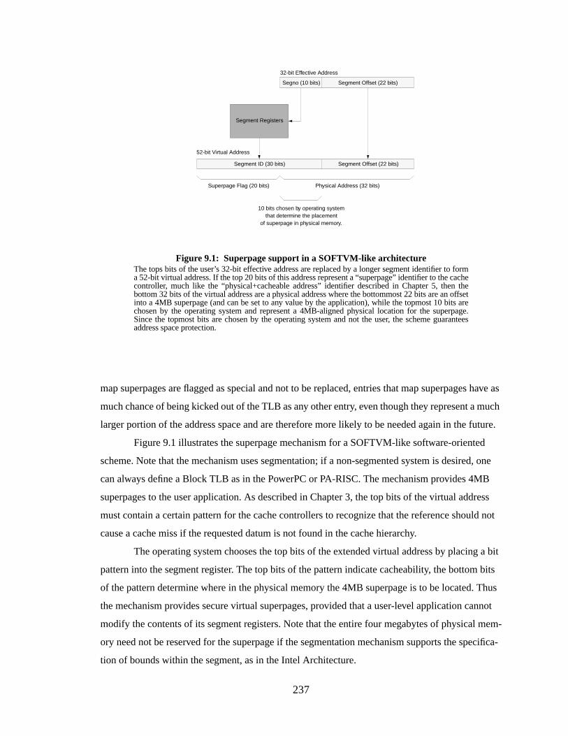
237
map superpages are flagged as special and not to be replaced, entries that map superpages have as
much chance of being kicked out of the TLB as any other entry, even though they represent a much
larger portion of the address space and are therefore more likely to be needed again in the future.
Figure 9.1 illustrates the superpage mechanism for a SOFTVM-like software-oriented
scheme. Note that the mechanism uses segmentation; if a non-segmented system is desired, one
can always define a Block TLB as in the PowerPC or PA-RISC. The mechanism provides 4MB
superpages to the user application. As described in Chapter 3, the top bits of the virtual address
must contain a certain pattern for the cache controllers to recognize that the reference should not
cause a cache miss if the requested datum is not found in the cache hierarchy.
The operating system chooses the top bits of the extended virtual address by placing a bit
pattern into the segment register. The top bits of the pattern indicate cacheability, the bottom bits
of the pattern determine where in the physical memory the 4MB superpage is to be located. Thus
the mechanism provides secure virtual superpages, provided that a user-level application cannot
modify the contents of its segment registers. Note that the entire four megabytes of physical mem-
ory need not be reserved for the superpage if the segmentation mechanism supports the specifica-
tion of bounds within the segment, as in the Intel Architecture.
Figure 9.1: Superpage support in a SOFTVM-like architectureThe tops bits of the user’s 32-bit effective address are replaced by a longer segment identifier to forma 52-bit virtual address. If the top 20 bits of this address represent a “superpage” identifier to the cachecontroller, much like the “physical+cacheable address” identifier described in Chapter 5, then thebottom 32 bits of the virtual address are a physical address where the bottommost 22 bits are an offsetinto a 4MB superpage (and can be set to any value by the application), while the topmost 10 bits arechosen by the operating system and represent a 4MB-aligned physical location for the superpage.Since the topmost bits are chosen by the operating system and not the user, the scheme guaranteesaddress space protection.
Segment Offset (22 bits)
32-bit Effective Address
Segno (10 bits)
Segment Registers
Segment Offset (22 bits)Segment ID (30 bits)
52-bit Virtual Address
Superpage Flag (20 bits) Physical Address (32 bits)
10 bits chosen by operating systemthat determine the placement
of superpage in physical memory.

238
This arrangement may have disastrous side-effects if the segment registers do not also
contain valid bits; the use of DMA might conflict with the scheme otherwise. If a process has
access to a region of memory whenever it performs a load or store, it could potentially load stale
data or have the store overwritten by the DMA transfer at a later date. Therefore the operating sys-
tem must disable access to these superpages during DMA transfers. The potential disadvantage of
this is the large locking granularity—applications may be stalled for many cycles while waiting for
the transfer to complete, whereas if the region were locked on a per-page basis (requiring much
more operating-system overhead), the application would be able to access the data earlier. How-
ever, it is possible that this can be amortized over very large data transfers that better match the
bandwidth capabilities of I/O devices.
9.3 Performance Measurements
Figure 9.2 shows the relative memory-system performance of a hardware-oriented scheme
and a software-oriented scheme (without superpages), each running the STREAM benchmark.
1 2 4 8 16 32 64 128L1 Cache Size - per side (1/2/4MB L2 at each pt.)
0.0
2.0
4.0
6.0
8.0
10.0
Ove
rhea
d (C
PI)
Figure 9.2: Memory-system performance on STREAM/alphaThis is the overhead of the virtual memory system; it is only MCPI, and does not contain VMCPI. Ateach L1 cache size there are three bars: one each for L2 cache sizes of 1MB, 2MB, and 4MB. Notethat increasing the size of the L2 cache does virtually nothing to decrease overhead. However,increasing the size of the L1 cache accounts for a small performance gain for SOFTVM, as once theL1 cache is large enough (4K), the handler code fits without contention. There is no such performancegain for ULTRIX because the TLB-miss handler code is executed much less frequently than thecache-miss handler code in SOFTVM, and it therefore does not interfere with the STREAM code.
1 2 4 8 16 32 64 128L1 Cache Size - per side (1/2/4MB L2 at each pt.)
0.0
2.0
4.0
6.0
8.0
10.0
Ove
rhea
d (C
PI)
L1i-missL1d-missL2i-missL2d-miss
SOFTVM — 32/64-byte L1/L2 linesizes ULTRIX — 32/64-byte L1/L2 linesizes
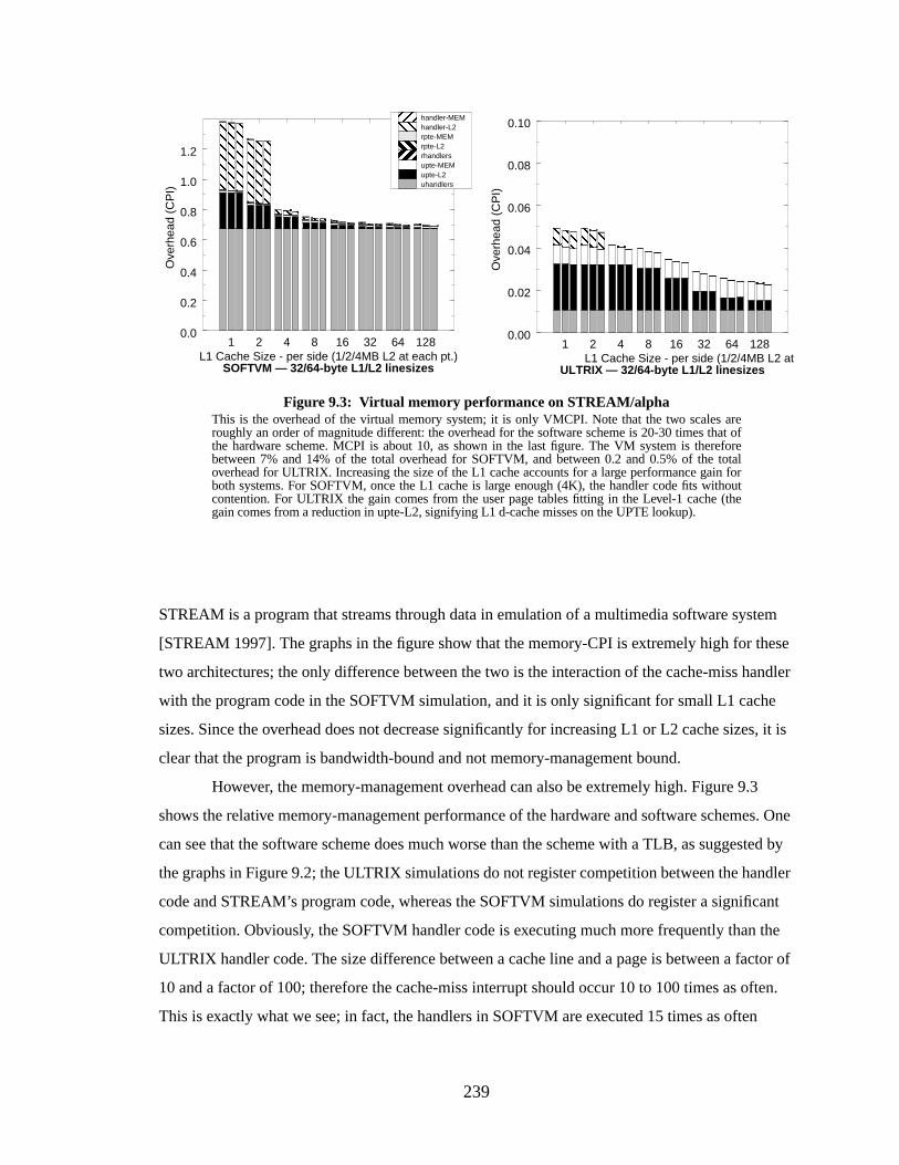
239
STREAM is a program that streams through data in emulation of a multimedia software system
[STREAM 1997]. The graphs in the figure show that the memory-CPI is extremely high for these
two architectures; the only difference between the two is the interaction of the cache-miss handler
with the program code in the SOFTVM simulation, and it is only significant for small L1 cache
sizes. Since the overhead does not decrease significantly for increasing L1 or L2 cache sizes, it is
clear that the program is bandwidth-bound and not memory-management bound.
However, the memory-management overhead can also be extremely high. Figure 9.3
shows the relative memory-management performance of the hardware and software schemes. One
can see that the software scheme does much worse than the scheme with a TLB, as suggested by
the graphs in Figure 9.2; the ULTRIX simulations do not register competition between the handler
code and STREAM’s program code, whereas the SOFTVM simulations do register a significant
competition. Obviously, the SOFTVM handler code is executing much more frequently than the
ULTRIX handler code. The size difference between a cache line and a page is between a factor of
10 and a factor of 100; therefore the cache-miss interrupt should occur 10 to 100 times as often.
This is exactly what we see; in fact, the handlers in SOFTVM are executed 15 times as often
Figure 9.3: Virtual memory perf ormance on STREAM/alphaThis is the overhead of the virtual memory system; it is only VMCPI. Note that the two scales areroughly an order of magnitude different: the overhead for the software scheme is 20-30 times that ofthe hardware scheme. MCPI is about 10, as shown in the last figure. The VM system is thereforebetween 7% and 14% of the total overhead for SOFTVM, and between 0.2 and 0.5% of the totaloverhead for ULTRIX. Increasing the size of the L1 cache accounts for a large performance gain forboth systems. For SOFTVM, once the L1 cache is large enough (4K), the handler code fits withoutcontention. For ULTRIX the gain comes from the user page tables fitting in the Level-1 cache (thegain comes from a reduction in upte-L2, signifying L1 d-cache misses on the UPTE lookup).
1 2 4 8 16 32 64 128L1 Cache Size - per side (1/2/4MB L2 at each pt.)
0.0
0.2
0.4
0.6
0.8
1.0
1.2
Ove
rhea
d (C
PI) uhandlers
upte-L2upte-MEMrhandlersrpte-L2rpte-MEMhandler-L2handler-MEM
1 2 4 8 16 32 64 128L1 Cache Size - per side (1/2/4MB L2 at each pt.)
0.00
0.02
0.04
0.06
0.08
0.10
Ove
rhea
d (C
PI)
ULTRIX — 32/64-byte L1/L2 linesizesSOFTVM — 32/64-byte L1/L2 linesizes
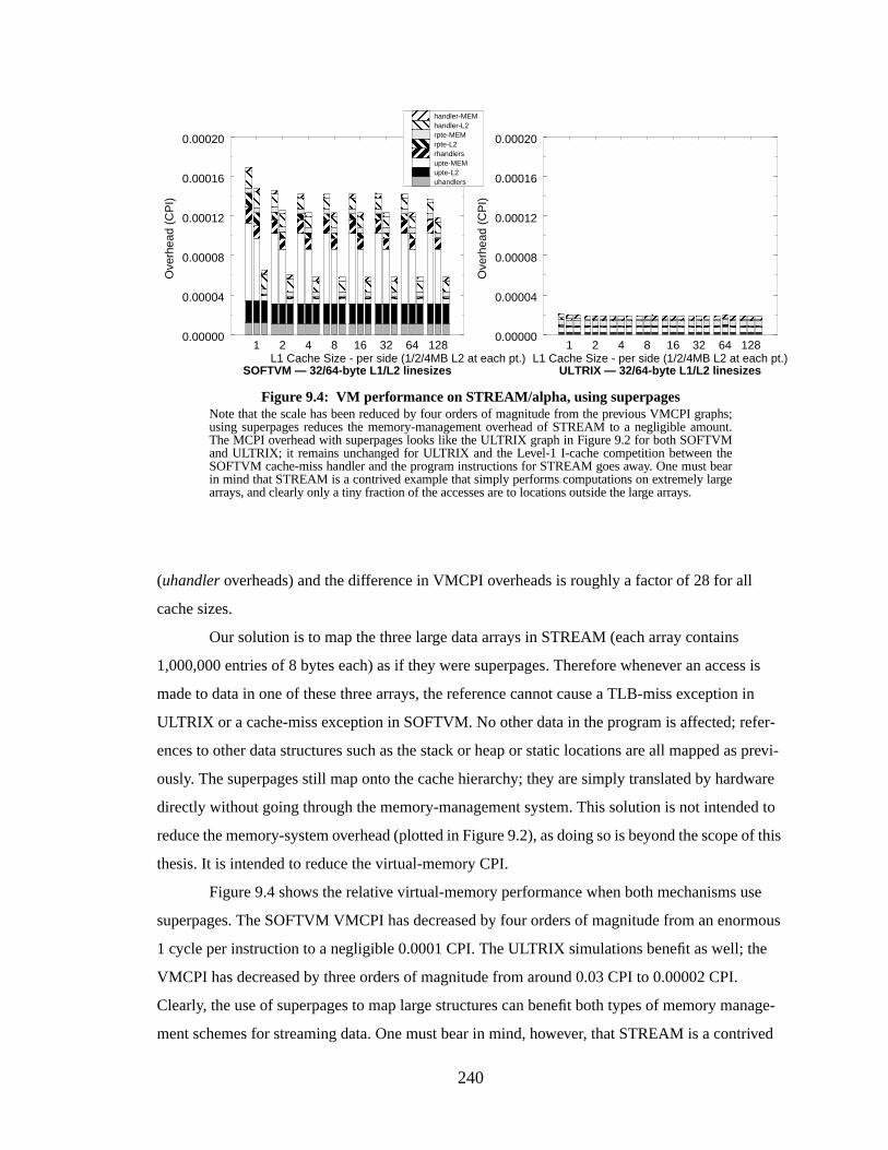
240
(uhandler overheads) and the difference in VMCPI overheads is roughly a factor of 28 for all
cache sizes.
Our solution is to map the three large data arrays in STREAM (each array contains
1,000,000 entries of 8 bytes each) as if they were superpages. Therefore whenever an access is
made to data in one of these three arrays, the reference cannot cause a TLB-miss exception in
ULTRIX or a cache-miss exception in SOFTVM. No other data in the program is affected; refer-
ences to other data structures such as the stack or heap or static locations are all mapped as previ-
ously. The superpages still map onto the cache hierarchy; they are simply translated by hardware
directly without going through the memory-management system. This solution is not intended to
reduce the memory-system overhead (plotted in Figure 9.2), as doing so is beyond the scope of this
thesis. It is intended to reduce the virtual-memory CPI.
Figure 9.4 shows the relative virtual-memory performance when both mechanisms use
superpages. The SOFTVM VMCPI has decreased by four orders of magnitude from an enormous
1 cycle per instruction to a negligible 0.0001 CPI. The ULTRIX simulations benefit as well; the
VMCPI has decreased by three orders of magnitude from around 0.03 CPI to 0.00002 CPI.
Clearly, the use of superpages to map large structures can benefit both types of memory manage-
ment schemes for streaming data. One must bear in mind, however, that STREAM is a contrived
1 2 4 8 16 32 64 128L1 Cache Size - per side (1/2/4MB L2 at each pt.)
0.00000
0.00004
0.00008
0.00012
0.00016
0.00020
Ove
rhea
d (C
PI)
1 2 4 8 16 32 64 128L1 Cache Size - per side (1/2/4MB L2 at each pt.)
0.00000
0.00004
0.00008
0.00012
0.00016
0.00020
Ove
rhea
d (C
PI)
Figure 9.4: VM perf ormance on STREAM/alpha, using superpagesNote that the scale has been reduced by four orders of magnitude from the previous VMCPI graphs;using superpages reduces the memory-management overhead of STREAM to a negligible amount.The MCPI overhead with superpages looks like the ULTRIX graph in Figure 9.2 for both SOFTVMand ULTRIX; it remains unchanged for ULTRIX and the Level-1 I-cache competition between theSOFTVM cache-miss handler and the program instructions for STREAM goes away. One must bearin mind that STREAM is a contrived example that simply performs computations on extremely largearrays, and clearly only a tiny fraction of the accesses are to locations outside the large arrays.
uhandlersupte-L2upte-MEMrhandlersrpte-L2rpte-MEMhandler-L2handler-MEM
SOFTVM — 32/64-byte L1/L2 linesizes ULTRIX — 32/64-byte L1/L2 linesizes
241
example that simply performs a large number of floating-point operations between three multi-
megabyte arrays. It is dominated by access to these three large structures and so it is not surprising
that eliminating these references from the virtual-memory overhead should reduce it to near zero.
9.4 Conclusions
Software-oriented memory management has an Achilles heel: its performance is tied to
that of the caches. Therefore applications that exhibit poor cache performance will see poor perfor-
mance in a software-oriented memory management system. One of the most visible classes of
applications that routinely show poor cache behavior is that of multimedia applications, character-
ized by their tendency to walk sequentially through their address spaces. Such behavior results in
little to no temporal locality but a high degree of spatial locality. What is important in this disserta-
tion is to show that a software-oriented scheme will perform no worse than a hardware-oriented
scheme in the face of such applications. Without special help, a software-oriented scheme per-
forms many times worse than a hardware-oriented scheme, roughly corresponding to the differ-
ence in size between a cache line (the granularity of a cache-miss exception) and a virtual page
(the granularity of a TLB-miss exception). We have shown that mapping the multimedia data
stream eliminates a significant fraction of the cache-miss-exception overhead and closes the per-
formance gap between the two memory-management systems.
242
CHAPTER 10
THE PROBLEMS WITH LARGE OFF-CHIP CACHESAND A SOLUTION USING PHYSICAL MEMORY
This chapter addresses the issue of cost. Previous chapters have described a system using
large Level-2 caches to obtain acceptable performance. In this chapter, we show that performance
is still acceptable without expensive Level-2 caches, provided that main memory is treated like a
virtual cache. We describe several configurations and simulate one to serve as proof-of-concept.
10.1 Intr oduction
We have shown that a software-oriented memory management scheme works because vir-
tual caches require no address translation, and large virtual caches have high hit rates, requiring
address translation only infrequently. Small caches will have poor hit rates and will therefore dem-
onstrate poor performance with this scheme. As it stands, software-oriented memory management
requires large Level-2 caches for acceptable performance; this would seem to preclude using soft-
ware schemes in the embedded processor market, or in any cost-sensitive market since large
SRAM caches are among the most expensive components in a computer system.
However, the small-cache-leads-to-poor-performance conclusion assumes that address
translation is required for every reference to main memory. What if this were not the case? Sup-
pose we had a system without Level-2 caches. What if main memory were configured such that
one could use virtual addresses to reference its storage locations? What if address translation was
only required when references missed main memory? What if main memory looked like an enor-
mously large, slow, virtually-addressed Level-2 cache built out of DRAM? It is easy to imagine
that the system could perform almost as well as a system with a moderately large, fast, virtually-
addressed Level-2 cache built out of SRAM. This has been demonstrated in theSensitivity section
of Chapter 6 where we graphed the performance of medium- and low-performance hierarchy
designs. The advantage of such an organization is that it would eliminate the need to perform
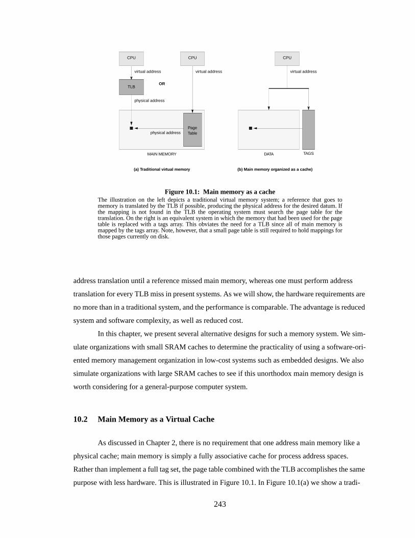
243
address translation until a reference missed main memory, whereas one must perform address
translation for every TLB miss in present systems. As we will show, the hardware requirements are
no more than in a traditional system, and the performance is comparable. The advantage is reduced
system and software complexity, as well as reduced cost.
In this chapter, we present several alternative designs for such a memory system. We sim-
ulate organizations with small SRAM caches to determine the practicality of using a software-ori-
ented memory management organization in low-cost systems such as embedded designs. We also
simulate organizations with large SRAM caches to see if this unorthodox main memory design is
worth considering for a general-purpose computer system.
10.2 Main Memory as a Virtual Cache
As discussed in Chapter 2, there is no requirement that one address main memory like a
physical cache; main memory is simply a fully associative cache for process address spaces.
Rather than implement a full tag set, the page table combined with the TLB accomplishes the same
purpose with less hardware. This is illustrated in Figure 10.1. In Figure 10.1(a) we show a tradi-
Figure 10.1: Main memory as a cacheThe illustration on the left depicts a traditional virtual memory system; a reference that goes tomemory is translated by the TLB if possible, producing the physical address for the desired datum. Ifthe mapping is not found in the TLB the operating system must search the page table for thetranslation. On the right is an equivalent system in which the memory that had been used for the pagetable is replaced with a tags array. This obviates the need for a TLB since all of main memory ismapped by the tags array. Note, however, that a small page table is still required to hold mappings forthose pages currently on disk.
PageTable
MAIN MEMORY
CPU
TLB
(a) Traditional vir tual memor y (b) Main memor y organiz ed as a cache)
virtual address
physical address
CPU
virtual address
physical address
TAGSDATA
CPU
virtual address
OR
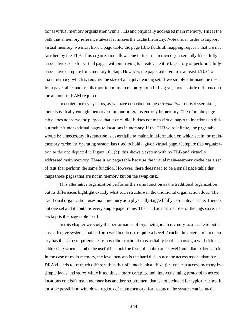
244
tional virtual memory organization with a TLB and physically addressed main memory. This is the
path that a memory reference takes if it misses the cache hierarchy. Note that in order to support
virtual memory, we must have a page table; the page table fields all mapping requests that are not
satisfied by the TLB. This organization allows one to treat main memory essentially like a fully
associative cache for virtual pages, without having to create an entire tags array or perform a fully-
associative compare for a memory lookup. However, the page table requires at least 1/1024 of
main memory, which is roughly the size of an equivalent tag set. If we simply eliminate the need
for a page table, and use that portion of main memory for a full tag set, there is little difference in
the amount of RAM required.
In contemporary systems, as we have described in theIntroduction to this dissertation,
there is typically enough memory to run our programs entirely in memory. Therefore the page
table does not serve the purpose that it once did; it does not map virtual pages to locations on disk
but rather it maps virtual pages to locations in memory. If the TLB were infinite, the page table
would be unnecessary; its function is essentially to maintain information on which set in the main-
memory cache the operating system has used to hold a given virtual page. Compare this organiza-
tion to the one depicted in Figure 10.1(b); this shows a system with no TLB and virtually
addressed main memory. There is no page table because the virtual main-memory cache has a set
of tags that perform the same function. However, there does need to be a small page table that
maps those pages that are not in memory but on the swap disk.
This alternative organization performs the same function as the traditional organization
but its differences highlight exactly what each structure in the traditional organization does. The
traditional organization uses main memory as a physically-tagged fully associative cache. There is
but one set and it contains every single page frame. The TLB acts as a subset of the tags store; its
backup is the page table itself.
In this chapter we study the performance of organizing main memory as a cache to build
cost-effective systems that perform well but do not require a Level-2 cache. In general, main mem-
ory has the same requirements as any other cache; it must reliably hold data using a well-defined
addressing scheme, and to be useful it should be faster than the cache level immediately beneath it.
In the case of main memory, the level beneath is the hard disk; since the access mechanism for
DRAM tends to be much different than that of a mechanical drive (i.e. one can access memory by
simple loads and stores while it requires a more complex and time-consuming protocol to access
locations on disk), main memory has another requirement that is not included for typical caches. It
must be possible to wire down regions of main memory; for instance, the system can be made
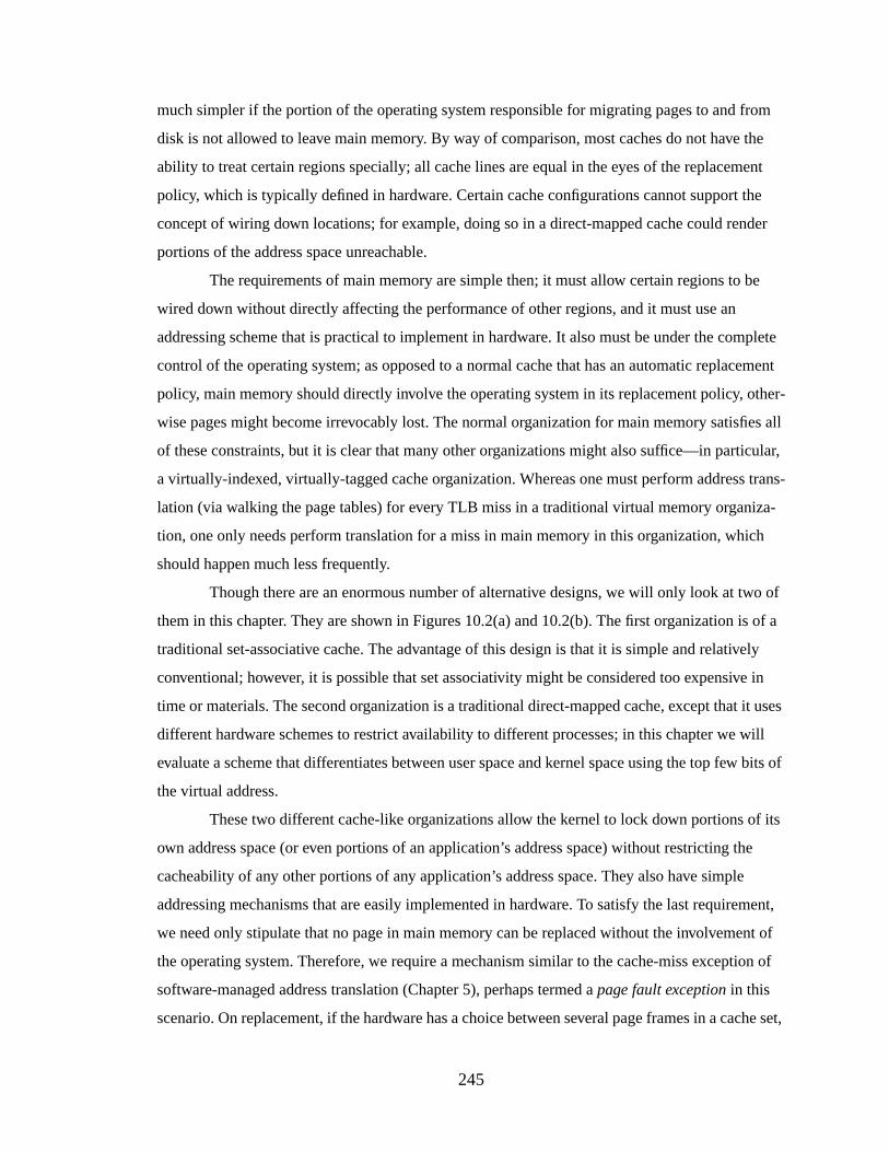
245
much simpler if the portion of the operating system responsible for migrating pages to and from
disk is not allowed to leave main memory. By way of comparison, most caches do not have the
ability to treat certain regions specially; all cache lines are equal in the eyes of the replacement
policy, which is typically defined in hardware. Certain cache configurations cannot support the
concept of wiring down locations; for example, doing so in a direct-mapped cache could render
portions of the address space unreachable.
The requirements of main memory are simple then; it must allow certain regions to be
wired down without directly affecting the performance of other regions, and it must use an
addressing scheme that is practical to implement in hardware. It also must be under the complete
control of the operating system; as opposed to a normal cache that has an automatic replacement
policy, main memory should directly involve the operating system in its replacement policy, other-
wise pages might become irrevocably lost. The normal organization for main memory satisfies all
of these constraints, but it is clear that many other organizations might also suffice—in particular,
a virtually-indexed, virtually-tagged cache organization. Whereas one must perform address trans-
lation (via walking the page tables) for every TLB miss in a traditional virtual memory organiza-
tion, one only needs perform translation for a miss in main memory in this organization, which
should happen much less frequently.
Though there are an enormous number of alternative designs, we will only look at two of
them in this chapter. They are shown in Figures 10.2(a) and 10.2(b). The first organization is of a
traditional set-associative cache. The advantage of this design is that it is simple and relatively
conventional; however, it is possible that set associativity might be considered too expensive in
time or materials. The second organization is a traditional direct-mapped cache, except that it uses
different hardware schemes to restrict availability to different processes; in this chapter we will
evaluate a scheme that differentiates between user space and kernel space using the top few bits of
the virtual address.
These two different cache-like organizations allow the kernel to lock down portions of its
own address space (or even portions of an application’s address space) without restricting the
cacheability of any other portions of any application’s address space. They also have simple
addressing mechanisms that are easily implemented in hardware. To satisfy the last requirement,
we need only stipulate that no page in main memory can be replaced without the involvement of
the operating system. Therefore, we require a mechanism similar to the cache-miss exception of
software-managed address translation (Chapter 5), perhaps termed apage fault exception in this
scenario. On replacement, if the hardware has a choice between several page frames in a cache set,
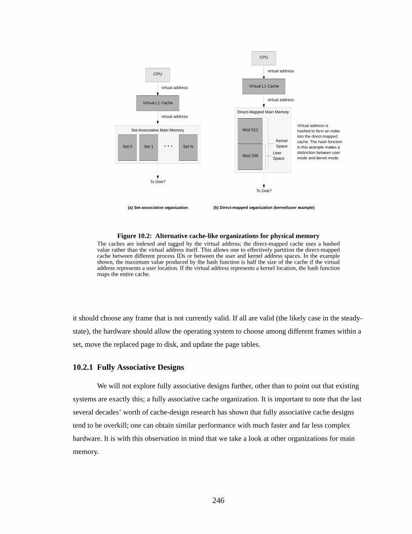
246
it should choose any frame that is not currently valid. If all are valid (the likely case in the steady-
state), the hardware should allow the operating system to choose among different frames within a
set, move the replaced page to disk, and update the page tables.
10.2.1 Fully Associative Designs
We will not explore fully associative designs further, other than to point out that existing
systems are exactly this; a fully associative cache organization. It is important to note that the last
several decades’ worth of cache-design research has shown that fully associative cache designs
tend to be overkill; one can obtain similar performance with much faster and far less complex
hardware. It is with this observation in mind that we take a look at other organizations for main
memory.
Figure 10.2: Alter native cache-like organizations for physical memoryThe caches are indexed and tagged by the virtual address; the direct-mapped cache uses a hashedvalue rather than the virtual address itself. This allows one to effectively partition the direct-mappedcache between different process IDs or between the user and kernel address spaces. In the exampleshown, the maximum value produced by the hash function is half the size of the cache if the virtualaddress represents a user location. If the virtual address represents a kernel location, the hash functionmaps the entire cache.
CPU
Virtual L1 Cache
To Disk?
Set 0 Set 1 Set N. . .
Set-Associative Main Memory
Mod 256
Mod 512
Direct-Mapped Main Memory
KernelSpace
UserSpace
CPU
Virtual L1 Cache
To Disk?
(a) Set-associative or ganization (b) Direct-mapped or ganization (kernel/user e xample)
virtual address
virtual address
virtual address
virtual address
Virtual address ishashed to form an indexinto the direct-mappedcache. The hash functionin this example makes adistinction between usermode and kernel mode.
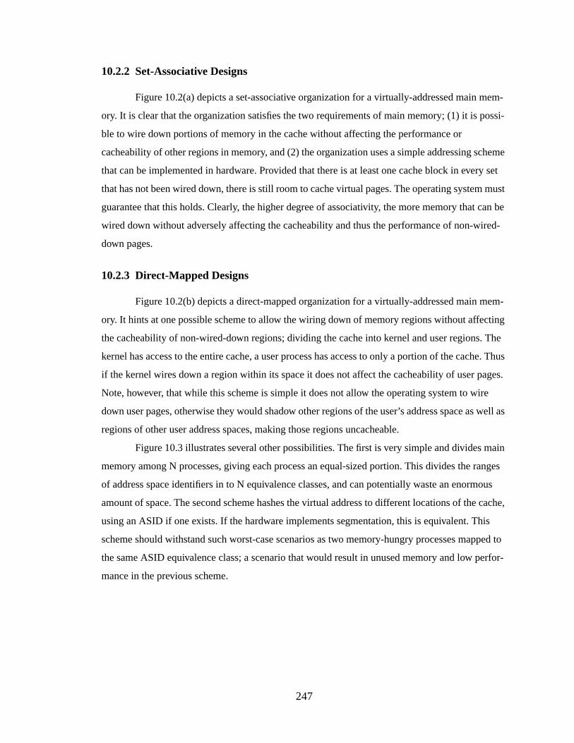
247
10.2.2 Set-Associative Designs
Figure 10.2(a) depicts a set-associative organization for a virtually-addressed main mem-
ory. It is clear that the organization satisfies the two requirements of main memory; (1) it is possi-
ble to wire down portions of memory in the cache without affecting the performance or
cacheability of other regions in memory, and (2) the organization uses a simple addressing scheme
that can be implemented in hardware. Provided that there is at least one cache block in every set
that has not been wired down, there is still room to cache virtual pages. The operating system must
guarantee that this holds. Clearly, the higher degree of associativity, the more memory that can be
wired down without adversely affecting the cacheability and thus the performance of non-wired-
down pages.
10.2.3 Dir ect-Mapped Designs
Figure 10.2(b) depicts a direct-mapped organization for a virtually-addressed main mem-
ory. It hints at one possible scheme to allow the wiring down of memory regions without affecting
the cacheability of non-wired-down regions; dividing the cache into kernel and user regions. The
kernel has access to the entire cache, a user process has access to only a portion of the cache. Thus
if the kernel wires down a region within its space it does not affect the cacheability of user pages.
Note, however, that while this scheme is simple it does not allow the operating system to wire
down user pages, otherwise they would shadow other regions of the user’s address space as well as
regions of other user address spaces, making those regions uncacheable.
Figure 10.3 illustrates several other possibilities. The first is very simple and divides main
memory among N processes, giving each process an equal-sized portion. This divides the ranges
of address space identifiers in to N equivalence classes, and can potentially waste an enormous
amount of space. The second scheme hashes the virtual address to different locations of the cache,
using an ASID if one exists. If the hardware implements segmentation, this is equivalent. This
scheme should withstand such worst-case scenarios as two memory-hungry processes mapped to
the same ASID equivalence class; a scenario that would result in unused memory and low perfor-
mance in the previous scheme.
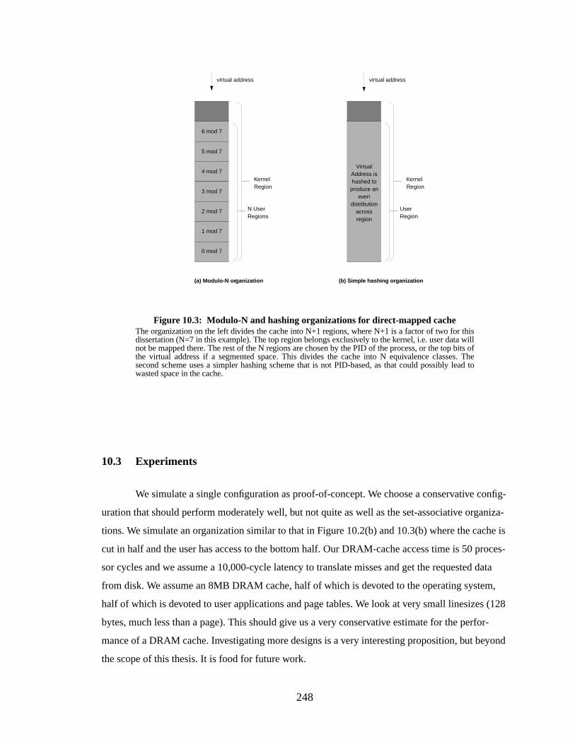
248
10.3 Experiments
We simulate a single configuration as proof-of-concept. We choose a conservative config-
uration that should perform moderately well, but not quite as well as the set-associative organiza-
tions. We simulate an organization similar to that in Figure 10.2(b) and 10.3(b) where the cache is
cut in half and the user has access to the bottom half. Our DRAM-cache access time is 50 proces-
sor cycles and we assume a 10,000-cycle latency to translate misses and get the requested data
from disk. We assume an 8MB DRAM cache, half of which is devoted to the operating system,
half of which is devoted to user applications and page tables. We look at very small linesizes (128
bytes, much less than a page). This should give us a very conservative estimate for the perfor-
mance of a DRAM cache. Investigating more designs is a very interesting proposition, but beyond
the scope of this thesis. It is food for future work.
Figure 10.3: Modulo-N and hashing organizations for dir ect-mapped cacheThe organization on the left divides the cache into N+1 regions, where N+1 is a factor of two for thisdissertation (N=7 in this example). The top region belongs exclusively to the kernel, i.e. user data willnot be mapped there. The rest of the N regions are chosen by the PID of the process, or the top bits ofthe virtual address if a segmented space. This divides the cache into N equivalence classes. Thesecond scheme uses a simpler hashing scheme that is not PID-based, as that could possibly lead towasted space in the cache.
(b) Simple hashing or ganization
virtual address
KernelRegion
N UserRegions
(a) Modulo-N or ganization
virtual address
0 mod 7
1 mod 7
2 mod 7
3 mod 7
4 mod 7
5 mod 7
6 mod 7
KernelRegion
UserRegion
VirtualAddress ishashed to
produce aneven
distributionacrossregion
249
The graphs in Figure 10.4 plot the performance of such a DRAM cache. They show that
the memory management is a small portion of the overall cost, and that for a bare-bones system
with a pitifully small main memory, the system performs acceptably well (well enough for a low-
cost system). Thus, the organization warrants further study.
10.4 Conclusions
It is possible to build low-cost systems that perform acceptably well, organizing main
memory as a virtual cache. The memory-management overhead does not grow to enormous pro-
portions as might be expected: 0.05 CPI is very low, even for a high-performance system. This
result suggests that the virtual-cache organization of main memory is worth further study. As dis-
cussed in detail in Section 6.4, the use of a software-oriented memory-management scheme should
allow one to obtain the same performance as a hardware-oriented scheme, but with a hardware
savings of 20-30%.
1 2 4 8 16 32 64 128L1 Cache Size - per side (KB)
0
5
10
15
20
25
30
Ove
rhea
d (C
PI)
Figure 10.4: The VM-overhead of the DRAM cache: GCC/alphaThis plots the performance of different Level-1 cache configurations with a DRAM main-memorycache. The graph on the left shows the total memory-system CPI, the graph on the right shows thecomponent due to memory management. The cost of memory management is no more than 10% ofthe total. Though the MCPI figures look high, this represents a bare-bones system with not enoughmemory to hold the entire program (previous measurements ignored the effects of missing mainmemory). When this is taken into account, the scheme actually has respectable performance.
1 2 4 8 16 32 64 128L1 Cache Size - per side (KB)
0.00
0.05
0.10
0.15
0.20
Ove
rhea
d (C
PI)
L1 cache linesize 16 bytesL1 cache linesize 32 bytesL1 cache linesize 64 bytesL1 cache linesize 128 bytes
MCPI overhead Virtual-memory overhead
L1 cache linesize 16 bytesL1 cache linesize 32 bytesL1 cache linesize 64 bytesL1 cache linesize 128 bytes
250
CHAPTER 11
CONCLUSIONS
The memory management unit is a hardware-oriented structure, for which one sacrifices
chip area, flexibility , and possibly clock speed to perform a certain set of functions (address trans-
lation, process protection, and memory sharing) in hardware. This is a good tradeoff when the cost
of executing system-level functions out of the memory hierarchy is high.
We have reached a point in time where the cost of executing system-level functions out of
the memory hierarchy is no longer high; the caches today are large and cheap, as are the DRAM
chips used for main memory. Memory systems are thus large enough to withstand the competition
between user-level code and system-level code, making the hardware-oriented tradeoff look less
inviting.
A software-oriented system dispenses with special-purpose hardware and instead imple-
ments the same functions in software. In such a scheme, one sacrifices performance to gain sim-
plicity of design, flexibility , and possibly clock speed. The prevalence of software-managed TLBs
in today’s microprocessor market is testimony to the usefulness of gaining simplicity and flexibil-
ity at a small cost in performance.
This dissertation has shown that the increase in memory-management overhead is not
large when moving from a hardware-oriented memory management system to a software-oriented
one, and that the software scheme uses less hardware to achieve the same overall performance as a
hardware scheme. Moreover, the gain in flexibility is substantial; the mechanisms and granularities
for all aspects of memory management are almost entirely defined in software (the exception is the
size of the superpage as superpages are still handled in hardware). This software-oriented organi-
zation benefits multiprocessor designs, real-time systems, and architecture emulation systems.
In this dissertation, we have proposed a model for software-oriented memory management
design. Its primary features are a virtual cache hierarchy and a cache-miss interrupt raised when a
memory reference misses the lowest-level cache in the hierarchy. The virtually-indexed, virtually-
251
tagged cache hierarchy replaces the traditional TLB found in hardware-oriented schemes; when-
ever a reference is found in the cache hierarchy, no translation is needed. The cache-miss interrupt
replaces the page-table-walking finite state machine found in many architectures. The operating
system must walk the page table when a reference misses the Level-2 cache; when such a miss
occurs, a cache-miss interrupt wakes the operating system.
There are a number of benefits to be gained by eliminating the TLB; the performance of
the system can increase, the amount of chip real estate needed can be reduced, and the elimination
of the TLB makes the system much more flexible.
Performance. Compared to hardware schemes that use two 128-entry fully associative TLBs,
the software scheme has roughly the same performance. The cold-cache overhead is
roughly twice that of the other schemes, indicating that it has a tougher time bringing data
into cold caches. When all things are considered, including the cost of Level-1 and Level-2
cache misses, all the schemes are roughly similar. However, compared to hardware schemes
that use two 64-entry TLBs, which are much more prevalent in today’s processors and are
easier to build, a software scheme can have a virtual-memory performance that is up to five
times better. When the effects of cold-cache start-up are included, the software scheme is
only twice as fast as other VM-simulations; the total difference when all sources of mem-
ory-CPI are included is roughly 5-10%. This is pictured in Figure 11.1, which shows the
overheads for GCC and VORTEX, using cache/TLB configurations of split 8KB/8KB and
128KB/128KB Level-1 caches with 64-byte linesizes, split 2MB/2MB Level-2 caches with
128-byte linesizes, and split 64/64-entry fully associative TLBs. Moreover, we have shown
that the virtual-memory performance of hardware-oriented schemes is highly sensitive to
the size of the TLB; eliminating the TLB may make the performance of the system more
predictable.
Die area (for some designs).When the Level-1 caches are small, the size of the TLB is impor-
tant, because a large TLB is roughly the size of a small Level-1 cache. When the Level-1
caches are small (below 128KB each), the elimination of the TLB significantly impacts the
total die area, allowing the software scheme to use less total hardware even though a virtual
cache is slightly larger than a physical cache of the same storage capacity. One can achieve
the same performance with a software-oriented design as a hardware-oriented design that is
20-30% larger in die area when the Level-1 caches are small. This is very significant for
small, space-conscious designs such as found in embedded systems (those that use caches).
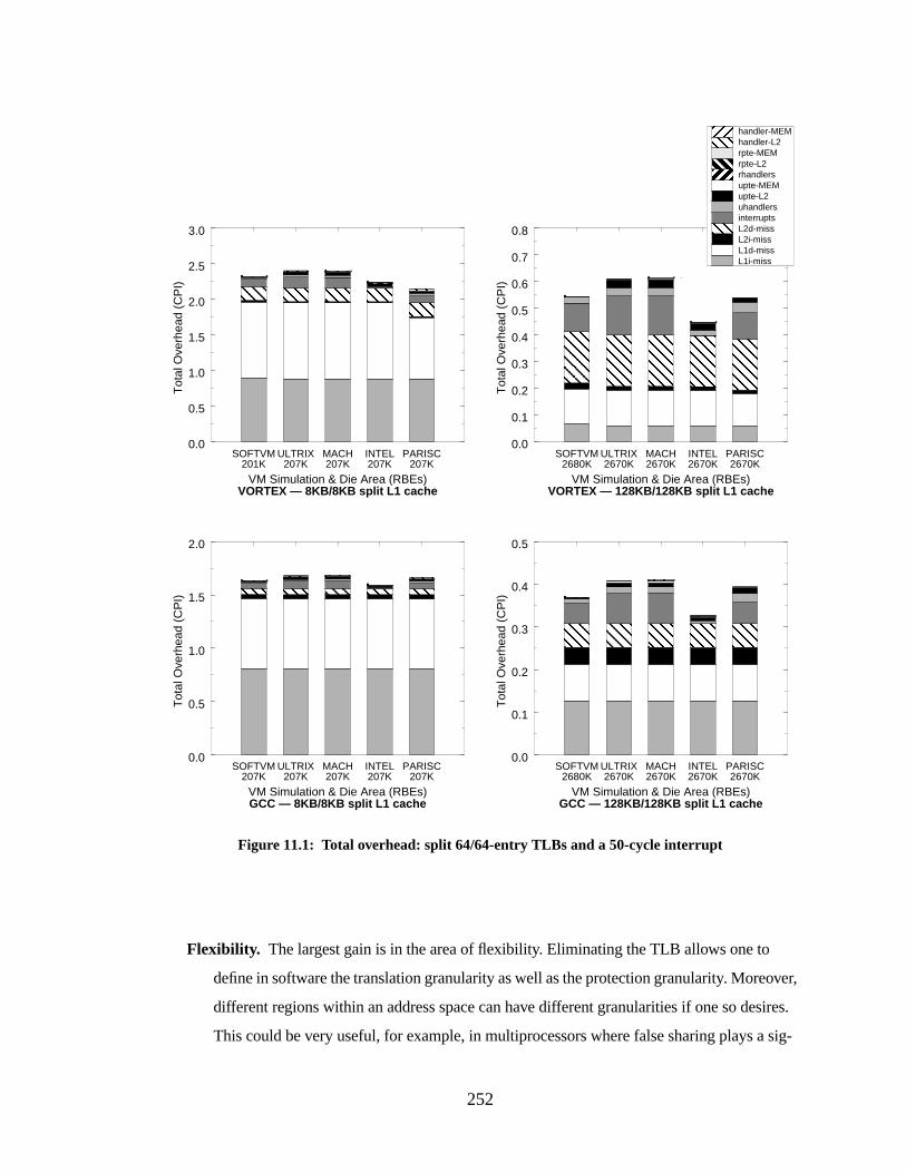
252
Flexibility . The largest gain is in the area of flexibility. Eliminating the TLB allows one to
define in software the translation granularity as well as the protection granularity. Moreover,
different regions within an address space can have different granularities if one so desires.
This could be very useful, for example, in multiprocessors where false sharing plays a sig-
0.0
0.1
0.2
0.3
0.4
0.5
0.6
0.7
0.8
Tot
al O
verh
ead
(CP
I)
0.0
0.5
1.0
1.5
2.0
2.5
3.0
Tot
al O
verh
ead
(CP
I)
Figure 11.1: Total overhead: split 64/64-entry TLBs and a 50-cycle interrupt
L1i-missL1d-missL2i-missL2d-missinterruptsuhandlersupte-L2upte-MEMrhandlersrpte-L2rpte-MEMhandler-L2handler-MEM
SOFTVM ULTRIX MACH INTEL PARISC
SOFTVM ULTRIX MACH INTEL PARISCSOFTVM ULTRIX MACH INTEL PARISC
SOFTVM ULTRIX MACH INTEL PARISC
VM Simulation & Die Area (RBEs)VORTEX — 8KB/8KB split L1 cache
201K 207K 207K 207K 207K
VM Simulation & Die Area (RBEs)VORTEX — 128KB/128KB split L1 cache
2670K2670K2670K2670K2680K
VM Simulation & Die Area (RBEs)GCC — 8KB/8KB split L1 cache
207K207K207K207K207K
VM Simulation & Die Area (RBEs)GCC — 128KB/128KB split L1 cache
2670K2670K2670K2670K2680K
0.0
0.5
1.0
1.5
2.0
Tot
al O
verh
ead
(CP
I)
0.0
0.1
0.2
0.3
0.4
0.5
Tot
al O
verh
ead
(CP
I)

253
nificant role in limiting performance. A software-oriented design allows one to translate and
protect addressable units as small as a cache line. The software-oriented scheme is also a
proof-of-concept for software-managed caches; this is good news for real-time systems.
Real-time systems have traditionally forgone the use of caches to simplify the timing analy-
sis of performing system functions. If the caches are totally under the control of the operat-
ing system (i.e. all replacement in the cache is done by the operating system), then portions
of the real-time system can be cached without fear of replacement. Lastly, the software-ori-
ented scheme is a least-common-denominator of memory-management hardware, and
should therefore be a good tool for emulating the memory-management hardware of other
architectures.
There are also some disadvantages of removing the TLB. These include a loss of perfor-
mance from systems with very large TLBs or very small Level-2 caches, the fact that the system is
highly sensitive to TLB organization, and an increased overhead for multimedia-type applications.
Performance (for some designs).When the TLBs are very large (larger than a 128-entry I-
TLB and a 128-entry D-TLB), they have very good performance, though they might be
power-hungry or might severely constrain clock speed. We have shown that the software
scheme performs similarly to a hardware scheme with two 128-entry TLBs, therefore larger
TLBs will have much less overhead than the software scheme. This is also the case when
the Level-2 cache is too small to handle the software scheme; if there are too many Level-2
cache misses, one spends most of the time walking the page table. We have found that a
split 2MB Level-2 cache (1MB on each side) has an acceptable hit rate, and larger Level-2
caches are even better.
Sensitivity. While the hardware schemes are extremely sensitive to the size of the TLBs, the
software scheme is highly sensitive to the choice of Level-1 and Level-2 cache line sizes.
Fortunately, there is an obvious trend to follow so that one does not incur needlessly high
overheads: larger linesizes tend to perform significantly better than smaller linesizes.
Multimedia. We have shown that without the use of superpages, a software scheme performs
15-20 times worse than a hardware scheme on multimedia-type applications. This tends to
be only a small fraction of the overall performance degradation (cache misses on multime-
dia-type applications tend to be quite high); for instance, memory-management on
STREAM added roughly 15% to the total for the software scheme but only 1% to the total
254
for the hardware scheme. We have shown that the use of superpages reduces this overhead
significantly; nonetheless, without such support the elimination of the TLB results in dra-
matic increases in memory-management overhead.
The software-oriented system also raises several issues in the areas of virtual caches, inter-
rupt handling, multimedia support, and cost. We have discussed these issues and have proposed
solutions for any inherent problems. We have shown that segmentation solves the problem of large
virtually-addressed caches, and that a segment cache may be an attractive alternative to a TLB; it
can be made smaller (and therefore faster and lower-power) and yet still have a higher hit ratio—
when combined with software-managed address translation it yields the same or better perfor-
mance compared to a TLB system. We have discussed an alternative to precise interrupts for han-
dling the (potentially) costly overhead of taking an interrupt; relaxed-precision interrupts will
maintain program integrity as if they were precise interrupts, and they have roughly 10% of the
performance overhead. This is important, as we have shown that the cost of taking an interrupt is a
substantial portion of the memory-management overhead for designs similar to today’s out-of-
order microprocessors. We have shown that the use of superpages to map multimedia data struc-
tures (or any large data structures, for that matter) can reduce the cost of the memory-management
system substantially. And we have discussed alternative organizations of physical memory that can
reduce the cost of a software-oriented scheme.
As we move to larger caches, the overhead of memory management becomes significant.
With large caches and medium-sized TLBs, the overhead of memory management approaches
40% for well-behaved applications (bear in mind that our simulations did not include disk activity
and so should be optimistic compared to measurements of actual systems). Even with very large
TLBs (256-entry, split 128/128), the memory management overhead is high—assuming large
caches, the overhead is around 10%. We have shown that with large caches, the software-oriented
scheme tends to perform as well as or better than hardware schemes, and can reduce overhead by
as much as 20% over hardware schemes with the same size caches. With small caches, the size of
the TLBs becomes a serious issue; a large TLB is roughly the same size as a small cache. Elimi-
nating the TLBs in favor of a software-oriented design can yield roughly the same performance at
a 20-30% reduction in die area requirements.
The bottom line is that the software-oriented scheme does exactly what we set out to do:
we have demonstrated that it is possible to remove the TLB without incurring significant perfor-
mance overheads. Doing so makes the system simpler, smaller, possibly faster, and much more
flexible.
255
APPENDIX
256
APPENDIX A
ORDERS OF MAGNITUDE
This appendix lists the prefixes for the data-unit powers of ten as well as their origins and
some humorous discussion on the topic. It is included primarily for comedic value, and also
because I always forget what comes after terabytes.
Data Powers of Ten (Stolen from Roy Williams [Williams 1997])
The following list is a collection of estimates of the quantities of data contained by the var-
ious media. Each is rounded to be a power of 10 times 1, 2 or 5. Most of the links are to small
images. Suggestions and contributions are welcomed, especially picture files or pointers to pic-
tures, and disagreements are accepted [email protected].
The numbers quoted are approximate. In fact a kilobyte is 1024 bytes not 1000 bytes but
this fact does not keep me awake at night.
Byte (8 bits).
0.1 bytes: A binary decision
1 byte: A single character
10 bytes: A single word
100 bytes: A telegramOR A punched card
Kilobyte (1000 bytes).
1 Kilobyte: A very short story
2 Kilobytes: A Typewritten page
10 Kilobytes: An encyclopaedic pageOR A deck of punched cards
50 Kilobytes: A compressed document image page
100 Kilobytes: A low-resolution photograph
200 Kilobytes: A box of punched cards
500 Kilobytes: A very heavy box of punched cards
Megabyte (1 000 000 bytes).
1 Megabyte: A small novel OR A 3.5 inch floppy disk
2 Megabytes: A high resolution photograph
257
5 Megabytes: The complete works of ShakespeareOR 30 seconds of TV-quality video
10 Megabytes: A minute of high-fidelity soundOR A digital chest X-ray
20 Megabytes: A box of floppy disks
50 Megabytes: A digital mammogram
100 Megabytes: 1 meter of shelved booksOR A two-volume encyclopaedic book
500 Megabytes: A CD-ROM OR The hard disk of a PC
Gigabyte (1 000 000 000 bytes).
1 Gigabyte: A pickup truck filled with paperOR A symphony in high-fidelity soundOR
A movie at TV quality
2 Gigabytes: 20 meters of shelved booksOR A stack of 9-track tapes
5 Gigabytes: An 8mm Exabyte tape
10 Gigabytes:
20 Gigabytes: A good collection of the works of BeethovenOR 5 Exabyte tapesOR A
VHS tape used for digital data
50 Gigabytes: A floor of booksOR Hundreds of 9-track tapes
100 Gigabytes: A floor of academic journalsOR A large ID-1 digital tape
200 Gigabytes: 50 Exabyte tapes
Terabyte (1 000 000 000 000 bytes).
1 Terabyte: An automated tape robotOR All the X-ray films in a large technological hos-
pital OR 50000 trees made into paper and printedOR Daily rate of EOS data (1998)
10 Terabytes: The printed collection of the US Library of Congress
50 Terabytes: The contents of a large Mass Storage System
Petabyte (1 000 000 000 000 000 bytes).
1 Petabyte: 3 years of EOS data (2001)
2 Petabytes: All US academic research libraries
20 Petabytes: Production of hard-disk drives in 1995
200 Petabytes: All printed materialOR Production of digital magnetic tape in 1995
Exabyte (1 000 000 000 000 000 000 bytes).
5 Exabytes: All words ever spoken by human beings.
Zettabyte (1 000 000 000 000 000 000 000 bytes).
Yottabyte (1 000 000 000 000 000 000 000 000 bytes).
258
Etymology of Units (Stolen by Roy Williams from PC Harihan)
Kilo. Greekkhilioi = 1000
Mega. Greekmegas = great, e.g., Alexandros Megos
Giga. Latin gigas = giant
Tera. Greekteras = monster
Peta. Greekpente = five, fifth prefix, peNta - N = peta
Exa. Greekhex = six, sixth prefix, Hexa - H = exa
Remember, in standard French, the initial H is silent, so they would pronounce Hexa as Exa.
It is far easier to call it Exa for everyone’s sake, right?
Zetta. Almost homonymic with GreekZeta, but last letter of the Latin alphabet
Yotta. Almost homonymic with Greekiota, but penultimate letter of the Latin alphabet
The first prefix is number-derived; second, third, and fourth are based on mythology. Fifth
and sixth are supposed to be just that: fifth and sixth. But, with the seventh, another fork has been
taken. The General Conference of Weights and Measures (CGMP, from the French; they have been
headquartered, since 1874, in Sevres on the outskirts of Paris) has now decided to name the pre-
fixes, starting with the seventh, with the letters of the Latin alphabet, but starting from the end.
Now, that makes it all clear! Remember, both according to CGMP and SI, the prefixes refer to
powers of 10. Mega is 106, exactly 1,000,000; kilo is exactly 1000, not 1024.
End ofEtymology of Units 101.
You might also like to check outThe Peta Principle, by Jim Binder, of the San Diego
Supercomputer Center, and read the following extract fromThe Jargon File, which suggests aban-
doning greek letters and using the names of the Marx Brothers instead.
Quantifiers, from The Jargon File [Raymond 1997]
In techspeak and jargon, the standard metric prefixes used in the SI (Système Interna-
tional) conventions for scientific measurement have dual uses. With units of time or things that
come in powers of 10, such as money, they retain their usual meanings of multiplication by powers
259
of 1000 = 103. But when used with bytes or other things that naturally come in powers of 2, they
usually denote multiplication by powers of 1024 = 210.
Here are the SI magnifying prefixes, along with the corresponding binary interpretations
in common use:
Here are the SI fractional prefixes:
The prefixes zetta-, yotta-, zepto-, and yocto- have been included in these tables purely for
completeness and giggle value; they were adopted in 1990 by the ‘19th Conference Generale des
Poids et Mesures’. The binary peta- and exa- loadings, though well established, are not in jargon
use either — yet. The prefix milli-, denoting multiplication by 1/1000, has always been rare in jar-
Prefix Decimal Binary
kilo- 10001 10241 = 210 = 1,024
mega- 10002 10242 = 220 = 1,048,576
giga- 10003 10243 = 230 = 1,073,741,824
tera- 10004 10244 = 240 = 1,099,511,627,776
peta- 10005 10245 = 250 = 1,125,899,906,842,624
exa- 10006 10246 = 260 = 1,152,921,504,606,846,976
zetta- 10007 10247 = 270 = 1,180,591,620,717,411,303,424
yotta- 10008 10248 = 280 = 1,208,925,819,614,629,174,706,176
Prefix Decimal Jargon Usage
milli- 1000-1 (seldom used in jargon)
micro- 1000-2 small or human-scale
nano- 1000-3 even smaller
pico- 1000-4 even smaller yet
femto- 1000-5 (not used in jargon—yet)
atto- 1000-6 (not used in jargon—yet)
zepto- 1000-7 (not used in jargon—yet)
yocto- 1000-8 (not used in jargon—yet)
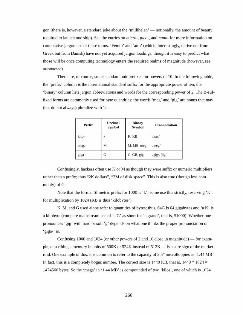
260
gon (there is, however, a standard joke about the ‘millihelen’ — notionally, the amount of beauty
required to launch one ship). See the entries onmicro-, pico-, andnano- for more information on
connotative jargon use of these terms. ‘Femto’ and ‘atto’ (which, interestingly, derive not from
Greek but from Danish) have not yet acquired jargon loadings, though it is easy to predict what
those will be once computing technology enters the required realms of magnitude (however, see
attoparsec).
There are, of course, some standard unit prefixes for powers of 10. In the following table,
the ‘prefix’ column is the international standard suffix for the appropriate power of ten; the
‘binary’ column lists jargon abbreviations and words for the corresponding power of 2. The B-suf-
fixed forms are commonly used for byte quantities; the words ‘meg’ and ‘gig’ are nouns that may
(but do not always) pluralize with ‘s’.
Confusingly, hackers often use K or M as though they were suffix or numeric multipliers
rather than a prefix; thus “2K dollars”, “2M of disk space”. This is also true (though less com-
monly) of G.
Note that the formal SI metric prefix for 1000 is ‘k’; some use this strictly, reserving ‘K’
for multiplication by 1024 (KB is thus ‘kilobytes’).
K, M, and G used alone refer to quantities of bytes; thus, 64G is 64 gigabytes and ‘a K’ is
a kilobyte (compare mainstream use of ‘a G’ as short for ‘a grand’, that is, $1000). Whether one
pronounces ‘gig’ with hard or soft ‘g’ depends on what one thinks the proper pronunciation of
‘giga-’ is.
Confusing 1000 and 1024 (or other powers of 2 and 10 close in magnitude) — for exam-
ple, describing a memory in units of 500K or 524K instead of 512K — is a sure sign of the market-
roid. One example of this: it is common to refer to the capacity of 3.5” microfloppies as ‘1.44 MB’
In fact, this is a completely bogus number. The correct size is 1440 KB, that is, 1440 * 1024 =
1474560 bytes. So the ‘mega’ in ‘1.44 MB’ is compounded of two ‘kilos’, one of which is 1024
PrefixDecimalSymbol
BinarySymbol
Pronunciation
kilo- k K, KB /kay/
mega- M M, MB, meg /meg/
giga- G G, GB, gig /gig/, /jig/
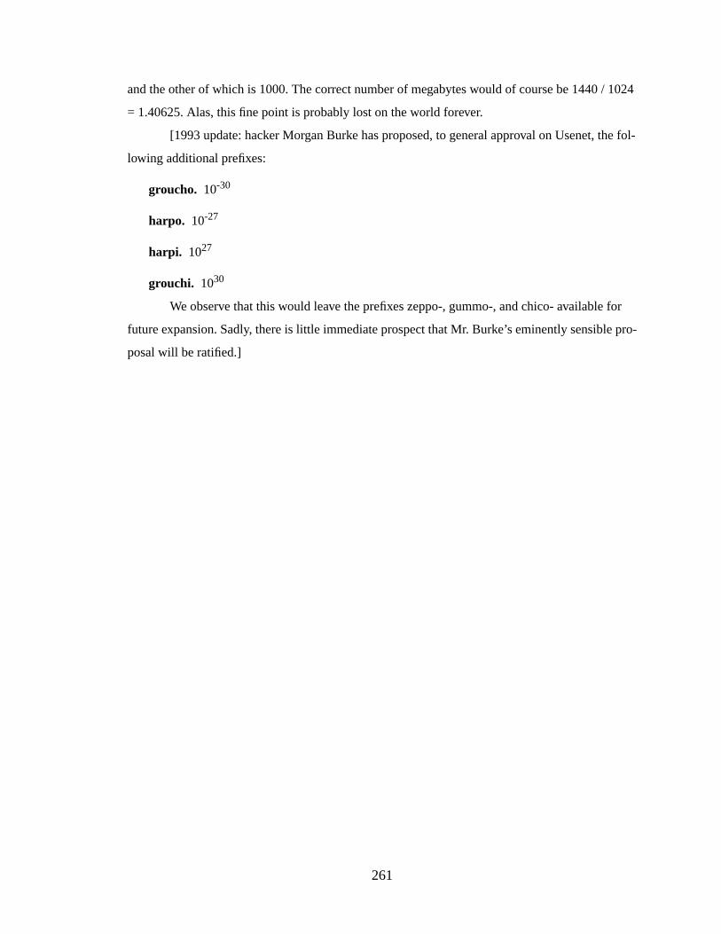
261
and the other of which is 1000. The correct number of megabytes would of course be 1440 / 1024
= 1.40625. Alas, this fine point is probably lost on the world forever.
[1993 update: hacker Morgan Burke has proposed, to general approval on Usenet, the fol-
lowing additional prefixes:
groucho. 10-30
harpo. 10-27
harpi. 1027
grouchi. 1030
We observe that this would leave the prefixes zeppo-, gummo-, and chico- available for
future expansion. Sadly, there is little immediate prospect that Mr. Burke’s eminently sensible pro-
posal will be ratified.]

262
BIBLIOGRAPHY
263
BIBLIOGRAPHY
M. Accetta, R.Baron, W.Bolosky, D.Golub, R.Rashid, A.Tevanian, and M.Young. 1986.“Mach: A new kernel foundation for UNIX development.” InUSENIX Technical Confer-ence Proceedings.
T. E. Anderson, H.M. Levy, B.N. Bershad, and E.D. Lazowska. 1991. “The interaction of archi-tecture and operating system design.” InProc. Fourth Int’l Conf. on Architectural Supportfor Programming Languages and Operating Systems (ASPLOS-4), pages 108–120.
A. W. Appel and K.Li. 1991. “Virtual memory primitives for user programs.” InProc. Fourth Int’lConf. on Architectural Support for Programming Languages and Operating Systems (AS-PLOS-4), pages 96–107.
Apple Computer, Inc. 1992.Technical Introduction to the Macintosh Family, 2nd Edition. Addi-son-Wesley Publishing Company, Reading MA.
M. J. Bach. 1986.The Design of the UNIX Operating System. Prentice-Hall, Inc., Englewood Cliffs,NJ.
K. Bala, M.F. Kaashoek, and W.E. Weihl. 1994. “Software prefetching and caching for translationlookaside buffers.” InProc. First USENIX Symposium on Operating Systems Design andImplementation (OSDI-1).
R. Balan and K.Gollhardt. 1992. “A scalable implementation of virtual memory HAT layer forshared memory multiprocessor machines.” InUSENIX Technical Conference Proceedings.
B. N. Bershad, C.Chambers, S.Eggers, C.Maeda, D.McNamee, P.Pardyak, S.Savage, and E.G.Sirer. 1994. “SPIN – an extensible microkernel for application-specific operating systemservices.” Technical Report 94-03-03, University of Washington.
B. Case. 1994a. “AMD unveils first superscalar 29K core.”Microprocessor Report, 8(14).
B. Case. 1994b. “x86 has plenty of performance headroom.”Microprocessor Report, 8(11).
A. Chang and M.F. Mergen. 1988. “801 storage: Architecture and programming.”ACM Transac-tions on Computer Systems, 6(1).
C. Chao, M.Mackey, and B.Sears. 1990. “Mach on a virtually addressed cache architecture.” InUSENIX Mach Workshop.
J.S. Chase, H.M. Levy, M. Baker-Harvey, and E.D. Lazowska. 1992a. “How to use a 64-bit vir-tual address space.” Technical Report 92-03-02, University of Washington.
J.S. Chase, H.M. Levy, E.D. Lazowska, and M.Baker-Harvey. 1992b. “Lightweight shared ob-jects in a 64-bit operating system.” Technical Report 92-03-09, University of Washington.
J.B. Chen, A.Borg, and N.P. Jouppi. 1992. “A simulation based study of TLB performance.” InProc. 19th Annual International Symposium on Computer Architecture (ISCA-19).
264
R. Cheng. 1987. “Virtual address cache in UNIX.” InProceedings of the Summer 1987 USENIXTechnical Conference.
D. R. Cheriton, H.A. Goosen, and P.D. Boyle. 1989. “Multi-level shared caching techniques forscalability in VMP-MC.” InProc. 16th Annual International Symposium on Computer Ar-chitecture (ISCA-16).
D. R. Cheriton, A.Gupta, P.D. Boyle, and H.A. Goosen. 1988. “The VMP multiprocessor: Initialexperience, refinements and performance evaluation.” InProc. 15th Annual InternationalSymposium on Computer Architecture (ISCA-15).
D. R. Cheriton, G.A. Slavenburg, and P.D. Boyle. 1986. “Software-controlled caches in the VMPmultiprocessor.” InProc. 13th Annual International Symposium on Computer Architecture(ISCA-13).
T. Chiueh and R.H. Katz. 1992. “Eliminating the address translation bottleneck for physical ad-dress caches.” InProc. Fifth Int’l Conf. on Architectural Support for Programming Lan-guages and Operating Systems (ASPLOS-5).
D. W. Clark and J.S. Emer. 1985. “Performance of the VAX-11/780 translation buffer: Simulationand measurement.”ACM Transactions on Computer Systems, 3(1).
R. Colwell, R.Nix, J.O’Donnell, D.Papworth, and P.Rodman. 1987. “A VLIW architecture for atrace scheduling compiler.” InProc. Second Int’l Conf. on Architectural Support for Pro-gramming Languages and Operating Systems (ASPLOS-2), pages 180–192.
H. Custer. 1993.Inside Windows NT. Microsoft Press, Redmond WA.
H. Deitel. 1990.Inside OS/2. Addison-Wesley, Reading MA.
P.J. Denning. 1970. “Virtual memory.”Computing Surveys, 2(3):153–189.
Digital. 1994.DECchip 21064 and DECchip 21064A Alpha AXP Microprocessors Hardware Ref-erence Manual. Digital Equipment Corporation, Maynard MA.
Digital. 1996.Digital Semiconductor 21164 (366 MHz Through 433 MHz) Alpha MicroprocessorHardware Reference Manual. Digital Equipment Corporation, Maynard MA.
Digital. 1997.DIGITAL FX!32. Digital Equipment Corp., http://www.digital.com/info/semicon-ductor/amt/fx32/fx.html.
P.Druschel and L.L. Peterson. 1993. “Fbufs: A high-bandwidth cross-domain transfer facility.” InProc. Fourteenth ACM Symposium on Operating Systems Principles (SOSP-14), pages189–202.
R. Duncan, C.Petzold, A.Schulman, M.S. Baker, R.P. Nelson, S.R. Davis, and R.Moote. 1994.Extending DOS – A Programmer’s Guide to Protected-Mode DOS, 2nd Edition. Addison-Wesley Publishing Company, Reading MA.
265
K. Ebcioglu and E.R. Altman. 1997. “DAISY: Dynamic compilation for 100% architectural com-patibility.” In Proc. 24th Annual International Symposium on Computer Architecture (IS-CA-24), pages 26–37, Denver CO.
D. Engler, R.Dean, A.Forin, and R.Rashid. 1994. “The operating system as a secure programma-ble machine.” InProc. 1994 European SIGOPS Workshop.
A. Eustace and A.Srivastava. 1994. “ATOM: A flexible interface for building high performanceprogram analysis tools.” Technical Report WRL-TN-44, DEC Western Research Labora-tory.
D. M. Gallagher, W.Y. Chen, S.A. Mahlke, J.C. Gyllenhaal, and W.mei W.Hwu. 1994. “Dy-namic memory disambiguation using the memory conflict buffer.” InProc. Sixth Int’lConf. on Architectural Support for Programming Languages and Operating Systems (AS-PLOS-6), San Jose CA.
W. E. Garrett, R.Bianchini, L.Kontothanassis, R.A. McCallum, J.Thomas, R.Wisniewski, andM. L. Scott. 1992. “Dynamic sharing and backward compatibility on 64-bit machines.”Technical Report TR 418, University of Rochester.
W. E. Garrett, M.L. Scott, R.Bianchini, L.I. Kontothanassis, R.A. McCallumm, J.A. Thomas,R. Wisniewski, and S.Luk. 1993. “Linking shared segments.” InUSENIX Technical Con-ference Proceedings.
J.R. Goodman. 1987. “Coherency for multiprocessor virtual address caches.” InProc. Second Int’lConf. on Architectural Support for Programming Languages and Operating Systems (AS-PLOS-2), pages 72–81.
L. Gwennap. 1994a. “MIPS R10000 uses decoupled architecture.”Microprocessor Report, 8(14).
L. Gwennap. 1994b. “PA-8000 combines complexity and speed.”Microprocessor Report, 8(15).
L. Gwennap. 1995a. “Intel’s P6 uses decoupled superscalar design.”Microprocessor Report, 9(2).
L. Gwennap. 1995b. “PA-8000 stays on track (sidebar in Integrated PA-7300LC powers HPmidrange).”Microprocessor Report, 9(15).
G. Hamilton and P.Kougiouris. 1993. “The Spring nucleus: A microkernel for objects.” InUS-ENIX Technical Conference Proceedings.
J.Heinrich, editor. 1995.MIPS R10000 Microprocessor User’s Manual, version 1.0. MIPS Tech-nologies, Inc., Mountain View CA.
J.L. Hennessy and D.A. Patterson. 1990.Computer Architecture: A Quantitative Approach. Mor-gan Kaufmann Publishers, Inc.
Hewlett-Packard. 1990.PA-RISC 1.1 Architecture and Instruction Set Reference Manual. Hewlett-Packard Company.
266
M. D. Hill, S. J. Eggers, J.R. Larus, G.S. Taylor, G.Adams, B.K. Bose, G.A. Gibson, P.M.Hansen, J.Keller, S.I. Kong, C.G. Lee, D.Lee, J.M. Pendleton, S.A. Ritchie, D.A.Wood, B.G. Zorn, P.N. Hilfinger, D.Hodges, R.H. Katz, J.K. Ousterhout, and D.A.Patterson. 1986. “Design Decisions in SPUR.”IEEE Computer, 19(11).
M. Horowitz, M.Martonosi, T.C. Mowry, and M.D. Smith. 1995. “Informing loads: Enablingsoftware to observe and react to memory behavior.” Technical Report CSL-TR-95-673,Stanford University.
A. S. Huang, G.Slavenberg, and J.P. Shen. 1994. “Speculative disambiguation: A compilationtechnique for dynamic memory disambiguation.” InProc. 21st Annual International Sym-posium on Computer Architecture (ISCA-21), Chicago IL.
J.Huck. 1996.Personal communication.
J.Huck and J.Hays. 1993. “Architectural support for translation table management in large addressspace machines.” InProc. 20th Annual International Symposium on Computer Architec-ture (ISCA-20).
W.-M. Hwu and Y.N. Patt. 1986. “HPSm, a high performance restricted data flow architecture hav-ing minimal functionality.” InProc. 13th Annual International Symposium on ComputerArchitecture (ISCA-13).
W.-M. W. Hwu and Y.N. Patt. 1987. “Checkpoint repair for out-of-order execution machines.” InProc. 14th Annual International Symposium on Computer Architecture (ISCA-14).
IBM and Motorola. 1993.PowerPC 601 RISC Microprocessor User’s Manual. IBM Microelec-tronics and Motorola.
IBM and Motorola. 1994.PowerPC 604 RISC Microprocessor User’s Manual. IBM Microelec-tronics and Motorola.
J. Inouye, R.Konuru, J.Walpole, and B.Sears. 1992. “The effects of virtually addressed caches onvirtual memory design and performance.” Technical Report CS/E 92-010, Oregon Gradu-ate Institute.
Intel. 1993.Pentium Processor User’s Manual. Intel Corporation, Mt. Prospect IL.
Intel. 1995.Pentium Pro Family Developer’s Manual, Volume 3: Operating System Writer’sGuide. Intel Corporation, Mt. Prospect IL.
B. L. Jacob and T.N. Mudge. 1996. “Specification of the PUMA memory management design.”Technical Report CSE-TR-314-96, University of Michigan.
B. L. Jacob and T.N. Mudge. 1997. “Software-managed address translation.” InProc. Third Inter-national Symposium on High Performance Computer Architecture (HPCA-3), San AntonioTX.
M. Johnson. 1991.Superscalar Microprocessor Design. Prentice-Hall Inc.

267
T. L. Johnson and W.-M.W. Hwu. 1997. “Run-time adaptive cache hierarchy management via ref-erence analysis.” InProc. 24th Annual International Symposium on Computer Architecture(ISCA-24), pages 315–326, Denver CO.
N. P. Jouppi. 1990. “Improving direct-mapped cache performance by the addition of a small fully-associative cache and prefetch buffers.” InProc. 17th Annual International Symposium onComputer Architecture (ISCA-17).
G. Kane. 1996.PA-RISC 2.0 Architecture. Prentice-Hall PTR, Upper Saddle River NJ.
G. Kane and J.Heinrich. 1992.MIPS RISC Architecture. Prentice-Hall, Englewood Cliffs NJ.
Y. A. Khalidi and M.Talluri. 1995. “Improving the address translation performance of widelyshared pages.” Technical Report SMLI TR-95-38, Sun Microsystems.
Y. A. Khalidi, M. Talluri, M. N. Nelson, and D.Williams. 1993. “Virtual memory support for mul-tiple page sizes.” InProc. Fourth Workshop on Workstation Operating Systems.
D. E. Knuth. 1973.The Art of Computer Programming–Volume 3 (Sorting and Searching). Addi-son-Wesley.
D. Kroft. 1981. “Lockup-free instruction fetch/prefetch cache organization.” InProc. 8th AnnualInternational Symposium on Computer Architecture (ISCA-8), Minneapolis MN.
A. Kumar. 1996. “The HP PA-8000 RISC CPU: A high performance out-of-order processor.” InHot Chips 8: A Symposium on High-Performance Chips, http://infopad.eecs.berkeley.edu/HotChips8/, Stanford CA.
S.J. Leffler, M.K. McKusick, M.J. Karels, and J.S. Quarterman. 1989.The Design and Imple-mentation of the 4.3BSD UNIX Operating System. Addison-Wesley Publishing Company.
J.Liedtke. 1993. “Improving IPC by kernel design.” InProc. Fourteenth ACM Symposium on Op-erating Systems Principles (SOSP-14), pages 175–187.
J.Liedtke. 1995a. “Address space sparsity and fine granularity.”ACM Operating Systems Review,29(1):87–90.
J.Liedtke. 1995b. “On micro-kernel construction.” InProc. Fifteenth ACM Symposium on Operat-ing Systems Principles (SOSP-15).
J.Liedtke and K.Elphinstone. 1996. “Guarded page tables on MIPS R4600.”ACM Operating Sys-tems Review, 30(1):4–15.
C. May, E.Silha, R.Simpson, and H.Warren, editors 1994.The PowerPC Architecture: A Speci-fication for a New Family of RISC Processors. Morgan Kaufmann Publishers, San Fran-cisco CA.
J.Mitchell, J.Gibbons, G.Hamilton, P.Kessler, Y.Khalidi, P.Kougiouris, P.Madany, M.Nelson,M. Powell, and S.Radia. 1994. “An overview of the Spring system.” InProceedings ofIEEE Compcon.
268
J.E. B. Moss. 1992. “Working with persistent objects: To swizzle or not to swizzle.”IEEE Trans-actions on Software Engineering, 18(8):657–673.
J.M. Mulder, N.T. Quach, and M.J. Flynn. 1991. “An area model for on-chip memories and itsapplication.”IEEE Journal of Solid-State Circuits, 26(2):98–106.
D. Nagle. 1995.Personal communication.
D. Nagle, R.Uhlig, T. Mudge, and S.Sechrest. 1994. “Optimal Allocation of On-Chip Memory forMultiple-API Operating Systems.” InProceedings of the 1994 International Symposium onComputer Architecture.
D. Nagle, R.Uhlig, T. Stanley, S.Sechrest, T.Mudge, and R.Brown. 1993. “Design tradeoffs forsoftware-managed TLBs.” InProc. 20th Annual International Symposium on ComputerArchitecture (ISCA-20).
R. Nair. “xprof/xtrace – an RS/6000 Xwindows-based tracing and profiling package.” Technical re-port, IBM T. J. Watson Research Lab.
R. Nair. 1996. “Profiling IBM RS/6000 applications.”International Journal in Computer Simula-tion, 6(1):101–112.
R. Nair and M.E. Hopkins. 1997. “Exploiting instruction level parallelism in processors by cachingscheduled groups.” InProc. 24th Annual International Symposium on Computer Architec-ture (ISCA-24), pages 13–25, Denver CO.
A. Nicolau. 1989. “Run-time disambiguation: Coping with statically unpredictable dependencies.”IEEE Transactions on Computers, 38(5):663–678.
E. I. Organick. 1972.The Multics System: An Examination of its Structure. The MIT Press, Cam-bridge MA.
A. R. Pleszkun, J.R. Goodman, W.-C. Hsu, R.T. Joersz, G.Bier, P.Woest, and P.B. Schechter.1987. “WISQ: A restartable architecture using queues.” InProc. 14th Annual InternationalSymposium on Computer Architecture (ISCA-14).
R. Rashid, A.Tevanian, M.Young, D.Young, R.Baron, D.Black, W.Bolosky, and J.Chew.1988. “Machine-independent virtual memory management for paged uniprocessor andmultiprocessor architectures.”IEEE Transactions on Computers, 37(8):896–908.
E. S. Raymond. 1997.The On-line Hacker Jargon File, version 4.0.0. The MIT Press, http://www.ccil.org/jargon/.
S.Reinhardt, M.Hill, J. Larus, A.Lebeck, J.Lewis, and D.Wood. 1993. “The Wisconsin WindTunnel: Virtual prototyping of parallel computers.” InProc. ACM SIGMETRICS Confer-ence on Measurement and Modeling of Computer Systems ’93.
S.A. Ritchie. 1985. “TLB for free: In-cache address translation for a multiprocessor workstation.”Technical Report UCB/CSD 85/233, University of California.
269
T. Roscoe. 1994. “Linkage in the Nemesis single address space operating system.”ACM OperatingSystems Review, 28(4):48–55.
T. Roscoe. 1995.The Structure of a Multi-Service Operating System. PhD thesis, Queens’ College,University of Cambridge.
M. Rosenblum, E.Bugnion, S.A. Herrod, E.Witchel, and A.Gupta. 1995. “The impact of archi-tectural trends on operating system performance.” InProc. Fifteenth ACM Symposium onOperating Systems Principles (SOSP-15).
M. L. Scott, T.J. LeBlanc, and B.D. Marsh. 1988. “Design rationale for Psyche, a general-purposemultiprocessor operating system.” InProc. 1988 International Conference on ParallelProcessing.
R. L. Sites, editor 1992.Alpha Architecture Reference Manual. Digital Equipment Corporation,Maynard MA.
M. Slater. 1994. “AMD’s K5 designed to outrun Pentium.”Microprocessor Report, 8(14).
A. J. Smith. 1982. “Cache memories.”Computing Surveys, 14(3):473–530.
J.E. Smith, G.E. Dermer, and M.A. Goldsmith. 1988.Computer System Employing Virtual Mem-ory. United States Patent Office, patent no. 4,774,659.
J.E. Smith and A.R. Pleszkun. 1988. “Implementing precise interrupts in pipelined processors.”IEEE Transactions on Computers, 37(5).
G. S. Sohi and S.Vajapeyam. 1987. “Instruction issue logic for high-performance, interruptablepipelined processors.” InProc. 14th Annual International Symposium on Computer Archi-tecture (ISCA-14).
A. Srivastava and A.Eustace. 1994. “ATOM: A system for building customized program analysistools.” Technical Report WRL-RR-94/2, DEC Western Research Laboratory.
STREAM. 1997.STREAM: Measuring Sustainable Memory Bandwidth in High PerformanceComputers. The University of Virginia, http://www.cs.virginia.edu/stream/.
Sun. 1997.Wabi 2.2 Product Overview. Sun Microsystems, http://www.sun.com/solaris/products/wabi/.
M. Talluri and M.D. Hill. 1994. “Surpassing the TLB performance of superpages with less operat-ing system support.” InProc. Sixth Int’l Conf. on Architectural Support for ProgrammingLanguages and Operating Systems (ASPLOS-6), San Jose CA.
M. Talluri, M. D. Hill, and Y.A. Khalidi. 1995. “A new page table for 64-bit address spaces.” InProc. Fifteenth ACM Symposium on Operating Systems Principles (SOSP-15).
M. Talluri, S.Kong, M.D. Hill, and D.A. Patterson. 1992. “Tradeoffs in supporting two page siz-es.” InProc. 19th Annual International Symposium on Computer Architecture (ISCA-19).
270
G. Taylor, P.Davies, and M.Farmwald. 1990. “The TLB slice – a low-cost high-speed addresstranslation mechanism.” InProc. 17th Annual International Symposium on Computer Ar-chitecture (ISCA-17).
J.Torrellas, A.Gupta, and J.Hennessy. 1992. “Characterizing the caching and synchronizationperformance of a multiprocessor operating system.” InProc. Fifth International Confer-ence on Architectural Support for Programming Languages and Operating Systems.
G. Tyson, M.Farrens, J.Matthews, and A.R. Pleszkun. 1995. “A modified approach to data cachemanagement.” InProc. 28th Annual International Symposium on Microarchitecture (MI-CRO-28), pages 93–103, Ann Arbor MI.
S.-Y. Tzou and D.P. Anderson. 1991. “The performance of message-passing using restricted vir-tual memory remapping.”Software—Practice and Experience, 21(3):251–267.
R. Uhlig, D. Nagle, T.Mudge, and S.Sechrest. 1994. “Trap-driven simulation with Tapeworm-II.”In Proc. Sixth Int’l Conf. on Architectural Support for Programming Languages and Op-erating Systems (ASPLOS-6), San Jose CA.
M. Upton. 1997.Personal communication.
R. Wahbe, S.Lucco, T.E. Anderson, and S.L. Graham. 1993. “Efficient software-based fault iso-lation.” InProc. Fourteenth ACM Symposium on Operating Systems Principles (SOSP-14),pages 203–216.
W.-H. Wang, J.-L. Baer, and H.M. Levy. 1989. “Organization and performance of a two-level vir-tual-real cache hierarchy.” InProc. 16th Annual International Symposium on ComputerArchitecture (ISCA-16), pages 140–148.
D. L. Weaver and T.Germand, editors. 1994.The SPARC Architecture Manual version 9. PTRPrentice Hall, Englewood Cliffs NJ.
S.Weiss and J.E. Smith. 1984. “Instruction issue login in pipelined supercomputers.”IEEE Trans-actions on Computers, 33(11).
S.Weiss and J.E. Smith. 1994.POWER and PowerPC. Morgan Kaufmann Publishers, San Fran-cisco CA.
B. Wheeler and B.N. Bershad. 1992. “Consistency management for virtually indexed caches.” InProc. Fifth Int’l Conf. on Architectural Support for Programming Languages and Operat-ing Systems (ASPLOS-5).
R. Williams. 1997.Data Powers of Ten. Center for Advanced Computing Research, Caltech, Pas-adena CA, http://www.cacr.caltech.edu/roy/dataquan/.
D. A. Wood. 1990.The Design and Evaluation of In-Cache Address Translation. PhD thesis, Uni-versity of California at Berkeley.
271
D. A. Wood, S.J. Eggers, G.Gibson, M.D. Hill, J. M. Pendleton, S.A. Ritchie, G.S. Taylor, R.H.Katz, and D.A. Patterson. 1986. “An in-cache address translation mechanism.” InProc.13th Annual International Symposium on Computer Architecture (ISCA-13).
K. C. Yeager. 1996. “The MIPS R10000 superscalar microprocessor.”IEEE Micro, pages 28–40.