a cap model for partially saturated soils
TRANSCRIPT
INTERNATIONAL JOURNAL FOR NUMERICAL AND ANALYTICAL METHODS IN GEOMECHANICSInt. J. Numer. Anal. Meth. Geomech. (2007)Published online in Wiley InterScience (www.interscience.wiley.com). DOI: 10.1002/nag.658
A cap model for partially saturated soils
R. Kohler and G. Hofstetter∗,†
Institute for Basic Sciences in Civil Engineering, Unit for Strength of Materials and Structural Analysis,University of Innsbruck, Technikerstrasse 13, A-6020 Innsbruck, Austria
SUMMARY
The present paper deals with the extension of a cap model in order to describe the material behavior ofpartially saturated soils, in particular, of partially saturated sands and silts. The soil model is formulatedin terms of two stress state variables, using net stress and matric suction and, alternatively, the averagesoil skeleton stress and suction, the latter playing the role of a stress-like plastic internal variable. Theyield surface, consisting of a shear failure surface and a hardening cap surface, the plastic potentials forthe non-associated flow rule and the hardening law for the cap are extended by taking into account theeffects of matric suction on the material behavior. Furthermore, the third invariant of the deviatoric stresstensor is taken into account in the formulation of the yield surfaces. The developed model is validatedby the numerical simulation of an extensive series of suction controlled tests for a silty sand, which wereconducted at different constant values of suction. Although both versions of the soil model yield identicalresults for stress paths at constant values of matric suction, differences are encountered for stress pathsinvolving wetting. Copyright q 2007 John Wiley & Sons, Ltd.
Received 2 January 2007; Revised 26 July 2007; Accepted 26 July 2007
KEY WORDS: partially saturated soils; matric suction; plasticity theory; cap model; net stress; averagesoil skeleton stress
1. INTRODUCTION
Partially saturated soils are three-phase media consisting of a deformable soil skeleton and the twofluid phases water and air. These two fluids, filling the entire void space, are separated by interfacesthat play an important role in the mechanical behavior of the soil skeleton. The curved shape ofthese water–air interfaces and the presence of surface tension cause a difference between thepressures in the water and the air phase, called capillary pressure or matric suction. Experimentalevidence shows that an increase in matric suction produces an increase in stiffness and shear
∗Correspondence to: G. Hofstetter, Institute for Basic Sciences in Civil Engineering, Unit for Strength of Materialsand Structural Analysis, University of Innsbruck, Technikerstrasse 13, A-6020 Innsbruck, Austria.
†E-mail: [email protected]
Copyright q 2007 John Wiley & Sons, Ltd.
R. KOHLER AND G. HOFSTETTER
strength of the soil, whereas a decrease in matric suction, i.e. an increase of the degree of watersaturation, under high stresses can produce an irreversible decrease of the soil volume, denoted ascollapse on wetting.
In recent years increasing research efforts have been made in the development of constitutivemodels for the mechanical behavior of partially saturated soils. In the following a brief survey ofconstitutive models for the mechanical behavior of partially saturated soils is given. The survey isnot considered to be complete and different or extended schemes of classification are possible. Fora detailed overview with important historical developments and advances in constitutive modellingof partially saturated soils including the selection of suitable stress state variables refer to [1–3]and the more recent overviews and classification of elastic–plastic models for partially saturatedsoils given in [4, 5].
Early constitutive models for partially saturated soils are based on the assumption of elasticmaterial behavior, relating the strain of the soil skeleton uniquely to the two stress state variables,net stress, and matric suction. Models of this type are either elastic or incrementally elastic withoutdistinguishing between reversible and irreversible strains. Models of this type are described, e.g.in [6, 7] and were used for a coupled flow–deformation analysis of an earth dam in [8, 9]. Furthernumerical applications of nonlinear elastic models are presented, e.g. in [10] for the simulation ofa full scale in situ test or in [11], both including thermal effects. A nonlinear elastic constitutivemodel for highly expansive clays, containing active clay minerals, is outlined in [12] and used toanalyze the heave of a nuclear power station in [13].
In order to overcome the shortcomings of elastic constitutive models, significant effort hasbeen made in recent years to develop elastic–plastic models for partially saturated soils. Basically,two different classes of models have been developed: (i) models proposed for soils that are nothighly expansive (granular soils and clays of low or medium plasticity) and (ii) models for highlyexpansive soils containing active clay minerals.
The first elastic–plastic model for partially saturated soils that are not highly expansive wasproposed in [14]. The model presented in this pioneering work is often referred to as Barcelonabasic model (BBM). Three basic features define the fundamental characteristics of this model:(i) the modified Cam clay model [15] is used as reference constitutive law for water-saturatedconditions; (ii) two independent stress state variables, namely net stress and matric suction, areadopted for the formulation of the model and (iii) the evolution of the preconsolidation pressurewith increasing matric suction is explicitly defined and denoted as loading collapse (LC) yieldcurve. In [16] a similar model was presented using an associated flow rule and adding moreflexibility for the definition of the LC yield curve and the evolution of the critical state line withmatric suction at the expense of a larger number of required material parameters.
A generalized plasticity model for partially saturated soils in terms of Bishop stress and matricsuction was developed in [17, 18]. In contrast to classical plasticity theory, generalized plasticitymodels are formulated without explicit reference to a yield surface and a plastic potential. Onlythe loading direction vector and the direction of the plastic strain rate as well as a plastic modulusfor both, loading and unloading, have to be defined. The choice of the Bishop stress instead ofnet stress in addition to matric suction is advantageous when the transition to saturated states isconsidered, particularly when dynamic behavior of fully and partially saturated zones is modelledsimultaneously [17].
An elastic–plastic model adopting the saturated effective stress, which is the total stress in excessof the pore water pressure, and matric suction as independent stress state variables, is presented in[19]. In this model two types of soil behavior are distinguished: (i) the mechanical behavior, which
Copyright q 2007 John Wiley & Sons, Ltd. Int. J. Numer. Anal. Meth. Geomech. (2007)DOI: 10.1002/nag
A CAP MODEL FOR PARTIALLY SATURATED SOILS
corresponds to changes in external load and (ii) the so-called hydric behavior, which accounts forchanges in matric suction. For each type a yield surface and a plastic potential are proposed.
For partially saturated compacted soils an elastic–plastic model, considering the dependence ofthe soil behavior on the initial density, is presented in [20]. This model is formulated in terms of thetranslated stress tensor, which is the net stress plus the so-called bonding stress, and matric suction.The bonding stress, which accounts for the cohesion, is assumed to vary in a hyperbolic fashionwith matric suction. In contrast to other elastic–plastic models for partially saturated soils, whichare validated only by hydrostatic compression (HC) tests, oedometer tests or triaxial compression(TC) tests, in [20] the dependence of the yield surface on the third invariant of the deviatoric stresstensor is taken into account and the proposed material model is validated by experiments includingalso triaxial extension (TE) tests and truly triaxial tests.
Applications of elastic–plastic models for partially saturated soils to geotechnical problems arepresented in [21, 22]. In the former a backfill hydration test is analyzed, whereas in the lattera plate test with wetting in collapsible soil is numerically simulated and compared with theexperimental results. A comparison of elastic and elastic–plastic constitutive models, applied tothe determination of surface subsidence above exploited gas reservoirs, is presented in [23]. It isshown that consideration of capillary effects in an elastic–plastic material model is essential toobtain reasonable predictions of the ongoing subsidence.
The elastic–plastic constitutive models mentioned so far are able to, at least qualitatively,reproduce the main features of partially saturated soils that are not highly expansive, e.g. the changeof elastic–plastic stiffness and shear strength with matric suction as well as the collapse phenomenonon wetting. However, irreversible swelling behavior on wetting or irreversible shrinkage as observedin experiments conducted on expansive soils, reported e.g. in [24], cannot be reproduced by thesemodels.
A conceptual framework for expansive soils, which is characterized by combining the microstruc-tural behavior of expansive minerals with the macrostructural behavior of the soil, is proposedin [25]. The irreversible swelling of the macrostructure on wetting (or irreversible shrinkage ondrying) is assumed to result from elastic swelling (shrinkage) of the saturated microstructure ex-ceeding a maximum value that can be absorbed by the macrostructure without plastic deformations.This conceptual work led to elastic–plastic material models for highly expansive soils [26, 27] byadding two yield surfaces to the BBM for limiting the elastic domain for an increase of suctionas well as for a decrease of suction.
Motivated by experimental data, indicating that irreversible swelling and shrinkage can alsooccur in nonexpansive-compacted clays, in [28] a coupled hydro-mechanical elastic–plastic modelis outlined in a qualitative form. It is characterized by relating the irreversible volume behaviorof clays during wetting and drying cycles to the hysteresis of the relationship between the degreeof water saturation and matric suction. This hysteresis effect is rather pronounced in fine-grainedsoils while it is of less importance for more coarse-textured ones and it may even be neglectedwhen dealing, e.g. with coarse sands or gravel.
Two types of recently developed elastic–plastic models incorporating the hysteresis effect canbe distinguished: (i) models that account for the hysteresis effect by means of additional yieldsurfaces [29–31] and (ii) models in which the degree of water saturation, and consequently theeffect of the hydraulic hysteresis, is included in the evolution of the LC yield curve [32, 33].
Most of these material models accounting for partially saturated conditions were mainly devel-oped for the application to clay barrier problems. Consequently, they focus on highly impermeableclays and adopt some type of Cam clay formulation. However, the present work is conducted in
Copyright q 2007 John Wiley & Sons, Ltd. Int. J. Numer. Anal. Meth. Geomech. (2007)DOI: 10.1002/nag
R. KOHLER AND G. HOFSTETTER
the context of the application of compressed air as a means for displacing the groundwater insoils. This method can be applied to soils with a certain range of permeability, i.e. to sands andsilts [34, 35]. These types of soils more likely call for a Mohr Coulomb model or a cap model inwhich a shear failure surface is available.
The main issue of this paper is to propose an extension of the cap model, originally proposedin [36], in order to represent the fundamental features of the mechanical behavior of partiallysaturated soils that are not highly expansive. In the first part of the paper the formulation of theconstitutive model for partially saturated soils in terms of two stress state variables is presented.Two options for the choice of the stress state variables will be followed, namely net stress andmatric suction on the one hand, and the average soil skeleton stress (i.e. Bishop stress with theBishop parameter equal to the degree of water saturation) and matric suction, the latter playingthe role of a stress-like plastic internal variable, on the other hand. In the second part of the paperan extensive series of suction controlled tests, described in [37, 38], will be simulated numericallyby both versions of the proposed material model and their performance will be compared with theexperimental results.
2. FORMULATION OF A CAP MODEL FOR PARTIALLY SATURATED SOILS
2.1. Original formulation of the cap model
As the basis for the development of a cap model for partially saturated soils serves the modified capmodel presented in [39]. The latter represents a reformulation of the original cap model, proposedin [36], to make it amenable to the application of a closest point projection algorithm. It is a multi-surface plasticity model, characterized by a yield surface consisting of a shear failure surface f1(r),a strain hardening cap surface f2(r, �) with � representing the hardening parameter, and a tensioncutoff surface f3(r), which intersect in a non-smooth manner. The latter is not considered in thefollowing, since failure of partially saturated soils under tension is not addressed in the presentwork.
Basic assumptions are the additive decomposition of the total strain tensor e into an elastic partee and a plastic part ep,
e= ee + ep (1)
and the determination of the stress tensor from the elastic strains by the generalized Hooke’s law
r=C : ee =C : (e− ep) (2)
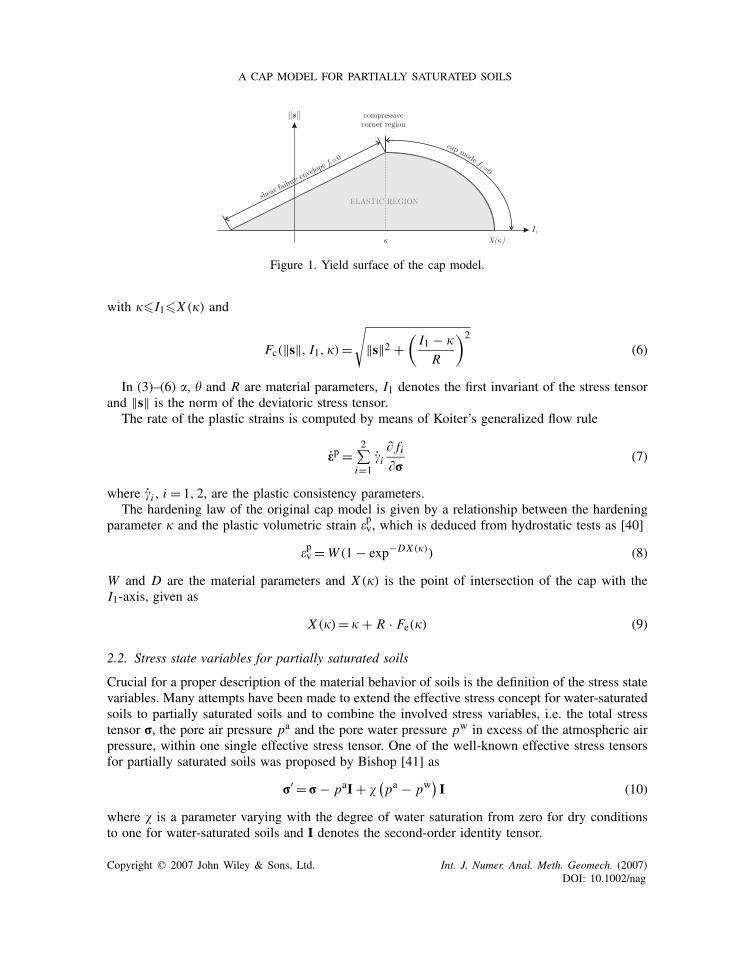
with C denoting the elasticity tensor. The functional forms of the yield surfaces (Figure 1) aregiven for the shear failure surface as
f1(r) =‖s‖ − Fe (I1) (3)
with
Fe(I1) = � + �I1 (4)
and for the strain hardening cap as
f2(r, �) = Fc(‖s‖, I1, �) − Fe(�) (5)
Copyright q 2007 John Wiley & Sons, Ltd. Int. J. Numer. Anal. Meth. Geomech. (2007)DOI: 10.1002/nag
A CAP MODEL FOR PARTIALLY SATURATED SOILS
Figure 1. Yield surface of the cap model.
with ��I1�X (�) and
Fc(‖s‖, I1, �) =√
‖s‖2 +(I1 − �
R
)2
(6)
In (3)–(6) �, � and R are material parameters, I1 denotes the first invariant of the stress tensorand ‖s‖ is the norm of the deviatoric stress tensor.
The rate of the plastic strains is computed by means of Koiter’s generalized flow rule
ep =2∑
i=1�i
� fi�r
(7)
where �i , i = 1, 2, are the plastic consistency parameters.The hardening law of the original cap model is given by a relationship between the hardening
parameter � and the plastic volumetric strain �pv, which is deduced from hydrostatic tests as [40]�pv =W (1 − exp−DX (�)) (8)
W and D are the material parameters and X (�) is the point of intersection of the cap with theI1-axis, given as
X (�) = � + R · Fe(�) (9)
2.2. Stress state variables for partially saturated soils
Crucial for a proper description of the material behavior of soils is the definition of the stress statevariables. Many attempts have been made to extend the effective stress concept for water-saturatedsoils to partially saturated soils and to combine the involved stress variables, i.e. the total stresstensor r, the pore air pressure pa and the pore water pressure pw in excess of the atmospheric airpressure, within one single effective stress tensor. One of the well-known effective stress tensorsfor partially saturated soils was proposed by Bishop [41] as
r′ = r− paI + �(pa − pw
)I (10)
where � is a parameter varying with the degree of water saturation from zero for dry conditionsto one for water-saturated soils and I denotes the second-order identity tensor.
Copyright q 2007 John Wiley & Sons, Ltd. Int. J. Numer. Anal. Meth. Geomech. (2007)DOI: 10.1002/nag
R. KOHLER AND G. HOFSTETTER
It is, however, now widely recognized that some basic features of partially saturated soils are notexplicable in terms of a single effective stress tensor. Possible definitions of stress state variablesbeing work conjugate to the strains of the soil skeleton are derived, e.g. in [42–44].
During the last decades, the use of net stress r′′, i.e. the total stress in excess of the pore airpressure, and matric suction pc,
r′′ = r− paI, pc = pa − pw (11)
as independent stress state variables was a popular choice for the development of constitutivemodels for partially saturated soils. This approach was first used in [45, 46]. A claimed advantageof this choice is given by the fact that r′′ and pc degenerate to the total stress and to the negativepore water pressure in the case of atmospheric pore air pressure. However, using these two stressvariables the transition from a partially saturated to a saturated state requires a switch of the stressstate variables, because in the case of atmospheric air pressure, i.e. pa = 0, (11) does not containthe effective stress tensor for water-saturated soils, proposed by Terzaghi [47], as a special case.
From thermodynamic considerations it follows that a material model for the soil skeleton of apartially saturated soil can be formulated in terms of the Bishop stress tensor (10), with the Bishopparameter � equal to the degree of water saturation Sw [42–44]. Hence, from (10) one obtains
r∗ = r− paI + Sw(pa − pw)I (12)
which can be denoted as average soil skeleton stress. In order to be consistent with the thermody-namic considerations in [43] the second stress variable pc is used as a stress-like plastic internalvariable. The choice of r∗ as stress state variable is advantageous, because for the limiting caseof a water-saturated soil, characterized by Sw = 1, (12) degenerates to the well-known effectivestress tensor for water saturated soils. Thus, material models for partially saturated soils, formu-lated in terms of r∗ and pc, allow a straightforward transition from partially saturated to saturatedconditions.
2.3. Extended cap model, formulated in terms of net stress and matric suction
Using net stress and matric suction as stress state variables allows to model independently theeffects of a change in net stress and of a change in matric suction on the mechanical behavior ofthe soil skeleton. Thus, the elastic strain tensor ee can be partitioned into a part ee,n due to netstress r′′ and a volumetric part ee,s due to matric suction pc:
ee = ee,n + ee,s (13)
Assuming linear behavior for the elastic domain results in
ee =D : r′′ + pc
3K c I (14)
with D=C−1 denoting the elastic compliance tensor and K c as the bulk modulus of the soilskeleton with respect to matric suction [2]. Substituting (14) into (1) and rearranging the resultyields
r′′ =C :(e− pc
3K c I − ep)
(15)
Copyright q 2007 John Wiley & Sons, Ltd. Int. J. Numer. Anal. Meth. Geomech. (2007)DOI: 10.1002/nag
A CAP MODEL FOR PARTIALLY SATURATED SOILS
The degree of water saturation Sw is expressed as a function of matric suction by the approxi-mation proposed in [48]
Sw = Swr + (Sws − Swr )
[1 +
(pc
pcb
)n]−m
(16)
In (16) Sws and Swr denote the maximum and residual degree of water saturation, respectively, andpcb is the air entry value. m and n are parameters to fit the empirical equation to experimental data.In general, these parameters are independent but, according to [48], the relation n = 1/(1 − m)
leads to adequate results for many soils.The functional form of the shear failure surface (3) is replaced by
f1(r′′, pc) = L(ϑ)‖s‖ − Fe(I
′′1 ) − Fs(p
c) (17)
where I ′′1 denotes the first invariant of the net stress tensor r′′ and ‖s‖ is the norm of the deviatoric
stress tensor, the latter being equal for total stresses and net stresses as pa is only hydrostatic.In contrast to the original formulation of the cap model the dependence of the yield surface on
the third invariant of the stress tensor is taken into account by [49]
L(ϑ) =(1 − � cos 3ϑ
1 − �
)−�
(18)
In (18) ϑ is the Lode angle, which is given by
cos(3ϑ) = 3√3
2
I s3(I s2)
1.5(19)
with I s2 and I s3 as the second and third invariant of the deviatoric stress tensor and � and � asparameters defining the shape of the yield surface with respect to ϑ.
In (17) Fe(I ′′1 ) defines the shear failure envelope at vanishing matric suction and Fs(pc) accounts
for the dependence of the shear strength on matric suction. These two functions are defined as
Fe(I′′1 ) = � + �I ′′
1 and Fs(pc) = kpc (20)
with k as a parameter controlling the increase of the shear failure envelope with increasing matricsuction. The motivation for (202) is given by the extended Mohr Coulomb failure criterion
f = c′ + (n − pa) tan�′ + (pa − pw) tan�b (21)
proposed in [50]. In (21) c′ is the effective cohesion, (n − pa) denotes the net normal stress and�′ and �b denote the angles indicating the rate of increase in shear strength with increasing netnormal stress and with increasing matric suction. In order to obtain (202) from (21), constant valuesfor the angles �′ and �b are assumed. Since, however, the increase of shear strength with matricsuction tends toward a maximum, (202) may result in an overestimation of the shear strength forhigh values of matric suction. As a remedy, according to Vanapalli et al. [51] in (21) the termtan�b can be replaced by (Sw)� tan�′ with � as a fitting parameter. This modification can beinterpreted as �b depending on water saturation (or capillary pressure). The improved relation forthe dependence of the shear strength on matric suction is finally obtained as [52]
Fs(pc) = 3�(Sw)� pc (22)
Copyright q 2007 John Wiley & Sons, Ltd. Int. J. Numer. Anal. Meth. Geomech. (2007)DOI: 10.1002/nag
R. KOHLER AND G. HOFSTETTER
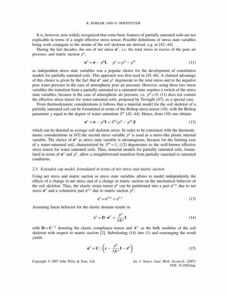
Figure 2. The yield surface of the extended cap model in terms of net stress and matric suction.
The functional form of the strain hardening cap (5) is replaced by
f2(r′′, �(pc), pc) = Fc(‖s‖, I ′′
1 , ϑ, �(pc)) − Fe(�(pc)) − Fs(pc) (23)
with �(pc)�I ′′1 �X (�(pc)) and
Fc(‖s‖, I ′′1 ,ϑ, �(pc))=
√L2(ϑ)‖s‖2 +
(I ′′1 − �(pc)
R
)2
(24)
The yield surface of the extended cap model is shown in Figure 2.In contrast to the original formulation of the cap model, the direction of the plastic strain rate
is assumed to be non-associated with the yield surface in the deviatoric planes, since experimentalresults indicate a plastic potential with a circular shape [53]. Consequently, the direction of theplastic flow is determined by means of a plastic potential, given as
g1(r′′, pc) = ‖s‖ − � − I ′′
1 − Fs(pc) (25)
for the shear failure surface with the parameter governing the amount of plastic dilation. Theplastic potential for the strain hardening cap is assumed as
g2(r′′, �(pc), pc) =
√‖s‖2 +
(I ′′1 − �(pc)
R
)2
− Fe(�(pc)) − Fs(pc) (26)
As the plastic strain rate is now determined by a non-associated flow rule, Koiter’s generalizedflow rule (7) is replaced by
ep =2∑
i=1�i
�gi�r′′
(27)
In contrast to the original formulation of the strain hardening cap, the hardening parameter �in (23) and (24) now depends on matric suction. Because of numerical reasons the hardening lawof the original cap model (8) is replaced by a logarithmic hardening law that relates the plasticvolumetric strain rate �pv to the hardening parameter �(pc):
�pv = �(pc)X(�(pc))
X (�(pc))(28)
Copyright q 2007 John Wiley & Sons, Ltd. Int. J. Numer. Anal. Meth. Geomech. (2007)DOI: 10.1002/nag
A CAP MODEL FOR PARTIALLY SATURATED SOILS
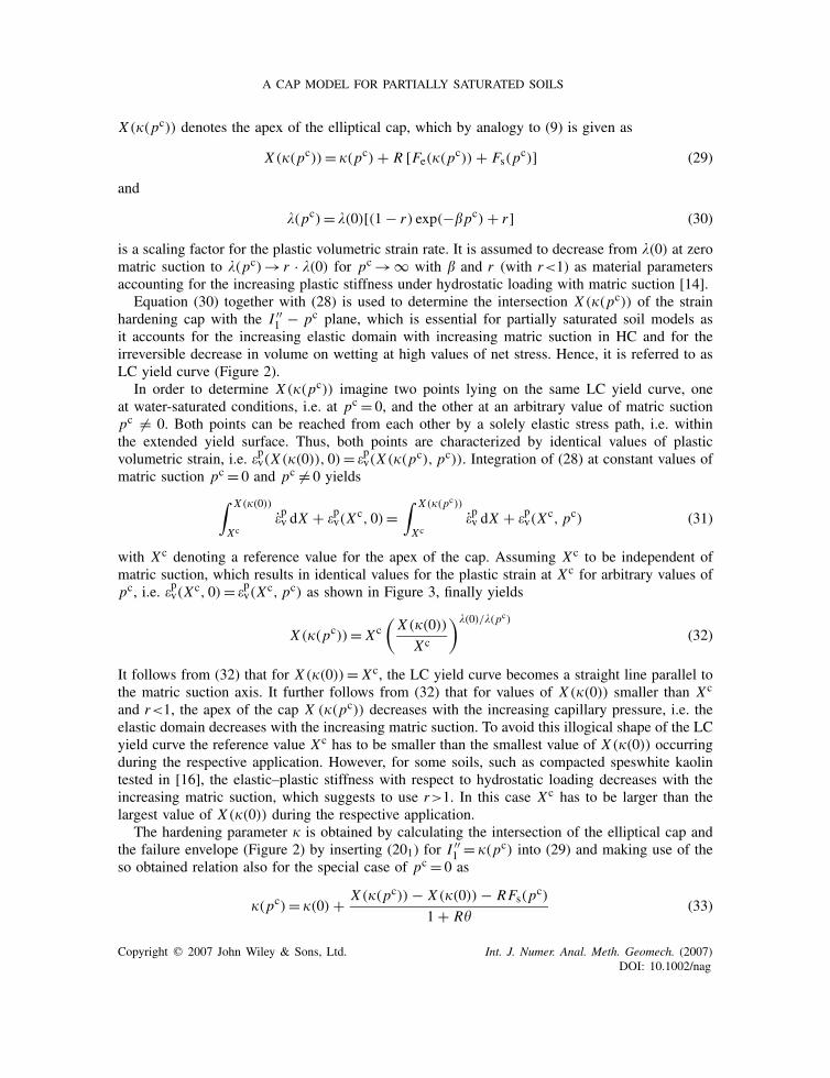
X (�(pc)) denotes the apex of the elliptical cap, which by analogy to (9) is given as
X (�(pc))= �(pc) + R [Fe(�(pc)) + Fs(pc)] (29)
and
�(pc) = �(0)[(1 − r) exp(−�pc) + r ] (30)
is a scaling factor for the plastic volumetric strain rate. It is assumed to decrease from �(0) at zeromatric suction to �(pc) → r · �(0) for pc → ∞ with � and r (with r<1) as material parametersaccounting for the increasing plastic stiffness under hydrostatic loading with matric suction [14].
Equation (30) together with (28) is used to determine the intersection X (�(pc)) of the strainhardening cap with the I ′′
1 − pc plane, which is essential for partially saturated soil models asit accounts for the increasing elastic domain with increasing matric suction in HC and for theirreversible decrease in volume on wetting at high values of net stress. Hence, it is referred to asLC yield curve (Figure 2).
In order to determine X (�(pc)) imagine two points lying on the same LC yield curve, oneat water-saturated conditions, i.e. at pc = 0, and the other at an arbitrary value of matric suctionpc �= 0. Both points can be reached from each other by a solely elastic stress path, i.e. withinthe extended yield surface. Thus, both points are characterized by identical values of plasticvolumetric strain, i.e. �pv(X (�(0)), 0) = �pv(X (�(pc), pc)). Integration of (28) at constant values ofmatric suction pc = 0 and pc �= 0 yields∫ X (�(0))
Xc�pv dX + �pv(X
c, 0) =∫ X (�(pc))
Xc�pv dX + �pv(X
c, pc) (31)
with X c denoting a reference value for the apex of the cap. Assuming X c to be independent ofmatric suction, which results in identical values for the plastic strain at X c for arbitrary values ofpc, i.e. �pv(X c, 0) = �pv(X c, pc) as shown in Figure 3, finally yields
X (�(pc))= X c(X (�(0))
X c
)�(0)/�(pc)
(32)
It follows from (32) that for X (�(0))= X c, the LC yield curve becomes a straight line parallel tothe matric suction axis. It further follows from (32) that for values of X (�(0)) smaller than X c
and r<1, the apex of the cap X (�(pc)) decreases with the increasing capillary pressure, i.e. theelastic domain decreases with the increasing matric suction. To avoid this illogical shape of the LCyield curve the reference value X c has to be smaller than the smallest value of X (�(0)) occurringduring the respective application. However, for some soils, such as compacted speswhite kaolintested in [16], the elastic–plastic stiffness with respect to hydrostatic loading decreases with theincreasing matric suction, which suggests to use r>1. In this case X c has to be larger than thelargest value of X (�(0)) during the respective application.
The hardening parameter � is obtained by calculating the intersection of the elliptical cap andthe failure envelope (Figure 2) by inserting (201) for I ′′
1 = �(pc) into (29) and making use of theso obtained relation also for the special case of pc = 0 as
�(pc) = �(0) + X (�(pc)) − X (�(0)) − RFs(pc)
1 + R�(33)
Copyright q 2007 John Wiley & Sons, Ltd. Int. J. Numer. Anal. Meth. Geomech. (2007)DOI: 10.1002/nag
R. KOHLER AND G. HOFSTETTER
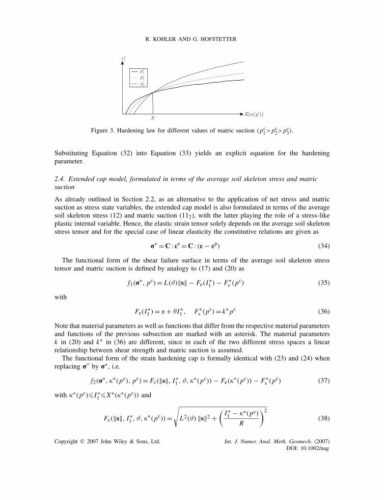
Figure 3. Hardening law for different values of matric suction (pc1>pc2>pc3).
Substituting Equation (32) into Equation (33) yields an explicit equation for the hardeningparameter.
2.4. Extended cap model, formulated in terms of the average soil skeleton stress and matricsuction
As already outlined in Section 2.2, as an alternative to the application of net stress and matricsuction as stress state variables, the extended cap model is also formulated in terms of the averagesoil skeleton stress (12) and matric suction (112), with the latter playing the role of a stress-likeplastic internal variable. Hence, the elastic strain tensor solely depends on the average soil skeletonstress tensor and for the special case of linear elasticity the constitutive relations are given as
r∗ =C : ee =C : (e− ep) (34)
The functional form of the shear failure surface in terms of the average soil skeleton stresstensor and matric suction is defined by analogy to (17) and (20) as
f1(r∗, pc) = L(ϑ)‖s‖ − Fe(I
∗1 ) − F∗
s (pc) (35)
with
Fe(I∗1 ) = � + �I ∗
1 , F∗s (pc) = k∗ pc (36)
Note that material parameters as well as functions that differ from the respective material parametersand functions of the previous subsection are marked with an asterisk. The material parametersk in (20) and k∗ in (36) are different, since in each of the two different stress spaces a linearrelationship between shear strength and matric suction is assumed.
The functional form of the strain hardening cap is formally identical with (23) and (24) whenreplacing r′′ by r∗, i.e.
f2(r∗, �∗(pc), pc) = Fc(‖s‖, I ∗
1 , ϑ, �∗(pc)) − Fe(�∗(pc)) − F∗
s (pc) (37)
with �∗(pc)�I ∗1 �X∗(�∗(pc)) and
Fc(‖s‖, I ∗1 , ϑ, �∗(pc))=
√L2(ϑ) ‖s‖2 +
(I ∗1 − �∗(pc)
R
)2
(38)
Copyright q 2007 John Wiley & Sons, Ltd. Int. J. Numer. Anal. Meth. Geomech. (2007)DOI: 10.1002/nag
A CAP MODEL FOR PARTIALLY SATURATED SOILS
The plastic potentials g1 and g2 for the non-associated flow rule are given by analogy to (25)and (26) as
g1(r∗, pc) =‖s‖ − � − I ∗
1 − F∗s (pc) (39)
and
g2(r∗, �∗(pc), pc) =
√‖s‖2 +
(I ∗1 − �∗(pc)
R
)2
− Fe(�∗(pc)) − F∗
s (pc) (40)
The hardening parameter �∗(pc) is derived by analogy to (33) by calculating the intersectionof the shear failure surface and the cap as
�∗(pc) = �∗(0) + X∗(�∗(pc)) − X∗(�∗(0)) − R F∗s (pc)
1 + R�(41)
Transforming the LC yield curve (32) from net stresses to the average soil skeleton stress accordingto [54] or [31] yields the apex of the cap as
X∗(�∗(pc))= X (�(pc)) + 3Sw pc = X c(X (�(0))
X c
)�(0)/�(pc)
+ 3Sw pc (42)
The term 3Sw pc in (42) follows from a comparison of r′′ in (11) and r∗ in (12), which revealsthat the two stress variables differ by Sw pc I resulting in 3Sw pc for quantities related to the firstinvariant of the stress state.
Inserting (42) into (41) yields an explicit equation for the evolution of the hardening parameter.The plastic volumetric strain rate �pv is derived by reordering (42) and inserting the resultingequation into (28)
�pv = �(pc)X∗(�∗(pc)) − 3(Sw pc + Sw pc)
X∗(�∗(pc)) − 3Sw pc(43)
Since (42) is obtained from a transformation of (32) from net stresses to average soil skeletonstresses, �(pc) is given according to (30). Hence, the parameters r and � are identical for bothformulations.
3. NUMERICAL INVESTIGATION
3.1. Experimental data
Both versions of the extended cap model are validated by the numerical simulation of a seriesof suction controlled tests [37, 38]. They were conducted on cubical specimens of recompactedpiedmont residual soil, classified as silty sand, in order to study the mechanical behavior of partiallysaturated soils under multi-axial stress states.
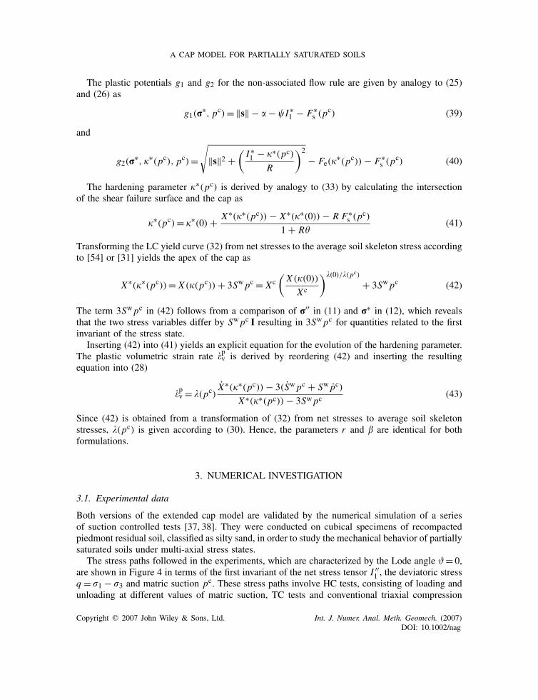
The stress paths followed in the experiments, which are characterized by the Lode angle ϑ = 0,are shown in Figure 4 in terms of the first invariant of the net stress tensor I ′′
1 , the deviatoric stressq = 1 − 3 and matric suction pc. These stress paths involve HC tests, consisting of loading andunloading at different values of matric suction, TC tests and conventional triaxial compression
Copyright q 2007 John Wiley & Sons, Ltd. Int. J. Numer. Anal. Meth. Geomech. (2007)DOI: 10.1002/nag
R. KOHLER AND G. HOFSTETTER
Figure 4. Experimentally and numerically simulated stress paths at ϑ = 0.
(a) (b)
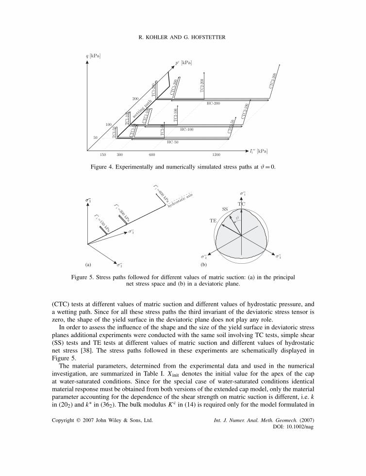
Figure 5. Stress paths followed for different values of matric suction: (a) in the principalnet stress space and (b) in a deviatoric plane.
(CTC) tests at different values of matric suction and different values of hydrostatic pressure, anda wetting path. Since for all these stress paths the third invariant of the deviatoric stress tensor iszero, the shape of the yield surface in the deviatoric plane does not play any role.
In order to assess the influence of the shape and the size of the yield surface in deviatoric stressplanes additional experiments were conducted with the same soil involving TC tests, simple shear(SS) tests and TE tests at different values of matric suction and different values of hydrostaticnet stress [38]. The stress paths followed in these experiments are schematically displayed inFigure 5.
The material parameters, determined from the experimental data and used in the numericalinvestigation, are summarized in Table I. X init denotes the initial value for the apex of the capat water-saturated conditions. Since for the special case of water-saturated conditions identicalmaterial response must be obtained from both versions of the extended cap model, only the materialparameter accounting for the dependence of the shear strength on matric suction is different, i.e. kin (202) and k∗ in (362). The bulk modulus K c in (14) is required only for the model formulated in
Copyright q 2007 John Wiley & Sons, Ltd. Int. J. Numer. Anal. Meth. Geomech. (2007)DOI: 10.1002/nag

A CAP MODEL FOR PARTIALLY SATURATED SOILS
Table I. Material parameters for both versions of the extended cap model.
Parameter Value Unit
K 42 440 kPaG 8803 kPaK c 35 000 kPa� 0.0 kPa� 0.269 —R 3.0 —�(0) 0.095 —X init 126.3 kPaXc 108.0 kPar 0.2 —� 0.018 kPa−1
k 1.1262 —k∗ 0.6 —
Swr 0.25 —Sws 0.95 —pcb 50.0 kPam 0.32 —
terms of net stress and suction. Since relationship (16) between the degree of water saturation andmatric suction was not determined in the experimental program, the hydraulic parameters givenin the lower part of Table I are chosen according to values for silty sands given in the literature.
3.2. Integration algorithm
In order to simulate the experiments with given net stress and suction paths an implicit stress-driven algorithm for the determination of the strain increment from a given net stress incrementand a given matric suction increment is outlined subsequently. The algorithm is presented for theextended cap model formulated in terms of net stress and matric suction. It can be adapted easilyfor the extended cap model formulated in terms of the average soil skeleton stress and matricsuction.
Let the total strain tensor en be known up to load increment n. The total strains at the end ofstep n + 1 are derived by adding the (yet unknown) elastic and plastic strain increments for thecurrent load increment as
en+1 = en + �een+1 + �epn+1 (44)
The incremental elastic strain tensor can be calculated using (14) as
�een+1 =D :�r′′n+1 + �pcn+1
3K c I (45)
Splitting the incremental plastic strain tensor into a volumetric and a deviatoric part yields
�epn+1 =��m,pn+1I + �epn+1 (46)
For loading in the failure envelope mode or in the compressive corner region the yield surfacebehaves as in ideal plasticity. Stress states lying in these regions with fi>0 cannot be carried by
Copyright q 2007 John Wiley & Sons, Ltd. Int. J. Numer. Anal. Meth. Geomech. (2007)DOI: 10.1002/nag
R. KOHLER AND G. HOFSTETTER
the specimen and are, thus, not reached within the experimental program. Therefore, loading in thefailure envelope mode and in the compressive corner region are not considered in the following.
In case of plastic loading in the cap mode, the condition f2(r′′n+1, �n+1(pcn+1), pcn+1) = 0 holds.
Inserting (23) together with (24) and (201) into this condition yields
[1 − R2�2](�n+1(pcn+1))
2 − 2[I ′′1,n+1 + R2�(� + Fs(p
cn+1))]�n+1(p
cn+1)
+R2[L2(ϑ)‖sn+1‖2 − (� + Fs(pcn+1))
2] + (I ′′1,n+1)
2 = 0 (47)
from which the actual value of the hardening parameter �n+1(pcn+1) can be computed. The apexof the cap X (�n+1(pcn+1)) at the end of the load increment n + 1 can be calculated by insertingthe hardening parameter into (29).
The plastic volumetric strain increment is obtained by integrating (28) as
��m,pn+1 = ��pv,n+1
3= 1
3
[�(pcn+1) ln
X (�n+1(pcn+1))
X c − �(pcn) lnX (�n(pcn))
X c
](48)
Since the volumetric plastic strain has the same value for any stress state located on the same LCyield curve, the second term in the squared brackets on the right-hand side of (48) is equal to
�(pcn) lnX (�n(pcn))
X c = �(pcn+1) lnX (�n(pcn+1))
X c (49)
Inserting this equation into (48) finally gives the volumetric part of the plastic strain increment as
��m,pn+1 = �(pcn+1)
3ln
X (�n+1(pcn+1))
X (�n(pcn+1))(50)
Applying an implicit integration scheme to the flow rule (27) yields the volumetric and thedeviatoric part of the incremental plastic strain tensor as
��m,pn+1 = ��2,n+1
�g2,n+1
�I ′′1,n+1
=��2,n+1
I ′′1,n+1 − �n+1(pcn+1)
R2
√‖sn+1‖2 +
(I ′′1,n+1−�n+1(pcn+1)
R
)2(51)
�epn+1 = ��2,n+1�g2,n+1
�sn+1=��2,n+1
sn+1√‖sn+1‖2 +
(I ′′1,n+1−�n+1(pcn+1)
R
)2(52)
Using (51) in (52) the deviatoric part of the strain tensor can be rewritten as
�epn+1 = R2sn+1
[I ′′1,n+1 − �n+1(pcn+1)]
��m,pn+1 (53)
Inserting (50) into (53) finally gives
�epn+1 = R2sn+1�(pcn+1)
3[I ′′1,n+1 − �n+1(pcn+1)]
lnX (�n+1(pcn+1))
X (�n(pcn+1))(54)
Copyright q 2007 John Wiley & Sons, Ltd. Int. J. Numer. Anal. Meth. Geomech. (2007)DOI: 10.1002/nag
A CAP MODEL FOR PARTIALLY SATURATED SOILS
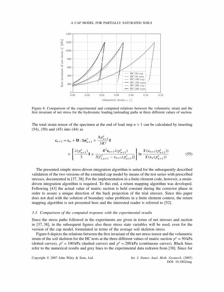
Figure 6. Comparison of the experimental and computed relations between the volumetric strain and thefirst invariant of net stress for the hydrostatic loading/unloading paths at three different values of suction.
The total strain tensor of the specimen at the end of load step n + 1 can be calculated by inserting(54), (50) and (45) into (44) as
en+1 = en + D :�r′′n+1 + �pcn+1
3K c I
+{
�(pcn+1)
3I + R2sn+1�(pcn+1)
3[I ′′1,n+1 − �n+1(pcn+1)]
}ln
X (�n+1(pcn+1))
X (�n(pcn+1))(55)
The presented simple stress-driven integration algorithm is suited for the subsequently describedvalidation of the two versions of the extended cap model by means of the test series with prescribedstresses, documented in [37, 38]. For the implementation in a finite element code, however, a strain-driven integration algorithm is required. To this end, a return mapping algorithm was developed.Following [43] the actual value of matric suction is held constant during the corrector phase inorder to assure a unique direction of the back projection of the trial stresses. Since this paperdoes not deal with the solution of boundary value problems in a finite element context, the returnmapping algorithm is not presented here and the interested reader is referred to [52].
3.3. Comparison of the computed response with the experimental results
Since the stress paths followed in the experiments are given in terms of net stresses and suctionin [37, 38], in the subsequent figures also these stress state variables will be used, even for theversion of the cap model, formulated in terms of the average soil skeleton stress.
Figure 6 depicts the relations between the first invariant of the net stress tensor and the volumetricstrain of the soil skeleton for the HC tests at the three different values of matric suction pc = 50 kPa(dotted curves), pc = 100 kPa (dashed curves) and pc = 200 kPa (continuous curves). Black linesrefer to the numerical results and grey lines to the experimental data redrawn from [38]. Since for
Copyright q 2007 John Wiley & Sons, Ltd. Int. J. Numer. Anal. Meth. Geomech. (2007)DOI: 10.1002/nag
R. KOHLER AND G. HOFSTETTER
the extended cap model based on the average soil skeleton stress and suction the LC yield curveand the hardening law were derived by reformulating the respective relations of the extended capmodel formulated in terms of net stress and suction, identical results are obtained for both versionsof the model. As can be seen the proposed material model is able to reproduce the stiffening effectdue to matric suction under hydrostatic loading. Furthermore, the experimental data support theassumption of the elasticity tensor being independent of matric suction.
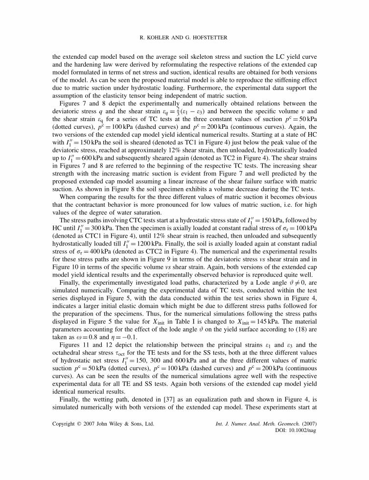
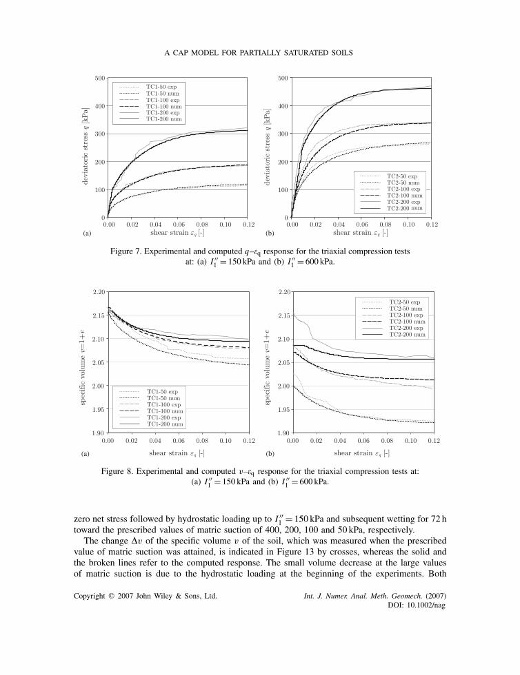
Figures 7 and 8 depict the experimentally and numerically obtained relations between thedeviatoric stress q and the shear strain �q = 2
3 (�1 − �3) and between the specific volume v andthe shear strain �q for a series of TC tests at the three constant values of suction pc = 50 kPa(dotted curves), pc = 100 kPa (dashed curves) and pc = 200 kPa (continuous curves). Again, thetwo versions of the extended cap model yield identical numerical results. Starting at a state of HCwith I ′′
1 = 150 kPa the soil is sheared (denoted as TC1 in Figure 4) just below the peak value of thedeviatoric stress, reached at approximately 12% shear strain, then unloaded, hydrostatically loadedup to I ′′
1 = 600 kPa and subsequently sheared again (denoted as TC2 in Figure 4). The shear strainsin Figures 7 and 8 are referred to the beginning of the respective TC tests. The increasing shearstrength with the increasing matric suction is evident from Figure 7 and well predicted by theproposed extended cap model assuming a linear increase of the shear failure surface with matricsuction. As shown in Figure 8 the soil specimen exhibits a volume decrease during the TC tests.
When comparing the results for the three different values of matric suction it becomes obviousthat the contractant behavior is more pronounced for low values of matric suction, i.e. for highvalues of the degree of water saturation.
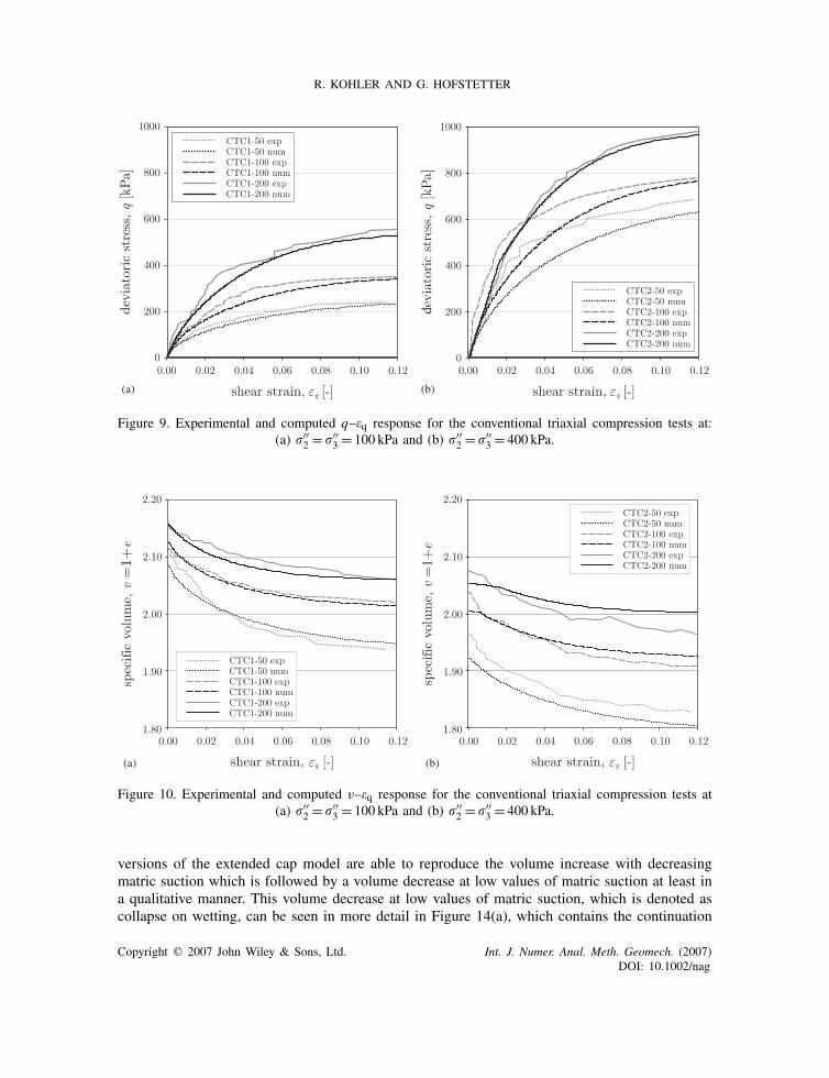
The stress paths involving CTC tests start at a hydrostatic stress state of I ′′1 = 150 kPa, followed by
HC until I ′′1 = 300 kPa. Then the specimen is axially loaded at constant radial stress of r = 100 kPa
(denoted as CTC1 in Figure 4), until 12% shear strain is reached, then unloaded and subsequentlyhydrostatically loaded till I ′′
1 = 1200 kPa. Finally, the soil is axially loaded again at constant radialstress of r = 400 kPa (denoted as CTC2 in Figure 4). The numerical and the experimental resultsfor these stress paths are shown in Figure 9 in terms of the deviatoric stress vs shear strain and inFigure 10 in terms of the specific volume vs shear strain. Again, both versions of the extended capmodel yield identical results and the experimentally observed behavior is reproduced quite well.
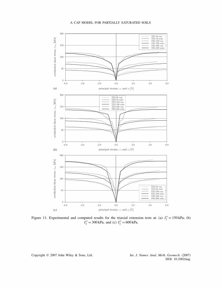
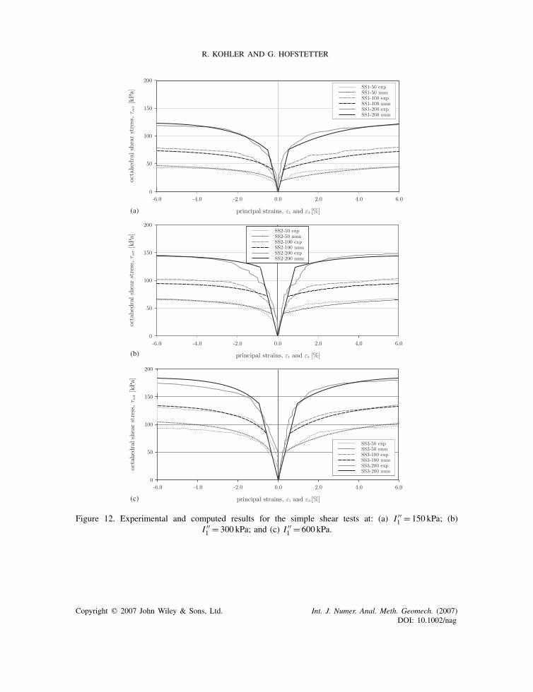
Finally, the experimentally investigated load paths, characterized by a Lode angle ϑ �= 0, aresimulated numerically. Comparing the experimental data of TC tests, conducted within the testseries displayed in Figure 5, with the data conducted within the test series shown in Figure 4,indicates a larger initial elastic domain which might be due to different stress paths followed forthe preparation of the specimens. Thus, for the numerical simulations following the stress pathsdisplayed in Figure 5 the value for X init in Table I is changed to X init = 145 kPa. The materialparameters accounting for the effect of the lode angle ϑ on the yield surface according to (18) aretaken as �= 0.8 and � =−0.1.
Figures 11 and 12 depict the relationship between the principal strains �1 and �3 and theoctahedral shear stress oct for the TE tests and for the SS tests, both at the three different valuesof hydrostatic net stress I ′′
1 = 150, 300 and 600 kPa and at the three different values of matricsuction pc = 50 kPa (dotted curves), pc = 100 kPa (dashed curves) and pc = 200 kPa (continuouscurves). As can be seen the results of the numerical simulations agree well with the respectiveexperimental data for all TE and SS tests. Again both versions of the extended cap model yieldidentical numerical results.
Finally, the wetting path, denoted in [37] as an equalization path and shown in Figure 4, issimulated numerically with both versions of the extended cap model. These experiments start at
Copyright q 2007 John Wiley & Sons, Ltd. Int. J. Numer. Anal. Meth. Geomech. (2007)DOI: 10.1002/nag
A CAP MODEL FOR PARTIALLY SATURATED SOILS
(a) (b)
Figure 7. Experimental and computed q–�q response for the triaxial compression testsat: (a) I ′′
1 = 150 kPa and (b) I ′′1 = 600 kPa.
(a) (b)
Figure 8. Experimental and computed v–�q response for the triaxial compression tests at:(a) I ′′
1 = 150 kPa and (b) I ′′1 = 600 kPa.
zero net stress followed by hydrostatic loading up to I ′′1 = 150 kPa and subsequent wetting for 72 h
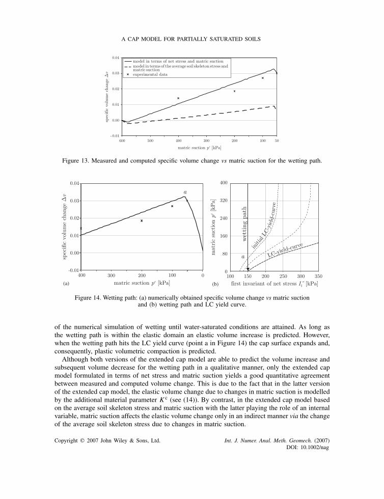
toward the prescribed values of matric suction of 400, 200, 100 and 50 kPa, respectively.The change �v of the specific volume v of the soil, which was measured when the prescribed
value of matric suction was attained, is indicated in Figure 13 by crosses, whereas the solid andthe broken lines refer to the computed response. The small volume decrease at the large valuesof matric suction is due to the hydrostatic loading at the beginning of the experiments. Both
Copyright q 2007 John Wiley & Sons, Ltd. Int. J. Numer. Anal. Meth. Geomech. (2007)DOI: 10.1002/nag
R. KOHLER AND G. HOFSTETTER
(a) (b)
Figure 9. Experimental and computed q–�q response for the conventional triaxial compression tests at:(a) ′′
2 = ′′3 = 100 kPa and (b) ′′
2 = ′′3 = 400 kPa.
(a) (b)
Figure 10. Experimental and computed v–�q response for the conventional triaxial compression tests at(a) ′′
2 = ′′3 = 100 kPa and (b) ′′
2 = ′′3 = 400 kPa.
versions of the extended cap model are able to reproduce the volume increase with decreasingmatric suction which is followed by a volume decrease at low values of matric suction at least ina qualitative manner. This volume decrease at low values of matric suction, which is denoted ascollapse on wetting, can be seen in more detail in Figure 14(a), which contains the continuation
Copyright q 2007 John Wiley & Sons, Ltd. Int. J. Numer. Anal. Meth. Geomech. (2007)DOI: 10.1002/nag
A CAP MODEL FOR PARTIALLY SATURATED SOILS
(a)
(b)
(c)
Figure 11. Experimental and computed results for the triaxial extension tests at: (a) I ′′1 = 150 kPa; (b)
I ′′1 = 300 kPa; and (c) I ′′
1 = 600 kPa.
Copyright q 2007 John Wiley & Sons, Ltd. Int. J. Numer. Anal. Meth. Geomech. (2007)DOI: 10.1002/nag
R. KOHLER AND G. HOFSTETTER
(a)
(b)
(c)
Figure 12. Experimental and computed results for the simple shear tests at: (a) I ′′1 = 150 kPa; (b)
I ′′1 = 300 kPa; and (c) I ′′
1 = 600 kPa.
Copyright q 2007 John Wiley & Sons, Ltd. Int. J. Numer. Anal. Meth. Geomech. (2007)DOI: 10.1002/nag
A CAP MODEL FOR PARTIALLY SATURATED SOILS
Figure 13. Measured and computed specific volume change vs matric suction for the wetting path.
(a) (b)
Figure 14. Wetting path: (a) numerically obtained specific volume change vs matric suctionand (b) wetting path and LC yield curve.
of the numerical simulation of wetting until water-saturated conditions are attained. As long asthe wetting path is within the elastic domain an elastic volume increase is predicted. However,when the wetting path hits the LC yield curve (point a in Figure 14) the cap surface expands and,consequently, plastic volumetric compaction is predicted.
Although both versions of the extended cap model are able to predict the volume increase andsubsequent volume decrease for the wetting path in a qualitative manner, only the extended capmodel formulated in terms of net stress and matric suction yields a good quantitative agreementbetween measured and computed volume change. This is due to the fact that in the latter versionof the extended cap model, the elastic volume change due to changes in matric suction is modelledby the additional material parameter K c (see (14)). By contrast, in the extended cap model basedon the average soil skeleton stress and matric suction with the latter playing the role of an internalvariable, matric suction affects the elastic volume change only in an indirect manner via the changeof the average soil skeleton stress due to changes in matric suction.
Copyright q 2007 John Wiley & Sons, Ltd. Int. J. Numer. Anal. Meth. Geomech. (2007)DOI: 10.1002/nag
R. KOHLER AND G. HOFSTETTER
4. CONCLUSIONS
In order to describe the material behavior of partially saturated soils that are not highly expansive,in particular of partially saturated sands and silts, the extension of an elastic–plastic cap modelwas presented. It is based on two independent stress state variables. Two options for the stressstate variables were taken into account, namely net stress and matric suction and, alternatively, theaverage soil skeleton stress (i.e. the Bishop stress with the Bishop parameter equal to the degreeof water saturation) and suction, the latter playing the role of a stress-like plastic internal variable.For both versions of the cap model the yield surface, consisting of a shear failure envelope and astrain hardening cap, and the plastic potentials for the non-associated flow rule were extended inorder to allow the consideration of partially saturated conditions. In addition, the third invariant ofthe deviatoric stress tensor was included in the formulation of the yield surfaces and the hardeninglaw for the cap surface was reformulated.
The numerical simulation of an extensive series of suction controlled tests on a silty sand,consisting of hydrostatic loading and unloading at several constant values of matric suction, TCtests, CTC tests, TE tests and SS tests at different constant values of matric suction and differentvalues of hydrostatic net stress, showed identical response for both versions of the extended capmodel and is in good agreement with the experimental results.
However, differences in the predicted soil behavior were encountered for tests with a varyingdegree of matric suction. On the one hand, using net stress and matric suction as independentstress state variables yields a better correspondence of the predicted specific volume change withexperimental data than using the average soil skeleton stress and matric suction. This differenceis related to the constitutive relations for the elastic material behavior. When using net stressand matric suction as stress variables the elastic volume change due to changes in matric suctionis modelled by an additional material parameter, which represents the bulk modulus of the soilskeleton with respect to matric suction. By contrast, when using the average soil skeleton stressand matric suction with the latter playing the role of a stress-like plastic internal variable, matricsuction affects the elastic volume change only in an indirect manner via the change of the averagesoil skeleton stress due to changes in matric suction. On the other hand, using the average soilskeleton stress and matric suction as independent stress state variables offers the advantage of aneasy transition from partially saturated to saturated states and vice versa, whereas using net stressand matric suction requires a switch of the stress state variables, because the net stress tensor doesnot contain the effective stresses for water-saturated soils as a special case.
REFERENCES
1. Wheeler SJ, Karube D. Constitutive modelling. Proceedings of the 1st International Conference on UnsaturatedSoils, 1996; 1323–1356.
2. Fredlund DG, Rahardjo H. Soil Mechanics for Unsaturated Soils. Wiley; New York, 1993.3. Gens A. Constitutive modelling: application to compacted soils. Proceedings of the 1st International Conference
on Unsaturated Soils, 1996; 1179–1200.4. Gens A. Effective Stresses. 1st MUSE School: Fundamentals of Unsaturated Soils, Barcelona. http://muse.dur.
ac.uk/presentations.htm.5. Vaunat J. Elastoplastic Framework to Model Unsaturated Soils. 1st MUSE School: Fundamentals of Unsaturated
Soils, Barcelona. http://muse.dur.ac.uk/presentations.htm.6. Lloret A, Alonso EE. State surfaces for partially saturated soils. Proceedings of the 11th International Conference
on Soil Mechanics and Foundation Engineering, vol. 2, San Francisco, 1985; 557–562.
Copyright q 2007 John Wiley & Sons, Ltd. Int. J. Numer. Anal. Meth. Geomech. (2007)DOI: 10.1002/nag
A CAP MODEL FOR PARTIALLY SATURATED SOILS
7. Lloret A, Gens A, Battle F, Alonso EE. Flow and deformation analysis of partially saturated soils. Proceedingsof the 9th European Conference on Soil Mechanics and Foundation Engineering, vol. 2, Dublin, 1987; 565–568.
8. Alonso EE, Battle F, Gens A, Lloret A. Consolidation analysis of partially saturated soils: application to earthdamconstruction. Proceedings of the 6th International Conference on Numerical Methods in Geomechanics, vol. 2,Innsbruck, 1988; 1303–1308.
9. Alonso EE, Battle F. Construction and impoundment of an earth dam. Application of the coupled flow-deformationanalysis of unsaturated soils. Modern Issues in Non-Saturated Soils, Gens A, Jouanna P, Schrefler BA (eds).CISM Courses and Lectures, vol. 357. Springer: Wien, 1995; 357–395.
10. Gens A, Garcia-Molina AJ, Olivella S, Alonso EE, Huertas F. Analysis of a full scale in situ test simulatingrepository conditions. International Journal for Numerical and Analytical Methods in Geomechanics 1998;22:515–548.
11. Thomas HR, Yang H. An analysis of coupled heat, moisture and air transfer in a deformable unsaturated soil.Geotechnique 1996; 45(4):677–689.
12. Alonso EE, Lloret A, Gens A, Battle F. A new approach for the prediction of long term heave. Proceedings ofthe 12th International Conference on Soil Mechanics and Foundation Engineering, vol. 1, Rio de Janeiro, 1989;571–574.
13. Gens A, Alonso EE, Lloret A, Battle F. Predictions of long term swelling of expansive soft rocks: a doublestructure approach. Proceedings of the International Conference on Hard Soils–Soft Rocks, vol. 1, Athens, 1993;495–500.
14. Alonso EE, Gens A, Josa A. A constitutive model for partially saturated soils. Geotechnique 1990; 40(3):405–430.15. Roscoe KH, Burland JB. On the generalized stress–strain behavior of ‘wet’ clay. In Engineering Plasticity,
Heyman J, Leckie FA (eds). Cambridge University Press: Cambridge, 1968; 535–609.16. Wheeler SJ, Sivakumar V. An elasto-plastic critical state framework for unsaturated soils. Geotechnique 1995;
45(1):35–53.17. Bolzon G, Schrefler BA. Elastoplastic soil constitutive laws generalized to partially saturated states. Geotechnique
1996; 46(2):279–289.18. Santagiuliana R, Schrefler BA. Enhancing the Bolzon–Schrefler–Zienkiewicz constitutive model for partially
saturated soil. Transport in Porous Media 2006; 65(1):1–30.19. Geiser F, Laloui L, Vulliet L. Modelling the behaviour of unsaturated silt. In Experimental Evidence and Theoretical
Approaches in Unsaturated Soils, Tarantino A, Mancuso C (eds). A.A. Balkema: Rotterdam, Brookfield, 2000;155–176.
20. Sun DA, Matsuoka H, Cui HB, Xu YF. Three-dimensional elasto-plastic model for unsaturated compacted soilswith different initial densities. International Journal for Numerical and Analytical Methods in Geomechanics2003; 27:1079–1098.
21. Alonso EE, Lloret A, Delahaye CH, Vaunat J, Gens A, Volckaert G. Coupled analysis of a backfill hydrationtest. International Journal for Numerical and Analytical Methods in Geomechanics 1998; 22:1–27.
22. Costa LM, Pontes Filho IDS, Ferreira SRM. Numerical modelling of hydro-mechanical behaviour of plate testswith wetting in collapsible soil. In VII International Conference on Computational Plasticity, Onate E, OwenDRJ (eds). Barcelona, 2003.
23. Simoni L, Salomoni V, Schrefler BA. Elastoplastic subsidence models with and without capillary affects. ComputerMethods in Applied Mechanics and Engineering 1999; 171:491–502.
24. Alonso EE, Lloret A, Gens A, Yang DQ. Experimental behavior of highly expansive double-structure clay.Proceedings of the 1st International Conference on Unsaturated Soils, vol. 1, Paris, 1995; 11–16.
25. Gens A, Alonso EE. A framework for the behavior of unsaturated expansive clays. Canadian GeotechnicalJournal 1992; 29:1013–1032.
26. Alonso EE, Vaunat J, Gens A. Modelling the mechanical behavior of expansive clays. Engineering Geology1999; 54:173–183.
27. Sanchez M, Gens A, Guimaraes LdN, Olivella S. A double structure generalized plasticity model for expansivematerials. International Journal for Numerical and Analytical Methods in Geomechanics 2005; 29:751–787.
28. Buisson MSR, Wheeler SJ. Inclusion of hydraulic hysteresis in a new elasto-plastic framework. In ExperimentalEvidence and Theoretical Approaches in Unsaturated Soils, Tarantino A, Mancuso C (eds). A.A. Balkema:Rotterdam, Brookfield, 2000; 109–119.
29. Vaunat J, Romero E, Jommi C. An elastoplastic hydro-mechanical model for unsaturated soils. In ExperimentalEvidence and Theoretical Approaches in Unsaturated Soils, Tarantino A, Mancuso C (eds). A.A. Balkema:Rotterdam, Brookfield, 2000; 121–138.
Copyright q 2007 John Wiley & Sons, Ltd. Int. J. Numer. Anal. Meth. Geomech. (2007)DOI: 10.1002/nag
R. KOHLER AND G. HOFSTETTER
30. Wheeler SJ, Sharma RS, Buisson MSR. Coupling of hydraulic hysteresis and stress–strain behavior in unsaturatedsoils. Geotechnique 2003; 53(1):41–54.
31. Sheng D, Sloan SW, Gens A. A constitutive model for unsaturated soils: thermomechanical and computationalaspects. Computational Mechanics 2004; 33:453–465.
32. Gallipoli D, Gens A, Sharma R, Vaunat J. An elasto-plastic model for unsaturated soil incorporating the effectsof suction and degree of saturation on mechanical behaviour. Geotechnique 2003; 53(1):123–135.
33. Tamagnini R. An extended Cam-clay model for unsaturated soils with hydraulic hysteresis. Geotechnique 2004;54(3):223–228.
34. Kammerer G. Experimentelle untersuchungen von stromungsvorgangen in teilgesattigten boden undspritzbetonrissen im hinblick auf den einsatz von druckluft zur wasserhaltung im tunnelbau. Ph.D. Thesis,Graz University of Technology, Austria, 2000 (in German).
35. Distelmeier H. Anwendung von Spritzbetonbauweisen im Tunnelbau unter Druckluftbedingungen. Tunnel 1981;81(1):199–210 (in German).
36. DiMaggio FL, Sandler IS. Material model for granular soils. Journal of the Engineering Mechanics Division(ASCE) 1971; 97:935–950.
37. Macari EJ, Hoyos LR, Arduino P. Constitutive modeling of unsaturated soil behaviour under axisymmetric stressstates using a stress/suction-controlled cubical test cell. International Journal of Plasticity 2003; 19:1481–1515.
38. Macari EJ, Hoyos LR. Mechanical behavior of an unsaturated soil under multi-axial stress states. GeotechnicalTesting Journal 2001; 24(1):14–22.
39. Hofstetter G, Simo JC, Taylor RL. A modified cap model: closest point solution algorithms. Computers andStructures 1993; 46(2):203–214.
40. Sandler IS, Rubin D. An algorithm and a modular subroutine for the cap model. International Journal forNumerical and Analytical Methods in Geomechanics 1979; 3:173–186.
41. Bishop AW. The principle of effective stress. Teknisk Ukseblad 1959; 106(39):859–863.42. Houlsby GT. The work input to an unsaturated granular material. Geotechnique 1997; 47(1):193–196.43. Borja RI. Cam-clay plasticity. Part V: a mathematical framework for three-phase deformation and strain localization
analyses of partially saturated porous media. Computer Methods in Applied Mechanics and Engineering 2004;193:5301–5338.
44. Schrefler BA. Mechanics and thermodynamics of saturated/unsaturated porous materials and quantitative solutions.Applied Mechanics Reviews 2002; 55(4):351–387.
45. Coleman JD. Stress strain relations for partly saturated soils. Geotechnique 1962; 12(4):348–350.46. Bishop AW, Blight GE. Some aspects of effective stress in saturated and partly saturated soils. Geotechnique
1963; 13(3):177–197.47. Terzaghi K. The shear resistance of saturated soils. Proceedings of the 1st International Conference on Soil
Mechanics and Foundation Engineering, vol. 1, 1936; 54–56.48. Van Genuchten MTh, Nielsen DR. On describing and predicting the hydraulic properties of unsaturated soils.
Annales Geophysicae 1985; 3(5):615–628.49. de Borst R, Groen AE. Computational strategies for standard soil plasticity models. In Modeling in Geomechanics,
Zaman M, Booker J, Gioda G (eds). Wiley: New York, 2000.50. Fredlund DG, Morgenstern NR, Widger RA. Shear strength of unsaturated soils. Canadian Geotechnical Journal
1978; 31:521–532.51. Vanapalli SK, Fredlund DG, Pufahl DE, Clifton AW. Model for the prediction of shear strength with respect to
soil suction. Canadian Geotechnical Journal 1996; 33:379–392.52. Kohler R. Numerical modelling of partially saturated soils in the context of a three-phase-FE-formulation.
Dissertation, University of Innsbruck, Austria, 2006.53. Kim MK, Lade PV. Single hardening constitutive model for frictional materials I. Plastic potential function.
Computers and Geotechnics 1988; 5:307–324.54. Jommi C. Remarks on the constitutive modelling of unsaturated soils. In Experimental Evidence and Theoretical
Approaches in Unsaturated Soils, Tarantino A, Mancuso C (eds). A.A. Balkema: Rotterdam, Brookfield, 2000;139–153.
Copyright q 2007 John Wiley & Sons, Ltd. Int. J. Numer. Anal. Meth. Geomech. (2007)DOI: 10.1002/nag