2020 kyocera round tools digest catalog
TRANSCRIPT

2020 KYOCERA Round Tools Digest Catalog
ROUND TOOLSA u t o m o t i v e | M o l d & D i e | A e r o s p a c e | H i g h P e r f o r m a n c e | G e n e r a l | S p e c i a l T o o l s
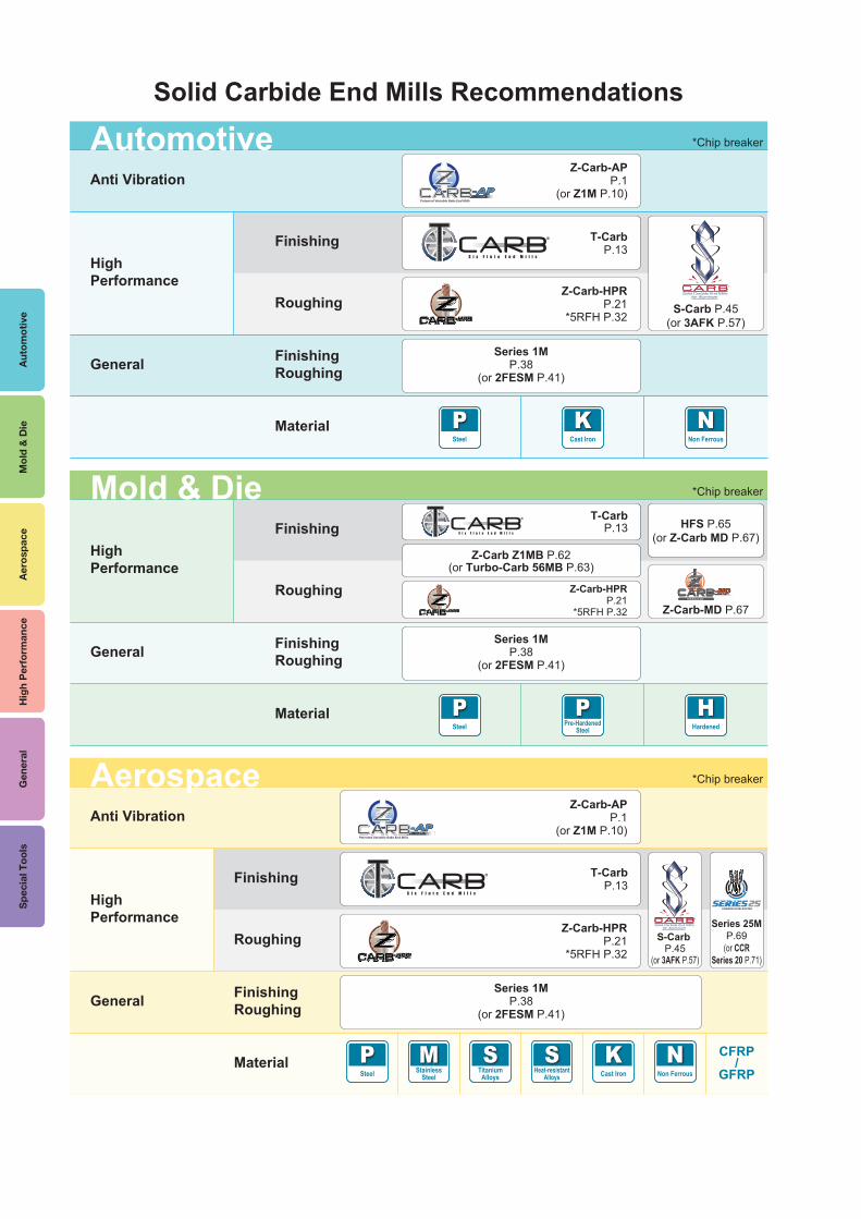
Solid Carbide End Mills Recommendations
Anti Vibration
High Performance
General
Finishing
Roughing
FinishingRoughing
®
®
Z-Carb-APP.1
(or Z1M P.10)
T-CarbP.13
Z-Carb-HPRP.21
*5RFH P.32S-Carb P.45
(or 3AFK P.57)
Series 1MP.38
(or 2FESM P.41)
NNon Ferrous
KCast Iron
Material
Automotive *Chip breaker
PSteel
Material
Anti Vibration
High Performance
General
Finishing
Roughing
FinishingRoughing
®
®
Z-Carb-APP.1
(or Z1M P.10)
T-CarbP.13
Z-Carb-HPRP.21
*5RFH P.32S-Carb
P.45(or 3AFK P.57)
Series 1MP.38
(or 2FESM P.41)
Series 25MP.69
(or CCRSeries 20 P.71)
SHeat-resistant
Alloys
KCast Iron
MStainless
Steel
STitanium
Alloys
PSteel
NNon Ferrous
CFRP/
GFRP
Aerospace *Chip breaker
High Performance
Finishing
Roughing
FinishingRoughing
®
Z-Carb-HPRP.21
*5RFH P.32
Series 1MP.38
(or 2FESM P.41)
HFS P.65(or Z-Carb MD P.67)
Z-Carb Z1MB P.62(or Turbo-Carb 56MB P.63)
Z-Carb-MD P.67
General
Material
Mold & Die *Chip breaker
PSteel
HHardened
PPre-Hardened
Steel
T-CarbP.13
Aut
omot
ive
Mol
d &
Die
Aer
ospa
ceH
igh
Per
form
ance
Gen
eral
Spe
cial
Too
ls
Autom
otiveM
old & D
ieA
erospace
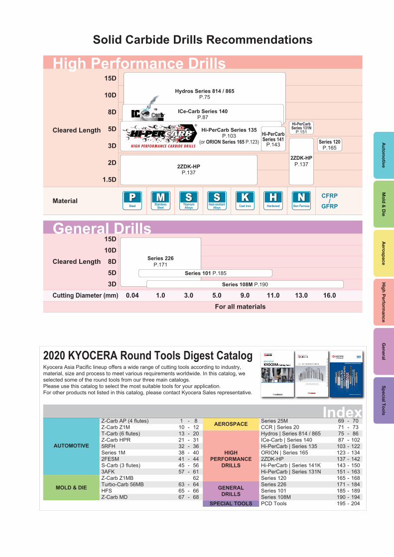
Solid Carbide Drills Recommendations
15D
10D
8D
5D
3D
2D
1.5D
For all materials
Hydros Series 814 / 865P.75
Cleared Length
High Performance Drills
SHeat-resistant
Alloys
KCast Iron
MStainless
Steel
STitanium
Alloys
PSteel
HHardened
CFRP/
GFRPN
Non Ferrous
ICe-Carb Series 140P.87
Hi-PerCarb Series 135P.103
(or ORION Series 165 P.123)Hi-PerCarbSeries 141
P.143
Hi-PerCarbSeries 131N
P.151
2ZDK-HPP.137
Series 120P.165
2ZDK-HPP.137
Material
®
15D10D8D5D3D
0.04Cutting Diameter (mm) 1.0 3.0 5.0 9.0 11.0 13.0 16.0For all materials
Series 226P.171
Series 101 P.185
Series 108M P.190
Cleared Length
General Drills
Z-Carb AP (4 flutes)Z-Carb Z1MT-Carb (6 flutes)Z-Carb HPR5RFHSeries 1M2FESMS-Carb (3 flutes)3AFKZ-Carb Z1MBTurbo-Carb 56MBHFSZ-Carb MD
11013213238414557
636567
8122031364044566162646668
---------
---
AUTOMOTIVE
MOLD & DIE
AEROSPACE Series 25MCCR | Series 20Hydros | Series 814 / 865ICe-Carb | Series 140Hi-PerCarb | Series 135ORION | Series 1652ZDK-HPHi-PerCarb | Series 141KHi-PerCarb | Series 131NSeries 120Series 226Series 101Series 108MPCD Tools
69717587103123137143151165171185190195
707386102122134142150163168184189194204
--------------
HIGHPERFORMANCE
DRILLS
GENERALDRILLS
SPECIAL TOOLS
Index
2020 KYOCERA Round Tools Digest CatalogKyocera Asia Pacific lineup offers a wide range of cutting tools according to industry, material, size and process to meet various requirements worldwide. In this catalog, we selected some of the round tools from our three main catalogs. Please use this catalog to select the most suitable tools for your application.For other products not listed in this catalog, please contact Kyocera Sales representative. www.kyocera-sgstool.com
2016 Global Product Catalog
Solid Carbide Tools
High P
erformance
General
Special Tools

1
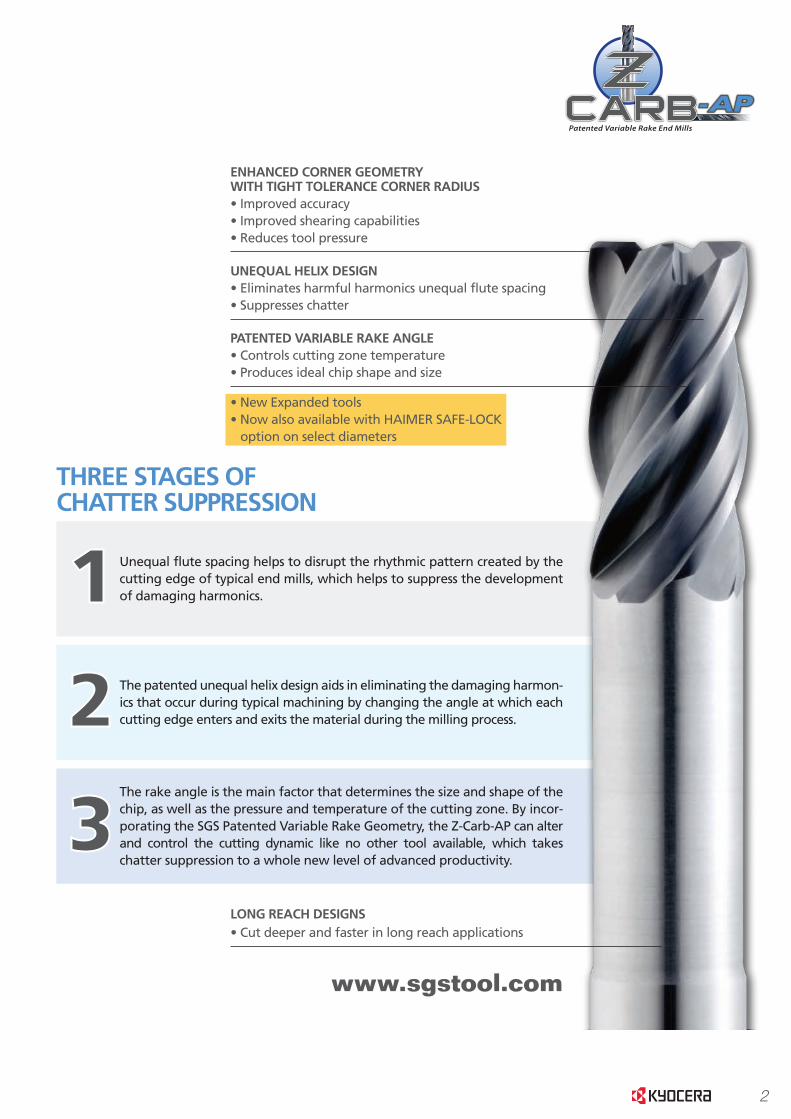
ADVANCED PATENTED DESIGNDELIVERS ADVANCED PRODUCTIVITY
With conventional end mills, the cutting teeth entering and exiting the material creates a natural
rhythm that results in damaging harmonics. Harmonics produce a frequency that resonates
through the entire tool, resulting in one of the most damaging forms of cutter wear known as
chatter. Chatter degrades the quality of your finish. It also creates tool pressure which has a neg-
ative effect on tool life. If you use conventional long reach tools, your chatter problem is further
compounded by deflection, which limits your maximum speeds and cutting depths. Until now,
your only choice was to adjust your operating parameters to account for the limitations of your
conventional end mill.
WITH ITS PATENTED, ONE-OF-A-KIND GEOMETRY, THE Z-CARB-AP OFFERS THREE STAGES OF CHATTER SUPPRESSION, RESULTING IN THE QUIETEST, MOST STABLE MILLING EXPERIENCE AVAILABLE.
THREE STAGES OFCHATTER SUPPRESSION
2
3
1
The rake angle is the main factor that determines the size and shape of the chip, as well as the pressure and temperature of the cutting zone. By incor-porating the SGS Patented Variable Rake Geometry, the Z-Carb-AP can alter and control the cutting dynamic like no other tool available, which takes chatter suppression to a whole new level of advanced productivity.
The patented unequal helix design aids in eliminating the damaging harmon-ics that occur during typical machining by changing the angle at which each cutting edge enters and exits the material during the milling process.
Unequal flute spacing helps to disrupt the rhythmic pattern created by the cutting edge of typical end mills, which helps to suppress the development of damaging harmonics.
LONG REACH DESIGNS• Cut deeper and faster in long reach applications
ENHANCED CORNER GEOMETRYWITH TIGHT TOLERANCE CORNER RADIUS• Improved accuracy• Improved shearing capabilities• Reduces tool pressure
UNEQUAL HELIX DESIGN• Eliminates harmful harmonics unequal flute spacing• Suppresses chatter
PATENTED VARIABLE RAKE ANGLE• Controls cutting zone temperature• Produces ideal chip shape and size
• New Expanded tools• Now also available with HAIMER SAFE-LOCK
option on select diameters
2
ADVANCED PATENTED DESIGNDELIVERS ADVANCED PRODUCTIVITY
With conventional end mills, the cutting teeth entering and exiting the material creates a natural
rhythm that results in damaging harmonics. Harmonics produce a frequency that resonates
through the entire tool, resulting in one of the most damaging forms of cutter wear known as
chatter. Chatter degrades the quality of your finish. It also creates tool pressure which has a neg-
ative effect on tool life. If you use conventional long reach tools, your chatter problem is further
compounded by deflection, which limits your maximum speeds and cutting depths. Until now,
your only choice was to adjust your operating parameters to account for the limitations of your
conventional end mill.
WITH ITS PATENTED, ONE-OF-A-KIND GEOMETRY, THE Z-CARB-AP OFFERS THREE STAGES OF CHATTER SUPPRESSION, RESULTING IN THE QUIETEST, MOST STABLE MILLING EXPERIENCE AVAILABLE.
THREE STAGES OFCHATTER SUPPRESSION
2
3
1
The rake angle is the main factor that determines the size and shape of the chip, as well as the pressure and temperature of the cutting zone. By incor-porating the SGS Patented Variable Rake Geometry, the Z-Carb-AP can alter and control the cutting dynamic like no other tool available, which takes chatter suppression to a whole new level of advanced productivity.
The patented unequal helix design aids in eliminating the damaging harmon-ics that occur during typical machining by changing the angle at which each cutting edge enters and exits the material during the milling process.
Unequal flute spacing helps to disrupt the rhythmic pattern created by the cutting edge of typical end mills, which helps to suppress the development of damaging harmonics.
LONG REACH DESIGNS• Cut deeper and faster in long reach applications
ENHANCED CORNER GEOMETRYWITH TIGHT TOLERANCE CORNER RADIUS• Improved accuracy• Improved shearing capabilities• Reduces tool pressure
UNEQUAL HELIX DESIGN• Eliminates harmful harmonics unequal flute spacing• Suppresses chatter
PATENTED VARIABLE RAKE ANGLE• Controls cutting zone temperature• Produces ideal chip shape and size
• New Expanded tools• Now also available with HAIMER SAFE-LOCK
option on select diameters
3
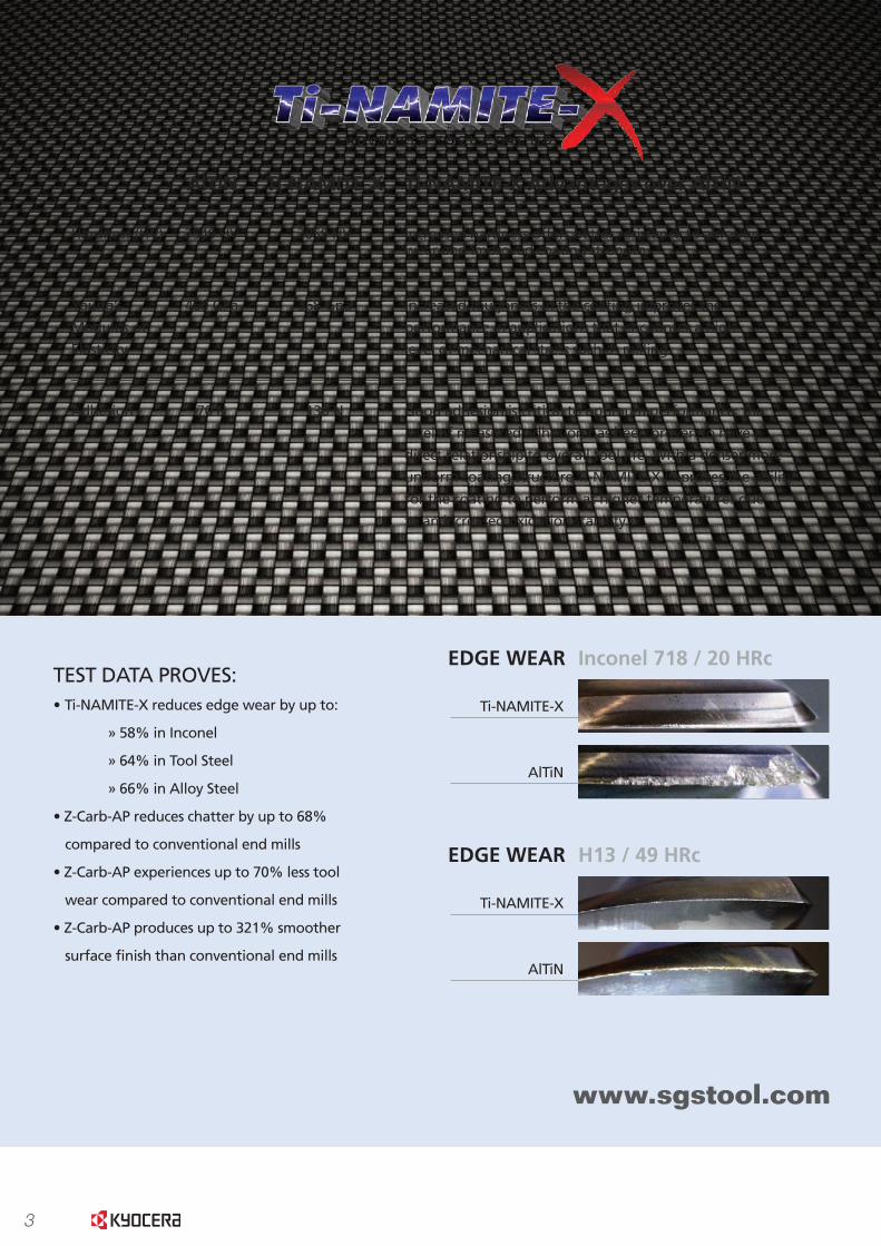
Inconel 718 / 20 HRcEDGE WEAR
Ti-NAMITE-X
AlTiN
H13 / 49 HRcEDGE WEAR
Ti-NAMITE-X
AlTiN
Quotes and figures
from end users using
Z-Carb AP tools in
their shops and
getting real results,
with real savings.
The Z-Carb AP tool saved an end user almost 74%, taking a cost per partfrom $1,073 to $281!
They’ve exceeded so well…I’m getting insane results here.
THEY HAVEN’T FAILED ME.
I know you needed results for thequarter, but I can’t give you exactdata until this thing dies.
It isn’t getting any better…with straight endmilling.
That is why I recommend you all around town.
TEST DATA PROVES:• Ti-NAMITE-X reduces edge wear by up to:
» 58% in Inconel
» 64% in Tool Steel
» 66% in Alloy Steel
• Z-Carb-AP reduces chatter by up to 68%
compared to conventional end mills
• Z-Carb-AP experiences up to 70% less tool
wear compared to conventional end mills
• Z-Carb-AP produces up to 321% smoother
surface finish than conventional end mills
AlTiN Ti-NAMITE-X Ti-NAMITE-X Advantages over AlTiN
Hardness (HV) 2549 HV 3059 HV Increased hardness offers better resistance to abrasion wear and improved coating strength.
Adhesion 70 N 130 N Good adhesion is critical to optimum performance; the
level of measured adhesion has been proven to have a
direct relationship to overall tool life. With a denser more
uniform coating structure Ti-NAMITE-X improves the ability
for the coating to perform at higher temperatures due
to an increased oxidation stability.
Young’s 460 GPa 368 Gpa Increased toughness in the coating improves the
Modulus of performance in applications that encounter a high
Elasticity level of mechanical stress such as milling.

4
Inconel 718 / 20 HRcEDGE WEAR
Ti-NAMITE-X
AlTiN
H13 / 49 HRcEDGE WEAR
Ti-NAMITE-X
AlTiN
Quotes and figures
from end users using
Z-Carb AP tools in
their shops and
getting real results,
with real savings.
The Z-Carb AP tool saved an end user almost 74%, taking a cost per partfrom $1,073 to $281!
They’ve exceeded so well…I’m getting insane results here.
THEY HAVEN’T FAILED ME.
I know you needed results for thequarter, but I can’t give you exactdata until this thing dies.
It isn’t getting any better…with straight endmilling.
That is why I recommend you all around town.
TEST DATA PROVES:• Ti-NAMITE-X reduces edge wear by up to:
» 58% in Inconel
» 64% in Tool Steel
» 66% in Alloy Steel
• Z-Carb-AP reduces chatter by up to 68%
compared to conventional end mills
• Z-Carb-AP experiences up to 70% less tool
wear compared to conventional end mills
• Z-Carb-AP produces up to 321% smoother
surface finish than conventional end mills
AlTiN Ti-NAMITE-X Ti-NAMITE-X Advantages over AlTiN
Hardness (HV) 2549 HV 3059 HV Increased hardness offers better resistance to abrasion wear and improved coating strength.
Adhesion 70 N 130 N Good adhesion is critical to optimum performance; the
level of measured adhesion has been proven to have a
direct relationship to overall tool life. With a denser more
uniform coating structure Ti-NAMITE-X improves the ability
for the coating to perform at higher temperatures due
to an increased oxidation stability.
Young’s 460 GPa 368 Gpa Increased toughness in the coating improves the
Modulus of performance in applications that encounter a high
Elasticity level of mechanical stress such as milling.

5
Aut
omot
ive
Aer
ospa
ceH
igh
Per
form
ance
Gen
eral
Spe
cial
Too
lsM
old
& D
ie
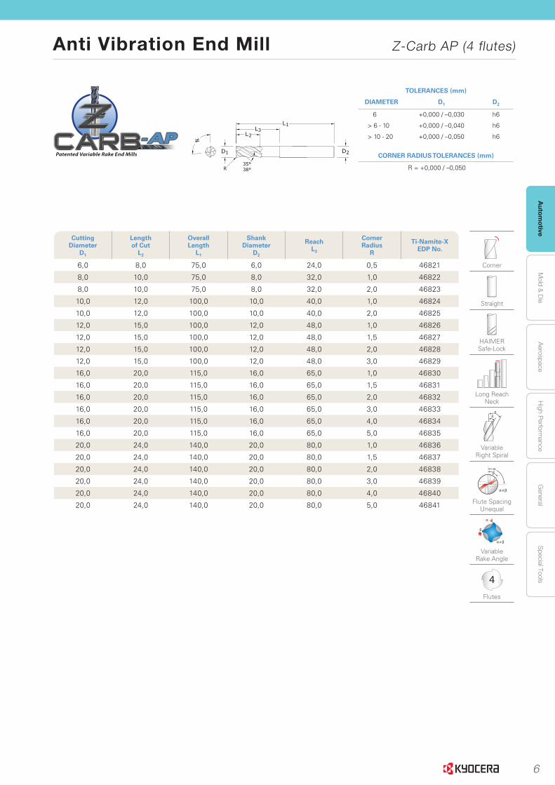
Anti Vibration End Mill Z-Carb AP (4 flutes)
www.sgstool.com8
Seri
es
Z1M
PC
R
| M
etri
c
TOLERANCES (mm)
DIAMETER D1 D2
< 3 +0,012 / –0,012 h6
3 - 6 +0,000 / –0,030 h6
> 6 - 10 +0,000 / –0,040 h6
> 10 - 25 +0,000 / –0,050 h6
CORNER RADIUS TOLERANCES (mm)
< 3 = +0,000 / –0,025
≥ 3 = +0,000 / –0,050
Cutting Diameter
D1
Lengthof Cut
L2
OverallLength
L1
Shank Diameter
D2
Corner Radius
R
Ti-Namite-X EDP No. w/o Flat
Ti-Namite-X EDP No. w/ Flat
JetStream EDP No.
1,0 3,0 57,0 6,0 0,1 46873 – –
1,5 4,5 57,0 6,0 0,1 46849 – –
2,0 6,0 57,0 6,0 0,2 46850 – –
2,5 7,0 57,0 6,0 0,2 46874 – –
3,0 8,0 57,0 6,0 0,3 46851 – –
3,0 8,0 57,0 6,0 0,5 46880 – –
4,0 11,0 57,0 6,0 0,3 46852 – –
4,0 11,0 57,0 6,0 0,5 46881 – –
5,0 6,0 57,0 13,0 0,3 46853 – –
6,0 13,0 57,0 6,0 0,25 46882 – –
6,0 13,0 57,0 6,0 0,5 46854 – –
6,0 13,0 57,0 6,0 1,0 46855 – –
6,0 13,0 57,0 6,0 1,5 46884 – –
8,0 19,0 63,0 8,0 0,5 46856 – –
8,0 19,0 63,0 8,0 1,0 46857 – –
8,0 19,0 63,0 8,0 1,5 46886 – –
8,0 19,0 63,0 8,0 2,0 46887 – –
10,0 22,0 72,0 10,0 0,5 46858 – –
10,0 22,0 72,0 10,0 1,0 46859 – –
10,0 22,0 72,0 10,0 1,5 46889 – –
10,0 22,0 72,0 10,0 2,0 46890 – –
10,0 22,0 72,0 10,0 2,5 46891 – –
12,0 26,0 83,0 12,0 0,5 46860 46909 –
12,0 26,0 83,0 12,0 0,75 46861 46910 –
12,0 26,0 83,0 12,0 1,0 46893 46911 –
12,0 26,0 83,0 12,0 1,5 46894 46912 –
12,0 26,0 83,0 12,0 2,0 46895 46913 –
12,0 26,0 83,0 12,0 2,5 46896 46914 –
12,0 26,0 83,0 12,0 3,0 42718 46915 –
14,0 14,0 83,0 26,0 1,0 46862 46916 46494
16,0 32,0 92,0 16,0 1,0 46863 46917 46495
16,0 32,0 92,0 16,0 1,5 46898 46918 –
16,0 32,0 92,0 16,0 2,0 46899 46919 –
16,0 32,0 92,0 16,0 2,5 46900 46920 –
16,0 32,0 92,0 16,0 3,0 46864 46921 –
20,0 38,0 104,0 20,0 1,0 46865 46922 46497
20,0 38,0 104,0 20,0 1,5 46903 46923 –
20,0 38,0 104,0 20,0 2,0 46904 46924 –
20,0 38,0 104,0 20,0 2,5 46905 46925 –
20,0 38,0 104,0 20,0 3,0 42722 46926 –
25,0 38,0 104,0 25,0 1,0 46866 46927 46498
Corner
Straight
Weldon Flat
HAIMER Safe-Lock
Regular
Variable Right Spiral
≠
Flute Spacing Unequal
≠
Variable Rake Angle
JetStream Coolant Slots
4
Flutes
New Expanded Tools
Z-Carb-AP with JetStream
Z-Carb-AP
6
Autom
otiveA
erospaceH
igh Perform
anceG
eneralS
pecial ToolsM
old & D
ie
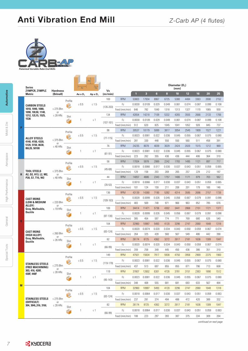
Anti Vibration End Mill Z-Carb AP (4 flutes)
www.sgstool.com10
Seri
es
Z1M
PLC
|
Met
ric
TOLERANCES (mm)
DIAMETER D1 D2
6 +0,000 / –0,030 h6
> 6 - 10 +0,000 / –0,040 h6
> 10 - 20 +0,000 / –0,050 h6
CORNER RADIUS TOLERANCES (mm)
R = +0,000 / –0,050
Cutting Diameter
D1
Lengthof Cut
L2
OverallLength
L1
Shank Diameter
D2
ReachL3
Corner Radius
R
Ti-Namite-X EDP No.
6,0 8,0 75,0 6,0 24,0 0,5 46821
8,0 10,0 75,0 8,0 32,0 1,0 46822
8,0 10,0 75,0 8,0 32,0 2,0 46823
10,0 12,0 100,0 10,0 40,0 1,0 46824
10,0 12,0 100,0 10,0 40,0 2,0 46825
12,0 15,0 100,0 12,0 48,0 1,0 46826
12,0 15,0 100,0 12,0 48,0 1,5 46827
12,0 15,0 100,0 12,0 48,0 2,0 46828
12,0 15,0 100,0 12,0 48,0 3,0 46829
16,0 20,0 115,0 16,0 65,0 1,0 46830
16,0 20,0 115,0 16,0 65,0 1,5 46831
16,0 20,0 115,0 16,0 65,0 2,0 46832
16,0 20,0 115,0 16,0 65,0 3,0 46833
16,0 20,0 115,0 16,0 65,0 4,0 46834
16,0 20,0 115,0 16,0 65,0 5,0 46835
20,0 24,0 140,0 20,0 80,0 1,0 46836
20,0 24,0 140,0 20,0 80,0 1,5 46837
20,0 24,0 140,0 20,0 80,0 2,0 46838
20,0 24,0 140,0 20,0 80,0 3,0 46839
20,0 24,0 140,0 20,0 80,0 4,0 46840
20,0 24,0 140,0 20,0 80,0 5,0 46841
Corner
Straight
HAIMER Safe-Lock
Long Reach Neck
Variable Right Spiral
≠
Flute Spacing Unequal
≠
Variable Rake Angle
4
Flutes
7
Aut
omot
ive
Aer
ospa
ceH
igh
Per
form
ance
Gen
eral
Spe
cial
Too
lsM
old
& D
ie
Anti Vibration End Mill Z-Carb AP (4 flutes)
www.sgstool.com14
Z-C
arb
-AP
|
Spee
d &
Fee
d R
eco
mm
end
atio
ns
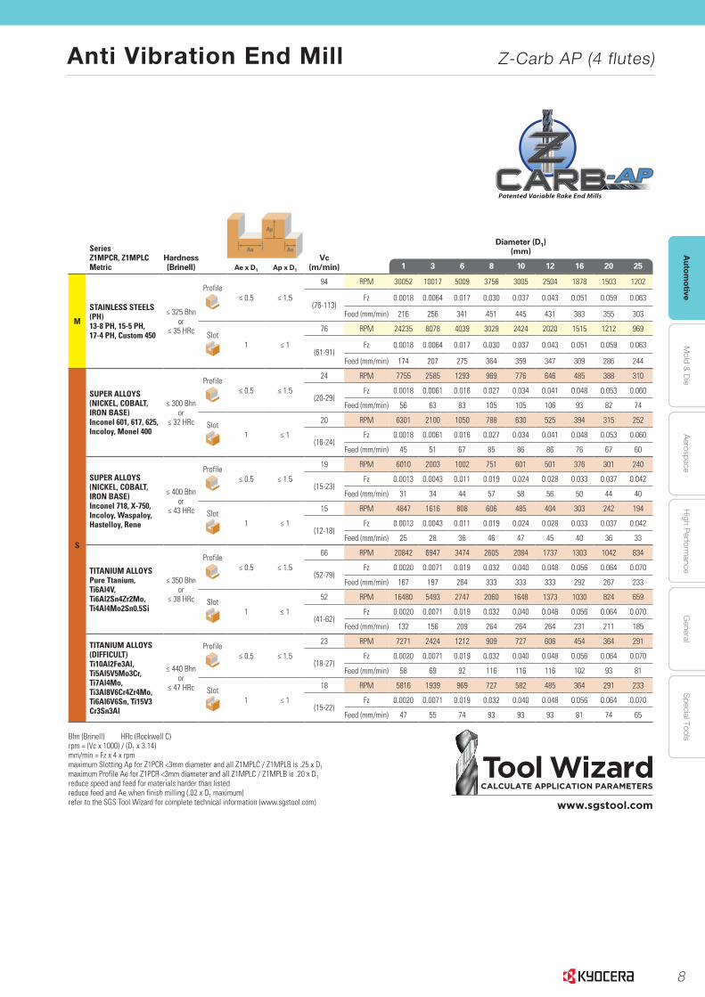
Series Z1MPCR, Z1MPLC Metric
Hardness(Brinell)
Ap
Ae AeVc
(m/min)
Diameter (D1)(mm)
Ae x D1 Ap x D11 3 6 8 10 12 16 20 25
P
CARBON STEELS 1018, 1040, 1080, 1090, 10L50, 1140, 1212, 12L15, 1525, 1536
≤ 275 Bhnor
≤ 28 HRc
Profile≤ 0.5 ≤ 1.5
169 RPM 53803 17934 8967 6725 5380 4484 3363 2690 2152
(135-203)Fz 0.0030 0.0109 0.029 0.049 0.061 0.074 0.087 0.099 0.108
Feed (mm/min) 646 782 1040 1318 1313 1327 1170 1065 930
Slot1 ≤ 1
134 RPM 42654 14218 7109 5332 4265 3555 2666 2133 1706
(107-161)Fz 0.0030 0.0109 0.029 0.049 0.061 0.074 0.087 0.099 0.108
Feed (mm/min) 512 620 825 1045 1041 1052 928 845 737
ALLOY STEELS4140, 4150, 4320, 5120, 5150, 8630, 86L20, 50100
≤ 375 Bhnor
≤ 40 HRc
Profile≤ 0.5 ≤ 1.5
96 RPM 30537 10179 5089 3817 3054 2545 1909 1527 1221
(77-115)Fz 0.0023 0.0081 0.022 0.036 0.045 0.055 0.067 0.075 0.080
Feed (mm/min) 281 330 448 550 550 560 511 458 391
Slot1 ≤ 1
76 RPM 24235 8078 4039 3029 2424 2020 1515 1212 969
(61-91)Fz 0.0023 0.0081 0.022 0.036 0.045 0.055 0.067 0.075 0.080
Feed (mm/min) 223 262 355 436 436 444 406 364 310
HTOOL STEELS A2, D2, H13, L2, M2, P20, S7, T15, W2
≤ 375 Bhnor
≤ 40 HRc
Profile≤ 0.5 ≤ 1.5
56 RPM 17934 5978 2989 2242 1793 1495 1121 897 717
(45-68)Fz 0.0018 0.0066 0.017 0.030 0.037 0.043 0.051 0.059 0.065
Feed (mm/min) 129 158 203 269 265 257 229 212 187
Slot1 ≤ 1
44 RPM 14057 4686 2343 1757 1406 1171 879 703 562
(35-53)Fz 0.0018 0.0066 0.017 0.030 0.037 0.043 0.051 0.059 0.065
Feed (mm/min) 101 124 159 211 208 201 179 166 146
K
CAST IRONS(LOW & MEDIUM ALLOY)Gray, Malleable, Ductile
≤ 220 Bhnor
≤ 19 HRc
Profile≤ 0.5 ≤ 1.5
136 RPM 43139 14380 7190 5392 4314 3595 2696 2157 1726
(109-163)Fz 0.0028 0.0099 0.026 0.045 0.056 0.067 0.079 0.091 0.098
Feed (mm/min) 483 569 748 971 966 963 852 785 676
Slot1 ≤ 1
108 RPM 34414 11471 5736 4302 3441 2868 2151 1721 1377
(87-130)Fz 0.0028 0.0099 0.026 0.045 0.056 0.067 0.079 0.091 0.098
Feed (mm/min) 385 454 597 774 771 769 680 626 540
CAST IRONS (HIGH ALLOY)Gray, Malleable, Ductile
≤ 260 Bhnor
≤ 26 HRc
Profile≤ 0.5 ≤ 1.5
104 RPM 32960 10987 5493 4120 3296 2747 2060 1648 1318
(83-124)Fz 0.0020 0.0074 0.020 0.034 0.043 0.050 0.059 0.067 0.074
Feed (mm/min) 264 325 439 560 567 549 486 442 390
Slot1 ≤ 1
82 RPM 26174 8725 4362 3272 2617 2181 1636 1309 1047
(66-99)Fz 0.0020 0.0074 0.020 0.034 0.043 0.050 0.059 0.067 0.074
Feed (mm/min) 209 258 349 445 450 436 386 351 310
M
STAINLESS STEELS(FREE MACHINING) 303, 416, 420F, 430F, 440F
≤ 275 Bhnor
≤ 28 HRc
Profile≤ 0.5 ≤ 1.5
149 RPM 47501 15834 7917 5938 4750 3958 2969 2375 1900
(119-179)Fz 0.0023 0.0081 0.022 0.036 0.045 0.055 0.067 0.075 0.080
Feed (mm/min) 437 513 697 855 855 871 796 713 608
Slot1 ≤ 1
119 RPM 37807 12602 6301 4726 3781 3151 2363 1890 1512
(95-143)Fz 0.0023 0.0081 0.022 0.036 0.045 0.055 0.067 0.075 0.080
Feed (mm/min) 348 408 555 681 681 693 633 567 484
STAINLESS STEELS (DIFFICULT) 304, 304L,316, 316L
≤ 275 Bhnor
≤ 28 HRc
Profile≤ 0.5 ≤ 1.5
104 RPM 32960 10987 5493 4120 3296 2747 2060 1648 1318
(83-124)Fz 0.0018 0.0064 0.017 0.030 0.037 0.043 0.051 0.059 0.063
Feed (mm/min) 237 281 374 494 488 472 420 389 332
Slot1 ≤ 1
82 RPM 26174 8725 4362 3272 2617 2181 1636 1309 1047
(66-99)Fz 0.0018 0.0064 0.017 0.030 0.037 0.043 0.051 0.059 0.063
Feed (mm/min) 188 223 297 393 387 375 334 309 264
continued on next page
8
Autom
otiveA
erospaceH
igh Perform
anceG
eneralS
pecial ToolsM
old & D
ie
Anti Vibration End Mill Z-Carb AP (4 flutes)
www.sgstool.com 15
Z-Ca
rb-A
P
| Sp
eed &
Feed R
ecom
men
datio
ns
Tool WizardCALCULATE APPLICATION PARAMETERS
www.sgstool.com
Series Z1MPCR, Z1MPLC Metric
Hardness(Brinell)
Ap
Ae AeVc
(m/min)
Diameter (D1)(mm)
Ae x D1 Ap x D11 3 6 8 10 12 16 20 25
M
STAINLESS STEELS (PH) 13-8 PH, 15-5 PH, 17-4 PH, Custom 450
≤ 325 Bhnor
≤ 35 HRc
Profile≤ 0.5 ≤ 1.5
94 RPM 30052 10017 5009 3756 3005 2504 1878 1503 1202
(76-113)Fz 0.0018 0.0064 0.017 0.030 0.037 0.043 0.051 0.059 0.063
Feed (mm/min) 216 256 341 451 445 431 383 355 303
Slot1 ≤ 1
76 RPM 24235 8078 4039 3029 2424 2020 1515 1212 969
(61-91)Fz 0.0018 0.0064 0.017 0.030 0.037 0.043 0.051 0.059 0.063
Feed (mm/min) 174 207 275 364 359 347 309 286 244
S
SUPER ALLOYS(NICKEL, COBALT, IRON BASE) Inconel 601, 617, 625, Incoloy, Monel 400
≤ 300 Bhnor
≤ 32 HRc
Profile≤ 0.5 ≤ 1.5
24 RPM 7755 2585 1293 969 776 646 485 388 310
(20-29)Fz 0.0018 0.0061 0.016 0.027 0.034 0.041 0.048 0.053 0.060
Feed (mm/min) 56 63 83 105 105 106 93 82 74
Slot1 ≤ 1
20 RPM 6301 2100 1050 788 630 525 394 315 252
(16-24)Fz 0.0018 0.0061 0.016 0.027 0.034 0.041 0.048 0.053 0.060
Feed (mm/min) 45 51 67 85 86 86 76 67 60
SUPER ALLOYS(NICKEL, COBALT, IRON BASE) Inconel 718, X-750, Incoloy, Waspaloy, Hastelloy, Rene
≤ 400 Bhnor
≤ 43 HRc
Profile≤ 0.5 ≤ 1.5
19 RPM 6010 2003 1002 751 601 501 376 301 240
(15-23)Fz 0.0013 0.0043 0.011 0.019 0.024 0.028 0.033 0.037 0.042
Feed (mm/min) 31 34 44 57 58 56 50 44 40
Slot1 ≤ 1
15 RPM 4847 1616 808 606 485 404 303 242 194
(12-18)Fz 0.0013 0.0043 0.011 0.019 0.024 0.028 0.033 0.037 0.042
Feed (mm/min) 25 28 36 46 47 45 40 36 33
TITANIUM ALLOYS Pure Ttanium, Ti6Al4V, Ti6Al2Sn4Zr2Mo, Ti4Al4Mo2Sn0.5Si
≤ 350 Bhnor
≤ 38 HRc
Profile≤ 0.5 ≤ 1.5
66 RPM 20842 6947 3474 2605 2084 1737 1303 1042 834
(52-79)Fz 0.0020 0.0071 0.019 0.032 0.040 0.048 0.056 0.064 0.070
Feed (mm/min) 167 197 264 333 333 333 292 267 233
Slot1 ≤ 1
52 RPM 16480 5493 2747 2060 1648 1373 1030 824 659
(41-62)Fz 0.0020 0.0071 0.019 0.032 0.040 0.048 0.056 0.064 0.070
Feed (mm/min) 132 156 209 264 264 264 231 211 185
TITANIUM ALLOYS (DIFFICULT) Ti10Al2Fe3Al, Ti5Al5V5Mo3Cr, Ti7Al4Mo, Ti3Al8V6Cr4Zr4Mo, Ti6Al6V6Sn, Ti15V3 Cr3Sn3Al
≤ 440 Bhnor
≤ 47 HRc
Profile≤ 0.5 ≤ 1.5
23 RPM 7271 2424 1212 909 727 606 454 364 291
(18-27)Fz 0.0020 0.0071 0.019 0.032 0.040 0.048 0.056 0.064 0.070
Feed (mm/min) 58 69 92 116 116 116 102 93 81
Slot1 ≤ 1
18 RPM 5816 1939 969 727 582 485 364 291 233
(15-22)Fz 0.0020 0.0071 0.019 0.032 0.040 0.048 0.056 0.064 0.070
Feed (mm/min) 47 55 74 93 93 93 81 74 65
Bhn (Brinell) HRc (Rockwell C)rpm = (Vc x 1000) / (D1 x 3.14)mm/min = Fz x 4 x rpmmaximum Slotting Ap for Z1PCR <3mm diameter and all Z1MPLC / Z1MPLB is .25 x D1 maximum Profile Ae for Z1PCR <3mm diameter and all Z1MPLC / Z1MPLB is .20 x D1 reduce speed and feed for materials harder than listed reduce feed and Ae when finish milling (.02 x D1 maximum)refer to the SGS Tool Wizard for complete technical information (www.sgstool.com)

9
Memo
10
Autom
otiveA
erospaceH
igh Perform
anceG
eneralS
pecial ToolsM
old & D
ieA
erospaceSTEELS
STAINLESS STEELS
CAST IRON
HIGH TEMP ALLOYS
TITANIUM
HARDENED STEELS
52www.kyocera-sgstool.comEND MILLS END MILLS
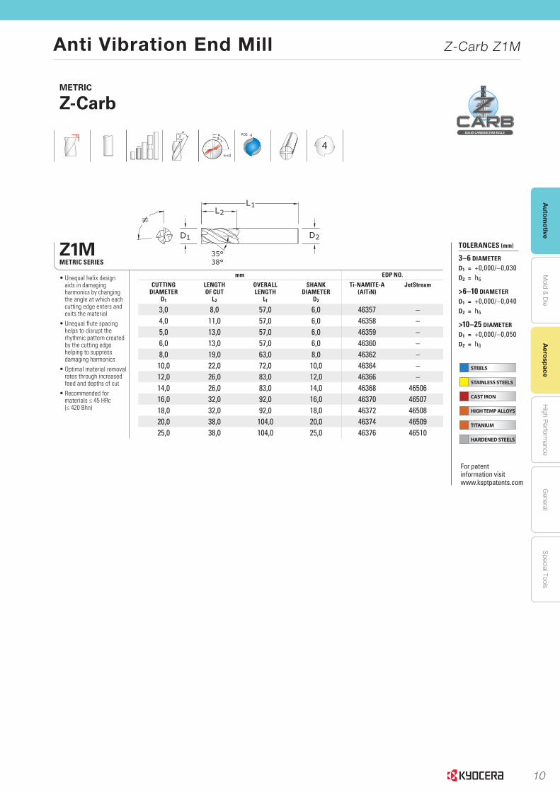
Z1MMETRIC SERIES
mm EDP NO.
CUTTING DIAMETER
D1
LENGTH OF CUT
L2
OVERALL LENGTH
L1
SHANK DIAMETER
D2
Ti-NAMITE-A(AlTiN)
JetStream
3,0 8,0 57,0 6,0 46357 –4,0 11,0 57,0 6,0 46358 –5,0 13,0 57,0 6,0 46359 –6,0 13,0 57,0 6,0 46360 –8,0 19,0 63,0 8,0 46362 –10,0 22,0 72,0 10,0 46364 –12,0 26,0 83,0 12,0 46366 –14,0 26,0 83,0 14,0 46368 4650616,0 32,0 92,0 16,0 46370 4650718,0 32,0 92,0 18,0 46372 4650820,0 38,0 104,0 20,0 46374 4650925,0 38,0 104,0 25,0 46376 46510
METRIC
Z-Carb
• Unequal helix design aids in damaging harmonics by changing the angle at which each cutting edge enters and exits the material
• Unequal flute spacing helps to disrupt the rhythmic pattern created by the cutting edge helping to suppress damaging harmonics
• Optimal material removal rates through increased feed and depths of cut
• Recommended for materials ≤ 45 HRc (≤ 420 Bhn)
≠
POS
4
TOLERANCES (mm)
3–6 DIAMETER
D1 = +0,000/–0,030D2 = h6
>6–10 DIAMETER
D1 = +0,000/–0,040D2 = h6
>10–25 DIAMETER
D1 = +0,000/–0,050D2 = h6
For patent information visit www.ksptpatents.com
Anti Vibration End Mill Z-Carb Z1M
11
Aut
omot
ive
Aer
ospa
ceH
igh
Per
form
ance
Gen
eral
Spe
cial
Too
lsM
old
& D
ie
Anti Vibration End Mill Z-Carb Z1M
Aer
ospa
ce
54 END MILLS END MILLSwww.kyocera-sgstool.com
METRIC
Z-Carb
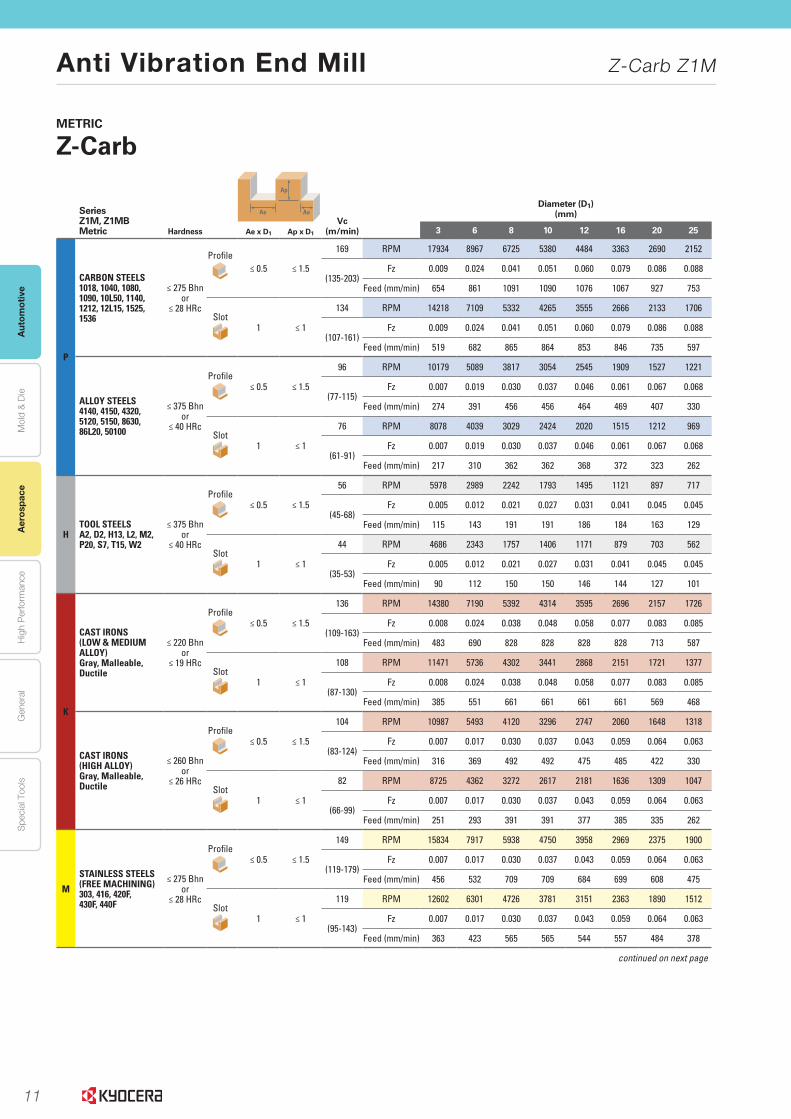
Series Z1M, Z1MBMetric Hardness
Ap
Ae AeVc
(m/min)
Diameter (D1)(mm)
Ae x D1 Ap x D1 3 6 8 10 12 16 20 25
P
CARBON STEELS1018, 1040, 1080, 1090, 10L50, 1140, 1212, 12L15, 1525, 1536
≤ 275 Bhnor
≤ 28 HRc
Profile≤ 0.5 ≤ 1.5
169 RPM 17934 8967 6725 5380 4484 3363 2690 2152
(135-203)Fz 0.009 0.024 0.041 0.051 0.060 0.079 0.086 0.088
Feed (mm/min) 654 861 1091 1090 1076 1067 927 753
Slot1 ≤ 1
134 RPM 14218 7109 5332 4265 3555 2666 2133 1706
(107-161)Fz 0.009 0.024 0.041 0.051 0.060 0.079 0.086 0.088
Feed (mm/min) 519 682 865 864 853 846 735 597
ALLOY STEELS4140, 4150, 4320, 5120, 5150, 8630, 86L20, 50100
≤ 375 Bhnor
≤ 40 HRc
Profile≤ 0.5 ≤ 1.5
96 RPM 10179 5089 3817 3054 2545 1909 1527 1221
(77-115)Fz 0.007 0.019 0.030 0.037 0.046 0.061 0.067 0.068
Feed (mm/min) 274 391 456 456 464 469 407 330
Slot1 ≤ 1
76 RPM 8078 4039 3029 2424 2020 1515 1212 969
(61-91)Fz 0.007 0.019 0.030 0.037 0.046 0.061 0.067 0.068
Feed (mm/min) 217 310 362 362 368 372 323 262
HTOOL STEELSA2, D2, H13, L2, M2, P20, S7, T15, W2
≤ 375 Bhnor
≤ 40 HRc
Profile≤ 0.5 ≤ 1.5
56 RPM 5978 2989 2242 1793 1495 1121 897 717
(45-68)Fz 0.005 0.012 0.021 0.027 0.031 0.041 0.045 0.045
Feed (mm/min) 115 143 191 191 186 184 163 129
Slot1 ≤ 1
44 RPM 4686 2343 1757 1406 1171 879 703 562
(35-53)Fz 0.005 0.012 0.021 0.027 0.031 0.041 0.045 0.045
Feed (mm/min) 90 112 150 150 146 144 127 101
K
CAST IRONS(LOW & MEDIUM ALLOY)Gray, Malleable, Ductile
≤ 220 Bhnor
≤ 19 HRc
Profile≤ 0.5 ≤ 1.5
136 RPM 14380 7190 5392 4314 3595 2696 2157 1726
(109-163)Fz 0.008 0.024 0.038 0.048 0.058 0.077 0.083 0.085
Feed (mm/min) 483 690 828 828 828 828 713 587
Slot1 ≤ 1
108 RPM 11471 5736 4302 3441 2868 2151 1721 1377
(87-130) Fz 0.008 0.024 0.038 0.048 0.058 0.077 0.083 0.085
Feed (mm/min) 385 551 661 661 661 661 569 468
CAST IRONS (HIGH ALLOY)Gray, Malleable, Ductile
≤ 260 Bhnor
≤ 26 HRc
Profile≤ 0.5 ≤ 1.5
104 RPM 10987 5493 4120 3296 2747 2060 1648 1318
(83-124)Fz 0.007 0.017 0.030 0.037 0.043 0.059 0.064 0.063
Feed (mm/min) 316 369 492 492 475 485 422 330
Slot1 ≤ 1
82 RPM 8725 4362 3272 2617 2181 1636 1309 1047
(66-99)Fz 0.007 0.017 0.030 0.037 0.043 0.059 0.064 0.063
Feed (mm/min) 251 293 391 391 377 385 335 262
M
STAINLESS STEELS(FREE MACHINING)303, 416, 420F, 430F, 440F
≤ 275 Bhnor
≤ 28 HRc
Profile≤ 0.5 ≤ 1.5
149 RPM 15834 7917 5938 4750 3958 2969 2375 1900
(119-179)Fz 0.007 0.017 0.030 0.037 0.043 0.059 0.064 0.063
Feed (mm/min) 456 532 709 709 684 699 608 475
Slot1 ≤ 1
119 RPM 12602 6301 4726 3781 3151 2363 1890 1512
(95-143)Fz 0.007 0.017 0.030 0.037 0.043 0.059 0.064 0.063
Feed (mm/min) 363 423 565 565 544 557 484 378
continued on next page

12
Autom
otiveA
erospaceH
igh Perform
anceG
eneralS
pecial ToolsM
old & D
ie
Anti Vibration End Mill Z-Carb Z1M
Aerospace
55END MILLS END MILLSwww.kyocera-sgstool.com
METRIC
Z-Carb
Series Z1M, Z1MBMetric Hardness
Ap
Ae AeVc
(m/min)
Diameter (D1)(mm)
Ae x D1 Ap x D1 3 6 8 10 12 16 20 25
M
STAINLESS STEELS (DIFFICULT)304, 304L, 316, 316L
≤ 275 Bhnor
≤ 28 HRc
Profile≤ 0.5 ≤ 1.5
104 RPM 10987 5493 4120 3296 2747 2060 1648 1318
(83-124)Fz 0.005 0.014 0.023 0.029 0.034 0.046 0.051 0.050
Feed (mm/min) 211 316 387 387 369 380 334 264
Slot1 ≤ 1
82 RPM 8725 4362 3272 2617 2181 1636 1309 1047
(66-99)Fz 0.005 0.014 0.023 0.029 0.034 0.046 0.051 0.050
Feed (mm/min) 168 251 307 307 293 302 265 209
STAINLESS STEELS (PH)13-8 PH, 15-5 PH,17-4 PH, Custom 450
≤ 325 Bhnor
≤ 35 HRc
Profile≤ 0.5 ≤ 1.5
94 RPM 10017 5009 3756 3005 2504 1878 1503 1202
(76-113)Fz 0.005 0.014 0.023 0.029 0.034 0.046 0.051 0.050
Feed (mm/min) 192 288 353 353 337 346 305 240
Slot1 ≤ 1
76 RPM 8078 4039 3029 2424 2020 1515 1212 969
(61-91)Fz 0.005 0.014 0.023 0.029 0.034 0.046 0.051 0.050
Feed (mm/min) 155 233 284 284 271 279 246 194
S
SUPER ALLOYS(NICKEL, COBALT, IRON BASE) Inconel 601, 617, 625, Incoloy, Monel 400
≤ 300 Bhnor
≤ 32 HRc
Profile≤ 0.5 ≤ 1.5
24 RPM 2585 1293 969 776 646 485 388 310
(20-29)Fz 0.005 0.010 0.017 0.021 0.024 0.033 0.037 0.038
Feed (mm/min) 55 50 66 53 62 65 58 47
Slot1 ≤ 1
20 RPM 2100 1050 788 630 525 394 315 252
(16-24)Fz 0.005 0.010 0.017 0.021 0.024 0.033 0.037 0.038
Feed (mm/min) 40 40 54 54 50 52 47 38
SUPER ALLOYS(NICKEL, COBALT, IRON BASE) Inconel 718, X-750, Incoloy, Waspaloy, Hastelloy, Rene
≤ 400 Bhnor
≤ 43 HRc
Profile≤ 0.5 ≤ 1.5
19 RPM 2003 1002 751 601 501 376 301 240
(15-23)Fz 0.002 0.007 0.011 0.013 0.017 0.020 0.024 0.025
Feed (mm/min) 19 29 32 32 34 31 29 24
Slot1 ≤ 1
15 RPM 1583 792 594 475 396 297 238 190
(12-18)Fz 0.002 0.007 0.011 0.013 0.017 0.020 0.024 0.025
Feed (mm/min) 15 23 25 25 27 24 23 19
TITANIUM ALLOYSPure Titanium, Ti6Al4V, Ti6Al2Sn4Zr2Mo, Ti4Al4Mo2Sn0.5Si
≤ 350 Bhnor
≤ 38 HRc
Profile≤ 0.5 ≤ 1.5
66 RPM 6947 3474 2605 2084 1737 1303 1042 834
(52-79)Fz 0.005 0.012 0.021 0.027 0.031 0.041 0.045 0.045
Feed (mm/min) 133 167 222 222 217 213 189 150
Slot1 ≤ 1
52 RPM 5493 2747 2060 1648 1373 1030 824 659
(41-62)Fz 0.005 0.012 0.021 0.027 0.031 0.041 0.045 0.045
Feed (mm/min) 105 132 176 176 171 169 149 119
TITANIUM ALLOYS (DIFFICULT) Ti10Al2Fe3Al, Ti5Al5V5Mo3Cr, Ti7Al4Mo, Ti3Al8V6Cr4Zr4Mo, Ti6Al6V6Sn, Ti15V3 Cr3Sn3Al
≤ 440 Bhnor
≤ 47 HRc
Profile≤ 0.5 ≤ 1.5
23 RPM 2424 1212 909 727 606 454 364 291
(18-27)Fz 0.005 0.012 0.021 0.027 0.031 0.041 0.045 0.045
Feed (mm/min) 47 58 78 78 76 74 66 52
Slot1 ≤ 1
18 RPM 1939 969 727 582 485 364 291 233
(15-22)Fz 0.005 0.012 0.021 0.027 0.031 0.041 0.045 0.045
Feed (mm/min) 37 47 62 62 60 60 53 42
Bhn (Brinell) HRc (Rockwell C)rpm = (Vc x 1000) / (D1 x 3.14)ipm = Fz x 4 x rpm reduce speed and feed for materials harder than listedreduce feed and Ae when finish milling (.02 x D1 maximum)refer to the KYOCERA SGS Tool Wizard® for complete technical information (www.kyocera-sgstool.com)
13
2 www.kyocera-sgstool.com
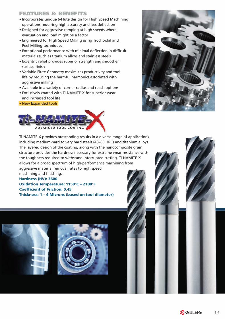
®FEATURES & BENEFITS• Incorporates unique 6-Flute design for High Speed Machining
operations requiring high accuracy and less deflection • Designed for aggressive ramping at high speeds where
evacuation and load might be a factor• Engineered for High Speed Milling using Trochoidal and
Peel Milling techniques• Exceptional performance with minimal deflection in difficult
materials such as titanium alloys and stainless steels• Eccentric relief provides superior strength and smoother
surface finish• Variable Flute Geometry maximizes productivity and tool
life by reducing the harmful harmonics associated with aggressive milling
• Available in a variety of corner radius and reach options• Exclusively coated with Ti-NAMITE-X for superior wear
and increased tool life• New Expanded tools
Ti-NAMITE-X provides outstanding results in a diverse range of applications including medium-hard to very hard steels (40–65 HRC) and titanium alloys. The layered design of the coating, along with the nanocomposite grain structure provides the hardness necessary for extreme wear resistance with the toughness required to withstand interrupted cutting. Ti-NAMITE-X allows for a broad spectrum of high-performance machining from aggressive material removal rates to high speed machining and finishing.Hardness (HV): 3600 Oxidation Temperature: 1150°C – 2100°F Coef�cient of Friction: 0.45 Thickness: 1 – 4 Microns (based on tool diameter)
T-CARB® HIGH SPEED MACHINING END MILLS AREIDEAL FOR AGGRESSIVE MILLING APPLICATIONSIN THESE TARGET MARKETS:• Aerospace Structural and Titanium Components
• Medical Replacement Parts and Joints
• Automotive & Motorized Vehicles
• Energy and Power Generation
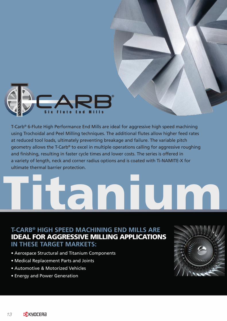
T-Carb® 6-Flute High Performance End Mills are ideal for aggressive high speed machining
using Trochoidal and Peel Milling techniques. The additional flutes allow higher feed rates
at reduced tool loads, ultimately preventing breakage and failure. The variable pitch
geometry allows the T-Carb® to excel in multiple operations calling for aggressive roughing
and finishing, resulting in faster cycle times and lower costs. The series is offered in
a variety of length, neck and corner radius options and is coated with Ti-NAMITE-X for
ultimate thermal barrier protection.
Titanium
®
14
2 www.kyocera-sgstool.com
®FEATURES & BENEFITS• Incorporates unique 6-Flute design for High Speed Machining operations requiring high accuracy and less deflection • Designed for aggressive ramping at high speeds where evacuation and load might be a factor• Engineered for High Speed Milling using Trochoidal and Peel Milling techniques• Exceptional performance with minimal deflection in difficult materials such as titanium alloys and stainless steels• Eccentric relief provides superior strength and smoother surface finish• Variable Flute Geometry maximizes productivity and tool life by reducing the harmful harmonics associated with aggressive milling• Available in a variety of corner radius and reach options• Exclusively coated with Ti-NAMITE-X for superior wear and increased tool life• New Expanded tools
Ti-NAMITE-X provides outstanding results in a diverse range of applications including medium-hard to very hard steels (40–65 HRC) and titanium alloys. The layered design of the coating, along with the nanocomposite grain structure provides the hardness necessary for extreme wear resistance with the toughness required to withstand interrupted cutting. Ti-NAMITE-X allows for a broad spectrum of high-performance machining from aggressive material removal rates to high speed machining and finishing.Hardness (HV): 3600 Oxidation Temperature: 1150°C – 2100°F Coef�cient of Friction: 0.45 Thickness: 1 – 4 Microns (based on tool diameter)
T-CARB® HIGH SPEED MACHINING END MILLS AREIDEAL FOR AGGRESSIVE MILLING APPLICATIONSIN THESE TARGET MARKETS:• Aerospace Structural and Titanium Components
• Medical Replacement Parts and Joints
• Automotive & Motorized Vehicles
• Energy and Power Generation
T-Carb® 6-Flute High Performance End Mills are ideal for aggressive high speed machining
using Trochoidal and Peel Milling techniques. The additional flutes allow higher feed rates
at reduced tool loads, ultimately preventing breakage and failure. The variable pitch
geometry allows the T-Carb® to excel in multiple operations calling for aggressive roughing
and finishing, resulting in faster cycle times and lower costs. The series is offered in
a variety of length, neck and corner radius options and is coated with Ti-NAMITE-X for
ultimate thermal barrier protection.
Titanium
®
3www.kyocera-sgstool.com
®FEATURES & BENEFITS• Incorporates unique 6-Flute design for High Speed Machining operations requiring high accuracy and less deflection • Designed for aggressive ramping at high speeds where evacuation and load might be a factor• Engineered for High Speed Milling using Trochoidal and Peel Milling techniques• Exceptional performance with minimal deflection in difficult materials such as titanium alloys and stainless steels• Eccentric relief provides superior strength and smoother surface finish• Variable Flute Geometry maximizes productivity and tool life by reducing the harmful harmonics associated with aggressive milling• Available in a variety of corner radius and reach options• Exclusively coated with Ti-NAMITE-X for superior wear and increased tool life• New Expanded tools
Ti-NAMITE-X provides outstanding results in a diverse range of applications including medium-hard to very hard steels (40–65 HRC) and titanium alloys. The layered design of the coating, along with the nanocomposite grain structure provides the hardness necessary for extreme wear resistance with the toughness required to withstand interrupted cutting. Ti-NAMITE-X allows for a broad spectrum of high-performance machining from aggressive material removal rates to high speed machining and finishing.Hardness (HV): 3600 Oxidation Temperature: 1150°C – 2100°F Coef�cient of Friction: 0.45 Thickness: 1 – 4 Microns (based on tool diameter)
T-CARB® HIGH SPEED MACHINING END MILLS AREIDEAL FOR AGGRESSIVE MILLING APPLICATIONSIN THESE TARGET MARKETS:• Aerospace Structural and Titanium Components
• Medical Replacement Parts and Joints
• Automotive & Motorized Vehicles
• Energy and Power Generation
T-Carb® 6-Flute High Performance End Mills are ideal for aggressive high speed machining
using Trochoidal and Peel Milling techniques. The additional flutes allow higher feed rates
at reduced tool loads, ultimately preventing breakage and failure. The variable pitch
geometry allows the T-Carb® to excel in multiple operations calling for aggressive roughing
and finishing, resulting in faster cycle times and lower costs. The series is offered in
a variety of length, neck and corner radius options and is coated with Ti-NAMITE-X for
ultimate thermal barrier protection.
Titanium
®
15
Aut
omot
ive
Aer
ospa
ceH
igh
Per
form
ance
Gen
eral
Spe
cial
Too
lsM
old
& D
ie
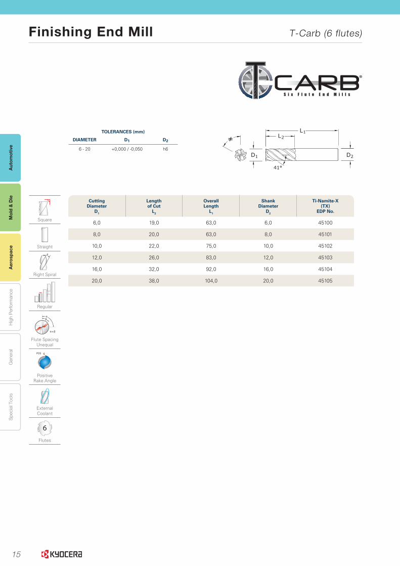
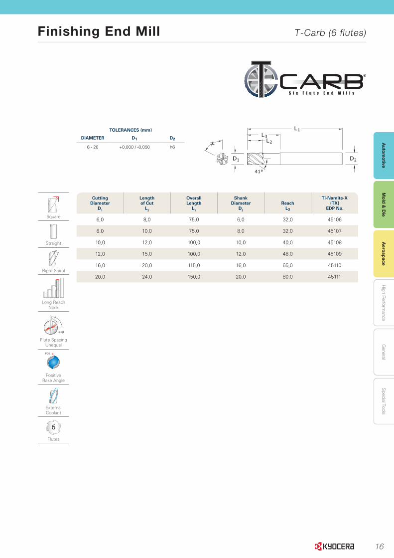
Finishing End Mill T-Carb (6 flutes)
Mol
d &
Die
Aer
ospa
ce
5www.kyocera-sgstool.com
®
Se
ries 51M
|M
etric
Tolerances (mm)
DiameTer D1 D2
6 - 20 +0,000 / -0,050 h6
Square
Straight
Right Spiral
Regular
≠
Flute Spacing Unequal
POS
Positive Rake Angle
External Coolant
6
Flutes
2D
L1L2
1D
≠
41°
cutting Diameter
D1
lengthof cut
l2
overall length
l1
shank Diameter
D2
Ti-namite-X (TX)
eDP no.
6,0 19,0 63,0 6,0 45100
8,0 20,0 63,0 8,0 45101
10,0 22,0 75,0 10,0 45102
12,0 26,0 83,0 12,0 45103
16,0 32,0 92,0 16,0 45104
20,0 38,0 104,0 20,0 45105
16
Autom
otiveA
erospaceH
igh Perform
anceG
eneralS
pecial ToolsM
old & D
ie
Finishing End Mill T-Carb (6 flutes)
Mold &
Die
Aerospace
7www.kyocera-sgstool.com
®
Se
ries 51M
L |
Metric
Tolerances (mm)
DiameTer D1 D2
6 - 20 +0,000 / -0,050 h6
2D
L1
L2L3
1D
≠
41°
cutting Diameter
D1
lengthof cut
l2
overall length
l1
shank Diameter
D2
reach l3
Ti-namite-X (TX)
eDP no.
6,0 8,0 75,0 6,0 32,0 45106
8,0 10,0 75,0 8,0 32,0 45107
10,0 12,0 100,0 10,0 40,0 45108
12,0 15,0 100,0 12,0 48,0 45109
16,0 20,0 115,0 16,0 65,0 45110
20,0 24,0 150,0 20,0 80,0 45111
Square
Straight
Right Spiral
Long Reach Neck
≠
Flute Spacing Unequal
POS
Positive Rake Angle
External Coolant
6
Flutes
17
Aut
omot
ive
Aer
ospa
ceH
igh
Per
form
ance
Gen
eral
Spe
cial
Too
lsM
old
& D
ie
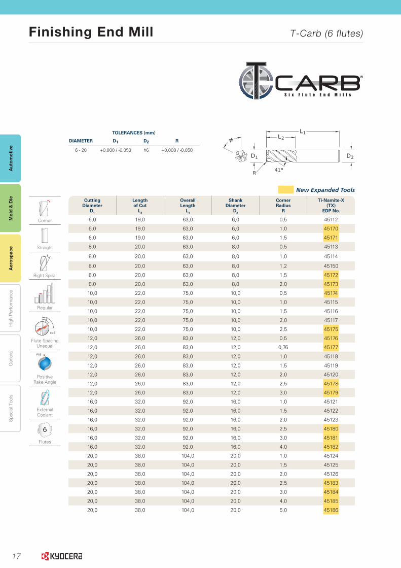
Finishing End Mill T-Carb (6 flutes)
Mol
d &
Die
Aer
ospa
ce
9www.kyocera-sgstool.com
®
Se
ries 51M
CR
|M
etric
Tolerances (mm)
DiameTer D1 D2 r
6 - 20 +0,000 / -0,050 h6 +0,000 / -0,050
cutting Diameter
D1
lengthof cut
l2
overall length
l1
shank Diameter
D2
corner radius
r
Ti-namite-X (TX)
eDP no.
6,0 19,0 63,0 6,0 0,5 45112
6,0 19,0 63,0 6,0 1,0 45170
6,0 19,0 63,0 6,0 1,5 45171
8,0 20,0 63,0 8,0 0,5 45113
8,0 20,0 63,0 8,0 1,0 45114
8,0 20,0 63,0 8,0 1,2 45150
8,0 20,0 63,0 8,0 1,5 45172
8,0 20,0 63,0 8,0 2,0 45173
10,0 22,0 75,0 10,0 0,5 45174
10,0 22,0 75,0 10,0 1,0 45115
10,0 22,0 75,0 10,0 1,5 45116
10,0 22,0 75,0 10,0 2,0 45117
10,0 22,0 75,0 10,0 2,5 45175
12,0 26,0 83,0 12,0 0,5 45176
12,0 26,0 83,0 12,0 0,76 45177
12,0 26,0 83,0 12,0 1,0 45118
12,0 26,0 83,0 12,0 1,5 45119
12,0 26,0 83,0 12,0 2,0 45120
12,0 26,0 83,0 12,0 2,5 45178
12,0 26,0 83,0 12,0 3,0 45179
16,0 32,0 92,0 16,0 1,0 45121
16,0 32,0 92,0 16,0 1,5 45122
16,0 32,0 92,0 16,0 2,0 45123
16,0 32,0 92,0 16,0 2,5 45180
16,0 32,0 92,0 16,0 3,0 45181
16,0 32,0 92,0 16,0 4,0 45182
20,0 38,0 104,0 20,0 1,0 45124
20,0 38,0 104,0 20,0 1,5 45125
20,0 38,0 104,0 20,0 2,0 45126
20,0 38,0 104,0 20,0 2,5 45183
20,0 38,0 104,0 20,0 3,0 45184
20,0 38,0 104,0 20,0 4,0 45185
20,0 38,0 104,0 20,0 5,0 45186
Corner
Straight
Right Spiral
Regular
≠
Flute Spacing Unequal
POS
Positive Rake Angle
External Coolant
6
Flutes
New Expanded Tools
2D
L1L2
1D
≠
R 41°
18
Autom
otiveA
erospaceH
igh Perform
anceG
eneralS
pecial ToolsM
old & D
ie
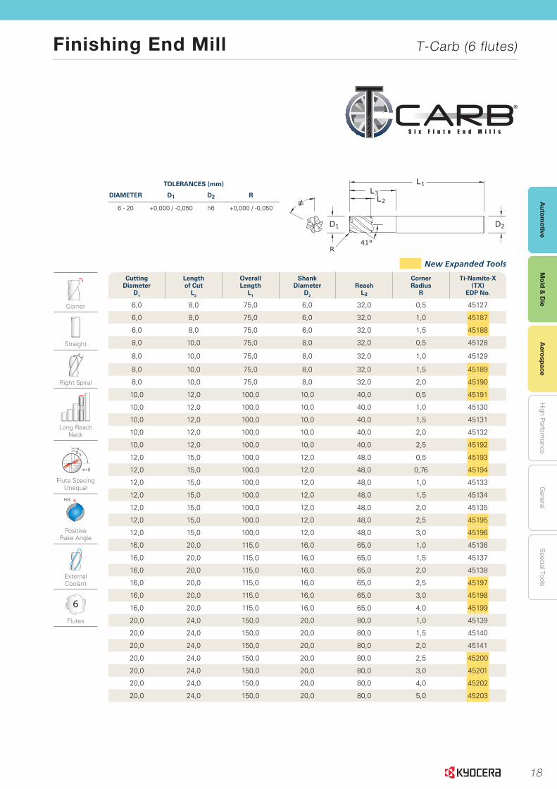
Finishing End Mill T-Carb (6 flutes)
Mold &
Die
Aerospace
11www.kyocera-sgstool.com
®
Se
ries 51M
LC
| M
etric
Tolerances (mm)
DiameTer D1 D2 r
6 - 20 +0,000 / -0,050 h6 +0,000 / -0,050
2D
L1
L2L3
1D
≠
41°R
cutting Diameter
D1
lengthof cut
l2
overall length
l1
shank Diameter
D2
reach l3
corner radius
r
Ti-namite-X (TX)
eDP no.
6,0 8,0 75,0 6,0 32,0 0,5 45127
6,0 8,0 75,0 6,0 32,0 1,0 45187
6,0 8,0 75,0 6,0 32,0 1,5 45188
8,0 10,0 75,0 8,0 32,0 0,5 45128
8,0 10,0 75,0 8,0 32,0 1,0 45129
8,0 10,0 75,0 8,0 32,0 1,5 45189
8,0 10,0 75,0 8,0 32,0 2,0 45190
10,0 12,0 100,0 10,0 40,0 0,5 45191
10,0 12,0 100,0 10,0 40,0 1,0 45130
10,0 12,0 100,0 10,0 40,0 1,5 45131
10,0 12,0 100,0 10,0 40,0 2,0 45132
10,0 12,0 100,0 10,0 40,0 2,5 45192
12,0 15,0 100,0 12,0 48,0 0,5 45193
12,0 15,0 100,0 12,0 48,0 0,76 45194
12,0 15,0 100,0 12,0 48,0 1,0 45133
12,0 15,0 100,0 12,0 48,0 1,5 45134
12,0 15,0 100,0 12,0 48,0 2,0 45135
12,0 15,0 100,0 12,0 48,0 2,5 45195
12,0 15,0 100,0 12,0 48,0 3,0 45196
16,0 20,0 115,0 16,0 65,0 1,0 45136
16,0 20,0 115,0 16,0 65,0 1,5 45137
16,0 20,0 115,0 16,0 65,0 2,0 45138
16,0 20,0 115,0 16,0 65,0 2,5 45197
16,0 20,0 115,0 16,0 65,0 3,0 45198
16,0 20,0 115,0 16,0 65,0 4,0 45199
20,0 24,0 150,0 20,0 80,0 1,0 45139
20,0 24,0 150,0 20,0 80,0 1,5 45140
20,0 24,0 150,0 20,0 80,0 2,0 45141
20,0 24,0 150,0 20,0 80,0 2,5 45200
20,0 24,0 150,0 20,0 80,0 3,0 45201
20,0 24,0 150,0 20,0 80,0 4,0 45202
20,0 24,0 150,0 20,0 80,0 5,0 45203
New Expanded Tools
Corner
Straight
Right Spiral
Long Reach Neck
≠
Flute Spacing Unequal
POS
Positive Rake Angle
External Coolant
6
Flutes
19
Aut
omot
ive
Aer
ospa
ceH
igh
Per
form
ance
Gen
eral
Spe
cial
Too
lsM
old
& D
ie
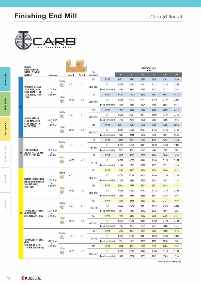
Finishing End Mill T-Carb (6 flutes)
Mol
d &
Die
Aer
ospa
ce
14 www.kyocera-sgstool.com
®
Se
rie
s 51
|
Spee
d &
Fee
d R
eco
mm
end
atio
ns
series 51m, 51mcr, 51ml, 51mlcmetric Hardness
Ap
Ae AeVc
(m/min)
Diameter (D1)(mm)
ae x D1 ap x D16 8 10 12 16 20
P
CARBON STEELS 1018, 1040, 1080, 1090, 10L50, 1140, 1212, 12L15, 1525, 1536
≤ 275 Bhnor
≤ 28 HRc
Profile≤ 0.1 ≤ 1
219 RPM 11633 8725 6980 5816 4362 3490
(176-263)Fz 0.048 0.081 0.101 0.121 0.142 0.158
Feed (mm/min) 3350 4240 4230 4223 3717 3308
HSM≤ 0.05 ≤ 2
279 RPM 14784 11088 8870 7392 5544 4435
(223-335)Fz 0.066 0.113 0.141 0.169 0.197 0.220
Feed (mm/min) 5854 7517 7504 7495 6553 5854
ALLOY STEELS4140, 4150, 4320, 5120, 5150, 8630, 86L20, 50100
≤ 375 Bhnor
≤ 40 HRc
Profile≤ 0.1 ≤ 1
149 RPM 7917 5938 4750 3958 2969 2375
(119-179)Fz 0.036 0.061 0.077 0.092 0.107 0.119
Feed (mm/min) 1710 2173 2195 2185 1906 1696
HSM≤ 0.05 ≤ 2
189 RPM 10017 7513 6010 5009 3756 3005
(151-227)Fz 0.049 0.083 0.104 0.125 0.146 0.163
Feed (mm/min) 2945 3741 3750 3756 3291 2939
HTOOL STEELS A2, D2, H13, L2, M2, P20, S7, T15, W2
≤ 375 Bhnor
≤ 40 HRc
Profile≤ 0.1 ≤ 1
73 RPM 3878 2908 2327 1939 1454 1163
(59-88)Fz 0.029 0.049 0.061 0.073 0.086 0.096
Feed (mm/min) 675 855 852 849 750 670
HSM≤ 0.05 ≤ 2
93 RPM 4928 3696 2957 2464 1848 1478
(74-112)Fz 0.040 0.069 0.086 0.103 0.120 0.134
Feed (mm/min) 1183 1530 1526 1523 1331 1189
M
STAINLESS STEELS(FREE MACHININg) 303, 416, 420F, 430F, 440F
≤ 275 Bhnor
≤ 28 HRc
Profile≤ 0.1 ≤ 1
155 RPM 8240 6180 4944 4120 3090 2472
(140-171)Fz 0.035 0.060 0.075 0.090 0.105 0.117
Feed (mm/min) 1730 2225 2225 2225 1947 1735
HSM≤ 0.05 ≤ 2
198 RPM 10502 7877 6301 5251 3938 3151
(178-218)Fz 0.048 0.082 0.102 0.122 0.143 0.159
Feed (mm/min) 3025 3875 3856 3844 3379 3006
STAINLESS STEELS (DIFFICuLT) 304, 304L, 316, 316L
≤ 275 Bhnor
≤ 28 HRc
Profile≤ 0.1 ≤ 1
107 RPM 5655 4241 3393 2827 2121 1696
(96-117)Fz 0.029 0.049 0.061 0.073 0.086 0.096
Feed (mm/min) 984 1247 1242 1238 1094 977
HSM≤ 0.05 ≤ 2
137 RPM 7271 5453 4362 3635 2726 2181
(123-151)Fz 0.040 0.069 0.086 0.103 0.120 0.134
Feed (mm/min) 1745 2258 2251 2247 1963 1754
STAINLESS STEELS (PH) 13-8 PH, 15-5 PH, 17-4 PH, Custom 450
≤ 325 Bhnor
≤ 35 HRc
Profile≤ 0.1 ≤ 1
99 RPM 5251 3938 3151 2626 1969 1575
(89-109)Fz 0.029 0.049 0.061 0.073 0.086 0.096
Feed (mm/min) 914 1158 1153 1150 1016 907
HSM≤ 0.05 ≤ 2
125 RPM 6624 4968 3975 3312 2484 1987
(112-137)Fz 0.040 0.069 0.086 0.103 0.120 0.134
Feed (mm/min) 1590 2057 2051 2047 1789 1598
continued on next page
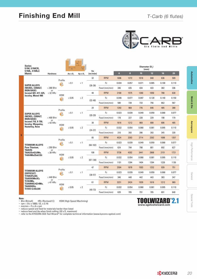
20
Autom
otiveA
erospaceH
igh Perform
anceG
eneralS
pecial ToolsM
old & D
ie
Finishing End Mill T-Carb (6 flutes)
Mold &
Die
Aerospace
15www.kyocera-sgstool.com
®
series 51m, 51mcr, 51ml, 51mlcmetric Hardness
Ap
Ae AeVc
(m/min)
Diameter (D1)(mm)
ae x D1 ap x D16 8 10 12 16 20
S
SuPER ALLOYS(NICkEL, COBALT, IRON BASE) Inconel 601, 617, 625, Incoloy, Monel 400
≤ 300 Bhnor
≤ 32 HRc
Profile≤ 0.1 ≤ 1
32 RPM 1696 1272 1018 848 636 509
(26-38)Fz 0.034 0.057 0.071 0.085 0.100 0.110
Feed (mm/min) 346 435 434 433 382 336
HSM≤ 0.05 ≤ 2
40 RPM 2100 1575 1260 1050 788 630
(32-48)Fz 0.046 0.077 0.097 0.120 0.140 0.150
Feed (mm/min) 580 728 733 756 662 567
SuPER ALLOYS(NICkEL, COBALT, IRON BASE) Inconel 718, X-750, Incoloy, Waspaloy, Hastelloy, Rene
≤ 400 Bhnor
≤ 43 HRc
Profile≤ 0.1 ≤ 1
24 RPM 1293 969 776 646 485 388
(20-29)Fz 0.023 0.039 0.049 0.059 0.068 0.077
Feed (mm/min) 178 227 228 229 198 179
HSM≤ 0.05 ≤ 2
30 RPM 1616 1212 969 808 606 485
(24-37)Fz 0.032 0.054 0.068 0.081 0.095 0.110
Feed (mm/min) 310 393 396 393 345 320
TITANIuM ALLOYS Pure Titanium, Ti6Al4V, Ti6Al2Sn4Zr2Mo, Ti4Al4Mo2Sn0.5Si
≤ 350 Bhnor
≤ 38 HRc
Profile≤ 0.1 ≤ 1
85 RPM 4524 3393 2714 2262 1696 1357
(68-102)Fz 0.023 0.039 0.049 0.059 0.068 0.077
Feed (mm/min) 624 794 798 801 692 627
HSM≤ 0.05 ≤ 2
108 RPM 5736 4302 3441 2868 2151 1721
(87-130)Fz 0.032 0.054 0.068 0.081 0.095 0.110
Feed (mm/min) 1101 1394 1404 1394 1226 1136
TITANIuM ALLOYS (DIFFICuLT) Ti10Al2Fe3Al, Ti5Al5V5Mo3Cr, Ti7Al4Mo, Ti3Al8V6Cr4Zr4Mo, Ti6Al6V6Sn, Ti15V3 Cr3Sn3Al
≤ 440 Bhnor
≤ 47 HRc
Profile≤ 0.1 ≤ 1
47 RPM 2504 1878 1503 1252 939 751
(38-57)Fz 0.023 0.039 0.049 0.059 0.068 0.077
Feed (mm/min) 346 440 442 443 383 347
HSM≤ 0.05 ≤ 2
61 RPM 3231 2424 1939 1616 1212 969
(49-73)Fz 0.032 0.054 0.068 0.081 0.095 0.110
Feed (mm/min) 620 785 791 785 691 640
Note:• Bhn (Brinell) HRc (Rockwell C) HSM (High Speed Machining)• rpm = (Vc x 1000) / (D1 x 3.14)• mm/min = Fz x 6 x rpm• reduce speed and feed for materials harder than listed • reduce feed and Ae when finish milling (.02 x D1 maximum)• refer to the KYOCERA SGS Tool Wizard® for complete technical information (www.kyocera-sgstool.com)
Se
ries 51
|
Speed
& Feed
Reco
mm
end
ation
s
TOOLWIZARD 2.1www.sgstoolwizard.com
®

21
EXPANSIVE OFFERING• Over 700 items in portfolio • Available in stub and regular lengths• Full complement of corner radii available• Central coolant hole option available on select diameters• Plain and Weldon Flat options available for diameters ½” and 12mm and above (other retention methods available upon request)• Special tooling design attributes available upon request• Available in Ti-NAMITE-A coating ideal for Stainless Steel applications• Available coatings are suitable for dry machining in ferrous based materials such as cast irons and many carbon steels
THE Z-CARB HPR MATERIAL REMOVAL RATES (MRR) MAKE THIS TOOL IDEAL FOR THE FOLLOWING TARGET MARKETS:
• Energy & Power Generation
• Castings & Forgings
• General Engineering
• Aerospace Structural Components
• Medical Implants
• Automotive & Heavy Transportation
INTRODUCING THE NEXT GENERATION Z-CARBThe Z-Carb HPR Five Flute Roughing End Mills are ideal
for achieving high material removal rates (MRR) and superior
�nishes. The specialized �ve �ute design is engineered for
increased productivity over three and four �ute end mills.
The variable indexing geometry allows for improved chatter
suppression over symmetrical designs. The series is offered
in a variety of length, square, and corner radius options and
is coated with Ti-NAMITE-M and Ti-NAMITE-A for superior
performance in dif�cult to machine materials like Titanium
and Stainless Steel.
Features of Ti-Namite-M include high wear resistance, reduced friction, and excellent prevention of cutting edge build up. This coating provides superior material removal rates and tool life when used in high performance operations in Cast Iron and Steel and with dif�cult to machine materials like Titanium.
Hardness (HV): 3600Oxidation Temperature: 1150°C / 2100°FCoef�cient of Friction: 0.45Thickness: 1 – 4 Microns (based on tool diameter)
The Z-Carb HPR is available with an abrasive resistant and hard coating, Aluminum Titanium Nitride (AlTiN) or Ti-NAMITE-A. The coating has a high hardness giving ultimate protection against abrasive wear and erosion. Ideal for high temperature alloys and stainless steel applications.
Hardness (HV): 3700Oxidation Temperature: 1100°C / 2010°FCoef�cient of Friction: 0.30Thickness: 1 – 4 Microns (based on tool diameter)

22
EXPANSIVE OFFERING• Over 700 items in portfolio • Available in stub and regular lengths• Full complement of corner radii available• Central coolant hole option available on select diameters• Plain and Weldon Flat options available for diameters ½” and 12mm and above (other retention methods available upon request)• Special tooling design attributes available upon request• Available in Ti-NAMITE-A coating ideal for Stainless Steel applications• Available coatings are suitable for dry machining in ferrous based materials such as cast irons and many carbon steels
THE Z-CARB HPR MATERIAL REMOVAL RATES (MRR) MAKE THIS TOOL IDEAL FOR THE FOLLOWING TARGET MARKETS:
• Energy & Power Generation
• Castings & Forgings
• General Engineering
• Aerospace Structural Components
• Medical Implants
• Automotive & Heavy Transportation
INTRODUCING THE NEXT GENERATION Z-CARBThe Z-Carb HPR Five Flute Roughing End Mills are ideal
for achieving high material removal rates (MRR) and superior
�nishes. The specialized �ve �ute design is engineered for
increased productivity over three and four �ute end mills.
The variable indexing geometry allows for improved chatter
suppression over symmetrical designs. The series is offered
in a variety of length, square, and corner radius options and
is coated with Ti-NAMITE-M and Ti-NAMITE-A for superior
performance in dif�cult to machine materials like Titanium
and Stainless Steel.
Features of Ti-Namite-M include high wear resistance, reduced friction, and excellent prevention of cutting edge build up. This coating provides superior material removal rates and tool life when used in high performance operations in Cast Iron and Steel and with dif�cult to machine materials like Titanium.
Hardness (HV): 3600Oxidation Temperature: 1150°C / 2100°FCoef�cient of Friction: 0.45Thickness: 1 – 4 Microns (based on tool diameter)
The Z-Carb HPR is available with an abrasive resistant and hard coating, Aluminum Titanium Nitride (AlTiN) or Ti-NAMITE-A. The coating has a high hardness giving ultimate protection against abrasive wear and erosion. Ideal for high temperature alloys and stainless steel applications.
Hardness (HV): 3700Oxidation Temperature: 1100°C / 2010°FCoef�cient of Friction: 0.30Thickness: 1 – 4 Microns (based on tool diameter)

23
FEATURES
RADIAL RAKE• Specially designed radial rake balances positive cutting action and edge strength• End grind features include: (1) Positive axial rake for high performance shearing and lifting of material; and (2) Increased clearances to eliminate edge build-up during ramping
FLUTING & HELIX ANGLE• Specialized �ve �ute design is engineered for strength, chip evacuation, and increased productivity over three and four �ute end mills by 20–40%• The variable �ute pattern provides excellent chatter suppression over a range of spindle speeds• Open center design delivers ef�ciency during entry movements into the work-piece• Helix angle engineered for balance between positive cutting action and reduced contact area to control tool pressure and spindle load
THROUGH COOLANT • Central hole delivers coolant effectively to the cutting zone • Enhances chip removal when pocketing or slotting • Select fractional and metric diameters in stock
laB TEsTING rEsUlTs – HEaVY PrOFIlING IN TITaNIUm1400
1200
1000
800
600
400
200
0
US
AG
E (
INC
HE
S)
12871179
504
324 324
59
KSPT Z5
Competitor A
Competitor B
Competitor C
Competitor D
Competitor E
RESULTS IN TITANIUM 6AL4V @ 32HRC Z5CR 1/2” TESTED AT 1643 RPM X 16.4 IPM.250” RADIAL WIDTH OF CUT X .750” AXIAL DEPTH OF CUT
1800
1600
1400
1200
1000
800
600
400
200
0
US
AG
E (
INC
HE
S)
1590
730
560 520
221 203110
42 30
KSPT Z5
Competitor A
Competitor B
Competitor C
Competitor D
Competitor E
Competitor F
Competitor G
Competitor H
laB TEsTING rEsUlTs – HEaVY PrOFIlING IN sTaINlEss sTEEl
CAPABILITIESRAMPING• Typical ramp angles of 5 degrees are common; greater than 5 degree ramp angles are obtain- able with reduced feed rates• Entry feed rates can achieve 100% of the slotting value• The open center provides an ideal exit for central coolant and chip �ushing while maintaining the 5 degree ramp angle
HIGH-SPEED MACHINING• Variable geometry design and open �uting eliminate vibration to enable increased rates for High Speed Machining• Exclusive Ti-NAMITE-M coating for higher heat resistance to enhance tool life in dif�cult to machine materials like Titanium• Available with Ti-NAMITE-A coating for superior wear, edge build-up resistance and extended tool life in dif�cult to machine materials like Stainless Steel
ROUGHING• One times diameter slotting capability is typical• 50% radial by 150% axial heavy pro�ling capability is common
FINISHING• Variable geometry contributes to exceptional �nishing capabilities• 10 µin. Ra possible
RESULTS IN STAINLESS STEEL 316 @ 160HB Z5CR 1/2” TESTED AT 2540 RPM X 31.7 IPM .250” RADIAL WIDTH OF CUT X .750” AXIAL DEPTH OF CUT

24
FEATURES
RADIAL RAKE• Specially designed radial
rake balances positivecutting action andedge strength
• End grind featuresinclude: (1) Positive axial rake for high performance shearing and lifting of material; and (2) Increased clearances to eliminate edge build-up during
ramping
FLUTING & HELIX ANGLE• Specialized �ve �ute
design is engineered forstrength, chip evacuation,and increased productivityover three and four �ute end mills by 20–40%
• The variable �ute patternprovides excellent chattersuppression over a rangeof spindle speeds
• Open center designdelivers ef�ciency duringentry movements into the
work-piece• Helix angle engineered
for balance between positivecutting action and reducedcontact area to control toolpressure and spindle load
THROUGH COOLANT • Central hole delivers
coolant effectively tothe cutting zone
• Enhances chip removalwhen pocketing or slotting
• Select fractional andmetric diameters in stock
laB TEsTING rEsUlTs – HEaVY PrOFIlING IN TITaNIUm1400
1200
1000
800
600
400
200
0
US
AG
E (
INC
HE
S)
12871179
504
324 324
59
KSPT Z5
Competitor A
Competitor B
Competitor C
Competitor D
Competitor E
RESULTS IN TITANIUM 6AL4V @ 32HRC Z5CR 1/2” TESTED AT 1643 RPM X 16.4 IPM.250” RADIAL WIDTH OF CUT X .750” AXIAL DEPTH OF CUT
1800
1600
1400
1200
1000
800
600
400
200
0
US
AG
E (
INC
HE
S)
1590
730
560 520
221 203110
42 30
KSPT Z5
Competitor A
Competitor B
Competitor C
Competitor D
Competitor E
Competitor F
Competitor G
Competitor H
laB TEsTING rEsUlTs – HEaVY PrOFIlING IN sTaINlEss sTEEl
CAPABILITIESRAMPING• Typical ramp angles of 5 degrees
are common; greater than5 degree ramp angles are obtain-
able with reduced feed rates• Entry feed rates can achieve
100% of the slotting value• The open center provides an
ideal exit for central coolant andchip �ushing while maintainingthe 5 degree ramp angle
HIGH-SPEED MACHINING• Variable geometry design and
open �uting eliminate vibrationto enable increased rates forHigh Speed Machining
• Exclusive Ti-NAMITE-M coatingfor higher heat resistance toenhance tool life in dif�cult to machine materials like Titanium
• Available with Ti-NAMITE-Acoating for superior wear, edgebuild-up resistance and extendedtool life in dif�cult to machinematerials like Stainless Steel
ROUGHING• One times diameter slotting
capability is typical• 50% radial by 150% axial heavy
pro�ling capability is common
FINISHING• Variable geometry contributes to
exceptional �nishing capabilities• 10 µin. Ra possible
RESULTS IN STAINLESS STEEL 316 @ 160HB Z5CR 1/2” TESTED AT 2540 RPM X 31.7 IPM .250” RADIAL WIDTH OF CUT X .750” AXIAL DEPTH OF CUT
25
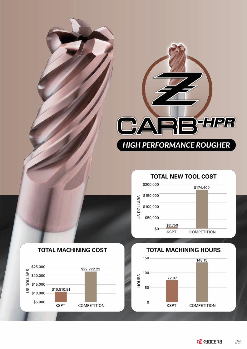
TOTal NEW TOOl cOsT$200,000
$150,000
$100,000
$50,000
$0
US
DO
LLA
RS
$2,750
KSPT
$174,400
COMPETITION
cYclE TImE100
80
60
40
20
0
MIN
UT
ES
43.24
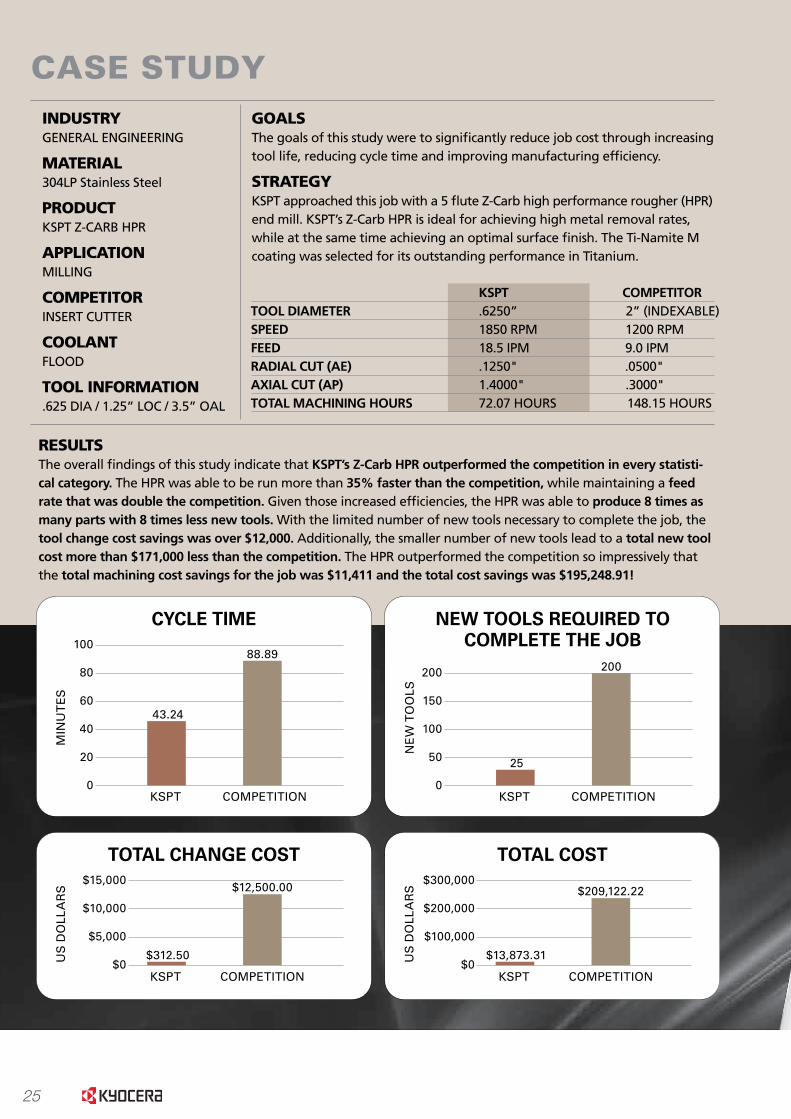
CASE STUDYINDUSTRYGENERAL ENGINEERING
MATERIAL304LP Stainless Steel
PRODUCTKSPT Z-CARB HPR
APPLICATIONMILLING
COMPETITORINSERT CUTTER
COOLANTFLOOD
TOOL INFORMATION.625 DIA / 1.25” LOC / 3.5” OAL
GOALSThe goals of this study were to signi�cantly reduce job cost through increasing tool life, reducing cycle time and improving manufacturing ef�ciency.
STRATEGYKSPT approached this job with a 5 �ute Z-Carb high performance rougher (HPR) end mill. KSPT’s Z-Carb HPR is ideal for achieving high metal removal rates, while at the same time achieving an optimal surface �nish. The Ti-Namite M coating was selected for its outstanding performance in Titanium.
RESULTSThe overall �ndings of this study indicate that KSPT’s Z-Carb HPR outperformed the competition in every statisti-cal category. The HPR was able to be run more than 35% faster than the competition, while maintaining a feed rate that was double the competition. Given those increased ef�ciencies, the HPR was able to produce 8 times as many parts with 8 times less new tools. With the limited number of new tools necessary to complete the job, the tool change cost savings was over $12,000. Additionally, the smaller number of new tools lead to a total new tool cost more than $171,000 less than the competition. The HPR outperformed the competition so impressively that the total machining cost savings for the job was $11,411 and the total cost savings was $195,248.91!
KSPT COMPETITORTOOL DIAMETER .6250” 2” (INDEXABLE)SPEED 1850 RPM 1200 RPMFEED 18.5 IPM 9.0 IPMRADIAL CUT (AE) .1250" .0500"AXIAL CUT (AP) 1.4000" .3000"TOTAL MACHINING HOURS 72.07 HOURS 148.15 HOURS
KSPT
88.89
COMPETITION
TOTal cOsT$300,000
$200,000
$100,000
$0US
DO
LLA
RS
$13,873.31
KSPT
$209,122.22
COMPETITION
TOTal cHaNGE cOsT$15,000
$10,000
$5,000
$0US
DO
LLA
RS
$312.50
KSPT
$12,500.00
COMPETITION
NEW TOOls rEQUIrED TOcOmPlETE THE JOB
200
150
100
50
0
NE
W T
OO
LS
25
KSPT
200
COMPETITION TOTal macHINING cOsT
$25,000
$20,000
$15,000
$10,000
$5,000
US
DO
LLA
RS
$10,810.81
KSPT
$22,222.22
COMPETITION
TOTal macHINING HOUrs150
100
50
0
HO
UR
S
72.07
KSPT
148.15
COMPETITION
26
TOTal NEW TOOl cOsT$200,000
$150,000
$100,000
$50,000
$0
US
DO
LLA
RS
$2,750
KSPT
$174,400
COMPETITION
cYclE TImE100
80
60
40
20
0
MIN
UT
ES
43.24
CASE STUDYINDUSTRYGENERAL ENGINEERING
MATERIAL304LP Stainless Steel
PRODUCTKSPT Z-CARB HPR
APPLICATIONMILLING
COMPETITORINSERT CUTTER
COOLANTFLOOD
TOOL INFORMATION.625 DIA / 1.25” LOC / 3.5” OAL
GOALSThe goals of this study were to signi�cantly reduce job cost through increasing tool life, reducing cycle time and improving manufacturing ef�ciency.
STRATEGYKSPT approached this job with a 5 �ute Z-Carb high performance rougher (HPR) end mill. KSPT’s Z-Carb HPR is ideal for achieving high metal removal rates, while at the same time achieving an optimal surface �nish. The Ti-Namite M coating was selected for its outstanding performance in Titanium.
RESULTSThe overall �ndings of this study indicate that KSPT’s Z-Carb HPR outperformed the competition in every statisti-cal category. The HPR was able to be run more than 35% faster than the competition, while maintaining a feed rate that was double the competition. Given those increased ef�ciencies, the HPR was able to produce 8 times as many parts with 8 times less new tools. With the limited number of new tools necessary to complete the job, the tool change cost savings was over $12,000. Additionally, the smaller number of new tools lead to a total new tool cost more than $171,000 less than the competition. The HPR outperformed the competition so impressively that the total machining cost savings for the job was $11,411 and the total cost savings was $195,248.91!
KSPT COMPETITORTOOL DIAMETER .6250” 2” (INDEXABLE)SPEED 1850 RPM 1200 RPMFEED 18.5 IPM 9.0 IPMRADIAL CUT (AE) .1250" .0500"AXIAL CUT (AP) 1.4000" .3000"TOTAL MACHINING HOURS 72.07 HOURS 148.15 HOURS
KSPT
88.89
COMPETITION
TOTal cOsT$300,000
$200,000
$100,000
$0US
DO
LLA
RS
$13,873.31
KSPT
$209,122.22
COMPETITION
TOTal cHaNGE cOsT$15,000
$10,000
$5,000
$0US
DO
LLA
RS
$312.50
KSPT
$12,500.00
COMPETITION
NEW TOOls rEQUIrED TOcOmPlETE THE JOB
200
150
100
50
0
NE
W T
OO
LS
25
KSPT
200
COMPETITION TOTal macHINING cOsT
$25,000
$20,000
$15,000
$10,000
$5,000
US
DO
LLA
RS
$10,810.81
KSPT
$22,222.22
COMPETITION
TOTal macHINING HOUrs150
100
50
0
HO
UR
S
72.07
KSPT
148.15
COMPETITION
27
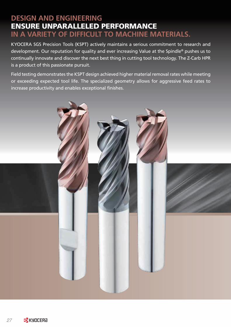
DESIGN AND ENGINEERINGENSURE UNPARALLELED PERFORMANCEIN A VARIETY OF DIFFICULT TO MACHINE MATERIALS.KYOCERA SGS Precision Tools (KSPT) actively maintains a serious commitment to research and
development. Our reputation for quality and ever increasing Value at the Spindle® pushes us to
continually innovate and discover the next best thing in cutting tool technology. The Z-Carb HPR
is a product of this passionate pursuit.
Field testing demonstrates the KSPT design achieved higher material removal rates while meeting
or exceeding expected tool life. The specialized geometry allows for aggressive feed rates to
increase productivity and enables exceptional finishes.
28
Autom
otiveA
erospaceH
igh Perform
anceG
eneralS
pecial ToolsM
old & D
ie
DESIGN AND ENGINEERINGENSURE UNPARALLELED PERFORMANCEIN A VARIETY OF DIFFICULT TO MACHINE MATERIALS.KYOCERA SGS Precision Tools (KSPT) actively maintains a serious commitment to research and
development. Our reputation for quality and ever increasing Value at the Spindle® pushes us to
continually innovate and discover the next best thing in cutting tool technology. The Z-Carb HPR
is a product of this passionate pursuit.
Field testing demonstrates the KSPT design achieved higher material removal rates while meeting
or exceeding expected tool life. The specialized geometry allows for aggressive feed rates to
increase productivity and enables exceptional finishes.
Roughing End Mill Z-Carb HPR
Mold &
Die
Aerospace

29
Aut
omot
ive
Aer
ospa
ceH
igh
Per
form
ance
Gen
eral
Spe
cial
Too
lsM
old
& D
ie
Roughing End Mill Z-Carb HPR
Mol
d &
Die
Aer
ospa
ce
30
Autom
otiveA
erospaceH
igh Perform
anceG
eneralS
pecial ToolsM
old & D
ie
Roughing End Mill Z-Carb HPR
Mold &
Die
Aerospace
www.kyocera-sgstool.com18
Z-C
arb
HP
R
| Sp
eed
& F
eed
Rec
om
men
dat
ion
s
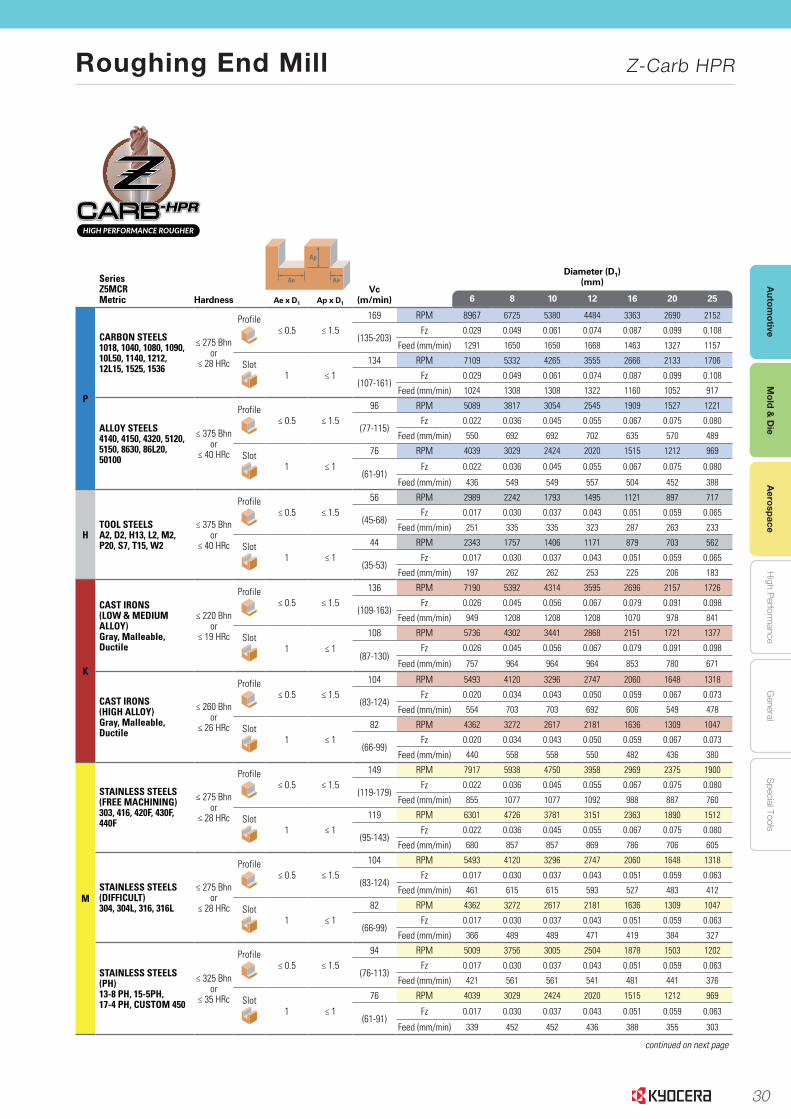
Series Z5MCRMetric Hardness
Ap
Ae AeVc
(m/min)
Diameter (D1)(mm)
Ae x D1 Ap x D16 8 10 12 16 20 25
P
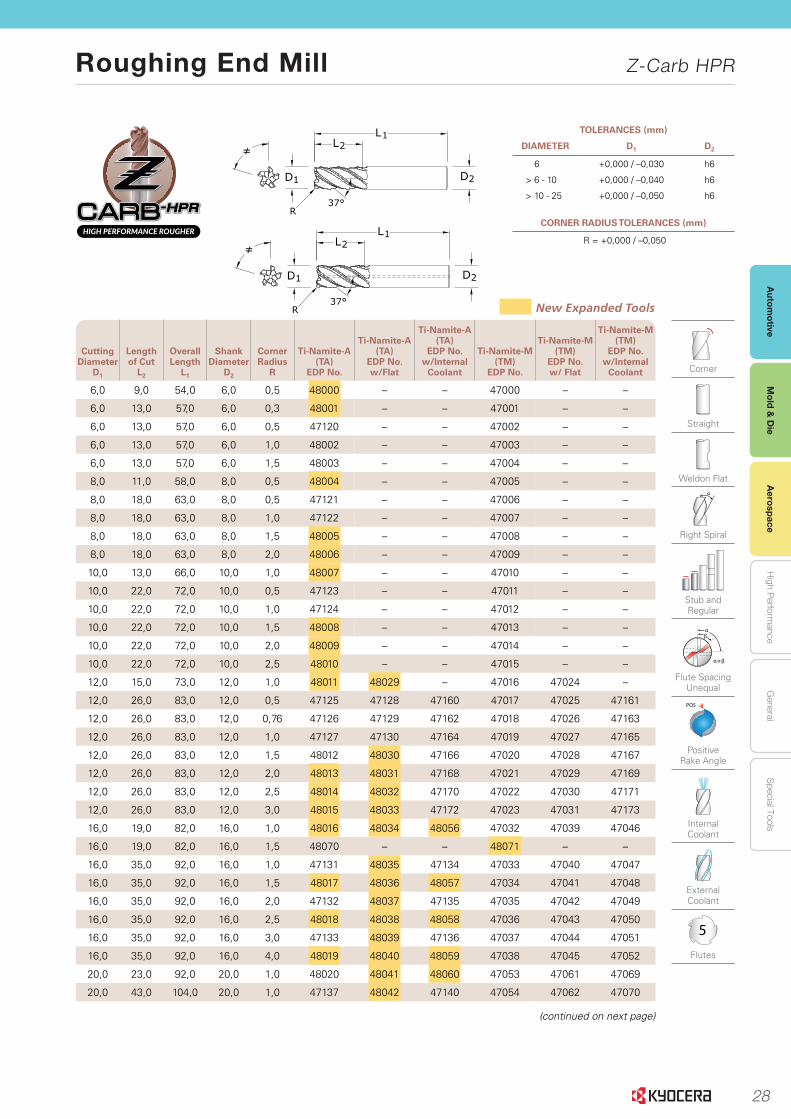
CARBON STEELS1018, 1040, 1080, 1090, 10L50, 1140, 1212, 12L15, 1525, 1536
≤ 275 Bhnor
≤ 28 HRc
Profile≤ 0.5 ≤ 1.5
169 RPM 8967 6725 5380 4484 3363 2690 2152
(135-203)Fz 0.029 0.049 0.061 0.074 0.087 0.099 0.108
Feed (mm/min) 1291 1650 1650 1668 1463 1327 1157
Slot1 ≤ 1
134 RPM 7109 5332 4265 3555 2666 2133 1706
(107-161)Fz 0.029 0.049 0.061 0.074 0.087 0.099 0.108
Feed (mm/min) 1024 1308 1308 1322 1160 1052 917
ALLOY STEELS4140, 4150, 4320, 5120,5150, 8630, 86L20, 50100
≤ 375 Bhnor
≤ 40 HRc
Profile≤ 0.5 ≤ 1.5
96 RPM 5089 3817 3054 2545 1909 1527 1221
(77-115)Fz 0.022 0.036 0.045 0.055 0.067 0.075 0.080
Feed (mm/min) 550 692 692 702 635 570 489
Slot1 ≤ 1
76 RPM 4039 3029 2424 2020 1515 1212 969
(61-91)Fz 0.022 0.036 0.045 0.055 0.067 0.075 0.080
Feed (mm/min) 436 549 549 557 504 452 388
HTOOL STEELSA2, D2, H13, L2, M2,P20, S7, T15, W2
≤ 375 Bhnor
≤ 40 HRc
Profile≤ 0.5 ≤ 1.5
56 RPM 2989 2242 1793 1495 1121 897 717
(45-68)Fz 0.017 0.030 0.037 0.043 0.051 0.059 0.065
Feed (mm/min) 251 335 335 323 287 263 233
Slot1 ≤ 1
44 RPM 2343 1757 1406 1171 879 703 562
(35-53)Fz 0.017 0.030 0.037 0.043 0.051 0.059 0.065
Feed (mm/min) 197 262 262 253 225 206 183
K
CAST IRONS(LOW & MEDIUM ALLOY)Gray, Malleable, Ductile
≤ 220 Bhnor
≤ 19 HRc
Profile≤ 0.5 ≤ 1.5
136 RPM 7190 5392 4314 3595 2696 2157 1726
(109-163)Fz 0.026 0.045 0.056 0.067 0.079 0.091 0.098
Feed (mm/min) 949 1208 1208 1208 1070 978 841
Slot1 ≤ 1
108 RPM 5736 4302 3441 2868 2151 1721 1377
(87-130)Fz 0.026 0.045 0.056 0.067 0.079 0.091 0.098
Feed (mm/min) 757 964 964 964 853 780 671
CAST IRONS (HIGH ALLOY)Gray, Malleable, Ductile
≤ 260 Bhnor
≤ 26 HRc
Profile≤ 0.5 ≤ 1.5
104 RPM 5493 4120 3296 2747 2060 1648 1318
(83-124)Fz 0.020 0.034 0.043 0.050 0.059 0.067 0.073
Feed (mm/min) 554 703 703 692 606 549 478
Slot1 ≤ 1
82 RPM 4362 3272 2617 2181 1636 1309 1047
(66-99)Fz 0.020 0.034 0.043 0.050 0.059 0.067 0.073
Feed (mm/min) 440 558 558 550 482 436 380
M
STAINLESS STEELS(FREE MACHINING)303, 416, 420F, 430F, 440F
≤ 275 Bhnor
≤ 28 HRc
Profile≤ 0.5 ≤ 1.5
149 RPM 7917 5938 4750 3958 2969 2375 1900
(119-179)Fz 0.022 0.036 0.045 0.055 0.067 0.075 0.080
Feed (mm/min) 855 1077 1077 1092 988 887 760
Slot1 ≤ 1
119 RPM 6301 4726 3781 3151 2363 1890 1512
(95-143)Fz 0.022 0.036 0.045 0.055 0.067 0.075 0.080
Feed (mm/min) 680 857 857 869 786 706 605
STAINLESS STEELS(DIFFICULT)304, 304L, 316, 316L
≤ 275 Bhnor
≤ 28 HRc
Profile≤ 0.5 ≤ 1.5
104 RPM 5493 4120 3296 2747 2060 1648 1318
(83-124)Fz 0.017 0.030 0.037 0.043 0.051 0.059 0.063
Feed (mm/min) 461 615 615 593 527 483 412
Slot1 ≤ 1
82 RPM 4362 3272 2617 2181 1636 1309 1047
(66-99)Fz 0.017 0.030 0.037 0.043 0.051 0.059 0.063
Feed (mm/min) 366 489 489 471 419 384 327
STAINLESS STEELS(PH)13-8 PH, 15-5PH,17-4 PH, CUSTOM 450
≤ 325 Bhnor
≤ 35 HRc
Profile≤ 0.5 ≤ 1.5
94 RPM 5009 3756 3005 2504 1878 1503 1202
(76-113)Fz 0.017 0.030 0.037 0.043 0.051 0.059 0.063
Feed (mm/min) 421 561 561 541 481 441 376
Slot1 ≤ 1
76 RPM 4039 3029 2424 2020 1515 1212 969
(61-91)Fz 0.017 0.030 0.037 0.043 0.051 0.059 0.063
Feed (mm/min) 339 452 452 436 388 355 303
continued on next page
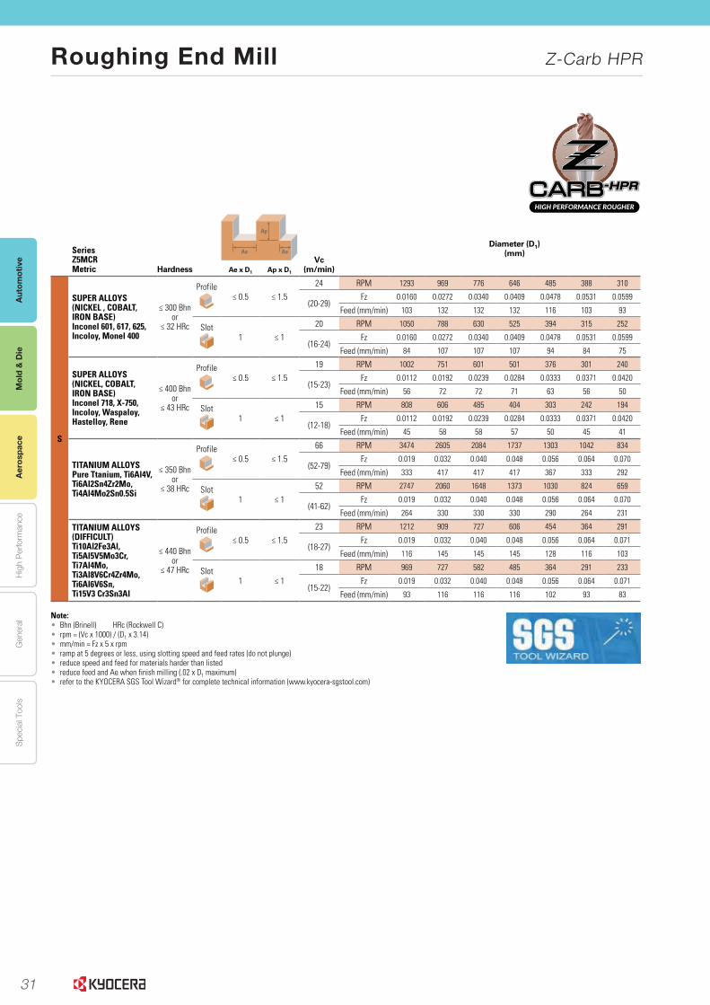
31
Aut
omot
ive
Aer
ospa
ceH
igh
Per
form
ance
Gen
eral
Spe
cial
Too
lsM
old
& D
ie
Roughing End Mill Z-Carb HPR
Mol
d &
Die
Aer
ospa
ce
www.kyocera-sgstool.com 19
Z-Ca
rb H
PR
|
Speed
& Feed
Reco
mm
end
ation
s
Series Z5MCRMetric Hardness
Ap
Ae AeVc
(m/min)
Diameter (D1)(mm)
Ae x D1 Ap x D16 8 10 12 16 20 25
S
SUPER ALLOYS(NICKEL , COBALT, IRON BASE)Inconel 601, 617, 625,Incoloy, Monel 400
≤ 300 Bhnor
≤ 32 HRc
Profile≤ 0.5 ≤ 1.5
24 RPM 1293 969 776 646 485 388 310
(20-29)Fz 0.0160 0.0272 0.0340 0.0409 0.0478 0.0531 0.0599
Feed (mm/min) 103 132 132 132 116 103 93
Slot1 ≤ 1
20 RPM 1050 788 630 525 394 315 252
(16-24)Fz 0.0160 0.0272 0.0340 0.0409 0.0478 0.0531 0.0599
Feed (mm/min) 84 107 107 107 94 84 75
SUPER ALLOYS(NICKEL, COBALT, IRON BASE)Inconel 718, X-750, Incoloy, Waspaloy, Hastelloy, Rene
≤ 400 Bhnor
≤ 43 HRc
Profile≤ 0.5 ≤ 1.5
19 RPM 1002 751 601 501 376 301 240
(15-23)Fz 0.0112 0.0192 0.0239 0.0284 0.0333 0.0371 0.0420
Feed (mm/min) 56 72 72 71 63 56 50
Slot1 ≤ 1
15 RPM 808 606 485 404 303 242 194
(12-18)Fz 0.0112 0.0192 0.0239 0.0284 0.0333 0.0371 0.0420
Feed (mm/min) 45 58 58 57 50 45 41
TITANIUM ALLOYSPure Ttanium, Ti6Al4V,Ti6Al2Sn4Zr2Mo,Ti4Al4Mo2Sn0.5Si
≤ 350 Bhnor
≤ 38 HRc
Profile≤ 0.5 ≤ 1.5
66 RPM 3474 2605 2084 1737 1303 1042 834
(52-79)Fz 0.019 0.032 0.040 0.048 0.056 0.064 0.070
Feed (mm/min) 333 417 417 417 367 333 292
Slot1 ≤ 1
52 RPM 2747 2060 1648 1373 1030 824 659
(41-62)Fz 0.019 0.032 0.040 0.048 0.056 0.064 0.070
Feed (mm/min) 264 330 330 330 290 264 231
TITANIUM ALLOYS(DIFFICULT)Ti10Al2Fe3Al, Ti5Al5V5Mo3Cr, Ti7Al4Mo, Ti3Al8V6Cr4Zr4Mo, Ti6Al6V6Sn, Ti15V3 Cr3Sn3Al
≤ 440 Bhnor
≤ 47 HRc
Profile≤ 0.5 ≤ 1.5
23 RPM 1212 909 727 606 454 364 291
(18-27)Fz 0.019 0.032 0.040 0.048 0.056 0.064 0.071
Feed (mm/min) 116 145 145 145 128 116 103
Slot1 ≤ 1
18 RPM 969 727 582 485 364 291 233
(15-22)Fz 0.019 0.032 0.040 0.048 0.056 0.064 0.071
Feed (mm/min) 93 116 116 116 102 93 83
Note:• Bhn (Brinell) HRc (Rockwell C)• rpm = (Vc x 1000) / (D1 x 3.14)• mm/min = Fz x 5 x rpm• ramp at 5 degrees or less, using slotting speed and feed rates (do not plunge)• reduce speed and feed for materials harder than listed • reduce feed and Ae when finish milling (.02 x D1 maximum)• refer to the KYOCERA SGS Tool Wizard® for complete technical information (www.kyocera-sgstool.com)
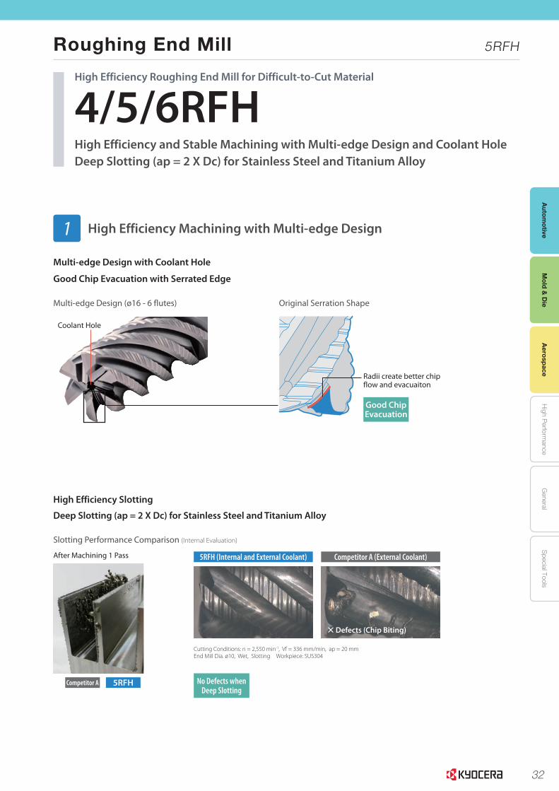
32
Autom
otiveA
erospaceH
igh Perform
anceG
eneralS
pecial ToolsM
old & D
ie
1
Slotting Performance Comparison (Internal Evaluation)
Original Serration ShapeMulti-edge Design (ø16 - 6 flutes)
Cutting Conditions: n = 2,550 min-1, Vf = 336 mm/min, ap = 20 mmEnd Mill Dia. ø10, Wet, Slotting Workpiece: SUS304
4/5/6RFHHigh Efficiency and Stable Machining with Multi-edge Design and Coolant HoleDeep Slotting (ap = 2 X Dc) for Stainless Steel and Titanium Alloy
High Efficiency Roughing End Mill for Difficult-to-Cut Material
Coolant Hole
High Efficiency Machining with Multi-edge Design
Multi-edge Design with Coolant Hole
Good Chip Evacuation with Serrated Edge
High Efficiency Slotting
Deep Slotting (ap = 2 X Dc) for Stainless Steel and Titanium Alloy
1
Radii create better chip flow and evacuaiton
After Machining 1 Pass
× Defects (Chip Biting)
5RFHCompetitor A
5RFH (Internal and External Coolant) Competitor A (External Coolant)
Good Chip Evacuation
No Defects when Deep Slotting
Roughing End Mill 5RFH
Mold &
Die
Aerospace
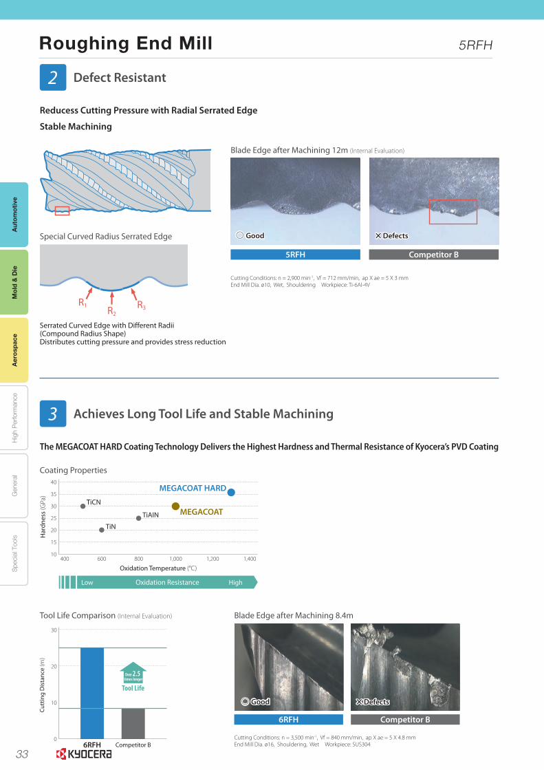
33
Aut
omot
ive
Aer
ospa
ceH
igh
Per
form
ance
Gen
eral
Spe
cial
Too
lsM
old
& D
ie
Roughing End Mill 5RFH
2
Blade Edge after Machining 12m (Internal Evaluation)
Blade Edge after Machining 8.4m
Special Curved Radius Serrated Edge
Cutting Conditions: n = 2,900 min-1, Vf = 712 mm/min, ap X ae = 5 X 3 mmEnd Mill Dia. ø10, Wet, Shouldering Workpiece: Ti-6Al-4V
Cutting Conditions: n = 3,500 min-1, Vf = 840 mm/min, ap X ae = 5 X 4.8 mmEnd Mill Dia. ø16, Shouldering, Wet Workpiece: SUS304
Defect Resistant
Achieves Long Tool Life and Stable Machining
Reducess Cutting Pressure with Radial Serrated Edge
Stable Machining
The MEGACOAT HARD Coating Technology Delivers the Highest Hardness and Thermal Resistance of Kyocera’s PVD Coating
2
3
R2R3
R1
Good
Good
× Defects
× Defects
40
35
30
25
20
15
10400 600 800 1,000 1,200 1,400
MEGACOATTiCN
TiN
TiAIN
MEGACOAT HARD
Low HighOxidation Resistance
Har
dnes
s (G
Pa)
Oxidation Temperature (°C)
Serrated Curved Edge with Different Radii (Compound Radius Shape)Distributes cutting pressure and provides stress reduction
Coating Properties
6RFH
5RFH
Competitor B
Competitor B
Tool Life Comparison (Internal Evaluation)
6RFH Competitor B
Over 2.5 times longer
30
20
10
0
Cutt
ing
Dis
tanc
e (m
)
Tool Life
Mol
d &
Die
Aer
ospa
ce
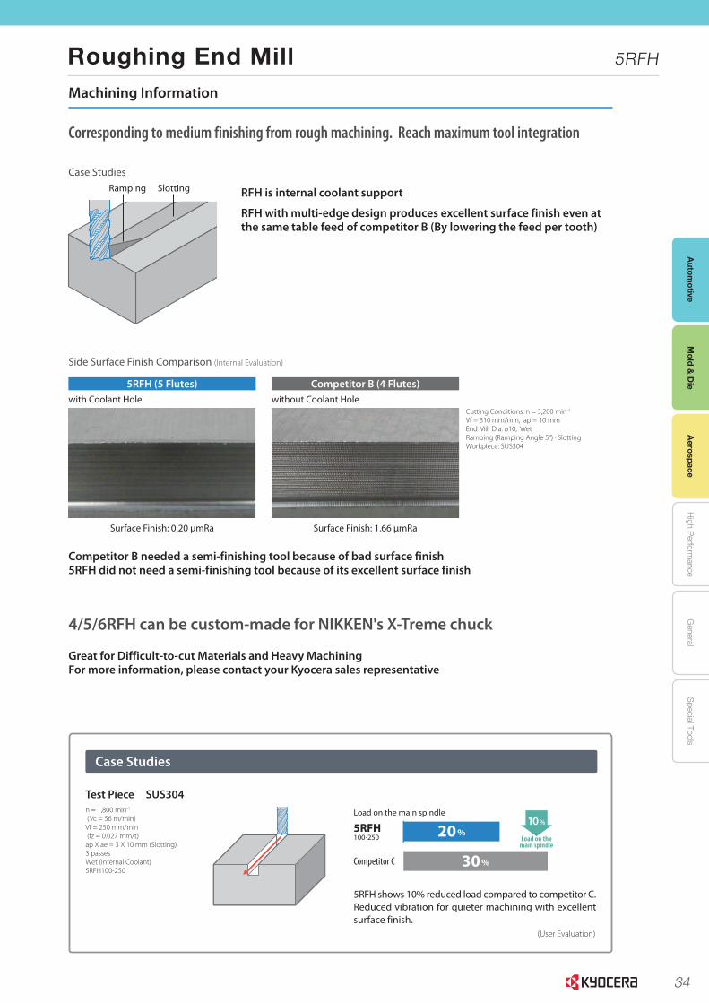
34
Autom
otiveA
erospaceH
igh Perform
anceG
eneralS
pecial ToolsM
old & D
ie
Roughing End Mill 5RFH
Mold &
Die
Aerospace
3
Side Surface Finish Comparison (Internal Evaluation)
Case Studies
Case Studies
with Coolant Hole
Surface Finish: 0.20 μmRa Surface Finish: 1.66 μmRa
without Coolant HoleCutting Conditions: n = 3,200 min-1
Vf = 310 mm/min, ap = 10 mmEnd Mill Dia. ø10, WetRamping (Ramping Angle 5°) · Slotting Workpiece: SUS304
Corresponding to medium finishing from rough machining. Reach maximum tool integration
4/5/6RFH can be custom-made for NIKKEN's X-Treme chuck
RFH is internal coolant support
RFH with multi-edge design produces excellent surface finish even at the same table feed of competitor B (By lowering the feed per tooth)
Great for Difficult-to-cut Materials and Heavy MachiningFor more information, please contact your Kyocera sales representative
Ramping Slotting
Competitor B needed a semi-finishing tool because of bad surface finish 5RFH did not need a semi-finishing tool because of its excellent surface finish
Machining Information
(User Evaluation)
n = 1,800 min-1
(Vc = 56 m/min)Vf = 250 mm/min (fz = 0.027 mm/t)ap X ae = 3 X 10 mm (Slotting)3 passesWet (Internal Coolant)5RFH100-250
5RFH shows 10% reduced load compared to competitor C. Reduced vibration for quieter machining with excellent surface finish.
20%
30%
10%Load on the main spindle
Competitor C
5RFH 100-250 Load on the
main spindle
Test Piece SUS304
5RFH (5 Flutes) Competitor B (4 Flutes)
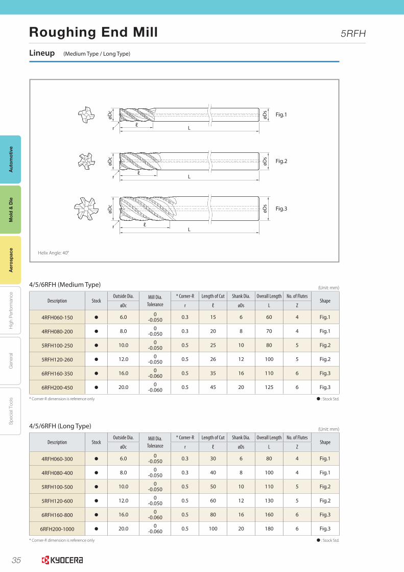
35
Aut
omot
ive
Aer
ospa
ceH
igh
Per
form
ance
Gen
eral
Spe
cial
Too
lsM
old
& D
ie
Roughing End Mill 5RFH
Mol
d &
Die
Aer
ospa
ce
4
Fig.1
Fig.2
Fig.3
L
L
L
ℓr
ℓ
ℓ
øDc
øDs
øDs
øDs
øDc
øDc
r
r
Lineup (Medium Type / Long Type)
4/5/6RFH (Medium Type)
4/5/6RFH (Long Type)
Description StockOutside Dia. Mill Dia.
Tolerance
* Corner-R Length of Cut Shank Dia. Overall Length No. of FlutesShape
øDc r ℓ øDs L Z
4RFH060-150 6.0 0-0.050 0.3 15 6 60 4 Fig.1
4RFH080-200 8.0 0-0.050 0.3 20 8 70 4 Fig.1
5RFH100-250 10.0 0-0.050 0.5 25 10 80 5 Fig.2
5RFH120-260 12.0 0-0.050 0.5 26 12 100 5 Fig.2
6RFH160-350 16.0 0-0.060 0.5 35 16 110 6 Fig.3
6RFH200-450 20.0 0-0.060 0.5 45 20 125 6 Fig.3
Description StockOutside Dia. Mill Dia.
Tolerance
* Corner-R Length of Cut Shank Dia. Overall Length No. of FlutesShape
øDc r ℓ øDs L Z
4RFH060-300 6.0 0-0.050 0.3 30 6 80 4 Fig.1
4RFH080-400 8.0 0-0.050 0.3 40 8 100 4 Fig.1
5RFH100-500 10.0 0-0.050 0.5 50 10 110 5 Fig.2
5RFH120-600 12.0 0-0.050 0.5 60 12 130 5 Fig.2
6RFH160-800 16.0 0-0.060 0.5 80 16 160 6 Fig.3
6RFH200-1000 20.0 0-0.060 0.5 100 20 180 6 Fig.3
: Stock Std.* Corner-R dimension is reference only
: Stock Std.* Corner-R dimension is reference only
(Unit: mm)
(Unit: mm)
Helix Angle: 40°

36
Autom
otiveA
erospaceH
igh Perform
anceG
eneralS
pecial ToolsM
old & D
ie
Roughing End Mill 5RFH
Mold &
Die
Aerospace
Cutting Conditions
Applications Workpiece ApplicationDepth of Cutap X ae (mm)
Outside Dia.Dc (mm)
ø 6 ø 8 ø 10 ø 12 ø 16 ø 20
Carbon Steel, Alloy Steel, Cast Iron
S45C, SCM, SNCM FC
Shouldering 1.5Dc X 0.3DcSpindle Revolution (min-1) 6,400 4,800 3,800 3,200 2,400 1,900
Feed Rate (mm/min) 1,040 1,050 1,100 1,000 980 920
Slotting
1.0DcSpindle Revolution (min-1) 5,300 4,000 3,200 2,700 2,000 1,600
Feed Rate (mm/min) 790 790 830 740 700 640
2.0DcSpindle Revolution (min-1) 5,300 4,000 3,200 2,700 2,000 1,600
Feed Rate (mm/min) 550 550 580 510 490 450
Pre-hardened Steel(30~45HRC)
Shouldering 1.5Dc X 0.3DcSpindle Revolution (min-1) 4,200 3,200 2,500 2,100 1,600 1,300
Feed Rate (mm/min) 490 620 580 540 490 460
Slotting
1.0DcSpindle Revolution (min-1) 3,700 2,800 2,200 1,900 1,400 1,100
Feed Rate (mm/min) 410 410 430 400 370 360
2.0DcSpindle Revolution (min-1) 3,700 2,800 2,200 1,900 1,400 1,100
Feed Rate (mm/min) 290 290 300 280 260 250
Stainless SteelSUS304
Shouldering 1.5Dc X 0.3DcSpindle Revolution (min-1) 6,400 4,800 3,800 3,200 2,400 1,900
Feed Rate (mm/min) 410 410 410 400 380 380
Slotting
1.0DcSpindle Revolution (min-1) 5,300 4,000 3,200 2,700 2,000 1,600
Feed Rate (mm/min) 280 260 310 240 250 250
2.0DcSpindle Revolution (min-1) 5,300 4,000 3,200 2,700 2,000 1,600
Feed Rate (mm/min) 220 210 250 190 200 200
Titanium Alloys
Shouldering 1.5Dc X 0.3DcSpindle Revolution (min-1) 4,200 3,200 2,500 2,100 1,600 1,300
Feed Rate (mm/min) 330 420 410 390 380 370
Slotting
1.0DcSpindle Revolution (min-1) 3,700 2,800 2,200 1,900 1,400 1,100
Feed Rate (mm/min) 220 240 240 240 250 250
2.0DcSpindle Revolution (min-1) 3,700 2,800 2,200 1,900 1,400 1,100
Feed Rate (mm/min) 180 190 190 190 200 200
Super Alloy
Shouldering 1.5Dc X 0.2DcSpindle Revolution (min-1) 800 600 480 400 300 240
Feed Rate (mm/min) 60 60 60 60 60 60
Slotting
1.0DcSpindle Revolution (min-1) 530 400 320 270 200 160
Feed Rate (mm/min) 28 28 28 28 28 28
2.0DcSpindle Revolution (min-1) 530 400 320 270 200 160
Feed Rate (mm/min) 20 20 20 20 20 20
Water soluble coolant is recommended for stainless steel, titanium alloy, and super alloy.
Applications Workpiece ApplicationDepth of Cutap X ae (mm)
Outside Dia.Dc (mm)
ø 6 ø 8 ø 10 ø 12 ø 16 ø 20
Carbon Steel, Alloy Steel, Cast Iron
S45C, SCM, SNCM FCShouldering
ap: 4.0Dcae: 0.1Dc (Dc ø12)
ae: 1.2mm (Dc ø12)
Spindle Revolution (min-1) 5,100 3,800 3,100 2,500 1,900 1,500
Feed Rate (mm/min) 620 630 660 600 590 550
Pre-hardened Steel(30~45HRC)
Shoulderingap: 4.0Dc
ae: 0.1Dc (Dc ø12)ae: 1.2mm (Dc ø12)
Spindle Revolution (min-1) 3,400 2,500 2,000 1,700 1,300 1,000
Feed Rate (mm/min) 340 430 410 380 340 320
Stainless SteelSUS304
Shoulderingap: 4.0Dc
ae: 0.1Dc (Dc ø12)ae: 1.2mm (Dc ø12)
Spindle Revolution (min-1) 5,100 3,800 3,100 2,500 1,900 1,500
Feed Rate (mm/min) 290 290 290 280 270 270
Titanium Alloys Shoulderingap: 4.0Dc
ae: 0.1Dc (Dc ø12)ae: 1.2mm (Dc ø12)
Spindle Revolution (min-1) 3,400 2,500 2,000 1,700 1,300 1,000
Feed Rate (mm/min) 230 290 290 270 270 260
Super Alloy Shoulderingap: 4.0 X Dc
ae: 0.1Dc (Dc ø12)ae: 1.0mm (Dc ø12)
Spindle Revolution (min-1) 640 480 380 320 240 190
Feed Rate (mm/min) 20 20 20 20 20 20
Water soluble coolant is recommended for stainless steel, titanium alloy, and super alloy.
ae
ap
Shouldering
ae
ap
Shouldering
ap
Slotting
4/5/6RFH (Medium Type)
4/5/6RFH (Long Type)
The information contained in this brochure is current as of April 2017.Duplication or reproduction of any part of this brochure without approval is prohibited.
CP404 CAT/17T1704NSN© 2017 KYOCERA Corporation
37
General Purpose End Mills
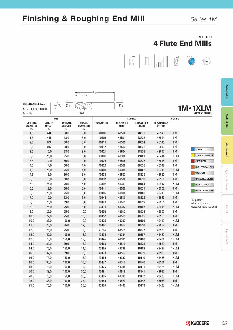
38
Autom
otiveA
erospaceH
igh Perform
anceG
eneralS
pecial ToolsM
old & D
ie
STEELS
STAINLESS STEELS
CAST IRON
HIGH TEMP ALLOYS
TITANIUM
HARDENED STEELS
NON-FERROUS
PLASTICS/COMPOSITES
223
END MILLS END MILLS
www.kyocera-sgstool.com
1M • 1XLM METRIC SERIES
mm EDP NO. SERIES
CUTTING DIAMETER
D1
LENGTH OF CUT
L2
OVERALL LENGTH
L1
SHANK DIAMETER
D2
UNCOATED Ti-NAMITE(TiN)
Ti-NAMITE-C(TiCN)
Ti-NAMITE-A(AlTiN)
1,0 4,0 38,0 3,0 40105 48500 48522 48543 1M1,5 4,5 38,0 3,0 40109 48501 48523 48544 1M2,0 6,3 38,0 3,0 40113 48502 48524 48545 1M2,5 9,5 38,0 3,0 40117 48503 48525 48546 1M3,0 12,0 38,0 3,0 40121 48504 48526 48547 1M3,0 25,0 75,0 3,0 43101 49388 49401 49414 1XLM3,5 12,0 50,0 4,0 40125 48505 48527 48548 1M4,0 14,0 50,0 4,0 40129 48506 48528 48549 1M4,0 25,0 75,0 4,0 43103 49389 49402 49415 1XLM4,5 16,0 50,0 6,0 40133 48507 48529 48550 1M5,0 16,0 50,0 6,0 40137 48508 48530 48551 1M5,0 25,0 75,0 5,0 43107 49391 49404 49417 1XLM6,0 19,0 50,0 6,0 40141 48509 48531 48552 1M6,0 25,0 75,0 6,0 43105 49390 49403 49416 1XLM7,0 19,0 63,0 8,0 40145 48510 48532 48553 1M8,0 20,0 63,0 8,0 40149 48511 48533 48554 1M8,0 25,0 75,0 8,0 43115 49392 49405 49418 1XLM9,0 22,0 75,0 10,0 40153 48512 48534 48555 1M
10,0 22,0 75,0 10,0 40157 48513 48535 48556 1M10,0 38,0 100,0 10,0 43125 49393 49406 49419 1XLM11,0 25,0 75,0 12,0 40161 48514 48536 48557 1M12,0 25,0 75,0 12,0 41665 48515 48537 48558 1M12,0 50,0 100,0 12,0 43135 49394 49407 49420 1XLM12,0 75,0 150,0 12,0 43145 49395 49408 49421 1XLM14,0 32,0 89,0 14,0 40169 48516 48538 48559 1M14,0 75,0 150,0 14,0 43155 49396 49409 49422 1XLM16,0 32,0 89,0 16,0 40173 48517 48539 48560 1M16,0 75,0 150,0 16,0 43165 49397 49410 49423 1XLM18,0 38,0 100,0 18,0 40177 48518 48540 48561 1M18,0 75,0 150,0 18,0 43175 49398 49411 49424 1XLM20,0 38,0 100,0 20,0 40181 48519 48541 48562 1M20,0 75,0 150,0 20,0 43185 49399 49412 49425 1XLM25,0 38,0 100,0 25,0 40185 48520 48542 48563 1M25,0 75,0 150,0 25,0 43195 49400 49413 49426 1XLM
METRIC
4 Flute End Mills
POS
4
TOLERANCES (mm)
D1 = +0,000/–0,050D2 = h6
For patent information visit www.ksptpatents.com
Finishing & Roughing End Mill Series 1M
Aerospace
Mold &
Die
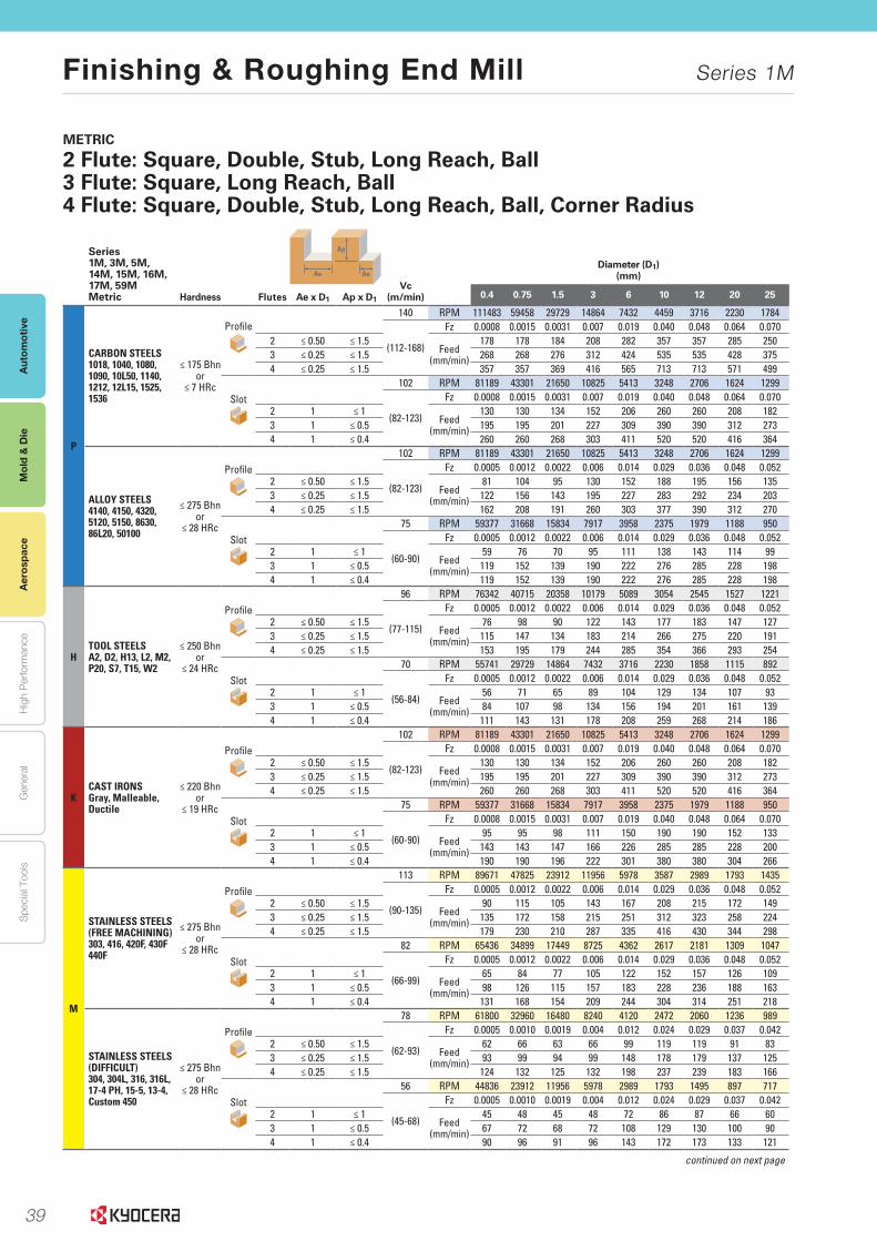
39
Aut
omot
ive
Aer
ospa
ceH
igh
Per
form
ance
Gen
eral
Spe
cial
Too
lsM
old
& D
ie
Finishing & Roughing End Mill Series 1M
Aer
ospa
ceM
old
& D
ie
228
END MILLS END MILLS
www.kyocera-sgstool.com
METRIC
2 Flute: Square, Double, Stub, Long Reach, Ball3 Flute: Square, Long Reach, Ball 4 Flute: Square, Double, Stub, Long Reach, Ball, Corner Radius
Series 1M, 3M, 5M, 14M, 15M, 16M, 17M, 59MMetric Hardness Flutes
Ap
Ae Ae
Vc (m/min)
Diameter (D1)(mm)
Ae x D1 Ap x D1 0.4 0.75 1.5 3 6 10 12 20 25
P
CARBON STEELS1018, 1040, 1080, 1090, 10L50, 1140, 1212, 12L15, 1525, 1536
≤ 175 Bhnor
≤ 7 HRc
Profile140 RPM 111483 59458 29729 14864 7432 4459 3716 2230 1784
(112-168)
Fz 0.0008 0.0015 0.0031 0.007 0.019 0.040 0.048 0.064 0.0702 ≤ 0.50 ≤ 1.5
Feed (mm/min)
178 178 184 208 282 357 357 285 2503 ≤ 0.25 ≤ 1.5 268 268 276 312 424 535 535 428 3754 ≤ 0.25 ≤ 1.5 357 357 369 416 565 713 713 571 499
Slot102 RPM 81189 43301 21650 10825 5413 3248 2706 1624 1299
(82-123)
Fz 0.0008 0.0015 0.0031 0.007 0.019 0.040 0.048 0.064 0.0702 1 ≤ 1
Feed (mm/min)
130 130 134 152 206 260 260 208 1823 1 ≤ 0.5 195 195 201 227 309 390 390 312 2734 1 ≤ 0.4 260 260 268 303 411 520 520 416 364
ALLOY STEELS4140, 4150, 4320, 5120, 5150, 8630, 86L20, 50100
≤ 275 Bhnor
≤ 28 HRc
Profile102 RPM 81189 43301 21650 10825 5413 3248 2706 1624 1299
(82-123)
Fz 0.0005 0.0012 0.0022 0.006 0.014 0.029 0.036 0.048 0.0522 ≤ 0.50 ≤ 1.5
Feed (mm/min)
81 104 95 130 152 188 195 156 1353 ≤ 0.25 ≤ 1.5 122 156 143 195 227 283 292 234 2034 ≤ 0.25 ≤ 1.5 162 208 191 260 303 377 390 312 270
Slot75 RPM 59377 31668 15834 7917 3958 2375 1979 1188 950
(60-90)
Fz 0.0005 0.0012 0.0022 0.006 0.014 0.029 0.036 0.048 0.0522 1 ≤ 1
Feed (mm/min)
59 76 70 95 111 138 143 114 993 1 ≤ 0.5 119 152 139 190 222 276 285 228 1984 1 ≤ 0.4 119 152 139 190 222 276 285 228 198
HTOOL STEELSA2, D2, H13, L2, M2, P20, S7, T15, W2
≤ 250 Bhnor
≤ 24 HRc
Profile96 RPM 76342 40715 20358 10179 5089 3054 2545 1527 1221
(77-115)
Fz 0.0005 0.0012 0.0022 0.006 0.014 0.029 0.036 0.048 0.0522 ≤ 0.50 ≤ 1.5
Feed (mm/min)
76 98 90 122 143 177 183 147 1273 ≤ 0.25 ≤ 1.5 115 147 134 183 214 266 275 220 1914 ≤ 0.25 ≤ 1.5 153 195 179 244 285 354 366 293 254
Slot70 RPM 55741 29729 14864 7432 3716 2230 1858 1115 892
(56-84)
Fz 0.0005 0.0012 0.0022 0.006 0.014 0.029 0.036 0.048 0.0522 1 ≤ 1
Feed (mm/min)
56 71 65 89 104 129 134 107 933 1 ≤ 0.5 84 107 98 134 156 194 201 161 1394 1 ≤ 0.4 111 143 131 178 208 259 268 214 186
KCAST IRONSGray, Malleable, Ductile
≤ 220 Bhnor
≤ 19 HRc
Profile102 RPM 81189 43301 21650 10825 5413 3248 2706 1624 1299
(82-123)
Fz 0.0008 0.0015 0.0031 0.007 0.019 0.040 0.048 0.064 0.0702 ≤ 0.50 ≤ 1.5
Feed (mm/min)
130 130 134 152 206 260 260 208 1823 ≤ 0.25 ≤ 1.5 195 195 201 227 309 390 390 312 2734 ≤ 0.25 ≤ 1.5 260 260 268 303 411 520 520 416 364
Slot75 RPM 59377 31668 15834 7917 3958 2375 1979 1188 950
(60-90)
Fz 0.0008 0.0015 0.0031 0.007 0.019 0.040 0.048 0.064 0.0702 1 ≤ 1
Feed (mm/min)
95 95 98 111 150 190 190 152 1333 1 ≤ 0.5 143 143 147 166 226 285 285 228 2004 1 ≤ 0.4 190 190 196 222 301 380 380 304 266
M
STAINLESS STEELS(FREE MACHINING)303, 416, 420F, 430F 440F
≤ 275 Bhnor
≤ 28 HRc
Profile113 RPM 89671 47825 23912 11956 5978 3587 2989 1793 1435
(90-135)
Fz 0.0005 0.0012 0.0022 0.006 0.014 0.029 0.036 0.048 0.0522 ≤ 0.50 ≤ 1.5
Feed (mm/min)
90 115 105 143 167 208 215 172 1493 ≤ 0.25 ≤ 1.5 135 172 158 215 251 312 323 258 2244 ≤ 0.25 ≤ 1.5 179 230 210 287 335 416 430 344 298
Slot82 RPM 65436 34899 17449 8725 4362 2617 2181 1309 1047
(66-99)
Fz 0.0005 0.0012 0.0022 0.006 0.014 0.029 0.036 0.048 0.0522 1 ≤ 1
Feed (mm/min)
65 84 77 105 122 152 157 126 1093 1 ≤ 0.5 98 126 115 157 183 228 236 188 1634 1 ≤ 0.4 131 168 154 209 244 304 314 251 218
STAINLESS STEELS(DIFFICULT)304, 304L, 316, 316L,17-4 PH, 15-5, 13-4, Custom 450
≤ 275 Bhnor
≤ 28 HRc
Profile78 RPM 61800 32960 16480 8240 4120 2472 2060 1236 989
(62-93)
Fz 0.0005 0.0010 0.0019 0.004 0.012 0.024 0.029 0.037 0.0422 ≤ 0.50 ≤ 1.5
Feed (mm/min)
62 66 63 66 99 119 119 91 833 ≤ 0.25 ≤ 1.5 93 99 94 99 148 178 179 137 1254 ≤ 0.25 ≤ 1.5 124 132 125 132 198 237 239 183 166
Slot56 RPM 44836 23912 11956 5978 2989 1793 1495 897 717
(45-68)
Fz 0.0005 0.0010 0.0019 0.004 0.012 0.024 0.029 0.037 0.0422 1 ≤ 1
Feed (mm/min)
45 48 45 48 72 86 87 66 603 1 ≤ 0.5 67 72 68 72 108 129 130 100 904 1 ≤ 0.4 90 96 91 96 143 172 173 133 121
continued on next page
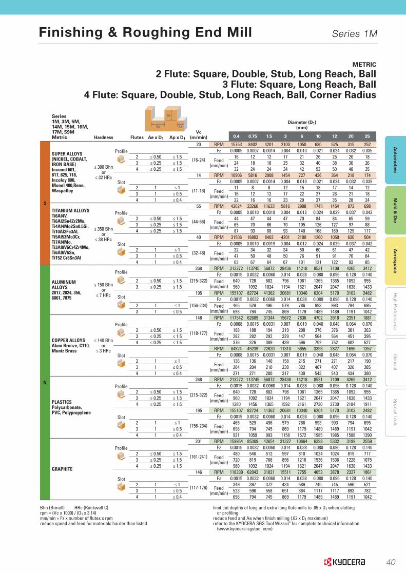
40
Autom
otiveA
erospaceH
igh Perform
anceG
eneralS
pecial ToolsM
old & D
ie
Finishing & Roughing End Mill Series 1M
Aerospace
Mold &
Die
229
END MILLS END MILLS
www.kyocera-sgstool.com
METRIC
2 Flute: Square, Double, Stub, Long Reach, Ball3 Flute: Square, Long Reach, Ball
4 Flute: Square, Double, Stub, Long Reach, Ball, Corner Radius
Series 1M, 3M, 5M, 14M, 15M, 16M, 17M, 59MMetric Hardness Flutes
Ap
Ae Ae
Vc (m/min)
Diameter (D1)(mm)
Ae x D1 Ap x D1 0.4 0.75 1.5 3 6 10 12 20 25
S
SUPER ALLOYS(NICKEL, COBALT, IRON BASE) Inconel 601, 617, 625, 718, Incoloy 800, Monel 400,Rene, Waspalloy
≤ 300 Bhnor
≤ 32 HRc
Profile20 RPM 15753 8402 4201 2100 1050 630 525 315 252
(16-24)
Fz 0.0005 0.0007 0.0014 0.004 0.010 0.021 0.024 0.032 0.0352 ≤ 0.50 ≤ 1.5
Feed (mm/min)
16 12 12 17 21 26 25 20 183 ≤ 0.25 ≤ 1.5 24 18 18 25 32 40 38 30 264 ≤ 0.25 ≤ 1.5 32 24 24 34 42 53 50 40 35
Slot14 RPM 10906 5816 2908 1454 727 436 364 218 174
(11-16)
Fz 0.0005 0.0007 0.0014 0.004 0.010 0.021 0.024 0.032 0.0352 1 ≤ 1
Feed (mm/min)
11 8 8 12 15 18 17 14 123 1 ≤ 0.5 16 12 12 17 22 27 26 21 184 1 ≤ 0.4 22 16 16 23 29 37 35 28 24
TITANIUM ALLOYSTi6Al4V, Ti6Al2Sn4Zr2Mo, Ti4Al4Mo2Sn0.5Si, Ti10Al2Fe3Al, Ti5Al53Mo3Cr, Ti7Al4Mo, Ti3Al8V6Cr4Zr4Mo, Ti6Al6V6Sn,Ti152 Cr3Sn3Al
≤ 350 Bhnor
≤ 38 HRc
Profile55 RPM 43624 23266 11633 5816 2908 1745 1454 872 698
(44-66)
Fz 0.0005 0.0010 0.0019 0.004 0.012 0.024 0.029 0.037 0.0422 ≤ 0.50 ≤ 1.5
Feed (mm/min)
44 47 44 47 70 84 84 65 593 ≤ 0.25 ≤ 1.5 65 70 66 70 105 126 127 97 884 ≤ 0.25 ≤ 1.5 87 93 88 93 140 168 169 129 117
Slot40 RPM 31506 16803 8402 4201 2100 1260 1050 630 504
(32-48)
Fz 0.0005 0.0010 0.0019 0.004 0.012 0.024 0.029 0.037 0.0422 1 ≤ 1
Feed (mm/min)
32 34 32 34 50 60 61 47 423 1 ≤ 0.5 47 50 48 50 76 91 91 70 644 1 ≤ 0.4 63 67 64 67 101 121 122 93 85
N
ALUMINUM ALLOYS2017, 2024, 356, 6061, 7075
≤ 150 Bhnor
≤ 7 HRc
Profile268 RPM 213272 113745 56872 28436 14218 8531 7109 4265 3412
(215-322)Fz 0.0015 0.0032 0.0060 0.014 0.038 0.080 0.096 0.128 0.140
2 ≤ 0.50 ≤ 1.5 Feed (mm/min)
640 728 682 796 1081 1365 1365 1092 9553 ≤ 0.25 ≤ 1.5 960 1092 1024 1194 1621 2047 2047 1638 1433
Slot195 RPM 155107 82724 41362 20681 10340 6204 5170 3102 2482
(156-234)Fz 0.0015 0.0032 0.0060 0.014 0.038 0.080 0.096 0.128 0.140
2 1 ≤ 1 Feed (mm/min)
465 529 496 579 786 993 993 794 6953 1 ≤ 0.5 698 794 745 869 1179 1489 1489 1191 1042
COPPER ALLOYSAlum Bronze, C110, Muntz Brass
≤ 140 Bhnor
≤ 3 HRc
Profile148 RPM 117542 62689 31344 15672 7836 4702 3918 2351 1881
(118-177)
Fz 0.0008 0.0015 0.0031 0.007 0.019 0.040 0.048 0.064 0.0702 ≤ 0.50 ≤ 1.5
Feed (mm/min)
188 188 194 219 298 376 376 301 2633 ≤ 0.25 ≤ 1.5 282 282 292 329 447 564 564 451 3954 ≤ 0.25 ≤ 1.5 376 376 389 439 596 752 752 602 527
SlotRPM 84824 45239 22620 11310 5655 3393 2827 1696 1357
Fz 0.0008 0.0015 0.0031 0.007 0.019 0.040 0.048 0.064 0.0702 1 ≤ 1
Feed (mm/min)
136 136 140 158 215 271 271 217 1903 1 ≤ 0.5 204 204 210 238 322 407 407 326 2854 1 ≤ 0.4 271 271 280 317 430 543 543 434 380
PLASTICSPolycarbonate, PVC, Polypropylene
Profile268 RPM 213272 113745 56872 28436 14218 8531 7109 4265 3412
(215-322)
Fz 0.0015 0.0032 0.0060 0.014 0.038 0.080 0.096 0.128 0.1402 ≤ 0.50 ≤ 1.5
Feed (mm/min)
640 728 682 796 1081 1365 1365 1092 9553 ≤ 0.25 ≤ 1.5 960 1092 1024 1194 1621 2047 2047 1638 14334 ≤ 0.25 ≤ 1.5 1280 1456 1365 1592 2161 2730 2730 2184 1911
Slot195 RPM 155107 82724 41362 20681 10340 6204 5170 3102 2482
(156-234)
Fz 0.0015 0.0032 0.0060 0.014 0.038 0.080 0.096 0.128 0.1402 1 ≤ 1
Feed (mm/min)
465 529 496 579 786 993 993 794 6953 1 ≤ 0.5 698 794 745 869 1179 1489 1489 1191 10424 1 ≤ 0.4 931 1059 993 1158 1572 1985 1985 1588 1390
GRAPHITE
Profile201 RPM 159954 85309 42654 21327 10664 6398 5332 3199 2559
(161-241)
Fz 0.0015 0.0032 0.0060 0.014 0.038 0.080 0.096 0.128 0.1402 ≤ 0.50 ≤ 1.5
Feed (mm/min)
480 546 512 597 810 1024 1024 819 7173 ≤ 0.25 ≤ 1.5 720 819 768 896 1216 1536 1536 1228 10754 ≤ 0.25 ≤ 1.5 960 1092 1024 1194 1621 2047 2047 1638 1433
Slot146 RPM 116330 62043 31021 15511 7755 4653 3878 2327 1861
(117-176)
Fz 0.0015 0.0032 0.0060 0.014 0.038 0.080 0.096 0.128 0.1402 1 ≤ 1
Feed (mm/min)
349 397 372 434 589 745 745 596 5213 1 ≤ 0.5 523 596 558 651 884 1117 1117 893 7824 1 ≤ 0.4 698 794 745 869 1179 1489 1489 1191 1042
Bhn (Brinell) HRc (Rockwell C)rpm = (Vc x 1000) / (D1 x 3.14)mm/min = Fz x number of flutes x rpmreduce speed and feed for materials harder than listed
limit cut depths of long and extra long flute mills to .05 x D1 when slotting or profiling
reduce feed and Ae when finish milling (.02 x D1 maximum)refer to the KYOCERA SGS Tool Wizard® for complete technical information
(www.kyocera-sgstool.com)
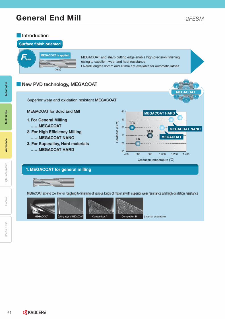
41
Aut
omot
ive
Aer
ospa
ceH
igh
Per
form
ance
Gen
eral
Spe
cial
Too
lsM
old
& D
ie
General End Mill 2FESM
Mol
d &
Die
Aer
ospa
ce
L6
L
Sol
id T
ools
Tool Selection Guide
JSeries
High efficiency and stable machining for Heat Resistant Alloys such as Inconel®
Long tool life machining with MEGACOAT HARD for excellent heat resistance(4JER)
MEGACOAT HARD is applied
Surface finish oriented
MEGACOAT and sharp cutting edge enable high precision finishing owing to excellent wear and heat resistanceOverall lengths 35mm and 45mm are available for automatic lathes
MEGACOAT is applied
(FES)
FSeries
High efficiency , High feed rate
High feed rate and high efficiency shouldering with multi-edge design (6 flutes /8 flutes)Varied interval flute design and variable lead to minimize chattering
PFK MEGACOAT NANO is applied
(6PFK)
Superalloy
(5DERM)
Varied interval flute design with 5 flutesFor high efficiency slotting and shoulderingApplicable to difficult-to-cut materials like stainless steel and heat resistant steel
DSeries
3ZFKMulti-functional, high efficiency end millApplicable to plunge milling, slotting and finishing with one end mill.Smooth chip evacuation because sub-groove on gash breaks chips during plunge milling.(3ZFKS)
MEGACOAT is applied
High efficiency, Excellent chip evacuation
Superior chattering resistance with Kyocera's unique varied interval �ute design and variable leadAchieves high rigidity and stable chip evacuation with new special �ute designAchieves high feed rate, high efficiency machining(4MFK)
MEGACOAT NANO is appliedMSeries
High efficiency end mill for difficult-to-cut materials (stainless steel, titanium alloys and heat-resistant alloys )Varied interval �ute design / Variable Lead
TSeriesMEGACOAT NANO is applied
(4TFK)
■ Introduction
L16~L22
L16
L18
L26
L22
L24
L24
L27
L20
L24~L25
L26~L27
Varied interval flute design
α≠β
αβ
α≠β
αβ
Varied interval flute design
L.indd 6 2019/09/04 10:19:33
L8
L
Sol
id T
ools
Solid End Mill Series
■New PVD technology, MEGACOAT
1. MEGACOAT for general milling
2. MEGACOAT NANO with special multilayer nano coating for high efficiency machining
3. MEGACOAT HARD for machining of superalloy and hard materials
15
20
25
30
35
40
400 600 800 1,000 1,200 1,400
Oxidation temperature (℃)
Har
dnes
s (G
Pa)
MEGACOAT HARD
MEGACOAT
MEGACOAT NANO
TiN
TiCN
TiAlN
MEGACOAT for Solid End Mill
1. For General Milling……MEGACOAT
2. For High Efficiency Milling……MEGACOAT NANO
3. For Superalloy, Hard materials……MEGACOAT HARD
MEGACOAT extend tool life for roughing to finishing of various kinds of material with superior wear resistance and high oxidation resistance
The special Multilayer Nano Coating realizes superior wear resistance due to high hardness and
anti-chipping performance. Suitable for high feed rate machining
The special multilayer coating provides high hardness and excellent oxidation resistance
Longer tool life and stability at machining of superalloys and hard materials
MEGACOAT
4MFK / 4MFRL16
H SeriesL35
4/5/6RFHL28
4JERL26
Superior wear and oxidation resistant MEGACOAT
· Long Tool Life with "MEGACOAT NANO". Doubled Wear Resistance compared to the Competitor's!
Edge Conditions after 140m Machining
4MFK/4MFR Competitor C Competitor D
〔Cutting Conditions:n=6,000min-1、Vf=1,100mm/min、ap x ae=5.0 x 0.8mm、 ø8, SCM440, Shouldering〕
Cutting edge of MEGACOAT Competitor B (Internal evaluation)Competitor AMEGACOAT
4MFK/4MFR
4TFK/4TFR
(H Series)
4JER
4/5/6RFH
(Internal evaluation)
4TFK / 4TFRL18
L.indd 8 2019/09/04 10:19:40
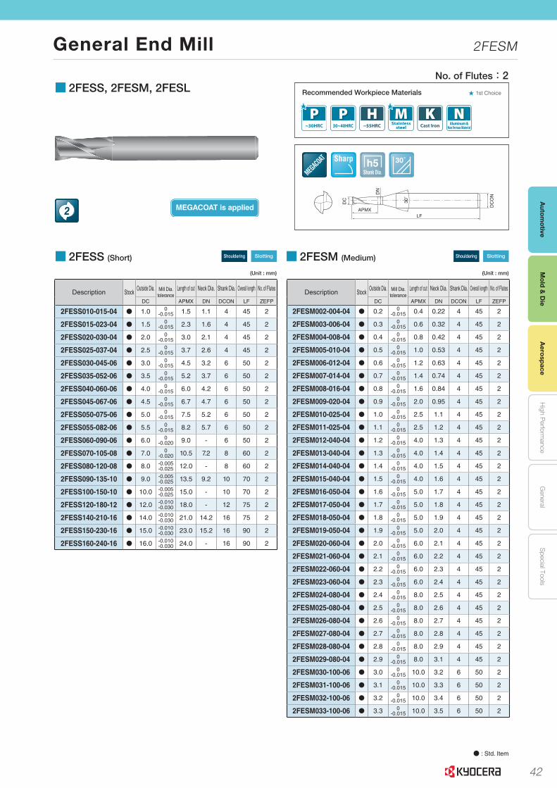
42
Autom
otiveA
erospaceH
igh Perform
anceG
eneralS
pecial ToolsM
old & D
ie
General End Mill 2FESM
Mold &
Die
Aerospace
L10
L
Sol
id T
ools
End Mills
Solid Tools for CFRP
Flat Bottom Drill
Cutting Conditions
■ 2FESS, 2FESM, 2FESL
DC
ON
LF
DC
DN
30°
APMX
Shank Dia.h5 30˚Sharp
Recommended Workpiece Materials ★ 1st Choice
MEGACOAT is applied2
Description StockOutside Dia. Mill Dia.
toleranceLength of cut Neck Dia. Shank Dia. Overall length No. of Flutes
DC APMX DN DCON LF ZEFP
2FESS010-015-04 N 1.0 0-0.015 1.5 1.1 4 45 2
2FESS015-023-04 N 1.5 0-0.015 2.3 1.6 4 45 2
2FESS020-030-04 N 2.0 0-0.015 3.0 2.1 4 45 2
2FESS025-037-04 N 2.5 0-0.015 3.7 2.6 4 45 2
2FESS030-045-06 N 3.0 0-0.015 4.5 3.2 6 50 2
2FESS035-052-06 N 3.5 0-0.015 5.2 3.7 6 50 2
2FESS040-060-06 N 4.0 0-0.015 6.0 4.2 6 50 2
2FESS045-067-06 N 4.5 0-0.015 6.7 4.7 6 50 2
2FESS050-075-06 N 5.0 0-0.015 7.5 5.2 6 50 2
2FESS055-082-06 N 5.5 0-0.015 8.2 5.7 6 50 2
2FESS060-090-06 N 6.0 0-0.020 9.0 - 6 50 2
2FESS070-105-08 N 7.0 0-0.020 10.5 7.2 8 60 2
2FESS080-120-08 N 8.0 -0.005-0.025 12.0 - 8 60 2
2FESS090-135-10 N 9.0 -0.005-0.025 13.5 9.2 10 70 2
2FESS100-150-10 N 10.0 -0.005-0.025 15.0 - 10 70 2
2FESS120-180-12 N 12.0 -0.010-0.030 18.0 - 12 75 2
2FESS140-210-16 N 14.0 -0.010-0.030 21.0 14.2 16 75 2
2FESS150-230-16 N 15.0 -0.010-0.030 23.0 15.2 16 90 2
2FESS160-240-16 N 16.0 -0.010-0.030 24.0 - 16 90 2
Description StockOutside Dia. Mill Dia.
toleranceLength of cut Neck Dia. Shank Dia. Overall length No. of Flutes
DC APMX DN DCON LF ZEFP
2FESM002-004-04 N 0.2 0-0.015 0.4 0.22 4 45 2
2FESM003-006-04 N 0.3 0-0.015 0.6 0.32 4 45 2
2FESM004-008-04 N 0.4 0-0.015 0.8 0.42 4 45 2
2FESM005-010-04 N 0.5 0-0.015 1.0 0.53 4 45 2
2FESM006-012-04 N 0.6 0-0.015 1.2 0.63 4 45 2
2FESM007-014-04 N 0.7 0-0.015 1.4 0.74 4 45 2
2FESM008-016-04 N 0.8 0-0.015 1.6 0.84 4 45 2
2FESM009-020-04 N 0.9 0-0.015 2.0 0.95 4 45 2
2FESM010-025-04 N 1.0 0-0.015 2.5 1.1 4 45 2
2FESM011-025-04 N 1.1 0-0.015 2.5 1.2 4 45 2
2FESM012-040-04 N 1.2 0-0.015 4.0 1.3 4 45 2
2FESM013-040-04 N 1.3 0-0.015 4.0 1.4 4 45 2
2FESM014-040-04 N 1.4 0-0.015 4.0 1.5 4 45 2
2FESM015-040-04 N 1.5 0-0.015 4.0 1.6 4 45 2
2FESM016-050-04 N 1.6 0-0.015 5.0 1.7 4 45 2
2FESM017-050-04 N 1.7 0-0.015 5.0 1.8 4 45 2
2FESM018-050-04 N 1.8 0-0.015 5.0 1.9 4 45 2
2FESM019-050-04 N 1.9 0-0.015 5.0 2.0 4 45 2
2FESM020-060-04 N 2.0 0-0.015 6.0 2.1 4 45 2
2FESM021-060-04 N 2.1 0-0.015 6.0 2.2 4 45 2
2FESM022-060-04 N 2.2 0-0.015 6.0 2.3 4 45 2
2FESM023-060-04 N 2.3 0-0.015 6.0 2.4 4 45 2
2FESM024-080-04 N 2.4 0-0.015 8.0 2.5 4 45 2
2FESM025-080-04 N 2.5 0-0.015 8.0 2.6 4 45 2
2FESM026-080-04 N 2.6 0-0.015 8.0 2.7 4 45 2
2FESM027-080-04 N 2.7 0-0.015 8.0 2.8 4 45 2
2FESM028-080-04 N 2.8 0-0.015 8.0 2.9 4 45 2
2FESM029-080-04 N 2.9 0-0.015 8.0 3.1 4 45 2
2FESM030-100-06 N 3.0 0-0.015 10.0 3.2 6 50 2
2FESM031-100-06 N 3.1 0-0.015 10.0 3.3 6 50 2
2FESM032-100-06 N 3.2 0-0.015 10.0 3.4 6 50 2
2FESM033-100-06 N 3.3 0-0.015 10.0 3.5 6 50 2
■ 2FESS (Short) Shouldering Slotting
(Unit : mm)
■ 2FESM (Medium) Shouldering Slotting
(Unit : mm)
No. of Flutes:2
● : Std. Item
L.indd 10 2019/09/04 10:19:45
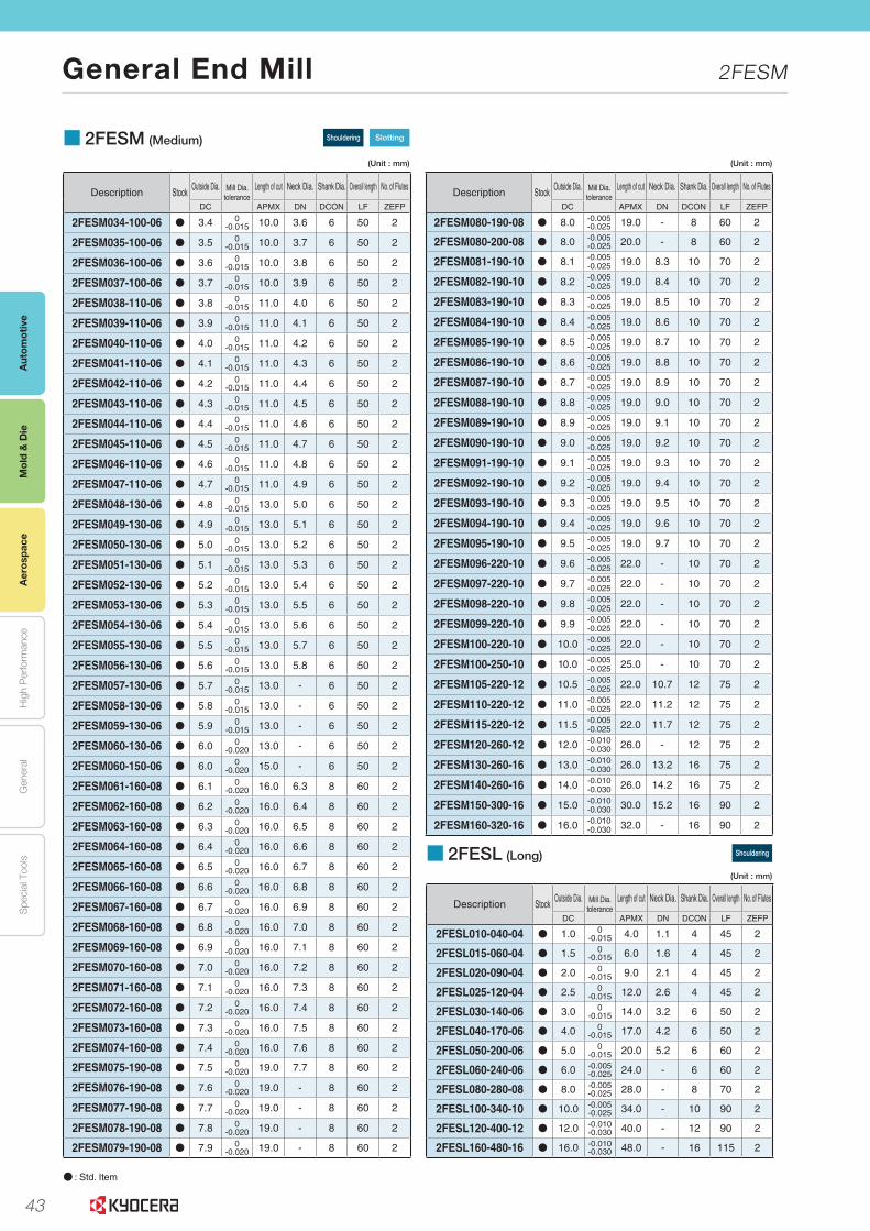
43
Aut
omot
ive
Aer
ospa
ceH
igh
Per
form
ance
Gen
eral
Spe
cial
Too
lsM
old
& D
ie
General End Mill 2FESM
Mol
d &
Die
Aer
ospa
ce
L11
Turning Indexable Inserts
CBN & PCD ToolsE
xternalS
mall P
arts M
achiningB
oringG
roovingC
ut-offT
hreadingD
rillingS
olid ToolsM
illingTools for
Turning Mill
Spare P
artsTechnical
Information
Index
A
B
C
D
E
F
G
H
J
K
L
M
N
P
R
T
Insert Grades
■ 2FESM�(Medium) Shouldering Slotting
(Unit : mm) (Unit : mm)
■ 2FESL�(Long) Shouldering
(Unit : mm)
Description StockOutside Dia. Mill Dia.
toleranceLength of cut Neck Dia. Shank Dia. Overall length No. of Flutes
DC APMX DN DCON LF ZEFP
2FESL010-040-04 N 1.0 0-0.015 4.0 1.1 4 45 2
2FESL015-060-04 N 1.5 0-0.015 6.0 1.6 4 45 2
2FESL020-090-04 N 2.0 0-0.015 9.0 2.1 4 45 2
2FESL025-120-04 N 2.5 0-0.015 12.0 2.6 4 45 2
2FESL030-140-06 N 3.0 0-0.015 14.0 3.2 6 50 2
2FESL040-170-06 N 4.0 0-0.015 17.0 4.2 6 50 2
2FESL050-200-06 N 5.0 0-0.015 20.0 5.2 6 60 2
2FESL060-240-06 N 6.0 -0.005-0.025 24.0 - 6 60 2
2FESL080-280-08 N 8.0 -0.005-0.025 28.0 - 8 70 2
2FESL100-340-10 N 10.0 -0.005-0.025 34.0 - 10 90 2
2FESL120-400-12 N 12.0 -0.010-0.030 40.0 - 12 90 2
2FESL160-480-16 N 16.0 -0.010-0.030 48.0 - 16 115 2
● : Std. Item
Description StockOutside Dia. Mill Dia.
toleranceLength of cut Neck Dia. Shank Dia. Overall length No. of Flutes
DC APMX DN DCON LF ZEFP
2FESM034-100-06 N 3.4 0-0.015 10.0 3.6 6 50 2
2FESM035-100-06 N 3.5 0-0.015 10.0 3.7 6 50 2
2FESM036-100-06 N 3.6 0-0.015 10.0 3.8 6 50 2
2FESM037-100-06 N 3.7 0-0.015 10.0 3.9 6 50 2
2FESM038-110-06 N 3.8 0-0.015 11.0 4.0 6 50 2
2FESM039-110-06 N 3.9 0-0.015 11.0 4.1 6 50 2
2FESM040-110-06 N 4.0 0-0.015 11.0 4.2 6 50 2
2FESM041-110-06 N 4.1 0-0.015 11.0 4.3 6 50 2
2FESM042-110-06 N 4.2 0-0.015 11.0 4.4 6 50 2
2FESM043-110-06 N 4.3 0-0.015 11.0 4.5 6 50 2
2FESM044-110-06 N 4.4 0-0.015 11.0 4.6 6 50 2
2FESM045-110-06 N 4.5 0-0.015 11.0 4.7 6 50 2
2FESM046-110-06 N 4.6 0-0.015 11.0 4.8 6 50 2
2FESM047-110-06 N 4.7 0-0.015 11.0 4.9 6 50 2
2FESM048-130-06 N 4.8 0-0.015 13.0 5.0 6 50 2
2FESM049-130-06 N 4.9 0-0.015 13.0 5.1 6 50 2
2FESM050-130-06 N 5.0 0-0.015 13.0 5.2 6 50 2
2FESM051-130-06 N 5.1 0-0.015 13.0 5.3 6 50 2
2FESM052-130-06 N 5.2 0-0.015 13.0 5.4 6 50 2
2FESM053-130-06 N 5.3 0-0.015 13.0 5.5 6 50 2
2FESM054-130-06 N 5.4 0-0.015 13.0 5.6 6 50 2
2FESM055-130-06 N 5.5 0-0.015 13.0 5.7 6 50 2
2FESM056-130-06 N 5.6 0-0.015 13.0 5.8 6 50 2
2FESM057-130-06 N 5.7 0-0.015 13.0 - 6 50 2
2FESM058-130-06 N 5.8 0-0.015 13.0 - 6 50 2
2FESM059-130-06 N 5.9 0-0.015 13.0 - 6 50 2
2FESM060-130-06 N 6.0 0-0.020 13.0 - 6 50 2
2FESM060-150-06 N 6.0 0 -0.020 15.0 - 6 50 2
2FESM061-160-08 N 6.1 0-0.020 16.0 6.3 8 60 2
2FESM062-160-08 N 6.2 0-0.020 16.0 6.4 8 60 2
2FESM063-160-08 N 6.3 0-0.020 16.0 6.5 8 60 2
2FESM064-160-08 N 6.4 0-0.020 16.0 6.6 8 60 2
2FESM065-160-08 N 6.5 0-0.020 16.0 6.7 8 60 2
2FESM066-160-08 N 6.6 0-0.020 16.0 6.8 8 60 2
2FESM067-160-08 N 6.7 0-0.020 16.0 6.9 8 60 2
2FESM068-160-08 N 6.8 0-0.020 16.0 7.0 8 60 2
2FESM069-160-08 N 6.9 0-0.020 16.0 7.1 8 60 2
2FESM070-160-08 N 7.0 0-0.020 16.0 7.2 8 60 2
2FESM071-160-08 N 7.1 0-0.020 16.0 7.3 8 60 2
2FESM072-160-08 N 7.2 0-0.020 16.0 7.4 8 60 2
2FESM073-160-08 N 7.3 0-0.020 16.0 7.5 8 60 2
2FESM074-160-08 N 7.4 0-0.020 16.0 7.6 8 60 2
2FESM075-190-08 N 7.5 0-0.020 19.0 7.7 8 60 2
2FESM076-190-08 N 7.6 0-0.020 19.0 - 8 60 2
2FESM077-190-08 N 7.7 0-0.020 19.0 - 8 60 2
2FESM078-190-08 N 7.8 0-0.020 19.0 - 8 60 2
2FESM079-190-08 N 7.9 0-0.020 19.0 - 8 60 2
Description StockOutside Dia. Mill Dia.
toleranceLength of cut Neck Dia. Shank Dia. Overall length No. of Flutes
DC APMX DN DCON LF ZEFP
2FESM080-190-08 N 8.0 -0.005-0.025 19.0 - 8 60 2
2FESM080-200-08 N 8.0 -0.005 -0.025 20.0 - 8 60 2
2FESM081-190-10 N 8.1 -0.005-0.025 19.0 8.3 10 70 2
2FESM082-190-10 N 8.2 -0.005-0.025 19.0 8.4 10 70 2
2FESM083-190-10 N 8.3 -0.005-0.025 19.0 8.5 10 70 2
2FESM084-190-10 N 8.4 -0.005-0.025 19.0 8.6 10 70 2
2FESM085-190-10 N 8.5 -0.005-0.025 19.0 8.7 10 70 2
2FESM086-190-10 N 8.6 -0.005-0.025 19.0 8.8 10 70 2
2FESM087-190-10 N 8.7 -0.005-0.025 19.0 8.9 10 70 2
2FESM088-190-10 N 8.8 -0.005-0.025 19.0 9.0 10 70 2
2FESM089-190-10 N 8.9 -0.005-0.025 19.0 9.1 10 70 2
2FESM090-190-10 N 9.0 -0.005-0.025 19.0 9.2 10 70 2
2FESM091-190-10 N 9.1 -0.005-0.025 19.0 9.3 10 70 2
2FESM092-190-10 N 9.2 -0.005-0.025 19.0 9.4 10 70 2
2FESM093-190-10 N 9.3 -0.005-0.025 19.0 9.5 10 70 2
2FESM094-190-10 N 9.4 -0.005-0.025 19.0 9.6 10 70 2
2FESM095-190-10 N 9.5 -0.005-0.025 19.0 9.7 10 70 2
2FESM096-220-10 N 9.6 -0.005-0.025 22.0 - 10 70 2
2FESM097-220-10 N 9.7 -0.005-0.025 22.0 - 10 70 2
2FESM098-220-10 N 9.8 -0.005-0.025 22.0 - 10 70 2
2FESM099-220-10 N 9.9 -0.005-0.025 22.0 - 10 70 2
2FESM100-220-10 N 10.0 -0.005-0.025 22.0 - 10 70 2
2FESM100-250-10 N 10.0 -0.005 -0.025 25.0 - 10 70 2
2FESM105-220-12 N 10.5 -0.005-0.025 22.0 10.7 12 75 2
2FESM110-220-12 N 11.0 -0.005-0.025 22.0 11.2 12 75 2
2FESM115-220-12 N 11.5 -0.005-0.025 22.0 11.7 12 75 2
2FESM120-260-12 N 12.0 -0.010-0.030 26.0 - 12 75 2
2FESM130-260-16 N 13.0 -0.010-0.030 26.0 13.2 16 75 2
2FESM140-260-16 N 14.0 -0.010-0.030 26.0 14.2 16 75 2
2FESM150-300-16 N 15.0 -0.010-0.030 30.0 15.2 16 90 2
2FESM160-320-16 N 16.0 -0.010-0.030 32.0 - 16 90 2
L.indd 11 2019/09/04 10:19:46

44
Autom
otiveA
erospaceH
igh Perform
anceG
eneralS
pecial ToolsM
old & D
ie
General End Mill 2FESM
Mold &
Die
Aerospace
L57
Turning Indexable Inserts
CBN & PCD ToolsE
xternalS
mall P
arts M
achiningB
oringG
roovingC
ut-offT
hreadingD
rillingS
olid ToolsM
illingTools for
Turning Mill
Spare P
artsTechnical
Information
Index
A
B
C
D
E
F
G
H
J
K
L
M
N
P
R
T
Insert Grades
■ 2FESSApplications Workpiece Material Application Outside Dia. DC (mm) ø1 ø2 ø4 ø6 ø8 ø12 ø16
ap
ae
Shouldering
Depth of Cut (ap x ae) (mm)
1.2DC x 0.05DC(DC<ø3)
1.2DC x 0.1DC(DC≥ø3)
ap
Slotting
Depth of Cut (ap) (mm)
0.1DC(DC<ø1)0.3DC(ø1≤DC<ø3)
0.5DC(DC≥ø3)
Carbon Steel, Cast Iron
ShoulderingSpindle Revolution (min-1) 25,500 13,200 6,600 4,400 3,300 2,200 1,700
Feed Rate (mm/min) 225 230 375 415 420 310 240
SlottingSpindle Revolution (min-1) 19,000 11,000 6,000 4,000 3,000 2,000 1,500
Feed Rate (mm/min) 135 140 225 250 250 245 245
Alloy Steel
ShoulderingSpindle Revolution (min-1) 22,000 11,000 5,600 3,700 2,800 1,900 1,400
Feed Rate (mm/min) 195 220 285 315 310 230 200
SlottingSpindle Revolution (min-1) 18,000 9,500 4,800 3,200 2,400 1,600 1,200
Feed Rate (mm/min) 115 130 170 190 185 185 185
Prehardened Steel
ShoulderingSpindle Revolution (min-1) 17,000 8,800 4,400 3,000 2,200 1,500 1,100
Feed Rate (mm/min) 55 80 100 105 105 110 110
SlottingSpindle Revolution (min-1) 16,000 8,000 4,000 2,700 2,000 1,300 990
Feed Rate (mm/min) 35 50 60 63 63 65 65
Stainless Steel
ShoulderingSpindle Revolution (min-1) 22,000 11,000 5,600 3,700 2,800 1,900 1,400
Feed Rate (mm/min) 95 95 110 115 115 115 115
SlottingSpindle Revolution (min-1) 16,000 8,000 4,000 2,700 2,000 1,300 990
Feed Rate (mm/min) 60 60 65 70 70 70 70
■ 2FESM
Applications Workpiece Material Application Outside Dia. DC (mm) ø0.5 ø1 ø2 ø4 ø6 ø8 ø12 ø16
ap
ae
Shouldering
Depth of Cut (ap x ae) (mm)
1.5DC x 0.05DC(DC<ø3)
1.5DC x 0.1DC(DC≥ø3)
ap
Slotting
Depth of Cut (ap) (mm)
0.1DC(DC<ø1)0.3DC(ø1≤DC<ø3)
0.5DC(DC≥ø3)
Carbon Steel, Cast Iron
ShoulderingSpindle Revolution (min-1) 32,000 25,500 13,200 6,600 4,400 3,300 2,200 1,700
Feed Rate (mm/min) 210 225 230 375 415 420 310 240
SlottingSpindle Revolution (min-1) 29,000 19,000 11,000 6,000 4,000 3,000 2,000 1,500
Feed Rate (mm/min) 130 135 140 225 250 250 245 245
Alloy Steel
ShoulderingSpindle Revolution (min-1) 27,000 22,000 11,000 5,600 3,700 2,800 1,900 1,400
Feed Rate (mm/min) 180 195 220 285 315 310 230 200
SlottingSpindle Revolution (min-1) 27,000 18,000 9,500 4,800 3,200 2,400 1,600 1,200
Feed Rate (mm/min) 105 115 130 170 190 185 185 185
Prehardened Steel
ShoulderingSpindle Revolution (min-1) 25,000 17,000 8,800 4,400 3,000 2,200 1,500 1,100
Feed Rate (mm/min) 50 55 80 100 105 105 110 110
SlottingSpindle Revolution (min-1) 25,000 16,000 8,000 4,000 2,700 2,000 1,300 990
Feed Rate (mm/min) 30 35 50 60 63 63 65 65
Stainless Steel
ShoulderingSpindle Revolution (min-1) 27,000 22,000 11,000 5,600 3,700 2,800 1,900 1,400
Feed Rate (mm/min) 60 95 95 110 115 115 115 115
SlottingSpindle Revolution (min-1) 25,000 16,000 8,000 4,000 2,700 2,000 1,300 990
Feed Rate (mm/min) 35 60 60 65 70 70 70 70
Recommended Cutting Conditions
* Machining with water soluble coolant is recommended for stainless steel.
* Machining with water soluble coolant is recommended for stainless steel.
L.indd 57 2019/09/04 10:21:36

45
The original, symmetrical flute design features
an engineered flute form that provides high
performance results through a full range of
machining conditions. These tools are designed for
aggressive aluminum, non-ferrous, and non-metallic
machining requiring a high level of material removal.
S-CARB® HIGH PERFORMANCE END MILLS
Aluminum
Engineered Flute Design• Effective chip removal at high
feed rates
• Lower cutting forces than comparable products
• Improved balance at high spindle speeds
• Improved workpiece finish through better balance
• More effective plunging vs. conventional designs
Circular Land• Increased control at various
speed and feed levels
• Reduced chatter
Various Reach, Neck and End Options Available• Ball End design for complex
workpieces
• Necked design with blended diameter transitions provide clearance to reach
• Short flutes for maximum rigidity
• Axial slotting up to 1xD
Series 43 Metric Expanded Tools Available with Polished Flutes• Polished flutes maximize chip
evacuation and enhance finish allowing for higher feed rates
• Less built up edge due to lower co-efficient of friction
S-CARB® END MILLS FOR ALUMINUM, NON-FERROUS &
NON-METALLIC MATERIALS
VALUE AT THE SPINDLE ®
ENHANCED PRODUCTIVITY RESULTING FROM
A SUPERIOR FLUTE DESIGN THAT MANAGES
THE SIZE AND VOLUME OF CHIPS PRODUCED
DURING AGGRESSIVE MACHINING.
®
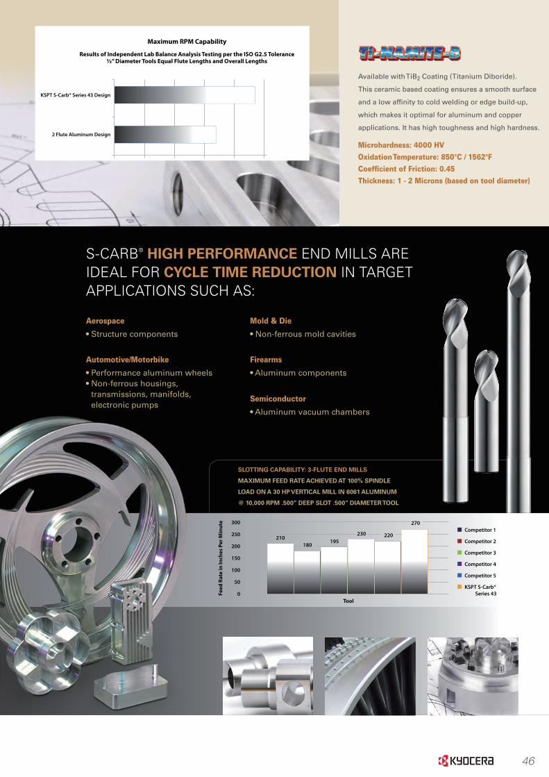
46
KSPT S-Carb® Series 43 Design
2 Flute Aluminum Design
0 5,000 10,000 15,000 20,000 25,000
Results of Independent Lab Balance Analysis Testing per the ISO G2.5 Tolerance½” Diameter Tools Equal Flute Lengths and Overall Lengths
Maximum RPM Capability
Aluminum
Aerospace
• Structure components
Automotive/Motorbike
• Performance aluminum wheels• Non-ferrous housings,
transmissions, manifolds, electronic pumps
S-CARB® HIGH PERFORMANCE END MILLS ARE IDEAL FOR CYCLE TIME REDUCTION IN TARGET APPLICATIONS SUCH AS:
Mold & Die
• Non-ferrous mold cavities
Firearms
• Aluminum components
Semiconductor
• Aluminum vacuum chambers
Available with TiB2 Coating (Titanium Diboride).
This ceramic based coating ensures a smooth surface
and a low affinity to cold welding or edge build-up,
which makes it optimal for aluminum and copper
applications. It has high toughness and high hardness.
Microhardness: 4000 HVOxidation Temperature: 850°C / 1562°FCoefficient of Friction: 0.45Thickness: 1 - 2 Microns (based on tool diameter)
SLOTTING CAPABILITY: 3-FLUTE END MILLS
MAXIMUM FEED RATE ACHIEVED AT 100% SPINDLE
LOAD ON A 30 HP VERTICAL MILL IN 6061 ALUMINUM
@ 10,000 RPM .500” DEEP SLOT .500” DIAMETER TOOL
Competitor 1300
210180
195230 220
270
250
200
150
100
50
0Tool
Feed
Rat
e in
Inch
es P
er M
inut
e
Competitor 2
Competitor 3
Competitor 4
Competitor 5
KSPT S-Carb® Series 43
Maximum Feed Rate Achieved at 100% Spindle Load on a 30 hp Vertical Mill In 6061 Aluminum @ 10,000 rpm .500” Deep Slot .500” Diameter Tool
Slotting Capability: 3-Flute End Mills
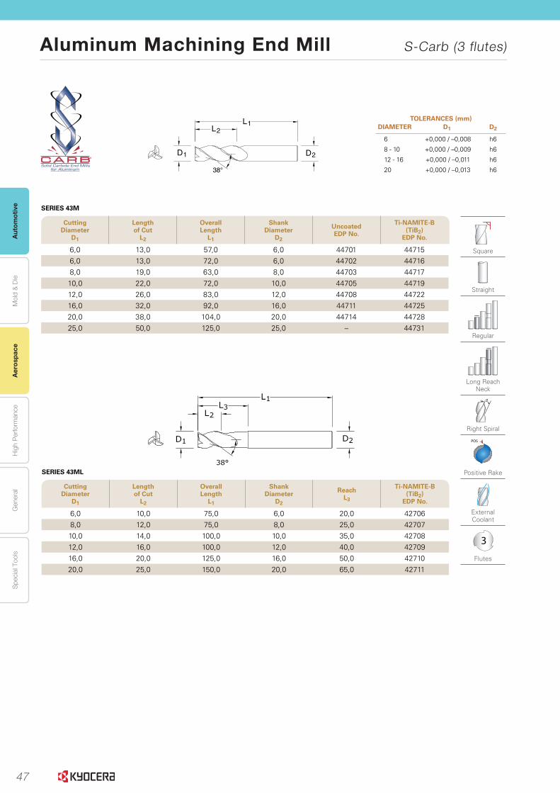
47
Aut
omot
ive
Aer
ospa
ceH
igh
Per
form
ance
Gen
eral
Spe
cial
Too
lsM
old
& D
ie
Aluminum Machining End Mill S-Carb (3 flutes)
Aer
ospa
ce
www.kyocera-sgstool.com18
®
Se
rie
s 4
3M
, 4
3M
L |
Met
ric
Cutting Diameter
D1
Lengthof Cut
L2
Overall Length
L1
Shank Diameter
D2
Uncoated EDP No.
Ti-NAMITE-B (TiB2)
EDP No.
6,0 13,0 57,0 6,0 44701 447156,0 13,0 72,0 6,0 44702 447168,0 19,0 63,0 8,0 44703 4471710,0 22,0 72,0 10,0 44705 4471912,0 26,0 83,0 12,0 44708 4472216,0 32,0 92,0 16,0 44711 4472520,0 38,0 104,0 20,0 44714 4472825,0 50,0 125,0 25,0 – 44731
2D1D
38°
L1L2
SERIES 43M
Square
Straight
Regular
Long Reach Neck
Right Spiral
POS
Positive Rake
External Coolant
3
Flutes
TOLERANCES (mm)DIAMETER D1 D2
6 +0,000 / –0,008 h6
8 - 10 +0,000 / –0,009 h6
12 - 16 +0,000 / –0,011 h6
20 +0,000 / –0,013 h6
Cutting Diameter
D1
Lengthof Cut
L2
Overall Length
L1
Shank Diameter
D2
Reach L3
Ti-NAMITE-B (TiB2)
EDP No.
6,0 10,0 75,0 6,0 20,0 427068,0 12,0 75,0 8,0 25,0 4270710,0 14,0 100,0 10,0 35,0 4270812,0 16,0 100,0 12,0 40,0 4270916,0 20,0 125,0 16,0 50,0 4271020,0 25,0 150,0 20,0 65,0 42711
SERIES 43ML
www.kyocera-sgstool.com 19
Se
ries 4
3M
CR
, 43
MLC
|
Metric
Cutting Diameter
D1
Lengthof Cut
L2
Overall Length
L1
Shank Diameter
D2
ReachL3
Corner Radius
R
Uncoated EDP No.
Ti-NAMITE-B (TiB2)
EDP No.
6,0 10,0 63,0 6,0 20,0 0,5 44769 447896,0 10,0 63,0 6,0 20,0 1,0 44770 447906,0 13,0 72,0 6,0 30,0 0,5 44771 447916,0 13,0 72,0 6,0 30,0 1,0 44772 447928,0 12,0 75,0 8,0 25,0 0,3 44773 447938,0 12,0 75,0 8,0 25,0 0,5 44774 447948,0 12,0 75,0 8,0 25,0 1,0 44775 447958,0 12,0 75,0 8,0 25,0 1,5 44776 4479610,0 14,0 100,0 10,0 35,0 0,3 44777 4479710,0 14,0 100,0 10,0 35,0 0,5 44778 4479810,0 14,0 100,0 10,0 35,0 1,0 44779 4479910,0 14,0 100,0 10,0 35,0 1,5 44780 4480012,0 16,0 100,0 12,0 40,0 0,5 44781 4480112,0 16,0 100,0 12,0 40,0 1,0 44782 4480212,0 16,0 100,0 12,0 40,0 1,5 44783 4480312,0 16,0 100,0 12,0 40,0 2,0 44784 4480412,0 16,0 100,0 12,0 40,0 2,5 44832 4483912,0 16,0 100,0 12,0 40,0 3,0 44833 4473812,0 16,0 100,0 12,0 40,0 4,0 44834 4474116,0 20,0 125,0 16,0 50,0 2,0 44785 4480516,0 20,0 125,0 16,0 50,0 2,5 44835 4484016,0 20,0 125,0 16,0 50,0 3,0 44836 4473916,0 20,0 125,0 16,0 50,0 4,0 44786 4480620,0 25,0 150,0 20,0 65,0 2,0 44787 4480720,0 25,0 150,0 20,0 65,0 2,5 44837 4484120,0 25,0 150,0 20,0 65,0 3,0 44838 4474020,0 25,0 150,0 20,0 65,0 4,0 44788 44808
SERIES 43MLC
2D
R
1D
38°
L1L3
L2
®
Cutting Diameter
D1
Lengthof Cut
L2
Overall Length
L1
Shank Diameter
D2
Corner Radius
R
Uncoated EDP No.
Ti-NAMITE-B (TiB2)
EDP No.
6,0 13,0 57,0 6,0 1,5 – 4473212,0 26,0 83,0 12,0 1,5 44814 4473312,0 26,0 83,0 12,0 2,0 44815 4482612,0 26,0 83,0 12,0 2,5 44816 4482712,0 26,0 83,0 12,0 3,0 44817 4473416,0 32,0 92,0 16,0 1,5 44818 4473516,0 32,0 92,0 16,0 2,0 44819 4482816,0 32,0 92,0 16,0 2,5 44820 4482916,0 32,0 92,0 16,0 3,0 44821 4473620,0 38,0 104,0 20,0 2,0 44822 4483020,0 38,0 104,0 20,0 2,5 44823 4483120,0 38,0 104,0 20,0 3,0 44824 44737
SERIES 43MCR
Corner
Straight
Regular
Long Reach Neck
POS
Positive Rake
External Coolant
3
Flutes
TOLERANCES (mm)DIAMETER D1 D2
6 +0,000 / –0,008 h6
8 - 10 +0,000 / –0,009 h6
12 - 16 +0,000 / –0,011 h6
20 +0,000 / –0,013 h6
CORNER RADIUS TOLERANCE (mm)
R = +0,00 / –0,05

48
Autom
otiveA
erospaceH
igh Perform
anceG
eneralS
pecial ToolsM
old & D
ie
Aluminum Machining End Mill S-Carb (3 flutes)
Aerospace
www.kyocera-sgstool.com 19
Se
ries 4
3M
CR
, 43
MLC
|
Metric
Cutting Diameter
D1
Lengthof Cut
L2
Overall Length
L1
Shank Diameter
D2
ReachL3
Corner Radius
R
Uncoated EDP No.
Ti-NAMITE-B (TiB2)
EDP No.
6,0 10,0 63,0 6,0 20,0 0,5 44769 447896,0 10,0 63,0 6,0 20,0 1,0 44770 447906,0 13,0 72,0 6,0 30,0 0,5 44771 447916,0 13,0 72,0 6,0 30,0 1,0 44772 447928,0 12,0 75,0 8,0 25,0 0,3 44773 447938,0 12,0 75,0 8,0 25,0 0,5 44774 447948,0 12,0 75,0 8,0 25,0 1,0 44775 447958,0 12,0 75,0 8,0 25,0 1,5 44776 4479610,0 14,0 100,0 10,0 35,0 0,3 44777 4479710,0 14,0 100,0 10,0 35,0 0,5 44778 4479810,0 14,0 100,0 10,0 35,0 1,0 44779 4479910,0 14,0 100,0 10,0 35,0 1,5 44780 4480012,0 16,0 100,0 12,0 40,0 0,5 44781 4480112,0 16,0 100,0 12,0 40,0 1,0 44782 4480212,0 16,0 100,0 12,0 40,0 1,5 44783 4480312,0 16,0 100,0 12,0 40,0 2,0 44784 4480412,0 16,0 100,0 12,0 40,0 2,5 44832 4483912,0 16,0 100,0 12,0 40,0 3,0 44833 4473812,0 16,0 100,0 12,0 40,0 4,0 44834 4474116,0 20,0 125,0 16,0 50,0 2,0 44785 4480516,0 20,0 125,0 16,0 50,0 2,5 44835 4484016,0 20,0 125,0 16,0 50,0 3,0 44836 4473916,0 20,0 125,0 16,0 50,0 4,0 44786 4480620,0 25,0 150,0 20,0 65,0 2,0 44787 4480720,0 25,0 150,0 20,0 65,0 2,5 44837 4484120,0 25,0 150,0 20,0 65,0 3,0 44838 4474020,0 25,0 150,0 20,0 65,0 4,0 44788 44808
SERIES 43MLC
2D
R
1D
38°
L1L3
L2
®
Cutting Diameter
D1
Lengthof Cut
L2
Overall Length
L1
Shank Diameter
D2
Corner Radius
R
Uncoated EDP No.
Ti-NAMITE-B (TiB2)
EDP No.
6,0 13,0 57,0 6,0 1,5 – 4473212,0 26,0 83,0 12,0 1,5 44814 4473312,0 26,0 83,0 12,0 2,0 44815 4482612,0 26,0 83,0 12,0 2,5 44816 4482712,0 26,0 83,0 12,0 3,0 44817 4473416,0 32,0 92,0 16,0 1,5 44818 4473516,0 32,0 92,0 16,0 2,0 44819 4482816,0 32,0 92,0 16,0 2,5 44820 4482916,0 32,0 92,0 16,0 3,0 44821 4473620,0 38,0 104,0 20,0 2,0 44822 4483020,0 38,0 104,0 20,0 2,5 44823 4483120,0 38,0 104,0 20,0 3,0 44824 44737
SERIES 43MCR
Corner
Straight
Regular
Long Reach Neck
POS
Positive Rake
External Coolant
3
Flutes
TOLERANCES (mm)DIAMETER D1 D2
6 +0,000 / –0,008 h6
8 - 10 +0,000 / –0,009 h6
12 - 16 +0,000 / –0,011 h6
20 +0,000 / –0,013 h6
CORNER RADIUS TOLERANCE (mm)
R = +0,00 / –0,05
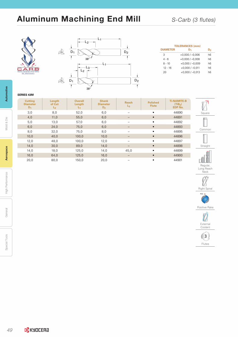
49
Aut
omot
ive
Aer
ospa
ceH
igh
Per
form
ance
Gen
eral
Spe
cial
Too
lsM
old
& D
ie
Aluminum Machining End Mill S-Carb (3 flutes)
Aer
ospa
ce
www.kyocera-sgstool.com20
Se
rie
s 4
3M
|
Met
ric
Cutting Diameter
D1
Lengthof Cut
L2
Overall Length
L1
Shank Diameter
D2
ReachL3
Polished Flute
Ti-NAMITE-B (TiB2)
EDP No.
3,0 8,0 52,0 6,0 – • 448904,0 11,0 55,0 6,0 – • 448915,0 13,0 57,0 6,0 – • 448926,0 24,0 75,0 6,0 – • 448938,0 32,0 75,0 8,0 – • 4489510,0 40,0 100,0 10,0 – • 4489612,0 48,0 100,0 12,0 – • 4489714,0 30,0 89,0 14,0 – • 4489814,0 18,0 125,0 14,0 45,0 • 4489916,0 64,0 125,0 16,0 – • 4490020,0 80,0 150,0 20,0 – • 44901
2D1D
38°
L1L2
2D1D
38°
L3L1
L2
TOLERANCES (mm)DIAMETER D1 D2
3 +0,000 / –0,006 h6
4 - 6 +0,000 / –0,008 h6
8 - 10 +0,000 / –0,009 h6
12 - 16 +0,000 / –0,011 h6
20 +0,000 / –0,013 h6
SERIES 43M
Square
Common
Straight
Regular, Long Reach
Neck
Right Spiral
POS
Positive Rake
External Coolant
3
Flutes
®
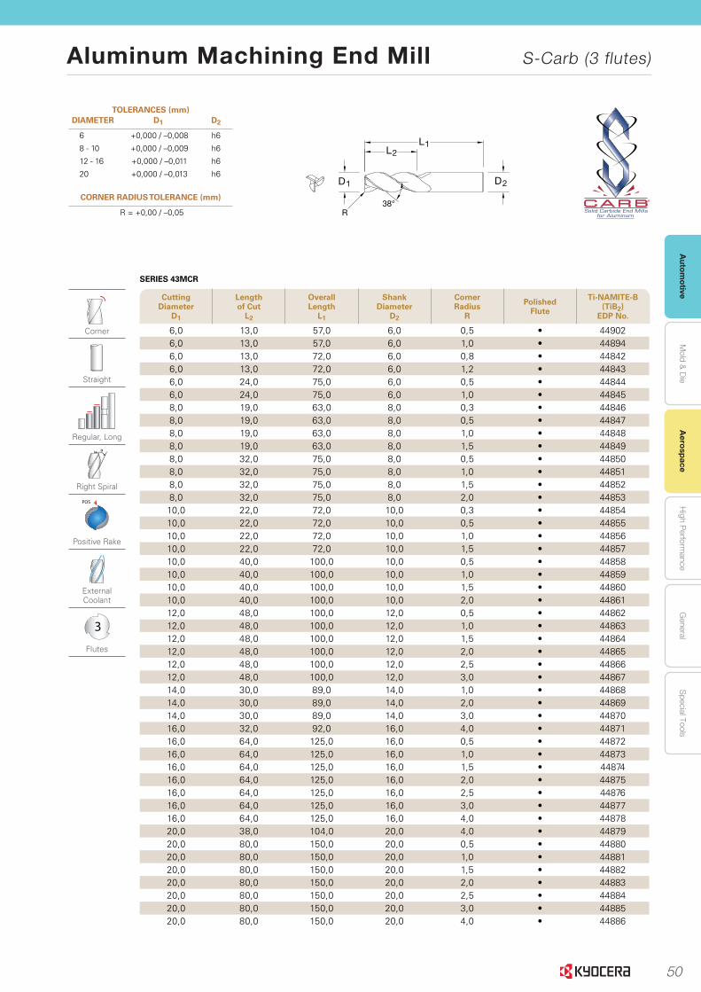
50
Autom
otiveA
erospaceH
igh Perform
anceG
eneralS
pecial ToolsM
old & D
ie
Aluminum Machining End Mill S-Carb (3 flutes)
Aerospace
www.kyocera-sgstool.com 21
Se
ries 4
3M
CR
|
Metric
Cutting Diameter
D1
Lengthof Cut
L2
Overall Length
L1
Shank Diameter
D2
Corner Radius
R
Polished Flute
Ti-NAMITE-B (TiB2)
EDP No.
6,0 13,0 57,0 6,0 0,5 • 449026,0 13,0 57,0 6,0 1,0 • 448946,0 13,0 72,0 6,0 0,8 • 448426,0 13,0 72,0 6,0 1,2 • 448436,0 24,0 75,0 6,0 0,5 • 448446,0 24,0 75,0 6,0 1,0 • 448458,0 19,0 63,0 8,0 0,3 • 448468,0 19,0 63,0 8,0 0,5 • 448478,0 19,0 63,0 8,0 1,0 • 448488,0 19,0 63,0 8,0 1,5 • 448498,0 32,0 75,0 8,0 0,5 • 448508,0 32,0 75,0 8,0 1,0 • 448518,0 32,0 75,0 8,0 1,5 • 448528,0 32,0 75,0 8,0 2,0 • 4485310,0 22,0 72,0 10,0 0,3 • 4485410,0 22,0 72,0 10,0 0,5 • 4485510,0 22,0 72,0 10,0 1,0 • 4485610,0 22,0 72,0 10,0 1,5 • 4485710,0 40,0 100,0 10,0 0,5 • 4485810,0 40,0 100,0 10,0 1,0 • 4485910,0 40,0 100,0 10,0 1,5 • 4486010,0 40,0 100,0 10,0 2,0 • 4486112,0 48,0 100,0 12,0 0,5 • 4486212,0 48,0 100,0 12,0 1,0 • 4486312,0 48,0 100,0 12,0 1,5 • 4486412,0 48,0 100,0 12,0 2,0 • 4486512,0 48,0 100,0 12,0 2,5 • 4486612,0 48,0 100,0 12,0 3,0 • 4486714,0 30,0 89,0 14,0 1,0 • 4486814,0 30,0 89,0 14,0 2,0 • 4486914,0 30,0 89,0 14,0 3,0 • 4487016,0 32,0 92,0 16,0 4,0 • 4487116,0 64,0 125,0 16,0 0,5 • 4487216,0 64,0 125,0 16,0 1,0 • 4487316,0 64,0 125,0 16,0 1,5 • 4487416,0 64,0 125,0 16,0 2,0 • 4487516,0 64,0 125,0 16,0 2,5 • 4487616,0 64,0 125,0 16,0 3,0 • 4487716,0 64,0 125,0 16,0 4,0 • 4487820,0 38,0 104,0 20,0 4,0 • 4487920,0 80,0 150,0 20,0 0,5 • 4488020,0 80,0 150,0 20,0 1,0 • 4488120,0 80,0 150,0 20,0 1,5 • 4488220,0 80,0 150,0 20,0 2,0 • 4488320,0 80,0 150,0 20,0 2,5 • 4488420,0 80,0 150,0 20,0 3,0 • 4488520,0 80,0 150,0 20,0 4,0 • 44886
2D1D
R38°
L1L2
SERIES 43MCR
TOLERANCES (mm)DIAMETER D1 D2
6 +0,000 / –0,008 h6
8 - 10 +0,000 / –0,009 h6
12 - 16 +0,000 / –0,011 h6
20 +0,000 / –0,013 h6
CORNER RADIUS TOLERANCE (mm)
R = +0,00 / –0,05
Corner
Straight
Regular, Long
Right Spiral
POS
Positive Rake
External Coolant
3
Flutes
®

51
Aut
omot
ive
Aer
ospa
ceH
igh
Per
form
ance
Gen
eral
Spe
cial
Too
lsM
old
& D
ie
Aluminum Machining End Mill S-Carb (3 flutes)
Aer
ospa
ce
www.kyocera-sgstool.com22
Se
rie
s 4
3M
LC
| M
etri
c
Cutting Diameter
D1
Lengthof Cut
L2
Overall Length
L1
Shank Diameter
D2
ReachL3
Corner Radius
R
Polished Flute
Ti-NAMITE-B (TiB2)
EDP No.
8,0 12,0 75,0 8,0 25,0 0,8 • 449508,0 12,0 75,0 8,0 25,0 1,2 • 449518,0 12,0 75,0 8,0 25,0 1,6 • 4495210,0 14,0 100,0 10,0 35,0 0,8 • 4495310,0 14,0 100,0 10,0 35,0 1,2 • 4495410,0 14,0 100,0 10,0 35,0 1,6 • 4495510,0 14,0 100,0 10,0 35,0 2,4 • 4495612,0 16,0 100,0 12,0 40,0 0,8 • 4495712,0 16,0 100,0 12,0 40,0 1,2 • 4495812,0 16,0 100,0 12,0 40,0 1,6 • 4495912,0 16,0 100,0 12,0 40,0 2,4 • 4496014,0 18,0 125,0 14,0 45,0 1,0 • 4496114,0 18,0 125,0 14,0 45,0 2,0 • 4496214,0 18,0 125,0 14,0 45,0 3,0 • 4496314,0 18,0 125,0 14,0 45,0 4,0 • 4496416,0 20,0 125,0 16,0 50,0 0,8 • 4496516,0 20,0 125,0 16,0 50,0 1,2 • 4496616,0 20,0 125,0 16,0 50,0 1,6 • 4496716,0 20,0 125,0 16,0 50,0 2,4 • 4496816,0 20,0 125,0 16,0 50,0 3,2 • 4496920,0 25,0 150,0 20,0 65,0 0,8 • 4497020,0 25,0 150,0 20,0 65,0 1,2 • 4497120,0 25,0 150,0 20,0 65,0 1,6 • 4497220,0 25,0 150,0 20,0 65,0 2,4 • 4497320,0 25,0 150,0 20,0 65,0 3,2 • 44974
SERIES 43MLC Aero Radius Range
Corner
Straight
Long Reach Neck
Right Spiral
POS
Positive Rake
External Coolant
3
Flutes
TOLERANCES (mm)DIAMETER D1 D2
8 - 10 +0,000 / –0,009 h6
12 - 16 +0,000 / –0,011 h6
20 +0,000 / –0,013 h6
CORNER RADIUS TOLERANCE (mm)
R = +0,00 / –0,05
2D
R
1D
38°
L1L3
L2
®

52
Autom
otiveA
erospaceH
igh Perform
anceG
eneralS
pecial ToolsM
old & D
ie
Aluminum Machining End Mill S-Carb (3 flutes)
Aerospace
www.kyocera-sgstool.com 23
Se
ries 4
3M
B
| M
etric
Cutting Diameter
D1
Lengthof Cut
L2
Overall Length
L1
Shank Diameter
D2
ReachL3
Polished Flute
Ti-NAMITE-B (TiB2)
EDP No.
3,0 4,5 57,0 6,0 – • 449163,0 6,0 57,0 6,0 10,0 • 449173,0 9,0 57,0 6,0 16,0 • 449184,0 6,0 57,0 6,0 – • 449194,0 8,0 57,0 6,0 13,0 • 449204,0 12,0 57,0 6,0 21,0 • 449215,0 7,5 57,0 6,0 – • 449225,0 10,0 63,0 6,0 16,0 • 449235,0 15,0 63,0 6,0 26,0 • 449246,0 9,0 57,0 6,0 – • 449256,0 12,0 63,0 6,0 19,0 • 449266,0 18,0 75,0 6,0 31,0 • 449278,0 12,0 63,0 8,0 – • 449288,0 16,0 75,0 8,0 25,0 • 449298,0 24,0 83,0 8,0 41,0 • 4493010,0 15,0 75,0 10,0 – • 4493110,0 20,0 83,0 10,0 31,0 • 4493210,0 30,0 100,0 10,0 51,0 • 4493312,0 18,0 83,0 12,0 – • 4493412,0 24,0 100,0 12,0 37,0 • 4493512,0 36,0 130,0 12,0 61,0 • 4493616,0 24,0 100,0 16,0 – • 4493716,0 32,0 130,0 16,0 49,0 • 4493816,0 48,0 150,0 16,0 81,0 • 4493920,0 30,0 108,0 20,0 – • 4494020,0 40,0 130,0 20,0 61,0 • 4494120,0 60,0 150,0 20,0 101,0 • 4494225,0 37,5 127,0 25,0 – • 4494325,0 50,0 152,0 25,0 76,0 • 4494425,0 75,0 170,0 25,0 126,0 • 44945
SERIES 43MB
Ball
Common
Straight
Stub, Regular, Long, Long Reach Neck
Right Spiral
POS
Positive Rake
External Coolant
3
Flutes
2D1D
38°
L1L2
2D1D
38°
L1L3
L2®
TOLERANCES (mm)DIAMETER D1 D2 BALL RADIUS
3 +0,000 / –0,006 h6 +0,0127 / -0,0127
4 - 6 +0,000 / –0,008 h6 +0,0127 / -0,0127
8 - 10 +0,000 / –0,009 h6 +0,0127 / -0,0127
12 - 16 +0,000 / –0,011 h6 +0,0127 / -0,0127
20 - 25 +0,000 / –0,013 h6 +0,0127 / -0,0127

53
Aut
omot
ive
Aer
ospa
ceH
igh
Per
form
ance
Gen
eral
Spe
cial
Too
lsM
old
& D
ie
Aluminum Machining End Mill S-Carb (3 flutes)
Aer
ospa
ce
www.kyocera-sgstool.com 27
Se
ries 4
3LC
B, 4
3M
CB
|
Fraction
al & M
etric
Cutting Diameter
D1
Lengthof Cut
L2
Overall Length
L1
Shank Diameter
D2
Corner Radius
R
Uncoated EDP No.
Ti-NAMITE-B (TiB2)
EDP No.
6,0 19,0 63,0 6,0 0,3 – 442998,0 19,0 63,0 8,0 0,3 44300 4430510,0 22,0 72,0 10,0 0,3 44301 4430612,0 26,0 83,0 12,0 1,0 44302 4430716,0 32,0 92,0 16,0 1,0 44303 4430820,0 38,0 104,0 20,0 1,0 44304 44309
Cutting Diameter
D1
Lengthof Cut
L2
Overall Length
L1
Shank Diameter
D2
ReachL3
Corner Radius
R
Uncoated EDP No.
Ti-NAMITE-B (TiB2)
EDP No.
1/4 3/8 4 1/4 3/4 .020 33500 335401/4 3/8 4 1/4 1-1/8 .020 33501 335411/4 3/8 4 1/4 2-1/8 .020 33502 335425/16 7/16 4 5/16 1-1/8 .020 33503 335435/16 7/16 4 5/16 2-1/8 .020 33504 335443/8 1/2 4 3/8 1-1/8 .020 33507 335473/8 1/2 4 3/8 2-1/8 .020 33508 335481/2 5/8 4 1/2 1-3/8 .030 33511 335511/2 5/8 4 1/2 2-1/4 .030 33512 335521/2 5/8 6 1/2 3-3/8 .030 33513 335531/2 5/8 6 1/2 4-1/4 .030 33514 335545/8 3/4 4 5/8 1-5/8 .030 33515 335555/8 3/4 6 5/8 2-3/8 .030 33516 335565/8 3/4 6 5/8 3-3/8 .030 33517 335575/8 3/4 6 5/8 4-3/8 .030 33518 335583/4 1 4 3/4 2 .030 33519 335593/4 1 6 3/4 2-1/2 .030 33520 335603/4 1 6 3/4 3-3/8 .030 33521 335613/4 1 6 3/4 4-3/8 .030 33522 335621 1-1/4 6 1 2-5/8 .030 33523 335631 1-1/4 6 1 3-3/8 .030 33524 335641 1-1/4 7 1 4-3/8 .030 33525 33565
L1
L2L3
2D1D
R 38°
L1L2
2D1D
R 38°
®
TOLERANCES (inch)DIAMETER D1 D2
1/4 - 3/8 +0.00000 / –0.00035 h6
1/2 - 5/8 +0.00000 / –0.00043 h6
3/4 - 1 +0.00000 / –0.00051 h6
CORNER RADIUS TOLERANCE (inch)
R = +0.0000 / –0.0020
TOLERANCES (mm)DIAMETER D1 D2
6 - 10 +0,000 / –0,009 h6
12 - 16 +0,000 / –0,011 h6
20 +0,000 / –0,013 h6
CORNER RADIUS TOLERANCE (mm)
R = +0,00 / –0,05
SERIES 43LCB
SERIES 43MCB
Corner
Straight
Regular, Long Reach Neck
Right Spiral
Chip Breaker
External Coolant
POS
Positive Rake
3
Flutes
®
L1L2
2D1D
R 38°

54
Autom
otiveA
erospaceH
igh Perform
anceG
eneralS
pecial ToolsM
old & D
ie
Aluminum Machining End Mill S-Carb (3 flutes)
Aerospace
®
www.kyocera-sgstool.com54
Me
tric
|
Spee
d &
Fee
d R
eco
mm
end
atio
ns
Series 44M, 43MCR, 43MLC, 43MCB, 43M, 43MB, 47M, 43ML, 47ML, 47MB, 47MLBMetric Hardness
Ap
Ae AeVc
(m/min)
Diameter (D1)(mm)
Ae x D1 Ap x D1 3 6 10 12 20 25
N ALLOYS 2024, 5052, 5086,6061, 6073, 7075
≤ 150 Bhnor
≤ 7 HRc
Slot1 ≤ 1
490 RPM 52022 26011 15607 13005 7803 6243
(392-588)
Fz 0.022 0.060 0.120 0.144 0.187 0.213
Feed 2 flutes (mm/min) 2247 3121 3746 3745 2913 2653
Feed 3 flutes (mm/min) 3371 4682 5618 5618 4370 3980
Profile≤ 0.5 ≤ 1.5
610 RPM 64762 32381 19429 16190 9714 7771
(488-732)
Fz 0.022 0.060 0.120 0.144 0.187 0.213
Feed 2 flutes (mm/min) 2797 3885 4663 4662 3627 3303
Feed 3 flutes (mm/min) 4196 5828 6994 6994 5440 4955
HSM≤ 0.05 ≤ 2
1005 RPM 106698 53349 32009 26674 16005 12804
(804-1206)
Fz 0.050 0.132 0.280 0.336 0.440 0.488
Feed 2 flutes (mm/min) 10754 14083 17925 17924 14084 12484
Feed 3 flutes (mm/min) 16131 21124 26888 26885 21126 18726
N
ALUMINUM DIE CAST ALLOYS(HIGH SILICON)A-390, A-392, B-390
≤ 125 Bhnor
≤ 77 HRb
Slot1 ≤ 1
185 RPM 19641 9820 5892 4910 2946 2357
(148-222)
Fz 0.022 0.060 0.120 0.144 0.187 0.213
Feed 2 flutes (mm/min) 848 1178 1414 1414 1100 1002
Feed 3 flutes (mm/min) 1273 1768 2121 2121 1650 1503
Profile≤ 0.5 ≤ 1.5
230 RPM 24418 12209 7326 6105 3663 2930
(184-276)
Fz 0.022 0.060 0.120 0.144 0.187 0.213
Feed 2 flutes (mm/min) 1055 1465 1758 1758 1367 1245
Feed 3 flutes (mm/min) 1582 2197 2637 2637 2051 1868
HSM≤ 0.05 ≤ 2
380 RPM 40343 20172 12103 10086 6052 4841
(304-456)
Fz 0.050 0.132 0.280 0.336 0.440 0.488
Feed 2 flutes (mm/min) 4066 5325 6778 6777 5325 4720
Feed 3 flutes (mm/min) 6099 7987 10166 10166 7988 7081
N
COPPER ALLOYSAluminum Bronze,Brass, Naval Brass,Red Brass
≤ 140 Bhnor
≤ 3 HRc
Slot1 ≤ 1
265 RPM 28134 14067 8440 7034 4220 3376
(212-318)
Fz 0.019 0.048 0.107 0.120 0.160 0.175
Feed 2 flutes (mm/min) 1080 1350 1801 1688 1350 1182
Feed 3 flutes (mm/min) 1620 2025 2701 2532 2026 1773
Profile≤ 0.5 ≤ 1.5
330 RPM 35035 17518 10511 8759 5255 4204
(264-396)
Fz 0.019 0.048 0.107 0.120 0.160 0.175
Feed 2 flutes (mm/min) 1345 1682 2242 2102 1682 1472
Feed 3 flutes (mm/min) 2018 2522 3363 3153 2523 2207
HSM≤ 0.05 ≤ 2
545 RPM 57861 28930 17358 14465 8679 6943
(436-654)
Fz 0.041 0.108 0.227 0.276 0.373 0.400
Feed 2 flutes (mm/min) 4721 6248 7869 7984 6480 5555
Feed 3 flutes (m/min) 7082 9373 11804 11976 9721 8332
continued on next page
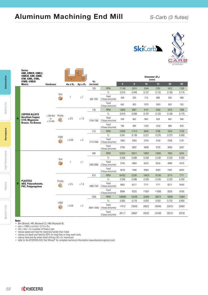
55
Aut
omot
ive
Aer
ospa
ceH
igh
Per
form
ance
Gen
eral
Spe
cial
Too
lsM
old
& D
ie
Aluminum Machining End Mill S-Carb (3 flutes)
Aer
ospa
ce
®
www.kyocera-sgstool.com 55
Me
tric |
Speed
& Feed
Reco
mm
end
ation
s
Series 44M, 43MCR, 43MLC, 43MCB, 43M, 43MB, 47M, 43ML, 47ML, 47MB, 47MLBMetric Hardness
Ap
Ae AeVc
(m/min)
Diameter (D1)(mm)
Ae x D1 Ap x D1 3 6 10 12 20 25
N
COPPER ALLOYSBeryllium Copper, C110, Maganese Bronze, Tin Bronze
≤ 200 Bhnor
≤ 23 HRc
Slot1 ≤ 1
105 RPM 11148 5574 3344 2787 1672 1338
(84-126)
Fz 0.019 0.048 0.107 0.120 0.160 0.175
Feed 2 flutes (mm/min) 428 535 713 669 535 468
Feed 3 flutes (mm/min) 642 803 1070 1003 803 702
Profile≤ 0.5 ≤ 1.5
130 RPM 13802 6901 4141 3450 2070 1656
(104-156)
Fz 0.019 0.048 0.107 0.120 0.160 0.175
Feed 2 flutes (mm/min) 530 662 883 828 662 580
Feed 3 flutes (mm/min) 795 994 1325 1242 994 870
HSM≤ 0.05 ≤ 2
215 RPM 22826 11413 6848 5706 3424 2739
(172-258)
Fz 0.041 0.108 0.227 0.276 0.373 0.400
Feed 2 flutes (mm/min) 1862 2465 3104 3150 2556 2191
Feed 3 flutes (mm/min) 2794 3697 4656 4725 3835 3287
NPLASTICSABS, Polycarbonate, PVC, Polypropylene
Slot1 ≤ 1
490 RPM 52022 26011 15607 13005 7803 6243
(392-588)
Fz 0.036 0.096 0.200 0.240 0.320 0.350
Feed 2 flutes (mm/min) 3745 4994 6243 6242 4994 4370
Feed 3 flutes (mm/min) 5618 7490 9364 9363 7491 6555
Profile≤ 0.5 ≤ 1.5
610 RPM 64762 32381 19429 16190 9714 7771
(488-732)
Fz 0.036 0.096 0.200 0.240 0.320 0.350
Feed 2 flutes (mm/min) 4662 6217 7771 7771 6217 5440
Feed 3 flutes (mm/min) 6994 9325 11657 11656 9326 8160
HSM≤ 0.05 ≤ 2
1005 RPM 106698 53349 32009 26674 16005 12804
(804-1206)
Fz 0.082 0.216 0.453 0.552 0.733 0.800
Feed 2 flutes (mm/min) 17412 23045 29022 29446 23473 20487
Feed 3 flutes (mm/min) 26117 34567 43532 44169 35210 30730
Note:• Bhn (Brinell), HRc (Rockwell C), HRb (Rockwell B)• rpm = (1000 x m/min) / (3.14 x D1) • mm / min = Fz x number of flutes x rpm • reduce speed and feed for materials harder than listed• reduce cut depth and feed by 50% for long flute or long reach tools• reduce feed and Ae when finish milling (.02 x D1 maximum)• refer to the KYOCERA SGS Tool Wizard® for complete technical information (www.kyocera-sgstool.com)
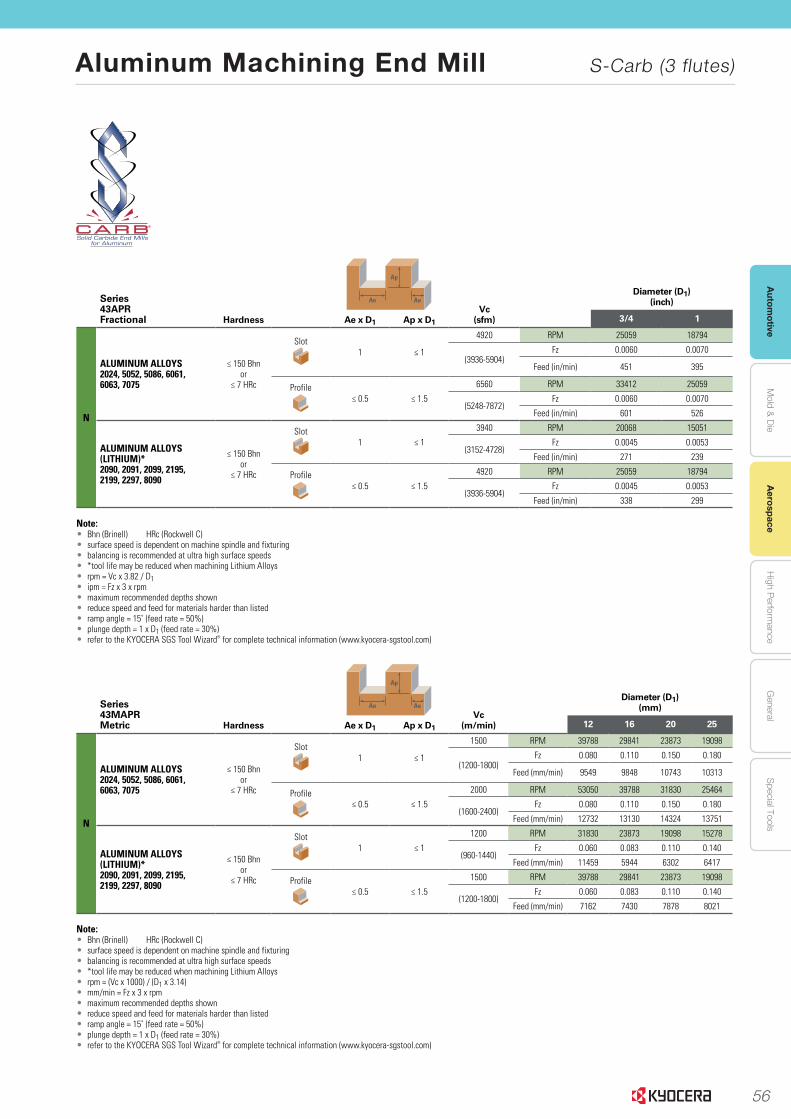
56
Autom
otiveA
erospaceH
igh Perform
anceG
eneralS
pecial ToolsM
old & D
ie
Aluminum Machining End Mill S-Carb (3 flutes)
Aerospace
www.kyocera-sgstool.com56
Fra
ctio
nal
& M
etr
ic
| Sp
eed
& F
eed
Rec
om
men
dat
ion
s
®
Series 43MAPRMetric Hardness
Ap
Ae AeVc
(m/min)
Diameter (D1)(mm)
Ae x D1 Ap x D1 12 16 20 25
N
ALUMINUM ALLOYS 2024, 5052, 5086, 6061, 6063, 7075
≤ 150 Bhnor
≤ 7 HRc
Slot1 ≤ 1
1500 RPM 39788 29841 23873 19098
(1200-1800)Fz 0.080 0.110 0.150 0.180
Feed (mm/min) 9549 9848 10743 10313
Profile≤ 0.5 ≤ 1.5
2000 RPM 53050 39788 31830 25464
(1600-2400)Fz 0.080 0.110 0.150 0.180
Feed (mm/min) 12732 13130 14324 13751
ALUMINUM ALLOYS (LITHIUM)*2090, 2091, 2099, 2195, 2199, 2297, 8090
≤ 150 Bhnor
≤ 7 HRc
Slot1 ≤ 1
1200 RPM 31830 23873 19098 15278
(960-1440)Fz 0.060 0.083 0.110 0.140
Feed (mm/min) 11459 5944 6302 6417
Profile≤ 0.5 ≤ 1.5
1500 RPM 39788 29841 23873 19098
(1200-1800)Fz 0.060 0.083 0.110 0.140
Feed (mm/min) 7162 7430 7878 8021
Note:• Bhn (Brinell) HRc (Rockwell C)• surface speed is dependent on machine spindle and fixturing• balancing is recommended at ultra high surface speeds• *tool life may be reduced when machining Lithium Alloys• rpm = (Vc x 1000) / (D1 x 3.14)• mm/min = Fz x 3 x rpm• maximum recommended depths shown• reduce speed and feed for materials harder than listed• ramp angle = 15˚ (feed rate = 50%)• plunge depth = 1 x D1 (feed rate = 30%)• refer to the KYOCERA SGS Tool Wizard® for complete technical information (www.kyocera-sgstool.com)
Series 43APRFractional Hardness
Ap
Ae AeVc
(sfm)
Diameter (D1)(inch)
Ae x D1 Ap x D1 3/4 1
N
ALUMINUM ALLOYS 2024, 5052, 5086, 6061, 6063, 7075
≤ 150 Bhnor
≤ 7 HRc
Slot1 ≤ 1
4920 RPM 25059 18794
(3936-5904)Fz 0.0060 0.0070
Feed (in/min) 451 395
Profile≤ 0.5 ≤ 1.5
6560 RPM 33412 25059
(5248-7872)Fz 0.0060 0.0070
Feed (in/min) 601 526
ALUMINUM ALLOYS (LITHIUM)*2090, 2091, 2099, 2195, 2199, 2297, 8090
≤ 150 Bhnor
≤ 7 HRc
Slot1 ≤ 1
3940 RPM 20068 15051
(3152-4728)Fz 0.0045 0.0053
Feed (in/min) 271 239
Profile≤ 0.5 ≤ 1.5
4920 RPM 25059 18794
(3936-5904)Fz 0.0045 0.0053
Feed (in/min) 338 299
Note:• Bhn (Brinell) HRc (Rockwell C)• surface speed is dependent on machine spindle and fixturing• balancing is recommended at ultra high surface speeds• *tool life may be reduced when machining Lithium Alloys• rpm = Vc x 3.82 / D1• ipm = Fz x 3 x rpm• maximum recommended depths shown• reduce speed and feed for materials harder than listed• ramp angle = 15˚ (feed rate = 50%)• plunge depth = 1 x D1 (feed rate = 30%)• refer to the KYOCERA SGS Tool Wizard® for complete technical information (www.kyocera-sgstool.com)

57
Aut
omot
ive
Aer
ospa
ceH
igh
Per
form
ance
Gen
eral
Spe
cial
Too
lsM
old
& D
ie
Aluminum Machining End Mill 3AFK
Aer
ospa
ce
1
High Efficiency with 3-Flutes. Excellent Machining Precision
Comparison of wall flatness (In-house Evaluation)
Cutting Conditions: n = 11,700 min-1, Vf = 3,500 – 5,600 mm/min, ap × ae = 15 × 1 mmMachining Diameter 10mm, Shouldering, Down Cut, Wet, HSK A63 Workpiece: A5052
Wal
l Fla
tnes
s de
viat
ion
(mm
)
Feed rate (mm/t)0.1 0.13 0.16
0.04
0.03
0.02
0.01
0
3AFK
Competitor A (3-flute)
Competitor B(2-flute)
Excellent Sharpness with Large Rake Angle and small margin width
Comparison of the Rake Angle and Margin Cutting Force Comparison (In-house Evaluation)
3AFK 3AFK
Large Rake Angle Small Margin width
Burr Comparison after Machining Cutting Conditions: n = 11,700 min-1, Vf = 4,600 mm/min, ap × ae = 10 × 1 mmMachining Diameter ø10, Shouldering, Down Cut, Wet, HSK A63 Workpiece: A7075
Cutting Conditions: n = 11,700 min-1, Vf = 3,400 mm/min ap × ae = 10 × 10 mmMachining Diameter ø10, Slotting, Wet, BT50 Workpiece: A5052
Burr Comparison after Machining (In-house Evaluation)
Large Burr
Competitor C Competitor C
Competitor C3AFK
DOWN
18%
DOWN
1,200
800
400
0
(N)
Measurement Point
3-Flute End Mill for High Efficiency and Precision
Sharp cutting edge and excellant Anti-Chattering Performance. Delivers High Stability in Diverse Machining Situations
For Aluminum Machining
3AFK
High-performance and High-precision Machining1
Burr reduction2
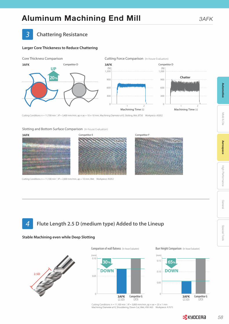
58
Autom
otiveA
erospaceH
igh Perform
anceG
eneralS
pecial ToolsM
old & D
ie
Aluminum Machining End Mill 3AFK
Aerospace
2
Larger Core Thickeness to Reduce Chattering
Cutting Force Comparison (In-house Evaluation)Core Thickness Comparison
Slotting and Bottom Surface Comparison (In-house Evaluation)
0
300
600
900
1,200
1 2
Machining Time (s)
(N)
0
300
600
900
1,200
1 2
Machining Time (s)
(N)3AFK
3AFK
3AFKCompetitor D
Competitor E
Competitor D
Competitor F
Cutting Conditions: n = 11,700 min-1, Vf = 3,400 mm/min, ap × ae = 10 × 10 mm, Machining Diameter ø10, Slotting, Wet, BT50 Workpiece: A5052
Cutting Conditions: n = 11,100 min-1, Vf = 2,600 mm/min, ap = 10 mm, Wet Workpiece: A5052
Chatter
Chatter Chatter
UP
20%
Stable Machining even while Deep Slotting
Comparison of wall flatness (In-house Evaluation) Burr Height Comparison (In-house Evaluation)
Cutting Conditions: n = 11,100 min-1, Vf = 3,800 mm/min, ap × ae = 20 × 1 mmMachining Diameter ø10, Shouldering, Down Cut, Wet, HSK A63 Workpiece: A7075
3AFK(2.5D)
Competitor G(2D)
0.10
0.05
0
DOWN
30%
DOWN
(mm)
3AFK(2.5D)
Competitor G(2D)
0.15
0.10
0.05
0
65%
DOWN
(mm)
2.5D
Chattering Resistance3
Flute Length 2.5 D (medium type) Added to the Lineup4
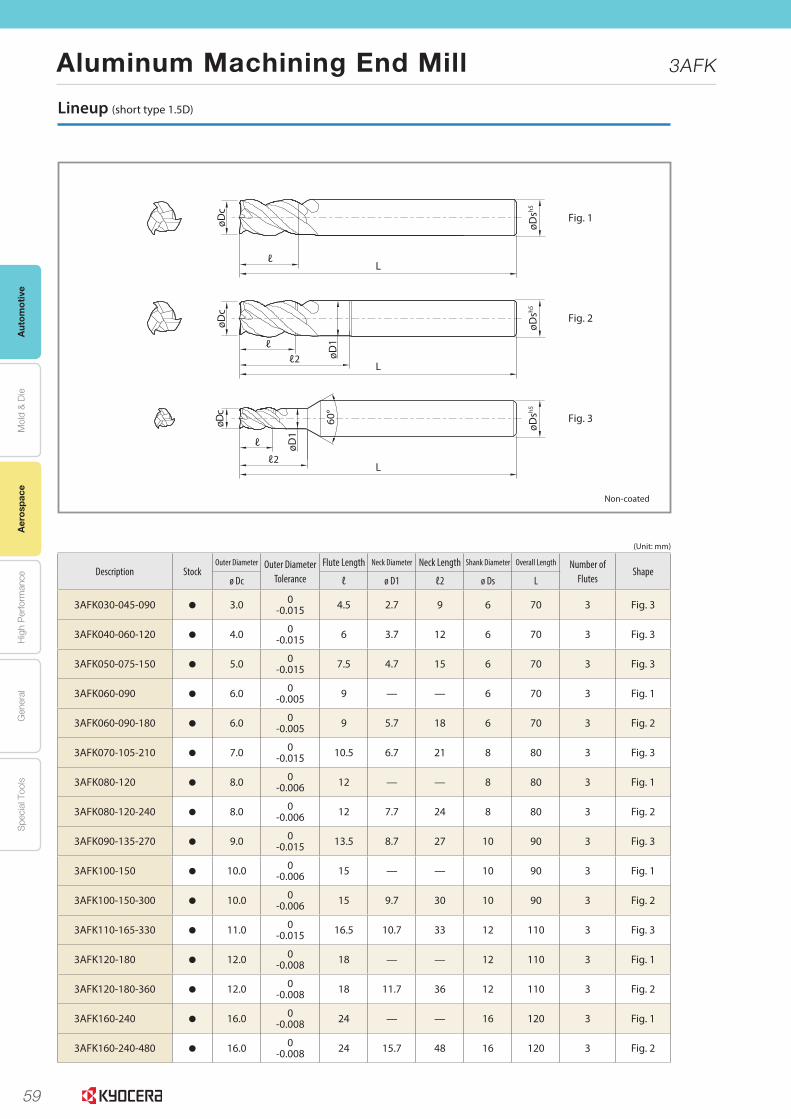
59
Aut
omot
ive
Aer
ospa
ceH
igh
Per
form
ance
Gen
eral
Spe
cial
Too
lsM
old
& D
ie
Aluminum Machining End Mill 3AFK
Aer
ospa
ce
4
ℓ2
ℓ
L
L
øDc
øD1
øDc
øDsh5
ℓ2ℓ
øD1
øDsh5
L
øDc
ℓ
øDsh5
Fig. 1
Fig. 2
Fig. 360°
Lineup (short type 1.5D)
(Unit: mm)
Description StockOuter Diameter Outer Diameter
ToleranceFlute Length Neck Diameter Neck Length Shank Diameter Overall Length Number of
FlutesShape
ø Dc ℓ ø D1 ℓ2 ø Ds L
3AFK030-045-090 3.0 0-0.015 4.5 2.7 9 6 70 3 Fig. 3
3AFK040-060-120 4.0 0-0.015 6 3.7 12 6 70 3 Fig. 3
3AFK050-075-150 5.0 0-0.015 7.5 4.7 15 6 70 3 Fig. 3
3AFK060-090 6.0 0-0.005 9 — — 6 70 3 Fig. 1
3AFK060-090-180 6.0 0-0.005 9 5.7 18 6 70 3 Fig. 2
3AFK070-105-210 7.0 0-0.015 10.5 6.7 21 8 80 3 Fig. 3
3AFK080-120 8.0 0-0.006 12 — — 8 80 3 Fig. 1
3AFK080-120-240 8.0 0-0.006 12 7.7 24 8 80 3 Fig. 2
3AFK090-135-270 9.0 0-0.015 13.5 8.7 27 10 90 3 Fig. 3
3AFK100-150 10.0 0-0.006 15 — — 10 90 3 Fig. 1
3AFK100-150-300 10.0 0-0.006 15 9.7 30 10 90 3 Fig. 2
3AFK110-165-330 11.0 0-0.015 16.5 10.7 33 12 110 3 Fig. 3
3AFK120-180 12.0 0-0.008 18 — — 12 110 3 Fig. 1
3AFK120-180-360 12.0 0-0.008 18 11.7 36 12 110 3 Fig. 2
3AFK160-240 16.0 0-0.008 24 — — 16 120 3 Fig. 1
3AFK160-240-480 16.0 0-0.008 24 15.7 48 16 120 3 Fig. 2
: Standard Stock
Non-coated
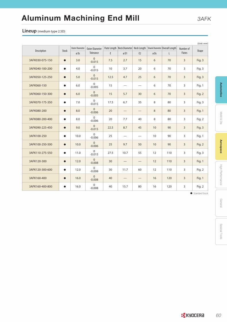
60
Autom
otiveA
erospaceH
igh Perform
anceG
eneralS
pecial ToolsM
old & D
ie
Aluminum Machining End Mill 3AFK
Aerospace
© 2016 KYOCERA Corporation CP368
Lineup (medium type 2.5D)
(Unit: mm)
Description StockOuter Diameter Outer Diameter
ToleranceFlute Length Neck Diameter Neck Length Shank Diameter Overall Length Number of
FlutesShape
ø Dc ℓ ø D1 ℓ2 ø Ds L
3AFK030-075-150 3.0 0-0.015 7.5 2.7 15 6 70 3 Fig. 3
3AFK040-100-200 4.0 0-0.015 10 3.7 20 6 70 3 Fig. 3
3AFK050-125-250 5.0 0-0.015 12.5 4.7 25 6 70 3 Fig. 3
3AFK060-150 6.0 0-0.005 15 — — 6 70 3 Fig. 1
3AFK060-150-300 6.0 0-0.005 15 5.7 30 6 70 3 Fig. 2
3AFK070-175-350 7.0 0-0.015 17.5 6.7 35 8 80 3 Fig. 3
3AFK080-200 8.0 0-0.006 20 — — 8 80 3 Fig. 1
3AFK080-200-400 8.0 0-0.006 20 7.7 40 8 80 3 Fig. 2
3AFK090-225-450 9.0 0-0.015 22.5 8.7 45 10 90 3 Fig. 3
3AFK100-250 10.0 0-0.006 25 — — 10 90 3 Fig. 1
3AFK100-250-500 10.0 0-0.006 25 9.7 50 10 90 3 Fig. 2
3AFK110-275-550 11.0 0-0.015 27.5 10.7 55 12 110 3 Fig. 3
3AFK120-300 12.0 0-0.008 30 — — 12 110 3 Fig. 1
3AFK120-300-600 12.0 0-0.008 30 11.7 60 12 110 3 Fig. 2
3AFK160-400 16.0 0-0.008 40 — — 16 120 3 Fig. 1
3AFK160-400-800 16.0 0-0.008 40 15.7 80 16 120 3 Fig. 2
: Standard Stock
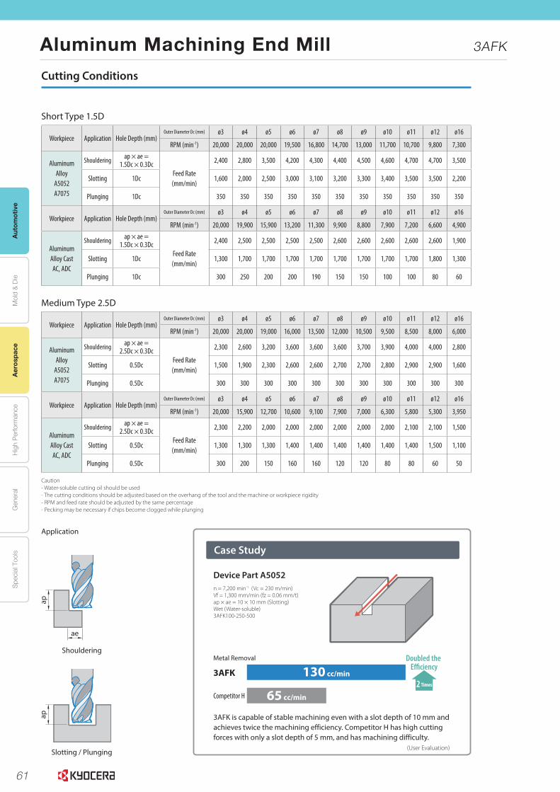
61
Aut
omot
ive
Aer
ospa
ceH
igh
Per
form
ance
Gen
eral
Spe
cial
Too
lsM
old
& D
ie
Aluminum Machining End Mill 3AFK
Aer
ospa
ce
3
Cutting Conditions
Workpiece Application Hole Depth (mm)Outer Diameter Dc (mm) ø3 ø4 ø5 ø6 ø7 ø8 ø9 ø10 ø11 ø12 ø16
RPM (min-1) 20,000 20,000 20,000 19,500 16,800 14,700 13,000 11,700 10,700 9,800 7,300
Aluminum Alloy
A5052A7075
Shouldering ap × ae = 1.5Dc × 0.3Dc
Feed Rate (mm/min)
2,400 2,800 3,500 4,200 4,300 4,400 4,500 4,600 4,700 4,700 3,500
Slotting 1Dc 1,600 2,000 2,500 3,000 3,100 3,200 3,300 3,400 3,500 3,500 2,200
Plunging 1Dc 350 350 350 350 350 350 350 350 350 350 350
Workpiece Application Hole Depth (mm)Outer Diameter Dc (mm) ø3 ø4 ø5 ø6 ø7 ø8 ø9 ø10 ø11 ø12 ø16
RPM (min-1) 20,000 19,900 15,900 13,200 11,300 9,900 8,800 7,900 7,200 6,600 4,900
Aluminum Alloy CastAC, ADC
Shouldering ap × ae = 1.5Dc × 0.3Dc
Feed Rate (mm/min)
2,400 2,500 2,500 2,500 2,500 2,600 2,600 2,600 2,600 2,600 1,900
Slotting 1Dc 1,300 1,700 1,700 1,700 1,700 1,700 1,700 1,700 1,700 1,800 1,300
Plunging 1Dc 300 250 200 200 190 150 150 100 100 80 60
Workpiece Application Hole Depth (mm)Outer Diameter Dc (mm) ø3 ø4 ø5 ø6 ø7 ø8 ø9 ø10 ø11 ø12 ø16
RPM (min-1) 20,000 20,000 19,000 16,000 13,500 12,000 10,500 9,500 8,500 8,000 6,000
Aluminum Alloy
A5052A7075
Shouldering ap × ae = 2.5Dc × 0.3Dc
Feed Rate (mm/min)
2,300 2,600 3,200 3,600 3,600 3,600 3,700 3,900 4,000 4,000 2,800
Slotting 0.5Dc 1,500 1,900 2,300 2,600 2,600 2,700 2,700 2,800 2,900 2,900 1,600
Plunging 0.5Dc 300 300 300 300 300 300 300 300 300 300 300
Workpiece Application Hole Depth (mm)Outer Diameter Dc (mm) ø3 ø4 ø5 ø6 ø7 ø8 ø9 ø10 ø11 ø12 ø16
RPM (min-1) 20,000 15,900 12,700 10,600 9,100 7,900 7,000 6,300 5,800 5,300 3,950
Aluminum Alloy CastAC, ADC
Shouldering ap × ae = 2.5Dc × 0.3Dc
Feed Rate (mm/min)
2,300 2,200 2,000 2,000 2,000 2,000 2,000 2,000 2,100 2,100 1,500
Slotting 0.5Dc 1,300 1,300 1,300 1,400 1,400 1,400 1,400 1,400 1,400 1,500 1,100
Plunging 0.5Dc 300 200 150 160 160 120 120 80 80 60 50
Caution- Water-soluble cutting oil should be used- The cutting conditions should be adjusted based on the overhang of the tool and the machine or workpiece rigidity- RPM and feed rate should be adjusted by the same percentage- Pecking may be necessary if chips become clogged while plunging
Case Study
n = 7,200 min-1 (Vc = 230 m/min)Vf = 1,300 mm/min (fz = 0.06 mm/t)ap × ae = 10 × 10 mm (Slotting)Wet (Water-soluble)3AFK100-250-500
Application
3AFK is capable of stable machining even with a slot depth of 10 mm and achieves twice the machining efficiency. Competitor H has high cutting forces with only a slot depth of 5 mm, and has machining difficulty. (User Evaluation)
Device Part A5052
Metal Removal
130 cc/min
65 cc/min
2 Times
Doubled the Efficiency
3AFK
Competitor H
Short Type 1.5D
Medium Type 2.5D
ae
ap
Shouldering
ap
Slotting / Plunging
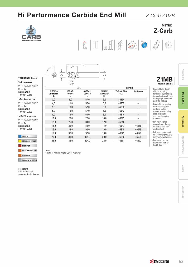
62
Autom
otiveA
erospaceH
igh Perform
anceG
eneralS
pecial ToolsM
old & D
ie
Hi Performance Carbide End Mill Z-Carb Z1MB
Aerospace
STEELS
STAINLESS STEELS
CAST IRON
HIGH TEMP ALLOYS
TITANIUM
HARDENED STEELS
STEELS
STAINLESS STEELS
CAST IRON
HIGH TEMP ALLOYS
TITANIUM
HARDENED STEELS
53www.kyocera-sgstool.comEND MILLS END MILLS
Z1MBMETRIC SERIES
mm EDP NO.
CUTTING DIAMETER
D1
LENGTH OF CUT
L2
OVERALL LENGTH
L1
SHANK DIAMETER
D2
Ti-NAMITE-X (TX)
JetStream
3,0 8,0 57,0 6,0 46354 –4,0 11,0 57,0 6,0 46355 –5,0 13,0 57,0 6,0 46356 –6,0 13,0 57,0 6,0 46343 –8,0 19,0 63,0 8,0 46344 –10,0 22,0 72,0 10,0 46345 –12,0 26,0 83,0 12,0 46346 –14,0 26,0 83,0 14,0 46347 4651816,0 32,0 92,0 16,0 46348 4651918,0 32,0 92,0 18,0 46349 4652020,0 38,0 104,0 20,0 46350 4652125,0 38,0 104,0 25,0 46351 46522
METRIC
Z-Carb
• Unequal helix design aids in damaging harmonics by changing the angle at which each cutting edge enters and exits the material
• Unequal flute spacing helps to disrupt the rhythmic pattern created by the cutting edge helping to suppress damaging harmonics
• Optimal material removal rates through increased feed and depths of cut
• Ball nose design ideal for finishing operations in complex workpieces
• Recommended for materials ≤ 45 HRc (≤ 420 Bhn)
≠
POS
4
TOLERANCES (mm)
3–6 DIAMETER
D1 = +0,000/–0,030D2 = h6
BALL RADIUS +0,000/–0,015
>6–10 DIAMETER
D1 = +0,000/–0,040D2 = h6
BALL RADIUS +0,000/–0,020
>10–25 DIAMETER
D1 = +0,000/–0,050D2 = h6
BALL RADIUS +0,000/–0,025
For patent information visit www.ksptpatents.com
Note: • Refer to P.11 and P.12 for Cutting Parameter.
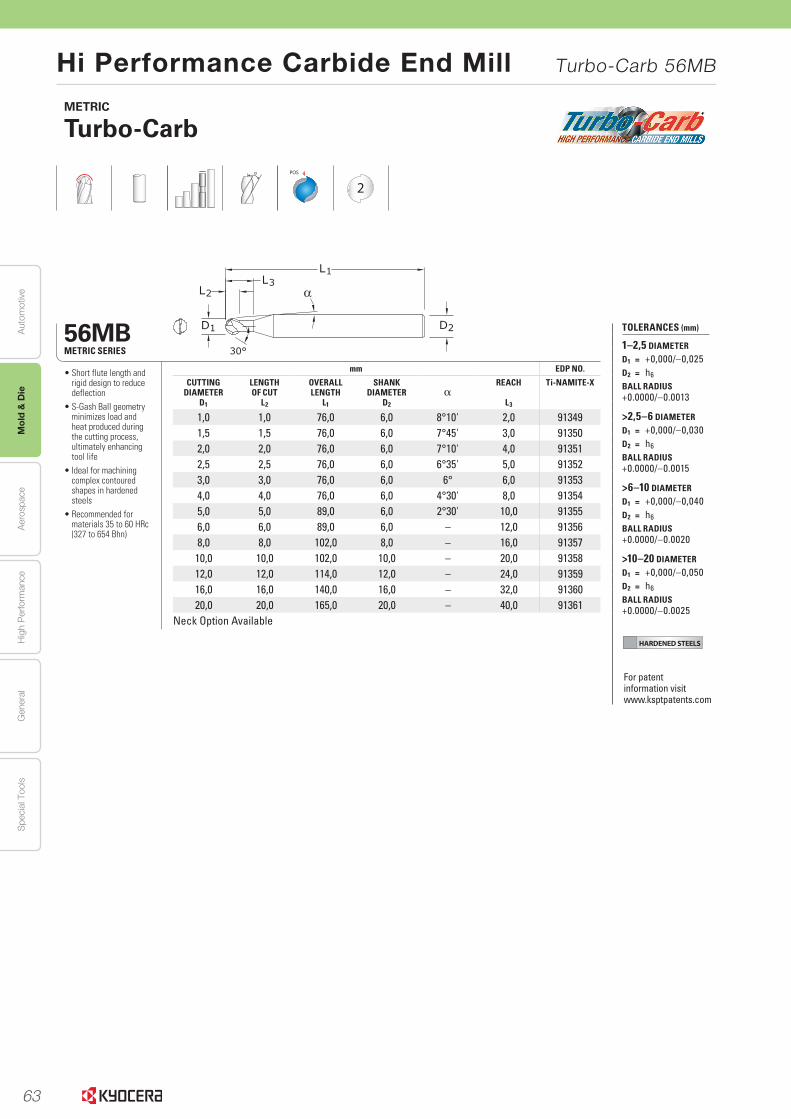
63
Aut
omot
ive
Aer
ospa
ceH
igh
Per
form
ance
Gen
eral
Spe
cial
Too
lsM
old
& D
ie
Hi Performance Carbide End Mill Turbo-Carb 56MB
END MILLS END MILLS
HARDENED STEELS
108www.kyocera-sgstool.comEND MILLS END MILLS
56MBMETRIC SERIES
mm EDP NO.
CUTTING DIAMETER
D1
LENGTH OF CUT
L2
OVERALL LENGTH
L1
SHANK DIAMETER
D2
αREACH
L3
Ti-NAMITE-X
1,0 1,0 76,0 6,0 8°10' 2,0 913491,5 1,5 76,0 6,0 7°45' 3,0 913502,0 2,0 76,0 6,0 7°10' 4,0 913512,5 2,5 76,0 6,0 6°35' 5,0 913523,0 3,0 76,0 6,0 6° 6,0 913534,0 4,0 76,0 6,0 4°30' 8,0 913545,0 5,0 89,0 6,0 2°30' 10,0 913556,0 6,0 89,0 6,0 – 12,0 913568,0 8,0 102,0 8,0 – 16,0 9135710,0 10,0 102,0 10,0 – 20,0 9135812,0 12,0 114,0 12,0 – 24,0 9135916,0 16,0 140,0 16,0 – 32,0 9136020,0 20,0 165,0 20,0 – 40,0 91361
Neck Option Available
METRIC
Turbo-Carb
POS
2
TOLERANCES (mm)
1–2,5 DIAMETER
D1 = +0,000/–0,025D2 = h6
BALL RADIUS +0.0000/–0.0013
>2,5–6 DIAMETER
D1 = +0,000/–0,030D2 = h6
BALL RADIUS +0.0000/–0.0015
>6–10 DIAMETER
D1 = +0,000/–0,040D2 = h6
BALL RADIUS +0.0000/–0.0020
>10–20 DIAMETER
D1 = +0,000/–0,050D2 = h6
BALL RADIUS +0.0000/–0.0025
• Short flute length and rigid design to reduce deflection
• S-Gash Ball geometry minimizes load and heat produced during the cutting process, ultimately enhancing tool life
• Ideal for machining complex contoured shapes in hardened steels
• Recommended for materials 35 to 60 HRc (327 to 654 Bhn)
For patent information visit www.ksptpatents.com
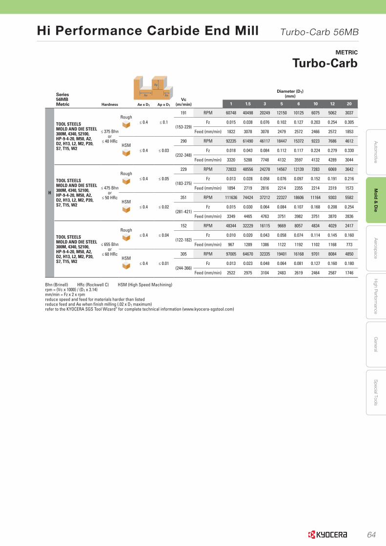
64
Autom
otiveA
erospaceH
igh Perform
anceG
eneralS
pecial ToolsM
old & D
ie
Hi Performance Carbide End Mill Turbo-Carb 56MB
109www.kyocera-sgstool.comEND MILLS END MILLS
Series 56MBMetric Hardness
Ap
Ae AeVc
(m/min)
Diameter (D1)(mm)
Ae x D1 Ap x D1 1 1.5 3 5 6 10 12 20
H
TOOL STEELSMOLD AND DIE STEEL300M, 4340, 52100, HP-9-4-20, M50, A2,D2, H13, L2, M2, P20, S7, T15, W2
≤ 375 Bhnor
≤ 40 HRc
Rough≤ 0.4 ≤ 0.1
191 RPM 60748 40498 20249 12150 10125 6075 5062 3037
(153-229)Fz 0.015 0.038 0.076 0.102 0.127 0.203 0.254 0.305
Feed (mm/min) 1822 3078 3078 2479 2572 2466 2572 1853
HSM≤ 0.4 ≤ 0.03
290 RPM 92235 61490 46117 18447 15372 9223 7686 4612
(232-348)Fz 0.018 0.043 0.084 0.112 0.117 0.224 0.279 0.330
Feed (mm/min) 3320 5288 7748 4132 3597 4132 4289 3044
TOOL STEELSMOLD AND DIE STEEL300M, 4340, 52100, HP-9-4-20, M50, A2,D2, H13, L2, M2, P20, S7, T15, W2
≤ 475 Bhnor
≤ 50 HRc
Rough≤ 0.4 ≤ 0.05
229 RPM 72833 48556 24278 14567 12139 7283 6069 3642
(183-275)Fz 0.013 0.028 0.058 0.076 0.097 0.152 0.191 0.216
Feed (mm/min) 1894 2719 2816 2214 2355 2214 2319 1573
HSM≤ 0.4 ≤ 0.02
351 RPM 111636 74424 37212 22327 18606 11164 9303 5582
(281-421)Fz 0.015 0.030 0.064 0.084 0.107 0.168 0.208 0.254
Feed (mm/min) 3349 4465 4763 3751 3982 3751 3870 2836
TOOL STEELSMOLD AND DIE STEEL300M, 4340, 52100, HP-9-4-20, M50, A2,D2, H13, L2, M2, P20, S7, T15, W2
≤ 655 Bhnor
≤ 60 HRc
Rough≤ 0.4 ≤ 0.04
152 RPM 48344 32229 16115 9669 8057 4834 4029 2417
(122-182)Fz 0.010 0.020 0.043 0.058 0.074 0.114 0.145 0.160
Feed (mm/min) 967 1289 1386 1122 1192 1102 1168 773
HSM≤ 0.4 ≤ 0.01
305 RPM 97005 64670 32335 19401 16168 9701 8084 4850
(244-366)Fz 0.013 0.023 0.048 0.064 0.081 0.127 0.160 0.180
Feed (mm/min) 2522 2975 3104 2483 2619 2464 2587 1746
Bhn (Brinell) HRc (Rockwell C) HSM (High Speed Machining)rpm = (Vc x 1000) / (D1 x 3.14)mm/min = Fz x 2 x rpmreduce speed and feed for materials harder than listedreduce feed and Ae when finish milling (.02 x D1 maximum) refer to the KYOCERA SGS Tool Wizard® for complete technical information (www.kyocera-sgstool.com)
METRIC
Turbo-Carb
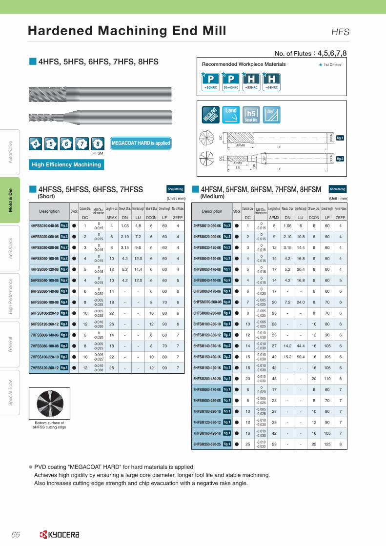
65
Aut
omot
ive
Aer
ospa
ceH
igh
Per
form
ance
Gen
eral
Spe
cial
Too
lsM
old
& D
ie
Hardened Machining End Mill HFS
L35
Turning Indexable Inserts
CBN & PCD ToolsE
xternalS
mall P
arts M
achiningB
oringG
roovingC
ut-offT
hreadingD
rillingS
olid ToolsM
illingTools for
Turning Mill
Spare P
artsTechnical
Information
Index
A
B
C
D
E
F
G
H
J
K
L
M
N
P
R
T
Insert Grades
No. of Flutes:4,5,6,7,8
■ 4HFSM, 5HFSM, 6HFSM, 7HFSM, 8HFSM Shouldering
(Medium)
Description StockOutside Dia. Mill Dia.
toleranceLength of cut Neck Dia. Under Neck Length Shank Dia. Overall length No. of Flutes
DC APMX DN LU DCON LF ZEFP
4HFSM010-050-06 fig.2 N 1 0-0.015 5 1.05 6 6 60 4
4HFSM020-090-06 fig.2 N 2 0-0.015 9 2.10 10.8 6 60 4
4HFSM030-120-06 fig.2 N 3 0-0.015 12 3.15 14.4 6 60 4
4HFSM040-140-06 fig.2 N 4 0-0.015 14 4.2 16.8 6 60 4
4HFSM050-170-06 fig.2 N 5 0-0.015 17 5.2 20.4 6 60 4
5HFSM040-140-06 fig.2 N 4 0-0.015 14 4.2 16.8 6 60 5
6HFSM060-170-06 fig.1 N 6 0-0.020 17 - - 6 60 6
6HFSM070-200-08 fig.2 N 7 -0.005-0.025 20 7.2 24.0 8 70 6
6HFSM080-230-08 fig.1 N 8 -0.005-0.025 23 - - 8 70 6
6HFSM100-280-10 fig.1 N 10 -0.005-0.025 28 - - 10 80 6
6HFSM120-330-12 fig.1 N 12 -0.010-0.030 33 - - 12 90 6
6HFSM140-370-16 fig.2 N 14 -0.010-0.030 37 14.2 44.4 16 105 6
6HFSM150-420-16 fig.2 N 15 -0.010-0.030 42 15.2 50.4 16 105 6
6HFSM160-420-16 fig.1 N 16 -0.010-0.030 42 - - 16 105 6
6HFSM200-480-20 fig.1 N 20 -0.010-0.030 48 - - 20 110 6
7HFSM060-170-06 fig.1 N 6 0-0.020 17 - - 6 60 7
7HFSM080-230-08 fig.1 N 8 -0.005-0.025 23 - - 8 70 7
7HFSM100-280-10 fig.1 N 10 -0.005-0.025 28 - - 10 80 7
7HFSM120-330-12 fig.1 N 12 -0.010-0.030 33 - - 12 90 7
7HFSM160-420-16 fig.1 N 16 -0.010-0.030 42 - - 16 105 7
8HFSM250-530-25 fig.1 N 25 -0.010-0.030 53 - - 25 125 8
■ 4HFSS, 5HFSS, 6HFSS, 7HFSS Shouldering
(Short)
Description StockOutside Dia. Mill Dia.
toleranceLength of cut Neck Dia. Under Neck Length Shank Dia. Overall length No. of Flutes
DC APMX DN LU DCON LF ZEFP
4HFSS010-040-06 fig.2 N 1 0-0.015 4 1.05 4.8 6 60 4
4HFSS020-060-06 fig.2 N 2 0-0.015 6 2.10 7.2 6 60 4
4HFSS030-080-06 fig.2 N 3 0-0.015 8 3.15 9.6 6 60 4
4HFSS040-100-06 fig.2 N 4 0-0.015 10 4.2 12.0 6 60 4
4HFSS050-120-06 fig.2 N 5 0-0.015 12 5.2 14.4 6 60 4
5HFSS040-100-06 fig.2 N 4 0-0.015 10 4.2 12.0 6 60 5
6HFSS060-140-06 fig.1 N 6 0-0.020 14 - - 6 60 6
6HFSS080-180-08 fig.1 N 8 -0.005-0.025 18 - - 8 70 6
6HFSS100-220-10 fig.1 N 10 -0.005-0.025 22 - - 10 80 6
6HFSS120-260-12 fig.1 N 12 -0.010-0.030 26 - - 12 90 6
7HFSS060-140-06 fig.1 N 6 0-0.020 14 - - 6 60 7
7HFSS080-180-08 fig.1 N 8 -0.005-0.025 18 - - 8 70 7
7HFSS100-220-10 fig.1 N 10 -0.005-0.025 22 - - 10 80 7
7HFSS120-260-12 fig.1 N 12 -0.010-0.030 26 - - 12 90 7
Bottom surface of 6HFSS cutting edge
● PVD coating "MEGACOAT HARD" for hard materials is applied.Achieves high rigidity by ensuring a large core diameter, longer tool life and stable machining.Also increases cutting edge strength and chip evacuation with a negative rake angle.
Recommended Workpiece Materials
Shank Dia.h5 45˚Land
MEGACOAT HARD is applied4 5 6 7
High Efficiency Machining
★ 1st Choice
DC
DN
APMX LF
DC
ON
DC
ON
LU LF
DC
30°
APMXfig.2
fig.1
8HFSM
■ 4HFS, 5HFS, 6HFS, 7HFS, 8HFS
● : Std. Item
(Unit : mm) (Unit : mm)
Recommended Cutting Conditions L72
L.indd 35 2019/09/04 10:20:48
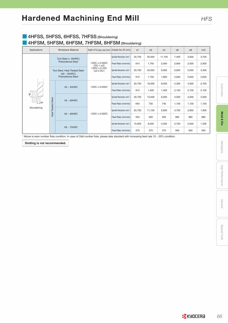
66
Autom
otiveA
erospaceH
igh Perform
anceG
eneralS
pecial ToolsM
old & D
ie
Hardened Machining End Mill HFS
L72
L
Sol
id T
ools
End Mills
Solid Tools for CFRP
Flat Bottom Drill
Cutting Conditions
Recommended Cutting Conditions
■ 4YEBMApplications Workpiece Material Application Depth of Cut (ap x ae) (mm) Outside Dia. DC (mm) ø5 ø6 ø8 ø10 ø12 ø16 ø20
ae
ap
Shouldering
ap
Slotting
Low Carbon Steel
Shouldering 1DC x 0.5DCSpindle Revolution (min-1) 9,400 7,900 5,900 4,700 3,900 2,900 2,400
Feed Rate (mm/min) 1,020 1,130 1,270 1,020 990 800 760
Slotting 1DCSpindle Revolution (min-1) 8,600 7,200 5,400 4,300 3,600 2,700 2,200
Feed Rate (mm/min) 930 1,030 1,160 930 900 730 700
Stainless Steel
Shouldering 1DC x 0.5DCSpindle Revolution (min-1) 5,700 4,800 3,600 2,900 2,400 1,800 1,400
Feed Rate (mm/min) 620 630 630 640 560 450 390
Slotting 1DCSpindle Revolution (min-1) 5,100 4,200 3,200 2,500 2,100 1,600 1,300
Feed Rate (mm/min) 550 610 570 550 500 400 350
Titanium Alloys
Shouldering 1DC x 0.3DCSpindle Revolution (min-1) 3,200 2,700 2,000 1,600 1,300 1,000 800
Feed Rate (mm/min) 180 190 220 170 170 160 160
Slotting 0.5DCSpindle Revolution (min-1) 2,900 2,400 1,800 1,400 1,200 900 700
Feed Rate (mm/min) 160 170 190 170 170 160 160
Heat-resistant Alloys
Shouldering 1DC x 0.2DCSpindle Revolution (min-1) 1,700 1,400 1,000 800 700 500 400
Feed Rate (mm/min) 70 80 100 80 90 90 80
Slotting 0.5DCSpindle Revolution (min-1) 1,400 1,200 900 700 600 400 400
Feed Rate (mm/min) 60 70 80 80 80 80 70
Gray Cast Iron
Shouldering 1DC x 0.4DCSpindle Revolution (min-1) 7,800 6,500 4,900 3,900 3,200 2,400 1,900
Feed Rate (mm/min) 840 930 1,050 840 820 660 630
Slotting 1DCSpindle Revolution (min-1) 7,000 5,800 4,400 3,500 2,900 2,200 1,800
Feed Rate (mm/min) 760 840 950 760 740 600 570
■ 4HFSS, 5HFSS, 6HFSS, 7HFSS (Shouldering)
■ 4HFSM, 5HFSM, 6HFSM, 7HFSM, 8HFSM (Shouldering)
Applications Workpiece Material Depth of Cut (ap x ae) (mm) Outside Dia. DC (mm) ø1 ø2 ø4 ø6 ø8 ø12
ap
ae
Shouldering
Tool Steel (< 40HRC)Prehardened Steel 1.5DC x 0.05DC
(DC<ø3)1.5DC x 0.1DC (ø3 ≤ DC)
Spindle Revolution (min-1) 20,700 20,000 11,100 7,400 5,600 3,700
Feed Rate (mm/min) 910 1,750 2,000 2,900 2,930 2,930
Tool Steel, Heat Treated Steel(40 ~ 45HRC)
Prehardened Steel
Spindle Revolution (min-1) 20,700 20,000 9,900 6,600 5,000 3,300
Feed Rate (mm/min) 910 1,750 1,800 2,630 2,650 2,650
Hea
t Tre
ated
Ste
el
45 ~ 55HRC 1.5DC x 0.05DCSpindle Revolution (min-1) 20,700 16,000 8,000 5,300 4,000 2,700
Feed Rate (mm/min) 910 1,400 1,400 2,100 2,100 2,100
55 ~ 60HRC
1.5DC x 0.02DC
Spindle Revolution (min-1) 20,700 12,000 6,000 4,000 3,000 2,000
Feed Rate (mm/min) 640 730 740 1,100 1,100 1,100
60 ~ 65HRC
Spindle Revolution (min-1) 20,700 11,100 5,600 3,700 2,800 1,900
Feed Rate (mm/min) 550 600 600 880 880 880
65 ~ 70HRC
Spindle Revolution (min-1) 15,900 8,000 4,000 2,700 2,000 1,330
Feed Rate (mm/min) 370 370 370 560 560 550
* Above is even number flute condition. In case of Odd number flute, please take standard with increasing feed rate 15 ~ 20% condition.
* Machining with water soluble coolant is recommended for stainless steel, titanium alloys and heat-resistant alloys.
Slotting is not recommended.
L.indd 72 2019/09/04 10:21:44
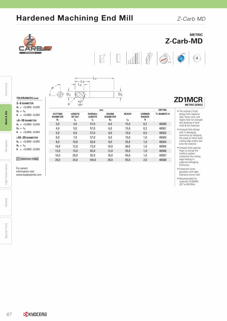
67
Aut
omot
ive
Aer
ospa
ceH
igh
Per
form
ance
Gen
eral
Spe
cial
Too
lsM
old
& D
ie
Hardened Machining End Mill Z-Carb MD
HARDENED STEELS
61www.kyocera-sgstool.comEND MILLS END MILLS
ZD1MCRMETRIC SERIES
mm EDP NO.
CUTTING DIAMETER
D1
LENGTH OF CUT
L2
OVERALL LENGTH
L1
SHANK DIAMETER
D2
REACH
L3
CORNER RADIUS
R
Ti-NAMITE-X
3,0 4,0 57,0 6,0 15,0 0,2 465604,0 5,0 57,0 6,0 15,0 0,3 465615,0 6,0 57,0 6,0 15,0 0,5 465626,0 7,0 57,0 6,0 15,0 1,0 465638,0 10,0 63,0 8,0 25,0 1,0 4656410,0 12,0 72,0 10,0 30,0 1,0 4656512,0 15,0 83,0 12,0 35,0 1,0 4656616,0 20,0 92,0 16,0 45,0 1,5 4656720,0 24,0 104,0 20,0 55,0 2,0 46568
METRIC
Z-Carb-MD
• The original Z-Carb design with negative rake, heavy core, and higher helix for strength and shearing of hard mold & die materials
• Unequal helix design aids in damaging harmonics by changing the angle at which each cutting edge enters and exits the material
• Unequal flute spacing helps to disrupt the rhythmic pattern created by the cutting edge helping to suppress damaging harmonics
• Enhanced corner geometry with tight tolerance corner radii
• Recommended for materials 35-60HRc (327 to 654 Bhn)
≠
NEG
4
TOLERANCES (mm)
3–6 DIAMETER
D1 = +0,000/–0,030D2 = h6
R = +0,000/–0,050
>6–10 DIAMETER
D1 = +0,000/–0,040D2 = h6
R = +0,000/–0,050
>10–20 DIAMETER
D1 = +0,000/–0,050D2 = h6
R = +0,000/–0,050
For patent information visit www.ksptpatents.com
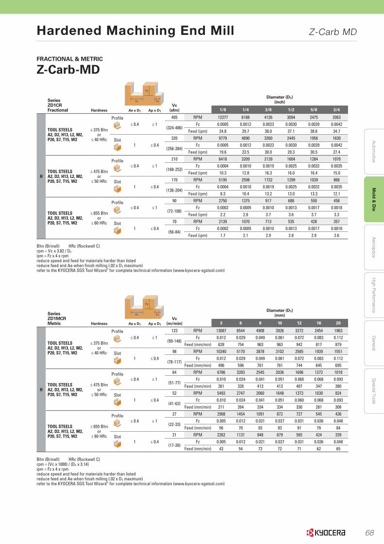
68
Autom
otiveA
erospaceH
igh Perform
anceG
eneralS
pecial ToolsM
old & D
ie
Hardened Machining End Mill Z-Carb MD
62 END MILLS END MILLSwww.kyocera-sgstool.com
FRACTIONAL & METRIC
Z-Carb-MD
Series ZD1MCRMetric Hardness
Ap
Ae AeVc
(m/min)
Diameter (D1)(mm)
Ae x D1 Ap x D1 3 6 8 10 12 16 20
H
TOOL STEELSA2, D2, H13, L2, M2, P20, S7, T15, W2
≤ 375 Bhnor
≤ 40 HRc
Profile≤ 0.4 ≤ 1
123 RPM 13087 6544 4908 3926 3272 2454 1963
(99-148)Fz 0.012 0.029 0.049 0.061 0.072 0.083 0.112
Feed (mm/min) 628 754 963 963 942 817 879
Slot1 ≤ 0.4
98 RPM 10340 5170 3878 3102 2585 1939 1551
(78-117)Fz 0.012 0.029 0.049 0.061 0.072 0.083 0.112
Feed (mm/min) 496 596 761 761 744 645 695
TOOL STEELSA2, D2, H13, L2, M2, P20, S7, T15, W2
≤ 475 Bhnor
≤ 50 HRc
Profile≤ 0.4 ≤ 1
64 RPM 6786 3393 2545 2036 1696 1272 1018
(51-77)Fz 0.010 0.024 0.041 0.051 0.060 0.068 0.093
Feed (mm/min) 261 326 413 413 407 347 380
Slot1 ≤ 0.4
52 RPM 5493 2747 2060 1648 1373 1030 824
(41-62)Fz 0.010 0.024 0.041 0.051 0.060 0.068 0.093
Feed (mm/min) 211 264 334 334 330 281 308
TOOL STEELSA2, D2, H13, L2, M2, P20, S7, T15, W2
≤ 655 Bhnor
≤ 60 HRc
Profile≤ 0.4 ≤ 1
27 RPM 2908 1454 1091 872 727 545 436
(22-33)Fz 0.005 0.012 0.021 0.027 0.031 0.036 0.048
Feed (mm/min) 56 70 93 93 91 79 84
Slot1 ≤ 0.4
21 RPM 2262 1131 848 679 565 424 339
(17-26)Fz 0.005 0.012 0.021 0.027 0.031 0.036 0.048
Feed (mm/min) 43 54 72 72 71 62 65
Bhn (Brinell) HRc (Rockwell C)rpm = (Vc x 1000) / (D1 x 3.14)ipm = Fz x 4 x rpm reduce speed and feed for materials harder than listedreduce feed and Ae when finish milling (.02 x D1 maximum)refer to the KYOCERA SGS Tool Wizard® for complete technical information (www.kyocera-sgstool.com)
Series ZD1CRFractional Hardness
Ap
Ae AeVc
(sfm)
Diameter (D1)(inch)
Ae x D1 Ap x D1 1/8 1/4 3/8 1/2 5/8 3/4
H
TOOL STEELSA2, D2, H13, L2, M2, P20, S7, T15, W2
≤ 375 Bhnor
≤ 40 HRc
Profile≤ 0.4 ≤ 1
405 RPM 12377 6188 4126 3094 2475 2063
(324-486)Fz 0.0005 0.0012 0.0023 0.0030 0.0039 0.0042
Feed (ipm) 24.8 29.7 38.0 37.1 38.6 34.7
Slot1 ≤ 0.4
320 RPM 9779 4890 3260 2445 1956 1630
(256-384)Fz 0.0005 0.0012 0.0023 0.0030 0.0039 0.0042
Feed (ipm) 19.6 23.5 30.0 29.3 30.5 27.4
TOOL STEELSA2, D2, H13, L2, M2, P20, S7, T15, W2
≤ 475 Bhnor
≤ 50 HRc
Profile≤ 0.4 ≤ 1
210 RPM 6418 3209 2139 1604 1284 1070
(168-252)Fz 0.0004 0.0010 0.0019 0.0025 0.0032 0.0035
Feed (ipm) 10.3 12.8 16.3 16.0 16.4 15.0
Slot1 ≤ 0.4
170 RPM 5195 2598 1732 1299 1039 866
(136-204)Fz 0.0004 0.0010 0.0019 0.0025 0.0032 0.0035
Feed (ipm) 8.3 10.4 13.2 13.0 13.3 12.1
TOOL STEELSA2, D2, H13, L2, M2, P20, S7, T15, W2
≤ 655 Bhnor
≤ 60 HRc
Profile≤ 0.4 ≤ 1
90 RPM 2750 1375 917 688 550 458
(72-108)Fz 0.0002 0.0005 0.0010 0.0013 0.0017 0.0018
Feed (ipm) 2.2 2.8 3.7 3.6 3.7 3.3
Slot1 ≤ 0.4
70 RPM 2139 1070 713 535 428 357
(56-84)Fz 0.0002 0.0005 0.0010 0.0013 0.0017 0.0018
Feed (ipm) 1.7 2.1 2.9 2.8 2.9 2.6
Bhn (Brinell) HRc (Rockwell C)rpm = Vc x 3.82 / D1ipm = Fz x 4 x rpm reduce speed and feed for materials harder than listedreduce feed and Ae when finish milling (.02 x D1 maximum)refer to the KYOCERA SGS Tool Wizard® for complete technical information (www.kyocera-sgstool.com)
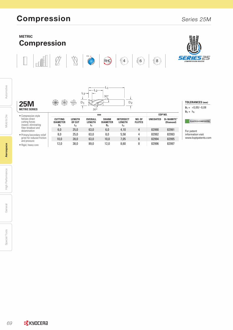
69
Aut
omot
ive
Aer
ospa
ceH
igh
Per
form
ance
Gen
eral
Spe
cial
Too
lsM
old
& D
ie
Compression Series 25M
ROUTERS ROUTERSROUTERSROUTERSROUTERS
PLASTICS/COMPOSITES
368www.kyocera-sgstool.com
METRIC
Compression
POS
RHC 4 6 8
25MMETRIC SERIES
mm EDP NO.
CUTTING DIAMETER
D1
LENGTH OF CUT
L2
OVERALL LENGTH
L1
SHANK DIAMETER
D2
INTERSECTLENGTH
L3
NO. OF FLUTES
UNCOATED Di-NAMITE®
(Diamond)
6,0 25,0 63,0 6,0 4,10 4 82990 829918,0 25,0 63,0 8,0 5,58 4 82992 82993
10,0 28,0 63,0 10,0 7,05 6 82994 8299512,0 38,0 89,0 12,0 8,60 8 82996 82997
• Compression-style helixes direct cutting forces inward, eliminating fiber breakout and delamination
• Primary/secondary relief grind for reduced friction and pressure
• Rigid, heavy core
TOLERANCES (mm)
D1 = +0,00/–0,08D2 = h6
For patent information visit www.ksptpatents.com
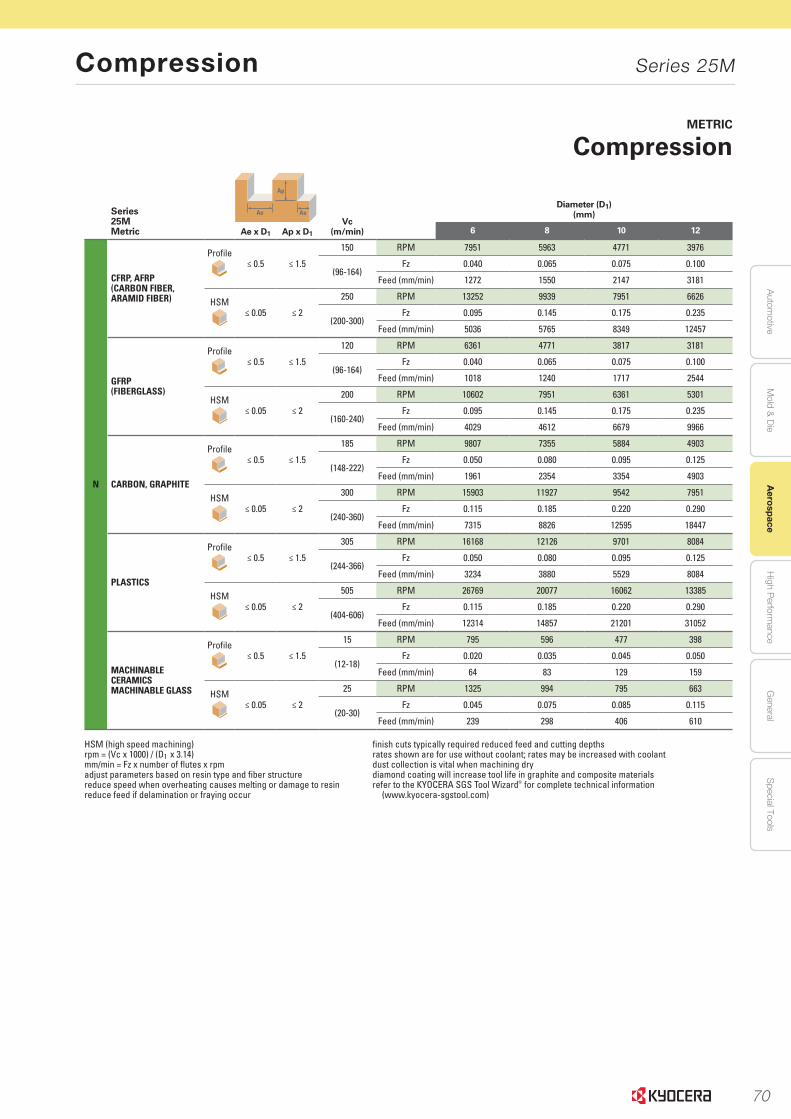
70
Autom
otiveA
erospaceH
igh Perform
anceG
eneralS
pecial ToolsM
old & D
ie
Compression Series 25M
ROUTERS ROUTERSROUTERSROUTERSROUTERS 369www.kyocera-sgstool.com
METRIC
Compression
Series 25MMetric
Ap
Ae AeVc
(m/min)
Diameter (D1)(mm)
Ae x D1 Ap x D1 6 8 10 12
N
CFRP, AFRP(CARBON FIBER, ARAMID FIBER)
Profile≤ 0.5 ≤ 1.5
150 RPM 7951 5963 4771 3976
(96-164)Fz 0.040 0.065 0.075 0.100
Feed (mm/min) 1272 1550 2147 3181
HSM≤ 0.05 ≤ 2
250 RPM 13252 9939 7951 6626
(200-300)Fz 0.095 0.145 0.175 0.235
Feed (mm/min) 5036 5765 8349 12457
GFRP(FIBERGLASS)
Profile≤ 0.5 ≤ 1.5
120 RPM 6361 4771 3817 3181
(96-164)Fz 0.040 0.065 0.075 0.100
Feed (mm/min) 1018 1240 1717 2544
HSM≤ 0.05 ≤ 2
200 RPM 10602 7951 6361 5301
(160-240)Fz 0.095 0.145 0.175 0.235
Feed (mm/min) 4029 4612 6679 9966
CARBON, GRAPHITE
Profile≤ 0.5 ≤ 1.5
185 RPM 9807 7355 5884 4903
(148-222)Fz 0.050 0.080 0.095 0.125
Feed (mm/min) 1961 2354 3354 4903
HSM≤ 0.05 ≤ 2
300 RPM 15903 11927 9542 7951
(240-360)Fz 0.115 0.185 0.220 0.290
Feed (mm/min) 7315 8826 12595 18447
PLASTICS
Profile≤ 0.5 ≤ 1.5
305 RPM 16168 12126 9701 8084
(244-366)Fz 0.050 0.080 0.095 0.125
Feed (mm/min) 3234 3880 5529 8084
HSM≤ 0.05 ≤ 2
505 RPM 26769 20077 16062 13385
(404-606)Fz 0.115 0.185 0.220 0.290
Feed (mm/min) 12314 14857 21201 31052
MACHINABLE CERAMICSMACHINABLE GLASS
Profile≤ 0.5 ≤ 1.5
15 RPM 795 596 477 398
(12-18)Fz 0.020 0.035 0.045 0.050
Feed (mm/min) 64 83 129 159
HSM≤ 0.05 ≤ 2
25 RPM 1325 994 795 663
(20-30)Fz 0.045 0.075 0.085 0.115
Feed (mm/min) 239 298 406 610
HSM (high speed machining) finish cuts typically required reduced feed and cutting depths rpm = (Vc x 1000) / (D1 x 3.14) rates shown are for use without coolant; rates may be increased with coolant mm/min = Fz x number of flutes x rpm dust collection is vital when machining dry adjust parameters based on resin type and fiber structure diamond coating will increase tool life in graphite and composite materials reduce speed when overheating causes melting or damage to resin refer to the KYOCERA SGS Tool Wizard® for complete technical informationreduce feed if delamination or fraying occur (www.kyocera-sgstool.com)

71
Aut
omot
ive
Aer
ospa
ceH
igh
Per
form
ance
Gen
eral
Spe
cial
Too
lsM
old
& D
ie
www.sgstool.com8
SERIES 20 CARBON COMPOSITE ROUTER
SGS Carbon Composite Routers were designed for maximum performance in CFRP materials.
We partnered with a leading Aerospace company to launch the original Series 20, a design
focused on trimming and finishing in demanding applications requiring minimal fiber breakout
and delamination.
• The multi-flute design and positive geometry cleanly shear through the material
with minimal pressure without delamination issues
• The unique clearance grind minimizes the contact between the tool diameter
and workpiece, eliminating friction and pressure concerns
• Left hand flutes engineered to control the fibers within CFRP, preventing
excessive fiber breakout
• Greater edge finish with longer tool life
• Available with and without end cut
• Now available with Di-NAMITE coating option
Performance by Design
The Original CCR is now available
in a diamond coated option for
maximum abrasion resistance
and increased tool life.
Carbon Composite Router CCR | Series 20
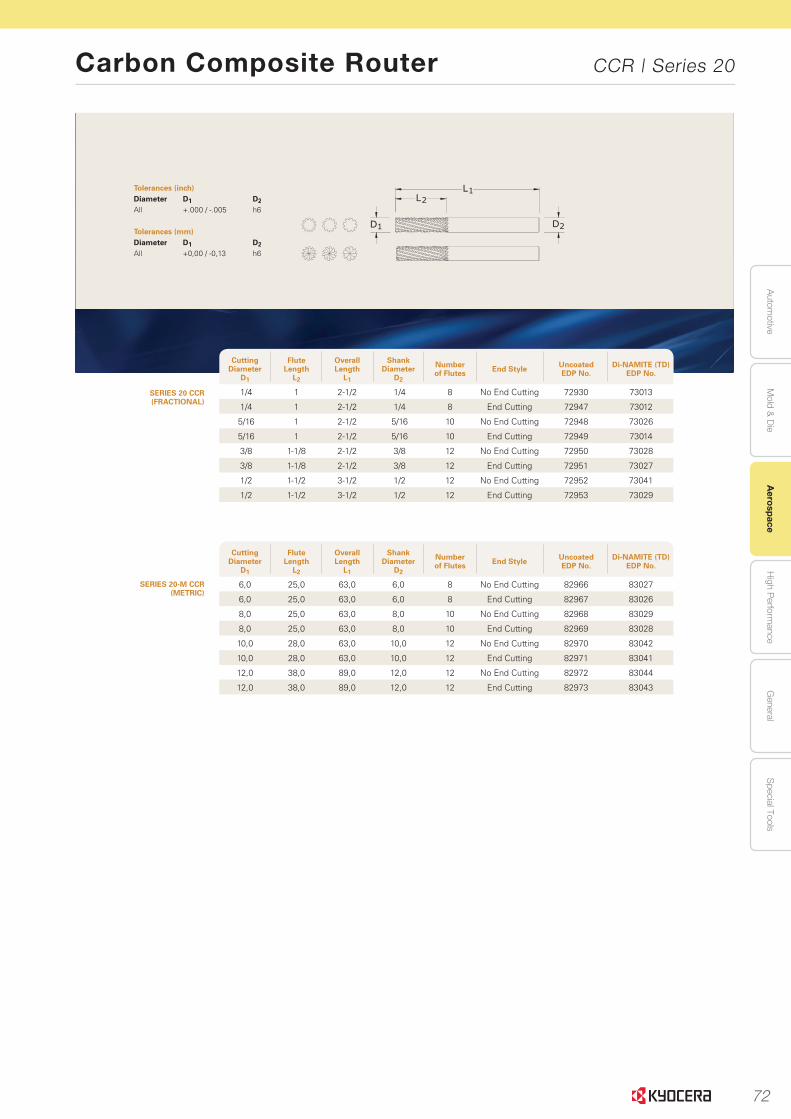
72
Autom
otiveA
erospaceH
igh Perform
anceG
eneralS
pecial ToolsM
old & D
ie
Carbon Composite Router CCR | Series 20
www.sgstool.com 9
SERIES 20 CCR(FRACTIONAL)
SERIES 20-M CCR (METRIC)
Tolerances (inch)Diameter D1 D2All +.000 / -.005 h6
Tolerances (mm)Diameter D1 D2All +0,00 / -0,13 h6
Cutting Diameter
D1
Flute Length
L2
Overall Length
L1
Shank Diameter
D2
Number of Flutes End Style Uncoated
EDP No.Di-NAMITE (TD)
EDP No.
1/4 1 2-1/2 1/4 8 No End Cutting 72930 73013
1/4 1 2-1/2 1/4 8 End Cutting 72947 73012
5/16 1 2-1/2 5/16 10 No End Cutting 72948 73026
5/16 1 2-1/2 5/16 10 End Cutting 72949 73014
3/8 1-1/8 2-1/2 3/8 12 No End Cutting 72950 73028
3/8 1-1/8 2-1/2 3/8 12 End Cutting 72951 73027
1/2 1-1/2 3-1/2 1/2 12 No End Cutting 72952 73041
1/2 1-1/2 3-1/2 1/2 12 End Cutting 72953 73029
Cutting Diameter
D1
Flute Length
L2
Overall Length
L1
Shank Diameter
D2
Number of Flutes End Style Uncoated
EDP No.Di-NAMITE (TD)
EDP No.
6,0 25,0 63,0 6,0 8 No End Cutting 82966 83027
6,0 25,0 63,0 6,0 8 End Cutting 82967 83026
8,0 25,0 63,0 8,0 10 No End Cutting 82968 83029
8,0 25,0 63,0 8,0 10 End Cutting 82969 83028
10,0 28,0 63,0 10,0 12 No End Cutting 82970 83042
10,0 28,0 63,0 10,0 12 End Cutting 82971 83041
12,0 38,0 89,0 12,0 12 No End Cutting 82972 83044
12,0 38,0 89,0 12,0 12 End Cutting 82973 83043
1D 2D
L1L2
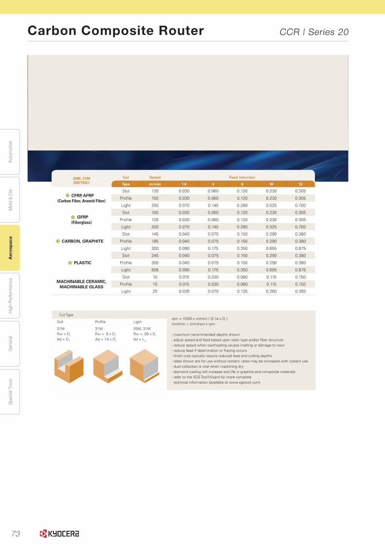
73
Aut
omot
ive
Aer
ospa
ceH
igh
Per
form
ance
Gen
eral
Spe
cial
Too
lsM
old
& D
ie
www.sgstool.com 13
Cut Typerpm = (1000 x m/min) / (3.14 x D1)mm/min = (mm/rev) x rpm
- maximum recommended depths shown- adjust speed and feed based upon resin type and/or fiber structure - reduce speed when overheating causes melting or damage to resin- reduce feed if delamination or fraying occurs- finish cuts typically require reduced feed and cutting depths - rates shown are for use without coolant; rates may be increased with coolant use- dust collection is vital when machining dry- diamond coating will increase tool life in graphite and composite materials- refer to the SGS Tool Wizard for more complete
technical information (available at www.sgstool.com)
Slot Profile Light
31MRw = D1
Ad = D1
31MRw = .5 x D1
Ad = 1.5 x D1
20M, 31MRw = .05 x D1
Ad = L2
20M, 31M (METRIC)
Cut Speed Feed (mm/rev)
Type m/min 1.6 3 6 10 12
CFRP, AFRP(Carbon Fiber, Aramid Fiber)
Slot 120 0.030 0.060 0.120 0.230 0.305
Profile 150 0.030 0.060 0.120 0.230 0.305
Light 250 0.070 0.140 0.280 0.525 0.700
GFRP(Fiberglass)
Slot 100 0.030 0.060 0.120 0.230 0.305
Profile 120 0.030 0.060 0.120 0.230 0.305
Light 200 0.070 0.140 0.280 0.525 0.700
CARBON, GRAPHITE
Slot 145 0.040 0.075 0.150 0.290 0.380
Profile 185 0.040 0.075 0.150 0.290 0.380
Light 300 0.090 0.175 0.350 0.655 0.875
PLASTIC
Slot 245 0.040 0.075 0.150 0.290 0.380
Profile 305 0.040 0.075 0.150 0.290 0.380
Light 505 0.090 0.175 0.350 0.655 0.875
MACHINABLE CERAMIC, MACHINABLE GLASS
Slot 10 0.015 0.030 0.060 0.115 0.150
Profile 15 0.015 0.030 0.060 0.115 0.150
Light 25 0.035 0.070 0.135 0.260 0.350
Carbon Composite Router CCR | Series 20

74
High Performance Drills
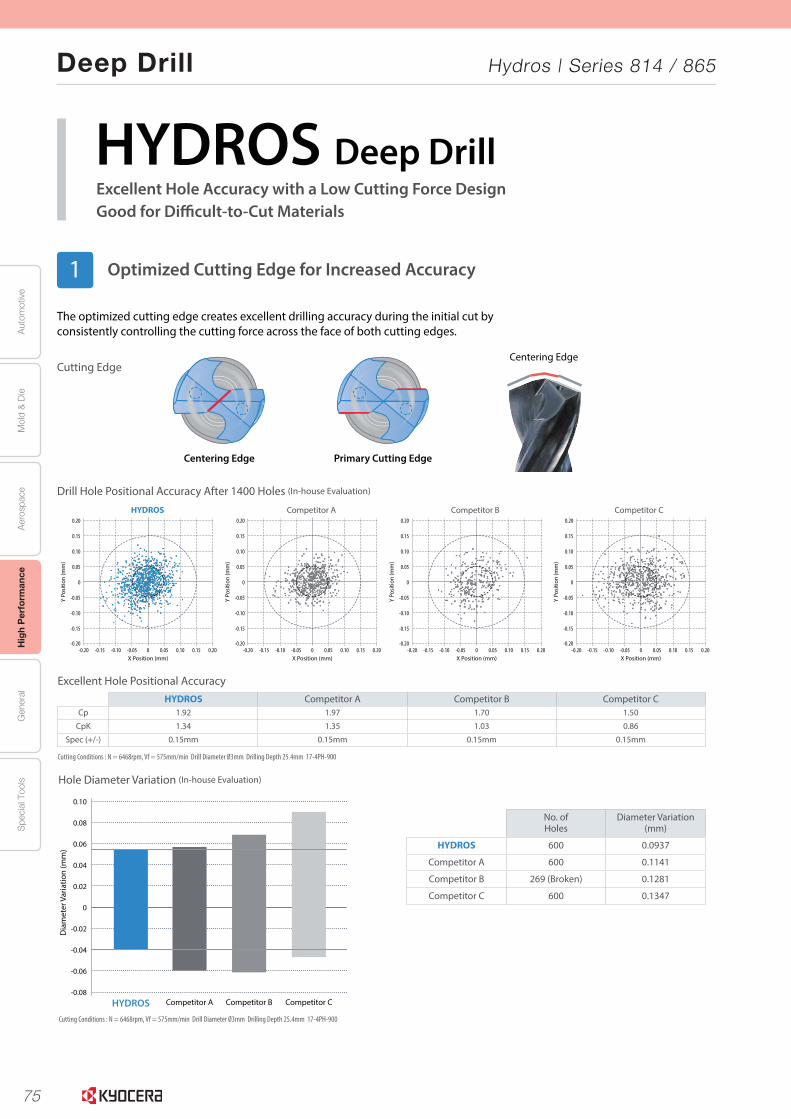
75
Aut
omot
ive
Aer
ospa
ceH
igh
Per
form
ance
Gen
eral
Spe
cial
Too
lsM
old
& D
ie
Deep Drill Hydros | Series 814 / 865
2
Excellent Hole Accuracy with a Low Cutting Force DesignGood for Difficult-to-Cut Materials
HYDROS Deep Drill
The optimized cutting edge creates excellent drilling accuracy during the initial cut by consistently controlling the cutting force across the face of both cutting edges.
Cutting Edge
Centering Edge Primary Cutting Edge
HYDROS Competitor A Competitor B Competitor C
Dia
met
er V
aria
tion
(mm
)
0.08
0.06
0.10
0.04
0.02
0
-0.02
-0.04
-0.06
-0.08
Hole Diameter Variation (In-house Evaluation)
Drill Hole Positional Accuracy After 1400 Holes (In-house Evaluation)
Excellent Hole Positional Accuracy
Centering Edge
No. ofHoles
Diameter Variation(mm)
HYDROS 600 0.0937
Competitor A 600 0.1141
Competitor B 269 (Broken) 0.1281
Competitor C 600 0.1347
HYDROS Competitor A Competitor B Competitor CCp 1.92 1.97 1.70 1.50
CpK 1.34 1.35 1.03 0.86
Spec (+/-) 0.15mm 0.15mm 0.15mm 0.15mm
Cutting Conditions : N = 6468rpm, Vf = 575mm/min Drill Diameter Ø3mm Drilling Depth 25.4mm 17-4PH-900
Cutting Conditions : N = 6468rpm, Vf = 575mm/min Drill Diameter Ø3mm Drilling Depth 25.4mm 17-4PH-900
Y Po
sitio
n (m
m)
X Position (mm)
0.20
0.15
0.10
0
0.05
-0.05
-0.10
-0.15
-0.20-0.20 -0.15 -0.10 -0.05 0 0.05 0.10 0.15 0.20
Y Po
sitio
n (m
m)
X Position (mm)
0.20
0.15
0.10
0
0.05
-0.05
-0.10
-0.15
-0.20-0.20 -0.15 -0.10 -0.05 0 0.05 0.10 0.15 0.20
Y Po
sitio
n (m
m)
X Position (mm)
0.20
0.15
0.10
0
0.05
-0.05
-0.10
-0.15
-0.20-0.20 -0.15 -0.10 -0.05 0 0.05 0.10 0.15 0.20
Y Po
sitio
n (m
m)
X Position (mm)
0.20
0.15
0.10
0
0.05
-0.05
-0.10
-0.15
-0.20-0.20 -0.15 -0.10 -0.05 0 0.05 0.10 0.15 0.20
HYDROS Competitor A Competitor B Competitor C
Optimized Cutting Edge for Increased Accuracy1

76
Autom
otiveA
erospaceH
igh Perform
anceG
eneralS
pecial ToolsM
old & D
ie
Deep Drill Hydros | Series 814 / 865
3
Oxidation Resistance
40
35
30
25
20
15
10400 600 800 1,000 1,200 1,400
Low High
TiCN
TiNTiAIN
AlTiN Nano
Har
dnes
s (G
Pa)
Oxidation Onset Temperature (°C)
Two margins create a cutting and wiping effect that create a smooth hole finish and smooth cutting performance along the hole wall.
Great for difficult-to-cut and hardened materials, the 2nd generation AlTiN supernitride with a nanocomposite coating structure has a hardness GPa of 36.3 and maximum application temperature (C°) of 1,100.
Coating Properties
Double Margins
Optimized for smooth cutting performance with excellent chip evacuation
HYDROS Competitor A Competitor B Competitor CHole 1 Hole 300 Hole 600 Hole 1 Hole 300 Hole 600 Hole 1 Hole 300 Hole 600 Hole 1 Hole 300 Hole 600
Ra (μm) 0.421 0.539 0.676 1.705 1.540 1.572 1.638 1.977 Broken 0.893 0.559 0.562
Rq (μm) 0.554 0.677 0.869 2.123 1.832 2.113 1.979 2.581 Broken 1.249 0.712 0.687
Rz (μm) 3.282 3.478 4.406 8.076 8.480 10.077 8.847 10.973 Broken 7.178 3.845 3.206
Cutting Conditions : N = 6468rpm, Vf = 575mm/min Drill Diameter Ø3mm Drilling Depth 25.4mm 17-4PH-900
Cutting Edge
Wiping Edge
Hole Roughness (In-house Evaluation)
Pro�
le (u
m)
Distance (mm)
8
10
6
4
0
2
2
4
6
8
100 0.5 1.5 2.5 3.5 4.5 5.5 6.5 7.5
Pro�
le (u
m)
Distance (mm)
8
10
6
4
0
2
2
4
6
8
100 0.5 1.5 2.5 3.5 4.5 5.5 6.5 7.5
Pro�
le (u
m)
Distance (mm)
8
10
6
4
0
2
2
4
6
8
100 0.5 1.5 2.5 3.5 4.5 5.5 6.5 7.5
Pro�
le (u
m)
Distance (mm)
8
10
6
4
0
2
2
4
6
8
100 0.5 1.5 2.5 3.5 4.5 5.5 6.5 7.5
HYDROS Competitor A Competitor B Competitor C
Chip ComparisonHYDROS Competitor A Competitor B Competitor C
Double Margin for Smooth Hole Finish2
Nanocomposite Super-nitride AlTiN Coating Technology3
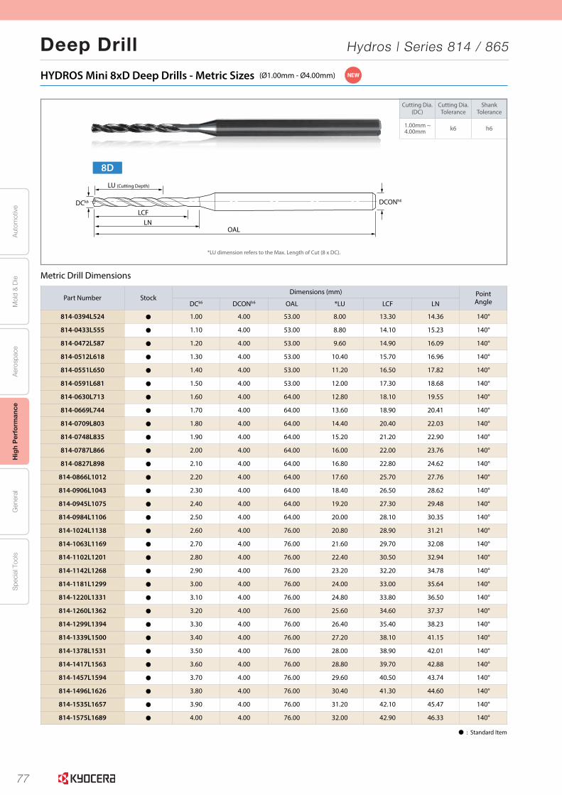
77
Aut
omot
ive
Aer
ospa
ceH
igh
Per
form
ance
Gen
eral
Spe
cial
Too
lsM
old
& D
ie
Deep Drill Hydros | Series 814 / 865
4
Cutting Dia.(DC)
Cutting Dia.Tolerance
ShankTolerance
1.00mm ~4.00mm k6 h6
HYDROS Mini 8xD Deep Drills - Metric Sizes (Ø1.00mm - Ø4.00mm)
Metric Drill Dimensions
Part Number StockDimensions (mm) Point
AngleDCk6 DCONh6 OAL *LU LCF LN
814-0394L524 Þ 1.00 4.00 53.00 8.00 13.30 14.36 140°
814-0433L555 Þ 1.10 4.00 53.00 8.80 14.10 15.23 140°
814-0472L587 Þ 1.20 4.00 53.00 9.60 14.90 16.09 140°
814-0512L618 Þ 1.30 4.00 53.00 10.40 15.70 16.96 140°
814-0551L650 Þ 1.40 4.00 53.00 11.20 16.50 17.82 140°
814-0591L681 Þ 1.50 4.00 53.00 12.00 17.30 18.68 140°
814-0630L713 Þ 1.60 4.00 64.00 12.80 18.10 19.55 140°
814-0669L744 Þ 1.70 4.00 64.00 13.60 18.90 20.41 140°
814-0709L803 Þ 1.80 4.00 64.00 14.40 20.40 22.03 140°
814-0748L835 Þ 1.90 4.00 64.00 15.20 21.20 22.90 140°
814-0787L866 Þ 2.00 4.00 64.00 16.00 22.00 23.76 140°
814-0827L898 Þ 2.10 4.00 64.00 16.80 22.80 24.62 140°
814-0866L1012 Þ 2.20 4.00 64.00 17.60 25.70 27.76 140°
814-0906L1043 Þ 2.30 4.00 64.00 18.40 26.50 28.62 140°
814-0945L1075 Þ 2.40 4.00 64.00 19.20 27.30 29.48 140°
814-0984L1106 Þ 2.50 4.00 64.00 20.00 28.10 30.35 140°
814-1024L1138 Þ 2.60 4.00 76.00 20.80 28.90 31.21 140°
814-1063L1169 Þ 2.70 4.00 76.00 21.60 29.70 32.08 140°
814-1102L1201 Þ 2.80 4.00 76.00 22.40 30.50 32.94 140°
814-1142L1268 Þ 2.90 4.00 76.00 23.20 32.20 34.78 140°
814-1181L1299 Þ 3.00 4.00 76.00 24.00 33.00 35.64 140°
814-1220L1331 Þ 3.10 4.00 76.00 24.80 33.80 36.50 140°
814-1260L1362 Þ 3.20 4.00 76.00 25.60 34.60 37.37 140°
814-1299L1394 Þ 3.30 4.00 76.00 26.40 35.40 38.23 140°
814-1339L1500 Þ 3.40 4.00 76.00 27.20 38.10 41.15 140°
814-1378L1531 Þ 3.50 4.00 76.00 28.00 38.90 42.01 140°
814-1417L1563 Þ 3.60 4.00 76.00 28.80 39.70 42.88 140°
814-1457L1594 Þ 3.70 4.00 76.00 29.60 40.50 43.74 140°
814-1496L1626 Þ 3.80 4.00 76.00 30.40 41.30 44.60 140°
814-1535L1657 Þ 3.90 4.00 76.00 31.20 42.10 45.47 140°
814-1575L1689 Þ 4.00 4.00 76.00 32.00 42.90 46.33 140°
8D
LCFLN
LU (Cutting Depth)
OAL
DCk6 DCONh6
Þ : Standard Item
NEW
*LU dimension refers to the Max. Length of Cut (8 x DC).
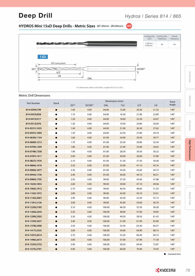
78
Autom
otiveA
erospaceH
igh Perform
anceG
eneralS
pecial ToolsM
old & D
ie
Deep Drill Hydros | Series 814 / 865
5
Cutting Dia.(DC)
Cutting Dia.Tolerance
ShankTolerance
1.00mm ~4.00mm k6 h6
HYDROS Mini 15xD Deep Drills - Metric Sizes (Ø1.00mm - Ø4.00mm)
Metric Drill Dimensions
Part Number StockDimensions (mm) Point
AngleDCk6 DCONh6 OAL *LU LCF LN
814-0394L799 Þ 1.00 4.00 64.00 15.00 20.30 21.32 140°
814-0433L858 Þ 1.10 4.00 64.00 16.50 21.80 22.89 140°
814-0472L917 Þ 1.20 4.00 64.00 18.00 23.30 24.47 140°
814-0512L976 Þ 1.30 4.00 64.00 19.50 24.80 26.04 140°
814-0551L1035 Þ 1.40 4.00 64.00 21.00 26.30 27.62 140°
814-0591L1094 Þ 1.50 4.00 64.00 22.50 27.80 29.19 140°
814-0630L1154 Þ 1.60 4.00 81.00 24.00 29.30 30.77 140°
814-0669L1213 Þ 1.70 4.00 81.00 25.50 30.80 32.34 140°
814-0709L1299 Þ 1.80 4.00 81.00 27.00 33.00 34.65 140°
814-0748L1358 Þ 1.90 4.00 81.00 28.50 34.50 36.23 140°
814-0787L1417 Þ 2.00 4.00 81.00 30.00 36.00 37.80 140°
814-0827L1476 Þ 2.10 4.00 81.00 31.50 37.50 39.38 140°
814-0866L1618 Þ 2.20 4.00 81.00 33.00 41.10 43.16 140°
814-0906L1677 Þ 2.30 4.00 81.00 34.50 42.60 44.73 140°
814-0945L1736 Þ 2.40 4.00 81.00 36.00 44.10 46.31 140°
814-0984L1795 Þ 2.50 4.00 90.00 37.50 45.60 47.88 140°
814-1024L1854 Þ 2.60 4.00 90.00 39.00 47.10 49.46 140°
814-1063L1913 Þ 2.70 4.00 90.00 40.50 48.60 51.03 140°
814-1102L1972 Þ 2.80 4.00 90.00 42.00 50.10 52.61 140°
814-1142L2067 Þ 2.90 4.00 90.00 43.50 52.50 55.13 140°
814-1181L2126 Þ 3.00 4.00 90.00 45.00 54.00 56.70 140°
814-1220L2185 Þ 3.10 4.00 106.00 46.50 55.50 58.28 140°
814-1260L2244 Þ 3.20 4.00 106.00 48.00 57.00 59.85 140°
814-1299L2303 Þ 3.30 4.00 106.00 49.50 58.50 61.43 140°
814-1339L2437 Þ 3.40 4.00 106.00 51.00 61.90 65.00 140°
814-1378L2496 Þ 3.50 4.00 106.00 52.50 63.40 66.57 140°
814-1417L2555 Þ 3.60 4.00 106.00 54.00 64.90 68.15 140°
814-1457L2614 Þ 3.70 4.00 106.00 55.50 66.40 69.72 140°
814-1496L2673 Þ 3.80 4.00 106.00 57.00 67.90 71.30 140°
814-1535L2732 Þ 3.90 4.00 106.00 58.50 69.40 72.87 140°
814-1575L2791 Þ 4.00 4.00 106.00 60.00 70.90 74.45 140°
*LU dimension refers to the Max. Length of Cut (15 x DC).
Þ : Standard Item
NEW
15D
LU (Cutting Depth)
DCk6 DCONh6
LCFLN
OAL

79
Aut
omot
ive
Aer
ospa
ceH
igh
Per
form
ance
Gen
eral
Spe
cial
Too
lsM
old
& D
ie
Deep Drill Hydros | Series 814 / 865
7
Cutting Dia.(DC)
Cutting Dia.Tolerance
ShankTolerance
3.00mm ~6.00mm h7 h6
HYDROS 7xD Deep Drills - Metric Sizes (Ø3.00mm - Ø6.00mm)
Metric Drill Dimensions
Part Number StockDimensions (mm) Point
AngleDCh7 DCONh6 OAL *LU LCF LN
865-1181AG1181 Þ 3.00 3.00 80.37 21.00 30.00 31.50 135°
865-1220AG1220 Þ 3.10 4.00 80.37 21.70 31.00 32.55 135°
865-1260AG1260 Þ 3.20 4.00 80.37 22.40 32.00 33.60 135°
865-1299AG1299 Þ 3.30 4.00 80.37 23.10 33.00 34.65 135°
865-1339AG1339 Þ 3.40 4.00 80.37 23.80 34.00 35.70 135°
865-1378AG1378 Þ 3.50 4.00 80.37 24.50 35.00 36.75 135°
865-1417AG1417 Þ 3.60 4.00 80.37 25.20 36.00 37.80 135°
865-1457AG1457 Þ 3.70 4.00 90.37 25.90 37.00 38.85 135°
865-1496AG1496 Þ 3.80 4.00 90.37 26.60 38.00 39.90 135°
865-1535AG1535 Þ 3.90 4.00 90.37 27.30 39.00 40.95 135°
865-1575AG1575 Þ 4.00 4.00 90.37 28.00 40.00 42.00 135°
865-1614AG1614 Þ 4.10 6.00 90.37 28.70 41.00 43.05 135°
865-1654AG1654 Þ 4.20 6.00 90.37 29.40 42.00 44.10 135°
865-1693AG1693 Þ 4.30 6.00 90.37 30.10 43.00 45.15 135°
865-1732AG1732 Þ 4.40 6.00 90.37 30.80 44.00 46.20 135°
865-1772AG1772 Þ 4.50 6.00 100.37 31.50 45.00 47.25 135°
865-1811AG1811 Þ 4.60 6.00 100.37 32.20 46.00 48.30 135°
865-1850AG1850 Þ 4.70 6.00 100.37 32.90 47.00 49.35 135°
865-1890AG1890 Þ 4.80 6.00 100.37 33.60 48.00 50.40 135°
865-1929AG1929 Þ 4.90 6.00 100.37 34.30 49.00 51.45 135°
865-1969AG1969 Þ 5.00 6.00 100.37 35.00 50.00 52.50 135°
865-2008AG2008 Þ 5.10 6.00 100.37 35.70 51.00 53.55 135°
865-2047AG2047 Þ 5.20 6.00 100.37 36.40 52.00 54.60 135°
865-2087AG2087 Þ 5.30 6.00 110.37 37.10 53.00 55.65 135°
865-2126AG2126 Þ 5.40 6.00 110.37 37.80 54.00 56.70 135°
865-2165AG2165 Þ 5.50 6.00 110.37 38.50 55.00 57.75 135°
865-2205AG2205 Þ 5.60 6.00 110.37 39.20 56.00 58.80 135°
865-2244AG2244 Þ 5.70 6.00 110.47 39.90 57.00 59.85 135°
865-2283AG2283 Þ 5.80 6.00 110.47 40.60 58.00 60.90 135°
865-2323AG2323 Þ 5.90 6.00 110.47 41.30 59.00 61.95 135°
865-2362AG2362 Þ 6.00 6.00 110.47 42.00 60.00 63.00 135°
*LU dimension refers to the Max. Length of Cut (7 x DC).If a pilot drill is needed for your application please match with ORION High Performance Drills Series 165.
Þ : Standard Item
NEW
LCFLN
LU (Cutting Depth)
OAL
DCh7 DCONh6
7D
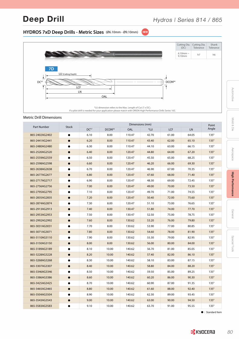
80
Autom
otiveA
erospaceH
igh Perform
anceG
eneralS
pecial ToolsM
old & D
ie
Deep Drill Hydros | Series 814 / 865
8
Cutting Dia.(DC)
Cutting Dia.Tolerance
ShankTolerance
6.10mm ~9.10mm h7 h6
HYDROS 7xD Deep Drills - Metric Sizes (Ø6.10mm - Ø9.10mm)
Metric Drill Dimensions
*LU dimension refers to the Max. Length of Cut (7 x DC).If a pilot drill is needed for your application please match with ORION High Performance Drills Series 165.
Þ : Standard Item
Part Number StockDimensions (mm) Point
AngleDCh7 DCONh6 OAL *LU LCF LN
865-2402AG2402 Þ 6.10 8.00 110.47 42.70 61.00 64.05 135°
865-2441AG2441 Þ 6.20 8.00 110.47 43.40 62.00 65.10 135°
865-2480AG2480 Þ 6.30 8.00 110.47 44.10 63.00 66.15 135°
865-2520AG2520 Þ 6.40 8.00 120.47 44.80 64.00 67.20 135°
865-2559AG2559 Þ 6.50 8.00 120.47 45.50 65.00 68.25 135°
865-2598AG2598 Þ 6.60 8.00 120.47 46.20 66.00 69.30 135°
865-2638AG2638 Þ 6.70 8.00 120.47 46.90 67.00 70.35 135°
865-2677AG2677 Þ 6.80 8.00 120.47 47.60 68.00 71.40 135°
865-2717AG2717 Þ 6.90 8.00 120.47 48.30 69.00 72.45 135°
865-2756AG2756 Þ 7.00 8.00 120.47 49.00 70.00 73.50 135°
865-2795AG2795 Þ 7.10 8.00 120.47 49.70 71.00 74.55 135°
865-2835AG2835 Þ 7.20 8.00 120.47 50.40 72.00 75.60 135°
865-2874AG2874 Þ 7.30 8.00 120.47 51.10 73.00 76.65 135°
865-2913AG2913 Þ 7.40 8.00 130.47 51.80 74.00 77.70 135°
865-2953AG2953 Þ 7.50 8.00 130.47 52.50 75.00 78.75 135°
865-2992AG2992 Þ 7.60 8.00 130.62 53.20 76.00 79.80 135°
865-3031AG3031 Þ 7.70 8.00 130.62 53.90 77.00 80.85 135°
865-3071AG3071 Þ 7.80 8.00 130.62 54.60 78.00 81.90 135°
865-3110AG3110 Þ 7.90 8.00 130.62 55.30 79.00 82.95 135°
865-3150AG3150 Þ 8.00 8.00 130.62 56.00 80.00 84.00 135°
865-3189AG3189 Þ 8.10 10.00 140.62 56.70 81.00 85.05 135°
865-3228AG3228 Þ 8.20 10.00 140.62 57.40 82.00 86.10 135°
865-3268AG3268 Þ 8.30 10.00 140.62 58.10 83.00 87.15 135°
865-3307AG3307 Þ 8.40 10.00 140.62 58.80 84.00 88.20 135°
865-3346AG3346 Þ 8.50 10.00 140.62 59.50 85.00 89.25 135°
865-3386AG3386 Þ 8.60 10.00 140.62 60.20 86.00 90.30 135°
865-3425AG3425 Þ 8.70 10.00 140.62 60.90 87.00 91.35 135°
865-3465AG3465 Þ 8.80 10.00 140.62 61.60 88.00 92.40 135°
865-3504AG3504 Þ 8.90 10.00 140.62 62.30 89.00 93.45 135°
865-3543AG3543 Þ 9.00 10.00 140.62 63.00 90.00 94.50 135°
865-3583AG3583 Þ 9.10 10.00 140.62 63.70 91.00 95.55 135°
NEW
LCFLN
LU (Cutting Depth)
OAL
DCh7 DCONh6
7D
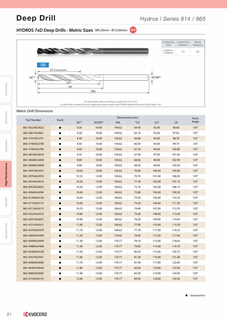
81
Aut
omot
ive
Aer
ospa
ceH
igh
Per
form
ance
Gen
eral
Spe
cial
Too
lsM
old
& D
ie
Deep Drill Hydros | Series 814 / 865
9
Cutting Dia.(DC)
Cutting Dia.Tolerance
ShankTolerance
9.20mm ~12.00mm h7 h6
HYDROS 7xD Deep Drills - Metric Sizes (Ø9.20mm - Ø12.00mm)
Metric Drill Dimensions
*LU dimension refers to the Max. Length of Cut (7 x DC).If a pilot drill is needed for your application please match with ORION High Performance Drills Series 165.
Þ : Standard Item
Part Number StockDimensions (mm) Point
AngleDCh7 DCONh6 OAL *LU LCF LN
865-3622AG3622 Þ 9.20 10.00 140.62 64.40 92.00 96.60 135°
865-3661AG3661 Þ 9.30 10.00 140.62 65.10 93.00 97.65 135°
865-3701AG3701 Þ 9.40 10.00 150.62 65.80 94.00 98.70 135°
865-3740AG3740 Þ 9.50 10.00 150.62 66.50 95.00 99.75 135°
865-3780AG3780 Þ 9.60 10.00 150.62 67.20 96.00 100.80 135°
865-3819AG3819 Þ 9.70 10.00 150.62 67.90 97.00 101.85 135°
865-3858AG3858 Þ 9.80 10.00 150.62 68.60 98.00 102.90 135°
865-3898AG3898 Þ 9.90 10.00 150.62 69.30 99.00 103.95 135°
865-3937AG3937 Þ 10.00 10.00 150.62 70.00 100.00 105.00 135°
865-3976AG3976 Þ 10.10 12.00 150.62 70.70 101.00 106.05 135°
865-4016AG4016 Þ 10.20 12.00 160.62 71.40 102.00 107.10 135°
865-4055AG4055 Þ 10.30 12.00 160.62 72.10 103.00 108.15 135°
865-4094AG4094 Þ 10.40 12.00 160.62 72.80 104.00 109.20 135°
865-4134AG4134 Þ 10.50 12.00 160.62 73.50 105.00 110.25 135°
865-4173AG4173 Þ 10.60 12.00 160.62 74.20 106.00 111.30 135°
865-4213AG4213 Þ 10.70 12.00 160.62 74.90 107.00 112.35 135°
865-4252AG4252 Þ 10.80 12.00 160.62 75.60 108.00 113.40 135°
865-4291AG4291 Þ 10.90 12.00 160.62 76.30 109.00 114.45 135°
865-4331AG4331 Þ 11.00 12.00 160.62 77.00 110.00 115.50 135°
865-4370AG4370 Þ 11.10 12.00 160.62 77.70 111.00 116.55 135°
865-4409AG4409 Þ 11.20 12.00 170.62 78.40 112.00 117.60 135°
865-4449AG4449 Þ 11.30 12.00 170.77 79.10 113.00 118.65 135°
865-4488AG4488 Þ 11.40 12.00 170.77 79.80 114.00 119.70 135°
865-4528AG4528 Þ 11.50 12.00 170.77 80.50 115.00 120.75 135°
865-4567AG4567 Þ 11.60 12.00 170.77 81.20 116.00 121.80 135°
865-4606AG4606 Þ 11.70 12.00 170.77 81.90 117.00 122.85 135°
865-4646AG4646 Þ 11.80 12.00 170.77 82.60 118.00 123.90 135°
865-4685AG4685 Þ 11.90 12.00 170.77 83.30 119.00 124.95 135°
865-4724AG4724 Þ 12.00 12.00 170.77 84.00 120.00 126.00 135°
NEW
LCFLN
LU (Cutting Depth)
OAL
DCh7 DCONh6
7D
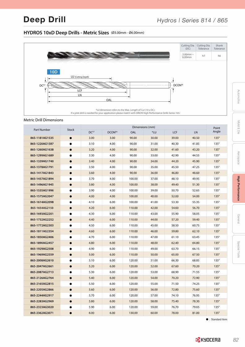
82
Autom
otiveA
erospaceH
igh Perform
anceG
eneralS
pecial ToolsM
old & D
ie
Deep Drill Hydros | Series 814 / 865
11
Cutting Dia.(DC)
Cutting Dia.Tolerance
ShankTolerance
3.00mm ~6.00mm h7 h6
HYDROS 10xD Deep Drills - Metric Sizes (Ø3.00mm - Ø6.00mm)
Metric Drill Dimensions
Part Number StockDimensions (mm) Point
AngleDCh7 DCONh6 OAL *LU LCF LN
865-1181AG1535 Þ 3.00 3.00 90.00 30.00 39.00 40.50 135°
865-1220AG1587 Þ 3.10 4.00 90.00 31.00 40.30 41.85 135°
865-1260AG1638 Þ 3.20 4.00 90.00 32.00 41.60 43.20 135°
865-1299AG1689 Þ 3.30 4.00 90.00 33.00 42.90 44.55 135°
865-1339AG1740 Þ 3.40 4.00 90.00 34.00 44.20 45.90 135°
865-1378AG1791 Þ 3.50 4.00 90.00 35.00 45.50 47.25 135°
865-1417AG1843 Þ 3.60 4.00 90.00 36.00 46.80 48.60 135°
865-1457AG1894 Þ 3.70 4.00 100.00 37.00 48.10 49.95 135°
865-1496AG1945 Þ 3.80 4.00 100.00 38.00 49.40 51.30 135°
865-1535AG1996 Þ 3.90 4.00 100.00 39.00 50.70 52.65 135°
865-1575AG2047 Þ 4.00 4.00 100.00 40.00 52.00 54.00 135°
865-1614AG2098 Þ 4.10 6.00 100.00 41.00 53.30 55.35 135°
865-1654AG2150 Þ 4.20 6.00 110.00 42.00 54.60 56.70 135°
865-1693AG2201 Þ 4.30 6.00 110.00 43.00 55.90 58.05 135°
865-1732AG2252 Þ 4.40 6.00 110.00 44.00 57.20 59.40 135°
865-1772AG2303 Þ 4.50 6.00 110.00 45.00 58.50 60.75 135°
865-1811AG2354 Þ 4.60 6.00 110.00 46.00 59.80 62.10 135°
865-1850AG2406 Þ 4.70 6.00 110.00 47.00 61.10 63.45 135°
865-1890AG2457 Þ 4.80 6.00 110.00 48.00 62.40 64.80 135°
865-1929AG2508 Þ 4.90 6.00 110.00 49.00 63.70 66.15 135°
865-1969AG2559 Þ 5.00 6.00 110.00 50.00 65.00 67.50 135°
865-2008AG2610 Þ 5.10 6.00 120.00 51.00 66.30 68.85 135°
865-2047AG2661 Þ 5.20 6.00 120.00 52.00 67.60 70.20 135°
865-2087AG2713 Þ 5.30 6.00 120.00 53.00 68.90 71.55 135°
865-2126AG2764 Þ 5.40 6.00 120.00 54.00 70.20 72.90 135°
865-2165AG2815 Þ 5.50 6.00 120.00 55.00 71.50 74.25 135°
865-2205AG2866 Þ 5.60 6.00 120.00 56.00 72.80 75.60 135°
865-2244AG2917 Þ 5.70 6.00 120.00 57.00 74.10 76.95 135°
865-2283AG2969 Þ 5.80 6.00 120.00 58.00 75.40 78.30 135°
865-2323AG3020 Þ 5.90 6.00 120.00 59.00 76.70 79.65 135°
865-2362AG3071 Þ 6.00 6.00 130.00 60.00 78.00 81.00 135°
*LU dimension refers to the Max. Length of Cut (10 x DC).If a pilot drill is needed for your application please match with ORION High Performance Drills Series 165.
Þ : Standard Item
10DLU (Cutting Depth)
DCh7 DCONh6
LCFLN
OAL
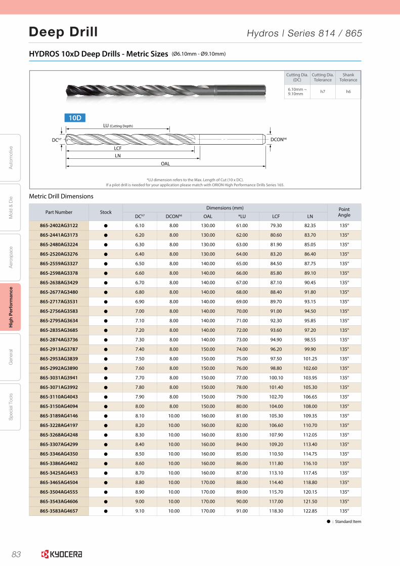
83
Aut
omot
ive
Aer
ospa
ceH
igh
Per
form
ance
Gen
eral
Spe
cial
Too
lsM
old
& D
ie
Deep Drill Hydros | Series 814 / 865
12
Cutting Dia.(DC)
Cutting Dia.Tolerance
ShankTolerance
6.10mm ~9.10mm h7 h6
HYDROS 10xD Deep Drills - Metric Sizes (Ø6.10mm - Ø9.10mm)
Metric Drill Dimensions
*LU dimension refers to the Max. Length of Cut (10 x DC).If a pilot drill is needed for your application please match with ORION High Performance Drills Series 165.
Þ : Standard Item
Part Number StockDimensions (mm) Point
AngleDCh7 DCONh6 OAL *LU LCF LN
865-2402AG3122 Þ 6.10 8.00 130.00 61.00 79.30 82.35 135°
865-2441AG3173 Þ 6.20 8.00 130.00 62.00 80.60 83.70 135°
865-2480AG3224 Þ 6.30 8.00 130.00 63.00 81.90 85.05 135°
865-2520AG3276 Þ 6.40 8.00 130.00 64.00 83.20 86.40 135°
865-2559AG3327 Þ 6.50 8.00 140.00 65.00 84.50 87.75 135°
865-2598AG3378 Þ 6.60 8.00 140.00 66.00 85.80 89.10 135°
865-2638AG3429 Þ 6.70 8.00 140.00 67.00 87.10 90.45 135°
865-2677AG3480 Þ 6.80 8.00 140.00 68.00 88.40 91.80 135°
865-2717AG3531 Þ 6.90 8.00 140.00 69.00 89.70 93.15 135°
865-2756AG3583 Þ 7.00 8.00 140.00 70.00 91.00 94.50 135°
865-2795AG3634 Þ 7.10 8.00 140.00 71.00 92.30 95.85 135°
865-2835AG3685 Þ 7.20 8.00 140.00 72.00 93.60 97.20 135°
865-2874AG3736 Þ 7.30 8.00 140.00 73.00 94.90 98.55 135°
865-2913AG3787 Þ 7.40 8.00 150.00 74.00 96.20 99.90 135°
865-2953AG3839 Þ 7.50 8.00 150.00 75.00 97.50 101.25 135°
865-2992AG3890 Þ 7.60 8.00 150.00 76.00 98.80 102.60 135°
865-3031AG3941 Þ 7.70 8.00 150.00 77.00 100.10 103.95 135°
865-3071AG3992 Þ 7.80 8.00 150.00 78.00 101.40 105.30 135°
865-3110AG4043 Þ 7.90 8.00 150.00 79.00 102.70 106.65 135°
865-3150AG4094 Þ 8.00 8.00 150.00 80.00 104.00 108.00 135°
865-3189AG4146 Þ 8.10 10.00 160.00 81.00 105.30 109.35 135°
865-3228AG4197 Þ 8.20 10.00 160.00 82.00 106.60 110.70 135°
865-3268AG4248 Þ 8.30 10.00 160.00 83.00 107.90 112.05 135°
865-3307AG4299 Þ 8.40 10.00 160.00 84.00 109.20 113.40 135°
865-3346AG4350 Þ 8.50 10.00 160.00 85.00 110.50 114.75 135°
865-3386AG4402 Þ 8.60 10.00 160.00 86.00 111.80 116.10 135°
865-3425AG4453 Þ 8.70 10.00 160.00 87.00 113.10 117.45 135°
865-3465AG4504 Þ 8.80 10.00 170.00 88.00 114.40 118.80 135°
865-3504AG4555 Þ 8.90 10.00 170.00 89.00 115.70 120.15 135°
865-3543AG4606 Þ 9.00 10.00 170.00 90.00 117.00 121.50 135°
865-3583AG4657 Þ 9.10 10.00 170.00 91.00 118.30 122.85 135°
10DLU (Cutting Depth)
DCh7 DCONh6
LCFLN
OAL
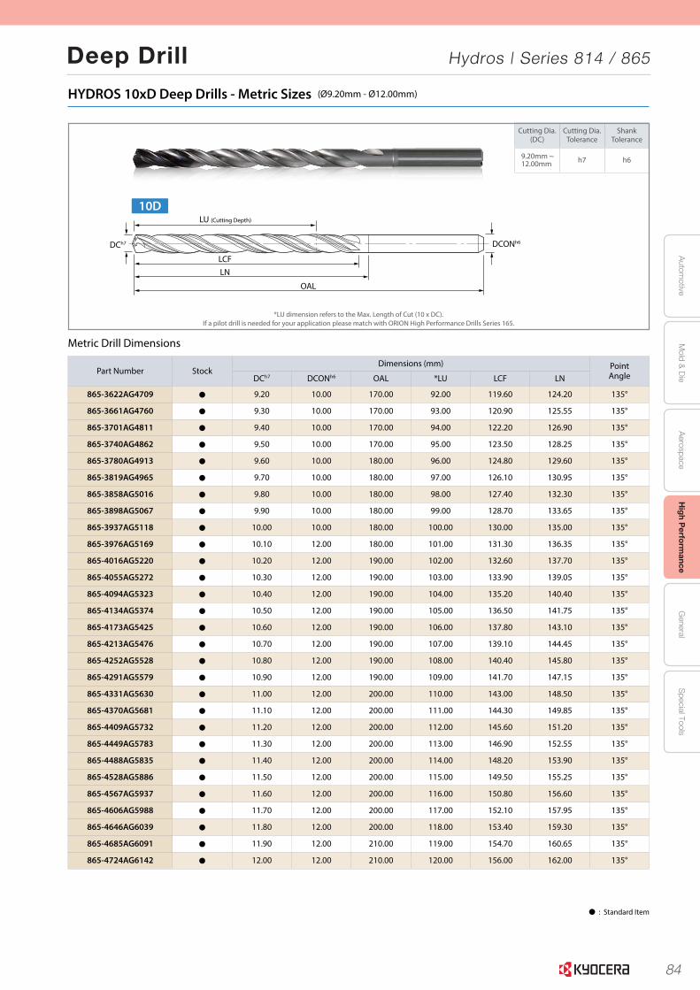
84
Autom
otiveA
erospaceH
igh Perform
anceG
eneralS
pecial ToolsM
old & D
ie
Deep Drill Hydros | Series 814 / 865
13
Cutting Dia.(DC)
Cutting Dia.Tolerance
ShankTolerance
9.20mm ~12.00mm h7 h6
HYDROS 10xD Deep Drills - Metric Sizes (Ø9.20mm - Ø12.00mm)
Metric Drill Dimensions
*LU dimension refers to the Max. Length of Cut (10 x DC).If a pilot drill is needed for your application please match with ORION High Performance Drills Series 165.
Þ : Standard Item
Part Number StockDimensions (mm) Point
AngleDCh7 DCONh6 OAL *LU LCF LN
865-3622AG4709 Þ 9.20 10.00 170.00 92.00 119.60 124.20 135°
865-3661AG4760 Þ 9.30 10.00 170.00 93.00 120.90 125.55 135°
865-3701AG4811 Þ 9.40 10.00 170.00 94.00 122.20 126.90 135°
865-3740AG4862 Þ 9.50 10.00 170.00 95.00 123.50 128.25 135°
865-3780AG4913 Þ 9.60 10.00 180.00 96.00 124.80 129.60 135°
865-3819AG4965 Þ 9.70 10.00 180.00 97.00 126.10 130.95 135°
865-3858AG5016 Þ 9.80 10.00 180.00 98.00 127.40 132.30 135°
865-3898AG5067 Þ 9.90 10.00 180.00 99.00 128.70 133.65 135°
865-3937AG5118 Þ 10.00 10.00 180.00 100.00 130.00 135.00 135°
865-3976AG5169 Þ 10.10 12.00 180.00 101.00 131.30 136.35 135°
865-4016AG5220 Þ 10.20 12.00 190.00 102.00 132.60 137.70 135°
865-4055AG5272 Þ 10.30 12.00 190.00 103.00 133.90 139.05 135°
865-4094AG5323 Þ 10.40 12.00 190.00 104.00 135.20 140.40 135°
865-4134AG5374 Þ 10.50 12.00 190.00 105.00 136.50 141.75 135°
865-4173AG5425 Þ 10.60 12.00 190.00 106.00 137.80 143.10 135°
865-4213AG5476 Þ 10.70 12.00 190.00 107.00 139.10 144.45 135°
865-4252AG5528 Þ 10.80 12.00 190.00 108.00 140.40 145.80 135°
865-4291AG5579 Þ 10.90 12.00 190.00 109.00 141.70 147.15 135°
865-4331AG5630 Þ 11.00 12.00 200.00 110.00 143.00 148.50 135°
865-4370AG5681 Þ 11.10 12.00 200.00 111.00 144.30 149.85 135°
865-4409AG5732 Þ 11.20 12.00 200.00 112.00 145.60 151.20 135°
865-4449AG5783 Þ 11.30 12.00 200.00 113.00 146.90 152.55 135°
865-4488AG5835 Þ 11.40 12.00 200.00 114.00 148.20 153.90 135°
865-4528AG5886 Þ 11.50 12.00 200.00 115.00 149.50 155.25 135°
865-4567AG5937 Þ 11.60 12.00 200.00 116.00 150.80 156.60 135°
865-4606AG5988 Þ 11.70 12.00 200.00 117.00 152.10 157.95 135°
865-4646AG6039 Þ 11.80 12.00 200.00 118.00 153.40 159.30 135°
865-4685AG6091 Þ 11.90 12.00 210.00 119.00 154.70 160.65 135°
865-4724AG6142 Þ 12.00 12.00 210.00 120.00 156.00 162.00 135°
10DLU (Cutting Depth)
DCh7 DCONh6
LCFLN
OAL
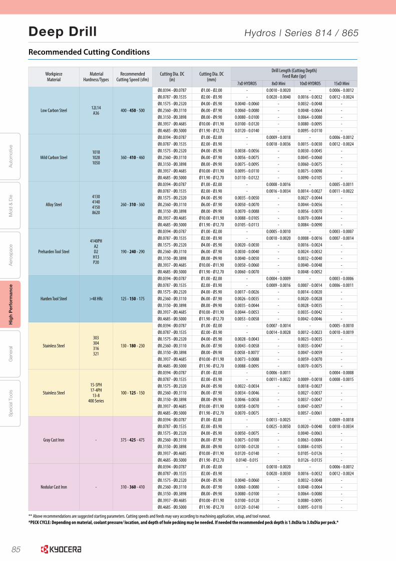
85
Aut
omot
ive
Aer
ospa
ceH
igh
Per
form
ance
Gen
eral
Spe
cial
Too
lsM
old
& D
ie
Deep Drill Hydros | Series 814 / 865
14
Recommended Cutting Conditions
** Above recommendations are suggested starting parameters. Cutting speeds and feeds may vary according to machining application, setup, and tool runout.*PECK CYCLE: Depending on material, coolant pressure/ location, and depth of hole pecking may be needed. If needed the recommended peck depth is 1.0xDia to 3.0xDia per peck.*
Workpiece Material
MaterialHardness/Types
RecommendedCutting Speed (sfm)
Cutting Dia. DC(in)
Cutting Dia. DC(mm)
Drill Length (Cutting Depth)Feed Rate (ipr)
7xD HYDROS 8xD Mini 10xD HYDROS 15xD Mini
Low Carbon Steel 12L14A36 400 - 450 - 500
Ø0.0394 - Ø0.0787 Ø1.00 - Ø2.00 - 0.0010 - 0.0020 - 0.0006 - 0.0012Ø0.0787 - Ø0.1535 Ø2.00 - Ø3.90 - 0.0020 - 0.0040 0.0016 - 0.0032 0.0012 - 0.0024Ø0.1575 - Ø0.2320 Ø4.00 - Ø5.90 0.0040 - 0.0060 - 0.0032 - 0.0048 -Ø0.2360 - Ø0.3110 Ø6.00 - Ø7.90 0.0060 - 0.0080 - 0.0048 - 0.0064 -Ø0.3150 - Ø0.3898 Ø8.00 - Ø9.90 0.0080 - 0.0100 - 0.0064 - 0.0080 -Ø0.3937 - Ø0.4685 Ø10.00 - Ø11.90 0.0100 - 0.0120 - 0.0080 - 0.0095 -Ø0.4685 - Ø0.5000 Ø11.90 - Ø12.70 0.0120 - 0.0140 - 0.0095 - 0.0110 -
Mild Carbon Steel101810281050
360 - 410 - 460
Ø0.0394 - Ø0.0787 Ø1.00 - Ø2.00 - 0.0009 - 0.0018 - 0.0006 - 0.0012Ø0.0787 - Ø0.1535 Ø2.00 - Ø3.90 - 0.0018 - 0.0036 0.0015 - 0.0030 0.0012 - 0.0024Ø0.1575 - Ø0.2320 Ø4.00 - Ø5.90 0.0038 - 0.0056 - 0.0030 - 0.0045 -Ø0.2360 - Ø0.3110 Ø6.00 - Ø7.90 0.0056 - 0.0075 - 0.0045 - 0.0060 -Ø0.3150 - Ø0.3898 Ø8.00 - Ø9.90 0.0075 - 0.0095 - 0.0060 - 0.0075 -Ø0.3937 - Ø0.4685 Ø10.00 - Ø11.90 0.0095 - 0.0110 - 0.0075 - 0.0090 -Ø0.4685 - Ø0.5000 Ø11.90 - Ø12.70 0.0110 - 0.0122 - 0.0090 - 0.0105 -
Alloy Steel
4130414041508620
260 - 310 - 360
Ø0.0394 - Ø0.0787 Ø1.00 - Ø2.00 - 0.0008 - 0.0016 - 0.0005 - 0.0011Ø0.0787 - Ø0.1535 Ø2.00 - Ø3.90 - 0.0016 - 0.0034 0.0014 - 0.0027 0.0011 - 0.0022Ø0.1575 - Ø0.2320 Ø4.00 - Ø5.90 0.0035 - 0.0050 - 0.0027 - 0.0044 -Ø0.2360 - Ø0.3110 Ø6.00 - Ø7.90 0.0050 - 0.0070 - 0.0044 - 0.0056 -Ø0.3150 - Ø0.3898 Ø8.00 - Ø9.90 0.0070 - 0.0088 - 0.0056 - 0.0070 -Ø0.3937 - Ø0.4685 Ø10.00 - Ø11.90 0.0088 - 0.0105 - 0.0070 - 0.0084 -Ø0.4685 - Ø0.5000 Ø11.90 - Ø12.70 0.0105 - 0.0113 - 0.0084 - 0.0090 -
Preharden Tool Steel
4140PHA2D2
H13P20
190 - 240 - 290
Ø0.0394 - Ø0.0787 Ø1.00 - Ø2.00 - 0.0005 - 0.0010 - 0.0003 - 0.0007Ø0.0787 - Ø0.1535 Ø2.00 - Ø3.90 - 0.0010 - 0.0020 0.0008 - 0.0016 0.0007 - 0.0014Ø0.1575 - Ø0.2320 Ø4.00 - Ø5.90 0.0020 - 0.0030 - 0.0016 - 0.0024 -Ø0.2360 - Ø0.3110 Ø6.00 - Ø7.90 0.0030 - 0.0040 - 0.0024 - 0.0032 -Ø0.3150 - Ø0.3898 Ø8.00 - Ø9.90 0.0040 - 0.0050 - 0.0032 - 0.0040 -Ø0.3937 - Ø0.4685 Ø10.00 - Ø11.90 0.0050 - 0.0060 - 0.0040 - 0.0048 -Ø0.4685 - Ø0.5000 Ø11.90 - Ø12.70 0.0060 - 0.0070 - 0.0048 - 0.0052 -
Harden Tool Steel >48 HRc 125 - 150 - 175
Ø0.0394 - Ø0.0787 Ø1.00 - Ø2.00 - 0.0004 - 0.0009 - 0.0003 - 0.0006Ø0.0787 - Ø0.1535 Ø2.00 - Ø3.90 - 0.0009 - 0.0016 0.0007 - 0.0014 0.0006 - 0.0011Ø0.1575 - Ø0.2320 Ø4.00 - Ø5.90 0.0017 - 0.0026 - 0.0014 - 0.0020 -Ø0.2360 - Ø0.3110 Ø6.00 - Ø7.90 0.0026 - 0.0035 - 0.0020 - 0.0028 -Ø0.3150 - Ø0.3898 Ø8.00 - Ø9.90 0.0035 - 0.0044 - 0.0028 - 0.0035 -Ø0.3937 - Ø0.4685 Ø10.00 - Ø11.90 0.0044 - 0.0053 - 0.0035 - 0.0042 -Ø0.4685 - Ø0.5000 Ø11.90 - Ø12.70 0.0053 - 0.0058 - 0.0042 - 0.0046 -
Stainless Steel
303304316321
130 - 180 - 230
Ø0.0394 - Ø0.0787 Ø1.00 - Ø2.00 - 0.0007 - 0.0014 - 0.0005 - 0.0010Ø0.0787 - Ø0.1535 Ø2.00 - Ø3.90 - 0.0014 - 0.0028 0.0012 - 0.0023 0.0010 - 0.0019Ø0.1575 - Ø0.2320 Ø4.00 - Ø5.90 0.0028 - 0.0043 - 0.0023 - 0.0035 -Ø0.2360 - Ø0.3110 Ø6.00 - Ø7.90 0.0043 - 0.0058 - 0.0035 - 0.0047 -Ø0.3150 - Ø0.3898 Ø8.00 - Ø9.90 0.0058 - 0.0073' - 0.0047 - 0.0059 -Ø0.3937 - Ø0.4685 Ø10.00 - Ø11.90 0.0073 - 0.0088 - 0.0059 - 0.0070 -Ø0.4685 - Ø0.5000 Ø11.90 - Ø12.70 0.0088 - 0.0095 - 0.0070 - 0.0075 -
Stainless Steel
15-5PH17-4PH
13-8400 Series
100 - 125 - 150
Ø0.0394 - Ø0.0787 Ø1.00 - Ø2.00 - 0.0006 - 0.0011 - 0.0004 - 0.0008Ø0.0787 - Ø0.1535 Ø2.00 - Ø3.90 - 0.0011 - 0.0022 0.0009 - 0.0018 0.0008 - 0.0015Ø0.1575 - Ø0.2320 Ø4.00 - Ø5.90 0.0022 - 0.0034 - 0.0018 - 0.0027 -Ø0.2360 - Ø0.3110 Ø6.00 - Ø7.90 0.0034 - 0.0046 - 0.0027 - 0.0037 -Ø0.3150 - Ø0.3898 Ø8.00 - Ø9.90 0.0046 - 0.0058 - 0.0037 - 0.0047 -Ø0.3937 - Ø0.4685 Ø10.00 - Ø11.90 0.0058 - 0.0070 - 0.0047 - 0.0057 -Ø0.4685 - Ø0.5000 Ø11.90 - Ø12.70 0.0070 - 0.0075 - 0.0057 - 0.0061 -
Gray Cast Iron - 375 - 425 - 475
Ø0.0394 - Ø0.0787 Ø1.00 - Ø2.00 - 0.0013 - 0.0025 - 0.0009 - 0.0018Ø0.0787 - Ø0.1535 Ø2.00 - Ø3.90 - 0.0025 - 0.0050 0.0020 - 0.0040 0.0018 - 0.0034Ø0.1575 - Ø0.2320 Ø4.00 - Ø5.90 0.0050 - 0.0075 - 0.0040 - 0.0063 -Ø0.2360 - Ø0.3110 Ø6.00 - Ø7.90 0.0075 - 0.0100 - 0.0063 - 0.0084 -Ø0.3150 - Ø0.3898 Ø8.00 - Ø9.90 0.0100 - 0.0120 - 0.0084 - 0.0105 -Ø0.3937 - Ø0.4685 Ø10.00 - Ø11.90 0.0120 - 0.0140 - 0.0105 - 0.0126 -Ø0.4685 - Ø0.5000 Ø11.90 - Ø12.70 0.0140 - 0.015 - 0.0126 - 0.0135 -
Nodular Cast Iron - 310 - 360 - 410
Ø0.0394 - Ø0.0787 Ø1.00 - Ø2.00 - 0.0010 - 0.0020 - 0.0006 - 0.0012Ø0.0787 - Ø0.1535 Ø2.00 - Ø3.90 - 0.0020 - 0.0030 0.0016 - 0.0032 0.0012 - 0.0024Ø0.1575 - Ø0.2320 Ø4.00 - Ø5.90 0.0040 - 0.0060 - 0.0032 - 0.0048 -Ø0.2360 - Ø0.3110 Ø6.00 - Ø7.90 0.0060 - 0.0080 - 0.0048 - 0.0064 -Ø0.3150 - Ø0.3898 Ø8.00 - Ø9.90 0.0080 - 0.0100 - 0.0064 - 0.0080 -Ø0.3937 - Ø0.4685 Ø10.00 - Ø11.90 0.0100 - 0.0120 - 0.0080 - 0.0095 -Ø0.4685 - Ø0.5000 Ø11.90 - Ø12.70 0.0120 - 0.0140 - 0.0095 - 0.0110 -
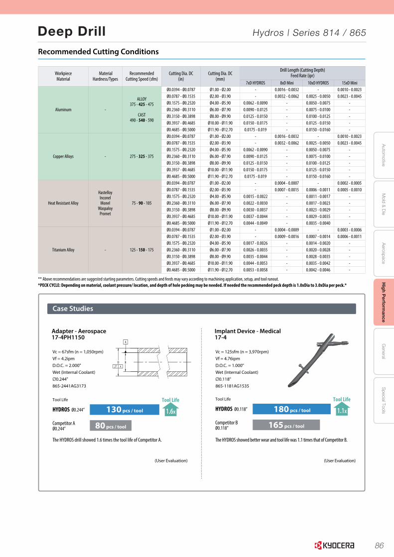
86
Autom
otiveA
erospaceH
igh Perform
anceG
eneralS
pecial ToolsM
old & D
ie
Deep Drill Hydros | Series 814 / 865
15
Tool Life
HYDROS Ø0.118”
Competitor BØ0.118” 165 pcs / tool
180 pcs / tool 1.1x
Tool Life
D BA
A
Tool LIfe
130 pcs / tool
80 pcs / tool
HYDROS Ø0.244”
Competitor AØ0.244”
1.6x
Tool Life
Case Studies
Vc = 67sfm (n = 1,050rpm)Vf = 4.2ipmD.O.C. = 2.000"Wet (Internal Coolant)Ø0.244"865-2441AG3173
Vc = 125sfm (n = 3,970rpm)Vf = 4.76ipmD.O.C. = 1.000"Wet (Internal Coolant)Ø0.118"865-1181AG1535
The HYDROS showed better wear and tool life was 1.1 times that of Competitor B.
(User Evaluation)
The HYDROS drill showed 1.6 times the tool life of Competitor A.
(User Evaluation)
Adapter - Aerospace17-4PH1150
Implant Device - Medical17-4
Recommended Cutting Conditions
** Above recommendations are suggested starting parameters. Cutting speeds and feeds may vary according to machining application, setup, and tool runout.*PECK CYCLE: Depending on material, coolant pressure/ location, and depth of hole pecking may be needed. If needed the recommended peck depth is 1.0xDia to 3.0xDia per peck.*
Workpiece Material
MaterialHardness/Types
RecommendedCutting Speed (sfm)
Cutting Dia. DC(in)
Cutting Dia. DC(mm)
Drill Length (Cutting Depth)Feed Rate (ipr)
7xD HYDROS 8xD Mini 10xD HYDROS 15xD Mini
Aluminum -
ALLOY375 - 425 - 475
CAST490 - 540 - 590
Ø0.0394 - Ø0.0787 Ø1.00 - Ø2.00 - 0.0016 - 0.0032 - 0.0010 - 0.0023Ø0.0787 - Ø0.1535 Ø2.00 - Ø3.90 - 0.0032 - 0.0062 0.0025 - 0.0050 0.0023 - 0.0045Ø0.1575 - Ø0.2320 Ø4.00 - Ø5.90 0.0062 - 0.0090 - 0.0050 - 0.0075 -Ø0.2360 - Ø0.3110 Ø6.00 - Ø7.90 0.0090 - 0.0125 - 0.0075 - 0.0100 -Ø0.3150 - Ø0.3898 Ø8.00 - Ø9.90 0.0125 - 0.0150 - 0.0100 - 0.0125 -Ø0.3937 - Ø0.4685 Ø10.00 - Ø11.90 0.0150 - 0.0175 - 0.0125 - 0.0150 -Ø0.4685 - Ø0.5000 Ø11.90 - Ø12.70 0.0175 - 0.019 - 0.0150 - 0.0160 -
Copper Alloys - 275 - 325 - 375
Ø0.0394 - Ø0.0787 Ø1.00 - Ø2.00 - 0.0016 - 0.0032 - 0.0010 - 0.0023Ø0.0787 - Ø0.1535 Ø2.00 - Ø3.90 - 0.0032 - 0.0062 0.0025 - 0.0050 0.0023 - 0.0045Ø0.1575 - Ø0.2320 Ø4.00 - Ø5.90 0.0062 - 0.0090 - 0.0050 - 0.0075 -Ø0.2360 - Ø0.3110 Ø6.00 - Ø7.90 0.0090 - 0.0125 - 0.0075 - 0.0100 -Ø0.3150 - Ø0.3898 Ø8.00 - Ø9.90 0.0125 - 0.0150 - 0.0100 - 0.0125 -Ø0.3937 - Ø0.4685 Ø10.00 - Ø11.90 0.0150 - 0.0175 - 0.0125 - 0.0150 -Ø0.4685 - Ø0.5000 Ø11.90 - Ø12.70 0.0175 - 0.019 - 0.0150 - 0.0160 -
Heat Resistant Alloy
HastelloyInconelMonel
WaspaloyPromet
75 - 90 - 105
Ø0.0394 - Ø0.0787 Ø1.00 - Ø2.00 - 0.0004 - 0.0007 - 0.0002 - 0.0005Ø0.0787 - Ø0.1535 Ø2.00 - Ø3.90 - 0.0007 - 0.0015 0.0006 - 0.0011 0.0005 - 0.0010Ø0.1575 - Ø0.2320 Ø4.00 - Ø5.90 0.0015 - 0.0022 - 0.0011 - 0.0017 -Ø0.2360 - Ø0.3110 Ø6.00 - Ø7.90 0.0022 - 0.0030 - 0.0017 - 0.0023 -Ø0.3150 - Ø0.3898 Ø8.00 - Ø9.90 0.0030 - 0.0037 - 0.0023 - 0.0029 -Ø0.3937 - Ø0.4685 Ø10.00 - Ø11.90 0.0037 - 0.0044 - 0.0029 - 0.0035 -Ø0.4685 - Ø0.5000 Ø11.90 - Ø12.70 0.0044 - 0.0049 - 0.0035 - 0.0040 -
Titanium Alloy - 125 - 150 - 175
Ø0.0394 - Ø0.0787 Ø1.00 - Ø2.00 - 0.0004 - 0.0009 - 0.0003 - 0.0006Ø0.0787 - Ø0.1535 Ø2.00 - Ø3.90 - 0.0009 - 0.0016 0.0007 - 0.0014 0.0006 - 0.0011Ø0.1575 - Ø0.2320 Ø4.00 - Ø5.90 0.0017 - 0.0026 - 0.0014 - 0.0020 -Ø0.2360 - Ø0.3110 Ø6.00 - Ø7.90 0.0026 - 0.0035 - 0.0020 - 0.0028 -Ø0.3150 - Ø0.3898 Ø8.00 - Ø9.90 0.0035 - 0.0044 - 0.0028 - 0.0035 -Ø0.3937 - Ø0.4685 Ø10.00 - Ø11.90 0.0044 - 0.0053 - 0.0035 - 0.0042 -Ø0.4685 - Ø0.5000 Ø11.90 - Ø12.70 0.0053 - 0.0058 - 0.0042 - 0.0046 -
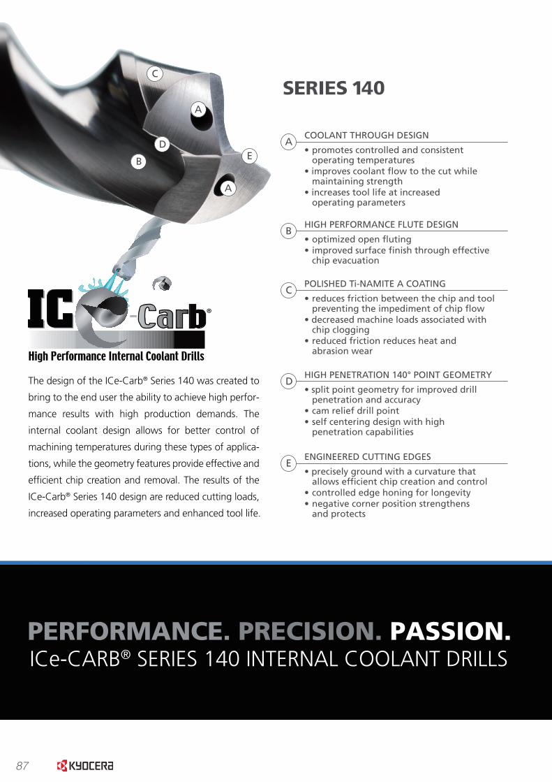
87
www.kyocera-sgstool.com
A
A
B
C
DE
The cutting edges of the ICe-Carb® Series 140 are designed to allow the tool to achieve high penetration rates,
while the highly polished Ti-NAMITE A tool coating allows the chips to move smoothly along the �ute and out of
the cut. This helps to avoid chip clogging often associated with elevated penetration rates. Through ef�cient chip
creation and movement, the drill operates at lower loads under identical conditions.
PERFORMANCE.
PERFORMANCE. PRECISION. PASSION.ICe-CARB® SERIES 140 INTERNAL COOLANT DRILLS
The design of the ICe-Carb® Series 140 was created to
bring to the end user the ability to achieve high perfor-
mance results with high production demands. The
internal coolant design allows for better control of
machining temperatures during these types of applica-
tions, while the geometry features provide effective and
ef�cient chip creation and removal. The results of the
ICe-Carb® Series 140 design are reduced cutting loads,
increased operating parameters and enhanced tool life.
COOLANT THROUGH DESIGN
• promotes controlled and consistent operating temperatures• improves coolant �ow to the cut while maintaining strength• increases tool life at increased operating parameters
A
SERIES 140
BHIGH PERFORMANCE FLUTE DESIGN
• optimized open �uting • improved surface �nish through effective chip evacuation
CPOLISHED Ti-NAMITE A COATING
• reduces friction between the chip and tool preventing the impediment of chip �ow• decreased machine loads associated with chip clogging• reduced friction reduces heat and abrasion wear
DHIGH PENETRATION 140° POINT GEOMETRY
• split point geometry for improved drill penetration and accuracy• cam relief drill point • self centering design with high penetration capabilities
EENGINEERED CUTTING EDGES
• precisely ground with a curvature that allows ef�cient chip creation and control• controlled edge honing for longevity• negative corner position strengthens and protects
TORQUE COMPARISON8620 Carbon Steel @ 175 BHN3/8” Diameter 1.125” Deep350 sfm / 29 ipm
0
10
20
30
40
50
60
70
Unpolished Polished
TOR
QU
E (i
n–l
bs)
20% LESSTORQUE
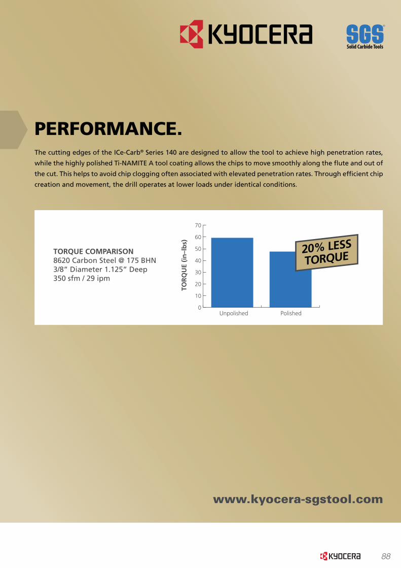
88
www.kyocera-sgstool.com
A
A
B
C
DE
The cutting edges of the ICe-Carb® Series 140 are designed to allow the tool to achieve high penetration rates,
while the highly polished Ti-NAMITE A tool coating allows the chips to move smoothly along the �ute and out of
the cut. This helps to avoid chip clogging often associated with elevated penetration rates. Through ef�cient chip
creation and movement, the drill operates at lower loads under identical conditions.
PERFORMANCE.
PERFORMANCE. PRECISION. PASSION.ICe-CARB® SERIES 140 INTERNAL COOLANT DRILLS
The design of the ICe-Carb® Series 140 was created to
bring to the end user the ability to achieve high perfor-
mance results with high production demands. The
internal coolant design allows for better control of
machining temperatures during these types of applica-
tions, while the geometry features provide effective and
ef�cient chip creation and removal. The results of the
ICe-Carb® Series 140 design are reduced cutting loads,
increased operating parameters and enhanced tool life.
COOLANT THROUGH DESIGN
• promotes controlled and consistent operating temperatures• improves coolant �ow to the cut while maintaining strength• increases tool life at increased operating parameters
A
SERIES 140
BHIGH PERFORMANCE FLUTE DESIGN
• optimized open �uting • improved surface �nish through effective chip evacuation
CPOLISHED Ti-NAMITE A COATING
• reduces friction between the chip and tool preventing the impediment of chip �ow• decreased machine loads associated with chip clogging• reduced friction reduces heat and abrasion wear
DHIGH PENETRATION 140° POINT GEOMETRY
• split point geometry for improved drill penetration and accuracy• cam relief drill point • self centering design with high penetration capabilities
EENGINEERED CUTTING EDGES
• precisely ground with a curvature that allows ef�cient chip creation and control• controlled edge honing for longevity• negative corner position strengthens and protects
TORQUE COMPARISON8620 Carbon Steel @ 175 BHN3/8” Diameter 1.125” Deep350 sfm / 29 ipm
0
10
20
30
40
50
60
70
Unpolished Polished
TOR
QU
E (i
n–l
bs)
20% LESSTORQUE

89
www.kyocera-sgstool.com
SPEED (RPM) 1600
FEED (IPM) 9.6
HOLE DIAMETER 9.1mm (.3583)
HOLE DEPTH 3.3”
COOLANT PRESSURE 60 psi (BELOW RECOMMENDATIONS)
TYPE OF COOLANT WATER SOLUBLE
TYPE OF MACHINE CNC LATHE – LIVE PART
ICe-CARB® SERIES 140 8xD VS. COMPETITOR 1ACTUAL CUSTOMER TEST IN 17-4 PH STAINLESS STEEL @ 36 HRc
PRECISION.The more ef�cient a drill can function, the more precise the results it can produce. The symmetrical grind of the
cam relieved point ensures balanced pressure during cutting, while the split point design ensures fast and accu-
rate engagement into the material. Precision must be maintained throughout the life of the drill, so the ICe-Carb®
Series 140 specialized hone, strong margin design and negative corner position help to delay the wear that often
causes a drill to lose precision in the cut and prematurely end tool life.
PASSION.Controlling temperatures during the cutting process certainly helps to improve the operating parameters and tool
life a tool is capable of achieving. All of the high performance features of the ICe-Carb® Series 140 are engineered
to work together to create the
most ef�cient total cutting
performance beyond what simply
having coolant through the tool
can offer. The �ute pro�le com-
pliments the coolant through
design of the ICe-Carb® Series
140 to create a strong cutting
tool that effectively transports
the chips being created, while
the cutting edges offer a balance
of strength and shear.
COST PER PART
$1.50$0.50$– $1.00
Competitor 1
ICe-Carb® Series 140
TOOL LIFE
NUMBER OF HOLES5004003002001000
ICe-Carb® Series 140
Competitor 1
DRILL SIZE 3/8” (.3750)
DEPTH OF HOLE 1.875”
MATERIAL 316 STAINLESS STEEL @ 140 BHN
SPEED 1430 RPM (140 sfm)
FEED 8.5 IPM (.0059 ipr)
COOLANT 8% WATER SOLUBLE @ 700 psi
MACHINE HAAS VF-3 VMC
TYPE OF HOLE BLIND
ICe-CARB® SERIES 140 VS. 2 COMPETITORS
CONDITION OF DRILLS AFTER 175 HOLES
ICe-CARB® SERIES 140 COMPETITOR 1 COMPETITOR 2
FIRST HOLE LAST HOLE FIRST HOLE LAST HOLE FIRST HOLE LAST HOLE
No damage found, good condition to continue using;.375” Ø throughout depth
with good �nish
Point severely chipped with wear on margins; Coating
loss below cutting lips; .375”Ø held but surface �nish
deteriorating
Better condition thanCompetitor 1 but unacceptable
holes; Holes out of round, oversized to .385” Ø and tapered to .392” Ø with
heavy swirl marks
www.kyocera-sgstool.com

90
www.kyocera-sgstool.com
SPEED (RPM) 1600
FEED (IPM) 9.6
HOLE DIAMETER 9.1mm (.3583)
HOLE DEPTH 3.3”
COOLANT PRESSURE 60 psi (BELOW RECOMMENDATIONS)
TYPE OF COOLANT WATER SOLUBLE
TYPE OF MACHINE CNC LATHE – LIVE PART
ICe-CARB® SERIES 140 8xD VS. COMPETITOR 1ACTUAL CUSTOMER TEST IN 17-4 PH STAINLESS STEEL @ 36 HRc
PRECISION.The more ef�cient a drill can function, the more precise the results it can produce. The symmetrical grind of the
cam relieved point ensures balanced pressure during cutting, while the split point design ensures fast and accu-
rate engagement into the material. Precision must be maintained throughout the life of the drill, so the ICe-Carb®
Series 140 specialized hone, strong margin design and negative corner position help to delay the wear that often
causes a drill to lose precision in the cut and prematurely end tool life.
PASSION.Controlling temperatures during the cutting process certainly helps to improve the operating parameters and tool
life a tool is capable of achieving. All of the high performance features of the ICe-Carb® Series 140 are engineered
to work together to create the
most ef�cient total cutting
performance beyond what simply
having coolant through the tool
can offer. The �ute pro�le com-
pliments the coolant through
design of the ICe-Carb® Series
140 to create a strong cutting
tool that effectively transports
the chips being created, while
the cutting edges offer a balance
of strength and shear.
COST PER PART
$1.50$0.50$– $1.00
Competitor 1
ICe-Carb® Series 140
TOOL LIFE
NUMBER OF HOLES5004003002001000
ICe-Carb® Series 140
Competitor 1
DRILL SIZE 3/8” (.3750)
DEPTH OF HOLE 1.875”
MATERIAL 316 STAINLESS STEEL @ 140 BHN
SPEED 1430 RPM (140 sfm)
FEED 8.5 IPM (.0059 ipr)
COOLANT 8% WATER SOLUBLE @ 700 psi
MACHINE HAAS VF-3 VMC
TYPE OF HOLE BLIND
ICe-CARB® SERIES 140 VS. 2 COMPETITORS
CONDITION OF DRILLS AFTER 175 HOLES
ICe-CARB® SERIES 140 COMPETITOR 1 COMPETITOR 2
FIRST HOLE LAST HOLE FIRST HOLE LAST HOLE FIRST HOLE LAST HOLE
No damage found, good condition to continue using;.375” Ø throughout depth
with good �nish
Point severely chipped with wear on margins; Coating
loss below cutting lips; .375”Ø held but surface �nish
deteriorating
Better condition thanCompetitor 1 but unacceptable
holes; Holes out of round, oversized to .385” Ø and tapered to .392” Ø with
heavy swirl marks
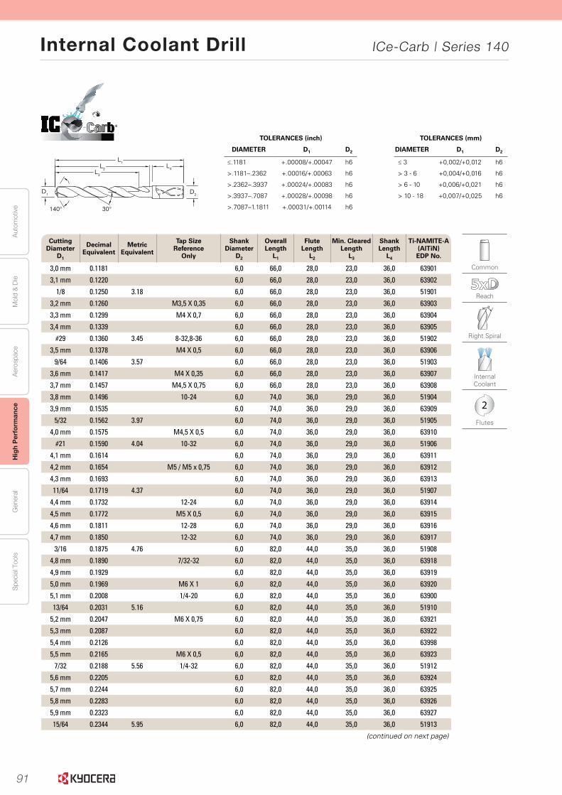
91
Aut
omot
ive
Aer
ospa
ceH
igh
Per
form
ance
Gen
eral
Spe
cial
Too
lsM
old
& D
ie
Internal Coolant Drill ICe-Carb | Series 140
52
Seri
es
140 5
xD
|
Frac
tio
nal
& M
etri
c
www.kyocera-sgstool.com
TOLERANCES (inch)
DIAMETER D1 D2
≤.1181 +.00008/+.00047 h6
>.1181–.2362 +.00016/+.00063 h6
>.2362–.3937 +.00024/+.00083 h6
>.3937–.7087 +.00028/+.00098 h6
>.7087–1.1811 +.00031/+.00114 h6
TOLERANCES (mm)
DIAMETER D1 D2
≤ 3 +0,002/+0,012 h6
> 3 - 6 +0,004/+0,016 h6
> 6 - 10 +0,006/+0,021 h6
> 10 - 18 +0,007/+0,025 h6
®
Common
Reach
Right Spiral
Internal Coolant
2
Flutes
Cutting Diameter
D1
Decimal Equivalent
Metric Equivalent
Tap Size Reference
Only
Shank Diameter
D2
Overall Length
L1
Flute Length
L2
Min. ClearedLength
L3
Shank Length
L4
Ti-NAMITE-A (AlTiN) EDP No.
3,0 mm 0.1181 6,0 66,0 28,0 23,0 36,0 63901
3,1 mm 0.1220 6,0 66,0 28,0 23,0 36,0 63902
1/8 0.1250 3.18 6,0 66,0 28,0 23,0 36,0 51901
3,2 mm 0.1260 M3,5 X 0,35 6,0 66,0 28,0 23,0 36,0 63903
3,3 mm 0.1299 M4 X 0,7 6,0 66,0 28,0 23,0 36,0 63904
3,4 mm 0.1339 6,0 66,0 28,0 23,0 36,0 63905
#29 0.1360 3.45 8-32,8-36 6,0 66,0 28,0 23,0 36,0 51902
3,5 mm 0.1378 M4 X 0,5 6,0 66,0 28,0 23,0 36,0 63906
9/64 0.1406 3.57 6,0 66,0 28,0 23,0 36,0 51903
3,6 mm 0.1417 M4 X 0,35 6,0 66,0 28,0 23,0 36,0 63907
3,7 mm 0.1457 M4,5 X 0,75 6,0 66,0 28,0 23,0 36,0 63908
3,8 mm 0.1496 10-24 6,0 74,0 36,0 29,0 36,0 51904
3,9 mm 0.1535 6,0 74,0 36,0 29,0 36,0 63909
5/32 0.1562 3.97 6,0 74,0 36,0 29,0 36,0 51905
4,0 mm 0.1575 M4,5 X 0,5 6,0 74,0 36,0 29,0 36,0 63910
#21 0.1590 4.04 10-32 6,0 74,0 36,0 29,0 36,0 51906
4,1 mm 0.1614 6,0 74,0 36,0 29,0 36,0 63911
4,2 mm 0.1654 M5 / M5 x 0,75 6,0 74,0 36,0 29,0 36,0 63912
4,3 mm 0.1693 6,0 74,0 36,0 29,0 36,0 63913
11/64 0.1719 4.37 6,0 74,0 36,0 29,0 36,0 51907
4,4 mm 0.1732 12-24 6,0 74,0 36,0 29,0 36,0 63914
4,5 mm 0.1772 M5 X 0,5 6,0 74,0 36,0 29,0 36,0 63915
4,6 mm 0.1811 12-28 6,0 74,0 36,0 29,0 36,0 63916
4,7 mm 0.1850 12-32 6,0 74,0 36,0 29,0 36,0 63917
3/16 0.1875 4.76 6,0 82,0 44,0 35,0 36,0 51908
4,8 mm 0.1890 7/32-32 6,0 82,0 44,0 35,0 36,0 63918
4,9 mm 0.1929 6,0 82,0 44,0 35,0 36,0 63919
5,0 mm 0.1969 M6 X 1 6,0 82,0 44,0 35,0 36,0 63920
5,1 mm 0.2008 1/4-20 6,0 82,0 44,0 35,0 36,0 63900
13/64 0.2031 5.16 6,0 82,0 44,0 35,0 36,0 51910
5,2 mm 0.2047 M6 X 0,75 6,0 82,0 44,0 35,0 36,0 63921
5,3 mm 0.2087 6,0 82,0 44,0 35,0 36,0 63922
5,4 mm 0.2126 6,0 82,0 44,0 35,0 36,0 63998
5,5 mm 0.2165 M6 X 0,5 6,0 82,0 44,0 35,0 36,0 63923
7/32 0.2188 5.56 1/4-32 6,0 82,0 44,0 35,0 36,0 51912
5,6 mm 0.2205 6,0 82,0 44,0 35,0 36,0 63924
5,7 mm 0.2244 6,0 82,0 44,0 35,0 36,0 63925
5,8 mm 0.2283 6,0 82,0 44,0 35,0 36,0 63926
5,9 mm 0.2323 6,0 82,0 44,0 35,0 36,0 63927
15/64 0.2344 5.95 6,0 82,0 44,0 35,0 36,0 51913
(continued on next page)
30°140°
L1L2
L3
L4
D2D1
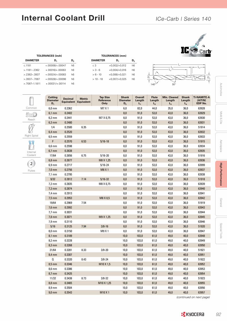
92
Autom
otiveA
erospaceH
igh Perform
anceG
eneralS
pecial ToolsM
old & D
ie
Internal Coolant Drill ICe-Carb | Series 140
53
Serie
s 140 5
xD
|
Fraction
al & M
etric
www.kyocera-sgstool.com
TOLERANCES (inch)
DIAMETER D1 D2
≤.1181 +.00008/+.00047 h6
>.1181–.2362 +.00016/+.00063 h6
>.2362–.3937 +.00024/+.00083 h6
>.3937–.7087 +.00028/+.00098 h6
>.7087–1.1811 +.00031/+.00114 h6
TOLERANCES (mm)
DIAMETER D1 D2
≤ 3 +0,002/+0,012 h6
> 3 - 6 +0,004/+0,016 h6
> 6 - 10 +0,006/+0,021 h6
> 10 - 18 +0,007/+0,025 h6
®
Common
Reach
Right Spiral
Internal Coolant
2
Flutes
Cutting Diameter
D1
Decimal Equivalent
Metric Equivalent
Tap Size Reference
Only
Shank Diameter
D2
Overall Length
L1
Flute Length
L2
Min. ClearedLength
L3
Shank Length
L4
Ti-NAMITE-A (AlTiN) EDP No.
6,0 mm 0.2362 M7 X 1 6,0 82,0 44,0 35,0 36,0 63928
6,1 mm 0.2402 8,0 91,0 53,0 43,0 36,0 63929
6,2 mm 0.2441 M7 X 0,75 8,0 91,0 53,0 43,0 36,0 63930
6,3 mm 0.2480 8,0 91,0 53,0 43,0 36,0 63931
1/4 0.2500 6.35 8,0 91,0 53,0 43,0 36,0 51914
6,4 mm 0.2520 8,0 91,0 53,0 43,0 36,0 63932
6,5 mm 0.2559 8,0 91,0 53,0 43,0 36,0 63933
F 0.2570 6.53 5/16-18 8,0 91,0 53,0 43,0 36,0 51915
6,6 mm 0.2598 8,0 91,0 53,0 43,0 36,0 63934
6,7 mm 0.2638 8,0 91,0 53,0 43,0 36,0 63935
17/64 0.2656 6.75 5/16-20 8,0 91,0 53,0 43,0 36,0 51916
6,8 mm 0.2677 M8 X 1,25 8,0 91,0 53,0 43,0 36,0 63936
6,9 mm 0.2717 5/16-24 8,0 91,0 53,0 43,0 36,0 63999
7,0 mm 0.2756 M8 X 1 8,0 91,0 53,0 43,0 36,0 63937
7,1 mm 0.2795 8,0 91,0 53,0 43,0 36,0 63938
9/32 0.2812 7.14 5/16-32 8,0 91,0 53,0 43,0 36,0 51918
7,2 mm 0.2835 M8 X 0,75 8,0 91,0 53,0 43,0 36,0 63939
7,3 mm 0.2874 8,0 91,0 53,0 43,0 36,0 63940
7,4 mm 0.2913 8,0 91,0 53,0 43,0 36,0 63941
7,5 mm 0.2953 M8 X 0,5 8,0 91,0 53,0 43,0 36,0 63942
19/64 0.2969 7.54 8,0 91,0 53,0 43,0 36,0 51919
7,6 mm 0.2992 8,0 91,0 53,0 43,0 36,0 63943
7,7 mm 0.3031 8,0 91,0 53,0 43,0 36,0 63944
7,8 mm 0.3071 M9 X 1,25 8,0 91,0 53,0 43,0 36,0 63945
7,9 mm 0.3110 8,0 91,0 53,0 43,0 36,0 63946
5/16 0.3125 7.94 3/8-16 8,0 91,0 53,0 43,0 36,0 51920
8,0 mm 0.3150 M9 X 1 8,0 91,0 53,0 43,0 36,0 63947
8,1 mm 0.3189 10,0 103,0 61,0 49,0 40,0 63948
8,2 mm 0.3228 10,0 103,0 61,0 49,0 40,0 63949
8,3 mm 0.3268 10,0 103,0 61,0 49,0 40,0 63950
21/64 0.3281 8.33 3/8-20 10,0 103,0 61,0 49,0 40,0 51921
8,4 mm 0.3307 10,0 103,0 61,0 49,0 40,0 63951
Q 0.3320 8.43 3/8-24 10,0 103,0 61,0 49,0 40,0 51922
8,5 mm 0.3346 M10 X 1,5 10,0 103,0 61,0 49,0 40,0 63952
8,6 mm 0.3386 10,0 103,0 61,0 49,0 40,0 63953
8,7 mm 0.3425 10,0 103,0 61,0 49,0 40,0 63954
11/32 0.3438 8.73 3/8-32 10,0 103,0 61,0 49,0 40,0 51923
8,8 mm 0.3465 M10 X 1,25 10,0 103,0 61,0 49,0 40,0 63955
8,9 mm 0.3504 10,0 103,0 61,0 49,0 40,0 63956
9,0 mm 0.3543 M10 X 1 10,0 103,0 61,0 49,0 40,0 63957
(continued on next page)
30°140°
L1L2
L3
L4
D2D1
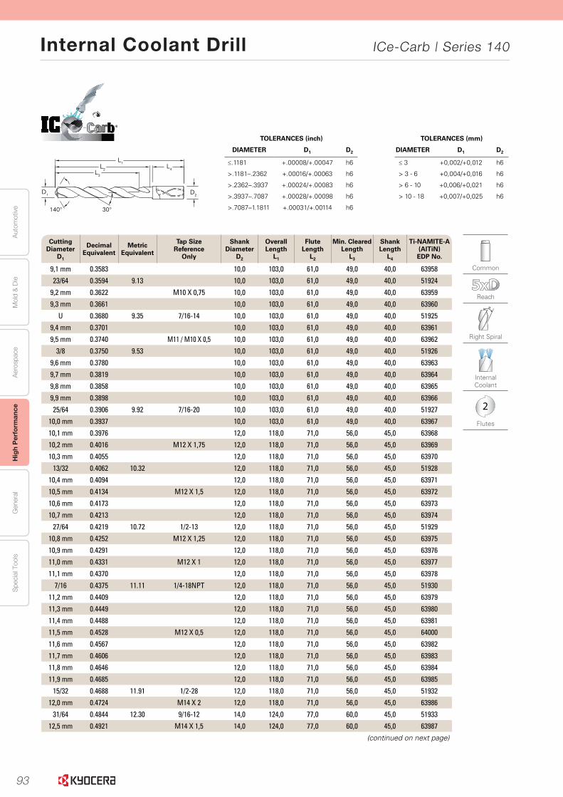
93
Aut
omot
ive
Aer
ospa
ceH
igh
Per
form
ance
Gen
eral
Spe
cial
Too
lsM
old
& D
ie
Internal Coolant Drill ICe-Carb | Series 140
54
Seri
es
140 5
xD
|
Frac
tio
nal
& M
etri
c
www.kyocera-sgstool.com
TOLERANCES (inch)
DIAMETER D1 D2
≤.1181 +.00008/+.00047 h6
>.1181–.2362 +.00016/+.00063 h6
>.2362–.3937 +.00024/+.00083 h6
>.3937–.7087 +.00028/+.00098 h6
>.7087–1.1811 +.00031/+.00114 h6
TOLERANCES (mm)
DIAMETER D1 D2
≤ 3 +0,002/+0,012 h6
> 3 - 6 +0,004/+0,016 h6
> 6 - 10 +0,006/+0,021 h6
> 10 - 18 +0,007/+0,025 h6
®
Common
Reach
Right Spiral
Internal Coolant
2
Flutes
Cutting Diameter
D1
Decimal Equivalent
Metric Equivalent
Tap Size Reference
Only
Shank Diameter
D2
Overall Length
L1
Flute Length
L2
Min. ClearedLength
L3
Shank Length
L4
Ti-NAMITE-A (AlTiN) EDP No.
9,1 mm 0.3583 10,0 103,0 61,0 49,0 40,0 63958
23/64 0.3594 9.13 10,0 103,0 61,0 49,0 40,0 51924
9,2 mm 0.3622 M10 X 0,75 10,0 103,0 61,0 49,0 40,0 63959
9,3 mm 0.3661 10,0 103,0 61,0 49,0 40,0 63960
U 0.3680 9.35 7/16-14 10,0 103,0 61,0 49,0 40,0 51925
9,4 mm 0.3701 10,0 103,0 61,0 49,0 40,0 63961
9,5 mm 0.3740 M11 / M10 X 0,5 10,0 103,0 61,0 49,0 40,0 63962
3/8 0.3750 9.53 10,0 103,0 61,0 49,0 40,0 51926
9,6 mm 0.3780 10,0 103,0 61,0 49,0 40,0 63963
9,7 mm 0.3819 10,0 103,0 61,0 49,0 40,0 63964
9,8 mm 0.3858 10,0 103,0 61,0 49,0 40,0 63965
9,9 mm 0.3898 10,0 103,0 61,0 49,0 40,0 63966
25/64 0.3906 9.92 7/16-20 10,0 103,0 61,0 49,0 40,0 51927
10,0 mm 0.3937 10,0 103,0 61,0 49,0 40,0 63967
10,1 mm 0.3976 12,0 118,0 71,0 56,0 45,0 63968
10,2 mm 0.4016 M12 X 1,75 12,0 118,0 71,0 56,0 45,0 63969
10,3 mm 0.4055 12,0 118,0 71,0 56,0 45,0 63970
13/32 0.4062 10.32 12,0 118,0 71,0 56,0 45,0 51928
10,4 mm 0.4094 12,0 118,0 71,0 56,0 45,0 63971
10,5 mm 0.4134 M12 X 1,5 12,0 118,0 71,0 56,0 45,0 63972
10,6 mm 0.4173 12,0 118,0 71,0 56,0 45,0 63973
10,7 mm 0.4213 12,0 118,0 71,0 56,0 45,0 63974
27/64 0.4219 10.72 1/2-13 12,0 118,0 71,0 56,0 45,0 51929
10,8 mm 0.4252 M12 X 1,25 12,0 118,0 71,0 56,0 45,0 63975
10,9 mm 0.4291 12,0 118,0 71,0 56,0 45,0 63976
11,0 mm 0.4331 M12 X 1 12,0 118,0 71,0 56,0 45,0 63977
11,1 mm 0.4370 12,0 118,0 71,0 56,0 45,0 63978
7/16 0.4375 11.11 1/4-18NPT 12,0 118,0 71,0 56,0 45,0 51930
11,2 mm 0.4409 12,0 118,0 71,0 56,0 45,0 63979
11,3 mm 0.4449 12,0 118,0 71,0 56,0 45,0 63980
11,4 mm 0.4488 12,0 118,0 71,0 56,0 45,0 63981
11,5 mm 0.4528 M12 X 0,5 12,0 118,0 71,0 56,0 45,0 64000
11,6 mm 0.4567 12,0 118,0 71,0 56,0 45,0 63982
11,7 mm 0.4606 12,0 118,0 71,0 56,0 45,0 63983
11,8 mm 0.4646 12,0 118,0 71,0 56,0 45,0 63984
11,9 mm 0.4685 12,0 118,0 71,0 56,0 45,0 63985
15/32 0.4688 11.91 1/2-28 12,0 118,0 71,0 56,0 45,0 51932
12,0 mm 0.4724 M14 X 2 12,0 118,0 71,0 56,0 45,0 63986
31/64 0.4844 12.30 9/16-12 14,0 124,0 77,0 60,0 45,0 51933
12,5 mm 0.4921 M14 X 1,5 14,0 124,0 77,0 60,0 45,0 63987
(continued on next page)
30°140°
L1L2
L3
L4
D2D1
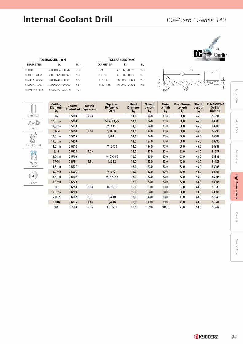
94
Autom
otiveA
erospaceH
igh Perform
anceG
eneralS
pecial ToolsM
old & D
ie
Internal Coolant Drill ICe-Carb | Series 140
55
Serie
s 140 5
xD
|
Fraction
al & M
etric
www.kyocera-sgstool.com
TOLERANCES (inch)
DIAMETER D1 D2
≤.1181 +.00008/+.00047 h6
>.1181–.2362 +.00016/+.00063 h6
>.2362–.3937 +.00024/+.00083 h6
>.3937–.7087 +.00028/+.00098 h6
>.7087–1.1811 +.00031/+.00114 h6
TOLERANCES (mm)
DIAMETER D1 D2
≤ 3 +0,002/+0,012 h6
> 3 - 6 +0,004/+0,016 h6
> 6 - 10 +0,006/+0,021 h6
> 10 - 18 +0,007/+0,025 h6
®
Common
Reach
Right Spiral
Internal Coolant
2
Flutes
Cutting Diameter
D1
Decimal Equivalent
Metric Equivalent
Tap Size Reference
Only
Shank Diameter
D2
Overall Length
L1
Flute Length
L2
Min. ClearedLength
L3
Shank Length
L4
Ti-NAMITE-A (AlTiN) EDP No.
1/2 0.5000 12.70 14,0 124,0 77,0 60,0 45,0 51934
12,8 mm 0.5039 M14 X 1,25 14,0 124,0 77,0 60,0 45,0 63988
13,0 mm 0.5118 M14 X 1 14,0 124,0 77,0 60,0 45,0 63989
33/64 0.5156 13.10 9/16-18 14,0 124,0 77,0 60,0 45,0 51935
13,5 mm 0.5315 5/8-11 14,0 124,0 77,0 60,0 45,0 64001
13,8 mm 0.5433 14,0 124,0 77,0 60,0 45,0 63990
14,0 mm 0.5512 M16 X 2 14,0 124,0 77,0 60,0 45,0 63991
9/16 0.5625 14.29 16,0 133,0 83,0 63,0 48,0 51937
14,5 mm 0.5709 M16 X 1,5 16,0 133,0 83,0 63,0 48,0 63992
37/64 0.5781 14.68 5/8-18 16,0 133,0 83,0 63,0 48,0 51938
14,8 mm 0.5827 16,0 133,0 83,0 63,0 48,0 63993
15,0 mm 0.5906 M16 X 1 16,0 133,0 83,0 63,0 48,0 63994
15,5 mm 0.6102 M18 X 2,5 16,0 133,0 83,0 63,0 48,0 63995
15,8 mm 0.6220 16,0 133,0 83,0 63,0 48,0 63996
5/8 0.6250 15.88 11/16-16 16,0 133,0 83,0 63,0 48,0 51939
16,0 mm 0.6299 16,0 133,0 83,0 63,0 48,0 63997
21/32 0.6562 16.67 3/4-10 18,0 143,0 93,0 71,0 48,0 51940
11/16 0.6875 17.46 3/4-16 18,0 143,0 93,0 71,0 48,0 51941
3/4 0.7500 19.05 13/16-16 20,0 153,0 101,0 77,0 50,0 51942
30°140°
L1L2
L3
L4
D2D1
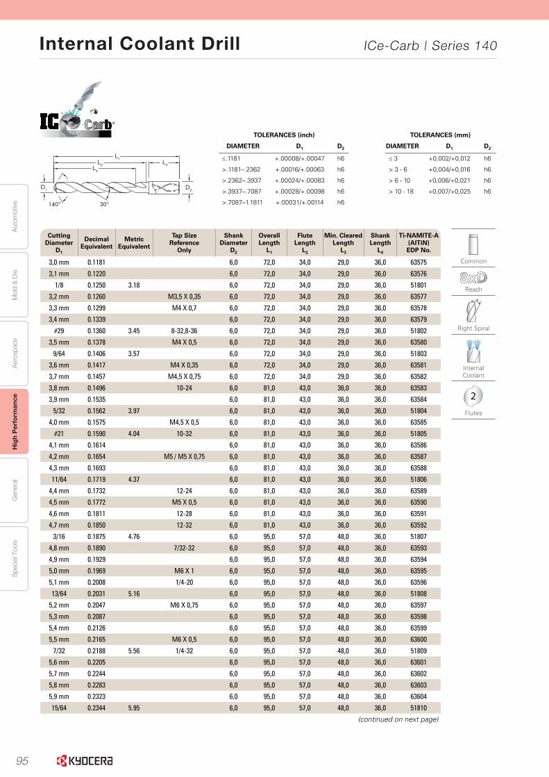
95
Aut
omot
ive
Aer
ospa
ceH
igh
Per
form
ance
Gen
eral
Spe
cial
Too
lsM
old
& D
ie
Internal Coolant Drill ICe-Carb | Series 140
56
Seri
es
140 8
xD
|
Frac
tio
nal
& M
etri
c
www.kyocera-sgstool.com
TOLERANCES (inch)
DIAMETER D1 D2
≤.1181 +.00008/+.00047 h6
>.1181–.2362 +.00016/+.00063 h6
>.2362–.3937 +.00024/+.00083 h6
>.3937–.7087 +.00028/+.00098 h6
>.7087–1.1811 +.00031/+.00114 h6
TOLERANCES (mm)
DIAMETER D1 D2
≤ 3 +0,002/+0,012 h6
> 3 - 6 +0,004/+0,016 h6
> 6 - 10 +0,006/+0,021 h6
> 10 - 18 +0,007/+0,025 h6
®
30°140°
L1L2
L3
L4
D2D1
Cutting Diameter
D1
Decimal Equivalent
Metric Equivalent
Tap Size Reference
Only
Shank Diameter
D2
Overall Length
L1
Flute Length
L2
Min. ClearedLength
L3
Shank Length
L4
Ti-NAMITE-A (AlTiN) EDP No.
3,0 mm 0.1181 6,0 72,0 34,0 29,0 36,0 63575
3,1 mm 0.1220 6,0 72,0 34,0 29,0 36,0 63576
1/8 0.1250 3.18 6,0 72,0 34,0 29,0 36,0 51801
3,2 mm 0.1260 M3,5 X 0,35 6,0 72,0 34,0 29,0 36,0 63577
3,3 mm 0.1299 M4 X 0,7 6,0 72,0 34,0 29,0 36,0 63578
3,4 mm 0.1339 6,0 72,0 34,0 29,0 36,0 63579
#29 0.1360 3.45 8-32,8-36 6,0 72,0 34,0 29,0 36,0 51802
3,5 mm 0.1378 M4 X 0,5 6,0 72,0 34,0 29,0 36,0 63580
9/64 0.1406 3.57 6,0 72,0 34,0 29,0 36,0 51803
3,6 mm 0.1417 M4 X 0,35 6,0 72,0 34,0 29,0 36,0 63581
3,7 mm 0.1457 M4,5 X 0,75 6,0 72,0 34,0 29,0 36,0 63582
3,8 mm 0.1496 10-24 6,0 81,0 43,0 36,0 36,0 63583
3,9 mm 0.1535 6,0 81,0 43,0 36,0 36,0 63584
5/32 0.1562 3.97 6,0 81,0 43,0 36,0 36,0 51804
4,0 mm 0.1575 M4,5 X 0,5 6,0 81,0 43,0 36,0 36,0 63585
#21 0.1590 4.04 10-32 6,0 81,0 43,0 36,0 36,0 51805
4,1 mm 0.1614 6,0 81,0 43,0 36,0 36,0 63586
4,2 mm 0.1654 M5 / M5 X 0,75 6,0 81,0 43,0 36,0 36,0 63587
4,3 mm 0.1693 6,0 81,0 43,0 36,0 36,0 63588
11/64 0.1719 4.37 6,0 81,0 43,0 36,0 36,0 51806
4,4 mm 0.1732 12-24 6,0 81,0 43,0 36,0 36,0 63589
4,5 mm 0.1772 M5 X 0,5 6,0 81,0 43,0 36,0 36,0 63590
4,6 mm 0.1811 12-28 6,0 81,0 43,0 36,0 36,0 63591
4,7 mm 0.1850 12-32 6,0 81,0 43,0 36,0 36,0 63592
3/16 0.1875 4.76 6,0 95,0 57,0 48,0 36,0 51807
4,8 mm 0.1890 7/32-32 6,0 95,0 57,0 48,0 36,0 63593
4,9 mm 0.1929 6,0 95,0 57,0 48,0 36,0 63594
5,0 mm 0.1969 M6 X 1 6,0 95,0 57,0 48,0 36,0 63595
5,1 mm 0.2008 1/4-20 6,0 95,0 57,0 48,0 36,0 63596
13/64 0.2031 5.16 6,0 95,0 57,0 48,0 36,0 51808
5,2 mm 0.2047 M6 X 0,75 6,0 95,0 57,0 48,0 36,0 63597
5,3 mm 0.2087 6,0 95,0 57,0 48,0 36,0 63598
5,4 mm 0.2126 6,0 95,0 57,0 48,0 36,0 63599
5,5 mm 0.2165 M6 X 0,5 6,0 95,0 57,0 48,0 36,0 63600
7/32 0.2188 5.56 1/4-32 6,0 95,0 57,0 48,0 36,0 51809
5,6 mm 0.2205 6,0 95,0 57,0 48,0 36,0 63601
5,7 mm 0.2244 6,0 95,0 57,0 48,0 36,0 63602
5,8 mm 0.2283 6,0 95,0 57,0 48,0 36,0 63603
5,9 mm 0.2323 6,0 95,0 57,0 48,0 36,0 63604
15/64 0.2344 5.95 6,0 95,0 57,0 48,0 36,0 51810
(continued on next page)
Common
Reach
Right Spiral
Internal Coolant
2
Flutes

96
Autom
otiveA
erospaceH
igh Perform
anceG
eneralS
pecial ToolsM
old & D
ie
Internal Coolant Drill ICe-Carb | Series 140
57
Serie
s 140 8
xD
|
Fraction
al & M
etric
30°140°
L1L2
L3
L4
D2D1
www.kyocera-sgstool.com
TOLERANCES (inch)
DIAMETER D1 D2
≤.1181 +.00008/+.00047 h6
>.1181–.2362 +.00016/+.00063 h6
>.2362–.3937 +.00024/+.00083 h6
>.3937–.7087 +.00028/+.00098 h6
>.7087–1.1811 +.00031/+.00114 h6
TOLERANCES (mm)
DIAMETER D1 D2
≤ 3 +0,002/+0,012 h6
> 3 - 6 +0,004/+0,016 h6
> 6 - 10 +0,006/+0,021 h6
> 10 - 18 +0,007/+0,025 h6
®
Common
Reach
Right Spiral
Internal Coolant
2
Flutes
Cutting Diameter
D1
Decimal Equivalent
Metric Equivalent
Tap Size Reference
Only
Shank Diameter
D2
Overall Length
L1
Flute Length
L2
Min. ClearedLength
L3
Shank Length
L4
Ti-NAMITE-A (AlTiN) EDP No.
6,0 mm 0.2362 M7 X 1 6,0 95,0 57,0 48,0 36,0 63605
6,1 mm 0.2402 8,0 114,0 76,0 64,0 36,0 63606
6,2 mm 0.2441 M7 X 0,75 8,0 114,0 76,0 64,0 36,0 63607
6,3 mm 0.2480 8,0 114,0 76,0 64,0 36,0 63608
1/4 0.2500 6.35 8,0 114,0 76,0 64,0 36,0 51811
6,4 mm 0.2520 8,0 114,0 76,0 64,0 36,0 63609
6,5 mm 0.2559 8,0 114,0 76,0 64,0 36,0 63610
F 0.2570 6.53 5/16-18 8,0 114,0 76,0 64,0 36,0 51812
6,6 mm 0.2598 8,0 114,0 76,0 64,0 36,0 63611
6,7 mm 0.2638 8,0 114,0 76,0 64,0 36,0 63612
17/64 0.2656 6.75 5/16-20 8,0 114,0 76,0 64,0 36,0 51813
6,8 mm 0.2677 M8 X 1,25 8,0 114,0 76,0 64,0 36,0 63613
6,9 mm 0.2717 8,0 114,0 76,0 64,0 36,0 63614
7,0 mm 0.2756 M8 X 1 8,0 114,0 76,0 64,0 36,0 63615
7,1 mm 0.2795 8,0 114,0 76,0 64,0 36,0 63616
9/32 0.2812 7.14 5/16-32 8,0 114,0 76,0 64,0 36,0 51814
7,2 mm 0.2835 M8 X 0,75 8,0 114,0 76,0 64,0 36,0 63617
7,3 mm 0.2874 8,0 114,0 76,0 64,0 36,0 63618
7,4 mm 0.2913 8,0 114,0 76,0 64,0 36,0 63619
7,5 mm 0.2953 M8 X 0,5 8,0 114,0 76,0 64,0 36,0 63620
19/64 0.2969 7.54 8,0 114,0 76,0 64,0 36,0 51815
7,6 mm 0.2992 8,0 114,0 76,0 64,0 36,0 63621
7,7 mm 0.3031 8,0 114,0 76,0 64,0 36,0 63622
7,8 mm 0.3071 M9 X 1,25 8,0 114,0 76,0 64,0 36,0 63623
7,9 mm 0.3110 8,0 114,0 76,0 64,0 36,0 63624
5/16 0.3125 7.94 3/8-16 8,0 114,0 76,0 64,0 36,0 51816
8,0 mm 0.3150 M9 X 1 8,0 114,0 76,0 64,0 36,0 63625
8,1 mm 0.3189 10,0 142,0 95,0 80,0 40,0 63626
8,2 mm 0.3228 10,0 142,0 95,0 80,0 40,0 63627
8,3 mm 0.3268 10,0 142,0 95,0 80,0 40,0 63628
21/64 0.3281 8.33 3/8-20 10,0 142,0 95,0 80,0 40,0 51817
8,4 mm 0.3307 10,0 142,0 95,0 80,0 40,0 63629
Q 0.3320 8.43 3/8-24 10,0 142,0 95,0 80,0 40,0 51818
8,5 mm 0.3346 M10 X 1,5 10,0 142,0 95,0 80,0 40,0 63630
8,6 mm 0.3386 10,0 142,0 95,0 80,0 40,0 63631
8,7 mm 0.3425 10,0 142,0 95,0 80,0 40,0 63632
11/32 0.3438 8.73 3/8-32 10,0 142,0 95,0 80,0 40,0 51819
8,8 mm 0.3465 M10 X 1,25 10,0 142,0 95,0 80,0 40,0 63633
8,9 mm 0.3504 10,0 142,0 95,0 80,0 40,0 63634
9,0 mm 0.3543 M10 X 1 10,0 142,0 95,0 80,0 40,0 63635
(continued on next page)

97
Aut
omot
ive
Aer
ospa
ceH
igh
Per
form
ance
Gen
eral
Spe
cial
Too
lsM
old
& D
ie
Internal Coolant Drill ICe-Carb | Series 140
58
Seri
es
140 8
xD
|
Frac
tio
nal
& M
etri
c
30°140°
L1L2
L3
L4
D2D1
www.kyocera-sgstool.com
TOLERANCES (inch)
DIAMETER D1 D2
≤.1181 +.00008/+.00047 h6
>.1181–.2362 +.00016/+.00063 h6
>.2362–.3937 +.00024/+.00083 h6
>.3937–.7087 +.00028/+.00098 h6
>.7087–1.1811 +.00031/+.00114 h6
TOLERANCES (mm)
DIAMETER D1 D2
≤ 3 +0,002/+0,012 h6
> 3 - 6 +0,004/+0,016 h6
> 6 - 10 +0,006/+0,021 h6
> 10 - 18 +0,007/+0,025 h6
®
Common
Reach
Right Spiral
Internal Coolant
2
Flutes
Cutting Diameter
D1
Decimal Equivalent
Metric Equivalent
Tap Size Reference
Only
Shank Diameter
D2
Overall Length
L1
Flute Length
L2
Min. ClearedLength
L3
Shank Length
L4
Ti-NAMITE-A (AlTiN) EDP No.
9,1 mm 0.3583 10,0 142,0 95,0 80,0 40,0 63636
23/64 0.3594 9.13 10,0 142,0 95,0 80,0 40,0 51820
9,2 mm 0.3622 M10 X 0,75 10,0 142,0 95,0 80,0 40,0 63637
9,3 mm 0.3661 10,0 142,0 95,0 80,0 40,0 63638
U 0.3680 9.35 7/16-14 10,0 142,0 95,0 80,0 40,0 51821
9,4 mm 0.3701 10,0 142,0 95,0 80,0 40,0 63639
9,5 mm 0.3740 M11 / M10 X 0,5 10,0 142,0 95,0 80,0 40,0 63640
3/8 0.3750 9.53 10,0 142,0 95,0 80,0 40,0 51822
9,6 mm 0.3780 10,0 142,0 95,0 80,0 40,0 63641
9,7 mm 0.3819 10,0 142,0 95,0 80,0 40,0 63642
9,8 mm 0.3858 10,0 142,0 95,0 80,0 40,0 63643
9,9 mm 0.3898 10,0 142,0 95,0 80,0 40,0 63644
25/64 0.3906 9.92 7/16-20 10,0 142,0 95,0 80,0 40,0 51823
10,0 mm 0.3937 10,0 142,0 95,0 80,0 40,0 63645
10,1 mm 0.3976 12,0 162,0 114,0 96,0 45,0 63646
10,2 mm 0.4016 M12 X 1,75 12,0 162,0 114,0 96,0 45,0 63647
10,3 mm 0.4055 12,0 162,0 114,0 96,0 45,0 63648
13/32 0.4062 10.32 12,0 162,0 114,0 96,0 45,0 51824
10,4 mm 0.4094 12,0 162,0 114,0 96,0 45,0 63649
10,5 mm 0.4134 M12 X 1,5 12,0 162,0 114,0 96,0 45,0 63650
10,6 mm 0.4173 12,0 162,0 114,0 96,0 45,0 63651
10,7 mm 0.4213 12,0 162,0 114,0 96,0 45,0 63652
27/64 0.4219 10.72 1/2-13 12,0 162,0 114,0 96,0 45,0 51825
10,8 mm 0.4252 M12 X 1,25 12,0 162,0 114,0 96,0 45,0 63653
10,9 mm 0.4291 12,0 162,0 114,0 96,0 45,0 63654
11,0 mm 0.4331 M12 X 1 12,0 162,0 114,0 96,0 45,0 63655
11,1 mm 0.4370 12,0 162,0 114,0 96,0 45,0 63656
7/16 0.4375 11.11 1/4-18NPT 12,0 162,0 114,0 96,0 45,0 51826
11,2 mm 0.4409 12,0 162,0 114,0 96,0 45,0 63657
11,3 mm 0.4449 12,0 162,0 114,0 96,0 45,0 63658
11,4 mm 0.4488 12,0 162,0 114,0 96,0 45,0 63659
11,5 mm 0.4528 M12 X 0,5 12,0 162,0 114,0 96,0 45,0 63660
11,6 mm 0.4567 12,0 162,0 114,0 96,0 45,0 63661
11,7 mm 0.4606 12,0 162,0 114,0 96,0 45,0 63662
11,8 mm 0.4646 12,0 162,0 114,0 96,0 45,0 63663
11,9 mm 0.4685 12,0 162,0 114,0 96,0 45,0 63664
15/32 0.4688 11.91 1/2-28 12,0 162,0 114,0 96,0 45,0 51827
12,0 mm 0.4724 M14 X 2 12,0 162,0 114,0 96,0 45,0 63665
31/64 0.4844 12.30 9/16-12 14,0 178,0 133,0 112,0 45,0 51828
12,5 mm 0.4921 M14 X 1,5 14,0 178,0 133,0 112,0 45,0 63666
(continued on next page)

98
Autom
otiveA
erospaceH
igh Perform
anceG
eneralS
pecial ToolsM
old & D
ie
Internal Coolant Drill ICe-Carb | Series 140
59
Serie
s 140 8
xD
|
Fraction
al & M
etric
30°140°
L1L2
L3
L4
D2D1
www.kyocera-sgstool.com
TOLERANCES (inch)
DIAMETER D1 D2
≤.1181 +.00008/+.00047 h6
>.1181–.2362 +.00016/+.00063 h6
>.2362–.3937 +.00024/+.00083 h6
>.3937–.7087 +.00028/+.00098 h6
>.7087–1.1811 +.00031/+.00114 h6
TOLERANCES (mm)
DIAMETER D1 D2
≤ 3 +0,002/+0,012 h6
> 3 - 6 +0,004/+0,016 h6
> 6 - 10 +0,006/+0,021 h6
> 10 - 18 +0,007/+0,025 h6
®
Common
Reach
Right Spiral
Internal Coolant
2
Flutes
Cutting Diameter
D1
Decimal Equivalent
Metric Equivalent
Tap Size Reference
Only
Shank Diameter
D2
Overall Length
L1
Flute Length
L2
Min. ClearedLength
L3
Shank Length
L4
Ti-NAMITE-A (AlTiN) EDP No.
1/2 0.5000 12.70 14,0 178,0 133,0 112,0 45,0 51829
12,8 mm 0.5039 M14 X 1,25 14,0 178,0 133,0 112,0 45,0 63667
13,0 mm 0.5118 M14 X 1 14,0 178,0 133,0 112,0 45,0 63668
33/64 0.5156 13.10 9/16-18 14,0 178,0 133,0 112,0 45,0 51830
13,5 mm 0.5315 5/8-11 14,0 178,0 133,0 112,0 45,0 63669
13,8 mm 0.5433 14,0 178,0 133,0 112,0 45,0 63670
14,0 mm 0.5512 M16 X 2 14,0 178,0 133,0 112,0 45,0 63671
9/16 0.5625 14.29 16,0 203,0 152,0 128,0 48,0 51831
14,5 mm 0.5709 M16 X 1,5 16,0 203,0 152,0 128,0 48,0 63672
37/64 0.5781 14.68 5/8-18 16,0 203,0 152,0 128,0 48,0 51832
14,8 mm 0.5827 16,0 203,0 152,0 128,0 48,0 63673
15,0 mm 0.5906 M16 X 1 16,0 203,0 152,0 128,0 48,0 63674
15,5 mm 0.6102 M18 X 2,5 16,0 203,0 152,0 128,0 48,0 63675
15,8 mm 0.6220 16,0 203,0 152,0 128,0 48,0 63676
5/8 0.6250 15.88 11/16-16 16,0 203,0 152,0 128,0 48,0 51833
16,0 mm 0.6299 16,0 203,0 152,0 128,0 48,0 63677
21/32 0.6562 16.67 3/4-10 18,0 222,0 171,0 144,0 48,0 51834
11/16 0.6875 17.46 3/4-16 18,0 222,0 171,0 144,0 48,0 51835
3/4 0.7500 19.05 13/16-16 20,0 243,0 190,0 160,0 50,0 51836
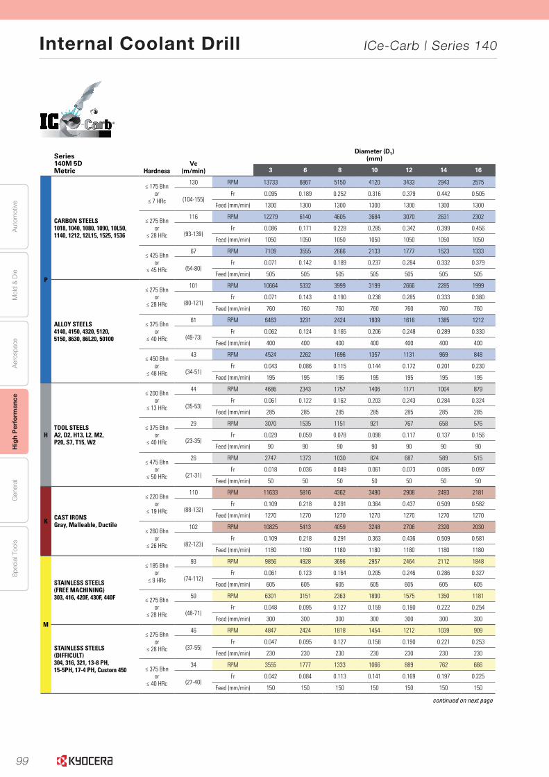
99
Aut
omot
ive
Aer
ospa
ceH
igh
Per
form
ance
Gen
eral
Spe
cial
Too
lsM
old
& D
ie
Internal Coolant Drill ICe-Carb | Series 140
62 www.kyocera-sgstool.com
®
Seri
es
140 5
xD
|
Spee
d &
Fee
d R
eco
mm
end
atio
ns
Series 140M 5DMetric Hardness
Vc (m/min)
Diameter (D1)(mm)
3 6 8 10 12 14 16
P
CARBON STEELS1018, 1040, 1080, 1090, 10L50, 1140, 1212, 12L15, 1525, 1536
≤ 175 Bhnor
≤ 7 HRc
130 RPM 13733 6867 5150 4120 3433 2943 2575
(104-155)Fr 0.095 0.189 0.252 0.316 0.379 0.442 0.505
Feed (mm/min) 1300 1300 1300 1300 1300 1300 1300
≤ 275 Bhnor
≤ 28 HRc
116 RPM 12279 6140 4605 3684 3070 2631 2302
(93-139)Fr 0.086 0.171 0.228 0.285 0.342 0.399 0.456
Feed (mm/min) 1050 1050 1050 1050 1050 1050 1050
≤ 425 Bhnor
≤ 45 HRc
67 RPM 7109 3555 2666 2133 1777 1523 1333
(54-80)Fr 0.071 0.142 0.189 0.237 0.284 0.332 0.379
Feed (mm/min) 505 505 505 505 505 505 505
ALLOY STEELS4140, 4150, 4320, 5120,5150, 8630, 86L20, 50100
≤ 275 Bhnor
≤ 28 HRc
101 RPM 10664 5332 3999 3199 2666 2285 1999
(80-121)Fr 0.071 0.143 0.190 0.238 0.285 0.333 0.380
Feed (mm/min) 760 760 760 760 760 760 760
≤ 375 Bhnor
≤ 40 HRc
61 RPM 6463 3231 2424 1939 1616 1385 1212
(49-73)Fr 0.062 0.124 0.165 0.206 0.248 0.289 0.330
Feed (mm/min) 400 400 400 400 400 400 400
≤ 450 Bhnor
≤ 48 HRc
43 RPM 4524 2262 1696 1357 1131 969 848
(34-51)Fr 0.043 0.086 0.115 0.144 0.172 0.201 0.230
Feed (mm/min) 195 195 195 195 195 195 195
HTOOL STEELSA2, D2, H13, L2, M2,P20, S7, T15, W2
≤ 200 Bhnor
≤ 13 HRc
44 RPM 4686 2343 1757 1406 1171 1004 879
(35-53)Fr 0.061 0.122 0.162 0.203 0.243 0.284 0.324
Feed (mm/min) 285 285 285 285 285 285 285
≤ 375 Bhnor
≤ 40 HRc
29 RPM 3070 1535 1151 921 767 658 576
(23-35)Fr 0.029 0.059 0.078 0.098 0.117 0.137 0.156
Feed (mm/min) 90 90 90 90 90 90 90
≤ 475 Bhnor
≤ 50 HRc
26 RPM 2747 1373 1030 824 687 589 515
(21-31)Fr 0.018 0.036 0.049 0.061 0.073 0.085 0.097
Feed (mm/min) 50 50 50 50 50 50 50
K CAST IRONSGray, Malleable, Ductile
≤ 220 Bhnor
≤ 19 HRc
110 RPM 11633 5816 4362 3490 2908 2493 2181
(88-132)Fr 0.109 0.218 0.291 0.364 0.437 0.509 0.582
Feed (mm/min) 1270 1270 1270 1270 1270 1270 1270
≤ 260 Bhnor
≤ 26 HRc
102 RPM 10825 5413 4059 3248 2706 2320 2030
(82-123)Fr 0.109 0.218 0.291 0.363 0.436 0.509 0.581
Feed (mm/min) 1180 1180 1180 1180 1180 1180 1180
M
STAINLESS STEELS(FREE MACHINING)303, 416, 420F, 430F, 440F
≤ 185 Bhnor
≤ 9 HRc
93 RPM 9856 4928 3696 2957 2464 2112 1848
(74-112)Fr 0.061 0.123 0.164 0.205 0.246 0.286 0.327
Feed (mm/min) 605 605 605 605 605 605 605
≤ 275 Bhnor
≤ 28 HRc
59 RPM 6301 3151 2363 1890 1575 1350 1181
(48-71)Fr 0.048 0.095 0.127 0.159 0.190 0.222 0.254
Feed (mm/min) 300 300 300 300 300 300 300
STAINLESS STEELS(DIFFICULT)304, 316, 321, 13-8 PH, 15-5PH, 17-4 PH, Custom 450
≤ 275 Bhnor
≤ 28 HRc
46 RPM 4847 2424 1818 1454 1212 1039 909
(37-55)Fr 0.047 0.095 0.127 0.158 0.190 0.221 0.253
Feed (mm/min) 230 230 230 230 230 230 230
≤ 375 Bhnor
≤ 40 HRc
34 RPM 3555 1777 1333 1066 889 762 666
(27-40)Fr 0.042 0.084 0.113 0.141 0.169 0.197 0.225
Feed (mm/min) 150 150 150 150 150 150 150
continued on next page
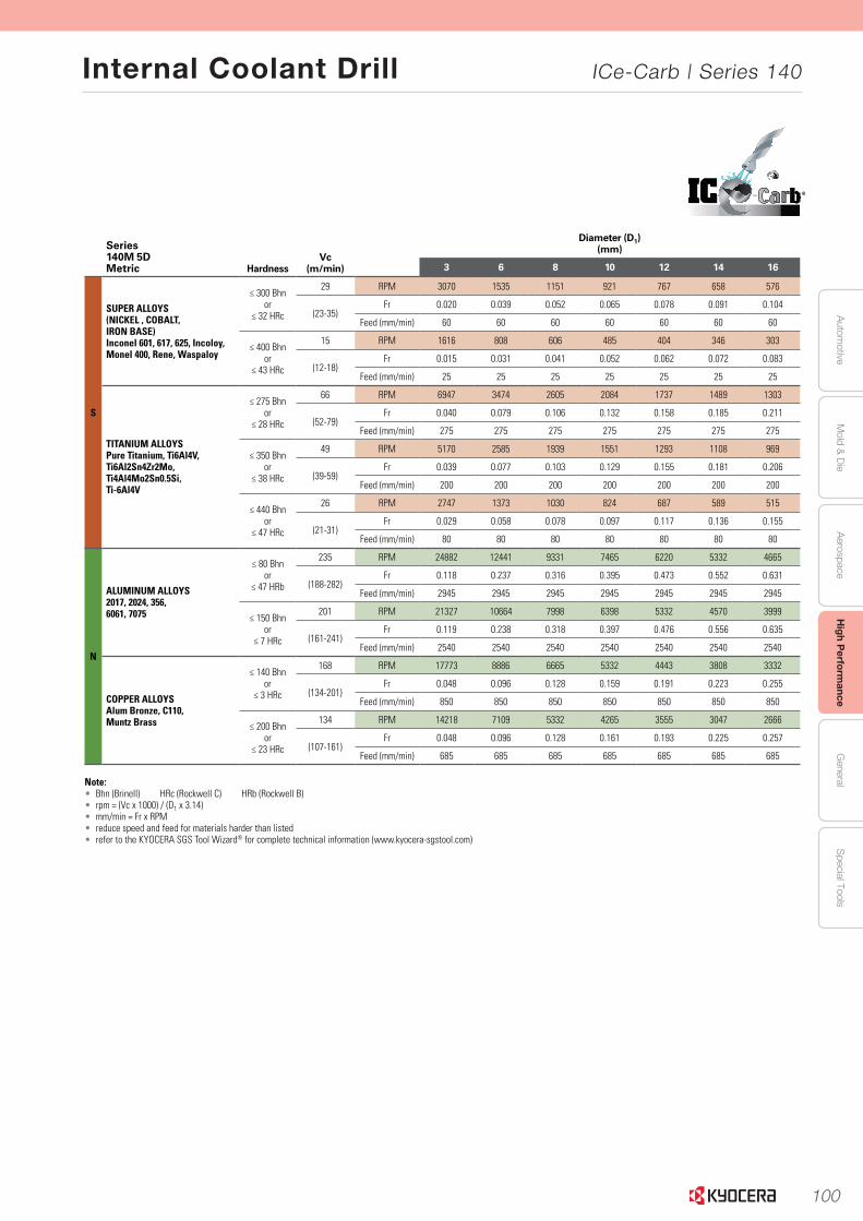
100
Autom
otiveA
erospaceH
igh Perform
anceG
eneralS
pecial ToolsM
old & D
ie
Internal Coolant Drill ICe-Carb | Series 140
63www.kyocera-sgstool.com
®
Serie
s 140 5
xD
|
Speed
& Feed
Reco
mm
end
ation
s
Series 140M 5DMetric Hardness
Vc (m/min)
Diameter (D1)(mm)
3 6 8 10 12 14 16
S
SUPER ALLOYS(NICKEL , COBALT, IRON BASE)Inconel 601, 617, 625, Incoloy, Monel 400, Rene, Waspaloy
≤ 300 Bhnor
≤ 32 HRc
29 RPM 3070 1535 1151 921 767 658 576
(23-35)Fr 0.020 0.039 0.052 0.065 0.078 0.091 0.104
Feed (mm/min) 60 60 60 60 60 60 60
≤ 400 Bhnor
≤ 43 HRc
15 RPM 1616 808 606 485 404 346 303
(12-18)Fr 0.015 0.031 0.041 0.052 0.062 0.072 0.083
Feed (mm/min) 25 25 25 25 25 25 25
TITANIUM ALLOYSPure Titanium, Ti6Al4V,Ti6Al2Sn4Zr2Mo,Ti4Al4Mo2Sn0.5Si,Ti-6Al4V
≤ 275 Bhnor
≤ 28 HRc
66 RPM 6947 3474 2605 2084 1737 1489 1303
(52-79)Fr 0.040 0.079 0.106 0.132 0.158 0.185 0.211
Feed (mm/min) 275 275 275 275 275 275 275
≤ 350 Bhnor
≤ 38 HRc
49 RPM 5170 2585 1939 1551 1293 1108 969
(39-59)Fr 0.039 0.077 0.103 0.129 0.155 0.181 0.206
Feed (mm/min) 200 200 200 200 200 200 200
≤ 440 Bhnor
≤ 47 HRc
26 RPM 2747 1373 1030 824 687 589 515
(21-31)Fr 0.029 0.058 0.078 0.097 0.117 0.136 0.155
Feed (mm/min) 80 80 80 80 80 80 80
N
ALUMINUM ALLOYS2017, 2024, 356, 6061, 7075
≤ 80 Bhnor
≤ 47 HRb
235 RPM 24882 12441 9331 7465 6220 5332 4665
(188-282)Fr 0.118 0.237 0.316 0.395 0.473 0.552 0.631
Feed (mm/min) 2945 2945 2945 2945 2945 2945 2945
≤ 150 Bhnor
≤ 7 HRc
201 RPM 21327 10664 7998 6398 5332 4570 3999
(161-241)Fr 0.119 0.238 0.318 0.397 0.476 0.556 0.635
Feed (mm/min) 2540 2540 2540 2540 2540 2540 2540
COPPER ALLOYSAlum Bronze, C110, Muntz Brass
≤ 140 Bhnor
≤ 3 HRc
168 RPM 17773 8886 6665 5332 4443 3808 3332
(134-201)Fr 0.048 0.096 0.128 0.159 0.191 0.223 0.255
Feed (mm/min) 850 850 850 850 850 850 850
≤ 200 Bhnor
≤ 23 HRc
134 RPM 14218 7109 5332 4265 3555 3047 2666
(107-161)Fr 0.048 0.096 0.128 0.161 0.193 0.225 0.257
Feed (mm/min) 685 685 685 685 685 685 685
Note:• Bhn (Brinell) HRc (Rockwell C) HRb (Rockwell B)• rpm = (Vc x 1000) / (D1 x 3.14)• mm/min = Fr x RPM• reduce speed and feed for materials harder than listed • refer to the KYOCERA SGS Tool Wizard® for complete technical information (www.kyocera-sgstool.com)

101
Aut
omot
ive
Aer
ospa
ceH
igh
Per
form
ance
Gen
eral
Spe
cial
Too
lsM
old
& D
ie
Internal Coolant Drill ICe-Carb | Series 140
66
Seri
es
140 8
xD
|
Spee
d &
Fee
d R
eco
mm
end
atio
ns
www.kyocera-sgstool.com
®
Series 140M 8DMetric Hardness
Vc (m/min)
Diameter (D1)(mm)
3 6 8 10 12 14 16
P
CARBON STEELS1018, 1040, 1080, 1090, 10L50, 1140, 1212, 12L15, 1525, 1536
≤ 175 Bhnor
≤ 7 HRc
123 RPM 13087 6544 4908 3926 3272 2804 2454
(100-170)Fr 0.085 0.171 0.228 0.285 0.342 0.399 0.455
Feed (mm/min) 1118 1118 1118 1118 1118 1118 1118
≤ 275 Bhnor
≤ 28 HRc
113 RPM 11956 5978 4484 3587 2989 2562 2242
(90-135)Fr 0.072 0.144 0.193 0.241 0.289 0.337 0.385
Feed (mm/min) 864 864 864 864 864 864 864
≤ 425 Bhnor
≤ 45 HRc
64 RPM 6786 3393 2545 2036 1696 1454 1272
(51-77)Fr 0.062 0.124 0.165 0.206 0.247 0.288 0.329
Feed (mm/min) 419 419 419 419 419 419 419
ALLOY STEELS4140, 4150, 4320, 5120,5150, 8630, 86L20, 50100
≤ 275 Bhnor
≤ 28 HRc
98 RPM 10340 5170 3878 3102 2585 2216 1939
(78-117)Fr 0.061 0.123 0.164 0.205 0.246 0.287 0.328
Feed (mm/min) 635 635 635 635 635 635 635
≤ 375 Bhnor
≤ 40 HRc
58 RPM 6140 3070 2302 1842 1535 1316 1151
(46-69)Fr 0.048 0.095 0.127 0.159 0.190 0.222 0.254
Feed (mm/min) 292 292 292 292 292 292 292
≤ 450 Bhnor
≤ 48 HRc
41 RPM 4362 2181 1636 1309 1091 935 818
(33-49)Fr 0.038 0.076 0.101 0.126 0.151 0.177 0.202
Feed (mm/min) 165 165 165 165 165 165 165
HTOOL STEELSA2, D2, H13, L2, M2,P20, S7, T15, W2
≤ 200 Bhnor
≤ 13 HRc
43 RPM 4524 2262 1696 1357 1131 969 848
(34-51)Fr 0.048 0.095 0.127 0.159 0.191 0.223 0.255
Feed (mm/min) 216 216 216 216 216 216 216
≤ 375 Bhnor
≤ 40 HRc
27 RPM 2908 1454 1091 872 727 623 545
(22-33)Fr 0.026 0.052 0.070 0.087 0.105 0.122 0.140
Feed (mm/min) 76 76 76 76 76 76 76
≤ 475 Bhnor
≤ 50 HRc
24 RPM 2585 1293 969 776 646 554 485
(20-29)Fr 0.015 0.029 0.039 0.049 0.059 0.069 0.079
Feed (mm/min) 38 38 38 38 38 38 38
K CAST IRONSGray, Malleable, Ductile
≤ 220 Bhnor
≤ 19 HRc
107 RPM 11310 5655 4241 3393 2827 2424 2121
(85-128)Fr 0.090 0.180 0.240 0.299 0.359 0.419 0.479
Feed (mm/min) 1016 1016 1016 1016 1016 1016 1016
≤ 260 Bhnor
≤ 26 HRc
94 RPM 10017 5009 3756 3005 2504 2147 1878
(76-113)Fr 0.094 0.188 0.250 0.313 0.375 0.438 0.500
Feed (mm/min) 940 940 940 940 940 940 940
M
STAINLESS STEELS(FREE MACHINING)303, 416, 420F, 430F, 440F
≤ 185 Bhnor
≤ 9 HRc
88 RPM 9371 4686 3514 2811 2343 2008 1757
(71-106)Fr 0.047 0.095 0.126 0.158 0.190 0.221 0.253
Feed (mm/min) 445 445 445 445 445 445 445
≤ 275 Bhnor
≤ 28 HRc
55 RPM 5816 2908 2181 1745 1454 1246 1091
(44-66)Fr 0.044 0.087 0.116 0.146 0.175 0.204 0.233
Feed (mm/min) 254 254 254 254 254 254 254
STAINLESS STEELS(DIFFICULT)304, 316, 321, 13-8 PH, 15-5PH, 17-4 PH, Custom 450
≤ 275 Bhnor
≤ 28 HRc
40 RPM 4201 2100 1575 1260 1050 900 788
(32-48)Fr 0.042 0.085 0.113 0.141 0.169 0.198 0.226
Feed (mm/min) 178 178 178 178 178 178 178
≤ 375 Bhnor
≤ 40 HRc
29 RPM 3070 1535 1151 921 767 658 576
(23-35)Fr 0.037 0.074 0.099 0.124 0.149 0.174 0.199
Feed (mm/min) 114 114 114 114 114 114 114
(continued on next page)
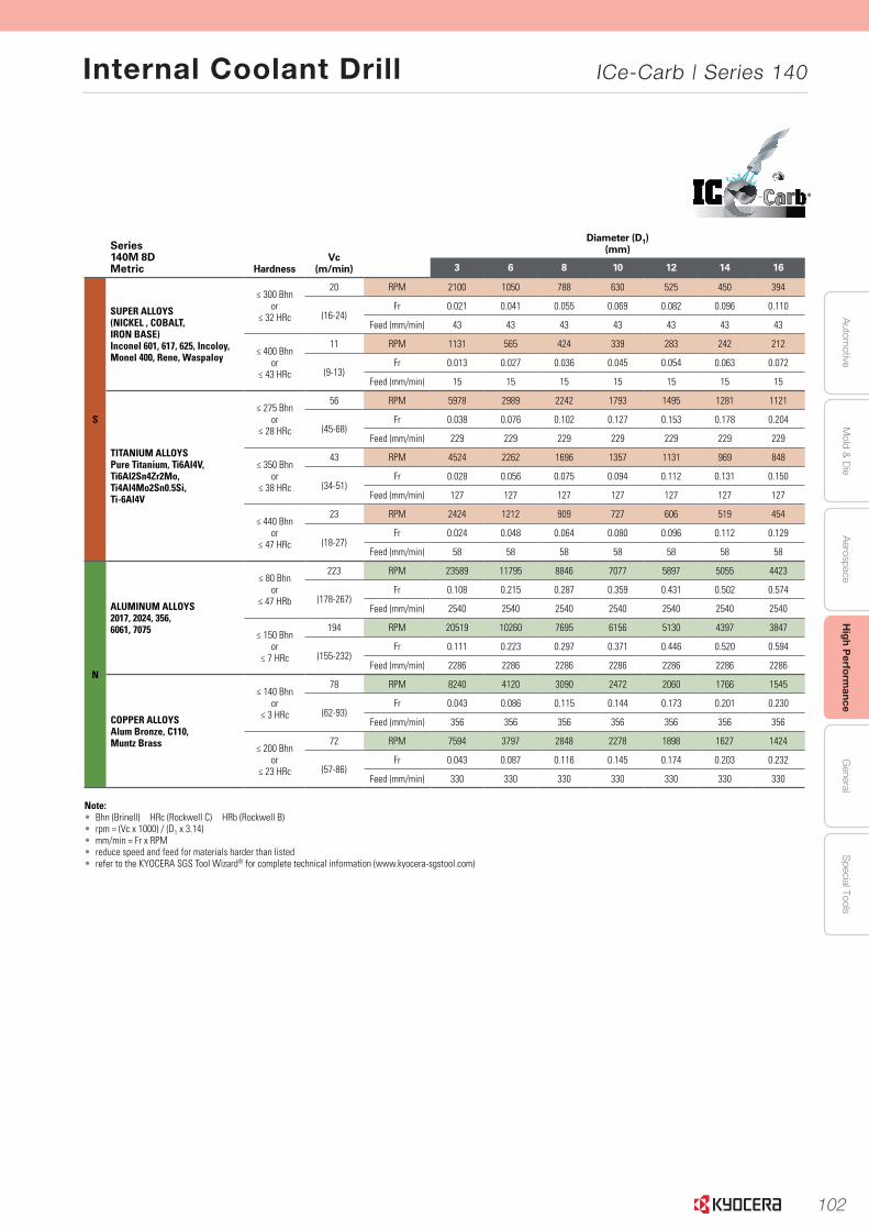
102
Autom
otiveA
erospaceH
igh Perform
anceG
eneralS
pecial ToolsM
old & D
ie
Internal Coolant Drill ICe-Carb | Series 140
67
Serie
s 140 8
xD
|
Speed
& Feed
Reco
mm
end
ation
s
www.kyocera-sgstool.com
®
Series 140M 8DMetric Hardness
Vc (m/min)
Diameter (D1)(mm)
3 6 8 10 12 14 16
S
SUPER ALLOYS(NICKEL , COBALT, IRON BASE)Inconel 601, 617, 625, Incoloy, Monel 400, Rene, Waspaloy
≤ 300 Bhnor
≤ 32 HRc
20 RPM 2100 1050 788 630 525 450 394
(16-24)Fr 0.021 0.041 0.055 0.069 0.082 0.096 0.110
Feed (mm/min) 43 43 43 43 43 43 43
≤ 400 Bhnor
≤ 43 HRc
11 RPM 1131 565 424 339 283 242 212
(9-13)Fr 0.013 0.027 0.036 0.045 0.054 0.063 0.072
Feed (mm/min) 15 15 15 15 15 15 15
TITANIUM ALLOYSPure Titanium, Ti6Al4V,Ti6Al2Sn4Zr2Mo,Ti4Al4Mo2Sn0.5Si,Ti-6Al4V
≤ 275 Bhnor
≤ 28 HRc
56 RPM 5978 2989 2242 1793 1495 1281 1121
(45-68)Fr 0.038 0.076 0.102 0.127 0.153 0.178 0.204
Feed (mm/min) 229 229 229 229 229 229 229
≤ 350 Bhnor
≤ 38 HRc
43 RPM 4524 2262 1696 1357 1131 969 848
(34-51)Fr 0.028 0.056 0.075 0.094 0.112 0.131 0.150
Feed (mm/min) 127 127 127 127 127 127 127
≤ 440 Bhnor
≤ 47 HRc
23 RPM 2424 1212 909 727 606 519 454
(18-27)Fr 0.024 0.048 0.064 0.080 0.096 0.112 0.129
Feed (mm/min) 58 58 58 58 58 58 58
N
ALUMINUM ALLOYS2017, 2024, 356, 6061, 7075
≤ 80 Bhnor
≤ 47 HRb
223 RPM 23589 11795 8846 7077 5897 5055 4423
(178-267)Fr 0.108 0.215 0.287 0.359 0.431 0.502 0.574
Feed (mm/min) 2540 2540 2540 2540 2540 2540 2540
≤ 150 Bhnor
≤ 7 HRc
194 RPM 20519 10260 7695 6156 5130 4397 3847
(155-232)Fr 0.111 0.223 0.297 0.371 0.446 0.520 0.594
Feed (mm/min) 2286 2286 2286 2286 2286 2286 2286
COPPER ALLOYSAlum Bronze, C110, Muntz Brass
≤ 140 Bhnor
≤ 3 HRc
78 RPM 8240 4120 3090 2472 2060 1766 1545
(62-93)Fr 0.043 0.086 0.115 0.144 0.173 0.201 0.230
Feed (mm/min) 356 356 356 356 356 356 356
≤ 200 Bhnor
≤ 23 HRc
72 RPM 7594 3797 2848 2278 1898 1627 1424
(57-86)Fr 0.043 0.087 0.116 0.145 0.174 0.203 0.232
Feed (mm/min) 330 330 330 330 330 330 330
Note:• Bhn (Brinell) HRc (Rockwell C) HRb (Rockwell B)• rpm = (Vc x 1000) / (D1 x 3.14)• mm/min = Fr x RPM• reduce speed and feed for materials harder than listed• refer to the KYOCERA SGS Tool Wizard® for complete technical information (www.kyocera-sgstool.com)
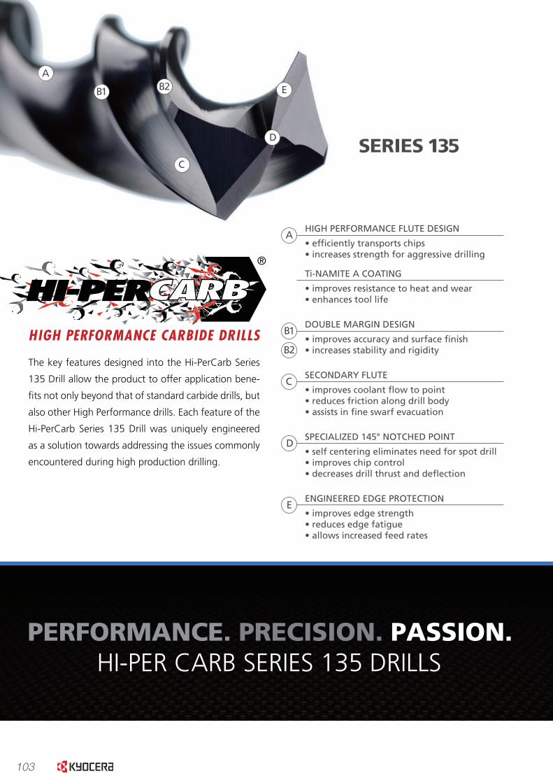
103
www.kyocera-sgstool.com
The second margin gives the Hi-PerCarb Series 135 Drill a burnishing effect and the �ute form effectively controls
and transports chips allowing the drill to offer superior surface �nishes and hole size in high production environ-
ments saving cycle time by often avoiding the need for reaming in many applications.
HI-PERCARB SERIES 135 SOLID CARBIDE DRILL AND REAMER
0
10
20
30
40
50
60
70
4140 Steel@ 28 HRc
6AI4V Titanium@ 30 HRc
MATERIAL GROUPS
AVERAGE SURFACE FINISH RESULTS
AV
ERA
GE
SUR
FAC
E FI
NIS
H IN
RA
MATERIAL GROUPS
ACCURACY OF HOLE PRODUCED
0.3122
0.3124
0.3126
0.3128
0.3130
0.3132
0.3134
4140 Steel@ 28 HRc
6AI4V Titanium@ 30 HRc
MEA
SUR
ED H
OLE
SIZ
E IN
INC
HES
05
1015202530354045
4140 Steel@ 28 HRc
6AI4V Titanium@ 30 HRc
MATERIAL GROUPS
TOTAL CYCLE TIME
TIM
E PE
R H
OLE
IN S
ECO
ND
S
PERFORMANCE.MACHINING ENVIRONMENT:
Haas VM-3 with 9% Water Soluble Oil Flood Coolant
5/16” (.3125) diameter hole:
4140 application – .650” deep
6Al-4V application – 1.125” deep
PERFORMANCE. PRECISION. PASSION.HI-PER CARB SERIES 135 DRILLS
The key features designed into the Hi-PerCarb Series
135 Drill allow the product to offer application bene-
�ts not only beyond that of standard carbide drills, but
also other High Performance drills. Each feature of the
Hi-PerCarb Series 135 Drill was uniquely engineered
as a solution towards addressing the issues commonly
encountered during high production drilling.
A
B1 B2
C
D
E
HIGH PERFORMANCE FLUTE DESIGN
• ef�ciently transports chips• increases strength for aggressive drilling
B1
B2
C
D
E
A
Ti-NAMITE A COATING
• improves resistance to heat and wear• enhances tool life
DOUBLE MARGIN DESIGN
• improves accuracy and surface �nish• increases stability and rigidity
SECONDARY FLUTE
• improves coolant �ow to point• reduces friction along drill body• assists in �ne swarf evacuation
SPECIALIZED 145° NOTCHED POINT
• self centering eliminates need for spot drill• improves chip control• decreases drill thrust and de�ection
ENGINEERED EDGE PROTECTION
• improves edge strength• reduces edge fatigue• allows increased feed rates
SERIES 135
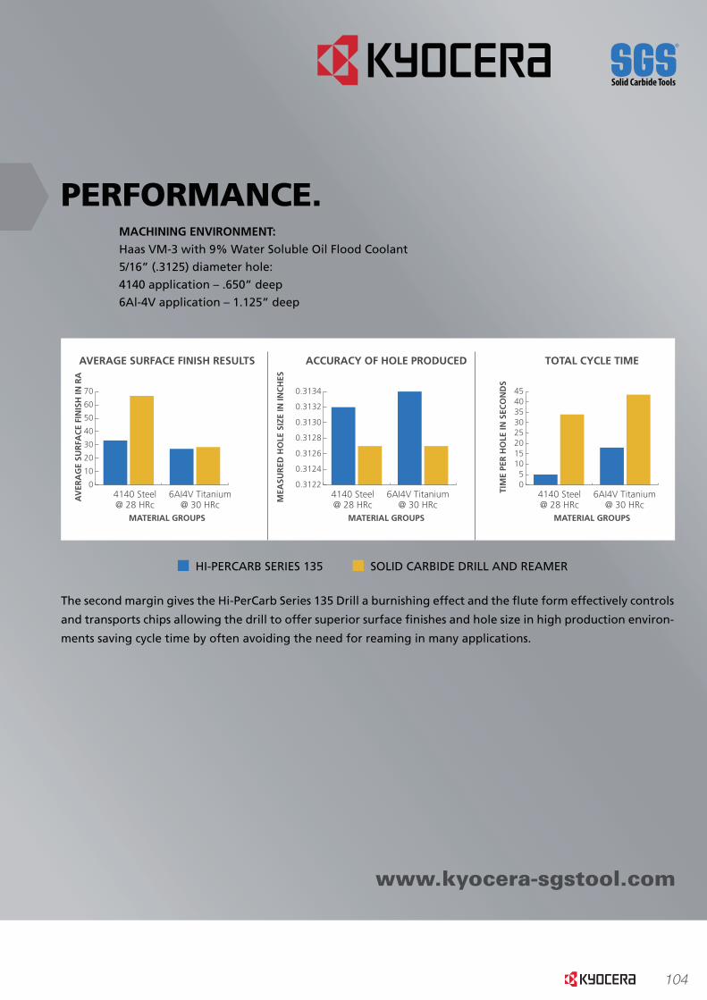
104
www.kyocera-sgstool.com
The second margin gives the Hi-PerCarb Series 135 Drill a burnishing effect and the �ute form effectively controls
and transports chips allowing the drill to offer superior surface �nishes and hole size in high production environ-
ments saving cycle time by often avoiding the need for reaming in many applications.
HI-PERCARB SERIES 135 SOLID CARBIDE DRILL AND REAMER
0
10
20
30
40
50
60
70
4140 Steel@ 28 HRc
6AI4V Titanium@ 30 HRc
MATERIAL GROUPS
AVERAGE SURFACE FINISH RESULTS
AV
ERA
GE
SUR
FAC
E FI
NIS
H IN
RA
MATERIAL GROUPS
ACCURACY OF HOLE PRODUCED
0.3122
0.3124
0.3126
0.3128
0.3130
0.3132
0.3134
4140 Steel@ 28 HRc
6AI4V Titanium@ 30 HRc
MEA
SUR
ED H
OLE
SIZ
E IN
INC
HES
05
1015202530354045
4140 Steel@ 28 HRc
6AI4V Titanium@ 30 HRc
MATERIAL GROUPS
TOTAL CYCLE TIME
TIM
E PE
R H
OLE
IN S
ECO
ND
S
PERFORMANCE.MACHINING ENVIRONMENT:
Haas VM-3 with 9% Water Soluble Oil Flood Coolant
5/16” (.3125) diameter hole:
4140 application – .650” deep
6Al-4V application – 1.125” deep
PERFORMANCE. PRECISION. PASSION.HI-PER CARB SERIES 135 DRILLS
The key features designed into the Hi-PerCarb Series
135 Drill allow the product to offer application bene-
�ts not only beyond that of standard carbide drills, but
also other High Performance drills. Each feature of the
Hi-PerCarb Series 135 Drill was uniquely engineered
as a solution towards addressing the issues commonly
encountered during high production drilling.
A
B1 B2
C
D
E
HIGH PERFORMANCE FLUTE DESIGN
• ef�ciently transports chips• increases strength for aggressive drilling
B1
B2
C
D
E
A
Ti-NAMITE A COATING
• improves resistance to heat and wear• enhances tool life
DOUBLE MARGIN DESIGN
• improves accuracy and surface �nish• increases stability and rigidity
SECONDARY FLUTE
• improves coolant �ow to point• reduces friction along drill body• assists in �ne swarf evacuation
SPECIALIZED 145° NOTCHED POINT
• self centering eliminates need for spot drill• improves chip control• decreases drill thrust and de�ection
ENGINEERED EDGE PROTECTION
• improves edge strength• reduces edge fatigue• allows increased feed rates
SERIES 135
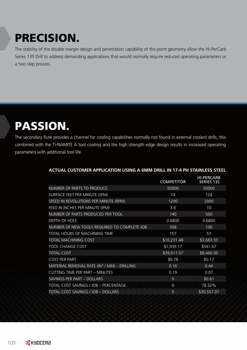
105
www.kyocera-sgstool.com
PRECISION.The stability of the double margin design and penetration capability of the point geometry allow the Hi-PerCarb
Series 135 Drill to address demanding applications that would normally require reduced operating parameters or
a two step process.
PASSION.The secondary �ute provides a channel for cooling capabilities normally not found in external coolant drills, this
combined with the Ti-NAMITE A tool coating and the high strength edge design results in increased operating
parameters with additional tool life.
ORIGINALTOTAL COST
TO DRILLPER PART
$0.78
$0.12(16%)$0.05
(7%)
$0.20(25%)
$0.15(19%)
$0.23(30%)
$0.02(3%)
NEWTOTAL COST
TO DRILLPER PART
$0.17
$0.03(16%)$0.01
(7%)
$0.04(25%)
$0.03(19%)
$0.05(30%)
$0.005(3%)
TOTALCOST TO DRILL
PER PARTREDUCED BY
$0.61(79%)
$0.10(12.51%)$0.04
(5.47%)
$0.15 (19.55%)
$0.12(14.86%)
$0.18 (23.46%)
$0.02(2.35%)
HI-PERCARBCOMPETITOR SERIES 135
NUMBER OF PARTS TO PRODUCE 50000 50000
SURFACE FEET PER MINUTE (SFM) 74 124
SPEED IN REVOLUTIONS PER MINUTE (RPM) 1200 2000
FEED IN INCHES PER MINUTE (IPM) 3.6 10
NUMBER OF PARTS PRODUCED PER TOOL 140 500
DEPTH OF HOLE 0.6800 0.6800
NUMBER OF NEW TOOLS REQUIRED TO COMPLETE JOB 358 100
TOTAL HOURS OF MACHINING TIME 157 57
TOTAL MACHINING COST $10,231.48 $3,683.33
TOOL CHANGE COST $1,939.17 $541.67
TOTAL COST $39,017.07 $8,460.00
COST PER PART $0.78 $0.17
MATERIAL REMOVAL RATE (IN3 / MIN) – DRILLING 0.16 0.44
CUTTING TIME PER PART – MINUTES 0.19 0.07
SAVINGS PER PART – DOLLARS 0 $0.61
TOTAL COST SAVINGS / JOB – PERCENTAGE 0 78.32%
TOTAL COST SAVINGS / JOB – DOLLARS 0 $30,557.07
ACTUAL CUSTOMER APPLICATION USING A 6MM DRILL IN 17-4 PH STAINLESS STEEL
Using 100 tools per job compared to 358 means less inventory and fewer purchase ordersto issue resulting in improved administrative cost and reduced tooling cost per job.
Increasing the feed by 278% has decreased the total hours of machine time by 100 hours gaining manufacturing capacity; this factored with the hourly shop rate has resulted in the largest portion of the savings.
With a tool life of 500 parts compared to 140 parts or a 357% improvement in tool life equates to less time dedicated to changing tools to keep the job running.
Increasing the material removal rate by .28 cubic inches or 275% requires less timein the cut and a reduced use of coolant.
TOOL COST REDUCED BY
MACHINING COST REDUCED BY
COOLANT COST REDUCED BY
TOOL COST
MACHINING COST
COOLANT COST
MACHINE DOWNTIME COST
TOOL CHANGE COST
ADMINISTRATIVE COST
MACHINE DOWNTIME COST REDUCED BY
TOOL CHANGE COST REDUCED BY
ADMINISTRATIVE COST REDUCED BY
BLIND HOLE THROUGH HOLE CROSS HOLE PRECAST HOLE INTERRUPTIONS
www.kyocera-sgstool.com
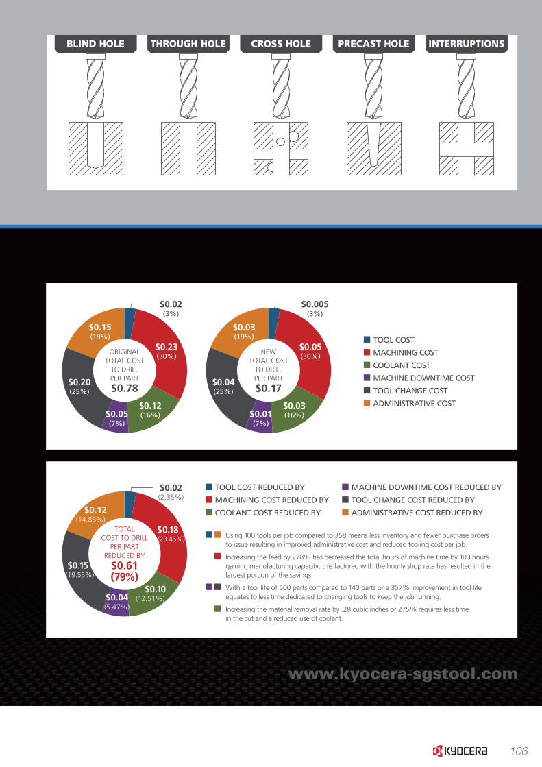
106
www.kyocera-sgstool.com
PRECISION.The stability of the double margin design and penetration capability of the point geometry allow the Hi-PerCarb
Series 135 Drill to address demanding applications that would normally require reduced operating parameters or
a two step process.
PASSION.The secondary �ute provides a channel for cooling capabilities normally not found in external coolant drills, this
combined with the Ti-NAMITE A tool coating and the high strength edge design results in increased operating
parameters with additional tool life.
ORIGINALTOTAL COST
TO DRILLPER PART
$0.78
$0.12(16%)$0.05
(7%)
$0.20(25%)
$0.15(19%)
$0.23(30%)
$0.02(3%)
NEWTOTAL COST
TO DRILLPER PART
$0.17
$0.03(16%)$0.01
(7%)
$0.04(25%)
$0.03(19%)
$0.05(30%)
$0.005(3%)
TOTALCOST TO DRILL
PER PARTREDUCED BY
$0.61(79%)
$0.10(12.51%)$0.04
(5.47%)
$0.15 (19.55%)
$0.12(14.86%)
$0.18 (23.46%)
$0.02(2.35%)
HI-PERCARBCOMPETITOR SERIES 135
NUMBER OF PARTS TO PRODUCE 50000 50000
SURFACE FEET PER MINUTE (SFM) 74 124
SPEED IN REVOLUTIONS PER MINUTE (RPM) 1200 2000
FEED IN INCHES PER MINUTE (IPM) 3.6 10
NUMBER OF PARTS PRODUCED PER TOOL 140 500
DEPTH OF HOLE 0.6800 0.6800
NUMBER OF NEW TOOLS REQUIRED TO COMPLETE JOB 358 100
TOTAL HOURS OF MACHINING TIME 157 57
TOTAL MACHINING COST $10,231.48 $3,683.33
TOOL CHANGE COST $1,939.17 $541.67
TOTAL COST $39,017.07 $8,460.00
COST PER PART $0.78 $0.17
MATERIAL REMOVAL RATE (IN3 / MIN) – DRILLING 0.16 0.44
CUTTING TIME PER PART – MINUTES 0.19 0.07
SAVINGS PER PART – DOLLARS 0 $0.61
TOTAL COST SAVINGS / JOB – PERCENTAGE 0 78.32%
TOTAL COST SAVINGS / JOB – DOLLARS 0 $30,557.07
ACTUAL CUSTOMER APPLICATION USING A 6MM DRILL IN 17-4 PH STAINLESS STEEL
Using 100 tools per job compared to 358 means less inventory and fewer purchase ordersto issue resulting in improved administrative cost and reduced tooling cost per job.
Increasing the feed by 278% has decreased the total hours of machine time by 100 hours gaining manufacturing capacity; this factored with the hourly shop rate has resulted in the largest portion of the savings.
With a tool life of 500 parts compared to 140 parts or a 357% improvement in tool life equates to less time dedicated to changing tools to keep the job running.
Increasing the material removal rate by .28 cubic inches or 275% requires less timein the cut and a reduced use of coolant.
TOOL COST REDUCED BY
MACHINING COST REDUCED BY
COOLANT COST REDUCED BY
TOOL COST
MACHINING COST
COOLANT COST
MACHINE DOWNTIME COST
TOOL CHANGE COST
ADMINISTRATIVE COST
MACHINE DOWNTIME COST REDUCED BY
TOOL CHANGE COST REDUCED BY
ADMINISTRATIVE COST REDUCED BY
BLIND HOLE THROUGH HOLE CROSS HOLE PRECAST HOLE INTERRUPTIONS
www.kyocera-sgstool.com
PRECISION.The stability of the double margin design and penetration capability of the point geometry allow the Hi-PerCarb
Series 135 Drill to address demanding applications that would normally require reduced operating parameters or
a two step process.
PASSION.The secondary �ute provides a channel for cooling capabilities normally not found in external coolant drills, this
combined with the Ti-NAMITE A tool coating and the high strength edge design results in increased operating
parameters with additional tool life.
ORIGINALTOTAL COST
TO DRILLPER PART
$0.78
$0.12(16%)$0.05
(7%)
$0.20(25%)
$0.15(19%)
$0.23(30%)
$0.02(3%)
NEWTOTAL COST
TO DRILLPER PART
$0.17
$0.03(16%)$0.01
(7%)
$0.04(25%)
$0.03(19%)
$0.05(30%)
$0.005(3%)
TOTALCOST TO DRILL
PER PARTREDUCED BY
$0.61(79%)
$0.10(12.51%)$0.04
(5.47%)
$0.15 (19.55%)
$0.12(14.86%)
$0.18 (23.46%)
$0.02(2.35%)
HI-PERCARBCOMPETITOR SERIES 135
NUMBER OF PARTS TO PRODUCE 50000 50000
SURFACE FEET PER MINUTE (SFM) 74 124
SPEED IN REVOLUTIONS PER MINUTE (RPM) 1200 2000
FEED IN INCHES PER MINUTE (IPM) 3.6 10
NUMBER OF PARTS PRODUCED PER TOOL 140 500
DEPTH OF HOLE 0.6800 0.6800
NUMBER OF NEW TOOLS REQUIRED TO COMPLETE JOB 358 100
TOTAL HOURS OF MACHINING TIME 157 57
TOTAL MACHINING COST $10,231.48 $3,683.33
TOOL CHANGE COST $1,939.17 $541.67
TOTAL COST $39,017.07 $8,460.00
COST PER PART $0.78 $0.17
MATERIAL REMOVAL RATE (IN3 / MIN) – DRILLING 0.16 0.44
CUTTING TIME PER PART – MINUTES 0.19 0.07
SAVINGS PER PART – DOLLARS 0 $0.61
TOTAL COST SAVINGS / JOB – PERCENTAGE 0 78.32%
TOTAL COST SAVINGS / JOB – DOLLARS 0 $30,557.07
ACTUAL CUSTOMER APPLICATION USING A 6MM DRILL IN 17-4 PH STAINLESS STEEL
Using 100 tools per job compared to 358 means less inventory and fewer purchase ordersto issue resulting in improved administrative cost and reduced tooling cost per job.
Increasing the feed by 278% has decreased the total hours of machine time by 100 hours gaining manufacturing capacity; this factored with the hourly shop rate has resulted in the largest portion of the savings.
With a tool life of 500 parts compared to 140 parts or a 357% improvement in tool life equates to less time dedicated to changing tools to keep the job running.
Increasing the material removal rate by .28 cubic inches or 275% requires less timein the cut and a reduced use of coolant.
TOOL COST REDUCED BY
MACHINING COST REDUCED BY
COOLANT COST REDUCED BY
TOOL COST
MACHINING COST
COOLANT COST
MACHINE DOWNTIME COST
TOOL CHANGE COST
ADMINISTRATIVE COST
MACHINE DOWNTIME COST REDUCED BY
TOOL CHANGE COST REDUCED BY
ADMINISTRATIVE COST REDUCED BY
BLIND HOLE THROUGH HOLE CROSS HOLE PRECAST HOLE INTERRUPTIONS

107
Aut
omot
ive
Aer
ospa
ceH
igh
Per
form
ance
Gen
eral
Spe
cial
Too
lsM
old
& D
ie
Hi Performance Drill Hi-PerCarb | Series 135
6 www.kyocera-sgstool.com
Seri
es
135 3
xD
|
Frac
tio
nal
& M
etri
c
Cutting Diameter
D1
Decimal Equivalent
Metric Equivalent
Tap Size Reference
Only
Shank Diameter
D2
Overall Length
L1
Flute Length
L2
Min. ClearedLength
L3
Shank Length
L4
Ti-NAMITE-A (AlTiN) EDP No.
1/64 0.0156 0.40 1/8 1-1/2 1/8 5/64 1 51752*
1/32 0.0312 0.79 1/8 1-1/2 1/4 3/16 1 51269*
3/64 0.0469 1.19 1/16-64 1/8 1-1/2 3/8 5/16 1 51270*
1,25 mm 0.0492 3,0 38,0 9,5 8,0 25,0 64500*
1,45 mm 0.0571 3,0 38,0 9,5 8,0 25,0 64501*
#53 0.0595 1.51 1/8 1-1/2 3/8 5/16 1 64502*
1/16 0.0625 1.59 5/64-60 1/8 2 7/16 3/8 1-1/4 51271*
1,6 mm 0.0630 3,0 50,0 11,0 9,0 32,0 64503*
1,75 mm 0.0689 3,0 50,0 11,0 9,0 32,0 64504*
#50 0.0700 1.78 1/8 2 7/16 3/8 1-1/4 64505*
5/64 0.0781 1.98 1/8 2 1/2 7/16 1-1/4 51272*
#47 0.0785 1.99 1/8 2 1/2 7/16 1-1/4 64506*
2,05 mm 0.0807 3,0 50,0 12,0 11,0 32,0 64507*
#46 0.0810 2.06 1/8 2 1/2 7/16 1-1/4 64508*
#43 0.0890 2.26 1/8 2 1/2 7/16 1-1/4 64509*
#42 0.0935 2.37 1/8 2 1/2 7/16 1-1/4 64510*
3/32 0.0938 2.38 1/8-32 1/8 2 1/2 7/16 1-1/4 51273
#40 0.0980 2.49 1/8 2 9/16 1/2 1-1/4 51274
2,5 mm 0.0984 3,0 50,0 14,0 12,0 32,0 64511
#39 0.0995 2.53 1/8 2 9/16 1/2 1-1/4 51753
#38 0.1015 2.58 5-40 1/8 2 9/16 1/2 1-1/4 51754
#37 0.1040 2.64 5-44 1/8 2 9/16 1/2 1-1/4 51755
#36 0.1065 2.71 6-32 1/8 2 9/16 1/2 1-1/4 51756
7/64 0.1094 2.78 1/8 2 5/8 9/16 1-1/4 51275
#35 0.1100 2.79 1/8 2 5/8 9/16 1-1/4 51276
#34 0.1110 2.82 1/8 2 5/8 9/16 1-1/4 51277
#33 0.1130 2.87 6-40 1/8 2 5/8 9/16 1-1/4 51757
2,9 mm 0.1142 3,0 50,0 16,0 14,0 32,0 64512
#32 0.1160 2.95 1/8 2 5/8 9/16 1-1/4 51758
3,0 mm 0.1181 6,0 62,0 20,0 17,0 36,0 63155
#31 0.1200 3.05 1/8 2 5/8 9/16 1-1/4 51759
3,1 mm 0.1220 6,0 62,0 20,0 17,0 36,0 63741
1/8 0.1250 3.18 1/4 2-1/2 3/4 21/32 1-7/16 51330
3,2 mm 0.1260 M3,5 X 0,35 6,0 62,0 20,0 17,0 36,0 63156
#30 0.1285 3.26 1/4 2-1/2 3/4 21/32 1-7/16 51278
3,3 mm 0.1299 M4 X 0,7 6,0 62,0 20,0 17,0 36,0 63157
3,4 mm 0.1339 6,0 62,0 20,0 17,0 36,0 63158
#29 0.1360 3.45 8-32,8-36 1/4 2-1/2 3/4 21/32 1-7/16 51331
3,5 mm 0.1378 M4 X 0,5 6,0 62,0 20,0 17,0 36,0 63159
#28 0.1405 3.57 8-40 1/4 2-1/2 3/4 21/32 1-7/16 51760
9/64 0.1406 3.57 1/4 2-1/2 3/4 21/32 1-7/16 51332
3,6 mm 0.1417 M4 X 0,35 6,0 62,0 20,0 17,0 36,0 63160 (continued on next page)
Common
Reach
Right Spiral
External Coolant
2
Flutes
TOLERANCES (inch)
DIAMETER D1 D2
≤.1181 +.00008/+.00047 h6
>.1181–.2362 +.00016/+.00063 h6
>.2362–.3937 +.00024/+.00083 h6
>.3937–.7087 +.00028/+.00098 h6
>.7087–1.1811 +.00031/+.00114 h6
TOLERANCES (mm)
DIAMETER D1 D2
≤ 3 +0,002/+0,012 h6
> 3 - 6 +0,004/+0,016 h6
> 6 - 10 +0,006/+0,021 h6
> 10 - 18 +0,007/+0,025 h6
> 18 - 30 +0,008/+0,029 h6145° 32°
L1L2
L3
L4
D2D1
*Single Margin

108
Autom
otiveA
erospaceH
igh Perform
anceG
eneralS
pecial ToolsM
old & D
ie
Hi Performance Drill Hi-PerCarb | Series 135
7
Serie
s 135 3
xD
|
Fraction
al & M
etric
www.kyocera-sgstool.com
Cutting Diameter
D1
Decimal Equivalent
Metric Equivalent
Tap Size Reference
Only
Shank Diameter
D2
Overall Length
L1
Flute Length
L2
Min. ClearedLength
L3
Shank Length
L4
Ti-NAMITE-A (AlTiN) EDP No.
#27 0.1440 3.66 1/4 2-1/2 3/4 21/32 1-7/16 51761
3,7 mm 0.1457 M4.5 X 0,75 6,0 62,0 20,0 17,0 36,0 63161
#26 0.1470 3.73 3/16-24 1/4 2-1/2 3/4 21/32 1-7/16 51762
#25 0.1495 3.80 10-24 1/4 2-5/8 7/8 23/32 1-7/16 51333
3,8 mm 0.1496 6,0 66,0 24,0 21,0 36,0 63742
#24 0.1520 3.86 10-28 1/4 2-5/8 7/8 23/32 1-7/16 51763
3,9 mm 0.1535 6,0 66,0 24,0 21,0 36,0 63743
#23 0.1540 3.91 1/4 2-5/8 7/8 23/32 1-7/16 51764
5/32 0.1562 3.97 1/4 2-5/8 7/8 23/32 1-7/16 51334
#22 0.1570 3.99 10-30 1/4 2-5/8 7/8 23/32 1-7/16 51765
4,0 mm 0.1575 M4,5 X 0,5 6,0 66,0 24,0 21,0 36,0 63162
#21 0.1590 4.04 10-32 1/4 2-5/8 7/8 23/32 1-7/16 51335
#20 0.1610 4.09 13/64-24 1/4 2-5/8 7/8 23/32 1-7/16 51279
4,1 mm 0.1614 6,0 66,0 24,0 21,0 36,0 63744
4,2 mm 0.1654 M5 / M5 X 0,75 6,0 66,0 24,0 21,0 36,0 63163
#19 0.1660 4.22 1/4 2-5/8 7/8 23/32 1-7/16 51766
4,3 mm 0.1693 6,0 66,0 24,0 21,0 36,0 63164
#18 0.1695 4.31 1/4 2-5/8 7/8 23/32 1-7/16 51767
11/64 0.1719 4.37 1/4 2-5/8 7/8 23/32 1-7/16 51336
#17 0.1730 4.39 1/4 2-5/8 7/8 23/32 1-7/16 51768
4,4 mm 0.1732 6,0 66,0 24,0 21,0 36,0 63745
#16 0.1770 4.50 12-24 1/4 2-5/8 7/8 23/32 1-7/16 51769
4,5 mm 0.1772 M5 X 0,5 6,0 66,0 24,0 21,0 36,0 63165
#15 0.1800 4.57 1/4 2-5/8 7/8 23/32 1-7/16 51770
4,6 mm 0.1811 12-28 6,0 66,0 24,0 21,0 36,0 63166
#14 0.1820 4.62 1/4 2-5/8 7/8 23/32 1-7/16 51771
#13 0.1850 4.70 12-32 1/4 2-5/8 7/8 23/32 1-7/16 51772
4,7 mm 0.1850 6,0 66,0 24,0 21,0 36,0 63746
3/16 0.1875 4.76 1/4 2-5/8 1 53/64 1-7/16 51337
#12 0.1890 4.80 7/32-32 1/4 2-5/8 1 53/64 1-7/16 51773
4,8 mm 0.1890 6,0 66,0 28,0 24,0 36,0 63167
#11 0.1910 4.85 1/4 2-5/8 1 53/64 1-7/16 51774
4,9 mm 0.1929 6,0 66,0 28,0 24,0 36,0 63747
#10 0.1935 4.91 14-20 1/4 2-5/8 1 53/64 1-7/16 51775
#9 0.1960 4.98 1/4 2-5/8 1 53/64 1-7/16 51776
5,0 mm 0.1969 M6 X 1 6,0 66,0 28,0 24,0 36,0 63168
#8 0.1990 5.05 1/4 2-5/8 1 53/64 1-7/16 51777
5,1 mm 0.2008 6,0 66,0 28,0 24,0 36,0 63748
#7 0.2010 5.11 1/4-20 1/4 2-5/8 1 53/64 1-7/16 51338
13/64 0.2031 5.16 1/4 2-5/8 1 53/64 1-7/16 51339
#6 0.2040 5.18 1/4 2-5/8 1 53/64 1-7/16 51778
5,2 mm 0.2047 M6 X 0,75 6,0 66,0 28,0 24,0 36,0 63749 (continued on next page)
Common
Reach
Right Spiral
External Coolant
2
Flutes
TOLERANCES (inch)
DIAMETER D1 D2
≤.1181 +.00008/+.00047 h6
>.1181–.2362 +.00016/+.00063 h6
>.2362–.3937 +.00024/+.00083 h6
>.3937–.7087 +.00028/+.00098 h6
>.7087–1.1811 +.00031/+.00114 h6
TOLERANCES (mm)
DIAMETER D1 D2
≤ 3 +0,002/+0,012 h6
> 3 - 6 +0,004/+0,016 h6
> 6 - 10 +0,006/+0,021 h6
> 10 - 18 +0,007/+0,025 h6
> 18 - 30 +0,008/+0,029 h6145° 32°
L1L2
L3
L4
D2D1
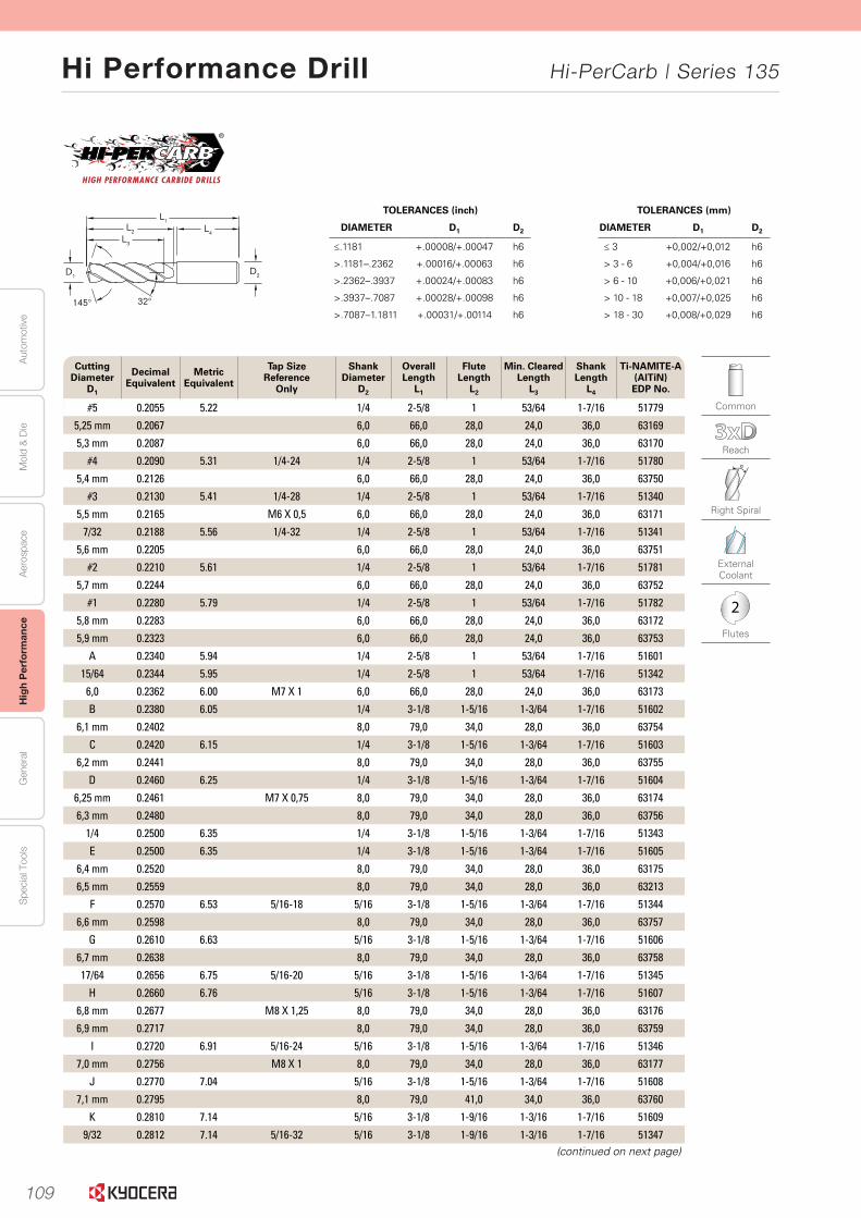
109
Aut
omot
ive
Aer
ospa
ceH
igh
Per
form
ance
Gen
eral
Spe
cial
Too
lsM
old
& D
ie
Hi Performance Drill Hi-PerCarb | Series 135
8
Seri
es
135 3
xD
|
Frac
tio
nal
& M
etri
c
www.kyocera-sgstool.com
145° 32°
L1L2
L3
L4
D2D1
Cutting Diameter
D1
Decimal Equivalent
Metric Equivalent
Tap Size Reference
Only
Shank Diameter
D2
Overall Length
L1
Flute Length
L2
Min. ClearedLength
L3
Shank Length
L4
Ti-NAMITE-A (AlTiN) EDP No.
#5 0.2055 5.22 1/4 2-5/8 1 53/64 1-7/16 51779
5,25 mm 0.2067 6,0 66,0 28,0 24,0 36,0 63169
5,3 mm 0.2087 6,0 66,0 28,0 24,0 36,0 63170
#4 0.2090 5.31 1/4-24 1/4 2-5/8 1 53/64 1-7/16 51780
5,4 mm 0.2126 6,0 66,0 28,0 24,0 36,0 63750
#3 0.2130 5.41 1/4-28 1/4 2-5/8 1 53/64 1-7/16 51340
5,5 mm 0.2165 M6 X 0,5 6,0 66,0 28,0 24,0 36,0 63171
7/32 0.2188 5.56 1/4-32 1/4 2-5/8 1 53/64 1-7/16 51341
5,6 mm 0.2205 6,0 66,0 28,0 24,0 36,0 63751
#2 0.2210 5.61 1/4 2-5/8 1 53/64 1-7/16 51781
5,7 mm 0.2244 6,0 66,0 28,0 24,0 36,0 63752
#1 0.2280 5.79 1/4 2-5/8 1 53/64 1-7/16 51782
5,8 mm 0.2283 6,0 66,0 28,0 24,0 36,0 63172
5,9 mm 0.2323 6,0 66,0 28,0 24,0 36,0 63753
A 0.2340 5.94 1/4 2-5/8 1 53/64 1-7/16 51601
15/64 0.2344 5.95 1/4 2-5/8 1 53/64 1-7/16 51342
6,0 0.2362 6.00 M7 X 1 6,0 66,0 28,0 24,0 36,0 63173
B 0.2380 6.05 1/4 3-1/8 1-5/16 1-3/64 1-7/16 51602
6,1 mm 0.2402 8,0 79,0 34,0 28,0 36,0 63754
C 0.2420 6.15 1/4 3-1/8 1-5/16 1-3/64 1-7/16 51603
6,2 mm 0.2441 8,0 79,0 34,0 28,0 36,0 63755
D 0.2460 6.25 1/4 3-1/8 1-5/16 1-3/64 1-7/16 51604
6,25 mm 0.2461 M7 X 0,75 8,0 79,0 34,0 28,0 36,0 63174
6,3 mm 0.2480 8,0 79,0 34,0 28,0 36,0 63756
1/4 0.2500 6.35 1/4 3-1/8 1-5/16 1-3/64 1-7/16 51343
E 0.2500 6.35 1/4 3-1/8 1-5/16 1-3/64 1-7/16 51605
6,4 mm 0.2520 8,0 79,0 34,0 28,0 36,0 63175
6,5 mm 0.2559 8,0 79,0 34,0 28,0 36,0 63213
F 0.2570 6.53 5/16-18 5/16 3-1/8 1-5/16 1-3/64 1-7/16 51344
6,6 mm 0.2598 8,0 79,0 34,0 28,0 36,0 63757
G 0.2610 6.63 5/16 3-1/8 1-5/16 1-3/64 1-7/16 51606
6,7 mm 0.2638 8,0 79,0 34,0 28,0 36,0 63758
17/64 0.2656 6.75 5/16-20 5/16 3-1/8 1-5/16 1-3/64 1-7/16 51345
H 0.2660 6.76 5/16 3-1/8 1-5/16 1-3/64 1-7/16 51607
6,8 mm 0.2677 M8 X 1,25 8,0 79,0 34,0 28,0 36,0 63176
6,9 mm 0.2717 8,0 79,0 34,0 28,0 36,0 63759
I 0.2720 6.91 5/16-24 5/16 3-1/8 1-5/16 1-3/64 1-7/16 51346
7,0 mm 0.2756 M8 X 1 8,0 79,0 34,0 28,0 36,0 63177
J 0.2770 7.04 5/16 3-1/8 1-5/16 1-3/64 1-7/16 51608
7,1 mm 0.2795 8,0 79,0 41,0 34,0 36,0 63760
K 0.2810 7.14 5/16 3-1/8 1-9/16 1-3/16 1-7/16 51609
9/32 0.2812 7.14 5/16-32 5/16 3-1/8 1-9/16 1-3/16 1-7/16 51347 (continued on next page)
Common
Reach
Right Spiral
External Coolant
2
Flutes
TOLERANCES (inch)
DIAMETER D1 D2
≤.1181 +.00008/+.00047 h6
>.1181–.2362 +.00016/+.00063 h6
>.2362–.3937 +.00024/+.00083 h6
>.3937–.7087 +.00028/+.00098 h6
>.7087–1.1811 +.00031/+.00114 h6
TOLERANCES (mm)
DIAMETER D1 D2
≤ 3 +0,002/+0,012 h6
> 3 - 6 +0,004/+0,016 h6
> 6 - 10 +0,006/+0,021 h6
> 10 - 18 +0,007/+0,025 h6
> 18 - 30 +0,008/+0,029 h6
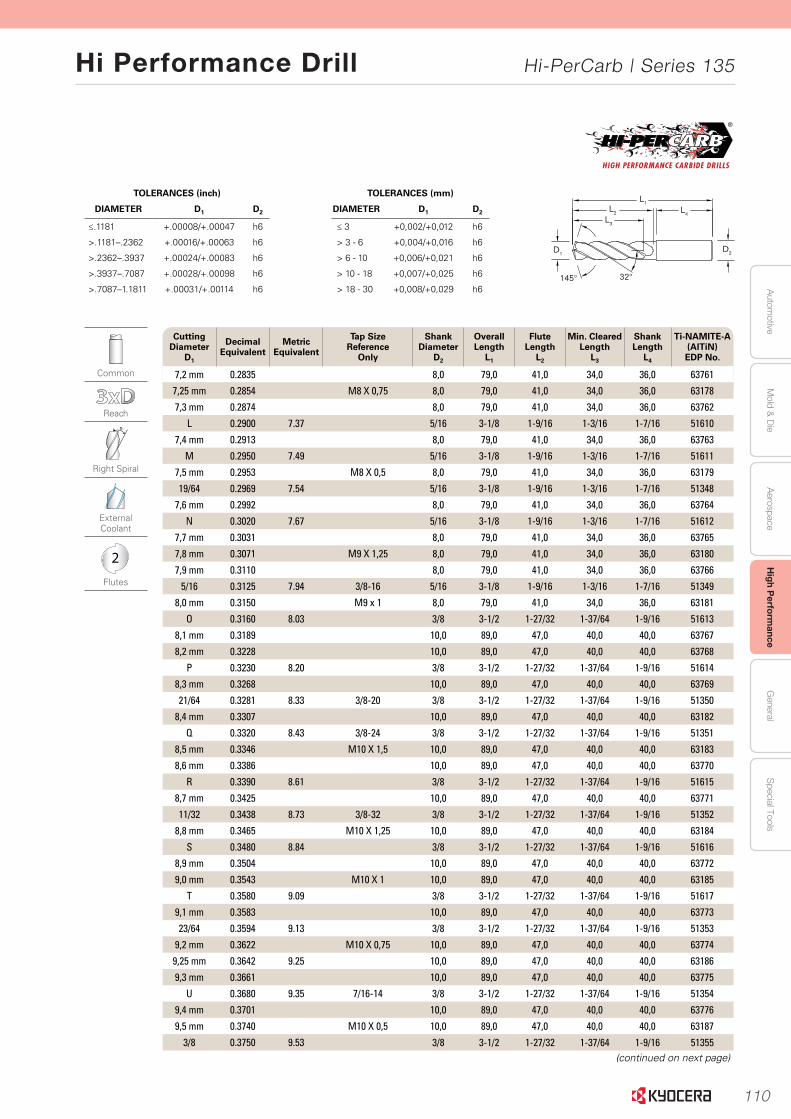
110
Autom
otiveA
erospaceH
igh Perform
anceG
eneralS
pecial ToolsM
old & D
ie
Hi Performance Drill Hi-PerCarb | Series 135
9
Serie
s 135 3
xD
|
Fraction
al & M
etric
www.kyocera-sgstool.com
Cutting Diameter
D1
Decimal Equivalent
Metric Equivalent
Tap Size Reference
Only
Shank Diameter
D2
Overall Length
L1
Flute Length
L2
Min. ClearedLength
L3
Shank Length
L4
Ti-NAMITE-A (AlTiN) EDP No.
7,2 mm 0.2835 8,0 79,0 41,0 34,0 36,0 63761
7,25 mm 0.2854 M8 X 0,75 8,0 79,0 41,0 34,0 36,0 63178
7,3 mm 0.2874 8,0 79,0 41,0 34,0 36,0 63762
L 0.2900 7.37 5/16 3-1/8 1-9/16 1-3/16 1-7/16 51610
7,4 mm 0.2913 8,0 79,0 41,0 34,0 36,0 63763
M 0.2950 7.49 5/16 3-1/8 1-9/16 1-3/16 1-7/16 51611
7,5 mm 0.2953 M8 X 0,5 8,0 79,0 41,0 34,0 36,0 63179
19/64 0.2969 7.54 5/16 3-1/8 1-9/16 1-3/16 1-7/16 51348
7,6 mm 0.2992 8,0 79,0 41,0 34,0 36,0 63764
N 0.3020 7.67 5/16 3-1/8 1-9/16 1-3/16 1-7/16 51612
7,7 mm 0.3031 8,0 79,0 41,0 34,0 36,0 63765
7,8 mm 0.3071 M9 X 1,25 8,0 79,0 41,0 34,0 36,0 63180
7,9 mm 0.3110 8,0 79,0 41,0 34,0 36,0 63766
5/16 0.3125 7.94 3/8-16 5/16 3-1/8 1-9/16 1-3/16 1-7/16 51349
8,0 mm 0.3150 M9 x 1 8,0 79,0 41,0 34,0 36,0 63181
O 0.3160 8.03 3/8 3-1/2 1-27/32 1-37/64 1-9/16 51613
8,1 mm 0.3189 10,0 89,0 47,0 40,0 40,0 63767
8,2 mm 0.3228 10,0 89,0 47,0 40,0 40,0 63768
P 0.3230 8.20 3/8 3-1/2 1-27/32 1-37/64 1-9/16 51614
8,3 mm 0.3268 10,0 89,0 47,0 40,0 40,0 63769
21/64 0.3281 8.33 3/8-20 3/8 3-1/2 1-27/32 1-37/64 1-9/16 51350
8,4 mm 0.3307 10,0 89,0 47,0 40,0 40,0 63182
Q 0.3320 8.43 3/8-24 3/8 3-1/2 1-27/32 1-37/64 1-9/16 51351
8,5 mm 0.3346 M10 X 1,5 10,0 89,0 47,0 40,0 40,0 63183
8,6 mm 0.3386 10,0 89,0 47,0 40,0 40,0 63770
R 0.3390 8.61 3/8 3-1/2 1-27/32 1-37/64 1-9/16 51615
8,7 mm 0.3425 10,0 89,0 47,0 40,0 40,0 63771
11/32 0.3438 8.73 3/8-32 3/8 3-1/2 1-27/32 1-37/64 1-9/16 51352
8,8 mm 0.3465 M10 X 1,25 10,0 89,0 47,0 40,0 40,0 63184
S 0.3480 8.84 3/8 3-1/2 1-27/32 1-37/64 1-9/16 51616
8,9 mm 0.3504 10,0 89,0 47,0 40,0 40,0 63772
9,0 mm 0.3543 M10 X 1 10,0 89,0 47,0 40,0 40,0 63185
T 0.3580 9.09 3/8 3-1/2 1-27/32 1-37/64 1-9/16 51617
9,1 mm 0.3583 10,0 89,0 47,0 40,0 40,0 63773
23/64 0.3594 9.13 3/8 3-1/2 1-27/32 1-37/64 1-9/16 51353
9,2 mm 0.3622 M10 X 0,75 10,0 89,0 47,0 40,0 40,0 63774
9,25 mm 0.3642 9.25 10,0 89,0 47,0 40,0 40,0 63186
9,3 mm 0.3661 10,0 89,0 47,0 40,0 40,0 63775
U 0.3680 9.35 7/16-14 3/8 3-1/2 1-27/32 1-37/64 1-9/16 51354
9,4 mm 0.3701 10,0 89,0 47,0 40,0 40,0 63776
9,5 mm 0.3740 M10 X 0,5 10,0 89,0 47,0 40,0 40,0 63187
3/8 0.3750 9.53 3/8 3-1/2 1-27/32 1-37/64 1-9/16 51355 (continued on next page)
145° 32°
L1L2
L3
L4
D2D1
Common
Reach
Right Spiral
External Coolant
2
Flutes
TOLERANCES (inch)
DIAMETER D1 D2
≤.1181 +.00008/+.00047 h6
>.1181–.2362 +.00016/+.00063 h6
>.2362–.3937 +.00024/+.00083 h6
>.3937–.7087 +.00028/+.00098 h6
>.7087–1.1811 +.00031/+.00114 h6
TOLERANCES (mm)
DIAMETER D1 D2
≤ 3 +0,002/+0,012 h6
> 3 - 6 +0,004/+0,016 h6
> 6 - 10 +0,006/+0,021 h6
> 10 - 18 +0,007/+0,025 h6
> 18 - 30 +0,008/+0,029 h6
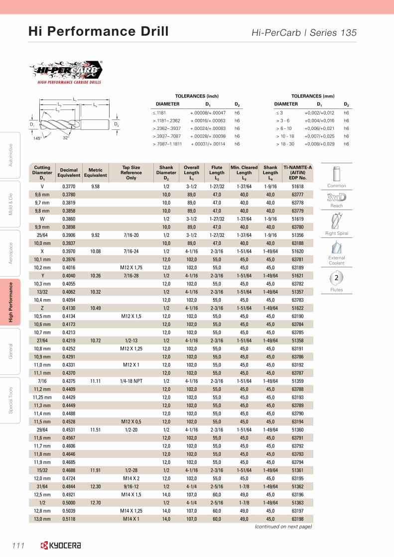
111
Aut
omot
ive
Aer
ospa
ceH
igh
Per
form
ance
Gen
eral
Spe
cial
Too
lsM
old
& D
ie
Hi Performance Drill Hi-PerCarb | Series 135
10
Seri
es
135 3
xD
|
Frac
tio
nal
& M
etri
c
www.kyocera-sgstool.com
145° 32°
L1L2
L3
L4
D2D1
Cutting Diameter
D1
Decimal Equivalent
Metric Equivalent
Tap Size Reference
Only
Shank Diameter
D2
Overall Length
L1
Flute Length
L2
Min. ClearedLength
L3
Shank Length
L4
Ti-NAMITE-A (AlTiN) EDP No.
V 0.3770 9.58 1/2 3-1/2 1-27/32 1-37/64 1-9/16 51618
9,6 mm 0.3780 10,0 89,0 47,0 40,0 40,0 63777
9,7 mm 0.3819 10,0 89,0 47,0 40,0 40,0 63778
9,8 mm 0.3858 10,0 89,0 47,0 40,0 40,0 63779
W 0.3860 1/2 3-1/2 1-27/32 1-37/64 1-9/16 51619
9,9 mm 0.3898 10,0 89,0 47,0 40,0 40,0 63780
25/64 0.3906 9.92 7/16-20 1/2 3-1/2 1-27/32 1-37/64 1-9/16 51356
10,0 mm 0.3937 10,0 89,0 47,0 40,0 40,0 63188
X 0.3970 10.08 7/16-24 1/2 4-1/16 2-3/16 1-51/64 1-49/64 51620
10,1 mm 0.3976 12,0 102,0 55,0 45,0 45,0 63781
10,2 mm 0.4016 M12 X 1,75 12,0 102,0 55,0 45,0 45,0 63189
Y 0.4040 10.26 7/16-28 1/2 4-1/16 2-3/16 1-51/64 1-49/64 51621
10,3 mm 0.4055 12,0 102,0 55,0 45,0 45,0 63782
13/32 0.4062 10.32 1/2 4-1/16 2-3/16 1-51/64 1-49/64 51357
10,4 mm 0.4094 12,0 102,0 55,0 45,0 45,0 63783
Z 0.4130 10.49 1/2 4-1/16 2-3/16 1-51/64 1-49/64 51622
10,5 mm 0.4134 M12 X 1,5 12,0 102,0 55,0 45,0 45,0 63190
10,6 mm 0.4173 12,0 102,0 55,0 45,0 45,0 63784
10,7 mm 0.4213 12,0 102,0 55,0 45,0 45,0 63785
27/64 0.4219 10.72 1/2-13 1/2 4-1/16 2-3/16 1-51/64 1-49/64 51358
10,8 mm 0.4252 M12 X 1,25 12,0 102,0 55,0 45,0 45,0 63191
10,9 mm 0.4291 12,0 102,0 55,0 45,0 45,0 63786
11,0 mm 0.4331 M12 X 1 12,0 102,0 55,0 45,0 45,0 63192
11,1 mm 0.4370 12,0 102,0 55,0 45,0 45,0 63787
7/16 0.4375 11.11 1/4-18 NPT 1/2 4-1/16 2-3/16 1-51/64 1-49/64 51359
11,2 mm 0.4409 12,0 102,0 55,0 45,0 45,0 63788
11,25 mm 0.4429 12,0 102,0 55,0 45,0 45,0 63193
11,3 mm 0.4449 12,0 102,0 55,0 45,0 45,0 63789
11,4 mm 0.4488 12,0 102,0 55,0 45,0 45,0 63790
11,5 mm 0.4528 M12 X 0,5 12,0 102,0 55,0 45,0 45,0 63194
29/64 0.4531 11.51 1/2-20 1/2 4-1/16 2-3/16 1-51/64 1-49/64 51360
11,6 mm 0.4567 12,0 102,0 55,0 45,0 45,0 63791
11,7 mm 0.4606 12,0 102,0 55,0 45,0 45,0 63792
11,8 mm 0.4646 12,0 102,0 55,0 45,0 45,0 63793
11,9 mm 0.4685 12,0 102,0 55,0 45,0 45,0 63794
15/32 0.4688 11.91 1/2-28 1/2 4-1/16 2-3/16 1-51/64 1-49/64 51361
12,0 mm 0.4724 M14 X 2 12,0 102,0 55,0 45,0 45,0 63195
31/64 0.4844 12.30 9/16-12 1/2 4-1/4 2-5/16 1-7/8 1-49/64 51362
12,5 mm 0.4921 M14 X 1,5 14,0 107,0 60,0 49,0 45,0 63196
1/2 0.5000 12.70 1/2 4-1/4 2-5/16 1-7/8 1-49/64 51363
12,8 mm 0.5039 M14 X 1,25 14,0 107,0 60,0 49,0 45,0 63197
13,0 mm 0.5118 M14 X 1 14,0 107,0 60,0 49,0 45,0 63198 (continued on next page)
Common
Reach
Right Spiral
External Coolant
2
Flutes
TOLERANCES (inch)
DIAMETER D1 D2
≤.1181 +.00008/+.00047 h6
>.1181–.2362 +.00016/+.00063 h6
>.2362–.3937 +.00024/+.00083 h6
>.3937–.7087 +.00028/+.00098 h6
>.7087–1.1811 +.00031/+.00114 h6
TOLERANCES (mm)
DIAMETER D1 D2
≤ 3 +0,002/+0,012 h6
> 3 - 6 +0,004/+0,016 h6
> 6 - 10 +0,006/+0,021 h6
> 10 - 18 +0,007/+0,025 h6
> 18 - 30 +0,008/+0,029 h6
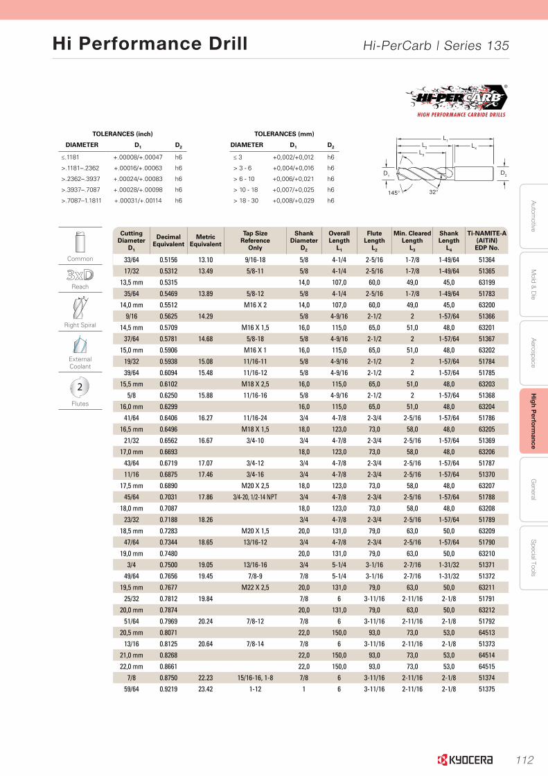
112
Autom
otiveA
erospaceH
igh Perform
anceG
eneralS
pecial ToolsM
old & D
ie
Hi Performance Drill Hi-PerCarb | Series 135
11
Serie
s 135 3
xD
|
Fraction
al & M
etric
www.kyocera-sgstool.com
145° 32°
L1L2
L3
L4
D2D1
Cutting Diameter
D1
Decimal Equivalent
Metric Equivalent
Tap Size Reference
Only
Shank Diameter
D2
Overall Length
L1
Flute Length
L2
Min. ClearedLength
L3
Shank Length
L4
Ti-NAMITE-A (AlTiN) EDP No.
33/64 0.5156 13.10 9/16-18 5/8 4-1/4 2-5/16 1-7/8 1-49/64 51364
17/32 0.5312 13.49 5/8-11 5/8 4-1/4 2-5/16 1-7/8 1-49/64 51365
13,5 mm 0.5315 14,0 107,0 60,0 49,0 45,0 63199
35/64 0.5469 13.89 5/8-12 5/8 4-1/4 2-5/16 1-7/8 1-49/64 51783
14,0 mm 0.5512 M16 X 2 14,0 107,0 60,0 49,0 45,0 63200
9/16 0.5625 14.29 5/8 4-9/16 2-1/2 2 1-57/64 51366
14,5 mm 0.5709 M16 X 1,5 16,0 115,0 65,0 51,0 48,0 63201
37/64 0.5781 14.68 5/8-18 5/8 4-9/16 2-1/2 2 1-57/64 51367
15,0 mm 0.5906 M16 X 1 16,0 115,0 65,0 51,0 48,0 63202
19/32 0.5938 15.08 11/16-11 5/8 4-9/16 2-1/2 2 1-57/64 51784
39/64 0.6094 15.48 11/16-12 5/8 4-9/16 2-1/2 2 1-57/64 51785
15,5 mm 0.6102 M18 X 2,5 16,0 115,0 65,0 51,0 48,0 63203
5/8 0.6250 15.88 11/16-16 5/8 4-9/16 2-1/2 2 1-57/64 51368
16,0 mm 0.6299 16,0 115,0 65,0 51,0 48,0 63204
41/64 0.6406 16.27 11/16-24 3/4 4-7/8 2-3/4 2-5/16 1-57/64 51786
16,5 mm 0.6496 M18 X 1,5 18,0 123,0 73,0 58,0 48,0 63205
21/32 0.6562 16.67 3/4-10 3/4 4-7/8 2-3/4 2-5/16 1-57/64 51369
17,0 mm 0.6693 18,0 123,0 73,0 58,0 48,0 63206
43/64 0.6719 17.07 3/4-12 3/4 4-7/8 2-3/4 2-5/16 1-57/64 51787
11/16 0.6875 17.46 3/4-16 3/4 4-7/8 2-3/4 2-5/16 1-57/64 51370
17,5 mm 0.6890 M20 X 2,5 18,0 123,0 73,0 58,0 48,0 63207
45/64 0.7031 17.86 3/4-20, 1/2-14 NPT 3/4 4-7/8 2-3/4 2-5/16 1-57/64 51788
18,0 mm 0.7087 18,0 123,0 73,0 58,0 48,0 63208
23/32 0.7188 18.26 3/4 4-7/8 2-3/4 2-5/16 1-57/64 51789
18,5 mm 0.7283 M20 X 1,5 20,0 131,0 79,0 63,0 50,0 63209
47/64 0.7344 18.65 13/16-12 3/4 4-7/8 2-3/4 2-5/16 1-57/64 51790
19,0 mm 0.7480 20,0 131,0 79,0 63,0 50,0 63210
3/4 0.7500 19.05 13/16-16 3/4 5-1/4 3-1/16 2-7/16 1-31/32 51371
49/64 0.7656 19.45 7/8-9 7/8 5-1/4 3-1/16 2-7/16 1-31/32 51372
19,5 mm 0.7677 M22 X 2,5 20,0 131,0 79,0 63,0 50,0 63211
25/32 0.7812 19.84 7/8 6 3-11/16 2-11/16 2-1/8 51791
20,0 mm 0.7874 20,0 131,0 79,0 63,0 50,0 63212
51/64 0.7969 20.24 7/8-12 7/8 6 3-11/16 2-11/16 2-1/8 51792
20,5 mm 0.8071 22,0 150,0 93,0 73,0 53,0 64513
13/16 0.8125 20.64 7/8-14 7/8 6 3-11/16 2-11/16 2-1/8 51373
21,0 mm 0.8268 22,0 150,0 93,0 73,0 53,0 64514
22,0 mm 0.8661 22,0 150,0 93,0 73,0 53,0 64515
7/8 0.8750 22.23 15/16-16, 1-8 7/8 6 3-11/16 2-11/16 2-1/8 51374
59/64 0.9219 23.42 1-12 1 6 3-11/16 2-11/16 2-1/8 51375
Common
Reach
Right Spiral
External Coolant
2
Flutes
TOLERANCES (inch)
DIAMETER D1 D2
≤.1181 +.00008/+.00047 h6
>.1181–.2362 +.00016/+.00063 h6
>.2362–.3937 +.00024/+.00083 h6
>.3937–.7087 +.00028/+.00098 h6
>.7087–1.1811 +.00031/+.00114 h6
TOLERANCES (mm)
DIAMETER D1 D2
≤ 3 +0,002/+0,012 h6
> 3 - 6 +0,004/+0,016 h6
> 6 - 10 +0,006/+0,021 h6
> 10 - 18 +0,007/+0,025 h6
> 18 - 30 +0,008/+0,029 h6
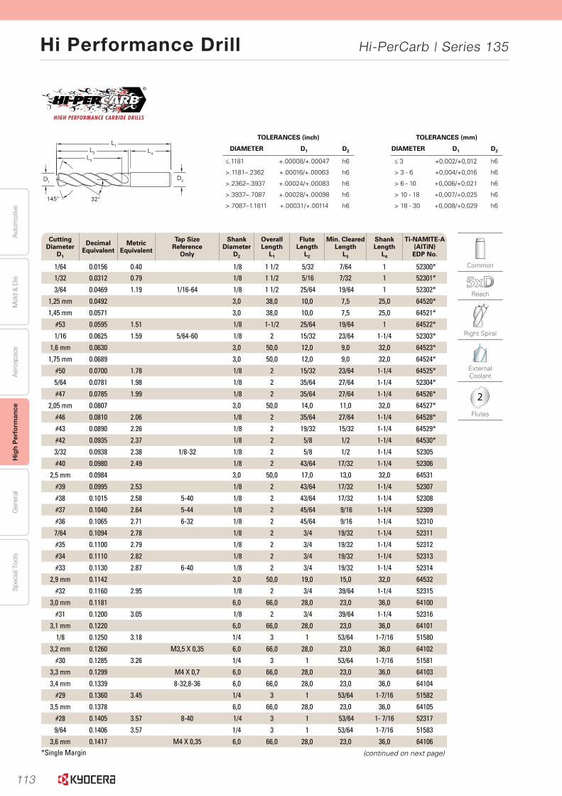
113
Aut
omot
ive
Aer
ospa
ceH
igh
Per
form
ance
Gen
eral
Spe
cial
Too
lsM
old
& D
ie
Hi Performance Drill Hi-PerCarb | Series 135
12
145° 32°
L1L2
L3
L4
D2D1
www.kyocera-sgstool.com
TOLERANCES (inch)
DIAMETER D1 D2
≤.1181 +.00008/+.00047 h6
>.1181–.2362 +.00016/+.00063 h6
>.2362–.3937 +.00024/+.00083 h6
>.3937–.7087 +.00028/+.00098 h6
>.7087–1.1811 +.00031/+.00114 h6
TOLERANCES (mm)
DIAMETER D1 D2
≤ 3 +0,002/+0,012 h6
> 3 - 6 +0,004/+0,016 h6
> 6 - 10 +0,006/+0,021 h6
> 10 - 18 +0,007/+0,025 h6
> 18 - 30 +0,008/+0,029 h6
Seri
es
135 5
xD
|
Frac
tio
nal
& M
etri
c
Cutting Diameter
D1
Decimal Equivalent
Metric Equivalent
Tap Size Reference
Only
Shank Diameter
D2
Overall Length
L1
Flute Length
L2
Min. ClearedLength
L3
Shank Length
L4
Ti-NAMITE-A (AlTiN) EDP No.
1/64 0.0156 0.40 1/8 1 1/2 5/32 7/64 1 52300*1/32 0.0312 0.79 1/8 1 1/2 5/16 7/32 1 52301*
3/64 0.0469 1.19 1/16-64 1/8 1 1/2 25/64 19/64 1 52302*
1,25 mm 0.0492 3,0 38,0 10,0 7,5 25,0 64520*
1,45 mm 0.0571 3,0 38,0 10,0 7,5 25,0 64521*
#53 0.0595 1.51 1/8 1-1/2 25/64 19/64 1 64522*
1/16 0.0625 1.59 5/64-60 1/8 2 15/32 23/64 1-1/4 52303*
1,6 mm 0.0630 3,0 50,0 12,0 9,0 32,0 64523*
1,75 mm 0.0689 3,0 50,0 12,0 9,0 32,0 64524*
#50 0.0700 1.78 1/8 2 15/32 23/64 1-1/4 64525*
5/64 0.0781 1.98 1/8 2 35/64 27/64 1-1/4 52304*
#47 0.0785 1.99 1/8 2 35/64 27/64 1-1/4 64526*
2,05 mm 0.0807 3,0 50,0 14,0 11,0 32,0 64527*
#46 0.0810 2.06 1/8 2 35/64 27/64 1-1/4 64528*
#43 0.0890 2.26 1/8 2 19/32 15/32 1-1/4 64529*
#42 0.0935 2.37 1/8 2 5/8 1/2 1-1/4 64530*
3/32 0.0938 2.38 1/8-32 1/8 2 5/8 1/2 1-1/4 52305
#40 0.0980 2.49 1/8 2 43/64 17/32 1-1/4 52306
2,5 mm 0.0984 3,0 50,0 17,0 13,0 32,0 64531
#39 0.0995 2.53 1/8 2 43/64 17/32 1-1/4 52307
#38 0.1015 2.58 5-40 1/8 2 43/64 17/32 1-1/4 52308
#37 0.1040 2.64 5-44 1/8 2 45/64 9/16 1-1/4 52309
#36 0.1065 2.71 6-32 1/8 2 45/64 9/16 1-1/4 52310
7/64 0.1094 2.78 1/8 2 3/4 19/32 1-1/4 52311
#35 0.1100 2.79 1/8 2 3/4 19/32 1-1/4 52312
#34 0.1110 2.82 1/8 2 3/4 19/32 1-1/4 52313
#33 0.1130 2.87 6-40 1/8 2 3/4 19/32 1-1/4 52314
2,9 mm 0.1142 3,0 50,0 19,0 15,0 32,0 64532
#32 0.1160 2.95 1/8 2 3/4 39/64 1-1/4 52315
3,0 mm 0.1181 6,0 66,0 28,0 23,0 36,0 64100
#31 0.1200 3.05 1/8 2 3/4 39/64 1-1/4 52316
3,1 mm 0.1220 6,0 66,0 28,0 23,0 36,0 64101
1/8 0.1250 3.18 1/4 3 1 53/64 1-7/16 51580
3,2 mm 0.1260 M3,5 X 0,35 6,0 66,0 28,0 23,0 36,0 64102
#30 0.1285 3.26 1/4 3 1 53/64 1-7/16 51581
3,3 mm 0.1299 M4 X 0,7 6,0 66,0 28,0 23,0 36,0 64103
3,4 mm 0.1339 8-32,8-36 6,0 66,0 28,0 23,0 36,0 64104
#29 0.1360 3.45 1/4 3 1 53/64 1-7/16 51582
3,5 mm 0.1378 6,0 66,0 28,0 23,0 36,0 64105
#28 0.1405 3.57 8-40 1/4 3 1 53/64 1- 7/16 52317
9/64 0.1406 3.57 1/4 3 1 53/64 1-7/16 51583
3,6 mm 0.1417 M4 X 0,35 6,0 66,0 28,0 23,0 36,0 64106
(continued on next page)
Common
Reach
Right Spiral
External Coolant
2
Flutes
*Single Margin

114
Autom
otiveA
erospaceH
igh Perform
anceG
eneralS
pecial ToolsM
old & D
ie
Hi Performance Drill Hi-PerCarb | Series 135
13
Serie
s 135 5
xD
|
Fraction
al & M
etric
145° 32°
L1L2
L3
L4
D2D1
www.kyocera-sgstool.com
TOLERANCES (inch)
DIAMETER D1 D2
≤.1181 +.00008/+.00047 h6
>.1181–.2362 +.00016/+.00063 h6
>.2362–.3937 +.00024/+.00083 h6
>.3937–.7087 +.00028/+.00098 h6
>.7087–1.1811 +.00031/+.00114 h6
TOLERANCES (mm)
DIAMETER D1 D2
≤ 3 +0,002/+0,012 h6
> 3 - 6 +0,004/+0,016 h6
> 6 - 10 +0,006/+0,021 h6
> 10 - 18 +0,007/+0,025 h6
> 18 - 30 +0,008/+0,029 h6
Cutting Diameter
D1
Decimal Equivalent
Metric Equivalent
Tap Size Reference
Only
Shank Diameter
D2
Overall Length
L1
Flute Length
L2
Min. ClearedLength
L3
Shank Length
L4
Ti-NAMITE-A (AlTiN) EDP No.
#27 0.1440 3.66 1/4 3 1 53/64 1-7/16 52318
3,7 mm 0.1457 M4.5 X 0,75 6,0 66,0 28,0 23,0 36,0 64107
#26 0.1470 3.73 3/16-24 1/4 3 1 53/64 1-7/16 52319
#25 0.1495 3.80 10-24 1/4 3-1/4 1-1/4 1-5/64 1-7/16 51584
3,8 mm 0.1496 6,0 74,0 36,0 29,0 36,0 64108
#24 0.1520 3.86 10-28 1/4 3-1/4 1-1/4 1-5/64 1-7/16 52321
3,9 mm 0.1535 6,0 74,0 36,0 29,0 36,0 64109
#23 0.1540 3.91 1/4 3-1/4 1-1/4 1-5/64 1-7/16 52322
5/32 0.1562 3.97 1/4 3-1/4 1-1/4 1-5/64 1-7/16 51585
#22 0.1570 3.99 10-30 1/4 3-1/4 1-1/4 1-5/64 1-7/16 52323
4,0 mm 0.1575 M4,5 X 0,5 6,0 74,0 36,0 29,0 36,0 64110
#21 0.1590 4.04 10-32 1/4 3-1/4 1-1/4 1-5/64 1-7/16 51586
#20 0.1610 4.09 13/64-24 1/4 3-1/4 1-1/4 1-5/64 1-7/16 51587
4,1 mm 0.1614 6,0 74,0 36,0 29,0 36,0 64111
4,2 mm 0.1654 M5 / M5 X 0,75 6,0 74,0 36,0 29,0 36,0 64112
#19 0.1660 4.22 1/4 3-1/4 1-1/4 1-5/64 1-7/16 52324
4,3 mm 0.1693 6,0 74,0 36,0 29,0 36,0 64113
#18 0.1695 4.31 1/4 3-1/4 1-1/4 1-5/64 1-7/16 52325
11/64 0.1719 4.37 1/4 3-1/4 1-1/4 1-5/64 1-7/16 51588
#17 0.1730 4.39 1/4 3-1/4 1-1/4 1-5/64 1-7/16 52326
4,4 mm 0.1732 6,0 74,0 36,0 29,0 36,0 64114
4,5 mm 0.1772 M5 X 0,5 6,0 74,0 36,0 29,0 36,0 64115
#15 0.1800 4.57 1/4 3-1/4 1-1/4 1-5/64 1-7/16 52327
4,6 mm 0.1811 12-28 6,0 74,0 36,0 29,0 36,0 64116
#14 0.1820 4.62 1/4 3-1/4 1-1/4 1-5/64 1-7/16 52328
#13 0.1850 4.70 12-32 1/4 3-1/4 1-1/4 1-5/64 1-7/16 52329
4,7 mm 0.1850 6,0 74,0 36,0 29,0 36,0 64117
3/16 0.1875 4.76 1/4 3-1/4 1-3/4 1-37/64 1-7/16 51589
#12 0.1890 4.80 7/32-32 1/4 3-1/4 1-3/4 1-37/64 1-7/16 52330
4,8 mm 0.1890 6,0 82,0 44,0 35,0 36,0 64118
4,9 mm 0.1929 6,0 82,0 44,0 35,0 36,0 64119
#10 0.1935 4.91 14-20 1/4 3-1/4 1-3/4 1-37/64 1-7/16 52331
#9 0.1960 4.98 1/4 3-1/4 1-3/4 1-37/64 1-7/16 52332
5,0 mm 0.1969 M6 X 1 6,0 82,0 44,0 35,0 36,0 64120
#8 0.1990 5.05 1/4 3-1/4 1-3/4 1-37/64 1-7/16 52333
5,1 mm 0.2008 6,0 82,0 44,0 35,0 36,0 64121
#7 0.2010 5.11 1/4-20 1/4 3-1/4 1-3/4 1-37/64 1-7/16 51506
13/64 0.2031 5.16 1/4 3-1/4 1-3/4 1-37/64 1-7/16 51507
#6 0.2040 5.18 1/4 3 1/4 1 3/4 1 37/64 1 7/16 52334
5,2 mm 0.2047 M6 X 0,75 6,0 82,0 44,0 35,0 36,0 64122
#5 0.2055 5.22 1/4 3-1/4 1-3/4 1-37/64 1-7/16 51590
5,25 mm 0.2067 6,0 82,0 44,0 35,0 36,0 64123
(continued on next page)
Common
Reach
Right Spiral
External Coolant
2
Flutes

115
Aut
omot
ive
Aer
ospa
ceH
igh
Per
form
ance
Gen
eral
Spe
cial
Too
lsM
old
& D
ie
Hi Performance Drill Hi-PerCarb | Series 135
14
Seri
es
135 5
xD
|
Frac
tio
nal
& M
etri
c
145° 32°
L1L2
L3
L4
D2D1
www.kyocera-sgstool.com
TOLERANCES (inch)
DIAMETER D1 D2
≤.1181 +.00008/+.00047 h6
>.1181–.2362 +.00016/+.00063 h6
>.2362–.3937 +.00024/+.00083 h6
>.3937–.7087 +.00028/+.00098 h6
>.7087–1.1811 +.00031/+.00114 h6
TOLERANCES (mm)
DIAMETER D1 D2
≤ 3 +0,002/+0,012 h6
> 3 - 6 +0,004/+0,016 h6
> 6 - 10 +0,006/+0,021 h6
> 10 - 18 +0,007/+0,025 h6
> 18 - 30 +0,008/+0,029 h6
Common
Reach
Right Spiral
External Coolant
2
Flutes
Cutting Diameter
D1
Decimal Equivalent
Metric Equivalent
Tap Size Reference
Only
Shank Diameter
D2
Overall Length
L1
Flute Length
L2
Min. ClearedLength
L3
Shank Length
L4
Ti-NAMITE-A (AlTiN) EDP No.
5,3 mm 0.2087 6,0 82,0 44,0 35,0 36,0 64124
#4 0.2090 5.31 1/4-24 1/4 3-1/4 1-3/4 1-37/64 1-7/16 51508
5,4 mm 0.2126 6,0 82,0 44,0 35,0 36,0 64125
#3 0.2130 5.41 1/4-28 1/4 3-1/4 1-3/4 1-37/64 1-7/16 51509
5,5 mm 0.2165 M6 X 0,5 6,0 82,0 44,0 35,0 36,0 64126
7/32 0.2188 5.56 1/4-32 1/4 3-1/4 1-3/4 1-37/64 1-7/16 51510
5,6 mm 0.2205 6,0 82,0 44,0 35,0 36,0 64127
#2 0.2210 5.61 1/4 3-1/4 1-3/4 1-37/64 1-7/16 52335
5,7 mm 0.2244 6,0 82,0 44,0 35,0 36,0 64128
#1 0.2280 5.79 1/4 3-1/4 1-3/4 1-37/64 1-7/16 52336
5,8 mm 0.2283 6,0 82,0 44,0 35,0 36,0 64129
5,9 mm 0.2323 6,0 82,0 44,0 35,0 36,0 64130
A 0.2340 5.94 1/4 3-1/4 1-3/4 1-37/64 1-7/16 52337
15/64 0.2344 5.95 1/4 3-1/4 1-3/4 1-37/64 1-7/16 51591
6,0 mm 0.2362 M7 X 1 6,0 82,0 44,0 35,0 36,0 64131
B 0.2380 6.05 1/4 3 5/8 2-5/64 1-51/64 1-7/16 52338
6,1 mm 0.2402 8,0 91,0 53,0 43,0 36,0 64132
C 0.2420 6.15 1/4 3 5/8 2-5/64 1-51/64 1-7/16 52339
6,2 mm 0.2441 8,0 91,0 53,0 43,0 36,0 64133
D 0.2460 6.25 1/4 3 5/8 2-5/64 1-51/64 1-7/16 52340
6,25 mm 0.2461 M7 X 0,75 8,0 91,0 53,0 43,0 36,0 64134
6,3 mm 0.2480 8,0 91,0 53,0 43,0 36,0 64135
1/4 0.2500 6.35 1/4 3-5/8 2-5/64 1-51/64 1-7/16 51511
6,4 mm 0.2520 8,0 91,0 53,0 43,0 36,0 64136
6,5 mm 0.2559 8,0 91,0 53,0 43,0 36,0 64137
F 0.2570 6.53 5/16-18 5/16 3-5/8 2-5/64 1-51/64 1-7/16 51512
6,6 mm 0.2598 8,0 91,0 53,0 43,0 36,0 64138
G 0.2610 6.63 5/16 3 5/8 2 5/64 1 51/64 1 7/16 52341
6,7 mm 0.2638 8,0 91,0 53,0 43,0 36,0 64139
17/64 0.2656 6.75 5/16-20 5/16 3-5/8 2-5/64 1-51/64 1-7/16 51513
H 0.2660 6.76 5/16 3-5/8 2-5/64 1-51/64 1-7/16 52342
6,8 mm 0.2677 M8 X 1,25 8,0 91,0 53,0 43,0 36,0 64140
6,9 mm 0.2717 8,0 91,0 53,0 43,0 36,0 64141
I 0.2720 6.91 5/16-24 5/16 3-5/8 2-5/64 1-51/64 1-7/16 51514
7,0 mm 0.2756 M8 X 1 8,0 91,0 53,0 43,0 36,0 64142
J 0.2770 7.04 5/16 3 5/8 2-5/64 1-51/64 1-7/16 52343
7,1 mm 0.2795 8,0 91,0 53,0 43,0 36,0 64143
K 0.2810 7.14 5/16 3 5/8 2-5/64 1-51/64 1-7/16 52344
9/32 0.2812 7.14 5/16-32 5/16 3-5/8 2-5/64 1-51/64 1-7/16 51515
7,2 mm 0.2835 8,0 91,0 53,0 43,0 36,0 64144
7,25 mm 0.2854 M8 X 0,75 8,0 91,0 53,0 43,0 36,0 64145
7,3 mm 0.2874 8,0 91,0 53,0 43,0 36,0 64146
(continued on next page)
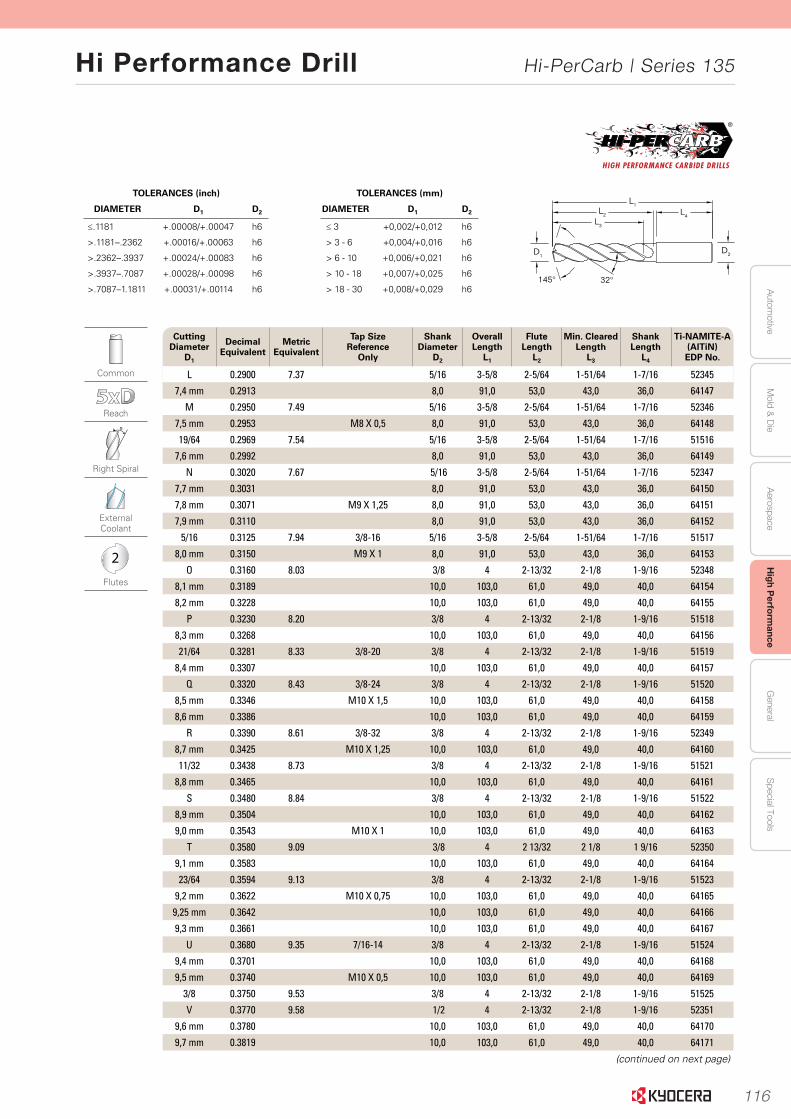
116
Autom
otiveA
erospaceH
igh Perform
anceG
eneralS
pecial ToolsM
old & D
ie
Hi Performance Drill Hi-PerCarb | Series 135
15
Serie
s 135 5
xD
|
Fraction
al & M
etric
145° 32°
L1L2
L3
L4
D2D1
www.kyocera-sgstool.com
TOLERANCES (inch)
DIAMETER D1 D2
≤.1181 +.00008/+.00047 h6
>.1181–.2362 +.00016/+.00063 h6
>.2362–.3937 +.00024/+.00083 h6
>.3937–.7087 +.00028/+.00098 h6
>.7087–1.1811 +.00031/+.00114 h6
TOLERANCES (mm)
DIAMETER D1 D2
≤ 3 +0,002/+0,012 h6
> 3 - 6 +0,004/+0,016 h6
> 6 - 10 +0,006/+0,021 h6
> 10 - 18 +0,007/+0,025 h6
> 18 - 30 +0,008/+0,029 h6
Common
Reach
Right Spiral
External Coolant
2
Flutes
Cutting Diameter
D1
Decimal Equivalent
Metric Equivalent
Tap Size Reference
Only
Shank Diameter
D2
Overall Length
L1
Flute Length
L2
Min. ClearedLength
L3
Shank Length
L4
Ti-NAMITE-A (AlTiN) EDP No.
L 0.2900 7.37 5/16 3-5/8 2-5/64 1-51/64 1-7/16 52345
7,4 mm 0.2913 8,0 91,0 53,0 43,0 36,0 64147
M 0.2950 7.49 5/16 3-5/8 2-5/64 1-51/64 1-7/16 52346
7,5 mm 0.2953 M8 X 0,5 8,0 91,0 53,0 43,0 36,0 64148
19/64 0.2969 7.54 5/16 3-5/8 2-5/64 1-51/64 1-7/16 51516
7,6 mm 0.2992 8,0 91,0 53,0 43,0 36,0 64149
N 0.3020 7.67 5/16 3-5/8 2-5/64 1-51/64 1-7/16 52347
7,7 mm 0.3031 8,0 91,0 53,0 43,0 36,0 64150
7,8 mm 0.3071 M9 X 1,25 8,0 91,0 53,0 43,0 36,0 64151
7,9 mm 0.3110 8,0 91,0 53,0 43,0 36,0 64152
5/16 0.3125 7.94 3/8-16 5/16 3-5/8 2-5/64 1-51/64 1-7/16 51517
8,0 mm 0.3150 M9 X 1 8,0 91,0 53,0 43,0 36,0 64153
O 0.3160 8.03 3/8 4 2-13/32 2-1/8 1-9/16 52348
8,1 mm 0.3189 10,0 103,0 61,0 49,0 40,0 64154
8,2 mm 0.3228 10,0 103,0 61,0 49,0 40,0 64155
P 0.3230 8.20 3/8 4 2-13/32 2-1/8 1-9/16 51518
8,3 mm 0.3268 10,0 103,0 61,0 49,0 40,0 64156
21/64 0.3281 8.33 3/8-20 3/8 4 2-13/32 2-1/8 1-9/16 51519
8,4 mm 0.3307 10,0 103,0 61,0 49,0 40,0 64157
Q 0.3320 8.43 3/8-24 3/8 4 2-13/32 2-1/8 1-9/16 51520
8,5 mm 0.3346 M10 X 1,5 10,0 103,0 61,0 49,0 40,0 64158
8,6 mm 0.3386 10,0 103,0 61,0 49,0 40,0 64159
R 0.3390 8.61 3/8-32 3/8 4 2-13/32 2-1/8 1-9/16 52349
8,7 mm 0.3425 M10 X 1,25 10,0 103,0 61,0 49,0 40,0 64160
11/32 0.3438 8.73 3/8 4 2-13/32 2-1/8 1-9/16 51521
8,8 mm 0.3465 10,0 103,0 61,0 49,0 40,0 64161
S 0.3480 8.84 3/8 4 2-13/32 2-1/8 1-9/16 51522
8,9 mm 0.3504 10,0 103,0 61,0 49,0 40,0 64162
9,0 mm 0.3543 M10 X 1 10,0 103,0 61,0 49,0 40,0 64163
T 0.3580 9.09 3/8 4 2 13/32 2 1/8 1 9/16 52350
9,1 mm 0.3583 10,0 103,0 61,0 49,0 40,0 64164
23/64 0.3594 9.13 3/8 4 2-13/32 2-1/8 1-9/16 51523
9,2 mm 0.3622 M10 X 0,75 10,0 103,0 61,0 49,0 40,0 64165
9,25 mm 0.3642 10,0 103,0 61,0 49,0 40,0 64166
9,3 mm 0.3661 10,0 103,0 61,0 49,0 40,0 64167
U 0.3680 9.35 7/16-14 3/8 4 2-13/32 2-1/8 1-9/16 51524
9,4 mm 0.3701 10,0 103,0 61,0 49,0 40,0 64168
9,5 mm 0.3740 M10 X 0,5 10,0 103,0 61,0 49,0 40,0 64169
3/8 0.3750 9.53 3/8 4 2-13/32 2-1/8 1-9/16 51525
V 0.3770 9.58 1/2 4 2-13/32 2-1/8 1-9/16 52351
9,6 mm 0.3780 10,0 103,0 61,0 49,0 40,0 64170
9,7 mm 0.3819 10,0 103,0 61,0 49,0 40,0 64171
(continued on next page)
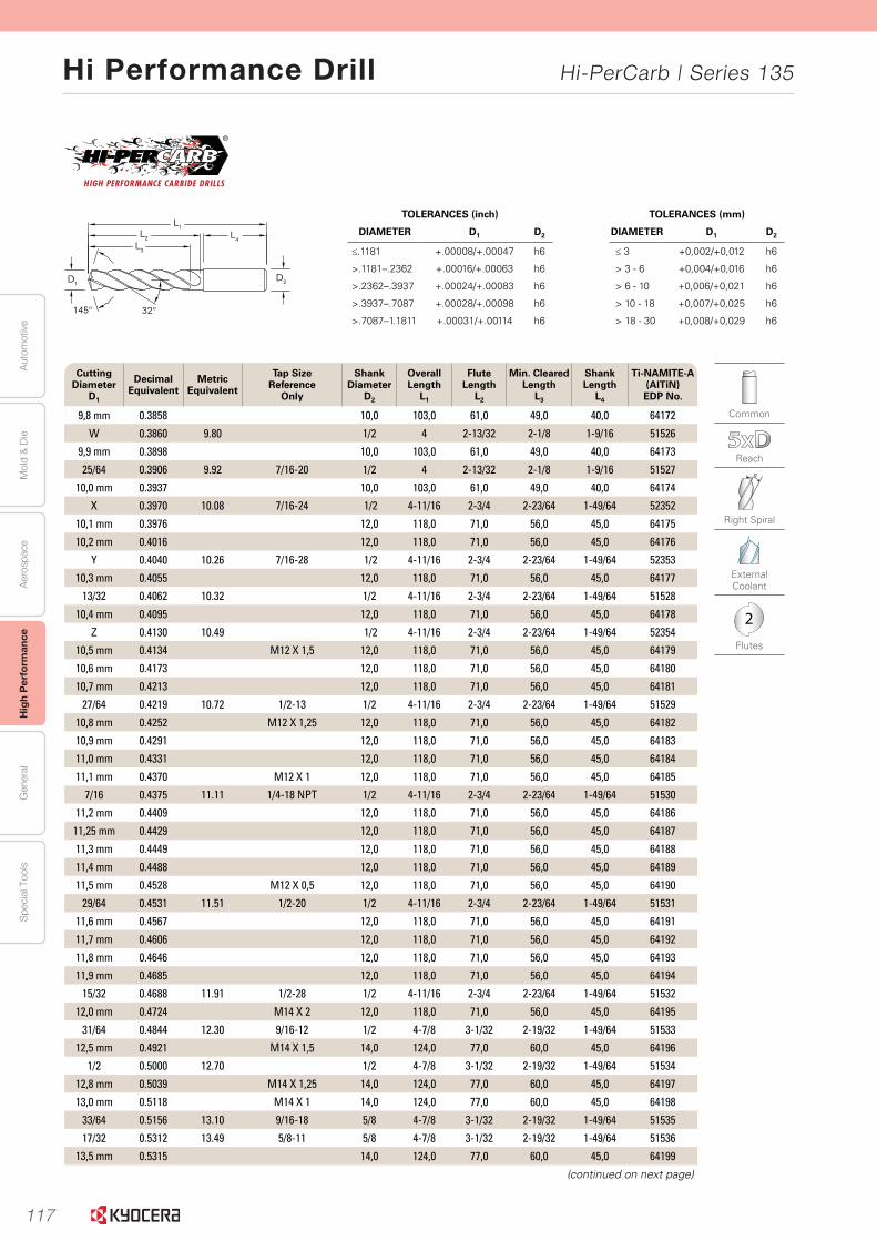
117
Aut
omot
ive
Aer
ospa
ceH
igh
Per
form
ance
Gen
eral
Spe
cial
Too
lsM
old
& D
ie
Hi Performance Drill Hi-PerCarb | Series 135
16
Seri
es
135 5
xD
|
Frac
tio
nal
& M
etri
c
www.kyocera-sgstool.com
145° 32°
L1L2
L3
L4
D2D1
TOLERANCES (mm)
DIAMETER D1 D2
≤ 3 +0,002/+0,012 h6
> 3 - 6 +0,004/+0,016 h6
> 6 - 10 +0,006/+0,021 h6
> 10 - 18 +0,007/+0,025 h6
> 18 - 30 +0,008/+0,029 h6
TOLERANCES (inch)
DIAMETER D1 D2
≤.1181 +.00008/+.00047 h6
>.1181–.2362 +.00016/+.00063 h6
>.2362–.3937 +.00024/+.00083 h6
>.3937–.7087 +.00028/+.00098 h6
>.7087–1.1811 +.00031/+.00114 h6
Common
Reach
Right Spiral
External Coolant
2
Flutes
Cutting Diameter
D1
Decimal Equivalent
Metric Equivalent
Tap Size Reference
Only
Shank Diameter
D2
Overall Length
L1
Flute Length
L2
Min. ClearedLength
L3
Shank Length
L4
Ti-NAMITE-A (AlTiN) EDP No.
9,8 mm 0.3858 10,0 103,0 61,0 49,0 40,0 64172
W 0.3860 9.80 1/2 4 2-13/32 2-1/8 1-9/16 51526
9,9 mm 0.3898 10,0 103,0 61,0 49,0 40,0 64173
25/64 0.3906 9.92 7/16-20 1/2 4 2-13/32 2-1/8 1-9/16 51527
10,0 mm 0.3937 10,0 103,0 61,0 49,0 40,0 64174
X 0.3970 10.08 7/16-24 1/2 4-11/16 2-3/4 2-23/64 1-49/64 52352
10,1 mm 0.3976 12,0 118,0 71,0 56,0 45,0 64175
10,2 mm 0.4016 12,0 118,0 71,0 56,0 45,0 64176
Y 0.4040 10.26 7/16-28 1/2 4-11/16 2-3/4 2-23/64 1-49/64 52353
10,3 mm 0.4055 12,0 118,0 71,0 56,0 45,0 64177
13/32 0.4062 10.32 1/2 4-11/16 2-3/4 2-23/64 1-49/64 51528
10,4 mm 0.4095 12,0 118,0 71,0 56,0 45,0 64178
Z 0.4130 10.49 1/2 4-11/16 2-3/4 2-23/64 1-49/64 52354
10,5 mm 0.4134 M12 X 1,5 12,0 118,0 71,0 56,0 45,0 64179
10,6 mm 0.4173 12,0 118,0 71,0 56,0 45,0 64180
10,7 mm 0.4213 12,0 118,0 71,0 56,0 45,0 64181
27/64 0.4219 10.72 1/2-13 1/2 4-11/16 2-3/4 2-23/64 1-49/64 51529
10,8 mm 0.4252 M12 X 1,25 12,0 118,0 71,0 56,0 45,0 64182
10,9 mm 0.4291 12,0 118,0 71,0 56,0 45,0 64183
11,0 mm 0.4331 12,0 118,0 71,0 56,0 45,0 64184
11,1 mm 0.4370 M12 X 1 12,0 118,0 71,0 56,0 45,0 64185
7/16 0.4375 11.11 1/4-18 NPT 1/2 4-11/16 2-3/4 2-23/64 1-49/64 51530
11,2 mm 0.4409 12,0 118,0 71,0 56,0 45,0 64186
11,25 mm 0.4429 12,0 118,0 71,0 56,0 45,0 64187
11,3 mm 0.4449 12,0 118,0 71,0 56,0 45,0 64188
11,4 mm 0.4488 12,0 118,0 71,0 56,0 45,0 64189
11,5 mm 0.4528 M12 X 0,5 12,0 118,0 71,0 56,0 45,0 64190
29/64 0.4531 11.51 1/2-20 1/2 4-11/16 2-3/4 2-23/64 1-49/64 51531
11,6 mm 0.4567 12,0 118,0 71,0 56,0 45,0 64191
11,7 mm 0.4606 12,0 118,0 71,0 56,0 45,0 64192
11,8 mm 0.4646 12,0 118,0 71,0 56,0 45,0 64193
11,9 mm 0.4685 12,0 118,0 71,0 56,0 45,0 64194
15/32 0.4688 11.91 1/2-28 1/2 4-11/16 2-3/4 2-23/64 1-49/64 51532
12,0 mm 0.4724 M14 X 2 12,0 118,0 71,0 56,0 45,0 64195
31/64 0.4844 12.30 9/16-12 1/2 4-7/8 3-1/32 2-19/32 1-49/64 51533
12,5 mm 0.4921 M14 X 1,5 14,0 124,0 77,0 60,0 45,0 64196
1/2 0.5000 12.70 1/2 4-7/8 3-1/32 2-19/32 1-49/64 51534
12,8 mm 0.5039 M14 X 1,25 14,0 124,0 77,0 60,0 45,0 64197
13,0 mm 0.5118 M14 X 1 14,0 124,0 77,0 60,0 45,0 64198
33/64 0.5156 13.10 9/16-18 5/8 4-7/8 3-1/32 2-19/32 1-49/64 51535
17/32 0.5312 13.49 5/8-11 5/8 4-7/8 3-1/32 2-19/32 1-49/64 51536
13,5 mm 0.5315 14,0 124,0 77,0 60,0 45,0 64199
(continued on next page)
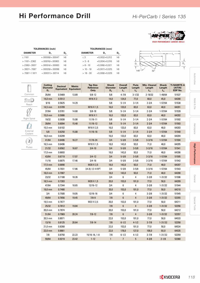
118
Autom
otiveA
erospaceH
igh Perform
anceG
eneralS
pecial ToolsM
old & D
ie
Hi Performance Drill Hi-PerCarb | Series 135
17
Serie
s 135 5
xD
|
Fraction
al & M
etric
145° 32°
L1L2
L3
L4
D2D1
www.kyocera-sgstool.com
TOLERANCES (mm)
DIAMETER D1 D2
≤ 3 +0,002/+0,012 h6
> 3 - 6 +0,004/+0,016 h6
> 6 - 10 +0,006/+0,021 h6
> 10 - 18 +0,007/+0,025 h6
> 18 - 30 +0,008/+0,029 h6
TOLERANCES (inch)
DIAMETER D1 D2
≤.1181 +.00008/+.00047 h6
>.1181–.2362 +.00016/+.00063 h6
>.2362–.3937 +.00024/+.00083 h6
>.3937–.7087 +.00028/+.00098 h6
>.7087–1.1811 +.00031/+.00114 h6
Common
Reach
Right Spiral
External Coolant
2
Flutes
Cutting Diameter
D1
Decimal Equivalent
Metric Equivalent
Tap Size Reference
Only
Shank Diameter
D2
Overall Length
L1
Flute Length
L2
Min. ClearedLength
L3
Shank Length
L4
Ti-NAMITE-A (AlTiN) EDP No.
35/64 0.5469 13.89 5/8-12 5/8 4-7/8 3-1/32 2-19/32 1-49/64 51537
14,0 mm 0.5512 M16 X 2 14,0 124,0 77,0 60,0 45,0 64200
9/16 0.5625 14.29 5/8 5-1/4 3-1/4 2-3/4 1-57/64 51538
14,5 mm 0.5709 M16 X 1,5 16,0 133,0 83,0 63,0 48,0 64201
37/64 0.5781 14.68 5/8-18 5/8 5-1/4 3-1/4 2-3/4 1-57/64 51539
15,0 mm 0.5906 M16 X 1 16,0 133,0 83,0 63,0 48,0 64202
19/32 0.5938 15.08 11/16-11 5/8 5-1/4 3-1/4 2-3/4 1-57/64 51592
39/64 0.6094 15.48 11/16-12 5/8 5-1/4 3-1/4 2-3/4 1-57/64 51593
15,5 mm 0.6102 M18 X 2,5 16,0 133,0 83,0 63,0 48,0 64203
5/8 0.6250 15.88 11/16-16 5/8 5-1/4 3-1/4 2-3/4 1-57/64 51540
16,0 mm 0.6299 16,0 133,0 83,0 63,0 48,0 64204
41/64 0.6406 16.27 11/16-24 3/4 5-5/8 3-5/8 3-3/16 1-57/64 51594
16,5 mm 0.6496 M18 X 1,5 18,0 143,0 93,0 71,0 48,0 64205
21/32 0.6562 16.67 3/4-10 3/4 5-5/8 3-5/8 3-3/16 1-57/64 51541
17,0 mm 0.6693 18,0 143,0 93,0 71,0 48,0 64206
43/64 0.6719 17.07 3/4-12 3/4 5-5/8 3-5/8 3-3/16 1-57/64 51595
11/16 0.6875 17.46 3/4-16 3/4 5-5/8 3-5/8 3-3/16 1-57/64 51542
17,5 mm 0.6890 M20 X 2,5 18,0 143,0 93,0 71,0 48,0 64207
45/64 0.7031 17.86 3/4-20, 1/2-14 NPT 3/4 5-5/8 3-5/8 3-3/16 1-57/64 51543
18,0 mm 0.7087 18,0 143,0 93,0 71,0 48,0 64208
23/32 0.7188 18.26 3/4 6 4 3-3/8 1-31/32 51596
18,5 mm 0.7283 M20 X 1,5 20,0 153,0 101,0 77,0 50,0 64209
47/64 0.7344 18.65 13/16-12 3/4 6 4 3-3/8 1-31/32 51544
19,0 mm 0.7480 20,0 153,0 101,0 77,0 50,0 64210
3/4 0.7500 19.05 13/16-16 3/4 6 4 3-3/8 1-31/32 51545
49/64 0.7656 19.45 7/8-9 7/8 6 4 3-3/8 1-31/32 52355
19,5 mm 0.7677 M22 X 2,5 20,0 153,0 101,0 77,0 50,0 64211
25/32 0.7812 19.84 7/8 6 4 3-3/8 1-31/32 52356
20,0 mm 0.7874 20,0 153,0 101,0 77,0 50,0 64212
51/64 0.7969 20.24 7/8-12 7/8 6 4 3-3/8 1-31/32 52357
20,5 mm 0.8071 22,0 153,0 101,0 77,0 50,0 64533
13/16 0.8125 20.64 7/8-14 7/8 6-1/2 4-1/2 3-7/8 1-31/32 52358
21,0 mm 0.8268 22,0 153,0 101,0 77,0 50,0 64534
22,0 mm 0.8661 22,0 178,0 127,0 108,0 50,0 64535
7/8 0.8750 22.23 15/16-16, 1-8 7/8 6-1/2 4-1/2 3-7/8 1-31/32 52359
59/64 0.9219 23.42 1-12 1 7 5 4-3/8 2-1/8 52360
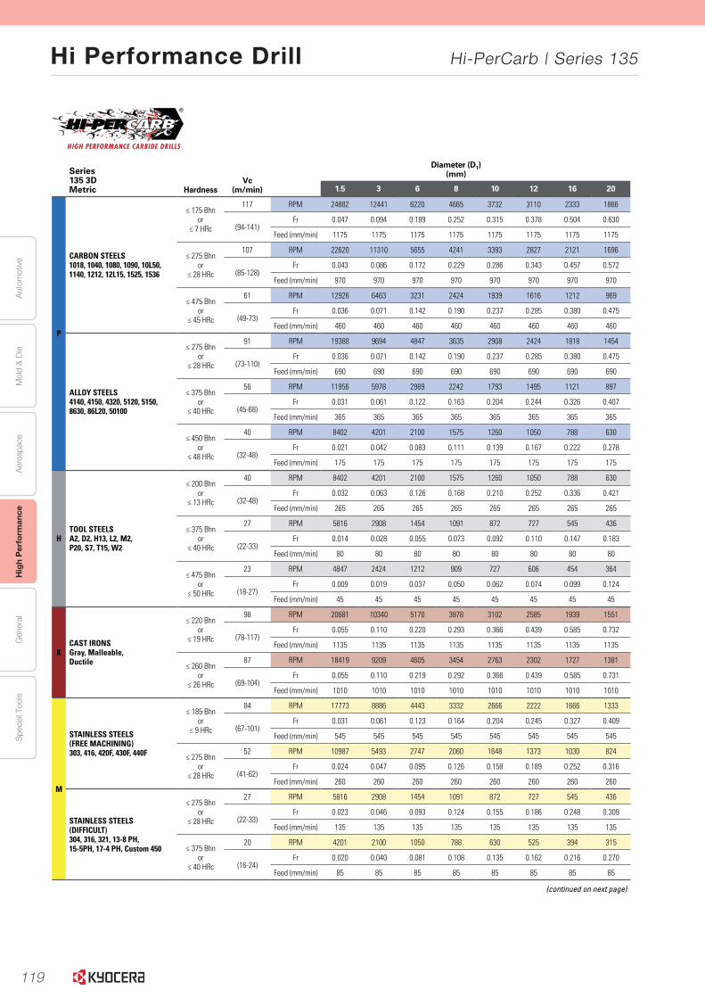
119
Aut
omot
ive
Aer
ospa
ceH
igh
Per
form
ance
Gen
eral
Spe
cial
Too
lsM
old
& D
ie
Hi Performance Drill Hi-PerCarb | Series 135
www.kyocera-sgstool.com20
Seri
es
135 3
xD
|
Spee
d &
Fee
d R
eco
mm
end
atio
ns
Series 135 3DMetric Hardness
Vc (m/min)
Diameter (D1)(mm)
1.5 3 6 8 10 12 16 20
P
CARBON STEELS 1018, 1040, 1080, 1090, 10L50, 1140, 1212, 12L15, 1525, 1536
≤ 175 Bhnor
≤ 7 HRc
117 RPM 24882 12441 6220 4665 3732 3110 2333 1866
(94-141)Fr 0.047 0.094 0.189 0.252 0.315 0.378 0.504 0.630
Feed (mm/min) 1175 1175 1175 1175 1175 1175 1175 1175
≤ 275 Bhnor
≤ 28 HRc
107 RPM 22620 11310 5655 4241 3393 2827 2121 1696
(85-128)Fr 0.043 0.086 0.172 0.229 0.286 0.343 0.457 0.572
Feed (mm/min) 970 970 970 970 970 970 970 970
≤ 475 Bhnor
≤ 45 HRc
61 RPM 12926 6463 3231 2424 1939 1616 1212 969
(49-73)Fr 0.036 0.071 0.142 0.190 0.237 0.285 0.380 0.475
Feed (mm/min) 460 460 460 460 460 460 460 460
ALLOY STEELS4140, 4150, 4320, 5120, 5150, 8630, 86L20, 50100
≤ 275 Bhnor
≤ 28 HRc
91 RPM 19388 9694 4847 3635 2908 2424 1818 1454
(73-110)Fr 0.036 0.071 0.142 0.190 0.237 0.285 0.380 0.475
Feed (mm/min) 690 690 690 690 690 690 690 690
≤ 375 Bhnor
≤ 40 HRc
56 RPM 11956 5978 2989 2242 1793 1495 1121 897
(45-68)Fr 0.031 0.061 0.122 0.163 0.204 0.244 0.326 0.407
Feed (mm/min) 365 365 365 365 365 365 365 365
≤ 450 Bhnor
≤ 48 HRc
40 RPM 8402 4201 2100 1575 1260 1050 788 630
(32-48)Fr 0.021 0.042 0.083 0.111 0.139 0.167 0.222 0.278
Feed (mm/min) 175 175 175 175 175 175 175 175
HTOOL STEELS A2, D2, H13, L2, M2, P20, S7, T15, W2
≤ 200 Bhnor
≤ 13 HRc
40 RPM 8402 4201 2100 1575 1260 1050 788 630
(32-48)Fr 0.032 0.063 0.126 0.168 0.210 0.252 0.336 0.421
Feed (mm/min) 265 265 265 265 265 265 265 265
≤ 375 Bhnor
≤ 40 HRc
27 RPM 5816 2908 1454 1091 872 727 545 436
(22-33)Fr 0.014 0.028 0.055 0.073 0.092 0.110 0.147 0.183
Feed (mm/min) 80 80 80 80 80 80 80 80
≤ 475 Bhnor
≤ 50 HRc
23 RPM 4847 2424 1212 909 727 606 454 364
(18-27)Fr 0.009 0.019 0.037 0.050 0.062 0.074 0.099 0.124
Feed (mm/min) 45 45 45 45 45 45 45 45
KCAST IRONSGray, Malleable, Ductile
≤ 220 Bhnor
≤ 19 HRc
98 RPM 20681 10340 5170 3878 3102 2585 1939 1551
(78-117)Fr 0.055 0.110 0.220 0.293 0.366 0.439 0.585 0.732
Feed (mm/min) 1135 1135 1135 1135 1135 1135 1135 1135
≤ 260 Bhnor
≤ 26 HRc
87 RPM 18419 9209 4605 3454 2763 2302 1727 1381
(69-104)Fr 0.055 0.110 0.219 0.292 0.366 0.439 0.585 0.731
Feed (mm/min) 1010 1010 1010 1010 1010 1010 1010 1010
M
STAINLESS STEELS(FREE MACHINING)303, 416, 420F, 430F, 440F
≤ 185 Bhnor
≤ 9 HRc
84 RPM 17773 8886 4443 3332 2666 2222 1666 1333
(67-101)Fr 0.031 0.061 0.123 0.164 0.204 0.245 0.327 0.409
Feed (mm/min) 545 545 545 545 545 545 545 545
≤ 275 Bhnor
≤ 28 HRc
52 RPM 10987 5493 2747 2060 1648 1373 1030 824
(41-62)Fr 0.024 0.047 0.095 0.126 0.158 0.189 0.252 0.316
Feed (mm/min) 260 260 260 260 260 260 260 260
STAINLESS STEELS(DIFFICULT)304, 316, 321, 13-8 PH, 15-5PH, 17-4 PH, Custom 450
≤ 275 Bhnor
≤ 28 HRc
27 RPM 5816 2908 1454 1091 872 727 545 436
(22-33)Fr 0.023 0.046 0.093 0.124 0.155 0.186 0.248 0.309
Feed (mm/min) 135 135 135 135 135 135 135 135
≤ 375 Bhnor
≤ 40 HRc
20 RPM 4201 2100 1050 788 630 525 394 315
(16-24)Fr 0.020 0.040 0.081 0.108 0.135 0.162 0.216 0.270
Feed (mm/min) 85 85 85 85 85 85 85 85
(continued on next page)
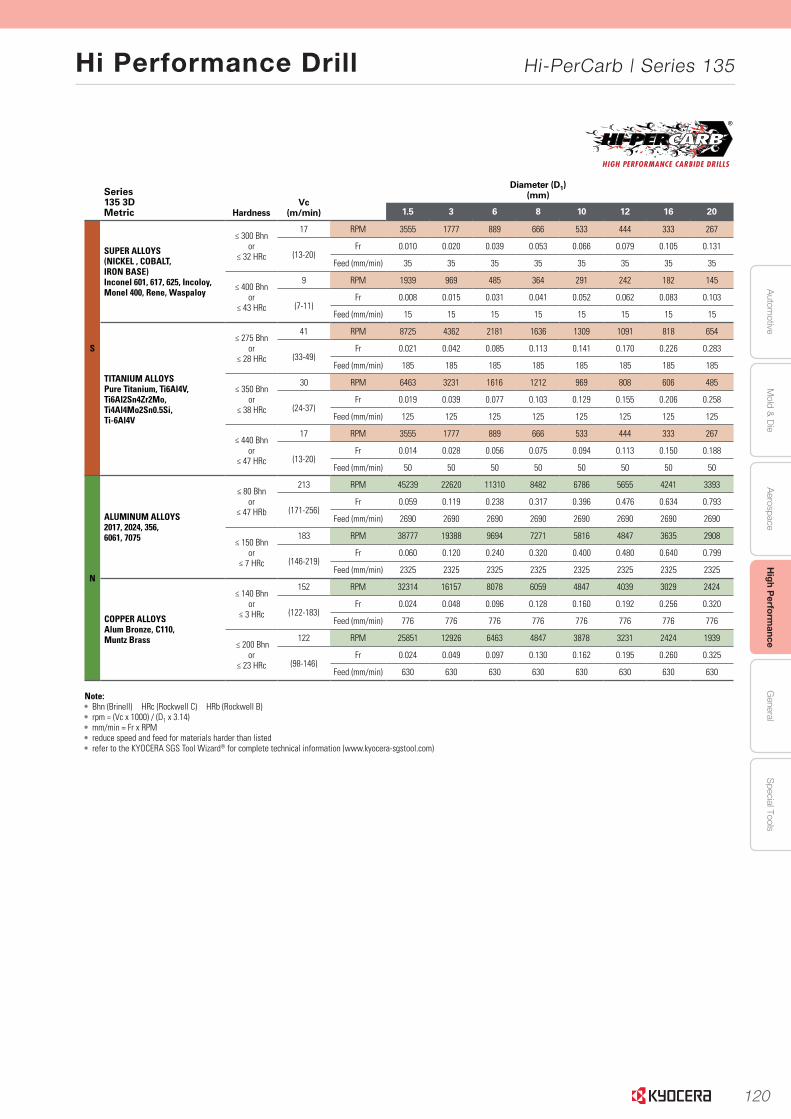
120
Autom
otiveA
erospaceH
igh Perform
anceG
eneralS
pecial ToolsM
old & D
ie
Hi Performance Drill Hi-PerCarb | Series 135
www.kyocera-sgstool.com 21
Serie
s 135 3
xD
|
Speed
& Feed
Reco
mm
end
ation
s
Series 135 3DMetric Hardness
Vc (m/min)
Diameter (D1)(mm)
1.5 3 6 8 10 12 16 20
S
SUPER ALLOYS(NICKEL , COBALT, IRON BASE)Inconel 601, 617, 625, Incoloy, Monel 400, Rene, Waspaloy
≤ 300 Bhnor
≤ 32 HRc
17 RPM 3555 1777 889 666 533 444 333 267
(13-20)Fr 0.010 0.020 0.039 0.053 0.066 0.079 0.105 0.131
Feed (mm/min) 35 35 35 35 35 35 35 35
≤ 400 Bhnor
≤ 43 HRc
9 RPM 1939 969 485 364 291 242 182 145
(7-11)Fr 0.008 0.015 0.031 0.041 0.052 0.062 0.083 0.103
Feed (mm/min) 15 15 15 15 15 15 15 15
TITANIUM ALLOYSPure Titanium, Ti6Al4V,Ti6Al2Sn4Zr2Mo,Ti4Al4Mo2Sn0.5Si,Ti-6Al4V
≤ 275 Bhnor
≤ 28 HRc
41 RPM 8725 4362 2181 1636 1309 1091 818 654
(33-49)Fr 0.021 0.042 0.085 0.113 0.141 0.170 0.226 0.283
Feed (mm/min) 185 185 185 185 185 185 185 185
≤ 350 Bhnor
≤ 38 HRc
30 RPM 6463 3231 1616 1212 969 808 606 485
(24-37)Fr 0.019 0.039 0.077 0.103 0.129 0.155 0.206 0.258
Feed (mm/min) 125 125 125 125 125 125 125 125
≤ 440 Bhnor
≤ 47 HRc
17 RPM 3555 1777 889 666 533 444 333 267
(13-20)Fr 0.014 0.028 0.056 0.075 0.094 0.113 0.150 0.188
Feed (mm/min) 50 50 50 50 50 50 50 50
N
ALUMINUM ALLOYS2017, 2024, 356, 6061, 7075
≤ 80 Bhnor
≤ 47 HRb
213 RPM 45239 22620 11310 8482 6786 5655 4241 3393
(171-256)Fr 0.059 0.119 0.238 0.317 0.396 0.476 0.634 0.793
Feed (mm/min) 2690 2690 2690 2690 2690 2690 2690 2690
≤ 150 Bhnor
≤ 7 HRc
183 RPM 38777 19388 9694 7271 5816 4847 3635 2908
(146-219)Fr 0.060 0.120 0.240 0.320 0.400 0.480 0.640 0.799
Feed (mm/min) 2325 2325 2325 2325 2325 2325 2325 2325
COPPER ALLOYSAlum Bronze, C110, Muntz Brass
≤ 140 Bhnor
≤ 3 HRc
152 RPM 32314 16157 8078 6059 4847 4039 3029 2424
(122-183)Fr 0.024 0.048 0.096 0.128 0.160 0.192 0.256 0.320
Feed (mm/min) 776 776 776 776 776 776 776 776
≤ 200 Bhnor
≤ 23 HRc
122 RPM 25851 12926 6463 4847 3878 3231 2424 1939
(98-146)Fr 0.024 0.049 0.097 0.130 0.162 0.195 0.260 0.325
Feed (mm/min) 630 630 630 630 630 630 630 630
Note: • Bhn (Brinell) HRc (Rockwell C) HRb (Rockwell B)• rpm = (Vc x 1000) / (D1 x 3.14)• mm/min = Fr x RPM• reduce speed and feed for materials harder than listed• refer to the KYOCERA SGS Tool Wizard® for complete technical information (www.kyocera-sgstool.com)
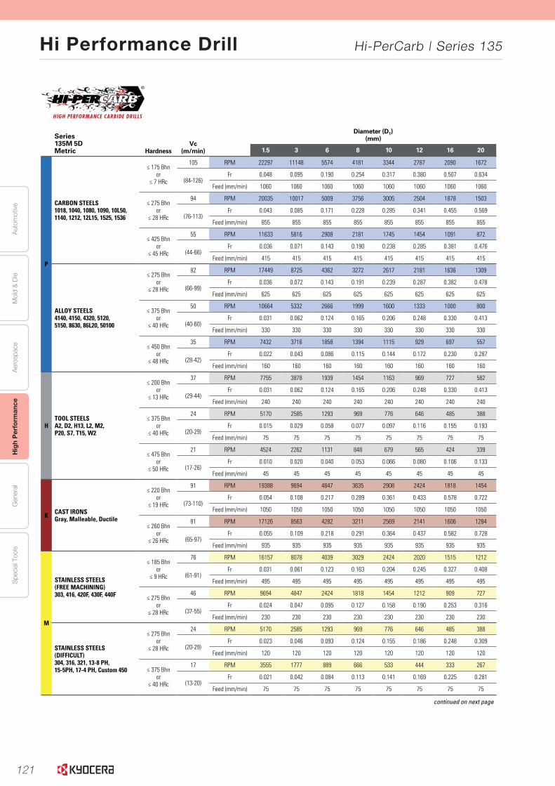
121
Aut
omot
ive
Aer
ospa
ceH
igh
Per
form
ance
Gen
eral
Spe
cial
Too
lsM
old
& D
ie
Hi Performance Drill Hi-PerCarb | Series 135
www.kyocera-sgstool.com24
Seri
es
135 5
xD
|
Spee
d &
Fee
d R
eco
mm
end
atio
ns
Series 135M 5DMetric Hardness
Vc (m/min)
Diameter (D1)(mm)
1.5 3 6 8 10 12 16 20
P
CARBON STEELS1018, 1040, 1080, 1090, 10L50, 1140, 1212, 12L15, 1525, 1536
≤ 175 Bhnor
≤ 7 HRc
105 RPM 22297 11148 5574 4181 3344 2787 2090 1672
(84-126)Fr 0.048 0.095 0.190 0.254 0.317 0.380 0.507 0.634
Feed (mm/min) 1060 1060 1060 1060 1060 1060 1060 1060
≤ 275 Bhnor
≤ 28 HRc
94 RPM 20035 10017 5009 3756 3005 2504 1878 1503
(76-113)Fr 0.043 0.085 0.171 0.228 0.285 0.341 0.455 0.569
Feed (mm/min) 855 855 855 855 855 855 855 855
≤ 425 Bhnor
≤ 45 HRc
55 RPM 11633 5816 2908 2181 1745 1454 1091 872
(44-66)Fr 0.036 0.071 0.143 0.190 0.238 0.285 0.381 0.476
Feed (mm/min) 415 415 415 415 415 415 415 415
ALLOY STEELS4140, 4150, 4320, 5120,5150, 8630, 86L20, 50100
≤ 275 Bhnor
≤ 28 HRc
82 RPM 17449 8725 4362 3272 2617 2181 1636 1309
(66-99)Fr 0.036 0.072 0.143 0.191 0.239 0.287 0.382 0.478
Feed (mm/min) 625 625 625 625 625 625 625 625
≤ 375 Bhnor
≤ 40 HRc
50 RPM 10664 5332 2666 1999 1600 1333 1000 800
(40-60)Fr 0.031 0.062 0.124 0.165 0.206 0.248 0.330 0.413
Feed (mm/min) 330 330 330 330 330 330 330 330
≤ 450 Bhnor
≤ 48 HRc
35 RPM 7432 3716 1858 1394 1115 929 697 557
(28-42)Fr 0.022 0.043 0.086 0.115 0.144 0.172 0.230 0.287
Feed (mm/min) 160 160 160 160 160 160 160 160
HTOOL STEELSA2, D2, H13, L2, M2,P20, S7, T15, W2
≤ 200 Bhnor
≤ 13 HRc
37 RPM 7755 3878 1939 1454 1163 969 727 582
(29-44)Fr 0.031 0.062 0.124 0.165 0.206 0.248 0.330 0.413
Feed (mm/min) 240 240 240 240 240 240 240 240
≤ 375 Bhnor
≤ 40 HRc
24 RPM 5170 2585 1293 969 776 646 485 388
(20-29)Fr 0.015 0.029 0.058 0.077 0.097 0.116 0.155 0.193
Feed (mm/min) 75 75 75 75 75 75 75 75
≤ 475 Bhnor
≤ 50 HRc
21 RPM 4524 2262 1131 848 679 565 424 339
(17-26)Fr 0.010 0.020 0.040 0.053 0.066 0.080 0.106 0.133
Feed (mm/min) 45 45 45 45 45 45 45 45
K CAST IRONSGray, Malleable, Ductile
≤ 220 Bhnor
≤ 19 HRc
91 RPM 19388 9694 4847 3635 2908 2424 1818 1454
(73-110)Fr 0.054 0.108 0.217 0.289 0.361 0.433 0.578 0.722
Feed (mm/min) 1050 1050 1050 1050 1050 1050 1050 1050
≤ 260 Bhnor
≤ 26 HRc
81 RPM 17126 8563 4282 3211 2569 2141 1606 1284
(65-97)Fr 0.055 0.109 0.218 0.291 0.364 0.437 0.582 0.728
Feed (mm/min) 935 935 935 935 935 935 935 935
M
STAINLESS STEELS(FREE MACHINING)303, 416, 420F, 430F, 440F
≤ 185 Bhnor
≤ 9 HRc
76 RPM 16157 8078 4039 3029 2424 2020 1515 1212
(61-91)Fr 0.031 0.061 0.123 0.163 0.204 0.245 0.327 0.408
Feed (mm/min) 495 495 495 495 495 495 495 495
≤ 275 Bhnor
≤ 28 HRc
46 RPM 9694 4847 2424 1818 1454 1212 909 727
(37-55)Fr 0.024 0.047 0.095 0.127 0.158 0.190 0.253 0.316
Feed (mm/min) 230 230 230 230 230 230 230 230
STAINLESS STEELS(DIFFICULT)304, 316, 321, 13-8 PH, 15-5PH, 17-4 PH, Custom 450
≤ 275 Bhnor
≤ 28 HRc
24 RPM 5170 2585 1293 969 776 646 485 388
(20-29)Fr 0.023 0.046 0.093 0.124 0.155 0.186 0.248 0.309
Feed (mm/min) 120 120 120 120 120 120 120 120
≤ 375 Bhnor
≤ 40 HRc
17 RPM 3555 1777 889 666 533 444 333 267
(13-20)Fr 0.021 0.042 0.084 0.113 0.141 0.169 0.225 0.281
Feed (mm/min) 75 75 75 75 75 75 75 75
continued on next page
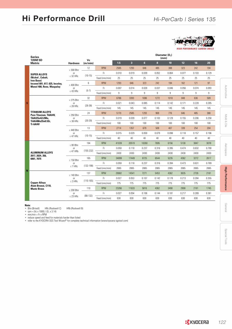
122
Autom
otiveA
erospaceH
igh Perform
anceG
eneralS
pecial ToolsM
old & D
ie
Hi Performance Drill Hi-PerCarb | Series 135
www.kyocera-sgstool.com 25
Serie
s 135 5
xD
|
Speed
& Feed
Reco
mm
end
ation
s
Series 135M 5DMetric Hardness
Vc (m/min)
Diameter (D1)(mm)
1.5 3 6 8 10 12 16 20
S
SUPER ALLOYS(Nickel , Cobalt, Iron Base)Inconel 601, 617, 625, Incoloy, Monel 400, Rene, Waspaloy
≤ 300 Bhnor
≤ 32 HRc
12 RPM 2585 1293 646 485 388 323 242 194
(10-15)Fr 0.010 0.019 0.039 0.052 0.064 0.077 0.103 0.129
Feed (mm/min) 25 25 25 25 25 25 25 25
≤ 400 Bhnor
≤ 43 HRc
6 RPM 1293 646 323 242 194 162 121 97
(5-7)Fr 0.007 0.014 0.028 0.037 0.046 0.056 0.074 0.093
Feed (mm/min) 9 9 9 9 9 9 9 9
TITANIUM ALLOYSPure Titanium, Ti6Al4V,Ti6Al2Sn4Zr2Mo,Ti4Al4Mo2Sn0.5Si,Ti-6Al4V
≤ 275 Bhnor
≤ 28 HRc
32 RPM 6786 3393 1696 1272 1018 848 636 509
(26-38)Fr 0.021 0.043 0.085 0.114 0.142 0.171 0.228 0.285
Feed (mm/min) 145 145 145 145 145 145 145 145
≤ 350 Bhnor
≤ 38 HRc
24 RPM 5170 2585 1293 969 776 646 485 388
(20-29)Fr 0.019 0.039 0.077 0.103 0.129 0.155 0.206 0.258
Feed (mm/min) 100 100 100 100 100 100 100 100
≤ 440 Bhnor
≤ 47 HRc
13 RPM 2714 1357 679 509 407 339 254 204
(10-15)Fr 0.015 0.029 0.059 0.079 0.098 0.118 0.157 0.196
Feed (mm/min) 40 40 40 40 40 40 40 40
N
ALUMINUM ALLOYS2017, 2024, 356, 6061, 7075
≤ 80 Bhnor
≤ 47 HRb
194 RPM 41039 20519 10260 7695 6156 5130 3847 3078
(155-232)Fr 0.059 0.118 0.237 0.316 0.395 0.474 0.632 0.790
Feed (mm/min) 2430 2430 2430 2430 2430 2430 2430 2430
≤ 150 Bhnor
≤ 7 HRc
165 RPM 34899 17449 8725 6544 5235 4362 3272 2617
(132-198)Fr 0.059 0.118 0.237 0.316 0.394 0.473 0.631 0.789
Feed (mm/min) 2065 2065 2065 2065 2065 2065 2065 2065
Copper AlloysAlum Bronze, C110, Muntz Brass
≤ 140 Bhnor
≤ 3 HRc
137 RPM 29082 14541 7271 5453 4362 3635 2726 2181
(110-165)Fr 0.027 0.053 0.107 0.142 0.178 0.213 0.284 0.355
Feed (mm/min) 775 775 775 775 775 775 775 775
≤ 200 Bhnor
≤ 23 HRc
110 RPM 23266 11633 5816 4362 3490 2908 2181 1745
(88-132)Fr 0.027 0.054 0.108 0.144 0.181 0.217 0.289 0.361
Feed (mm/min) 630 630 630 630 630 630 630 630
Note:• Bhn (Brinell) HRc (Rockwell C) HRb (Rockwell B)• rpm = (Vc x 1000) / (D1 x 3.14)• mm/min = Fr x RPM• reduce speed and feed for materials harder than listed • refer to the KYOCERA SGS Tool Wizard® for complete technical information (www.kyocera-sgstool.com)

123
Aut
omot
ive
Aer
ospa
ceH
igh
Per
form
ance
Gen
eral
Spe
cial
Too
lsM
old
& D
ie
Hi Performance Drill ORION | Series 165
2
Excellent Hole Accuracy with a Low Cutting Force DesignGood for Difficult-to-Cut Materials
ORION High Performance Drill
The optimized cutting edge creates excellent drilling accuracy during the initial cut by consistently controlling the cutting force across the face of both cutting edges.
Cutting Edge
Centering Edge Primary Cutting Edge
Hole Diameter Variation (In-house Evaluation)3mm Coolant Fed Drill Hole Positional Accuracy(After using the ORION as a pilot drill)
With ORION Without
Cp 3.80 1.98
CpK 3.17 1.06
Spec (+/-) 0.15 0.15
Cutting Conditions : N = 2588rpm, Vf = 196mm/min Drill Diameter Ø3mm Drilling Depth 9mm 17-4PH-900
Cutting Conditions : N = 2588rpm, Vf = 196mm/min Drill Diameter Ø3mm Drilling Depth 9mm 17-4PH-900
Y Po
sitio
n (m
m)
X Position (mm)
0.20
0.15
0.10
0
0.05
-0.05
-0.10
-0.15
-0.20-0.20 -0.15 -0.10 -0.05 0 0.05 0.10 0.15 0.20
With ORION as Pilot Without
Optimized Cutting Edge for Increased Accuracy1
ORION Competitor A Competitor B Competitor C
Dia
met
er V
aria
tion
(mm
)
0.02
0.03
0.01
0
-0.01
-0.02
-0.03
Drill No. ofHoles
Diameter Variation(mm)
ORION 600 0.0071
Competitor A 600 0.0113
Competitor B 600 0.0109
Competitor C 600 0.0087
Centering Edge
Y Po
sitio
n (m
m)
X Position (mm)
0.20
0.15
0.10
0
0.05
-0.05
-0.10
-0.15
-0.20-0.20 -0.15 -0.10 -0.05 0 0.05 0.10 0.15 0.20
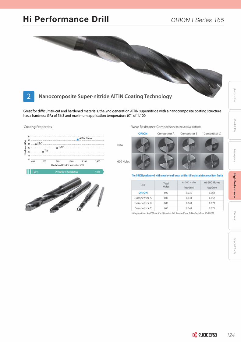
124
Autom
otiveA
erospaceH
igh Perform
anceG
eneralS
pecial ToolsM
old & D
ie
Hi Performance Drill ORION | Series 165
3
Oxidation Resistance
40
35
30
25
20
15
10400 600 800 1,000 1,200 1,400
Low High
TiCN
TiNTiAIN
AlTiN Nano
Har
dnes
s (G
Pa)
Oxidation Onset Temperature (°C)
Great for difficult-to-cut and hardened materials, the 2nd generation AlTiN supernitride with a nanocomposite coating structure has a hardness GPa of 36.3 and maximum application temperature (C°) of 1,100.
Wear Resistance Comparison (In-house Evaluation)Coating Properties
Cutting Conditions : N = 2588rpm, Vf = 196mm/min Drill Diameter Ø3mm Drilling Depth 9mm 17-4PH-900
The ORION performed with good overall wear while still maintaining good tool finish
Competitor AORION
New
600 Holes
Competitor B Competitor C
Drill TotalHoles
At 300 Holes At 600 Holes
Wear (mm) Wear (mm)
ORION 600 0.032 0.068
Competitor A 600 0.031 0.057
Competitor B 600 0.044 0.073
Competitor C 600 0.044 0.071
Nanocomposite Super-nitride AlTiN Coating Technology2
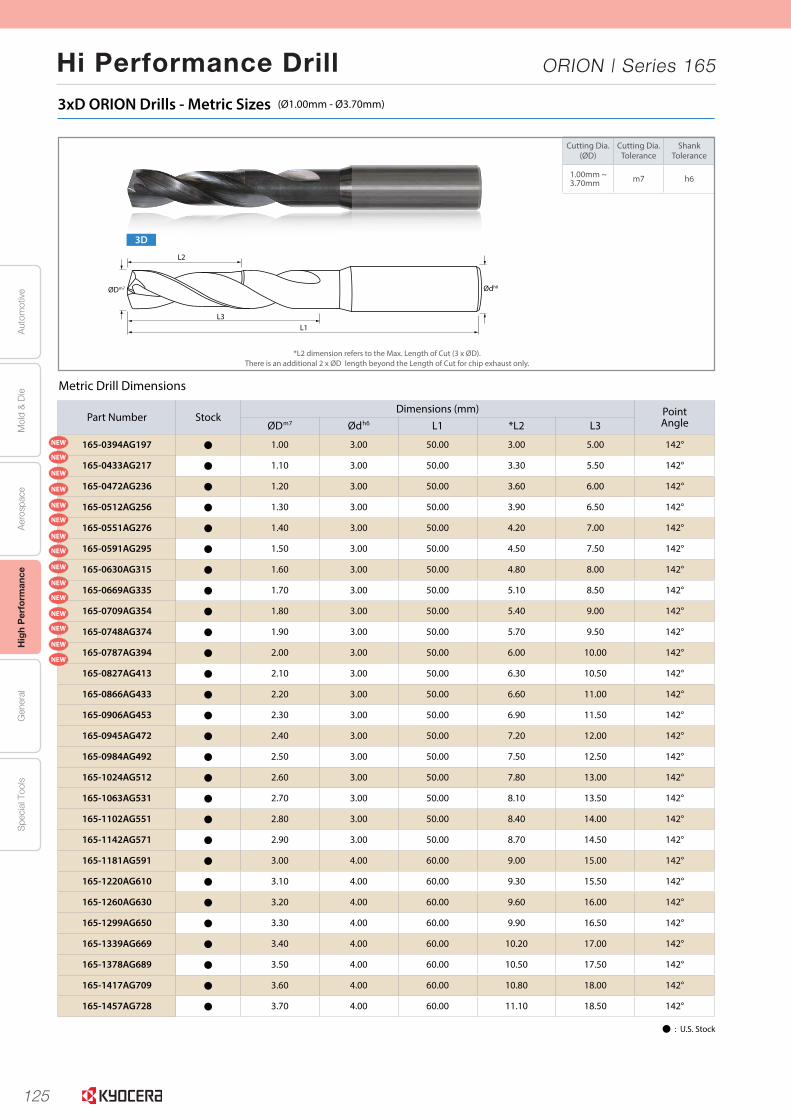
125
Aut
omot
ive
Aer
ospa
ceH
igh
Per
form
ance
Gen
eral
Spe
cial
Too
lsM
old
& D
ie
Hi Performance Drill ORION | Series 165
5
3xD ORION Drills - Metric Sizes (Ø1.00mm - Ø3.70mm)
Part Number StockDimensions (mm) Point
AngleØDm7 Ødh6 L1 *L2 L3
165-0394AG197 Þ 1.00 3.00 50.00 3.00 5.00 142°
165-0433AG217 Þ 1.10 3.00 50.00 3.30 5.50 142°
165-0472AG236 Þ 1.20 3.00 50.00 3.60 6.00 142°
165-0512AG256 Þ 1.30 3.00 50.00 3.90 6.50 142°
165-0551AG276 Þ 1.40 3.00 50.00 4.20 7.00 142°
165-0591AG295 Þ 1.50 3.00 50.00 4.50 7.50 142°
165-0630AG315 Þ 1.60 3.00 50.00 4.80 8.00 142°
165-0669AG335 Þ 1.70 3.00 50.00 5.10 8.50 142°
165-0709AG354 Þ 1.80 3.00 50.00 5.40 9.00 142°
165-0748AG374 Þ 1.90 3.00 50.00 5.70 9.50 142°
165-0787AG394 Þ 2.00 3.00 50.00 6.00 10.00 142°
165-0827AG413 Þ 2.10 3.00 50.00 6.30 10.50 142°
165-0866AG433 Þ 2.20 3.00 50.00 6.60 11.00 142°
165-0906AG453 Þ 2.30 3.00 50.00 6.90 11.50 142°
165-0945AG472 Þ 2.40 3.00 50.00 7.20 12.00 142°
165-0984AG492 Þ 2.50 3.00 50.00 7.50 12.50 142°
165-1024AG512 Þ 2.60 3.00 50.00 7.80 13.00 142°
165-1063AG531 Þ 2.70 3.00 50.00 8.10 13.50 142°
165-1102AG551 Þ 2.80 3.00 50.00 8.40 14.00 142°
165-1142AG571 Þ 2.90 3.00 50.00 8.70 14.50 142°
165-1181AG591 Þ 3.00 4.00 60.00 9.00 15.00 142°
165-1220AG610 Þ 3.10 4.00 60.00 9.30 15.50 142°
165-1260AG630 Þ 3.20 4.00 60.00 9.60 16.00 142°
165-1299AG650 Þ 3.30 4.00 60.00 9.90 16.50 142°
165-1339AG669 Þ 3.40 4.00 60.00 10.20 17.00 142°
165-1378AG689 Þ 3.50 4.00 60.00 10.50 17.50 142°
165-1417AG709 Þ 3.60 4.00 60.00 10.80 18.00 142°
165-1457AG728 Þ 3.70 4.00 60.00 11.10 18.50 142°
Cutting Dia.(ØD)
Cutting Dia.Tolerance
ShankTolerance
1.00mm ~3.70mm m7 h6
Metric Drill Dimensions
*L2 dimension refers to the Max. Length of Cut (3 x ØD).There is an additional 2 x ØD length beyond the Length of Cut for chip exhaust only.
Þ : U.S. Stock
3D
L3
L2
L1
ØDm7 Ødh6
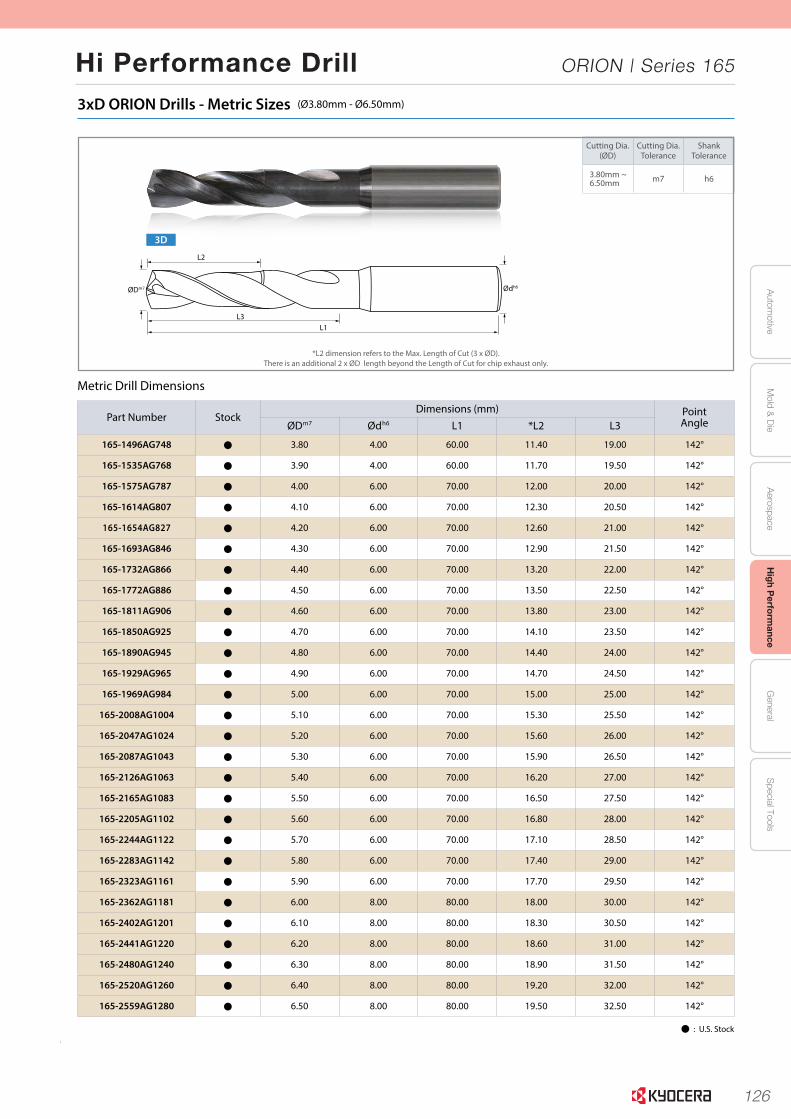
126
Autom
otiveA
erospaceH
igh Perform
anceG
eneralS
pecial ToolsM
old & D
ie
Hi Performance Drill ORION | Series 165
6
3xD ORION Drills - Metric Sizes (Ø3.80mm - Ø6.50mm)
Cutting Dia.(ØD)
Cutting Dia.Tolerance
ShankTolerance
3.80mm ~6.50mm m7 h6
3D
L3
L2
L1
ØDm7 Ødh6
Metric Drill Dimensions
Part Number StockDimensions (mm) Point
AngleØDm7 Ødh6 L1 *L2 L3
165-1496AG748 Þ 3.80 4.00 60.00 11.40 19.00 142°
165-1535AG768 Þ 3.90 4.00 60.00 11.70 19.50 142°
165-1575AG787 Þ 4.00 6.00 70.00 12.00 20.00 142°
165-1614AG807 Þ 4.10 6.00 70.00 12.30 20.50 142°
165-1654AG827 Þ 4.20 6.00 70.00 12.60 21.00 142°
165-1693AG846 Þ 4.30 6.00 70.00 12.90 21.50 142°
165-1732AG866 Þ 4.40 6.00 70.00 13.20 22.00 142°
165-1772AG886 Þ 4.50 6.00 70.00 13.50 22.50 142°
165-1811AG906 Þ 4.60 6.00 70.00 13.80 23.00 142°
165-1850AG925 Þ 4.70 6.00 70.00 14.10 23.50 142°
165-1890AG945 Þ 4.80 6.00 70.00 14.40 24.00 142°
165-1929AG965 Þ 4.90 6.00 70.00 14.70 24.50 142°
165-1969AG984 Þ 5.00 6.00 70.00 15.00 25.00 142°
165-2008AG1004 Þ 5.10 6.00 70.00 15.30 25.50 142°
165-2047AG1024 Þ 5.20 6.00 70.00 15.60 26.00 142°
165-2087AG1043 Þ 5.30 6.00 70.00 15.90 26.50 142°
165-2126AG1063 Þ 5.40 6.00 70.00 16.20 27.00 142°
165-2165AG1083 Þ 5.50 6.00 70.00 16.50 27.50 142°
165-2205AG1102 Þ 5.60 6.00 70.00 16.80 28.00 142°
165-2244AG1122 Þ 5.70 6.00 70.00 17.10 28.50 142°
165-2283AG1142 Þ 5.80 6.00 70.00 17.40 29.00 142°
165-2323AG1161 Þ 5.90 6.00 70.00 17.70 29.50 142°
165-2362AG1181 Þ 6.00 8.00 80.00 18.00 30.00 142°
165-2402AG1201 Þ 6.10 8.00 80.00 18.30 30.50 142°
165-2441AG1220 Þ 6.20 8.00 80.00 18.60 31.00 142°
165-2480AG1240 Þ 6.30 8.00 80.00 18.90 31.50 142°
165-2520AG1260 Þ 6.40 8.00 80.00 19.20 32.00 142°
165-2559AG1280 Þ 6.50 8.00 80.00 19.50 32.50 142°
*L2 dimension refers to the Max. Length of Cut (3 x ØD).There is an additional 2 x ØD length beyond the Length of Cut for chip exhaust only.
Þ : U.S. Stock
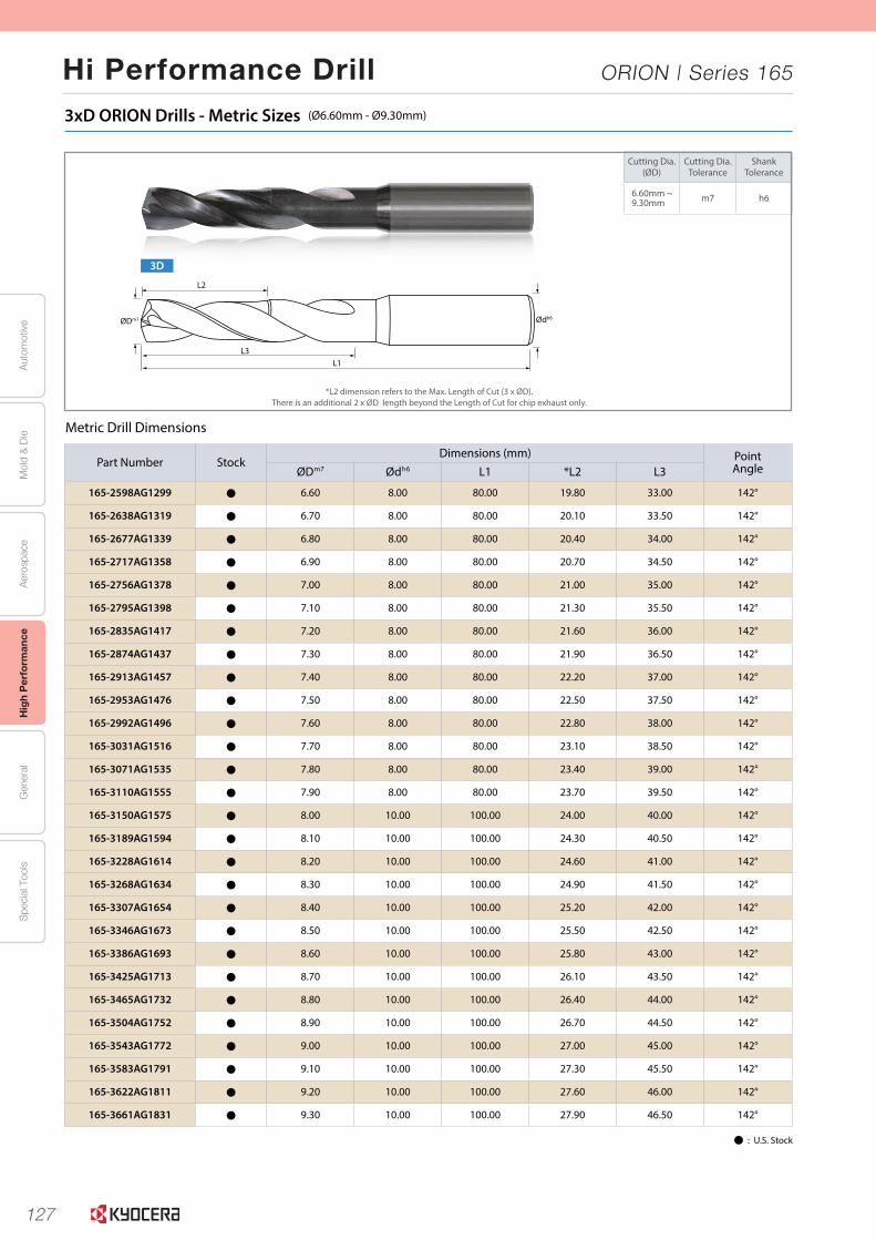
127
Aut
omot
ive
Aer
ospa
ceH
igh
Per
form
ance
Gen
eral
Spe
cial
Too
lsM
old
& D
ie
Hi Performance Drill ORION | Series 165
7
3xD ORION Drills - Metric Sizes (Ø6.60mm - Ø9.30mm)
Cutting Dia.(ØD)
Cutting Dia.Tolerance
ShankTolerance
6.60mm ~9.30mm m7 h6
Metric Drill Dimensions
Part Number StockDimensions (mm) Point
AngleØDm7 Ødh6 L1 *L2 L3
165-2598AG1299 Þ 6.60 8.00 80.00 19.80 33.00 142°
165-2638AG1319 Þ 6.70 8.00 80.00 20.10 33.50 142°
165-2677AG1339 Þ 6.80 8.00 80.00 20.40 34.00 142°
165-2717AG1358 Þ 6.90 8.00 80.00 20.70 34.50 142°
165-2756AG1378 Þ 7.00 8.00 80.00 21.00 35.00 142°
165-2795AG1398 Þ 7.10 8.00 80.00 21.30 35.50 142°
165-2835AG1417 Þ 7.20 8.00 80.00 21.60 36.00 142°
165-2874AG1437 Þ 7.30 8.00 80.00 21.90 36.50 142°
165-2913AG1457 Þ 7.40 8.00 80.00 22.20 37.00 142°
165-2953AG1476 Þ 7.50 8.00 80.00 22.50 37.50 142°
165-2992AG1496 Þ 7.60 8.00 80.00 22.80 38.00 142°
165-3031AG1516 Þ 7.70 8.00 80.00 23.10 38.50 142°
165-3071AG1535 Þ 7.80 8.00 80.00 23.40 39.00 142°
165-3110AG1555 Þ 7.90 8.00 80.00 23.70 39.50 142°
165-3150AG1575 Þ 8.00 10.00 100.00 24.00 40.00 142°
165-3189AG1594 Þ 8.10 10.00 100.00 24.30 40.50 142°
165-3228AG1614 Þ 8.20 10.00 100.00 24.60 41.00 142°
165-3268AG1634 Þ 8.30 10.00 100.00 24.90 41.50 142°
165-3307AG1654 Þ 8.40 10.00 100.00 25.20 42.00 142°
165-3346AG1673 Þ 8.50 10.00 100.00 25.50 42.50 142°
165-3386AG1693 Þ 8.60 10.00 100.00 25.80 43.00 142°
165-3425AG1713 Þ 8.70 10.00 100.00 26.10 43.50 142°
165-3465AG1732 Þ 8.80 10.00 100.00 26.40 44.00 142°
165-3504AG1752 Þ 8.90 10.00 100.00 26.70 44.50 142°
165-3543AG1772 Þ 9.00 10.00 100.00 27.00 45.00 142°
165-3583AG1791 Þ 9.10 10.00 100.00 27.30 45.50 142°
165-3622AG1811 Þ 9.20 10.00 100.00 27.60 46.00 142°
165-3661AG1831 Þ 9.30 10.00 100.00 27.90 46.50 142°
*L2 dimension refers to the Max. Length of Cut (3 x ØD).There is an additional 2 x ØD length beyond the Length of Cut for chip exhaust only.
Þ : U.S. Stock
3D
L3
L2
L1
ØDm7 Ødh6

128
Autom
otiveA
erospaceH
igh Perform
anceG
eneralS
pecial ToolsM
old & D
ie
Hi Performance Drill ORION | Series 165
8
3xD ORION Drills - Metric Sizes (Ø9.40mm - Ø12.00mm)
Cutting Dia.(ØD)
Cutting Dia.Tolerance
ShankTolerance
9.40mm ~12.00mm m7 h6
Metric Drill Dimensions
*L2 dimension refers to the Max. Length of Cut (3 x ØD).There is an additional 2 x ØD length beyond the Length of Cut for chip exhaust only.
Þ : U.S. Stock
Part Number StockDimensions (mm) Point
AngleØDm7 Ødh6 L1 *L2 L3
165-3701AG1850 Þ 9.40 10.00 100.00 28.20 47.00 142°
165-3740AG1870 Þ 9.50 10.00 100.00 28.50 47.50 142°
165-3780AG1890 Þ 9.60 10.00 100.00 28.80 48.00 142°
165-3819AG1909 Þ 9.70 10.00 100.00 29.10 48.50 142°
165-3858AG1929 Þ 9.80 10.00 100.00 29.40 49.00 142°
165-3898AG1949 Þ 9.90 10.00 100.00 29.70 49.50 142°
165-3937AG1969 Þ 10.00 12.00 110.00 30.00 50.00 142°
165-3976AG1988 Þ 10.10 12.00 110.00 30.30 50.50 142°
165-4016AG2008 Þ 10.20 12.00 110.00 30.60 51.00 142°
165-4055AG2028 Þ 10.30 12.00 110.00 30.90 51.50 142°
165-4094AG2047 Þ 10.40 12.00 110.00 31.20 52.00 142°
165-4134AG2067 Þ 10.50 12.00 110.00 31.50 52.50 142°
165-4173AG2087 Þ 10.60 12.00 110.00 31.80 53.00 142°
165-4213AG2106 Þ 10.70 12.00 110.00 32.10 53.50 142°
165-4252AG2126 Þ 10.80 12.00 110.00 32.40 54.00 142°
165-4291AG2146 Þ 10.90 12.00 110.00 32.70 54.50 142°
165-4331AG2165 Þ 11.00 12.00 110.00 33.00 55.00 142°
165-4370AG2185 Þ 11.10 12.00 110.00 33.30 55.50 142°
165-4409AG2205 Þ 11.20 12.00 110.00 33.60 56.00 142°
165-4449AG2224 Þ 11.30 12.00 110.00 33.90 56.50 142°
165-4488AG2244 Þ 11.40 12.00 110.00 34.20 57.00 142°
165-4528AG2264 Þ 11.50 12.00 110.00 34.50 57.50 142°
165-4567AG2283 Þ 11.60 12.00 110.00 34.80 58.00 142°
165-4606AG2303 Þ 11.70 12.00 110.00 35.10 58.50 142°
165-4646AG2323 Þ 11.80 12.00 110.00 35.40 59.00 142°
165-4685AG2343 Þ 11.90 12.00 110.00 35.70 59.50 142°
165-4724AG2362 Þ 12.00 14.00 110.00 36.00 60.00 142°
3D
L3
L2
L1
ØDm7 Ødh6
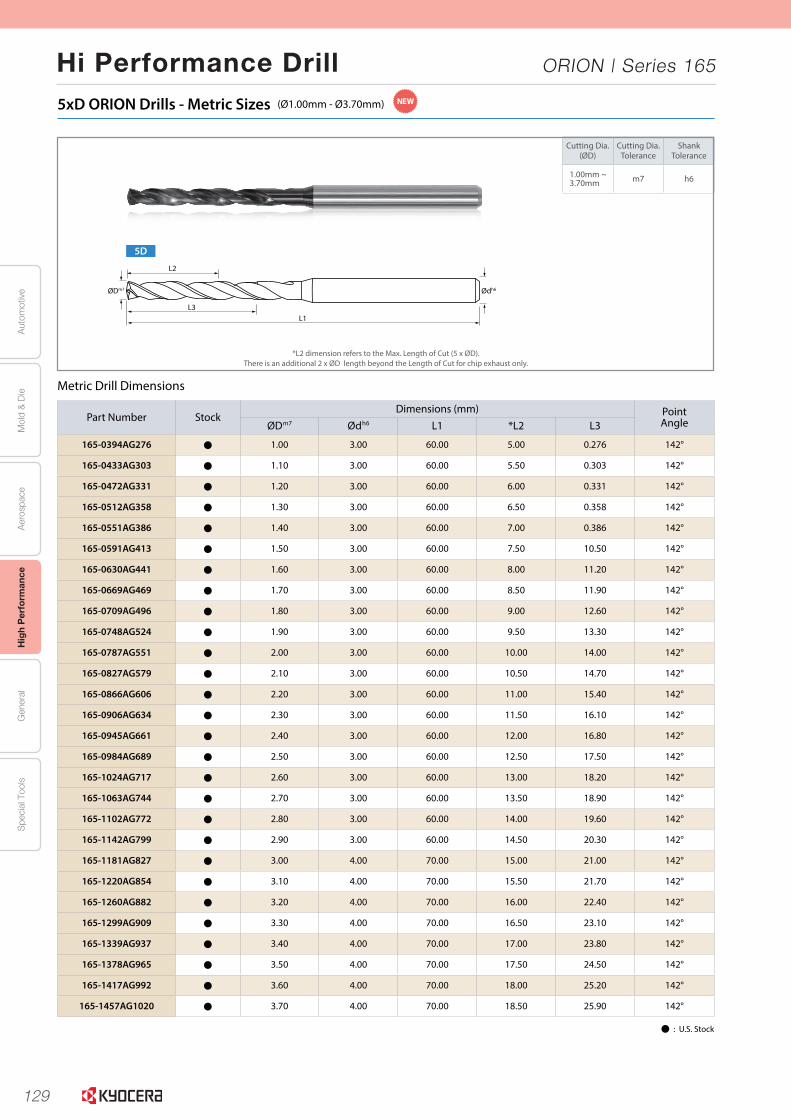
129
Aut
omot
ive
Aer
ospa
ceH
igh
Per
form
ance
Gen
eral
Spe
cial
Too
lsM
old
& D
ie
Hi Performance Drill ORION | Series 165
10
Cutting Dia.(ØD)
Cutting Dia.Tolerance
ShankTolerance
1.00mm ~3.70mm m7 h6
5xD ORION Drills - Metric Sizes (Ø1.00mm - Ø3.70mm)
Metric Drill Dimensions
*L2 dimension refers to the Max. Length of Cut (5 x ØD).There is an additional 2 x ØD length beyond the Length of Cut for chip exhaust only.
Part Number StockDimensions (mm) Point
AngleØDm7 Ødh6 L1 *L2 L3
165-0394AG276 Þ 1.00 3.00 60.00 5.00 0.276 142°
165-0433AG303 Þ 1.10 3.00 60.00 5.50 0.303 142°
165-0472AG331 Þ 1.20 3.00 60.00 6.00 0.331 142°
165-0512AG358 Þ 1.30 3.00 60.00 6.50 0.358 142°
165-0551AG386 Þ 1.40 3.00 60.00 7.00 0.386 142°
165-0591AG413 Þ 1.50 3.00 60.00 7.50 10.50 142°
165-0630AG441 Þ 1.60 3.00 60.00 8.00 11.20 142°
165-0669AG469 Þ 1.70 3.00 60.00 8.50 11.90 142°
165-0709AG496 Þ 1.80 3.00 60.00 9.00 12.60 142°
165-0748AG524 Þ 1.90 3.00 60.00 9.50 13.30 142°
165-0787AG551 Þ 2.00 3.00 60.00 10.00 14.00 142°
165-0827AG579 Þ 2.10 3.00 60.00 10.50 14.70 142°
165-0866AG606 Þ 2.20 3.00 60.00 11.00 15.40 142°
165-0906AG634 Þ 2.30 3.00 60.00 11.50 16.10 142°
165-0945AG661 Þ 2.40 3.00 60.00 12.00 16.80 142°
165-0984AG689 Þ 2.50 3.00 60.00 12.50 17.50 142°
165-1024AG717 Þ 2.60 3.00 60.00 13.00 18.20 142°
165-1063AG744 Þ 2.70 3.00 60.00 13.50 18.90 142°
165-1102AG772 Þ 2.80 3.00 60.00 14.00 19.60 142°
165-1142AG799 Þ 2.90 3.00 60.00 14.50 20.30 142°
165-1181AG827 Þ 3.00 4.00 70.00 15.00 21.00 142°
165-1220AG854 Þ 3.10 4.00 70.00 15.50 21.70 142°
165-1260AG882 Þ 3.20 4.00 70.00 16.00 22.40 142°
165-1299AG909 Þ 3.30 4.00 70.00 16.50 23.10 142°
165-1339AG937 Þ 3.40 4.00 70.00 17.00 23.80 142°
165-1378AG965 Þ 3.50 4.00 70.00 17.50 24.50 142°
165-1417AG992 Þ 3.60 4.00 70.00 18.00 25.20 142°
165-1457AG1020 Þ 3.70 4.00 70.00 18.50 25.90 142°
Þ : U.S. Stock
5D
L3
L2
L1
ØDm7 Ødh6
NEW

130
Autom
otiveA
erospaceH
igh Perform
anceG
eneralS
pecial ToolsM
old & D
ie
Hi Performance Drill ORION | Series 165
11
5xD ORION Drills - Metric Sizes (Ø3.80mm - Ø6.50mm)
Cutting Dia.(ØD)
Cutting Dia.Tolerance
ShankTolerance
3.80mm ~6.50mm m7 h6
Metric Drill Dimensions
*L2 dimension refers to the Max. Length of Cut (5 x ØD).There is an additional 2 x ØD length beyond the Length of Cut for chip exhaust only.
Þ : U.S. Stock
5D
L3
L2
L1
ØDm7 Ødh6
Part Number StockDimensions (mm) Point
AngleØDm7 Ødh6 L1 *L2 L3
165-1496AG1047 Þ 3.80 4.00 70.00 19.00 26.60 142°
165-1535AG1075 Þ 3.90 4.00 70.00 19.50 27.30 142°
165-1575AG1102 Þ 4.00 6.00 90.00 20.00 28.00 142°
165-1614AG1130 Þ 4.10 6.00 90.00 20.50 28.70 142°
165-1654AG1157 Þ 4.20 6.00 90.00 21.00 29.40 142°
165-1693AG1185 Þ 4.30 6.00 90.00 21.50 30.10 142°
165-1732AG1213 Þ 4.40 6.00 90.00 22.00 30.80 142°
165-1772AG1240 Þ 4.50 6.00 90.00 22.50 31.50 142°
165-1811AG1268 Þ 4.60 6.00 90.00 23.00 32.20 142°
165-1850AG1295 Þ 4.70 6.00 90.00 23.50 32.90 142°
165-1890AG1323 Þ 4.80 6.00 90.00 24.00 33.60 142°
165-1929AG1350 Þ 4.90 6.00 90.00 24.50 34.30 142°
165-1969AG1378 Þ 5.00 6.00 90.00 25.00 35.00 142°
165-2008AG1406 Þ 5.10 6.00 90.00 25.50 35.70 142°
165-2047AG1433 Þ 5.20 6.00 90.00 26.00 36.40 142°
165-2087AG1461 Þ 5.30 6.00 90.00 26.50 37.10 142°
165-2126AG1488 Þ 5.40 6.00 90.00 27.00 37.80 142°
165-2165AG1516 Þ 5.50 6.00 90.00 27.50 38.50 142°
165-2205AG1543 Þ 5.60 6.00 90.00 28.00 39.20 142°
165-2244AG1571 Þ 5.70 6.00 90.00 28.50 39.90 142°
165-2283AG1598 Þ 5.80 6.00 90.00 29.00 40.60 142°
165-2323AG1626 Þ 5.90 6.00 90.00 29.50 41.30 142°
165-2362AG1654 Þ 6.00 8.00 100.00 30.00 42.00 142°
165-2402AG1681 Þ 6.10 8.00 100.00 30.50 42.70 142°
165-2441AG1709 Þ 6.20 8.00 100.00 31.00 43.40 142°
165-2480AG1736 Þ 6.30 8.00 100.00 31.50 44.10 142°
165-2520AG1764 Þ 6.40 8.00 100.00 32.00 44.80 142°
165-2559AG1791 Þ 6.50 8.00 100.00 32.50 45.50 142°
NEW

131
Aut
omot
ive
Aer
ospa
ceH
igh
Per
form
ance
Gen
eral
Spe
cial
Too
lsM
old
& D
ie
Hi Performance Drill ORION | Series 165
12
5xD ORION Drills - Metric Sizes (Ø6.60mm - Ø9.30mm)
Cutting Dia.(ØD)
Cutting Dia.Tolerance
ShankTolerance
6.60mm ~9.30mm m7 h6
Metric Drill Dimensions
*L2 dimension refers to the Max. Length of Cut (5 x ØD).There is an additional 2 x ØD length beyond the Length of Cut for chip exhaust only.
Þ : U.S. Stock
5D
L3
L2
L1
ØDm7 Ødh6
Part Number StockDimensions (mm) Point
AngleØDm7 Ødh6 L1 *L2 L3
165-2598AG1819 Þ 6.60 8.00 100.00 33.00 46.20 142°
165-2638AG1846 Þ 6.70 8.00 100.00 33.50 46.90 142°
165-2677AG1874 Þ 6.80 8.00 100.00 34.00 47.60 142°
165-2717AG1902 Þ 6.90 8.00 100.00 34.50 48.30 142°
165-2756AG1929 Þ 7.00 8.00 100.00 35.00 49.00 142°
165-2795AG1957 Þ 7.10 8.00 100.00 35.50 49.70 142°
165-2835AG1984 Þ 7.20 8.00 100.00 36.00 50.40 142°
165-2874AG2012 Þ 7.30 8.00 100.00 36.50 51.10 142°
165-2913AG2039 Þ 7.40 8.00 100.00 37.00 51.80 142°
165-2953AG2067 Þ 7.50 8.00 100.00 37.50 52.50 142°
165-2992AG2094 Þ 7.60 8.00 100.00 38.00 53.20 142°
165-3031AG2122 Þ 7.70 8.00 100.00 38.50 53.90 142°
165-3071AG2150 Þ 7.80 8.00 100.00 39.00 54.60 142°
165-3110AG2177 Þ 7.90 8.00 100.00 39.50 55.30 142°
165-3150AG2205 Þ 8.00 10.00 120.00 40.00 56.00 142°
165-3189AG2232 Þ 8.10 10.00 120.00 40.50 56.70 142°
165-3228AG2260 Þ 8.20 10.00 120.00 41.00 57.40 142°
165-3268AG2287 Þ 8.30 10.00 120.00 41.50 58.10 142°
165-3307AG2315 Þ 8.40 10.00 120.00 42.00 58.80 142°
165-3346AG2343 Þ 8.50 10.00 120.00 42.50 59.50 142°
165-3386AG2370 Þ 8.60 10.00 120.00 43.00 60.20 142°
165-3425AG2398 Þ 8.70 10.00 120.00 43.50 60.90 142°
165-3465AG2425 Þ 8.80 10.00 120.00 44.00 61.60 142°
165-3504AG2453 Þ 8.90 10.00 120.00 44.50 62.30 142°
165-3543AG2480 Þ 9.00 10.00 120.00 45.00 63.00 142°
165-3583AG2508 Þ 9.10 10.00 120.00 45.50 63.70 142°
165-3622AG2535 Þ 9.20 10.00 120.00 46.00 64.40 142°
165-3661AG2563 Þ 9.30 10.00 120.00 46.50 65.10 142°
NEW
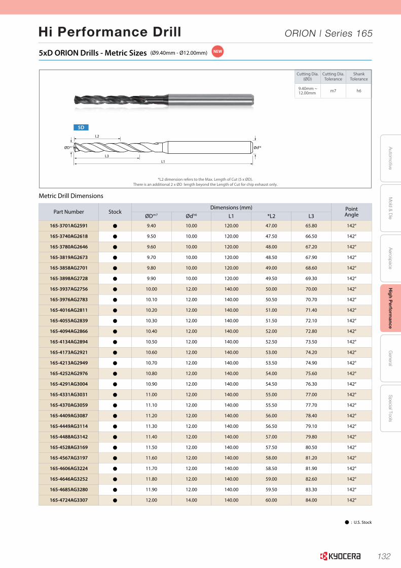
132
Autom
otiveA
erospaceH
igh Perform
anceG
eneralS
pecial ToolsM
old & D
ie
Hi Performance Drill ORION | Series 165
13
5xD ORION Drills - Metric Sizes (Ø9.40mm - Ø12.00mm)
Cutting Dia.(ØD)
Cutting Dia.Tolerance
ShankTolerance
9.40mm ~12.00mm m7 h6
Metric Drill Dimensions
*L2 dimension refers to the Max. Length of Cut (5 x ØD).There is an additional 2 x ØD length beyond the Length of Cut for chip exhaust only.
Þ : U.S. Stock
5D
L3
L2
L1
ØDm7 Ødh6
NEW
Part Number StockDimensions (mm) Point
AngleØDm7 Ødh6 L1 *L2 L3
165-3701AG2591 Þ 9.40 10.00 120.00 47.00 65.80 142°
165-3740AG2618 Þ 9.50 10.00 120.00 47.50 66.50 142°
165-3780AG2646 Þ 9.60 10.00 120.00 48.00 67.20 142°
165-3819AG2673 Þ 9.70 10.00 120.00 48.50 67.90 142°
165-3858AG2701 Þ 9.80 10.00 120.00 49.00 68.60 142°
165-3898AG2728 Þ 9.90 10.00 120.00 49.50 69.30 142°
165-3937AG2756 Þ 10.00 12.00 140.00 50.00 70.00 142°
165-3976AG2783 Þ 10.10 12.00 140.00 50.50 70.70 142°
165-4016AG2811 Þ 10.20 12.00 140.00 51.00 71.40 142°
165-4055AG2839 Þ 10.30 12.00 140.00 51.50 72.10 142°
165-4094AG2866 Þ 10.40 12.00 140.00 52.00 72.80 142°
165-4134AG2894 Þ 10.50 12.00 140.00 52.50 73.50 142°
165-4173AG2921 Þ 10.60 12.00 140.00 53.00 74.20 142°
165-4213AG2949 Þ 10.70 12.00 140.00 53.50 74.90 142°
165-4252AG2976 Þ 10.80 12.00 140.00 54.00 75.60 142°
165-4291AG3004 Þ 10.90 12.00 140.00 54.50 76.30 142°
165-4331AG3031 Þ 11.00 12.00 140.00 55.00 77.00 142°
165-4370AG3059 Þ 11.10 12.00 140.00 55.50 77.70 142°
165-4409AG3087 Þ 11.20 12.00 140.00 56.00 78.40 142°
165-4449AG3114 Þ 11.30 12.00 140.00 56.50 79.10 142°
165-4488AG3142 Þ 11.40 12.00 140.00 57.00 79.80 142°
165-4528AG3169 Þ 11.50 12.00 140.00 57.50 80.50 142°
165-4567AG3197 Þ 11.60 12.00 140.00 58.00 81.20 142°
165-4606AG3224 Þ 11.70 12.00 140.00 58.50 81.90 142°
165-4646AG3252 Þ 11.80 12.00 140.00 59.00 82.60 142°
165-4685AG3280 Þ 11.90 12.00 140.00 59.50 83.30 142°
165-4724AG3307 Þ 12.00 14.00 140.00 60.00 84.00 142°
133
Aut
omot
ive
Aer
ospa
ceH
igh
Per
form
ance
Gen
eral
Spe
cial
Too
lsM
old
& D
ie
Hi Performance Drill ORION | Series 165
L196
L
SOLI
DTO
OLS
(U.S.) 1.888.848.8449(International) 001.714.428.3636
Visit us online at KyoceraPrecisionTools.com
RECOMMENDED CUTTING CONDITIONS
Drilling - High Performance
**Recommended starting parameters based on good setup, minimum tool runout & good tooling**
Workpiece Material
MaterialHardness/
Types
RecommendedCutting Speed Cutting Dia. DC
(in)Cutting Dia. DC
(mm)
Feed Rate Drill Length to Dia Ratio
3xD & 5xD
sfm m/min (ipr) (mm/rev)
Low�Carbon�Steel
12L14A36
270 - 300 - 330 80 - 90 - 100
Ø0.0394 - Ø0.0787 Ø1.00 - Ø2.00 0.0015 - 0.0030 0.04 - 0.08
Ø0.0787 - Ø0.1535 Ø2.00 - Ø3.90 0.0030 - 0.0060 0.08 - 0.15
Ø0.1575 - Ø0.2320 Ø4.00 - Ø5.90 0.0060 - 0.0090 0.15 - 0.23
Ø0.2360 - Ø0.3110 Ø6.00 - Ø7.90 0.0090 - 0.0120 0.23 - 0.30
Ø0.3150 - Ø0.3898 Ø8.00 - Ø9.90 0.0120 - 0.0150 0.30 - 0.38
Ø0.3937 - Ø0.4685 Ø10.00 - Ø11.90 0.0120 - 0.0150 0.30 - 0.38
Ø0.4685 - Ø0.5000 Ø11.90 - Ø12.70 0.0120 - 0.0150 0.30 - 0.38
Mild�Carbon�Steel
101810281050
250 - 275 - 300 75 - 85 - 90
Ø0.0394 - Ø0.0787 Ø1.00 - Ø2.00 0.0015 - 0.0030 0.04 - 0.08
Ø0.0787 - Ø0.1535 Ø2.00 - Ø3.90 0.0030 - 0.0060 0.08 - 0.15
Ø0.1575 - Ø0.2320 Ø4.00 - Ø5.90 0.0060 - 0.0090 0.15 - 0.23
Ø0.2360 - Ø0.3110 Ø6.00 - Ø7.90 0.0090 - 0.0120 0.23 - 0.30
Ø0.3150 - Ø0.3898 Ø8.00 - Ø9.90 0.0120 - 0.0150 0.30 - 0.38
Ø0.3937 - Ø0.4685 Ø10.00 - Ø11.90 0.0120 - 0.0150 0.30 - 0.38
Ø0.4685 - Ø0.5000 Ø11.90 - Ø12.70 0.0120 - 0.0150 0.30 - 0.38
Alloy�Steel
4130414041508620
225 - 250 - 275 70 - 75 - 85
Ø0.0394 - Ø0.0787 Ø1.00 - Ø2.00 0.0010 - 0.0020 0.03 - 0.05
Ø0.0787 - Ø0.1535 Ø2.00 - Ø3.90 0.0020 - 0.0045 0.05 - 0.11
Ø0.1575 - Ø0.2320 Ø4.00 - Ø5.90 0.0045 - 0.0070 0.11 - 0.18
Ø0.2360 - Ø0.3110 Ø6.00 - Ø7.90 0.0070 - 0.0090 0.18 - 0.23
Ø0.3150 - Ø0.3898 Ø8.00 - Ø9.90 0.0090 - 0.0115 0.23 - 0.29
Ø0.3937 - Ø0.4685 Ø10.00 - Ø11.90 0.0090 - 0.0115 0.23 - 0.29
Ø0.4685 - Ø0.5000 Ø11.90 - Ø12.70 0.0090 - 0.0115 0.23 - 0.29
Prehardened�Tool�Steel
4140PHA2D2H13P20
150 - 200 - 250 45 - 60 - 75
Ø0.0394 - Ø0.0787 Ø1.00 - Ø2.00 0.0010 - 0.0020 0.03 - 0.05
Ø0.0787 - Ø0.1535 Ø2.00 - Ø3.90 0.0020 - 0.0040 0.05 - 0.10
Ø0.1575 - Ø0.2320 Ø4.00 - Ø5.90 0.0040 - 0.0060 0.10 - 0.15
Ø0.2360 - Ø0.3110 Ø6.00 - Ø7.90 0.0060 - 0.0080 0.15 - 0.20
Ø0.3150 - Ø0.3898 Ø8.00 - Ø9.90 0.0060 - 0.0080 0.15 - 0.20
Ø0.3937 - Ø0.4685 Ø10.00 - Ø11.90 0.0060 - 0.0080 0.15 - 0.20
Ø0.4685 - Ø0.5000 Ø11.90 - Ø12.70 0.0060 - 0.0080 0.15 - 0.20
Hardened�Tool�Steel
>48�HRc 75 - 100 - 125 20 - 30 - 40
Ø0.0394 - Ø0.0787 Ø1.00 - Ø2.00 0.0005 - 0.0010 0.01 - 0.03
Ø0.0787 - Ø0.1535 Ø2.00 - Ø3.90 0.0010 - 0.0020 0.03 - 0.05
Ø0.1575 - Ø0.2320 Ø4.00 - Ø5.90 0.0020 - 0.0030 0.05 - 0.08
Ø0.2360 - Ø0.3110 Ø6.00 - Ø7.90 0.0030 - 0.0040 0.08 - 0.10
Ø0.3150 - Ø0.3898 Ø8.00 - Ø9.90 0.0040 - 0.0050 0.10 - 0.13
Ø0.3937 - Ø0.4685 Ø10.00 - Ø11.90 0.0040 - 0.0050 0.10 - 0.13
Ø0.4685 - Ø0.5000 Ø11.90 - Ø12.70 0.0040 - 0.0050 0.10 - 0.13
Stainless�Steel��
303304316321
115 - 130 - 145 35 - 40 - 45
Ø0.0394 - Ø0.0787 Ø1.00 - Ø2.00 0.0010 - 0.0020 0.03 - 0.05
Ø0.0787 - Ø0.1535 Ø2.00 - Ø3.90 0.0020 - 0.0045 0.05 - 0.11
Ø0.1575 - Ø0.2320 Ø4.00 - Ø5.90 0.0045 - 0.0070 0.11 - 0.18
Ø0.2360 - Ø0.3110 Ø6.00 - Ø7.90 0.0070 - 0.0090 0.18 - 0.23
Ø0.3150 - Ø0.3898 Ø8.00 - Ø9.90 0.0090 - 0.0115 0.23 - 0.29
Ø0.3937 - Ø0.4685 Ø10.00 - Ø11.90 0.0110 - 0.0125 0.28 - 0.32
Ø0.4685 - Ø0.5000 Ø11.90 - Ø12.70 0.00120 - 0.0135 0.03 - 0.34
Stainless�Steel��
15-5PH17-4PH13-8
400�Series
90 - 100 - 110 25 - 30 - 35
Ø0.0394 - Ø0.0787 Ø1.00 - Ø2.00 0.0010 - 0.0020 0.03 - 0.05
Ø0.0787 - Ø0.1535 Ø2.00 - Ø3.90 0.0020 - 0.0040 0.05 - 0.10
Ø0.1575 - Ø0.2320 Ø4.00 - Ø5.90 0.0040 - 0.0060 0.10 - 0.15
Ø0.2360 - Ø0.3110 Ø6.00 - Ø7.90 0.0050 - 0.0070 0.13 - 0.18
Ø0.3150 - Ø0.3898 Ø8.00 - Ø9.90 0.0060 - 0.0080 0.15 - 0.20
Ø0.3937 - Ø0.4685 Ø10.00 - Ø11.90 0.0070 - 0.0090 0.18 - 0.23
Ø0.4685 - Ø0.5000 Ø11.90 - Ø12.70 0.0090 - 0.0110 0.23 - 0.28
• Above recommendations are suggested starting parameters. Cutting speeds and feed rates may vary according to machining application and setup.
DRILLS
END MILLS
ROUTERS
THREAD MILLS
ENGRAVERS
BORINGBARS
REAMERS
TECHNICAL
134
Autom
otiveA
erospaceH
igh Perform
anceG
eneralS
pecial ToolsM
old & D
ie
Hi Performance Drill ORION | Series 165
L197
L
SOLID
TOOLS
H
CUT-O
FF
J
THREAD
ING
M
MILLIN
G
N
QUICK�CHANG
ETO
OLIN
G
R
TECHNICAL
P
SPARE�PAR
TS
T
INDEX
B
TURNING�
INSER
TS
G
GROOVIN
G
C
CBN/PC
D�
INSER
TS
K
DRILLIN
G
A
INSER
T�GRAD
ES
D
TURNING�
HOLD
ERS
E
SMALL
TOOLS
F
BORING
(U.S.) 1.888.848.8449(International) 001.714.428.3636Visit us online at KyoceraPrecisionTools.com
RECOMMENDED CUTTING CONDITIONS
Drilling - High Performance
**Recommended starting parameters based on good setup, minimum tool runout & good tooling**
Workpiece Material
MaterialHardness/
Types
RecommendedCutting Speed Cutting Dia. DC
(in)Cutting Dia. DC
(mm)
Feed Rate Drill Length to Dia Ratio
3xD & 5xD
sfm m/min (ipr) (mm/rev)
Gray�Cast�Iron
- 295 - 325 - 355 90 - 100 - 110
Ø0.0394 - Ø0.0787 Ø1.00 - Ø2.00 0.0015 - 0.0030 0.04 - 0.08
Ø0.0787 - Ø0.1535 Ø2.00 - Ø3.90 0.0030 - 0.0060 0.08 - 0.15
Ø0.1575 - Ø0.2320 Ø4.00 - Ø5.90 0.0060 - 0.0090 0.15 - 0.23
Ø0.2360 - Ø0.3110 Ø6.00 - Ø7.90 0.0090 - 0.0120 0.23 - 0.30
Ø0.3150 - Ø0.3898 Ø8.00 - Ø9.90 0.0120 - 0.0150 0.30 - 0.38
Ø0.3937 - Ø0.4685 Ø10.00 - Ø11.90 0.0150 - 0.0170 0.38 - 0.43
Ø0.4685 - Ø0.5000 Ø11.90 - Ø12.70 0.0170 - 0.0190 0.43 - 0.48
NodularCast�Iron
- 235 - 260 - 285 70 - 80 - 85
Ø0.0394 - Ø0.0787 Ø1.00 - Ø2.00 0.0010 - 0.0025 0.03 - 0.06
Ø0.0787 - Ø0.1535 Ø2.00 - Ø3.90 0.0025 - 0.0050 0.06 - 0.13
Ø0.1575 - Ø0.2320 Ø4.00 - Ø5.90 0.0055 - 0.0080 0.14 - 0.20
Ø0.2360 - Ø0.3110 Ø6.00 - Ø7.90 0.0080 - 0.0110 0.20 - 0.28
Ø0.3150 - Ø0.3898 Ø8.00 - Ø9.90 0.0110 - 0.0130 0.28 - 0.33
Ø0.3937 - Ø0.4685 Ø10.00 - Ø11.90 0.0130 - 0.0150 0.33 - 0.38
Ø0.4685 - Ø0.5000 Ø11.90 - Ø12.70 0.0150 - 0.0170 0.38 - 0.43
Aluminum -
ALLOY
320 - 350 - 380
CAST
400 - 450 - 500
ALLOY
100 - 105 - 115
CAST
120 - 135 - 150
Ø0.0394 - Ø0.0787 Ø1.00 - Ø2.00 0.0015 - 0.0030 0.04 - 0.08
Ø0.0787 - Ø0.1535 Ø2.00 - Ø3.90 0.0030 - 0.0070 0.08 - 0.18
Ø0.1575 - Ø0.2320 Ø4.00 - Ø5.90 0.0070 - 0.0095 0.18 - 0.24
Ø0.2360 - Ø0.3110 Ø6.00 - Ø7.90 0.0095 - 0.0125 0.24 - 0.32
Ø0.3150 - Ø0.3898 Ø8.00 - Ø9.90 0.0125 - 0.0140 0.32 - 0.36
Ø0.3937 - Ø0.4685 Ø10.00 - Ø11.90 0.0140 - 0.0155 0.36 - 0.39
Ø0.4685 - Ø0.5000 Ø11.90 - Ø12.70 0.0155 - 0.0170 0.39 - 0.43
Copper�Alloys
- 280 - 325 - 360 85 - 100 - 110
Ø0.0394 - Ø0.0787 Ø1.00 - Ø2.00 0.0015 - 0.0030 0.04 - 0.08
Ø0.0787 - Ø0.1535 Ø2.00 - Ø3.90 0.0030 - 0.0070 0.08 - 0.18
Ø0.1575 - Ø0.2320 Ø4.00 - Ø5.90 0.0070 - 0.0095 0.18 - 0.24
Ø0.2360 - Ø0.3110 Ø6.00 - Ø7.90 0.0095 - 0.0125 0.24 - 0.32
Ø0.3150 - Ø0.3898 Ø8.00 - Ø9.90 0.0125 - 0.0140 0.32 - 0.36
Ø0.3937 - Ø0.4685 Ø10.00 - Ø11.90 0.0140 - 0.0155 0.36 - 0.39
Ø0.4685 - Ø0.5000 Ø11.90 - Ø12.70 0.0155 - 0.0170 0.39 - 0.43
Heat�Resistant�Alloy
HastelloyInconelMonel
WaspaloyPromet
60 - 75 - 85 20 - 22 - 25
Ø0.0394 - Ø0.0787 Ø1.00 - Ø2.00 0.0005 - 0.0010 0.01 - 0.03
Ø0.0787 - Ø0.1535 Ø2.00 - Ø3.90 0.0010 - 0.0020 0.03 - 0.05
Ø0.1575 - Ø0.2320 Ø4.00 - Ø5.90 0.0020 - 0.0030 0.05 - 0.08
Ø0.2360 - Ø0.3110 Ø6.00 - Ø7.90 0.0030 - 0.0040 0.08 - 0.10
Ø0.3150 - Ø0.3898 Ø8.00 - Ø9.90 0.0040 - 0.0050 0.10 - 0.13
Ø0.3937 - Ø0.4685 Ø10.00 - Ø11.90 0.0050 - 0.0060 0.13 - 0.15
Ø0.4685 - Ø0.5000 Ø11.90 - Ø12.70 0.0060 - 0.0070 0.15 - 0.18
Titanium�Alloy
- 90 - 100 - 110 27 - 30 - 33
Ø0.0394 - Ø0.0787 Ø1.00 - Ø2.00 0.0005 - 0.0010 0.01 - 0.03
Ø0.0787 - Ø0.1535 Ø2.00 - Ø3.90 0.0010 - 0.0020 0.03 - 0.05
Ø0.1575 - Ø0.2320 Ø4.00 - Ø5.90 0.0020 - 0.0030 0.05 - 0.08
Ø0.2360 - Ø0.3110 Ø6.00 - Ø7.90 0.0030 - 0.0040 0.08 - 0.10
Ø0.3150 - Ø0.3898 Ø8.00 - Ø9.90 0.0040 - 0.0050 0.10 - 0.13
Ø0.3937 - Ø0.4685 Ø10.00 - Ø11.90 0.0040 - 0.0050 0.10 - 0.13
Ø0.4685 - Ø0.5000 Ø11.90 - Ø12.70 0.0040 - 0.0050 0.10 - 0.13
• Above recommendations are suggested starting parameters. Cutting speeds and feed rates may vary according to machining application and setup.

135
Aut
omot
ive
Aer
ospa
ceH
igh
Per
form
ance
Gen
eral
Spe
cial
Too
lsM
old
& D
ie
15
Tool Life
ORION Ø2.1mm
Competitor BØ2.1mm 600 Parts (2,400 Holes)
1,000 Parts (4,000 Holes) 1.7x
Tool LifeTool LIfe
659pcs / tool
200 pcs / tool
ORION Ø0.3125”
Competitor AØ0.3125”
3.3x
Tool Life
Case Studies
Vc = 147.3 sfm (n = 1,800 rpm)Vf = 4.32 ipmD.O.C. = 0.500"Ø0.3125"160-3125AG1563
Vc = 165 sfm (n = 7,583 rpm)Vf = 0.005 iptD.O.C. = 0.276"Ø2.1mm165-0827AG413 (Special)Number of Holes: 4
The ORION drill showed 1.7 times the tool life of Competitor B.There is also a 10% better cost performance.
(User Evaluation)
The ORION drill showed 3.3 times the tool life of Competitor A.
(User Evaluation)
Bushing17-4PH Stainless Steel
Gear1045 Steel
D BA
A
Recommended Cutting Conditions
** Above recommendations are suggested starting parameters. Cutting speeds and feeds may vary according to machining application, setup, and tool runout.*PECK CYCLE: Depending on material, coolant pressure/ location, and depth of hole pecking may be needed. If needed the recommended peck depth is 1.0xDia to 3.0xDia per peck.*
Workpiece Material
MaterialHardness/Types
RecommendedCutting Speed
(sfm)
Cutting Dia. ØD(in)
Cutting Dia. ØD(mm)
Drill Length (Cutting Depth)Feed Rate (Ipr)
3xD & 5xD
Aluminum -
ALLOY320 - 350 - 380
CAST400 - 450 - 500
Ø0.0394 - Ø0.0787 Ø1.00 - Ø2.00 0.0015 - 0.0030Ø0.0787 - Ø0.1535 Ø2.00 - Ø3.90 0.0030 - 0.0070Ø0.1575 - Ø0.2320 Ø4.00 - Ø5.90 0.0070 - 0.0095Ø0.2360 - Ø0.3110 Ø6.00 - Ø7.90 0.0095 - 0.0125Ø0.3150 - Ø0.3898 Ø8.00 - Ø9.90 0.0125 - 0.0140Ø0.3937 - Ø0.4685 Ø10.00 - Ø11.90 0.0140 - 0.0155Ø0.4685 - Ø0.5000 Ø11.90 - Ø12.70 0.0155 - 0.0170
Copper Alloys - 280 - 325 - 360
Ø0.0394 - Ø0.0787 Ø1.00 - Ø2.00 0.0015 - 0.0030Ø0.0787 - Ø0.1535 Ø2.00 - Ø3.90 0.0030 - 0.0070Ø0.1575 - Ø0.2320 Ø4.00 - Ø5.90 0.0070 - 0.0095Ø0.2360 - Ø0.3110 Ø6.00 - Ø7.90 0.0095 - 0.0125Ø0.3150 - Ø0.3898 Ø8.00 - Ø9.90 0.0125 - 0.0140Ø0.3937 - Ø0.4685 Ø10.00 - Ø11.90 0.0140 - 0.0155Ø0.4685 - Ø0.5000 Ø11.90 - Ø12.70 0.0155 - 0.0170
Heat Resistant Alloy
HastelloyInconelMonel
WaspaloyPromet
60 - 75 - 85
Ø0.0394 - Ø0.0787 Ø1.00 - Ø2.00 0.0005 - 0.0010Ø0.0787 - Ø0.1535 Ø2.00 - Ø3.90 0.0010 - 0.0020Ø0.1575 - Ø0.2320 Ø4.00 - Ø5.90 0.0020 - 0.0030Ø0.2360 - Ø0.3110 Ø6.00 - Ø7.90 0.0030 - 0.0040Ø0.3150 - Ø0.3898 Ø8.00 - Ø9.90 0.0040 - 0.0050Ø0.3937 - Ø0.4685 Ø10.00 - Ø11.90 0.0050 - 0.0060Ø0.4685 - Ø0.5000 Ø11.90 - Ø12.70 0.0060 - 0.0070
Titanium Alloy - 90 - 100 - 110
Ø0.0394 - Ø0.0787 Ø1.00 - Ø2.00 0.0005 - 0.0010Ø0.0787 - Ø0.1535 Ø2.00 - Ø3.90 0.0010 - 0.0020Ø0.1575 - Ø0.2320 Ø4.00 - Ø5.90 0.0020 - 0.0030Ø0.2360 - Ø0.3110 Ø6.00 - Ø7.90 0.0030 - 0.0040Ø0.3150 - Ø0.3898 Ø8.00 - Ø9.90 0.0040 - 0.0050Ø0.3937 - Ø0.4685 Ø10.00 - Ø11.90 0.0040 - 0.0050Ø0.4685 - Ø0.5000 Ø11.90 - Ø12.70 0.0040 - 0.0050Hi Performance Drill ORION | Series 165
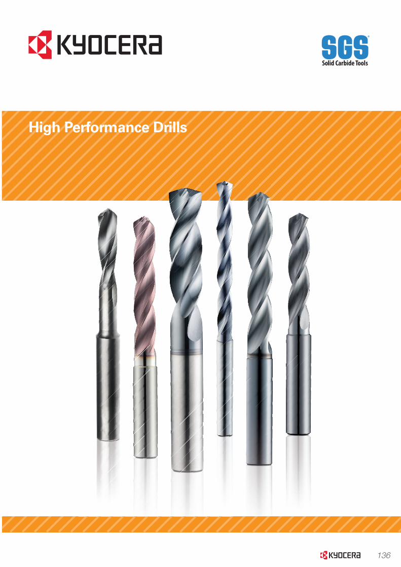
136
High Performance Drills
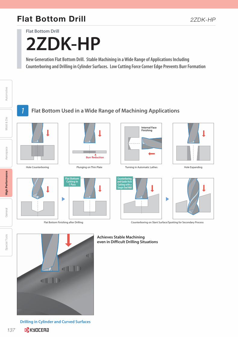
137
Aut
omot
ive
Aer
ospa
ceH
igh
Per
form
ance
Gen
eral
Spe
cial
Too
lsM
old
& D
ie
Flat Bottom Drill 2ZDK-HP
1
Achieves Stable Machining even in Difficult Drilling Situations
Drilling in Cylinder and Curved Surfaces
Internal Face Finishing
Burr Reduction
Flat BottomCutting in
1 Pass
Counterboringand Guide HoleCutting with aSingle End Mill
Flat Bottom Finishing after Drilling Counterboring on Slant Surface/Spotting for Secondary Process
Hole Counterboring Plunging on Thin Plate Turning in Automatic Lathes Hole Expanding
2ZDK-HPNew Generation Flat Bottom Drill. Stable Machining in a Wide Range of Applications Including Counterboring and Drilling in Cylinder Surfaces. Low Cutting Force Corner Edge Prevents Burr Formation
Flat Bottom Drill
Flat Bottom Used in a Wide Range of Machining Applications1
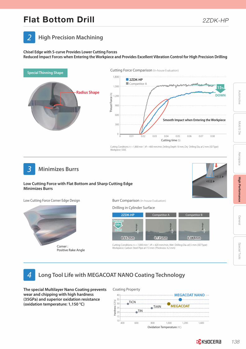
138
Autom
otiveA
erospaceH
igh Perform
anceG
eneralS
pecial ToolsM
old & D
ie
Flat Bottom Drill 2ZDK-HP
2
Radius Shape
The special Multilayer Nano Coating prevents wear and chipping with high hardness (35GPa) and superior oxidation resistance (oxidation temperature: 1,150 °C)
Coating Property
Low Cutting Force Corner Edge Design
Corner : Positive Rake Angle
Low Cutting Force with Flat Bottom and Sharp Cutting EdgeMinimizes Burrs
Oxidation Resistance
40
35
30
25
20
15
10400 600 800 1,000 1,200 1,400
Low High
MEGACOATTiCN
TiNTiAIN
MEGACOAT NANOCoating Property
Har
dnes
s (G
Pa)
Oxidation Temperature (ºC)
Chisel Edge with S-curve Provides Lower Cutting ForcesReduced Impact Forces when Entering the Workpiece and Provides Excellent Vibration Control for High Precision Drilling
Cutting Force Comparison (In-house Evaluation)
Burr Comparison (In-house Evaluation)
High Precision Machining2
Minimizes Burrs3
Long Tool Life with MEGACOAT NANO Coating Technology4
Special Thinning Shape
Thru
st F
orce
(N)
Cutting time (S)
0 0.02 0.03 0.04 0.080.070.060.050.010
600
300
900
1,200
1,500
1,800
15%
DOWN
Smooth Impact when Entering the Workpiece
2ZDK-HPCompetitor A
Cutting Conditions: n = 1,800 min-1, Vf = 400 mm/min, Drilling Depth 10 mm, Dry Drilling Dia. ø12 mm (3D Type)Workpiece: S50C
Drilling in Cylinder Surface
Cutting Conditions: n = 7,000 min-1, Vf = 420 mm/min, Wet Drilling Dia. ø3.5 mm (3D Type)Workpiece: Carbon Steel Pipe ø17.3 mm (Thickness 3.2 mm)
0.037mm 0.135mm 0.084mm
2ZDK-HP Competitor A Competitor B
50%
DOWN
Burr Height
Burr
Heig
ht
Burr
Heig
ht
Burr
Heig
ht
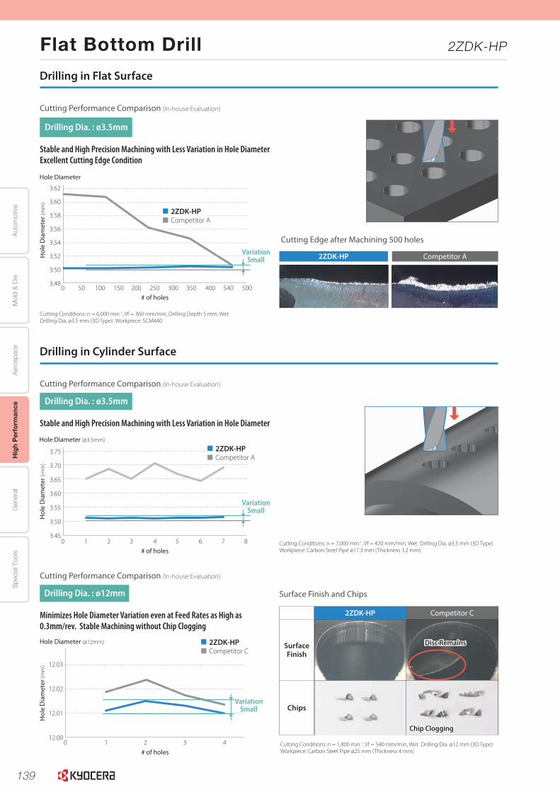
139
Aut
omot
ive
Aer
ospa
ceH
igh
Per
form
ance
Gen
eral
Spe
cial
Too
lsM
old
& D
ie
Flat Bottom Drill 2ZDK-HP
3
Stable and High Precision Machining with Less Variation in Hole Diameter
Minimizes Hole Diameter Variation even at Feed Rates as High as 0.3mm/rev. Stable Machining without Chip Clogging
Stable and High Precision Machining with Less Variation in Hole DiameterExcellent Cutting Edge Condition
Drilling in Cylinder Surface
Drilling in Flat Surface
Cutting Performance Comparison (In-house Evaluation)
Cutting Performance Comparison (In-house Evaluation)
Surface Finish and Chips
Cutting Edge after Machining 500 holes
Cutting Performance Comparison (In-house Evaluation)
Hol
e D
iam
eter
(mm
)
# of holes
Hole Diameter
0 500540400350300250200150100503.48
3.50
3.52
3.54
3.56
3.58
3.60
3.62
2ZDK-HPCompetitor A
Cutting Conditions: n = 6,000 min-1, Vf = 360 mm/min, Drilling Depth 5 mm, WetDrilling Dia. ø3.5 mm (3D Type) Workpiece: SCM440
Cutting Conditions: n = 1,800 min-1, Vf = 540 mm/min, Wet Drilling Dia. ø12 mm (3D Type)Workpiece: Carbon Steel Pipe ø25 mm (Thickness 4 mm)
Cutting Conditions: n = 7,000 min-1, Vf = 420 mm/min, Wet Drilling Dia. ø3.5 mm (3D Type)Workpiece: Carbon Steel Pipe ø17.3 mm (Thickness 3.2 mm)
2ZDK-HP Competitor C
Surface Finish
Chips
Chip Clogging
Disc Remains
2ZDK-HP Competitor A
Drilling Dia. : ø3.5mm
Drilling Dia. : ø12mm
Drilling Dia. : ø3.5mm
VariationSmall
Hol
e D
iam
eter
(mm
)
# of holes
Hole Diameter (ø3.5mm)
03.45
3.50
3.55
3.60
3.65
3.70
3.75
651 2 3 4 7 8
Hol
e D
iam
eter
(mm
)
# of holes
Hole Diameter (ø12mm)
40 32112.00
12.01
12.02
12.03
2ZDK-HPCompetitor A
2ZDK-HPCompetitor C
VariationSmall
Hol
e D
iam
eter
(mm
)
# of holes
Hole Diameter (ø3.5mm)
03.45
3.50
3.55
3.60
3.65
3.70
3.75
651 2 3 4 7 8
Hol
e D
iam
eter
(mm
)
# of holes
Hole Diameter (ø12mm)
40 32112.00
12.01
12.02
12.03
2ZDK-HPCompetitor A
2ZDK-HPCompetitor C
VariationSmall
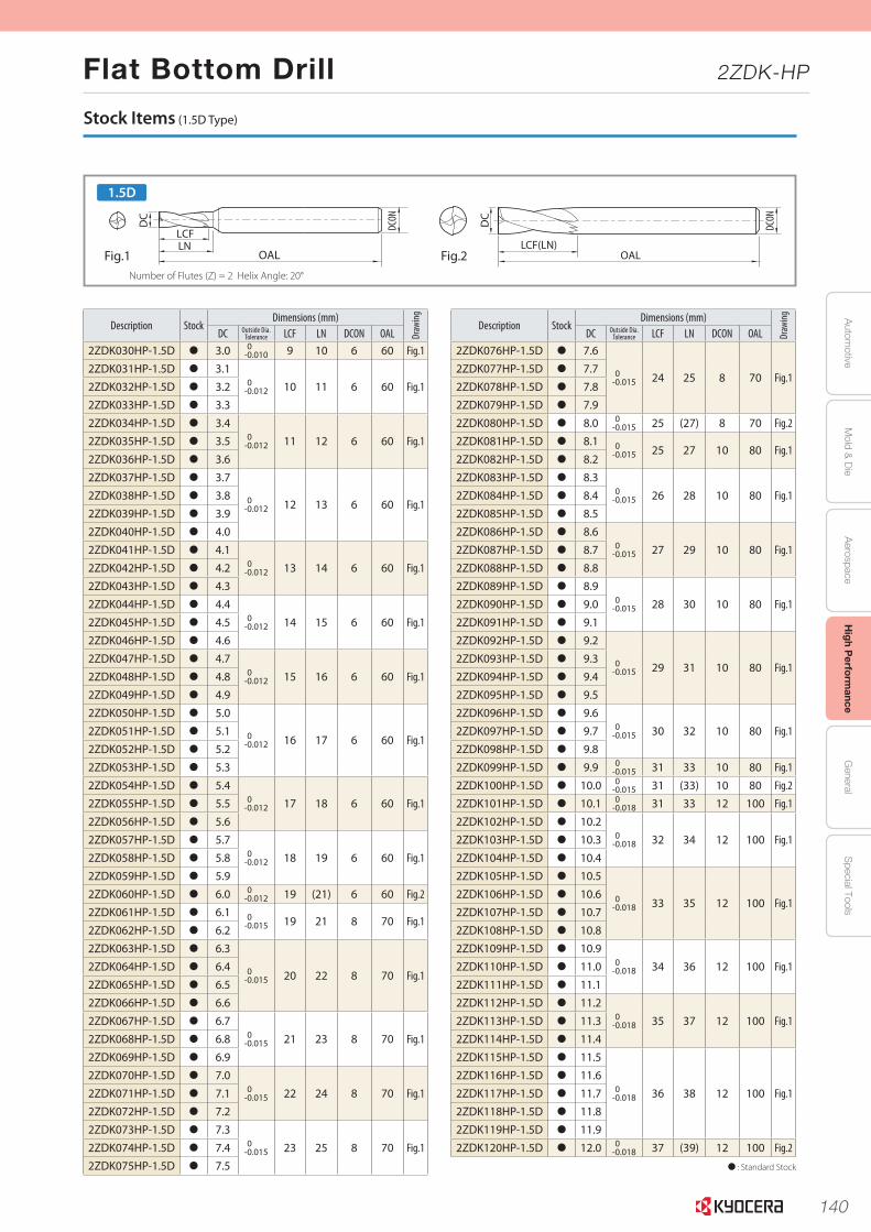
140
Autom
otiveA
erospaceH
igh Perform
anceG
eneralS
pecial ToolsM
old & D
ie
Flat Bottom Drill 2ZDK-HP
5
: Standard Stock
Description StockDimensions (mm)
Draw
ing
DC Outside Dia. Tolerance LCF LN DCON OAL
2ZDK030HP-1.5D 3.0 0-0.010 9 10 6 60 Fig.1
2ZDK031HP-1.5D 3.10
-0.012 10 11 6 60 Fig.12ZDK032HP-1.5D 3.22ZDK033HP-1.5D 3.32ZDK034HP-1.5D 3.4
0-0.012 11 12 6 60 Fig.12ZDK035HP-1.5D 3.5
2ZDK036HP-1.5D 3.62ZDK037HP-1.5D 3.7
0-0.012 12 13 6 60 Fig.1
2ZDK038HP-1.5D 3.82ZDK039HP-1.5D 3.92ZDK040HP-1.5D 4.02ZDK041HP-1.5D 4.1
0-0.012 13 14 6 60 Fig.12ZDK042HP-1.5D 4.2
2ZDK043HP-1.5D 4.32ZDK044HP-1.5D 4.4
0-0.012 14 15 6 60 Fig.12ZDK045HP-1.5D 4.5
2ZDK046HP-1.5D 4.62ZDK047HP-1.5D 4.7
0-0.012 15 16 6 60 Fig.12ZDK048HP-1.5D 4.8
2ZDK049HP-1.5D 4.92ZDK050HP-1.5D 5.0
0-0.012 16 17 6 60 Fig.1
2ZDK051HP-1.5D 5.12ZDK052HP-1.5D 5.22ZDK053HP-1.5D 5.32ZDK054HP-1.5D 5.4
0-0.012 17 18 6 60 Fig.12ZDK055HP-1.5D 5.5
2ZDK056HP-1.5D 5.62ZDK057HP-1.5D 5.7
0-0.012 18 19 6 60 Fig.12ZDK058HP-1.5D 5.8
2ZDK059HP-1.5D 5.92ZDK060HP-1.5D 6.0 0
-0.012 19 (21) 6 60 Fig.2
2ZDK061HP-1.5D 6.1 0-0.015 19 21 8 70 Fig.1
2ZDK062HP-1.5D 6.22ZDK063HP-1.5D 6.3
0-0.015 20 22 8 70 Fig.1
2ZDK064HP-1.5D 6.42ZDK065HP-1.5D 6.52ZDK066HP-1.5D 6.62ZDK067HP-1.5D 6.7
0-0.015 21 23 8 70 Fig.12ZDK068HP-1.5D 6.8
2ZDK069HP-1.5D 6.92ZDK070HP-1.5D 7.0
0-0.015 22 24 8 70 Fig.12ZDK071HP-1.5D 7.1
2ZDK072HP-1.5D 7.22ZDK073HP-1.5D 7.3
0-0.015 23 25 8 70 Fig.12ZDK074HP-1.5D 7.4
2ZDK075HP-1.5D 7.5
Description StockDimensions (mm)
Draw
ing
DC Outside Dia. Tolerance LCF LN DCON OAL
2ZDK076HP-1.5D 7.6
0-0.015 24 25 8 70 Fig.1
2ZDK077HP-1.5D 7.72ZDK078HP-1.5D 7.82ZDK079HP-1.5D 7.92ZDK080HP-1.5D 8.0 0
-0.015 25 (27) 8 70 Fig.2
2ZDK081HP-1.5D 8.1 0-0.015 25 27 10 80 Fig.1
2ZDK082HP-1.5D 8.22ZDK083HP-1.5D 8.3
0-0.015 26 28 10 80 Fig.12ZDK084HP-1.5D 8.4
2ZDK085HP-1.5D 8.52ZDK086HP-1.5D 8.6
0-0.015 27 29 10 80 Fig.12ZDK087HP-1.5D 8.7
2ZDK088HP-1.5D 8.82ZDK089HP-1.5D 8.9
0-0.015 28 30 10 80 Fig.12ZDK090HP-1.5D 9.0
2ZDK091HP-1.5D 9.12ZDK092HP-1.5D 9.2
0-0.015 29 31 10 80 Fig.1
2ZDK093HP-1.5D 9.32ZDK094HP-1.5D 9.42ZDK095HP-1.5D 9.52ZDK096HP-1.5D 9.6
0-0.015 30 32 10 80 Fig.12ZDK097HP-1.5D 9.7
2ZDK098HP-1.5D 9.82ZDK099HP-1.5D 9.9 0
-0.015 31 33 10 80 Fig.1
2ZDK100HP-1.5D 10.0 0-0.015 31 (33) 10 80 Fig.2
2ZDK101HP-1.5D 10.1 0-0.018 31 33 12 100 Fig.1
2ZDK102HP-1.5D 10.20
-0.018 32 34 12 100 Fig.12ZDK103HP-1.5D 10.32ZDK104HP-1.5D 10.42ZDK105HP-1.5D 10.5
0-0.018 33 35 12 100 Fig.1
2ZDK106HP-1.5D 10.62ZDK107HP-1.5D 10.72ZDK108HP-1.5D 10.82ZDK109HP-1.5D 10.9
0-0.018 34 36 12 100 Fig.12ZDK110HP-1.5D 11.0
2ZDK111HP-1.5D 11.12ZDK112HP-1.5D 11.2
0-0.018 35 37 12 100 Fig.12ZDK113HP-1.5D 11.3
2ZDK114HP-1.5D 11.42ZDK115HP-1.5D 11.5
0-0.018 36 38 12 100 Fig.1
2ZDK116HP-1.5D 11.62ZDK117HP-1.5D 11.72ZDK118HP-1.5D 11.82ZDK119HP-1.5D 11.92ZDK120HP-1.5D 12.0 0
-0.018 37 (39) 12 100 Fig.2
Stock Items (1.5D Type)
Fig.1 Fig.2
1.5D
LCF
OAL
DC
DCON
LN
DC
OALLCF(LN)
DCON
Number of Flutes (Z) = 2 Helix Angle: 20°
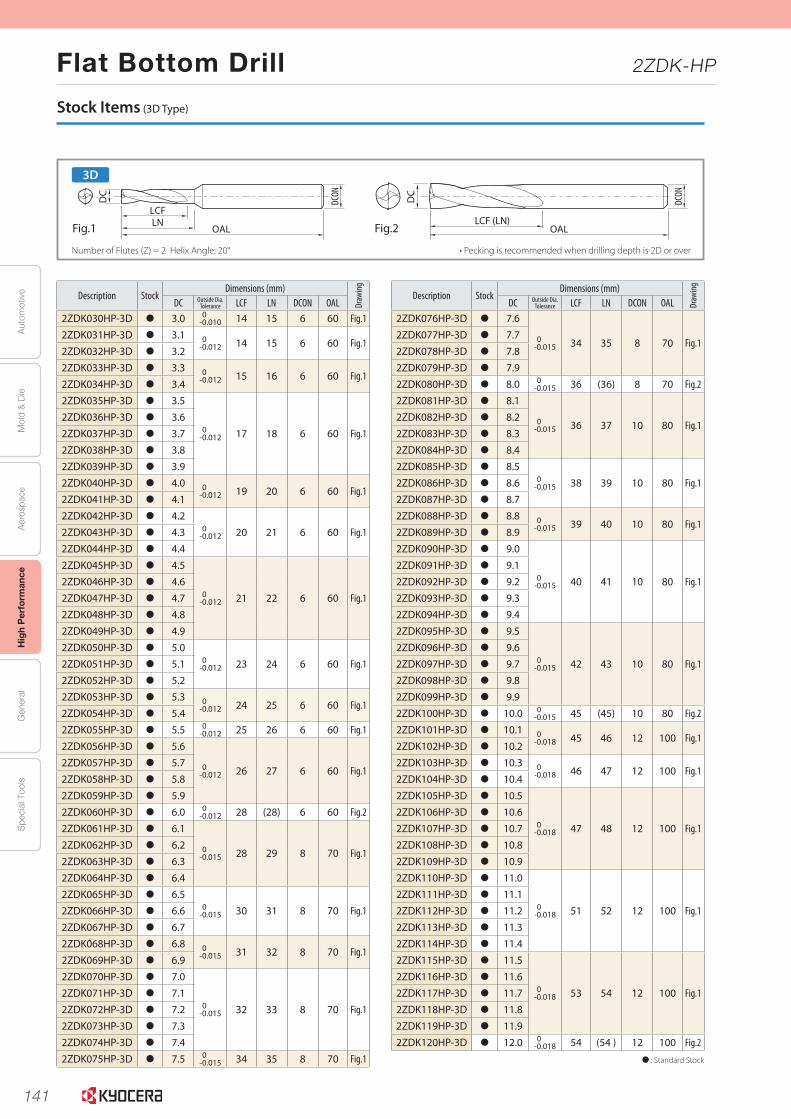
141
Aut
omot
ive
Aer
ospa
ceH
igh
Per
form
ance
Gen
eral
Spe
cial
Too
lsM
old
& D
ie
Flat Bottom Drill 2ZDK-HP
6
Stock Items (3D Type)
: Standard Stock
Description StockDimensions (mm)
Draw
ing
DC Outside Dia. Tolerance LCF LN DCON OAL
2ZDK030HP-3D 3.0 0-0.010 14 15 6 60 Fig.1
2ZDK031HP-3D 3.1 0-0.012 14 15 6 60 Fig.1
2ZDK032HP-3D 3.2 2ZDK033HP-3D 3.3 0
-0.012 15 16 6 60 Fig.12ZDK034HP-3D 3.4 2ZDK035HP-3D 3.5
0-0.012 17 18 6 60 Fig.1
2ZDK036HP-3D 3.6 2ZDK037HP-3D 3.7 2ZDK038HP-3D 3.8 2ZDK039HP-3D 3.9 2ZDK040HP-3D 4.0 0
-0.012 19 20 6 60 Fig.12ZDK041HP-3D 4.1 2ZDK042HP-3D 4.2
0-0.012 20 21 6 60 Fig.12ZDK043HP-3D 4.3
2ZDK044HP-3D 4.4 2ZDK045HP-3D 4.5
0-0.012 21 22 6 60 Fig.1
2ZDK046HP-3D 4.6 2ZDK047HP-3D 4.7 2ZDK048HP-3D 4.8 2ZDK049HP-3D 4.9 2ZDK050HP-3D 5.0
0-0.012 23 24 6 60 Fig.12ZDK051HP-3D 5.1
2ZDK052HP-3D 5.2 2ZDK053HP-3D 5.3 0
-0.012 24 25 6 60 Fig.12ZDK054HP-3D 5.4 2ZDK055HP-3D 5.5 0
-0.012 25 26 6 60 Fig.1
2ZDK056HP-3D 5.6
0-0.012 26 27 6 60 Fig.1
2ZDK057HP-3D 5.7 2ZDK058HP-3D 5.8 2ZDK059HP-3D 5.9 2ZDK060HP-3D 6.0 0
-0.012 28 (28) 6 60 Fig.2
2ZDK061HP-3D 6.1
0-0.015 28 29 8 70 Fig.1
2ZDK062HP-3D 6.2 2ZDK063HP-3D 6.3 2ZDK064HP-3D 6.4 2ZDK065HP-3D 6.5
0-0.015 30 31 8 70 Fig.12ZDK066HP-3D 6.6
2ZDK067HP-3D 6.7 2ZDK068HP-3D 6.8 0
-0.015 31 32 8 70 Fig.12ZDK069HP-3D 6.9 2ZDK070HP-3D 7.0
0-0.015 32 33 8 70 Fig.1
2ZDK071HP-3D 7.1 2ZDK072HP-3D 7.2 2ZDK073HP-3D 7.3 2ZDK074HP-3D 7.4 2ZDK075HP-3D 7.5 0
-0.015 34 35 8 70 Fig.1
Description StockDimensions (mm)
Draw
ing
DC Outside Dia. Tolerance LCF LN DCON OAL
2ZDK076HP-3D 7.6
0-0.015 34 35 8 70 Fig.1
2ZDK077HP-3D 7.7 2ZDK078HP-3D 7.8 2ZDK079HP-3D 7.9 2ZDK080HP-3D 8.0 0
-0.015 36 (36) 8 70 Fig.2
2ZDK081HP-3D 8.1
0-0.015 36 37 10 80 Fig.1
2ZDK082HP-3D 8.2 2ZDK083HP-3D 8.3 2ZDK084HP-3D 8.4 2ZDK085HP-3D 8.5
0-0.015 38 39 10 80 Fig.12ZDK086HP-3D 8.6
2ZDK087HP-3D 8.7 2ZDK088HP-3D 8.8 0
-0.015 39 40 10 80 Fig.12ZDK089HP-3D 8.9 2ZDK090HP-3D 9.0
0-0.015 40 41 10 80 Fig.1
2ZDK091HP-3D 9.1 2ZDK092HP-3D 9.2 2ZDK093HP-3D 9.3 2ZDK094HP-3D 9.4 2ZDK095HP-3D 9.5
0-0.015 42 43 10 80 Fig.1
2ZDK096HP-3D 9.6 2ZDK097HP-3D 9.7 2ZDK098HP-3D 9.8 2ZDK099HP-3D 9.9 2ZDK100HP-3D 10.0 0
-0.015 45 (45) 10 80 Fig.2
2ZDK101HP-3D 10.1 0-0.018 45 46 12 100 Fig.1
2ZDK102HP-3D 10.2 2ZDK103HP-3D 10.3 0
-0.018 46 47 12 100 Fig.12ZDK104HP-3D 10.4 2ZDK105HP-3D 10.5
0-0.018 47 48 12 100 Fig.1
2ZDK106HP-3D 10.6 2ZDK107HP-3D 10.7 2ZDK108HP-3D 10.8 2ZDK109HP-3D 10.9 2ZDK110HP-3D 11.0
0-0.018 51 52 12 100 Fig.1
2ZDK111HP-3D 11.1 2ZDK112HP-3D 11.2 2ZDK113HP-3D 11.3 2ZDK114HP-3D 11.4 2ZDK115HP-3D 11.5
0-0.018 53 54 12 100 Fig.1
2ZDK116HP-3D 11.6 2ZDK117HP-3D 11.7 2ZDK118HP-3D 11.8 2ZDK119HP-3D 11.9 2ZDK120HP-3D 12.0 0
-0.018 54 (54 ) 12 100 Fig.2
OALLNLCF
OALLCF (LN)
DCON
DCON
DC
DC
3D
Fig.1 Fig.2
Number of Flutes (Z) = 2 Helix Angle: 20° • Pecking is recommended when drilling depth is 2D or over
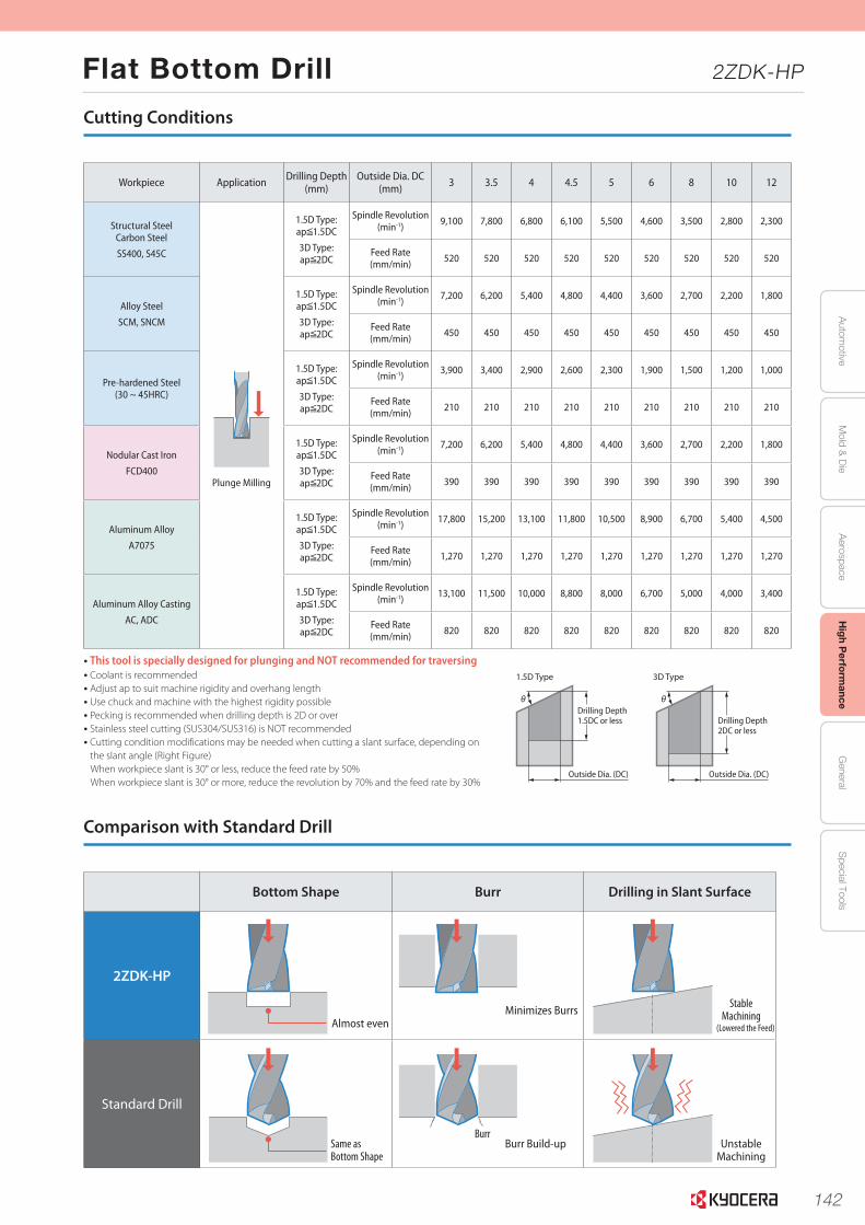
142
Autom
otiveA
erospaceH
igh Perform
anceG
eneralS
pecial ToolsM
old & D
ie
Flat Bottom Drill 2ZDK-HP
4
Workpiece Application Drilling Depth(mm)
Outside Dia. DC(mm) 3 3.5 4 4.5 5 6 8 10 12
Structural SteelCarbon Steel
SS400, S45C
Plunge Milling
1.5D Type:ap 1.5DC
3D Type:ap 2DC
Spindle Revolution (min-1)
9,100 7,800 6,800 6,100 5,500 4,600 3,500 2,800 2,300
Feed Rate(mm/min)
520 520 520 520 520 520 520 520 520
Alloy Steel
SCM, SNCM
1.5D Type:ap 1.5DC
3D Type:ap 2DC
Spindle Revolution (min-1)
7,200 6,200 5,400 4,800 4,400 3,600 2,700 2,200 1,800
Feed Rate(mm/min)
450 450 450 450 450 450 450 450 450
Pre-hardened Steel(30 ~ 45HRC)
1.5D Type:ap 1.5DC
3D Type:ap 2DC
Spindle Revolution (min-1)
3,900 3,400 2,900 2,600 2,300 1,900 1,500 1,200 1,000
Feed Rate(mm/min)
210 210 210 210 210 210 210 210 210
Nodular Cast Iron
FCD400
1.5D Type:ap 1.5DC
3D Type:ap 2DC
Spindle Revolution (min-1)
7,200 6,200 5,400 4,800 4,400 3,600 2,700 2,200 1,800
Feed Rate(mm/min)
390 390 390 390 390 390 390 390 390
Aluminum Alloy
A7075
1.5D Type:ap 1.5DC
3D Type:ap 2DC
Spindle Revolution (min-1)
17,800 15,200 13,100 11,800 10,500 8,900 6,700 5,400 4,500
Feed Rate(mm/min)
1,270 1,270 1,270 1,270 1,270 1,270 1,270 1,270 1,270
Aluminum Alloy Casting
AC, ADC
1.5D Type:ap 1.5DC
3D Type:ap 2DC
Spindle Revolution (min-1)
13,100 11,500 10,000 8,800 8,000 6,700 5,000 4,000 3,400
Feed Rate(mm/min)
820 820 820 820 820 820 820 820 820
Bottom Shape Burr Drilling in Slant Surface
2ZDK-HP
Standard Drill
• This tool is specially designed for plunging and NOT recommended for traversing• Coolant is recommended• Adjust ap to suit machine rigidity and overhang length• Use chuck and machine with the highest rigidity possible• Pecking is recommended when drilling depth is 2D or over• Stainless steel cutting (SUS304/SUS316) is NOT recommended• Cutting condition modifications may be needed when cutting a slant surface, depending on
the slant angle (Right Figure)When workpiece slant is 30° or less, reduce the feed rate by 50% When workpiece slant is 30° or more, reduce the revolution by 70% and the feed rate by 30%
Drilling Depth2DC or less
θ
Outside Dia. (DC)
θ
Outside Dia. (DC)
Drilling Depth1.5DC or less
3D Type1.5D Type
Cutting Conditions
Comparison with Standard Drill
Burr
Almost evenMinimizes Burrs
Stable Machining
(Lowered the Feed)
Unstable Machining
Burr Build-upSame as Bottom Shape
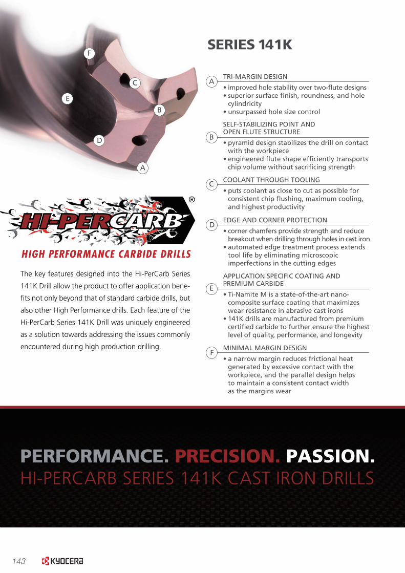
143
TOO
L LI
FE (
ho
les)
0
500
1000
1500
2000
2500
3000
3500 12
0
2
4
6
8
10
Competitor 1 Competitor 2 SERIES 141K
26523027
7.4
8.5
10.3
2377
TEN
SIO
N
TOR
SIO
N
0
5
10
15
20
25
30
35
40
36.2
29.2
Competitor 1 Competitor 2 Competitor 3
28.1
SERIES 141K
16.7
SUR
FAC
E R
OU
GH
NES
S (R
a)
FORCECOMPARISON
SURFACE FINISHCOMPARISON
USAGE & WEARCOMPARISONS
Series 141K drills with 20% less force than the top competitors
Series 141K drill results in improvement of hole �nishes 40-50% over leading competitors
Series 141K drill results in 50% tool life improvement over a range of leading competitors
www.kyocera-sgstool.com
PERFORMANCE.
The key features designed into the Hi-PerCarb Series
141K Drill allow the product to offer application bene-
�ts not only beyond that of standard carbide drills, but
also other High Performance drills. Each feature of the
Hi-PerCarb Series 141K Drill was uniquely engineered
as a solution towards addressing the issues commonly
encountered during high production drilling.
A
B
C
D
E
F
TRI-MARGIN DESIGN
• improved hole stability over two-�ute designs• superior surface �nish, roundness, and hole cylindricity• unsurpassed hole size control
B
C
D
E
A
SELF-STABILIZING POINT AND OPEN FLUTE STRUCTURE
• pyramid design stabilizes the drill on contact with the workpiece• engineered �ute shape ef�ciently transports chip volume without sacri�cing strength
COOLANT THROUGH TOOLING
• puts coolant as close to cut as possible for consistent chip �ushing, maximum cooling, and highest productivity
EDGE AND CORNER PROTECTION
• corner chamfers provide strength and reduce breakout when drilling through holes in cast iron• automated edge treatment process extends tool life by eliminating microscopic imperfections in the cutting edges
FMINIMAL MARGIN DESIGN
• a narrow margin reduces frictional heat generated by excessive contact with the workpiece, and the parallel design helps to maintain a consistent contact width as the margins wear
APPLICATION SPECIFIC COATING AND PREMIUM CARBIDE
• Ti-Namite M is a state-of-the-art nano- composite surface coating that maximizes wear resistance in abrasive cast irons • 141K drills are manufactured from premium certi�ed carbide to further ensure the highest level of quality, performance, and longevity
SERIES 141K
PERFORMANCE. PRECISION. PASSION.HI-PERCARB SERIES 141K CAST IRON DRILLS
0
1000
2000
3000
4000
5000
6000
7000
Competitor 1(chipped)
Competitor 2(broke)
Competitor 3(broke)
50604750
SERIES 141K(wear)
2832
6312
Tension (N)Torsion (Nm)
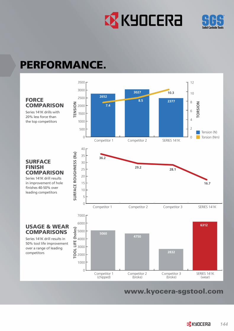
144
TOO
L LI
FE (
ho
les)
0
500
1000
1500
2000
2500
3000
3500 12
0
2
4
6
8
10
Competitor 1 Competitor 2 SERIES 141K
26523027
7.4
8.5
10.3
2377
TEN
SIO
N
TOR
SIO
N
0
5
10
15
20
25
30
35
40
36.2
29.2
Competitor 1 Competitor 2 Competitor 3
28.1
SERIES 141K
16.7
SUR
FAC
E R
OU
GH
NES
S (R
a)
FORCECOMPARISON
SURFACE FINISHCOMPARISON
USAGE & WEARCOMPARISONS
Series 141K drills with 20% less force than the top competitors
Series 141K drill results in improvement of hole �nishes 40-50% overleading competitors
Series 141K drill results in 50% tool life improvement over a range of leading competitors
www.kyocera-sgstool.com
PERFORMANCE.
The key features designed into the Hi-PerCarb Series
141K Drill allow the product to offer application bene-
�ts not only beyond that of standard carbide drills, but
also other High Performance drills. Each feature of the
Hi-PerCarb Series 141K Drill was uniquely engineered
as a solution towards addressing the issues commonly
encountered during high production drilling.
A
B
C
D
E
F
TRI-MARGIN DESIGN
• improved hole stability over two-�ute designs• superior surface �nish, roundness, and hole cylindricity• unsurpassed hole size control
B
C
D
E
A
SELF-STABILIZING POINT AND OPEN FLUTE STRUCTURE
• pyramid design stabilizes the drill on contact with the workpiece
• engineered �ute shape ef�ciently transports chip volume without sacri�cing strength
COOLANT THROUGH TOOLING
• puts coolant as close to cut as possible forconsistent chip �ushing, maximum cooling, and highest productivity
EDGE AND CORNER PROTECTION
• corner chamfers provide strength and reducebreakout when drilling through holes in cast iron
• automated edge treatment process extends tool life by eliminating microscopic imperfections in the cutting edges
FMINIMAL MARGIN DESIGN
• a narrow margin reduces frictional heat generated by excessive contact with the workpiece, and the parallel design helps to maintain a consistent contact width as the margins wear
APPLICATION SPECIFIC COATING AND PREMIUM CARBIDE
• Ti-Namite M is a state-of-the-art nano-composite surface coating that maximizes wear resistance in abrasive cast irons
• 141K drills are manufactured from premium certi�ed carbide to further ensure the highest level of quality, performance, and longevity
SERIES 141K
PERFORMANCE. PRECISION. PASSION.HI-PERCARB SERIES 141K CAST IRON DRILLS
0
1000
2000
3000
4000
5000
6000
7000
Competitor 1(chipped)
Competitor 2(broke)
Competitor 3(broke)
50604750
SERIES 141K(wear)
2832
6312
Tension (N)Torsion (Nm)
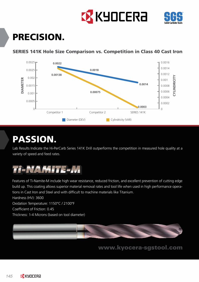
145
Competitor 1 Competitor 2 SERIES 141K
PRECISION.
PASSION.Lab Results Indicate the Hi-PerCarb Series 141K Drill outperforms the competition in measured hole quality at a
variety of speed and feed rates.
www.kyocera-sgstool.com
Features of Ti-Namite-M include high wear resistance, reduced friction, and excellent prevention of cutting edge
build up. This coating allows superior material removal rates and tool life when used in high performance opera-
tions in Cast Iron and Steel and with dif�cult to machine materials like Titanium.
Hardness (HV): 3600
Oxidation Temperature: 1150°C / 2100°F
Coef�cient of Friction: 0.45
Thickness: 1-4 Microns (based on tool diameter)
SERIES 141K Hole Size Comparison vs. Competition in Class 40 Cast Iron
0
0.0005
0.001
0.0015
0.002
0.0025
0.0025 0.0016
0
0.0002
0.0004
0.0006
0.0008
0.001
0.0012
0.00140.0018
0.0022
0.00138
0.00075
0.0003
0.0014
DIA
MET
ER
CY
LIN
DR
ICIT
Y
Diameter (DEV) Cylindricity (VAR)
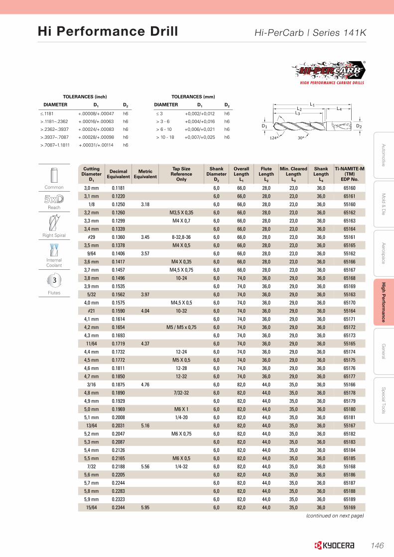
146
Autom
otiveA
erospaceH
igh Perform
anceG
eneralS
pecial ToolsM
old & D
ie
Hi Performance Drill Hi-PerCarb | Series 141K
43
Serie
s 135 5
xD
|
Fraction
al & M
etric
www.kyocera-sgstool.com
Serie
s 141K
5xD
|Fractio
nal &
Metric
Common
Reach
Right Spiral
Internal Coolant
3
Flutes
Cutting Diameter
D1
Decimal Equivalent
Metric Equivalent
Tap Size Reference
Only
Shank Diameter
D2
Overall Length
L1
Flute Length
L2
Min. ClearedLength
L3
Shank Length
L4
Ti-NAMITE-M (TM)
EDP No.
3,0 mm 0.1181 6,0 66,0 28,0 23,0 36,0 65160
3,1 mm 0.1220 6,0 66,0 28,0 23,0 36,0 65161
1/8 0.1250 3.18 6,0 66,0 28,0 23,0 36,0 55160
3,2 mm 0.1260 M3,5 X 0,35 6,0 66,0 28,0 23,0 36,0 65162
3,3 mm 0.1299 M4 X 0,7 6,0 66,0 28,0 23,0 36,0 65163
3,4 mm 0.1339 6,0 66,0 28,0 23,0 36,0 65164
#29 0.1360 3.45 8-32,8-36 6,0 66,0 28,0 23,0 36,0 55161
3,5 mm 0.1378 M4 X 0,5 6,0 66,0 28,0 23,0 36,0 65165
9/64 0.1406 3.57 6,0 66,0 28,0 23,0 36,0 55162
3,6 mm 0.1417 M4 X 0,35 6,0 66,0 28,0 23,0 36,0 65166
3,7 mm 0.1457 M4,5 X 0,75 6,0 66,0 28,0 23,0 36,0 65167
3,8 mm 0.1496 10-24 6,0 74,0 36,0 29,0 36,0 65168
3,9 mm 0.1535 6,0 74,0 36,0 29,0 36,0 65169
5/32 0.1562 3.97 6,0 74,0 36,0 29,0 36,0 55163
4,0 mm 0.1575 M4,5 X 0,5 6,0 74,0 36,0 29,0 36,0 65170
#21 0.1590 4.04 10-32 6,0 74,0 36,0 29,0 36,0 55164
4,1 mm 0.1614 6,0 74,0 36,0 29,0 36,0 65171
4,2 mm 0.1654 M5 / M5 x 0,75 6,0 74,0 36,0 29,0 36,0 65172
4,3 mm 0.1693 6,0 74,0 36,0 29,0 36,0 65173
11/64 0.1719 4.37 6,0 74,0 36,0 29,0 36,0 55165
4,4 mm 0.1732 12-24 6,0 74,0 36,0 29,0 36,0 65174
4,5 mm 0.1772 M5 X 0,5 6,0 74,0 36,0 29,0 36,0 65175
4,6 mm 0.1811 12-28 6,0 74,0 36,0 29,0 36,0 65176
4,7 mm 0.1850 12-32 6,0 74,0 36,0 29,0 36,0 65177
3/16 0.1875 4.76 6,0 82,0 44,0 35,0 36,0 55166
4,8 mm 0.1890 7/32-32 6,0 82,0 44,0 35,0 36,0 65178
4,9 mm 0.1929 6,0 82,0 44,0 35,0 36,0 65179
5,0 mm 0.1969 M6 X 1 6,0 82,0 44,0 35,0 36,0 65180
5,1 mm 0.2008 1/4-20 6,0 82,0 44,0 35,0 36,0 65181
13/64 0.2031 5.16 6,0 82,0 44,0 35,0 36,0 55167
5,2 mm 0.2047 M6 X 0,75 6,0 82,0 44,0 35,0 36,0 65182
5,3 mm 0.2087 6,0 82,0 44,0 35,0 36,0 65183
5,4 mm 0.2126 6,0 82,0 44,0 35,0 36,0 65184
5,5 mm 0.2165 M6 X 0,5 6,0 82,0 44,0 35,0 36,0 65185
7/32 0.2188 5.56 1/4-32 6,0 82,0 44,0 35,0 36,0 55168
5,6 mm 0.2205 6,0 82,0 44,0 35,0 36,0 65186
5,7 mm 0.2244 6,0 82,0 44,0 35,0 36,0 65187
5,8 mm 0.2283 6,0 82,0 44,0 35,0 36,0 65188
5,9 mm 0.2323 6,0 82,0 44,0 35,0 36,0 65189
15/64 0.2344 5.95 6,0 82,0 44,0 35,0 36,0 55169
(continued on next page)
TOLERANCES (mm)
DIAMETER D1 D2
≤ 3 +0,002/+0,012 h6
> 3 - 6 +0,004/+0,016 h6
> 6 - 10 +0,006/+0,021 h6
> 10 - 18 +0,007/+0,025 h6
TOLERANCES (inch)
DIAMETER D1 D2
≤.1181 +.00008/+.00047 h6
>.1181–.2362 +.00016/+.00063 h6
>.2362–.3937 +.00024/+.00083 h6
>.3937–.7087 +.00028/+.00098 h6
>.7087–1.1811 +.00031/+.00114 h6
2D
L1L2
L3L4
124° 30°
1D
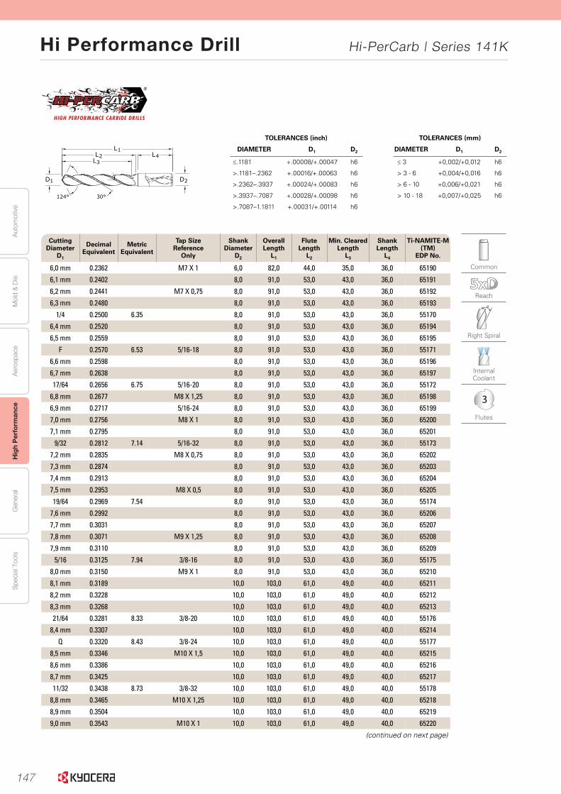
147
Aut
omot
ive
Aer
ospa
ceH
igh
Per
form
ance
Gen
eral
Spe
cial
Too
lsM
old
& D
ie
Hi Performance Drill Hi-PerCarb | Series 141K
44 www.kyocera-sgstool.com
Seri
es
141K
5xD
|Fr
acti
on
al &
Met
ric
TOLERANCES (mm)
DIAMETER D1 D2
≤ 3 +0,002/+0,012 h6
> 3 - 6 +0,004/+0,016 h6
> 6 - 10 +0,006/+0,021 h6
> 10 - 18 +0,007/+0,025 h6
TOLERANCES (inch)
DIAMETER D1 D2
≤.1181 +.00008/+.00047 h6
>.1181–.2362 +.00016/+.00063 h6
>.2362–.3937 +.00024/+.00083 h6
>.3937–.7087 +.00028/+.00098 h6
>.7087–1.1811 +.00031/+.00114 h6
2D
L1L2
L3L4
124° 30°
1D
Common
Reach
Right Spiral
Internal Coolant
3
Flutes
Cutting Diameter
D1
Decimal Equivalent
Metric Equivalent
Tap Size Reference
Only
Shank Diameter
D2
Overall Length
L1
Flute Length
L2
Min. ClearedLength
L3
Shank Length
L4
Ti-NAMITE-M (TM)
EDP No.
6,0 mm 0.2362 M7 X 1 6,0 82,0 44,0 35,0 36,0 65190
6,1 mm 0.2402 8,0 91,0 53,0 43,0 36,0 65191
6,2 mm 0.2441 M7 X 0,75 8,0 91,0 53,0 43,0 36,0 65192
6,3 mm 0.2480 8,0 91,0 53,0 43,0 36,0 65193
1/4 0.2500 6.35 8,0 91,0 53,0 43,0 36,0 55170
6,4 mm 0.2520 8,0 91,0 53,0 43,0 36,0 65194
6,5 mm 0.2559 8,0 91,0 53,0 43,0 36,0 65195
F 0.2570 6.53 5/16-18 8,0 91,0 53,0 43,0 36,0 55171
6,6 mm 0.2598 8,0 91,0 53,0 43,0 36,0 65196
6,7 mm 0.2638 8,0 91,0 53,0 43,0 36,0 65197
17/64 0.2656 6.75 5/16-20 8,0 91,0 53,0 43,0 36,0 55172
6,8 mm 0.2677 M8 X 1,25 8,0 91,0 53,0 43,0 36,0 65198
6,9 mm 0.2717 5/16-24 8,0 91,0 53,0 43,0 36,0 65199
7,0 mm 0.2756 M8 X 1 8,0 91,0 53,0 43,0 36,0 65200
7,1 mm 0.2795 8,0 91,0 53,0 43,0 36,0 65201
9/32 0.2812 7.14 5/16-32 8,0 91,0 53,0 43,0 36,0 55173
7,2 mm 0.2835 M8 X 0,75 8,0 91,0 53,0 43,0 36,0 65202
7,3 mm 0.2874 8,0 91,0 53,0 43,0 36,0 65203
7,4 mm 0.2913 8,0 91,0 53,0 43,0 36,0 65204
7,5 mm 0.2953 M8 X 0,5 8,0 91,0 53,0 43,0 36,0 65205
19/64 0.2969 7.54 8,0 91,0 53,0 43,0 36,0 55174
7,6 mm 0.2992 8,0 91,0 53,0 43,0 36,0 65206
7,7 mm 0.3031 8,0 91,0 53,0 43,0 36,0 65207
7,8 mm 0.3071 M9 X 1,25 8,0 91,0 53,0 43,0 36,0 65208
7,9 mm 0.3110 8,0 91,0 53,0 43,0 36,0 65209
5/16 0.3125 7.94 3/8-16 8,0 91,0 53,0 43,0 36,0 55175
8,0 mm 0.3150 M9 X 1 8,0 91,0 53,0 43,0 36,0 65210
8,1 mm 0.3189 10,0 103,0 61,0 49,0 40,0 65211
8,2 mm 0.3228 10,0 103,0 61,0 49,0 40,0 65212
8,3 mm 0.3268 10,0 103,0 61,0 49,0 40,0 65213
21/64 0.3281 8.33 3/8-20 10,0 103,0 61,0 49,0 40,0 55176
8,4 mm 0.3307 10,0 103,0 61,0 49,0 40,0 65214
Q 0.3320 8.43 3/8-24 10,0 103,0 61,0 49,0 40,0 55177
8,5 mm 0.3346 M10 X 1,5 10,0 103,0 61,0 49,0 40,0 65215
8,6 mm 0.3386 10,0 103,0 61,0 49,0 40,0 65216
8,7 mm 0.3425 10,0 103,0 61,0 49,0 40,0 65217
11/32 0.3438 8.73 3/8-32 10,0 103,0 61,0 49,0 40,0 55178
8,8 mm 0.3465 M10 X 1,25 10,0 103,0 61,0 49,0 40,0 65218
8,9 mm 0.3504 10,0 103,0 61,0 49,0 40,0 65219
9,0 mm 0.3543 M10 X 1 10,0 103,0 61,0 49,0 40,0 65220
(continued on next page)
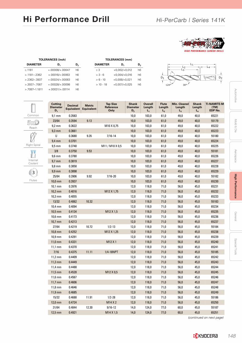
148
Autom
otiveA
erospaceH
igh Perform
anceG
eneralS
pecial ToolsM
old & D
ie
Hi Performance Drill Hi-PerCarb | Series 141K
45www.kyocera-sgstool.com
Serie
s 141K
5xD
|
Fraction
al & M
etric
TOLERANCES (mm)
DIAMETER D1 D2
≤ 3 +0,002/+0,012 h6
> 3 - 6 +0,004/+0,016 h6
> 6 - 10 +0,006/+0,021 h6
> 10 - 18 +0,007/+0,025 h6
TOLERANCES (inch)
DIAMETER D1 D2
≤.1181 +.00008/+.00047 h6
>.1181–.2362 +.00016/+.00063 h6
>.2362–.3937 +.00024/+.00083 h6
>.3937–.7087 +.00028/+.00098 h6
>.7087–1.1811 +.00031/+.00114 h6
2D
L1L2
L3L4
124° 30°
1D
Common
Reach
Right Spiral
Internal Coolant
3
Flutes
Cutting Diameter
D1
Decimal Equivalent
Metric Equivalent
Tap Size Reference
Only
Shank Diameter
D2
Overall Length
L1
Flute Length
L2
Min. ClearedLength
L3
Shank Length
L4
Ti-NAMITE-M (TM)
EDP No.
9,1 mm 0.3583 10,0 103,0 61,0 49,0 40,0 65221
23/64 0.3594 9.13 10,0 103,0 61,0 49,0 40,0 55179
9,2 mm 0.3622 M10 X 0,75 10,0 103,0 61,0 49,0 40,0 65222
9,3 mm 0.3661 10,0 103,0 61,0 49,0 40,0 65223
U 0.3680 9.35 7/16-14 10,0 103,0 61,0 49,0 40,0 55180
9,4 mm 0.3701 10,0 103,0 61,0 49,0 40,0 65224
9,5 mm 0.3740 M11 / M10 X 0,5 10,0 103,0 61,0 49,0 40,0 65225
3/8 0.3750 9.53 10,0 103,0 61,0 49,0 40,0 55181
9,6 mm 0.3780 10,0 103,0 61,0 49,0 40,0 65226
9,7 mm 0.3819 10,0 103,0 61,0 49,0 40,0 65227
9,8 mm 0.3858 10,0 103,0 61,0 49,0 40,0 65228
9,9 mm 0.3898 10,0 103,0 61,0 49,0 40,0 65229
25/64 0.3906 9.92 7/16-20 10,0 103,0 61,0 49,0 40,0 55182
10,0 mm 0.3937 10,0 103,0 61,0 49,0 40,0 65230
10,1 mm 0.3976 12,0 118,0 71,0 56,0 45,0 65231
10,2 mm 0.4016 M12 X 1,75 12,0 118,0 71,0 56,0 45,0 65232
10,3 mm 0.4055 12,0 118,0 71,0 56,0 45,0 65233
13/32 0.4062 10.32 12,0 118,0 71,0 56,0 45,0 55183
10,4 mm 0.4094 12,0 118,0 71,0 56,0 45,0 65234
10,5 mm 0.4134 M12 X 1,5 12,0 118,0 71,0 56,0 45,0 65235
10,6 mm 0.4173 12,0 118,0 71,0 56,0 45,0 65236
10,7 mm 0.4213 12,0 118,0 71,0 56,0 45,0 65237
27/64 0.4219 10.72 1/2-13 12,0 118,0 71,0 56,0 45,0 55184
10,8 mm 0.4252 M12 X 1,25 12,0 118,0 71,0 56,0 45,0 65238
10,9 mm 0.4291 12,0 118,0 71,0 56,0 45,0 65239
11,0 mm 0.4331 M12 X 1 12,0 118,0 71,0 56,0 45,0 65240
11,1 mm 0.4370 12,0 118,0 71,0 56,0 45,0 65241
7/16 0.4375 11.11 1/4-18NPT 12,0 118,0 71,0 56,0 45,0 55185
11,2 mm 0.4409 12,0 118,0 71,0 56,0 45,0 65242
11,3 mm 0.4449 12,0 118,0 71,0 56,0 45,0 65243
11,4 mm 0.4488 12,0 118,0 71,0 56,0 45,0 65244
11,5 mm 0.4528 M12 X 0,5 12,0 118,0 71,0 56,0 45,0 65245
11,6 mm 0.4567 12,0 118,0 71,0 56,0 45,0 65246
11,7 mm 0.4606 12,0 118,0 71,0 56,0 45,0 65247
11,8 mm 0.4646 12,0 118,0 71,0 56,0 45,0 65248
11,9 mm 0.4685 12,0 118,0 71,0 56,0 45,0 65249
15/32 0.4688 11.91 1/2-28 12,0 118,0 71,0 56,0 45,0 55186
12,0 mm 0.4724 M14 X 2 12,0 118,0 71,0 56,0 45,0 65250
31/64 0.4844 12.30 9/16-12 14,0 124,0 77,0 60,0 45,0 55187
12,5 mm 0.4921 M14 X 1,5 14,0 124,0 77,0 60,0 45,0 65251
(continued on next page)
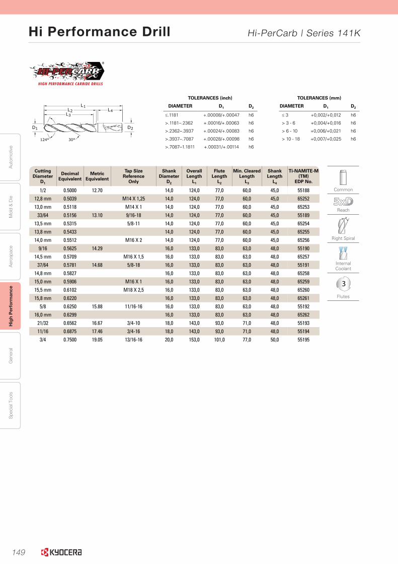
149
Aut
omot
ive
Aer
ospa
ceH
igh
Per
form
ance
Gen
eral
Spe
cial
Too
lsM
old
& D
ie
Hi Performance Drill Hi-PerCarb | Series 141K
46 www.kyocera-sgstool.com
TOLERANCES (mm)
DIAMETER D1 D2
≤ 3 +0,002/+0,012 h6
> 3 - 6 +0,004/+0,016 h6
> 6 - 10 +0,006/+0,021 h6
> 10 - 18 +0,007/+0,025 h6
TOLERANCES (inch)
DIAMETER D1 D2
≤.1181 +.00008/+.00047 h6
>.1181–.2362 +.00016/+.00063 h6
>.2362–.3937 +.00024/+.00083 h6
>.3937–.7087 +.00028/+.00098 h6
>.7087–1.1811 +.00031/+.00114 h6
2D
L1L2
L3L4
124° 30°
1D
Common
Reach
Right Spiral
Internal Coolant
3
Flutes
Cutting Diameter
D1
Decimal Equivalent
Metric Equivalent
Tap Size Reference
Only
Shank Diameter
D2
Overall Length
L1
Flute Length
L2
Min. ClearedLength
L3
Shank Length
L4
Ti-NAMITE-M (TM)
EDP No.
1/2 0.5000 12.70 14,0 124,0 77,0 60,0 45,0 55188
12,8 mm 0.5039 M14 X 1,25 14,0 124,0 77,0 60,0 45,0 65252
13,0 mm 0.5118 M14 X 1 14,0 124,0 77,0 60,0 45,0 65253
33/64 0.5156 13.10 9/16-18 14,0 124,0 77,0 60,0 45,0 55189
13,5 mm 0.5315 5/8-11 14,0 124,0 77,0 60,0 45,0 65254
13,8 mm 0.5433 14,0 124,0 77,0 60,0 45,0 65255
14,0 mm 0.5512 M16 X 2 14,0 124,0 77,0 60,0 45,0 65256
9/16 0.5625 14.29 16,0 133,0 83,0 63,0 48,0 55190
14,5 mm 0.5709 M16 X 1,5 16,0 133,0 83,0 63,0 48,0 65257
37/64 0.5781 14.68 5/8-18 16,0 133,0 83,0 63,0 48,0 55191
14,8 mm 0.5827 16,0 133,0 83,0 63,0 48,0 65258
15,0 mm 0.5906 M16 X 1 16,0 133,0 83,0 63,0 48,0 65259
15,5 mm 0.6102 M18 X 2,5 16,0 133,0 83,0 63,0 48,0 65260
15,8 mm 0.6220 16,0 133,0 83,0 63,0 48,0 65261
5/8 0.6250 15.88 11/16-16 16,0 133,0 83,0 63,0 48,0 55192
16,0 mm 0.6299 16,0 133,0 83,0 63,0 48,0 65262
21/32 0.6562 16.67 3/4-10 18,0 143,0 93,0 71,0 48,0 55193
11/16 0.6875 17.46 3/4-16 18,0 143,0 93,0 71,0 48,0 55194
3/4 0.7500 19.05 13/16-16 20,0 153,0 101,0 77,0 50,0 55195
Seri
es
141K
5xD
|
Frac
tio
nal
& M
etri
c
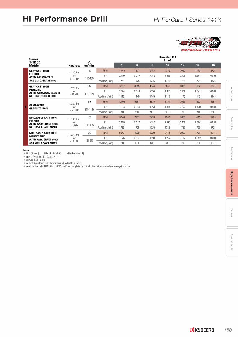
150
Autom
otiveA
erospaceH
igh Perform
anceG
eneralS
pecial ToolsM
old & D
ie
Hi Performance Drill Hi-PerCarb | Series 141K
47www.kyocera-sgstool.com
Series 141K 5DMetric Hardness
Vc (m/min)
Diameter (D1)(mm)
3 6 8 10 12 14 16
K
GRAY CAST IRONFERRITICASTM A48: CLASS 20SAE J431C: GRADE 1800
≤ 150 Bhnor
≤ 80 HRb
137 RPM 14541 7271 5453 4362 3635 3116 2726
(110-165)Fr 0.119 0.237 0.316 0.395 0.475 0.554 0.633
Feed (mm/min) 1725 1725 1725 1725 1725 1725 1725
GRAY CAST IRONPEARLITICASTM A48: CLASS 30, 35, 40SAE J431C: GRADE 3000
≤ 220 Bhnor
≤ 19 HRc
114 RPM 12118 6059 4544 3635 3029 2597 2272
(91-137)Fr 0.094 0.189 0.252 0.315 0.378 0.441 0.504
Feed (mm/min) 1145 1145 1145 1145 1145 1145 1145
COMPACTEDGRAPHITE IRON
≤ 250 Bhnor
≤ 25 HRc
99 RPM 10502 5251 3938 3151 2626 2250 1969
(79-119)Fr 0.094 0.189 0.251 0.314 0.377 0.440 0.503
Feed (mm/min) 990 990 990 990 990 990 990
MALLEABLE CAST IRONFERRITICASTM A220: GRADE 40010SAE J158: GRADE M4504
≤ 160 Bhnor
≤ 3 HRc
137 RPM 14541 7271 5453 4362 3635 3116 2726
(110-165)Fr 0.119 0.237 0.316 0.395 0.475 0.554 0.633
Feed (mm/min) 1725 1725 1725 1725 1725 1725 1725
MALLEABLE CAST IRONMARTENSITEASTM A220: GRADE 90001SAE J158: GRADE M8501
≤ 320 Bhnor
≤ 34 HRc
76 RPM 8078 4039 3029 2424 2020 1731 1515
(61-91)Fr 0.076 0.151 0.201 0.252 0.302 0.352 0.403
Feed (mm/min) 610 610 610 610 610 610 610
Note:• Bhn (Brinell) HRc (Rockwell C) HRb (Rockwell B)• rpm = (Vc x 1000) / (D1 x 3.14) • mm/min = Fr x rpm• reduce speed and feed for materials harder than listed • refer to the KYOCERA SGS Tool Wizard® for complete technical information (www.kyocera-sgstool.com)
Serie
s 141K
5xD
|
Speed
& Feed
Reco
mm
end
ation
s
Series 141K 5DFractional Hardness
Vc (sfm)
Diameter (D1)(inch)
1/8 3/16 1/4 3/8 1/2 5/8 3/4
K
GRAY CAST IRONFERRITICASTM A48: CLASS 20SAE J431C: GRADE 1800
≤ 150 Bhnor
≤ 80 HRb
450 RPM 13752 9168 6876 4584 3438 2750 2292
(360-540)Fr 0.0049 0.0074 0.0099 0.0148 0.0198 0.0247 0.0297
Feed (ipm) 68 68 68 68 68 68 68
GRAY CAST IRONPEARLITICASTM A48: CLASS 30, 35, 40SAE J431C: GRADE 3000
≤ 220 Bhnor
≤ 19 HRc
375 RPM 11460 7640 5730 3820 2865 2292 1910
(300-450)Fr 0.0039 0.0059 0.0079 0.0118 0.0157 0.0196 0.0236
Feed (ipm) 45 45 45 45 45 45 45
COMPACTEDGRAPHITE IRON
≤ 250 Bhnor
≤ 25 HRc
325 RPM 9932 6621 4966 3311 2483 1986 1655
(260-390)Fr 0.0039 0.0059 0.0079 0.0118 0.0157 0.0196 0.0236
Feed (ipm) 39 39 39 39 39 39 39
MALLEABLE CAST IRONFERRITICASTM A220: GRADE 40010SAE J158: GRADE M4504
≤ 160 Bhnor
≤ 3 HRc
450 RPM 13752 9168 6876 4584 3438 2750 2292
(360-540)Fr 0.0049 0.0074 0.0099 0.0148 0.0198 0.0247 0.0297
Feed (ipm) 68 68 68 68 68 68 68
MALLEABLE CAST IRONMARTENSITEASTM A220: GRADE 90001SAE J158: GRADE M8501
≤ 320 Bhnor
≤ 34 HRc
250 RPM 7640 5093 3820 2547 1910 1528 1273
(200-300)Fr 0.0031 0.0047 0.0063 0.0094 0.0126 0.0157 0.0188
Feed (mm/min) 24 24 24 24 24 24 24
Note:• Bhn (Brinell) HRc (Rockwell C) HRb (Rockwell B)• rpm = Vc x 3.82 / D1• ipm = Fr x rpm• reduce speed and feed for materials harder than listed • refer to the KYOCERA SGS Tool Wizard® for complete technical information (www.kyocera-sgstool.com)
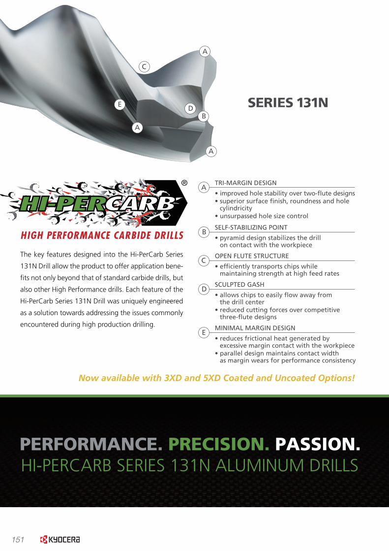
151
PERFORMANCE. PRECISION. PASSION.HI-PERCARB SERIES 131N ALUMINUM DRILLS
The key features designed into the Hi-PerCarb Series
131N Drill allow the product to offer application bene-
�ts not only beyond that of standard carbide drills, but
also other High Performance drills. Each feature of the
Hi-PerCarb Series 131N Drill was uniquely engineered
as a solution towards addressing the issues commonly
encountered during high production drilling.
TRI-MARGIN DESIGN
• improved hole stability over two-�ute designs• superior surface �nish, roundness and hole cylindricity• unsurpassed hole size control
A
A
A
A
B
B
SELF-STABILIZING POINT
• pyramid design stabilizes the drill on contact with the workpiece
C
C
OPEN FLUTE STRUCTURE
• ef�ciently transports chips while maintaining strength at high feed rates
D
D
SCULPTED GASH
• allows chips to easily �ow away from the drill center• reduced cutting forces over competitive three-�ute designs
E
E
MINIMAL MARGIN DESIGN
• reduces frictional heat generated by excessive margin contact with the workpiece• parallel design maintains contact width as margin wears for performance consistency
0
0.002
0.004
0.006
0.008
0.01
0.012
0.014
Uncoated Ti-Namite B 0
100
200
300
400
500
600
700
800
Uncoated Ti-Namite B
689
311
USA
GE
(in
ches
)
WEA
R (
inch
es)
0.0015
.0124
0
50
100
150
200
250
300
350
400
SERIES 131N Competitor 1 Competitor 2 Competitor 3
361.2 348 360.2
293.7
FOR
CE
(lb
s)
0
10
20
30
40
50
60
70
80
SERIES 131N
29
Competitor 1
56
Competitor 2
43
Competitor 3
66
Competitor 4
75
FIN
ISH
(R
a)
FORCECOMPARISON
SURFACE FINISHCOMPARISON
USAGE & WEARCOMPARISONS
Series 131N drills with15-20% less force than the top competitors
Series 131N drill results in improvement of hole�nishes 30-60% over leading competitors
Ti-NAMITE B coatingsigni�cantly improves wear resistance, which is particularly bene�cial when drilling high silicon aluminum alloys
SERIES 131N PERFORMANCE.
Now available with 3XD and 5XD Coated and Uncoated Options!

152
PERFORMANCE. PRECISION. PASSION.HI-PERCARB SERIES 131N ALUMINUM DRILLS
The key features designed into the Hi-PerCarb Series
131N Drill allow the product to offer application bene-
�ts not only beyond that of standard carbide drills, but
also other High Performance drills. Each feature of the
Hi-PerCarb Series 131N Drill was uniquely engineered
as a solution towards addressing the issues commonly
encountered during high production drilling.
TRI-MARGIN DESIGN
• improved hole stability over two-�ute designs• superior surface �nish, roundness and hole cylindricity• unsurpassed hole size control
A
A
A
A
B
B
SELF-STABILIZING POINT
• pyramid design stabilizes the drillon contact with the workpiece
C
C
OPEN FLUTE STRUCTURE
• ef�ciently transports chips whilemaintaining strength at high feed rates
D
D
SCULPTED GASH
• allows chips to easily �ow away fromthe drill center
• reduced cutting forces over competitivethree-�ute designs
E
E
MINIMAL MARGIN DESIGN
• reduces frictional heat generated byexcessive margin contact with the workpiece
• parallel design maintains contact widthas margin wears for performance consistency
0
0.002
0.004
0.006
0.008
0.01
0.012
0.014
Uncoated Ti-Namite B 0
100
200
300
400
500
600
700
800
Uncoated Ti-Namite B
689
311
USA
GE
(in
ches
)
WEA
R (
inch
es)
0.0015
.0124
0
50
100
150
200
250
300
350
400
SERIES 131N Competitor 1 Competitor 2 Competitor 3
361.2 348 360.2
293.7
FOR
CE
(lb
s)
0
10
20
30
40
50
60
70
80
SERIES 131N
29
Competitor 1
56
Competitor 2
43
Competitor 3
66
Competitor 4
75
FIN
ISH
(R
a)
FORCECOMPARISON
SURFACE FINISHCOMPARISON
USAGE & WEARCOMPARISONS
Series 131N drills with15-20% less force than the top competitors
Series 131N drill results in improvement of hole�nishes 30-60% over leading competitors
Ti-NAMITE B coatingsigni�cantly improves wear resistance, which is particularly bene�cial when drilling high silicon aluminum alloys
SERIES 131N PERFORMANCE.
Now available with 3XD and 5XD Coated and Uncoated Options!
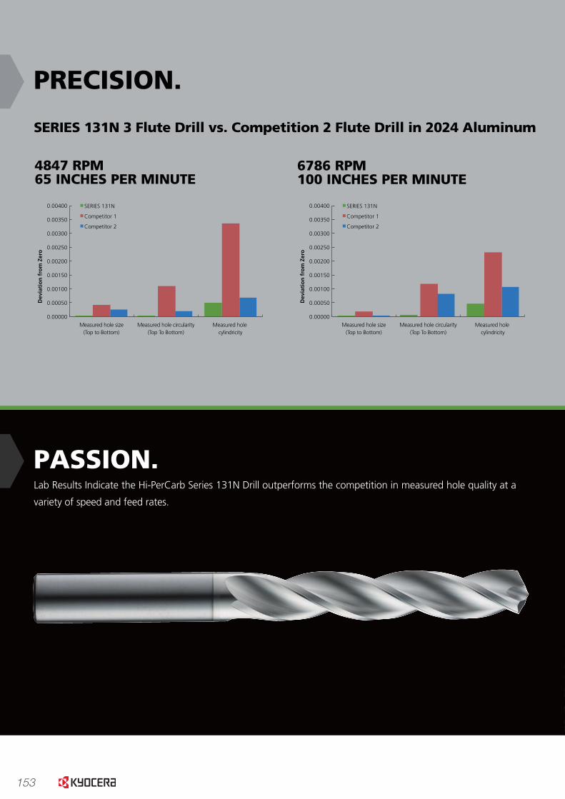
153
www.kyocera-sgstool.com
PRECISION.
PASSION.Lab Results Indicate the Hi-PerCarb Series 131N Drill outperforms the competition in measured hole quality at a
variety of speed and feed rates.
www.kyocera-sgstool.com
This ceramic based coating ensures a smooth surface and a low af�nity to cold welding or edge build-up, which makes
it optimal for aluminum and copper applications. It has high toughness and high hardness.
Microhardness: 4000 HV
Oxidation Temperature: 850°C / 1562°F
Coef�cient of Friction: 0.45
Thickness: 1-2 Microns (based on tool diameter)
6786 RPM100 INCHES PER MINUTE
9530 RPM200 INCHES PER MINUTE
SERIES 131N 3 Flute Drill vs. Competition 2 Flute Drill in 2024 Aluminum
4847 RPM 65 INCHES PER MINUTE
Measured hole size (Top to Bottom)
Measured hole circularity (Top To Bottom)
Measured hole cylindricity
Dev
iati
on
fro
m Z
ero
0.00000
0.00050
0.00100
0.00150
0.00200
0.00250
0.00300
0.00350 SERIES 131N
Competitor 1
Competitor 2
Measured hole size (Top to Bottom)
Measured hole circularity (Top To Bottom)
Measured hole cylindricity
Dev
iati
on
fro
m Z
ero
0.00000
0.00050
0.00100
0.00150
0.00200
0.00250
0.00300
0.00350
0.00400 SERIES 131N
Competitor 1
Competitor 2
Measured hole size (Top to Bottom)
Measured hole circularity (Top To Bottom)
Measured hole cylindricity
Dev
iati
on
fro
m Z
ero
0.00000
0.00050
0.00100
0.00150
0.00200
0.00250
0.00300
0.00350
0.00400 SERIES 131N
Competitor 1
Competitor 2
Now also available uncoated!
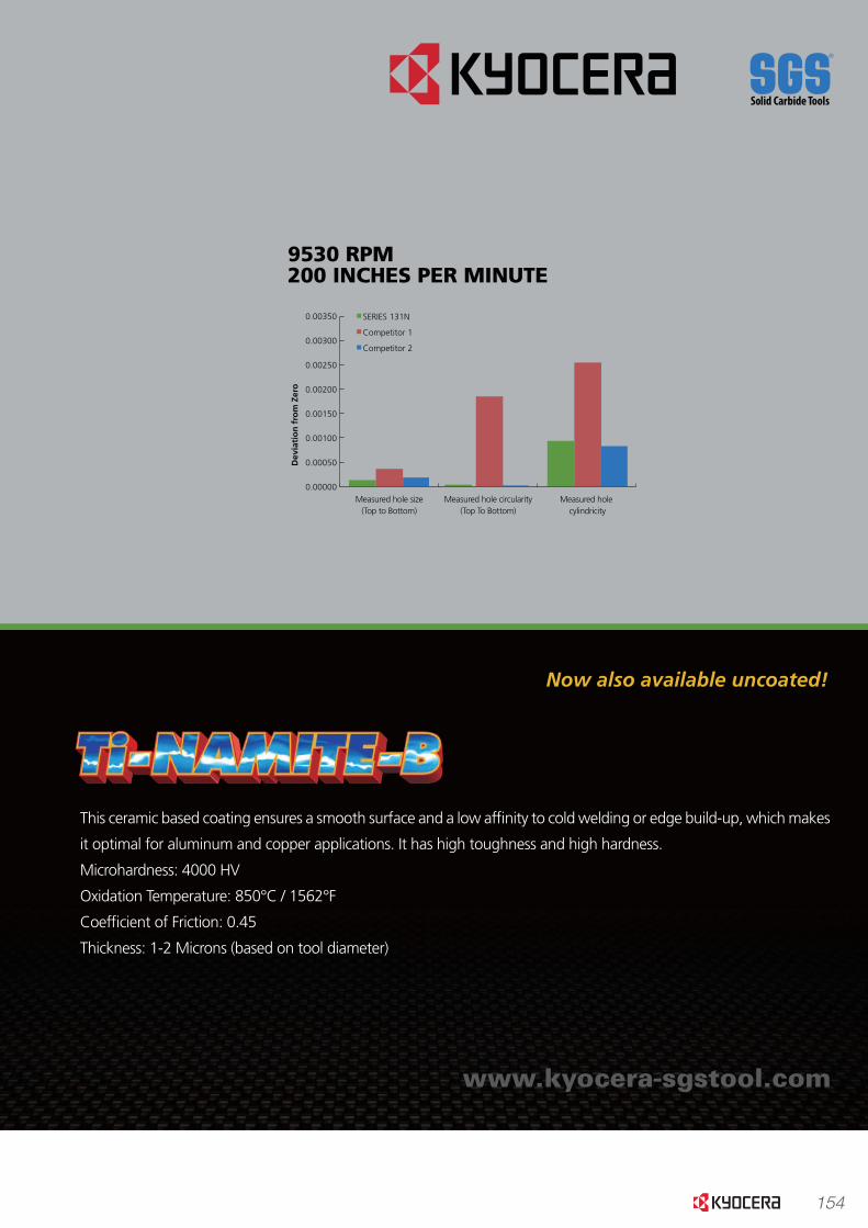
154
www.kyocera-sgstool.com
PRECISION.
PASSION.Lab Results Indicate the Hi-PerCarb Series 131N Drill outperforms the competition in measured hole quality at a
variety of speed and feed rates.
This ceramic based coating ensures a smooth surface and a low af�nity to cold welding or edge build-up, which makes
it optimal for aluminum and copper applications. It has high toughness and high hardness.
Microhardness: 4000 HV
Oxidation Temperature: 850°C / 1562°F
Coef�cient of Friction: 0.45
Thickness: 1-2 Microns (based on tool diameter)
6786 RPM100 INCHES PER MINUTE
9530 RPM200 INCHES PER MINUTE
SERIES 131N 3 Flute Drill vs. Competition 2 Flute Drill in 2024 Aluminum
4847 RPM 65 INCHES PER MINUTE
Measured hole size (Top to Bottom)
Measured hole circularity (Top To Bottom)
Measured hole cylindricity
Dev
iati
on
fro
m Z
ero
0.00000
0.00050
0.00100
0.00150
0.00200
0.00250
0.00300
0.00350 SERIES 131N
Competitor 1
Competitor 2
Measured hole size (Top to Bottom)
Measured hole circularity (Top To Bottom)
Measured hole cylindricity
Dev
iati
on
fro
m Z
ero
0.00000
0.00050
0.00100
0.00150
0.00200
0.00250
0.00300
0.00350
0.00400 SERIES 131N
Competitor 1
Competitor 2
Measured hole size (Top to Bottom)
Measured hole circularity (Top To Bottom)
Measured hole cylindricity
Dev
iati
on
fro
m Z
ero
0.00000
0.00050
0.00100
0.00150
0.00200
0.00250
0.00300
0.00350
0.00400 SERIES 131N
Competitor 1
Competitor 2
Now also available uncoated!
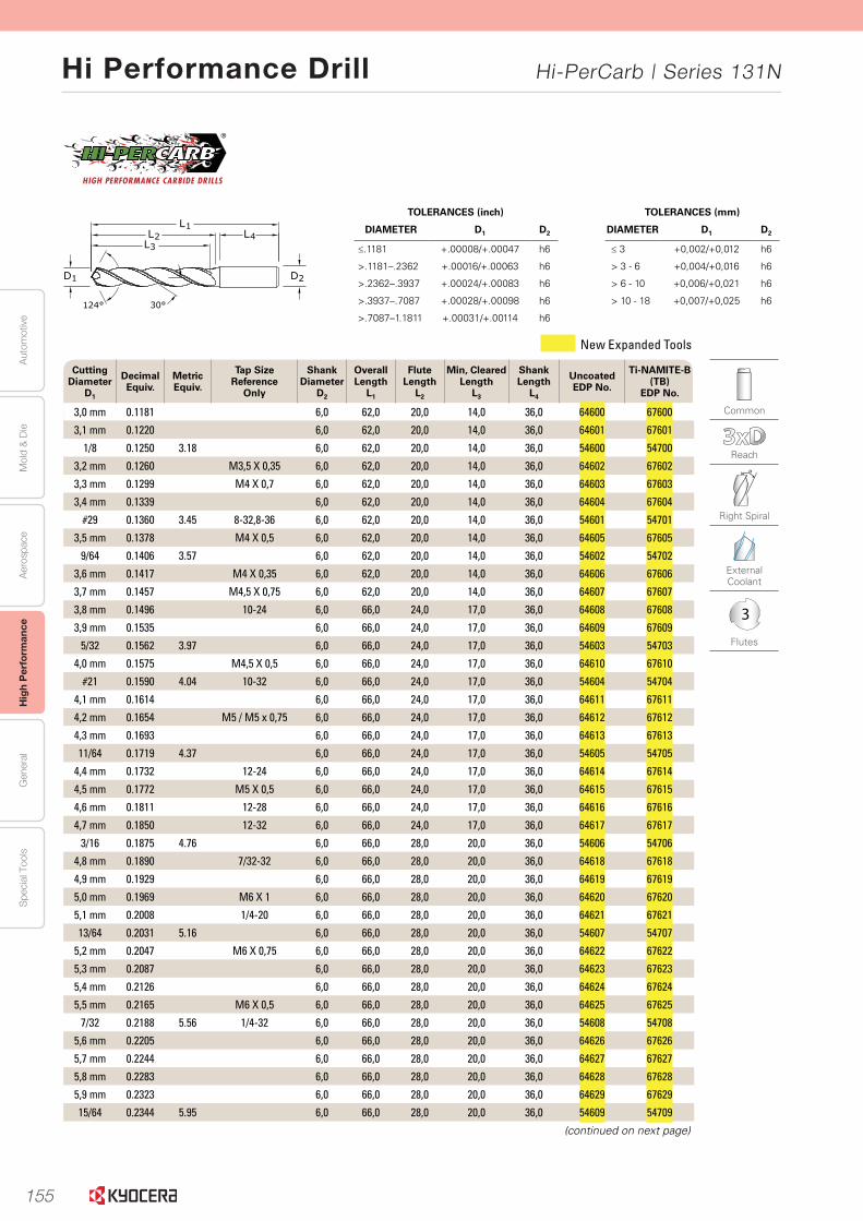
155
Aut
omot
ive
Aer
ospa
ceH
igh
Per
form
ance
Gen
eral
Spe
cial
Too
lsM
old
& D
ie
Hi Performance Drill Hi-PerCarb | Series 131N
30 www.kyocera-sgstool.com
Se
rie
s 13
1N 3
XD
|
Frac
tio
nal
& M
etri
c Common
Reach
Right Spiral
External Coolant
3
Flutes
TOLERANCES (mm)
DIAMETER D1 D2
≤ 3 +0,002/+0,012 h6
> 3 - 6 +0,004/+0,016 h6
> 6 - 10 +0,006/+0,021 h6
> 10 - 18 +0,007/+0,025 h6
TOLERANCES (inch)
DIAMETER D1 D2
≤.1181 +.00008/+.00047 h6
>.1181–.2362 +.00016/+.00063 h6
>.2362–.3937 +.00024/+.00083 h6
>.3937–.7087 +.00028/+.00098 h6
>.7087–1.1811 +.00031/+.00114 h6
2D
L1L2
L3L4
124° 30°
1D
Cutting Diameter
D1
Decimal Equiv.
Metric Equiv.
Tap Size Reference
Only
Shank Diameter
D2
Overall Length
L1
Flute Length
L2
Min, ClearedLength
L3
Shank Length
L4
Uncoated EDP No.
Ti-NAMITE-B (TB)
EDP No.
3,0 mm 0.1181 6,0 62,0 20,0 14,0 36,0 64600 67600
3,1 mm 0.1220 6,0 62,0 20,0 14,0 36,0 64601 67601
1/8 0.1250 3.18 6,0 62,0 20,0 14,0 36,0 54600 54700
3,2 mm 0.1260 M3,5 X 0,35 6,0 62,0 20,0 14,0 36,0 64602 67602
3,3 mm 0.1299 M4 X 0,7 6,0 62,0 20,0 14,0 36,0 64603 67603
3,4 mm 0.1339 6,0 62,0 20,0 14,0 36,0 64604 67604
#29 0.1360 3.45 8-32,8-36 6,0 62,0 20,0 14,0 36,0 54601 54701
3,5 mm 0.1378 M4 X 0,5 6,0 62,0 20,0 14,0 36,0 64605 67605
9/64 0.1406 3.57 6,0 62,0 20,0 14,0 36,0 54602 54702
3,6 mm 0.1417 M4 X 0,35 6,0 62,0 20,0 14,0 36,0 64606 67606
3,7 mm 0.1457 M4,5 X 0,75 6,0 62,0 20,0 14,0 36,0 64607 67607
3,8 mm 0.1496 10-24 6,0 66,0 24,0 17,0 36,0 64608 67608
3,9 mm 0.1535 6,0 66,0 24,0 17,0 36,0 64609 67609
5/32 0.1562 3.97 6,0 66,0 24,0 17,0 36,0 54603 54703
4,0 mm 0.1575 M4,5 X 0,5 6,0 66,0 24,0 17,0 36,0 64610 67610
#21 0.1590 4.04 10-32 6,0 66,0 24,0 17,0 36,0 54604 54704
4,1 mm 0.1614 6,0 66,0 24,0 17,0 36,0 64611 67611
4,2 mm 0.1654 M5 / M5 x 0,75 6,0 66,0 24,0 17,0 36,0 64612 67612
4,3 mm 0.1693 6,0 66,0 24,0 17,0 36,0 64613 67613
11/64 0.1719 4.37 6,0 66,0 24,0 17,0 36,0 54605 54705
4,4 mm 0.1732 12-24 6,0 66,0 24,0 17,0 36,0 64614 67614
4,5 mm 0.1772 M5 X 0,5 6,0 66,0 24,0 17,0 36,0 64615 67615
4,6 mm 0.1811 12-28 6,0 66,0 24,0 17,0 36,0 64616 67616
4,7 mm 0.1850 12-32 6,0 66,0 24,0 17,0 36,0 64617 67617
3/16 0.1875 4.76 6,0 66,0 28,0 20,0 36,0 54606 54706
4,8 mm 0.1890 7/32-32 6,0 66,0 28,0 20,0 36,0 64618 67618
4,9 mm 0.1929 6,0 66,0 28,0 20,0 36,0 64619 67619
5,0 mm 0.1969 M6 X 1 6,0 66,0 28,0 20,0 36,0 64620 67620
5,1 mm 0.2008 1/4-20 6,0 66,0 28,0 20,0 36,0 64621 67621
13/64 0.2031 5.16 6,0 66,0 28,0 20,0 36,0 54607 54707
5,2 mm 0.2047 M6 X 0,75 6,0 66,0 28,0 20,0 36,0 64622 67622
5,3 mm 0.2087 6,0 66,0 28,0 20,0 36,0 64623 67623
5,4 mm 0.2126 6,0 66,0 28,0 20,0 36,0 64624 67624
5,5 mm 0.2165 M6 X 0,5 6,0 66,0 28,0 20,0 36,0 64625 67625
7/32 0.2188 5.56 1/4-32 6,0 66,0 28,0 20,0 36,0 54608 54708
5,6 mm 0.2205 6,0 66,0 28,0 20,0 36,0 64626 67626
5,7 mm 0.2244 6,0 66,0 28,0 20,0 36,0 64627 67627
5,8 mm 0.2283 6,0 66,0 28,0 20,0 36,0 64628 67628
5,9 mm 0.2323 6,0 66,0 28,0 20,0 36,0 64629 67629
15/64 0.2344 5.95 6,0 66,0 28,0 20,0 36,0 54609 54709
(continued on next page)
New Expanded Tools
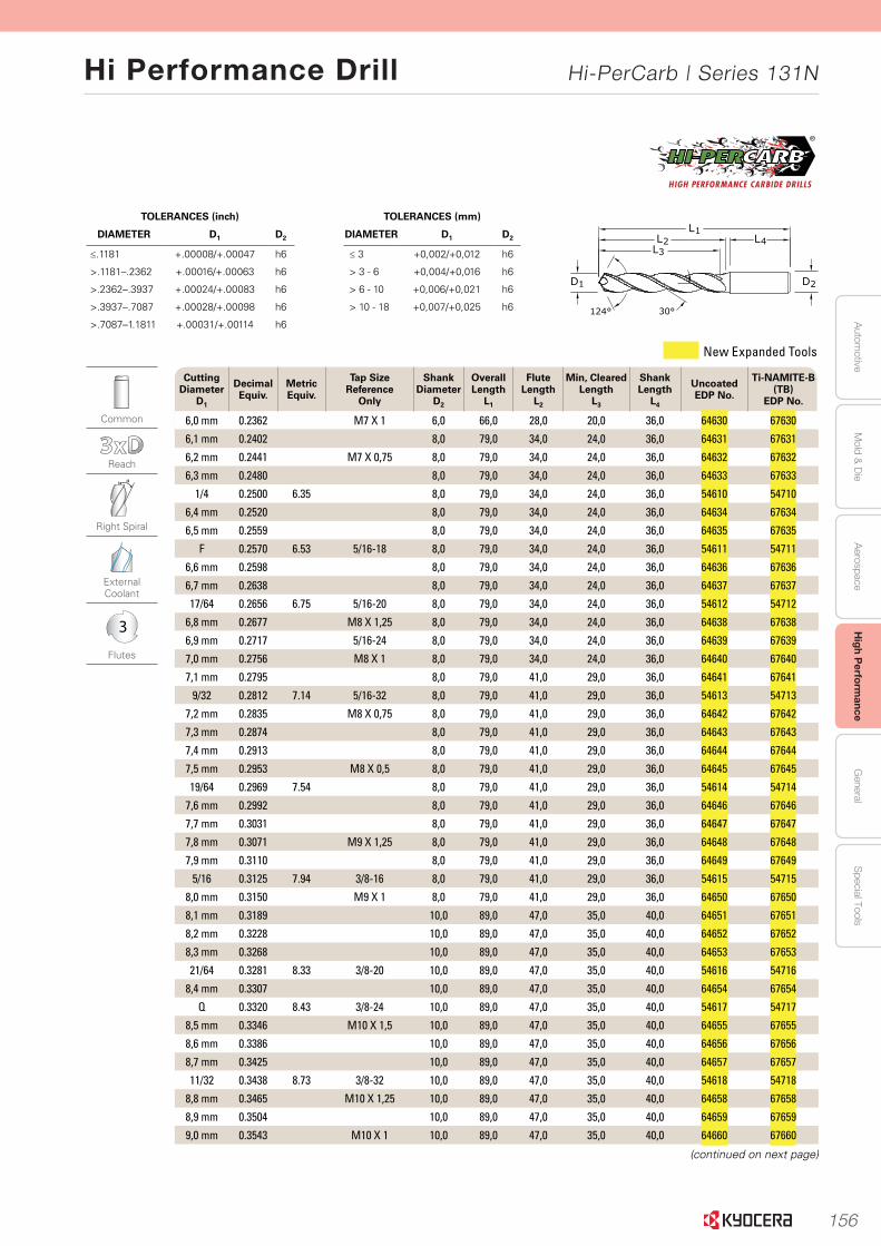
156
Autom
otiveA
erospaceH
igh Perform
anceG
eneralS
pecial ToolsM
old & D
ie
Hi Performance Drill Hi-PerCarb | Series 131N
31www.kyocera-sgstool.com
Se
ries 131N
3XD
|Fractio
nal &
Metric
Common
Reach
Right Spiral
External Coolant
3
Flutes
TOLERANCES (mm)
DIAMETER D1 D2
≤ 3 +0,002/+0,012 h6
> 3 - 6 +0,004/+0,016 h6
> 6 - 10 +0,006/+0,021 h6
> 10 - 18 +0,007/+0,025 h6
TOLERANCES (inch)
DIAMETER D1 D2
≤.1181 +.00008/+.00047 h6
>.1181–.2362 +.00016/+.00063 h6
>.2362–.3937 +.00024/+.00083 h6
>.3937–.7087 +.00028/+.00098 h6
>.7087–1.1811 +.00031/+.00114 h6
2D
L1L2
L3L4
124° 30°
1D
Cutting Diameter
D1
Decimal Equiv.
Metric Equiv.
Tap Size Reference
Only
Shank Diameter
D2
Overall Length
L1
Flute Length
L2
Min, ClearedLength
L3
Shank Length
L4
Uncoated EDP No.
Ti-NAMITE-B (TB)
EDP No.
6,0 mm 0.2362 M7 X 1 6,0 66,0 28,0 20,0 36,0 64630 67630
6,1 mm 0.2402 8,0 79,0 34,0 24,0 36,0 64631 67631
6,2 mm 0.2441 M7 X 0,75 8,0 79,0 34,0 24,0 36,0 64632 67632
6,3 mm 0.2480 8,0 79,0 34,0 24,0 36,0 64633 67633
1/4 0.2500 6.35 8,0 79,0 34,0 24,0 36,0 54610 54710
6,4 mm 0.2520 8,0 79,0 34,0 24,0 36,0 64634 67634
6,5 mm 0.2559 8,0 79,0 34,0 24,0 36,0 64635 67635
F 0.2570 6.53 5/16-18 8,0 79,0 34,0 24,0 36,0 54611 54711
6,6 mm 0.2598 8,0 79,0 34,0 24,0 36,0 64636 67636
6,7 mm 0.2638 8,0 79,0 34,0 24,0 36,0 64637 67637
17/64 0.2656 6.75 5/16-20 8,0 79,0 34,0 24,0 36,0 54612 54712
6,8 mm 0.2677 M8 X 1,25 8,0 79,0 34,0 24,0 36,0 64638 67638
6,9 mm 0.2717 5/16-24 8,0 79,0 34,0 24,0 36,0 64639 67639
7,0 mm 0.2756 M8 X 1 8,0 79,0 34,0 24,0 36,0 64640 67640
7,1 mm 0.2795 8,0 79,0 41,0 29,0 36,0 64641 67641
9/32 0.2812 7.14 5/16-32 8,0 79,0 41,0 29,0 36,0 54613 54713
7,2 mm 0.2835 M8 X 0,75 8,0 79,0 41,0 29,0 36,0 64642 67642
7,3 mm 0.2874 8,0 79,0 41,0 29,0 36,0 64643 67643
7,4 mm 0.2913 8,0 79,0 41,0 29,0 36,0 64644 67644
7,5 mm 0.2953 M8 X 0,5 8,0 79,0 41,0 29,0 36,0 64645 67645
19/64 0.2969 7.54 8,0 79,0 41,0 29,0 36,0 54614 54714
7,6 mm 0.2992 8,0 79,0 41,0 29,0 36,0 64646 67646
7,7 mm 0.3031 8,0 79,0 41,0 29,0 36,0 64647 67647
7,8 mm 0.3071 M9 X 1,25 8,0 79,0 41,0 29,0 36,0 64648 67648
7,9 mm 0.3110 8,0 79,0 41,0 29,0 36,0 64649 67649
5/16 0.3125 7.94 3/8-16 8,0 79,0 41,0 29,0 36,0 54615 54715
8,0 mm 0.3150 M9 X 1 8,0 79,0 41,0 29,0 36,0 64650 67650
8,1 mm 0.3189 10,0 89,0 47,0 35,0 40,0 64651 67651
8,2 mm 0.3228 10,0 89,0 47,0 35,0 40,0 64652 67652
8,3 mm 0.3268 10,0 89,0 47,0 35,0 40,0 64653 67653
21/64 0.3281 8.33 3/8-20 10,0 89,0 47,0 35,0 40,0 54616 54716
8,4 mm 0.3307 10,0 89,0 47,0 35,0 40,0 64654 67654
Q 0.3320 8.43 3/8-24 10,0 89,0 47,0 35,0 40,0 54617 54717
8,5 mm 0.3346 M10 X 1,5 10,0 89,0 47,0 35,0 40,0 64655 67655
8,6 mm 0.3386 10,0 89,0 47,0 35,0 40,0 64656 67656
8,7 mm 0.3425 10,0 89,0 47,0 35,0 40,0 64657 67657
11/32 0.3438 8.73 3/8-32 10,0 89,0 47,0 35,0 40,0 54618 54718
8,8 mm 0.3465 M10 X 1,25 10,0 89,0 47,0 35,0 40,0 64658 67658
8,9 mm 0.3504 10,0 89,0 47,0 35,0 40,0 64659 67659
9,0 mm 0.3543 M10 X 1 10,0 89,0 47,0 35,0 40,0 64660 67660
(continued on next page)
New Expanded Tools
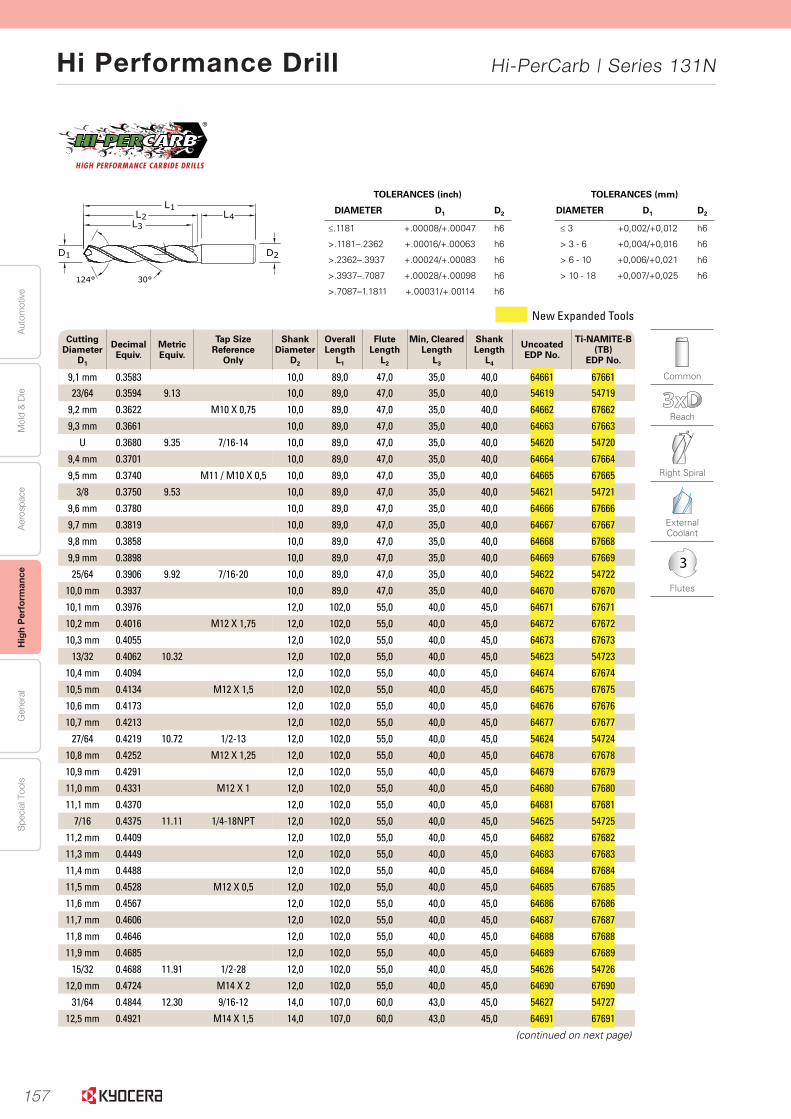
157
Aut
omot
ive
Aer
ospa
ceH
igh
Per
form
ance
Gen
eral
Spe
cial
Too
lsM
old
& D
ie
Hi Performance Drill Hi-PerCarb | Series 131N
32 www.kyocera-sgstool.com
Se
rie
s 13
1N 3
XD
|
Frac
tio
nal
& M
etri
c Common
Reach
Right Spiral
External Coolant
3
Flutes
TOLERANCES (mm)
DIAMETER D1 D2
≤ 3 +0,002/+0,012 h6
> 3 - 6 +0,004/+0,016 h6
> 6 - 10 +0,006/+0,021 h6
> 10 - 18 +0,007/+0,025 h6
TOLERANCES (inch)
DIAMETER D1 D2
≤.1181 +.00008/+.00047 h6
>.1181–.2362 +.00016/+.00063 h6
>.2362–.3937 +.00024/+.00083 h6
>.3937–.7087 +.00028/+.00098 h6
>.7087–1.1811 +.00031/+.00114 h6
2D
L1L2
L3L4
124° 30°
1D
Cutting Diameter
D1
Decimal Equiv.
Metric Equiv.
Tap Size Reference
Only
Shank Diameter
D2
Overall Length
L1
Flute Length
L2
Min, ClearedLength
L3
Shank Length
L4
Uncoated EDP No.
Ti-NAMITE-B (TB)
EDP No.
9,1 mm 0.3583 10,0 89,0 47,0 35,0 40,0 64661 6766123/64 0.3594 9.13 10,0 89,0 47,0 35,0 40,0 54619 54719
9,2 mm 0.3622 M10 X 0,75 10,0 89,0 47,0 35,0 40,0 64662 67662
9,3 mm 0.3661 10,0 89,0 47,0 35,0 40,0 64663 67663
U 0.3680 9.35 7/16-14 10,0 89,0 47,0 35,0 40,0 54620 54720
9,4 mm 0.3701 10,0 89,0 47,0 35,0 40,0 64664 67664
9,5 mm 0.3740 M11 / M10 X 0,5 10,0 89,0 47,0 35,0 40,0 64665 67665
3/8 0.3750 9.53 10,0 89,0 47,0 35,0 40,0 54621 54721
9,6 mm 0.3780 10,0 89,0 47,0 35,0 40,0 64666 67666
9,7 mm 0.3819 10,0 89,0 47,0 35,0 40,0 64667 67667
9,8 mm 0.3858 10,0 89,0 47,0 35,0 40,0 64668 67668
9,9 mm 0.3898 10,0 89,0 47,0 35,0 40,0 64669 67669
25/64 0.3906 9.92 7/16-20 10,0 89,0 47,0 35,0 40,0 54622 54722
10,0 mm 0.3937 10,0 89,0 47,0 35,0 40,0 64670 67670
10,1 mm 0.3976 12,0 102,0 55,0 40,0 45,0 64671 67671
10,2 mm 0.4016 M12 X 1,75 12,0 102,0 55,0 40,0 45,0 64672 67672
10,3 mm 0.4055 12,0 102,0 55,0 40,0 45,0 64673 67673
13/32 0.4062 10.32 12,0 102,0 55,0 40,0 45,0 54623 54723
10,4 mm 0.4094 12,0 102,0 55,0 40,0 45,0 64674 67674
10,5 mm 0.4134 M12 X 1,5 12,0 102,0 55,0 40,0 45,0 64675 67675
10,6 mm 0.4173 12,0 102,0 55,0 40,0 45,0 64676 67676
10,7 mm 0.4213 12,0 102,0 55,0 40,0 45,0 64677 67677
27/64 0.4219 10.72 1/2-13 12,0 102,0 55,0 40,0 45,0 54624 54724
10,8 mm 0.4252 M12 X 1,25 12,0 102,0 55,0 40,0 45,0 64678 67678
10,9 mm 0.4291 12,0 102,0 55,0 40,0 45,0 64679 67679
11,0 mm 0.4331 M12 X 1 12,0 102,0 55,0 40,0 45,0 64680 67680
11,1 mm 0.4370 12,0 102,0 55,0 40,0 45,0 64681 67681
7/16 0.4375 11.11 1/4-18NPT 12,0 102,0 55,0 40,0 45,0 54625 54725
11,2 mm 0.4409 12,0 102,0 55,0 40,0 45,0 64682 67682
11,3 mm 0.4449 12,0 102,0 55,0 40,0 45,0 64683 67683
11,4 mm 0.4488 12,0 102,0 55,0 40,0 45,0 64684 67684
11,5 mm 0.4528 M12 X 0,5 12,0 102,0 55,0 40,0 45,0 64685 67685
11,6 mm 0.4567 12,0 102,0 55,0 40,0 45,0 64686 67686
11,7 mm 0.4606 12,0 102,0 55,0 40,0 45,0 64687 67687
11,8 mm 0.4646 12,0 102,0 55,0 40,0 45,0 64688 67688
11,9 mm 0.4685 12,0 102,0 55,0 40,0 45,0 64689 67689
15/32 0.4688 11.91 1/2-28 12,0 102,0 55,0 40,0 45,0 54626 54726
12,0 mm 0.4724 M14 X 2 12,0 102,0 55,0 40,0 45,0 64690 67690
31/64 0.4844 12.30 9/16-12 14,0 107,0 60,0 43,0 45,0 54627 54727
12,5 mm 0.4921 M14 X 1,5 14,0 107,0 60,0 43,0 45,0 64691 67691
(continued on next page)
New Expanded Tools
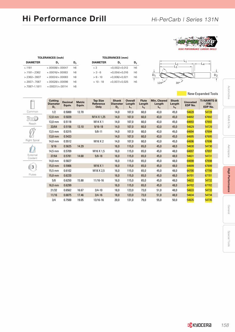
158
Autom
otiveA
erospaceH
igh Perform
anceG
eneralS
pecial ToolsM
old & D
ie
Hi Performance Drill Hi-PerCarb | Series 131N
33www.kyocera-sgstool.com
Se
ries 131N
3XD
|
Fraction
al & M
etric
Common
Reach
Right Spiral
External Coolant
3
Flutes
TOLERANCES (mm)
DIAMETER D1 D2
≤ 3 +0,002/+0,012 h6
> 3 - 6 +0,004/+0,016 h6
> 6 - 10 +0,006/+0,021 h6
> 10 - 18 +0,007/+0,025 h6
TOLERANCES (inch)
DIAMETER D1 D2
≤.1181 +.00008/+.00047 h6
>.1181–.2362 +.00016/+.00063 h6
>.2362–.3937 +.00024/+.00083 h6
>.3937–.7087 +.00028/+.00098 h6
>.7087–1.1811 +.00031/+.00114 h6
2D
L1L2
L3L4
124° 30°
1D
Cutting Diameter
D1
Decimal Equiv.
Metric Equiv.
Tap Size Reference
Only
Shank Diameter
D2
Overall Length
L1
Flute Length
L2
Min, ClearedLength
L3
Shank Length
L4
Uncoated EDP No.
Ti-NAMITE-B (TB)
EDP No.
1/2 0.5000 12.70 14,0 107,0 60,0 43,0 45,0 54628 54728
12,8 mm 0.5039 M14 X 1,25 14,0 107,0 60,0 43,0 45,0 64692 67692
13,0 mm 0.5118 M14 X 1 14,0 107,0 60,0 43,0 45,0 64693 67693
33/64 0.5156 13.10 9/16-18 14,0 107,0 60,0 43,0 45,0 54629 54729
13,5 mm 0.5315 5/8-11 14,0 107,0 60,0 43,0 45,0 64694 67694
13,8 mm 0.5433 14,0 107,0 60,0 43,0 45,0 64695 67695
14,0 mm 0.5512 M16 X 2 14,0 107,0 60,0 43,0 45,0 64696 67696
9/16 0.5625 14.29 16,0 115,0 65,0 45,0 48,0 54630 54730
14,5 mm 0.5709 M16 X 1,5 16,0 115,0 65,0 45,0 48,0 64697 67697
37/64 0.5781 14.68 5/8-18 16,0 115,0 65,0 45,0 48,0 54631 54731
14,8 mm 0.5827 16,0 115,0 65,0 45,0 48,0 64698 67698
15,0 mm 0.5906 M16 X 1 16,0 115,0 65,0 45,0 48,0 64699 67699
15,5 mm 0.6102 M18 X 2,5 16,0 115,0 65,0 45,0 48,0 64700 67700
15,8 mm 0.6220 16,0 115,0 65,0 45,0 48,0 64701 67701
5/8 0.6250 15.88 11/16-16 16,0 115,0 65,0 45,0 48,0 54632 54732
16,0 mm 0.6299 16,0 115,0 65,0 45,0 48,0 64702 67702
21/32 0.6562 16.67 3/4-10 18,0 123,0 73,0 51,0 48,0 54633 54733
11/16 0.6875 17.46 3/4-16 18,0 123,0 73,0 51,0 48,0 54634 54734
3/4 0.7500 19.05 13/16-16 20,0 131,0 79,0 55,0 50,0 54635 54735
New Expanded Tools
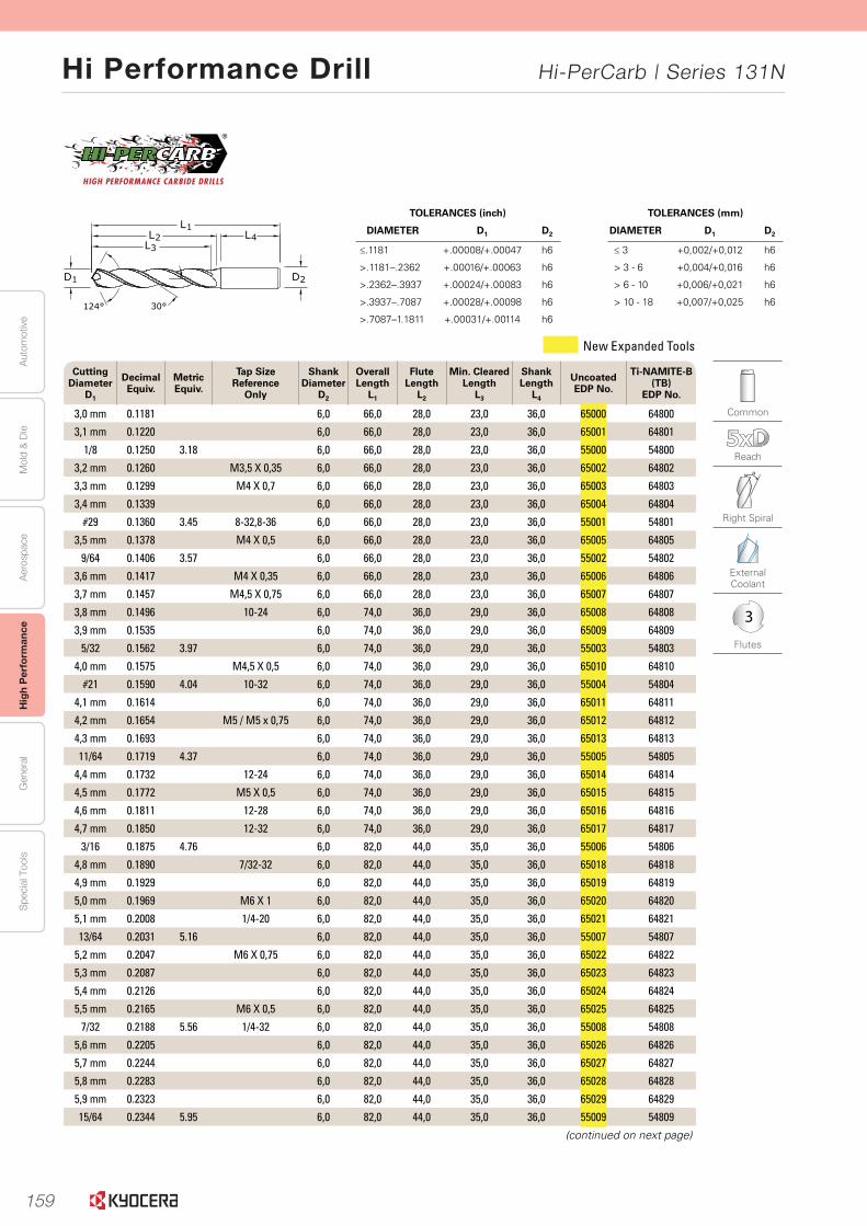
159
Aut
omot
ive
Aer
ospa
ceH
igh
Per
form
ance
Gen
eral
Spe
cial
Too
lsM
old
& D
ie
Hi Performance Drill Hi-PerCarb | Series 131N
34 www.kyocera-sgstool.com
Se
rie
s 13
1N 5
XD
|Fr
acti
on
al &
Met
ric Common
Reach
Right Spiral
External Coolant
3
Flutes
TOLERANCES (mm)
DIAMETER D1 D2
≤ 3 +0,002/+0,012 h6
> 3 - 6 +0,004/+0,016 h6
> 6 - 10 +0,006/+0,021 h6
> 10 - 18 +0,007/+0,025 h6
TOLERANCES (inch)
DIAMETER D1 D2
≤.1181 +.00008/+.00047 h6
>.1181–.2362 +.00016/+.00063 h6
>.2362–.3937 +.00024/+.00083 h6
>.3937–.7087 +.00028/+.00098 h6
>.7087–1.1811 +.00031/+.00114 h6
2D
L1L2
L3L4
124° 30°
1D
Cutting Diameter
D1
Decimal Equiv.
Metric Equiv.
Tap Size Reference
Only
Shank Diameter
D2
Overall Length
L1
Flute Length
L2
Min. ClearedLength
L3
Shank Length
L4
Uncoated EDP No.
Ti-NAMITE-B (TB)
EDP No.
3,0 mm 0.1181 6,0 66,0 28,0 23,0 36,0 65000 64800
3,1 mm 0.1220 6,0 66,0 28,0 23,0 36,0 65001 64801
1/8 0.1250 3.18 6,0 66,0 28,0 23,0 36,0 55000 54800
3,2 mm 0.1260 M3,5 X 0,35 6,0 66,0 28,0 23,0 36,0 65002 64802
3,3 mm 0.1299 M4 X 0,7 6,0 66,0 28,0 23,0 36,0 65003 64803
3,4 mm 0.1339 6,0 66,0 28,0 23,0 36,0 65004 64804
#29 0.1360 3.45 8-32,8-36 6,0 66,0 28,0 23,0 36,0 55001 54801
3,5 mm 0.1378 M4 X 0,5 6,0 66,0 28,0 23,0 36,0 65005 64805
9/64 0.1406 3.57 6,0 66,0 28,0 23,0 36,0 55002 54802
3,6 mm 0.1417 M4 X 0,35 6,0 66,0 28,0 23,0 36,0 65006 64806
3,7 mm 0.1457 M4,5 X 0,75 6,0 66,0 28,0 23,0 36,0 65007 64807
3,8 mm 0.1496 10-24 6,0 74,0 36,0 29,0 36,0 65008 64808
3,9 mm 0.1535 6,0 74,0 36,0 29,0 36,0 65009 64809
5/32 0.1562 3.97 6,0 74,0 36,0 29,0 36,0 55003 54803
4,0 mm 0.1575 M4,5 X 0,5 6,0 74,0 36,0 29,0 36,0 65010 64810
#21 0.1590 4.04 10-32 6,0 74,0 36,0 29,0 36,0 55004 54804
4,1 mm 0.1614 6,0 74,0 36,0 29,0 36,0 65011 64811
4,2 mm 0.1654 M5 / M5 x 0,75 6,0 74,0 36,0 29,0 36,0 65012 64812
4,3 mm 0.1693 6,0 74,0 36,0 29,0 36,0 65013 64813
11/64 0.1719 4.37 6,0 74,0 36,0 29,0 36,0 55005 54805
4,4 mm 0.1732 12-24 6,0 74,0 36,0 29,0 36,0 65014 64814
4,5 mm 0.1772 M5 X 0,5 6,0 74,0 36,0 29,0 36,0 65015 64815
4,6 mm 0.1811 12-28 6,0 74,0 36,0 29,0 36,0 65016 64816
4,7 mm 0.1850 12-32 6,0 74,0 36,0 29,0 36,0 65017 64817
3/16 0.1875 4.76 6,0 82,0 44,0 35,0 36,0 55006 54806
4,8 mm 0.1890 7/32-32 6,0 82,0 44,0 35,0 36,0 65018 64818
4,9 mm 0.1929 6,0 82,0 44,0 35,0 36,0 65019 64819
5,0 mm 0.1969 M6 X 1 6,0 82,0 44,0 35,0 36,0 65020 64820
5,1 mm 0.2008 1/4-20 6,0 82,0 44,0 35,0 36,0 65021 64821
13/64 0.2031 5.16 6,0 82,0 44,0 35,0 36,0 55007 54807
5,2 mm 0.2047 M6 X 0,75 6,0 82,0 44,0 35,0 36,0 65022 64822
5,3 mm 0.2087 6,0 82,0 44,0 35,0 36,0 65023 64823
5,4 mm 0.2126 6,0 82,0 44,0 35,0 36,0 65024 64824
5,5 mm 0.2165 M6 X 0,5 6,0 82,0 44,0 35,0 36,0 65025 64825
7/32 0.2188 5.56 1/4-32 6,0 82,0 44,0 35,0 36,0 55008 54808
5,6 mm 0.2205 6,0 82,0 44,0 35,0 36,0 65026 64826
5,7 mm 0.2244 6,0 82,0 44,0 35,0 36,0 65027 64827
5,8 mm 0.2283 6,0 82,0 44,0 35,0 36,0 65028 64828
5,9 mm 0.2323 6,0 82,0 44,0 35,0 36,0 65029 64829
15/64 0.2344 5.95 6,0 82,0 44,0 35,0 36,0 55009 54809
(continued on next page)
New Expanded Tools
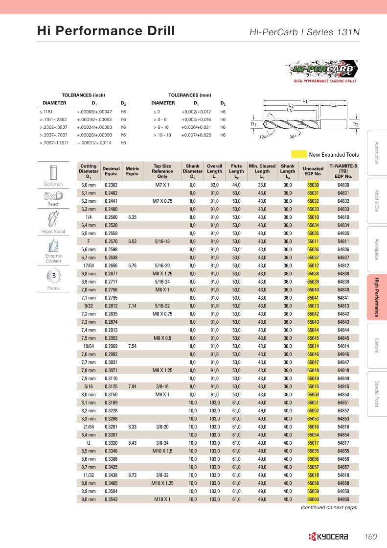
160
Autom
otiveA
erospaceH
igh Perform
anceG
eneralS
pecial ToolsM
old & D
ie
Hi Performance Drill Hi-PerCarb | Series 131N
35www.kyocera-sgstool.com
Se
ries 131N
5X
D
| Fractio
nal &
Metric
Common
Reach
Right Spiral
External Coolant
3
Flutes
TOLERANCES (mm)
DIAMETER D1 D2
≤ 3 +0,002/+0,012 h6
> 3 - 6 +0,004/+0,016 h6
> 6 - 10 +0,006/+0,021 h6
> 10 - 18 +0,007/+0,025 h6
TOLERANCES (inch)
DIAMETER D1 D2
≤.1181 +.00008/+.00047 h6
>.1181–.2362 +.00016/+.00063 h6
>.2362–.3937 +.00024/+.00083 h6
>.3937–.7087 +.00028/+.00098 h6
>.7087–1.1811 +.00031/+.00114 h6
2D
L1L2
L3L4
124° 30°
1D
Cutting Diameter
D1
Decimal Equiv.
Metric Equiv.
Tap Size Reference
Only
Shank Diameter
D2
Overall Length
L1
Flute Length
L2
Min. ClearedLength
L3
Shank Length
L4
Uncoated EDP No.
Ti-NAMITE-B (TB)
EDP No.
6,0 mm 0.2362 M7 X 1 6,0 82,0 44,0 35,0 36,0 65030 64830
6,1 mm 0.2402 8,0 91,0 53,0 43,0 36,0 65031 64831
6,2 mm 0.2441 M7 X 0,75 8,0 91,0 53,0 43,0 36,0 65032 64832
6,3 mm 0.2480 8,0 91,0 53,0 43,0 36,0 65033 64833
1/4 0.2500 6.35 8,0 91,0 53,0 43,0 36,0 55010 54810
6,4 mm 0.2520 8,0 91,0 53,0 43,0 36,0 65034 64834
6,5 mm 0.2559 8,0 91,0 53,0 43,0 36,0 65035 64835
F 0.2570 6.53 5/16-18 8,0 91,0 53,0 43,0 36,0 55011 54811
6,6 mm 0.2598 8,0 91,0 53,0 43,0 36,0 65036 64836
6,7 mm 0.2638 8,0 91,0 53,0 43,0 36,0 65037 64837
17/64 0.2656 6.75 5/16-20 8,0 91,0 53,0 43,0 36,0 55012 54812
6,8 mm 0.2677 M8 X 1,25 8,0 91,0 53,0 43,0 36,0 65038 64838
6,9 mm 0.2717 5/16-24 8,0 91,0 53,0 43,0 36,0 65039 64839
7,0 mm 0.2756 M8 X 1 8,0 91,0 53,0 43,0 36,0 65040 64840
7,1 mm 0.2795 8,0 91,0 53,0 43,0 36,0 65041 64841
9/32 0.2812 7.14 5/16-32 8,0 91,0 53,0 43,0 36,0 55013 54813
7,2 mm 0.2835 M8 X 0,75 8,0 91,0 53,0 43,0 36,0 65042 64842
7,3 mm 0.2874 8,0 91,0 53,0 43,0 36,0 65043 64843
7,4 mm 0.2913 8,0 91,0 53,0 43,0 36,0 65044 64844
7,5 mm 0.2953 M8 X 0,5 8,0 91,0 53,0 43,0 36,0 65045 64845
19/64 0.2969 7.54 8,0 91,0 53,0 43,0 36,0 55014 54814
7,6 mm 0.2992 8,0 91,0 53,0 43,0 36,0 65046 64846
7,7 mm 0.3031 8,0 91,0 53,0 43,0 36,0 65047 64847
7,8 mm 0.3071 M9 X 1,25 8,0 91,0 53,0 43,0 36,0 65048 64848
7,9 mm 0.3110 8,0 91,0 53,0 43,0 36,0 65049 64849
5/16 0.3125 7.94 3/8-16 8,0 91,0 53,0 43,0 36,0 55015 54815
8,0 mm 0.3150 M9 X 1 8,0 91,0 53,0 43,0 36,0 65050 64850
8,1 mm 0.3189 10,0 103,0 61,0 49,0 40,0 65051 64851
8,2 mm 0.3228 10,0 103,0 61,0 49,0 40,0 65052 64852
8,3 mm 0.3268 10,0 103,0 61,0 49,0 40,0 65053 64853
21/64 0.3281 8.33 3/8-20 10,0 103,0 61,0 49,0 40,0 55016 54816
8,4 mm 0.3307 10,0 103,0 61,0 49,0 40,0 65054 64854
Q 0.3320 8.43 3/8-24 10,0 103,0 61,0 49,0 40,0 55017 54817
8,5 mm 0.3346 M10 X 1,5 10,0 103,0 61,0 49,0 40,0 65055 64855
8,6 mm 0.3386 10,0 103,0 61,0 49,0 40,0 65056 64856
8,7 mm 0.3425 10,0 103,0 61,0 49,0 40,0 65057 64857
11/32 0.3438 8.73 3/8-32 10,0 103,0 61,0 49,0 40,0 55018 54818
8,8 mm 0.3465 M10 X 1,25 10,0 103,0 61,0 49,0 40,0 65058 64858
8,9 mm 0.3504 10,0 103,0 61,0 49,0 40,0 65059 64859
9,0 mm 0.3543 M10 X 1 10,0 103,0 61,0 49,0 40,0 65060 64860
(continued on next page)
New Expanded Tools
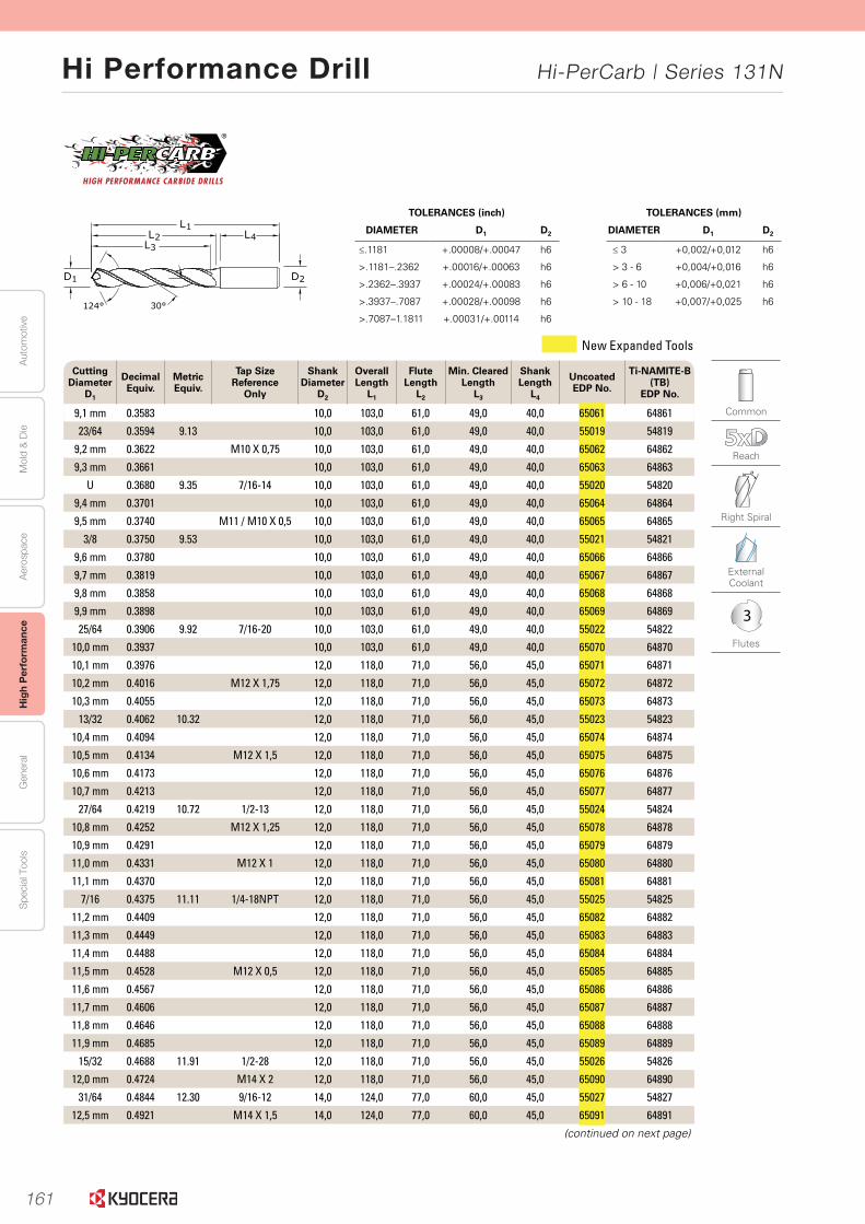
161
Aut
omot
ive
Aer
ospa
ceH
igh
Per
form
ance
Gen
eral
Spe
cial
Too
lsM
old
& D
ie
Hi Performance Drill Hi-PerCarb | Series 131N
36 www.kyocera-sgstool.com
Cutting Diameter
D1
Decimal Equiv.
Metric Equiv.
Tap Size Reference
Only
Shank Diameter
D2
Overall Length
L1
Flute Length
L2
Min. ClearedLength
L3
Shank Length
L4
Uncoated EDP No.
Ti-NAMITE-B (TB)
EDP No.
9,1 mm 0.3583 10,0 103,0 61,0 49,0 40,0 65061 64861
23/64 0.3594 9.13 10,0 103,0 61,0 49,0 40,0 55019 54819
9,2 mm 0.3622 M10 X 0,75 10,0 103,0 61,0 49,0 40,0 65062 64862
9,3 mm 0.3661 10,0 103,0 61,0 49,0 40,0 65063 64863
U 0.3680 9.35 7/16-14 10,0 103,0 61,0 49,0 40,0 55020 54820
9,4 mm 0.3701 10,0 103,0 61,0 49,0 40,0 65064 64864
9,5 mm 0.3740 M11 / M10 X 0,5 10,0 103,0 61,0 49,0 40,0 65065 64865
3/8 0.3750 9.53 10,0 103,0 61,0 49,0 40,0 55021 54821
9,6 mm 0.3780 10,0 103,0 61,0 49,0 40,0 65066 64866
9,7 mm 0.3819 10,0 103,0 61,0 49,0 40,0 65067 64867
9,8 mm 0.3858 10,0 103,0 61,0 49,0 40,0 65068 64868
9,9 mm 0.3898 10,0 103,0 61,0 49,0 40,0 65069 64869
25/64 0.3906 9.92 7/16-20 10,0 103,0 61,0 49,0 40,0 55022 54822
10,0 mm 0.3937 10,0 103,0 61,0 49,0 40,0 65070 64870
10,1 mm 0.3976 12,0 118,0 71,0 56,0 45,0 65071 64871
10,2 mm 0.4016 M12 X 1,75 12,0 118,0 71,0 56,0 45,0 65072 64872
10,3 mm 0.4055 12,0 118,0 71,0 56,0 45,0 65073 64873
13/32 0.4062 10.32 12,0 118,0 71,0 56,0 45,0 55023 54823
10,4 mm 0.4094 12,0 118,0 71,0 56,0 45,0 65074 64874
10,5 mm 0.4134 M12 X 1,5 12,0 118,0 71,0 56,0 45,0 65075 64875
10,6 mm 0.4173 12,0 118,0 71,0 56,0 45,0 65076 64876
10,7 mm 0.4213 12,0 118,0 71,0 56,0 45,0 65077 64877
27/64 0.4219 10.72 1/2-13 12,0 118,0 71,0 56,0 45,0 55024 54824
10,8 mm 0.4252 M12 X 1,25 12,0 118,0 71,0 56,0 45,0 65078 64878
10,9 mm 0.4291 12,0 118,0 71,0 56,0 45,0 65079 64879
11,0 mm 0.4331 M12 X 1 12,0 118,0 71,0 56,0 45,0 65080 64880
11,1 mm 0.4370 12,0 118,0 71,0 56,0 45,0 65081 64881
7/16 0.4375 11.11 1/4-18NPT 12,0 118,0 71,0 56,0 45,0 55025 54825
11,2 mm 0.4409 12,0 118,0 71,0 56,0 45,0 65082 64882
11,3 mm 0.4449 12,0 118,0 71,0 56,0 45,0 65083 64883
11,4 mm 0.4488 12,0 118,0 71,0 56,0 45,0 65084 64884
11,5 mm 0.4528 M12 X 0,5 12,0 118,0 71,0 56,0 45,0 65085 64885
11,6 mm 0.4567 12,0 118,0 71,0 56,0 45,0 65086 64886
11,7 mm 0.4606 12,0 118,0 71,0 56,0 45,0 65087 64887
11,8 mm 0.4646 12,0 118,0 71,0 56,0 45,0 65088 64888
11,9 mm 0.4685 12,0 118,0 71,0 56,0 45,0 65089 64889
15/32 0.4688 11.91 1/2-28 12,0 118,0 71,0 56,0 45,0 55026 54826
12,0 mm 0.4724 M14 X 2 12,0 118,0 71,0 56,0 45,0 65090 64890
31/64 0.4844 12.30 9/16-12 14,0 124,0 77,0 60,0 45,0 55027 54827
12,5 mm 0.4921 M14 X 1,5 14,0 124,0 77,0 60,0 45,0 65091 64891
(continued on next page)
Common
Reach
Right Spiral
External Coolant
3
Flutes
Se
rie
s 13
1N 5
XD
|
Frac
tio
nal
& M
etri
c
TOLERANCES (mm)
DIAMETER D1 D2
≤ 3 +0,002/+0,012 h6
> 3 - 6 +0,004/+0,016 h6
> 6 - 10 +0,006/+0,021 h6
> 10 - 18 +0,007/+0,025 h6
TOLERANCES (inch)
DIAMETER D1 D2
≤.1181 +.00008/+.00047 h6
>.1181–.2362 +.00016/+.00063 h6
>.2362–.3937 +.00024/+.00083 h6
>.3937–.7087 +.00028/+.00098 h6
>.7087–1.1811 +.00031/+.00114 h6
2D
L1L2
L3L4
124° 30°
1D
New Expanded Tools
37www.kyocera-sgstool.com
Se
ries 131N
5X
D
| Fractio
nal &
Metric
Cutting Diameter
D1
Decimal Equiv.
Metric Equiv.
Tap Size Reference
Only
Shank Diameter
D2
Overall Length
L1
Flute Length
L2
Min. ClearedLength
L3
Shank Length
L4
Uncoated EDP No.
Ti-NAMITE-B (TB)
EDP No.
1/2 0.5000 12.70 14,0 124,0 77,0 60,0 45,0 55028 54828
12,8 mm 0.5039 M14 X 1,25 14,0 124,0 77,0 60,0 45,0 65092 64892
13,0 mm 0.5118 M14 X 1 14,0 124,0 77,0 60,0 45,0 65093 64893
33/64 0.5156 13.10 9/16-18 14,0 124,0 77,0 60,0 45,0 55029 54829
13,5 mm 0.5315 5/8-11 14,0 124,0 77,0 60,0 45,0 65094 64894
13,8 mm 0.5433 14,0 124,0 77,0 60,0 45,0 65095 64895
14,0 mm 0.5512 M16 X 2 14,0 124,0 77,0 60,0 45,0 65096 64896
9/16 0.5625 14.29 16,0 133,0 83,0 63,0 48,0 55030 54830
14,5 mm 0.5709 M16 X 1,5 16,0 133,0 83,0 63,0 48,0 65097 64897
37/64 0.5781 14.68 5/8-18 16,0 133,0 83,0 63,0 48,0 55031 54831
14,8 mm 0.5827 16,0 133,0 83,0 63,0 48,0 65098 64898
15,0 mm 0.5906 M16 X 1 16,0 133,0 83,0 63,0 48,0 65099 64899
15,5 mm 0.6102 M18 X 2,5 16,0 133,0 83,0 63,0 48,0 65100 64900
15,8 mm 0.6220 16,0 133,0 83,0 63,0 48,0 65101 64901
5/8 0.6250 15.88 11/16-16 16,0 133,0 83,0 63,0 48,0 55032 54832
16,0 mm 0.6299 16,0 133,0 83,0 63,0 48,0 65102 64902
21/32 0.6562 16.67 3/4-10 18,0 143,0 93,0 71,0 48,0 55033 54833
11/16 0.6875 17.46 3/4-16 18,0 143,0 93,0 71,0 48,0 55034 54834
3/4 0.7500 19.05 13/16-16 20,0 153,0 101,0 77,0 50,0 55035 54835
Common
Reach
Right Spiral
External Coolant
3
Flutes
TOLERANCES (mm)
DIAMETER D1 D2
≤ 3 +0,002/+0,012 h6
> 3 - 6 +0,004/+0,016 h6
> 6 - 10 +0,006/+0,021 h6
> 10 - 18 +0,007/+0,025 h6
TOLERANCES (inch)
DIAMETER D1 D2
≤.1181 +.00008/+.00047 h6
>.1181–.2362 +.00016/+.00063 h6
>.2362–.3937 +.00024/+.00083 h6
>.3937–.7087 +.00028/+.00098 h6
>.7087–1.1811 +.00031/+.00114 h6
2D
L1L2
L3L4
124° 30°
1D
New Expanded Tools
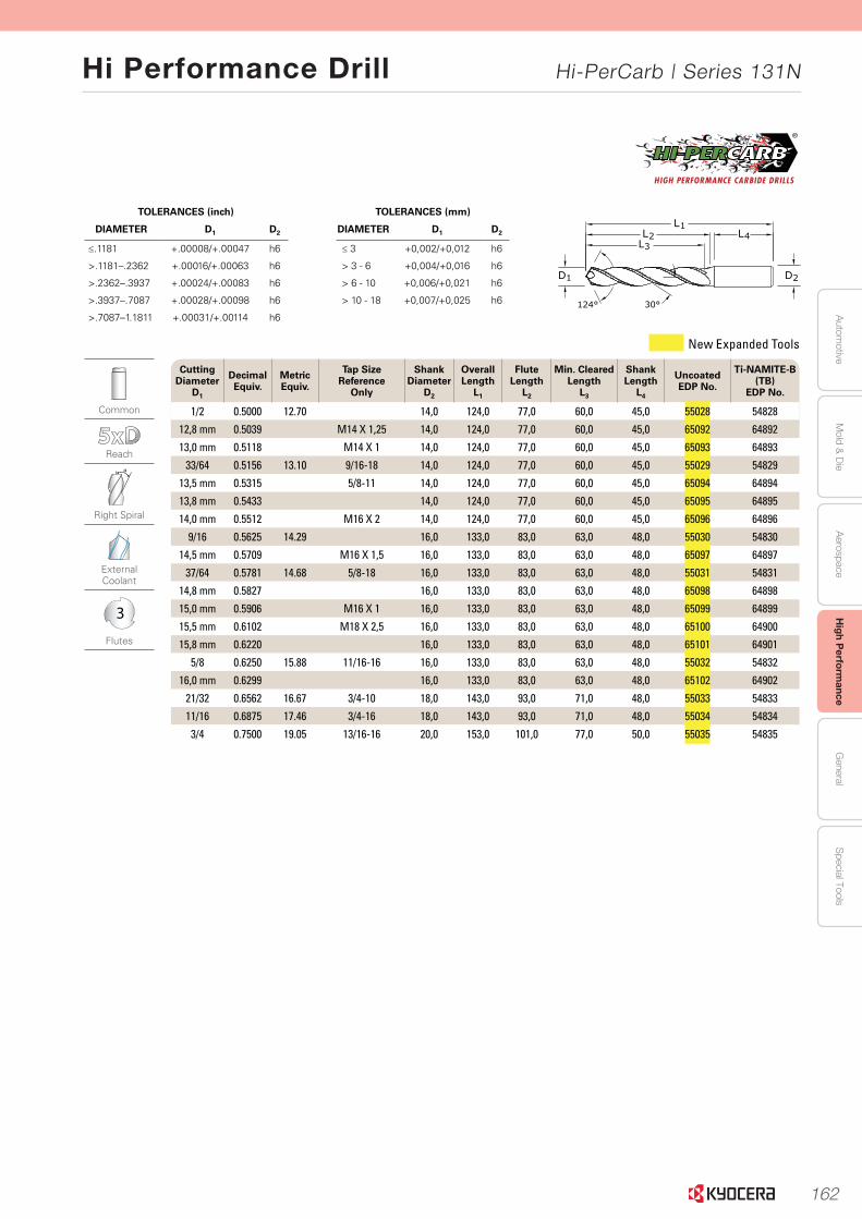
162
Autom
otiveA
erospaceH
igh Perform
anceG
eneralS
pecial ToolsM
old & D
ie
Hi Performance Drill Hi-PerCarb | Series 131N
37www.kyocera-sgstool.com
Se
ries 131N
5X
D
| Fractio
nal &
Metric
Cutting Diameter
D1
Decimal Equiv.
Metric Equiv.
Tap Size Reference
Only
Shank Diameter
D2
Overall Length
L1
Flute Length
L2
Min. ClearedLength
L3
Shank Length
L4
Uncoated EDP No.
Ti-NAMITE-B (TB)
EDP No.
1/2 0.5000 12.70 14,0 124,0 77,0 60,0 45,0 55028 54828
12,8 mm 0.5039 M14 X 1,25 14,0 124,0 77,0 60,0 45,0 65092 64892
13,0 mm 0.5118 M14 X 1 14,0 124,0 77,0 60,0 45,0 65093 64893
33/64 0.5156 13.10 9/16-18 14,0 124,0 77,0 60,0 45,0 55029 54829
13,5 mm 0.5315 5/8-11 14,0 124,0 77,0 60,0 45,0 65094 64894
13,8 mm 0.5433 14,0 124,0 77,0 60,0 45,0 65095 64895
14,0 mm 0.5512 M16 X 2 14,0 124,0 77,0 60,0 45,0 65096 64896
9/16 0.5625 14.29 16,0 133,0 83,0 63,0 48,0 55030 54830
14,5 mm 0.5709 M16 X 1,5 16,0 133,0 83,0 63,0 48,0 65097 64897
37/64 0.5781 14.68 5/8-18 16,0 133,0 83,0 63,0 48,0 55031 54831
14,8 mm 0.5827 16,0 133,0 83,0 63,0 48,0 65098 64898
15,0 mm 0.5906 M16 X 1 16,0 133,0 83,0 63,0 48,0 65099 64899
15,5 mm 0.6102 M18 X 2,5 16,0 133,0 83,0 63,0 48,0 65100 64900
15,8 mm 0.6220 16,0 133,0 83,0 63,0 48,0 65101 64901
5/8 0.6250 15.88 11/16-16 16,0 133,0 83,0 63,0 48,0 55032 54832
16,0 mm 0.6299 16,0 133,0 83,0 63,0 48,0 65102 64902
21/32 0.6562 16.67 3/4-10 18,0 143,0 93,0 71,0 48,0 55033 54833
11/16 0.6875 17.46 3/4-16 18,0 143,0 93,0 71,0 48,0 55034 54834
3/4 0.7500 19.05 13/16-16 20,0 153,0 101,0 77,0 50,0 55035 54835
Common
Reach
Right Spiral
External Coolant
3
Flutes
TOLERANCES (mm)
DIAMETER D1 D2
≤ 3 +0,002/+0,012 h6
> 3 - 6 +0,004/+0,016 h6
> 6 - 10 +0,006/+0,021 h6
> 10 - 18 +0,007/+0,025 h6
TOLERANCES (inch)
DIAMETER D1 D2
≤.1181 +.00008/+.00047 h6
>.1181–.2362 +.00016/+.00063 h6
>.2362–.3937 +.00024/+.00083 h6
>.3937–.7087 +.00028/+.00098 h6
>.7087–1.1811 +.00031/+.00114 h6
2D
L1L2
L3L4
124° 30°
1D
New Expanded Tools
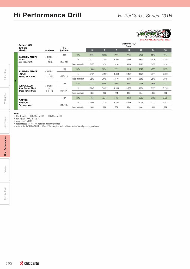
163
Aut
omot
ive
Aer
ospa
ceH
igh
Per
form
ance
Gen
eral
Spe
cial
Too
lsM
old
& D
ie
Hi Performance Drill Hi-PerCarb | Series 131N
www.kyocera-sgstool.com 39
Se
ries 131N
|Sp
eed &
Feed R
ecom
men
datio
ns
Series 131N 3D& 5DMetric Hardness
Vc (m/min)
Diameter (D1)(mm)
3 6 8 10 12 14 16
N
ALUMINUM ALLOYS< 12% SI6061, 2024, 7075
≤ 150 Bhnor
≤ 7 HRc
244 RPM 25851 12926 9694 7755 6463 5540 4847
(195-293)Fr 0.133 0.265 0.354 0.442 0.531 0.619 0.708
Feed (mm/min) 3430 3430 3430 3430 3430 3430 3430
ALUMINUM ALLOYS> 12% SIA356.0, 390.0, 319.0
≤ 125 Bhnor
≤ 77 HRb
183 RPM 19388 9694 7271 5816 4847 4155 3635
(146-219)Fr 0.131 0.262 0.349 0.437 0.524 0.611 0.699
Feed (mm/min) 2540 2540 2540 2540 2540 2540 2540
COPPER ALLOYSAlum Bronze, Muntz Brass, Navel Brass
≤ 175 Bhnor
≤ 16 HRc
168 RPM 17773 8886 6665 5332 4443 3808 3332
(134-201)Fr 0.049 0.097 0.130 0.162 0.194 0.227 0.259
Feed (mm/min) 864 864 864 864 864 864 864
PLASTICSAcrylic, PVC,Polypropylene
137 RPM 14541 7271 5453 4362 3635 3116 2726
(110-165)Fr 0.059 0.119 0.158 0.198 0.238 0.277 0.317
Feed (mm/min) 864 864 864 864 864 864 864
Note:• Bhn (Brinell) HRc (Rockwell C) HRb (Rockwell B)• rpm = (Vc x 1000) / (D1 x 3.14)• mm/min = Fr x RPM• reduce speed and feed for materials harder than listed• refer to the KYOCERA SGS Tool Wizard® for complete technical information (www.kyocera-sgstool.com)

164
Memo
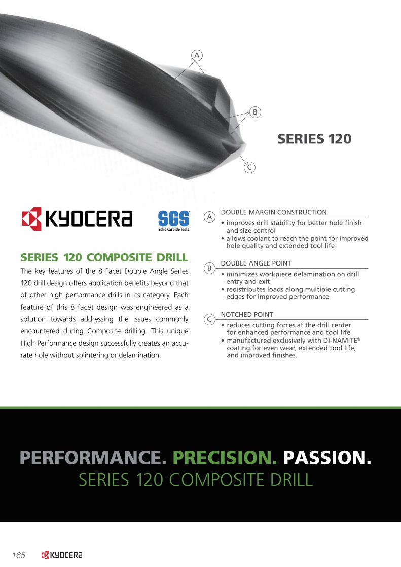
165
• Double margin design stabilized the drill for greater hole accuracy and improvedsurface �nish in �nal hole.
• Minimized delamination at hole entry/exit.• Manufactured exclusively with Di-NAMITE® coating for even wear,
extended tool life and improved �nishes.
PERFORMANCE.
PERFORMANCE. PRECISION. PASSION.SERIES 120 COMPOSITE DRILL
SERIES 120 COMPOSITE DRILLThe key features of the 8 Facet Double Angle Series
120 drill design offers application bene�ts beyond that
of other high performance drills in its category. Each
feature of this 8 facet design was engineered as a
solution towards addressing the issues commonly
encountered during Composite drilling. This unique
High Performance design successfully creates an accu-
rate hole without splintering or delamination.
A
B
DOUBLE MARGIN CONSTRUCTION
• improves drill stability for better hole �nishand size control
• allows coolant to reach the point for improvedhole quality and extended tool life
A
DOUBLE ANGLE POINT
• minimizes workpiece delamination on drillentry and exit
• redistributes loads along multiple cuttingedges for improved performance
NOTCHED POINT
• reduces cutting forces at the drill centerfor enhanced performance and tool life
• manufactured exclusively with Di-NAMITE®
coating for even wear, extended tool life,and improved �nishes.
C
C
B
1ST HOLE 3RD HOLE 50TH HOLE AFTER 50 HOLES
50 holes.0001”.190” CFRP drilluncoated1
TOOL NO. TYPEDESCRIPTION
TIR INMACHINE USAGE
SPEED5,000 rpm
FEED5.0 ipm
DIAMETER.190”
HOLE DEPTH.240”
WORKPIECE CFRP
MACHINE TYPEVertical Machining Center
COOLANTnone
Good hole quality for 1st 3 holes.fraying starting by 3rd hole, .0021” wear
INSPECTIONNOTES
1ST HOLE 25TH HOLE 50TH HOLE AFTER 50 HOLES
50 holes.0002”.190” CFRP drilldiamond2
TOOL NO. TYPEDESCRIPTION
TIR INMACHINE USAGE
Good hole quality all 50 holesslight fraying, .0013” wear
INSPECTIONNOTES
PASSION.
www.kyocera-sgstool.com
PRECISION.A test was conducted of our CFRP drill to determine the necessity of coating when drilling Carbon Fiber material. Fifty holes were drilled using a special size .190” CFRP drill. The tool’s design produces acceptable quality holes; but as shown in the photos, early edge wear on the uncoated drill resulted in holes with frayed edges. The diamond coated drill produced all 50 holes with little to no fraying and edge wear was 38% less than the uncoated drills.The geometry of the 8 Facet drill with the Di-NAMITE® coating is a necessity for additional tool life and productivity when manufacturing Carbon Fiber material.
• The compound angle creates 4 cutting edges along the drill point.• Distinct double angle prevents abrasiveness of the Composite from localizing along the point
and diminishing tool life.
SERIES 120
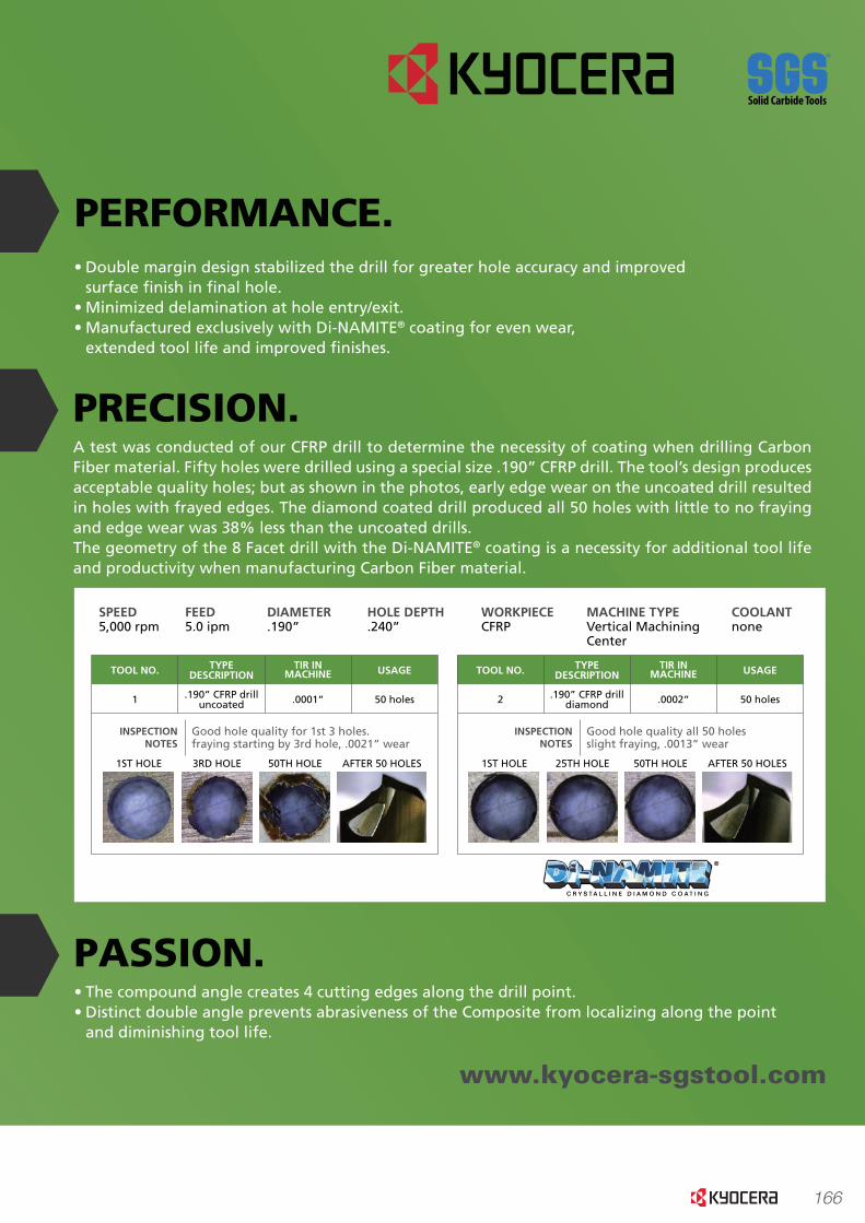
166
• Double margin design stabilized the drill for greater hole accuracy and improved surface �nish in �nal hole.• Minimized delamination at hole entry/exit.• Manufactured exclusively with Di-NAMITE® coating for even wear, extended tool life and improved �nishes.
PERFORMANCE.
PERFORMANCE. PRECISION. PASSION.SERIES 120 COMPOSITE DRILL
SERIES 120 COMPOSITE DRILLThe key features of the 8 Facet Double Angle Series
120 drill design offers application bene�ts beyond that
of other high performance drills in its category. Each
feature of this 8 facet design was engineered as a
solution towards addressing the issues commonly
encountered during Composite drilling. This unique
High Performance design successfully creates an accu-
rate hole without splintering or delamination.
A
B
DOUBLE MARGIN CONSTRUCTION
• improves drill stability for better hole �nish and size control• allows coolant to reach the point for improved hole quality and extended tool life
A
DOUBLE ANGLE POINT
• minimizes workpiece delamination on drill entry and exit• redistributes loads along multiple cutting edges for improved performance
NOTCHED POINT
• reduces cutting forces at the drill center for enhanced performance and tool life• manufactured exclusively with Di-NAMITE® coating for even wear, extended tool life, and improved �nishes.
C
C
B
1ST HOLE 3RD HOLE 50TH HOLE AFTER 50 HOLES
50 holes.0001”.190” CFRP drilluncoated1
TOOL NO. TYPEDESCRIPTION
TIR INMACHINE USAGE
SPEED5,000 rpm
FEED5.0 ipm
DIAMETER.190”
HOLE DEPTH.240”
WORKPIECE CFRP
MACHINE TYPEVertical Machining Center
COOLANTnone
Good hole quality for 1st 3 holes.fraying starting by 3rd hole, .0021” wear
INSPECTIONNOTES
1ST HOLE 25TH HOLE 50TH HOLE AFTER 50 HOLES
50 holes.0002”.190” CFRP drilldiamond2
TOOL NO. TYPEDESCRIPTION
TIR INMACHINE USAGE
Good hole quality all 50 holesslight fraying, .0013” wear
INSPECTIONNOTES
PASSION.
www.kyocera-sgstool.com
PRECISION.A test was conducted of our CFRP drill to determine the necessity of coating when drilling Carbon Fiber material. Fifty holes were drilled using a special size .190” CFRP drill. The tool’s design produces acceptable quality holes; but as shown in the photos, early edge wear on the uncoated drill resulted in holes with frayed edges. The diamond coated drill produced all 50 holes with little to no fraying and edge wear was 38% less than the uncoated drills.The geometry of the 8 Facet drill with the Di-NAMITE® coating is a necessity for additional tool life and productivity when manufacturing Carbon Fiber material.
• The compound angle creates 4 cutting edges along the drill point.• Distinct double angle prevents abrasiveness of the Composite from localizing along the point and diminishing tool life.
SERIES 120
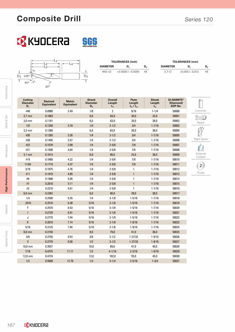
167
Aut
omot
ive
Aer
ospa
ceH
igh
Per
form
ance
Gen
eral
Spe
cial
Too
lsM
old
& D
ie
Composite Drill Series 120
70 www.kyocera-sgstool.com
Seri
es
120
|
Frac
tio
nal
& M
etri
c
Cutting Diameter
D1
Decimal Equivalent
Metric Equivalent
Shank Diameter
D2
Overall Length
L1
Flute LengthL2 / L3
Shank Length
L4
Di-NAMITE® (Diamond)
EDP No.
#40 0.0980 2.49 1/8 2 9/16 1-1/4 50000
2,7 mm 0.1063 6,0 63,0 20,0 32,0 50001
3,0 mm 0.1181 6,0 63,0 20,0 36,0 50002
1/8 0.1250 3.18 1/4 2-1/2 3/4 1-7/16 50003
3,2 mm 0.1260 6,0 63,0 20,0 36,0 50004
#30 0.1285 3.26 1/4 2-1/2 3/4 1-7/16 50005
#28 0.1405 3.57 1/4 2-1/2 3/4 1-7/16 50006
#22 0.1570 3.99 1/4 2-5/8 7/8 1-7/16 50007
#21 0.1590 4.04 1/4 2-5/8 7/8 1-7/16 50008
4,1 mm 0.1614 6,0 66,0 24,0 36,0 50009
#19 0.1660 4.22 1/4 2-5/8 7/8 1-7/16 50010
11/64 0.1719 4.37 1/4 2-5/8 7/8 1-7/16 50011
3/16 0.1875 4.76 1/4 2-5/8 1 1-7/16 50012
#11 0.1910 4.85 1/4 2-5/8 1 1-7/16 50013
#8 0.1990 5.05 1/4 2-5/8 1 1-7/16 50014
#7 0.2010 5.11 1/4 2-5/8 1 1-7/16 50015
#2 0.2210 5.61 1/4 2-5/8 1 1-7/16 50016
6,0 mm 0.2362 6,0 66,0 28,0 36,0 50017
1/4 0.2500 6.35 1/4 3-1/8 1-5/16 1-7/16 50018
.2510 0.2510 6.38 5/16 3-1/8 1-5/16 1-7/16 50019
F 0.2570 6.53 5/16 3-1/8 1-5/16 1-7/16 50020
I 0.2720 6.91 5/16 3-1/8 1-5/16 1-7/16 50021
J 0.2770 7.04 5/16 3-1/8 1-5/16 1-7/16 50022
K 0.2810 7.14 5/16 3-1/8 1-9/16 1-7/16 50023
5/16 0.3125 7.94 5/16 3-1/8 1-9/16 1-7/16 50024
8,0 mm 0.3150 8,0 79,0 41,0 36,0 50025
3/8 0.3750 9.53 3/8 3-1/2 1-27/32 1-9/16 50026
V 0.3770 9.58 1/2 3-1/2 1-27/32 1-9/16 50027
10,0 mm 0.3937 10,0 89,0 47,0 40,0 50028
7/16 0.4375 11.11 1/2 4-1/16 2-3/16 1-9/16 50029
12,0 mm 0.4724 12,0 102,0 55,0 45,0 50030
1/2 0.5000 12.70 1/2 4-1/4 2-5/16 1-3/4 50031
Common
Reach
Right Spiral
External Coolant
2
Flutes
TOLERANCES (mm)
DIAMETER D1 D2
2,7-12 +0,000 / –0,013 h6
TOLERANCES (inch)
DIAMETER D1 D2
#40-1/2 +0.0000 / –0.0005 h6

168
Autom
otiveA
erospaceH
igh Perform
anceG
eneralS
pecial ToolsM
old & D
ie
Composite Drill Series 120
71www.kyocera-sgstool.com
Serie
s 120
|
Speed
& Feed
Reco
mm
end
ation
s
Series 120Fractional
Vc (sfm)
Diameter (D1)(inch)
1/8 3/16 1/4 5/16 3/8 7/16 1/2
N
CFRP, AFRP(Carbon Fiber, Aramid Fiber)
320 RPM 9779 6519 4890 3912 3260 2794 2445
(256-384)Fr 0.0006 0.0009 0.0012 0.0015 0.0018 0.0021 0.0024
Feed (ipm) 5.9 5.9 5.9 5.9 5.9 5.9 5.9
GFRP(Fiberglass)
240 RPM 7334 4890 3667 2934 2445 2096 1834
(192-288)Fr 0.0006 0.0009 0.0012 0.0015 0.0018 0.0021 0.0024
Feed (ipm) 4.4 4.4 4.4 4.4 4.4 4.4 4.4
CARBON, GRAPHITE
400 RPM 12224 8149 6112 4890 4075 3493 3056
(320-480)Fr 0.0008 0.0012 0.0016 0.0020 0.0024 0.0028 0.0032
Feed (ipm) 9.8 9.8 9.8 9.8 9.8 9.8 9.8
Note:• rpm = Vc x 3.82 / D1 • ipm = Fr x RPM• adjust speed and / or feed based on resin type and / or fiber structure• refer to the KYOCERA SGS Tool Wizard® for complete technical information (www.kyocera-sgstool.com)
Series 120Metric
Vc (m/min)
Diameter (D1)(mm)
2.5 3 4 6 8 10 12
N
CFRP, AFRP(Carbon Fiber, Aramid Fiber)
100 RPM 12722 10602 7951 5301 3976 3181 2650
(80-120)Fr 0.012 0.014 0.019 0.028 0.038 0.047 0.057
Feed (mm/min) 150 150 150 150 150 150 150
GFRP(Fiberglass)
75 RPM 9542 7951 5963 3976 2982 2385 1988
(65-90)Fr 0.012 0.014 0.019 0.029 0.039 0.048 0.058
Feed (mm/min) 115 115 115 115 115 115 115
CARBON, GRAPHITE
120 RPM 15266 12722 9542 6361 4771 3817 3181
(96-144)Fr 0.015 0.018 0.025 0.037 0.049 0.062 0.074
Feed (mm/min) 235 235 235 235 235 235 235
Note:• rpm = (Vc x 1000) / (D1 x 3.14)• mm/min = Fr x RPM• adjust speed and / or feed based on resin type and / or fiber structure• refer to the KYOCERA SGS Tool Wizard® for complete technical information (www.kyocera-sgstool.com)

169
Memo
General Purpose Drills
170
General Purpose Drills
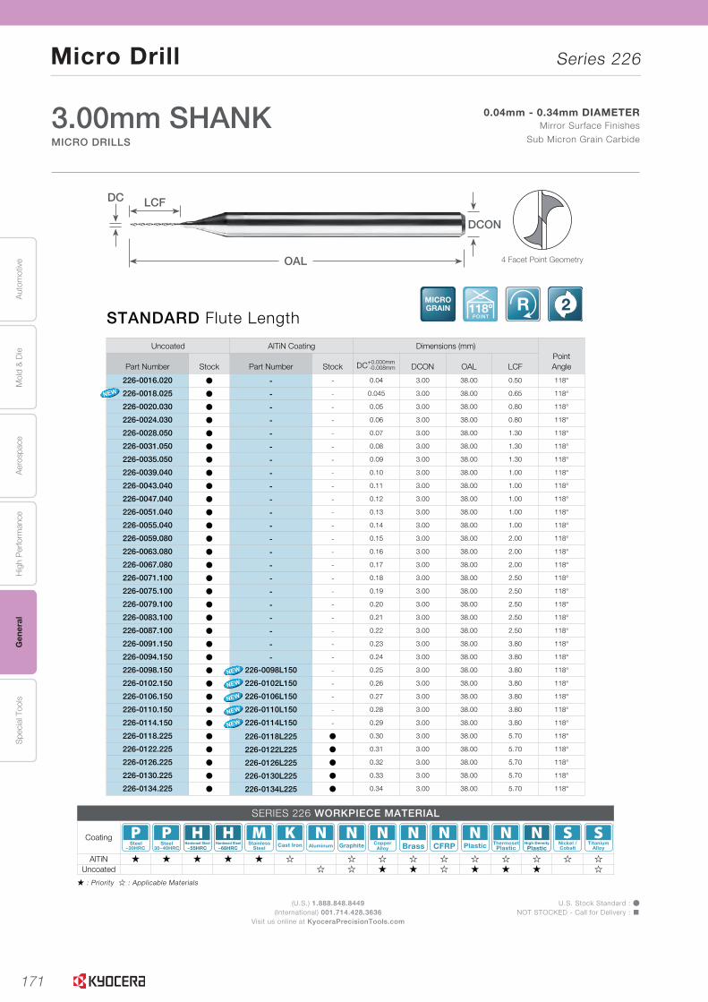
171
Aut
omot
ive
Aer
ospa
ceH
igh
Per
form
ance
Gen
eral
Spe
cial
Too
lsM
old
& D
ie
Micro Drill Series 226
(U.S.) 1.888.848.8449(International) 001.714.428.3636
Visit us online at KyoceraPrecisionTools.com
U.S. Stock Standard : ÞNOT STOCKED - Call for Delivery : �
� : Priority � : Applicable Materials
L
SOLI
DTO
OLS
L26
Uncoated AlTiN Coating Dimensions (mm)PointAnglePart Number Stock Part Number Stock DC+0.000mm
-0.008mm DCON OAL LCF
226-0016.020 Þ - - 0.04 3.00 38.00 0.50 118°
226-0018.025 Þ - - 0.045 3.00 38.00 0.65 118°
226-0020.030 Þ - - 0.05 3.00 38.00 0.80 118°
226-0024.030 Þ - - 0.06 3.00 38.00 0.80 118°
226-0028.050 Þ - - 0.07 3.00 38.00 1.30 118°
226-0031.050 Þ - - 0.08 3.00 38.00 1.30 118°
226-0035.050 Þ - - 0.09 3.00 38.00 1.30 118°
226-0039.040 Þ - - 0.10 3.00 38.00 1.00 118°
226-0043.040 Þ - - 0.11 3.00 38.00 1.00 118°
226-0047.040 Þ - - 0.12 3.00 38.00 1.00 118°
226-0051.040 Þ - - 0.13 3.00 38.00 1.00 118°
226-0055.040 Þ - - 0.14 3.00 38.00 1.00 118°
226-0059.080 Þ - - 0.15 3.00 38.00 2.00 118°
226-0063.080 Þ - - 0.16 3.00 38.00 2.00 118°
226-0067.080 Þ - - 0.17 3.00 38.00 2.00 118°
226-0071.100 Þ - - 0.18 3.00 38.00 2.50 118°
226-0075.100 Þ - - 0.19 3.00 38.00 2.50 118°
226-0079.100 Þ - - 0.20 3.00 38.00 2.50 118°
226-0083.100 Þ - - 0.21 3.00 38.00 2.50 118°
226-0087.100 Þ - - 0.22 3.00 38.00 2.50 118°
226-0091.150 Þ - - 0.23 3.00 38.00 3.80 118°
226-0094.150 Þ - - 0.24 3.00 38.00 3.80 118°
226-0098.150 Þ 226-0098L150 - 0.25 3.00 38.00 3.80 118°
226-0102.150 Þ 226-0102L150 - 0.26 3.00 38.00 3.80 118°
226-0106.150 Þ 226-0106L150 - 0.27 3.00 38.00 3.80 118°
226-0110.150 Þ 226-0110L150 - 0.28 3.00 38.00 3.80 118°
226-0114.150 Þ 226-0114L150 - 0.29 3.00 38.00 3.80 118°
226-0118.225 Þ 226-0118L225 Þ 0.30 3.00 38.00 5.70 118°
226-0122.225 Þ 226-0122L225 Þ 0.31 3.00 38.00 5.70 118°
226-0126.225 Þ 226-0126L225 Þ 0.32 3.00 38.00 5.70 118°
226-0130.225 Þ 226-0130L225 Þ 0.33 3.00 38.00 5.70 118°
226-0134.225 Þ 226-0134L225 Þ 0.34 3.00 38.00 5.70 118°
STANDARD Flute LengthMICROGRAIN 118º
POINT
R 2
MICRO DRILLS
3.00mm SHANKMICRO DRILLS
0.04mm - 0.34mm DIAMETERMirror Surface Finishes
Sub Micron Grain Carbide
Series 226
SERIES 226 WORKPIECE MATERIAL
Coating~30HRC
Steel30~40HRC
Steel~55HRC
Hardened Steel~68HRC
Hardened Steel StainlessSteel Cast Iron Aluminum Graphite Copper
Alloy Brass CFRP Plastic ThermosetPlastic Plastic
High Density Nickel /Cobalt
TitaniumAlloy
AlTiN � � � � � � � � � � � � � � �Uncoated � � � � � � � � �
DC
OAL
LCF
NEW
NEW
NEW
NEW
NEW
DCON
NEW
ITEM
S!
NEW
4 Facet Point Geometry
DRILLS
END MILLS
ROUTERS
THREAD MILLS
ENGRAVERS
BORINGBARS
REAMERS
TECHNICAL
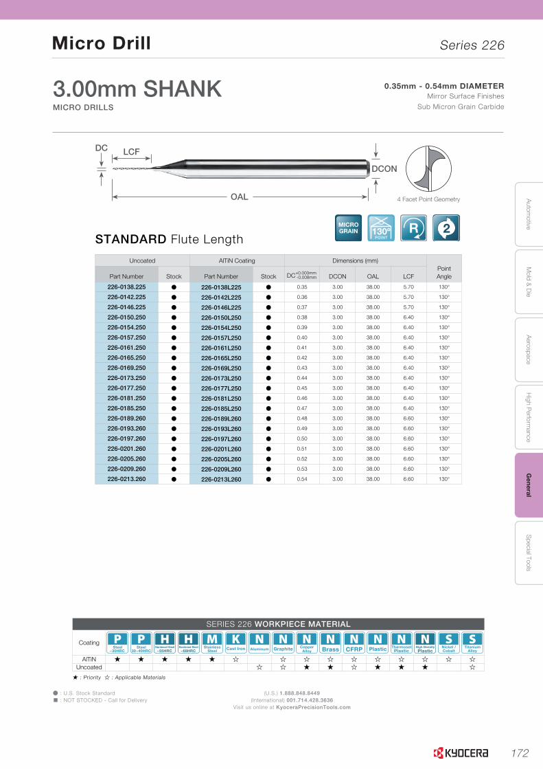
172
Autom
otiveA
erospaceH
igh Perform
anceG
eneralS
pecial ToolsM
old & D
ie
Micro Drill Series 226
(U.S.) 1.888.848.8449(International) 001.714.428.3636
Visit us online at KyoceraPrecisionTools.com
Þ : U.S. Stock Standard� : NOT STOCKED - Call for Delivery
� : Priority � : Applicable Materials
L
SOLID
TOO
LS
L27
H
CU
T-OFF
J
THR
EADIN
G
M
MILLIN
G
N
QUICK CHANG
ETO
OLIN
G
R
TECH
NIC
AL
P
SPARE PAR
TS
T
IND
EX
B
TUR
NIN
G
INSER
TS
G
GR
OO
VING
C
CB
N/PC
D
INSER
TS
K
DR
ILLING
A
INSER
T G
RAD
ES
D
TUR
NIN
G
HO
LDER
S
E
SMALL
TOO
LS
F
BO
RIN
G
3.00mm SHANKMICRO DRILLS
0.35mm - 0.54mm DIAMETERMirror Surface Finishes
Sub Micron Grain Carbide
MICRO DRILLS Series 226
STANDARD Flute LengthMICROGRAIN 130º
POINT
R 2
Uncoated AlTiN Coating Dimensions (mm)PointAnglePart Number Stock Part Number Stock DC+0.000mm
-0.008mm DCON OAL LCF
226-0138.225 Þ 226-0138L225 Þ 0.35 3.00 38.00 5.70 130°
226-0142.225 Þ 226-0142L225 Þ 0.36 3.00 38.00 5.70 130°
226-0146.225 Þ 226-0146L225 Þ 0.37 3.00 38.00 5.70 130°
226-0150.250 Þ 226-0150L250 Þ 0.38 3.00 38.00 6.40 130°
226-0154.250 Þ 226-0154L250 Þ 0.39 3.00 38.00 6.40 130°
226-0157.250 Þ 226-0157L250 Þ 0.40 3.00 38.00 6.40 130°
226-0161.250 Þ 226-0161L250 Þ 0.41 3.00 38.00 6.40 130°
226-0165.250 Þ 226-0165L250 Þ 0.42 3.00 38.00 6.40 130°
226-0169.250 Þ 226-0169L250 Þ 0.43 3.00 38.00 6.40 130°
226-0173.250 Þ 226-0173L250 Þ 0.44 3.00 38.00 6.40 130°
226-0177.250 Þ 226-0177L250 Þ 0.45 3.00 38.00 6.40 130°
226-0181.250 Þ 226-0181L250 Þ 0.46 3.00 38.00 6.40 130°
226-0185.250 Þ 226-0185L250 Þ 0.47 3.00 38.00 6.40 130°
226-0189.260 Þ 226-0189L260 Þ 0.48 3.00 38.00 6.60 130°
226-0193.260 Þ 226-0193L260 Þ 0.49 3.00 38.00 6.60 130°
226-0197.260 Þ 226-0197L260 Þ 0.50 3.00 38.00 6.60 130°
226-0201.260 Þ 226-0201L260 Þ 0.51 3.00 38.00 6.60 130°
226-0205.260 Þ 226-0205L260 Þ 0.52 3.00 38.00 6.60 130°
226-0209.260 Þ 226-0209L260 Þ 0.53 3.00 38.00 6.60 130°
226-0213.260 Þ 226-0213L260 Þ 0.54 3.00 38.00 6.60 130°
4 Facet Point Geometry
DC
OAL
LCF
DCON
SERIES 226 WORKPIECE MATERIAL
Coating~30HRC
Steel30~40HRC
Steel~55HRC
Hardened Steel~68HRC
Hardened Steel StainlessSteel Cast Iron Aluminum Graphite Copper
Alloy Brass CFRP Plastic ThermosetPlastic Plastic
High Density Nickel /Cobalt
TitaniumAlloy
AlTiN � � � � � � � � � � � � � � �Uncoated � � � � � � � � �
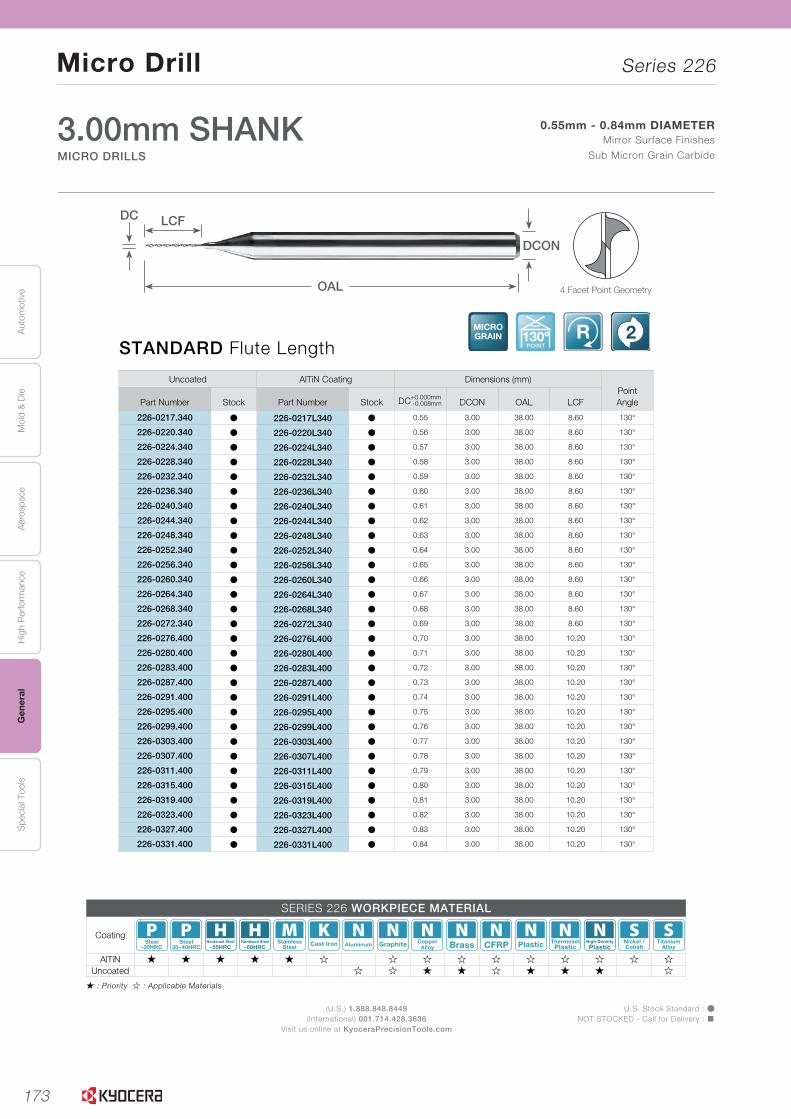
173
Aut
omot
ive
Aer
ospa
ceH
igh
Per
form
ance
Gen
eral
Spe
cial
Too
lsM
old
& D
ie
Micro Drill Series 226
(U.S.) 1.888.848.8449(International) 001.714.428.3636
Visit us online at KyoceraPrecisionTools.com
U.S. Stock Standard : ÞNOT STOCKED - Call for Delivery : �
� : Priority � : Applicable Materials
L
SOLI
DTO
OLS
L28
Uncoated AlTiN Coating Dimensions (mm)PointAnglePart Number Stock Part Number Stock DC+0.000mm
-0.008mm DCON OAL LCF
226-0217.340 Þ 226-0217L340 Þ 0.55 3.00 38.00 8.60 130°
226-0220.340 Þ 226-0220L340 Þ 0.56 3.00 38.00 8.60 130°
226-0224.340 Þ 226-0224L340 Þ 0.57 3.00 38.00 8.60 130°
226-0228.340 Þ 226-0228L340 Þ 0.58 3.00 38.00 8.60 130°
226-0232.340 Þ 226-0232L340 Þ 0.59 3.00 38.00 8.60 130°
226-0236.340 Þ 226-0236L340 Þ 0.60 3.00 38.00 8.60 130°
226-0240.340 Þ 226-0240L340 Þ 0.61 3.00 38.00 8.60 130°
226-0244.340 Þ 226-0244L340 Þ 0.62 3.00 38.00 8.60 130°
226-0248.340 Þ 226-0248L340 Þ 0.63 3.00 38.00 8.60 130°
226-0252.340 Þ 226-0252L340 Þ 0.64 3.00 38.00 8.60 130°
226-0256.340 Þ 226-0256L340 Þ 0.65 3.00 38.00 8.60 130°
226-0260.340 Þ 226-0260L340 Þ 0.66 3.00 38.00 8.60 130°
226-0264.340 Þ 226-0264L340 Þ 0.67 3.00 38.00 8.60 130°
226-0268.340 Þ 226-0268L340 Þ 0.68 3.00 38.00 8.60 130°
226-0272.340 Þ 226-0272L340 Þ 0.69 3.00 38.00 8.60 130°
226-0276.400 Þ 226-0276L400 Þ 0.70 3.00 38.00 10.20 130°
226-0280.400 Þ 226-0280L400 Þ 0.71 3.00 38.00 10.20 130°
226-0283.400 Þ 226-0283L400 Þ 0.72 3.00 38.00 10.20 130°
226-0287.400 Þ 226-0287L400 Þ 0.73 3.00 38.00 10.20 130°
226-0291.400 Þ 226-0291L400 Þ 0.74 3.00 38.00 10.20 130°
226-0295.400 Þ 226-0295L400 Þ 0.75 3.00 38.00 10.20 130°
226-0299.400 Þ 226-0299L400 Þ 0.76 3.00 38.00 10.20 130°
226-0303.400 Þ 226-0303L400 Þ 0.77 3.00 38.00 10.20 130°
226-0307.400 Þ 226-0307L400 Þ 0.78 3.00 38.00 10.20 130°
226-0311.400 Þ 226-0311L400 Þ 0.79 3.00 38.00 10.20 130°
226-0315.400 Þ 226-0315L400 Þ 0.80 3.00 38.00 10.20 130°
226-0319.400 Þ 226-0319L400 Þ 0.81 3.00 38.00 10.20 130°
226-0323.400 Þ 226-0323L400 Þ 0.82 3.00 38.00 10.20 130°
226-0327.400 Þ 226-0327L400 Þ 0.83 3.00 38.00 10.20 130°
226-0331.400 Þ 226-0331L400 Þ 0.84 3.00 38.00 10.20 130°
STANDARD Flute LengthMICROGRAIN 130º
POINT
R 2
MICRO DRILLS
3.00mm SHANKMICRO DRILLS
0.55mm - 0.84mm DIAMETERMirror Surface Finishes
Sub Micron Grain Carbide
Series 226
4 Facet Point Geometry
DC
OAL
LCF
DCON
SERIES 226 WORKPIECE MATERIAL
Coating~30HRC
Steel30~40HRC
Steel~55HRC
Hardened Steel~68HRC
Hardened Steel StainlessSteel Cast Iron Aluminum Graphite Copper
Alloy Brass CFRP Plastic ThermosetPlastic Plastic
High Density Nickel /Cobalt
TitaniumAlloy
AlTiN � � � � � � � � � � � � � � �Uncoated � � � � � � � � �
DRILLS
END MILLS
ROUTERS
THREAD MILLS
ENGRAVERS
BORINGBARS
REAMERS
TECHNICAL

174
Autom
otiveA
erospaceH
igh Perform
anceG
eneralS
pecial ToolsM
old & D
ie
Micro Drill Series 226
(U.S.) 1.888.848.8449(International) 001.714.428.3636
Visit us online at KyoceraPrecisionTools.com
Þ : U.S. Stock Standard� : NOT STOCKED - Call for Delivery
� : Priority � : Applicable Materials
L
SOLID
TOO
LS
L29
H
CU
T-OFF
J
THR
EADIN
G
M
MILLIN
G
N
QUICK CHANG
ETO
OLIN
G
R
TECH
NIC
AL
P
SPARE PAR
TS
T
IND
EX
B
TUR
NIN
G
INSER
TS
G
GR
OO
VING
C
CB
N/PC
D
INSER
TS
K
DR
ILLING
A
INSER
T G
RAD
ES
D
TUR
NIN
G
HO
LDER
S
E
SMALL
TOO
LS
F
BO
RIN
G
STANDARD Flute LengthMICROGRAIN 130º
POINT
R 2
3.00mm SHANKMICRO DRILLS
0.85mm - 1.14mm DIAMETERMirror Surface Finishes
Sub Micron Grain Carbide
MICRO DRILLS Series 226
Uncoated AlTiN Coating Dimensions (mm)PointAnglePart Number Stock Part Number Stock DC+0.000mm
-0.008mm DCON OAL LCF
226-0335.400 Þ 226-0335L400 Þ 0.85 3.00 38.00 10.20 130°
226-0339.400 Þ 226-0339L400 Þ 0.86 3.00 38.00 10.20 130°
226-0343.400 Þ 226-0343L400 Þ 0.87 3.00 38.00 10.20 130°
226-0346.400 Þ 226-0346L400 Þ 0.88 3.00 38.00 10.20 130°
226-0350.400 Þ 226-0350L400 Þ 0.89 3.00 38.00 10.20 130°
226-0354.400 Þ 226-0354L400 Þ 0.90 3.00 38.00 10.20 130°
226-0358.400 Þ 226-0358L400 Þ 0.91 3.00 38.00 10.20 130°
226-0362.400 Þ 226-0362L400 Þ 0.92 3.00 38.00 10.20 130°
226-0366.400 Þ 226-0366L400 Þ 0.93 3.00 38.00 10.20 130°
226-0370.400 Þ 226-0370L400 Þ 0.94 3.00 38.00 10.20 130°
226-0374.400 Þ 226-0374L400 Þ 0.95 3.00 38.00 10.20 130°
226-0378.400 Þ 226-0378L400 Þ 0.96 3.00 38.00 10.20 130°
226-0382.400 Þ 226-0382L400 Þ 0.97 3.00 38.00 10.20 130°
226-0386.400 Þ 226-0386L400 Þ 0.98 3.00 38.00 10.20 130°
226-0390.400 Þ 226-0390L400 Þ 0.99 3.00 38.00 10.20 130°
226-0394.400 Þ 226-0394L400 Þ 1.00 3.00 38.00 10.20 130°
226-0398.400 Þ 226-0398L400 Þ 1.01 3.00 38.00 10.20 130°
226-0402.400 Þ 226-0402L400 Þ 1.02 3.00 38.00 10.20 130°
226-0406.400 Þ 226-0406L400 Þ 1.03 3.00 38.00 10.20 130°
226-0409.400 Þ 226-0409L400 Þ 1.04 3.00 38.00 10.20 130°
226-0413.400 Þ 226-0413L400 Þ 1.05 3.00 38.00 10.20 130°
226-0417.400 Þ 226-0417L400 Þ 1.06 3.00 38.00 10.20 130°
226-0421.400 Þ 226-0421L400 Þ 1.07 3.00 38.00 10.20 130°
226-0425.400 Þ 226-0425L400 Þ 1.08 3.00 38.00 10.20 130°
226-0429.400 Þ 226-0429L400 Þ 1.09 3.00 38.00 10.20 130°
226-0433.400 Þ 226-0433L400 Þ 1.10 3.00 38.00 10.20 130°
226-0437.400 Þ 226-0437L400 Þ 1.11 3.00 38.00 10.20 130°
226-0441.400 Þ 226-0441L400 Þ 1.12 3.00 38.00 10.20 130°
226-0445.400 Þ 226-0445L400 Þ 1.13 3.00 38.00 10.20 130°
226-0449.400 Þ 226-0449L400 Þ 1.14 3.00 38.00 10.20 130°
4 Facet Point Geometry
DC
OAL
LCF
DCON
SERIES 226 WORKPIECE MATERIAL
Coating~30HRC
Steel30~40HRC
Steel~55HRC
Hardened Steel~68HRC
Hardened Steel StainlessSteel Cast Iron Aluminum Graphite Copper
Alloy Brass CFRP Plastic ThermosetPlastic Plastic
High Density Nickel /Cobalt
TitaniumAlloy
AlTiN � � � � � � � � � � � � � � �Uncoated � � � � � � � � �

175
Aut
omot
ive
Aer
ospa
ceH
igh
Per
form
ance
Gen
eral
Spe
cial
Too
lsM
old
& D
ie
Micro Drill Series 226
(U.S.) 1.888.848.8449(International) 001.714.428.3636
Visit us online at KyoceraPrecisionTools.com
U.S. Stock Standard : ÞNOT STOCKED - Call for Delivery : �
� : Priority � : Applicable Materials
L
SOLI
DTO
OLS
L30
Uncoated AlTiN Coating Dimensions (mm)PointAnglePart Number Stock Part Number Stock DC+0.000mm
-0.008mm DCON OAL LCF
226-0453.400 Þ 226-0453L400 Þ 1.15 3.00 38.00 10.20 130°
226-0457.400 Þ 226-0457L400 Þ 1.16 3.00 38.00 10.20 130°
226-0461.400 Þ 226-0461L400 Þ 1.17 3.00 38.00 10.20 130°
226-0465.400 Þ 226-0465L400 Þ 1.18 3.00 38.00 10.20 130°
226-0469.400 Þ 226-0469L400 Þ 1.19 3.00 38.00 10.20 130°
226-0472.400 Þ 226-0472L400 Þ 1.20 3.00 38.00 10.20 130°
226-0476.400 Þ 226-0476L400 Þ 1.21 3.00 38.00 10.20 130°
226-0480.400 Þ 226-0480L400 Þ 1.22 3.00 38.00 10.20 130°
226-0484.400 Þ 226-0484L400 Þ 1.23 3.00 38.00 10.20 130°
226-0488.400 Þ 226-0488L400 Þ 1.24 3.00 38.00 10.20 130°
226-0492.400 Þ 226-0492L400 Þ 1.25 3.00 38.00 10.20 130°
226-0496.400 Þ 226-0496L400 Þ 1.26 3.00 38.00 10.20 130°
226-0500.400 Þ 226-0500L400 Þ 1.27 3.00 38.00 10.20 130°
226-0504.400 Þ 226-0504L400 Þ 1.28 3.00 38.00 10.20 130°
226-0508.400 Þ 226-0508L400 Þ 1.29 3.00 38.00 10.20 130°
226-0512.400 Þ 226-0512L400 Þ 1.30 3.00 38.00 10.20 130°
226-0516.400 Þ 226-0516L400 Þ 1.31 3.00 38.00 10.20 130°
226-0520.400 Þ 226-0520L400 Þ 1.32 3.00 38.00 10.20 130°
226-0524.400 Þ 226-0524L400 Þ 1.33 3.00 38.00 10.20 130°
226-0528.400 Þ 226-0528L400 Þ 1.34 3.00 38.00 10.20 130°
226-0531.400 Þ 226-0531L400 Þ 1.35 3.00 38.00 10.20 130°
226-0535.400 Þ 226-0535L400 Þ 1.36 3.00 38.00 10.20 130°
226-0539.400 Þ 226-0539L400 Þ 1.37 3.00 38.00 10.20 130°
226-0543.400 Þ 226-0543L400 Þ 1.38 3.00 38.00 10.20 130°
226-0547.400 Þ 226-0547L400 Þ 1.39 3.00 38.00 10.20 130°
226-0551.400 Þ 226-0551L400 Þ 1.40 3.00 38.00 10.20 130°
226-0555.400 Þ 226-0555L400 Þ 1.41 3.00 38.00 10.20 130°
226-0559.400 Þ 226-0559L400 Þ 1.42 3.00 38.00 10.20 130°
226-0563.400 Þ 226-0563L400 Þ 1.43 3.00 38.00 10.20 130°
226-0567.400 Þ 226-0567L400 Þ 1.44 3.00 38.00 10.20 130°
STANDARD Flute LengthMICROGRAIN 130º
POINT
R 2
MICRO DRILLS
3.00mm SHANKMICRO DRILLS
1.15mm - 1.44mm DIAMETERMirror Surface Finishes
Sub Micron Grain Carbide
Series 226
4 Facet Point Geometry
DC
OAL
LCF
DCON
SERIES 226 WORKPIECE MATERIAL
Coating~30HRC
Steel30~40HRC
Steel~55HRC
Hardened Steel~68HRC
Hardened Steel StainlessSteel Cast Iron Aluminum Graphite Copper
Alloy Brass CFRP Plastic ThermosetPlastic Plastic
High Density Nickel /Cobalt
TitaniumAlloy
AlTiN � � � � � � � � � � � � � � �Uncoated � � � � � � � � �
DRILLS
END MILLS
ROUTERS
THREAD MILLS
ENGRAVERS
BORINGBARS
REAMERS
TECHNICAL

176
Autom
otiveA
erospaceH
igh Perform
anceG
eneralS
pecial ToolsM
old & D
ie
Micro Drill Series 226
(U.S.) 1.888.848.8449(International) 001.714.428.3636
Visit us online at KyoceraPrecisionTools.com
Þ : U.S. Stock Standard� : NOT STOCKED - Call for Delivery
� : Priority � : Applicable Materials
L
SOLID
TOO
LS
L31
H
CU
T-OFF
J
THR
EADIN
G
M
MILLIN
G
N
QUICK CHANG
ETO
OLIN
G
R
TECH
NIC
AL
P
SPARE PAR
TS
T
IND
EX
B
TUR
NIN
G
INSER
TS
G
GR
OO
VING
C
CB
N/PC
D
INSER
TS
K
DR
ILLING
A
INSER
T G
RAD
ES
D
TUR
NIN
G
HO
LDER
S
E
SMALL
TOO
LS
F
BO
RIN
G
3.00mm SHANKMICRO DRILLS
1.45mm - 1.74mm DIAMETERMirror Surface Finishes
Sub Micron Grain Carbide
MICRO DRILLS Series 226
STANDARD Flute LengthMICROGRAIN 130º
POINT
R 2
Uncoated AlTiN Coating Dimensions (mm)PointAnglePart Number Stock Part Number Stock DC+0.000mm
-0.008mm DCON OAL LCF
226-0571.400 Þ 226-0571L400 Þ 1.45 3.00 38.00 10.20 130°
226-0575.400 Þ 226-0575L400 Þ 1.46 3.00 38.00 10.20 130°
226-0579.400 Þ 226-0579L400 Þ 1.47 3.00 38.00 10.20 130°
226-0583.400 Þ 226-0583L400 Þ 1.48 3.00 38.00 10.20 130°
226-0587.400 Þ 226-0587L400 Þ 1.49 3.00 38.00 10.20 130°
226-0591.400 Þ 226-0591L400 Þ 1.50 3.00 38.00 10.20 130°
226-0594.400 Þ 226-0594L400 Þ 1.51 3.00 38.00 10.20 130°
226-0598.400 Þ 226-0598L400 Þ 1.52 3.00 38.00 10.20 130°
226-0602.400 Þ 226-0602L400 Þ 1.53 3.00 38.00 10.20 130°
226-0606.400 Þ 226-0606L400 Þ 1.54 3.00 38.00 10.20 130°
226-0610.400 Þ 226-0610L400 Þ 1.55 3.00 38.00 10.20 130°
226-0614.400 Þ 226-0614L400 Þ 1.56 3.00 38.00 10.20 130°
226-0618.400 Þ 226-0618L400 Þ 1.57 3.00 38.00 10.20 130°
226-0622.400 Þ 226-0622L400 Þ 1.58 3.00 38.00 10.20 130°
226-0626.400 Þ 226-0626L400 Þ 1.59 3.00 38.00 10.20 130°
226-0630.400 Þ 226-0630L400 Þ 1.60 3.00 38.00 10.20 130°
226-0634.400 Þ 226-0634L400 Þ 1.61 3.00 38.00 10.20 130°
226-0638.400 Þ 226-0638L400 Þ 1.62 3.00 38.00 10.20 130°
226-0642.400 Þ 226-0642L400 Þ 1.63 3.00 38.00 10.20 130°
226-0646.400 Þ 226-0646L400 Þ 1.64 3.00 38.00 10.20 130°
226-0650.400 Þ 226-0650L400 Þ 1.65 3.00 38.00 10.20 130°
226-0654.400 Þ 226-0654L400 Þ 1.66 3.00 38.00 10.20 130°
226-0657.400 Þ 226-0657L400 Þ 1.67 3.00 38.00 10.20 130°
226-0661.400 Þ 226-0661L400 Þ 1.68 3.00 38.00 10.20 130°
226-0665.400 Þ 226-0665L400 Þ 1.69 3.00 38.00 10.20 130°
226-0669.400 Þ 226-0669L400 Þ 1.70 3.00 38.00 10.20 130°
226-0673.400 Þ 226-0673L400 Þ 1.71 3.00 38.00 10.20 130°
226-0677.400 Þ 226-0677L400 Þ 1.72 3.00 38.00 10.20 130°
226-0681.400 Þ 226-0681L400 Þ 1.73 3.00 38.00 10.20 130°
226-0685.400 Þ 226-0685L400 Þ 1.74 3.00 38.00 10.20 130°
4 Facet Point Geometry
DC
OAL
LCF
DCON
SERIES 226 WORKPIECE MATERIAL
Coating~30HRC
Steel30~40HRC
Steel~55HRC
Hardened Steel~68HRC
Hardened Steel StainlessSteel Cast Iron Aluminum Graphite Copper
Alloy Brass CFRP Plastic ThermosetPlastic Plastic
High Density Nickel /Cobalt
TitaniumAlloy
AlTiN � � � � � � � � � � � � � � �Uncoated � � � � � � � � �

177
Aut
omot
ive
Aer
ospa
ceH
igh
Per
form
ance
Gen
eral
Spe
cial
Too
lsM
old
& D
ie
Micro Drill Series 226
(U.S.) 1.888.848.8449(International) 001.714.428.3636
Visit us online at KyoceraPrecisionTools.com
U.S. Stock Standard : ÞNOT STOCKED - Call for Delivery : �
� : Priority � : Applicable Materials
L
SOLI
DTO
OLS
L32
Uncoated AlTiN Coating Dimensions (mm)PointAnglePart Number Stock Part Number Stock DC+0.000mm
-0.008mm DCON OAL LCF
226-0689.400 Þ 226-0689L400 Þ 1.75 3.00 38.00 10.20 130°
226-0693.400 Þ 226-0693L400 Þ 1.76 3.00 38.00 10.20 130°
226-0697.400 Þ 226-0697L400 Þ 1.77 3.00 38.00 10.20 130°
226-0701.400 Þ 226-0701L400 Þ 1.78 3.00 38.00 10.20 130°
226-0705.400 Þ 226-0705L400 Þ 1.79 3.00 38.00 10.20 130°
226-0709.400 Þ 226-0709L400 Þ 1.80 3.00 38.00 10.20 130°
226-0713.400 Þ 226-0713L400 Þ 1.81 3.00 38.00 10.20 130°
226-0717.400 Þ 226-0717L400 Þ 1.82 3.00 38.00 10.20 130°
226-0720.400 Þ 226-0720L400 Þ 1.83 3.00 38.00 10.20 130°
226-0724.400 Þ 226-0724L400 Þ 1.84 3.00 38.00 10.20 130°
226-0728.400 Þ 226-0728L400 Þ 1.85 3.00 38.00 10.20 130°
226-0732.400 Þ 226-0732L400 Þ 1.86 3.00 38.00 10.20 130°
226-0736.400 Þ 226-0736L400 Þ 1.87 3.00 38.00 10.20 130°
226-0740.400 Þ 226-0740L400 Þ 1.88 3.00 38.00 10.20 130°
226-0744.400 Þ 226-0744L400 Þ 1.89 3.00 38.00 10.20 130°
226-0748.400 Þ 226-0748L400 Þ 1.90 3.00 38.00 10.20 130°
226-0752.400 Þ 226-0752L400 Þ 1.91 3.00 38.00 10.20 130°
226-0756.400 Þ 226-0756L400 Þ 1.92 3.00 38.00 10.20 130°
226-0760.400 Þ 226-0760L400 Þ 1.93 3.00 38.00 10.20 130°
226-0764.400 Þ 226-0764L400 Þ 1.94 3.00 38.00 10.20 130°
226-0768.400 Þ 226-0768L400 Þ 1.95 3.00 38.00 10.20 130°
226-0772.400 Þ 226-0772L400 Þ 1.96 3.00 38.00 10.20 130°
226-0776.400 Þ 226-0776L400 Þ 1.97 3.00 38.00 10.20 130°
226-0780.400 Þ 226-0780L400 Þ 1.98 3.00 38.00 10.20 130°
226-0783.400 Þ 226-0783L400 Þ 1.99 3.00 38.00 10.20 130°
226-0787.400 Þ 226-0787L400 Þ 2.00 3.00 38.00 10.20 130°
226-0791.400 Þ 226-0791L400 Þ 2.01 3.00 38.00 10.20 130°
226-0795.400 Þ 226-0795L400 Þ 2.02 3.00 38.00 10.20 130°
STANDARD Flute LengthMICROGRAIN 130º
POINT
R 2
MICRO DRILLS
3.00mm SHANKMICRO DRILLS
1.75mm - 2.02mm DIAMETERMirror Surface Finishes
Sub Micron Grain Carbide
Series 226
4 Facet Point Geometry
DC
OAL
LCF
DCON
SERIES 226 WORKPIECE MATERIAL
Coating~30HRC
Steel30~40HRC
Steel~55HRC
Hardened Steel~68HRC
Hardened Steel StainlessSteel Cast Iron Aluminum Graphite Copper
Alloy Brass CFRP Plastic ThermosetPlastic Plastic
High Density Nickel /Cobalt
TitaniumAlloy
AlTiN � � � � � � � � � � � � � � �Uncoated � � � � � � � � �
DRILLS
END MILLS
ROUTERS
THREAD MILLS
ENGRAVERS
BORINGBARS
REAMERS
TECHNICAL

178
Autom
otiveA
erospaceH
igh Perform
anceG
eneralS
pecial ToolsM
old & D
ie
Micro Drill Series 226
(U.S.) 1.888.848.8449(International) 001.714.428.3636
Visit us online at KyoceraPrecisionTools.com
Þ : U.S. Stock Standard� : NOT STOCKED - Call for Delivery
� : Priority � : Applicable Materials
L
SOLID
TOO
LS
L33
H
CU
T-OFF
J
THR
EADIN
G
M
MILLIN
G
N
QUICK CHANG
ETO
OLIN
G
R
TECH
NIC
AL
P
SPARE PAR
TS
T
IND
EX
B
TUR
NIN
G
INSER
TS
G
GR
OO
VING
C
CB
N/PC
D
INSER
TS
K
DR
ILLING
A
INSER
T G
RAD
ES
D
TUR
NIN
G
HO
LDER
S
E
SMALL
TOO
LS
F
BO
RIN
G
3.00mm SHANKMICRO DRILLS
2.03mm - 2.30mm DIAMETERMirror Surface Finishes
Sub Micron Grain Carbide
MICRO DRILLS Series 226
STANDARD Flute LengthMICROGRAIN 130º
POINT
R 2
Uncoated AlTiN Coating Dimensions (mm)PointAnglePart Number Stock Part Number Stock DC+0.000mm
-0.008mm DCON OAL LCF
226-0799.400 Þ 226-0799L400 Þ 2.03 3.00 38.00 10.20 130°
226-0803.400 Þ 226-0803L400 Þ 2.04 3.00 38.00 10.20 130°
226-0807.400 Þ 226-0807L400 Þ 2.05 3.00 38.00 10.20 130°
226-0811.400 Þ 226-0811L400 Þ 2.06 3.00 38.00 10.20 130°
226-0815.400 Þ 226-0815L400 Þ 2.07 3.00 38.00 10.20 130°
226-0819.400 Þ 226-0819L400 Þ 2.08 3.00 38.00 10.20 130°
226-0823.400 Þ 226-0823L400 Þ 2.09 3.00 38.00 10.20 130°
226-0827.400 Þ 226-0827L400 Þ 2.10 3.00 38.00 10.20 130°
226-0831.400 Þ 226-0831L400 Þ 2.11 3.00 38.00 10.20 130°
226-0835.400 Þ 226-0835L400 Þ 2.12 3.00 38.00 10.20 130°
226-0839.400 Þ 226-0839L400 Þ 2.13 3.00 38.00 10.20 130°
226-0843.400 Þ 226-0843L400 Þ 2.14 3.00 38.00 10.20 130°
226-0846.400 Þ 226-0846L400 Þ 2.15 3.00 38.00 10.20 130°
226-0850.400 Þ 226-0850L400 Þ 2.16 3.00 38.00 10.20 130°
226-0854.400 Þ 226-0854L400 Þ 2.17 3.00 38.00 10.20 130°
226-0858.400 Þ 226-0858L400 Þ 2.18 3.00 38.00 10.20 130°
226-0862.400 Þ 226-0862L400 Þ 2.19 3.00 38.00 10.20 130°
226-0866.400 Þ 226-0866L400 Þ 2.20 3.00 38.00 10.20 130°
226-0870.400 Þ 226-0870L400 Þ 2.21 3.00 38.00 10.20 130°
226-0874.400 Þ 226-0874L400 Þ 2.22 3.00 38.00 10.20 130°
226-0878.400 Þ 226-0878L400 Þ 2.23 3.00 38.00 10.20 130°
226-0882.400 Þ 226-0882L400 Þ 2.24 3.00 38.00 10.20 130°
226-0886.400 Þ 226-0886L400 Þ 2.25 3.00 38.00 10.20 130°
226-0890.400 Þ 226-0890L400 Þ 2.26 3.00 38.00 10.20 130°
226-0894.400 Þ 226-0894L400 Þ 2.27 3.00 38.00 10.20 130°
226-0898.400 Þ 226-0898L400 Þ 2.28 3.00 38.00 10.20 130°
226-0902.400 Þ 226-0902L400 Þ 2.29 3.00 38.00 10.20 130°
226-0906.400 Þ 226-0906L400 Þ 2.30 3.00 38.00 10.20 130°
4 Facet Point Geometry
DC
OAL
LCF
DCON
SERIES 226 WORKPIECE MATERIAL
Coating~30HRC
Steel30~40HRC
Steel~55HRC
Hardened Steel~68HRC
Hardened Steel StainlessSteel Cast Iron Aluminum Graphite Copper
Alloy Brass CFRP Plastic ThermosetPlastic Plastic
High Density Nickel /Cobalt
TitaniumAlloy
AlTiN � � � � � � � � � � � � � � �Uncoated � � � � � � � � �

179
Aut
omot
ive
Aer
ospa
ceH
igh
Per
form
ance
Gen
eral
Spe
cial
Too
lsM
old
& D
ie
Micro Drill Series 226
(U.S.) 1.888.848.8449(International) 001.714.428.3636
Visit us online at KyoceraPrecisionTools.com
U.S. Stock Standard : ÞNOT STOCKED - Call for Delivery : �
� : Priority � : Applicable Materials
L
SOLI
DTO
OLS
L34
Uncoated AlTiN Coating Dimensions (mm)PointAnglePart Number Stock Part Number Stock DC+0.000mm
-0.008mm DCON OAL LCF
226-0909.400 Þ 226-0909L400 Þ 2.31 3.00 38.00 10.20 130°
226-0913.400 Þ 226-0913L400 Þ 2.32 3.00 38.00 10.20 130°
226-0917.400 Þ 226-0917L400 Þ 2.33 3.00 38.00 10.20 130°
226-0921.400 Þ 226-0921L400 Þ 2.34 3.00 38.00 10.20 130°
226-0925.400 Þ 226-0925L400 Þ 2.35 3.00 38.00 10.20 130°
226-0929.400 Þ 226-0929L400 Þ 2.36 3.00 38.00 10.20 130°
226-0933.400 Þ 226-0933L400 Þ 2.37 3.00 38.00 10.20 130°
226-0937.400 Þ 226-0937L400 Þ 2.38 3.00 38.00 10.20 130°
226-0941.400 Þ 226-0941L400 Þ 2.39 3.00 38.00 10.20 130°
226-0945.400 Þ 226-0945L400 Þ 2.40 3.00 38.00 10.20 130°
226-0949.400 Þ 226-0949L400 Þ 2.41 3.00 38.00 10.20 130°
226-0953.400 Þ 226-0953L400 Þ 2.42 3.00 38.00 10.20 130°
226-0957.400 Þ 226-0957L400 Þ 2.43 3.00 38.00 10.20 130°
226-0961.400 Þ 226-0961L400 Þ 2.44 3.00 38.00 10.20 130°
226-0965.400 Þ 226-0965L400 Þ 2.45 3.00 38.00 10.20 130°
226-0969.400 Þ 226-0969L400 Þ 2.46 3.00 38.00 10.20 130°
226-0972.400 Þ 226-0972L400 Þ 2.47 3.00 38.00 10.20 130°
226-0976.400 Þ 226-0976L400 Þ 2.48 3.00 38.00 10.20 130°
226-0980.400 Þ 226-0980L400 Þ 2.49 3.00 38.00 10.20 130°
226-0984.400 Þ 226-0984L400 Þ 2.50 3.00 38.00 10.20 130°
226-0988.400 Þ 226-0988L400 Þ 2.51 3.00 38.00 10.20 130°
226-0992.400 Þ 226-0992L400 Þ 2.52 3.00 38.00 10.20 130°
226-0996.400 Þ 226-0996L400 Þ 2.53 3.00 38.00 10.20 130°
226-1000.400 Þ 226-1000L400 Þ 2.54 3.00 38.00 10.20 130°
226-1004.400 Þ 226-1004L400 Þ 2.55 3.00 38.00 10.20 130°
226-1008.400 Þ 226-1008L400 Þ 2.56 3.00 38.00 10.20 130°
226-1012.400 Þ 226-1012L400 Þ 2.57 3.00 38.00 10.20 130°
226-1016.400 Þ 226-1016L400 Þ 2.58 3.00 38.00 10.20 130°
226-1020.400 Þ 226-1020L400 Þ 2.59 3.00 38.00 10.20 130°
226-1024.400 Þ 226-1024L400 Þ 2.60 3.00 38.00 10.20 130°
STANDARD Flute LengthMICROGRAIN 130º
POINT
R 2
MICRO DRILLS
3.00mm SHANKMICRO DRILLS
2.31mm - 2.60mm DIAMETERMirror Surface Finishes
Sub Micron Grain Carbide
Series 226
4 Facet Point Geometry
DC
OAL
LCF
DCON
SERIES 226 WORKPIECE MATERIAL
Coating~30HRC
Steel30~40HRC
Steel~55HRC
Hardened Steel~68HRC
Hardened Steel StainlessSteel Cast Iron Aluminum Graphite Copper
Alloy Brass CFRP Plastic ThermosetPlastic Plastic
High Density Nickel /Cobalt
TitaniumAlloy
AlTiN � � � � � � � � � � � � � � �Uncoated � � � � � � � � �
DRILLS
END MILLS
ROUTERS
THREAD MILLS
ENGRAVERS
BORINGBARS
REAMERS
TECHNICAL
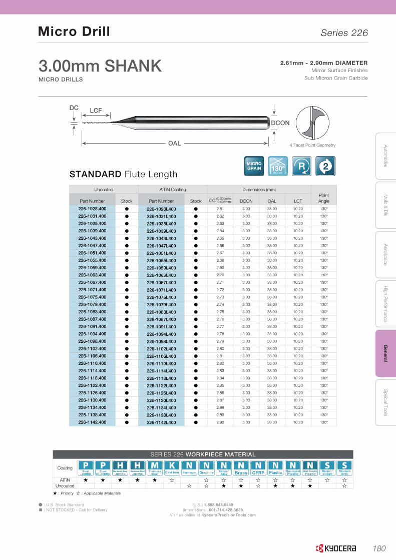
180
Autom
otiveA
erospaceH
igh Perform
anceG
eneralS
pecial ToolsM
old & D
ie
Micro Drill Series 226
(U.S.) 1.888.848.8449(International) 001.714.428.3636
Visit us online at KyoceraPrecisionTools.com
Þ : U.S. Stock Standard� : NOT STOCKED - Call for Delivery
� : Priority � : Applicable Materials
L
SOLID
TOO
LS
L35
H
CU
T-OFF
J
THR
EADIN
G
M
MILLIN
G
N
QUICK CHANG
ETO
OLIN
G
R
TECH
NIC
AL
P
SPARE PAR
TS
T
IND
EX
B
TUR
NIN
G
INSER
TS
G
GR
OO
VING
C
CB
N/PC
D
INSER
TS
K
DR
ILLING
A
INSER
T G
RAD
ES
D
TUR
NIN
G
HO
LDER
S
E
SMALL
TOO
LS
F
BO
RIN
G
STANDARD Flute LengthMICROGRAIN 130º
POINT
R 2
3.00mm SHANKMICRO DRILLS
2.61mm - 2.90mm DIAMETERMirror Surface Finishes
Sub Micron Grain Carbide
MICRO DRILLS Series 226
Uncoated AlTiN Coating Dimensions (mm)PointAnglePart Number Stock Part Number Stock DC+0.000mm
-0.008mm DCON OAL LCF
226-1028.400 Þ 226-1028L400 Þ 2.61 3.00 38.00 10.20 130°
226-1031.400 Þ 226-1031L400 Þ 2.62 3.00 38.00 10.20 130°
226-1035.400 Þ 226-1035L400 Þ 2.63 3.00 38.00 10.20 130°
226-1039.400 Þ 226-1039L400 Þ 2.64 3.00 38.00 10.20 130°
226-1043.400 Þ 226-1043L400 Þ 2.65 3.00 38.00 10.20 130°
226-1047.400 Þ 226-1047L400 Þ 2.66 3.00 38.00 10.20 130°
226-1051.400 Þ 226-1051L400 Þ 2.67 3.00 38.00 10.20 130°
226-1055.400 Þ 226-1055L400 Þ 2.68 3.00 38.00 10.20 130°
226-1059.400 Þ 226-1059L400 Þ 2.69 3.00 38.00 10.20 130°
226-1063.400 Þ 226-1063L400 Þ 2.70 3.00 38.00 10.20 130°
226-1067.400 Þ 226-1067L400 Þ 2.71 3.00 38.00 10.20 130°
226-1071.400 Þ 226-1071L400 Þ 2.72 3.00 38.00 10.20 130°
226-1075.400 Þ 226-1075L400 Þ 2.73 3.00 38.00 10.20 130°
226-1079.400 Þ 226-1079L400 Þ 2.74 3.00 38.00 10.20 130°
226-1083.400 Þ 226-1083L400 Þ 2.75 3.00 38.00 10.20 130°
226-1087.400 Þ 226-1087L400 Þ 2.76 3.00 38.00 10.20 130°
226-1091.400 Þ 226-1091L400 Þ 2.77 3.00 38.00 10.20 130°
226-1094.400 Þ 226-1094L400 Þ 2.78 3.00 38.00 10.20 130°
226-1098.400 Þ 226-1098L400 Þ 2.79 3.00 38.00 10.20 130°
226-1102.400 Þ 226-1102L400 Þ 2.80 3.00 38.00 10.20 130°
226-1106.400 Þ 226-1106L400 Þ 2.81 3.00 38.00 10.20 130°
226-1110.400 Þ 226-1110L400 Þ 2.82 3.00 38.00 10.20 130°
226-1114.400 Þ 226-1114L400 Þ 2.83 3.00 38.00 10.20 130°
226-1118.400 Þ 226-1118L400 Þ 2.84 3.00 38.00 10.20 130°
226-1122.400 Þ 226-1122L400 Þ 2.85 3.00 38.00 10.20 130°
226-1126.400 Þ 226-1126L400 Þ 2.86 3.00 38.00 10.20 130°
226-1130.400 Þ 226-1130L400 Þ 2.87 3.00 38.00 10.20 130°
226-1134.400 Þ 226-1134L400 Þ 2.88 3.00 38.00 10.20 130°
226-1138.400 Þ 226-1138L400 Þ 2.89 3.00 38.00 10.20 130°
226-1142.400 Þ 226-1142L400 Þ 2.90 3.00 38.00 10.20 130°
4 Facet Point Geometry
DC
OAL
LCF
DCON
SERIES 226 WORKPIECE MATERIAL
Coating~30HRC
Steel30~40HRC
Steel~55HRC
Hardened Steel~68HRC
Hardened Steel StainlessSteel Cast Iron Aluminum Graphite Copper
Alloy Brass CFRP Plastic ThermosetPlastic Plastic
High Density Nickel /Cobalt
TitaniumAlloy
AlTiN � � � � � � � � � � � � � � �Uncoated � � � � � � � � �
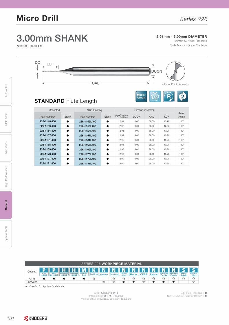
181
Aut
omot
ive
Aer
ospa
ceH
igh
Per
form
ance
Gen
eral
Spe
cial
Too
lsM
old
& D
ie
Micro Drill Series 226
(U.S.) 1.888.848.8449(International) 001.714.428.3636
Visit us online at KyoceraPrecisionTools.com
U.S. Stock Standard : ÞNOT STOCKED - Call for Delivery : �
� : Priority � : Applicable Materials
L
SOLI
DTO
OLS
L36
Uncoated AlTiN Coating Dimensions (mm)PointAnglePart Number Stock Part Number Stock DC+0.000mm
-0.008mm DCON OAL LCF
226-1146.400 Þ 226-1146L400 Þ 2.91 3.00 38.00 10.20 130°
226-1150.400 Þ 226-1150L400 Þ 2.92 3.00 38.00 10.20 130°
226-1154.400 Þ 226-1154L400 Þ 2.93 3.00 38.00 10.20 130°
226-1157.400 Þ 226-1157L400 Þ 2.94 3.00 38.00 10.20 130°
226-1161.400 Þ 226-1161L400 Þ 2.95 3.00 38.00 10.20 130°
226-1165.400 Þ 226-1165L400 Þ 2.96 3.00 38.00 10.20 130°
226-1169.400 Þ 226-1169L400 Þ 2.97 3.00 38.00 10.20 130°
226-1173.400 Þ 226-1173L400 Þ 2.98 3.00 38.00 10.20 130°
226-1177.400 Þ 226-1177L400 Þ 2.99 3.00 38.00 10.20 130°
226-1181.400 Þ 226-1181L400 Þ 3.00 3.00 38.00 10.20 130°
STANDARD Flute LengthMICROGRAIN 130º
POINT
R 2
MICRO DRILLS
3.00mm SHANKMICRO DRILLS
Series 226
2.91mm - 3.00mm DIAMETERMirror Surface Finishes
Sub Micron Grain Carbide
4 Facet Point Geometry
DC
OAL
LCF
DCON
SERIES 226 WORKPIECE MATERIAL
Coating~30HRC
Steel30~40HRC
Steel~55HRC
Hardened Steel~68HRC
Hardened Steel StainlessSteel Cast Iron Aluminum Graphite Copper
Alloy Brass CFRP Plastic ThermosetPlastic Plastic
High Density Nickel /Cobalt
TitaniumAlloy
AlTiN � � � � � � � � � � � � � � �Uncoated � � � � � � � � �
DRILLS
END MILLS
ROUTERS
THREAD MILLS
ENGRAVERS
BORINGBARS
REAMERS
TECHNICAL

182
Autom
otiveA
erospaceH
igh Perform
anceG
eneralS
pecial ToolsM
old & D
ie
Micro Drill Series 226
(U.S.) 1.888.848.8449(International) 001.714.428.3636
Visit us online at KyoceraPrecisionTools.com
Þ : U.S. Stock Standard� : NOT STOCKED - Call for Delivery
� : Priority � : Applicable Materials
L
SOLID
TOO
LS
L37
H
CU
T-OFF
J
THR
EADIN
G
M
MILLIN
G
N
QUICK CHANG
ETO
OLIN
G
R
TECH
NIC
AL
P
SPARE PAR
TS
T
IND
EX
B
TUR
NIN
G
INSER
TS
G
GR
OO
VING
C
CB
N/PC
D
INSER
TS
K
DR
ILLING
A
INSER
T G
RAD
ES
D
TUR
NIN
G
HO
LDER
S
E
SMALL
TOO
LS
F
BO
RIN
G
3.00mm SHANKMICRO DRILLS
MICRO DRILLS Series 226
EXTENDED Flute LengthMICROGRAIN 130º
POINT
R 2
Uncoated AlTiN Coating Dimensions (mm)PointAnglePart Number Stock Part Number Stock DC+0.000mm
-0.008mm DCON OAL LCF
226-0295.433 Þ 226-0295L433 Þ 0.75 3.00 50.00 11.00 130°
226-0315.433 Þ 226-0315L433 Þ 0.80 3.00 50.00 11.00 130°
226-0335.512 Þ 226-0335L512 Þ 0.85 3.00 50.00 13.00 130°
226-0354.512 Þ 226-0354L512 Þ 0.90 3.00 50.00 13.00 130°
226-0374.591 Þ 226-0374L591 Þ 0.95 3.00 50.00 15.00 130°
226-0394.591 Þ 226-0394L591 Þ 1.00 3.00 50.00 15.00 130°
226-0413.670 Þ 226-0413L670 Þ 1.05 3.00 50.00 17.00 130°
226-0433.670 Þ 226-0433L670 Þ 1.10 3.00 50.00 17.00 130°
226-0453.670 Þ 226-0453L670 Þ 1.15 3.00 50.00 17.00 130°
226-0472.670 Þ 226-0472L670 Þ 1.20 3.00 50.00 17.00 130°
226-0492.749 Þ 226-0492L749 Þ 1.25 3.00 50.00 19.00 130°
226-0512.749 Þ 226-0512L749 Þ 1.30 3.00 50.00 19.00 130°
226-0531.749 Þ 226-0531L749 Þ 1.35 3.00 50.00 19.00 130°
226-0551.749 Þ 226-0551L749 Þ 1.40 3.00 50.00 19.00 130°
226-0571.788 Þ 226-0571L788 Þ 1.45 3.00 50.00 20.00 130°
226-0591.788 Þ 226-0591L788 Þ 1.50 3.00 50.00 20.00 130°
226-0610.788 Þ 226-0610L788 Þ 1.55 3.00 50.00 20.00 130°
226-0630.788 Þ 226-0630L788 Þ 1.60 3.00 50.00 20.00 130°
226-0650.788 Þ 226-0650L788 Þ 1.65 3.00 50.00 20.00 130°
226-0669.788 Þ 226-0669L788 Þ 1.70 3.00 50.00 20.00 130°
226-0689.788 Þ 226-0689L788 Þ 1.75 3.00 50.00 20.00 130°
226-0709.788 Þ 226-0709L788 Þ 1.80 3.00 50.00 20.00 130°
0.75mm - 1.80mm DIAMETERMirror Surface Finishes
Sub Micron Grain Carbide
4 Facet Point Geometry
DC
OAL
LCF
DCON
SERIES 226 WORKPIECE MATERIAL
Coating~30HRC
Steel30~40HRC
Steel~55HRC
Hardened Steel~68HRC
Hardened Steel StainlessSteel Cast Iron Aluminum Graphite Copper
Alloy Brass CFRP Plastic ThermosetPlastic Plastic
High Density Nickel /Cobalt
TitaniumAlloy
AlTiN � � � � � � � � � � � � � � �Uncoated � � � � � � � � �
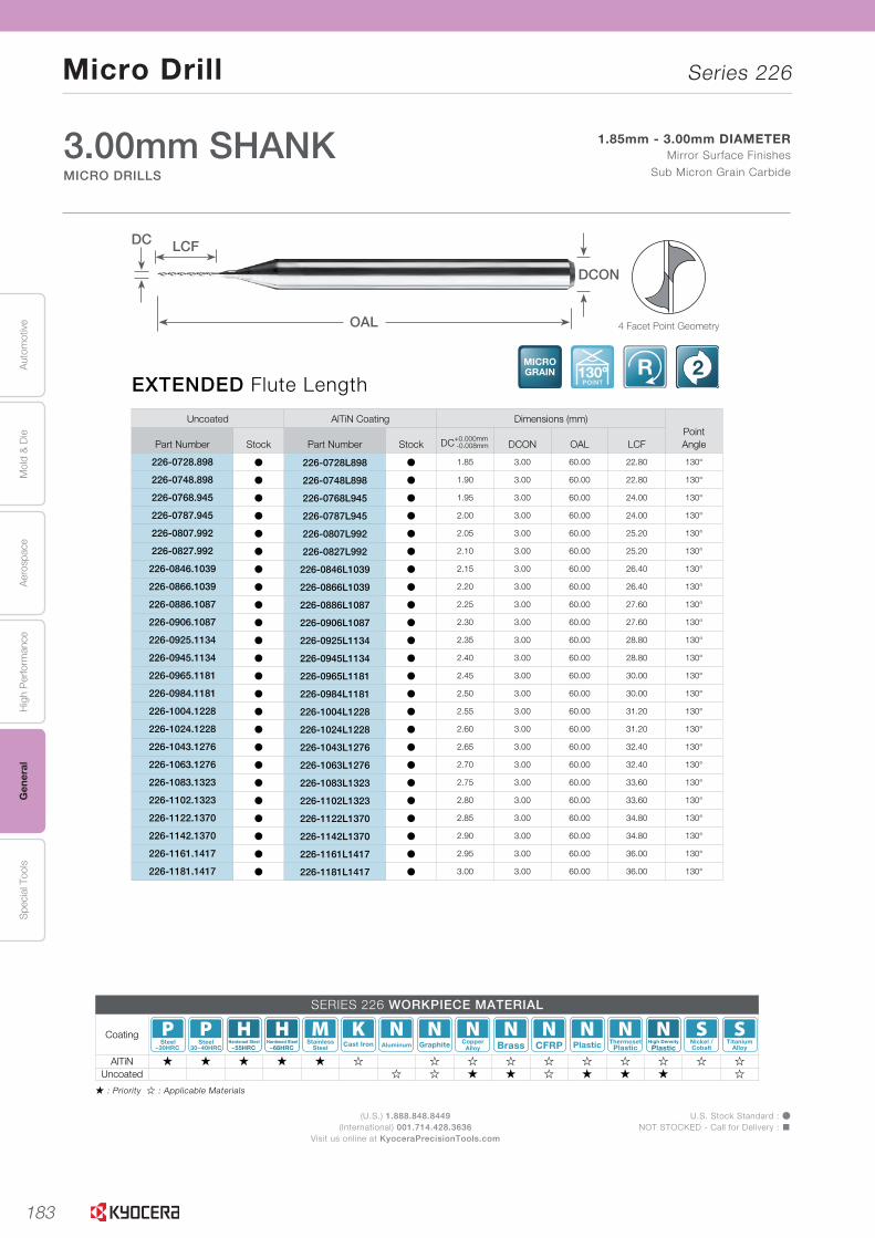
183
Aut
omot
ive
Aer
ospa
ceH
igh
Per
form
ance
Gen
eral
Spe
cial
Too
lsM
old
& D
ie
Micro Drill Series 226
(U.S.) 1.888.848.8449(International) 001.714.428.3636
Visit us online at KyoceraPrecisionTools.com
U.S. Stock Standard : ÞNOT STOCKED - Call for Delivery : �
� : Priority � : Applicable Materials
L
SOLI
DTO
OLS
L38
EXTENDED Flute LengthMICROGRAIN 130º
POINT
R 2
3.00mm SHANKMICRO DRILLS
1.85mm - 3.00mm DIAMETERMirror Surface Finishes
Sub Micron Grain Carbide
MICRO DRILLS Series 226
Uncoated AlTiN Coating Dimensions (mm)PointAnglePart Number Stock Part Number Stock DC+0.000mm
-0.008mm DCON OAL LCF
226-0728.898 Þ 226-0728L898 Þ 1.85 3.00 60.00 22.80 130°
226-0748.898 Þ 226-0748L898 Þ 1.90 3.00 60.00 22.80 130°
226-0768.945 Þ 226-0768L945 Þ 1.95 3.00 60.00 24.00 130°
226-0787.945 Þ 226-0787L945 Þ 2.00 3.00 60.00 24.00 130°
226-0807.992 Þ 226-0807L992 Þ 2.05 3.00 60.00 25.20 130°
226-0827.992 Þ 226-0827L992 Þ 2.10 3.00 60.00 25.20 130°
226-0846.1039 Þ 226-0846L1039 Þ 2.15 3.00 60.00 26.40 130°
226-0866.1039 Þ 226-0866L1039 Þ 2.20 3.00 60.00 26.40 130°
226-0886.1087 Þ 226-0886L1087 Þ 2.25 3.00 60.00 27.60 130°
226-0906.1087 Þ 226-0906L1087 Þ 2.30 3.00 60.00 27.60 130°
226-0925.1134 Þ 226-0925L1134 Þ 2.35 3.00 60.00 28.80 130°
226-0945.1134 Þ 226-0945L1134 Þ 2.40 3.00 60.00 28.80 130°
226-0965.1181 Þ 226-0965L1181 Þ 2.45 3.00 60.00 30.00 130°
226-0984.1181 Þ 226-0984L1181 Þ 2.50 3.00 60.00 30.00 130°
226-1004.1228 Þ 226-1004L1228 Þ 2.55 3.00 60.00 31.20 130°
226-1024.1228 Þ 226-1024L1228 Þ 2.60 3.00 60.00 31.20 130°
226-1043.1276 Þ 226-1043L1276 Þ 2.65 3.00 60.00 32.40 130°
226-1063.1276 Þ 226-1063L1276 Þ 2.70 3.00 60.00 32.40 130°
226-1083.1323 Þ 226-1083L1323 Þ 2.75 3.00 60.00 33.60 130°
226-1102.1323 Þ 226-1102L1323 Þ 2.80 3.00 60.00 33.60 130°
226-1122.1370 Þ 226-1122L1370 Þ 2.85 3.00 60.00 34.80 130°
226-1142.1370 Þ 226-1142L1370 Þ 2.90 3.00 60.00 34.80 130°
226-1161.1417 Þ 226-1161L1417 Þ 2.95 3.00 60.00 36.00 130°
226-1181.1417 Þ 226-1181L1417 Þ 3.00 3.00 60.00 36.00 130°
4 Facet Point Geometry
DC
OAL
LCF
SERIES 226 WORKPIECE MATERIAL
Coating~30HRC
Steel30~40HRC
Steel~55HRC
Hardened Steel~68HRC
Hardened Steel StainlessSteel Cast Iron Aluminum Graphite Copper
Alloy Brass CFRP Plastic ThermosetPlastic Plastic
High Density Nickel /Cobalt
TitaniumAlloy
AlTiN � � � � � � � � � � � � � � �Uncoated � � � � � � � � �
DCON
DRILLS
END MILLS
ROUTERS
THREAD MILLS
ENGRAVERS
BORINGBARS
REAMERS
TECHNICAL
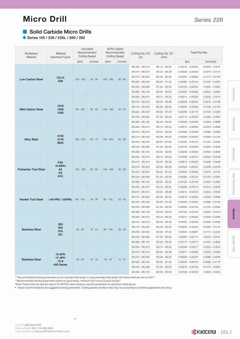
184-1
Autom
otiveA
erospaceH
igh Perform
anceG
eneralS
pecial ToolsM
old & D
ie
Micro Drill Series 226
L213
L
SOLID
TOO
LS
H
CU
T-OFF
J
THR
EADIN
G
M
MILLIN
G
N
QUICK CHANG
ETO
OLIN
G
R
TECH
NIC
AL
P
SPARE PAR
TS
T
IND
EX
B
TUR
NIN
G
INSER
TS
G
GR
OO
VING
C
CB
N/PC
D
INSER
TS
K
DR
ILLING
A
INSER
T G
RAD
ES
D
TUR
NIN
G
HO
LDER
S
E
SMALL
TOO
LS
F
BO
RIN
G
(U.S.) 1.888.848.8449(International) 001.714.428.3636Visit us online at KyoceraPrecisionTools.com
RECOMMENDED CUTTING CONDITIONS Reaming - Standard� Solid Carbide Micro Drills� Series 105 / 226 / 226L / 390 / 392
Workpiece Material
MaterialHardness/Types
UncoatedRecommendedCutting Speed
AlTiN CoatedRecommendedCutting Speed
Cutting Dia. DC(in)
Cutting Dia. DC(mm)
Feed Per Rev
(sfm) (m/min) (sfm) (m/min) (ipr) (mm/rev)
Low Carbon Steel12L14A36
130 - 165 40 - 50 165 - 195 50 - 60
Ø0.005 - Ø0.010 Ø0.13 - Ø0.25 0.00015 - 0.00030 0.0040 - 0.0075
Ø0.010 - Ø0.015 Ø0.25 - Ø0.38 0.00030 - 0.00045 0.0075 - 0.0115
Ø0.015 - Ø0.020 Ø0.38 - Ø0.50 0.00045 - 0.00060 0.0115 - 0.0150
Ø0.020 - Ø0.040 Ø0.50 - Ø1.00 0.00060 - 0.00120 0.0150 - 0.0300
Ø0.040 - Ø0.080 Ø1.00 - Ø2.00 0.00120 - 0.00240 0.0300 - 0.0600
Ø0.080 - Ø0.125 Ø2.00 - Ø3.00 0.00240 - 0.00360 0.0600 - 0.0900
Mild Carbon Steel101810281050
98 - 150 30 - 45 130 - 180 40 - 54
Ø0.005 - Ø0.010 Ø0.13 - Ø0.25 0.00014 - 0.00028 0.0035 - 0.0070
Ø0.010 - Ø0.015 Ø0.25 - Ø0.38 0.00028 - 0.00042 0.0070 - 0.0106
Ø0.015 - Ø0.020 Ø0.38 - Ø0.50 0.00042 - 0.00056 0.0106 - 0.0140
Ø0.020 - Ø0.040 Ø0.50 - Ø1.00 0.00056 - 0.00115 0.0140 - 0.0280
Ø0.040 - Ø0.080 Ø1.00 - Ø2.00 0.00115 - 0.00226 0.0280 - 0.0560
Ø0.080 - Ø0.125 Ø2.00 - Ø3.00 0.00226 - 0.00353 0.0560 - 0.0896
Alloy Steel413041408620
180 - 245 55 - 75 195 - 260 60 - 80
Ø0.005 - Ø0.010 Ø0.13 - Ø0.25 0.00013 - 0.00026 0.0033 - 0.0066
Ø0.010 - Ø0.015 Ø0.25 - Ø0.38 0.00026 - 0.00039 0.0066 - 0.0099
Ø0.015 - Ø0.020 Ø0.38 - Ø0.50 0.00039 - 0.00052 0.0099 - 0.0132
Ø0.020 - Ø0.040 Ø0.50 - Ø1.00 0.00052 - 0.00104 0.0132 - 0.0264
Ø0.040 - Ø0.080 Ø1.00 - Ø2.00 0.00104 - 0.00208 0.0264 - 0.0528
Ø0.080 - Ø0.125 Ø2.00 - Ø3.00 0.00208 - 0.00326 0.0528 - 0.0828
Preharden Tool Steel
P204140PH
A2D2H13
100 - 165 30 - 50 130 - 195 40 - 60
Ø0.005 - Ø0.010 Ø0.13 - Ø0.25 0.00008 - 0.00015 0.0020 - 0.0038
Ø0.010 - Ø0.015 Ø0.25 - Ø0.38 0.00015 - 0.00023 0.0038 - 0.0058
Ø0.015 - Ø0.020 Ø0.38 - Ø0.50 0.00023 - 0.00030 0.0038 - 0.0076
Ø0.020 - Ø0.040 Ø0.50 - Ø1.00 0.00030 - 0.00060 0.0076 - 0.0152
Ø0.040 - Ø0.080 Ø1.00 - Ø2.00 0.00060 - 0.00120 0.0152 - 0.0304
Ø0.080 - Ø0.125 Ø2.00 - Ø3.00 0.00120 - 0.00190 0.0304 - 0.0483
Harden Tool Steel >48 HRc/ <55HRc 60 - 100 18 - 30 80 - 140 25 - 42
Ø0.005 - Ø0.010 Ø0.13 - Ø0.25 0.00006 - 0.00013 0.0015 - 0.0033
Ø0.010 - Ø0.015 Ø0.25 - Ø0.38 0.00013 - 0.00019 0.0033 - 0.0048
Ø0.015 - Ø0.020 Ø0.38 - Ø0.50 0.00019 - 0.00026 0.0048 - 0.0066
Ø0.020 - Ø0.040 Ø0.50 - Ø1.00 0.00026 - 0.00052 0.0066 - 0.0132
Ø0.040 - Ø0.080 Ø1.00 - Ø2.00 0.00052 - 0.00105 0.0132 - 0.0264
Ø0.080 - Ø0.125 Ø2.00 - Ø3.00 0.00105 - 0.00163 0.0264 - 0.0414
Stainless Steel
303304316321
50 - 80 15 - 24 65 - 100 20 - 30
Ø0.005 - Ø0.010 Ø0.13 - Ø0.25 0.00011 - 0.00022 0.0028 - 0.0056
Ø0.010 - Ø0.015 Ø0.25 - Ø0.38 0.00022 - 0.00033 0.0056 - 0.0084
Ø0.015 - Ø0.020 Ø0.38 - Ø0.50 0.00033 - 0.00044 0.0084 - 0.0110
Ø0.020 - Ø0.040 Ø0.50 - Ø1.00 0.00044 - 0.00087 0.0110 - 0.0220
Ø0.040 - Ø0.080 Ø1.00 - Ø2.00 0.00087 - 0.00174 0.0220 - 0.0442
Ø0.080 - Ø0.125 Ø2.00 - Ø3.00 0.00174 - 0.00272 0.0442 - 0.0690
Stainless Steel
15-5PH17-4PH
13-8400 Series
30 - 50 10 - 15 40 - 70 12 - 21
Ø0.005 - Ø0.010 Ø0.13 - Ø0.25 0.00009 - 0.00017 0.0023 - 0.0043
Ø0.010 - Ø0.015 Ø0.25 - Ø0.38 0.00017 - 0.00026 0.0043 - 0.0066
Ø0.015 - Ø0.020 Ø0.38 - Ø0.50 0.00026 - 0.00035 0.0066 - 0.0089
Ø0.020 - Ø0.040 Ø0.50 - Ø1.00 0.00035 - 0.00070 0.0089 - 0.0178
Ø0.040 - Ø0.080 Ø1.00 - Ø2.00 0.00070 - 0.00139 0.0178 - 0.0353
Ø0.080 - Ø0.125 Ø2.00 - Ø3.00 0.00139 - 0.00218 0.0353 - 0.0553
***Recommended starting parameters are for standard flute length if using extended flute length drill reduce feed per rev by 25%*****Recommended starting parameters based on good setup, minimum tool runout & good tooling***Note: These tools can also be used in PLASTICS, when doing so use the parameters for aluminum listed above*• Above recommendations are suggested starting parameters. Cutting speeds and feed rates may vary according to machining application and setup.
(U.S.) 1.888.848.8449(International) 001.714.428.3636Visit us online at KyoceraPrecisionTools.com
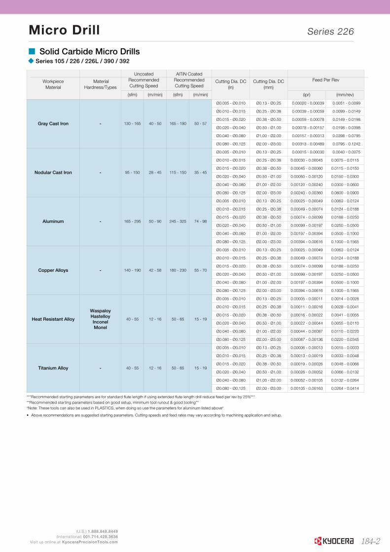
(U.S.) 1.888.848.8449(International) 001.714.428.3636
Visit us online at KyoceraPrecisionTools.com
Workpiece Material
MaterialHardness/Types
UncoatedRecommendedCutting Speed
AlTiN CoatedRecommendedCutting Speed
Cutting Dia. DC(in)
Cutting Dia. DC(mm)
Feed Per Rev
(sfm) (m/min) (sfm) (m/min) (ipr) (mm/rev)
Gray Cast Iron - 130 - 165 40 - 50 165 - 190 50 - 57
Ø0.005 - Ø0.010 Ø0.13 - Ø0.25 0.00020 - 0.00039 0.0051 - 0.0099
Ø0.010 - Ø0.015 Ø0.25 - Ø0.38 0.00039 - 0.00059 0.0099 - 0.0149
Ø0.015 - Ø0.020 Ø0.38 - Ø0.50 0.00059 - 0.00078 0.0149 - 0.0198
Ø0.020 - Ø0.040 Ø0.50 - Ø1.00 0.00078 - 0.00157 0.0198 - 0.0398
Ø0.040 - Ø0.080 Ø1.00 - Ø2.00 0.00157 - 0.00313 0.0398 - 0.0795
Ø0.080 - Ø0.125 Ø2.00 - Ø3.00 0.00313 - 0.00489 0.0795 - 0.1242
Nodular Cast Iron - 95 - 150 28 - 45 115 - 150 35 - 45
Ø0.005 - Ø0.010 Ø0.13 - Ø0.25 0.00015 - 0.00030 0.0040 - 0.0075
Ø0.010 - Ø0.015 Ø0.25 - Ø0.38 0.00030 - 0.00045 0.0075 - 0.0115
Ø0.015 - Ø0.020 Ø0.38 - Ø0.50 0.00045 - 0.00060 0.0115 - 0.0150
Ø0.020 - Ø0.040 Ø0.50 - Ø1.00 0.00060 - 0.00120 0.0150 - 0.0300
Ø0.040 - Ø0.080 Ø1.00 - Ø2.00 0.00120 - 0.00240 0.0300 - 0.0600
Ø0.080 - Ø0.125 Ø2.00 - Ø3.00 0.00240 - 0.00360 0.0600 - 0.0900
Aluminum - 165 - 295 50 - 90 245 - 325 74 - 98
Ø0.005 - Ø0.010 Ø0.13 - Ø0.25 0.00025 - 0.00049 0.0063 - 0.0124
Ø0.010 - Ø0.015 Ø0.25 - Ø0.38 0.00049 - 0.00074 0.0124 - 0.0188
Ø0.015 - Ø0.020 Ø0.38 - Ø0.50 0.00074 - 0.00099 0.0188 - 0.0250
Ø0.020 - Ø0.040 Ø0.50 - Ø1.00 0.00099 - 0.00197 0.0250 - 0.0500
Ø0.040 - Ø0.080 Ø1.00 - Ø2.00 0.00197 - 0.00394 0.0500 - 0.1000
Ø0.080 - Ø0.125 Ø2.00 - Ø3.00 0.00394 - 0.00616 0.1000 - 0.1565
Copper Alloys - 140 - 190 42 - 58 180 - 230 55 - 70
Ø0.005 - Ø0.010 Ø0.13 - Ø0.25 0.00025 - 0.00049 0.0063 - 0.0124
Ø0.010 - Ø0.015 Ø0.25 - Ø0.38 0.00049 - 0.00074 0.0124 - 0.0188
Ø0.015 - Ø0.020 Ø0.38 - Ø0.50 0.00074 - 0.00099 0.0188 - 0.0250
Ø0.020 - Ø0.040 Ø0.50 - Ø1.00 0.00099 - 0.00197 0.0250 - 0.0500
Ø0.040 - Ø0.080 Ø1.00 - Ø2.00 0.00197 - 0.00394 0.0500 - 0.1000
Ø0.080 - Ø0.125 Ø2.00 - Ø3.00 0.00394 - 0.00616 0.1000 - 0.1565
Heat Resistant Alloy
WaspaloyHastelloyInconelMonel
40 - 55 12 - 16 50 - 65 15 - 19
Ø0.005 - Ø0.010 Ø0.13 - Ø0.25 0.00005 - 0.00011 0.0014 - 0.0028
Ø0.010 - Ø0.015 Ø0.25 - Ø0.38 0.00011 - 0.00016 0.0028 - 0.0041
Ø0.015 - Ø0.020 Ø0.38 - Ø0.50 0.00016 - 0.00022 0.0041 - 0.0055
Ø0.020 - Ø0.040 Ø0.50 - Ø1.00 0.00022 - 0.00044 0.0055 - 0.0110
Ø0.040 - Ø0.080 Ø1.00 - Ø2.00 0.00044 - 0.00087 0.0110 - 0.0220
Ø0.080 - Ø0.125 Ø2.00 - Ø3.00 0.00087 - 0.00136 0.0220 - 0.0345
Titanium Alloy - 40 - 55 12 - 16 50 - 65 15 - 19
Ø0.005 - Ø0.010 Ø0.13 - Ø0.25 0.00006 - 0.00013 0.0015 - 0.0033
Ø0.010 - Ø0.015 Ø0.25 - Ø0.38 0.00013 - 0.00019 0.0033 - 0.0048
Ø0.015 - Ø0.020 Ø0.38 - Ø0.50 0.00019 - 0.00026 0.0048 - 0.0066
Ø0.020 - Ø0.040 Ø0.50 - Ø1.00 0.00026 - 0.00052 0.0066 - 0.0132
Ø0.040 - Ø0.080 Ø1.00 - Ø2.00 0.00052 - 0.00105 0.0132 - 0.0264
Ø0.080 - Ø0.125 Ø2.00 - Ø3.00 0.00105 - 0.00163 0.0264 - 0.0414
***Recommended starting parameters are for standard flute length if using extended flute length drill reduce feed per rev by 25%*****Recommended starting parameters based on good setup, minimum tool runout & good tooling***Note: These tools can also be used in PLASTICS, when doing so use the parameters for aluminum listed above*
• Above recommendations are suggested starting parameters. Cutting speeds and feed rates may vary according to machining application and setup.
Micro Drill Series 226
� Solid Carbide Micro Drills� Series 105 / 226 / 226L / 390 / 392
184-2
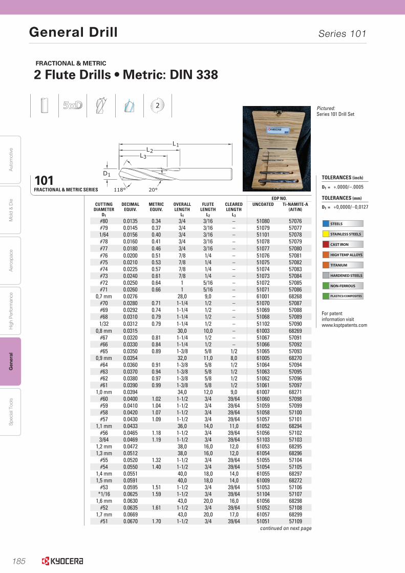
185
Aut
omot
ive
Aer
ospa
ceH
igh
Per
form
ance
Gen
eral
Spe
cial
Too
lsM
old
& D
ie
General Drill Series 101
DRILLS DRILLS302www.kyocera-sgstool.com
EDP NO.CUTTING
DIAMETERD1
DECIMALEQUIV.
METRICEQUIV.
OVERALL LENGTH
L1
FLUTE LENGTH
L2
CLEAREDLENGTH
L3
UNCOATED Ti-NAMITE-A (AlTiN)
#80 0.0135 0.34 3/4 3/16 – 51080 57076#79 0.0145 0.37 3/4 3/16 – 51079 570771/64 0.0156 0.40 3/4 3/16 – 51101 57078#78 0.0160 0.41 3/4 3/16 – 51078 57079#77 0.0180 0.46 3/4 3/16 – 51077 57080#76 0.0200 0.51 7/8 1/4 – 51076 57081#75 0.0210 0.53 7/8 1/4 – 51075 57082#74 0.0225 0.57 7/8 1/4 – 51074 57083#73 0.0240 0.61 7/8 1/4 – 51073 57084#72 0.0250 0.64 1 5/16 – 51072 57085#71 0.0260 0.66 1 5/16 – 51071 57086
0,7 mm 0.0276 28,0 9,0 – 61001 68268#70 0.0280 0.71 1-1/4 1/2 – 51070 57087#69 0.0292 0.74 1-1/4 1/2 – 51069 57088#68 0.0310 0.79 1-1/4 1/2 – 51068 570891/32 0.0312 0.79 1-1/4 1/2 – 51102 57090
0,8 mm 0.0315 30,0 10,0 – 61003 68269#67 0.0320 0.81 1-1/4 1/2 – 51067 57091#66 0.0330 0.84 1-1/4 1/2 – 51066 57092#65 0.0350 0.89 1-3/8 5/8 1/2 51065 57093
0,9 mm 0.0354 32,0 11,0 8,0 61005 68270#64 0.0360 0.91 1-3/8 5/8 1/2 51064 57094#63 0.0370 0.94 1-3/8 5/8 1/2 51063 57095#62 0.0380 0.97 1-3/8 5/8 1/2 51062 57096#61 0.0390 0.99 1-3/8 5/8 1/2 51061 57097
1,0 mm 0.0394 34,0 12,0 9,0 61007 68271#60 0.0400 1.02 1-1/2 3/4 39/64 51060 57098#59 0.0410 1.04 1-1/2 3/4 39/64 51059 57099#58 0.0420 1.07 1-1/2 3/4 39/64 51058 57100#57 0.0430 1.09 1-1/2 3/4 39/64 51057 57101
1,1 mm 0.0433 36,0 14,0 11,0 61052 68294#56 0.0465 1.18 1-1/2 3/4 39/64 51056 571023/64 0.0469 1.19 1-1/2 3/4 39/64 51103 57103
1,2 mm 0.0472 38,0 16,0 12,0 61053 682951,3 mm 0.0512 38,0 16,0 12,0 61054 68296
#55 0.0520 1.32 1-1/2 3/4 39/64 51055 57104#54 0.0550 1.40 1-1/2 3/4 39/64 51054 57105
1,4 mm 0.0551 40,0 18,0 14,0 61055 682971,5 mm 0.0591 40,0 18,0 14,0 61009 68272
#53 0.0595 1.51 1-1/2 3/4 39/64 51053 57106*1/16 0.0625 1.59 1-1/2 3/4 39/64 51104 57107
1,6 mm 0.0630 43,0 20,0 16,0 61056 68298#52 0.0635 1.61 1-1/2 3/4 39/64 51052 57108
1,7 mm 0.0669 43,0 20,0 17,0 61057 68299#51 0.0670 1.70 1-1/2 3/4 39/64 51051 57109
continued on next page
FRACTIONAL & METRIC
2 Flute Drills • Metric: DIN 338
101FRACTIONAL & METRIC SERIES
2
STEELS
STAINLESS STEELS
CAST IRON
HIGH TEMP ALLOYS
TITANIUM
HARDENED STEELS
NON-FERROUS
PLASTICS/COMPOSITES
TOLERANCES (inch)
D1 = +.0000/–.0005
TOLERANCES (mm)
D1 = +0,0000/–0,0127
For patent information visit www.ksptpatents.com
Pictured: Series 101 Drill Set
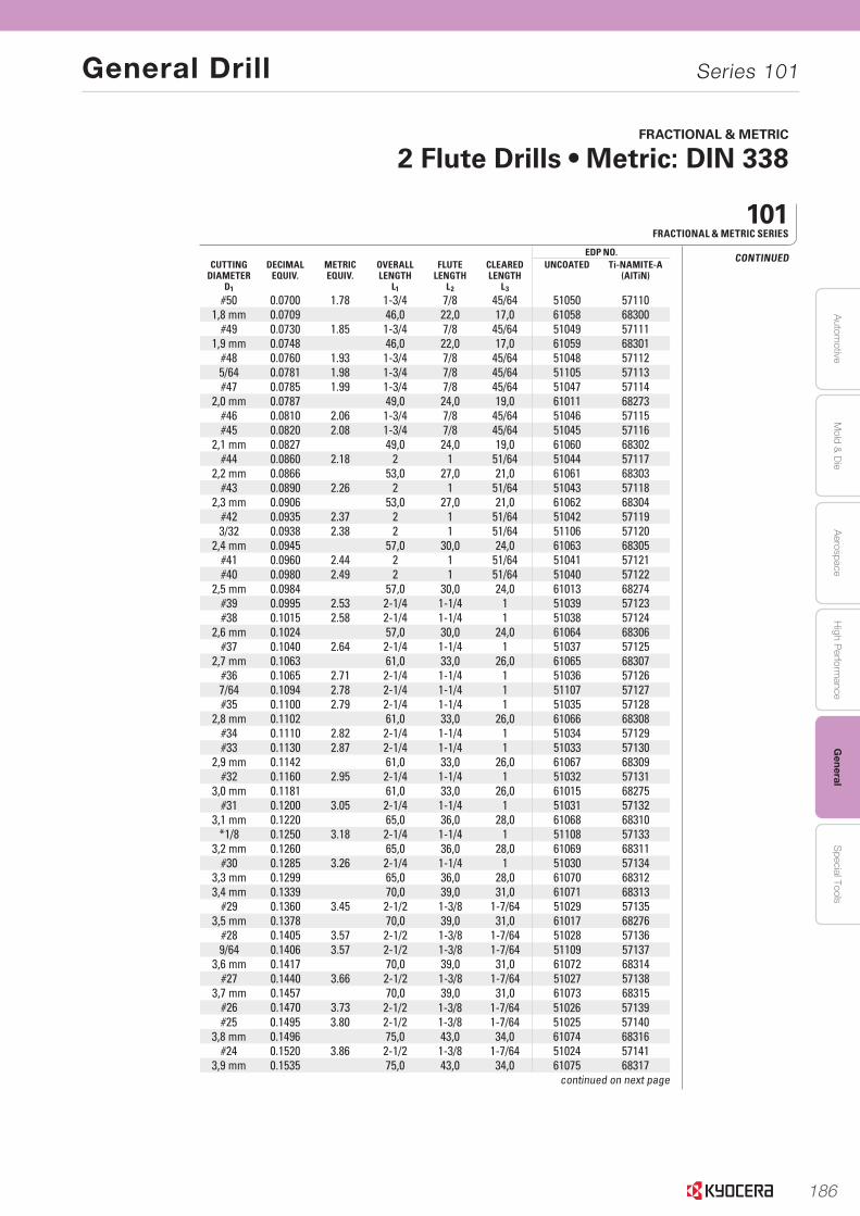
186
Autom
otiveA
erospaceH
igh Perform
anceG
eneralS
pecial ToolsM
old & D
ie
General Drill Series 101
303www.kyocera-sgstool.comDRILLS DRILLS
EDP NO.CUTTING
DIAMETERD1
DECIMALEQUIV.
METRICEQUIV.
OVERALL LENGTH
L1
FLUTE LENGTH
L2
CLEAREDLENGTH
L3
UNCOATED Ti-NAMITE-A (AlTiN)
#50 0.0700 1.78 1-3/4 7/8 45/64 51050 571101,8 mm 0.0709 46,0 22,0 17,0 61058 68300
#49 0.0730 1.85 1-3/4 7/8 45/64 51049 571111,9 mm 0.0748 46,0 22,0 17,0 61059 68301
#48 0.0760 1.93 1-3/4 7/8 45/64 51048 571125/64 0.0781 1.98 1-3/4 7/8 45/64 51105 57113#47 0.0785 1.99 1-3/4 7/8 45/64 51047 57114
2,0 mm 0.0787 49,0 24,0 19,0 61011 68273#46 0.0810 2.06 1-3/4 7/8 45/64 51046 57115#45 0.0820 2.08 1-3/4 7/8 45/64 51045 57116
2,1 mm 0.0827 49,0 24,0 19,0 61060 68302#44 0.0860 2.18 2 1 51/64 51044 57117
2,2 mm 0.0866 53,0 27,0 21,0 61061 68303#43 0.0890 2.26 2 1 51/64 51043 57118
2,3 mm 0.0906 53,0 27,0 21,0 61062 68304#42 0.0935 2.37 2 1 51/64 51042 571193/32 0.0938 2.38 2 1 51/64 51106 57120
2,4 mm 0.0945 57,0 30,0 24,0 61063 68305#41 0.0960 2.44 2 1 51/64 51041 57121#40 0.0980 2.49 2 1 51/64 51040 57122
2,5 mm 0.0984 57,0 30,0 24,0 61013 68274#39 0.0995 2.53 2-1/4 1-1/4 1 51039 57123#38 0.1015 2.58 2-1/4 1-1/4 1 51038 57124
2,6 mm 0.1024 57,0 30,0 24,0 61064 68306#37 0.1040 2.64 2-1/4 1-1/4 1 51037 57125
2,7 mm 0.1063 61,0 33,0 26,0 61065 68307#36 0.1065 2.71 2-1/4 1-1/4 1 51036 571267/64 0.1094 2.78 2-1/4 1-1/4 1 51107 57127#35 0.1100 2.79 2-1/4 1-1/4 1 51035 57128
2,8 mm 0.1102 61,0 33,0 26,0 61066 68308#34 0.1110 2.82 2-1/4 1-1/4 1 51034 57129#33 0.1130 2.87 2-1/4 1-1/4 1 51033 57130
2,9 mm 0.1142 61,0 33,0 26,0 61067 68309#32 0.1160 2.95 2-1/4 1-1/4 1 51032 57131
3,0 mm 0.1181 61,0 33,0 26,0 61015 68275#31 0.1200 3.05 2-1/4 1-1/4 1 51031 57132
3,1 mm 0.1220 65,0 36,0 28,0 61068 68310*1/8 0.1250 3.18 2-1/4 1-1/4 1 51108 57133
3,2 mm 0.1260 65,0 36,0 28,0 61069 68311#30 0.1285 3.26 2-1/4 1-1/4 1 51030 57134
3,3 mm 0.1299 65,0 36,0 28,0 61070 683123,4 mm 0.1339 70,0 39,0 31,0 61071 68313
#29 0.1360 3.45 2-1/2 1-3/8 1-7/64 51029 571353,5 mm 0.1378 70,0 39,0 31,0 61017 68276
#28 0.1405 3.57 2-1/2 1-3/8 1-7/64 51028 571369/64 0.1406 3.57 2-1/2 1-3/8 1-7/64 51109 57137
3,6 mm 0.1417 70,0 39,0 31,0 61072 68314#27 0.1440 3.66 2-1/2 1-3/8 1-7/64 51027 57138
3,7 mm 0.1457 70,0 39,0 31,0 61073 68315#26 0.1470 3.73 2-1/2 1-3/8 1-7/64 51026 57139#25 0.1495 3.80 2-1/2 1-3/8 1-7/64 51025 57140
3,8 mm 0.1496 75,0 43,0 34,0 61074 68316#24 0.1520 3.86 2-1/2 1-3/8 1-7/64 51024 57141
3,9 mm 0.1535 75,0 43,0 34,0 61075 68317continued on next page
CONTINUED
101FRACTIONAL & METRIC SERIES
FRACTIONAL & METRIC
2 Flute Drills • Metric: DIN 338

187
Aut
omot
ive
Aer
ospa
ceH
igh
Per
form
ance
Gen
eral
Spe
cial
Too
lsM
old
& D
ie
General Drill Series 101
DRILLS DRILLS304www.kyocera-sgstool.com
EDP NO.CUTTING
DIAMETERD1
DECIMALEQUIV.
METRICEQUIV.
OVERALL LENGTH
L1
FLUTE LENGTH
L2
CLEAREDLENGTH
L3
UNCOATED Ti-NAMITE-A (AlTiN)
#23 0.1540 3.91 2-1/2 1-3/8 1-7/64 51023 571425/32 0.1562 3.97 2-1/2 1-3/8 1-7/64 51110 57143#22 0.1570 3.99 2-1/2 1-3/8 1-7/64 51022 57144
4,0 mm 0.1575 75,0 43,0 34,0 61019 68277#21 0.1590 4.04 2-1/2 1-3/8 1-7/64 51021 57145#20 0.1610 4.09 2-1/2 1-3/8 1-7/64 51020 57146
4,1 mm 0.1614 75,0 43,0 34,0 61076 683184,2 mm 0.1654 75,0 43,0 34,0 61077 68319
#19 0.1660 4.22 2-1/2 1-5/8 1-19/64 51019 571474,3 mm 0.1693 80,0 47,0 37,0 61078 68320
#18 0.1695 4.31 2-3/4 1-5/8 1-19/64 51018 5714811/64 0.1719 4.37 2-3/4 1-5/8 1-19/64 51111 57149#17 0.1730 4.39 2-3/4 1-5/8 1-19/64 51017 57150
4,4 mm 0.1732 80,0 47,0 37,0 61079 68321#16 0.1770 4.50 2-3/4 1-5/8 1-19/64 51016 57151
4,5 mm 0.1772 80,0 47,0 37,0 61021 68278#15 0.1800 4.57 2-3/4 1-5/8 1-19/64 51015 57152
4,6 mm 0.1811 80,0 47,0 37,0 61080 68322#14 0.1820 4.62 2-3/4 1-5/8 1-19/64 51014 57153
4,7 mm 0.1850 80,0 47,0 37,0 61081 68323#13 0.1850 4.70 2-3/4 1-5/8 1-19/64 51013 57154
*3/16 0.1875 4.76 2-3/4 1-5/8 1-19/64 51112 571554,8 mm 0.1890 86,0 52,0 41,0 61082 68324
#12 0.1890 4.80 2-3/4 1-5/8 1-19/64 51012 57156#11 0.1910 4.85 2-3/4 1-5/8 1-19/64 51011 57157
4,9 mm 0.1929 86,0 52,0 41,0 61083 68325#10 0.1935 4.91 2-3/4 1-5/8 1-19/64 51010 57158#9 0.1960 4.98 3 1-3/4 1-13/32 51009 57159
5,0 mm 0.1969 86,0 52,0 41,0 61023 68279#8 0.1990 5.05 3 1-3/4 1-13/32 51008 57160
5,1 mm 0.2008 86,0 52,0 41,0 61084 68326#7 0.2010 5.11 3 1-3/4 1-13/32 51007 57161
13/64 0.2031 5.16 3 1-3/4 1-13/32 51113 57162#6 0.2040 5.18 3 1-3/4 1-13/32 51006 57163
5,2 mm 0.2047 86,0 52,0 41,0 61085 68327#5 0.2055 5.22 3 1-3/4 1-13/32 51005 57164
5,3 mm 0.2087 86,0 52,0 41,0 61086 68328#4 0.2090 5.31 3 1-3/4 1-13/32 51004 57165
5,4 mm 0.2126 93,0 57,0 45,0 61087 68329#3 0.2130 5.41 3 1-3/4 1-13/32 51003 57166
5,5 mm 0.2165 93,0 57,0 1-13/32 61025 682807/32 0.2188 5.56 3 1-3/4 1-13/32 51114 57167
5,6 mm 0.2205 93,0 57,0 45,0 61088 68330#2 0.2210 5.61 3 1-3/4 1-13/32 51002 57168
continued on next page
101FRACTIONAL & METRIC SERIES
2
FRACTIONAL & METRIC
2 Flute Drills • Metric: DIN 338
STEELS
STAINLESS STEELS
CAST IRON
HIGH TEMP ALLOYS
TITANIUM
HARDENED STEELS
NON-FERROUS
PLASTICS/COMPOSITES
TOLERANCES (inch)
D1 = +.0000/–.0005
TOLERANCES (mm)
D1 = +0,0000/–0,0127
For patent information visit www.ksptpatents.com
Pictured: Series 101 Drill Set
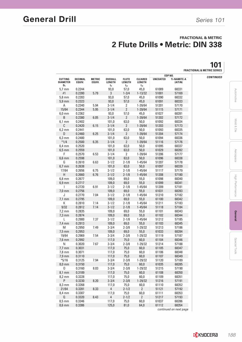
188
Autom
otiveA
erospaceH
igh Perform
anceG
eneralS
pecial ToolsM
old & D
ie
General Drill Series 101
DRILLS DRILLS 305www.kyocera-sgstool.com
EDP NO.CUTTING
DIAMETERD1
DECIMALEQUIV.
METRICEQUIV.
OVERALL LENGTH
L1
FLUTE LENGTH
L2
CLEAREDLENGTH
L3
UNCOATED Ti-NAMITE-A (AlTiN)
5,7 mm 0.2244 93,0 57,0 45,0 61089 68331#1 0.2280 5.79 3 1-3/4 1-13/32 51001 57169
5,8 mm 0.2283 93,0 57,0 45,0 61090 683325,9 mm 0.2323 93,0 57,0 45,0 61091 68333
A 0.2340 5.94 3-1/4 2 1-39/64 51201 5717015/64 0.2344 5.95 3-1/4 2 1-39/64 51115 57171
6,0 mm 0.2362 93,0 57,0 45,0 61027 68281B 0.2380 6.05 3-1/4 2 1-39/64 51202 57172
6,1 mm 0.2402 101,0 63,0 50,0 61092 68334C 0.2420 6.15 3-1/4 2 1-39/64 51203 57173
6,2 mm 0.2441 101,0 63,0 50,0 61093 68335D 0.2460 6.25 3-1/4 2 1-39/64 51204 57174
6,3 mm 0.2480 101,0 63,0 50,0 61094 68336*1/4 0.2500 6.35 3-1/4 2 1-39/64 51116 57176
6,4 mm 0.2520 101,0 63,0 50,0 61095 683376,5 mm 0.2559 101,0 63,0 50,0 61029 68282
F 0.2570 6.53 3-1/4 2 1-39/64 51206 571776,6 mm 0.2598 101,0 63,0 50,0 61096 68338
G 0.2610 6.63 3-1/2 2-1/8 1-45/64 51207 571786,7 mm 0.2638 101,0 63,0 50,0 61097 6833917/64 0.2656 6.75 3-1/2 2-1/8 1-45/64 51117 57179
H 0.2660 6.76 3-1/2 2-1/8 1-45/64 51208 571806,8 mm 0.2677 109,0 69,0 55,0 61098 683406,9 mm 0.2717 109,0 69,0 55,0 61099 68341
I 0.2720 6.91 3-1/2 2-1/8 1-45/64 51209 571817,0 mm 0.2756 109,0 69,0 55,0 61031 68283
J 0.2770 7.04 3-1/2 2-1/8 1-45/64 51210 571827,1 mm 0.2795 109,0 69,0 55,0 61100 68342
K 0.2810 7.14 3-1/2 2-1/8 1-45/64 51211 571839/32 0.2812 7.14 3-1/2 2-1/8 1-45/64 51118 57184
7,2 mm 0.2835 109,0 69,0 55,0 61101 683437,3 mm 0.2874 109,0 69,0 55,0 61102 68344
L 0.2900 7.37 3-1/2 2-1/8 1-45/64 51212 571857,4 mm 0.2913 109,0 69,0 55,0 61103 68345
M 0.2950 7.49 3-3/4 2-3/8 1-29/32 51213 571867,5 mm 0.2953 109,0 69,0 55,0 61033 6828419/64 0.2969 7.54 3-3/4 2-3/8 1-29/32 51119 57187
7,6 mm 0.2992 117,0 75,0 60,0 61104 68346N 0.3020 7.67 3-3/4 2-3/8 1-29/32 51214 57188
7,7 mm 0.3031 117,0 75,0 60,0 61105 683477,8 mm 0.3071 117,0 75,0 60,0 61106 683487,9 mm 0.3110 117,0 75,0 60,0 61107 68349*5/16 0.3125 7.94 3-3/4 2-3/8 1-29/32 51120 57189
8,0 mm 0.3150 117,0 75,0 60,0 61035 68285O 0.3160 8.03 3-3/4 2-3/8 1-29/32 51215 57190
8,1 mm 0.3189 117,0 75,0 60,0 61108 683508,2 mm 0.3228 117,0 75,0 60,0 61109 68351
P 0.3230 8.20 3-3/4 2-3/8 1-29/32 51216 571918,3 mm 0.3268 117,0 75,0 60,0 61110 6835221/64 0.3281 8.33 4 2-1/2 2 51121 57192
8,4 mm 0.3307 117,0 75,0 60,0 61111 68353Q 0.3320 8.43 4 2-1/2 2 51217 57193
8,5 mm 0.3346 117,0 75,0 60,0 61037 682868,6 mm 0.3386 125,0 81,0 64,0 61112 68354
continued on next page
CONTINUED
101FRACTIONAL & METRIC SERIES
FRACTIONAL & METRIC
2 Flute Drills • Metric: DIN 338
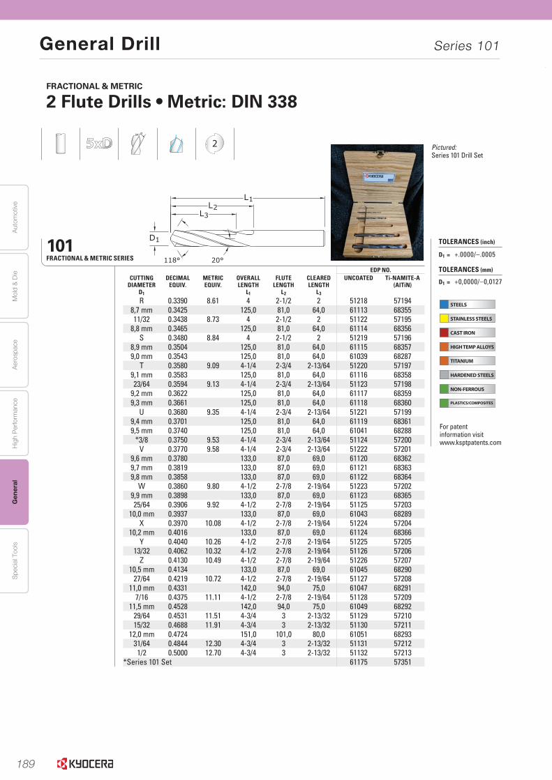
189
Aut
omot
ive
Aer
ospa
ceH
igh
Per
form
ance
Gen
eral
Spe
cial
Too
lsM
old
& D
ie
General Drill Series 101
DRILLS DRILLS306www.kyocera-sgstool.com
EDP NO.CUTTING
DIAMETERD1
DECIMALEQUIV.
METRICEQUIV.
OVERALL LENGTH
L1
FLUTE LENGTH
L2
CLEAREDLENGTH
L3
UNCOATED Ti-NAMITE-A (AlTiN)
R 0.3390 8.61 4 2-1/2 2 51218 571948,7 mm 0.3425 125,0 81,0 64,0 61113 6835511/32 0.3438 8.73 4 2-1/2 2 51122 57195
8,8 mm 0.3465 125,0 81,0 64,0 61114 68356S 0.3480 8.84 4 2-1/2 2 51219 57196
8,9 mm 0.3504 125,0 81,0 64,0 61115 683579,0 mm 0.3543 125,0 81,0 64,0 61039 68287
T 0.3580 9.09 4-1/4 2-3/4 2-13/64 51220 571979,1 mm 0.3583 125,0 81,0 64,0 61116 6835823/64 0.3594 9.13 4-1/4 2-3/4 2-13/64 51123 57198
9,2 mm 0.3622 125,0 81,0 64,0 61117 683599,3 mm 0.3661 125,0 81,0 64,0 61118 68360
U 0.3680 9.35 4-1/4 2-3/4 2-13/64 51221 571999,4 mm 0.3701 125,0 81,0 64,0 61119 683619,5 mm 0.3740 125,0 81,0 64,0 61041 68288
*3/8 0.3750 9.53 4-1/4 2-3/4 2-13/64 51124 57200V 0.3770 9.58 4-1/4 2-3/4 2-13/64 51222 57201
9,6 mm 0.3780 133,0 87,0 69,0 61120 683629,7 mm 0.3819 133,0 87,0 69,0 61121 683639,8 mm 0.3858 133,0 87,0 69,0 61122 68364
W 0.3860 9.80 4-1/2 2-7/8 2-19/64 51223 572029,9 mm 0.3898 133,0 87,0 69,0 61123 6836525/64 0.3906 9.92 4-1/2 2-7/8 2-19/64 51125 57203
10,0 mm 0.3937 133,0 87,0 69,0 61043 68289X 0.3970 10.08 4-1/2 2-7/8 2-19/64 51224 57204
10,2 mm 0.4016 133,0 87,0 69,0 61124 68366Y 0.4040 10.26 4-1/2 2-7/8 2-19/64 51225 57205
13/32 0.4062 10.32 4-1/2 2-7/8 2-19/64 51126 57206Z 0.4130 10.49 4-1/2 2-7/8 2-19/64 51226 57207
10,5 mm 0.4134 133,0 87,0 69,0 61045 6829027/64 0.4219 10.72 4-1/2 2-7/8 2-19/64 51127 57208
11,0 mm 0.4331 142,0 94,0 75,0 61047 682917/16 0.4375 11.11 4-1/2 2-7/8 2-19/64 51128 57209
11,5 mm 0.4528 142,0 94,0 75,0 61049 6829229/64 0.4531 11.51 4-3/4 3 2-13/32 51129 5721015/32 0.4688 11.91 4-3/4 3 2-13/32 51130 57211
12,0 mm 0.4724 151,0 101,0 80,0 61051 6829331/64 0.4844 12.30 4-3/4 3 2-13/32 51131 57212
1/2 0.5000 12.70 4-3/4 3 2-13/32 51132 57213*Series 101 Set 61175 57351
101FRACTIONAL & METRIC SERIES
2
FRACTIONAL & METRIC
2 Flute Drills • Metric: DIN 338
STEELS
STAINLESS STEELS
CAST IRON
HIGH TEMP ALLOYS
TITANIUM
HARDENED STEELS
NON-FERROUS
PLASTICS/COMPOSITES
TOLERANCES (inch)
D1 = +.0000/–.0005
TOLERANCES (mm)
D1 = +0,0000/–0,0127
For patent information visit www.ksptpatents.com
Pictured: Series 101 Drill Set
DRILLS DRILLS 307www.kyocera-sgstool.com
mm EDP NO,CUTTING
DIAMETERD1 / D2
OVERALLLENGTH
L1
FLUTE LENGTH
L2
CLEAREDLENGTH
L3
UNCOATED Ti-NAMITE-A(AlTiN)
0,5 20,0 3,0 – 62001 686430,55 21,0 3,5 – 62003 686440,6 21,0 3,5 – 62005 68645
0,65 22,0 4,0 – 62007 686460,7 23,0 4,5 – 62009 68647
0,75 23,0 4,5 – 62011 686480,8 24,0 5,0 – 62013 68649
0,85 24,0 5,0 – 62015 686500,9 25,0 5,5 4,0 62017 68651
0,95 25,0 5,5 4,0 62019 686521,0 26,0 6,0 4,7 62021 68653
1,05 26,0 6,0 4,7 62023 686541,1 28,0 7,0 5,4 62025 68655
1,15 28,0 7,0 5,4 62027 686561,2 30,0 8,0 6,0 62029 68657
1,25 30,0 8,0 6,0 62031 686581,3 30,0 8,0 6,0 62033 68659
1,35 32,0 9,0 7,0 62035 686601,4 32,0 9,0 7,0 62037 68661
1,45 32,0 9,0 7,0 62039 686621,5 32,0 9,0 7,0 62041 686631,6 34,0 10,0 7,0 62043 686641,7 34,0 10,0 7,0 62045 686651,8 36,0 11,0 8,0 62047 686661,9 36,0 11,0 8,0 62049 686672,0 38,0 12,0 9,0 62051 686682,1 38,0 12,0 9,0 62053 686692,2 40,0 13,0 10,0 62055 686702,3 40,0 13,0 10,0 62057 686712,4 43,0 14,0 11,0 62059 686722,5 43,0 14,0 11,0 62061 686732,6 43,0 14,0 11,0 62063 686742,7 46,0 16,0 12,0 62065 686752,8 46,0 16,0 12,0 62067 68676
continued on next page
METRIC
Short Length Self Centering Drills • DIN 6539
2
108M PlusMETRIC SERIES
TOLERANCES (mm)
≤3 DIAMETER
D1 = +0,000/–0,010D2 = h6
>3–6 DIAMETER
D1 = +0,000/–0,012D2 = h6
>6–10 DIAMETER
D1 = +0,000/–0,015D2 = h6
>10–18 DIAMETER
D1 = +0,000/–0,018D2 = h6
STEELS
STAINLESS STEELS
CAST IRON
HIGH TEMP ALLOYS
TITANIUM
HARDENED STEELS
NON-FERROUS
PLASTICS/COMPOSITES
For patent information visit www.ksptpatents.com

190
Autom
otiveA
erospaceH
igh Perform
anceG
eneralS
pecial ToolsM
old & D
ie
General Drill Series 108M
DRILLS DRILLS 307www.kyocera-sgstool.com
mm EDP NO,CUTTING
DIAMETERD1 / D2
OVERALLLENGTH
L1
FLUTE LENGTH
L2
CLEAREDLENGTH
L3
UNCOATED Ti-NAMITE-A(AlTiN)
0,5 20,0 3,0 – 62001 686430,55 21,0 3,5 – 62003 686440,6 21,0 3,5 – 62005 68645
0,65 22,0 4,0 – 62007 686460,7 23,0 4,5 – 62009 68647
0,75 23,0 4,5 – 62011 686480,8 24,0 5,0 – 62013 68649
0,85 24,0 5,0 – 62015 686500,9 25,0 5,5 4,0 62017 68651
0,95 25,0 5,5 4,0 62019 686521,0 26,0 6,0 4,7 62021 68653
1,05 26,0 6,0 4,7 62023 686541,1 28,0 7,0 5,4 62025 68655
1,15 28,0 7,0 5,4 62027 686561,2 30,0 8,0 6,0 62029 68657
1,25 30,0 8,0 6,0 62031 686581,3 30,0 8,0 6,0 62033 68659
1,35 32,0 9,0 7,0 62035 686601,4 32,0 9,0 7,0 62037 68661
1,45 32,0 9,0 7,0 62039 686621,5 32,0 9,0 7,0 62041 686631,6 34,0 10,0 7,0 62043 686641,7 34,0 10,0 7,0 62045 686651,8 36,0 11,0 8,0 62047 686661,9 36,0 11,0 8,0 62049 686672,0 38,0 12,0 9,0 62051 686682,1 38,0 12,0 9,0 62053 686692,2 40,0 13,0 10,0 62055 686702,3 40,0 13,0 10,0 62057 686712,4 43,0 14,0 11,0 62059 686722,5 43,0 14,0 11,0 62061 686732,6 43,0 14,0 11,0 62063 686742,7 46,0 16,0 12,0 62065 686752,8 46,0 16,0 12,0 62067 68676
continued on next page
METRIC
Short Length Self Centering Drills • DIN 6539
2
108M PlusMETRIC SERIES
TOLERANCES (mm)
≤3 DIAMETER
D1 = +0,000/–0,010D2 = h6
>3–6 DIAMETER
D1 = +0,000/–0,012D2 = h6
>6–10 DIAMETER
D1 = +0,000/–0,015D2 = h6
>10–18 DIAMETER
D1 = +0,000/–0,018D2 = h6
STEELS
STAINLESS STEELS
CAST IRON
HIGH TEMP ALLOYS
TITANIUM
HARDENED STEELS
NON-FERROUS
PLASTICS/COMPOSITES
For patent information visit www.ksptpatents.com

191
Aut
omot
ive
Aer
ospa
ceH
igh
Per
form
ance
Gen
eral
Spe
cial
Too
lsM
old
& D
ie
General Drill Series 108M
DRILLS DRILLS308www.kyocera-sgstool.com
mm EDP NO,CUTTING
DIAMETERD1 / D2
OVERALLLENGTH
L1
FLUTE LENGTH
L2
CLEAREDLENGTH
L3
UNCOATED Ti-NAMITE-A(AlTiN)
2,9 46,0 16,0 12,0 62069 686773,0 46,0 16,0 12,0 62071 686783,1 49,0 18,0 14,0 62073 686793,2 49,0 18,0 14,0 62075 686803,3 49,0 18,0 14,0 62077 686813,4 52,0 20,0 15,0 62079 686823,5 52,0 20,0 15,0 62081 686833,6 52,0 20,0 15,0 62083 686843,7 52,0 20,0 15,0 62085 686853,8 55,0 22,0 17,0 62087 686863,9 55,0 22,0 17,0 62089 686874,0 55,0 22,0 17,0 62091 686884,1 55,0 22,0 17,0 62093 686894,2 55,0 22,0 17,0 62095 686904,3 58,0 24,0 18,0 62097 686914,4 58,0 24,0 18,0 62099 686924,5 58,0 24,0 18,0 62101 686934,6 58,0 24,0 18,0 62103 686944,7 58,0 24,0 18,0 62105 686954,8 62,0 26,0 20,0 62107 686964,9 62,0 26,0 20,0 62109 686975,0 62,0 26,0 20,0 62111 686985,1 62,0 26,0 20,0 62113 686995,2 62,0 26,0 20,0 62115 687005,3 62,0 26,0 20,0 62117 687015,4 66,0 28,0 21,0 62119 687025,5 66,0 28,0 21,0 62121 687035,6 66,0 28,0 21,0 62123 687045,7 66,0 28,0 21,0 62125 687055,8 66,0 28,0 21,0 62127 687065,9 66,0 28,0 21,0 62129 687076,0 66,0 28,0 21,0 62131 68708
continued on next page
METRIC
Short Length Self Centering Drills • DIN 6539
TOLERANCES (mm)
≤3 DIAMETER
D1 = +0,000/–0,010D2 = h6
>3–6 DIAMETER
D1 = +0,000/–0,012D2 = h6
>6–10 DIAMETER
D1 = +0,000/–0,015D2 = h6
>10–16 DIAMETER
D1 = +0,000/–0,018D2 = h6
2
108M PlusMETRIC SERIES
STEELS
STAINLESS STEELS
CAST IRON
HIGH TEMP ALLOYS
TITANIUM
HARDENED STEELS
NON-FERROUS
PLASTICS/COMPOSITES
For patent information visit www.ksptpatents.com
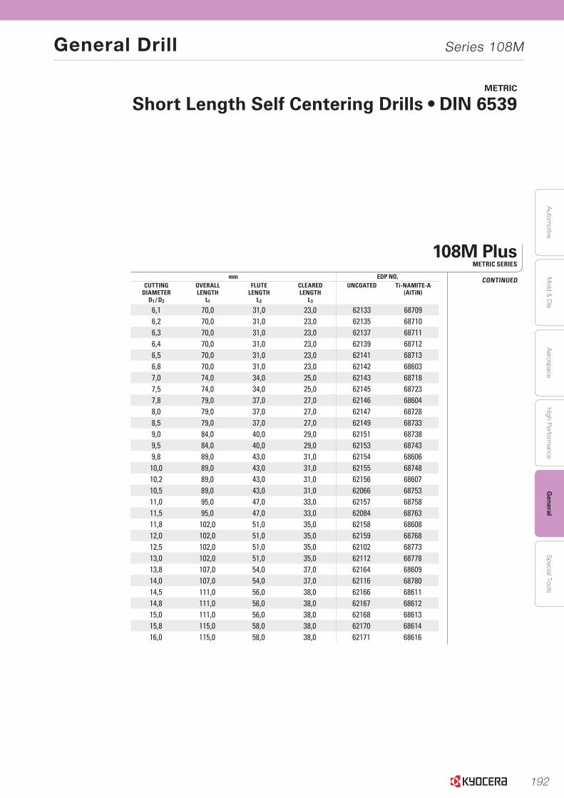
192
Autom
otiveA
erospaceH
igh Perform
anceG
eneralS
pecial ToolsM
old & D
ie
General Drill Series 108M
DRILLS DRILLS 309www.kyocera-sgstool.com
mm EDP NO,CUTTING
DIAMETERD1 / D2
OVERALLLENGTH
L1
FLUTE LENGTH
L2
CLEAREDLENGTH
L3
UNCOATED Ti-NAMITE-A(AlTiN)
6,1 70,0 31,0 23,0 62133 687096,2 70,0 31,0 23,0 62135 687106,3 70,0 31,0 23,0 62137 687116,4 70,0 31,0 23,0 62139 687126,5 70,0 31,0 23,0 62141 687136,8 70,0 31,0 23,0 62142 686037,0 74,0 34,0 25,0 62143 687187,5 74,0 34,0 25,0 62145 687237,8 79,0 37,0 27,0 62146 686048,0 79,0 37,0 27,0 62147 687288,5 79,0 37,0 27,0 62149 687339,0 84,0 40,0 29,0 62151 687389,5 84,0 40,0 29,0 62153 687439,8 89,0 43,0 31,0 62154 68606
10,0 89,0 43,0 31,0 62155 6874810,2 89,0 43,0 31,0 62156 6860710,5 89,0 43,0 31,0 62066 6875311,0 95,0 47,0 33,0 62157 6875811,5 95,0 47,0 33,0 62084 6876311,8 102,0 51,0 35,0 62158 6860812,0 102,0 51,0 35,0 62159 6876812,5 102,0 51,0 35,0 62102 6877313,0 102,0 51,0 35,0 62112 6877813,8 107,0 54,0 37,0 62164 6860914,0 107,0 54,0 37,0 62116 6878014,5 111,0 56,0 38,0 62166 6861114,8 111,0 56,0 38,0 62167 6861215,0 111,0 56,0 38,0 62168 6861315,8 115,0 58,0 38,0 62170 6861416,0 115,0 58,0 38,0 62171 68616
METRIC
Short Length Self Centering Drills • DIN 6539
108M PlusMETRIC SERIES
CONTINUED
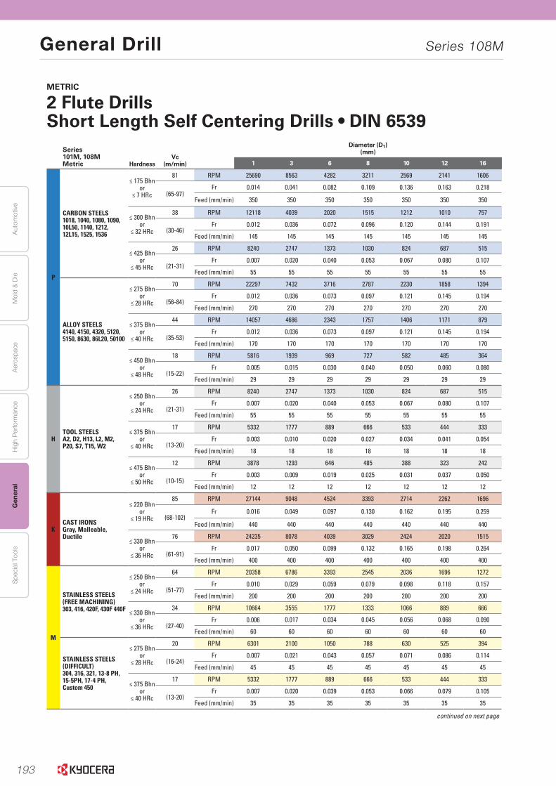
193
Aut
omot
ive
Aer
ospa
ceH
igh
Per
form
ance
Gen
eral
Spe
cial
Too
lsM
old
& D
ie
General Drill Series 108M
DRILLS DRILLS312www.kyocera-sgstool.com
METRIC
2 Flute DrillsShort Length Self Centering Drills • DIN 6539
Series 101M, 108MMetric Hardness
Vc (m/min)
Diameter (D1)(mm)
1 3 6 8 10 12 16
P
CARBON STEELS1018, 1040, 1080, 1090, 10L50, 1140, 1212, 12L15, 1525, 1536
≤ 175 Bhnor
≤ 7 HRc
81 RPM 25690 8563 4282 3211 2569 2141 1606
(65-97)Fr 0.014 0.041 0.082 0.109 0.136 0.163 0.218
Feed (mm/min) 350 350 350 350 350 350 350
≤ 300 Bhnor
≤ 32 HRc
38 RPM 12118 4039 2020 1515 1212 1010 757
(30-46)Fr 0.012 0.036 0.072 0.096 0.120 0.144 0.191
Feed (mm/min) 145 145 145 145 145 145 145
≤ 425 Bhnor
≤ 45 HRc
26 RPM 8240 2747 1373 1030 824 687 515
(21-31)Fr 0.007 0.020 0.040 0.053 0.067 0.080 0.107
Feed (mm/min) 55 55 55 55 55 55 55
ALLOY STEELS4140, 4150, 4320, 5120, 5150, 8630, 86L20, 50100
≤ 275 Bhnor
≤ 28 HRc
70 RPM 22297 7432 3716 2787 2230 1858 1394
(56-84)Fr 0.012 0.036 0.073 0.097 0.121 0.145 0.194
Feed (mm/min) 270 270 270 270 270 270 270
≤ 375 Bhnor
≤ 40 HRc
44 RPM 14057 4686 2343 1757 1406 1171 879
(35-53)Fr 0.012 0.036 0.073 0.097 0.121 0.145 0.194
Feed (mm/min) 170 170 170 170 170 170 170
≤ 450 Bhnor
≤ 48 HRc
18 RPM 5816 1939 969 727 582 485 364
(15-22)Fr 0.005 0.015 0.030 0.040 0.050 0.060 0.080
Feed (mm/min) 29 29 29 29 29 29 29
HTOOL STEELSA2, D2, H13, L2, M2, P20, S7, T15, W2
≤ 250 Bhnor
≤ 24 HRc
26 RPM 8240 2747 1373 1030 824 687 515
(21-31)Fr 0.007 0.020 0.040 0.053 0.067 0.080 0.107
Feed (mm/min) 55 55 55 55 55 55 55
≤ 375 Bhnor
≤ 40 HRc
17 RPM 5332 1777 889 666 533 444 333
(13-20)Fr 0.003 0.010 0.020 0.027 0.034 0.041 0.054
Feed (mm/min) 18 18 18 18 18 18 18
≤ 475 Bhnor
≤ 50 HRc
12 RPM 3878 1293 646 485 388 323 242
(10-15)Fr 0.003 0.009 0.019 0.025 0.031 0.037 0.050
Feed (mm/min) 12 12 12 12 12 12 12
KCAST IRONSGray, Malleable, Ductile
≤ 220 Bhnor
≤ 19 HRc
85 RPM 27144 9048 4524 3393 2714 2262 1696
(68-102)Fr 0.016 0.049 0.097 0.130 0.162 0.195 0.259
Feed (mm/min) 440 440 440 440 440 440 440
≤ 330 Bhnor
≤ 36 HRc
76 RPM 24235 8078 4039 3029 2424 2020 1515
(61-91)Fr 0.017 0.050 0.099 0.132 0.165 0.198 0.264
Feed (mm/min) 400 400 400 400 400 400 400
M
STAINLESS STEELS(FREE MACHINING)303, 416, 420F, 430F 440F
≤ 250 Bhnor
≤ 24 HRc
64 RPM 20358 6786 3393 2545 2036 1696 1272
(51-77)Fr 0.010 0.029 0.059 0.079 0.098 0.118 0.157
Feed (mm/min) 200 200 200 200 200 200 200
≤ 330 Bhnor
≤ 36 HRc
34 RPM 10664 3555 1777 1333 1066 889 666
(27-40)Fr 0.006 0.017 0.034 0.045 0.056 0.068 0.090
Feed (mm/min) 60 60 60 60 60 60 60
STAINLESS STEELS (DIFFICULT)304, 316, 321, 13-8 PH, 15-5PH, 17-4 PH, Custom 450
≤ 275 Bhnor
≤ 28 HRc
20 RPM 6301 2100 1050 788 630 525 394
(16-24)Fr 0.007 0.021 0.043 0.057 0.071 0.086 0.114
Feed (mm/min) 45 45 45 45 45 45 45
≤ 375 Bhnor
≤ 40 HRc
17 RPM 5332 1777 889 666 533 444 333
(13-20)Fr 0.007 0.020 0.039 0.053 0.066 0.079 0.105
Feed (mm/min) 35 35 35 35 35 35 35
continued on next page
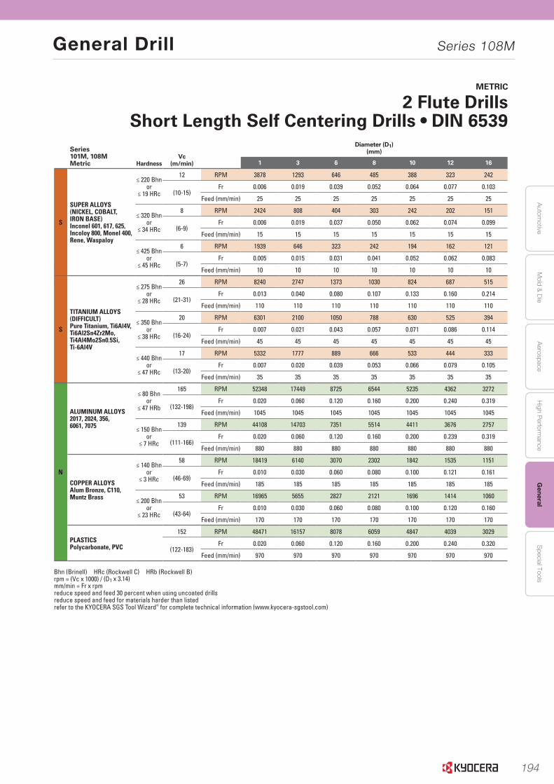
194
Autom
otiveA
erospaceH
igh Perform
anceG
eneralS
pecial ToolsM
old & D
ie
General Drill Series 108M
DRILLS DRILLS 313www.kyocera-sgstool.com
METRIC
2 Flute DrillsShort Length Self Centering Drills • DIN 6539
Series 101M, 108MMetric Hardness
Vc (m/min)
Diameter (D1)(mm)
1 3 6 8 10 12 16
S
SUPER ALLOYS(NICKEL, COBALT, IRON BASE) Inconel 601, 617, 625, Incoloy 800, Monel 400, Rene, Waspaloy
≤ 220 Bhnor
≤ 19 HRc
12 RPM 3878 1293 646 485 388 323 242
(10-15)Fr 0.006 0.019 0.039 0.052 0.064 0.077 0.103
Feed (mm/min) 25 25 25 25 25 25 25
≤ 320 Bhnor
≤ 34 HRc
8 RPM 2424 808 404 303 242 202 151
(6-9)Fr 0.006 0.019 0.037 0.050 0.062 0.074 0.099
Feed (mm/min) 15 15 15 15 15 15 15
≤ 425 Bhnor
≤ 45 HRc
6 RPM 1939 646 323 242 194 162 121
(5-7)Fr 0.005 0.015 0.031 0.041 0.052 0.062 0.083
Feed (mm/min) 10 10 10 10 10 10 10
S
TITANIUM ALLOYS (DIFFICULT) Pure Titanium, Ti6Al4V,Ti6Al2Sn4Zr2Mo,Ti4Al4Mo2Sn0.5Si,Ti-6Al4V
≤ 275 Bhnor
≤ 28 HRc
26 RPM 8240 2747 1373 1030 824 687 515
(21-31)Fr 0.013 0.040 0.080 0.107 0.133 0.160 0.214
Feed (mm/min) 110 110 110 110 110 110 110
≤ 350 Bhnor
≤ 38 HRc
20 RPM 6301 2100 1050 788 630 525 394
(16-24)Fr 0.007 0.021 0.043 0.057 0.071 0.086 0.114
Feed (mm/min) 45 45 45 45 45 45 45
≤ 440 Bhnor
≤ 47 HRc
17 RPM 5332 1777 889 666 533 444 333
(13-20)Fr 0.007 0.020 0.039 0.053 0.066 0.079 0.105
Feed (mm/min) 35 35 35 35 35 35 35
N
ALUMINUM ALLOYS2017, 2024, 356, 6061, 7075
≤ 80 Bhnor
≤ 47 HRb
165 RPM 52348 17449 8725 6544 5235 4362 3272
(132-198)Fr 0.020 0.060 0.120 0.160 0.200 0.240 0.319
Feed (mm/min) 1045 1045 1045 1045 1045 1045 1045
≤ 150 Bhnor
≤ 7 HRc
139 RPM 44108 14703 7351 5514 4411 3676 2757
(111-166)Fr 0.020 0.060 0.120 0.160 0.200 0.239 0.319
Feed (mm/min) 880 880 880 880 880 880 880
COPPER ALLOYSAlum Bronze, C110, Muntz Brass
≤ 140 Bhnor
≤ 3 HRc
58 RPM 18419 6140 3070 2302 1842 1535 1151
(46-69)Fr 0.010 0.030 0.060 0.080 0.100 0.121 0.161
Feed (mm/min) 185 185 185 185 185 185 185
≤ 200 Bhnor
≤ 23 HRc
53 RPM 16965 5655 2827 2121 1696 1414 1060
(43-64)Fr 0.010 0.030 0.060 0.080 0.100 0.120 0.160
Feed (mm/min) 170 170 170 170 170 170 170
PLASTICSPolycarbonate, PVC
152 RPM 48471 16157 8078 6059 4847 4039 3029
(122-183)Fr 0.020 0.060 0.120 0.160 0.200 0.240 0.320
Feed (mm/min) 970 970 970 970 970 970 970
Bhn (Brinell) HRc (Rockwell C) HRb (Rockwell B)rpm = (Vc x 1000) / (D1 x 3.14)mm/min = Fr x rpmreduce speed and feed 30 percent when using uncoated drills reduce speed and feed for materials harder than listedrefer to the KYOCERA SGS Tool Wizard® for complete technical information (www.kyocera-sgstool.com)
195
PCD Tools
UM DANDIA™ tooling solutions for the automotive industry
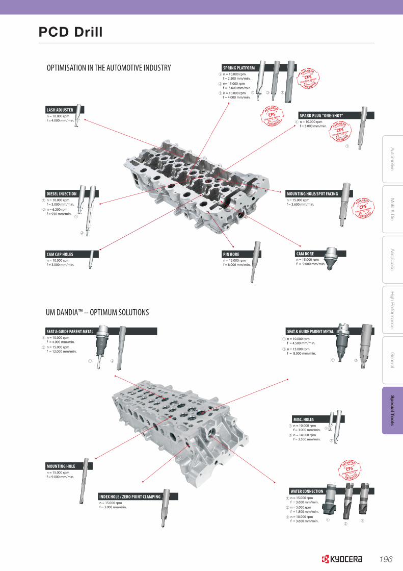
196
Autom
otiveA
erospaceH
igh Perform
anceG
eneralS
pecial ToolsM
old & D
ie
PCD Drill
LASH ADJUSTER
DIESEL INJECTION
CAM CAP HOLES
2
1
1
2
OPTIMISATION IN THE AUTOMOTIVE INDUSTRY
n = 10.000 rpmf = 4.000 mm/min.
n = 10.000 rpmf = 3.000 mm/min. n = 6.200 rpmf = 930 mm/min.
n = 10.000 rpmf = 3.000 mm/min.
PIN BORE CAM BORE
MOUNTING HOLE/SPOT FACING
SPRING PLATFORM
CFSChip Flow System
PATENTED
P A T E N T E D
CFSChip Flow System
PATENTED
P A T E N T E D
CFSChip Flow System
CFSChip Flow System
CFSChip Flow System
PATENTED
P A T E N T E D
2
1
3 1 2 3 CFSChip Flow System
Chip Flow System
CFSChip Flow System
PATENTED
P A T E N T E D
n = 15.000 rpm f = 8.000 mm/min.
n = 15.000 rpm f = 9.000 mm/min.
n = 15.000 rpm f = 3.600 mm/min.
n = 10.000 rpm f = 3.000 mm/min.
n = 10.000 rpm f = 2.500 mm/min. n= 15.000 rpm f = 3.600 mm/min.n = 10.000 rpm f = 4.000 mm/min.
1
SPARK PLUG ”ONE-SHOT”
1
6
SEAT & GUIDE PARENT METAL
MOUNTING HOLE
UM DANDIA™ – OPTIMUM SOLUTIONS
1 2
2
1 n = 10.000 rpmf = 4.000 mm/min.
n = 15.000 rpmf = 12.000 mm/min.
n = 15.000 rpmf = 9.000 mm/min.
INDEX HOLE / ZERO POINT CLAMPINGn = 15.000 rpmf = 3.000 mm/min.
7
SEAT & GUIDE PARENT METAL
MISC. HOLES
WATER CONNECTION
1
2
1
2
1
2
CFSChip Flow System
PATENTED
P A T E N T E D
n = 10.000 rpmf = 4.500 mm/min.
n = 15.000 rpmf = 8.000 mm/min.
n = 10.000 rpmf = 3.000 mm/min.
n = 14.000 rpmf = 3.500 mm/min.
n = 15.000 rpmf = 3.600 mm/min.
n = 5.000 rpmf = 1.800 mm/min.
n = 10.000 rpmf = 3.600 mm/min.
12
3
1 2
1
2
3
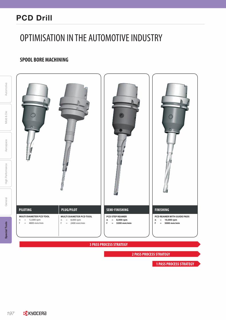
197
Aut
omot
ive
Aer
ospa
ceH
igh
Per
form
ance
Gen
eral
Spe
cial
Too
lsM
old
& D
ie
PCD Drill
SPOOL BORE MACHINING
OPTIMISATION IN THE AUTOMOTIVE INDUSTRY
PILOTING PLUG/PILOT SEMI-FINISHING FINISHING
MULTI DIAMETER PCD TOOLn = 12,000 rpm f = 4800 mm/min
MULTI DIAMETER PCD TOOLn = 8,000 rpm f = 2400 mm/min
PCD STEP REAMERn = 8,000 rpm f = 3200 mm/min
PCD REAMER WITH GUIDE PADSn = 10,000 rpm f = 5000 mm/min
3 PASS PROCESS STRATEGY
2 PASS PROCESS STRATEGY
1 PASS PROCESS STRATEGY
n = 3000 RPM fn = 0,3 mm/rev.
n = 3000 RPM fn = 0,3 mm/rev.
4
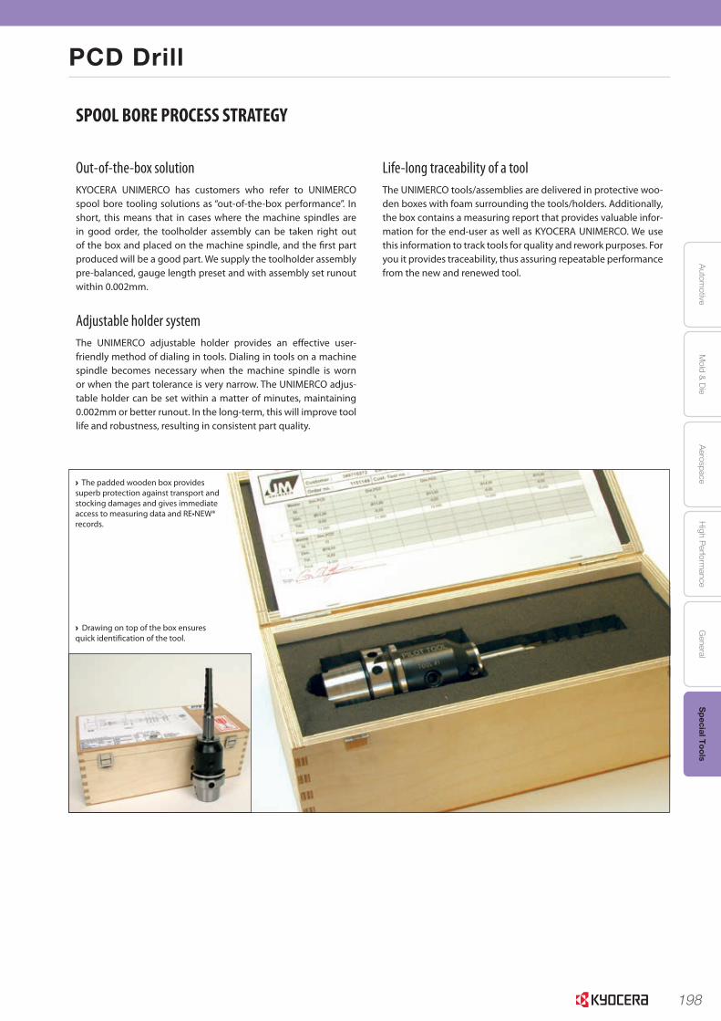
198
Autom
otiveA
erospaceH
igh Perform
anceG
eneralS
pecial ToolsM
old & D
ie
PCD Drill
SPOOL BORE PROCESS STRATEGY
Out-of-the-box solutionKYOCERA UNIMERCO has customers who refer to UNIMERCO spool bore tooling solutions as “out-of-the-box performance”. In short, this means that in cases where the machine spindles are in good order, the toolholder assembly can be taken right out of the box and placed on the machine spindle, and the first part produced will be a good part. We supply the toolholder assembly pre-balanced, gauge length preset and with assembly set runout within 0.002mm.
Adjustable holder systemThe UNIMERCO adjustable holder provides an effective user-friendly method of dialing in tools. Dialing in tools on a machine spindle becomes necessary when the machine spindle is worn or when the part tolerance is very narrow. The UNIMERCO adjus-table holder can be set within a matter of minutes, maintaining 0.002mm or better runout. In the long-term, this will improve tool life and robustness, resulting in consistent part quality.
Life-long traceability of a toolThe UNIMERCO tools/assemblies are delivered in protective woo-den boxes with foam surrounding the tools/holders. Additionally, the box contains a measuring report that provides valuable infor-mation for the end-user as well as KYOCERA UNIMERCO. We use this information to track tools for quality and rework purposes. For you it provides traceability, thus assuring repeatable performance from the new and renewed tool.
› The padded wooden box provides superb protection against transport and stocking damages and gives immediate access to measuring data and RE•NEW® records.
› Drawing on top of the box ensures quick identification of the tool.
6
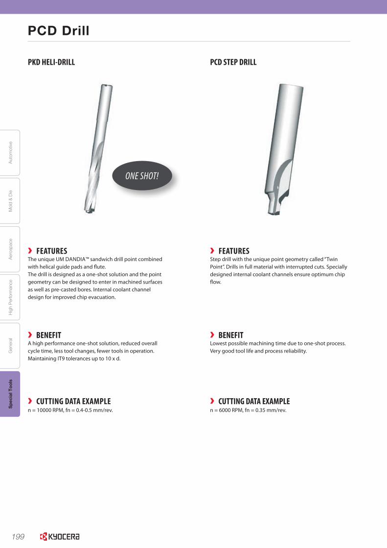
199
Aut
omot
ive
Aer
ospa
ceH
igh
Per
form
ance
Gen
eral
Spe
cial
Too
lsM
old
& D
ie
PCD Drill
4
PCD drills
› FEATURES› FEATURES
› BENEFIT› BENEFIT
PKD HELI-DRILL PCD STEP DRILL
› CUTTING DATA EXAMPLE› CUTTING DATA EXAMPLE
Step drill with the unique point geometry called “Twin Point”. Drills in full material with interrupted cuts. Specially designed internal coolant channels ensure optimum chip flow.
The unique UM DANDIA™ sandwich drill point combined with helical guide pads and flute.The drill is designed as a one-shot solution and the point geometry can be designed to enter in machined surfaces as well as pre-casted bores. Internal coolant channel design for improved chip evacuation.
Lowest possible machining time due to one-shot process. Very good tool life and process reliability.
A high performance one-shot solution, reduced overall cycle time, less tool changes, fewer tools in operation. Maintaining IT9 tolerances up to 10 x d.
n = 6000 RPM, fn = 0.35 mm/rev.n = 10000 RPM, fn = 0.4-0.5 mm/rev.
ONE SHOT!
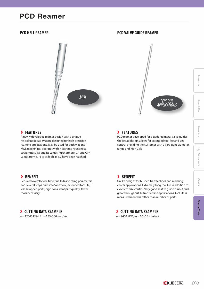
200
Autom
otiveA
erospaceH
igh Perform
anceG
eneralS
pecial ToolsM
old & D
ie
PCD Reamer
5
PCD reamers
› FEATURES › FEATURES
› BENEFIT › BENEFIT
PCD HELI-REAMER PCD VALVE GUIDE REAMER
› CUTTING DATA EXAMPLE› CUTTING DATA EXAMPLE
A newly developed reamer design with a unique helical guidepad system, designed for high precision reaming applications. May be used for both wet and MQL machining, operates within extreme roundness, straightness, Ra and Rz values. Furthermore, CP and CPK values from 3.16 to as high as 6.7 have been reached.
PCD reamer developed for powdered metal valve guides Guidepad design allows for extended tool life and size control providing the customer with a very tight diameter range and high Cpk.
Reduced overall cycle time due to fast cutting parameters and several steps built into “one” tool, extended tool life, less scrapped parts, high consistent part quality, fewer tools necessary.
Unlike designs for bushed transfer lines and maching center applications. Extremely long tool life in addition to excellent size control. Very good seat to guide runout and great throughput. In transfer line applications, tool life is measured in weeks rather than number of parts.
n = 2400 RPM, fn = 0.2-0.3 mm/rev.n = 12000 RPM, fn = 0.35-0.50 mm/rev.
MQLFERROUS
APPLICATIONS
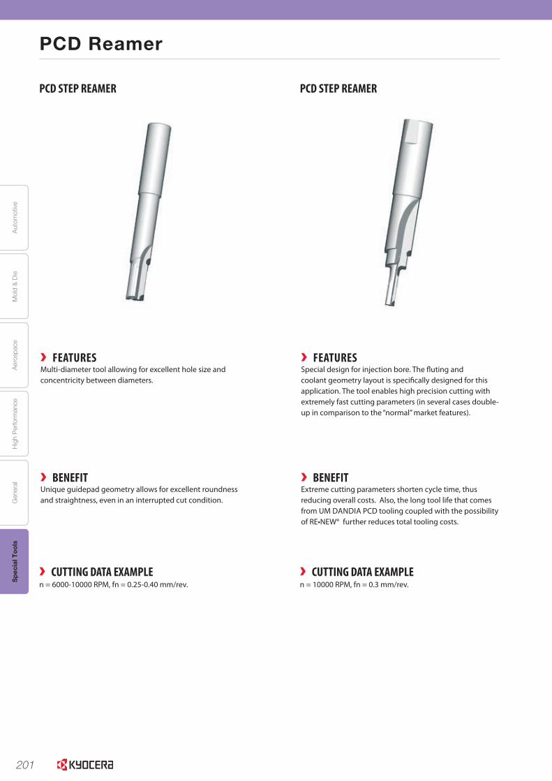
201
Aut
omot
ive
Aer
ospa
ceH
igh
Per
form
ance
Gen
eral
Spe
cial
Too
lsM
old
& D
ie
PCD Reamer
6
PCD reamers
› FEATURES› FEATURES
› BENEFIT› BENEFIT
Special design for injection bore. The fluting and coolant geometry layout is specifically designed for this application. The tool enables high precision cutting with extremely fast cutting parameters (in several cases double-up in comparison to the “normal” market features).
Multi-diameter tool allowing for excellent hole size and concentricity between diameters.
Extreme cutting parameters shorten cycle time, thus reducing overall costs. Also, the long tool life that comes from UM DANDIA PCD tooling coupled with the possibility of RE•NEW® further reduces total tooling costs.
Unique guidepad geometry allows for excellent roundness and straightness, even in an interrupted cut condition.
› CUTTING DATA EXAMPLE› CUTTING DATA EXAMPLEn = 10000 RPM, fn = 0.3 mm/rev. n = 6000-10000 RPM, fn = 0.25-0.40 mm/rev.
PCD STEP REAMER PCD STEP REAMER
202
Autom
otiveA
erospaceH
igh Perform
anceG
eneralS
pecial ToolsM
old & D
ie
PCD Reamer
7
› FEATURES › FEATURES
› BENEFIT › BENEFIT
Monoblock reamer with uneven number of inserts allowing for excellent hole size and surface quality. The integrated spindle adapter and multiple step diameters ensure good concentricity between diameters. Internal coolant channel design for improved chip evacuation.
Combining reamer and profile geometry on the PCD inserts, this multi-purpose PCD tool is able to cut three different difficult features in.
Fluting and cutting geometries developed specifically for this application.
Reduced overall costs, due to reduction in cycle time provided by the very high cutting parameters. The very long tool life means that fewer tools are needed – also due to the possibility to RE•NEW® the tools.
This combination reamer enables reduced overall cycle time due to fewer operations and increased cutting parameters.
› CUTTING DATA EXAMPLE› CUTTING DATA EXAMPLEn = 8000-15000 RPM, fn = 0.3-0.5 mm/rev. n = 5000-7000 RPM, fn = 0.3-0.5 mm/.
PCD STEP REAMER PCD STEP/PROFILE REAMER
203
Aut
omot
ive
Aer
ospa
ceH
igh
Per
form
ance
Gen
eral
Spe
cial
Too
lsM
old
& D
ie
PCD Combination Tool
8
PCD combination tools
› FEATURES› FEATURES
› BENEFIT› BENEFIT
A special 2-fluted tool design for the shrink fit holder system. First step is drilling in solid material and the remaining steps are reaming pre-casted material. Internal coolant channel design for improved chip evacuation.
A specially designed PCD insert and flute geometry combining several operations in one tool. Ensures a vibration -free finishing of all valve bore diameters in one pass, creates different surface roughness values within a specified range and a T-groove geometry.
One-shot solution, reduced overall cycle time, less tool changes, fewer tools in operation.
Reduced overall cycle time with the multi tasking tool design due to reduction of tool changes and number of tools necessary.
› CUTTING DATA EXAMPLE› CUTTING DATA EXAMPLEn = 6500 RPM, fn = 0.3-0.4 mm/rev.n = 3000 RPM, fn = 0.2-0.3 mm/rev.
PCD STEP REAMER/MILL PCD STEP DRILL/REAMER

204
Autom
otiveA
erospaceH
igh Perform
anceG
eneralS
pecial ToolsM
old & D
ie
PCD Combination Tool
9
› FEATURES › FEATURES
› BENEFIT › BENEFIT
Special PCD tool design in the flute opening, coolant placement and guidepad geometry. This tool is available as either a combination tool, with solid carbide tool body for the PCD reamer and steel body for the PCD bushing, or as a one -piece construction.
Single flute, out-bore, multi diameter PCD tool. The different diameters can be adjusted separately fast and easy due to the unique UM DANDIA™ design. The toolholder / spindle adapter allows for customized design.
High cutting parameters yield reduced overall costs due to reduction in cycle time. Furthermore, fewer tools are required because of the long tool life coupled with our RE•NEW™ process.
Very accurate hole quality and production reliability. Extremely easy to run in and reduced overall cycle time due to the separate diameter adjustability.
› CUTTING DATA EXAMPLE› CUTTING DATA EXAMPLEn = 2000 - 4000 RPM, fn = 0.1-0.2 mm/rev.n = 8000 - 15000 RPM, fn = 0.25 - 08 mm/rev.
PCD REAMER/COUNTERSINK TOOL OUT-BORE PCD REAMER, ADJUSTABLE
IS09001JMI-0036
EC99J2032京セラ株式会社は、環境マネジメントシステムISO14001: 2004の認証を取得しています。
IS09001JMI-0036
EC99J2032京セラ株式会社は、環境マネジメントシステムISO14001: 2004の認証を取得しています。
KYOCERA Asia Pacific Pte. Ltd.http://www.kyocera.com.sg/products/cuttingtools/
2020 KYOCERA Round Tools Digest Catalog