medium power film capacitors - kyocera avx
TRANSCRIPT

Medium Power Film Capacitors
080621

IMPORTANT INFORMATION/DISCLAIMER
All product specifications, statements, information and data (collectively, the “Information”) in this datasheet or made available on the website are subject to change. The customer is responsible for checking and verifying the extent to which the Information contained in this publication is applicable to an order at the time the order is placed. All Information given herein is believed to be accurate and reliable, but it is presented without guarantee, warranty, or responsibility of any kind, expressed or implied.
Statements of suitability for certain applications are based on KYOCERA AVX’s knowledge of typical operating conditions for such applications, but are not intended to constitute and KYOCERA AVX specifically disclaims any warranty concerning suitability for a specific customer application or use.
ANY USE OF PRODUCT OUTSIDE OF SPECIFICATIONS OR ANY STORAGE OR INSTALLATION INCONSISTENT WITH PRODUCT GUIDANCE VOIDS ANY WARRANTY.
The Information is intended for use only by customers who have the requisite experience and capability to determine the correct products for their application. Any technical advice inferred from this Information or otherwise provided by KYOCERA AVX with reference to the use of KYOCERA AVX’s products is given without regard, and KYOCERA AVX assumes no obligation or liability for the advice given or results obtained.
Although KYOCERA AVX designs and manufactures its products to the most stringent quality and safety standards, given the current state of the art, isolated component failures may still occur. Accordingly, customer applications which require a high degree of reliability or safety should employ suitable designs or other safeguards (such as installation of protective circuitry or redundancies) in order to ensure that the failure of an electrical component does not result in a risk of personal injury or property damage.
Unless specifically agreed to in writing, KYOCERA AVX has not tested or certified its products, services or deliverables for use in high risk applications including medical life support, medical device, direct physical patient contact, water treatment, nuclear facilities, weapon systems, mass and air transportation control, flammable environments, or any other potentially life critical uses. Customer understands and agrees that KYOCERA AVX makes no assurances that the products, services or deliverables are suitable for any high-risk uses. Under no circumstances does KYOCERA AVX warrant or guarantee suitability for any customer design or manufacturing process.
Although all product–related warnings, cautions and notes must be observed, the customer should not assume that all safety measures are indicted or that other measures may not be required.
121119
– medium power film capacitors –
The Important Information/Disclaimer is incorporated in the catalog where these specifications came from or available online at www.avx.com/disclaimer/ by reference and should be reviewed in full before placing any order.

MEDIUM POWER FILM CAPACITORSTable of Contents
INTRODUCTIONGeneral Description .......................................................................................................................................................................................................1
DC FILTERINGFM* ...............................................................................................................................................................................................................................3FB* ................................................................................................................................................................................................................................8FE* ..............................................................................................................................................................................................................................19FFB* ............................................................................................................................................................................................................................33FFV3* ..........................................................................................................................................................................................................................37FFG Design (FFH-RoHS Compliant) ..............................................................................................................................................................................40FFVE/FFVI (FFWE/FFWI RoHS Compliant) ....................................................................................................................................................................43FFVS* ..........................................................................................................................................................................................................................47FFLR 600Vdc to 3800Vdc* ...........................................................................................................................................................................................49FFLI 800V to 1400Vdc* ................................................................................................................................................................................................55FFLI HV 1500V to 3800Vdc* ........................................................................................................................................................................................61FFPC 800Vdc to 3800Vdc ..........................................................................................................................................................................................67FFLC ............................................................................................................................................................................................................................77FFHV/FTHV 1600Vdc to 3000Vdc ................................................................................................................................................................................86
AC FILTERINGFV X2* .......................................................................................................................................................................................................................101FLC* ..........................................................................................................................................................................................................................106FLA* ..........................................................................................................................................................................................................................110FLB* ..........................................................................................................................................................................................................................115
PROTECTIONFSB* ..........................................................................................................................................................................................................................119FPX (FPY RoHS Compliant) ........................................................................................................................................................................................124FPG (FPH RoHS Compliant) .......................................................................................................................................................................................128
TUNINGFAV* ..........................................................................................................................................................................................................................131FAI* ...........................................................................................................................................................................................................................133
APPLICATION NOTES ............................................................................................................................................................................................142
SPECIFIC PRODUCT REQUEST...........................................................................................................................................................................148
In 1979, TPC (formerly LCC, then THOMSON-CSF PASSIVE COMPONENTS) developed CONTROLLED SELF-HEALING technology for medium power capacitors.These capacitors made great advances over previous technologies by combining the benefits of Controlled Self-Healing process with superior energy densities, making it one of the most compact capacitors on the market for 1/2 CV2.TPC produces both dry-wound and impregnated capacitors for medium voltage filtering, covering the whole spectrum from 75Vdc to 3kVdc.With CONTROLLED SELF-HEALING, the capacitance is divided into several million elementary capacitor elements protected by “fuse gates”. Weak points of the dielectric are insulated and the capacitor continues functioning normally without any short circuit or explosion.The capacitor acts like a battery. It “consumes” a certain amount of the capacitance through the gradual breakdown of the individual capacitance cells. Over the operating life of the capacitor, the capacitance gradually decreases. At the end of the capacitor’s life, the nominal capacitance will decrease down to either 2%, 5% or can be determined per customer requirements.
*RoHS Compliant Series as Standard
– medium power film capacitors –
The Important Information/Disclaimer is incorporated in the catalog where these specifications came from or available online at www.avx.com/disclaimer/ by reference and should be reviewed in full before placing any order.

1
General DescriptionINTRODUCTION
DC FILTERINGThe FF series use a wound metallized polypropylene or polyester dielectric. Dry segmented, wet segmented and wet non segmented metallization solutions have been developed to insure the controlled self healing process. The FF series are able to operate at a very high dielectric strength up to 105°C hot spot temperature. (see specific description) For more informations about the controlled self healing process and itsfeatures and advantages, see a complete presentation.
AN ALTERNATIVE TO ELECTROLYTICSFF series capacitors are an ideal alternative to electrolytic capacitors, because they can withstand much higher levels of surge voltage, very high rms currents and offer longer lifetimes (see section on lifetime as well as determination tables and application notes).
APPLICATIONSThe FF series capacitors are specifically designed for DC filtering and low reactive power. Main applications are: power supplies, motors, drives, electric utilities, induction heating, people movers, tramways, metro systems, unit supported power supplies, etc.
LIFETIME EXPECTANCYOne unique feature of the segmented metallized technology is how the capacitor acts at the end of its lifetime. Unlike electrolytic capacitors, which are a short circuit failure mode, film capacitors only experience a parametric loss of capacitance of about 2%, with no catastrophic failure mode. The capacitor gradually loses capacitance over its lifetime (like a battery), and eventually becomes an open circuit.
Lifetime, therefore, as it is defined here, is a function of several elements:
• Decrease in capacitance limit (-2% in the example above)• Average applied voltage (expressed as a ratio vs nominal rated
voltage)• Average hot spot temperatureBy changing any of these parameters we can change the defined “lifetime” of the capacitor. The capacitor will continue to function even beyond the preestablished limit for capacitance decrease. See lifetime expectancy tables in the individual series data sheets to help in this determination.
STANDARDS IEC 61071-1, IEC 61071-2: Power electronic capacitors IEC 60068-1: Environmental testing IEC 60077: Rules for electric traction equipment UL 94: Fire requirements NF F 16-101: Fire and smoke requirements NF F 16-102: Fire and smoke requirements EN 45545-2: Railways applications – Fire protection on railway vehicles
Part 2: Requirements for fire behavior of materials and components IEC 60384-2: Fixed metallized polyester capacitors IEC 61881: Railway applications, rolling stock equipment, capacitors for power electronics
ELECTRICAL CHARACTERISTICS FOR POLYPROPYLENE AND POLYESTER DIELECTRIC CAPACITANCE FOR POLYPROPYLENE DIELECTRICPolypropylene has a constant dielectric constant, irrespective of frequency up to 1 MHz: εr = 2.2
POLYPROPYLENE DIELECTRIC CAPACITANCE vs TEMPERATURE
TANGENT OF LOSS ANGLE (TAN δ0) FOR POLYPROPYLENE DIELECTRICPolypropylene has a constant dielectric loss factor of 2x10⁻⁴ irrespective of temperature and frequency (up to 1 MHz).
3.0
2.0
1.0
-1.0-60 -40 -20 0 20
6040
80 100 120
-2.0
-3.0
-4.0
-5.0
C/C (%)
Temperature (°C)
GRAPH 1
091615
– medium power film capacitors –
The Important Information/Disclaimer is incorporated in the catalog where these specifications came from or available online at www.avx.com/disclaimer/ by reference and should be reviewed in full before placing any order.

2
CAPACITANCE FOR POLYESTER DIELECTRICCapacitance of polyester capacitors is a function of temperature and frequency (see the curves).
3
2
1
0
-1
-2
-3
-40.05 0.1 1 10
T: Room Temperature
C/C
(%)
100 F (kHz)
100kHz10kHz
1kHz100Hz
5
0
-5
-55 0 50 85T (C)
C/C
(%)
GRAPH 2
GRAPH 3
TANGENT OF LOSS ANGLE (TAN δ0) FOR POLYESTER DIELECTRICDielectric loss factor of polyester is a function of temperature and frequency (see the curves).
0
50
100
150
200
250
300
-40 -20 0 20 40 60 80 100
1kHz
10kHz
100kHz
1MHz
frequency
Loss factor in Polyester Dielectric
Hot spot temperature (∞C)
Tg
δ (
10-4
)O
GRAPH 4
HOT SPOT TEMPERATUREThe maximum operating (hot spot) temperature of film capacitors can be calculated in the following manner:
The loss factor of the capacitor is made up of the sum of two components. The first represents electrical losses in the dielectric and the second component represents the Joule heating effect in the external connection and foils (Rs.C.2 π f).
For all applications, the temperature in the hot spot must be lower than the maximum operating temperature for the particular capacitor series.
θhot spot = θambient + [tgδ0.Q+Rs.(Irms)2].Rth
With:Q : Reactive power in VarRS in OhmIrms in AmpereRth : Rth ambient / hot spot in °C/Wtg δ0
.(10-4) is the tangent of loss angle [see tan δ0 page 2 (polypropylene) and graph 4 above (polyester)]
091615
General DescriptionINTRODUCTION
– medium power film capacitors –
The Important Information/Disclaimer is incorporated in the catalog where these specifications came from or available online at www.avx.com/disclaimer/ by reference and should be reviewed in full before placing any order.
3
DC FILTERINGFM* RoHS Compliant
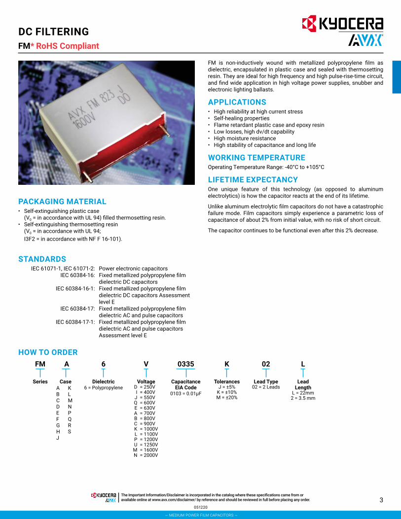
FM is non-inductively wound with metallized polypropylene film as dielectric, encapsulated in plastic case and sealed with thermosetting resin. They are ideal for high frequency and high pulse-rise-time circuit, and find wide application in high voltage power supplies, snubber and electronic lighting ballasts.
APPLICATIONS• High reliability at high current stress• Self-healing properties• Flame retardant plastic case and epoxy resin• Low losses, high dv/dt capability• High moisture resistance• High stability of capacitance and long life
WORKING TEMPERATUREOperating Temperature Range: -40°C to +105°C
LIFETIME EXPECTANCYOne unique feature of this technology (as opposed to aluminum electrolytics) is how the capacitor reacts at the end of its lifetime.
Unlike aluminum electrolytic film capacitors do not have a catastrophic failure mode. Film capacitors simply experience a parametric loss of capacitance of about 2% from initial value, with no risk of short circuit.
The capacitor continues to be functional even after this 2% decrease.
PACKAGING MATERIAL• Self-extinguishing plastic case
(V0 = in accordance with UL 94) filled thermosetting resin.• Self-extinguishing thermosetting resin
(V0 = in accordance with UL 94; I3F2 = in accordance with NF F 16-101).
STANDARDS IEC 61071-1, IEC 61071-2: Power electronic capacitors IEC 60384-16: Fixed metallized polypropylene film
dielectric DC capacitors IEC 60384-16-1: Fixed metallized polypropylene film
dielectric DC capacitors Assessment level E
IEC 60384-17: Fixed metallized polypropylene film dielectric AC and pulse capacitors
IEC 60384-17-1: Fixed metallized polypropylene film dielectric AC and pulse capacitors Assessment level E
FM A K 02 L6 V 0335
Series Case Dielectric6 = Polypropylene
Voltage D = 250V I = 400V J = 550V Q = 600V E = 630V A = 700V B = 800V C = 900V K = 1000V L = 1100V P = 1200V U = 1250V M = 1600V N = 2000V
CapacitanceEIA Code
0103 = 0.01μF
TolerancesJ = ±5%
K = ±10%M = ±20%
Lead Type02 = 2 Leads
Lead Length
L = 22mm2 = 3.5 mm
HOW TO ORDER
ABCDEFGHJ
KLMNPQRS
051220
– medium power film capacitors –
The Important Information/Disclaimer is incorporated in the catalog where these specifications came from or available online at www.avx.com/disclaimer/ by reference and should be reviewed in full before placing any order.

4
DC FILTERINGFM*
LIFETIME EXPECTANCY VS HOT SPOT TEMPERATURE AND VOLTAGE
1000
10000
100000
1000000
0.7 0.8 0.9 1 1.1 1.2 1.3 1.4 1.5
Exp
ecte
d L
ifeti
me
(h)
Working/Rated Voltage Ratio (Uw/Un)
60ºC 50ºC
70ºC85ºC
105ºC
Expected Lifetime Curves (FM Series)
W +0.5max
T +0.5)max
H +0.5 max
P
2 .giF1 .giF
dΦ20 min
W +0.5max
T +0.5max
H +0.5 max
PdΦL0
DIMENSIONS GENERAL DESCRIPTION
Case Ref W(mm)
H(mm)
T(mm)
P(mm)
d (mm)
A 13 11 5 10 0.6B 13 12 6 10 0.6C 18 11 5 15 0.8D 18 12 6 15 0.8E 18 13.5 6 15 0.8F 18 13.5 7.5 15 0.8G 18 14.5 8 15z 0.8H 18 14.5 8.5 15 0.8J 18 16 10 15 0.8K 18 18 10 15 0.8L 18 19 11 15 0.8M 26 13.5 6 22.5 0.8N 26 16.5 7 22.5 0.8P 26 17 8.5 22.5 0.8Q 26 19 10 22.5 0.8R 26 20 11 22.5 0.8S 26 23 13 22.5 0.8
051220
RoHS Compliant
– medium power film capacitors –
The Important Information/Disclaimer is incorporated in the catalog where these specifications came from or available online at www.avx.com/disclaimer/ by reference and should be reviewed in full before placing any order.
5
DC FILTERINGFM*
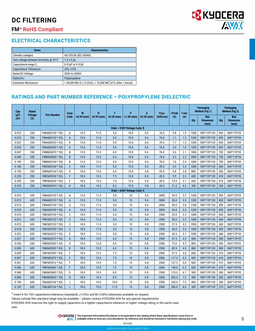
ELECTRICAL CHARACTERISTICS
Items Characteristics
Climatic category 40/105/56 (IEC 60068)Test voltage between terminals @ 25°C 1.5 x Vndc Capacitance range Cn 0.01μF to 0.47μFCapacitance Tolerances: ±5%, ±10%Rated DC Voltage: 250V to 2000VDielectric: PolypropyleneInsulation Resistance: > 30,000 MΩ (C ≤ 0.33uF), > 10,000 MΩ*uF/C after 1 minute
RATINGS AND PART NUMBER REFERENCE – POLYPROPYLENE DIELECTRIC
Cap (μF)±5%
Rated Voltage
(V)Part Number Case
CodeW
±0.50 (mm)H
±0.50 (mm)T
±0.50 (mm)P
±1.00 (mm)d
±0.50 (mm)V/μs
(Volt/sec)I Peak
(A)I rms (A)
Packaging Method (Fig 1)
Packaging Method (Fig 2)
QtyBox
Dimension (mm)
QtyBox
Dimension (mm)
Vndc = 250V Voltage Code: D0.010 250 FMA6D0103 * 02L A 13.0 11.0 5.0 10.0 0.6 76.0 0.8 1.0 1200 180*170*120 850 360*170*350.015 250 FMA6D0153 * 02L A 13.0 11.0 5.0 10.0 0.6 76.0 1.1 1.2 1200 180*170*120 850 360*170*350.022 250 FMA6D0223 * 02L A 13.0 11.0 5.0 10.0 0.6 76.0 1.7 1.5 1200 180*170*120 850 360*170*350.033 250 FMA6D0333 * 02L A 13.0 11.0 5.0 10.0 0.6 76.0 2.5 1.8 1200 180*170*120 850 360*170*350.047 250 FMB6D0473 * 02L B 13.0 12.0 6.0 10.0 0.6 76.0 3.6 2.1 1000 180*170*120 700 360*170*350.068 250 FMB6D0683 * 02L B 13.0 12.0 6.0 10.0 0.6 76.0 5.2 2.3 1000 180*170*120 700 360*170*350.100 250 FMB6D0104 * 02L B 13.0 12.0 6.0 10.0 0.6 76.0 7.6 2.4 1000 180*170*120 700 360*170*350.100 250 FMC6D0104 * 02L C 18.0 11.0 5.0 15.0 0.6 45.0 4.5 2.4 1000 180*170*120 600 360*170*350.150 250 FMD6D0154 * 02L D 18.0 12.0 6.0 15.0 0.8 45.0 6.8 2.8 800 180*170*120 500 360*170*350.220 250 FMF6D0224 * 02L F 18.0 13.5 7.5 15.0 0.8 45.0 9.9 3.3 600 180*170*120 410 360*170*350.330 250 FMF6D0334 * 02L F 18.0 13.5 7.5 15.0 0.8 45.0 14.9 3.7 600 180*170*120 410 360*170*350.470 250 FMG6D0474 * 02L H 18.0 14.5 8.5 15.0 0.8 45.0 21.2 4.2 500 180*170*120 350 360*170*35
Vndc = 630V Voltage Code: E0.010 630 FMA6E0103 * 02L A 13.0 11.0 5.0 10 0.6 3000 30.0 2.2 1200 180*170*120 850 360*170*350.012 630 FMA6E0123 * 02L A 13.0 11.0 5.0 10 0.6 3000 36.0 2.5 1200 180*170*120 850 360*170*350.015 630 FMA6E0153 * 02L A 13.0 11.0 5.0 10 0.6 3000 45.0 2.8 1200 180*170*120 850 360*170*350.018 630 FMA6E0183 * 02L A 13.0 11.0 5.0 10 0.6 3000 54.0 3.0 1200 180*170*120 850 360*170*350.010 630 FMC6E0103 * 02L C 18.0 11.0 5.0 15 0.8 2500 25.0 2.2 1000 180*170*120 600 360*170*350.012 630 FMC6E0123 * 02L C 18.0 11.0 5.0 15 0.8 2500 30.0 2.5 1000 180*170*120 600 360*170*350.015 630 FMC6E0153 * 02L C 18.0 11.0 5.0 15 0.8 2500 37.5 3.3 1000 180*170*120 600 360*170*350.018 630 FMC6E0183 * 02L C 18.0 11.0 5.0 15 0.8 2500 45.0 3.4 1000 180*170*120 600 360*170*350.022 630 FMC6E0223 * 02L C 18.0 11.0 5.0 15 0.8 2500 55.5 3.7 1000 180*170*120 600 360*170*350.027 630 FMD6E0273 * 02L D 18.0 12.0 6.0 15 0.8 2500 67.5 4.0 800 180*170*120 500 360*170*350.030 630 FMD6E0303 * 02L D 18.0 12.0 6.0 15 0.8 2500 75.0 4.3 800 180*170*120 500 360*170*350.033 630 FMD6E0333 * 02L D 18.0 12.0 6.0 15 0.8 2500 82.5 4.5 800 180*170*120 500 360*170*350.039 630 FMF6E0393 * 02L F 18.0 13.5 7.5 15 0.8 2500 97.5 4.8 600 180*170*120 410 360*170*350.047 630 FMF6E0473 * 02L F 18.0 13.5 7.5 15 0.8 2500 117.5 5.3 600 180*170*120 410 360*170*350.051 630 FMF6E0513 * 02L F 18.0 13.5 7.5 15 0.8 2500 127.5 5.8 600 180*170*120 410 360*170*350.056 630 FMF6E0563 * 02L F 18.0 13.5 7.5 15 0.8 2500 140.0 6.3 600 180*170*120 410 360*170*35
0.068 630 FMG6E0683 * 02L G 18.0 14.5 8.0 15 0.8 2500 170.0 6.7 500 180*170*120 380 360*170*35
0.082 630 FMH6E0823 * 02L H 18.0 14.5 8.5 15 0.8 2500 205.0 7.2 500 180*170*120 350 360*170*350.100 630 FMJ6E0104 * 02L J 18.0 16.0 10.0 15 0.8 2500 250.0 7.5 400 180*170*120 300 360*170*350.120 630 FML6E0124 * 02L L 18.0 19.0 11.0 15 0.8 2500 300.0 8.0 300 180*170*120 270 360*170*35
* Insert K for 10% capacitance tolerance (standard); J (+5%) and M (+20%) tolerances available on request.Values outside this standard range may be available – please contact KYOCERA AVX for any special requirements.KYOCERA AVX reserves the right to supply capacitors to a tighter capacitance tolerance or higher voltage rating, in the same case size.
051220
RoHS Compliant
– medium power film capacitors –
The Important Information/Disclaimer is incorporated in the catalog where these specifications came from or available online at www.avx.com/disclaimer/ by reference and should be reviewed in full before placing any order.

6
DC FILTERINGFM*
* Insert K for 10% capacitance tolerance (standard); J (+5%) and M (+20%) tolerances available on request.Values outside this standard range may be available – please contact KYOCERA AVX for any special requirements.KYOCERA AVX reserves the right to supply capacitors to a tighter capacitance tolerance or higher voltage rating, in the same case size.
051220
RoHS Compliant
RATINGS AND PART NUMBER REFERENCE – POLYPROPYLENE DIELECTRIC
Cap (μF)±5%
Rated Voltage
(V)Part Number Case
CodeW
±0.50 (mm)H
±0.50 (mm)T
±0.50 (mm)P
±1.00 (mm)d
±0.50 (mm)V/μs
(Volt/sec)I Peak
(A)I rms (A)
Packaging Method (Fig 1)
Packaging Method (Fig 2)
QtyBox
Dimension (mm)
QtyBox
Dimension (mm)
Vndc = 1000V Voltage Code: K0.010 1000 FMA6K0103 * 02L A 13.0 11.0 5.0 10 0.6 4500 45.0 2.6 1200 180*170*120 850 360*170*350.012 1000 FMA6K0123 * 02L A 13.0 11.0 5.0 10 0.6 4500 54.0 2.9 1200 180*170*120 850 360*170*350.015 1000 FMA6K0153 * 02L A 13.0 11.0 5.0 10 0.6 4500 67.5 3.2 1200 180*170*120 850 360*170*350.018 1000 FMA6K0183 * 02L A 13.0 11.0 5.0 10 0.6 4500 81.0 3.4 1200 180*170*120 850 360*170*350.010 1000 FMC6K0103 * 02L C 18.0 11.0 5.0 15 0.8 3200 32.0 2.4 1000 180*170*120 600 360*170*350.012 1000 FMC6K0123 * 02L C 18.0 11.0 5.0 15 0.8 3200 38.4 2.7 1000 180*170*120 600 360*170*350.015 1000 FMC6K0153 * 02L C 18.0 11.0 5.0 15 0.8 3200 48.0 3.0 1000 180*170*120 600 360*170*350.018 1000 FMC6K0183 * 02L C 18.0 11.0 5.0 15 0.8 3200 57.6 3.2 1000 180*170*120 600 360*170*350.022 1000 FMC6K0223 * 02L C 18.0 11.0 5.0 15 0.8 3200 70.4 3.6 1000 180*170*120 600 360*170*350.027 1000 FMD6K0273 * 02L D 18.0 12.0 6.0 15 0.8 3200 86.4 3.9 800 180*170*120 500 360*170*350.030 1000 FMD6K0303 * 02L D 18.0 12.0 6.0 15 0.8 3200 96.0 4.5 800 180*170*120 500 360*170*350.033 1000 FMD6K0333 * 02L D 18.0 12.0 6.0 15 0.8 3200 105.6 5.1 800 180*170*120 500 360*170*350.039 1000 FMF6K0393 * 02L F 18.0 13.5 7.5 15 0.8 3200 124.8 5.6 600 180*170*120 410 360*170*350.047 1000 FMF6K0473 * 02L F 18.0 13.5 7.5 15 0.8 3200 150.4 6.0 600 180*170*120 410 360*170*350.051 1000 FMF6K0513 * 02L F 18.0 13.5 7.5 15 0.8 3200 163.2 6.4 600 180*170*120 410 360*170*350.056 1000 FMF6K0563 * 02L F 18.0 13.5 7.5 15 0.8 3200 179.2 6.7 600 180*170*120 410 360*170*350.068 1000 FMG6K0683 * 02L G 18.0 14.5 8.0 15 0.8 3200 217.6 7.1 500 180*170*120 380 360*170*350.082 1000 FMH6K0823 * 02L H 18.0 14.5 8.5 15 0.8 3200 262.4 7.4 500 180*170*120 350 360*170*350.100 1000 FMJ6K0104 * 02L J 18.0 16.0 10.0 15 0.8 3200 320.0 7.8 400 180*170*120 300 360*170*350.120 1000 FML6K0124 * 02L L 18.0 19.0 11.0 15 0.8 3200 384.0 8.5 300 180*170*120 270 360*170*35
Vndc = 1250V Voltage Code: U0.01 1250 FMA6U0103 * 02L A 13.0 11.0 5.0 10.0 0.6 4600 46.0 2.8 1200 180*170*120 850 360*170*35
0.012 1250 FMA6U0123 * 02L A 13.0 11.0 5.0 10.0 0.6 4600 55.2 3.1 1200 180*170*120 850 360*170*350.015 1250 FMA6U0153 * 02L A 13.0 11.0 5.0 10.0 0.6 4600 69.0 3.3 1200 180*170*120 850 360*170*350.018 1250 FMA6U0183 * 02L A 13.0 11.0 5.0 10.0 0.6 4600 82.8 2.6 1200 180*170*120 850 360*170*350.01 1250 FMC6U0103 * 02L C 18.0 11.0 5.0 15.0 0.8 3300 33.0 2.8 1000 180*170*120 600 360*170*35
0.012 1250 FMC6U0123 * 02L C 18.0 11.0 5.0 15.0 0.8 3300 39.6 3.0 1000 180*170*120 600 360*170*350.015 1250 FMC6U0153 * 02L C 18.0 11.0 5.0 15.0 0.8 3300 49.5 3.2 1000 180*170*120 600 360*170*350.018 1250 FMC6U0183 * 02L C 18.0 11.0 5.0 15.0 0.8 3300 59.4 3.6 1000 180*170*120 600 360*170*350.022 1250 FMD6U0223 * 02L D 18.0 12.0 6.0 15.0 0.8 3300 72.6 4.0 800 180*170*120 500 360*170*350.027 1250 FME6U0273 * 02L E 18.0 13.5 6.0 15.0 0.8 3300 89.1 4.5 600 180*170*120 500 360*170*350.030 1250 FMF6U0303 * 02L F 18.0 13.5 7.5 15.0 0.8 3300 99.0 4.9 600 180*170*120 410 360*170*350.033 1250 FMF6U0333 * 02L F 18.0 13.5 7.5 15.0 0.8 3300 108.9 5.4 600 180*170*120 410 360*170*350.039 1250 FMG6U0393 * 02L G 18.0 14.5 8.0 15.0 0.8 3300 128.7 5.8 500 180*170*120 380 360*170*350.047 1250 FMG6U0473 * 02L G 18.0 14.5 8.0 15.0 0.8 3300 155.1 6.3 500 180*170*120 380 360*170*350.051 1250 FMH6U0513 * 02L H 18.0 14.5 8.5 15.0 0.8 3300 168.3 6.7 500 180*170*120 350 360*170*350.056 1250 FMH6U0563 * 02L H 18.0 14.5 8.5 15.0 0.8 3300 184.8 7.0 500 180*170*120 350 360*170*350.068 1250 FMJ6U0683 * 02L J 18.0 16.0 10.0 15.0 0.8 3300 224.4 7.4 400 180*170*120 300 360*170*350.082 1250 FMK6U0823 * 02L K 18.0 18.0 10.0 15.0 0.8 3300 270.6 7.8 300 180*170*120 300 360*170*350.100 1250 FML6U0104 * 02L L 18.0 19.0 11.0 15.0 0.8 3300 330.0 8.0 300 180*170*120 270 360*170*35
– medium power film capacitors –
The Important Information/Disclaimer is incorporated in the catalog where these specifications came from or available online at www.avx.com/disclaimer/ by reference and should be reviewed in full before placing any order.

7
DC FILTERINGFM*
* Insert K for 10% capacitance tolerance (standard); J (+5%) and M (+20%) tolerances available on request.Values outside this standard range may be available – please contact KYOCERA AVX for any special requirements.KYOCERA AVX reserves the right to supply capacitors to a tighter capacitance tolerance or higher voltage rating, in the same case size.
051220
RoHS Compliant
RATINGS AND PART NUMBER REFERENCE – POLYPROPYLENE DIELECTRIC
Cap (μF)±5%
Rated Voltage
(V)Part Number Case
CodeW
±0.50 (mm)H
±0.50 (mm)T
±0.50 (mm)P
±1.00 (mm)d
±0.50 (mm)V/μs
(Volt/sec)I Peak
(A)I rms (A)
Packaging Method (Fig 1)
Packaging Method (Fig 2)
QtyBox
Dimension (mm)
QtyBox
Dimension (mm)
Vndc = 1600V Voltage Code: M0.01 1600 FMD6M0103 * 02L D 18.0 12.0 6.0 15.0 0.8 5800 58.0 2.5 800 180*170*120 500 360*170*35
0.012 1600 FMF6M0123 * 02L F 18.0 13.5 7.5 15.0 0.8 5800 69.6 2.9 600 180*170*120 410 360*170*350.015 1600 FMF6M0153 * 02L F 18.0 13.5 7.5 15.0 0.8 5800 87.0 3.4 600 180*170*120 410 360*170*350.018 1600 FMH6M0183 * 02L H 18.0 14.5 8.5 15.0 0.8 5800 104.4 3.8 500 180*170*120 350 360*170*350.022 1600 FMH6M0223 * 02L H 18.0 14.5 8.5 15.0 0.8 5800 127.6 4.3 500 180*170*120 350 360*170*350.027 1600 FMJ6M0273 * 02L J 18.0 16.0 10.0 15.0 0.8 5800 156.6 4.7 400 180*170*120 300 360*170*350.033 1600 FML6M0333 * 02L L 18.0 19.0 11.0 15.0 0.8 5800 191.4 5.4 300 180*170*120 270 360*170*350.033 1600 FMN6M0333 * 02L N 26.0 16.5 7.0 22.5 0.8 3000 99.0 5.8 400 180*170*120 290 360*170*350.039 1600 FMP6M0393 * 02L P 26.0 17.0 8.5 22.5 0.8 3000 117.0 6.2 300 180*170*120 240 360*170*350.047 1600 FMP6M0473 * 02L P 26.0 17.0 8.5 22.5 0.8 3000 141.0 6.5 300 180*170*120 240 360*170*350.056 1600 FMQ6M0563 * 02L Q 26.0 19.0 10.0 22.5 0.8 3000 168.0 7.0 250 180*170*120 200 360*170*350.068 1600 FMR6M0683 * 02L R 26.0 10.0 11.0 22.5 0.8 3000 204.0 7.6 200 180*170*120 180 360*170*350.082 1600 FMR6M0823 * 02L R 26.0 20.0 11.0 22.5 0.8 3000 246.0 8.1 200 180*170*120 180 360*170*350.100 1600 FMS6M0104 * 02L S 26.0 23.0 13.0 22.5 0.8 3000 300.0 8.7 100 180*170*120 150 360*170*35
Vndc = 2000V Voltage Code: N0.010 2000 FMF6N0103 * 02L F 18.0 13.5 7.5 15.0 0.8 9000 90.0 3.0 600 180*170*120 410 360*170*350.012 2000 FMH6N0123 * 02L H 18.0 14.5 8.5 15.0 0.8 9000 108.0 3.2 500 180*170*120 350 360*170*350.015 2000 FMJ6N0153* 02L J 18.0 16.0 10.0 15.0 0.8 9000 135.0 3.5 400 180*170*120 300 360*170*350.010 2000 FMM6N0103 * 02L M 26.0 13.5 6.0 22.5 0.8 3500 35.0 2.8 400 180*170*120 350 360*170*350.012 2000 FMM6N0123 * 02L M 26.0 13.5 6.0 22.5 0.8 3500 42.0 3.0 400 180*170*120 350 360*170*350.015 2000 FMN6N0153 * 02L N 26.0 16.5 7.0 22.5 0.8 3500 52.5 3.3 400 180*170*120 290 360*170*350.018 2000 FMN6N0183 * 02L N 26.0 16.5 7.0 22.5 0.8 3500 63.0 3.8 400 180*170*120 290 360*170*350.022 2000 FMP6N0223 * 02L P 26.0 17.0 8.5 22.5 0.8 3500 77.0 4.3 300 180*170*120 240 360*170*350.027 2000 FMQ6N0273 * 02L Q 26.0 19.0 10.0 22.5 0.8 3500 94.5 4.9 250 180*170*120 200 360*170*350.033 2000 FMQ6N0333 * 02L Q 26.0 19.0 10.0 22.5 0.8 3500 115.5 5.7 250 180*170*120 200 360*170*350.039 2000 FMR6N0393 * 02L R 26.0 20.0 11.0 22.5 0.8 3500 136.5 6.5 200 180*170*120 180 360*170*350.047 2000 FMS6N0473 * 02L S 26.0 23.0 13.0 22.5 0.8 3500 164.5 7.0 100 180*170*120 150 360*170*350.056 2000 FMS6N0563 * 02L S 26.0 23.0 13.0 22.5 0.8 3500 196.0 8.2 100 180*170*120 150 360*170*35
– medium power film capacitors –
The Important Information/Disclaimer is incorporated in the catalog where these specifications came from or available online at www.avx.com/disclaimer/ by reference and should be reviewed in full before placing any order.

8
FB*
GENERAL CHARACTERISTICS• Able to Withstand Harsh Environment Conditions• Low Profile Available
FEATURES & BENEFITS• High Performance DC Filter• Low ESR, High Peak & RMS Current• THB Compliance• Able to Withstand Harsh Environment Conditions (THB Compliance)• Low Profile Available
GENERAL DESCRIPTIONThe FB series uses a non-impregnated metallized polypropylene dielectric specially treated to have a very high dielectric strength in operation condition up to 105oC.
FB series performance characteristics make them a viable alternative to aluminum electrolytic technology due to much lower ESR and much higher surge voltage capability (dv/dt).
LIFE EXPECTANCYOne unique feature of this technology (versus aluminum electrolytics) is how the capacitor reacts at the end of its lifetime.
Unlike aluminum electrolytic film capacitors do not have a catastrophic failure mode. Film capacitors simply experience a parametric loss of capacitance of about 2% from initial value, with no risk of short circuit.
The capacitor continues to be functional even after this 2% decrease.
HOW TO ORDERFB
SeriesFB
Pitch27 = 27.5mm37 = 37.5mm52 = 52.5mm
27
Case SizeE* for P=27.5mmF* for P=37.5mmG* for P=52.5mm
G*
Type6 = Polypropylene
7 = Polypropylene THB8 = Polypropylene Low Profile
6
VoltageI = 450VH = 500VJ = 550VQ = 600VA = 700VB = 800VC = 900V
K = 1000VL = 1100VP = 1200V
K
CapµF Code
0685
ToleranceJ = ± 5%K = ±10%M = ±20%
K
Pitch P2A = 10.2B = 20.3
C = 2 pins
A
(1) For Type, 6 for Polypropylene, 7 for THB Products and 8 for Low Profile Products
OPERATING TEMPERATURE RANGE• Operating temperature range: -40ºC to +100ºC
STANDARDS• IEC 61071-1: Power electronic capacitors• IEC 61071-2: Power electronic capacitors• IEC 60384-16: Fixed metallized polypropylene film dielectric DC
capacitors• IEC 60384-16-1: Fixed metallized polypropylene film dielectric DC
capacitors Assessment level E
• IEC 60384-17: Fixed metallized polypropylene film dielectric AC and pulse capacitors
• IEC 60384-17-1: Fixed metallized polypropylene film dielectric AC and pulse capacitors
• EN CZDS2.E514026 Certificate: E514026 (approved by UL)
APPLICATIONS• Renewable Energy Inverter• OBC & Automotive Applications• Motor Drives• Industrial Power Supply• UPS System
PACKAGING MATERIALSelf-extinguishing plastic case (V0 = in accordance with UL 94) filled thermosetting resin.
Self-extinguishing thermosetting resin (V0 = in accordance with UL 94; I3F2 = in accordance with NF F 16-101).
080621
DIMENSIONS
DC FILTERINGRoHS Compliant
– medium power film capacitors –
The Important Information/Disclaimer is incorporated in the catalog where these specifications came from or available online at www.avx.com/disclaimer/ by reference and should be reviewed in full before placing any order.

9051220
FB*
ELECTRICAL CHARACTERISTICS – POLYPROPYLENE DIELECTRIC
Items Characteristics
Application DC Filtering / DC Link
Reference Standard IEC 61071
Climatic Category 40/85/56 IEC 60068-1
Operating Temperature Range -40~ +105°C (+85°C observing voltage must be de-rating at 1.35% per °C)
Upper Temperature Tmax +85°C
Lower Temperature Tmin -40°C
Rated Voltage 450Vdc ~ 1200Vdc
Capacitance Range 1µF ~ 80µF
Capacitance Tolerance ±5% or ±10% at +25°C
Dissipation Factor (DF)≤ 0.002 (0.20%) at 1 KHz. C≤20µF at +25°C
≤ 0.003 (0.30%) at 1 KHz. C>20µF at +25°C
Test Voltage Between Terminals 1.5 x rated voltage for 10s (terminal to terminal)
Test Voltage Terminal to Case 3.0kVrms 50 Hz for 10 sec at +25°C
Insulation Resistance IR x C≥30,000 Seconds at 100VDC 1 minute at +25°C
Life Expectancy 100,000 hours at Un @ Hot-Spot temperature T=+70°C
ProtectionSolvent resistant plastic case UL94 V-0
Thermosetting resin sealing UL 94 V-0 compliant
Installation Any position
Leads Tinned copper wires, standard lead wire length 5 ±1mm
Packaging Packed in cardboard boxes with protection for the terminals
RoHS Compliant Compliant with the restricted substance requirements of Directive 2011/65/EU
Storage Conditions
Storage time: ≤ 24 months from the date marked on the label package
Temperature and relative humidity should be -10°C ~ +40°C and not more than 75%RH.
RH ≤ 85% for 30 days randomly distributed throughout the year
Humidity Test
Test conditions & performance:
Temperature: +40°C±2°C Relative humidity (RH): 93% ±2%
Test duration: 56 days
Capacitance change: ≤±5% DF change (△tgδ): ≤50 X 10-4 at 1KHz
Insulation resistance: ≥50% of initial limit
Endurance Test
Test conditions & performance:
Temperature: +85°C±2°C Voltage applied: 1.3 X VR (d.c.)
Test duration: 1000 hours
Capacitance change: ≤±5% DF change (△ tgδ): ≤50 X 10-4 at 1KHz
Insulation resistance: ≥50% of initial limit
POLYPROPYLENE DIELECTRIC FOR INDUSTRIAL DC FILTERINGThese capacitors have been designed primarily for high and medium power DC filtering applications.
DC FILTERINGRoHS Compliant
– medium power film capacitors –
The Important Information/Disclaimer is incorporated in the catalog where these specifications came from or available online at www.avx.com/disclaimer/ by reference and should be reviewed in full before placing any order.

10
CASE CODE mm
Case Code
DimensionsW
± 0.5H
± 0.5T
± 0.5P1
± 1.0mm mm mm mm
EC 32.0 18.0 9.0 27.5E1 32.0 20.0 11.0 27.5E2 32.0 22.0 13.0 27.5EE 32.0 24.5 15.0 27.5E3 32.0 28.0 14.0 27.5E4 32.0 28.0 18.0 27.5EG 32.0 31.0 21.0 27.5E6 32.0 33.0 18.0 27.5EI 32.0 35.0 20.0 27.5E9 32.0 37.0 22.0 27.5FH 42.5 18.0 24.0 37.5F3 42.5 32.0 19.0 37.5FI 42.5 33.5 22.0 37.5F4 42.5 36.0 19.0 37.5F5 42.5 38.0 20.0 37.5F6 42.5 40.0 20.0 37.5F8 42.5 44.0 24.0 37.5F9 42.5 45.0 30.0 37.5FP 42.5 57.0 30.0 37.5G9 57.5 45.0 25.0 52.5GA 57.5 45.0 30.0 52.5GC 57.5 50.0 35.0 52.5
FB - Standard *RoHS Compliant
Cap Rated Voltage PN Voltage
CodeCase Code
Dimensionsdv/dt Peak
Current Irms ESR 10KHz Rth ESL SPQW
± 0.5H
± 0.5T
± 0.5P1
± 1.0d
± 0.05uF V mm mm mm mm mm V/us A A mΩ °C/W nH pcs
Voltage Vndc 450V Voltage Code I1.0 450 FB27EC6I0105*C I EC 32.0 18.0 9.0 27.5 0.8 60 60 2.5 45.0 53.3 25 180 2.0 450 FB27EC6I0205*C I EC 32.0 18.0 9.0 27.5 0.8 60 120 3.0 30.0 55.6 25 180 3.0 450 FB27E16I0305*C I E1 32.0 20.0 11.0 27.5 0.8 60 180 4.0 20.0 46.9 25 150 4.0 450 FB27E16I0405*C I E1 32.0 20.0 11.0 27.5 0.8 60 240 4.0 18.0 52.1 25 150 5.0 450 FB27E16I0505*C I E1 32.0 20.0 11.0 27.5 0.8 60 300 5.0 12.0 50.0 25 150 5.0 450 FB27E26I0505*C I E2 32.0 22.0 13.0 27.5 0.8 60 300 5.5 11.0 45.1 25 120
10.0 450 FB27E36I0106*C I E3 32.0 28.0 14.0 27.5 0.8 60 600 7.5 8.5 31.4 25 110 10.0 450 FB27E46I0106*C I E4 32.0 28.0 18.0 27.5 0.8 60 600 9.0 8.0 23.1 25 90 12.0 450 FB27E66I0126*C I E6 32.0 33.0 18.0 27.5 0.8 60 720 10.0 7.0 21.4 25 90 15.0 450 FB27E96I0156*C I E9 32.0 37.0 22.0 27.5 0.8 60 900 11.5 6.0 18.9 25 70 18.0 450 FB27E96I0186*C I E9 32.0 37.0 22.0 27.5 0.8 60 1080 10.0 6.0 25.0 25 70 20.0 450 FB27E96I0206*C I E9 32.0 37.0 22.0 27.5 0.8 60 1200 11.0 5.0 24.8 25 70 22.0 450 FB27E96I0226*C I E9 32.0 37.0 22.0 27.5 0.8 60 1320 12.5 5.0 19.2 25 70 15.0 450 FB37FH6I0156*C I FH 42.5 18.0 24.0 37.5 1.0 30 450 9.5 8.5 19.6 30 49
Voltage Vndc 500V Voltage Code J3.0 550 FB27E16J0305*C J E1 32.0 20.0 11.0 27.5 0.8 60 180 4.0 28.0 33.5 25 150 5.0 550 FB27E26J0505*C J E2 32.0 22.0 13.0 27.5 0.8 60 300 6.0 14.0 29.8 25 120 8.0 550 FB27E36J0805*C J E3 32.0 28.0 14.0 27.5 0.8 60 480 8.5 12.5 16.6 25 110
10.0 550 FB27E66J0106*C J E6 32.0 33.0 18.0 27.5 0.8 60 600 10.0 8.0 18.8 25 90 15.0 550 FB27E96J0156*C J E9 32.0 37.0 22.0 27.5 0.8 60 900 12.0 6.5 16.0 25 70 15.0 550 FB37FH6J0156*C J FH 42.5 18.0 24.0 37.5 0.8 60 900 10.5 6.5 20.9 30 49
Voltage Vndc 600V Voltage Code Q1.0 600 FB27EC6Q0105*C Q EC 32.0 18.0 9.0 27.5 0.8 50 50 2.5 55.0 43.6 25 180 2.0 600 FB27EC6Q0205*C Q EC 32.0 18.0 9.0 27.5 0.8 50 100 3.0 35.0 47.6 25 180 3.0 600 FB27E16Q0305*C Q E1 32.0 20.0 11.0 27.5 0.8 60 180 4.0 28.0 33.5 25 150 4.0 600 FB27E16Q0405*C Q E1 32.0 20.0 11.0 27.5 0.8 60 240 5.0 26.0 23.1 25 150 5.0 600 FB27E26Q0505*C Q E2 32.0 22.0 13.0 27.5 0.8 50 250 5.0 17.0 35.3 25 120 5.0 600 FB27E36Q0505*C Q E3 32.0 28.0 14.0 27.5 0.8 60 300 6.0 14.5 28.7 25 110
RATING & PART NUMBER REFERENCE
051220
DC FILTERING
– medium power film capacitors –
The Important Information/Disclaimer is incorporated in the catalog where these specifications came from or available online at www.avx.com/disclaimer/ by reference and should be reviewed in full before placing any order.

11
Cap Rated Voltage PN Voltage
CodeCase Code
Dimensionsdv/dt Peak
Current Irms ESR 10KHz Rth ESL SPQW
± 0.5H
± 0.5T
± 0.5P1
± 1.0d
± 0.05uF V mm mm mm mm mm V/us A A mΩ °C/W nH pcs6.0 600 FB27EE6Q0605*C Q EE 32.0 24.5 15.0 27.5 0.8 50 300 6.0 14.0 29.8 25 110 7.0 600 FB27EE6Q0705*C Q EE 32.0 24.5 15.0 27.5 0.8 50 350 6.0 12.0 34.7 25 110 8.0 600 FB27E36Q0805*C Q E3 32.0 28.0 14.0 27.5 0.8 60 480 7.5 12.0 22.2 25 110 8.0 600 FB27E46Q0805*C Q E4 32.0 28.0 18.0 27.5 0.8 50 400 8.0 9.0 26.0 25 90 9.0 600 FB27E46Q0905*C Q E4 32.0 28.0 18.0 27.5 0.8 50 450 8.0 9.0 26.0 25 90
10.0 600 FB27E46Q0106*C Q E4 32.0 28.0 18.0 27.5 0.8 50 500 9.0 8.0 23.1 25 90 10.0 600 FB27E66Q0106*C Q E6 32.0 33.0 18.0 27.5 0.8 60 600 8.5 7.5 27.7 25 90 12.0 600 FB27E66Q0126*C Q E6 32.0 33.0 18.0 27.5 0.8 60 720 9.5 7.5 22.2 25 90 12.0 600 FB27EG6Q0126*C Q EG 32.0 31.0 21.0 27.5 0.8 50 600 10.0 7.0 21.4 25 80 15.0 600 FB27E96Q0156*C Q E9 32.0 37.0 22.0 27.5 0.8 60 900 10.5 7.5 18.1 25 70 15.0 600 FB27EI6Q0156*C Q EI 32.0 35.0 20.0 27.5 0.8 50 750 10.0 6.0 25.0 25 80 10.0 600 FB37F46Q0106*C Q F4 42.5 36.0 19.0 37.5 1.0 25 250 7.0 14.0 21.9 30 56 12.0 600 FB37F46Q0126*C Q F4 42.5 36.0 19.0 37.5 1.0 25 300 8.0 12.0 19.5 30 56 12.0 600 FB37FH6Q0126*C Q FH 42.5 18.0 24.0 37.5 1.0 35 420 8.0 9.5 24.7 30 49 15.0 600 FB37F46Q0156*C Q F4 42.5 36.0 19.0 37.5 1.0 25 375 9.0 9.0 20.6 30 56 15.0 600 FB37FH6Q0156*C Q FH 42.5 18.0 24.0 37.5 1.0 35 525 12.0 6.0 17.4 30 49 20.0 600 FB37F56Q0206*C Q F5 42.5 38.0 20.0 37.5 1.0 25 500 11.0 7.0 17.7 30 56 22.0 600 FB37F56Q0226*C Q F5 42.5 38.0 20.0 37.5 1.0 25 550 11.0 8.0 15.5 30 56 25.0 600 FB37F56Q0256*C Q F5 42.5 38.0 20.0 37.5 1.0 25 625 11.0 7.0 17.7 30 56 30.0 600 FB37F86Q0306*C Q F8 42.5 44.0 24.0 37.5 1.0 25 750 13.0 6.0 14.8 30 49 35.0 600 FB37F96Q0356*C Q F9 42.5 45.0 30.0 37.5 1.0 25 875 17.0 4.0 13.0 30 35 40.0 600 FB37F96Q0406*C Q F9 42.5 45.0 30.0 37.5 1.0 25 1000 17.0 4.0 13.0 30 35 45.0 600 FB37F96Q0456*C Q F9 42.5 45.0 30.0 37.5 1.0 25 1125 17.0 4.0 13.0 30 35 50.0 600 FB37FP6Q0506*C Q FP 42.5 57.0 30.0 37.5 1.0 25 1250 18.0 3.0 15.4 30 35 40.0 600 FB52G96Q0406*C Q G9 57.5 45.0 25.0 52.5 1.2 14 560 13.0 7.0 12.7 35 30 45.0 600 FB52G96Q0456*C Q G9 57.5 45.0 25.0 52.5 1.2 14 630 13.0 7.0 12.7 35 30 50.0 600 FB52GA6Q0506*C Q GA 57.5 45.0 30.0 52.5 1.2 14 700 15.0 6.0 11.1 35 25 55.0 600 FB52GA6Q0556*C Q GA 57.5 45.0 30.0 52.5 1.2 14 770 15.0 6.0 11.1 35 25 60.0 600 FB52GA6Q0606*C Q GA 57.5 45.0 30.0 52.5 1.2 14 840 15.0 5.0 13.3 35 25 65.0 600 FB52GC6Q0656*C Q GC 57.5 50.0 35.0 52.5 1.2 14 910 18.0 4.0 11.6 35 20 70.0 600 FB52GC6Q0706*C Q GC 57.5 50.0 35.0 52.5 1.2 14 980 18.0 4.5 10.3 35 20 75.0 600 FB52GC6Q0756*C Q GC 57.5 50.0 35.0 52.5 1.2 14 1050 18.0 4.0 11.6 35 20 80.0 600 FB52GC6Q0806*C Q GC 57.5 50.0 35.0 52.5 1.2 14 1120 18.0 4.0 11.6 35 20
Voltage Vndc 700V Voltage Code A1.0 700 FB27EC6A0105*C A EC 32.0 18.0 9.0 27.5 0.8 60 60 2.5 54.0 44.4 25 180 2.0 700 FB27EC6A0205*C A EC 32.0 18.0 9.0 27.5 0.8 60 120 3.0 35.0 47.6 25 180 3.0 700 FB27E16A0305*C A E1 32.0 20.0 11.0 27.5 0.8 60 180 4.5 28.0 26.5 25 150 3.3 700 FB27E36A0335*C A E3 32.0 28.0 14.0 27.5 0.8 60 198 5.5 26.0 19.1 25 110 5.0 700 FB27E36A0505*C A E3 32.0 28.0 14.0 27.5 0.8 60 300 6.0 14.0 29.8 25 110 6.0 700 FB27E46A0605*C A E4 32.0 28.0 18.0 27.5 0.8 60 360 6.0 14.0 29.8 25 90 8.0 700 FB27E66A0805*C A E6 32.0 33.0 18.0 27.5 0.8 60 480 9.0 10.0 18.5 25 90
10.0 700 FB27E66A0106*C A E6 32.0 33.0 18.0 27.5 0.8 60 600 10.0 7.0 21.4 25 90 10.0 700 FB27E96A0106*C A E9 32.0 37.0 22.0 27.5 0.8 60 600 12.0 6.5 16.0 25 70 12.0 700 FB27E96A0126*C A E9 32.0 37.0 22.0 27.5 0.8 60 720 12.5 6.0 16.0 25 70 10.0 700 FB37FH6A0106*C A FH 42.5 18.0 24.0 37.5 1.0 35 350 11.5 7.5 15.1 30 49 12.0 700 FB37FH6A0126*C A FH 42.5 18.0 24.0 37.5 1.0 35 420 12.0 7.0 14.9 30 49 15.0 700 FB37FI6A0156*C A FI 42.5 33.5 22.0 37.5 1.0 35 525 9.0 9.0 20.6 30 49
Voltage Vndc 800V Voltage Code B1.0 800 FB27EC6B0105*C B EC 32.0 18.0 9.0 27.5 0.8 60 60 2.0 62.0 60.5 25 180 2.0 800 FB27E16B0205*C B E1 32.0 20.0 11.0 27.5 0.8 60 120 3.5 31.0 39.5 25 150 2.0 800 FB27EC6B0205*C B EC 32.0 18.0 9.0 27.5 0.8 60 120 3.0 35.0 47.6 25 180 3.0 800 FB27E16B0305*C B E1 32.0 20.0 11.0 27.5 0.8 60 180 4.0 23.0 40.8 25 150 3.0 800 FB27E26B0305*C B E2 32.0 22.0 13.0 27.5 0.8 60 180 4.5 21.0 35.3 25 120 3.3 800 FB27E36B0335*C B E3 32.0 28.0 14.0 27.5 0.8 60 198 4.0 25.0 37.5 25 110 4.0 800 FB27E26B0405*C B E2 32.0 22.0 13.0 27.5 0.8 60 240 5.0 17.0 35.3 25 120 5.0 800 FB27E36B0505*C B E3 32.0 28.0 14.0 27.5 0.8 60 300 6.0 12.0 34.7 25 110 5.0 800 FB27EE6B0505*C B EE 32.0 24.5 15.0 27.5 0.8 60 300 6.0 14.0 29.8 25 110 6.0 800 FB27E46B0605*C B E4 32.0 28.0 18.0 27.5 0.8 60 360 7.5 10.5 25.4 25 90 7.0 800 FB27E46B0705*C B E4 32.0 28.0 18.0 27.5 0.8 60 420 8.0 10.0 23.4 25 90 8.0 800 FB27E46B0805*C B E4 32.0 28.0 18.0 27.5 0.8 60 480 8.0 9.0 26.0 25 90 8.0 800 FB27E66B0805*C B E6 32.0 33.0 18.0 27.5 0.8 60 480 9.5 9.5 17.5 25 90 9.0 800 FB27E66B0905*C B E6 32.0 33.0 18.0 27.5 0.8 60 540 10.0 8.5 17.6 25 90
FB - Standard *RoHS Compliant
RATING & PART NUMBER REFERENCE
051220
DC FILTERING
– medium power film capacitors –
The Important Information/Disclaimer is incorporated in the catalog where these specifications came from or available online at www.avx.com/disclaimer/ by reference and should be reviewed in full before placing any order.

12
FB - Standard *RoHS Compliant
RATING & PART NUMBER REFERENCE
Cap Rated Voltage PN Voltage
CodeCase Code
Dimensionsdv/dt Peak
Current Irms ESR 10KHz Rth ESL SPQW
± 0.5H
± 0.5T
± 0.5P1
± 1.0d
± 0.05uF V mm mm mm mm mm V/us A A mΩ °C/W nH pcs9.0 800 FB27EG6B0905*C B EG 32.0 31.0 21.0 27.5 0.8 60 540 10.0 7.5 20.0 25 80
10.0 800 FB27E96B0106*C B E9 32.0 37.0 22.0 27.5 0.8 60 600 11.5 9.5 11.9 25 70 10.0 800 FB27EG6B0106*C B EG 32.0 31.0 21.0 27.5 0.8 60 600 10.0 7.0 21.4 25 80 12.0 800 FB27EI6B0126*C B EI 32.0 35.0 20.0 27.5 0.8 60 720 11.0 6.0 20.7 25 80 10.0 800 FB37F36B0106*C B F3 42.5 32.0 19.0 37.5 1.0 35 350 8.0 12.5 18.8 30 56 10.0 800 FB37F46B0106*C B F4 42.5 36.0 19.0 37.5 1.0 35 350 7.0 14.0 21.9 30 56 12.0 800 FB37F46B0126*C B F4 42.5 36.0 19.0 37.5 1.0 35 420 8.0 12.0 19.5 30 56 15.0 800 FB37F46B0156*C B F4 42.5 36.0 19.0 37.5 1.0 35 525 9.0 9.0 20.6 30 56 20.0 800 FB37F56B0206*C B F5 42.5 38.0 20.0 37.5 1.0 35 700 11.0 7.0 17.7 30 56 22.0 800 FB37F86B0226*C B F8 42.5 44.0 24.0 37.5 1.0 35 770 13.0 6.0 14.8 30 49 25.0 800 FB37F86B0256*C B F8 42.5 44.0 24.0 37.5 1.0 35 875 13.0 6.0 14.8 30 49 30.0 800 FB37F96B0306*C B F9 42.5 45.0 30.0 37.5 1.0 35 1050 16.0 5.0 11.7 30 35 35.0 800 FB37F96B0356*C B F9 42.5 45.0 30.0 37.5 1.0 35 1225 17.0 4.0 13.0 30 35 40.0 800 FB37FP6B0406*C B FP 42.5 57.0 30.0 37.5 1.0 35 1400 18.0 3.0 15.4 30 35 30.0 800 FB52G96B0306*C B G9 57.5 45.0 25.0 52.5 1.2 18 540 11.0 9.0 13.8 35 30 35.0 800 FB52G96B0356*C B G9 57.5 45.0 25.0 52.5 1.2 18 630 12.0 8.0 13.0 35 30 40.0 800 FB52G96B0406*C B G9 57.5 45.0 25.0 52.5 1.2 18 720 13.0 7.0 12.7 35 30 45.0 800 FB52GA6B0456*C B GA 57.5 45.0 30.0 52.5 1.2 18 810 14.0 6.0 12.8 35 25 50.0 800 FB52GA6B0506*C B GA 57.5 45.0 30.0 52.5 1.2 18 900 15.0 6.0 11.1 35 25 55.0 800 FB52GC6B0556*C B GC 57.5 50.0 35.0 52.5 1.2 18 990 17.0 5.0 10.4 35 20 60.0 800 FB52GC6B0606*C B GC 57.5 50.0 35.0 52.5 1.2 18 1080 18.0 5.0 9.3 35 20 65.0 800 FB52GC6B0656*C B GC 57.5 50.0 35.0 52.5 1.2 18 1170 19.0 4.0 10.4 35 20
Voltage Vndc 900V Voltage Code C1.0 900 FB27EC6C0105*C C EC 32.0 18.0 9.0 27.5 0.8 60 60 2.0 63.0 59.5 25 180 2.0 900 FB27E16C0205*C C E1 32.0 20.0 11.0 27.5 0.8 60 120 3.0 25.0 66.7 25 150 3.0 900 FB27E26C0305*C C E2 32.0 22.0 13.0 27.5 0.8 60 180 5.0 18.5 32.4 25 120 3.3 900 FB27EE6C0335*C C EE 32.0 24.5 15.0 27.5 0.8 60 198 5.0 18.5 32.4 25 110 4.0 900 FB27EE6C0405*C C EE 32.0 24.5 15.0 27.5 0.8 65 260 5.0 16.0 37.5 25 110 5.0 900 FB27E46C0505*C C E4 32.0 28.0 18.0 27.5 0.8 60 300 7.0 12.5 24.5 25 90 6.0 900 FB27E46C0605*C C E4 32.0 28.0 18.0 27.5 0.8 65 390 7.0 11.0 27.8 25 90 6.0 900 FB27E66C0605*C C E6 32.0 33.0 18.0 27.5 0.8 60 360 8.0 11.0 21.3 25 90 7.0 900 FB27EG6C0705*C C EG 32.0 31.0 21.0 27.5 0.8 65 455 9.0 9.0 20.6 25 80 8.0 900 FB27E96C0805*C C E9 32.0 37.0 22.0 27.5 0.8 60 480 10.5 10.0 13.6 25 70 8.0 900 FB27EG6C0805*C C EG 32.0 31.0 21.0 27.5 0.8 65 520 9.0 8.0 23.1 25 80 9.0 900 FB27EI6C0905*C C EI 32.0 35.0 20.0 27.5 0.8 65 585 9.0 7.0 26.5 25 80
10.0 900 FB27E96C0106*C C E9 32.0 37.0 22.0 27.5 0.8 60 600 12.0 10.0 10.4 25 70 10.0 900 FB27EI6C0106*C C EI 32.0 35.0 20.0 27.5 0.8 65 650 9.0 7.0 26.5 25 80 9.0 900 FB37F46C0905*C C F4 42.5 36.0 19.0 37.5 1.0 35 315 8.0 14.0 16.7 30 56
10.0 900 FB37F46C0106*C C F4 42.5 36.0 19.0 37.5 1.0 35 350 8.0 13.0 18.0 30 56 10.0 900 FB37F66C0106*C C F6 42.5 40.0 20.0 37.5 1.0 35 350 8.5 12.0 17.3 30 56 12.0 900 FB37F46C0126*C C F4 42.5 36.0 19.0 37.5 1.0 35 420 8.0 11.0 21.3 30 56 15.0 900 FB37F56C0156*C C F5 42.5 38.0 20.0 37.5 1.0 35 525 10.0 9.0 16.7 30 56 15.0 900 FB37F86C0156*C C F8 42.5 44.0 24.0 37.5 1.0 35 525 10.5 8.0 17.0 30 49 18.0 900 FB37F86C0186*C C F8 42.5 44.0 24.0 37.5 1.0 35 630 10.5 8.0 17.0 30 49 20.0 900 FB37F86C0206*C C F8 42.5 44.0 24.0 37.5 1.0 35 700 13.0 6.0 14.8 30 49 20.0 900 FB37F96C0206*C C F9 42.5 45.0 30.0 37.5 1.0 35 700 14.0 6.0 12.8 30 35 22.0 900 FB37F96C0226*C C F9 42.5 45.0 30.0 37.5 1.0 35 770 14.0 6.0 12.8 30 35 25.0 900 FB37F96C0256*C C F9 42.5 45.0 30.0 37.5 1.0 35 875 15.0 5.0 13.3 30 35 30.0 900 FB37FP6C0306*C C FP 42.5 57.0 30.0 37.5 1.0 35 1050 17.0 4.5 11.5 30 35 35.0 900 FB37FP6C0356*C C FP 42.5 57.0 30.0 37.5 1.0 35 1225 18.0 3.5 13.2 30 35 30.0 900 FB52G96C0306*C C G9 57.5 45.0 25.0 52.5 1.2 18 540 12.0 8.0 13.0 35 30 35.0 900 FB52GA6C0356*C C GA 57.5 45.0 30.0 52.5 1.2 18 630 13.0 7.0 12.7 35 25 40.0 900 FB52GA6C0406*C C GA 57.5 45.0 30.0 52.5 1.2 18 720 14.0 6.0 12.8 35 25 45.0 900 FB52GC6C0456*C C GC 57.5 50.0 35.0 52.5 1.2 18 810 16.0 6.0 9.8 35 20 50.0 900 FB52GC6C0506*C C GC 57.5 50.0 35.0 52.5 1.2 18 900 17.0 5.0 10.4 35 20
Voltage Vndc 1000V Voltage Code K1.0 1000 FB27E16K0105*C K E1 32.0 20.0 11.0 27.5 0.8 80 80 2.5 45.0 53.3 25 150 1.0 1000 FB27EC6K0105*C K EC 32.0 18.0 9.0 27.5 0.8 70 70 2.0 65.0 57.7 25 180 2.0 1000 FB27E26K0205*C K E2 32.0 22.0 13.0 27.5 0.8 80 160 3.5 30.0 40.8 25 120 3.0 1000 FB27EE6K0305*C K EE 32.0 24.5 15.0 27.5 0.8 80 240 5.0 25.0 24.0 25 110 4.0 1000 FB27E46K0405*C K E4 32.0 28.0 18.0 27.5 0.8 70 280 6.0 16.0 26.0 25 90
051220
DC FILTERING
– medium power film capacitors –
The Important Information/Disclaimer is incorporated in the catalog where these specifications came from or available online at www.avx.com/disclaimer/ by reference and should be reviewed in full before placing any order.

13
FB - Standard *RoHS Compliant
Cap Rated Voltage PN Voltage
CodeCase Code
Dimensionsdv/dt Peak
Current Irms ESR 10KHz Rth ESL SPQW
± 0.5H
± 0.5T
± 0.5P1
± 1.0d
± 0.05uF V mm mm mm mm mm V/us A A mΩ °C/W nH pcs5.0 1000 FB27E66K0505*C K E6 32.0 33.0 18.0 27.5 0.8 80 400 8.0 14.0 16.7 25 90 5.0 1000 FB27EG6K0505*C K EG 32.0 31.0 21.0 27.5 0.8 70 350 7.0 13.0 23.5 25 80 6.0 1000 FB27EG6K0605*C K EG 32.0 31.0 21.0 27.5 0.8 70 420 8.0 10.0 23.4 25 80 7.0 1000 FB27EI6K0705*C K EI 32.0 35.0 20.0 27.5 0.8 70 490 9.0 9.0 20.6 25 80 8.0 1000 FB27E96K0805*C K E9 32.0 37.0 22.0 27.5 0.8 80 640 10.0 12.0 12.5 25 70 5.0 1000 FB37F46K0505*C K F4 42.5 36.0 19.0 37.5 1.0 35 175 6.0 21.0 19.8 30 56 6.0 1000 FB37F46K0605*C K F4 42.5 36.0 19.0 37.5 1.0 35 210 6.0 18.0 23.1 30 56 7.0 1000 FB37F46K0705*C K F4 42.5 36.0 19.0 37.5 1.0 35 245 6.0 18.0 23.1 30 56 8.0 1000 FB37F46K0805*C K F4 42.5 36.0 19.0 37.5 1.0 35 280 7.0 16.0 19.1 30 56 9.0 1000 FB37F46K0905*C K F4 42.5 36.0 19.0 37.5 1.0 35 315 7.0 14.0 21.9 30 56
10.0 1000 FB37F56K0106*C K F5 42.5 38.0 20.0 37.5 1.0 35 350 8.0 12.0 19.5 30 56 10.0 1000 FB37F66K0106*C K F6 42.5 40.0 20.0 37.5 1.0 40 400 8.5 12.0 17.3 30 56 12.0 1000 FB37F56K0126*C K F5 42.5 38.0 20.0 37.5 1.0 35 420 9.0 10.0 18.5 30 56 15.0 1000 FB37F86K0156*C K F8 42.5 44.0 24.0 37.5 1.0 40 600 10.5 8.0 17.0 30 49 20.0 1000 FB37F96K0206*C K F9 42.5 45.0 30.0 37.5 1.0 35 700 14.0 6.0 12.8 30 35 22.0 1000 FB37FP6K0226*C K FP 42.5 57.0 30.0 37.5 1.0 35 770 14.0 6.0 12.8 30 35 25.0 1000 FB37FP6K0256*C K FP 42.5 57.0 30.0 37.5 1.0 35 875 16.0 4.0 14.6 30 35 15.0 1000 FB52G96K0156*C K G9 57.5 45.0 25.0 52.5 1.2 18 270 9.0 14.0 13.2 35 30 20.0 1000 FB52G96K0206*C K G9 57.5 45.0 25.0 52.5 1.2 18 360 9.0 12.0 15.4 35 30 22.0 1000 FB52G96K0226*C K G9 57.5 45.0 25.0 52.5 1.2 18 396 10.0 11.0 13.6 35 30 25.0 1000 FB52GA6K0256*C K GA 57.5 45.0 30.0 52.5 1.2 18 450 11.0 10.0 12.4 35 25 30.0 1000 FB52GA6K0306*C K GA 57.5 45.0 30.0 52.5 1.2 18 540 12.0 8.0 13.0 35 25 35.0 1000 FB52GC6K0356*C K GC 57.5 50.0 35.0 52.5 1.2 18 630 14.0 7.0 10.9 35 20 40.0 1000 FB52GC6K0406*C K GC 57.5 50.0 35.0 52.5 1.2 18 720 15.0 6.0 11.1 35 20
Voltage Vndc 1100V Voltage Code L1.0 1100 FB27E16L0105*C L E1 32.0 20.0 11.0 27.5 0.8 80 80 2.5 45.0 53.3 25 150 1.5 1100 FB27E26L0155*C L E2 32.0 22.0 13.0 27.5 0.8 80 120 3.5 30.0 40.8 25 120 2.0 1100 FB27EE6L0205*C L EE 32.0 24.5 15.0 27.5 0.8 80 160 4.0 25.0 37.5 25 110 2.2 1100 FB27E36L0225*C L E3 32.0 28.0 14.0 27.5 0.8 80 176 5.0 16.5 36.4 25 110 3.3 1100 FB27E46L0335*C L E4 32.0 28.0 18.0 27.5 0.8 80 264 6.5 11.5 30.9 25 90 4.0 1100 FB27E66L0405*C L E6 32.0 33.0 18.0 27.5 0.8 80 320 8.0 10.5 22.3 25 90 5.0 1100 FB27E96L0505*C L E9 32.0 37.0 22.0 27.5 0.8 80 400 8.5 9.5 21.9 25 70 8.0 1100 FB37F66L0805*C L F6 42.5 40.0 20.0 37.5 1.0 40 320 10.5 14.0 9.7 30 56
10.0 1100 FB37F86L0106*C L F8 42.5 44.0 24.0 37.5 1.0 40 400 14.0 9.0 8.5 30 49 Voltage Vndc1200V Voltage Code P
1.0 1200 FB27E16P0105*C P E1 32.0 20.0 11.0 27.5 0.8 90 90 4.5 32.5 22.8 25 150 2.0 1200 FB27EE6P0205*C P EE 32.0 24.5 15.0 27.5 0.8 90 180 5.0 32.5 18.5 25 110 2.2 1200 FB27E46P0225*C P E4 32.0 28.0 18.0 27.5 0.8 90 198 5.5 17.0 29.2 25 90 3.0 1200 FB27E46P0305*C P E4 32.0 28.0 18.0 27.5 0.8 90 270 7.0 16.0 19.1 25 90 3.3 1200 FB27E66P0335*C P E6 32.0 33.0 18.0 27.5 0.8 90 297 8.0 13.5 17.4 25 90 4.0 1200 FB27EG6P0405*C P EG 32.0 31.0 21.0 27.5 0.8 85 340 8.0 12.0 19.5 25 80 5.0 1200 FB27E96P0505*C P E9 32.0 37.0 22.0 27.5 0.8 90 450 10.0 12.0 12.5 25 70 5.0 1200 FB27EI6P0505*C P EI 32.0 35.0 20.0 27.5 0.8 85 425 8.0 10.0 23.4 25 80 5.0 1200 FB37F46P0505*C P F4 42.5 36.0 19.0 37.5 1.0 40 200 6.0 18.0 23.1 30 56 5.0 1200 FB37FI6P0505*C P FI 42.5 33.5 22.0 37.5 1.0 45 225 7.5 15.5 17.2 30 49 6.0 1200 FB37F46P0605*C P F4 42.5 36.0 19.0 37.5 1.0 40 240 7.0 15.0 20.4 30 56 6.0 1200 FB37F66P0605*C P F6 42.5 40.0 20.0 37.5 1.0 45 270 7.5 15.5 17.2 30 56 7.0 1200 FB37F56P0705*C P F5 42.5 38.0 20.0 37.5 1.0 40 280 8.0 13.0 18.0 30 56 8.0 1200 FB37F56P0805*C P F5 42.5 38.0 20.0 37.5 1.0 40 320 9.0 11.0 16.8 30 56 9.0 1200 FB37F86P0905*C P F8 42.5 44.0 24.0 37.5 1.0 40 360 10.0 10.0 15.0 30 49
10.0 1200 FB37F86P0106*C P F8 42.5 44.0 24.0 37.5 1.0 40 400 10.0 9.0 16.7 30 49 12.0 1200 FB37F96P0126*C P F9 42.5 45.0 30.0 37.5 1.0 40 480 12.0 8.0 13.0 30 35 15.0 1200 FB37FP6P0156*C P FP 42.5 57.0 30.0 37.5 1.0 40 600 14.0 6.0 12.8 30 35 10.0 1200 FB52G96P0106*C P G9 57.5 45.0 25.0 52.5 1.2 20 200 8.0 18.0 13.0 35 30 12.0 1200 FB52G96P0126*C P G9 57.5 45.0 25.0 52.5 1.2 20 240 8.0 15.0 15.6 35 30 15.0 1200 FB52G96P0156*C P G9 57.5 45.0 25.0 52.5 1.2 20 300 9.0 12.0 15.4 35 30 20.0 1200 FB52GA6P0206*C P GA 57.5 45.0 30.0 52.5 1.2 20 400 11.0 9.0 13.8 35 25 22.0 1200 FB52GC6P0226*C P GC 57.5 50.0 35.0 52.5 1.2 20 440 13.0 8.0 11.1 35 20 25.0 1200 FB52GC6P0256*C P GC 57.5 50.0 35.0 52.5 1.2 20 500 14.0 7.0 10.9 35 20
RATING & PART NUMBER REFERENCE
051220
DC FILTERING
– medium power film capacitors –
The Important Information/Disclaimer is incorporated in the catalog where these specifications came from or available online at www.avx.com/disclaimer/ by reference and should be reviewed in full before placing any order.

14
CASE CODE mm
Case Code
DimensionsW
± 0.5H
± 0.5T
± 0.5P1
± 1.0mm mm mm mm
EA 32.0 12.0 24.0 27.5EB 32.0 15.0 27.0 27.5FA 42.0 15.0 27.0 37.5FB 42.0 15.0 33.0 37.5FC 42.0 18.0 24.0 37.5FD 42.0 18.0 27.0 37.5FE 42.0 18.0 39.0 37.5FF 42.0 24.0 30.0 37.5FG 42.0 24.0 39.0 37.5G1 57.5 15.0 33.0 52.5G2 57.5 15.0 45.0 52.5G4 57.5 18.0 35.0 52.5G7 57.5 24.0 39.0 52.5
Cap Rated Voltage PN Voltage
CodeCase Code
Dimensionsdv/dt Peak
Current Irms ESR 10KHz Rth ESL SPQW
± 0.5H
± 0.5T
± 0.5P1
± 1.0d
± 0.05uF V mm mm mm mm mm V/us A A mΩ °C/W nH pcs
Voltage Vndc 500V Voltage Code H5.0 500 FB27EA8H0505*C H EA 32.0 12.0 24.0 27.5 0.8 30 150 4.0 13.0 72.1 25 70 7.0 500 FB27EB8H0705*C H EB 32.0 15.0 27.0 27.5 0.8 30 210 5.0 10.0 60.0 25 60
10.0 500 FB37FA8H0106*C H FA 42.0 15.0 27.0 37.5 1.0 15 150 5.0 10.0 60.0 30 42 15.0 500 FB37FB8H0156*C H FB 42.0 15.0 33.0 37.5 1.0 15 225 6.5 7.0 50.7 30 35 20.0 500 FB52G18H0206*C H G1 57.5 15.0 33.0 52.5 1.2 7 140 6.0 9.5 43.9 35 30 30.0 500 FB52G28H0306*C H G2 57.5 15.0 45.0 52.5 1.2 7 210 8.5 6.5 31.9 35 15 10.0 500 FB37FC8H0106*C H FC 42.0 18.0 24.0 37.5 1.0 15 150 5.0 10.0 60.0 30 49 15.0 500 FB37FD8H0156*C H FD 42.0 18.0 27.0 37.5 1.0 15 225 6.5 6.5 54.6 30 42 20.0 500 FB37FE8H0206*C H FE 42.0 18.0 39.0 37.5 1.0 15 300 8.5 5.0 41.5 30 28 30.0 500 FB52G48H0306*C H G4 57.5 18.0 35.0 52.5 1.2 7 210 8.0 6.5 36.1 35 20 20.0 500 FB37FF8H0206*C H FF 42.0 24.0 30.0 37.5 1.0 15 300 8.5 5.0 41.5 30 35 30.0 500 FB37FG8H0306*C H FG 42.0 24.0 39.0 37.5 1.0 15 450 11.0 3.5 35.4 30 28 50.0 500 FB52G78H0506*C H G7 57.5 24.0 39.0 52.5 1.2 7 350 11.5 4.0 28.4 35 20
Voltage Vndc 700V Voltage Code A3.0 700 FB27EA8A0305*C A EA 32.0 12.0 24.0 27.5 0.8 35 105 3.5 14.0 87.5 25 70 5.0 700 FB27EB8A0505*C A EB 32.0 15.0 27.0 27.5 0.8 35 175 5.0 8.0 75.0 25 60 7.0 700 FB37FA8A0705*C A FA 42.0 15.0 27.0 37.5 1.0 17 119 5.0 15.0 40.0 30 42
10.0 700 FB37FB8A0106*C A FB 42.0 15.0 33.0 37.5 1.0 17 170 6.0 11.0 37.9 30 35 15.0 700 FB52G18A0156*C A G1 57.5 15.0 33.0 52.5 1.2 8 120 6.0 12.0 34.7 35 30 20.0 700 FB52G28A0206*C A G2 57.5 15.0 45.0 52.5 1.2 8 160 8.0 9.0 26.0 35 15 7.0 700 FB37FC8A0705*C A FC 42.0 18.0 24.0 37.5 1.0 17 119 5.0 15.0 40.0 30 49
10.0 700 FB37FD8A0106*C A FD 42.0 18.0 27.0 37.5 1.0 17 170 6.0 11.0 37.9 30 42 15.0 700 FB37FE8A0156*C A FE 42.0 18.0 39.0 37.5 1.0 17 255 8.5 7.0 29.7 30 28 20.0 700 FB52G48A0206*C A G4 57.5 18.0 35.0 52.5 1.2 8 160 7.5 9.0 29.6 35 20 15.0 700 FB37FF8A0156*C A FF 42.0 24.0 30.0 37.5 1.0 17 255 8.5 7.0 29.7 30 35 20.0 700 FB37FG8A0206*C A FG 42.0 24.0 39.0 37.5 1.0 17 340 10.5 6.0 22.7 30 28 30.0 700 FB52G78A0306*C A G7 57.5 24.0 39.0 52.5 1.2 8 240 10.5 6.0 22.7 35 20
Voltage Vndc 1000V Voltage Code K2.0 1000 FB27EA8K0205*C K EA 32.0 12.0 24.0 27.5 0.8 50 100 3.0 16.0 104.2 25 70 5.0 1000 FB37FA8K0505*C K FA 42.0 15.0 27.0 37.5 1.0 25 125 4.5 16.0 46.3 30 42 7.0 1000 FB37FB8K0705*C K FB 42.0 15.0 33.0 37.5 1.0 25 175 5.5 12.0 41.3 30 35
10.0 1000 FB52G18K0106*C K G1 57.5 15.0 33.0 52.5 1.2 12 120 5.5 13.0 38.1 35 30 15.0 1000 FB52G28K0156*C K G2 57.5 15.0 45.0 52.5 1.2 12 180 7.5 9.0 29.6 35 15 3.0 1000 FB37FC8K0305*C K FC 42.0 18.0 24.0 37.5 1.0 25 75 3.5 27.0 45.4 30 49
RATING & PART NUMBER REFERENCE
FB - Low Profile *RoHS Compliant
051220
DC FILTERING
– medium power film capacitors –
The Important Information/Disclaimer is incorporated in the catalog where these specifications came from or available online at www.avx.com/disclaimer/ by reference and should be reviewed in full before placing any order.

15
Cap Rated Voltage PN Voltage
CodeCase Code
Dimensionsdv/dt Peak
Current Irms ESR 10KHz Rth ESL SPQW
± 0.5H
± 0.5T
± 0.5P1
± 1.0d
± 0.05uF V mm mm mm mm mm V/us A A mΩ °C/W nH pcs5.0 1000 FB37FD8K0505*C K FD 42.0 18.0 27.0 37.5 1.0 25 125 4.5 16.0 46.3 30 42 7.0 1000 FB37FE8K0705*C K FE 42.0 18.0 39.0 37.5 1.0 25 175 6.5 12.0 29.6 30 28
10.0 1000 FB37FE8K0106*C K FE 42.0 18.0 39.0 37.5 1.0 25 250 7.5 8.0 33.3 30 28 7.0 1000 FB37FF8K0705*C K FF 42.0 24.0 30.0 37.5 1.0 25 175 6.5 12.0 29.6 30 35
10.0 1000 FB37FG8K0106*C K FG 42.0 24.0 39.0 37.5 1.0 25 250 8.5 8.0 26.0 30 28 15.0 1000 FB52G78K0156*C K G7 57.5 24.0 39.0 52.5 1.2 12 180 8.0 9.0 26.0 35 20 20.0 1000 FB52G78K0206*C K G7 57.5 24.0 39.0 52.5 1.2 12 240 9.5 7.0 23.7 35 20
RATING & PART NUMBER REFERENCE
FB - Low Profile *RoHS Compliant
051220
DC FILTERING
– medium power film capacitors –
The Important Information/Disclaimer is incorporated in the catalog where these specifications came from or available online at www.avx.com/disclaimer/ by reference and should be reviewed in full before placing any order.

16
FB - THB *RoHS Compliant
mm
Case Code
DimensionsW
± 0.5H
± 0.5T
± 0.5P1
± 1.0mm mm mm mm
EC 32.0 18.0 9.0 27.5E1 32.0 20.0 11.0 27.5E2 32.0 22.0 13.0 27.5EE 32.0 24.5 15.0 27.5E3 32.0 28.0 14.0 27.5E4 32.0 28.0 18.0 27.5E6 32.0 33.0 18.0 27.5E9 32.0 37.0 22.0 27.5FH 42.5 18.0 24.0 37.5F3 42.5 32.0 19.0 37.5FI 42.5 33.5 22.0 37.5F6 42.5 40.0 20.0 37.5F8 42.5 44.0 24.0 37.5F9 42.5 45.0 30.0 37.5
CASE CODE
Cap Rated Voltage PN Voltage
CodeCase Code
Dimensionsdv/dt Peak
Current Irms ESR 10KHz Rth ESL SPQW
± 0.5H
± 0.5T
± 0.5P1
± 1.0d
± 0.05uF V mm mm mm mm mm V/us A A mΩ °C/W nH pcs
Voltage Vndc 450V Voltage Code I1.0 450 FB27EC7I0105*C I EC 32.0 18.0 9.0 27.5 0.8 60 60 2.5 45.0 53.3 25 180 2.0 450 FB27EC7I0205*C I EC 32.0 18.0 9.0 27.5 0.8 60 120 3.0 30.0 55.6 25 180 3.0 450 FB27E17I0305*C I E1 32.0 20.0 11.0 27.5 0.8 60 180 4.0 20.0 46.9 25 150 4.0 450 FB27E17I0405*C I E1 32.0 20.0 11.0 27.5 0.8 60 240 4.0 18.0 52.1 25 150 5.0 450 FB27E17I0505*C I E1 32.0 20.0 11.0 27.5 0.8 60 300 5.0 12.0 50.0 25 150 5.0 450 FB27E27I0505*C I E2 32.0 22.0 13.0 27.5 0.8 60 300 5.5 11.0 45.1 25 120
10.0 450 FB27E37I0106*C I E3 32.0 28.0 14.0 27.5 0.8 60 600 7.5 8.5 31.4 25 110 10.0 450 FB27E47I0106*C I E4 32.0 28.0 18.0 27.5 0.8 60 600 9.0 8.0 23.1 25 90 12.0 450 FB27E67I0126*C I E6 32.0 33.0 18.0 27.5 0.8 60 720 10.0 7.0 21.4 25 90 15.0 450 FB27E97I0156*C I E9 32.0 37.0 22.0 27.5 0.8 60 900 11.5 6.0 18.9 25 70 15.0 450 FB37FH7I0156*C I FH 42.5 18.0 24.0 37.5 1.0 30 450 9.5 8.5 19.6 30 49 18.0 450 FB27E97I0186*C I E9 32.0 37.0 22.0 27.5 0.8 60 1080 10.0 6.0 25.0 25 70 20.0 450 FB27E97I0206*C I E9 32.0 37.0 22.0 27.5 0.8 60 1200 11.0 5.0 24.8 25 70 22.0 450 FB27E97I0226*C I E9 32.0 37.0 22.0 27.5 0.8 60 1320 12.5 5.0 19.2 25 70
Voltage Vndc 550V Voltage Code J3.0 550 FB27E17J0305*C J E1 32.0 20.0 11.0 27.5 0.8 60 180 4.0 28.0 33.5 25 150 5.0 550 FB27E27J0505*C J E2 32.0 22.0 13.0 27.5 0.8 60 300 6.0 14.0 29.8 25 120 8.0 550 FB27E37J0805*C J E3 32.0 28.0 14.0 27.5 0.8 60 480 8.5 12.5 16.6 25 110
10.0 550 FB27E67J0106*C J E6 32.0 33.0 18.0 27.5 0.8 60 600 10.0 8.0 18.8 25 90 15.0 550 FB27E97J0156*C J E9 32.0 37.0 22.0 27.5 0.8 60 900 12.0 6.5 16.0 25 70 15.0 550 FB37FH7J0156*C J FH 42.5 18.0 24.0 37.5 1.0 60 900 10.5 6.5 20.9 30 49
Voltage Vndc 600V Voltage Code Q3.0 600 FB27E17Q0305*C Q E1 32.0 20.0 11.0 27.5 0.8 60 180 4.0 28.0 33.5 25 150 4.0 600 FB27E17Q0405*C Q E1 32.0 20.0 11.0 27.5 0.8 60 240 5.0 26.0 23.1 25 150 5.0 600 FB27E37Q0505*C Q E3 32.0 28.0 14.0 27.5 0.8 60 300 6.0 14.5 28.7 25 110 8.0 600 FB27E37Q0805*C Q E3 32.0 28.0 14.0 27.5 0.8 60 480 7.5 12.0 22.2 25 110
10.0 600 FB27E67Q0106*C Q E6 32.0 33.0 18.0 27.5 0.8 60 600 8.5 7.5 27.7 25 90 12.0 600 FB27E67Q0126*C Q E6 32.0 33.0 18.0 27.5 0.8 60 720 9.5 7.5 22.2 25 90 12.0 600 FB37FH7Q0126*C Q FH 42.5 18.0 24.0 37.5 1.0 35 420 8.0 9.5 24.7 30 49 15.0 600 FB27E97Q0156*C Q E9 32.0 37.0 22.0 27.5 0.8 60 900 10.5 7.5 18.1 25 70 15.0 600 FB37FH7Q0156*C Q FH 42.5 18.0 24.0 37.5 1.0 35 525 12.0 6.0 17.4 30 49
RATING & PART NUMBER REFERENCE
051220
DC FILTERING
– medium power film capacitors –
The Important Information/Disclaimer is incorporated in the catalog where these specifications came from or available online at www.avx.com/disclaimer/ by reference and should be reviewed in full before placing any order.

17
FB - THB *RoHS Compliant
RATING & PART NUMBER REFERENCE
Cap Rated Voltage PN Voltage
CodeCase Code
Dimensionsdv/dt Peak
Current Irms ESR 10KHz Rth ESL SPQW
± 0.5H
± 0.5T
± 0.5P1
± 1.0d
± 0.05uF V mm mm mm mm mm V/us A A mΩ °C/W nH pcs
Voltage Vndc 700V Voltage Code A1.0 700 FB27EC7A0105*C A EC 32.0 18.0 9.0 27.5 0.8 60 60 2.5 54.0 44.4 25 180 2.0 700 FB27EC7A0205*C A EC 32.0 18.0 9.0 27.5 0.8 60 120 3.0 35.0 47.6 25 180 3.0 700 FB27E17A0305*C A E1 32.0 20.0 11.0 27.5 0.8 60 180 4.5 28.0 26.5 25 150 3.3 700 FB27E37A0335*C A E3 32.0 28.0 14.0 27.5 0.8 60 198 5.5 26.0 19.1 25 110 5.0 700 FB27E37A0505*C A E3 32.0 28.0 14.0 27.5 0.8 60 300 6.0 14.0 29.8 25 110 6.0 700 FB27E47A0605*C A E4 32.0 28.0 18.0 27.5 0.8 60 360 6.0 14.0 29.8 25 90 8.0 700 FB27E67A0805*C A E6 32.0 33.0 18.0 27.5 0.8 60 480 9.0 10.0 18.5 25 90
10.0 700 FB27E67A0106*C A E6 32.0 33.0 18.0 27.5 0.8 60 600 10.0 7.0 21.4 25 90 10.0 700 FB27E97A0106*C A E9 32.0 37.0 22.0 27.5 0.8 60 600 12.0 6.5 16.0 25 70 10.0 700 FB37FH7A0106*C A FH 42.5 18.0 24.0 37.5 1.0 35 350 11.5 7.5 15.1 30 49 12.0 700 FB27E97A0126*C A E9 32.0 37.0 22.0 27.5 0.8 60 720 12.5 6.0 16.0 25 70 12.0 700 FB37FH7A0126*C A FH 42.5 18.0 24.0 37.5 1.0 35 420 12.0 7.0 14.9 30 49 15.0 700 FB37FI7A0156*C A FI 42.5 33.5 22.0 37.5 1.0 35 525 9.0 9.0 20.6 30 49
Voltage Vndc 800V Voltage Code B1.0 800 FB27EC7B0105*C B EC 32.0 18.0 9.0 27.5 0.8 60 60 2.0 62.0 60.5 25 180 2.0 800 FB27E17B0205*C B E1 32.0 20.0 11.0 27.5 0.8 60 120 3.5 31.0 39.5 25 150 3.0 800 FB27E27B0305*C B E2 32.0 22.0 13.0 27.5 0.8 60 180 4.5 21.0 35.3 25 120 3.3 800 FB27E37B0335*C B E3 32.0 28.0 14.0 27.5 0.8 60 198 4.0 25.0 37.5 25 110 5.0 800 FB27E37B0505*C B E3 32.0 28.0 14.0 27.5 0.8 60 300 6.0 12.0 34.7 25 110 6.0 800 FB27E47B0605*C B E4 32.0 28.0 18.0 27.5 0.8 60 360 7.5 10.5 25.4 25 90 8.0 800 FB27E67B0805*C B E6 32.0 33.0 18.0 27.5 0.8 60 480 9.5 9.5 17.5 25 90 9.0 800 FB27E67B0905*C B E6 32.0 33.0 18.0 27.5 0.8 60 540 10.0 8.5 17.6 25 90
10.0 800 FB27E97B0106*C B E9 32.0 37.0 22.0 27.5 0.8 60 600 11.5 9.5 11.9 25 70 10.0 800 FB37F37B0106*C B F3 42.5 32.0 19.0 37.5 1.0 35 350 8.0 12.5 18.8 30 56
Voltage Vndc 900V Voltage Code C1.0 900 FB27EC7C0105*C C EC 32.0 18.0 9.0 27.5 0.8 60 60 2.0 63.0 59.5 25 180 2.0 900 FB27E17C0205*C C E1 32.0 20.0 11.0 27.5 0.8 60 120 3.0 25.0 66.7 25 150 3.0 900 FB27E27C0305*C C E2 32.0 22.0 13.0 27.5 0.8 60 180 5.0 18.5 32.4 25 120 3.3 900 FB27EE7C0335*C C EE 32.0 24.5 15.0 27.5 0.8 60 198 5.0 18.5 32.4 25 110 5.0 900 FB27E47C0505*C C E4 32.0 28.0 18.0 27.5 0.8 60 300 7.0 12.5 24.5 25 90 6.0 900 FB27E67C0605*C C E6 32.0 33.0 18.0 27.5 0.8 60 360 8.0 11.0 21.3 25 90 8.0 900 FB27E97C0805*C C E9 32.0 37.0 22.0 27.5 0.8 60 480 10.5 10.0 13.6 25 70
10.0 900 FB27E97C0106*C C E9 32.0 37.0 22.0 27.5 0.8 60 600 12.0 10.0 10.4 25 70 10.0 900 FB37F67C0106*C C F6 42.5 40.0 20.0 37.5 1.0 35 350 8.5 12.0 17.3 30 56 15.0 900 FB37F87C0156*C C F8 42.5 44.0 24.0 37.5 1.0 35 525 10.5 8.0 17.0 30 49 18.0 900 FB37F87C0186*C C F8 42.5 44.0 24.0 37.5 1.0 35 630 10.5 8.0 17.0 30 49 20.0 900 FB37F97C0206*C C F9 42.5 45.0 30.0 37.5 1.0 35 700 14.0 6.0 12.8 30 35
Voltage Vndc 1000V Voltage Code K1.0 1000 FB27E17K0105*C K E1 32.0 20.0 11.0 27.5 0.8 80 80 2.5 45.0 53.3 25 150 2.0 1000 FB27E27K0205*C K E2 32.0 22.0 13.0 27.5 0.8 80 160 3.5 30.0 40.8 25 120 3.0 1000 FB27EE7K0305*C K EE 32.0 24.5 15.0 27.5 0.8 80 240 5.0 25.0 24.0 25 110 5.0 1000 FB27E67K0505*C K E6 32.0 33.0 18.0 27.5 0.8 80 400 8.0 14.0 16.7 25 90 8.0 1000 FB27E97K0805*C K E9 32.0 37.0 22.0 27.5 0.8 80 640 10.0 12.0 12.5 25 70
10.0 1000 FB37F67K0106*C K F6 42.5 40.0 20.0 37.5 1.0 40 400 8.5 12.0 17.3 30 56 15.0 1000 FB37F87K0156*C K F8 42.5 44.0 24.0 37.5 1.0 40 600 10.5 8.0 17.0 30 49
Voltage Vndc 1100V Voltage Code L1 1100 FB27E17L0105*C L E1 32.0 20.0 11.0 27.5 0.8 80 80 2.5 45.0 53.3 25 150
1.5 1100 FB27E27L0155*C L E2 32.0 22.0 13.0 27.5 0.8 80 120 3.5 30.0 40.8 25 120 2.0 1100 FB27EE7L0205*C L EE 32.0 24.5 15.0 27.5 0.8 80 160 4.0 25.0 37.5 25 110 2.2 1100 FB27E37L0225*C L E3 32.0 28.0 14.0 27.5 0.8 80 176 5.0 16.5 36.4 25 110 3.3 1100 FB27E47L0335*C L E4 32.0 28.0 18.0 27.5 0.8 80 264 6.5 11.5 30.9 25 90 4.0 1100 FB27E67L0405*C L E6 32.0 33.0 18.0 27.5 0.8 80 320 8.0 10.5 22.3 25 90 5.0 1100 FB27E97L0505*C L E9 32.0 37.0 22.0 27.5 0.8 80 400 8.5 9.5 21.9 25 70 8.0 1100 FB37F67L0805*C L F6 42.5 40.0 20.0 37.5 1.0 40 320 10.5 14.0 9.7 30 56
10.0 1100 FB37F87L0106*C L F8 42.5 44.0 24.0 37.5 1.0 40 400 14.0 9.0 8.5 30 49
051220
DC FILTERING
– medium power film capacitors –
The Important Information/Disclaimer is incorporated in the catalog where these specifications came from or available online at www.avx.com/disclaimer/ by reference and should be reviewed in full before placing any order.

18
RATING & PART NUMBER REFERENCE
Cap Rated Voltage PN Voltage
CodeCase Code
Dimensionsdv/dt Peak
Current Irms ESR 10KHz Rth ESL SPQW
± 0.5H
± 0.5T
± 0.5P1
± 1.0d
± 0.05uF V mm mm mm mm mm V/us A A mΩ °C/W nH pcs
Voltage Vndc 1200V Voltage Code P1.0 1200 FB27E17P0105*C P E1 32.0 20.0 11.0 27.5 0.8 90 90 4.5 32.5 22.8 25 150 2.0 1200 FB27EE7P0205*C P EE 32.0 24.5 15.0 27.5 0.8 90 180 5.0 32.5 18.5 25 110 2.2 1200 FB27E47P0225*C P E4 32.0 28.0 18.0 27.5 0.8 90 198 5.5 17.0 29.2 25 90 3.0 1200 FB27E47P0305*C P E4 32.0 28.0 18.0 27.5 0.8 90 270 7.0 16.0 19.1 25 90 3.3 1200 FB27E67P0335*C P E6 32.0 33.0 18.0 27.5 0.8 90 297 8.0 13.5 17.4 25 90 5.0 1200 FB27E97P0505*C P E9 32.0 37.0 22.0 27.5 0.8 90 450 10.0 12.0 12.5 25 70 5.0 1200 FB37FI7P0505*C P FI 42.5 33.5 22.0 37.5 1.0 45 225 7.5 15.5 17.2 30 49 6.0 1200 FB37F67P0605*C P F6 42.5 40.0 20.0 37.5 1.0 45 270 7.5 15.5 17.2 30 56
FB - THB *RoHS Compliant
051220
DC FILTERING
– medium power film capacitors –
The Important Information/Disclaimer is incorporated in the catalog where these specifications came from or available online at www.avx.com/disclaimer/ by reference and should be reviewed in full before placing any order.
19
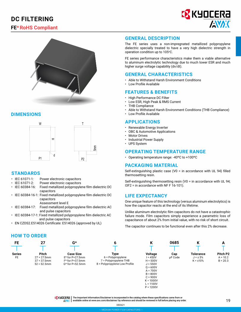
FE*
GENERAL CHARACTERISTICS• Able to Withstand Harsh Environment Conditions• Low Profile Available
FEATURES & BENEFITS• High Performance DC Filter• Low ESR, High Peak & RMS Current• THB Compliance• Able to Withstand Harsh Environment Conditions (THB Compliance)• Low Profile Available
GENERAL DESCRIPTIONThe FE series uses a non-impregnated metallized polypropylene dielectric specially treated to have a very high dielectric strength in operation condition up to 105oC.
FE series performance characteristics make them a viable alternative to aluminum electrolytic technology due to much lower ESR and much higher surge voltage capability (dv/dt).
LIFE EXPECTANCYOne unique feature of this technology (versus aluminum electrolytics) is how the capacitor reacts at the end of its lifetime.
Unlike aluminum electrolytic film capacitors do not have a catastrophic failure mode. Film capacitors simply experience a parametric loss of capacitance of about 2% from initial value, with no risk of short circuit.
The capacitor continues to be functional even after this 2% decrease.
HOW TO ORDERFE
SeriesFE
Pitch27 = 27.5mm37 = 37.5mm52 = 52.5mm
27
Case SizeE* for P=27.5mmF* for P=37.5mmG* for P=52.5mm
G*
Type6 = Polypropylene
7 = Polypropylene THB8 = Polypropylene Low Profile
6
VoltageI = 450VH = 500VJ = 550VQ = 600VA = 700VB = 800VC = 900V
K = 1000VL = 1100VP = 1200V
K
CapµF Code
0685
ToleranceJ = ± 5%K = ±10%
K
Pitch P2A = 10.2B = 20.3
A
OPERATING TEMPERATURE RANGE• Operating temperature range: -40ºC to +100ºC
STANDARDS• IEC 61071-1: Power electronic capacitors• IEC 61071-2: Power electronic capacitors• IEC 60384-16: Fixed metallized polypropylene film dielectric DC
capacitors• IEC 60384-16-1: Fixed metallized polypropylene film dielectric DC
capacitors Assessment level E
• IEC 60384-17: Fixed metallized polypropylene film dielectric AC and pulse capacitors
• IEC 60384-17-1: Fixed metallized polypropylene film dielectric AC and pulse capacitors
• EN CZDS2.E514026 Certificate: E514026 (approved by UL)
APPLICATIONS• Renewable Energy Inverter• OBC & Automotive Applications• Motor Drives• Industrial Power Supply• UPS System
PACKAGING MATERIALSelf-extinguishing plastic case (V0 = in accordance with UL 94) filled thermosetting resin.
Self-extinguishing thermosetting resin (V0 = in accordance with UL 94; I3F2 = in accordance with NF F 16-101).
080621
DIMENSIONS
RoHS CompliantDC FILTERING
– medium power film capacitors –
The Important Information/Disclaimer is incorporated in the catalog where these specifications came from or available online at www.avx.com/disclaimer/ by reference and should be reviewed in full before placing any order.

20051220
FE* RoHS CompliantDC FILTERING
POLYPROPYLENE DIELECTRIC FOR INDUSTRIAL DC FILTERINGThese capacitors have been designed primarily for high and medium power DC filtering applications.
ELECTRICAL CHARACTERISTICS – POLYPROPYLENE DIELECTRICItems Characteristics
Application DC Filtering / DC LinkReference Standard IEC 61071Climatic Category 40/85/56 IEC 60068-1Operating Temperature Range -40~ +105°C (+85°C observing voltage must be de-rating at 1.35% per °C)Upper Temperature Tmax +85°CLower Temperature Tmin -40°CRated Voltage 450Vdc ~ 1200VdcCapacitance Range 5µF ~ 1500µFCapacitance Tolerance ±5% or ±10% at +25°C
Dissipation Factor (DF)≤ 0.002 (0.20%) at 1 KHz. C≤20µF at +25°C≤ 0.003 (0.30%) at 1 KHz. C>20µF at +25°C
Test Voltage Between Terminals 1.5 x rated voltage for 10s (terminal to terminal)
Test Voltage Terminal to Case 3.0kVrms 50 Hz for 10 sec at +25°C
Insulation Resistance IR x C≥30,000 Seconds at 100VDC 1 minute at +25°C
Life Expectancy 100,000 hours at Un @ Hot-Spot temperature T=+70°C
ProtectionSolvent resistant plastic case UL94 V-0Thermosetting resin sealing UL 94 V-0 compliant
Installation Any positionLeads Tinned copper wires, standard lead wire length 5 ±1mmPackaging Packed in cardboard boxes with protection for the terminalsRoHS Compliant Compliant with the restricted substance requirements of Directive 2011/65/EU
Storage ConditionsStorage time: ≤ 24 months from the date marked on the label packageTemperature and relative humidity should be -10°C ~ +40°C and not more than 75%RH.RH ≤ 85% for 30 days randomly distributed throughout the year
Humidity Test
Test conditions & performance:Temperature: +40°C±2°C Relative humidity (RH): 93% ±2%Test duration: 56 daysCapacitance change: ≤±5% DF change (△tgδ): ≤50 X 10-4 at 1KHzInsulation resistance: ≥50% of initial limit
Endurance Test
Test conditions & performance:Temperature: +85°C±2°C Voltage applied: 1.3 X VR (d.c.)Test duration: 1000 hoursCapacitance change: ≤±5% DF change (△ tgδ): ≤50 X 10-4 at 1KHzInsulation resistance: ≥50% of initial limit
– medium power film capacitors –
The Important Information/Disclaimer is incorporated in the catalog where these specifications came from or available online at www.avx.com/disclaimer/ by reference and should be reviewed in full before placing any order.

21
CASE CODE mm
Case Code
DimensionsW
± 0.50H
± 0.50T
± 0.50P1
± 1.00P2
± 1.00d
± 0.05mm mm mm mm mm mm
FI 42.5 33.5 22.0 37.5 10.2 1.2F4 42.5 36.0 19.0 37.5 10.2 1.2FK 42.5 37.0 22.0 37.5 10.2 1.2FL 42.5 37.0 28.0 37.5 10.2 1.2F5 42.5 38.0 20.0 37.5 10.2 1.2F6 42.5 40.0 20.0 37.5 10.2 1.2F8 42.5 44.0 24.0 37.5 10.2 1.2F9 42.5 45.0 30.0 37.5 20.3 1.2FN 42.5 50.0 35.0 37.5 20.3 1.2FP 42.5 57.0 30.0 37.5 20.3 1.2G6 57.5 22.0 43.0 52.5 20.3 1.2G9 57.5 45.0 25.0 52.5 10.2 1.2GA 57.5 45.0 30.0 37.5 20.3 1.2GB 57.5 45.0 45.0 52.5 20.3 1.2GC 57.5 50.0 35.0 52.5 20.3 1.2GD 57.5 53.0 50.0 52.5 20.3 1.2GE 57.5 55.0 45.0 52.5 20.3 1.2GF 57.5 60.0 35.0 52.5 20.3 1.2GG 57.5 65.0 130.0 52.5 20.3 1.2GH 57.5 65.0 35.0 52.5 20.3 1.2GI 57.5 65.0 45.0 52.5 20.3 1.2GJ 57.5 65.0 70.0 52.5 20.3 1.2GK 57.5 70.0 35.0 52.5 20.3 1.2GL 57.5 80.0 35.0 52.5 20.3 1.2
051220
RATING & PART NUMBER REFERENCE
Cap Rated Voltage PN Voltage
CodeCase Code
Dimensionsdv/dt Peak
Current Irms ESR 10KHz Rth ESL SPQW
± 0.5H
± 0.5T
± 0.5P1
± 1.0P2
± 1.0d
± 0.05uF V mm mm mm mm mm mm V/us A A mΩ °C/W nH pcs
Voltage Vndc 450V Voltage Code I25.0 450 FE37FK6I0256*A I FK 42.5 37.0 22.0 37.5 10.2 1.2 35 875 12.5 5.5 17.5 30 49 30.0 450 FE37F66I0306*A I F6 42.5 40.0 20.0 37.5 10.2 1.2 35 1050 12.0 6.0 17.4 30 56 40.0 450 FE37FL6I0406*A I FL 42.5 37.0 28.0 37.5 10.2 1.2 35 1400 14.0 5.5 13.9 30 42 40.0 450 FE37F86I0406*A I F8 42.5 44.0 24.0 37.5 10.2 1.2 35 1400 15.0 5.2 12.8 30 49 50.0 450 FE37F96I0506*B I F9 42.5 45.0 30.0 37.5 20.3 1.2 35 1750 15.0 4.0 16.7 30 35 60.0 450 FE37F96I0606*B I F9 42.5 45.0 30.0 37.5 20.3 1.2 35 2100 16.5 4.0 13.8 30 35 40.0 450 FE52G66I0406*B I G6 57.5 22.0 43.0 52.5 20.3 1.2 35 1400 12.0 8.0 13.0 35 15 50.0 450 FE52G66I0506*B I G6 57.5 22.0 43.0 52.5 20.3 1.2 35 1750 14.0 6.5 11.8 35 15 55.0 450 FE37GA6I0556*B I GA 57.5 45.0 30.0 37.5 20.3 1.2 35 1925 15.5 5.0 12.5 35 25 60.0 450 FE37GA6I0606*B I GA 57.5 45.0 30.0 37.5 20.3 1.2 35 2100 16.5 4.5 12.2 35 25 80.0 450 FE52GA6I0806*B I GA 57.5 45.0 30.0 52.5 20.3 1.2 20 1600 16.0 4.0 14.6 35 25
100.0 450 FE52GC6I0107*B I GC 57.5 50.0 35.0 52.5 20.3 1.2 20 2000 18.0 3.8 12.2 35 20 130.0 450 FE52GF6I0137*B I GF 57.5 60.0 35.0 52.5 20.3 1.2 20 2600 22.0 3.5 8.9 35 20 140.0 450 FE52GH6I0147*B I GH 57.5 65.0 35.0 52.5 20.3 1.2 20 2800 24.0 3.4 7.7 35 20 150.0 450 FE52GK6I0157*B I GK 57.5 70.0 35.0 52.5 20.3 1.2 20 3000 26.0 3.2 6.9 35 20 160.0 450 FE52GL6I0167*B I GL 57.5 80.0 35.0 52.5 20.3 1.2 20 3200 28.0 3.1 6.2 35 20 170.0 450 FE52GL6I0177*B I GL 57.5 80.0 35.0 52.5 20.3 1.2 20 3400 30.0 3.0 5.6 35 20
Voltage Vndc 500V Voltage Code H20.0 500 FE37F46H0206*B H F4 42.5 36.0 19.0 37.5 20.3 1.2 20 400 9.0 8.0 23.1 30 56 22.0 500 FE37F56H0226*B H F5 42.5 38.0 20.0 37.5 20.3 1.2 20 440 10.0 7.0 21.4 30 56 25.0 500 FE37F56H0256*B H F5 42.5 38.0 20.0 37.5 20.3 1.2 20 500 10.0 6.0 25.0 30 56 30.0 500 FE37F86H0306*B H F8 42.5 44.0 24.0 37.5 20.3 1.2 20 600 13.0 5.0 17.8 30 49 35.0 500 FE37F86H0356*B H F8 42.5 44.0 24.0 37.5 20.3 1.2 20 700 14.0 4.5 17.0 30 49
DC FILTERINGFE - Standard *RoHS Compliant
– medium power film capacitors –
The Important Information/Disclaimer is incorporated in the catalog where these specifications came from or available online at www.avx.com/disclaimer/ by reference and should be reviewed in full before placing any order.

22110920
Cap Rated Voltage PN Voltage
CodeCase Code
Dimensionsdv/dt Peak
Current Irms ESR 10KHz Rth ESL SPQW
± 0.5H
± 0.5T
± 0.5P1
± 1.0P2
± 1.0d
± 0.05uF V mm mm mm mm mm mm V/us A A mΩ °C/W nH pcs
40.0 500 FE37F96H0406*B H F9 42.5 45.0 30.0 37.5 20.3 1.2 20 800 15.0 4.0 16.7 30 35 45.0 500 FE37F96H0456*B H F9 42.5 45.0 30.0 37.5 20.3 1.2 20 900 16.0 3.5 16.7 30 35 50.0 500 FE37F96H0506*B H F9 42.5 45.0 30.0 37.5 20.3 1.2 20 1000 17.0 3.0 17.3 30 35 55.0 500 FE37FP6H0556*B H FP 42.5 57.0 30.0 37.5 20.3 1.2 20 1100 18.0 3.0 15.4 30 35 60.0 500 FE37FP6H0606*B H FP 42.5 57.0 30.0 37.5 20.3 1.2 20 1200 18.0 3.0 15.4 30 35 65.0 500 FE37FP6H0656*B H FP 42.5 57.0 30.0 37.5 20.3 1.2 20 1300 19.0 2.0 20.8 30 35 50.0 500 FE52G96H0506*B H G9 57.5 45.0 25.0 52.5 10.2 1.2 10 500 11.0 6.0 20.7 35 30 55.0 500 FE52G96H0556*B H G9 57.5 45.0 25.0 52.5 10.2 1.2 10 550 13.0 6.0 14.8 35 30 60.0 500 FE52GA6H0606*B H GA 57.5 45.0 30.0 52.5 20.3 1.2 10 600 14.0 5.0 15.3 35 25 65.0 500 FE52GA6H0656*B H GA 57.5 45.0 30.0 52.5 20.3 1.2 10 650 14.0 5.0 15.3 35 25 70.0 500 FE52GA6H0706*B H GA 57.5 45.0 30.0 52.5 20.3 1.2 10 700 15.0 5.0 13.3 35 25 75.0 500 FE52GC6H0756*B H GC 57.5 50.0 35.0 52.5 20.3 1.2 10 750 16.0 4.0 14.6 35 20 80.0 500 FE52GC6H0806*B H GC 57.5 50.0 35.0 52.5 20.3 1.2 10 800 17.0 3.0 17.3 35 20 90.0 500 FE52GC6H0906*B H GC 57.5 50.0 35.0 52.5 20.3 1.2 10 900 18.0 3.0 15.4 35 20
100.0 500 FE52GC6H0107*B H GC 57.5 50.0 35.0 52.5 20.3 1.2 10 1000 19.0 3.0 13.9 35 20 110.0 500 FE52GB6H0117*B H GB 57.5 45.0 45.0 52.5 20.3 1.2 10 1100 19.0 2.5 16.6 35 15 120.0 500 FE52GB6H0127*B H GB 57.5 45.0 45.0 52.5 20.3 1.2 10 1200 19.0 2.5 16.6 35 15 250.0 500 FE52GJ6H0257*B H GJ 57.5 65.0 70.0 52.5 20.3 1.2 4 1000 25.0 2.0 12.0 35 10 500.0 500 FE52GG6H0507*B H GG 57.5 65.0 130.0 52.5 20.3 1.2 2 1000 45.0 1.5 4.9 35 5
Voltage Vndc 550V Voltage Code J20.0 550 FE37F66J0206*A J F6 42.5 40.0 20.0 37.5 10.2 1.2 35 700 12.5 6.5 14.8 30 56 22.0 550 FE37F66J0226*A J F6 42.5 40.0 20.0 37.5 10.2 1.2 35 770 13.5 6.5 12.7 30 56 25.0 550 FE37F66J0256*A J F6 42.5 40.0 20.0 37.5 10.2 1.2 35 875 14.5 6.5 11.0 30 56 30.0 550 FE37F86J0306*A J F8 42.5 44.0 24.0 37.5 10.2 1.2 35 1050 16.0 6.0 9.8 30 49 35.0 550 FE37F96J0356*B J F9 42.5 45.0 30.0 37.5 20.3 1.2 35 1225 18.0 6.0 7.7 30 35 40.0 550 FE37F96J0406*B J F9 42.5 45.0 30.0 37.5 20.3 1.2 35 1400 18.0 5.5 8.4 30 35 50.0 550 FE37FN6J0506*B J FN 42.5 50.0 35.0 37.5 20.3 1.2 35 1750 20.0 5.0 7.5 30 28 40.0 550 FE57G66J0406*B J G6 57.5 22.0 43.0 57.5 20.3 1.2 35 1400 16.0 5.8 10.1 35 15 60.0 550 FE37GA6J0606*B J GA 57.5 45.0 30.0 37.5 20.3 1.2 20 1200 18.0 4.8 9.6 35 25 75.0 550 FE52GC6J0756*B J GC 57.5 50.0 35.0 52.5 20.3 1.2 20 1500 20.0 5.0 7.5 35 20
100.0 550 FE52GE6J0107*B J GE 57.5 55.0 45.0 52.5 20.3 1.2 20 2000 24.0 4.5 5.8 35 15 110.0 550 FE52GE6J0117*B J GE 57.5 55.0 45.0 52.5 20.3 1.2 20 2200 26.0 4.0 5.5 35 15 130.0 550 FE52GF6J0137*B J GF 57.5 60.0 35.0 52.5 20.3 1.2 20 2600 23.0 3.4 8.3 35 20 140.0 550 FE52GH6J0147*B J GH 57.5 65.0 35.0 52.5 20.3 1.2 20 2800 25.0 3.3 7.3 35 20 150.0 550 FE52GK6J0157*B J GK 57.5 70.0 35.0 52.5 20.3 1.2 20 3000 27.0 3.1 6.6 35 20 160.0 550 FE52GL6J0167*B J GL 57.5 80.0 35.0 52.5 20.3 1.2 20 3200 29.0 3.0 5.9 35 20 170.0 550 FE52GL6J0177*B J GL 57.5 80.0 35.0 52.5 20.3 1.2 20 3400 32.0 2.8 5.2 35 20
Voltage Vndc 600V Voltage Code Q10.0 600 FE37F46Q0106*A Q F4 42.5 36.0 19.0 37.5 10.2 1.2 25 250 8.0 12.0 19.5 30 56 12.0 600 FE37F46Q0126*A Q F4 42.5 36.0 19.0 37.5 10.2 1.2 25 300 9.0 10.0 18.5 30 56 15.0 600 FE37F46Q0156*A Q F4 42.5 36.0 19.0 37.5 10.2 1.2 25 375 10.0 8.0 18.8 30 56 20.0 600 FE37F56Q0206*A Q F5 42.5 38.0 20.0 37.5 10.2 1.2 25 500 12.0 6.0 17.4 30 56 20.0 600 FE37F66Q0206*A Q F6 42.5 40.0 20.0 37.5 10.2 1.2 35 700 11.0 6.0 20.7 30 56 22.0 600 FE37F56Q0226*A Q F5 42.5 38.0 20.0 37.5 10.2 1.2 25 550 12.0 7.0 14.9 30 56 25.0 600 FE37F56Q0256*A Q F5 42.5 38.0 20.0 37.5 10.2 1.2 25 625 13.0 6.0 14.8 30 56 30.0 600 FE37F86Q0306*B Q F8 42.5 44.0 24.0 37.5 10.2 1.2 25 750 15.0 5.0 13.3 30 49 30.0 600 FE37FL6Q0306*A Q FL 42.5 37.0 28.0 37.5 10.2 1.2 35 1050 13.0 5.5 16.1 30 42 35.0 600 FE37F86Q0356*A Q F8 42.5 44.0 24.0 37.5 10.2 1.2 35 1225 16.5 5.0 11.0 30 49 35.0 600 FE37F96Q0356*B Q F9 42.5 45.0 30.0 37.5 20.3 1.2 25 875 18.0 3.5 13.2 30 35 40.0 600 FE37F96Q0406*B Q F9 42.5 45.0 30.0 37.5 20.3 1.2 35 1400 18.0 4.0 11.6 30 35 45.0 600 FE37F96Q0456*B Q F9 42.5 45.0 30.0 37.5 20.3 1.2 25 1125 18.0 3.5 13.2 30 35 50.0 600 FE37FP6Q0506*B Q FP 42.5 57.0 30.0 37.5 20.3 1.2 25 1250 19.0 2.5 16.6 30 35 35.0 600 FE52G66Q0356*B Q G6 57.5 22.0 43.0 52.5 20.3 1.2 20 700 13.5 5.5 15.0 35 15 40.0 600 FE52G96Q0406*B Q G9 57.5 45.0 25.0 52.5 20.3 1.2 14 560 14.0 6.0 12.8 35 30 45.0 600 FE52G96Q0456*B Q G9 57.5 45.0 25.0 52.5 10.2 1.2 14 630 14.0 6.0 12.8 35 30 50.0 600 FE52GA6Q0506*B Q GA 57.5 45.0 30.0 52.5 20.3 1.2 14 700 16.0 5.0 11.7 35 25 50.0 600 FE52GC6Q0506*B Q GC 57.5 50.0 35.0 52.5 20.3 1.2 20 1000 14.0 6.5 11.8 35 20
RATING & PART NUMBER REFERENCE
DC FILTERINGFE - Standard *RoHS Compliant
– medium power film capacitors –
The Important Information/Disclaimer is incorporated in the catalog where these specifications came from or available online at www.avx.com/disclaimer/ by reference and should be reviewed in full before placing any order.

23
RATING & PART NUMBER REFERENCE
Cap Rated Voltage PN Voltage
CodeCase Code
Dimensionsdv/dt Peak
Current Irms ESR 10KHz Rth ESL SPQW
± 0.5H
± 0.5T
± 0.5P1
± 1.0P2
± 1.0d
± 0.05uF V mm mm mm mm mm mm V/us A A mΩ °C/W nH pcs
55.0 600 FE52GA6Q0556*B Q GA 57.5 45.0 30.0 52.5 20.3 1.2 14 770 16.0 5.0 11.7 35 25 60.0 600 FE52GA6Q0606*B Q GA 57.5 45.0 30.0 52.5 20.3 1.2 14 840 17.0 4.0 13.0 35 25 60.0 600 FE52GC6Q0606*B Q GC 57.5 50.0 35.0 52.5 20.3 1.2 20 1200 16.0 5.0 11.7 35 20 65.0 600 FE52GC6Q0656*B Q GC 57.5 50.0 35.0 52.5 20.3 1.2 14 910 20.0 3.5 10.7 35 20 70.0 600 FE52GC6Q0706*B Q GC 57.5 50.0 35.0 52.5 20.3 1.2 20 1400 18.0 5.0 9.3 35 20 75.0 600 FE52GC6Q0756*B Q GC 57.5 50.0 35.0 52.5 20.3 1.2 14 1050 21.0 3.5 9.7 35 20 80.0 600 FE52GC6Q0806*B Q GC 57.5 50.0 35.0 52.5 20.3 1.2 14 1120 21.0 3.5 9.7 35 20 80.0 600 FE52GE6Q0806*B Q GE 57.5 55.0 45.0 52.5 20.3 1.2 20 1600 20.0 4.0 9.4 35 15 90.0 600 FE52GB6Q0906*B Q GB 57.5 45.0 45.0 52.5 20.3 1.2 14 1260 22.0 3.0 10.3 35 15 90.0 600 FE52GE6Q0906*B Q GE 57.5 55.0 45.0 52.5 20.3 1.2 20 1800 24.0 4.0 6.5 35 15
100.0 600 FE52GB6Q0107*B Q GB 57.5 45.0 45.0 52.5 20.3 1.2 14 1400 23.0 2.5 11.3 35 15 100.0 600 FE52GD6Q0107*B Q GD 57.5 53.0 50.0 52.5 20.3 1.2 20 2000 26.0 4.0 5.5 35 15 110.0 600 FE52GD6Q0117*B Q GD 57.5 53.0 50.0 52.5 20.3 1.2 20 2200 28.0 3.5 5.5 35 15 120.0 600 FE52GF6Q0127*B Q GF 57.5 60.0 35.0 52.5 20.3 1.2 20 2400 30.0 3.4 4.9 35 20 130.0 600 FE52GH6Q0137*B Q GH 57.5 65.0 35.0 52.5 20.3 1.2 20 2600 32.0 3.3 4.4 35 20 140.0 600 FE52GI6Q0147*B Q GI 57.5 65.0 45.0 52.5 20.3 1.2 20 2800 34.0 3.2 4.1 35 15 140.0 600 FE52GK6Q0147*B Q GK 57.5 70.0 35.0 52.5 20.3 1.2 20 2800 34.0 3.2 4.1 35 20 150.0 600 FE52GL6Q0157*B Q GL 57.5 80.0 35.0 52.5 20.3 1.2 20 3000 36.0 3.0 3.9 35 20 200.0 600 FE52GJ6Q0207*D Q GJ 57.5 65.0 70.0 52.5 20.3 1.2 5 1000 30.0 2.0 8.3 35 10 400.0 600 FE52GG6Q0407*E Q GG 57.5 65.0 130.0 52.5 20.3 1.2 2.5 1000 50.0 1.5 4.0 35 5
Voltage Vndc 700V Voltage Code A15.0 700 FE37FI6A0156*A A FI 42.5 33.5 22.0 37.5 10.2 1.2 35 525 10.0 8.0 18.8 30 49 15.0 700 FE37F66A0156*A A F6 42.5 40.0 20.0 37.5 10.2 1.2 35 525 10.0 8.0 18.8 30 56 20.0 700 FE37FL6A0206*A A FL 42.5 37.0 28.0 37.5 10.2 1.2 35 700 12.0 7.5 13.9 30 42 22.0 700 FE37F86A0226*A A F8 42.5 44.0 24.0 37.5 10.2 1.2 35 770 14.0 6.5 11.8 30 49 25.0 700 FE37F86A0256*A A F8 42.5 44.0 24.0 37.5 10.2 1.2 35 875 16.0 6.0 9.8 30 49 30.0 700 FE37F96A0306*B A F9 42.5 45.0 30.0 37.5 20.3 1.2 35 1050 16.0 5.8 10.1 30 35 35.0 700 FE37FN6A0356*B A FN 42.5 50.0 35.0 37.5 20.3 1.2 35 1225 20.0 5.5 6.8 30 28 30.0 700 FE52G66A0306*B A G6 57.5 22.0 43.0 52.5 20.3 1.2 20 600 12.0 8.5 12.3 35 15 40.0 700 FE52GA6A0406*B A GA 57.5 45.0 30.0 52.5 20.3 1.2 20 800 14.0 5.0 15.3 35 25 45.0 700 FE52GA6A0456*B A GA 57.5 45.0 30.0 52.5 20.3 1.2 20 900 15.5 5.0 12.5 35 25 50.0 700 FE52GC6A0506*B A GC 57.5 50.0 35.0 52.5 20.3 1.2 20 1000 15.0 4.8 13.9 35 20 55.0 700 FE52GC6A0556*B A GC 57.5 50.0 35.0 52.5 20.3 1.2 20 1100 16.0 4.5 13.0 35 20 60.0 700 FE52GC6A0606*B A GC 57.5 50.0 35.0 52.5 20.3 1.2 20 1200 18.0 4.0 11.6 35 20 65.0 700 FE52GE6A0656*B A GE 57.5 55.0 45.0 52.5 20.3 1.2 20 1300 20.0 4.0 9.4 35 15 70.0 700 FE52GE6A0706*B A GE 57.5 55.0 45.0 52.5 20.3 1.2 20 1400 20.0 3.8 9.9 35 15 75.0 700 FE52GE6A0756*B A GE 57.5 55.0 45.0 52.5 20.3 1.2 20 1500 20.0 3.8 9.9 35 15 80.0 700 FE52GE6A0806*B A GE 57.5 55.0 45.0 52.5 20.3 1.2 20 1600 22.0 3.5 8.9 35 15 80.0 700 FE52GF6A0806*B A GF 57.5 60.0 35.0 52.5 20.3 1.2 20 1600 23.0 3.4 8.3 35 20 90.0 700 FE52GE6A0906*B A GE 57.5 55.0 45.0 52.5 20.3 1.2 20 1800 24.0 3.5 7.4 35 15 90.0 700 FE52GF6A0906*B A GF 57.5 60.0 35.0 52.5 20.3 1.2 20 1800 24.0 3.5 7.4 35 20
100.0 700 FE52GH6A0107*B A GH 57.5 65.0 35.0 52.5 20.3 1.2 20 2000 26.0 3.5 6.3 35 20 110.0 700 FE52GK6A0117*B A GK 57.5 70.0 35.0 52.5 20.3 1.2 20 2200 28.0 3.4 5.6 35 20 120.0 700 FE52GL6A0127*B A GL 57.5 80.0 35.0 52.5 20.3 1.2 20 2400 30.0 3.0 5.6 35 20 130.0 700 FE52GI6A0137*B A GI 57.5 65.0 45.0 52.5 20.3 1.2 20 2600 32.0 2.8 5.2 35 15
Voltage Vndc 800V Voltage Code B10.0 800 FE37F46B0106*B B F4 42.5 36.0 19.0 37.5 10.2 1.2 35 350 8.0 12.0 19.5 30 56 12.0 800 FE37F46B0126*B B F4 42.5 36.0 19.0 37.5 10.2 1.2 35 420 9.0 10.0 18.5 30 56 15.0 800 FE37F46B0156*B B F4 42.5 36.0 19.0 37.5 10.2 1.2 35 525 10.0 8.0 18.8 30 56 15.0 800 FE37F66B0156*A B F6 42.5 40.0 20.0 37.5 10.2 1.2 35 525 10.0 8.0 18.8 30 56 20.0 800 FE37F56B0206*B B F5 42.5 38.0 20.0 37.5 10.2 1.2 35 700 12.0 6.0 17.4 30 56 20.0 800 FE37F86B0206*A B F8 42.5 44.0 24.0 37.5 10.2 1.2 35 700 13.5 6.5 12.7 30 49 20.0 800 FE37FL6B0206*A B FL 42.5 37.0 28.0 37.5 10.2 1.2 35 700 12.0 7.0 14.9 30 42 22.0 800 FE37F86B0226*A B F8 42.5 44.0 24.0 37.5 10.2 1.2 35 770 14.0 6.0 12.8 30 49 22.0 800 FE37F86B0226*B B F8 42.5 44.0 24.0 37.5 10.2 1.2 35 770 14.0 5.0 15.3 30 49 25.0 800 FE37F86B0256*B B F8 42.5 44.0 24.0 37.5 10.2 1.2 35 875 14.0 5.0 15.3 30 49 25.0 800 FE37F96B0256*B B F9 42.5 45.0 30.0 37.5 20.3 1.2 35 875 14.0 5.5 13.9 30 35
051220
DC FILTERINGFE - Standard *RoHS Compliant
– medium power film capacitors –
The Important Information/Disclaimer is incorporated in the catalog where these specifications came from or available online at www.avx.com/disclaimer/ by reference and should be reviewed in full before placing any order.

24051220
RATING & PART NUMBER REFERENCE
Cap Rated Voltage PN Voltage
CodeCase Code
Dimensionsdv/dt Peak
Current Irms ESR 10KHz Rth ESL SPQW
± 0.5H
± 0.5T
± 0.5P1
± 1.0P2
± 1.0d
± 0.05uF V mm mm mm mm mm mm V/us A A mΩ °C/W nH pcs
30.0 800 FE37F96B0306*B B F9 42.5 45.0 30.0 37.5 20.3 1.2 35 1050 16.0 4.5 13.0 30 35 35.0 800 FE37F96B0356*B B F9 42.5 45.0 30.0 37.5 20.3 1.2 35 1225 18.0 3.5 13.2 30 35 40.0 800 FE37FP6B0406*B B FP 42.5 57.0 30.0 37.5 20.3 1.2 35 1400 19.0 2.5 16.6 30 35 30.0 800 FE52G96B0306*B B G9 57.5 45.0 25.0 52.5 10.2 1.2 18 540 12.0 8.0 13.0 35 30 35.0 800 FE52G96B0356*B B G9 57.5 45.0 25.0 52.5 10.2 1.2 18 630 13.0 7.0 12.7 35 30 35.0 800 FE52GA6B0356*B B GA 57.5 45.0 30.0 52.5 20.3 1.2 20 700 14.2 6.5 11.4 35 25 40.0 800 FE52G96B0406*B B G9 57.5 45.0 25.0 52.5 10.2 1.2 18 720 14.0 6.0 12.8 35 30 40.0 800 FE52GA6B0406*B B GA 57.5 45.0 30.0 52.5 20.3 1.2 20 800 14.0 6.0 12.8 35 25 45.0 800 FE52GA6B0456*B B GA 57.5 45.0 30.0 52.5 20.3 1.2 20 900 15.5 5.5 11.4 35 25 47.0 800 FE52GC6B0476*B B GC 57.5 50.0 35.0 52.5 20.3 1.2 20 940 17.5 5.0 9.8 35 20 50.0 800 FE52GA6B0506*B B GA 57.5 45.0 30.0 52.5 20.3 1.2 18 900 16.0 5.0 11.7 35 25 50.0 800 FE52GC6B0506*B B GC 57.5 50.0 35.0 52.5 20.3 1.2 20 1000 16.0 5.0 11.7 35 20 55.0 800 FE52GC6B0556*B B GC 57.5 50.0 35.0 52.5 20.3 1.2 20 1100 17.0 4.6 11.3 35 20 60.0 800 FE52GC6B0606*B B GC 57.5 50.0 35.0 52.5 20.3 1.2 18 1080 19.0 4.0 10.4 35 20 65.0 800 FE52GC6B0656*B B GC 57.5 50.0 35.0 52.5 20.3 1.2 18 1170 20.0 3.5 10.9 35 20 65.0 800 FE52GE6B0656*B B GE 57.5 55.0 45.0 52.5 20.3 1.2 20 1300 20.0 4.0 9.4 35 15 65.0 800 FE52GF6B0656*B B GF 57.5 60.0 35.0 52.5 20.3 1.2 20 1300 19.0 4.0 10.4 35 20 70.0 800 FE52GB6B0706*B B GB 57.5 45.0 45.0 52.5 20.3 1.2 18 1260 20.0 3.5 10.7 35 15 70.0 800 FE52GE6B0706*B B GE 57.5 55.0 45.0 52.5 20.3 1.2 20 1400 20.0 3.8 9.9 35 15 70.0 800 FE52GF6B0706*B B GF 57.5 60.0 35.0 52.5 20.3 1.2 20 1400 20.0 3.8 9.9 35 20 75.0 800 FE52GB6B0756*B B GB 57.5 45.0 45.0 52.5 20.3 1.2 18 1350 22.0 3.0 10.3 35 15 75.0 800 FE52GE6B0756*B B GE 57.5 55.0 45.0 52.5 20.3 1.2 20 1500 22.0 3.8 8.2 35 15 75.0 800 FE52GH6B0756*B B GH 57.5 65.0 35.0 52.5 20.3 1.2 20 1500 22.0 3.8 8.2 35 20 80.0 800 FE52GB6B0806*B B GB 57.5 45.0 45.0 52.5 20.3 1.2 18 1440 22.0 3.0 10.3 35 15 80.0 800 FE52GI6B0806*B B GI 57.5 65.0 45.0 52.5 20.3 1.2 20 1600 23.0 3.5 8.1 35 15 80.0 800 FE52GK6B0806*B B GK 57.5 70.0 35.0 52.5 20.3 1.2 20 1600 23.0 3.5 8.1 35 20 90.0 800 FE52GI6B0906*B B GI 57.5 65.0 45.0 52.5 20.3 1.2 20 1800 25.0 3.3 7.3 35 15 90.0 800 FE52GL6B0906*B B GL 57.5 80.0 35.0 52.5 20.3 1.2 20 1800 25.0 3.3 7.3 35 20
100.0 800 FE52GI6B0107*B B GI 57.5 65.0 45.0 52.5 20.3 1.2 20 2000 28.0 3.2 6.0 35 15 160.0 800 FE52GJ6B0167*D B GJ 57.5 65.0 70.0 52.5 20.3 1.2 8 1280 30.0 2.5 6.7 35 10 320.0 800 FE52GG6B0327*E B GG 57.5 65.0 130.0 52.5 20.3 1.2 4 1280 55.0 1.5 3.3 35 5
Voltage Vndc 900V Voltage Code C9.0 900 FE37F46C0905*B C F4 42.5 36.0 19.0 37.5 10.2 1.2 35 315 9.0 12.0 15.4 30 56
10.0 900 FE37F46C0106*B C F4 42.5 36.0 19.0 37.5 10.2 1.2 35 350 9.0 11.0 16.8 30 56 10.0 900 FE37F66C0106*A C F6 42.5 40.0 20.0 37.5 10.2 1.2 35 350 9.5 11.5 14.5 30 56 12.0 900 FE37F46C0126*B C F4 42.5 36.0 19.0 37.5 10.2 1.2 35 420 9.0 9.0 20.6 30 56 15.0 900 FE37F56C0156*B C F5 42.5 38.0 20.0 37.5 10.2 1.2 35 525 11.0 8.0 15.5 30 56 15.0 900 FE37F86C0156*A C F8 42.5 44.0 24.0 37.5 10.2 1.2 35 525 12.0 7.5 13.9 30 49 18.0 900 FE37F86C0186*A C F8 42.5 44.0 24.0 37.5 10.2 1.2 35 630 12.0 7.5 13.9 30 49 20.0 900 FE37F86C0206*B C F8 42.5 44.0 24.0 37.5 10.2 1.2 35 700 14.0 5.0 15.3 30 49 20.0 900 FE37F96C0206*B C F9 42.5 45.0 30.0 37.5 20.3 1.2 35 700 15.0 5.5 12.1 30 35 22.0 900 FE37F96C0226*B C F9 42.5 45.0 30.0 37.5 20.3 1.2 35 770 15.0 5.0 13.3 30 35 25.0 900 FE37F96C0256*B C F9 42.5 45.0 30.0 37.5 20.3 1.2 35 875 17.0 5.5 9.4 30 35 30.0 900 FE37FN6C0306*B C FN 42.5 50.0 35.0 37.5 20.3 1.2 35 1050 19.0 5.0 8.3 30 28 30.0 900 FE37FP6C0306*B C FP 42.5 57.0 30.0 37.5 20.3 1.2 35 1050 18.0 4.0 11.6 30 35 35.0 900 FE37FP6C0356*B C FP 42.5 57.0 30.0 37.5 20.3 1.2 35 1225 19.0 3.0 13.9 30 35 20.0 900 FE52G66C0206*B C G6 57.5 22.0 43.0 52.5 20.3 1.2 20 400 12.0 8.6 12.1 35 15 30.0 900 FE52G96C0306*B C G9 57.5 45.0 25.0 52.5 10.2 1.2 18 540 13.0 7.0 12.7 35 30 30.0 900 FE52GA6C0306*B C GA 57.5 45.0 30.0 52.5 20.3 1.2 20 600 15.0 5.5 12.1 35 25 35.0 900 FE52GA6C0356*B C GA 57.5 45.0 30.0 52.5 20.3 1.2 18 630 14.0 6.0 12.8 35 25 35.0 900 FE52GC6C0356*B C GC 57.5 50.0 35.0 52.5 20.3 1.2 20 700 15.5 5.5 11.4 35 20 40.0 900 FE52GA6C0406*B C GA 57.5 45.0 30.0 52.5 20.3 1.2 18 720 15.0 5.0 13.3 35 25 40.0 900 FE52GC6C0406*B C GC 57.5 50.0 35.0 52.5 20.3 1.2 20 800 16.0 6.5 9.0 35 20 45.0 900 FE52GC6C0456*B C GC 57.5 50.0 35.0 52.5 20.3 1.2 18 810 17.0 5.0 10.4 35 20 50.0 900 FE52GC6C0506*B C GC 57.5 50.0 35.0 52.5 20.3 1.2 20 1000 18.0 3.6 12.9 35 20 55.0 900 FE52GB6C0556*B C GB 57.5 45.0 45.0 52.5 20.3 1.2 18 990 19.0 4.0 10.4 35 15 55.0 900 FE52GE6C0556*B C GE 57.5 55.0 45.0 52.5 20.3 1.2 20 1100 20.0 3.4 11.0 35 15
DC FILTERINGFE - Standard *RoHS Compliant
– medium power film capacitors –
The Important Information/Disclaimer is incorporated in the catalog where these specifications came from or available online at www.avx.com/disclaimer/ by reference and should be reviewed in full before placing any order.

25
RATING & PART NUMBER REFERENCE
051220
Cap Rated Voltage PN Voltage
CodeCase Code
Dimensionsdv/dt Peak
Current Irms ESR 10KHz Rth ESL SPQW
± 0.5H
± 0.5T
± 0.5P1
± 1.0P2
± 1.0d
± 0.05uF V mm mm mm mm mm mm V/us A A mΩ °C/W nH pcs
55.0 900 FE52GF6C0556*B C GF 57.5 60.0 35.0 52.5 20.3 1.2 20 1100 19.0 3.5 11.9 35 20 60 900 FE52GB6C0606*B C GB 57.5 45.0 45.0 52.5 20.3 1.2 18 1080 20.0 3.5 10.7 35 15
60.0 900 FE52GE6C0606*B C GE 57.5 55.0 45.0 52.5 20.3 1.2 20 1200 20.0 3.4 11.0 35 15 65.0 900 FE52GK6C0656*B C GK 57.5 70.0 35.0 52.5 20.3 1.2 20 1300 22.0 3.3 9.4 35 20 70.0 900 FE52GE6C0706*B C GE 57.5 55.0 45.0 52.5 20.3 1.2 20 1400 24.0 3.2 8.1 35 15 70.0 900 FE52GL6C0706*B C GL 57.5 80.0 35.0 52.5 20.3 1.2 20 1400 24.0 3.2 8.1 35 20 80.0 900 FE52GI6C0806*B C GI 57.5 65.0 45.0 52.5 20.3 1.2 20 1600 25.0 3.2 7.5 35 15 120 900 FE52GJ6C0127*D C GJ 57.5 65.0 70.0 52.5 20.3 1.2 13 1560 25.0 3.0 8.0 35 10 240 900 FE52GG6C0247*E C GG 57.5 65.0 130.0 52.5 20.3 1.2 6 1440 45.0 1.5 4.9 35 5
Voltage Vndc 1000V Voltage Code K5.0 1000 FE37F46K0505*B K F4 42.5 36.0 19.0 37.5 10.2 1.2 35 175 7.0 19.0 16.1 30 56 6.0 1000 FE37F46K0605*B K F4 42.5 36.0 19.0 37.5 10.2 1.2 35 210 7.0 16.0 19.1 30 56 7.0 1000 FE37F46K0705*B K F4 42.5 36.0 19.0 37.5 10.2 1.2 35 245 7.0 16.0 19.1 30 56 8.0 1000 FE37F46K0805*B K F4 42.5 36.0 19.0 37.5 10.2 1.2 35 280 8.0 14.0 16.7 30 56 9.0 1000 FE37F46K0905*B K F4 42.5 36.0 19.0 37.5 10.2 1.2 35 315 8.0 12.0 19.5 30 56
10.0 1000 FE37F56K0106*B K F5 42.5 38.0 20.0 37.5 10.2 1.2 35 350 9.0 11.0 16.8 30 56 10.0 1000 FE37F66K0106*A K F6 42.5 40.0 20.0 37.5 10.2 1.2 40 400 9.5 11.5 14.5 30 56 12.0 1000 FE37F56K0126*B K F5 42.5 38.0 20.0 37.5 10.2 1.2 35 420 10.0 9.0 16.7 30 56 12.0 1000 FE37F86K0126*A K F8 42.5 44.0 24.0 37.5 10.2 1.2 40 480 10.5 9.0 15.1 30 49 15.0 1000 FE37F86K0156*A K F8 42.5 44.0 24.0 37.5 10.2 1.2 40 600 12.0 7.5 13.9 30 49 15.0 1000 FE37F86K0156*B K F8 42.5 44.0 24.0 37.5 10.2 1.2 35 525 12.0 7.0 14.9 30 49 15.0 1000 FE37F96K0156*B K F9 42.5 45.0 30.0 37.5 20.3 1.2 40 600 14.0 7.5 10.2 30 35 20.0 1000 FE37F96K0206*B K F9 42.5 45.0 30.0 37.5 20.3 1.2 40 800 15.0 6.5 10.3 30 35 22.0 1000 FE37FP6K0226*B K FP 42.5 57.0 30.0 37.5 20.3 1.2 35 770 15.0 5.0 13.3 30 35 25.0 1000 FE37FN6K0256*B K FN 42.5 50.0 35.0 37.5 20.3 1.2 40 1000 18.0 5.5 8.4 30 28 25.0 1000 FE37FP6K0256*B K FP 42.5 57.0 30.0 37.5 20.3 1.2 35 875 17.0 3.5 14.8 30 35 15.0 1000 FE52G66K0156*B K G6 57.5 22.0 43.0 52.5 20.3 1.2 40 600 12.0 8.5 12.3 35 15 15.0 1000 FE52G96K0156*B K G9 57.5 45.0 25.0 52.5 10.2 1.2 18 270 10.0 12.0 12.5 35 30 20.0 1000 FE52G96K0206*B K G9 57.5 45.0 25.0 52.5 10.2 1.2 18 360 10.0 11.0 13.6 35 30 22.0 1000 FE52G96K0226*B K G9 57.5 45.0 25.0 52.5 10.2 1.2 18 396 11.0 10.0 12.4 35 30 25.0 1000 FE52GA6K0256*B K GA 57.5 45.0 30.0 52.5 20.3 1.2 18 450 12.0 9.0 11.6 35 25 30.0 1000 FE52GA6K0306*B K GA 57.5 45.0 30.0 52.5 20.3 1.2 25 750 15.0 5.5 12.1 35 25 35.0 1000 FE52GC6K0356*B K GC 57.5 50.0 35.0 52.5 20.3 1.2 25 875 16.0 5.5 10.7 35 20 40.0 1000 FE52GC6K0406*B K GC 57.5 50.0 35.0 52.5 20.3 1.2 25 1000 16.0 5.0 11.7 35 20 40.0 1000 FE52GE6K0406*B K GE 57.5 55.0 45.0 52.5 20.3 1.2 25 1000 17.0 5.0 10.4 35 15 45.0 1000 FE52GB6K0456*B K GB 57.5 45.0 45.0 52.5 20.3 1.2 18 810 17.0 5.0 10.4 35 15 50.0 1000 FE52GB6K0506*B K GB 57.5 45.0 45.0 52.5 20.3 1.2 18 900 18.0 4.0 11.6 35 15 50.0 1000 FE52GE6K0506*B K GE 57.5 55.0 45.0 52.5 20.3 1.2 25 1250 19.0 4.5 9.2 35 15 50.0 1000 FE52GH6K0506*B K GH 57.5 65.0 35.0 52.5 20.3 1.2 25 1250 19.0 4.5 9.2 35 20 55.0 1000 FE52GK6K0556*B K GK 57.5 70.0 35.0 52.5 20.3 1.2 25 1375 20.0 4.4 8.5 35 20 60.0 1000 FE52GI6K0606*B K GI 57.5 65.0 45.0 52.5 20.3 1.2 25 1500 22.0 4.0 7.7 35 15 60.0 1000 FE52GL6K0606*B K GL 57.5 80.0 35.0 52.5 20.3 1.2 25 1500 22.0 4.0 7.7 35 20
100.0 1000 FE52GJ6K0107*D K GJ 57.5 65.0 70.0 52.5 20.3 1.2 15 1500 25.0 3.5 6.9 35 10 200.0 1000 FE52GG6K0207*E K GG 57.5 65.0 130.0 52.5 20.3 1.2 7 1400 45.0 1.5 4.9 35 5
Voltage Vndc 1100V Voltage Code L6.8 1100 FE37FI6L0685*A L FI 42.5 33.5 22.0 37.5 10.2 1.2 40 272 12.0 13.5 7.7 30 49 8.0 1100 FE37F66L0805*A L F6 42.5 40.0 20.0 37.5 10.2 1.2 40 320 12.5 12.5 7.7 30 56 8.0 1100 FE37FK6L0805*A L FK 42.5 37.0 22.0 37.5 10.2 1.2 40 320 12.5 12.5 7.7 30 49 9.0 1100 FE37FK6L0905*A L FK 42.5 37.0 22.0 37.5 10.2 1.2 40 360 12.8 12.2 7.5 30 49
10.0 1100 FE37F86L0106*A L F8 42.5 44.0 24.0 37.5 10.2 1.2 40 400 15.0 8.5 7.8 30 49 12.0 1100 FE37F96L0126*B L F9 42.5 45.0 30.0 37.5 20.3 1.2 40 480 15.5 7.5 8.3 30 35 15.0 1100 FE37F96L0156*B L F9 42.5 45.0 30.0 37.5 20.3 1.2 40 600 16.0 7.0 8.4 30 35 18.0 1100 FE37FN6L0186*B L FN 42.5 50.0 35.0 37.5 20.3 1.2 40 720 15.5 7.5 8.3 30 28 20.0 1100 FE37FN6L0206*B L FN 42.5 50.0 35.0 37.5 20.3 1.2 40 800 16.5 7.2 7.7 30 28 20.0 1100 FE52GA6L0206*B L GA 57.5 45.0 30.0 52.5 20.3 1.2 25 500 12.0 8.5 12.3 35 25 25.0 1100 FE52GC6L0256*B L GC 57.5 50.0 35.0 52.5 20.3 1.2 25 625 13.0 8.2 10.8 35 20 30.0 1100 FE52GC6L0306*B L GC 57.5 50.0 35.0 52.5 20.3 1.2 25 750 15.0 5.0 13.3 35 20
DC FILTERINGFE - Standard *RoHS Compliant
– medium power film capacitors –
The Important Information/Disclaimer is incorporated in the catalog where these specifications came from or available online at www.avx.com/disclaimer/ by reference and should be reviewed in full before placing any order.

26
FE - Standard *RoHS Compliant
RATING & PART NUMBER REFERENCE
051220
Cap Rated Voltage PN Voltage
CodeCase Code
Dimensionsdv/dt Peak
Current Irms ESR 10KHz Rth ESL SPQW
± 0.5H
± 0.5T
± 0.5P1
± 1.0P2
± 1.0d
± 0.05uF V mm mm mm mm mm mm V/us A A mΩ °C/W nH pcs
35.0 1100 FE52GF6L0356*B L GF 57.5 60.0 35.0 52.5 20.3 1.2 25 875 16.0 4.9 12.0 35 20 40.0 1100 FE52GH6L0406*B L GH 57.5 65.0 35.0 52.5 20.3 1.2 25 1000 17.0 5.5 9.4 35 20 40.0 1100 FE52GE6L0406*B L GE 57.5 55.0 45.0 52.5 20.3 1.2 25 1000 17.0 5.5 9.4 35 15 45.0 1100 FE52GK6L0456*B L GK 57.5 70.0 35.0 52.5 20.3 1.2 25 1125 18.0 5.4 8.6 35 20 50.0 1100 FE52GI6L0506*B L GI 57.5 65.0 45.0 52.5 20.3 1.2 25 1250 19.5 5.2 7.6 35 15
Voltage Vndc1200V Voltage Code P5.0 1200 FE37F46P0505*B P F4 42.5 36.0 19.0 37.5 10.2 1.2 40 200 7.0 16.0 19.1 30 56 6.0 1200 FE37F46P0605*B P F4 42.5 36.0 19.0 37.5 10.2 1.2 40 240 8.0 14.0 16.7 30 56 7.0 1200 FE37F56P0705*B P F5 42.5 38.0 20.0 37.5 10.2 1.2 40 280 9.0 12.0 15.4 30 56 7.0 1200 FE37FK6P0705*A P FK 42.5 37.0 22.0 37.5 10.2 1.2 45 315 8.0 15.2 15.4 30 49 8.0 1200 FE37F56P0805*B P F5 42.5 38.0 20.0 37.5 10.2 1.2 40 320 10.0 10.0 15.0 30 56 8.0 1200 FE37F86P0805*A P F8 42.5 44.0 24.0 37.5 10.2 1.2 45 360 9.0 12.5 14.8 30 49 9.0 1200 FE37F86P0905*B P F8 42.5 44.0 24.0 37.5 10.2 1.2 40 360 11.0 9.0 13.8 30 49
10.0 1200 FE37F86P0106*A P F8 42.5 44.0 24.0 37.5 10.2 1.2 45 450 10.0 10.5 14.3 30 49 10.0 1200 FE37F86P0106*B P F8 42.5 44.0 24.0 37.5 10.2 1.2 40 400 11.0 8.0 15.5 30 49 10.0 1200 FE37F96P0106*B P F9 42.5 45.0 30.0 37.5 20.3 1.2 45 450 12.0 8.0 13.0 30 35 12.0 1200 FE37F96P0126*B P F9 42.5 45.0 30.0 37.5 20.3 1.2 40 480 13.0 7.0 12.7 30 35 15.0 1200 FE37FN6P0156*B P FN 42.5 50.0 35.0 37.5 20.3 1.2 45 675 15.0 6.5 10.3 30 28 15.0 1200 FE37FP6P0156*B P FP 42.5 57.0 30.0 37.5 20.3 1.2 40 600 14.0 5.0 15.3 30 35 10.0 1200 FE52G96P0106*B P G9 57.5 45.0 25.0 52.5 10.2 1.2 20 200 9.0 16.0 11.6 35 30 12.0 1200 FE52G96P0126*B P G9 57.5 45.0 25.0 52.5 10.2 1.2 20 240 9.0 13.0 14.2 35 30 15.0 1200 FE52G96P0156*B P G9 57.5 45.0 25.0 52.5 10.2 1.2 20 300 10.0 11.0 13.6 35 30 20.0 1200 FE52GA6P0206*B P GA 57.5 45.0 30.0 52.5 20.3 1.2 30 600 13.0 8.5 10.4 35 25 22.0 1200 FE52GC6P0226*B P GC 57.5 50.0 35.0 52.5 20.3 1.2 20 440 14.0 7.0 10.9 35 20 25.0 1200 FE52GC6P0256*B P GC 57.5 50.0 35.0 52.5 20.3 1.2 30 750 15.0 6.5 10.3 35 20 30.0 1200 FE52GB6P0306*B P GB 57.5 45.0 45.0 52.5 20.3 1.2 20 600 16.0 5.0 11.7 35 15 30.0 1200 FE52GE6P0306*B P GE 57.5 55.0 45.0 52.5 20.3 1.2 30 900 17.0 5.5 9.4 35 15 30.0 1200 FE52GF6P0306*B P GF 57.5 60.0 35.0 52.5 20.3 1.2 30 900 17.0 5.5 9.4 35 20 35.0 1200 FE52GE6P0356*B P GE 57.5 55.0 45.0 52.5 20.3 1.2 30 1050 18.0 5.0 9.3 35 15 35.0 1200 FE52GK6P0356*B P GK 57.5 70.0 35.0 52.5 20.3 1.2 30 1050 18.0 5.0 9.3 35 20 40.0 1200 FE52GI6P0406*B P GI 57.5 65.0 45.0 52.5 20.3 1.2 30 1200 20.0 4.5 8.3 35 15 45.0 1200 FE52GI6P0456*B P GI 57.5 65.0 45.0 52.5 20.3 1.2 30 1350 22.0 4.3 7.2 35 15 60.0 1200 FE52GJ6P0606*D P GJ 57.5 65.0 70.0 52.5 20.3 1.2 20 1200 40.0 2.5 3.8 35 10 65.0 1200 FE52GJ6P0656*D P GJ 57.5 65.0 70.0 52.5 20.3 1.2 18 1170 40.0 2.0 4.7 35 10
140.0 1200 FE52GG6P0147*E P GG 57.5 65.0 130.0 52.5 20.3 1.2 10 1400 45.0 1.5 4.9 35 5
DC FILTERING
– medium power film capacitors –
The Important Information/Disclaimer is incorporated in the catalog where these specifications came from or available online at www.avx.com/disclaimer/ by reference and should be reviewed in full before placing any order.

27
CASE CODE mm
Case Code
DimensionsW
± 0.5H
± 0.5T
± 0.5P1
± 1.0P2
± 1.0d
± 0.05mm mm mm mm mm mm
FA 42.0 15.0 27.0 37.5 10.2 1.2FB 42.0 15.0 33.0 37.5 10.2 1.2FC 42.0 18.0 24.0 37.5 10.2 1.2FD 42.0 18.0 27.0 37.5 10.2 1.2FE 42.0 18.0 39.0 37.5 10.2 1.2FF 42.0 24.0 30.0 37.5 10.2 1.2FG 42.0 24.0 39.0 37.5 10.2 1.2G1 57.5 15.0 33.0 52.5 20.3 1.2G2 57.5 15.0 45.0 52.5 20.3 1.2G3 57.5 15.0 62.0 52.5 20.3 1.2G4 57.5 18.0 35.0 52.5 20.3 1.2G5 57.5 18.0 50.0 52.5 20.3 1.2G7 57.5 24.0 39.0 52.5 20.3 1.2G8 57.5 24.0 70.0 52.5 20.3 1.2
Cap Rated Voltage PN Voltage
CodeCase Code
Dimensionsdv/dt Peak
Current Irms ESR 10KHz Rth ESL SPQW
± 0.5H
± 0.5T
± 0.5P1
± 1.0P2
± 1.0d
± 0.05uF V mm mm mm mm mm mm V/us A A mΩ °C/W nH pcs
Voltage Vndc 500V Voltage Code H10.0 500 FE37FA8H0106*A H FA 42.0 15.0 27.0 37.5 10.2 1.2 15 150 5.0 7.5 80.0 30 42 15.0 500 FE37FB8H0156*A H FB 42.0 15.0 33.0 37.5 10.2 1.2 15 225 7.0 5.0 61.2 30 35 20.0 500 FE52G18H0206*B H G1 57.5 15.0 33.0 52.5 20.3 1.2 7 140 6.5 8.0 44.4 35 30 30.0 500 FE52G28H0306*B H G2 57.5 15.0 45.0 52.5 20.3 1.2 7 210 9.0 5.5 33.7 35 15 50.0 500 FE52G38H0506*D H G3 57.5 15.0 62.0 52.5 20.3 1.2 7 350 13.5 3.5 23.5 35 10 10.0 500 FE37FC8H0106*A H FC 42.0 18.0 24.0 37.5 10.2 1.2 15 150 5.5 7.5 66.1 30 49 15.0 500 FE37FD8H0156*A H FD 42.0 18.0 27.0 37.5 10.2 1.2 15 225 7.0 5.0 61.2 30 42 20.0 500 FE37FE8H0206*A H FE 42.0 18.0 39.0 37.5 10.2 1.2 15 300 9.0 4.0 46.3 30 28 30.0 500 FE52G48H0306*B H G4 57.5 18.0 35.0 52.5 20.3 1.2 7 210 8.5 5.5 37.7 35 20 50.0 500 FE52G58H0506*B H G5 57.5 18.0 50.0 52.5 20.3 1.2 7 350 12.5 3.5 27.4 35 15 20.0 500 FE37FF8H0206*A H FF 42.0 24.0 30.0 37.5 10.2 1.2 15 300 9.0 4.0 46.3 30 35 30.0 500 FE37FG8H0306*A H FG 42.0 24.0 39.0 37.5 10.2 1.2 15 450 12.0 2.5 41.7 30 28 50.0 500 FE52G78H0506*B H G7 57.5 24.0 39.0 52.5 20.3 1.2 7 350 12.5 3.5 27.4 35 20
100.0 500 FE52G88H0107*D H G8 57.5 24.0 70.0 52.5 20.3 1.2 7 700 22.0 2.0 15.5 35 10 Voltage Vndc 700V Voltage Code A
7.0 700 FE37FA8A0705*A A FA 42.0 15.0 27.0 37.5 10.2 1.2 17 119 5.0 11.5 52.2 30 42 10.0 700 FE37FB8A0106*A A FB 42.0 15.0 33.0 37.5 10.2 1.2 17 170 6.5 8.0 44.4 30 35 15.0 700 FE52G18A0156*B A G1 57.5 15.0 33.0 52.5 20.3 1.2 8 120 6.5 10.0 35.5 35 30 20.0 700 FE52G28A0206*B A G2 57.5 15.0 45.0 52.5 20.3 1.2 8 160 8.5 7.5 27.7 35 15 30.0 700 FE52G38A0306*D A G3 57.5 15.0 62.0 52.5 20.3 1.2 8 240 12.0 5.0 20.8 35 10 7.0 700 FE37FC8A0705*A A FC 42.0 18.0 24.0 37.5 10.2 1.2 17 119 5.0 11.5 52.2 30 49
10.0 700 FE37FD8A0106*A A FD 42.0 18.0 27.0 37.5 10.2 1.2 17 170 6.5 8.0 44.4 30 42 15.0 700 FE37FE8A0156*A A FE 42.0 18.0 39.0 37.5 10.2 1.2 17 255 9.0 5.5 33.7 30 28 20.0 700 FE52G48A0206*B A G4 57.5 18.0 35.0 52.5 20.3 1.2 8 160 8.0 7.5 31.3 35 20 30.0 700 FE52G58A0306*B A G5 57.5 18.0 50.0 52.5 20.3 1.2 8 240 11.5 5.0 22.7 35 15 15.0 700 FE37FF8A0156*A A FF 42.0 24.0 30.0 37.5 10.2 1.2 17 255 9.0 5.5 33.7 30 35 20.0 700 FE37FG8A0206*A A FG 42.0 24.0 39.0 37.5 10.2 1.2 17 340 11.5 4.0 28.4 30 28 30.0 700 FE52G78A0306*B A G7 57.5 24.0 39.0 52.5 20.3 1.2 8 240 11.0 5.0 24.8 35 20 50.0 700 FE52G88A0506*D A G8 57.5 24.0 70.0 52.5 20.3 1.2 8 400 18.0 3.0 15.4 35 10
Voltage Vndc 1000V Voltage Code K5.0 1000 FE37FA8K0505*A K FA 42.0 15.0 27.0 37.5 10.2 1.2 25 125 4.5 11.5 64.4 30 42 7.0 1000 FE37FB8K0705*A K FB 42.0 15.0 33.0 37.5 10.2 1.2 25 175 6.0 8.0 52.1 30 35
10.0 1000 FE52G18K0106*B K G1 57.5 15.0 33.0 52.5 20.3 1.2 12 120 6.0 10.0 41.7 35 30
LOW PROFILE RATING & PART NUMBER REFERENCE
051220
DC FILTERINGFE - Low Profile *RoHS Compliant
– medium power film capacitors –
The Important Information/Disclaimer is incorporated in the catalog where these specifications came from or available online at www.avx.com/disclaimer/ by reference and should be reviewed in full before placing any order.

28
Cap Rated Voltage PN Voltage
CodeCase Code
Dimensionsdv/dt Peak
Current Irms ESR 10KHz Rth ESL SPQW
± 0.5H
± 0.5T
± 0.5P1
± 1.0P2
± 1.0d
± 0.05uF V mm mm mm mm mm mm V/us A A mΩ °C/W nH pcs
15.0 1000 FE52G28K0156*B K G2 57.5 15.0 45.0 52.5 20.3 1.2 12 180 8.0 6.5 36.1 35 15 20.0 1000 FE52G38K0206*D K G3 57.5 15.0 62.0 52.5 20.3 1.2 12 240 11.0 5.0 24.8 35 10 3.0 1000 FE37FC8K0305*A K FC 42.0 18.0 24.0 37.5 10.2 1.2 25 75 3.5 19.0 64.4 30 49 5.0 1000 FE37FD8K0505*A K FD 42.0 18.0 27.0 37.5 10.2 1.2 25 125 5.0 11.5 52.2 30 42 7.0 1000 FE37FE8K0705*A K FE 42.0 18.0 39.0 37.5 10.2 1.2 25 175 7.0 8.0 38.3 30 28
10.0 1000 FE37FE8K0106*A K FE 42.0 18.0 39.0 37.5 10.2 1.2 25 250 8.0 6.0 39.1 30 28 15.0 1000 FE52G58K0156*B K G5 57.5 18.0 50.0 52.5 20.3 1.2 12 180 9.0 6.5 28.5 35 15 20.0 1000 FE52G58K0206*B K G5 57.5 18.0 50.0 52.5 20.3 1.2 12 240 10.0 5.0 30.0 35 15 7.0 1000 FE37FF8K0705*A K FF 42.0 24.0 30.0 37.5 10.2 1.2 25 175 6.5 8.0 44.4 30 35
10.0 1000 FE37FG8K0106*A K FG 42.0 24.0 39.0 37.5 10.2 0.5 25 250 9.0 6.0 30.9 30 28 15.0 1000 FE52G78K0156*B K G7 57.5 24.0 39.0 52.5 20.3 1.2 12 180 8.5 6.5 31.9 35 20 20.0 1000 FE52G78K0206*B K G7 57.5 24.0 39.0 52.5 20.3 1.2 12 240 10.0 5.0 30.0 35 20 30.0 1000 FE52G88K0306*D K G8 57.5 24.0 70.0 52.5 20.3 1.2 12 360 15.5 4.0 15.6 35 10
LOW PROFILE RATING & PART NUMBER REFERENCE
051220
DC FILTERINGFE - Low Profile *RoHS Compliant
– medium power film capacitors –
The Important Information/Disclaimer is incorporated in the catalog where these specifications came from or available online at www.avx.com/disclaimer/ by reference and should be reviewed in full before placing any order.

29
mm
Case Code
DimensionsW
± 0.5H
± 0.5T
± 0.5P1
± 1.0P2
± 1.0d
± 0.05mm mm mm mm mm mm
FI 42.5 33.5 22.0 37.5 10.2 1.2FK 42.5 37.0 22.0 37.5 10.2 1.2FL 42.5 37.0 28.0 37.5 10.2 1.2F6 42.5 40.0 20.0 37.5 10.2 1.2F8 42.5 44.0 24.0 37.5 10.2 1.2F9 42.5 45.0 30.0 37.5 20.3 1.2FN 42.5 50.0 35.0 37.5 20.3 1.2G6 57.5 22.0 43.0 52.5 20.3 1.2GA 57.5 45.0 30.0 52.5 20.3 1.2GC 57.5 50.0 35.0 52.5 20.3 1.2GD 57.5 53.0 50.0 52.5 20.3 1.2GE 57.5 55.0 45.0 52.5 20.3 1.2GF 57.5 60.0 35.0 52.5 20.3 1.2GH 57.5 65.0 35.0 52.5 20.3 1.2GI 57.5 65.0 45.0 52.5 20.3 1.2GK 57.5 70.0 35.0 52.5 20.3 1.2GL 57.5 80.0 35.0 52.5 20.3 1.2
CASE CODE
Cap Rated Voltage PN Voltage
CodeCase Code
Dimensionsdv/dt Peak
Current Irms ESR 10KHz Rth ESL SPQW
± 0.5H
± 0.5T
± 0.5P1
± 1.0P2
± 1.0d
± 0.05uF V mm mm mm mm mm mm V/us A A mΩ °C/W nH pcs
Voltage Vndc 450V Voltage Code I25.0 450 FE37FK7I0256*A I FK 42.5 37.0 22.0 37.5 10.2 1.2 35 875 12.5 5.5 17.5 30 49 30.0 450 FE37F67I0306*A I F6 42.5 40.0 20.0 37.5 10.2 1.2 35 1050 12.0 6.0 17.4 30 56 40.0 450 FE37FL7I0406*A I FL 42.5 37.0 28.0 37.5 10.2 1.2 35 1400 14.0 5.5 13.9 30 42 40.0 450 FE37F87I0406*A I F8 42.5 44.0 24.0 37.5 10.2 1.2 35 1400 15.0 5.2 12.8 30 49 40.0 450 FE52G67I0406*B I G6 57.5 22.0 43.0 52.5 20.3 1.2 35 1400 12.0 8.0 13.0 35 15 50.0 450 FE37F97I0506*B I F9 42.5 45.0 30.0 37.5 20.3 1.2 35 1750 15.0 4.0 16.7 30 35 50.0 450 FE52G67I0506*B I G6 57.5 22.0 43.0 52.5 20.3 1.2 35 1750 14.0 6.5 11.8 35 15 55.0 450 FE52GA7I0556*B I GA 57.5 45.0 30.0 52.5 20.3 1.2 35 1925 15.5 5.0 12.5 35 25 60.0 450 FE52GA7I0606*B I GA 57.5 45.0 30.0 52.5 20.3 1.2 35 2100 16.5 4.5 12.2 35 25 60.0 450 FE37F97I0606*B I F9 42.5 45.0 30.0 37.5 20.3 1.2 35 2100 16.5 4.0 13.8 30 35 80.0 450 FE52GA7I0806*B I GA 57.5 45.0 30.0 52.5 20.3 1.2 20 1600 16.0 4.0 14.6 35 25
100.0 450 FE52GC7I0107*B I GC 57.5 50.0 35.0 52.5 20.3 1.2 20 2000 18.0 3.8 12.2 35 20 130.0 450 FE52GF7I0137*B I GF 57.5 60.0 35.0 52.5 20.3 1.2 20 2600 22.0 3.5 8.9 35 20 140.0 450 FE52GH7I0147*B I GH 57.5 65.0 35.0 52.5 20.3 1.2 20 2800 24.0 3.4 7.7 35 20 150.0 450 FE52GK7I0157*B I GK 57.5 70.0 35.0 52.5 20.3 1.2 20 3000 26.0 3.2 6.9 35 20 160.0 450 FE52GL7I0167*B I GL 57.5 80.0 35.0 52.5 20.3 1.2 20 3200 28.0 3.1 6.2 35 20 170.0 450 FE52GL7I0177*B I GL 57.5 80.0 35.0 52.5 20.3 1.2 20 3400 30.0 3.0 5.6 35 20
Voltage Vndc 550V Voltage Code J20.0 550 FE37F67J0206*A J F6 42.5 40.0 20.0 37.5 10.2 1.2 35 700 12.5 6.5 14.8 30 56 22.0 550 FE37F67J0226*A J F6 42.5 40.0 20.0 37.5 10.2 1.2 35 770 13.5 6.5 12.7 30 56 25.0 550 FE37F67J0256*A J F6 42.5 40.0 20.0 37.5 10.2 1.2 35 875 14.5 6.5 11.0 30 56 30.0 550 FE37F87J0306*A J F8 42.5 44.0 24.0 37.5 10.2 1.2 35 1050 16.0 6.0 9.8 30 49 35.0 550 FE37F97J0356*B J F9 42.5 45.0 30.0 37.5 20.3 1.2 35 1225 18.0 6.0 7.7 30 35 40.0 550 FE37F97J0406*B J F9 42.5 45.0 30.0 37.5 20.3 1.2 35 1400 18.0 5.5 8.4 30 35 40.0 550 FE52G67J0406*B J G6 57.5 22.0 43.0 52.5 20.3 1.2 35 1400 16.0 5.8 10.1 35 15 50.0 550 FE37FN7J0506*B J FN 42.5 50.0 35.0 37.5 20.3 1.2 35 1750 20.0 5.0 7.5 30 28 60.0 550 FE37GA7J0606*B J GA 57.5 45.0 30.0 37.5 20.3 1.2 20 1200 18.0 4.8 9.6 35 25 75.0 550 FE52GC7J0756*B J GC 57.5 50.0 35.0 52.5 20.3 1.2 20 1500 20.0 5.0 7.5 35 20
100.0 550 FE52GE7J0107*B J GE 57.5 55.0 45.0 52.5 20.3 1.2 20 2000 24.0 4.5 5.8 35 15 110.0 550 FE52GE7J0117*B J GE 57.5 55.0 45.0 52.5 20.3 1.2 20 2200 26.0 4.0 5.5 35 15 130.0 550 FE52GF7J0137*B J GF 57.5 60.0 35.0 52.5 20.3 1.2 20 2600 23.0 3.4 8.3 35 20
RATING & PART NUMBER REFERENCE
051220
DC FILTERINGFE - THB *RoHS Compliant
– medium power film capacitors –
The Important Information/Disclaimer is incorporated in the catalog where these specifications came from or available online at www.avx.com/disclaimer/ by reference and should be reviewed in full before placing any order.

30
RATING & PART NUMBER REFERENCE
Cap Rated Voltage PN Voltage
CodeCase Code
Dimensionsdv/dt Peak
Current Irms ESR 10KHz Rth ESL SPQW
± 0.5H
± 0.5T
± 0.5P1
± 1.0P2
± 1.0d
± 0.05uF V mm mm mm mm mm mm V/us A A mΩ °C/W nH pcs
140.0 550 FE52GH7J0147*B J GH 57.5 65.0 35.0 52.5 20.3 1.2 20 2800 25.0 3.3 7.3 35 20 150.0 550 FE52GK7J0157*B J GK 57.5 70.0 35.0 52.5 20.3 1.2 20 3000 27.0 3.1 6.6 35 20 160.0 550 FE52GL7J0167*B J GL 57.5 80.0 35.0 52.5 20.3 1.2 20 3200 29.0 3.0 5.9 35 20 170.0 550 FE52GL7J0177*B J GL 57.5 80x.0 35.0 52.5 20.3 1.2 20 3400 32.0 2.8 5.2 35 20
Voltage Vndc 600V Voltage Code Q20.0 600 FE37F67Q0206*A Q F6 42.5 40.0 20.0 37.5 10.2 1.2 35 700 11.0 6.0 20.7 30 56 30.0 600 FE37FL7Q0306*A Q FL 42.5 37.0 28.0 37.5 10.2 1.2 35 1050 13.0 5.5 16.1 30 42 35.0 600 FE37F87Q0356*A Q F8 42.5 44.0 24.0 37.5 10.2 1.2 35 1225 16.5 5.0 11.0 30 49 35.0 600 FE52G67Q0356*B Q G6 57.5 22.0 43.0 52.5 20.3 1.2 20 700 13.5 5.5 15.0 35 15 40.0 600 FE37F97Q0406*B Q F9 42.5 45.0 30.0 37.5 20.3 1.2 35 1400 18.0 4.0 11.6 30 35 50.0 600 FE52GC7Q0506*B Q GC 57.5 50.0 35.0 52.5 20.3 1.2 20 1000 14.0 6.5 11.8 35 20 60.0 600 FE52GC7Q0606*B Q GC 57.5 50.0 35.0 52.5 20.3 1.2 20 1200 16.0 5.0 11.7 35 20 70.0 600 FE52GC7Q0706*B Q GC 57.5 50.0 35.0 52.5 20.3 1.2 20 1400 18.0 5.0 9.3 35 20 80.0 600 FE52GE7Q0806*B Q GE 57.5 55.0 45.0 52.5 20.3 1.2 20 1600 20.0 4.0 9.4 35 15 90.0 600 FE52GE7Q0906*B Q GE 57.5 55.0 45.0 52.5 20.3 1.2 20 1800 24.0 4.0 6.5 35 15
100.0 600 FE52GD7Q0107*B Q GD 57.5 53.0 50.0 52.5 20.3 1.2 20 2000 26.0 4.0 5.5 35 15 110.0 600 FE52GD7Q0117*B Q GD 57.5 53.0 50.0 52.5 20.3 1.2 20 2200 28.0 3.5 5.5 35 15 120.0 600 FE52GF7Q0127*B Q GF 57.5 60.0 35.0 52.5 20.3 1.2 20 2400 30.0 3.4 4.9 35 20 130.0 600 FE52GH7Q0137*B Q GH 57.5 65.0 35.0 52.5 20.3 1.2 20 2600 32.0 3.3 4.4 35 20 140.0 600 FE52GK7Q0147*B Q GK 57.5 70.0 35.0 52.5 20.3 1.2 20 2800 34.0 3.2 4.1 35 20 140.0 600 FE52GI7Q0147*B Q GI 57.5 65.0 45.0 52.5 20.3 1.2 20 2800 34.0 3.2 4.1 35 15 150.0 600 FE52GL7Q0157*B Q GL 57.5 80.0 35.0 52.5 20.3 1.2 20 3000 36.0 3.0 3.9 35 20
Voltage Vndc 700V Voltage Code A15.0 700 FE37FI7A0156*A A FI 42.5 33.5 22.0 37.5 10.2 1.2 35 525 10.0 8.0 18.8 30 49 15.0 700 FE37F67A0156*A A F6 42.5 40.0 20.0 37.5 10.2 1.2 35 525 10.0 8.0 18.8 30 56 20.0 700 FE37FL7A0206*A A FL 42.5 37.0 28.0 37.5 10.2 1.2 35 700 12.0 7.5 13.9 30 42 22.0 700 FE37F87A0226*A A F8 42.5 44.0 24.0 37.5 10.2 1.2 35 770 14.0 6.5 11.8 30 49 25.0 700 FE37F87A0256*A A F8 42.5 44.0 24.0 37.5 10.2 1.2 35 875 16.0 6.0 9.8 30 49 30.0 700 FE37F97A0306*B A F9 42.5 45.0 30.0 37.5 20.3 1.2 35 1050 16.0 5.8 10.1 30 35 30.0 700 FE52G67A0306*B A G6 57.5 22.0 43.0 52.5 20.3 1.2 20 600 12.0 8.5 12.3 35 15 35.0 700 FE37FN7A0356*B A FN 42.5 50.0 35.0 37.5 20.3 1.2 35 1225 20.0 5.5 6.8 30 28 40.0 700 FE52GA7A0406*B A GA 57.5 45.0 30.0 52.5 20.3 1.2 20 800 14.0 5.0 15.3 35 25 45.0 700 FE52GA7A0456*B A GA 57.5 45.0 30.0 52.5 20.3 1.2 20 900 15.5 5.0 12.5 35 25 50.0 700 FE52GC7A0506*B A GC 57.5 50.0 35.0 52.5 20.3 1.2 20 1000 15.0 4.8 13.9 35 20 55.0 700 FE52GC7A0556*B A GC 57.5 50.0 35.0 52.5 20.3 1.2 20 1100 16.0 4.5 13.0 35 20 60.0 700 FE52GC7A0606*B A GC 57.5 50.0 35.0 52.5 20.3 1.2 20 1200 18.0 4.0 11.6 35 20 65.0 700 FE52GE7A0656*B A GE 57.5 55.0 45.0 52.5 20.3 1.2 20 1300 20.0 4.0 9.4 35 15 70.0 700 FE52GE7A0706*B A GE 57.5 55.0 45.0 52.5 20.3 1.2 20 1400 20.0 3.8 9.9 35 15 75.0 700 FE52GE7A0756*B A GE 57.5 55.0 45.0 52.5 20.3 1.2 20 1500 20.0 3.8 9.9 35 15 80.0 700 FE52GE7A0806*B A GE 57.5 55.0 45.0 52.5 20.3 1.2 20 1600 22.0 3.5 8.9 35 15 80.0 700 FE52GF7A0806*B A GF 57.5 60.0 35.0 52.5 20.3 1.2 20 1600 23.0 3.4 8.3 35 20 90.0 700 FE52GE7A0906*B A GE 57.5 55.0 45.0 52.5 20.3 1.2 20.0 1800 24.0 3.5 7.4 35 15 90.0 700 FE52GF7A0906*B A GF 57.5 60.0 35.0 52.5 20.3 1.2 20 1800 24.0 3.5 7.4 35 20
100.0 700 FE52GH7A0107*B A GH 57.5 65.0 35.0 52.5 20.3 1.2 20 2000 26.0 3.5 6.3 35 20 110.0 700 FE52GK7A0117*B A GK 57.5 70.0 35.0 52.5 20.3 1.2 20 2200 28.0 3.4 5.6 35 20 120.0 700 FE52GL7A0127*B A GL 57.5 80.0 35.0 52.5 20.3 1.2 20 2400 30.0 3.0 5.6 35 20 130.0 700 FE52GI7A0137*B A GI 57.5 65.0 45.0 52.5 20.3 1.2 20 2600 32.0 2.8 5.2 35 15
Voltage Vndc 800V Voltage Code B15.0 800 FE37F67B0156*A B F6 42.5 40.0 20.0 37.5 10.2 1.2 35 525 10.0 8.0 18.8 30 56 20.0 800 FE37FL7B0206*A B FL 42.5 37.0 28.0 37.5 10.2 1.2 35 700 12.0 7.0 14.9 30 42 20.0 800 FE37F87B0206*A B F8 42.5 44.0 24.0 37.5 10.2 1.2 35 700 13.5 6.5 12.7 30 49 22.0 800 FE37F87B0226*A B F8 42.5 44.0 24.0 37.5 10.2 1.2 35 770 14.0 6.0 12.8 30 49 25.0 800 FE37F97B0256*B B F9 42.5 45.0 30.0 37.5 20.3 1.2 35 875 14.0 5.5 13.9 30 35 30.0 800 FE37F97B0306*B B F9 42.5 45.0 30.0 37.5 20.3 1.2 35 1050 16.0 4.5 13.0 30 35 35.0 800 FE52GA7B0356*B B GA 57.5 45.0 30.0 52.5 20.3 1.2 20 700 14.2 6.5 11.4 35 25 40.0 800 FE52GA7B0406*B B GA 57.5 45.0 30.0 52.5 20.3 1.2 20 800 14.0 6.0 12.8 35 25 45.0 800 FE52GA7B0456*B B GA 57.5 45.0 30.0 52.5 20.3 1.2 20 900 15.5 5.5 11.4 35 25
051220
DC FILTERINGFE - THB *RoHS Compliant
– medium power film capacitors –
The Important Information/Disclaimer is incorporated in the catalog where these specifications came from or available online at www.avx.com/disclaimer/ by reference and should be reviewed in full before placing any order.

31
RATING & PART NUMBER REFERENCE
Cap Rated Voltage PN Voltage
CodeCase Code
Dimensionsdv/dt Peak
Current Irms ESR 10KHz Rth ESL SPQW
± 0.5H
± 0.5T
± 0.5P1
± 1.0P2
± 1.0d
± 0.05uF V mm mm mm mm mm mm V/us A A mΩ °C/W nH pcs
47.0 800 FE52GC7B0476*B B GC 57.5 50.0 35.0 52.5 20.3 1.2 20 940 17.5 5.0 9.8 35 20 50.0 800 FE52GC7B0506*B B GC 57.5 50.0 35.0 52.5 20.3 1.2 20 1000 16.0 5.0 11.7 35 20 55.0 800 FE52GC7B0556*B B GC 57.5 50.0 35.0 52.5 20.3 1.2 20 1100 17.0 4.6 11.3 35 20 65.0 800 FE52GF7B0656*B B GF 57.5 60.0 35.0 52.5 20.3 1.2 20 1300 19.0 4.0 10.4 35 20 65.0 800 FE52GE7B0656*B B GE 57.5 55.0 45.0 52.5 20.3 1.2 20 1300 20.0 4.0 9.4 35 15 70.0 800 FE52GE7B0706*B B GE 57.5 55.0 45.0 52.5 20.3 1.2 20 1400 20.0 3.8 9.9 35 15 70.0 800 FE52GF7B0706*B B GF 57.5 60.0 35.0 52.5 20.3 1.2 20 1400 20.0 3.8 9.9 35 20 75.0 800 FE52GE7B0756*B B GE 57.5 55.0 45.0 52.5 20.3 1.2 20 1500 22.0 3.8 8.2 35 15 75.0 800 FE52GH7B0756*B B GH 57.5 65.0 35.0 52.5 20.3 1.2 20 1500 22.0 3.8 8.2 35 20 80.0 800 FE52GI7B0806*B B GI 57.5 65.0 45.0 52.5 20.3 1.2 20 1600 23.0 3.5 8.1 35 15 80.0 800 FE52GK7B0806*B B GK 57.5 70.0 35.0 52.5 20.3 1.2 20 1600 23.0 3.5 8.1 35 20 90.0 800 FE52GI7B0906*B B GI 57.5 65.0 45.0 52.5 20.3 1.2 20 1800 25.0 3.3 7.3 35 15 90.0 800 FE52GL7B0906*B B GL 57.5 80.0 35.0 52.5 20.3 1.2 20 1800 25.0 3.3 7.3 35 20
100.0 800 FE52GI7B0107*B B GI 57.5 65.0 45.0 52.5 20.3 1.2 20 2000 28.0 3.2 6.0 35 15 Voltage Vndc 900V Voltage Code C
10.0 900 FE37F67C0106*A C F6 42.5 40.0 20.0 37.5 10.2 1.2 35 350 9.5 11.5 14.5 30 56 15.0 900 FE37F87C0156*A C F8 42.5 44.0 24.0 37.5 10.2 1.2 35 525 12.0 7.5 13.9 30 49 18.0 900 FE37F87C0186*A C F8 42.5 44.0 24.0 37.5 10.2 1.2 35 630 12.0 7.5 13.9 30 49 20.0 900 FE37F97C0206*B C F9 42.5 45.0 30.0 37.5 20.3 1.2 35 700 15.0 5.5 12.1 30 35 20.0 900 FE52G67C0206*B C G6 57.5 22.0 43.0 52.5 20.3 1.2 20 400 12.0 8.6 12.1 35 15 25.0 900 FE37F97C0256*B C F9 42.5 45.0 30.0 37.5 20.3 1.2 35 875 17.0 5.5 9.4 30 35 30.0 900 FE37FN7C0306*B C FN 42.5 50.0 35.0 37.5 20.3 1.2 35 1050 19.0 5.0 8.3 30 28 30.0 900 FE52GA7C0306*B C GA 57.5 45.0 30.0 52.5 20.3 1.2 20 600 15.0 5.5 12.1 35 25 35.0 900 FE52GC7C0356*B C GC 57.5 50.0 35.0 52.5 20.3 1.2 20 700 15.5 5.5 11.4 35 20 40.0 900 FE52GC7C0406*B C GC 57.5 50.0 35.0 52.5 20.3 1.2 20 800 16.0 6.5 9.0 35 20 50.0 900 FE52GC7C0506*B C GC 57.5 50.0 35.0 52.5 20.3 1.2 20 1000 18.0 3.6 12.9 35 20 55.0 900 FE52GF7C0556*B C GF 57.5 60.0 35.0 52.5 20.3 1.2 20 1100 19.0 3.5 11.9 35 20 55.0 900 FE52GE7C0556*B C GE 57.5 55.0 45.0 52.5 20.3 1.2 20 1100 20.0 3.4 11.0 35 15 60.0 900 FE52GE7C0606*B C GE 57.5 55.0 45.0 52.5 20.3 1.2 20 1200 20.0 3.4 11.0 35 15 65.0 900 FE52GK7C0656*B C GK 57.5 70.0 35.0 52.5 20.3 1.2 20 1300 22.0 3.3 9.4 35 20 70.0 900 FE52GE7C0706*B C GE 57.5 55.0 45.0 52.5 20.3 1.2 20 1400 24.0 3.2 8.1 35 15 70.0 900 FE52GL7C0706*B C GL 57.5 80.0 35.0 52.5 20.3 1.2 20 1400 24.0 3.2 8.1 35 20 80.0 900 FE52GI7C0806*B C GI 57.5 65.0 45.0 52.5 20.3 1.2 20 1600 25.0 3.2 7.5 35 15
Voltage Vndc 1000V Voltage Code K10.0 1000 FE37F67K0106*A K F6 42.5 40.0 20.0 37.5 10.2 1.2 40 400 9.5 11.5 14.5 30 56 12.0 1000 FE37F87K0126*A K F8 42.5 44.0 24.0 37.5 10.2 1.2 40 480 10.5 9.0 15.1 30 49 15.0 1000 FE37F87K0156*A K F8 42.5 44.0 24.0 37.5 10.2 1.2 40 600 12.0 7.5 13.9 30 49 15.0 1000 FE37F97K0156*B K F9 42.5 45.0 30.0 37.5 20.3 1.2 40 600 14.0 7.5 10.2 30 35 15.0 1000 FE52G67K0156*B K G6 57.5 22.0 43.0 52.5 20.3 1.2 40 600 12.0 8.5 12.3 35 15 20.0 1000 FE37F97K0206*B K F9 42.5 45.0 30.0 37.5 20.3 1.2 40 800 15.0 6.5 10.3 30 35 25.0 1000 FE37FN7K0256*B K FN 42.5 50.0 35.0 37.5 20.3 1.2 40 1000 18.0 5.5 8.4 30 28 30.0 1000 FE52GA7K0306*B K GA 57.5 45.0 30.0 52.5 20.3 1.2 25 750 15.0 5.5 12.1 35 25 35.0 1000 FE52GC7K0356*B K GC 57.5 50.0 35.0 52.5 20.3 1.2 25 875 16.0 5.5 10.7 35 20 40.0 1000 FE52GC7K0406*B K GC 57.5 50.0 35.0 52.5 20.3 1.2 25 1000 16.0 5.0 11.7 35 20 40.0 1000 FE52GE7K0406*B K GE 57.5 55.0 45.0 52.5 20.3 1.2 25 1000 17.0 5.0 10.4 35 15 50.0 1000 FE52GE7K0506*B K GE 57.5 55.0 45.0 52.5 20.3 1.2 25 1250 19.0 4.5 9.2 35 15 50.0 1000 FE52GH7K0506*B K GH 57.5 65.0 35.0 52.5 20.3 1.2 25 1250 19.0 4.5 9.2 35 20 55.0 1000 FE52GK7K0556*B K GK 57.5 70.0 35.0 52.5 20.3 1.2 25 1375 20.0 4.4 8.5 35 20 60 1000 FE52GL7K0606*B K GL 57.5 80.0 35.0 52.5 20.3 1.2 25 1500 22.0 4.0 7.7 35 20 60 1000 FE52GI7K0606*B K GI 57.5 65.0 45.0 52.5 20.3 1.2 25 1500 22.0 4.0 7.7 35 15
Voltage Vndc 1100V Voltage Code L6.8 1100 FE37FI7L0685*A L FI 42.5 33.5 22.0 37.5 10.2 1.2 40 272 12.0 13.5 7.7 30 49 8.0 1100 FE37F67L0805*A L F6 42.5 40.0 20.0 37.5 10.2 1.2 40 320 12.5 12.5 7.7 30 56 8.0 1100 FE37FK7L0805*A L FK 42.5 37.0 22.0 37.5 10.2 1.2 40 320 12.5 12.5 7.7 30 49 9.0 1100 FE37FK7L0905*A L FK 42.5 37.0 22.0 37.5 10.2 1.2 40 360 12.8 12.2 7.5 30 49
10.0 1100 FE37F87L0106*A L F8 42.5 44.0 24.0 37.5 10.2 1.2 40 400 15.0 8.5 7.8 30 49 12.0 1100 FE37F97L0126*B L F9 42.5 45.0 30.0 37.5 20.3 1.2 40 480 15.5 7.5 8.3 30 35
051220
DC FILTERINGFE - THB *RoHS Compliant
– medium power film capacitors –
The Important Information/Disclaimer is incorporated in the catalog where these specifications came from or available online at www.avx.com/disclaimer/ by reference and should be reviewed in full before placing any order.

32
RATING & PART NUMBER REFERENCE
FE - THB *RoHS Compliant
Cap Rated Voltage PN Voltage
CodeCase Code
Dimensionsdv/dt Peak
Current Irms ESR 10KHz Rth ESL SPQW
± 0.5H
± 0.5T
± 0.5P1
± 1.0P2
± 1.0d
± 0.05uF V mm mm mm mm mm mm V/us A A mΩ °C/W nH pcs
15.0 1100 FE37F97L0156*B L F9 42.5 45.0 30.0 37.5 20.3 1.2 40 600 16.0 7.0 8.4 30 35 18.0 1100 FE37FN7L0186*B L FN 42.5 50.0 35.0 37.5 20.3 1.2 40 720 15.5 7.5 8.3 30 28 20.0 1100 FE37FN7L0206*B L FN 42.5 50.0 35.0 37.5 20.3 1.2 40 800 16.5 7.2 7.7 30 28 20.0 1100 FE52GA7L0206*B L GA 57.5 45.0 30.0 52.5 20.3 1.2 25 500 12.0 8.5 12.3 35 25 25.0 1100 FE52GC7L0256*B L GC 57.5 50.0 35.0 52.5 20.3 1.2 25 625 13.0 8.2 10.8 35 20 30.0 1100 FE52GC7L0306*B L GC 57.5 50.0 35.0 52.5 20.3 1.2 25 750 15.0 5.0 13.3 35 20 35.0 1100 FE52GF7L0356*B L GF 57.5 60.0 35.0 52.5 20.3 1.2 25 875 16.0 4.9 12.0 35 20 40.0 1100 FE52GH7L0406*B L GH 57.5 65.0 35.0 52.5 20.3 1.2 25 1000 17.0 5.5 9.4 35 20 40.0 1100 FE52GE7L0406*B L GE 57.5 55.0 45.0 52.5 20.3 1.2 25 1000 17.0 5.5 9.4 35 15 45.0 1100 FE52GK7L0456*B L GK 57.5 70.0 35.0 52.5 20.3 1.2 25 1125 18.0 5.4 8.6 35 20 50.0 1100 FE52GI7L0506*B L GI 57.5 65.0 45.0 52.5 20.3 1.2 25 1250 19.5 5.2 7.6 35 15
Voltage Vndc 1200V Voltage Code P7.0 1200 FE37FK7P0705*A P FK 42.5 37.0 22.0 37.5 10.2 1.2 45 315 8.0 15.2 15.4 30 49 8.0 1200 FE37F87P0805*A P F8 42.5 44.0 24.0 37.5 10.2 1.2 45 360 9.0 12.5 14.8 30 49
10.0 1200 FE37F87P0106*A P F8 42.5 44.0 24.0 37.5 10.2 1.2 45 450 10.0 10.5 14.3 30 49 10.0 1200 FE37F97P0106*B P F9 42.5 45.0 30.0 37.5 20.3 1.2 45 450 12.0 8.0 13.0 30 35 15.0 1200 FE37FN7P0156*B P FN 42.5 50.0 35.0 37.5 20.3 1.2 45 675 15.0 6.5 10.3 30 28 20.0 1200 FE52GA7P0206*B P GA 57.5 45.0 30.0 52.5 20.3 1.2 30 600 13.0 8.5 10.4 35 25 25.0 1200 FE52GC7P0256*B P GC 57.5 50.0 35.0 52.5 20.3 1.2 30 750 15.0 6.5 10.3 35 20 30.0 1200 FE52GE7P0306*B P GE 57.5 55.0 45.0 52.5 20.3 1.2 30 900 17.0 5.5 9.4 35 15 30.0 1200 FE52GF7P0306*B P GF 57.5 60.0 35.0 52.5 20.3 1.2 30 900 17.0 5.5 9.4 35 20 35.0 1200 FE52GE7P0356*B P GE 57.5 55.0 45.0 52.5 20.3 1.2 30 1050 18.0 5.0 9.3 35 15 35.0 1200 FE52GK7P0356*B P GK 57.5 70.0 35.0 52.5 20.3 1.2 30 1050 18.0 5.0 9.3 35 20 40.0 1200 FE52GI7P0406*B P GI 57.5 65.0 45.0 52.5 20.3 1.2 30 1200 20.0 4.5 8.3 35 15 45.0 1200 FE52GI7P0456*B P GI 57.5 65.0 45.0 52.5 20.3 1.2 30 1350 22.0 4.3 7.2 35 15
051220
DC FILTERING
– medium power film capacitors –
The Important Information/Disclaimer is incorporated in the catalog where these specifications came from or available online at www.avx.com/disclaimer/ by reference and should be reviewed in full before placing any order.

33
DC FILTERINGFFB*
PACKAGING MATERIALSelf-extinguishing plastic case (V0 = in accordance with UL 94) filled thermosetting resin.Self-extinguishing thermosetting resin (V0 = in accordance with UL 94; I3F2 = in accordance with NF F 16-101).
STANDARDS IEC 61071-1, IEC 61071-2: Power electronic capacitors IEC 60384-16: Fixed metallized polypropylene film
dielectric DC capacitors IEC 60384-16-1: Fixed metallized polypropylene film
dielectric DC capacitors Assessment level E
IEC 60384-17: Fixed metallized polypropylene film dielectric AC and pulse capacitors
IEC 60384-17-1: Fixed metallized polypropylene film dielectric AC and pulse capacitors Assessment level E
IEC 60384-2: Fixed metallized polyester capacitors
The FFB series uses a metallized polypropylene or polyester dielectric with the controlled self-healing process, specially treated to have a very high dielectric strength in operating conditions up to 105°C.
This is a dry solution for polypropylene and dry or wet for polyester.
The FFB has been designed for printed circuit board mounting. Furthermore, their performances allow to be a very interesting alternative to electrolytic technology because they can withstand much higher levels of surge voltage.
APPLICATIONSThe FFB capacitor is particularly designed for DC filtering, low reactive power.
HOT SPOT CALCULATIONSee Hot Spot Temperature, page 3.
θhot spot = θambient + (Pd + Pt) x Rth with Pd (Dielectric losses) = Q x tgδ0
Q x tgδ0 [ ½ x Cn x (Vpeak to peak)2 x f ] x tgδ0 tgδ0 (tan delta)For polypropylene, tgδ0 = 2 x 10⁻⁴ for frequencies up to 1MHz and is independent of temperatures. For polyester, tgδ0 values are shown in graph 4 on page 3.
Pt (Thermal losses) = Rs x (Irms)2
where Cn in FaradV in VoltRth in °C/W
Irms in AmpereRs in Ohm
f in Hertzθ in °C
OPERATING TEMPERATURE RANGE(according to the power to be dissipated) -55°C to +105°C
LIFETIME EXPECTANCYOne unique feature of this technology (as opposed to electrolytics) is how the capacitor reacts at the end of its lifetime. Unlike aluminum, electrolytics film capacitors do not have a catastrophic failure mode. Film capacitors simply experience a parametric loss of capacitance of about 2%, with no risk of short circuit.
Please note that this is theoretical, however, as the capacitor continues to be functional even after this 2% decrease.
051220
RoHS Compliant
– medium power film capacitors –
The Important Information/Disclaimer is incorporated in the catalog where these specifications came from or available online at www.avx.com/disclaimer/ by reference and should be reviewed in full before placing any order.

34
DC FILTERINGFFB* RoHS Compliant
FFB 1 K ––4 D 0336
Series Case Size
Dielectric4 = Polyester6 = Polypropylene
Voltage Code
D = 75Vdc E = 100Vdc H = 300Vdc I = 400Vdc J = 525Vdc A = 720Vdc C = 900Vdc L = 1100Vdc
CapacitanceCode
0 + pF code0336 = 33μF0686 = 68μF
0117 = 110μFetc.
CapacitanceTolerances
K = ±10%
Lead Styles– – = 2 LeadedJC = 4 Leaded
Consult Factory for Special
Options
HOW TO ORDER
12345
GENERAL DESCRIPTION
CASE STYLE: P0; 18; 19; 26; R682 LEADED STYLE
General Tolerance: ± 0.5mm
LS
Ø Lead
0.4
min
DETAIL B
DETAIL BHei
ght
Length
Wid
th
Resin meniscus0.5 max
5.5
± 1
CASE STYLE: R684 LEADED STYLE
27.5 ± 0.5
General Tolerance: ± 0.5mm
1.2 ± 0.1
DETAIL A
DETAIL A
Resin meniscus0.5 max
12.7 ± 0.5 5.5
± 1Th: 0.6
37
32
22
0.4
min
DIMENSIONS: millimeters
Case Size Case Style Length (mm)
Width (mm)
Height (mm)
Dimensions lead (mm)
LS(mm)
1 PO 31.1 13.0 22.4 Ø 0.80 27.52 18 31.1 14.9 25.7 Ø 0.80 27.53 19 31.1 17.3 29.8 Ø 0.80 27.54 26 31.1 20.8 31.3 Ø 1.00 27.5
5
R682 Leaded Style 32.0 22.0 37.0 Ø 1.00 27.5
R684 Leaded Style 32.0 22.0 37.0 1.20 x 0.60 27.5
022321
– medium power film capacitors –
The Important Information/Disclaimer is incorporated in the catalog where these specifications came from or available online at www.avx.com/disclaimer/ by reference and should be reviewed in full before placing any order.

35
DC FILTERINGFFB* – Polyester Dielectric RoHS Compliant
Items CharacteristicsClimatic category 55/105/56 (IEC 60068)Test voltage between terminals @ 25°C 1.5 x VndcCapacitance range Cn 6.2μF to 110μFTolerance on Cn ±10%Rated DC voltage Vndc 75 to 400 VDielectric polyesterMax Stray Inductance 20nH
POLYESTER DIELECTRIC FOR LOW VOLTAGE DC FILTERING
ELECTRICAL CHARACTERISTICS – POLYESTER DIELECTRIC
LIFETIME EXPECTANCY vs VOLTAGE AND HOT SPOT TEMPERATURE
– POLYESTER DIELECTRIC
50°C
60°C
70°C
95°C
85°C
105°C
Vw
/Vnd
c
1.2
1.1
1.0
0.8
0.9
0.7
0.6
0.5
0.4
0.3100 1000 10000 100000
Lifetime Expectancy (hours)
Vw = Permanent working or operating DC voltage.
RATINGS AND PART NUMBER REFERENCE – POLYESTER DIELECTRIC
Part Number Capacitance (μF) Case Style Irms max.
(A)RS
(mΩ)Rth
(°C/W)Typical
Weight (g)Vndc 75V Vrms max.: 45 volts Voltage Code: D
FFB14D0336K-- 33 PO 3 3 40.7 15
FFB24D0476K-- 47 18 4.3 2 33.3 20
FFB34D0686K-- 68 19 6.2 1.7 29.9 25
FFB44D0826K-- 82 26 7.4 1.6 26.7 32
FFB54D0117K-- 110 R68 (2 terminals) 10 1.4 22.9 40
FFB54D0117KJC 110 R68 (4 terminals) 10 1.4 22.9 40
Vndc 100V Vrms max.: 60 volts Voltage Code: E
FFB14E0206K-- 20 PO 2.6 3 40.5 15
FFB24E0276K-- 27 18 3.5 2.5 33.3 20
FFB34E0396K-- 39 19 5 2 29.8 25
FFB44E0476K-- 47 26 6 1.7 26.6 32
FFB54E0686K-- 68 R68 (2 terminals) 9 1.4 22.8 40
FFB54E0686KJC 68 R68 (4 terminals) 9 1.4 22.8 40
Vndc 300V Vrms max.: 90 volts Voltage Code: H
FFB14H0755K-- 7.5 PO 2.4 16 40.7 15
FFB24H0116K-- 11 18 3.6 11 33.5 20
FFB34H0166K-- 16 19 5.2 8 29.9 25
FFB44H0186K-- 18 26 6 7 27.1 32
FFB54H0276K-- 27 R68 (2 terminals) 9 5 22.9 40
FFB54H0276KJC 27 R68 (4 terminals) 9 5 22.9 40
Vndc 400V Vrms max.: 105 volts Voltage Code: I
FFB14I0625K--* 6.2 PO 2.5 17 40.5 15
FFB24I0755K--* 7.5 18 3.1 14 33.5 20
FFB34I0126K--* 12 19 5 9 29.9 25
FFB44I0156K--* 15 26 6.2 7 26.4 32
FFB54I0206K--* 20 R68 (2 terminals) 8.2 5.5 22.8 40
FFB54I0206KJC* 20 R68 (4 terminals) 8.2 5.5 22.8 40
(*) Polyester dielectric film wet silicone
022321
– medium power film capacitors –
The Important Information/Disclaimer is incorporated in the catalog where these specifications came from or available online at www.avx.com/disclaimer/ by reference and should be reviewed in full before placing any order.

36
DC FILTERINGFFB* – Polypropylene Dielectric RoHS Compliant
Climatic category 55/105/56 (IEC 60068)Test voltage between terminals @ 25°C 1.5 x Vndc Capacitance range Cn 1.5μF to 13μFTolerance on Cn ±10%Rated DC voltage Vndc 525 to 1100 V Dielectric polypropylene
POLYPROPYLENE DIELECTRIC FOR INDUSTRIAL DC FILTERINGThese capacitors have been designed principally for high and medium power DC filtering applications.
ELECTRICAL CHARACTERISTICS – POLYPROPYLENE DIELECTRIC
LIFETIME EXPECTANCY VS VOLTAGE AND HOT SPOT TEMPERATURE – POLYPROPYLENE DIELECTRIC
RATINGS AND PART NUMBER REFERENCE – POLYPROPYLENE DIELECTRIC
Part Number Capacitance (μF) Case Style Irms max.
(A)RS
(mΩ)Rth
(°C/W)Typical
Weight (g)Vndc 525V Vrms max.: 105 volts Voltage Code: J
FFB16J0395K-- 3.9 PO 5.1 30 45.7 15
FFB26J0565K-- 5.6 18 7.4 21 36.4 20
FFB36J0825K-- 8.2 19 10.9 15 32.6 25
FFB46J0106K-- 10 26 12 12 29.8 32
FFB56J0136K-- 13 R68 (2 terminals) 12 9 24.3 40
FFB56J0136KJC 13 R68 (4 terminals) 16.7 9 24.3 40
Vndc 720V Vrms max.: 120 volts Voltage Code: A
FFB16A0335K-- 3.3 PO 5.0 31 45.0 15
FFB26A0435K-- 4.3 18 6.5 24 36.2 20
FFB36A0625K-- 6.2 19 9.4 17 32.7 25
FFB46A0755K-- 7.5 26 11.4 14 29.9 32
FFB56A0106K-- 10 R68 (2 terminals) 12 11 24.2 40
FFB56A0106KJC 10 R68 (4 terminals) 15.2 11 24.2 40
Vndc 900V Vrms max.: 150 volts Voltage Code: C
FFB16C0205K-- 2 PO 3.6 41 45.7 15
FFB26C0275K-- 2.7 18 4.9 30 36.6 20
FFB36C0395K-- 3.9 19 7.2 21 32.9 25
FFB46C0515K-- 5.1 26 9.3 16 29.7 32
FFB56C0685K-- 6.8 R68 (2 terminals) 12 12 24.1 40
FFB56C0685KJC 6.8 R68 (4 terminals) 12.5 12 24.1 40
Vndc 1100V Vrms max.: 180 volts Voltage Code: L
FFB16L0155K-- 1.5 PO 3.3 45 45.2 15
FFB26L0185K-- 1.8 18 3.9 40 36.5 20
FFB36L0245K-- 2.4 19 5.3 28 33.4 25
FFB46L0305K-- 3 26 6.6 23 30.2 32
FFB56L0475K-- 4.7 R68 (2 terminals) 10.3 15 24.1 40
FFB56L0475KJC 4.7 R68 (4 terminals) 10.3 15 24.1 40
50°C60°C
70°C
95°C
85°C
80°C
105°C
Vw
/Vnd
c
1.2
1.1
1.0
0.8
0.7
0.9
100 1000 10000 100000Lifetime Expectancy (hours)
Vw = Working DC Voltage • Vn = Rated DC Voltage
061520
– medium power film capacitors –
The Important Information/Disclaimer is incorporated in the catalog where these specifications came from or available online at www.avx.com/disclaimer/ by reference and should be reviewed in full before placing any order.
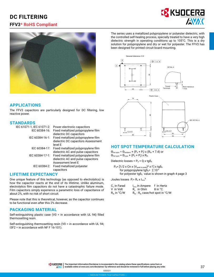
37
DC FILTERINGFFV3*
The series uses a metallized polypropylene or polyester dielectric, with the controlled self-healing process, specially treated to have a very high dielectric strength in operating conditions up to 105°C. This is a dry solution for polypropylene and dry or wet for polyester. The FFV3 has been designed for printed circuit board mounting.
APPLICATIONSThe FFV3 capacitors are particularly designed for DC filtering, low reactive power.
STANDARDS IEC 61071-1, IEC 61071-2: Power electronic capacitors IEC 60384-16: Fixed metallized polypropylene film
dielectric DC capacitors IEC 60384-16-1: Fixed metallized polypropylene film
dielectric DC capacitors Assessment level E
IEC 60384-17: Fixed metallized polypropylene film dielectric AC and pulse capacitors
IEC 60384-17-1: Fixed metallized polypropylene film dielectric AC and pulse capacitors Assessment level E
IEC 60384-2: Fixed metallized polyester capacitors
LIFETIME EXPECTANCYOne unique feature of this technology (as opposed to electrolytics) is how the capacitor reacts at the end of its lifetime. Unlike aluminum, electrolytics film capacitors do not have a catastrophic failure mode. Film capacitors simply experience a parametric loss of capacitance of about 2%, with no risk of short circuit.
Please note that this is theoretical, however, as the capacitor continues to be functional even after this 2% decrease.
PACKAGING MATERIALSelf-extinguishing plastic case (V0 = in accordance with UL 94) filled thermosetting resin.
Self-extinguishing thermosetting resin (V0 = in accordance with UL 94; I3F2 = in accordance with NF F 16-101).
HOT SPOT TEMPERATURE CALCULATIONΘhot spot = Θambient + (Pd + Pj) x (Rth + 7.4) or Θhot spot = Θcase + (Pd + Pj) x Rth
Dielectric losses = Pd = Q x tgδ0
Pd= [1/2 x Cn x (Vpeak to peak)² x f ] x tgδ0 for polypropylene tgδ0= 2.10-4 for polyester tgδ0 value is shown in graph 4 page 3
Joules losses Pj= Rs x Irms²
Cn in Farad Irms in Ampere f in HertzV in Volt Rs in Ohm θ in °CRth in °C/W Rth : Rth case/hot spot in °C/W
General tolerance: 0.5
Resin meniscus1 max
Plastic Case
SEE DETAIL A
300.8 ± 0.11.2 ± 0.1
4.5
± 1
4036
DETAIL A
1.2
0.6
30
25
16
40
A
B
A
B
TinnedTerminals
030321
RoHS Compliant
– medium power film capacitors –
The Important Information/Disclaimer is incorporated in the catalog where these specifications came from or available online at www.avx.com/disclaimer/ by reference and should be reviewed in full before placing any order.

38
DC FILTERINGFFV3* for Low Voltage Applications RoHS Compliant
FFV3 K ––4 D
Series Dielectric4 = Polyester6 = Polypropylene
Voltage Code CapacitanceTolerances
K = ±10%
Lead Styles– – = Standard
Consult Factory for Special
Options
HOW TO ORDER
ELECTRICAL CHARACTERISTICS – POLYESTER DIELECTRIC
RATINGS AND PART NUMBER REFERENCE – POLYESTER DIELECTRIC
Part Number Capacitance (μF)
Irms max. (A)
I2t10 shots (A2s)
I2t1000 shots (A2s)
Rs (mΩ)
Rth (°C/W)
Typical Weight (g)
Vndc = 75 V Vrms = 45 v max Voltage Code: DFFV34D0137K-- 130 23 370 37 0.56 5.6 90FFV34D0167K-- 160 28 560 56 0.47 5 90
Vndc = 100 V Vrms = 60 v max Voltage Code: EFFV34E0806K-- 80 19 250 25 0.67 6.2 90FFV34E0107K-- 100 24 390 39 0.55 5.4 90
Vndc = 160 V Vrms = 75 v max Voltage Code: FFFV34F0556K-- 55 17 180 18 0.77 6.6 90FFV34F0656K-- 65 20 260 26 0.66 6 90
Vndc = 300 V Vrms = 90 v max Voltage Code: HFFV34H0406K-- 40 20 150 15 2.80 9.6 90FFV34H0506K-- 50 26 230 23 2.25 8.5 90
Vndc = 400 V Vrms = 105 v max Voltage Code: IFFV34I0306K--* 30 17 110 11 2.93 9.9 90FFV34I0406K--* 40 23 200 20 2.21 8.4 90
D = 75Vdc E = 100Vdc F = 160Vdc H = 300Vdc I = 400Vdc
J = 525Vdc A = 720Vdc C = 900Vdc L = 1100Vdc
Items CharacteristicsClimatic category 40/105/56 (IEC 60068) Test voltage between terminals @ 25°C 1.5 x Vndc during 10sTest voltage between terminals and case @ 25°C “ @ 4 kVrms @ 50 Hz during 1 min.Capacitance range Cn 30μF to 160μFTolerance on Cn ±10%Rated DC voltage Vndc 75 to 400 VDielectric PolyesterMax Stray Inductance 15nH
(*) Polyester dielectric film wet silicone
LIFETIME EXPECTANCY VS VW/Vn AND HOT SPOT TEMPERATURE POLYESTER DIELECTRIC
Vw = Permanent working or operating DC voltage.
50ºC
60ºC
70ºC85ºC
95ºC
105ºC
Vw
/Vnd
c
1.2
1.1
1.0
0.8
0.9
0.7
0.6
0.5
0.4
0.3000010001001
Lifetime Expectancy (hours)
100000
022421
– medium power film capacitors –
The Important Information/Disclaimer is incorporated in the catalog where these specifications came from or available online at www.avx.com/disclaimer/ by reference and should be reviewed in full before placing any order.
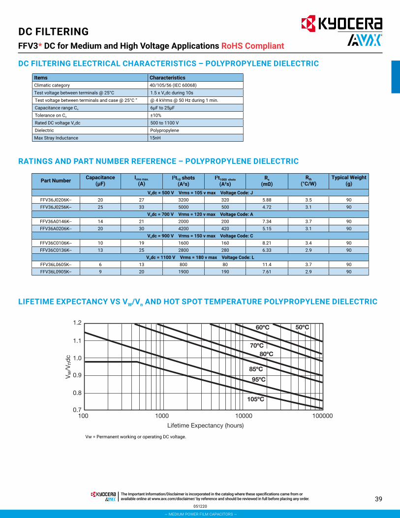
39
Vw = Permanent working or operating DC voltage.
DC FILTERINGFFV3* DC for Medium and High Voltage Applications RoHS Compliant
RATINGS AND PART NUMBER REFERENCE – POLYPROPYLENE DIELECTRIC
Part Number Capacitance (μF)
Irms max. (A)
I2t10 shots (A2s)
I2t1000 shots (A2s)
Rs (mΩ)
Rth (°C/W)
Typical Weight (g)
Vndc = 500 V Vrms = 105 v max Voltage Code: JFFV36J0206K-- 20 27 3200 320 5.88 3.5 90FFV36J0256K-- 25 33 5000 500 4.72 3.1 90
Vndc = 700 V Vrms = 120 v max Voltage Code: AFFV36A0146K-- 14 21 2000 200 7.34 3.7 90FFV36A0206K-- 20 30 4200 420 5.15 3.1 90
Vndc = 900 V Vrms = 150 v max Voltage Code: CFFV36C0106K-- 10 19 1600 160 8.21 3.4 90FFV36C0136K-- 13 25 2800 280 6.33 2.9 90
Vndc = 1100 V Vrms = 180 v max Voltage Code: LFFV36L0605K-- 6 13 800 80 11.4 3.7 90FFV36L0905K-- 9 20 1900 190 7.61 2.9 90
Items CharacteristicsClimatic category 40/105/56 (IEC 60068) Test voltage between terminals @ 25°C 1.5 x Vndc during 10sTest voltage between terminals and case @ 25°C “ @ 4 kVrms @ 50 Hz during 1 min.Capacitance range Cn 6μF to 25μFTolerance on Cn ±10%Rated DC voltage Vndc 500 to 1100 VDielectric PolypropyleneMax Stray Inductance 15nH
LIFETIME EXPECTANCY VS VW/Vn AND HOT SPOT TEMPERATURE POLYPROPYLENE DIELECTRIC
DC FILTERING ELECTRICAL CHARACTERISTICS – POLYPROPYLENE DIELECTRIC
50ºC60ºC
70ºC80ºC
85ºC
95ºC
105ºC
Vw
/Vnd
c
0.9
1.2
1.1
0.7
1.0
0.8
000010001001
Lifetime Expectancy (hours)
100000
Vw = Permanent working or operating DC voltage.
051220
– medium power film capacitors –
The Important Information/Disclaimer is incorporated in the catalog where these specifications came from or available online at www.avx.com/disclaimer/ by reference and should be reviewed in full before placing any order.

40
DC FILTERINGFFG Design (FFH-RoHS Compliant)
DC FILTERING
GENERAL DESCRIPTIONThe FFG series uses a non-impregnated metallized dielectric, which features a controlled self-healing process.
PACKAGING MATERIALSelf-extinguishing plastic case (V0 = in accordance with UL 94) filled thermosetting resin.Self-extinguishing thermosetting resin (V0 = in accordance with UL 94; I3F1 = in accordance with NF F 16-101).
STANDARDS IEC 61071-1, IEC 61071-2: Power electronic capacitors IEC 60068-1: Environmental testing UL 94: Fire requirement
HOT SPOT CALCULATIONθhot spot = θterminal + (Pd + Pt) x Rth
with Pd (Dielectric losses) = Q x tgδ0 and tgδ0 = 2.10, where Pt (Thermal losses) = Rs x Irms
2
where Cn in FaradV in VoltRth in °C/W
Irms in AmpereRs in Ohm
f in Hertzθ in °C
FFG K03768 ––6 K
SeriesFFG = StandardFFH = RoHS Compliant
Dielectric6 = Polypropylene
Voltage Code
CapacitanceTolerances
K = ±10%
Capacitance Code
0 + pF code0376 = 36μF0256 = 25μF0505 = 5μF
etc.
Case Size
8
Voltage Range
– – = < 1kVJ7 = ≥ 1kV
HOW TO ORDER
K = 600VdcB = 800VdcC = 900VdcL = 1000VdcU = 1200VdcN = 1900Vdc
Please select correct termination style.
TPC
Ø4
A
A
Tinned Output
General Tolerance: 2
M8/8
Plastic Case orResin Molding
Resin
h 2.00
h 2.00
H 1.0
Ød
ØD max
H 62.5Max Torque: 8.5Nm (M8)
DIMENSIONS (CASE SIZES)plastic case – Outputs: threaded insert M8 filled with thermosetting resin
051220
– medium power film capacitors –
The Important Information/Disclaimer is incorporated in the catalog where these specifications came from or available online at www.avx.com/disclaimer/ by reference and should be reviewed in full before placing any order.

41
DC FILTERINGFFG (FFH RoHS Compliant)
RATINGS AND PART NUMBER REFERENCE (600V TO 900V)
Part Number Cn (μF)
Height ±1
(mm)
h ±2
(mm)
D max
(mm)
d ±0.50 (mm)
I2t max
(A2s)
Irms max (A)
Rs (mΩ)
Rth (°C/W)
Typical Weight (g)
Undc 600 V (Voltage Code K)FFG86K0376K-- 37 52 5 60 22 4 28 1.3 10.1 190FFG86K0586K-- 58 52 5 72 22 10 44 1 6.4 260FFG86K0806K-- 80 52 5 82 22 20 61 0.7 4.9 320FFG86K0167K-- 160 62.5 5 92 22 32 76 0.8 5.8 475
Undc 800 V (Voltage Code B)FFG86B0236K-- 23 52 5 60 22 3 26 1.7 10.1 190FFG86B0376K-- 37 52 5 72 22 8 43 1.2 6.5 260FFG86B0516K-- 51 52 5 82 22 15 59 0.9 4.8) 320FFG86B0107K-- 100 62.5 5 92 22 24 73 1 5.9 475
Undc 900 V (Voltage Code C)FFG86C0166K-- 16 52 5 60 22 2.8 27 2 9.8 190FFG86C0266K-- 26 52 5 72 22 7 44 1.3 6.5 260FFG86C0356K-- 35 52 5 82 22 13 60 1 4.8 320FFG86C0706K-- 70 62.5 5 92 22 20 75 1.2 5.8 475
Items CharacteristicsOperating temperature: –40°C + 105°C
Storage temperature: –55°C + 85°C
Capacitance range: 5μF to 160μF
Rated DC voltage Vndc: 600 to 900 V
Capacitance tolerance: ±10%
Test voltage between terminals: @ 25°C: 1.5 x Undc during 10s
Test voltage between terminals and case: @ 25°C: @ 4 kVrms @ 50 Hz during 1 mn (test type)
Dielectric: Polypropylene
LIFETIME EXPECTANCY vs HOT SPOT TEMPERATURE AND VOLTAGE
ELECTRICAL CHARACTERISTICS
Dimensions millimeters
Vw = Permanent working or operating DC voltage.
50°C
70°C
85°C
95°C
105°C
Vw
/Vnd
c
1.8
1.6
1.4
1.2
1.0
0.8
0.6100 1000 10000
Lifetime Expectancy (hours)
100000 1000000
051220
– medium power film capacitors –
The Important Information/Disclaimer is incorporated in the catalog where these specifications came from or available online at www.avx.com/disclaimer/ by reference and should be reviewed in full before placing any order.

42
DC FILTERINGFFG (FFH RoHS Compliant)
RATINGS AND PART NUMBER REFERENCE (1000V TO 1900V)
Part Number Cn (μF)
Height ±1
(mm)
h ±2
(mm)
D max (mm)
d ±0.50 (mm)
I2t max
(A2s)
Irms max (A)
Rs (mΩ)
Rth (°C/W)
Typical Weight (g)
Undc 600 V (Voltage Code K)FFG86K0376K-- 37 52 5 60 22 4 28 1.3 10.1 190FFG86K0586K-- 58 52 5 72 22 10 44 1 6.4 260FFG86K0806K-- 80 52 5 82 22 20 61 0.7 4.9 320FFG86K0167K-- 160 62.5 5 92 22 32 76 0.8 5.8 475
Undc 800 V (Voltage Code B)FFG86B0236K-- 23 52 5 60 22 3 26 1.7 10.1 190FFG86B0376K-- 37 52 5 72 22 8 43 1.2 6.5 260FFG86B0516K-- 51 52 5 82 22 15 59 0.9 4.8) 320FFG86B0107K-- 100 62.5 5 92 22 24 73 1 5.9 475
Undc 900 V (Voltage Code C)FFG86C0166K-- 16 52 5 60 22 2.8 27 2 9.8 190FFG86C0266K-- 26 52 5 72 22 7 44 1.3 6.5 260FFG86C0356K-- 35 52 5 82 22 13 60 1 4.8 320FFG86C0706K-- 70 62.5 5 92 22 20 75 1.2 5.8 475
Items CharacteristicsOperating temperature: –40°C + 105°C
Storage temperature: –55°C + 85°C
Capacitance range: 5μF to 160μF
Rated DC voltage Vndc: 1000 to 1900 V
Capacitance tolerance: ±10%
Test voltage between terminals: @ 25°C: 1.5 x Undc during 10s
Test voltage between terminals and case: @ 25°C: @ 4 kVrms @ 50 Hz during 1 mn (test type)
Dielectric: Polypropylene
LIFETIME EXPECTANCY vs HOT SPOT TEMPERATURE AND VOLTAGE
ELECTRICAL CHARACTERISTICS
Dimensions millimeters
Vw = Permanent working or operating DC voltage.
50°C
70°C
85°C
95°C
100°C
105°C
1.6
1.5
1.4
1.3
1.2
1.1
1.0
0.9
0.8
0.7
0.6100 1,000 10,000
Lifetime Expectancy (Hours)
100,000 1,000,000
VW
/Vnd
c
051220
– medium power film capacitors –
The Important Information/Disclaimer is incorporated in the catalog where these specifications came from or available online at www.avx.com/disclaimer/ by reference and should be reviewed in full before placing any order.

43
DC FILTERINGFFVE/FFVI (FFWE/FFWI RoHS Compliant)
HOT SPOT CALCULATIONSee Hot Spot Temperature, page 3.
θhot spot = θcase + (Pd + Pt) x Rth
with Pd (Dielectric losses) = Q x tgδ0
Q x tgδ0 [ ½ x Cn x (Vpeak to peak)2 x f ] x tgδ0 tgδ0 (tan delta)For polypropylene, tgδ0 = 2 x 10⁻⁴ for frequencies up to 1MHz and is independent of temperatures.For polyester, tgδ0 values are shown in graph 4 on page 3.
Pt (Thermal losses) = Rs x (Irms)2
where Cn in FaradV in VoltRth in °C/W
Irms in AmpereRs in Ohm
f in Hertzθ in °C
FFVE K0187 ––6 H
Series Dielectric4 = Polyester6 = Polypropylene
Voltage Code CapacitanceTolerances
K = ±10%
Capacitance Code
0 + pF code0187 = 180μF0356 = 35μF
etc.
Terminal Code– – or J7 = Male Threaded
JE or 7X = Female ThreadedSee Ratings and Part
Reference Tables for details
HOW TO ORDER
H = 300V I = 400V J = 500V K = 600V A = 700V B = 800V C = 900V
Please select correct termination style.
GENERAL DESCRIPTIONThe FFV capacitor is specifically designed for DC filtering, low reactive power.
The series uses a non-impregnated metallized polypropylene or polyester dielectric, which features a controlled self-healing process, specially treated to have a very high dielectric strength in operating conditions up to 105°C.
The FFV special design gives this series a very low level of stray inductance (18 nH to 40 nH).
Furthermore, the performance levels of the FFVE capacitor makes them a very interesting alternative to electrolytic technology, because they can withstand much higher levels of surge voltage, very high rms current ratings, and longer lifetimes.
PACKAGING MATERIALSelf-extinguishing plastic case (V0 = in accordance with UL 94) filled thermosetting resin.
Self-extinguishing thermosetting resin (V0 = in accordance with UL 94; I3F1 = in accordance with NF F 16-101).
FFVE capacitors meet the Level 2 requirement of the fire behavior standard NF F 16-102.
DIMENSIONSAlso available with threaded female connections - M5 x 7.5mm max Torque 2.5Nm
*Mounting with Thermal Interface Grease General Tolerance: ±0.5
Tightening Torque3 N.m max
Ø16 min
Ø84max
Ø5.5
Ø20 ± 1
Plastic Case
Resin
Tinned Output
22
0.6
20
71.7
84.5 max71.7
84.5 max
5
5
1.0
H±1
5
5
H±1
45 ± 1
101
Max Torque 8.5 N.m for M8Max Torque 2.5 N.m for M5
– – Male Threaded Terminal Code
JE or 7XFemale Threaded
M8
M5x7.5
LEBALLEBAL
L = 1000V (FFVE/FFWE)
L = 1100V (FFVI/FFWI)
U = 1200V N = 1900V
θcase = bottom center of case
Rs(f) vs FREQUENCYFor frequency higher than 1 kHz
use following curve
Rs(f) = (Rs-a) + k aH=34: a 0.20H=40: a 0.21H=51: a 0.23H=64: a 0.24
3.5
3.0
2.5
2.0
1.5
1.01 10
Frequency (kHz)
K
100 1000
051220
FFVE = StandardFFVI = StandardFFWE = RoHS CompliantFFWI = RoHS Compliant
– medium power film capacitors –
The Important Information/Disclaimer is incorporated in the catalog where these specifications came from or available online at www.avx.com/disclaimer/ by reference and should be reviewed in full before placing any order.

44
DC FILTERINGFFVE/FFVI (FFWE/FFWI RoHS Compliant)
RATINGS AND PART NUMBER REFERENCE – POLYESTER DIELECTRIC
Part Number* Capacitance (μF)
Height (mm)
Irms max. (A)
Ls max. (nH)
Rs (mΩ)
Rth (°C/W)
Typical Weight (g)
Vndc 300 volts (Voltage Code H)FFVE4H0187K-- 180 34 100 18 0.8 4.7 300FFVE4H1956K-- 195 34 100 18 0.8 4.4 300FFVE4H0257K-- 250 40 100 25 0.6 5.2 350FFVE4H0357K-- 350 51 100 32 0.8 7.2 420FFVE4H0407K-- 400 51 110 32 0.8 7.1 420
Vndc 400 volts (Voltage Code I)FFVE4I0107K-- 100 34 80 18 0.7 4.7 300FFVE4I0127K-- 120 34 100 18 0.6 4.1 300FFVE4I0157K-- 150 40 100 25 0.7 5.0 350FFVE4I0187K-- 180 51 80 32 1.0 8.5 420FFVE4I0227K-- 220 51 100 32 0.9 7.2 420
Items CharacteristicsWorking temperature -40°C to +105°C (according to the power to be dissipated)
Capacitance range 100μF to 400μF
Capacitance tolerance ±10%
Rated DC voltage 300 to 400 V
Test voltage between terminals @ 25°C 1.5 x Vndc 10s
Insulation voltage between shorted terminals and earth 7 kVrms/60sec/50Hz
Dielectric Polyester
LIFETIME EXPECTANCYFFVE POLYESTER
ELECTRICAL CHARACTERISTICS – FFVE/FFWE POLYESTER DIELECTRIC
Vw = Permanent working or operating DC voltage.
*Change “--” to “JE” for female connectors M5 x 7.5mm Dimensions millimeters
50°C
60°C
70°C
85°C
95°C105°C
Vw
/Vnd
c
1.51.41.31.21.11.0
0.40.50.60.70.80.9
100 1000 10000
Lifetime Expectancy (hours)
100000 1000000
051220
– medium power film capacitors –
The Important Information/Disclaimer is incorporated in the catalog where these specifications came from or available online at www.avx.com/disclaimer/ by reference and should be reviewed in full before placing any order.

45
DC FILTERINGFFVE/FFVI (FFWE/FFWI RoHS Compliant)
Part Number* Capacitance (μF)
Height (mm)
Irms max. (A)
Ls max. (nH)
Rs (mΩ)
Rth (°C/W)
Typical Weight (g)
Vndc 600 volts (Voltage Code K)FFVE6K0256K-- 25 34 90 18 0.7 4.3 300FFVE6K0107K-- 100 40 100 25 0.6 4.8 350FFVE6K0157K-- 150 51 110 32 0.9 6.9 420FFVE6K0227K-- 220 64 100 40 1.0 8.4 500
Vndc 800 volts (Voltage Code B)FFVE6B0666K-- 66 40 100 25 0.7 4.7 350FFVE6B0107K-- 100 51 90 32 1.0 6.7 420FFVE6B0147K-- 140 64 100 40 1.3 8.4 500
Vndc 900 volts (Voltage Code C)FFVE6C0126K-- 12 34 70 18 0.9 4.4 300FFVE6C0386K-- 38 34 100 18 1.6 3.9 300FFVE6C0476K-- 47 40 100 25 0.8 4.6 350FFVE6C0706K-- 70 51 100 32 1.2 6.7 420FFVE6C0107K-- 100 64 90 40 1.1 8.2 500
Vndc 1000 volts (Voltage Code L)FFVE6L0666KJ7 66 40 70 25 1.5 5.1 350FFVE6L0107KJ7 100 51 64 32 2.0 7.3 420FFVE6L0147KJ7 140 64 51 40 2.5 9.2 500
Vndc 1200 volts (Voltage Code U)FFVE6U0476KJ7 47 40 66 25 1.7 4.9 350FFVE6U0706KJ7 70 51 59 32 2.4 7.2 420FFVE6U0107KJ7 100 64 49 40 2.9 8.9 500
Vndc 1900 volts (Voltage Code N)FFVE6N0156KJ7 15 40 73 25 1.1 5.2 350FFVE6N0246KJ7 24 51 73 32 1.3 6.5 420FFVE6N0356KJ7 35 64 67 40 1.6 8.4 500
Items CharacteristicsWorking temperature -40°C to +105°C (according to the power to be dissipated)Capacitance range 12μF to 220μFCapacitance tolerance ±10%Rated DC voltage 600 to 1900 VTest voltage between terminals @ 25°C 1.5 x Vndc 10s Insulation voltage between shorted terminals and earth 7 kVrms/60sec/50Hz
Dielectric Polypropylene
ELECTRICAL CHARACTERISTICS – FFVE/FFWE POLYPROPYLENE DIELECTRIC
RATINGS AND PART NUMBER REFERENCE – POLYPROPYLENE DIELECTRIC
*Change “--” to “JE” for female connectors M5 x 7.5mm Dimensions millimeters*Change “J7” to “7X” for female connectors M5 x 7.5mm
LIFETIME EXPECTANCY FOR FFVE POLYPROPYLENE
Vw: permanent working or operating DC-voltage.
50°C
70°C
85°C95°C105°C
Vw
/Vnd
c
1.6
1.8
1.4
1.2
1.0
0.8
0.6100 1000 10000
Lifetime Expectancy (hours)
100000 1000000
-- and JE
Vw: permanent working or operating DC-voltage.
70°C85°C
95°C
105°C
100°C
50°C
Vw
/Vnd
c
1.61.51.41.31.21.1
1.0
0.60.70.80.9
100 1000 10000
Lifetime Expectancy (hours)
100000 1000000
J7 and 7X
051220
– medium power film capacitors –
The Important Information/Disclaimer is incorporated in the catalog where these specifications came from or available online at www.avx.com/disclaimer/ by reference and should be reviewed in full before placing any order.

46
DC FILTERINGFFVE/FFVI (FFWE/FFWI RoHS Compliant)
Part Number* Capacitance (μF)
Height (mm)
Irms max. (A)
Ls max. (nH)
Rs (mΩ)
Rth (°C/W)
Typical Weight (g)
Vndc 500 volts (Voltage Code J)FFVI6J1256K-- 125 40 90 25 0.6 5.0 350FFVI6J0207K-- 200 51 90 32 0.8 6.7 420FFVI6J2756K-- 275 64 90 40 0.9 8.7 500
Vndc 700 volts (Voltage Code A)FFVI6A0107K-- 100 40 100 25 0.6 4.8 350FFVI6A0157K-- 150 51 100 32 0.9 6.9 420FFVI6A0227K-- 220 64 100 40 1.0 8.4 500
Vndc 900 volts (Voltage Code C)FFVI6C0666K-- 66 40 100 25 0.7 4.7 350FFVI6C0107K-- 100 51 90 32 1.0 6.7 420FFVI6C0147K-- 140 64 100 40 1.3 8.4 500
Vndc 1100 volts (Voltage Code L)FFVI6L0476K-- 47 40 100 25 0.8 4.6 350FFVI6L0706K-- 70 51 100 32 1.2 6.7 420FFVI6L0107K-- 100 64 90 40 1.1 8.2 500
Items CharacteristicsWorking temperature -40°C to +105°C (according to the power to be dissipated)
Capacitance range 47μF to 275μF
Capacitance tolerance ±10%
Rated DC voltage 500 to 1100V
Test voltage between terminals @ 25°C 1.25 x Vndc 10s
Insulation voltage between shorted terminals and earth 7 kVrms/60sec/50Hz
Dielectric Polypropylene
ELECTRICAL CHARACTERISTICS – FFVE/FFWE POLYPROPYLENE DIELECTRIC
RATINGS AND PART NUMBER REFERENCE – POLYPROPYLENE DIELECTRIC
Dimensions millimeters
LIFETIME EXPECTANCY FOR FFVI
Vw: permanent working or operating DC-voltage.
50°C
70°C
85°C
95°C
105°C
Vw
/Vnd
c
1.2
1.1
1.0
0.9
0.8
0.7
0.6
0.5100 1000 10000
Lifetime Expectancy (hours)
100000
051220
– medium power film capacitors –
The Important Information/Disclaimer is incorporated in the catalog where these specifications came from or available online at www.avx.com/disclaimer/ by reference and should be reviewed in full before placing any order.

47
DC FILTERINGFFVS*Low Inductance Range Capacitor for Power Electronics
FFVS series is a specific range of DC filtering capacitors designed for use in high frequency, high ripple applications beyond the limits of standard FFVE or FFVI.
Typical applications include DC power supply for induction heating, resonant DC power supply for scanner, X-ray machines, etc.
Due to the sophisticated internal design, stray inductance is extremely low, between 8 and 13nH.
FFVS products are RoHs compliant.
DIMENSIONSThreaded female terminals version M5 x 7.5mm are also available, To order, the suffix becomes “JE” instead of “--”
PACKAGING MATERIALSelf extinguishing plastic case (V0: in accordance with UL 94) filled thermosetting resin.
Self extinguishing thermosetting resin (V0: in accordance with UL 94; I3F1: in accordance with NF F 16-101).
84.5 max
71.7
5.00H+6.50±2.00
H±1.00
0.60 Ø84
M5x7.50
45.0 ± 1.00
TPC
LABEL
84.5 max
M820.0±1.00
H+6.00±2.00
45.0±1.00
TPC
LABEL5.00
71.7
H±1.00
101
Tightening Torque:3N.m max
Plastic Case
Ø16.0 min
Tinned Output
ResinØ5.50 [x2]
Threaded Female Terminal Code JE
Threaded MaleTerminal Code --
HOT SPOT CALCULATIONSee Hot Spot Temperature, page 3.
θhot spot = θcase + (Pd + Pt) x Rth
with Pd (Dielectric losses) = Q x tgδ0
Q x tgδ0 [ ½ x Cn x (Vpeak to peak)2 x f ] x tgδ0 tgδ0 (tan delta)For polypropylene, tgδ0 = 2 x 10⁻⁴ for frequencies up to 1MHz and is independent of temperatures.For polyester, tgδ0 values are shown in graph 4 on page 3.
Pt (Thermal losses) = Rs x (Irms)2
where Cn in FaradV in VoltRth in °C/W
Irms in AmpereRs in Ohm
f in Hertzθ in °C
FFVS K0226 ––6 K
Series Dielectric6 = Polypropylene
Voltage Code
CapacitanceTolerances
K = ±10%
Capacitance Code Terminal Code– – = Male Threaded
JE = Female Threaded
HOW TO ORDER
K = 600VB = 800VC = 900VL = 1000VU = 1200VN = 1900V
θcase = bottom center of case
Capacitance Values with 2 significant
digits:0 + pF code0226 = 22μF
0147 = 140μFetc.
Capacitance Values with 3 significant
digits:1956 = 195μF1286 = 138μF1356 = 135μF
091615
RoHS Compliant
– medium power film capacitors –
The Important Information/Disclaimer is incorporated in the catalog where these specifications came from or available online at www.avx.com/disclaimer/ by reference and should be reviewed in full before placing any order.

48
DC FILTERINGFFVS*Low Inductance Range Capacitor for Power Electronics
Items CharacteristicsWorking temperature -40°C +105°C (according to the power to be dissipated)Capacitance range CN 22 μF to 200 μFTolerance on CN ± 10 %Rated dc voltage UN dc 600V to 1900VTest voltage between terminals @ 25°C: 1.5 x UNdc during 10sInsulation voltage between shorted terminals and earth (type test) @ 4 kVrms @ 50Hz during 1 min.
ELECTRICAL CHARACTERISTICS
Part Number Capacitance (μF)
Height mm
Irms (A)
I2t (A2s)
Ls max. (nH)
RS (mΩ)
Rth (ºC/W)
Typical Weight (g)
Undc 600 volts (Voltage Code K)FFVS6K0226K-- 22 34 78 11.5 8 0.74 4.2 320FFVS6K0906K-- 90 40 84 24 9 0.60 4.9 345FFVS6K0147K-- 140 51 82 23.5 11 0.83 6.8 405FFVS6K1956K-- 195 64 84 24 13 1.04 8.6 475
Undc 800 volts (Voltage Code B)FFVS6B0586K-- 58 40 83 19 9 0.72 4.9 345FFVS6B0926K-- 92 51 83 19 11 0.99 6.7 405FFVS6B1286K-- 128 64 84 19.5 13 1.25 8.5 475
Undc 900 volts (Voltage Code C)FFVS6C0306K-- 30 34 56 7 8 1.55 4.2 320FFVS6C0406K-- 40 40 85 16.5 9 0.85 5.0 345FFVS6C0656K-- 65 51 86 17 11 1.15 6.7 405FFVS6C0906K-- 90 64 87 17 13 1.46 8.5 475
Undc 1000 volts (Voltage Code L)FFVS6L0536K-- 53 40 61 9.5 9 1.56 4.9 345FFVS6L0956K-- 95 51 63 11 11 1.98 6.7 405FFVS6L1356K-- 135 64 65 11.5 13 2.42 8.3 475
Undc 1200 volts (Voltage Code U)FFVS6U0406K-- 40 40 57 7.5 9 1.77 4.9 345FFVS6U0656K-- 65 51 57 7.5 11 2.38 6.8 405FFVS6U0866K-- 86 64 58 7 13 3.02 8.5 475
Undc 1900 volts (Voltage Code N)FFVS6N0146K-- 14 40 66 12.5 10 1.05 4.9 345FFVS6N0226K-- 22 51 68 13.5 13 1.26 6.3 405FFVS6N0326K-- 32 64 68 13.5 16 1.58 8.1 475
RATINGS AND PART NUMBER REFERENCE
Dimensions millimeters
LIFETIME EXPECTANCY
Vw: permanent working or operating DC-voltage.
50ºC
70ºC85ºC95ºC105ºC
100 1000 10000
Lifetime Expectancy (hours)
100000 1000000
Vw
/Vnd
c
1.8
1.6
1.4
1.0
1.2
0.8
0.6
FFVS for 600V, 800V and 900V
Vw: permanent working or operating DC-voltage.
50ºC
70ºC
85ºC
95ºC100ºC
105ºC
Vw
/Vnd
c
1.6
1.5
1.4
1.2
1.3
1.1
1.0
0.9
0.8
0.7
0.6100 1000 10000
Lifetime Expectancy (hours)
100000 1000000
FFVS for 1000V, 1200V and 1900V
051320
RoHS Compliant
– medium power film capacitors –
The Important Information/Disclaimer is incorporated in the catalog where these specifications came from or available online at www.avx.com/disclaimer/ by reference and should be reviewed in full before placing any order.
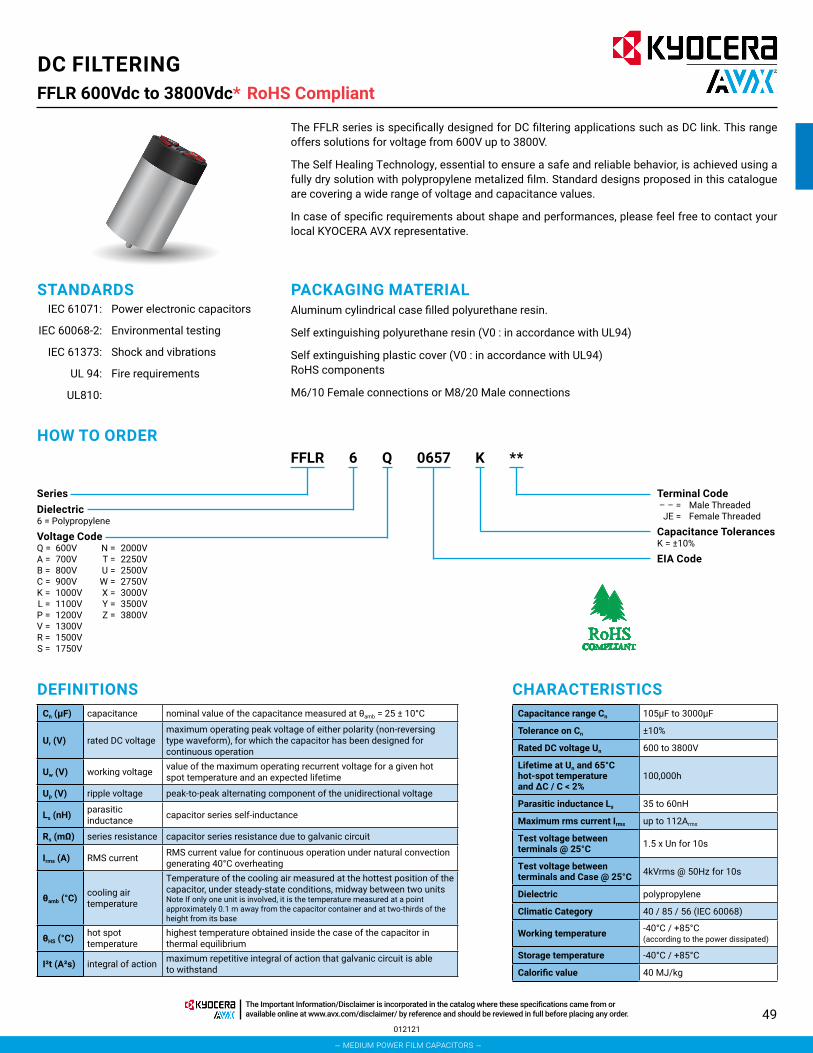
49012121
FFLR 600Vdc to 3800Vdc*DC FILTERING
The FFLR series is specifically designed for DC filtering applications such as DC link. This range offers solutions for voltage from 600V up to 3800V.
The Self Healing Technology, essential to ensure a safe and reliable behavior, is achieved using a fully dry solution with polypropylene metalized film. Standard designs proposed in this catalogue are covering a wide range of voltage and capacitance values.
In case of specific requirements about shape and performances, please feel free to contact your local KYOCERA AVX representative.
SeriesDielectric6 = Polypropylene
Voltage Code Q = 600V N = 2000V A = 700V T = 2250V B = 800V U = 2500V C = 900V W = 2750V K = 1000V X = 3000V L = 1100V Y = 3500V P = 1200V Z = 3800V V = 1300V R = 1500V S = 1750V
Terminal Code – – = Male Threaded JE = Female Threaded
Capacitance TolerancesK = ±10%
EIA Code
FFLR K0657 **6 QHOW TO ORDER
DEFINITIONSCn (μF) capacitance nominal value of the capacitance measured at θamb = 25 ± 10°C
Ur (V) rated DC voltagemaximum operating peak voltage of either polarity (non-reversing type waveform), for which the capacitor has been designed for continuous operation
Uw (V) working voltage value of the maximum operating recurrent voltage for a given hot spot temperature and an expected lifetime
Up (V) ripple voltage peak-to-peak alternating component of the unidirectional voltage
Ls (nH) parasitic inductance capacitor series self-inductance
Rs (mΩ) series resistance capacitor series resistance due to galvanic circuit
Irms (A) RMS current RMS current value for continuous operation under natural convection generating 40°C overheating
θamb (°C) cooling air temperature
Temperature of the cooling air measured at the hottest position of the capacitor, under steady-state conditions, midway between two unitsNote If only one unit is involved, it is the temperature measured at a point approximately 0.1 m away from the capacitor container and at two-thirds of the height from its base
θHS (°C) hot spot temperature
highest temperature obtained inside the case of the capacitor in thermal equilibrium
I²t (A²s) integral of action maximum repetitive integral of action that galvanic circuit is able to withstand
CHARACTERISTICSCapacitance range Cn 105μF to 3000μF
Tolerance on Cn ±10%
Rated DC voltage Un 600 to 3800V
Lifetime at Un and 65°C hot-spot temperature and ∆C / C < 2%
100,000h
Parasitic inductance Ls 35 to 60nH
Maximum rms current Irms up to 112Arms
Test voltage between terminals @ 25°C 1.5 x Un for 10s
Test voltage between terminals and Case @ 25°C 4kVrms @ 50Hz for 10s
Dielectric polypropylene
Climatic Category 40 / 85 / 56 (IEC 60068)
Working temperature -40°C / +85°C (according to the power dissipated)
Storage temperature -40°C / +85°C
Calorific value 40 MJ/kg
RoHS Compliant
STANDARDS IEC 61071: Power electronic capacitors
IEC 60068-2: Environmental testing
IEC 61373: Shock and vibrations
UL 94: Fire requirements
UL810:
PACKAGING MATERIALAluminum cylindrical case filled polyurethane resin.
Self extinguishing polyurethane resin (V0 : in accordance with UL94)
Self extinguishing plastic cover (V0 : in accordance with UL94) RoHS components
M6/10 Female connections or M8/20 Male connections
– medium power film capacitors –
The Important Information/Disclaimer is incorporated in the catalog where these specifications came from or available online at www.avx.com/disclaimer/ by reference and should be reviewed in full before placing any order.

50
FFLR 600Vdc to 3800Vdc*DC FILTERING
LIFETIME EXPECTANCY VS HOT SPOT TEMPERATURE AND VOLTAGE
111820
RoHS Compliant
– medium power film capacitors –
The Important Information/Disclaimer is incorporated in the catalog where these specifications came from or available online at www.avx.com/disclaimer/ by reference and should be reviewed in full before placing any order.

51
RoHS CompliantDC FILTERING
DIMENSIONSFEMALE TERMINALS MALE TERMINALS
D (mm) 86 100 116 136P (mm) 32 50 50 50Dt (mm) 12 15 15 15Hc (mm) 30 40 40 40
Max Torque (Nm)M6 4.5M8 8.5M12 15
Distance terminal to terminal (mm)
Distance terminal to case (mm)
D (mm) Creepage Clearance Creepage Clearance76 35 20 48 4686 35 20 52 50
100 50 35 59 57116 50 35 67 65136 50 35 77 75
MECHANICAL MOUNTINGCapacitors enclosure presents a M12 x 16 bolt in order to fix the capacitor. Over height (H) more than 1.5 x D (diameter of tube), we recommend to clamp (constraint < 35daN), just below the plastic cover, the capacitor in order to limit oscillations in case of potential Shock&Vibration stress.
071520
FFLR 600Vdc to 3800Vdc* RoHS Compliant
– medium power film capacitors –
The Important Information/Disclaimer is incorporated in the catalog where these specifications came from or available online at www.avx.com/disclaimer/ by reference and should be reviewed in full before placing any order.

52
DC FILTERING
RATINGS AND PART NUMBER REFERENCE
**Insert - - for male terminals or JE for female terminals
021121
FFLR 600Vdc to 3800Vdc* RoHS Compliant
C (µF) Un (V) PN Voltage
Code
Dimensions Irms Peak ESRESL Thermal
Res dv/dt SPQ MOQD L P 10KHz
50℃ Current 1KHz
mm mm mm A A mΩ nH *C/W V/us pcs pcs
650 600 FFLR6Q0657K** Q 86 105 32 70 3900 1.2 60 5 6 8 240800 600 FFLR6Q0807K** Q 86 142.5 32 75 6400 1.5 60 3.6 8 8 240
1000 600 FFLR6Q0108K** Q 86 161 32 60 7500 1 65 3.7 8 8 240220 700 FFLR6A0227K** A 76 80 32 50 3080 2.6 40 7.2 14 12 360300 700 FFLR6A0307K** A 86 80 32 55 4200 2.4 40 6.5 14 8 240420 700 FFLR6A0427K** A 86 105 32 58 2940 2.5 50 4.2 7 8 240450 700 FFLR6A0457K** A 86 126 32 65 3150 2.3 50 4.6 7 8 240550 700 FFLR6A0557K** A 86 142.5 32 65 3300 2.5 60 4.1 6 8 240290 800 FFLR6B0297K** B 76 105 32 50 3045 4 60 4 11 12 360300 800 FFLR6B0307K** B 86 105 32 60 2550 2.5 60 3.8 9 8 240390 800 FFLR6B0397K** B 86 105 32 62 3315 2.9 60 3.6 9 8 240450 800 FFLR6B0457K** B 86 142.5 32 65 3600 2.4 60 3.2 8 8 240460 800 FFLR6B0467K** B 86 151 50 70 3680 2.3 50 3.4 8 8 240850 800 FFLR6B0857K** B 86 205 50 60 4250 1.8 50 3.6 5 8 240
1000 800 FFLR6B0108K** B 116 155 50 65 7000 1.8 60 2.6 7 5 1501600 800 FFLR6B0168K** B 116 180 50 75 9600 3 65 3.4 6 5 150480 900 FFLR6C0487K** C 86 142.5 32 65 4080 2 50 4.2 9 8 240
1000 900 FFLR6C0108K** C 116 155 50 68 7000 1.6 80 3 7 5 1501500 900 FFLR6C0158K** C 116 185 50 60 12000 2 65 4.8 8 5 1501800 900 FFLR6C0188K** C 116 235 50 100 14400 0.8 60 2.4 8 5 150900 1000 FFLR6K0907K** K 116 155 50 72 10800 2.9 85 2.6 12 5 150
1300 1000 FFLR6K0138K** K 116 230 50 100 9750 1.5 100 2.4 8 5 1501600 1000 FFLR6K0168K** K 116 230 50 100 8000 1.5 75 2.1 5 5 150170 1100 FFLR6L0177K** L 76 105 32 50 1700 3.2 60 3.8 10 12 360240 1100 FFLR6L0247K** L 86 105 32 55 3000 1.7 50 3.8 13 8 240300 1100 FFLR6L0307K** L 86 142.5 32 58 2550 2 60 2.7 9 8 240330 1100 FFLR6L0337K** L 86 142.5 32 60 2805 3 60 3.3 9 8 240400 1100 FFLR6L0407K** L 86 142.5 32 60 3400 2.8 60 3.3 9 8 240420 1100 FFLR6L0427K** L 86 142.5 32 58 3570 2.3 85 3 9 8 240500 1100 FFLR6L0507K** L 86 180 32 72 6000 1.5 80 3 12 8 240600 1100 FFLR6L0607K** L 86 225 32 65 6300 2.5 60 2 11 8 240720 1100 FFLR6L0727K** L 116 155 50 69 9360 3.2 85 2.6 13 5 150800 1100 FFLR6L0807K** L 116 170 50 80 8800 1.5 55 2.4 11 5 150
1000 1100 FFLR6L0108K** L 116 205 50 85 10000 2.2 50 2.5 10 5 1501100 1100 FFLR6L0118K** L 116 230 50 90 9900 1.3 60 2.1 9 5 1501600 1100 FFLR6L0168K** L 116 340 50 100 12000 2.3 100 2.4 8 5 1501700 1100 FFLR6L0178K** L 136 235 50 110 10200 1.5 60 1.7 6 2 602000 1100 FFLR6L0208K** L 136 265 50 120 12000 1.2 60 1.3 6 2 602200 1100 FFLR6L0228K** L 136 340 50 120 13200 1.2 60 1 6 2 60420 1200 FFLR6P0427K** P 86 180 32 60 4200 3 70 3.2 10 8 240540 1200 FFLR6P0547K** P 86 225 32 60 5400 2.5 85 3.3 10 8 240950 1200 FFLR6P0957K** P 116 235 50 90 9500 1.5 75 2.1 10 5 150
1000 1200 FFLR6P0108K** P 116 235 50 90 10000 1.5 75 2.1 10 5 1501200 1200 FFLR6P0128K** P 116 265 50 70 12000 0.8 50 1.5 10 5 150250 1300 FFLR6V0257K** V 86 142 32 40 2000 4 85 5.4 8 8 240330 1300 FFLR6V0337K** V 86 180 32 55 4950 2.6 80 3.4 15 8 240420 1300 FFLR6V0427K** V 116 105 32 50 6300 2.3 40 2.1 15 5 150470 1300 FFLR6V0477K** V 116 161 50 65 5640 1.5 80 7.1 12 5 150
1100 1300 FFLR6V0118K** V 116 330 50 85 9900 2.7 200 2.1 9 5 150250 1500 FFLR6R0257K** R 86 155 32 51 3000 3.2 50 3.6 12 8 240
– medium power film capacitors –
The Important Information/Disclaimer is incorporated in the catalog where these specifications came from or available online at www.avx.com/disclaimer/ by reference and should be reviewed in full before placing any order.

53
RoHS CompliantDC FILTERINGFFLR 600Vdc to 3800Vdc* RoHS Compliant
RATINGS AND PART NUMBER REFERENCE
C (µF) Un (V) PN Voltage
Code
Dimensions Irms Peak ESRESL Thermal
Res dv/dt SPQ MOQD L P 10KHz
50℃ Current 1KHz
mm mm mm A A mΩ nH *C/W V/us pcs pcs
310 1500 FFLR6R0317K** R 86 180 32 49 3720 3.8 60 3.3 12 8 240370 1500 FFLR6R0377K** R 100 155 50 62 4440 2.3 50 3.3 12 5 150450 1500 FFLR6R0457K** R 100 180 50 59 5400 2.7 60 3.1 12 5 150510 1500 FFLR6R0517K** R 116 155 50 74 6120 1.8 50 3.1 12 5 150620 1500 FFLR6R0627K** R 116 180 50 70 6200 2.1 60 2.9 10 5 150700 1500 FFLR6R0707K** R 116 240 50 92 7000 1.1 40 3.2 10 5 150900 1500 FFLR6R0907K** R 116 290 50 90 7200 1.3 50 2.9 8 5 1501100 1500 FFLR6R0118K** R 116 340 50 89 7700 1.5 60 2.5 7 5 150185 1750 FFLR6S1856K** S 86 155 32 48 2775 3.7 50 3.6 15 8 240225 1750 FFLR6S2256K** S 86 180 32 46 3375 4.4 60 3.3 15 8 240270 1750 FFLR6S0277K** S 100 155 50 58 4050 2.6 50 3.3 15 5 150330 1750 FFLR6S0337K** S 100 180 50 56 4950 3.1 60 3.1 15 5 150370 1750 FFLR6S0377K** S 116 155 50 69 5550 2 50 3.1 15 5 150450 1750 FFLR6S0457K** S 116 180 50 65 5850 2.4 60 2.9 13 5 150520 1750 FFLR6S0527K** S 116 240 50 89 5720 1.2 40 3.2 11 5 150670 1750 FFLR6S0677K** S 116 290 50 86 6030 1.4 50 2.9 9 5 150820 1750 FFLR6S0827K** S 116 340 50 85 6560 1.7 60 2.5 8 5 150140 2000 FFLR6N0147K** N 86 155 32 45 2520 4.2 50 3.6 18 8 240170 2000 FFLR6N0177K** N 86 180 32 43 3060 5 60 3.3 18 8 240205 2000 FFLR6N2056K** N 100 155 50 55 3690 3 50 3.3 18 5 150250 2000 FFLR6N0257K** N 100 180 50 52 4000 3.5 60 3.1 16 5 150280 2000 FFLR6N0287K** N 116 155 50 65 4480 2.3 50 3.1 16 5 150350 2000 FFLR6N0357K** N 116 180 50 62 5250 2.6 60 2.9 15 5 150400 2000 FFLR6N0407K** N 116 240 50 85 5600 1.3 40 3.2 14 5 150510 2000 FFLR6N0517K** N 116 290 50 82 6630 1.5 50 2.9 13 5 150620 2000 FFLR6N0627K** N 116 340 50 81 7440 1.8 60 2.5 12 5 150110 2250 FFLR6T0117K** T 86 155 32 43 1760 4.7 50 3.6 16 8 240135 2250 FFLR6T1356K** T 86 180 32 41 2160 5.5 60 3.3 16 8 240160 2250 FFLR6T0167K** T 100 155 50 52 2560 3.3 50 3.3 16 5 150195 2250 FFLR6T1956K** T 100 180 50 49 2925 4 60 3.1 15 5 150220 2250 FFLR6T0227K** T 116 155 50 62 3300 2.5 50 3.1 15 5 150270 2250 FFLR6T0277K** T 116 180 50 59 4050 3 60 2.9 15 5 150310 2250 FFLR6T0317K** T 116 240 50 81 4340 1.4 40 3.2 14 5 150400 2250 FFLR6T0407K** T 116 290 50 79 5200 1.7 50 2.9 13 5 150490 2250 FFLR6T0497K** T 116 340 50 78 6125 2 60 2.5 12.5 5 15085 2500 FFLR6U0856K** U 86 155 32 40 1530 5.2 50 3.6 18 8 240
105 2500 FFLR6U1056K** U 86 180 32 39 1890 6.1 60 3.3 18 8 240120 2500 FFLR6U0127K** U 100 155 50 49 2160 3.8 50 3.3 18 5 150150 2500 FFLR6U0157K** U 100 180 50 47 2700 4.4 60 3.1 18 5 150170 2500 FFLR6U0177K** U 116 155 50 59 3400 2.8 50 3.1 20 5 150210 2500 FFLR6U0217K** U 116 180 50 56 4200 3.3 60 2.9 20 5 150230 2500 FFLR6U0237K** U 116 240 50 77 4600 1.6 40 3.2 20 5 150300 2500 FFLR6U0307K** U 116 290 50 75 5400 1.9 50 2.9 18 5 150380 2500 FFLR6U0387K** U 116 340 50 75 6460 2.2 60 2.5 17 5 15070 2750 FFLR6W0706K** W 86 155 32 39 1400 5.7 50 3.6 20 8 24085 2750 FFLR6W0856K** W 86 180 32 37 1700 6.8 60 3.3 20 8 240
100 2750 FFLR6W0107K** W 100 155 50 47 2000 4.1 50 3.3 20 5 150125 2750 FFLR6W1256K** W 100 180 50 45 2500 4.8 60 3.1 20 5 150140 2750 FFLR6W0147K** W 116 155 50 56 2800 3 50 3.1 20 5 150
**Insert - - for male terminals or JE for female terminals
111320
– medium power film capacitors –
The Important Information/Disclaimer is incorporated in the catalog where these specifications came from or available online at www.avx.com/disclaimer/ by reference and should be reviewed in full before placing any order.

54
DC FILTERINGFFLR 600Vdc to 3800Vdc* RoHS Compliant
RATINGS AND PART NUMBER REFERENCE
C (µF) Un (V) PN Voltage
Code
Dimensions Irms Peak ESRESL Thermal
Res dv/dt SPQ MOQD L P 10KHz
50℃ Current 1KHz
mm mm mm A A mΩ nH *C/W V/us pcs pcs
170 2750 FFLR6W0177K** W 116 180 50 53 3060 3.6 60 2.9 18 5 150190 2750 FFLR6W0197K** W 116 240 50 74 3230 1.7 40 3.2 17 5 150250 2750 FFLR6W0257K** W 116 290 50 73 4000 2 50 2.9 16 5 150310 2750 FFLR6W0317K** W 116 340 50 72 4960 2.4 60 2.5 16 5 15058 3000 FFLR6X0586K** X 86 155 32 37 1276 6.3 50 3.6 22 8 24070 3000 FFLR6X0706K** X 86 180 32 35 1540 7.6 60 3.3 22 8 24085 3000 FFLR6X0856K** X 100 155 50 45 2040 4.4 50 3.3 24 5 150
105 3000 FFLR6X1056K** X 100 180 50 43 2520 5.2 60 3.1 24 5 150115 3000 FFLR6X1156K** X 116 155 50 54 2760 3.3 50 3.1 24 5 150145 3000 FFLR6X1456K** X 116 180 50 51 3480 3.9 60 2.9 24 5 150160 3000 FFLR6X0167K** X 116 240 50 72 3520 1.8 40 3.2 22 5 150210 3000 FFLR6X0217K** X 116 290 50 70 4620 2.1 50 2.9 22 5 150260 3000 FFLR6X0267K** X 116 340 50 69 5460 2.5 60 2.5 21 5 15060 3500 FFLR6Y0606K** Y 100 155 50 60 1500 2.5 50 3.3 25 5 15075 3500 FFLR6Y0756K** Y 100 180 50 58 1875 2.9 60 3.1 25 5 15085 3500 FFLR6Y0856K** Y 116 155 50 72 2210 1.9 50 3.1 26 5 150
105 3500 FFLR6Y1056K** Y 116 180 50 68 2730 2.2 60 3 26 5 150115 3500 FFLR6Y1156K** Y 116 240 50 89 2875 1.2 40 3.3 25 5 150150 3500 FFLR6Y0157K** Y 116 290 50 88 3750 1.3 50 2.9 25 5 150190 3500 FFLR6Y0197K** Y 116 340 50 88 4560 1.6 60 2.5 24 5 15053 3800 FFLR6Z0536K** Z 100 155 50 59 1484 2.6 50 3.3 28 5 15066 3800 FFLR6Z0666K** Z 100 180 50 56 1848 3 60 3.1 28 5 15072 3800 FFLR6Z0726K** Z 116 155 50 69 2160 2 50 3.1 30 5 15090 3800 FFLR6Z0906K** Z 116 180 50 66 2700 2.3 60 3 30 5 150
100 3800 FFLR6Z0107K** Z 116 240 50 88 2700 1.2 40 3.3 27 5 150130 3800 FFLR6Z0137K** Z 116 290 50 86 3380 1.4 50 2.9 26 5 150165 3800 FFLR6Z1656K** Z 116 340 50 87 4125 1.6 60 2.5 25 5 150
**Insert - - for male terminals or JE for female terminals
111320
– medium power film capacitors –
The Important Information/Disclaimer is incorporated in the catalog where these specifications came from or available online at www.avx.com/disclaimer/ by reference and should be reviewed in full before placing any order.
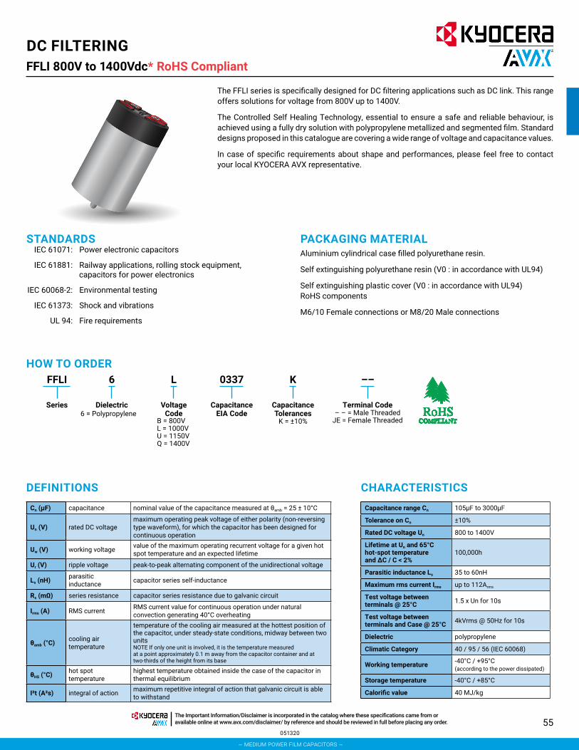
55
RoHS CompliantDC FILTERINGFFLI 800V to 1400Vdc*
The FFLI series is specifically designed for DC filtering applications such as DC link. This range offers solutions for voltage from 800V up to 1400V.
The Controlled Self Healing Technology, essential to ensure a safe and reliable behaviour, is achieved using a fully dry solution with polypropylene metallized and segmented film. Standard designs proposed in this catalogue are covering a wide range of voltage and capacitance values.
In case of specific requirements about shape and performances, please feel free to contact your local KYOCERA AVX representative.
FFLI K0337 ––6 L
Series Dielectric6 = Polypropylene
Voltage Code
CapacitanceTolerances
K = ±10%
CapacitanceEIA Code
Terminal Code– – = Male Threaded
JE = Female Threaded
HOW TO ORDER
B = 800VL = 1000VU = 1150VQ = 1400V
DEFINITIONS CHARACTERISTICSCn (μF) capacitance nominal value of the capacitance measured at θamb = 25 ± 10°C
Un (V) rated DC voltagemaximum operating peak voltage of either polarity (non-reversing type waveform), for which the capacitor has been designed for continuous operation
Uw (V) working voltage value of the maximum operating recurrent voltage for a given hot spot temperature and an expected lifetime
Ur (V) ripple voltage peak-to-peak alternating component of the unidirectional voltage
Ls (nH) parasitic inductance capacitor series self-inductance
Rs (mΩ) series resistance capacitor series resistance due to galvanic circuit
Irms (A) RMS current RMS current value for continuous operation under natural convection generating 40°C overheating
θamb (°C) cooling air temperature
temperature of the cooling air measured at the hottest position of the capacitor, under steady-state conditions, midway between two units NOTE If only one unit is involved, it is the temperature measured at a point approximately 0.1 m away from the capacitor container and at two-thirds of the height from its base
θHS (°C) hot spot temperature
highest temperature obtained inside the case of the capacitor in thermal equilibrium
I²t (A²s) integral of action maximum repetitive integral of action that galvanic circuit is able to withstand
Capacitance range Cn 105μF to 3000μF
Tolerance on Cn ±10%
Rated DC voltage Un 800 to 1400V
Lifetime at Un and 65°C hot-spot temperature and ∆C / C < 2%
100,000h
Parasitic inductance Ls 35 to 60nH
Maximum rms current Irms up to 112Arms
Test voltage between terminals @ 25°C 1.5 x Un for 10s
Test voltage between terminals and Case @ 25°C 4kVrms @ 50Hz for 10s
Dielectric polypropylene
Climatic Category 40 / 95 / 56 (IEC 60068)
Working temperature -40°C / +95°C (according to the power dissipated)
Storage temperature -40°C / +85°C
Calorific value 40 MJ/kg
051320
RoHS Compliant
STANDARDS IEC 61071: Power electronic capacitors
IEC 61881: Railway applications, rolling stock equipment, capacitors for power electronics
IEC 60068-2: Environmental testing
IEC 61373: Shock and vibrations
UL 94: Fire requirements
PACKAGING MATERIALAluminium cylindrical case filled polyurethane resin.
Self extinguishing polyurethane resin (V0 : in accordance with UL94)
Self extinguishing plastic cover (V0 : in accordance with UL94) RoHS components
M6/10 Female connections or M8/20 Male connections
– medium power film capacitors –
The Important Information/Disclaimer is incorporated in the catalog where these specifications came from or available online at www.avx.com/disclaimer/ by reference and should be reviewed in full before placing any order.

56
DC FILTERINGFFLI 800V to 1400Vdc*
LIFETIME EXPECTANCY VS HOT SPOT TEMPERATURE AND VOLTAGE1.5
1.4
1.3
1.2
1.1
1
0.9
0.8
0.7100 1,000 10,000 100,000 1,000,000
Lifetime Expectancy (hours)
Uw
/Un
θHS = 55ºC
θHS = 65ºC
θHS = 75ºC
θHS = 85ºC
θHS = 95ºC
Time
Vo
ltag
e
Uw
Un
Ur
1/f
HS AMB
Rth
HOW TO CHOSE THE RIGHT CAPACITORThe capacitor lifetime depends on the working voltage and the hot spot temperature.
Our caps are designed to meet 100000 hours lifetime at rated voltage and 65°C hot spot temperature. In accordance with operating conditions, please calculate the hot spot temperature and deduce from this calculation if the obtained lifetime can suit the application.
1. From the tables, select a capacitor with required capacitance Cn and voltage Un.
Calculate the maximum ripple voltage allowed for the selected cap: Urmax = 0.2Un
If Ur>Urmax, select a capacitor with higher rated voltage
Make sure Irms application < Irms table
Copy out:
• serial resistance (Rs): see table of values• thermal resistances Rth
2. Hot spot temperature calculationTotal losses are calculated as follow: Pt=Pj+Pd
Joule losses: Pj = Rs x Irms²
Dielectric losses: Pd = Q x tgδ0 with
• Q(reactive power) = for a sinusoidal waveform
• tgδ0 = 2 x 10⁻⁴ (dielectric losses of polypropylene)Hot spot temperature will be:
θHS = θamb + (Pj + Pd) x Rth
θHS absolute maximum is 95°C
If temperature is higher than 95°C, come back to #1 and start again with another selection.
Rth: thermal resistance between case and ambient air
091615
RoHS Compliant
– medium power film capacitors –
The Important Information/Disclaimer is incorporated in the catalog where these specifications came from or available online at www.avx.com/disclaimer/ by reference and should be reviewed in full before placing any order.

57
RoHS CompliantDC FILTERINGFFLI 800V to 1400Vdc*
3. Refer to the curve and deduce the lifetime vs Uw/Un ratio
1.5
1.4
1.3
1.2
1.1
1
0.9
0.8
0.7100 1,000 10,000 50,000
1.05
1,000,000
Lifetime Expectancy (hours)
Uw
/Un
θHS = 65ºC
eg: rated voltage 1000V working voltage 1050Vρ = 1.05 lifetime 50,000 hours
@ 65°C hot spot temperature
Please, find a calculation form at the end of the catalog
MTBF CALCULATIONBased on Return Of Experience from the field of more than 30 years, we have established the following relation. The failure rate λB depends on hot spot temperature θHS and charge ratio ρ.
ρ = Uw/Un
in failures/hour
GENERAL FAILURE RATEλ=λB x πQ x πB x πE failures/hour • πQ, πB and πE see following tables
Qualification Qualification factor πQ
Product qualified on IEC61071 and internal qualification 1
Product qualified on IEC61071 2Product answering on another norm 5Product without qualification 15
Environment Environment factor πE
On ground (good conditions) 1On ground (fixed materials) 2On ground (on board) 4On ship 9On plane 15
Environment Environment factor πB
Favorable 1Unfavourable 5
MEAN TIME BETWEEN FAILURE (MTBF)MTBF = 1/λ hours
SURVIVAL FUNCTIONN = N0 x exp (-λt)
N is the number of pieces still working after t hours.
N0 is the number of pieces at the origin (t = 0)
FAILURE MODEMain failure mode due to KYOCERA AVX’s Controlled Self-Healing Technology is only losses of capacitance. Thanks to Controlled Self-Healing solution to interrupt self-healing process in order to prevent avalanche effect due to polypropylene molecular cracking producing gas and potential explosion in confined box for none Controlled Self-Healing capacitors.
051820
RoHS Compliant
– medium power film capacitors –
The Important Information/Disclaimer is incorporated in the catalog where these specifications came from or available online at www.avx.com/disclaimer/ by reference and should be reviewed in full before placing any order.

58
DC FILTERINGFFLI 800V to 1400Vdc*
DIMENSIONS
UL94 V-0Resin Filling
UL94 V-0Plastic Cover
Aluminium Case
M12x16
D±2
A±15±0.53.5 2.5
H±2
Hc
40
M6x10
Dt
UL94 V-0Resin Filling
D±2
40
M8x20
Dt
AVX TPC UL94 V-0Plastic Cover
Aluminium Case
M12x16
A±1
5±0.5
3.5 2.5
H±2
Hc
AVX TPC
SLANIMRET ELAMSLANIMRET ELAMEF
D (mm) 75 85 100 116A (mm) 32 32 50 50Dt (mm) 12 12 15 15Hc (mm) 30 30 40 40
Max Torque (Nm)M6 4.5M8 8.5M12 15
Distance terminal to terminal (mm)
Distance terminal to case (mm)
D (mm) creepage clearance creepage clearance75 40 19 47 4585 40 19 52 50
100 55 34 59 57116 55 34 67 65
MECHANICAL MOUNTINGCapacitors enclosure presents a M12 x 16 bolt in order to fix the capacitor. Over height (H) more than 1.5 x D (diameter of tube), we recommend to clamp (constraint < 35daN), just below the plastic cover, the capacitor in order to limit oscillations in case of potential Shock&Vibration stress.
051320
RoHS Compliant
– medium power film capacitors –
The Important Information/Disclaimer is incorporated in the catalog where these specifications came from or available online at www.avx.com/disclaimer/ by reference and should be reviewed in full before placing any order.

59
RoHS CompliantDC FILTERINGFFLI 800V to 1400Vdc*
RATINGS AND PART NUMBER REFERENCE
Part Number Capacitance (μF) D H Irms
(A)I2t
(A2s)Typical LS
(nH)Typical RS
(mΩ)Rth
(°C/W)Typical
Weight (g)
Undc 800VFFLI6B0297K** 290 75 105 54 13 35 3.1 4.5 600FFLI6B0397K** 390 85 105 66 24 35 2.3 4.0 700FFLI6B0507K** 500 75 155 49 13 50 4.1 4.0 850FFLI6B0687K** 680 85 155 59 24 50 3.1 3.7 1100FFLI6B0817K** 810 85 180 58 24 60 3.5 3.4 1300FFLI6B1007K** 1000 100 155 73 52 50 2.2 3.4 1500FFLI6B1207K** 1200 100 180 70 52 60 2.5 3.3 1800FFLI6B1357K** 1350 116 155 86 95 50 1.7 3.2 2000FFLI6B1607K** 1600 116 180 80 95 60 2.0 3.1 2400FFLI6B1907K** 1900 116 240 112 320 40 1.1 2.9 3200FFLI6B2407K** 2400 116 290 111 320 50 1.2 2.7 3900FFLI6B3007K** 3000 116 340 109 320 60 1.4 2.4 4500
Undc 1000VFFLI6L0197K** 190 75 105 49 8 35 3.7 4.5 600FFLI6L0267K** 260 85 105 60 16 35 2.8 4.0 700FFLI6L0337K** 330 75 155 45 8 50 4.9 4.0 850FFLI6L0457K** 450 85 155 54 16 50 3.7 3.7 1100FFLI6L0547K** 540 85 180 53 16 60 4.2 3.4 1300FFLI6L0657K** 650 100 155 66 33 50 2.7 3.4 1500FFLI6L0787K** 780 100 180 64 33 60 3.0 3.3 1800FFLI6L0907K** 900 116 155 79 66 50 2.0 3.2 2000FFLI6L1107K** 1100 116 180 75 66 60 2.3 3.1 2400FFLI6L1307K** 1300 116 240 107 210 40 1.2 2.9 3200FFLI6L1607K** 1600 116 290 103 210 50 1.4 2.7 3900FFLI6L2007K** 2000 116 340 102 210 60 1.6 2.4 4500
Undc 1150VFFLI6U0157K** 150 75 105 46 7 35 4.2 4.5 600FFLI6U0207K** 200 85 105 56 12 35 3.2 4.0 700FFLI6U0267K** 260 75 155 42 7 50 5.6 4.0 850FFLI6U0357K** 350 85 155 51 12 50 4.2 3.7 1100FFLI6U0437K** 430 85 180 50 12 60 4.7 3.4 1300FFLI6U0537K** 530 100 155 64 27 50 2.9 3.4 1500FFLI6U0637K** 630 100 180 61 27 60 3.3 3.3 1800FFLI6U0727K** 720 116 155 75 51 50 2.2 3.2 2000FFLI6U0867K** 860 116 180 72 51 60 2.5 3.1 2400FFLI6U1007K** 1000 116 240 99 160 40 1.4 2.9 3200FFLI6U1307K** 1300 116 290 99 160 50 1.5 2.7 3900FFLI6U1607K** 1600 116 340 99 160 60 1.7 2.4 4500
Undc 1400VFFLI6Q1056K** 105 75 105 43 5 35 4.9 4.5 600FFLI6Q0147K** 140 85 105 51 9 35 3.8 4.0 700FFLI6Q1856K** 185 75 155 40 5 50 6.4 4.0 850FFLI6Q0257K** 250 85 155 47 9 50 4.8 3.7 1100FFLI6Q0307K** 300 85 180 46 9 60 5.5 3.4 1300FFLI6Q0367K** 360 100 155 58 19 50 3.5 3.4 1500FFLI6Q0447K** 440 100 180 56 19 60 3.9 3.3 1800FFLI6Q0507K** 500 116 155 69 36 50 2.6 3.2 2000FFLI6Q0607K** 600 116 180 66 36 60 3.0 3.1 2400FFLI6Q0707K** 700 116 240 96 120 40 1.5 2.9 3200FFLI6Q0907K** 900 116 290 93 120 50 1.7 2.7 3900FFLI6Q1107K** 1100 116 340 91 120 60 2.0 2.4 4500
**Insert - - for male terminals or JE for female terminals
051320
RoHS Compliant
– medium power film capacitors –
The Important Information/Disclaimer is incorporated in the catalog where these specifications came from or available online at www.avx.com/disclaimer/ by reference and should be reviewed in full before placing any order.

60
DC FILTERINGFFLI 800V to 1400Vdc*
CALCULATION FORMSPECIFICATION
Capacitance C (μF)
Working voltage Uw (V)
Rms current Irms (Arms)
Frequency f (Hz)
Ripple voltage Ur (V)
Ambient temperature θamb (°C)
Lifetime @ Uw,Irms and θamb hours
Parasitic inductance L (nH)
Cooling conditions
Expected lifetime at hot spot calculated and U = Uw
PN
Capacitance C (μF)
Rated voltage Un (V)
Serial resistance Rs (mΩ)
between hot spot and case Rth (°C/W)
Your choice
CALCULATIONS
Maximum ripple voltage Urmax = 0.2 Un Urmax = V
The maximum ripple voltage of the selected capacitor must be in any case higher than the ripple voltage of your application
Ratio Uw/Un ρ = Uw/Un ρ =
Joule losses Pj = RsxIrms2 Pj = W
Dielectric losses Pd = Qxtgδ0=Qx 2.10-4 Pd = W
Hot spot temperature θHS = θamb+(Pj+Pd)xRth θHS = °C
The hot spot temperature must be in any case lower than 95°C
LIFETIME EXPECTANCY VS HOT SPOT TEMPERATURE AND VOLTAGE1.5
1.4
1.3
1.2
1.1
1
0.9
0.8
0.7100 1,000 10,000 100,000 1,000,000
Lifetime Expectancy (hours)
Uw
/Un
θHS = 55ºC
θHS = 65ºC
θHS = 75ºC
θHS = 85ºC
θHS = 95ºC
061520
RoHS Compliant
– medium power film capacitors –
The Important Information/Disclaimer is incorporated in the catalog where these specifications came from or available online at www.avx.com/disclaimer/ by reference and should be reviewed in full before placing any order.

61
DC FILTERINGFFLI HV 1500V to 3800Vdc*
The FFLI series is specifically designed for DC filtering applications such as DC link. This high voltage range offers solutions for voltage from 1500V up to 3800V.
The Controlled Self Healing Technology, essential to ensure a safe and reliable behavior, is achieved using a wet solution with both polypropylene metallized film and oil (without free oil). Standard designs proposed in this catalogue are covering a wide range of voltage and capacitance values.
In case of specific requirements about shape and performances, please feel free to contact your local KYOCERA AVX representative.
PACKAGING MATERIALAluminium cylindrical case filled polyurethane resin.
Self extinguishing polyurethane resin (V0 : in accordance with UL94)
Self extinguishing plastic cover (V0: in accordance with UL94) RoHS components
M6/10 Female connections or M8/20 Male connections
K
CapacitanceTolerances
K = ±10%
0257
CapacitanceEIA Code
––
Terminal Code– – = Male Threaded
JE = Female Threaded
6
Dielectric6 = Polypropylene
FFLI
Series
HOW TO ORDER
DEFINITIONS CHARACTERISTICSCn (μF) capacitance nominal value of the capacitance measured at θamb = 25 ± 10°C
Un (V) rated DC voltagemaximum operating peak voltage of either polarity (non-reversing type waveform), for which the capacitor has been designed for continuous operation
Uw (V) working voltage value of the maximum operating recurrent voltage for a given hotspot temperature and an expected lifetime
Ur (V) ripple voltage peak-to-peak alternating component of the unidirectional voltage
Ls (nH) parasitic inductance capacitor series self-inductance
Rs (mΩ) series resistance capacitor series resistance due to galvanic circuit
Irms (A) RMS current RMS current value for continuous operation under naturalconvection generating 30°C overheating
θamb (°C) cooling air temperature
temperature of the cooling air measured at the hottest position of the capacitor, under steady-state conditions, midway between two unitsNOTE If only one unit is involved, it is the temperature measured at a point approximately 0.1 m away from the capacitor container and at two-thirds of the height from its base
θHS (°C) hot spot temperature
highest temperature obtained inside the case of the capacitor in thermal equilibrium
I²t (A²s) integral of action maximum repetitive integral of action that galvanic circuit is able to withstand
Capacitance range Cn 53μF to 1100μF
Tolerance on Cn ±10%
Rated DC voltage Un 1500 to 3800V
Lifetime at Un and 70°C hot-spot temperature and ∆C / C < 2%
100,000h
Parasitic inductance Ls 40 to 60nH
Maximum rms current Irms up to 92Arms
Test voltage between terminals @ 25°C 1.5 x Un for 10s
Test voltage between terminals and Case @ 25°C 9kVrms @ 50Hz for 10s
Dielectric polypropylene
Climatic Category 40 / 95 / 56 (IEC 60068)
Working temperature -40°C / +95°C (according to the power dissipated)
Storage temperature -40°C / +95°C
Calorific value 40 MJ/kg
051320
RoHS Compliant
STANDARDSIEC 61071: Power electronic capacitorsIEC 61881: Railway applications, rolling stock
equipment, capacitors for power electronics
IEC 60068-2: Environmental testingIEC 61373: Shock and vibrations
UL 94: Fire requirements
L
Voltage Code
R = 1500VS = 1750VN = 2000VT = 2250VP = 2500VW = 2750VX = 3000VY = 3500VZ = 3800V
– medium power film capacitors –
The Important Information/Disclaimer is incorporated in the catalog where these specifications came from or available online at www.avx.com/disclaimer/ by reference and should be reviewed in full before placing any order.
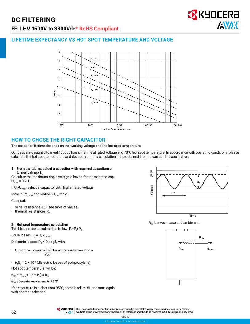
62
DC FILTERINGFFLI HV 1500V to 3800Vdc*
LIFETIME EXPECTANCY VS HOT SPOT TEMPERATURE AND VOLTAGE
HOW TO CHOSE THE RIGHT CAPACITORThe capacitor lifetime depends on the working voltage and the hot spot temperature.
Our caps are designed to meet 100000 hours lifetime at rated voltage and 70°C hot spot temperature. In accordance with operating conditions, please calculate the hot spot temperature and deduce from this calculation if the obtained lifetime can suit the application.
1. From the tables, select a capacitor with required capacitance Cn and voltage Un.
Calculate the maximum ripple voltage allowed for the selected cap: Urmax = 0.2Un
If Ur>Urmax, select a capacitor with higher rated voltage
Make sure Irms application < Irms table
Copy out:
• serial resistance (Rs): see table of values• thermal resistances Rth
2. Hot spot temperature calculationTotal losses are calculated as follow: Pt=Pj+Pd
Joule losses: Pj = Rs x Irms²
Dielectric losses: Pd = Q x tgδ0 with
• Q(reactive power) = for a sinusoidal waveform
• tgδ0 = 2 x 10⁻⁴ (dielectric losses of polypropylene)Hot spot temperature will be:
θHS = θamb + (Pj + Pd) x Rth
θHS absolute maximum is 95°C
If temperature is higher than 95°C, come back to #1 and start again with another selection.
Time
Vo
ltag
e
Uw
Un
Ur
1/f
HS AMB
Rth
121319
RoHS Compliant
Rth: between case and ambient air
– medium power film capacitors –
The Important Information/Disclaimer is incorporated in the catalog where these specifications came from or available online at www.avx.com/disclaimer/ by reference and should be reviewed in full before placing any order.

63
DC FILTERINGFFLI HV 1500V to 3800Vdc*
3. Refer to the curve and deduce the lifetime vs Uw/Un ratio
eg: rated voltage 2000V working voltage 2200Vρ = 1.1 lifetime 80,000 hours @ 60°C hot spot temperature
Please, find a calculation form at the end of the catalog
MTBF CALCULATIONThe failure rate λB depends on hot spot temperature θHS and charge ratio ρ.
ρ = Uw/Un
in failures/hour
GENERAL FAILURE RATEλ=λB x πQ x πB x πE failures/hour • πQ, πB and πE see following tables
Qualification Qualification factor πQ
Product qualified on IEC61071 and internal qualification 1
Product qualified on IEC61071 2Product answering on another norm 5Product without qualification 15
Environment Environment factor πE
On ground (good conditions) 1On ground (fixed materials) 2On ground (on board) 4On ship 9On plane 15
Environment Environment factor πB
Favorable 1Unfavourable 5
MEAN TIME BETWEEN FAILURE (MTBF)MTBF = 1/λ hours
SURVIVAL FUNCTIONN = N0 x exp (-λt)
N is the number of pieces still working after t hours.
N0 is the number of pieces at the origin (t = 0)
FAILURE MODEMain failure mode due to KYOCERA AVX’s Controlled Self-Healing Technology is only losses of capacitance. Thanks to Controlled Self-Healing solution to interrupt self-healing process in order to prevent avalanche effect due to polypropylene molecular cracking producing gas and potential explosion in confined box for none Controlled Self-Healing capacitors.
1.5
1.4
1.3
1.2
1
0.9
0.8
0.7100 1,000 10,000 80,000
1.1
1,000,000
Lifetime Expectancy (hours)
Uw
/Un
θHS = 60ºC
051320
RoHS Compliant
– medium power film capacitors –
The Important Information/Disclaimer is incorporated in the catalog where these specifications came from or available online at www.avx.com/disclaimer/ by reference and should be reviewed in full before placing any order.

64
DC FILTERINGFFLI HV 1500V to 3800Vdc*
UL94 V-0Resin Filling
UL94 V-0Plastic Cover
Aluminium Case
M12x16
D±2
A±15±0.53.5 2.5
H±2
Hc
40
M6x10
Dt
UL94 V-0Resin Filling
D±2
40
M8x20
Dt
AVX TPC UL94 V-0Plastic Cover
Aluminium Case
M12x16
A±1
5±0.5
3.5 2.5
H±2
Hc
AVX TPC
SLANIMRET ELAMSLANIMRET ELAMEF
D (mm) 85 100 116 116A (mm) 32 50 50 50Dt (mm) 12 15 15 15Hc (mm) 30 40 40 40
Max Torque (Nm)M6 4.5M8 8.5M12 15
Distance terminal to terminal (mm)
Distance terminal to case (mm)
D (mm) creepage clearance creepage clearance85 40 19 52 50
100 55 34 59 57116 55 34 67 65
MECHANICAL MOUNTINGCapacitors enclosure presents a M12 x 16 bolt in order to fix the capacitor. Over height (H) more than 1.5 x D (diameter of tube), we recommend to clamp (constraint < 35daN), just below the plastic cover, the capacitor in order to limit oscillations in case of potential Shock&Vibration stress.
DIMENSIONS
051320
RoHS Compliant
– medium power film capacitors –
The Important Information/Disclaimer is incorporated in the catalog where these specifications came from or available online at www.avx.com/disclaimer/ by reference and should be reviewed in full before placing any order.

65
DC FILTERINGFFLI HV 1500V to 3800Vdc*
RATINGS AND PART NUMBER REFERENCEPart Number Capacitance (μF) D H Irms (A) I2t (A2s) Typical LS (nH) Typical RS (mΩ) Rth (°C/W) Typical Weight (g)
Un = 1500VFFLI6R0257K** 250 85 155 51 11 50 3.2 3.6 1100FFLI6R0317K** 310 85 180 49 11 60 3.8 3.3 1300FFLI6R0377K** 370 100 155 62 24 50 2.3 3.3 1500FFLI6R0457K** 450 100 180 59 24 60 2.7 3.1 1800FFLI6R0517K** 510 116 155 74 45 50 1.8 3.1 2000FFLI6R0627K** 620 116 180 70 45 60 2.1 2.9 2400FFLI6R0707K** 700 116 240 92 140 40 1.1 3.2 3200FFLI6R0907K** 900 116 290 90 140 50 1.3 2.9 3900FFLI6R1107K** 1100 116 340 89 140 60 1.5 2.5 4500
Un = 1750VdcFFLI6S1856K** 185 85 155 48 8 50 3.7 3.6 1100FFLI6S2256K** 225 85 180 46 8 60 4.4 3.3 1300FFLI6S0277K** 270 100 155 58 18 50 2.6 3.3 1500FFLI6S0337K** 330 100 180 56 18 60 3.1 3.1 1800FFLI6S0377K** 370 116 155 69 33 50 2.0 3.1 2000FFLI6S0457K** 450 116 180 65 33 60 2.4 2.9 2400FFLI6S0527K** 520 116 240 89 108 40 1.2 3.2 3200FFLI6S0677K** 670 116 290 86 108 50 1.4 2.9 3900FFLI6S0827K** 820 116 340 85 108 60 1.7 2.5 4500
Un = 2000VdcFFLI6N0147K** 140 85 155 45 6 50 4.2 3.6 1100FFLI6N0177K** 170 85 180 43 6 60 5.0 3.3 1300FFLI6N2056K** 205 100 155 55 13 50 3.0 3.3 1500FFLI6N0257K** 250 100 180 52 13 60 3.5 3.1 1800FFLI6N0287K** 280 116 155 65 25 50 2.3 3.1 2000FFLI6N0357K** 350 116 180 62 25 60 2.6 2.9 2400FFLI6N0407K** 400 116 240 85 82 40 1.3 3.2 3200FFLI6N0517K** 510 116 290 82 82 50 1.5 2.9 3900FFLI6N0627K** 620 116 340 81 82 60 1.8 2.5 4500
Un = 2250VdcFFLI6T0117K** 110 85 155 43 5 50 4.7 3.6 1100FFLI6T1356K** 135 85 180 41 5 60 5.5 3.3 1300FFLI6T0167K** 160 100 155 52 10 50 3.3 3.3 1500FFLI6T0187K** 195 100 180 49 10 60 4.0 3.1 1800FFLI6T0227K** 220 116 155 62 20 50 2.5 3.1 2000FFLI6T0277K** 270 116 180 59 20 60 3.0 2.9 2400FFLI6T0317K** 310 116 240 81 64 40 1.4 3.2 3200FFLI6T0407K** 400 116 290 79 64 50 1.7 2.9 3900FFLI6T0497K** 490 116 340 78 64 60 2.0 2.5 4500
Un = 2500VdcFFLI6P0856K** 85 85 155 40 4 50 5.2 3.6 1100FFLI6P1056K** 105 85 180 39 4 60 6.1 3.3 1300FFLI6P0127K** 120 100 155 49 8 50 3.8 3.3 1500FFLI6P0157K** 150 100 180 47 8 60 4.4 3.1 1800FFLI6P0177K** 170 116 155 59 16 50 2.8 3.1 2000FFLI6P0217K** 210 116 180 56 16 60 3.3 2.9 2400FFLI6P0237K** 230 116 240 77 50 40 1.6 3.2 3200FFLI6P0307K** 300 116 290 75 50 50 1.9 2.9 3900FFLI6P0387K** 380 116 340 75 50 60 2.2 2.5 4500
Un = 2750VdcFFLI6W0706K** 70 85 155 39 3.3 50 5.7 3.6 1100FFLI6W0856K** 85 85 180 37 3.3 60 6.8 3.3 1300FFLI6W0107K** 100 100 155 47 7 50 4.1 3.3 1500FFLI6W1256K** 125 100 180 45 7 60 4.8 3.1 1800FFLI6W0147K** 140 116 155 56 13 50 3.0 3.1 2000FFLI6W0177K** 170 116 180 53 13 60 3.6 2.9 2400FFLI6W0197K** 190 116 240 74 42 40 1.7 3.2 3200FFLI6W0257K** 250 116 290 73 42 50 2.0 2.9 3900FFLI6W0317K** 310 116 340 72 42 60 2.4 2.5 4500
Un = 3000VdcFFLI6X0586K** 58 85 155 37 2.7 50 6.3 3.6 1100FFLI6X0706K** 70 85 180 35 2.7 60 7.6 3.3 1300FFLI6X0856K** 85 100 155 45 6 50 4.4 3.3 1500FFLI6X1056K** 105 100 180 43 6 60 5.2 3.1 1800FFLI6X1156K** 115 116 155 54 11 50 3.3 3.1 2000FFLI6X1456K** 145 116 180 51 11 60 3.9 2.9 2400FFLI6X0167K** 160 116 240 72 35 40 1.8 3.2 3200FFLI6X0217K** 210 116 290 70 35 50 2.1 2.9 3900FFLI6X0267K** 260 116 340 69 35 60 2.5 2.5 4500
Un = 3500VdcFFLI6Y0606K** 60 100 155 60 17 50 2.5 3.3 1500FFLI6Y0756K** 75 100 180 58 17 60 2.9 3.1 1800FFLI6Y0856K** 85 116 155 72 34 50 1.9 3.1 2000FFLI6Y1056K** 105 116 180 68 34 60 2.2 3.0 2400FFLI6Y1156K** 115 116 240 89 110 40 1.2 3.3 3200FFLI6Y0157K** 150 116 290 88 106 50 1.3 2.9 3900FFLI6Y0197K** 190 116 340 88 110 60 1.6 2.5 4500
Un = 3800VdcFFLI6Z0536K** 53 100 155 59 15 50 2.6 3.3 1500FFLI6Z0666K** 66 100 180 56 15 60 3.0 3.1 1800FFLI6Z0726K** 72 116 155 69 28 50 2.0 3.1 2000FFLI6Z0906K** 90 116 188 66 28 60 2.3 3.0 2400FFLI6Z0107K** 100 116 240 88 95 40 1.2 3.3 3200FFLI6Z0137K** 130 116 290 86 92 50 1.4 2.9 3900FFLI6Z1656K** 165 116 340 87 95 60 1.5 2.5 4500
**Insert - - for male terminals or JE for female terminals
051320
RoHS Compliant
– medium power film capacitors –
The Important Information/Disclaimer is incorporated in the catalog where these specifications came from or available online at www.avx.com/disclaimer/ by reference and should be reviewed in full before placing any order.

66
DC FILTERINGFFLI HV 1500V to 3800Vdc*
CALCULATION FORMSPECIFICATION
Capacitance C (μF)
Working voltage Uw (V)
Rms current Irms (Arms)
Frequency f (Hz)
Ripple voltage Ur (V)
Ambient temperature θamb (°C)
Lifetime @ Uw,Irms and θamb hours
Parasitic inductance L (nH)
Expected lifetime at hot spot calculated at Uw
PN
Capacitance C (μF)
Rated voltage Un (V)
Serial resistance Rs (mΩ)
between hot spot and case Rth (°C/W)
Your choice
CALCULATIONS
Maximum ripple voltage Urmax = 0.2 Un Urmax = V
The maximum ripple voltage of the selected capacitor must be in any case higher than the ripple voltage of your application
Ratio Uw/Un ρ = Uw/Un ρ =
Joule losses Pj = RsxIrms2 Pj = W
Dielectric losses Pd = Qxtgδ0=Qx 2.10-4 Pd = W
Hot spot temperature θHS = θamb+(Pj+Pd)xRth θHS = °C
The hot spot temperature must be in any case lower than 95°C
LIFETIME EXPECTANCY VS HOT SPOT TEMPERATURE AND VOLTAGE
061520
RoHS Compliant
– medium power film capacitors –
The Important Information/Disclaimer is incorporated in the catalog where these specifications came from or available online at www.avx.com/disclaimer/ by reference and should be reviewed in full before placing any order.

67070820
Medium Power Film CapacitorsFFPC 800Vdc to 3800Vdc
PACKAGING MATERIAL
STANDARDS
HOW TO ORDER
Rectangular resin filled plastic case (PA66 30% GF) 2 or 4 terminals M12x30mm
IEC 61071 : Power electronic capacitors
IEC 61881 : Railway applications, rolling stock equipment, capacitors for power electronics
IEC 60068-2 : Environmental testing
UL 94: Test for Flammability of Plastic Materials for Parts in Devices and Appliances.
EN 45545-2: Railway applications — Fire protection on railway vehicles Part 2: Requirements for fire behavior of materials and components
FFPC
Series Terminals Numbers
24
2
CapacitanceEIA code
1697
Capacitance toleranceK = ±10%
K
Terminal Code-- = Male Threaded
JE = Female Threaded
°°B
B = 800V C = 900VL = 1000VU = 1100VV = 1250VQ = 1350VR = 1500V M= 1750V
S = 1900VN = 2000VT = 2300VP = 2550VW= 2800VX = 3000VY = 3500VZ = 3800V
Voltage
GENERAL DESCRIPTIONThe FFPC series is specifically designed for DC filtering applications such as DC link or resonant filters for voltages up to 3800V.
The safe and reliable Controlled Self Healing Technology makes this series particularly suitable for power converters in traction, drives and renewable energy areas.
FFPC use a dry solution or a wet solution (without free oil) with polypropylene metallized film.
Standard designs proposed in this catalogue are covering a wide range of voltage and capacitance values.
In case of specific requirements about shape and performances, feel free to contact your local KYOCERA AVX representative.
– medium power film capacitors –
The Important Information/Disclaimer is incorporated in the catalog where these specifications came from or available online at www.avx.com/disclaimer/ by reference and should be reviewed in full before placing any order.

68
Medium Power Film CapacitorsFFPC 800Vdc to 3800Vdc
DEFINITIONS
CHARACTERISTICS
Cn (µF) capacitance nominal value of the capacitance measured at θamb = 25 ± 10°C
Un (V) rated DC voltagemaximum operating peak voltage of either polarity (non-reversing type waveform), for which the capacitor has been designed for continuous operation
Uw (V) working voltage value of the maximum operating recurrent voltage for a given hot spot temperature and an expected lifetime
Ur (V) ripple voltage peak-to-peak alternating component of the unidirectional voltage
Ls (nH) parasitic inductance capacitor series self-inductance
Rs (mΩ) series resistance capacitor series resistance due to galvanic circuit
Irms (A) RMS current rms current value @ 100Hz for continuous operation under natural convection generating 20°C overheating
θamb (°C) cooling air temperature
temperature of the cooling air measured at the hottest position of the capacitor, under steady-state conditions, midway between two units NOTE If only one unit is involved, it is the temperature measured at a point approximately 0,1 m away from the capacitor container and at two-thirds of the height from its base
θHS (°C) hot spot temperature highest temperature obtained inside the case of the capacitor in thermal equilibrium
Capacitance range Cn 95µF to 5060µF
Tolerance on Cn ±10%
Rated DC voltage Un 800 to 3800V
Lifetime at Un and 70°C hot-spot temperature and ∆C/C<2% 100,000h
Typical parasitic inductance Ls 35nH to 85nH
Maximum rms current Irms maxup to 155Arms for 2 terminalsup to 300Arms for 4 terminals
Test voltage between terminals @ 25°C 1.5 x Un for 10s
Test voltage between terminals and Case @ 25°C 9 kVrms @ 50Hz for 10s
Dielectric polypropylene
Climatic Category 40 / 85 / 56 (IEC 60068)
Working temperature -40°C / +85°C(according to the power dissipated)
Storage temperature -40°C / +85°C
Calorific value 40 MJ/kg
070820
– medium power film capacitors –
The Important Information/Disclaimer is incorporated in the catalog where these specifications came from or available online at www.avx.com/disclaimer/ by reference and should be reviewed in full before placing any order.

69
Medium Power Film CapacitorsFFPC 800Vdc to 3800Vdc
LIFETIME EXPECTANCY VS HOT SPOT TEMPERATURES
HOW TO CHOOSE THE RIGHT CAPACITOR
0.7
0.8
0.9
1
1.1
1.2
1.3
1.4
1.5
100 1,000 10,000 100,000 1,000,000
Uw
/Un
Lifetime Expectancy (hours)
θHS= 85°C
θHS= 80°C
θHS= 70°C
θHS= 60°C
The capacitor lifetime depends on the working voltage and the hot spot temperature.
Our caps are designed to meet 100000 hours lifetime at rated voltage and 70°C hot spot temperature. In accordance with operating conditions, please calculate the hot spot temperature and deduce from this calculation if the obtained lifetime can suit the application.
Calculate the maximum ripple voltage allowed for the selected cap : Urmax = 0,2Un
If Ur > Urmax, select a capacitor with higher rated voltage
Make sure Irms application < Irms table
Copy out:
• serial resistance (Rs) : see table of values• hermal resistance Rth : see table of values
1- From the tables, select a capacitor with required capacitance Cn and voltage Un.
Volta
ge
time
UwUn
Ur
1/f
070820
– medium power film capacitors –
The Important Information/Disclaimer is incorporated in the catalog where these specifications came from or available online at www.avx.com/disclaimer/ by reference and should be reviewed in full before placing any order.

70
Medium Power Film CapacitorsFFPC 800Vdc to 3800Vdc
2- Hot spot temperature calculation
Total losses are calculated as follow: Pt = Pj + Pd
Joule losses: Pj = Rs x Irms²
Dielectric losses: Pd = Q x tgδ0 with
- Q(reactive power) = for a sinusoidal waveform
- tgδ0 = 2 x 10⁻⁴ (dielectric losses of polypropylene)
Hot spot temperature will be: ӨHS = Өamb + (Pj + Pd) x Rth
ӨHS absolute maximum is 85°C
If temperature is higher than 85°C, come back to #1 and start again with another selection.
3- Refer to the curve and deduce the lifetime vs Uw/Un ratio
Eg: rated voltage 2000V
working voltage 1900V
ρ = Uw / Un= 0,95 lifetime is 200 000hours @ 70°C hot spot temperature
You will find a calculation form at the end of the catalogue
Rth: thermal resistance between hot spot and ambient air
�CIrms
2
width
θHS
Rth
0.7
0.8
0.9
1
1.1
1.2
1.3
1.4
1.5
100 1,000 10,000 100,000 1,000,000
Uw
/Un
Lifetime Expectancy (hours)
θHS = 70°C
070820
– medium power film capacitors –
The Important Information/Disclaimer is incorporated in the catalog where these specifications came from or available online at www.avx.com/disclaimer/ by reference and should be reviewed in full before placing any order.

71
Medium Power Film CapacitorsFFPC 800Vdc to 3800Vdc
THERMAL RESISTANCE
MTBF CALCULATION
PARASITIC INDUCTANCERth (°C/W): Thermal resistance between hot spot and ambient temperatures (Natural air cooling)
For confined area, capacitor working in a closed cabinet, a thermal test under real conditions is necessary to evaluate the thermal resistance.
GENERAL FAILURE RATE
MEAN TIME BETWEEN FAILURE (MTBF)
FAILURE MODE
SURVIVAL FUNCTION
The failure rate λB depends on hot spot temperature ӨHS and charge ratio ρ. ρ = Uw/Un
MTBF = 1/λ hours
Main failure mode due to KYOCERA AVX’s Controlled Self-Healing Technology is only losses of capacitance.
Thanks to Controlled Self-healing solution to interrupt self-healing process in order to prevent avalanche effect due to polypropylene molecular cracking producing gas and potential explosion in confined box for none Controlled Self-Healing capacitors.
N = N0 x exp(-λt)
N is the number of pieces sill working after t hours N0 is the number of pieces at the origin (t=0)
λ = λB x πQ x πB x πE failures/hour πQ, πB and πE see following tables
Measurement @ 1MHz
Height (mm) Rth (ºC/W)109 2,9187 2,2
262,5 1,4
Qualification Qualification factor πQ
Product qualified on IEC61071 and internal qualification 1
Product qualified on IEC61071 2
Product answering on another norm 5
Product without qualification 15
Environment Environment factor πB
Favorable 1
Unfavorable 5
Environment Environment factor πE
On ground (good conditions) 1
On ground (fixed materials) 2
On ground (on board) 4
On ship 9
On plane 15
Height (mm)
Typical Ls (nH)
2 terminals 4 terminals
109 45 35
187 65 55
262,5 85 75
in failures/hour��
�
�3,2��
�
����
��� θHS + 273 30
358 x10-9
λB = 3x10 2,75 (ρ-1) × e
070820
– medium power film capacitors –
The Important Information/Disclaimer is incorporated in the catalog where these specifications came from or available online at www.avx.com/disclaimer/ by reference and should be reviewed in full before placing any order.

72
Medium Power Film CapacitorsFFPC 800Vdc to 3800Vdc
MALE TERMINALS VERSION DIMENSIONS
070820
– medium power film capacitors –
The Important Information/Disclaimer is incorporated in the catalog where these specifications came from or available online at www.avx.com/disclaimer/ by reference and should be reviewed in full before placing any order.

73
Medium Power Film CapacitorsFFPC 800Vdc to 3800Vdc
FEMALE TERMINALS VERSION DIMENSIONS
070820
– medium power film capacitors –
The Important Information/Disclaimer is incorporated in the catalog where these specifications came from or available online at www.avx.com/disclaimer/ by reference and should be reviewed in full before placing any order.

74
Medium Power Film CapacitorsFFPC 800Vdc to 3800Vdc
Part Number Un (Vdc) C (µF) H (mm) Rs (mΩ) Irms (A)FFPC*B1697K°° 800 1690 109 1,50 65FFPC*B3377K°° 800 3370 187 0,78 103FFPC*B5067K°° 800 5060 262,5 0,56 155FFPC*C1367K°° 900 1360 109 1,67 61FFPC*C2727K°° 900 2720 187 0,87 97FFPC*C4087K°° 900 4080 262,5 0,61 146FFPC*L1127K°° 1000 1120 109 1,83 58FFPC*L2237K°° 1000 2230 187 0,95 92FFPC*L3357K°° 1000 3350 262,5 0,67 139FFPC*U0907K°° 1100 900 109 2,05 54FFPC*U1797K°° 1100 1790 187 1,06 87FFPC*U2687K°° 1100 2680 262,5 0,74 131FFPC*V0697K°° 1250 690 109 2,32 50FFPC*V1387K°° 1250 1380 187 1,19 81FFPC*V2067K°° 1250 2060 262,5 0,83 123FFPC*Q0627K°° 1350 620 109 2,44 49FFPC*Q1247K°° 1350 1240 187 1,26 78FFPC*Q1857K°° 1350 1850 262,5 0,87 119FFPC*R0647K°° 1500 640 109 1,68 57FFPC*R1287K°° 1500 1280 187 0,88 91FFPC*R1917K°° 1500 1910 262,5 0,62 137FFPC*M0477K°° 1750 470 109 1,94 52FFPC*M0947K°° 1750 940 187 1,01 83FFPC*M1417K°° 1750 1410 262,5 0,70 126FFPC*S0417K°° 1900 410 109 2,08 50FFPC*S0827K°° 1900 820 187 1,08 80FFPC*S1227K°° 1900 1220 262,5 0,75 121FFPC*N0367K°° 2000 360 109 2,23 47FFPC*N0717K°° 2000 710 187 1,15 76FFPC*N1077K°° 2000 1070 262,5 0,80 116FFPC*T0287K°° 2300 280 109 2,51 44FFPC*T0567K°° 2300 560 187 1,29 71FFPC*T0847K°° 2300 840 262,5 0,89 108FFPC*P0227K°° 2550 220 109 2,83 40FFPC*P0437K°° 2550 430 187 1,45 65FFPC*P0657K°° 2550 650 262,5 1,00 100FFPC*W0187K°° 2800 180 109 3,12 38FFPC*W0367K°° 2800 360 187 1,59 61FFPC*W0537K°° 2800 530 262,5 1,10 93FFPC*X0157K°° 3000 150 109 3,40 36FFPC*X0307K°° 3000 300 187 1,74 58FFPC*X0457K°° 3000 450 262,5 1,19 88FFPC*Y0117K°° 3500 110 109 1,76 39FFPC*Y0227K°° 3500 220 187 0,91 63FFPC*Y0337K°° 3500 330 262,5 0,64 96FFPC*Z0956K°° 3800 95 109 1,90 37FFPC*Z0197K°° 3800 190 187 0,98 59FFPC*Z2856K°° 3800 285 262,5 0,69 91
* Insert terminal number (2 or 4)°° insert "- -" for male terminals or "JE" for female terminals
TABLE OF VALUES
070920
– medium power film capacitors –
The Important Information/Disclaimer is incorporated in the catalog where these specifications came from or available online at www.avx.com/disclaimer/ by reference and should be reviewed in full before placing any order.
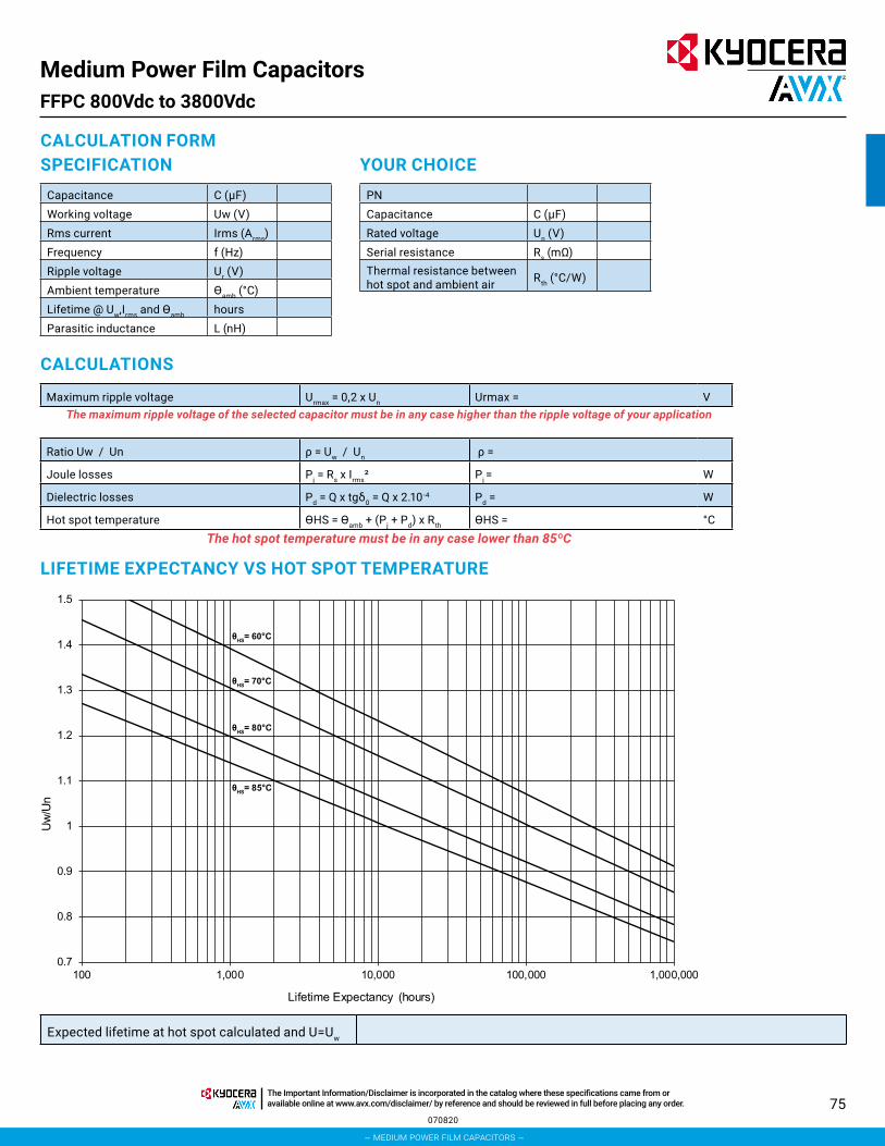
75
Medium Power Film CapacitorsFFPC 800Vdc to 3800Vdc
LIFETIME EXPECTANCY VS HOT SPOT TEMPERATURE
CALCULATION FORM
CALCULATIONS
SPECIFICATION YOUR CHOICECapacitance C (µF)Working voltage Uw (V)Rms current Irms (Arms)Frequency f (Hz)Ripple voltage Ur (V)Ambient temperature Өamb (°C)Lifetime @ Uw,Irms and Өamb hoursParasitic inductance L (nH)
Maximum ripple voltage Urmax = 0,2 x Un Urmax = VThe maximum ripple voltage of the selected capacitor must be in any case higher than the ripple voltage of your application
Expected lifetime at hot spot calculated and U=Uw
Ratio Uw / Un ρ = Uw / Un ρ =
Joule losses Pj = Rs x Irms² Pj = W
Dielectric losses Pd = Q x tgδ0 = Q x 2.10-4 Pd = W
Hot spot temperature ӨHS = Өamb + (Pj + Pd) x Rth ӨHS = °CThe hot spot temperature must be in any case lower than 85ºC
PNCapacitance C (µF)Rated voltage Un (V)Serial resistance Rs (mΩ)Thermal resistance between hot spot and ambient air Rth (°C/W)
0.7
0.8
0.9
1
1.1
1.2
1.3
1.4
1.5
100 1,000 10,000 100,000 1,000,000
Uw
/Un
Lifetime Expectancy (hours)
θHS= 85°C
θHS= 80°C
θHS= 70°C
θHS= 60°C
070820
– medium power film capacitors –
The Important Information/Disclaimer is incorporated in the catalog where these specifications came from or available online at www.avx.com/disclaimer/ by reference and should be reviewed in full before placing any order.

76
Medium Power Film CapacitorsFFPC 800Vdc to 3800Vdc
This questionnaire lists the information we require to prepare an offer according to your exact requirmentsCompany / Name / Email Project / Quantity
Applications DC Filtering Discharge* Protection* Tuning
Capacitance (μF)
Tolerance (%)
Operating Voltage Vpeak Vch Vpeak Vdc Vrms
Ripple Voltage (peak to peak) V
Working frequency (Hz)
Operating current Arms Apeak Arms Arms
Maximum Current/Duration Arms s Apeak
Discharge Aperiodic Oscillatory
Pulse Duration (5% lpeak)
Time to lpeak (μs)
Ringing Frequency (Hz)
Reversal Voltage (%)
Repetition Rate shots/min/hour/day Hz
Hold Time @ Full Voltage (s)
Fault Peak Current/nb shots Apeak shots Apeak shots
Fault Reversal Voltage (%)
Lifetime Expectancy hours shots hours hours
Maximum Inductance (nH)
Test Voltage between Terminals (V)
Test Voltage between Shorted Terminals and Case (V)
Maximum Surge Voltage (MSV)
MSV Duration / Frequency s /years s /yearDue to the particularities of varying waveforms in such application, more information on the exact nature of waveform is generally required for a full analysis.
Description
Dimensions (mm) / Shape Operating Position Terminas
Section: Height vertical, horizontal, inclined, and upside down
Type Quantity
rectangular, cylindrical
Thermal Characteris tics
Storage Temperature (ºC) Operating Temperature (ºC) Cooling Method
min. min. Natural Convection
average average Forced Air (m/s)
max. max. Water
Remarks
070820
– medium power film capacitors –
The Important Information/Disclaimer is incorporated in the catalog where these specifications came from or available online at www.avx.com/disclaimer/ by reference and should be reviewed in full before placing any order.

77
DC FILTERINGFFLC
GENERAL DESCRIPTIONThe FFLC series is specifically designed for DC filtering applications such as DC link or resonant filters.
Large case sizes up to 35 liters and high specific energy up to 240J/l together with safe and reliable Controlled Self Healing Technology make this series particularly suitable for power converters in traction, drives and renewable energy areas.
FFLC uses polypropylene metallized segmented film and it is fully dry technology.
Standard designs proposed in this catalogue are covering a wide range of voltage and capacitance.
PACKAGING MATERIALNon-painted rectangular resin filled aluminum case
Mounting brackets
4 M8/15 Female connections or M12/30 Male connections
STANDARDS IEC 61071: Power electronic capacitors IEC 61881: Railway applications, rolling stock equipment,
capacitors for power electronics IEC 60068-2: Environmental testing UL 94: Fire requirements NF F 16-101: Rolling stock – Fire behaviour – Materials choosing NF F 16-102: Rolling stock – Fire behaviour – Materials choosing,
application for electric equipments EN 45545-2: Railways applications – Fire protection on railway
vehicles Part 2 : Requirements for fire behaviour of materials and components
SeriesWidth1 = 100mm2 = 125mm
Height1 = 245mm2 = 315mm3 = 385mm
Terminal Codes F = Female M = Male
HOW TO ORDER1 M MFFLC 3 A 4427
Capacitance EIA CodeVoltage A = 800V B = 900V C = 1000V D = 1100V E = 1350V
BracketsM
4 = 455mm5 = 525mm6 = 595mm
3 = 150mm4 = 175mm
121020
– medium power film capacitors –
The Important Information/Disclaimer is incorporated in the catalog where these specifications came from or available online at www.avx.com/disclaimer/ by reference and should be reviewed in full before placing any order.

78
DC FILTERINGFFLC
LIFETIME EXPECTANCY VS. HOT SPOT TEMPERATURE AND VOLTAGE
1.4
1.3
1.2
1.1
1.0
0.9
0.8100 1,000 10,000 100,000 1,000,000
Lifetime Expectancy (hours)
Uw
/Un
θHS = 70ºC
θHS = 85ºC
θHS = 55ºC
DEFINITIONSCn capacitance nominal value of the capacitance measured at θamb = 25 ± 10°C
Un rated DC voltage maximum operating peak voltage of either polarity (non-reversing type waveform), for which the capacitor has been designed for continuous operation
Uw working voltage value of the maximum operating recurrent voltage for a given hotspot temperature and an expected lifetime
Ur ripple voltage peak-to-peak alternating component of the unidirectional voltageLs parasitic inductance capacitor series self-inductanceRs capacitor series resistance capacitor series resistance due to galvanic circuit
Irms thermal 1 RMS current value for continuous operation under naturalconvection generating 20°C overheating
Irms thermal 2 rms current value for continuous operation under forced airgenerating 20°C overheating
θamb (°C) cooling air temperature
temperature of the cooling air measured at the hottest position of the capacitor, under steady-state conditions, midway between two unitsNOTE If only one unit is involved, it is the temperature measured at a point approximately 0.1 m away from the capacitor container and at two-thirds of the height from its base
θHS (°C) hot spot temperature highest temperature obtained inside the case of the capacitor in thermal equilibrium
CHARACTERISTICSCapacitance range Cn 1750μF to 20600μF
Tolerance on Cn ±10%
Rated DC voltage Un 800 to 1350VLifetime at Un and 70°C hot-spot temperature and ∆C / C < 2% 100,000h
Parasitic inductance Ls 32 to 55nHMaximum rms current Irms up to 400Arms
Test voltage between terminals @ 25°C 1.5 x Un for 10s
Test voltage between terminals and Case @ 25°C 4kVrms @ 50Hz for 10s
Dielectric polypropyleneClimatic Category 40 / 85 / 56 (IEC 60068)
Working temperature -40°C / +85°C (according to the power dissipated)
Storage temperature -40°C / +85°CCalorific value 27 MJ/kg
121020
– medium power film capacitors –
The Important Information/Disclaimer is incorporated in the catalog where these specifications came from or available online at www.avx.com/disclaimer/ by reference and should be reviewed in full before placing any order.

79
HOW TO CHOSE THE RIGHT CAPACITORThe capacitor lifetime depends on the working voltage and the hot spot temperature.
Our caps are designed to meet 100000 hours lifetime at rated voltage and 70°C hot spot temperature. In accordance with operating conditions, please calculate the hot spot temperature and deduce from this calculation if the obtained lifetime can suit the application.
1. From the tables, select a capacitor with required capacitance Cn and voltage Un.
Calculate the maximum ripple voltage allowed for the selected cap: Urmax = 0.2Un
If Ur>Urmax, select a capacitor with higher rated voltage
Make sure Irms application < Irms table
Copy out:
• serial resistance (Rs): see table of values• thermal resistances Rth1 and Rth2 (depending on cooling conditions)
2. Hot spot temperature calculationTotal losses are calculated as follow: Pt=Pj+Pd
Joule losses: Pj = Rs x Irms²
Dielectric losses: Pd = Q x tgδ0 with
• Q(reactive power) = for a sinusoidal waveform
• tgδ0 = 2 x 10⁻⁴ (dielectric losses of polypropylene)Hot spot temperature will be:
θHS = θamb + (Pj + Pd) x (Rth1 + Rth2)
θHS absolute maximum is 85°C
If temperature is higher than 85°C, come back to #1 and start again with another selection.
Rth1: Thermal resistance between hot spot and case
Rth2: Thermal resistance between case and ambient air
3. Refer to the curve and deduce the lifetime vs Uw/Un ratio
Time
Vo
ltag
e
Uw
Un
Ur
1/f
width
HS CASE AMB
Rth1 Rth2
Time
Vo
ltag
e
Uw
Un
Ur
1/f
width
HS CASE AMB
Rth1 Rth2
DC FILTERINGFFLC
eg: rated voltage 1000V working voltage 950Vρ = 0.95 lifetime 200,000 hours
@ 70°C hot spot temperature
Please, find a calculation form at the end of the catalog
0.8
0.9
1
.1.1
1.2
1.3
1.4
000,000,1000,001000,01000,1001
Lifetime Expectancy (hours)
Uw/U
n
HS=70°C
200,000
0.95
121020
– medium power film capacitors –
The Important Information/Disclaimer is incorporated in the catalog where these specifications came from or available online at www.avx.com/disclaimer/ by reference and should be reviewed in full before placing any order.

80
DC FILTERINGFFLC
MTBF CALCULATIONBased on Return Of Experience from the field of more than 30 years, we have established the following relation.
ρ = Uw/Un
in failures/hour
GENERAL FAILURE RATEλ=λB x πQ x πB x πE failures/hour • πQ, πB and πE see following tables
Qualification Qualification factor πQ
Product qualified on IEC61071 and internal qualification 1
Product qualified on IEC61071 2Product answering on another norm 5Product without qualification 15
Environment Environment factor πE
On ground (good conditions) 1On ground (fixed materials) 2On ground (on board) 4On ship 9On plane 15
Environment Environment factor πB
Favorable 1Unfavourable 5
MEAN TIME BETWEEN FAILURE (MTBF)MTBF = 1/λ hours
SURVIVAL FUNCTIONN = N0 x exp (-λt)
N is the number of pieces still working after t hours.
N0 is the number of pieces at the origin (t = 0)
121020
THERMAL RESISTANCESRth1 (°C/W): Thermal resistance between hot spot and case
Measurement @ 1MHz
Rth2 (°C/W): Thermal resistance between case and ambient air under natural convection and forced air
Rth1 (°C/W)
Height (mm)
Width (mm)100 125 150 175
245 0.56 0.67 0.76 0.82315 0.41 0.49 0.56 0.6385 0.3 0.36 0.41 0.44455 0.25 0.3 0.34 0.37525 0.2 0.24 0.27 0.3595 0.17 0.21 0.24 0.26
Ls (nH)Height (mm)
Width (mm)100 125 150 175
245 32 34 35 37315 34 36 38 40385 36 39 41 44455 38 41 44 48525 40 43 47 51595 42 46 51 55
Rth2 (°C)
Height (mm)
Natural air cooling Forced air cooling >2m/sWidth (mm) Width (mm)
100 125 150 175 100 125 150 175245 0.47 0.44 0.42 0.40 0.23 0.22 0.21 0.20315 0.36 0.35 0.33 0.31 0.18 0.17 0.16 0.16385 0.30 0.28 0.27 0.25 0.15 0.14 0.13 0.13455 0.25 0.24 0.23 0.22 0.13 0.12 0.11 0.11525 0.22 0.21 0.20 0.19 0.11 0.10 0.10 0.09595 0.19 0.18 0.17 0.16 0.10 0.09 0.09 0.08
For confined area, capacitor working in a closed cabinet, a thermal test under real conditions is necessary to evaluate the thermal resistance.
PARASITIC INDUCTANCE VS SIZE
Low inductance design available on request
FAILURE MODEMain failure mode due to KYOCERA AVX’s Controlled Self-Healing Technology is only losses of capacitance. Thanks to Controlled Self-Healing solution to interrupt self-healing process in order to prevent avalanche effect due to polypropylene molecular cracking producing gas and potential explosion in confined box for none Controlled Self-Healing capacitors.
– medium power film capacitors –
The Important Information/Disclaimer is incorporated in the catalog where these specifications came from or available online at www.avx.com/disclaimer/ by reference and should be reviewed in full before placing any order.

81
DC FILTERINGFFLC
DIMENSIONS
Female terminals
(Max torque 15Nm)
Female terminals
(Max torque 25Nm)
Available standard dimensions (other dimensions on request for specific design)H (mm): 245, 315, 385, 455, 525 and 595W (mm): 100, 125, 150 and 175
WEIGHT VS SIZEmm
Weight (kg)
Height Width100 125 150 175
245 12 15 17.5 20.5315 15 18.5 22.5 26385 18.5 23 27.5 32455 21.5 27 32.5 37.5525 25 31.5 37.5 42.5595 28.5 35 41.5 48.5
121020
– medium power film capacitors –
The Important Information/Disclaimer is incorporated in the catalog where these specifications came from or available online at www.avx.com/disclaimer/ by reference and should be reviewed in full before placing any order.

82
* Insert F for female terminals or M for male terminals
DC FILTERINGFFLC
TABLE OF VALUES
121020
Part Number Capacitance (μF) Width (mm) Height (mm) Rs (mΩ) Irms Thermal 1 (A) Irms Thermal 2 (A)Un = 800Vdc
FFLC11 * MA4777 4,770 100 245 0.27 270 306FFLC12 * MA6087 6,080 100 315 0.23 333 380FFLC21 * MA6557 6,550 125 245 0.29 249 276FFLC13 * MA7817 7,810 100 385 0.20 400 400FFLC31 * MA8317 8,310 150 245 0.32 231 255FFLC22 * MA8337 8,330 125 315 0.25 310 348FFLC14 * MA9117 9,110 100 455 0.19 400 400FFLC41 * MA1008 10,000 175 245 0.35 218 240FFLC32 * MA1068 10,600 150 315 0.27 288 320FFLC23 * MA1078 10,700 125 385 0.22 380 400FFLC15 * MA1098 10,900 100 525 0.17 400 400FFLC16 * MA1228 12,200 100 595 0.17 400 400FFLC24 * MA1258 12,500 125 455 0.20 400 400FFLC42 * MA1278 12,700 175 315 0.29 274 299FFLC33 * MA1368 13,600 150 385 0.23 355 395FFLC25 * MA1498 14,900 125 525 0.18 400 400FFLC34 * MA1598 15,900 150 455 0.21 400 400FFLC43 * MA1648 16,400 175 385 0.25 338 374FFLC26 * MA1678 16,700 125 595 0.22 400 400FFLC35 * MA1898 18,900 150 525 0.20 400 400FFLC44 * MA1918 19,100 175 455 0.23 385 400FFLC36 * MA2118 21,100 150 595 0.19 400 400FFLC45 * MA2288 22,800 175 525 0.21 400 400FFLC46 * MA2558 25,500 175 595 0.20 400 400
Un = 900VdcFFLC11 * MB3847 3,840 100 245 0.29 261 296FFLC12 * MB4897 4,890 100 315 0.25 323 368FFLC21 * MB5277 5,270 125 245 0.31 240 267FFLC13 * MB6287 6,280 100 385 0.21 310 400FFLC31 * MB6707 6,700 150 245 0.34 222 245FFLC22 * MB6717 6,710 125 315 0.27 300 337FFLC14 * MB7337 7,330 100 455 0.20 400 400FFLC41 * MB8077 8,070 175 245 0.37 209 231FFLC32 * MB8537 8,530 150 315 0.29 278 309FFLC23 * MB8627 8,620 125 385 0.23 369 400FFLC15 * MB8737 8,730 100 525 0.18 400 400FFLC16 * MB9777 9,770 100 595 0.17 400 400FFLC24 * MB1018 10,100 125 455 0.21 400 400FFLC42 * MB1038 10,300 175 315 0.32 264 289FFLC33 * MB1108 11,000 150 385 0.25 344 383FFLC25 * MB1258 12,500 125 525 0.19 400 400FFLC34 * MB1288 12,800 150 455 0.23 393 400FFLC43 * MB1328 13,200 175 385 0.27 327 362FFLC26 * MB1348 13,400 125 595 0.18 400 400FFLC35 * MB1528 15,200 150 525 0.21 400 400FFLC44 * MB1548 15,400 175 455 0.24 373 400FFLC36 * MB1718 17,100 150 595 0.20 400 400FFLC45 * MB1848 18,400 175 525 0.22 400 400FFLC46 * MB2068 20,600 175 595 0.21 400 400
– medium power film capacitors –
The Important Information/Disclaimer is incorporated in the catalog where these specifications came from or available online at www.avx.com/disclaimer/ by reference and should be reviewed in full before placing any order.

83
* Insert F for female terminals or M for male terminals
DC FILTERINGFFLC
TABLE OF VALUES
121020
Part Number Capacitance (μF) Width (mm) Height (mm) Rs (mΩ) Irms Thermal 1 (A) Irms Thermal 2 (A)Un = 1000Vdc
FFLC11 * MC3167 3,160 100 245 0.30 253 287FFLC12 * MC4027 4,020 100 315 0.26 314 358FFLC21 * MC4337 4,330 125 245 0.33 232 258FFLC13 * MC5177 5,170 100 385 0.23 385 400FFLC31 * MC5517 5,510 150 245 0.37 215 237FFLC22 * MC5527 5,520 125 315 0.28 291 326FFLC14 * MC6037 6,030 100 455 0.21 400 400FFLC41 * MC6647 6,640 175 245 0.40 202 223FFLC32 * MC7017 7,010 150 315 0.31 269 299FFLC23 * MC7097 7,090 125 385 0.24 358 400FFLC15 * MC7187 7,180 100 525 0.19 400 400FFLC16 * MC8047 8,040 100 595 0.18 400 400FFLC24 * MC8277 8,270 125 455 0.22 400 400FFLC42 * MC8467 8,460 175 315 0.34 255 279FFLC33 * MC9027 9,020 150 385 0.26 334 372FFLC25 * MC9857 9,850 125 525 0.20 400 400FFLC34 * MC1058 10,500 150 455 0.24 382 400FFLC43 * MC1098 10,900 175 385 0.29 317 351FFLC26 * MC1108 11,000 125 595 0.19 400 400FFLC35 * MC1258 12,500 150 525 0.22 400 400FFLC44 * MC1278 12,700 175 455 0.26 362 400FFLC36 * MC1408 14,000 150 595 0.21 400 400FFLC45 * MC1518 15,100 175 525 0.23 400 400FFLC46 * MC1698 16,900 175 595 0.22 400 400
Un = 1100VdcFFLC11 * MD2537 2,530 100 245 0.33 243 276FFLC12 * MD3227 3,220 100 315 0.28 303 345FFLC21 * MD3487 3,480 125 245 0.36 223 248FFLC13 * MD4147 4,140 100 385 0.24 373 400FFLC31 * MD4427 4,420 150 245 0.40 206 227FFLC22 * MD4437 4,430 125 315 0.31 280 314FFLC14 * MD4837 4,830 100 455 0.22 400 400FFLC41 * MD5347 5,340 175 245 0.44 194 214FFLC32 * MD5637 5,630 150 315 0.34 259 288FFLC23 * MD5697 5,690 125 385 0.26 346 392FFLC15 * MD5757 5,750 100 525 0.20 400 400FFLC16 * MD6447 6,440 100 595 0.19 400 400FFLC24 * MD6647 6,640 125 455 0.24 395 400FFLC42 * MD6797 6,790 175 315 0.37 245 269FFLC33 * MD7247 7,240 150 385 0.28 323 359FFLC25 * MD7907 7,900 125 525 0.22 400 400FFLC34 * MD8447 8,440 150 455 0.26 370 400FFLC43 * MD8737 8,730 175 385 0.31 306 339FFLC26 * MD8857 8,850 125 595 0.20 400 400FFLC35 * MD1018 10,100 150 525 0.23 400 400FFLC44 * MD1028 10,200 175 455 0.28 350 388FFLC36 * MD1138 11,300 150 595 0.22 400 400FFLC45 * MD1218 12,100 175 525 0.25 400 400FFLC46 * MD1368 13,600 175 595 0.23 400 400
– medium power film capacitors –
The Important Information/Disclaimer is incorporated in the catalog where these specifications came from or available online at www.avx.com/disclaimer/ by reference and should be reviewed in full before placing any order.

84
DC FILTERINGFFLC
* Insert F for female terminals or M for male terminals
TABLE OF VALUES
121020
Part Number Capacitance (μF) Width (mm) Height (mm) Rs (mΩ) Irms Thermal 1 (A) Irms Thermal 2 (A)Un = 1350Vdc
FFLC11 * ME1757 1,750 100 245 0.37 228 259FFLC12 * ME2237 2,230 100 315 0.32 285 325FFLC21 * ME2407 2,400 125 245 0.41 208 232FFLC13 * ME2867 2,860 100 385 0.27 353 400FFLC31 * ME3057 3,050 150 245 0.46 192 212FFLC22 * ME3067 3,060 125 315 0.35 263 210FFLC14 * ME3347 3,340 100 455 0.24 400 400FFLC41 * ME3677 3,670 175 245 0.51 180 199FFLC32 * ME3887 3,880 150 315 0.38 242 270FFLC23 * ME3927 3,920 125 385 0.28 334 378FFLC15 * ME3987 3,980 100 525 0.22 400 400FFLC16 * ME4457 4,450 100 595 0.21 400 400FFLC24 * ME4587 4,580 125 455 0.26 374 400FFLC42 * ME4687 4,680 175 315 0.42 229 251FFLC33 * ME4997 4,990 150 385 0.32 303 337FFLC25 * ME5457 5,450 125 525 0.24 400 400FFLC34 * ME5827 5,820 150 455 0.29 349 393FFLC43 * ME6017 6,010 175 385 0.35 287 318FFLC26 * ME6107 6,100 125 595 0.22 400 400FFLC35 * ME6937 6,930 150 525 0.26 400 400FFLC44 * ME7017 7,010 175 455 0.31 329 365FFLC36 * ME7767 7,760 150 595 0.24 400 400FFLC45 * ME8357 8,350 175 525 0.28 383 400FFLC46 * ME9357 9,350 175 595 0.26 400 400
– medium power film capacitors –
The Important Information/Disclaimer is incorporated in the catalog where these specifications came from or available online at www.avx.com/disclaimer/ by reference and should be reviewed in full before placing any order.
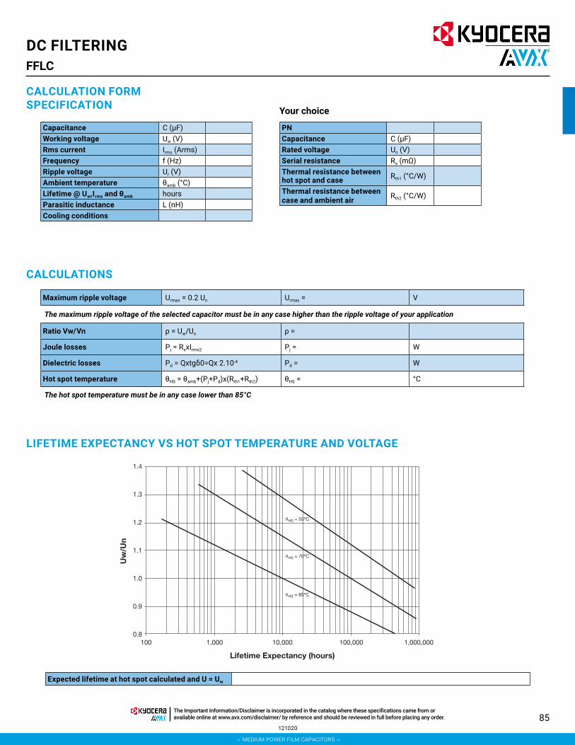
85
DC FILTERINGFFLC
Expected lifetime at hot spot calculated and U = Uw
CALCULATION FORM SPECIFICATION
Capacitance C (μF)Working voltage Uw (V)Rms current Irms (Arms)Frequency f (Hz)Ripple voltage Ur (V)Ambient temperature θamb (°C)Lifetime @ Uw,Irms and θamb hoursParasitic inductance L (nH)Cooling conditions
PNCapacitance C (μF)Rated voltage Un (V)Serial resistance Rs (mΩ)Thermal resistance between hot spot and case Rth1 (°C/W)
Thermal resistance between case and ambient air Rth2 (°C/W)
Your choice
CALCULATIONS
Maximum ripple voltage Urmax = 0.2 Un Urmax = V
The maximum ripple voltage of the selected capacitor must be in any case higher than the ripple voltage of your application
Ratio Vw/Vn ρ = Uw/Un ρ =
Joule losses Pj = RsxIrms2 Pj = W
Dielectric losses Pd = Qxtgδ0=Qx 2.10-4 Pd = W
Hot spot temperature θHS = θamb+(Pj+Pd)x(Rth1+Rth2) θHS = °C
The hot spot temperature must be in any case lower than 85°C
LIFETIME EXPECTANCY VS HOT SPOT TEMPERATURE AND VOLTAGE
1.4
1.3
1.2
1.1
1.0
0.9
0.8100 1,000 10,000 100,000 1,000,000
Lifetime Expectancy (hours)
Uw
/Un
θHS = 70ºC
θHS = 85ºC
θHS = 55ºC
121020
– medium power film capacitors –
The Important Information/Disclaimer is incorporated in the catalog where these specifications came from or available online at www.avx.com/disclaimer/ by reference and should be reviewed in full before placing any order.

86
DC FILTERINGFFHV/FTHV 1600Vdc to 3000Vdc
The FFHV and FTHV series are specifically designed for DC filtering applications such as DC link or resonant filters for voltages up to 3000V.
These capacitors are proposed in 2 different versions: resin top for the FFHV series and hermetic case for the FTHV.
Large case sizes up to 36 liters and high specific energy up to 455J/l* together with safe and reliable Controlled Self Healing Technology make this series particularly suitable for power converters in traction, drives, renewable energy and power transmission areas.*for 100,000 hours and 70°C hot spot temperature
FFHV and FTHV use a wet solution with polypropylene metallized film and oil (without free oil).
Standard designs proposed in this catalogue are covering a wide range of voltage and capacitance values.
In case of specific requirements about shape and performances, feel free to contact your local KYOCERA AVX representative.
PACKAGING MATERIAL
STANDARDS
FFHV FTHV
Non-painted rectangular resin filled aluminium caseMounting bracketsM8/17 female connections or M12/30 male connections 2 or 4 connections
Non-painted rectangular aluminium hermetic caseMounting bracketsM8/17 female terminals or M12/30 male terminals 2 or 4 terminals
FFHV FTHVIEC 61071: Power electronic capacitorsIEC 61881: Railway applications, rolling stock equipment, capacitors for
power electronicsIEC 61373: Railways application, rolling stock equipment, shock and
vibrations testsIEC 60068-2: Environmental testing. Part2: Tests UL 94: Test for flammability of Plastic Materials for Parts in Devices
and AppliancesEN 45545-2: Railways applications – Fire protection on railway vehicles.
Part 2 : Requirements for fire behaviour of materials and components
IEC 61071: Power electronic capacitors IEC 61881: Railway applications, rolling stock equipment, capacitors for
power electronics IEC61373: Railways application, rolling stock equipment, shock and
vibrations tests IEC 60068-2: Environmental testing. Part 2: Tests EN 45545-2: Railways applications – Fire protection on railway vehicles. Part 2: Requirements for fire behaviour of materials and components
M
Terminal Code
F = FemaleM = Male
M
Terminal Code
F = FemaleM = Male
2637
CapacitanceEIA Code
2637
CapacitanceEIA Code
1
Section and Option1 = 340x125 2 connexions2 = 340x125 4 connexions3 = 340x175 2 connexions4 = 340x175 4 connexions
1
Section and Option1 = 340x125 2 connexions2 = 340x125 4 connexions3 = 340x175 2 connexions4 = 340x175 4 connexions
D
D
FFHV
SeriesFFHV: resin top
FTHV
SeriesFTHV: hermetic case
HOW TO ORDER1
Height1 = 230mm2 = 295mm3 = 370mm4 = 450mm5 = 530mm6 = 610mm
1
Height1 = 240mm2 = 305mm3 = 380mm4 = 460mm5 = 540mm6 = 620mm
R
VoltageA = 1600VB = 1900VC = 2000VD = 2150VE = 2450VF = 2750VG = 3000V
R
VoltageA = 1600VB = 1900VC = 2000VD = 2150VE = 2450VF = 2750VG = 3000V
121019
– medium power film capacitors –
The Important Information/Disclaimer is incorporated in the catalog where these specifications came from or available online at www.avx.com/disclaimer/ by reference and should be reviewed in full before placing any order.

87
Cn (μF) capacitance nominal value of the capacitance measured at θamb = 25 ± 10°C
Un (V) rated DC voltage maximum operating peak voltage of either polarity (non-reversing type waveform), for which the capacitor has been designed for continuous operation
Uw (V) working voltage value of the maximum operating recurrent voltage for a given hot spot temperature and an expected lifetime
Ur (V) ripple voltage peak-to-peak alternating component of the unidirectional voltage
Ls (nH) parasitic inductance capacitor series self-inductance
Rs (mΩ) series resistance capacitor series resistance due to galvanic circuit @ ambient temperature
Irms thermal 1 (A) RMS current rms current value @ 100Hz for continuous operation under natural convection generating 20°C overheating(255Arms maximum for 2 connexions or terminals and 400Arms maximum for 4 connexions or terminals)
Irms thermal 2 (A) RMS currentrms current value @ 100Hz for continuous operation under forcedair generating 20°C overheating (255Arms maximum for 2 connexions or terminals and 400Arms maximum for 4 connexions or terminals)
θamb (°C) cooling air temperaturetemperature of the cooling air measured at the hottest position of the capacitor, under steady-state conditions, midway between two unitsNOTE If only one unit is involved, it is the temperature measured at a point approximately 0,1 m away from the capacitor container and at two-thirds of the height from its base
θHS (°C) hot spot temperature highest temperature obtained inside the case of the capacitor in thermal equilibrium
DC FILTERINGFFHV/FTHV 1600Vdc to 3000Vdc
DEFINITIONS
CHARACTERISTICS
Capacitance range Cn 590μF to 12600μF
Tolerance on Cn ±10%
Rated DC voltage Un 1600 to 3000V
Lifetime at Un and ∆C / C < 2% FFHV: 100,000h @ 70°C hot spot temperatureFTHV: 100,000h @ 85°C hot spot temperature
Parasitic inductance Ls 27nH to 88nH
Maximum rms current Irms up to 400Arms
Test voltage between terminals @ 25°C 1.5 x Un for 10s
Test voltage between terminals and Case @ 25°C 7kVrms @ 50Hz for 10s
Dielectric polypropylene
Climatic Category FFHV: 40 / 85 / 56 (IEC 60068)FTHV: 40 / 95 / 56 (IEC 60068)
Working temperature FFHV: -40°C / +85°C (according to the power dissipated)FTHV: -40°C / +95°C (according to the power dissipated)
Storage temperature -40°C / +85°C
Calorific value 34 MJ/kg
060920
– medium power film capacitors –
The Important Information/Disclaimer is incorporated in the catalog where these specifications came from or available online at www.avx.com/disclaimer/ by reference and should be reviewed in full before placing any order.

88112019
FFHV LIFETIME EXPECTANCY VS HOT SPOT TEMPERATURE AND VOLTAGE
FTHV LIFETIME EXPECTANCY VS HOT SPOT TEMPERATURE AND VOLTAGE
DC FILTERINGFFHV/FTHV 1600Vdc to 3000Vdc
– medium power film capacitors –
The Important Information/Disclaimer is incorporated in the catalog where these specifications came from or available online at www.avx.com/disclaimer/ by reference and should be reviewed in full before placing any order.

89
DC FILTERINGFFHV/FTHV 1600Vdc to 3000Vdc
HOW TO CHOSE THE RIGHT CAPACITORThe capacitor lifetime depends on the working voltage and the hot spot temperature.
Our caps are designed to meet 100000 hours lifetime at rated voltage and 70°C (for FFHV) or 85°C (for FTHV) hot spot temperature. In accordance with operating conditions, please calculate the hot spot temperature and deduce from this calculation if the obtained lifetime can suit the application.
1. From the tables, select a capacitor with required capacitance Cn and voltage Un.
Calculate the maximum ripple voltage allowed for the selected cap: Urmax = 0.2Un
If Ur>Urmax, select a capacitor with higher rated voltage
Make sure Irms application < Irms table
Copy out:
• serial resistance (Rs): see table of values• thermal resistances Rth1 and Rth2 (depending on cooling conditions)
2. Hot spot temperature calculationTotal losses are calculated as follow: Pt=Pj+Pd
Joule losses: Pj = Rs x Irms²
Dielectric losses: Pd = Q x tgδ0 with
• Q(reactive power) = for a sinusoidal waveform
• tgδ0 = 3 x 10⁻⁴ (dielectric losses of polypropylene)Hot spot temperature will be:θHS = θamb + (Pj + Pd) x (Rth1 + Rth2)
θHS absolute maximum is:
85°C for FFHV or 95°C for FTHV
If temperature is higher than 85°C, come back to #1 and start again with another selection.
Time
Vo
ltag
e
Uw
Un
Ur
1/f
width
HS CASE AMB
Rth1 Rth2
Time
Vo
ltag
e
Uw
Un
Ur
1/f
width
HS CASE AMB
Rth1 Rth2
121820
Rth1: Thermal resistance between hot spot and caseRth2: Thermal resistance between case and ambient air
– medium power film capacitors –
The Important Information/Disclaimer is incorporated in the catalog where these specifications came from or available online at www.avx.com/disclaimer/ by reference and should be reviewed in full before placing any order.

90121319
3. Refer to the curve and deduce the lifetime vs Uw/Un ratio
eg: rated voltage 2000V working voltage 1900Vρ = 0.95 lifetime 150,000 hours @ 80°C hot spot temperature
Please, find a calculation form at the end of the catalog
DC FILTERINGFFHV/FTHV 1600Vdc to 3000Vdc
FFHV LIFETIME EXPECTANCY VS HOT SPOT TEMPERATURE AND VOLTAGE
– medium power film capacitors –
The Important Information/Disclaimer is incorporated in the catalog where these specifications came from or available online at www.avx.com/disclaimer/ by reference and should be reviewed in full before placing any order.

91
DC FILTERINGFFHV/FTHV 1600Vdc to 3000Vdc
THERMAL RESISTANCESRth1 (°C/W): Thermal resistance between hot spot and case
Measurement @ 1MHz
Rth2 (°C/W): Thermal resistance between case and ambient air under natural convection and forced air
Rth1 (°C/W)
Height (mm)
Width (mm)125 175
230/240 0.40 0.41295/305 0.33 0.36370/380 0.27 0.30450/460 0.22 0.26530/540 0.19 0.22610/620 0.17 0.19
Ls (nH) FFHV resin top
Height (mm)
Width (mm)2 Connections 4 Connections
125 175 125 175230 70 73 27 30295 72 77 29 34370 75 82 32 39450 79 86 36 43530 82 91 39 48610 85 96 42 53
Ls (nH) FTHV hermetic case
Height (mm)
Width (mm)2 Connections 4 Connections
125 175 125 175240 73 76 28 31305 75 80 30 35380 78 85 33 40460 82 89 37 44540 85 94 40 49620 88 99 43 54
Rth2 (°C/W)Natural air cooling Forced air cooling >2m/s
Height (mm)Width (mm) Width (mm)
125 175 125 175230/240 0.3 0.26 0.15 0.13295/305 0.25 0.21 0.13 0.11370/380 0.2 0.18 0.1 0.09450/460 0.17 0.15 0.09 0.08530/540 0.15 0.13 0.08 0.07610/620 0.13 0.11 0.07 0.06
For confined area, capacitor working in a closed cabinet, a thermal test under real conditions is necessary to evaluate the thermal resistance.
PARASITIC INDUCTANCE VS SIZE
051820
– medium power film capacitors –
The Important Information/Disclaimer is incorporated in the catalog where these specifications came from or available online at www.avx.com/disclaimer/ by reference and should be reviewed in full before placing any order.

92
DC FILTERINGFFHV/FTHV 1600Vdc to 3000Vdc
MTBF CALCULATIONBased on Return Of Experience from the field of more than 30 years, we have established the following relation. The failure rate λB depends on hot spot temperature θHS and charge ratio ρ.
ρ = Uw/Un
GENERAL FAILURE RATEλ=λB x πQ x πB x πE failures/hour • πQ, πB and πE see following tables
Qualification Qualification factor πQ
Product qualified on IEC61071 and internal qualification 1
Product qualified on IEC61071 2Product answering on another norm 5Product without qualification 15
Environment Environment factor πE
On ground (good conditions) 1On ground (fixed materials) 2On ground (on board) 4On ship 9On plane 15
Environment Environment factor πB
Favorable 1Unfavourable 5
MEAN TIME BETWEEN FAILURE (MTBF)MTBF = 1/λ hours
SURVIVAL FUNCTIONN = N0 x exp (-λt)
N is the number of pieces still working after t hours.
N0 is the number of pieces at the origin (t = 0)
FAILURE MODEMain failure mode due to KYOCERA AVX’s Controlled Self-Healing Technology is only losses of capacitance. Thanks to Controlled Self-Healing solution to interrupt self-healing process in order to prevent avalanche effect due to polypropylene molecular cracking producing gas and potential explosion in confined box for none Controlled Self-Healing capacitors.
051820
� � 93682735,4
166,3 .10 in failures/hour103
25
����
��� �
� ����HS
.eB
�
��
– medium power film capacitors –
The Important Information/Disclaimer is incorporated in the catalog where these specifications came from or available online at www.avx.com/disclaimer/ by reference and should be reviewed in full before placing any order.

93
DC FILTERINGFFHV/FTHV 1600Vdc to 3000Vdc
DIMENSIONS
2 FEMALE CONNECTIONS
W+1
5 m
ax
General tolerances: 3
HW
80
130,
5
18 0,5
15 1
25th
:4
143
2
==
==
10
1022,5
=165 1=
340
385 2
430
75
6010
4 FEMALE CONNECTIONS
W+1
5 m
ax
1
General tolerances: 3
HW
80
130,
518 0,5
15 1
25th
:4
143
2
==
==
10
1022,5
=80 180 180 1=
340
385 2
430
75
5010
2 MALE CONNECTIONS
W+1
5 m
ax
General tolerances: 3
HW
80
130,
5
18 0,5
15 1
25th
:4
143
2
==
==
10
1022,5
=165 1
340
385 2
430
75
5010
=
MALE CONNECTIONS
W+1
5 m
ax
1
General tolerances: 3
HW
80
130,
5
18 0,5
15 1
25th
:4
143
2
==
==
10
1022,5
=80 180 180 1=
340
385 2
430
75
5010
112019
– medium power film capacitors –
The Important Information/Disclaimer is incorporated in the catalog where these specifications came from or available online at www.avx.com/disclaimer/ by reference and should be reviewed in full before placing any order.

94
DIMENSIONS
2 FEMALE TERMINALS
W+1
5 m
ax
General tolerances: 3
Obturation screw 30,h~7
HW
80
130,
5
18 0,5
15 1
25th
:4
143
2
==
==
10
1022,5
=165 1
340
385 2
430
75
5010
=
304 2 FEMALE TERMINALS
W+1
5 m
ax
1
General tolerances: 3
Obturation screw 30,h~7
HW
80
130,
5 18 0,5
15 1
25th
:4
143
2
==
==
10
1022,5
=80 1
340
385 2
430
75
5010
= 80 1 80 1
30
2 MALE TERMINALS
W+1
5 m
ax
General tolerances: 3
Obturation screw 30,h~7
HW
80
130,
5
18 0,5
15 1
25th
:4
143
2
==
==
10
1022,5
=165 1
340
385 2
430
75
5010
=
30
MALE TERMINALS
W+1
5 m
ax
1
General tolerances: 3
Obturation screw 30,h~7
HW
80
130,
5
18 0,5
15 1
25th
:4
143
2
==
==
10
1022,5
=80 1
340
385 2
430
75
5010
= 80 180 1
30
DC FILTERINGFFHV/FTHV 1600Vdc to 3000Vdc
112019
– medium power film capacitors –
The Important Information/Disclaimer is incorporated in the catalog where these specifications came from or available online at www.avx.com/disclaimer/ by reference and should be reviewed in full before placing any order.

95
DIMENSIONS
FEMALE CONNECTIONS (max torque 15Nm)
231
20 1
M8 depth 17-0+4
MALE CONNECTIONS (max torque 25Nm)
M12
301
231
25 1
FEMALE TERMINAL (max torque 15Nm)
ø28±1
M8 depth 17-0+4
ø60±1
23±1
Creepage distance : 52mmAir distance : 30mm
MALE TERMINAL (max torque 25Nm)
M12
30±1
23±1
ø28±1
ø60±1
Creepage distance : 52mmAir distance : 30mm
DC FILTERINGFFHV/FTHV 1600Vdc to 3000Vdc
WEIGHT VS SIZEWeight (kg) FFHV resin top
Height (mm)
Width (mm)2 Connections 4 Connections
125 175 125 175230 13 17.5 13.5 18295 17 22.5 17.5 23370 21 27.5 21.5 28450 25 33.5 25.5 34530 29 39 29.5 39.5610 33.5 44.5 34 45
Weight (kg) FTHV hermetic case
Height (mm)
Width (mm)2 Connections 4 Connections
125 175 125 175240 14.5 19 15 19.5305 18 24 18.5 24.5380 22 29.5 22.5 30460 26.5 35 27 35.5540 30.5 40.5 31 41620 34.5 46 35 46.5
051820
– medium power film capacitors –
The Important Information/Disclaimer is incorporated in the catalog where these specifications came from or available online at www.avx.com/disclaimer/ by reference and should be reviewed in full before placing any order.
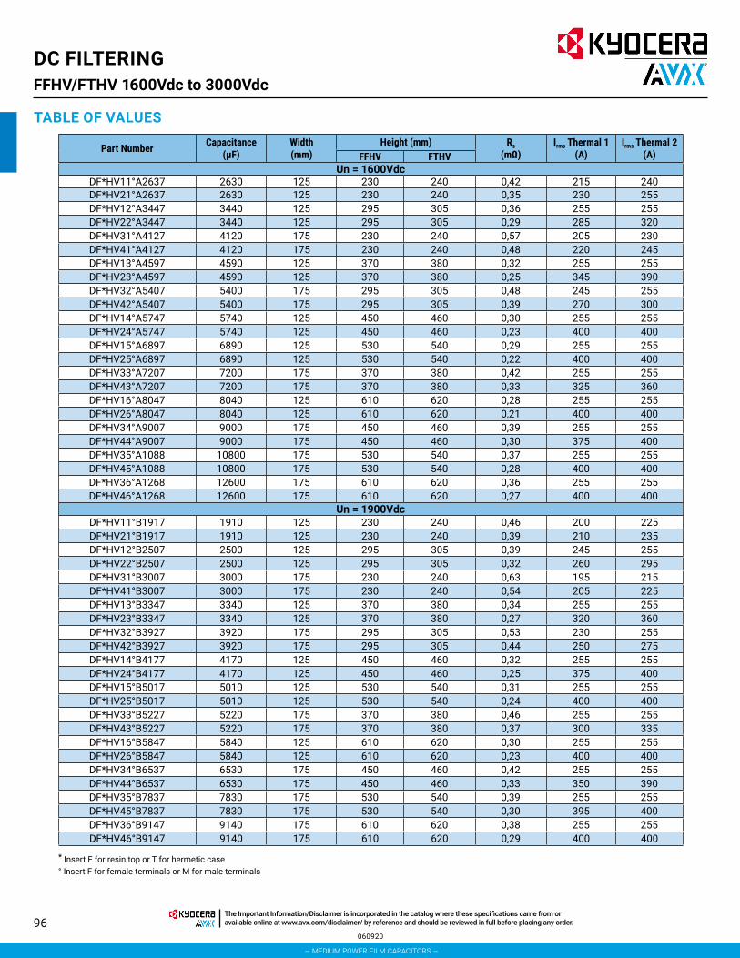
96
DC FILTERINGFFHV/FTHV 1600Vdc to 3000Vdc
TABLE OF VALUES
Part Number Capacitance (μF)
Width (mm)
Height (mm) Rs (mΩ)
Irms Thermal 1 (A)
Irms Thermal 2 (A)FFHV FTHV
Un = 1600VdcDF*HV11°A2637 2630 125 230 240 0,42 215 240DF*HV21°A2637 2630 125 230 240 0,35 230 255DF*HV12°A3447 3440 125 295 305 0,36 255 255DF*HV22°A3447 3440 125 295 305 0,29 285 320DF*HV31°A4127 4120 175 230 240 0,57 205 230DF*HV41°A4127 4120 175 230 240 0,48 220 245DF*HV13°A4597 4590 125 370 380 0,32 255 255DF*HV23°A4597 4590 125 370 380 0,25 345 390DF*HV32°A5407 5400 175 295 305 0,48 245 255DF*HV42°A5407 5400 175 295 305 0,39 270 300DF*HV14°A5747 5740 125 450 460 0,30 255 255DF*HV24°A5747 5740 125 450 460 0,23 400 400DF*HV15°A6897 6890 125 530 540 0,29 255 255DF*HV25°A6897 6890 125 530 540 0,22 400 400DF*HV33°A7207 7200 175 370 380 0,42 255 255DF*HV43°A7207 7200 175 370 380 0,33 325 360DF*HV16°A8047 8040 125 610 620 0,28 255 255DF*HV26°A8047 8040 125 610 620 0,21 400 400DF*HV34°A9007 9000 175 450 460 0,39 255 255DF*HV44°A9007 9000 175 450 460 0,30 375 400DF*HV35°A1088 10800 175 530 540 0,37 255 255DF*HV45°A1088 10800 175 530 540 0,28 400 400DF*HV36°A1268 12600 175 610 620 0,36 255 255DF*HV46°A1268 12600 175 610 620 0,27 400 400
Un = 1900VdcDF*HV11°B1917 1910 125 230 240 0,46 200 225DF*HV21°B1917 1910 125 230 240 0,39 210 235DF*HV12°B2507 2500 125 295 305 0,39 245 255DF*HV22°B2507 2500 125 295 305 0,32 260 295DF*HV31°B3007 3000 175 230 240 0,63 195 215DF*HV41°B3007 3000 175 230 240 0,54 205 225DF*HV13°B3347 3340 125 370 380 0,34 255 255DF*HV23°B3347 3340 125 370 380 0,27 320 360DF*HV32°B3927 3920 175 295 305 0,53 230 255DF*HV42°B3927 3920 175 295 305 0,44 250 275DF*HV14°B4177 4170 125 450 460 0,32 255 255DF*HV24°B4177 4170 125 450 460 0,25 375 400DF*HV15°B5017 5010 125 530 540 0,31 255 255DF*HV25°B5017 5010 125 530 540 0,24 400 400DF*HV33°B5227 5220 175 370 380 0,46 255 255DF*HV43°B5227 5220 175 370 380 0,37 300 335DF*HV16°B5847 5840 125 610 620 0,30 255 255DF*HV26°B5847 5840 125 610 620 0,23 400 400DF*HV34°B6537 6530 175 450 460 0,42 255 255DF*HV44°B6537 6530 175 450 460 0,33 350 390DF*HV35°B7837 7830 175 530 540 0,39 255 255DF*HV45°B7837 7830 175 530 540 0,30 395 400DF*HV36°B9147 9140 175 610 620 0,38 255 255DF*HV46°B9147 9140 175 610 620 0,29 400 400
* Insert F for resin top or T for hermetic case° Insert F for female terminals or M for male terminals
060920
– medium power film capacitors –
The Important Information/Disclaimer is incorporated in the catalog where these specifications came from or available online at www.avx.com/disclaimer/ by reference and should be reviewed in full before placing any order.

97
DC FILTERINGFFHV/FTHV 1600Vdc to 3000Vdc
TABLE OF VALUES
Part Number Capacitance (μF)
Width (mm)
Height (mm) Rs (mΩ)
Irms Thermal 1 (A)
Irms Thermal 2 (A)FFHV FTHV
Un = 2000VdcDF*HV11°C1627 1620 125 230 240 0.49 190 215DF*HV21°C1627 1620 125 230 240 0.41 200 225DF*HV12°C2137 2130 125 295 305 0.42 230 255DF*HV22°C2137 2130 125 295 305 0.34 245 280DF*HV31°C2547 2540 175 230 240 0.65 185 210DF*HV41°C2547 2540 175 230 240 0.56 200 220DF*HV13°C2847 2840 125 370 380 0.37 255 255DF*HV23°C2847 2840 125 370 380 0.29 305 340DF*HV32°C3337 3330 175 295 305 0.55 225 250DF*HV42°C3337 3330 175 295 305 0.46 240 265DF*HV14°C3547 3540 125 450 460 0.35 255 255DF*HV24°C3547 3540 125 450 460 0.27 355 400DF*HV15°C4257 4250 125 530 540 0.33 255 255DF*HV25°C4257 4250 125 530 540 0.25 400 400DF*HV33°C4447 4440 175 370 380 0.48 255 255DF*HV43°C4447 4440 175 370 380 0.39 290 320DF*HV16°C4967 4960 125 610 620 0.32 255 255DF*HV26°C4967 4960 125 610 620 0.24 400 400DF*HV34°C5557 5550 175 450 460 0.43 255 255DF*HV44°C5557 5550 175 450 460 0.34 340 375DF*HV35°C6657 6650 175 530 540 0.41 255 255DF*HV45°C6657 6650 175 530 540 0.32 385 400DF*HV36°C7767 7760 175 610 620 0.39 255 255DF*HV46°C7767 7760 175 610 620 0.3 400 400
Un = 2150VdcDF*HV11°D1447 1440 125 230 240 0,50 180 200DF*HV21°D1447 1440 125 230 240 0,43 185 210DF*HV12°D1887 1880 125 295 305 0,42 225 255DF*HV22°D1887 1880 125 295 305 0,35 240 270DF*HV31°D2257 2250 175 230 240 0,69 175 195DF*HV41°D2257 2250 175 230 240 0,60 185 205DF*HV13°D2517 2510 125 370 380 0,37 255 255DF*HV23°D2517 2510 125 370 380 0,30 295 335DF*HV32°D2957 2950 175 295 305 0,57 215 240DF*HV42°D2957 2950 175 295 305 0,48 230 260DF*HV14°D3147 3140 125 450 460 0,34 255 255DF*HV24°D3147 3140 125 450 460 0,27 345 390DF*HV15°D3777 3770 125 530 540 0,32 255 255DF*HV25°D3777 3770 125 530 540 0,25 395 400DF*HV33°D3937 3930 175 370 380 0,49 255 255DF*HV43°D3937 3930 175 370 380 0,40 280 310DF*HV16°D4407 4400 125 610 620 0,31 255 255DF*HV26°D4407 4400 125 610 620 0,24 400 400DF*HV34°D4917 4910 175 450 460 0,44 255 255DF*HV44°D4917 4910 175 450 460 0,35 330 365DF*HV35°D5907 5900 175 530 540 0,42 255 255DF*HV45°D5907 5900 175 530 540 0,33 375 400DF*HV36°D6887 6880 175 610 620 0,40 255 255DF*HV46°D6887 6880 175 610 620 0,31 400 400
* Insert F for resin top or T for hermetic case° Insert F for female terminals or M for male terminals
060920
– medium power film capacitors –
The Important Information/Disclaimer is incorporated in the catalog where these specifications came from or available online at www.avx.com/disclaimer/ by reference and should be reviewed in full before placing any order.

98
DC FILTERINGFFHV/FTHV 1600Vdc to 3000Vdc
TABLE OF VALUES
Part Number Capacitance (μF)
Width (mm)
Height (mm) Rs (mΩ)
Irms Thermal 1 (A)
Irms Thermal 2 (A)FFHV FTHV
Un = 2450VdcDF*HV11°E1067 1060 125 230 240 0,56 165 190DF*HV21°E1067 1060 125 230 240 0,48 175 195DF*HV12°E1377 1370 125 295 305 0,47 205 230DF*HV22°E1377 1370 125 295 305 0,40 215 240DF*HV31°E1707 1700 175 230 240 0,75 165 185DF*HV41°E1707 1700 175 230 240 0,66 175 195DF*HV13°E1847 1840 125 370 380 0,41 250 255DF*HV23°E1847 1840 125 370 380 0,33 265 300DF*HV32°E2207 2200 175 295 305 0,63 200 225DF*HV42°E2207 2200 175 295 305 0,54 215 240DF*HV14°E2307 2300 125 450 460 0,38 255 255DF*HV24°E2307 2300 125 450 460 0,30 315 355DF*HV15°E2757 2750 125 530 540 0,36 255 255DF*HV25°E2757 2750 125 530 540 0,28 360 400DF*HV33°E2947 2940 175 370 380 0,53 245 255DF*HV43°E2947 2940 175 370 380 0,44 260 290DF*HV16°E3217 3210 125 610 620 0,34 255 255DF*HV26°E3217 3210 125 610 620 0,26 400 400DF*HV34°E3687 3680 175 450 460 0,48 255 255DF*HV44°E3687 3680 175 450 460 0,39 310 340DF*HV35°E4427 4420 175 530 540 0,44 255 255DF*HV45°E4427 4420 175 530 540 0,35 350 390DF*HV36°E5157 5150 175 610 620 0,42 255 255DF*HV46°E5157 5150 175 610 620 0,33 390 400
Un = 2750VdcDF*HV11°F0877 870 125 230 240 0,57 155 175DF*HV21°F0877 870 125 230 240 0,50 160 185DF*HV12°F1137 1130 125 295 305 0,48 200 225DF*HV22°F1137 1130 125 295 305 0,41 205 235DF*HV31°F1397 1390 175 230 240 0,80 160 175DF*HV41°F1397 1390 175 230 240 0,71 165 185DF*HV13°F1517 1510 125 370 380 0,41 245 255DF*HV23°F1517 1510 125 370 380 0,34 260 290DF*HV32°F1827 1820 175 295 305 0,65 195 215DF*HV42°F1827 1820 175 295 305 0,56 205 230DF*HV14°F1897 1890 125 450 460 0,37 255 255DF*HV24°F1897 1890 125 450 460 0,30 305 345DF*HV15°F2277 2270 125 530 540 0,35 255 255DF*HV25°F2277 2270 125 530 540 0,28 350 400DF*HV33°F2427 2420 175 370 380 0,55 235 255DF*HV43°F2427 2420 175 370 380 0,46 250 280DF*HV16°F2657 2650 125 610 620 0,33 255 255DF*HV26°F2657 2650 125 610 620 0,26 400 400DF*HV34°F3037 3030 175 450 460 0,49 255 255DF*HV44°F3037 3030 175 450 460 0,40 295 330DF*HV35°F3647 3640 175 530 540 0,46 255 255DF*HV45°F3647 3640 175 530 540 0,37 340 375DF*HV36°F4257 4250 175 610 620 0,43 255 255DF*HV46°F4257 4250 175 610 620 0,34 380 400
* Insert F for resin top or T for hermetic case° Insert F for female terminals or M for male terminals
060920
– medium power film capacitors –
The Important Information/Disclaimer is incorporated in the catalog where these specifications came from or available online at www.avx.com/disclaimer/ by reference and should be reviewed in full before placing any order.

99
DC FILTERINGFFHV/FTHV 1600Vdc to 3000Vdc
TABLE OF VALUES
Part Number Capacitance (μF)
Width (mm)
Height (mm) Rs (mΩ)
Irms Thermal 1 (A)
Irms Thermal 2 (A)FFHV FTHV
Un = 3000VdcDF*HV11°G0717 710 125 230 240 0,61 145 165DF*HV21°G0717 710 125 230 240 0,54 150 170DF*HV12°G0937 930 125 295 305 0,51 185 210DF*HV22°G0937 930 125 295 305 0,44 195 220DF*HV31°G1147 1140 175 230 240 0,85 150 165DF*HV41°G1147 1140 175 230 240 0,76 155 175DF*HV13°G1247 1240 125 370 380 0,43 230 255DF*HV23°G1247 1240 125 370 380 0,36 240 275DF*HV32°G1497 1490 175 295 305 0,70 185 205DF*HV42°G1497 1490 175 295 305 0,61 195 215DF*HV14°G1557 1550 125 450 460 0,39 255 255DF*HV24°G1557 1550 125 450 460 0,32 285 325DF*HV15°G1867 1860 125 530 540 0,36 255 255DF*HV25°G1867 1860 125 530 540 0,29 330 375DF*HV33°G1997 1990 175 370 380 0,58 225 250DF*HV43°G1997 1990 175 370 380 0,48 240 265DF*HV16°G2177 2170 125 610 620 0,35 255 255DF*HV26°G2177 2170 125 610 620 0,28 375 400DF*HV34°G2497 2490 175 450 460 0,52 255 255DF*HV44°G2497 2490 175 450 460 0,43 280 310DF*HV35°G2997 2990 175 530 540 0,48 255 255DF*HV45°G2997 2990 175 530 540 0,39 320 360DF*HV36°G3487 3480 175 610 620 0,45 255 255DF*HV46°G3487 3480 175 610 620 0,36 360 400
* Insert F for resin top or T for hermetic case° Insert F for female terminals or M for male terminals
060920
– medium power film capacitors –
The Important Information/Disclaimer is incorporated in the catalog where these specifications came from or available online at www.avx.com/disclaimer/ by reference and should be reviewed in full before placing any order.
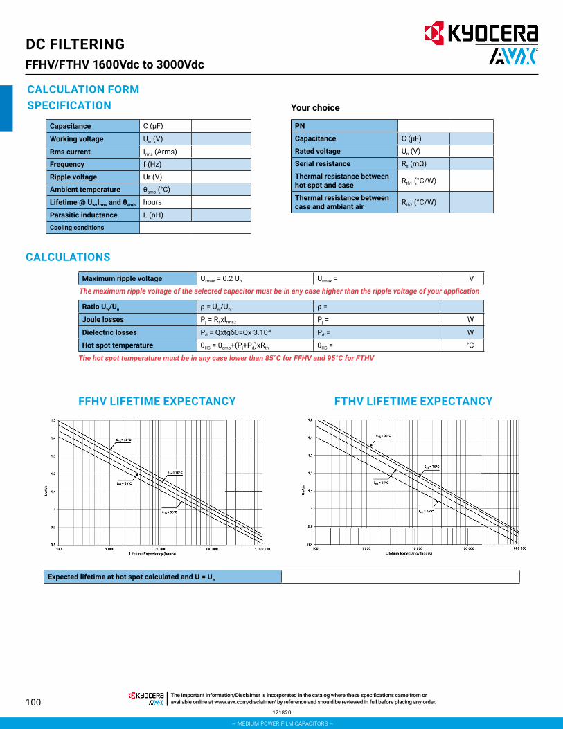
100
DC FILTERINGFFHV/FTHV 1600Vdc to 3000Vdc
CALCULATION FORMSPECIFICATION
Capacitance C (μF)
Working voltage Uw (V)
Rms current Irms (Arms)
Frequency f (Hz)
Ripple voltage Ur (V)
Ambient temperature θamb (°C)
Lifetime @ Uw,Irms and θamb hours
Parasitic inductance L (nH)
Cooling conditions
Expected lifetime at hot spot calculated and U = Uw
PN
Capacitance C (μF)
Rated voltage Un (V)
Serial resistance Rs (mΩ)
Thermal resistance between hot spot and case Rth1 (°C/W)
Thermal resistance between case and ambiant air Rth2 (°C/W)
Your choice
CALCULATIONS
Maximum ripple voltage Urmax = 0.2 Un Urmax = V
The maximum ripple voltage of the selected capacitor must be in any case higher than the ripple voltage of your application
Ratio Uw/Un ρ = Uw/Un ρ =
Joule losses Pj = RsxIrms2 Pj = W
Dielectric losses Pd = Qxtgδ0=Qx 3.10-4 Pd = W
Hot spot temperature θHS = θamb+(Pj+Pd)xRth θHS = °C
The hot spot temperature must be in any case lower than 85°C for FFHV and 95°C for FTHV
FFHV LIFETIME EXPECTANCY FTHV LIFETIME EXPECTANCY
121820
– medium power film capacitors –
The Important Information/Disclaimer is incorporated in the catalog where these specifications came from or available online at www.avx.com/disclaimer/ by reference and should be reviewed in full before placing any order.

101
AC FILTERINGFV X2*
FEATURES• Self-healing properties.• High moisture resistance.• Over voltage stress withstanding.• Excellent active and passive flame resistant abilities
• Widely used in across-the-line, interference suppression circuit, etc.
STANDARDSENEC-VDE: EN60384-14(2005)UL/CUL: UL60384-14 / CSA E60384-14KC: K60384-14CQC: GB/T 14472
FV are non-inductively wound with metallized polypropylene film as dielectric and electrode, encapsulated in solventresistant and self – extinguishing UL94v0 thermoplastic case, with epoxy resin sealed. They provide interference Suppression with safety approvals. They are suitable for Across-the-line Capacitors, EMI Filters, Spark-Killer Circuits, etc.
APPLICATIONS• The FV capacitor is suitable for Across-the-line, EMI Filters• Capacitance Range: 0.01uF ~ 10.0uF• Capacitance Tolerance: ±10% (K), ±20% (M)• Rated Voltage: 305Vrms• Frequency: 50Hz, 60Hz• Insulation Resistance: > 15,000MΩ (≤ 0.33uF)
> 5,000MΩ (> 0.33uF)
• Dielectric Strength: 1312VDC for 60sec.Or 2000vdc for 2sec
Climatic Category: 40/110/56
Passive Flammability Category: B
WORKING TEMPERATUREOperating Temperature Range: -40°C to +110°C
FV A1 M L6 H 0103 2
Series CaseA1-A3
B1C1-C9D1-D6E1-E9F1-F9
Dielectric6 = Polypropylene
VoltageH = 305V
Capacitance EIA Code
Environment TypeTolerancesK = ±10%M = ±20%
Lead LengthL = 22mm
2 = 3.5 mmT = Tape packaging
HOW TO ORDER
0103 = 0.01μF 2 = standard environment H = THB (temperature
humidity bias)
120815
RoHS Compliant
– medium power film capacitors –
The Important Information/Disclaimer is incorporated in the catalog where these specifications came from or available online at www.avx.com/disclaimer/ by reference and should be reviewed in full before placing any order.

102
AC FILTERINGFV X2*
LIFETIME EXPECTANCY VS HOT SPOT TEMPERATURE AND VOLTAGE
1000
10000
100000
1000000
0.7 0.8 0.9 1 1.1 1.2 1.3 1.4 1.5
Exp
ecte
d L
ifeti
me
(h)
Working/Rated Voltage Ratio (Uw/Un)
60ºC70ºC
85ºC
110ºC
Expected Lifetime Curves
W +0.5max
T +0.5)max
H +0.5 max
P
2 .giF1 .giF
dΦ20 min
W +0.5max
T +0.5max
H +0.5 max
PdΦL0
GENERAL DESCRIPTIONDIMENSIONSCase Ref W
(mm)H
(mm)T
(mm)P
(mm)d
(mm)A1 13 11 5 10 0.6A2 13 12 6 10 0.6A3 13 16 8 10 0.6B1 15 13.5 7 12.5 0.8C1 18 11 5 15 0.6C2 18 12 6 15 0.6C3 18 12 6 15 0.8C4 18 13.5 7.5 15 0.8C5 18 14 8 15 0.8C6 18 16 10 15 0.8C7 18 18 9 15 0.8C8 18 18 10 15 0.8C9 18 19 11 15 0.8D1 26 17 8.5 22.5 0.8D2 26 19 10 22.5 0.8D3 26 20 11 22.5 0.8D4 26 22 12 22.5 0.8D5 26 23 13 22.5 0.8D6 26 25 15 22.5 0.8E1 31 20 11 27.5 0.8E2 31 22 13 27.5 0.8E3 31 28 14 27.5 0.8E4 31 28 18 27.5 0.8E5 31 28 19.5 27.5 0.8E6 31 33 18 27.5 0.8E7 31 35 26 27.5 0.8E8 31 31 23 27.5 0.8E9 31 36 22 27.5 0.8F1 41.5 32 16 37.5 1F2 41.5 28 19 37.5 1F3 41.5 32 19 37.5 1F4 41.5 36 19 37.5 1F5 41.5 38 20 37.5 1F6 41.5 40 20 37.5 1F7 41.5 43 28 37.5 1F8 41.5 44 24 37.5 1F9 41.5 45 30 37.5 1
060920
RoHS Compliant
– medium power film capacitors –
The Important Information/Disclaimer is incorporated in the catalog where these specifications came from or available online at www.avx.com/disclaimer/ by reference and should be reviewed in full before placing any order.
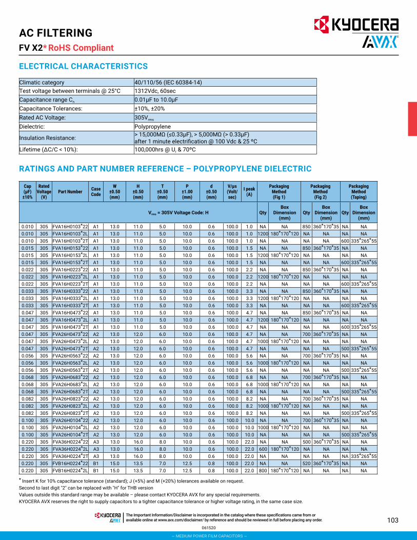
103
AC FILTERINGFV X2*
Climatic category 40/110/56 (IEC 60384-14) Test voltage between terminals @ 25°C 1312Vdc, 60sec Capacitance range Cn 0.01μF to 10.0μFCapacitance Tolerances: ±10%, ±20%Rated AC Voltage: 305Vrms
Dielectric: Polypropylene
Insulation Resistance: > 15,000MΩ (≤0.33μF), > 5,000MΩ (> 0.33μF) after 1 minute electrification @ 100 Vdc & 25 ºC
Lifetime (∆C/C < 10%): 100,000hrs @ Ur & 70ºC
ELECTRICAL CHARACTERISTICS
RATINGS AND PART NUMBER REFERENCE – POLYPROPYLENE DIELECTRIC
Cap (μF)±10%
Rated Voltage
(V)Part Number Case
Code
W±0.50(mm)
H±0.50(mm)
T±0.50(mm)
P±1.00(mm)
d±0.50(mm)
V/μs (Volt/sec)
I peak (A)
Packaging Method (Fig 1)
Packaging Method (Fig 2)
Packaging Method (Taping)
Vrms = 305V Voltage Code: H QtyBox
Dimension (mm)
QtyBox
Dimension (mm)
QtyBox
Dimension (mm)
0.010 305 FVA16H0103*22 A1 13.0 11.0 5.0 10.0 0.6 100.0 1.0 NA NA 850 360*170*35 NA NA0.010 305 FVA16H0103*2L A1 13.0 11.0 5.0 10.0 0.6 100.0 1.0 1200 180*170*120 NA NA NA NA0.010 305 FVA16H0103*2T A1 13.0 11.0 5.0 10.0 0.6 100.0 1.0 NA NA NA NA 600 335*265*550.015 305 FVA16H0153*22 A1 13.0 11.0 5.0 10.0 0.6 100.0 1.5 NA NA 850 360*170*35 NA NA0.015 305 FVA16H0153*2L A1 13.0 11.0 5.0 10.0 0.6 100.0 1.5 1200 180*170*120 NA NA NA NA0.015 305 FVA16H0153*2T A1 13.0 11.0 5.0 10.0 0.6 100.0 1.5 NA NA NA NA 600 335*265*550.022 305 FVA16H0223*22 A1 13.0 11.0 5.0 10.0 0.6 100.0 2.2 NA NA 850 360*170*35 NA NA0.022 305 FVA16H0223*2L A1 13.0 11.0 5.0 10.0 0.6 100.0 2.2 1200 180*170*120 NA NA NA NA0.022 305 FVA16H0223*2T A1 13.0 11.0 5.0 10.0 0.6 100.0 2.2 NA NA NA NA 600 335*265*550.033 305 FVA16H0333*22 A1 13.0 11.0 5.0 10.0 0.6 100.0 3.3 NA NA 850 360*170*35 NA NA0.033 305 FVA16H0333*2L A1 13.0 11.0 5.0 10.0 0.6 100.0 3.3 1200 180*170*120 NA NA NA NA0.033 305 FVA16H0333*2T A1 13.0 11.0 5.0 10.0 0.6 100.0 3.3 NA NA NA NA 600 335*265*550.047 305 FVA16H0473*22 A1 13.0 11.0 5.0 10.0 0.6 100.0 4.7 NA NA 850 360*170*35 NA NA0.047 305 FVA16H0473*2L A1 13.0 11.0 5.0 10.0 0.6 100.0 4.7 1200 180*170*120 NA NA NA NA0.047 305 FVA16H0473*2T A1 13.0 11.0 5.0 10.0 0.6 100.0 4.7 NA NA NA NA 600 335*265*550.047 305 FVA26H0473*22 A2 13.0 12.0 6.0 10.0 0.6 100.0 4.7 NA NA 700 360*170*35 NA NA0.047 305 FVA26H0473*2L A2 13.0 12.0 6.0 10.0 0.6 100.0 4.7 1000 180*170*120 NA NA NA NA0.047 305 FVA26H0473*2T A2 13.0 12.0 6.0 10.0 0.6 100.0 4.7 NA NA NA NA 500 335*265*550.056 305 FVA26H0563*22 A2 13.0 12.0 6.0 10.0 0.6 100.0 5.6 NA NA 700 360*170*35 NA NA0.056 305 FVA26H0563*2L A2 13.0 12.0 6.0 10.0 0.6 100.0 5.6 1000 180*170*120 NA NA NA NA0.056 305 FVA26H0563*2T A2 13.0 12.0 6.0 10.0 0.6 100.0 5.6 NA NA NA NA 500 335*265*550.068 305 FVA26H0683*22 A2 13.0 12.0 6.0 10.0 0.6 100.0 6.8 NA NA 700 360*170*35 NA NA0.068 305 FVA26H0683*2L A2 13.0 12.0 6.0 10.0 0.6 100.0 6.8 1000 180*170*120 NA NA NA NA0.068 305 FVA26H0683*2T A2 13.0 12.0 6.0 10.0 0.6 100.0 6.8 NA NA NA NA 500 335*265*550.082 305 FVA26H0823*22 A2 13.0 12.0 6.0 10.0 0.6 100.0 8.2 NA NA 700 360*170*35 NA NA0.082 305 FVA26H0823*2L A2 13.0 12.0 6.0 10.0 0.6 100.0 8.2 1000 180*170*120 NA NA NA NA0.082 305 FVA26H0823*2T A2 13.0 12.0 6.0 10.0 0.6 100.0 8.2 NA NA NA NA 500 335*265*550.100 305 FVA26H0104*22 A2 13.0 12.0 6.0 10.0 0.6 100.0 10.0 NA NA 700 360*170*35 NA NA0.100 305 FVA26H0104*2L A2 13.0 12.0 6.0 10.0 0.6 100.0 10.0 1000 180*170*120 NA NA NA NA0.100 305 FVA26H0104*2T A2 13.0 12.0 6.0 10.0 0.6 100.0 10.0 NA NA NA NA 500 335*265*550.220 305 FVA36H0224*22 A3 13.0 16.0 8.0 10.0 0.6 100.0 22.0 NA NA 500 360*170*35 NA NA0.220 305 FVA36H0224*2L A3 13.0 16.0 8.0 10.0 0.6 100.0 22.0 600 180*170*120 NA NA NA NA0.220 305 FVA36H0224*2T A3 13.0 16.0 8.0 10.0 0.6 100.0 22.0 NA NA NA NA NA 335*265*550.220 305 FVB16H0224*22 B1 15.0 13.5 7.0 12.5 0.8 100.0 22.0 NA NA 520 360*170*35 NA NA0.220 305 FVB16H0224*2L B1 15.0 13.5 7.0 12.5 0.8 100.0 22.0 800 180*170*120 NA NA NA NA
* Insert K for 10% capacitance tolerance (standard); J (+5%) and M (+20%) tolerances available on request.Second to last digit "2" can be replaced with "H" for THB versionValues outside this standard range may be available – please contact KYOCERA AVX for any special requirements.KYOCERA AVX reserves the right to supply capacitors to a tighter capacitance tolerance or higher voltage rating, in the same case size.
061520
RoHS Compliant
– medium power film capacitors –
The Important Information/Disclaimer is incorporated in the catalog where these specifications came from or available online at www.avx.com/disclaimer/ by reference and should be reviewed in full before placing any order.

104
AC FILTERINGFV X2*
* Insert K for 10% capacitance tolerance (standard); J (+5%) and M (+20%) tolerances available on request.Second to last digit "2" can be replaced with "H" for THB versionValues outside this standard range may be available – please contact KYOCERA AVX for any special requirements.KYOCERA AVX reserves the right to supply capacitors to a tighter capacitance tolerance or higher voltage rating, in the same case size.
060920
RoHS Compliant
RATINGS AND PART NUMBER REFERENCE – POLYPROPYLENE DIELECTRIC
Cap (μF)±10%
Rated Voltage
(V)Part Number Case
Code
W±0.50(mm)
H±0.50(mm)
T±0.50(mm)
P±1.00(mm)
d±0.50(mm)
V/μs (Volt/sec)
I peak (A)
Packaging Method (Fig 1)
Packaging Method (Fig 2)
Packaging Method (Taping)
Vrms = 305V Voltage Code: H QtyBox
Dimension (mm)
QtyBox
Dimension (mm)
QtyBox
Dimension (mm)
0.220 305 FVB16H0224*2T B1 15.0 13.5 7.0 12.5 0.8 100.0 22.0 NA NA NA NA 400 335*265*550.015 305 FVC16H0153*22 C1 18.0 11.0 5.0 15.0 0.6 100.0 1.5 NA NA 600 360*170*35 NA NA0.015 305 FVC16H0153*2L C1 18.0 11.0 5.0 15.0 0.6 100.0 1.5 1000 180*170*120 NA NA NA NA0.015 305 FVC16H0153*2T C1 18.0 11.0 5.0 15.0 0.6 100.0 1.5 NA NA NA NA 600 335*265*550.047 305 FVC16H0473*22 C1 18.0 11.0 5.0 15.0 0.6 100.0 4.7 NA NA 600 360*170*35 NA NA0.047 305 FVC16H0473*2L C1 18.0 11.0 5.0 15.0 0.6 100.0 4.7 1000 180*170*120 NA NA NA NA0.047 305 FVC16H0473*2T C1 18.0 11.0 5.0 15.0 0.6 100.0 4.7 NA NA NA NA 600 335*265*550.056 305 FVC16H0563*22 C1 18.0 11.0 5.0 15.0 0.6 100.0 5.6 NA NA 600 360*170*35 NA NA0.056 305 FVC16H0563*2L C1 18.0 11.0 5.0 15.0 0.6 100.0 5.6 1000 180*170*120 NA NA NA NA0.056 305 FVC16H0563*2T C1 18.0 11.0 5.0 15.0 0.6 100.0 5.6 NA NA NA NA 600 335*265*550.100 305 FVC16H0104*22 C1 18.0 11.0 5.0 15.0 0.6 100.0 10.0 NA NA 600 360*170*35 NA NA0.100 305 FVC16H0104*2L C1 18.0 11.0 5.0 15.0 0.6 100.0 10.0 1000 180*170*120 NA NA NA NA0.100 305 FVC16H0104*2T C1 18.0 11.0 5.0 15.0 0.6 100.0 10.0 NA NA NA NA 600 335*265*550.068 305 FVC26H0683*22 C2 18.0 12.0 6.0 15.0 0.6 100.0 6.8 NA NA 500 360*170*35 NA NA0.068 305 FVC26H0683*2L C2 18.0 12.0 6.0 15.0 0.6 100.0 6.8 800 180*170*120 NA NA NA NA0.068 305 FVC26H0683*2T C2 18.0 12.0 6.0 15.0 0.6 100.0 6.8 NA NA NA NA 500 335*265*550.082 305 FVC26H0823*22 C2 18.0 11.0 5.0 15.0 0.6 100.0 8.2 NA NA 600 360*170*35 NA NA0.082 305 FVC26H0823*2L C2 18.0 11.0 5.0 15.0 0.6 100.0 8.2 1000 180*170*120 NA NA NA NA0.082 305 FVC26H0823*2T C2 18.0 11.0 5.0 15.0 0.6 100.0 8.2 NA NA NA NA 600 335*265*550.150 305 FVC36H0154*22 C3 18.0 12.0 6.0 15.0 0.8 100.0 15.0 NA NA 500 360*170*35 NA NA0.150 305 FVC36H0154*2L C3 18.0 12.0 6.0 15.0 0.8 100.0 15.0 800 180*170*120 NA NA NA NA0.150 305 FVC36H0154*2T C3 18.0 12.0 6.0 15.0 0.8 100.0 15.0 NA NA NA NA 500 335*265*550.220 305 FVC46H0224*22 C4 18.0 13.5 7.5 15.0 0.8 100.0 22.0 NA NA 410 360*170*35 NA NA0.220 305 FVC46H0224*2L C4 18.0 13.5 7.5 15.0 0.8 100.0 22.0 600 180*170*120 NA NA NA NA0.220 305 FVC46H0224*2T C4 18.0 13.5 7.5 15.0 0.8 100.0 22.0 NA NA NA NA 400 335*265*550.330 305 FVC56H0334*22 C5 18.0 14.0 8.0 15.0 0.8 100.0 33.0 NA NA 380 360*170*35 NA NA0.330 305 FVC56H0334*2L C5 18.0 14.0 8.0 15.0 0.8 100.0 33.0 500 180*170*120 NA NA NA NA0.330 305 FVC56H0334*2T C5 18.0 14.0 8.0 15.0 0.8 100.0 33.0 NA NA NA NA 350 335*265*550.470 305 FVC66H0474*22 C6 18.0 16.0 10.0 15.0 0.8 100.0 47.0 NA NA 300 360*170*35 NA NA0.470 305 FVC66H0474*2L C6 18.0 16.0 10.0 15.0 0.8 100.0 47.0 400 180*170*120 NA NA NA NA0.470 305 FVC66H0474*2T C6 18.0 16.0 10.0 15.0 0.8 100.0 47.0 NA NA NA NA 300 335*265*550.470 305 FVC76H0474*22 C7 18.0 18.0 9.0 15.0 0.8 100.0 47.0 NA NA 340 360*170*35 NA NA0.470 305 FVC76H0474*2L C7 18.0 18.0 9.0 15.0 0.8 100.0 47.0 400 180*170*120 NA NA NA NA0.470 305 FVC76H0474*2T C7 18.0 18.0 9.0 15.0 0.8 100.0 47.0 NA NA NA NA 300 335*265*550.560 305 FVC86H0564*22 C8 18.0 18.0 10.0 15.0 0.8 100.0 56.0 NA NA 300 360*170*35 NA NA0.560 305 FVC86H0564*2L C8 18.0 18.0 10.0 15.0 0.8 100.0 56.0 300 180*170*120 NA NA NA NA0.560 305 FVC86H0564*2T C8 18.0 18.0 10.0 15.0 0.8 100.0 56.0 NA NA NA NA 300 335*265*550.680 305 FVC96H0684*22 C9 18.0 19.0 11.0 15.0 0.8 100.0 68.0 NA NA 270 360*170*35 NA NA0.680 305 FVC96H0684*2L C9 18.0 19.0 11.0 15.0 0.8 100.0 68.0 300 180*170*120 NA NA NA NA0.680 305 FVC96H0684*2T C9 18.0 19.0 11.0 15.0 0.8 100.0 68.0 NA NA NA NA 250 335*265*550.820 305 FVC96H0824*22 C9 18.0 19.0 11.0 15.0 0.8 100.0 82.0 NA NA 270 360*170*35 NA NA0.820 305 FVC96H0824*2L C9 18.0 19.0 11.0 15.0 0.8 100.0 82.0 300 180*170*120 NA NA NA NA0.820 305 FVC96H0824*2T C9 18.0 19.0 11.0 15.0 0.8 100.0 82.0 NA NA NA NA 250 335*265*550.330 305 FVD16H0334*22 D1 26.0 17.0 8.5 22.5 0.8 100.0 33.0 NA NA 240 360*170*35 NA NA0.330 305 FVD16H0334*2L D1 26.0 17.0 8.5 22.5 0.8 100.0 33.0 300 180*170*120 NA NA NA NA0.470 305 FVD16H0474*22 D1 26.0 17.0 8.5 22.5 0.8 100.0 47.0 NA NA 240 360*170*35 NA NA0.470 305 FVD16H0474*2L D1 26.0 17.0 8.5 22.5 0.8 100.0 47.0 300 180*170*120 NA NA NA NA
– medium power film capacitors –
The Important Information/Disclaimer is incorporated in the catalog where these specifications came from or available online at www.avx.com/disclaimer/ by reference and should be reviewed in full before placing any order.

105
AC FILTERINGFV X2*
* Insert K for 10% capacitance tolerance (standard); J (+5%) and M (+20%) tolerances available on request.Second to last digit "2" can be replaced with "H" for THB versionValues outside this standard range may be available – please contact KYOCERA AVX for any special requirements.KYOCERA AVX reserves the right to supply capacitors to a tighter capacitance tolerance or higher voltage rating, in the same case size.
060920
RoHS Compliant
RATINGS AND PART NUMBER REFERENCE – POLYPROPYLENE DIELECTRIC
Cap (μF)±10%
Rated Voltage
(V)Part Number Case
Code
W±0.50(mm)
H±0.50(mm)
T±0.50(mm)
P±1.00(mm)
d±0.50(mm)
V/μs (Volt/sec)
I peak (A)
Packaging Method (Fig 1)
Packaging Method (Fig 2)
Packaging Method (Taping)
Vrms = 305V Voltage Code: H QtyBox
Dimension (mm)
QtyBox
Dimension (mm)
QtyBox
Dimension (mm)
0.680 305 FVD26H0684*22 D2 26.0 19.0 10.0 22.5 0.8 100.0 68.0 NA NA 200 360*170*35 NA NA0.680 305 FVD26H0684*2L D2 26.0 19.0 10.0 22.5 0.8 100.0 68.0 250 180*170*120 NA NA NA NA0.820 305 FVD26H0824*22 D2 26.0 19.0 10.0 22.5 0.8 100.0 82.0 NA NA 200 360*170*35 NA NA0.820 305 FVD26H0824*2L D2 26.0 19.0 10.0 22.5 0.8 100.0 82.0 250 180*170*120 NA NA NA NA1.000 305 FVD36H0105*22 D3 26.0 20.0 11.0 22.5 0.8 100.0 100.0 NA NA 180 360*170*35 NA NA1.000 305 FVD36H0105*2L D3 26.0 20.0 11.0 22.5 0.8 100.0 100.0 200 180*170*120 NA NA NA NA1.200 305 FVD46H0125*22 D4 26.0 22.0 12.0 22.5 0.8 100.0 120.0 NA NA 160 360*170*35 NA NA1.200 305 FVD46H0125*2L D4 26.0 22.0 12.0 22.5 0.8 100.0 120.0 100 180*170*120 NA NA NA NA1.500 305 FVD56H0155*22 D5 26.0 23.0 13.0 22.5 0.8 100.0 150.0 NA NA 150 360*170*35 NA NA1.500 305 FVD56H0155*2L D5 26.0 23.0 13.0 22.5 0.8 100.0 150.0 100 180*170*120 NA NA NA NA1.800 305 FVD56H0185*22 D5 26.0 23.0 13.0 22.5 0.8 100.0 180.0 NA NA 150 360*170*35 NA NA1.800 305 FVD56H0185*2L D5 26.0 23.0 13.0 22.5 0.8 100.0 180.0 100 180*170*120 NA NA NA NA2.200 305 FVD66H0225*22 D6 26.0 25.0 15.0 22.5 0.8 100.0 220.0 NA NA 138 360*170*50 NA NA2.200 305 FVD66H0225*2L D6 26.0 25.0 15.0 22.5 0.8 100.0 220.0 100 180*170*120 NA NA NA NA1.000 305 FVE16H0105*22 E1 31.0 20.0 11.0 27.5 0.8 100.0 100.0 NA NA 150 360*170*35 NA NA1.200 305 FVE26H0125*22 E2 31.0 22.0 13.0 27.5 0.8 100.0 120.0 NA NA 130 360*170*35 NA NA1.500 305 FVE26H0155*22 E2 31.0 22.0 13.0 27.5 0.8 100.0 150.0 NA NA 130 360*170*35 NA NA1.800 305 FVE36H0185*22 E3 31.0 28.0 14.0 27.5 0.8 100.0 180.0 NA NA 125 360*170*50 NA NA2.200 305 FVE36H0225*22 E3 31.0 28.0 14.0 27.5 0.8 100.0 220.0 NA NA 125 360*170*50 NA NA2.700 305 FVE46H0275*22 E4 31.0 28.0 18.0 27.5 0.8 100.0 270.0 NA NA 95 360*170*50 NA NA3.000 305 FVE56H0305*22 E5 31.0 28.0 19.5 27.5 0.8 100.0 300.0 NA NA 85 360*170*50 NA NA3.300 305 FVE66H0335*22 E6 31.0 33.0 18.0 27.5 0.8 100.0 330.0 NA NA 95 360*170*50 NA NA3.900 305 FVE76H0395*22 E7 31.0 35.0 26.0 27.5 0.8 100.0 390.0 NA NA 65 360*170*50 NA NA3.900 305 FVE86H0395*22 E8 31.0 31.0 23.0 27.5 0.8 100.0 390.0 NA NA 75 360*170*50 NA NA3.900 305 FVF16H0395*22 F1 41.5 32.0 16.0 37.5 1.0 100.0 390.0 NA NA 84 360*170*50 NA NA3.900 305 FVF26H0395*22 F2 41.5 28.0 19.0 37.5 1.0 100.0 390.0 NA NA 72 360*170*50 NA NA4.700 305 FVE76H0475*22 E7 31.0 35.0 26.0 27.5 0.8 100.0 470.0 NA NA 65 360*170*50 NA NA4.700 305 FVE96H0475*22 E9 31.0 36.0 22.0 27.5 0.8 100.0 470.0 NA NA 75 360*170*50 NA NA4.700 305 FVF36H0475*22 F3 41.5 32.0 19.0 37.5 1.0 100.0 470.0 NA NA 72 360*170*50 NA NA4.700 305 FVF46H0475*22 F4 41.5 36.0 19.0 37.5 1.0 100.0 470.0 NA NA 72 360*170*50 NA NA5.600 305 FVF36H0565*22 F3 41.5 32.0 19.0 37.5 1.0 100.0 560.0 NA NA 72 360*170*50 NA NA5.600 305 FVF56H0565*22 F5 41.5 38.0 20.0 37.5 1.0 100.0 560.0 NA NA 68 360*170*50 NA NA5.600 305 FVF66H0565*22 F6 41.5 40.0 20.0 37.5 1.0 100.0 560.0 NA NA 56 350*170*80 NA NA6.800 305 FVF56H0685*22 F5 41.5 38.0 20.0 37.5 1.0 100.0 680.0 NA NA 68 360*170*50 NA NA6.800 305 FVF76H0685*22 F7 41.5 43.0 28.0 37.5 1.0 100.0 680.0 NA NA 48 350*170*80 NA NA6.800 305 FVF86H0685*22 F8 41.5 44.0 24.0 37.5 1.0 100.0 680.0 NA NA 42 350*170*80 NA NA8.200 305 FVF56H0825*22 F5 41.5 38.0 25.0 37.5 1.0 100.0 820.0 NA NA 56 360*170*50 NA NA8.200 305 FVF66H0825*22 F6 41.5 40.0 20.0 37.5 1.0 100.0 820.0 NA NA 56 350*170*80 NA NA8.200 305 FVF76H0825*22 F7 41.5 43.0 28.0 37.5 1.0 100.0 820.0 NA NA 48 350*170*80 NA NA
10.000 305 FVF76H0106*22 F7 41.5 43.0 28.0 37.5 1.0 100.0 1000 NA NA 48 350*170*80 NA NA10.000 305 FVF96H0106*22 F9 41.5 45.0 30.0 37.5 1.0 100.0 1000 NA NA 44 350*170*80 NA NA
– medium power film capacitors –
The Important Information/Disclaimer is incorporated in the catalog where these specifications came from or available online at www.avx.com/disclaimer/ by reference and should be reviewed in full before placing any order.

106
AC FILTERINGFLC*
PACKAGING MATERIAL• Self-extinguishing plastic case
(V0 = in accordance with UL 94) filled thermosetting resin.• Self-extinguishing thermosetting resin
(V0 = in accordance with UL 94).
STANDARDSIEC 61071-1, IEC 61071-2: Power electronic capacitors IEC 60384-17: Fixed metallized polypropylene film dielectric AC and pulse capacitorsIEC 60384-17-1: Fixed metallized polypropylene film dielectric AC and pulse capacitors Assessment level EEN CZDS2.E514026 Certificate: E514026 (approved by UL)
The FLC series uses a non-impregnated metallized polypropylene dielectric specially treated to have a very high dielectric strength in operating conditions up to 85°C.
The FLC has been designed for printed circuit board mounting. They are suitable for output AC filtering for power converters, UPS systems, solar inverters and motor drives etc.
APPLICATIONS• The FLC capacitor is particularly designed for AC filtering.
HOT SPOT CALCULATIONSee Hot Spot Temperature, page 66.
θhot spot = θambient + (Pd + Pt) x Rth with Pd (Dielectric losses) = Q x tgδ0
Q x tgδ0 [ ½ x Cn x (Vpeak to peak)2 x f ] x tgδ0 tgδ0 (tan delta)For polypropylene, tgδ0 = 2 x 10⁻⁴ for frequencies up to 1MHz and is independent of temperatures.
Pt (Thermal losses) = Rs x (Irms)2
where Cn in FaradV in VoltRth in °C/W
Irms in AmpereRs in Ohm
f in Hertzθ in °C
WORKING TEMPERATUREAccording to the power to be dissipated -40°C to +85°C
LIFETIME EXPECTANCYOne unique feature of this technology (as opposed to aluminum electrolytics) is how the capacitor reacts at the end of its lifetime.
Unlike aluminum electrolytic film capacitors do not have a catastrophic failure mode. Film capacitors simply experience a parametric loss of capacitance of about 5% from initial value, with no risk of short circuit.
The capacitor continues to be functional even after this 5% decrease.
FLC A K C6 V 0225 2
Series Case Dielectric6 = Polypropylene
VoltageH = 300VI = 350V
A = 250VL = 400V
M = 450V
Cap μF Code Lead TypeTolerancesJ = ±5%
K = ±10%
LeadLenght
C = 5mmL = 15mm
0225 = 2.5μF0106 = 10μF
ABCDEFGH
IJKLMNO
2 = 2 Leads4 = 4 Leads
HOW TO ORDER
080621
RoHS Compliant
– medium power film capacitors –
The Important Information/Disclaimer is incorporated in the catalog where these specifications came from or available online at www.avx.com/disclaimer/ by reference and should be reviewed in full before placing any order.

107
AC FILTERINGFLC*
LIFETIME EXPECTANCY VS HOT SPOT TEMPERATURE AND VOLTAGE
GENERAL DESCRIPTION
1000
10000
100000
1000000
0.7 0.8 0.9 1 1.1 1.2 1.3 1.4 1.5
Exp
ecte
d L
ifeti
me
(h)
Working/Rated Voltage Ratio (Uw/Un)
60ºC70ºC
50ºC
85ºC
Expected Lifetime Curves (FLC Series)
DIMENSIONSTwo Terminal Version
Four Terminal Version
Case Ref W(mm)
H(mm)
T(mm)
P(mm)
d (mm)
A 32 22 13 27.5 0.8B 32 28 14 27.5 0.8C 32 33 18 27.5 0.8D 42.5 40 20 37.5 1.0E 42.5 43 28 37.5 1.0F 42.5 44 24 37.5 1.0G 42.5 45 30 37.5 1.2H 57.5 45 30 52.5 1.2I 57.5 50 35 52.5 1.2
Case Ref W(mm)
H(mm)
T(mm)
P(mm)
P1(mm)
d (mm)
J 42.5 40 20 37.5 10.2 1.2K 42.5 43 28 37.5 10.2 1.2L 42.5 44 24 37.5 10.2 1.2M 42.5 45 30 37.5 20.3 1.2N 57.5 45 30 52.5 20.3 1.2O 57.5 50 35 52.5 20.3 1.2
060920
RoHS Compliant
– medium power film capacitors –
The Important Information/Disclaimer is incorporated in the catalog where these specifications came from or available online at www.avx.com/disclaimer/ by reference and should be reviewed in full before placing any order.

108
AC FILTERINGFLC*
Climatic category 40/85/56 (IEC 60068) Test voltage between terminals @ 25°C 2.15 x Vrms
Capacitance range Cn 1.0μF to 50μFCapacitance Tolerances: ±5%, ±10%Rated AC Voltage: Vrms 250V to 350VDielectric: PolypropyleneInsulation Resistance: > 3,000MΩ μF/C after 1 minute electrification @ 100 Vdc & 25ºCLifetime (∆C/C < 5%): 100,000hrs @ Ur & 70ºC
ELECTRICAL CHARACTERISTICS
Cap (μF)
Rated Voltage (V) Part Number Case
CodeW ±0.50
(mm)H ±0.50
(mm)T ±0.50(mm)
P ±1.00(mm)
d ±0.50(mm)
V/μs (Volt/sec)
I peak (A)
I rms (A)
Rs (mΩ)
ESL (nH)
Rth (ºC/W)
Packaging Method
Vrms = 250V Voltage Code: ABox Qty
(mm)Dimensions
2.2 250 FLCA6A0225K2C A 32.0 22 13.0 27.5 0.8 25.0 55.0 4.0 17.0 24.0 36.8 130 350*170*803.3 250 FLCB6A0335K2C B 32.0 28 14.0 27.5 0.8 25.0 82.5 6.0 11.6 24.0 23.9 110 350*170*805.0 250 FLCC6A0505K2C C 32.0 33 18.0 27.5 0.8 25.0 125 8.0 8.0 27.0 19.5 95 350*170*80
10.0 250 FLCD6A0106K2C D 42.5 40 20.0 37.5 1.0 17.0 170 11.0 7.4 30.0 11.2 56 350*170*8018.0 250 FLCE6A0186K2C E 42.5 43 28.0 37.5 1.0 17.0 306 12.0 4.0 30.0 17.4 35 350*170*8020.0 250 FLCG6A0206K2C G 42.5 45 30.0 37.5 1.2 17.0 340 14.0 3.8 33.0 13.4 44 350*170*8025.0 250 FLCH6A0256K2C H 57.5 45 30.0 52.5 1.2 11.0 275 17.0 6.5 35.0 5.3 25 350*170*8030.0 250 FLCI6A0306K2C I 57.5 50 35.0 52.5 1.2 11.0 330 20.0 5.4 38.0 4.6 20 350*170*8040.0 250 FLCI6A0406K2C I 57.5 50 35.0 52.5 1.2 11.0 440 19.0 5.8 38.0 4.8 20 350*170*8050.0 250 FLCI6A0506K2C I 57.5 50 35.0 52.5 1.2 12.0 600 21.0 5.5 38.0 4.1 20 350*170*80
Vrms = 300V Voltage Code: H1.5 300 FLCA6H0155K2C A 32.0 22 13.0 27.5 0.8 28.0 42.0 4.0 21.2 24.0 29.5 130 350*170*802.5 300 FLCB6H0255K2C B 32.0 28 14.0 27.5 0.8 28.0 70.0 6.0 14.4 24.0 19.3 110 350*170*803.3 300 FLCC6H0335K2C C 32.0 33 18.0 27.5 0.8 28.0 92.4 8.0 10.6 27.0 14.7 95 350*170*80
10.0 300 FLCF6H0106K2C F 42.5 44 24.0 37.5 1.0 19.0 190 12.0 6.0 30.0 11.6 42 350*170*8012.0 300 FLCE6H0126K2C E 42.5 43 28.0 37.5 1.0 19.0 228 12.0 5.0 30.0 13.9 35 350*170*8015.0 300 FLCG6H0156K2C G 42.5 45 30.0 37.5 1.2 19.0 285 12.0 4.2 33.0 16.5 44 350*170*8020.0 300 FLCH6H0206K2C H 57.5 45 30.0 52.5 1.2 13.0 260 16.0 6.8 35.0 5.7 25 350*170*8025.0 300 FLCI6H0256K2C I 57.5 50 35.0 52.5 1.2 13.0 325 19.0 5.4 38.0 5.1 20 350*170*80
Vrms = 350V Voltage Code: I1.0 350 FLCA6I0105K2C A 32.0 22 13.0 27.5 0.8 35.0 35.0 4.0 23.5 24.0 26.6 130 350*170*801.8 350 FLCB6I0185K2C B 32.0 28 14.0 27.5 0.8 35.0 63.0 6.0 16.5 24.0 16.8 110 350*170*802.5 350 FLCC6I0255K2C C 32.0 33 18.0 27.5 0.8 35.0 87.5 8.0 11.3 27.0 13.8 95 350*170*807.5 350 FLCF6I0755K2C F 42.5 44 24.0 37.5 1.0 24.0 180 10.0 7.5 30.0 13.3 42 350*170*809.0 350 FLCE6I0905K2C E 42.5 43 28.0 37.5 1.0 24.0 216 10.0 6.2 30.0 16.1 35 350*170*80
10.0 350 FLCG6I0106K2C G 42.5 45 30.0 37.5 1.2 24.0 240 10.0 4.8 33.0 20.8 44 350*170*8012.0 350 FLCH6I0126K2C H 57.5 45 30.0 52.5 1.2 17.0 204 17.0 6.5 35.0 5.3 25 350*170*8020.0 350 FLCI6I0206K2C I 57.5 50 35.0 52.5 1.2 17.0 340 20.0 5.8 38.0 4.3 20 350*170*80
Vrms = 400V Voltage Code: L1.5 400 FLCA6L0155K2C A 32.0 22 13.0 27.5 0.8 36.0 54.0 4.0 15.0 25.0 41.6 130 350*170*802.2 400 FLCB6L0225K2C B 32.0 28 14.0 27.5 0.8 36.0 79.2 6.0 11.0 26.0 25.2 110 350*170*803.5 400 FLCC6L0355K2C C 32.0 33 18.0 27.5 0.8 36.0 126.0 8.0 7.0 27.0 22.3 95 350*170*807.5 400 FLCD6L0755K2C D 42.5 40 20.0 37.5 1.0 25.0 187.5 10.0 5.5 30.0 18.1. 56 350*170*80
10.0 400 FLCE6L0106K2C E 42.5 43 28.0 37.5 1.0 25.0 250.0 13.0 4.5 30.0 13.1 35 350*170*8012.0 400 FLCG6L0126K2C G 42.5 45 30.0 37.5 1.2 25.0 300.0 16.0 3.5 33.0 11.1 44 350*170*8016.0 400 FLCH6L0166K2C H 57.5 45 30.0 52.5 1.2 20.0 320.0 13.0 4.5 35.0 13.1 25 350*170*8020.0 400 FLCI6L0206K2C I 57.5 50 35.0 52.5 1.2 20.0 400.0 16.0 3.5 38.0 11.1 20 350*170*80
Vrms = 450V Voltage Code: M1.00 450 FLCA6M0105K2C A 32.0 22 13.0 27.5 0.8 40.0 40.0 4.0 12.0 25.0 52.0 130 350*170*801.50 450 FLCB6M0155K2C B 32.0 28 14.0 27.5) 0.8 40.0 60.0 6.0 10.0 26.0 27.7 110 350*170*802.20 450 FLCC6M0225K2C C 32.0 33 18.0 27.5 0.8 40.0 88.0 8.0 6.5 27.0 24.0 95 350*170*804.70 450 FLCD6M0475K2C D 42.5 40 20.0 37.5 1.0 35.0 164.5 10.0 5.3 30.0 18.8 56 350*170*807.50 450 FLCE6M0755K2C E 42.5 43 28.0 37.5 1.0 35.0 262.5 12.0 4.6 30.0 15.0 35 350*170*808.50 450 FLCG6M0855K2C G 42.5 45 30.0 37.5 1.2 35.0 297.5 13.0 4.0 33.0 14.8 44 350*170*8012.0 450 FLCH6M0126K2C H 57.5 45 30.0 52.5 1.2 28.0 336.0 13.0 4.5 35.0 13.1 25 350*170*8016.0 450 FLCI6M0166K2C I 57.5 50 35.0 52.5 1.2 28.0 448.0 16.0 3.5 38.0 11.1 20 350*170*80
RATINGS AND PART NUMBER REFERENCE – POLYPROPYLENE DIELECTRICTWO TERMINAL
* Insert K for 10% capacitance tolerance (standard); J (+5%) and M (+20%) tolerances available on request.Values outside this standard range may be available – please contact KYOCERA AVX for any special requirements.KYOCERA AVX reserves the right to supply capacitors to a tighter capacitance tolerance or higher voltage rating, in the same case size.
061520
RoHS Compliant
– medium power film capacitors –
The Important Information/Disclaimer is incorporated in the catalog where these specifications came from or available online at www.avx.com/disclaimer/ by reference and should be reviewed in full before placing any order.

109
AC FILTERINGFLC*
Cap (μF)
Rated Voltage
(V)Part Number Case
CodeW ±0.50
(mm)H ±0.50
(mm)T ±0.50(mm)
P ±1.00(mm)
P1 ±1.00(mm)
d ±0.50(mm)
V/μs (Volt/sec)
I peak (A)
I rms (A)
Rs (mΩ)
ESL (nH)
Rth (ºC/W)
Packaging Method
Vrms = 250V Voltage Code: ABox Qty
(mm)Dimensions
10.0 250 FLCJ6A0106K4C J 42.5 40 20.0 37.5 10.2 1.2 17.0 170.0 12.0 6.9 30.0 10.1 56 350*170*8018.0 250 FLCK6A0186K4C K 42.5 43 28.0 37.5 10.2 1.2 17.0 306.0 13.0 3.5 30.0 16.9 35 350*170*8020.0 250 FLCM6A0206K4C M 42.5 45 30.0 37.5 20.3 1.2 17.0 340.0 15.0 3.3 33.0 13.5 44 350*170*8025.0 250 FLCN6A0256K4C N 57.5 45 30.0 52.5 20.3 1.2 11.0 275.0 18.0 6.0 35.0 5.1 25 350*170*8030.0 250 FLCN6A0306K4C N 57.5 45 30.0 52.5 20.3 1.2 11.0 330.0 21.0 4.9 35.0 4.6 20 350*170*8040.0 250 FLCO6A0406K4C O 57.5 50 35.0 52.5 20.3 1.2 11.0 440.0 20.0 5.3 38.0 4.7 20 350*170*8050.0 250 FLCO6A0506K4C O 57.5 50 35.0 52.5 20.3 1.2 12.0 600.0 22.0 5.0 38.0 4.1 20 350*170*80
Vrms = 300V Voltage Code: H10.0 300 FLCL6H0106K4C L 42.5 44 24.0 37.5 10.2 1.2 19.0 190.0 13.0 5.5 30.0 10.8 42 350*170*8012.0 300 FLCK6H0126K4C K 42.5 43 28.0 37.5 10.2 1.2 19.0 228.0 13.0 4.5 30.0 13.1 35 350*170*8015.0 300 FLCM6H0156K4C M 42.5 45 30.0 37.5 20.3 1.2 19.0 285.0 13.0 3.8 33.0 15.6 44 350*170*8020.0 300 FLCN6H0206K4C N 57.5 45 30.0 52.5 20.3 1.2 13.0 260.0 17.0 6.3 35.0 5.5 25 350*170*8025.0 300 FLCO6H0256K4C O 57.5 50 35.0 52.5 20.3 1.2 13.0 325.0 20.0 4.9 38.0 5.1 20 350*170*80
Vrms = 350V Voltage Code: I7.5 350 FLCL6I0755K4C L 42.5 44 24.0 37.5 10.2 1.2 24.0 180.0 11.0 7.0 30.0 11.8 42 350*170*809.0 350 FLCK6I0905K4C K 42.5 43 28.0 37.5 10.2 1.2 24.0 216.0 11.0 5.7 30.0 14.5 35 350*170*80
10.0 350 FLCM6I0106K4C M 42.5 45 30.0 37.5 20.3 1.2 24.0 240.0 11.0 4.3 33.0 19.2 44 350*170*8012.0 350 FLCN6I0126K4C N 57.5 45 30.0 52.5 20.3 1.2 17.0 204.0 18.0 6.0 35.0 5.1 25 350*170*8020.0 350 FLCO6I0206K4C O 57.5 50 35.0 52.5 20.3 1.2 17.0 340.0 21.0 5.3 38.0 4.3 20 350*170*80
Vrms = 400V Voltage Code: L7.5 400 FLCJ6L0755K4C J 42.5 40 20.0 37.5 10.2 1.0 25.0 187.5 11.0 5.5 30.0 15.00 56 350*170*80
10.0 400 FLCK6L0106K4C K 42.5 43 28.0 37.5 10.2 1.0 25.0 250.0 14.0 4.5 30.0 11.30 35 350*170*8013.0 400 FLCM6L0136K4C M 42.5 45 30.0 37.5 20.3 1.2 25.0 325.0 17.0 4.0 33.0 8.60 44 350*170*8016.0 400 FLCN6L0166K4C N 57.5 45 30.0 52.5 20.3 1.2 20.0 320.0 14.0 5.0 35.0 10.20 25 350*170*8020.0 400 FLCO6L0206K4C O 57.5 50 35.0 52.5 20.3 1.2 20.0 400.0 20.0 4.0 38.0 6.20 20 350*170*80
Vrms = 450V Voltage Code: M4.70 450 FLCJ6M0475K4C J 42.5 40 20.0 37.5 10.2 1.0 35.0 164.5 12.0 5.0 30.0 13.80 56 350*170*807.50 450 FLCK6M0755K4C K 42.5 43 28.0 37.5 10.2 1.0 35.0 262.5 14.0 4.0 30.0 12.70 35 350*170*808.50 450 FLCM6M0855K4C M 42.5 45 30.0 37.5 20.3 1.2 35.0 297.5 14.0 3.5 33.0 14.50 44 350*170*8012.0 450 FLCN6M0126K4C N 57.5 45 30.0 52.5 20.3 1.2 28.0 336.0 14.0 4.0 35.0 12.70 25 350*170*8016.0 450 FLCO6M0166K4C O 57.5 50 35.0 52.5 20.3 1.2 28.0 448.0 17.0 3.0 38.0 11.50 20 350*170*80
* Insert K for 10% capacitance tolerance (standard); J (+5%) and M (+20%) tolerances available on request.Values outside this standard range may be available – please contact KYOCERA AVX for any special requirements.KYOCERA AVX reserves the right to supply capacitors to a tighter capacitance tolerance or higher voltage rating, in the same case size.
FOUR TERMINAL
060920
RoHS Compliant
– medium power film capacitors –
The Important Information/Disclaimer is incorporated in the catalog where these specifications came from or available online at www.avx.com/disclaimer/ by reference and should be reviewed in full before placing any order.

110
AC FILTERINGFLA*
PACKAGING MATERIAL• Aluminium can with soft PU
STANDARDSIEC 61071-1, IEC 61071-2: Power electronic capacitorsEN CYWT2.E514025 Certificate: E514025 (approved by UL)
The FLA series uses metallized polypropylene dielectric, aluminum can, impregnated with soft PU specially treated to have a very high dielectric strength in operating conditions up to 85°C.
The FLA has been designed with overpressure disconnected device. They are suitable for output AC filtering for power converters, UPS systems, solar inverters and motor drives etc.
APPLICATIONS• The FLA capacitor is particularly designed for AC filtering.
HOT SPOT CALCULATIONSee Hot Spot Temperature, page 70.
θhot spot = θambient + (Pd + Pt) x Rth with Pd (Dielectric losses) = Q x tgδ0
Q x tgδ0 [ ½ x Cn x (Vpeak to peak)2 x f ] x tgδ0 tgδ0 (tan delta)For polypropylene, tgδ0 = 2 x 10⁻⁴ for frequencies up to 1MHz and is independent of temperatures.
Pt (Thermal losses) = Rs x (Irms)2
where Cn in FaradV in VoltRth in °C/W
Irms in AmpereRs in Ohm
f in Hertzθ in °C
WORKING TEMPERATUREAccording to the power to be dissipated -40°C to +85°C
LIFETIME EXPECTANCYOne unique feature of this technology (as opposed to aluminum electrolytics) is how the capacitor reacts at the end of its lifetime.
Unlike aluminum electrolytic film capacitors do not have a catastrophic failure mode. Film capacitors simply experience a parametric loss of capacitance of about 5% from initial value, with no risk of short circuit.
The capacitor continues to be functional even after this 5% decrease.
FLA A1 K C6 V 0606
Series Case Dielectric6 = Polypropylene
VoltageA = 250VH = 330VL = 450VM = 480VJ = 550VR = 600VN = 660VO = 690V
CapacitanceEIA Code
TolerancesJ = ±5%
K = ±10%
Terminal CodeF = Fast-on terminalsH = M8 screw terminals0606 = 60uF
A1-A2B1-B4
C1D1
E1-E8F1-F5G1-G6H1-H2
HOW TO ORDER
080621
RoHS Compliant
– medium power film capacitors –
The Important Information/Disclaimer is incorporated in the catalog where these specifications came from or available online at www.avx.com/disclaimer/ by reference and should be reviewed in full before placing any order.

111
AC FILTERINGFLA*
LIFETIME EXPECTANCY VS HOT SPOT TEMPERATURE AND VOLTAGE
1000
10000
100000
1000000
0.7 0.8 0.9 1 1.1 1.2 1.3 1.4 1.5
Exp
ecte
d L
ifeti
me
(h)
Working/Rated Voltage Ratio (Uw/Un)
60ºC70ºC 50ºC
85ºC
Expected Lifetime Curves (FLA Series)
Fast-on terminals
M 8 screw terminals
GENERAL DESCRIPTION DIMENSIONS
INSTALLATION TORQUE
Case Ref OD(mm)
H(mm)
A1 45 100A2 45 125B1 50 75B2 50 100B3 50 125B4 50 150C1 55 125D1 60 130E1 63.5 70E2 63.5 75E3 63.5 80E4 63.5 100E5 63.5 125E6 63.5 150E7 63.5 165E8 63.5 197F1 75 107F2 75 122F3 75 152F4 75 180F5 75 197G1 85 122G2 85 152G3 85 180G4 85 197G5 85 210G6 85 247H1 106 210H2 106 247
Terminals Torque NmTerminals Torque Nm
M8 6Stud of Case Torque Nm
M10 10M12 15
062321
RoHS Compliant
– medium power film capacitors –
The Important Information/Disclaimer is incorporated in the catalog where these specifications came from or available online at www.avx.com/disclaimer/ by reference and should be reviewed in full before placing any order.

112
AC FILTERINGFLA*
Climatic category 40/85/56 (IEC 60068) Test voltage between terminals @ 25°C 2.15 x Vrms
Capacitance range Cn 10μF to 600μFCapacitance Tolerances: ±5%, ±10%Rated AC Voltage: Vrms 250V to 690VDielectric: PolypropyleneLifetime (∆C/C < 5%): 100,000hrs @ Ur & 70ºC
ELECTRICAL CHARACTERISTICS
POLYPROPYLENE DIELECTRIC FOR INDUSTRIAL AC FILTERINGThese capacitors have been designed principally for high and medium power AC filtering applications.
Cap (μF)
Rated Voltage
(V)Part No. Case
CodeOD ±2(mm)
H ±2(mm)
V/μs (Volt/sec)
I Peak (A)
I rms (A)
Rs (mΩ)
ESL (nH)
Rth (ºC/W)
Packaging Method
Qty Box Dimension (mm)
Vrms = 250V Voltage Code: A60.0 250 FLAB26A0606KF B2 50.0 100.0 16.7 999.0 16.0 6.2 175.0 7.6 20 375*285*23580.0 250 FLAB26A0806KF B2 50.0 100.0 16.7 1332.0 16.0 5.6 175.0 8.4 20 375*285*235
100.0 250 FLAB36A0107KF B3 50.0 125.0 12.6 1260.0 16.0 7.5 175.0 6.3 20 375*285*235120.0 250 FLAC16A0127KF C1 55.0 125.0 12.6 1512.0 16.0 7.1 175.0 6.6 20 375*285*235150.0 250 FLAD16A0157KF D1 60.0 130.0 12.6 1890.0 18.5 7.5 175.0 4.7 20 375*285*235150.0 250 FLAF26A0157KH F2 75.0 122.0 10.8 1620.0 28.0 3.0 190.0 5.1 10 375*285*235175.0 250 FLAE56A1756KF E5 63.5 125.0 12.6 2205.0 20.0 7.5 180.0 4.0 12 375*285*235200.0 250 FLAE76A0207KF E7 63.5 165.0 11.3 2268.0 20.0 7.5 180.0 4.0 12 375*285*365200.0 250 FLAG16A0207KH G1 85.0 122.0 11.7 2340.0 40.0 2.5 200.0 3.0 8 375*285*235230.0 250 FLAF36A0237KH F3 75.0 152.0 8.6 1987.2 35.0 3.5 190.0 2.8 10 375*285*365250.0 250 FLAF36A0257KH F3 75.0 152.0 8.6 2160.0 32.0 3.6 190.0 3.3 10 375*285*365300.0 250 FLAF46A0307KH F4 75.0 180.0 8.6 2592.0 40.0 2.1 190.0 3.6 10 375*285*365350.0 250 FLAG36A0357KH G3 85.0 180.0 10.4 3622.5 44.0 1.9 200.0 3.3 8 375*285*365400.0 250 FLAG36A0407KH G3 85.0 180.0 10.4 4140.0 45.0 1.8 200.0 3.3 8 375*285*365500.0 250 FLAG56A0507KH G5 85.0 210.0 10.8 5400.0 50.0 2.3 220.0 2.1 8 375*285*365600.0 250 FLAG66A0607KH G6 85.0 247.0 8.0 4806.0 45.0 2.2 200.0 2.7 8 375*285*365
Vrms = 330V Voltage Code: H50.0 330 FLAB26H0506KF B2 50.0 100.0 16.7 832.5 16.0 8.7 175.0 5.4 20 375*285*23560.0 330 FLAB36H0606KF B3 50.0 125.0 12.6 756.0 16.0 8.2 175.0 5.7 20 375*285*235
100.0 330 FLAD16H0107KF D1 60.0 130.0 12.6 1260.0 16.0 8.0 175.0 5.9 20 375*285*235100.0 330 FLAF26H0107KH F2 75.0 122.0 13.1 1305.0 25.0 3.4 190.0 5.6 10 375*285*235120.0 330 FLAD16H0127KF D1 60.0 130.0 7.2 864.0 18.5 7.4 175.0 4.7 20 375*285*235150.0 330 FLAE66H0157KF E6 63.5 150.0 8.7 1309.5 20.0 6.8 175.0 4.4 12 375*285*235150.0 330 FLAF36H0157KH F3 75.0 152.0 9.0 1350.0 25.0 4.4 190.0 4.4 10 375*285*235175.0 330 FLAE76H1756KF E7 63.5 165.0 8.6 1496.3 20.0 6.8 175.0 4.4 12 375*285*365200.0 330 FLAF46H0207KH F4 75.0 180.0 13.1 2610.0 35.0 3.7 190.0 2.6 10 375*285*365200.0 330 FLAG26H0207KH G2 85.0 152.0 13.1 2610.0 35.0 3.3 200.0 3.0 8 375*285*235250.0 330 FLAF46H0257KH F4 75.0 180.0 8.6 2137.5 40.0 2.1 190.0 3.6 10 375*285*365300.0 330 FLAG36H0307KH G3 85.0 180.0 13.1 3915.0 40.0 2.0 200.0 3.8 8 375*285*365350.0 330 FLAG56H0357KH G5 85.0 210.0 13.1 4567.5 40.0 1.9 200.0 3.9 8 375*285*365400.0 330 FLAG66H0407KH G6 85.0 247.0 8.1 3240.0 45.0 2.5 200.0 2.4 8 375*285*365450.0 330 FLAG66H0457KH G6 85.0 247.0 8.1 3645.0 45.0 2.2 200.0 2.7 8 375*285*365
Vrms = 450V Voltage Code: L20.0 450 FLAB16L0206KF B1 50.0 75.0 35.0 700.0 12.0 9.5 175.0 8.8 20 375*285*23530.0 450 FLAB26L0306KF B2 50.0 100.0 23.3 700.0 12.0 9.2 175.0 9.1 20 375*285*23533.0 450 FLAB26L0336KF B2 50.0 100.0 21.2 700.0 16.0 7.2 175.0 6.5 12 375*285*23540.0 450 FLAB26L0406KF B2 50.0 100.0 13.5 540.0 16.0 8.2 175.0 5.7 20 375*285*23550.0 450 FLAB36L0506KF B3 50.0 125.0 10.8 540.0 16.0 8.7 175.0 5.4 20 375*285*23550.0 450 FLAF16L0506KH F1 75.0 107.0 17.1 855.0 25.0 7.1 190.0 2.7 10 375*285*23570.0 450 FLAE56L0706KF E5 63.5 125.0 13.0 907.0 20.0 6.8 175.0 4.4 12 375*285*235
RATINGS AND PART NUMBER REFERENCE – POLYPROPYLENE DIELECTRIC
* Insert K for 10% capacitance tolerance (standard); J (+5%) and M (+20%) tolerances available on request.Values outside this standard range may be available – please contact KYOCERA AVX for any special requirements.KYOCERA AVX reserves the right to supply capacitors to a tighter capacitance tolerance or higher voltage rating, in the same case size.
062321
RoHS Compliant
– medium power film capacitors –
The Important Information/Disclaimer is incorporated in the catalog where these specifications came from or available online at www.avx.com/disclaimer/ by reference and should be reviewed in full before placing any order.

113
AC FILTERINGFLA*
* Insert K for 10% capacitance tolerance (standard); J (+5%) and M (+20%) tolerances available on request.Values outside this standard range may be available – please contact KYOCERA AVX for any special requirements.KYOCERA AVX reserves the right to supply capacitors to a tighter capacitance tolerance or higher voltage rating, in the same case size.
062321
RoHS Compliant
Cap (μF)
Rated Voltage
(V)Part No. Case
CodeOD ±2(mm)
H ±2(mm)
V/μs (Volt/sec)
I Peak (A)
I rms (A)
Rs (mΩ)
ESL (nH)
Rth (ºC/W)
Packaging Method
Qty Box Dimension (mm)
80.0 450 FLAE56L0806KF E5 63.5 125.0 11.3 907.2 20.0 6.8 175.0 4.4 12 375*285*23590.0 450 FLAE56L0906KF E5 63.5 125.0 11.3 1020.6 20.0 6.8 175.0 4.4 12 375*285*365
100.0 450 FLAF36L0107KH F3 75.0 152.0 10.8 1080.0 40.0 2.8 190.0 2.7 10 375*285*365150.0 450 FLAG26L0157KH G2 85.0 152.0 13.1 1957.5 40.0 2.3 200.0 3.3 8 375*285*365200.0 450 FLAG56L0207KH G5 85.0 210.0 13.5 2700.0 50.0 2.0 220.0 2.4 6 375*285*365250.0 450 FLAG66L0257KH G6 85.0 247.0 8.1 2025.0 45.0 2.8 200.0 2.1 8 375*285*365300.0 450 FLAG66L0307KH G6 85.0 247.0 8.0 2403.0 50.0 2.4 220.0 2.0 6 375*285*365
Vrms = 480V Voltage Code: M20.0 480 FLAE16M0206KF E1 63.5 70.0 37.5 750.0 16.0 5.2 175.0 9.0 12 375*285*23525.0 480 FLAE36M0256KF E3 63.5 80.0 30.0 750.0 16.0 6.3 175.0 7.4 12 375*285*23530.0 480 FLAE36M0306KF E3 63.5 80.0 25.0 750.0 16.0 5.8 175.0 8.1 12 375*285*23540.0 480 FLAE46M0406KF E4 63.5 100.0 21.3 850.0 16.0 7.9 175.0 5.9 12 375*285*23550.0 480 FLAE46M0506KF E4 63.5 100.0 17.0 850.0 20.0 7.2 175.0 4.2 12 375*285*23550.0 480 FLAF16M0506KH F1 75.0 107.0 19.0 950.0 25.0 3.8 190.0 5.1 10 375*285*23560.0 480 FLAF26M0606KH F2 75.0 122.0 17.6 1053.0 25.0 3.8 190.0 5.1 10 375*285*23570.0 480 FLAF36M0706KH F3 75.0 152.0 22.5 1575.0 40.0 2.1 190.0 3.6 10 375*285*23580.0 480 FLAF36M0806KH F3 75.0 152.0 15.3 1224.0 40.0 1.9 190.0 3.9 10 375*285*235
100.0 480 FLAF56M0107KH F5 75.0 197.0 17.1 1710.0 40.0 2.8 190.0 2.7 10 375*285*365150.0 480 FLAG46M0157KH G4 85.0 197.0 17.1 2565.0 45.0 2.3 200.0 2.6 8 375*285*365200.0 480 FLAG66M0207KH G6 85.0 247.0 13.1 2610.0 45.0 2.8 200.0 2.1 8 375*285*365250.0 480 FLAG66M0257KH G6 85.0 247.0 11.7 2925.0 45.0 2.8 200.0 2.1 8 375*285*365
Vrms = 550V Voltage Code: J20.0 550 FLAB26J0206KF B2 50.0 100.0 30.0 600.0 12.0 8.0 175.0 10.4 20 375*285*23530.0 550 FLAB36J0306KF B3 50.0 125.0 25.0 750.0 12.0 8.6 175.0 9.7 20 375*285*23540.0 550 FLAC16J0406KF C1 55.0 125.0 18.8 750.0 12.0 7.9 175.0 10.5 20 375*285*23550.0 550 FLAD16J0506KF D1 60.0 130.0 17.0 850.0 18.5 7.2 175.0 4.9 20 375*285*23570.0 550 FLAE76J0706KF E7 63.5 165.0 12.9 900.0 20.0 5.4 175.0 5.6 12 375*285*36580.0 550 FLAF46J0806KH F4 75.0 180.0 22.5 1800.0 30.0 3.0 190.0 4.4 10 375*285*365
100.0 550 FLAG36J0107KH G3 85.0 180.0 28.2 2821.0 40.0 2.8 200.0 2.7 8 375*285*365125.0 550 FLAG36J1256KH G3 85.0 180.0 22.6 2821.0 40.0 2.4 200.0 3.1 8 375*285*365150.0 550 FLAG66J0157KH G6 85.0 247.0 21.4 3217.0 45.0 2.6 200.0 2.3 8 375*285*365200.0 550 FLAG66J0207KH G6 85.0 247.0 16.1 3217.0 45.0 2.4 200.0 2.5 8 375*285*365250.0 550 FLAH26J0257KH H2 106.0 247.0 14.0 3500.0 50.0 2.8 240.0 1.7 6 375*285*365300.0 550 FLAH26J0307KH H2 106.0 247.0 11.7 3500.0 50.0 2.7 240.0 1.8 6 375*285*365
Vrms = 600V Voltage Code: R10.0 600 FLAB16R0106KF B1 50.0 75.0 35.0 350.0 6.5 9.5 160.0 29.9 30 375*285*23520.0 600 FLAB36R0206KF B3 50.0 125.0 25.0 500.0 12.0 8.4 160.0 9.9 20 375*285*23525.0 600 FLAB36R0256KF B3 50.0 125.0 20.0 500.0 12.0 8.4 160.0 9.9 20 375*285*23525.0 600 FLAE46R0256KF E4 63.5 100.0 24.0 600.0 18.0 7.6 175.0 4.9 12 375*285*23530.0 600 FLAE46R0306KF E4 63.5 100.0 20.0 600.0 18.0 7.6 175.0 4.9 12 375*285*23535.0 600 FLAE56R0356KF E5 63.5 125.0 20.0 700.0 18.0 7.2 175.0 5.1 12 375*285*23540.0 600 FLAE56R0406KF E5 63.5 125.0 17.5 700.0 20.0 5.8 175.0 5.2 12 375*285*23545.0 600 FLAE56R0456KF E5 63.5 125.0 15.6 700.0 20.0 5.8 175.0 5.2 12 375*285*23550.0 600 FLAE66R0506KF E6 63.5 150.0 17.0 850.0 20.0 5.4 175.0 5.6 12 375*285*235
Vrms = 660V Voltage Code: N10.0 660 FLAA16N0106KF A1 45.0 100.0 40.0 400.0 6.5 9.5 160.0 29.9 30 375*285*23510.0 660 FLAB16N0106KF B1 50.0 75.0 55.0 550.0 8.0 8.5 160.0 22.1 20 375*285*23512.0 660 FLAA16N0126KF A1 45.0 100.0 35.0 420.0 6.5 9.5 160.0 29.9 30 375*285*23515.0 660 FLAA26N0156KF A2 45.0 125.0 28.0 420.0 6.5 9.5 160.0 29.9 30 375*285*23515.0 660 FLAB26N0156KF B2 50.0 100.0 36.7 550.0 8.0 8.5 160.0 22.1 20 375*285*23518.0 660 FLAA26N0186KF A2 45.0 125.0 25.0 450.0 6.5 9.5 160.0 29.9 30 375*285*23518.0 660 FLAE26N0186KF E2 63.5 75.0 36.1 650.0 12.0 7.8 175.0 10.7 12 375*285*23520.0 660 FLAB36N0206KF B3 50.0 125.0 27.5 550.0 12.0 7.8 175.0 10.7 20 375*285*23520.0 660 FLAE26N0206KF E2 63.5 75.0 32.5 650.0 12.0 7.8 175.0 10.7 12 375*285*23525.0 660 FLAB46N0256KF B4 50.0 150.0 22.0 550.0 12.0 7.8 175.0 10.7 20 375*285*23525.0 660 FLAE46N0256KF E4 63.5 100.0 26.0 650.0 16.0 7.0 175.0 6.7 12 375*285*23530.0 660 FLAE56N0306KF E5 63.5 125.0 25.0 750.0 16.0 7.0 175.0 6.7 12 375*285*23535.0 660 FLAE56N0356KF E5 63.5 125.0 21.4 750.0 16.0 7.0 175.0 6.7 12 375*285*235
RATINGS AND PART NUMBER REFERENCE – POLYPROPYLENE DIELECTRIC
– medium power film capacitors –
The Important Information/Disclaimer is incorporated in the catalog where these specifications came from or available online at www.avx.com/disclaimer/ by reference and should be reviewed in full before placing any order.

114
AC FILTERINGFLA*
* Insert K for 10% capacitance tolerance (standard); J (+5%) and M (+20%) tolerances available on request.Values outside this standard range may be available – please contact KYOCERA AVX for any special requirements.KYOCERA AVX reserves the right to supply capacitors to a tighter capacitance tolerance or higher voltage rating, in the same case size.
062321
RoHS Compliant
RATINGS AND PART NUMBER REFERENCE – POLYPROPYLENE DIELECTRIC
Cap (μF)
Rated Voltage
(V)Part No. Case
CodeOD ±2(mm)
H ±2(mm)
V/μs (Volt/sec)
I Peak (A)
I rms (A)
Rs (mΩ)
ESL (nH)
Rth (ºC/W)
Packaging Method
Qty Box Dimension (mm)
40.0 660 FLAE66N0406KF E6 63.5 150.0 22.5 900.0 16.0 7.0 175.0 6.7 12 375*285*23545.0 660 FLAE66N0456KF E6 63.5 150.0 20.0 900.0 16.0 6.8 175.0 6.9 12 375*285*23550.0 660 FLAE86N0506KF E8 63.5 194.0 20.0 1000.0 18.0 6.0 175.0 6.2 12 375*285*365
Vrms = 690V Voltage Code: O10.0 690 FLAB36O0106KF B3 50.0 125.0 75.0 750.0 12.0 8.9 175.0 9.4 20 375*285*23515.0 690 FLAB36O0156KF B3 50.0 125.0 50.0 750.0 12.0 8.3 175.0 10.0 20 375*285*23520.0 690 FLAE56R0206KF E5 63.5 125.0 45.0 900.0 16.0 6.5 175.0 7.2 12 375*285*23530.0 690 FLAE56O0306KF E5 63.5 125.0 30.0 900.0 16.0 6.5 175.0 7.2 12 375*285*36540.0 690 FLAF46O0406KH F4 75.0 180.0 28.8 1150.0 25.0 5.8 190.0 3.3 10 375*285*36550.0 690 FLAF46O0506KH F4 75.0 180.0 23.0 1150.0 25.0 5.4 190.0 3.6 10 375*285*36570.0 690 FLAG56O0706KH G5 85.0 210.0 18.0 1260.0 40.0 3.4 200.0 2.2 8 375*285*36585.0 690 FLAG56O0856KH G5 85.0 210.0 18.0 1530.0 50.0 3.0 220.0 1.6 6 375*285*365
100.0 690 FLAH16O0107KH H1 106.0 210.0 18.0 1800.0 50.0 2.7 240.0 1.8 6 375*285*365125.0 690 FLAH26O1256KH H2 106.0 247.0 12.5 1563.0 50.0 2.6 220.0 1.8 6 375*285*365150.0 690 FLAH26O0157KH H2 106.0 247.0 12.5 1875.0 50.0 2.4 240.0 2.0 6 375*285*365170.0 690 FLAH26O0177KH H2 106.0 247.0 12.5 2125.0 50.0 2.2 240.0 2.2 6 375*285*365
– medium power film capacitors –
The Important Information/Disclaimer is incorporated in the catalog where these specifications came from or available online at www.avx.com/disclaimer/ by reference and should be reviewed in full before placing any order.
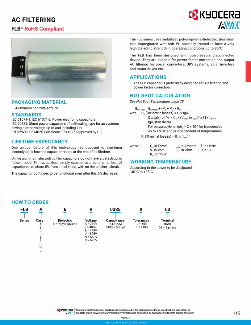
115
AC FILTERINGFLB*
PACKAGING MATERIAL• Aluminium can with soft PU
STANDARDSIEC 61071-1, IEC 61071-2: Power electronic capacitors IEC 60831: Shunt power capacitors of selfhealing type for ac systems having a rated voltage up to and including 1kvEN CYWT2.E514025 Certificate: E514025 (approved by UL)
LIFETIME EXPECTANCYOne unique feature of this technology (as opposed to aluminum electrolytic) is how the capacitor reacts at the end of its lifetime.
Unlike aluminum electrolytic film capacitors do not have a catastrophic failure mode. Film capacitors simply experience a parametric loss of capacitance of about 5% from initial value, with no risk of short circuit.
The capacitor continues to be functional even after this 5% decrease.
The FLB series uses metallized polypropylene dielectric, aluminum can, impregnated with soft PU specially treated to have a very high dielectric strength in operating conditions up to 85°C.
The FLB has been designed with overpressure disconnected device. They are suitable for power factor correction and output AC filtering for power converters, UPS systems, solar inverters and motor drives etc.
APPLICATIONS• The FLB capacitor is particularly designed for AC filtering and
power factor correction.
HOT SPOT CALCULATIONSee Hot Spot Temperature, page 75.
θhot spot = θambient + (Pd + Pt) x Rth with Pd (Dielectric losses) = Q x tgδ0
Q x tgδ0 [ ½ x Cn x (Vpeak to peak)2 x f ] x tgδ0 tgδ0 (tan delta)For polypropylene, tgδ0 = 2 x 10⁻⁴ for frequencies up to 1MHz and is independent of temperatures.
Pt (Thermal losses) = Rs x (Irms)2
where Cn in FaradV in VoltRth in °C/W
Irms in AmpereRs in Ohm
f in Hertzθ in °C
WORKING TEMPERATUREAccording to the power to be dissipated -40°C to +85°C
FLB A K 036 V 0335
Series Case Dielectric6 = Polypropylene
VoltageA = 230VI = 400VL = 440VJ = 525VN = 660VO = 690V
CapacitanceEIA Code
TolerancesJ = ±5%
K = ±10%
Terminal Code
03 = 3 phase0103 = 0.01μFABCDEFGHJ
HOW TO ORDER
080621
RoHS Compliant
– medium power film capacitors –
The Important Information/Disclaimer is incorporated in the catalog where these specifications came from or available online at www.avx.com/disclaimer/ by reference and should be reviewed in full before placing any order.

116
AC FILTERINGFLB*
LIFETIME EXPECTANCY VS HOT SPOT TEMPERATURE AND VOLTAGE
GENERAL DESCRIPTION
DIMENSIONS
1000
10000
100000
1000000
0.7 0.8 0.9 1 1.1 1.2 1.3 1.4 1.5
Exp
ecte
d L
ifeti
me
(h)
Working/Rated Voltage Ratio (Uw/Un)
60ºC70ºC 50ºC
85ºC
Expected Lifetime Curves (FLB Series)
* Rs is external discharge resistor selected from following range by customer. KYOCERA AVX doesnt provide external discharge capacitor.
Case Ref OD(mm)
H(mm)
A 85 200B 85 265C 85 350D 116 160E 116 200F 116 230G 116 265H 136 200J 136 230
Vrms Resistor Range230V 220kΩ~400kΩ400V 270kΩ~800kΩ440V 270kΩ~800kΩ525V 270kΩ~1200kΩ660V 800kΩ~2000kΩ690V 800kΩ~1500kΩ
061120
RoHS Compliant
– medium power film capacitors –
The Important Information/Disclaimer is incorporated in the catalog where these specifications came from or available online at www.avx.com/disclaimer/ by reference and should be reviewed in full before placing any order.

117
AC FILTERINGFLB*
Climatic category -40/D (IEC 60068) Test voltage between terminals @ 25°C 2.15 x Vrms
Capacitance range Cn 3*20.3μF to 3*335μFCapacitance Tolerances: ±5%, ±10%Rated AC Voltage: Vrms 230V to 690VDielectric: PolypropyleneLifetime (∆C/C ≤ 5%): 100,000hrs @ Ur & 70ºC
ELECTRICAL CHARACTERISTICS
Cap (μF)
Rated Voltage (V) Part No. Case
CodeDiameter ±2
(mm)H ±2(mm)
Output (kvar)
I rms (A)
V/μs (Volt/sec)
I Peak (A)
Packaging Method
Box Qty (mm) Dimension
Vrms = 230V Voltage Code: A3 x 200.6 230 FLBB6A0207K03 B 85.0 265.0 10.0 25.1 37.0 7530 8 375*285*3653 x 200.6 230 FLBD6A0207K03 D 116.0 160.0 10.0 25.1 37.0 7530 5 375*285*2353 x 250.7 230 FLBC6A0257K03 C 85.0 350.0 12.5 31.4 37.0 9420 8 375*285*4353 x 250.7 230 FLBE6A0257K03 E 116.0 200.0 12.5 31.4 37.0 9420 5 375*285*3653 x 300.9 230 FLBC6A0307K03 C 85.0 350.0 15.0 37.7 37.0 11310 8 375*285*4353 x 300.9 230 FLBE6A0307K03 E 116.0 200.0 15.0 37.7 37.0 11310 5 375*285*3653 x 335.0 230 FLBF6A3356K03 F 116.0 230.0 16.7 41.9 37.0 12570 5 375*285*365
Vrms = 400V Voltage Code: I3 x 66.3 400 FLBA6I0666K03 A 85.0 200.0 10.0 14.4 65.0 4320 8 375*285*3653 x 82.9 400 FLBA6I0826K03 A 85.0 200.0 12.5 18.0 65.0 5400 8 375*285*3653 x 99.5 400 FLBA6I0996K03 A 85.0 200.0 15.0 21.6 65.0 6480 8 375*285*365
3 x 110.7 400 FLBB6I0117K03 B 85.0 265.0 16.7 24.1 65.0 7230 8 375*285*3653 x 110.7 400 FLBD6I0117K03 D 116.0 160.0 16.7 24.1 65.0 7230 5 375*285*2353 x 132.6 400 FLBB6I1326K03 B 85.0 265.0 20.0 28.8 65.0 8640 8 375*285*3653 x 132.6 400 FLBD6I1326K03 D 116.0 160.0 20.0 28.8 65.0 8640 5 375*285*2353 x 165.8 400 FLBB6I1656K03 B 85.0 265.0 25.0 36.1 65.0 10830 8 375*285*3653 x 165.8 400 FLBE6I1656K03 E 116.0 200.0 25.0 36.1 65.0 10830 5 375*285*3653 x 198.9 400 FLBH6I1986K03 H 136.0 200.0 30.0 43.3 65.0 12990 4 375*285*365
Vrms = 440V Voltage Code: L3 x 68.5 440 FLBA6L0686K03 A 85.0 200.0 12.5 16.4 72.0 4920 8 375*285*3653 x 77.0 440 FLBA6L0776K03 A 85.0 200.0 14.1 18.5 72.0 5550 8 375*285*3653 x 77.0 440 FLBD6L0776K03 D 116.0 160.0 14.1 18.5 72.0 5550 5 375*285*2353 x 82.2 440 FLBA6L0826K03 A 85.0 200.0 15.0 19.7 72.0 5910 8 375*285*3653 x 92.6 440 FLBA6L0926K03 A 85.0 200.0 16.9 22.2 72.0 6660 8 375*285*365
3 x 103.0 440 FLBB6L1036K03 B 85.0 265.0 18.8 24.7 72.0 7410 8 375*285*3653 x 103.0 440 FLBD6L1036K03 D 116.0 160.0 18.8 24.7 72.0 7410 5 375*285*2353 x 109.0 440 FLBB6L1096K03 B 85.0 265.0 20.0 26.2 72.0 7860 8 375*285*3653 x 109.0 440 FLBD6L1096K03 D 116.0 160.0 20.0 26.2 72.0 7860 5 375*285*2353 x 123.3 440 FLBB6L1236K03 B 85.0 265.0 22.5 29.5 72.0 8850 8 375*285*3653 x 123.3 440 FLBD6L1236K03 D 116.0 160.0 22.5 29.5 72.0 8850 5 375*285*2353 x 137.0 440 FLBB6L1376K03 B 85.0 265.0 25.0 32.8 72.0 9840 8 375*285*3653 x 137.0 440 FLBE6L1376K03 E 116.0 200.0 25.0 32.8 72.0 9840 5 375*285*3653 x 154.0 440 FLBB6L1546K03 B 85.0 265.0 28.1 36.9 72.0 11070 8 375*285*3653 x 154.0 440 FLBE6L1546K03 E 116.0 200.0 28.1 36.9 72.0 11070 5 375*285*3653 x 164.4 440 FLBC6L1646K03 C 85.0 350.0 30.0 39.4 72.0 11820 8 375*285*4353 x 164.4 440 FLBE6L1646K03 E 116.0 200.0 30.0 39.4 72.0 11820 5 375*285*3653 x 180.9 440 FLBH6L1806K03 H 136.0 200.0 33.0 43.3 72.0 12990 2 375*285*365
RATINGS AND PART NUMBER REFERENCE – POLYPROPYLENE DIELECTRIC
* Insert K for 10% capacitance tolerance (standard); J (+5%) and M (+20%) tolerances available on request.Values outside this standard range may be available – please contact KYOCERA AVX for any special requirements.KYOCERA AVX reserves the right to supply capacitors to a tighter capacitance tolerance or higher voltage rating, in the same case size.
061120
RoHS Compliant
– medium power film capacitors –
The Important Information/Disclaimer is incorporated in the catalog where these specifications came from or available online at www.avx.com/disclaimer/ by reference and should be reviewed in full before placing any order.

118
AC FILTERINGFLB*
* Insert K for 10% capacitance tolerance (standard); J (+5%) and M (+20%) tolerances available on request.Values outside this standard range may be available – please contact KYOCERA AVX for any special requirements.KYOCERA AVX reserves the right to supply capacitors to a tighter capacitance tolerance or higher voltage rating, in the same case size.
061120
RoHS Compliant
RATINGS AND PART NUMBER REFERENCE – POLYPROPYLENE DIELECTRIC
Cap (μF)
Rated Voltage (V) Part No. Case
CodeDiameter ±2
(mm)H ±2(mm)
Output (kvar)
I rms (A)
V/μs (Volt/sec)
I Peak (A)
Packaging Method
Box Qty (mm) Dimension
Vrms = 525V Voltage Code: J3 x 38.5 525 FLBA6J0386K03 A 85.0 200.0 10 11.0 86.0 3300 8 375*285*3653 x 48.1 525 FLBA6J0486K03 A 85.0 200.0 12.5 13.7 86.0 4110 8 375*285*3653 x 53.1 525 FLBA6J0536K03 A 85.0 200.0 13.8 15.2 86.0 4560 8 375*285*3653 x 57.7 525 FLBA6J0576K03 A 85.0 200.0 15.0 16.5 86.0 4950 8 375*285*3653 x 77.0 525 FLBB6J0776K03 B 85.0 265.0 20.0 22.0 86.0 6600 8 375*285*3653 x 77.0 525 FLBD6J0776K03 D 116.0 160.0 20.0 22.0 86.0 6600 5 375*285*2353 x 96.2 525 FLBB6J0966K03 B 85.0 265.0 25.0 27.5 86.0 8250 8 375*285*3653 x 96.2 525 FLBE6J0966K03 E 116.0 200.0 25.0 27.5 86.0 8250 5 375*285*365
3 x 115.4 525 FLBF6J1156K03 F 116.0 230.0 30.0 33.0 86.0 9900 5 375*285*3653 x 115.4 525 FLBH6J1156K03 H 136.0 200.0 30.0 33.0 86.0 9900 2 375*285*3653 x 138.2 525 FLBG6J1386K03 G 116.0 265.0 35.9 39.5 86.0 11850 5 375*285*3653 x 138.2 525 FLBJ6J1386K03 J 136.0 230.0 35.9 39.5 86.0 11850 2 375*285*3653 x 142.8 525 FLBG6J1426K03 G 116.0 265.0 37.1 40.8 86.0 12240 5 375*285*3653 x 142.8 525 FLBJ6J1426K03 J 136.0 230.0 37.1 40.8 86.0 12240 2 375*285*365
Vrms = 660V Voltage Code: N3 x 20.3 660 FLBA6N0206K03 A 85.0 200.0 8.33 7.3 108.0 2190 8 375*285*3653 x 24.4 660 FLBa6N0246K03 A 85.0 200.0 10.0 8.7 108.0 2610 8 375*285*3653 x 30.4 660 FLBB6N0306K03 B 85.0 265.0 12.5 10.9 108.0 3270 8 375*285*3653 x 36.5 660 FLBB6N0366K03 B 85.0 265.0 15.0 13.1 108.0 3930 8 375*285*3653 x 40.7 660 FLBB6N0406K03 B 85.0 265.0 16.7 14.6 108.0 4380 8 375*285*3653 x 48.7 660 FLBC6N0486K03 C 85.0 350.0 20.0 17.5 108.0 5250 8 375*285*4353 x 55.8 660 FLBC6N0556K03 C 85.0 350.0 22.9 20.0 108.0 6000 8 375*285*435
Vrms = 690V Voltage Code: O3 x 27.9 690 FLBB6O0276K03 B 85.0 265.0 12.5 10.5 112.0 3150 8 375*285*3653 x 33.4 690 FLBB6O0336K03 B 85.0 265.0 15.0 12.5 112.0 3750 8 375*285*3653 x 44.6 690 FLBC6O0446K03 C 85.0 350.0 20.0 16.7 112.0 5010 8 375*285*4353 x 55.7 690 FLBC6O0556K03 C 85.0 350.0 25.0 20.9 112.0 6270 8 375*285*435
– medium power film capacitors –
The Important Information/Disclaimer is incorporated in the catalog where these specifications came from or available online at www.avx.com/disclaimer/ by reference and should be reviewed in full before placing any order.

119
PROTECTIONFSB*
GENERAL DESCRIPTIONMetallized polypropylene dielectric capacitor with controlled self-healing.
Reinforced metallization developed for high impulse currents.
APPLICATIONS• IGBT protection• IGBT clamping
PACKAGING MATERIAL• Plastic case backfilled with thermosetting resin
HOW TO ORDERFSB 1 J ––6 U 0154
Series Case Size Dielectric6 = Polypropylene
Voltage Code
A = 700VB = 850VC = 1000VU = 1200VG = 1500VN = 2000V
CapacitanceCode
Capacitance Tolerances
J = ± 5%K = ±10%
(Case size 6 only)
Terminal Code– – = 2 TerminalJC = 4 Terminal(Case Size 5 option only)90 = 90° Terminals18 = 180° Terminals(Case size 6-C options only)
0 + pF code0154 = 0.15μF0334 = 0.33μF0255 = 2.5μF
etc.
1 = PO Style2 = 18 Style3 = 19 Style4 = 26 style5 = R28 Style
(2 terminal or 4 terminal)
6-C (Lug Terminals)
ELECTRICAL CHARACTERISTICS
Capacitance Range Cn 0.10μF to 5.6μFTolerance on Cn ±5%, ±10%Rated DC Voltage Vndc 700 to 2000 VStray Inductance ≤ 25 nH
RMS Current Irms max. = up to 28A The currents shown in the tables are maximum. It is necessary to maintain operation within the maximum temperature of the dielectric 85°C. See “Hot spot temperature calculation”
Insulation Resistance Ri x C ≥ 30,000 s
Impulse Current I2.t max. = up to 1.69 A2sSpikes or peak currents in the capacitors may cause a deterioration of the bonding between the metallization and the connections. These bonds are capable of withstanding only a limited amount of energy for each spike. The table shows the maximum energy permitted in the form (I2.t), where I is in Amperes, and t is in seconds.
Note: The formula (I2.t) replaces dv/dt which is less easy to use as it is not an expression of energy (I = C.dv/dt). This type of capacitor has been designed to withstand high (I2.t) values.
Variation of Capacitance with Temperature ≤ ±2% between -40 and +85°C
Climatic Category 40/085/56 (IEC 68) Test Voltage Between Terminals @ 25°C 1.6 Vndc during 10s Withstanding Voltage Between Terminals and Case @ 25°C
@ 3 kVrms @ 50Hz during 1 min.
061120
RoHS Compliant
– medium power film capacitors –
The Important Information/Disclaimer is incorporated in the catalog where these specifications came from or available online at www.avx.com/disclaimer/ by reference and should be reviewed in full before placing any order.

120
PROTECTIONFSB*
GENERAL DESCRIPTION
DIMENSIONS
RATINGS AND PART NUMBER REFERENCE
STYLE: P0; 18; 19; 26; R68ALL CASE SIZES2 TERMINALS VERSION
Length
Height
LS 0.4 min5.5±1
Width
Ø Lead
General Tolerance: 0.5mm
STYLE: R68CASE SIZE 5 ONLY4 TERMINALS VERSION
32
37
5±1
1.2±0.05
12.7±0.5
Width
1.2±0.05
22
27.5±1
General Tolerance: 0.5mm
Case Size Case Style Length±0.50 mm
Width±0.50 mm
Height±0.50 mm
Dimensions lead -0.05 mm
LS±1.00 mm
1 PO 32 13.0 22.0 Ø 0.80 27.5
2 18 32 16.0 25.0 Ø 0.80 27.5
3 19 32 18.0 28.0 Ø 0.80 27.5
4 26 32 21.0 31.0 Ø 1.00 27.5
5
R682 Terminals
Version32 22.0 37.0 Ø 1.00 27.5
R684 Terminals
Version32 2.0 37.0 Ø 1.20 27.5
Part Number Capacitance (μF) Case Style Dv/Dt Irms (A)
Rs (mΩ)
Rth (hotspot/amb.)
ESL (nH)
Vndc=1200V Vpeak=1600V Vrms=560v Vs=2000V Voltage Code: UFSB16U0154J-- 0.15 PO 500 3.0 14.3 45.9 25.0FSB26U0274J-- 0.27 18 500 7.6 8.4 36.8 25.0FSB36U0394J-- 0.39 19 500 11.0 6.2 32.2 25.0FSB46U0474J-- 0.47 26 500 12.0 5.6 29.4 25.0FSB56U0684J-- 0.68 R68 (2 terminals) 500 12.0 3.8 23.7 25.0
FSB56U0684JJC 0.68 R68 (4 terminals) 500 16.7 3.8 23.7 25.0Vndc=1600V Vpeak=2000V Vrms=630v Vs=2300V Voltage Code: M
FSB16M0134J-- 0.13 PO 600 4.6 13.3 44.9 25.0FSB26M0184J-- 0.18 18 600 6.4 9.9 35.9 25.0FSB36M0244J-- 0.24 19 600 8.5 7.8 32.4 25.0FSB46M0334J-- 0.33 26 600 11.7 5.6 28.6 25.0FSB56M0434J-- 0.43 R68 (2 terminals) 600 12.0 4.6 23.8 25.0
FSB56M0434JJC 0.43 R68 (4 terminals) 600 15.2 4.6 23.8 25.0Vndc=2000V Vpeak=2400V Vrms=700v Vs=2600V Voltage Code: N
FSB16N0104J-- 0.10 PO 700 4.2 14.3 44.6 25.0FSB26N0134J-- 0.13 18 700 5.5 11.3 35.7 25.0FSB36N0184J-- 0.18 19 700 7.6 8.5 32.1 25.0FSB46N0224J-- 0.22 26 700 9.3 6.8 29.1 25.0FSB56N0304J-- 0.30 R68 (2 terminals) 700 12.0 5.3 23.8 25.0
FSB56N0304JJC 0.30 R68 (4 terminals) 700 12.7 5.3 23.8 25.0
061120
RoHS Compliant
– medium power film capacitors –
The Important Information/Disclaimer is incorporated in the catalog where these specifications came from or available online at www.avx.com/disclaimer/ by reference and should be reviewed in full before placing any order.

121
PROTECTIONFSB*
CASE SIZE 6-C
RATINGS AND PART NUMBER REFERENCE FOR LUG TERMINALS
W ± 1
P1 ± 1
P2 ± 16.507.00
Marking
Marking
Resin
Plastic Case
7.00 +0.50-1.50
T ± 1 H ± 1
0.80 ± 0.10
º081º09
T ± 1
6.00
Cap (μF)±10%
Rated Voltage
(V)
Part Number Case Size
W±0.50(mm)
H±0.50(mm)
T±0.50(mm)
P1±0.50(mm)
P2±0.50(mm)
dv/dt Volt/sec
I peak Amps
I rms Amps
Rs mΩ
ESLnH
RthºC/W
Packaging Inner Box90º 180º
Vndc = 700V Vpeak = ?V Vrms = ?v Vs = ?V Voltage Code: A Qty Size1.20 700 FSBA6A0125K90 FSBA6A0125K18 A 42.50 27.5 24.5 23~28 11.0 600.0 720.0 17.5 4.0 18.0 16.4 42 360*170*802.00 700 FSBB6A0205K90 FSBB6A0205K18 B 42.50 35.5 33.5 23~28 11.0 600.0 1200.0 23.5 3.3 20.0 11.3 35 360*170*802.20 700 FSBB6A0225K90 FSBB6A0225K18 B 42.50 35.5 33.5 23~28 11.0 600.0 1320.0 24.0 3.1 20.0 10.8 35 360*170*802.50 700 FSBB6A0255K90 FSBB6A0255K18 B 42.50 35.5 33.5 23~28 11.0 600.0 1500.0 24.5 2.9 20.0 10.1 35 360*170*803.00 700 FSBB6A0305K90 FSBB6A0305K18 B 42.50 45.0 33.0 23~28 11.0 600.0 1800.0 27.5 2.7 20.0 7.7 40 360*170*803.30 700 FSB96A0335K90 FSB96A0335K18 9 42.50 45.0 33.0 23~28 11.0 600.0 1980.0 28.0 2.7 25.0 7.2 40 360*170*803.50 700 FSB96A0355K90 FSB96A0355K18 9 42.50 45.0 33.0 23~28 11.0 600.0 2100.0 28.5 2.6 25.0 7.4 40 360*170*804.00 700 FSB86A0405K90 FSB86A0405K18 8 57.50 45.0 30.0 37~39 24.0 360.0 1440.0 29.0 4.4 35.0 7.9 25 360*170*804.70 700 FSB76A0475K90 FSB76A0475K18 7 57.50 50.0 35.0 37~39 24.0 360.0 1692.0 35.0 4.1 38.0 6.9 20 360*170*805.00 700 FSB76A0505K90 FSB76A0505K18 7 57.50 50.0 35.0 37~39 24.0 360.0 1800.0 37.0 3.9 38.0 6.9 20 360*170*805.60 700 FSB76A0565K90 FSB76A0565K18 7 57.50 50.0 35.0 37~39 24.0 360.0 2016.0 39.0 3.7 38.0 6.5 20 360*170*80
Vndc = 850V Vpeak = 1200V Vrms = 450v Vs = 1500V Voltage Code: B Qty Size0.82 850 FSBA6B0824K90 FSBA6B0824K18 A 42.5 27.5 24.5 23~28 11.0 750.0 615.0 13.0 6.7 18.0 20.7 42 360*170*801.00 850 FSBA6B0105K90 FSBA6B0105K18 A 42.5 27.5 24.5 23~28 11.0 750.0 750.0 15.0 5.5 18.0 18.8 42 360*170*801.50 850 FSBB6B0155K90 FSBB6B0155K18 B 42.5 35.5 33.5 23~28 11.0 750.0 1125.0 22.0 3.9 20.0 13.9 35 360*170*801.75 850 FSBB6B0175K90 FSBB6B0175K18 B 42.5 35.5 33.5 23~28 11.0 750.0 1312.5 24.0 3.4 20.0 12.6 35 360*170*802.00 850 FSB66B0205K90 FSB66B0205K18 6 42.5 45.0 30.0 23~28 11.0 750.0 1500.0 25.0 3.4 25.0 19.1 40 360*170*802.20 850 FSB66B0225K90 FSB66B0225K18 6 42.5 45.0 30.0 23~28 11.0 750.0 1650.0 28.0 3.1 25.0 18.6 40 360*170*802.50 850 FSB66B0255K90 FSB66B0255K18 6 42.5 45.0 30.0 23~28 11.0 750.0 1875.0 28.0 2.7 25.0 17.8 40 360*170*802.50 850 FSB76B0255K90 FSB76B0255K18 7 57.5 50.0 35.0 37~39 24.0 469.0 1172.5 24.0 5.3 38.0 10.7 20 360*170*803.00 850 FSB86B0305K90 FSB86B0305K18 8 57.5 45.0 30.0 37~39 24.0 469.0 1407.0 27.0 4.5 35.0 9.9 25 360*170*803.30 850 FSB86B0335K90 FSB86B0335K18 8 57.5 45.0 30.0 37~39 24.0 469.0 1547.7 27.5 4.1 35.0 9.3 25 360*170*804.00 850 FSB76B0405K90 FSB76B0405K18 7 57.5 50.0 35.0 37~39 24.0 469.0 1876.0 33.0 3.5 38.0 8.0 20 360*170*805.00 850 FSB66B0505K90 FSB66B0505K18 7 57.5 50.0 35.0 37~39 24.0 469.0 2345.0 37.0 2.9 38.0 6.9 20 360*170*80
Vndc = 1000V Vpeak = ?V Vrms = ?v Vs = ?V Voltage Code: C Qty Size0.68 1000 FSBA6C0684K90 FSBA6C0684K18 A 42.5 27.5 24.5 23~28 11.0 870.0 591.6 16.5 4.3 18.0 14.6 42 360*170*800.75 1000 FSBA6C0754K90 FSBA6C0754K18 A 42.5 27.5 24.5 23~28 11.0 870.0 652.5 17.5 4.0 18.0 14.2 42 360*170*801.20 1000 FSBB6C0125K90 FSBB6C0125K18 B 42.5 35.5 33.5 23~28 11.0 870.0 1044.0 23.5 3.3 20.0 9.2 35 360*170*801.50 1000 FSBB6C0155K90 FSBB6C0155K18 B 42.5 35.5 33.5 23~28 11.0 870.0 1305.0 25.0 2.9 20.0 8.9 35 360*170*801.75 1000 FSB96C0175K90 FSB96C0175K18 9 42.5 45.0 33.0 23~28 11.0 870.0 1522.5 27.0 2.7 25.0 7.0 40 360*170*802.00 1000 FSB96C0205K90 FSB96C0205K18 9 42.5 45.0 33.0 23~28 11.0 870.0 1740.0 28.0 2.6 25.0 6.9 40 360*170*802.20 1000 FSB86C0225K90 FSB86C0225K18 8 57.5 45.0 30.0 37~39 24.0 500.0 1100.0 27.5 3.3 35.0 8.1 25 360*170*802.50 1000 FSB96C0255K90 FSB96C0255K18 9 42.5 45.0 33.0 23~28 11.0 750.0 1875.0 24.5 4.0 25.0 6.0 40 360*170*803.00 1000 FSB86C0305K90 FSB86C0305K18 8 57.5 45.0 30.0 37~39 24.0 450.0 1350.0 24.5 4.8 35.0 6.4 25 360*170*803.00 1000 FSB76C0305K90 FSB76C0305K18 7 57.5 50.0 35.0 37~39 24.0 500.0 1500.0 32.0 2.7 38.0 5.7 20 360*170*803.30 1000 FSB86C0335K90 FSB86C0335K18 8 57.5 45.0 30.0 37~39 24.0 450.0 1485.0 25.5 4.6 35.0 6.9 25 360*170*80
061120
RoHS Compliant
– medium power film capacitors –
The Important Information/Disclaimer is incorporated in the catalog where these specifications came from or available online at www.avx.com/disclaimer/ by reference and should be reviewed in full before placing any order.

122
PROTECTIONFSB*
* Insert K for 10% capacitance tolerance (standard): J = +5% tolerances available on request.Last two characters terminal styles 90 = 90° terminals insert 18 =180°Values outside this standard range may be available – please contact KYOCERA AVX for any special requirements.KYOCERA AVX reserves the right to supply capacitors to a tighter capacitance tolerance or higher voltage rating, in the same case size.
061120
RoHS Compliant
RATINGS AND PART NUMBER REFERENCE FOR LUG TERMINALSCap (μF)±10%
Rated Voltage
(V)
Part Number Case Size
W±0.50(mm)
H±0.50(mm)
T±0.50(mm)
P1±0.50(mm)
P2±0.50(mm)
dv/dt Volt/sec
I peak Amps
I rms Amps
Rs mΩ
ESLnH
RthºC/W
Packaging Inner Box90º 180º
3.30 1000 FSB76C0335K90 FSB76C0335K18 7 57.5 50.0 35.0 37~39 24.0 450.0 1485.0 32.5 2.6 38.0 5.5 20 360*170*804.00 1000 FSB76C0405K90 FSB76C0405K18 7 57.5 50.0 35.0 37~39 24.0 450.0 1800.0 29.5 4.0 38.0 5.6 20 360*170*80
Vndc = 1200V Vpeak = 1600V Vrms = 560v Vs = 2000V Voltage Code: U Qty Size0.33 1200 FSBA6U0334K90 FSBA6U0334K18 A 42.5 27.5 24.5 23~28 11.0 1000.0 330.0 9.3 7.4 18.0 20.3 42 360*170*800.39 1200 FSBA6U0394K90 FSBA6U0394K18 A 42.5 27.5 24.5 23~28 11.0 1000.0 390.0 10.5 6.4 18.0 18.7 42 360*170*800.47 1200 FSBA6U0474K90 FSBA6U0474K18 A 42.5 27.5 24.5 23~28 11.0 1000.0 470.0 11.9 5.5 18.0 16.3 42 360*170*800.56 1200 FSBA6U0564K90 FSBA6U0564K18 A 42.5 27.5 24.5 23~28 11.0 1000.0 560.0 13.7 4.8 18.0 14.9 42 360*170*800.68 1200 FSBB6U0684K90 FSBB6U0684K18 B 42.5 35.5 33.5 23~28 11.0 1000.0 680.0 16.5 4.1 20.0 12.0 35 360*170*800.82 1200 FSBB6U0824K90 FSBB6U0824K18 B 42.5 35.5 33.5 23~28 11.0 1000.0 820.0 18.5 3.6 20.0 11.0 35 360*170*801.00 1200 FSB66U0105K90 FSB66U0105K18 6 42.5 45.0 30.0 23~28 11.0 1000.0 1000.0 17.3 3.7 25.0 12.3 40 360*170*801.20 1200 FSBB6U0125K90 FSBB6U0125K18 B 42.5 35.5 33.5 23~28 11.0 1000.0 1200.0 18.4 3.3 20.0 12.4 35 360*170*801.20 1200 FSB66U0125K90 FSB66U0125K18 6 42.5 45.0 30.0 23~28 11.0 1200.0 1440.0 26.0 3.4 25.0 17.5 40 360*170*801.50 1200 FSB66U0155K90 FSB66U0155K18 6 42.5 45.0 30.0 23~28 11.0 870.0 1305.0 26.0 3.4 25.0 17.5 40 360*170*801.50 1200 FSBB6U0155K90 FSBB6U0155K18 B 42.5 35.5 33.5 23~28 11.0 1000.0 1500.0 21.0 2.8 20.0 11.2 35 360*170*802.00 1200 FSB96U0205K90 FSB96U0205K18 9 42.5 45.0 30.0 23~28 11.0 870.0 1740.0 28.0 2.8 25.0 7.2 25 360*170*802.00 1200 FSB86U0205K90 FSB86U0205K18 8 57.5 45.0 30.0 37~39 24.0 575.0 1150.0 19.7 2.4 35.0 8.8 25 360*170*802.20 1200 FSB86U0225K90 FSB86U0225K18 8 57.5 45.0 30.0 37~39 24.0 500.0 1100.0 21.0 4.2 35.0 8.1 25 360*170*802.20 1200 FSB76U0225K90 FSB76U0225K18 7 57.5 50.0 35.0 37~39 24.0 575.0 1265.0 21.4 3.9 38.0 7.6 20 360*170*802.50 1200 FSB86U0255K90 FSB86U0255K18 8 57.5 45.0 30.0 37~39 24.0 500.0 1250.0 21.2 4.9 35.0 7.9 25 360*170*803.00 1200 FSB76U0305K90 FSB76U0305K18 7 57.5 50.0 35.0 37~39 24.0 575.0 1725.0 32.8 4.3 38.0 6.5 20 360*170*803.30 1200 FSB76U0335K90 FSB76U0335K18 7 57.5 50.0 35.0 37~39 24.0 500.0 1650.0 28.2 3.0 38.0 6.2 20 360*170*80
Vndc = 1500V Vpeak = ?V Vrms = ?v Vs = ?V Voltage Code: G Qty Size0.33 1500 FSBA6G0334K90 FSBA6G0334K18 A 42.5 27.5 24.5 23~28 11.00 1220.0 402.6 14.0 6.0 18.0 17.0 42 360*170*800.39 1500 FSBA6G0394K90 FSBA6G0394K18 A 42.5 27.5 24.5 23~28 11.00 1220.0 475.8 14.5 5.6 18.0 15.9 42 360*170*800.47 1500 FSBB6G0474K90 FSBB6G0474K18 B 42.5 35.5 33.5 23~28 11.00 1220.0 573.4 19.0 4.8 20.0 11.0 35 360*170*800.68 1500 FSBB6G0684K90 FSBB6G0684K18 B 42.5 35.5 33.5 23~28 11.00 1220.0 829.6 21.0 4.0 20.0 9.8 35 360*170*800.75 1500 FSBB6G0754K90 FSBB6G0754K18 B 42.5 35.5 33.5 23~28 11.00 1220.0 915.0 22.0 3.6 20.0 9.4 35 360*170*801.00 1500 FSB96G0105K90 FSB96G0105K18 9 42.5 45.0 33.0 23~28 11.00 1220.0 1220.0 23.0 3.3 25.0 7.4 40 360*170*801.20 1500 FSB86G0125K90 FSB86G0125K18 8 57.5 45.0 30.0 37~39 24.00 870.0 1044.0 26.0 3.6 35.0 7.3 25 360*170*801.50 1500 FSB76G0155K90 FSB76G0155K18 7 57.5 50.0 35.0 37~39 24.00 725.0 1087.5 29.5 3.3 38.0 5.9 20 360*170*801.80 1500 FSB76G0185K90 FSB76G0185K18 7 57.5 50.0 35.0 37~39 24.00 725.0 1305.0 30.5 3.0 38.0 5.6 20 360*170*80
Vndc = 2000V Vpeak = 2400V Vrms = 700v Vs = 2600V Voltage Code: N Qty Size0.10 2000 FSBA6N0104K90 FSBA6N0104K18 A 42.5 27.5 24.5 23~28 11.0 1600.0 160.0 8.5 16.3 18.0 23.6 42 360*170*800.15 2000 FSBA6N0154K90 FSBA6N0154K18 A 42.5 27.5 24.5 23~28 11.0 1600.0 240.0 11.0 9.8 18.0 18.8 42 360*170*800.22 2000 FSBA6N0224K90 FSBA6N0224K18 A 42.5 27.5 24.5 23~28 11.0 1600.0 352.0 13.5 6.6 18.0 15.3 42 360*170*800.33 2000 FSBA6N0334K90 FSBA6N0334K18 A 42.5 27.5 24.5 23~28 11.0 1220.0 402.6 12.5 9.6 18.0 15.1 42 360*170*800.33 2000 FSBB6N0334K90 FSBB6N0334K18 B 42.5 35.5 33.5 23~28 11.0 1600.0 528.0 18.0 5.3 20.0 9.8 35 360*170*800.39 2000 FSBB6N0394K90 FSBB6N0394K18 B 42.5 35.5 33.5 23~28 11.0 1000.0 390.0 17.5 4.7 20.0 9.4 35 360*170*800.47 2000 FSB66N0474K90 FSB66N0474K18 6 42.5 45.0 30.0 23~28 11.0 1600.0 752.0 22.0 6.3 25.0 19.4 40 360*170*800.56 2000 FSB66N0564K90 FSB66N0564K18 6 42.5 45.0 30.0 23~28 11.0 1600.0 896.0 23.0 5.2 25.0 17.9 40 360*170*800.68 2000 FSB66N0684K90 FSB66N0684K18 6 42.5 45.0 30.0 23~28 11.0 1200.0 816.0 24.0 4.4 25.0 17.3 40 360*170*800.68 2000 FSBB6N0684K90 FSBB6N0684K18 B 42.5 35.5 33.5 23~28 11.0 1220.0 829.6 18.0 6.5 20.0 7.1 35 360*170*800.82 2000 FSB96N0824K90 FSB96N0824K18 9 42.5 45.0 33.0 23~28 11.0 1220.0 1000.4 20.0 6.0 25.0 7.0 40 360*170*800.82 2000 FSB86N0824K90 FSB86N0824K18 8 57.5 45.0 30.0 37~39 24.0 930.0 762.6 24.5 4.0 35.0 7.4 25 360*170*801.00 2000 FSB96N0105K90 FSB96N0105K18 9 42.5 45.0 33.0 23~28 11.0 1220.0 1220.0 21.5 5.3 25.0 6.9 40 360*170*801.00 2000 FSB76N0105K90 FSB76N0105K18 7 57.5 50.0 35.0 37~39 24.0 930.0 930.0 28.0 3.6 38.0 6.0 20 360*170*801.20 2000 FSB86N0125K90 FSB86N0125K18 8 57.5 45.0 30.0 37~39 24.0 725.0 870.0 22.5 5.9 35.0 6.6 25 360*170*801.50 2000 FSB76N0155K90 FSB76N0155K18 7 57.5 50.0 35.0 37~39 24.0 725.0 1087.5 26.0 5.2 38.0 4.9 20 360*170*80
– medium power film capacitors –
The Important Information/Disclaimer is incorporated in the catalog where these specifications came from or available online at www.avx.com/disclaimer/ by reference and should be reviewed in full before placing any order.
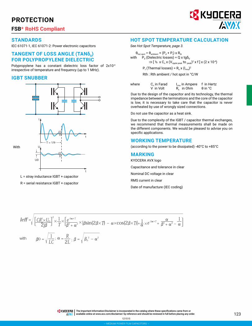
123
PROTECTIONFSB*
STANDARDSIEC 61071-1, IEC 61071-2: Power electronic capacitors
TANGENT OF LOSS ANGLE (TANδ0) FOR POLYPROPYLENE DIELECTRICPolypropylene has a constant dielectric loss factor of 2x10⁻⁴ irrespective of temperature and frequency (up to 1 MHz).
IGBT SNUBBER
T = 1/fr
I
U
U0
t
t
With
L = stray inductance IGBT + capacitor
R = serial resistance IGBT + capacitor
HOT SPOT TEMPERATURE CALCULATIONSee Hot Spot Temperature, page 3.
θhot spot = θambient + (Pd + Pt) x Rth with Pd (Dielectric losses) = Q x tgδ0
[ ½ x Cn x (Vripple peak to peak)2 x f ] x (2 x 10⁻⁴)
Pt (Thermal losses) = Rs x (Irms)2
Rth : Rth ambient / hot spot in °C/W
where Cn in FaradV in Volt
Irms in AmpereRs in Ohm
f in Hertzθ in °C
Due to the design of the capacitor and its technology, the thermal impedance between the terminations and the core of the capacitor is low, it is necessary to take care that the capacitor is never overheated by use of wrongly sized connections.
Do not use the capacitor as a heat sink.
Due to the complexity of the IGBT / capacitor thermal exchanges, we recommend that thermal measurements shall be made on the different components. We would be pleased to advise you on specific applications.
WORKING TEMPERATURE(according to the power to be dissipated) -40°C to +85°C
MARKINGKYOCERA AVX logo
Capacitance and tolerance in clear
Nominal DC voltage in clear
RMS current in clear
Date of manufacture (IEC coding)
121515
RoHS Compliant
– medium power film capacitors –
The Important Information/Disclaimer is incorporated in the catalog where these specifications came from or available online at www.avx.com/disclaimer/ by reference and should be reviewed in full before placing any order.
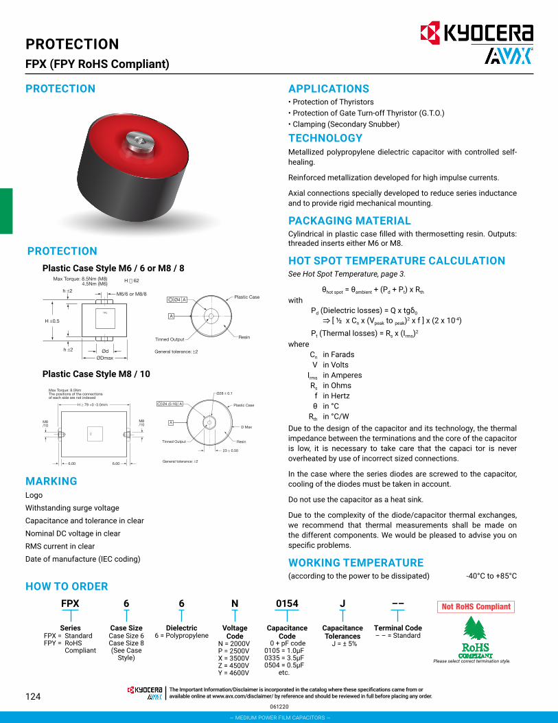
124
PROTECTIONFPX (FPY RoHS Compliant)
HOW TO ORDERFPX 6 J ––6 N 0154
Series Case Size Dielectric6 = Polypropylene
Voltage Code
N = 2000VP = 2500VX = 3500VZ = 4500VY = 4600V
CapacitanceCode
Capacitance Tolerances
J = ± 5%
Terminal Code– – = Standard
0 + pF code0105 = 1.0μF0335 = 3.5μF0504 = 0.5μF
etc.
FPX = StandardFPY = RoHS
Compliant
Case Size 6Case Size 8(See Case
Style)
PROTECTION
PROTECTIONPlastic Case Style M6 / 6 or M8 / 8
Plastic Case Style M8 / 10
MARKINGLogoWithstanding surge voltageCapacitance and tolerance in clearNominal DC voltage in clearRMS current in clearDate of manufacture (IEC coding)
APPLICATIONS• Protection of Thyristors• Protection of Gate Turn-off Thyristor (G.T.O.) • Clamping (Secondary Snubber)
TECHNOLOGYMetallized polypropylene dielectric capacitor with controlled self-healing.
Reinforced metallization developed for high impulse currents.
Axial connections specially developed to reduce series inductance and to provide rigid mechanical mounting.
PACKAGING MATERIALCylindrical in plastic case filled with thermosetting resin. Outputs: threaded inserts either M6 or M8.
HOT SPOT TEMPERATURE CALCULATIONSee Hot Spot Temperature, page 3.
θhot spot = θambient + (Pd + Pt) x Rth with
Pd (Dielectric losses) = Q x tgδ0
[ ½ x Cn x (Vpeak to peak)2 x f ] x (2 x 10⁻⁴)Pt (Thermal losses) = Rs x (Irms)2
where Cn in Farads V in Volts Irms in Amperes Rs in Ohms f in Hertz θ in °C Rth in °C/WDue to the design of the capacitor and its technology, the thermal impedance between the terminations and the core of the capacitor is low, it is necessary to take care that the capaci tor is never overheated by use of incorrect sized connections.
In the case where the series diodes are screwed to the capacitor, cooling of the diodes must be taken in account.
Do not use the capacitor as a heat sink.
Due to the complexity of the diode/capacitor thermal exchanges, we recommend that thermal measurements shall be made on the different components. We would be pleased to advise you on specific problems.
WORKING TEMPERATURE(according to the power to be dissipated) -40°C to +85°C
ØDmaxØd
M6/6 or M8/8h ±2
Max Torque: 8.5Nm (M8) 4.5Nm (M6)
H ±0.5
h ±2
TPC
H 62
General tolerance: ±2
A
Ø4 APlastic Case
ResinTinned Output
TPC
Max Torque: 8.5NmThe positions of the connections of each side are not indexed
H ≥ 79 +0 -3.0mm
M8/10
M8 /10
6.00 6.00 General tolerance: ±2
A
Ø4 (0.16) A
Ø28 ± 0.1
Plastic Case
D Max
ResinTinned Output
23 ± 0.50
Please select correct termination style.
061220
– medium power film capacitors –
The Important Information/Disclaimer is incorporated in the catalog where these specifications came from or available online at www.avx.com/disclaimer/ by reference and should be reviewed in full before placing any order.
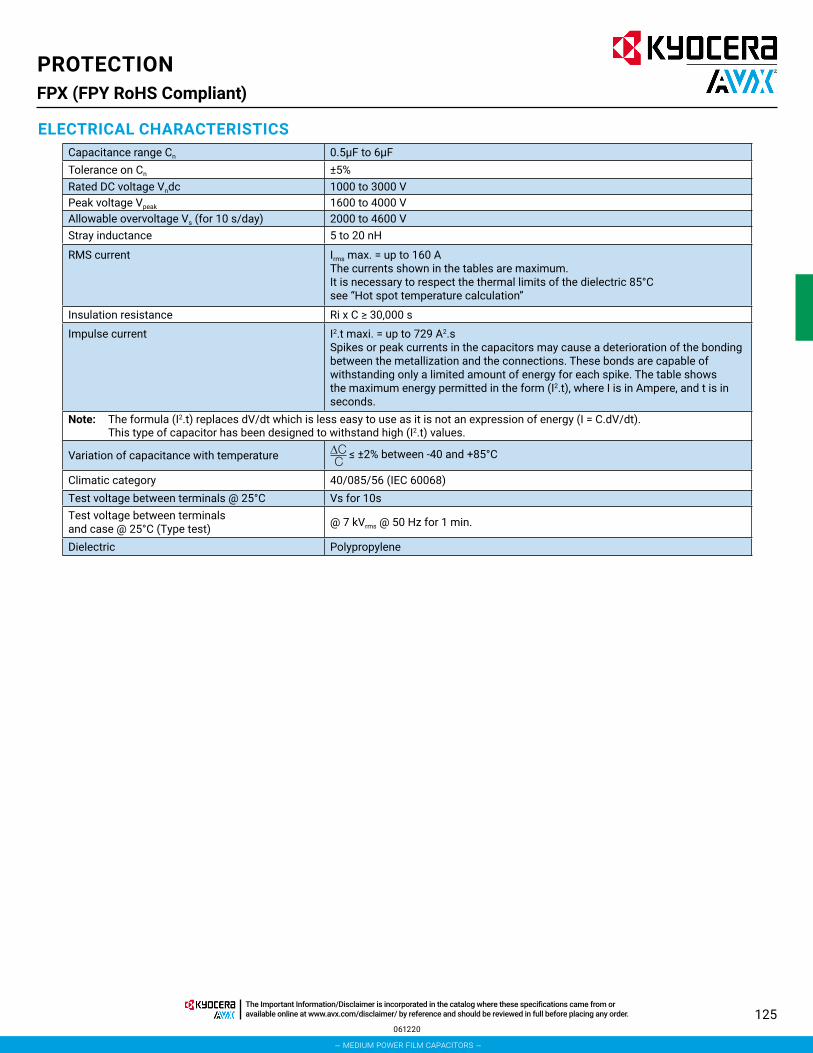
125
PROTECTIONFPX (FPY RoHS Compliant)
ELECTRICAL CHARACTERISTICSCapacitance range Cn 0.5μF to 6μFTolerance on Cn ±5%Rated DC voltage Vndc 1000 to 3000 VPeak voltage Vpeak 1600 to 4000 V Allowable overvoltage Vs (for 10 s/day) 2000 to 4600 V Stray inductance 5 to 20 nH
RMS current Irms max. = up to 160 A The currents shown in the tables are maximum. It is necessary to respect the thermal limits of the dielectric 85°C see “Hot spot temperature calculation”
Insulation resistance Ri x C ≥ 30,000 s
Impulse current I2.t maxi. = up to 729 A2.s Spikes or peak currents in the capacitors may cause a deterioration of the bonding between the metallization and the connections. These bonds are capable of withstanding only a limited amount of energy for each spike. The table shows the maximum energy permitted in the form (I2.t), where I is in Ampere, and t is in seconds.
Note: The formula (I2.t) replaces dV/dt which is less easy to use as it is not an expression of energy (I = C.dV/dt). This type of capacitor has been designed to withstand high (I2.t) values.
Variation of capacitance with temperature ≤ ±2% between -40 and +85°C
Climatic category 40/085/56 (IEC 60068) Test voltage between terminals @ 25°C Vs for 10sTest voltage between terminals and case @ 25°C (Type test) @ 7 kVrms @ 50 Hz for 1 min.
Dielectric Polypropylene
061220
– medium power film capacitors –
The Important Information/Disclaimer is incorporated in the catalog where these specifications came from or available online at www.avx.com/disclaimer/ by reference and should be reviewed in full before placing any order.

126
Part Number Cn (μF)
Dimensions I2.tmax. (A2.s)
Irms max. (A)
Rs (mΩ)
Rth (°C/W)
Typical Weight (g)Case
Style
H*±0.5(mm)
h±2
(mm)
Dmax. (mm)
d±0.5(mm)
FPX 2000V Vndc = 1000V Vpeak = 1600V Vrms = 560V Vs = 2000V (Voltage Code N)FPX66N0105J-- 1 Plastic case M6/6 52 5 40 18 2 15 2.4 14) 120FPX86N0205J-- 2 Plastic case M8/8 52 5 60 22 8 30 1.2 6.1 190FPX86N0305J-- 3 Plastic case M8/8 52 5 72 22 18 45 0.9 4.5 260FPX86N0355J-- 3.5 Plastic case M8/8 52 5 72 22 25 50 0.85 4.5 260FPX86N0405J-- 4 Plastic case M8/8 52 5 82 22 32 60 0.75 3.5 320FPX86N0505J-- 5 Plastic case M8/8 52 5 82 22 50 70 0.65 2.5 320
FPX 2500V Vndc = 1300V Vpeak = 2000V Vrms = 700V Vs = 2500V (Voltage Code P)FPX66P0504J-- 0.5 Plastic case M6/6 52 5 40 18 1 15 3 14 120FPX86P0105J-- 1 Plastic case M8/8 52 5 60 22 3 20 2.3 10.5 190FPX86P0155J-- 1.5 Plastic case M8/8 52 5 60 22 7 30 1.5 6.1 190FPX86P0205J-- 2 Plastic case M8/8 52 5 72 22 12.7 40 1.1 4.5 260FPX86P0255J-- 2.5 Plastic case M8/8 52 5 72 22 20 60 0.89 3.7 260FPX86P0305J-- 3 Plastic case M8/8 52 5 82 22 28 60 0.85 3.2 320FPX86P0355J-- 3.5 Plastic case M8/8 52 5 82 22 39 65 0.78 2.9 320
FPX 3500V Vndc = 2000V Vpeak = 2400V Vrms = 850V Vs = 3500V (Voltage Code X)FPX86X0205J-- 2 Plastic case M8/8 62 5 72 22 23 41 1.24 6.1 310FPX86X0305J-- 3 Plastic case M8/8 62 5 92 22 50 62 0.92 3.9 475FPX86X0355J-- 3.5 Plastic case M8/8 62 5 92 22 70 72 0.83 3.4 475FPX86X0405J-- 4 Plastic case M8/8 62 5 92 22 85 80 0.78 3.1 475
FPX 4500V Vndc = 2500V Vpeak = 3200V Vrms = 1130V Vs = 4500V (Voltage Code Z)FPX86Z0904J-- 0.9 Plastic case M8/8 62 5 72 22 15 40 1.5 6.2 310FPX86Z0105J-- 1 Plastic case M8/8 62 5 72 22 15 38 1.4 6.2 310FPX86Z0205J-- 2 Plastic case M8/8 62 5 92 22 70 75 0.85 3.1 475
FPX 4600V Vndc = 3000V Vpeak = 4000V Vrms = 1400V Vs = 4600V (Voltage Code Y)FPX86Y0504J-- 0.5 Plastic case M8/8 62 5 72 22 7 40 1.7 12 310FPX86Y0684J-- 0.68 Plastic case M8/8 62 5 72 22 14 35 1.59 6.2 310FPX86Y1254J-- 1.25 Plastic case M8/8 62 5 92 22 50 65 1 3.3 475FPX86Y0155J-- 1.5 Plastic case M8/10 79 6 98 – 32 60 1.4 8.3 630FPX86Y0175J-- 1.7 Plastic case M8/10 79 6 98 – 40 70 1.3 7.4 630FPX86Y0205J-- 2 Plastic case M8/10 79 6 98 – 56 80 1.1 6.3 630FPX86Y0255J-- 2.5 Plastic case M8/10 118 6 98 – 200 130 0.8 1.1 1020FPX86Y0275J-- 2.7 Plastic case M8/10 118 6 98 – 232 140 0.7 1.1 1020FPX86Y0305J-- 3 Plastic case M8/10 143 6 98 – 128 100 0.9 1.5 1280FPX86Y0355J-- 3.5 Plastic case M8/10 143 6 98 – 170 110 0.8 1.4 1280FPX86Y0405J-- 4 Plastic case M8/10 143 6 98 – 224 115 0.8 1.4 1280FPX86Y0455J-- 4.5 Plastic case M8/10 163 6 98 – 522 120 0.6 1.7 1500FPX86Y0505J-- 5 Plastic case M8/10 163 6 98 – 600 130 0.6 1.7 1500FPX86Y0605J-- 6 Plastic case M8/10 163 6 98 – 729 160 0.5 1.7 1500
* Tol: +0 / -3mm for H ≥ 118mm
PROTECTIONFPX (FPY RoHS Compliant) Table of Values
PROTECTION
061220
– medium power film capacitors –
The Important Information/Disclaimer is incorporated in the catalog where these specifications came from or available online at www.avx.com/disclaimer/ by reference and should be reviewed in full before placing any order.

127
PROTECTIONFPX (FPY RoHS Compliant) General / Application Notes
PROTECTION
G.T.O.
THYRISTOR
CLAMPING
Choice of voltage: V1 ≤ Vpeak V2 ≤ Vndc
Choice of voltage: V1 ≤ Vpeak V2 ≤ Vndc
Nominal DC voltage (Vndc) and peak voltage (Vpeak) are given in the tables.
Nominal DC voltage (Vndc) and peak voltage (Vpeak) are given in the tables.
V
0
T - 1/fr
V2
V1
t
Choice of voltage: V1 ≤ Vpeak
Note that V1 is the voltage peak to peak and cannot be symmetrical vs 0 V
Peak voltage is given in the tables.
V
t0V
V1
091615
– medium power film capacitors –
The Important Information/Disclaimer is incorporated in the catalog where these specifications came from or available online at www.avx.com/disclaimer/ by reference and should be reviewed in full before placing any order.

128
PROTECTIONFPG (FPH RoHS Compliant)
PROTECTION
DIMENSIONS millimeters
ØDmaxØd
M6/6 or M8/8h ±2
Max Torque: 8.5Nm (M8) 4.5Nm (M6)
H ±0.5
h ±2
TPC
H 62
General tolerance: ±2
A
Ø4 APlastic Case
ResinTinned Output
HOW TO ORDERFPG 8 J ––6 R 0105
Series Case Size Dielectric6 = Polypropylene
Voltage Code
R = 1500VN = 2000VP = 2500VW = 2600VX = 3500VZ = 4500VY = 4600V
CapacitanceCode
Capacitance Tolerances
J = ± 5%
Terminal Code– – = Standard
0 + pF code0105 = 1.0μF0405 = 4.0μF0604 = 0.6μF
etc.
FPG = StandardFPH = RoHS Compliant
Case Size 8
MARKINGLogo
Withstanding surge voltage
Capacitance and tolerance in clear
Nominal DC voltage in clear
RMS current in clear
Date of manufacture (IEC coding)
PACKAGING MATERIALCylindrical in plastic case filled with thermosetting resin.
Outputs: threaded inserts either M6 or M8.
Metallized polypropylene dielectric capacitor with controlled self-healing.
Reinforced metallization on margins developed for high impulse currents.
Axial connections specially developed to reduce series inductance and to provide rigid mechanical mounting.
APPLICATIONS• Protection of Gate Turn-off Thyristor (G.T.O.)• Medium Frequency Tuning
HOT SPOT TEMPERATURE CALCULATIONSee Hot Spot Temperature, page 3.
θhot spot = θambient + (Pd + Pt) x Rth
withPd (Dielectric losses) = Q x tgδ0
[ ½ x Cn x (Vpeak to peak)2 x f ] x (2 x 10⁻⁴)Pt (Thermal losses) = Rs x (Irms)2
where Cn in Farads V in Volts Irms in Amperes Rs in Ohms f in Hertz θ in °C Rth in °C/WDue to the design of the capacitor and its technology, the thermal impedance between the terminations and the core of the capacitor is low, it is necessary to take care that the capacitor is never overheated by use of incorrect sized connections.
In the case where the series diodes are screwed to the capacitor, cooling of the diodes must be taken in account.
Do not use the capacitor as a heat sink.
Due to the complexity of the diode/capacitor thermal exchanges, we recommend that thermal measurements shall be made on the different components. We would be pleased to advise you on specific problems.
WORKING TEMPERATURE(according to the power to be dissipated) -40°C to +85°C
Please select correct termination style.
061220
– medium power film capacitors –
The Important Information/Disclaimer is incorporated in the catalog where these specifications came from or available online at www.avx.com/disclaimer/ by reference and should be reviewed in full before placing any order.

129
PROTECTIONFPG (FPH RoHS Compliant)
ELECTRICAL CHARACTERISTICSCapacitance range Cn 0.12μF to 6μFTolerance on Cn ±5%Rated DC voltage Vndc 800 to 3000 VPeak voltage Vpeak 1200 to 4000 V Allowable overvoltage Vs (for 10 s/day) 1500 to 4600 V Nominal RMS voltage Vndc 500 to 1400 VStray inductance ≈10 nH
RMS current Irms max. = up to 80 A The currents shown in the tables are maximum. It is necessary to respect the thermal limits of the dielectric 85°C see “Hot spot temperature calculation”
Insulation resistance Ri x C ≥ 30,000 s
Impulse current I2.t max. given in the tables Spikes or peak currents in the capacitors may cause a deterioration of the bonding between the metallization and the connections. These bonds are capable of withstanding only a limited amount of energy for each spike. The table shows the maximum energy permitted in the form (I2.t), where I is in Ampere, and t is in seconds.
Note: The formula (I2.t) replaces dV/dt which is less easy to use as it is not an expression of energy (I = C.dV/dt). This type of capacitor has been designed to withstand high (I2.t) values.
Variation of capacitance with temperature ≤ ±2% between -40 and +85°C
Climatic category 40/085/56 (IEC 60068) Test voltage between terminals @ 25°C Vs during 10sTest voltage between terminals and case @ 25°C (Type test) @ 4 kVrms @ 50 Hz during 1 min.
Dielectric Polypropylene
PROTECTION
APPLICATION NOTES
G.T.O. PROTECTION
Choice of voltage: V1 ≤ Vpeak V2 ≤ Vndc Maximum overvoltage ≤ Vs (10 s/day)
Nominal DC voltage (Vndc) and peak voltage (Vpeak) are given in the table of values.
061220
– medium power film capacitors –
The Important Information/Disclaimer is incorporated in the catalog where these specifications came from or available online at www.avx.com/disclaimer/ by reference and should be reviewed in full before placing any order.

130
PROTECTIONFPG (FPH RoHS Compliant) Table of Values
Part Number Cn (μF)
Dimensions I2.tmax. (A2.s)
Irms max. (A)
Rs (mΩ)
Rth (°C/W)
Typical Weight (g)Case
Style
H*±0.5(mm)
h±2
(mm)
Dmax. (mm)
d±0.5(mm)
FPG 1500V Vndc = 800V Vpeak = 1200V Vrms = 500V Vs = 1500V (Voltage Code R)FPG66R0105J-- 1 Plastic Case M6/6 52 5 40 18 2 15 2.4 14 120FPG66R0155J-- 1.5 Plastic Case M6/6 52 5 55 18 4.6 20 1.6 10.5 160FPG86R0205J-- 2 Plastic Case M8/8 52 5 60 22 8 30 1.2 6.1 190FPG86R0305J-- 3 Plastic Case M8/8 52 5 72 22 18 45 0.9 4.5 260FPG86R0355J-- 3.5 Plastic Case M8/8 52 5 72 22 25 50 0.85 4.5 260FPG86R0405J-- 4 Plastic Case M8/8 52 5 82 22 32 60 0.75 3.5 320FPG86R0505J-- 5 Plastic Case M8/8 52 5 82 22 50 70 0.65 2.5 320FPG86R0605J-- 6 Plastic Case M8/8 52 5 92 22 73 75 0.6 2.5 400
FPG 2000V Vndc = 1000V Vpeak = 1600V Vrms = 600V Vs = 2000V (Voltage Code N)FPG66N0504J-- 0.5 Plastic Case M6/6 52 5 40 18 1 15 3 14 120FPG86N0105J-- 1 Plastic Case M8/8 52 5 60 22 3 20 2.3 10.5 190FPG86N0155J-- 1.5 Plastic Case M8/8 52 5 60 22 7 30 1.5 6.1 190FPG86N0205J-- 2 Plastic Case M8/8 52 5 72 22 12.7 40 1.1 4.5 260FPG86N0255J-- 2.5 Plastic Case M8/8 52 5 72 22 20 60 0.89 3.7 260FPG86N0305J-- 3 Plastic Case M8/8 52 5 82 22 28 60 0.85 3.2 320FPG86N0355J-- 3.5 Plastic Case M8/8 52 5 82 22 39 65 0.78 2.9 320FPG86N0405J-- 4 Plastic Case M8/8 52 5 92 22 50 70 0.7 2.5 400
FPG 2500V Vndc = 1300V Vpeak = 2000V Vrms = 700V Vs = 2500V (Voltage Code P)FPG66P0474J-- 0.47 Plastic Case M6/6 62 5 40 18 0.7 15 6 25 160FPG66P0105J-- 1 Plastic Case M6/6 62 5 55 18 2 18 3 13 180FPG66P0155J-- 1.5 Plastic Case M6/6 62 5 60 22 4.5 25 2 10 220FPG86P0205J-- 2 Plastic Case M8/8 62 5 72 22 8 35 1.5 6.5 310FPG86P0255J-- 2.5 Plastic Case M8/8 62 5 72 22 12.5 40 1.3 4.8 310FPG86P0305J-- 3 Plastic Case M8/8 62 5 82 22 18 50 1.15 4.4 410FPG86P0405J-- 4 Plastic Case M8/8 62 5 92 22 32 65 0.95 3.4 475
FPG 2600V Vndc = 1750V Vpeak = 2000V Vrms = 800V Vs = 2600V (Voltage Code W)FPG66W0474J-- 0.47 Plastic Case M6/6 62 5 40 18 1.4 12 4.04 28 160FPG66W0105J-- 1 Plastic Case M6/6 62 5 55 18 5.7 21 2.17 10.9 180FPG66W0155J-- 1.5 Plastic Case M6/6 62 5 60 18 12.9 31 1.55 7.7 220FPG86W0205J-- 2 Plastic Case M8/8 62 5 72 22 23 41 1.24 6.1 310FPG86W0255J-- 2.5 Plastic Case M8/8 62 5 82 22 36 51 1.05 4.5 410FPG86W0305J-- 3 Plastic Case M8/8 62 5 92 22 50 62 0.92 3.9 475FPG86W0355J-- 3.5 Plastic Case M8/8 62 5 92 22 70 72 0.83 3.4 475FPG86W0395J-- 3.9 Plastic Case M8/8 62 5 92 22 85 80 0.78 3.1 475
FPG 3500V Vndc = 2000V Vpeak = 2400V Vrms = 1000V Vs = 3500V (Voltage Code X)FPG66X0334J-- 0.33 Plastic Case M6/6 62 5 40 18 2 15 2.5 28 160FPG66X0504J-- 0.5 Plastic Case M6/6 62 5 55 18 5 19 2.5 11.2 180FPG86X0105J-- 1 Plastic Case M8/8 62 5 72 22 15 38 1.4 6.2 310FPG86X0155J-- 1.5 Plastic Case M8/8 62 5 82 22 40 56 1.03 3.9 410FPG86X0205J-- 2 Plastic Case M8/8 62 5 92 22 70 75 0.85 3.1 475
FPG 4500V Vndc = 2500V Vpeak = 3200V Vrms = 1200V Vs = 4500V (Voltage Code Z)FPG66Z0224J-- 0.22 Plastic Case M6/6 62 5 40 18 1.5 15 3.8 25 160FPG66Z0474J-- 0.47 Plastic Case M6/6 62 5 60 18 7 24 2.16 8.5 220FPG86Z0684J-- 0.68 Plastic Case M8/8 62 5 72 22 14 35 1.59 6.2 310FPG86Z0105J-- 1 Plastic Case M8/8 62 5 82 22 30 52 1.18 4 410FPG86Z1254J-- 1.25 Plastic Case M8/8 62 5 92 22 50 65 1 3.3 475
FPG 4600V Vndc = 3000V Vpeak = 4000V Vrms = 1400V Vs = 4600V (Voltage Code Y)FPG66Y0124J-- 0.12 Plastic Case M6/6 62 5 40 18 0.8 15 6 28 160FPG66Y0224J-- 0.22 Plastic Case M6/6 62 5 60 18 3 20 3.48 11 220FPG86Y0334J-- 0.33 Plastic Case M8/8 62 5 72 22 6.8 25 2.42 7.7 310FPG86Y0474J-- 0.47 Plastic Case M8/8 62 5 82 22 13.8 35 1.79 5.2 410FPG86Y0604J-- 0.60 Plastic Case M8/8 62 5 92 22 22 45 1.47 4.2 475
PROTECTION
061220
– medium power film capacitors –
The Important Information/Disclaimer is incorporated in the catalog where these specifications came from or available online at www.avx.com/disclaimer/ by reference and should be reviewed in full before placing any order.

131
TUNINGFAV*
DIMENSIONSCase Size 3
General tolerance: 0.5
Resin meniscus1 max
Plastic Case
SEE DETAIL A
300.8 ± 0.11.2 ± 0.1
4.5
± 1
4036
DETAIL A
1.2
0.6
30
25
16
40
A
B
A
B
TinnedTerminals
APPLICATIONS• High Reactive Energy Tuning for Convertors
• Protection of Semi-Conductors
TECHNOLOGYMetallized polypropylene film and metal foil.
Dry capacitor.
PACKAGINGRectangular resin case.
4 leads 1.2 x 0.8mm for printed circuit board mounting.
Self-extinguishing plastic case (V0 = in accordance with UL 94) filled thermosetting resin.
Self-extinguishing thermosetting resin (V0 = in accordance with UL 94; I3F2 = in accordance with NF F 16-101).
(Note that FFV3 and FAV3 are in the same packaging.)
STANDARDSIEC 61071-1: IEC 61071-2: Power electronic capacitors
IEC 60068-1: Environmental testing
IEC 60077: Rules for electric traction equipment
UL 94: Fire requirements
NF F 16-101
NF F 16-102: Fire and smoke requirements
HOT SPOT TEMPERATURE CALCULATIONΘhot spot = Θambient + (Pd + Pj) x (Rth + 7.4) or Θhot spot = Θcase + (Pd + Pj) x Rth
Dielectric losses = Pd = Q x tgδ0
for tuning applications: Pd= (Vrms
2 x C x 2 x π x f) x 2.10-4 For protection applications: Pd= [1/2 x Cn x (Vpeak to peak)2 x f ] x 2.10-4
Joules losses Pj= Rs x Irms²
Cn in Farad Irms in Ampere f in HertzV in Volt Rs in Ohm θ in °CRth in °C/W Rth : Rth case/hot spot in °C/W
HOW TO ORDERK
Capacitance Tolerances
K = ±10%
––
Terminal Code– – = Standard
6
Dielectric6 = Polypropylene
K
Voltage Code
K = 600VdcB = 800VdcL = 1000VdcU = 1200VdcR = 1500VdcN = 2000Vdc
FAV
Series
0125
Capacitance Code0 + pF code
0125 = 1.2μF (1200nF)0105 = 1.0μF (1000nF)0154 = 0.15μF (150nF)
etc.
3
Case SizeCase Size 3
030321
RoHS Compliant
– medium power film capacitors –
The Important Information/Disclaimer is incorporated in the catalog where these specifications came from or available online at www.avx.com/disclaimer/ by reference and should be reviewed in full before placing any order.

132
TUNINGFAV*
ELECTRICAL CHARACTERISTICS
RATINGS AND PART NUMBER REFERENCE
Climatic category 40/085/56 (IEC 60068)Working temperature hot spot temperature: -40°C to +85°CHot spot temperature ≤85°C (must be calculated: see below)Capacitance range Cn 80 to 1200nFTolerance ±10%Rated AC voltage Vnrms = 300 to 650 VRated DC voltage Vndc = 600 to 2000 VMaximum rms current Irms max = 10 to 40 ArmsMaximum reactive power Q max = 7 to 14 kvarStray inductance 15 nHTest voltage between terminals 1.5 x Vndc 10s Withstanding voltage between terminals and case 3000 Vrms 60s
Dielectric Polypropylene
Part Number Capacitance (nF)
I rms max (A)
Q max (kV)
Rs (mΩ)
Ls (nH)
Rth (°C/W)
Typical Weight (g)
Vndc 600V Vrms: 300VFAV36K0125K-- 1200 40 12 0.85 5 4 90FAV36K0105K-- 1000 32 10 1 5 4.1 90
Vndc 800V Vrms: 400VFAV36B0804K-- 800 35 14 0.9 5 4 90FAV36B0624K-- 620 27 11 1.1 5 4.1 90
Vndc 1000V Vrms: 450VFAV36L0564K-- 560 30 14 1 5 4 90FAV36L0474K-- 470 25 12 1.2 5 4.1 90
Vndc 1200V Vrms: 500VFAV36U0334K-- 330 21 11 1.4 5 4.2 90FAV36U0274K-- 270 17 9 1.7 5 4.4 90
Vndc 1500V Vrms: 600VFAV36R0184K-- 180 16 10 1.7 5 4.4 90FAV36R0154K-- 150 13 8 2 5 4.5 90
Vndc 2000V Vrms: 650VFAV36N0124K-- 120 15 10 1.7 5 4.6 90FAV36N0104K-- 100 12 8 1.9 5 4.9 90FAV36N0803K-- 80 10 7 2 5 5.2 90
LIFETIME EXPECTANCY1.00E+ 06
1.00E+ 05
1.00E+ 04
1.00E+ 0360 65 70 75
Temperature (°C)
Life
time
(Hou
rs)
80 85
061220
RoHS Compliant
– medium power film capacitors –
The Important Information/Disclaimer is incorporated in the catalog where these specifications came from or available online at www.avx.com/disclaimer/ by reference and should be reviewed in full before placing any order.

133
TUNINGFAI*
Capacitance range Cn 110nF to 60μFTolerance ±10%Rated AC voltage 200 to 650 VrmsSeries parasitic inductance < 5 nH Test voltage between terminals @ 25°C 1.2 Vrms 50/60 Hz 10s
Dielectric Polypropylene
TUNING
HOT SPOT (THERMAL) CALCULATIONSee Hot Spot Temperature page 3.
You can calculate the maximum operating (hot spot) temperature of this capacitor in the following manner:
Polypropylene has a constant loss factor (tgδ0) of 2x10⁻⁴ irrespective of temperature and frequency (up to 1 MHz).
The loss factor of the capacitor is made up of the sum of two components. The first represents electrical losses (tgδ0 = 2.10-
4) and the second represents Joule effect in the connection and foils: Rs.C.2πF.
For all applications, the temperature in the hot spot capacitor must be lower than 85°C.
θ hot spot = θ terminals + (tgδ0.Q + Rs
.(Irms)2).Rth
Heating calculation of hot spot capacitor: FAI6
θ hot spot = θ water + (tgδ0Q + Rs.(Irms)2).Rth
With: tgδ0 = 2.10-4
Q in Var
Rs in Ohms
Irms in Amperes
Rth in °C/W (water flow = 10 dm3/minute)
Note: The life time depends of hot spot temperature, see following curve.
HOW TO ORDERFAI 1 K ––6 J 0114
Series Case Size
Dielectric6 = Polypropylene
Voltage Code H = 300 Vrms I = 350 Vrms (Case size 3) I = 400 Vrms (Case size 4) J = 500 Vrms K = 60 Vrms
Capacitance Code Capacitance Tolerances
K = ±10%
Terminal Code– – = Standard0 + pF code
0114 = 0.11μF (110nF)0245 = 2.4μF (2400nF)0405 = 4.0μF (4000nF)
etc.
123456
The FAI series uses metallized polypropylene dielectric specifically designed for very high reactive power.
The FAI's special design gives to this series a very low level of stray inductance.
APPLICATIONSThese capacitors have been designed principally for: low and medium frequency applications (10 kHz to 500 kHz).
MAXIMUM WORKING TEMPERATURE (HOT SPOT)+85°C: Hot spot temperature must be calculated as function of power dissipation.
ELECTRICAL CHARACTERISTICS
1000
10000
100000
1000000
09080706
Life
Tim
e (H
ours
)
Theoretical life time vs hot spot temperature
Hot spot temperature (∞C)
061220
RoHS Compliant
– medium power film capacitors –
The Important Information/Disclaimer is incorporated in the catalog where these specifications came from or available online at www.avx.com/disclaimer/ by reference and should be reviewed in full before placing any order.

134
TUNINGFAI*
FAI3 STYLECASE SIZE 3 DIMENSIONS
Part Number C (nF) Irms max (A) Vrms max (V) Q max kVARS Rs
(mΩ)Rth
(°C/W)L max (mm) H max (mm) Typical Weight
(g)
FAI36J0114K-- 110 180 500 100 0.3 0.82 55 35 150FAI36J0334K-- 330 350 500 175 0.15 0.55 75 37 220FAI36J0514K-- 510 500 500 250 0.1 0.3 95 42 315FAI36J0664K-- 660 600 500 300 0.1 0.24 95 42 315
FAI4 STYLECASE SIZE 4 DIMENSIONS 40.0±0.50 50.0
65.0±0.50
30.2±0.10
M6 Depth 65.00
75.0
5.00
1
Marking
Part NumberC
(nF)Irms max
(A)Vrms max
(V)Q max kVARS
Rs (mΩ)
Rth (°C/W)
Typical Weight (g)
FAI46H0405K-- 4000 600 300 180 0.13 0.15 315FAI46I0245K-- 2400 500 400 200 0.15 0.20 315FAI46J0185K-- 1800 550 450 230 0.35 0.38 315FAI46J0125K-- 1200 500 500 200 0.20 0.22 315FAI46J0664K-- 660 450 500 220 0.26 0.32 315FAI46K0334K-- 330 380 600 220 0.315 0.315 315FAI46K0284K-- 280 320 600 190 0.37 0.375 315
FAI2 STYLECASE SIZE 2 DIMENSIONS
Part NumberC
(nF)Irms max (A) Vrms max (V) Q max kVARS
Rs (mΩ)
Rth (°C/W)
L max (mm) H max (mm)Typical Weight
(g)FAI26J0664K-- 660 300 500 180 5 x 10⁻⁴ x √F + 0.25 0.6 75 40 300FAI26J0125K-- 1200 400 500 200 5 x 10⁻⁴ x √F + 0.20 0.56 75 40 300FAI26I0245K-- 2400 500 350 175 5 x 10⁻⁴ x √F + 0.17 0.55 75 40 300
With F in Hz
TUNING FAI1 STYLECASE SIZE 1 DIMENSIONS
Part NumberC
(nF)Irms max (A) Vrms max (V) Q max kVARS
Rs (mΩ)
Rth (°C/W)
L max (mm) H max (mm)Typical Weight
(g)FAI16J0114K-- 110 180 500 100 8 x 10⁻⁴ x √F + 0.19 0.86 55 35 125FAI16J0214K-- 210 300 500 150 5 x 10⁻⁴ x √F + 0.12 0.67 75 40 195FAI16J0334K-- 330 350 500 175 5 x 10⁻⁴ x √F + 0.15 0.54 75 40 195FAI16J0514K-- 510 500 500 250 4 x 10⁻⁴ x √F + 0.08 0.49 95 45 275FAI16J0664K-- 660 600 500 300 3.5 x 10⁻⁴ x √F + 0.06 0.38 95 45 275
With F in Hz
061220
RoHS Compliant
– medium power film capacitors –
The Important Information/Disclaimer is incorporated in the catalog where these specifications came from or available online at www.avx.com/disclaimer/ by reference and should be reviewed in full before placing any order.

135
TUNINGFAI*
TUNING
110 nF 500 VrmsFAI16J0114K--FAI36J0114K--
660 nF 500 VrmsFAI16J0664K--FAI36J0664K--
330 nF 500 VrmsFAI16J0334K--FAI36J0334K--
1200 nF 500 VrmsFAI26J0125K--
510 nF 500 VrmsFAI16J0514K--FAI36J0514K--
2400 nF 350 VrmsFAI26J0245K--
210 nF 500 VrmsFAI16J0214K--
660 nF 500 VrmsFAI26J0664K--
091615
RoHS Compliant
– medium power film capacitors –
The Important Information/Disclaimer is incorporated in the catalog where these specifications came from or available online at www.avx.com/disclaimer/ by reference and should be reviewed in full before placing any order.

136
TUNINGFAI*
TUNING
I (Arms)
U (Vrms)
Q (Kvar)
600
500
400
300
200
100
000101
Frequency (kHz)1000
I (Arms)
U (Vrms)
Q (Kvar)
600
500
400
300
200
100
000101
Frequency (kHz)1000
I (Arms)
U (Vrms)
Q (Kvar)
600
500
400
300
200
100
000101
Frequency (kHz)1000
I (Arms)
U (Vrms)
Q (Kvar)
600
500
400
300
200
100
000101
Frequency (kHz)1000
I (Arms)
U (Vrms)
Q (Kvar)
600
500
400
300
200
100
000101
Frequency (kHz)1000
I (Arms)
U (Vrms)
Q (Kvar)
600
500
400
300
200
100
000101
Frequency (kHz)1000
FAI46H0405K--4000nF±10% 300Vrms
FAI46I0245K--2400nF±10% 400Vrms
FAI46J0185K--1800nF±10% 450Vrms
FAI46J0664K--660nF±10% 500Vrms
FAI46J0334K--330nF±10% 600Vrms
FAI46J0284K--280nF±10% 600Vrms
091615
RoHS Compliant
– medium power film capacitors –
The Important Information/Disclaimer is incorporated in the catalog where these specifications came from or available online at www.avx.com/disclaimer/ by reference and should be reviewed in full before placing any order.

137
TUNINGFAI*
TUNINGFAI6
Part Number Width (mm) Vrms max (V)
C (μF)
Qmax (kVAR) Irms max (A) Rs
(mΩ)Rth
(°C/W)Typical
Weight (g)FAI66F0156K--
90
200 15 160 800 5.10-4 x √ f(Hz) + 0.025 0.104 1900FAI66H0126K-- 300 12 240 800 5.10-4 x √ f(Hz) + 0.03 0.104 1900FAI66I0705K-- 400 7 320 800 5.10-4 x √ f(Hz) + 0.035 0.114 1900FAI66J0505K-- 500 5 320 640 5.10-4 x √ f(Hz) + 0.04 0.114 1900FAI66K0355K-- 600 3.5 320 530 5.10-4 x √ f(Hz) + 0.05 0.124 1900FAI66A0155K-- 650 1.5 320 490 5.10-4 x √ f(Hz) + 0.07 0.134 1900FAI66F0306K--
190
200 30 240 1200 2.5.10-4 x √ f(Hz) + 0.0125 0.079 3950FAI66H0246K-- 300 24 360 1200 2.5.10-4 x √ f(Hz) + 0.015 0.079 3950FAI66I0146K-- 400 14 480 1200 2.5.10-4 x √ f(Hz) + 0.0175 0.084 3950FAI66J0106K-- 500 10 600 1200 2.5.10-4 x √ f(Hz) + 0.02 0.084 3950FAI66K0705K-- 600 7 640 1070 2.5.10-4 x √ f(Hz) + 0.025 0.089 3950FAI66A0305K-- 650 3 640 985 2.5.10-4 x √ f(Hz) + 0.035 0.094 3950FAI66F0456K--
290
200 45 320 1600 2.10-4 x √ f(Hz) + 0.0083 0.072 6100FAI66H0366K-- 300 36 480 1600 2.10-4 x √ f(Hz) + 0.01 0.072 6100FAI66I0216K-- 400 21 640 1600 2.10-4 x √ f(Hz) + 0.0117 0.075 6100FAI66J0156K-- 500 15 800 1600 2.10-4 x √ f(Hz) + 0.0133 0.075 6100FAI66K1055K-- 600 10.5 960 1600 2.10-4 x √ f(Hz) + 0.0167 0.078 6100FAI66A0455K-- 650 4.5 960 1480 2.10-4 x √ f(Hz) + 0.0233 0.082 6100FAI66F0606K--
390
200 60 400 2000 1.5.10-4 x √ f(Hz) + 0.00625 0.067 8200FAI66H0486K-- 300 48 600 2000 1.5.10-4 x √ f(Hz) + 0.0075 0.067 8200FAI66I0286K-- 400 28 800 2000 1.5.10-4 x √ f(Hz) + 0.00875 0.070 8200FAI66J0206K-- 500 20 1000 2000 1.5.10-4 x √ f(Hz) + 0.01 0.070 8200FAI66K0146K-- 600 14 1200 2000 1.5.10-4 x √ f(Hz) + 0.0125 0.072 8200FAI66A0605K-- 650 6 1280 1970 1.5.10-4 x √ f(Hz) + 0.0175 0.075 8200
061220
RoHS Compliant
– medium power film capacitors –
The Important Information/Disclaimer is incorporated in the catalog where these specifications came from or available online at www.avx.com/disclaimer/ by reference and should be reviewed in full before placing any order.
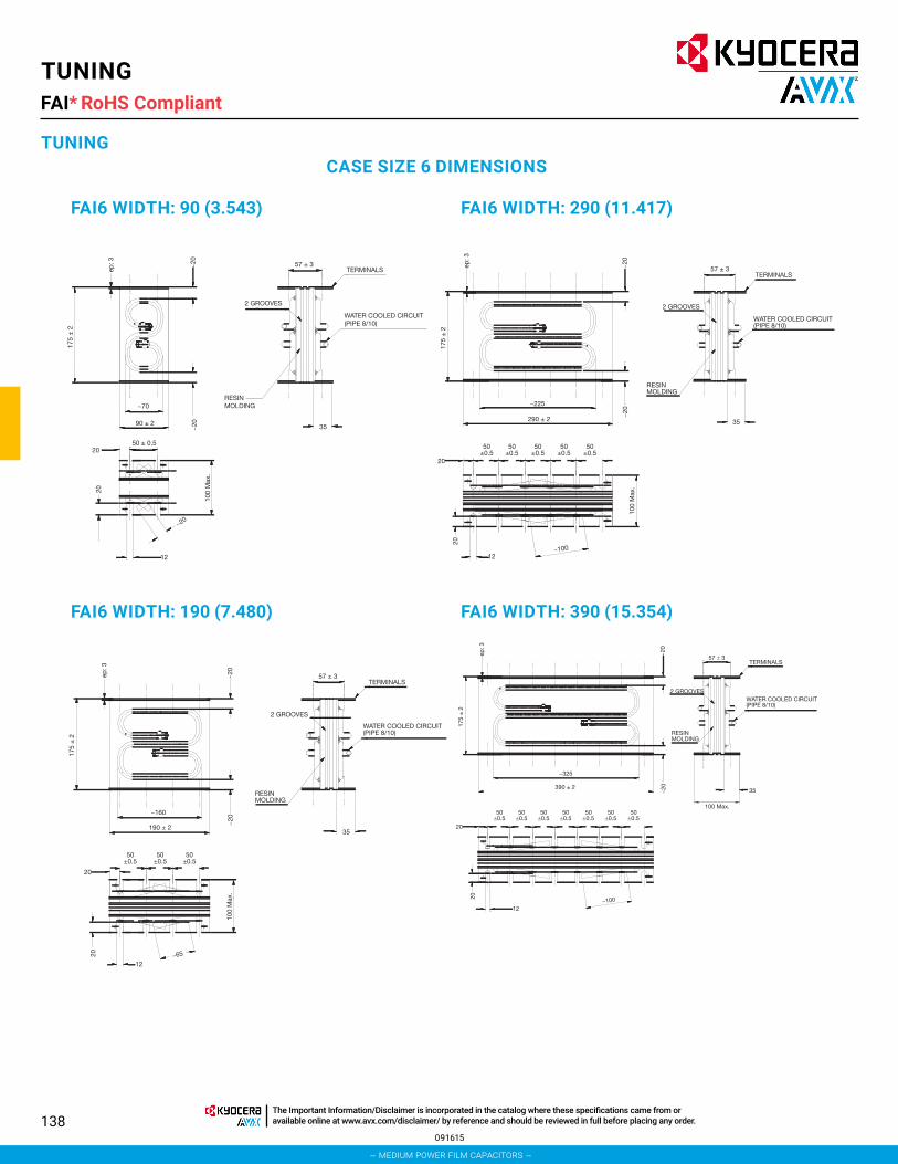
138
TUNINGFAI*
TUNINGCASE SIZE 6 DIMENSIONS
FAI6 WIDTH: 90 (3.543)
FAI6 WIDTH: 190 (7.480)
FAI6 WIDTH: 290 (11.417)
FAI6 WIDTH: 390 (15.354)
RESIN MOLDING
2 GROOVES
WATER COOLED CIRCUIT(PIPE 8/10)
TERMINALS57 ± 3
35
50 ± 0.520
20
~20
~20
~
20
12
100
Max
.
~70
90 ± 2
175
± 2
ep: 3
RESIN MOLDING
2 GROOVES
WATER COOLED CIRCUIT(PIPE 8/10)
TERMINALS57 ± 3
35
50±0.5
50±0.5
50±0.5
50±0.5
50±0.5
2020
12
100
Max
.
~100
~20
~20
175
± 2
ep: 3
~225
290 ± 2
RESIN MOLDING
2 GROOVES
WATER COOLED CIRCUIT(PIPE 8/10)
TERMINALS57 ± 3
35
50±0.5
50±0.5
50±0.5
20
20
12
100
Max
.
~65
~20
~20
175
± 2
ep: 3
~160
190 ± 2
RESIN MOLDING
2 GROOVESWATER COOLED CIRCUIT(PIPE 8/10)
TERMINALS57 ± 3
35
100 Max.50
±0.550
±0.550
±0.550
±0.550
±0.550
±0.550
±0.520
20
12~100
~20
~20
175
± 2
ep: 3
~325
390 ± 2
091615
RoHS Compliant
– medium power film capacitors –
The Important Information/Disclaimer is incorporated in the catalog where these specifications came from or available online at www.avx.com/disclaimer/ by reference and should be reviewed in full before placing any order.

139
TUNINGFAI*
TUNING15 µF 200 Vrms Width 90 mm
FAI66F0156K--12 µF 300 Vrms Width 90 mm
FAI66H0126K--
24 µF 300 Vrms Width 190 mmFAI66H0246K--
36 µF 300 Vrms Width 290 mmFAI66H0366K--
48 µF 300 Vrms Width 390 mmFAI66H0486K--
30 µF 200 Vrms Width 190 mmFAI66F0306K--
45 µF 200 Vrms Width 290 mmFAI66F0456K--
60 µF 200 Vrms Width 390 mmFAI66F0606K--
091615
RoHS Compliant
– medium power film capacitors –
The Important Information/Disclaimer is incorporated in the catalog where these specifications came from or available online at www.avx.com/disclaimer/ by reference and should be reviewed in full before placing any order.

140
TUNINGFAI*
TUNING
0
100
200
300
400
500
600
700
800
00101
F (kHz)
U (Vrms)
I ( Arms)
Q( kVAR)
0
200
400
600
800
1000
1200
00101
F (kHz)
U (Vrms)
I ( Arms)
Q( kVAR)
0
200
400
600
800
1000
1200
1400
1600
00101
F (kHz)
U (Vrms)
I ( Arms)
Q( kVAR)
0
500
1000
1500
2000
00101
F (kHz)
U (Vrms)
I ( Arms)
Q( kVAR)
0
100
200
300
400
500
600
700
00101
F (kHz)
U (Vrms)
I ( Arms)
Q( kVAR)
0
200
400
600
800
1000
1200
00101
F (kHz)
U (Vrms)
I ( Arms)
Q( kVAR)
0
200
400
600
800
1000
1200
1400
1600
00101
F (kHz)
U (Vrms)
I ( Arms)
Q( kVAR)
0
500
1000
1500
2000
00101
F (kHz)
U (Vrms)
I ( Arms)
Q( kVAR)
7 µF 400 Vrms Width 90 mmFAI66I0705K--
5 µF 500 Vrms Width 90 mmFAI66J0505K--
10 µF 500 Vrms Width 190 mmFAI66J0106K--
15 µF 500 Vrms Width 290 mmFAI66J0156K--
20 µF 500 Vrms Width 390 mmFAI66J0206K--
14 µF 400 Vrms Width 190 mmFAI66I0146K--
21 µF 400 Vrms Width 290 mmFAI66I0216K--
28 µF 400 Vrms Width 390 mmFAI66I0286K--
091615
RoHS Compliant
– medium power film capacitors –
The Important Information/Disclaimer is incorporated in the catalog where these specifications came from or available online at www.avx.com/disclaimer/ by reference and should be reviewed in full before placing any order.

141
TUNINGFAI*
TUNING
0
100
200
300
400
500
600
00101
F (kHz)
U (Vrms)
I ( Arms)
Q( kVAR)
0
200
400
600
800
1000
1200
00101
F (kHz)
U (Vrms)
I ( Arms)
Q( kVAR)
0
200
400
600
800
1000
1200
1400
1600
00101
F (kHz)
U (Vrms)
I ( Arms)
Q( kVAR)
0
500
1000
1500
2000
00101
F (kHz)
U (Vrms)
I ( Arms)
Q( kVAR)
0
100
200
300
400
500
600
700
00101
F (kHz)
U (Vrms)
I ( Arms)
Q( kVAR)
0100200300400500600700800900
1000
00101
F (kHz)
U (Vrms)
I ( Arms)
Q( kVAR)
0
200
400
600
800
1000
1200
1400
1600
00101
F (kHz)
U (Vrms)
I ( Arms)
Q( kVAR)
0
500
1000
1500
2000
00101
F (kHz)
U (Vrms)
I ( Arms)
Q( kVAR)
3.5 µF 600 Vrms Width 90 mmFAI66K0355K--
1.5 µF 650 Vrms Width 90 mmFAI66A0155K--
3 µF 650 Vrms Width 190 mmFAI66A0305K--
4.5 µF 650 Vrms Width 290 mmFAI66A0455K--
6 µF 650 Vrms Width 390 mmFAI66A0605K--
7 µF 600 Vrms Width 190 mmFAI66K0705K--
10.5 µF 600 Vrms Width 290 mmFAI66K1055K--
14 µF 600 Vrms Width 390 mmFAI66K0146K--
091615
RoHS Compliant
– medium power film capacitors –
The Important Information/Disclaimer is incorporated in the catalog where these specifications came from or available online at www.avx.com/disclaimer/ by reference and should be reviewed in full before placing any order.

142
APPLICATION NOTES
INDUCTION HEATING
APPLICATIONSLocal thermal treatment, metallic surface hardening, pipe welding, tin coating treatment,...
FUNCTION, PRODUCTS
DC FilteringThe purpose of this filter is to smooth the low frequency ripple coming from the bridge (up to 360 Hz) and to filter the high frequency ripple coming from the converter (15/20 kHz)*.*Frequency will be lower than capacitor resonance frequency, on request, TPC can propose specific models for high frequency.
Main criteria are: High rms. current and good behavior against overvoltage are needed.
Products to offer
FFG/FFH 5 to 160μF 600 to 1900VdcFFVE/FFWE 12 to 400μF 300 to 1900VdcFFVI/FFWI 47 to 275μF 500 to 1100VdcFFLI/FFLB 58 to 800μF 680 to 1900VdcFFLC 1120 to 8800μF 680 to 1200Vdc
TuningIn order to obtain the requested frequency, a capacitor is needed to tune with the inductance. The main characteristic of this capacitor is the reactive power (express in kVar) versus frequency.
Products to offer
TRACTION
FUNCTION, PRODUCTS
DC FilteringThe purpose of the product is to filter the high frequency ripple coming from the converter in order to avoid rejection and perturbation on the network.
TPC has developed controlled-self healing range allowing reliable and competitive solution compare electrolytic technology.
See calculation example how to replace electrolytic technology.
Note that on new developments based on IGBT converter, manufacturer wish to have a main DC filter close to the converter and some light filters sprayed on the line.
Products to offer
APPLICATIONSSpeed converter for power for mass transit and/or people mover system.
FAI6 10 kHz ≤ F ≤ 100 kHz 1.5 to 60μF 200 to 650Vrms 160 to 1280kVar
FAI1 to 4 100 kHz ≤ F ≤ 500 kHz 110 to 4000nF 300 to 600Vrms 100 to 300kVar
Main DC Filter FFLC 1120 to 8800μF up to 1200VdcAdditional FFLI/FFLB 58 to 800μF up to 1900Vdc DC Filter FFVE/FFWE 12 to 400μF up to 1900Vdc
FFG/FFV 5 to 160μF up to 1900Vdc
Thyristors and GTO snubbers FPX/FPY 0.5μF to 6μF up to 4600V*
IGBT clamping FSBFFVE
0.1 to 2.5μF 12 to 400μF
up to 2kVdc up to 1.9kVdc
Protection of semi-conductorsOvervoltage and clamping due to switching of semi-conductors.
Products to offer
*higher voltage on request
POWER SUPPLIES AND RESONANT CONVERTER
APPLICATIONSMedical X-ray, scanner power supplies
Traction Battery charger
Industrial All application requesting power supplies
061220
– medium power film capacitors –
The Important Information/Disclaimer is incorporated in the catalog where these specifications came from or available online at www.avx.com/disclaimer/ by reference and should be reviewed in full before placing any order.

143
FFB/FFV3 1.5 to 160μF 75 to 1100VdcFFG/FFH 5 to 160μF 600 to 1900VdcFFVE/FFWE 12 to 400μF 300 to 1900VdcFFVI/FFWI 47 to 275μF 500 to 1100VdcFFLI/FFLB 58 to 800μF 680 to 1900Vdc
FAV 80 to 1200nF up to 650VrmsFAI1 to 4 110 to 4000nF up to 600Vrms
FFLI/FFLB 58 to 800μF 680 to 1900Vdc FFVE/FFWE 12 to 400μF 300 to 1900Vdc FFVI/FFWI 47 to 275μF 500 to 1100Vdc FFB/FFV3 1.5 to 160μF 75 to 1100Vdc
FFVE/FFWE 12 to 400μF 300 to 1900V FFVI/FFWI 47 to 275μF 500 to 1100V FFB/FFV3 1.5 to 160μF 75 to 1100V
IGBT clamping FSB 0.1 to 3μF up to 2kVdc
Mos-Fet transistor protection FSV 10nF to 150nF up to 2kVdc
FUNCTION, PRODUCTS
DC FilteringThe purpose of this filter is to smooth the low frequency ripple coming from the bridge (up to 360 Hz) and to filter the high frequency ripple coming from the converter (15/20 kHz).
High rms. current and good behavior against overvoltage are needed.
Products to offer
TuningIn order to obtain the requested frequency, a capacitor is needed to tune with the inductance transformer.
The main characteristic of this capacitor is the reactive power and rms. current.
Products to offer
Protection of semi-conductorsOvervoltage and clamping due to switching of semi-conductors.
Products to offer
SPEED CONVERTER
APPLICATIONSSpeed converter for medium power (20 to 100kW) Traction: auxiliary converter for air cooling system, light,... Industrial: speed variation
FUNCTION, PRODUCTS
DC FilteringThe purpose of this product is to filter the high frequency ripple coming from the converter in order to avoid rejection and perturbation on the network.
Due to IGBT converter, heavy rms. current and very compact product is requested; film technology is able to achieve these 2 targets.
Products to offer
WELDING
APPLICATIONSGenerate, out of the main supply, through a converter (chopper) and a transformer an overvoltage able to create an electrical arc.
FUNCTION, PRODUCTS
DC FilteringThe purpose of this filter is to smooth the low frequency ripple coming from the rectifier (up to 360 Hz) and to filter the high frequency ripple coming from the converter (15/20 kHz).
Products to offer
ELECTRICAL VEHICLE
APPLICATIONSBattery powered car, electric fork lift truck and hybrid electric vehicle.
Due to high rms. current needed through the capacitor, metallized controlled self-healing technology will be an excellent solution.
See calculation example on page 105 .
APPLICATION NOTES
– medium power film capacitors –
The Important Information/Disclaimer is incorporated in the catalog where these specifications came from or available online at www.avx.com/disclaimer/ by reference and should be reviewed in full before placing any order.

144
FUNCTION, PRODUCTS
DC FilteringBetween battery and converter, a capacitor is needed.
Its main purpose is to filter the ripple coming from the converter, to avoid damaging the battery.
Metallized Film Capacitors are able to fulfill this function using 2 or 3 cases (only electrolytic can not).
Products to offer
FFVE/FFWE 12 to 400μF 300 to 1900VdcFFVI/FFWI 47 to 275μF 500 to 1100Vdc
According to quantity, a custom design could be developed, achieving the total function with a single case.
WIND MILL
APPLICATIONSEnergy power supplied by the wind, new wind mill generation use electronic converter in order to control power, phase and voltage.
FUNCTION, PRODUCTS
DC FilteringThe purpose of the product is to filter voltage ripple.
TPC has developed controlled self-healing range allowing reliable and competitive solution compare electrolytic technology.
See calculation example how to replace electrolytic technology on pages 104 and 105.
Products to offer
FFLC 1120 to 8800μF up to 1200Vdc
Protection of semi-conductorsOvervoltage and clamping due to switching of semi-conductors.
Products to offer
Snubbers FSB 0.1 to 3μF up to 2kVdcClamping FFVE/FFWE 12 to 400μF up to 1.9kVdc
ENERGY STORAGE
APPLICATIONSMedical: cardiac defibrillator
Industrial and military: laser telemetry, flash lamp
FUNCTION, PRODUCTS
DC FilteringStored energy is used to generate electrical pulse.
Products to offer
FDV1 5 to 80μF 1000 to 1700VFDBB 70 to 150μF 1800 to 3000V*
*Specific FDBB can be offered with energy density over more than 1.5J per cc.
FILM TECHNOLOGY TO REPLACE ALUMINUM ELECTROLYTIC TECHNOLOGYThe trend in the industrial and traction market for power conversion is to replace electrolytic capacitors by film technology.
This trend is generated by the many advantages that film technology offers. Among these advantages, we have:
*High rms. current capabilities up to 1Arms. per μF
*Overvoltage withstanding up to 2 times the rated voltage
*Handle a reversal voltage
*High peak current capabilities
*No acid inside
*Long lifetime
*No storage problem
However, this replacement is not necessarily capacitance but for capacitance by application/Function.
Despite the advantages of film technology, replacement solutions won’t be possible for each application, there will be several approaches to do this.
In order to help the use, we will present some examples where film gives a major benefit over electrolytic technology.
APPLICATION NOTES
– medium power film capacitors –
The Important Information/Disclaimer is incorporated in the catalog where these specifications came from or available online at www.avx.com/disclaimer/ by reference and should be reviewed in full before placing any order.

145
1) DC LINK FILTER: HIGH CURRENT DESIGN & CAPACITANCE VALUE DESIGN
1a) Energy supplied with batteriesApplications will be: electric car
electric fork lift truck
In that case, capacitor will be used as a decoupling capacitor.
Film capacitor is particularly well adapted for this use, because main criteria for DC link capacitor will be rms. current withstanding.
It means that DC link capacitor can be designed on rms. current value.
If we take an electric car in account as example:
Requirement data:
Working voltage: 120Vdc
Ripple voltage allowed: 4Vrms
Rms. current: 80 Arms. @ 20kHz
Minimum capacitance value will be:
So, it will be easy to find a capacitance value close to these values.
Comparison with electrolytic capacitor.
If we take in account 20mA per μF for example, in order to handle 80 Arms, capacitance value minimum would be:
1b) Industrial motor drive, energy supplied from supply network
DC Link Filter
U
U
U max
t
DC link voltage waveform:
Capacitance value will be defined taken in account that supply frequency is lower than converter frequency.
To determine needed capacitance, we can use the following approached equation:
Irms. through capacitor will be (approached expression):
Of course this current doesn’t take in account frequency converter current
So, with this approximation, Irms. through the capacitor will be depending of the Power of load, Umax and U ripple.
APPLICATION NOTES
– medium power film capacitors –
The Important Information/Disclaimer is incorporated in the catalog where these specifications came from or available online at www.avx.com/disclaimer/ by reference and should be reviewed in full before placing any order.

146
To illustrate, we will take a concrete example:
DC voltage 1000 Volts U ripple 200 volts
-P = 1 MW-P = 500 kW-P = 100 kW
Dc voltage = 1000VU ripple = 200V
80
100
60
40
20
00 400 800 1200 1600 2000
Frequency (Hz)
Cap
acita
nce
Valu
e (m
F)
-P = 1 MW-P = 500 kW-P = 100 kW
Dc voltage = 1000VU ripple = 200V
40
20
0100 150 200 250 300 350 400
Frequency (Hz)
Cap
acita
nce
Valu
e (m
F)
-P = 10 kW-P = 5 kW-P = 1 kW
Dc voltage = 1000VU ripple = 200V
0.5
0.4
0.3
0.2
0.1
0100 150 200 250
Frequency (Hz)
Cap
acita
nce
Valu
e (m
F)
300 350 400
U
t
Undc
Overvoltage
V
MOTOR
DC Link Filter
P Irms1 MW 2468 Arms
500 kW 1234 Arms100 kW 247 Arms
It becomes necessary to have a zoom on low frequency:
To compare with electrolytic solution, we will take a current capability of 20mA per μF for electrolytic capacitors. First case, power at 1Mwatt:
Rms. current is 2468 Arms, which would impose minimum capacitance value of 123.4mF (taking into account 0.02Arms. per μF).
If we look at this value on the curve, we can see that this capacitance value is needed (the given example for film technology) for a rectifier frequency lower than 100Hz.
So, with 3 phases, 6 diodes rectifier, frequency will be 300Hz.
We can see on the 1 megawatt curve that capacitance needed is 18.5mF. Film solution will be almost 4 times smaller than electrolytic solution, with high reliability in addition.
Lower power will give similar results, and for power up to 10 kwatts, capacitance value becomes so small that film technology still constitutes the best solution.
Even at 100Hz rectifier frequency, no more than 555μF are needed, supply voltage and ripple still the same than previously.
2) OVERVOLTAGE DESIGNWe will consider light traction application, like metro, tramway, electric buses, ...
DC link voltage wave form:
APPLICATION NOTES
– medium power film capacitors –
The Important Information/Disclaimer is incorporated in the catalog where these specifications came from or available online at www.avx.com/disclaimer/ by reference and should be reviewed in full before placing any order.

147
Due to the principle of carrying the power from the catenary to the train, some contact discontinuity appears between pantograph and catenary.
When contact is not done, energy come from DC link filter, with for effect, to decrease the voltage. So, as soon as the contact is re-established, an overvoltage appears.
Worse case would be ∆V = catenary voltage, because overvoltage could almost reach 2 times the rated voltage.
So, film capacitor can handle this kind of overvoltage.
Comparison with electrolytic technology:
Electrolytic handle 1.2 DC voltage max:
So minimum voltage that electrolytic should handle would be:
DC voltage of electrolytic technology:
4 capacitors 450 Volts in series would be needed.
Volume occupied for 10mF with electrolytic would be: 26 I and Irms. max would be 220Arms.With film, volume occupied would be 25 I, and rms. current capability would be higher than 500Arms.In other hand, link to these overvoltages, peak current appear through the capacitor:So, we have to calculate the energy generated by this overvoltage
.
After few periods, current becomes null, then:
with:
This energy calculation will be used for short circuit discharge between terminal as well. Such discharge will generate a very high peak current and some ringing that electrolytic could not handle.
3) VOLTAGE RATINGFunction of the voltage rating needed, film solution will become more and more interesting.
If high capacitance value is requested, film solution will be less competitive. Indeed, if there is no overvoltage, low rms. current, large capacitance value, it will be difficult for film technology to be competitive below 900 volts.
LIFETIME CALCULATIONFilm technology allows a very long lifetime expectancy, depending on voltage load conditions (working voltage) and hot spot temperature.
For DC filtering, lifetime meets the curves shown in this catalog.
End of life criteria is a decrease of capacitance value of 2%. However, this is a theoretical end of life, because capacitor can be still used after this point. If application can allow 5% capacitance decrease, lifetime will be widely increased.
Hot spot temperature will be determined with the following expression:
with: θmaxhotspot: the maximum hot spot temperature
tgδ0: dielectric losses
Rth: Thermal resistance
Rs: Serial resistance
θhot spot will be 85°C or 105°C function of the application and the technology.
4) CONCLUSIONThis document gives some ways for the engineer designer to do their choice. Of course, for each case a complete calculation will have to be done.
Anyway, if the request is only capacitance value, low voltage, low rms. Current, no overvoltage, no reversal voltage, no peak current, film technology certainly won’t be a good solution.
APPLICATION NOTES
– medium power film capacitors –
The Important Information/Disclaimer is incorporated in the catalog where these specifications came from or available online at www.avx.com/disclaimer/ by reference and should be reviewed in full before placing any order.

148
SPECIFIC PRODUCT REQUEST
This questionnaire lists the information we require to prepare an offer according to your exact requirements
Company / Name / Email Project / Quantity
Applications DC Filtering Discharge* Protection* TuningCapacitance (μF)
Tolerance (%)
Operating Voltage Vpeak Vch Vpeak Vdc Vrms
Ripple Voltage (peak to peak) V
Working Frequency (Hz)
Operating Current Arms Apeak Arms Arms
Maximum Current/Duration Arms s Apeak
Discharge Aperiodic Oscillatory
Pulse Duration (5% lpeak)
Time to lpeak (μs)
Ringing Frequency (Hz)
Reversal Voltage (%)
Repetition Rate shots/min/hour/day Hz
Hold Time @ Full Voltage (s)
Fault Peak Current / nb shots Apeak shots Apeak shots
Fault Reversal Voltage (%)
Lifetime Expectancy hours shots hours hours
Maximum Inductance (nH)
Test Voltage between Terminals (V)
Test Voltage between Shorted Terminals and Case (V)
Maximum Surge Voltage (MSV)
MSV Duration / Frequency s /year s /year
*Due to the particularities of varying waveforms in such application, more information on the exact nature of waveform is generally required for a full analysis.
Description
Dimensions (mm) / Shape Operating Position Terminals
Section: Height:
rectangular, cylindrical
vertical, horizontal inclined, upside
down
type quantity
Thermal CharacteristicsStorage Temperature (ºC) Operating Temperature (ºC) Cooling Method
min. min. Natural Convection
average average Forced Air (m/s)
max. max. Water
Remarks
– medium power film capacitors –
The Important Information/Disclaimer is incorporated in the catalog where these specifications came from or available online at www.avx.com/disclaimer/ by reference and should be reviewed in full before placing any order.

149
CERTIFICATES
– medium power film capacitors –
The Important Information/Disclaimer is incorporated in the catalog where these specifications came from or available online at www.avx.com/disclaimer/ by reference and should be reviewed in full before placing any order.

North AmericaTel: +1 864-967-2150
Central AmericaTel: +55 11-46881960
AsiaTel: +65 6286-7555
JapanTel: +81 740-321250
EuropeTel: +44 1276-697000
visit us at www.kyocera-avx.com
FOLLOW US: