electrochemical double-layer capacitors using carbon nanotube electrode structures
TRANSCRIPT

INV ITEDP A P E R
Electrochemical Double-LayerCapacitors Using CarbonNanotube Electrode StructuresThese capacitors can store large amounts of energy and deliver very high
peak power; they are used in electric vehicles and may have applications in
linear motor drives.
By Riccardo Signorelli, Student Member IEEE, Daniel C. Ku, Student Member IEEE,
John G. Kassakian, Life Fellow IEEE, and Joel E. Schindall, Fellow IEEE
ABSTRACT | The structure and behavior of the electrical
double-layer capacitor (EDLC) are described. The use of
activated carbon electrodes is discussed and the limitations
on voltage and accessible surface area are presented. Metrics
for evaluating EDLC performance are defined and previously
reported results of experimental carbon nanotube (CNT)
electrodes are tabulated. New experimental results of electro-
des constructed of vertically aligned CNTs grown on a conduct-
ing substrate are presented. By extrapolating prior and new
experimental data the energy density of CNT-based EDLCs is
shown to be potentially up to seven times that of commercial
activated carbon-based EDLCs.
KEYWORDS | Double-layer capacitors; capacitors; carbon
nanotubes; energy storage; ultracapacitors
I . INTRODUCTION
The electrochemical double-layer capacitor (EDLC), also
known as an ultracapacitor or supercapacitor, exploits the
double-layer of charge formed when a voltage is applied
to an electrode immersed in an electrolyte. Further, the
electrodes of an EDLC are constructed of highly porous
carbon resulting in a very large surface area to volume
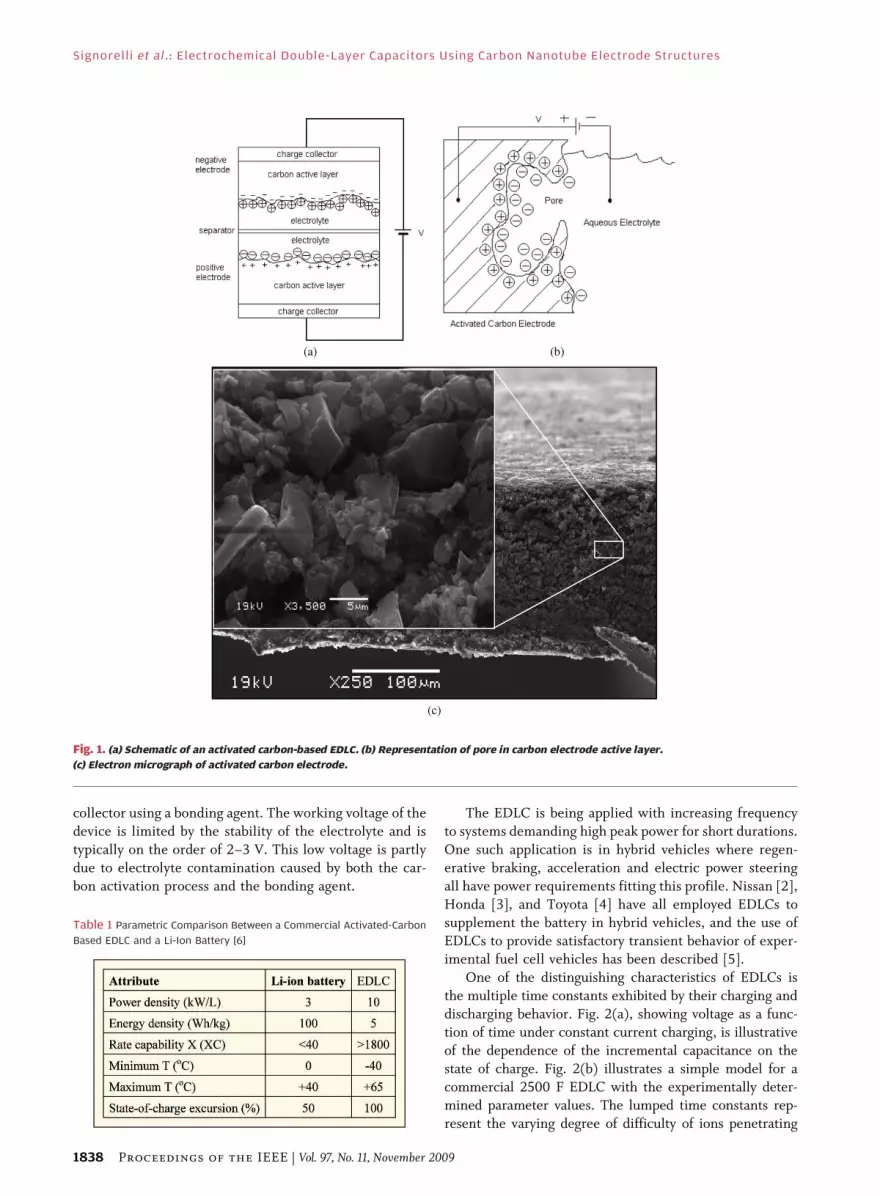
ratio. Fig. 1 shows schematically the construction of an
EDLC comprising two carbon electrodes, each with a
double-layer of charge at the electrolyte interface. The very
small charge separation in the double-layer and the largesurface area of the electrode results in a specific capac-
itance on the order of 40–60 F/cm3. The breakdown field
strength of the EDLC, calculated in V/cm, is extremely
high relative to that for conventional capacitors. These
three factorsVhigh surface area, small charge separation
and high field strengthVgive rise to the very high energy
density achievable with the EDLC. The EDLC, first
described by Rightmire in 1966 [1], should not be confusedwith the electrolytic capacitor which is comprised of two
metal foil electrodes (typically Al or Ta), one of which has
an oxidized surface, separated by electrolyte soaked paper
and rolled into a tubular form. The oxide layer forms the
dielectric, its thinness and high breakdown voltage giving
rise to the high specific capacitance of electrolytics relative
to solid film capacitors. An EDLC has a volumetric
capacitance on the order of 106 � 108, that of anelectrolytic of comparable physical size. However, since
the working voltage of the EDLC is about 10�2, that of an
electrolytic, the energy density of commercial EDLCs is
about 102 � 103, that of electrolytics. On the other hand,
the low ESR of the EDLC produces a device with an
extremely high power density.
As the energy density of EDLCs has increased they are
being viewed as a potential replacement for batteries. Withtheir much longer cycle life and better behavior as a func-
tion of temperature they are an attractive alternative. A
parametric comparison between EDLCs and Li-ion bat-
teries is shown in Table 1.
The carbon forming the electrodes of the EDLC, made
highly porous by a thermal activation process yielding
activated carbon (AC), is attached to the metallic current
Manuscript received November 11, 2008; revised April 14, 2009. First published
October 16, 2009; current version published October 28, 2009.
The authors are with the Laboratory for Electromagnetic and Electronic Systems,
Massachusetts Institute of Technology, Cambridge, MA 02139-4301 USA.
Digital Object Identifier: 10.1109/JPROC.2009.2030240
Vol. 97, No. 11, November 2009 | Proceedings of the IEEE 18370018-9219/$26.00 �2009 IEEE
collector using a bonding agent. The working voltage of the
device is limited by the stability of the electrolyte and is
typically on the order of 2–3 V. This low voltage is partly
due to electrolyte contamination caused by both the car-
bon activation process and the bonding agent.
The EDLC is being applied with increasing frequency
to systems demanding high peak power for short durations.
One such application is in hybrid vehicles where regen-
erative braking, acceleration and electric power steering
all have power requirements fitting this profile. Nissan [2],
Honda [3], and Toyota [4] have all employed EDLCs to
supplement the battery in hybrid vehicles, and the use of
EDLCs to provide satisfactory transient behavior of exper-imental fuel cell vehicles has been described [5].
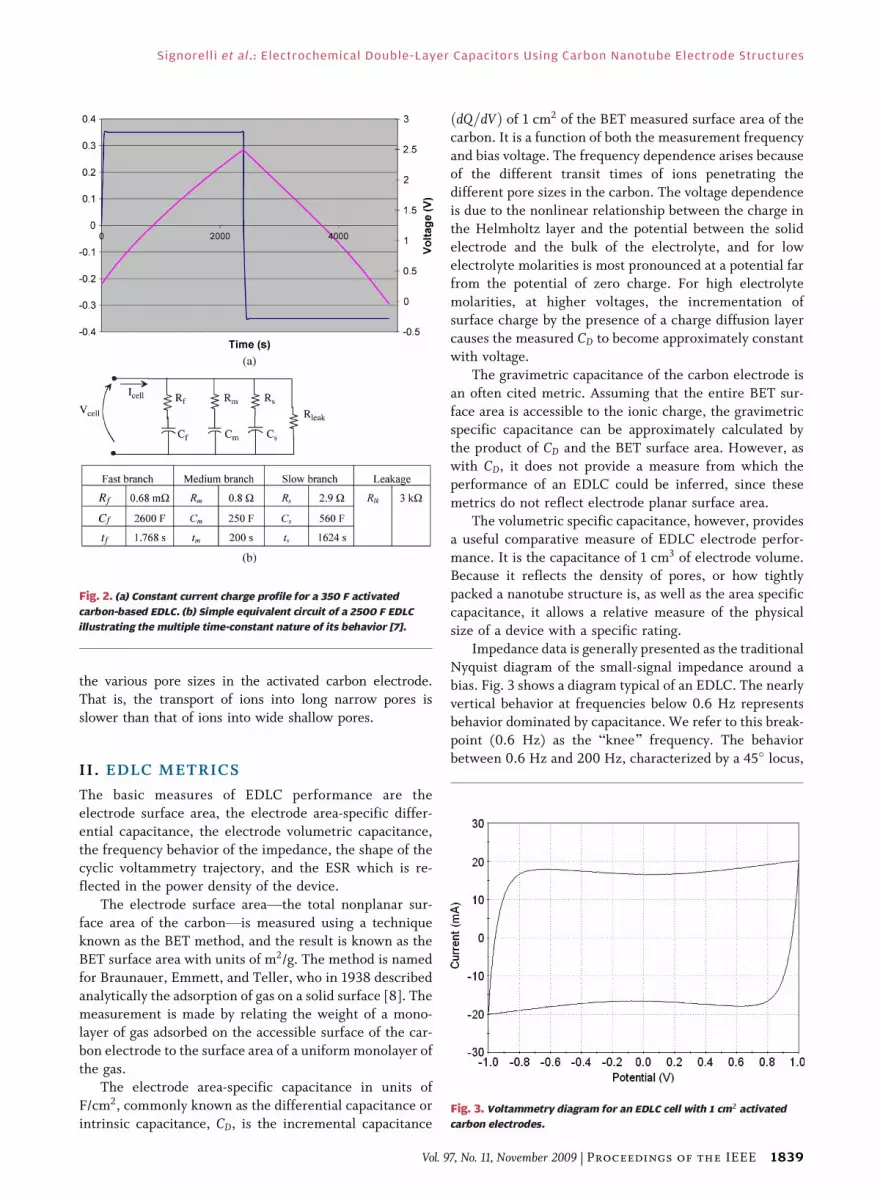
One of the distinguishing characteristics of EDLCs is
the multiple time constants exhibited by their charging and
discharging behavior. Fig. 2(a), showing voltage as a func-
tion of time under constant current charging, is illustrative
of the dependence of the incremental capacitance on the
state of charge. Fig. 2(b) illustrates a simple model for a
commercial 2500 F EDLC with the experimentally deter-mined parameter values. The lumped time constants rep-
resent the varying degree of difficulty of ions penetrating
Fig. 1. (a) Schematic of an activated carbon-based EDLC. (b) Representation of pore in carbon electrode active layer.
(c) Electron micrograph of activated carbon electrode.
Table 1 Parametric Comparison Between a Commercial Activated-Carbon
Based EDLC and a Li-Ion Battery [6]
Signorelli et al.: Electrochemical Double-Layer Capacitors Using Carbon Nanotube Electrode Structures
1838 Proceedings of the IEEE | Vol. 97, No. 11, November 2009
the various pore sizes in the activated carbon electrode.
That is, the transport of ions into long narrow pores is
slower than that of ions into wide shallow pores.
II . EDLC METRICS
The basic measures of EDLC performance are the
electrode surface area, the electrode area-specific differ-
ential capacitance, the electrode volumetric capacitance,
the frequency behavior of the impedance, the shape of thecyclic voltammetry trajectory, and the ESR which is re-
flected in the power density of the device.
The electrode surface areaVthe total nonplanar sur-
face area of the carbonVis measured using a technique
known as the BET method, and the result is known as the
BET surface area with units of m2/g. The method is named
for Braunauer, Emmett, and Teller, who in 1938 described
analytically the adsorption of gas on a solid surface [8]. Themeasurement is made by relating the weight of a mono-
layer of gas adsorbed on the accessible surface of the car-
bon electrode to the surface area of a uniform monolayer of
the gas.
The electrode area-specific capacitance in units of
F/cm2, commonly known as the differential capacitance or
intrinsic capacitance, CD, is the incremental capacitance
ðdQ=dVÞ of 1 cm2 of the BET measured surface area of thecarbon. It is a function of both the measurement frequency
and bias voltage. The frequency dependence arises because
of the different transit times of ions penetrating the
different pore sizes in the carbon. The voltage dependence
is due to the nonlinear relationship between the charge in
the Helmholtz layer and the potential between the solid
electrode and the bulk of the electrolyte, and for low
electrolyte molarities is most pronounced at a potential farfrom the potential of zero charge. For high electrolyte
molarities, at higher voltages, the incrementation of
surface charge by the presence of a charge diffusion layer
causes the measured CD to become approximately constant
with voltage.
The gravimetric capacitance of the carbon electrode is
an often cited metric. Assuming that the entire BET sur-
face area is accessible to the ionic charge, the gravimetricspecific capacitance can be approximately calculated by
the product of CD and the BET surface area. However, as
with CD, it does not provide a measure from which the
performance of an EDLC could be inferred, since these
metrics do not reflect electrode planar surface area.
The volumetric specific capacitance, however, provides
a useful comparative measure of EDLC electrode perfor-
mance. It is the capacitance of 1 cm3 of electrode volume.Because it reflects the density of pores, or how tightly
packed a nanotube structure is, as well as the area specific
capacitance, it allows a relative measure of the physical
size of a device with a specific rating.
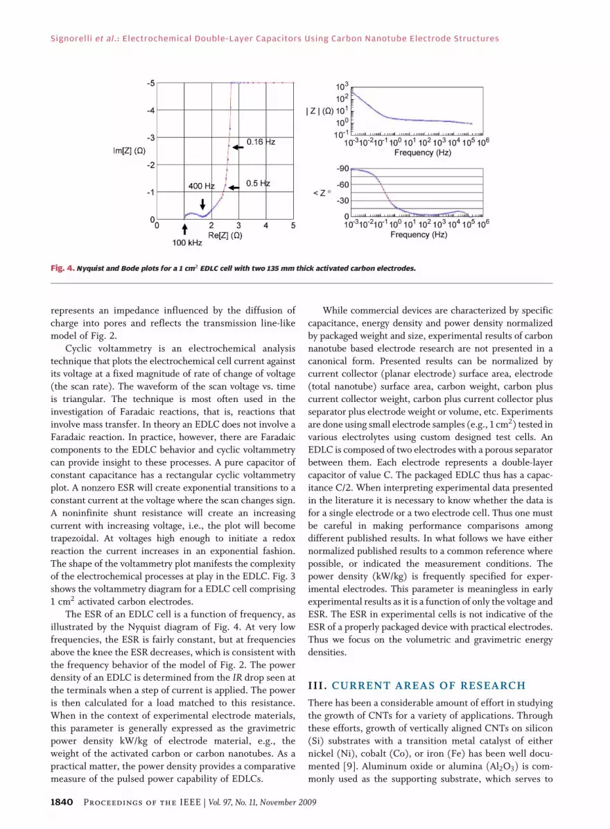
Impedance data is generally presented as the traditional
Nyquist diagram of the small-signal impedance around a
bias. Fig. 3 shows a diagram typical of an EDLC. The nearly
vertical behavior at frequencies below 0.6 Hz representsbehavior dominated by capacitance. We refer to this break-
point (0.6 Hz) as the Bknee[ frequency. The behavior
between 0.6 Hz and 200 Hz, characterized by a 45� locus,
Fig. 2. (a) Constant current charge profile for a 350 F activated
carbon-based EDLC. (b) Simple equivalent circuit of a 2500 F EDLC
illustrating the multiple time-constant nature of its behavior [7].
Fig. 3. Voltammetry diagram for an EDLC cell with 1 cm2 activated
carbon electrodes.
Signorelli et al. : Electrochemical Double-Layer Capacitors Using Carbon Nanotube Electrode Structures
Vol. 97, No. 11, November 2009 | Proceedings of the IEEE 1839
represents an impedance influenced by the diffusion of
charge into pores and reflects the transmission line-like
model of Fig. 2.
Cyclic voltammetry is an electrochemical analysis
technique that plots the electrochemical cell current againstits voltage at a fixed magnitude of rate of change of voltage
(the scan rate). The waveform of the scan voltage vs. time
is triangular. The technique is most often used in the
investigation of Faradaic reactions, that is, reactions that
involve mass transfer. In theory an EDLC does not involve a
Faradaic reaction. In practice, however, there are Faradaic
components to the EDLC behavior and cyclic voltammetry
can provide insight to these processes. A pure capacitor ofconstant capacitance has a rectangular cyclic voltammetry
plot. A nonzero ESR will create exponential transitions to a
constant current at the voltage where the scan changes sign.
A noninfinite shunt resistance will create an increasing
current with increasing voltage, i.e., the plot will become
trapezoidal. At voltages high enough to initiate a redox
reaction the current increases in an exponential fashion.
The shape of the voltammetry plot manifests the complexityof the electrochemical processes at play in the EDLC. Fig. 3
shows the voltammetry diagram for a EDLC cell comprising
1 cm2 activated carbon electrodes.
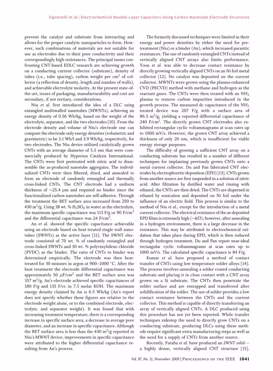
The ESR of an EDLC cell is a function of frequency, as
illustrated by the Nyquist diagram of Fig. 4. At very low
frequencies, the ESR is fairly constant, but at frequencies
above the knee the ESR decreases, which is consistent with
the frequency behavior of the model of Fig. 2. The powerdensity of an EDLC is determined from the IR drop seen at
the terminals when a step of current is applied. The power
is then calculated for a load matched to this resistance.
When in the context of experimental electrode materials,
this parameter is generally expressed as the gravimetric
power density kW/kg of electrode material, e.g., the
weight of the activated carbon or carbon nanotubes. As a
practical matter, the power density provides a comparativemeasure of the pulsed power capability of EDLCs.
While commercial devices are characterized by specific
capacitance, energy density and power density normalized
by packaged weight and size, experimental results of carbon
nanotube based electrode research are not presented in a
canonical form. Presented results can be normalized bycurrent collector (planar electrode) surface area, electrode
(total nanotube) surface area, carbon weight, carbon plus
current collector weight, carbon plus current collector plus
separator plus electrode weight or volume, etc. Experiments
are done using small electrode samples (e.g., 1 cm2) tested in
various electrolytes using custom designed test cells. An
EDLC is composed of two electrodes with a porous separator
between them. Each electrode represents a double-layercapacitor of value C. The packaged EDLC thus has a capac-
itance C/2. When interpreting experimental data presented
in the literature it is necessary to know whether the data is
for a single electrode or a two electrode cell. Thus one must
be careful in making performance comparisons among
different published results. In what follows we have either
normalized published results to a common reference where
possible, or indicated the measurement conditions. Thepower density (kW/kg) is frequently specified for exper-
imental electrodes. This parameter is meaningless in early
experimental results as it is a function of only the voltage and
ESR. The ESR in experimental cells is not indicative of the
ESR of a properly packaged device with practical electrodes.
Thus we focus on the volumetric and gravimetric energy
densities.
III . CURRENT AREAS OF RESEARCH
There has been a considerable amount of effort in studying
the growth of CNTs for a variety of applications. Through
these efforts, growth of vertically aligned CNTs on silicon
(Si) substrates with a transition metal catalyst of either
nickel (Ni), cobalt (Co), or iron (Fe) has been well docu-
mented [9]. Aluminum oxide or alumina ðAl2O3Þ is com-
monly used as the supporting substrate, which serves to
Fig. 4. Nyquist and Bode plots for a 1 cm2 EDLC cell with two 135 mm thick activated carbon electrodes.
Signorelli et al.: Electrochemical Double-Layer Capacitors Using Carbon Nanotube Electrode Structures
1840 Proceedings of the IEEE | Vol. 97, No. 11, November 2009
prevent the catalyst and substrate from interacting andallows for the proper catalytic nanoparticles to form. How-
ever, such combinations of materials are not suitable for
use as electrodes due to their poor conductivity and their
correspondingly high resistances. The principal issues con-
fronting CNT-based EDLC research are achieving growth
on a conducting current collector (substrate), density of
tubes (i.e., tube spacing), carbon weight per cm2 of col-
lector (a reflection of density, length and number of walls),and achievable electrolyte molarity. At the present state-of-
the-art, issues of packaging, manufacturability and cost are
secondary, if not tertiary, considerations.
Niu et al. first introduced the idea of a DLC using
entangled multiwalled nanotubes (MWNTs), achieving an
energy density of 0.56 Wh/kg, based on the weight of the
electrolyte, separator, and the two electrodes [10]. From the
electrode density and volume of Niu’s electrode one cancompute the electrode only energy densities (volumetric and
gravimetric) to be 3.1 Wh/l and 3.9 Wh/kg, respectively, for
two electrodes. The Niu device utilized catalytically grown
CNTs with an average diameter of 5.5 nm that were com-
mercially produced by Hyperion Catalysis International.
The CNTs were first pretreated with nitric acid to disas-
semble the as-produced nanotube aggregates. The individ-
ualized CNTs were then filtered, dried, and annealed toform an electrode of randomly entangled and thermally
cross-linked CNTs. The CNT electrode had a uniform
thickness of �25.4 �m and required no binder since the
functionalized carbon nanotubes are self-adhesive. Through
the treatment the BET surface area increased from 250 to
430 m2/g. Using 38 wt. % H2SO4 in water as the electrolyte,
the maximum specific capacitance was 113 F/g or 90 F/cm3
and the differential capacitance was 24 F/cm2.An et al. showed the specific capacitance achievable
using an electrode based on heat treated single wall nano-
tubes (SWNTs) as the active layer [11]. The SWNT elec-
trode consisted of 70 wt. % of randomly entangled and
cross-linked SWNTs and 30 wt. % polyvinylidene chloride
(PVDC) as the binder. The ratio of CNTs to binder was
determined empirically. The electrode was then heat-
treated for 30 minutes in argon at 900–1000 �C. After theheat treatment the electrode differential capacitance was
approximately 50 �F/cm2 and the BET surface area was
357 m2/g. An’s electrode achieved specific capacitances of
180 F/g and 135 F/cc in 7.5 molar KOH. The maximum
energy density claimed by An is 6.5 Wh/kg (An’s report
does not specify whether these figures are relative to the
electrode weight alone, or to the combined electrode, elec-
trolyte, and separator weight). It was found that withincreasing treatment temperature, there is a corresponding
increase in specific surface area, a decrease in average pore
diameter, and an increase in specific capacitance. Although
the BET surface area is less than the 430 m2/g reported in
Niu’s MWNT device, improvements in specific capacitance
were attributed to the higher differential capacitance re-
sulting from An’s process.
The formerly discussed techniques were limited in theirenergy and power densities by either the need for pre-
treatment (Niu) or a binder (An), which increased parasitic
resistances. The use of randomly entangled CNTs instead of
vertically aligned CNT arrays also limits performance.
Yoon et al. was able to decrease contact resistance by
directly growing vertically aligned CNTs on an Ni foil metal
collector [12]. No catalyst was deposited on the current
collector. MWNTs were grown using the plasma-enhancedCVD (PECVD) method with methane and hydrogen as the
reactant gases. The CNTs were then treated with an NH3
plasma to remove carbon impurities introduced in the
growth process. The measured dc capacitance of the NH3
treated device was 207 F/g with a surface area of
86.5 m2/g, yielding a reported differential capacitance of
240 F/cm2. The directly grown CNT electrodes also ex-
hibited rectangular cyclic voltammagrams at scan rates upto 1000 mV/s. However, the grown CNT array achieved a
thickness of only 20 nm, which is insufficient for viable
energy storage purposes.
The difficulty of growing a sufficient CNT array on a
conducting substrate has resulted in a number of different
techniques for implanting previously grown CNTs onto a
metal current collector. Du and Pan fabricated CNT elec-
trodes by electrophoretic deposition (EPD) [13]. CNTs grownfrom another source are first suspended in a solution of nitric
acid. After filtration by distilled water and rinsing with
ethanol, the CNTs are then dried. The CNTs are dispersed in
ethanol by sonication and deposited on Ni foil under the
influence of an electric field. This process is similar to the
method of Niu et al., except for the introduction of a metal
current collector. The electrical resistance of the as-deposited
EPD films is extremely high ð�k�Þ; however, after annealingin a hydrogen environment, there is a large decrease in the
resistance. This may be attributed to electrochemical oxi-
dation that takes place during EPD, which is then reduced
through hydrogen treatment. Du and Pan report near-ideal
rectangular cyclic voltammagrams at scan rates up to
1000 mV/s. The calculated specific capacitance is 84 F/g.
Kumar et al. have proposed a method of contact
transfer of CNTs using low temperature solder alloys [14].The process involves annealing a solder coated conducting
substrate and placing it in close contact with a CNT array
grown on a Si substrate. The CNTs then penetrate the
solder surface and are entrapped and transferred after
solidification of the solder. The use of solder provides a low
contact resistance between the CNTs and the current
collector. This method is capable of directly transferring an
array of vertically aligned CNTs. A DLC produced usingthis procedure has not yet been reported. While transfer
techniques sidestep the need to directly grow CNTs on a
conducting substrate, producing DLCs using these meth-
ods require significant extra manufacturing steps as well as
the need for a supply of CNTs from another source.
Recently, Futaba et al. have produced an SWNT solidVa highly dense, vertically aligned CNT structure [15].
Signorelli et al. : Electrochemical Double-Layer Capacitors Using Carbon Nanotube Electrode Structures
Vol. 97, No. 11, November 2009 | Proceedings of the IEEE 1841

It uses the surface tension of liquids to zip together aCNT forest initially grown on silicon. The zipping to-
gether of the CNTs demonstrates the potential for greater
density in the growth of CNTs to produce a greater surface
area. The BSWNT solid[ has a density on the order of
8.3� 1012 CNTs/cm2, CNT diameters of 2.8 nm, and a
BET surface area of 1000 m2/g. An electrochemical cell
was produced by sandwiching the SWNT solid between
platinum sheets, using 1 M tetraethylammonium tetra-fluoroborate ðEt4NBF4Þ/propylene carbonate (PC) elec-
trolyte. From the reported data the gravimetric and
volumetric specific capacitances of Futaba’s electrode can
be estimated to be 60 F/g and 12 F/cm3 (at very low
current densities). The reported energy densities for a two
electrode cell at 2.5 V are 13 Wh/kg and 10.4 Wh/l. The
main limitation of Futaba’s electrode is its poor differential
capacitance of 6 �F/cm2 when compared to that achievedby Niu (24 �F/cm2) and An (50 �F/cm2) with their elec-
trodes. It may be that ions cannot freely penetrate the
interstitial spaces of such a dense structure, i.e., much of
the BET surface area does not participate in charge storage.
IV. CNT GROWTH ONCONDUCTING SUBSTRATES
We have fabricated multiwall carbon nanotubes (MWNT)
on a variety of substrates using low-pressure chemical
vapor deposition (LPCVD). The process uses a gas mixture
of acetylene, argon, and hydrogen, and an iron catalyst
deposited on the substrate using electron beam vaporiza-
tion. Fabricated electrodes are 1 cm2 and are tested in an
experimental cell using 1.4 M acetonitrile. The purposes of
these experiments has been to demonstrate the growth oflong CNTs on a conducting substrate, determine the wet-
ting properties of the electrolyte, identify process param-
eters that control CNT density and wall numbers, and
provide measurements indicative of the electrical proper-
ties of the electrodes if applied to EDLCs.
Fig. 5 is an electron micrograph of CNTs grown on a
tungsten substrate. The inset show a single seven-wall
nanotube. On average, the as-grown CNTs have three wallsand have been grown as long as 300 �m. Fig. 6 is a plot of
the experimentally measured electrode capacitance as a
function of nanotube length. The approximately linear
relationship supports the assumption that the electrolyte is
completely wetting the carbon layer. A caveat with respect
to this conclusion is that the density of nanotubes in the
samples on which these measurements were made was
5� 1010/cm2, which is relatively sparse. It is yet to beshown that complete wetting occurs with higher tube
densities, where the closer spacing of the nanotubes pre-
sents a greater wetting challenge.
The density of nanotubes was determined by removing
the carbon layer and observing the residual tube Bfootprints[on the substrate surface. Using either AFM or SEM micro-
scopy, the footprints were counted within a measured sur-
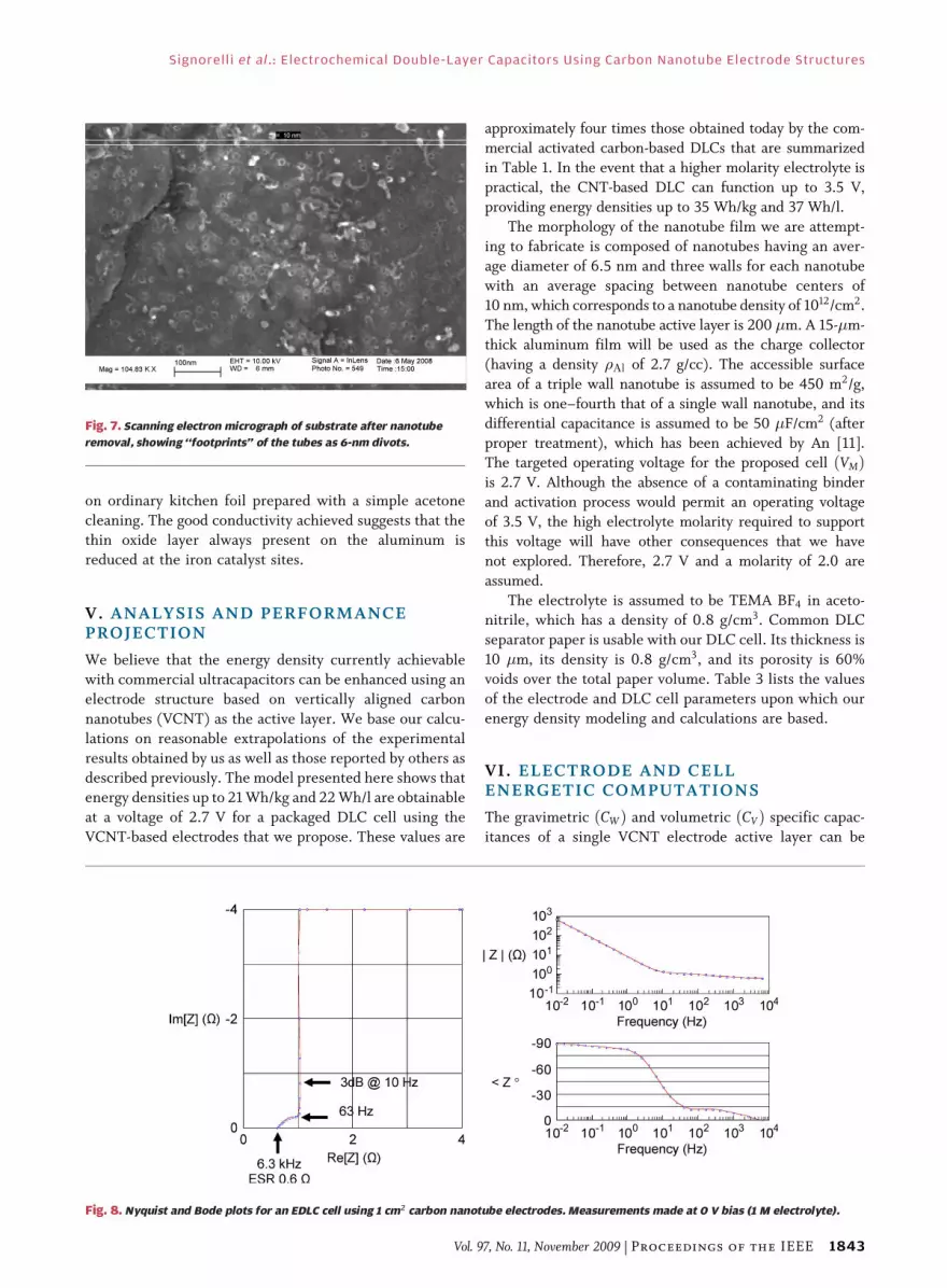
face area. Fig. 7 is one such photograph showing thefootprints as tiny circular divots. The maximum measured
density achieved to date is 4� 1011/cm2.
Knowing the density, average number of walls,
diameter, and length of the tubes, and the density of
carbon, the weight of the nanotube layer can be computed.
Confirmation was obtained by weighing the electrode
before and after nanotube growth. The resulting differen-
tial (carbon area specific) capacitance, CD, was determinedto be 10 �F/cm2. This relatively low value is due to the lack
of either thermal or acid aftertreatment of the nanotubes.
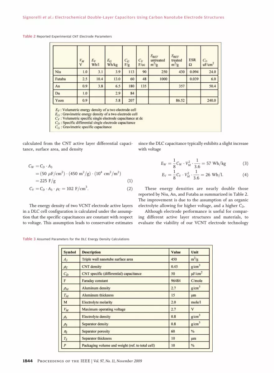
The Nyquist and Bode plots for one electrode are shown in
Fig. 8. These plots show a capacitance of about 16 mF for
the 1 cm2 sample, implying a two electrode cell capacitance
of 8 mF.
In addition to tungsten, we have grown 100-�m-long
CNTs on aluminum foil. Adequate adhesion was observedFig. 5. CNTs grown on a tungsten substrate with an aluminum
interlayer. The inset shows a single nanotube having seven walls.
Fig. 6. Measured capacitance vs. CNT length showing uniform wetting.
Signorelli et al.: Electrochemical Double-Layer Capacitors Using Carbon Nanotube Electrode Structures
1842 Proceedings of the IEEE | Vol. 97, No. 11, November 2009
on ordinary kitchen foil prepared with a simple acetone
cleaning. The good conductivity achieved suggests that the
thin oxide layer always present on the aluminum isreduced at the iron catalyst sites.
V. ANALYSIS AND PERFORMANCEPROJECTION
We believe that the energy density currently achievable
with commercial ultracapacitors can be enhanced using an
electrode structure based on vertically aligned carbon
nanotubes (VCNT) as the active layer. We base our calcu-
lations on reasonable extrapolations of the experimental
results obtained by us as well as those reported by others asdescribed previously. The model presented here shows that
energy densities up to 21 Wh/kg and 22 Wh/l are obtainable
at a voltage of 2.7 V for a packaged DLC cell using the
VCNT-based electrodes that we propose. These values are
approximately four times those obtained today by the com-mercial activated carbon-based DLCs that are summarized
in Table 1. In the event that a higher molarity electrolyte is
practical, the CNT-based DLC can function up to 3.5 V,
providing energy densities up to 35 Wh/kg and 37 Wh/l.
The morphology of the nanotube film we are attempt-
ing to fabricate is composed of nanotubes having an aver-
age diameter of 6.5 nm and three walls for each nanotube
with an average spacing between nanotube centers of10 nm, which corresponds to a nanotube density of 1012/cm2.
The length of the nanotube active layer is 200 �m. A 15-�m-
thick aluminum film will be used as the charge collector
(having a density �Al of 2.7 g/cc). The accessible surface
area of a triple wall nanotube is assumed to be 450 m2/g,
which is one–fourth that of a single wall nanotube, and its
differential capacitance is assumed to be 50 �F/cm2 (after
proper treatment), which has been achieved by An [11].The targeted operating voltage for the proposed cell ðVMÞis 2.7 V. Although the absence of a contaminating binder
and activation process would permit an operating voltage
of 3.5 V, the high electrolyte molarity required to support
this voltage will have other consequences that we have
not explored. Therefore, 2.7 V and a molarity of 2.0 are
assumed.
The electrolyte is assumed to be TEMA BF4 in aceto-nitrile, which has a density of 0.8 g/cm3. Common DLC
separator paper is usable with our DLC cell. Its thickness is
10 �m, its density is 0.8 g/cm3, and its porosity is 60%
voids over the total paper volume. Table 3 lists the values
of the electrode and DLC cell parameters upon which our
energy density modeling and calculations are based.
VI. ELECTRODE AND CELLENERGETIC COMPUTATIONS
The gravimetric ðCWÞ and volumetric ðCVÞ specific capac-
itances of a single VCNT electrode active layer can be
Fig. 7. Scanning electron micrograph of substrate after nanotube
removal, showing ‘‘footprints’’ of the tubes as 6-nm divots.
Fig. 8. Nyquist and Bode plots for an EDLC cell using 1 cm2 carbon nanotube electrodes. Measurements made at 0 V bias (1 M electrolyte).
Signorelli et al. : Electrochemical Double-Layer Capacitors Using Carbon Nanotube Electrode Structures
Vol. 97, No. 11, November 2009 | Proceedings of the IEEE 1843
calculated from the CNT active layer differential capaci-
tance, surface area, and density
CW ¼ CD � A3
¼ð50 �F=cm2Þ � ð450 m2=gÞ � ð104 cm2=m2Þ¼ 225 F=g (1)
CV ¼ CD � A3 � �C ¼ 102 F=cm3: (2)
The energy density of two VCNT electrode active layers
in a DLC cell configuration is calculated under the assump-
tion that the specific capacitances are constant with respect
to voltage. This assumption leads to conservative estimates
since the DLC capacitance typically exhibits a slight increase
with voltage
EW ¼1
8CW � V2
M �1
3:6¼ 57 Wh=kg (3)
EV ¼1
8CV � V2
M �1
3:6¼ 26 Wh=l: (4)
These energy densities are nearly double those
reported by Niu, An, and Futaba as summarized in Table 2.
The improvement is due to the assumption of an organic
electrolyte allowing for higher voltage, and a higher CD.
Although electrode performance is useful for compar-
ing different active layer structures and materials, to
evaluate the viability of our VCNT electrode technology
Table 2 Reported Experimental CNT Electrode Parameters
Table 3 Assumed Parameters for the DLC Energy Density Calculations
Signorelli et al.: Electrochemical Double-Layer Capacitors Using Carbon Nanotube Electrode Structures
1844 Proceedings of the IEEE | Vol. 97, No. 11, November 2009

we estimate the achievable energy density of a packagedcell. The parameters used to make this estimation for a DLC
cell using two 1 cm2 VCNT electrodes are summarized inTable 4, along with the resulting total energy stored in the
cell at VM. The charge, Q, in this table is the ionic chargerequired for one electrode at a voltage of 1.35 V (half the
cell voltage) and a capacitance of 2.04 F ðCwWCÞ.The energy densities of a cell comprised of two VCNT
active layers and aluminum charge collectors, separator,and electrolyte are given by
E0W ¼ETOT
2 � ðWAl þWCÞ þWS þWe¼ 23:0 Wh/kg (5)
E0V ¼ 24:2 Wh/l: (6)
The weights of each CNT active layer and of thenecessary electrolyte are
WC ¼ �C � VC ¼ 9:08 mg (7)
We ¼2Q � �e
M � F ¼ 23 mg: (8)
The electrolyte weight, We, is calculated based on the
assumption that twice the minimum required ion density,
Q, is necessary to maintain electrolyte conductivity.
Assuming a weight and volume of the packagingequivalent to 10% of the total cell weight and volume
(electrodes, electrolyte and separator), the overall volu-
metric and gravimetric energy densities are estimated
using (9) and (10). These assumptions are realistic when
aluminum is used for the cell package
E00W ¼ E0W � 0:9 ¼ 21 Wh/kg (9)
E00V ¼ E0V � 0:9 ¼ 22 Wh/l: (10)
Comparing Table 5 with Table 1 we see that the theo-
retical gravimetric energy densities of a VCNT-based DLC
cell is four times that of a typical commercial ultracapacitor.
This improvement is due to the specific capacitances
obtainable with our VCNT electrodes in conjunction with a
nanotube morphology conducive to electrolyte storage.
The calculated values in Table 5 were based on anassumed maximum working voltage of 2.7 V. However, this
Table 4 Energy and Charge Stored by Two 1 cm2 VCNT Electrodes Along With the Weights and Volumes of the Electrodes and
Cell Components With Dimension Described in Table 3
Table 5 Summary of Specific Capacitances and Cell Energy Densities
Signorelli et al. : Electrochemical Double-Layer Capacitors Using Carbon Nanotube Electrode Structures
Vol. 97, No. 11, November 2009 | Proceedings of the IEEE 1845

limitation is due to electrolyte degradation in conventionalactivated carbon DLCs resulting from contamination during
the activation process and from the binder used to attach the
carbon to the current collector. The purity of CNTs avoids
this contamination, resulting in the ability to operate the
device at a working voltage approaching 3.5 V. Keeping
volume fixed, the higher voltage would require a higher
molarity electrolyte. Under these conditions the energy
densities are increased to about 35 Wh/kg and 37 Wh/l.
VII. CONCLUSION
We have shown that long, vertically aligned carbon
nanotubes can be grown directly on an aluminum foil
current collector. Wetting properties have been shown to
be satisfactory for a tube density of 4� 1011=cm2. A
carbon area specific capacitance of 50 �F/cm2 has been
demonstrated by others, and together with an anticipatedtube density of 1012=cm2 and an electrolyte of 2.0 M
acetonitrile, energy densities of 21 Wh/kg and 22 Wh/l
are projected for a packaged, commercial CNT-based
EDLC at 2.7 V. If a molarity of 2.7 for the electrolyte is
shown to be practical, the increase in working voltage to
3.5 V results in energy densities of 35 Wh/kg and 37 Wh/l.
This is approximately seven times higher than the energy
densities available with commercial activated carbonEDLCs. h
Acknowledgment
The authors thank Profs. D. Sadoway and
M. Dresselhaus of MIT, Dr. J. R. Miller of JME, Inc., and
Dr. J. M. Miller of Maxwell Technologies, Inc. for their
suggestions and guidance during the course of this work.
REF ERENCE S
[1] R. A. Rightmire, BElectrical Energy StorageApparatus,[ U.S. Patent 3 288 641,Nov. 29, 1966.
[2] BGlobal vehicles,’’ Automotive Eng. Int.,pp. 14–16, Dec. 2002.
[3] U.S. Fuel Cell Council. [Online]. Available:http://www.usfcc.com
[4] K. Miyadera, BDevelopment of ES3 smallsized low-fuel consumption vehicle,[ ToyotaTech. Rev., vol. 52, no. 1, pp. 22–27,Sep. 2002.
[5] P. Rodatz, O. Garcia, L. Guzzella, F. Buchi,G. Scherer, and A. Wokaun, ‘‘Performanceand Operational Characteristics of a HybridVehicle Powered by Fuel Cells and Super-Capacitors,’’ SAE Int. Publ. 2003-01-0418,SAE Special Publ. SP-1741, Fuel Cell Powerfor Transportation 2003.
[6] J. M. Miller, P. J. McCleer, and M. Cohen,BUltra-capacitors as energy buffers in amultiple zone electrical distribution system,[
in 2003 Global Power Train Conf., Ann Arbor,MI, Sep. 23–25, 2003.
[7] D. A. New, BDouble layer capacitors:automotive applications and modeling,[M.S. Thesis, Dept. Elect. Eng. Comput. Sci.,Massachusetts Inst. Technol., Cambridge,Feb. 2004.
[8] S. Braunauer, P. H. Emmett, and E. Teller,BAdsorption of gases in multimolecularlayers,[ J. Amer. Chem. Soc., vol. 60, no. 2,pp. 309–319, 1938.
[9] A. C. Dupuis, BThe catalyst in the CCVD ofcarbon nanotubes-a review,[ Prog. Mater. Sci.,vol. 50, pp. 929–961, 2005.
[10] C. Niu, E. K. Sichel, R. Hoch, D. Moy, andH. Tennent, BHigh power electrochemicalcapacitors based on carbon nanotubeelectrodes,[ Appl. Phys. Lett., vol. 70,pp. 1480–1482, 1996.
[11] K. H. An, W. S. Kim, Y. S. Park, J.-M. Moon,D. J. Bae, S. C. Lim, Y. S. Lee, and Y. H. Lee,BElectrochemical properties of high-powersupercapacitors using single-walled carbon
nanotube electrodes,[ Adv. Functional Mater.,vol. 11, pp. 387–392, 2001.
[12] B.-J. Yoon, S.-H. Jeong, K.-H. Lee, H. S. Kim,C. G. Park, and J. H. Han, BElectricalproperties of electrical double layer capacitorswith integrated carbon nanotube electrodes,[Chem. Phys. Lett., vol. 388, pp. 170–174, 2004.
[13] C. Du and N. Pan, BSupercapacitors usingcarbon nanotubes films by electrophoreticdeposition,[ J. Power Sources, vol. 160,pp. 1487–1494, 2006.
[14] A. Kumar, V. L. Pushparaj, S. Kar,O. Nalamasu, and P. M. Ajayan, BContacttransfer of aligned carbon nanotube arraysonto conducting substrates,[ Appl. Phys. Lett.,vol. 89, p. 163120, 2006.
[15] D. N. Futaba, K. Hata, T. Yamada, T. Hiraoka,Y. Hayamizu, Y. Kakudate, O. Tanaike,H. Hatori, M. Yumura, and S. Iijima,BShape-engineerable and highly denselypacked single-walled carbon nanotubes andtheir application as super-capacitorelectrodes,[ Nature, vol. 5, pp. 987–994,2006.
ABOUT THE AUT HORS
Riccardo Signorelli (Student Member, IEEE) re-
ceived the Laurea degree (cum laude) from the
Polytechnic Institute of Milan, Italy, the M.Sc. degree
in engineering from theUniversity of Texas at Austin,
and the Ph.D degree from the Massachusetts
Institute of Technology (MIT), Cambridge.
He is the founder of FastCAP SYSTEMS, a com-
pany devoted to the commercialization of next-
generation energy storage systems for power
grid applications. Prior to joining MIT in 2003 he
worked as a researcher at GE Global Research, in Schenectady, NY, as an
Engineer at Siemens AG, in Erlangen, Germany, and EXIDE Technology, in
Italy. During his six-year Ph.D. research at the Laboratory for Electro-
magnetic and Electronic System, MIT, he codesigned and codeveloped a
low cost, high energy, and power density ultracapacitor.
Daniel C. Ku (Student Member, IEEE) received
the B.S. degree in electrical engineering from the
U.S. Naval Academy, Annapolis, MD, in 2007. He is
currently pursuing his S.M. degree in electrical
engineering at the Laboratory of Electromagnetic
and Electronic Systems at the Massachusetts
Institute of Technology, Cambridge. He performs
research in the area of energy storage devices and
fabrication of carbon nanotubes.
Signorelli et al.: Electrochemical Double-Layer Capacitors Using Carbon Nanotube Electrode Structures
1846 Proceedings of the IEEE | Vol. 97, No. 11, November 2009

John G. Kassakian (Life Fellow, IEEE) received his
undergraduate and graduate degrees from the
Massachusetts Institute of Technology (MIT),
Cambridge.
He is Professor of Electrical Engineering and
Computer Science at MIT, and prior to joining the
MIT faculty, served a tour of duty in the U.S. Navy.
He has published extensively in the areas of power
electronics, education, and automotive electrical
systems, and is a coauthor of the textbook Prin-
ciples of Power Electronics.
Prof. Kassakian is the Founding President of the IEEE Power
Electronics Society, and is the recipient of the IEEE Centennial Medal,
the IEEE William E. Newell Award, the IEEE Power Electronics Society’s
Distinguished Service Award, and the IEEE Millennium Medal. He is a Life
Fellow of the IEEE and a member of the National Academy of Engineering.
Joel E. Schindall (Fellow, IEEE) received the B.S.,
M.S., and Ph.D. degrees in electrical engineering
from the Massachusetts Institute of Technology
(MIT), Cambridge, in 1963, 1964, and 1967,
respectively.
He became the Bernard Gordon Professor of
Product Development at MIT in June of 2002 after
a 35-year career in the defense, aerospace, and
telecommunications industries. He is also the
Acting Director of the Laboratory for Electromag-
netic and Electronic Systems. As codirector of the Bernard M. Gordon-MIT
Engineering Leadership Program, he is actively engaged in a program to
enhance, expand, focus, and disseminate the teaching of engineering
design and leadership within the MIT School of Engineering. Prior to
joining MIT in 2002, he was Vice President and Chief Technology Officer
of Loral Space and Communications (a manufacturer and operator of
commercial satellites), Senior Vice President and Chief Engineer for
Globalstar (a 48 satellite LEO mobile pice hone system), and President of
Loral Conic (a manufacturer of telemetry systems for missiles and
satellites).
Signorelli et al. : Electrochemical Double-Layer Capacitors Using Carbon Nanotube Electrode Structures
Vol. 97, No. 11, November 2009 | Proceedings of the IEEE 1847