2 5l engine disassembly
TRANSCRIPT
Evan Groenke
From: Daniel Lelovic [[email protected]]
Sent: May 8, 2005 12:06 PM
To: 'Evan Groenke'
Subject: 2.5 L Engine Disassembly
Page 1 of 31Message
18/07/2005
Engine
SECTION 303-01B: Engine — 2.5L 2000 Contour/Mystique Workshop Manual DISASSEMBLY Procedure revision date: 11/22/2001
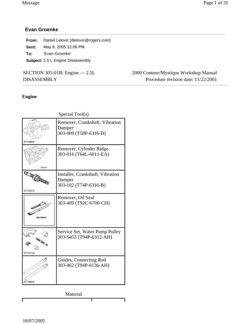
Special Tool(s)
Remover, Crankshaft, Vibration Damper 303-009 (T58P-6316-D)
Remover, Cylinder Ridge 303-016 (T64L-6011-EA)
Installer, Crankshaft, Vibration Damper 303-102 (T74P-6316-B)
Remover, Oil Seal 303-409 (T92C-6700-CH)
Service Set, Water Pump Pulley 303-S455 (T94P-6312-AH)
Guides, Connecting Rod 303-462 (T94P-6136-AH)
Material
Disassembly
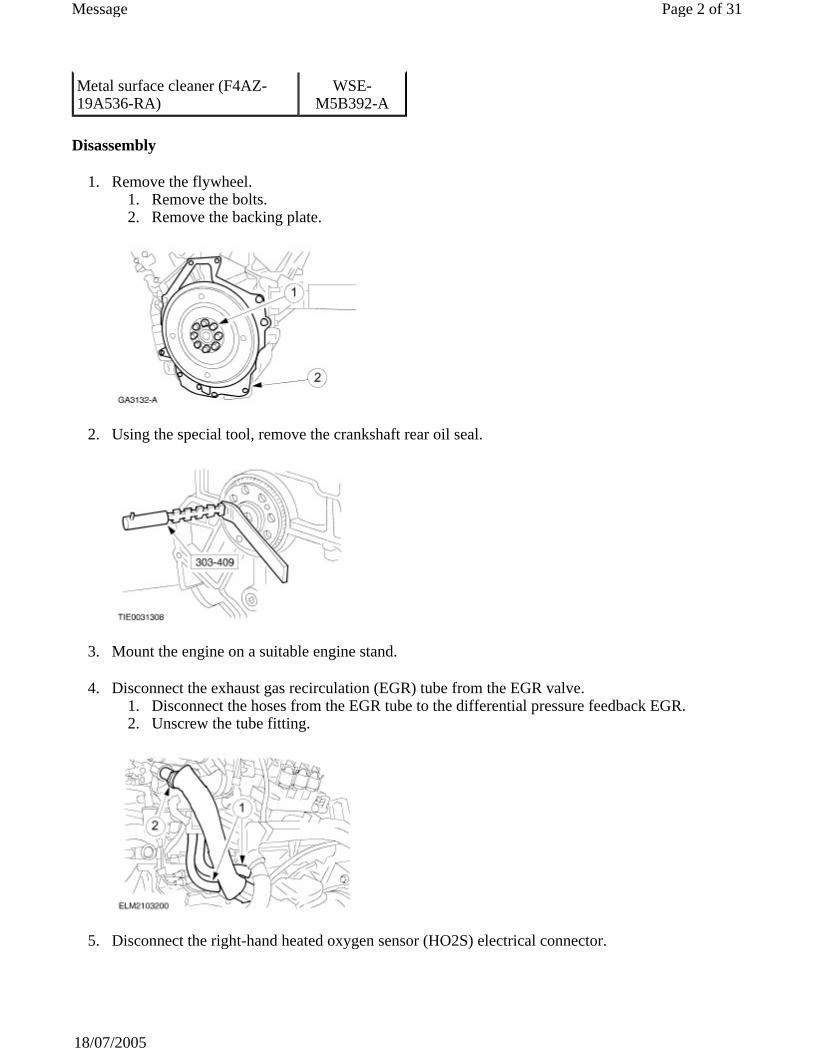
1. Remove the flywheel. 1. Remove the bolts. 2. Remove the backing plate.
2. Using the special tool, remove the crankshaft rear oil seal.
3. Mount the engine on a suitable engine stand.
4. Disconnect the exhaust gas recirculation (EGR) tube from the EGR valve. 1. Disconnect the hoses from the EGR tube to the differential pressure feedback EGR. 2. Unscrew the tube fitting.
5. Disconnect the right-hand heated oxygen sensor (HO2S) electrical connector.
Metal surface cleaner (F4AZ-19A536-RA)
WSE-M5B392-A
Page 2 of 31Message
18/07/2005
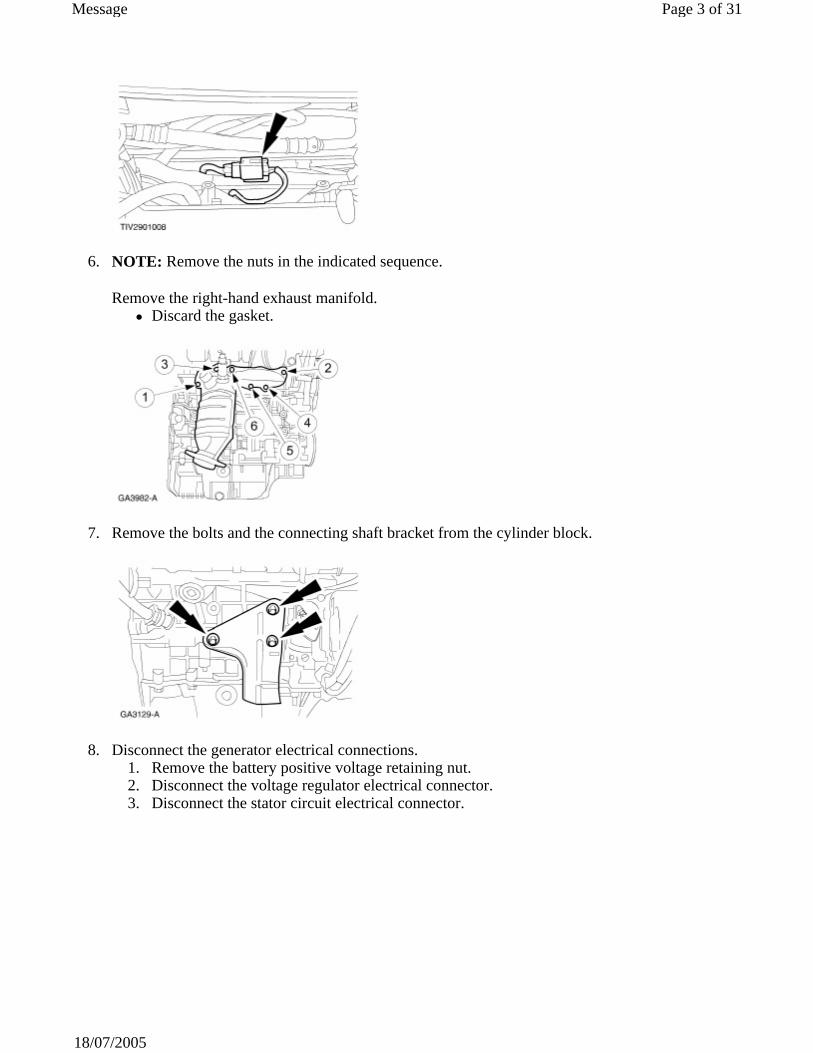
6. NOTE: Remove the nuts in the indicated sequence.
Remove the right-hand exhaust manifold. Discard the gasket.
7. Remove the bolts and the connecting shaft bracket from the cylinder block.
8. Disconnect the generator electrical connections. 1. Remove the battery positive voltage retaining nut. 2. Disconnect the voltage regulator electrical connector. 3. Disconnect the stator circuit electrical connector.
Page 3 of 31Message
18/07/2005

9. Disconnect the differential pressure feedback EGR electrical connector.
10. Disconnect the electronic vacuum regulator solenoid.
11. Disconnect the engine coolant temperature (ECT) sensor and remove the wiring harness.
12. Disconnect the intake manifold runner control (IMRC) cable. 1. Disconnect the IMRC cable from the retainer. 2. Disconnect the IMRC cable end.
Page 4 of 31Message
18/07/2005
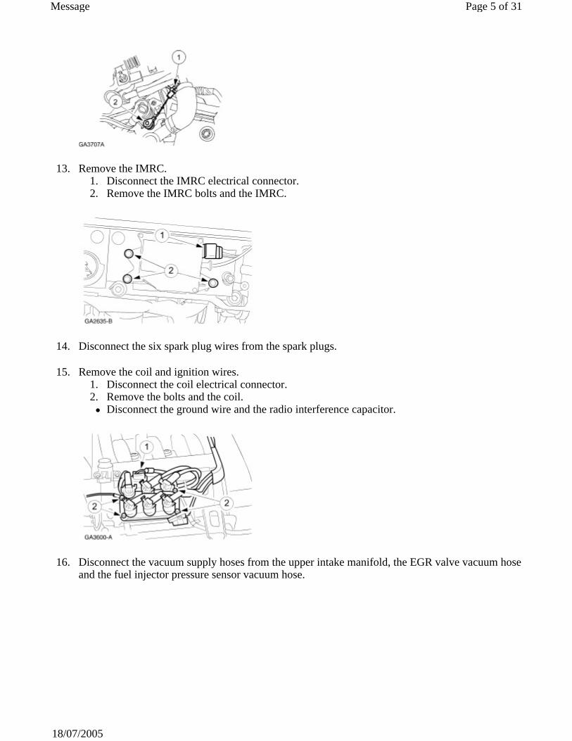
13. Remove the IMRC. 1. Disconnect the IMRC electrical connector. 2. Remove the IMRC bolts and the IMRC.
14. Disconnect the six spark plug wires from the spark plugs.
15. Remove the coil and ignition wires. 1. Disconnect the coil electrical connector. 2. Remove the bolts and the coil.
Disconnect the ground wire and the radio interference capacitor.
16. Disconnect the vacuum supply hoses from the upper intake manifold, the EGR valve vacuum hose and the fuel injector pressure sensor vacuum hose.
Page 5 of 31Message
18/07/2005

17. Disconnect the electronic vacuum regulator (EVR) hoses and remove the vacuum hose harness.
18. Disconnect the positive crankcase ventilation (PCV) hose from the throttle body.
19. Disconnect the throttle position (TP) sensor and the fuel injector pressure sensor electrical connectors.
20. Disconnect the idle air control (IAC) valve electrical connector.
Page 6 of 31Message
18/07/2005
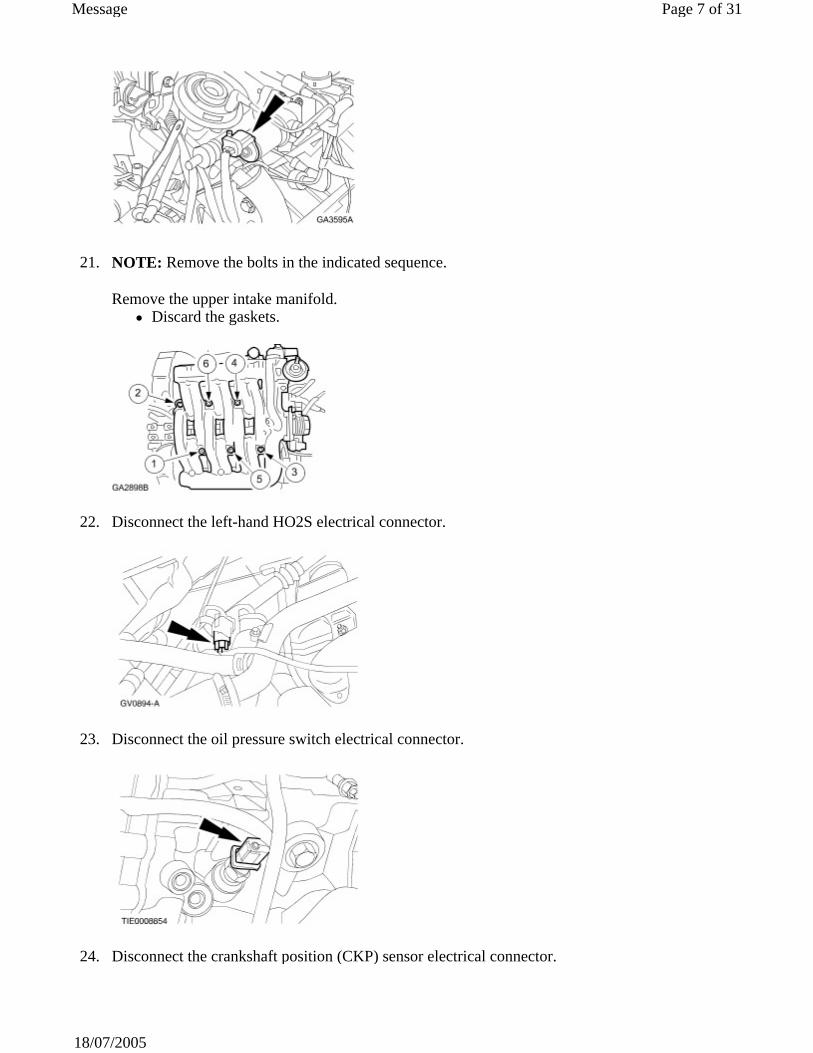
21. NOTE: Remove the bolts in the indicated sequence.
Remove the upper intake manifold. Discard the gaskets.
22. Disconnect the left-hand HO2S electrical connector.
23. Disconnect the oil pressure switch electrical connector.
24. Disconnect the crankshaft position (CKP) sensor electrical connector.
Page 7 of 31Message
18/07/2005
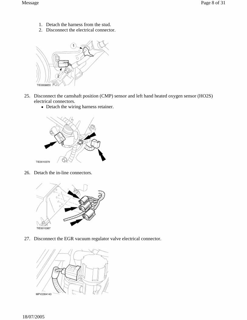
1. Detach the harness from the stud. 2. Disconnect the electrical connector.
25. Disconnect the camshaft position (CMP) sensor and left hand heated oxygen sensor (HO2S) electrical connectors.
Detach the wiring harness retainer.
26. Detach the in-line connectors.
27. Disconnect the EGR vacuum regulator valve electrical connector.
Page 8 of 31Message
18/07/2005
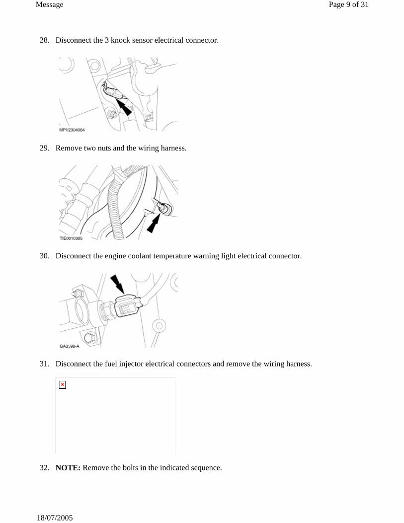
28. Disconnect the 3 knock sensor electrical connector.
29. Remove two nuts and the wiring harness.
30. Disconnect the engine coolant temperature warning light electrical connector.
31. Disconnect the fuel injector electrical connectors and remove the wiring harness.
32. NOTE: Remove the bolts in the indicated sequence.
Page 9 of 31Message
18/07/2005
Remove the lower intake manifold. Discard the gaskets.
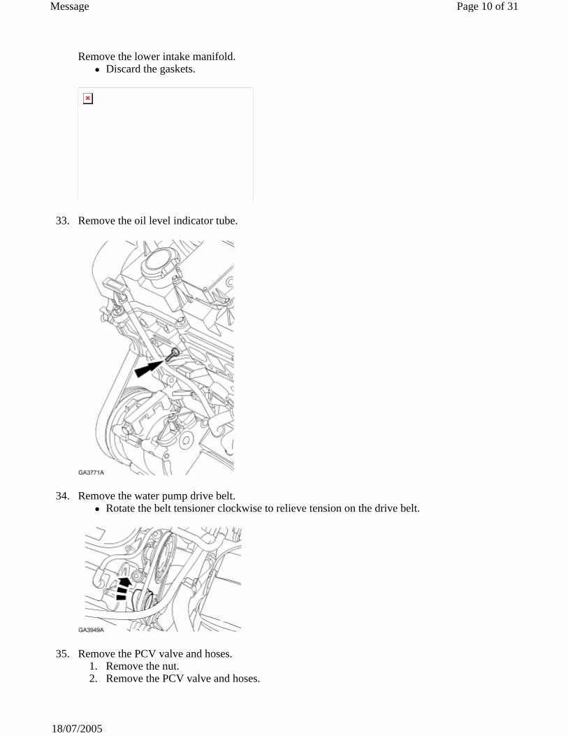
33. Remove the oil level indicator tube.
34. Remove the water pump drive belt. Rotate the belt tensioner clockwise to relieve tension on the drive belt.
35. Remove the PCV valve and hoses. 1. Remove the nut. 2. Remove the PCV valve and hoses.
Page 10 of 31Message
18/07/2005
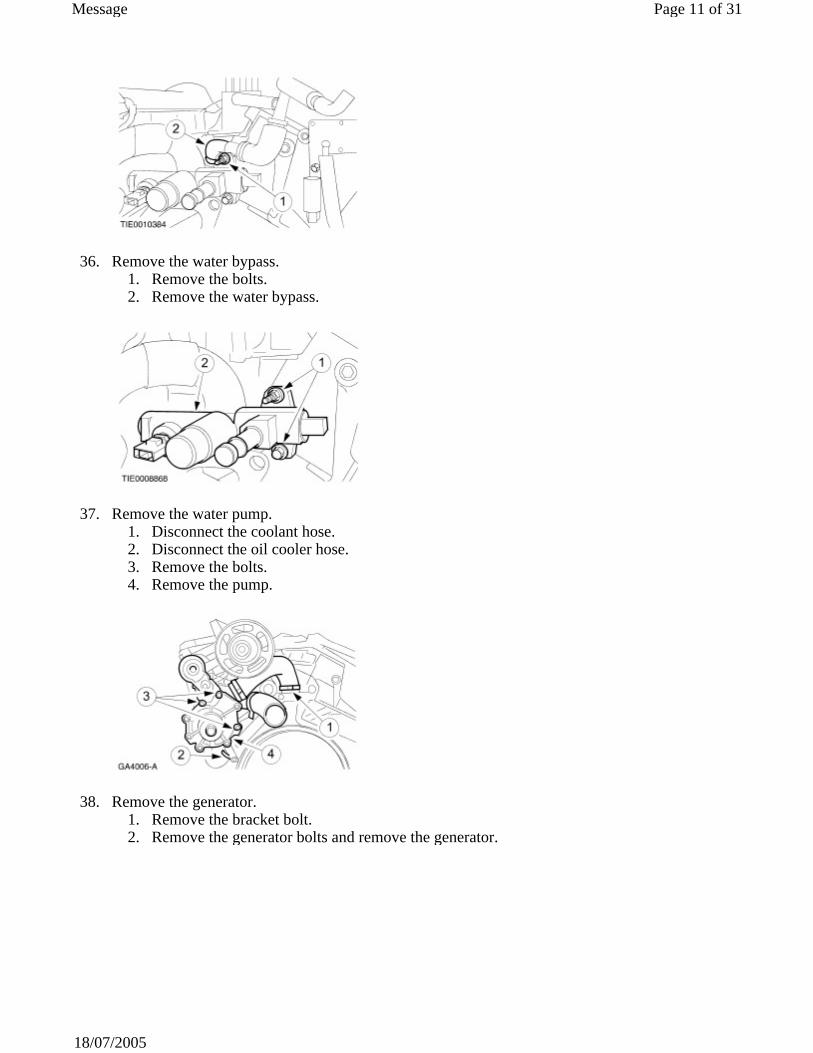
36. Remove the water bypass. 1. Remove the bolts. 2. Remove the water bypass.
37. Remove the water pump. 1. Disconnect the coolant hose. 2. Disconnect the oil cooler hose. 3. Remove the bolts. 4. Remove the pump.
38. Remove the generator. 1. Remove the bracket bolt. 2. Remove the generator bolts and remove the generator.
Page 11 of 31Message
18/07/2005

39. Remove the bolts and the generator bracket.
40. Remove the oil filter.
41. NOTE: Remove the bolts in the indicated sequence.
Remove the left-hand exhaust manifold. Discard the gasket.
42. Remove the oil cooler (SVT only).
Page 12 of 31Message
18/07/2005
1. Remove the oil cooler bolt. 2. Remove the oil pressure switch.
43. Drain engine oil.
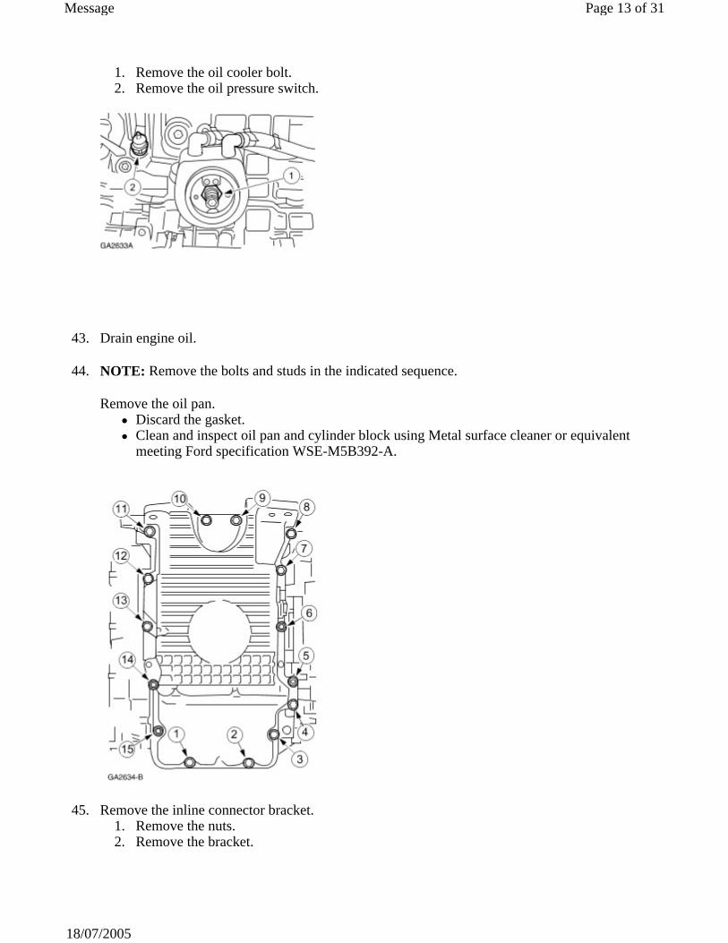
44. NOTE: Remove the bolts and studs in the indicated sequence.
Remove the oil pan. Discard the gasket. Clean and inspect oil pan and cylinder block using Metal surface cleaner or equivalent meeting Ford specification WSE-M5B392-A.
45. Remove the inline connector bracket. 1. Remove the nuts. 2. Remove the bracket.
Page 13 of 31Message
18/07/2005

46. NOTE: Remove the bolts and studs in the indicated sequence.
Remove the cylinder head covers. Discard the gaskets.
47. Using the special tools, remove the water pump drive pulley. 1. Install the special tool. 2. Install the special tool. 3. Remove the water pump pulley.
Page 14 of 31Message
18/07/2005
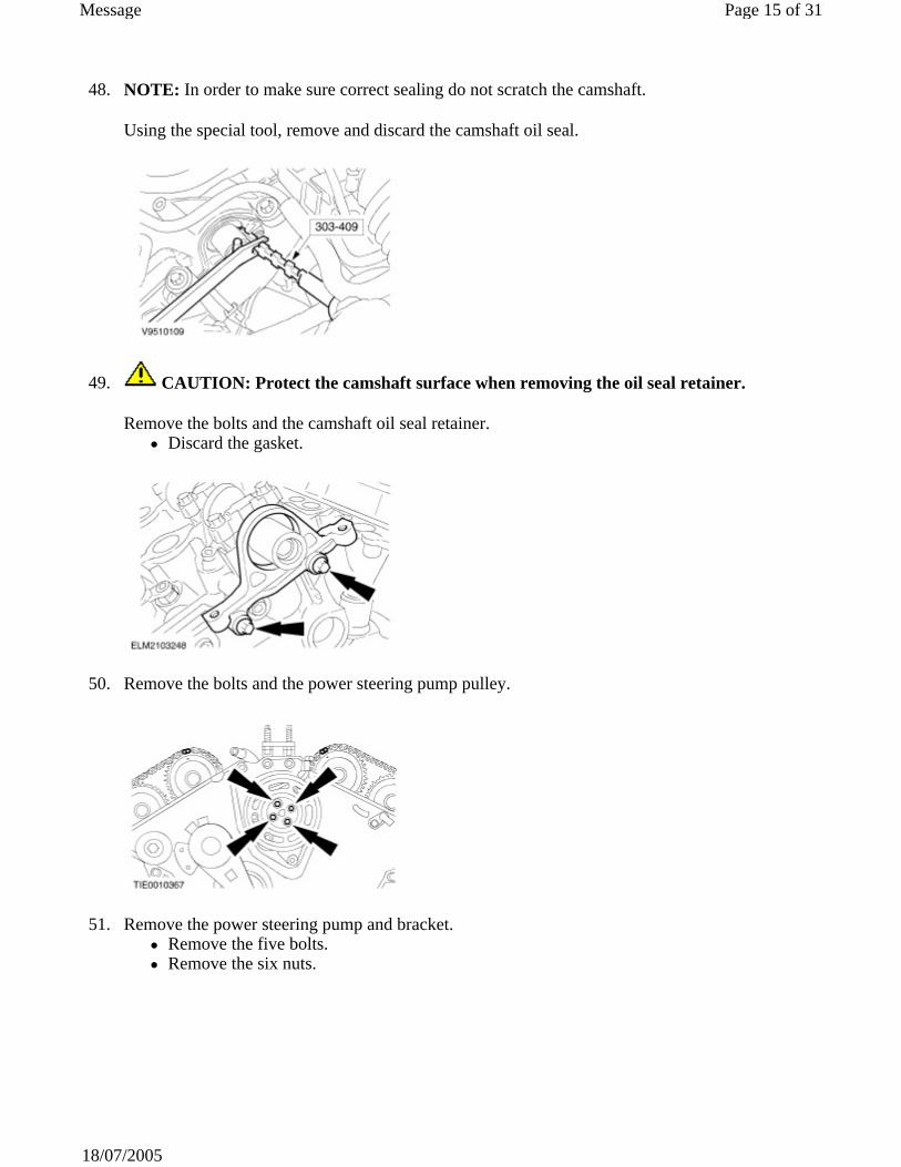
48. NOTE: In order to make sure correct sealing do not scratch the camshaft.
Using the special tool, remove and discard the camshaft oil seal.
49. CAUTION: Protect the camshaft surface when removing the oil seal retainer.
Remove the bolts and the camshaft oil seal retainer. Discard the gasket.
50. Remove the bolts and the power steering pump pulley.
51. Remove the power steering pump and bracket. Remove the five bolts. Remove the six nuts.
Page 15 of 31Message
18/07/2005
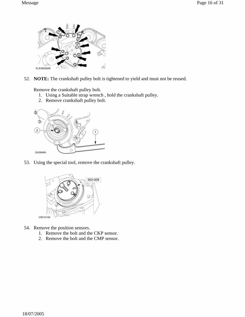
52. NOTE: The crankshaft pulley bolt is tightened to yield and must not be reused.
Remove the crankshaft pulley bolt. 1. Using a Suitable strap wrench , hold the crankshaft pulley. 2. Remove crankshaft pulley bolt.
53. Using the special tool, remove the crankshaft pulley.
54. Remove the position sensors. 1. Remove the bolt and the CKP sensor. 2. Remove the bolt and the CMP sensor.
Page 16 of 31Message
18/07/2005
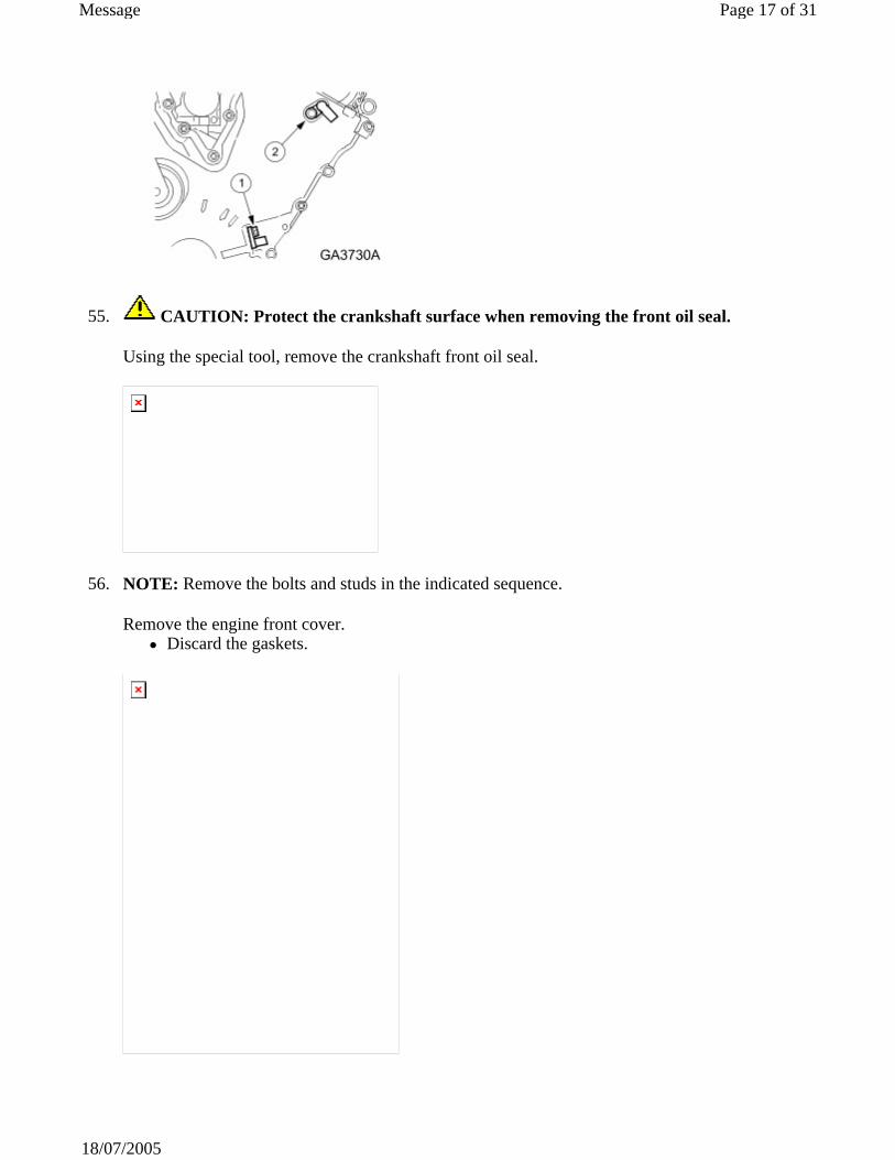
55. CAUTION: Protect the crankshaft surface when removing the front oil seal.
Using the special tool, remove the crankshaft front oil seal.
56. NOTE: Remove the bolts and studs in the indicated sequence.
Remove the engine front cover. Discard the gaskets.
Page 17 of 31Message
18/07/2005
57. CAUTION: This pulse wheel has two keyway slots and is used in several different engines. Install the pulse wheel in the keyway slot stamped 25, color coded blue.
Remove the CKP sensor pulse wheel.
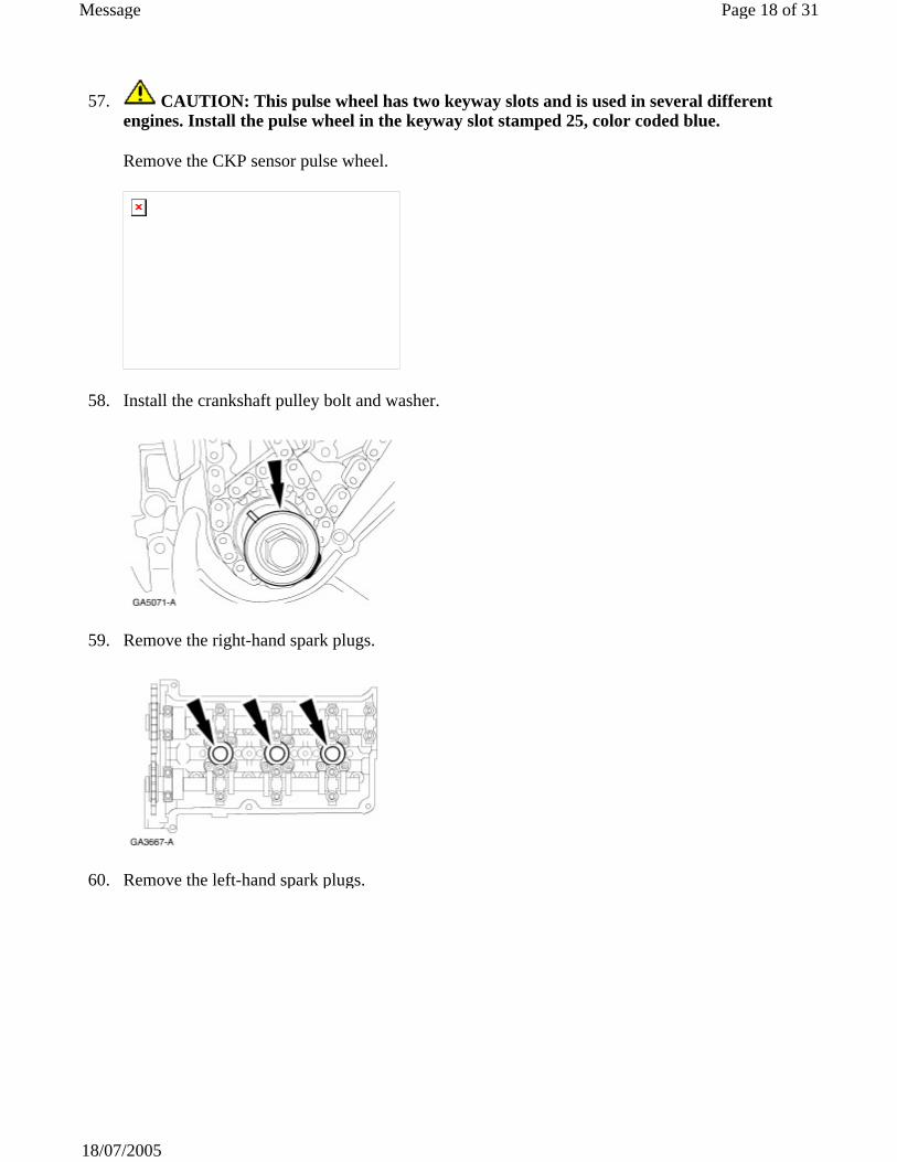
58. Install the crankshaft pulley bolt and washer.
59. Remove the right-hand spark plugs.
60. Remove the left-hand spark plugs.
Page 18 of 31Message
18/07/2005
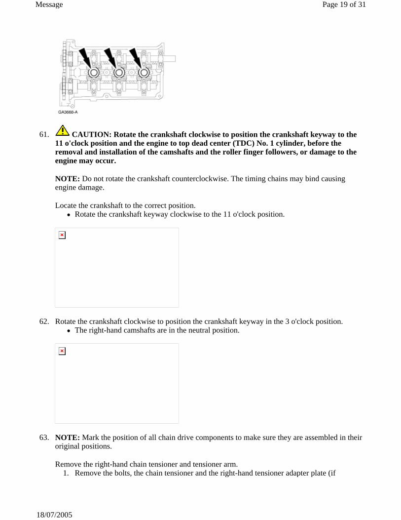
61. CAUTION: Rotate the crankshaft clockwise to position the crankshaft keyway to the 11 o'clock position and the engine to top dead center (TDC) No. 1 cylinder, before the removal and installation of the camshafts and the roller finger followers, or damage to the engine may occur.
NOTE: Do not rotate the crankshaft counterclockwise. The timing chains may bind causing engine damage.
Locate the crankshaft to the correct position. Rotate the crankshaft keyway clockwise to the 11 o'clock position.
62. Rotate the crankshaft clockwise to position the crankshaft keyway in the 3 o'clock position. The right-hand camshafts are in the neutral position.
63. NOTE: Mark the position of all chain drive components to make sure they are assembled in their original positions.
Remove the right-hand chain tensioner and tensioner arm. 1. Remove the bolts, the chain tensioner and the right-hand tensioner adapter plate (if
Page 19 of 31Message
18/07/2005

equipped). 2. Remove the timing chain tensioner arm.
64. Remove the right-hand timing chain. 1. Remove the bolts and the fixed chain guide. 2. Remove the right-hand timing chain.
65. CAUTION: The cylinder head and the camshaft bearing caps are numbered to make sure they are reassembled in their original position. When removed, keep the bearing caps with the cylinder head they were removed from. Do not mix the caps.
NOTE: Camshaft bearing caps are dowelled to the cylinder head. If necessary, use a plastic mallet to loosen the caps.
NOTE: Remove camshaft bearing thrust caps No. 1R and 5R first. Do not loosen any other bolts until the thrust caps are removed.
NOTE: Loosen the remaining bolts and bearing caps in the indicated sequence in several passes to allow the camshafts to gradually raise from the cylinder head.
Page 20 of 31Message
18/07/2005
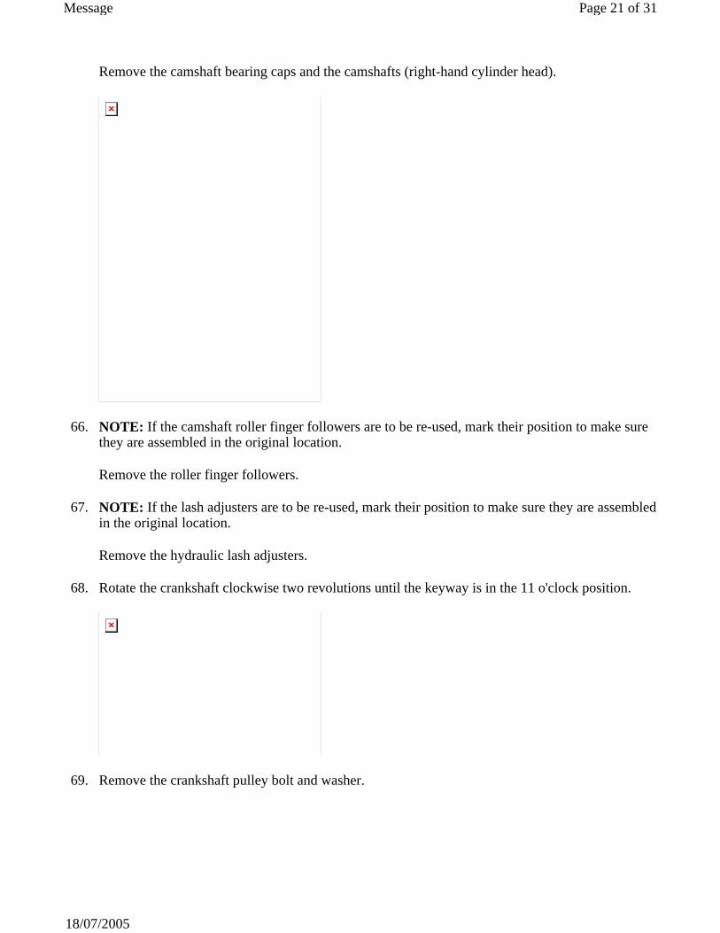
Remove the camshaft bearing caps and the camshafts (right-hand cylinder head).
66. NOTE: If the camshaft roller finger followers are to be re-used, mark their position to make sure they are assembled in the original location.
Remove the roller finger followers.
67. NOTE: If the lash adjusters are to be re-used, mark their position to make sure they are assembled in the original location.
Remove the hydraulic lash adjusters.
68. Rotate the crankshaft clockwise two revolutions until the keyway is in the 11 o'clock position.
69. Remove the crankshaft pulley bolt and washer.
Page 21 of 31Message
18/07/2005
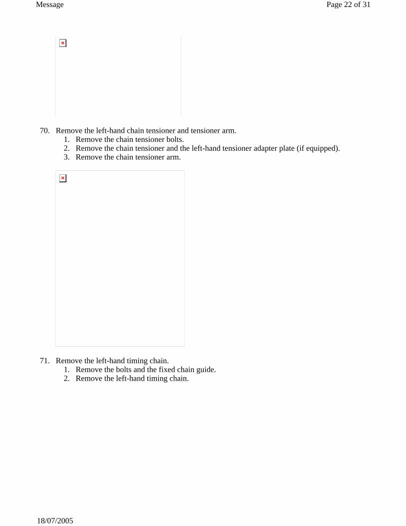
70. Remove the left-hand chain tensioner and tensioner arm. 1. Remove the chain tensioner bolts. 2. Remove the chain tensioner and the left-hand tensioner adapter plate (if equipped). 3. Remove the chain tensioner arm.
71. Remove the left-hand timing chain. 1. Remove the bolts and the fixed chain guide. 2. Remove the left-hand timing chain.
Page 22 of 31Message
18/07/2005

72. CAUTION: The cylinder head and the camshaft bearing caps are numbered to make sure they are reassembled in their original position. When removed, keep the bearing caps with the cylinder head they were removed from. Do not mix the caps.
NOTE: Remove camshaft bearing thrust caps No. 1L and 5L first. Do not loosen any of the other bolts until the thrust caps are removed.
NOTE: Loosen the remaining bolts and bearing caps in the indicated sequence in several passes to allow the camshafts to gradually raise from the cylinder head.
Remove the camshaft bearing caps and the camshafts (left-hand cylinder head).
Page 23 of 31Message
18/07/2005
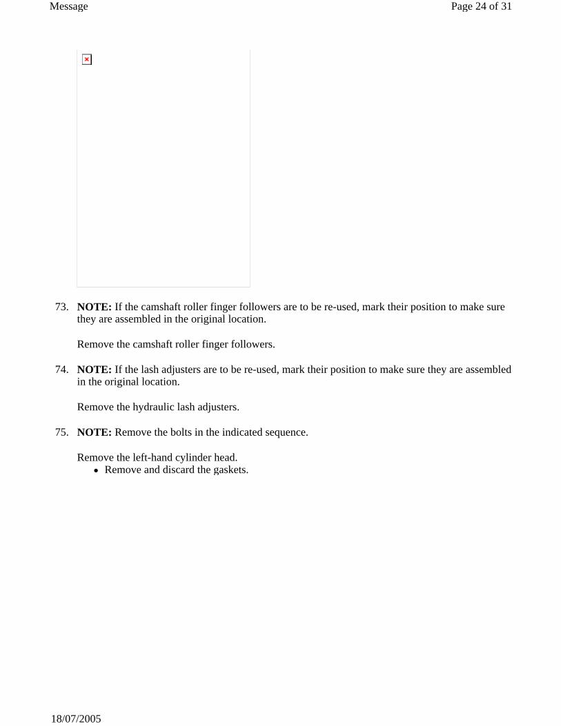
73. NOTE: If the camshaft roller finger followers are to be re-used, mark their position to make sure they are assembled in the original location.
Remove the camshaft roller finger followers.
74. NOTE: If the lash adjusters are to be re-used, mark their position to make sure they are assembled in the original location.
Remove the hydraulic lash adjusters.
75. NOTE: Remove the bolts in the indicated sequence.
Remove the left-hand cylinder head. Remove and discard the gaskets.
Page 24 of 31Message
18/07/2005
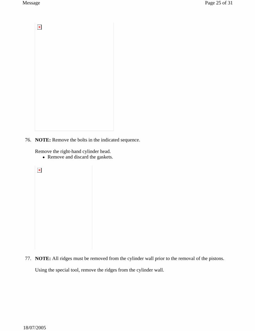
76. NOTE: Remove the bolts in the indicated sequence.
Remove the right-hand cylinder head. Remove and discard the gaskets.
77. NOTE: All ridges must be removed from the cylinder wall prior to the removal of the pistons.
Using the special tool, remove the ridges from the cylinder wall.
Page 25 of 31Message
18/07/2005
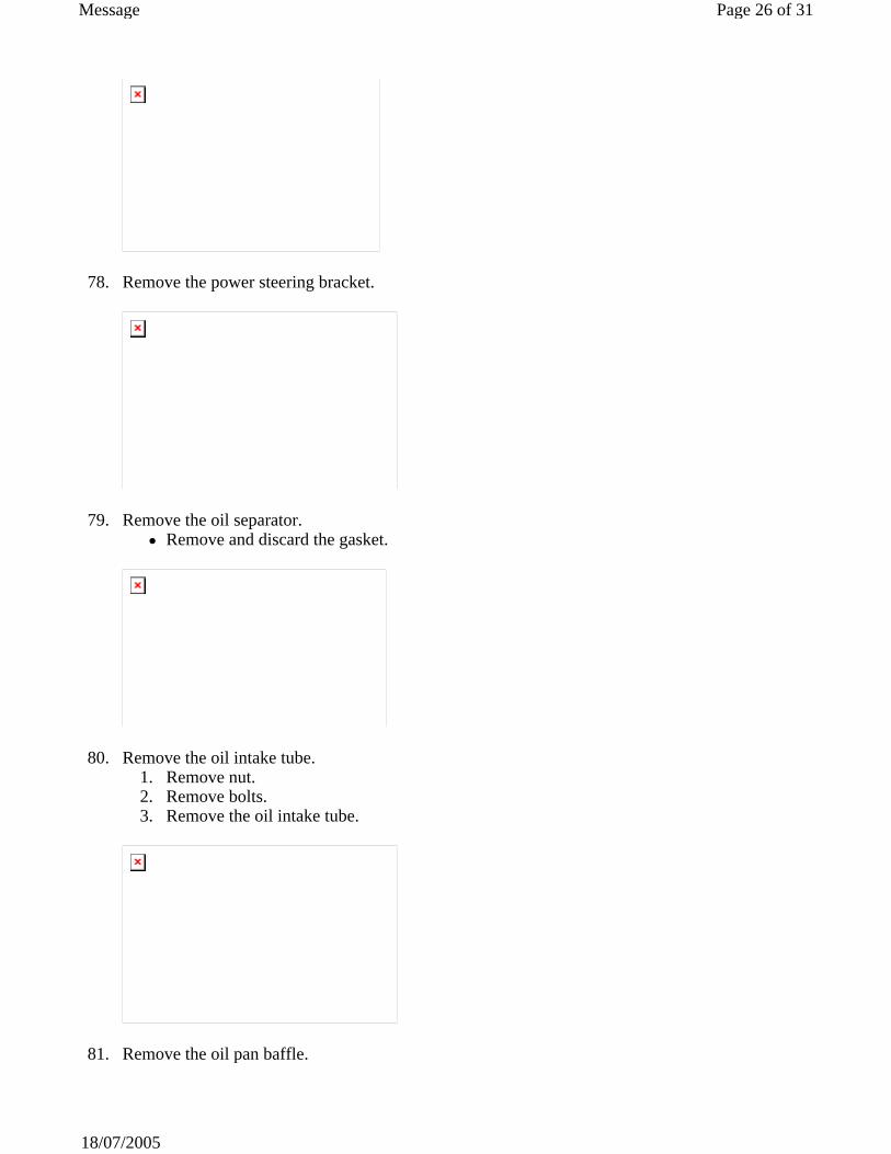
78. Remove the power steering bracket.
79. Remove the oil separator. Remove and discard the gasket.
80. Remove the oil intake tube. 1. Remove nut. 2. Remove bolts. 3. Remove the oil intake tube.
81. Remove the oil pan baffle.
Page 26 of 31Message
18/07/2005
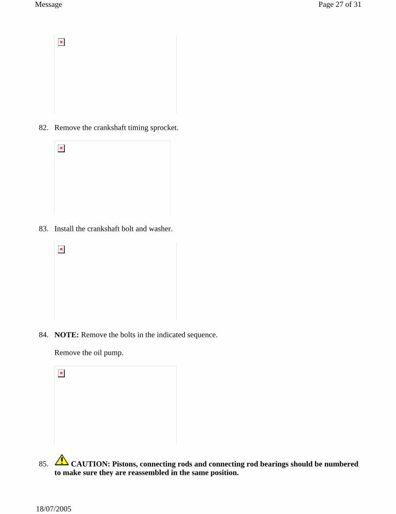
82. Remove the crankshaft timing sprocket.
83. Install the crankshaft bolt and washer.
84. NOTE: Remove the bolts in the indicated sequence.
Remove the oil pump.
85. CAUTION: Pistons, connecting rods and connecting rod bearings should be numbered to make sure they are reassembled in the same position.
Page 27 of 31Message
18/07/2005

NOTE: Mark the position of the connecting rod caps to the connecting rods to make sure of correct installation.
Rotate the crankshaft to locate the pistons at the bottom of their travel.
86. Remove the connecting rod bolts, caps and lower connecting rod bearings.
87. CAUTION: Use appropriate protection to prevent damage to the crankshaft bearing journals and cylinder bore surfaces.
Install the special tool to the connecting rods.
88. CAUTION: Care should be taken not to damage the connecting rod and cap joint face surfaces or possible engine damage may occur. Avoid contaminating the fracture joint surfaces with dirt or grease.
NOTE: Re-attach the connecting rods and caps after removal to avoid mismatch.
Remove the pistons.
Page 28 of 31Message
18/07/2005
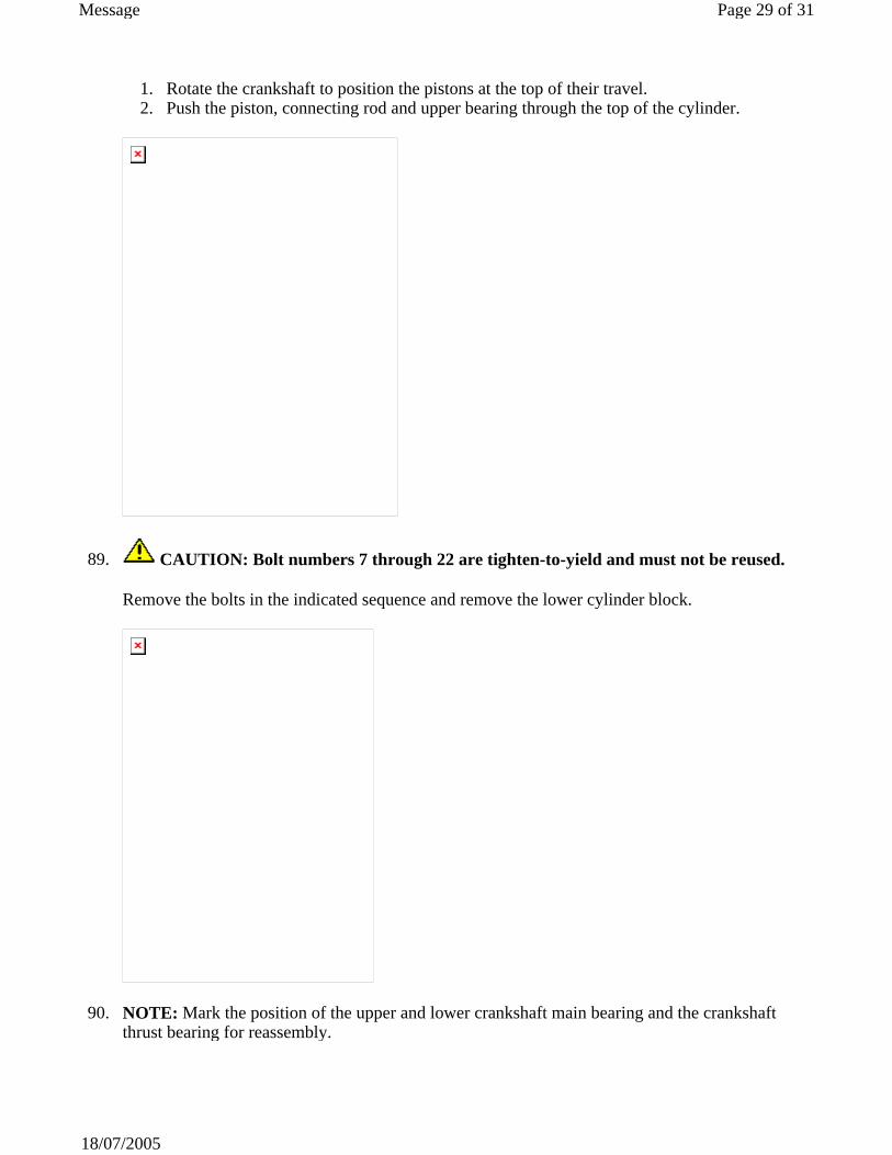
1. Rotate the crankshaft to position the pistons at the top of their travel. 2. Push the piston, connecting rod and upper bearing through the top of the cylinder.
89. CAUTION: Bolt numbers 7 through 22 are tighten-to-yield and must not be reused.
Remove the bolts in the indicated sequence and remove the lower cylinder block.
90. NOTE: Mark the position of the upper and lower crankshaft main bearing and the crankshaft thrust bearing for reassembly.
Page 29 of 31Message
18/07/2005
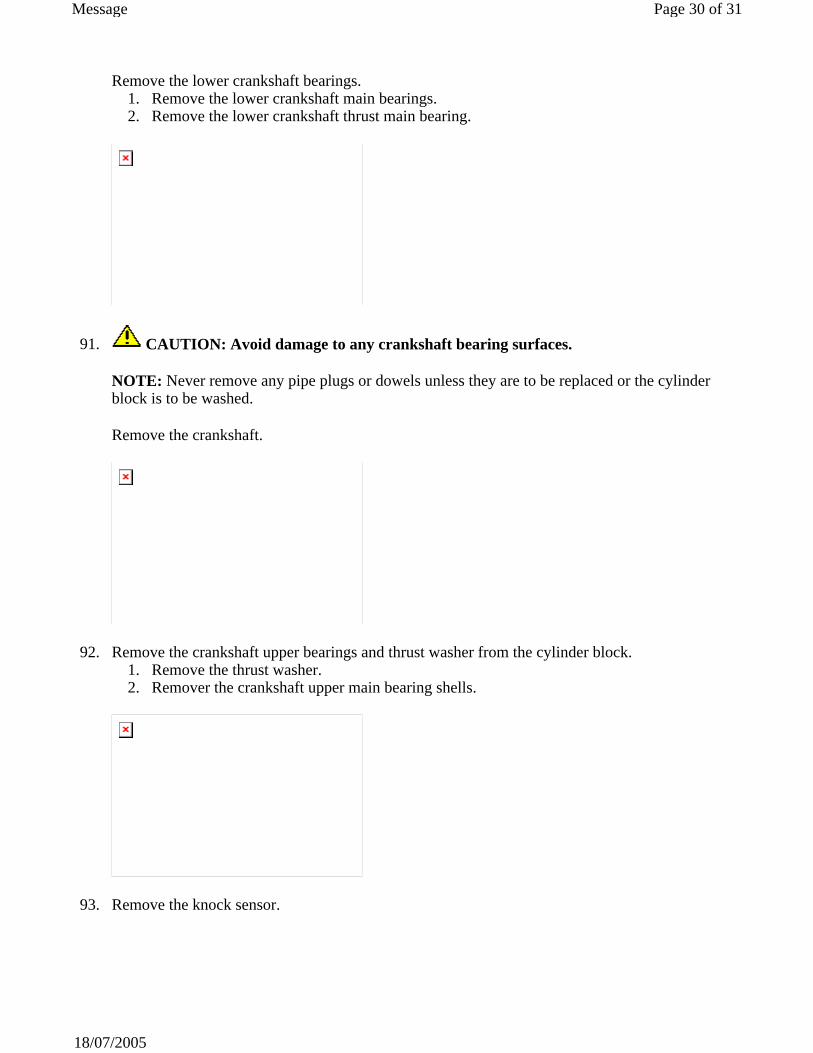
Remove the lower crankshaft bearings. 1. Remove the lower crankshaft main bearings. 2. Remove the lower crankshaft thrust main bearing.
91. CAUTION: Avoid damage to any crankshaft bearing surfaces.
NOTE: Never remove any pipe plugs or dowels unless they are to be replaced or the cylinder block is to be washed.
Remove the crankshaft.
92. Remove the crankshaft upper bearings and thrust washer from the cylinder block. 1. Remove the thrust washer. 2. Remover the crankshaft upper main bearing shells.
93. Remove the knock sensor.
Page 30 of 31Message
18/07/2005
94. WARNING: Eye protection is required during the use of compressed air. Failure to follow this instruction may result in personal injury.
Clean the cylinder block with a soap and water solution. Dry the cylinder block completely with compressed air.
Page 31 of 31Message
18/07/2005