cylinder head, disassembly/assembly - open auction
TRANSCRIPT
Service Information
Document Title: Function Group: Information Type: Date:Cylinder head, disassembly/assembly
211 Service Information 2014/3/30
Profile:CEX, EW60C [GB]
Cylinder head, disassembly/assembly
Op nbr 2111
Disassemble in the order of the numbers shown in the illustration. (service point)
1. Remove the alternator assembly. (service point 1)
2. Remove the fan, pulley and V–belt.
3. Remove the thermostat case. (service point 2)
4. Remove the fuel filter and fuel oil piping. (service point 3)
5. Remove the oil level gauge assembly.
6. Remove the oil filter. (service point 4)
7. Remove the fuel injection pipes. (service point 5)
8. Remove the intake manifold assembly.
9. Remove the exhaust manifold assembly.
10. Remove the rocker cover.
11. Remove the rocker shaft assembly, push rods and valve caps. (service point 6)
12. Remove the cylinder head assembly and head gasket. (service point 7)
13. Remove the fuel injection valves and fuel return pipe. (service point 8)
14. Remove the intake/exhaust valves, stem seals and valve springs. (service point 9)
15. Remove the rocker arms from the rocker shaft.For assembly, reverse the procedure.
Service pointsPoint 1
Disassembly :
Loosen the mounting screw while supporting the alternator.
NOTE!Do not tilt the alternator towards the cylinder block in a haste since it may damage the alternator or pinch a finger.
Reassembly:
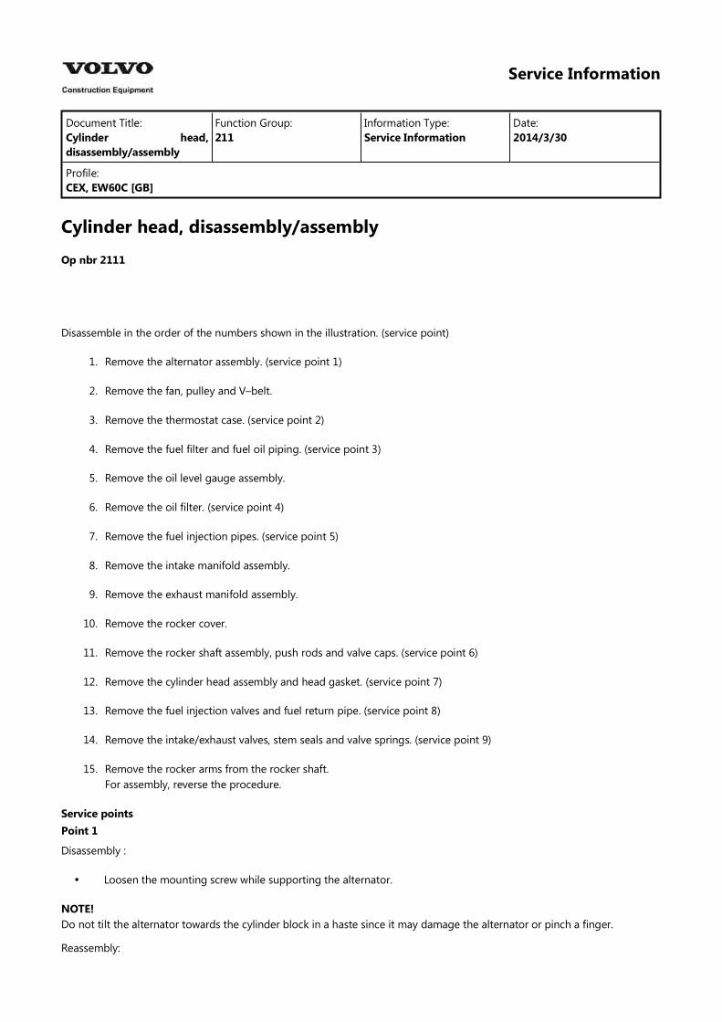
The belt deflection shall be checked according to Inspection after initial 50 hours operation.Replace the belt with a new one if cracked, worn or damaged.
Figure 2Adjustment, V-belt tension
A.B.C.
BarAdjusterAlternator
Carefully prevent the belt from being smeared with oil or grease.
Point 2
Reassembly :
Check the thermostat function.
Point 3
Reassemble :
Replace the fuel filter element with a new one.
Disassemble :
Cover the fuel pipe opening with tape to prevent intrusion of foreign matters.
Point 4
Reassemble :
Replace the oil filter with a new one.After fully tightening the filter manually, retighten it with a filter wrench by 3/4 turn.
Point 5
Disassemble :
Cover the fuel injection pipe and pump inlets and outlets with tape or the like to prevent intrusion of foreign matter.
Point 6
Disassemble :
Keep the removed push rods by attaching tags showing corresponding cylinder numbers.
Reassemble :
Always apply oil to the contact portions of the push rods and valve clearance adjusting screws.
Point 7
Disassemble :
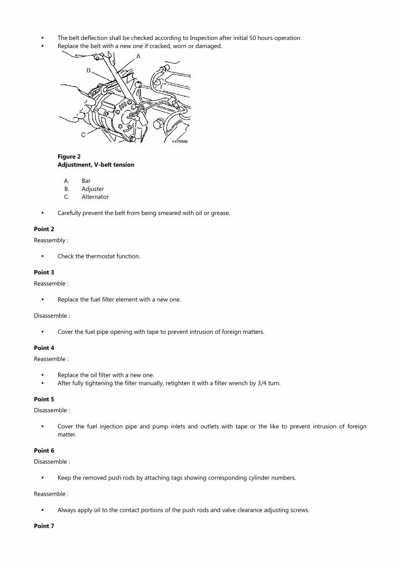
Loosen the cylinder head screws in two steps in the illustrated order.
Figure 3Head screw disassembly order
1. Fan side
Place the cylinder head assembly on cardboard to prevent any damage to the combustion face.
Reassemble :
Replace the head gasket with a new one.
Figure 4Head screw tightening order
1. Fan side
Uniformly install the head screws manually after applying oil on the threads and seat portions.They shall be tightened in two steps in the reverse of the order for disassembly.Tightening torque :
First step : 5 ~ 6 kgf·m (36.1 ~ 43.3 lbf·ft)Second step : 10.5 ~ 11.5 kgf·m (75.8 ~ 83.0 lbf·ft)
Point 8
Disassemble :
Carefully remove the fuel injection valve so as not to leave the tip end protector from being left inside the cylinder.
Reassemble :
Replace the fuel injection valve protector with a new one.
Point 9
Disassemble :
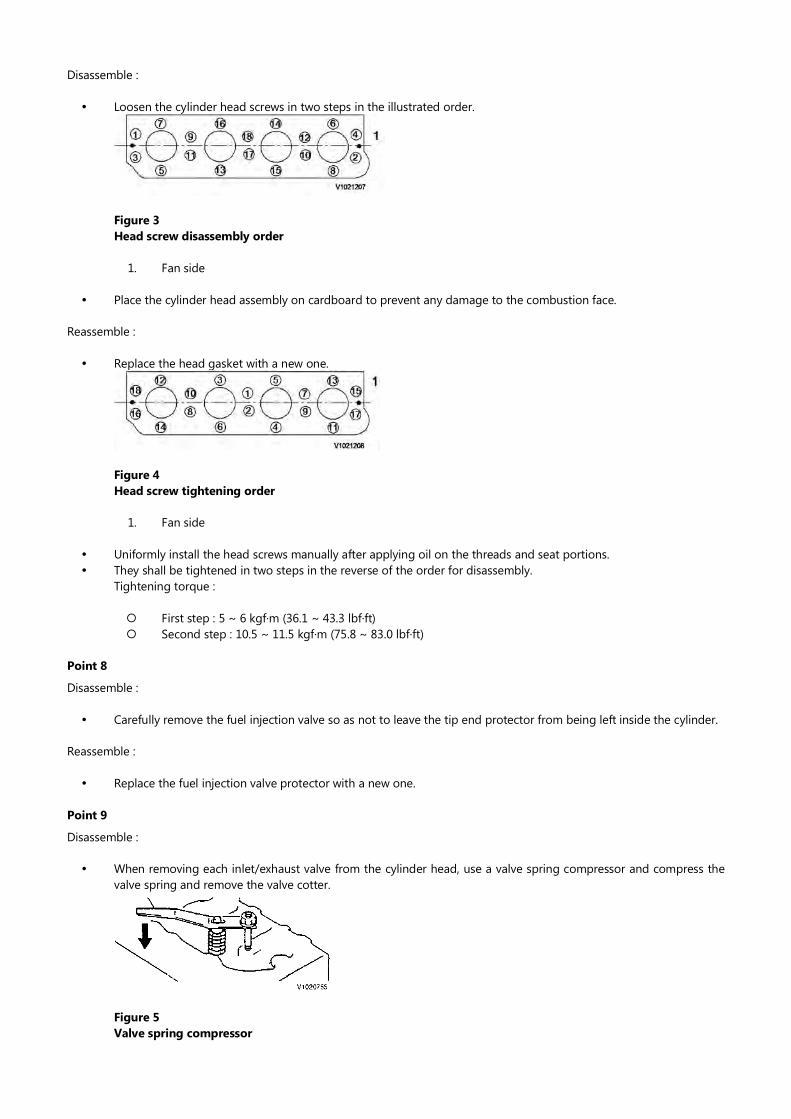
When removing each inlet/exhaust valve from the cylinder head, use a valve spring compressor and compress the valve spring and remove the valve cotter.
Figure 5Valve spring compressor
Keep each removed inlet/exhaust valve after attaching a tag showing the corresponding cylinder number.If cotter burr is seen at the shaft of each inlet/exhaust valve stem, remove it with an oilstone and extract the valve from the cylinder head.
Reassemble :
Replace the stem seal with a new one when an intake/exhaust valve is disassembled.Carefully install each valve after oil application so as not to damage the stem seal.Different stem seals are provided for the intake and exhaust valves. Do not confuse them since those for exhaust valves are marked with yellow paint.After assembling the intake/exhaust valve, stem seal, valve spring, seat, and cotter, tap the head of the valve stem lightly for settling.Do not forget to install the valve cap.
Service Information
Document Title: Function Group: Information Type: Date:Cylinder head, parts inspection and measurement
211 Service Information 2014/3/30
Profile:CEX, EW60C [GB]
Cylinder head, parts inspection and measurementCylinder headClean the cylinder head, mainly the combustion surface, valve seats and intake/exhaust ports, remove carbon deposit and bonding agent, and check the surface state.
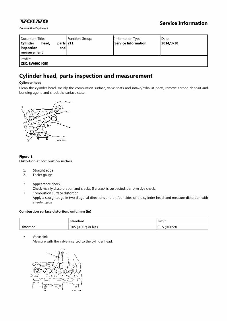
Figure 1Distortion at combustion surface
1.2.
Straight edgeFeeler gauge
Appearance checkCheck mainly discoloration and cracks. If a crack is suspected, perform dye check.Combustion surface distortionApply a straightedge in two diagonal directions and on four sides of the cylinder head, and measure distortion with a feeler gage
Combustion surface distortion, unit: mm (in)
Standard Limit
Distortion 0.05 (0.002) or less 0.15 (0.0059)
Valve sinkMeasure with the valve inserted to the cylinder head.
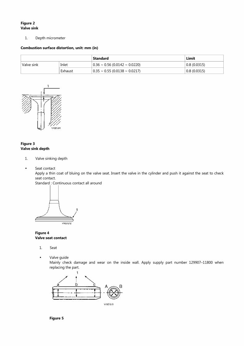
Figure 2Valve sink
1. Depth micrometer
Combustion surface distortion, unit: mm (in)
Standard Limit
Inlet 0.36 ∼ 0.56 (0.0142 ∼ 0.0220) 0.8 (0.0315)Valve sink
Exhaust 0.35 ∼ 0.55 (0.0138 ∼ 0.0217) 0.8 (0.0315)
Figure 3Valve sink depth
1. Valve sinking depth
Seat contactApply a thin coat of bluing on the valve seat. Insert the valve in the cylinder and push it against the seat to check seat contact.Standard : Continuous contact all around
Figure 4Valve seat contact
1. Seat
Valve guideMainly check damage and wear on the inside wall. Apply supply part number 129907–11800 when replacing the part.
Figure 5
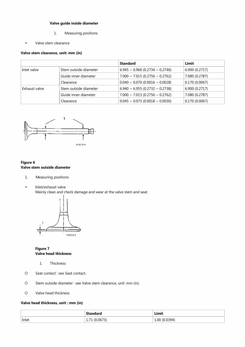
Valve guide inside diameter
1. Measuring positions
Valve stem clearance
Valve stem clearance, unit: mm (in)
Standard Limit
Stem outside diameter 6.945 ~ 6.960 (0.2734 ~ 0.2740) 6.900 (0.2717)Inlet valve
Guide inner diameter 7.000 ~ 7.015 (0.2756 ~ 0.2762) 7.080 (0.2787)
Clearance 0.040 ~ 0.070 (0.0016 ~ 0.0028) 0.170 (0.0067)
Stem outside diameter 6.940 ~ 6.955 (0.2732 ~ 0.2738) 6.900 (0.2717)Exhaust valve
Guide inner diameter 7.000 ~ 7.015 (0.2756 ~ 0.2762) 7.080 (0.2787)
Clearance 0.045 ~ 0.075 (0.0018 ~ 0.0030) 0.170 (0.0067)
Figure 6Valve stem outside diameter
1. Measuring positions
Inlet/exhaust valveMainly clean and check damage and wear at the valve stem and seat.
Figure 7Valve head thickness
1. Thickness
Seat contact : see Seat contact.
Stem outside diameter : see Valve stem clearance, unit: mm (in).
Valve head thickness
Valve head thickness, unit : mm (in)
Standard Limit
Inlet 1.71 (0.0673) 1.00 (0.0394)
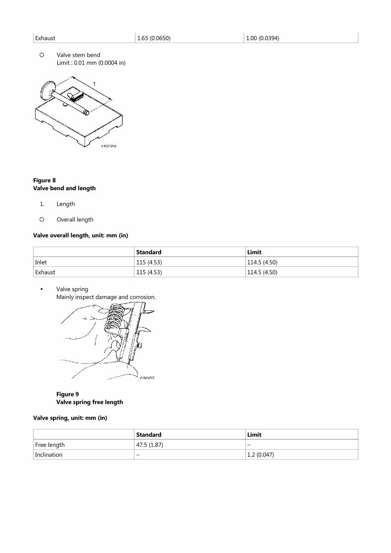
Exhaust 1.65 (0.0650) 1.00 (0.0394)
Valve stem bendLimit : 0.01 mm (0.0004 in)
Figure 8Valve bend and length
1. Length
Overall length
Valve overall length, unit: mm (in)
Standard Limit
Inlet 115 (4.53) 114.5 (4.50)
Exhaust 115 (4.53) 114.5 (4.50)
Valve springMainly inspect damage and corrosion.
Figure 9Valve spring free length
Valve spring, unit: mm (in)
Standard Limit
Free length 47.5 (1.87) –
Inclination – 1.2 (0.047)
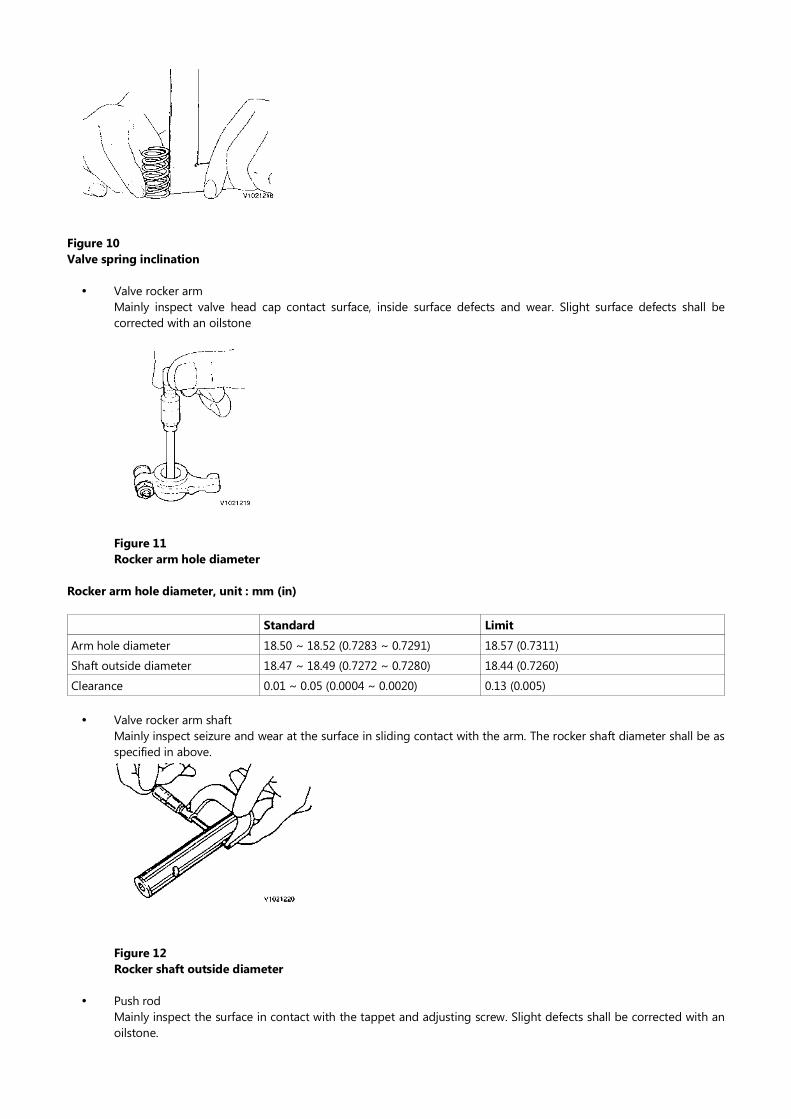
Figure 10Valve spring inclination
Valve rocker armMainly inspect valve head cap contact surface, inside surface defects and wear. Slight surface defects shall be corrected with an oilstone
Figure 11Rocker arm hole diameter
Rocker arm hole diameter, unit : mm (in)
Standard Limit
Arm hole diameter 18.50 ~ 18.52 (0.7283 ~ 0.7291) 18.57 (0.7311)
Shaft outside diameter 18.47 ~ 18.49 (0.7272 ~ 0.7280) 18.44 (0.7260)
Clearance 0.01 ~ 0.05 (0.0004 ~ 0.0020) 0.13 (0.005)
Valve rocker arm shaftMainly inspect seizure and wear at the surface in sliding contact with the arm. The rocker shaft diameter shall be as specified in above.
Figure 12Rocker shaft outside diameter
Push rodMainly inspect the surface in contact with the tappet and adjusting screw. Slight defects shall be corrected with an oilstone.
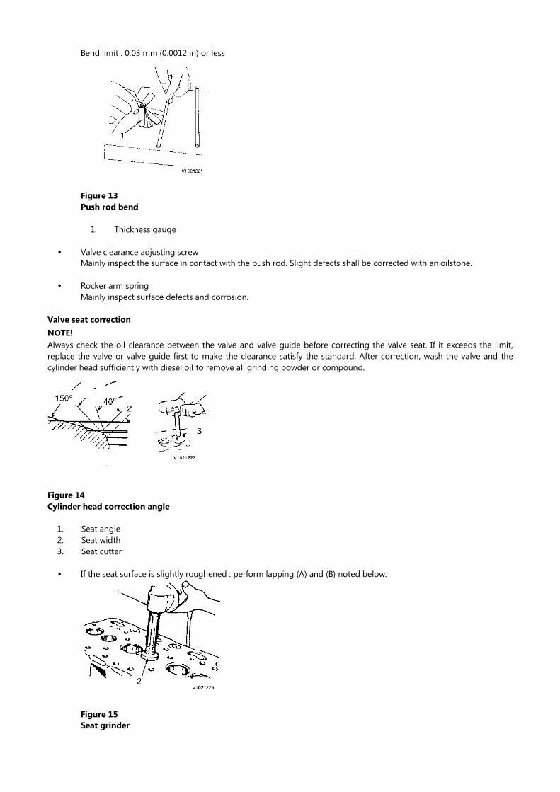
Bend limit : 0.03 mm (0.0012 in) or less
Figure 13Push rod bend
1. Thickness gauge
Valve clearance adjusting screwMainly inspect the surface in contact with the push rod. Slight defects shall be corrected with an oilstone.
Rocker arm springMainly inspect surface defects and corrosion.
Valve seat correctionNOTE!Always check the oil clearance between the valve and valve guide before correcting the valve seat. If it exceeds the limit, replace the valve or valve guide first to make the clearance satisfy the standard. After correction, wash the valve and the cylinder head sufficiently with diesel oil to remove all grinding powder or compound.
Figure 14Cylinder head correction angle
1.2.3.
Seat angleSeat widthSeat cutter
If the seat surface is slightly roughened : perform lapping (A) and (B) noted below.
Figure 15Seat grinder

1.2.
GrinderGrindstone
If the seat is heavily roughened but the width is almost normal, correct with a seat grinder or seat cutter first. Then perform lapping (A) and (B) noted below.
Seat cutter angle, unit: degree
Inlet Exhaust
Seat cutter angle 120 90
If the seat is heavily roughened and the width is much enlarged, grind the seat inner surface with a seat grinder whose center angle is 40°, then grind the seat outer surface with a grinder whose center angle is 150° to make the seat width match the standard. Then perform seat correction as described above, and then carry out lapping (A) and (B) noted below.
Grinding wheel angle, unit: degree
θ1 θ2
Grinding wheel angle 40 150
Figure 16Valve lapping
NOTE!(A) : Lap the valve and seat with a mixture of valve compound and engine oil.
NOTE!(B) : Lap with engine oil only.
Valve guide replacement
Use a valve guide extraction tool and extract the valve guide from the cylinder head.
Figure 17Valve guide replacement
1.2.3.4.
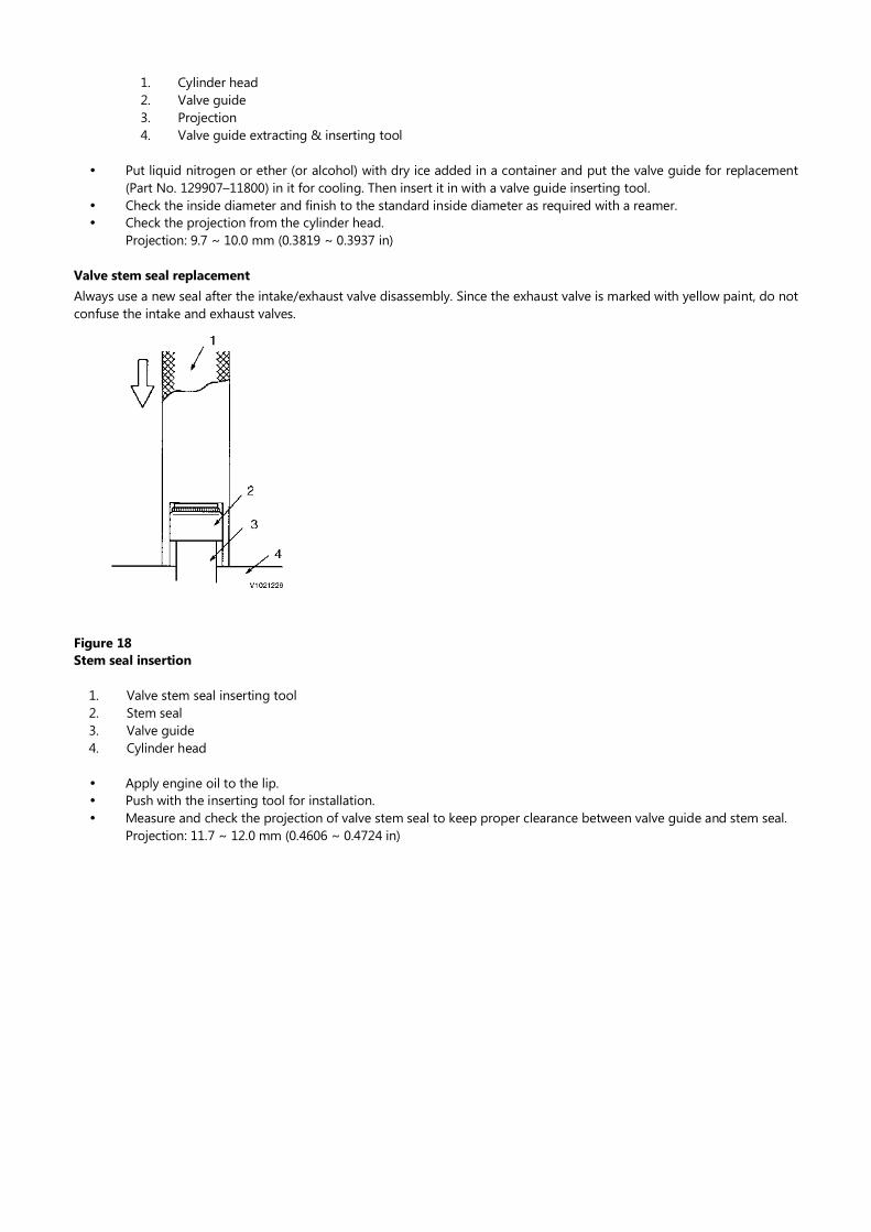
Cylinder headValve guideProjectionValve guide extracting & inserting tool
Put liquid nitrogen or ether (or alcohol) with dry ice added in a container and put the valve guide for replacement (Part No. 129907–11800) in it for cooling. Then insert it in with a valve guide inserting tool.Check the inside diameter and finish to the standard inside diameter as required with a reamer.Check the projection from the cylinder head.Projection: 9.7 ~ 10.0 mm (0.3819 ~ 0.3937 in)
Valve stem seal replacementAlways use a new seal after the intake/exhaust valve disassembly. Since the exhaust valve is marked with yellow paint, do not confuse the intake and exhaust valves.
Figure 18Stem seal insertion
1.2.3.4.
Valve stem seal inserting toolStem sealValve guideCylinder head
Apply engine oil to the lip.Push with the inserting tool for installation.Measure and check the projection of valve stem seal to keep proper clearance between valve guide and stem seal.Projection: 11.7 ~ 12.0 mm (0.4606 ~ 0.4724 in)
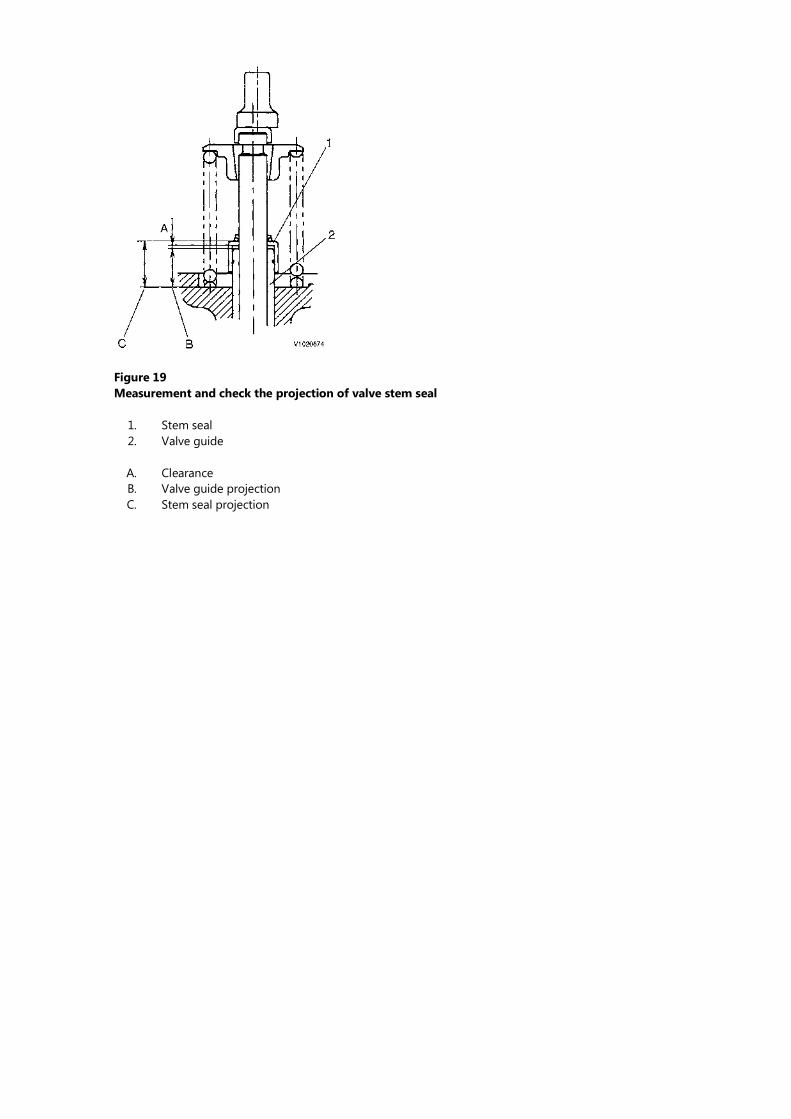
Figure 19Measurement and check the projection of valve stem seal
1.2.
Stem sealValve guide
A.B.C.
ClearanceValve guide projectionStem seal projection
Service Information
Document Title: Function Group: Information Type: Date:Cylinder block, description 212 Service Information 2014/3/30
Profile:CEX, EW60C [GB]
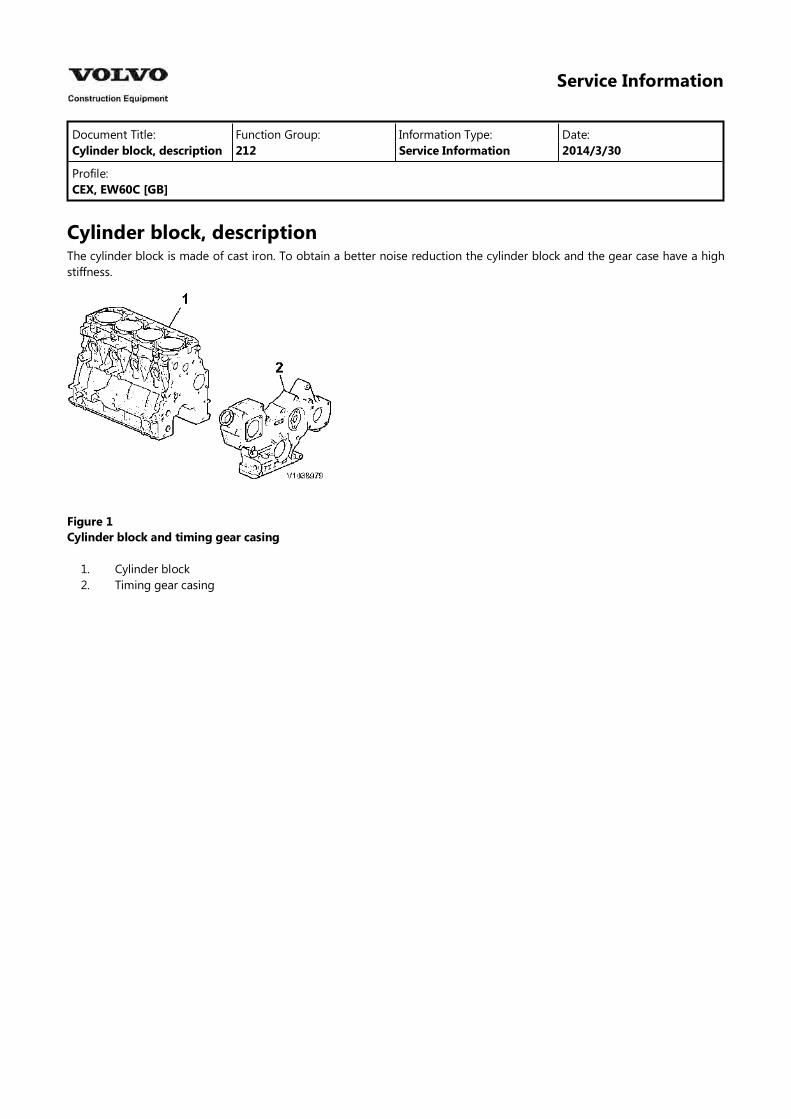
Cylinder block, descriptionThe cylinder block is made of cast iron. To obtain a better noise reduction the cylinder block and the gear case have a high stiffness.
Figure 1Cylinder block and timing gear casing
1.2.
Cylinder blockTiming gear casing
Service Information
Document Title: Function Group: Information Type: Date:Exploded view, cylinder block
212 Service Information 2014/3/30
Profile:CEX, EW60C [GB]
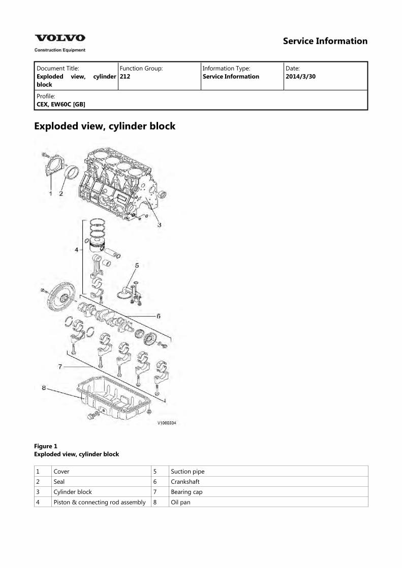
Exploded view, cylinder block
Figure 1Exploded view, cylinder block
1 Cover 5 Suction pipe
2 Seal 6 Crankshaft
3 Cylinder block 7 Bearing cap
4 Piston & connecting rod assembly 8 Oil pan
Service Information
Document Title: Function Group: Information Type: Date:Cylinder block, disassembly and assembly
212 Service Information 2014/3/30
Profile:CEX, EW60C [GB]
Cylinder block, disassembly and assembly
Op nbr 00000
Disassemble in the order of the numbers in the illustration.
1. Perform steps 1 to 12 in the cylinder head disassembly procedure.
2. Perform steps 1 to 12 in the gear train disassembly procedure.
3. Remove the oil pan. (service point 1)
4. Remove the lubricating oil suction pipe.
5. Remove the piston with rod. (service point 2)
6. Remove the mounting flange. (service point 3)
7. Remove the bearing metal caps. (service point 4)
8. Remove the crankshaft. (service point 5)
9. Remove the tappets.
10. Remove the pistons and rings. (service point 6)
11. Remove the oil seal from the mounting flange. (service point 7)For assembly, reverse the procedure.
Service pointsPoint 1 Oil pan
Disassembly :
Sealant is applied to the oil pan mounting surface on the block. Carefully operate so as not to damage or distort the bonding surface.
Reassembly :
Apply sealant (Part No. 977770–01212) before reassembly.
Point 2 Piston with rod
Disassembly :
Measure the connecting rod side gap.Standard : 0.20 ~ 0.40 mm (0.0079 ~ 0.0157 inch)Carefully remove the carbon deposit on top of the cylinder so as not to damage the inner side of the cylinder.
Set the piston at the BDC (Bottom Dead Center) position and remove the connecting rod cap. Then set the piston at the TDC (Top Dead Center) position, and push the connecting rod big end with the wooden shaft of a hammer. Proceed carefully so as not to cause the cylinder block to catch the rod big end. Set the rod caps and crankpin metals in their correct combinations.
Reassembly :
Apply oil especially carefully to the sliding contact surfaces of the pistons, rods and rings.Use the piston insertion tool to insert each piston with rod in the cylinder block and install the bearing metal cap.
Tightening torque (Rod screw): 53.93 ~ 58.83 N m (5.5 ~ 6 kgf m) (39.7 ~ 152.4 lbf ft) (lubrication oil applied)
Point 3 Mounting flange
Disassembly :
Place the engine on a stable base with the cylinder block upper surface facing down, and remove the mounting flange carefully so as not to damage the combustion surface.
Reassembly :
Apply sealant (Part No. 977770–01212) and install the mounting flange by matching the two dowel pins. After assembly, raise the engine with its mounting flange on the bottom side.
WARNINGRisk of personal injury. Very heavy object.
Unforeseen injury may arise due to falling or slipping when raising or reversing the engine. Carefully operate so as not to lose balance.
Point 4 Journal bearing cap
Disassembly :
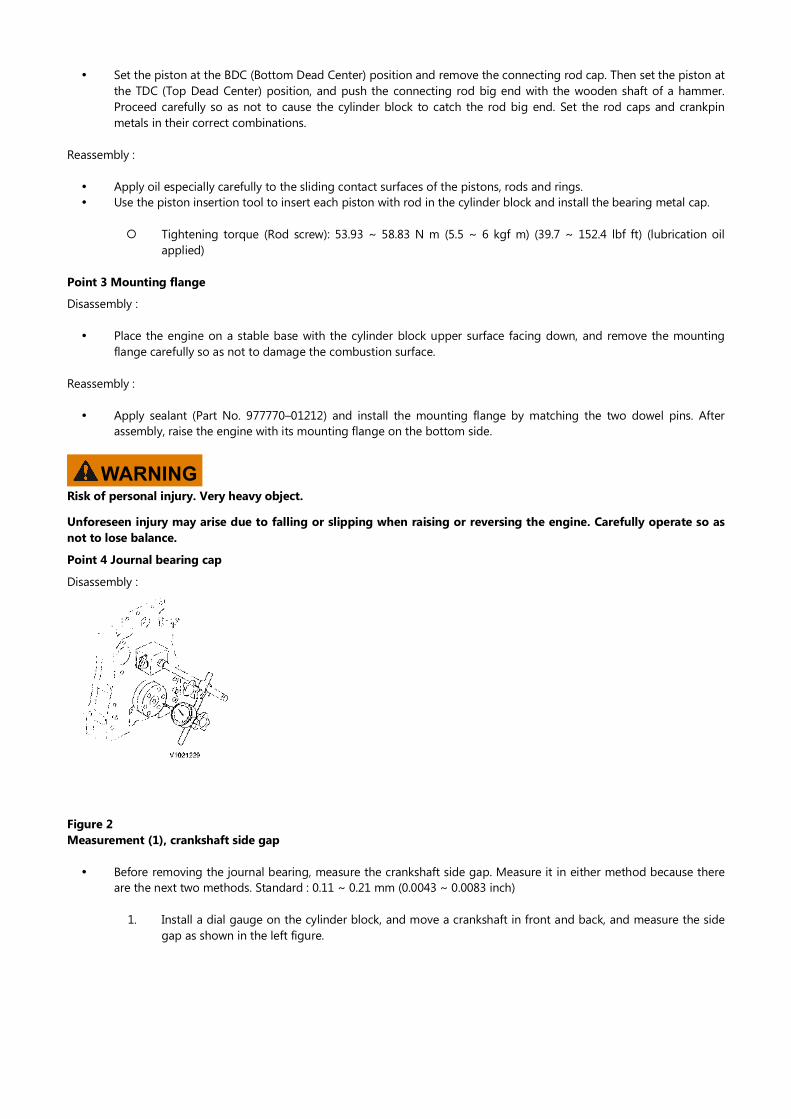
Figure 2Measurement (1), crankshaft side gap
Before removing the journal bearing, measure the crankshaft side gap. Measure it in either method because there are the next two methods. Standard : 0.11 ~ 0.21 mm (0.0043 ~ 0.0083 inch)
1. Install a dial gauge on the cylinder block, and move a crankshaft in front and back, and measure the side gap as shown in the left figure.
2.
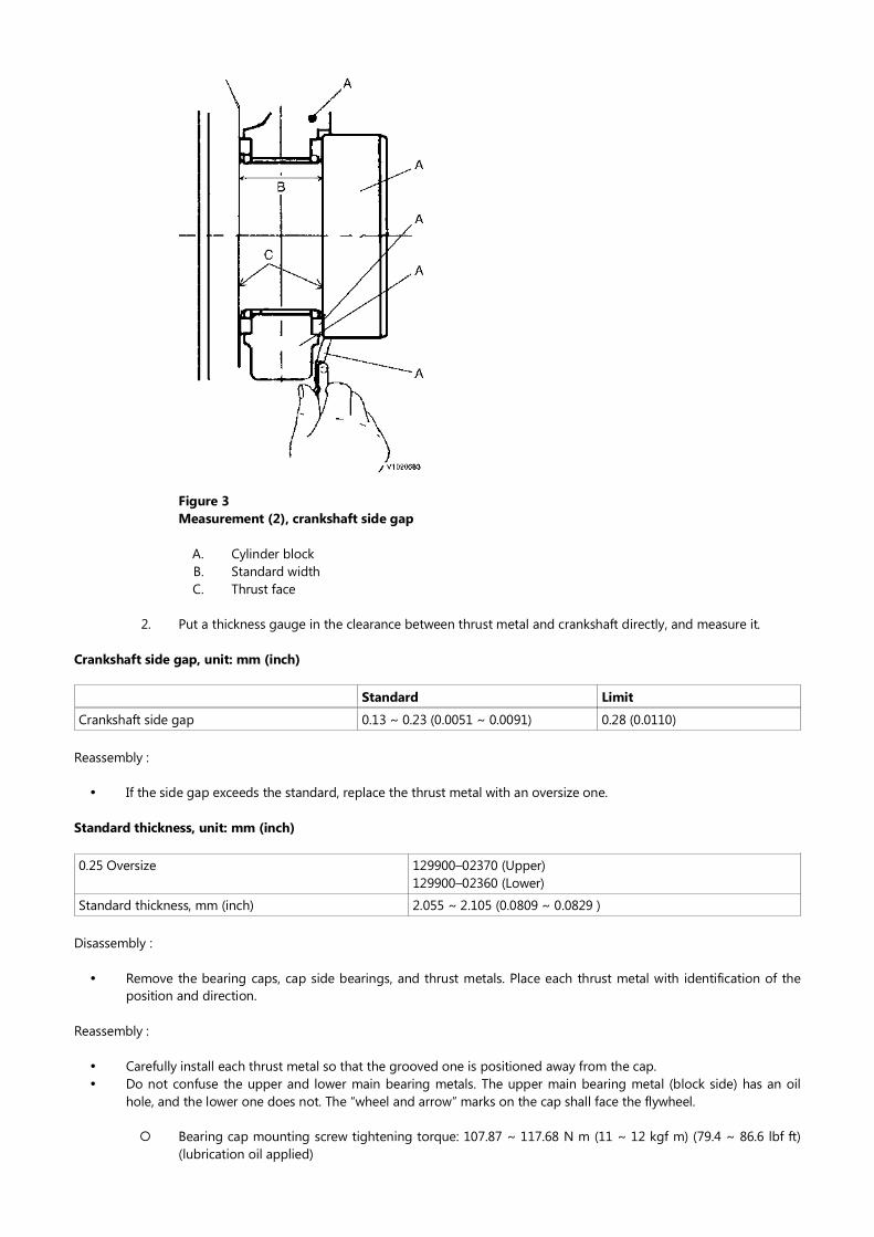
Figure 3Measurement (2), crankshaft side gap
A.B.C.
Cylinder blockStandard widthThrust face
Put a thickness gauge in the clearance between thrust metal and crankshaft directly, and measure it.
Crankshaft side gap, unit: mm (inch)
Standard Limit
Crankshaft side gap 0.13 ~ 0.23 (0.0051 ~ 0.0091) 0.28 (0.0110)
Reassembly :
If the side gap exceeds the standard, replace the thrust metal with an oversize one.
Standard thickness, unit: mm (inch)
0.25 Oversize 129900–02370 (Upper)129900–02360 (Lower)
Standard thickness, mm (inch) 2.055 ~ 2.105 (0.0809 ~ 0.0829 )
Disassembly :
Remove the bearing caps, cap side bearings, and thrust metals. Place each thrust metal with identification of the position and direction.
Reassembly :
Carefully install each thrust metal so that the grooved one is positioned away from the cap.Do not confuse the upper and lower main bearing metals. The upper main bearing metal (block side) has an oil hole, and the lower one does not. The “wheel and arrow” marks on the cap shall face the flywheel.
Bearing cap mounting screw tightening torque: 107.87 ~ 117.68 N m (11 ~ 12 kgf m) (79.4 ~ 86.6 lbf ft) (lubrication oil applied)
Thank you very much for reading.
This is part of the demo page.
GET MORE:
Hydraulic System, Setting Instructions, Functional Description, Electrical System And more……
Click Here BUY NOW Then Instant Download the Complete Manual.