3. disassembly and reassembly
TRANSCRIPT
Samsung Electronics 3-1
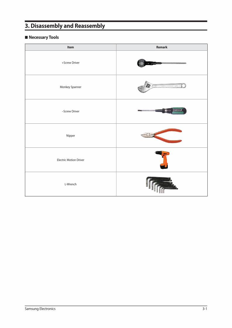
Necessary Tools
3. Disassembly and Reassembly
Item Remark
+Screw Driver
Monkey Spanner
–Screw Driver
Nipper
Electric Motion Driver
L-Wrench
3-2 Samsung Electronics
No Parts Procedure Remark
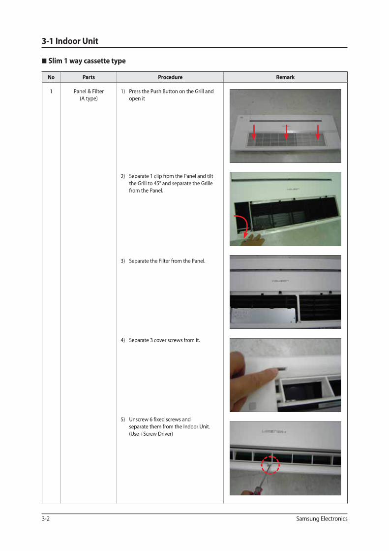
1 Panel & Filter
(A type)
1) Press the Push Button on the Grill and
open it
2) Separate 1 clip from the Panel and tilt
the Grill to 45° and separate the Grille
from the Panel.
3) Separate the Filter from the Panel.
4) Separate 3 cover screws from it.
5) Unscrew 6 fixed screws and
separate them from the Indoor Unit.
(Use +Screw Driver)
3-1 Indoor Unit
Slim 1 way cassette type
Disassembly and Reassembly
Samsung Electronics 3-3
No Parts Procedure Remark
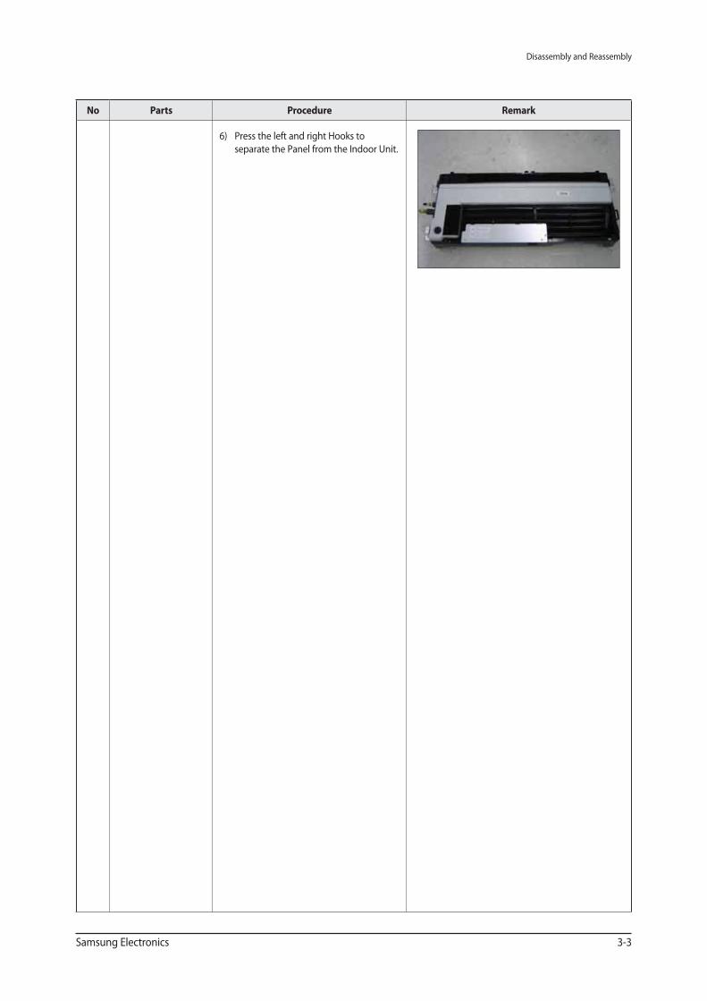
6) Press the left and right Hooks to
separate the Panel from the Indoor Unit.
Disassembly and Reassembly
3-4 Samsung Electronics
No Parts Procedure Remark
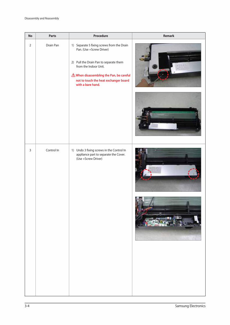
2 Drain Pan 1) Separate 5 fixing screws from the Drain
Pan. (Use +Screw Driver)
2) Pull the Drain Pan to separate them
from the Indoor Unit.
When disassembling the Pan, be careful
not to touch the heat exchanger board
with a bare hand.
3 Control In 1) Undo 3 fixing screws in the Control In
appliance part to separate the Cover.
(Use +Screw Driver)
Disassembly and Reassembly
Samsung Electronics 3-5
No Parts Procedure Remark
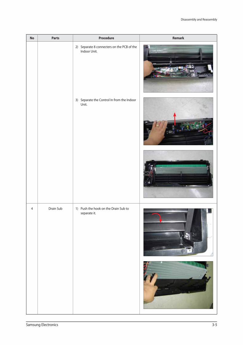
2) Separate 8 connecters on the PCB of the
Indoor Unit.
3) Separate the Control In from the Indoor
Unit.
4 Drain Sub 1) Push the hook on the Drain Sub to
separate it.
Disassembly and Reassembly
3-6 Samsung Electronics
No Parts Procedure Remark
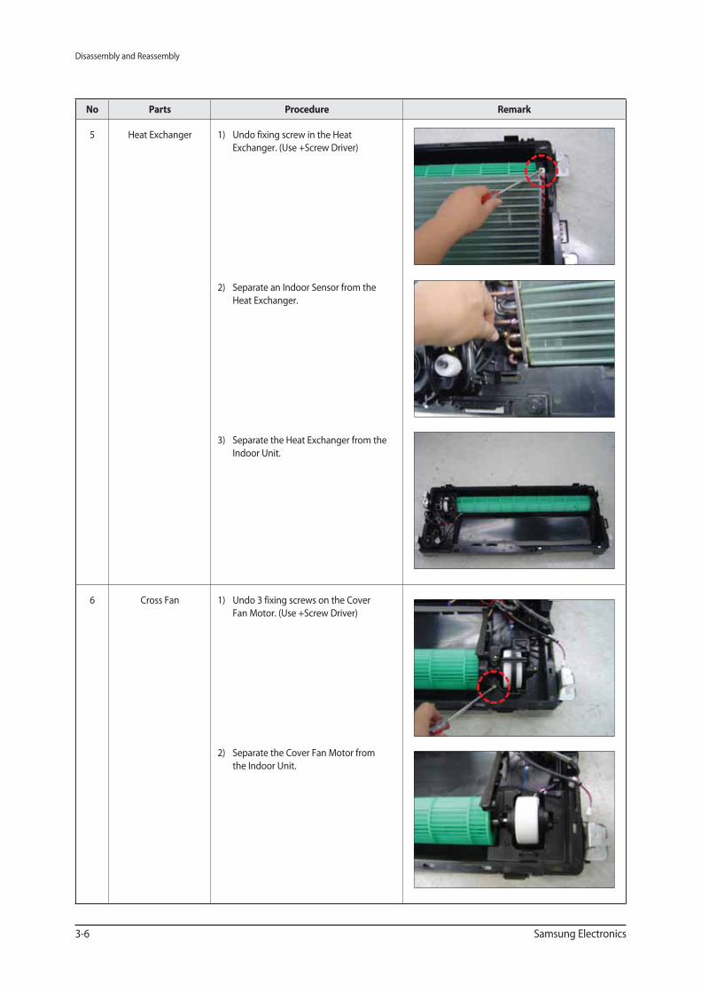
5 Heat Exchanger 1) Undo fixing screw in the Heat
Exchanger. (Use +Screw Driver)
2) Separate an Indoor Sensor from the
Heat Exchanger.
3) Separate the Heat Exchanger from the
Indoor Unit.
6 Cross Fan 1) Undo 3 fixing screws on the Cover
Fan Motor. (Use +Screw Driver)
2) Separate the Cover Fan Motor from
the Indoor Unit.
Disassembly and Reassembly
Samsung Electronics 3-7
No Parts Procedure Remark
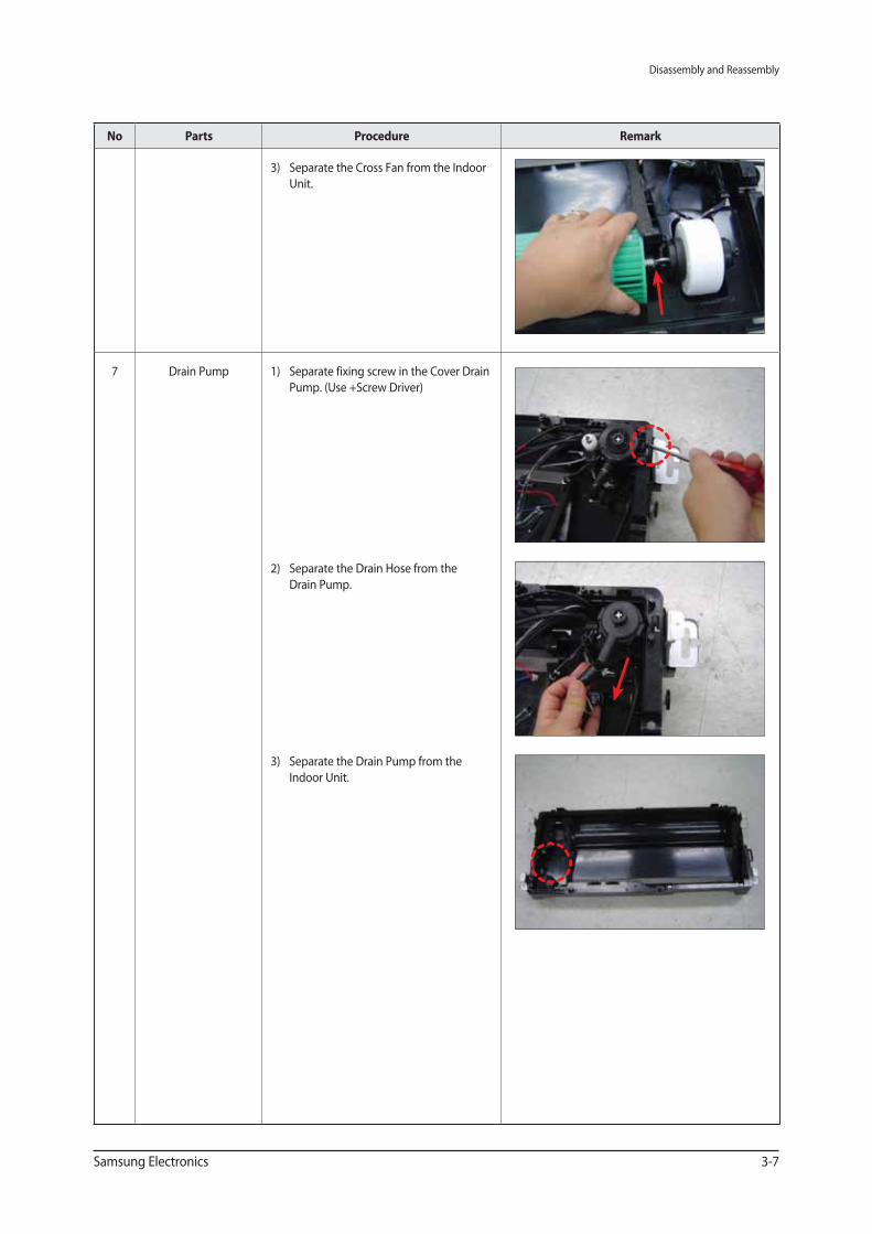
3) Separate the Cross Fan from the Indoor
Unit.
7 Drain Pump 1) Separate fixing screw in the Cover Drain
Pump. (Use +Screw Driver)
2) Separate the Drain Hose from the
Drain Pump.
3) Separate the Drain Pump from the
Indoor Unit.
Disassembly and Reassembly
3-8 Samsung Electronics
No Parts Procedure Remark
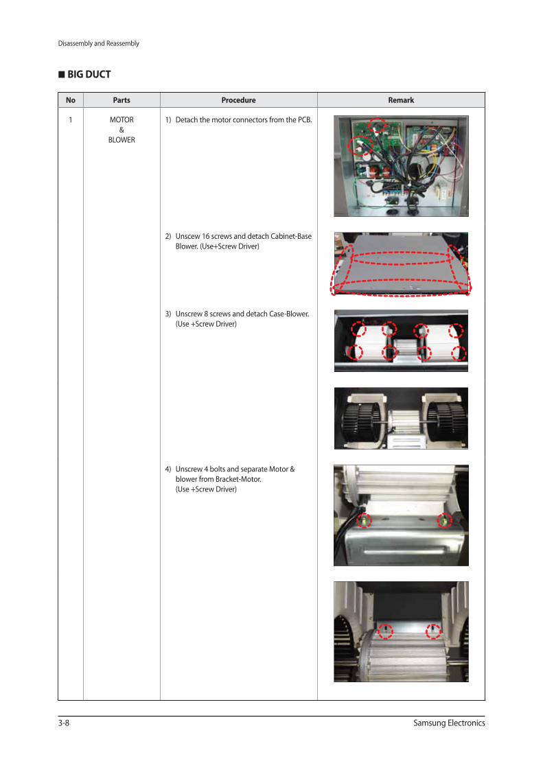
1 MOTOR
&
BLOWER
1) Detach the motor connectors from the PCB.
2) Unscew 16 screws and detach Cabinet-Base
Blower. (Use+Screw Driver)
3) Unscrew 8 screws and detach Case-Blower.
(Use +Screw Driver)
4) Unscrew 4 bolts and separate Motor &
blower from Bracket-Motor.
(Use +Screw Driver)
BIG DUCT
Disassembly and Reassembly
Samsung Electronics 3-9
No Parts Procedure Remark
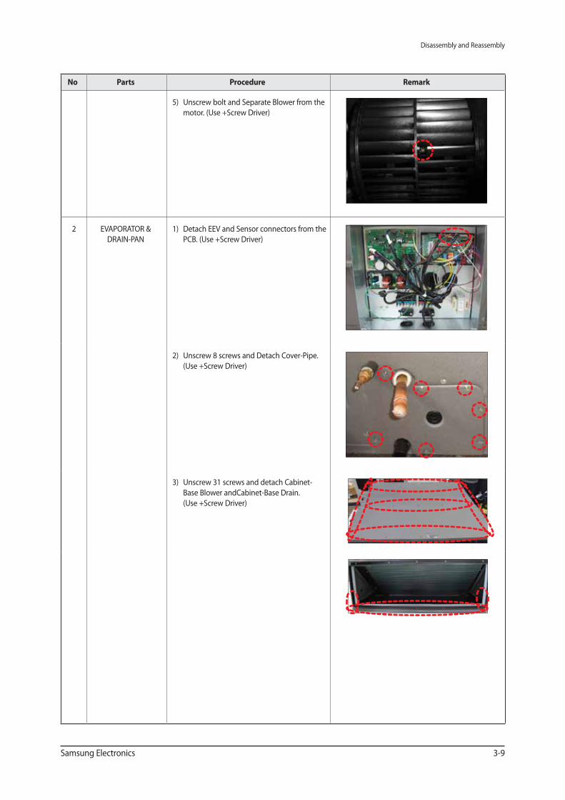
5) Unscrew bolt and Separate Blower from the
motor. (Use +Screw Driver)
2 EVAPORATOR &
DRAIN-PAN
1) Detach EEV and Sensor connectors from the
PCB. (Use +Screw Driver)
2) Unscrew 8 screws and Detach Cover-Pipe.
(Use +Screw Driver)
3) Unscrew 31 screws and detach Cabinet-
Base Blower andCabinet-Base Drain.
(Use +Screw Driver)
Disassembly and Reassembly
3-10 Samsung Electronics
No Parts Procedure Remark
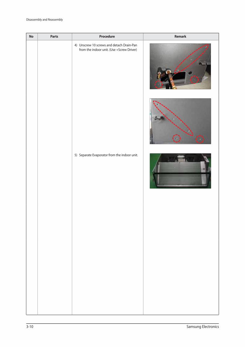
4) Unscrew 10 screws and detach Drain-Pan
from the indoor unit. (Use +Screw Driver)
5) Separate Evaporator from the indoor unit.
Disassembly and Reassembly
Samsung Electronics 3-11
Global 4way Cassette type
No Parts Procedure Remark
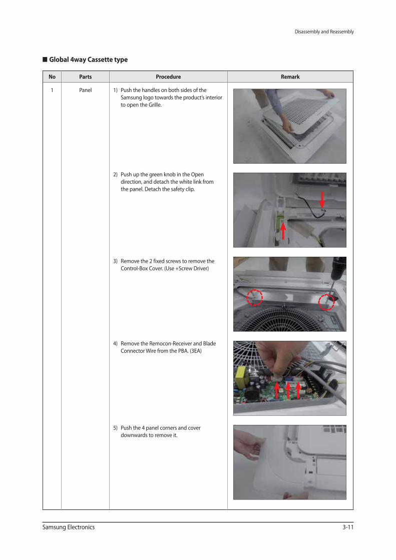
1 Panel 1) Push the handles on both sides of the
Samsung logo towards the product’s interior
to open the Grille.
2) Push up the green knob in the Open
direction, and detach the white link from
the panel. Detach the safety clip.
3) Remove the 2 fixed screws to remove the
Control-Box Cover. (Use +Screw Driver)
4) Remove the Remocon-Receiver and Blade
Connector Wire from the PBA. (3EA)
5) Push the 4 panel corners and cover
downwards to remove it.
Disassembly and Reassembly
3-12 Samsung Electronics
No Parts Procedure Remark
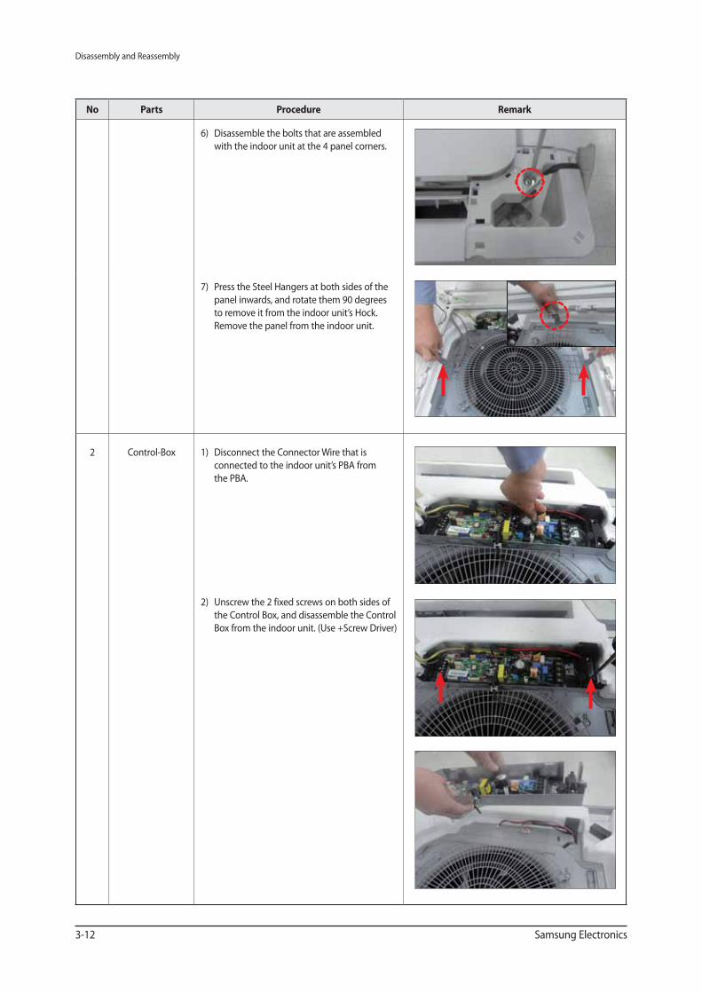
6) Disassemble the bolts that are assembled
with the indoor unit at the 4 panel corners.
7) Press the Steel Hangers at both sides of the
panel inwards, and rotate them 90 degrees
to remove it from the indoor unit’s Hock.
Remove the panel from the indoor unit.
2 Control-Box 1) Disconnect the Connector Wire that is
connected to the indoor unit’s PBA from
the PBA.
2) Unscrew the 2 fixed screws on both sides of
the Control Box, and disassemble the Control
Box from the indoor unit. (Use +Screw Driver)
Disassembly and Reassembly
Samsung Electronics 3-13
No Parts Procedure Remark
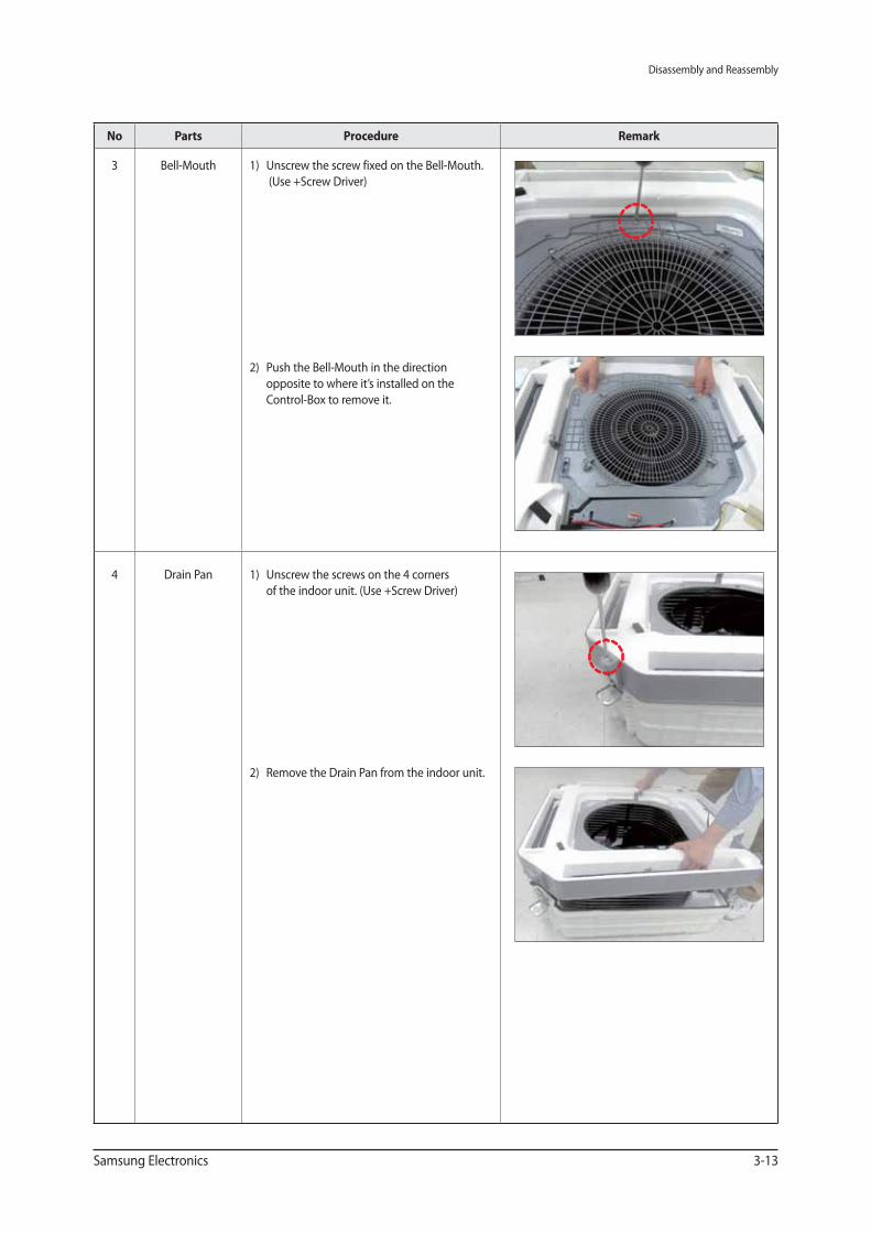
3 Bell-Mouth 1) Unscrew the screw fixed on the Bell-Mouth.
(Use +Screw Driver)
2) Push the Bell-Mouth in the direction
opposite to where it’s installed on the
Control-Box to remove it.
4 Drain Pan 1) Unscrew the screws on the 4 corners
of the indoor unit. (Use +Screw Driver)
2) Remove the Drain Pan from the indoor unit.
Disassembly and Reassembly
3-14 Samsung Electronics
No Parts Procedure Remark
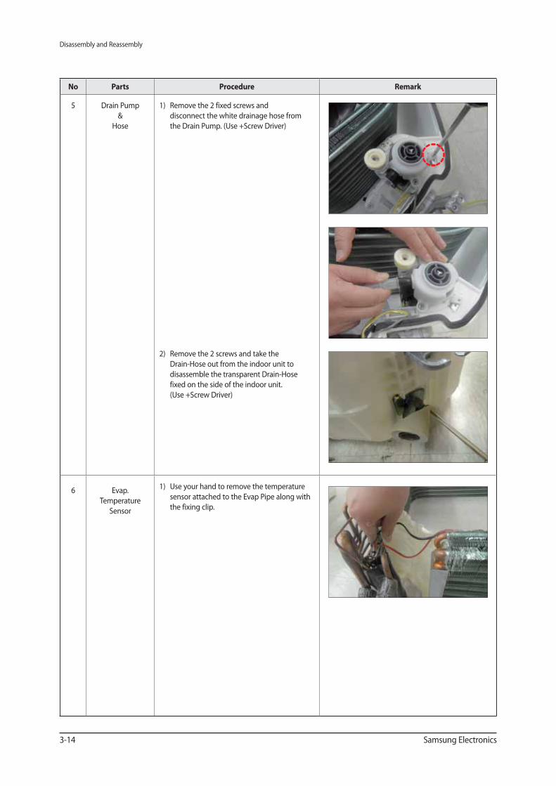
5 Drain Pump
&
Hose
1) Remove the 2 fixed screws and
disconnect the white drainage hose from
the Drain Pump. (Use +Screw Driver)
2) Remove the 2 screws and take the
Drain-Hose out from the indoor unit to
disassemble the transparent Drain-Hose
fixed on the side of the indoor unit.
(Use +Screw Driver)
6 Evap.
Temperature
Sensor
1) Use your hand to remove the temperature
sensor attached to the Evap Pipe along with
the fixing clip.
Disassembly and Reassembly
Samsung Electronics 3-15
No Parts Procedure Remark
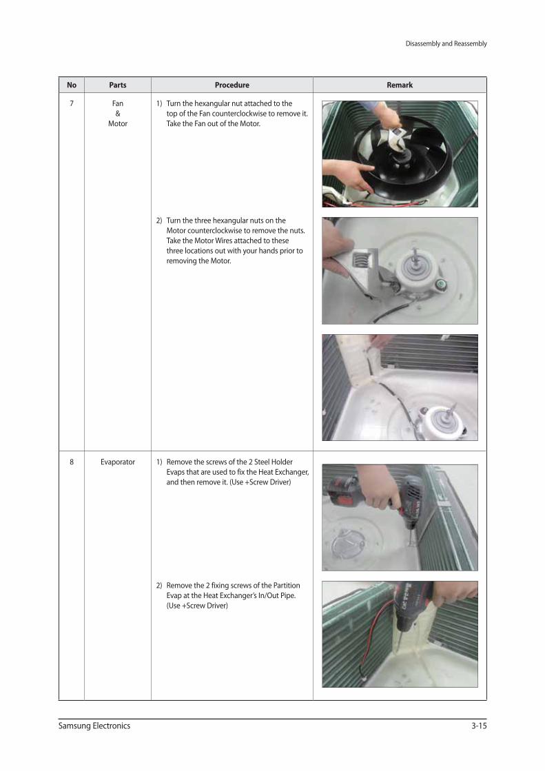
7 Fan
&
Motor
1) Turn the hexangular nut attached to the
top of the Fan counterclockwise to remove it.
Take the Fan out of the Motor.
2) Turn the three hexangular nuts on the
Motor counterclockwise to remove the nuts.
Take the Motor Wires attached to these
three locations out with your hands prior to
removing the Motor.
8 Evaporator 1) Remove the screws of the 2 Steel Holder
Evaps that are used to fix the Heat Exchanger,
and then remove it. (Use +Screw Driver)
2) Remove the 2 fixing screws of the Partition
Evap at the Heat Exchanger’s In/Out Pipe.
(Use +Screw Driver)
Disassembly and Reassembly
3-16 Samsung Electronics
No Parts Procedure Remark
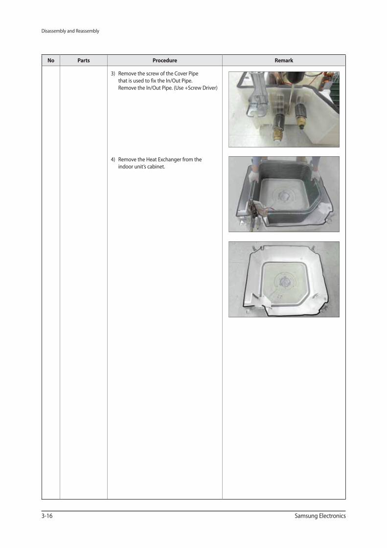
3) Remove the screw of the Cover Pipe
that is used to fix the In/Out Pipe.
Remove the In/Out Pipe. (Use +Screw Driver)
4) Remove the Heat Exchanger from the
indoor unit’s cabinet.
Disassembly and Reassembly
Samsung Electronics 3-17
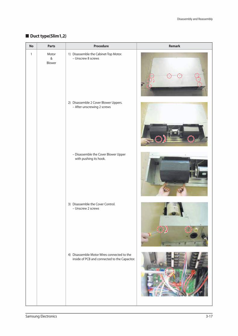
Duct type(Slim1,2)
No Parts Procedure Remark
1 Motor
&
Blower
1) Disassemble the Cabinet-Top Motor.
– Unscrew 8 screws
2) Disassemble 2 Cover Blower Uppers.
– After unscrewing 2 screws
– Disassemble the Cover Blower Upper
with pushing its hook.
3) Disassemble the Cover Control.
– Unscrew 2 screws
4) Disassemble Motor Wires connected to the
inside of PCB and connected to the Capacitor.
Disassembly and Reassembly
3-18 Samsung Electronics
No Parts Procedure Remark
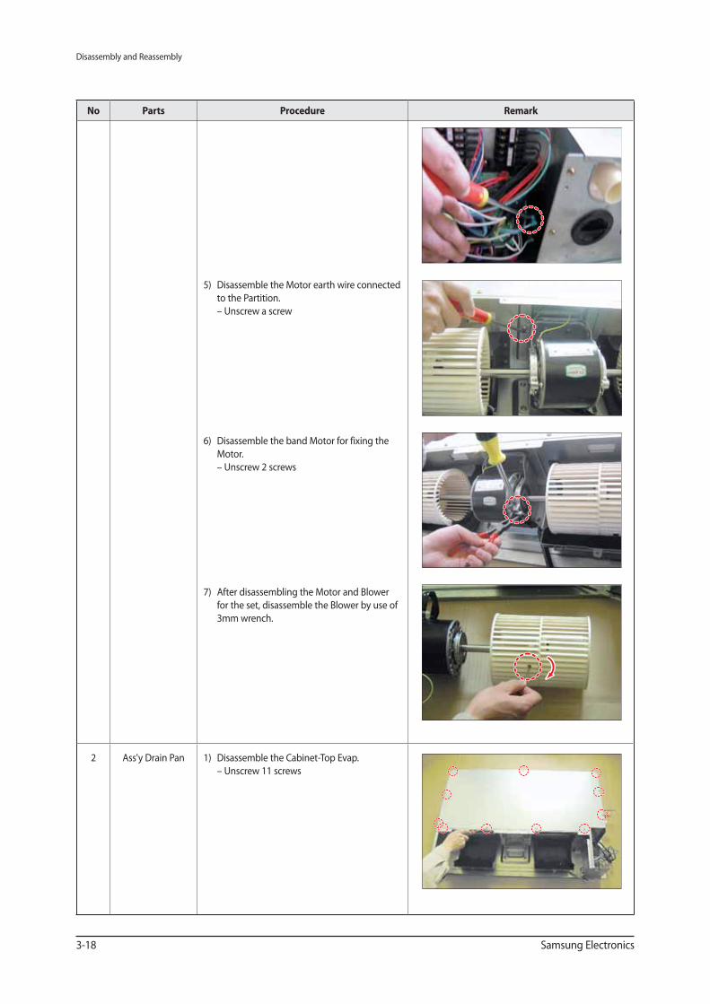
5) Disassemble the Motor earth wire connected
to the Partition.
– Unscrew a screw
6) Disassemble the band Motor for fixing the
Motor.
– Unscrew 2 screws
7) After disassembling the Motor and Blower
for the set, disassemble the Blower by use of
3mm wrench.
2 Ass'y Drain Pan 1) Disassemble the Cabinet-Top Evap.
– Unscrew 11 screws
Disassembly and Reassembly
Samsung Electronics 3-19
No Parts Procedure Remark
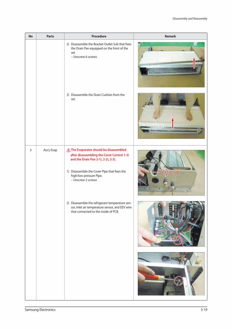
2) Disassemble the Bracket Outlet Sub that fixes
the Drain Pan equipped on the front of the
set.
– Unscrew 6 screws
3) Disassemble the Drain Cushion from the
set.
3 Ass'y Evap The Evaporator should be disassembled
after disassembling the Cover Control 1-3)
and the Drain Pan 2-1), 2-2), 2-3).
1) Disassemble the Cover Pipe that fixes the
high/low pressure Pipe.
– Unscrew 2 screws
2) Disassemble the refrigerant temperature sen-
sor, Inlet air temperature sensor, and EEV wire
that connected to the inside of PCB.
Disassembly and Reassembly
3-20 Samsung Electronics
No Parts Procedure Remark
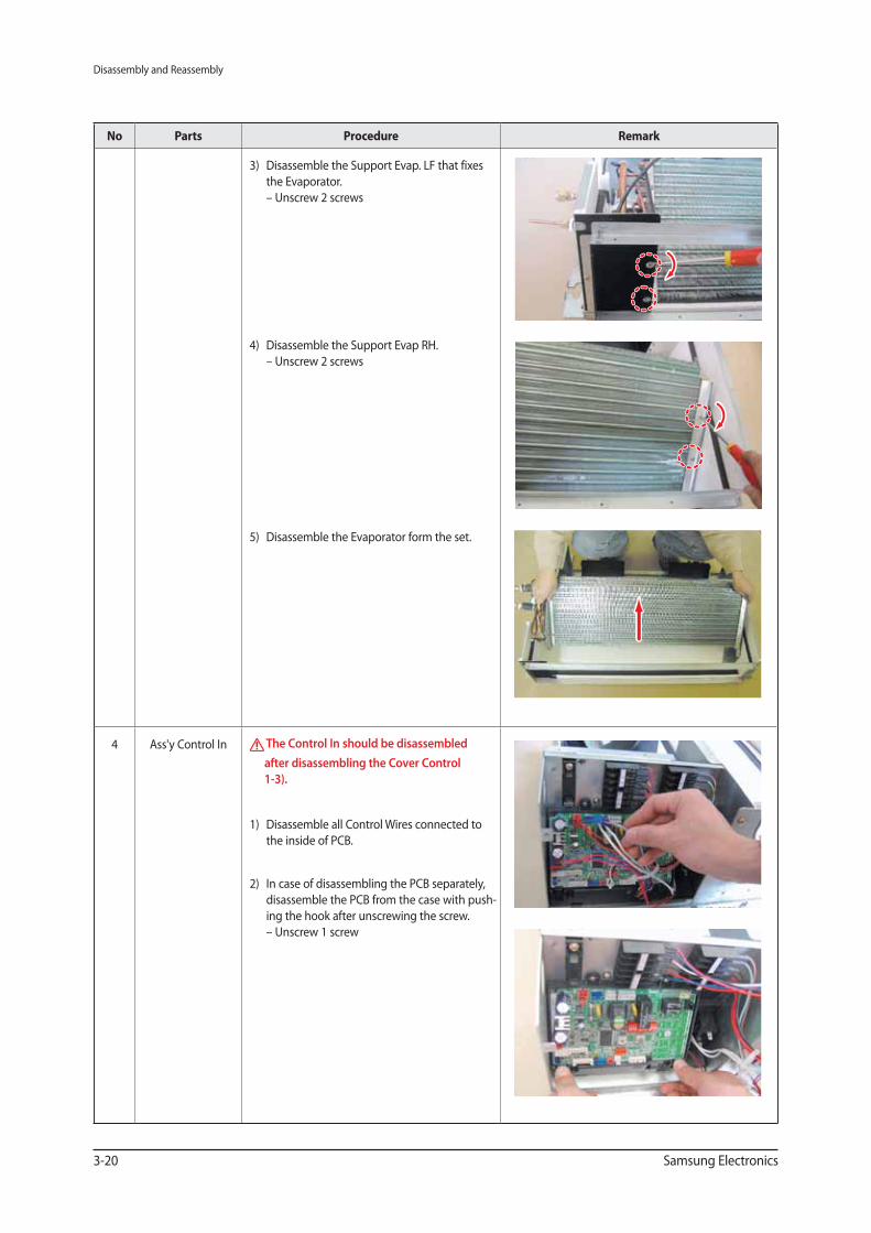
3) Disassemble the Support Evap. LF that fixes
the Evaporator.
– Unscrew 2 screws
4) Disassemble the Support Evap RH.
– Unscrew 2 screws
5) Disassemble the Evaporator form the set.
4 Ass'y Control In The Control In should be disassembled
after disassembling the Cover Control
1-3).
1) Disassemble all Control Wires connected to
the inside of PCB.
2) In case of disassembling the PCB separately,
disassemble the PCB from the case with push-
ing the hook after unscrewing the screw.
– Unscrew 1 screw
Disassembly and Reassembly
Samsung Electronics 3-21
No Parts Procedure Remark
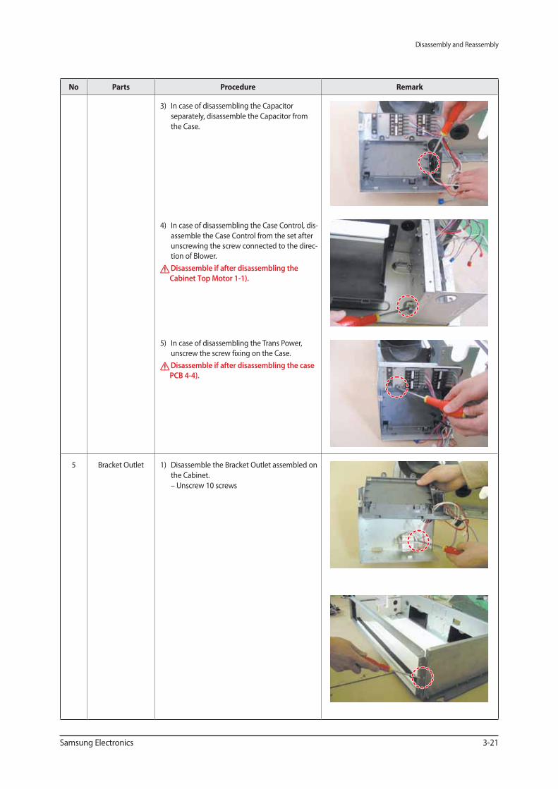
3) In case of disassembling the Capacitor
separately, disassemble the Capacitor from
the Case.
4) In case of disassembling the Case Control, dis-
assemble the Case Control from the set after
unscrewing the screw connected to the direc-
tion of Blower.
Disassemble if after disassembling the
Cabinet Top Motor 1-1).
5) In case of disassembling the Trans Power,
unscrew the screw fixing on the Case.
Disassemble if after disassembling the case
PCB 4-4).
5 Bracket Outlet 1) Disassemble the Bracket Outlet assembled on
the Cabinet.
– Unscrew 10 screws
Disassembly and Reassembly
3-22 Samsung Electronics
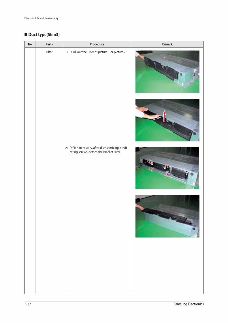
Duct type(Slim3)
No Parts Procedure Remark
1 Filter 1) DPull out the Filter as picture 1 or picture 2.
2) DIf it is necessary, after disassembling 8 indi-
cating screws, detach the Bracket Filter.
Disassembly and Reassembly
Samsung Electronics 3-23
No Parts Procedure Remark
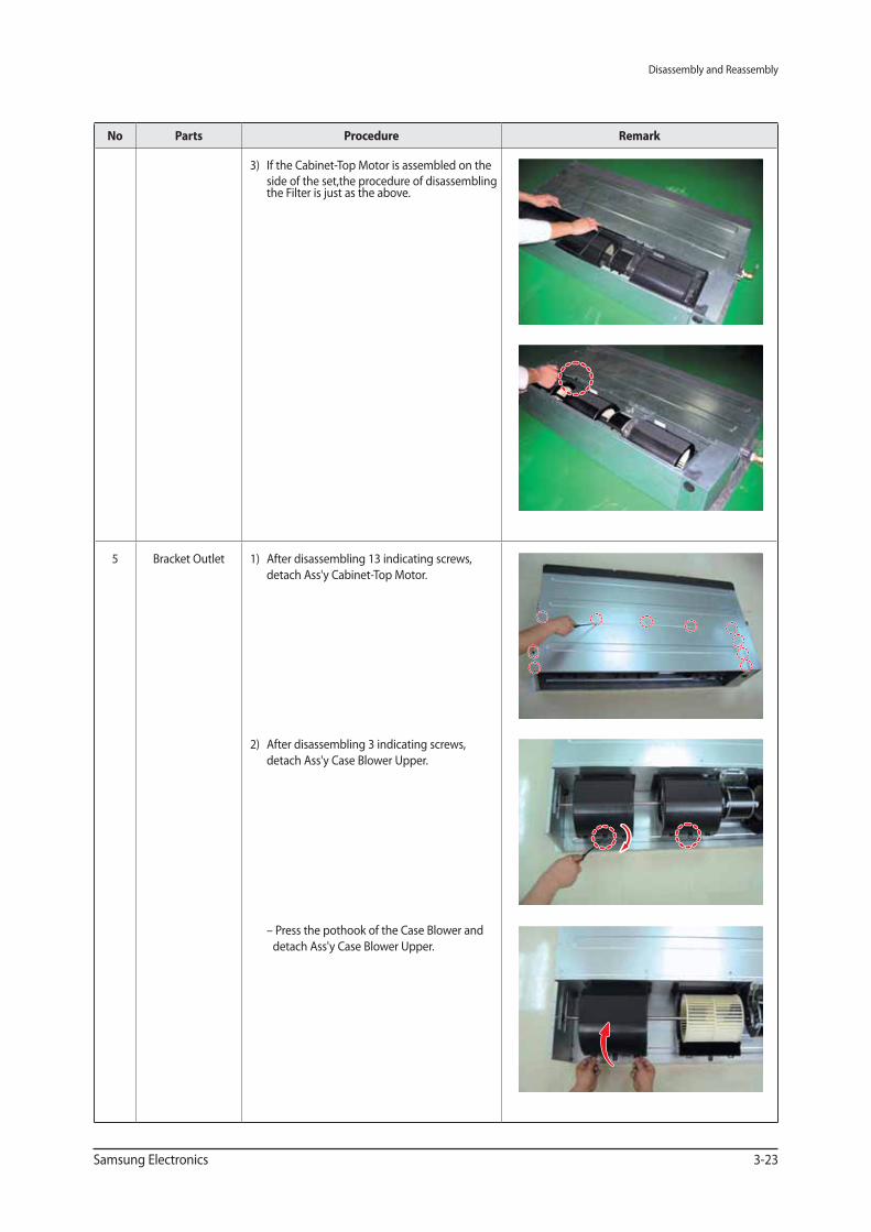
3) If the Cabinet-Top Motor is assembled on the
side of the set,the procedure of disassembling the Filter is just as the above.
5 Bracket Outlet 1) After disassembling 13 indicating screws,
detach Ass'y Cabinet-Top Motor.
2) After disassembling 3 indicating screws,
detach Ass'y Case Blower Upper.
– Press the pothook of the Case Blower and
detach Ass'y Case Blower Upper.
Disassembly and Reassembly
3-24 Samsung Electronics
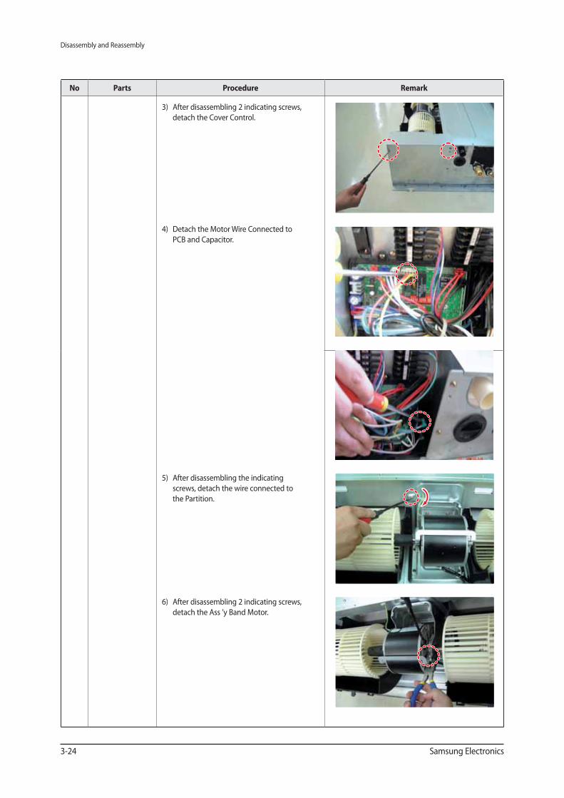
No Parts Procedure Remark
3) After disassembling 2 indicating screws,
detach the Cover Control.
4) Detach the Motor Wire Connected to
PCB and Capacitor.
5) After disassembling the indicating
screws, detach the wire connected to
the Partition.
6) After disassembling 2 indicating screws,
detach the Ass ’y Band Motor.
Disassembly and Reassembly
Samsung Electronics 3-25
No Parts Procedure Remark
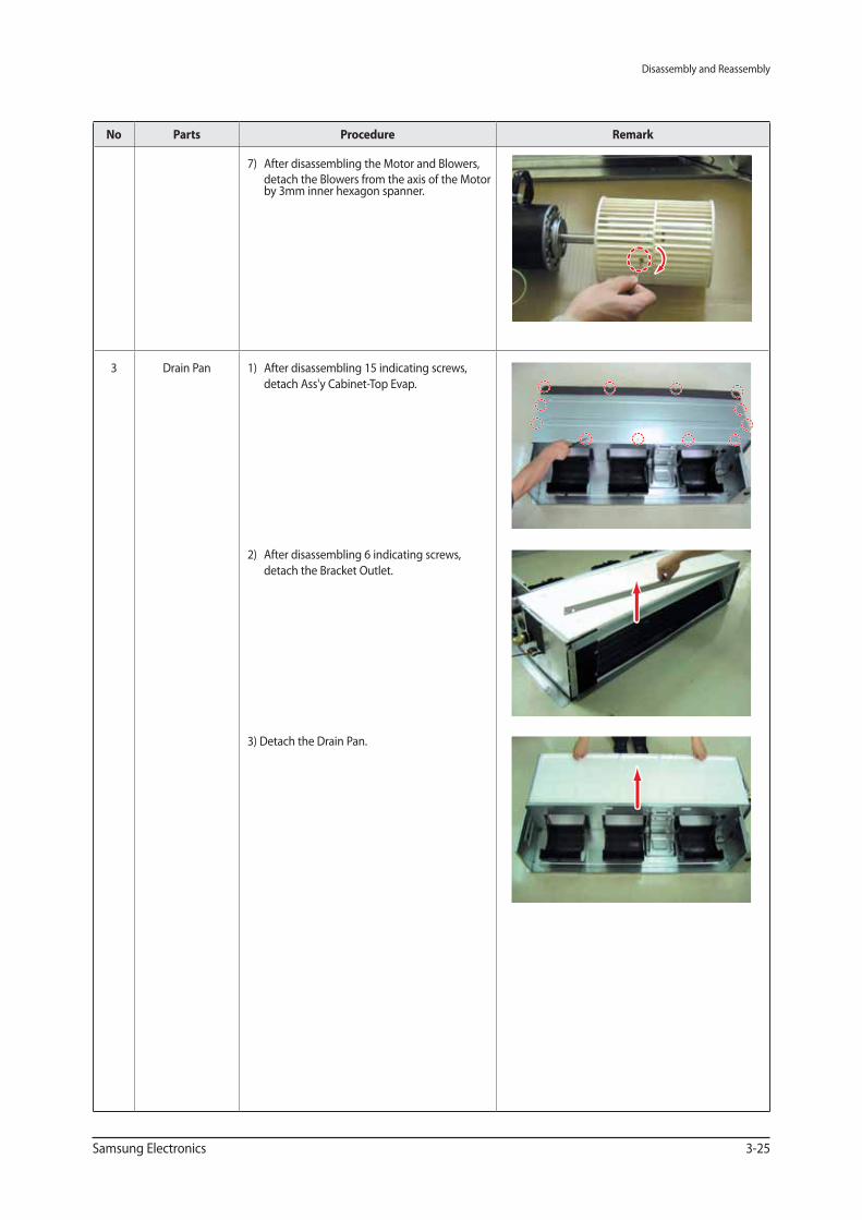
7) After disassembling the Motor and Blowers,
detach the Blowers from the axis of the Motor by 3mm inner hexagon spanner.
3 Drain Pan 1) After disassembling 15 indicating screws,
detach Ass'y Cabinet-Top Evap.
2) After disassembling 6 indicating screws,
detach the Bracket Outlet.
3) Detach the Drain Pan.
Disassembly and Reassembly
3-26 Samsung Electronics
No Parts Procedure Remark
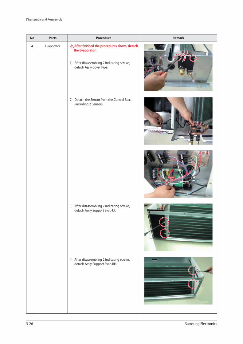
4 Evaporator After finished the procedures above, detach
the Evaporator.
1) After disassembling 2 indicating screws,
detach Ass'y Cover Pipe.
2) Detach the Sensor from the Control Box.
(including 2 Sensors)
3) After disassembling 2 indicating screws,
detach Ass'y Support Evap LF.
4) After disassembling 2 indicating screws,
detach Ass'y Support Evap RH.
Disassembly and Reassembly
Samsung Electronics 3-27
No Parts Procedure Remark
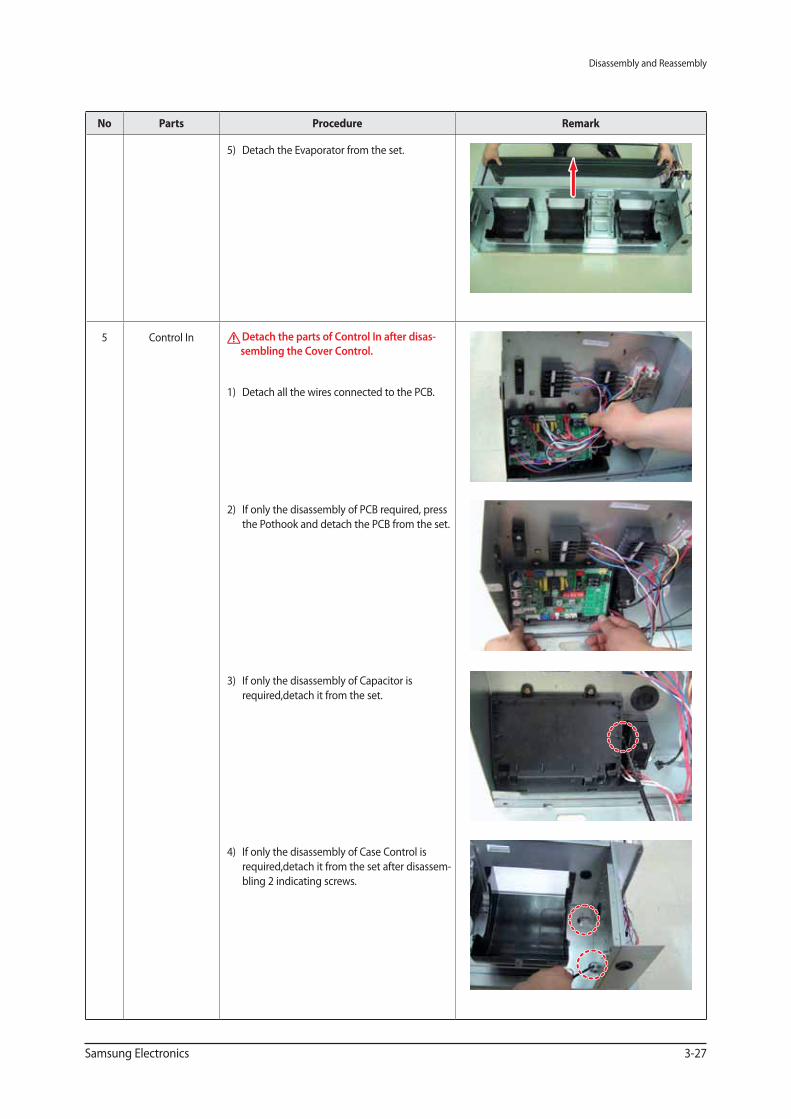
5) Detach the Evaporator from the set.
5 Control In Detach the parts of Control In after disas-
sembling the Cover Control.
1) Detach all the wires connected to the PCB.
2) If only the disassembly of PCB required, press
the Pothook and detach the PCB from the set.
3) If only the disassembly of Capacitor is
required,detach it from the set.
4) If only the disassembly of Case Control is
required,detach it from the set after disassem-
bling 2 indicating screws.
Disassembly and Reassembly
3-28 Samsung Electronics
No Parts Procedure Remark
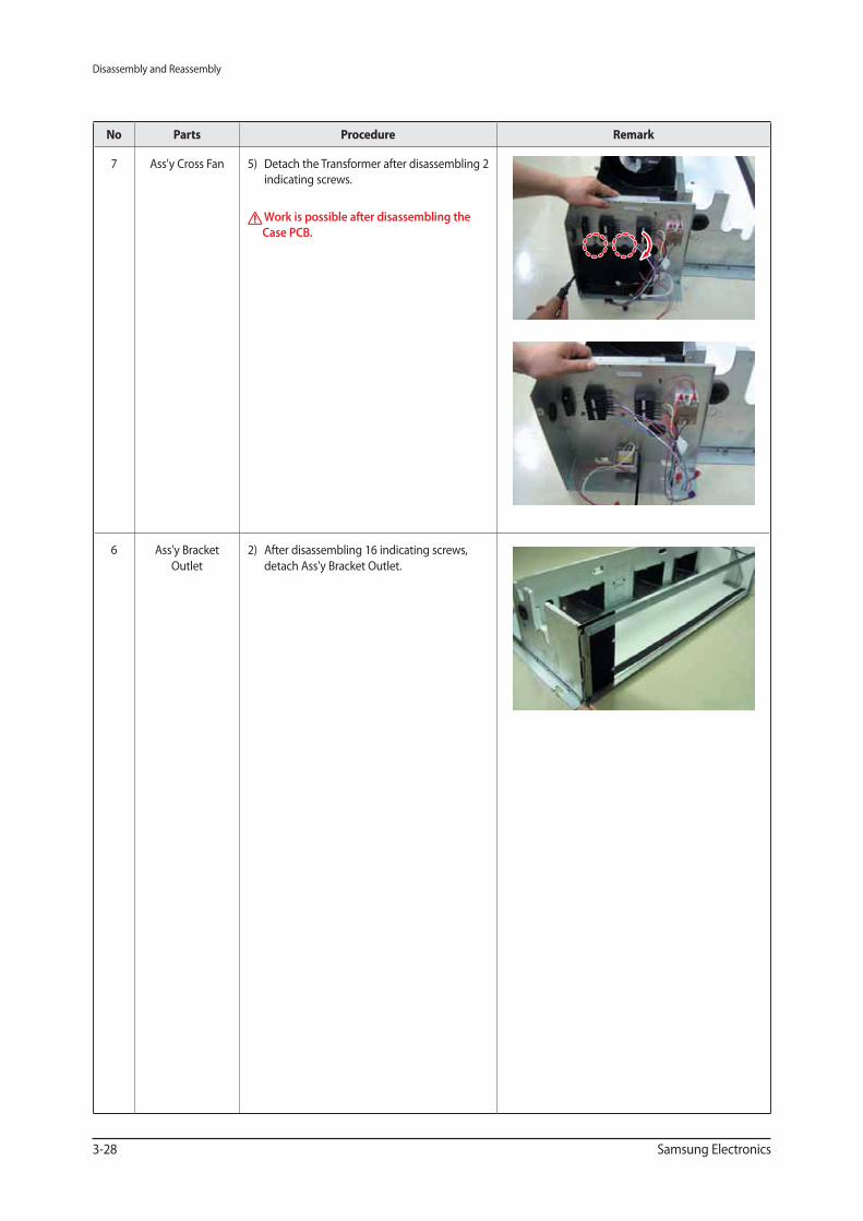
7 Ass'y Cross Fan 5) Detach the Transformer after disassembling 2
indicating screws.
Work is possible after disassembling the
Case PCB.
6 Ass'y Bracket
Outlet
2) After disassembling 16 indicating screws,
detach Ass'y Bracket Outlet.
Disassembly and Reassembly
Samsung Electronics 3-29
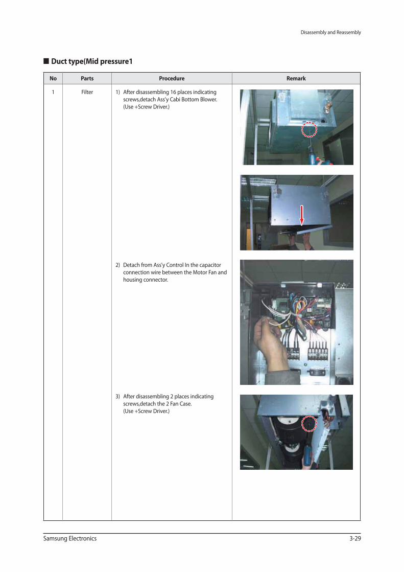
Duct type(Mid pressure1
No Parts Procedure Remark
1 Filter 1) After disassembling 16 places indicating
screws,detach Ass'y Cabi Bottom Blower.
(Use +Screw Driver.)
2) Detach from Ass'y Control In the capacitor
connection wire between the Motor Fan and
housing connector.
3) After disassembling 2 places indicating
screws,detach the 2 Fan Case.
(Use +Screw Driver.)
Disassembly and Reassembly
3-30 Samsung Electronics
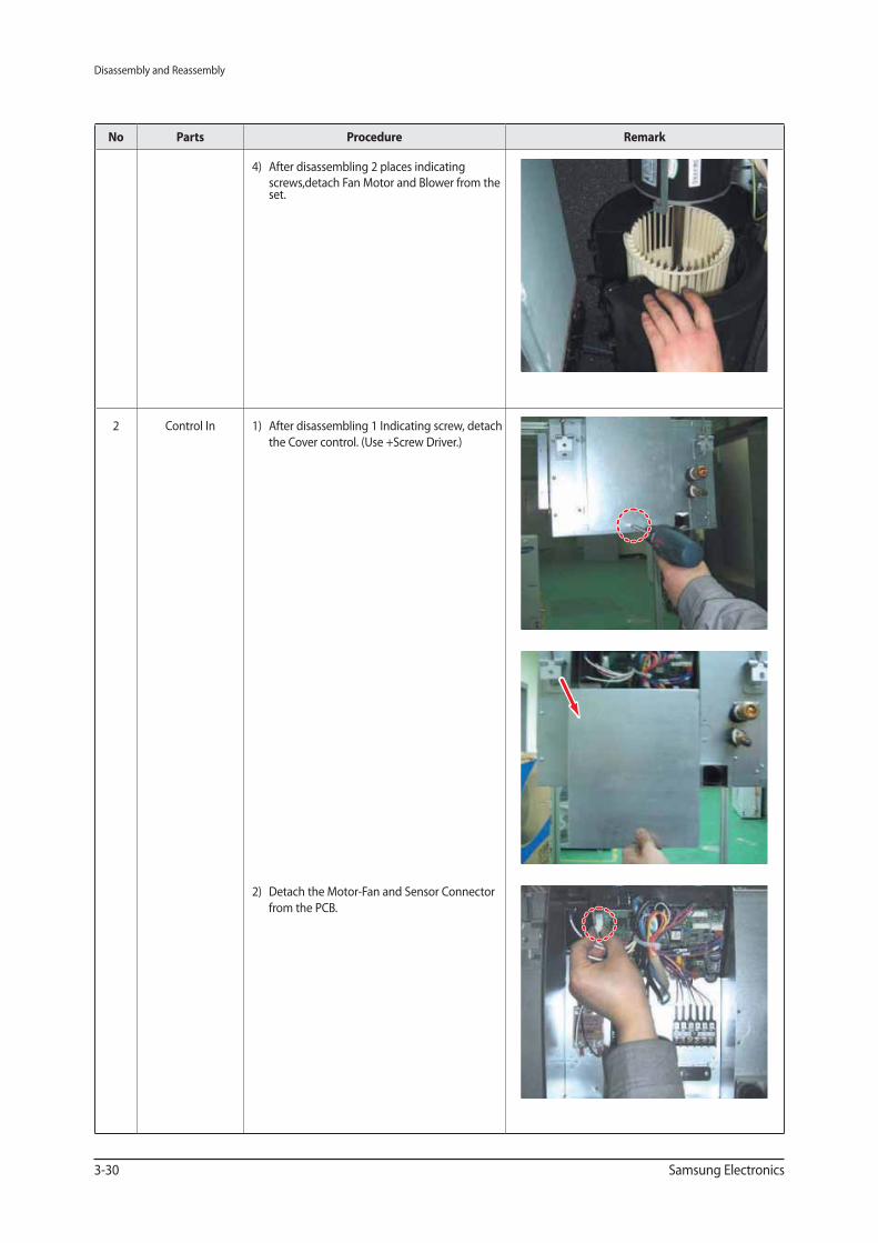
No Parts Procedure Remark
4) After disassembling 2 places indicating
screws,detach Fan Motor and Blower from the set.
2 Control In 1) After disassembling 1 Indicating screw, detach
the Cover control. (Use +Screw Driver.)
2) Detach the Motor-Fan and Sensor Connector
from the PCB.
Disassembly and Reassembly
Samsung Electronics 3-31
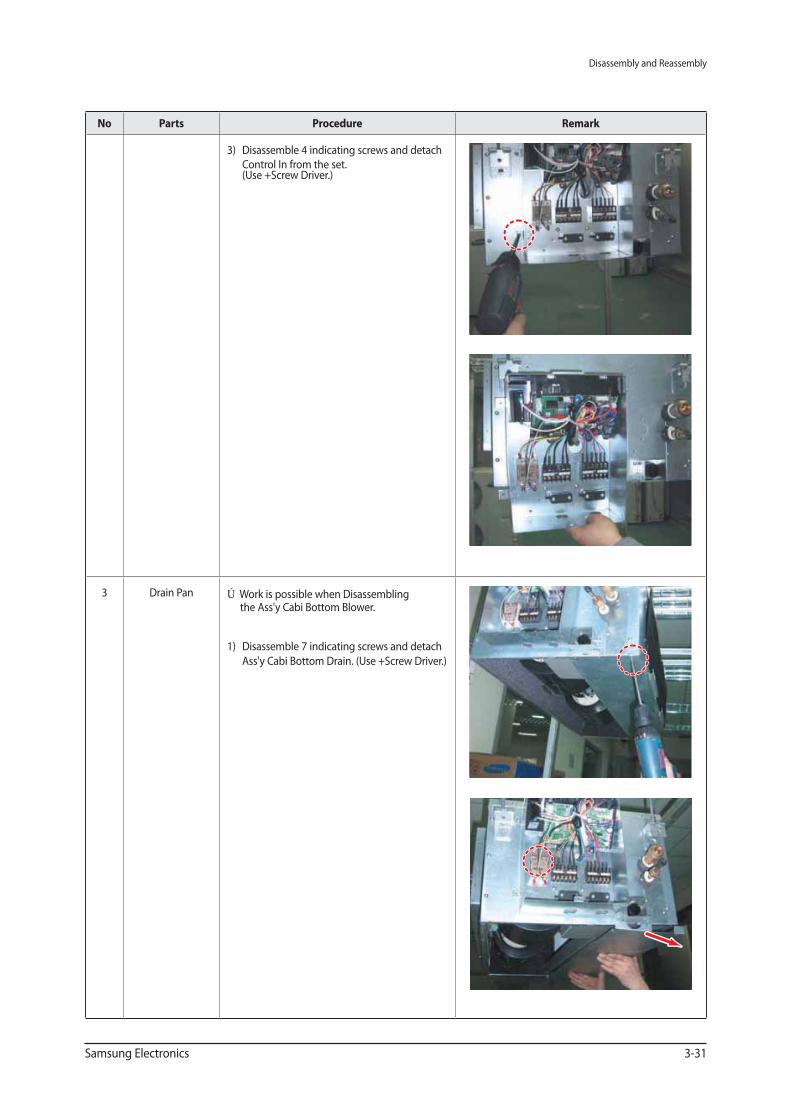
No Parts Procedure Remark
3) Disassemble 4 indicating screws and detach
Control In from the set. (Use +Screw Driver.)
3 Drain Pan ※ Work is possible when Disassembling the Ass'y Cabi Bottom Blower.
1) Disassemble 7 indicating screws and detach
Ass'y Cabi Bottom Drain. (Use +Screw Driver.)
Disassembly and Reassembly
3-32 Samsung Electronics
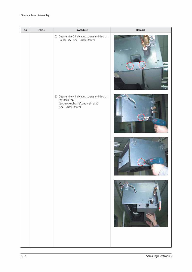
No Parts Procedure Remark
2) Disassemble 2 indicating screws and detach
Holder Pipe. (Use +Screw Driver.)
3) Disassemble 4 indicating screws and detach
the Drain Pan.
(2 screws each at left and right side)
(Use +Screw Driver.)
Disassembly and Reassembly
Samsung Electronics 3-33
No Parts Procedure Remark
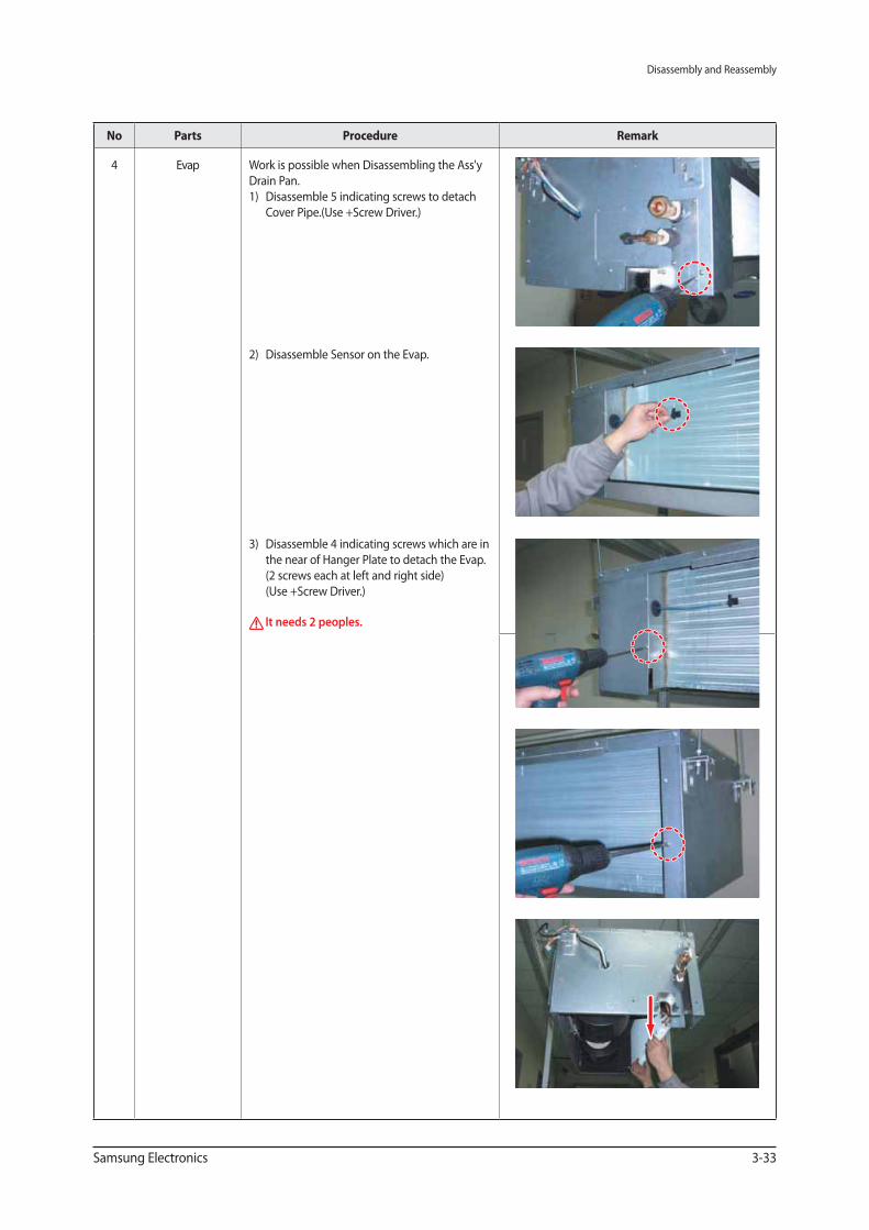
4 Evap Work is possible when Disassembling the Ass'y
Drain Pan.
1) Disassemble 5 indicating screws to detach
Cover Pipe.(Use +Screw Driver.)
2) Disassemble Sensor on the Evap.
3) Disassemble 4 indicating screws which are in
the near of Hanger Plate to detach the Evap.
(2 screws each at left and right side)
(Use +Screw Driver.)
It needs 2 peoples.
Disassembly and Reassembly
3-34 Samsung Electronics
Duct type(Mid pressure2)
No Parts Procedure Remark
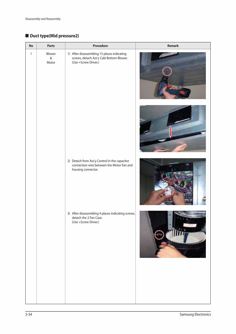
1 Blower
&
Motor
1) After disassembling 15 places indicating
screws, detach Ass'y Cabi Bottom Blower.
(Use +Screw Driver.)
2) Detach from Ass'y Control In the capacitor
connection wire between the Motor Fan and
housing connector.
3) After disassembling 4 places indicating screws,
detach the 2 Fan Case.
(Use +Screw Driver.)
Disassembly and Reassembly
Samsung Electronics 3-35
No Parts Procedure Remark
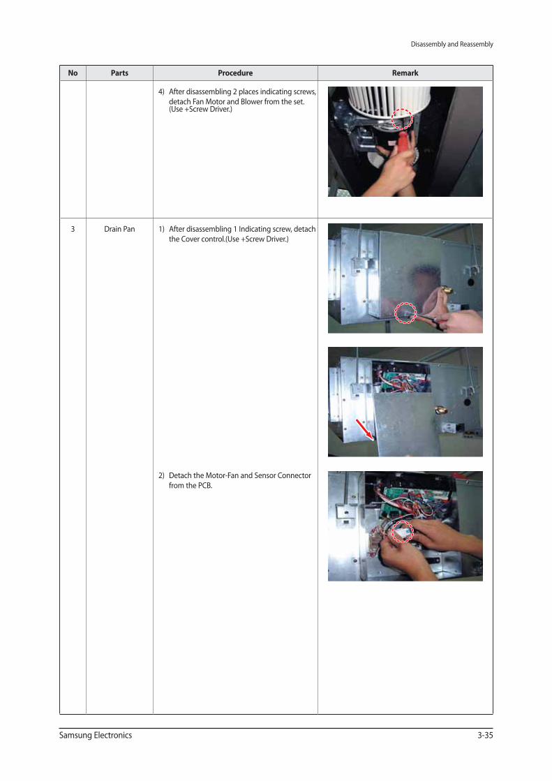
4) After disassembling 2 places indicating screws,
detach Fan Motor and Blower from the set. (Use +Screw Driver.)
3 Drain Pan 1) After disassembling 1 Indicating screw, detach
the Cover control.(Use +Screw Driver.)
2) Detach the Motor-Fan and Sensor Connector
from the PCB.
Disassembly and Reassembly
3-36 Samsung Electronics
No Parts Procedure Remark
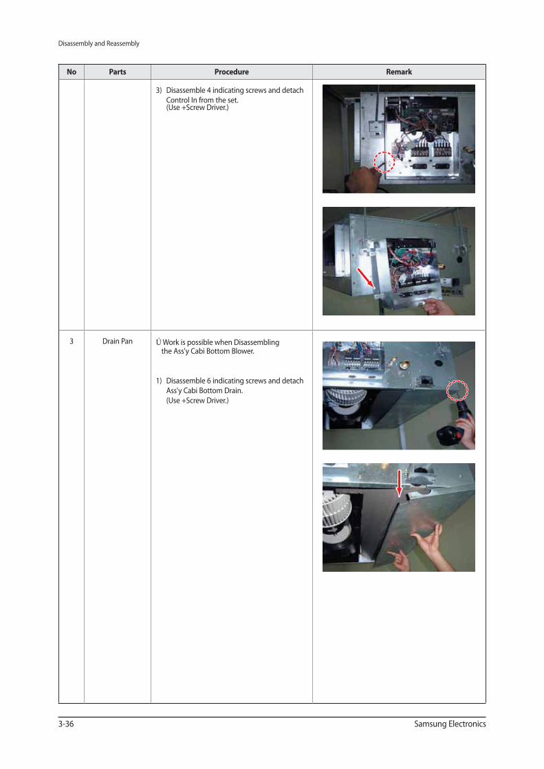
3) Disassemble 4 indicating screws and detach
Control In from the set. (Use +Screw Driver.)
3 Drain Pan ※ Work is possible when Disassembling the Ass'y Cabi Bottom Blower.
1) Disassemble 6 indicating screws and detach
Ass'y Cabi Bottom Drain.
(Use +Screw Driver.)
Disassembly and Reassembly
Samsung Electronics 3-37
No Parts Procedure Remark
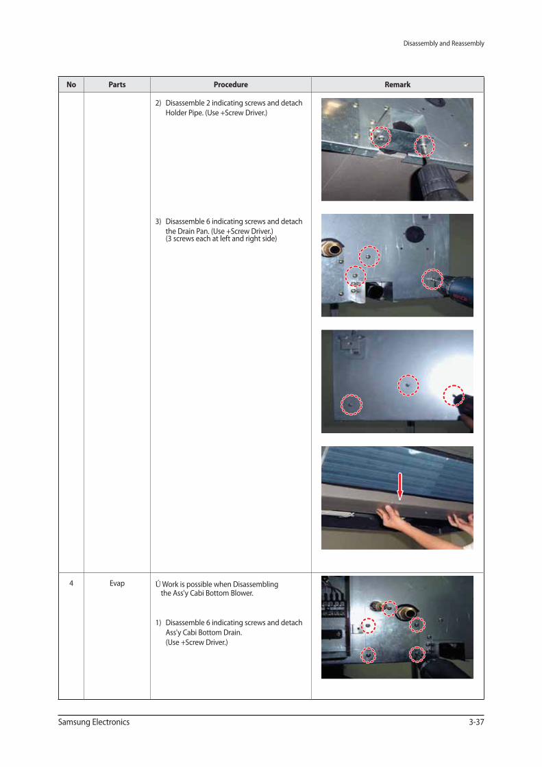
2) Disassemble 2 indicating screws and detach
Holder Pipe. (Use +Screw Driver.)
3) Disassemble 6 indicating screws and detach
the Drain Pan. (Use +Screw Driver.) (3 screws each at left and right side)
4 Evap ※ Work is possible when Disassembling the Ass'y Cabi Bottom Blower.
1) Disassemble 6 indicating screws and detach
Ass'y Cabi Bottom Drain.
(Use +Screw Driver.)
Disassembly and Reassembly
3-38 Samsung Electronics
No Parts Procedure Remark
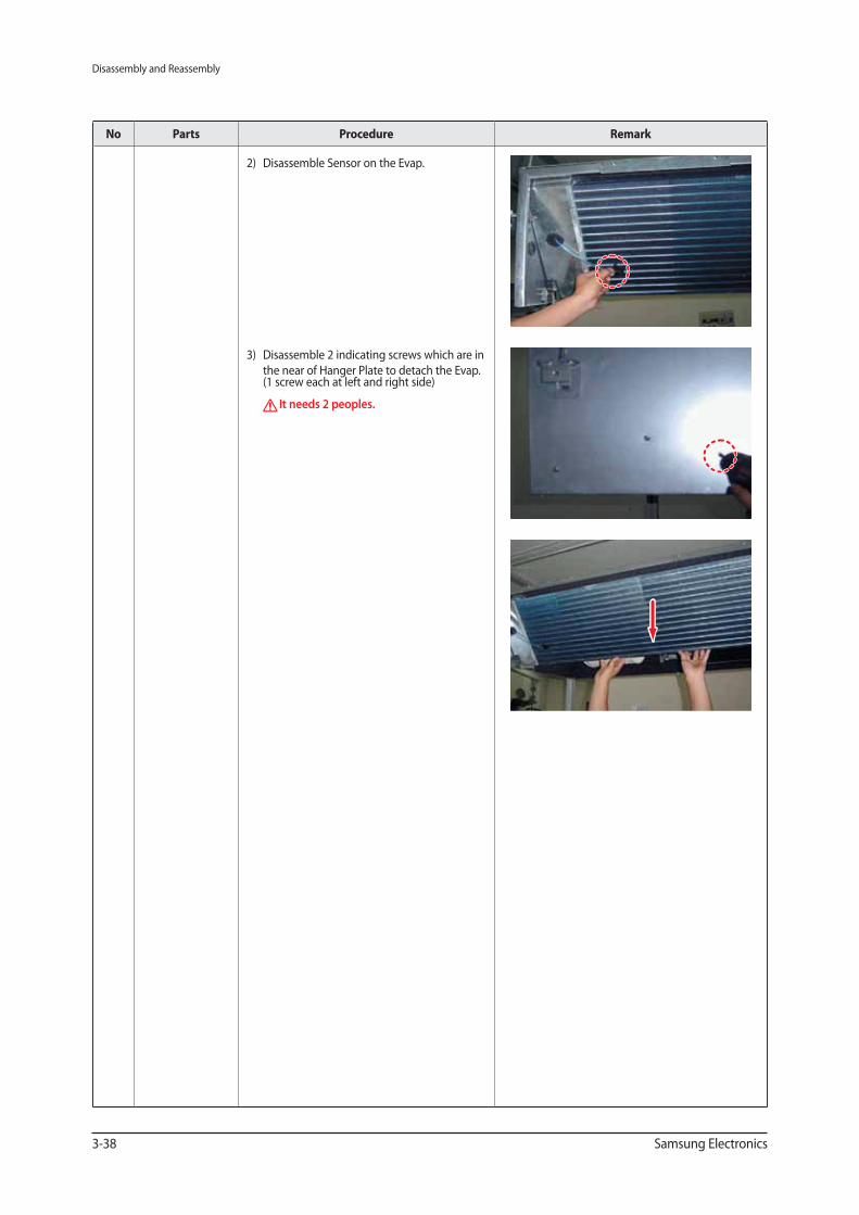
2) Disassemble Sensor on the Evap.
3) Disassemble 2 indicating screws which are in
the near of Hanger Plate to detach the Evap. (1 screw each at left and right side)
It needs 2 peoples.
Disassembly and Reassembly
Samsung Electronics 3-39
CEILING
No Parts Procedure Remark
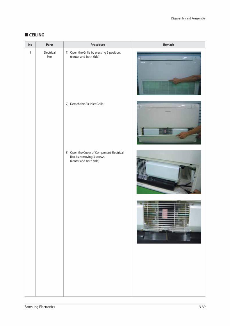
1 Electrical
Part
1) Open the Grille by pressing 3 position.
(center and both side)
2) Detach the Air Inlet Grille.
3) Open the Cover of Component Electrical
Box by removing 3 screws.
(center and both side)
Disassembly and Reassembly
3-40 Samsung Electronics
No Parts Procedure Remark
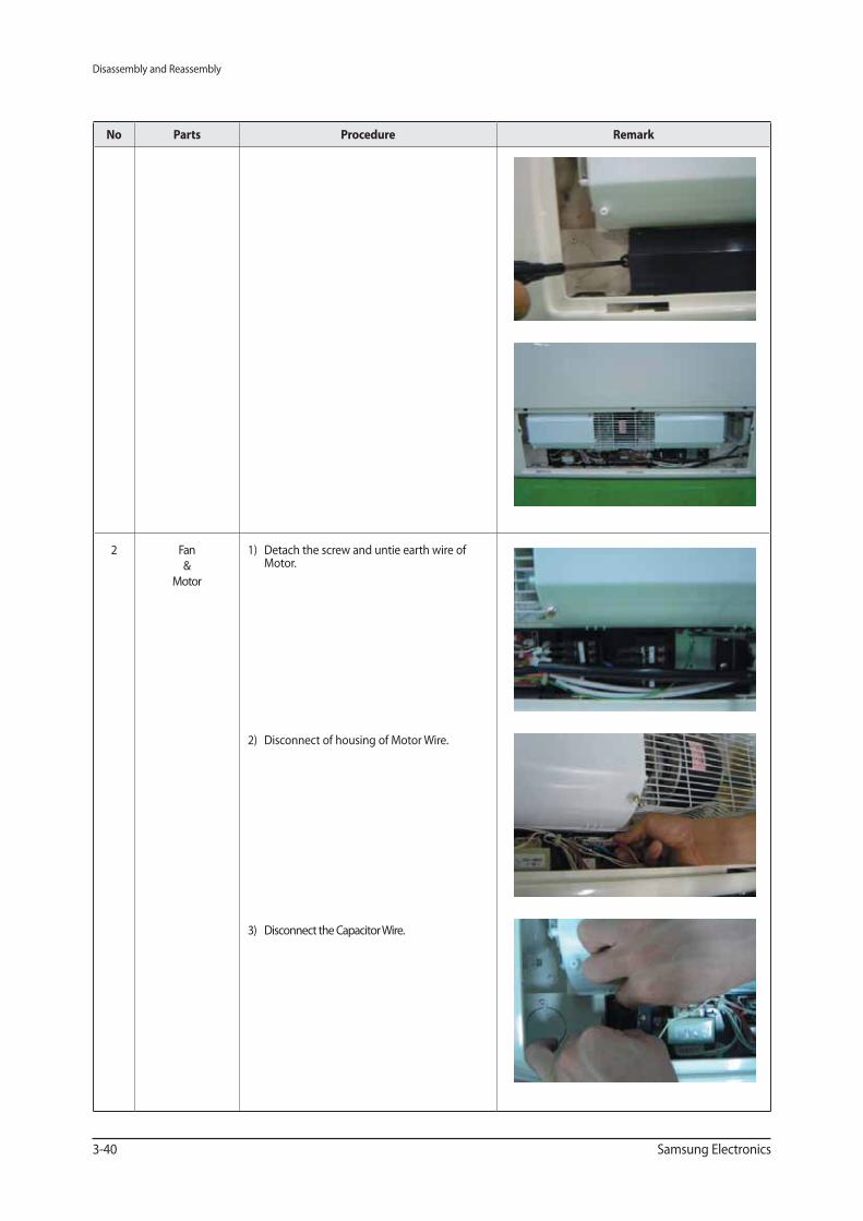
2 Fan
&
Motor
1) Detach the screw and untie earth wire of Motor.
2) Disconnect of housing of Motor Wire.
3) Disconnect the Capacitor Wire.
Disassembly and Reassembly
Samsung Electronics 3-41
No Parts Procedure Remark
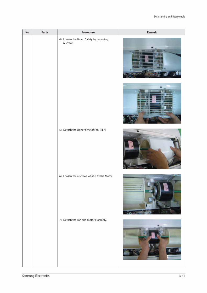
4) Loosen the Guard Safety by removing
6 screws.
5) Detach the Upper Case of Fan. (2EA)
6) Loosen the 4 screws what is fix the Motor.
7) Detach the Fan and Motor assembly.
Disassembly and Reassembly
3-42 Samsung Electronics
No Parts Procedure Remark
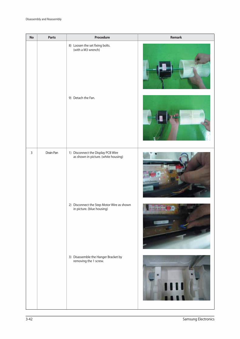
8) Loosen the set fixing bolts.
(with a M3 wrench)
9) Detach the Fan.
3 Drain Pan 1) Disconnect the Display PCB Wireas shown in picture. (white housing)
2) Disconnect the Step Motor Wire as shownin picture. (blue housing)
3) Disassemble the Hanger Bracket byremoving the 1 screw.
Disassembly and Reassembly
Samsung Electronics 3-43
No Parts Procedure Remark
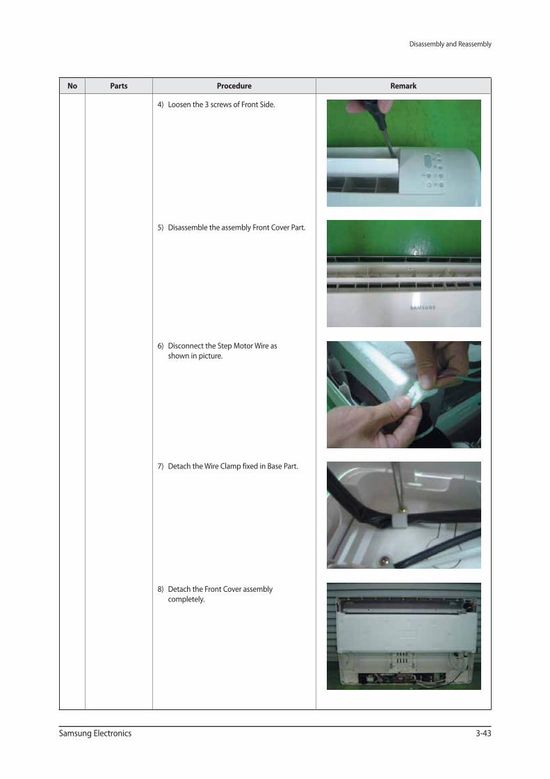
4) Loosen the 3 screws of Front Side.
5) Disassemble the assembly Front Cover Part.
6) Disconnect the Step Motor Wire as
shown in picture.
7) Detach the Wire Clamp fixed in Base Part.
8) Detach the Front Cover assembly
completely.
Disassembly and Reassembly
3-44 Samsung Electronics
No Parts Procedure Remark
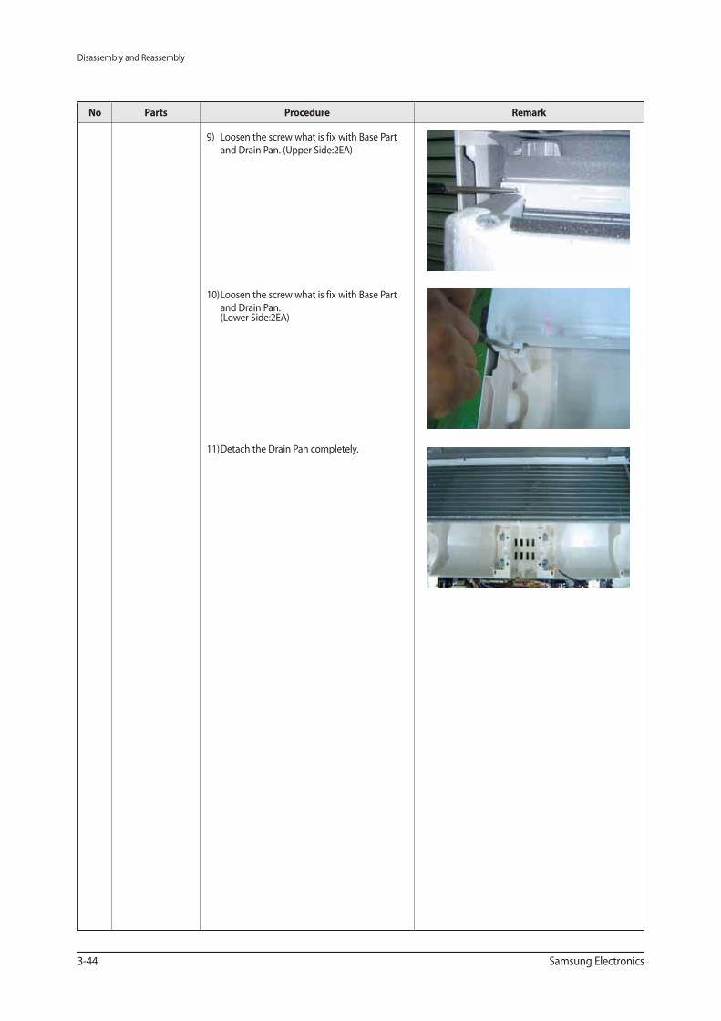
9) Loosen the screw what is fix with Base Part
and Drain Pan. (Upper Side:2EA)
10) Loosen the screw what is fix with Base Part
and Drain Pan. (Lower Side:2EA)
11) Detach the Drain Pan completely.
Disassembly and Reassembly
Samsung Electronics 3-45
No Parts Procedure Remark
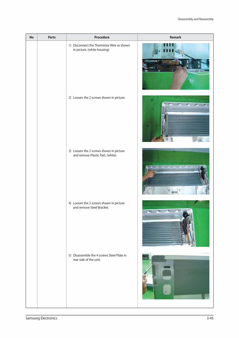
1) Disconnect the Thermistor Wire as shown
in picture. (white housing)
2) Loosen the 2 screws shown in picture.
3) Loosen the 2 screws shown in picture
and remove Plastic Part. (white)
4) Loosen the 2 screws shown in picture
and remove Steel Bracket.
5) Disassemble the 4 screws Steel Plate in
rear side of the unit.
Disassembly and Reassembly
3-46 Samsung Electronics
No Parts Procedure Remark
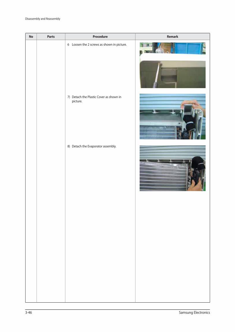
6 Loosen the 2 screws as shown in picture.
7) Detach the Plastic Cover as shown in
picture.
8) Detach the Evaporator assembly.
Disassembly and Reassembly
Samsung Electronics 3-47
No Parts Procedure Remark
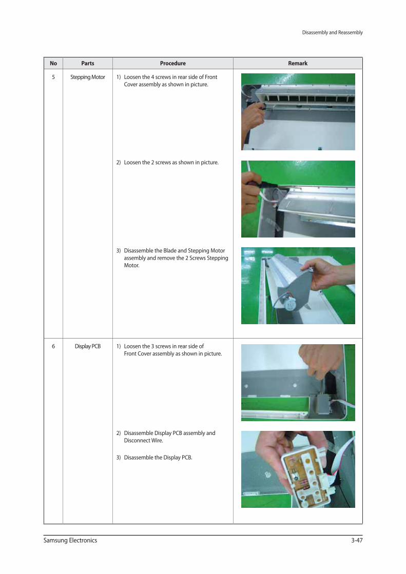
5 Stepping Motor 1) Loosen the 4 screws in rear side of Front
Cover assembly as shown in picture.
2) Loosen the 2 screws as shown in picture.
3) Disassemble the Blade and Stepping Motor
assembly and remove the 2 Screws Stepping
Motor.
6 Display PCB 1) Loosen the 3 screws in rear side of
Front Cover assembly as shown in picture.
2) Disassemble Display PCB assembly and
Disconnect Wire.
3) Disassemble the Display PCB.
Disassembly and Reassembly
3-48 Samsung Electronics
CONSOLE
No Parts Procedure Remark
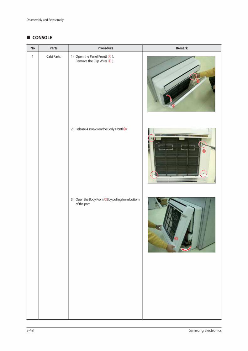
1 Cabi Parts 1) Open the Panel Front( ).
Remove the Clip Wire( ).
2) Release 4 screws on the Body Front ).
3) Open the Body Front( ) by pulling from bottom
of the part.
Disassembly and Reassembly
Samsung Electronics 3-49
No Parts Procedure Remark
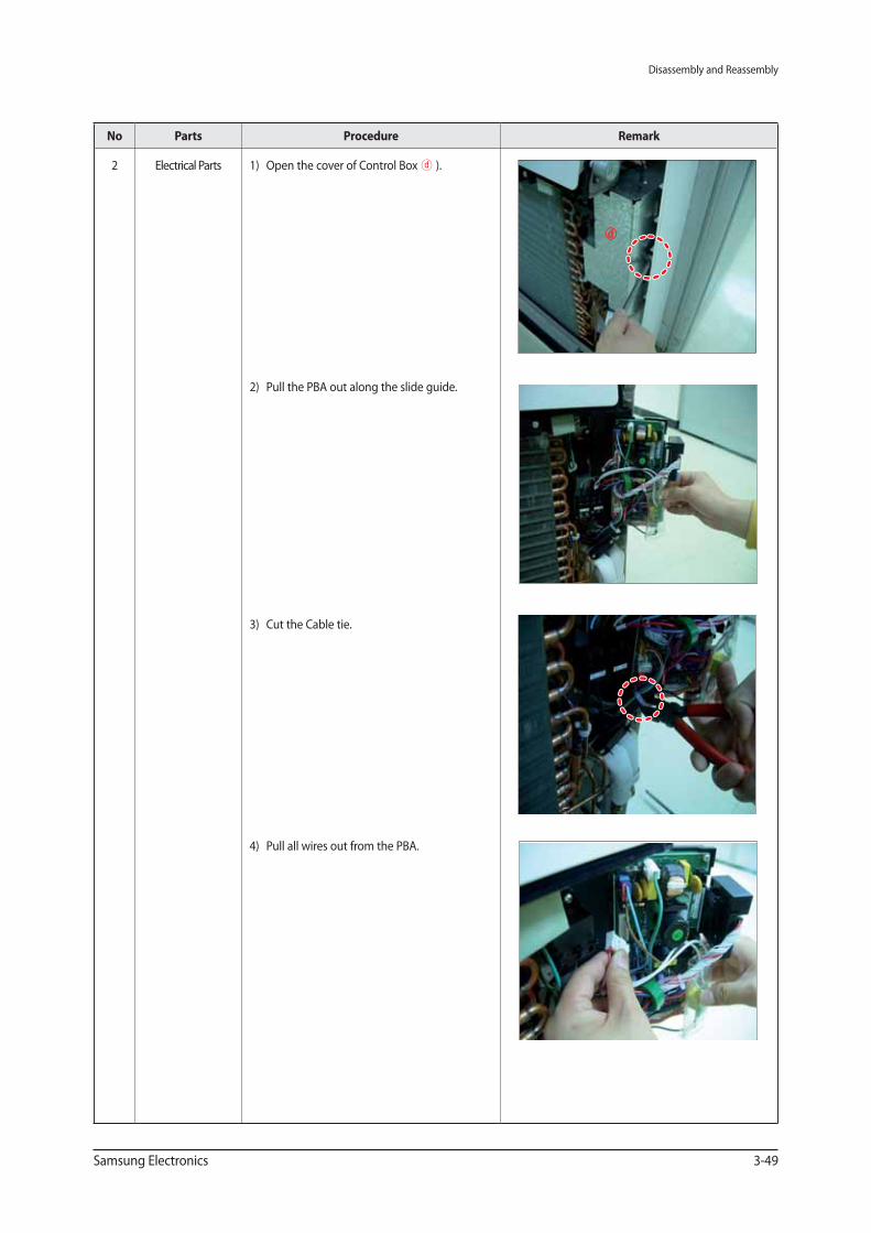
2 Electrical Parts 1) Open the cover of Control Box ).
2) Pull the PBA out along the slide guide.
3) Cut the Cable tie.
4) Pull all wires out from the PBA.
Disassembly and Reassembly
3-50 Samsung Electronics
No Parts Procedure Remark
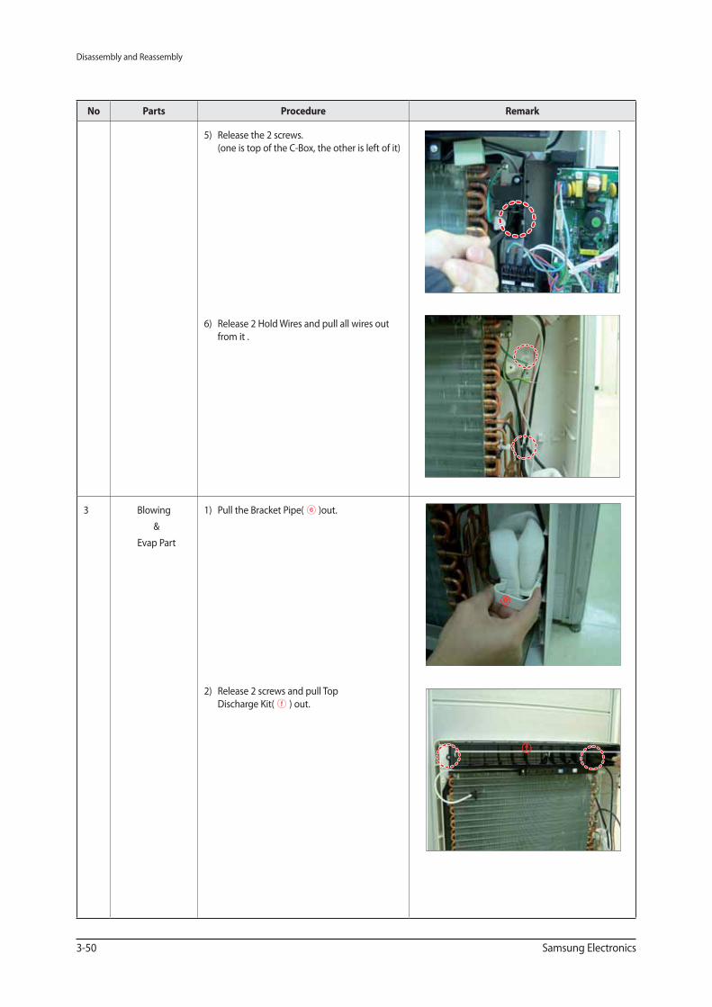
5) Release the 2 screws.
(one is top of the C-Box, the other is left of it)
6) Release 2 Hold Wires and pull all wires out
from it .
3 Blowing
&
Evap Part
1) Pull the Bracket Pipe( )out.
2) Release 2 screws and pull Top
Discharge Kit( ) out.
Disassembly and Reassembly
Samsung Electronics 3-51
No Parts Procedure Remark
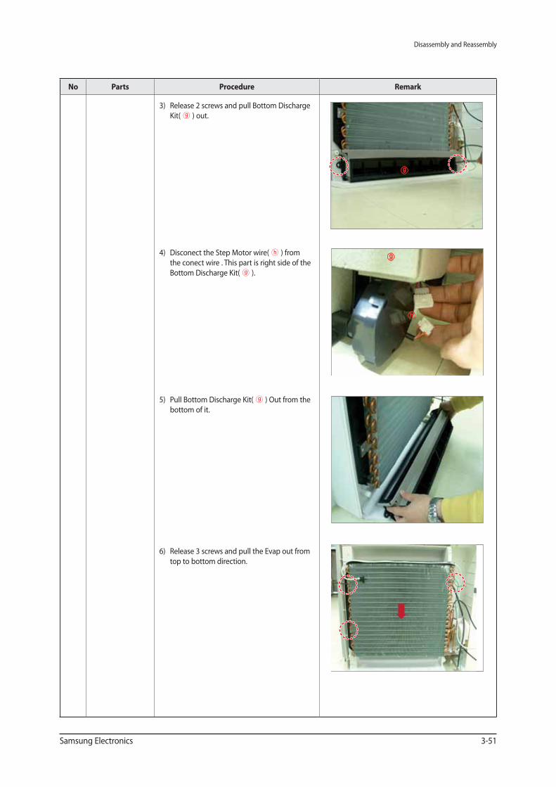
3) Release 2 screws and pull Bottom Discharge
Kit( ) out.
4) Disconect the Step Motor wire( ) from
the conect wire . This part is right side of the
Bottom Discharge Kit( ).
5) Pull Bottom Discharge Kit( ) Out from the
bottom of it.
6) Release 3 screws and pull the Evap out from
top to bottom direction.
Disassembly and Reassembly
3-52 Samsung Electronics
No Parts Procedure Remark
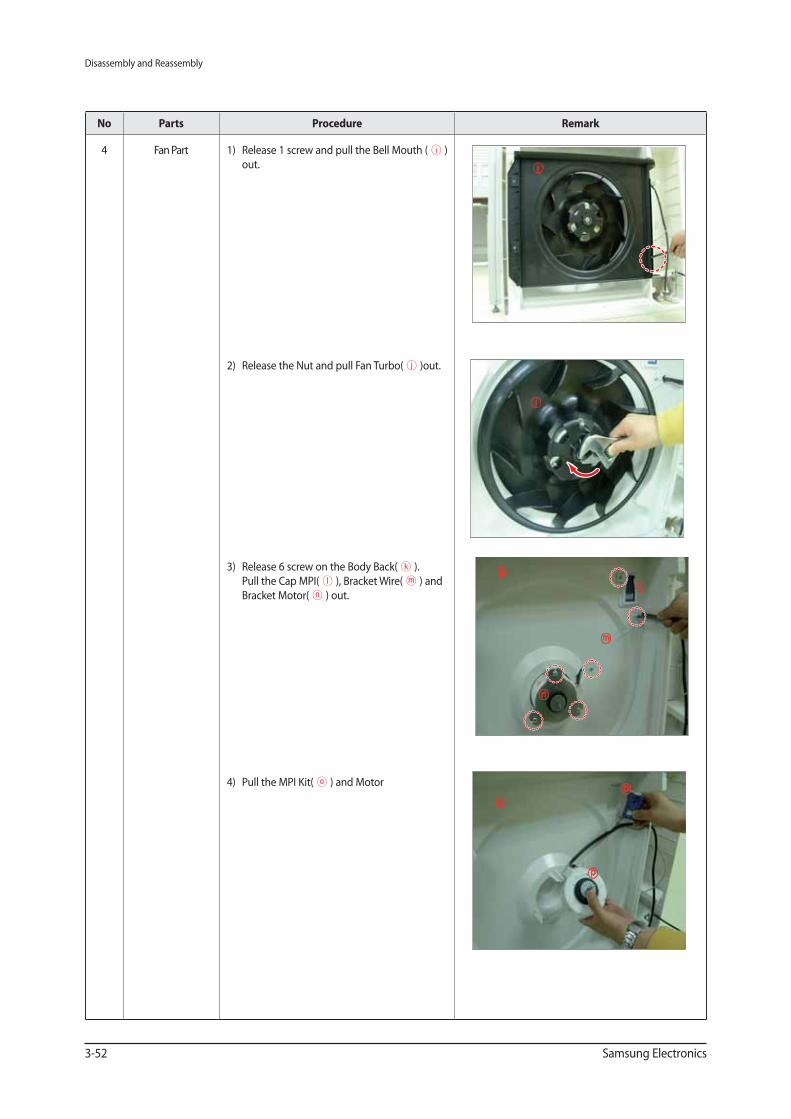
4 Fan Part 1) Release 1 screw and pull the Bell Mouth ( )
out.
2) Release the Nut and pull Fan Turbo( )out.
3) Release 6 screw on the Body Back( ).
Pull the Cap MPI( ), Bracket Wire( ) and
Bracket Motor( ) out.
4) Pull the MPI Kit( ) and Motor
Disassembly and Reassembly
Samsung Electronics 3-53
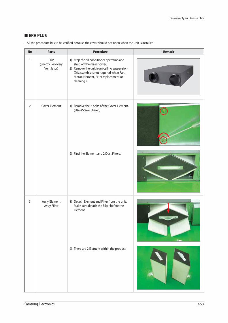
ERV PLUS
No Parts Procedure Remark
1 ERV
(Energy Recovery
Ventilator)
1) Stop the air conditioner operation and
shut off the main power.
2) Remove the unit from ceiling suspension.
(Disassembly is not required when Fan,
Motor, Element, Filter replacement or
cleaning.)
2 Cover Element 1) Remove the 2 bolts of the Cover Element.
(Use +Screw Driver.)
2) Find the Element and 2 Dust Filters.
3 Ass’y Element
Ass’y Filter
1) Detach Element and Filter from the unit.
Make sure detach the Filter before the
Element.
2) There are 2 Element within the product.
– All the procedure has to be verified because the cover should not open when the unit is installed.
Disassembly and Reassembly
3-54 Samsung Electronics
No Parts Procedure Remark
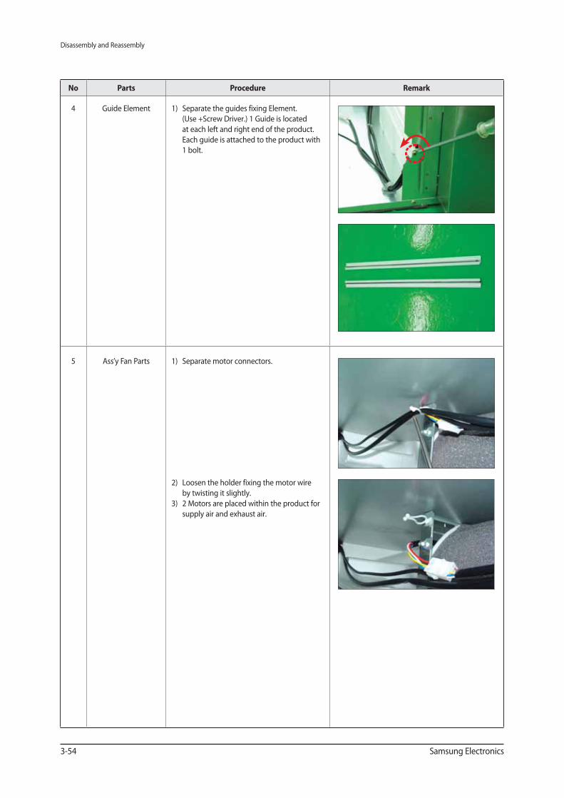
4 Guide Element 1) Separate the guides fixing Element.
(Use +Screw Driver.) 1 Guide is located
at each left and right end of the product.
Each guide is attached to the product with
1 bolt.
5 Ass’y Fan Parts 1) Separate motor connectors.
2) Loosen the holder fixing the motor wire
by twisting it slightly.
3) 2 Motors are placed within the product for
supply air and exhaust air.
Disassembly and Reassembly
Samsung Electronics 3-55
No Parts Procedure Remark
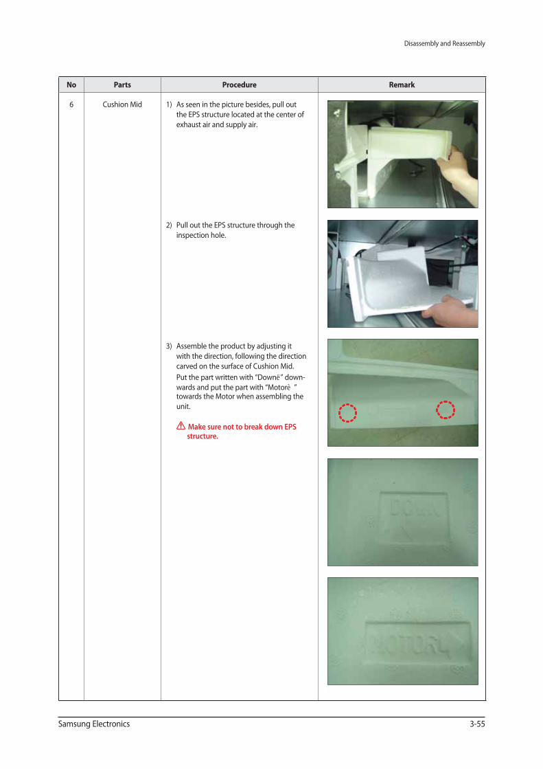
6 Cushion Mid 1) As seen in the picture besides, pull out
the EPS structure located at the center of
exhaust air and supply air.
2) Pull out the EPS structure through the
inspection hole.
3) Assemble the product by adjusting it
with the direction, following the direction
carved on the surface of Cushion Mid.
Put the part written with “Down↓” down-
wards and put the part with “Motor→” towards the Motor when assembling the
unit.
Make sure not to break down EPS structure.
Disassembly and Reassembly
3-56 Samsung Electronics
No Parts Procedure Remark
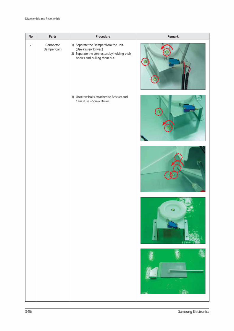
7 Connector
Damper Cam
1) Separate the Damper from the unit.
(Use +Screw Driver.)
2) Separate the connectors by holding their
bodies and pulling them out.
3) Unscrew bolts attached to Bracket and
Cam. (Use +Screw Driver.)
Disassembly and Reassembly
Samsung Electronics 3-57
No Parts Procedure Remark
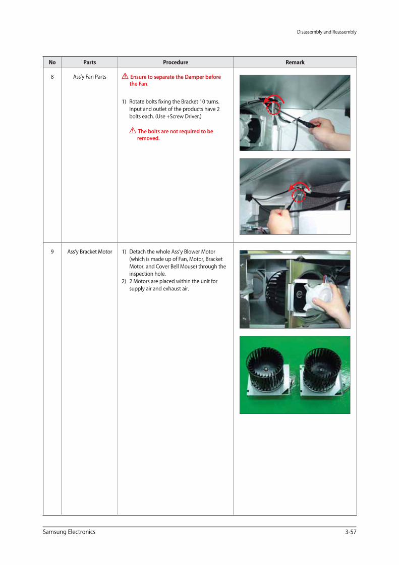
8 Ass’y Fan Parts Ensure to separate the Damper before the Fan.
1) Rotate bolts fixing the Bracket 10 turns.
Input and outlet of the products have 2
bolts each. (Use +Screw Driver.)
The bolts are not required to be removed.
9 Ass’y Bracket Motor 1) Detach the whole Ass’y Blower Motor
(which is made up of Fan, Motor, Bracket
Motor, and Cover Bell Mouse) through the
inspection hole.
2) 2 Motors are placed within the unit for
supply air and exhaust air.
Disassembly and Reassembly
3-58 Samsung Electronics
No Parts Procedure Remark
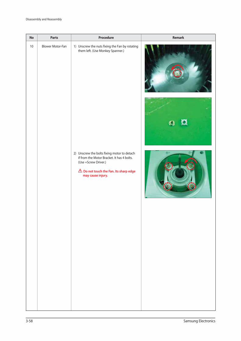
10 Blower Motor-Fan 1) Unscrew the nuts fixing the Fan by rotating
them left. (Use Monkey Spanner.)
2) Unscrew the bolts fixing motor to detach
if from the Motor Bracket. It has 4 bolts.
(Use +Screw Driver.)
Do not touch the Fan. Its sharp edge may cause injury.
Disassembly and Reassembly
Samsung Electronics 3-59
No Parts Procedure Remark
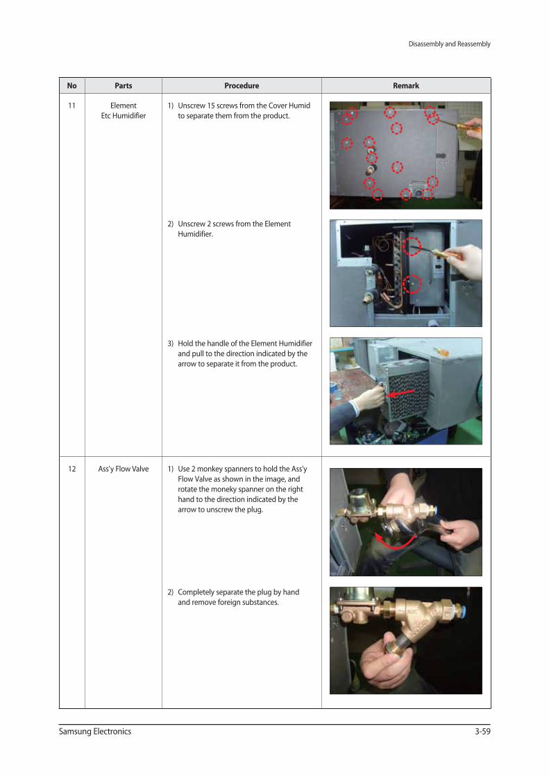
11 Element
Etc Humidifier
1) Unscrew 15 screws from the Cover Humid
to separate them from the product.
2) Unscrew 2 screws from the Element
Humidifier.
3) Hold the handle of the Element Humidifier
and pull to the direction indicated by the
arrow to separate it from the product.
12 Ass'y Flow Valve 1) Use 2 monkey spanners to hold the Ass'y
Flow Valve as shown in the image, and
rotate the moneky spanner on the right
hand to the direction indicated by the
arrow to unscrew the plug.
2) Completely separate the plug by hand
and remove foreign substances.
Disassembly and Reassembly
3-60 Samsung Electronics
No Parts Procedure Remark
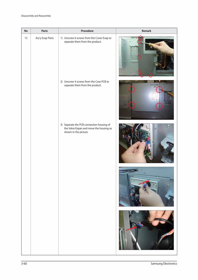
13 Ass'y Evap Parts 1) Unscrew 6 screws from the Cover Evap to
separate them from the product.
2) Unscrew 4 screws from the Case PCB to
separate them from the product.
3) Separate the PCB connection housing of
the Valve Expan and move the housing as
shown in the picture.
Disassembly and Reassembly
Samsung Electronics 3-61
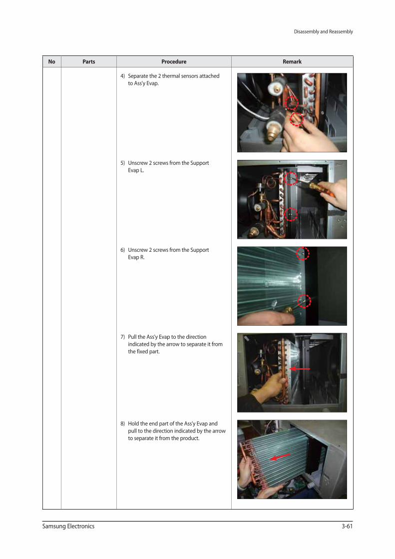
No Parts Procedure Remark
4) Separate the 2 thermal sensors attached
to Ass'y Evap.
5) Unscrew 2 screws from the Support
Evap L.
6) Unscrew 2 screws from the Support
Evap R.
7) Pull the Ass'y Evap to the direction
indicated by the arrow to separate it from
the fixed part.
8) Hold the end part of the Ass'y Evap and
pull to the direction indicated by the arrow
to separate it from the product.
Disassembly and Reassembly
3-62 Samsung Electronics
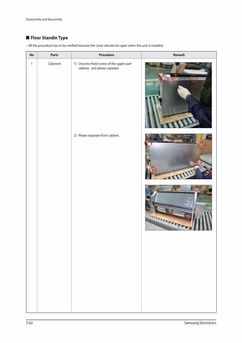
Floor Standin Type
No Parts Procedure Remark
1 Cabinnet 1) Unscrew fixed screw of the upper part
cabinet, and please separate
2) Please separate front cabinet.
– All the procedure has to be verified because the cover should not open when the unit is installed.
Disassembly and Reassembly
Samsung Electronics 3-63
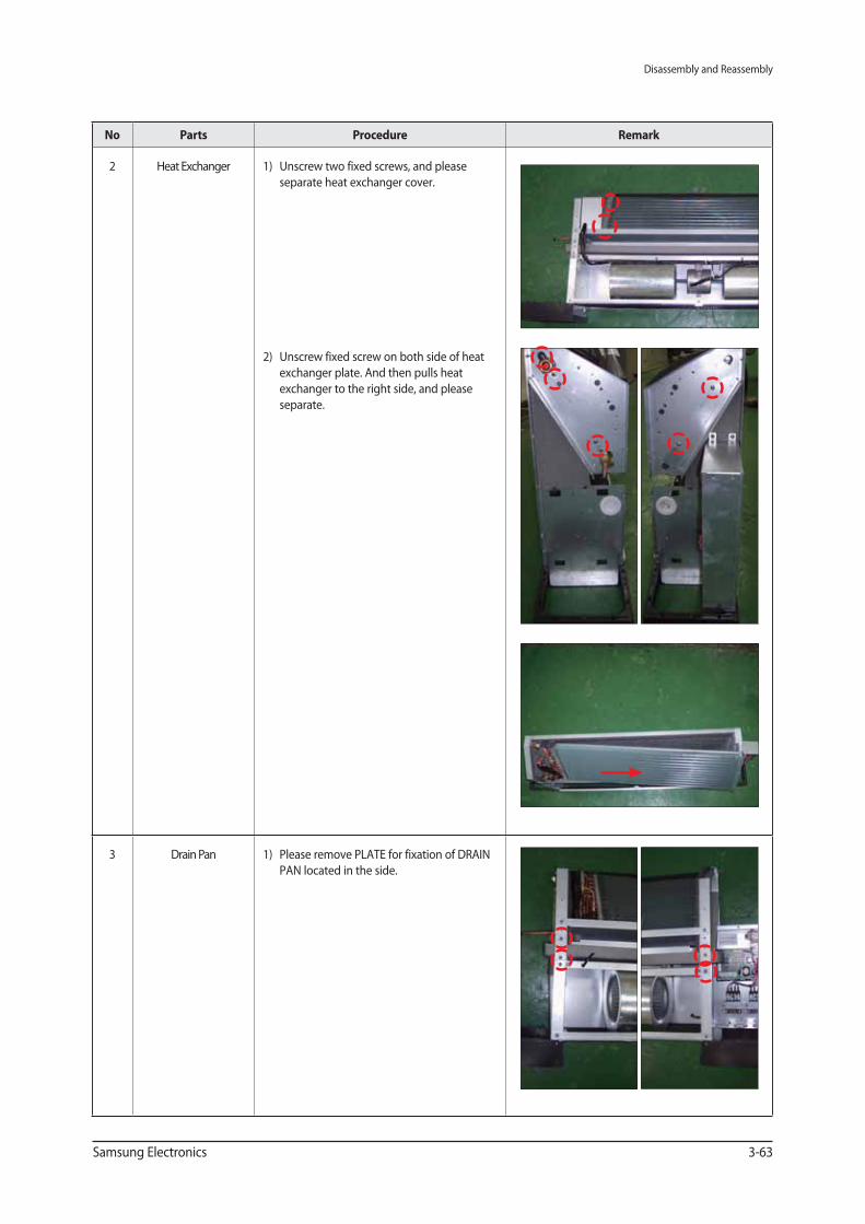
No Parts Procedure Remark
2 Heat Exchanger 1) Unscrew two fixed screws, and please
separate heat exchanger cover.
2) Unscrew fixed screw on both side of heat
exchanger plate. And then pulls heat
exchanger to the right side, and please
separate.
3 Drain Pan 1) Please remove PLATE for fixation of DRAIN
PAN located in the side.
Disassembly and Reassembly
3-64 Samsung Electronics
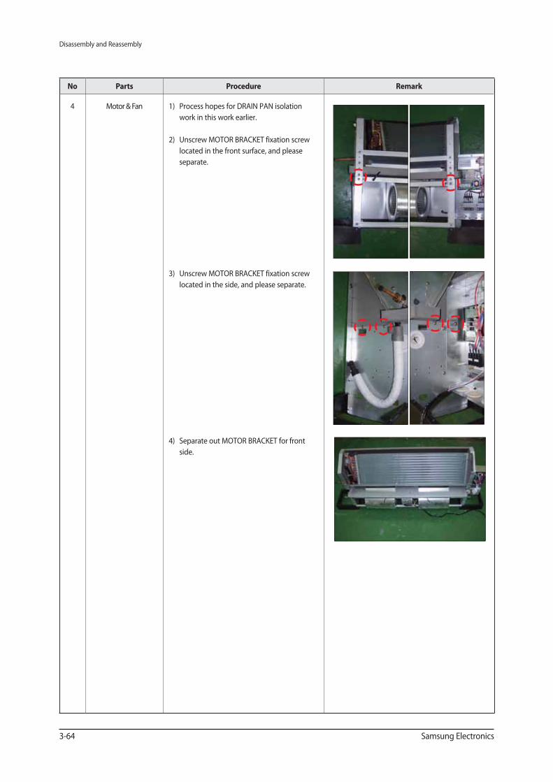
No Parts Procedure Remark
4 Motor & Fan 1) Process hopes for DRAIN PAN isolation
work in this work earlier.
2) Unscrew MOTOR BRACKET fixation screw
located in the front surface, and please
separate.
3) Unscrew MOTOR BRACKET fixation screw
located in the side, and please separate.
4) Separate out MOTOR BRACKET for front
side.
Disassembly and Reassembly
Samsung Electronics 3-65
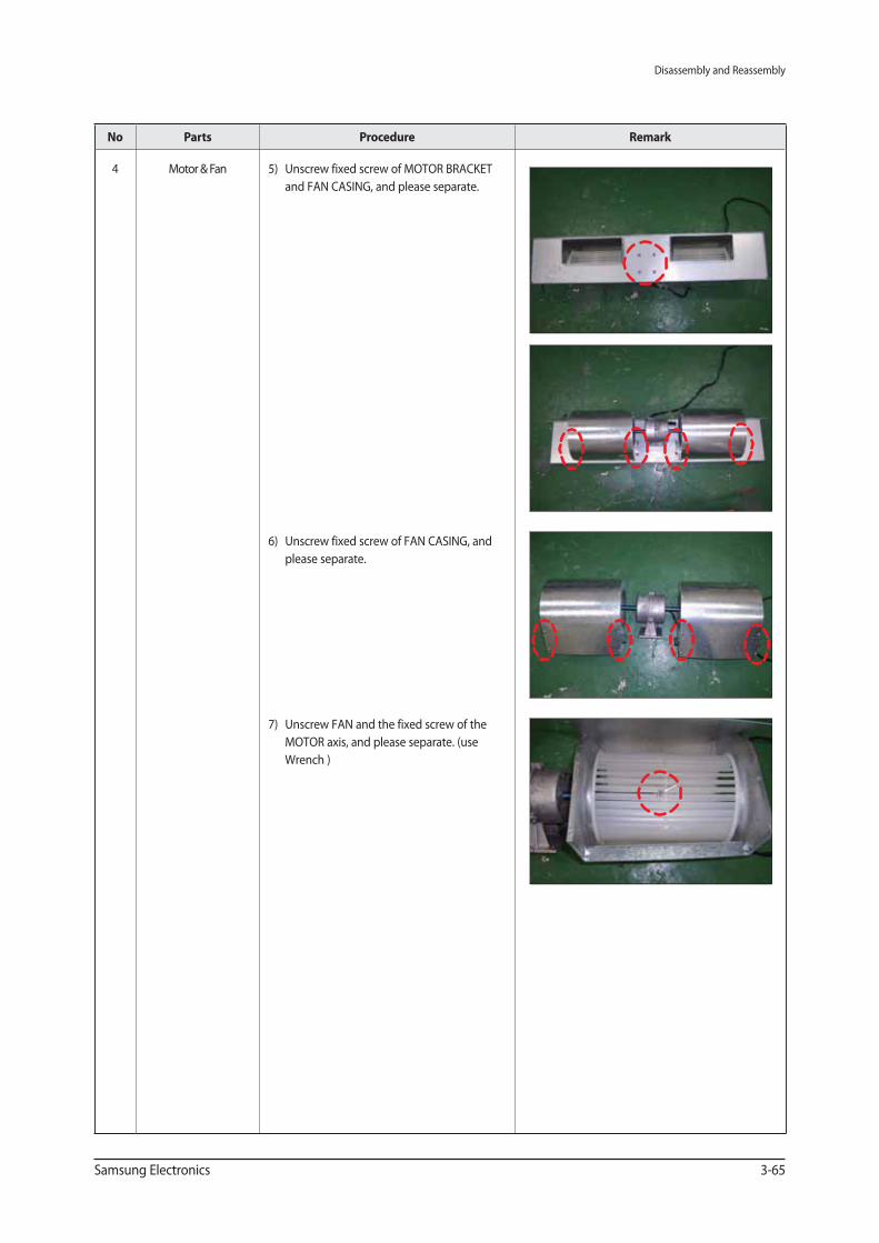
No Parts Procedure Remark
4 Motor & Fan 5) Unscrew fixed screw of MOTOR BRACKET
and FAN CASING, and please separate.
6) Unscrew fixed screw of FAN CASING, and
please separate.
7) Unscrew FAN and the fixed screw of the
MOTOR axis, and please separate. (use
Wrench )
Disassembly and Reassembly
3-66 Samsung Electronics
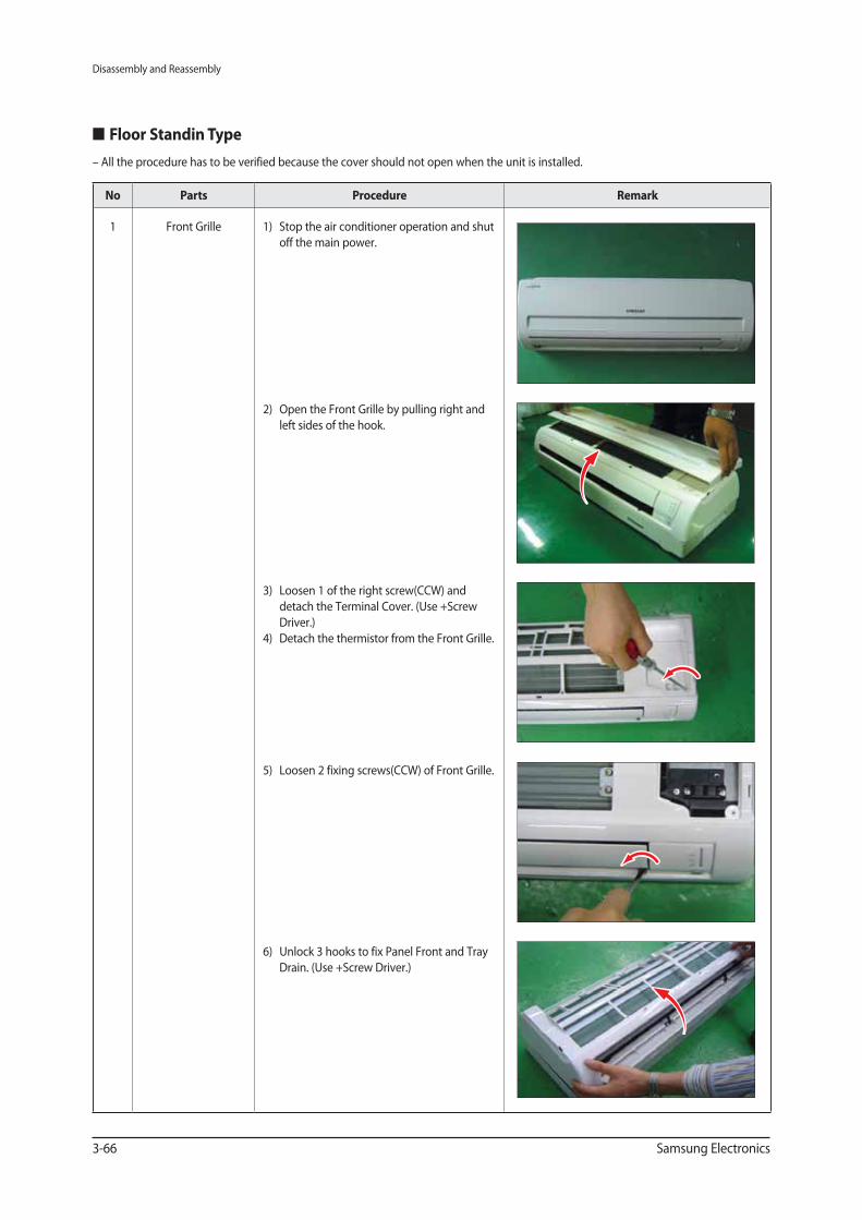
Floor Standin Type
No Parts Procedure Remark
1 Front Grille 1) Stop the air conditioner operation and shut
off the main power.
2) Open the Front Grille by pulling right and
left sides of the hook.
3) Loosen 1 of the right screw(CCW) and
detach the Terminal Cover. (Use +Screw
Driver.)
4) Detach the thermistor from the Front Grille.
5) Loosen 2 fixing screws(CCW) of Front Grille.
6) Unlock 3 hooks to fix Panel Front and Tray
Drain. (Use +Screw Driver.)
– All the procedure has to be verified because the cover should not open when the unit is installed.
Disassembly and Reassembly
Samsung Electronics 3-67
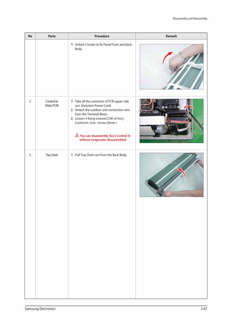
No Parts Procedure Remark
7) Unlock 3 hooks to fix Panel Front and Back-
Body.
2 Control-In
(Main PCB)
1) Take all the connector of PCB upper side
out. (Inclusion Power Cord)
2) Detach the outdoor unit connection wire
from the Terminal Block.
3) Loosen 4 fixing screws(CCW) of Ass'y
Control-In. (Use +Screw Driver.)
You can disassembly Ass'y Control In without evaporator disassembled.
3 Tray Drain 1) Pull Tray Drain out from the Back Body.
Disassembly and Reassembly
3-68 Samsung Electronics
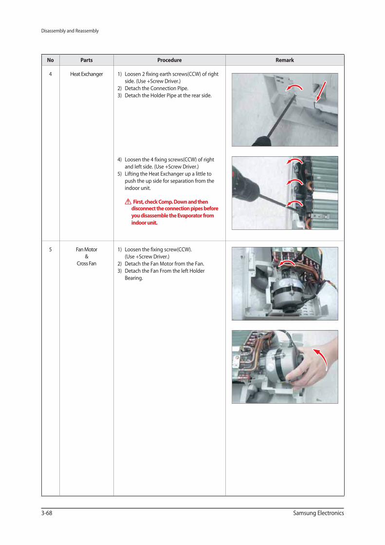
No Parts Procedure Remark
4 Heat Exchanger 1) Loosen 2 fixing earth screws(CCW) of right
side. (Use +Screw Driver.)
2) Detach the Connection Pipe.
3) Detach the Holder Pipe at the rear side.
4) Loosen the 4 fixing screws(CCW) of right
and left side. (Use +Screw Driver.)
5) Lifting the Heat Exchanger up a little to
push the up side for separation from the
indoor unit.
First, check Comp. Down and then disconnect the connection pipes before you disassemble the Evaporator from indoor unit.
5 Fan Motor
&
Cross Fan
1) Loosen the fixing screw(CCW).
(Use +Screw Driver.)
2) Detach the Fan Motor from the Fan.
3) Detach the Fan From the left Holder
Bearing.
Disassembly and Reassembly
Samsung Electronics 3-69
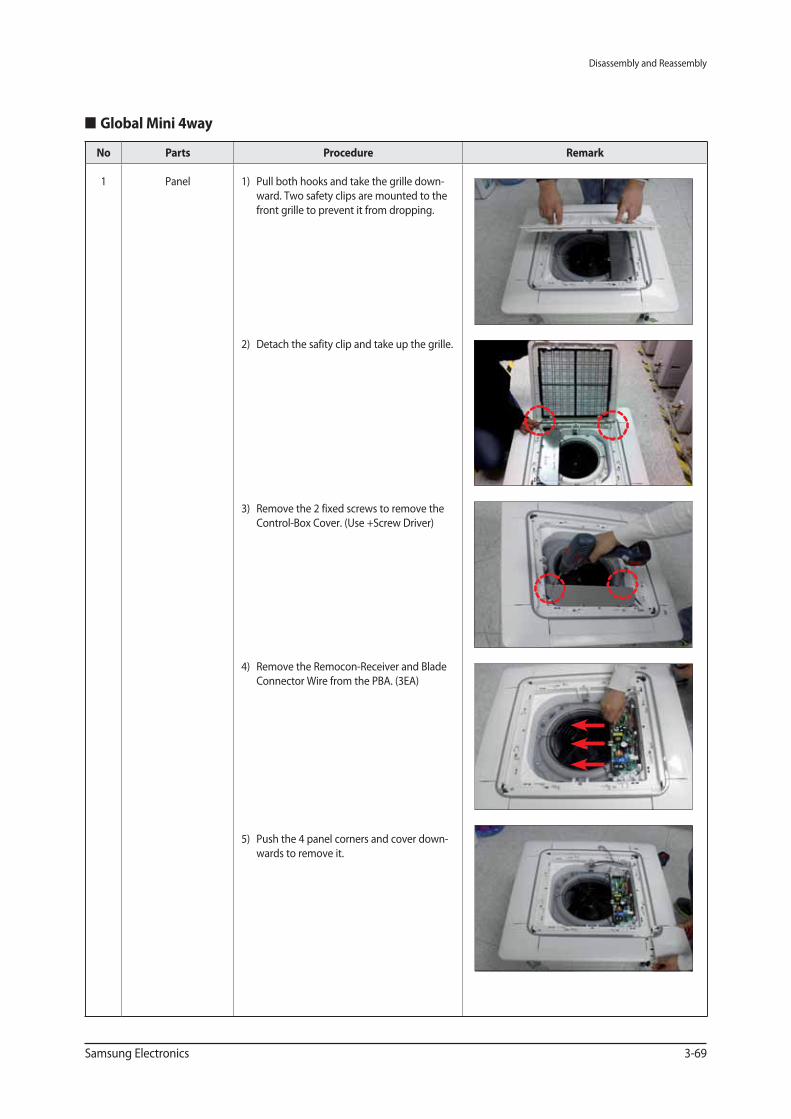
Global Mini 4way
No Parts Procedure Remark
1 Panel 1) Pull both hooks and take the grille down-
ward. Two safety clips are mounted to the
front grille to prevent it from dropping.
2) Detach the safity clip and take up the grille.
3) Remove the 2 fixed screws to remove the
Control-Box Cover. (Use +Screw Driver)
4) Remove the Remocon-Receiver and Blade
Connector Wire from the PBA. (3EA)
5) Push the 4 panel corners and cover down-
wards to remove it.
Disassembly and Reassembly
3-70 Samsung Electronics
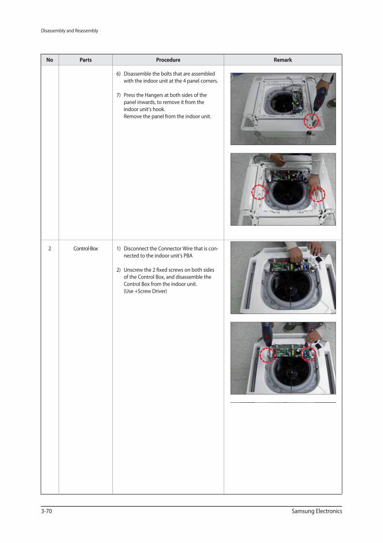
No Parts Procedure Remark
6) Disassemble the bolts that are assembled
with the indoor unit at the 4 panel corners.
7) Press the Hangers at both sides of the
panel inwards, to remove it from the
indoor unit’s hook.
Remove the panel from the indoor unit.
2 Control-Box 1) Disconnect the Connector Wire that is con-
nected to the indoor unit’s PBA
2) Unscrew the 2 fixed screws on both sides
of the Control Box, and disassemble the
Control Box from the indoor unit.
(Use +Screw Driver)
Disassembly and Reassembly
Samsung Electronics 3-71
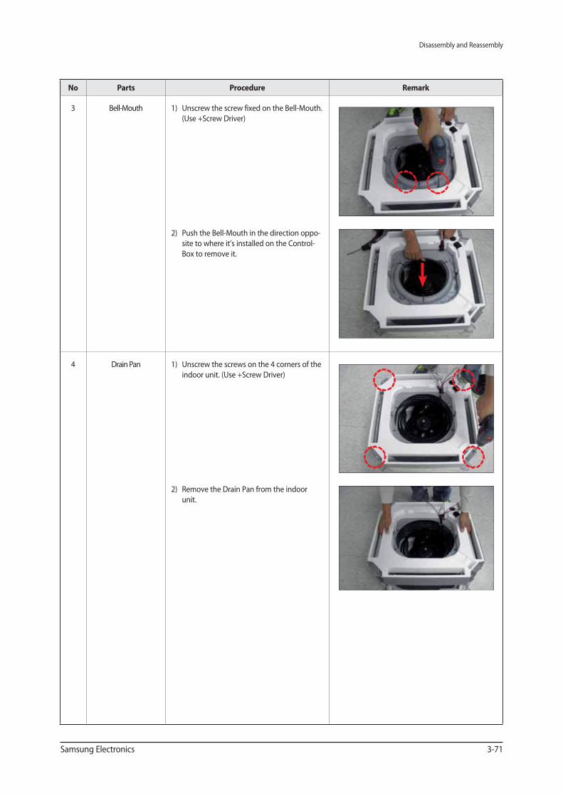
No Parts Procedure Remark
3 Bell-Mouth 1) Unscrew the screw fixed on the Bell-Mouth.
(Use +Screw Driver)
2) Push the Bell-Mouth in the direction oppo-
site to where it’s installed on the Control-
Box to remove it.
4 Drain Pan 1) Unscrew the screws on the 4 corners of the
indoor unit. (Use +Screw Driver)
2) Remove the Drain Pan from the indoor
unit.
Disassembly and Reassembly
3-72 Samsung Electronics
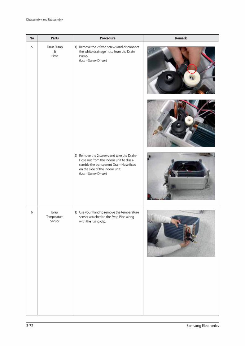
No Parts Procedure Remark
5 Drain Pump
&
Hose
1) Remove the 2 fixed screws and disconnect
the white drainage hose from the Drain
Pump.
(Use +Screw Driver)
2) Remove the 2 screws and take the Drain-
Hose out from the indoor unit to disas-
semble the transparent Drain-Hose fixed
on the side of the indoor unit.
(Use +Screw Driver)
6 Evap.
Temperature
Sensor
1) Use your hand to remove the temperature
sensor attached to the Evap Pipe along
with the fixing clip.
Disassembly and Reassembly
Samsung Electronics 3-73
No Parts Procedure Remark
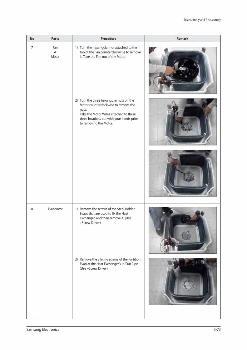
7 Fan
&
Motor
1) Turn the hexangular nut attached to the
top of the Fan counterclockwise to remove
it. Take the Fan out of the Motor.
2) Turn the three hexangular nuts on the
Motor counterclockwise to remove the
nuts.
Take the Motor Wires attached to these
three locations out with your hands prior
to removing the Motor.
8 Evaporator 1) Remove the screws of the Steel Holder
Evaps that are used to fix the Heat
Exchanger, and then remove it. (Use
+Screw Driver)
2) Remove the 2 fixing screws of the Partition
Evap at the Heat Exchanger’s In/Out Pipe.
(Use +Screw Driver)
Disassembly and Reassembly
3-74 Samsung Electronics
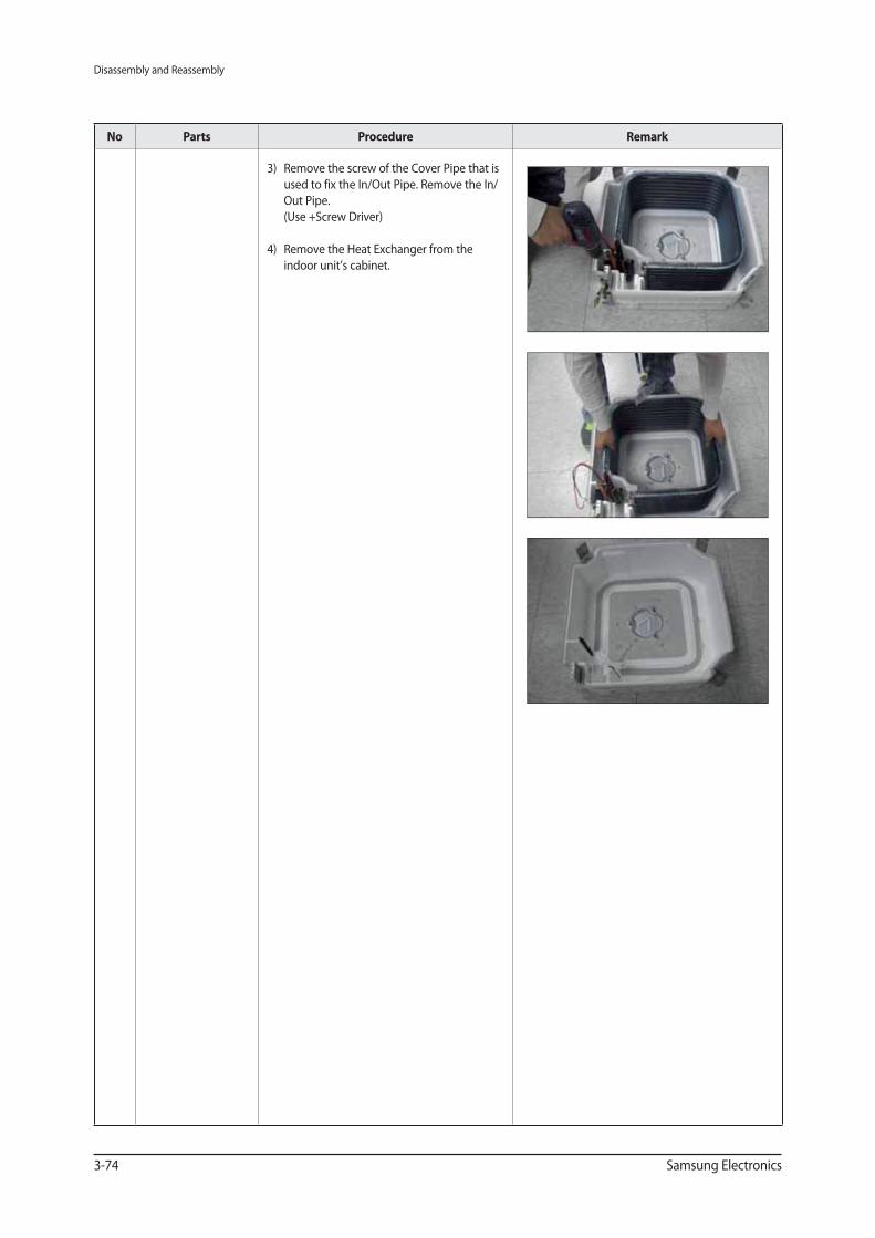
No Parts Procedure Remark
3) Remove the screw of the Cover Pipe that is
used to fix the In/Out Pipe. Remove the In/
Out Pipe.
(Use +Screw Driver)
4) Remove the Heat Exchanger from the
indoor unit’s cabinet.