1edt621885 - international nuclear information system (inis)
TRANSCRIPT
SEP 2 9 1897/ i ? \ ENGINEERING DATA TRANSM1TTALP«ge1 of i
1 E D T621885
2. To: (Receiving Organization)
Packaging Engineering3. From: (Originating Organization)
Packaging Engineering4 . Related EDT Ho. :
6218815. Proj./Prog./Dept./Div.:
03E00
6. Design Authority/ Design Agent/Cog.Engr.:
T. Romano
7. Purchase Order No. :
NA8. Originator Remarks:
The attached SEP is being submitted for approval andrelease.
9. Equip./Component No.:
NA10. System/Bldg./Facility:
NA11. Rece-iver Remarks: 11A. Design Baseline Document? [] Yes [X] No 12. Major Assm. Dug. No.:
_ 1 NA13. Permit/Permit Application No.:
NA14. Required Response Date:
NADATA TRANSMITTED
(B) Document/Drawing No. SheetNo.
(D)Rev. (E) Title or Description of Data
ApprovalDesig-nator Trans-
mittalDispo-
HNF-SD-TP-SEP-063 NA Safety Evaluation forPackaging (Onsite)Plutonium RecycleTest Reactor GraphiteCask
SQ 1,2
Approval Designator (F) Reason for Transmittal (G) Disposition <H) & (I)
E, S, Q, D or N/A(see WHC-CM-3-5,Sec. 12.7)
1. Approval 4. Review2. Release 5. Post-Review3. Information 6. Dist. (Receipt Acknow. Required)
1. Approved 4. Reviewed no/comment2. Approved w/comment 5. Reviewed w/comment3. Disapproved w/comment 6. Receipt acknowledged
17. SIGNATURE/DISTRIBUTION(See Approval Designator for required signatures)
[] Approved[] Approved w/comments[] Disapproved w/comments
BD-7400-172-2 (05/96) GEF097
BD-7400-172-1
HNF-SD-TP-SEP-063, Rev. 0
Safety Evaluation for Packaging (Onsite)Plutonium Recycle Test Reactor Graphite Cask
T. RomanoWaste Management Federal Services, Inc., Northwest OperationsRichland, Washington 99352U.S. Department of Energy Contract DE-AC06-96RL13200
EDT/ECN: EDT 621885Org Code: 03E00B&R Code: EX312O02O
UC: 513Charge Code:Total Pages:
K7A21178
Key Words: transfer, PRTR Graphite Cask, 327 Building, 300 Area,Type B, mixed oxide fuel, metal oxide fuel
Abstract: This safety evaluation for packaging (SEP) provides theevaluation necessary to demonstrate that the Plutonium Recycle TestReactor (PRTR) Graphite Cask meets the requirements of WHC-CM-2-14,Hazardous Material Packaging and Shipping, for transfer of Type B,fissile, non-highway route controlled quantities of radioactive materialwithin the 300 Area of the Hanford Site. The scope of this SEP includesrisk, shieldling, criticality, and tiedown analyses to demonstrate thatonsite transportation safety requirements are satisfied. This SEP alsoestablishes operational and maintenance guidelines to ensure thattransport of the PRTR Graphite Cask is performed safely in accordancewith WHC-CM-2-14. This SEP is valid until October 1, 1999. After thisdate, an update or upgrade to this document is required.
TRADEMARK DISCLAIMER. Reference herein to any specific comnercial product, process, or service bytrade name, trademark, manufacturer, or otherwise, does not necessarily constitute or imply itsendorsement, recommendation, or favoring by the United States Government or any agency thereof orits contractors or subcontractors.
Printed in the United States of America. To obtain copies of this document, contact: WHC/BCSDocument Control Services, P.O. Box 1970, Hailstop H6-08, Richland UA 99352, Phone (509) 372-2420;Fax (509) 376-4989.
(lease Approval / Date
Approved for Public Release
A-6400-073 (10/95) GEF321
HNF-SD-TP-SEP-063, Rev. 0
CONTENTS
PART A: DESCRIPTION AND OPERATIONS
1.0 INTRODUCTION A1-11.1 GENERAL INFORMATION . . A1-11.2 SYSTEM DESCRIPTION A1-11.3 REVIEW AND UPDATE CYCLES A1-1
2.0 PACKAGING SYSTEM . A2-12.1 CONFIGURATION AND DIMENSIONS A2-12.2 MATERIALS OF CONSTRUCTION A2-12.3 WEIGHTS AND CENTER OF GRAVITY A2-12.4 CONTAINMENT BOUNDARY A2-12.5 CAVITY SIZE A2-12.6 SHIELDING A2-12.7 LIFTING DEVICES A2-22.8 TIEDOWN DEVICES A2-2
3.0 PACKAGE CONTENTS A3-13.1 GENERAL DESCRIPTION A3-13.2 CONTENTS RESTRICTIONS A3-1
3.2.1 Radioactive Materials A3-13.2.2 Nonradioactive Hazardous Materials A3-1
4.0 TRANSPORT SYSTEM A4-14.1 TRANSPORTER A4-14.2 TIEDOWN SYSTEM A4-14.3 SPECIAL TRANSPORT REQUIREMENTS A4-2
4.3.1 Routing and Access Control A4-24.3.2 Radiological Limitations A4-24.3.3 Speed Limitations A4-24.3.4 Environmental Conditions A4-24.3.5 Frequency of Use and Mileage Limitations A4-34.3.6 Emergency Response A4-3
5.0 ACCEPTANCE OF PACKAGING FOR USE A5-15.1 NEW PACKAGING A5-15.2 PACKAGING FOR REUSE A5-1
6.0 OPERATING REQUIREMENTS A6-16.1 GENERAL REQUIREMENTS '. A6-16.2 LOADING OF CONTENTS INTO THE CASK A6-1
6.2.1 Inner Container Loading A6-16.2.2 Preparing the Cask for Loading A6-16.2.3 Loading Contents into the Cask A6-2
6.3 PREPARATION OF THE CASK FOR SHIPMENT A6-26.4 UNLOADING THE CASK A6-36.5 EMPTY PACKAGING .' A6-3
HNF-SD-TP-SEP-063, Rev. 0
CONTENTS (cont)
7.0 QUALITY ASSURANCE REQUIREMENTS A7-17.1 INTRODUCTION A7-17.2 GENERAL REQUIREMENTS A7-17.3 ORGANIZATION A7-17.4 QA PLAN AND ACTIVITIES : A7-2
7.4.1 Design Control A7-27.4.2 Procurement and Fabrication Control A7-27.4.3 Control of Operations/Processes A7-27.4.4 Control of Inspection A7-27.4.5 Test Control A7-27.4.6 Control of Measuring and Test Equipment A7-27.4.7 Control of Nonconforming Items A7-27.4.8 Corrective Action A7-37.4.9 QA Records and Document Control A7-37.4.10 Audits A7-3
8.0 MAINTENANCE . A8-18.1 GENERAL REQUIREMENTS A8-18.2 INSPECTION AND VERIFICATION SCHEDULES A8-18.3 RECORDS AND DOCUMENTATION A8-1
9:0 REFERENCES A9-1
10.0 APPENDICES A10-110.1 DRAWINGS A10-110.2 USER BIENNIAL INSPECTION CHECKLIST AND NONDESTRUCTIVE TESTING
OF LIFTING APPARATUS A10-17
PART B: PACKAGE EVALUATION
1.0 INTRODUCTION B1-11.1 SAFETY EVALUATION METHODOLOGY B1-11.2 EVALUATION SUMMARY AND CONCLUSIONS B1-1
1.2.1 Contents B1-11.2.2 Radiological Risk B1-11.2.3 Containment . B1-11.2.4 Shielding B1-11.2.5 Criticality B1-21.2.6 Structural B1 -21.2.7 Thermal B1 -21.2.8 Gas Generation B1 -21.2.9 Tiedown System B1-2
1.3 REFERENCES B1-2
2.0 CONTENTS EVALUATION B2-12.1 CHARACTERIZATION '. B2-1
2.1.1 Fissile Material Content B2-22.2 RESTRICTIONS B2-2
HNF-SD-TP-SEP-063, Rev. 0
CONTENTS (cont)
2.3 SIZE AND WEIGHT • B2-22.4 CONCLUSIONS B2-22.5 REFERENCES B2-3
3.0 RADIOLOGICAL RISK EVALUATION B3-13.1 INTRODUCTION B3-1
3.1.1 Summary of Results B3-13.2 RISK ACCEPTANCE CRITERIA B3-13.3 DOSE CONSEQUENCE ANALYSIS RESULTS B3-23.4 PACKAGE FAILURE THRESHOLD ANALYSIS B3-23.5 ACCIDENT RELEASE FREQUENCY ASSESSMENT • B3-3
3.5.1 Approach B3-33.5.2 Accident Release Frequency Analysis B3-4
3.6 EVALUATION AND CONCLUSION B3-63.7 REFERENCES B3-73.8 APPENDIX: CHECKLIST FOR REVIEW B3-8
4.0 CONTAINMENT EVALUATION B4-14.1 INTRODUCTION B4-14.2 CONTAINMENT SOURCE SPECIFICATION : . . . B4-14.3 NORMAL TRANSPORT CONDITIONS B4-1
4.3.1 Conditions To Be Evaluated B4-14.3.2 Containment Acceptance Criteria B4-1
4.4 ACCIDENT CONDITIONS B4-14.4.1 Conditions To Be Evaluated '. . . . B4-1
4.5 CONTAINMENT EVALUATION AND CONCLUSIONS B4-14.5.1 Normal Transport Conditions B4-14.5.2 Accident Conditions B4-2
4.6 SUMMARY OF DOSE CONSEQUENCE RESULTS B4-24.6.1 Introduction and Overview B4-34.6.2 Dose Consequence Analysis Methodology B4-34.6.3 Source Term B4-34.6.4 External Dose Due to Photon (Gamma) Exposure B4-44.6.5 External Dose Due to P-Particle Emitters B4-54.6.6 Inhalation and Ingestion Dose B4-54.6.7 Skin Contamination and Ingestion Dose B4-84.6.8 Submersion Dose Due to Gaseous Vapor B4-94.6.9 Special Considerations B4-94.6.10 Total Dose B4-9
4.7 REFERENCES B4-94.8 APPENDICES B4-11
4.8.1 ISO-PC Input File B4-114.8.2 GXQ Input File B4-124.8.3 GENII Input File B4-144.8.4 Checklist for Technical Peer Review B4-174.8.5 HEDOP Review Checklist B4-18
5.0 SHIELDING EVALUATION B5-15.1 INTRODUCTION . , B5-15.2 DIRECT RADIATION SOURCE SPECIFICATION B5-1
5.2.1 Gamma Source B5-15.2.2 Beta Source B5-15.2.3 Neutron Source B5-1
HNF-SD-TP-SEP-063, Rev. 0
CONTENTS (cont)
5.3 SUMMARY OF SHIELDING PROPERTIES OF MATERIALS B5-25.4 NORMAL TRANSPORT CONDITIONS B5-2
5.4.1 Conditions To Be Evaluated B5-25.4.2 Acceptance Criteria B5-25.4.3 Assumptions B5-25.4.4 Shielding Model B5-35.4.5 Shielding Calculations B5-4
5.5 ACCIDENT CONDITIONS B5-45.5.1 Conditions To Be Evaluated B5-45.5.2 Acceptance Criteria B5-45.5.3 Assumptions B5-55.5.4 Shielding Model . B5-55.5.5 Shielding Calculations B5-5
5.6 CONCLUSIONS B5-55.7 REFERENCES '. B5-65.8 APPENDICES < B5-6
5.8.1 ISO-PC Input Files '. B5-65.8.2 ORIGEN Input File B5-85.8.3 Neutron Dose Calculations • B5-95.8.4 Peer Review Checklist for Shielding B5-10
6.0 CRITICALITY EVALUATION B6-16.1 APPENDIX: CRITICALITY SAFETY ANALYSIS B6-1
7.0 STRUCTURAL EVALUATION B7-17.1 INTRODUCTION B7-17.2 STRUCTURAL EVALUATION OF PACKAGE B7-1
7.2.1 Package Structural Description B7-17.2.2 Chemical and Galvanic Reactions B7-17.2.3 Sizes of Package and Cavity B7-17.2.4 Weight B7-17.2.5 Tamper- Indicating Devices B7-17.2.6 Positive Closure B7-27.2.7 Lifting and Tiedown Devices B7-2
7.3 NORMAL TRANSPORT CONDITIONS B7-27.3.1 Conditions To Be Evaluated . B7-27.3.2 Acceptance Criteria B7-27.3.3 Hot and Cold Evaluation B7-27.3.4 Reduced and Increased External Pressure B7-37.3.5 Vibration B7-37.3.6 Water Spray B7-37.3.7 Compression B7-37.3.8 Inertial Loading B7-37.3.9 Penetration B7-47.3.10 Conclusions B7-4
7.4 REFERENCES B7-47.5 APPENDIX: STRUCTURAL ANALYSIS B7-5
8.0 THERMAL EVALUATION B8-18.1 INTRODUCTION B8-18.2 THERMAL EVALUATION OF PACKAGE B8-1
8.2.1 Package Description B8-1
HNF-SD-TP-SEP-063, Rev. 0
CONTENTS (cont)
8.3 NORMAL TRANSPORT CONDITIONS THERMAL EVALUATION B8-18.3.1 Conditions To Be Evaluated .- B8-18.3.2 Acceptance Criteria B8-18.3.3 Thermal Evaluation and Conclusions B8-1
8.4 REFERENCE B8-28.5 APPENDIX: PRTR GRAPHITE CASK NTC THERMAL EVALUATION B8-3
9.0 PRESSURE AND GAS GENERATION EVALUATION B9-1
10.0 TIEDOWN EVALUATION B10-110.1 SYSTEM DESI.GN B10-110.2 ATTACHMENTS, RATINGS, AND REQUIREMENTS B10-210.3 REFERENCE B10-210.4 APPENDIX: ENGINEERING SAFETY EVALUATION B10-3
FIGURE
B3-1 Flow Chart for Hanford Site Large Package Truck Accidents B3-5
LIST OF TABLES
A3-1 Maximum Allowable Source Term A3-1
A3-2 Fissile/Fissionable Material Limits in the Plutonium Recycle Test Reactor Graphite Cask . . . A3-2
A3-3 Inner Container Description . A3-2
A4-1 External Container Contamination Limits A4-2
B2-1 Maximum Allowable Source Term B2-1
B2-2 Decay Heat and A2 Calculation for the Plutonium Recycle Test Reactor Graphite Cask . . . . B2-1
B2-3 Fissile/Fissionable Material Limits in the Plutonium Recycle Test Reactor Graphite Cask . . . B2-2
B2-4 Inner Container Description B2-3
B3-1 Risk Acceptance Criteria Limits B3-2
B3-2 Summary of Doses B3-2
B3-3 Failure Thresholds and Conditional Release Probabilities B3-6
B4-1 Summary of Doses (rem) for the Plutonium Recycle Test Reactor Graphite Cask B4-2
B4-2 Plutonium Recycle Test Reactor Graphite Casks Radioactive Inventory B4-4
HNF-SD-TP-SEP-063, Rev. 0
LIST OF TABLES (cont)
B4-3 P-Particle Dose Rate for Beta Emitters Contributing > 0.01% to the Total Dose B4-5
B4-4 Accident Airborne Release Quantities, Ci B4-6
B4-5 Inhalation and Submersion Dose (reml B4-8
B5-1 Maximum Allowable Shielding Source Term B5-1
B5-2 Neutron Source Term for 175g of 239Pu B5-2
B5-3 Source Parameters B5-3
B5-4 Shielding Parameters B5-3
B5-5 Maximum Dose Rates Around the Plutonium Recycle Test Reactor Graphite Cask B5-4
B5-6 Maximum Dose Rates Around the Plutonium Recycle Test Reactor Graphite Cask forAccident Conditions B5-5
HNF-SD-TP-SEP-063, Rev. 0
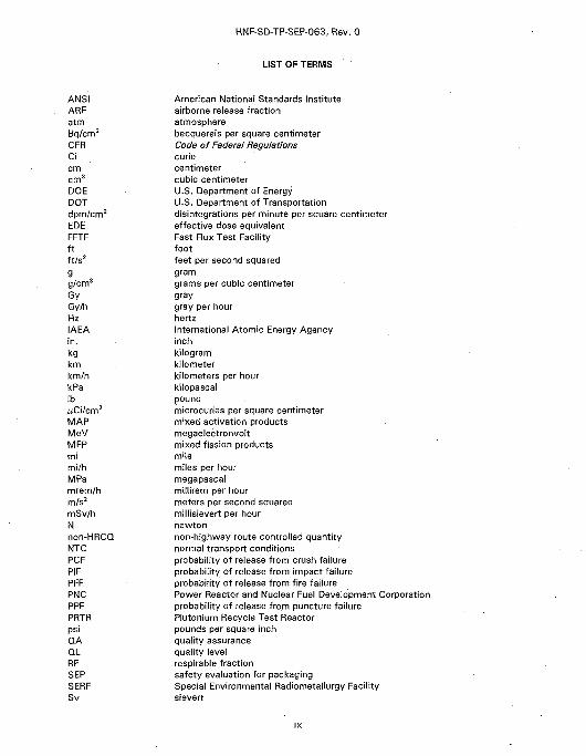
LIST OF TERMS
ANSIARFatmBq/cm2
CFRCicmcm3
DOEDOTdpm/cm2
EDEFFTFftft /s2
gg/cm3
GyGy/hHzIAEAin.kgkmkm/hkPaIb/uC'ilcm2
MAPMeVMFPmimi/hMPamrem/hm/s2
mSv/hNnon-HRCQNTCPCFPIFPFFPNCPPFPRTRpsiQAQLRFSEPSERFSv
American National Standards Instituteairborne release fractionatmospherebecquerels per square centimeterCode of Federal Regulationscuriecentimetercubic centimeterU.S. Department of EnergyU.S. Department of Transportationdisintegrations per minute per square centimetereffective dose equivalentFast Flux Test Facilityfootfeet per second squaredgramgrams per cubic centimetergraygray per hourhertzInternational Atomic Energy Agencyinchkilogramkilometerkilometers per hourkilopascalpoundmicrocuries per square centimetermixed activation productsmegaelectronvoltmixed fission productsmilemiles per hourmegapascalmillirem per hourmeters per second squaredmillisievert per hournewtonnon-highway route controlled quantitynormal transport conditionsprobability of release from crush failureprobability of release from impact failureprobability of release from fire failurePower Reactor and Nuclear Fuel Development Corporationprobability of release from puncture failurePlutonium Recycle Test Reactorpounds per square inchquality assurancequality levelrespirable fractionsafety evaluation for packagingSpecial Environmental Radiometallurgy Facilitysievert

HNF-SD-TP-SEP-063, Rev. 0
LIST OF TERMS (cont)
Sv/h sievert per hourTBq terabeoquerelTHI Transportation Hazard IndexW wattW/Ci watts per curie
HNF-SD-TP-SEP-063, Rev. 0
SAFETY EVALUATION FOR PACKAGING (ONSITE) PLUTONIUMRECYCLE TEST REACTOR GRAPHITE CASK
PART A: DESCRIPTION AND OPERATIONS
1.0 INTRODUCTION
1.1 GENERAL INFORMATION
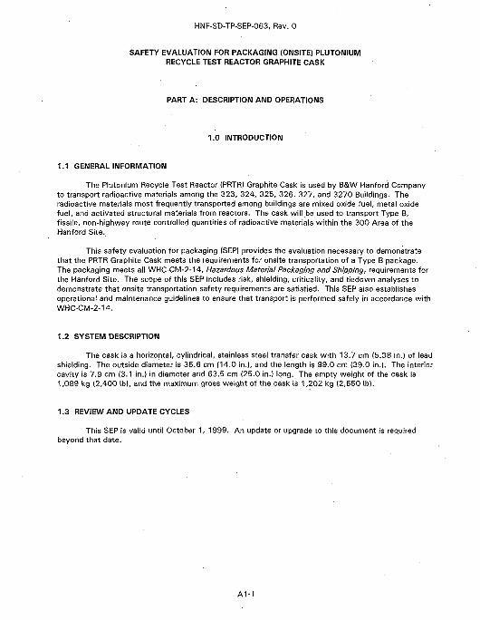
The Plutonium Recycle Test Reactor (PRTR) Graphite Cask is used by B&W Hanford Companyto transport radioactive materials among the 323, 324, 325, 326, 327, and 3270 Buildings. Theradioactive materials most frequently transported among buildings are mixed oxide fuel, metal oxidefuel, and activated structural materials from reactors. The cask will be used to transport Type B,fissile, non-highway route controlled quantities of radioactive materials within the 300 Area of theHanford Site.
This safety evaluation for packaging (SEP) provides the evaluation necessary to demonstratethat the PRTR Graphite Cask meets the requirements for onsite transportation of a Type B package.The packaging meets all WHC-CM-2-14, Hazardous Material Packaging and Shipping, requirements forthe Hanford Site. The scope of this SEP includes risk, shielding, criticality, and tiedown analyses todemonstrate that onsite transportation safety requirements are satisfied. This SEP also establishesoperational and maintenance guidelines to ensure that transport is performed safely in accordance withWHC-CM-2-14.
1.2 SYSTEM DESCRIPTION
The cask is a horizontal, cylindrical, stainless steel transfer cask with 13.7 cm (5.38 in.) of leadshielding. The outside diameter is 35.6 cm (14.0 in!), and the length is 99.0 cm (39.0 in.). The interiorcavity is 7.9 cm (3.1 in.) in diameter and 63.5 cm (25.0 in.) long. The empty weight of the cask is1,089 kg (2,400 Ib), and the maximum gross weight of the cask is 1,202 kg (2,650 Ib).
1.3 REVIEW AND UPDATE CYCLES
This SEP is valid until October 1, 1999. An update or upgrade to this document is requiredbeyond that date.
A1-1

HNF-SD-TP-SEP-063, Rev. 0
This page left intentionally blank.
A1-2
HNF-SD-TP-SEP-063, Rev. 0
2.0 PACKAGING SYSTEM
2.1 CONFIGURATION AND DIMENSIONS
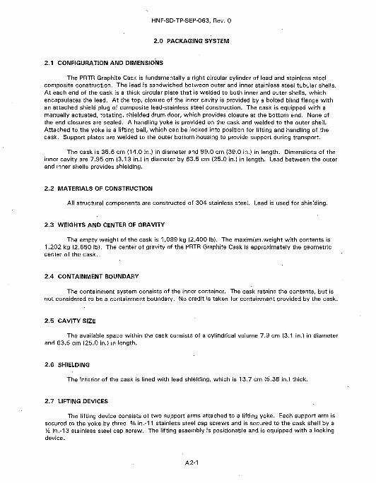
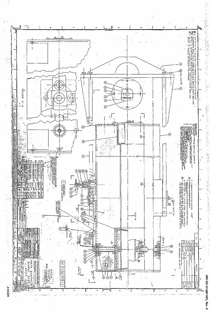
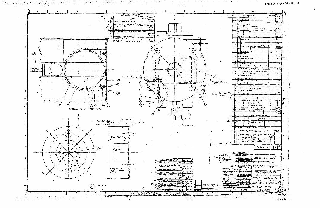
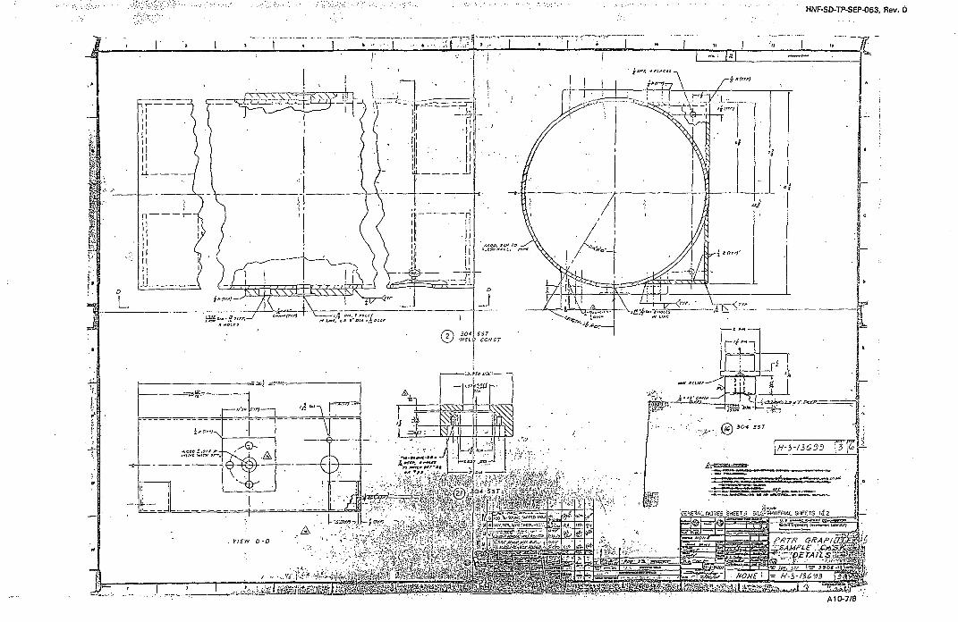
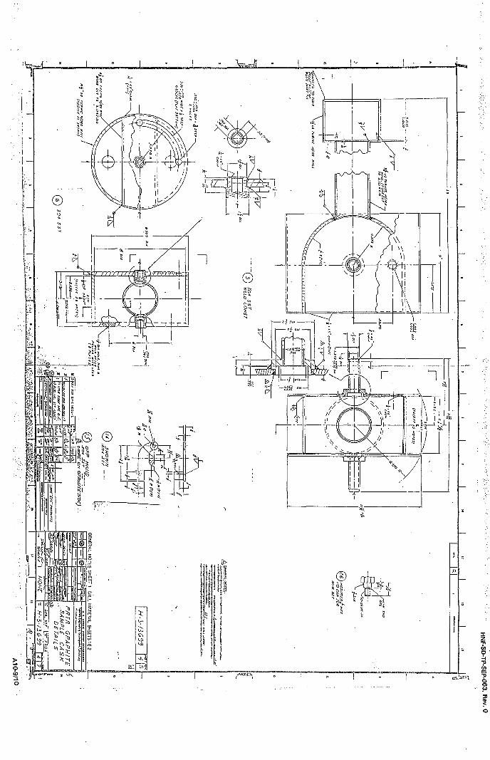
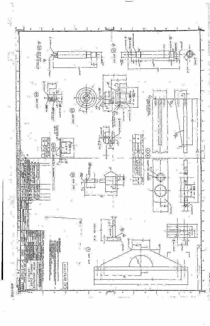
The PRTR Graphite Cask is fundamentally a right circular cylinder of lead and stainless steelcomposite construction. The lead is sandwiched between outer and inner stainless steel tubular shells.At each end of the cask is a thick circular pfate that is welded to both inner and outer sheils, whichencapsulates the lead. At the top, closure of the inner cavity is provided by a bolted blind flange withan attached shield plug of composite lead-stainless steel construction. The cask is equipped with amanually actuated, rotating, shielded drum door, which provides closure at the bottom end. None ofthe end closures are sealed. A handling yoke is provided on the cask and welded to the outer shell.Attached to the yoke is a lifting bail, which can be locked into position for lifting and handling of thecask. Support plates are welded to the outer bottom housing to provide support during transport.
The cask is 35.6 cm (14.0 in.) in diameter and 99.0 cm (39.0 in.) in length. Dimensions of theinner cavity are 7.95 cm (3.13 in.) in diameter by 63.5 cm (25.0 in.) in length. Lead between the outerand inner shells provides shielding.
2.2 MATERIALS OF CONSTRUCTION
All structural components are constructed of 304 stainless steel. Lead is used for shielding.
2.3 WEIGHTS AND CENTER OF GRAVITY
The empty weight of the cask is 1,089 kg (2,400 Ib). The maximum weight with contents is1,202 kg (2,650 Ib). The center of gravity of the PRTR Graphite Cask is approximately the geometriccenter of the cask.
2.4 CONTAINMENT BOUNDARY
The containment system consists of the inner container. The cask retains the contents, but isnot considered to be a containment boundary. No credit is taken for containment provided by the cask.
2.5 CAVITY SIZE
The available space within the cask consists of a cylindrical volume 7.9 cm (3.1 in.) in diameterand 63.5 cm (25.0 in.) in length.
2.6 SHIELDING
The interior of the cask is lined with lead shielding, which is 13.7 cm (5.38 in.) thick.
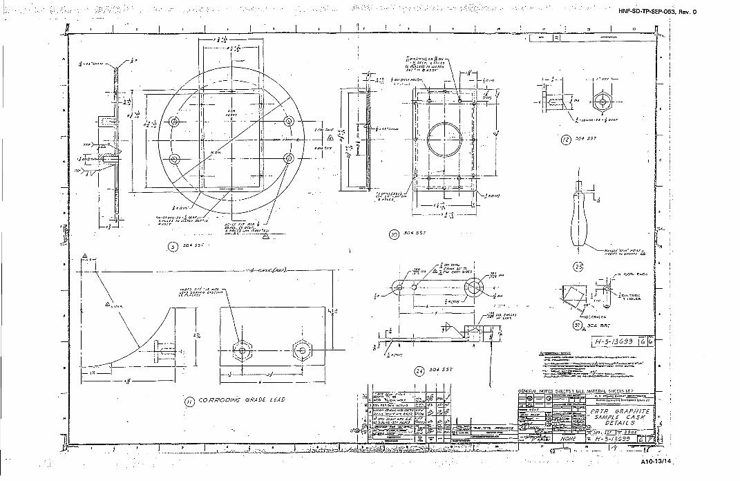
2.7 LIFTING DEVICES
The lifting device consists of two support arms attached to a lifting yoke. Each support arm issecured to the yoke by three % in.-11 stainless steel cap screws and is secured to the cask shell by a% in.-13 stainless steel cap screw. The lifting assembly is positionable and is equipped with a lockingdevice.
A2-1

HNF-SD-TP-SEP-063, Rev. 0
2.8 TIEDOWN DEVICES
There are no ttedowh devices attached to the cask.
A2-2
HNF-SD-TP-SEP-063, Rev. 0
3.0 PACKAGE CONTENTS
3.1 GENERAL DESCRIPTION
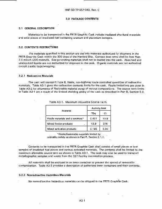
Materials to be transported in the PRTR Graphite Cask include irradiated structural materialsand solid pieces of irradiated fuel containing uranium and plutonium isotopes.
3.2 CONTENTS RESTRICTIONS
The materials specified in this section are the only materials authorized for shipment in thePRTR Graphite Cask within the 300 Area of the Hanford Site. Contact dose rates shall be less than2.0 mSv/h {200 mrem/h). Gas-generating materials shall not be loaded into the cask. Absorbed andunabsorbed liquids are not authorized for shipment in the cask. Organic materials are not authorizedexcept plastic bags/wrapping.
3.2.1 Radioactive Materials
The cask will transport Type B, fissile, non-highway route controlled quantities of radioactivematerials. Table A3-1 gives the radioactive contents limits for the cask. Fissile limitations are given inTable A3-2 for shipments of fissionable material scrap of various compositions. The source term limitsin Table A3-1 are a result of the limited shielding ability of the cask as described in Part B, Section 5.0.
Table A3-1. Maximum Allowable Source Term.
Material
Fissile materials and a emitters*
Mixed fission products
Mixed activation products
Activity limit
TBq
0.401
13.9
0.185
Ci
10.9
375
5.00
*Fissile/fissionable materials limited bycriticality safety as shown in Part B, Section 2.1.1.
Contents to be transported in the PRTR Graphite Cask shall consist of small pieces or testsamples of irradiated fuel pieces and various activated materials. The contents shall be limited to themaximum allowable source term as shown in Table A3-1. The cask may also be used to transportmetallographic samples and waste from the 327 Facility examination process.
All materials shall be enclosed in an inner container to prevent the spread of removablecontamination. Table A3-3 provides a description of authorized inner containers and their contents.
3.2.2 Nonradioactive Hazardous Materials
No nonradioactive hazardous materials can be shipped in the PRTR Graphite Cask.
A3-1
HNF-SD-TP-SEP-063, Rev. 0
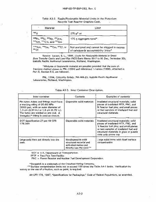
Table A3-2. Fissile/Fissionable Material Limits in the PlutoniumRecycle Test Reactor Graphite Cask.
Material
235(j
239Pu, 2 3 3U, 237Np, 241Am,2 4 3Am, 244Cm, and 247Cm
242mAm, 243Cm, 245Cm, 249Cf, or251Cf
Limit
275 g* or
175 g aggregate to ta l *
Not analyzed and cannot be shipped in excessof safeguards accountability limits'*
Source: Larson, S. L, 1996, Limits for Fissionable Material in SmallBore Transfer Casks and Lead Pigs (NCS Basis Memo 96-2 to M. Dec, December 30},Battelle Pacific Northwest Laboratories, Richland, Washington.
*Mixtures of fissionable material are possible provided that the sum-of-fractions method shown in PNL (1994} and referenced in Larson (1 996), attached inPart B, Section 6.0, are followed.
PNL, 1994, Criticality Safety, PNL-MA-25, Battelle Pacific NorthwestLaboratories, Richland, Washington.
Table A3-3. Inner Container Description.
Inner container
Pin tubes-tubes and fittings must havea working rating of 20.68 MPa(3000 psi), with an outer diameter of1.3 cm (0.50 in.) or 1.9 cm {0.75 in.).The tubes are welded on one end. ASwagelok* fitting is used as closure.
DOT Specification 2R per 49 CFR178.360
Large solid item put directly into thecask
Contents
Dtspersible solid materials
Dispersible solid materials
Nondispersible solidstructural material andactivated metals putdirectly into the cask**
Examples of contents
Irradiated structural materials; solidpieces of irradiated FFTF, PNC, andN Reactor fuel pins; and small piecesor test samples of irradiated fuel andstructural materials
Irradiated structural materials; solidpieces of irradiated FFTF, PNC, andN Reactor fuel pins; and small piecesor test samples of irradiated fuel andstructural materials in glass or plasticvials with screw cap
Large solid items with fixed surfacecontamination
DOT = U.S. Department of Transportation.FFTF = Fast Flux Test Facility.PNC = Power Reactor and Nuclear Fuel Development Corporation.
*Swagelok is a trademark of the Crawford Fitting Company.* * Surface contamination limits not to exceed 100 times the Table A4-1 limits. Verification by
survey or the use of a fixative, such as paint, is required.
49 CFR 178, 1 997, "Specifications for Packagings," Code of Federal Regulations, as amended.
A3-2
HNF-SD-TP-SEP-063, Rev. 0
4.0 TRANSPORT SYSTEM
4.1 TRANSPORTER
The transporter consists of a low boy or flatbed trailer and tractor. The trailer shall be rated forthe weight of the loaded cask and have a large enough bed to prevent the cask from protruding overthe edges of the trailer.
4.2 TIEDOWN SYSTEM
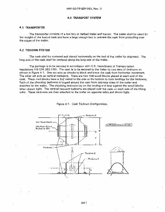
The cask shall be centered and placed horizontally on the bed of the trailer for shipment. Thelong axis of the cask shall be centered along the long axis of the trailer.
The package is to be secured in accordance with U.S. Department of Transportationregulations (49 CFR 393.100). The cask is to be secured to the trailer by two sets of tiedowns asshown in Figure 4-1. One set acts as chocks to block and brace the cask from horizontal movement.The other set acts as vertical restraints. There are two 4x4 wood blocks placed at each end of thecask. These 4x4 blocks have a 2x2 nailed to the side at the bottom to form landings for the tiedowns.Each of the chocking tiedowns is looped around the cask from opposite sides of the trailer andattached to the trailer. The chocking tiedowns lay on the landing and bear against the wood blockswhen drawn tight. The vertical restraint tiedowns are placed over the cask on each side of the liftingyoke. These tiedowns are then attached to the trailer on opposite sides and drawn tight.
Figure 4-1. Cask Tiedown Configuration.
4X4 Wood Block
SX2 Wood BlockNailed to 4X4
A4-1
HNF-SD-TP-SEP-063, Rev. 0
Each tiedown and trailer attachment point must have a minimum working strength of 11,120 N(2,500 Ib). The 2x2 wood blocks must be nailed to the 4x4 wood blocks with a minimum of three 10 dnails. The length of the blocks is specified as the same as the diameter of the cask to within atolerance of 0.32 cm (Va in.).
Alternative configurations that have been shown to meet 49 CFR 393, Subpart I, areacceptable.
4.3 SPECIAL TRANSPORT REQUIREMENTS
4.3.1 Routing and Access Control
The PRTR Graphite Cask is authorized for oiisite transport only within the 300 Area. Transfersshall be made in accordance with WHC-CM-2-14 over a predetermined route.
4.3.2 Radiological Limitations
The dose rate must be less than 2 mSv/h {200 mrem/h) at the surface of the cask, 0.1 mSv/h(10 mrem/h) at 1 m from the cask surface, and 0.02 mSv/h (2 mrem/h) in any normally occupied space.Transport of the PRTR Graphite Cask above these limits is not authorized. The shielding analysis inPart B, Section 5.0, shows the projected dose rates meet these limits for the authorized source term.
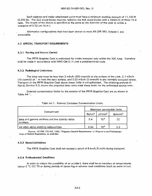
External contamination limits for the exterior of the PRTR Graphite Cask are as shown inTable A4-1.
Table A4-1. External Container Contamination Limits.
Contaminant
Beta and gamma emitters and low toxicity alphaemitters
All other alpha-emitting radionuclides
Maximum permissible limits
Bq/cm2
0.4
0.04
/;Ci/cm2
io-6
10'6
dpm/cm2
22
2.2
Source: 49 CFR 173.443, 1995, "Shippers-General Requirements for Shipments and Packagings,"Code of Federal Regulations, as amended.
4.3.3 Speed Limitations
The PRTR Graphite Cask shall not exceed a speed of 8 km/h (5 mi/h) during transport.
4.3.4 Environmental Conditions
In order to reduce the possibility of an accident, there shall be no transfers at temperaturesbelow 0 °C (32 °F) or during periods of dense fog or adverse road conditions (such as snow or ice}.
A4-2
HNF-SD-TP-SEP-063, Rev. 0
4.3.5 Frequency of Use and Mileage Limitations
A risk analysis was performed on the 327 Building casks to determine mileage limitations. Theresults of the evaluation have determined that transfers shall not exceed a total of 16.0 km {10.0 mi)per year for the 327 Building family of casks, which includes the Special EnvironmentalRadiometallurgy Facility Cask, the Radioactive Waste Disposal Cask, and the PRTR Graphite Cask. Thislimit allows up to 40 transfers of 0.40 km (0.25 mi] per year. This limit does not apply to empty caskshipments.
4.3.6 Emergency Response
Emergency responders shall be notified prior to transfers of the cask. The shipping andreceiving facilities, Radiation Protection, Safety, Packaging Engineering, and Transportation Logisticsshall be notified of all accidents involving radioactive material shipment that result in vehicle damage,container damage, personnel injury, or contamination spread.
A4-3

HNF-SD-TP-SEP-063, Rev. 0
This page intentionally left blank.
A4-4
HNF-SD-TP-SEP-063, Rev. 0
5.0 ACCEPTANCE OF PACKAGING FOR USE
5.1 NEW PACKAGING
The PRTR Graphite Cask was originally accepted for use in the 1960s. That acceptance isdocumented in Hazardous Materials Packaging and Shipping Manual (HEDL 1987). The cask has beenused for shipments within the 300 Area for approximately 20 years without incident. The PRTRGraphite Cask has a frequency of use of approximately six transfers per year. No new casks will bemanufactured, so new packaging acceptance requirements do not apply.
5.2 PACKAGING FOR REUSE
In order to continue using the PRTR Graphite Cask, the maintenance and operating plans mustbe followed. A visual inspection for physical damage and corrosion on the cask and a check of theclosing mechanism for proper operation shall occur prior to reuse. These inspections shall bedocumented in accordance with facility operating procedures.
If required, the cask shall be decontaminated prior to use to meet external contamination limitsper Table A4-1.
A5-1

HNF-SD-TP-SEP-063, Rev. 0
This page left intentionally blank.
A5-2
HNF-SD-TP-SEP-063, Rev. 0
6.0 OPERATING REQUIREMENTS
6.1 GENERAL REQUIREMENTS
The following are requirements for the use of the PRTR Graphite Cask. Prior to loading andshipment of the cask, specific operating procedures with appropriate Quality Assurance/Quality Controlhold points shall be written by the user and approved per WHC-CM-2-14. The procedures shallimplement the requirements of this section and the additional requirements found in this SEP.
For loading and unloading operations, the following general requirements shall be performed.
1. Visually inspect the PRTR Graphite Cask for cracks or damage.
2. Visually inspect the lifting attachments for cracks and damage.
3. Verify that radiological contamination limits are within the allowable limits shown inTable A4-1 of this SEP.
4. Verify radiological dose rates are acceptable prior to shipment of the cask inaccordance with Part A, Section 4.3.2, of this SEP. The dose rate limits are 2 mSv/h(200 mrem/h) on any surface of the cask, 0.1 mSv/h (10 mrem/hl at 1 m from thecask, and 0.02 mSv/h (2 mrem/h) in any normally occupied space.
5. Verify that the number of transfers or mileage shipped in a year has not exceeded theamount established by the risk assessment (40 shipments of approximately 0.40 km[0.25 mi] each or 16.0 km [10.0 mi] per year).
6.2 LOADING OF CONTENTS INTO THE CASK
6.2.1 Inner Container Loading
1. Prior to loading contents, visually inspect the inner container to be used.
2. If vials are to be used, visually inspect them for damage.
3. Place cushioning material in the inner container to protect glass vials. Multiple vialsmay be placed in the inner container. Plastic vials may be packaged as glass vials.
4. After placing the vials in the inner container, fill the void spaces with cushioningmaterial.
5. Close the inner container.
6.2.2 Preparing the Cask for Loading
1. Verify that the contents to be loaded into the cask are as authorized in Part A,Section 3.0, of this SEP and that criticality limits have not been exceeded.
2. Verify that the cask is positioned properly at the cell loading port and is ready toreceive the contents. Open the cell loading port.
A6-1
HNF-SD-TP-SEP-063, Rev. 0
6.2.3 Loading Contents into the Cask
1. Attach the push/pull rod to the rear end of the cask scoop fixture, commonly called thecask boat.
2. Release the locking mechanism and rotate the closure valve 90°.
3. Release the locking pin holding the boat and push the boat into the cell to the desiredposition.
4. Load the materials onto the boat and pull the boat back into the cask. Secure thelocking pin.
5. Rotate the closure valve 90° and secure the locking mechanism.
6. Close the ceil loading port and move the cask away from the cell.
7. Perform radiological dose and contamination surveys to verify levels have not exceededthe limits authorized in Part A, Section 4.0, of this SEP. Decontaminate ifcontamination limits are exceeded. Do not ship if radiological dose has exceeded2 mSv/h (200 mrem/h) on the surface of the cask, 0.1 mSv/h (10 mrem/h) at 1 m fromthe cask, and 0.02 mSv/h (2 mrem/h) in any normally occupied space.
8. Following radiological survey, wrap the ends of the cask with 10-mil plastic and tape tothe cask body using duct tape.
6.3 PREPARATION OF THE CASK FOR SHIPMENT
1. Verify that the shipping papers have been prepared properly and the cask is properlymarked and labeled per the requirements of WHC-CM-2-14.
2. Position the transport vehicle where it will be accessible to the overhead crane.
3. Verify the lifting equipment is in accordance with the Hanford Site Hoisting and RiggingManual, DOE/RL-92-36 (RL 1996).
4. Attach the lifting equipment to the cask lifting attachment and the crane hook.
5. Lift the cask from the floor to allow a radiological survey of the cask to be performed.
6. Move the cask over the vehicle and slowly lower it into position on the transportvehicle.
7. Unhook the lifting equipment from the cask and install tiedown attachments per therequirements of Part A, Section 4.2.
8. Prior to transport, verify that the shipping documentation has been completed perWHC-CM-2-14 and signed by a trained Hazardous Material Shipper.
A6-2

HNF-SD-TP-SEP-063, Rev. 0
6.4 UNLOADING THE CASK
1. Position the transport vehicle where it will be accessible to the overhead crane.
2. Perform radiological contamination and dose surveys of the cask to verify that thelimits in Part A, Section 4.0, have not been exceeded.
3. Remove the tiedown equipment from the cask and transport vehicle.
4. Attach the lifting equipment to the cask lifting attachment and the crane hook.
5. Lift the cask off of the transport vehicle and move to a designated location. Removethe plastic from the ends of the cask.
6. Perform a radiological contamination survey of the cask ends to verify thecontamination limits have not been exceeded.
7. Position the cask at the cell loading port and remove the rigging equipment from thecask.
8. Open the cell loading port.
9. Attach the push/pull rod to the rear end of the cask scoop fixture, commonly called thecask boat.
10. Release the closure valve locking mechanism and rotate the closure valve 90°.
11. Release the locking pin holding the boat and push the boat into the cell to the desiredposition.
12. Unload the materials from the boat and pull the boat back into the cask. Secure thelocking pin.
13. Rotate the closure valve and secure the locking mechanism.
14. Close the cell loading port and move the cask away from the cell.
15. Perform radiological dose and contamination surveys to verify levels have not exceededlimits authorized in Part A, Section 4.0, of this SEP. Decontaminate if contaminationlimits are exceeded.
6.5 EMPTY PACKAGING
To be transported as an empty radioactive container, the cask must be prepared for transport inaccordance with 49 CFR 173.428 (1995 version).
A6-3

HNF-SD-TP-SEP-063, Rev. 0
This page left intentionally blank.
A6-4
HNF-SD-TP-SEP-063, Rev. 0
7.0 QUALITY ASSURANCE REQUIREMENTS
7.1 INTRODUCTION
This section describes the quality assurance (QA) requirements for operation of the PRTRGraphite Cask. The packaging was fabricated in the 1960s following a quality program in effect at thetime. The PRTR Graphite Cask is used to perform onsite shipments at the Hanford Site. The formatand requirements for the use of the PRTR Graphite Cask on the Hanford Site are in accordance withWHC-CM-4-2, Quality Assurance Manual, and WHC-CM-2-14.
7.2 GENERAL REQUIREMENTS
These requirements apply to activities, which include loading, unloading, and transportationoperations, that could affect the quality of the packaging and associated hardware. The overal!packaging is classified per WHC-CM-2-14 as a Transportation Hazard Index (THI) 1.
THI 1 packaging systems, defined in WHC-CM-2-14, represent the highest level of hazard forthe contents. A packaging system assigned this level has the potential of causing a dose consequenceto an individual in excess of 25 rem at the Hanford Site boundary if fully released.
Each THI invokes a quality level (QL] designator (defined in WHC-CM-2-14) consisting of twoparts: an alpha designator and a numerical designator. The alpha designator assigns the fabrication,testing, use, maintenance standards, and quality requirements for each component of the packagingsystem. The numeric designator following the letter is the THI number of the packaging system.Because the PRTR Graphite Cask ships a Type B quantity of material with potentially high hazards, thepackage as a whole is assigned a QL designator of A-1.
Documentation and review requirements are based upon the QL of the package. Changes ordiscoveries of noncompiiance for all QL A-1 components and activities shall be reviewed by theunreviewed safety question screening process to ensure the quality and safety of the change ordiscovery. Changes to the SEP safety bases (contents, shielding, structural, containment, criticality)will require unreviewed safety question screening regardless of QL.
7.3 ORGANIZATION
The organizational structure and the assignment of responsibility shall be such that quality isachieved and maintained by those who have been assigned responsibility for performing the work.Quality achievement is to be verified by persons or organizations not directly responsible for performingthe work.
Packaging Engineering and the onsite user are responsible for the quality of the work performedby their respective organizations and for performing the following activities:
• Follow the current requirements of this SEP, WHC-CM-4-2, and WHC-CM-2-14• Provide instructions for implementing QA requirements.
The cognizant manager, Quality Assurance, is responsible for establishing and administering theHanford QA program as stated in WHC-CM-4-2.
A7-1
HNF-SD-TP-SEP-063, Rev. 0
7.4 OA PLAN AND ACTIVITIES
7.4.1 Design Control
Design control is not applicable. This cask was fabricated over 30 years ago, and no designchanges will be made. B&W Hanford Company is the design authority for the package.
7.4.2 Procurement and Fabrication Control
Procurement and fabrication control is not applicable. This package is over 30 years old, andno casks will be procured in the future.
7.4.3 Control of Operations/Processes
' Loading/unloading procedures written by the user will be used to ensure acceptable operationof the packaging. Those loading/unloading procedures shall be consistent with this SEP. Theloading/unloading procedures identify actions required by personnel to safely and properly load andunload the packaging in accordance with this SEP.
Quality Control inspection checklists are established to ensure that final inspection verifiescompliance with the following items.
• The PRTR Graphite Cask is properly assembled.
• All acceptance criteria (Part A, Section 5.0) are met for use of the package.
• Operational (Part A, Section 6.01 and maintenance procedures (Part A, Section 8.0) areproperly completed.
7.4.4 Control of Inspection
Control of inspection and testing will be accomplished by facility procedures incorporating therequirements of Part A, Section 7.4.3.
7.4.5 Test Control
Test control is not applicable. No testing is required on this package.
7.4.6 Control of Measuring and Test Equipment
Any measuring equipment that is used shall meet the accuracy and calibration requirements asrequired by WHC-CM-4-2; i.e., radiation survey equipment.
7.4.7 Control of Nonconforming Items
Identification, documentation, evaluation, and disposition of nonconforming items and activities,shall be accomplished per WHC-CM-4-2, regardless of the assigned QL.
A7-2
HNF-SD-TP-SEP-063, Rev. 0
7.4.8 Corrective Action
Nonconformance, or conditions adverse to quality, are evaluated as described in Part A,Section 7.4.8, and the need for corrective action is determined in accordance with WHC-CM-4-2.
7.4.9 QA Records and Document Control
Records that furnish documentary evidence of quality shall be specified, prepared, andmaintained per WHC-CM-4-2. This includes all procedures, inspection reports, the SEP, and anynonconformance reports that are developed while this cask is used.
7.4.10 Audits
Internal and external independent assessments are performed in accordance with WHC-CM-4-2.
A7-3

HNF-SD-TP-SEP-063, Rev. 0
This page left intentionally blank.
A7-4
HNF-SD-TP-SEP-063, Rev. 0
8.0 MAINTENANCE
8.1 GENERAL REQUIREMENTS
The 327 Facility shall provide the procedures for the required maintenance and inspections ofthe PRTR Graphite Cask.
8.2 INSPECTION AND VERIFICATION SCHEDULES
The PRTR Graphite Cask shall undergo a user inspection every two years. Inspections shall beperformed using the Radioactive Material Shipping Container User Biennial Inspection Checklist (Part A,Section 10.2). Nondestructive testing of the welds on the lifting apparatus shall be performed everyfive years using the Radioactive Material Shipping Container NDT of Lifting Apparatus !5 Year! (Part A,Section 10.2).
8.3 RECORDS AND DOCUMENTATION
The maintenance records shall be maintained for the length of time the PRTR Graphite Cask isowned, plus one year. The inspection records of the PRTR Graphite Cask shall be maintained until thenext inspection of the same type is successfully completed.
A8-1

HNF-SD-TP-SEP-063, Rev. 0
This page left intentionally blank.
A8-2
HNF-SD-TP-SEP-063, Rev. 0
9.0 REFERENCES
49 CFR 173, 1995, "Shippers-General Requirements for Shipments and Packagings," Code of FederalRegulations, as amended.
49 CFR 178, 1997, "Specifications for Packagings," Code of Federal Regulations, as amended.
49 CFR 393, 1997, "Parts and Accessories Necessary for Safe Operation," Code of FederalRegulations, as amended.
HEDL, 1987, Hazardous Materials Packaging and Shipping Manual, MG-137, Rev. 10, HanfordEngineering Development Laboratory, Richland, Washington.
Larson, S. L., 1996, Limits for Fissionable Material in Small Bore Transfer Casks and Lead Pigs iNCSBasis Memo 96-2 to M. Dec, December 30), Battelle Pacific Northwest Laboratories, Richland,Washington.
PNL, 1994, Criticality Safety, PNL-MA-25, Battelle Pacific Northwest Laboratories, Richland,Washington.
RL, 1996, Hanford Site Hoisting and Rigging Manual, DOE/RL-92-36, U.S. Department of Energy,Richland Operations Office, Richland, Washington.
WHC-CM-2-14, Hazardous Material Packaging and Shipping, Westinghouse Hanford Company,Richland, Washington.
WHC-CM-4-2, Quality Assurance Manual, Westinghouse Hanford Company, Richland, Washington.
A9-1

HNF-SD-TP-SEP-063, Rev. 0
This page left intentionally blank.
A9-2

HNF-SD-TP-SEP-063, Rev. 0
10.0 APPENDICES
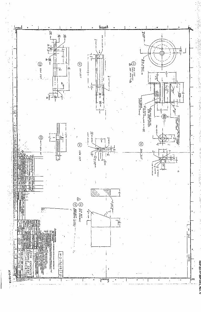
10.1 DRAWINGS
A10-1

HNF-SD-TP-SEP-063, Rev. 0
This page intentionally left blank.
A10-2
HNF-SD-TP-SEP-063, Rev. 0
! LJI. 11
/.1C Hi.
HNF-SD-TP-SEP-063, Rev. 0
A1O-7/8
IzCO
I
HNF-SD-TP-SEP-063, Rev. 0
A10-13/14
HNF-SD-TP-SEP-063, Rev. 0
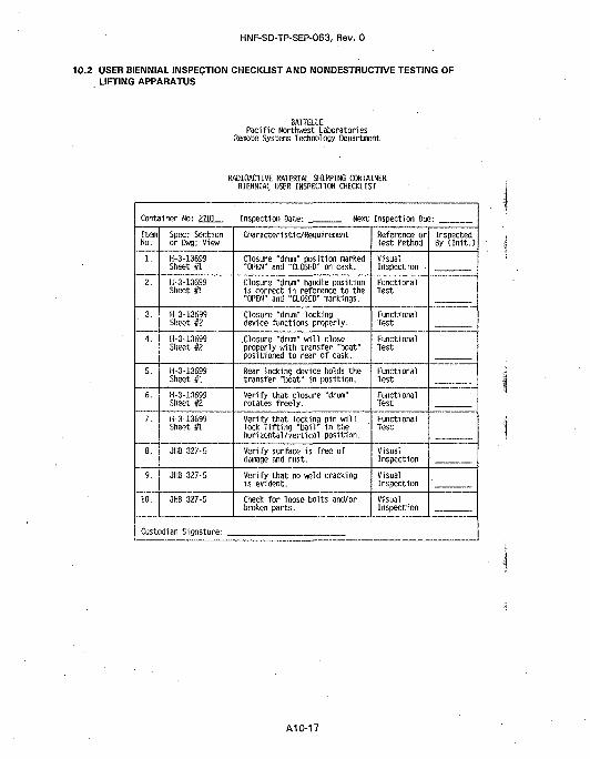
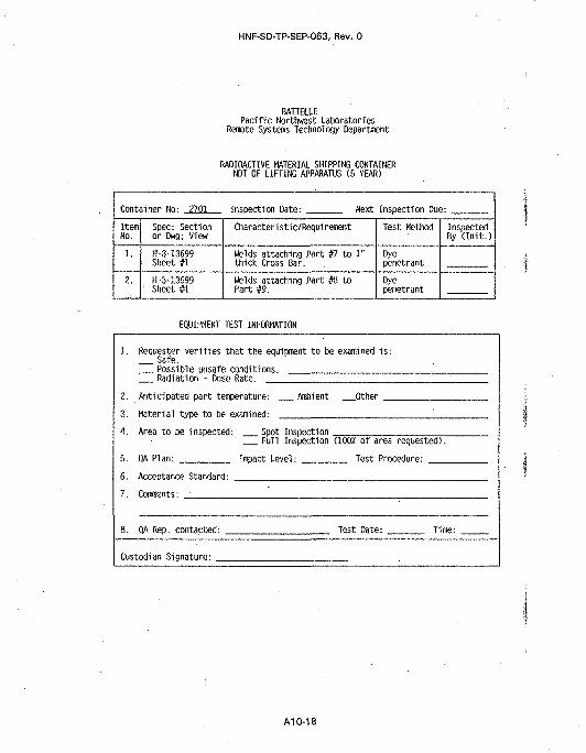
10.2 USER BIENNIAL INSPECTION CHECKLIST AND NONDESTRUCTIVE TESTING OFLIFTING APPARATUS
BATTEU.EPacific Northwest Laboratories
Remote Systems Technology Oepartinent
RADIOACTIVE MATERIAL SHIPPING CONTAINERBIENNIAL USER INSPECTION CHECKLIST
Container No: 2701 Inspection Date: Next Inspection Due:
ItemNo.
1.
2.
3.
4.
5.
6.
7.
8.
9.
10.
Spec: Sectionor Dwg; View
H-3-13699Sheet #1
H-3-13699Sheet #1
H-3-13699Sheet #2
H-3-13699Sheet #2
H-3-13699Sheet #1
H-3-13699Sheet #2
H-3-13699Sheet #1
JHB 327-5
JHB 327-5
JHB 327-5
Characteri sti c/Requi rement
Closure "drum" position marked"OPEN" and "CLOSED" on cask.
Closure "drum" handle positionis correct in reference to the"OPEN" and "CLOSED" markings.
Closure "drum" lockingdevice functions properly.
Closure "drum" will closeproperly with transfer "boat"positioned to rear of cask.
Rear locking device holds thetransfer "boat" in position.
Verify that closure "drun"rotates freely.
Verify that locking pin willlock lifting "bail" in thehorizontal/vertical position.
Verify surface is free ofdamage and rust.
Verify that no weld crackingis evident.
Check for loose bolts and/orbroken parts.
Reference orTest Method
VisualInspection
FunctionalTest
FunctionalTest
FunctionalTest
FunctionalTest
FunctionalTest
FunctionalTest
VisualInspection
VisualInspection
VisualInspection
InspectedBy (Init.)
Custodian Siqnature:
A1O-17
HNF-SD-TP-SEP-063, Rev. 0
BATTELLEPacific Northwest Laboratories
Remote Systems Technology Department
RADIOACTIVE MATERIAL SHIPPING CONTAINERNDT OF LIFriNG APPARATUS (5 YEAR)
Container No: 2701 InsDection Date: Next Inspection Due:
ItemNo.
1.
2.
Spec; Sectionor Dwg; View
H-3-13699Sheet #1
H-3-13699Sheet #1
Characteristic/Requirement
Welds attaching Part #7 to 1"thick Cross Bar.
Welds attaching Part #8 toPart #9.
Test Method
Dyepenetrant
Dyepenetrant
InspectedBy (Init.)
EQUIPMENT TEST INFORMATION
. Ambient . Other .
1. Requester verifies that the equipment to be examined is:Safe.Possible unsafe conditions. ,Radiation - Dose Rate.
2. Anticipated part temperature:
3. Material type to be examined:
4. Area to be inspected:
5. QA Plan:
6. Acceptance Standard:
7. Comments:
. Spot Inspection .Full Inspection (1002 of area requested).
Impact Level: Test Procedure:
8. QA Rep. contacted: Test Date: Time:
Custodian Signature:
A10-18
HNF-SD-TP-SEP-063, Rev. 0
PART B: PACKAGE EVALUATION
1.0 INTRODUCTION
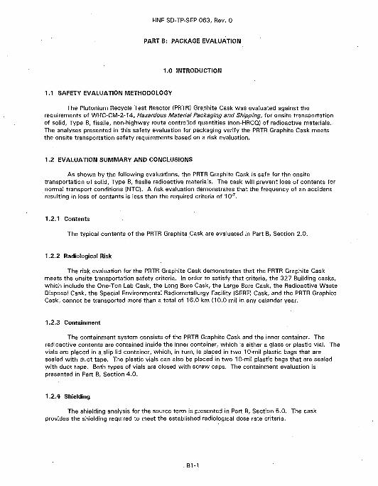
1.1 SAFETY EVALUATION METHODOLOGY
The Plutonium Recycle Test Reactor (PRTR) Graphite Cask was evaluated against therequirements of WHC-CM-2-14, Hazardous Material Packaging and Shipping, for onsite transportationof solid, Type B, fissile, non-highway route controlled quantities (non-HRCQ) of radioactive materials.The analyses presented in this safety evaluation for packaging verify the PRTR Graphite Cask meetsthe onsite transportation safety requirements based on a risk evaluation.
1.2 EVALUATION SUMMARY AND CONCLUSIONS
As shown by the following evaluations, the PRTR Graphite Cask is safe for the onsitetransportation of solid. Type B, fissile radioactive materials. The cask will prevent loss of contents fornormal transport conditions INTO. A risk evaluation demonstrates that the frequency of an accidentresulting in loss of contents is less than the required criteria of 10'7.
1.2.1 Contents
The typical contents of the PRTR Graphite Cask are evaluated in Part B, Section 2.0.
1.2.2 Radiological Risk
The risk evaluation for the PRTR Graphite Cask demonstrates that the PRTR Graphite Caskmeets the onsite transportation safety criteria. In order to satisfy that criteria, the 327 Building casks,which include the One-Ton Lab Cask, the Long Bore Cask, the Large Bore Cask, the Radioactive WasteDisposal Cask, the Special Environmental Radiometallurgy Facility (SERF) Cask, and the PRTR GraphiteCask, cannot be transported more than a total of 16.0 km (10.0 mil in any calendar year.
1.2.3 Containment
The containment system consists of the PRTR Graphite Cask and the inner container. Theradioactive contents are contained inside the inner container, which is either a glass or plastic vial. Thevials are placed in a slip lid container, which, in turn, is placed in two 10-mil plastic bags that aresealed with duct tape. The plastic vials can also be placed in two 10-mil plastic bags that are sealedwith duct tape. Both types of vials are closed with screw caps. The containment evaluation ispresented in Part B, Section 4.0.
1.2.4 Shielding
The shielding analysis for the source term is presented in Part B, Section 5.0. The caskprovides the shielding required to meet the established radiological dose rate criteria.
B1-1
HNF-SD-TP-SEP-063, Rev. 0-
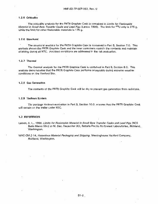
1.2.5 Criticality
The criticality analysis for the PRTR Graphite Cask is contained in Limits for FissionableMaterial in Small Bore Transfer Casks and Lead Pigs (Larson 1996). The limit for 235U only is 275 g,while the limit for other fissionable materials is 175 g.
1,2.6 Structural
The structural analysis for the PRTR Graphite Cask is contained in Part B, Section 7.0. Thisanalysis shows the PRTR Graphite Cask and the inner containers contain the contents and maintainshielding during all NTC. Accident conditions are addressed in the risk evaluation.
1.2.7 Thermal
The thermal analysis for the PRTR Graphite Cask is contained in Part B, Section 8.0. Thisanalysis demonstrates that the PRTR Graphite Cask performs acceptably during extreme weatherconditions on the Hanford Site.
1.2.8 Gas Generation
The contents of the PRTR Graphite Cask will be dry to prevent gas generation from radiolysis.
1.2.9 Tiedown System
The package tiedown evaluation in Part B, Section 10.0, ensures that the PRTR Graphite Caskwill remain on the trailer under NTC.
1.3 REFERENCES
Larson, S. L., 1996, Limits for Fissionable Material in Small Bore Transfer Casks and Lead Pigs (NCSBasis Memo 96-2 to M. Dec, December 30), Battelle Pacific Northwest Laboratories, Richland,.Washington.
WHC-CIVI-2-14, Hazardous Material Packaging and Shipping, Westinghouse Hanford Company,Richland, Washington.
B1-2
HNF-SD-TP-SEP-063, Rev. 0
2.0 CONTENTS EVALUATION
2.1 CHARACTERIZATION
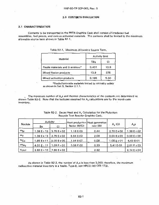
Contents to be transported in the PRTR Graphite Cask shall consist of irradiated fuelassemblies, fuel pieces, and various activated materials. The contents shall be limited to the maximumallowable source term shown in Table B2-1.
Table B2-1. Maximum Allowable Source Term.
Material
Fissile materials and a emitters*
Mixed fission products
Mixed activation products
Activity limit
TBq
0.401
13.9
0.185
Ci
10.9
375
5.00
*Fissile/fissionable materials limited by criticality safetyas shown in Part B, Section 2.1.1.
The maximum number of A2s and thermal characteristics of the contents, are determined asshown Table B2-2. Note that the isotopes assumed for A2 calculations are for the worst-caseinventory.
Table B2-2. Decay Heat and A2 Calculation for the PlutoniumRecycle Test Reactor Graphite Cask.
Nuclide
90Sr
60Co
239pu
Total
Activity
Bq
1.39E + 13
1.39 E +13
1.85 E +11
4.01 E + 11
2.83 E + 13
Ci
3.75 E + 02
3.75 E + 02
5.00 E + 00
1.09 E +01
7.66 E + 02
Heat productionfactor (W/Ci)
1.16 E-03
5.54 E-03
1.54 E-02
3.06 E-02
Heat generationrate (W)
0.44
2.08
0.08
0.33
2.92
. A2(Ci)
2.70 E + 00
0.00 E + 00
1.08 E + 01
•5.41 E-03
A2s
1.39 E + 02
0.00 E + 00
4.63 E-01
2.01 E + 03
2.14 E + 03
As shown in Table B2-2, the number of A2s is less than 3,000; therefore, the maximumradioactive material inventory is a fissile, Type-B, non-HRCQ (49 CFR 173}.
B2-1
HNF-SD-TP-SEP-063, Rev. 0
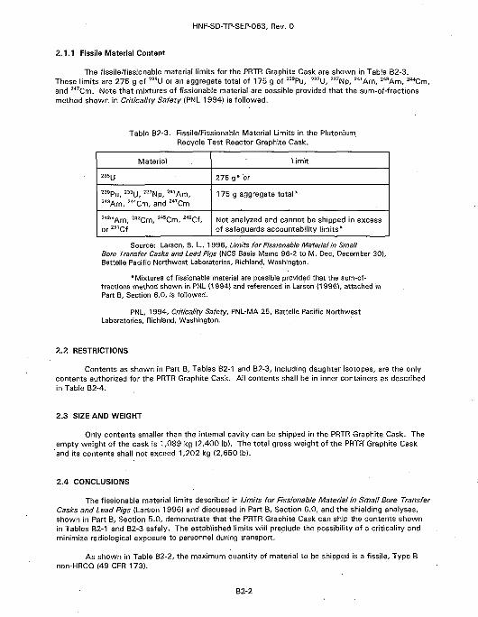
2.1.1 Fissile Material Content
The fissile/fissionable material limits for the PRTR Graphite Cask are shown in Table B2-3.These limits are 275 g of 235U or an aggregate total of 175 g of 239Pu, 233U, 237Np, 241Am, 243Am, 244Cm,and 247Cm. Note that mixtures of fissionable material are possible provided that the sum-of-fractionsmethod shown in Criticality Safety (PNL 1994) is followed.
Table B2-3. Fissile/Fissionable Material Limits in the Plutonium.Recycle Test Reactor Graphite Cask.
Material
235y
2MPu, 233U, a37Np, M 1Am,243Am, 244Cm, and 247Cm
242mAm, 243Cm, 245Cm, 249Cf,or 251Cf
Limit
275 g* or
175 g aggregate total*
Not analyzed and cannot be shipped in excessof safeguards accountability limits*
Source: Larson, S. L., 1996, Limits for Fissionable Material in SmallBore Transfer Casks and Lead Pigs (NCS Basis Memo 96-2 to M. Dec, December 30),Battelle Pacific Northwest Laboratories, Richland, Washington.
* Mixtures of fissionable material are possible provided that the sum-of-fractions method shown in PNL (1994) and referenced in Larson {1996), attached inPart B, Section 6.0, is followed.
PNL, 1994, Criticality Safety, PNL:MA-25, Battelle Pacific NorthwestLaboratories, Richland, Washington.
2.2 RESTRICTIONS
Contents as shown in Part B, Tables B2-1 and B2-3, including daughter isotopes, are the onlycontents authorized for the PRTR Graphite Cask. All contents shall be in inner containers as describedin Table B2-4.
2.3 SIZE AND WEIGHT
Only contents smaller than the internal cavity can be shipped in the PRTR Graphite Cask. Theempty weight of the cask is 1,089 kg (2,400 Ib). The total gross weight of the PRTR Graphite Caskand its contents shall not exceed 1,202 kg (2,650 Ib).
2.4 CONCLUSIONS
The fissionable material limits described in Limits for Fissionable Material in Small Bore TransferCasks and Lead Pigs (Larson 1996) and discussed in Part B, Section 6.0, and the shielding analyses,shown in Part B, Section 5.0, demonstrate that the PRTR Graphite Cask can ship the contents shownin Tables B2-1 and B2-3 safely. The established limits will preclude the possibility of a criticality andminimize radiological exposure to personnel during transport.
As shown in Table B2-2, the maximum quantity of material to be shipped is a fissile, Type Bnon-HRCQ(49 CFR 173).
B2-2
HNF-SD-TP-SEP-063, Rev. 0
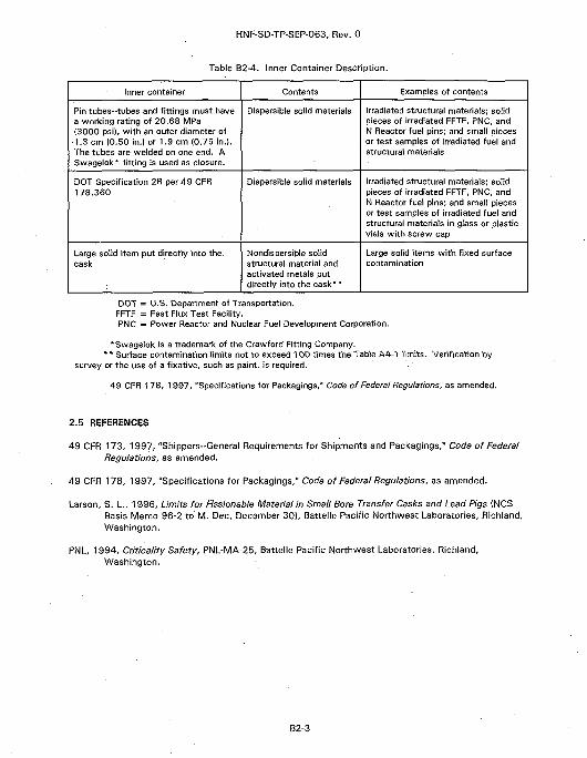
Table B2-4. Inner Container Description.
Inner container
Pin tubes-tubes and fittings must havea working rating of 20.68 MPa(3000 psi), with an outer diameter of
•1.3 cm (0.50 in.) or 1.9 cm {0.75 in.).The tubes are welded on one end. ASwagelok* fitting is used as closure.
DOT Specification 2R per 49 CFR178.360
Large solid item put directly into the.cask
Contents
Dispersible solid materials
Dispersible solid materials
Nondispersible solidstructural material andactivated metals putdirectly into the cask**
Examples of contents
Irradiated structural materials; solidpieces of irradiated FFTF, PNC, andN Reactor fuel pins; and small piecesor test samples of irradiated fuel andstructural materials
Irradiated structural materials; solidpieces of irradiated FFTF, PNC, andN Reactor fuel pins; and small piecesor test samples of irradiated fuel andstructural materials in glass or plasticvials with screw cap
Large solid items with fixed surfacecontamination
DOT = U.S. Department of Transportation.FFTF = Fast Flux Test Facility.PNC = Power Reactor and Nuclear Fuel Development Corporation.
*SwageIok is a trademark of the Crawford Fitting Company.* * Surface contamination limits not to exceed 100 times the Table A4-1 limits. Verification by
survey or the use of a fixative, such as paint, is required.
49 CFR 178, 1997, "Specifications for Packagings," Code of Federal Regulations; as amended.
2.5 REFERENCES
49 CFR 173, 1997, "Shippers-General Requirements for Shipments and Packagings," Code of FederalRegulations, as amended.
49 CFR 178, 1997, "Specifications for Packagings," Code of Federal Regulations, as amended.
Larson, S. L., 1996, Limits for Fissionable Material in Small Bore Transfer Casks and Lead Pigs (NCSBasis Memo 96-2 to M. Dec, December 30), Battelle Pacific Northwest Laboratories, Richland,Washington.
PNL, 1994, Criticality Safety, PNL-MA-25, Battelle Pacific Northwest Laboratories, Richland,Washington.
B2-3

HNF-SD-TP-SEP-063, Rev. 0
This page left intentionally blank.
B2-4
HNF-SD-TP-SEP-063, Rev. 0
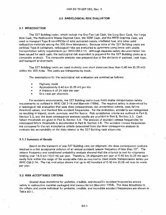
3.0 RADIOLOGICAL RISK EVALUATION
3.1 INTRODUCTION
The 327 Building casks, which include the One-Ton Lab Cask, the Long Bore Cask, the LargeBore Cask, the Radioactive Waste Disposal Cask, the SERF Cask, and the PRTR Graphite Cask, areused to transport Type B non-HRCQs of solid activated metals, irradiated fuel, and other solidradioactive materials among the 300 Area laboratories. Because none of the 327 Building casks arecertified Type B containers, radiological risks are evaluated to determine compliance with onsitetransportation safety requirements per WHC-CM-2-14. Although separate safety documentation hasbeen issued for each cask, the radiological risk evaluation is prepared for the 327 Building casks as acomposite analysis. The composite analysis was prepared due to the similarity in payload, cask type,and transport environment.
The 327 Building casks are used routinely over short distances (less than 0.40 km [0.25 mi])within the 300 Area. The casks are transported by truck.
The assumptions for the radiological risk evaluation are summed as follows:
Highway modeHighway modeApproximately 0.40 km (0.25 mi) per tripA maximum of 24 trips per yearOne cask per shipment.
For accident environments, the 327 Building casks must meet onsite transportation safetyrequirements as outlined in WHC-CM-2-14 and Mercado (1994). The required safety is determined bya radiological risk evaluation that uses dose consequences, risk acceptance criteria, cask failurethreshold values, and Hanford Site accident frequencies. For the evaluation, accidents are categorizedas resulting in impact, crush, puncture, and fire forces. Risk acceptance criteria are outlined in Part B,Section 3.2, and the dose consequence analyses results are provided in Part B, Section 3.3. Caskfailure thresholds are given in Part B, Section 3.4. The analysis of accident release frequencies forassociated failure thresholds is documented in Part B, Section 3.E.- The accident release frequenciesare compared to the risk acceptance criteria determined from the dose consequence analysis toevaluate the acceptability of the risks related to the 327 Building cask shipments.
3.1.1 Summary of Results
Based on the transport of one 327 Building cask per shipment, the dose consequence analysisresulted in a risk acceptance criterion of an annual accident release frequency of less than 10"7. Therelease frequency and conditional probability analysis showed that the criterion is met for shipmentstotaling over 16.0 km (10.0 mi) per year. Therefore, 24 shipments per year of 0.40 km (0.25 mi) eacheasily falls within the range of the acceptable risks as required to meet onsite transportation safety perWHC-CM-2-14. The risk evaluation shows that up to 40 transfers of 0.40 km (0.25 mi) may be madeper year.
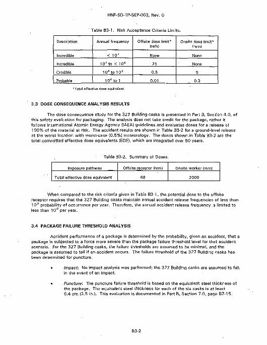
3.2 RISK ACCEPTANCE CRITERIA
Graded dose limitations for probable, credible, and incredible accident frequencies ensuresafety in radioactive material packaging and transportation (Mercado 1994). The dose limitations tothe offsite and onsite individual for probable, credible, and incredible accident frequencies are shown inTable B3-1.
B3-1
HNF-SD-TP-SEP-063, Rev. 0
Table B3-1. Risk Acceptance Criteria Limits.
Description
Incredible
Incredible
Credible
Probable
Annual frequency
< 10 '
10"7 to < 10'6
Iff6 to 103
10'3 to 1
Offsite dose limit*(rem}
None
25
0.5
0.01
Onsite dose limit*(rem}
None
None
5
0.2
•Total effective dose equivalent.
3.3 DOSE CONSEQUENCE ANALYSIS RESULTS
The dose consequence study for the 327 Building casks is presented in Part B, Section 4.0, ofthis safety evaluation for packaging. The analysis does not take credit for the package, rather itfollows International Atomic Energy Agency {IAEA} guidelines and evaluates doses for a release of100% of the material at risk. The accident results are shown in Table B3-2 for a ground-level releaseat the worst location with worst-case (0.5%} meteorology. The doses shown.in Table B3-2 are thetotal committed effective dose equivalents (EDE), which are integrated over 50 years.
Table B3-2. Summary of Doses
Exposure pathway
Total effective dose equivalent
Offsite receptor (rem)
68
Onsite worker (rem)
2000
When compared to the risk criteria given in Table B3-1, the potential dose to the offsitereceptor requires that the 327 Building casks maintain annual accident release frequencies of less than10"7 probability of occurrence per year. Therefore, the annual accident release frequency is limited toless than 10"' per year.
3.4 PACKAGE FAILURE THRESHOLD ANALYSIS
Accident performance of a package is determined by the probability, given an accident, that apackage is subjected to a force more severe than the package failure threshold level for that accidentscenario. For the 327 Building casks, the failure thresholds are assumed to be minimal, and thepackage is assumed to fail if an accident occurs. The failure threshold of the 327 Building casks hasbeen determined for puncture.
• Impact: No impact analysis was performed; the 327 Building casks are assumed to failin the event of an impact.
• Puncture: The puncture failure threshold is based on the equivalent steel thickness ofthe package. The equivalent steel thickness for each of the six casks is at least6.4 cm (2.5 in.). This evaluation is documented in Part B, Section 7.0, page B7-15.
B3-2
HNF-SD-TP-SEP-063, Rev. 0
Crush: No crush analysis was performed; the 327 Building casks are assumed to fail inany accident involving crush.
Fire: No fire failure analysis was performed, therefore the 327 Building casks areassumed to fail any accident involving a fire.
3.5 ACCIDENT RELEASE FREQUENCY ASSESSMENT
3.5.1 Approach
The accident release frequency assessment is based on the assumption that all failure modesfrom the different forces described as impact, puncture, crush, and fire result in the same level ofconsequence. The union of the package conditional release probabilities from different scenarios withsimilar consequences is multiplied by the frequency of truck accidents to arrive at a total annualaccident release frequency. -
The frequency {F) of a truck accident is the product of the annual number of trips, the numberof miles per trip, and the accident rate per mile.
year trip mite
Hanford Site truck accidents have been compiled in a report using Site-specific data(Green et al. 1996), which gives the accident rate for trucks as 2.0 x 10'7 accidents per mile. For ashipment of radioactive materials that is carried out by trained truck drivers during daylight hours ingood road conditions, a reduction factor of 20 can be applied to lower the rate to 1 x 10"8 (H&R 1995)accidents per mile. Appendix B of Recommended Onsite Transportation Risk ManagementMethodology (H&R 1995) summarizes statistics from the U.S. Department of Transportation (DOT), andthe studies conducted by Sandia National Laboratory on accident responses of small and largepackages. The report recommends reducing truck accident rates by 10 for "safe" truck drivers andanother factor of two for shipment of radioactive material. These reduction factors are based on thefollowing logic.
• Safe truck drivers: Hanford Site truck drivers have special training. Drivers mustcomplete several driver's education courses, have a valid commercial driver's licensewith hazardous endorsement, complete specific training for highway route controlledquantities of radioactive material, and complete radiation worker and hazardousmaterials training. References show that drivers who participate in special safetyprograms reduce single-vehicle accident rates by up to a factor of 100. The H&Rreport (H&R 1995) recommends using an overall accident reduction factor of 10.
• Radioactive material: An additional factor of two is recommended based on the higherlevel of training required for drivers of vehicles carrying radioactive material and thehigher level of caution that would be expected from drivers of cargos consisting ofradioactive material.
After the frequency of accidents is calculated, it is then multiplied by the union of theconditional release probabilities determined in Part B, Section 3.5.2, to arrive at an annual accidentrelease frequency. The annual release frequency is compared to the criteria determined from the doseconsequence analysis (<10'7).
B3-3
HNF-SD-TP-SEP-063, Rev. 0
3.5.2 Accident Release Frequency Analysis
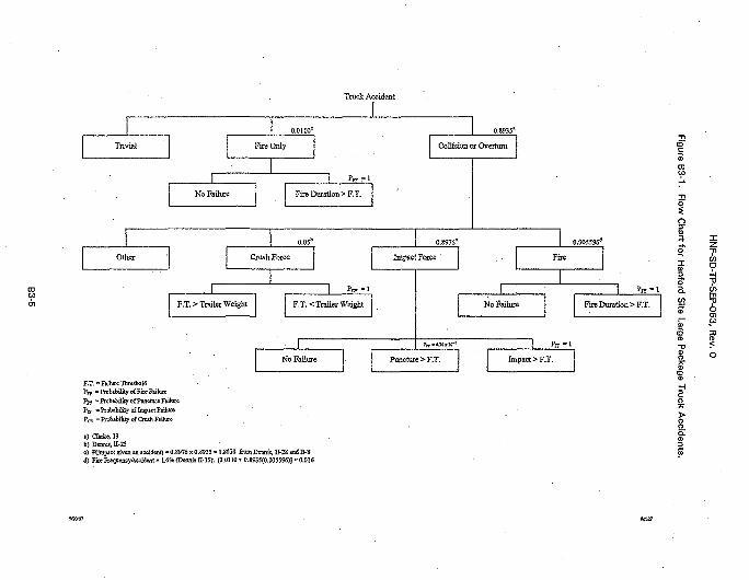
Information for the probability of occurrence and conditional probabilities of failure is takenfrom Severities of Transportation Accidents Involving Large Packages (Dennis et al. 1978|, Severitiesof Transportation Accidents Volume III - Motor Carriers (Clarke et al. 19761, and H&R (1995).A simplified generic flow chart, shown in Figure B3-1, has been developed using statistics presented inClarke et al. (1976) and Dennis et al. (1978). It visually depicts events that may occur as a result of atruck accident on the Hanford Site. Scenarios, such as immersion, that are not pertinent to theshipment of radioactive material on the Hanford Site are not included. Package failure and materialrelease may occur from fire, impact, crush, and puncture, which for purposes of the joint probabilitycalculations are assumed to be independent events.
The probability of an event in the flow chart, given a preceding event, is determined from thestudies presented with large and small packages in Clarke et al. (1976) and Dennis et al. (1978). Thus,as can be seen in Figure B3-1, the probability of a fire only given a truck accident is 0.0110, and theprobability of an accident resulting in collision or overturn is 0.8935 (Clarke et al. 1976 [p.13]). Trivialaccidents are defined only in terms of the cargo and refer to those accidents that do not affect thepayioad (for example accidents with objects of much lesser mass).
The crush force in the flow chart represents static crush. For large packages inertial crush fallsunder the category of an impact force, and impact failure thresholds are accordingly evaluated foreither impact or inertial crush failure, whichever is the limiting value.. The conditional probability ofstatic crush given a collision or overturn accident is found in Dennis et al. (1978 [p. II-253) as 0.05.This means that 1 in 20 collision or overturn accidents results in static crush to the package. Use ofthe 0.05 value is recommended in Dennis et al. (1978) even though the study states that accidentstatistics indicate a lower rate would be more representative of accident conditions.
The impact environment may result in puncture or impact failure for large packages.Dennis et al. (1978) cites a value of 0.8020 for the probability of an impact or inertial crush force givenan accident. Accordingly, the probability of an impact force occurring given a collision or overturn iscalculated to be 0.8976 (0.8020/0.8935). In a similar manner, the conditional probability of fire givena collision or overturn is calculated from the fire frequency per accident of 1.6% (Dennis et al. 1978[p. 11-15]) and the value for the fire-only scenario of 0.0110. It is worth noting that the statistics inDennis et al. (1978) do not discriminate between fires that affect cargo and fires that do not affectcargo. Therefore, some overconservatism may result from the assumption that all fires affect thecargo.
3.5.2.1 Conditional Release Probabilities. Conditional release probabilities for crush are either 1.0 forfailure or 0 for no failure. In an accident involving crush, for example, failure occurs if the static crushfailure threshold for the package is less than the weight of the truck trailer. No other static crush forcewill occur on the Hanford Site. For the 327 Building casks, the conditional release probability due tocrush-induced failure (PCF) is 1.0 because the casks are assumed to fail in any accident involving crushforces.
The conditional probability of release from failure from fire (PFF) is determined from an H&Rreport {H&R 1995), which incorporates Hanford Site information for emergency response time and fireduration. The value represents the probability that the fire duration is greater than the length of timedetermined to be the failure point for the package. For the 327 Building casks, PFF is equal to 1.0because the package is assumed to fail any fire.
The conditional probability of release from puncture given an impact event (PPF) represents theprobability that an impact event will result in a puncture force large enough to penetrate and fail theequivalent steel thickness of the package. The PPF values are found in Dennis et ai. (1978 [p. M-35]}.The 327 Building casks have an equivalent steel thickness of 6.6 cm (2.6 in), which is rounded downto 6.4 cm (2.5 in.) for a PPF value of 4.36 x 10¹⁰.
B3-4
Truck Accidcnt
1 1 0.0110"
Trivial Fire Only
•
1 INo Failure
JOther
ftp-1
Fire Duration > F.T.
0.S935*
Collision or Overturn
0.05*
Crush Force
i iF.T. > Trailer Weight F.T. < Trailer Weight
1No Failure
0.8976°
Impact Force '
.005596*
Fire
1 ! fiF " 1
No Failure Fire Duration > F.T.
^T«4.3(xlS' a j Pjy " 1
Puncture > F.T. Impact > F.T.
Fig
ure
B
3-1.
Flo
So3-to
i ir~SD
or H
J -TP-S
nfo
rc
a 33
I <1 °
, - Portability ofPiieFailra=• Itobabilily of PnnctQie Failorc
Pep =Prol>al)jlityofQnshFaiture
te, 15b)Do»li<, 11-25
« given an aceident) * 0.8976 X 0.S935 = 0.S02O ftom Dratnis, IT-28 and B-85); (0.0110 *• 0.8935(0.005596)J«0.016
HNF-SD-TP-SEP-063, Rev. 0
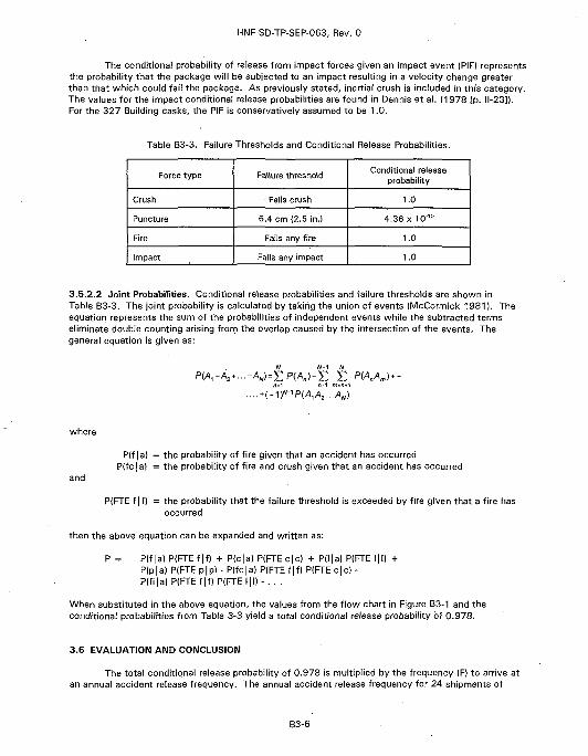
The conditional probability of release from impact forces given an impact event (PIF) representsthe probability that the package will be subjected to an impact resulting in a velocity change greaterthan that which could fail the package. As previously stated, inertial crush is included in this category.The values for the impact conditional release probabilities are found in Dennis et al. (1978 [p. 11-23]).For the 327 Building casks, the PIF is conservatively assumed to be 1.0.
Table B3-3. Failure Thresholds and Conditional Release Probabilities.
Force type
Crush
Puncture
Fire
Impact
Failure threshold
Fails crush
6.4 cm (2.5 in.)
Fails any fire
Fails any impact
Conditional releaseprobability
1.0
4.36 x 10"'°
1.0
1.0
3.5.2.2 Joint Probabilities. Conditional release probabilities and failure thresholds are shown inTable B3-3. The joint probability is calculated by taking the union of events (McCormick 1981). Theequation represents the sum of the probabilities of independent events while the subtracted termseliminate double counting arising from the overlap caused by the intersection of the events. Thegeneral equation is given as:
where
and
P(f | a) = the probability of fire given that an accident has occurredP(fc|al = the probability of fire and crush given that an accident has occurred
P(FTE f |f) = the probability that the failure threshold is exceeded by fire given that a fire hasoccurred
then the above equation can be expanded and written as:
P = P(f|a) P(FTEf|f) + P(c|a) P(FTEc|c) + P(l|a) P(FTE l|l) +P(p|a) P(FTE p|p) - P(fc|a) P(FTE f |f) P(FTE c|c) -P(fi|a)P(FTEf|f)P(FTEI|l)-. . .
When substituted in the above equation, the values from the flow chart in Figure B3-1 and theconditional probabilities from Table 3-3 yield a total conditional release probability of 0.978.
3.6 EVALUATION AND CONCLUSION
The total conditional release probability of 0.978 is multiplied by the frequency (F) to arrive atan annual accident release frequency. The annual accident release frequency for 24 shipments of
B3-6
HNF-SD-TP-SEP-063, Rev. 0
327 Building casks is 5.9 x 10"8. This value is less than the 1 x 10'7 required. In fact, the 327 Buildingcasks can be shipped for up to 16.0 km (10.0 mij per year, and the release frequency is less than thecriterion.
3.7 REFERENCES
Clarke, R. K., J. T. Foley, W. F. Hartman, and D. W. Larson, 1976, Severities of TransportationAccidents, Volume III - Motor Carriers, SLA-74-0001, Sandia National Laboratories,Albuquerque, New Mexico.
Dennis, A. W., J. T. Foley, W. F. Hartman, and D. W. Larson, 1978, Severities of TransportationAccidents Involving Large Packages, SAND77-0001, Sandia National Laboratories,Albuquerque, New Mexico.
DOE, 1994, Airborne Release Fractions/Rates and Respirable Fractions for Nonreactor NuclearFacilities, DOE-HDBK-3010-94, U.S. Department of Energy, Washington, D.C.
Green, J. R., B. D. Flanagan, and H. W. Harris, 1996, Hanford Site Truck Accident Rate, 1990-1995,WHC-SD-TP-RPT-021, Rev. 0, Westinghouse Hanford Company, Richland, Washington.
H&R, 1995, Recommended Onsite Transportation Risk Management Methodology, H&R522-1, H&RTechnical Associates, Inc., Oak Ridge, Tennessee.
McCormick, N. J., 1981, Reliability and Risk Analysis: Methods and Nuclear Power Applications,Academic Press, San Diego, California.
Mercado, J. E., 1994, Report on Equivalent Safety for Transportation and Packaging of RadioactiveMaterials, WHC-SD-TP-RPT-001, Rev. 0, Westinghouse Hanford Company, Richland,Washington.
WHC-CM-2-14, Hazardous Material Packaging and Shipping, Westinghouse Hanford Company,Richland, Washington.
B3-7
HNF-SD-TP-SEP-063, Rev. 0
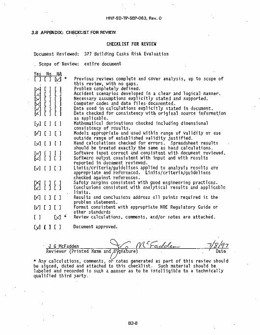
3.8 APPENDIX: CHECKLIST FOR REVIEW
CHECKLIST FOR REVIEW
Document Reviewed: 327 Building Casks Risk Evaluation
Scope of Review: entire document
Yes No NA[ ] [ ] [kd * Previous reviews complete and cover analysis, up to scope of
this review, with no gaps.M - [ ] [ ] Problem completely defined.1x3 [ ] [ 3 Accident scenarios developed in a clear and logical manner.M [ ] [ ] Necessary assumptions explicitly stated and supported.D<] [ ] [ ] Computer codes and data files-documented.\/\ [ ]• [ ] Data used in calculations explicitly stated in document,fii] [ ] [ ] Data checked for consistency with original source information
as applicable.[y] [ ] [ ] Mathematical derivations checked including dimensional
consistency of results.|/] [ ].[] Models appropriate and used within range of validity or use
outside range of established validity justified.M [ ] [ ] Hand calculations checked for errors. Spreadsheet results
should be treated exactly the same as hand calculations.\y] [ ] [ ] Software input correct and consistent with document reviewed.fyt] [ ] [ ] Software output consistent with input and with results
reported in document reviewed.D/] [ ] [ ] Limits/criteria/guidelines applied to analysis results are
appropriate and referenced. Limits/criteria/guidelineschecked against references.
[ ] [ ] Safety margins consistent with good engineering practices.[ ] [ ] Conclusions consistent with analytical results and applicable
. limits.D^] [ ] [ ] Results and conclusions address all points required in the
problem statement.IV] [ ] [ ] Format consistent with appropriate NRC Regulatory Guide or
other standards[ ] [y3 * Review calculations, comments, and/or notes are attached.
[y] [ ] [ ] Document approved.
Reviewer (Printed Name and^gnTture) \ Date
* Any calculations, comments, or notes generated as part of this review shouldbe signed, dated and attached to this checklist. Such material should belabeled and recorded in such a manner as to be intelligible to a technicallyqualified third party.
B3-8
HNF-SD-TP-SEP-063, Rev. 0
4.0 CONTAINMENT EVALUATION
4.1 INTRODUCTION
The containment system consists of the PRTR Graphite Cask and the inner container. Theinner container can be either a stainless steel tube 1.3 cm (0.50 in.} or 1.9 cm (0.75 in.) in diameter ora DOT Specification 2R container per 49 CFR 178.360. An authorized exception to having an innercontainer would be a large solid item with fixed surface contamination. Items such as described canbe placed directly into the cask. See Table B2-4.
4.2 CONTAINMENT SOURCE SPECIFICATION
The authorized radioactive contents of the PRTR Graphite Cask are described in Part B,Section 2.1. For conservatism, the containment analysis assumes that the inner container consists ofthe two 10-mi! plastic bags, which are placed one inside the other.
4.3 NORMAL TRANSPORT CONDITIONS
4.3.1 Conditions To Be Evaluated
The structural performance of the cask was assessed for the Hanford Site normal conditionsthat are listed in Part B, Section 7.3.1.
4.3.2 Containment Acceptance Criteria
The acceptance criteria for the cask for NTC are that the cask shall retain the inner containerand the inner container (plastic or glass vial} shall retain the radioactive material payload.
4.4 ACCIDENT CONDITIONS
4.4.1 Conditions To Be Evaluated
Accident conditions are evaluated for the PRTR Graphite Cask by radiological risk and doseconsequence analyses. The radiological risk evaluation is given in Part B, Section 3.0, of this safetyevaluation. The dose consequence and associated Transportation Hazard Index (THI) are given inPart B, Section 4.6.
4.5 CONTAINMENT EVALUATION AND CONCLUSIONS
4.5.1 Normal Transport Conditions
The PRTR Graphite Cask will provide the structural integrity necessary to transport the payload.The PRTR Graphite Cask has been used for shipments within the 300 Area for approximately 20 years.Prior approval for use of the cask to ship radioactive material was given in MG 137, HazardousMaterials Packaging and Shipping Manual, Rev. 1 (HEDL 1981). Although the PRTR Graphite Cask
B4-1
HNF-SD-TP-SEP-063, Rev. 0
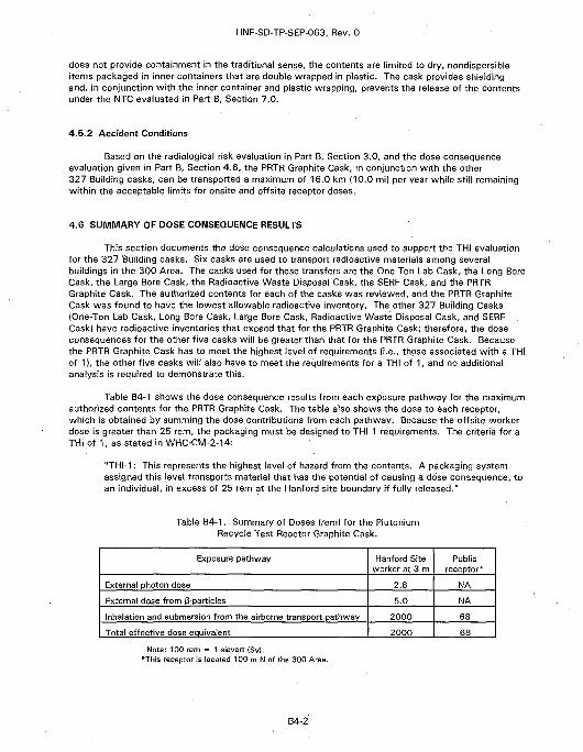
does not provide containment in the traditional sense, the contents are limited to dry, nondispersibleitems packaged in inner containers that are double wrapped in plastic. The cask provides shieldingand, in conjunction with the inner container and plastic wrapping, prevents the release of the contentsunder the NTC evaluated in Part B, Section 7.0.
4.5.2 Accident Conditions
Based on the radiological risk evaluation in Part B, Section 3.0, and the dose consequenceevaluation given in Part B, Section 4.6, the PRTR Graphite Cask, in conjunction with the other327 Building casks, can be transported a maximum of 16.0 km (10.0 mi) per year while still remainingwithin the acceptable limits for onsite and offsite receptor doses.
4.6 SUMMARY OF DOSE CONSEQUENCE RESULTS
This section documents the dose consequence calculations used to support the THI evaluationfor the 327 Building casks. Six casks are used to transport radioactive materials among severalbuildings in the 300 Area. The casks used for these transfers are the One-Ton Lab Cask, the Long BoreCask, the Large Bore Cask, the Radioactive Waste Disposal Cask, the SERF Cask, and the PRTRGraphite Cask. The authorized contents for each of the casks was reviewed, and the PRTR GraphiteCask was found to have the lowest allowable radioactive inventory. The other 327 Building Casks(One-Ton Lab Cask, Long Bore Cask, Large Bore Cask, Radioactive Waste Disposal Cask, and SERF .Cask) have radioactive inventories that exceed that for the PRTR Graphite Cask; therefore, the doseconsequences for the other five casks will be greater than that for the PRTR Graphite Cask. Becausethe PRTR Graphite Cask has to meet the highest level of requirements (i.e., those associated with a THIof 1), the other five casks will also have to meet the requirements for a THI of 1, and no additionalanalysis is required to demonstrate this.
Table B4-1 shows the dose consequence results from each exposure pathway for the maximumauthorized contents for the PRTR Graphite Cask. The table also shows the dose to each receptor,which is obtained by summing the dose contributions from each pathway. Because the offsite workerdose is greater than 25 rem, the packaging must be designed to THI 1 requirements. The criteria for aTHI of 1, as stated in WHC-CM-2-14:
"THI-1: This represents the highest level of hazard from the contents. A packaging systemassigned this level transports material that has the potential of causing a dose consequence, toan individual, in excess of 25 rem at the Hanford site boundary if fully released."
Table B4-1. Summary of Doses (rem) for the PlutoniumRecycle Test Reactor Graphite Cask.
Exposure pathway
External photon dose
External dose from 3-particles
Inhalation and submersion from the airborne transport pathway
Total effective dose equivalent
Hanford Siteworker at 3 m
2.8
5.0
2000
2000
Publicreceptor*
NA
NA
68
68
Note: 100 rem = 1 sievert (Sv).*This receptor is located 100 m N of the 300 Area.
B4-2
HNF-SD-TP-SEP-063, Rev. 0
4.6.1 Introduction and Overview
Six casks are used to transport radioactive materials among several buildings in the 300 Area.The casks used for these transfers are the One-Ton Lab Cask, the Long Bore Cask, the Large BoreCask, the Radioactive Waste Disposal Cask, the SERF Cask, and the PRTR Graphite Cask. Theradioactive materials most frequently transported among buildings are irradiated Fast Flux Test Facilityand Power Reactor and Nuclear Fuel Development Corporation fuel, spent N Reactor fuel, mixed oxide,metal oxide, activated structural materials from reactors, and cesium chloride capsules.
An estimate of the dose consequences for various exposure pathways is necessary todetermine the THI for the 327 Building casks. Part B, Section 4.6.2, discusses the generalmethodology used to perform the dose consequence calculations. Part B, Section 4.6.3, addresses thesource term, and Part B, Sections 4.6.4 through 4.6.9, summarize the results for various exposurepathways. The analysis assumes the casks will only be transported within the 300 Area.
4.6.2 Dose Consequence Analysis Methodology
IAEA (1990J defines a standardized approach for evaluating transportation packagingrequirements, called the Q-system. The Q-system methods, as outlined in IAEA (1990), have beenincorporated into the document, Report on Equivalent Safety for Transportation and Packaging ofRadioactive Materials (Mercado 1994). This document (Mercado 1994) is used to demonstrate thatonsite shipments meet onsite transportation safety requirements per WHC-CM-2-14.
In the Q-system, the following five exposure pathways are considered: (1) external exposure tophotons, (2) external exposure to p-particles, (3) inhalation, (4) skin contamination and ingestion, and(5) submersion in a cloud of gaseous isotopes. In special cases, such as a-particle or neutron emitters,other exposure routes are considered. In some cases a pathway will be judged to be small with respectto the others, and consideration will be minimal. Modifications to the IAEA scenarios are incorporatedto more closely describe the particular conditions of the shipment. Detailed calculations for thepostulated accident are performed whenever possible. However, in some cases, the IAEA guide's(IAEA 1990) worst-case rules-of-thumb are used.
The Q-system was developed as an all-encompassing generalized methodology using only theisotope as the defining variable. In this report, the specifics of the package are considered. Some ofthe dose pathways may be considered incredible (frequency <10'6/yr), and although these pathwaysare covered in the IAEA guide, they are disregarded in the analysis.
In the IAEA system, the Q-values that are calculated are the radionuclide activitiescorresponding to each exposure route that causes the individual to receive the effective doseequivalent limit. The minimum Q-values define the A2 values for the shipped materials. In the case ofnondispersible materials (limited by the A, values), only the first two Q-values (based on exposure toexternal photon and external beta particles) are used. Note that for all radiation except neutrons,protons, and heavier charged particles (including a-particles), 1 gray (Gy) = 1 sievert (Sv), and 1 rad =1 rem.
There are two receptors of interest in the Q-system. They are the Hanford Site worker and thepublic receptor. The Hanford Site worker is assumed to be located about 3 m from the package. Thepublic receptor is assumed to be located at the nearest point of public access.
4.6.3 Source Term
The authorized contents for the PRTR Graphite Cask are shown in Table B4-2. The externaldose due to gamma exposure was calculated assuming the mixed fission products (MFP) consist of137Cs, and the mixed activation products (MAP) consist of 60Co, which produce the highest gamma
B4-3
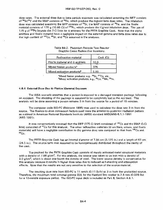
HNF-SD-TP-SEP-063, Rev. 0
dose rates. The external dose due to beta particle exposure was calculated assuming the MFP consistsof 90Sr/90Y and the MAP consists of 59Fe, which produce the highest beta dose rates. The inhalationdose was calculated assuming the MFP consists of 90Sr, the MAP consists of 59Fe, and the fissilematerial consists of 175 g {10.85 CiJ of 239Pu, which produce the highest inhalation dose. The use of175 g of 239Pu bounds the 2-Ci limit for a emitters for the PRTR Graphite Cask. Note that the alphaemitters and fissile material have a negligible impact on the external gamma and beta dose rates due tothe high content of 137Cs, 90Sr, and 6oCo assumed in the analyses.
Table B4-2. Plutonium Recycle Test ReactorGraphite Casks Radioactive Inventory.
Radioactive material
Fissile material and a emitters
Mixed fission products"
Mixed activation products'
Cask (Ci)
10.9
375
5.00
"Mixed fission products; e.g., 90Sr, 137Cs, etc.bMixed activation products; e.g., 60Co, 54Mn, 59Fe
4.6.4 External Dose Due to Photon (Gamma) Exposure
The IAEA scenario assumes that a person is exposed to a damaged transport package followingan accident. The shielding of the package is assumed to be completely lost in the accident. Thisanalysis will be done assuming a person remains 3 m from the source for a period of 15 minutes.
The computer code ISO-PC (Rittmann 19951 was used to calculate the dose rate 3 m from thesource. The fluence-to-dose conversion factors used were the anterior-to-posterior irradiation patternas outlined in American National Standards Institute (ANSI) standard ANSI/ANS-6.1.1-1991(ANS 1991).
It was conservatively assumed that the MFP (375-Ci limit) consisted of 137Cs and the MAP (5-Cilimit) consisted of 60Co for this analysis. The other radioactive materials (a emitters, others, and fissilematerials) will have a negligible contribution to the gamma dose rate compared to that from 137Cs and60Co.
The PRTR Graphite Cask has an internal diameter of 7.94 cm (3.125 in.) and a length of 62 cm(24.5 in.). The source term was assumed to be homogeneously distributed throughout the cavity ofthe cask.
The payload for the PRTR Graphite Cask consists of mainly activated metal structural materialswith a density of 7.86 g/cm3. For this analysis, the source was taken to be iron with a density of'2.0 g/cm3, which is about one-fourth the density of steel. The lower source density is conservative forthis analysis because it results in higher dose rates due to reduced self-shielding and attenuationeffects. Note that the results are not very sensitive to the selection of the source material.
The resulting dose rate from ISO-PC is 11 rem/h (0.11 Sv/h) at 3 m from the unshielded source.Therefore, the maximum total external gamma EDE for the Hanford Site worker is 2.8 rem (0.028 Sv)for a 15-minute exposure period. The ISO-PC input deck is included as Part B, Section 4.8.1.
B4-4
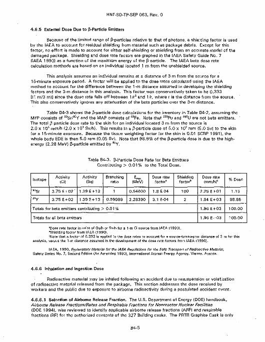
HNF-SD-TP-SEP-063, Rev. 0
4.6.5 External Dose Due to p-Particle Emitters
Because of the limited range of P-particles relative to that of photons, a shielding factor is usedby the IAEA to account for residual shielding from material such as package debris. Except for thisfactor, no effort is made to account for either self-shielding or shielding from an accurate model of thedamaged package. Shielding and dose rate factors are graphed in the IAEA Safety Guide No. 7(IAEA 1990) as a function of the maximum energy of the p-particle. The IAEA beta dose ratecalculation methods are based on an individual located 1 m from the unshielded source.
This analysis assumes an individual remains at a distance of 3 m from the source for a15-minute exposure period. A factor will be applied to the dose rates calculated using the IAEAmethod to account for the difference between the 1-m distance assumed in developing the shieldingfactors and the 3-m distance in this analysis. This factor was conservatively taken to be 0.333[(1 m/3 ml] since the dose rate falls off between 1/r2 and 1/r, where r is the distance from the source.This also conservatively ignores any attenuation of the beta particles over the 3-m distance.
Table B4-3 shows the p-particle dose calculations for the inventory in Table B4-2, assuming theMFP consists of 90Sr/90Y and the MAP consists of 59Fe. Note that 239Pu and 235U are not beta emitters.The total P-particle dose rate to the skin for an individual located 3 m from the source is2.0 x 103 rem/h (2.0 x 10' Sv/h). This results in a p-particle dose of 5.0 x 10² rem (5.0 Svl to the skinfor a 15-minute exposure. Because the tissue weighting factor for the skin is 0.01 (1CRP 1991), thewhole body EDE is then 5.0 rem (0.05 Sv). Note that 98 .9% of the 3-particle dose is due to the high-energy (2.28 MeV) p-particle emitted by 90Y.
Table B4-3. P-Particle Dose Rate for Beta EmittersContributing > 0 . 0 1 % to the Total Dose.
Isotope
soSr
90y
Activity(Ci)
3.75 E + 02
3.75 E + 02
Activity(Bq)
1.39 E + 13
1.39 E + 13
Branchingratio
1
0.99989
(MeV)
0.54600
2.28390
Dose ratefactor*
1.8 E-04
3.1 E-04
Shieldingfactor"
100
2
Totals for beta emitters contributing > 0.01 %
Totals for all beta emitters
Dose rate(rem/h)0
2.25 E + 01
1.94 E + 03
1.96 E + 03
1.96 E+03
% Dose
1.15
98.85
100.00
100.00
"Dose rate factor in units of Gy/h or Sv/h for a 1-m Ci source from IAEA (1990)."Shielding factor from IAEA (1990)."Note that a factor of 0.333 is applied to the dose rates to account for a source-to-receptor distance of 3 m for this
analysis, versus the 1-m distance assumed in the development of the dose rate factors from IAEA (1990).
IAEA, 1990, Explanatory Material for the IAEA Regulations for the Safe Transport of Radioactive Material,Safety Series No. 7, Second Edition (As Amended 1990), International Atomic Energy Agency, Vienna, Austria.
4.6.6 Inhalation and Ingestion Dose
Radioactive material may be inhaled following an accident due to resuspension or volatizationof radioactive material released from the package. This section addresses the dose received byworkers and the public due to exposure to airborne radioactivity during a postulated accident event.
4.6.6.1 Selection of Airborne Release Fraction. The U.S. Department of Energy (DOE) handbook.Airborne Release Fractions/Rates and Respirable Fractions for Nonreactor Nuclear Facilities(DOE 1994), was reviewed to identify applicable airborne release fractions (ARF) and respirablefractions (RF) for the authorized contents of the 327 Building casks. The PRTR Graphite Cask is only
B4-5
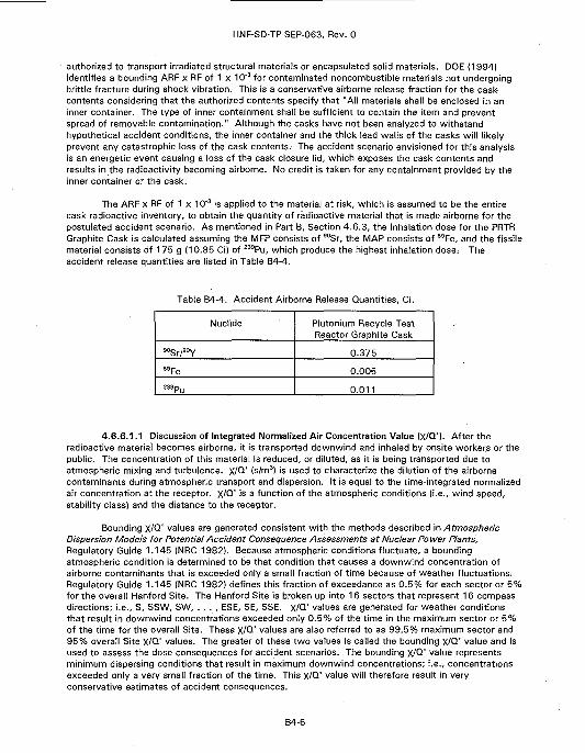
HNF-SD-TP-SEP-063, Rev. 0
' authorized to transport irradiated structural materials or encapsulated solid materials. DOE {1994}identifies a bounding ARF x RF of 1 x 10'3 for contaminated noncombustible materials not undergoingbrittle fracture during shock vibration. This is a conservative airborne release fraction for the cask-contents considering that the authorized contents specify that "All materials shall be enclosed in aninner container. The type of inner containment shall be sufficient to contain the item and preventspread of removable contamination." Although the casks have not been analyzed to withstandhypothetical accident conditions, the inner container and the thick lead walls of the casks will likelyprevent any catastrophic loss of the cask contents. The accident scenario envisioned for this analysisis an energetic event causing a loss of the cask closure lid, which exposes the cask contents andresults in the radioactivity becoming airborne. No credit is taken for any containment provided by theinner container or the cask.
The ARF x RF of 1 x 10~3 is applied to the material at risk, which is assumed to be the entirecask radioactive inventory, to obtain the quantity of radioactive material that is made airborne for thepostulated accident scenario. As mentioned in Part B, Section 4.6.3, the inhalation dose for the PRTRGraphite Cask is calculated assuming the MFP consists of 90Sr, the MAP consists of 59Fe, and the fissilematerial consists of 175 g (10.85 Ci) of 239Pu, which produce the highest inhalation dose> Theaccident release quantities are listed in Table B4-4.
Table B4-4. Accident Airborne Release Quantities, Ci.
Nuclide
so S r / 9o Y
5 9Fe
239pu
Plutonium Recycle TestReactor Graphite Cask
0.375
0.005
0.011
4.6.6.1.1 Discussion of Integrated Normalized Air Concentration Value (X/Q'). After theradioactive material becomes airborne, it is transported downwind and inhaled by onsite workers or thepublic. The concentration of this material is reduced, or diluted, as it is being transported due toatmospheric mixing and turbulence. X/Q' (s/m3) is used to characterize the dilution of the airbornecontaminants during atmospheric transport and dispersion. It is equal to the time-integrated normalizedair concentration at the receptor. X/Q' i s a function of the atmospheric conditions (i.e., wind speed,stability class) and the distance to the receptor.
Bounding X/Q' values are generated consistent with the methods described in AtmosphericDispersion Models for Potential Accident Consequence Assessments at Nuclear Power Plants,Regulatory Guide 1.145 (NRC 1982). Because atmospheric conditions fluctuate, a boundingatmospheric condition is determined to be that condition that causes a downwind concentration ofairborne contaminants that is exceeded only a small fraction of time because of weather fluctuations.Regulatory Guide 1.145 (NRC 1982) defines this fraction of exceedance as 0.5% for each sector or 5%for the overall Hanford Site. The Hanford Site is broken up into 16 sectors that represent 16 compassdirections; i.e., S, SSW, SW, . . . , ESE, SE, SSE. X/Q' values are generated for weather conditionsthat result in downwind concentrations exceeded only 0.5% of the time in the maximum sector or 5%of the time for the overall Site. These X/Q' values are also referred to as 99.5% maximum sector and95% overall Site X/Q' values. The greater of these two values is called the bounding X/Q' value and isused to assess the dose consequences for accident scenarios. The bounding X/Q' value representsminimum dispersing conditions that result in maximum downwind concentrations; i.e., concentrationsexceeded only a very small fraction of the time. This X/Q' value will therefore result in veryconservative estimates of accident consequences.
B4-6
HNF-SD-TP-SEP-063, Rev. 0
The X/Q' values in this report were generated using the GXQ computer program. Version 3.1C(Hey 1993a, 1993b). The meteorological data used by GXQ are in the form of joint frequency tables.The joint frequency data are the most recent data available; they are nine-year-averaged data(1983-1991) from the Hanford Site meteorology towers located in the 300 Area. The X/Q' values aregenerated using the methods described in Regulatory Guide 1.145 (NRC 1982) for a ground releasewith no credit taken for plume rise, plume meander, plume depletion, or any other models. This isconservative because all of these models reduce the airborne concentration at the downwind receptorlocations.
Although we are interested in the dose to a Hanford Site worker at 3 m, the dose to an onsitereceptor located 100 m from the release point is calculated using the worst-case X/Q' value at 100 m.This dose is then multiplied by a factor of 30 to obtain the dose to the Hanford Site worker at 1 m inaccordance with IAEA (1990). This approach is taken because the Gaussian equation, along with theparameters used to calculate the X/Q' values, are only valid for distances of 100 m or greater.Although this analysis assumes the transport worker remains 3 m from the package, the inhalationportion of the transport worker dose is conservatively taken to be that calculated using the IAEAmethod for a worker located 1 m from the package.
The 327 Building casks will be transported within the 300 Area. The maximum X/Q' value foran onsite receptor is 4.21 x 10"2 s/m3 and occurs for an individual located 100 m N of the release pointin the 300 Area.
The 300 Area is not a public exclusion area. Even though the roads may be closed duringmovement of the 327 Building casks, members of the public may be in the area. Therefore, it isconservatively assumed for this analysis that the public receptor is located 100 m from the releasepoint in any compass direction. The maximum onsite and public receptor X/Q' value will therefore bethe same, i.e., the maximum public receptor X/Q' value is 4.21 x 10'2 s/m3. The GXQ input file for themaximum X/Q' case is listed in Part B, Section 4.8.2. The title of the joint frequency file used by GXQis 300 AREA - 10 M - Pasquill A - G (1983 - 1991 Average).
4.6.6.1.2 Inhalation and Submersion Dose Calculations. Because the GENII computer codeVersion 1.485 (Napier 1988) is the Site standard computer code for environmental release dosecalculations, it was used to calculate the inhalation and submersion dose for the maximum onsjte andpublic receptors. The airborne release quantities used in GENII are shown in Table B4-4. An exampleGENII input deck is listed in Part B, Section 4.8.3. The Worst Case Solubility class library was used,which is the most conservative library. The GENII libraries used were as follows:
• GENII Default Parameter Values (28-Mar-90 RAP)• Radionuclide Library - Times < 100 years (23-July-93 PDR)• External Dose Factors for GENII in person Sv/yr per Bq/n (8-May-90)• Worst Case Solubilities, Yearly Dose Increments (23-Jul-93 PDR).
The EDE from GENII for the inhalation and submersion pathways is 1.2 x 10² rem (1.2 Sv) forthe maximum onsite receptor at 100 m N of the 300 Area. The inhalation dose contribution to the EDEis based on a 50-year dose commitment period. The maximum x/Q' value from GENII was7.4 x 10"2 s/m3 for the maximum onsite receptor. The dose rates calculated by GENII are proportionalto the x/Q' values. The GXQ code calculates the 99.5% maximum sector and 95% overall Site X/Q'values consistent with Regulatory Guide 1.145 (NRC 1982) methods, while GENII is inconsistent withRegulatory Guide 1.145 methods. As mentioned in the previous section, the maximum onsite receptorX/Q' value from GXQ is 4.21 x 10"02 s/m3. Therefore, the EDE for the inhalation and submersionpathways is 6.8 x 101 rem (6.8 x 10"1 Sv) for the maximum onsite receptor at 100 m using the GXQX/Q' value. This value was obtained by multiplying the GENII dose rate by the ratio of the GXQ X/Q'value to the GENII X/Q' value. Therefore the maximum public receptor dose is 6.8 x 101 rem(6.8 x 101 Sv).
B4-7
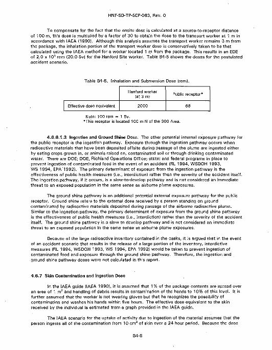
HNF-SD-TP-SEP-063, Rev. 0
To compensate for the fact that the onsite dose is calculated at a source-to-receptor distanceof 100 m, this dose is multiplied by a factor of 30 to obtain the dose to the transport worker at 1 m inaccordance with IAEA (1990]. Although this analysis assumes the transport worker remains 3 m fromthe package, the inhalation portion of the transport worker dose is conservatively taken to be thatcalculated using the IAEA method for a worker located 1 m from the package. This results in an EDEof 2.0 x 1O3 rem (20.0 Sv) for the Hanford Site worker. Table B4-5 shows the doses for the postulatedaccident scenario.
Table B4-5. Inhalation and Submersion Dose (rem).
Effective dose equivalent
Hanford worker(at 3 m)
2000
Public receptor*
68
Note: 100 rem = 1 Sv.*This receptor is located 100 m N of the 300 Area.
4.6.6.1.3 Ingestion and Ground Shine Dose. The other potential internal exposure pathway forthe public receptor is the ingestion pathway. Exposure through the ingestion pathway occurs whenradioactive materials that have been deposited offsite during passage of the plume are ingested eitherby eating crops grown in, or animals raised on, contaminated soil or through drinking contaminatedwater. There are DOE; DOE, Richland Operations Office; state; and federal programs in place toprevent ingestion of contaminated food in the event of an accident (RL 1994, WSDOH 1993,WS 1994, EPA 1992). The primary determinant of exposure from the ingestion pathway is theeffectiveness of public health measures (i.e., interdiction) rather than the severity of the accident itself.The ingestion pathway, if it occurs, is a slow-to-develop pathway and is not considered an immediatethreat to an exposed population in the same sense as airborne plume exposures.
The ground shine pathway is an additional potential external exposure pathway for the publicreceptor. Ground shine refers to the external dose received by a person standing on groundcontaminated by radioactive materials deposited during passage of the airborne radioactive plume.Similar to the ingestion pathway, the primary determinant of exposure from the ground shine pathwayis the effectiveness of public health measures (i.e., interdiction) rather than the severity of the accidentitself. The ground shine pathway is a slow-to-develop pathway and is not considered an immediatethreat to an exposed population in the same sense as airborne plume exposures.
Because of the large radioactive inventory contained in the casks, it is argued that in the eventof an accident scenario that results in the release of a large portion of the inventory, interdictivemeasures (RL 1994, WSDOH 1993, WS 1994, EPA 1992) would be taken to prevent ingestion ofcontaminated food and exposure through the ground shine pathway. Therefore, the ingestion andground shine pathway doses were not calculated in this report.
4.6.7 Skin Contamination and Ingestion Dose
In the IAEA guide (IAEA 1990), it is assumed that 1 % of the package contents are spread overan area of 1 m2 and handling of debris results in contamination of the hands to 10% of this level. It isfurther assumed that the worker is not wearing gloves but that he recognizes the possibility ofcontamination and washes his hands within five hours. The effective dose equivalent to the skinreceived by the individual is estimated from a graph provided in the IAEA guide.
The IAEA scenario for the uptake of activity due to ingestion of the material assumes that theperson ingests all of the contamination from 10 cm2 of skin over a 24-hour period. Because the dose
B4-8
HNF-SD-TP-SEP-063, Rev. 0
per unit uptake via inhalation is generally the same order or larger than that via ingestion, the inhalationpathway will normally be limiting for internal contamination due to P-ray emitters. In particular, if theskin contamination dose is much larger than the inhalation dose, the ingestion pathway is notconsidered.
Both these pathways are ordinarily neglected when calculating the dose consequences from anonsite transportation accident. The transportation workers are trained in the appropriate response toprotect themselves from experiencing unnecessary radiation exposure, including preventing skincontamination and ingestion.
4.6.8 Submersion Dose Due to Gaseous Vapor
This exposure pathway is caused by submersion in a cloud of gaseous isotopes that are nottaken into the body. A rapid release of 100% of the package contents is assumed. The IAEA guide(IAEA 1990) concentrates entirely on releases within confined structures. No guidance is given foroutside releases.
There are no gaseous vapors present in the cask; therefore, this exposure pathway is notapplicable.
4.6.9 Special Considerations
Alpha particle emitters are not of significance in the material considered in this report. Thealpha particle emitters are of a low concentration, and their effect will be through the mechanism ofinhalation that has been considered separately. Therefore, they are not addressed in this report. Thequantity of radon present in the fuel is insignificant; therefore, radon is not addressed in this report.
The fuel (e.g., plutonium) contained in the casks emits neutrons through (ot,n) and spontaneousfission reactions. These neutron emitters will contribute to the dose received by the Hanford Siteworker, but will have a negligible impact on the public receptor. A conservative estimate of theneutron dose was made using the method described in Nelson (1996). The results indicate that theneutron dose contribution is negligible compared to the gamma dose due to the large MFP and MAPinventory. Therefore, the neutron dose was not calculated separately in this report.
Bremsstrahlung has been included in the consideration of photon effects, and the effects ofshort-lived daughter products have been included in all of the calculations. Where these isotopes aresignificant, they are assumed to be in equilibrium with their longer-lived parent isotopes.
4.6.10 Total Dose
Table B4-1 in Part B, Section 4.6, shows the dose from each exposure pathway.
4.7 REFERENCES
ANS, 1991, Neutron and Gamma-Ray Fluence-to-Dose Factors, ANSI/ANS-6.1.1-1991, AmericanNuclear Society, La Grange Park, Illinois.
DOE, 1994, Airborne Release Fractions/Rates and Respirable Fractions for Nonreactor NuclearFacilities, DOE-HDBK-3010-94, U.S. Department of Energy, Washington, D.C.
B4-9
HNF-SD-TP-SEP-063, Rev. 0
DOE, 1992, Hazard Categorization and Accident Analysis Techniques for Compliance with DOE Order5480.23, Nuclear Safety Analysis Reports, DOE-STD-1027-92, U.S. Department of Energy,Washington, D.C.
DOE, 1988, Radiation Protection for Occupational Workers, DOE Order 5480.11, U.S. Department ofEnergy, Washington, D.C.
EPA, 1992, Manual of Protective Action Guides and Protective Actions for Nuclear Incidents,U.S. Environmental Protection Agency, Washington, D.C.
HEDL, 1981, Hazardous Materials Packaging and Shipping Manual, MG 137, Rev. 1, HanfordEngineering Development Laboratory, Richland, Washington.
Hey, B. E., 1993a, GXQ Program Users' Guide, WHC-SD-GN-SWD-30002, Rev. 0, WestinghouseHanford Company, Richland, Washington.
Hey, B. E., 1993b, GXQ Program Verification and Validation, WHC-SD-GN-SWD-30003, Rev. 0,Westinghouse Hanford Company, Richland, Washington.
IAEA, 1990, Explanatory Material for the IAEA Regulations for the Safe Transport of RadioactiveMaterial, Safety Series No. 7, Second Edition (As Amended 1990), International Atomic EnergyAgency, Vienna.
ICRP, 1991, International Commission on Radiological Protection, Annals of the ICRP, Publication 60,1991, International Commission on Radiological Protection, New York, New York. •
Mercado, J. E., 1994, Report on Equivalent Safety for Transportation and Packaging of RadioactiveMaterials, WHC-SD-TP-RPT-001, Rev. 0, Westinghouse Hanford Company, Richland,Washington.
Napier, B. A., et al., December 1988, GENII - The Hanford Environmental Radiation Dosimetry SoftwareSystem, PNL-6584, Vol. 1, UC-600, Pacific Northwest Laboratory, Richland, Washington.
Nelson, J. V., 1996, Estimation of Neutron Dose Rates from Nuclear Waste Packages, (internal memo8M730-JVN-96-007 to J. R. Green, March 8), Westinghouse Hanford Company, Richland,Washington.
NRC, 1982, Atmospheric Dispersion Models for Potential Accident Consequence Assessments atNuclear Power Plants, Regulatory Guide 1.145, U.S. Nuclear Regulatory Commission,Washington, D.C.
Rittmann, P. D., 1995, ISO-PC Version 1.98 - User's Guide, WHC-SD-WM-UM-030, Rev. 0,Westinghouse Hanford Company, Richland, Washington.
RL, 1994, Emergency Implementation Procedures, DOE-0223, U.S. Department of Energy, RichlandOperations Office, Richland, Washington. :
WHC-CM-2-14, Hazardous Material Packaging and Shipping, Westinghouse Hanford Company,Richland, Washington.
WHC-CM-4-46, Nonreactor Facility Safety Analysis Manual, Westinghouse Hanford Company, Richland,Washington.
WHC, 1995, Packaging Design Criteria, Transfer and Disposal of Long-Length Equipment, Hanford TankFarm Complex, WHC-SD-TP-PDC-020, Rev. 2, Westinghouse Hanford Company, Richland,Washington.
B4-10
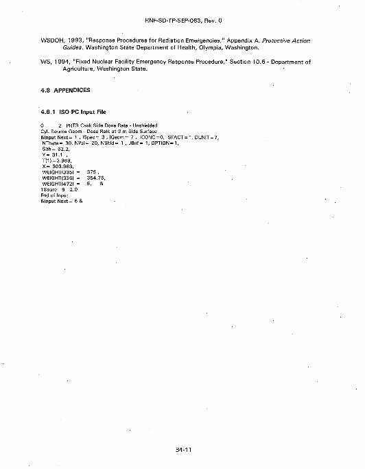
HNF-SD-TP-SEP-063, Rev. 0
WSDOH, 1993, "Response Procedures for Radiation Emergencies," Appendix A, Protective ActionGuides, Washington State Department of Health, Olympia, Washington.
WS, 1994, "Fixed Nuclear Facility Emergency Response Procedure," Section 10.6 - Department ofAgriculture, Washington State.
4.8 APPENDICES
4.8.1 ISO-PC Input File
0 2 PRTR Cask Side Dose Rate - UnshieldedCyl. Source Geom - Dose Rate at 3 m Side SurfaceStlnput Next= 1 , ISpec= 3 , IGeom= 7 , IC0NC = 0, SFACT = 1, DUNIT = 7,NTheta= 30, NPsi= 20, NShld= 1 , JBuf = 1, OPTION = 1,Slth= 62.2,Y= 31.1 ,T(1) = 3.969,X= 303.969,WEIGHTI335) = 375 ,WEIGHT(336) = 354.75,WEIGHTI472) = 5, &ISourc 9 2.0End of Input&lnputNext= 6 &
B4-11
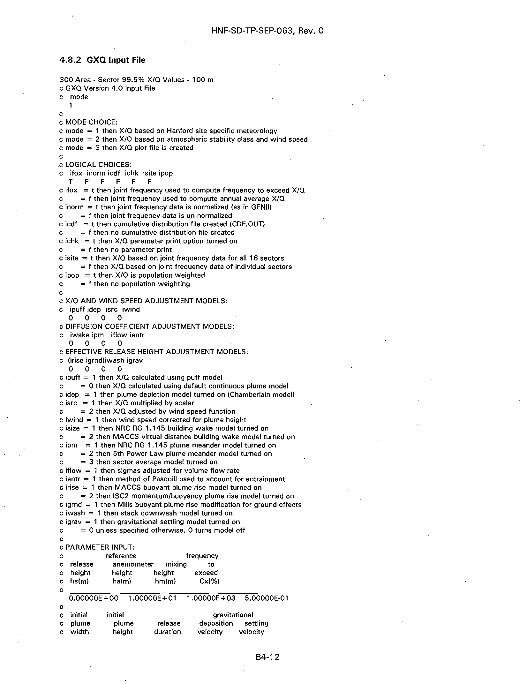
HNF-SD-TP-SEP-063, Rev. 0
4.8.2 GXQ Input File
300 Area - Sector 99.5% X/Q Values - 100 mc GXQ Version 4.0 Input Filec mode
1cc MODE CHOICE:c mode = 1 then X/Q based on Hanford site specific meteorologyc mode = 2 then.X/Q based on atmospheric stability class and wind speedc mode = 3 then X/Q plot file is createdcc LOGICAL CHOICES:c ifox inorm icdf ichk isite ipop
T F F F F Fc ifox = t then joint frequency used to compute frequency to exceed X/Qc = f then joint frequency used to compute annual average X/Qc inorm = t then joint frequency data is normalized (as in GENII)c = f then joint frequency data is un-normalizedc icdf = t then cumulative distribution file created (CDF.OUT)c = f then no cumulative distribution file createdc ichk = t then X/Q parameter print option turned onc = f then no parameter printc isite = t then X/Q based on joint frequency data for all 16 sectorsc = f then X/Q based on joint frequency data of individual sectorsc ipop = t then X/Q is population weightedc = f then no population weightingcc X/Q AND WIND SPEED ADJUSTMENT MODELS:c ipuff idep isrc iwind
0 0 0 0C DIFFUSION COEFFICIENT ADJUSTMENT MODELS:c iwake ipm iflow ientr
0 0 0 0c EFFECTIVE RELEASE HEIGHT ADJUSTMENT MODELS:c (irise igrnd)iwash igrav
0 0 0 0c ipuff = 1 then X/Q calculated using puff modelc = 0 then X/Q calculated using default continuous plume modelc idep = 1 then plume depletion model turned on (Chamberlain model)c isrc = 1 then X/Q multiplied by scalarc = 2 then X/Q adjusted by wind speed functionc iwind = 1 then wind speed corrected for plume heightc isize = 1 then NRC RG 1.145 building wake model turned onc = 2 then MACCS virtual distance building wake model turned onc ipm = 1 then NRC RG 1.145 plume meander model turned onc = 2 then 5th Power Law plume meander model turned onc = 3 then sector average model turned onc iflow = 1 then sigmas adjusted for volume flow ratec ientr = 1 then method of Pasquill used to account for entrainmentc irise = 1 then MACCS buoyant plume rise model turned onc = 2 then ISC2 momentum/buoyancy plume rise model turned onc igrnd = 1 then Mills buoyant plume rise modification for ground effectsc iwash = 1 then stack downwash model turned onc igrav = 1 then gravitational settling model turned onc = 0 unless specified otherwise, 0 turns model offc
c PARAMETER INPUT:c reference frequency
releaseheighths(m)
0.00000E
initialplumewidth
anemometer mixinjheightha(m)
+ 00 1.
initialplumeheight
heighthm(m)
00000E + 01
releaseduration
] toexceed
Cx(%)
1.00000E + 03 5.00000E-01
gravitationaldepositionvelocity
settlingvelocity
B4-12
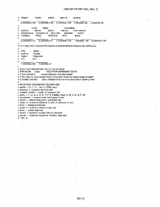
HNF-SD-TP-SEP-063, Rev. 0
(m/s) vg{m/s)
O.OOOOOE + 00 0.00000E + 00 0.00000E + 00 1.00000E-03 1.00000E-03cc initial initial convectivec ambient plume plume release heat releasec temperature temperature flow rate diameter rated)c Tamb(C) TO{C) V0{m3/s) d(m) qh{w)c
2.00000E + 01 2.2O000E +01 1.00000E + 00 1.00000E + 00 O.OOOOOE + 00cc {1) If zero then buoyant flux based on plume/ambient temperature difference,cc X/Q Windc scaling Speedc factor Exponent
1 .OOOOOE +00 7.80000E-01cc RECEPTOR DEPENDENT DATA (no line limit)c FOR MODE make RECEPTOR DEPENDENT DATAc 1 {site specific) sector distance receptor-heightc 2 (by class & wind speed) class windspeed distance offset receptor-heightc 3 (create plot file) class windspeed xmax imax ymax jmax xqmin powercc RECEPTOR PARAMETER DESCRIPTIONc sector = 0, 1, 2... {all, S, SSW, etc.)c distance = receptor distance (m)c receptor height = height of receptor {m)c class = 1, 2, 3, 4, 5, 6, 7 (P-G stability class A, B, C, D, E, F, G)c windspeed = anemometer wind speed {m/s)c offset = offset from plume centerline (m)c xmax = maximum distance to plot or calculate to (m)c imax = distance intervalsc ymax = maximum offset to plot (m)c jmax = offset intervalsc xqmin = minimum scaled X/Q. to calculatec power = exponent in power function step size0 100 0
B4-13
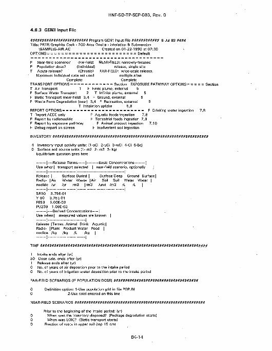
HNF-SD-TP-SEP-063, Rev. 0
4.8.3 GENII Input File
######################### Program GENII Input File ############ 8 Jul 88 ####Title: PRTR Graphite Cask - 300 Area Onsite - Inhalation & Submersion
\SAMPL\G-AIR.AC Created on 01-22-1990 at 07:30OPTIONS = = = = = = = = = = = = = = = = = = = = = = = = = Default
F Near-field scenario? (Far-field) NEAR-FIELD: narrowly-focusedF Population dose? (Individual) release, single siteT Acute release? (Chronic) FAR-FIELD: wide-scale release.
Maximum Individual data set used multiple sitesComplete Complete
TRANSPORT OPTIONS = = = = = = = = = = = = Section EXPOSURE PATHWAY OPTIONS = = = = = SetT Air Transport 1 F Finite plume, external 5F Surface Water Transport 2 T Infinite plume, external 5F Biotic Transport (near-field) 3,4 F Ground, external 5F Waste Form Degradation (near) 3,4 F Recreation, external 5
T Inhalation uptake 5,6REPORT OPTIONS = = = = = = = = = = = = = = = = = = = = = = = F Drinking water ingestion 7,8T Report AEDE only F Aquatic foods ingestion 7,8F Report by radionuclide F Terrestrial foods ingestion 7,9F Report by exposure pathway F Animal product ingestion 7,10F Debug report on screen F Inadvertent soil ingestion
INVENTORY M##UUU#U###################8#1t##1t1t1t#######U##UU1tUU##########1t##1t####
4 Inventory input activity units: (1-pCi 2-uCi 3-mCi 4-Ci 5-Bq)0 Surface soil source units (1- m2- 2- m3 3- kg)
Equilibrium question goes here
| -—Release Terms 1 -—Basic Concentrations [Use when | transport selected | near-field scenario, optionally j
I i iRelease j Surface Buried | Surface Deep Ground Surface]Radio- [Air Water Waste |Air Soil Soil Water Water |nuclide |/yr /yr /m3 |/m3 /unit /m3 /L /L |
I I ISR90 3.75E-01Y 90 3.75E-01FE59 5.00E-03PU239 1.09E-02
| —Derived Concentrations 1Use when | measured values are known |
I ' Ii I
Release |Terres. Animal Drink Aquatic|Radio- | Plant Product Water Food |nuclide |/kg /kg /L /kg |
I I
1 Intake ends after (yr)50 Dose calc. ends after (yr)1 Release ends after (yr)0 No. of years of air deposition prior to the intake period0 No. of years of irrigation water deposition prior to the intake period
FAR-FIELD SCENARIOS (IF POPULATION DOSE) #####################################
0 Definition option: 1-Use population grid in file POP.IN
0 2-Use total entered on this line
NEAR-FIELD SCENARIOS #########################################################
Prior to the beginning of the intake period: (yr)0 When was the inventory disposed? (Package degradation starts)0 When was LOIC? (Biotic transport starts)0 Fraction of roots in upper soil (top 1 5 cm)
B4-14
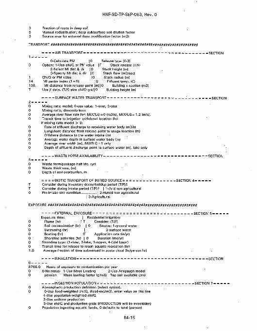
HNF-SD-TP-SEP-063, Rev. 0
0 Fraction of roots in deep soil0 Manual redistribution: deep soil/surface soil dilution factor0 Source area for external dose modification factor (m2)
TRANSPORT ####################################################################
= = = =AIRTRANSPORT= = = = = = = = = = = = = = = = = = = = = = = = = = = = = = = = = = = = =SECTION
O-Calculate PM |0 Release type (0-3)3 Option: 1-Use chi/Q or PM value |F Stack release (T/F)
2-Select Ml dist & dir |0 Stack height (m)3-Specify Ml dist & dir 10 Stack flow (m3/sec)
1 Chi/Q or PM value |0 Stack radius (m)14 Ml sector index (1 =S) JO Effluent temp. (C)100. Ml distance from release point (m)]0 Building x-section (m2)T Use jf data, (T/F) else chi/Q gridjO Building height (m)
= = = =SURFACE WATER TRANSPORT= = = = = = = = = = = = = = = = = = = = = = = = = = = = = = =SECTION2 = = = = =0 Mixing ratio model: 0-use value, 1-river, 2-lake0 Mixing ratio, dimensionless0 Average river flow rate for: MIXFLG=0 (m3/s), MIXFLG = 1,2 (m/s),
. 0 Transit time to irrigation withdraw! location (hr)If mixing ratio model > 0:
0 Rate of effluent discharge to receiving water body (m3/s)0 Longshore distance from release point to usage location (m)0 Offshore distance to the water intake (m)0 Average water depth in surface water body (m)0 Average river width (m), MIXFLG = 1 only0 Depth of effluent discharge point to surface water (m), lake only
= = = =WASTE FORM AVAILABILITY = = = = = = = = = = = = = = = = = = = = = = = = = = = = = = =SECTION3 = = = = =0 Waste form/package half life, (yr)0 Waste thickness, (m)0 Depth of soil overburden, m
= = = =BIOTIC TRANSPORT OF BURIED SOURCE= = = = = = = = = = = = = = = =SECTION 4= = = = =T Consider during inventory decay/buildup period (T/F)?T Consider during intake period (T/F)? | 1-Arid non agricultural0 Pre-lntake site condition | 2-Humid non agricultural
| 3-Agricultural
EXPOSURE #####################################################################
= = = =EXTERNAL EXPOSURE = = = = = = = = = = = = = = = = = = = = = = = = = = = = = =SECTION 5 = = = = =Exposure time: | Residential irrigation:
0 Plume (hr) | T Consider: (T/F)0 Soil contamination (hr) | 0 Source: 1-ground water0 Swimming (hr) | 2-surface water0 Boating (hr) | 0 Application rate (in/yr)0 Shoreline activities (hr) | 0 Duration (mo/yr)0 Shoreline type: (1-river, 2-lake, 3-ocean, 4-tidal basin)0 Transit time for release to reach aquatic recreation (hr)1.0 Average fraction of time submersed in acute cloud (hr/person hr)
= = = = INHALATION = = = = = = = = = = = = = = = = = = = = = = = = = = = = = = = = = = = = = = = SECTION6 = = = = =8766.0 Hours of exposure to contamination per year0 0-No resus- 1-Use Mass Loading 2-Use Anspaugh model0 pension Mass loading factor (g/m3) Top soil available (cm)
= = = =INGESTION POPULATION= = = = = = = = = = = = = = = = =0 Atmospheric production definition (select option):0 0-Use food-weighted chi/Q, (food-sec/m3), enter value on this line
•1-Use population-weighted chi/Q2-Use uniform production3-Use chi/Q and production grids (PRODUCTION will be overridden)
0 Population ingesting aquatic foods, 0 defaults to total (person)
B4-1 5
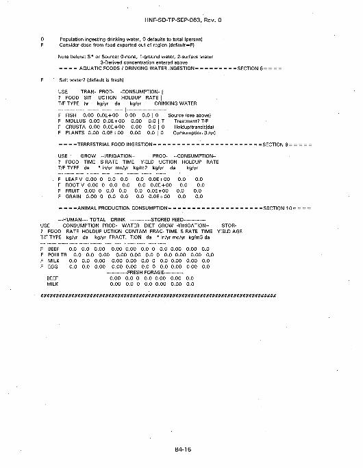
HNF-SD-TP-SEP-063, Rev. 0
0 Population ingesting drinking water, 0 defaults to total (person)F Consider dose from food exported out of region (default = F)
Note below: S* or Source: O-none, 1-ground water, 2-surface water3-Derived concentration entered above
= = = = AQUATIC FOODS / DRINKING WATER INQESTION= = = = = = = = =SECTION 8 = = = =
F Salt water? (default is freshl
USE TRAN- PROD- -CONSUMPTION- |? FOOD SIT UCTION HOLDUP RATE |T/F TYPE hr kg/yr da kg/yr | DRINKINQ WATER
F FISH 0.00 0.0E + 00 0.00 0.0 | 0 Source (see above)F MOLLUS 0.00 0.0E + 00 0.00 0.0 | T Treatment? T/FF CRUSTA 0.00 O.OE + 00 0.00 0.0 | 0 Holdup/transitlda)F PLANTS 0.00 O.OE + 00 0.00 0.0 | 0 Consumption (L/yr)
= = = =TERRESTRIAL FOOD INQESTION= = = = = = = = = = = = = = = = = = = = = = =SECTION 9 =
USE QROW -IRRIGATION- PROD- -CONSUMPTION-? FOOD TIME S RATE TIME YIELD UCTION HOLDUP RATET/F TYPE da * in/yr mo/yr kg/m2 kg/yr da kg/yr
. F LEAFV 0.00 0 0.0 0.0 0.0 O.OE + 00 0.0 0.0F ROOTV 0.00 0 0.0 0.0 0.0 O.OE + 00 0.0 0.0F FRUIT 0.00 0 0.0 0.0 0.0 O.OE + 00 0.0 0.0F GRAIN 0.00 0 0.0 0.0 0.0 O.OE + 00 0.0 0.0
= = = =ANIMAL PRODUCTION CONSUMPTION = = = = = = = = = = = = = = = = = = = = SECTION 10= = = =
—HUMAN—- TOTAL DRINK STORED FEEDUSE CONSUMPTION PROD- WATER DIET GROW -IRRIGATION- STOR-? FOOD RATE HOLDUP UCTION CONTAM FRAC- TIME S RATE TIME YIELD AGET/F TYPE kg/yr da kg/yr FRACT. TION da * in/yr mo/yr kg/m3 da
F BEEF 0.0 0.0 0.00 0.00 0.00 0.0 0 0.0 0.00 0.00 0.0F POULTR 0.0 0.0 0.00 0.00 0.00 0.0 0 0.0 0.00 0.00 0.0F MILK 0.0 0.0 0.00 0.00 0.00 0.0 0 0.0 0.00 0.00 0.0F EGG 0.0 0.0 0.00 0.00 0.00 0.0 0 0.0 0.00 0.00 0.0
FRESH FORAGEBEEF 0.00 0.0 0 0.0 0.00 0.00 0.0MILK 0.00 0.0 0 0.0 0.00 0.00 0.0
B4-16
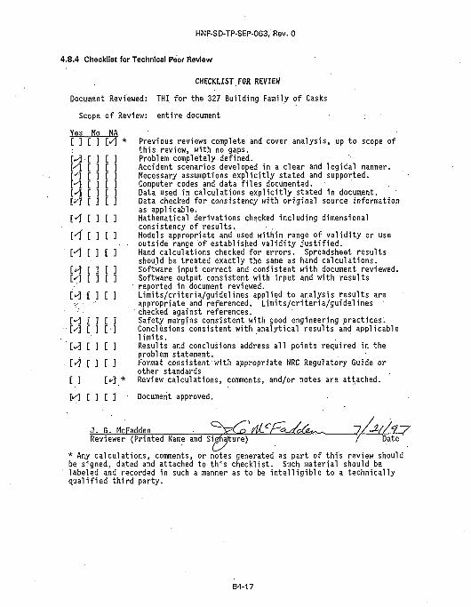
HNF-SD-TP-SEP-063, Rev. 0
4.8.4 Checklist for Technical Peer Review
CHECKLIST FOR REVIEW
Document Reviewed: THI for the 327 Building Family of Casks
Scope of Review: entire document
Yes No NA[ ] [ ] M *
M EY\ [:•"•] t
A [yi i
] t ]3 t :] [ :i [:3 t :] c ]
H [ 3 [ 3
[<f [ 3 [ 3
M [ 3 [ 3
M [ ] C 3M [ ] [ ]M I 3 [ 3
M 3 [ 33 [•]
W [ 3 [ 3
MUM[ 3 [*}.
M [ 1 I 1
Previous reviews complete and cover analysis, up to scope ofthis review, with no gaps.Problem completely defined.Accident scenarios developed in a clear and logical manner.Necessary assumptions explicitly stated and supported.Computer codes and data files documented.Data used in calculations explicitly stated in document.Data checked for consistency with original source informationas applicable.Mathematical derivations checked including dimensionalconsistency of results. • .Models appropriate and used within range of validity or useoutside range of established validity justified.Hand calculations checked for errors. Spreadsheet resultsshould be treated exactly the same as hand calculations.Software input correct and consistent with document reviewed.Software output consistent with input and with resultsreported in document reviewed.Limits/criteria/guidelines applied to analysis results areappropriate and referenced. Limits/criteria/guidelinss 'checked against references.Safety margins consistent with good engineering practices.Conclusions consistent with analytical results and applicablelimits. . ' . 'Results and conclusions address all points required in theproblem statement.Format consistent with appropriate NRC Regulatory Guide orother standardsReview calculations, comments, and/or notes are attached.
Document approved.
J. G. McFaddenReviewer (Printed Name and Sigfiajture) / Date
* Any calculations, comments, or notes generated as part of this review shouldbe signed, dated and attached to this checklist. Such material should belabeled and recorded in such a manner as to be intelligible to a technicallyqualified third party.
B4-17
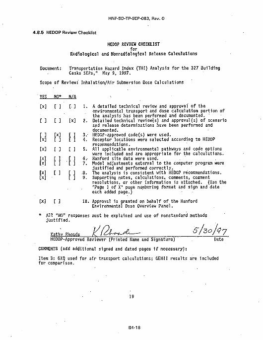
HNF-SD-TP-SEP-063, Rev. 0
4.8.5 HEDOP Review Checklist
HEDOP REVIEW CHECKLISTfor
Radiological and Konradiological Release Calculations
Document: Transportation Hazard Index (THI) Analysis for the 327 BuildingCasks SEPs," Hay 9, 1997.
Scope of Review: Inhalation/Air Submersion Dose Calculations
YES NO* N/A
[x] [ ] [ ] 1. A detailed technical review and approval of theenvironmental transport and dose calculation portion ofthe analysis has been performed and documented.
[ ] [ ] [x] 2. Detailed technical review(s) and approval(s) of scenarioand release determinations have been performed anddocumented.
[ ] [x] [ ] 3. HEDOP-approved code(s) were used,[x] [ ] [ ] 4. Receptor locations were selected according to HEDOP
recommendations,[x] [ ] [ ] 5. All applicable environmental pathways and code options
were included and are appropriate for the calculations,[x] [ ] [ ] 6.- Hanford site data were used.[x] [ ] [ ] 7. Model adjustments external to the computer program were
justified and performed correctly.[x] [ ] [ ] .8. . The analysis is consistent with HEDOP recommendations.[x] [ ] 9. Supporting notes, calculations, comments, comment
resolutions, or other information is attached. (Use the"Page 1 of X" page numbering format and sign and dateeach added page.)
[x] [ ] 10. Approval is granted on behalf of the HanfordEnvironmental Dose Overview Panel.
* All "NO" responses must be explained and use of nonstandard methodsjustified.
Kathv RhoadsHEDOP-Approved Reviewer (Printed Name and Signature) . Date
COMMENTS (add additional signed and dated pages if necessary):
Item 3: GXQ used for air transport calculations; GENII results are includedfor comparison.
19
B4-18
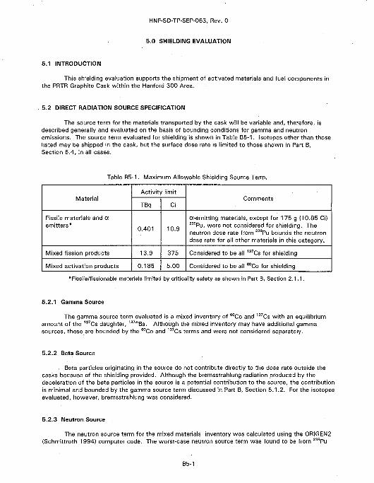
HNF-SD-TP-SEP-063, Rev. 0
5.0 SHIELDING EVALUATION
5.1 INTRODUCTION
This shielding evaluation supports the shipment of activated materials and fuel components inthe PRTR Graphite Cask within the Hanford 300 Area.
5.2 DIRECT RADIATION SOURCE SPECIFICATION
The source term for the materials transported by the cask will be variable and, therefore, isdescribed generally and evaluated on the basis of bounding conditions for gamma and neutronemissions. The source term evaluated for shielding is shown in Table B5-1. Isotopes other than thoselisted may be shipped in the cask, but the surface dose rate is limited to those shown in Part B,Section 5.4, in all cases.
Table B5-1. Maximum Allowable Shielding Source Term.
Material
Fissile materials and aemitters*
Mixed fission products
Mixed activation products
Activity limit
TBq
0.401
13.9
0.185
Ci
10.9
375
5.00
Comments
a-emitting materials, except for 175 g (10.85 Ci)239Pu, were not considered for shielding. Theneutron dose rate from 239Pu bounds the neutrondose rate for all other materials in this category.
Considered to be all 137Cs for shielding
Considered to be all 60Co for shielding
* Fissile/fissionable materials limited by criticaiity safety as shown in Part B, Section 2.1.1.
5.2.1 Gamma Source
The gamma source term evaluated is a mixed inventory of 60Co and 137Cs with an equilibriumamount of the 137Cs daughter, 137mBa. Although the mixed inventory may have additional gammasources, these are bounded by the 60Co and 137Cs terms and were not considered separately.
5.2.2 Beta Source
Beta particles originating in the source do not contribute directly to the dose rate outside thecasks because of the shielding provided. Although the bremsstrahlung radiation produced by thedeceleration of the beta particles in the source is a potential contribution to the source, the contributionis minimal and bounded by the gamma source term discussed in Part B, Section 5.1.2. For the isotopesevaluated, however, bremsstrahlung was considered.
5.2.3 Neutron Source
The neutron source term for the mixed materials inventory was calculated using the ORIGEN2(Schmittroth 1994) computer code. The worst-case neutron source term was found to be from 239Pu
B5-1
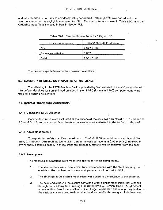
HNF-SD-TP-SEP-063, Rev. 0
and was found to occur prior to any decay being considered. Although 235U was considered, theneutron source term is negligible compared to 239Pu. The source term is shown in Table B5-2, and theORIGEN2 input file is included in Part B, Section 5.8.
Table B5-2. Neutron Source Term for 175g of 239Pu
Component of source
(a,n)
Spontaneous fission
Total
Source strength (neutrons/s)
7.927 E+03
3.967
7.931 E + 03
The cesium capsule inventory has no neutron emitters.
5.3 SUMMARY OF SHIELDING PROPERTIES OF MATERIALS
The shielding in the PRTR Graphite Cask is provided by lead encased in a stainless steel shell.The default densities for iron and lead provided in the ISO-PC (Rittmann 1995) computer code wereused for shielding calculations.
5.4 NORMAL TRANSPORT CONDITIONS
5.4.1 Conditions To Be Evaluated
Gamma dose rates were evaluated at the surface of the cask (with an offset of 1.0 cm) and at2.0 m (6.6 ft) from the cask surface. Neutron dose rates were estimated at the surface of the cask.
5.4.2 Acceptance Criteria
Transportation safety specifies a maximum of 2 mSv/h (200 mrem/h) on any surface of thecask, 0.1 mSv/h (10 mrem/h) at 2.0 m (6.6 ft) from the cask surface, and 0.02 mSv/h (2 mrem/h) inany normally occupied space. If these limits are exceeded, material will be removed from the cask.
5.4.3 Assumptions
The following assumptions were made and applied to the shielding model.
1. The steel in the closure mechanism tube was combined with the steel covering theoutside of the mechanism to make a single inner shell and outer shell.
2. The air space in the closure mechanism was added to the distance to the detector.
3. The cask end opposite the closure contains a steel plunger mechanism that extendsthrough the shielding (see drawing H-3-13699 [Part A, Section 10.1]). A cylindricalsource with a diameter equivalent to the plunger mechanism and a length equivalent tothe cask cavity was used to determine the dose outside the plunger. This dose was
B5-2
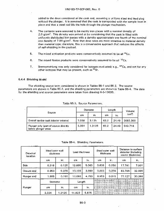
HNF-SD-TP-SEP-063, Rev. 0
added to the dose considered at the cask end, assuming a uniform steel and lead plugwithout the plunger. It is assumed that the cask is transported with the sample boat inplace and that a steel rod fills the hole through the plunger mechanism.
4. The contents were assumed to be mainly iron pieces with a nominal density of2.0 g/cm3. This density was arrived at by considering that the cask is filled withuniformly distributed iron pieces with a density approximately one-fourth of the nominaliron density of 7.86 g/cm3. Note that dose rates are more sensitive to material densitythan material type; therefore, this is a conservative approach that reduces the effectsof self-shielding in the payload.
5. The mixed activation products were conservatively assumed to be all 60Co.
6. The mixed fission products were conservatively assumed to be all 137Cs.
7. Bremsstrahlung was only considered for isotopes evaluated; e.g., 137Cs, and not for anyother isotopes that may be present, such as 90Sr.
5.4.4 Shielding Model
The shielding source term considered is shown in Tables B5-1 and B5-2. The sourceparameters are shown in Table B5-3, and the shielding parameters are shown in Table B5-4. The datafor the shielding and source parameters were taken from drawing H-3-13699.
Table B5-3. Source Parameters.
Source
Overall (entire cask interior volume)
Plunger only (part of source directlybelow plunger area)
Diameter
cm
7.938
3.334
in.
3.125
1.3125
Length
cm
62.2
62.2
in.
24.49
24.49
Volume(cm3)
3082.300
543.718
Table B5-4. Shielding Parameters.
Detectorlocation
Side
Closure end
Plunger end
Plunger
Steel inner wallthickness
cm
0.318
0.953
1.905
in'.
0.125
0.375
0.750
Diameter
cm
3.334
in.
1.3125
Lead thickness
cm
12.860
10.133
12.065
in.
5.063
3.989
4.750
Length
cm
14.923
in.
5.875
Steel outer wallthickness
cm
0.635
0.953
0.953
in.
0.250
0.375
0.375
Distance to surfacedetector (Includingsource thickness)
cm
17.781
83.796
77.127
in.
7.001
32.990
30.365
B5-3
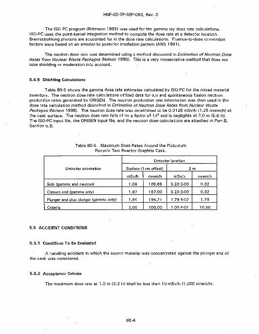
HNF-SD-TP-SEP-063, Rev. 0
The ISO-PC program (Rittmann 1995} was used for the gamma-ray dose rate calculations.ISO-PC uses the point-kernel integration method to compute the dose rate at a detector location.Bremsstrahlung photons are accounted for in the dose rate calculations. Fluence-to-dose conversionfactors were based on an anterior-to-posterior irradiation pattern (ANS 1991).
The neutron dose rate was determined using a method discussed in Estimation of Neutron DoseRates from Nuclear Waste Packages {Nelson 1996). This is a very conservative method that does nottake shielding or moderation into account.
5.4.5 Shielding Calculations
Table B5-5 shows the gamma dose, rate estimates calculated by ISO-PC for the mixed materialinventory. The neutron dose rate calculations utilized data for a,n and spontaneous fission neutronproduction rates generated by ORIGEN. The neutron production rate information was then used in thedose rate calculation method described in Estimation of Neutron Dose Rates from Nuclear WastePackages (Nelson 1996). The neutron dose rate was determined to be 0.0125 mSv/h (1.25 mrem/h) atthe cask surface. The neutron dose rate falls of by a factor of 1/r2 and is negligible at 2.0 m (6.6 ft).The ISO-PC input file, the ORIGEN input file, and the neutron dose calculations are attached in Part B,Section 5.8.
Table B5-5. Maximum Dose Rates Around the PlutoniumRecycle Test Reactor Graphite Cask.
Detector orientation
Side (gamma and neutron)
Closure end {gamma only)
Plunger end plus plunger {gamma only)
Criteria
Detector location
Surface (1cm offset)
mSv/h .
1.09
1.87
1.94
2.00
mrem/h
108.65
187.00
194.21
200.00
2 m
mSv/h
3.20 E-03
3.20 E-03
1.79 E-02
1.00 E-01
mrem/h
0.32
0.32
1.79
10.00
5.5 ACCIDENT CONDITIONS
5.5.1 Conditions To Be Evaluated
A handling accident in which the source material was concentrated against the plunger end ofthe cask was considered.
5.5.2 Acceptance Criteria
The maximum dose rate at 1.0 m (3.3 ft) shall be less than 10 mSv/h (1,000 mrem/h).
B5-4
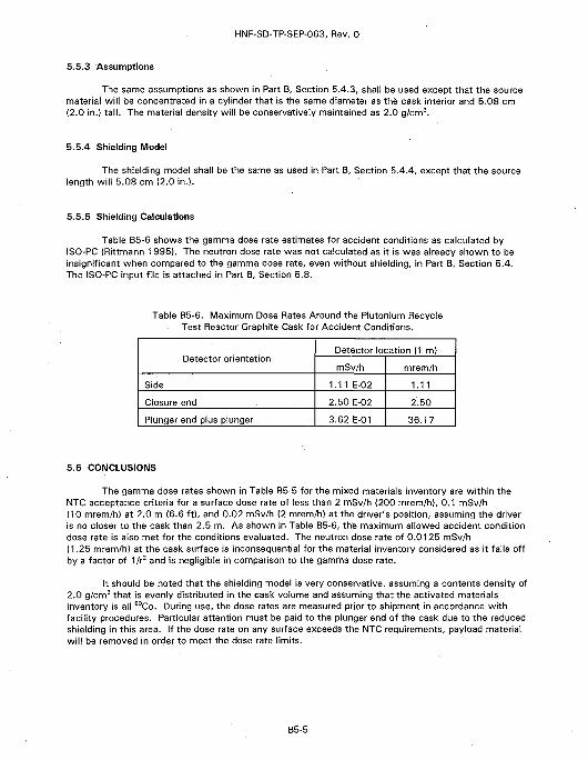
HNF-SD-TP-SEP-063, Rev. 0
5.5.3 Assumptions
The same assumptions as shown in Part B, Section 5.4.3, shall be used except that the sourcematerial will be concentrated in a cylinder that is the same diameter as the cask interior and 5.08 cm(2.0 in.) tall. The material density will be conservatively maintained as 2.0 g/cm3.
5.5.4 Shielding Model
The shielding model shall be the same as used in Part B, Section 5.4.4, except that the sourcelength will 5.08 cm (2.0 in.).
5.5.5 Shielding Calculations
Table B5-6 shows the gamma dose rate estimates for accident conditions as oalcuiated byISO-PC (Rittmann 1995). The neutron dose rate was not calculated as it is was already shown to beinsignificant when compared to the gamma dose rate, even without shielding, in Part B, Section 5.4.The ISO-PC input file is attached in Part B, Section 5.8.
Table B5-6. Maximum Dose Rates Around the Plutonium RecycleTest Reactor Graphite Cask for Accident Conditions.
Detector orientation
Side
Closure end
Plunger end plus plunger
Detector location (1 m)
mSWh
1.11 E-02
2.50 E-02
3.62 E-01
mrem/h
1.11
2.50
36.17
5.6 CONCLUSIONS
The gamma dose rates shown in Table B5-5 for the mixed materials inventory are within theNTC acceptance criteria for a surface dose rate of less than 2 mSv/h (200 mrem/h), 0.1 mSv/h(10 mrem/h) at 2.0 m (6.6 ft), and 0.02 mSv/h (2 mrem/h) at the driver's position, assuming the driveris no closer to the cask than 2.5 m. As shown in Table B5-6, the maximum allowed accident conditiondose rate is also met for the conditions evaluated. The neutron dose rate of 0.0125 mSv/h(1.25 mrem/h) at the cask surface is inconsequential for the material inventory considered as it falls offby a factor of 1/r2 and is negligible in comparison to the gamma dose rate.
It should be noted that the shielding model is very conservative, assuming a contents density of2.0 g/cm3 that is evenly distributed in the cask volume and assuming that the activated materialsinventory is all 60Co. During use, the dose rates are measured prior to shipment in accordance withfacility procedures. Particular attention must be paid to the plunger end of the cask due to the reducedshielding-in this area. If the dose rate on any surface exceeds the NTC requirements, payload materialwill be removed in order to meet the dose rate limits.
B5-5
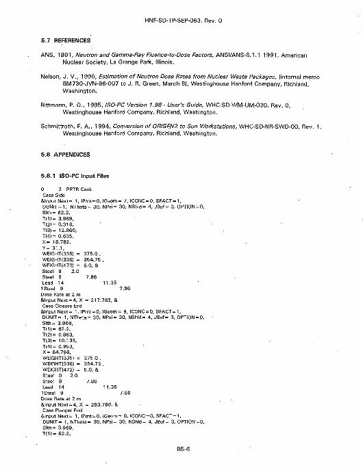
HNF-SD-TP-SEP-063, Rev. 0
5.7 REFERENCES
ANS, 1991, Neutron and Gamma-Ray Fluence-to-Dose Factors, ANSI/ANS-6.1.1-1991, AmericanNuclear Society, La Grange Park, Illinois.
Nelson, J. V., 1996, Estimation of Neutron Dose Rates from Nuclear Waste Packages, (internal memo8M730-JVN-96-007 to J. R. Green, March 8), Westinghouse Hanford Company, Richland,Washington.
Rittmann, P. D., 1995, ISO-PC Version 1.98 - User's Guide, WHC-SD-WM-UM-030, Rev. 0,Westinghouse Hanford Company, Richland, Washington.
Schmittroth, F. A., 1994, Conversion of 0RIGEN2 to Sun Workstations, WHC-SD-NR-SWD-00, Rev. 1,Westinghouse Hanford Company, Richland, Washington.
5.8 APPENDICES
5.8.1 ISO-PC Input Files
0 2 PRTR CaskCase Side
&lnputNext = 1, IPrnt=O, IGeom = 7, ICONC = O, SFACT=1,DUNIT=1, NTheta= 30, NPsi= 30, NShld= 4, JBuf= 3, OPTION = 0,Slth= 62.2,T(1|= 3.969,T(2)= 0.318,T(3)= 12.860,T[4)= 0.635,X= 18.782,Y= 31.1,WEIGHTI335) = 375.0 ,WEIGHTI336) = 354.75 ,WEIGHTI472) = 5.0, &Steel 9 2.0Steel 9 7.86Lead 14 11.351 Steel 9 7.86Dose Rate at 2 m&lnput Next = 4, X = 217.782, &Case Closure End
&lnputNext= 1, IPrnt = O, IGeom = 9, ICONC=O, SFACT=1,DUNIT= 1, NTheta= 30, NPsi= 30, NShld= 4, JBuf= 3, OPTION = 0,Slth= 3.969,T(1)= 62.2,TI2)= 0.953,T(3)= 10.133,T(4)= 0.953,X= 84.796,WEIGHTI335) = 375.0 ,WEIGHTI336) = 354.75 ,WEIGHTI472) = 5.0, &Steel 9 2.0Steel 9 7.86Lead 14 11.351 Steel 9 7.86Dose Rate at 2 m&lnput Next = 4, X = 283.796, &Case Plunger End
&lnput Next= 1, IPrnt = O, IGeom= 9, ICONC = 0, SFACT=1,DUN1T= 1, NTheta= 30, NPsi= 30, NShld= 4, JBuf= 3, OPTION = 0,Slth= 3.969,T(1)= 62.2,
B5-6
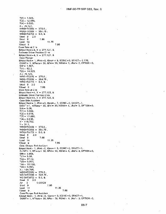
HNF-SD-TP-SEP-063, Rev. 0
T(2)= 1.S05,T(3)= 12.065,T(4)= 0.953,X= 78.127,WEIGHTI335) = 375.0 ,WEIGHTI336) = 354.75 ,WEIGHT(472) = 5.0, &Steel 9 2.0Steel 9 7.86Lead 14 11.351 Steel 9 7.86Dose Rate at 2 m&lnput Next = 4, X = 277.127, &Estimate Driver Position (2 m)&lnput Next=4, X = 277.127, &Case Plunger
&lnput Next = 1, IPrnt = O, IQeom= 9, ICONC = 0, SFACT= 0.176,DUNIT= 1, NTheta= 30, NPsi= 30, NShld= 2, JBuf= 2, OPTION = 0,Slth= 1.667,T(1)= 62.2,T(2I= 14.923,X= 78.123,WEIGHTI335) = 375.0 ,WEIGHTI336) = 354.75 ,WEIGHTI472) = 5.0, &Steel 9 2.01 Steel 9 7.86Dose Rate at 2 m&lnput Next=4, X = 277.123, &Estimate Driver Position {2 m}&lnputNext=4, X = 277.123, &Case Side Accident
&lnput Next= 1, IPrnt = O, IGeom = 7, ICONC = 0, SFACT=1,DUNIT = 1, NTheta = 30, NPsi = 30, NShld = 4, JBuf = 3, OPTION = 0,Slth= 5.08,T(1)= 3.969,T(2)= 0.318,T(3)= 12.860,T(4)= 0.635,X= 118.782,Y= 31.1,WEIGHTI335) = 375.0 ,WEIGHTI336I = 354.75 ,WEIGHT(472) = 5.0, &Steel 9 2.0Steel 9 7.86Lead 14 11.351 Steel 9 7.86Case Closure End Accident
&lnput Next= 1, IPrnt = O, IGeom= 9, ICONC = 0, SFACT=1,DUNIT = 1, NTheta = 30, NPsi= 30, NShld = 5, JBuf= 4, OPTION = 0,Slth= 3.969,T(1)= 5.08,T(2>= 57.12,T(3)= 0.953,T(4)= 10.133,T(5)= 0.953,X= 184.796,WEIGHT(335I = 375.0 ,WEIGHTI336I = 354.75 ,WEIGHTI472) = 5.0, &Steel 9 2.0Air 3 0.00129Steel 9 7.86Lead 14 11.351 Steel 9 . 7.86Case Plunger End Accident
&lnput Next= 1, IPrnt = O, IGeom= 9, ICONC = 0, SFACT=1,DUNIT = 1, NTheta = 30, NPsi= 30, NShld = 4, JBuf= 3, OPTION = 0,
B5-7
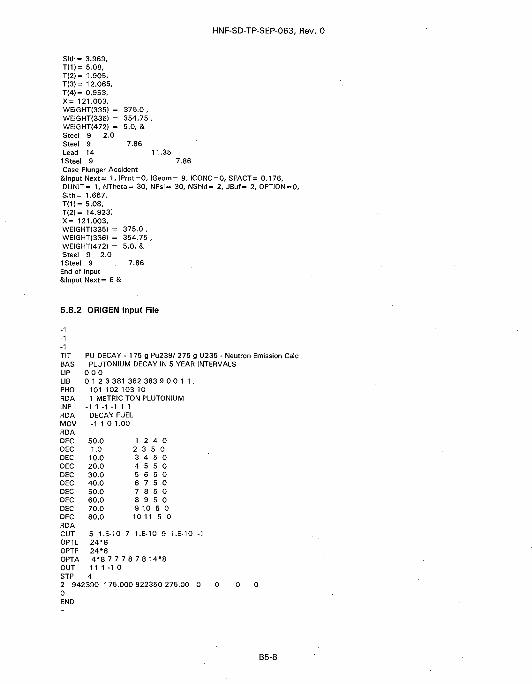
HNF-SD-TP-SEP-063, Rev. 0
Slth= 3.969,T(1)= 5.08,T(2)= 1.905,T(3)= 12.065,T(4)= 0.953,X= 121.003,WEIGHTO35) = 375.0 ,WEIGNTI336) = 354.75 ,WEIGHT(472> = 5.0, &Steel 9 2.0Steel 9 7.86Lead 14 11.351 Steel 9 7.86Case Plunger Accident
Silnput Next= 1, IPrnt=0, IGeom= 9, IC0NC=0, SFACT= 0.176,DUNIT= 1, NTheta= 30, NPsi= 30, NShld = 2, JBuf= 2, OPTION=O,Slth= 1.667,T(1)= 5.08,T(2)= 14.923;X= 121.003,WEIGHTI335) = 375.0 ,WEIGHTI336) = 354.75 ,WEIGHTI472) = 5.0, &Steel 9 2.01 Steel 9 7.86End of InputStlnput Next= 6 &
5.8.2 ORIGEN Input File
-1-1TIT PU DECAY - 175 g Pu239/ 275 g U235 - Neutron Emission Calc8AS PLUTONIUM DECAY IN 5 YEAR INTERVALSLIP 0 0 0LIB 0 1 2 3 381 382 383 9 0 0 1 1 .PHO 101 102 103 10RDA 1 METRIC TON PLUTONIUMINP - 1 1 - 1 - 1 1 1RDA DECAY FUELMOV -1 1 0 1.00RDADEC 50.0 1 2 4 0DEC 1.0 2 3 5 0DEC 10.0 3 4 5 0DEC 20.0 4 5 5 0DEC 30.0 5 6 5 0DEC 40.0 6 7 5 0DEC 50.0 7 8 5 0DEC 60.0 8 9 5 0DEC 70.0 9 10 5 0DEC 80.0 10 11 5 0RDACUT 5 1.6-10 7 1.E-10 9 1.E-10 -1OPTL 2 4 ' 8OPTF 24"8OPTA 4"8 7 7 7 8 7 8 14*8OUT 1 1 1 - 1 0STP 42 942390 175.000 922350 275.00 0 0 0 00END
B5-8
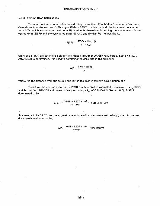
HNF-SD-TP-SEP-063, Rev. 0
5.8.3 Neutron Dose Calculations
The neutron dose rate was determined using, the method described in Estimation of NeutronDose Rates from Nuclear Waste Packages {Nelson 1996). In this method, the total neutron sourceterm SIT), which accounts for neutron multiplication, is determined by adding the spontaneous fissionsource term (S(SF)) and the cc,n source term (S( a,n)} and dividing by 1 minus the keff.
= (S{SF) - S(g, n))(1 * )
S(SFI and S( a,n) are determined either from Nelson (1996) or ORIGEN (see Part B, Section 5.8.2).After S(ST) is determined, it is used to determine the dose rate in the equation;
D(r) __ 0.01 • S(ST)
where r is the distance from the source and D(r) is the dose in mrem/h as a function of r.
Therefore, the neutron dose for the PRTR Graphite Cask is estimated as follows. Using S(SF)and S( a,n) from ORIGEN and conservatively assuming a kell of 0.8 (Part B, Section 6.0), S(ST) isdetermined to be,
3.967 • 7.927 x 10*(1 - 0.8)
Assuming r to be 17.78 cm (the approximate surface of cask as measured radially), the total neutrondose rate is estimated to be,
D(r) = 0.01 • 3.965 X 10< = ,h17.782
B5-9
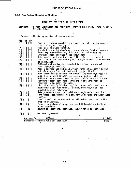
HNF-SD-TP-SEP-063, Rev. 0
5.8.4 Peer Review Checklist for Shielding
CHECKLIST FOR TECHNICAL PEER REVIEW
Document: Safety Evaluation for Packaging (Onsite) PRTR Cask, June 4, 1997,by John McCoy.
Scope: Shielding portion of the analysis.
Yes No NA[ ] [ ] [X] Previous reviews complete and cover analysis, up to scope of
this review, with no gaps.[X] [ ] [ ] Problem completely defined.[ ] [ ] [X] Accident scenarios developed in a clear and logical manner.[X] [ ] [ 1 Necessary assumptions explicitly stated and supported.[X] [ ] [ ] Computer codes and data files documented.[X] [ ] [ ] Data used in calculations explicitly stated in document.[X] [ ] £ ] Data checked for consistency with original source information
as applicable.[X] [ ] [ ] Mathematical derivations checked including dimensional
consistency of results.[X] [ ] [ ] Models appropriate and used within range of validity or use
outside range of established validity justified.[X] [ ] [ ] Hand calculations checked for errors. Spreadsheet results
should be treated exactly the same as hand calculations.[X] [ ] [ ] Software input correct and consistent with document reviewed.[X] [ ] [ ] Software output consistent with input and with results
reported in document reviewed.[X] [ ] [ ] Limits/criteria/guidelines applied to analysis results are
appropriate and referenced. Limits/criteria/guidelineschecked against references.
[X] [ ] [ ] Safety margins consistent with good engineering practices.[X] [ ] [ ] Conclusions consistent with analytical results and applicable
limits.[X] [ ] [ ] Results and conclusions address all points required in the
problem statement.[X] [ ] [ ] Format consistent with appropriate NRC Regulatory Guide or
other standards[ ] [X] Review calculations, comments, and/or notes are attached.
[X] [ ] [ ] Document approved.
Anthony Saving MJj*—± : 6/ 4/97Reviewer (Printed Name and Signature) . Date
B5-1O
HNF-SD-TP-SEP-063, Rev. 0
6.0 CRITICALITY EVALUATION
The criticality analysis of the PRTR Graphite Cask was completed in Limits for FissionableMaterial, in Small Bore Transfer Casks and Lead Pigs (see Section 6.1). This analysis demonstrates thatthe PRTR Graphite Cask remains subcritical when loaded with 275 g or less of 23BU. The package isalso subcritical when loaded wi th 175 g or less of 239Pu, 2 3 3U, 237Np, 2 4 'Am, 243Am, w C m , and 247Cm.The following fissionable materials were not analyzed and cannot be shipped in excess of safeguardsaccountability limits: M 2 " A m , 243Cm, 245Cm, M9Cf, or 251Cf.
6.1 APPENDIX: CRITICALITY SAFETY ANALYSIS
B6-1
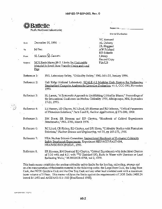
HNF-SD-TP-SEP-063, Rev. 0
llBatfenePacific Northwest Laboratories
Date December 30, 1996
To M Dec
From SL Larson <yC- Ussw-
subject NCS Basis Memo 96-2. Limits for FissionableMaterial in Small Bore Transfer Casks and LeadPigs
Internal Distribution
VC AsmundAL DohertyDL HaggardAWPrichardRD ScheeleLibraryRecord CopyFile/LB
Reference 1: PNL Laboratory Safety, "Criticality Safety," PNL-MA-25, January 1994.
Reference 2: Oak Ridge National Laboratory, SCALE 4.2 Modular Code System for PerformingStandardized Computer Analyses for Licensing Evaluation, vl-3, CCC-545, November1993.
Reference 3: SL Larson, "A Systematic Approach to Establishing Criticality Biases," Proceedings ofthe International Conference on Nuclear Criticality 1995, Albuquerque, NM, September17-21,1995.
Reference 4: LE Hansen, ED Clayton, RC Lloyd, SR Bierman and RD Johnson, "Critical Parametersof Plutonium Solutions," Parts I and II, Nuclear Applications, & 371-390,1969.
Reference 5: BM Durst, SR Bierman and ED Clayton, "Handbook of Critical ExperimentsBenchmarks," PNL-2700, March 1978. .
Reference 6: RC Lloyd, CR Richey, ED Clayton, and DR Skeen, "Criticality Studies with PlutoniumSolutions," Nuclear Science and Engineering, vol 25, pp 165-173, 1966.
Reference 7: NEA Nuclear Science Committee, International Handbook of Evaluated CriticalitvSafety Benchmark Experiments. Experiment HEU-MET-FAST-004,NEA/MSC/DOC(95)03/II, 1995.
Reference 8: SR Bierman, BM Durst and ED Clayton, "Critical Experiments with Subcritical Clustersof 2.35 \vt% and 4.31 wt% 235U Enriched UO2 Rods in Water with Uranium or LeadReflecting Walls," NUREG/CR-0796, vol 2, 1979.
This basis memo establishes the nuclear criticality safety limits for the loading, unloading, storage andon-site transportation of fissionable material in the following casks: the Large Bore Cask, the Long BoreCask, the PRTR Graphite Cask and the One Ton Cask and any other lead shielded cask with a maximuminner volume of 5 liters. This memo validates the limits against the requirements of DOE Order 54S0.24issued 8/12/92 and ANSI/ANS-8.1-19S3 [Reaffirmed 1988].
B6-2
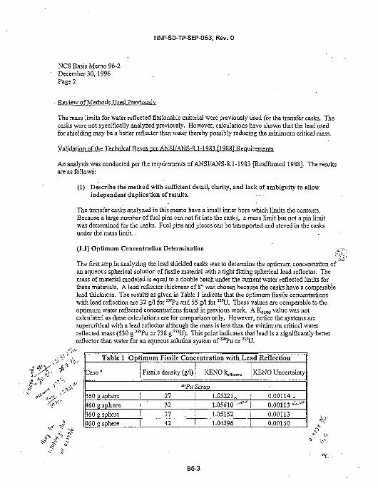
HNF-SD-TP-SEP-063, Rev. 0
NCS Basis Memo 96-2December 30,1996Page 2
Review of Methods Used Previously
The mass limits for water reflected fissionable material were previously used for the transfer casks. Thecasks were not specifically analyzed previously. However, calculations have shown that the lead usedfor shielding may be a better reflector than water thereby possibly reducing the minimum critical mass.
Validation of the Technical Rases per ANSI/ANS-8.1 -1983 [1988] Requirements
An analysis was conducted per the requirements of ANSI/ANS-8.1-1983 [Reaffirmed 1988]. The resultsare as follows:
(1) Describe the method with sufficient detail, clarity, and lack of ambiguity to allowindependent duplication of results.
The transfer casks analyzed in this memo have a small inner bore which limits the contents.Because a large number of fuel pins can not fit into the casks, a mass limit but not a pin limitwas determined for the casks. Fuel pins and pieces can be transported and stored in the casksunder the mass limit.
(1.1) Optimum Concentration Determination >r-
The first step in analyzing the lead shielded casks was to determine the optimum concentration ofan aqueous spherical solution of fissile material with a tight fitting spherical lead reflector. Themass of material modeled is equal to a double batch under the current water reflected limits forthese materials. A lead reflector thickness of 8" was chosen because.the casks have a comparablelead thickness. The results as given in Table 1 indicate that the optimum fissile concentrationswith lead reflection are 32 g/1 for MPu and 55 g/1 for !35U. These values are comparable to theoptimum water reflected concentrations found in previous work. A K$slis value was notcalculated as these calculations are for comparison only. However, notice the systems aresupercritical with a lead reflector although the mass is less than the minimum critical waterreflected mass (530 g 23sPu or 738 g 23iU). This point indicates that lead is a significantly betterreflector than water for an aqueous solution system of 239Pu or 235U.
^ / * ^?
Table 1 Optimum Fissile Concentration with. Lead Reflection
Case"
460 g sphere460 g sphere460 g sphere460 g sphere
Fissile density (g/1) K E N O k ^ ,
"•Pu Scrap27323742
1.0522ULoseio'1"*'"1.051521.04596
KENO Uncertainty
0.00114.0.00113 "•'•'"'0.001130.00150
B6-3
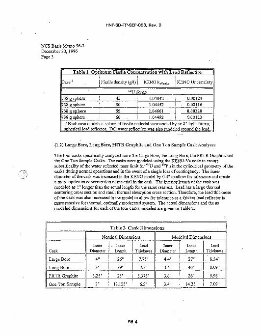
HNF-SD-TP-SEP-063, Rev. 0
NCS Basis Memo 96-2December 30,1996Page 3
Table 1 Optimum Fissile Concentration with Lead Reflectioni i
C a s e ; . j Fissile density (g/1) j KENO ktflicIivc KENO Uncertainty
'"UScrap738 g sphere | 45
738 g sphere ' 501.04042 i 0.001231.04452
738 g sphere j 55 j 1.04661
738 g sphere 1 60 . I 1.04492
. 0.00116
0.001200.00123
* Each case models a sphere of fissile material surrounded by an 8" tight fittingspherical lead reflector. Full water reflection was also modeled around the lead.
(1.2) Large Bore, Long Bore, PRTR Graphite and One Ton Sample Cask Analyses
The four casks specifically analyzed were the Large Bore, the Long Bore, the PRTR Graphite andthe One Ton Sample Casks. The casks were modeled using the KENO-Va code to ensuresubcriticality of the water reflected mass limit for235U and 23sPu in the cylindrical geometry of thecasks during normal operations and in the event of a single loss of contingency. The innerdiameter of the cask was increased in the KENO model by 0.4" to ailow for tolerance and createa more optimum concentration of material in the cask. The interior length of the cask wasmodeled as 1" longer than the actual length for the same reasons. Lead has a large thermalscattering cross section and small thermal absorption cross section. Therefore, the lead thicknessof the cask was also increased in the model to allow for tolerance as a thicker lead reflector ismore reactive for thermal, optimally moderated system. The actual dimensions and the asmodeled dimensions for each of the four casks modeled are given in Table 2.
Table 2 Cask Dimensions
Cask
Large Bore
Long Bore
PRTR Graphite
One Ton Sample
Nominal Dimensions
InnerDiameter
4"
• 3 "
3.25"
3"
InnerLength
26"
39"
25"
13.125"
LeadThickness
7.75"
7.5"
5.375"
6.5"
Modeled Dimensions
Inner j InnerDiameter i Length
l •
4.4" ; 27"
3.4" ! 40"
3.6" i 26"•
3.4" 14.25"
LeadThickness
8.34"
8.09"
5.96"
7.09"
B6-4
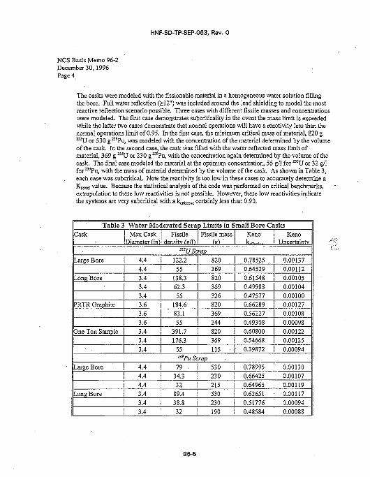
HNF-SD-TP-SEP-063, Rev. 0
NCS Basis Memo 96-2December 30,1996Page 4
The casks were modeled with the fissionable material in a homogeneous water solution fillingthe bore. Full water reflection (>12") was included around the lead shielding to model the mostreactive reflection scenario possible. Three cases with different fissile masses and concentrationswere modeled. The first case demonstrates subcriticality in the event the mass limit is exceededwhile the latter two cases demonstrate that normal operations will have a reactivity less than thenormal operations limit of 0.95. In the first case, the minimum critical mass of material, 820 g23SU or 53 0 g 239Pu, was modeled with the concentration of the material determined by the volumeof the cask. In the second case, the cask was filled with the water reflected mass limit ofmaterial, 369 g 23iU or 230 g23'Pu, with the concentration again determined by the volume of thecask. The final case modeled the material at the optimum concentration, 55 g/1 for 2J5U or 32 g/1for239Pu, with the mass of material determined by the volume of the cask. As shown in Table 3,each case was subcritical. Note the reactivity is too low in these cases to accurately determine aKOTS value. Because the statistical analysis of the code was performed on critical benchmarks,extrapolation to these low reactivities is not possible. However, these low reactivities indicatethe systems are very subcritical with a k , ,^ , , certainly less than 0.90.
Table 3Cask
Large Bore
Water Moderated Scrap Limits in Small Bore CasksMax Cask
Diameterlin)
4:4I 4.4
Long Bore
PRTR Graphite
One Ton Sample
3.43.43.43.63.6
3.63.43.4
3.4
Large Bore
Long Bore
4.44.44.43.4
3.4
3.4
Fissiledensity (a/1)
Fissile massfel '
'"UScrap
122.255
138.362.3
55184.683.1
55391.7176.3
55
820
369820369326820369244820
369115 •
Kenok.,,.
0.78525
0.645290.615480.499880.475770.662890.562270.493080.608000.54668
• 0.39872
KenoUncertainty
0.00137
0.001120.001050.001040.001000.001270.001080.000980.001220.00125
0.00094n'Pu Scrap
7 9 •
34.332
89.438.832
530230215530230
190
0.789950.66425
0.649650.626510.517760.48584
0.001300.001070.001190.001170.00094
0.00088
B6-5
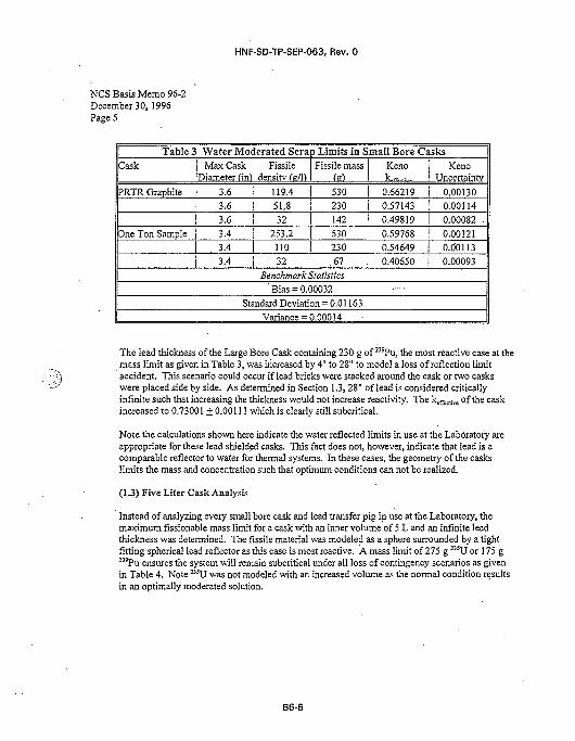
HNF-SD-TP-SEP-063, Rev. 0
NCS Basis Memo 96-2December 30,1996Page 5
Table 3
Cask
PRTR Graphite
Dne Ton Sample
Water Moderated Scrap Limits in Small Bore CasksMax Cask
Diameter (in)
3.63.63.63.43.43.4
Fissiledensity Cs/1)
Fissile mass<s)
119.4 | 53051.832
253.2
230142530
110 ! 23032 I .67
Benchmark StatisticsBias = 0.00032
Standard Deviation = 0.01163Variance = 0.00014
Kenok rr
0.662190.571430.498190.597680.54649
0.40650
1 Keno! Uncertainty
i 0.00130' 0.00114i 0.00082 .
! 0.00121! 0.00113i 0.00093
The lead thickness of the Large Bore Cask containing 230 g of 23'Pu, the most reactive case at themass limit as given in Table 3, was increased by 4" to 28" to model a loss of reflection limitaccident. This scenario could occur if lead bricks were stacked around the cask or two caskswere placed side by side. As determined in Section 1.3,28" of lead is considered criticallyinfinite such that increasing the thickness would not increase reactivity. The keffecrive of the caskincreased to 0.73001 ± 0.00111 which is clearly still subcritical.
Note the calculations shown here indicate the water reflected limits in use at the Laboratory areappropriate for these lead shielded casks. This fact does not, however, indicate that lead is acomparable reflector to water for thermal systems. In these cases, the geometry of the caskslimits the mass and concentration such that optimum conditions can not be realized.
(1.3) Five Liter Cask Analysis
Instead of analyzing every small bore cask and lead transfer pig in use at the Laboratory, themaximum fissionable mass limit for a cask with an inner volume of 5 L and an infinite leadthickness was determined. The fissile material was modeled as a sphere surrounded by a tightfitting spherical lead reflector as this case is most reactive. A mass limit of 275 g 2!!U Or 175 g23sPu ensures the system will remain subcritical under all loss of contingency scenarios as givenin Table 4. Note 235U was not modeled with an increased volume as the normal condition resultsin an optimally moderated solution.
B6-6
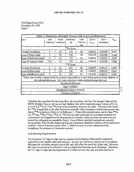
HNF-SD-TP-SEP-063, Rev. 0
NCS Basis Memo 96-2December 30, 1996Page 6
Table 4
: a s e b •
Maximum Allowable Volume with Full Lead Reflection
Cask j FissileVolume (!) j density (g/1)
Fissile mass LeadThickness
(in)
KENO KENOUncertainty
mPu Scrap •
Normal ConditionsLoss of Mass LimitLoss of Reflector Limit
Loss of Volume Limit
5 ! 35 ! 175 j 285 j 70 ! 350 : 28
5 j 357.47 . 32
175 ! 32
175 28
0.849190.934790.86916
0.88350
0.001000.00108
0.001330.00108
0.8730.986
0.8770.880
:3!U ScrapNormal ConditionsLoss of Mass LimitLoss of Reflector Limit
5 i 55 ! 275 28
5 I 110 | 550 [ 285 i 55 | 275 ! 32
0.830770.960020.83255
0.001140.001400.00117
0.8580.987
0.859* Each case models a sphere of fissile material surrounded by a tight fitting spherical lead reflector of
the indicated thickness. Full water reflection is also modeled around the lead.Benchmark Statistics
Bias = 0.00032Standard Deviation = 0.01163
Variance = 0.00014 «
Therefore the mass limit for the Large Bore, the Long Bore, the One Ton Sample Cask and thePRTR Graphite Cask as well as any lead shielded cask with a maximum inner volume of 5 L isset at 275 g 235U or 175 g 239Pu to provide consistency between the casks. The scrap limit foundfor 239Pu is applicable to all other fissionable materials with a minimum critical mass greater thanthat of 239Pu as given in Table 6.5 of Reference 1. Fissionable material more reactive than 239Pu,i.e., 242™Am, 243Cm, 24!Cm, 2<'Cf, or K1Cf have not been analyzed; however these materials areconsidered to be insignificant for the purposes of criticality safety provided the mass does notexceed the safeguards accountability limits. None of these restricted materials are currentlyaccounted for at the Pacific Northwest National Laboratory; therefore violation of this limit is notcredible. Sum of Fractions method (Ref. 1, Table 6.1) may be used to determine limitcompliance for mixtures of fissionable material.
(1.4) Spacing Requirements
The minimum 12" edge-to-edge spacing requirement for batches of fissionable material isapplicable to the transfer casks and lead pigs. Because the lead in the casks is not of an infinitethickness for criticality, material around the cask will affect the reactivity of the cask. However,the cask was proven to be subcritical with an infinite lead thickness in all directions. Therefore,the 12" edge-to-edge spacing requirement is in effect between the cask and other batches of
B6-7
HNF-SD-TP-SEP-063, Rev. 0
NCS Basis Memo 96-2December 30,1996Page 7
fissionable material but no spacing requirements are needed between the cask and otherreflectors.
(2) State computer programs used, the options, the recipes for choosing mesh pointswhere applicable, the cross section sets, and any numerical parameters necessary todescribe the input.
The SCALE 4.2 system of codes2 was used to model the casks. The codes were executed oneither a HP 755 with HP-UNIX version 9.03 or a HP 735 running HP-UNIX version 9.05. Codequality assurance documentation verifies the two operating systems give identical results. TheNITAWL code was used to process cross-section data and KENO-Va was used to model the caskgeometry and predict k,,,^.,. The standard 27-group ENDF/B-IV cross-section library was usedthroughout. All calculations ran 120 generations with 5000 neutrons'tracked per generation inKENO-Va. The first 20 generations were skipped when determining the standard deviation ofthe run. All input files containing geometry specification and material atom densities areincluded in Appendix A.
(3) Identify experimental data and list parameters derived therefrom for use in thevalidation of the model.
The results of the experimental benchmarks modeled with the SCALE 4.2 codes are shown inTable 5. These cases were chosen to represent the materials and geometries used in the caskcalculations such that the code calculational scheme and cross section libraries are benchmarked.Therefore, 239Pu solution and 23SU solution benchmarks are included in the set to represent thefissile solution and the lead wall benchmarks are included to represent the lead walls of thecasks. The benchmark results define the code statistics used in the determination of the K?sm
value for each run. Each benchmark case tracked 5000 neutrons per KENO generation for 120generations with 20 generations skipped. The same scheme was employed in generating cross-sections sets and calculating k ^ ^ as was used to model the worst case geometries. Allparameters required to model these benchmarks are described in the input files given inAppendix B and the references indicated in Table 5.
B6-8
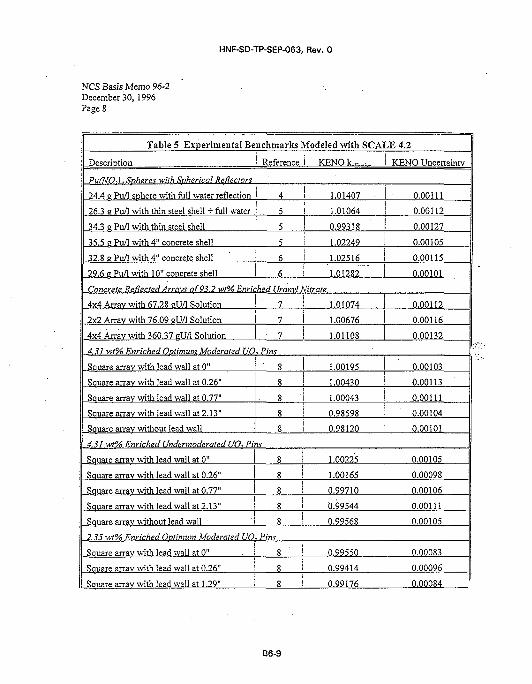
HNF-SD-TP-SEP-063, Rev. 0
NCS Basis Memo 96-2December 30,1996Page 8
Table 5 Experimental Benchmarks Modeled with SCALE 4.2
Description
PulNO,), Spheres with Spherical Reflectors
24.4 2 Pu/1 sphere with full water reflection
26.3 2 Pu/1 with thin steel shell + full water
34.3 2 Pu/1 with thin steel shell
35.5 2 Pu/1 with 4" concrete shell
32.8 2 Pu/1 with 4" concrete shell
29.6 2 Pu/1 with 10" concrete shell
Reference
4
5
5
5
6
6
KENO k.^,...
1.01407
1.01064
0.99318
1.02249
1.02516
1.01282
Concrete ReflectedArravs of 93.2 v/t% Enriched Uranv! Nitrate
4x4 Arrav with 67.28 2U/1 Solution
2x2 Anav with 76.09 2U/I Solution
4x4 Arrav with 360.37 2U/1 Solution
4.31 wt% Enriched Optimum Moderated UO
Square arrav with lead wall at 0"
Square arrav with lead wall at 0.26"
Square array with lead wall at 0.77"
Square arrav with lead wall at 2.13"
Sauare arrav without lead wall
7
7
7
, Pins• g
g
8
8
8
4.31 wt% Enriched Undermoderated UO. Pins
Sauare arrav with lead wall at 0"
Square arrav with lead wall at 0.26"
Square arrav with lead wall at 0.77"
Square arrav with lead wall at 2.13"
Square arrav without lead wall
2 35 wt% Enriched Ovtimum Moderated UO
Square arrav with lead wall at 0"
Square arrav with lead wall at 0.26"
Square array with lead wail at 1.29"
8
8
8
8
8
. Pint
8
8
8
1.01074
1.00676
1.01108
1.00195
1.00430
1.00043
0.98598
0.98120
1.00225
1.00165
0.99710
0.99544
0.99568
0.99550
0.99414
0.99176
KENO Uncertainty
0.00111
0.00112
0.00127
0.00105
0.00115
0.00101
0.00112
0.00116
0.00132
0.00103
0.00113
0.00111
0.00104
0.00101
0.00105
0.00098
0.00106
0.00111
0.00105
0.00083
0.00096
0.00084
B6-9
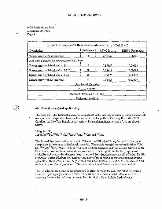
HNF-SD-TP-SEP-063, Rev. 0
NCS Basis Memo 96-2December 30,1996Page 9
Table 5 Experimental Benchmarks Modeled with SCALE 4.2
Description
Square arrav without lead wall
Reference i
I 8 i2.35 wt% F.nriched llndermoderated UO., Pins
Square arrav with lead wall at 0"
Sauare arrav with lead wall at 0.26"
Square arrav with lead wall at 1.29"
Sauare arrav without lead wall
8 ;
8 i
8
8 • '>
Benchmark Statistics
Bias = 0.00032
KENO k.m_,...
0.98542
0.99022
0.99414
0.99176
0.98365
Standard Deviation = 0.01163
Variance = 0.00014
KENO Uncertainty
0.00086
0.00093
0.00099 .
0.00099
0.00097
(4) State the area(s) of applicability.
The mass limits for fissionable materials applicable to the loading, unloading, storage and on-sitetransportation of specified fissionable material in the Large Bore, the Long Bore, the PRTRGraphite, the One Ton Sample or any cask with a maximum inner volume of 5 L are shownbelow.
275gfor235U,175 g for '"Pu, 233U,237 Np, 2<IAm, 2«Am, w Cm, and 2«Cm,
The Sum of Fractions method defined in Table 6.1 in PNL-MA-25 may be used to determinecompliance for mixtures of fissionable material. Fissionable material more reactive than 239Pu,i.e., 2"™Am, 243Cm, 2<5Cm, 2wCf, or 251Cf have not been analyzed and thus are not allowed underthese limits; however these materials are considered to be insignificant for the purposes ofcriticality safety provided the mass does not exceed the safeguards accountability limits. PacificNorthwest National Laboratory currently has none of these restricted materials in accountablequantities. These materials can only be obtained in accountable quantities as a source and thuscould not be accidentally obtained. Therefore, violation of this restriction is not credible.
The 12" edge-to-edge spacing requirement is in effect between the cask and other fissionablematerial. Spacing requirements between the cask and other heavy metal reflectors are notnecessary because the cask was proven to be subcritical with an infinite lead reflector.
B6-10
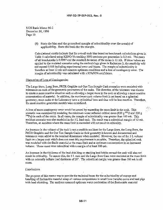
HNF-SD-TP-SEP-063, Rev. 0
NCS Basis Memo 96-2December 30,1996Page 10
(5) State the bias and the prescribed margin of subcriticaliry over the area(s) ofapplicability. State the basis for the margin.
Calculational results indicate that the overall code bias based on benchmark calculations given inTable 5 calculated using KENO-Va tracking 5000 neutrons per generation is 0.3 ink. The meanof all benchmarks is 0.9997 and the standard deviation of the mean is 12 mk. If these values areapplied to the modeled scenarios using the methodology given in Reference 3, the reactivity willnot exceed 0.988 including experimental error and biases. The margin of subcriticality istherefore at least 12 mk and assumes optimum conditions and a loss of contingency error. Themargin of subcriticality was calculated with a 95%/95% confidence.
Discussion of Loss of Contingencies
The Large Bore, Long Bore, PRTR Graphite and One Ton Sample Cask scenarios were modeled with.tolerances on each of the geometric parameters of the casks. The direction of the tolerance was chosento create a more reactive situation such as allowing a larger mass in the cask or allowing a more reactiveconcentration of material. In addition, the maximum cask volume limit is set based on a sphericalgeometry; most casks at the Laboratory have a cylindrical bore and thus will be less reactive. Therefore,the most reactive geometric models were considered.
A loss of mass contingency error would be caused by exceeding the mass limit in the cask. This .scenario was examined by modeling the minimum water reflected critical mass (820 g 23SU and 530 g23'Pu) in each of the casks. In all cases, the margin of subcriticality was greater than 100 mk. Thisaccident scenario was also modeled in the 5 L lead cask. The result was a subcritical margin of 12 ink.Therefore, an accident where the mass limit is exceeded will not result in criticality.
An increase in the volume of the cask is not a credible accident for the Large Bore, the Long Bore, thePRTR Graphite and the One Ton Sample Casks as their geometry is known and documented andtolerances were added to the nominal dimensions when modeled. However, the use of the 5 L volumelimit on a larger cask which does not meet this requirement is possible. Therefore, the spherical caskwas modeled with the fissile material at the mass limit and at optimum concentration in an increasedvolume. These cases were subcritical with a margin of at least 100 mk.
An increase in the thickness of the lead shielding or stacking lead bricks around the cask will also notresult in criticality. To ensure this, the 5 L cask and the Large Bore Cask were modeled at the mass limitwith .an critically infinite lead thickness of 28". The subcritical margin was greater than 100 mk in all
The purpose of this memo was to provide the technical bases for the subcriticality of storage andhandling of fissionable material scrap of various compositions in small bore transfer casks and lead pigswith lead shielding. The analyses assumed optimum water moderation of the fissionable material
B6-11
HNF-SD-TP-SEP-063, Rev. 0
NCS Basis Memo 96-2December 30,1996
•Page 11
located inside the casks and demonstrated subcriticality during normal operations and following the lossof a single contingency including over batching, an increase in the reflector thickness (i.e. stacking leadbricks around the cask) and an increase in the cask volume (using the mass limit for a larger cask).These analyses bound all possible loss of contingency scenarios and ensure the double contingencyprinciple is met. In conclusion, batch limits for the amount of scrap in the Large Bore, the Long Bore,the PRTR Graphite and the One Ton Sample Casks have been determined. The limit for 23SU as the onlyfissionable material is 275 g 23iU. The limit for other types of fissionable material except 2<2mAm, ™Cm,245Cm, 249Cf, and 2slCf is 175 g of fissionable material. These limits are also valid for lead shieldedcasks with a maximum inner volume of 5 liters and an unlimited lead thickness. The 12" edge-to-edgespacing requirement is in effect between the cask and other fissionable material but spacing requirementsbetween the cask and other heavy metal reflectors are not necessary.
Concurrence:Senior SpecialistCriticality Safety Analysis
B6-12
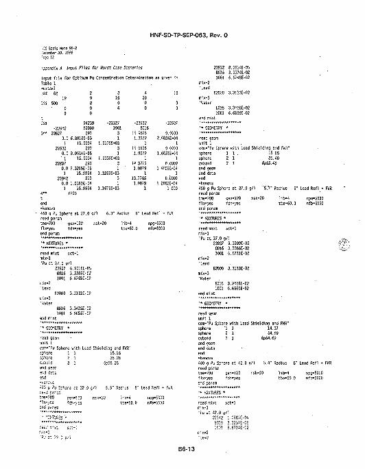
HNF-SD-TP-SEP-063, Rev. 0
•:S i i s is HBO 85-2:e=e=Mr 30. IS5S:ece 12
-??sndix A Input Files for Worst Use Scenarios
input f i l e for Optinrjm Pu Concentration Determination as given inTable 1-nitswl:ss 82 2 3 4 !3
19 9 15 20 .!SS 500 6 0 0 0
0 0 4 0 00 0
it! S4239 -23527•23S42 E2000 1001
3 " 23527 293 30.0 6.801SE-05 1
1 15.9951 l.S17SE»0323532 253 3
0.0 3.0514E-05 1' 1 15.9954 1.S335E-03
23937 253 30.0 9.32CSE-05 11 15.SSS4 1.32S9E*03
23942 253 30.0 1.05E1E-04 1
1 15.9554 1.16/SE-03A" f293
-23932 -235378016
15.5525 0.00001.0079 2.0024E-04
1 115.0836 0.00501.0079 1.6351E-G4
1 114.3710 0.00001.0079 l.<60SE*M
1 113.7765 • O.OOOO
1.0079 1.2S63E-041 1.000
end-kenova
• 460 g Pu Sphere at 27.0 g/1 6.3" Radius 8" Lead Refl * FV3read paremMe-700 gen-120 nsk-20 l i b -4 npg-5000fix-yes fdn-yes tba-60.0 nfb-8000end param
' • MIXTURES *
read mixt sct -1i.ix-1'Pu at 27.0 g/1
23527 6.6016E-C58016 3.3383E-021001 6.6/65E-02
mix-2•Lead
82000 3.3133E-02oix-3•Water
8016 3.3426E-021001 6.6656E-02
end mixt
' * GEOMETRY *
read geomrait 1COT,--PU Sphere with Lead Shielding and Fk'X"sphere 1 1 15.56sphere 2 1 36.23cubsid 3 1 6?55.23end cecffl•er.j ii-.ssr.d
453 g ?y Sphere at 32.0 c/1 5.raa; par=3t-5-703 cer.-123 nsk-20flx-i 'es fd-.-\eser.S paraa
'* ":>TJS=S *
" SiC:iL;s S" Lead F.efl
iib-4 npc-50C-0tpa-SO.O r,fD-&0S0
mix-2'Lead
mix-3'Water
2353280161001
82000
80161001
end mixt
' * GEOMETRY
8.0514E-053.3374E-026.6/48E-C2
3.3133E-02
3.3428E-026.6856E-02
*
read geonunit 1ccxr.-"Pu Sphere with Lead Shielding end F R"sphere 1 1 . 15. OSsphere 2 1 35.40cuboid 3 1 6p65.40end gecwend dataend-kenova460 9 Pu Sphere at 37.0 g/1 "5.7- Radiusreed parara
i" Lead Refl • FIR
tne-700 gen-120fix-yes fdn-yesend peram
nsk-20 l ib-4tba-60.0
npg-5000nfb-6000
' * KIXTURES •
read mixt ECt-1
•pu a t 37.0 g/123937
80161001
mix-2"Lead
82000mix-3'Water
80161001
eni mixt
' * GEOMETRY
9.3209E-053.3365E-026.6731E-02
3.3133E-02
3.3426E-026.6856E-02
unit 1conKPu Sphere with Lead Shielding snd FWR"sphere 1 1 14.37sphere 2 1 34.69'cuboid 3 1 6p54.69end.oecciend dataend-kenova450 g Pu Sphere at 42.0 gn 5.4" Rsdius S" LeEd Refl + FWRreed pErEmtrr,£-7C0 oen-120 nsk-20 "lib-4 npg-5000fix-yes fdn-i'es tbc-50.0 nfb-6000
•* MiXTL'RES *
reed mix! sct-1
"Pu at ^2.0 c/12"^2 1.05S1E-K
B6-13
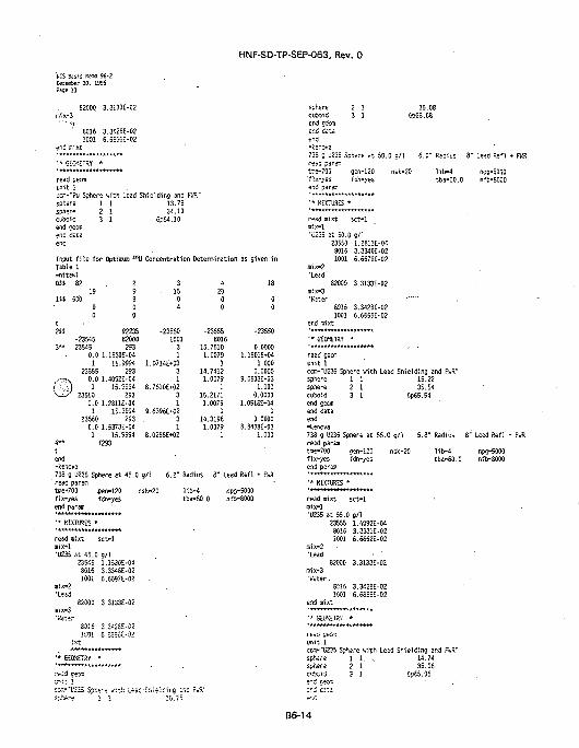
HNF-SD-TP-SEP-063, Rev. 0
NCS Basis Ksum 96-2Cecwfcer 30. 1996Page 13
82000 3.3133E-02
80161001
er.d mixt
•* GECK-TRV
read geomunit 1
3.342SE-026.6S56E-02
•
coa-"Pu Sphere with Lead Shielding and FWR"spherespherecuboidend geonend dataend
1 12 13 1
13.7834.10
6p64.10
Input f i l e for Optimum MSU Concentration Determination as given inTable 1-nitewlOSS 82 2
19 91SS 500 8
0 00 0
2SS 92235-23545 82000
3 " 23545 2530.0 1.1530E-04
1 15.999423555 293
. - n N 0.0 1.4092E-04•':•'•) 1 15.9994'•--is 23550 293
0.0 1.2811E-041 15.9594
23560 2930.0 1.5373E-04
1 15.95544-* f293
end-fcenova
3• 15
04
-235501001
31
1.07ME*0331
8.7610E*0231
9.6396E-KI231
8.0288E-KI2
t20
00
-23555
18
00
-235508016
15.76101.0079
114.7412
1.00791
15.21711.0079
114.3198
1.00791
0.00001.180!E»04
1.0000.0000
9.6503E-031.000
0.00001.0616M4
10.0000
8.8436E-031.000
738 g U235 Sphere at 45.0 g/1 6.2" Radius 8" Lead Refl + FiiRread param •tme-700 .cen-120 nsfc-20 I1b=4fix-yes fdn-yesend param
'* MIXTURES •
read mixt sc t -1mix-l•U235 at 45.0 g/1
23545 1.1530E-048016 3.3348E-021001 6.6597E-02
mix-2•Lead
82000 3.3133E-02
tba-60.0npg-5000nf»-8000
sphere 2 1cuboid 3 1end oecmen<3 da t aend•kenova733 g U235 Sphere et 50.0 g/1rs;d p=re:atr:e-700 gsn-120 nsk.-;•flx-^es fan-yesend parem
6.0" Radius 6" Lead Refl •
l i b - 4 npg-5000tba-50.0 nfS-SOOO
'* MIXTURES •
read mixtmix-l
sct-1
'U235 at 50.0 g/12355080161001
mix-2•Lead
82000
'Water50151001
end mixt
1.2811E-043.3340E-026.6679E-02
3.3133E-02
3.3428E-026.6655E-02
' • GECKETSY •
read seemunit Icar.-"U235 Sphere with Lead Shielding and FWR"sphere 1 1 15.22sphere 2 1 35.54cuboid 3 1 6P65.54end geonend dataend-kenova738 g LJ23S Sphere at 55.0 g/1 5.8" Radius 8" Lead Reflread par;
nsk-20tra-700 gen-120fix-yes fdn-yesend paran
lib-4 npg-5000tba-60.0 nfb-8000
* KIXTURES '
read mixt sct-1oix-1•U235 at 55.0 g/1
23555 1.4092E-048015 3.3331E-02iOOl 6.6662E-02
mix-2•Lead • '
82000 3.3133E-02mix-3'Water.
8515 3.3428E-021001 6.6S56E-02
end mixt
ixt
' • GECMET5Y •
read c=Da
CD:--L'235 Spf.i-3 t : th Lea: Shis
read c e ^unit 1CO3--U235 Spheresphere 1 1sphere 2 1catoid 3 1
i t h Lead Shielding and fiffi-14.7435.05
6=55.06
B6-14
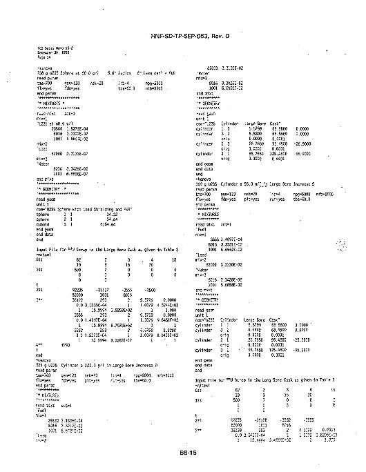
HNF-SD-TP-SEP-063, Rev. 0
KCS Basis nemo 95-2tece&er 30. 19S5Page 14
-kenova738 g U235 Sphere at 50.0 g/1read paramtrae-700 gen-120 nsk-2<fix-yes fdn-yesend param
•• KIKTURES *
5.6" Reiius S" Lesd Ref) + fKR
l ib-4tb£-60.0
npg-5000nfb-8000
read mixt sct-1mix-1'U235 at 60.0 g/1
23560 1.5373E-048016 3.3322E-021001 6.6544E-02
mix-2"Lead
62000 3.3133E-02
mix-3
'Water
8016 3.342SE-021001 6.6856E-02
end mix t
• • GECHETRY .*
read gsomunit 1c<»i--U23S Sphere ui th Lead Shielding and FVR-sphere 1 1 14.32sphere 2 1 34.64cuboid 3 1 6pS4.64end oeomend dataend
Input Fi le for asU Scrap in the Large Bore Cask as given in Table 3-nitawlOSS 82 2 3 4
19 9 IS 20IS! 500 7 0 0
0 0 3 00 0
18
2SS
3 "
4**
S2235• 8200035122
-351221001293
-35558016
21
f2S3
0.0 3.1335E-C41 15.9994 3.9259E-02
3555 293 20.0 1.4097E-04 1
1 • 15.9994 8.7578E»023560 2S3 2
0.0 1.5373E-C4 11 15.9994 8.0288E*C2
-3560
5.5799 0.00001.0079 4.3244E-KI3
• 1 1.0005.5799 0.00001.0079 9.646SE-KI3
1 15.5799 0.00001.0079 8.S438E-03
1 1
end•kenova820 9 U235 Cylinder a 122.3 9/1 in large Bore Increase Dread psremtee-700 sen-!20 nsk-20 l i b -1 npg-5000 nfb-SOOOfix-yes fc"n-y=s pit-yes r-jr.-yes tba-50.0
d
KIXTD5ES
sct-1read mixt•fuelMx-1
35122 3.1325E-04£0!5 3.32!2i-C21001 5.54^1-02
82000 3.3130E-02•tetermix-3
8016 3.3426E-02
1001 6.6S55E-02
end mixt
'• G-CBETSY
read sew
unit 1
CQ--"U235
cylinder
cylinder
Cylinder
1 1 •3 1orig2 1
Large Bore Cask"5.5799 68.5800 0.0000
5.5800 68.5800 0.0000
0.0000 0.0001
cylinder 2 1 26.7650 95.4800 -26.9000
orig 0.0000 0.0001
cylinder 3 1 56.7650 125.4S00 -55.9000
orig 0.0000 0.0001
end gecffl
end data
end
-kenova
359 g 0235 Cylinder a 55.0 g/j in Large Bore Increase 0read paranitme-700 sen-120 nsk-20 11b-4 npg-5000 rfix-yes fdr.-yes pit-yes run-yes tba-60.0end param
•* HIXTURES
read mixt sct-1'Fuelinix-l
3555 1.4097E-04
8015 3.3331E-02 .
1001 6.6562E-02
"Lead
mix-2
82000 3.3130E-02•Watermix-3
8016 3.342SE-021001 6.6856E-O2
end mixt
•• GEOMETRY
read gecoiunit 1coo-"0235 Cylinder Large Bore Cask"
1 13 1orig2 1crig3 1orig
5.57S95.58000.000026.76500.000055.76500.0000
68.580068.58000.000195.48000.0001
125.48000.0001
0.00000.0000
-25.9000
-56.9000
cylindercyl inder
cylinder
cylinder
end gecfflend dataend
Input File for "EU Scrap in the Long Bore Cask as given in-nitawlCSS
1SS
821950000
9223582000'35! 380.0 3j
29700
•3513S
hi'.543/E-e^
31503
•3552S0162I
A2000
•3=55
4.3:991.CC79
I
IS
00
0.03003.E205E-C3
l.KO
B6-15
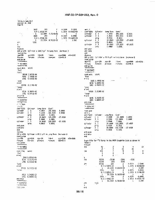
HNF-SD-TP-SEP-063, Rev. 0
KCS Essis Hedo 96-2Oxe.rser 30. 1SSSPiSS 15
3562 253 20.0 1.5952E-04 1
• 1 15.9994 7.7314E*023555 293 2
0.0 1.40S2E-04 11 15.5554 8.76!0E*02
f253
4.3099 0.00001.0079 8.5I62E-MJ3
1 14.3D99 0.00001.0079 9.6503E*03
1 1.000
-kenova
820 9 U235 Cylinder a 138.3 g/1 in Long Bore Increase 0
read par'amtrae-"700 gen-120fix-yes fcin-yesend param
nsk-20pH-yes
npg-5000 nfb«3000tbo-60.0
•* MIXTURES
read mixt•Fuelcix-1
sct-1
35138 3.5437E-0460161001
•Leadr.ix-2
S2000'Watermix-3
80161001
end mixt
' * GEOKETRY
.,„,„„„-•.';:-;ec«iCOI--0235cylindercylinder
cylinder
cylinder
end geanend dataend-fcenova369 9 U235read paremt/ae-700fix-yesend param
'* MIXTURES
read mixt'FuelBiix-1
3.3183E-026.6367E-02
3.3130E-02
3.3428E-026.6555E-02
Cyl inter1 13 1-orig2 1orig3 1ori9
Cylinder a
gen-120fdn-yes
set" !
3562 1.5S62E-046016
• IOOI'Lea;
S2300
60161001
3.3315E-026.6535E-02
3.3i::E-02
3.3425E-026.65S6--02
Long Bore4.30594.31000.000024.86000.000054.86000.0000
Cask"101.6000 0.0000101.6000 0.00000.0001
129.2938 -27.65380.0001
159.2938 -57.65380.0001
62.3 o/l in Long 8ore Increase D
nsk-20pit-yes
l ib-4 npg-5000 nfa-8000run-yes tba-60.0
unit 1CCQ--U235 Cylinder Long Bore Cask-cylinder 1 1 4.3099 101.5000 0.0000cylinder 3 1 4.3100 101.6000 0.0000
orig 0.0000 0.0001cylinder 2 1 24.8600 129.2933 -27.6533
crig 0.0000 0.0001cylinder 3 1 54.6600 159.2938 -57.6933
orig 0.0000 0.0001end cecfflend dataend-kenova325 g U235 Cylinder a 55.0 5/1 in Long Sore Increase Dreed paramtire-700 oen-120 nsk-20 l ib-4 npg-5000 nfb-8000fix-yes fdn-yes pit-yes run-yes tba-50.0end paraa
' * HKTIRES
read mixt sct-1'Fuelnix-1 ' ' ' '
3555 1.4092E-0480!6 3.3331E-022001 6.6552E-02
'Lead. mix-2
82000 3.3130E-02'Watermix-3
8016 3.3428E-021001 6.6856E-02
end mixt
' * GEOMETRY '
Input F i le for a iU Scrap in the PRTR Graphite Cask as given in 'Tabl
8219
50000
315
03
92235 -3518582000 100135155 293
0.0 4.7297E-041 15.95=4
3553 2930.0 2.1291E-04
1 15.9594 5.7358E-023555 - 293 20.0 1.40S2E-M i
1 15.9594 8.7610E-52
35638016
21
" 21
200 00 0
-3555
4.6274 0.0000J.K-75 2.8555E»03
• 1.0004.62:4 0.00001.0079 6.3776E>03
1 14.6274 0.00001.0079 S.6503E-S3
1 1.000
B6-16
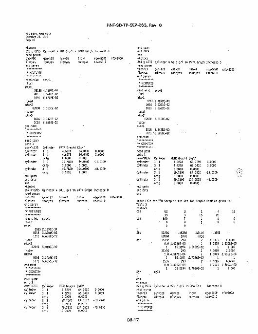
HNF-SD-TP-SEP-063, Rev. 0
NCS Sasis Hero S6-2Decesber 30. 1SS5Page 16
-kenova620 9 U235read pararoras-700f lx-yssend param* * * * * * * * * * *
' * MIXTURES
read mixt'Fuel
mix-13518580161001
•Leadmix-2
82000•Watermix-3
80161001
end mixt* * * * * * * * * * *
•' GEOKETRY* * * * * * * * * * *
read ceomunit 1CM--U23Scylindercylinder
cylinder
cylinder
end geonend dataend-kenova369 g- U235read paraaitse-700fix-yesend param
•« MIXTURES* * * * * * * * * * *
read raixt•Fue l 'mix-1
Cylinder a
gen-120fdn-yes
sct-1 .
4.7297E-043.3102E-026.6203E-02
3.313CE-02
3.3426E-C26.68S6S-02
Cylindsr1 13 1orig2 1orig3 1orig
Cylinder a
gen-120fdn-yes
sct-1
3583 2.1291E-0480151001
'Leadmix-2
82000'Watermix-3
80161001
end mixt
' • GECKETSY
read cso.iiunit 1COB-TB35cylindsrcylinder
cylinder
cylinder
3.3281E-026.5562E-02
3.3130E-02
3.3426E-026.65S5E-02
Cylindsr1 13 1orio2 1eric3 i
184.6 9/1 i
nsk-20pit-yes
PRTR Graphi4.62744.62750.000019.78000.0000 .49.78000.0000
PRTR Greph Increase O
l ib -4run-yes
Cask"66.040066.04000.000184.05000.0001
114.05000.0001
83.1 9/1 in PRTRGrapt
nsk-20pit-yes
PS7R Graphi4.62744.62750.000019.7=00O.COC'O49.7300
l ib -4run-yes
Cask-66.040066.04000.C00!64.05030.00C1
114 c - ' ' 1
0.GCC1
npg-5000 nfb-8000tba-50.0
O.00000.0000
-18.0100
-48.0100
1 Increase 0
npg-5000 nfb-8000tba-50.0
0.00000.0000
-13.0100
.£= r.;-.n
end ceanend dataend-kencva244 g U235read pareatme-700fix-yes
' * KiXTUSES
read mixt•Fuelmix-1
3555801610C1
"Leadmix-2
82000"Watermix-3
80161001
end mixt• • • * * * * * * * *
' '* GEOKETRY***********read geonuni t 1com-'u"235cylindercylinder .
cylinder
cylinder
end gecnend dataend
Cylinder 3
gen-120fdn-yes
sct-1
1.4092E-043.3331E-026.6552E-C2
3.3130E-02
3.342SE-026.6856E-02
Cylinder1 13 1orig2 1orig3 1orig
55.0 g/1 in
nsk-20pit-yes
PRTR Graph)4.62744.62750.000019.78000.000049.78000.0000
PRTR Graph Increase D
l ib -4run-yes
Cask"66.039966.04000.000184.05000.0001
114.05000.0001
npg-5000tba-50.0
0.000O0.0000
-18.0100
-48.0100
Input File for "sLf Scrap in the One Ton Sample Cask as giTable 3-nitawlOSS
lss
t2SS
3 "
4 * *
er.d-kenova820 g U235read parantrce-700fix-yesend pars.n'*******'**
8219
50000
922358200035392
29700
-353921001293
0.0 1.0036E-031
35176' 15.9994
2930.0 4.5170E-041
355515.9994
2930.0 1.4092E-C41 ' "
f2S3
Cylinder a
Sen-120fdn-yes
351.7 g/1 ir
nsk-20pit-yes
31503
-351768016
21
1.2082E»0221
2.7156E»0221
8.7610E+02
1 One Ton
l ib-4run-yes
42000
-3555
4.30991.0079
14.30991.0079
14.30991.0079
1
Increase I
npg-5000tba-50.0
nfo-SOOO
ven i n
IS
00
0.00001.3308E»03
1.0000.0000
2.9912E*031
0.00009.6503E-03
1.000
)
nfb-3000
B6-17
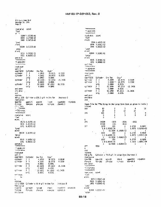
HNF-SD-TP-SEP-063, Rev. 0
NCS Basis K«ro S5-2Oec«0er 30. 1SS5Fsge 17
read mi xt•Fuel
sct-1
IF ' '35392 1.0036E-0380161001
'Leadir.ix-2
82000Vateruiix-3
60151001
end mixt***********• • GEOMETRY' * * » * » * . » * *
read geonunit 1con-"U235cylindercylinder
cylinder
cylinder
end geaaend dataend-kencva369 g U235read paramtme-700n-.-yes' ' • • • ' • ' • • ' r a m
•• KIXTURES
read mixt•Fuelnix-1 '
3.2735E-026.S471E-02
3.3I30E-02
3.342SE-026.6S55E-02
Cylinder1 13 1orig2 1orig3 1orig
Cylinder a
gen-120fdn-yes
sct-1
35175 4.5I70E-0480161001 •
•Leadmix-2
82000"Wateroix-3
60161001
end mixt
' • GE01ETRY
read geanunit 1cos-"U235cylinder
cy.inder
cylinder
cylinder
en* qeciMta
•kenova115 o U235r=ai param •--r.e-703fix-yes
3.3115E-026.6233E-02
3.3130E-02
3.3428E-026.6855E-02
Cylinder1 1
orig2 1orig3 1oric
Cylinder a
ge-.-!20fc-.-yes
One Ton4.30994.31000.0000
22.3200 •0.0000
52.32000.0000
176.3 g/1
nsk-20pit-yes
One Ton4.3099
4.31000.0000
22.32000.0000
52.32000.0000
55.0 g/1 1
r.sk-20pit-yes
Cask"35.877535.87750.000157.22130.0001
87.22130.0001
in One Ton
l ib-4run-yes
Cask"35.S775
35.87750.000!57.22130.0001
87.2213o.ecoi
n One Ton
l ib-4r^r.-yes
0.00000.0000
-21.3438
-51.3433
Increase D
npg-5000 rtba-50.0
0.0000
0.0000
-21.3433
.si 3435
Increase D
nr=-5000 rt:a-:C-.C-
ifb-8000
A - 5 K 0
' • KIXTUKS
read mixt•Fuelrsix-1
355580161001
•Leadmix-2
82000"Waternix-3
80161001
end fflixt
• • GEOMETRY* * * * * * * * * * *
read ceomunit 1cor.-"U235cylindercylinder
cylinder
cylinder
end geanend dataend
sct-1
i.4052E-043.3331E-025.6562E-02
3.3130E-02
3.3428E-026.6856E-02
Cylinder1 13 1orig2 1'orig3 1orig
One Ton4.30994.3100- -0.0000
22.32000.0000
52.32000.0000
Cask"35.877135.87750.000157.22130.0001 •
87.22130.0001
Input Fi le for B!Pu Scrap in the Large Bore C-nitawlOSS
lss
t2SS
3 "
4**tend-kenova530 g Puread paramt-ne-700
end param***********•• RIXTl'SES***********read ir.ixt•FuelBliX-.l
397980151001
' leadrr.ix-2
E20D0
8219
50000
942398200039790.01
3934
29700
-39791001293
1.9904E-O415.9994
2930.0 8.6408E-051
393215.9994
2930.0 8.0614E-051
f293
Cylinder a
oen-120
sct-1
1 CC04E-04
3.3295E-025.6585E-02
3.3130E-02
1-5.9994
31503
-39348016
21
6.1959E-0221
1.4305E*0321
1.6336E»03
79.0 g/1 in Large Sore
nsk-20 l ib -4
0.00000.0000
-21.3438
-51.3438
*sk as given in Table 3
42000
-3932
5.57991.0079
15.57991.0079
15.57991.0079
1
Increase D
npg-5000
18
00
0.00006.6249E»03
10.0000
1.5757E*041
0.00001.6891E*04
1
nfo-8000
B6-18
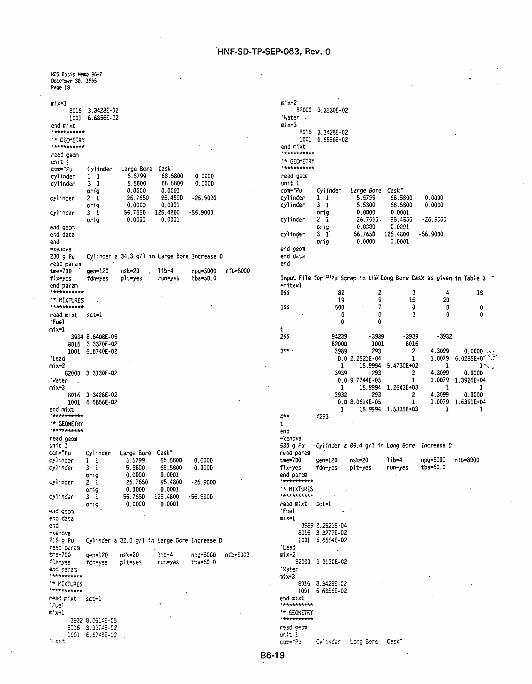
HNF-SD-TP-SEP-063, Rev. 0
HCS Basis Herc) 96-2Oecerier 30.Page 18
ir.ix-38016
1001
end m ix t
• * GEOMETRY
read geom
unit 1COT-"Pu
cylindercylinder
cylinder
cylinder
end geomend dataend-kenova230 9 Puread paramtme-700 'f ix-yesend param
'« MIXTURES
read mixt•Fuelmix-1
19S5
3.3428E-02
6.6856E-02
Cyl inder
1 1
3 1orig2 1crig3 1orig
Cylinder a
gen-120fdn-yes
sct-1
3934 8.6408E-0580161001
•Leadmix-2 .
82000•k'ater .mix-3
80151001
end mixt
'* GEOMETRY
read geomunit 1COTi-"Pu
cylindercylinder
cylinder
cylinder
end geomend dataend-kenova215 g Puread paraa3=6-700fix-yesend pararr.
'* MIXTURES
read mixt
ir.ix-1
3.3370E-026.6740E-02
3.3130E-02
3.3428E-026.6856E-02
Cylinder1 13 1orig2 1orig3 1orig
Cylinder a
gen-120fdn-yes
sct-1
3932 8.C6!i;-053.3374E-C2
Large Bore5.57995.58000.000026.76500.0000
55.76500.0000
Cask"63.580068.58000.000195.48000.0001
125.48000.0001
0.00000.0000
-26.9000
-55.9000
34.3 g/1 in Large Bore Increase D
nsk-20 .pit-yes
Large Bore5.57995.58000.000026.76500.0000
55.76500.0000
lib-4run-yes
Cask"68.580068.58000.000195.48000.0001
125.48000.0001
npg-5000 nfb-8000tba-60.0
0.00000.0000
-26.9000
-56.5000
32.0 g/1 in Large Bcre Increase D
nsk-20pit-yes
lib-4rjn-yes
r.pg-50C0 nfb-3003»3-50.0
mix-282000
"Water •nix-3
80151001
end fiixt
• • GEOMETRY
read geom
unit 1ccvn-"pucylindercylinder
cylinder
cylinder
end gecxnend dataend
3.3130E-02
3.3428E-026.6656E-02
Cylinder1 13 1orig2 1crig3 1"orig'
Large Bore5.57995.53000.000025.7550-0.0000
56.76500.0000
Cask"68.530068.58000.0001S5.4500C.0C01
125.48000.0001
0.00000.0000
-25.SCC0
-56.9000
Input File for aJPu Scrap in the'Eong Bore Cask as given in Table 3-nitawlOSS
1SS
t2SS
3**
8219
50000
94239820003989
29700
-39891001293
0.0 2.2521E-041
393915.9994
2930.0 9.7744E-051
393215.9994
2930.0 8.0614E-051 15.9994
31503
-39398016
21
5.4730E*0221
1.2643E*0321
1.5335E»03
42000
-3932
4.30991.0079
14.30991.0079
I4.30991.0079
1
18
00
0.00006.0285E-0'
1"0.0000
1.3926E»041
0.00001.6S91E-04
14 " f293tend-kenova530 g Pu Cylinder a 89.4 g/1 in Long Bore Increase Dread paremtiae-700 gen-120 nsk-20 l i b -4 npg-5000 nfix-yes fdn-yes pi t -yes run-yes tba-60.0end paran
' * MIXTURES
read mixt sct-1•Fuel • •
mix-13969 2.2521E-04
8016 3.3277E-021001 6.6554E-02
•Leadmix-2
S20C0 3.3130E-02•Hatern'.x-3
8016 3.3428E-C21001 5.6S56E-02
end nixt
• • GEOMETRY
read geos
C D T - " ? - 1 Cy l inder tcng Sore Cask"
B6-19
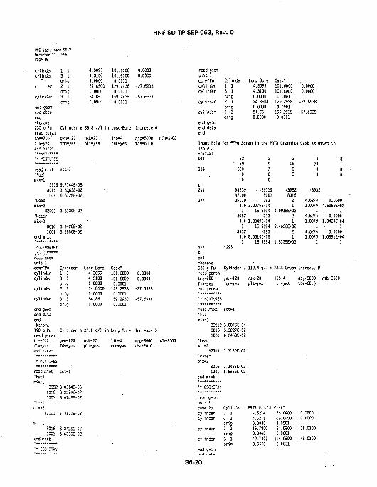
HNF-SD-TP-SEP-063, Rev. 0
HCS Bssis f*™ 96-2Decetter 30. 19SSPage 19
cylindercylinder
1 13 1orig2 1orig3 1orig
gen-120fdn-yes
cylinder
end gecrnend dataend-kencva230 g Puread paramtus-700 'fix-yesend pararc
'• MIXTURES
read rr.ixt sct-1•ru-1
mix-13939 9.7744E-058016 3.3363E-021001 6.672SE-02
•Leadnix-2
82000 3.3130E-02'Watermix-3
8016 3.3428E-021001 6.6856E-02
end fflixt
4.30994.31000.000024.65000.000054.850.0000
101.6000101.60000.0001
129.29330.0001
159.29330.0001
0.00300.0000
-27.6S33
-57.6933
Cylinder a 38.8 g/1 in Long'Bore Increase D
nsk-20pit-yes
l ib-4 r.pg-5000 nfb-30run-yes tba-50.0
0.00000.0000
ft-.-, seemunit 1•COH--PUcylindercylinder
cylinder
cylinder
end gecoiend dataend-kencva190 g Pu Cylinder a 32.0 g/1 in Long Bore Increase Dread paramtme-700 gen-120 nsk-20 l i b -4 npg-5000 nfb-8000fix-yes fdn-yes pit-yes run-yes tba-50.0end peraa
Cylinder1 13 1orig2 1orig
'3 1orig
Lcig Bore4.30994.31000.000024.86000.000054.860.0000
Cask"101.6000101.60000.0001
129.29380.0001
159.29380.0001
read j•Fuelsix-1
•Leadiix-2
i
?!
r.ixt sct-1
3932 8.0514E-C580151001
•2000
80161001
ix t •
3.3374E-025.674SE-02
3.3I30E-C2
3.342SE-026.6355E-02
read oecmun i f lcon-'Pucylindercylinder
cylinder
cylinder
end seemend dataend •
Cylinder1 13 1orig2 1orig3 1crig
Input F i l e f o r " 'Pu ScrTable 3- n i t awlCSS
1SS
t2SS
3. .
4«*
tend-kenova530 g Puread paramtoe-700f ix-yesend parani
'* KIXTOR-S
read mixt•Fuel
82• 1 9
50000
94239820003S119
Long Bore4.30994.31000.000024.85000.000054.550.0000
Cask"101.6000101.60000.0001
129.29330.0001
159.29380.000!
0.00000.0000
-27.6933
-57.6938
•ap in the PRTR Graphite Cask as g
29700
• -39119W01293
0.0 3.0079E-041
395215.9994
2S30.0 1.304SE-041
393215.9994
•2930.08.0614E-051
f293
Cylinder a
sen-120fdn-yes
sct-1
39119 3.0079E-0480161001
'Leadir.ix-2
82000'Watermix-3
80161001
end mixt
' • GEOMETRY
read gecQunit 1cors-'pycylindercylinder
cylinder
cylinder
3.3227E-026.6453E-02
3.3130E-02
3.3428E-026.6856E-02
Cylinder1 13 1orig2 1c-rig3 1crig
15.9994
119.4 g/1 i
nsk-20pit-yes
PST5 GrssM4.52744.62750.000019.78000.000049.73000.0000
31503
-39528016
21
4.0916E»0221
9.4636E*0221
1.5335E*03
PBTR Graph
l ib -4run-yes
CsSk"66.040065.04000.000164.05000.0001
114.C5000.0001
42000
-3932
4.62741.0079
14.62741.0079
14.62741.0079
1
Increase 0
npg-5000tba-60.0
O.COOO0.0000
-18.0100
-43.0100
1ven in
18
00
0.00004.5069E*03
10.0000
1.0424E»M1
0.00001.6S91E-04
1
nfb-8000
B6-2O
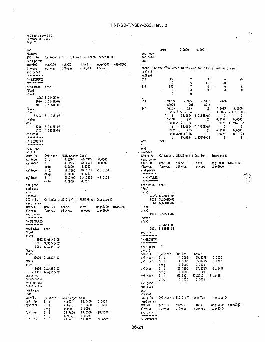
HNF-SD-TP-SEP-063, Rev. 0
NCS Eisis Memo SS-2December 30. I9S6Page 20
end-kenova230 9 Pu Cyl inder a 51.8 g/1 i n PRTR Graph Increase 0read parsm
0.0000 0.0001
Ke-700fix-yesend param
• • KIXTUSES
read mixt•Fuelmix-1
gsn-120fan-yes
sct-1
3952 1.3049E-0480161001
•Leadmix-2
82000•'Watermix-3
80161001
end mixt .
• • GEOMETRY
read geomunit ICOTr'Pucylindercylinder
cylinder
cylinder
end S2OTi
end dataend-kenova142 g Puread paramtoe-700fix-yesend param
•* KIXTURES
read mixt•Fuelmix-1
3.3341E-026.6661E-02
3.3130E-02
3.3426E-026.6656E-02
Cylinder1 13 1orig2 1orig3 1orig
Cylinder a
gen-120fdn-yes
sct-1
3932 8.0614E-0580161001
'Lead»ix-2
82C0O'Watermix-3
6016• 1001
end n;ixt
' * C-ECKETRY
3.3374E-026.674SE-02
3.3130E-02
3.3428E-026.6856E-02
nsk-20ptt-yes
PRTR Graph4.62744.62750.000019.78000.000049.78000.0000
l ib-4run-yes
i Cask"66.040066.04000.000184.05000.0001
114.05000.0001
32.0 g/1 in PRTR Graph
nsk-20pit-yes
l ib -4run-yes
npg-5000 nfb-8000tba-60.0
0.00000.0000
-18.0100
-48.0100
Increase D
npg-5000 nfb-8000tba-60.0
r=;d CSDTIur.it 1csr.-"Py Cylinder- PRTR Grsphi Cask"cyl i nder 1 1 4.5274 65.04C0 0.0000Cylinder 3 1 4.6275 66.WOO 0.0G00
orig 0.0009 0.0001cylinder 2 1 1S.7S00 64.0530 -13.0100
Orig 0.0000 0.0001
end gecraend dataend
Input Fi le for v'Pu Scrap in the One Ton Sanple Cask as given inTable 3-nitawlCSS
1SS
t2SS
3«*
tend-kenova530 9 Puread para™tme-700fix-yesend parent
' * KIXTURES
read mixt'Fuelmix-1
8219
50000
9423982000352=3
C-.C1
39110
29700
-392531001
6.37S5M415.5594
2930.0 2.7711E-C41
393215.9994
2530.0. 8.0614E-051
f293
Cyl inder a
gen-120fdn-yes
sct-1
39253 6.3785E-0480161001
'Leadmix-2
82000'Watermix-3
80161001
end fflixt .
' * GEOMETRY
read georaunit 1can-"Pucylindercylinder
cylinder
cylinder
end seenend dataend-kenova230 g Pu •read paraat=e-7C0fix-yes
3.3001E-026.6001E-02
3.3130E-02
3.3428E-026.6856E-02
Cylinder -1 13 1orig2 1orig3 1crig
Cylinder a
cen-120fen-yes
15.5594"
253.2 g/1 i
nsk-20pit-yes
One Ton4.30954.31000.0000
22.32000.0000
31503
-351108016
i.1
1.5163E-0221
4.4434E*0221
1.5335E*03
One Ton
l ib -4run-yes
Cask"35.877535.87750.000157.22130.0001
42000
-3532
4.30^51.0075
14.30991.0079
14.30991.0079
' l
Increase 0
nps-5000tba-60.0
0.00000.0000
-21.3438
52.320 67.2213 -51.34380.0000
110.0 9/1 i
nsk-20pit-yes
0.0001
One Ten
l ib-4r-jn-yes
Increase 0
rpg-5000tba-50.0
18
C0
0.00002.UC»*!3
10.0000
4.8944E*03I
0.00001.6891E-04
1
nfb-8000
nfo-SOOO
B6-21
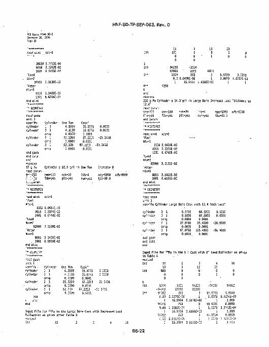
NCS BssiS K*w S6-2Dace^er 30. 1595
HNF-SD-TP-SEP-063, Rev. 0
' 39110 2.77UE-048016 3.3242E-021001 6.64S5E-C2
'Leadr.lx-2
82000 3.3130E-C2"Wateraix-3
8016 3.3428E-021001 6.6SS6E-02
end mixt***********•• GEOKETW
read' geomunit 1ccffi-"Pucylindercylinder
cylinder
cylinder
end ceanend d3taend-kenova67 g Pu
Cylinder One Ton4.30994.3100O.OOOO-
22.32000.0000
52.320• 0.0000
y1 13 1orig2 1orig3 1orig
Cask"35.8775 0.000035.8775 0.00000.000157.2213 -21.34380.0001
87.2213 -51.34330.0001
7 g u Cylinder a 32.0 g/1 in One'Ton Increase Dread paramt—-7.00 gen-120 nsk-20 l i c -4 npg-5000 nfb-8000*• X ) s fdn-yes pit-yes run-yes tba-SO.O
read mixt•Fuelmix-1
sct-1
3932 8.0514E-058016!0W
•leadir.ix-2
82000•Waterir.ix-3
80161001
end mixt
' • GE0HETRV
reed geconunit 1ccffi-"Pucylindercylinder
cylinder
cylinder
3.3374E-026.6748E-02
3.3130E-02
3.342SE-026.6S56E-02
Cylinder1 13 1orig2 !ori a3 1crio
One Ten4.30994.31000.0000
22.32000.0000
52.3200.0000
Cask"35.877535.87750.000!57.22130.000!
87.22130.CCG1
0.00000.0000
- 2 ! ,343
-SI.3435
19500
00
94239620003934
9500
-39341001293
0.0 8.6408E-051 15.95=4 1
1501
801621
.4305E*03
2000
5.57591.0079
1
00
0.00001.5757E-04
14 " f293tend-kenova230 g Pu Cylinder a 34.3 g/1 in Large Bore Increase Lead Thickness to12.4-ii pe.-a-
Input Fi le for :; iPu in tile Larce Bor-e Cask with Increased Le3dReflection as given after Table 3
fr:e-70?f ix -yesend param
' * MIXTURES
read mixt'Fuelmix-1
sen-120 nsk-20fdn-yes pit-yes
sct-1
3934 8.6408E-0580161001
'Leadmix-2
82000•Water
mix»380151001
end m1xt
' * GEOMETRY
reed gecxnunit 1
3.3370E-026.6740E-02
3.3130E-02
3.3428E-026.6856E-02
ccm-"Pu Cylinder Large Bore Cask
cylindercylinder
cylinder
cylinder
end geonend dataend
1 1 5.57993 1 5.5800orig 0.00002 1 37.0760Cr19 0.00003 1 67.0760orig 0.0000
lib-4run-yes
with 12.4
68.580068.58000.0001
95.43000.0001
125.48000.0001
Input File for "!Pu in the 5 1 Cask with 8"in Table A-nitawlOSS
1SS
82 219 9
500 80 00 0
2SS 8315 100! <•.-9-
3** 9-c
•345 25000 =:352 293i.03 2.317£E-C4
3IS03
npo-5000 nfb-8000tba-60.0
inch Lead"
0.00000.0000
-26.9000
-56.9000
Lead Reflector as given
4 13200 00 0
14239 -94092 -54032300
3 10.6030 0.00001 1.007S 5.J574E-03
1 15.5994 S.3!76E»02 '94346 2930.00 1.1555E-D4
9;
1 LOCO3 10.6060 0.00001 1
! 15.9594 1.0560E-03032 293 3 1!
1 J5.5994 1.53j5£*:-3
.0079 l.!742E»041 1.000
.9719 0.0000
i ' !.•;::•
B6-22
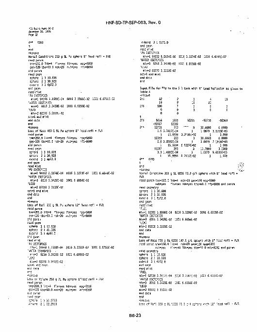
HNF-SD-TP-SEP-063, Rev. 0KCS Basis Hero SS-2Deceiver 30. 1995Page 22
A— f2S3tend-kenova-Normal Conditions 230 g 5L Pu sphere 8" lead re f l + F*:Rreed param£r,e-200.0 lib-4" fix-yes fdn-yes npg-5000gen-120 tbe-50.0 nsk-20 nub-yes nfb-8000er.d paramread geomsphere 1 1 10.608sphere 2 1 30.528cuboid 3 1 6p72.0end seanread ffiixt•FU ISOTOPICSmix-1 54045 1.1583E-04 8015 3.3350E-02 iOOl 6.S70IE-C2
•»AT£S iSOTOPiCSmix-3 8016 3.3426E-02 1001 6.6856E-02
•LEW)mix-2 82000 3.3133E-O2
sct-1 end mixtend dataend-kenovaLoss, of Kass 450 G SL Pu sphere 8" lead re f l * F«Rread paramMe-200.0 l ib -4 f ix-yes fdn-yes nps-5000gen-120 tba-60.0 nsk-20 nub-yes nfb-8000
end paramread geansphere 1 1 10.608sphere 2 1 30.323cuboid 3 1 6p72.0
end gecaread mixt•PU ISOTOPICS
mix-1 94092 2.3176E-04 8016 3.3273E-02 1001 6.6546E.02'ViATES. 1S0TOPKS
mix-3 8015 3.3426E-02 1001 6.6856E-02•LESS
mix-2 82000 3.3133E-02sct-1 end mixtend dataend-kenovaLoss of Refl 230 g 5L .Pu sphere 12" lead re f l + P*'Rread paremtme-200.0 lifc-4 f ix-yes fdn-yes npg-5000 -cen-120 tba-60.0 nsk-20 nub-yes nfb-8000
end paramread geomsphere 1 1 10.603sphere 2 1 41.088cuboid 3 1 6p82.0
end geonread mixt'PU ISffTOPlCS
isix-l S4046 1.1568E-04 8015 3.335CE-02 1001 6.6701E-02'KATES ISOTOPICS .
tiix-3 8016 3.3428E-02 1001 6.6855E-02'LEAS
•six-2 82000 3.3133E-02s: ' .- i KiS n1xt
e"d-kenovaLoss cf Vcl i r^ 230 g 7L Pu sphere 8"lead re f l + FWSread paramtme-200.0 l i b -4 f ix-yes fdn-yes npg-5000Ser.»!20 tba-50.0 nsk-20 nub-yes fifb-8000
e-.d p=ram
s:-.i-e i I Zl.liii
cuboid 3 1 6p73.0end ceoiiread mixt•PU ISOTOPICS
rsix-1 S4032 8.0514E-05 8015 3.3374E-02 1001 6.674SE-02•KATES ISOTOPICS
r.ix-3 6315 3.342EE-02 1001 6.6S56E-02•LEO
mix-2 82030 3.3133E-02sct-1 end mixtend dataend
Input F i le for "SU i n the 5 1 Cask vrith V Lead Reflector as given inTable 4
OSS
1SS
t2SS
3"
321950000
8016•92007 .927380.0 31
52359
2S700
100182000253
.78I7E-0415.5994
2530.0 1.8909E-041
920070.0 11
15.9954253
.4092E-0415.9994
3
"o3
52235
31
3.2466E-0231
6.5227E*0231
8.7610E»02
2000
•52738
10.60801.0079
110.60801.0079
111.70001.0079
1
13
00
-52369
0.00003.5783E*03
1.0000.0000
7.1848M31.0000.0000
S.6503£«031.000
4 " f293t ' •:•
end V-:-kenova v ,Normal Condition 355 g 5L U235 73.8 g/1 sphere with 8" lead re f l •FKSread param tse-150.0 lib-4 nsk-20 gen-120 npg-5000
r-yb-yes fix-yes fdn-yes tba-60.0 nfb-8000 end paramread geometrysphere 1 1 10.608sphere 2 I 30.528cuboid 3 I 6p72.0end geomread mixt•FUEL
mix-1 52355 1.8909E-C4 8016 3.3296E-O2 1001 6.6595E-02'k'ATER ISOTOPiCSmix-3 8016 3.3428E-02 1001 6.6S56E-02•LEAD 'mix-2 82000 3.3133E-02end dataend-kenovaLoss of Kass 738 g 5L U235 147.6 g / l sphere with 8" lead re f l * FKP.read parea tme-!50.0 i*b-4 nsk-20 gen-120 npg-5000
nub-yes fix-yes fdn-yes tba-£0.0 nf&-S000 end paramread eeoraetrysphere 1 1 10.606sphere 2 1 30.923cuboid 3 ! 6P72.0end oscaread mixt•FUELmix-1 52733 3.7S17E-04 30:6 3.3J57--02 iOCl 6.6334E-02•WATER ISOTOPICS
mix-3 8015 3.342SE-02 1001 6.5555E-02'LEAOmix-2 S200S 3.3133E-C2end dataend
Less Cf ^-*: 355 = ;L "J225 72. : c ' l s?'e'S wit ' . ;2 " lead re f l + F/R
B6-23
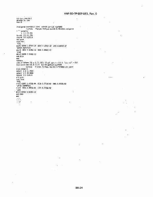
HNF-SD-TP-SEP-063, Rev. 0
KCS Easis Hero 96-2feeffler 30. 1955Page 23
read parani ttie-150.0 l i b -4 nsk-20 oen-120 npg-5000nub-yes f ix -yss fdn-yes tba-50.0 nft-8000 end param
' ~' gecmetryJ 1 1 10.608
sv..ere 2 1 41.083cuto^d 3 1 6pS2.0end gecmr=cd mixt•FUtL
aix-1 S236S 1.85S5t-04 6016 3.32S5E-02 1MI 6.65S5£-02•HATER ISOTOPICSnix-3 8016 3.3428E-02 1001 6.6S56E-02•LEADmix-2 82000 3.3133E-02end dataend"JtenovaLOSS of Volute 365 g 6."11 U235 55 g/L sph,e.-e with 2" Had ref : + !read param bne-150.0 l i b - 4 ' nsfc-20 gen-120 npg-5000
nub-yes f ix-yes fdn-yes tba-60.0 nfb-8000 end para^iread gectretrysphere 1 1 11.7000sphere 2 1 32.0200cuboid 3 1 6p63.0end geanread mixt•FUELnix-1 S2007 1.4092E-04 8016 3.3331E-02 1001 6.6562E-02•WATER 1S0T0PICSnix-3 8016 3.3428E-02 1001 6.6855E-02'LEAD«ix-2 82000 3.3133E-02end dataend
B6-24
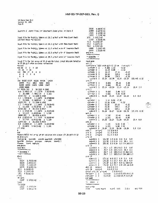
HNF-SD-TP-SEP-063, Rev. 0
Kl Basis Kew 95-ZGKKMr 33. 1995Page 24
Appendix B Input Files for Benchmark Cases given in Table 5
Input File for Pu<NOj), Sphere at 26.3 g Pu/1 with Thin Steel Shelland Full Water Reflection
Input File for Pu(KO,), Sphere at 34.3 g Pu/1 with Thin Steel Shell
Input File for Pu<N0,)4 Sphere at 35.5 g Pu/1 with 4" Concrete Shell
Input File for Pu(NOj), Sphere at 32.8 g Pu/1 with 4" Concrete Shell
Input File for Pu(S0,>, Sphere at 29.6 g Pu/1 with W Concrete Shell
Input File for 4x4 array of 93.2 wtx Enriched Uranyl Nitrate Solutionat 67.23 gUVl with concrete reflection-nitawlOSS 62 2 3 4 1319 20 9 15
1SS 500 17 0 0 00 0 6 0 00 0
t2SS 92235 92234 92235 92238 1400026000 7014 6012 8016 100120000 22000 11023 12000 1302719000 16000
3 " 92234 293 2 10.5600 0.95020.0 1.7693E-06 1 1.0079 7.5125E»051 16.1609 7.4984£*04 1 1.000
92235 293 2 10.5600 0.55020.0 1.6061E-04 1 1.0079 8.2758E*031 15.9415 8.144SE»02 1 1.000
92236 2S3 2 10.5600 0.95020.0 7.4495E-07 1 1.0079 1.7843M61 15.1622 1.7811E-05 1 1.000
92233 293 2 • 10.5500 0.95020.0 9.1432E-06 1 1.0079 1.4537£*051 15.1517 1.4502E»04 1 1.000
26000 293 1 25.4000 0.00000.0 2.5278E-04 1 1.0079 6.39396*021 15.7297 8.9763M2 1 1.000
11023 293 1 25.4000 0.00000.0 3.8303E-04 1 1.0079 5.5395E"021 15.8578 5.9671E*02 1 1.000
4 " f293tend-fcenova ROT53 4x4 array of UN solution w/o sleeve (57.28 gU/1-21.12en dies cyl)read param cefl-120 nsk-20 np9->5000 nfb-5000tne-700 .fdn-yes pit-yes run-yes tba-60.0fix-yes l ib-4 nub-yesend paramread mixt
' • KIXTKES *
"Fuel92234 1.7S53E-0692235 1.6061E-0492235 7.4455E-0792233 9.1432E-05
S01S 3.414SE-52/0!4 4.2152E-C41001 6.5I56--C2
B!X-2•Al tatt
13027 5.9i=9--02
20000 8.0213E-0326000 2.527SE-041S000 4.E976E-0414000 7.7139E-03
1001 1.0401E-0211023 3.6303E-04
80H 4.2352E-026012 6.4237E-037014 1.95SSE-0S
iSOOO 6.2509E-0522000 2.9192E-05
end inixt
•* GEOKETRY •
read gecfflun i t 1C£--"Sphere 'J23S with c'J/1-21.12 Cfl dia^i cyl) "
cylinder 1 1 . 0.505 0.00 -0.32cylinder 2 1 10.56 0.00 • -0.32cylinder 1 1 10.56 27.15 -0.32
10.55 119.1 -0.3210.96 119.1 -0.32
15.24 -15.24 15.24 -15.24 12
cylinder 0cylinder 2
cuboid 0 1unit 2
cylinder 1 1cylinder 2 1
cuboid 3 1unit 3
cylinder 1 1cylinder 2 1
cuboid 0 1unit 4
cylinder 1 1cylinder 2 1cylinder 1 1cylinder 0 Icylinder 2. 1
0.5050.635
15.24 -15.24
0.5050.635
15.24 -15.24
25.4025.4015.24
0.000.00
-15.24
5.00 0.005.00 0.0015.24 -15.24
1.14 0.00 -0.3210.56 0.00 -0.3210.56 27.15 -0.3210.56 119.110.96 119.1
unit 9unit 10
cuboid 0cuboid 3cuboid 0
unit I Icuboid 0cuboid 3cuboid 0cuboid 3
unit 12cuboid 0cuboid 3 1cuboid 0 1cuboid 3 1
-0.32•0.32
-15.24
0.000.00
-15.24
1.140 5.00 0.00 •1.270 5.00 0.00
15.24 -15.24 15.24 -15.240.0 0.0 0.00.0 0.0 0.0
cuboid 0 1 15.24 -15.24 15.24unit 5
cylinder 1 1 1.14U 25.40cylinder 2 1 1.270 25.40
cuboid 3 1 15.24 -15.24 15.24unit 6
cylinder 1 1cylinder 2 1
cuboid 0 1unit 7 array-1unit 8 erray-2
•ay-3 0.0 0.0 0.0
1 121.52 0.0 0.14 0.0 5.0 0.01 121.92 0.0 0.14 0.0 30.4 0.0-1 121.92 0.0 0.14 0.0 154.165 0.0
1 . 25.7 0.0 122.2 0.0 5.0 0.0'1 25.7 0.0 122.2 0.0 30.4 0.01 25.7 0.0 122.2 0.0 31.035 0.01 25.7 0.0 122.2 0.0 154.165 0.0
173.32 0.0 25.7 0.0 5.0 0.0173.32 0.0 25.7 0.0 30.4 0.0173.32 0.0 25.7 0.0 31.035 0.0173.32 0.0 25.7 0.0 154.155 0.0
unit 13 errey-4 0.0 0.0 0.0unit 14 irrs-y-5 0.0 0.0 0.0global unit 15 arrsy-5 0.0 0.0 0.0reflector 0 1 0.0 0.0 0.0 0.0 0.635 0.0 1.0reflector 3 1 0.0 0.0 0.0 0.0 25.4 0.0 1.0
r~ii arrayi-i-1 '
B6-25
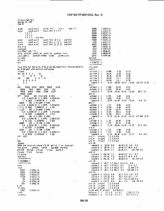
HNF-SD-TP-SEP-063, Rev. 0
»CS Basi s w » S6-2U K « e r 30. 1995Pase 25
ara-2ara-3
ara-4ara-5ara-6
nux-1 nuy-1nux-4 nuy-4 '
7 8 7 77 8 7 77 7 7 7 end ff
nux-1 nuy-3nux-3 nuy-1nux-1 nuyM3
nuz-3nuz-1
11nuz-1nuz-1nuz-1
fillfill
fillfillfill
6 547 7 7 7
!0 9 1011 13 1112 14 12
end f i l lend f i l lend f i l l
end arrayread plottt l - . 'Plot ' nch-' * ! . 'xul-0 xlr-125 yul-71.45 jlr-71.46 zul-!55 z l r - 5uax-1 wdn--l nax-130 ndn-80 lpi-10 pic-mix endend plotend dataend •
Input File for 2x2 array of 93.2 v t i Enriched Uranyl Nitrate Solutionat 76.09 gU/l with concrete reflection-nitawlOSS 82 2 3 4 18
19 20 9 • 151SS 500 17 0 0 0
0 6 0 0
92236 92233 140008015 1C01
12000 13027
0 0t2SS 92235 92234
26000 7014 601220000" 22000 1102319000 16000
3** 92234 293 2 10,5500 0.95020.0 2.0009E-06 1 1.0079 6.6236E*051 16.1816 6.6870E*04 1 1.000
92235 293 2 10.5600 0.9502,<--0.0 1.8164E-04 1 1.0079 7.2963E-03•: "fvl 15.9352 7.2503E*02 1 1.000•••..i36 293 2 10.5600 0.9502
0.0 8.4250E-07 1 1.0079 1.5731E*051 16.1829 l.S883E»05 1 1.000
92238 293 2 10.5600 0.95020.0 1.0341E-0S 1 1.0079 1.2816E-051 16.1712 1.29301*04 1 1.000
26000 293 1 25.400 0.00000.0 2.5276E-04 1 1.0079 8.3939E»021 16.7297 8.9763E»02 1 1.000
11023 293 1 25.400 0.00000.0 3.8303E-04 1 1.0079 5.53S5E*02 •1 16.8578 5.9S71M2 1 1.000
4 " f293tend-fcenovaR0T54 2x2 array w/o sleeve {76.09 gU/1-21.12 cm diamcyl)read param gen-120 nsk-20 r.pg-5000 nfb-8000tme-700 fdn-yes pit-yes run-yes tba-50.0fix-yes l ib-4 nub-yesend paramread mixt
•• MIXTURES
n-.ix-''Fusl
5223492235=2235" 2 3 3
'15014
1001mix-2"Al t a r*
13027rix-3•Cccrs-.e
* .
2.000SE-C-S1.E164E-048.4250--071.C34SE-053.424SE-024.7215E-046.4955E-02
5.9-J5E-52
120001302720000
• 2600019000140001001
11023801660127014
1500022000
end mixt
7.1685E-041.1241E-038.0213E-032.5278E-044.8976E-047.7135E-031.0401E-023.6303E-044.23S2E-026.4237E-031.9958E-058.2809E-052.9192E-05
' * GECMETSY
read georaunit 1cylinder 1cylinder 2cylinder 1cylinder 0cylinder 2
cuboid 0unit 2cylinder 1cylinder^
cuboid 3unit 3cylinder 1cylinder 2
cuboid 0unit 4cylinder 1cylinder 2cylinder 1cylinder 0cylinder 2
cuboid 0unit 5cylinder 1cylinder 2
cuboid 3unit 6cylinder 1cylinder 2
cuboid 0unit 7 arunit 8 arunit 9 arunit 10
cuboid 0cuboid 3cuboid 0
unit 11cuboid 0cuboid 3cuboid 0
unit 12cuboid 0cuboid 3cuboid 0cuboid 3
unit !3cuboid 0cuboid 3cuboid 0cuboid 3
ur.it 14 erunit 15 a.-ur.it 15 erS'.cbal m i ;
0.505 0.00 -0.3210.56 0.00 -0.3210.56 62.34 -0.3210.55 119.1 -0.3210.96 119.1 -0:3215.24 -15,24- 15.24 -15.24 123.445 -0.32
1 0.505 25.40 0.001 0.635 25.40 0.001 15.24 -15.24 15.24 -15.24 25.4 0.0
1 0.505 5.00 0.001 0.635 5.00 0.001 15.24 -15.24 15.24 -15.24 5.0 0.0
1 1.14 0.00 -0.321 10.55 0.00 -0.321 • 10.56 62.34 -0.321 10.55 119.1 -0.321 10.96 • 119.1 -0.321 15.24 -15.24 15.24 -15.24 123.445 -0.32
1 1.140 25.40 0.001 1.270 25.40 • 0.001 15.24 -15.24 15.24 -15.24 25.4 0.0
'1 1.140 5.00 0.001 1.270 5.00 0.001 15.24 -15.24 15.24 -15.24 5.0 0.0
ray-1 0.0 0.0 0.0ray-2 0.0 0.0 0.0rey-3 0.0 0.0 0.0
1 30.48 0.0 60.96 0.0 5.0 0.01 30.48 0.0 60.96 0.0 30.4 0.01 30.48 0.0 60.96 0.0 154.155 0.0
1 121.92'0.0 30.62 0.0 5.0 0.01 121.92 0.0 30.62 0.0 30.4 0.01 121.92 0.0 30.62 0.0 154.155 0.0
1 25.7 0.0 122.2 0.0 5.0 0.01 25.7 0.0 122.2 0.0 30.4 0.01 25.7 0.0 122.2 0.0 31.035 0.0I 25.7 0.0 122.2 0.0 154.155 0.0
173.32 0.0 25.7 0.0 5.0 0.0173.32 0.0 25.7 0.0 30.4 0.0173.32 0.0 25.7173.32 0.0 25.7 0.0
iy-4 0.0 0.0 0.0ray-5 0.0 0.0 0.0
:y-5 0.0- 0.0 0.0arrav-7 0.0 0.0 0.0
0.C 0.0 5.0 0.0 C0.0 0.0 0.0 0.0 2-
0.0 31.035 0.0154.165 0.0
B6-26
HNF-SD-TP-SEP-063, Rev. 0
KCS Basis Keno S6-2DKKt.er 30. 1955Page 26
end geom
•* A W V *
read arrayara-1 nux-1 nuy-1ara-2 nux-1 nuy-1arc-3 nux-2 nuy-2ars-4 nux-3 nuy-1cf£-5 nux-2 nuy-3ere-6 nux-3 nuy-1era-7 nux-1 nuy-3end arrayread plott t l - 'P lo t * • nch-' * !
nyz-3nuz-3nu2-ln-j2-lttUZ-1nuz-1nuz-1
fillfillfillfillfillfillfill
picmix
3 2 16 5 48 7 3710 5 1011 14 1112 15 1213 15 13
end f i l lend f i l lend f i l lend f i l lend f i nend f i l lend f i l l
xul-25. xir-73 yul-71.45 ylr-71.45 2ul-165 z l r - 1iax-3 wdn-1 nax'UO ndr,-S0 lpi-10 endend- plotend dataend
Input File for 4x4 array of 93.2 wtx Enriched Uranyl Nitrate Solutionat 360.37 gU/1 with concrete reflection•nitawlOSS 82 2 3 4 18
1SS195000 00 0
20 9
23 0 0 0
15
t2!S 92235 92234 92236 92238 14000
26000 -26001 6012 6016 100120000 22000 11023 12000 1302719000 16000 15031 25055 42000
• 7014 24000 280003** 92234 293 2 8.3S00 0.6576
0.0 9.4767E-06 1 1.0079 1.2499E*051 16.7021 1.8007E*04 1 1.000
92235 293 2 8.3300 0.65760.0 8.6027E-04 1 1.0079 1.3769E*031 15.7583 1. S67SE-02 1. 1.000
92236 293 2 8.3800 0.65760.0 3.9902E-06 1 1.0079 2.968SE*0S1 16.7073 4.2781E»04 1 1.000
92238 293 2 8.3800 0.6576. •0.0 4.8974E-05 1 1.0079 2.4186Ei041 16.6623 3.4759E»03 1 1.000
26000 293 1 25.4000 0.00000.0 2.5278E-04 1 1.0079 8.3939E*021 16.7297 8.9.763E-02 1 1.000
11023 293 1 25.4000 0.00000.0 3.8303E-04 1 1.0079 S.5395E+021 16.8578 S.5S71E»02 1 1.000
25001 2S3 1 0.3100 0.00000.0 5.9852E-02 1 .58.69 2.2046E*001 48.1197 4.0995E-02 1 1.000
25055 293 1 0.3100 0.00000.0 1.1209E-03 1 55.847 6.0S72E*021 54.2180 3.6440E-02 1 1.000
24000 293 1 0.3100 0.00000.0 l.eSSH-ta 2 55.84; 4.0172£*021 55.4EG0 3.5621E-02 1 1.000
28000 293 1 0.3100 0.00000.0 7.5400E-03 1 E5.847 9.0492E»011 48.1157 4.C5S5E-02 ! 1.000
4 " f253te.-d-kenovaS0T51 4x4 array US solution w/sleeve (350.37 oU/1-15.12 cread paren cen-120 nsk-20 npc-5000 nfD-S000tT^-700 fc*n-yes pit-yes rur.-yes tb=-50.0fix-yes l ib-4 nuS-yes
3 cyl)
' • K1XTU3ES •
nix-1•Fuel
92234 9.4757E-0592235 8.6027E-0492235 3.5S02E-0592233 4.S974E-05£3!S 3.72S5E-0270i4 2.1977E-031001 5.8064E-02
mix-2•Al tank
13027 5.S459E-02«1x-3•Steel Sleeve
•25001 5.9S52E-0224000 1.69SSE-022600O 7.5400E-036012 2.6231E-04
14000 1.3768E-0315031 3.8530E-0516000 2.82S2E-0525055 1.1209E-0342000 8.9553E-06
fflix-4'Concrete
12000 7.1385E-0413027 1.1241E-03200CO 8.0213E-0326000 2.5278E-0419000 4.6976E-0414000 7.7139E-031001 1.0401E-02
11023 3.8303E-048015 4.2362E-026012 6.4237E-037014 1.955SE-05
16000 8.2809E-0522000 2.9192E-05
end raixt
'* GEOKETBY •
read seenunit 1
cylinder 1 1cylinder 2 1cylinder 1 1cylinder 0 1cylinder 2 1cylinder 0 1cylinder 3 1
0.5058.068.058.068.338.388.69
0.00 -0.320.00 -0.32
32.32119.1119.1121.68121.68
cuboid 0- 1 15.24 -15.24 15.24unit 2
cylinder 1 1cylinder 2 1
- 0'. 5050.635
25.4025.40
cuboid 4 1 15.24 -15.24 15.24unit 3
cylinder 1 1cylinder 2 1
0.5050.635
-0.32-0.32•0.32•0.32-0.32
-15.24 123.445 -0.32
' 0.000.00
-15.24 25.4 0.0
5.00 0.005.00 0.00
cuboid 0 1 15.24 -15.24 15.24unit 4
cylinder ! 1cvlinde.- 2 1cvl-.ncer i 1cylinder 0 1cylinder 2 1cylinder 0 1cylinder 3 1
cuboid 0 1 15.
cylinde- : 1cylinder 2 i
1.143.058.068.068.338.338.69
24 -!:
' '401.27G
0.00 -0.32
-15.24 5.0 0.0
0.00 -0.3232.32119.1119.1121.63121.68
5.24 15.24
25.4325.40
•0.32-0.32•0.32-0.32-0.32
-15.24 123.445 -0.32
0.00O.CD
B6-27
HNF-SD-TP-SEP-063, Rev. 0
KCS Basis Meso 96-2DeceSer 30. 1595 •Page 27
cuboid 4 1 15.24 -15.24 15.24 -15.24 25.4 0.0unit 6
" ' i n t e r 1 1 1.140 5.00 0.00nder 2 1 1.270 5.00 0.03
cuboid 0 1 15.24 -15.24 15.24 -35.24 5.0 0.0unit 7 array-1 0.0 0.0 0.0unit's array-2 0.0 0.0 0.0unit 5 array-3 0.0 0.0 0.0unit 10
cuboid 0 1 121.92 0.0 0.14 0.0 5.0 0.0cuboid 4 1 121.52 0.0 0.14 0.0 30.4 0.0cuboid 0 1 121.92 0.0 0.14 0.0 154.165 0.0
unit 11
1 34.0419 6.1400M1 1 1.00024000 293 2 0.70735 0.0000
0.64135 1.0904E-04 1 26.98154 7.4309M21 35.0663 6.013iE-0! 1 1 000
4 " f293tend-ksnova4.31 k t ! l>02 rods P-2.54 ca (Opt foe1) lead ref lector S 0.00 Inread paraatae-700 oen-120 nsk-20- • l ib-4 npg-5000fix-yes fdn-yes tba-50.0 nub-yes nfb-8000run-yes end param
cuboid 0cuboid 4cuboid 0ci£oid 4
unit 12cuboid 0cuboid 4cuboid 0cuboid 4
1 25.71 .25.71 25.71 25.7
1 173.321 173.321 173.321 173.32
0.0 122.2 0.0 5 0 0.00.0 122.2 0.0 30.4 0.00.0 122.2 0.0 31.035 0.00.0 122.2 0.0 154.165 0.0
0.0 25.7 0.0 5.0 0.00.0 25.7 0.0 30.4 0.0-0.0 25.7 0.0 31.035 0.00.0 25.7 0.0 154.155 0.0
unit 13 array-4 0.0 0.0 0.0unit 14 arrglobal unit 15reflector 0reflector 4end geom
•* ARRAY *
read arrayara-1 nuxara-2 nux
ay-5 0.0 0.0-0.0array-5 0.0 0.0 0.0
1 0.0 0.0 0.0 0.0 0.635 0.0 1.01 0.0 0.0 0.0 0.0 25.4 0.0 1.0 '
- ! nuy-1•1 nuy-1
er-v?3 nux-4 nuy-4wara-4 nvx •1 nuy-3ara-5 nux-3 nuy-1ara-6 nux-1 nuy-3end array •read plott t l - ' P l o t ' nchxul-0. x!r-150uax-1 wdn—1end plotend dataend
naz-3 f i l l 3 2 1nuz-3 f i l l 6 5 4nuz-1 f i l l 7 7 7 7
7 8 7 77 8 7 77 7 7 7 end
ma-1 01) 10 9 10 end
end f i l lend f i l l
f i l lf i l l
r.uz-1 f i l l 11 13 11 end f i l lnuz-1 f i l l 12 14 12 end
•' * ! . ' p ic iaixyul-71.45nex-130
ylr-71.45 zul-165 z l r - 3ncn-SO lpi-10 end
f i l l
Input File for 4.31 wU Optiimjm Moderated U0, Rods with Lead Reflectorat Various Distances-nitavlOSS 82
19-SS 500
00
t2SS 92235
!001140002505545D00
; • * 52235CO
92233CO t
125001
0.641351
250010.54135
22021
00
92233220001600012000
253.K24E-C3233.C5IB
293.21935-02235.0435
2532.0305E-04
3J.4S24253
IClrTi-'i
3 49 150 0
5 0
13027 82000-25001 2503024000 2000017000 22000
2
2.3237E-C221
5.3372E-C!21
2.3202E-0i2
.63255.9954
1.53255.9554
1.707355.93154
1.70735- ci"4
18
0
0
8016-25001
70146012
0.0—091.6SS0E-32
1.0000.0405
7.745SE-001.0000.0000
3.52C6E-021.0000.0000
7.5i53i-02
' * KIXTU3-S *• *******************reed mixt sct-1•Fueli»1x-l
92235 1.0124E-03• 92238 2.2193E-02
6015 4.6411E-02'Cladraix-2
' 13027 5.7378E-02140C0 2.3072E-0426001 2.0305E-0429001 1.0197E-04
25055 4.4230E-05120OO 7.9981E-04
24000 1.0904E-0422300 5.072SE-05
'Watermix-3
8015 3.3428E-02100! 6.6656E-02
17000 5.1298E-0726000 3.2350E-10 •82000 1.4532E-1148000 3.2144E-11
7014 4.0792E-09'Lead151 x-4
82000 3.2771E-0229000 1.3509E-04
"Rubber End Capsmix-5
60!2 3.8415E-021001 5.1304E-02
20000 2.2527E-0315030 4.2183E-0480!6 1.0589E-02
14000 8.4975E-05end mixt
' * GEKTRY •
read gemunit 1car.-"Sinole Fuel Pin"
cylinder 1 1 0.63245cylinder 0 1 0.64135cylinder- 2 1 0.70735cylir-isr- 5 1 0.70735
c.i:1« 3 1 1.270 -1.270g r i t 2 sr-ray 1 -10.15CCT.-"i3 x 5 array of pins"unit 3c&T.-"Crit1C51 Separation - Witer Gap"
ciosfj 3 1 2P10.150clotal u ' i t 4 array 2 0 0 0'inr.er s'nell for lead
cuio'S 3 1 20.320 0.00•D.;sr- i-C\ -o f'.V: »itn H i i
•:-•:•:•; i 1 30.52 -ID.20
9!.4491.4491.4493.S3
1.2"0 -1.270-16.51
2P10.310
152.15 -11.65
152.15 -11.£5
000
-2.5423.93 -2.54
-2.=4
93.93 -2.54
107.42 -15.93
1C7.42 -J5.53
B6-28
HNF-SD-TP-SEP-063, Rev. 0
h'CS Basis Keroo 96-2December 30. 1956
'Water tankcvhoid 3
end aeon
read arrayera-1 nux-8 nuy-13 nuz-1era-2 nux-1 nuy-S nuz-1
50.82 -30.50 170.SO -30.50 223.54 -30.59
f i l l lO4rl t end f i l lf i l l 2 3 2 3 2 t -end. f i l l
cu&oio 3 1 20.S6Q -0.66 152.31 .11.69 107.42 -15.SS'Gutsr shell to f i l l with lead
cuboid 4 I 31.18 -10.85 152.31 .-11.69 107.42 -15.S3'Water t=r,k
cubcid 3 1 50.82-30.50 171.12-30.50 121.54-30.50end gsc.7i
end amer.d datend-kenova4.31 wtread patme-70(f1x-yesrun-yes
aya
S UO2 rods P-2.54 cm (Opt Mod) lead reflector t 0.25 inram
gen-120fdn-yesend parem
*************•* FUTURES *
read mi'Fuel
mix-1
'Cladmix-2
'Watermix-3
•Leadnlx-4
•Rubbernix«5
end mixt
•* GEOKE
«t sct-1
92235 1.0124E-0392238 2.2193E-028016 4.6411E-02
13027 5.7878E-0214000 2.3072E-0425001 2.0305E-0429001 1.0197E-0425055 4.4230E-0512000 7.9981E-0424000 1.0904E-0422000 5.0729E-06
8016 3.342SE-021001 6.6856E-02
17000 5.1258E-0725000 3.2350E-1082000 1.4532E-1148000 3.2144E-U
7014 4.0792E-09
82000 3.2771E-0229000 1.3909E-04End Caps
6012 3.S415E-021001 5.1304E-02
20000 2.2627E-0316000 4.2183E-048016 1.09S9E-02
14000 8.4975E-05
TRY •************
read gs&njnit 1corVSingie Fuel Pin"
c v n
cyli
CvV
nder 1ncer 0r.der 2nder 5
CtAetfd 3jai t 2COT.-"13^•; t 3
; : » ^
arrayx 8 arra >• of pins
nsk-20 . 11b-4 npg-SOOOtba-50.0 nub-yes nfb-8000
0.63245 91.44 00.54135 51.44 o0.70735 91.44 00.70735 93.95 -2.54
1.270 -1.270 1.270 -1.270 93.93 -2.54-10.15 -15.51 -2.54
cc 's '""
read arrayara-1 nux-3 n-y-13 nuz-1ara-2 nux-1 nuy-5 nuz-1end arrayend dataend-kenova
f i l l !04rl tf i l l 2 3 2 3
end f i l l2 t end f i l l
4.31 wtS UC2 rods P-2.54 cm (Opt Mod) lead ref lector 0 0.52 inread paraafcre-700' oen-120fix-yes fcn-yesrun-yes end paramI*******************
' * MIXTURES *
read mixt sc t -1•Fuelmix-1
92235 1.0124E-0392233 2.2193E-028015 4.6411E-02
•Cladmix-2
13027 5.7878E-0214000 2.3072E-0425001 2.0305E-0429001 1.0197E-0425055 4.4230E-0512000 7.9981E-0424000 1.0904E-0422000 5.0729E-05
'Watermix-3
E0i5 3.3428E-02100! 6.6856E-02
17000 5.129SE-0726000 3.2350E-1082000 1.4532E-114SSO0 3.2144E-H7014 4.0792E-09
"Leadmix-4
82000 3.2771E-0225000 1.3909E-04
'Rubber End Capstnix-b
6012 3.6415E-021051 5.1304E-02
20000 2.2627E-0315000 4.2153E-04
60i5 1.0935E-0214500 8.4575E-05
end mixt
' • C-ECKETSY •' * * * * * * * * * . * * * * * * * * *
r=sd cepnunit 1ccc?-"Sin=;e Fuel ?'.ir
cvlir.:ar 1 Icylinder 0 1cylinder 2 1cylinder 5 1
cubrc 3 1
CD~-"!3 X £ array cf pins
nsk-20 l i b -4 npg-5000tba-60.0 nub-yes nfo-6000
0.632450.64135
• 0.707350.70735
1.270 -1.270 1.270
-10.15
91.44 C51.44 f51.44 053.98 -2.54
-1.270 53.98 -2.54
B6-29
HNF-SD-TP-SEP-063, Rev. 0
50.82 -30.50 170.80 -30.50 121.54 -30.50
KCS Basis nax> 96-2D*c**er 30. 19S5Page 2B
'Water tankcuboid 3 1
end ceOT
reed arrayera-l nux-8 nuy-13 nuz-1sre-2 nyx-1 nyy-5 nuz-1end arrayer.d dstaend-kenova4.31 wtS U02 rods P-2.54 cm {Opt Hod) lead reflector 9 0.25 inread paramtn-ie-700 gen-120 nsk-20 1 i b-4 npg-5000fix-yes fdn-yes tba-60.0 nub-yes nfb-50G0run-yes end parsffl
f i l l 104rl t end f i l lf i l l 2 3 2 3 2 t end.f i l l
"" BiXTlRES *
read mixt sct-1"fuelmix-1
'Cladmix-2
"watermix-3
'leadmix-4
92235 1.0124E-0392238 2.2193E-028016 4.6411E-02
13027 5.7878E-0214000 2.3072E-0426001 2.0305E-04 •29001 1.0197E-0425055 4.4230E-0512000 7.9931E-0424000 1.0904E-0422000 5.0729E-05
8016 3.3423E-021001 6.6855E-02
17000 5.12S3E-0726000 3.2350E-1O82000 1.4532E-1148000 3.2144E-U
7014 4.07S2E-09
82000 3.2771E-0225000 1.3S05E-04
'Rubber End Capsmix-5
end mix
6012 3.8415E-021001 5.1304E-02
20000 2.2527E-0316000 4.2133E-048016 1.0939E-02
14000 8.4975E-05
"* GECME7.W *
unit 1ca~-"Sir
cAcv'cylcyl
ale Fuel Pin"nder 1 !
ncr.i
cubeunit 2CO---13IT1'." ^COT.-"Cr
c
X
-.-
ar 0 1er 2 1ar 5 !id 3 1 "1array 15 array of pins"
cal Se:araticn -id 3 't V :.7!y 2 o
0.53245 51.440.54135 91.440.70735 91.440.70735 S3.S3
270 -1.270 1.270 -1.270•10.16 ' -15.51
Water Gap"2310.150 2?!0.3900 0
000
-2.54-2.54-2.54
f i l l 104rl fend f i l lf i l l 2 3 2 3 2 t end f f i l
cuboid 3 1 20.980 -0.66 152..31 -11.69 107.42 -15.58"Outer shell to f i l l with lead
cuboid 4 1 31.18 -10.86 152.31.-11.69 107.42 -15.5S"Water tank
cuboid 3 1 50.82 -30.50 171.12 -30.50 121.94 -30.60end cecffl
read arrayerc-i nux-3 ruy-13 nuz-1cTc-2 nux-l nuy-5 nvz-1end arrayend dataend-kenova4.31 «8 U02 rods P-2.54 csi (Opt Kod) lead reflector G 0.52 inread paramtse-700" oen-120 nst-20 . l ib-4 nps-5000fix-yes fdn-yes tba-60.0 nub-yes nfb-3000run-yes end param
"• MIXTURES •
"Fuelmix-1
•Cladmix-2
92235 1.0124E-0392238 2.2193E-028015 4.64UE-02
13027 5.7878E-02 '14000 2.3072E-0426001 2.0305E-0425001 1.0197E-0425055 4.4230E-0512000 7.9981E-0424000 1.0904E-0422000 5.0729E-05
'Watermix-3
6015' 3.3428E-02. 1001 6.6856E-02
17000 5.12S8E-0726000 3.2350E-1082CC0 1.4S32E-1145000 3.2144E-117014 4.0792E-09
'Lead • •mix-4
82000 3.2771E-0229000 1.3909E-04
"Rubber End Capsmix-5
60:2 3.8415E-021001 5.1304E-02
20000 2.2627E-0315000 4.2183E-045016 1.0989E-02
14000 8.4975E-05end mixt
•• KWETRY -
read cexiunit 1coi--Sin=!e Fuel Pin"
cylinKr i 1cylinder 0 1cylinder 2 1cylinder 5 I
cuboid 3 1•j'M 2 srray 1COT.-"13 x 5 array of pins"ur/.t 3co--"Crit"cel Separation
0.63245 91.44 00.64135 91.44 C
" 0.70735 SI.44 00.70735 S3.98 -2.54
1.270 -1.270 1.270 -1.270 93.98 -2.54•10.15 -15.51 -2.54
Water Gap"
B6-3O
HNF-SD-TP-SEP-063, Rev. 0
NCS Basis H K O 9S-2Oe:s.Tisr 30. 1SS5Page 29
cuboid 3 1 2pl0.160 2p3.520 93.53global unit 4 array 2 0 0 0•"" -r shell for lead
cuboid 3 1 21.641 -1.32 150.57 -13.43 107.42X-^er shall to f i l l with lead
cuboid 4 1 31.64 -11.52 150.57 -13.43 107.42•'niter tank
cuboid 3 1 50.S2 -30.50 167.64 -30.50 121.54er;d ceom
read arrayara-1 nux-8 nuy-13 nuz-1ara-2 nux-1 nuy-5 nuz-1end arrayend dataend
15.S3
15.93
30.50
f i l l 104rl t end f i l lf i l l 2 3 2 3 2 t end f i l l
4.31 «S U02 rods f-2.54 cm (Opt Kcread paramtms-700 gen-120 nsk-20fix-yes fdn-yes tba-60.0run-yes end param
•• KIKTURES •
) lead reflector ? 2.13 in
1ib-4nub-yss
npg-5000nfb-80C0
read mixt sct-1'Fuelmix-1
92235 1.0124E-0392238 2.2193E-028016 4.6411E-02
•Cladir,ix-2
'Waterrsix-3
13027 5.7878E-0214000 2.3072E-0426001 2.0305E-0429001 1.0197E-0425055 4.4230E-0512000 7.9981E-0424000 1.0904E-042-2000 5.0729E-05
8016 3.3428E-021001 6.6855E-02
17000 5.12S8E-0726000 3.2350E-1082000 1.4532E-1148000 3.2144E-11
7014 4.0752E-09'Leadmix-4
82000 3.2771E-0225000.1.3909E-04
"Rubber End Capsmix-5
6012 3.E415E-021001 5.1304E-02
20000 2.2627E-0316000 4.2163E-046015 1.05S9E-02
14000 8.45;5E-05
. f i l l lMrl t end f i l lf i l l 2 32 3 2 tend f i l l
ccc-"i3 x 8 array of pins-unit 3cor.-"Critical Separation - Water Gap"
cuboid 3 1 2pl0.150 2p5.150 93.98 -2.54global unit 4 array 2 0 0 0'Inner shell for lead
cuboid 3 1 25.725 -5.41 141.63 -22.17 107.42 -15.95'Outer snell to f i l l with lead
cuboid 4 1 35.53 -15.61 141.83 -22.17 107.42 -15.93'Water tank
cuboid 3 1 50.82 -30.50 150.15 -30.50 121.94 -30.50end cean
read arrayara-1 nux-3 nvy-13 nuz-1are-2 nux-1 nuy-5 nuz-1end arrayer.d dataend-kenova4.31 wts U02 rods P-2.54 cm (Opt Hod) without lead reflectorread peramose-700 sen-120 nsk-20 l ib-4 npo-5000fix-yes fdn-yes tba-60.0 nub-yes nfb-8000run-yes end param —
'• MixllRES •
read mixf sct-1'Fuelmix-I
52235 1.0124E-0352238 2.2193E-028015 4.64UE-02
•Cladmix-2
'Watermix-3
1302? 5.7878E-0214000 2.3072E-0426001 2.0305E-0425001 1.0197E-0425055 4.4230E-0512003 7.9S81E-0424000 1.0S04E-0422000 5.0729E-05
8015 3.342SE-021O01 6.6855E-0217000 5.1298E-0725000 3.2350E-1082000 1.4532E-1148000 3.2144E-117014 4.0752E-09
"Leadmix-4
82000 3.2771E-0229000 1.3905E-04
'Rubber End Caps
5012 3.6415E-02100! S.1304E-02
20000 2.2627E-0315000 4.2183E-045015 1.0939E-0214000 3.4975E-05
singlecylindercylindercylindercylinder
2 er
Fuel Fin"1 10 12 15 I• I 1.270
0.632450.64135C 707350.70735•1.270 1.270-10.15
51.4451.4451.4453.53
-1.2^0 53.55
000
-2.54-2.54•2.54
mi ceo'nunit !co=--S:n;'e
cv'irce
-v>i—-
?uelr 1
r 0
- 2
pin"11i
0.632453.54:350.70735
51.445i.4491.44
B6-31
HNF-SD-TP-SEP-063, Rev. 0
KCS Basis Hero 96-2Decetoer 30. 1996Page 30
cylinder 5 1 0.70735 93.98 -2.54cuboid 3 1 1.270 -1.270 1.270 -1.270 93.93 -2.54
unit 2 array 1 -10.16 -16.51 -2.54ccm-"13 x 8 array of pins"unit 3cotrVCritical Separation - Water Gap"
cuboid 3 1 2?10.160 2p4.120 .93.95 -2.54global unit 4 array 2 0 0 0"Water tank
Cuboid 3 1 50.S2 -30.50 146.04 -30.50 121.94 -30.50end gecm
read arrayara-1 nux-8 nuy l3 nuz-1era-2 flux-1 nuy-5 nuz-1end arrayend dataend
f i l l 104rl t end f i l lf i l l 2 3 2 3 2 t end f i l l
Input Fi le for 4.31 wt* Undenroderated U02 Rods with Lead Reflector a tVarious Distances
' LEAD UALL ISOTOPICSnix- 4
62000 3.2771E-022S0OO 3.9239E-04
end fiixt
SETUP GEOMETRY
12X15 PI» LATTICE
unit. 1COT,-" UNIT PIN CELL •cylinder 1 1 0.63245 92.075 0.0cylinder 0 1 0.64135 92.075 0.0cylinder 2 1 0.70735 92.075 0.0cuboid 3 1 0.945 -0.946 0.946 -0.946 92.075 0.0
.OSS
1SS
t2SS
3 "
4**
end-keno5
8219
50000
9223492235253041302725000
2350.0
1233CO
1f293.16
29
2400
2505524304290001200023000
293.160.0010104
31502
9223592238420005010
4030221
238.049392 232.5850528293.15
0.0221621
235.043971 0.538340131
SIMULATED SHIPPING CONTAINER EXP- - 4 . 3 1 \ m FUELread pararaeterstra-290.0 tba-50.0 cen-120 npg-5000 1fix-yespit-yesend par
fdn-yes nub-yes pwt-yesrun-yes nsk-20
araeters
iib-4
42000
-235-238
283045011
820000.63245 0.15.9994 171
1-0.63245 0.
18
00
80161001
14000' 24000
18049495..4236421
118049496
15.9994 7.8161754511
LEAD REFL
1
(nps-5000)
un i t 2 array 1 -11.352 -15.136 0.0c m - " 12X16 PI.N ARRAY (ASSEM3LY >'-cuboid 3 1 11.35201 -11.35201 15.13601 -15.13601 92.075 0.0
u n i t 3ceo-" CRITICAL SEPARATION WATER GAP • •cuboid 3 1 11.35201 -11.35201 8.87 -8.67 92.075 0.0
global un i t 4 array 2 0.0 0.0 0.0c m - " CRITICAL ARRAY GEOMETRY (3 ASSEMBLIES) "•INNER CU5OID SHELL FOR LEADcuboid 3 1 22.70402 -0.00002 145.148 -18.852 105.56 -17.84•OUTER CU30I0 SHELL TO FILL K/LEAOcuboid 4 1 32.90402 -10.20002 145.148 -18.852 105.55 -17.84•CUSOID OF HATER TANScuboid 3 1 53.20401 -30.501 170.878 -54.122 107.275 -17.84end seonetry
read arrayara-1 nux-12 nuy-16 nuz-1 f i l l 192rl t end f i l lara-2 nux-1 nuy-5 nuz-1 f i l l 2 3 2 3 2 t end f i l lend arrayread start nst-1 end start
SETUP MIXTURES
rsed rnixt sct-11 FUEL ISOTOPICS
92234235
92236238
S016
5.1843E-051.0104E-035.1403i-052.2160E-024.6762E-02
' CLAO ISOTOPICSsix - 2
13027120001400024000250552600029000
5.E075--025.34S7E-044.63:SE-041.C942--044.43S1E-C52.0374E-041.0233E-C4
• KSESATCS ISOTC=:CSsix- 3
8515100!
3.3:-;=E-C25.5737E-02
read plot
t t l - ' XY PIS CELL SY MATERIAL'nch«* o:-1
xul-0.0 xlr-1.892 yul-l.S92 ylr -0.0 zul-50.0 zlr-50.0uax-1.0 vdn--1.0 nax-80 lpi-10 p ie t is t end
t t l - 1 XY SECTION OF 12x15 ASSEMBLY BY MATERIAL'ncn-' 00-'xul-3.0 xlr-22.'704yul-30.272ylr-0.0 zvl-50.0 zlr-50.0uax-l.G vcr.—!.O nex>-100 lpi-10 pic^r;=t e.id
t t l - 1 XY SECTION Of CRniWl A^s« 5Y KAT£SIAL'nch-' OD-*'xul —15.0 xir-35.0 yul"140.0 y l r - -5 .0 zul-50.0 zV-50.0ucx-1.0 vtfn--1.0 nax-100 lpi-10 pic-TiSt end
t t l - ' X2 StCTiOV Or CRITICAL ASSAY BY KA7ESIAL'ncfi-' oo-*'x- j l -15.0 xlr-35.0 yai-1.27 ylr-1.27 2u>sO.O z i r - IO.Oyjx-i.O W-.--1.0 nax-100 lpi-10 :ic-G£t end
B6-32
HNF-SD-TP-SEP-063, Rev. 0
KS Easis Kew S6-2Ds=«»er 30. 1995Page 31
er.d plotend data
s-wiated shipping container exp - 4.31 wt? fuel lead refl (np=-5000)read parameterstfie-290.0 tba-50.0 gen-120 nsk-20 npg-5000 lib-4fix-yes fdn-yes nub yes pwt-yesp':-yes run-yesend parameters
setup mixtures
'cuboid cf water tankcuboid 3 1 53.20401 -30.501 170.£78 -54.122 107.275 -17.84end ceaiietry
re=d arrayara-1 nyx-12 n-jy-16 nuz-1 f i l l l«2r! t end f i l lara-2 nux-1 nay-S nuz-1 f i l l 2 3 2 3 2 t end f i l lend arrayread start r.st-1 end start
read ntixt sct-1" fuel isotopicsrcix- 1
92234 5.1843e-06235 1.0104e-03
92235 5.1403e-05235 2.216Ce-02
£016 4.6752e-G2- dad isotopicsmix- 2
13027 5.S075e-0212000 5.3487e-0414000 4.6300e-0424000 1.0942e-0425055 4.43Sle-0525000 2.0374e-0429000 1.0233S-04
' moderator isotopicsmix- 3. :- 6016 3.3369S-02..-.-.• 1001 6.6737e-021 v.jd wall isotopicsmix- 4
62000 3.2771e-0229000 3.9239e-04
end mixt
setup geometry
12x15 pin latt ice
read plot
t t l - ' xy pin cell by materiel'nch-' o:- 'xul-0.0 xlr-1.892 yul-1.892 ylr-0.0 zul-50.0 zlr-50.0ucx-1.0 vdn—1.0 nax-SO lpi-10 pic-mat end
t t l - ' ' xy section of 12x15 assembly by material"nch-" oo-'1
xul-0.0 xlr-22.704 yul-30.272 ylr-0.0 zul-50.0 zlr-50.0uax-1.0 vdr.--1.0 nax-100 lpi-10 pic-mat end
t t l - ' xy section of cr i t ical array by material'rich"' oo-*' •xyl-15.0 xlr-35.0 yul-140.0 y l r - 5 . 0 2U1-50.0 zlr-50.0uax-1.0 vdn--1.0 nax-100 lpi-10 pic-mat end
t t l - ' xz section of cr i t ica l array by material'nch-* co-*"xul-15.0 xlr-35.0 yul-1.27 ylr-1.27 zul-50.0 z l r -10.0uax-1.0 wdn—1.0 nax-100 lpi-10 picnnat endend plotend dataend-kenc5Simulated shipping container exp -4.31v.tS fuel lead refl 93 cm (5000)read parameterstne-290.0 tW-60.0 gen-120 nsk-20 npg-5000 l ib-4fix-yes fdn-yes nub-yes' pwt-yespit-yes run-yesend parameters
unit 1con:-" unit pin cell "cylinder 1 1 0.63245 92.075 0.0cylinder 0 1 0.54135 92.075 0.0cylinder 2 1 0.70735 92.075 0.0Cuboid 3 1 0.S46 -0.946 0.946 -0.945 92.075 0.0
ar.it.2 array 1 -11.352 -15.135 0.0car,-" 12x15 pin array (assembly)"cuicid 3 1 11.35201 -11.35201 15.13501 -15.13601 92.075 0.0
re it 3COT.-" critical separation water cap "c^-.ii 3 i 1I.352C1 -11.35201 3.715 -S.715 52.075
o^o^sl unit 4 array 2 0.0 0.0 0.0COT:-" cr i t ical array ceccetry (3 esseaalies) "-'.--=r cyboid sr.ell fcr leadCJt-cod 3 1 24.cS -1.955 1^5.1*3 -15.352 105.55 -17.' :-:=r CUSDIS sr.?":" :o f*":! w/lssc:•-::•:; 4 j 34.55 -12.ZU 1^5.1-6 -15.S52 105.56 -17.e
read mixt • sct-1' fuel isotopicsmix- 1
92234 5.1843e-05235 1.01C4e-03 "
92235 5.1403e-06"233' 2.2160e-02
8015 4.6762e-02" clad isctcpicsnix- 2
13027 5.£0756-0212000 5.3487e-C4liOC-3 4.5300e-0424000 1.0W2e-0425055 4.i3Sle-052:0C0 2.G374e-C425050 1.02339-C4
":rr c'e.-=-.cr isctopicsmix- 3
SO15 3.3359e-02lC:i 5,5737e-C2
' Isss wil l isotopics
B6-33
KCS Basis Hero 96-2DeceAer 30. 1995?iSe 32
25000 3.923Se-04end mixt
12x15 pin l a t t i c e
HNF-SD-TP-SEP-063, Rev. 0
-kenoSSimulated shipping container exp - 4.31 wtX fuel lesd ref l (nps-5000)read pareTieterstme-2S0.0 tba-50.0 oen-120 nsk-20 npg-5000 11b-4fix-yes fdn-yes nub-yes pwt-yespit-yes run-yesend para-eters
unit 1core-" unit pin cell "cylinder 1 1 0.6324= S2.075 0.0cylinder 0 1 0.64135 92.075 0.0cylinder 2 I 0.70735 S2.075 0.0cuboid 3 1 0.946 "-0.946 0.945 -0.945 92.075 0.0
unit 2 array 1 -11.352 -15.136 0.0caii-" 12x16 pin array (assembly)"cuboid 3 1 11.35201 -11.35201 15.13601 -15.13601 92.075 0.0
unit 3com-" cr i t ical separation water gap "cuboid 3 1 11.35201 -11.35201 8.125 -8.125 92.075 0.0
global unit 4 array 2 0.O 0.0 0.0COE-" cr i t ical array geometry (3 assemblies) "'inner cuboid shell for leadcuboid 3 1 25.704 -3.0 145.148 -18.852 105.55 -17.84•outer cuboid'shell to f i l l w/leadcuboid 4 1 35.904 -13.2 145.148 -18.852 105.65 -17.84'cuboid of water tankcuboid 3 1 53.20401 -30.501 170.878 -54.122 107.275 -17.84end geometry
read arrayara-1 nux-12 nuy-16 nu2-l f i l l 192rl t end f i l lara-2 nux-1 nuy-5 nu2-l f i l l 2 3 2 3 2 t end f i l lend arrayread start nst-1 end start
read mixt sct-1' fuel isotopicsmix- 1 •
92234 5.1E43S-06-235 l.ClO-Je-03
92235 5.1403e-06238 2.'2150e-02
8016 4.5762e-02' clad isotopicsmix- 2
13027 5.8075e-0212000 5.3487e-0414000 4.6300e-0424000 1.0942e-0425055 4.4381e-0S26000 2.0374e-0429000 !.0233e-04
' moderator isotopicsmix- 3
8016 3.3369e-021001 6.6737e-02
' lead wall isotopicsmix- 4
82000 3.2771e-0229000 3.S239e-04
end mixt
setup geometry
12x16 pin latt ice
plot oecoetry
read plot
t t l " ' xy pin cell by material'nch-' o:- 'xul-0.0 xlr-1.692 yul-1.892 ylr-0.0 zul-50.0 zlr-50.0uax-1.0 vdn--1.0 nax-SO lpi-10 pic-mat end
t t l - ' xy section of 12x16 assembly by material'nch-' oo-'xui-0.0 xlr-22.704 yuI-30.272 ylr-5.0 zjl-50.0 zIr-53.0uax-1.0 vcn--1.0 nax-100 lpi-10 pic-siat end
t t l - ' xy section of cr i t ica l array by material'ncr.-' cc-*'xal-15.0 xlr-35.0 yul-!40.0 ylr--5.0 zu>53.0 zl-53.0ucx-i.o vor.--1.0 nax-100 lpi-10 pic-s:at =r,d
t t l - ' xz section of cr i t ica l array by material'nor.-' oo-*'xsl-15.0 x!r-35.0 yul-1.27 ylr-1.27 :al-50.0 z lr-10.0usx-l.O wcn--1.0 nax-100 lpi-10 pic-r,at end
d i
unit 1com-" unit pin cell "cylinder 1 1 0.63245 92.075 0.0cylinder 0 1 0.64135 92.075 0.0cylinder 2 1 0.70735 92.075 0.0cuboid 3 1 0.946 -0.946 0.946 -0.945 92.075 0.0
unit 2 array 1 -11.352 -15.136 0.0a w " 12x16 pin array (assembly)"cuboid 3 1 11.35201 -11.35201 15.13601 -15.13601 92.075 0.0
unit 3ca?-" cri t ical separation water cap "c-jboid 3 1 11.35201 -11.35201 7.175 -7.175 92.075 0.0 .
global unit 4 array 2 0.0 0.0 0.0car,-" cr i t ics) array csaretry (3 ass=7*)ie3) ""inner cuboid shell for leadcuboid 3 1 23.109 -5.405 145.143 -18.852 105.56 -17.84•outer cuboid shell to f i l l w/Hadcuboid 4 1 3S.309 -15.605 145.143 -13.852 105.55 -17.84
cui:"i ! ! 53.20*31 -30.531 173.J73 -54.122 1C7.275 -17.S4
B6-34
HNF-SD-TP-SEP-063, Rev. 0
NCS Basis tleoo 95-2
Cscsffler 30. 1SS5
Page 33
i2x l5 pin l a t t i c e
f •"•irray
; "iux-12 nuy-16 nuz-1 f i l l 192rl t end f i l la- t'nax-1 nuy-5 nuz-1 f i l l 2 3 2 3 2 t end f i l lend arrayrsa3 start nst-1 end start
plot geometry
read plot
t t l " * xy pin cel l by material'rich-' c:- 'xy>0.0 xlr-l.SS2 yyl-1.852 ylr-0.0 2u>50.0 zlr-50.0usx-1.0 vdn—1.0 nax-80 lpi-10 pic^nat end
t t l - " xy section of 12x15 assembly by material'nch-' oo-'xul-0.0 xlr-22.704 yul-30.272 ylr-0.0 zul-50.0 zlr-50.0uax-1.0 vdn--1.0 nax-100 lpi-10 pic^nat end
t t l - ' xy section of c r i t i ca l array by material'nch-' oo-*'xul-15.0 xlr-35.0 yul-140.0 y l r - 5 . 0 zu1-5Q.O zlr-50.0uax-1.0 vdrr-1.0 nax-100 lpi-10 pic-mat end
ia l 'nch-' oo-*'xul—15.0 xlr-35.0 yul-1.27 ylr-1.27 zul-50.0 z l r -10 .0uax-1.0 wdn--1.0 nax-ICO lpi-10 piciaat endend ploten^-^atae' " ^
read geometry
unit 1CO*-" unit pin cell "cylinder 1 1 0.63245 S2.075 0.0cylinder 0 1 0.64135 92.075 0.0cylinder 2 1 0.70735 92.075 0.0cuboid 3 1 0.945 -0.945 0.S45 -0.546 92.075 0.0
unit 2 array 1 -U.352 -15.135 0.0 •car.-" 12x16 pin array (assembly)"cuboid 3 1 1!.35201 -11.25201 15.13601 -15.13501 92.075 0.0
unit 3COT.-" cr i t ica l separation water cap "cuboid 3 1 11.352 -11.352 6.485 -6.485 92.075 0.0
global unit 4 array 2 0.0 0.-0--0.0com-* cr i t ical array cecroetry (3 assemblies) "cuboid 3 1 53.20401 -30.501 147.25603 -30.503 107.275 -17.(end geometry
read arrayara-1 nux-12 nuy-16 nuz-1 f i l l 192rl t end f i l lara-2 nux-1 nuy-5 nuz-1 f i l l 2 3 2 3 2 t end f i l lend arrayread start nst-1 end start
Simulated shipping container exp - 4.31 wt? fuel water ref l(r.pg-5000)reed parametersfne-250.0 tba-60.0 gen-120 npg-5000 l ib-4fix-yes fdn-yes nub-yes pwt-yespit-yes run-yes nsk-20end parameters
plot geometry
read roixt sct-1* fuel isotopicsmix- 1
92234 5.1843e-06235 1.01We-03
92236 5.1403a-05238 2.2160e-02.
8016 4.5762e-02' clad isotopicsmix- 2
. 13027 5.8075e-C212000 5.34S7e-041^000 4.63G0e-0424003 1.0942e-0425C55 4.43Sle-0526000 ^.03745-04
isctcpics
sO:5 3.33595-021001 5.6737e-02
read plot
ttl-' xy pin cell by material"nch-' o:-'xul-0.0 xlr-1.892 yui-1.892 ylr-0.0 zul-50.0 zlr-50.0uax-1.0 vdn--i.O nex-80 lpi-10 pic-Miat end
t t l - ' xy section of 12x16 assembly by material'nch-.' oo-'xul-0.0 xlr-22.704 yul-30.272 ylr-0.0 .zul-50.0 zlr-50.0uax-1.0 vdn--1.0 nax-100 lpi-10 pic-ssat end
t t l - ' xy section of c r i t i ca l array by material'nch-' oo-'xu l -5 .0 xlr-25.0 yul-140.0 y l r - 5 . 0 zul-50.0 zlr-50.0uax-1.0 va'p."-1.0 nax-100 lpi-10 pic-mst end
t t l - ' xz section of c r i t i ca l array by material"nch-' oo-'XJI—5.0.xlr-25.0 yul-1.27 ylr-1.27 zul-100.0 zlr--10.0uax-1.0 wdn-1.0 nax-100 lpi-10 p i cke t endend plotend Cetaend
Input File for 2.35 wt* Optimum Moderated U0: Rods with Lead Reflectoret Various Distances-r.itav.-lOSS 82 2 3 4 18
1= 20 9 151SS 500 17 0 0 0
0 0 5 0 00 0
t2SS 52235 52233 13C-27 1^000 2:D55
B6-35
HNF-SD-TP-SEP-063, Rev. 0
NCS Basis Reno S5-2De:e*>er 30. 1S55Pags 34
2=000 -25001 12000 24000
JSOOO 26000 -25001 22000
6015 1001 17000 82000
3 " 52235 253 2 0.553S 0.0697
0.0 4.E326E-04 1 15.9994 3.1135E*02
1 23S.O508 4.34S0E*02 1 1.000
9223S 293 2 0.555S O.0SS7
0.0 2.C033E-02 • 1 15.5954 7.5S36E*00
1 235.0435 2.S517E-01 1 1.000
26001 253 2 0.6350 0.0000
0.6583 2.0305E-04 1 26.58154 3.9S06£*02
1 30.4524 2.3202E»01 1 1.000
25001 253 2 0.6350 0.0000
0.5588 1.0197E-04 1 26.93154 7.S4S3E-02
1 34.0415 6.140CE-01 1 1.000 .
24300 253 2 0.6350 0.0000
J.55S3 I.MOIZ-Ot 1 25.58154 7.43C9E»02
1 35.0863 6.0!31E*0! 1 1.000
4** f2S3
t
end -kenova
2.35 w « UO2 rods wi th lead ref lector at 0.00 inread param
tTie-700 gen-120 nsk-20 npg-5000 nfb-8000
fix-yes f^n-yes pi t-yes run-yes tba-50.0nub-yes l i b -4
end param
• * HIXTU8ES
read mixt sc t -1
•fuelmix-1
92235
92238
S016
•Clad
mix-2' 33027
14000
26001
2500125055
12000
2400022000
'Water
mix-3
80161001
17000
2600082000
48000
'Leadmix-4
82000
25000
end mixt
' • GECKETSy
read cecinunit. 1
Tual
cylinder 1
cylinder 2
•a End Plu;<cylinder 2
cubcid 3LT,-.I 2 sr
UV:t 3:-br.-"Cri- Si
4.8328E-04 '
2.0033E-02
4.1043E-02
5.7S73E-022.3072E-04
2.0305E-04
1.01S7E-04
4.4230E-057.SSS1E-04
1.0504E-04
5.0725E-05
3.3427E-02
6.6S54E-02
1.00S5E-05
3.2350E-103.8505E-10
5.37S8E-11
3.2771E-021.3909E-04
•
i C.55SS 51.44 0
1 0.635 51.44 0
1 0.635 55.52 -1.27
1 1.C1S -1.015 1.016 -1.015 55.5•ray 1 -16.255 -15.304 0
global unit 4 array 2 0 0 0
'Inner sneli lea
cuboid 3 1
'Outer shell of
cuboid 4 1
'Water tank
cuboid 3 1
end ssora
32.512 O.G0 153.75 -10.25 109.33 -14.0
42.71 -10.20 153.75 -10.25 10S.33 -14.0
63.01 -30.50 174.00 -30.50 121.54 -30.5
read array
ara~l nux-15
ara-2 nux-1end array
read s tar t nst-1 end s ta r t
end iataend . -fcenova
2.35 wt% V02 roCS
read psrarri
tree-700 se.n-120 nsk-20 npg-5000 nfb-8000
fix-yes fdn-yes pit-yes run-yes tba-50.0 .
nub-yes l i b -4end param
nuy-19 nuz-1 f i l lnuy-5 nuz-1 f i l l
with les
304rl t end f i l l
2 3 2 3 2 t end f i l l
•efiector at 0,26 in
•* nisnusEs
read mixt ;
•Fuelraix-1
92235
52233
8015
'Clad
mix-213027
14000
260C1
25001
25055! 2 «
24000
22000"Water
uix-3
6016
100117000
26000
8200048000
•Leadmix-4
82000
25000end mixt
•
sct-1
4.8328E-04
2.0033E-02
4.1043E-02
5.7878E-022.3072E-04
2.0305E-04
1.01S7E-C4
4.4230E-057.9981E-04
1.0904E-04
5.0729E-05
3.3427E-02
6.68S4E-02
1.00S5E-063.2350E-10
3.S60SE-10
5.37S6E-11
3.2771E-021.350SE-04
0.5588
0.635
91.«
51.44
• * GEOMETRY •
read cecraunit 1•Fuel
cylinder 1 1•Al Clad
cylinder 2 1•Al End Flues
cylinder 2 1
cuboid 3 1unit 2 array 1
•wtit 3cc=T.-"Crit Separation"
cuboid 3 1 2f.15.256 2o5.650s'obal unit 4 array 2 0 0 0 -"inner shell lea
cuboid 3 1 33.172-0.55 153.63 -!0.37 109.33 -14.0'C-ter shel' cf
cuboid 4 1 23.37 -10.E6 153.63 -10.37 109.33 -14.0
0.635 55.52 -1.27
l.OiS -1.0:5 1.016 -1.0:5 96.62 -1.27
-16.255 -15.304 0
56.52 -1.27
B6-36
HNF-SD-TP-SEP-063, Rev. 0
KCS Sesis Keao S5-2Oece*er 30. 1555
1 63.01 -30.50 173.76 -30.50 121.94 -30.5
r t s j arrayara-1 nux-15 nuy-19 nuz"l f i l lara-2 nux-1 • nuy-5 nuz-1 f i l ler.d arrayread,start nst-1 end startend dataend-kenova2.35 wtf U02 rods with leadread paramw.e-700 ger,-120 nsk-20 nps-5000f ix- j=s fdn-yes pit-yes run-yes tba-50.1
nub-yes Hb-4end psram
'* MIXTURES *
304rl t end f i l l2 3 2 3 2 t . end f i l l
•eflector at 1.03 i
nfb-SGOO
read mixt sct-1'Fuelmix-1
92235922388016
•Cladmix-2
1302714000250012900125055
,-7:12000
: ;'. woo•-- ;i2000'Water
niix-380161001
17000260008200048000
leadmix-4
8200025000
end mixt
•* GECKETRY
read ceon
unit 1•Fuel
cylinder 1•Al Clad
cylinder 2•Al End Plugs
cylinder 2cuboid 3
unit 2 arunit 3
4.8828E-042.0033E-024.1043E-02
5.7S78E-022.3072E-042.0305E-041.0197E-044.4230E-057.9981E-041.0904E-045.0729E-05
3.3427E-026.6854E-021.0095E-063.2350E-103.860SE-105.3795E-11
3.277IE-021.3909E-04
1 0.5583 91.44 0
1 0.635 91.44 0
1 0.635 96.62 -1.271 1.016 -1.016 1.016 -1.015 95.52
ray 1 -15.256 -19.304 '0
COT.--Crit Separation"cuboid 3
c ^ a l unit 41 2p!5.255 2S5.625 55.52 -1.27
array 2 0 0 0
read arraya r a - 3 n i i x - i S n u y l 9 nvz-1 f i l l 3 £ ) 4 r l t end f i l la.-e-2 fiux-1 nuy-5 nuz-1 f i l l 2 3 2 3 2 t end f i l lend arrayread start nst-1 end startend dataend -ksnova2.35 wtS U02 rods without lead reflectorread parastT«-700 csn-120 nsk-20 npg-SOOO nfb-8000fix-yes fdn-yes pit-yes run-yes tba-60.0nub-yes l ib -4end param
'* KDfTJRES *
read m'xt sct-1•Fuelitfx-1
92235922388016
•CUdmfx-2 •
1302714000260012900125055120002400022000
'Watermix-3
80161001
1700025000820004S000
' leadmix-4
62000• 29000
end l i i ixt
'* GEOMETRY
read geaaunit 1•Fuel
cylinder 1•Al Clad
cylinder 2'Al End Plugs
cylinder 2cuboid 3
4.8828E-04 •2.0033E-024.1043E-02
5.7878E-022.3072E-042.0305E-041.0197E-044.4230E-057.9981E-041.0904E-045.0729E-05
3.3427E-026.6854E-021.0095E-053.2350E-103.8609E-105.3798E-11
3.2771E-021.3909E-04
1 0.5588 91.44 0
1 0.635 91.44 0
1 0.635 95.52 -1.271 1.016 -1.016 1.015 -1.016 96.52 -1.27
unit 2 array 1 -16.255 -19.304 0unit 3car.-"Crit Separation"
cuboid 3global unit 4•Water «r.k
cuboid 3erd ceom
1 2P16.256 ZP4.1S5 95.6? -1.27array 2 0 0 0
1 63.01 -30.50 162.94 -30.50 121.94 -30.5
-uboii 3 1 35.123 -2.62 151.15 -32.64 109.33 -14.0'Outer shell of
cuboid 4 1 45.33 -12.S2 151.15 -12.84 105.33 -14.0'water tank
cube-id 3 1 £3.01 -30.50 153.8; -33.50 12;.r- -30.5
srs-1 nux->5 nuy-19 nuz-I f i l l 304rl t end f i l lara-2 nux-1 nuy-5 nuz-1 f i l l 2 3 2 3 2 t end f i l lend arrayread stert nst-1 end starter,i tmend
B6-37
HNF-SD-TP-SEP-063, Rev. 0
HCS Basis Keoo 96-2December 30. 1SS5Page 36
Input File for 2.35 wtX Undermoderated UO, Rods with Lead Reflector atVarious Distances
t2SS 92235 92238 13027
29000 -29001 1200048000 26000 -260018016 1001 17000
3»* 92235 293 20.0 4.8828E-04 11 238.050! 4.3490E*02
92238 293 20.0 2.0033E-O2 11 235.0439 2.8517E-01
26001 293 20.5583 2.0306E-04 1
1 30.4624 2.3202E»0123001 293 2
0.55S3 1.0197E-04 11 34.0419 6.1400E*0!
24000 293 ' 20.5588 1.0904E-04 1
1 35.0863 6.0!31E*014 " f293t • •
end
-kencva2.35 wt! UO2 Rods P-1.684 (Undemod)read paramfse-700 gen-120 nsk-20 tba-60.0fix-yes fdn-yes nub-yes l ib-4end parani
'* MIXTURES *
14000240002200082000
0.558815.9S94
10.555815.9594
10.6350
25.961541
0.635026.98154
10.6350
25.561541
0.20533.1!35E*02
1.0000.2093
7.5S86E*001.000
0.00003.5S05E*02
0.00007.9453E*02
1.000• 0.0000
7.4309E-021.000
lead reflector e 0.00
npg-5000nfb-8000
read ir.ixt"Fuelir.ix-1
'Cladm-ix-2
92235 4.8828E-0492238 2.0033E-028016 4.1043E-02
13027 5.7878E-0214000 2.3072E-0426001 2.0305E-0429001 1.0197E-0425055 4.4230E-0512000 7.5951E-0424000 1.0904E-0422000 5.0725E-05
'Waternix-3
'Leadnix-4
8016 3.3427E-021001 6.6S54E-02
17000 8.4931E-0825000 2.5S80E-0782000 1.4532E-H48000 5.3573E-12
cylinder 1 1'A! Clad
cylinder 2 1•Al End Plugs
cylinder 2 1cuboid 3 1
unit 2 array 1ccc.-"Center Cluster"unit 3 array 2co.~-"End Cluster"unit 4ca7.-"Critical Separation
cuboid 3 1global unit 5 array 3'Inner sr.ell lead
cuboid 3 1"Outer shell of lead
cuboid 4 1"Water tank
cuboid 3 1end geoa
0.55SS
0.635
0.6354p0.642
-15.155
-15.155
- Water Gap"
91.44
91.44
95.5295.52
-19.356 .
-16.64
2pl5.156 2p5.030 96.5;0 0 0
30.312 0.00 145.11
40.51 -10.20 145.11
60.81 -30.50 156.71
0
0
-1.27-1.27-1.27
-1.27
> -1.27
-18.89 109.33 -14.08
-18.89 109.33
-30.50 127.02
-14.08
-30.50
read arrayara-1 nux-18 nuy-23 nuz-1 f i l l 414rl t end f i l lara-2 nux-18 nuy-20 nuz-1 f i l l 360rl t end f i l lara-3 nux-1 nuy-5 nuz-1end arrayend dataend*i:enov32.35 wtS U02 Rods P-l.read paraatee-700 gen-120 nsk-20'fix-yes fdn-yes nub-yesend parsm
f i l l 3 4 2 4 3 t end f i l l
(Undermod) lead reflector @ 0.25
tba-60.0 fipg-5000Hb-4 • nfo-8000
read mixt"Fuelmix-1
92235 4.8828E-0492238 2.0033E-028016 4.1043E-02
"Cladmix-2
13027 5.7878E-0214000 2.3072E-0425001 2-.0305E-0429001 1.0197E-0425055 4.4230E-0512000 7.9981E-0424000 1.0904E-0422000 5.0729E-05
'Watermix-3
8016 3.3427E-021001 6.6854E-0217000 8.4931E-0825000 2.5680E-0782000 1.4532E-U43000 5.3573M2
'Lead!7:iX"4
£2000 3.2771E-0229000 1.3509E-C4
82000 3.2771E-C225:50 1.3905E-04
"* GEOMETRY
read cex i
reed ceanur.u 1
cylinder 1 1"Ai Clad
B6-38
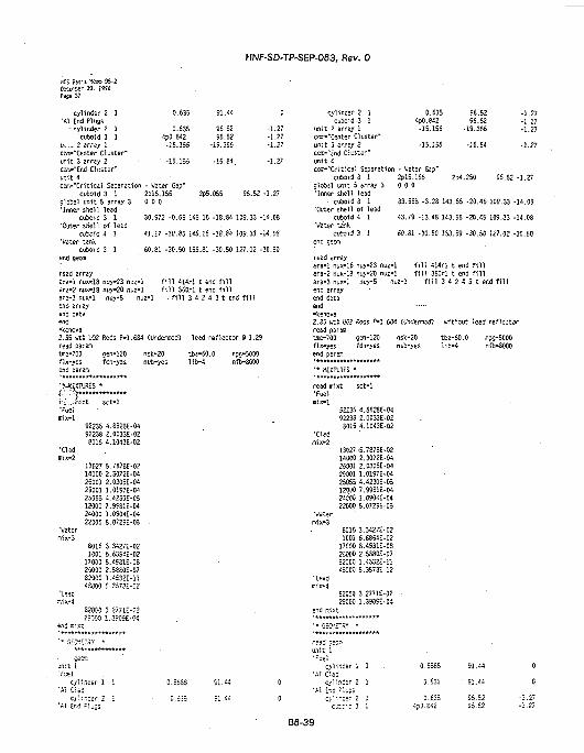
HNF-SD-TP-SEP-063, Rev. 0
HCS Basis Me.ro SS-2Oeceaber 30. ISHPage 37
cylinder 2 1•Al End Plugs
- -ylindsr 2 Icuboid 3 1
ti:... 2 srrsy 1co.--"Center cluster-unit 3 array 2cCt"-"End Cluster"vr.it 4cc.Ti-"Critical Separation
cuboid 3 1global unit 5 array 3'Inner shell lead
cuboid 3 1'Outer shell of lead
c»5cid 4 1'Water tank
cuboid 3 1end gecffl
reed arrayera-1 nux*!8 nuy-23 fiuz-!ara-2 nux-18 nuy-20 nuz-:
0.635 91.44
0.635 56.524p0.842 95.52-15.156 -19.355
' -15.155 -16.84.
- Water Gap"2pl5.166 2P5.055 96.520 0 0
30.972 -0.65 145.16 -18.84 109.33
41.27 -10.85 145.15 -18.84 109.33
60.81 -30.50 155.81 -30.50 127.02
[ f i l l 414rl t end f i l l1 f i l l 360rl t end f i l l
ara-3 nux-1 nuy-5 nuz-1 - f i l l 3 4 2 4 3 t end f i l lend arrayend dataend•kenova2.35 wtX U02 Rods P-1.68'read paramUre-700 gen-120fix-yes fdn-yasend param
r,^_./nixt sct-1'FuelITiiX-l
92235 4.S523E-0492238 2.0C33E-028016 4.1043E-02
'Cladmix-2
13027 5.7873E-0214000 2.3072E-0425001 2.0305E-0425001 1.0197E-C425055 4.4230E-0512000 7.9981E-0424000 1.0904E-0422000 5.0729E-05
•Watermix-3
8015 3.3427E-021001 6.6654E-02
17000 8.4931E-C825000 2.5SE0E-C782000 1.4332E-114S000 5.3573M2
'Lead!7,ix-4
82O0O 3.2771E-02
2=vO0 1.3909E-04end Kixt
unit 1'fuel
cylinder 1 1'Al Clad
o l i ns— - 1'A! Ir.t Flu:s
0
-1.27-1.27-1.27
-1.27
-1.27
-14.08
-14.03
-30.50
1 (Undermod) lead reflector 9 1.29
nsk-20 tba-60.0 npg-5000nub-yes l ib-4 nfb-8000
0.5553 91.44 0
0
cylinder 2 1cuboid 3 1
unit 2 array 1com-"Center Cluster"unit 3 array 2cc---"cnd Cluster"unit 4co.--"Critical Separation
cuboid 3 1olobal un'.t 5 array 3'Inner shell lead
• cuboid 3 1'Outer shell of lead
cuboid 4 1'Water tank
cuboid 3 1end ceom
read arrayara-1 nux-15 nuy-23 nuz-!ara-2 nux-!3 nuy-20 nuz-j
0.635 96.52 -1.274p0.842 96.52 -1.27
•15.155 -19.366 -1.27
-15.155 -16.64 -1.27
- Water 6a?"2pl5.!56 2D4.250 95.52 -1.270 0 0
33.588 -3.28 143.55 -20.45 109.33 -14.03
43.79 -13.48 143.55 -20.45 109.33 -14.08
60.81 -30.50 1S3.59 -30.53 127.02 -30.50.
I f i l l 414rl t end f i l l1 f i l l 350rl t end f i l l
are-3 nux-1 nuy-5 nuz-1 f i l l 3 4 2 4 3 t end f i l lend arrayend dataend-kencva2.35 >.« U02Rods P-!.68<read paramtie-700 cen-120fix-yes fdn-yesend paraa•**•***«******»*****
' * MIXTURES *
read mixt sct-1•Fuelmix-1
92235 4.S826E-0492238 2.0033E-02
6015 4.1043E-02•Cladmix-2
13027 -5.787SE-0214000 2.3072E-0426001 2.0305E-0429001 1.0197E-0425055 4.4230E-05120OO 7.9981E-0424300 1.0S04E-0422000 5.0729E-05
'Watermix-3
6015 3.3427E-021001 6.6854E-02
17000 8.4931E-03255D0 2.5880E-0782000 1.4532E-1145000 5.3573E-12
'Leadmix-4
82000 3.2771E-0225000 1.3905E-04
end rr,1xt
'* 6EOETCT *
m3 se^Tiunit 1•Fuel
cylinder 1 1'Al Clad
cylinder 2 1•Al i'.c Flu:3
c-.::-: 3 1
1 (t/ndermorf) without lead ref lector
nsk-20 tba-60.0 npg-5000nub-yes l i b -4 nfb-8000
0.5563 SI.44 0
0.635 ' SI.44 0
0.635 =5.52 -1.274?0.£42 95.52 -1.27
B6-39
HNF-SD-TP-SEP-063, Rev. 0
KS Basis Ke« S5-2DecerSsr 30. 1SSS?J3e 33
unit 2 arrey 1COT-'Center Cluster"unit 3 array 2cC".""tnd Cluster"unit 4coTi»"Critical Separation
cuboid 3 1
•Water tankcuboid 3 1
er.d gean
-15.155
-15.155
' • Wster Gap"2P15.1550 0 0
60.81 -30.50 14
•19.355
•16. K
2?3.295 . S5.52
5.77 -30.50 127.02
-1.27
-1.27
-1.27
•30.50
read arrayara-1 nux-18 nuy-23 nuz-1 f i l l 414rl t end f i l lare-2 nux-18 nuy-20 nuz-1 f i l l 360rl t end f i l lara-3 n?x-l r.uy-5 nuz-1 f i 17 3 A 2 A 3 t £-:end arrayend dataend
B6-40
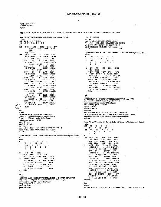
HNF-SD-TP-SEP-063, Rev. 0
NCS Basis Memo 96-2December 30.1996Page 39
• Appendix B Input Files for Benchmarks used for the Statistical Analysis of the Calculations in this Basis Memo
input File for w P u Water Reflected Critical Mass as given in Table S.
OSS 82 2 3 4 IS 19 915 201SS 500 12 0 0 0 0 0 9 0 0
94239 -2390! -23902 -23903 -23904-23905 -23906 -23908 -23911-23914
1001 801623901 293 3 17.540 0.0000.0 6.146SE-5 1 1.0079 2.2161E4
1 15.9994 2.0119E3 1 1.00023902 293 3 15.700 0.000
0.0 S.3637E-5 1 1.0079 1.62S0E41 15.9994 1.4:S0E3 1 1.000
23903 293 3 ' 15.130 0.0000.0 9.7240E-5 1 1.0079 13999E4
1 15.9994 1.2708E3 1 1.00023904 .293 3 35.100 0.000
0.0 9.7492E-5 1 1.0079 1.3962E41 • 15.9994 1.2676E3 1 1.000
23905 293 3 14.370 0.0000.0 1.1966E-4 1 1.0079 1.1371E4
1 15.9994 1.0323E3 I 1.00023906 293 3 13.230 0.000
0.0 1.8390E-4 I 1.0079 7.3891E31 15.9994 6.7081E2 I 1.000
23908 293 3 12.640 0.0000.0 2.S192E-1 I 1.0079 5.3S67E3
15.9994 4.8903E223911 293 3 12.2100.0 7.4316E-4 1 1.0079
] 15.9994 1.6414E2 123914 293 . 3 8.3900.0 1.0480E-2 1 1.0079
1 15.9994 9.340100 1F293
t.0000.000
1.8080E31.000
0.0001.O28SE2
1.000
. end-kenoS
pu 24.4g/l sphere with water reflector (npg-5000)read param ime-200.0 lib-4 nsk-20 gen-120 fix-yesfdn-yes npg-5000 nub-y« tba-60.0 end paramread geometry sphere 1 1 17.54sphere 2 1 48.02cuboid 0 1 6P48.0S
readmi t mix-1 23901 6.1468-5 80163.3387-2 1001 6.6774-2mix-2 8016 3.3455S-2 1001 6.69116-2 s e f l end mixtend data end
Inpur File for "*Pu with a Thin Ste<S.-nitawl
1 Shell and Full Water Reflection at given in Table
2SS 8016 7014 100124000 28000 26000 -2600194238 9-239 94240 94241 94242
3 " 94239 299.8 3 17.7800 0.00000.0 6.6QWE-05 I 1.0079 2.OO92E-O4
1 15.8772 2.0505E-03 ' 1 1.00026001 299.8 3 17.9070 0.000
0.0 0.061S 1 5S.69 2.3121 51.9960 1.15-J6E-00 1 1.0M
ktr,o5 •J BENCHMARK 4 SPHERE WITH STEEL SHELL AND WATER REFLECTOR
(np£»5000) read param tme-200.0 lib-4 r.sk-20 gen-120 fix-yesfdn-yes nub-yes r.pg»5000 tba-60.0 end paramread gcomeirv sphere 1 1 17.78Sphere 2 1 17.907sphere 3 1 46.000
cuboid 0 1 6P46.IO0endeeomread mixt mix-1 9-1239 6.6004-5 9 4 2 « 3.5692-77014 7.5114-4 S016 3.4514-2 1001 6.5006-2 2S0OO 1.5457-6mix-2 26001 6.1TSE-2 24000 1.658-2 280OO 8.15S-3mix-3 8016 3.332-2 1001 6.663-2 SCt-I end mixt
id data
with a Thin Steel Shell and No Wat.
80162J0O094238
94239
70142S0OO94239
299.80.0 S.2232E-O5
1001 26000 -26001
94240 94241 94242• 3 19.3130 0.0000
1 1.0079 1.6254E+O41 15.8987 I.6340E-O3 1 1.000
94240 299.8 3 19.3180 0.00000.03.9321E-06 1 1.0079 3.3992E+05
1 16.0003 3.4396E-4M 1 1.00026001 299.8 3 19.4400 0.00000.0 6.3310E-02 1 58.69 1.7995ET<H)
1 51.9960 1.1234E-KW 1 1.0004 " 1299.8
end-kenaiPU BENXHMARK 4 SPHERE ^TTH STEEL REFLECTOR (npg-5000)read param tme-200.0 lib-4 nsk-20 gen-120 fix-yesfdn-yes npj-5000 nub-yes tba-60.0 end paramrcadgeomeay sphere 1 1 19.318sphere 2 119 .«cuboid 016P19.5end geomread mint roix-1 94239 8^232-5 94240 3 . 9 J 2 1 - 6 94241 2.6356-794242 5.3567-9 7014 6.4132-4 8016 3.4536-2 1001 6.5520-2 26000 6.965*7mix"2 26001 6.331E-2 24000 1.654-2 28000 6.51-3 sct-1 end mixtend data end
!S 8016 7014 1001 24000 2SOO094238 94239 94240 94241 9434226000 -26001 -26002 12000 1302720000 19000 25055 14000 11023
' • 94239 296 3 17.8700 0.00000.0 8.506OE-O5 1 1.0079 1.4673E*O4
1 15.7040 1.8144E+03 1 1.00094240 296 3 17.8700 0.0000
0.04.0700E-06 1- j.0079 3.0665E+051 15.794J 3.8144ETO4 1 1.000
26001 296 3 17.9820 0.00000.0 6J310E-02 1 58.69 1.7995E-O0
1 51.9960 I.I23JE-00 1 1.000 •26002 296 3.0000E-KW 28.142 0.0000
0.0 0.0013 1 1.0079 264.W51 18.0027 1.6293E-KQ 1 1-000
25055 296 3.0000E-00 2S.142 0.00000.0 2.756OE-O5 1 1.0079 12857.329
i JS.S550 S . 4 S : : E - 0 3 I 1.00011023 296 3.0QOOE-00 ZS.142 0.0000O.Ol.NiOE-04 1 1.0079 3094.742
1 1S.SI23 2.040SE-03 I 1.000•f296
B6-41
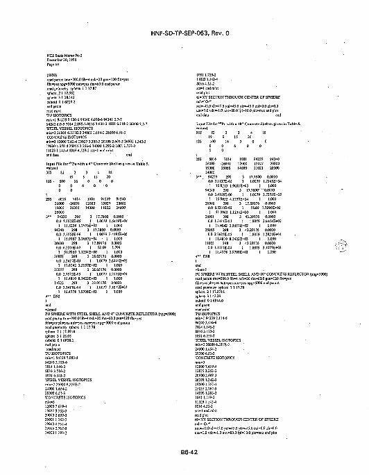
HNF-SD-TP-SEP-063, Rev. 0
NCS Basis Memo 96-2December 30,1996Paje 40
(5000)read param tme-200.0 lib—1 nsk-20 gcn-120 fix-yesfdn-yes npg-SOOO nub-yes tba-60.0 end paramreadfeomeay sphere 1 1 17.S7sphere 2 1 17.9S2sphere 3 1 23.142cuboid 0 I 6P2S.2
•PU 1S0T0PICSmix-1 94239 S.506-5 94240 4.070-6 9424! 2.7-794243 6.0-9 7014 2.098-340!6 3.601-2 1001 6.118-2 26000 7.3-7•STEEL VESSEL ISOTOPICSmix=2 26001 6.331E-2 24000 1.654-2 28000 6.51-3'CONCRETE ISOTOPICSmix-3 12000 7.62-4 13O27 3.353-3 20OOO2.6O9-3 26OO2I.342-319000 4.35S-4 25055 2.756-5 14000 1.293-2 1001 1.737-211023 1.145-1 8016 4.529-2 SCl-1 end irend data
Input File fc-nitawlOSS 82
end
°'Pu with * 4" Concrete Shell i s given in Table 5.
8016260001900028000
94239
7014-2600125055
2980.0 7.SS28E-05
1001 94239 9424012000 13027 2000014000 11023 24000
3 17.7800 0.0000 '1 1.0079 1.6419E-W
1 15.8238 I . 7 9 7 5 E T 4 3 1 1.00094240 298 3 17.7S00 0.0000
0.0 3.7S51E-O6 I 1.0079 3.4195E+0S1 15.9157 3.7659E+04 • 1 t.000
26000 298 3 17.89176 0.00000.0 6.3310E-O2 1 58.69 1.799
1 51.9960 1.1234E-'OO 1 1.00026001' 298 3 28.05176 0.0000
0.0 1.3417E-03 1 1.0079 2.6444E-HJ21 17.6042 1.5657E+02 - 1 1.000
25055 298 3 28.05176 0.00000.0 2.7673E-05 1 1.0079 1.2821E-KJ4
I 18.4810 8.1422E+03 1 1.00011023 298 3 28.05176 0.00000.0 1.1417E-O4 I 1.0079 3.1O77E+O3
1 18.4778 1.9708E+03 1 1.0004 " f298
end-keoo5PU SPHERE WITH STEEL SHELL AND 4" CONCRETE REFLECTOR (npg-5000)read param tme-200.0 lib—4 nsk-20 iba-60.0 gen-120 fU-yesfdn-yes pit-yes nub-yes mn-yes npi^5000 end parararead geometry sphere I I 17.7Ssphere 2 1 17.8918sphere 3 1 28.05cuboid 0 1 6P2S.1endgcomread mixt
•PU ISOTOPICSmix-1 94239 7.833-594240 3.785-67014 1.146-38016 3.516-2100! 6.345-2
•STEEL VESSEL ISOTOPICSmijc-2 26000 6.331E-224000 1.654-22SO0O 6.51-3•CONCRETE ISOTOPiCS
12000 7.619-413027 3353-3200002.609-326001 1.342-319000 4.357-425055 2.767-51-000 1.293-2
1001 1.739-211023 1.142-18016 4.53-2
read plotCil-'XY SECTION THROUGH CENTER OF SPHERE"nch-'O-'1
xuI-45.0 x!r-45.0 yul-45.0 ylr—15.0 zuI-0.0 zJr-0.0uax-1.0 vdi-1 .0 nax-SO.O lpi-10.0 pic-mai end plotend data end
Input File for *"Puw a 10"Con te Shell »•
2SS 8016 7014 1001 94239 9424026000 -26001 12000 13027 2000019000 25055 14000 11023 2S00O24000
3 " 94239 298 3 17.7800 0.00000.0 7.1137E-O5 1 1.0079 1.7945E+O41 15.8213 1.9691E-O3 1 1.000
94240 298 3 17.7SOO"" 0.00000.0 3.41SSE-06 1 1.0079 3.7373E-K151 15.9052 4.1233E+O4 1 1.000
26000 298 3 17.89176 0.00000.0 6.331OE-O2 1 58.69 1.7995E-KK)1 51.9960 1.1234E+00 1 1.000
26001 29E 3 43.29176 0.00000.0 U417E-03 1 1.0079 2.6444E+021 17.6042 1.5657E*O2 1 1.000
250JS 298 3 43.29176 0.00000.0 2.7673E-05 1 1.0079 1.2821E+O41 18.4810 8.1422E*O3 1 J.000
11023 298 3 4329176 0.00000.0 1.M17E-04 1 1.0079 3.1077E+O31 18.4778 1.970SE+03 I 1.000
4 " f29Stend-keno5PU SPHERE WITH STEEL SHELL AND 10" CONCRETE REFLECTOR (npg-5000)lead param tme<00.0 !ib*4 nsls-20 tba-60.0 gen-120 flx-yesfdo-j'es p!i-yes nub-yes run-yes npg-5000 end paramread geometry sphere 1 1 17.78sphere 21 17.8918sphere 3 1 43.29cuboid 01 6P44.0end geom
TUISOTOP3CSmix-I 94239 7.114-594240 3.416-67014 1.146-38016 3.473-23001 6.25S-2•STEEL VESSEL ISOTOPICSmix-2 26000 6331E-2240001.654-228000 6.51-3•CONCRETE ISOTOPiCSmix-312000 7.619-J13027 3.353-3200002.609-326001 1.342-3190004J57-J25055 2.76%514000 3.293-21001 1.739-211023 U42-48016 4.53-2sc;-l end mixttead plotnl-'XY SECTION' THROUGH CENTER OF SPHERE1
wh- 'O-"xu'.—45.0 xIr-45.0 vul-i5.0 ylr—45.0 zul-0.0 zlr-0.0uax'I.O v*s»-1.0 RW-80.0 lpi-10.0 pic-ma! end plot
B6-42
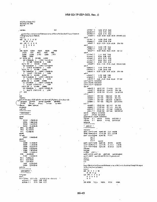
HNF-SD-TP-SEP-063, Rev. 0
NCS Basis Memo 96-2December 30,1996Page 41
922547014
2200016000
92236601211023
92238S01612000
.pui File for a 4x4 Concrete Reflected Array of 93.2 wt% Enriched Uranyl Nitrate ato7.:S f/I at given in Tabie 5.-nitawlOSS S2 2 3 4 IS
19 20 9 15 " •ISS 500 17 0 0 0
0 0 6 0 00 0
I2SS 92235
26000 7014 6012 8016 10012000019000
3 " 92234 293 2 10.5600 0.95020.0 1.7693E-06 1 1.0079 7.5125E-051 16.1609 7.4984E-KW I 1.000
92235 293 2 10.5600 0.95020.0 1.6061E-04 1 1.0079 S.2758E+031 15.9415 E.1445E-02 1 1.000
92236 293 2 10.5600 0.95020.0 7.4495E-07 1 1.0079 1.7843E4O61 16.1622 1.7811E-KJ5 1 1.000
92238 293 2 10.5600 0.95020.0 9.1432E-06 1 1.0079 1.4537E-K151 16.1517 I.4502E-I-04 1 1.000
26000 293 1 25.4000 0.00000.0 2.527SE-O4 1 1.0079 8.3939E+021 16.7297 8.9763E-tO2 1 1.000
11023 293 1 25.4000 0.00000.0 3.8303E-04 1 1.0079 5.5395E--021 16.8578 S.9671E+02 1 1.000
4 " f293
end"kenova
_^_ROT53 4x4 array of UN solution w/o sleeve (67.28 gU/1-21.12 crs~ ""^adparam gen-120 nsk*2O npg-5000 nfb-8000\ ._: ^e-700 fdn=y« pl 'Tes run-yes iba-60.0'*—'Ilx-yes lib—4 nub-yes
92234922359223692238
1.7693E-O61.6061E-047.4495E-079.U32E-O6
8016 3.41J9E-O27014 4.I162E-041001 6.S156E-O2
mix«2'Altank
13027mix-3•Concrete
12000130272000026000
. 1900014000
S.9469E-02
7.18S5E-041.1241E-038.0213E-032.527EE-O44.8976E-047.7139E-O3
1001 1.0401E-0211023 3.S303E-04
8016 4.2362E-026012 6.42J7E-03TOM I.995SE-0S
160002:000
er.d mixi
S.2S0SE-052.9I92E-05
:o.T.--Sph«e U255 «--Ji gU-Wt.12 eicylinder 1 1 0.505 0.00 -0.32cylinder 2 1 10.56 0.00 -0..-2
cylinder 1 1cylinder 0 1cylinder 2 1cuboid 0 1
evlinder 1cylinder 2
cuboid 3
cvlinder 1
111
1cylinder 2 1
cuboid 0unit 4
cylinder 1cvlinder 2cylinder I
1
111
10.5610.5610.96
27.15119.1119.1
15.24 -15.24
0.5050.635
-0.32-0J2-0.32
15.24 -15.24 123.445-0.32
25.40 0.0025.40 0.00
15.24 -15.24
0.5050.635
5.005.00
15.24 -15.24.
1.1410.5610.56
0.000.0027.15
15.24 -15.24 25.4 0.0
0.000.00
15.24 -15.24 5.0 0.0
•0.32-032-0.32
- ..... . . 10.S6 I19.I -0.52cylinder: 1 10.96 119.1 -0.32
cuboid 0 1 15.24-15.24 15.34-15.24 123.445-0.32it 5
cylinder! 1 1.U0 25.40 0.00cylinder 2 1 1.270 25.40 0.00cuboid 3 1 15.24 -15.24 15.24 -15.24 25.4 0.0
cylinder 1 1cylinder 2 1
cuboid 0 1unit 7 array-! 0.0 0.0 0.0unit 8 «rey»2 0.0 0.0 0.0unit 9 amv-3 0.00.00.0unit 1<
1.140 5.00 0.001270 5.00 0.00
15.24 -15.24 15.24 --15:24 5.0 0.0
cuboid 0 1 121.92 0.0 0.14 0.0121.92 0.0 0.14 0.0cuboid 3 1
cuboid 0 1uni t l l
cuboid 0 1
lit 12cuboid 0cuboid 5 1.cuboid 0 1cuboid 3 1
4 0.0
25.7 0.0 122.2 0.025.7 0.0 122.2 0.025.7 0.0 122.2 0.025.7 0!0 122.2 0.0
0.0
unit 14global ur
175.32 0.0 25.7 0.0173.32 0.0 25.7 0.0173.32 0.0 25.7 0.0
y-4 0.0 0.0 0.0arrav-5 0.0 0.0 0,0
15 array-6 0.00.0 0.00 1 0.0 0.0 0.0 0.03 1 0.0 0.0 0.0 0.0
5.0 0.030.4 0.0154.165 0.0
5.0 0.030.4 0.031.035 0.0154.165 0.0
5.0 0.030.4 0.031.035 0.0154.165 0.0
0.635 0.01.025.4 0.0 1.0
ara-1 oiara-2 DIix- 3 nuv-lara-3 nux~4 cuy-4
ara-4 mara-5 mar3=6 niend arrayread plotttl-'Plot'xul=0 xli
7 8 7 77 8 7 77 7 7 7
JX-1 nuv-3JX-3 na\--lixrl nu\--3
nuz-3 fillnui-3 fillnuz-1 fill
end fillmiz-1 fillnuz-1 fillnuz-1 fill
r-125 >-u!-71.46 ylr-7uax-1 wdn«-l nax-
tni da: a
3 2 1 end fill6 5 4 end fill7 7 7 7
10910 eadfill11 13 11 end fill12 14 12 end fill
1.46 zu l -166dr -S130ndn-S0 lpi«10 pie-mix end
a 2\l Concrete Reflected Array of 93.2 wt% Enriched Uranyl Xnr,ver, in Table 5.
OSS E2 2 3 4 IS19 20 9 15
ISS SQO I? O 0 O0 0 6 Q 00 0
2SS 9221-5 S;;:-4 <
B6-43
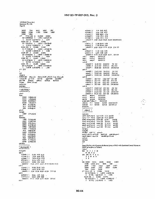
HNF-SD-TP-SEP-063, Rev. 0
KCS Basis Memo 96-2December 30,1996Paje 42
26000 7014 6012 SOI 6" 100120000 22000 11023 12000 1302719000 16000
3 " 92234 293 2 10.5600 0.95020.0 2.00O9E-O6 1 1.0079 6.6236E-*«5I 16.1S16 6.687CE-Q4 I (.000
92235 293 2 10.5600 0.95020.0 l.S16iE-04 1 1.0079 7.2963E->031 15.9552 7.250-E-02 1 1.000
92236 293 2 10.5600 0.95020.0 8.42J0E-07 1 1.0079 1.S731E-O6I 16.1829 1.SBS3E-1-05 1 1.000
922J8 293 2 10.5600 0.9S020.0 1.034IE-05 1 1.0079 I.2S16E+051 16.1712 1.2930E-04 I 1.000
26000 293 I 25.400 0.00000.0 2.527SE-04 1 1.0079 8.3939E-021 16.7297 S.9763E-02 1 1.000
11023 293 1 25.400 0.00000.0 3.S303E-04 ) 1.0079 5.S3WE-HJ21 16.8578 5.9671E+O2 1 1.000
4 " f293
-kenova• ROT54 2x2 array Wo sleeve (76.09 gtM-21.12 cm diamcyl)
read param £en*I20 nsk»20 np$-5000 nfb-8000mie-700 fdn-yes plfyes nin-yes tba-60.0fix-yes lib-4 nub=yesend paramread mix!
•• MIXTURES •
Tuel92234922359223692233801670141001
mix-2•Altank
13027mix-3'Concrete
120001302720000260001900014000100111023
• 8016601270141600022000
end mixt
2.0OO9E-O61.SI64E-048.4250E-071.0341E-O5
3.424SE-024.7215E-O46.4966E-O2
S.9469E-02
7.1S85E-O41.1241E-03S.0213E-O32.527SE-O44.8976E-O47.7139E-031.0401E-023.63<J3E-Q<t4.23S2E-026.4237E-O31.9958E-0S82S09E-052.9192E-0S
'* GEOMETRY •
ead geominii 1
cylinder I 1cylinder 2 1cylinder 1 Jcylinder 0 1cylinder 2 1
0.505 0.00 -0.3210.56 0.00 -0.3210,56 62.34 -0.3210.56 119.1 -0.3210.96 119.1 -0.32
cubcidO 1 15.24 -15.24 15.24 -15.24 123.44J-0.32
0.505 25.40 0.000.635 25.40 0.00
15.24 -15.24 15.24 -15.24 25.4 0.0
0.505 5.00 0,00 .0.635 5.00 0.00
15.24 -15.2-1 15.24 -15.24 5.0 0.0
cylinder I I 1.14 0.00 -0.32cylinder 2 I 10.56 0.00 -0.32cylinder 1 1 10.56 62.34 -0.32cylindirO 1 10.56 119.1 -0.32cylinder 2 1 10.96 119.1 -0.32cuboid0 1 15.24 -15.24 15.24 -1J.24 123.44J-0.3;
unit 5cylinder 1 I 1.140 25.40 0.00cylinder^ 1 1.270 25.40 0.00
unit 6cylinder I 1 1.140 J.00 0.00cy!inder2 J j.27-0 S.00 0.00
cuboid 0 1 15.24 -15.24 15.24 -15.24 5.0 0.0unit 7 array-1 0.0 0.0 0.0unit 8 array-2 0.0 0.0 0.0unit 9 array-3 o.O 0.0 0.0unit 10
cuboid 0 1 30.48 0.0 60.96 0.0 5.0 0.0cuboid 3 J 30.48 0.0 60.96 0.0 30.4 0.0cuboid 0 1 30.48 0.0 60.96 0.0 154.165 0.0
unit 11cuboidO 1 121.92 0.0 30.62 O.O 5.0 0.0cuboid3 1 121.92 0.0 30.620.0 30.4 0.0cuboidO 1 17.1.92 0.0 30.620.0 154.1650.0
unit 12cuboidO 1 25.7 0.0 122.2 0.0""5.0 0.0euboid3 1 25.7 0.0 122.2 0.0 30.4 0.0cuboidO 1 25.7 0.0 122.2 0.0 51.03SO.Ocuboid 3 1 25.7 0.0 122.2 0.0 154.165 0.0
unit 13cuboidO I 173.32 0.0 25.7 0.0 5.0 0.0cuboid 3 1 173.32 0.0 25.7 0.0 30.4 0.0cuboidO 1 173.32 0.0 25.7 0.0 31.035 0.0cuboid 3 1 173.32 0.0 25.7 0.0 154.165 0.0
unit 14 airay-4 0.0 0.0 0.0unit 15 array-5 0.0 0.0 0.0unit 16 arraywti O.O 0.0 0.0 'global unit 17 arrsy-7 0.0 0.0 0.0reflector 0 1 ' 0.0 0.0 0.0 0.0 0.635 0.0 1.0reflector 3,1 0.00.0 0.0 0.0 25.4 0.01.0end geam
- ARRAY '
n- lnuy- l nu2-3 fill 32 1 end fillc-1 nuy-1 rmz-3 fill 6 5 4 end fill
a/s-4 nux-3ara-5 nux-lara-6 nux-3ara-7 nux-1end arraylead plotnl-TJot* ncxul-25. xlr-7uax-1 wdn»-end plotend data
noy»l nuz-1 fillnu>-«3 nur-1 fill
nu>-»3 nui-lfill
h-' •;.' pfc-mix
S 7 8 7109101114 11215 113161
3yu!-71.46 ylr-71.461 nax-130 ndn-SO lp|-
1213
Za10
endfitfend fillend fillend fillend (it!
1-166 zlr-1end
Jnpat File for a 4x4 Concrete Refiectfd Amy o!93.t » t t Enriched Vnnv) fiitr.360.37 gfl as givtn in T«ble 5.
OSS 82 2 3 4 IS19 20 9 15
1SS 500 23 0 0 00 0 10 o 00 0
:SS 92235 9 ; ; M 92236 9223S 1400026000 CSOOt 6012 8016 100120000 2:OC>0 11023 12000 1302719000 16303 15031 25055 420007014 2-&00 2SO0O
3 " 92234 293 2 83800 0:65760.0 9.4767E-C6 1 1.0079 1.2499E-KIS1 16.702] 1.8007EHJ4 1 1.000
92235 293 3 S.3S0O 0.65760.0 S.50r£-C4 1 1.0079 1.3769E-03 '! 15.75S- 1 S5TSE-C2 1 1.000
B6-44
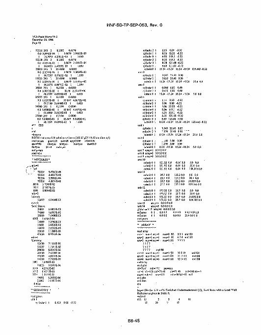
NCS Basis Memo 9S-2December 30.1996Page 43
HNF-SD-TP-SEP-063, Rev. 0
92236 293 2 8.3S0O 0.65760.0 3.9902E-O6 I 1.0079 2.968iE+051 16.7073 4.2781E-O4 1 1.000
92238 293 2 8.3S0O 0.65760.0 4.8974E-05 1 1.0079 2.4185E-041 16.6623 3.4759E-03 1 1.000
26000 293 I 25.4000 0.00000.0 2.S27SE-O4 1 1.0079 8.3939E-^O21 16.7297 S.9763E---02 1 1.000
11023 293 1 25.4000 0.00000.0 3.S303E-04 1 1.0079 5.539SE-O21 16.8578 S.9671E-rO2 1 1.000
26001 293 1 0.3100 . 0.00000.0 S.9852E-02 1 58.69 2.2046E-00I 48.1197 4.0995E-02 ! 1.000
25055 293 1 0.3100 0.00000.0 1.1209E-03 1 55.847 6.0S72E-021 S4.21S0 3.6440E-02 1 1.000
24000 293 1 0.3100 0.00000.0 1.6985E-02 1 55.847 4.O171E-O11 55.4800 3.562IE-02 1 1.000
28000 293 I 0.3100 0.00000.0 7.5400E-03 1 55.847 9.0492E+O11 4S.U97 4.0995E-02 1 1.000
" f293
ROT61 4x4 array UN solution w/sleeve (360.37 eU/l-16.1 2 eireadparam een-120 nsk-20 npg-5000 nfb-8000
70 run-yes lba»60.0une-700fix-yesendparamread mixt
fdn-yes p1
] i b -4 ' nub<
•• MIXTURES •
mix-1• \iel
•; 92234922359223692238
9.4767E-068.6027E-043.9902E-O64.8974E-05
SO 16 3.7295E-O27014 2.1I977E-03
13027 5.9469E-02
Si«l Sleeve260012400028000
5.9852E-021.6985E-027.5400E-03
6012 2.6231E-04140001503116000
• 2S05542000
mix-4
120001302720000260001900014000
1.376SE-033.S530E-052.8282E-O5I.1209E-03S.9563E-06
7.18SSE-041.1241E-03S.0213E-032.J278E-044.S976E-047.7139E-03
1001 1.0-J01E-0211023 3.8303E-04
S016 4.2-62E-O26012 6.4:TC1-J 1.9:
16000iJsE-05
S.2S09E-052.919;-E-O5
•GEOMETRY •
c>i:sJsrli i o.5o; ooo -o..-;
cylinder 2 1 8.06 0.00 -0.32cylinder! I 8.06 3232 -0.32cylinderO 1 8.06 119.1 -0.32cylinder2 1 8.38 119.1 -0.32
cylinders 1
cvlinderl 1cylinder 2 1
3cylinder! 1cylinder 2 1
4eviiader) icylinder 2 1cylinder 1 1cylinder 0 1cylinder 2 1evIindtrO 1cvtinder3 1
cuboid 0 1
cylinder 1 1cvlinder2 1
cuboid 4 1
cylinder! 1cylinder 2 Icuboid 0 1
8.69
0.5050.635
121.68 -0.32
25.40 0.0025.40 0.00 '
0.50S 5.000.635
. I.i48.06S.06S.OS8.388.388.69
5.00
0.000.0032.32119.1119.1
0.000.00
-0.32•0.32-0J2-0.32-0J2
121.68 -0.32121.68 -0.32
15.24 -15.24
1.1401.270
15.24 -15.24 123.445-0.32
25.40 0.0025.40 0.00
15.24 -15.24
1.1401.270
5.005.00
15.24 -15.24
15.24 -15.24 25.4 0.0
0.000.00
15.24 -15.24 5.0 0.0unit 7 a.Tay-1 0.0 0.0 0.0iinitS arra>-2 0.0 0.0 0.0wit 9 array-3 0.0 0.0 0.0
cuboid 0 Icuboid 4 Icuboid 0 I
unit IIcuboid 0 1cuboid 4 Icuboid 0 1cuboid 4 1
unit 12cuboid 0 1cuboid 4 1cuboid 0 1cuboid 4 1
unit 1 j i i ay -
121.92 0.0121.92 0.0121.92 0.0
0.14' 0.00.14 0.00.14 0.0
25.7 0.0 122.20.025.7 0.0. 1222 0.025.7 0.0 122.2 0.025.7 0.0 122.2 0.0
25.7 0.025.7 0.025.7 O.O25.7 0.0
173.32 0.0173.32 0.0173.32 0.0173.32 0.0
I 0.0 0.0 0.0yS 0.0 0.0 0.0
global unit 15 a m y - 6 0.0 0.0 0.0reflector 0 1 . 0.0 0.0 0.0 0.0reflector 4 1 0.0 0.0 0.0 0.0
'• ARRAY •
5.0 0.030.4 0.0154.165 0.0
5.0 0.030.4 0.0
31.035 0.0154.16J 0.0
5.0 0.030.4 0.0
31.035 0.0154.165 0.0
ara-2 nuara-3 nu
:x-1 nuy-1ix-1 nuy-1;x-J nuy-4 •
7 8 7 7
nuz-3 fsllnuz-3 fillnuz-1 fill
7 7 7 7 end fillara-4 nuara-5 nuar»-6 nuend arrayread plotnl-Tlot'
uax»! wderd pldend data
x-1 nuy-3:x»3 nuy-1•x-I nuv-3
neh"' *!.'
rs"-l "nsx"'
nuz-t fillnuz-1 fillnuz-1 fill
picmix
3 2 16 5 4
end fillend fill
7 7 7 7
10911 131214
1.46 vlr-71.46130 nd-TSOIpi-
10 endfiil11 end fill12 end fill
zul-166z!r-3• 10. end
Input File for 4.31 wtV. Enriched UndermoderateiJ t O , Fuel Rods with a Lead WailReflector i s ;ivcn in Table 5.
B6-45
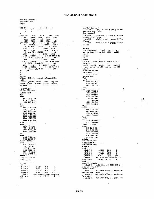
tiCS Basis Memo 96-2December 30,1996
HNF-SD-TP-SEP-063, Rev. 0
92238290001600012000
293
13027-2900124O0017000
2
820OO26000
' 2000022000
0.632S
8016•26001
6012O.lSOl
2SS 92235• 1 0 0 1
1400025055
3 " 922350.0 1.0124E-03 1 15.9994 1.69S0E*O2
1 238.0508 2.3237E-02 1 1.00092238 293 2 0.6325 0.1801
0.0 2.2193E-02 1 15.9994 7.74i9EfOO1 255.0439 5J372E-01 1 1.000
26001 2S3 2 0.6985 0.00000.6325 2.O3OSE-W 1 26.98154 3.9906E+02
I 30.4624 2J202E-01 f 1.00029001 293 2 0.698S 0.0000
0.6325 I.O197E-04 J 2$.98iS4 /.94«H*02I 34.M19 6.1400E-4J1 ] 1.000
24000 293 2 0.6985 0.00000.6325 1.0904E-04 1 26.98154 7.4309E-02
1 35.0S63 6.0131E-01 1 1.0004 " f293
end
4.31 wi% U02rods withlead refiectorai 0.00inread paramime-700 gen-120 nsk-20 lib-4 npg-SOOOfix-yes fdn-yes iba-60.0 nub-yes nfb-8000end param
'• MIXTURES •
lead mixt7uelmix-1
92235922388016
'Clad .mix-2
1302714000260012900125055120002400022000
•Water
801610011700026000
•Leadmix--)
8200029000
SCl-1
1.0124E-O32.2193E-O2
4.6411E-02
5.7878E-022.3072E-042.O305E-O41.0197E-044.4230E-057.9981 E-04I.09WE-046.1944E-OS
3.3427E-O26.685SE-028.4931E-082.58S0E-07
3.2771E-021.B909E-04
•Rubber End Caps
60121001
2000014000801616000
end mixt
3.S41SE-02S.1304E-022.2627E-034.21 S3 E-041.0989E-028.4975E-05
'• GEOMETRY '
cylinder 1cvlinder 3cyiinder 2cylinder 5
e-jboid 3t 2 J.T3V
0.632450.641350.70735'0.70735
91.4491.4491.4493.98
000
-2.50.946 -0.946 0.946-0.946'93.9S
-15.136 •11.552 0
com--Crit Separation"cuboid3 1 1J.136-15.1368.870-S.870 93.98 -2.54
global unit 4 srcay 2 0 0 0"Inner shell for lead
cuboid3 1 30.2720.00 145.15-18.85 109.96-13.44•Outer shell to fill w.iead
cuboid 4 1 40.47-10.20 145.15-18.85 109.96-13.44•Water tank
cuboid3 I 60.77-30.50 156.80-30,50121.94-30.50endgeom
read array«]6nuy»12 nuz-1 fill 192M t end fill-1 nu j -5 ntu-1 fill 2 3 2 3 21 end fill
4.51 HIM VO2 rods with Uadread param
fix-yes fdn-yes tba-60.0end param
lib>*4 npg-5000nub-yes nfb-8000
•• MIXTURES •
readmixt•Fuel
9223592238£016
•Cladmix-2
13027(4000260012900125055120002400022000
'Waterroix-3
£016100117000260O0
•Lead
8200029000
sct-1
1.O124E-O32.2193E-O24.6411E-02
5.7S7SE-O22.-072E-O42.0305E-O41.0197E-O44.4330E-0S7.9981 E-041.09O4E-O46.1944E-05
3J427E-O26.6SS5E-O28.4931E-O82.5SS0E-O7
3.2771E-O21.3909E-04
•Rubber End Caps
60121001
2000014000301616000
enrfmi'xt
3.8415E-O25.1304E-022.2627E-O34.2I83E-M1.09S9E-02S.4975E-0S
'• GEOMETRY •
cylinder 1 1cylinder 3 1c>'Jind«2 I1
cylinder 5 1"euboidS 1
it 2 array 1it 3m-"CriI S:par;
cuboid 5 1
0.632450.641350.507550.70735
91.44 091.44 09J;44 095.98 -2.54
0.946-0.946 0.946-0.946 93.98 -2.5-15.136
ition"
•11.352 0
15.136-15.136 9.090-9.090 93.98 -2global unit 4 array 2 0 0 0'Inner shell for lead
cuboidS 1 30.932-0.66 K5.59-1S.41 109.96-13.44•Outer shell to fill w/lead
cubo:d4 1 40.47-10.20 145.59-18.41109.96-13.44•Water i n k
caboid 5 1 60.77-30.50 15/.65-30.50 121.94-30.50
B6-46
HNF-SD-TP-SEP-063, Rev. 0
NCS Basis Memo 96-2December 30,1996Pane 45
end a.Tavend data'end*kenova4.31 wt%read paramtme-700fix-yes 1end param
UO2 rods with lead
jen-120 nsk-20fdn-yes tba-60.0 i
•• MIXTURES •
read mixt•Fuelmix-1
92235922388016.
•Clad
1302714000260012900125055120002400022000
•Watermix-3
8016100117000
\ 26000lead
fnix-48200029000
SCl-l
1.0124E-032.2I93E-O24.6411E-O2
5.787SE-022.3072E-042.0305E-O41.0I97E-044.423OE-O5 '7.9981E-041.0904E-046.1944E-05
3.3427E-O26.6855E-028.4931 E-OS2.5SS0E-O7
3.2771E-021.3909E-O4
•Rubber End Capsmix-J
60121001
2000014000E01616000
3.S415E-02'S.I304E-022.2627E-034.21S3E-041.0989E-028.4975E-0S
•* GEOMETRY *
read jeom
cylinder 1cylinder 3cylinder 2cylinder 5
1 0.632451 0.641351 0.707351 0.70735
reflecio:
lib-4nub-yes
91.4491.4491.4493.98
I t end fill
r at 0.77 in
npg-5000nfb-SOOO
000
-2.54cuboid 3 1 0.946 -0.946 6.946 -0.946 93.98 -2.54
unit 2 am;>• 1 -15.136 •31352 0
eom-'Crit Separation"euboid3 1 15.136-15.1368.715-8.715 93.98 -2.54
global uni!4 array 2 0 0 0'Inner shell for lead
cuboid3 1 32.228-1.96 144.S4 -19.36 109.96-13.44Ouwr shell to fill w,1ead
ccboid4 1 40.47-10.20 144.84-19.16 109.96-13.44
e-jbv.it 1 60.77-30.50 156.18-30.50 121.94-30.50
4.31 «1% UO2rod:
tme-700" gen-120 nsk-20 lib-4fix-yes fdn-yes tba-60.0 nub-ye
" MIXTURES'
:ad reileciorat 1.97 in
92235922388016
•Clad
1302714000260012900125055120002400022000
•Watermix-3
801610011700026000
'Lead
. 8200029000
1.0I24E-032.2193E-O24.6411E-02
5.TSTSE-022.3O72E-O42.03O5E-O41.0I97E-044.4230E-057.998 IE-041.09O4E-O46.I94JE-05
3.3427E-O26.6S55E-028.4931 E-OS2.5S80E-07
3.2771E-021.59O9E-04
'Rubber End Caps
60121001
' 2000014000801616000
3.841SE-025.1304E-022.2627E-034J1S3E-O41.09S9E-028.4975E-05
cylinder 1cvlinder3cvlinder2cvlindir5
cuboid 3on it 2 array
1
1111
0.632450.641350.707350.70735
0.946 -0.946•15.136
91.4491.4491.4493.98
000
-2.540.946 -0.946 93.98 -2.54
-11.352 0
com--Crit SeparatJon-euboidS 1 15.136-15.136 7.175-7.175 93.98 -2.54
global unit 4 axray2 0 0 0"Inner shell for lead
cuboid3 1 35^73-5.00 141.76-22.24 109.96-13.44'Outer shell to fill w/lcad
cuboid4 1 40.47-10.20 141.76-22.24 109.96-13.44'Water 12.1k
euboid3 1 60.77-30.50 150.O2-3O.5O121.94-30.5O
read a n y
wiihoui lead reriecio:
»l iiuy-5
tT.e-700 £tr.-120 rsk-20fix-v-es fii«i-es iba-60.0 nub-yes
B6-47
NCS Basis Memo 96-2December 30,1996Page 46
HNF-SD-TP-SEP-063, Rev. 0
92235 1.0124E-O39223S 2.2193E-O28016 4.64ME-02
13027 5.7S7SE-O2MOW 2.3G72E-0426001 2.0305E-0429001 1.0197E-O425055 4.4230E-0S12000 7.9981E-0424000 1.0904E-Q422O00 6.I944E-05
"Waier
S016 3.3427E-021001 6.68S5E-02
17000 8.4931E-08260O0 2.58SOE-O7
'Leadmix-4
82000 3.2771E-0229000 1.3909E-04
'Rubber End Capsmix-S
6012 3.S-II5E-021001 S.13WE-02
20000 2.2627E-0314000 4.2183E-O48016 1.09S9E-0216000 S.4975E-O5
•• GEOMETRY •
read geomunit 1
cylinder 1 1cylinder 3 1cylinder 2 1cylinder5 1cuboidS 1
0.63245 91.44 00.64135 91.44 00.70735 91.44 00.70735 93.98 -2.54
0.946 -0.946 0.946 -0.946 93.98 -2.54•15.136 -11.352 0
*"Crit Separation"cuboid3 1 15.136-15.1366.4S5-6.48S 93.98 -2.S4
globalunii4 array2 0 0 0•Waiertajik
cuboid 3 1 60.77-30.50 147.26-3O.J0 121.94-30.50end gei
read array
1 30.4624 2.3202£J-01 1 1.00029001 293 2 0.70735 0.0000
0.64J35 1.019TE-04 1 26.98154 7.9463E-O2'1 -4.0419 6.I400E-r01 1 1.000
24000 293 2 0.70735 0.00000.64135 1.0904E-04 1 26.98154 7.4309E-O2
1 35.OS63 6.013IE-01 1 1.0004 " O93tend
4.31 «1% UO2 rods P-2.S4 cm (Opt Mod) lead reflector @ 0.00 inreadparamtme-700 gen-120 nsk-20 lib-4 npg-5000fix-yes fdn-yes tba-60.0 nub-yes nfb-SOOO.runwes end paiam
•• MIXTURES •
9223592238E016
1.0124E-O32.219-E-O24.64HE-02
1302714000260012900125055120002400022000
5.7S7SE-02JJ072E-O12.0305E-041.0197E-044.4230E-05
.99SIE-041.0904E-04J.0729E-05
, -16nuj-12x«l nuy-5
z-lfill 192rlt eudfill- lf i! l 2 3 2 3 21 endfiil
1001 6.68J6E-O217000 5.129SE-O726000 3.23 50E-1082000 1.4532E-1148000 3.2144E-U7014 4.0792E-09
- S20O0 3.2771E-0229000 1.3909E-04
"Rubber End Caps
6012 3.S415E-021001 5.1304E-02
20000 2.2627E-03160O04.21S3E-0480161.09S9E-0214000 8.4975E-05
Input File for 431 wl"/. Enriched Ontimum Moderated L'O] Fuel RodReflector i s given in Table 5.
with a Lead Walt
OSS S219
1SS S0000
2SS 92235100114000250554SOO0
3 " 92235
220
21O0
9223B290001600012000
2930.0 1.0124E-03
1 239223S
3 49 IS
0 05 0 0
IS
0
13027 S2000 SOIt-29001 26000
24000 2000017000 22030
2 0.63251 15.9994
S.0508 2.3237E-02 1393 2 0.6325
-2600170146012
0.04091.69SC€-02
1.0000.0409
0.0 2.2193E-02 1 15.9994 7.745SE-001 235.0439 5.33T2E-01 1 1.000
26001 293 2 0.70Ti< O.00M0.W135 2.O3C5E-04 1 ;5.?£iJ4 :-.990S£-0
read geomunit 1com-"Single Fuel Pin*
cylindcrl I 0.63245cylinder 0 1 0.64135cylinder 2 1 0.70735cylinder 5 1 0.70735
cuboid 3 1
91.44 091.44 091.44 ' 093.93 -2.54
1.27O-1.27OI.27O-1.27O 93.98 -2.54unit 2 a-Tayl -10.16 -16.51 -2.54cosi*"13 x E 2.Tay of pins*
com-"Critical S=pi.-a;ion - Water Gap-cuboid 3 1 2pl0.160 2pl0.310 93.98 -2.J4
global uni: - array 2 0 0 0•L-.n!rsh*!] for lead
cuboidS 1 20.3200.00 152.1S-ll.SS 107.42-15.9S•Oy::r shi!! to fill wish lead
cuboid 4 1 30.52 -10.20 152.15 -11.S5 107.42 -15.98•Waseruofc
cuboid 3 1 50.82 -30.50 170.80 -30.50 121.94 -30.50
B6-48
HNF-SD-TP-SEP-063, Rev. 0
NCS Basis Memo 96-2December 30.1996Pane 47
lilt )04rl t end fillHI! 2 3 2 3 21 end fill
kenova.31 wi% UO2 rods P-2.S-I cm (Opt Mod) leadreflecior @ 0.26 inead param.3 U
read param0
read paramane«7O0 gen-120 nsk-20 lib—4 npg-5000flx»y« fdn"yes tba»60.0 nub»yes nfb"8OOOrun™ycs end paism
end dataend
4.31 will UO2 rods P-2.J4 cm (Opt Mod) lead reflector @ 0.52 in
tme-700 gen-120 r.sk-20 lib-4 npg-5000fl\"\'es fdr.'^'es tba~60.0 nub-jes nfb-8Q00run-yes end param
•• MIXTURES *
92235 1.012iE-0392238 2.2I93E-02S016 4.641 IE-02
13027 5.78TSE-0214000 2.3072E-0426001 2.0305E-0429001 1.0197E-0425055 4.4230E-05I2OO07.99S1E-0424000 1.0904E-0422000 J.0729E-O5
"Watermix-3
8016 3.342SE-021001 6.6856E-02I7000 5.129SE-0726000 3.23S0E-10820001.4532E-1I
> 4S000 3.2144E-H'j/ 7014 4.0792E-09
mix-482000 3.2771E-0229000 U909E-04
•Rubber End Caps-mix-5
6012 3.84I5E-021001 5.1304E-02
20000 2.2627E-O316000 4.21S3E-O4£016 1.09S9E-0214000 8.497JE-O5
end mixt
unit 1 'eora--Sine]e Fuel Pin-
cylinder I 1 0.63245 91.44 0e>!inderO 1 0.64135 91.44 0cylinder 2 1 0.707SS 91.44 0cylinders 1 0.70735 93.98 -2.54cvboidl } • 1.270-1.270 1.270-1.270 95.9$ -2.54 .
unit 2 array 1 -10.16 -16.51 -2.54com-"I5 x 8 array of pins"unit 3com-"Criiical Separation - Water Gap"
cuboid 3 I 2p30.160 2pl0J90 93.98 -2.54globs] unit 4 array 2 0 0 0
cuboid i ]• 20.980 -0.66 152.31 -11.69 107.42 -15.98•Ov.it shdl to O m\h lead
cuboid 4 I 3I.1S-10.S6 152.31 -11.69 107.42-I5.9S•Wate: tank
cuboid 5 1 50.S2-30.50 171.12-30.50 321.94-30.50end j t o n
read array3,-a-l nus"Smiy-13m:z-] fill 10-Srl t endfiili-a-2 nux-i n-jy-s nuz-\ f:ll 2 3 2 3 2 t end fillendair^y
92235 1.0IJ4E-039223S2.2593E-O280164.W11E-02
13027 S.7S78E-O2UQ002.S012E-Q426001 2.0305E-O429O011.0I&7E-O425055 4.4330E-O512000 7.998IE-0424000 1.09O4E-O422CM5O 5-0729E-O5
1001 6.6S56E-0217000 5.139SE-0726000 5.255OE-1OS2000 1.45S2E-1148000 3.2H4E-117014 4.0792E-O9
82000 3.2771E-O229000 1J909E-O4
'Rubber End Caps
60123.84IJE-O21001 J.lJOiE-02
20000 2.2627E-03I60004.2ISJE-O48016I.0989E-0214000 S.4975E-05
•• GEOMETRY •
readjeora
com--SiB£le Fuel Pin"cylinder 1 1 0.63245 91.44 0eytindeiO I 0.64(35 91.4* 0cylinder^ 1 0.70735 91.44 0cylinder 5 1 0.70735 93.98 -2.54cuboid3 1 U 7 0 - U 7 0 1 . 2 7 0 - t . 2 7 0 93.98-2.54
unit 2 array! -10.16 -16.51 -2.54eom»"13 x£ array of pins'
eom-'Criiieal Separation - Water Gap"cuboidS 1 2pl0.!60 2p9.520 93.98 -2.54
global unit4 artsy 2 0 0 0liner shell for lead
euboidS 1 21.641-1.32 150.57-13.43 107.42-15.98•Outer shell to fit! with lead
cuboid i 1 31.84-11.52 150.57-13.43 107.42-13.9S
cuboid 3 I 50.82 -30.50 167.61 -30.50 121.94 -30.50
ara"! nux-i
end anayend (Js;a
IJZ-l12-1
fill IWrl t efill 2 3 2 3 2
no fill[ end fill
4.31 «-,% UO! rods P-2.54 cm <Opl Mod) icad reflector ig 2.13
B6-49

HNF-SD-TP-SEP-063, Rev. 0
NCS Basis Memo 96-2December 30.1996Page 48
jen-120 nsk-20fdn-yes tba-60.0
endparam
lib-4 npg-5000nub-yes n(b-SOOO
92235 J.O12JE-O3922382.2193E-028016 4.6411E-02
13027 5.78TSE-0214000 2.3072E-0426001 2.0305E-0429001 1.019TE-0425055 4.4230E-O512000 7.9981E-0424000 1.0904E-0422000 S.0729E-0J
S0I6 3.3428E-O21001 6.6856E-02
17000 5.129SE-O726000 3.2350E-I082000 1.4532E-1148000 3.2144E-I1701-1 4.0792E-09
S2OOO3.277IE-O229000 I.3909E-04
•Rubber End Capsmix-5
6012 3.8415E-021001 S.1304E-02
20000 2.2627E-03160004.21S3E-048016 1.09S9E-0214000 S.-1975E-05
'• GEOMETRY •
read jeomunit 1eom-'Single Fuel Pin"
cylinder 1 1 0.63245 91.44 0cylinder 0 1 0.64135 91.44 0cylinder 2 1 0.70735 91.44 0cylinder 5 I 0.70735 93.98 -2.54
cuboid 3 1 U70-1.270 1.270-1.270 93.98-2.54unii2 sway! -10.16 -16.51 -2.54com-"13 x 8 array of pins"unit 3com-'Critical Separation - Water Gap"
cuboid 3 1 2pl0.160 2p5.150 93.98-2.54global unii4 array 2 0 0 0'Inner shell for lead
cuboidS 1 25.725-5.41 141.83-22.17 107.42-15.98"Ouier shell to fill with lead
cuboid4 1 35.93-15.61 141.83-22.17 107.42-15.98'Water tank
cuboid 3 1 50.82 -30.50 150.16 -30.50 121.94 -30.50
S nuy"13 ni:i=l fill 104rl I end fill\ nuy-S nu : - l fill 2 3 2 3 21 end fill
-kenovaJ.31 vn*,i UO2 tods P-2.54 cm (Op! Mod) wshow lead reflectorread para.-nIms-TOO j;en-120 nsk-30 . l:b-4 np™5000f.x-l'es fdti »yes tbs"60.0 nub^'es r.fb-SOOO
92235 1-0J24E-039223S 2.2195E-O2E016 4.64HE-02
13027 5.7S78E-O214000 2.3072E-0426001 2.03QSE-O429001 1.0197E-O425055 4.4230E-0512000 7.99S1E-04240O0 1.09WE-0422000 5.0729E-OS
8016 3.342SE-021O016.6856E-02
17OOO5.I2S3E-O726000 3.235OE-1O82000 1.4J32E-1148000 3.2144E-1I7014 4.0793E-O9 •
82000 3.2771E-02- 29000 U905E-O4
•Rubber End Caps
6012 3.8415E-O21001 5.1304E-02
2OOO0 2.2627E-O316000 4.21S3E-O480161.09S9E-0214000 8.-J97JE-05
unit 1com-"Single Fuel Pin1
cylinder 1 Icylinder 0 1cylinder 2 1
l i d s 1y
cyli
0.632450.641350.707350.70735
91.4491.4493.98
-uboidS 1 1J270-U70U70-1.270 93.98 -2.54unit2 array I -10.16 -16.51 -2.54com--13x8arrayofpins-unit 3eom--CriticalSeparation -WaterGap-
cuboid 3 1 2pl0.160 2p4.120 93.98 -2.54global unit 4 array 2 0 0 0•Water tank
cuboid 3 1 50.82 -30.50 146.04 -30.50 121.94 -30.J0end geom
read 3,-rayara-1 nux-S nuy>13 n u i - 1 " fill )04rl t end fillara»2 nux-1 nuy-S nuz-1 fill 2 3 2 3 21 end fill
Input File for 2.35 wtV. Enriched Undermoderated L'O, Fuel Rods wiltReflector as given in Table 5.
OSS 82 ' 2 3 4 IS19 20 9 15
1SS 500 17 .0 0 0
2SS 92235 92238 13027 1400029000 -25001 12000 24000iSOOO 2600D -26001 22000£016 1001 17000 S2000
B6-50
HNF-SD-TP-SEP-063, Rev. 0
92235 293 2 O.55S8 0.20980.04.SS2SE-04 1 15.999-1 3.1135E-02
1 23S.OS08 4.3490E-rO2 1 1.00092238
0.0 2.O033E-021 235.0459 2.!
26001 2930.55SS 2.030SE-O4
1 30.4624 2.3202E-0129001 293 2 0.6350
0.5588 0.20981 15.9994 7.5SS6E-O0
7E-01 I 1.0002 0.6350 0.0000
1 26.98154 3.9906E-021.000
0.00000.55S8 1.0197E-04 1 26.98154 7.9J63E-K12
1 34.0419 6.1400E-KJ1 1 1.00024000 293 2 0.6350 0.0000
O.5J8S 1.0904E-04 1 26.98154 7.430SE-021 35.0863 6.0131E-0I 1 1.000
4 " f293
end
2.35 w;% U 0 2 Rods P-1.684 (Undermod) lead reflecior @ 0.lead paramtme-700 gen-120 nsk-20 lba«60.0 npe-5000 'flx-yei fdn-yes nub-yes lib-4 nffc-3000endparam
'• MIXTURES •
readm'Fuel
92235 4.S828E-0492238 2.OO33E-O280164.1043E-02
•Clad
13027 S.7S7SE-0214000 2.3072E-O4
, 260012.030SE-04•:• i 29001'1.0197E-O4• 'J 25055 4.4230E-0S
" ' 12000 7.9981E-O424000 1.Q904E-O422000 5.O729E-O5
•Watermix-3
S016.3.3427E-021001 6.6854E-02
17000 8.493IE-0826000 2.5880E-O782000 1.4S32E-1148000 5.3573E-12
•Lead
82O0O3.2771E-O229000 1.3909E-04
end mixt
'• GEOMETRY •
unil ITuel
cylinder 1 1•Al Clad
cylinder 2 !•Al End Plufs
cylinder 2 1cuboid 3 1
unil 2 array 1eom-'Cemer Cluster"unh 3 array 2 -15.156
O.55SS
0.63S
0.6354p0.842-15.156
96.5296.52
-19.366
cuboid 3 1 30.512 0.00 145.11-18.89109.33-14.08•Oussr shell of lead
cuboid 4 I 40.51 -10.20 145.11 -18.89 109.3- -14.08•W2T=n=:;k
r^bc:d3 I 6 0 S ! -50.50 !56.71 -30.50 12/.C:-30.50
read i i a yara-1 nux-18 nu;-23 nm-1 fill 414rl t end fill
fill 36Orl t end fillfill 3 4 2 4 3tend fill
2.35 v.1%UO2 Rods P-l.684 (Undemiod) lead (edecior@ 0.26d
ilx-yesendpara
nsk-20nub-jes
92235 4.8S28E-O492238 2.O033E-O28016 4.1045E-O2
13027 5.787SE-0214000 2.3072E-0426001 2.03OJE-O429001 1.0197E-0425055 4.4230E-0512000 7.99S1E-O4240O0 1.0904E-0422000 5.O729E-OS
S016 3J427E^I21001 6.6S54E-02
17000 8.4931E-08.26000 2.5SSOE-O782000 1.4532E-M48000 5J573E-12
•Lead
" GEOMETRY •
read gtom
Tuclcylinder! 1
•Al Clade>'linder2 1
•Al End Plugscylinder 2 1
cuboid 3 1
com-'Ceater Cluster*
0.5588
O.63S
0.6354p0.842-15.156
91.44
91.44 •
96.52
96.52-19.366
--End'ciusier-•15.156- -16.84
com-"Critical Separation - Water Gap"' cuboid3 1 2pl5.)56 • 2p5.055 96.52-1.27jlobai unii 5 array 3 0 0 0'Inner shell lead. cuboid 3 1 30.972 -0.66 145.16 -18.84 109.33 -14.08•Ouser shell of lead
cuboid 4 1 41.17-10.86 145.16-18.84 109.33-14.08•\Va:
er.duboid 3 1 60.S1 -30.S0 156.81 -30.50 127.02 -30.50
d array- l S nuy-23 n
ara-2nux-3Snuy-:O nars«3 niw-1 nu\-5
-1 fill 414il t end fill- 1 fill 560rlt end fillr -1 fill 3 4 2 4 3 t end fill
B6-51
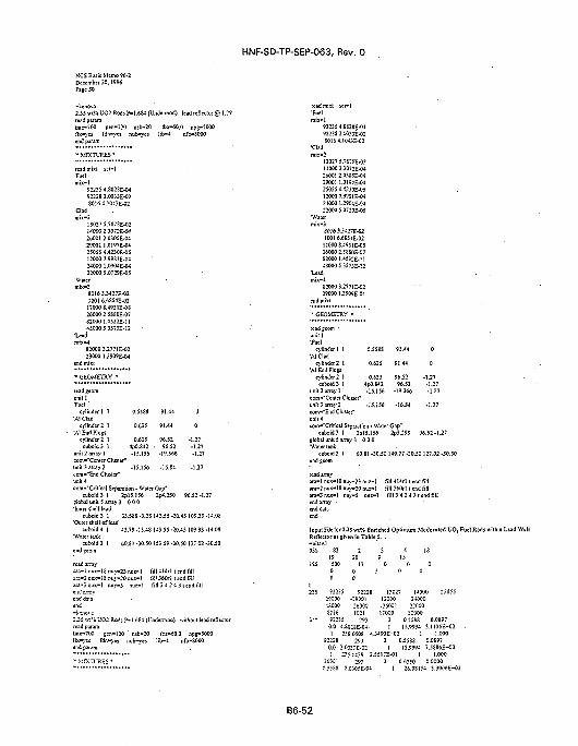
HNF-SD-TP-SEP-063, Rev. 0
NCS Basis Memo 96-2December 30,1996Page JO
•kenova2.35 wt% UO2 Rods P-1.684 (Undermod) lead renector @read parwntme-700 ^en-120 nsk-20 tba-60.0 npg-5000fix-yes fdn-yes nub-yes lib-4end param
•• MIXTURES *
readmixl scl-1"Fuelmix-1
92235 4.S82SE-O492238 2.OO33E-O2S016 4.1O45E-O2
'Cladmix-2
15027 S.787SE-O214000 23O72E-0426001 2.0305E-O429001 1.0197E-04250S5 4.4230E-0S120OO7.99S1E-O424000 1.0904E-W22000 5.0729E-05
•Watermix-3
80I6 3.3427E-021001 6.6S54E-02
17000 8.4931E-0826OO0 2.5S30E-0782000 1.4532E-1148000 5.3573E-12
leadmix-4
82000 3.2771E-0229000 1.3909E-04
end mixl
- GEOMETRY •
-r™Hinder 1 1 0.5588
•Al Cladcylinder 2 1 0.635
'Al End Plugscv!inder2 1 0.635
cuboid 3 ) 4pO.S42unit2arrav| -15.156com«-Cemer Cluster"unit3arra>-2 -15.156com-"End Cluster"
91.44
91.44
96.52• 96.52
-19.366
•16.84
0
0
-1.27-1.27-1.27
•1.27
com-"Critical Separation - Water Gap"cuboid 3 I 2plJ.156 2p4.3S0 96.52-1.27
global unit 5 array 3 0 0 0'Inner shell lead
euboid3 I 33.588 -3.28 143.55 -20.45 109.33 -14.08•Outer shell of lead
euboid 4 1 43.79 -13.48 143.55 -20.45 109.33 -14.08•Water tank
cuboid 3 1 60.81 -30.50 153.59 -30.50 127.02 -30.50end geom
ead a.-ray
•teaova2.55 w.% UOread pararatme-700flx-j-es fdend pa.-am
fill 414rl tend fillf)l) MQrl t end fflfill 3 4 2 4 3 1 end :T
s P-1.6S1 (L-ndsrmoti) wiL
92255 4.SS2SE-049223S 2.O033E-028016 4.10C-E-02
adx-2
l-O27J.-;s:gE-O214000 2.-Q72E4426001 2.O3O5E-O429001 1.0197E-0425055 4.4230E-O512000 7.9981E-0424000 1.0904 E-0422000 5.O729E-O5
8016 y-127E-O21001 6.68S4E-0217000 8.493 IE-OS26000 2.5ES0E-07S2D0O1.4532E-I14SOOO5.3575E-12
82000 3.2771E-0229000 1.5909E-04
read geom •
'Fuelcylinder 1 1 0.558S 91.44 0
VU Cladcylinder 2 1 0.635 91.44 0
*AI End Plugscylinde.-2 1 0.635 96.52 -1.27
euboid 3 1 4p0.842 96.52 -1.27unit 2 array 1 -15.156 -19.366 -1.27com--Center Clustet'uni: Sarray2 -15.156 -16.84 -1.27eom»"End Ouster"
com""Cridcal Separation • Water Gap"euboid3 1 2pl5.1J6 2p3.295 96.52-1.27
global unit 5 array 3 0 0 0"Water tank
cuboid 3 1 60.81 -30.50 149.77 -30.50 127.02 -30.50
read arrayara-1 nux-18 nuy-23 nuz-1 fill 414rl t end fillara-2 nux-18 nuj-20 nuz-1 fill 360rI t end filla ja-3nux-l mi'y-j suz-1 fill 3 4 2 4 31 end fillend arrayend dataend
Input FtJe for 135 wi% Enriched Optimum .Moderated UO, Fuel Rods with i Lead WallReflector is j i n n in Table 5. .
I 92255 92238 13027 14000 2505529000 .29S0I 12000 240004SO00 26000 -26001 22000SDi6 1001 17000 S200O« : ? 5 295 2 O.558S 0.0897
0.0 4.is:SE-04- 1 15.9994 3.1I3SE-02 .1 25S.0508 4.349OE-02 1 1.000
92238 -2S3 2 0.5588 0.0S970.0 2.O035E-02 1 li.9994 7.5SS6E-001 "\£04."9 2.SII/E-01 I 1.000
26CC1 293 2 0.63J0 0.0000O.f-!ES :,0-0;E-04 1 26.9S154 3.99D6E-02
B6-52
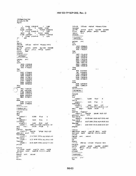
NCS Basis Memo 96-2December 30.1996Page SI
HNF-SD-TP-SEP-063, Rev. 0
1 30.4624 2.3202E-OI 1 1.00029001 193 2 0.6350 0.0000O.55SS 1.0197E-04 1 26.9E154 7.9463E-02
1 34.0419 6.140CE-OI 1 1.00024000 393 2 0.6350 0.00000.S5SS 1.0904E-04 1 26.9S154 T.450SE-02
1 35.OSS3 6.0131E-OI 1 1.0004 " f293
end-kenova2.35 «i% UO2 rods with lead reflector at 0.00 inread paramime-700 gen-120 nsk-20 npg-5000 nfb-8000fix-yes fdn"yes pk-yes run»yes tba-60.0nub-yes lib-4
- MIXTURES p
read mixt•Fuel
9223592238SOI 6
•Clad
1302714000260012900125055120002400022000
•Watermix-3\ 8016
' 10011700026000$200048000
leadmix-4
S200029000
end mit t '
SC!-1
4.8S2SE-042.OO33E-O2
•J.1045E-02
S.787SE-O22.3072E-042.0305E-041.0197E-04J.423OE-O57.9981 E-041.0904E-045.0729E-05
3.3427E-026.6S54E-O21.0O95E-0532550E-103.S609E-105.3798E-1I
3.2771E-O21.3909E-04
"• GEOMETRY •
tttd jeorn
"Fuelcylinder 1 1 0.5SSS 91.44 0
•A! Cladcylinder 2 1 0.635 91.-14 0
'Al End Plugscylinder' I 0.635 96.S2 -1.27
cuboid3 I 1.016-1.016 1.0)6-J 01696.52 -1.27unit 2 array 1 -16.256 -19.304 0unit 3comH Cnt oepafaEion
cuboids 1 2pl6.256 2p6.920 96.52 -1.27global unit 4 array 2 0 0 0Inner shell tea
cuboid 5 ) 32.5J20.00 )53."5 -J0.2S 109.:-:- -)i,0'Outer shell of
cuboid 4 1 42.71-10.20 153.75 .10 25 109.33 -14.0•Waitrtar.1;
c-jboid3 1 63.01 -50.50 174.OO.j0.5O 121.94-30.5end geom
rcai!«ny
.•a-2 nux-1 nay-5 nui-'l fill 2 & 2 3 2 t end fiilend anaylead s;a.T ns:»l end s:anend data
2.35 WT% UO2 rods with lead reflector at 0.26 inread paia.-ntme-700 £«n>*120 nik-20 npg-5000 rJb»SOfk-yes fdn-\es plr->'es run*jes iba-60.0nub«yes lib^lend pi'i-ti
92235 4.SS28E-O492238 2.M33E-02£016 4.1043E-02
JJ027 5.?S7S£-O214000 2.3072E-0426001 2.0305E-0429001 1.0197E-0425055 4.4230E-0512000 7.998 tE-0424000 1.0904E-M22000 S.0729E-OS
S0I6 3.3427E-O21001 6.6E54E-0217000 1.O095E-O626000 323J0E-IO82000 3.86O9E-1O48000 5.3798E-11
82000 3^771E-0229000 1.3909E-04
endmixt
unit!•Fuel
cylinder] 1. 0.5588 91.44 • 0•Al Clad
cylinder 2 1. 0.635 91.44 0•Al End Plugs
cylinder 2 1 0.635 96,52 -1.27cuboidj 1 1.016-1.016 1.016-1.01696.52 -1.27
unit 2 array 1 -16.256 -19.304 0unit 3com-"Crit Separation*
cuboid 3 1 2pl6.256 2p6.860 96.52 -1.27global unit 4 array2 0 0 0•Inner shell lea
cuboid 3 1 33.172-0.66 153.63-10.37 109.33-14.0•Outer sbell of
cuboid 4 1 43.37-10.86 153.63-10.37 109.33-14.0•Water tank
euboid3 1 63.01-30.50 173.76-30.50 121.94-30.Send geom
-16 nuy-19 nuz-1 fill 30-Srl t end fill- l nu>-5 nuz-1 fill 2 3 2 3 21 end fill
end array
end dataend-fcenova2.35 wfii
read pa.-a.iitme-TOO
n^b-^'esend p'aram
-
L-02 rods «-i:h lead
gsn-120 nsk-20faa«\-es plt-^-es nl;b-4
• MLXTVRSS'
read nixt sc:»l
reflecior a
npg-5000
t 1.03 in
ntV-SODba-60.0
B6-53
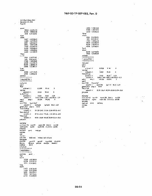
HNF-SD-TP-SEP-063, Rev. 0
NCS Basis Mlemo 96-2December 30,1996Page 52
mix-19223592238SOI 6
•dad
1302714000-260012900125055120002400022000
'Water
80161001
17000260008200048000
Leadmix-4
8200029000
4.SS2SE-042.OO33E-03-J.10J3E-02
S.787SE-022.3072E-O42.0305E-041.0197E-044.4230E-0S7.99S1E-041.0904E-04S.O729E-O5
3.3427E-026.68S4E-021.009IE-063.23S0E-103.86O9E-105.3798E-11
3.2771E-021.3909E-04
0.5588
0.635
91.44
91,44
- GEOMETRY •
•Fuelcylinder] 1
'AlCIad
cylinder 2 1'A! End Plugs
cylinder 2 1cuboids 1
unit 2 array 1
unit 3com-'Crit Separation"
cuboid 3 I 2pl6.256 2pS.625 96.52-1.27global unit4 array 2 0 0 0'Inner shell lea
35.12S -2.62 151.16 -12.84 109.33 -14.0
- 0.635 96.52 - U 71.016-1.016 1.016-1.016*6.52 -1.27
-16.256 -19.304 0
cuboid 3 1•Outer Shell of
cuboid 4 1"Water lank
cuboid 3 1end geom
read array
45.33 -12.82 151.16 -12.84 109.33 -14.0
63.01 -30.50 168.82 -30.50121.94 -30.5
end arrayread stanend data
nuy"I9 nu i " l fill 3Wrl t end fillnuy-5 nui -1 fill 2 3 2 3 2 1 end fill
120002400022000
'Wiser
S0161001!70O026000820OO48000
•Lsadmix-4
8200029000
7.9981 E-041.0904E-045.0729E-O5
3.3J27E-026.6S54E-021.0095E-063.235OE-1O3.S6O9E-1O5.379SE-11
3.2771E-02I.3909E-04
read jeomunit 1•Fuel
cylinder I 1'Al Clad
cylinder 2 1'Al End Plugs
cvlinder2 1cuboid 3 1
unit 2 arrav I
O.55SS
0.635
0.63S1.016-1.016
-16.256
91:44
91.44
96.52'1.016-1-19J0.
O
0
•"•• - 1 . 2 7
.016 96.52 -1.27i o
com-"Crit Separation'cuboid 3 1 2pl6.256 2p4.1J5 96.52 -1XI
global unit 4 array 2 0 0 0
endgeom
read array
63.01 -30.50 162.94-30.50121.94-30.5
nuy-19 nuz-lfi l l 304rl t end fillnuy-5 nuz>imi 2 3 2 3 2 1 end fill
read paramtme-700
fd
UO2 rods
•120• - . ' «
lib-4rublesend param
'• MIXTURES •
readmixt sct-1 .'Fuel
92235 4.SS:$E-0492238 2.M33E-02S016 4.iC4:-E-02
rsk-20 npg-5000 nfb-SOOOpit-yes • run-j'es tba»60.0
13027 5.7S7SE-O2i-iooo 2.;O::E-O426001 2.O305E-O429001 1.0197E-W25055 4 . J :5C-E-05
B6-54
HNF-SD-TP-SEP-063, Rev. 0
7.0 STRUCTURAL EVALUATION
7.1 INTRODUCTION
The PRTR Graphite Cask, or Radiometallurgy Cask 27, is an onsite, intra-area packaging fortransporting Type B radioactive material within the 300 Area of the Hanford Site. This section of thedocument defines and evaluates the NTC structural requirements for intra-area transport of thispackage. Structural performance of the package is evaluated only for NTC; accident conditions areevaluated in the risk and dose consequence section of this document.
7.2 STRUCTURAL EVALUATION OF PACKAGE
7.2.1 Package Structural Description
The PRTR Graphite Cask is fundamentally a right circular cylinder of lead and stainless steelcomposite construction. The lead is sandwiched between outer and inner stainless steel tubular shells.At each end of the cask is a thick circular plate, that is welded to both inner and outer shells, whichencapsulates the lead. At the top, closure of the inner cavity is provided by a bolted blind flange withan attached shield plug of composite lead-stainless steel construction. The cask is equipped with amanually actuated, rotating, shielded drum door, which provides closure at the bottom end. None ofthe end closures are sealed. A handling yoke is provided on the cask and welded to the outer shell.Attached to the yoke is a lifting bail, which can be locked into position for lifting and handling of thecask. Support plates are welded to the outer bottom housing to provide support during transport.
The cask is constructed of welded 304 stainless steel. Shielding is provided by lead, which ispoured after fabrication of the stainless steel body and internal components.
7.2.2 Chemical and Galvanic Reactions
At the operating temperatures, no chemical or galvanic interaction of the materials will occur.The lead is encapsulated in the stainless steel; consequently, there are no agents to generate chemicalor galvanic reactions, (n addition, stainless steel forms a natural oxide layer, which provides protectionfrom most corrosive agents (i.e., water) under the normal operating temperatures.
7.2.3 Sizes of Package and Cavity
The outside dimensions of the cask are 36.0 cm (14.0 in.) in diameter by 99.0 cm (39.0 in.) inlength. Dimensions of the inner cavity are 7.94 cm { 3.13 in.) in diameter by 63.5 cm (25.0 in.) inlength.
7.2.4 Weight
The PRTR Graphite Cask has an empty weight of 1,089 kg (2,400 Ib) and a maximum grossweight of 1,202 kg (2,650 Ib).
7.2.5 Tamper- Indicating Devices
Due to the weight of the cask closures and the intra-area shipment of this cask, no tamperindicating devices are provided.
B7-1
HNF-SD-TP-SEP-063, Rev. 0
7.2.6 Positive Closure
Positive closure of the cask is provided by the bolted blind end flanges. The top end blindflange is secured with four, No. 10 hex head screws. At the bottom end the flange is closed off with arotating shielded drum door.
7.2.7 Lifting and Tiedown Devices
No tiedown devices are provided on the cask. For lifting and handling, yokes on each side ofthe cask with a rotating bail are provided. The yokes are recessed into the outer housing andreinforced with welded plates. The bail is equipped with bearings that are pressed onto the yoke. Asshown in the Part B, Section 7.5, the yoke and the lifting attachments meet the requirements of theHanford Site Hoisting and Rigging Manual (RL1993).
7.3 NORMAL TRANSPORT CONDITIONS
7.3.1 Conditions To Be Evaluated
Onsite structural performance of the package is assessed for Hanford Site normal conditions inthis section. The onsite conditions evaluated for are hot and cold temperature extremes, reduced andincreased external pressure, vibration, water spray, compression, inertial loading, and penetration. Thepackage structural response with solar insolation is evaluated for the onsite hot ambient temperatureextreme of 46 °C (115 °F [Fadeff 1992]} and without for the cold, ambient temperature extreme of-33 °C (-27 °F [Fadeff 1992]). Reduced and increased external pressure structural response isevaluated for a Hanford Site maximum barometric pressure range of 0.94 atm (13.81 psi} to 1.01 atm(14.85 psi). Vibrational loading response of the package is evaluated for the parameters established inANSI N14.23 (ANSI 1980). In the case of water spray, package response is evaluated for in-leakage ofwater at ambient temperatures and pressures. The package structural response to compression isevaluated for compressive loads resulting from anticipated stacking onto the package. Because thereare no in-transient load transfers, structural response of the package to inertial loads is evaluated forrough transport of the package based on ANSI N14.23 shock loading parameters. Penetrationstructural response is idealized as a loading from a steel rod 3.2 cm (1.25 in.) in diameter with arounded end weighing 6.0 kg (13.0 Ib) dropping onto the package from a height of 1.0 m (40.0 in.).These loads are to be applied independently and nonsequentially.
7.3.2 Acceptance Criteria
The criteria for acceptable performance of the package are based on all major criticalcomponents of the package remaining structurally functional, the contents remaining contained, andonly superficial damage of noncritical components being incurred during NTC. To meet the criteria forNTC, the analytical tests are to assume, as a worst case, the package is intermittently subjected to theabove loading conditions during normal transport operations. Performances of the package in meetingthese criteria are demonstrated by either positive margins of safety based on material yield strength orpackage loadings that are within acceptable limits of the component/materials used in the package.
7.3.3 Hot and Cold Evaluation
Based on the thermal evaluation from Part B, Section 8.0, for a worst-case heat source of5.65 W with solar insolation under Hanford Site conditions, the maximum internal componenttemperature of the cask is 79 °C (175 °F). Considering the materials of construction (lead andstainless steel), no material degradation or appreciable reduction in yield strength will occur. Under
B7-2
HNF-SD-TP-SEP-063, Rev. 0
these conditions the external temperature of the cask is 78 °C (172 °F). Consequently, structuralperformance of the package is not affected by the Hanford Site hot temperature extreme. Followingthe thermal analysis, the radiological payload activity was reduced, resulting in a heat loading of2.92 W. Because the heat loading is less than that previously analyzed, the conclusions remain thesame.
Evaluation of cold temperature package performance shows that because the primary structuralmaterial of construction is stainless steel, no extremely cold weather shipping restrictions are required.Austenitic stainless steel is not susceptible to low-temperature brittle fracture. Consequently, with anonsite, low, extremely cold temperature of -33 °C (-27 °F), no degradation cask of performance willoccur.
7.3.4 Reduced and Increased External Pressure
Because the cask is not sealed, reduced or increased external pressure is not a concern.
7.3.5 Vibration
Vibration of the package is not a concern because the shipment occurs only 12 times a year fora distance of less than 1.61 km (1.0 mi). Based on a speed of 24 km/h (15 mi/h) for a distance of1.61 km (1.0 mi), 12 times a year, at a loading frequency of 2 Hz (ANSI 1980), this equates toapproximately 6,000 cycles per year. Relative to the loading on the materials and the material fatiguestrengths, vibrational loading on this cask is not significant.
7.3.6 Water Spray
Because the package is not sealed, in-leakage of water into the cask cavity is a concern.Consequently, all payloads must be shipped in sealed containers. Prior to and after transport, the caskmust be inspected for any in-leakage of water into the cask cavity.
7.3.7 Compression
The package is shipped as an exclusive-use shipment, and stacking on the package isprohibited. Consequently, package compression is not a concern.
7.3.8 Inertial Loading
During normal transport of this package, no in-transit load transfers are involved.Consequently, normal condition inertial loads would arise from rough transport shock loads of 3.55svertical to the plane of travel and 2.3£rs in the direction of travel (ANSI 1980).
In the case of the rough transport, shock loads of the conveyance are evaluated as intermittentin nature and applied as a single pulse to the package. Because the duration of the shock load is ofsuch long duration (greater than three times the natural frequency of the system), it is applied as aquasi-static load, and the package is evaluated by classical linear elastic methods. To ensurecomponent and material loading are within the elastic range, the allowable stresses are established onthe basis of the maximum shear stress theory of failure. The weld allowable loading is established onbase material yield strength with a joint efficiency reduction factor based on the American Society ofMechanical Engineers Boiler and Pressure Vessel Code, Section VIII (ASME 1992).
B7-3
HNF-SD-TP-SEP-063, Rev. 0
Evaluation of rough transport loads on the package presented in Part B, Section 7.5, showsthat the package remains fuliy functional, maintains structural integrity, and maintains the contents,the evaluation, package performance is analyzed for both vertical and longitudinal loadings. In bothcases the evaluation shows the induced stresses on the package are below the allowable stresses.
7.3.9 Penetration
The evaluation presented in Part B, Section 7.5, shows the exposed surfaces of the packagecannot be penetrated by a 6.0-kg (13.0-lb) object dropped from 1.0 m (40.0 in.). Results of theevaluation show that only superficial marring of the exposed stainless steel surfaces results fromdropping the object.
7.3.10 Conclusions
The results of these evaluations show the package is acceptable for transport on the HanfordSite under NTC. Due to the possibility of in-leakage of water into the cask cavity, proper protectionand sealing of the.payload and cask internals are required.
7.4 REFERENCES
ANSI, 1980, American National Standard Design Basis for Resistance to Shock and Vibration ofRadioactive Material Packages Greater than One Ton in Truck Transport, DRAFT, ANSI N14.23,American National Standards Institute, New York, New York.
ASME, 1992, Boiler and Pressure Vessel Code, Section VIII, Division 1, American Society ofMechanical Engineers, New York, New York.
Fadeff, J. G., 1992, Environmental Conditions for On-site Hazardous Materials Packages,WHC-SD-TP-RPT-004, Rev. 0, Westinghouse Hanford Company, Richland, Washington.
RL, 1993, Hanford Site Hoisting and Rigging Manual, DOE/RL-92-36, U.S. Department of Energy,Richland Operations Office, Richland, Washington.
B7-4
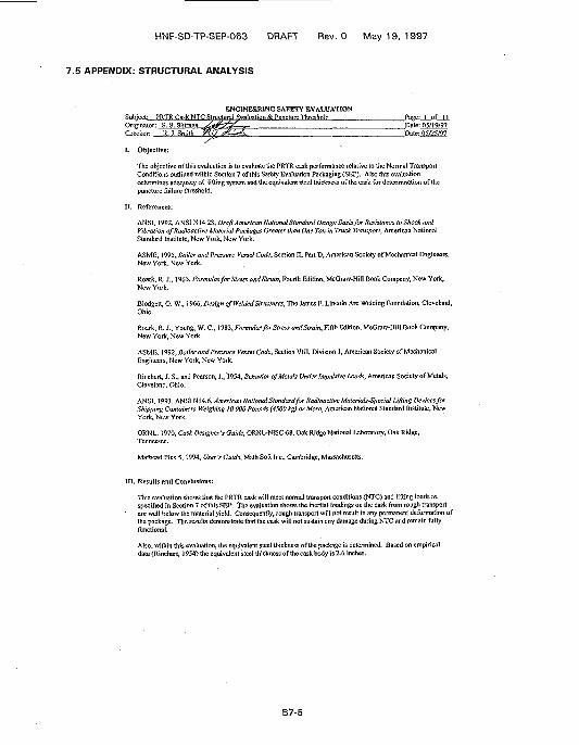
HNF-SD-TP-SEP-063 DRAFT Rev. 0 May 19, 1997
7.5 APPENDIX: STRUCTURAL ANALYSIS
ENGINEERING SAFETY EVALUATION, , P R T R Cask NTC Structural Evaluation & Puncture Threshold : Page: 1, of II
Originator? S. S. Shiraca jfafp&C--— Date: 05/19/97Checker: R. J. Smith 7<O J?U*&^ Pate: 05/25/97
I. Objective:
The objective of this evaluation is to evaluate the PRTR cask performance relative to the Normal TransportConditions outlined within Section 7 of this Safety Evaluation Packaging (SEP). Also this evaluationdetermines adequacy of lifting system and the equivalent steel thickness of the cask for determination of thepuncture failure threshold.
II. References:
ANSI, 1992, ANSI N 14.23, Draft American National Standard Design Basis for Resistance to Shock andVibration of Radioactive Material Packages Greater than One Ton in Truck Transport, American NationalStandard Institute, New York, New York.
ASME, 1995, Boiler and Pressure Vessel Code, Section II, Part D, American Society of Mechanical Engineers,New York, New York.
Roark, R. J., 1965, Formulas for Stress andStrain, Fourth Edition, McGraw-Hill Book Company, New York,New York.
Blodgelt, O. W., 1966, Design of Welded Structures, The James F. Lincoln Arc Welding Foundation, Cleveland,Ohio.
Roark, R.}., Young, W. C , 1 983, Formulas for Stress andStrain, Fifth Edition, McGraw-Hill Book Company,New York, New York.
ASME, 3992, Boiler and Pressure Vessel Code, Section VIII, Division 1, American Society of MechanicalEngineers, New York, New York.
Rinehart, J. S., and Pearson, 3., 1954, Behavior of Metals Under Impulsive Loads, American Society of Metals,Cleveland, Ohio.
ANSI, 1993, ANSI N14.6, American National Standard for Radioactive Materials-Special Lifting Devices forShipping Containers Weighing 10 000 Pounds (4500 kg) or More, American National Standard Institute, NewYork, New York.
ORNL, 1970, Cask Designer's Guide, ORNL-NISC-68, Oak Ridge National Laboratory, Oak Ridge,Tennessee.
Mathcad Plus 5, 1994, User's Guide, Math Soft Inc., Cambridge, Massachusetts.
III. Results and Conclusions:
This evaluation shows that the PRTR cask will meet normal transport conditions (NTC) and lifting loads asspecified in Section 7 of this SEP. The evaluation shows the incrtial loadings on the cask from rough transportare well below the material yield. Consequently, rough transport will not result in any permanent deformation ofthe package. The results demonstrate that the cask will not sustain any damage during NTC and remain fullyfunctional.
Also, within this evaluation, the equivalent steel thickness of the package is determined. Based on empiricaldata (Rinchart, 1954) the equivalent steel thickness of the cask body is 2.6 inches.
B7-5
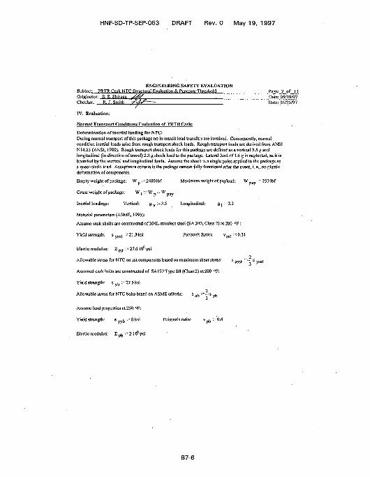
HNF-SD-TP-SEP-063 DRAFT Rev. 0 May 19, 1997
ENGINEERING SAFETY EVALUATIONSubject: PRTR Cask NTC Structural Evaluation & Puncture Threshold Page:_2_Originator: S. S. Shirapa V ^ f : Date: 05;Checker: R. J. Smith -fXi^- • Date: 05/
/IV. Evaluation:
Normal Transport Conditions Evaluation of PRTR Cask:
Determination of inertia! loading for NTC:During normal transport of this package no in-transit load transfers are involved. Consequently, normalcondition inertia! loads arise from rough transport shock loads. Rough transport loads are derived from ANSIN 14.23 (ANSI, 1980). Rough transport shock loads for this package are defined as a vertical 3.5 g andlongitudinal (in direction of travel) 2.3 g shock ioad to the package. Lateral load of 1.6 g is neglected, as it isbounded by the vertical and longitudinal loads. Assume the shock is a single pulse applied to the package asa quasi-static toad. Acceptance criteria is the package remain fiilly functional after the event, i. c., no plasticdeformation of components.
Empty weight of package: W p :-• 24001bf Maximum weight of payload: \V p a v ;~ 25(Hbf
Gross weight of package: W t :~ W -i- W p a v
Inertia! loadings: Vertical: g v :~3.5 Longitudinal: g | :"2.3
Material parameters (ASME, 1995):
Assume cask shells are constructed of 3041. stainless steel (SA 240, Class 2) at 200 °F:
Poisson's Ratio: v g s t :~0.31
Elastic modulus: E s s t :-27.6I06-psi
Allowable stress for NTC on sst components based on maximum shear stress: s a s s t :•= —s v s s (
Assumed cask bolts are constructed of SA193TypeB8(Class2)at200 °F:
Yield strength: s y b :-27.5ksi
" "" s a b : ; ; ~ s y b
Assume lead properties at 250 °F:
Yield strength: s ypb : ~ Sksi Poisson's ratio: v b :-0.4
Elastic modulus: E p
Allowable stress for NTC bolts based on ASME criteria:
B7-6
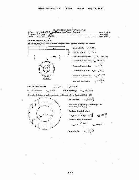
HNF-SD-TP-SEP-063 DRAFT Rev. 0 May 19, 1997
ENGINEERING SAFETY EVALUATIONSubject: PRTR Cask NTC Structural Evaluation & Puncture Threshold Page: 3,. of. .1.1.Originator: S. S. Shirapa j f ^ ^ ' Date: 05/19/97Checker: R. J. Smith '7X/<g~~. Pate: 05/25/97
Geometric parameters of package:
Idealize the package as a composite beam with of concentric cylinders of stainless steel and lead.
' c ' Lcngthofcask: l c ~39.625in
Diameter of cask: d c :- 14in
Length between supports: 1 s : ; 1 c 2(2.5in)
Outer shell wall thickness: t o s : - 0.250 in
d cOutcrshcll outside radius: r ^ :•• — •
Outer shell inside radius: r_; :"r n r t tn-
2
.. 3.12Sin
Inner shell outside radius:
Inner shell inside radius:2
Inner shell wall thickness: t ; s ~ r j 0 - r ;j t ; s = O.I2*in
End plate thickness: t c p • = 0.5-in End plate weld leg: w | e g : " O.I 875in
Determine deflection of lead, assuming the lend is unbonded to the stainless steel walls:
Density of lead: p p b : - 7 I 0 - -
Idealize as ring supporting it's own weiglit. UseRoark, 19(55, case 18, page 176.
Weight per linear inch of lead:
w p b •"Ppb' | i7 t \ roi ' r io /
Moment of inertia of the section:
\ 4roi " r io
.'pb-«—~iroiH
B7-7
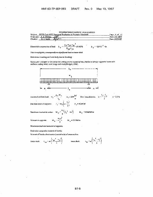
HNF-SD-TP-SEP-063 DRAFT Rev. 0 May 19, 1997
ENGINEERING SAFETY EVALUATIONSubject: PRTR Cask NTC Stnicftiral Evaluation & Puncture ThresholdOriginatoTT S. S. Shiraga ^66/Checker: R. J. Smith Alj/-—
Page: 4 of HDate: 05/19/97Date: 05/25/97
f lead: A --—-—P---E-.(0.4674) A =-8.8-10 6 -inDiametrial compression oE p b ' p b
This is negligible, consequently no significant load on inner shell.
Determine leading on Cask Body due to Bending;
Since cask is shipped in the horizontal, setting on two support plates, idealize as simply supported beam withuniform loading which over hangs each end (Biodgett, 1966).
uiuuuuuumimmuiuuiumui
Assumed uniform loac
Reaction loads at supports: F r '
= 234*- - Over hang distance: x: ; ~ -
F r = 4638'lbf
W |Maximum moment at center: M _ :;-~— I . - 4-x M . =34346*lbfin
c c. \ s ; c
Maxitiium load and moment at supports.
Determine composite moment of inertia:
Moment of inertia about center (neutral axis) of cross section:
Outer shell: ]«:=••«- - - " ~ Inner shell: I •„
B7-8
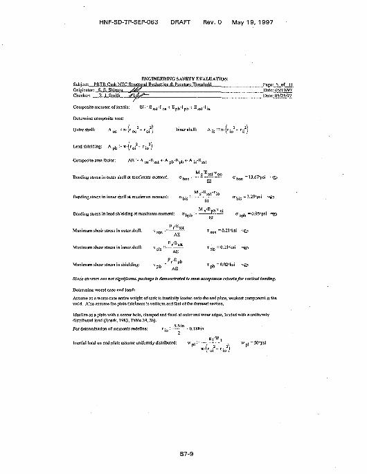
HNF-SD-TP-SEP-063 DRAFT Rev. 0 May 19, 1997
ENGINEERING SAFETY EVALUATIONSubject: PRTR Cask NTC Structural Evaluation &. Puncture ThresholdOriginator: ...S..S...Shirae;a J ^ !Checker: J".R.,',J".Smith jQ&SL~
Composite moment of inertia: ^ ' : "^ss t " ' o s "*' pb ' 'pb ' 1 ^ssf ' is
Determine composite area:
Outer shell: A nc • • n - f r * - rn !2) Innershell: A ic :=«-(r:
Page:,..5_.of_1.1.Date: 05/19/97Date:.05/25/97
Lead shielding: A p b :- n-(roj - r
Composite area factor: AE : = A
A
-t- A pD-EpD -t- A jg-E
Bending stress in outer shell at maximum moment:
Bending stress in inner shell at maximum moment:
Bending stress in lead shielding at maximum momer
Maximum shear stress in outer shell: T s o s : : : -
Maximum shear stress in inner shell:
Maximum shear stress in shielding:
AE
M
EI
131
EI
' s o
•rooa
^ ,
s =0.211s:
, =0.2l*ksi
bos "
bis =
'bpb
i " €
= l3.67-psi
3.29-psi
-0.95-psi
5
^ =0.02"ksiT ^ •"
Since stresses are not significant, package is demonstrated to meet acceptance criteria for vertical loading.
Determine worst case end load:
Assume as a worst case entire weight of cask is inertially loaded onto the end plate, weakest component is theweld. Also assume the plate thickness is uniform and that of the thinnest section.
Idealize as a plate with a center hole, clamped and fixed at outer and inner edges, loaded with a uniformlydistributed load (Roark, 1983, Table 24,2h).
For determination of moments redefine: r:- :~-••'-- • - 0.188 in
Inertial load on end plate assume uniformly distributed: wgrwt _
(r 2-r AVoi rio y
w , =50-psi
B7-9
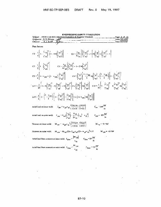
HNF-SD-TP-SEP-063 DRAFT Rev. 0 May 19, 1997
ENGINEERING SAFETY EVALUATIONSubject: PKTR Cask NTC Structural Evaluation & Puncture Threshold Page: 6 of 11Originator: ...S._S.., .Shiraga.. s%%f Date: 05/19/97Checker: R.J. Smith ,.AJt±zz Date: 05/25/97
, • , ' . . . • > ' , .
\'u
-'/, N"
...vsstM,-vsst) - O 5 p
N< roi/
' o i \ • / ' - *
'r./'T 4
._ I1.14-16
rio'2
roi.
AKiaHoadoninnerweld: 01 \ C2C6 C3C5 i
Axial load on outer weld:l: row riw- : " r ," \'oi rio J fc\ r0i; ^ r0i
Momemoninner^o:P' ° ' I C2C6 C3-C5 /
. . , "•• M i w C 8 .- f i w r o i -C9 - » p l r o i2 - U 7
Axial load from moment on inner weld: fu-.^.'" -—• ^hiw~37*
Moment on outer weld:
ow
M i w
•89'
= 9
M „
Ibfin
4-lbf
... - 63•Ibf
Axial load from moment on outer weld: f i i r ow
B7-10
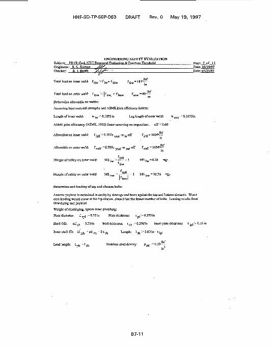
HNF-SD-TP-SEP-063 DRAFT Rev. 0 May 19, 1997
ENGINEERING SAFETY EVALUATIONSubject: PRTR Cask NTC Structural Bvaluation & Puncture Threshold . Page: 7 of 11Originator: S. S. Shiraca x 4 ^ ? Date: OS/19/97Checker: R. J. Smith /</ ,f^ Date: 05/25/97
Total load on inner weld: f f :w - f ;w^fhiw ft;u,= 181*~tiw"Ibf
Total load on outer weld: f tow ' f o w | l f b o w, Ibf
Determine allowable on welds:
Assuming base material strengths and ASME joint efficiency factors:
Length of inner weld: w -m : r 0.1875in Leg length of outer weld: w o u t :~0.1875in
ASME joint efficiency (ASME, 1992) factor assuming no inspection:, eff: - 0.60
Allowable on inner weld: f iall : ""° - 7 & 7 s ysst 'w in ' e f r fiall = HS94--
Allowable on outer weld: foa!!:~ 0.707s ysst-wol]t-eff foall~ 1694*T"
fj,,.Margin ofsafety on inner weld: MSiw:=—" - 1 MSiw-8.38 i£>
f[jw
fo_|,Margin of safety on outer weld: M S 0 1 1 / ~ - — j ~ ' MSOW=20.26 «^i
Determine end loading of top end closure bolts:
Assume payload is restrained in cavity by dunnage and bears against the top and bottom closures. Worstcase loading would occur at the top closure, since it has the fewest number of bolts. Loading results fromshield plug and payload.
Weight of shield plug, ignore inner plumbing:
Plate diameter, d s p ! --8.75-in Plate thickness: t p ) :70.37Si»
Shell OD: od s h 5.25in Wall thickness: t g h :"0.25Oin Inner plate thickness: t i p | :~0.25in
Inner shell ID: id i s h ' o d s h - 2-tsh Length: l s h ^S.OOin- t i p ]
Lead length: 1 p b := 1 s h Stainless steel density: p s s t :-0.29
B7-11
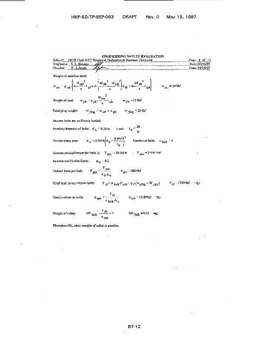
HNF-SD-TP-SEP-063 DRAFT Rev. 0 May 19, 1997
ENGINEERING SAFETY EVALUATIONSubject: PRTR Cask NTC Structural Evaluation & Puncture ThresholdOriginator: S. S. Shiraga ^0^^ ,Checker: R. J. Smith
Weight of stainless steel:
—t „ , H- asst ' | J
id nh<Weightoflead: W p b ' P p b — " r - ' p b w p b ' 1 H b f
Total plug weight: > l u g : " s s t 1 » pb "plug = 2 s - l b f
Assume bolts are uniformly loaded:
20Nominal diameter of bolts: d b
: "0 .25in Lead: ' b ; ".
0 9743\2
Tensile stress area: A s - 0 . 7 8 5 4 d b - ~ ' ~ Number of bolts: n b o I t : 4
b /
Assume preload torque for bolts is: T p r c :- 30-lbf-in T p r e =2.5*ft*lbf
Assume nut friction factor: \i n r 0.2
Preload force per bolt: F p r e : ~ — " [ - r p r e = 6 0 0 " l b f
Total load on top closure bolts: F d •' n b o l , - F p r e r g | ( w p , n g + W p a y ) F d - 1769-lbf
Tensile stress on bolts: °ten " ^ — a t e n = 13.89'ksi =S3n bolfA s
Margin of safety: MS j ^ , : - — * • - I MS Mt -0.32 - ®"ten
Therefore OK, since margin of safety is positive.
B7-12
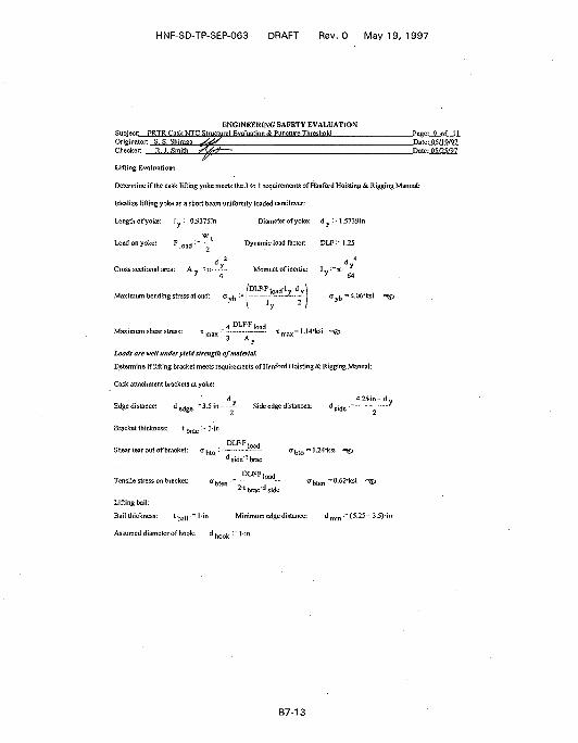
HNF-SD-TP-SEP-063 DRAFT Rev. 0 May 19, 1997
ENGINEERING SAFETY EVALUATIONSubject: PRTR Cask NTCgtructiiral Evaluation & Puncture Threshold Page:..9_.of I.I.Originator:. S. S. Sh.i'raga"" jfi/ZS I."....'"".!."""". Pate: 05/19/97.Checker: R. J. Smith ?^4^—' Pate: 05/25/97
Lifting Evaluation:
Determine if the cask lifting yoke meets the 3 to 1 requirements of Hanford Hoisting & Rigging Manual:
Idealize lifting yoke as a short beam uniformly loaded cantilever:
Length of yoke: l y -~0.9375in Diameter of yoke: d y :~l.5739in
\V (Load on yoke: F |o a c J : = ~ - Dynamic load factor: DLF: " 1.25
. 2 . 4V V
Cross sectional area: A v : - i r - - - - Moment of inertia: I v 'r-n-- *•y 4 y 64
/DLF-F,o a d-Iy d yMaximum bending stress at end: a ^ := x..-.J.
\ 'y
Maximum shear stress: xmax'" ~" Tmax='-'''"'(S' " ^3 Ay
Loads are welt under yield strength of material.
Determine if lifting bracket meets requirements of Hanford Hoisting & Rigging Manual:
Cask attachment brackets at yoke:
d v . 4.25in~dEdgedistance: d
e d g e " 3 S m - " Side edge distances: d s i c J e : -•-
Bracket thickness: *brac " ' 'n
DLFF • d
Shear tear out of bracket: o ^ t 0 :: : O(j t 0 ~ 1.24'ksi *=§p
d side' l brae
DLFF|«,HTensile stress on bracket: "bten :""
2 t brae d s i<lc
Lifting bail:
Bail thickness: t ^ j p - l - i n Minimum edge distance: d min:""(5.25-3.5)-in
Assumed diameter of hook: d ^ :- J-in
B7-13
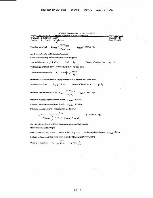
HNF-SD-TP-SEP-063 DRAFT Rev. 0 May 19, 1997
ENGINEERING SAFETY EVALUATIONSubject: PRTR Cask NTC Structural Evaluation & Puncture Threshold Page: 10 of IIOriginator: S. S. Shiraaa ^kf Date: 05/19/97Checker: R°'LSm'ith /^./s* Date: 05/25/97
D L P F l o a d
Shear tear out of bail: ^bailto "r °bailto ~".47*ksi * ^2 ' d min t ba i l
Loads are well under yield strength of material
Check of bofts holding bail and cask yoke brackets together.
Nominal diameter: d ^ :"0.625in Lead: 1^ '•"•- • Number of bolts per leg: n ^ :"3
Yield strength of PH-18-8 bolt ( assumed same as 304 stainless steel):
Tensile stress area of screw: A s : • 0.7854 b
' b' b
Determine If Sufficient Thread Engagement Is Available (Industrial Press, 1992):
Available thread depth: ^ avail' 1-5-in Number of threads per in: n
DLFF, o a d
Minimum tensile strength of bolt: s bolt ^ s bol t = ^* ' < s ' "^
nVAs
Maximum minor diameter of internal thread: K n m a x: " 0.546in
Minimum pitch diameter of external thread: Es m j n : O.S561in
Minimum engagement length since materials are the same:
2-A s
n m K | ^ t ( E ! m i n - Knma>[)j
Since Lavail>Le, there is sufficient thread engagement and bolt strength.
NTC Penetration of Package:
Mass of projectile: m_ =6-kg Height of drop: h ^ :- 1-m Hemispherical end diameter: d i i e n i j ' -3.2-cm
Evaluate package penetration by empirical methods (Uhinehart and Pearson, 1954):
Velocity of projectile: v 0 : = 2-g-h d r v 0 = 14.5---
B7-14
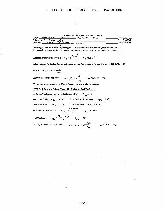
HNF-SD-TP-SEP-063 DRAFT Rev. 0 May 19, 1997
ENGINEERING SAFETY EVALUATIONSubject: PRTR Cask NTC Structural Evaluation & Puncture Threshold Page: II of IIOriginator: S. S. Shiraea . ^ f Date: 05/11111Checker: R.) . Smith ~^M Date: 05<25/97
/Assuming the test rod is a hard unyielding object, at this velocity (< 10,000 ft/sec), the force that acts onthe projectile is proportional to the cross sectional area and is essentially constant during penetration.
4 •'
Volume of material displaced per unit of energy constant (Rhinehart and Pearson, 1954, page 202, Table 12-1):
1 •> K sDepth ofpenetration into steel: s s p :- '—mp-v0 s s p =O.00Hn =@p
2 A p
The penetration depth is not significant, therefore no penetration of package.
PRTR Cask Puncture Failure Thresholds, J^ujvalM-StecLTliicKness:
Equivalent Thickness of lead to steel (Rinehart, 1954): f "-• 2.3
ID of Outer Shell: id o 3 " 13,5-in Outer Shell Wall Thickness: t o w 3 :- 0.25in
OD of Inner Shell: od i 3 :--3.375in ID of Inner Shell: id i 3 : - 3.125in
od ••>- id J3Inner Shell Wall Thickness: l iw3 :" l iw3 = 0 ] 25* in
id o 3 - od i 3Lead Thickness: t p b 3 -~ t b 3 =5.06*in
Total Equivalent thickness of steel: t ^ :" * Ow3"'' * itv3"*—^ "Ow3"'' * itv3"*—^ "" leq3 =
B7-15

HNF-SD-TP-SEP-063, Rev. 0
This page intentionally left blank.
B7-16
HNF-SD-TP-SEP-063, Rev. 0
8.0 THERMAL EVALUATION
8.1 INTRODUCTION
The PRTR Graphite Cask is an onsite, intra-area packaging for transporting Type B radioactivematerial within the 300 Area of the Hanford Site. This section of the document defines and evaluatesthe NTC structural requirements for intra-area transport of this package. Thermal performance of thepackage is evaluated only for NTC; accident conditions are evaluated in the risk and dose consequencesection of this document.
8.2 THERMAL EVALUATION OF PACKAGE
8.2.1 Package Description
The PRTR Graphite Cask is fundamentally a right circular cylinder of lead and stainless steelcomposite construction. The lead is sandwiched between outer and inner stainless steel tubular shells.At each end of the cask is a thick circular plate that is welded to both inner and outer shells, whichencapsulates the lead. At the top, closure of the inner cavity is provided by a bolted blind flange withan attached shield plug of.composite lead-stainless steel construction. The cask is equipped with amanually actuated, sliding trap door, which provides closure at the bottom end. None of the endclosures are sealed. A handling yoke is provided on the cask and welded to the outer shell. Inaddition, support plates are welded to the outer housing of the cask to provide support during transportand lifting attachment anchors for handling.
The cask is constructed of welded 304L stainless steel. Shielding is provided by lead, which ispoured after fabrication of the stainless steel body and internal components.
8.3 NORMAL TRANSPORT CONDITIONS THERMAL EVALUATION
8.3.1 Conditions To Be Evaluated
Thermal performance of the package is assessed for Hanfbrd Site NTC in this section. Thepackage is evaluated for the worst-case Hanford Site thermal loading condition of a still-air ambienttemperature of 4-6 °C (115 °F [Fadeff 19921) with decay heat sources with and without solarinsolation. Because of the variability of the payloads, the heat sources are assumed to be tightlypacked in the cask cavity and against the inside wall of the cask.
8.3.2 Acceptance Criteria
The criterion for acceptable performance of the package is the accessible surface of thepackage in still air at 46 °C (115 °F) and in the shade is not to exceed 82 °C (182 °F). This is basedon this package being transported as an exclusive-use shipment.
8.3.3 Thermal Evaluation and Conclusions
For this evaluation the worst-case decay heat source is assumed to generate a total heat loadof 5.65 W. Based on the variable geometries of the payloads, the configuration of the heat source isassumed to be uniformly distributed over the length of the cask cavity and fitted tightly up against theinside wall of the cavity. This provides a conservative estimate of the cask temperature, but it does
B8-1
HNF-SD-TP-SEP-063, Rev. 0
not provide a conservative estimate of the temperature load to the payload. This evaluation boundstemperatures for the cask, but does not provide any estimation of payload temperatures. Temperature-sensitive payloads must be evaluated on a case-by-case basis to determine the temperature parameterswithin the cask.
Results of this evaluation show the cask component temperatures under solar insolation arebelow 99 °C (211 °F) for the structural evaluation. The results also show the cask meets the NTCexterior surface temperature requirement of 82 °C (182 °F) in the shade for exclusive-use shipments.Table B2-2 shows a heat loading of 2.92 W resulting from a reduced payload. Because the heatloading is less than the previously analyzed heat loading, the thermal evaluation conclusion remains thesame.
8.4 REFERENCE
Fadeff, J. G., 1992, Environmental Conditions for On-site Hazardous Materials Packages,WHC-SD-TP-RPT-004, Rev. 0, Westinghouse Hanford Company, Richland, Washington.
B8-2
HNF-SD-TP-SEP-063, Rev. 0
8.5 APPENDIX: PRTR GRAPHITE CASK NTC THERMAL EVALUATION
ENGINEERING SAFETY EVALUATIONSubject: PRTR Cask Normal Ttansgortgonditions Thermal Evaluation Page:_l_ofVSOriginator: S. S. Shiraga . ^ 9 % . ? 1 = ^ S - . . Date: 05/20/97Checker: S. R. Crow. *f\, /£ (U**) Date: 05/25/97
I. Objective:
The objective of this evaluation is determine the cask component temperatures under solar insolation for thestructural evaluation and the exterior temperature in the shade as specified in Section 8 of this Safety Evaluationfor Packaging (SEP).
II. References:
Irwin, J. J., 1995, WHC-SD-TP-RPT-005, Rev. 1, Thermal Analysis Methods for Safety Analysis Reports forPackaging, Westinghouse Hanford Company, Richland, Wash.
ORNL, 1970, Cask Designer's Guide, ORNL-NISC-68, Oak Ridge National Laboratory, Oak Ridge,Tennessee.
Mathcad Plus 5,1994, User's Guide, Math Soft Inc., Cambridge, Massachusetts.
WHC, 1980, Drawing No. H-3-13699, Rev. 7, PRTR Graphite Sample Cask Assy., Westinghouse HanfordCompany, Richland, Washington.
III. Results and Conclusions:
The results also show the cask meets the normal transport conditions (NTC) exterior temperature requirement of182 °F in the shade for exclusive use shipments. Because of the variability of the payloads, the heat sources areassumed to be tightly packed in the cask cavity and against the inside wall of the cask. This provides aconservative estimate of the peak temperatures subjected to the cask, but it does not provide a conservativeestimate of the payload temperatures. Temperature sensitive payloads must be.evaluated on a case by case basisto verify payload stability and integrity.
B8-3
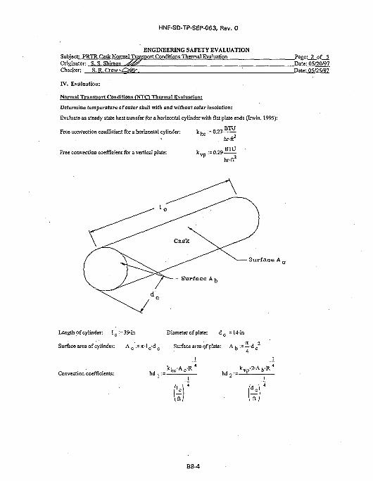
HNF-SD-TP-SEP-063, Rev. 0
ENGINEERING SAFETY EVALUATIONSubiect: PRTR Cask Normal Transport Conditions Thermal EvaluationOriginator: S. S. ShiragaChecker: S. R.
Page: 2 of 5
IV. Evaluation:
Normal Transport Conditions (NTO Thermal Evaluation:
Determine temperature of outer shell with and without solar insolation:
Evaluate as steady state heat transfer for a horizontal cylinder with flat plate ends (Irwin, 1995):
BTU
hr-ft2
. . « ^ B T U
Free convection coefficient for a horizontal cylinder:
Free convection coefficient for a vertical plate:hr-ft2
S u r f a c e A ,
Length of cylinder: I_:=39-in Diameter of plate: d c := 14-in
Surface area of cylinder: Ac :=rc-lc-dc Surface area of plate: A ^ : = — d c
Convection coefficients: h d . hd, :=_k v p -2-A b -R 4
B8-4
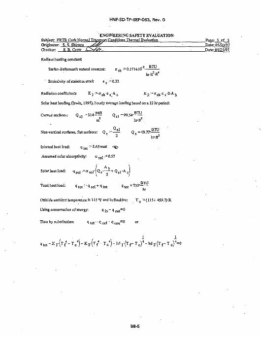
HNF-SD-TP-SEP-063, Rev. 0
ENGINEERING SAFETY EVALUATIONSubject: PRTR Cask Normal Transport Conditions Thermal Evaluation Page: 3 of 5Originator: S. S. Shiraga ^*6£S • p a t e ; 05/20/97Checker: S.R.Crow £ V ^ . Date: 05/25/97
Radient heating constant:
Stefan-Boltzman's natural constant:hr-ft2-R4
Emissivity of stainless steel: es:=0.32
Radiation coefficients Kj :~^sb'S S-A c K2:-Gsh-ss-2-/
Solar heat loading (Irwin, 1995), hourly average loading based on a 12 hr period:
Curved surfaces: Q s l : = 3 1 4 — Q s l = 9 9 . 5 4 ' ^ ^m2 hr-ft2
Non-vertical surfaces, flat surfaces: Q s := Q s =49.77*
2 hr-ft2
Internal heat load: q !n t :=5.65watt •=&
Assumed solar absorptivity: a s o j -=0.57
Solar heat load: q so l : = a s o i - [ Q s - — + Q s i - A c
BTT JTotal heat load: q t o t :=q s o l + q i n t q t o t = 7 1 0 - - —
nr
Outside ambient temperature is 115 °F and in Rankine: T 0 •= (115+ 459.7)-R
Using conservation of energy: q ;n - q o u t = 0
B8-5
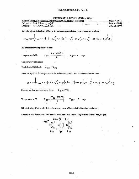
HNF-SD-TP-SEP-063, Rev. 0
ENGINEERING SAFETY EVALUATIONSubject: PRTR Cask Normal Transport Conditions Thermal Evaluation ; Page: 4 of 5Originator: S. S. ShiragaChecker: S. R. Crow
Solve for Tfwhich the temperature at the surface using MathCad roots of equation solution:
Tfl:=root[qtot-Kr(Tf4-To
4)-K2.(Tf'1-To
4)-hd1-(TrTo)4-hd2.(Tf-To)4>TfJ
Date: 05/20/97Date: 05/25/97
External surface temperature in sun:
Tf,-459.7RJTemperature in °F: T ff:=
Temperature ia Shade:
Total shaded heat load: 1 s t o t ' ^ int
Solve for Tf which the temperature at the surface using MathCad roots of equation solution:
External surface temperature in shate: T ^ = 577*R
T C -459 .7RTemperature in °F: T ff2:=
R
With this simplified model determine temperature of inner shell with solar insolation:
Assume as one-dimensional heat transfer and internal heat source is against inside shell wall, no gap.
In — In — In —r 2
r lIn
r 2 r 3
B8-6
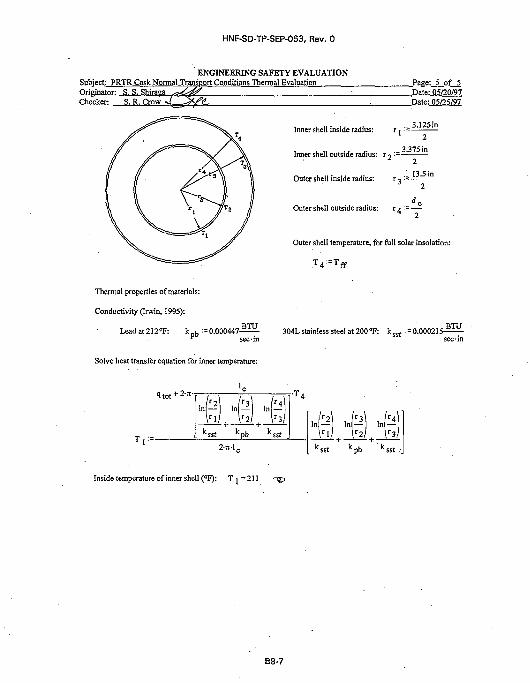
HNF-SD-TP-SEP-063, Rev. 0
ENGINEERING SAFETY EVALUATIONSubject: PRTR Cask Normal Transport Conditions Thermal Evaluation Page: 5 of 5Originator: S. S. Shiraga s?j£^ Date: 05/20/97
. Date: 05/25/97Checker: S. R. Crow
Inner shell inside radius: r j := 3A25m
Inner shell outside radius: r *> '-=._ 3,375in
. . 13.5inOuter shell inside radius: r 3 '=
Outer shell outside radius: r / := —
Outer shell temperature, for full solar insolation:
Thermal properties of materials:
Conductivity (Irwin, 1995):
Leadat212»F: . k D b :=0.000447-^±f- 304L stainless steel at 200 »F: k s s t :=0.000215-5if-
Solve heat transfer equation for inner temperature:
1 t o t + 2"' t-
- I n - In
Inside temperature of inner shell (°F): T j = 2 1 1
B8-7

HNF-SD-TP-SEP-063, Rev. 0
This page intentionally left blank.
B8-8

HNF-SD-TP-SEP-063, Rev. 0
9.0 PRESSURE AND GAS GENERATION EVALUATION
Only dry contents are authorized for the PRTR Graphite Cask. Therefore, there are no pressureor gas generation concerns.
B9-1

HNF-SD-TP-SEP-063, Rev. 0
This page left intentionally blank.
B9-2
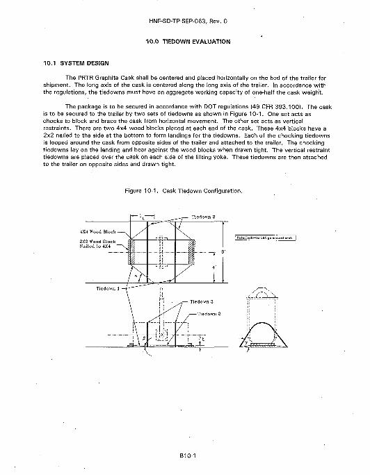
HNF-SD-TP-SEP-063, Rev. 0
10.0 TIEDOWN EVALUATION
10.1 SYSTEM DESIGN
The PRTR Graphite Cask shall be centered and placed horizontally on the bed of the trailer forshipment. The long axis of the cask is centered along the long axis of the trailer. In accordance withthe regulations, the tiedowns must have an aggregate working capacity of one-haif the cask weight.
The package is to be secured in accordance with DOT regulations (49 CFR 393.100}. The caskis to be secured to the trailer by two sets of tiedowns as shown in Figure 10-1. One set acts aschocks to block and brace the cask from horizontal movement. The other set acts as verticalrestraints. There are two 4x4 wood blocks placed at each end of the cask. These 4x4 blocks have a2x2 nailed to the side at the bottom to form landings for the tiedowns. Each of the chocking tiedownsis looped around the cask from opposite sides of the trailer and attached to the trailer. The chockingtiedowns lay on the landing and bear against the wood blocks when drawn tight. The vertical restrainttiedowns are placed over the cask on each side of the lifting yoke. These tiedowns are then attachedto the trailer on opposite sides and drawn tight.
Figure 10-1. Cask Tiedown Configuration.
4X4 Wood Block -
SXS Wood BlockNailed lo 4X4
B10-1
HNF-SD-TP-SEP-063, Rev. 0
10.2 ATTACHMENTS, RATINGS, AND REQUIREMENTS
Each tiedown and trailer attachment point must have a minimum working strength of11,120 N (2,500 Ib). The 2x2 wood blocks must be nailed to the 4x4 wood blocks with a minimum ofthree 10 d nails. The length of the blocks is specified as the same as the diameter of the cask towithin a tolerance of 0.32 cm (Vs in.).
10.3 REFERENCE
49 CFR 393.100, 1997, "Parts and Accessories Necessary for Safe Operation," Code of FederalRegulations, as amended.
B10-2
HNF-SD-TP-SEP-063, Rev. 0
10.4 APPENDIX: ENGINEERING SAFETY EVALUATION
ENGINEERING SAFETY EVALUATION
Subject: 327 PRTR Cask Tiedown Evaluation Page 1 of 3Preparer: S. S. Shiraaa \4J.rff— //st/ _ _ Date 07/21/97Checker: P. C. Ferrell Porf- C. <C^ny^/' Date #fr~/f 7Section Chief: S. S. Shiraaa s&fr&~>SsSZ—_ Date_
1.0 OBJECTIVE
The objective of this evaluation is to determine the capacity and configuration of the tiedownsystem for the 327 PRTR Cask. The tiedowns are specified to the requirements of 49 CFR393.100.
2.0 REFERENCES
49 CFR 393.100, 1995, "Protection Against Falling Cargo," Subpart I, Code of Federal Regulations, asamended.
3.0 ASSUMPTIONS, RESULTS, AND CONCLUSIONS
As defined in this document, shipment of the 327 PRTR cask within the 300 Area isauthorized under a risk based assessment. Consequently, the tiedown system must be anengineered system to ensure that the package remains on the conveyance during all normalnon-accident conditions. Since the shipment is only within the 300 Area, the system isspecified based on the requirements of 49 CFR 393.100.
As shown in the evaluation, the cask is assumed to be centered on a standard flat bed trailerand the lifting yoke placed in the vertical position. The system consists of two 4X4 woodblocks with 2X2 wood blocks nailed to them, forming an "L" shape. These "L" shaped blocksspan the width of the cask and are placed at each end. Two cables or chains are loopedaround the cask and blocks from each side and drawn tight. The cables or chains rest on thelanding formed by the "L" shape of the blocks. This forms the blocking and bracing to restrainlongitudinal and lateral loads. Placed over the cask on each side of the lifting yoke are twotiedown straps, cables, or chains to provide vertical restraint. The minimum specified workingstrength of the tiedowns is 2,500 Ib. The wood blocks are to be constructed from standardcommercial grade lumber. The 2X2 blocks are to be nailed to the 4X4 blocks With a minimumof three 10 d nails.
WMNW-PE-001/2
B10-3
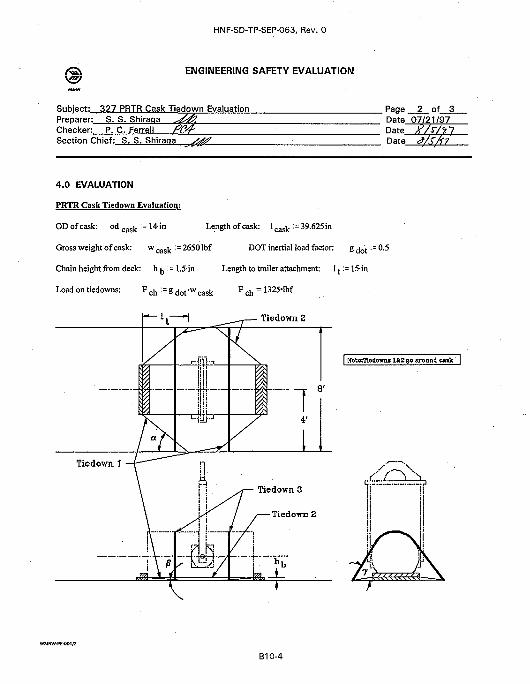
HNF-SD-TP-SEP-063, Rev. 0
ENGINEERING SAFETY EVALUATION
Subject; 327 PRTR Cask Tiedown EvaluationPreparer: S. S. ShiraqaChecker: P. C. FerrellSection Chief: S. S. Shiraqa
. Page 2 of 3Date 07/21/97Date y//Date <?/x/(7
4.0 EVALUATION
PRTR Cask Tiedown Evaluation:
OD of cask: od c a s k := 14-in Length of cask: 1 c a s k :=39.625in
Gross weight of cask: w c a s k :=26501bf DOT inertial load factor: g ( j o t : = 0.5
Chain height from deck: h ^ ^ l . ^ i n Length to trailer attachment: 1 := 15-in
Loadontiedowns: F ch : = Sdofwcask Fch = 1 3 2 5 # I b f
Tiedown. 1
• 1 . Tiedown £
-iHi--iili
JL 1L
Tiedown 3
TiedoTm 2
BiTfodOTms lfcg go aronnd cask |
WMMW-PE-001/2
B10-4
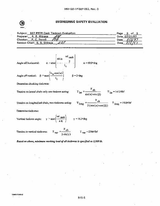
HNF-SD-TP-SEP-063, Rev. 0
ENGINEERING SAFETY EVALUATION
Subject: 327 PRTR Cask Tiedown EvaluationPreparer:Checker:
S.P.
Section Chief:
S.C.
S
Shiraaa x ^ "Ferrell fP/f-. S. Shiraqa ^ ^
Page 3 of 3Date 07/21/97DateDate
Angle offhorizontal: a := atan
od48-in--
cask
ce=69.9-deg
Angle off vertical: P : = atan •/h b-cos(a)
I ' tP=2Meg
Determine chocking tiedowns:
Tension on lateral chain only one tiedown acting: T | a t := —r c h
sin(a)-cos(P)
Tension on longitudinal chain, two tiedowns acting: T | o ng : =r c h
2(cos(a)-cos(P))
Determine tiedowns:
Vertical tiedown angle: y :=atan
Tension in vertical tiedowns: T
od cask4-ft
y = 16.3'deg
• c h
2-sin(y)
Based on above, minimum working load of all tiedowns is specified as 2,500 Ib.
t = 1412-lbf
WMNW-PE-001/2
B10-5
DISTRIBUTION SHEETTo
Distr ibut ion
From
Packaging Engineering
Project Title/Work Order
Safety Evaluation for Packaging (Onsite) Plutonium Recycle TestReactor Graphite Cask (HNF-SD-TP-SEP-063, Rev. 0) .
Name MSINText
With AllAttach.
Page 1 of 1
Date Sept. 24, 1997
EDT No. 621885
ECN No. N/A
Text Only Attach./Appendix
Only
EDT/ECNOnly
R. L.. ClawsonJ. G. FieldC. R. HooverS. B. Johnston
HNF-SD-TP-SEP-063 Fi leP97-046 (D. Kelly)
Central Files
Hl-14 XHl-15 XHl-15 XLl-03 X
Hl-15 XHl-15A3-88 X
A-6000-135 (01/93) WEF067