1400mm j-3 v4
TRANSCRIPT
1400mm J-3 V4
FLOATOptional float
RIGIDStrong durable EPO
STABLESmooth flying performance
Manuel d’utilisation
Instruction ManualBedienungsanleitung
操作手册

WARNING: Read the ENTIRE instruction manual to become familiar with the features of the product before operating. Failure to operate the product correctly can result in damage to the product,personal property and cause serious injury. This is a sophisticated hobby product and NOT a toy. It must be operated with caution and common sense and failure to do so could result in injury or damage to the product or other property. This product is not intended for use by children without direct adult supervision. This manual contains instructions for safety operation and maintenance. It is essential to read and follow all the instructions and warnings in the manual prior to assembly, setup or use, in order to operate and avoid damage or serious injury.
WARNING
As the user of this product, you are solely responsible for operating in a manner that does not endanger yourself and others or result in damage to the product or the property of others. This model is controlled by a radio signal subject to interference from many sources outside your control. This interference can cause momentary loss of control so it is advisable to always keep a safe distance in all directions around your model, as this margin will help avoid collisions or injury.Age Recommendation: Not for children under 14 years. This is not a toy.·Never operate your model with low transmitter batteries.·Always operate your model in an open area away from cars, traffic or people.·Avoid operating your model in the street where injury or damage can occur.·Never operate the model in populated areas for any reason.·Carefully follow the directions and warnings for this and any optional support equipment you use (chargers,rechargeable battery packs, etc.)·Keep all chemicals, small parts and anything electrical out of the reach of children.·Moisture causes damage to electronics. Avoid water exposure to all equipment not specifically designed and protected for this purpose.·Never lick or any place of any your model in your mouth as it could cause serious injury or even death.
Lithium Polymer (Li-Po) Battery WarningCAUTION: Always follow the manufacturer’s instructions for safe use and disposal of batteries. Fire, propertydamage, or serious injury can result from the mishandling of Li-Po batteries.
By handling, charging or using a Li-Po Battery you assume all risks associated with lithium batteries.If at any time the batteries begin to swell or balloon, discontinue use immediately!Always store the batteries at room temperature in a dry area to extend the life of the battery. Always transportor temporarily store the battery in a temperature range of 40-120F. Do not store the battery or model in a car or in direct sunlight. If stored in a hot car, the battery can be damaged or even catch fire.Never use a Ni-Mh Charger to charge Li-Po Batteries. Failure to charge the battery with a Li-Po compatible chargermay cause fire resulting in personal injury and property damage.Never discharge Li-Po Cells below 3V.Never leave charging batteries unattended.Never charge damaged batteries.Charging the Flight Battery WarningUse a battery charger that is designed to safely charge the Li-Po Battery. Read the charger instructions carefully before use. When charging the battery, make certain the battery is on a heat resistant surface. It is also highlyrecommended to place the Li-Po Battery inside a fire resistant charging bag readily available at hobby shops oronline.
EN
p w
3
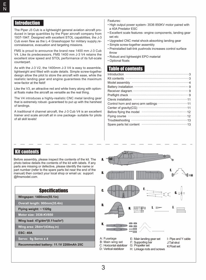
Before assembly, please inspect the contents of the kit. The photo below details the contents of the kit with labels. If any parts are missing or defective, please identify the name or part number (refer to the spare parts list near the end of the
manual) then contact your local shop or email us: support
Kit contents
A: FuselageB: Main wing set C: Horizontal stabilizer D: Vertical stabilizer
E: Main landing gear set I: Pipe and Y cableJ:Tail strutK:Float set
F: Supporting barG: Propeller setH: Linkage rods and screws
Introduction Kit contents Model assembly Battery installationReceiver diagramPreflight checkClevis installation Control horn and servo arm settings Center of gravity(CG) Before flying the model Flying courseTroubleshooting Spare parts list content
Table of contents·····························································
·····
3·························································3
·······················································4············································· ········ 9
··················································· 9
·······································
·····
·····
·····
9····················································11
··························
·················
11··············································· 11
··············································12···························································12
······················································13············································13
Introduction
Wingspan: 1400mm(55.1in)
Overall length: 900mm(35.4in)
Flying weight: ~ 1320g
Motor size: 3536-KV850
Wing load: 47g/dm²(0.11oz/in²)
Wing area: 28dm²(434sq.in)
ESC: 40A
Servo: 9g Servo x 4
Recommended battery: 11.1V 2200mAh 25C
Specifications
EN
@fmsmodel.com.
A.
B.
D.I. J.
K.
F.G.
H.
C.
E.
The Piper J3 Cub is a lightweight general aviation aircraft pro-duced in large quantities by the Piper aircraft company from 1937-1947. Designed with excellent STOL capabilities, the J-3 Cub even flew as the L-4 Grasshopper for military supply,re-connaissance, evacuation and targeting missions.
FMS is proud to announce the brand new 1400 mm J-3 Cub V4. Like its predecessors, FMS 1400 mm J-3 V4 retains the excellent slow speed and STOL performance of its full-scale counterpart.
As with the J-3 V2, the 1400mm J-3 V4 is easy to assemble, lightweight and filled with scale details. Simple screw-together design allow the pilot to store the aircraft with ease, while the realistic landing gear and engine guarantees the maximum wow-factor at the field!
Like the V3, an attractive red and white livery along with option-al floats make the aircraft as versatile as the real thing.
The V4 introduces a highly-realistic CNC metal landing gear that is extremely robust- guaranteed to put up with the harshest of landings.
A traditional 4 channel aircraft, the J-3 Cub V4 is an excellent trainer and scale aircraft all in one package- suitable for pilots of all skill levels!
Features:• High output power system- 3536 850KV motor paired with a 40A Predator ESC• Excellent scale features- engine components, landing gear set etc• Upgraded CNC metal shock-absorbing landing gear• Simple screw-together assembly• Preinstalled ball-link pushrods increases control surface throw• Robust and lightweight EPO material• Optional floats
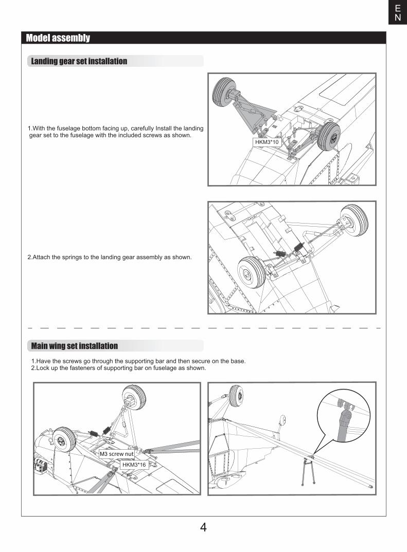
Landing gear set installation
Main wing set installation
4
Model assembly
1.With the fuselage bottom facing up, carefully Install the landing gear set to the fuselage with the included screws as shown.
2.Attach the springs to the landing gear assembly as shown.
1.Have the screws go through the supporting bar and then secure on the base.2.Lock up the fasteners of supporting bar on fuselage as shown.
EN
HKM3*10
HKM3*16
M3 screw nut
5
Model assembly
EN
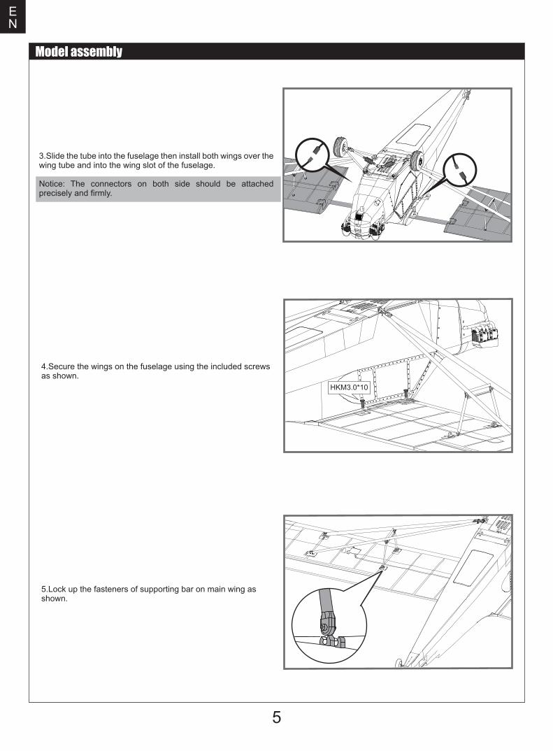
3.Slide the tube into the fuselage then install both wings over the wing tube and into the wing slot of the fuselage.
Notice: The connectors on both side should be attached precisely and firmly.
4.Secure the wings on the fuselage using the included screws as shown.
5.Lock up the fasteners of supporting bar on main wing as shown.
HKM3.0*10
KA2.0*8
6
EN
Model assembly
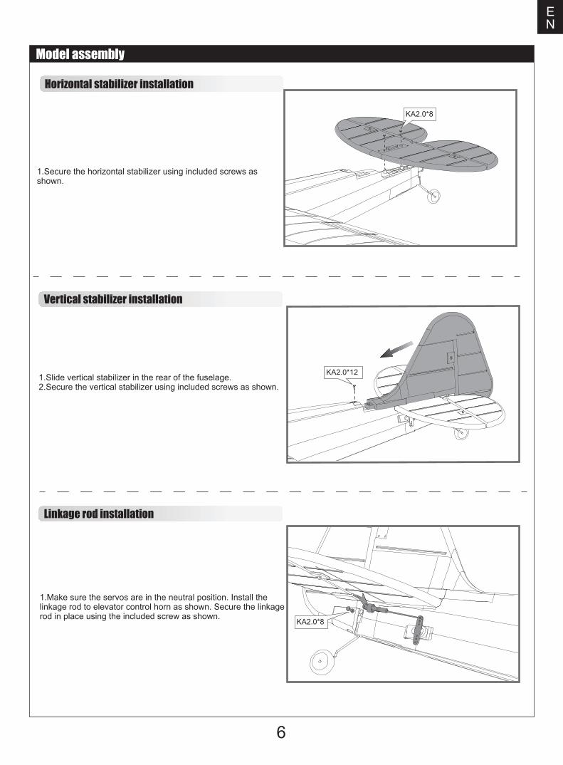
Horizontal stabilizer installation
1.Secure the horizontal stabilizer using included screws as shown.
1.Make sure the servos are in the neutral position. Install the linkage rod to elevator control horn as shown. Secure the linkage rod in place using the included screw as shown.
Linkage rod installation
1.Slide vertical stabilizer in the rear of the fuselage.2.Secure the vertical stabilizer using included screws as shown.
Vertical stabilizer installation
KA2.0*8
KA2.0*12
7
EN
Model assembly
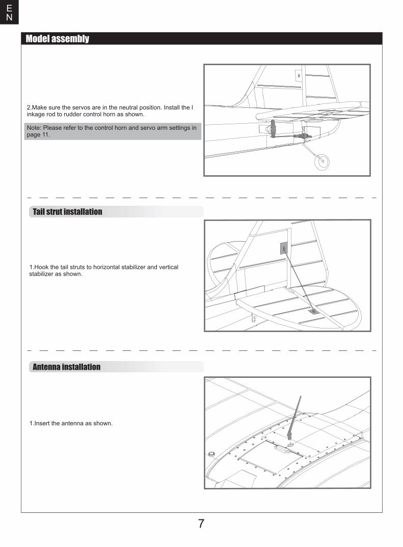
2.Make sure the servos are in the neutral position. Install the linkage rod to rudder control horn as shown.
Note: Please refer to the control horn and servo arm settings in page 11.
1.Hook the tail struts to horizontal stabilizer and vertical stabilizer as shown.
Tail strut installation
Antenna installation
1.Insert the antenna as shown.
8
EN
Model assembly
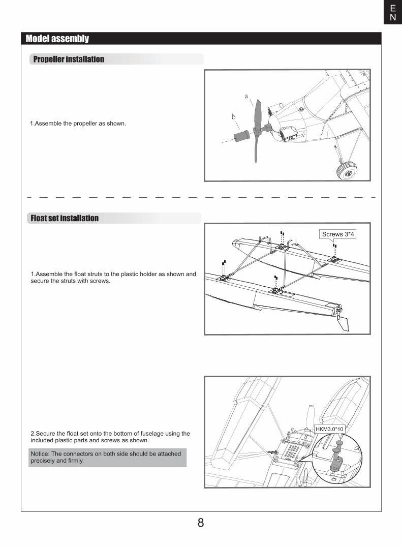
1.Assemble the float struts to the plastic holder as shown and secure the struts with screws.
Float set installation
Propeller installation
1.Assemble the propeller as shown.
2.Secure the float set onto the bottom of fuselage using the included plastic parts and screws as shown.
Notice: The connectors on both side should be attached precisely and firmly.
a
b
Screws 3*4
HKM3.0*10
Important ESC and model informationThe ESC included with the model has a safe start. If the motor battery is connected to the ESC and the throttle stick is not in the low throttle or off position, the motor will not start until the throttle stick is moved to the low throttle or off position. Once the throttle stick is moved to the low throttle or off position, the motor will emit a series of beeps. Several beeps with the same tune means the ESC has detected the cells of the battery. The count of the beeps equals the cells of the battery. The motor is now armed and will start when the throttle is moved.The motor and ESC come pre-connected and the motor rotation should be correct. If for any reason the motor is rotating in the wrong direction, simply reverse two of the three motor wires to change the direction of rotation.The motor has an optional brake setting. The ESC comes with brake switched off and we recommend that the model be flown with the brake off. However, the brake could be accidentally switched on if the motor battery is connected to the ESC while the throttle stick is set at full throttle. To switch the brake off, move the throttle stick to full throttle and plug in the motor battery. The motor will beep one time. Move the throttle stick to low throttle or the off position. The motor is ready to run and the brake will be switched off.Battery Selection and Installation. We recommend the 11.1V 2200mAh 25C Li-Po battery. If using another battery, the battery must be at least a 11.1V 2200mAh 25C battery. Your battery should be approximately the same capacity, dimension and weight as the 11.1V 2200mAh 25C Li-Po battery to fit the fuselage without changing the center of gravity significantly.
1.
2.
3.
4.
9
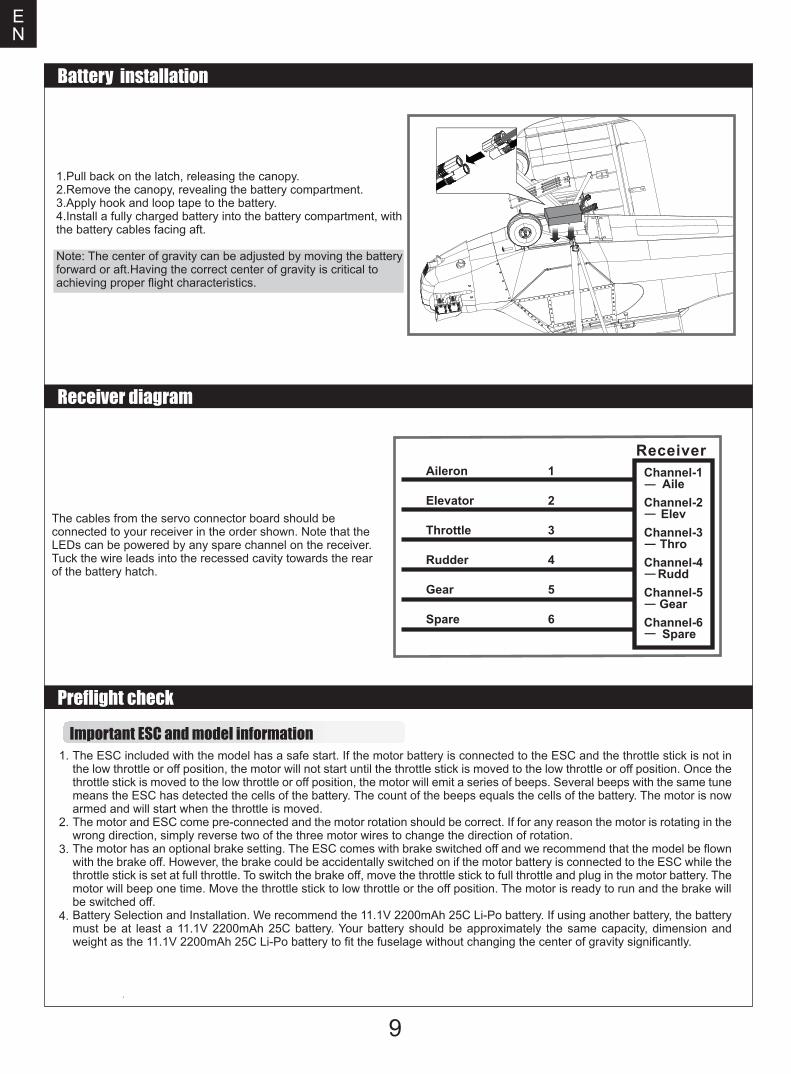
1.Pull back on the latch, releasing the canopy.2.Remove the canopy, revealing the battery compartment.3.Apply hook and loop tape to the battery.4.Install a fully charged battery into the battery compartment, with the battery cables facing aft.
Note: The center of gravity can be adjusted by moving the batteryforward or aft.Having the correct center of gravity is critical to achieving proper flight characteristics.
EN
Battery installation
Receiver diagram
Preflight check
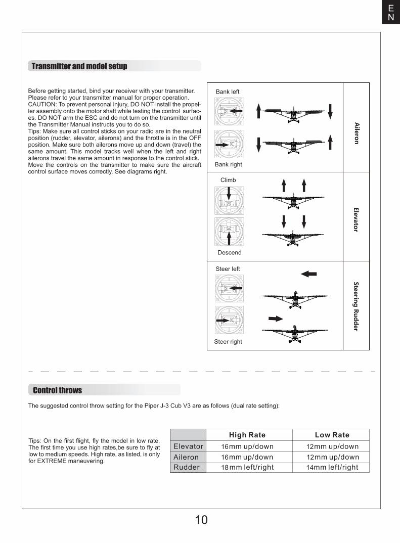
The cables from the servo connector board should be connected to your receiver in the order shown. Note that the LEDs can be powered by any spare channel on the receiver. Tuck the wire leads into the recessed cavity towards the rear of the battery hatch.
Spare
Gear
Rudder
Throttle
EIevator
Aileron Channel-1Aile
Channel-2Elev
Channel-3Thro
Channel-4Rudd
Channel-5Gear
Channel-6Spare
6
5
4
3
2
1
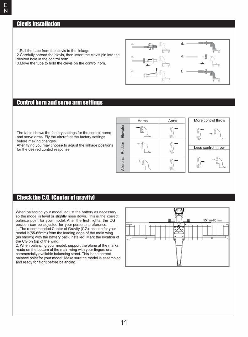
Transmitter and model setup
Before getting started, bind your receiver with your transmitter.Please refer to your transmitter manual for proper operation.CAUTION: To prevent personal injury, DO NOT install the propel-ler assembly onto the motor shaft while testing the control surfac-es. DO NOT arm the ESC and do not turn on the transmitter until the Transmitter Manual instructs you to do so.Tips: Make sure all control sticks on your radio are in the neutral position (rudder, elevator, ailerons) and the throttle is in the OFF position. Make sure both ailerons move up and down (travel) the same amount. This model tracks well when the left and right ailerons travel the same amount in response to the control stick.Move the controls on the transmitter to make sure the aircraft control surface moves correctly. See diagrams right.
10
Control throwsThe suggested control throw setting for the Piper J-3 Cub V3 are as follows (dual rate setting):
Tips: On the first flight, fly the model in low rate. The first time you use high rates,be sure to fly at low to medium speeds. High rate, as listed, is only for EXTREME maneuvering.
EN
Aileron
Bank left
Bank right
Elevator
Climb
Descend
Steering R
udd
er
Steer left
Steer right
16 121214
1618
11
More control throw
Less control throw
Horns Arms
a.
b.
c.
d.
e.
f.
EN
Clevis installation
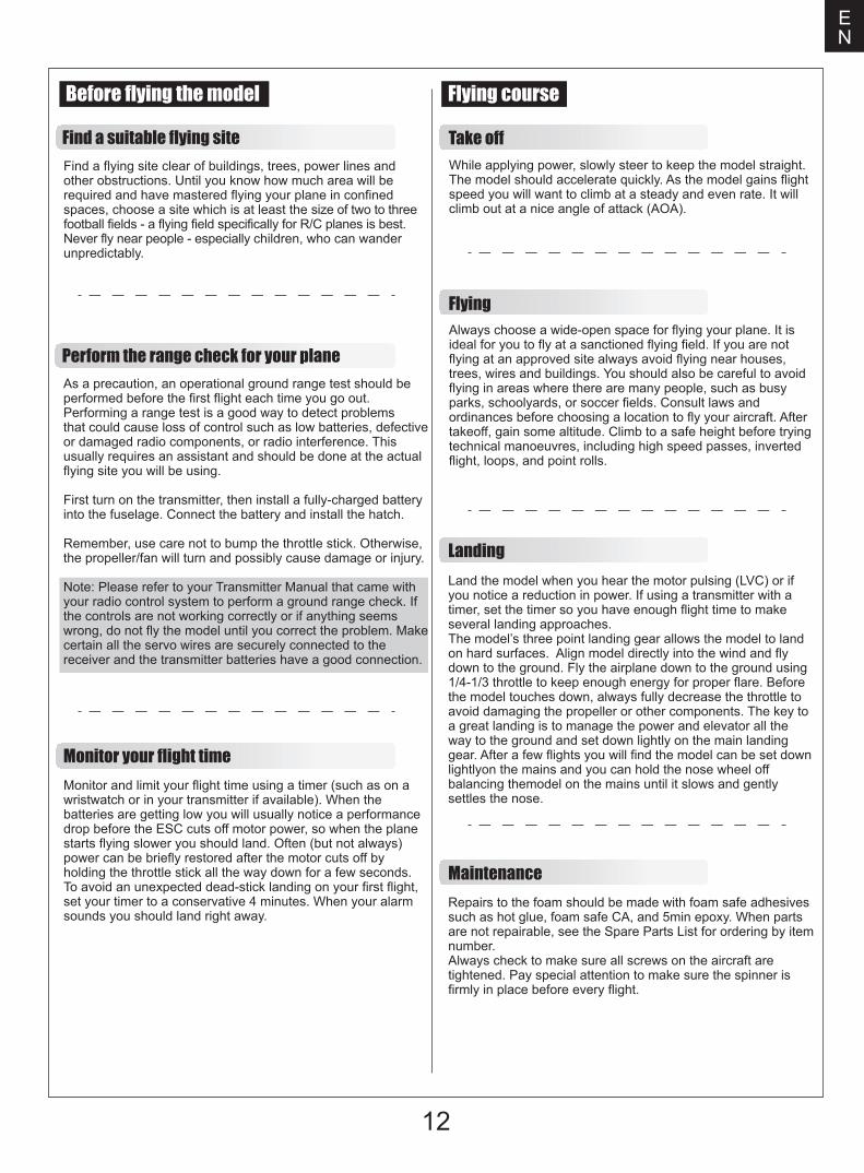
1.Pull the tube from the clevis to the linkage.2.Carefully spread the clevis, then insert the clevis pin into the desired hole in the control horn.3.Move the tube to hold the clevis on the control horn.
Control horn and servo arm settings
The table shows the factory settings for the control hornsand servo arms. Fly the aircraft at the factory settings before making changes.After flying,you may choose to adjust the linkage positionsfor the desired control response.
Elev
ator
Rud
der
Aile
rons
Check the C.G. (Center of gravity)
When balancing your model, adjust the battery as necessary so the model is level or slightly nose down. This is the correct balance point for your model. After the first flights, the CG position can be adjusted for your personal preference.1. The recommended Center of Gravity (CG) location for your model is(55-65mm) from the leading edge of the main wing (as shown) with the battery pack installed. Mark the location of the CG on top of the wing.2. When balancing your model, support the plane at the marks made on the bottom of the main wing with your fingers or a commercially available balancing stand. This is the correct balance point for your model. Make surethe model is assembledand ready for flight before balancing.
55mm-65mm
Take off
Maintenance
Landing
Find a suitable flying site
Perform the range check for your plane
Monitor your flight time
Find a flying site clear of buildings, trees, power lines and other obstructions. Until you know how much area will be required and have mastered flying your plane in confined spaces, choose a site which is at least the size of two to three football fields - a flying field specifically for R/C planes is best. Never fly near people - especially children, who can wander unpredictably.
As a precaution, an operational ground range test should beperformed before the first flight each time you go out. Performing a range test is a good way to detect problems that could cause loss of control such as low batteries, defectiveor damaged radio components, or radio interference. This usually requires an assistant and should be done at the actualflying site you will be using.
First turn on the transmitter, then install a fully-charged battery into the fuselage. Connect the battery and install the hatch.
Remember, use care not to bump the throttle stick. Otherwise,the propeller/fan will turn and possibly cause damage or injury.
Note: Please refer to your Transmitter Manual that came with your radio control system to perform a ground range check. If the controls are not working correctly or if anything seems wrong, do not fly the model until you correct the problem. Makecertain all the servo wires are securely connected to the receiver and the transmitter batteries have a good connection.
Monitor and limit your flight time using a timer (such as on a wristwatch or in your transmitter if available). When the batteries are getting low you will usually notice a performancedrop before the ESC cuts off motor power, so when the plane starts flying slower you should land. Often (but not always) power can be briefly restored after the motor cuts off by holding the throttle stick all the way down for a few seconds.To avoid an unexpected dead-stick landing on your first flight,set your timer to a conservative 4 minutes. When your alarm sounds you should land right away.
12
EN
Before flying the model Flying course
While applying power, slowly steer to keep the model straight.The model should accelerate quickly. As the model gains flightspeed you will want to climb at a steady and even rate. It will climb out at a nice angle of attack (AOA).
FlyingAlways choose a wide-open space for flying your plane. It isideal for you to fly at a sanctioned flying field. If you are not flying at an approved site always avoid flying near houses, trees, wires and buildings. You should also be careful to avoid flying in areas where there are many people, such as busy parks, schoolyards, or soccer fields. Consult laws and ordinances before choosing a location to fly your aircraft. After takeoff, gain some altitude. Climb to a safe height before trying technical manoeuvres, including high speed passes, inverted flight, loops, and point rolls.
Land the model when you hear the motor pulsing (LVC) or if you notice a reduction in power. If using a transmitter with a timer, set the timer so you have enough flight time to make several landing approaches.The model’s three point landing gear allows the model to land on hard surfaces. Align model directly into the wind and fly down to the ground. Fly the airplane down to the ground using 1/4-1/3 throttle to keep enough energy for proper flare. Before the model touches down, always fully decrease the throttle to avoid damaging the propeller or other components. The key to a great landing is to manage the power and elevator all the way to the ground and set down lightly on the main landing gear. After a few flights you will find the model can be set downlightlyon the mains and you can hold the nose wheel off balancing themodel on the mains until it slows and gently settles the nose.
Repairs to the foam should be made with foam safe adhesives such as hot glue, foam safe CA, and 5min epoxy. When parts are not repairable, see the Spare Parts List for ordering by item number.Always check to make sure all screws on the aircraft are tightened. Pay special attention to make sure the spinner is firmly in place before every flight.
13
EN
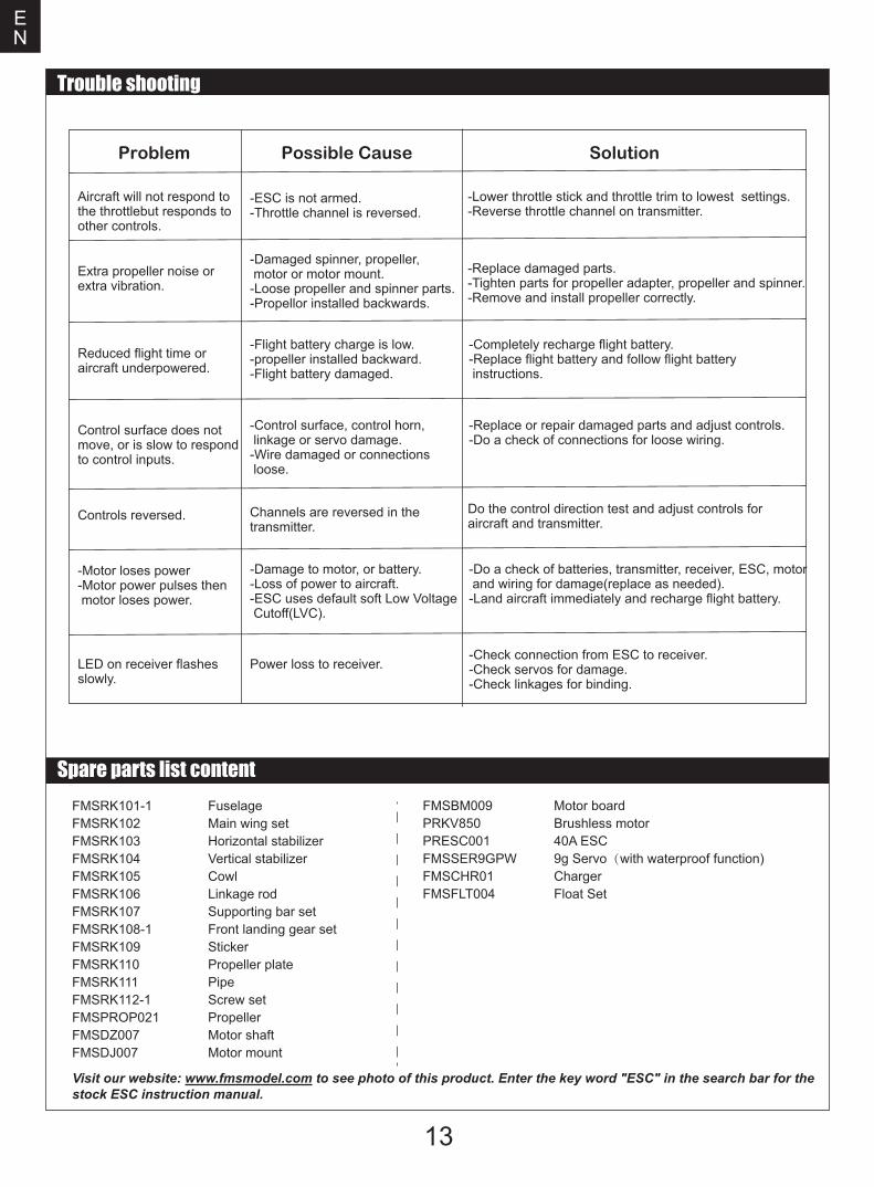
Trouble shooting
Problem Possible Cause Solution
Aircraft will not respond to the throttlebut responds to other controls.
-ESC is not armed.-Throttle channel is reversed.
-Lower throttle stick and throttle trim to lowest settings.-Reverse throttle channel on transmitter.
Extra propeller noise or extra vibration.
-Damaged spinner, propeller, motor or motor mount.-Loose propeller and spinner parts.-Propellor installed backwards.
-Replace damaged parts.-Tighten parts for propeller adapter, propeller and spinner.-Remove and install propeller correctly.
Reduced flight time or aircraft underpowered.
-Flight battery charge is low.-propeller installed backward.-Flight battery damaged.
-Completely recharge flight battery.-Replace flight battery and follow flight battery instructions.
Control surface does not move, or is slow to respond to control inputs.
-Control surface, control horn, linkage or servo damage.-Wire damaged or connections loose.
-Replace or repair damaged parts and adjust controls.-Do a check of connections for loose wiring.
Controls reversed. Channels are reversed in the transmitter.
Do the control direction test and adjust controls for aircraft and transmitter.
-Motor loses power-Motor power pulses then motor loses power.
-Damage to motor, or battery.-Loss of power to aircraft.-ESC uses default soft Low Voltage Cutoff(LVC).
-Do a check of batteries, transmitter, receiver, ESC, motor and wiring for damage(replace as needed).-Land aircraft immediately and recharge flight battery.
LED on receiver flashes slowly.
Power loss to receiver.-Check connection from ESC to receiver.-Check servos for damage.-Check linkages for binding.
Spare parts list contentFMSRK101-1FMSRK102FMSRK103FMSRK104FMSRK105FMSRK106FMSRK107FMSRK108-1FMSRK109FMSRK110FMSRK111FMSRK112-1FMSPROP021FMSDZ007FMSDJ007
FuselageMain wing setHorizontal stabilizerVertical stabilizerCowlLinkage rodSupporting bar setFront landing gear setStickerPropeller platePipeScrew setPropellerMotor shaftMotor mount
FMSBM009PRKV850PRESC001FMSSER9GPWFMSCHR01FMSFLT004
Motor boardBrushless motor40A ESC9g Servo(with waterproof function)ChargerFloat Set
Visit our website: www.fmsmodel.com to see photo of this product. Enter the key word "ESC" in the search bar for the stock ESC instruction manual.