cutler-hammer low-voltage switchgear and switchboards e2-1
TRANSCRIPT

January 1999
Cutler-Hammer
E2-1
CAT.71.01.T.E
E
Low-Voltage Switchgear and SwitchboardsMetal-Enclosed Low-Voltage Switchgear (DS
II
)
General Description
Metal-Enclosed SwitchgearWith Types DS
II
and DSL
II
Power Circuit Breakers in Drawout Construction
General Standards, Ratings
Type DS
II
Switchgear is constructed inaccordance with ANSI C37.20.1 standards for metal-enclosed low-voltage drawout switch-gear. As such, it contains low-voltage power circuit breakers, Type DS
II
(no limiters) and Type DSL
II
(with limiters) as the overcurrent protective devices both as main and as feeder protection. The drawout feature of DS
II
Breakers facilitates testing and maintenance which are important in many applications.
Compartmentalization of the drawout breakers is part of the standard construction and addi-tional safety barriers are available in mainte-nance areas. DS
II
and DSL
II
Breakers are designed to NEMA Standard SG-3; ANSI Standards C37.13, C37.16 and C37.17; and UL 1066 in frame sizes ranging from 800 to 5000 Amperes. Type DS
II
Switchgear is designed in accordance with NEMA Standard SG-5; ANSI Standards C37.20.1, C37.51 and UL Standard 1558.
Ratings are as follows:
Voltage: 120-600 Volts ac, 3-phase,3-wire or 4-wire
Main bus ampacity: 800-5000 amperescontinuous
Short circuit capability: up to 85 kA with non-current limiting breakers (DS
II
) interrup-tion and bus rating; up to 200 kA with current limiting type breakers (DSL
II
) at 480 volts ac.
Features
●
Four-Position Drawout
●
Double Steel Front Safety Barrier
●
Ease of Inspection and Maintenance
●
Safety Shutter System for PrimaryStationary Contacts (optional).
●
Standard 100 kA Bus Bracing
●
Front Accessible Terminal Block Trays
●
Rugged formed Steel Base With Jacking Provisions
●
Doors with Removable Hinge Pins
Construction Details
Cell With Breaker
Outer door with quick-opening latches closes compartment completely with breaker in or out. All controls on the face of the breaker are protected from unauthorized or accidental operation. Removable hinge pins allow unrestricted access to the breaker and compartment.
Breaker Cell Terminal Block Tray Withdrawn and in Inspection Position
Type DS
II
Switchgear features removable ter-minal block trays above each circuit breaker. These trays contain fuses for circuit breaker control protection, short circuiting terminal blocks for cts and terminations for circuit breaker secondary wiring and remote control connections. The tray front also provides a location for breaker control and indication devices, and 2% ammeters and switches. Non-adhesive wire anchors are provided to secure factory and field installed wiring. Trays are de-signed to hang from openings of compartment doors for the clear access to terminal blocks and wiring. Standard wire markers further aid in circuit identification and maintenance.

CAT.71.01.T.E
Cutler-Hammer
E2-2
January 1999
E
General Description
Full sized metal shield on breaker face pro-tects operator from live parts while operat-ing, racking or checking trip unit settings with door open. Interlocking is provided to pre-vent racking a closed breaker or closing a breaker during racking.
Operating controls for DS
II
and DSL
II
Break-ers are easily accessible with the cell door open. Charging the stored energy springs, mechanically closing and tripping the break-er, racking the breaker to its 4 positions and making adjustments to the trip settings are all accomplished at the breaker inner front panel. Indicators to show drawout position, contacts open or closed and charging spring condition are also incorporated on this panel.
A microprocessor tripping system provides continuous wide range adjustability. No con-trol power is required for the tripping func-tions. Adjustable long delay, short delay, instantaneous and ground fault trip characteristics in various combinations are available.
Ventilating Hoods
Rear Bus Barriers Installed Rear Bus Barriers Removed
DS
II
Rear View
Cable lug adaptors are provided which allow either compression lugs (shown) or mechanical lugs to be mounted at a 45° angle (up or down) to facilitate cable termination with a minimum bending radius.
The rear portion of the switchgear houses the bolted main bus connections and terminals. Cable lug adaptors provide for mounting of terminals at a 45° angle (up or down) to facil-itate cable terminations with a minimum bending radius. A safety feature is provided which isolates the cable connections. Steel barriers are assembled between the runback supports to provide this full height segrega-tion. Rear covers are bolt-on type, split into two separate sections for ease of handling during installation. Main bus and section bus are silver-plated copper standard and they are bolted at all joints with conical spring type washers as standard. Bus sizing is based on NEMA standard temperature rise criteria of 65°C over 40°C ambient (outside the enclosure).
Types DS
II
and DSL
II
Power Circuit Breakers
Types DS
II
and DSL
II
Power Circuit Breakers constitute a complete, modern, and rugged line of low-voltage power circuit breakers utilizing the DE-ION principle of arc extinction. The breaker family is distinguished by its sim-ilarity of appearance and operation frame to frame. All frame sizes are either manually or electrically operated.
DSL
II
Current Limiting Breakers
DSL
II
Circuit Breakers are coordinated combi-nations of Type DS
II
Breakers and series con-nected current limiters. They are commonly applied when available fault currents at their point of application exceed the interrupting rating of the breaker alone. Limiters are mounted integrally with the drawout breaker element and in series with the upper termi-nals on 800 through 2000 Ampere frames. For 3200 and 4000 Ampere combination, limiters are on a separate drawout carriage from that of the DS
II
Breaker.
Circuit Breaker Features
●
Two-step stored energy closing mechanism
●
Closing spring automatic discharge on breaker withdrawal
●
Interchangeable current sensors
●
Digitrip RMS trip units
●
UL label
●
Can be applied at 100% of frame rating
●
Built in trip unit test provision
Optional Accessories
●
Compartment position switch
●
Undervoltage trip either instantaneous or time delay
●
Bell alarm switch (OTS)
●
Electric close release
●
Key interlock
●
Operation counter
●
Capacitor trip (ac)
●
Short time delay
●
Shunt trip attachments for manually oper-ated breakers
●
Auxiliary switch
●
Portable test kit
●
Integral breaker ground fault tripping (3-wire or 4-wire systems)
●
Electric lockout for manual breaker
●
Zone interlocking wiring
Complete DS
II
3-Pole Breaker
Low-Voltage Switchgear and SwitchboardsMetal-Enclosed Low-Voltage Switchgear (DS
II
)
Further Information
CAT.73.01.T.E

January 1999
Cutler-Hammer
E2-3
CAT.71.01.T.E
E
A long-life lithium battery is included to provide power to the mode of trip LEDs following an auto-matic circuit breaker trip and simultaneous loss of control to the power/relay module (when provid-ed). The battery is located in the rating plug and can be easily replaced. A battery check pushbutton and green LED are included to monitor battery status.
Electronic Trip Units
Cutler-Hammer offers the most comprehen-sive range of electronic trip units in the industry for power circuit breakers. The UL listed OPTIM electronic trip units are true RMS sensing and can be applied in any DSII breakers.
Digitrip electronic trip units are ac devices that employ microprocessor-based technol-ogy that provides a true RMS current sensing means for proper correlation with thermal characteristics of conductors and equipment. The primary function of the Digitrip electronic trip unit is to provide circuit protection. This is achieved by analyzing the secondary current signals received from the circuit breaker cur-rent sensors and initiating trip signals to the circuit breaker trip unit when pre-set current levels and time delay settings are exceeded. By sampling the current waveform at various points on the wave and calculating true RMS current, the Digitrip is able to reduce nuisance tripping events due to non-sinusoidal wave shapes.
Electronic trip units are applied to distribution systems when high standards of protection and coordination are called for. In addition, electronic trip units can provide further enhanced features such as alarming, diagnostics, system monitoring and communications.
Cutler-Hammer RMS sensing trip units for power breakers fall into two main categories:
●
Front adjustable trip units: Digitrip RMS 510, 610, 810, 910
●
Programmable trip units: Digitrip OPTIM 750, 1050
Digitrip RMS Trip Units
Cutler-Hammer introduced the first micropro-cessor-based trip unit and has advanced the technology into a new family of UL listed Digitrip RMS trip units that are user friendly and easy to operate.
The Digitrip RMS trip units provide increased circuit protection with true RMS sensing for proper correlation with thermal characteris-tics of conductors and equipment.
Digitrip RMS trip units afford opportunities to improve systems control, monitoring, and testing while also providing for present and future energy monitoring, power quality monitoring and remote communications requirements.
Along with circuit protection, all Digitrip RMS models include information and self-testing functions. The Digitrip RMS 510 is the basic model. The 610/810/910 units build upon the 510 and each other to provide increased func-tionality and flexibility to meet specific distri-bution system requirements.
Interchangeable rating plugs establish the circuit breaker’s continuous ampere rating. Different types and ratings are available to match the desired ampere rating and type of circuit breaker into which a Digitrip RMS trip unit is installed. The rating plugs are suitable for use on either 50 or 60 Hz system applications. Rating plugs may be applied as low as 50% of sensor rating.
All Digitrips include LEDs that light to indicate what function initiated a trip (Long Delay, Short Delay, Instantaneous, or Ground). The 610, 810, and 910 trip units have an alphanu-meric display window to provide circuit and trip unit status and cause of trip indication. The display uses LEDs and characters are
1
⁄
2
inch high for clear visibility.
Remote communications and energy moni-toring functions are provided by the Digitrip 810 and 910 trip units. The 910 includes dis-plays for harmonic content of the waveform being monitored and percent Total Harmonic Distortion for each particular harmonic order. The 910 also features waveform analysis for transmission via IMPACC/PowerNet to a remote PC terminal.
As many as five phase and two ground time-current adjustments, providing increased levels of protection, are available on each Digitrip RMS trip unit to help meet specific system requirements. Units include long time settings and user selected choices of short time, instantaneous and ground protection, each with a wide range of settings adjusted by discretely set dials on the front of the trip unit.
Digitrip RMS trip units are completely self-contained and when the circuit breaker is closed, no external power is required to oper-ate their protection systems. They operate from current signal levels and the control power is derived from the current sensorsintegrally mounted in the circuit breaker.
General Description
Low-Voltage Switchgear and SwitchboardsMetal-Enclosed Low-Voltage Switchgear (DS
II
)

CAT.71.01.T.E
Cutler-Hammer
E2-4
January 1999
E
OPTIM RMS Trip Units
OPTIM trip units are electronic trip units that have up to ten time-current setting options that are programmed electronically by the use of a programming device. Trip units are readily accessible from the front of the break-ers. Programmability means more settings, better accuracy, faster configuration, remote accessibility, higher system security, and the ability to apply limitless software. The appli-cation for programmable trip units would be high integrity distribution systems that re-quire superior levels of system coordination coupled with system alarming, diagnostics and monitoring.
Digitrip OPTIM for power breakers are avail-able in three configurations:
- Long time, short time, and instanta-neous (LSI)
- Long time, short time, instantaneous and ground fault protection (LSIG)
- Long time, short time, instantaneous and ground fault alarm (LSIA)
For maximum selectability, OPTIM trip units allow the user to disable either short time or instantaneous functions, but not both.
Rating Plugs
Rating plugs provide a means to establish the breaker’s continuous current rating. Rating plugs are unique to a particular breaker type, and are color coded to make it easy to match the correct rating plug with the correct circuit breaker type. Rating plugs are fixed type, and are interchangeable so that amp ratings can be changed simply by changing from one plug to another in a given breaker. The same rating plug can be applied to both 50 and 60 Hz distribution systems.
Rating plugs are available down to an ampere value of half the sensor rating. Sensors are selectable on DS
II
breakers and are equal to the breaker frame rating. The plug value is referred to as I
n
.
Time-Current Curve Shaping
All Digitrip OPTIM settings are continuously adjustable, allowing virtually an infinite num-ber of possibilities within setting ranges. Ranges are based on the plug rating I
n
and
the long delay pickup setting I
r
. For ease of use all pickup values are programmed in amps rather than in multiples of I
n
or I
r
. Figure 1 illustrates available setting ranges.
For improved system coordination OPTIM features a new setting not available on previ-ous models of Digitrip. The I
4
t long delay slope will provide superior coordination with upstream fuses and transformer damage curves.
For additional information see section B3.
OPTIM 750
●
RMS Sensing
●
10 Functions
●
Programmable
●
Load Monitoring
●
Diagnostics
●
Communications
OPTIM 1050
●
RMS Sensing
●
10 Functions
●
Programmable
●
Load Monitoring
●
Diagnostics
●
Communications
●
Power and Energy Monitoring
●
Harmonics
I
n
= Rating Plug Rating I
r
= LDPU Setting * Varies with Breaker Type and Frame – See small table this page.
10 Curve Shaping Adjustments
Function Multiplier/ Setting
Setting Range
Overload
1. Long Delay Pickup XI
n
0.4 - 1.0
2A. Long Delay Time I
2
t @6I
r
2 - 24 sec.
2B. Long Delay Time I
4
t @6I
r
1 - 5 sec.
Short Circuit
3. Short Delay Pickup XI
r
1.5 - S max.*
4A. Short Delay Time Flat Response XI
r
0.1 - 0.5 sec.
4B. Short Delay Time I
2
t Response XI
r
0.1 - 0.5 sec.
5. Instantaneous XI
n
2.0 - M max.*
Ground Fault
6. Ground Fault Pickup XI
n
0.25 - 1.0 (1200 A max)
7A. Ground Fault Delay Flat Response XI
n
0.1 - 0.5 sec.
7B. Ground Fault Delay I
2
t Response XI
n
0.1 - 0.5 sec.
Breaker Type Frame S max. M max.
DSII All 10 12
7B
7A
6
Tim
e
5
1
4B
4A
2A
2B2
3
Current in Multiples
4
7
Figure 1.
General Description
Low-Voltage Switchgear and SwitchboardsMetal-Enclosed Low-Voltage Switchgear (DSII)

January 1999
Cutler-Hammer E2-5
CAT.71.01.T.E
E
RMS 510 RMS 610 RMS 810 RMS 910 OPTIM 750 OPTIM 1050
9 Functions—Front Adjustable
9 Functions—Front Adjustable—Load Monitoring—Diagnostics
9 Functions—Front Adjustable—Load Monitoring—Diagnostics—Communications—Power and Energy Monitoring
9 Functions—Front Adjustable—Load Monitoring—Diagnostics—Communications—Power and EnergyMonitoring—Harmonics
10 Functions—Programmable—Load Monitoring—Diagnostics—Communications
10 Functions—Programmable—Load Monitoring—Diagnostics—Communications—Power and EnergyMonitoring—Harmonics
Low Voltage Trip Unit - Selection Data
Breaker Type
Frame(s) All DSII and DSLII All DSII and DSLII All DSII and DSLII All DSII and DSLII All DSII and DSLII All DSII and DSLII
Ampere Range 100A-5000A 100A-5000A 100A-5000A 100A-5000A 100A-5000A 100A-5000A
Interrupting Rating @ 480V 30 thru 200 kA 30 thru 200 kA 30 thru 200 kA 30 thru 200 kA 30 thru 200 kA 30 thru 200 kA
Trip Unit Sensing
rms Sensing Yes Yes Yes Yes Yes Yes
Protection and Coordination
Protection Ordering Options LI, LS, LSI, LIGLSG, LSIG
LI, LS, LSI, LIGLSG, LSIG
LI, LS, LSI, LIGLSG, LSIG
LI, LS, LSI, LIGLSG, LSIG
LSI(A), LSIG LSI(A), LSIG
Fixed Rating Plug (In) Yes Yes Yes Yes Yes Yes
Overtemperature Trip Yes Yes Yes Yes Yes Yes
Long
Delay
Adjustable Rating Plug (In) No No No No No No
Long Delay Setting 0.5-1.0 (Ir) 0.5-1.0 (Ir) 0.5-1.0 (Ir) 0.5-1.0 (Ir) 0.4-1.0 x (In) 0.4-1.0 x (In)
Long Delay Time I2T 2-24 Seconds 2-24 Seconds 2-24 Seconds 2-24 Seconds 2-24 Seconds 2-24 Seconds
Long Delay Time I4T No No No No 1-5 Seconds 1-5 Seconds
Long Delay Thermal Memory Yes Yes Yes Yes Yes Yes
High Load Alarm No 0.85 x lr 0.85 x lr 0.85 x lr 0.5-1.0 x Ir 0.5-1.0 x IrShort
Delay
Short Delay Setting 200-600% S1 & S2 (Ir) 200-600% S1 & S2 (Ir) 200-600% S1 & S2 (Ir) 200-600% S1 & S2 (Ir) 150-800% x (Ir) 150-800% x (Ir)
Short Delay Time I2T 100-500 ms 100-500 ms 100-500 ms 100-500 ms 100-500 ms 100-500 ms
Short Delay Time Flat 100-500 ms 100-500 ms 100-500 ms 100-500 ms 100-500 ms 100-500 ms
Short Delay Time ZSI Yes Yes Yes Yes Yes Yes
Instanta-
neous
Instantaneous Setting 200-600% M1 & M2 200-600% M1 & M2 200-600% M1 & M2 200-600% M1 & M2 200-800% x (In) 200-800% x (In)
Discriminator Yes➀ Yes➀ Yes➀ Yes➀ Yes Yes
Instantaneous Override Yes (Not Type DSII) Yes (Not Type DSII) Yes (Not Type DSII) Yes (Not Type DSII) Yes Yes
Ground
Fault
Ground Fault Alarm No No No No 20/25-100%➁ 20/25-100%➁
Ground Fault Setting 25-100%(In)➁ 25-100%(In)➁ 25-100%(In)➁ 25-100%(In)➁ 20/25-100%➁ 20/25-100%➁
Ground Fault Delay I2T 100-500 ms 100-500 ms 100-500 ms 100-500 ms 100-500 ms 100-500 ms
Ground Fault Delay Flat 100-500 ms 100-500 ms 100-500 ms 100-500 ms 100-500 ms 100-500 ms
Ground Fault ZSI Yes Yes Yes Yes Yes Yes
Ground Fault Thermal Memory Yes Yes Yes Yes Yes Yes
System Diagnostics
Cause of Trip LEDs Yes Yes Yes Yes Yes Yes
Magnitude of Trip Information No Yes Yes Yes Yes Yes
Remote Signal Contacts No Yes Yes Yes Yes Yes
System Monitoring
Digital Display No Yes Yes Yes Yes➂ Yes➃
Current No Yes Yes Yes Yes Yes
Voltage No No No Yes No Yes
Power and Energy No No Yes Yes No Yes
Power Quality - Harmonics No No No Yes No Yes
Power Factor No No Yes➄ Yes No Yes
System Communications
IMPACC/PowerNet No No Yes Yes Yes Yes
Field Testing
Testing Method Integral➄ Integral➄ Integral➄ Integral➄ OPTIMizer, BIM, IMPACC/PowerNet
OPTIMizer, BIM, IMPACC/PowerNet
➀ LS/LSG Only.➁ Not to exceed 1200 Amperes.➂ By OPTIMizer/BIM.
BIM = Breaker Interface ModuleIs= Sensor RatingIn=Rating PlugIr= LDPU Setting x ln(A) = GF Alarm
➃ Over IMPACC/PowerNet only.➄ Secondary injection testing performed for DSII/
DSLII.
Low-Voltage Switchgear and SwitchboardsMetal-Enclosed Low-Voltage Switchgear (DSII)
CAT.71.01.T.E
Cutler-HammerE2-6January 1999
E
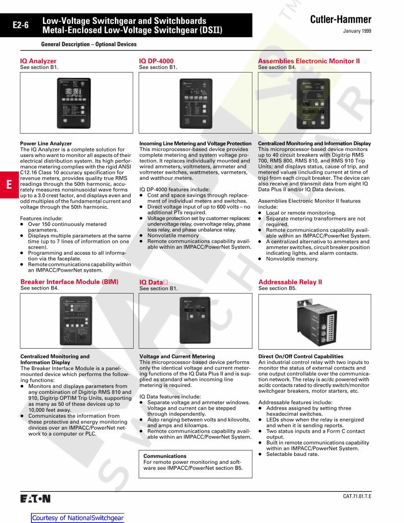
IQ AnalyzerSee section B1.
IQ DP-4000See section B1.
Assemblies Electronic Monitor IISee section B4.
Power Line AnalyzerThe IQ Analyzer is a complete solution for users who want to monitor all aspects of their electrical distribution system. Its high perfor-mance metering complies with the rigid ANSI C12.16 Class 10 accuracy specification for revenue meters, provides quality true RMS readings through the 50th harmonic, accu-rately measures nonsinusoidal wave forms up to a 3.0 crest factor, and displays even and odd multiples of the fundamental current and voltage through the 50th harmonic.
Features include:● Over 150 continuously metered
parameters. ● Displays multiple parameters at the same
time (up to 7 lines of information on one screen).
● Programming and access to all informa-tion via the faceplate.
● Remote communications capability within an IMPACC/PowerNet system.
Incoming Line Metering and Voltage ProtectionThis microprocessor-based device provides complete metering and system voltage pro-tection. It replaces individually mounted and wired ammeters, voltmeters, ammeter and voltmeter switches, wattmeters, varmeters, and watthour meters.
IQ DP-4000 features include:● Cost and space savings through replace-
ment of individual meters and switches.● Direct voltage input of up to 600 volts – no
additional PTs required.● Voltage protection set by customer replaces:
undervoltage relay, overvoltage relay, phase loss relay, and phase unbalance relay.
● Nonvolatile memory● Remote communications capability avail-
able within an IMPACC/PowerNet System.
Centralized Monitoring and Information DisplayThis microprocessor-based device monitors up to 40 circuit breakers with Digitrip RMS 700, RMS 800, RMS 810, and RMS 910 Trip Units; and displays status, cause of trip, and metered values (including current at time of trip) from each circuit breaker. The device can also receive and transmit data from eight IQ Data Plus II and/or IQ Data devices.
Assemblies Electronic Monitor II features include:● Local or remote monitoring.● Separate metering transformers are not
required.● Remote communications capability avail-
able within an IMPACC/PowerNet System.● A centralized alternative to ammeters and
ammeter switches, circuit breaker position indicating lights, and alarm contacts.
● Nonvolatile memory.
IQ DataSee section B1.
Addressable Relay IISee section B5.
Voltage and Current MeteringThis microprocessor-based device performs only the identical voltage and current meter-ing functions of the IQ Data Plus II and is sup-plied as standard when incoming line metering is required.
IQ Data features include:● Separate voltage and ammeter windows.
Voltage and current can be stepped through independently.
● Auto ranging between volts and kilovolts, and amps and kiloamps.
● Remote communications capability avail-able within an IMPACC/PowerNet System.
Direct On/Off Control CapabilitiesAn industrial control relay with two inputs to monitor the status of external contacts and one output controllable over the communica-tion network. The relay is ac/dc powered with ac/dc contacts rated to directly switch/monitor switchgear breakers, motor starters, etc.
Addressable features include:● Address assigned by setting three
hexadecimal switches.● LEDs show when the relay is energized
and when it is sending reports.● Two status inputs and a Form C contact
output.● Built in remote communications capability
within an IMPACC/PowerNet System.● Selectable baud rate.Communications
For remote power monitoring and soft-ware see IMPACC/PowerNet section B5.
Centralized Monitoring and Information DisplayThe Breaker Interface Module is a panel-mounted device which performs the follow-ing functions:● Monitors and displays parameters from
any combination of Digitrip RMS 810 and 910, Digitrip OPTIM Trip Units, supporting as many as 50 of these devices up to 10,000 feet away.
● Communicates the information from these protective and energy monitoring devices over an IMPACC/PowerNet net-work to a computer or PLC.
Breaker Interface Module (BIM)See section B4.
General Description – Optional Devices
Low-Voltage Switchgear and SwitchboardsMetal-Enclosed Low-Voltage Switchgear (DSII)

January 1999
Cutler-Hammer E2-7
CAT.71.01.T.E
E
Electrical Characteristics of DSII and DSLII Power Circuit Breakers
Table 1: Ratings of DSII and DSLII Breakers
Breaker Type
AvailableAmpereRange
Current SensorRating, Ampere
Ratings, Symmetrical Amperes (000)
Interrupting Rating Short Time Ratings➀
240V 480V 600V 240V 480V 600V
DSII-308
DSII-508
DSII-608
DSII-516
DSII-616
DSII-620
DSII-632DSII-840DSII-850
DSLII-308
DSLII-516
DSLII-620DSLII-632DSLII-840
50- 800
50- 800
50- 800
50-1600
50-1600
50-2000
800-32001000-40001600-5000
50- 800
50-1600
500-2000800-3200
1000-4000
200, 300, 400,600, 800200, 300, 400,600, 800200, 300, 400,600, 800200, 300, 400, 600,800, 1200, 1600200, 300, 400, 600,800, 1200, 1600200, 300, 400, 600,800, 1200, 1600,20002400, 32003200, 40005000
200, 300, 400,600, 800200, 300, 400, 600,800, 1200, 160020002400, 32003200, 4000
42
65
65
65
65
65
85130130
200
200
200200200
30
50
65
50
65
65
658585
200
200
200200200
30
42
50
42
50
50
658585
200
200
200200200
30
50
65
50
65
65
658585
–
–
–––
30
50
65
50
65
65
658585
–
–
–––
30
42
50
42
50
50
658585
–
–
–––
Table 2: Available Digitrip RMS Rating Plugs Marked 50/60 Hertz➁
Sensor Ratings, Amperes
Plug Rating in Amperes (In)
200300400600800
1200160020002400320040005000
100, 200200, 250, 300200, 250, 300, 400300, 400, 600400, 600, 800600, 800, 1000, 1200800, 1000, 1200, 16001000, 1200, 1600, 20001600, 2000, 24001600, 2000, 2400, 3000➅, 32002000, 2400, 3200, 40003200, 4000, 5000
Table 3: Digitrip RMS Adjustable Trip Settings
Time/Current Characteristic
Pick-Up Setting Pick-Up Point(see note)
Time Band, Seconds
Long Delay 0.5, 0.6, 0.7, 0.8,0.85, 0.9, 0.95, 1.0
In TimesLong DelaySetting
2, 4, 7, 10, 12, 15, 20, 24(at 6 times pick-up value)
Instantaneous 2, 2.5, 3, 4, 5, 6M1 = 8M2 = 12
In TimesInstantaneousSetting
Short Delay 2, 2.5, 3, 4, 5, 6S1 = 8S2 = 10
Ir TimesShort DelaySetting
0.1, 0.2, 0.3, 0.4, 0.5(Flat Response)0.1*, 0.3*, 0.5**(I2t Response)
Ground Fault A (.25), B (.3), C (.35),D (.4), E (.5), F (.6),H (.75), K (1.0)(1200A Max.)
In TimesGround FaultSetting
0.1, 0.2, 0.3, 0.4, 0.5(Flat Response)0.1*, 0.3*, 0.5*(I2t Response)
Note: In= Rating Plug ValueIr = Long Delay Pickup Setting x In
➀ Also withstand ratings➁ The Rating Plug is for 50 and 60 Hertz applica-
tions. Rating Plugs are not interchangeable with 60 Hertz or 50 Hertz only Rating Plugs.
➂ For use only when protection of downstream equipment is required. Not completely coordinat-ed with breaker to avoid nuisance blowing.
➃ Lowest rating that can be coordinated with breaker to minimize nuisance blowing.
➄ Highest available ratings, for protection of breaker only.
➅ Not available on 840 or 850 frame.
Standard Control VoltagesDc: 48, 125, 250Ac: 120, 240
Table 4: DSLII Breakers-Limiter Selection
Breaker Type
Sensor Rating Amps
Limiter Rating, Amperes
Mini-mum➂
Recom-mended➃
Maxi-mum➄
DSLII-308DSLII-308DSLII-308DSLII-308DSLII-308DSLII-308DSLII-308DSLII-516DSLII-516DSLII-516DSLII-516DSLII-620
100150200300400600800600800
120016002000
150200250400600800
1200800
10002000
– –
120012001200120012001200160020002000250030003000
2000200020002000200020002000300030003000 – –
Table 5: DSLII-632 and DSLII-840 Available Limiters
Breaker Type Available Limiters
DSLII-632
DSLII-840
2500, 3000, 4000A
2500, 3000, 4000, 5000A
Center of GravityFor seismic calculations, the following dimensions should be used to locate the center of gravity for Type DSII Switchgear.Vertical ........................... 60 inches (1524 mm)Left to right .............................center of lineupFrom the front.................. 24 inches (610 mm)
(28 inches for assemblies containing DSLII, DSII-840 and DSII-850 Breakers)
Estimated Heat Loss Per Breaker (watts)(See Note Below) DSII-308 (DSLII-308)..........................400 (600)DSII-516 (DSLII-516)......................1000 (1500)DSII-620 (DSLII-620)......................1500 (2250)DSII-632..................................................... 2400DSII-840..................................................... 3000DSII-850..................................................... 4700DSII-FT32 .................................................. 3600DSII-FT40 .................................................. 4500
Note: Add heat loss of structure per the following.Main bus through 3200 Amps................. 4000Main bus 4000 Amps maximum............. 5000Main bus 5000 Amps maximum............. 7000
Low-Voltage Switchgear and SwitchboardsMetal-Enclosed Low-Voltage Switchgear (DSII)Technical Data

CAT.71.01.T.E
Cutler-HammerE2-8January 1999
E
DSII Mains - Cable or Bus Duct Connected
DSII Ties
DSII Feeders➂
Miscellaneous
MAIN ➅DSII-308DSII-516DSII-620
METERING
FEEDER ➅DSII-308DSII-516DSII-620
FEEDER ➅DSII-308DSII-516DSII-620
METERING
MAINDSII-840DSII-850
➃
METERINGTRANSITION
FEEDERDSII-308DSII-516DSII-620
MAINDSII-632
TRANSITION METERING
MAINDSII-840DSII-850
➃
METERING
MAIN ➅DSII-308DSII-516DSII-620
FEEDER ➅DSII-308DSII-516DSII-620
METERING
MAINDSII-632
METERING
MAINDSII-632
FEEDERDSII-308DSII-516DSII-620
FEEDERDSII-308DSII-516DSII-620
FEEDERDSII-308DSII-516DSII-620
FEEDERDSII-308DSII-516DSII-620
TIEDSII-308DSII-516DSII-620
➅
➅
➅
➅
FEEDER ➅DSII-308DSII-516DSII-620
FEEDERDSII-308DSII-516DSII-620
TIEDSII-632
➅
TIEDSII-840DSII-850
METERING
TRANSITIONTO MCC
BLANK
3/4AUXILIARY
TRANSITIONORAUXILIARY
TRANSITION
TO
DS
POWERCOMPANYMETERING
FEEDERDSII-308DSII-516DSII-620
FEEDERDSII-308DSII-516DSII-620
FEEDERDSII-632
➅
➅
FEEDERDSII-308DSII-516DSII-620
FEEDERDSII-308DSII-516DSII-620
FEEDERDSII-632
➅
➅FEEDERDSII-308DSII-516DSII-620
FEEDERDSII-308DSII-516DSII-620
FEEDERDSII-308DSII-516DSII-620
FEEDERDSII-308DSII-516DSII-620
➅
➅
➅
➅
DSII Main - Close Coupled to Transformer
TRANSITION METERING
MAIN ➅DSII-308DSII-516DSII-620
FEEDER ➅DSII-308DSII-516DSII-620
FEEDER ➅DSII-308DSII-516DSII-620
➃
21
Fig. 1
(533)21
(533)21
Fig. 2
(533)21
(533)34
Fig. 3
(533)21
(864)
Fig. 4
(533)21
Fig. 5
(533)21
Fig. 6
(533)21
Fig. 7
(533)21
Fig. 8
(864)34
Fig. 9
(533)21
Fig. 10
(533)21
Fig. 11
(864)34
Fig. 12
(965)38
Fig. 15
(533)21
(1270)50
Fig. 14
(533)21
(864)34
Fig. 13
(330)13
Fig. 16
(533)21
Fig. 17
(533)21
Fig. 18
(533)21
➀ Maximum indoor shipping width is 5 vertical sections or 120 inches (3048 mm), whichever is smaller. Maximum outdoor shipping width is 96 inches (2438 mm) including aisle doors, any trans-former connections, etc.
➁ All vertical sections are 92 inches (2339 mm) high plus 4-inch (102 mm) ventilators and non-remov-able lifting angle. When the top-of-gear breaker lifter is used, height is 104 inches (2642 mm) over the lifter and 97.38 inches (2473 mm) over the lift-er rail.
➂ When bus ducts out of feeder sections are required, the depth of the lineup may increase and vertical stacking may be affected. Refer to Cutler-Hammer.
➃ Transition may be omitted if: standard dry-type transformer is used; auxiliary and meteringdevices are not located in transition; no fire pump breaker; no zero sequence ground fault.
➄ Refer to Cutler-Hammer for availability.➅ Also DSII-308, DSII-608, DSII-616 (Max. of 2 fully
loaded DSII-620 breakers per section).
Note: Blank may be substituted for any breaker position. Auxiliary may be substituted for any transition.
Low-Voltage Switchgear and SwitchboardsMetal-Enclosed Low-Voltage Switchgear (DSII)Layout Guide – Indoor – DSII Breakers➀➁➂
* These breakers have the current limiters mounted on the breaker.
** These breakers have the current limiters mounted separately.
Ampacity vs. Catalog Number
Frame Breaker Designation
800A1600A2000A3200A4000A5000A
DSII-308, -508, -608, DSLII-308 *DSII-516, -616, DSLII-516 *DSII-620, DSLII-620 *DSII-632, DSLII-632 **DSII-840, DSLII-840 **DSII-850
Dimensions are in inches (millimeters).

January 1999
Cutler-Hammer E2-9
CAT.71.01.T.E
E
21
Fig. 7
METERING
MAINDSLII-308DSLII-516
FEEDERDSLII-308DSLII-516
DSLII Ties
21 21
METERING
MAINDSLII-308DSLII-516
FEEDERDSLII-308DSLII-516
➃
FEEDERDSLII-308DSLII-516
DSLII Mains - Cable or Bus Duct Connected
Fig. 1
TRANSITIONTO TRANS-
FORMER
21 21
Fig. 2
➃
BLANK
MAINDSLII-620
METERINGTRANSITIONTO TRANS-
FORMER
BLANK
METERING
MAINDSII-632
FEEDERDSLII-308DSLII-516
21 21
➃DSII-FT32
TRANSITIONTO TRANS-
FORMER
21
BLANK
Fig. 3
21
MAINDSII-632
DSII-FT32
21
TRANSITIONTO TRANS-
FORMER
Fig. 4
MAINDSII-840
DSII-FT40
21 34
TRANSITIONTO TRANS-
FORMER
Fig. 5
BLANK
METERING
34 34
➃DSII-FT40
TRANSITIONTO TRANS-
FORMER
21
Fig. 6
MAINDSII-840
METERING
BLANK
21
Fig. 9
METERING
MAINDSLII-620
21
Fig. 10
METERING
MAINDSLII-620
FEEDERDSLII-308DSLII-516
21 21
Fig. 11
METERING METERING
MAINDSII-632
FEEDERDSLII-308DSLII-516
DSII-FT32
21
Fig. 12
MAINDSII-632
DSII-FT32➄
➄
34
METERING METERING
MAINDSII-840
DSII-FT40
34
Fig. 13
MAINDSII-840
34
DSII-FT40 ➄
➄
Fig. 14
FEEDERDSLII-308DSLII-516
TIEDSLII-308DSLII-516
21
FEEDERDSLII-308DSLII-516
FEEDERDSLII-308DSLII-516
Fig. 15
BLANK
TIEDSLII-620
21
FEEDERDSLII-308DSLII-516
Fig. 16
TIEDSII-632
21
DSII-FT32➄
➄
Fig. 17
21 21
DSII-FT32 TIEDSII-632
Fig. 18
TIEDSII-840
34
DSII-FT40 ➄
➄
Fig. 19
34 34
DSII-FT40 TIEDSII-840
Fig. 20
DSLII Mains - Close Coupled to Transformer
21
Fig. 8
METERING
MAINDSLII-516DSLII-308
FEEDERDSLII-516DSLII-308
FEEDERDSLII-516DSLII-308
➃
(533) (533) (533) (533) (533) (533) (533) (533) (533) (533) (864)
(533) (864) (864)
(533) (864) (864) (864)(533) (533) (533) (533) (533) (533)
(533) (864) (864) (864)(533) (533) (533) (533)
* These breakers have the current limiters mounted on the breaker.
** These breakers have the current limiters mounted
Ampacity vs. Catalog Number
Frame Breaker Designation
800A1600A2000A3200A4000A5000A
DSII-308, -508, -608, DSLII-308 *DSII-516, -616, DSLII-516 *DSII-620, DSLII-620 *DSII-632, DSLII-632 **DSII-840, DSLII-840 **DSII-850
Low-Voltage Switchgear and SwitchboardsMetal-Enclosed Low-Voltage Switchgear (DSII)Layout Guide – Indoor – DSLII Breakers➀➁➂
Dimensions are in inches (millimeters).
➀ Maximum indoor shipping width is 5 vertical sections or 120 inches (3048 mm), whichever is smaller. Maximum outdoor shipping width is 96 inches (2438 mm) including aisle doors, any trans-former connections, etc.
➁ All vertical sections are 92 inches (2339 mm) high plus 4-inch (102 mm) ventilators and non-remov-able lifting angle. When the top-of-gear breaker lifter is used, height is 104 inches (2642 mm) over
the lifter and 97.38 inches (2473 mm) over the lifter rail.
➂ When bus ducts out of feeder sections are required, the depth of the lineup may increase and vertical stacking may be affected. Refer to Cutler-Hammer.
➃ Transition may be omitted if: standard dry-type transformer is used; auxiliary and meteringdevices are not located in transition; no fire pump
breaker; no zero sequence ground fault.➄ Refer to Cutler-Hammer for availability.Note: Blank may be substituted for any breaker
position. Auxiliary may be substituted for any transition.

CAT.71.01.T.E
Cutler-HammerE2-10January 1999
E.56 X 1.00
(14.2 x 25.4)(6)
➃ControlWiringConduit
Area
➃PowerCable
ConduitArea
B
CC
A➄
D
➅FC
W
Front
3.88(98.6)
2.75(69.9)
1.50(38.1)
1.38(35.1)
3.13(79.5)4.63
(117.6)
2.75(69.9)
1.50(38.1)
1.38(35.1)
1.50(38.1)
DSLII Feeders
21
Fig. 21
FEEDERDSLII-308DSLII-516
FEEDERDSLII-308DSLII-516
FEEDERDSLII-308DSLII-516
FEEDERDSLII-308DSLII-516
FEEDERDSLII-620
21
FEEDERDSLII-308DSLII-516
FEEDERDSLII-308DSLII-516
Fig. 22
FEEDERDSLII-308DSLII-516
FEEDERDSII-632
21
FEEDERDSLII-308DSLII-516
Fig. 23
FEEDERDSII-632
FEEDERDSLII-308DSLII-516
21
FEEDERDSLII-308DSLII-516
Fig. 24
DSII-FT32
FEEDERDSII-632
21
Fig. 25
DSII-FT40
FEEDERDSII-840
34
Fig. 26(533) (864)(533) (533) (533) (533)
Type of Breakers in Section
FC➅ W D CC➆ A➄ B Recommended➃No. of PowerConduits (Max.)
3.5 Inches 4 Inches
All DSII,ExceptDSII-840DSII-850
36(914)
21(533)
60 (1524)66 (1676)72 (1829)78 (1981)84 (2134)90 (2286)
10 (254) 16 (406)22 (559)28 (711)34 (864)40 (1016)
30.50(775)
1.750(445)
6 912151821
3 6 9121518
DSII-840DSII-850
44(1118)
34(864)
72 (1829)78 (1981)84 (2134)90 (2268)
14 (356)20 (508)26 (660)32 (813)
38.50(978)
23.50(597)
14182332
10152328
DSLII-308DSLII-516DSLII-620
44(1118)
21(533)
66 (1676)72 (1829)78 (1981)84 (2134)90 (2286)
8 (203)14 (356)20 (508)26 (660)32 (813)
38.50(978)
25.50(648)
4 8101518
3 6 91215
DSLII-632DSII-FT32(non stacked)
44(1118)
21(533)
72 (1829)78 (1981)84 (2134)90 (2286)
14 (356)20 (508)26 (660)32 (813)
38.50(978)
25.50(648)
8101518
6 91215
DSLII-632DSII-FT32(stacked)
44(1118)
21(533)
72 (1829)78 (1981)84 (2134)90 (2286)
0 (0) 6 (152)12 (305)18 (457)
38.50(978)
25.50(648)
0 3 6 9
0 3 6 9
DSLII-840DSII-FT40(non stacked)
44(1118)
34(864)
72 (1829)78 (1981)84 (2134)90 (2286)
14 (356)20 (508)26 (660)32 (813)
38.50(978)
23.50(597)
14182332
10152328
DSLII-840DSII-FT40(stacked)
44(1118)
34(864)
72 (1829)78 (1981)84 (2134)90 (2286)
0 (0) 6 (152)12 (305)18 (457)
38.50(978)
23.50(597)
0 51015
0 51015
➀ Maximum indoor shipping width is 5 vertical sections or 120 inches (3048 mm), whichever is smaller. Maximum outdoor shipping width is 96 inches (2438 mm) including aisle doors, any trans-former connections, etc.
➁ All vertical sections are 92 inches (2339 mm) high plus 4-inch ventilators and non-removable lifting angle. When the top-of-gear breaker lifter is used, height is 104 inches (2642 mm) over the lifter and 97.38 inches (2473 mm) over the lifter rail.
➂ When bus ducts out of feeder sections are required, the depth of the lineup may increase and vertical stacking may be affected. Refer to Cutler-Hammer.
➃ Stub conduit 2 inches (50 mm) maximum in power
Note: Blank may be substituted for any breaker position. Auxiliary may be substituted for any transition.
Low-Voltage Switchgear and SwitchboardsMetal-Enclosed Low-Voltage Switchgear (DSII)Layout Guide – Indoor – DSLII Breakers➀➁➂
Dimensions, in Inches
Floor Plan
Dimensions are in inches (millimeters).
cable area, 1 inch (25 mm) maximum in control wiring area.
➄ Bolt hole location for mounting the center floor channel when required. Floor channels not included. Note that when there is an assembly containing structures with different channel locations, a channel must be used for each of the locations.
➅ FC is the recommended front clearance for breaker removal with top-of-switchgear-mounted breaker lifter. If a portable breaker lifter is to be used, allow at least 60 inches (1624 mm) of aisle space.
➆ When a zero-sequence ground-fault ct is mounted on line-side or load-side of a breaker, reduce CC dimension by 10 inches (254 mm).
Top View
Top EntryControl CableWiring Space
1(25)
Breaker
DSII ExceptDSII-840, DSII-FT40,DSII-850
DSII-840, DSII-FT40,DSII-850
DSLII
“Y”
23.5(597)
26.27(667)
31.5(800)
“X”
5.5(140)
8.72(221)
5.5(140)
X
4 (102)
Front
Y

January 1999
Cutler-Hammer E2-11
CAT.71.01.T.E
E
➁
Metal Enclosed ShippingSplit Terminal Blocks
Optional Top-of-Gear Breaker Lifter
Lifting Plate
Vent Deflector (Typ.)5.38(137)
MetalInsolationBarriers(Full Height)(Standard)
Neutral
GroundBus
JackingSlot (Typ.)
CableTerminalsat 45° Angle.
Can be Upor Down.
Inst
rum
ent C
ontr
ol T
ray
(Typ
.)
Breaker CellPosition “D”
Breaker CellPosition “C”
Breaker CellPosition “B”
Breaker CellPosition “A”
FrontCompartment
BusCompartment
CableCompartment
D
104(2642)
➁
4
➁
A
96(2438) 92
(2339)
Type DSII Indoor Switchgear Weights —Pounds (Approximate)
Stationary Structures 21 in. (533 mm) wide breaker structure less breakers:
66 in. (1676 mm) maximum depth .................. 130078 in. (1981 mm) maximum depth .................. 140090 in. (2286 mm) maximum depth .................. 1500
34 in. (864 mm) wide breaker structure less breaker:66 in. (1676 mm) maximum depth .................. 150078 in. (1981 mm) maximum depth .................. 160090 in. (2286 mm) maximum depth .................. 1700
21 in. (533 mm) wide auxiliary structure less breaker:66 in. (1676 mm) maximum depth .................. 100078 in. (1981 mm) maximum depth .................. 110090 in. (2286 mm) maximum depth .................. 1200
34 in. (864 mm) wide auxiliary structure less breaker:66 in. (1676 mm) maximum depth .................. 110078 in. (1981 mm) maximum depth .................. 120090 in. (2286 mm) maximum depth .................. 1300
13 in. (330 mm) wide Bus Transition structure ... 70021 in. (533 mm) Transformer Transition structure. 1000
Section View of Typical Structure
Low-Voltage Switchgear and SwitchboardsMetal-Enclosed Low-Voltage Switchgear (DSII)Layout Guide
Drawout Elements➀ DSII-308 Breaker .................................................... 150DSII-508 Breaker .................................................... 195DSII-608 Breaker .................................................... 200DSII-516 Breaker .................................................... 195DSII-616 Breaker .................................................... 200DSII-620 Breaker .................................................... 200DSII-632 Breaker .................................................... 300DSII-840 Breaker .................................................... 400DSII-850 Breaker .................................................... 400DSLII-308 Breaker .................................................. 200DSLII-516 Breaker .................................................. 260DSLII-620 Breaker .................................................. 325DSII-FT32 Fuse Truck ........................................... 325DSII-FT40 Fuse Truck ............................................ 430
➀ Manually or electronically operated. For approxi-mate impact weight, add 50% of breaker weight.
➁ Floor channels not included. See page E1-10 forlocation of center channel(s).
Dimensions are in inches (millimeters).

CAT.71.01.T.E
Cutler-HammerE2-12January 1999
E
Rear Door➀21 Width = 20.88 to Base
(533.4) (530.4)34 Width = 33.88 to Base
(863.6) (860.6)38 Width = 37.88 to Base
(965.2) (962.2)“A”“A”
19.25(489)
BusOpening
Unit
34.75(882.7)
Door Swing
➁
40.50(1028.7)
5.50(139.7)(Ref.)Front of
BaseOutdoorSwitchgear
For ConduitInformation
See Page E1-10
CL
CL
118.88(3019.6)
1.00(25.4)
5.56(141.2)
6.80(172.7)
108.00(2744.7)OverallHeight
34.75(882.7)
Door Width
42.62(1082.5)
Aisle Width
4.00(101.6)
LiftingAngleShown
5.18(131.6)
124.12 (Overall Depth With Mounting Angles)(3152.6)
2.81(71.4)
0.75 Dia.(19.1)
1.38(35.1)(Rear Door➀)
1.75(44.5)
19.25(489)
Bus Duct EntranceWhen Required
Mounting Angle(Inverted Lifting Angles)
6.12 Outdoor Base(155.4)
CL
Rear of Baseand Frame
Rear of Baseand Frame
StandardUnit Widths From Table Pages E1-8 – E1-10
OutdoorSwitchgearBase
Platform
5.50(139.7)
1.50(38.1)
6.12(155.4)
W1 W2 W3
D➃
W
5.50(139.7)(Ref.)
31.90(810.3)
Opening Width104.00
(2641.6)101.00
(2563.9)
116.12 (Base)(2949.4)
Weights of Outdoor Structures
Stationary Structures➂ Weight–Lbs. (kg)
End trims (one set per lineup) 1500(682)
21 in. wide breaker section (533 mm)
2600(1182)
34 in. wide breaker section (864 mm)
2700(1227)
21 in. wide auxiliary section (533 mm)
2300(1045)
34 in. wide auxiliary section (864 mm)
2400(1091)
38 in. wide utility section (965 mm)
2700(1227)
50 in. wide utility section (1270 mm)
3200(1455)
21 in. bus transition section (533 mm)
2500(1136)
Transformer throat 150(68)
Typical Dimensions - Outdoor Walk-In
➀ Rear doors are standard.➁ Enclosures equipped with hinged door on each
end of aisle.
Right-Hand End View
Plan View Front View
➂ Weight of structure is less breakers.➃ When a zero-sequence ground-fault ct is mount-
ed on line-side or load-side of a breaker, reduce CC dimension by 10 inches (254 mm).
Low-Voltage Switchgear and SwitchboardsMetal-Enclosed Low-Voltage Switchgear (DSII)Layout Guide
Dimensions are in inches (millimeters).

January 1999
Cutler-Hammer E2-13
CAT.71.01.T.E
E
RatingsA. Voltage rating shall be as indicated on the
drawings. The entire assembly shall be suitable for 600 volts maximum AC service.
B. The assembly shall be rated to withstand mechanical forces exerted during short-circuit conditions [of (30,000) (42,000) (50,000) (65,000) (85,000) amperes sym-metrical at rated voltage] [as shown on the drawings] per ANSI standard.
C. The bus system shall have a minimum ANSI 4-cycle short-circuit withstand rating of [100,000] [150,000] [200,000] amperes symmetrical.
D. All circuit breakers shall have a minimum symmetrical interrupting capacity of [30,000] [42,000] [50,000] [65,000] [85,000] [200,000] amperes. To assure a fully selec-tive system, all circuit breakers shall have 30-cycle short time withstand ratings equal to their symmetrical interrupting ratings, regardless of whether equipped with instantaneous trip protection or not.
E. Where circuit breakers are equipped with current limiters, the combination shall have short time ratings in accordance with the characteristics of the limiter selected.
F. All ratings shall be tested to the require-ments of ANSI C37.20.1, C37.50 and C37.51 and UL 1558.
ConstructionA. The Switchgear shall consist of the
required number of vertical sections, bolted together to form a rigid assembly. The sides shall be covered with remov-able bolt-on covers. All edges of front covers or hinged front panels shall be formed. Provide ventilators located on the top of the switchgear over the breaker and bus compartments to ensure ade-quate ventilation within the enclosure. [The rear covers shall be fabricated in two (2) pieces for ease of handling, and shall be mounted using captive hardware.] [Hinged rear doors, complete with provi-sions for padlocking, shall be provided.]
B. The assembly shall be provided with ade-quate lifting means and shall be capable of being moved into installation position and bolted directly to [contractor supplied floor sills to be set level in concrete per manufacturer's recommendations] [the floor without the use of floor sills provid-ing the floor is level to 1/8-inch per 3-foot distance in any direction]. Provisions shall be made for jacking of shipping groups, for removal of skids or insertion of equip-ment rollers. Base of assembly shall be suitable for rolling directly on pipes without skids. The base shall be equipped with slots in the bottom side frame mem-bers to accommodate the forks of a lift
truck. The base frame member shall be constructed such that the forks can not protrude into the breaker, bus or cable compartments of the assembly.
C. Each vertical steel unit, forming part of the switchgear line-up, shall be a self-contained housing having one or more individual breaker or instrument compart-ments, a centralized bus compartment, and a rear cabling compartment. Each individual circuit breaker compartment, or cell, shall be segregated from adjacent compartments and sections, including the bus compartment, by means of steel bar-riers. It shall be equipped with drawout rails and primary and secondary discon-necting contacts. Removable hinge pins shall be provided on the breaker compart-ment door hinges. Current transformers for feeder instrumentation, where shown on the plans, shall be located within the appropriate breaker cells.
D. The stationary part of the primary discon-necting devices for each power circuit breaker, shall consist of a set of contacts extending to the rear, through a glass polyester insulating support barrier; cor-responding moving finger contacts suit-ably spaced shall be furnished on the power circuit breaker studs which engage in only the connected position. The assembly shall provide multiple silver-to-silver full floating high-pressure point contacts with uniform pressure on each finger maintained by springs. Each circuit shall include the necessary three-phase bus connections between the section bus and the breaker line side studs. Load studs shall be equipped with insulated copper load extension busses terminating in solderless type terminals in the rear cable compartment of each structure. Bus extensions shall be [silver-plated] [tin-plated] where outgoing terminals are attached.
E. The secondary disconnecting devices shall consist of floating fingers mounted on the removable unit and engaging flat contact segments at the rear of the com-partment. The secondary disconnecting devices shall be silver-plated and sliding contact engagement shall be maintained in the CONNECTED and TEST positions.
F. The removable power circuit breaker ele-ment shall be equipped with disconnect-ing contacts, wheels and interlocks for drawout application. It shall have four positions, CONNECTED, TEST, DISCON-NECTED, and REMOVED all of which per-mit closing the compartment door. The breaker drawout element shall contain a worm gear levering “in” and “out” mechanism with removable lever crank. Mechanical interlocking shall be provided so that the breaker is in the tripped posi-tion before levering “in” or “out” of the cell. The breaker shall include a provision
for padlocking open to prevent manual or electric closing. The padlocking shall also secure the breaker in the connected, test or disconnected position by preventing levering.
G. An insulating flash shield shall be mounted above each circuit breaker to prevent flashover from the arc chutes to ground.
H. Provide a rear compartment steel barrier between the cable compartment and the main bus to protect against inadvertent contact with main or vertical bus bars.
I. The switchgear shall be Cutler-Hammer type DSII low-voltage metal-enclosed switchgear, utilizing type DSII or DSLII power air circuit breakers as herein specified.
J. Provide in the cell, when the circuit breaker is withdrawn, a safety shutter which automatically covers the line and load stabs and protects against accidental contact.
K. [Provide a metal barrier full height and depth between adjacent vertical struc-tures in the cable compartment.]
L. Provide a glass polyester full height and depth barrier between adjacent vertical structures in the bus compartment with appropriate slots for main bus.
M. The switchgear shall be suitable for use as service entrance equipment and be labeled in accordance with UL requirements.
BusA. All bus bars shall be [silver-plated copper]
[tin-plated copper]. Main horizontal bus bars shall be mounted with all three phases arranged in the same vertical plane. Bus sizing shall be based on ANSI standard temperature rise criteria of 65 degrees C over a 40 degrees C ambient (outside the enclosure).
1. In addition to full UL air clearances, the bus shall be insulated with a mini-mum of 5 mill thickness of epoxy resin coating. Removable non-PVC boots shall be provided to give access to the cross bus joints for inspection and maintenance.
B. Provide a [half] [full] capacity neutral bus where a neutral bus is indicated on the drawings.
C. A copper ground bus shall be furnished firmly secured to each vertical section structure and shall extend the entire length of the switchgear. The ground bus short time withstand rating shall meet that of the largest circuit breaker within the assembly.
Low-Voltage Switchgear and SwitchboardsMetal-Enclosed Low-Voltage Switchgear (DSII)Typical Specifications

CAT.71.01.T.E
Cutler-HammerE2-14January 1999
E
D. All hardware used on conductors shall be high-tensile strength and zinc plated. All bus joints shall be provided with Belleville-type washers.
Wiring/TerminationsA. Small wiring, necessary fuse blocks and
terminal blocks within the switchgear shall be furnished as required. Control components mounted within the assem-bly shall be suitably marked for identifica-tion corresponding to the appropriate designations on manufacturer's wiring diagrams.
B. All control wire shall be type SIS. Wire bundles shall be secured with nylon ties and anchored to the assembly with the use of prepunched wire lances or nylon non-adhesive anchor. All current trans-former secondary leads shall first be con-nected to conveniently accessible short circuit terminal blocks before connecting to any other device. Four (4) shorting screws with provisions for storage shall be provided. All groups of control wires leaving the switchgear shall be provided with terminal blocks with suitable num-bering strips. Provide wire markers at each end of all control wiring. Plug-in ter-minal blocks shall be provided for all ship-ping split wires. Terminal connections to remote devices or sources shall be front accessible via removable trays above each circuit breaker. Control fuses for each electrically operated circuit breaker shall also be located in these trays.
C. NEMA 2-hole [mechanical-] [crimp-] type lugs shall be provided for all line and load terminations suitable for copper or alumi-num cable rated for 75 degrees C of the size indicated on the drawings.
D. A termination system shall be provided such that no additional cable bracing, tying or lashing is required to maintain the short circuit withstand ratings of the assembly through 85 kA.
E. Lugs shall be provided in the incoming line section for connection of the main grounding conductor. Additional lugs for connection of other grounding conduc-tors shall be provided as indicated on the drawings.
Circuit BreakersA. All protective devices shall be drawout
low-voltage power air circuit breakers, Cutler-Hammer type “DSII” or approved equal. Frame ratings shall be 800, 1600, 2000, 3200, 4000, or 5000 amperes. All breakers shall be UL listed for application in their intended enclosures for 100% of their continuous ampere rating.
B. Breakers shall be manually operated (MO) unless electrically operated (EO) is indi-cated on the drawings.
C. Electrically operated breakers shall be complete with [120-Vac] [48-Vdc] [125-Vdc] [250-Vdc] operators, [OPEN/CLOSE pushbuttons] [control switch], plus red and green indicating lights to indicate breaker contact position. [DC source shall be supplied from a remote battery sys-tem] [AC source shall be taken from a (remote source) (control power trans-former internal to the switchgear assembly)].
D. Main power circuit breakers shall be pro-vided with trip units as specified in para-graph [ __.__ through __].
E. Tie power circuit breakers shall be pro-vided with trip units as specified in para-graph [__.__ through __].
F. Feeder power circuit breakers shall be provided with trip units as specified in paragraph [__.__ through __].
G. [Main] [Tie] [and Feeder] power circuit breakers (where indicated on the draw-ings) shall include current limiters. Limit-ers shall be integrally mounted on 800-, 1600- and 2000-ampere breakers. For 3200-ampere and 4000-ampere breakers, limiters shall be mounted on a separate draw-out limiter truck. Current limiters
Utilize the applicable paragraphs for the type trip unit(s) desired, and delete the remaining non-applicable paragraphs.
Mains, tie, and feeders may utilize different types of trip units depending on features de-sired for the specific application. Suggested format as follows:
Digitrip RMS510 – Basic protection and curve shaping Trip Units (Digitrip) Paragraphs A through J
Digitrip RMS610 – Same as 510 plus local current display Trip Units (Digitrip) Paragraphs A through N
Digitrip RMS810 – Same as 610 plus energy monitoring/display, and remote communications Trip Units (Digitrip) Paragraphs A through R
Digitrip RMS910 – Same as 810 plus volt-age, power factor and harmonic analysis and display Trip Units (Digitrip) Paragraphs A through S
Digitrip OPTIM 750 – Programmable curve shaping, load monitoring, and communications Programmable Trip Units (Digitrip OPTIM) Paragraphs A through O
Digitrip OPTIM 1050 – Same as 750 plus power and energy monitoring; harmonic monitoring and analysis.Programmable Trip Units (Digitrip OPTIM) Paragraphs A through Q
shall be coordinated with the breaker trip device, so as to avoid unnecessary blow-ing of the current limiters. Breakers shall include an anti-single-phase device that will trip the breaker in the event of a blown limiter, indicate from the front of the breaker which limiter is blown, and prevent the breaker from being re-closed on a single-phase condition due to miss-ing or blown limiters.
1. Current limiters which are integrally mounted with breaker shall be inac-cessible until the breaker is com-pletely withdrawn from its compartment assuring complete isola-tion. Current limiters mounted on a separate truck shall be key interlocked with the breaker to prevent withdraw-ing or insertion unless the breaker is locked open.
2. Power circuit breakers with current limiting fuses shall have a 200,000-ampere RMS symmetrical interrupting capacity at 600 volts and below.
Trip Units (Digitrip)A. Each draw-out low-voltage power circuit
breaker shall be equipped with a solid-state tripping system consisting of three (3) current sensors, microprocessor-based trip device and flux-transfer shunt trip. Current sensors shall provide opera-tion and signal function. The trip unit shall use microprocessor-based technology to provide the basic adjustable time-current protection functions. True RMS sensing circuit protection shall be achieved by analyzing the secondary current signals received from the circuit breaker current sensors and initiating trip signals to the circuit breaker trip actuators when prede-termined trip levels and time delay set-tings are reached.
B. Interchangeable rating plugs shall estab-lish the maximum continuous trip ratings of each circuit breaker. Rating plugs shall be fixed type as indicated. Rating plugs shall be interlocked so they are not inter-changeable between frames, and inter-locked such that a breaker cannot be closed and latched with the rating plug removed.
C. Complete system selective coordination shall be provided by the addition of the following individually adjustable time/cur-rent curve shaping solid-state elements:
1. All breakers shall have adjustments for long delay pick-up and time.
2. [Main] [Tie] [and Feeders] shall have individual adjustments for short delay pick-up and time, and include selec-tive flat or l2t curve shaping.
3. [Main] [Tie] [and Feeders] shall have an adjustable instantaneous pick-up.
Low-Voltage Switchgear and SwitchboardsMetal-Enclosed Low-Voltage Switchgear (DSII)Typical Specifications

January 1999
Cutler-Hammer E2-15
CAT.71.01.T.E
E
4. Breakers where indicated on the draw-ings, shall have individually adjustable ground fault current pick-up and time, and include selective flat or l2t curve shaping.
D. The microprocessor-based trip unit shall have both powered and unpowered ther-mal memory to provide protection against cumulative overheating should a number of overload conditions occur in quick succession.
E. Trip units to include zone interlocking capability for the short time delay and ground fault delay trip functions for improved system coordination. The zone interlocking system shall restrain the trip-ping of an upstream circuit breaker and allow the circuit breaker closest to the fault to trip with no intentional time delay. In the event that the downstream breaker does not trip, the upstream breaker shall trip after the pre-set time delay. [Factory wire zone interlocking system for break-ers within the switchgear.]
F. For trip units that do not have an instanta-neous adjustment, a discriminator circuit shall be provided to prevent the breaker being closed and latched on to a faulted circuit.
G. Internal ground fault protection settings shall not exceed 1200 amperes. Provide neutral ground fault sensor for four-wire loads.
H. The trip unit shall have an information system that utilizes battery backed-up LEDs to indicate mode of trip following an automatic trip operation. The indication of the mode of trip shall be retained after an automatic trip. A trip reset button shall be provided to turn off the LED indication after an automatic trip. A test pushbutton shall energize an LED to indicate battery status.
I. The trip unit shall be provided with a rep-resentation of the time-current curve on the trip unit that indicates the protection function settings. The unit shall be contin-uously self-checking and provide LED indication that the internal circuitry is being monitored and is fully operational.
J. The trip unit shall contain an integral test panel with a test selector switch and a test pushbutton. The test selector switch shall enable the user to select the values of test current within a range of available set-tings. The basic protection functions shall not be affected during test operations. The breaker shall be capable of being tested in either the TRIP or NO TRIP test mode. Provide a keyed receptacle for use with an optional auxiliary power module. The auxiliary power module shall allow the breaker trip unit to be tested with a 120-volt external power source.
K. A four-digit, 3/4-inch high, LED alphanu-meric display shall be provided to indicate the following data:
1. Cause of trip
2. Instantaneous value of maximum phase and ground current
3. Level of fault current that initiated an automatic trip operation
4. Display shall be high output LED for low-level light readability. LCD dis-plays are unacceptable.
L. The trip unit shall include a power/relay module which shall supply control power to the readout display. Following an auto-matic trip operation of the circuit breaker, it shall maintain the cause of trip history and the mode of trip LED indication as long as its internal power supply is avail-able. Internal relays shall provide contacts for remote indication of mode of trip and high load.
M. A red LED shall be provided on the face of the trip unit pre-set to turn on when 85% of the trip setting is exceeded (a 40-sec-ond delay shall be provided to avoid nui-sance alarms).
N. Metering display accuracy of the com-plete system including current sensors, auxiliary CTs, and the trip unit shall be +/- 2% of full scale for current values.
O. The trip unit shall include a potential transformer module, suitable for opera-tion up to 600V, 50/60 Hz. The primary of the PTM shall be connected internally to the load side of the circuit breaker through a dielectric disconnect plug. The unit shall calculate energy monitoring parameters as follows:
1. Peak demand (Megawatts)
2. Present demand (Megawatts)
3. Energy consumption (Megawatt-hours).
P. The energy-monitoring parameter values (peak demand, present demand and energy consumption) shall be indicated in the trip unit alphanumeric display panel.
Q. Metering display accuracy of the com-plete system of full scale shall be +/- 3% for power values, +/- 4% of full scale for energy values.
R. The trip unit shall be equipped to permit communication via a network twisted pair for remote monitoring and control. The trip unit shall be provided with an address register for identification on the network. All monitored values shall be transmitta-ble over the network.
S. For enhanced system analysis the follow-ing additional parameter values shall be calculated and indicated in the trip unit alphanumeric display panel:
1. Line-to-line voltage
2. Power factor
3. Percentage harmonic content
4. Total harmonic distortion (THD).
Programmable Trip Units (Digitrip OPTIM)A. Each draw-out low-voltage power circuit
breaker microprocessor-based tripping system shall consist of three (3) current sensors, a trip unit and a flux-transfer shunt trip. The trip unit shall use micropro-cessor-based technology to provide the adjustable time-current protection func-tions. True RMS sensing circuit protection shall be achieved by analyzing the second-ary current signals received from the cir-cuit breaker current sensors and initiating trip signals to the circuit breaker trip actua-tors when predetermined trip levels and time delay settings are reached.
B. Interchangeable rating plugs shall estab-lish the maximum continuous trip ratings of each circuit breaker. Rating plugs shall be fixed-type as indicated. Rating plugs shall be interlocked so they are not inter-changeable between frames, and inter-locked such that a breaker cannot be closed and latched with the rating plug removed.
C. Complete system selective coordination shall be provided by the addition of the following individually adjustable time/cur-rent curve shaping solid-state elements:
1. All breakers shall have adjustments for long delay pick-up and time.
2. [Main] [Tie] [and Feeders] shall have individual adjustments for short delay pick-up and time, and include selec-tive flat or l2t curve shaping.
3. [Main] [Tie] [and Feeders] shall have adjustable instantaneous pick-up.
4. Breakers where indicated on the draw-ings, shall have individually adjust-able ground fault current pick-up and time, and include selective flat or l2t curve shaping.
D. The microprocessor-based trip unit shall have a powered/unpowered selectable thermal memory to provide protection against cumulative overheating should a number of overload conditions occur in a quick succession.
E. Trip units to include zone interlocking capability for the short-time delay and ground fault delay trip functions for
Low-Voltage Switchgear and SwitchboardsMetal-Enclosed Low-Voltage Switchgear (DSII)Typical Specifications

CAT.71.01.T.E
Cutler-HammerE2-16January 1999
E
improved system coordination. The zone interlocking system shall restrain the trip-ping of an upstream circuit breaker and allow the circuit breaker, closest to the fault to trip with no intentional time delay. In the event that the downstream breaker does not trip, the upstream breaker shall trip after the pre-set time delay. [Factory shall wire zone interlocking system for breakers within the switchgear.]
F. When the instantaneous setting has been deselected, a selectable discriminator circuit shall be provided to prevent the breaker being closed and latched on to a faulted circuit.
G. Internal ground fault protection or alarm settings shall not exceed 1200 amperes. Provide neutral ground fault sensor for four-wire loads.
H. The trip unit shall have an information system that utilizes battery backed-up LEDs to indicate mode of trip following an automatic trip operation. The indication of the mode of trip shall be retained after an automatic trip. A trip reset button shall be provided to turn off the LED indication after an automatic trip. A test push-button shall energize an LED to indicate battery status.
I. Circuit breakers where required shall be provided with a 30-volt DC power supply mounted within the assembly. In addition, provide a minimum of one auxiliary switch and one bell alarm, each with form C contacts in each breaker. Provide addi-tional auxiliary switches, bell alarms, shunt trips, and undervoltage releases where indicated on the drawings.
J. Circuit breakers shall be provided with a power/relay module to supply control power. Internal relays shall provide con-tacts for remote indication of the mode of trip (long delay, short-circuit, ground fault) and high load.
K. A red LED shall be provided on the face of the trip unit and pre-set to flash on and off when an adjustable high load level is exceeded. A time delay shall be provided to avoid nuisance alarms. The micropro-cessor-based trip units shall be capable of monitoring the following data:
1. Instantaneous value of phase, neutral and ground current
2. Minimum and maximum current values
3. Average demand current
4. System diagnostic information such as alarms and cause of trip
5. Approximate level of fault current that initiated an automatic trip operation.
L. The monitored data shall be displayed by a hand-held programmer, a breaker inter-face module or a remote computer.
M. The trip unit shall be capable of two-way communication via a network twisted pair for remote monitoring and control. The trip unit shall be provided with an address register for identification on the network. All monitored values shall be transmitta-ble over the network.
N. The trip unit shall contain test capability. Testing shall be carried out by using a hand-held programmer, a breaker inter-face module or a remote computer to select the values of test current within a range of available settings. The basic pro-tection functions shall not be affected dur-ing test operations. The breaker may be tested in either the TRIP or NO TRIP test mode. Provide an optional auxiliary power module to allow the breaker trip unit to be tested with a 120-volt external power source.
O. A hand-held programming unit shall be provided to set/change the network com-munication breaker address for each device, set the system baud rate, distribu-tion frequency, display breaker informa-tion, and display monitored values. In addition, provide password protection for programming time current set points and to perform functional testing of phase and ground trip characteristics. The program-mer shall be self-powered by an internal battery. Provide as a minimum one (1) hand-held programming unit per assembly.
P. Circuit breakers shall be provided with a potential transformer module suitable for operation up to 600 volts. The primary of the potential transformer module shall be connected internally to the load side of the circuit breaker through a dielectric disconnect plug.
Q. For enhanced system analysis the follow-ing additional parameter values shall be monitored:
1. Peak demand (kW)
2. Present demand (kW)
3. Reverse energy (kWh)
4. Forward energy (kWh)
5. Total energy (kWh)
6. Power factor
7. Percentage harmonic content
8. Total harmonic distortion (THD)
Central Display UnitA. Where indicated on the drawings, provide
a central display unit capable of display-ing information and data from trip units specified above.
Miscellaneous DevicesA. Key interlocks shall be provided as indi-
cated on the drawings. These interlocks shall keep the circuit breakers trip-free when actuated.
B. Each section of the switchgear shall be provided with a space heater [thermostati-cally controlled]. Power for the space heat-ers shall be obtained [from a control power transformer within the switchgear] [from a source as indicated on the draw-ings]. Supply voltage shall be 120 volts AC.
C. Fused control power transformers shall be provided as indicated on the drawings or as required for proper operation of the equipment. A manual disconnect shall be provided ahead of the primary fuses. [Control power transformers shall have adequate capacity to supply power to the transformer cooling fans.]
Utility MeteringA. Where indicated on the drawings, furnish
a separate barriered-off utility metering compartment, complete with hinged seal-able door. Bus work shall include provi-sions for mounting utility company current transformers and potential trans-formers, or potential taps as required by the utility company. Provide service entrance label and necessary applicable service entrance features per NEC and local code requirements.
Customer MeteringA. Where indicated on the drawings, provide
a separate customer metering compart-ment with front hinged door.
B. Provide current transformers for each meter. Current transformers shall be wired to shorting-type terminal blocks.
C. Provide [potential transformers including primary and secondary fuses with discon-necting means] [fused potential taps as the potential source] for metering as shown on the drawings.
For centralized local monitoring of the Dig-itrip 810/910 and OPTIM trip units, select BIM from section B4.
Low-Voltage Switchgear and SwitchboardsMetal-Enclosed Low-Voltage Switchgear (DSII)Typical Specifications

January 1999
Cutler-Hammer E2-17
CAT.71.01.T.E
E
A. Microprocessor-Based Metering System
EnclosuresA. NEMA 1 Enclosure
B. Outdoor Walk-in Enclosure
1. Switchgear shall be enclosed in an outdoor walk-in NEMA 3R enclosure conforming to all applicable require-ments of UL and designed to with-stand wind velocities of [110] [125] mph. The enclosure shall have a roof sloping toward the rear. Outer sec-tions shall be the same widths as indoor structures except the end sec-tions of a walk-in enclosure shall be wider than the inner sections to permit opening the inner door. Each end of the outdoor structure shall have an end trim. Front aisle depth for walk-in structures shall be 42 inches, minimum.
2. The enclosure shall be provided with rear hinged padlockable doors with wind stops for each section. Aisle doors shall be supplied with provi-sions for padlocking. A steel floor shall be provided in walk-in aisle space and under each vertical section. An anti-skid floor strip shall be provided in the aisle. Ventilating openings shall be
Select devices as required for paragraph D.
IQ Analyzer section B1IQ DP-4000 section B1IQ Generator section B1IQ Data section B1
provided complete with replaceable fiberglass air filters which are remov-able from the exterior of the enclo-sure. Provide necessary space heaters thermostatically controlled for breaker, bus and cable compartments of adequate wattage to prevent the accumulation of moisture within the compartments.
3. Provide panic door hardware on aisle doors at each end of the line-up. Exter-nal padlocking of the aisle doors shall not prevent operation of the panic hardware from the interior of the enclo-sure. The construction of the enclosure shall be modular so future sections can be added without affecting NEMA 3R integrity. Provide interior aisle fluores-cent lights, 3-way switches and GFI protected receptacles.
4. The enclosure shall be provided with undercoating applied to all members in contact with the foundation surface to retard corrosion.
5. Power for the space heaters, lights and receptacles shall be obtained from a [control power transformer within the switchgear] [source as indicated on the drawings]. Supply voltage shall be 120 volts AC.
6. An overhead circuit breaker lifter shall be provided in the aisle of the enclosure.
7. Each shipping section shall be shipped completely assembled.
NameplatesA. Engraved nameplates, mounted on the
face of the assembly, shall be furnished for all main and feeder circuits as indi-cated on the drawings. Nameplates shall be laminated plastic, black characters on white background, and secured with screws. Characters shall be 3/16-inch high, minimum. Nameplates shall give item designation and circuit number as well as frame ampere size and appropri-ate trip rating.
B. Furnish master nameplate giving switch-gear designation, voltage ampere rating, short-circuit rating, manufacturer's name, general order number, and item number.
C. Control components mounted within the assembly, such as fuse blocks, relays, pushbuttons, switches, etc., shall be suit-ably marked for identification correspond-ing to appropriate designations on manufacturer's drawings.
FinishA. All exterior and interior steel surfaces of
the switchgear shall be properly cleaned and provided with a rust-inhibiting phos-phatized coating. Color and finish of the switchgear shall be the manufacturer's standard.
AccessoriesA. Provide a [traveling-type circuit breaker
lifter, rail-mounted on top of switchgear] [portable circuit breaker transfer truck with manual lifting mechanism].
Transient Voltage Surge SuppressionA. Provide transient voltage surge suppres-
sion as specified in section L.
For a complete product specification in CSI format, see Cutler-Hammer Product Specification Guide, section 16426.
Low-Voltage Switchgear and SwitchboardsMetal-Enclosed Low-Voltage Switchgear (DSII)Typical Specifications

CAT.71.01.T.E
Cutler-HammerE2-18January 1999
E
Low-Voltage Switchgear and SwitchboardsMetal-Enclosed Low-Voltage Switchgear (DSII)
This page intentionally left blank