wl quick start guide complete - industrial … already be installed in low voltage switchgear,...
TRANSCRIPT
1
WARNINGHazardous voltage! Will cause death, serious personal injury, or equipment/property damage. Disconnect incoming power before working on this equipment. Only qualified personnel should work on this equipment, after becoming thoroughly familiar with all warnings, safety notices, and maintenance procedures. The successful and safe operation of this equipment is dependant on proper handling, installation, operation, and maintenance. For the purpose of this quick start guide, a “qualified person” is one who is familiar with the installation, construction and operation of the equipment and the hazards involved. In addition, he or she has the following qualifications:
a) Is trained and authorized to energize,
UL489 and UL1066 WL Circuit Breaker Quick Start Guide
Congratulations on your purchase of the Siemens WL Air Circuit Breaker. This breaker combines compact design, modularity, safety features, highest reliability/maintainability, innovative options, and most advanced technology in the marketplace. This Quick Start Guide summarizes the steps required to unpack, install, and operate your new circuit breaker. Many of these breakers will already be installed in low voltage switchgear, switchboards, motor control centers, or other electrical apparatus so only purchasers of loose breakers will be required to read the entire guide. NOTICE This quick start guide does not purport to cover all details or variations in equipment, nor to provide for every possible contingency to be met in connection with installation or operation. Should further information be desired or should particular problems arise which are not covered sufficiently for the Purchaser’s purposes, please refer to the Operating Instructions supplied with the circuit breaker, if this does not aid in resolution then the matter should be referred to the local Siemens Sales Support Office. The contents of this quick start guide shall not become part of or modify any prior or existing agreement, commitment or relationship. The sales contract contains the entire obligations of Siemens. The warranty contained in the contract between the parties is the sole warranty of Siemens. Any statements contained herein do not create new warranties or modify the existing warranty.
2
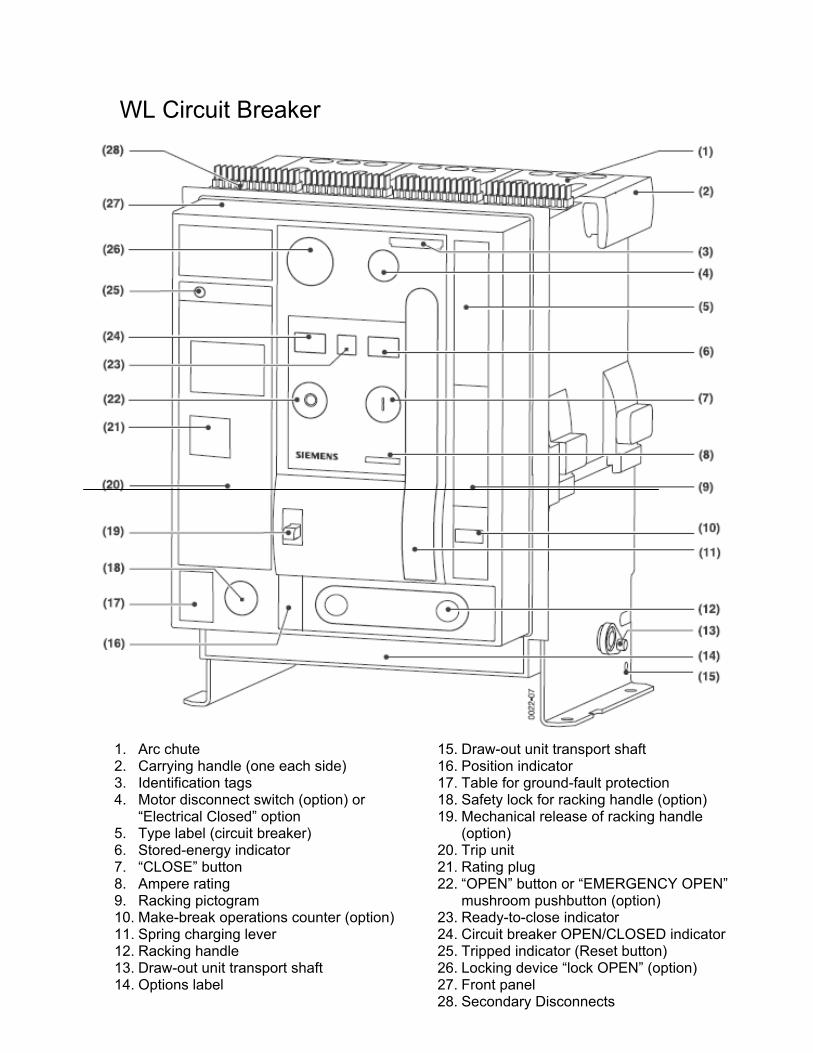
WL Circuit Breaker
1. Arc chute 2. Carrying handle (one each side) 3. Identification tags 4. Motor disconnect switch (option) or
“Electrical Closed” option 5. Type label (circuit breaker) 6. Stored-energy indicator 7. “CLOSE” button 8. Ampere rating 9. Racking pictogram 10. Make-break operations counter (option) 11. Spring charging lever 12. Racking handle 13. Draw-out unit transport shaft 14. Options label
15. Draw-out unit transport shaft 16. Position indicator 17. Table for ground-fault protection 18. Safety lock for racking handle (option) 19. Mechanical release of racking handle
(option) 20. Trip unit 21. Rating plug 22. “OPEN” button or “EMERGENCY OPEN”
mushroom pushbutton (option) 23. Ready-to-close indicator 24. Circuit breaker OPEN/CLOSED indicator 25. Tripped indicator (Reset button) 26. Locking device “lock OPEN” (option) 27. Front panel 28. Secondary Disconnects
3
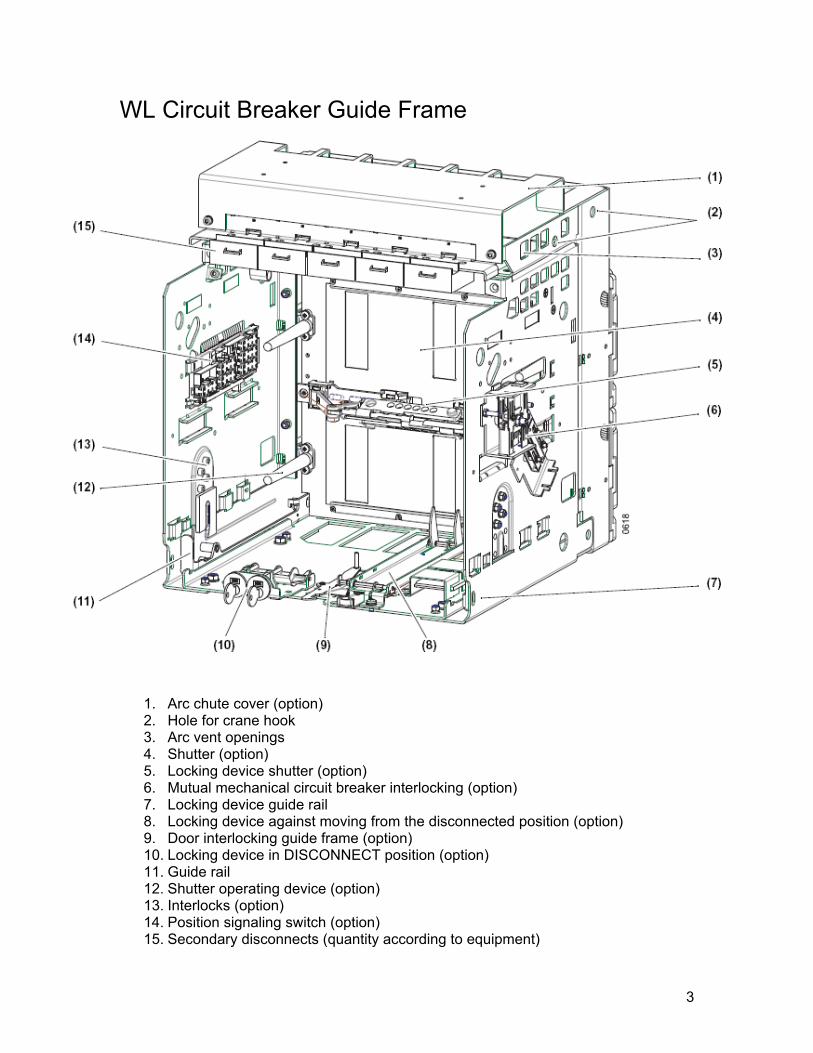
WL Circuit Breaker Guide Frame
1. Arc chute cover (option) 2. Hole for crane hook 3. Arc vent openings 4. Shutter (option) 5. Locking device shutter (option) 6. Mutual mechanical circuit breaker interlocking (option) 7. Locking device guide rail 8. Locking device against moving from the disconnected position (option) 9. Door interlocking guide frame (option) 10. Locking device in DISCONNECT position (option) 11. Guide rail 12. Shutter operating device (option) 13. Interlocks (option) 14. Position signaling switch (option) 15. Secondary disconnects (quantity according to equipment)
4
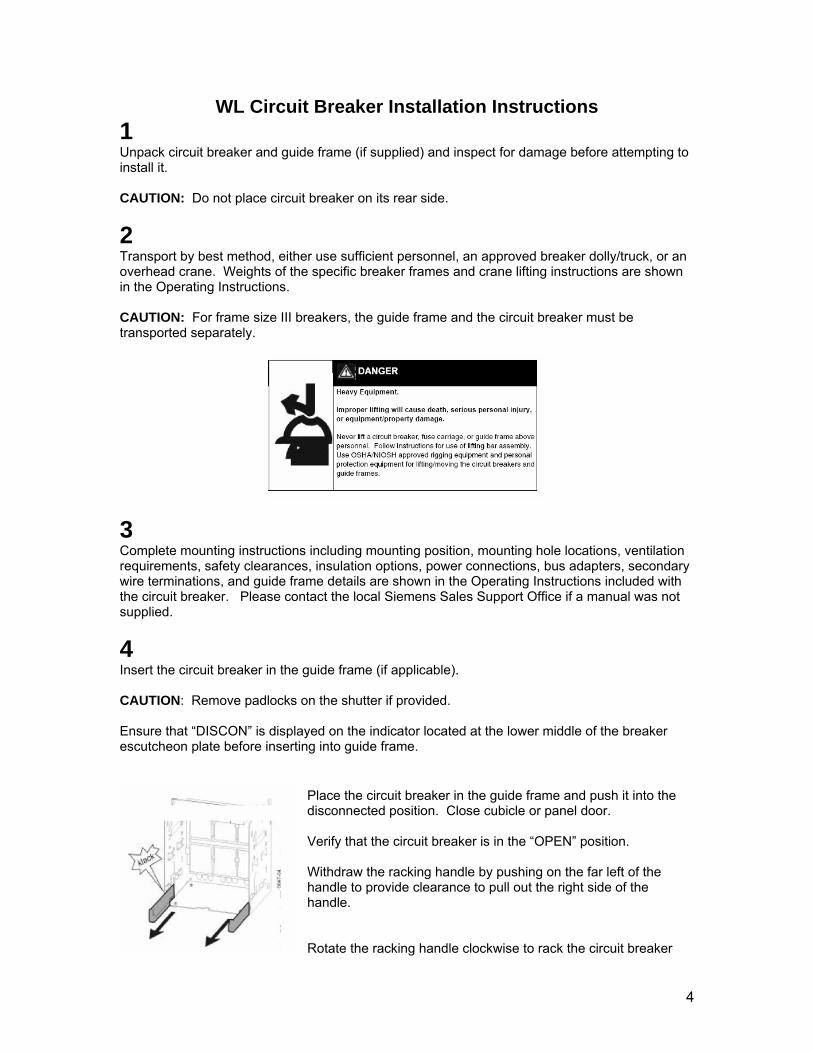
WL Circuit Breaker Installation Instructions 1 Unpack circuit breaker and guide frame (if supplied) and inspect for damage before attempting to install it. CAUTION: Do not place circuit breaker on its rear side.
2 Transport by best method, either use sufficient personnel, an approved breaker dolly/truck, or an overhead crane. Weights of the specific breaker frames and crane lifting instructions are shown in the Operating Instructions. CAUTION: For frame size III breakers, the guide frame and the circuit breaker must be transported separately.
3 Complete mounting instructions including mounting position, mounting hole locations, ventilation requirements, safety clearances, insulation options, power connections, bus adapters, secondary wire terminations, and guide frame details are shown in the Operating Instructions included with the circuit breaker. Please contact the local Siemens Sales Support Office if a manual was not supplied.
4 Insert the circuit breaker in the guide frame (if applicable). CAUTION: Remove padlocks on the shutter if provided. Ensure that “DISCON” is displayed on the indicator located at the lower middle of the breaker escutcheon plate before inserting into guide frame.
Place the circuit breaker in the guide frame and push it into the disconnected position. Close cubicle or panel door. Verify that the circuit breaker is in the “OPEN” position. Withdraw the racking handle by pushing on the far left of the handle to provide clearance to pull out the right side of the handle. Rotate the racking handle clockwise to rack the circuit breaker
5
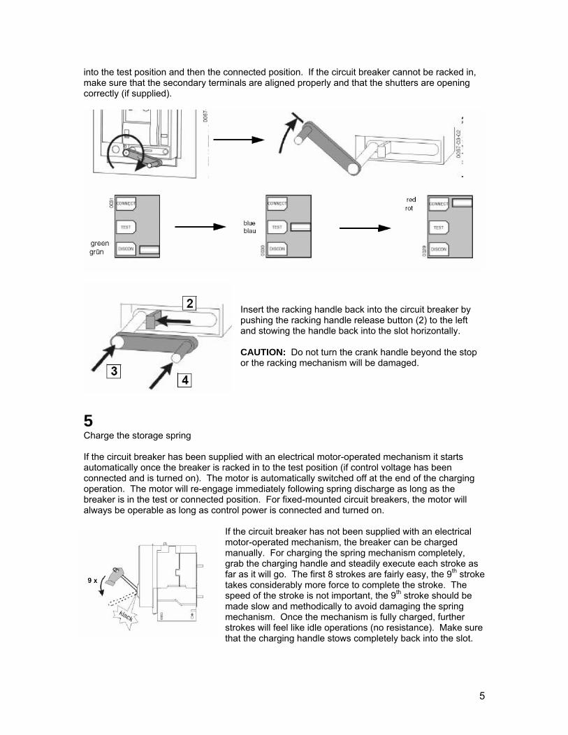
into the test position and then the connected position. If the circuit breaker cannot be racked in, make sure that the secondary terminals are aligned properly and that the shutters are opening correctly (if supplied).
Insert the racking handle back into the circuit breaker by pushing the racking handle release button (2) to the left and stowing the handle back into the slot horizontally. CAUTION: Do not turn the crank handle beyond the stop or the racking mechanism will be damaged.
5 Charge the storage spring If the circuit breaker has been supplied with an electrical motor-operated mechanism it starts automatically once the breaker is racked in to the test position (if control voltage has been connected and is turned on). The motor is automatically switched off at the end of the charging operation. The motor will re-engage immediately following spring discharge as long as the breaker is in the test or connected position. For fixed-mounted circuit breakers, the motor will always be operable as long as control power is connected and turned on.
If the circuit breaker has not been supplied with an electrical motor-operated mechanism, the breaker can be charged manually. For charging the spring mechanism completely, grab the charging handle and steadily execute each stroke as far as it will go. The first 8 strokes are fairly easy, the 9th stroke takes considerably more force to complete the stroke. The speed of the stroke is not important, the 9th stroke should be made slow and methodically to avoid damaging the spring mechanism. Once the mechanism is fully charged, further strokes will feel like idle operations (no resistance). Make sure that the charging handle stows completely back into the slot.
6
Requirement for “Ready to Close” or “OK” UL489 and UL1066 WL Low Voltage Air Circuit Breakers
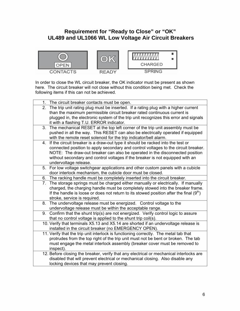
In order to close the WL circuit breaker, the OK indicator must be present as shown here. The circuit breaker will not close without this condition being met. Check the following items if this can not be achieved.
1. The circuit breaker contacts must be open. 2. The trip unit rating plug must be inserted. If a rating plug with a higher current
than the maximum permissible circuit breaker rated continuous current is plugged in, the electronic system of the trip unit recognizes this error and signals it with a flashing T.U. ERROR indicator.
3. The mechanical RESET at the top left corner of the trip unit assembly must be pushed in all the way. This RESET can also be electrically operated if equipped with the remote reset solenoid for the trip indicator/bell alarm.
4. If the circuit breaker is a draw-out type it should be racked into the test or connected position to apply secondary and control voltages to the circuit breaker. NOTE: The draw-out breaker can also be operated in the disconnected position without secondary and control voltages if the breaker is not equipped with an undervoltage release.
5. For low voltage switchgear applications and other custom panels with a cubicle door interlock mechanism, the cubicle door must be closed.
6. The racking handle must be completely inserted into the circuit breaker. 7. The storage springs must be charged either manually or electrically. If manually
charged, the charging handle must be completely stowed into the breaker frame. If the handle is loose or does not return to its stowed position after the final (9th) stroke, service is required.
8. The undervoltage release must be energized. Control voltage to the undervoltage release must be within the acceptable range.
9. Confirm that the shunt trip(s) are not energized. Verify control logic to assure that no control voltage is applied to the shunt trip coil(s).
10. Verify that terminals X5.13 and X5.14 are shorted if an undervoltage release is installed in the circuit breaker (no EMERGENCY OPEN).
11. Verify that the trip unit interlock is functioning correctly. The metal tab that protrudes from the top right of the trip unit must not be bent or broken. The tab must engage the metal interlock assembly (breaker cover must be removed to inspect).
12. Before closing the breaker, verify that any electrical or mechanical interlocks are disabled that will prevent electrical or mechanical closing. Also disable any locking devices that may prevent closing.
7
CubicleBUS Module Status Indicators and Operation
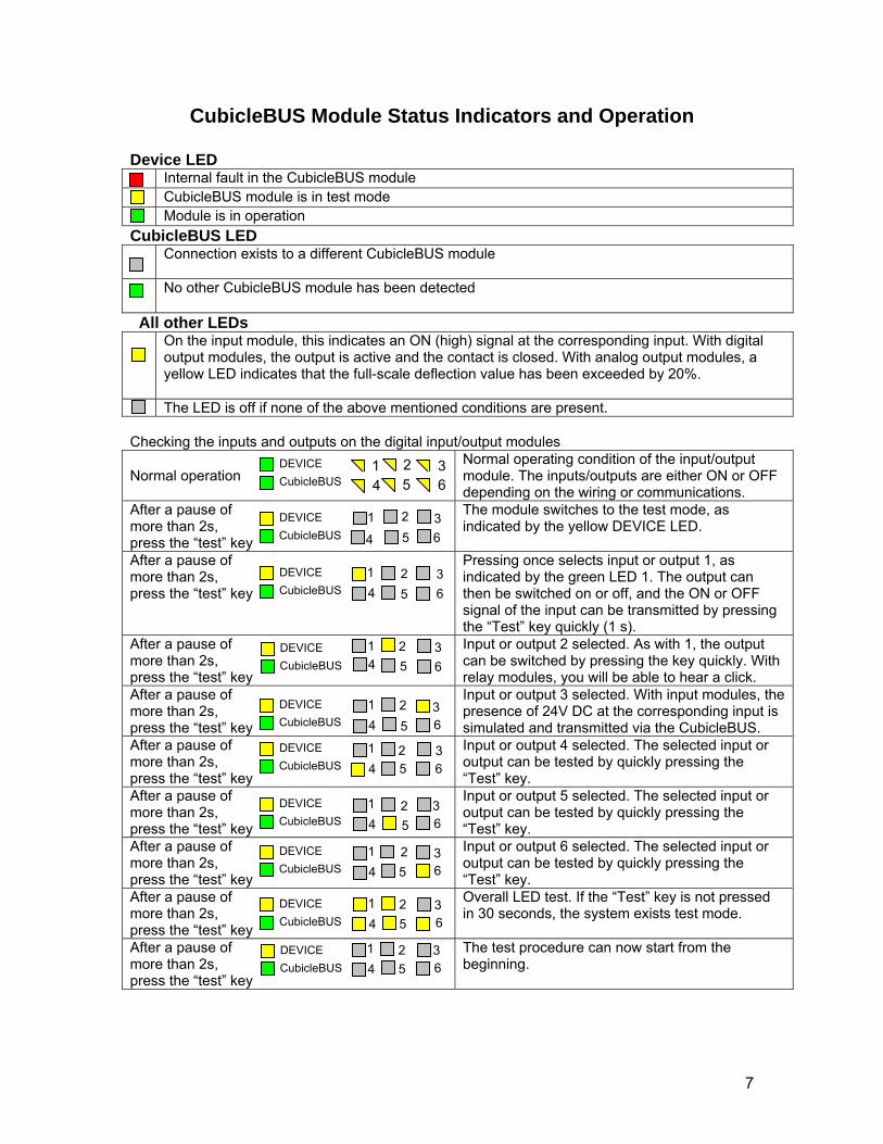
Device LED Internal fault in the CubicleBUS module CubicleBUS module is in test mode Module is in operation CubicleBUS LED Connection exists to a different CubicleBUS module
No other CubicleBUS module has been detected
All other LEDs On the input module, this indicates an ON (high) signal at the corresponding input. With digital
output modules, the output is active and the contact is closed. With analog output modules, a yellow LED indicates that the full-scale deflection value has been exceeded by 20%.
The LED is off if none of the above mentioned conditions are present. Checking the inputs and outputs on the digital input/output modules Normal operation
Normal operating condition of the input/output module. The inputs/outputs are either ON or OFF depending on the wiring or communications.
After a pause of more than 2s, press the “test” key
The module switches to the test mode, as indicated by the yellow DEVICE LED.
After a pause of more than 2s, press the “test” key
Pressing once selects input or output 1, as indicated by the green LED 1. The output can then be switched on or off, and the ON or OFF signal of the input can be transmitted by pressing the “Test” key quickly (1 s).
After a pause of more than 2s, press the “test” key
Input or output 2 selected. As with 1, the output can be switched by pressing the key quickly. With relay modules, you will be able to hear a click.
After a pause of more than 2s, press the “test” key
Input or output 3 selected. With input modules, the presence of 24V DC at the corresponding input is simulated and transmitted via the CubicleBUS.
After a pause of more than 2s, press the “test” key
Input or output 4 selected. The selected input or output can be tested by quickly pressing the “Test” key.
After a pause of more than 2s, press the “test” key
Input or output 5 selected. The selected input or output can be tested by quickly pressing the “Test” key.
After a pause of more than 2s, press the “test” key
Input or output 6 selected. The selected input or output can be tested by quickly pressing the “Test” key.
After a pause of more than 2s, press the “test” key
Overall LED test. If the “Test” key is not pressed in 30 seconds, the system exists test mode.
After a pause of more than 2s, press the “test” key
The test procedure can now start from the beginning.
DEVICE CubicleBUS
1 2 34 5 6
DEVICE CubicleBUS
1
4 52 3
6
DEVICE CubicleBUS
1 4 5
2 3 6
DEVICE CubicleBUS
1 4 5
2 3 6
DEVICE CubicleBUS
1 4 5
2 3 6
DEVICE CubicleBUS
1 4 5
2 3 6
DEVICE CubicleBUS
1 4 5
2 3 6
DEVICE CubicleBUS
1 4 5
2 3 6
DEVICE CubicleBUS
1 4 5
2 3 6
1 4 5
2 3 6
DEVICE CubicleBUS
8
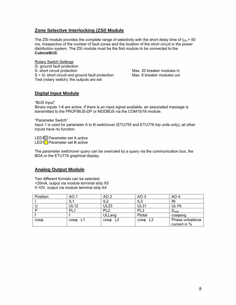
Zone Selective Interlocking (ZSI) Module The ZSI module provides the complete range of selectivity with the short delay time of tZSI = 50 ms, irrespective of the number of fault zones and the location of the short circuit in the power distribution system. The ZSI module must be the first module to be connected to the CubicleBUS. Rotary Switch Settings G: ground fault protection S: short circuit protection Max. 20 breaker modules in S + G: short circuit and ground fault protection Max. 8 breaker modules out Test (rotary switch): the outputs are set Digital Input Module “BUS Input” Binary inputs 1-6 are active. If there is an input signal available, an associated massage is transmitted to the PROFIBUS-DP or MODBUS via the COM15/16 module. “Parameter Switch” Input 1 is used for parameter A to B switchover (ETU755 and ETU776 trip units only), all other inputs have no function. LED1 Parameter set A active LED1 Parameter set B active The parameter switchover query can be overruled by a query via the communication bus, the BDA or the ETU776 graphical display. Analog Output Module Two different formats can be selected: +20mA, output via module terminal strip X5 0-10V, output via module terminal strip X4 Position AO 1 AO 2 AO 3 AO 4 I IL1 IL2 IL3 IN U UL12 UL23 UL31 UL1N P PL1 PL2 PL3 Stotal f f ULLavg Ptotal cosφavg cosφ cosφ L1 cosφ L2 cosφ L3 Phase unbalance
current in %
9
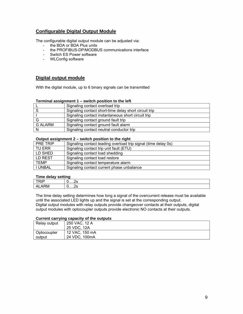
Configurable Digital Output Module The configurable digital output module can be adjusted via:
- the BDA or BDA Plus units - the PROFIBUS-DP/MODBUS communications interface - Switch ES Power software - WLConfig software
Digital output module With the digital module, up to 6 binary signals can be transmitted Terminal assignment 1 – switch position to the left L Signaling contact overload trip S Signaling contact short-time delay short circuit trip I Signaling contact instantaneous short circuit trip G Signaling contact ground fault trip G ALARM Signaling contact ground fault alarm N Signaling contact neutral conductor trip Output assignment 2 – switch position to the right PRE TRIP Signaling contact leading overload trip signal (time delay 0s) TU ERR Signaling contact trip unit fault (ETU) LD SHED Signaling contact load shedding LD REST Signaling contact load restore TEMP Signaling contact temperature alarm I UNBAL Signaling contact current phase unbalance Time delay setting TRIP 0….2s ALARM 0….2s The time delay setting determines how long a signal of the overcurrent release must be available until the associated LED lights up and the signal is set at the corresponding output. Digital output modules with relay outputs provide changeover contacts at their outputs, digital output modules with optocoupler outputs provide electronic NO contacts at their outputs. Current carrying capacity of the outputs Relay output 250 VAC, 12 A
25 VDC, 12A Optocoupler output
12 VAC, 150 mA 24 VDC, 100mA
10
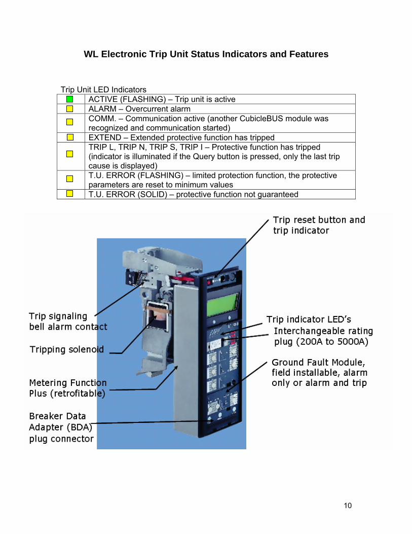
WL Electronic Trip Unit Status Indicators and Features Trip Unit LED Indicators ACTIVE (FLASHING) – Trip unit is active ALARM – Overcurrent alarm COMM. – Communication active (another CubicleBUS module was
recognized and communication started) EXTEND – Extended protective function has tripped TRIP L, TRIP N, TRIP S, TRIP I – Protective function has tripped
(indicator is illuminated if the Query button is pressed, only the last trip cause is displayed)
T.U. ERROR (FLASHING) – limited protection function, the protective parameters are reset to minimum values
T.U. ERROR (SOLID) – protective function not guaranteed
11
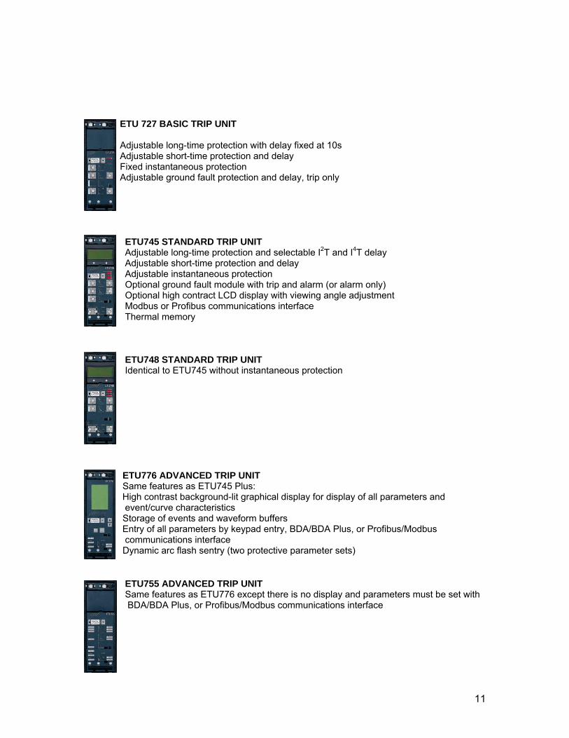
ETU 727 BASIC TRIP UNIT Adjustable long-time protection with delay fixed at 10s Adjustable short-time protection and delay Fixed instantaneous protection Adjustable ground fault protection and delay, trip only
ETU745 STANDARD TRIP UNIT Adjustable long-time protection and selectable I2T and I4T delay Adjustable short-time protection and delay Adjustable instantaneous protection Optional ground fault module with trip and alarm (or alarm only) Optional high contract LCD display with viewing angle adjustment Modbus or Profibus communications interface Thermal memory
ETU748 STANDARD TRIP UNIT Identical to ETU745 without instantaneous protection
ETU776 ADVANCED TRIP UNIT Same features as ETU745 Plus:
High contrast background-lit graphical display for display of all parameters and event/curve characteristics
Storage of events and waveform buffers Entry of all parameters by keypad entry, BDA/BDA Plus, or Profibus/Modbus communications interface
Dynamic arc flash sentry (two protective parameter sets)
ETU755 ADVANCED TRIP UNIT Same features as ETU776 except there is no display and parameters must be set with BDA/BDA Plus, or Profibus/Modbus communications interface
12
WL Circuit Breaker COM15 and COM16 Commissioning Procedure
1. Verify that the COM15/16 module is mounted properly at the top of the breaker so that the microswitches on the bottom of the module are activated when the breaker is drawn in and out of the guide frame (only applies to draw-out breakers). 2. Verify that the four black cables coming out of the COM15/16 module are landed on X8:1, X8:2, X8:3, and X8:4 (wires are labeled accordingly). 3. DP Write is enabled on the COM15/16 module (put jumper across terminals 1 and 2 on the module). 4. Put terminating resistor in the COM15/16 module or the last CubicleBus module. 5. Change the COM15/16 address to a unique identifying address (1-125), factory default address is 126. 6. Briefly interrupt the 24VDC supply to the COM15/16 module in order to activate the new address. 7. Verify that the COMM. LED is green on the WL ETU trip unit. 8. Verify that the CubicleBus LED is steady green on the COM15/16 module. 9. Verify that the Profibus or Modbus LED is green on the COM15/16 module. 10. The preferable way to set up the COM15 Profibus DP slave device is with Switch ES Power Object Manager in STEP7. The slave can also be set up with integration of the GSD file in the Profibus-DP Master hardware configuration tool. 11. Enable Sync and Freeze in Profibus DP master (if applicable) 12. Cyclic data exchange should be minimized for the specific application in order to maintain acceptable speeds. 13. For initial communications verification use default assignment Basic Data Type 1. This will initiate basic cyclic data exchange with the COM15/16 module. After communications are established, basic data type can be changed and modified. DPV1 acyclic data exchanges should be set up last after communications are active. 14. If communications can not be established, request complete diagnostic data from the COM15/16.