operations and maintenance manual-switchboards and switchgear · switchgear. this document is...
TRANSCRIPT
Operations and Maintenance Manual-Switchboards and SwitchgearDara Switchboards

Scope
This document covers the procedures and recommendations for the maintenance of low voltage electrical switchboards and switchgear. This document is prepared in line with Australian standard (AS/NZS 2467:2008) for maintenance of electrical switchgear.
Introduction
Low voltage electrical switchboards are at the heart of power distribution in a modern building where there is increased dependence on computers and automated processes that cannot afford downtime.
Electrical switchgear by its design and construction does not call for maintenance to ensure its function. Routine maintenance is however required to ensure continued safe and efficient operation without loss of supply to the installation.
Safety of personnel carrying out operations and maintenance
Computational fluid dynamics (CFD) analysis was carried out to find the maximum wind pressure applied on the switchboard in case of a maximum wind gust speed.
Results from the CFD analysis showed that the wind pressure on the switchboard can reach up to 4000 Pa (Figure 2) in an event of 237.6 km/h (66 m/s) maximum wind gust speed
Statutory requirements
Operation and maintenance of electrical equipment possess a degree of danger and it is the responsibility of engineers and other supervisory personnel engaged in electrical work or operations to become acquainted with the statutory requirements applicable to the industry and state where the work is carried out. NO LIVE WORK IS TO BE CARRIED OUT.
If for any reason a fault does arise, a qualified electrician must be obtained for investigation into the fault and correction.
First aid equipment
Where the maintenance of electrical equipment is carried out especially inside switchrooms, a notice giving instructions on treatment of a person suffering from electric shock should be affixed and first aid equipment should be made available for the treatment of personnel.
Operations and Maintenance Manual Switchboards and Switchgear
Instruction, notices and labels
Adequate instructions on shut down procedures and correct schematic drawings shall be provided or displayed in the switchroom to ensure the operator carries out work safely after isolation work is carried out correctly.
Maintenance of newly installed switchboards and switchgear
Switchboards, irrespective of the class of duty, should be examined prior to commissioning and inspected within 12 months of the defect liability period.
Below is a list of examinations to be done for newly installed switchboards:
•Check the tightness of any fixing and fastenings especially at terminals for conductors and joints of copper connections. (these could come loose during transportation and would result in hot spots and fire hazards)
•Internal cleanliness (this is important as the dust and presence of foreign objects increase the possibility of flash overs).
•Condition of insulation
•Operation of circuit breakers, handle mechanisms •Integrity of mechanical interlocks (you may need to adjust the cable interlocks once the switchboard is transported to site for correct operation)
•Condition of weather seals and gaskets on doors
•Condition of protective coating and signs of corrosion
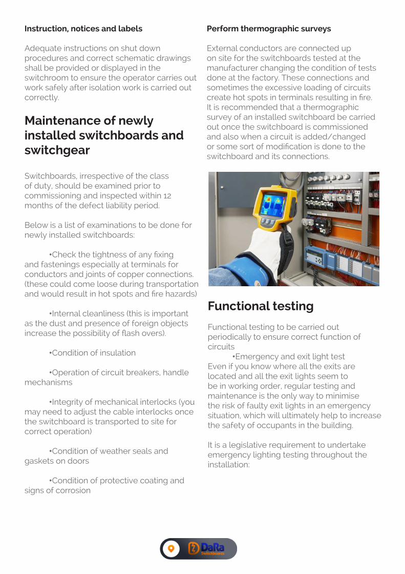
Perform thermographic surveys
External conductors are connected up on site for the switchboards tested at the manufacturer changing the condition of tests done at the factory. These connections and sometimes the excessive loading of circuits create hot spots in terminals resulting in fire. It is recommended that a thermographic survey of an installed switchboard be carried out once the switchboard is commissioned and also when a circuit is added/changed or some sort of modification is done to the switchboard and its connections.
Functional testing
Functional testing to be carried out periodically to ensure correct function of circuits •Emergency and exit light testEven if you know where all the exits are located and all the exit lights seem to be in working order, regular testing and maintenance is the only way to minimise the risk of faulty exit lights in an emergency situation, which will ultimately help to increase the safety of occupants in the building. It is a legislative requirement to undertake emergency lighting testing throughout the installation:

Six monthly: Twelve monthly:
1.Visual check 1. Visual check
2. Discharge test 90 minutes
2. Discharge test 90 minutes
3. Reinstate supply 3. Re instate supply
4. Clean all light emitting and reflecting surfaces
Select test position of the emergency lighting test unit for the manufacturers set hours or other desired period. Check whether emergency lights go off after set time period or follow instructions provided by emergency lighting test unit supplier.
Trip button testMost moulded case circuit breakers have an inbuilt trip button to check the functionality of the operating device and this trip button can be used to check the correct operation of the circuit breakers
RCD testingSafety Switches, or Residual Current Devices (RCDs) are designed to save lives. They operate by tripping (cutting the electricity supply) when an electrical current imbalance is detected between the active and neutral conductors.
You should ensure that you conduct regular RCD testing in accordance with your industry and state based regulations. As a minimum, a trip button test to ensure the correct operation of the RCD.
Routine maintenance
Inspect all switchgear installations at frequent intervals. Perform a visual inspection, front and rear, to see that there is no evidence of loose parts, warping, or undue vibration. Take steps to remedy any deficiencies of this nature that may appear. Keep the assembly dry. Cover to prevent moisture from dripping on the equipment. Do not block vents.
DANGER
There are hazards of electrical shocks and/or burns whenever working in or around electrical equipment. Turn off power ahead of the switchgear before perform-ing any maintenance operations. Check incoming line terminals to verify that the equipment is deenergized. Check the out-going terminals to make sure that no feedback conditions exist.
Every 6 months
Perform an overall visual inspection Check all indicators, meters, and instruments for proper operation. Make sure all bolted panels are secure. Verify operation of heaters and thermostats, if used. Check for undue noise or vibration that might loosen bolted connections. Look for evidence of moisture in the switchgear.

Every 12 months
Check the insulations are embrittled or discoloured insulation may indicate an overheated connection and need to be fixed. Inspect all cables for tight connections. Inspect control wiring for signs of wear and damage. Replace wires wherever doubtful.
Withdraw all drawout components and clean as per the circuit breaker manufacturers recommendations.
Clean air filters of vents. Follow the recommendations of any individual device instructions furnished for maintenance of the device. Indicating devices such as mechanical ‘ON’ and ‘OFF’ indicators, semaphores, etc. should be inspected to ensure that they are in good order and operating correctly. Correct operation of any interlocks and padlocking devices should be verified and any adjustments required should be made. Exercise circuit breakers by manually operating circuit breakers which will enable contacts to be kept clean and helps operating mechanisms operate freely.
After 10 years
Torque all primary conductor connection bolts to recommended values
BOLT SIZE TIGHTNING TORQUE (Nm)
M6 20
M8 30
M10 40
M12 60
Tighten all secondary control wire connections. Check for loose lug crimps and broken wire strands.
Reinsulate or replace any conductors showing damage to its primary insulation.
Thermographic survey after reconnections to ensure the thermal performance during operation.
Perform insulating testing.
Do functional testing of all circuits including emergency stop, shunt trip mechanisms, auto changeover etc.
Upgrade any equipment that is obsolete in technology. Factors to consider include the operating environment, availability of spare parts, reliability, and the cost of ongoing maintenance.
Post fault maintenance
DANGER
Circuit breakers operate under fault conditions. Do not operate the circuit breaker until the fault is cleared and there is no risk of closing on to a fault which could result in arcing faults causing serious burns to the operator
DiagnosticsCircuit breakers operate due to fault conditions in the circuit and therefore need to be diagnosed by a qualified personal (eg. Electrician) and the fault conditions need to be removed from the circuit before operating the circuit breaker
CleaningThe circuit breaker operation mechanism should be verified

MechanismsThe circuit breaker operation mechanism should be verified
Insulation testA test should be made of the insulation resistance before putting the switchgear back into service.
Keep Good Records and Trend Performance
By tracking test data, you can get a better idea of the expected life of the equipment and focus your maintenance efforts on the areas that truly need it the most.
Records should be in the form of a sheet or schedule to suit the particular plant or installation. Records should state:
The condition of the equipment at the nominated inspection intervals Work carried out
Any areas that may give future concerns

Date Inspection / maintenance activity Notes / comments Done by
Maintenance Record

For more infomation please visit www.electricalswitchboards.com.au