attached is the software configuration management plan .../67531/metadc735475/m2/1/high...rpp-7142,...
TRANSCRIPT

ATTACHED IS THE SOFTWARE CONFIGURATION MANAGEMENT PLAN (SCMP) FOR THE SALTWELL LEAK DETECTOR STATIONS (LDS).
I I I IMANAGEMENT PLAN (SCMP) I I I I
4ppmvai Dedgnator (F)
E, S. Q, D OR N/A (See WC-CM-55.
Sec. 12.7)
16. KEY
Reaaon for Tranmmal(0) D W b n (H) a (1)
4. Review 1. Approved 4. Ravkwsd nolcommenl 4: irrz' 5. Pod-Reviaw 2. A roved wlcomment 5. Revkwsd wlmmment 3. information 6. Dist. (Receipt Acknow. Required) 3. Dflp,pproved wlcomment 6. Rewlpt acknowledged
QA N/A
Safety N/A
Em. N/A 1 s.
F.M. MAIDEN Signature of EDT Date Ablhorlnd Re naentative Date Originator for Rewiving grgankatbn
21. DOE APPROVAL (if required)
%$q& D e i n Authority/ Cog&ant Manager
CMNo. N/A W.F. URO F 0 Appmvd
Date Approved wlcommsnts 0 Disapproved w/comments

DISTRIBUTION SHEET
To 1 From D I l n 1 rl , "&J' A "I L
Distribution I Date 11/08/00 Proied TiileMlork Order
RPP-7142 SALWELL LEAK DETECTOR STATION PROGRAMMABLE LOGIC CONTOLLER
A4MW)-135 (10197)
RPP-7142, Rev. 0
SALTWELL LEAK DETECTOR STATION PROGRAMMABLE LOGIC CONTROLLER (PLC) SOFTWARE CONFIGURATION MANAGEMENT PLAN (SCMP) m.R. uocn
Richland, WA 99352 US. Department of Energy Contract DE-AC06-98RLI 3200
EDTIECN: 629927 uc: orgcode: 4 7 ~ 0 0 Charge Code: ~10250
CHZMHILL HANFORD GROUP, INC.
Code: EW3120071 Total Pages: )x 12 p d d
Keywords: PLC, LADDER LOGIC, LEAK DETECTOR STATION, SALTWELL INTERIM STABILIZATION, SCMP
Abstract: This document describes the Software Configuration Management Plan for the Saltwell Leak Detector Station software. It identifies the requirements, associated documents, and the software controls.
*Allen Bradley is a registered trademark of Allen Bradley Company *Wonderware is a registered trademark of Wonderware Corporation.
TRADEMARK DISCLAIMER. Rekrenm herein to any spdilc mmmerdal product, pmmu, or SONIC. by tnda name, trademark, manufadurer, or 0thmmi.r. dms not mcauarily con.tltute or imply b endonemenl nmmmernialbn, or favoring by the Unbd Stabs Governmmnt or any agenq thereof or Ita mntracton or aubcontradon.
Pdntd In the Uniled Stabs of A m e h . To obtain mpies of this document, contact: Document Control Servlms, P.O. BOX 950. Mdktop H W X , Richbnd WA SS352. Phone (SOS) 372-2420: Fax (506’) 378-4989.
- I - . HANFORD
RELEASE
DATE:
STA
I // z.q/m R e b a r Approval Dah R e b a r Stamp
Approved For Public Release
A-6400073.1 (1N7)

RPP-7142, Rw. 0
SALTWELL LEAK DETECTOR STATION PROGRAMhfABLE LOGIC CONTROLLER (PLC)
SOFTWARE CONFIGURATION MANAGEMENT PLAN
Prepared by:
F. M. Maiden
November 2000
COGEMA Engineering Corporation Richland, Washington
RPP.7142. Rev . 0
TABLE OF CONTENTS
1 INTRODUCTION .......................................................................................................................... 1
1.1 PURPOSE .......................................................................................................... 1 1.2 SCOPE ............................................................................................................... 1 1.3 OVERVIEW ...................................................................................................... 1 1.4 DEFINITIONS ................................................................................................... 4 1.5 ACRONYMS I ABBREVIATIONS ................................................................... 4 1.6 TERMS .............................................................................................................. 4
2 MANAGEMENT ............................................................................................................................ 5
2.1 ORGANIZATION ............................................................................................. 5 2.2 RESPONSIBILITIES ......................................................................................... 5 2.3 IMPLEMENTATION ........................................................................................ 8 2.4 POLICIES AND PROCEDURES ...................................................................... 8 2.5 INTERFACE CONTROL .................................................................................. 8 SOFTWARE CONFIGURATION MANAGEMENT ACTIVITIES ............................................ 8
3.1 CONFIGURATION IDENTIFICATION ........................................................... 8 3.2 CONFIGURATION CONTROL ........................................................................ 9 3.3 CONFIGURATION STATUS ACCOUNTING ............................................... 10 3.4 TESTING & TRACEABILITY ........................................................................ 11 3.5 MEDIA CONTROL ......................................................................................... 11 3.6 AUDITS AND REVIEWS ............................................................................... 11 3.7 ACCESS CONTROL ....................................................................................... 1 1 3.8 BACKUP AND RECOVERY .......................................................................... 1 1 3.9 SOFTWARE RETIREMENT ........................................................................... 11
4 TOOLS, TECHNIQUES, AM) METEODOLQGIES ................................................................. 12
5 SUPPLIER CONTROL ................................................................................................................ 12
6 RECORD COLLECTION AM) RETENTION ........................................................................... 12
3
6.1 DOCUMENTS .......................................................................................................... 12 SAFETY, RELUJMLlTY, AND QUAJJTY ASSURANCE ........................................................ 13
SAFETY CLASSIFICATION AND SIGNATURE DESIGNATION ............... 13 QUALITY ASSURANCE AND QUALITY CONTROL ................................. 13
8 SOFTWARE CHANGE REQUEST ............................................................................................ 14
9 REFERENCES ....................................................................................................................... ...... 17
LEAK DETECTOR STATION PLC SOFTWARE LIFE CYCLE
7
7.1 7.2
i

RPP-7142, Rev. 0
LIST OF FIGURES
Figure 1. Example -- A-FarmNetworkLoop Block Diagram .......................................... 3
ii

RPP-7142, Rev. 0
1 INTRODUCTION
1.1 PURPOSE
This document provides the procedures and guidelines necessary for computer software configuration management activities during the operation and maintenance phases of the Saltwell Leak Detector Stations as required by HNF-PRO-309, Rev. 1, Computer SofWure Quality Assurance, Section 2.4, Sofluwe Conjgurution Mmgemeni. The software configuration management plan (SCMP) integrates technical and administrative controls to establish and maintain technical consistency among requirements, physical configuration, and documentation for the Saltwell Leak Detector Station Programmable Logic Controller (F'LC) software during the Hanford application, operations and maintenance. This SCMP establishes the Saltwell Leak Detector Station PLC Software Baseline, status changes to that baseline, and ensures that software meets design and operational requirements and is tested in accordance with their design basis.
1.2 SCOPE
This plan applies to those organizations responsible for the operation and maintenance of the Saltwell Leak Detector Station PLC software. This plan applies to the operational phase (including maintenance and transition to deactivation) of the present Saltwell Leak Detector Station PLC software as well as any hture software developed for new Saltwell Leak Detector Station PLCs. Specific scope objectives for the Saltwell Leak Detector Station PLC SCMP are the following:
Establish and maintain the requirements and associated documents to accurately reflect the Saltwell Leak Detector Station PLC software. Identify and maintain the documents within the scope of the SCMP (see Section 6.1). Control and status changes to software to ensure the continued quality of the requirements, physical configuration, and documentation. Conduct assessments to ensure that the software configuration management plan is effective in establishing and maintaining the technical requirements.
1.3 OVERVIEW
The Saltwell Leak Detector Station is composed of a programmable logic controller (PLC), a DH485 interface, and VO ports connected to various local leak detector sensing devices. The sensing device trips the local Leak Detector alarms (lights) and sends an alarm signal to the Leak Detector Station. The Leak Detector Station PLC receives the alarm signal through an I/O port and then communicates the alarm over the DH-485 network to Saltwell PIC skids connected to the transfer line.
1

RPP-7142, Rev. 0
1.3.1 Saltwell Leak Detector Station Control System Components and Associated Software
PLC Ladder Logic Software Micrologic 1000 PLC or SLC-500 PLC

RPP-7142, Rev. 0
LOCATED IN 241-A-271
Figure 1. Example -- A-Farm Network Loop Block Diagram
I I 1770 K F 3 MODULE A271-SALW-CONV-151
1770 K F 3 MODULE A271-SALW-CONV-150
COMPUTER FOR SALTWELL PUMPING
TMACS PB
I I INPUT FROM V A L V E P IT AX-A
INPUT FROM V A L V E P IT AX-B
TMACS PB- LOCATED ON 241-A-101 SKID
PlCS 241-AX-101 + LOCATED ON 241-AX-I01 SKID

RPP-7142, Rev. 0
1.4 DEFINITIONS
See AcronymdAbbreviations
1.5 ACRONYMS /ABBREVIATIONS
SDD SRD DOE DOE-RL FDH HLAN CHG LMSI ORP FPH SCR PLC CVI
- Software Design Description - Software Requirements Document - United States Department of Energy - DOE Richland Operations Ofice - Fluor Daniel Hanford Corporation - Hanford Local Area Network - CH2M HILL Hanford Group, Inc. - Lockheed Martin Services Inc - Office of River Protection - Fluor Project Hanford - Software Change Request - Programmable Logic Controller - Certified Vendor Information
1.6 TERMS
Application Softwaro is the general term applied to the software covered by this software configuration management plan.
Master Coon is the official copy of the Leak Detector Station PLC software. The master copy of the Leak Detector Station PLC software will be controlled by the Leak Detector Station PLC Software Custodian and reside in the Software file cabinet.
Initial Baseline for Leak Detector Station PLC Software is PIC skid “ D (SX-104) software, each subsequent unique Leak Detector PLC software baseline will be set at the completion ofthe Functional Test for that particular Leak Detector Station.
*NOTE: Leak Detector software is based on the PIC skid PLC software modified as needed to meet the requirements of each Leak Detector Stations.
refer to everything needed to justify, define, and describe the physical and operational configuration of a Structure, System, or Component (SSC). For the Leak Detector Station this includes the PLC and the associated software.
Software Life Cvcle is the period of time that starts when a software product is conceived and ends when the product is no longer available for use.

RPP-7142, Rw. 0
2 MANAGEMENT
Organizational roles and responsibilities are established to ensure that functional organizations are aware of the responsibilities required for implementation of this plan.
2.1 ORGANIZATION
This plan applies to the following:
Tank Farm Interim Stabilization Engineering and Tank Farm Interim Stabilization Project Operations, currently performed by CH2M HILL Hanford Group (CHG),
Nuclear Safety and Quality Assurance, currently performed by CH2M HILL Hanford Group (CHG)
Leak Detector Station PLC Software Design Agent, currently performed by CH2M HILL Hanford Group (CHG)
Software Custodian, currently performed by CH2M HILL Hanford Group (CHG)
2.2 RESPONSIBILITIES
The Department of Energy (DOE) Ofice of River Protection (OW) oversees the Hanford Site's tank waste remediation systems. The O W is responsible for developing and implementing requirements and procedures that establish management responsibilities and process methodologies. CHG is the DOE contractor responsible for managing the Hanford tank farms.
2.2.1 Interim Stabilization Engineering
CHG Interim Stabilization Engineering is responsible for:
1. Establishing and managing the Leak Detector Station PLC software configuration management program elements defined in Section 6.1.
2. Initiating the software changes.
3. Assisting in the identification, definition, and control of programmatic and technical interfaces.
4. Ensuring that software configuration management controls are used in the conduct of operations.
5. Identifying, establishing, reviewing, and approving minimum testing criteria.
6. Assisting in the review/acceptance of vendor information.
5

RPP-7142, Rev. 0
2.2.1.1 Interim Stabi l i t ion Engineering - Cognizant Engineer
The Cognizant Engineer is the assigned owner of the Leak Detector Station PLC software and operational configuration and is responsible for:
1. Implementing and managing the SCMP (shared responsibility with Design Authority).
2. Ensuring that complete and accurate technical documentation is developed and maintained.
3. Providing engineering direction and oversight to ensure that the designs remain consistent with technical baselines.
2.2.1.2 Interim Stabilization Engineering - Cognizant Manager
The Cognizant Manager is responsible for assuring that reviews and approvals appropriate to impact levels are obtained for software and other configuration items.
2.2.1.3 Interim Stabilization Engineering - Design Authority
The Design Authority is the assigned owner of the Leak Detector Station PLC software requirements, design baseline, and system configuration and is responsible for the following:
1. Controlling the technical baseline.
2. Implementing and managing the software configuration management plan (shared responsibility with Cognizant Engineer).
3. Ensuring that complete and accurate technical documentation is developed and maintained.
4. Providing engineering direction and oversight to ensure that designs remain consistent with the technical baselines.
2.2.2 Interim Stabilization Project Operations
CHG Interim Stabilization Project Operations (Operations) operates the Hanford waste tank farm Saltwells under the management direction of the O W . Operations is responsible for providing input for the identification of changes to the Leak Detector Station PLC software.
2.2.3 Nuclear Safety
Nuclear Safety is responsible for addressing safety issues and reviewing and approving Leak Detector Station PLC software changes with an approval designator “S”.
6
RPP-7142, Rev. 0
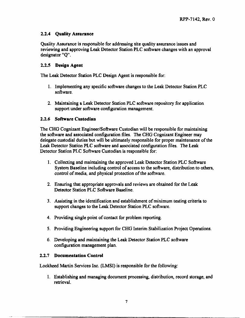
2.2.4 Quality Assurance
Quality Assurance is responsible for addressing site quality assurance issues and reviewing and approving Leak Detector Station PLC software changes with an approval designator “ Q .
2.2.5 Design Agent
The Leak Detector Station PLC Design Agent is responsible for:
1. Implementing any specific software changes to the Leak Detector Station PLC software.
2. Maintaining a Leak Detector Station PLC software repository for application support under software configuration management.
2.2.6 Software Custodian
The CHG Cognizant EngineedSohare Custodian will be responsible for maintaining the software and associated configuration files. The CHG Cognizant Engineer may delegate custodial duties but will be ultimately responsible for proper maintenance of the Leak Detector Station PLC s o h a r e and associated configuration files. The Leak Detector Station PLC Software Custodian is responsible for:
1. Collecting and maintaining the approved Leak Detector Station PLC Software System Baseline including control of access to the software, distribution to others, control of media, and physical protection of the software.
2. Ensuring that appropriate approvals and reviews are obtained for the Leak Detector Station PLC Software Baseline.
3. Assisting in the identification and establishment of minimum testing criteria to support changes to the Leak Detector Station PLC software.
4. Providing single point of contact for problem reporting.
5 . Providing Engineering support for CHG Interim Stabilization Project Operations.
6. Developing and maintaining the Leak Detector Station PLC software configuration management plan.
2.2.7 Documentation Control
Lockheed Martin Services Inc. (LMSI) is responsible for the following:
1. Establishing and managing document processing, distribution, record storage, and retrieval.
I

RPP-7142, Rev. 0
2. Providing vault storage for documentation.
2.3 IMPLEMENTATION
This software configuration management plan will be effective upon release.
2.4 POLICIES AND PROCEDURES
Procedures and Policies used to implement this plan
HNF-PRO-309 “Computer Software Quality Assurance Requirement” HNF-IP-0842 “Tank Farm Administration Procedure” HNF-PRO-2778 “Application Software System Life Cycle Standards”
2.5 INTERFACE CONTROL
Interface and agreements between companies will be identified, defined and controlled per contracts with CHG. Additional organizational or programmatic intefices are defined in Section 2.2.
3 SOFTWARE CONFIGURATION MANAGEMENT ACTIVITIES
3.1 CONFIGURATION IDENTIFICATION
Software related documents that are defined in Section 6.1 will be controlled as Supporting Documents.
Supporting documents will be issued a document number according to HNF-PRO-604, “Hanford Document System,” and released via an Engineering Data Transmittal (EDT) form according to RPP-PRO-244, “Engineering Data Transmittal Requirements.” Changes to released supporting documents will be controlled via an Engineering Document Change Notice (ECN) according to HNF-IP-0842, Volume 4, Section 4.29, “Engineering Document Change Control Requirements.”
During changes to the software, the applicable Supporting Documents may be presented in an unreleased form at the review that verifies them but must be released immediately following incorporation of comments from that review. Prior to release, the CHG Cognizant Engineer will control software documents.
8

RPP-7142, Rev. 0
3.1.1 Baseline Elements
Items that describe the physical attributes and hnction of the Saltwell Leak Detector Station PLC Software are the following:
1. Documents:
Functional Test Software Description Document (Requirements and Design Description)
2. Computer Software: SX-104 PIC skid “ D software is the baseline software for the Leak Detector Station PLC Software.
** Note: Leak Detector software is based on the PIC skid PLC software modified as needed to meet the requirements of each Leak Detector Stations.
3. Vendor Information & Specifications: Vendor information located in CVI File # 22726
3.1.2 Labeling of Software Media
Upon successfld installation of any Leak Detector Station PLC Software, a label will be affixed to the Master copy and system backup with the following information displayed:
PLCSoftwareID. Leak Detector Station ID
Initial of VerifierNalidator. Revision numbeddate for the software.
3.2 CONFIGURATION CONTROL
3.2.1 Software Change Request (SCR)
During the Operations and Maintenance Phase of the Leak Detector Station PLC software life cycle, problems, errors, difficulties with the software, requests for changes, or requests for new services will be reported to the CHG cognizant engineer and the designated Software Custodian.
The designated Software Custodian will fill out a Software Change Request (SCR) which will follow the guidelines in HNF-PRO-2778 (Each SCR will be numbered and entered into the “SCR” file maintained in the Leak Detector Station PLC Software file cabinet).
The CHG Cognizant Engineer will assess the problem or change request and assign it for consideration to the Design Agent. The Design Agent will enter the SCR report into the Leak Detector Station PLC Software Custodian notebook.
9

RPP-7142, Rev. 0
The Design Agent will determine whether the problems require corrective action, whether corrective action requires changes to the baseline configuration, and how extensive the modification will be.
If no corrective action is needed, the SCR is closed at that point
If corrective action is required, based upon the Design Agent determination, CHG Interim Stabilization Engineering may grant the authority to modify the affected software components, upgrade the system, or develop new software components to the appropriate individual.
3.2.2 Documenting Changes
When changedmodifications to existing software components are complete and verified, an ECN is approved and issued for the new version of the software and any revised documents (see section 6.1). The ECN will reference the Leak Detector Station I.D. and associated Leak Detectors. The new version of the software is introduced into the Design Agent’s software repository, delivered to the Software Custodian who introduces it into the software file cabinet, and the Leak Detector Station PLC software is certified by testing.
3.3 CONFIGURATION STATUS ACCOUNTING
The designated Software Custodian will prepare a status accounting file before each Leak Detector Station PLC software release.. The status accounting will include a list of all software files that make or produce a release product. The status accounting file will include the following:
Software ID Software Revision Numberhtevision Date
Leak Detector Station I.D. (Location where produdsohare is installed)
Instructions on how to build the software product from the files will include identification of support software. Support sofhvare includes compilers, assemblers, editors, operating systems, and other utility software.
3.3.1 Revision History
The contents of the status accounting file will include the revision history. The revision history will include a description of the initial field release and all subsequent changes to the file. The description will include the following:
Revision numberlrevision date Nature of the change Identity of the requester Rationale for the change Identity of author making the change
10

RPP-7142, Rev. 0
3.4 TESTING & TRACEABILITY
The Leak Detector Station PLC software will be verified and validated during the functional test of the leak detectors.
S/SX/SY&T Farms “Functional Test TF-FT-479-004 “ UFarm “Functional Test TF-FT-509-009”
9 A/AX/AX/AZFarms “Functional Test TF-FT-259-009”
Functional test will provide traceability linking hardware and test documentation together.
3.5 MEDIA CONTROL
The form of media used to store approved release software will be 3 %” diskettes. The software will be stored in at least two locations. One set of the software media will be stored in a locked fire resistant file cabinet drawer labeled “Software Records” in the file named “Leak Detector Station PLC Field software”. This file cabinet will be located as specified by the manager of the Software Custodian. Each approved release software will bear a label with the information required in Section 3.1.2, Labeling ofSof3vure Media, of this document. The second set of software media is stored in the Design Agent’s software repository and is controlled by configuration management.
3.6 AUDITS AND REVIEWS
The Leak Detector Station Functional Test will be used to verify and document that any upgrades to the Leak Detector Station PLC software are complete.
3.7 ACCESS CONTROL
Leak Detector Station PLC system hardware access will be controlled by tank farm access requirements when the system is installed within the farm boundaries. The Master backup of the software will be stored in a locked cabinet. The Hanford Site document control process will control all documentation.
3.8 BACKUP AND RECOVERY
Backups for each Leak Detector Station PLC software will be kept on 3 %” diskettes for the duration of the Leak Detector Station’s active life.
3.9 SOFIWARE RETIREMENT
Software Retirement for individual Leak Detector Station PLC software will be initiated after it has been removed from service.
11

RPP-7142, Rev. 0
4 TOOLS, TECHNIQUES, AND METHODOLOGIES
None
5 SUPPLIER CONTROL
Pertinent vendor technical information shall be identified, collected, and entered into the Hanford Site documentation control system as vendor information using an EDT.
Documents shall be written in a format that is compatible with Hanford Site Document Control.
6 RECORD COLLECTION AND RETENTION
Records handling will be as described in HNF-PRO-2778, “IRM Application Software System Life Cycle Standards.” All Leak Detector Station PLC software documentation will be retained through the removal of the Leak Detector Station from active service and the retirement of the PLC software. Any hrther record retention of the PLC software documentation will be addressed at that time.
6.1 LEAK DETECTOR STATION PLC SOFlWARE LIFE CYCLE DOCUMENTS
Configuration items include the following (6.1.1 through 6.1.3):
6.1.1 Software Documents
Includes Software Requirements and Software Design Description for the Leak Detector Station PLC system.
6.1.2 Test Documentation
Test Documentation consisted of
Test Case Specification Test Results
Test Procedure Specification
All three of these items are covered in the Leak Detector Station Functional Test.
6.1.3 User Documentation
User Documentation consists of the following: User’s and Maintenance Manuals for the PLC. User developed documentation, e.g., Software Design Document and Software Requirements.
12

RPP-7142, Rev. 0
7 SAFETY, RELIABILITY, AND QUALITY ASSURANCE
7.1 SAFETY CLASSIFICATION AND SIGNATURE DESIGNATION
“F-SD-WM-SAR-067, Rev. 1 3 , Final Safety Analysis Report (FSAR), identifies potential accident scenarios and the equipment necessary to prevent or mitigate these accidents. The equipment relevant to the saltwell pumping operation includes leak detection, service water pressure detection, and saltwell flow totalizers. Leak detectors are Safety Significant (SS) as defined in the FSAR. The Leak Detector Station PLC System and Software used for the Hanford Saltwell Interim Stabilization are General Service, Defense in Depth. General design and quality assurance requirements for non- safety items shall be followed.
At a minimum, documentation must satisfy a (Q) documentation Approval with Safety (S) and Environmental Assurance (E) as deemed appropriate. An ESQ is a designator for documentation that impacts occupational safety (including “as low as reasonably achievable” [ALARA] principles) and environmental monitoring and requires quality assurance verification of conformance to requirements. These have been determined in accordance with RPP-PRO-233, Review und Approval of Documents.
7.2 QUALITY ASSURANCE AND QUALITY CONTROL
All work is conducted in accordance with the relevant quality requirements of RPP-Mp-599, “QuaIity Assurance Program Description. ”

RPP-7142, Rev. 0
'3 SOFTWARE CHANGE REQUEST
Figure 2: LDS Software Change Request Form
SOFTWARE CHANGE REQUEST
1. SCR Number:
3 . Software Identification or Name:
5. Originator:
2. Page 1 of:
4. System Identification or Name:
6. Date:
7. Description of Change:
8. Justification:
9. Priority: [ ] Routine [ ] Urgent
10. Software Documents Affected:
11. Testing Requirements:
12. Approvals: IS Cognizant Engineer:
IS Cognizant Manager:
COPY AS NEEDED
14

RF'P-7142, Rev. 0
1. SCR Number: 2. Page of:
COPY AS NEEDED
15

RPP-7142, Rw. 0
SOFTWARE CHANGE REQUEST FORM INSTRUCTIONS
These instructions provide guidelines for preparing the Saltwell PIC skid Software Change Request form. See Figure 2.
1 . Record the unique SCR number in the format:
PIC-(TANK ID)-(SKID ID)-(YY)-(NNN)
EXAMPLE: PIC-SX104-D-00-001
Where : TANK ID = SX104 SKJDID=D
NNN = (sequential number starting at 001) = 001 w = (year) = 00
2. Record number of pages in SCR.
3. Record the software identification or name.
4. Record the system identification or name.
5 . Record the name of the person requesting the change.
6. Record the Date.
7. Provide a description of the changes requested. When appropriate, describe any effect the change may have on other systems.
8. Provide justification for the requested change.
9. Indicate the requester's priority
10. Indicate software document types affected by the change. List specific documents and their revisions. Reference and/or attach any applicable E m s .
11. Describe how the change will be verified.
12. Obtain the IS cognizant engineer's signature. Obtain IS cognizant manager's signature.
13. If more space is needed use continuation page of SCR.
16

RPP-7142, Rev. 0
9 REFERENCES
HNF-IP-0842, Tank Waste Remediation @stem Ahinistration Procedure, Vol. I , Section 2.1, Rev. loa, “Procedures Development and Maintenance,” CH2M HILL Hanford Group, Richland, Washington.
HNF-IP-0842, Tank Waste Remediation System Ahinistration Procedure, Vol. IV, Section 3.5, Rev. le, “Engineering Documents,” CH2M HILL Hanford Group, Richland, Washington.
HIW-IP-0842, Tank Waste Remediation System Ahinistration Procedure, Vol. IV, Section 4.26, Rev. Oc, “Supporting Document Requirements,” CH2M HILL Hanford Group, Richland, Washington.
HNF-IP-0842, Tank Waste Remediation System Ahinistration Procedure, Vol. IV, Section 4.29, Rev. 0, “Engineering Document Change Control Requirements,” CH2M HILL Hanford Group, Richland, Washington.
RPP-Mp-599, Rev. 0, Quality Assurance Program Description, CH2M HILL Hanford Group, Richland, Washington.
HNF-PRO-224, Rev. 3, Document Control Program Stamhrh, CH2M HILL Hanford Group, Richland, Washington.
RPP-PRO-233, Rev. 0, Project Hanford Policy and Procedure @stem, Review and Approval of Documents, CH2M HILL Hanford Group, Richland, Washington.
RPP-PRO-244, Rev. 0, Engineering Data Transmitral Requiremen&, CH2M HILL Hanford Group, Richland, Washington.
HNF-PRO-309, Rev. 1, Computer Sofmare Quality Assurance Requirements, Section 2.3.2.h ‘‘Minimum Required Documentation,” CH2M HILL Hanford Group, Richland, Washington.
HNF-PRO-309, Rev. 1, Computer Sofmare Quality Assurance Requirements, Section 2.4, “Software Configuration Management,” CH2M HILL Hanford Group, Richland, Washington.
HNF-PRO-604, Rev. 2, Hanford Document Numbering System, CH2M HILL Hanford Group, Richland, Washington.
RPP-PRO-1819, Rev. 4, Engineering Requirements, Section 2.8.2, “Design Output - Documents in General,” CH2M HILL Hanford Group, Richland Washington.
RPP-PRO-18 19, Rev. 4, Engineering Requirements, Section 2.3, “Design Baseline,” CH2M HILL Hanford Group, Richland Washington.
17

RPP-7142, Rev. 0
RPP-PRO-1819, Rev. 4, Engineering Requirements, Section 5.0, “Record Identification,” CH2MHILL Hanford Group, Richland Washington.
HNF-PRO-2778, Rev. 0, Application SofWare System Life Cycle S t a h d , Section 9.0, “System Retirement Stage,” CH2M HILL Hanford Group, Richland, Washington.
18