arina: arduino remote infrared network adapter
TRANSCRIPT

ARINA:
Arduino Remote Infrared Network Adapter
Rene Neff, Thomas Trimborn and Matthias Wubbeling
Institute of Computer Science 4, IT Security, Universitat Bonn, Germany{neff, trimborn, wueb}@cs.uni-bonn.de
Abstract
In this paper we present ARINA, a light-weight Arduino based system for forwardinginfrared signals via Ethernet. Short introductions on infrared communication and Arduinoas a development platform will be given. A transport protocol will be defined and its usageexplained throughout the projects software design. Full functionality of all built hard- andsoftware components will be shown in the evaluation which will be supported by conductedtests. Finally, we will present possible future extensions and a their potential use in smarthome environments.
1 Introduction
This project aims to create a compact solution to operate infrared controlled devices withoutthe need of direct line of sight. It even provides full control over multiple stationary infraredcontrolled multimedia devices via a mobile Ethernet based network adapter. Having a TVset-top box hidden away or start recording channels at home from every location around theglobe are some of many possible use cases one might think of. Although many modern devicesalready support different kinds of control, there is no universal solution that supports multipleendpoints. Unlike such an app, there is one common basis: nearly all multimedia devices stilluse infrared remote controls. To provide a non-line of sight control we develop and implement away to receive, encapsulate and display infrared signals, as shown in figure 1. We aim to createan economical and easily recreatable solution. First, we investigate related work and providea basic set of background information regarding infrared signaling and the chosen Arduinoplatform [9]. We follow up with an overview of the software design, including a self-definedprotocol for encapsulating infrared signals for the purpose of transportation via a TCP networkconnection [8]. The implementation is presented including a full list of components and thecorresponding hardware connection layout. Finally, we present an evaluation of the built hard-and software components and the results of the tests with different kinds of multimedia devices,ranging from television to toy helicopters. A short outlook on future work will concludes thispaper.
Figure 1: A typical ARINA setup
1

2 Related work
Different solutions for slightly similar purposes are already commercially available. Productsfrom Logitechs Harmony series [3], Philips Prestigo [5] or OFAs URC8800 [4] are starting fromprices about 70 e. All those products feature some kind of single hub which interacts withmultimedia devices via infrared signals and an app used on a smartphone or tablet. Thosedevices rely on pre-defined protocols fitted to their product specific infrared signals. At bestthese solutions allow users to have unknown commands added into their control options. As faras our research conducted, none of those products support an open protocol for interaction andtherefore no extension beyond their predefined purpose. Special purpose products by IRTransGmbH are based on an ATMega32/64 microcontoller, they use closed source hard- and softwareto recieve, forward and transmit infrared signals [1]. As an easily available and well knownplatform to tinkering hobbyist we base our work on an Arduino Mega 2560. The selectedArduino provides a single-board microcontroller based on an 8-bit Atmel AVR. It features anUSB interface, 16 analog input pins, as well as 54 digital Input/Output pins which allow toattach various extension boards [2]. Our setup is powered by a connected battery which lastsfor about 20 hours or a connected USB power source for longer use. With ARINA and theself-defined transmission protocol, we open up many different options which exceed just turningon TV or switching to DVD playback. ARINAs open protocol and its support for unknowninfrared protocols allow many different ways of interaction, even automation become possible,please refer our outlook on future work in chapter 7.
Figure 2: Electromagnetic spectrumSource: en.wikipedia.org/wiki/File:Infrared_spectrum.gif, Autor: Clemente Ibarra-Castanedo

3 Research on infrared
To send and receive data over infrared it is necessary to take a closer look on what infraredlight is and how to send and receive data. As we know how to transfer data over infraredconnections, we determine how data is encoded in infrared remote controls and the meaning ofeach transmitted bit. Infrared light is electromagnetic radiation in the spectral range betweenvisible light and microwave radiation as shown in figure 2. Its wavelength ranges from 10−3mm(1mm) to 7.8 ∗ 10−7mm (780nm) and is not visible to the human eye but easy to produce andmeasure.
3.1 Infrared signaling
Infrared remote controls emit modulated signals with a frequency around 36kHz and 38kHz,some manufacturer also use higher or lower modulation frequencies [6]. A short impulse ofinfrared light is called a burst. Lining up a sequence of bursts at a given carrier frequencywhich are interrupted by breaks gives one half of the data used in command sequences ofremote controls. The second half is described by the pause, where no light is emitted. Outof these two blocks all signals composite a unique signal. A block of bursts is interpreted asa logical 1 and a block of pause is interpreted as logical 0. The specific command is definedby the specific protocol used and is not represented directly by the actually received data.The interpretation depends on the specific manufacturer’s application protocol, as describedin section 3.2. Infrared diodes are light emitting diodes (LED), emitting light in the infraredspectrum, if electric power is sent in forward current of the diode. Infrared diodes are producedwith support of a spectral range between 840nm and 950nm and most infrared remote controlsuse diodes with around 940nm. These contain aluminum gallium arsenide which is the cheapestmaterial in capacity emit infrared light. There are some issues when the infrared spectrum isconcerned, as it is impossible to detect a single source for recognition, because everythingemitting energy (such as a body’s temperature) produces infrared light. To filter the specificinfrared signal from background noise, the signals are represented by short bursts of light with aspecific frequency set by the used protocol. The receiver ignores signals of different frequencies.The recognized phases of transmission and pause do not necessarily correspond with formermentioned 1s and 0s. Therefor, it is needed to build the bitvector out of a combination ofbursts and pause in a fashion that two consecutive set bits are safely detected and transmittedand not misinterpreted by the receiver if anything crosses the line of sight between sender andreceiver. To send modulated infrared signals via an electric circuit, pulse-width modulation(PWM) outlets are used on the sending ARINA. This allows emission of short flashes of light atthe exact frequency expected by the receiver. Infrared radiation is absorbed and transformedinto electric currency by photodiodes. The resistance in back direction of the photo diode
Figure 3: As modulated infrared radiation transmitted data is transformed back into a digitalsignal
Source: http://sbprojects.net/knowledge/ir/index.php

lowers, if light in the specified wavelength is absorbed. The received signal is reinforced, limitedand sent through a band-pass filter to suppress background noise before forwarding it to ademodulation unit. This, as presented in figure 3, releases a digital signal which does notcontain modulated bursts but electricity switched on and off accordingly. All these functionalparts are integrated into the integrated circuit (IC) thus, an assembler of an ARINA device caneasily use it. This range can be covered by one single IC, even if it only supports a subrange,if it is possible to fill the gaps occuring when receiving a signal of another frequency, as shownin figure 4 Additionally, it is possible to use more than one receiver for different frequencies,which is not yet supported by the ARINA software.
Figure 4: shift of timeslots in 0,5ms at given frequencies
3.2 Known and unknown protocols of infrared transmission
Infrared remote controls are shipped with several multimedia devices, often incompatible to eachother. This leads to living room tables collecting a lot of different remote controls, which wouldnot interact with devices of other brands. There are software libraries to control all deviceswith one microcontroller or a personal computer which acts like a universal remote control.Such libraries implement different protocols of different vendors. They contain descriptions ofa preamble and how it is used, as well as how a command is represented, i.e. the order ofsent data of the supported devices. A library can be saved and used on every ARINA, butit can always happen that an unknown protocol is useed by a multimedia device, in whichcase it is impossible to interpret the received data. In that cases, data has to be transportedfrom and restored to in its exact representation. To recognize the form of the data sent, alldevices have to know about the protocol used. Lots of different protocols are implemented indevices nowadays. Two of the most frequently used are described later on to give an overviewof differences between them.The NEC protocol is commonly used in Japan and other Asian countries but also appearsoften in Europe and America. It transmits an 8 bit address and an 8 bit command in eachpacket and both are sent twice to minimize the detection failure rate. The infrared signals aretransmitted on a 38kHz modulated signal as shown in figure 5, containing the representationof 1s and 0s. As shown in figure 6, each message starts with a burst of 9ms followed by 4.5mspause. This defines the preamble of the protocol, followed by the address twice, with the secondone having all bits inverted. After that the command is also sent twice, with inverted bits on thesecond transmission. Due to the second transmission of all bits, every message lasts 67,42ms.If a button on the remote control is pressed longer than the transmission of the message, thesame message is sent repeatedly every 110ms which consists of a 9ms burst, a 4,5ms break anda 560µs pause.
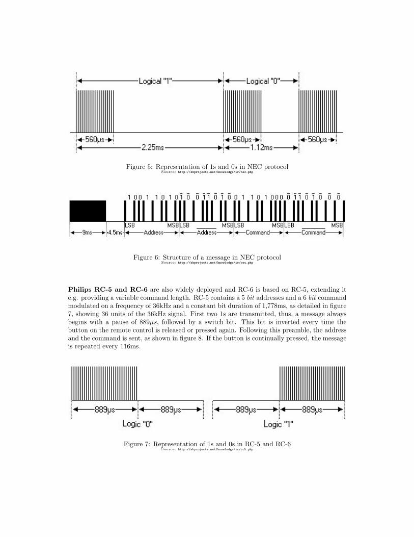
Figure 5: Representation of 1s and 0s in NEC protocolSource: http://sbprojects.net/knowledge/ir/nec.php
Figure 6: Structure of a message in NEC protocolSource: http://sbprojects.net/knowledge/ir/nec.php
Philips RC-5 and RC-6 are also widely deployed and RC-6 is based on RC-5, extending ite.g. providing a variable command length. RC-5 contains a 5 bit addresses and a 6 bit commandmodulated on a frequency of 36kHz and a constant bit duration of 1,778ms, as detailed in figure7, showing 36 units of the 36kHz signal. First two 1s are transmitted, thus, a message alwaysbegins with a pause of 889µs, followed by a switch bit. This bit is inverted every time thebutton on the remote control is released or pressed again. Following this preamble, the addressand the command is sent, as shown in figure 8. If the button is continually pressed, the messageis repeated every 116ms.
Figure 7: Representation of 1s and 0s in RC-5 and RC-6Source: http://sbprojects.net/knowledge/ir/rc5.php

Figure 8: Structure of a message in Philips RC-5 protocolSource: http://sbprojects.net/knowledge/ir/rc5.php
4 Software Design
To support future use and development beyond this specific project, ease of adoption and mod-ularity where major design goals. This benefits beginners and experienced developers likewiseas it provides an easy point to get started with a project using single components of ARINA.Additionally, we used Doxygen for documenting the project, providing a consistent documenta-tion. One has to address different limitations when developing microcontroller software, thoserange from limited computing power to limited memory up to limited space to save programcode or data in general. This led to a focus on using the call by reference principle throughoutour code. With use of an external infrared signal decoding and encoding library [7] we coveredthe most common infrared signals encodings. To circumvent the limitaion of implemented en-codings we had to cover the case of a raw encoding transmission, which is used as a fallbackin case of failing identification of the used infrared signal encoding. As our previous conductedresearch revealed, there is no standardized way of transporting decoded or raw infrared signalsvia Ethernet. Therefore, we developed and defined a new protocol which serves this purposeexplicitly.
4.1 Protocol
Ethernet and IP are used in conjunction with various protocols which utilize their standardizedfeatures, so do Transmission Control Protocol (TCP) and User Datagram Protocol (UDP).A single UDP package can hold up to 65535 bytes, which suffice to transport an encodedinfrared signal. Each received infrared signal should be send as fast as possible to be availableat the remotely stationed ARINA, this results in a steady stream of data packages. As theorder of sequential infrared signals is important, order preserving mechanisms are necessary.Besides order, lost packages, therefore lost commands, are also to be avoided. Additionally,there are media devices responding to given commands by sending infrared signals themselves.Finally, data transmission should not suffer from more loss than necessary, which ultimatelyled us to choose a reliable, ordered and error-checked protocol and therefore TCP over UDP astransmission protocol.

The Arduino Ethernet Shield and its corresponding Ethernet library, segments provided datainto single byte-sized fragments. Thus, we chose to focus on this entity size when designing ourcustom protocol. To be able to even support future multimedia devices and their possibly newway of encoding each single commands (e.g. ’Play’ or ’Stop’) in infrared signals, we used welldefined infrared signal encoding protocols as for example the widely used NEC protocol, referprotocol section 3.2. Those encode long infrared signal sequences in a reproducible way so theycan be represented by, in comparison, shorter long integer values. Additionally, this saves theneed for a large code to command database for every possible, already available multimediadevice and those to come. We see this as a fair tradeoff between recognition of a single commandand the size of data to be sent. To be able to transmit infrared signals in the way previously
Figure 9: Flowchart: Transmission of IR signals via ARINA
described, we designed the software to recognize whether we were able to identify the receivedinfrared signal. If so we are thereby able to decode it by matching it with known infrared signalprotocols, therefore we have to transmit a protocol identifier and the corresponding decodedvalue. Otherwise, if decoding fails, ARINA falls back to raw data transmission. This leavesus with two different cases in which our protocol has to transmit data, as shown in figure 9.The designed protocol is defined upon a byte vector which includes a header section followedby a payload section. The header section holds the infrared protocol used to decode the datawithin the payload section, which is a 32 bit long integer value. Additionally, a header fieldcontains the length of the following payload section. Payload will then be the encoded infraredsignal closed by a byte, which provides the number of set bits of the reconstructed long integervalue. In case of raw data transmission, as illustrated in figure 10, we define the protocol headerflag ID to be ”-1” in two’s complement (Binary: 11111111). The payload section then containssingle infrared pulses coded into binary representation by describing the duration of every burstand pause in 16bit for each time slot.

Figure 10: Protocol in general and raw data transmission example
5 Hardware
The ARINA is based on an Arduino Mega 2560 [2] with an Arduino Ethernet Shield and severalother components described later in 5.1. The Arduino itself supports 14 PWM outlets, utilizedto send an infrared signal modulated with a defined frequency as described in 3.1. The ArduinoEthernet Shield contains a 100Mb/s ethernet port as well as a micro sd cardreader. TheEthernet connection is used to connect to another ARINA component and the SD cardreaderis needed to read configuration files, to support a comfortable configuration of the devices. Anexampe device is shown in figure 11.
Figure 11: Arduino Mega 2560 with Arduino Ethernet ShieldPicture from onemansanthology.com

5.1 Components
In addition to the Arduino, a infrared diode by Harvatek model descriptor HE3-290AC isconnected. It is built in 5mm structure and it emits infrared radiation at a wavelength of940nm. The infrared receiver module used is a OS-1638 by OS-OPTO, which is capable to detectinfrared signals with a wavelength about 940nm and a frequency of 38kHz. Both parts will workat 5V current, which is provided by a stabilized output port of the Arduino. Additionaly, weuse thre LED in different colors to represent the different states of the software. These partsare assembled on a breadboard, cables and resistors to the Arduino Mega 2560 are wired asshown on the circuit diagram in figure 12.
Figure 12: Circuit diagram of an ARINA unit
5.2 Handling
To use the described ARINA solution, one has to setup the configuration files for each deviceand to ensure that they are connected via Ethernet. If powered on, both ARINA will indicatethe initial state with the red LED on each breadboard. After pressing one of the buttons ofa infrared remote control the blue LED flashes on both devices, signaling that data is beingtransmitted. The red LED turns off and the green one on, as soon as a connection betweenboth devices is established.

6 Evaluation
The task of the project group was to build a system to transfer infrared data, received on adistant location, through existing networks and replay the command at another site. This eval-uation shows the capability of ARINA to do so (6.3). Furthermore, functionality of receiving,transmitting and sending loops (6.1 and 6.2) with ARINA are shown. This section also explainsthe structure of experimental assemblies and discusses the results of related experiments.
6.1 Direct reflection
This experiment is designed proving the concept of receiving and sending infrared data ingeneral. Software is needed, receiving an infrared message end replying it five seconds later onthe same ARINA device which received the original message. The functionality is evaluatedon two different devices of ARINA. The first multimedia device is an Epson projector (typeEB-1771w) which uses the well known NEC protocol (see section 3.2) and the second one isa Samsung Television unknown model using an unknown protocol. After pressing randomlyselected buttons on the related remote control the device responds immediately on the signaland five seconds later on the repeated signal sent by our ARINA.
Figure 13: Field-Study setup
6.2 Reflection loop
Aftersuccessfully conducting the first experiment, a second ARINA device is built up andsoftware to receive, transmit, and send infrared signals is used. To test the interconnection, aloop is created, where an infrared signal is initialized by pressing a button on a remote controlaimed at one ARINA, which receives the signal, transmits it to a second ARINA over Ethernetwhere it is emitted and sent back again to the first ARINA via infrared signals. Suring our testseach signal was recognized every time by the device shipped with the used remote control, tocheck if it is still solid enough to transmit the desired control message. On average a signal wasrecognized for about four loops up to fifteen loops in some cases. The quality of a particulartransmission always was close to the original signal, with little variance at the length of burstand pause sections, which is caused by the low sampling rate of Arduino input pins.
6.3 Final evaluation
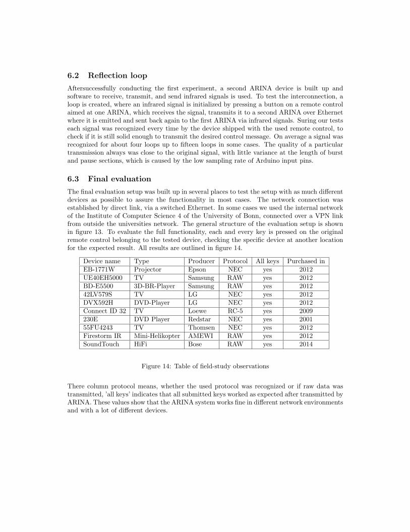
The final evaluation setup was built up in several places to test the setup with as much differentdevices as possible to assure the functionality in most cases. The network connection wasestablished by direct link, via a switched Ethernet. In some cases we used the internal networkof the Institute of Computer Science 4 of the University of Bonn, connected over a VPN linkfrom outside the universities network. The general structure of the evaluation setup is shownin figure 13. To evaluate the full functionality, each and every key is pressed on the originalremote control belonging to the tested device, checking the specific device at another locationfor the expected result. All results are outlined in figure 14.
Device name Type Producer Protocol All keys Purchased inEB-1771W Projector Epson NEC yes 2012UE40EH5000 TV Samsung RAW yes 2012BD-E5500 3D-BR-Player Samsung RAW yes 201242LV579S TV LG NEC yes 2012DVX592H DVD-Player LG NEC yes 2012Connect ID 32 TV Loewe RC-5 yes 2009230E DVD Player Redstar NEC yes 200155FU4243 TV Thomsen NEC yes 2012Firestorm IR Mini-Helikopter AMEWI RAW yes 2012SoundTouch HiFi Bose RAW yes 2014
Figure 14: Table of field-study observations
There column protocol means, whether the used protocol was recognized or if raw data wastransmitted, ’all keys’ indicates that all submitted keys worked as expected after transmitted byARINA. These values show that the ARINA system works fine in different network environmentsand with a lot of different devices.

7 Future Work
As stated earlier, many different use cases could be realized using the presented ARINA ap-proach and its specially designed protocol. A system extended by a central server could supportautomated events which might depend on different user defined triggers. It is easily possible touse it as an automated recording system even with older devices not having a built-in PersonalVideo Recorder. In combination with an electronic program guide it may be possible to alsorecord shows according to predefined keywords included in a shows title or description. Onemight also think of a simple intruder scare system, turning on and off a TV or switches throughdifferent channels, thereby creating an illusion of an individual being at home.Arduino supports multiple extension shields. Thus, different interactions via bluetooth, Wi-Fior other ISM band based could be added to the already available infrared connection. The al-ready used ethernet shield also supports power over ethernet with a small add-on, which wouldrender any other connected power resource obsolete.
References
[1] IRTrans GmbH Website.http://www.irtrans.de/de/technicalinfo/index.php, 2009.
[2] Arduino Project.http://arduino.cc/de/Main/ArduinoBoardMega2560, 2013.
[3] Logitech, Harmony Ultimate Hub.http://www.logitech.com/de-de/product/harmony-ultimate-hub, 2014.
[4] One for All ,Tablet remote URC 8800.http://www.oneforall.com/remotes/urc8800-tablet-remote.html, 2014.
[5] Philips, Prestigo Universal remote control.http://www.philips.de/c-p/SRT8215_10/, 2014.
[6] San Bergmans. IR Remote Control Theory.http://www.sbprojects.com, 2014.
[7] Ken Shirriff. IRremote library for the Arduino.https://github.com/shirriff/Arduino-IRremote, 2012.
[8] Rene Neff & Thomas Trimborn. Final report for BA Projektgruppe: ”ARINA - Arduino RemoteInfrared Network Adapter”.http://net.cs.uni-bonn.de/fileadmin/user_upload/wuebbel/lehre/13ss/ARINA_-_final_
report.pdf, 2013.
[9] Rene Neff & Thomas Trimborn. ”Theoretische Ausarbeitung zur Entwicklung einer Netzwerk-basierten Infrarot-Fernbedienung”, 2013.
All webpages last visited on 16.04.2014.