02 t ace tcontrol-con compact microprocessor controller ... tcontrol-cont-02 user... · 02 compact...
TRANSCRIPT
Dig
iTra
ce T
CO
NT
RO
L-C
ON
T-02
Com
pac
t m
icro
pro
cess
or c
ontr
olle
r
Op
erat
ing
Man
ual
BR
70.
3011
/111
.03/

!P
leas
e re
ad t
his
Man
ual c
aref
ully
bef
ore
star
ting
up t
he in
stru
men
t. K
eep
thi
s M
anua
l in
a p
lace
whi
ch is
at
all t
imes
acc
essi
ble
to
all u
sers
. P
leas
e as
sist
us
to im
pro
ve t
his
Man
ual
whe
re n
eces
sary
. You
r su
gges
tions
will
be
mos
t w
elco
me.
!A
ll ne
cess
ary
sett
ings
are
des
crib
ed in
thi
s O
per
atin
g M
anua
l. If
any
diff
icul
ties
shou
ld s
till
aris
e d
urin
g st
art-
up, y
ou a
re a
sked
not
to c
arry
out
any
man
ipul
atio
ns o
n th
e un
it w
hich
are
no
t p
erm
itted
. You
cou
ld e
ndan
ger
your
rig
hts
und
er t
he w
arra
nty.
Ple
ase
cont
act
the
near
-es
t of
fice
or t
he m
ain
fact
ory.
EW
hen
retu
rnin
g ch
assi
s, a
ssem
blie
s or
com
pon
ents
, the
rul
es o
f E
N 1
00 0
15 “
Pro
tect
ion
of
elec
tros
tatic
ally
end
ange
red
com
pon
ents
” ha
ve t
o b
e ob
serv
ed.
Use
onl
y th
e ap
pro
pria
te
ESD
pac
kagi
ng m
ater
ial f
or t
rans
por
t.
Ple
ase
note
tha
t w
e ca
n no
t b
e he
ld li
able
for
any
dam
ages
cau
sed
by
ES
D (
elec
tros
tatic
d
isch
arge
s).
P >2s
e
Par
amet
er le
vel
Pag
e
Al 1
226
, 41
Al 2
026
, 41
Pb
10
22, 4
1
Pb
2a
022
, 41
dt
8022
, 41
rt35
022
, 41
Cy
120
.022
, 41
Cy
2120
.022
, 41
db
023
, 41
HY
S 1
223
, 41
HY
S 2
11.
023
, 41
Y0
023
, 41
Y1
100
24, 4
1
Y2
-100
24, 4
1
dF
0.6
16, 4
1
rAS
d0
31, 4
1
c
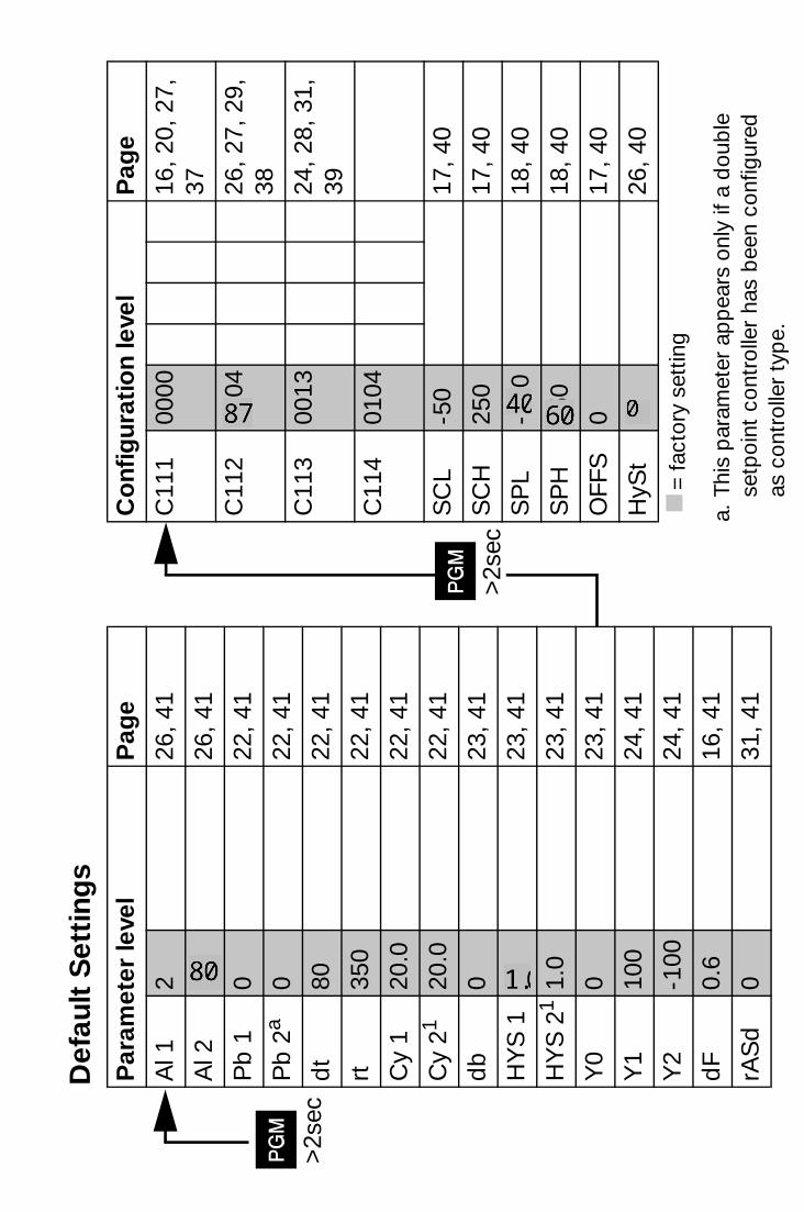
Def
ault
Set
ting
s
Co
nfig
urat
ion
leve
lP
age
C11
100
0016
, 20,
27,
37
C11
220
04
26, 2
7, 2
9,
38
C11
300
1324
, 28,
31,
39
C11
401
04
SC
L-5
017
, 40
SC
H25
017
, 40
SP
L-2
00
18, 4
0
SP
H85
018
, 40
OFF
S0
17, 4
0
HyS
t1
26, 4
0
k=
fact
ory
sett
ing
a.Th
is p
aram
eter
ap
pea
rs o
nly
if a
dou
ble
se
tpoi
nt c
ontr
olle
r ha
s b
een
conf
igur
ed
as c
ontr
olle
r ty
pe.
c
P >2s
e
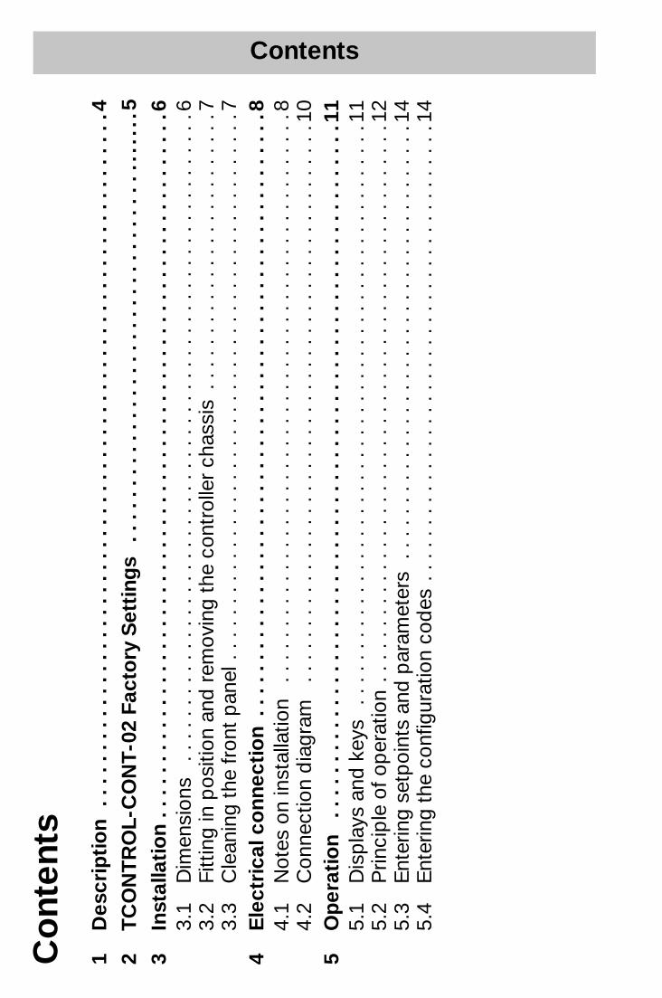
Contents
Cont
ents
1 D
escr
ipti
on
. . .
. . .
. . .
. . .
. . .
. . .
. . .
. . .
. . .
. . .
. . .
. . .
. . .
. . .
. . .
. . .
. . .
. . .
. . .
. . .
. .4
2 T
CO
NT
RO
L-C
ON
T-0
2 Fa
cto
ry S
etti
ngs
. . .
. . .
. . .
. . .
. . .
. . .
. . .
. . .
. . .
. . .
. . .
...
....
53
Inst
alla
tio
n . .
. . .
. . .
. . .
. . .
. . .
. . .
. . .
. . .
. . .
. . .
. . .
. . .
. . .
. . .
. . .
. . .
. . .
. . .
. . .
. . .
.6
3.1
Dim
ensi
ons
. . .
. . .
. . .
. . .
. . .
. . .
. . .
. . .
. . .
. . .
. . .
. . .
. . .
. . .
. . .
. . .
. . .
. . .
. . .
.6
3.2
Fitt
ing
in p
ositi
on a
nd r
emov
ing
the
cont
rolle
r ch
assi
s . .
. . .
. . .
. . .
. . .
. . .
. . .
. . .
. .7
3.3
Cle
anin
g th
e fr
ont
pan
el .
. . .
. . .
. . .
. . .
. . .
. . .
. . .
. . .
. . .
. . .
. . .
. . .
. . .
. . .
. . .
. . .
74
Ele
ctri
cal c
onn
ecti
on
. . .
. . .
. . .
. . .
. . .
. . .
. . .
. . .
. . .
. . .
. . .
. . .
. . .
. . .
. . .
. . .
. . .
. . .
84.
1 N
otes
on
inst
alla
tion
. . .
. . .
. . .
. . .
. . .
. . .
. . .
. . .
. . .
. . .
. . .
. . .
. . .
. . .
. . .
. . .
. . .
84.
2 C
onne
ctio
n d
iagr
am
. . .
. . .
. . .
. . .
. . .
. . .
. . .
. . .
. . .
. . .
. . .
. . .
. . .
. . .
. . .
. . .
. .10
5 O
per
atio
n .
. . .
. . .
. . .
. . .
. . .
. . .
. . .
. . .
. . .
. . .
. . .
. . .
. . .
. . .
. . .
. . .
. . .
. . .
. . .
. . .
.11
5.1
Dis
pla
ys a
nd k
eys
. .
. . .
. . .
. . .
. . .
. . .
. . .
. . .
. . .
. . .
. . .
. . .
. . .
. . .
. . .
. . .
. . .
. .11
5.2
Prin
cip
le o
f op
erat
ion
. . .
. . .
. . .
. . .
. . .
. . .
. . .
. . .
. . .
. . .
. . .
. . .
. . .
. . .
. . .
. . .
. .12
5.3
Ent
erin
g se
tpoi
nts
and
par
amet
ers
. . .
. . .
. . .
. . .
. . .
. . .
. . .
. . .
. . .
. . .
. . .
. . .
. . .
145.
4 E
nter
ing
the
conf
igur
atio
n co
des
. .
. . .
. . .
. . .
. . .
. . .
. . .
. . .
. . .
. . .
. . .
. . .
. . .
. . .
14
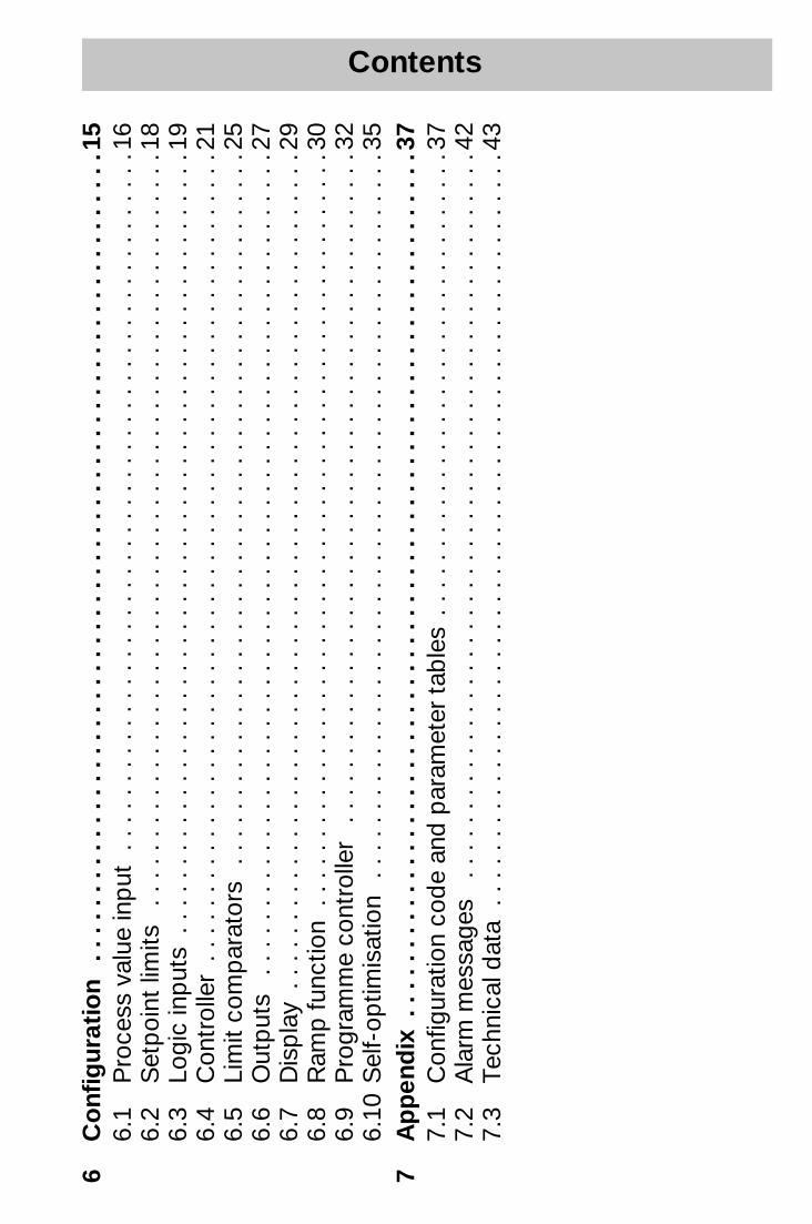
Contents
6Co
nfig
urat
ion
. . .
. . .
. . .
. . .
. . .
. . .
. . .
. . .
. . .
. . .
. . .
. . .
. . .
. . .
. . .
. . .
. . .
. . .
. . .
. .1
56.
1 P
roce
ss v
alue
inp
ut .
. . .
. . .
. . .
. . .
. . .
. . .
. . .
. . .
. . .
. . .
. . .
. . .
. . .
. . .
. . .
. . .
. .1
66.
2 S
etp
oint
lim
its
. . .
. . .
. . .
. . .
. . .
. . .
. . .
. . .
. . .
. . .
. . .
. . .
. . .
. . .
. . .
. . .
. . .
. . .
.18
6.3
Logi
c in
put
s . .
. . .
. . .
. . .
. . .
. . .
. . .
. . .
. . .
. . .
. . .
. . .
. . .
. . .
. . .
. . .
. . .
. . .
. . .
.19
6.4
Con
trol
ler
. . .
. . .
. . .
. . .
. . .
. . .
. . .
. . .
. . .
. . .
. . .
. . .
. . .
. . .
. . .
. . .
. . .
. . .
. . .
. .21
6.5
Lim
it co
mp
arat
ors
. . .
. . .
. . .
. . .
. . .
. . .
. . .
. . .
. . .
. . .
. . .
. . .
. . .
. . .
. . .
. . .
. . .
.25
6.6
Out
put
s .
. . .
. . .
. . .
. . .
. . .
. . .
. . .
. . .
. . .
. . .
. . .
. . .
. . .
. . .
. . .
. . .
. . .
. . .
. . .
. .27
6.7
Dis
pla
y . .
. . .
. . .
. . .
. . .
. . .
. . .
. . .
. . .
. . .
. . .
. . .
. . .
. . .
. . .
. . .
. . .
. . .
. . .
. . .
. .2
96.
8 R
amp
func
tion
. . .
. . .
. . .
. . .
. . .
. . .
. . .
. . .
. . .
. . .
. . .
. . .
. . .
. . .
. . .
. . .
. . .
. . .
.30
6.9
Pro
gram
me
cont
rolle
r .
. . .
. . .
. . .
. . .
. . .
. . .
. . .
. . .
. . .
. . .
. . .
. . .
. . .
. . .
. . .
. . .
326.
10 S
elf-
optim
isat
ion
. . .
. . .
. . .
. . .
. . .
. . .
. . .
. . .
. . .
. . .
. . .
. . .
. . .
. . .
. . .
. . .
. . .
. .3
57
Ap
pen
dix
. .
. . .
. . .
. . .
. . .
. . .
. . .
. . .
. . .
. . .
. . .
. . .
. . .
. . .
. . .
. . .
. . .
. . .
. . .
. . .
. . .
.37
7.1
Con
figur
atio
n co
de
and
par
amet
er t
able
s . .
. . .
. . .
. . .
. . .
. . .
. . .
. . .
. . .
. . .
. . .
. .3
77.
2 A
larm
mes
sage
s .
. . .
. . .
. . .
. . .
. . .
. . .
. . .
. . .
. . .
. . .
. . .
. . .
. . .
. . .
. . .
. . .
. . .
.42
7.3
Tech
nica
l dat
a .
. . .
. . .
. . .
. . .
. . .
. . .
. . .
. . .
. . .
. . .
. . .
. . .
. . .
. . .
. . .
. . .
. . .
. . .
43
1 Description 4
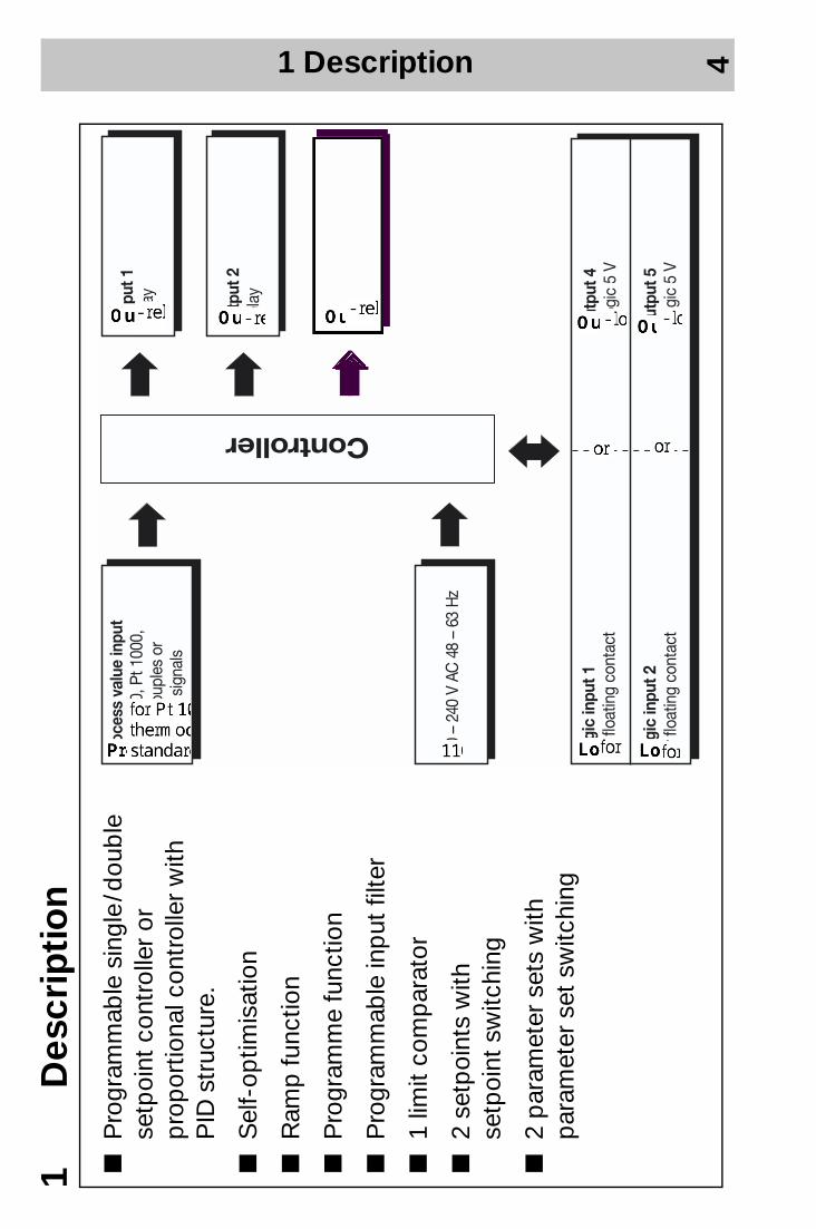
1 D
escr
ipti
on
P
rogr
amm
able
sin
gle
/ dou
ble
se
tpoi
nt c
ontr
olle
r or
p
rop
ortio
nal c
ontr
olle
r w
ith
PID
str
uctu
re.
S
elf-
optim
isat
ion
R
amp
func
tion
P
rogr
amm
e fu
nctio
n
P
rogr
amm
able
inp
ut fi
lter
1
limit
com
par
ator
2
setp
oint
s w
ith
setp
oint
sw
itchi
ng
2
par
amet
er s
ets
with
p
aram
eter
set
sw
itchi
ng
2 TCONTROL-CONT-02 Factory Settings 5
2 T
CO
NT
RO
L-C
ON
T-02
Fac
tory
Set
ting
s
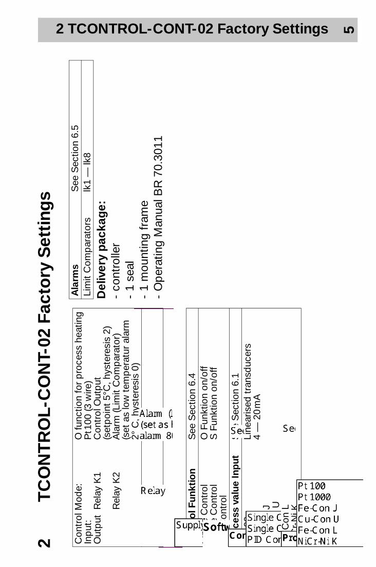
Con
trol
Mod
e:In
put
:O
utp
ut R
elay
K1
Rel
ay K
2
O fu
nctio
n fo
r p
roce
ss h
eatin
gP
t 100
(3 w
ire)
Con
trol
Out
put
(s
etp
oint
5°C
, hys
tere
sis
2)A
larm
(Lim
it C
omp
arat
or)
(set
as
low
tem
per
atur
ala
rm
2° C
, hys
tere
sis
0)
Co
ntro
l Fun
ktio
nS
ee S
ectio
n 6.
4S
ingl
e C
ontr
olS
ingl
e C
ontr
olP
ID C
ontr
ol
O F
unkt
ion
on/o
ffS
Fun
ktio
n on
/off
Pro
cess
val
ue In
put
See
Sec
tion
6.1
Pt
100
Pt
1000
Fe-C
on J
Cu-
Con
UFe
-Con
LN
iCr-
Ni K
Line
aris
ed t
rans
duc
ers
4 —
20
mA
Del
iver
y p
acka
ge:
- co
ntro
ller
- 1
seal
-
1 m
ount
ing
fram
e -
Op
erat
ing
Man
ual B
R 7
0.30
11
Ala
rms
See
Sec
tion
6.5
Lim
it C
omp
arat
ors
lk1
— lk
8
3 Installation 6
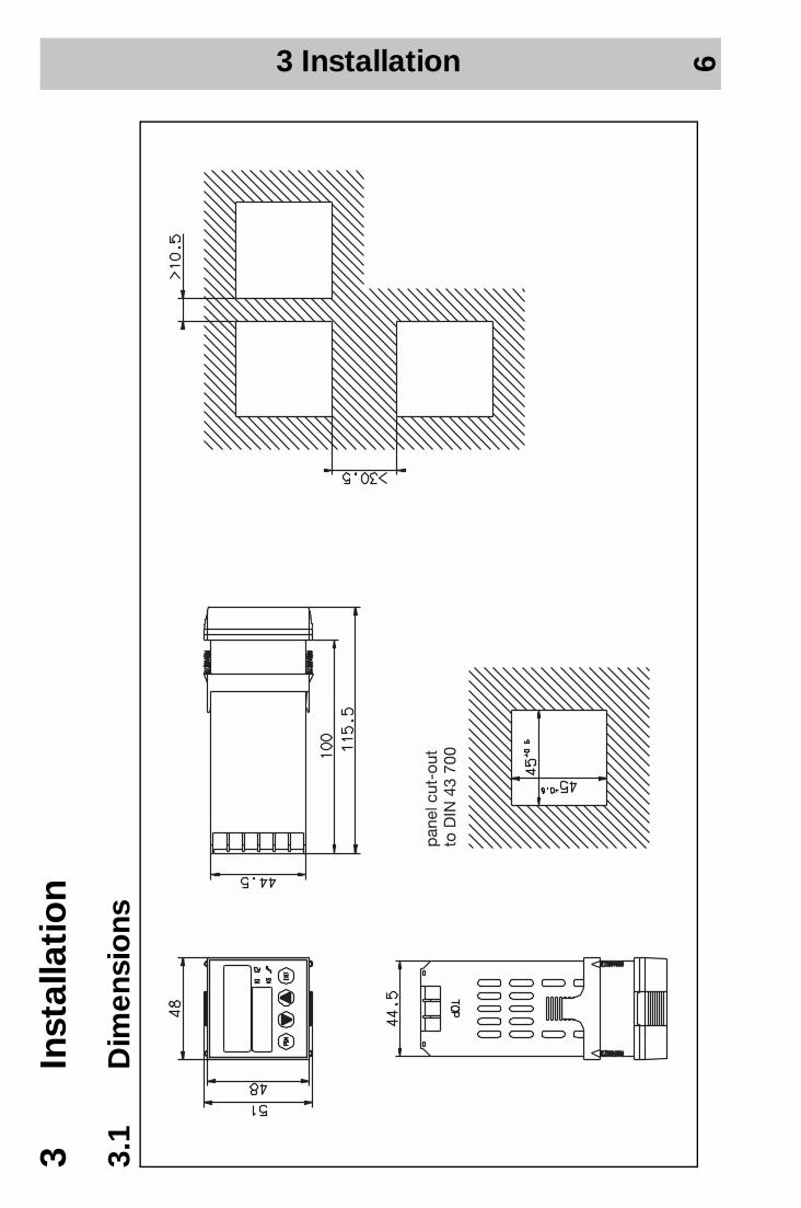
3 In
stal
lati
on
3.1
Dim
ensi
ons
3 Installation 7
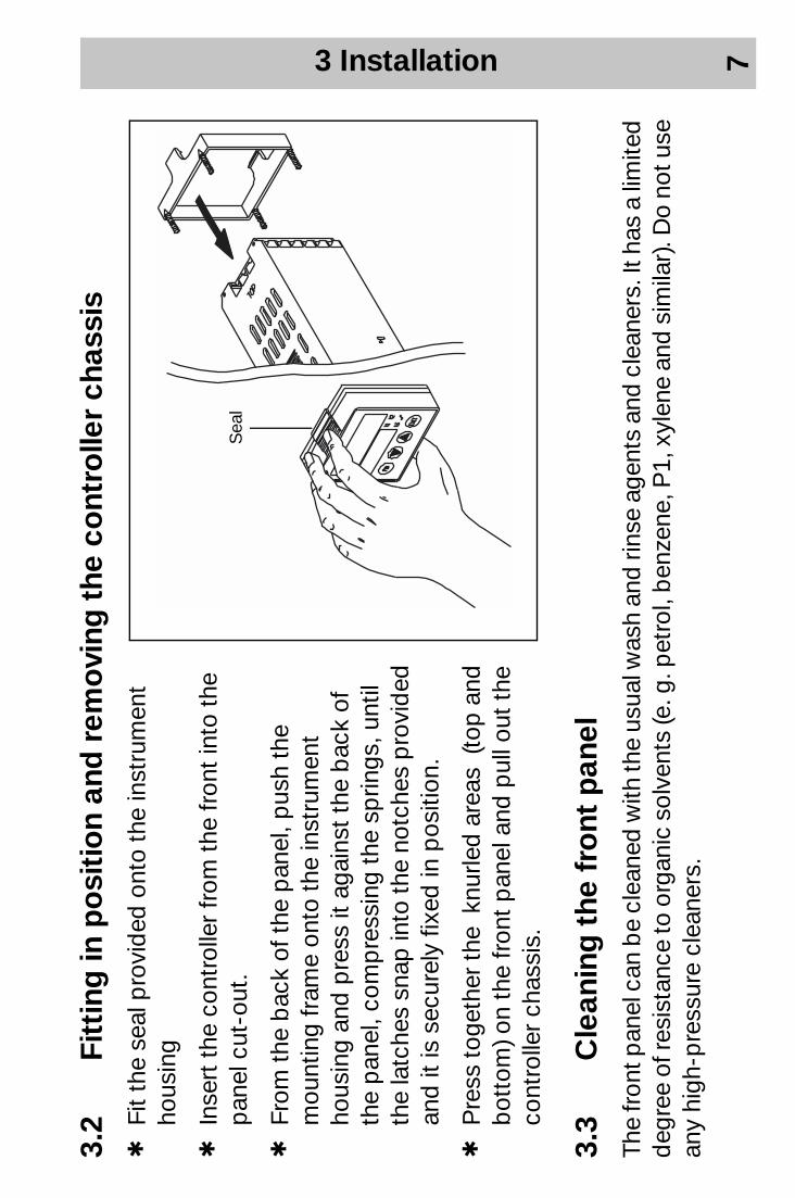
3.2
Fitt
ing
in p
osi
tio
n an
d r
emo
ving
the
co
ntro
ller
chas
sis
hFi
t th
e se
al p
rovi
ded
ont
o th
e in
stru
men
t ho
usin
g
hIn
sert
the
con
trol
ler
from
the
fron
t in
to t
he
pan
el c
ut-o
ut.
hFr
om t
he b
ack
of t
he p
anel
, pus
h th
e m
ount
ing
fram
e on
to t
he in
stru
men
t ho
usin
g an
d p
ress
it a
gain
st t
he b
ack
of
the
pan
el, c
omp
ress
ing
the
sprin
gs, u
ntil
the
latc
hes
snap
into
the
notc
hes
pro
vid
ed
and
it is
sec
urel
y fix
ed in
pos
ition
.
hP
ress
toge
ther
the
knu
rled
are
as (
top
and
b
otto
m) o
n th
e fr
ont
pan
el a
nd p
ull o
ut t
he
cont
rolle
r ch
assi
s.
3.3
Cle
anin
g t
he f
ront
pan
elTh
e fr
ont p
anel
can
be
clea
ned
with
the
usua
l was
h an
d ri
nse
agen
ts a
nd c
lean
ers.
It h
as a
lim
ited
deg
ree
of re
sist
ance
to o
rgan
ic s
olve
nts
(e. g
. pet
rol,
ben
zene
, P1,
xyl
ene
and
sim
ilar)
. Do
not u
se
any
high
-pre
ssur
e cl
eane
rs.
S
eal
4 Electrical connection 8
4 E
lect
rica
l co
nnec
tio
n
4.1
No
tes
on
inst
alla
tio
n-
The
choi
ce o
f cab
le, t
he in
stal
latio
n an
d t
he e
lect
rical
con
nect
ion
mus
t co
nfor
m t
o th
e re
-q
uire
men
ts o
f VD
E 0
100
“Reg
ulat
ions
on
the
Inst
alla
tion
of P
ower
Circ
uits
with
nom
inal
vo
ltage
s b
elow
100
0 V
” or
the
ap
pro
pria
te lo
cal r
egul
atio
ns.
-Th
e el
ectr
ical
con
nect
ion
mus
t on
ly b
e ca
rrie
d o
ut b
y p
rop
erly
qua
lifie
d p
erso
nnel
.
-If
cont
act
with
live
par
ts is
pos
sib
le w
hen
wor
king
on
the
inst
rum
ent,
it h
as t
o b
e is
olat
ed o
n b
oth
pol
es fr
om t
he s
upp
ly.
-A
cur
rent
lim
iting
res
isto
r in
terr
upts
the
sup
ply
circ
uit
in c
ase
of a
sho
rt-c
ircui
t. T
he e
xter
nal
fuse
of t
he s
upp
ly s
houl
d n
ot b
e ra
ted
ab
ove
1 A
(slo
w).
The
load
circ
uit m
ust b
e fu
sed
for t
he
max
imum
rel
ay c
urre
nt in
ord
er t
o p
reve
nt w
eld
ing
of t
he o
utp
ut r
elay
con
tact
s in
cas
e of
an
exte
rnal
sho
rt-c
ircui
t.
-E
lect
rom
agne
tic c
omp
atib
ility
con
form
s to
the
sta
ndar
ds
and
reg
ulat
ions
list
ed u
nder
Te
chni
cal D
ata.
-R
un in
put
, out
put
and
sup
ply
line
s se
par
atel
y an
d n
ot p
aral
lel t
o ea
ch o
ther
.
4 Electrical connection 9
-S
enso
r an
d in
terf
ace
lines
sho
uld
be
arra
nged
as
twis
ted
and
scr
eene
d c
able
s.
Do
not
run
them
clo
se t
o cu
rren
t-ca
rryi
ng c
omp
onen
ts o
r ca
ble
s.
-D
o no
t co
nnec
t an
y ad
diti
onal
load
s to
the
sup
ply
ter
min
al o
f the
inst
rum
ent.
-Th
e in
stru
men
t is
not
sui
tab
le fo
r in
stal
latio
n in
haz
ard
ous
area
s.
-A
par
t fr
om fa
ulty
inst
alla
tion,
the
re is
a p
ossi
bilit
y of
inte
rfer
ence
or
dam
age
to c
ontr
olle
d
pro
cess
es d
ue t
o in
corr
ect
sett
ings
on
the
cont
rolle
r (s
etp
oint
, dat
a of
par
amet
er a
nd
conf
igur
atio
n le
vels
, int
erna
l ad
just
men
ts).
Saf
ety
dev
ices
ind
epen
den
t of t
he c
ontr
olle
r, su
ch
as o
verp
ress
ure
valv
es o
r te
mp
erat
ure
limite
rs /m
onito
rs, s
houl
d a
lway
s b
e p
rovi
ded
and
sh
ould
be
cap
able
of a
dju
stm
ent o
nly
by
spec
ialis
t per
sonn
el. P
leas
e re
fer t
o th
e ap
pro
pria
te
safe
ty re
gula
tions
in th
is c
onne
ctio
n. S
ince
aut
o-tu
ning
(sel
f-op
timis
atio
n) c
an n
ot b
e ex
pec
t -ed
to
hand
le a
ll p
ossi
ble
con
trol
loop
s th
ere
is a
the
oret
ical
pos
sib
ility
of u
nsta
ble
par
amet
er
sett
ings
. The
res
ultin
g p
roce
ss v
alue
sho
uld
the
refo
re b
e m
onito
red
for
its s
tab
ility
.
4 Electrical connection 10
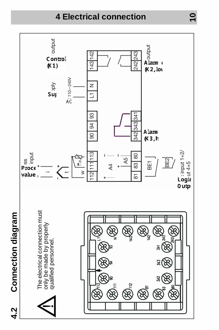
4.2
Co
nnec
tio
n d
iag
ram
VTh
e el
ectr
ical
con
nect
ion
mus
t on
ly b
e m
ade
by
pro
per
ly
qua
lifie
d p
erso
nnel
.
5 Operation 11
5 O
per
atio
n
5.1
Dis
pla
ys a
nd k
eys
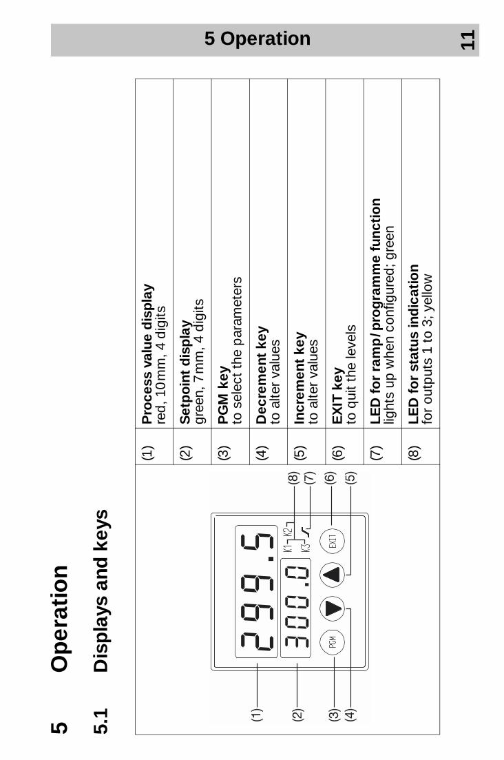
(1)
Pro
cess
val
ue d
isp
lay
red
, 10
mm
, 4 d
igits
(2)
Set
po
int
dis
pla
ygr
een,
7 m
m, 4
dig
its
(3)
PG
M k
eyto
sel
ect
the
par
amet
ers
(4)
Dec
rem
ent
key
to a
lter
valu
es
(5)
Incr
emen
t ke
yto
alte
r va
lues
(6)
EX
IT k
eyto
qui
t th
e le
vels
(7)
LED
fo
r ra
mp
/ pro
gra
mm
e fu
ncti
on
light
s up
whe
n co
nfig
ured
; gre
en
(8)
LED
fo
r st
atus
ind
icat
ion
for
outp
uts
1 to
3; y
ello
w
5 Operation 12
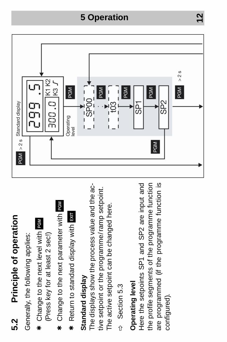
5.2
Pri
ncip
le o
f o
per
atio
nG
ener
ally
, the
follo
win
g ap
plie
s:
hC
hang
e to
the
nex
t le
vel w
ith P
(P
ress
key
for
at le
ast
2 se
c!)
hC
hang
e to
the
nex
t p
aram
eter
with
P
hR
etur
n to
sta
ndar
d d
isp
lay
with
X
Sta
ndar
d d
isp
lay
The
dis
pla
ys s
how
the
pro
cess
val
ue a
nd th
e ac
-tiv
e se
tpoi
nt o
r th
e p
rogr
amm
e / r
amp
set
poi
nt.
The
activ
e se
tpoi
nt c
an b
e ch
ange
d h
ere.
vS
ectio
n 5.
3
Op
erat
ing
leve
l H
ere
the
setp
oint
s S
P1
and
SP
2 ar
e in
put
and
th
e p
rofil
e se
gmen
ts o
f the
pro
gram
me
func
tion
are
pro
gram
med
(if
the
pro
gram
me
func
tion
is
conf
igur
ed).
5 Operation 13
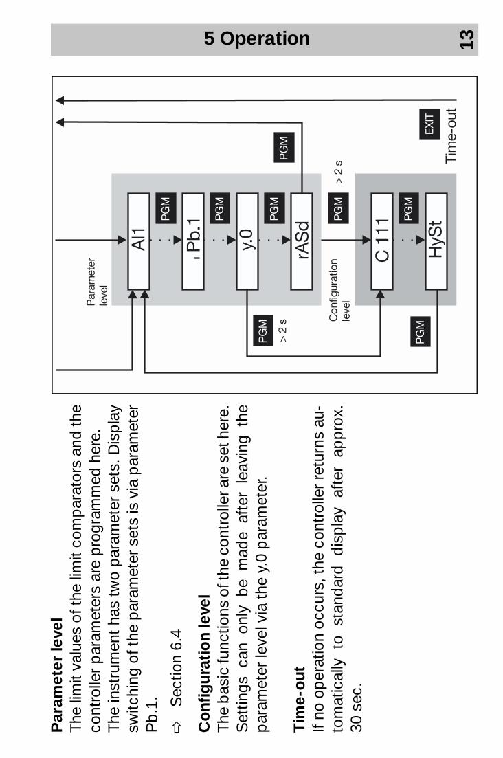
Par
amet
er le
vel
The
limit
valu
es o
f the
lim
it co
mp
arat
ors
and
the
cont
rolle
r p
aram
eter
s ar
e p
rogr
amm
ed h
ere.
Th
e in
stru
men
t ha
s tw
o p
aram
eter
set
s. D
isp
lay
switc
hing
of t
he p
aram
eter
set
s is
via
par
amet
er
Pb
.1.
vS
ectio
n 6.
4
Co
nfig
urat
ion
leve
l Th
e b
asic
func
tions
of t
he c
ontr
olle
r are
set
her
e.
Set
tings
can
onl
y b
e m
ade
afte
r le
avin
g th
e p
aram
eter
leve
l via
the
y.0
par
amet
er.
Tim
e-o
ut
If no
op
erat
ion
occu
rs, t
he c
ontr
olle
r re
turn
s au
-to
mat
ical
ly
to
stan
dar
d
dis
pla
y af
ter
app
rox.
30
sec
.
5 Operation 14
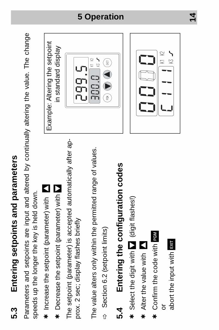
5.3
Ent
erin
g s
etp
oin
ts a
nd p
aram
eter
sP
aram
eter
s an
d s
etp
oint
s ar
e in
put
and
alte
red
by
cont
inua
lly a
lterin
g th
e va
lue.
The
cha
nge
spee
ds
up t
he lo
nger
the
key
is h
eld
dow
n.
hIn
crea
se t
he s
etp
oint
(par
amet
er) w
ith I
hD
ecre
ase
the
setp
oint
(par
amet
er) w
ith D
The
setp
oint
(par
amet
er) i
s ac
cep
ted
aut
omat
ical
ly a
fter
ap-
pro
x. 2
sec
; dis
pla
y fla
shes
brie
fly
The
valu
e al
ters
onl
y w
ithin
the
per
mitt
ed r
ange
of v
alue
s.
vS
ectio
n 6.
2 (s
etp
oint
lim
its)
5.4
Ent
erin
g t
he c
onf
igur
atio
n co
des
h
Sel
ect
the
dig
it w
ith D
(dig
it fla
shes
!)
hA
lter
the
valu
e w
ith I
hC
onfir
m t
he c
ode
with
P
or
abor
t th
e in
put
with
X
Exa
mp
le: A
lterin
g th
e se
tpoi
nt
in
sta
ndar
d d
isp
lay
6 Configuration 15
6 C
onf
igur
atio
nTh
e fo
llow
ing
sect
ions
des
crib
e th
e fu
nctio
ns o
f the
inst
rum
ent w
ith th
eir r
elev
ant p
aram
eter
s an
d se
ttin
gs.
The
par
amet
er a
nd th
e co
nfig
urat
ion
cod
es a
re li
sted
in th
e se
que
nce
in w
hich
they
ap
pea
r with
in
the
leve
l str
uctu
re. T
he fo
llow
ing
pro
ced
ure
is h
owev
er r
ecom
men
ded
:
Pre
sent
atio
n Th
e co
nfig
urat
ion
cod
es h
ave
4 p
ositi
ons.
For
func
tiona
lly re
leva
nt p
ositi
ons,
the
kind
of f
unct
ion
and
its
sele
ctio
n p
ossi
bili
ty is
des
crib
ed in
the
ap
pro
pria
te c
olum
n. P
ositi
ons
whi
ch a
re n
ot r
ele -
vant
for
the
func
tion
are
mar
ked
with
an
“X”
in t
he c
olum
n.
hFa
mili
aris
e yo
urse
lf w
ith t
he c
ontr
olle
r fu
nctio
ns
hE
nter
the
par
amet
er v
alue
s an
d t
he c
onfig
urat
ion
cod
es in
the
tab
le p
rovi
ded
for
this
p
urp
ose
on t
he b
ack
cove
r. Th
e p
aram
eter
s an
d c
onfig
urat
ion
cod
es a
re li
sted
in t
he
ord
er o
f the
ir ap
pea
ranc
e.
hE
nter
the
par
amet
ers
and
con
figur
atio
n co
des
into
the
inst
rum
ent
HFo
r th
e ex
per
ienc
ed u
ser,
the
par
amet
ers
and
con
figur
atio
n co
des
are
sum
mar
ised
in
the
tab
les
whi
ch a
re p
rovi
ded
in t
he A
pp
end
ix.
vS
ectio
n 7.
1
6 Configuration 16
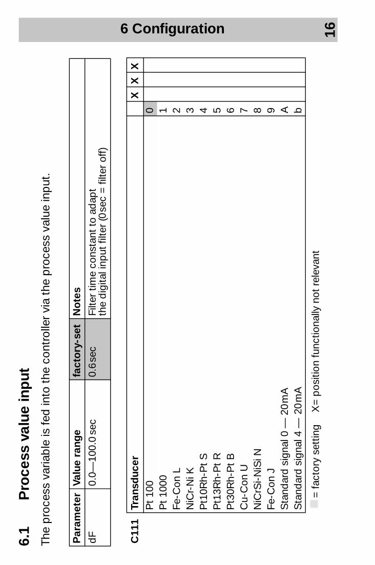
6.1
Pro
cess
val
ue in
put
The
pro
cess
var
iab
le is
fed
into
the
con
trol
ler
via
the
pro
cess
val
ue in
put
.
Par
amet
erVa
lue
rang
e fa
cto
ry-s
et
No
tes
dF
0.0—
100.
0 se
c 0.
6 se
c Fi
lter
time
cons
tant
to
adap
t th
e d
igita
l inp
ut fi
lter
(0 se
c =
filte
r of
f)
C11
1Tr
ansd
ucer
XX
XP
t 10
00
Pt
1000
1Fe
-Con
L2
NiC
r-N
i K3
Pt1
0Rh-
Pt
S4
Pt1
3Rh-
Pt
R5
Pt3
0Rh-
Pt
B6
Cu-
Con
U7
NiC
rSi-
NiS
i N8
Fe-C
on J
9S
tand
ard
sig
nal 0
— 2
0 m
A
AS
tand
ard
sig
nal 4
— 2
0 m
A
b
k=
fact
ory
sett
ing
X =
pos
ition
func
tiona
lly n
ot r
elev
ant
6 Configuration 17
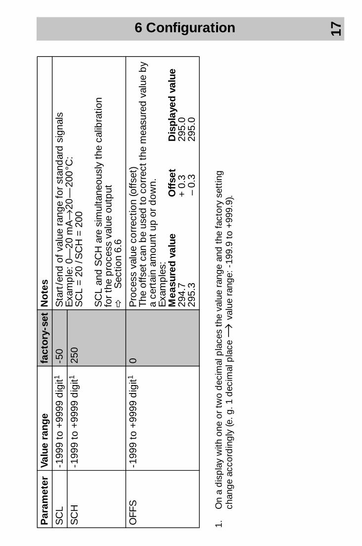
1.O
n a
dis
pla
y w
ith o
ne o
r tw
o d
ecim
al p
lace
s th
e va
lue
rang
e an
d t
he fa
ctor
y se
ttin
g ch
ange
acc
ord
ingl
y (e
. g. 1
dec
imal
pla
ce →
valu
e ra
nge:
-19
9.9
to +
999.
9).
Par
amet
erVa
lue
rang
e fa
cto
ry-s
et N
ote
s
SC
L-1
999
to +
9999
dig
it1-5
0S
tart
/end
of v
alue
ran
ge fo
r st
and
ard
sig
nals
Exa
mp
le: 0
—20
mA
→20
— 2
00 °C
: S
CL
= 2
0 / S
CH
= 2
00
SC
L an
d S
CH
are
sim
ulta
neou
sly
the
calib
ratio
n fo
r th
e p
roce
ss v
alue
out
put
vS
ectio
n 6.
6
SC
H-1
999
to +
9999
dig
it125
0
OFF
S-1
999
to +
9999
dig
it10
Pro
cess
val
ue c
orre
ctio
n (o
ffset
)Th
e of
fset
can
be
used
to c
orre
ct th
e m
easu
red
val
ue b
y a
cert
ain
amou
nt u
p o
r d
own.
Exa
mp
les:
Mea
sure
d v
alue
O
ffse
t D
isp
laye
d v
alue
29
4.7
+ 0
.3
295.
0 29
5.3
– 0
.3
295.
0
6 Configuration 18
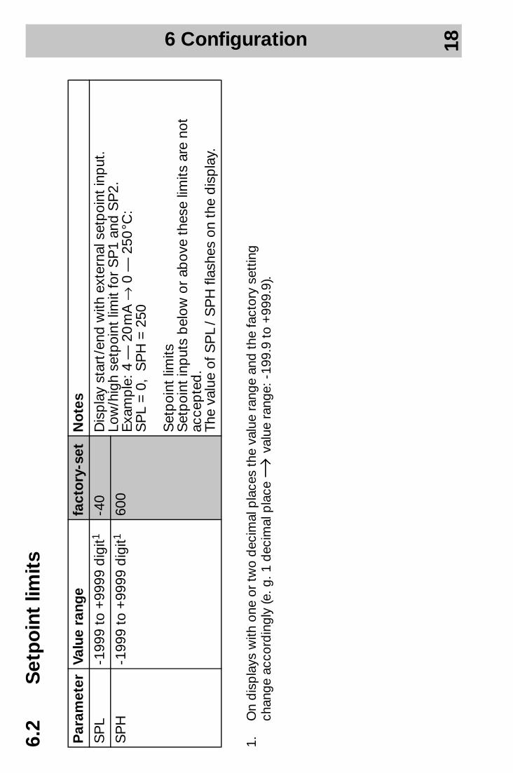
6.2
Set
po
int
limit
s
1.O
n d
isp
lays
with
one
or
two
dec
imal
pla
ces
the
valu
e ra
nge
and
the
fact
ory
sett
ing
chan
ge a
ccor
din
gly
(e. g
. 1 d
ecim
al p
lace
→ va
lue
rang
e: -
199.
9 to
+99
9.9)
.
Par
amet
erVa
lue
rang
e fa
cto
ry-s
et
No
tes
SP
L-1
999
to +
9999
dig
it1-4
0
Dis
pla
y st
art /
end
with
ext
erna
l set
poi
nt in
put
. Lo
w/h
igh
setp
oint
lim
it fo
r S
P1
and
SP
2.
Exa
mp
le: 4
— 2
0 m
A →
0 —
250
°C:
SP
L =
0,
SP
H =
250
Set
poi
nt li
mits
Set
poi
nt in
put
s b
elow
or
abov
e th
ese
limits
are
not
ac
cep
ted
. Th
e va
lue
of S
PL
/ S
PH
flas
hes
on t
he d
isp
lay.
SP
H-1
999
to +
9999
dig
it160
0

6 Configuration 19
6.3
Log
ic in
put
sVa
rious
op
erat
ing
func
tions
can
be
activ
ated
via
the
tw
o lo
gic
inp
uts.
Key
inhi
bit
O
per
atio
n is
pos
sib
le b
y ke
ys
No
op
erat
ion
by
keys
Leve
l inh
ibit
A
cces
s p
ossi
ble
to
par
amet
er
and
con
figur
atio
n le
vel.
Sta
rt o
f sel
f-op
timis
atio
n is
pos
sib
le.
No
acc
ess
to p
aram
eter
and
co
nfig
urat
ion
leve
l N
o s
tart
of s
elf-
optim
isat
ion
Pro
gra
mm
e/
ram
p s
top
P
rogr
amm
e /r
amp
run
ning
(whe
n co
nfig
ured
!)P
rogr
amm
e /r
amp
sto
pp
ed
Pro
gra
mm
e/
ram
p s
tart
–P
rogr
amm
e /r
amp
(re)
star
ted
Set
po
int
swit
chin
g
Set
poi
nt S
P1
is a
ctiv
ated
. S
etp
oint
SP
2 is
act
ivat
ed.
Par
amet
er s
et
swit
chin
gP
aram
eter
set
1 is
act
ivat
ed.
(, Pb. 1
)P
aram
eter
set
2 is
act
ivat
ed.
(„ Pb. 1
)
Ena
blin
g t
he
limit
co
mp
arat
ors
Lim
it co
mp
arat
ors
are
off.
Lim
it co
mp
arat
ors
are
activ
ated
.
6 Configuration 20
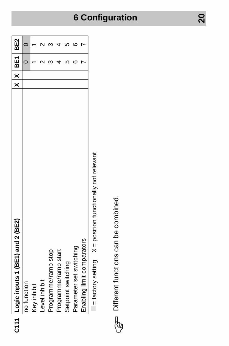
C11
1Lo
gic
inp
uts
1 (B
E1)
and
2 (B
E2)
XX
BE
1B
E2
no fu
nctio
n0
0K
ey in
hib
it1
1Le
vel i
nhib
it2
2P
rogr
amm
e /r
amp
sto
p3
3P
rogr
amm
e /r
amp
sta
rt4
4S
etp
oint
sw
itchi
ng5
5P
aram
eter
set
sw
itchi
ng6
6E
nab
ling
limit
com
par
ator
s7
7
k=
fact
ory
sett
ing
X =
pos
ition
func
tiona
lly n
ot r
elev
ant
HD
iffer
ent
func
tions
can
be
com
bin
ed.
6 Configuration 21
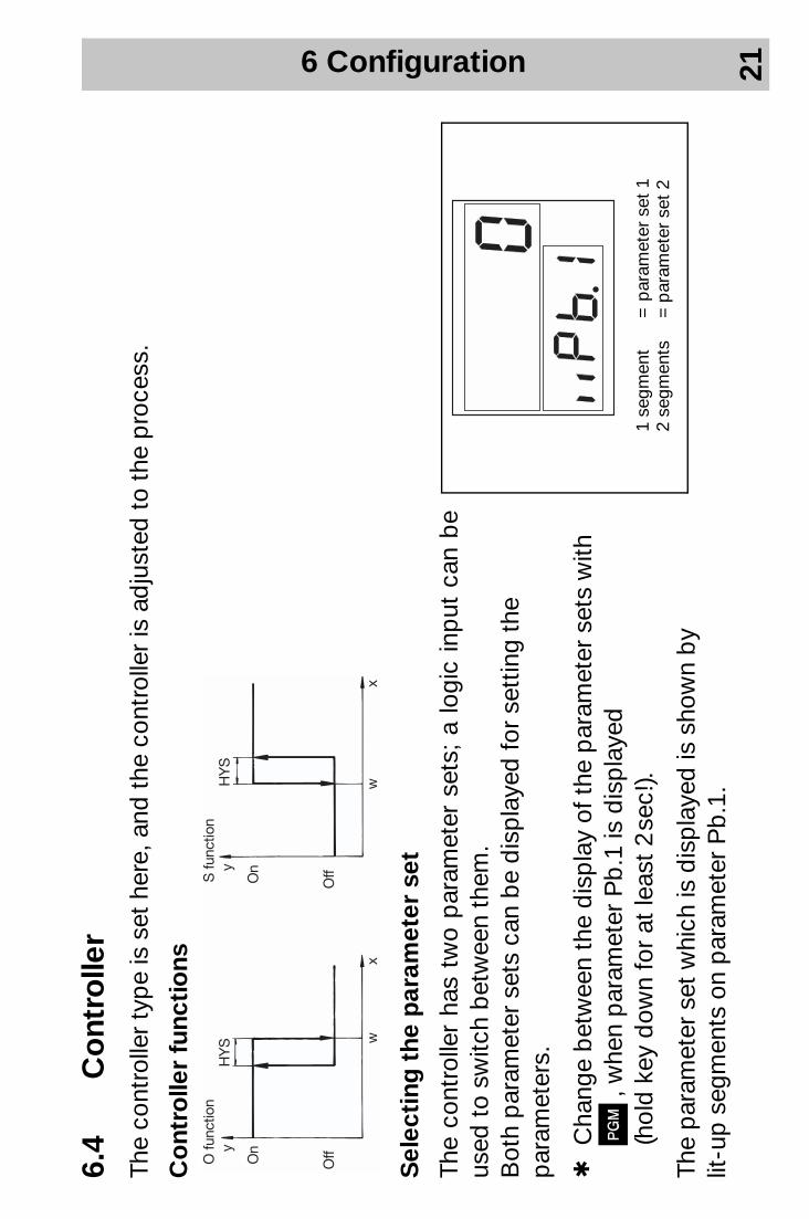
6.4
Co
ntro
ller
The
cont
rolle
r ty
pe
is s
et h
ere,
and
the
con
trol
ler
is a
dju
sted
to
the
pro
cess
.
Co
ntro
ller
func
tio
ns
Sel
ecti
ng t
he p
aram
eter
set
The
cont
rolle
r ha
s tw
o p
aram
eter
set
s; a
logi
c in
put
can
be
used
to
switc
h b
etw
een
them
. B
oth
par
amet
er s
ets
can
be
dis
pla
yed
for
sett
ing
the
par
amet
ers.
hC
hang
e b
etw
een
the
dis
pla
y of
the
par
amet
er s
ets
with
P
, w
hen
par
amet
er P
b.1
is d
isp
laye
d
(hol
d k
ey d
own
for
at le
ast
2 se
c!).
The
par
amet
er s
et w
hich
is d
isp
laye
d is
sho
wn
by
lit-u
p s
egm
ents
on
par
amet
er P
b.1
.
1 se
gmen
t=
par
amet
er s
et 1
2 se
gmen
ts=
par
amet
er s
et 2

6 Configuration 22
Co
ntro
ller
stru
ctur
eTh
e co
ntro
ller
stru
ctur
e is
def
ined
thr
ough
par
amet
ers
Pb
, dt
and
rt.
Exa
mp
le: P
I → P
b≠0
, dt=
0, r
t ≠0
Par
amet
erVa
lue
rang
e fa
cto
ry-s
et
No
tes
Pb
1
0—99
99 d
igit1
0P
rop
ortio
nal b
and
1 (c
ontr
olle
r ou
tput
1)
Pro
por
tiona
l ban
d 2
(con
trol
ler
outp
ut 2
)In
fluen
ces
the
P a
ctio
n of
the
con
trol
ler
If P
b =
0, t
he c
ontr
olle
r st
ruct
ure
is in
effe
ctiv
e.P
b 2
0—
9999
dig
it10
dt
0—99
99 s
ec
80 s
ec
Der
ivat
ive
time
Influ
ence
s th
e D
act
ion
of t
he c
ontr
olle
r. If
dt=
0, t
he c
ontr
olle
r ha
s no
D a
ctio
n.
rt
0—99
99 s
ec
350
sec
Res
et t
ime
Influ
ence
s th
e I a
ctio
n of
the
con
trol
ler.
If rt
=0,
the
con
trol
ler
has
no I
actio
n.
Cy
1 0.
5—99
9.9
sec
20.0
sec
D
urat
ion
of s
witc
hing
cyc
le 1
(con
trol
ler
outp
ut 1
)D
urat
ion
of s
witc
hing
cyc
le 2
(con
trol
ler
outp
ut 2
)D
urat
ion
of s
witc
hing
cyc
le o
n sw
itchi
ng o
utp
uts.
Th
e cy
cle
time
shou
ld b
e se
lect
ed s
o th
at t
he e
nerg
y su
pp
ly t
o th
e p
roce
ss is
virt
ually
con
tinuo
us w
hile
the
sw
itchi
ng e
lem
ents
are
not
sub
ject
to
exce
ssiv
e w
ear.
Cy
2 0.
5—99
9.9
sec
20
.0 s
ec
1.O
n th
e d
isp
lay
with
one
or
two
dec
imal
pla
ces
the
valu
e ra
nge
and
the
fact
ory
sett
ing
ch
ange
acc
ord
ingl
y (e
. g. 1
dec
imal
pla
ce →
valu
e ra
nge:
-19
9.9
to +
999.
9).
6 Configuration 23
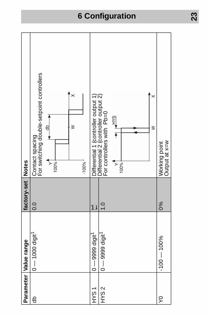
db
0
— 1
000
dig
it1 0.
0 C
onta
ct s
pac
ing
For
switc
hing
dou
ble
-set
poi
nt c
ontr
olle
rs
HY
S 1
0
— 9
999
dig
it1 2
Diff
eren
tial 1
(con
trol
ler
outp
ut 1
)D
iffer
entia
l 2 (c
ontr
olle
r ou
tput
2)
For
cont
rolle
rs w
ith P
b=
0H
YS
2
0 —
999
9 d
igit1
1.
0
Y0
-100
— 1
00 %
0
%
Wor
king
poi
nt
Out
put
at
x=w
Par
amet
erVa
lue
rang
e fa
cto
ry-s
et
No
tes
6 Configuration 24
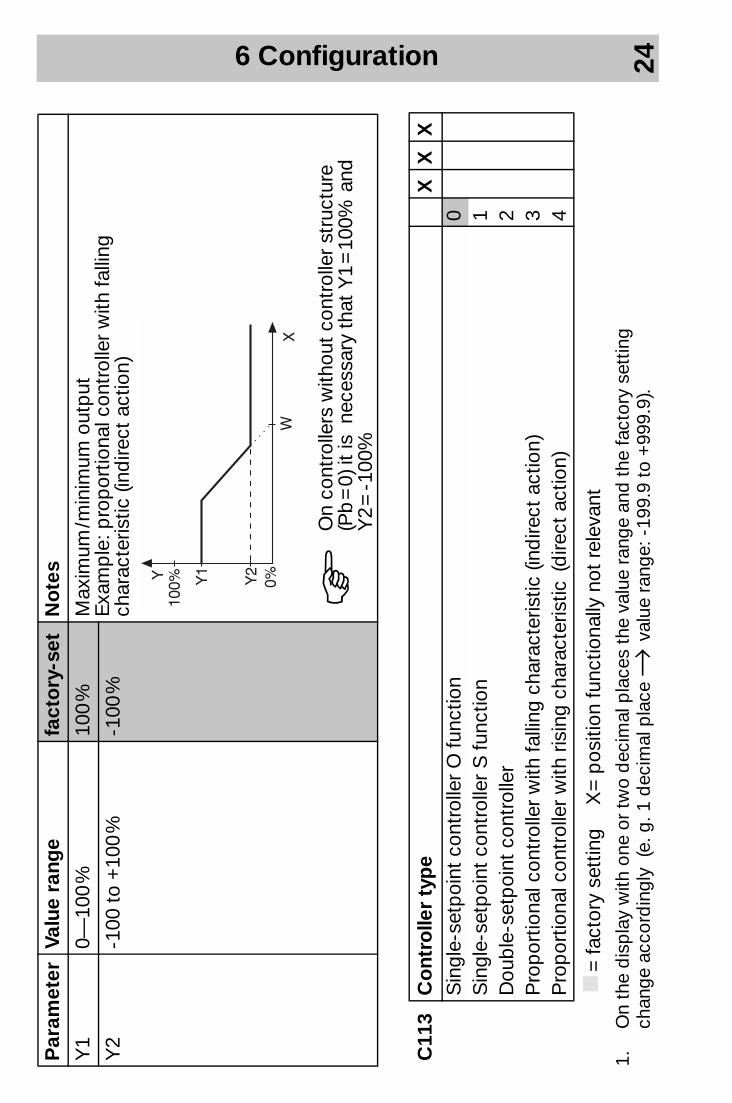
Y1
0—10
0 %
100
%
Max
imum
/min
imum
out
put
Exa
mp
le: p
rop
ortio
nal c
ontr
olle
r w
ith fa
lling
ch
arac
teris
tic (i
ndire
ct a
ctio
n)
Y2
-100
to
+10
0 %
-100
%
C11
3C
ont
rolle
r ty
pe
XX
XS
ingl
e-se
tpoi
nt c
ontr
olle
r O
func
tion
0S
ingl
e-se
tpoi
nt c
ontr
olle
r S
func
tion
1D
oub
le-s
etp
oint
con
trol
ler
2P
rop
ortio
nal c
ontr
olle
r w
ith fa
lling
cha
ract
eris
tic (i
ndire
ct a
ctio
n)3
Pro
por
tiona
l con
trol
ler
with
ris
ing
char
acte
ristic
(d
irect
act
ion)
4
k=
fact
ory
sett
ing
X =
pos
ition
func
tiona
lly n
ot r
elev
ant
Par
amet
erVa
lue
rang
e fa
cto
ry-s
et
No
tes H
On
cont
rolle
rs w
ithou
t co
ntro
ller
stru
ctur
e (P
b =
0) i
t is
nec
essa
ry t
hat
Y1
= 1
00%
and
Y
2 =
-100
%
1.O
n th
e d
isp
lay
with
one
or
two
dec
imal
pla
ces
the
valu
e ra
nge
and
the
fact
ory
sett
ing
ch
ange
acc
ord
ingl
y (e
. g. 1
dec
imal
pla
ce →
valu
e ra
nge:
-19
9.9
to +
999.
9).
6 Configuration 25
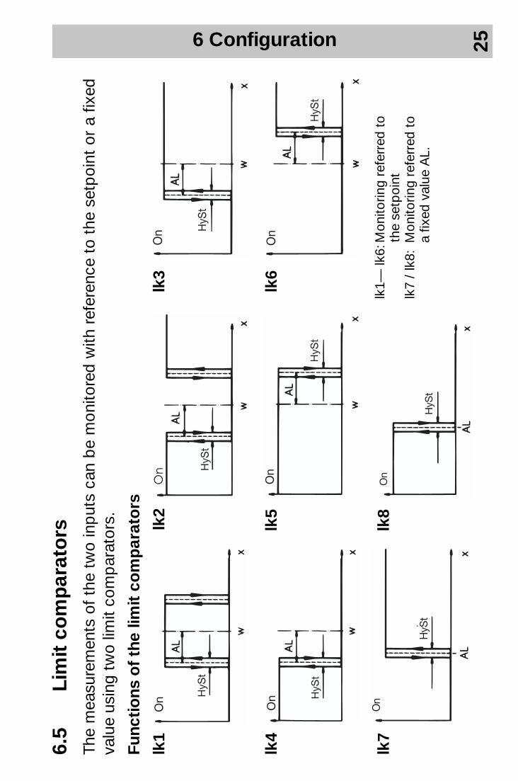
6.5
Lim
it c
om
par
ato
rsTh
e m
easu
rem
ents
of
the
two
inp
uts
can
be
mon
itore
d w
ith r
efer
ence
to
the
setp
oint
or
a fix
ed
valu
e us
ing
two
limit
com
par
ator
s.
Func
tio
ns o
f th
e lim
it c
om
par
ato
rs
lk2
lk3
lk4
lk5
lk6
lk7
lk8
lk1
lk1—
lk6:
Mon
itorin
g re
ferr
ed t
o
the
set
poi
ntlk
7 /
lk8:
Mon
itorin
g re
ferr
ed t
o
a fi
xed
val
ue A
L.

6 Configuration 26
1.In
the
dis
pla
y w
ith o
ne o
r tw
o d
ecim
al p
lace
s th
e va
lue
rang
e an
d t
he fa
ctor
y se
ttin
g
chan
ge a
ccor
din
gly
(e. g
. 1 d
ecim
al p
lace
→ va
lue
rang
e: -
199.
9 to
+99
9.9)
.
Par
amet
erVa
lue
rang
e fa
cto
ry-s
et
No
tes
AL
1 -1
999
to +
9999
dig
it12
Lim
it lim
it co
mp
arat
or 1
AL
2 -1
999
to +
9999
dig
it180
Lim
it lim
it co
mp
arat
or 2
C11
2Li
mit
co
mp
arat
or
1 (L
K1)
and
2 (L
K2)
LK1
LK2
XX
no fu
nctio
n0
0lk
1 (p
roce
ss v
alue
inp
ut)
11
lk 2
(pro
cess
val
ue in
put
)2
2lk
3 (p
roce
ss v
alue
inp
ut)
33
lk 4
(pro
cess
val
ue in
put
)4
4lk
5 (p
roce
ss v
alue
inp
ut)
55
lk 6
(pro
cess
val
ue in
put
)6
6lk
7 (p
roce
ss v
alue
inp
ut)
77
lk 8
(pro
cess
val
ue in
put
)8
8
k=
fact
ory
sett
ing
X =
pos
ition
func
tiona
lly n
ot r
elev
ant
Par
amet
erVa
lue
rang
e fa
cto
ry-s
et
No
tes
HyS
t-1
999
to +
9999
dig
it11
Sw
itchi
ng d
iffer
entia
l of t
he li
mit
com
par
ator
s
6 Configuration 27
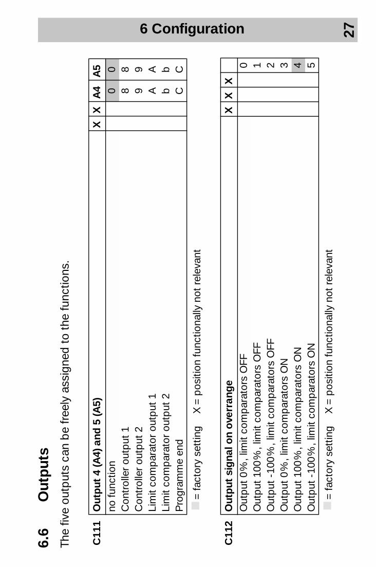
6.6
Out
put
sTh
e fiv
e ou
tput
s ca
n b
e fr
eely
ass
igne
d t
o th
e fu
nctio
ns.
C11
1O
utp
ut 4
(A4)
and
5 (A
5)X
XA
4A
5no
func
tion
00
Con
trol
ler
outp
ut 1
88
Con
trol
ler
outp
ut 2
99
Lim
it co
mp
arat
or o
utp
ut 1
AA
Lim
it co
mp
arat
or o
utp
ut 2
bb
Pro
gram
me
end
CC
k=
fact
ory
sett
ing
X =
pos
ition
func
tiona
lly n
ot r
elev
ant
C11
2O
utp
ut s
igna
l on
ove
rran
ge
XX
XO
utp
ut 0
%, l
imit
com
par
ator
s O
FF0
Out
put
100
%, l
imit
com
par
ator
s O
FF1
Out
put
-10
0 %
, lim
it co
mp
arat
ors
OFF
2O
utp
ut 0
%, l
imit
com
par
ator
s O
N3
Out
put
100
%, l
imit
com
par
ator
s O
N4
Out
put
-10
0 %
, lim
it co
mp
arat
ors
ON
5
k=
fact
ory
sett
ing
X =
pos
ition
func
tiona
lly n
ot r
elev
ant

6 Configuration 28
C11
3O
utp
ut 1
(K1;
rel
ay) a
nd 2
(K2;
rel
ay)
XX
K1
K2
no fu
nctio
n0
0C
ontr
olle
r ou
tput
11
1C
ontr
olle
r ou
tput
22
2Li
mit
com
par
ator
out
put
13
3Li
mit
com
par
ator
out
put
24
4P
rogr
amm
e en
d5
5
k=
fact
ory
sett
ing
X =
pos
ition
func
tiona
lly n
ot r
elev
ant

6 Configuration 29
6.7
Dis
pla
yTh
e nu
mb
er o
f th
e d
ecim
al p
lace
s w
hen
dis
pla
ying
pro
cess
val
ue a
nd s
etp
oint
in t
he s
tand
ard
dis
pla
y is
def
ined
her
e. In
ad
diti
on, t
he u
nit
of t
he p
roce
ss v
alue
is d
eter
min
ed.
Dis
pla
ying
the
uni
t an
d s
oft
war
e ve
rsio
n
hD
isp
lay
the
soft
war
e ve
rsio
n an
d u
nit o
f the
pro
cess
val
ue
with
P +
I(h
old
key
s d
own!
)
C11
2D
ecim
al p
lace
s /u
nit
XX
Xno
dec
imal
pla
ce, d
egre
e C
elsi
us0
one
dec
imal
pla
ce, d
egre
e C
elsi
us1
two
dec
imal
pla
ces,
deg
ree
Cel
sius
2no
dec
imal
pla
ce, d
egre
e Fa
hren
heit
3on
e d
ecim
al p
lace
, deg
ree
Fahr
enhe
it4
two
dec
imal
pla
ces,
deg
ree
Fahr
enhe
it5
k=
fact
ory
sett
ing
X =
pos
ition
func
tiona
lly n
ot r
elev
ant
6 Configuration 30
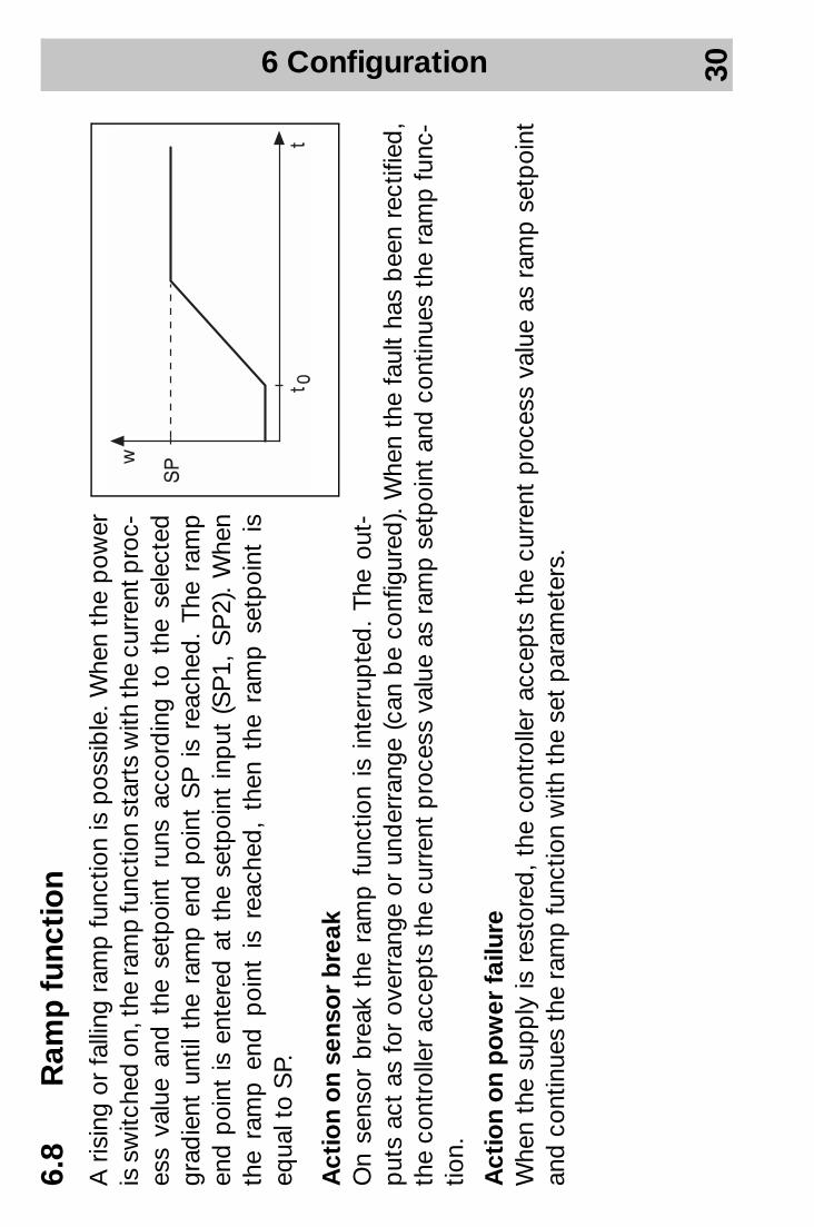
6.8
Ram
p f
unct
ion
A r
isin
g or
fal
ling
ram
p f
unct
ion
is p
ossi
ble
. Whe
n th
e p
ower
is
sw
itche
d o
n, th
e ra
mp
func
tion
star
ts w
ith th
e cu
rren
t pro
c-es
s va
lue
and
the
set
poi
nt r
uns
acco
rdin
g to
the
sel
ecte
d gr
adie
nt u
ntil
the
ram
p e
nd p
oint
SP
is
reac
hed
. Th
e ra
mp
end
poi
nt is
ent
ered
at
the
setp
oint
inp
ut (
SP
1, S
P2)
. W
hen
the
ram
p e
nd p
oint
is
reac
hed
, th
en t
he r
amp
set
poi
nt i
s eq
ual t
o S
P.
Act
ion
on
sens
or
bre
ak
On
sens
or b
reak
the
ram
p f
unct
ion
is i
nter
rup
ted
. Th
e ou
t-p
uts
act
as f
or o
verr
ange
or
und
erra
nge
(can
be
conf
igur
ed).
Whe
n th
e fa
ult
has
bee
n re
ctifi
ed,
the
cont
rolle
r ac
cep
ts t
he c
urre
nt p
roce
ss v
alue
as
ram
p s
etp
oint
and
con
tinue
s th
e ra
mp
func
-tio
n.
Act
ion
on
po
wer
fai
lure
W
hen
the
sup
ply
is r
esto
red
, th
e co
ntro
ller
acce
pts
the
cur
rent
pro
cess
val
ue a
s ra
mp
set
poi
nt
and
con
tinue
s th
e ra
mp
func
tion
with
the
set
par
amet
ers.
6 Configuration 31
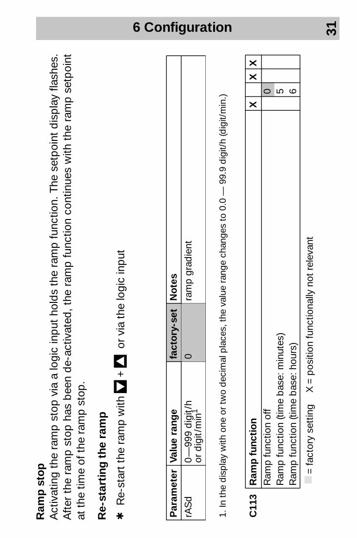
Ram
p s
top
A
ctiv
atin
g th
e ra
mp
sto
p v
ia a
logi
c in
put
hol
ds
the
ram
p f
unct
ion.
The
set
poi
nt d
isp
lay
flash
es.
Aft
er t
he r
amp
sto
p h
as b
een
de-
activ
ated
, the
ram
p f
unct
ion
cont
inue
s w
ith t
he r
amp
set
poi
nt
at t
he t
ime
of t
he r
amp
sto
p.
Re-
star
ting
the
ram
p
hR
e-st
art
the
ram
p w
ith D
+ I
or v
ia t
he lo
gic
inp
ut
Par
amet
erVa
lue
rang
e fa
cto
ry-s
et
No
tes
rAS
d
0 —
999
dig
it /h
or
dig
it /m
in1
0ra
mp
gra
die
nt
1. In
the
dis
pla
y w
ith o
ne o
r tw
o d
ecim
al p
lace
s, t
he v
alue
ran
ge c
hang
es t
o 0.
0 —
99.
9 d
igit/
h (d
igit/
min
.)
C11
3R
amp
fun
ctio
nX
XX
Ram
p fu
nctio
n of
f0
Ram
p fu
nctio
n (ti
me
bas
e: m
inut
es)
5R
amp
func
tion
(tim
e b
ase:
hou
rs)
6
k=
fact
ory
sett
ing
X =
pos
ition
func
tiona
lly n
ot r
elev
ant
6 Configuration 32
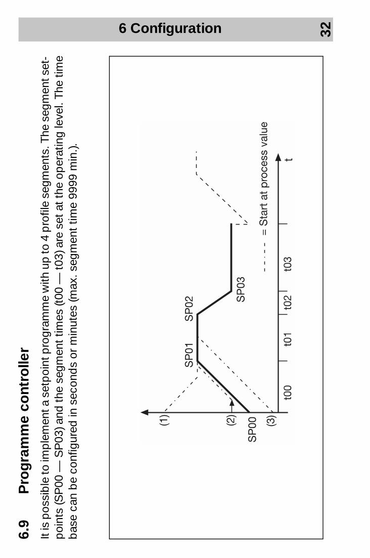
6.9
Pro
gra
mm
e co
ntro
ller
It is
pos
sib
le to
imp
lem
ent a
set
poi
nt p
rogr
amm
e w
ith u
p to
4 p
rofil
e se
gmen
ts. T
he s
egm
ent s
et-
poi
nts
(SP
00 —
SP
03) a
nd th
e se
gmen
t tim
es (t
00 —
t03)
are
set
at t
he o
per
atin
g le
vel.
The
time
bas
e ca
n b
e co
nfig
ured
in s
econ
ds
or m
inut
es (m
ax. s
egm
ent
time
9999
min
.).
6 Configuration 33
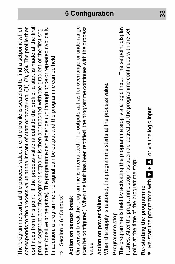
The
pro
gram
me
star
ts a
t th
e p
roce
ss v
alue
, i. e
. the
pro
file
is s
earc
hed
to
find
a s
etp
oint
whi
ch
corr
esp
ond
s to
the
pro
cess
val
ue a
t the
inst
ant o
f sta
rt o
r pow
er-o
n. ((
1), (
2), (
3)).
The
pro
file
then
co
ntin
ues
from
thi
s p
oint
. If
the
pro
cess
val
ue is
out
sid
e th
e p
rofil
e, a
sta
rt is
mad
e at
the
firs
t p
rofil
e se
gmen
t an
d t
he s
egm
ent
setp
oint
is t
hen
app
roac
hed
with
the
gra
die
nt o
f th
e fir
st s
eg-
men
t (p
ositi
ve o
r neg
ativ
e). T
he p
rogr
amm
e ca
n ei
ther
be
run
thro
ugh
once
or r
epea
ted
cyc
lical
ly.
In a
dd
ition
, a p
rogr
amm
e en
d s
igna
l can
be
outp
ut a
nd t
he p
rogr
amm
e ca
n b
e he
ld.
vS
ectio
n 6.
6 “O
utp
uts”
Act
ion
on
sens
or
bre
ak
On
sens
or b
reak
the
pro
gram
me
is in
terr
upte
d. T
he o
utp
uts
act
as f
or o
verr
ange
or
und
erra
nge
(can
be
conf
igur
ed).
Whe
n th
e fa
ult h
as b
een
rect
ified
, the
pro
gram
me
cont
inue
s w
ith th
e p
roce
ss
valu
e.
Act
ion
on
po
wer
fai
lure
W
hen
the
sup
ply
is r
esto
red
, the
pro
gram
me
star
ts a
t th
e p
roce
ss v
alue
.
Pro
gra
mm
e st
op
Th
e p
rogr
amm
e is
hel
d b
y ac
tivat
ing
the
pro
gram
me
stop
via
a lo
gic
inp
ut. T
he s
etp
oint
dis
pla
y fla
shes
. Aft
er th
e p
rogr
amm
e st
op h
as b
een
de-
activ
ated
, the
pro
gram
me
cont
inue
s w
ith th
e se
t -p
oint
at
the
time
of t
he p
rogr
amm
e st
op.
Re-
star
ting
the
pro
gra
mm
eh
Re-
star
t th
e p
rogr
amm
e w
ith D
+ I
or v
ia t
he lo
gic
inp
ut
6 Configuration 34
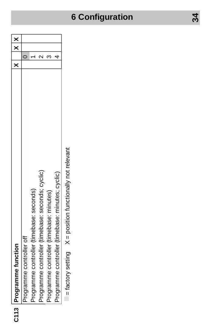
C11
3P
rog
ram
me
func
tio
nX
XX
Pro
gram
me
cont
rolle
r of
f0
Pro
gram
me
cont
rolle
r (ti
meb
ase:
sec
ond
s)1
Pro
gram
me
cont
rolle
r (ti
meb
ase:
sec
ond
s; c
yclic
)2
Pro
gram
me
cont
rolle
r (ti
meb
ase:
min
utes
)3
Pro
gram
me
cont
rolle
r (ti
meb
ase:
min
utes
; cyc
lic)
4
k=
fact
ory
sett
ing
X =
pos
ition
func
tiona
lly n
ot r
elev
ant
6 Configuration 35
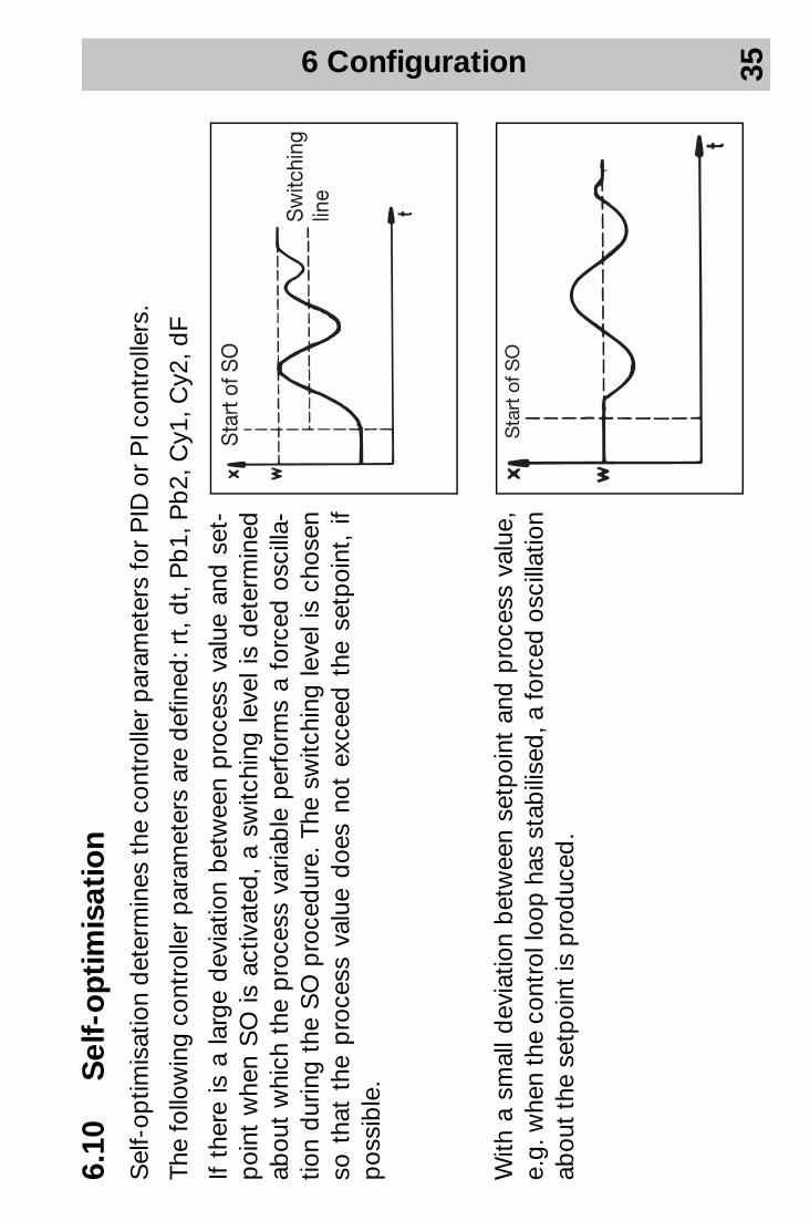
6.10
Sel
f-o
pti
mis
atio
nS
elf-
optim
isat
ion
det
erm
ines
the
con
trol
ler
par
amet
ers
for
PID
or
PI c
ontr
olle
rs.
The
follo
win
g co
ntro
ller
par
amet
ers
are
def
ined
: rt,
dt,
Pb
1, P
b2,
Cy1
, Cy2
, dF
If th
ere
is a
larg
e d
evia
tion
bet
wee
n p
roce
ss v
alue
and
set
-p
oint
whe
n S
O is
act
ivat
ed,
a sw
itchi
ng le
vel i
s d
eter
min
ed
abou
t w
hich
the
pro
cess
var
iab
le p
erfo
rms
a fo
rced
osc
illa -
tion
dur
ing
the
SO
pro
ced
ure.
The
sw
itchi
ng le
vel i
s ch
osen
so
tha
t th
e p
roce
ss v
alue
doe
s no
t ex
ceed
the
set
poi
nt,
if p
ossi
ble
.
With
a s
mal
l dev
iatio
n b
etw
een
setp
oint
and
pro
cess
val
ue,
e.g.
whe
n th
e co
ntro
l loo
p h
as s
tab
ilise
d, a
forc
ed o
scill
atio
n ab
out
the
setp
oint
is p
rod
uced
.

6 Configuration 36
Sta
rtin
g s
elf-
op
tim
isat
ion
hS
tart
SO
with
X
(hol
d d
own
key
for
at le
ast
2 se
c !)
hA
bor
t w
ith X
(w
hile
sel
f-op
timis
atio
n is
run
ning
)
If "t
une"
doe
s no
t fla
sh a
ny lo
nger
, sel
f-op
timis
atio
n is
ter
mi-
nate
d a
nd th
e co
ntro
ller
func
tions
with
the
par
amet
ers
whi
ch
have
bee
n es
tab
lishe
d.
hS
tore
the
par
amet
ers
with
X
(Hol
d d
own
key
for
at le
ast
2 se
c!)
HS
tart
ing
SO
is n
ot p
ossi
ble
with
act
ive
leve
l inh
ibit.
Th
e ac
tive
par
amet
er s
et is
op
timis
ed.
With
act
ive
ram
p /p
rogr
amm
e fu
nctio
n, t
he r
amp
/pro
gram
me
seq
uenc
e is
sto
pp
ed
dur
ing
self-
optim
isat
ion.
7 Appendix 37
7 A
pp
end
ix
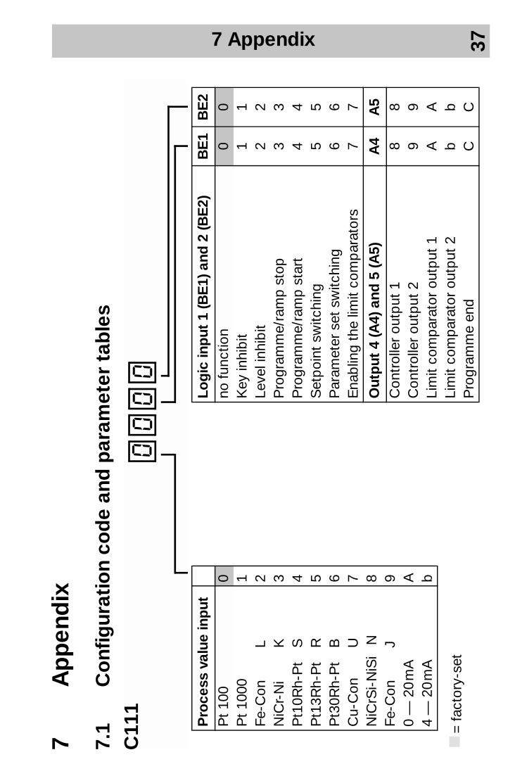
7.1
Co
nfig
urat
ion
cod
e an
d p
aram
eter
tab
les
Pro
cess
val
ue in
put
Pt
100
0P
t 10
001
Fe-C
onL
2N
iCr-
Ni
K3
Pt1
0Rh-
Pt
S4
Pt1
3Rh-
Pt
R5
Pt3
0Rh-
Pt
B6
Cu-
Con
U7
NiC
rSi-
NiS
iN
8Fe
-Con
J
90
— 2
0 m
AA
4 —
20
mA
b
Log
ic in
put
1 (B
E1)
and
2 (B
E2)
BE
1B
E2
no fu
nctio
n0
0K
ey in
hib
it1
1Le
vel i
nhib
it2
2P
rogr
amm
e/ra
mp
sto
p3
3P
rogr
amm
e/ra
mp
sta
rt4
4S
etp
oint
sw
itchi
ng5
5P
aram
eter
set
sw
itchi
ng6
6E
nab
ling
the
limit
com
par
ator
s7
7
Out
put
4 (A
4) a
nd 5
(A5)
A4
A5
Con
trol
ler
outp
ut 1
88
Con
trol
ler
outp
ut 2
99
Lim
it co
mp
arat
or o
utp
ut 1
AA
Lim
it co
mp
arat
or o
utp
ut 2
bb
Pro
gram
me
end
CC
C11
10000
k=
fact
ory-
set
7 Appendix 38
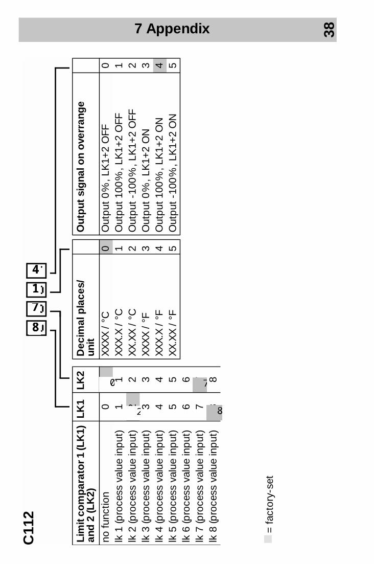
Lim
it c
om
par
ato
r 1 (L
K1)
an
d 2
(LK
2)LK
1LK
2
no fu
nctio
n0
0lk
1 (p
roce
ss v
alue
inp
ut)
11
lk 2
(pro
cess
val
ue in
put
)2
2lk
3 (p
roce
ss v
alue
inp
ut)
33
lk 4
(pro
cess
val
ue in
put
)4
4lk
5 (p
roce
ss v
alue
inp
ut)
55
lk 6
(pro
cess
val
ue in
put
)6
6lk
7 (p
roce
ss v
alue
inp
ut)
77
lk 8
(pro
cess
val
ue in
put
)8
8
Out
put
sig
nal o
n o
verr
ang
e
Out
put
0 %
, LK
1+2
OFF
0O
utp
ut 1
00 %
, LK
1+2
OFF
1O
utp
ut -
100
%, L
K1+
2 O
FF2
Out
put
0 %
, LK
1+2
ON
3O
utp
ut 1
00 %
, LK
1+2
ON
4O
utp
ut -
100
%, L
K1+
2 O
N5
Dec
imal
pla
ces/
un
itX
XX
X /
°C
0X
XX
.X /
°C
1X
X.X
X /
°C
2X
XX
X /
°F
3X
XX
.X /
°F
4X
X.X
X /
°F
5
C11
22004
k=
fact
ory-
set
7 Appendix 39
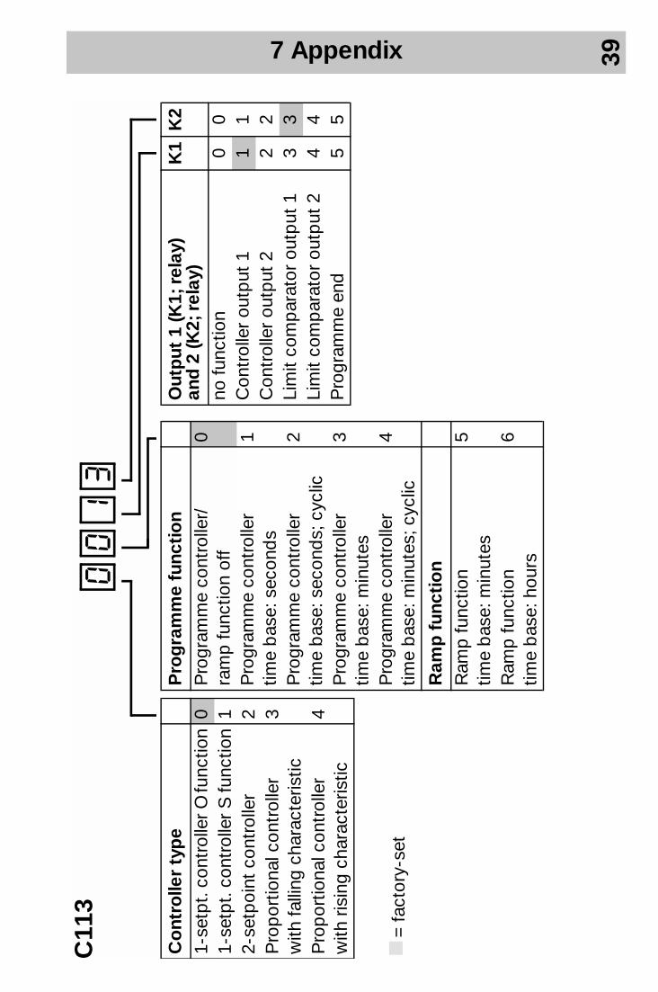
Co
ntro
ller
typ
e1-
setp
t. c
ontr
olle
r O fu
nctio
n0
1-se
tpt.
cont
rolle
r S
func
tion
12-
setp
oint
con
trol
ler
2P
rop
ortio
nal c
ontr
olle
r w
ith fa
lling
cha
ract
eris
tic3
Pro
por
tiona
l con
trol
ler
w
ith r
isin
g ch
arac
teris
tic4
Out
put
1 (K
1; r
elay
) an
d 2
(K2;
rel
ay)
K1
K2
no fu
nctio
n0
0C
ontr
olle
r ou
tput
11
1C
ontr
olle
r ou
tput
22
2Li
mit
com
par
ator
out
put
13
3Li
mit
com
par
ator
out
put
24
4P
rogr
amm
e en
d5
5
Pro
gra
mm
e fu
ncti
on
Pro
gram
me
cont
rolle
r/
ram
p fu
nctio
n of
f0
Pro
gram
me
cont
rolle
r tim
e b
ase:
sec
ond
s1
Pro
gram
me
cont
rolle
r tim
e b
ase:
sec
ond
s; c
yclic
2
Pro
gram
me
cont
rolle
r tim
e b
ase:
min
utes
3
Pro
gram
me
cont
rolle
r tim
e b
ase:
min
utes
; cyc
lic4
Ram
p f
unct
ion
Ram
p fu
nctio
n
time
bas
e: m
inut
es5
Ram
p fu
nctio
n
time
bas
e: h
ours
6
C11
30013
k=
fact
ory-
set
! ! E
7 Appendix 40
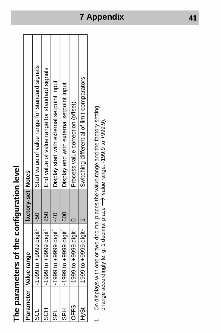
The
par
amet
ers
of
the
conf
igur
atio
n le
vel
1.O
n d
isp
lays
with
one
or
two
dec
imal
pla
ces
the
valu
e ra
nge
and
the
fact
ory
sett
ing
chan
ge a
ccor
din
gly
(e. g
. 1 d
ecim
al p
lace
→ va
lue
rang
e: -
199.
9 to
+99
9.9)
.
Par
amet
erVa
lue
rang
e fa
cto
ry-s
et N
ote
s
SC
L-1
999
to +
9999
dig
it1-5
0S
tart
val
ue o
f val
ue r
ange
for
stan
dar
d s
igna
ls
SC
H-1
999
to +
9999
dig
it125
0E
nd v
alue
of v
alue
ran
ge fo
r st
and
ard
sig
nals
SP
L-1
999
to +
9999
dig
it1-4
0
Dis
pla
y st
art
with
ext
erna
l set
poi
nt in
put
SP
H-1
999
to +
9999
dig
it160
0 D
isp
lay
end
with
ext
erna
l set
poi
nt in
put
OFF
S-1
999
to +
9999
dig
it10
Pro
cess
val
ue c
orre
ctio
n (o
ffset
)
HyS
t-1
999
to +
9999
dig
it11
Sw
itchi
ng d
iffer
entia
l of l
imit
com
par
ator
s
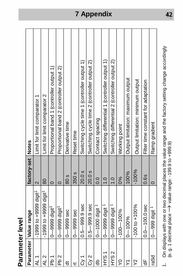
7 Appendix 41
Par
amet
er le
vel
1.O
n d
isp
lays
with
one
or
two
dec
imal
pla
ces
the
valu
e ra
nge
and
the
fact
ory
sett
ing
chan
ge a
ccor
din
gly
(e. g
. 1 d
ecim
al p
lace
→ va
lue
rang
e: -
199.
9 to
+99
9.9)
Par
amet
erVa
lue
rang
e fa
cto
ry-s
et
No
tes
AL
1 -1
999
to +
9999
dig
it12
Lim
it fo
r lim
it co
mp
arat
or 1
AL
2 -1
999
to +
9999
dig
it180
Lim
it fo
r lim
it co
mp
arat
or 2
Pb
1
0—99
99 d
igit1
0P
rop
ortio
nal b
and
1 (c
ontr
olle
r ou
tput
1)
Pb
2
0—99
99 d
igit1
0P
rop
ortio
nal b
and
2 (c
ontr
olle
r ou
tput
2)
dt
0— 9
999
sec
80 s
D
eriv
ativ
e tim
e
rt
0— 9
999
sec
350
s R
eset
tim
e
Cy
1 0.
5— 9
99.9
sec
20
.0 s
S
witc
hing
cyc
le t
ime
1 (c
ontr
olle
r ou
tput
1)
Cy
2 0.
5— 9
99.9
sec
20.0
s
Sw
itchi
ng c
ycle
tim
e 2
(con
trol
ler
outp
ut 2
)
db
0—
1000
dig
it 1
0.0
Con
tact
sp
acin
g
HY
S 1
0—
999
9 d
igit
11.
0
Sw
itchi
ng d
iffer
entia
l 1 (c
ontr
olle
r ou
tput
1)
HY
S 2
0—
999
9 d
igit
1
1.0
Sw
itchi
ng d
iffer
entia
l 2 (c
ontr
olle
r ou
tput
2)
Y0
-100
— 1
00 %
0
%
Wor
king
poi
nt
Y1
0— 1
00 %
100
%
Out
put
lim
itatio
n: m
axim
um o
utp
ut
Y2
-100
to
+10
0 %
-100
%O
utp
ut li
mita
tion:
min
imum
out
put
dF
0.0—
100
.0 s
ec
0.6
s Fi
lter
time
cons
tant
for
adap
tatio
n
raS
d0
— 9
99 d
igit
10
Ram
p g
rad
ient
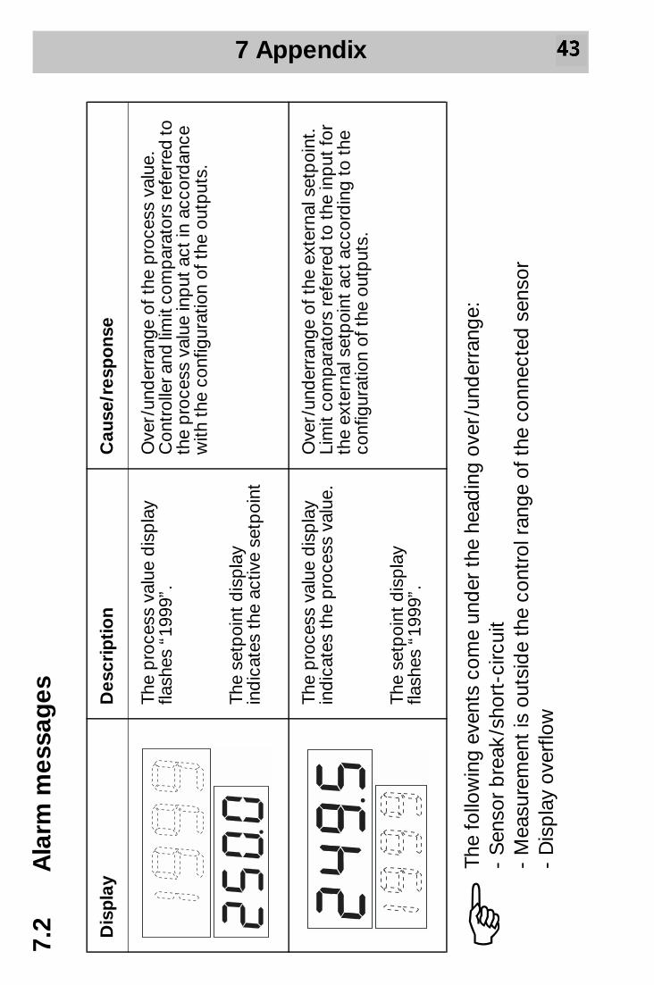
7 Appendix 42
7.2
Ala
rm m
essa
ges
Dis
pla
yD
escr
ipti
on
Cau
se/r
esp
ons
e
The
pro
cess
val
ue d
isp
lay
flash
es “
1999
”.
The
setp
oint
dis
pla
y in
dic
ates
the
act
ive
setp
oint
Ove
r /un
der
rang
e of
the
pro
cess
val
ue.
Con
trol
ler a
nd li
mit
com
par
ator
s re
ferr
ed to
th
e p
roce
ss v
alue
inp
ut a
ct in
acc
ord
ance
w
ith t
he c
onfig
urat
ion
of t
he o
utp
uts.
The
pro
cess
val
ue d
isp
lay
ind
icat
es t
he p
roce
ss v
alue
.
The
setp
oint
dis
pla
y fla
shes
“19
99”.
Ove
r /un
der
rang
e of
the
ext
erna
l set
poi
nt.
Lim
it co
mp
arat
ors
refe
rred
to
the
inp
ut fo
r th
e ex
tern
al s
etp
oint
act
acc
ord
ing
to t
he
conf
igur
atio
n of
the
out
put
s.
HTh
e fo
llow
ing
even
ts c
ome
und
er t
he h
ead
ing
over
/und
erra
nge:
-
Sen
sor
bre
ak /s
hort
-circ
uit
- M
easu
rem
ent
is o
utsi
de
the
cont
rol r
ange
of t
he c
onne
cted
sen
sor
- D
isp
lay
over
flow

7 Appendix 43
7.3
Tech
nica
l dat
a
Inp
uts
Thes
e va
lues
incl
ude
the
linea
risat
ion
tole
ranc
es.
Tran
sduc
erC
ont
rol r
ang
eM
easu
rem
ent
accu
racy
/A
mb
ient
te
mp
erat
ure
erro
r
Mea
sure
men
t ci
rcui
t
mo
nito
ring
1
Sen
sor
brea
kS
hort
-cir
cuit
Pro
cess
val
ue in
put
Pt
1002
-200
+
850
°C≤
0.1
% /
≤ 25
pp
m /
°CX
XP
t 10
002
-200
+
850
°C≤
0.1
% /
≤ 2
5 p
pm
/ °C
XX
Fe-C
on L
3-2
00
+90
0 °C
≤ 0.
25 %
/ ≤
100
pp
m / °
CX
–Fe
-Con
J3
-200
+12
00 °C
≤ 0.
25 %
/ ≤
100
pp
m / °
CX
–N
iCr-
Ni K
3-2
00 +
1372
°C≤
0.25
% /
≤ 1
00 p
pm
/ °C
X–
Cu-
Con
U3
-200
+
600
°C≤
0.25
% /
≤ 1
00 p
pm
/ °C
X–
NiC
rSi-
NiS
i N3
-100
+13
00 °C
≤ 0.
25 %
/ ≤
100
pp
m / °
CX
–P
t10R
h-P
t S
30
— 1
768
°C≤
0.25
% /
≤ 1
00 p
pm
/ °C
X–
Pt1
3Rh-
Pt
R3
0 —
176
8 °C
≤ 0.
25 %
/ ≤
100
pp
m / °
CX
–P
t30R
h-P
t6R
h B
30
— 1
820
°C≤
0.25
% /
≤ 1
00 p
pm
/ °C
4X
–0
— 2
0 m
A5
scal
able
≤ 0.
1 %
/ ≤
100
pp
m / °
C–
–4
— 2
0 m
A5
scal
able
≤ 0.
1 %
/ ≤
100
pp
m / °
CX
X
7 Appendix 44
1.X
= re
cogn
ised
, – =
not
rec
ogni
sed
Th
e ou
tput
s m
ove
to a
def
ined
sta
tus.
2.P
t 10
0, P
t 100
0 in
2-
or 3
-wire
circ
uit
Lead
com
pen
satio
n:
Not
req
uire
d fo
r 3-
wire
circ
uit.
Whe
n us
ed w
ith a
res
ista
nce
ther
mom
eter
in 2
-wire
circ
uit,
lead
com
pen
sa-
tion
can
be
pro
vid
ed b
y an
ext
erna
l lea
d c
omp
ensa
tion
resi
stor
. (R
com
p =
Rlin
e). I
n ad
diti
on, t
he le
ad r
esis
tanc
e ca
n b
e co
mp
ensa
ted
in s
oftw
are
thro
ugh
pro
cess
val
ue c
or-
rect
ion.
3.Te
mp
erat
ure
com
pen
satio
n: in
tern
al4.
With
in t
he r
ange
of 3
00 —
182
0 °C
5.V
olta
ge d
rop
∆u e
less
tha
n 1
V
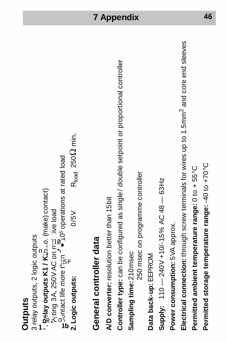
7 Appendix 45
Out
put
s 3
rela
y ou
tput
s, 2
logi
c ou
tput
s
1.R
elay
out
put
s K
1 /
K2:
n.o.
(mak
e) c
onta
ct)
Rat
ing
3 A
, 250
V A
C o
n re
sist
ive
load
C
onta
ct li
fe m
ore
than
5 •
105
oper
atio
ns a
t ra
ted
load
2.Lo
gic
out
put
s:0
/5 V
R
load
250
Ω m
in.
Gen
eral
co
ntro
ller
dat
aA
/D c
onv
erte
r: r
esol
utio
n b
ette
r th
an 1
5 b
it
Co
ntro
ller
typ
e: c
an b
e co
nfig
ured
as
sing
le /
dou
ble
set
poi
nt o
r p
rop
ortio
nal c
ontr
olle
r
Sam
plin
g t
ime:
210
mse
c
2
50 m
sec
on p
rogr
amm
e co
ntro
ller
Dat
a b
ack-
up: E
EP
RO
M
Sup
ply
: 11
0 —
240
V +
10/-
15 %
AC
48
— 6
3 H
z
Po
wer
co
nsum
pti
on:
5 V
A a
pp
rox.
Ele
ctri
cal c
onn
ecti
on:
thr
ough
scr
ew t
erm
inal
s fo
r w
ires
up t
o 1.
5 m
m2
and
cor
e en
d s
leev
es
Per
mit
ted
am
bie
nt t
emp
erat
ure
rang
e: 0
to
+ 5
5 °C
Per
mit
ted
sto
rag
e te
mp
erat
ure
rang
e: -
40 t
o +
70 °C
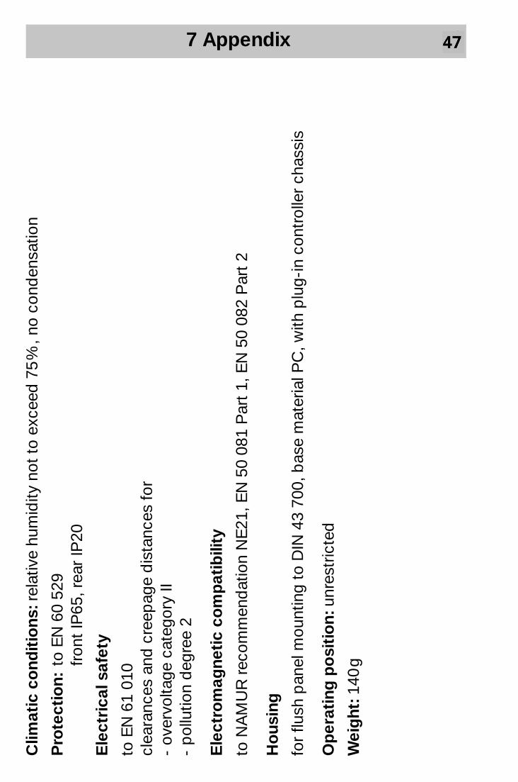
7 Appendix 46
Clim
atic
co
ndit
ions
: rel
ativ
e hu
mid
ity n
ot t
o ex
ceed
75
%, n
o co
nden
satio
n
Pro
tect
ion:
to E
N 6
0 52
9 fr
ont
IP65
, rea
r IP
20
Ele
ctri
cal s
afet
y
to E
N 6
1 01
0 cl
eara
nces
and
cre
epag
e d
ista
nces
for
- ov
ervo
ltage
cat
egor
y II
- p
ollu
tion
deg
ree
2
Ele
ctro
mag
neti
c co
mp
atib
ility
to N
AM
UR
rec
omm
end
atio
n N
E21
, EN
50
081
Par
t 1,
EN
50
082
Par
t 2
Ho
usin
g
for
flush
pan
el m
ount
ing
to D
IN 4
3 70
0, b
ase
mat
eria
l PC
, with
plu
g-in
con
trol
ler
chas
sis
Op
erat
ing
po
siti
on:
unr
estr
icte
d
Wei
ght
: 140
g
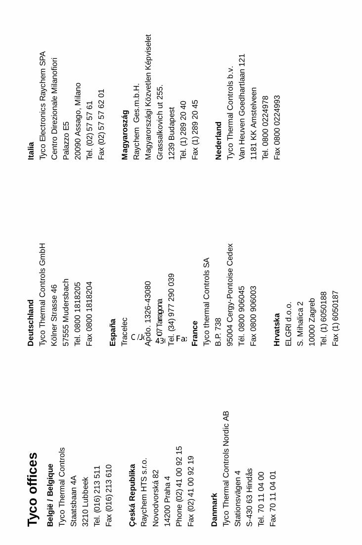
Tyco
off
ices
Bel
gië
/ B
elg
ique
Tyco
The
rmal
Con
trol
s
Sta
atsb
aan
4A
3210
Lub
bee
k
Tel.
(016
) 213
511
Fax
(016
) 213
610
Çes
ká R
epub
lika
Ray
chem
HTS
s.r.
o.
Nov
odvo
rská
82
1420
0 P
raha
4
Pho
ne (0
2) 4
1 00
92
15
Fax
(02)
41
00 9
2 19
Dan
mar
kTy
co T
herm
al C
ontr
ols
Nor
dic
AB
Sta
tions
väge
n 4
S-4
30 6
3 H
ind
ås
Tel.
70 1
1 04
00
Fax
70 1
1 04
01
Deu
tsch
land
Tyco
The
rmal
Con
trol
s G
mb
H
Köl
ner
Str
asse
46
5755
5 M
uder
sbac
h
Tel.
0800
181
8205
Fax
0800
181
8204
Esp
aña
Trac
elec
Ap
do.
132
6-43
080
4300
7 Ta
rrago
na
Tel.
(34)
977
290
039
Fran
ceTy
co t
herm
al C
ontr
ols
SA
B.P
. 738
9500
4 C
ergy
-Pon
tois
e C
edex
Tél.
0800
906
045
Fax
0800
906
003
Hrv
atsk
aE
LGR
I d.o
.o.
S. M
ihal
ica
2
1000
0 Z
agre
b
Tel.
(1) 6
0501
88
Fax
(1) 6
0501
87
Ital
iaTy
co E
lect
roni
cs R
aych
em S
PA
Cen
tro
Dire
zion
ale
Mila
nofio
ri
Pal
azzo
E5
2009
0 A
ssag
o, M
ilano
Tel.
(02)
57
57 6
1
Fax
(02)
57
57 6
2 01
Mag
yaro
szág
Ray
chem
Ges
.m.b
.H.
Mag
yaro
rszá
gi K
özve
tlen
Kép
vise
let
Gra
ssal
kovi
ch u
t 25
5.
1239
Bud
apes
t
Tel.
(1) 2
89 2
0 40
Fax
(1) 2
89 2
0 45
Ned
erla
ndTy
co T
herm
al C
ontr
ols
b.v
.
Van
Heu
ven
Goe
dha
rtla
an 1
21
1181
KK
Am
stel
veen
Tel.
0800
022
4978
Fax
0800
022
4993

No
rge
Tyco
The
rmal
Con
trol
s N
orw
ay A
S
Mal
erha
ugve
ien
25
Pos
tbok
s 60
76 -
Ett
erst
ad
0602
Osl
o
Tel.
+47
66
81 7
9 90
Fax
+47
66
80 8
3 92
Öst
erre
ich
Tyco
The
rmal
Con
trol
s N
.V. L
ubbe
ek
Offic
e Wien
Bro
wn-
Bov
eri S
tras
se 6
/14
2351
Wie
ner
Neu
dor
f
Tel.
(0 2
2 36
) 86
00 7
7
Fax
(0 2
2 36
) 86
00 7
7-5
Po
lska
Ray
chem
Pol
ska
Sp
. z.o
.o.
Tyco
The
rmal
Con
trol
s
ul. F
arb
iars
ka 6
9 C
02-8
62 W
arsz
awa
Tel.
(022
) 54
52 9
50
Fax
(022
) 54
52 9
51
Sch
wei
z /
Sui
sse
Tyco
The
rmal
Con
trol
s N
.V.
Offi
ce B
aar
Hal
den
stra
sse
5
Pos
tfac
h 27
24
6342
Baa
r
Tel.
(041
) 766
30
80
Suo
mi
Tyco
The
rmal
Con
trol
s N
ord
ic A
B
Sta
tions
väge
n 4
S-4
30 6
3 H
ind
ås
Puh
. 080
0 11
67
99
Tele
kop
io 0
800
11 8
6 74
Sve
rig
eTy
co T
herm
al C
ontr
ols
Nor
dic
AB
Sta
tions
väge
n 4
S-4
30 6
3 H
ind
ås
Tel.
0301
-228
00
Fax
0301
-212
-10
Uni
ted
Kin
gd
om
Tyco
The
rmal
Con
trol
s (U
K) L
td
3 R
uthe
rfor
d R
oad
,
Ste
phe
nson
Ind
ustr
ial E
stat
e
Was
hing
ton,
Tyn
e &
Wea
r
NE3
7 3H
X, U
nited
King
dom
Pho
ne 0
800
96 9
0 13
RO
SS
IÅ i
dru
gie
str
any
SN
GR
AJX
EM
1253
15, g
. Mos
kva
Leni
ngra
dsk
ij p
rosp
ekt,
dom
72,
ofis
807
Tel.:
(095
) 721
1888
Faks
: (09
5) 7
2118
91

