waterproofing details – design under constrained ...docserver.nrca.net/technical/7868.pdf ·...
TRANSCRIPT

1
Waterproofing Details – Design Under Constrained Conditions
Samuel Vesely, B.Sc. Key Words: Waterproofing details, constrained conditions, expansion joints Abstract
The research and development (R&D) effort to develop high quality waterproofing materials is an ongoing, worldwide, process. Recent development of high-quality membranes and spray-applied waterproofing materials, as well as a variety of complementary accessories, has opened a range of new capabilities in the design of waterproofing systems. Various types of hydrophilic swelling waterstops, sophisticated injectable hoses and a wide range of injectable resins, anchoring strips and terminating devices are but a few examples of such accessories. These may now provide an answer to just about any requirement that may be presented. Nevertheless, occasionally a constrained situation may arise. A constrained situation arises when an owner, architect, structural engineer, soil engineer or other co-designer is not aware of waterproofing problems that may be created by his requirements and/or design. This type of situation has no “text-book” solution, and conventional systems will, in some cases, provide no answer. In this presentation, examples of constrained conditions will be presented and the technical approach adopted in practice, in some cases, will be discussed. In other cases, architectural changes were needed to avoid future problems. Author Biography Samuel Vesely has an engineering degree from the University of British Columbia, Canada, 1973 and has been involved in various aspects of the waterproofing profession since 1979. At present, he is the manager of a firm of consulting engineers and specifiers specializing in the design of waterproofing systems to complex structures in Israel and a number of European and Latin American countries. Mr. Vesely is a member of the Israeli Organization of Consulting Engineers (IOCE) and of several committees at the Israeli Standards Institute. He made a presentation at the VII International Roofing and Waterproofing Congress, Madrid, 1992. Constrained – Meaning? Constraining situations in the design of waterproofing systems may arise under different sets of conditions. The following demonstrate some selected “constrained conditions”:

2
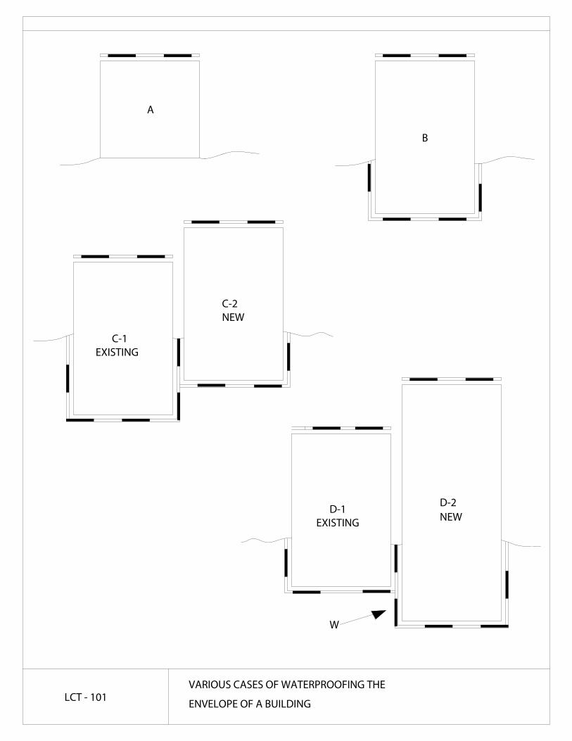
1. Proximity of a new building to an existing building – problem of access and/or safety. In some cases, available working space may be limited and/or unsafe to perform waterproofing work in a professional, controllable manner. Figure LCT-101 clearly demonstrates there is usually no problem to waterproof the building envelope on grade (A). Matters become more difficult as the building is lowered below ground (B). It gets more complicated to waterproof parts of the building that are to be submerged in ground water. The situation gets even more complicated when a below-ground building is to be built next to an existing building (C1 and C2). However, when a new building extends farther below an existing one (D1 and D2) – a serious waterproofing problem may be created. To waterproof area (W) an applicator must position himself underneath the existing building. The possibility of differential settlement of the new building relative to the existing one may complicate the matter even farther.
2. Construction Schedule - limited time. A series of pedestrian tunnels are to be constructed under railroad tracks. It has been decided the main part of the tunnel will be prefabricated on site. In due course, the tracks will be dismantled for a short period of time (a few hours), and a trench will be excavated. As soon as the 100-metric ton tunnel will be hoisted and positioned in place, everything will be returned to its original state. The question is, how does one waterproof under the prefabricated tunnel provided the precondition that “through-out the entire process train traffic may be interrupted for no longer than 24 hours” is met? See figure LCT-102
3. Constrained Conditions imposed by design or functional requirements 3.1 A large shopping center was enlarged. The new extension included a
basement submerged in ground water. See figure LCT-103. At an advanced stage of construction, the construction manager was faced with a dilemma: Option 1 - Keep de-watering the site until the waterproofing of the joint between the 2 parts of the complex will be completed. This would result in a long and costly de-watering operation. Option 2 – Stop the de-watering at a relatively early stage and save money, which in turn means dealing with the waterproofing of the joint area under wet conditions, which is a high-risk condition. In fact, it was decided to take the risk. The waterproofing problem was dealt with as described in figure LCT-104. The waterproofer used bentonite membranes for waterproofing the surface. The joints were treated by various types of waterstop strips, and an injection hose was positioned in between the waterstops. To seal the joint, 2 component polyurethane resin was injected into the hose. The selected resin, after solidification, will swell when submerged in water. The “under water” space, about 4000 square meters (m2), is now dry and occupied by an Office Depot store.
3.2 Openings are to be made in an existing swimming pool being renovated. The openings are shown in figures LCT-105, LCT-106 and LCT-107. As a

3
part of the renovation, new stairs will be sunk into the wall, new pipes will penetrate through the walls, and a new drainage sump will be constructed. As mechanical and other rooms are positioned under the pool, water leaks will have extremely serious consequences. In this case, a combination of parallel waterstop strips and injection hose placed in between the waterstop strips and injected with selected polyurethane resins did the job. In another case, an old swimming pool was extended. Expansion joints were designed along the interface between the old part and the new part of the pool. Because of possible differential settlement, the waterproofing specifications of the submerged expansion joint called for the application of Sodium Bentonite granules in the joint as well as for the injection of a 2 component polyurethane resin. Results were good.
3.3 The outside fasad of a high-rise building is designed to be made of prefabricated panels. Special mechanical fixtures are to be used to attach the panels to the structure. Openings were designed in the structure so that the fixtures may be positioned through the structure.
Only at a very late stage, someone noticed that a long water reservoir was positioned along the outer circumference of the roof. For the same purpose, openings were also designed in the walls of the water reservoir. In this case, an uncompromising demand - not to deal with waterproofing solutions but rather change the architectural design - was eventually accepted.
3.4 The Israeli National Geophysical Institute has sites throughout the country. The sites are instrumented to monitor earthquakes. The instruments are positioned on a concrete “table” cast directly on the subgrade rock. The below - ground structure is built around this concrete “table”. An expansion joint separates the concrete table and the building. See figure LCT-109. SBS modified bituminous membranes were used to waterproof the underground envelope of the structure. The problem was how to terminate the waterproofing membrane along the expansion joint around the concrete table. A special terminating and anchoring accessory, was used for that purpose. This anchoring accessory is a strip similar to a flat-sided PVC waterstop, but it is made of a special blend of modified polymeric material that is compatible with and torchable to the waterproofing membranes. A preformed polymeric adhesive strip, Ram-Nek, was used as a secondary waterproofing of the joint between the anchoring accessory and membrane.
Because the instruments are sensitive to moisture, as a precaution a few injection hoses were positioned around the table. Two component, flexible polyurethane was injected into the expansion joint to seal any possible leaks through the joint. See figure LCT-109 (B).

4
3.5 A part of the basement floor of a large commercial building will be lowered to increase the height of the basement by 1 meter. In winter months, this basement may be submerged in ground water. To lower the basement floor, a diaphragm wall of piles was cast down through the existing floor. Consequently, the waterproofing system under the floor was seriously damaged. See figure LCT-110. There was no problem to waterproof the new, lower part of the structure. However, it was practically impossible to repair the damaged waterproofing system, thus reservations were clearly stated in all relevant design and legal documents.
3.6 At the “High-Tech City” in Haifa, Israel 300-500 meters from the coast of
the Mediterranean Sea, all the buildings were designed with two underground parking levels. This was necessary to avoid ground water problems because of the rock formation and difficulties in de-watering the site.
A shortage of parking spaces required that the new building be constructed with three underground parking levels. This challenge was accepted by Mr. Yossi Shiran, the structural engineer, and myself. Once the excavation was completed, a network of drainage channels, about 60 centimeters deep was excavated in the subgrad rock. The size and location of the drainage channels were selected so they were as far away as possible from concentrated structural loads and to ensure no interference with load transfer to the ground. The drainage channels were covered with prefabricated concrete elements and lean concrete was cast on the entire floor area. See figure LCT-111. All the water that continued to flowed on the lean concrete was directed into the drainage channels and from there to the sumps and was pumped out of the site. The end result was a very wet, lean concrete substrate but no ponding water. The first layer of 5 millimeters thick polymer modified bituminous membrane was applied. The membranes were loose laid and torched to each other at the seams only. A second layer of polymer modified bituminous membrane was fully torched to the first layer. A protection course of 5 centimeters thick cementitious concrete was cast upon the waterproofing system. Finally, the floor slab was cast. Now, the basement floor is dry and a second building is under construction.
3.7 In a new hotel, soon after opening, it was discovered that water from the showers seeps under the gypsum walls into the rooms. The hotel, at a high rate of occupancy, had to solve the problem with no delay. See figure LCT-112. To remove the tiles and sand-bed and renew the waterproofing

5
system in an operating hotel was out of the question. Alternative ways to stop the leaks were presented and discussed.
Finally, it was decided to adopt a modified technique of soil stabilization using hydro-activated polyurethane resins pressure-injected into the sand-bed beneath the tiles. Repair work commenced at a rate of 10-16 rooms a day. At the first round of application, the problem was solved in 84.5 percent of the rooms. In the second round, the rate of success was increased to 96.5 percent. A rate of 100 percent success was reached by the third round of application.
In any situation with unforeseen waterproofing problems, the specifier will have no alternative but to resort to a different, unorthodox approach. He must consider a new alternative or a combination of innovative alternatives to ensure the functionality of the structure. Following are three alternatives: Alternative 1: To approach co-designers and explain the problems and convince
them and/or the owner to change the design. This will create a new set of conditions to accommodate a proper waterproofing design.
Alternative 2: The experienced and daring waterproofing specifier may come up
with an original, novel solution to a given problem. Alternative 3: In some cases the only solution may be a religious one, i.e., pray for
its success. Conclusions The main conclusions that may be drawn from this presentation include: 1. A waterproofing consultant should be involved in the early stages of the design
for any building where waterproofing problems are to be anticipated/expected. 2. Every effort should be made to avoid constrained conditions. 3. With some experience, imagination, determination and daring, we may come up
with solutions even to unprecedented waterproofing problems. 4. In a situation of constrained conditions, it is the responsibility of the waterproofing
specefier to stand firm on his professional beliefs based on education and experience. An unfortunate compromise may result in a flooded building.
5. In some cases, even an experienced consultant may find no proper solution to a
given waterproofing problem.
A
B
C-1
C-2
D-1D-2
W
EXISTING
NEW
EXISTING NEW
LCT - 101VARIOUS CASES OF WATERPROOFING THE
ENVELOPE OF A BUILDING

PREFABRICATED
LEAN CONCRETE
TUNNEL
COMPACTED SUBGRADE
WATERPROOFING
DIAPHRAGM WALL
(PILES)EXCAVATED AT A
LATER STAGE
TO BE
TEMPORERY
PROTECTION ON
WATERPROOFING
LCT - 102UNDER RAILROAD TRACKS
A PREFABRICATED TUNNEL PLACED

LCT-104
M2
WATER LEVEL
WALL OF
SLURRY
ESCALATOR
EXISTING
BUILDING
(DIAPHRAGM)
WALL
NEW
BUILDINGBUILDING
OLD
LCT - 103THE INTERFACE BETWEEN THE EXISTING AND
THE NEW BELOW-GROUND BUILDINGS

WALL
LEAN CONCRETE
PREFORMED POLYMERIC
ADHESIVE WATERSTOP
SLURRY WALL
STRIP
INJECTION HOSE
(BENTONITE)
WATERPROOFING
CONCRETE
HYDRO-ACTIVATED
BENTONITE
WATERSTOP STRIP
SEE LCT-103
LCT - 104WATERPROOFING SYSTEMS USED AT
A NEW BUILDING

LCT-106/B LCT-106/A
LCT-107
LCT - 105 SWIMMING POOL RENOVATION

A
B
EXISTING WALL
NEW WALL
ADHESIVE WATERSTOP
PREFORMED POLYMERIC
STRIP
WATERSTOP STRIPHYDRO-ACTIVATED
INJECTION HOSE
NEW PIPE PENETRATING
BACKER ROD
SEALANT
"STOPAQ"
TILESCERAMIC
8 CM MIN.
WATERSTOP
STRIP
THROUGH OPENNINGS IN
SWIMMING POOL WALL
EXISTING WALL AND A NEW ONE
WATERPROOFING JOINT BETWEEN
LCT - 106 NEW ADDITIONS TO EXISTING SWIMMING POOL

B
A
STRIP BETWEEN EPOXY OR
CRACK BRIDGING DESIGNATED
INJECTION HOSE
EXISTING FLOOR
WATERSTOP STRIP
HYDRO-ACTIVATED
SIMILAR BONDING LAYERS
LCT - 107 NEW ADDITIONS TO EXISTING SWIMMING POOL

INJECTION HOSE
SODIUM BENTONITE
GRANULES
10 cm
BACKER ROD
SEALANT
LCT - 108 EXPANSION JOINT SUBMERGED IN WATER

A
B
MODIFIED BITUMINOUS MEMBRANES
WATERPROOFING BY POLYMER
3-D HDPE FOR PROTECTION LEAN CONCRETE
TABLE
ROCK
INJECTION HOSE
LEAN CONCRETE
ROCK
PREFORMED POLYMERIC ADHESIVE STRIP
TERASTOP TERMINATING ACCESSORY
BITUMINOUS MEMBRANESBS MODIFIED
FLOOR
TERMINATION OF
WATERPROOFINGMEMBRANESSEE DETAIL B
LCT - 109 WATERPROOFING AROUND SEISMIC "TABLE"

A
PILES
SMOOTHING WALL
OUTERWALL
A
INNER WALL
SYSTEM
WATERPROOFING
CROSS SECTION AA
EXISTING FLOOR
PILES
NEW FLOOR
?
LCT - 110NEW PILES DRIVEN THROUGH EXSITING
WATERPROOFED BASEMENT FLOOR

WATERPROOFING
SYSTEM
CONCRETE (WET)
LEAN
WATER
FLOOR SLAB
PROTECTION
CEMENTIOUS
LAYER
ROCK
DRAINAGE CHANNEL
LEAN CONCRETE = MUD SLAB
PREFABRICATED
CONCRETE COVER
LCT - 111CROSS SECTION THROUGH DRAINAGE
CHANNEL UNDER FLOOR SLAB

WET ROOM
DRY WALL
H O2
H O2SAND BED
WATERPROOFINGSYSTEM
ADHEASIVEMORTAR AND TILES
CARPET
INJECTION (REPAIR)
WALL-TO-WALL
(GYPSUM)
POLYURETHANE
(PROBLEM)
LIQUID-APPLIED
H O2
LCT - 112 REPAIR OF LEAKS FROM HOTEL SHOWERS

WATER RESERVOIR
MECHANICAL ELEMENT TO
FIX THE PREFABRICATED
THE STRUCTURE
FACAD ELEMENT TO
FACAD ELEMENT
PREFABRICATED
LCT - 113A FASAD OF PREFABRICATED ELEMENTS FIXED TO THE
STRUCTURE THROUGH OPENNINGS IN THE STRUCTURE