user manual - endüstriyel otomasyonefesotomasyon.com/html/siemens/siemens-s5-pu-as511... · user...
TRANSCRIPT

User Manual
Connection to Siemens S5 PU (AS511)
Part Number: 80860.699
Version: 2
Date: 18.10.2006
Valid for: User Manuals
Version Date Modifications1 09.06.2006 First Edition2 18.10.2006 Optimized data transmission added, protocol parameter
stop bits changed
This manual, including all illustrations contained herein, is copyright protected. Use of this manual by any third party in departure from the copyright provision is forbidden. No part of this manual may be reproduced, trans-lated or electronically or photographically archived or altered without the express written consent from Sütron electronic GmbH. Violations shall be cause for damage liability.Sütron electronic reserves the right to make any changes that contribute to technical improvement.

Overall Table of Contents
Overall Table of Contents
1 Important Notes ....................................................................................................... 1-1
1.1 Symbols .................................................................................................... 1-1
1.2 Safety Notes ............................................................................................. 1-1
1.3 Intended Use............................................................................................. 1-1
1.4 Target Group............................................................................................. 1-1
2 Siemens S5 PU (AS511) ......................................................................................... 2-1
2.1 Data Types................................................................................................ 2-2
2.2 Optimized Data Transmission For Fast Screen Set-up ............................ 2-3
2.3 Programming ............................................................................................ 2-4
2.3.1 Protocol parameters ............................................................................ 2-42.3.1.1 Baud Rate...................................................................................................................2-4
2.3.1.2 Parity...........................................................................................................................2-4
2.3.1.3 Handshake..................................................................................................................2-4
2.3.1.4 Data Bits .....................................................................................................................2-5
2.3.1.5 Stop Bits .....................................................................................................................2-5
2.3.1.6 Maximum Waiting Time For Response.......................................................................2-5
2.3.1.7 Delay until Connection Set-Up....................................................................................2-6
2.3.1.8 Fast Data Block Access..............................................................................................2-6
2.3.2 Input Syntax......................................................................................... 2-7
2.4 Physical Connection ................................................................................. 2-8
2.4.1 Pin Assignment for Operating Devices with an Universal Interface..... 2-8
2.4.2 Cable SER1 TTY / 20 mA - Siemens S5 PU ....................................... 2-9
2.5 Error Messages....................................................................................... 2-10
A Index ........................................................................................................................A-1
i

Overall Table of Contents
ii

Important Notes
1 Important Notes
1.1 Symbols
The symbols in this manual are used to draw your attention on notes and dangers.
1.2 Safety Notes
– Read this manual carefully before using the software. Keep this manual in a place where it is always accessible to all users.
– The user manual, in particular the safety notes, must be observed by all person-nel working with the software and the programmed device.
– Observe the accident prevention rules and regulations that apply to the operating site.
– Installation and operation must only be carried out by qualified and trained per-sonnel.
1.3 Intended Use
– The software has to be used for programming operating devices exclusively. Ev-ery other use is not permitted.
1.4 Target Group
All configuration and programming work in connection with the automation system must be performed by trained personnel only (e.g. qualified electricians, electrical en-gineers).
The configuration and programming personnel must be familiar with the safety con-cepts of automation technology.
DangerThis symbol is used to refer to instructions which, if ignored or not carefully followed could result in personal injury.
NoteThis symbol indicates application tips or supplementary notes.
Reference to source of informationThis symbol refers to detailed sources of information on the current topic.
1-1

Important Notes
1-2

Siemens S5 PU (AS511)
2 Siemens S5 PU (AS511)
The Siemens S5 PU (AS511) protocol provides you
– random read and write access to all controller data
– bit access to all byte-oriented data types
– byte access to all data words in a data block.
The size of the address area depends on the controller being used.
This protocol supports a connection to the following Simatic S5 types.
The following Simatic S5 types are not supported by this protocol.
When the system writes to individual bits and individual bytes of a data word within a data block, a read-access is performed first. Then, the entire data structure can be accessed for a write operation. During this type of access, you must take care that neither the operating device nor the controller modify individual bits in a byte (or in-dividual bytes in a data word).
Table 2-1 Supported Simatic S5 types
Controller Type CPU
SIMATIC S5-90U 8-Bit CPU
SIMATIC S5-95U 8-Bit CPU
SIMATIC S5-100U CPU100 / 8-Bit CPU
CPU102 / 8-Bit CPU
CPU103 / 8-Bit CPU
SIMATIC S5-115U CPU941 / 8-Bit CPU
CPU942 / 8-Bit CPU
CPU943 / 8-Bit CPU
CPU944 / 8-Bit CPU
CPU945 / 8-Bit CPU with 20-Bit Address Area
SIMATIC S5-135U CPU922 / 16-Bit CPU
CPU928 / 16-Bit CPU
CPU928B / 16-Bit CPU
SIMATIC S5-155U CPU948 / 20-Bit CPU
Table 2-2 Simatic S5 types not supported
Controller Type CPU
SIMATIC S5-135U CPU921 / 16-Bit CPU
2-1

Siemens S5 PU (AS511)
2.1 Data Types
Direct access is possible to the following data types.
The size of the individual data areas depends on the controller's CPU.
Counter: For counters, a distinction is made between variables which have been assigned a counter address and variables which have been assigned another controller ad-dress.
When accessing counter addresses, the counter value is interpreted in binary format and the control bits of the counter are masked out.
The counter value is interpreted in BCD-code. This allows this value to be transferred within the controller program to the counter by means of the accumulator. Since the values are available in a Siemens compliant format, this service should be used to indirectly write counter starting values.
Timer: Timer values are made up of a time value and a time base.
The operating device reads the 2-byte sized variable and converts it internally into an imaginary, unsigned 4-byte variable that represents the time value for the base 0.01 seconds. The operating device makes a distinction between accesses to a timer address and accesses to other controller addresses.
Table 2-3 Data types for Siemens S5 PG (AS511)
Type Mnemonic Access
Input Bit E Bit Access (Read-only)
Input Byte EB Byte Access (Read-only)
Input Word EW Word Access (Read-only)
Input Double-Word ED Double-Word Access (Read-only)
Output Bit A Bit Access
Output Byte AB Byte Access
Output Word AW Word Access
Output Double-Word AD Double-Word Access
Flag Bit M Bit Access
Flag Byte MB Byte Access
Flag Word MW Word Access
Flag Double-Word MD Double-Word Access
Data Word DW Word Access
Data-Word Left (High) DL Word Access
Data-Word Right (Low) DR Word Access
Data Double-Word DD Double-Word Access
Timer T Word Access (Read-only)
Counter Z Word Access (Read-only)
To avoid control bits from being erased, accesses to counter addresses should be read-only.
2-2
Siemens S5 PU (AS511)
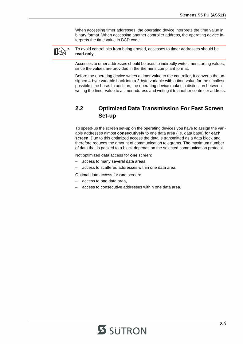
When accessing timer addresses, the operating device interprets the time value in binary format. When accessing another controller address, the operating device in-terprets the time value in BCD code.
Accesses to other addresses should be used to indirectly write timer starting values, since the values are provided in the Siemens compliant format.
Before the operating device writes a timer value to the controller, it converts the un-signed 4-byte variable back into a 2-byte variable with a time value for the smallest possible time base. In addition, the operating device makes a distinction between writing the timer value to a timer address and writing it to another controller address.
2.2 Optimized Data Transmission For Fast Screen Set-up
To speed-up the screen set-up on the operating devices you have to assign the vari-able addresses almost consecutively to one data area (i.e. data base) for each screen. Due to this optimized access the data is transmitted as a data block and therefore reduces the amount of communication telegrams. The maximum number of data that is packed to a block depends on the selected communication protocol.
Not optimized data access for one screen:
– access to many several data areas,
– access to scattered addresses within one data area.
Optimal data access for one screen:
– access to one data area,
– access to consecutive addresses within one data area.
To avoid control bits from being erased, accesses to timer addresses should be read-only.
2-3
Siemens S5 PU (AS511)
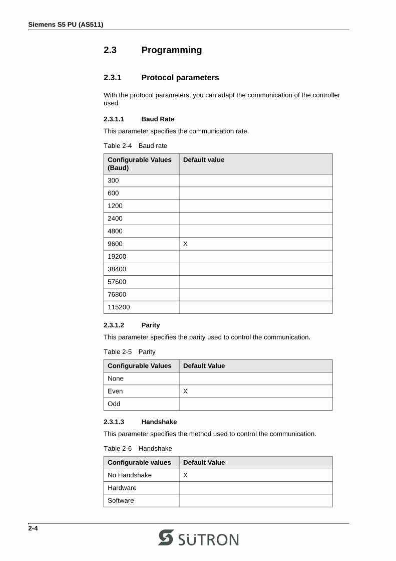
2.3 Programming
2.3.1 Protocol parameters
With the protocol parameters, you can adapt the communication of the controller used.
2.3.1.1 Baud Rate
This parameter specifies the communication rate.
2.3.1.2 Parity
This parameter specifies the parity used to control the communication.
2.3.1.3 Handshake
This parameter specifies the method used to control the communication.
Table 2-4 Baud rate
Configurable Values(Baud)
Default value
300
600
1200
2400
4800
9600 X
19200
38400
57600
76800
115200
Table 2-5 Parity
Configurable Values Default Value
None
Even X
Odd
Table 2-6 Handshake
Configurable values Default Value
No Handshake X
Hardware
Software
2-4

Siemens S5 PU (AS511)
2.3.1.4 Data Bits
This parameter specifies the number of data bits.
2.3.1.5 Stop Bits
This parameter specifies the number of stop bits.
2.3.1.6 Maximum Waiting Time For Response
This parameter specifies how long the operating device waits for a response from the controller.
Please note that the interfaces are interacting (see Siemens CPU manual). Forex-ample, if a PLC program is analyzed by means of the STATUS-function on thefirst interface of the CPU, this will cause the speed of protocol handling on thesecond in-terface to decrease significantly. With the STATUS-function, you can, so to speak, operate the PLC program in single-step-mode, i.e. the result of every program line is displayed on the screen.
In order to maintain the connection, you need to increase the "maximum waiting time for response" to about 5 seconds. If the normal time-out period is used, the operating terminal will generate a communication error message.
In this case each transmission requires 3-4 seconds, in contrast to a normal commu-nication cycle which requires approximately 60ms. This means a slow-down of the interface by a factor of 50!
Table 2-7 Data bits
Configurable Values Default Value
5
6
7
8 X
Table 2-8 Stop bits
Configurable Values Default Value
1 X
1.5
2
Table 2-9 Maximum waiting time for response
Configurable Values Default Value
50 ms to 65535 ms 1000 ms
CPUs equipped with 2 PG interfaces (e.g. CPU928B with PG module) are used dur-ing system commissioning thus keeping the PG interface available for program de-bugging.
2-5

Siemens S5 PU (AS511)
2.3.1.7 Delay until Connection Set-Up
This parameter specifies the waiting time after which the operating device starts the communication.
2.3.1.8 Fast Data Block Access
This parameter specifies whether a fast data block access is used.
Table 2-10 Delay until connection set-up
Configurable Values Default Value
0 s to 20 s 2 s
Table 2-11 Fast data block access
Configurable Values Default Value
ON
OFF X
The following applies to the fast data block access: The base address for each data block being used is determined only once and this information is stored temporarily in a local buffer with 10 positions. Any subsequent accesses continue to operate with the information stored in the local buffer. The in-formation in the buffer is erased when the operating device is rebooted or when a resynchronization is carried out after a communication error has occurred.In this case, do not modify data blocks dynamically or compress the memory while the connection between the operating device and the controller is still active!
The following applies if an operating device and a programming unit are simulta-neously connected to the controller by means of a multiplexer: the address location of the data blocks changes whenever you change the values of a data block using the programming device and transfer the data block to the controller again.
2-6

Siemens S5 PU (AS511)
2.3.2 Input Syntax
The following image illustrates the structure of the input syntax for variables in the programming software.
Figure 2-1 Syntax diagram
M Number . Number
MB
MW
E
A
AB
AW
AD
EB
EW
ED
DR
MD
DL
DD
DW
NumberDB
DX
Z
T
2-7

Siemens S5 PU (AS511)
2.4 Physical Connection
Plug-in connectors on the operating device for connection to the controller.
2.4.1 Pin Assignment for Operating Devices with an Univer-sal Interface
Table 2-12 Pin assignment TTY / 20 mA, active
Pin Designation Function
10 T+ Transmitted Data, Positive Polarity
12 S1+ Power Source 1, Positive Polarity
13 R+ Received Data, Positive Polarity
14 R- Received Data, Negative Polarity
16 S2+ Power Source 2, Positive Polarity
19 T- Transmitted Data, Negative Polarity
21 S1- Current Sink 1, Negative Polarity
24 S2- Current Sink 2, Negative Polarity
2-8

Siemens S5 PU (AS511)
2.4.2 Cable SER1 TTY / 20 mA - Siemens S5 PU
The following cabling diagram applies to operating devices with an universal inter-face only.
Both ends of the shield are connected to the metallic housing.
Operating DeviceTransmitter ActiveReceiver Active
SiemensSimatic S5Transmitter PassiveReceiver Active
D-SUBMale Connector25 Pin
D-SUBMale Connector15 Pin
14 YER-
24 GNS2-
19 BNT-
2WHR-
21 WHS1-
6YET+
7GNT-
9BNR+
1PG
1
8
13R+
16S2+
12S1+
10T+
2-9
Siemens S5 PU (AS511)
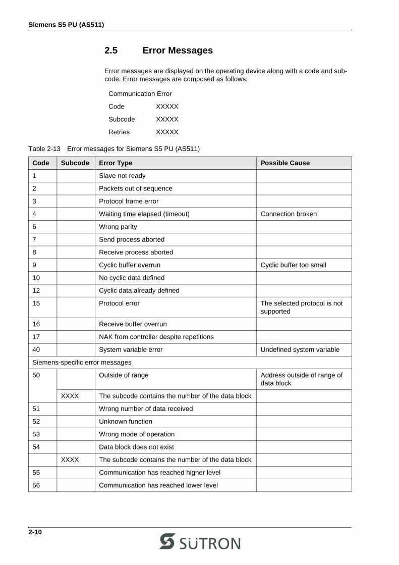
2.5 Error Messages
Error messages are displayed on the operating device along with a code and sub-code. Error messages are composed as follows:
Communication Error
Code XXXXX
Subcode XXXXX
Retries XXXXX
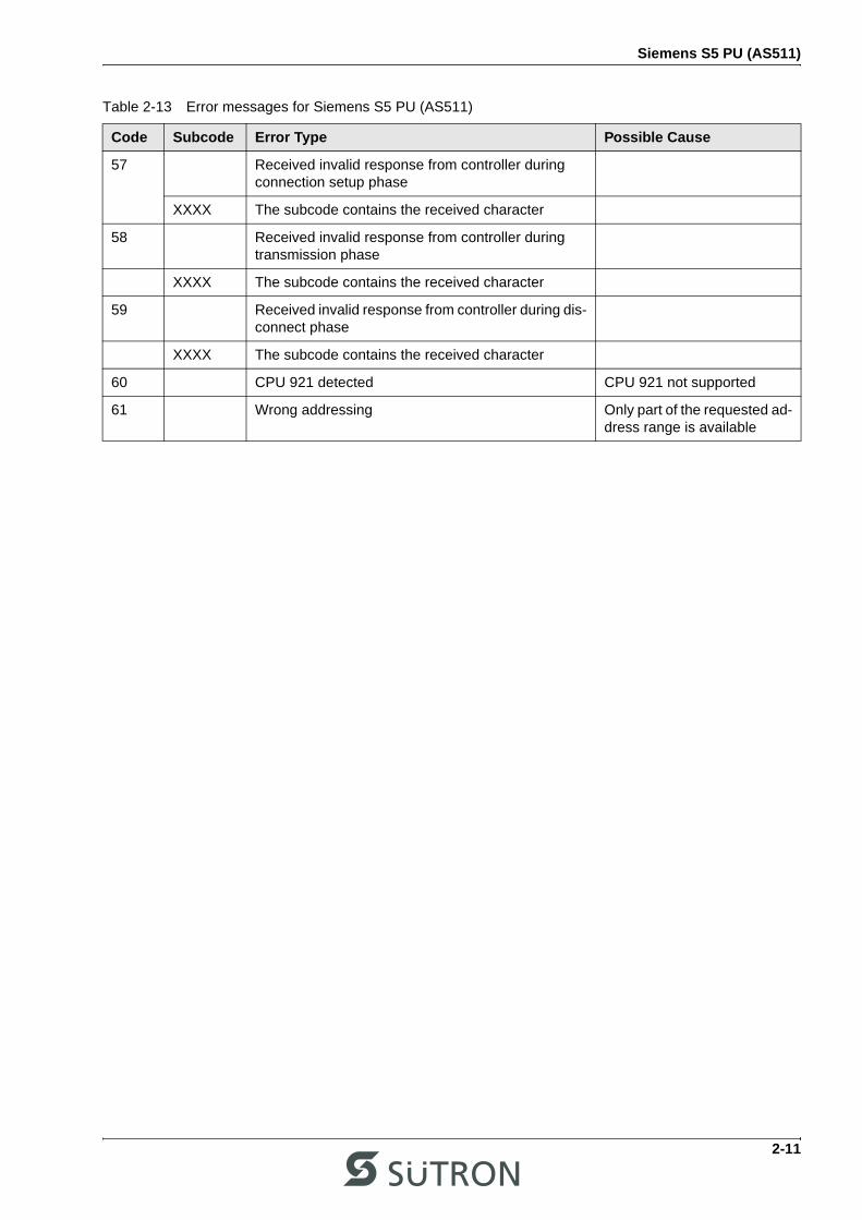
Table 2-13 Error messages for Siemens S5 PU (AS511)
Code Subcode Error Type Possible Cause
1 Slave not ready
2 Packets out of sequence
3 Protocol frame error
4 Waiting time elapsed (timeout) Connection broken
6 Wrong parity
7 Send process aborted
8 Receive process aborted
9 Cyclic buffer overrun Cyclic buffer too small
10 No cyclic data defined
12 Cyclic data already defined
15 Protocol error The selected protocol is not supported
16 Receive buffer overrun
17 NAK from controller despite repetitions
40 System variable error Undefined system variable
Siemens-specific error messages
50 Outside of range Address outside of range of data block
XXXX The subcode contains the number of the data block
51 Wrong number of data received
52 Unknown function
53 Wrong mode of operation
54 Data block does not exist
XXXX The subcode contains the number of the data block
55 Communication has reached higher level
56 Communication has reached lower level
2-10
Siemens S5 PU (AS511)
57 Received invalid response from controller during connection setup phase
XXXX The subcode contains the received character
58 Received invalid response from controller during transmission phase
XXXX The subcode contains the received character
59 Received invalid response from controller during dis-connect phase
XXXX The subcode contains the received character
60 CPU 921 detected CPU 921 not supported
61 Wrong addressing Only part of the requested ad-dress range is available
Table 2-13 Error messages for Siemens S5 PU (AS511)
Code Subcode Error Type Possible Cause
2-11

Siemens S5 PU (AS511)
2-12

Index
A Index
CCable SER1 TTY / 20 mA
Siemens S5 PU ........................................ 2-9
EError messages
Siemens S5 PU (AS511) ........................ 2-10
IImportant notes ................................................. 1-1Intended use ..................................................... 1-1
OOptimized data transmission for fast screen set-up .................................................... 2-3
PProtocol parameters
Siemens S5 PU (AS511) .......................... 2-4
SSafety notes ...................................................... 1-1Siemens S5 PU (AS511) .................................. 2-1Symbols ............................................................ 1-1Syntax diagram
Siemens S5 PU (AS511) .......................... 2-7
TTarget group ..................................................... 1-1
A-1

Index
A-2


Sütron electronic GmbHKurze Straße 29D-70794 FilderstadtPhone: 0049 711 / 77098-0Fax: 0049 711 / 77098-60E-Mail: [email protected]: www.suetron.com