tutorial=structure analysis in proe-mechanica
TRANSCRIPT

MECH410/520 Pro/E WF4 Structure Analysis Tutorial
2/23/2009 1
Structure Analysis in Pro/ENGINEER Wildfire 4.0
1 Introduction
Structural Analysis is a multi-discipline Computer Aided Engineering (CAE) tool that analyzes the physical behavior of a model to better understand and improve the mechanical performance of a design. It can be used to directly calculate stresses, deflections, thus to predict the behavior of the design in the real world. Structural Analysis is available in the integrated mode of Pro/E and analysis can be performed within the Pro/E environment.
Pro/E Structural Analysis and Pro/E Thermal Analysis share a very similar approach. Most of the procedures presented in this tutorial, such as model creation, constraints definition and load specification, are also applicable to Thermal Analysis.
There are two model types of Structure Analysis in Pro/E, the Native Type and FEM type. The difference between these two types of Structure Analysis lies in the element types used in the analysis process. The Native Type uses P-Element; while the FEM Type uses H-Element. The P-Element model reduces computation time in mesh model generation and refinement by incorporating a polynomial mesh, thus making the FEA analysis faster in the integrated CAD environment. While the traditional, linear H-Element model is more capable. FEM Structure Analysis in ANSYS uses the H-Element model.
In the integrated Pro/E Structure Analysis Module, the following analyses can be carried out:
• static, pre-stress, and buckling analyses
• vibration and modal analyses
• fatigue evaluation
• contact problem solution
The primary emphasis of Pro/E Structure Analysis lies with linear, small-deformation problems, but one can use this module to solve large-deformation problems as well.
In this tutorial, we are going to demonstrate procedures of a typical static Structure Analysis process. The designed model is an angle plate shown in the figure below.

MECH410/520 Pro/E WF4 Structure Analysis Tutorial
2/23/2009 2
The details of this angle plate that is used to support a shaft include:
• Dimension
Thickness: 100 (mm), width: 250 (mm), length: 500 (mm), height from bottom to center of the hole: 475 (mm).
• Material
HS low-alloy steel, density: 7827 (kg/m3), Poisson’s ratio: 0.27, Young’s modulus: 199.948 (GPa)
• Work Load
The load force is parallel to the vertical part of the plate and the force component along X axis is zero: F = [0; 10,000; - 5000] (N).
The deformation and stress of this angle plate subject to the given workload will be analyzed using Structure Analysis. The maximum stress and displacement in the plate will be reported.
2 Creation of Part CAD Model
The geometry model of the angle plate part is to be created and its mechanical properties are assigned.
2.1 Creating Geometric Model in Pro/E Create 3D solid model of the part and change default unit from in-lbm-sec to mm-N-s using Edit Set up Unit. The Units Manager dialog box display as shown below.
.
MECH410/520 Pro/E WF4 Structure Analysis Tutorial
2/23/2009 3
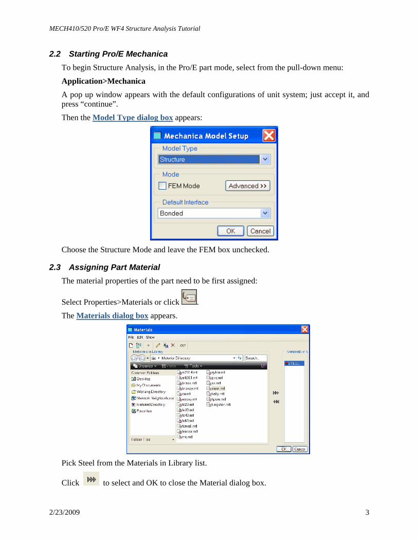
2.2 Starting Pro/E Mechanica To begin Structure Analysis, in the Pro/E part mode, select from the pull-down menu:
Application>Mechanica A pop up window appears with the default configurations of unit system; just accept it, and press “continue”.
Then the Model Type dialog box appears:
Choose the Structure Mode and leave the FEM box unchecked.
2.3 Assigning Part Material The material properties of the part need to be first assigned:
Select Properties>Materials or click .
The Materials dialog box appears.
Pick Steel from the Materials in Library list.
Click to select and OK to close the Material dialog box.

MECH410/520 Pro/E WF4 Structure Analysis Tutorial
2/23/2009 4
Click to assign material for the model.
Click OK to close the Material Assignment dialog box.
2.4 Adding Mechanical Constraints Constraints are defined to limit the model’s displacement in the active coordinate system. These constraints will fix the model so that it cannot move, or can only move in a predetermined way, under the applied loads. Only by applying constraints to the model, can the effect of workload forces on the model be observed. Constraints are specified as translational and rotational, with each has three components corresponding to X, Y, and Z axis. For our model, the bottom plane surface of the part is fully constrained in all three axes of motions. Steps to constrain the model are:
Select Insert>Displacement Constraint or click . The Constraint dialog box opens as shown below.

MECH410/520 Pro/E WF4 Structure Analysis Tutorial
2/23/2009 5
Enter a descriptive name or accept the default name.
We are going to create a new constraint set, click the New button to display the Constraint Set Definition dialog box; accept the default a name, leave optional description blank.
Select Surface(s) as References from the drop-down list.
Click and use the normal selection methods to select the bottom face of the part.
Leave the default coordinate system the WCS as selected; we have no reason to change it now.
Make sure the selected settings buttons for all translational and rotational degree of freedoms
are fixed, represented by the icon of .
Click OK to exit.
The model now looks like as shown below:

MECH410/520 Pro/E WF4 Structure Analysis Tutorial
2/23/2009 6
2.5 Applying Workload Apply a Uniform | Total force to the inside surface of the hole using components as shown in figure below.
Select Insert>Force/Moment Load or click .
The Force/Moment Load dialog box appears.
Enter a name for the load, or use the default name.
Click New button to display the Load Set dialog box and create a new load set.
Select Surface(s) as References to apply the force.
Click and pick the inside surface of the hole.

MECH410/520 Pro/E WF4 Structure Analysis Tutorial
2/23/2009 7
Leave the default coordinate system, the WCS, as selected. We still have no reason to change it.
Select Components from the drop-down list under Force to specify magnitude and direction, and enter the appropriate values given at the beginning of this tutorial.
You can display the load you just defined by clicking the Preview button.
Click OK to exit the dialog box.
Now, the load is applied on the part model.
2.6 Creating Mesh Model for FEA In general, the mesh model needed for FEA is automatically generated by the Pro/E system with not the need of user intervention.
For demonstrations purpose, the mesh generation process is illustrated here.
Select AutoGEM>Create or click .
The AutoGEM Control dialog box appears as shown below.
From the AutoGEM Reference drop down list select volume as shown below.
Click and select our model in the screen.
Click create, and close the dialog box.
The meshed mode will be created as shown in the following figure.

MECH410/520 Pro/E WF4 Structure Analysis Tutorial
2/23/2009 8
With all constraints and loads defined, we can now start the structure analysis.
3 Static Structure Analysis
3.1 Defining the Static Analysis task Static analysis calculates deformations, stresses, and strains on the defined model in response to specified loads and constraints. The task of static analysis is defined by:
Select Analysis>Mechanica Analyses/Studies or click . The Analyses and Design Studies dialog box appears (bottom left)
Select New Static from the File menu.
The Static Analysis Definition dialog box appears (bottom right).
Enter a name for the analysis. A description is optional.
Accept the constraints and loads selection as they are; we have no options.
Change the default method Single-Pass Adaptive to Multi-Pass Adaptive. Set the maximum polynomial order to 9, the percent convergence to 5. Click OK to leave this window.
MECH410/520 Pro/E WF4 Structure Analysis Tutorial
2/23/2009 9
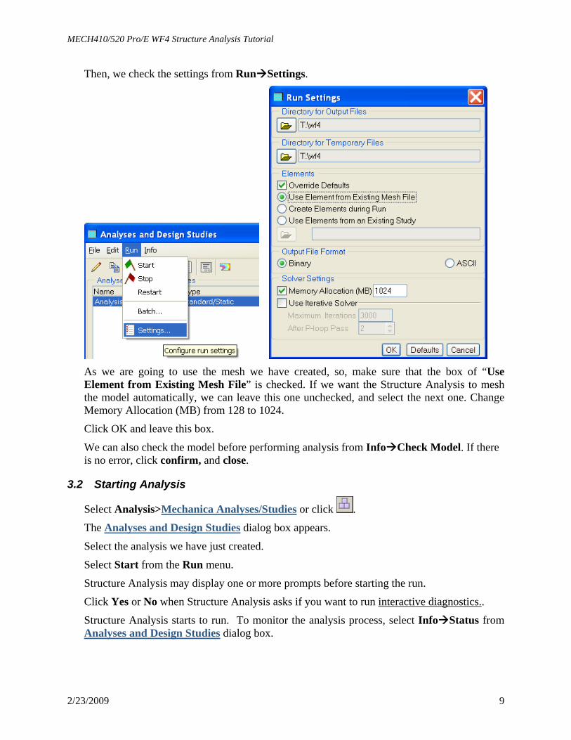
Then, we check the settings from Run Settings.
As we are going to use the mesh we have created, so, make sure that the box of “Use Element from Existing Mesh File” is checked. If we want the Structure Analysis to mesh the model automatically, we can leave this one unchecked, and select the next one. Change Memory Allocation (MB) from 128 to 1024.
Click OK and leave this box.
We can also check the model before performing analysis from Info Check Model. If there is no error, click confirm, and close.
3.2 Starting Analysis
Select Analysis>Mechanica Analyses/Studies or click .
The Analyses and Design Studies dialog box appears.
Select the analysis we have just created.
Select Start from the Run menu.
Structure Analysis may display one or more prompts before starting the run.
Click Yes or No when Structure Analysis asks if you want to run interactive diagnostics..
Structure Analysis starts to run. To monitor the analysis process, select Info Status from Analyses and Design Studies dialog box.

MECH410/520 Pro/E WF4 Structure Analysis Tutorial
2/23/2009 10
4 Analysis Results and Reports
4.1 Defining Result Windows Results are displayed in the result windows. These result windows are defined by:
From the Insert menu, select Result Window or click (Result Window) on the Results user interface toolbar.
The Result Window Definition dialog box appears.
In the Name text box, enter a name to identify the result window so that you can show or hide the window during your results session, or use the default.
In the Title text box, enter the title that you want to display at the bottom center of the result window.
Select the design study for which you want to display results by clicking .
If the design study has more than one analysis, select an analysis from the Analysis option menu.
Select one of these display types from the Display Type option menu:
• Fringe
• Vectors
• Graph
• Model Select a quantity from the Quantity option menu on the Quantity tab.
Select the Display Options tab and choose among the display options to determine the appearance and behavior of your model in the result window.
Select the Display Location tab and choose a location from the option menu. If you want to use all entities of a certain location type, select the Use All check box. To select a single entity, click the selector arrow.
MECH410/520 Pro/E WF4 Structure Analysis Tutorial
2/23/2009 11
To close the dialog box without displaying the result window, click OK.
To display the result window, click OK and Show. The display now shows the fringe plot of the Von Mises stress.
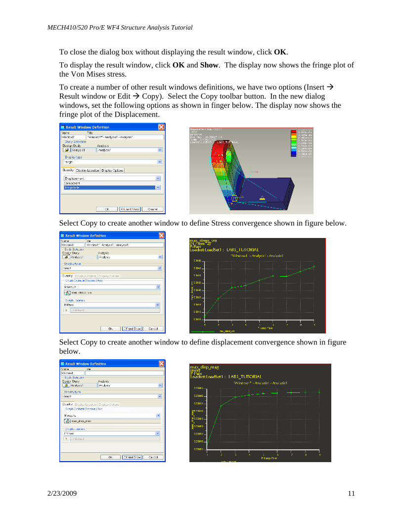
To create a number of other result windows definitions, we have two options (Insert Result window or Edit Copy). Select the Copy toolbar button. In the new dialog windows, set the following options as shown in finger below. The display now shows the fringe plot of the Displacement.
Select Copy to create another window to define Stress convergence shown in figure below.
Select Copy to create another window to define displacement convergence shown in figure below.

MECH410/520 Pro/E WF4 Structure Analysis Tutorial
2/23/2009 12
An example display window is shown
4.2 Evaluating the Results Based on the analysis results, further evaluation can be carried out. This can be carried out by selecting “info” in results window, and choosing the evaluation functions, such max, min, etc.
4.3 Generating Analysis Report Once you have defined and displayed result windows, you can generate reports that capture the vital points of your analyses. Structure Analysis provides you with the ability to print reports in a wide variety of print formats. For graphs, you can generate specialized graph reports so you can study the graph sampling points in depth.
Use these commands located on the File menu to generate reports:
Print — to print a selected result window, select Format JPEG and Output To File.
Export — to generate some other report types, select from the associated submenu.