thermatel modeltd1/td2 thermaldispersion · pdf filethermatel®modeltd1/td2...
TRANSCRIPT

Thermatel® Model TD1/TD2Thermal DispersionFlow/Level/Interface Switch
The Thermatel® TD1 and TD2 switches utilize the
Magnetrol® proven thermal dispersion technology. The
sensor consists of two RTD elements. One is the refer-
ence and the second is heated to a temperature above
the process temperature. The electronics detect the
temperature difference between the two elements. The
temperature difference is greatest in air, then decreases
when cooling occurs due to a change in media. An
increase in the flow rate further decreases the tempera-
ture difference.
The set point is adjusted for the switch to alarm at the
desired temperature difference. Once the set point is
reached, the relay will change state.
TD1 and TD2 Thermal Dispersion flow/level/interface
switches provide a new level of performance and
reliability not found in previous switches. Continuous
diagnostics with fault indication, temperature compen-
sation, narrow hysteresis and fast response time make
the TD1/TD2 the latest in thermal dispersion switch
technology.
TD1 is a basic switch with 24 VDC power and an 8-amp
DPDT relay. The TD2 adds LED indication through a
glass window, ability to electrically measure the set
point, mA output for diagnostics and trending, optional
hermetically sealed relay, plus time delay. A universal
AC power supply simplifies installation.
Thermatel® probes are available in 316 Stainless Steel,
Hastelloy® C, or Monel® with all welded construction.
• Temperature compensated to provide repeatablealarm under varying process temperatures
• Continuous diagnostics detect sensor fault
• Non-linear mA output signal can be used for trend-ing, diagnostics and repeatable flow/level indication(TD2)
• Detects minimum flow or presence/absence of flow
• Easy/fast calibration
• Excellent low flow sensitivity
• Optional hot tap available (see bulletin 41-103)
• Hygienic design available
• NACE construction available (consult factory)
• Process temperatures from -100° to +400° F (-73° to+204° C)—High temp. version to +850° F (+454° C)
D E S C R I P T I O N
T E C H N O L O G YF E A T U R E S
Model TD2with low flow body
Model TD2with spherical probe
Model TD1with twin-tip probe
Model TD2with hygienic stainless steel enclosure
& spherical tip probe

2
T E M P E R A T U R EC O M P E N S A T I O N
The alarm point of thermal dispersion switches has
previously been affected by changing temperatures.
With the TD1/TD2, the effect of varying process
temperature has been greatly reduced.
F A C T O R Y C A L I B R A T I O N
The THERMATEL flow switch can be ordered factory
calibrated to alarm at a specified flow rate. A complete
calibration curve can also be provided for the TD2.
Using this curve the user can determine the desired set
point. Using a volt meter, adjust the set point until the
desired alarm point is obtained. Calibration can be per-
formed on water and select organic compounds.
H O T T A P
Hot tap retractable probe assemblies for THERMATEL
probes are available. See Bulletin 41-103.
F A U L T D E T E C T I O N
One of the major concerns is questioning if the switch
will operate when an alarm condition occurs. The
TD1/TD2 is equipped with advanced diagnostics which
continuously monitor the signal from the sensor and
indicate if the signal has gone out of range. In the event
of a fault, the alarm relay will de-energize and the red
LED will blink. In the TD2 the mA output will change
to 3.6 mA (Low Level Fail-safe) or 22 mA (High Level
Fail-safe) to indicate a fault.
A D V A N C E D F E A T U R E S - T D 1 & T D 2
Flow (fps)
Sig
nal
Sig
nal
Flow (fps)
+70° F (+21° C)
+150° F (+66° C)
+240° F (+116° C)
No Temperature Compensation
With Temperature Compensation

3
mA output
The TD2 has a mA output signal can be used for diag-
nostics, fault detection and trending. While this mA signal
is not scalable by the user, it can provide important
process information. The mA signal will increase with
the sensor cooling – mA will be greater in a wet condi-
tion than in a dry condition and will further increase as
the flow rate increases.
The mA output can also be used for fault detection. In
the event of a fault, the mA output will follow NAMUR
NE 43 and go to less than 3.6 mA for Low Level Fail-safe
and greater than 22 mA for High Level Fail-safe selection.
Due to ATEX requirements the mA output is not
available on units for Zone 0 service (Model number
digit 9 = C).
Measure the set point
With the TD2 the user can obtain an electrical measure-
ment of the set point. This permits the user to periodi-
cally check the calibration point and verify that the set
point has not changed. Due to ATEX requirements, this
feature is not available on units for Zone 0 service
(Model number digit 9 = C).
Remote Electronics
The TD2 can be provided with remote electronics
with up to 500 feet (150 meters) separation between
the probe and electronics.
Hermetically sealed relay
The TD2 provides an optional hermetically sealed relay
for the most demanding applications.
A D V A N C E D F E A T U R E S - T D 2 O N L Y
Model TD2 with Window
Typical mA signals20
Dry Oil Water
Water Flow – FPS
mA
0 1 2 3 4 5
4
14
12
10
8
6
16
18

4
L E V E L S W I T C H
Level or Interface can be detected due to differences in
thermal conductivity. High or low level alarm applica-
tions may be installed either vertically or horizontally.
In the absence of media, the self-heated sensor tip cre-
ates a temperature difference between the two sensors.
As media contacts the sensor tip, heat is absorbed by the
fluid, decreasing the temperature difference.
F L O W S W I T C H
Flow is detected by an increase in heat transfer that
occurs as the flow rate increases. Exceptional low flow
sensitivity is obtained with no moving parts. The same
unit can be used for both liquid and gas flow detection.
In a low flow condition, the self-heated sensor tip cre-
ates a temperature differential between the two sensors.
As flow increases, heat is dissipated and temperature
difference decreases.
No Flow
Flow
Low Level
High Level
A P P L I C A T I O N S
THERMATEL has demonstrated reliable performance as a flow or level switch. For use as a flow switch,
THERMATEL can be used to detect either a high flow or a low flow condition for both gases and liquids.
As a level switch, THERMATEL can be used to detect difference in thermal conductivity of various media.
This includes interface detection between media such as liquid/foam, and oil/water.

5
P R O B E D E S I G N S
THERMATEL offers two sensor tip designs—the original
twin tip and the unique spherical tip. Both designs
have similar operating ranges.
The sensors in the twin tip are mounted at the end of
each tip. In the spherical tip, the sensors are bonded
directly to the wall of the tip, providing protection of
the sensors.
The spherical tip is recommended for all types of
applications—general purpose, high viscosity, and
applications where buildup can occur.
Twin tip Spherical tip
Spherical Tip
For general purpose use, liquid flow applications,
buildup, and hygienic service. Suitable for gas
flow applications. Maximum temperature of
+400° F (+200° C).
Twin Tip
For higher pressures up to 3000 psig, corrosion resistant
materials including Monel and Hastelloy C. Twin tip
probes are preferred for air flow applications.
Maximum temperature of +400° F (+200° C).
High Temperature/High Pressure (HTHP)
Suitable for temperatures up to +850º F (+454º C)
Pressures up to 6000 psi (410 bar). Available in both
316/316L stainless steel and Hastelloy C construction.
Mini Sensor
This twin tip sensor is suitable for installing in a Tee
in smaller pipe sizes. Available with 1⁄2", 3⁄4" and 1" NPT
connections for use with appropriate tee connection.
The twin tip design provides minimal blockage of
the pipe.
Low Flow Body
Used for even lower flow rates with 1⁄4" and 1⁄2"
connections. Liquid flow as low as 0.0055 gph (0.02 l/h)
and gas flow rates of 100 sccm can be detected.
Recommended set point ranges for various size tees
8.00
9.00
10.00
11.00
12.00
13.00
14.00
15.00
5.004.003.001.00 2.000.00
Typical Water Flow
Spherical Tip Twin Tip Hastelloy
mA
fps
Size Water Air1⁄4"
Flow body0.0055 GPH – 1.5 GPH
(0.02 – 5.7 l/h)100 sccm to 200 SCFH(100 sccm to 5.75 Nm3/h)
1⁄2"Flow body
0.01 to 3 GPH(0.04 to 11.5 l/h)
250 sccm to 400 SCFH(250 sccm to 11.5 Nm3/h)
1⁄2" Tee0.2 to 180 GPH(0.75 to 680 l/h)
0.5 to 70 SCFM(0.85 to 120 Nm3/h)
3⁄4" Tee0.5 to 240 GPH(2 to 900 l/h)
1.5 to 100 SCFM(2.5 to 170 Nm3/h)
1" Tee1 to 420 GPH(3.8 to 1600 l/h)
3 to 170 SCFM(5 to 290 Nm3/h)
04.00
6.00
8.00
10.00
12.00
16.00
18.00
mA
fps
14.00
50 100 150 200
Typical Air Flow
Twin Tip Spherical Tip Hastelloy

PUMP PROTECTION
Installed on the discharge of a pump, a THERMATEL switch
provides rapid indication of a low flow or no flow condition
to prevent pump damage. No moving parts, excellent low
flow sensitivity, and low hysteresis between alarm and
reset points are all important features in this application.
Enhanced temperature compensation minimizes set point
drift due to varying process temperatures.
COOLING WATER/COOLING AIR
Maintaining the flow of cooling air or water is essential to
protect heat generating equipment. A reliable flow switch
will ensure that sufficient cooling media is flowing in the
pipe. A low flow alarm will provide indication of inadequate
cooling prior to overheating of the device being protected.
LEVEL
A THERMATEL switch can be calibrated to detect the differ-
ence between two media based upon the difference in
thermal conductivity. This can include wet/dry, oil/water
interface, air/foam and foam/liquid. The sensitivity of the
switch can easily be adjusted for a wide range of conditions.
Probes can be mounted from the top or side of the tank.
CHEMICAL FEED PUMPS
Monitoring the addition of chemicals into a process is vital
for good performance. The TD1/TD2 with the low flow
body can handle extremely low flow rates of both liquids
and gases. With the TD2, time delay can be added.
A P P L I C A T I O N S
6
Pump Protection
Cooling Water/Cooling Air
Leak detection
Interface
Highlevel alarm
Lowlevel alarm
Input line
Level
Chemical Feed Pump

REL IEF VALVE MONITORING
When installed downstream of a relief valve, the switch can
detect when flow occurs. The low flow sensitivity of the
sensor permits the switches to be calibrated to detect minor
valve leakage.
LUBRICATION SYSTEMS
The flow switch with the low flow body can be used to
ensure that sufficient quantities of lubrication oil are flow-
ing throughout the entire lubrication system. No moving
parts and large openings prevent buildup or plugging
which can occur with mechanical switches.
A P P L I C A T I O N S
Lubrication Systems
Relief Valve Monitoring
7
• Exhaust Flow Monitoring
• Seal Leakage
• Safety Showers/Eyewash Stations
• Leak Detection
• Vacuum Pumps Seal Fluid
• Paint Flow
• Sampling Systems
• Analyzer Flow
S P E C I F I C A T I O N S
Supply Voltage TD1 19.2 to 28.8 VDC
TD2 19.2 to 28.8 VDC or 100 to 264 VAC , 50–60 Hz
Power Consumption TD1: 3.5 Watts at 24 VDC4.5 Watts at 30 VDC
TD2: 4 Watts at 24 VDC4.5 Watts at 30 VDC5 Watts at 100 to 264 VAC
Power to Probe Less than 1 Watt
Output Relay TD1 Electronics: DPDT, 8 amp at 120 VAC, 250 VAC(gold flashed) 8 amp at 30 VDC, 0.5 amp at 125 VDC
TD2 Electronics: DPDT, 8 amp at 120 VAC, 250 VAC8 amp at 30 VDC, 0.5 amp at 125 VDC orHermetically Sealed DPDT 1 amp at 28 VDC, 0.5 amp at 125 VDC
Ambient Temperature Electronics: -40° to +158° F (-40° to +70° C)
Storage Temperature Electronics: -58° to +170° F (-50° to +76° C)
Operating Temperature Sensor: -100° to +400° F (-73° to +200° C) �
High Temperature Sensor -100° to +850° F (-73° to +454° C)
Response Time 1–10 seconds (typical – dependent upon sensor type, application,and set point adjustment)
Set Point Range Water: 0.01 to 5.0 fps (0.003 to 1.5 m/s) (spherical tip and twin tip sensors)
0.01 to 1.0 fps (0.003 to 0.3 m/s) (HTHP, Hastelloy, Monel sensors)
Air: 0.1 to 500 fps (0.03 to 150 m/s)
Time Delay (TD2 only) 0–100 seconds adjustable (time delay in addition to sensor response)
OTHER APPL ICATIONS
� Use a probe with heat extension or remote electronics for process temperatures greater than +250° F (+120° C)

Probe Style Insertion LengthProcess/Temperature Rating
+100° F (+38° C) +250° F (+121° C) +400° F (+204° C) +850° F (+454° C)
Twin Tip (TXC, TXD)
(stainless steel)
2" (5 cm)3000 psig(206 bar)
2460 psig(169 bar)
2140 psig(147 bar)
—
3–130" (7–330 cm)1850 psig(127 bar)
1517 psig(104 bar)
1320 psig(91 bar)
—
Twin Tip (TXC, TXD)
(Hastelloy C)
2" (5 cm)3000 psig(206 bar)
2627 psig(181 bar)
2340 psig(161 bar)
—
3–130" (7–330 cm)1500 psig(103 bar)
1313 psig(90 bar)
1170 psig(80 bar)
—
Twin Tip (TXC, TXD)
(Monel)
2" (5 cm)2500 psig(172 bar)
2125 psig(146 bar)
1980 psig(136 bar)
—
3–130" (7–330 cm)1200 psig(82 bar)
1020 psig(70 bar)
950 psig(65 bar)
—
Spherical Tip (TXA, TXB) 2–130" (5–330 cm)600 psig(41 bar)
490 psig(34 bar)
415 psig(28 bar)
—
Mini Sensor (TXM)
1" (2.5 cm)3000 psig(206 bar)
2460 psig(169 bar)
2140 psig(147 bar)
—
2–130" (5–330 cm)1850 psig(127 bar)
1517 psig(104 bar)
1320 psig(91 bar)
—
Low Flow Body (TEL) —5800 psig(400 bar)
4760 psig(328 bar)
4100 psig(282 bar)
—
High Temperature/High Pressure (TXH)
2–36" (5–90 cm)6000 psig(413 bar)
4920 psig(339 bar)
4280 psig(295 bar)
3380 psig(233 bar)
Repeatability <1% at constant temperature
Enclosure Material Cast aluminum A356 containing less than 0.2% copper316 stainless steel or 304 stainless steel
SIL Safe Failure Fraction (SFF) TD1=69.3% TD2=73%
Probes:
Probe Materials of Construction Twin Tip All wetted parts of 316/316L stainless steel, Hastelloy C, or Monel
HTHP Sensor 316/316L stainless steel, Hastelloy CMini Sensor 316/316L stainless steelSpherical Tip 316/316L stainless steel
Low Flow Body 316/316L stainless steel
Process Connection Refer to part number construction
Probe Insertion Length: 2" (5 cm) minimum.Spherical Tip Probe, TXA, TXB Available in lengths from 2 to 130" in 1" incrementsTwin Tip Probe, TXC, TXD (5 to 330 cm in 1 cm increments)
Mini Sensor, TEM, TMM 1" (2.5 cm) min; Available insertion lengths 1" to 130" (3 to 330 cm)
High Temperature Sensor TEH, TMH 2" (5 cm) min.; Available in lengths from 2 to 36" in 1" increments �(5 to 91 cm in 1 cm increments)
Low Flow Body, TEL 1⁄4" and 1⁄2" NPT and G (BSP) threads.
Cable Length 500 feet (150 meters) maximum
Shipping Weight 4.6 lbs. (with 2" probe)
S P E C I F I C A T I O N S ( c o n t . )
8
P R E S S U R E / T E M P E R A T U R E R A T I N G
( D E P E N D E N T O N P R O C E S S C O N N E C T I O N )
� Longer lengths available. Consult factory.
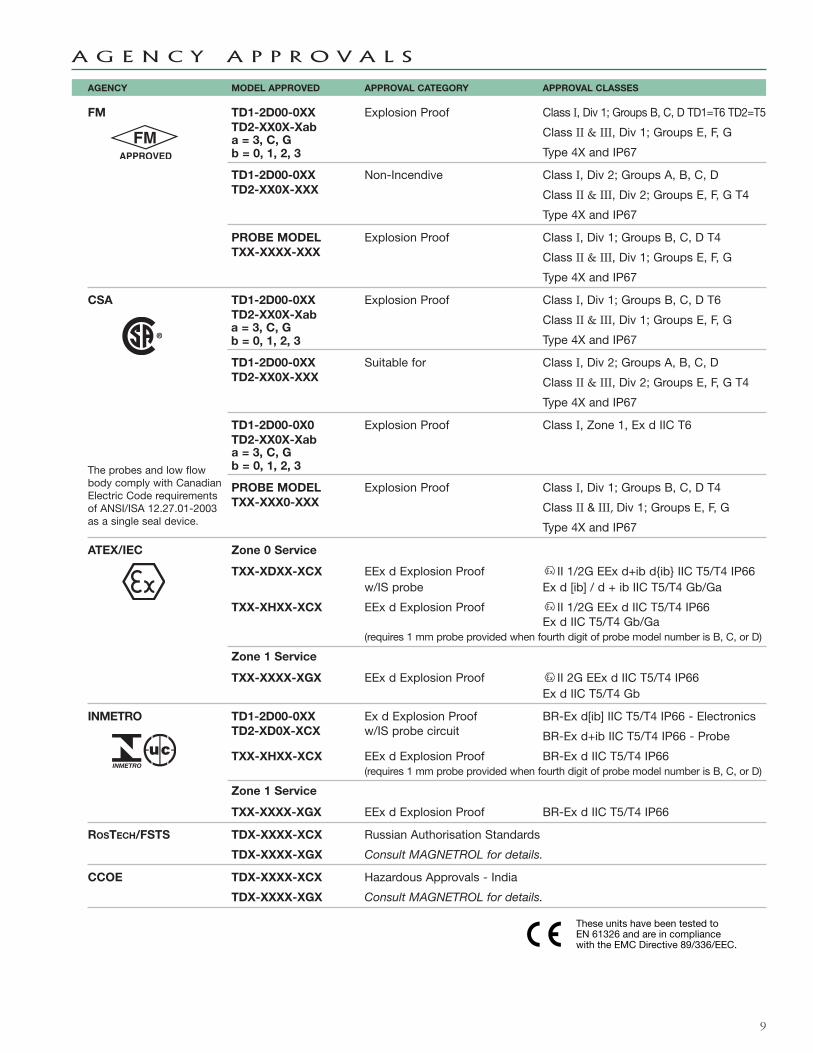
A G E N C Y A P P R O V A L S
9
AGENCY MODEL APPROVED APPROVAL CATEGORY APPROVAL CLASSES
FM TD1-2D00-0XX Explosion Proof Class I, Div 1; Groups B, C, D TD1=T6 TD2=T5TD2-XX0X-Xab Class II & III, Div 1; Groups E, F, G
Type 4X and IP67
TD1-2D00-0XX Non-Incendive Class I, Div 2; Groups A, B, C, DTD2-XX0X-XXX Class II & III, Div 2; Groups E, F, G T4
Type 4X and IP67
PROBE MODEL Explosion Proof Class I, Div 1; Groups B, C, D T4TXX-XXXX-XXX Class II & III, Div 1; Groups E, F, G
Type 4X and IP67
CSA TD1-2D00-0XX Explosion Proof Class I, Div 1; Groups B, C, D T6TD2-XX0X-Xab Class II & III, Div 1; Groups E, F, G
Type 4X and IP67
TD1-2D00-0XX Suitable for Class I, Div 2; Groups A, B, C, DTD2-XX0X-XXX Class II & III, Div 2; Groups E, F, G T4
Type 4X and IP67
TD1-2D00-0X0 Explosion Proof Class I, Zone 1, Ex d IIC T6TD2-XX0X-Xab
PROBE MODEL Explosion Proof Class I, Div 1; Groups B, C, D T4TXX-XXX0-XXX Class II & III, Div 1; Groups E, F, G
Type 4X and IP67
ATEX/IEC Zone 0 Service
TXX-XDXX-XCX EEx d Explosion Proof II 1/2G EEx d+ib d{ib} IIC T5/T4 IP66w/IS probe Ex d [ib] / d + ib IIC T5/T4 Gb/Ga
TXX-XHXX-XCX EEx d Explosion Proof II 1/2G EEx d IIC T5/T4 IP66Ex d IIC T5/T4 Gb/Ga
(requires 1 mm probe provided when fourth digit of probe model number is B, C, or D)
Zone 1 Service
TXX-XXXX-XGX EEx d Explosion Proof II 2G EEx d IIC T5/T4 IP66Ex d IIC T5/T4 Gb
INMETRO TD1-2D00-0XX Ex d Explosion Proof BR-Ex d[ib] IIC T5/T4 IP66 - ElectronicsTD2-XD0X-XCX w/IS probe circuit BR-Ex d+ib IIC T5/T4 IP66 - Probe
TXX-XHXX-XCX EEx d Explosion Proof BR-Ex d IIC T5/T4 IP66(requires 1 mm probe provided when fourth digit of probe model number is B, C, or D)
Zone 1 Service
TXX-XXXX-XGX EEx d Explosion Proof BR-Ex d IIC T5/T4 IP66
ROSTECH/FSTS TDX-XXXX-XCX Russian Authorisation Standards
TDX-XXXX-XGX Consult MAGNETROL for details.
CCOE TDX-XXXX-XCX Hazardous Approvals - India
TDX-XXXX-XGX Consult MAGNETROL for details.
These units have been tested to EN 61326 and are in compliance with the EMC Directive 89/336/EEC.
a = 3, C, Gb = 0, 1, 2, 3
a = 3, C, Gb = 0, 1, 2, 3
a = 3, C, Gb = 0, 1, 2, 3The probes and low flow
body comply with CanadianElectric Code requirementsof ANSI/ISA 12.27.01-2003as a single seal device.
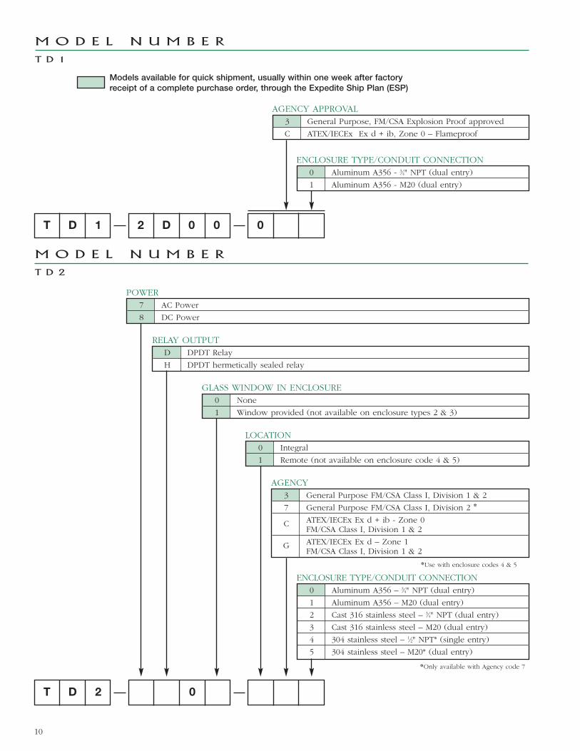
M O D E L N U M B E R
T D 1
M O D E L N U M B E R
T D 2
10
Models available for quick shipment, usually within one week after factoryreceipt of a complete purchase order, through the Expedite Ship Plan (ESP)
T D 2 0
POWER7 AC Power
8 DC Power
RELAY OUTPUTD DPDT Relay
H DPDT hermetically sealed relay
GLASS WINDOW IN ENCLOSURE0 None
1 Window provided (not available on enclosure types 2 & 3)
LOCATION0 Integral
1 Remote (not available on enclosure code 4 & 5)
AGENCY3 General Purpose FM/CSA Class I, Division 1 & 2
7 General Purpose FM/CSA Class I, Division 2 *
C ATEX/IECEx Ex d + ib - Zone 0FM/CSA Class I, Division 1 & 2
G ATEX/IECEx Ex d – Zone 1FM/CSA Class I, Division 1 & 2
ENCLOSURE TYPE/CONDUIT CONNECTION0 Aluminum A356 – 3⁄4" NPT (dual entry)
1 Aluminum A356 – M20 (dual entry)
2 Cast 316 stainless steel – 3⁄4" NPT (dual entry)
3 Cast 316 stainless steel – M20 (dual entry)
4 304 stainless steel – 1⁄2" NPT* (single entry)
5 304 stainless steel – M20* (dual entry)
T D 1 2 D 0 0 0
AGENCY APPROVAL3 General Purpose, FM/CSA Explosion Proof approved
C ATEX/IECEx Ex d + ib, Zone 0 – Flameproof
ENCLOSURE TYPE/CONDUIT CONNECTION0 Aluminum A356 - 3⁄4" NPT (dual entry)
1 Aluminum A356 - M20 (dual entry)
*Only available with Agency code 7
*Use with enclosure codes 4 & 5

A 316/316L stainless steel
B Hastelloy C �
C Monel �
D 316/316L stainless steel twin tip with 1 mm probe thickness �
A Spherical tip � max. +250° F (+121° C)/max. 600 psi(41 bar)
B Spherical tip – with 6-inch (15 cm) heat extension � max. +400° F (+204° C)/max. 600 psi (41 bar)
C Twin tip max. +250° F (+121° C)/max. 3000 psi (207 bar) �
D Twin tip – with 6-inch (15 cm) heat extension max. +400° F (+204° C)/max. 3000 psi (207 bar) �
0
TIP STYLE
MATERIAL OF CONSTRUCTION
INSERTION LENGTH
TE Probe length in inches
TM Probe length in centimeters
MODEL
11 3⁄4" NPT Thread
21 1" NPT Thread
22 G1 (1" BSP) Thread
PROCESS CONNECTION SIZE/TYPE
23 1" 150# ANSI RF Flange
24 1" 300# ANSI RF Flange
25 1" 600# ANSI RF Flange
33 11⁄2" 150# ANSI RF Flange
34 11⁄2" 300# ANSI RF Flange
ANSI RAISED FACE FLANGE CONNECTIONS35 11⁄2" 600# ANSI RF Flange
43 2" 150# ANSI RF Flange
44 2" 300# ANSI RF Flange
45 2" 600# ANSI RF Flange
EN/DIN FLANGED CONNECTIONS �
3T 11⁄2" Tri-Clamp® �
4T 2" Tri-Clamp �
VV DN65 Varivent® �
HYGIENIC CONNECTIONS� Only available for Spherical Sensor (TXA/TXB)
Contact MAGNETROL for other hygienic fittings includingNeumo, G1A, and DIN 11.851.
� Only available for TXA TipStyle.
M O D E L N U M B E R
S T A N D A R D P R O B E
11
� Available only with stainless steel construction� Consult pressure/temperature chart on page 9 for pressure rating on extended length probe and various materials of construction.
� DIN flanges only available in metric length(TMX) probes.
002 2" to 130" in 1" increments
Example: 4 inches = code 004
Note: minimum 3" with Flanges and G1 (BSP) threads
005 Minimum length 50 mm with NPT Threads
008 Minimum length 80 mm with G1 (BSP) and flange connections
Extended lengths in 10 mm increments to length 3300 mm
Examples: 50 mm = code 005, 3300 mm = code 330
Longer lengths available — consult factory
BA DN 25 PN 16 EN 1092-1 Type A
BB DN 25 PN 25/40 EN 1092-1 Type A
BC DN 25 PN 64/100 EN 1092-1 Type B2
CA DN 40 PN 16 EN 1092-1 Type A
CB DN 40 PN 25/40 EN 1092-1 Type A
CC DN 40 PN 64/100 EN 1092-1 Type B2
DA DN 50 PN 16 EN 1092-1 Type A
DB DN 50 PN 25/40 EN 1092-1 Type A
DD DN 50 PN 64 EN 1092-1 Type B2
DE DN 50 PN 100 EN 1092-1 Type B2
� Available only with TMC or TMD probes

H 0
A 316/316L stainless steel
B Hastelloy C
D 316/316L stainless steel twin tip with 1 mm probe thickness �
MATERIAL OF CONSTRUCTION
TE Probe length in inches
TM Probe length in centimeters
MODEL
H High temperature/high pressure twin tip max. +850° F (+450° C)/max. 6000 psi (413 bar)
TIP STYLE
11 3⁄4" NPT Thread
21 1" NPT Thread
22 G1 (1" BSP) Thread
PROCESS CONNECTION SIZE/TYPE
23 1" 150# ANSI RF Flange
24 1" 300# ANSI RF Flange
25 1" 600# ANSI RF Flange
27 1" 900/1500# ANSI RF Flange
33 11⁄2" 150# ANSI RF Flange
34 11⁄2" 300# ANSI RF Flange
35 11⁄2" 600# ANSI RF Flange
ANSI RAISED FACE FLANGE CONNECTIONS
37 11⁄2" 900/1500# ANSI RF Flange
38 11⁄2" 2500# ANSI RF Flange
43 2" 150# ANSI RF Flange
44 2" 300# ANSI RF Flange
45 2" 600# ANSI RF Flange
47 2" 900/1500# ANSI RF Flange
48 2" 2500# ANSI RF Flange
M O D E L N U M B E R
H I G H T E M P E R A T U R E / H I G H P R E S S U R E P R O B E
12
� DIN flanges only available on metriclength (TMX) probes.
INSERTION LENGTH
� Longer lengths available — consult factory
� Available only with TMH probes
BA DN 25 PN 16 EN 1092-1 Type A
BB DN 25 PN 25/40 EN 1092-1 Type A
BC DN 25 PN 64/100 EN 1092-1 Type B2
BG DN 25 PN 250 DIN 2527, Form E
CA DN 40 PN 16 EN 1092-1 Type A
CB DN 40 PN 25/40 EN 1092-1 Type A
CC DN 40 PN 64/100 EN 1092-1 Type B2
CG DN 40 PN 250 DIN 2527, Form E
CJ DN 40 PN 400 DIN 2527, Form E
EN/DIN FLANGED CONNECTIONS �
DA DN 50 PN 16 EN 1092-1 Type A
DB DN 50 PN 25/40 EN 1092-1 Type A
DD DN 50 PN 64 EN 1092-1 Type B2
DE DN 50 PN 100 EN 1092-1 Type B2
DG DN 50 PN 250 DIN 2527, Form E
DJ DN 50 PN 400 DIN 2527, Form E
2" to 36" in 1" increments �
Example: 6-inch probe = 006Note: minimum 3" with Flanges and G1 (BSP) threads
005 Minimum length 50 mm with NPT Threads
007 Minimum length 70 mm with G1 (BSP) or flange connections
Extended lengths in 10 mm increments to 910 mm �
Examples: 50 mm = code 005, 910 mm = code 091

T E L A 0
000 None
100 With mounting bracket
MOUNTING BRACKET
TEL Low Flow Body
MODEL
A 316/316L stainless steel
MATERIAL OF CONSTRUCTION
T1 1⁄4" NPT Thread
V1 1⁄2" NPT Thread
T0 G 1⁄4 (1⁄4" BSP) Thread
V0 G 1⁄2 (1⁄2" BSP) Thread
PROCESS CONNECTION SIZE/TYPE
M Mini twin tipmax. +400° F (+204° C)/max. 3000 psi (207 bar) for standard sensor length
max. +400° F (+204° C)/max. 1850 psi (127 bar) for sensors ≥ 2 inches (50 mm)
BODY STYLE
M A 0
A 316/316L stainless steel
MATERIAL OF CONSTRUCTION
T E Probe length in inches
T M Probe length in centimeters
MODEL
01 1⁄2" NPT Thread
11 3⁄4" NPT Thread
21 1" NPT Thread
PROCESS CONNECTION SIZE/TYPE
M O D E L N U M B E R
L O W F L O W B O D Y
M I N I S E N S O R
13
001 1" to 130" in 1" increments
Example: 6 inch probe = code 006
50 mm to 3300 mm in 10 mm increments
Examples: 50 mm = code 005, 3300 mm = code 330
Note: Use code 003 for minimum length of 25 mm
INSERTION LENGTH
Use 1-inch long probe when used with tee.
Example: Model Number of probe to fit in a 3⁄4" teeis TEM-A110-001 or TMM-A110-003.

Cable length in feet; 10 feet minimum, 500 feet maximum length
Example: 12 feet = Code 012
CONNECTING CABLE IN FEET
0 3 7 3 1 8 6
3 meters minimum, 152 meters maximum length
Example: 3 meters = Code 003
CONNECTING CABLE IN METERS
0 3 7 3 1 9 8
M O D E L N U M B E R
C O N N E C T I N G C A B L E ( G E N E R A L P U R P O S E , F M / C S A )
14
D I M E N S I O N A L S P E C I F I C A T I O N S
I N C H E S ( M M )
10.75(273)
8.00(203)
Insertionlength
flangedconnection
InsertionlengthNPT
connection
.84(21) Dia.
Insertionlength
BSP(G)connection
Insertionlength
.625(16) Dia.
1/2", 3/4", 1” NPTProcessconnection
2.00 (51)
1/4" or 1/2"NPT or BSP
High Temp/Pressure Sensor(TXH)
Mini Sensor(TXM)
Low Flow Body Sensors(TXL)

3.00(76)2.00
(51)
2 Holes.38 (10) dia.
2.75(70)
3.50(89)
2.35 (60) Typical
4.00(102)
Without Window4.43 (113)
With Window4.85 (123)
4.13(105)
0.875 (22) Dia.
Insertionlength
1.05 (26)Typical
5.24(133)
5.75(146)
Insertionlength
0.875 (22) Dia.
D I M E N S I O N A L S P E C I F I C A T I O N S ( c o n t . )
I N C H E S ( M M )
15
Model TD1with Twin Tip Sensor
Model TD2Integral Electronics
with Spherical Tip Sensor
4.13(105)
4.00(102)
InsertionlengthNPT
Connection
0.875 (22) Dia.
1.8 (46) Typical
InsertionlengthBSP(G)
Connection
Insertionlength
0.875 (22) Dia.
4.00(102)
Without Window4.43 (113)
With Window4.85 (123)
1.8 (46) Typical
Model TD2 with Remote Electronics Remote Spherical Tip Probewith Flange Connection
Model TD2with Hygienic HousingTri-Clamp® Connection

BULLETIN: 54-110.4EFFECTIVE: April 2012SUPERSEDES: April 2010
5300 Belmont Road • Downers Grove, Illinois 60515-4499 • 630-969-4000 • Fax 630-969-9489 • www.magnetrol.com145 Jardin Drive, Units 1 & 2 • Concord, Ontario Canada L4K 1X7 • 905-738-9600 • Fax 905-738-1306Heikensstraat 6 • B 9240 Zele, Belgium • 052 45.11.11 • Fax 052 45.09.93Regent Business Ctr., Jubilee Rd. • Burgess Hill, Sussex RH15 9TL U.K. • 01444-871313 • Fax 01444-871317
Copyright © 2012 Magnetrol International, Incorporated. All rights reserved. Printed in the USA.Performance specifications are effective with date of issue and are subject to change without notice.
For additional information, see:THERMATEL Instruction Manual 54-610Hygienic THERMATEL 54-160
Magnetrol, Magnetrol logotype and Thermatel are registered trademarks of Magnetrol International, Incorporated.CSA logotype is a registered trademark of Canadian Standards Association.Hastelloy is a registered trademark of Haynes International, Inc.Monel and Inconel® are registered trademarks of Special Metals Corporation.Varivent is a registered trademark of Tuchenhagen GmbH LTD.
The quality assurance system in place at
MAGNETROL guarantees the highest
level of quality throughout the company.
MAGNETROL is committed to providing full
customer satisfaction both in quality products
and quality service.
The MAGNETROL quality assurance system
is registered to ISO 9001 affirming its com-
mitment to known international quality
standards providing the strongest assurance
of product/service quality available.
Several THERMATEL flow and level switches
are available for quick shipment, usually
within one week after factory receipt of a
complete purchase order, through the
Expedite Ship Plan (ESP).
Models covered by ESP service are color
coded in the selection data charts.
To take advantage of ESP, simply match the
color coded model number codes (standard
dimensions apply).
ESP service may not apply to orders of ten
units or more. Contact your local representa-
tive for lead times on larger volume orders,
as well as other products and options.
EExpedite
SShip
PPlan
All MAGNETROL electronic level and flow
controls are warranted free of defects in
materials or workmanship for one full year
from the date of original factory shipment.
If returned within the warranty period;
and, upon factory inspection of the con-
trol, the cause of the claim is determined
to be covered under the warranty; then,
MAGNETROL will repair or replace the
control at no cost to the purchaser (or
owner) other than transportation.
MAGNETROL shall not be liable for misap-
plication, labor claims, direct or consequential
damage or expense arising from the instal-
lation or use of equipment. There are no
other warranties expressed or implied,
except special written warranties covering
some MAGNETROL products.
Q U A L I T Y
E S P
W A R R A N T Y