thermatel tg1/tg2 be51-604
TRANSCRIPT
THERMATEL®TG1/TG2Thermaldispersion switch
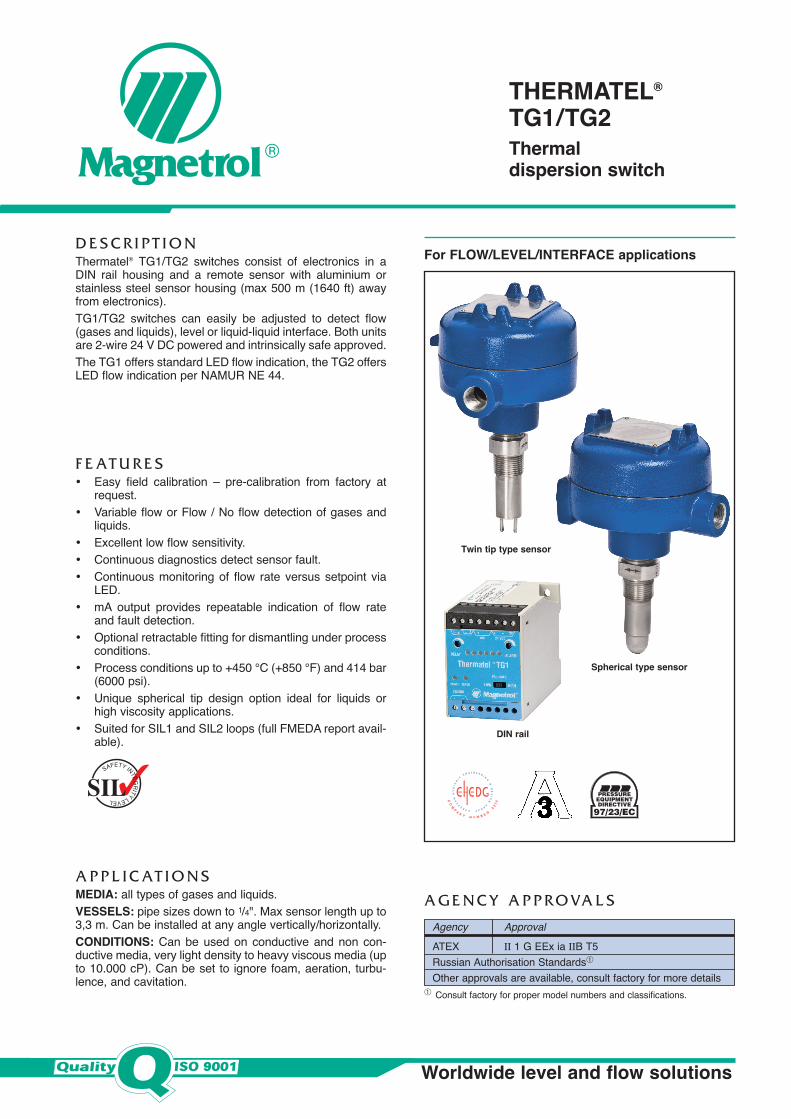
For FLOW/LEVEL/INTERFACE applicationsD E S C R I P T I O NThermatel® TG1/TG2 switches consist of electronics in aDIN rail housing and a remote sensor with aluminium orstainless steel sensor housing (max 500 m (1640 ft) awayfrom electronics). TG1/TG2 switches can easily be adjusted to detect flow(gases and liquids), level or liquid-liquid interface. Both unitsare 2-wire 24 V DC powered and intrinsically safe approved.The TG1 offers standard LED flow indication, the TG2 offersLED flow indication per NAMUR NE 44.
F E AT U R E S• Easy field calibration – pre-calibration from factory at
request.• Variable flow or Flow / No flow detection of gases and
liquids.• Excellent low flow sensitivity.• Continuous diagnostics detect sensor fault.• Continuous monitoring of flow rate versus setpoint via
LED.• mA output provides repeatable indication of flow rate
and fault detection.• Optional retractable fitting for dismantling under process
conditions.• Process conditions up to +450 °C (+850 °F) and 414 bar
(6000 psi).• Unique spherical tip design option ideal for liquids or
high viscosity applications.• Suited for SIL1 and SIL2 loops (full FMEDA report avail-
able).
A P P L I C AT I O N SMEDIA: all types of gases and liquids. VESSELS: pipe sizes down to 1/4". Max sensor length up to3,3 m. Can be installed at any angle vertically/horizontally.CONDITIONS: Can be used on conductive and non con-ductive media, very light density to heavy viscous media (upto 10.000 cP). Can be set to ignore foam, aeration, turbu-lence, and cavitation.
Worldwide level and flow solutions
A G E N C Y A P P R O VA L S
Agency ApprovalATEX II 1 G EEx ia IIB T5Russian Authorisation Standards�
Other approvals are available, consult factory for more details
Twin tip type sensor
Spherical type sensor
DIN rail
SAFETY INTEGRITY LEVEL
� Consult factory for proper model numbers and classifications.
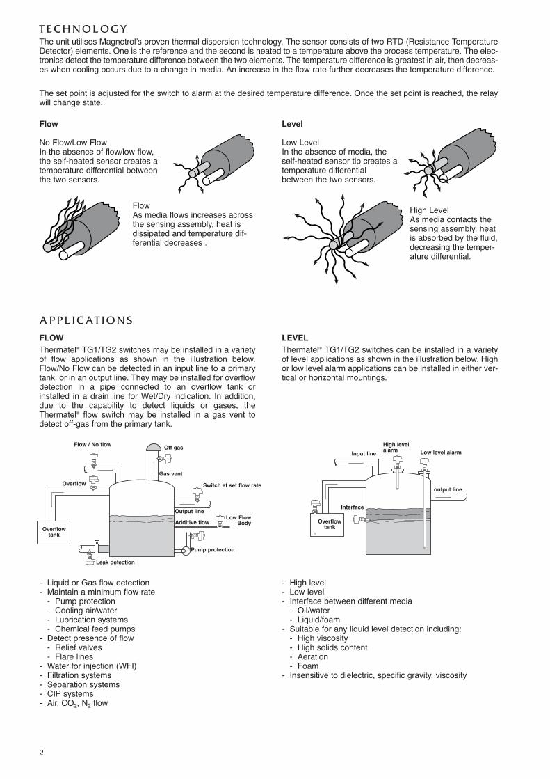
FLOWThermatel® TG1/TG2 switches may be installed in a varietyof flow applications as shown in the illustration below.Flow/No Flow can be detected in an input line to a primarytank, or in an output line. They may be installed for overflowdetection in a pipe connected to an overflow tank orinstalled in a drain line for Wet/Dry indication. In addition,due to the capability to detect liquids or gases, theThermatel® flow switch may be installed in a gas vent todetect off-gas from the primary tank.
LEVELThermatel® TG1/TG2 switches can be installed in a varietyof level applications as shown in the illustration below. Highor low level alarm applications can be installed in either ver-tical or horizontal mountings.
Flow / No flow
Low FlowBody
Overflow
Overflowtank
Overflowtank
Off gas
Gas vent
Switch at set flow rate
Output lineAdditive flow
output line
Input line
Interface
High levelalarm Low level alarm
Pump protection
Leak detection
2
Level
Low LevelIn the absence of media, theself-heated sensor tip creates atemperature differentialbetween the two sensors.
High LevelAs media contacts thesensing assembly, heatis absorbed by the fluid,decreasing the temper-ature differential.
Flow
No Flow/Low FlowIn the absence of flow/low flow,the self-heated sensor creates atemperature differential betweenthe two sensors.
FlowAs media flows increases acrossthe sensing assembly, heat isdissipated and temperature dif-ferential decreases .
- High level- Low level- Interface between different media
- Oil/water- Liquid/foam
- Suitable for any liquid level detection including:- High viscosity- High solids content- Aeration- Foam
- Insensitive to dielectric, specific gravity, viscosity
- Liquid or Gas flow detection- Maintain a minimum flow rate
- Pump protection- Cooling air/water- Lubrication systems- Chemical feed pumps
- Detect presence of flow- Relief valves- Flare lines
- Water for injection (WFI)- Filtration systems- Separation systems- CIP systems- Air, CO2, N2 flow
T E C H N O L O G YThe unit utilises Magnetrol’s proven thermal dispersion technology. The sensor consists of two RTD (Resistance TemperatureDetector) elements. One is the reference and the second is heated to a temperature above the process temperature. The elec-tronics detect the temperature difference between the two elements. The temperature difference is greatest in air, then decreas-es when cooling occurs due to a change in media. An increase in the flow rate further decreases the temperature difference.
The set point is adjusted for the switch to alarm at the desired temperature difference. Once the set point is reached, the relaywill change state.
A P P L I C AT I O N S
3
S E N S O R D E S I G N S
04.00
6.00
8.00
10.00
12.00
16.00
18.00
mA
m/s
14.00
15 30 45 60
Twin Tip Spherical Tip Hastelloy 8.00
9.00
10.00
11.00
12.00
13.00
14.00
15.00
1,51,20,90,3 0,60,0
Spherical Tip Twin Tip Hastelloy
mA
m/s
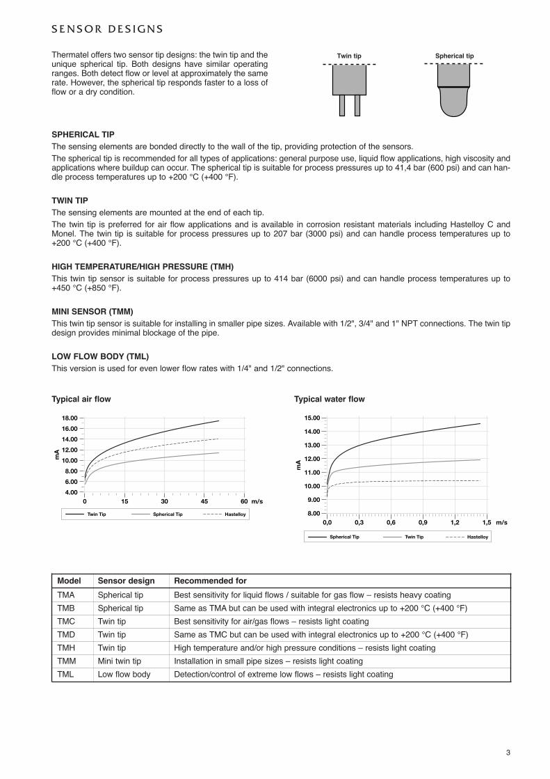
Typical air flow Typical water flow
Twin tip Spherical tipThermatel offers two sensor tip designs: the twin tip and theunique spherical tip. Both designs have similar operatingranges. Both detect flow or level at approximately the samerate. However, the spherical tip responds faster to a loss offlow or a dry condition.
SPHERICAL TIPThe sensing elements are bonded directly to the wall of the tip, providing protection of the sensors.The spherical tip is recommended for all types of applications: general purpose use, liquid flow applications, high viscosity andapplications where buildup can occur. The spherical tip is suitable for process pressures up to 41,4 bar (600 psi) and can han-dle process temperatures up to +200 °C (+400 °F).
TWIN TIPThe sensing elements are mounted at the end of each tip.The twin tip is preferred for air flow applications and is available in corrosion resistant materials including Hastelloy C andMonel. The twin tip is suitable for process pressures up to 207 bar (3000 psi) and can handle process temperatures up to+200 °C (+400 °F).
HIGH TEMPERATURE/HIGH PRESSURE (TMH)This twin tip sensor is suitable for process pressures up to 414 bar (6000 psi) and can handle process temperatures up to+450 °C (+850 °F).
MINI SENSOR (TMM)This twin tip sensor is suitable for installing in smaller pipe sizes. Available with 1/2", 3/4" and 1" NPT connections. The twin tipdesign provides minimal blockage of the pipe.
LOW FLOW BODY (TML)This version is used for even lower flow rates with 1/4" and 1/2" connections.
Model Sensor design Recommended forTMA Spherical tip Best sensitivity for liquid flows / suitable for gas flow – resists heavy coatingTMB Spherical tip Same as TMA but can be used with integral electronics up to +200 °C (+400 °F)TMC Twin tip Best sensitivity for air/gas flows – resists light coatingTMD Twin tip Same as TMC but can be used with integral electronics up to +200 °C (+400 °F)TMH Twin tip High temperature and/or high pressure conditions – resists light coatingTMM Mini twin tip Installation in small pipe sizes – resists light coatingTML Low flow body Detection/control of extreme low flows – resists light coating
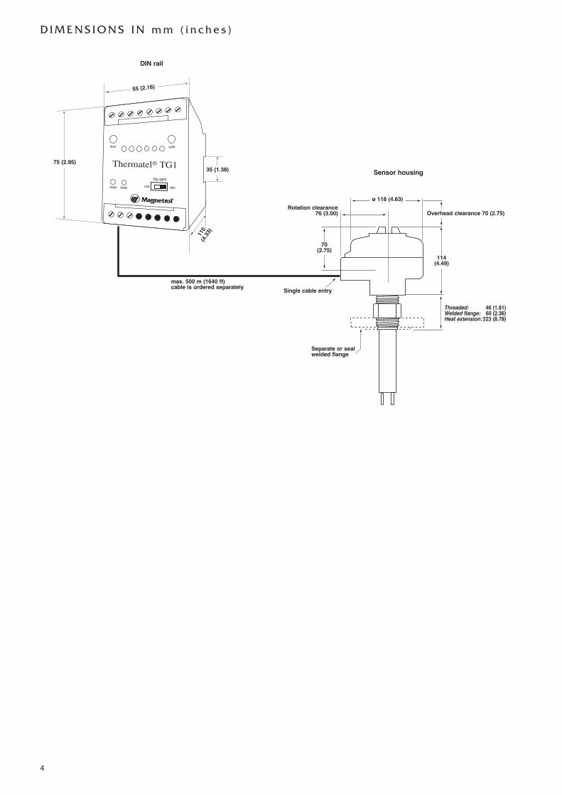
DIN rail
Sensor housing
Separate or sealwelded flange
ø 118 (4.63)Rotation clearance
76 (3.00)
70(2.75)
Single cable entry
®
ALARMDELAY
LOW HIGH
FAIL-SAFE
POWER ERROR
max. 500 m (1640 ft)cable is ordered separately
55 (2.16)
75 (2.95)
110
(4.33)
35 (1.38)
114 (4.49)
Overhead clearance 70 (2.75)
Threaded: 46 (1.81)Welded flange: 60 (2.36)Heat extension: 223 (8.78)
D I M E N S I O N S I N m m ( i n c h e s )
4
5
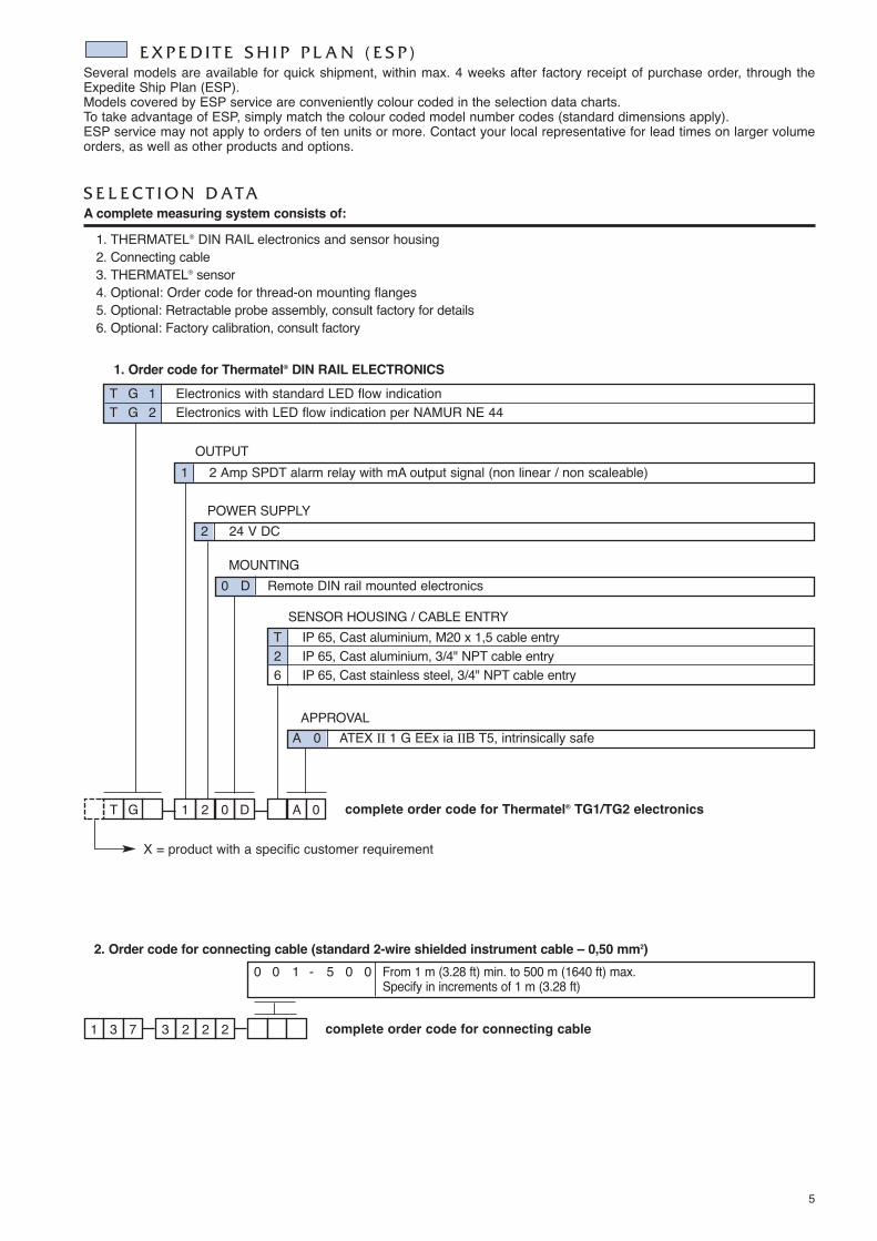
1. Order code for Thermatel® DIN RAIL ELECTRONICS
POWER SUPPLY
MOUNTING0 D Remote DIN rail mounted electronics
APPROVALA 0 ATEX II 1 G EEx ia IIB T5, intrinsically safe
2 24 V DC
OUTPUT1 2 Amp SPDT alarm relay with mA output signal (non linear / non scaleable)
S E L E C T I O N D ATAA complete measuring system consists of:
1. THERMATEL® DIN RAIL electronics and sensor housing2. Connecting cable3. THERMATEL® sensor4. Optional: Order code for thread-on mounting flanges5. Optional: Retractable probe assembly, consult factory for details6. Optional: Factory calibration, consult factory
SENSOR HOUSING / CABLE ENTRY
2. Order code for connecting cable (standard 2-wire shielded instrument cable – 0,50 mm2)
1 22 233 7 complete order code for connecting cable
0 0 1 - 5 0 0 From 1 m (3.28 ft) min. to 500 m (1640 ft) max. Specify in increments of 1 m (3.28 ft)
T D2 01G A 0 complete order code for Thermatel® TG1/TG2 electronics
E X P E D I T E S H I P P L A N ( E S P )Several models are available for quick shipment, within max. 4 weeks after factory receipt of purchase order, through theExpedite Ship Plan (ESP).Models covered by ESP service are conveniently colour coded in the selection data charts.To take advantage of ESP, simply match the colour coded model number codes (standard dimensions apply).ESP service may not apply to orders of ten units or more. Contact your local representative for lead times on larger volumeorders, as well as other products and options.
T G 1 Electronics with standard LED flow indicationT G 2 Electronics with LED flow indication per NAMUR NE 44
T IP 65, Cast aluminium, M20 x 1,5 cable entry2 IP 65, Cast aluminium, 3/4" NPT cable entry6 IP 65, Cast stainless steel, 3/4" NPT cable entry
X = product with a specific customer requirement
6
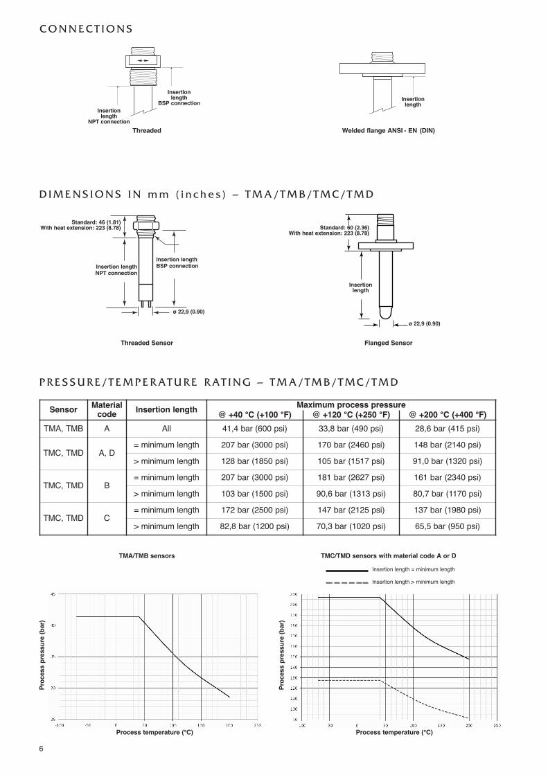
C O N N E C T I O N S
Threaded Welded flange ANSI - EN (DIN)
Insertionlength
BSP connection Insertionlength
Insertionlength
NPT connection
D I M E N S I O N S I N m m ( i n c h e s ) – T M A / T M B / T M C / T M D
Threaded Sensor Flanged Sensor
TMA/TMB sensors TMC/TMD sensors with material code A or D
Insertion lengthNPT connection
Insertion lengthBSP connection
Insertionlength
Insertion length = minimum length
Insertion length > minimum length
ø 22,9 (0.90)
ø 22,9 (0.90)
Standard: 46 (1.81)With heat extension: 223 (8.78) Standard: 60 (2.36)
With heat extension: 223 (8.78)
Sensor Material code Insertion length Maximum process pressure
@ +40 °C (+100 °F) @ +120 °C (+250 °F) @ +200 °C (+400 °F)TMA, TMB A All 41,4 bar (600 psi) 33,8 bar (490 psi) 28,6 bar (415 psi)
TMC, TMD A, D= minimum length 207 bar (3000 psi) 170 bar (2460 psi) 148 bar (2140 psi)> minimum length 128 bar (1850 psi) 105 bar (1517 psi) 91,0 bar (1320 psi)
TMC, TMD B= minimum length 207 bar (3000 psi) 181 bar (2627 psi) 161 bar (2340 psi)> minimum length 103 bar (1500 psi) 90,6 bar (1313 psi) 80,7 bar (1170 psi)
TMC, TMD C= minimum length 172 bar (2500 psi) 147 bar (2125 psi) 137 bar (1980 psi)> minimum length 82,8 bar (1200 psi) 70,3 bar (1020 psi) 65,5 bar (950 psi)
P R E S S U R E / T E M P E R AT U R E R AT I N G – T M A / T M B / T M C / T M D
Process temperature (°C)
Process pressure (bar)
Process temperature (°C)
Process pressure (bar)
7
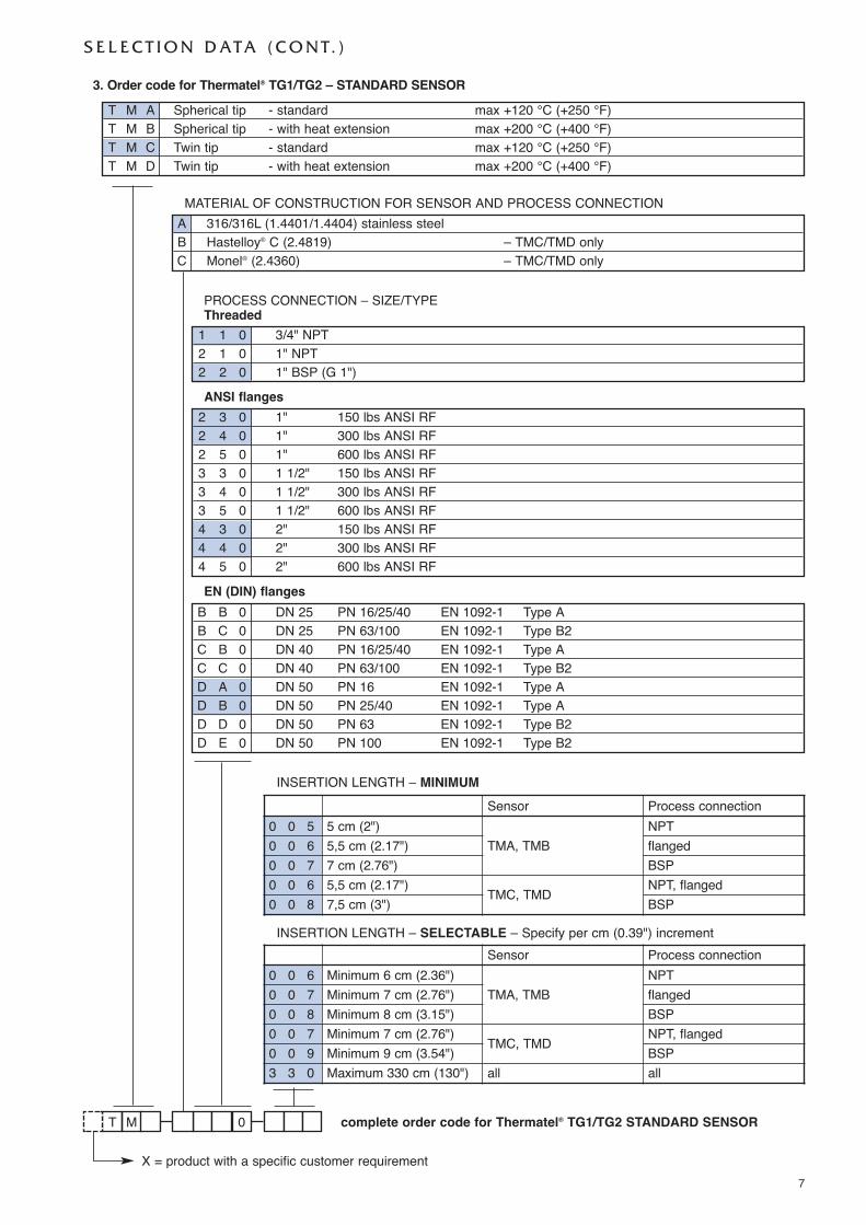
3. Order code for Thermatel® TG1/TG2 – STANDARD SENSOR
PROCESS CONNECTION – SIZE/TYPEThreaded
complete order code for Thermatel® TG1/TG2 STANDARD SENSORT 0M
1 1 0 3/4" NPT2 1 0 1" NPT2 2 0 1" BSP (G 1")ANSI flanges
2 3 0 1" 150 lbs ANSI RF2 4 0 1" 300 lbs ANSI RF2 5 0 1" 600 lbs ANSI RF3 3 0 1 1/2" 150 lbs ANSI RF3 4 0 1 1/2" 300 lbs ANSI RF3 5 0 1 1/2" 600 lbs ANSI RF4 3 0 2" 150 lbs ANSI RF4 4 0 2" 300 lbs ANSI RF4 5 0 2" 600 lbs ANSI RFEN (DIN) flanges
B B 0 DN 25 PN 16/25/40 EN 1092-1 Type AB C 0 DN 25 PN 63/100 EN 1092-1 Type B2C B 0 DN 40 PN 16/25/40 EN 1092-1 Type AC C 0 DN 40 PN 63/100 EN 1092-1 Type B2D A 0 DN 50 PN 16 EN 1092-1 Type AD B 0 DN 50 PN 25/40 EN 1092-1 Type AD D 0 DN 50 PN 63 EN 1092-1 Type B2D E 0 DN 50 PN 100 EN 1092-1 Type B2
S E L E C T I O N D ATA ( C O N T. )
MATERIAL OF CONSTRUCTION FOR SENSOR AND PROCESS CONNECTIONA 316/316L (1.4401/1.4404) stainless steelB Hastelloy® C (2.4819) – TMC/TMD onlyC Monel® (2.4360) – TMC/TMD only
T M A Spherical tip - standard max +120 °C (+250 °F)T M B Spherical tip - with heat extension max +200 °C (+400 °F)T M C Twin tip - standard max +120 °C (+250 °F)T M D Twin tip - with heat extension max +200 °C (+400 °F)
X = product with a specific customer requirement
INSERTION LENGTH – MINIMUM
INSERTION LENGTH – SELECTABLE – Specify per cm (0.39") increment
Sensor Process connection0 0 5 5 cm (2")
TMA, TMBNPT
0 0 6 5,5 cm (2.17") flanged0 0 7 7 cm (2.76") BSP0 0 6 5,5 cm (2.17") TMC, TMD NPT, flanged0 0 8 7,5 cm (3") BSP
Sensor Process connection0 0 6 Minimum 6 cm (2.36")
TMA, TMBNPT
0 0 7 Minimum 7 cm (2.76") flanged0 0 8 Minimum 8 cm (3.15") BSP0 0 7 Minimum 7 cm (2.76") TMC, TMD NPT, flanged0 0 9 Minimum 9 cm (3.54") BSP3 3 0 Maximum 330 cm (130") all all
8
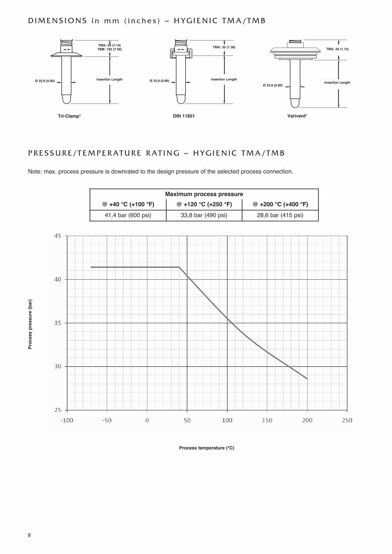
D I M E N S I O N S i n m m ( i n c h e s ) – H Y G I E N I C T M A / T M B
TMA: 29 (1.14)TMB: 192 (7.56)
Ø 22,9 (0.90) Insertion Length
Tri-Clamp®
TMA: 35 (1.38)
Ø 22,9 (0.90) Insertion Length
DIN 11851
TMA: 29 (1.14)
Ø 22,9 (0.90)Insertion Length
Varivent®
P R E S S U R E / T E M P E R AT U R E R AT I N G – H Y G I E N I C T M A / T M B
Note: max. process pressure is downrated to the design pressure of the selected process connection.
Process temperature (°C)
Process pressure (bar)
Maximum process pressure@ +40 °C (+100 °F) @ +120 °C (+250 °F) @ +200 °C (+400 °F)41,4 bar (600 psi) 33,8 bar (490 psi) 28,6 bar (415 psi)
9
S E L E C T I O N D ATA ( C O N T. )
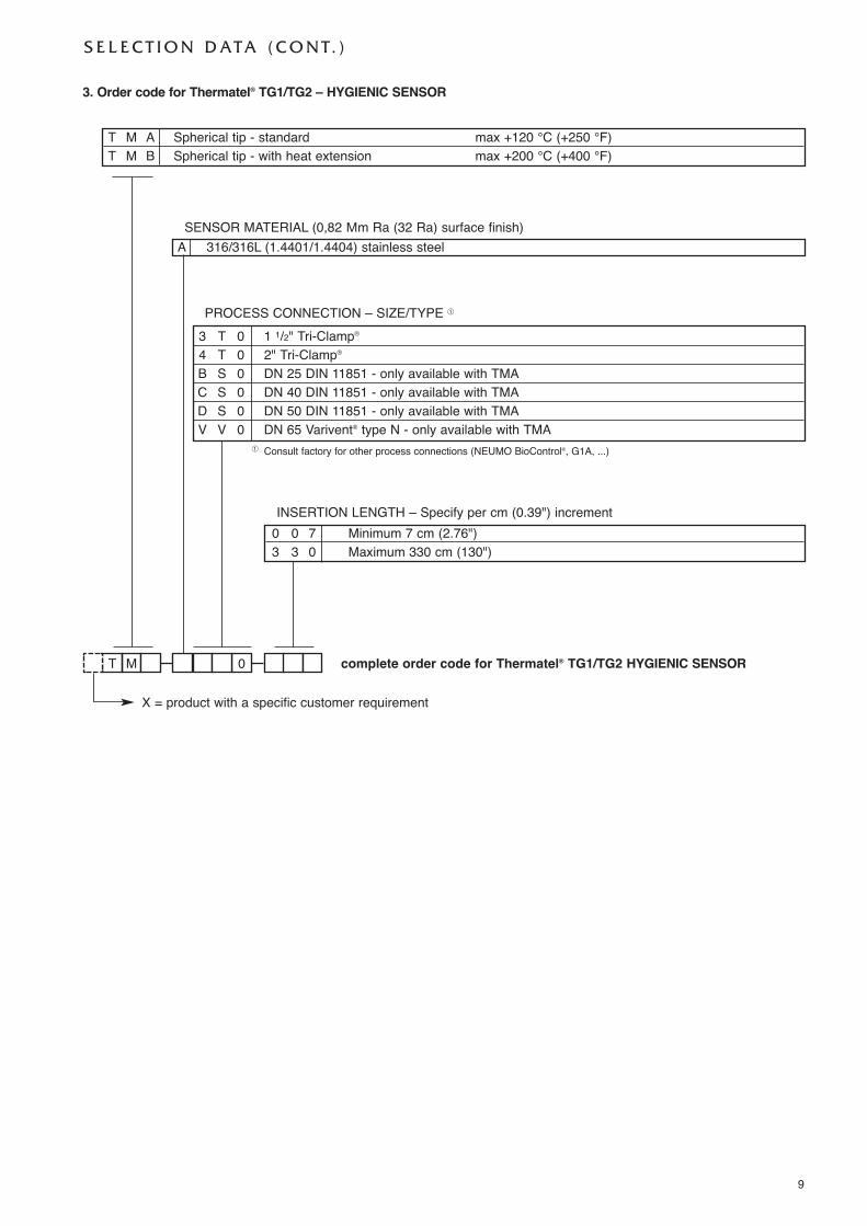
� Consult factory for other process connections (NEUMO BioControl®, G1A, ...)
X = product with a specific customer requirement
3. Order code for Thermatel® TG1/TG2 – HYGIENIC SENSOR
complete order code for Thermatel® TG1/TG2 HYGIENIC SENSORT 0M
INSERTION LENGTH – Specify per cm (0.39") increment0 0 7 Minimum 7 cm (2.76")3 3 0 Maximum 330 cm (130")
SENSOR MATERIAL (0,82 Μm Ra (32 Ra) surface finish)A 316/316L (1.4401/1.4404) stainless steel
T M A Spherical tip - standard max +120 °C (+250 °F)T M B Spherical tip - with heat extension max +200 °C (+400 °F)
PROCESS CONNECTION – SIZE/TYPE �
3 T 0 1 1/2" Tri-Clamp®
4 T 0 2" Tri-Clamp®
B S 0 DN 25 DIN 11851 - only available with TMAC S 0 DN 40 DIN 11851 - only available with TMAD S 0 DN 50 DIN 11851 - only available with TMAV V 0 DN 65 Varivent® type N - only available with TMA
10
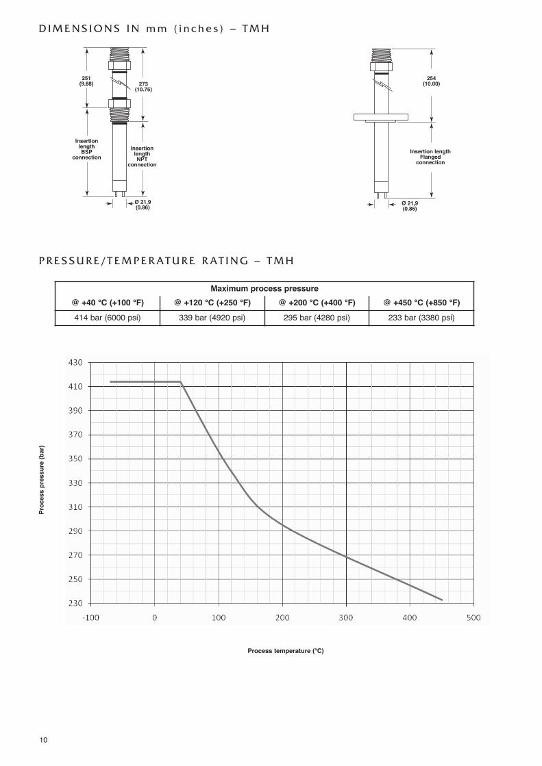
P R E S S U R E / T E M P E R AT U R E R AT I N G – T M H
D I M E N S I O N S I N m m ( i n c h e s ) – T M H
Maximum process pressure@ +40 °C (+100 °F) @ +120 °C (+250 °F) @ +200 °C (+400 °F) @ +450 °C (+850 °F)414 bar (6000 psi) 339 bar (4920 psi) 295 bar (4280 psi) 233 bar (3380 psi)
Process temperature (°C)
Process pressure (bar)
251(9.88)
InsertionlengthBSP
connectionInsertionlengthNPT
connection
Insertion lengthFlangedconnection
273(10.75)
254(10.00)
Ø 21,9(0.86) Ø 21,9
(0.86)
11
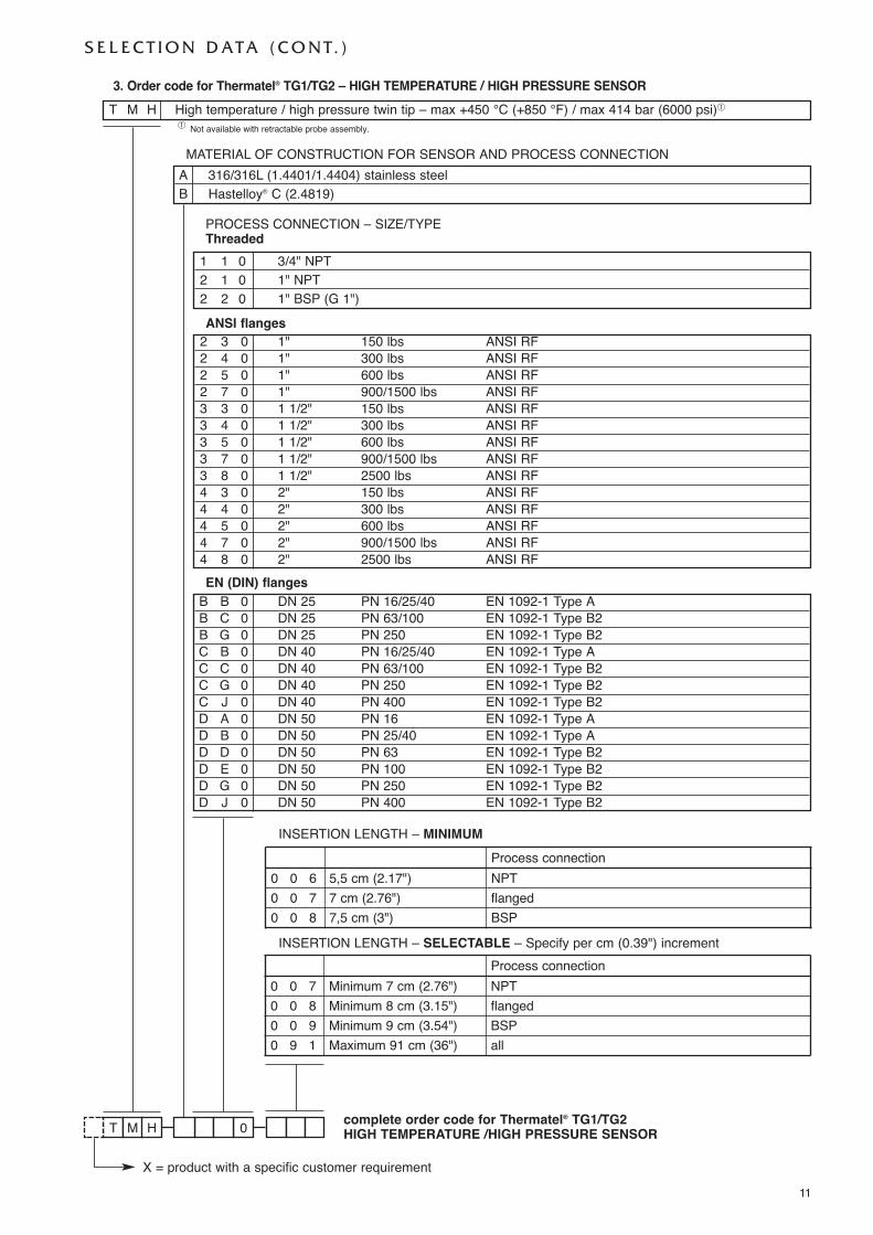
3. Order code for Thermatel® TG1/TG2 – HIGH TEMPERATURE / HIGH PRESSURE SENSOR
complete order code for Thermatel® TG1/TG2 HIGH TEMPERATURE /HIGH PRESSURE SENSORT 0M H
T M H High temperature / high pressure twin tip – max +450 °C (+850 °F) / max 414 bar (6000 psi)�
S E L E C T I O N D ATA ( C O N T. )
MATERIAL OF CONSTRUCTION FOR SENSOR AND PROCESS CONNECTIONA 316/316L (1.4401/1.4404) stainless steelB Hastelloy® C (2.4819)
PROCESS CONNECTION – SIZE/TYPEThreaded
1 1 0 3/4" NPT2 1 0 1" NPT2 2 0 1" BSP (G 1")ANSI flanges
2 3 0 1" 150 lbs ANSI RF2 4 0 1" 300 lbs ANSI RF2 5 0 1" 600 lbs ANSI RF2 7 0 1" 900/1500 lbs ANSI RF3 3 0 1 1/2" 150 lbs ANSI RF3 4 0 1 1/2" 300 lbs ANSI RF3 5 0 1 1/2" 600 lbs ANSI RF3 7 0 1 1/2" 900/1500 lbs ANSI RF3 8 0 1 1/2" 2500 lbs ANSI RF4 3 0 2" 150 lbs ANSI RF4 4 0 2" 300 lbs ANSI RF4 5 0 2" 600 lbs ANSI RF4 7 0 2" 900/1500 lbs ANSI RF4 8 0 2" 2500 lbs ANSI RFEN (DIN) flanges
B B 0 DN 25 PN 16/25/40 EN 1092-1 Type AB C 0 DN 25 PN 63/100 EN 1092-1 Type B2B G 0 DN 25 PN 250 EN 1092-1 Type B2C B 0 DN 40 PN 16/25/40 EN 1092-1 Type AC C 0 DN 40 PN 63/100 EN 1092-1 Type B2C G 0 DN 40 PN 250 EN 1092-1 Type B2C J 0 DN 40 PN 400 EN 1092-1 Type B2D A 0 DN 50 PN 16 EN 1092-1 Type AD B 0 DN 50 PN 25/40 EN 1092-1 Type AD D 0 DN 50 PN 63 EN 1092-1 Type B2D E 0 DN 50 PN 100 EN 1092-1 Type B2D G 0 DN 50 PN 250 EN 1092-1 Type B2D J 0 DN 50 PN 400 EN 1092-1 Type B2
� Not available with retractable probe assembly.
X = product with a specific customer requirement
INSERTION LENGTH – MINIMUMProcess connection
0 0 6 5,5 cm (2.17") NPT0 0 7 7 cm (2.76") flanged0 0 8 7,5 cm (3") BSP
Process connection0 0 7 Minimum 7 cm (2.76") NPT0 0 8 Minimum 8 cm (3.15") flanged0 0 9 Minimum 9 cm (3.54") BSP0 9 1 Maximum 91 cm (36") all
INSERTION LENGTH – SELECTABLE – Specify per cm (0.39") increment
12
S E L E C T I O N D ATA ( C O N T. )
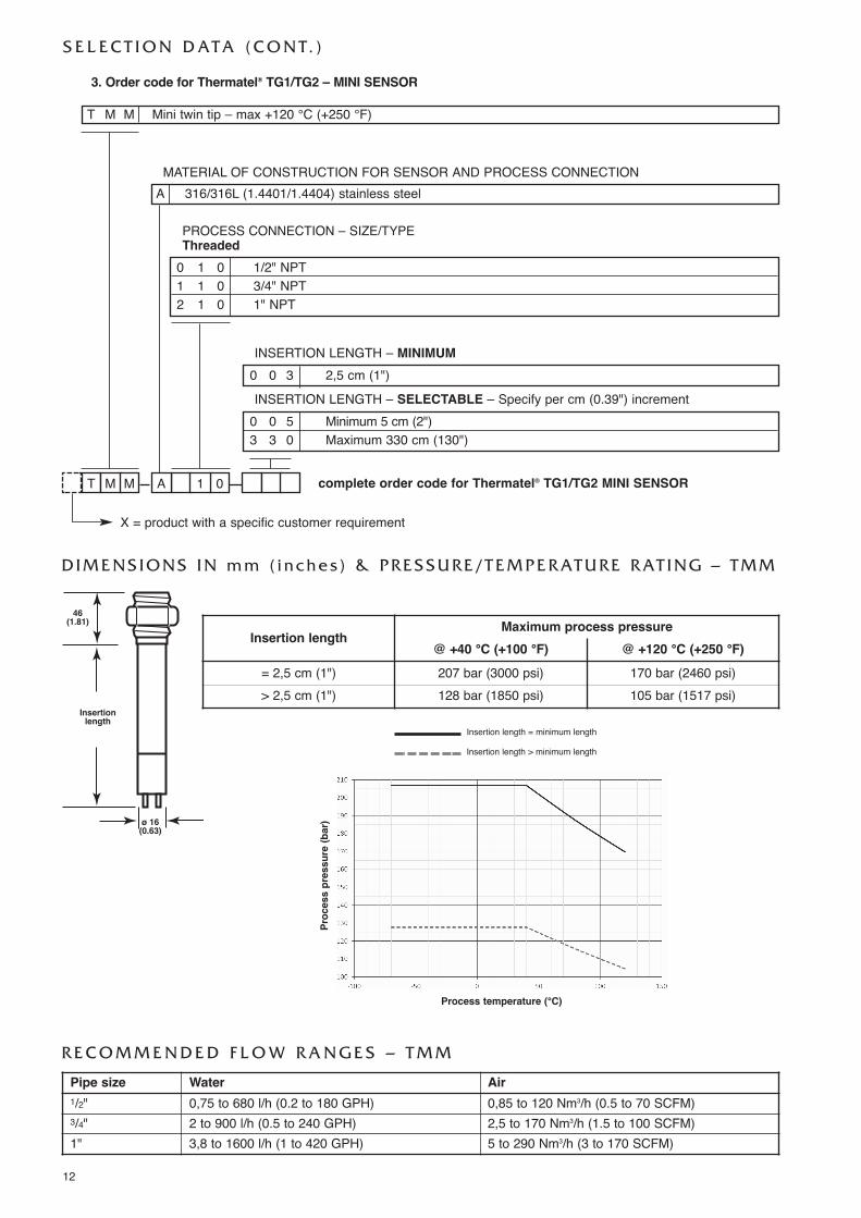
T 01AM M complete order code for Thermatel® TG1/TG2 MINI SENSOR
3. Order code for Thermatel® TG1/TG2 – MINI SENSOR
T M M Mini twin tip – max +120 °C (+250 °F)
D I M E N S I O N S I N m m ( i n c h e s ) & P R E S S U R E / T E M P E R AT U R E R AT I N G – T M M
46(1.81)
Insertionlength
ø 16(0.63)
MATERIAL OF CONSTRUCTION FOR SENSOR AND PROCESS CONNECTIONA 316/316L (1.4401/1.4404) stainless steel
PROCESS CONNECTION – SIZE/TYPEThreaded
0 1 0 1/2" NPT1 1 0 3/4" NPT2 1 0 1" NPT
INSERTION LENGTH – MINIMUM0 0 3 2,5 cm (1")INSERTION LENGTH – SELECTABLE – Specify per cm (0.39") increment
0 0 5 Minimum 5 cm (2")3 3 0 Maximum 330 cm (130")
R E C O M M E N D E D F L O W R A N G E S – T M M
Pipe size Water Air1/2" 0,75 to 680 l/h (0.2 to 180 GPH) 0,85 to 120 Nm3/h (0.5 to 70 SCFM)3/4" 2 to 900 l/h (0.5 to 240 GPH) 2,5 to 170 Nm3/h (1.5 to 100 SCFM)1" 3,8 to 1600 l/h (1 to 420 GPH) 5 to 290 Nm3/h (3 to 170 SCFM)
Insertion lengthMaximum process pressure
@ +40 °C (+100 °F) @ +120 °C (+250 °F)= 2,5 cm (1") 207 bar (3000 psi) 170 bar (2460 psi)> 2,5 cm (1") 128 bar (1850 psi) 105 bar (1517 psi)
X = product with a specific customer requirement
Insertion length = minimum length
Insertion length > minimum length
Process temperature (°C)
Process pressure (bar)
13
S E L E C T I O N D ATA ( C O N T. )
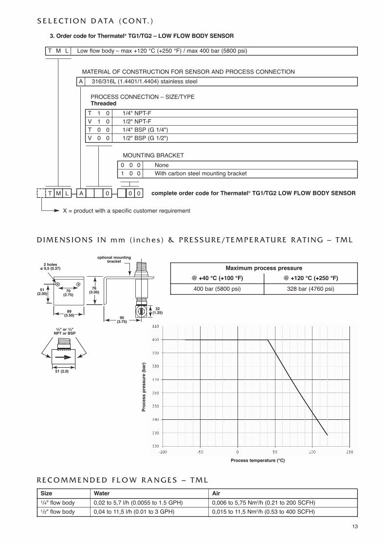
Maximum process pressure@ +40 °C (+100 °F) @ +120 °C (+250 °F)400 bar (5800 psi) 328 bar (4760 psi)
T 0AM L 0 0 complete order code for Thermatel® TG1/TG2 LOW FLOW BODY SENSOR
3. Order code for Thermatel® TG1/TG2 – LOW FLOW BODY SENSOR
T M L Low flow body – max +120 °C (+250 °F) / max 400 bar (5800 psi)
MATERIAL OF CONSTRUCTION FOR SENSOR AND PROCESS CONNECTIONA 316/316L (1.4401/1.4404) stainless steel
MOUNTING BRACKET0 0 0 None1 0 0 With carbon steel mounting bracket
PROCESS CONNECTION – SIZE/TYPEThreaded
T 1 0 1/4" NPT-FV 1 0 1/2" NPT-FT 0 0 1/4" BSP (G 1/4")V 0 0 1/2" BSP (G 1/2")
X = product with a specific customer requirement
D I M E N S I O N S I N m m ( i n c h e s ) & P R E S S U R E / T E M P E R AT U R E R AT I N G – T M L
R E C O M M E N D E D F L O W R A N G E S – T M L
2 holes ø 9,5 (0.37)
51(2.00) 70
(2.75)
89(3.50)
76(3.00)
95(3.75)
32(1.25)
optional mountingbracket
51 (2.0)
1/4" or 1/2"NPT or BSP
Size Water Air1/4" flow body 0,02 to 5,7 l/h (0.0055 to 1.5 GPH) 0,006 to 5,75 Nm3/h (0.21 to 200 SCFH)1/2" flow body 0,04 to 11,5 l/h (0.01 to 3 GPH) 0,015 to 11,5 Nm3/h (0.53 to 400 SCFH)
Process temperature (°C)
Process pressure (bar)
14
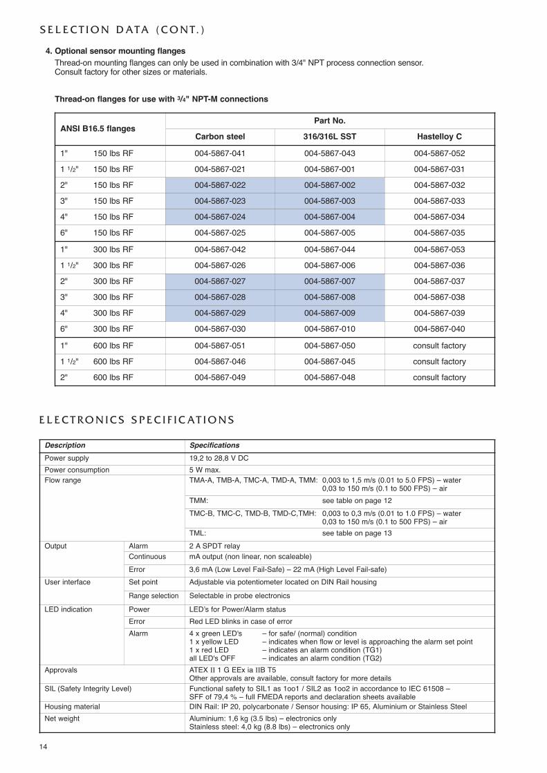
E L E C T R O N I C S S P E C I F I C AT I O N S
Description SpecificationsPower supply 19,2 to 28,8 V DCPower consumption 5 W max.Flow range TMA-A, TMB-A, TMC-A, TMD-A, TMM: 0,003 to 1,5 m/s (0.01 to 5.0 FPS) – water
0,03 to 150 m/s (0.1 to 500 FPS) – airTMM: see table on page 12TMC-B, TMC-C, TMD-B, TMD-C,TMH: 0,003 to 0,3 m/s (0.01 to 1.0 FPS) – water
0,03 to 150 m/s (0.1 to 500 FPS) – airTML: see table on page 13
Output Alarm 2 A SPDT relayContinuous mA output (non linear, non scaleable)Error 3,6 mA (Low Level Fail-Safe) – 22 mA (High Level Fail-safe)
User interface Set point Adjustable via potentiometer located on DIN Rail housingRange selection Selectable in probe electronics
LED indication Power LED’s for Power/Alarm statusError Red LED blinks in case of errorAlarm 4 x green LED's – for safe/ (normal) condition
1 x yellow LED – indicates when flow or level is approaching the alarm set point1 x red LED – indicates an alarm condition (TG1)all LED's OFF – indicates an alarm condition (TG2)
Approvals ATEX II 1 G EEx ia IIB T5Other approvals are available, consult factory for more details
SIL (Safety Integrity Level) Functional safety to SIL1 as 1oo1 / SIL2 as 1oo2 in accordance to IEC 61508 – SFF of 79,4 % – full FMEDA reports and declaration sheets available
Housing material DIN Rail: IP 20, polycarbonate / Sensor housing: IP 65, Aluminium or Stainless SteelNet weight Aluminium: 1,6 kg (3.5 lbs) – electronics only
Stainless steel: 4,0 kg (8.8 lbs) – electronics only
S E L E C T I O N D ATA ( C O N T. )
4. Optional sensor mounting flangesThread-on mounting flanges can only be used in combination with 3/4" NPT process connection sensor.Consult factory for other sizes or materials.
Thread-on flanges for use with 3/4" NPT-M connections
ANSI B16.5 flangesPart No.
Carbon steel 316/316L SST Hastelloy C1" 150 lbs RF 004-5867-041 004-5867-043 004-5867-0521 1/2" 150 lbs RF 004-5867-021 004-5867-001 004-5867-0312" 150 lbs RF 004-5867-022 004-5867-002 004-5867-0323" 150 lbs RF 004-5867-023 004-5867-003 004-5867-0334" 150 lbs RF 004-5867-024 004-5867-004 004-5867-0346" 150 lbs RF 004-5867-025 004-5867-005 004-5867-035
1" 300 lbs RF 004-5867-042 004-5867-044 004-5867-0531 1/2" 300 lbs RF 004-5867-026 004-5867-006 004-5867-0362" 300 lbs RF 004-5867-027 004-5867-007 004-5867-0373" 300 lbs RF 004-5867-028 004-5867-008 004-5867-0384" 300 lbs RF 004-5867-029 004-5867-009 004-5867-0396" 300 lbs RF 004-5867-030 004-5867-010 004-5867-040
1" 600 lbs RF 004-5867-051 004-5867-050 consult factory1 1/2" 600 lbs RF 004-5867-046 004-5867-045 consult factory2" 600 lbs RF 004-5867-049 004-5867-048 consult factory
15
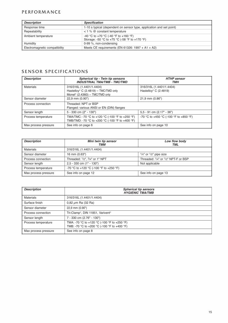
P E R F O R M A N C E
Description SpecificationResponse time 1-10 s typical (dependent on sensor type, application and set point)Repeatability < 1 % @ constant temperatureAmbient temperature -40 °C to +70 °C (-40 °F to +160 °F)
Storage: -50 °C to +75 °C (-58 °F to +170 °F)Humidity 0-99 %, non-condensingElectromagnetic compatibility Meets CE requirements (EN 61326: 1997 + A1 + A2)
S E N S O R S P E C I F I C AT I O N S
Description Spherical tip - Twin tip sensorsINDUSTRIAL TMA/TMB - TMC/TMD
HTHP sensorTMH
Materials 316/316L (1.4401/1.4404)Hastelloy® C (2.4819) – TMC/TMD onlyMonel® (2.4360) – TMC/TMD only
316/316L (1.4401/1.4404)Hastelloy® C (2.4819)
Sensor diameter 22,9 mm (0.90") 21,9 mm (0.86")Process connection Threaded: NPT or BSP
Flanged: various ANSI or EN (DIN) flangesSensor length 5 - 330 cm (2" - 130") 5,5 - 91 cm (2.17" - 36")Process temperature TMA/TMC: -70 °C to +120 °C (-100 °F to +250 °F)
TMB/TMD: -70 °C to +200 °C (-100 °F to +400 °F)-70 °C to +450 °C (-100 °F to +850 °F)
Max process pressure See info on page 6 See info on page 10
Description Spherical tip sensorsHYGIENIC TMA/TMB
Materials 316/316L (1.4401/1.4404)Surface finish 0,82 µm Ra (32 Ra)Sensor diameter 22,9 mm (0.90")Process connection Tri-Clamp®, DIN 11851, Varivent®
Sensor length 7 - 330 cm (2.76" - 130")Process temperature TMA: -70 °C to +120 °C (-100 °F to +250 °F)
TMB: -70 °C to +200 °C (-100 °F to +400 °F)Max process pressure See info on page 8
Description Mini twin tip sensorTMM
Low flow bodyTML
Materials 316/316L (1.4401/1.4404)Sensor diameter 16 mm (0.63") 1/4" or 1/2" pipe sizeProcess connection Threaded: 1/2", 3/4" or 1" NPT Threaded: 1/4" or 1/2" NPT-F or BSPSensor length 2,5 - 330 cm (1" - 130") Not applicableProcess temperature -70 °C to +120 °C (-100 °F to +250 °F)Max process pressure See info on page 12 See info on page 13
QUALITY ASSURANCE - ISO 9001:2008THE QUALITY ASSURANCE SYSTEM IN PLACE AT MAGNETROL GUARANTEES THE HIGHEST LEVEL OF QUALITY DURING THE DESIGN,THE CONSTRUCTION AND THE SERVICE OF CONTROLS.OUR QUALITY ASSURANCE SYSTEM IS APPROVED AND CERTIFIED TO ISO 9001:2008 AND OUR TOTAL COMPANY IS COMMITTED TOPROVIDING FULL CUSTOMER SATISFACTION BOTH IN QUALITY PRODUCTS AND QUALITY SERVICE.
PRODUCT WARRANTYALL MAGNETROL ELECTRONIC AND ULTRASONIC LEVEL CONTROLS ARE WARRANTED FREE OF DEFECTS IN MATERIALS AND WORK-
MANSHIP FOR ONE FULL YEAR FROM THE DATE OF ORIGINAL FACTORY SHIPMENT. IF RETURNED WITHIN THE WARRANTY PERIOD; AND, UPON FACTORY INSPEC-TION OF THE CONTROL, THE CAUSE OF THE CLAIM IS DETERMINED TO BE COVERED UNDER THE WARRANTY; THEN, MAGNETROL INTERNATIONAL WILL REPAIR ORREPLACE THE CONTROL AT NO COST TO THE PURCHASER (OR OWNER) OTHER THAN TRANSPORTATION. MAGNETROL SHALL NOT BE LIABLE FOR MISAPPLICATION, LABOR CLAIMS, DIRECT OR CONSEQUENTIAL DAMAGE OR EXPENSE ARISING FROM THE INSTALLATIONOR USE OF THE EQUIPMENT. THERE ARE NO OTHER WARRANTIES EXPRESSED OR IMPLIED, EXCEPT, SPECIAL WRITTEN WARRANTIES COVERING SOME MAGNETROLPRODUCTS.
:2008
BENELUX Heikensstraat 6, 9240 Zele, België -BelgiqueFRANCE Tel. +32 (0)52.45.11.11 • Fax. +32 (0)52.45.09.93 • E-Mail: [email protected] Alte Ziegelei 2-4, D-51491 Overath
Tel. +49 (0)2204 / 9536-0 • Fax. +49 (0)2204 / 9536-53 • E-Mail: [email protected]
ITALIA Via Arese 12, I-20159 MilanoTel. +39 02 607.22.98 • Fax. +39 02 668.66.52 • E-Mail: [email protected]
U.A.E. DAFZA Office 5EA 722 • PO Box 293671 • DubaiTel. +971-4-6091735 • Fax +971-4-6091736 • E-Mail: [email protected]
RUSSIA 198095 Saint-Petersburg, Marshala Govorova street, house 35A, office 427Tel. +7-812.702.70.87 • E-Mail: [email protected]
B-506, Sagar Tech Plaza, Saki Naka Junction, Andheri (E), Mumbai - 400072Tel. +91 22 2850 7903 • Fax. +91 22 2850 7904 • E-Mail: [email protected]
UNITED Unit 1 Regent Business Centre, Jubilee Road Burgess Hill West Sussex RH 15 9TLKINGDOM Tel. +44 (0)1444 871313 • Fax +44 (0)1444 871317 • E-Mail: [email protected]
www.magnetrol.com
BULLETIN N°: BE 54-105.7EFFECTIVE: DECEMBER 2014SUPERSEDES: November 2012
®®
UNDER RESERVE OF MODIFICATIONS
OUR NEAREST REPRESENTATIVE