the co-benefits evaluation tool for municipal solid waste
TRANSCRIPT

GUIDEBOOK
The Co-benefits Evaluation Tool for Municipal Solid Waste

Author:
Mehrnoosh Dashti Christopher Doll
Tools can be found online at: http://tools.ias.unu.edu
Cover photo credit: Dieter Joel Jagnow, Campus of the Lutheran University of Brazil, Canoas

GUIDEBOOK
The Co-benefits Evaluation Tool for
Municipal Solid Waste
March 2014

2

3
Contents
Contents .................................................................................................................................................. 3
1. Introduction ......................................................................................................................................... 5
1.1. Solid Waste Management and Climate Change ........................................................................... 5
1.2. The Scope of the tool ................................................................................................................... 6
1.3. Structure of the Manual ............................................................................................................... 6
1.4. Access to the download link ......................................................................................................... 7
2. Methodology and Background ............................................................................................................ 9
2.1. Background ................................................................................................................................... 9
2.1.1. Type of Waste ........................................................................................................................ 9
2.1.2. Waste Management Technologies ........................................................................................ 9
2.1.2.1. Waste Transportation ........................................................................................................ 9
2.2. Methodology and Approach ...................................................................................................... 13
2.2.1. LCA Concept ........................................................................................................................ 13
2.2.2. Assumptions ........................................................................................................................ 14
2.2.3. Emissions Inventory ............................................................................................................. 15
2.3. Policy Indicators ......................................................................................................................... 16
2.3.1. Emission Indicators .............................................................................................................. 16
2.3.2. Energy Indicator .................................................................................................................. 17
2.3.3. Economic Indicators ............................................................................................................ 17
2.4. Policy Intervention ..................................................................................................................... 19
3. Technical Calculations ....................................................................................................................... 20
3.1. Calculation of GHG Emissions in Different Sections ................................................................... 20
3.1.1. Waste Transportation ......................................................................................................... 20
3.1.2. Operational Activities .......................................................................................................... 21
3.1.3. Incineration ......................................................................................................................... 21
3.1.4. Open Burning ....................................................................................................................... 22
3.1.5. Landfilling ............................................................................................................................ 22
3.1.6. Composting.......................................................................................................................... 24
3.1.7. Anaerobic Digestion ............................................................................................................ 25
3.1.8 Recycling ............................................................................................................................... 25
4
3.1.9. Wastewater Generation ...................................................................................................... 26
3.1.10. Energy Recovery ................................................................................................................ 29
3.1.11. Compost Production as Fertilizer ...................................................................................... 29
3.1.12. Air Pollutants ..................................................................................................................... 30
3.1.13. Leachate Production.......................................................................................................... 30
4. Tool Description ................................................................................................................................ 31
4.1. “Home” sheet ............................................................................................................................. 31
4.2. Steps in the Tool ......................................................................................................................... 32
4.2.1. Input Data (Baseline Scenario) ............................................................................................ 32
4.2.2. Policy Intervention .............................................................................................................. 51
4.2.3. Results ................................................................................................................................. 56
4.2.4. Cost- Benefit Analysis (CBA) ................................................................................................ 57
4.3. Default Input Data ...................................................................................................................... 60
5. Conclusions and Future Work ........................................................................................................... 61
6. References: ........................................................................................................................................ 63

5
1. Introduction
Different waste management technologies have the potential to reduce the amount of
Municipal Solid Waste (MSW) disposed in landfills while also providing electricity or
electricity and heat that reduces GHG emissions.
This co-benefits evaluation tool in the municipal solid waste sector evaluates the climate co-
benefits of the municipal waste management technologies by using a life cycle assessment
(LCA) approach. This approach is used in the tool to consider coordination of a number of
actions to recover material and energy and to reduce environmental impact through
Integrated Waste Management System (IWMS). This tool quantify the environmental
impacts including GHG emissions and air pollutants accompanied by energy implications and
cost-benefit analysis of the various waste management technologies including incineration,
landfilling, composting, anaerobic digestion and recycling.
This guidebook provides a manual for the waste tool which is developed by the sustainable
urban future program in the United Nation University, Institute of Advanced Studies (UNU-
IAS), to estimate GHG emissions, energy potentials and economic evaluation of different
municipal solid waste management technologies. This chapter provides brief information for
understanding the concept of solid waste management and climate change. Also, the scope
of this assessment and structure of this manual is explained.
1.1. Solid Waste Management and Climate Change
The concentration of Greenhouse Gases (GHG) is increasing in the atmosphere through
human activity. This is expected to result in a significant warming of the earth’s surface and
other associated changes in climate within the next few decades. The greenhouse gases that
are making the largest contribution to global warming are carbon dioxide (CO2), methane
(CH4) and nitrous oxide (N2O). All three are produced during the management and disposal
of waste.
Under the United Nations Framework Convention on Climate Change (UNFCCC) through the
Kyoto Protocol, the developed countries have agreed to reduce emissions of greenhouse
gases. In this context, waste management policy has an important role in achieving this
objective.

6
The disposal of solid waste produces greenhouse gas emissions in a number of ways. First,
the anaerobic decomposition of waste in landfills produces methane, a greenhouse gas with
21 times the warming potential of carbon dioxide. Second, the incineration of waste
produces carbon dioxide as a by-product. Greenhouse gases are also emitted due to the
combustion of fossil fuels in transporting waste section for waste disposal. Additionally,
providing electrical and heat energy for operation of machinery can produce GHG emissions.
Finally, fossil fuels are required for extracting and processing the raw materials necessary to
replace those materials that are being disposed with new products in recycling technology.
In general, different waste management technologies such as incineration, landfilling,
composting, anaerobic digestion and recycling are effective and considerable approaches to
better manage the solid waste as follows:
• Reduces methane emissions from landfills
• Reduces GHG emissions from incineration, open-burning, composting, anaerobic
digestion and recycling
• Reduces emissions from energy consumption
• Increases storage of carbon in trees (carbon sequestration)
1.2. The Scope of the tool
The aim of the tool is to quantify the local and global impacts of different options for
managing Municipal Solid Waste (MSW). Waste management has an extensive variety of
environmental impacts.
The tool considers those environmental impacts associated with climate change, air
pollution and wastewater. It quantifies the emissions including GHG emissions and air
pollutants into the environment resulting from the technologies being considered. The
discharge of water to the land as wastewater also considered. The analysis is also
accompanied by energy recovery implications of the various scenarios by running the
Integrated Waste Management System (IWMS) method in the base of policy intervention. A
cost-Benefit Analysis (CBA) assessment capability is also included.
1.3. Structure of the Manual
This manual divided to four major chapters, introduction, background and methodology,
technical calculations and tool description. It aims to accommodate the needs of users with

7
different levels of available resources and skills to facilitate usage of the tool. This manual
has three further chapters.
Chapter 2, Background and Methodology, describes waste management technologies and
the methodology which has been used for estimating emissions from different technologies.
A brief description of different waste management technologies is addressed in the section
2-2. In the section of methodology and approach, sub-sections 2.3.1 to 2.3.3, the LCA
concept as applicable approach for analyzing, assumptions for modeling and also, the
emissions inventory are discussed. Section 2.4 presents the policy indicators in the three
different categories as emission indicators, energy indicators and economic indicators and,
the concept of policy intervention has presented in section 2.5.
Chapter 3, Technical Calculations, the calculation of GHG emissions and air pollution from
different waste management technologies and sections is addressed in section 3.1. The
technologies and sections include waste transportation, operational activities, incineration,
open-burning, landfilling, composting, anaerobic digestion, recycling, wastewater
generation. Also, air pollutant, GHG emissions avoidance from energy recovery and compost
production and, leachate production are explained in sub-sections 3.1.10 and 3.1.11. Section
3.2 describes the policy intervention and discussed three major factors can affect the
indicators.
Chapter 4, Tool Description, describes structure of the tool and explains procedure for the
sequential steps which should be done by the user to enter input data, run and get results.
In this content, the baseline scenario, policy intervention and economical analysis are three
different sections that will be discussed in this chapter.
Finally, conclusions and future works is presented for further developing tools in the waste
sector.
1.4. Access to the download link
The toolkit is is freely available for download and use to the users through the UNU-IAS
online website: http://tools.ias.unu.edu
At first, the users need to register in order to create their own account. Then, the users must
register their baseline scenario (input data described in this guide) by filling out the input
data forms. These forms provide the initial data which will be required to set up the
database of the toolkit. After submitting the input forms, the download link will be
accessible. Users can then download the tool on their personal computer. Upon opening the

8
tool, the user enters their username/password and their data will be downloaded into the
tool. Over time, users will be able to compare results with those of other users. Full details
are to be found in the “How to Use” tab at the website.

9
2. Methodology and Background This chapter describes waste management technologies and the methodology which has
been used for estimating emissions from different technologies. The LCA concept as
applicable approach for analyzing, assumptions for modeling and also, the emissions
inventory are discussed. Also, the policy indicators in the three different categories as
emission indicators, energy indicators and economic indicators and, the concept of policy
intervention are presented in this chapter.
2.1. Background
2.1.1. Type of Waste
The materials in municipal solid waste represent what is left over after primary
consumption. The various type of solid waste have different amount of degradable organic
carbon (DOC) and fossil carbon. Therefore, one of the major factors which affects on the
solid waste environmental emissions is waste composition. The definition of MSW used for
the tool is that given by the IPCC definition which includes food, paper and cardboard, wood,
textiles, rubber and leather, plastics, metal, glass, garden and park wastes, nappies and
other (e.g., ash, dirt, dust, soil, electronic waste).
2.1.2. Waste Management Technologies
For the purpose of the tool, the Waste Management System (WMS) includes waste
transportation, incineration, open burning, landfilling, composting, anaerobic digestion and,
recycling. A brief description of waste management technologies and variations on each of
the major technologies which evaluated in the tool are listed in Table 1.
2.1.2.1. Waste Transportation
The GHG emissions from transport of waste to the treatment/disposal facilities are also
considered in the tool. For all waste management technologies, collection, sorting and
transport of waste from the source to the treatment / disposal facilities and end markets for
recovered materials are needed. All of these steps have greenhouse gas impacts, mostly
through the use of fossil fuels (gasoline, diesel and, Compressed Natural Gas (CNG)) and
associated emission of CO2.

10
Table 1. Waste management technologies and their variations assessed in the tool
Waste management technology
Variables assessed in the tool
Landfilling Landfill gas recovered and used for electricity production
Landfill gas recovered and used for electricity and heat (CHP) production
No Recovery of landfill gas
Incineration Incineration with no energy recovery Incineration with energy recovered as electricity Incineration with energy recovered as heat and power (CHP)
Composting Compost recovered for beneficial use in agriculture Anaerobic Digestion Compost recovered for beneficial use in agriculture
Anaerobic digestion with energy recovered as electricity in biogas power plants Anaerobic digestion with energy recovered as fuel Anaerobic digestion without energy recovery
Recycling Metal Glass Plastics Paper and cardboard Wood Rubber and Leather
2.1.2.2. Incineration
The most widely practiced alternative to landfilling is incineration. In incinerators, bulk MSW
is burnt with little or no pre-treatment in a furnace. The main concerns are energy recovery
and control of air pollution from incinerators. The recovery of the energy released by the
combustion process is as electricity or electricity and heat which can be replaces the need
for providing energy from other sources, especially from fossil fuels. Then, there is a
potential for avoiding GHG production is caused by combustion of fossil fuels for providing
electricity and/or heat.
The main residue from incineration is a volume-reduced inorganic ash which is finally
disposed at landfills and so, incineration may therefore be considered as a landfill
pretreatment. The disposal fees charged are supported by revenue from energy sales.

11
In addition of MSW, Refuse-Derived Fuel (RDF) which is a fuel produced by shredding and
dehydrating solid waste with using mechanical heat treatment, mechanical biological
treatment or waste autoclaves can be used as incinerators feed. RDF consists largely of
combustible components of municipal waste such as plastics and biodegradable waste.
2.1.2.3. Open Burning
Open burning is defined as the burning of the waste that combustion products are emitted
directly into the ambient air without any control. This technology uses instead of, or in
addition to, disposal to landfills or incineration. The simplicity, convenience, or low cost of
this technology is the main reasons for waste open burning. The main problem of this
strategy is scattering of combustion products and GHG emissions which distribute in the
atmosphere with no control.
2.1.2.4. Landfilling
Landfilling involves the managed disposal of waste on land with little or no pre-treatment. As
such, it is distinguished from dumping, which is characterized by the absence of control of
the disposal operations and lack of management of the dump site. In fact, a landfill site is a
place where waste is dumped, flattened, covered with sand, and left to decompose or break
down and decays. It can be a large hole in the ground or it can be where waste is piled up
above the ground. Landfilling of biodegradable wastes results in the formation of landfill gas
(LFG). In a modern landfill site, decaying wastes use up the oxygen entrained within the
waste mass, creating anaerobic conditions. The depths of wastes typically employed means
that oxygen is used up faster than it can diffuse in from the air. Under anaerobic conditions,
the waste continues to degrade to produce landfill gas, which contains roughly 50% methane
and 50% carbon dioxide. The carbon dioxide component is generally considered as being
biogenic in origin and is thus not considered as greenhouse gas. Then, the methane emitted
in landfill gas is thought to represent the main greenhouse gas impact of MSW management.
All components of MSW are currently acceptable for landfilling, including residual fractions
left over after the separation of materials for recycling and the residues from pre-treatment
processes such as incineration, composting and anaerobic digestion.
2.1.2.5. Composting
Composting is a specific waste management process by which organic waste is aerobically
converted to a stabilized solid product called compost, which can then be used as fertilizer
or soil amendment. There are three common methods of composting: windrow composting,

12
aerated static pile composting and in-vessel composting. As a small fraction of carbon in the
waste may be converted to CH4 in anaerobic sections within composting piles, most of the
generated CH4 is oxidized in the aerobic sections of the compost. Therefore, most of the
carbon degraded within the compost pile will be converted to CO2 which have biogenic
origin.
2.1.2.6.Anaerobic Digestion
Anaerobic Digestion, as one of the main options for processing the biodegradable organic
materials in MSW, consists of the degradation of organic material in the absence of oxygen
and the presence of anaerobic microorganisms. It produces biogas as a source of renewable
energy which contains mainly 60-70% methane 30-40 % carbon dioxide gas, tracer amount
of nitrogen, oxygen, hydrogen and hydrogen sulfide as well as nutrients in the form of
compost product as a fertilizer and soil conditioner. The biogas which is produced in
anaerobic digestion process can be used directly as fuel or as electricity provider in a biogas
power plant. By recovering energy, the fossil fuel usage for providing energy can be avoided
and so, there is a potential for GHG emissions avoidance.
2.1.2.7. Recycling
Recycling means collecting materials from waste stream to reusable them in place of virgin
inputs in the manufacturing process, rather than being disposed of and managed as waste.
Recycling of materials from the municipal solid waste stream generally involves the following
steps:
1. Collecting the separated materials from individual households and transporting to
a place for further treatment
2. Sorting, baling and bulking for onward transfer to re-processors (e.g. at a Materials
Recycling Facility (MRF))
3. Reprocessing to produce marketable materials and products (Re- manufacturing)
There are two types of recycling cycle including closed loop and open loop. In a closed loop
cycle, materials are recycled into same materials, such as aluminum can is recycled into new
aluminum can. Open loop means that the secondary product is different than the primary
product and often occurs when a material is degraded or changed by the recycling process.
In general, recycling credit is based on closed- and open-loop recycling depending on the
materials.

13
2.2. Methodology and Approach
2.2.1. LCA Concept
The steps which are attributed in the waste management system include (1) collection of the
waste, (2) transportation of the waste, (3) processing of the wastes, and (4) disposal of the
waste to the landfills. In the case of recycling treatment technology, the extraction and
processing of raw materials is also considered. Every step along with municipal solid waste
management as “Life Cycle” contributes in GHG emissions production. So, the Life Cycle
Assessment (LCA) accounts for all possible environmental impacts along the whole steps
required to recover energy and/or material from the waste. The LCA method is applied in
the tool for estimating the environmental impacts from waste which is including GHG
emissions, air pollutions as well as energy recovery potentials. Note that different waste
management options have different implications for GHG emissions, energy consumption
and energy recovery potentials. This LCA assessment includes the four basic steps according
to Standards ISO 14040:
1- Definition of the scope of the system, the technologies and MSW system boundaries
(Scope Definition)
2- Energy and mass balance in every technology (Life Cycle Inventory (LCI))
3- Estimation of environmental impact of the technology through policy indicators
calculation (Life Cycle Impact Assessment (LCIA))
4- Evaluation of possible potential for reducing of environmental impacts by applying an
Integrated Waste Management System (IWMS) approach as different scenarios (Life
Cycle Interpretation)
Figure 1 illustrates the MSW technologies considered for LCA approach. In the tool, the WMS
includes incineration, open burning, landfilling, composting, anaerobic digestion and,
recycling.

14
Figure 1. The overall structure for waste management technologies in the tool
Generally, two main types of waste management system can be considered, depending on
whether bulk MSW or source-separation of various waste components is offered. The
landfilling, open-burning and incineration are used for the bulk MSW and composting,
anaerobic digestion and recycling deal with source-separated waste. On the basis of current
approach, it is assumed that the waste going to incineration, landfilling, composting,
anaerobic digestion and, recycling techniques as will result in a specified fraction of the total
gross MSW production collected waste. Then, the residue of materials as uncollected waste
is going to different scenarios including open-burning, self disposal, dispose to rivers and
others (Figure 1). In this analysis, the total MSW production can be calculated according to
population and waste rate production (kg/(person.day)) which are considered as input in the
tool.
2.2.2. Assumptions
The general assumptions that have been made to use for developing the waste tool are as
follows:
In every technology, estimated emissions were developed in units of mass emitted
per mass of input waste rather than unit mass of final product. For example, in
anaerobic digestion technology, the GHG emissions is expressed as “CO2eq./tonne
waste” instead of “CO2eq./tonne compost”.
The input waste is considered on a wet basis.

15
The sequence of each MSW management strategy starts when the waste transported
to the technology and then, leaves system as materials, disposals, environmental
impacts and/or energy carriers (electricity and/or heat).
The six different MSW technologies considered in IWMS are incineration, open-
burning, composting, anaerobic digestion, landfilling and recycling.
Estimation of emissions from landfills depends on the year whose emissions are of
interest.
When fossil fuels are used for the technology, consumption of this fuel is considered
under both GHG estimation, air pollutants and energy sector.
Recovered energy is considered as electricity and/or heat production. In the case of
heat production, the heat potential is estimated heat production (MJoule heat/year)
from diesel combustion.
Different types of energy recovery systems are considered where the energy can be
recovered from the process as electricity and/or heat. These systems available in the
tool include gas turbines, steam turbines, Internal Combustion Engines (ICE) and
Combined Heat and Power (CHP) systems.
The default concentration for specific GHG emissions and air pollutants compounds
have gathered by survey of different references. However, should the user have their
own, more appropriate or site-specific emission factors, these can be changed by the
user themselves.
Because specific air pollutants concentrations in the combustion products of
incinerator are slightly different for different types, there is a possibility for the user
to choose different types of incinerator in the tool.
The tool does not consider carbon sequestration for calculating the GHG emissions.
2.2.3. Emissions Inventory
The default concentration for specific GHG emissions and air pollutants which are used for
different technologies have been gathered through a literature review. The emission factors
of selected atmospheric pollutants which used in the tool has presented in the “Default
Emissions Factor” excel sheet for each waste management technology. But, there is a
possibility in the tool to change the emissions factor to the actual site-specific test data by
the user.
For calculating the GHG emissions and air pollutants, the following environmental emissions
are taken into account:
- GHG emissions from the transport of solid waste to the technologies due to
combustion of fossil fuels (gasoline, diesel and CNG)

16
- GHG emissions from operational activities
- GHG emissions from waste management process
- Avoided GHG emissions from fertilizer production in compost and anaerobic
digestion technologies
- Avoided GHG emissions from reduced production of original materials when the
original materials replaced by recycling.
- Avoided GHG emissions from electricity and/or heat production (energy recovery).
These emissions are calculated when electricity and heat are provided by fossil
power plants and diesel fuel combustion, respectively.
- Avoided GHG emissions from 100% landfilling in incineration, composting, anaerobic
digestion and, open-burning techniques
- Air pollutants from the transport of solid waste to the technologies as typical
combustion products like CO, SOX, NOX PM10, PM2.5,VOCs and, UHC.
- Air pollutants released from incineration and open burning which are included typical
combustion products and heavy metals
- Air pollutants released from landfilled disposal site
- Heavy metals released from incineration
- Leachate production from landfilled disposal site
- Wastewater generation from landfilled disposal site
2.3. Policy Indicators
For analyzing and monitoring sustainability towards climate change in terms of the
environmental impacts of waste management technologies, indicators are needed. These
indicators should provide an integrated view on the links between waste generation,
transportation, waste management technologies and environmental impacts. As mentioned
before, one of the approaches that facilitate such integrated view is life cycle approach. The
indicators used in the life-cycle approach cover the entire waste management chain and
account for the benefits or impacts associated with material or energy recovery. The
indicators are therefore valuable for evaluating and comparing waste management
technologies and scenarios. Different policy indicators which have been used in the tool are
emission indicators, energy indicators and economic indicators.
2.3.1. Emission Indicators
The emission indicators associated with the waste management technologies are mainly
driven by the accounting of greenhouse gases and air pollutants compounds concentration

17
which transmitted to the atmosphere. In this context, the GHG emission and air pollutant
indicators are defined as follows:
Eq.(1)
Eq.(2)
2.3.2. Energy Indicator
The recovery of secondary products or energy from waste substitutes primary production,
and can thus contribute to the reduction of resource/fuel consumption and emission
releases. Then, one of the important indicators which present energy recovery potential is
an energy indicator. The energy indicator is defined as:
Eq.(3)
2.3.3. Economic Indicators
Cost-benefit analysis is a simple and useful way to help decision-makers choosing the proper
scenario among the alternative scenarios economically. As the focus of the tool is to quantify
greenhouse gas fluxes, it is not needed to undertake a detailed cost-effectiveness analysis of
the waste management options which would require a much more detailed analysis of
economic costs.
The costs-benefit analysis reported here is provided to give an indication of the likely costs
of waste treatments. According to this approach, two different economic indicators are
considered in the tool. One of the indicators is “Benefit-Cost Ratio (BCR)” which is presents
amount of monetary gain realized by performing a project versus the amount it costs to
execute the project. The higher BCR which results in the higher benefits rather than costs
defines as follows:
Eq.(4)
BCR should be greater than 1 for a good investment. Another indicator is “Payback Period
(PBP)” which refers to the period of time required for the return on an investment. This
indicator which is considered as a proxy for repay time of the sum of the original investment
defines as follows:

18
Eq.(5)
For calculation of total costs and benefits, following items should be considered as cost and
benefit items:
Cost Items:
a) Fixed Costs
Land Acquisition Cost
Equipment and Technology Acquisition Cost
Construction and Installation Cost
b) Running Costs
Transportation Cost
Operational Cost
Maintenance Cost
Benefit Items
Revenue from heat production (energy recovery)
Revenue from electricity production (energy recovery)
Revenue from tipping fee
Revenue from sale of recovered/recycled materials (recycling)
Revenue from sale of produced materials (compost)
Benefit from avoided landfilling
Some benefit items are not considered depend on technology type. Table 2 summarizes the
benefit items for different technologies included in the tool.

19
Table 2. Benefit items for different technologies in the tool
Technology Incineration Landfilling Composting Anaerobic
Digestion
Recycling
Revenue from heat
production
Yes Yes NO Yes NO
Revenue from electricity
production
Yes Yes NO Yes NO
Revenue from tipping fee Yes Yes Yes Yes Yes
Revenue from sale of
recovered/recycled
materials
NO NO NO NO Yes
Revenue from sale of
produced materials
Yes NO Yes Yes NO
Benefit from avoided
landfilling
Yes NO Yes Yes Yes
2.4. Policy Intervention
The environmental indicators depend on the waste composition and, the share of each
strategy in the WMS highly as well as on the technology efficiency less. The policy
intervention deals with the effect of impressive parameters on the (policy) indicators
resulting in the decision of policy makers in the WMS. In this work, three different
interventions are examined as:
- the total waste volume and composition
- the waste composition in each waste management technologies
- the technology specifications
Different scenarios which can be run by changing the mentioned interventions examine the
effect of several variables on the GHG emissions, air pollution and energy recovery
potentials. The comparison between the results of different scenarios can direct the user to
choose the best scenario/technology in the WMS.

20
3. Technical Calculations This chapter describes the calculation of GHG emissions from different waste management
technologies and sections The technologies and sections include waste transportation,
operational activities, incineration, open-burning, landfilling, composting, anaerobic
digestion, recycling, wastewater generation. Also, air pollutant, GHG emissions avoidance
from energy recovery and compost production and, leachate production are explained.
Then, the policy intervention and discussed three major factors which can affect the
indicators are presented.
3.1. Calculation of GHG Emissions in Different Sections
3.1.1. Waste Transportation
Waste transportation system consumes fossil fuels (gasoline, diesel and CNG) to transport of
waste from the source to the treatment / disposal facilities. By considering the fossil fuel
consumption, GHG emissions of waste transportation are calculated as follows:
Eq. (6)
If the fuel millage data is available, following equation should be used instead of equation
(6):
Eq. (7)
where MSW and EF indicate annual municipal solid waste volume and emission factor,
respectively. In Eq.(6) and Eq.(7), the pollutants include CO2, CH4 and N2O species
(greenhouse gases). The emission factors and fuel efficiencies are considered as default
values which are defined in the “default emissions factors” and “default technical data”
sheets in the tool. For example, the amount of fuel efficiency of gasoline, diesel and CNG
which are considered for light truck vehicles are assumed 14.7, 12.5 and 8.3 Lit/100km,
respectively. If a user would like to use specific data, there is the possibility to change the
emissions factors in the tool.

21
3.1.2. Operational Activities
In some process such as landfilling, composting and, anaerobic digestion, pre-treatment
processes such as mechanical biological pre-treatment (for landfill) mechanical pre-
treatment, fermentation and maturing (for composting and anaerobic digestion) consume
electricity and/or heat for operation of machineries (operational activities). Therefore, there
is required to estimate GHG emissions due to providing of these energy carriers. As the
combustion of fossil fuels is considered as a source for providing heat, the tool consider only
CO2 as GHG emission gas and the CH4 and N2O emissions assumed to be negligible for fossil
fuel combustion. The following equations (8) and (9) are used to calculate CO2 emission from
operational activities with respect to energy source:
Eq.(8)
Eq.(9)
Note that the emission factor for providing the heat is obtained by assuming diesel
combustion. Also, the emission factor of oil products power plants are used as a default data
for calculation of GHG emission of electricity supply for operational activities. The emissions
factor of different energy sources are reported in Table (7) in “Default Emissions Factor”
excel sheet in the tool.
3.1.3. Incineration
Equations (10)-(12) are applied for calculation of GHG emissions in incineration process
according to IPCC 2006:
Eq.(10)
22
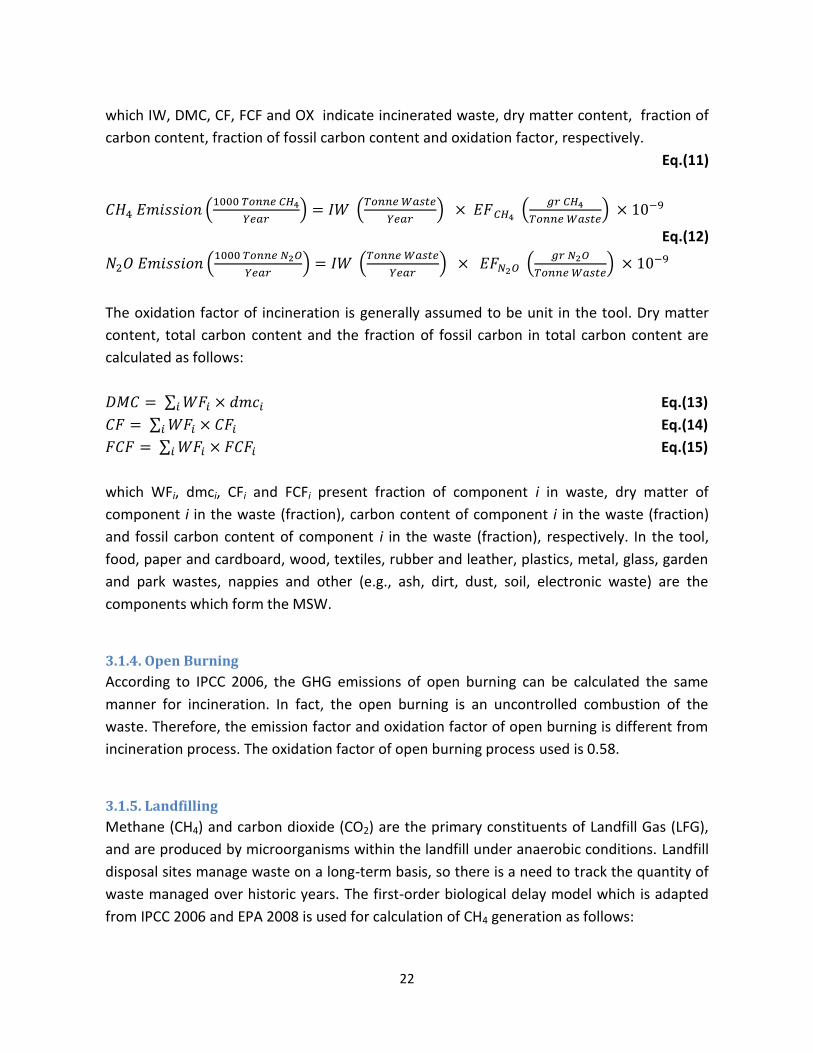
which IW, DMC, CF, FCF and OX indicate incinerated waste, dry matter content, fraction of
carbon content, fraction of fossil carbon content and oxidation factor, respectively.
Eq.(11)
Eq.(12)
The oxidation factor of incineration is generally assumed to be unit in the tool. Dry matter
content, total carbon content and the fraction of fossil carbon in total carbon content are
calculated as follows:
Eq.(13)
Eq.(14)
Eq.(15)
which WFi, dmci, CFi and FCFi present fraction of component i in waste, dry matter of
component i in the waste (fraction), carbon content of component i in the waste (fraction)
and fossil carbon content of component i in the waste (fraction), respectively. In the tool,
food, paper and cardboard, wood, textiles, rubber and leather, plastics, metal, glass, garden
and park wastes, nappies and other (e.g., ash, dirt, dust, soil, electronic waste) are the
components which form the MSW.
3.1.4. Open Burning
According to IPCC 2006, the GHG emissions of open burning can be calculated the same
manner for incineration. In fact, the open burning is an uncontrolled combustion of the
waste. Therefore, the emission factor and oxidation factor of open burning is different from
incineration process. The oxidation factor of open burning process used is 0.58.
3.1.5. Landfilling
Methane (CH4) and carbon dioxide (CO2) are the primary constituents of Landfill Gas (LFG),
and are produced by microorganisms within the landfill under anaerobic conditions. Landfill
disposal sites manage waste on a long-term basis, so there is a need to track the quantity of
waste managed over historic years. The first-order biological delay model which is adapted
from IPCC 2006 and EPA 2008 is used for calculation of CH4 generation as follows:

23
Eq. (16)
where
A = CH4 generation (Tonne/Year)
x = Year in which waste was disposed
S = Start year of inventory calculation
T = Inventory year for which emissions are calculated
LWx = the quantity of waste disposed at the landfill site (Tonne/Year)
L’x = CH4 generation potential (Tonne CH4/Tonne waste)
= MCF × DOC × DOCF × F × 16 / 12
where
MCF = Methane Correction Factor (fraction)
DOC = Degradable Organic Carbon [fraction (Tonne C in waste/Tonne waste)]
DOCF = Fraction of DOC which decomposes (fraction), generally assumed to
be 0.5
F = Fraction by volume of CH4 in landfill gas, generally assumed to be 0.5
k = Decay rate constant ( )
Amount of MCF is classified according to the type of landfill site according to IPCC 2006.
Also, the following equations estimate DOC and k:
Eq.(17)
Eq.(18)
where DOCi and ki indicate the fraction of degradable organic carbon fraction and the decay
rate constant of component i in waste, respectively. The default parameters for DOC and k
with respect to waste component are reported in Table (1) in “Default Technical Data” excel
sheet in the tool. The values of ki are depend on climate type that classified to dry, wet, dry
tropical and wet & most tropical climates. CO2 emission can be estimated by the following
equation:
Eq.(19
)
where
MWP = Molecular weight of CO2 which is 44 g/gmol
QCO2 = Emission rate of CO2, m3/Year; and
T = Temperature of LFG, oC

24
Eq.(19) assumes that the operating pressure of the system is approximately 1 atmosphere. If
the temperature of the LFG is not known, a temperature of is recommended. To
estimate QCO2, the following equation has been used:
Eq.(20)
Where:
QCH4 = CH4 generation rate, m3/Year (according to Eq.(17))
C CO2 = Concentration of CO2 in LFG, ppmv; and
CCH4 = Concentration of CH4 in the LFG, ppmv
The value of 0.5 in denominator presents the volume concentration of methane in LFG. The
concentration of CO2 and CH4 in ppmv (parts per million by volume) can be obtained by
considering 50% methane and 50% carbon dioxide in LFG (Typically, LFG also contains non-
methane organic compounds (NMOC) and volatile organic compounds (VOC), but in a very
low concentration rather than methane and carbon monoxide).
3.1.6. Composting
As mentioned before, most of the carbon degraded within the compost pile will be
converted to biogenic CO2 through aerobic degradation. While CO2 emissions from biogenic
sources are not considered in the tool, the major components of GHG emissions are CH4 and
N2O. The annual equivalent CO2 emission from composting can be estimated by using the
Global Warming Potentials (GWP) as:
Eq.(21)
]
Where OW indicates organic waste treated by composting treatment.
According to IPCC 2006, the emission factors of CH4 and N2O in compost facilities are 4 (kg
CH4/tonne waste) and 0.3 (kg N2O/tonne waste), respectively. Also, the GWPCH4 and GWPN2O
are assumed 21 and 310, respectively.

25
3.1.7. Anaerobic Digestion
Similar to composting, CO2 emissions of Anaerobic Digestion (AD) are of biogenic origin, and
are not considered in the tool [IPCC 2006, Chapter 4]. According to IPCC, 2006, N2O emission
factor of AD is assumed to be negligible and CH4 emission can be calculated as follows:
Eq.(22)
where OW indicates organic waste treated by anaerobic digestion treatment and R
represent total amount of CH4 recovered as biogas for energy recovery. Also, the amount of
CH4 emission can be converted to equivalent CO2 emission by using the GWP of CH4 as:
Eq.(23)
3.1.8 Recycling
No GHG emissions occur at the MSW management stage because the recycled material is
diverted from waste management facilities. In recycling, net GHG emissions which is
associated with remanufacture of recycled inputs reduce. The avoided GHG emissions are
calculated by the difference between (1) the GHG emissions from manufacturing the
marketable materials and products from 100% recycled materials and (2) the GHG emissions
from manufacturing the marketable and products from 100% virgin materials by accounting
loss rates in between recovery and manufacturing. The GHG emissions from making
materials from recycled inputs are typically less rather than virgin inputs.
When any material is recovered for recycling, some portion of the recovered material is
unsuitable for use as a recycled input. This portion is discarded either in the recovery stage
or in the remanufacturing stage. Consequently, less than 1 ton of recyclable material
generally is made from 1 ton of recovered material. Material losses are quantified and
translated into loss rates. Figure 2 shows the loss rates concept schematically.

26
Figure 2. The loss rates concept in the recycling strategy
By considering loss rates, recycling can be evaluated in terms of tonnes of recyclable
materials or tonnes of recovered materials. According to EPA, the avoided GHG emissions
factor of recycling which is associated with remanufacturing divided to two different
categories: energy related GHG emissions factor including processes and technology and;
non-energy related GHG emissions factor including processes. The GHG emissions factor
regarding of recovered material reported in Table (6) in “Default Emissions Factor” excel
sheet in the tool. In this table, the GHG emissions can be converted to MTCE/Tonne (MTCE:
Metric Tonne Carbon Equivalent) of recyclable material by using the loss rate of recovery
stage. In the tool, user can choose the units of material as recyclable or recovered according
to input data which are available.
By considering the GHG emission factors and the tones of material recycled reported by EPA,
the total GHG emissions of recycling can be estimated regarding GHG emissions of each
material as follows:
Eq.(24)
where index i presents components of
recycled material and RW indicates the recycled Waste.
3.1.9. Wastewater Generation
Wastewater is a term applied to any type of water that has been utilized in some capacity
that negatively impacts the quality of the water. Common examples of wastewater include
water that is discharged from households, office and retail buildings, and manufacturing
plants. Municipal wastewater is usually conveyed in a combined sewer or sanitary sewer,

27
and treated at a wastewater treatment (WWT) plant or septic tank. WWT plants are
industrial structure designed to remove biological or chemical waste products from water,
thereby permitting the treated water to be used for other purposes.
The wastewater generation rate represents average wastewater generation within the area
and is used to characterize the wastewater in terms of typical pollutant concentrations and
characteristics. According to IPCC 2006, wastewater can be a source of carbon dioxide,
methane and nitrous oxide when treated or disposed anaerobically. But, the origin of carbon
dioxide emission is biogenic and it should not be therefore included in national total
emissions. Domestic wastewater generation rate is developed from an assessment of the
IPCC 2006 as follows:
Eq. (25)
where:
TOW = Total Organic material in the Wastewater in inventory year
EF CH4 = Emission factor of methane
S = Organic component removed as sludge in inventory year, and
R = Amount of CH4 recovered in inventory year
TOW as total BOD in wastewater in inventory year and EFCH4 are calculated by using the
following equations:
Eq.(26)
where:
P = Country population in inventory year
BOD = Country-specific per capita BOD in inventory year (gr BOD/(person.day))
SBF= Fraction of BOD that settles, assumed to be 0.5
Eq.(27)
where:
B0 = Maximum CH4 producing capacity, 0.6
Weighted average MCF = Weighted average OF Methane Correction Factor, assumed
to be 0.8
Table (1) in the “Default Technical Data” excel sheet reported the BOD default values for
different countries.

28
Nitrous oxide emissions from wastewater (N2O) come from two different resources: direct
emission from WWT plants and indirect emission from wastewater after disposal of drainage
into waterways, lakes or the sea. Direct emissions need to be estimated only for countries
that have predominantly advanced centralized wastewater treatment plants with
nitrification and de-nitrification steps. Direct emissions can be estimated by using the
following equation developed by IPCC 2006:
Eq.(28)
Where:
P = Country population
TWWT Plant = Degree of utilization of modern, centralized WWT plants, assumed to be
90%
FInd.-Comm. = Fraction of industrial and commercial co-discharged protein, assumed to
be 1.25
EFWWT Plant = Emission factor of WWT plant, assumed to be 3.2 (gr N2O/(person.year))
Eq.(29)
Where:
N Effluent = Nitrogen in the effluent discharged to aquatic environments
EFEffluent = Emission factor for N2O emissions from discharged to wastewater
The N Effluent expressed as follows:
Eq.(30)
Where:
P = Country population
Protein = Annual per capita protein consumption (kg Protein/Person.Year)
FNPR = Fraction of nitrogen in protein, assumed to be 0.16 (kg N/kg Protein)
Fnon-con = Factor for non-consumed protein added to the wastewater, assumed to be
1.4 for developed country and 1.1 for developing country (This factor can differ for
developed and developing nations)
FInd.-Comm. = Factor for industrial and commercial co-discharged protein into the sewer
system, assumed to be 1.25
NSludge = Nitrogen removed with sludge, assumed to be zero (kg N/ Year)

29
Note that if wastewater emissions include N2O direct emissions from plants, the equal
amount of nitrogen associated with these emissions (which can be calculated by multiplying
N2O directly by 28/44, using the molecular weights) must be back calculated and subtracted
from the NEffluent.
3.1.10. Energy Recovery
Energy recovery is the process of generating energy in the form of electricity and, electricity
and heat from the waste management technologies. In the tool, incineration, landfilling and
anaerobic digestion are three common waste management technologies with possibility of
energy recovery using energy recovery devices. The combustion of fossil fuels is considered
as a source for providing heat and, gas turbine, steam turbine, ICE engine and, CHP systems
are considered as devices for electricity production. Regarding energy recovery of the waste,
the GHG emissions which are caused by fossil fuel combustion for energy production can be
avoided. As operational activities in section 3.1.2., the required equations for calculating the
GHG emissions of energy recovery (fuel, heat or electricity) are the same as Eq.(8) and (9),
with the difference that the calculated emissions should be considered negative (avoided
GHG emissions).
3.1.11. Compost Production as Fertilizer
As mentioned before, the compost which is produced through aerobic degradation of
organic waste in composting facility can be used as fertilizer or soil amendment in
agriculture. Therefore, by replacing the fertilizer by compost, the GHG emissions which are
yielded through fertilizer production can be avoided. The avoided GHG emissions from
fertilizer replacement can be calculated by using the GWP as follows:
Eq.(31)
where Mc is the amount of compost production.

30
3.1.12. Air Pollutants
The concentration of air pollutant is a factor determined by calculating the mount of air
pollution in the region. The type of air pollutant depends on the waste technology, whereas
CO, SOX, NOX PM10 and, PM2.5 are the common air pollutants in the different technologies.
Estimating the air pollutants concentration can be done according to air pollutants factor as
follows:
Eq.(32)
where MSW presents the amount of waste.
3.1.13. Leachate Production
Leachate is any liquid that, in passing through matter, extracts solutes, suspended solids or
any other component of the material through which it has passed. Leachate is most
commonly used in the context of land-filling of decayable or industrial waste in terms of
typical pollutant concentrations.
Landfill leachate is generated from liquids existing in the waste as it enters a landfill or from
rainwater that passes through the waste. The leachate consists of different organic and
inorganic compounds that may be either dissolved or suspended. High concentrations of
Chemical Oxygen Demand (COD) associated, Biochemical Oxygen Demand (BOD), nitrogen,
phenols, pesticides, solvents and heavy metals are common in these systems. The risks of
leachate generation can be mitigated by properly designed and engineered landfill sites,
such as sites that are constructed on geologically impermeable materials or sites that use
impermeable liners made of geo-membranes or engineered clay to prevent pollution into
surrounding ground and surface waters. Generally, a common leachate collection system
includes liners, filters, pumps and sumps. The compositions of leachate from landfills include
heavy metals which are As, Cd, Cr, Cu, Ni, Pb and Hg. The emissions of leachate are a
function of the amount of waste generated and an emission factor that characterizes the
extent to which this waste generate heavy metals as follows:
Eq.(33)
where MSW presents the amount of waste and index i indicate to different heavy metal
species including As, Cd, Cr, Cu, Ni, Pb and Hg.

31
4. Tool Description This chapter describes the procedure for the user to input data into the tool, how to set
policy interventions, get results and, perform an economic analysis.
4.1. “Home” sheet
The tool is run as an MS-Excel VBA (Visual Basic for Applications) spreadsheet, a windows-
based application. Upon opening the spreadsheet, a dialogue box needs to be opened to
enable macros. This is point [1] in Figure 3. Clicking it will open the dialogue box where
‘Enable this content’ needs to be selected and OK clicked in the box ([2] in Figure 3). When
this has been done the green “Home” sheet will become fully operational. This is the first
excel sheet of the tool to outline different available sections on the tool ([3] in Figure 3). The
user can select an action between different options which are included input data, baseline
results, policy intervention, summary results, detailed results, cost-benefit analysis,
emissions factor and technical data. The “Input Data” action should be selected as the first
action when user gets to work with the tool.
Figure 3. The opening sheet showing the option to enable macros [1], the dialogue box which
enabling of the macros needs to be selected [2], and the first excel sheet (“Home” sheet) in the tool
in the background [3]. Steps [1] and [2] need to be performed in order to use the tool.
1
2 3

32
Different parts of the tool can be accessed by clicking on the corresponding section by using
a sequential steps menu running along the top of the screen in every sheet as shown in
Figure 4.
Figure 4. The sequential steps configuration in the tool
All calculations in the all steps are based on equations were outlined in chapter 3. Also, as
mentioned before, there is a possibility in the tool to change all of the default input data
including emissions factor and technical data to the user’s own the site-specific data which
may be more accurate than the default values provided.
4.2. Steps in the Tool
4.2.1. Input Data (Baseline Scenario)
Figure 5 illustrates the input data excel sheet which is necessary to entered by the user as
baseline scenario data.
Figure 5. The Input Data excel sheet in the tool

33
A separate menu is available for each waste treatment technology. By clicking on each
button, the corresponding input data form appears as shown in Figures (6) to (12) for
different technologies. The technologies listed are intended to be exhaustive and therefore
it may be the case that certain technologies are not relevant to the situation being modeled.
In this case, users should enter a zero value for waste volume for the omitted waste
processing streams.
4.2.1.1 General Input Data
Figure 6 shows the general input data which are initially required to generate the baseline
scenario.
Figure 6. The general input data form in the tool
The general input data are categorized as follows:
-Waste generation as the amount of municipal solid waste which is generated per person
per day. The tool provides a dataset including default value for this parameter per different
regions
- Region population

34
- Waste distribution through the different treatment technologies
- Total waste composition
After entering the general data, the user needs to fill out the input data form for the other
technologies as follows:
4.2.1.2 Incineration
Figure 7 shows the input data form for incineration technology which is available by clicking
on the incineration button in input excel sheet (Figure 5).
Figure 7. The incineration input data form in the tool
>>Input Data:
In the incineration form, the user is asked to enter the following input data:
- Composition of incinerated waste, as mass percentage of food, paper and
cardboard, wood, textiles, rubber and leather, plastics, metal, glass,
garden and park wastes, nappies and other
- Amount of waste incinerated, as ‘Tonne/Year’

35
- Fuel type and fuel amount for waste transportation, as ‘Lit/Tonne Waste’
(fuel consumption) or ‘100km/Tonne Waste’ (fuel millage)
- Incinerator specification, Three different incineration process type
including continues type, semi-continue type and batch type were
included in the tool. Every type includes the stoker type and fluidized bed
type. The difference for incineration process, incineration technology and
management practices of incinerators are caused difference between CH4
emission factors highly and between N2O emission factors less.
- Energy recovery device, the tool includes different item as a energy
recovery device, steam turbine, gas turbine, diesel engine and CHP
(Combined Heat and Power) system for recovering energy from the heat
produced in the incinerators. Also, the item ‘NO Device’ indicates no
energy recovery.
>>Default Data:
The default data which is used in this section as follows:
Dry matter content of different types of waste
Carbon content of different types of waste
Fossil carbon fraction of different types of waste
Oxidation Factor of Incineration, assumed to be 100%
The GHG emissions factor for incineration process
The GHG emissions factor for different fuels (gasoline, diesel and CNG) in
transportation section
The GHG emissions factor for energy recovery (heat and/or electricity)
The GHG emissions factor for 100% landfilling of the waste
The emission factor of air pollutants for incineration process
The default emissions factor are provided in Table (1) in “Default Emissions Factor”
excel sheet in the tool.
>>Net GHG Emission:
The calculation of net GHG emissions of incineration technology is released by
considering the following items:
Waste transportation to incineration facilities
Incineration of waste
Energy recovery
100% landifilling of incinerated waste

36
Therefore, total GHG emissions and air pollutants from incineration are calculated as
follows:
Net GHG emissions from incineration = GHG emission from waste transportation +
GHG emission from incineration – Avoided GHG emissions from energy recovery
device – Avoided GHG emissions from 100% landfilling instead of incineration
In this tool, the GHG emissions avoidance potential from 100% landfilling of the
waste (instead of incineration) are not included in the net GHG emissions value as
default. If user would like to take into account the avoidance potential in the net
value, user can add this item to the total value by clicking on the “Include avoided
GHG emissions from 100% landfilling in Total Value” check box in the form. The net
GHG emissions can be positive or negative. The positive value of the net GHG
emissions is a proof of GHG emissions production by incineration and this technology
is a source of carbon to climate impact. If the net GHG emissions value is negative, it
shows that the technology contributes to mitigation of GHG as a carbon sink.
>>Net Air Pollutants:
The net air pollutants of incineration technology are calculation as follows:
Net air pollutants from incineration = Air pollutants from waste transportation + Air
pollutants from incineration
4.2.1.3. Open-Burning
The input data form for open-burning technology which is available by clicking on the open-
burning button in input data excel sheet (Figure 5) shown in Figure 8.
>>Input Data:
In the open-burning form, the user is asked to enter the following input data:
- Composition of open-burned waste, as mass percentage of food, paper and
cardboard, wood, textiles, rubber and leather, plastics, metal, glass, garden
and park wastes, nappies and other
- Amount of waste open-burned, as ‘Tonne/Year’
- Fuel type and fuel amount for waste transportation, as ‘Lit/Tonne Waste’
(fuel consumption) or ‘100km/Tonne Waste’ (fuel millage)

37
Figure 8. The open-burning input data form in the tool
>>Default Data:
The default data which is used in this section as follows:
Dry matter content of different types of waste
Carbon content of different types of waste
Fossil carbon fraction of different types of waste
Oxidation facto for uncontrolled combustion, assumed to be 58%
The GHG emissions factor for uncontrolled combustion process
The GHG emissions factor for different fuels (gasoline, diesel and CNG) in
transportation section
The emission factor of air pollutants for uncontrolled combustion process
The default emissions factor of open-burning are reported in Table (2) in “Default Emissions
Factor” excel sheet in the tool.
>>Net GHG Emission:
The net GHG emissions of open-burning strategy are calculated by considering the
following items:
Waste transportation to incineration facilities
Open burning of waste
Therefore, total GHG emissions from open-burning are calculated as follows:

38
Net GHG emissions from incineration = GHG emission from waste transportation + GHG
emission from uncontrolled combustion (open-burning process)
The net GHG emissions are positive and open-burning is a source of carbon to climate
impact, as expected.
>>Net Air Pollutants:
The net air pollutants of open-burning technology are calculation as follows:
Net air pollutants from open-burning = Air pollutants from waste transportation + Air
pollutants from open-burning
4.2.1.4. Landfilling
The input data form for landfilling technology which is available by clicking on the landfilling
button in input sheet (Figure 5) is shown in Figure 9.
>>Input Data:
The following items are required as input data for landfilling technology:
- Composition of landfilled waste, as mass percentage of food, paper and
cardboard, wood, textiles, rubber and leather, plastics, metal, glass, garden
and park wastes, nappies and other
- Energy consumption for operation of machineries, as ‘Lit/Tonne Waste’ of
fuel consumption and ‘kWh/Tonne Waste’ of electricity consumption for
operational activities
- Amount of waste landfilled, as ‘Tonne/Year’
- Fuel type and fuel amount for waste transportation, as ‘Lit/Tonne Waste’
(fuel consumption) or ‘100km/Tonne Waste’ (fuel millage);
- Landfilll site type, Three different landfill sites include managed landfill,
unmanaged landfill or open dump (two type: deep and shallow) and
uncategorized landfill. Managed landfill produces more methane emission

39
Figure 9. The landfilling input data form in the tool
rather than that of unmanaged landfill where waste can rot away aerobically
in the top layers. Also, greater methane emission is emitted from deeper
unmanaged sites rather than that of unmanaged sites.
- Landfilll covering, The landfill sites can be covered or uncovered with clay,
plastic liners, and composites to enhance methane oxidation. The purpose of
covering a landfill site are minimizing leachate generation, resisting erosion
due to wind/runoff and preventing exposure of waste to animals, insects and
rodents and, improve aesthetics.
- Climate type, The tool includes four different climates type for calculating
CH4 oxidation rate (dry temperate climate, wet temperate climate, dry
tropical climate and mist & wet tropical climate). Note that decay rate values
for the landfills can be changed according to the climate type.

40
- Efficiency of gas collection system, as percentage of the gas collection system
efficiency. If the user selects ‘No Device’ item as energy recovery device, the
efficiency is equaled to zero automatically.
- Energy recovery device, the tool includes different item as a energy recovery
device, steam turbine, gas turbine, diesel engine and CHP (Combined Heat
and Power) system for recovering energy from the heat produced in the
incinerators. Also, the item ‘No Device’ indicates no energy recovery.
>>Default Data:
The default data which is used in this section as follows:
Methane Correction Factor (MCF)
Fraction of DOC (DOCF) which decomposes, generally assumed to be 0.5
Degradable Organic Carbon (DOC) of different types of waste
Fraction by volume of CH4 in landfill gas, generally assumed to be 0.5
Fraction by volume of CO2 in landfill gas, generally assumed to be 0.5
Decay rate constant of different types of waste for various climate types
The GHG emissions factor for waste landfilling
The GHG emission factor for operation of machineries (diesel and electricity)
The GHG emissions factor for different fuels (gasoline, diesel and CNG) in
transportation section
The GHG emissions factor for energy recovery (heat and/or electricity)
The emission factor of air pollutants for operation of machineries (diesel and
electricity).
The emission factor of air pollutants for landfilling
These default emissions factor are provided in Table (3) in “Default Emissions Factor”
excel sheet in the tool.
>>Net GHG Emission:
The calculation of net GHG emissions of landfilling technology is released by
considering the following items:
Waste transportation to landfill site
Landfilling of waste
Usage of fuel and electricity for operational activities
Energy recovery
Therefore, total GHG emissions from landfilling are calculated as follows:

41
Net GHG emissions from landfill sites = GHG emission from waste transportation +
GHG emission from Landfill sites + GHG emission from operation of machineries -
Avoided emissions from energy recovery device
The positive value of the net GHG emissions is a reason that the landfilling is a source
of carbon production to climate impact and negative net GHG emissions value
indicates the mitigation of GHG emissions (carbon sink).
>>Net Air Pollutants:
The net air pollutants of landfilling technology are calculation as follows:
Net air pollutants from landfill sites = Air pollutants from waste transportation + Air
pollutants from landfill sites + Air pollutants from operation of machineries
4.2.1.5. Composting
The input data form for composting technology has illustrated in Figure 10.
Figure 10. The composting input data form in the tool
>>Input Data:
The following items are required as input data for composting technology:

42
- Composition of composted waste, as mass percentage of food, paper and
cardboard, wood, textiles, rubber and leather, plastics, metal, glass, garden
and park wastes, nappies and other
- Amount of waste composted, as ‘Tonne/Year’
- Amount of compost prodution, as ‘Tonne/Year’
- Amount of compost used as fertilizer, as ‘%’
- Fuel type and fuel amount for waste transportation, as ‘Lit/Tonne Waste’
(fuel consumption) or ‘100km/Tonne Waste’ (fuel millage);
- Energy Consumption for operation of machineries, as ‘kWh/Tonne Waste’ of
electricity consumption for operational activities
>>Default Data:
The default data which is used in this section as follows:
Global Warming Potentials of CH4 and N2O
The GHG emissions factor for waste composting
The GHG emission factor for operation of machineries (electricity)
The GHG emissions factor for different fuels (gasoline, diesel and CNG) in
transportation section
The GHG emissions factor for 100% landfilling of the waste
The emission factor of air pollutants for operation of machineries (electricity).
The emission factor of air pollutants for composting
The default emissions factor are provided in Table (4) in “Default Emissions Factor”
excel sheet in the tool.
>>Net GHG Emission:
The calculation of net GHG emissions of composting strategy is released by considering
the following items:
Waste transportation to composting facilities
Composting of waste
Usage of electricity for operational activities
100% landifilling of composted waste
Therefore, total GHG emissions from composting are calculated as follows:
Net GHG emissions from composting = GHG emission from waste transportation +
GHG emission from composting + GHG emission from operation of machineries -
Avoided emissions from 100% landfilling instead of composting

43
The positive value of the net GHG emissions shows that carbon is released to the
atmosphere by composting technology, while the negative value expresses that
composting is a carbon sink by mitigation of GHG emissions.
>>Net Air Pollutants:
The net air pollutants of composting technology are calculation as follows:
Net air pollutants from composting = Air pollutants from waste transportation + Air
pollutants from composting + Air pollutants from operation of machineries
4.2.1.6. Anaerobic Digestion
Figure 10 shows the input data form for anaerobic digestion technology which is available by
clicking on the anaerobic digestion button in input sheet (Figure 5).
>>Input Data:
Following items are needed to enter in the input form by the user:
- Composition of digested waste, as mass percentage of food, paper and
cardboard, wood, textiles, rubber and leather, plastics, metal, glass, garden
and park wastes, nappies and other
- Amount of waste digested, as ‘Tonne/Year’
- Amount of compost production, as ‘Tonne/Year’
- Amount of compost used as fertilizer, as ‘%’
- Fuel type and fuel amount for waste transportation, as ‘Lit/Tonne Waste’
(fuel consumption) or ‘100km/Tonne Waste’ (fuel millage)
- Energy consumption for operation of machineries, as ‘kWh/Tonne Waste’ of
electricity consumption for operational activities
- Energy recovery options, the tool includes two different items for using of
bio-gas as energy recovery resource which is produced in the anaerobic
digestion process as fuel or as electricity producer in the bio-gas power plant
Also, user can choose ‘Without energy recovery’ option for ignorance of
energy recovery in the process.

44
Figure 11. The anaerobic digestion input data form in the tool
>>Default Data:
The default data which is used in this section as follows:
Global Warming Potentials of CH4 and N2O
The GHG emissions factor for waste digestion anaerobically
The GHG emission factor for operation of machineries (electricity)
The GHG emissions factor for different fuels (gasoline, diesel and CNG) in
transportation section
The emission factor of air pollutants for operation of machineries (diesel and
electricity).
The GHG emissions factor for energy recovery (heat and/or electricity)
The GHG emissions factor for 100% landfilling of the waste
The emission factor of air pollutants for operation of machineries (electricity).
The emission factor of air pollutants for anaerobic digestion

45
The default emissions factor are reported in Table (5) in “Default Emissions Factor”
excel sheet in the tool.
>>Net GHG Emission:
Net GHG emissions of anaerobic digestion strategy are estimated by considering the
following items:
Waste transportation to digesting facilities
Digestion of waste
Usage of electricity for operational activities
Energy recovery
100% landifilling of digested waste
Total GHG emissions from digestion are computed as follows:
Net GHG emissions from digestion = GHG emission from waste transportation + GHG
emission from digestion + GHG emission from operation of machineries -Avoided
emissions from energy recovery device -Avoided emissions from 100% landfilling
instead of digestion
The positive value of the net GHG emissions shows that carbon is released to the
atmosphere by anaerobic digestion technology, while the negative value gives
evidence of mitigation of GHG emissions (carbon sink) by this technology.
>>Net Air Pollutants:
The net air pollutants of anaerobic digestion technology are calculation as follows:
Net air pollutants from digestion = Air pollutants from waste transportation + Air
pollutants from digestion + Air pollutants from operation of machineries
4.2.1.7. Recycling
Figure 12 presents the input data form for recycling technology which is available by clicking
on the recycling button in input sheet Figure 5).

46
Figure 12. The recycling input data form in the tool
>>Input Data:
Following items are needed to enter in the input form by the user:
- Composition of materials as waste, as mass percentage of metal, glass,
plastics, paper and cardboard, wood, rubber and leather
- Amount and type of materials as recycled or recovered, as ‘Tonne/Year’
- Rate of loss, dimensionless. User can choose default data or enter own
specified data for rate of loss.
-
>>Default Data:
The default data which is used in this section as follows:
The GHG emissions factor for waste transportation
The GHG emissions factor for recycling processes (including energy processes
and non-energy processes)
The default emissions factor are provided in Table (6) in “Default Emissions Factor”
excel sheet in the tool.
>>Net GHG Emission:

47
Net GHG emissions of recycling strategy are estimated by considering the following
items:
Waste transportation to recycling facilities
Recycling of waste
Total GHG emissions from recycling are computed as follows:
Net GHG emissions from recycling = GHG emission from waste transportation + GHG
emission from recycling process -Avoided emissions by recycling of the materials
The net GHG emissions of recycling are negative. It is associated with obtaining of
considerable amount of recovered materials from the recycling process replacing
them by the equivalent amount of virgin materials.
4.2.1.8. Wastewater Generation
Figure 13 presents the input data form for wastewater generation which is available by
clicking on the wastewater generation button in input sheet Figure 5).
>>Input Data:
Three groups of data are needed to enter in the input form by the user: Country
specifications, Coefficients for CH4 emission calculations, Coefficients for total N2O
emission (direct and indirect) calculations. For all data, user can choose default data or
enter own specified data.
- Country Specifications
Name of country
Type of country (Developed or developing)
Population, as ‘1000 persons’
Daily Biochemical Oxygen Demand (BOD) per capita, as ‘gr
BOD/(Person.Day)’
Daily protein intake per capita, as ‘gr Protein/(Person.Dday)
- Coefficients for CH4 emission calculations
Fraction of settled BOD, dimensionless
Average Methane Correction Factor (MCF), dimensionless
Amount of CH4 Recovered, as ‘kg CH4/Year’
Organic Component Removed as Sludge, as ‘kg BOD/Year’

48
Figure 13. The wastewater input data form in the tool
- Coefficients for total N2O emission (direct and indirect)
Using Wastewater Treatment Plant (WWTP), as ‘Yes’ or ‘NO’
Degree of Utilization of Modern, Centralized Wastewater Treatment Plant,
as ‘%’
Fraction of Industrial and Commercial Co-discharged Protein,
dimensionless
Factor for Non-Consumed Protein Added to the Wastewater,
dimensionless
Factor for Industrial and Commercial Co-discharged Protein into the Sewer
System, dimensionless
Nitrogen Removed with Sludge, as ‘kg N/Year’
>>Default Data:
The default data which is used in this section as follows:
Emission factor of CH4
Country population
Country-specific per capita BOD in inventory year (BOD) (gr
BOD/(person.day))
Fraction of BOD that settles (SBF), assumed to be 0.5

49
Maximum CH4 producing capacity (B0), 0.6(
Weighted average OF Methane Correction Factor (MCF), assumed to be 0.8
Degree of utilization of modern, centralized WWT plants, assumed to be 90%
Emission factor of WWT plant, assumed to be 3.2 (gr N2O/(person.year))
Fraction of nitrogen in protein, assumed to be 0.16 (kg N/kg Protein)
Factor for non-consumed protein added to the wastewater, assumed to be
1.4 for developed country and 1.1 for developing country
Factor for industrial and commercial co-discharged protein into the sewer
system, assumed to be 1.25
Nitrogen removed with sludge, assumed to be zero (kg N/ Year)
These default emissions factor are presented in Table (8) in “Default Emissions Factor” excel
sheet in the tool.
>>Net GHG Emission:
Total GHG emissions of wastewater generation are estimated by using the Global
Warming Potentials (GWP) as:
Eq.(22)
where the GWPCH4 and GWPN2O are assumed 21 and 310, respectively.
The total GHG emissions of wastewater are positive (source of carbon).
4.2.1.9. Common Buttons in Input Data Forms
As seen in Figures 7-13, there are four common different buttons for various technologies in
input data form as follows:
Upload Last Data
This button has been considered for recovery and upload the last data which entered by the
user in the last run.
Update
This button is designed to transfer the input data to database of tool for make calculation.

50
Show Results
By clicking on this button, the user can see the results for GHG emissions, air pollutants and
energy section for corresponding technology as specific value (per tonnage) and as total
value (per year). In Figure 14, the results form is shown as a sample for incineration
technology.
Figure 14. The incineration results form in the tool
In the tool, the results forms have similar format for all waste management technologies. As
seen from Figure 14, there are two different buttons, “Change Input Data” and “Close” in the
results form. By clicking on “Close” button, the form will be closed. Also, there is a possibility
for user to change input data after observing the results. If user would like to comeback to
input data form to know the results for another input data, it will be achievable by clicking
on the “Change Input Data” button.
Save and Close
This button makes allowance for the possibility of saving input data and closing the form
without seeing the results. In fact, this button helps to user to save the entered data and see

51
the results whenever the user wants.
Edit Data
By clicking on this button, all input data fields are deleted for entering the new ones.
4.2.1.10. Run the Baseline Scenario
The sequential steps which should be done for run baseline scenario (all waste management
technologies) as follows:
1. In the input data form, the user is asked to enter the required input data which has
described for each waste management technology in the previous sections.
Note that that waste volume is not necessary to enter by the user because it has
been calculated according to input data in “Waste Generation” form in the tool. Also,
there is possibility to use the last data which entered in the last run as input data in
the baseline scenario. For this purpose, user should click on “Upload Last Data”
button to observe the last input data in the input fields.
2. After entering required input data, user should click on “Update” button to transfer
entered input data to the database of the tool. Then, the “Show Results”, “Save and
Close” and “Edit Data” buttons will be changed from disable state to enabled state.
3. In the next step, user can select one of the following buttons:
“Show Results” button, to observe results as GHG emissions, air pollutants,
heavy metals and energy items
“Save and Close” button, to save entered input data and close the form without
observing results
“Edit Data”, to enable all input data fields to edit the entered data
4.2.2. Policy Intervention
As mentioned previously, three different interventions are examined in this work as three
different scenarios:
- Scenario 1: Changing the waste volume and composition
- Scenario 2: Shifting waste processing
- Scenario 3: Changing technology specifications
By clicking on ‘Policy Intervention’, the scenarios can be available (Figure 15).

52
Figure 15. The policy intervention form in the tool
Figures 16-18 show the designed forms to run scenarios 1, 2 and 3 three different scenarios,
respectively.
4.2.2.1. Scenario1: Changing Total Waste Composition
In this scenario, user can change waste volume through changing total waste composition.
As the scenario1 form opens, the values of waste composition and waste volume of baseline
scenario are appeared in the left column/field. User can enter the corresponding changing
percent of volume for each waste type (food, paper & cardboard, wood, etc) and then by
clicking on the ‘Update’ button, the new tonnage of waste are calculated accordance with
the entered changing values and then shown in the right column/field. If the change fields
keep blank, it is assumed that the changing percent is zero. After updating the waste volume
and composition, the user should save and close the form by clicking on ‘Save and Close’
button.
Also, there is possibility to use the last data which entered in the last run as changing
percent. User can click on “Upload Last Data” button to observe the changing percent in the
corresponding column.

53
Figure 16. The scenario1 input data form in the tool
4.2.2.2. Scenario2: Shifting Waste Processing
Shifting between different waste processing can be done in the scenario2 which is shown in
Figure 17. Total After clicking on scenario 2 button in Figure 15, total waste volume, share of
different waste management technologies and waste composition in each technology are
appeared. These values which have titled ‘Old’ are accordance with last scenario has been
run in the model (baseline scenario or scenario 1) and so, they cannot be changed by the
user. User can shift the waste volume between different wastes processing methods
(incineration, open-burning, landfilling, etc) by entering the new values of waste
composition in the ‘New’ field. If the change fields keep blank, it is assumed that the
changing percent is zero and the values are the same as old ones. By clicking on the ‘Update’
button, the new composition of waste are considered for every process. After updating, the
user should save and close the form by clicking on ‘Save and Close’ button. By clicking on this

54
button, the tool calculates the results according to the new composition, saves results and
then, closes the form.
If user would like to see/consider the last “New” values which entered in the last run as
input data, she/he should click on “Upload Last Data” button to observe the last values.
Figure 17. The input data form for changing shares of waste processing in the tool
4.2.2.3. Scenario3: Changing Technology Specifications
In this scenario, the effects of technology specifications on GHG emissions and air pollutants
as well as energy recovery potentials can be investigated (Figure 18). The parameters which
can be changed include: type and amount of fuel using for waste transporting, required
energy for operational activities, type of technology in each waste processing method and,
energy recovery devices.
As the scenario3 form opens, user can input the corresponding values/items for different
waste management technologies. If user would like to observe the last specifications which
entered for the last run, he/she should click on the ‘Upload Last Data’ button. After entering
the data, the button ‘Update’ should be clicked to take consideration the corresponding
change in the model database. Then, the ‘Save and Close’ button should be clicked for
calculation of results accordance with input changes, saving data and closing the form.

55
Figure 18. The data form for changing specific technologies and transport factors in the tool
4.2.2.4. Run the Policy Intervention
The sequential steps which should be done for run a scenario in policy intervention as
follows:
1. In the form, the user is asked to enter the required input data; changing percent of
volume for each waste type in scenario 1, the new values of waste composition in the
in different wastes processing methods in scenario 2 and technology specifications in
scenario 3.
Also, there is possibility to use the last data which entered in the last run as input
data in the scenarios. In this context, user should click on “Upload Last Data” button
to observe the last entered data in the related fields.
2. After entering required input data, user should click on “Update” button to transfer
entered input data to the database of the tool. Then, the “Save and Close” and “Edit
Data” buttons will be changed from disable state to enabled state.
3. In the next step, user can select one of the following buttons:

56
“Save and Close” button, to save entered input data and close the form
“Edit Data”, to enable all input data fields to edit the entered data
4.2.3. Results
After entering input data, the results of the model can be seen as excel sheets in three
formats. These can be accessed from the menu which runs along the top of the tool as
shown in Figure 19.
Figure 19. Location of the results sheets in the tool
Baseline results: This page shows the results for baseline scenario
Results Summary: This page shows the summary of results after considering all
interventions. In the other words, the results of last run can be seen in this page.
Results Details: This page shows the results for each scenario individually.
If user would like to know the effect of changing all policy interventions on the results, the
“Results Summary” excel sheet page should be selected. That is to say the “Results
Summary” shows the final results after considering all interventions. This is the page where
differences (co-benefits can be assessed as it shows the difference between the baseline and
the interventions.
The results of each accomplished scenarios can be seen in proper if the “Results Details”
selected. These can be accessed from the drop-down list shown in Figure 20.

57
Figure 20. List where individual results can be analysed for each policy intervention
All excel sheets which show the results (baseline results, results summary or results details)
are included following items:
a) Results in the table format as:
Annual waste volume
Annual total GHG emissions
Overall waste composition
Annual shares of sub-divisions (Transportation, Process, Energy Recovery and
Avoided Potential) for each technology in GHG emissions production
b) Results in the graphical format:
Annual total GHG emissions by technology
Annual air pollutants by technologies including CO, SO2, NOx, PM10 and PM2.5
Annual electricity production by technologies
Annual heat production by technologies
Note that this tool is capable to estimate more pollutants with the exception CO, SO2, NOx,
PM10 and PM2.5 (such as heavy metals composition in incineration, leachate composition in
lanfilling and other air pollutants in different technologies). These pollutants can be seen by
user in the results useform for each technology, in proper, if user clicks on the “Show
Results” button in Figures 7-13.
4.2.4. Cost- Benefit Analysis (CBA)
The Cost-Benefit Analysis (CBA) is the last step in the tool. In this section, economic
indicators including Benefit Cost Ratio (BCR) and Payback Period (PBP) are calculated for

58
each technology. Figure 21 shows a sample of CBA analysis form which is available by
clicking on the ‘Cost-Benefit Analysis’ in the first “Home” sheet in Figure (3) or sequential
step configuration in Figure (4) . As all technologies have similar structure for CBA forms, it
will suffice to mention ‘CBA-Incineration’ only as a sample.
In general, following items are required to enter in the cost-benefit analysis form by the
user:
- Input Data:
Infiltration rate, as ‘%’
Price of Electricity, as ‘$/kWh1’
Price of Oil Barrel, as ‘$/BOE2’
Life Time, as ‘Year’
Waste Generation Rate for This Technology, as ‘%’
Figure 21. The CBA input data form in the tool
- Cost Items
Fixed Costs, as ‘M$’ (million dollar) including : Land Acquisition Cost,
Equipment and Technology Acquisition Cost and, Construction and
Installation Cost
1 Barrel of Oil Equivalent (BOE)
2 Barrel of Oil Equivalent (BOE)

59
Running Costs, as ‘$/Tonne Waste’ including: Operational Cost and,
Maintenance Cost
- Benefit Items, as ‘$/Tonne Waste’ including:
Revenue from Sale of Produced Heat
Revenue from Sale of Produced Electricity
Revenue from Tipping Fee
Revenue from Sale of Recovered Materials
Revenue from Sale of Produced Materials
Saved Cost on Avoided Landfilling
It is important to note that, for all waste management technologies, cost of waste
transportation (except recycling), revenue from sale of produced heat and, revenue from
sale of produced electricity are not required to enter as input data by the user. In fact, the
mentioned items are calculated by the tool according with the recorded data by user in the
“Input Data” form. As a result, the corresponding fields are disabled in the CBA form and the
calculated values will be appeared in the corresponding fields after clicking on update
button.
In the CBA Results, the BCR and PBP are calculated as simple economical indicators to direct
the user to get information about economic view. As expected, the BCR is increased when
PPB is decreased. Note that the average life time of 20 year has been considered in the tool
for all waste management technology.
4.2.4. 1. Run the CBA for Each Technology
The sequential steps which should be done for run CBA for a technology as follows:
1. In the CBA form, the user is asked to enter the required input data, cost items and
benefit items (except waste transportation cost and revenue from sale of heat and
electricity production).
Also, there is possibility to use the last data which entered in the last run as input
data in the corresponding CBA. In this context, user should click on “Upload Last
Data” button to observe the last entered data in the related fields.
4. After entering required input data, user should click on “Update” button show BCR
and PBP as CBA results. Then, the “Show CBA Curves”, “Save and Close” and “Edit
Data” buttons will be changed from disable state to enabled state.
5. In the next step, user can select one of the following buttons:

60
“Show CBA Curves” button, to show cumulative cash flow and BCR as a function
of year in a excel sheet
“Save and Close” button, to save entered input data and close the form
“Edit Data”, to enable all input data fields to edit the entered data
4.3. Default Input Data
In this tool, two different groups of default data has been used: emissions factor and
technical data. Tables (1) to (9) in “Default Emissions Factor” excel sheet summarized the
emissions factors for different waste management technologies which are used in the tool as
default values. Also, the default technical data that are considered as default in this tool is
addressed in the “Default Technical Data” excel sheet in Tables (1) to (10). Due to lack of
country-specific data, this simulation uses an inventory data for emissions factor and
technical data of different technologies which represents by EPA, IPCC2006 and literature to
quantify GHG emissions, air pollutants and energy recovery implications.

61
5. Conclusions and Future Work The excel VBA structure of the simulation in this tool results in simplicity and ease of the
availability and understanding of different waste management practices including
incineration, open-burning, landfilling, composting, anaerobic digestion and recycling. This
tool can estimate the GHG emissions, air pollutants, energy recovery potentials as well as
perform a cost-benefit analysis for these technologies. Moreover, the tool can evaluate
possible reductions of environmental impacts by applying an Integrated Waste Management
System approach. Through the consideration of different scenarios, it is possible to consider
the impact of different policy interventions. The tool is flexible to the incorporation of
region/country specific data on emission factors or other technical data that the user may
have beyond what is provided in the existing database.
As such, there are some further improvements that can be made and will be investigated
over time as hopefully more people use the tool. Two suggestions for improving this tool in
the future work:
Due to lack of region/country-specific data, baseline data in the tool uses an
inventory data for emissions factor and some technical data which reported by EPA,
IPCC2006 and literature to quantify GHG emissions, air pollutants and energy
recovery implications. It is recommended that as much local data as possible is used
for the most accurate results. These data (e.g. emissions factors and some technical
data) can be added as necessary. Over time, though wider dissemination of the tool
to many different users, we aim to develop a database of emissions factors and
technical data which can help take into account country/region-specific data to
overcome to some difficulties in gathering the input data which user is required to
input in this tool.
Develop a model to simulate recycling technology to estimate GHG emissions at the
local authority level.
We welcome your feedback, suggestions and comments about this tool. Based on your
feedback, you can help us highlight opportunities to improve the next version of the tool.

62

63
6. References:
AP-42 series, Fifth Edition, Compilation of Air Pollutant Emission Factors, Volume I, Chapter 2: Solid Waste Disposal, Prepared by the U. S. Environmental Protection Agency, the Emission Factor And Inventory Group (EFIG)
http://www.unfccc.int, United Nations Framework Convention on Climate Change
IPCC, 2006, Guidelines for National Greenhouse Gas Inventories, Volume 5, Waste, Prepared
by the National Greenhouse Gas Inventories Programme, Edited by: Eggleston S., Buendia L.,
Miwa K., Ngara T. and Tanabe K. Published by : IGES, Japan. Environment, Alison Smith, Keith
Brown, Steve Ogilvie, Kathryn Rushton and Judith Bates
Waste management options and climate change: Final report, Prepared by European
Commission, DG, Smith A., Brown K.,Ogilvie S., Rushton K. and Bates J., July 2001.

United Nations University Institute of Advanced Studies 6F International Organizations Center Pacifico Yokohama, 1-1-1 Minato Mirai Nishi-ku, Yokohama 220-8502 JAPAN Tel: +81-45-221-2300 Fax: +81-45-221-2302 Email: [email protected] Website: www.ias.unu.edu
Authors:
Mehrnoosh Dashti Christopher Doll
Tools can be found online at: http://tools.ias.unu.edu
Cover photo credit: Dieter Joel Jagnow, Campus of the Lutheran University of Brazil, Canoas