rock mechanics and engineering volume 5: surface and
TRANSCRIPT

This article was downloaded by: 10.3.98.104On: 14 Mar 2022Access details: subscription numberPublisher: CRC PressInforma Ltd Registered in England and Wales Registered Number: 1072954 Registered office: 5 Howick Place, London SW1P 1WG, UK
Rock Mechanics and EngineeringVolume 5: Surface and Underground ProjectsXia-Ting Feng
Tunnels in the Himalaya
Publication detailshttps://www.routledgehandbooks.com/doi/10.1201/9781315364223-3
R.K. Goel, Bhawani SinghPublished online on: 12 Jun 2017
How to cite :- R.K. Goel, Bhawani Singh. 12 Jun 2017, Tunnels in the Himalaya from: RockMechanics and Engineering, Volume 5: Surface and Underground Projects CRC PressAccessed on: 14 Mar 2022https://www.routledgehandbooks.com/doi/10.1201/9781315364223-3
PLEASE SCROLL DOWN FOR DOCUMENT
Full terms and conditions of use: https://www.routledgehandbooks.com/legal-notices/terms
This Document PDF may be used for research, teaching and private study purposes. Any substantial or systematic reproductions,re-distribution, re-selling, loan or sub-licensing, systematic supply or distribution in any form to anyone is expressly forbidden.
The publisher does not give any warranty express or implied or make any representation that the contents will be complete oraccurate or up to date. The publisher shall not be liable for an loss, actions, claims, proceedings, demand or costs or damageswhatsoever or howsoever caused arising directly or indirectly in connection with or arising out of the use of this material.

Dow
nloa
ded
By:
10.
3.98
.104
At:
12:5
6 14
Mar
202
2; F
or: 9
7813
1536
4223
, cha
pter
3, 1
0.12
01/9
7813
1536
4223
-3Chapter 3
Tunnels in the Himalaya
R.K. Goel1 & Bhawani Singh21Chief Scientist & Professor (AcSIR), CSIR-CIMFR Regional Centre, Roorkee, India2Former Professor, Department of Civil Engineering, IIT Roorkee, Roorkee, India
“Learn from yesterday. Live for today. Hope for tomorrow.The important thing is not to stop questioning.”
– Albert Einstein
1 INTRODUCTION
Generally, a tunnel layout is first prepared and the tunneling operations are startedafter collecting adequate geological information of the area. Success of the tunnelingoperations depends upon the reliability of these geological predictions. It is easier tocollect geological details when the tunnel is shallow, the terrain is flat and the rockmassis notmuch disturbed. In such regions the ideal approachwould be first tomake a quickgeophysical exploration to identify such features as major faults, shear zones, sandpockets, water bodies etc. Once the presence or absence of such features is established,conventional geological exploration should be planned for detailing. Such an approachwould optimize the time and cost of exploration efforts besides providing usefulgeological information and reducing the chances of surprises.
The need for the geological information becomes all the more valid in a tunnel wherethe cover is high, the terrain is inaccessible and the rock mass is highly disturbedtectonically below a thick forest cover. Under such conditions, drilling up to the tunnelgrade is costly and sometimes impossible. Attempts to infer the geology up to the tunnelgrade by extrapolating meager surface data and to plan the layout of a major tunnelingproject on the basis of such geological projections often lead to serious unforeseenproblems. These problems sometimes lead to time and cost over-runs.
Major tunneling problems in India are encountered in the young Himalayan regions,particularly the lesser or lower Himalaya, where the geology is difficult, the rock massesare weak and undergoing intense tectonic activities resulting into major faults, folds andother discontinuities. Compared to this, in the peninsular (southern part) India where therocks are strong and less disturbed, tunneling problems are rarely encountered.
A number of hydroelectric projects are located in the lower Himalaya. In addition,rail and road tunnels are also being constructed on amass scale. These projects lie in theHimalayan states of Assam, Himachal Pradesh (H.P.), Jammu & Kashmir (J&K),Manipur, Uttarakhand, etc. in India. Detailed geological exploration work for all theprojects throughout the country has been mainly undertaken by Geological Survey ofIndia (GSI). Despite the best efforts of the geologists, inadequacies in the prediction ofnature of the rock masses, at the tunnel grade were observed in most of the tunnels in

Dow
nloa
ded
By:
10.
3.98
.104
At:
12:5
6 14
Mar
202
2; F
or: 9
7813
1536
4223
, cha
pter
3, 1
0.12
01/9
7813
1536
4223
-3
the Himalaya. These inadequacies led to different tunneling problems like water-in-rush, roof falls, cavity formation, face collapse, swelling, support failure, gas explosionetc. In addition, squeezing ground conditions in the weak rock masses of Himalayahave also created considerable construction problems.
Experience of TBM tunneling in the Himalaya, so far, is not encouraging. But, thesuccess of TBM in a recently completed head race tunnel of Kishanganga hydroelectricproject has certainly encouraged the morale of designers and engineers in favor ofTBM. The key issues for the success of TBM in the Himalaya are highlighted.
Since the chapter is on ‘Tunnels in Himalaya’, a brief geology of the Himalaya ispresented at first.
2 THE HIMALAYA
The Indian subcontinent is surrounded in the north by a lofty mountain chain known asthe Himalaya. The Himalayan range with NW-SE general trend was formed, accordingto the theory of ‘Continental Drift’, by the collision of the Indian Plate with the EurasianPlate. The Indian plate is known to be moving toward north at a rate of approximately5cm per year. This collision, which began with the first contact about 40 million yearsago, caused the sediments of the interveningTethys Sea and the Indian Shield to be foldedand faulted into the lofty peaks and outliers visible in the lesser Himalaya. Since thenorthward shift of the Indian plate is still continuing, the mountain building process isstill continuing and the zone is still active seismically. On the basis of its average heightfrom mean sea level (MSL), from south to north, the Himalayan range and the rockformations are divided as per Table 1 and shown in Figure 1. Similarly, geographicallyfrom west to east, the Himalaya is divided as given in Table 2.
Table 1 Rock formations and average height above mean sea level of Himalaya (Goel et al., 1995).
Rock Formation (Broadly) Average Height fromMean Sea Level (MSL)
Popular Name
SOUTH
Indo-Gangetic Planes
------------------------------------------ Main Frontal Thrust ------------------------------------------Soft, loose and easily erodible rocks, e.g. sandstone,siltstone, mudstones, clays and or claystones,conglomerates
Up to 1000m Sub-Himalaya orShiwaliks
------------------------------------------ Main Boundary Fault -----------------------------------------Sedimentary formations, e.g. slates, dolomites, quartzites,shales, claystones etc. Metamorphic formations, e.g.phyllites, quartzites, schists, gneisses etc.
1000m to 4000m Lesser or LowerHimalaya
------------------------------------------ Main Central Thrust ------------------------------------------Weak sedimentary formations e.g. shales sandstones,siltstones, conglomerates and strong metamorphicformations e.g. gneisses, migmatites schists, marble etc.
> 4000m Greater orHigher Himalaya
NORTH
70 Goel & Singh

Dow
nloa
ded
By:
10.
3.98
.104
At:
12:5
6 14
Mar
202
2; F
or: 9
7813
1536
4223
, cha
pter
3, 1
0.12
01/9
7813
1536
4223
-3
2.1 Geology of the Himalaya
Moving from south to north, main frontal thrust (MFT) separates the Shiwaliks fromthe Indo-Gangetic planes (Table 1).
2.1.1 The Shiwaliks
The Shiwalik rocks constitute the southern foothills of the Himalaya. With an averageheight of about 1000m from mean sea level (MSL), these are generally covered withthick forests and comprise the youngest rocks in the Himalayan range. The soft, loose,and easily erodible rocks are represented by sand rocks, sandstones, siltstones, clays-tones, mudstones and conglomerates. Water penetrates into these rock masses alongthe fractures and joints and sometimes creates flowing ground conditions (e.g. Khara
Figure 1 Longitudinal and transverse sub-divisions of the Himalaya (after Gansser, 1964).
Table 2 Sub-divisions of Himalaya from west to east.
WESTPunjab Himalaya
Kumaon Garhwal HimalayaNepal Himalaya
Sikkim Bhutan HimalayaNefaEAST
Tunnels in the Himalaya 71

Dow
nloa
ded
By:
10.
3.98
.104
At:
12:5
6 14
Mar
202
2; F
or: 9
7813
1536
4223
, cha
pter
3, 1
0.12
01/9
7813
1536
4223
-3
tunnel, Udhampur-Katra rail tunnel, etc.). Since the Shiwalik rocks are less resistant toweathering, the engineering behavior of these rocks is likely to vary with time.
2.1.2 The Main Boundary Fault (MBF)
Separating the Shiwalik Formations of the Sub-Himalaya from the older rocks of LesserHimalaya lying to their north, the Main Boundary Fault is a major structural planediscernible throughout the length of the Himalaya. Hitherto regarded as a steep northdipping fault, it is more likely a thrust which flattens with depth. The MBF, originallydefined as the tectonic feature separating the Shiwalik from the pre-Shiwalik Tertiaries,is exposed only in the extreme western sector in the Kumaon Himalaya, roughlybetween the Yamuna and Tons valleys. On East of the Yamuna, the higher KrolThrust has overlapped the Eocene Subathu and has completely concealed the MBF.The only exception is seen near Durgapipal in the east where a narrow belt of Subathuis exposed between the Shiwalik and overthrust Krol rocks. Secondary faults or thrustsbranch off the MBF, as for instance in southern Punjab. These secondary fault zonesalways diverge in a westward direction and merge with the MBF toward the east.The irregularity and sinuosity of the fault trace is evidence of a highly inclined plane.The older rocks of the lesser Himalaya are thrust over the Shiwaliks along a series ofmore or less parallel thrust planes. The Main Boundary Fault is a thrust fault withlarge-scale movements and is still very active.
2.1.3 The lower or lesser Himalaya
The lower Himalaya are separated from the Shiwaliks by the main boundary fault(MBF). The lower Himalaya are rugged mountain region having an averageheight of about 4000m from mean sea level. Like Shiwaliks, these are alsocovered with thick forests. The lesser Himalaya is made of sedimentary andmetamorphic rocks. The sedimentary formations vary from weak slates to mas-sive and thickly bedded dolomites. Limestones, quartzites, shales and claystonesare also present. These are intensely folded and faulted. The low grade meta-morphic rocks in the lesser Himalaya are phyllites, quartzites, schists andgneisses. The metamorphic formations are also folded and faulted (e.g. Chhibro-Khodri tunnel, Giri-Bata tunnel, Loktak tunnel, Maneri Stage I & II tunnels, Salaltunnel and Tehri tunnels, etc.).
2.1.4 The Main Central Thrust (MCT)
The main central thrust (MCT), marking the boundary between the lesser and higherHimalaya, is a zone of more or less parallel thrust planes along which the rocks of theCentral Crystallines have moved southwards against, and over the younger sedimen-tary and metasedimentary rocks. It is a major feature.
2.1.5 The higher Himalaya
The higher Himalaya are separated from the lesser Himalaya by the Main CentralThrust (MCT). The topography is rugged and the average height above mean sea level
72 Goel & Singh

Dow
nloa
ded
By:
10.
3.98
.104
At:
12:5
6 14
Mar
202
2; F
or: 9
7813
1536
4223
, cha
pter
3, 1
0.12
01/9
7813
1536
4223
-3
is about 8000m. These Himalayan ranges remain covered with snow. The formationsare divided into two units (a) The Central Crystallines, comprising of competent andmassive high grade metamorphic rocks such as gneisses, migmatites, schists and mar-bles and (b) The Tibetan- Tethys Zone, composed of incompetent rocks such as shales,sandstones, siltstones and conglomerates. The rocks of higher Himalaya are alsointensely folded and faulted.
The above geological description clearly indicates that the Himalayan rocks aretectonically disturbed, weak and the terrain is inaccessible. Tunnels in Himalaya havehigh overburden because of its great heights fromMSL. Because of these features, varioustunneling problems were encountered while excavating tunnels through the Himalaya.
2.1.6 Great earthquakes in the Himalaya
Many major earthquakes of differing size that have occurred during the past centuriesdominate the seismicity of the Himalayan region. The major ones among them are:1897 earthquake associated with the rupture in the south of Himalaya beneath theShillong plateau (and the formation of the Shillong plateau, M=8.7); the 1905 Kangraearthquake (M=8.6); the 1934 Bihar–Nepal earthquake (M=8.4) and the 1950 Assamearthquake (M=8.7). In addition to these, a few more earthquakes of magnitudeM > 7have occurred during the years 1916, 1936 and 1947. During the 1991–2000 decade,three significant and damaging earthquakes withM > 6.5 have occurred inHimalaya in1988 (M=6.6), 1991 (M=6.6), 1991 (M=6.6) and 1999 (M=6.3). An earthquake ofmagnitude 7.9 has stuck recently on 25th April 2015 in the north-west of Kathmandu,Nepal having widespread devastating effects.
The Himalaya is tectonically active region with number of earthquakes in the past.Weak and fragile rocks, with regional and smaller structural features have made thetunneling in the Himalaya a challenging task.
In the words of Dr. V. M. Sharma, an eminent engineer, “It is difficult to think ofIndia, more so of Rock Mechanics in India without the great Himalaya. On the onehand, it provides an enormous source of renewable energy, and on the other, it posessome of the most difficult challenges to the Rock Engineers”.
Prof. J. A. Hudson (Editor-in-Chief, Int. J. Rock Mech. Min. Science & Geomech.Abstract, 1994) once mentioned in his Editorial the importance of Rock Mechanicsactivities in India with these words, “To those of us who appreciate the romance andpassion of Rock Mechanics, there can be no more exciting work than building struc-tures in the Himalaya with the huge scales, the tectonic activity and the weatherabilityof the rocks ……. Having travelled on just a few of the roads in the foothills of theHimalaya, I have experienced the romance of this work carried out at great heights, lowtemperatures and in adverse conditions…..”
3 TUNNELING PROJECTS IN THE HIMALAYA
The Himalaya has the tunnels and other underground openings mainly for hydro-electric projects, roads and railways. Some of the important tunneling projects arelisted in Table 3. The rock type, major tunneling problems and the remedial measuresare highlighted against each project in Table 3.
Tunnels in the Himalaya 73

Dow
nloa
ded
By:
10.
3.98
.104
At:
12:5
6 14
Mar
202
2; F
or: 9
7813
1536
4223
, cha
pter
3, 1
0.12
01/9
7813
1536
4223
-3
Table 3 Major tunneling projects with problems faced and possible remedial measures.
Name of the Project,Name of Tunnel, Length,Size
Rock Type Tunneling Problems Remedial Measures &Supports
RanganadiHydroelectric Project,NE Himalaya: HRT –8.5 km long, 6.8m dia.
Schist, gneiss, shiwaliksandstone besides micachlorite/mica schist,granitic gneiss,carbonaceous shalesand soft sandstone
Intake portal collapse,squeezing ground, intra-thrust zone, methanegas, chimney formation,roof falls and overbreaks, crushed rockand flowing water fromroof
Forepoling and drainagethen tunnel driving,steel supports insqueezing grounds,shotcreting and rockbolting etc., changedtunnel alignment tocross main centralthrust (MCT)
Dul Hasti HydroelectricProject, J&K:HRT – 10.6km long,7.5m dia. circular/horse-shoe
Schist/gneiss on west,quartzite/phyllite oneast; Kishtwar faultseparating the twolithological units
Water ingress, cavityformation, TBM did notsucceed in a smoothmanner
Advanced probe holesand use of conventionalDBM, use of 20mmwiremesh at craterlocation to stop themuck flow, filling ofcavities with concrete,drainage
Nathpa JhakriHydroelectric Project,H.P.: HRT – 27.4kmlong, 10.15m dia,maximum tunnel depthup to 1300m.
Intrusive igneous &metamorphic rocks likegneiss/augen gneiss,quartz mica schist
No serious problem intunneling exceptcrossing a hot waterzone of 52–53°C withlarge quantity of water
Aeration, ice in largequantities, ties at face;short shift operation;special precautions inconcreting for lining;shotcreting and rockbolting
Uri HydroelectricProject, J&K: HRT-10.5 km long, 8.4m dia.
Phyllites, graphites,shales, limestones andmarble; saturatedcondition
Highly squeezing ground Feeler holes ahead ofdrilling for advancedrainage; grouting andspiling in saturatedhorizons; steel fiberreinforced shotcrete inlayers
Tehri Project,Uttarakhand: HRT (4nos.) – 1km long each,8.5m dia.
Thinly/thickly beddedphyllites of variousgrades, sheared phyllites
Minor tunnelingproblems generally insheared phyllites
Steel rib supports withfinal concrete lining inHRTs.
Yamuna Project,Uttarakhand: Ichhari-Chhibro tunnel-6.2kmlong, 7.0m dia.;Chhibro-KhodriTunnel – 5.6km long,7.5m dia., tunnel depth> 600m
Quartzite, slate,limestone, shale,sandstone and clays;recurrence of thrust inChhibro-Khodri tunnel
High overbreaks, water-in-rush, Squeezingconditions, high tunneldeformations, abnormalrock loads
Heading and benchingand multi-drift method;shotcreting, perfo-bolting, forepolingflexible lining
Beas Sutlej LinkHydroelectric Project,H.P.: Pandoh-BaggiTunnel- 13.12km long,7.62m dia
Granite with schistosebands and kaolinisedpockets and phyllites
Overbreak, cavityformation, flowing andsqueezing groundconditions, abnormalload, twisting of steelribs, heavy water inflow
Forepoling, distressingby drilling advance holesat heading and benchingfor draining rock behindthe face

Dow
nloa
ded
By:
10.
3.98
.104
At:
12:5
6 14
Mar
202
2; F
or: 9
7813
1536
4223
, cha
pter
3, 1
0.12
01/9
7813
1536
4223
-3
Table 3 (Cont.)
Name of the Project,Name of Tunnel, Length,Size
Rock Type Tunneling Problems Remedial Measures &Supports
Sundernagar-SlapperHydroelectric project,H.P.: HRT-12.23kmlong, 8.5m dia.
Limestone, dolomite Overbreak, cavityformation, flowingground, heaving ground,heavy water inflow
Forepoling, drainingwater from behind theheading face, changingtunnel alignment
Giri HydroelectricProject, H.P.: HRT-7.0km long, 3.7m dia.,
Slates with boulderbeds, phyllite, shale,clay, sandstone
Overbreak, Squeezingconditions, high tunneldeformation andsupport pressure,twisting of steel ribs,occurrences of gases
Shotcreting with perfo-bolting, flexible lining,excavating tunnel oflarge diameter to allowdeformation before finalsupporting, use of gasdetectors
Maneri Stage-IHydroelectric Project,Uttarakhand: HRT-8.56km long, 5.0m dia.,circular, maximumtunnel depth 800m
Quartzite, metabasic,Chlorite schist,quartzite with minorslate; fault andrecurrence of folds
Water-in-rush, cavityformation and highpressure because ofsqueezing conditionleading to supportfailure
Tunneled throughalternate alignment toavoid water-chargedzone; formation ofgrouted zone aroundtunnel to tackle thehighly jointed andcrushed metabasics andquartzites in cavity area;heavy steel rib supportswith steel lagging totackle squeezingcondition; secondarysupport of concretelining
Maneri Stage-IIHydroelectric Project,Uttarakhand: HRT-16.0km long, 6.5m widehorse-shoe, tunneldepth > 1000m
Quartzite, gneisses,phyllites, greywackes,slates, limestone,epidiorite; Srinagarthrust and faults
The lithological contactswere sheared,squeezing, high pressureand deformation,flowing groundcondition
Forepoling, grouting totackle the crushed andweak rocks; cavity wasgrouted using bulkheadand inserting the bolts,steel rib supports withconcrete backfill;excavation of bypass driftto release the waterpressure
Loktak Project,Manipur: HRT- 6.25kmlong, 4.6m dia., circular,maximum tunnel depth800m
Terrace and lakedeposits, sandstone,siltstone and shale
Squeezing and swellinggrounds, abnormalsupport pressures,methane gas explosion
Perfo-bolting,shotcreting and use ofNATM; largerexcavation size to allowdeformation,excavation diameter insqueezing condition was5.4m
Ranjit SagarHydroelectric Project,Sikkim: HRT- 3km long,4.5m dia.
Phyllitic zone, intakeportal at slope-wash/talus
Number of shear zoneswith flowing conditions
Cold bend rib supports,precast lagging,forepoling and backfillconcrete

Dow
nloa
ded
By:
10.
3.98
.104
At:
12:5
6 14
Mar
202
2; F
or: 9
7813
1536
4223
, cha
pter
3, 1
0.12
01/9
7813
1536
4223
-3
Table 3 (Cont.)
Name of the Project,Name of Tunnel, Length,Size
Rock Type Tunneling Problems Remedial Measures &Supports
Khara HydroelectricProject, Uttarakhand:HRT –10.2km long,6.0m dia.
Sandstone, clay andconglomerates
Overbreak and flowingground conditions,saturated with water
Creation of bulkhead,grouting, excavation andheavy supports of steelribs with final concretelining
Parbati Stage-IIHydroelectric Project,H.P.: HRT- 31.5km long,7.0m dia., circular,maximum tunnel depth1300m
Granite, gneissic graniteand quartzite; folded,faulted and jointed
Mild rock burst, waterinundation from probeholes flooding thetunnel and TBM, workstopped from TBM side,likely to resume soon.
High capacity steel ribsupports were installedin drill and blastexcavated section;secondary concretelining; rock bolts,wiremesh shotcrete andhexagonal precastconcrete segments wereinstalled in TBMexcavated section
Pir Panjal Rail Tunnel,J&K: 11.2km long, 8.4mwide horse-shoe,maximum tunnel depth1100m
Silicified limestone,andesite, basalt,quartzite, sandstone,limestone, shale andagglomerates
Squeezing in shales, highdeformation, roof falls,
NATM, rock bolts,shotcrete and latticegirder supports wereused; forepoles inweaker rocks; thoroughmonitoring to evaluatethe performance ofsupports; secondaryconcrete lining
Tala HydroelectricProject, Bhutan: HRT-22.4km long, 6.8m dia.,horse-shoe, maximumtunnel depth 1100m
Gneiss, quartz micaschist, chlorite, sericiteschist, quartzite; rocksare folded, faulted andhighly jointed; contactof two rock typessheared
Cavity formation,flowing ground,squeezing condition,other adverse geologicalconditions
Face supported bybamboo bolts,shotcrete, rock bolts,self-drilling anchors,steel rib supports,forepoles; face pluggedto grout the roof cavity;systematic drainage;secondary support byconcrete lining
Udhampur-Katra RailTunnel, J&K: TunnelT1 – 3.1km long, 6.5mwide, D-shape,maximum tunnel depth320m
Softs sandstone,siltstone and claystone;highly jointed; claystonehas swelling minerals; atplaces the rock mass ischarged with water
Squeezing and swellingconditions; highdeformation and supportpressure; floor heaving;steel rib supportsbuckled and twisted
Double steel ribsupports with invert andbackfill up to innerflange; Secondarysupport by concretelining
Chenani-NashriHighway Tunnel, J&K:9.0km long, 6.0mwidehorse-shoe escapetunnel and 12m widehorse-shape maintunnel, maximum tunneldepth 1200m
Sandstone, siltstone andclaystone; minor shearzones
High deformation forlonger period; roof fallsat places
Tunneling by NATM;longer rock bolts andadditional layer ofshotcrete along withlattice girders have beenused as primary supportwith final concrete lining

Dow
nloa
ded
By:
10.
3.98
.104
At:
12:5
6 14
Mar
202
2; F
or: 9
7813
1536
4223
, cha
pter
3, 1
0.12
01/9
7813
1536
4223
-3
Apart from the variation in geology, the Himalayan tunnels have posed all type ofchallenges of tunneling, such as, face collapse, cavity formation, water-in-rush, hotwater spring, gas explosion, flowing ground condition, squeezing, swelling, rock burst,etc. (Table 3). Thus, for researchers, engineers and geologists, the Himalaya providesthe best field laboratory in the world where the experience and knowledge of RockMechanics and Tunneling Technology can be tested and established with greaterconfidence.
4 VARIOUS TUNNELING ISSUES AND LESSONS LEARNT
4.1 Variation in predicted and actual geology
In the Himalaya, drilling up to the tunnel grade sometimes is not possible because ofhigh rock cover (or high tunnel depth), thick vegetation on surface, difficult andinaccessible terrain. The rocks are severely folded and faulted due to tectonic activities.Because of these reasons, the geological investigations are limited to portal areas oraround the low cover zones. Hence, in number of projects, it has been observed that thegeology encountered during the tunneling vary from that predicted or anticipatedgeology. This results in variation of excavation planning and methodology, supportstype and density, etc. For example, the Chhibro-Khodri tunnel (Figs. 2a & 2b) and theGiri-Bata tunnel (Table 4).
In Chhibro-Khodri tunnel of Yamuna hydroelectric project, recurrence of Krol andNahan thrusts have resulted in changing geology along the tunnel alignment (Figs. 2a& 2b). This resulted in the problems of water-inrush and squeezing ground conditionsduring tunneling through the intra-thrust zone, which delayed the project.
Table 4 shows the difference in the predicted and the actual geology along theGiri-Bata tunnel. The difference was mainly in terms of the position of faults and
Table 3 (Cont.)
Name of the Project,Name of Tunnel, Length,Size
Rock Type Tunneling Problems Remedial Measures &Supports
Rohtang HighwayTunnel, H.P.: 8.9kmlong, 10.0m wide horse-shoe, Maximum tunneldepth 1900m
Uniformly dippingalternate sequence ofquartzites, quartzitic-schist, and quartz-biotite schist with thinbands of phyllites; Serinala fault passes throughthe tunnel
Roof collapse; looserock falls at variousplaces; squeezing; highdeformations of roof;Seri nala fault floodedtunnel with rock debris
NATM was used.Shotcrete and rock boltsupports wasstrengthened; longerrock bolts were used;yieldable steel ribsupports are planned inpoor rock conditions;DRESS technology wasused to tackle the faultzone; the concretelining will be used as finalsupport
Notations: HRT –Head race tunnel; H.P. –Himachal Pradesh (an Indian state); J&K – Jammu andKashmir (anIndian state); NATM –NewAustrian tunnelingmethod; DBM –Drilling and blastingmethod; TBM –Tunnelboring machine; DRESS – Drainage, reinforcement, excavation and systematic support
Tunnels in the Himalaya 77

Dow
nloa
ded
By:
10.
3.98
.104
At:
12:5
6 14
Mar
202
2; F
or: 9
7813
1536
4223
, cha
pter
3, 1
0.12
01/9
7813
1536
4223
-3
thrusts, which were struck as surprise and resulted in the delay in completion oftunnel.
Rohtang highway tunnel project in H.P. state, India is a challenging project throughthe higher reaches of Himalaya. The tunnel is being excavated at an altitude of morethan 3000m and has the rock cover of upto 1.9km above the tunnel. While tunnelingfrom south end, the Seri nala fault was encountered about 300m before the expected
Figure 2 Geological cross-sections along Chhibro-Khodri tunnel (a) original before starting tunneling(b) actual encountered during tunneling (after Jethwa et al., 1980).
Table 4 Predicted and actual geology, Giri-Bata tunnel (Dube, 1979).
Geological Features Predicted Actual Difference (m)
1. Krol Thrust R.D. 2780m R. D. 3360mR. D. 2980m
580200
2. Nahan Thrust R.D. 3405m R. D. 3520m 1153. Sile Branch Fault R.D. 3350m R. D. 3196m
R. D. 3236mR. D. 3266m
1541484
4. Marar Fault R.D. 4959.5m R. D. 3360mR. D. 2980m
169.589.5
5. Length of Blaini Formation 1710m 1312m 3986. Length of Infra-Krol 1070m 1660m 5907. Length of Dadahus 625m 384m 2418. Length of Nahans 3710m 3593m 115
78 Goel & Singh

Dow
nloa
ded
By:
10.
3.98
.104
At:
12:5
6 14
Mar
202
2; F
or: 9
7813
1536
4223
, cha
pter
3, 1
0.12
01/9
7813
1536
4223
-3
location. As per the investigations, it was extrapolated to be encountered betweenCh. 2.20 and 2.80km from south end. But, during the tunneling, the Seri nala fault wasstruck at Ch. 1.90km, about 300m before the predicted location. At Ch. 1.918km thefault line was visible on the tunnel face where left half face is weak strata charged withwater and the right half of the face is undisturbed strata.
No probe hole could be drilled to ascertain the location of Seri nala fault. Generally,it is advised to have number of probe holes in different directions to know the locationof such important features. In this tunnel, as the excavation from south end progressed,Seri nala fault adversely affected the tunnel excavation and created difficult conditionsfor tunneling as shown in Figure 3. Finally, the tunnel through the fault zone wasexcavated using the DRESS method, which is found to be useful to excavate tunnelthrough soft, weak and water charged strata (Rao & Sharma, 2014). The DRESS(Drainage,Reinforcement, Excavation and Systematic Support) method has systematicpre-drainage ahead of face, reinforcement of ground, use of forepoles to form umbrella,pre-grouting if required, excavation in small steps by mechanical means and finally thesystematic supports. The DRESS method is found to be useful to excavate tunnelthrough such soft, weak and water charged strata (Rao & Sharma, 2014).
The variation in the predicted and actual geology sometimes makes it impossible totunnel along the planned alignment as discussed below.
4.2 Change in tunnel alignment
In earlier hydroelectric projects through the Himalayan rocks, in absence of thegeological investigations up to the tunnel grade, the straight tunnel alignment betweenthe inlet and the outlet locationwere chosen. The straight alignment, quite often, had tobe changed while constructing the tunnel because of difficult and adverse groundconditions. For example, in the head race tunnel (HRT) of Maneri stage-I project,India the tunnel had to be diverted because of the water-in-rush and chimney forma-tion. Three alternative tunnel alignments were considered as shown in Table 5. But,
Figure 3 Flow of clay matrix along with highly disintegrated and weathered rock mass from tunnel faceat Ch. 2077m (Rao & Sharma, 2014).
Tunnels in the Himalaya 79

Dow
nloa
ded
By:
10.
3.98
.104
At:
12:5
6 14
Mar
202
2; F
or: 9
7813
1536
4223
, cha
pter
3, 1
0.12
01/9
7813
1536
4223
-3
finally alternative at S.No. 5 in Table 5, i.e., ‘NewAlignment’was followed to completethe tunnel. This problem had led to time and cost over-runs. Thus, selection of a troublefree tunnel alignment is of great importance to complete the project within stipulatedtime and budget.
Almost similar problem was faced in the Chhibro-Khodri tunnel while tunneling inthe intra-thrust zone (Jethwa et al., 1980).
It has been experienced that a delay of about 20 per cent in time results in costescalation by 35 to 40 per cent. Therefore, detailed geological and geo-physical inves-tigations of the area are must and shall be carried out in the area where the geology isvarying. In addition, the provision of probe holes ahead of the tunnel face shall also bemandatory in the contract.
4.3 Mixed and fragile geology
Experiences related to theMurree formation of theHimalaya is highlighted here to showthe effect of mixed and fragile geology on tunneling. The Murree formation is repre-sented by a sequence of argillaceous and arenaceous rocks that includes interbeddedsandstone, siltstone, claystone/mudstone beds. These are also affected by minor shears.
The bands of sandstone, siltstone, claystone/mudstone of varying thickness havebeen frequently encountered during tunnel excavation. There is no fixed pattern of thebands of these rocks. Figure 4 shows an exposure of different rocks on tunnel face.In fact the bands of mixed rocks, for example, intermixed siltstone & sandstone andintermixed siltstone & claystone are also encountered frequently. The uniaxial com-pressive strengths of freshly obtained rock samples of sandstone, siltstone and clays-tone are 70–120MPa, 25–40MPa and 8–15 MPa respectively.
The claystone lies in the category of soft rocks. The claystone rock specimen, if leftexposed to atmosphere, degrades and crumbles to small pieces in about a week’s time.The freshly excavated claystone on tunnel face sometimes give deceptive appearance ofmassive rock or one or two joints, but after a day, it starts giving way. Siltstone are alsocreating the problems where the joints in siltstone have erodible clay fillings, reducingthe shear strength of the rock mass.
Rock mass behavior because of tunneling in mixed rock masses is different fromtunneling through only the poor rocks or through only the good rocks. In the Murreeformations having mixed rocks, the sandstone layers are usually separated from eachother by weaker layers of siltstone or claystone. Hence, rock-to-rock contact between
Table 5 Alternate tunnel alignments between Heena and Tiloth, Maneri stage-I project, India (Goelet al., 1995b).
S.No. Proposed Layout Total Length betweenHeena and Tiloth (m)
Tunnel Length through WaterCharged Quartzites (m)
Increase in TunnelLength (m)
1 Original 5065 1200 –
2 Alternative I 5940 920 8753 Alternative II 7170 – 21054 Alternative III 5535 920 4705 New Alignment 5207 1600 142
80 Goel & Singh

Dow
nloa
ded
By:
10.
3.98
.104
At:
12:5
6 14
Mar
202
2; F
or: 9
7813
1536
4223
, cha
pter
3, 1
0.12
01/9
7813
1536
4223
-3
blocks of sandstone is limited. Therefore, it is not appropriate to use the properties ofthe sandstone to determine the overall strength of the rock mass. On the other hand,using the ‘intact’ properties of the siltstone or claystone only may be conservative sincethe sandstone skeleton certainly contributes to the rock mass strength.
Murree formations of theHimalaya are comparable with the flysch rocks of the Alps.In order to know the uniaxial compressive strength of mixed rocks, Marinos & Hoek(2001) have proposed that a ‘weighted average’ of the intact strength properties of thestrong and weak rock layers should be used.
Barton’s rock mass quality Q (Barton et al., 1974) and Bieniawski’s rock mass ratingRMR (Bieniawski, 1994) have wide range for different rock masses being encounteredin the tunnel through layered mixed rocks. The variation in the values of Q is mainlybecause of the variation in RQD, Ja and SRF, whereas variation in RMR is because ofvariation in RQD, UCS and joint condition. In most of the cases there are three jointsets including the bedding plane plus random. In case of mixed rocks, since the rockmass behavior will vary as mentioned in above paragraphs, it is understood that theQ andRMR values shall be influenced by the per cent of different rocks.This highlightsthe need of a new engineering rock mass classification for characterizing the mixed(layered) rocks.
4.4 Squeezing ground condition
Commission on Squeezing Rocks in Tunnels of International Society for RockMechanics (ISRM) has published Definitions of Squeezing as reproduced here (Barla,1995).
“Squeezing of rock is the time-dependent large deformation, which occurs arounda tunnel and other underground openings, and is essentially associated with creepcaused by (stress) exceeding shear strength (limiting shear stress). Deformation mayterminate during construction or continue over a long time period”.
Figure 4 Photo showing exposure of different rocks on tunnel face, ch. 1546m, Chenani-Nashri maintunnel, south end.
Tunnels in the Himalaya 81
Dow
nloa
ded
By:
10.
3.98
.104
At:
12:5
6 14
Mar
202
2; F
or: 9
7813
1536
4223
, cha
pter
3, 1
0.12
01/9
7813
1536
4223
-3
This definition is complemented by the following additional statements:
• Squeezing can occur in both rock and soil as long as the particular combination ofinduced stresses and material properties pushes some zones around the tunnelbeyond the limiting shear stress at which creep starts.
• The magnitude of the tunnel convergence associated with squeezing, the rate ofdeformation, and the extent of the yielding zone around the tunnel depend on thegeological conditions, the in situ stresses relative to rock mass strength, the groundwater flow & pore pressure and the rock mass properties.
• Squeezing of rockmasses can occur as squeezing of intact rock, as squeezing of infilledrock discontinuities and / or along bedding and foliation surfaces, joints and faults.
• Squeezing is synonymous of over-stressing and does not comprise deformationscaused by loosening as might occur at the roof or at the walls of tunnels in jointedrock masses. Rock bursting phenomena do not belong to squeezing.
• Time dependent displacements around tunnels of similarmagnitudes as in squeezingground conditions, may also occur in rocks susceptible to swelling. While swellingalways implies volume increase due to penetration of the air and moisture into therock, squeezing does not, except for rocks exhibiting a dilatant behavior. However,it is recognized that in some cases squeezing may be associated with swelling.
• Squeezing is closely related to the excavation, support techniques and sequenceadopted in tunneling. If the support installation is delayed, the rock mass movesinto the tunnel and a stress re-distribution takes place around it. Conversely, if therock deformations are constrained, squeezing will lead to long-term load build-upon rock support.
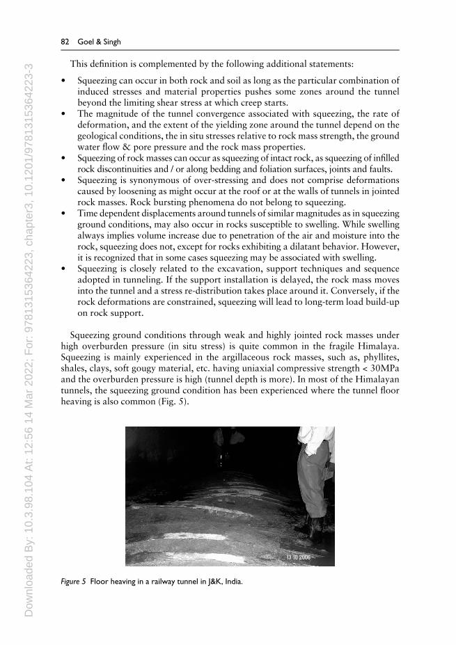
Squeezing ground conditions through weak and highly jointed rock masses underhigh overburden pressure (in situ stress) is quite common in the fragile Himalaya.Squeezing is mainly experienced in the argillaceous rock masses, such as, phyllites,shales, clays, soft gougy material, etc. having uniaxial compressive strength < 30MPaand the overburden pressure is high (tunnel depth is more). In most of the Himalayantunnels, the squeezing ground condition has been experienced where the tunnel floorheaving is also common (Fig. 5).
Figure 5 Floor heaving in a railway tunnel in J&K, India.
82 Goel & Singh

Dow
nloa
ded
By:
10.
3.98
.104
At:
12:5
6 14
Mar
202
2; F
or: 9
7813
1536
4223
, cha
pter
3, 1
0.12
01/9
7813
1536
4223
-3
The support pressure developing far behind the tunnel face in a heavily squeezingground depends considerably on the amount of support resistance during the yieldingphase. The higher the yield of the support, the lower will be the final load. A targetedreduction in support pressure can be achieved not only by installing a support that isable to accommodate a larger deformation (which is a well-known principle), but alsothrough selecting a support that yields at a higher pressure. Furthermore, a high yieldpressure reduces the risk of a violation of the clearance profile and increases safety levelagainst roof instabilities (loosening) during the deformation phase (Cantieni &Anagnostou, 2009).
4.4.1 Tunnel size and squeezing ground condition
In Chhibro-Khodri tunnel, in 1970s the main tunnel of 9m diameter was divided intothree tunnels of 4.5m diameter each to avoid the squeezing purely on the qualitativeconsideration. Thus, by reducing the tunnel size, the squeezing condition was avoided.But, in Maneri Stage-II head race tunnel, in 1980s the main tunnel of 6.0m diameterexperienced the squeezing ground condition. To bypass the problematic squeezingcondition zone, a smaller size drift (2.5m) was excavated. But, this 2.5m wide drifthad also experienced some squeezing ground condition. These two cases qualitativelyshowed that there is some effect of tunnel size on ground condition for tunnels andencouraged to develop approach for predicting the ground condition (see section5.2.1).
4.4.2 Effect of tunnel depth on support pressure
According to the elasto-plastic theory, failure of the rock mass around an openingunder the influence of depth pressure forms a broken zone called “coffin cover”.The failure process is associated with volumetric expansion of the broken rockmass and manifests itself in the form of squeezing into the opening (Labasse,1949; Daemen, 1975). The “characteristic line” – or the “ground reactioncurve” – concept explains that the support pressure increases with depth, providedthat the tunnel deformations are held constant. Further, large tunnel deformationsassociated with expansion of the broken zone lead to reduced support pressures(Fig. 7).
Higher tunnel deformations and support pressures observed in the red shales ata depth of 600 m at Chhibro-Khodri tunnel, as compared to those observed at a depthof 280m in the same tunnel, were explained by Jethwa et al. (1977) with the help ofthe elasto-plastic theory. They employed an empirical relation given by Komornik &David (1969) to estimate the swelling pressure and considered that the supportpressure was the arithmetic sum of elasto-plastic (squeezing plus loosening) andswelling pressures. Later, Singh (1978) emphasized the interaction between the swel-ling and squeezing pressure and suggested that only the greater of the two should beconsidered. The average elasto-plastic pressures, estimated according to the sugges-tions of Singh (1978), are close to the observed values. As such, the empiricalapproaches, developed to estimate support pressure for tunnel support design, mustbe amended to include the effect of tunnel depth in order to obtain reliable results
Tunnels in the Himalaya 83

Dow
nloa
ded
By:
10.
3.98
.104
At:
12:5
6 14
Mar
202
2; F
or: 9
7813
1536
4223
, cha
pter
3, 1
0.12
01/9
7813
1536
4223
-3
under squeezing rock conditions. The correction factor for overburden (or tunneldepth) for estimating support pressure using Q, as suggested by Singh et al. (1992), isaccepted now. Equation 6 also shows the effect of tunnel depth (H) on supportpressure.
4.4.3 Loose backfill with steel arch supports
In a deep tunnel under squeezing ground conditions, the supports are likely to attracthigh loads unless substantial tunnel deformations are allowed. An ideal support systemfor such conditions would be the one which absorbs large deformations while main-taining tunnel stability. Use of flexible supports in a slightly over-excavated tunnelprovides a possible solution to such a problem. The thickness of backfill should bedecided from the considerations of its compressibility and desirable tunneldeformations.
Although flexible steel arches were not used, loosely thrown tunnel muck behindsteel ribs provided an element of flexibility in the Chhibro-Khodri tunnel. It wasobserved that the support pressure reduced to a large extent with such a loose backfill(Fig. 6a & 6b after Jethwa et al., 1980).
4.5 Roof collapse and cavity formation
It has been experienced that because of frequently changing geology and presence of shearzone, support has either been inadequate or it has not been installed soon enough, whichhas resulted in deterioration of the rock mass quality and roof falls and cavity formation.
For example, in Maneri stage-I project head race tunnel a major cavity was formedduring excavation between ch. 5038m and 5050m in highly jointed and folded quart-zites. The tunnel crossed a shear zone at ch. 5050m. The crushed quartzite was alsocharged with water. Therefore, the crushed rock debris was continuously flowing fromthe roof, which formed a cavity. The total volume of the cavity was estimated as 813m3.The face was sealed after forepoling with rolled steel joists as shown in Figure 7.A bulkhead was constructed at the tunnel face leaving 2 to 3 pipes for grouting themuck and debris. Drainage holes were provided to release the hydrostatic pressure.A side drift was also excavated to release the water pressure. The cavity above theforepoles was then filled with concrete using the pipes inserted in the cavity for thispurpose. Themuck below the forepoles and behind the face was grouted using a cementwater slurry to check the water flow and to consolidate the muck. The tunnel then wasexcavated.
In yet another incident in the same tunnel, the sheared and crushed zone betweenmetabasics and quartzites was tackled by creating grouted plug ahead of the tunnel faceall around the tunnel (Fig. 8). This was then excavated and supported leaving 5mgrouted zone by following the steps shown in Figure 8.
Such collapses can be avoided by pre-grouting the rock mass ahead of the tunnel andor installing the effective supports timely close to the tunnel face. Invert supports, tocomplete the support ring, must be used in soft and weak rock masses, thick faultgouges and shear zones.
In the lower Himalaya, it has been observed that the contact of two rock formationsinvariably is sheared, which generally leads to support failure and collapse. Hence, this
84 Goel & Singh

Dow
nloa
ded
By:
10.
3.98
.104
At:
12:5
6 14
Mar
202
2; F
or: 9
7813
1536
4223
, cha
pter
3, 1
0.12
01/9
7813
1536
4223
-3
should be known to the geologists and site engineers so that timely preventive steps canbe taken.
4.6 Shear zone treatment
There are number of small or big shear zones and faults present in the lower Himalayanrocks. These shear zones and faults are sympathetic to regional main boundary faultandmain central thrust. It is generally said that in the tunnels through lowerHimalayanrocks if no fault or shear is seen for 100m it means this has been missed. The contact oftwo rock types is also found to be generally sheared in lower Himalaya (Goel et al.,1995a).
Figure 6 Effect of compressible loose backfill on support pressure in: a – black clays; b – red shales (afterJethwa et al., 1980).
Tunnels in the Himalaya 85

Dow
nloa
ded
By:
10.
3.98
.104
At:
12:5
6 14
Mar
202
2; F
or: 9
7813
1536
4223
, cha
pter
3, 1
0.12
01/9
7813
1536
4223
-3
Figure 7 Method for tackling the problem of cavity formation (Goel et al., 1995b).
Figure 8 Steps to tackle the problem of sheared contact zone of metabasic and quartzite (Goel et al.,1995b).

Dow
nloa
ded
By:
10.
3.98
.104
At:
12:5
6 14
Mar
202
2; F
or: 9
7813
1536
4223
, cha
pter
3, 1
0.12
01/9
7813
1536
4223
-3
It is envisaged that the rock mass affected by a shear zone is much larger thanthe shear zone itself. Hence, the affected rock mass must be down-graded to thequality of the shear zone so that a heavier support system than a regular one canbe installed. A method has been developed at NGI (Norwegian GeotechnicalInstitute) for assessing support requirements using the Q-system for rock massesaffected by shear zones (Grimstad & Barton, 1993). This has also been used insome Himalayan tunnels in India. In this method, weak zones and the surroundingrock mass are allocated their respective Q-values from which a mean Q-value canbe determined, taking into consideration the width of the weak zone/shear zone.Equation 1 may be used in calculating the weighted mean Q-value (Bhasin et al.,1995).
log Qm¼b: log Qwz þ log Qsr
bþ 1ð1Þ
where,
Qm = mean value of rock mass quality Q for deciding the support,Qwz = Q value of the weak zone/shear zone,Qsr = Q value of the surrounding rock, andb = width of the weak zone in meters.
The strike direction (θ) and thickness of weak zone (b) in relation to the tunnel axis isimportant for the stability of the tunnel and therefore the following correction factorshave been suggested for the value of b in the above Equation 1.
if θ = 90° – 45° to the tunnel axis then use 1b,if θ = 45° – 20° then use 2b in place of b,if θ = 10° – 20° then use 3b in place of b, andif θ < 10° then use 4b in place of b.
Hence, if the surrounding rock mass near a shear zones is downgraded with the use ofthe above equations, a heavier support should be chosen for the whole area instead ofthe weak zone alone.
Figure 9 shows a typical treatment method for shear zones (Lang, 1961) in theroof of tunnel. First the shear zone is excavated with caution up to some depth.After excavation, immediately one thin layer of shotcrete with wire mesh or steelfiber reinforced shotcrete (SFRS) shall be sprayed. The weak zone is then rein-forced with inclined rock bolts and finally shotcrete with wiremesh or SFRS(preferably SFRS) should be sprayed ensuring its proper thickness in weak zones.This methodology is urgently needed if NATM or NMT (Norwegian Method ofTunneling) is to be used in the tunnels of the Himalayan region, as seams/ shearzones/ faults/ thrusts/ thin intra-thrust zones are frequently found along tunnelsand caverns in the Himalaya. Stitching is perhaps the terminology that best suitsthis requirement.
In case of a thick shear zone (b>>2m) with sandy gouge, umbrella grouting or rockbolting is used to enhance the strength of roof and walls in advance of tunneling.The excavation is made manually. Steel ribs are placed closely and shotcreted until theshear zone is crossed. Each (blasting) round of advance should be limited to 0.5m or
Tunnels in the Himalaya 87

Dow
nloa
ded
By:
10.
3.98
.104
At:
12:5
6 14
Mar
202
2; F
or: 9
7813
1536
4223
, cha
pter
3, 1
0.12
01/9
7813
1536
4223
-3
even smaller depending upon the stand-up time of the material and fully supportedbefore starting another round of excavation.
4.7 Water-in-rush
In the tunnels in Himalaya, it has been experienced often that the rock mass abovethe shear zone is water-charged. This may be because of the presence of imperme-able gouge material in the shear zone. Hence, one should be careful and beprepared to tackle the water problem in the tunnels through shear zone havingimpermeable gouge material.
For example, in the case of Maneri stage-I project head race tunnel in Uttarakhandstate, India, because of tunneling, the trapped water in quartzites above imperviousshear zone rushed in to the tunnel causing roof collapse and debris flow flooding thetunnel (Fig. 10).
Figure 10 Schematic view of causes of water inrush in head race tunnel of Maneri stage-I project (Goelet al., 1995a).
Figure 9 Shear zone treatment in an underground opening (Lang, 1961).
88 Goel & Singh

Dow
nloa
ded
By:
10.
3.98
.104
At:
12:5
6 14
Mar
202
2; F
or: 9
7813
1536
4223
, cha
pter
3, 1
0.12
01/9
7813
1536
4223
-3
Intersection of water-charged zones while tunneling is also a common feature.However, when the normal seepage turns into free flowing conditions, particularlywith material outwash, tunneling problems attain serious dimensions. If caught una-wares, these problems are capable of completely disrupting tunneling activity andinfluencing the time schedules involved. Such cases call for state of art tunnelingtechniques like ground stabilization using special grout admixtures or freezing whichsaves draining arrangements running into several cumec capacity, advance probing,and so on.
In a rail tunnel in J&K state, the water started flowing from the tunnel face witha discharge of more than 500 liters per minute. The tunnel was being constructedthrough the terrace deposits. It was thought that the discharge rate will subside withtime. But, to our surprise, it remained continued with a rate of about 300 litersper minute. The tunnel was completed by pipe-roofing technique and by channelizingthe water with the help of drainage holes.
It is highlighted here that once thewater is stuck in the tunnel, it is difficult, costly andtime consuming to tackle it and tunnel through. Therefore, it is generally advised totake steps to probe and divert water as soon as first sign of water is seen.
4.8 Probe holes
An important step to prevent the geological surprise is to drill the probe holes indifferent directions, if required, from the tunnel face to get the geological information.Having 50m deep probe holes of at least 50 to 75mm diameter ahead of the tunnel facein the regions of highly changing geology could provide valuable advance informationof geology. Lesser depth of probe holes can also be drilled depending upon the require-ment and availability of drilling equipment and material. The ground conditions, thesupport pressures, etc., can also be ascertained as per the geological details obtainedfrom probe holes. Accordingly, the construction and supporting techniques may bemodified. Such probing is now becoming popular and being used in some projects. Forexample, in Chenani-Nashri highway tunnel project, J&K probe holes were drilled to
Figure 11 Water-in-rush in a rail tunnel in J&K, India.
Tunnels in the Himalaya 89

Dow
nloa
ded
By:
10.
3.98
.104
At:
12:5
6 14
Mar
202
2; F
or: 9
7813
1536
4223
, cha
pter
3, 1
0.12
01/9
7813
1536
4223
-3
know the water condition ahead of the tunnel face from north end in the escape tunnel.The probe holes have shown that the water pressure is reducing and accordingly thetunnel activity was planned.
Probe holes sometimes can be disastrous also. For example, Parbati stage-II headrace tunnel inNov. 2005 faced a problemwhen approximately 12000m3 of silt and finesand flowing out of a probe hole buried the TBM and half of the bored tunnel with7000 lit per min water inflow. Hence, it is essential to keep close watch on the variationof geology and water seepage with the excavation before and during drilling the probeholes.
Probing ahead of the tunnel face using geophysical means like tomographic analysisand radar is also becoming popular but is comparatively expensive and cannot be usedas a regular or on a routine basis. Seismic profiling is another methodology beingadopted to probe the geology ahead of tunnel face.
Probe holes planning, drilling and monitoring shall be carried out in the supervisionof experienced geologists to get the desired information and results.
4.9 Tunnel Boring Machine (TBM) in the Himalaya
Use of Tunnel Boring Machine (TBM) has not been very discouraging so far inHimalayan tunneling because of varying geology and water-charged formations.To highlight, three cases of TBM are briefly presented.
The work of 6.75km long Dulhasti project head race tunnel of 8.3m excavateddiameter was started with gripper type hard rock TBM. The rock mass waspredominantly hard and highly abrasive quartzites. While tunneling, the TBMwas inundated with a water inflow of over 1000litres/sec. This ‘inrush’ occurredat a minor shear zone aquifer (fractured quartzite) within impermeable interbeddedphyllites and included 4,000m3 of sand and quartzite pebbles. The inflows fell to150 liter/sec within 100 days and five years later inflows of 100 liter/sec were stillbeing recorded. The TBM could bore only 2.86km and finally abandoned. Thisexperience in Himalayan geology was not encouraging. The project has subse-quently been completed by conventional excavation. The project was commis-sioned in 2007, after a delay of about 19 years.
At the head race tunnel for Parbati Stage-II project, H.P. state of India, an incidentsimilar toDulhasti project tunnel occurred inMay 2007when routine probing ahead ofa 6.8m diameter refurbished Jarva open TBM tunnel in sheared and faulted quartzite at900moverburden cover punctured awater bearing horizonwhich resulted in inflows ofwater of over 120 l/sec containing about 40% sand and silt debris. The inflow wassudden and occurred at a high pressure which could not be contained. Eventually over7500m3 of sand and silt debris buried the TBM. The project supposed to be commis-sioned in 2007, was delayed for about 10 years (Sengupta et al., 2008).
National Thermal Power Corporation (NTPC) is constructing the Tapovan-Vishnugad hydroelectric power project (TVHEP) with installed capacity of 520MW(4x130MW). The project has HRT of length approximately 12.1 km, of which 8.6 kmhas been planned to excavate using a double shield TBM by a Joint Venture (JV) ofLarsen& Toubro Ltd., India, and Alpine, Austria. The remaining 3.5km of the HRT isbeing excavated conventionally. The tunnel passes below the steep hills of Himalayanear Joshimath, India. The tunnel depth at places is more than 1.0km. This is the first
90 Goel & Singh

Dow
nloa
ded
By:
10.
3.98
.104
At:
12:5
6 14
Mar
202
2; F
or: 9
7813
1536
4223
, cha
pter
3, 1
0.12
01/9
7813
1536
4223
-3
time the double shield hard rock tunnel-boring machine (ordered from Herrenknecht,Germany) has been used for a hydel power project tunnel in India. The TBM has anexcavation diameter of 6.575 m for an internal finished diameter of the HRT being5.64 m (Saxena, 2013).
Soon after TBM excavation started, it became clear that there are also groundwater-bearing, approximately NS striking, steeply inclined faults and fracture zones asso-ciated with quartz-rich lithologies such as quartzite, quartzitic gneiss and augen gneiss.These steeply inclined fracture and fault structures cut across the main foliation joint,which means that there is a high level of interconnection between the joint systems,allowing for the development of potent and high-pressure aquifers. The rock types aregneisses and quartzites (Brandl et al., 2010).
During the excavation, the TBM encountered a large fault zone. A major portion ofrock detached and dented the shield of the TBM and the TBM trapped. Subsequently,there was heavy ingress of ground water into the tunnel, commencing at the tail skinarea of the TBMand progressing rapidly, through the ungrouted section of the annulus,some 160 m back along the tunnel. The water pressure was very high carrying the rockmaterial and debris which resulted in more damages to TBM (Brandl et al., 2010).Work remains standstill for quite some time. Subsequently, a bypass tunnel wasexcavated to recover the buried TBM. The TBM has been recovered, repaired andagain put to use in the same tunnel.
While the excavation using TBM has been quite successful in other parts of India,e.g., Delhi metro, Srisailam left bank canal tunnel and BombayMalabar hill tunnel, theHimalaya remain a major challenge. The experience suggests that many of the pro-blems can be avoided if sufficient advance information ahead of the face is available.Following key issues have been identified by Goel (2014) for the success of TBM in theHimalaya.
4.10 Key issues for TBM success in the Himalaya
The Himalaya pose the most challenging ground conditions for tunneling. One of theprime reasons is that they are the youngest of the mountain chains and are stilltectonically active. The difficulties of tunneling at depth through high mountainousterrain pose major challenges not just for tunnel boring machines (TBM) but also forthe use of drill and blast (D&B).
The big investment in a sophisticated TBM and the expectation of mostly rapidadvance rates can be spoiled by the unexpected delays caused by unexpected ground.Only a few percent of the total length of a tunnel may be unexpected, yet thesefew percent could double the construction time in some cases.
Tunneling in adverse ground is significantly less tolerant of the limitations of thetunneling approach than in good ground. Generally, the more difficult the ground, themore flexibility is also needed. Tunneling in the Himalaya, the Andes and until recentlythe Alps has shied away from TBM use due to perceived inflexibility and the likelihoodof the machines getting trapped by adverse ground conditions, either as a result ofsqueezing or spalling/bursting conditions or because of ground collapses associatedwith rock falls or with running or flowing ground within faults. Any of these situationscan lead to problematic tunneling at best and collapses and abandonment at worst.
Following are the key issues for the success of TBM in the Himalaya.
Tunnels in the Himalaya 91

Dow
nloa
ded
By:
10.
3.98
.104
At:
12:5
6 14
Mar
202
2; F
or: 9
7813
1536
4223
, cha
pter
3, 1
0.12
01/9
7813
1536
4223
-3
4.10.1 Geological investigations and probe holes
The more challenging the ground, the greater the pre-planning that is required beforetunneling. This challenge is not just of tackling adverse ground, stress state and/orgroundwater conditions, it is also often about logistics. For deep tunnels in mountai-nous regions, problematic geologic zones often are at significant distance from thenearest portal and at such significant depth that surface pre-treatment is generallyimpractical (Carter, 2011).
Experience suggests that many of the problems associated with the TBM in theHimalaya can be avoided if sufficient geological and geohydrological information isavailable in advance. Faced with cost and time constraints, detailed investigationsbefore selecting a tunnel alignment are often compromised, resulting in encounteringvery disturbed geological conditions. It is essential that detailed exploration work iscarried out before the start of the project and exploration ahead of the face is under-taken on a continuous basis.
In particular for a TBM driven tunnels –which are not as flexible as a conventionallydriven tunnels – forward probe drilling from the tunnel face is certainly not an alter-native to an adequate pre-investigation. But, regular cautious probe drilling duringcutter change andmaintenance shifts could largely remove the unexpected; especially ifperformed with two slightly diverging probe holes (Barton, 2000). It must be high-lighted here that while drilling the probe holes, to avoid the blow outs, the groundwaterconditions shall be closely watched and an attempt shall be made to carry out geophy-sical investigations. It is needless to mention here that the probe holes shall be drilledunder close supervision of an experienced engineering geologist.
4.10.2 Selection of TBM and add-on-features
Selection of a TBM is the key decision. Complications in the decision-making process,in general, relate to the timing when making this decision, as it needs to be made 12–18months in advance of actually starting tunneling, so that sufficient lead time is availablefor building the machine. However, often detailed project site investigations areincomplete, still ongoing or sometimes not even started when this key decision is tobe made. Furthermore, once the contract is awarded to the contractor, generally aftera long tendering process, almost always insufficient time and/or funds have beenallocated to allow the contractor any opportunity for additional customized explora-tion to support his own excavation technology selection procedures before initiatingequipment procurement.
The choice of TBM also needs critical analysis at the planning stage. In theabsence of accepted standards for the design and construction of a type of TBMand the fact that no TBM can be designed for every type of geological condition,the design and special construction characteristics of each TBM need to be care-fully, project-specifically designed. The shielded TBM has a definite edge over theopen TBM as it is not as sensitive to the instability phenomena of the excavationwalls owing to the presence of precast concrete or steel lining inside and theprotection of the shield (Saxena, 2013).
TBM can be designed with add-on-features as per the site conditions, e.g. probehole drilling, forepoling, shotcrete spraying, rock bolting, pre-grouting/grouting,
92 Goel & Singh

Dow
nloa
ded
By:
10.
3.98
.104
At:
12:5
6 14
Mar
202
2; F
or: 9
7813
1536
4223
, cha
pter
3, 1
0.12
01/9
7813
1536
4223
-3
steel rib erection etc. As per the expected requirements, these features can be incor-porated in the TBM.
In mountainous terrain, when considering a decision on whether or not to usea TBM, and which type of TBM to use for a deep tunnel, it must be appreciated that,historically, three types of ground conditions have proved to be the most problematicfrom the viewpoint of halting tunnel advance. In order of severity, case records suggestfaults with gouge filling, heavy water and major stress, individually and/or in combina-tion, constitute the most problematic ground conditions. The three elements whichcontrol the trouble-free tunnel excavations at significant depth are, stress state, ground-water conditions and the rock or the medium. Adverse characteristics of any of thesethree elements can, on its own, compromise drill and blast (D&B) or TBM tunneling,but it usually takes a combination of all three being adverse to trap a machine or halta D&B drive to the extent that a bypass becomes necessary (Carter, 2011).
Hence, TBM shall be selected after detailed analysis of stresses, groundwater and theexpected rock masses and ground conditions.
4.10.3 Expert TBM crew
Even with the best possible TBM, the progress required may not be achieved.Experienced and dedicated TBM crew is very important for the success of TBM. It isthe expert crew, which can take the right decision at the right time and implement itproperly. Success of TBM in Kishanganga hydroelectric project in India is one suchexample.
Bieniawski (2007) also highlighted the influence of TBM crew and suggested anadjustment factor for the influence of TBM crew on its performance in rock massexcavatability index for TBM.
4.10.4 Timely decision and action
Extreme ground conditions present major contrasts to tunneling, so much so that theyinevitably demand use of flexible rock engineering solutions for the tunnel to progress.The fact that conditions within the Himalaya can be expected to be as bad as has everbeen encountered elsewhere means there has to be the ability while tunneling to allowchanges in excavation procedures and in pre- and post-excavation support approaches.It has been experienced that the delays in decision have enhanced the problems. Fortunnel to be completed successfully, the rock is not going to wait. Hence, timelydecision and action is important. There may be situations where the flexibility in thedesigns is required. This is possible only when the engineers-in-charge are givendecision and risk taking authority.
4.10.5 Risk sharing
“Engineers have to take a calculated risk, persons become wiser after an accident.If they were really wise, it was their duty to point out mistakes in the design toengineers” – Karl Terzaghi
In more difficult ground conditions, such as those encountered in the Himalaya, withminimal investigation comesmore risk of the TBMgetting trapped – either as a result of
Tunnels in the Himalaya 93

Dow
nloa
ded
By:
10.
3.98
.104
At:
12:5
6 14
Mar
202
2; F
or: 9
7813
1536
4223
, cha
pter
3, 1
0.12
01/9
7813
1536
4223
-3
squeezing or spalling/bursting conditions or because of ground collapses associatedwith rockfalls or with running or flowing ground within faults. These cases are furthercomplicated by heavy water inflows. To reduce these risks considerably more invest-ment must be made in the design process in these complex mountainous regions.Significant reduction of real risk can only be achieved throughmore investigative effort,not through design refinement. Cost and schedule analysis of past case records suggeststhat for complex ground conditions, some 5% of the engineer’s estimate of capitalexpenditure is required to be spent on investigating ground conditions to push theprocess in the right direction (Carter, 2011).
Hence, if the investigations are insufficient, whatever is the reason, various problemsare bound to be encountered as a surprise (mostly not at the expected location). Thereshould be provision of risk sharing between the client and the contractor in the contractdocument. Otherwise these surprises result in the time and cost over-runs andlitigations.
As mentioned earlier the contract document shall have the flexibility also toaccommodate the unforeseen conditions/events. The site engineers shall be giventhe responsibility of allowing and approving the use of newer techniques andmaterialrequired for tackling the unforeseen conditions. The contractor, once allowed by thesite engineer, shall get full payment after executing the job to the satisfaction of thesite engineers.
The contract should include (i) clause for compensation to contractor for an unex-pected geological conditions or surprises, (ii) clause on innovations by contractors andengineers on the basis of mutual agreements, (iii) clauses for first and second contin-gency plans for the preparedness and (iv) penalty for delays in construction. Obviouslycontract is not a license for injustice to any party. Injustice done should be correctedsoon (Singh & Goel, 2006).
4.11 General observations
Following are the general observations from various tunneling and undergroundprojects constructed so far.
(i) The alignments of long power tunnels have not been fixed after proper andpurposeful geological exploration. The surface geological features have provedmisleading. Consequently, many disastrous problems were faced in tunneling.
(ii) In squeezing grounds, the selection of size of power tunnel is important. Initially onebig tunnel was excavated, as it became difficult to drive, three tunnels of smallerdiameter were then driven (Mitra, 1991). This was because there were fewersupports, bridge action period was greater and heaving of the floor was limited.
(iii) The underground power house was located at one side of the river and not toohigh above the water level in the river. Consequently during flood, water enteredinto the cavern through the tail race tunnel while its excavation was going on.The rock masses in the roof and walls were submerged for a couple of weeksbefore water could be pumped out. Fortunately the cavern remained stable.
(iv) The seepage through dam foundation is increased after a major earthquake, aspermeability of the jointed rock mass increases drastically during shearing.On the contrary permeability of micro-fissured rock is reduced due to
94 Goel & Singh

Dow
nloa
ded
By:
10.
3.98
.104
At:
12:5
6 14
Mar
202
2; F
or: 9
7813
1536
4223
, cha
pter
3, 1
0.12
01/9
7813
1536
4223
-3
deformation of the joints beneath the foundation due to thrust on the reservoirfilling, thereby making the grout curtain redundant which led to a dam failure.
(v) The study (on the basis of 11 years of monitoring of Chhibro undergroundcavern of Yamuna hydro-electric project) has shown that ultimate roof supportpressure for water-charged rock masses with erodible joint filling may rise up to6 times the short-term support pressure. The damage to the support systemduring an earthquake of 6.3 magnitude is not appreciable except near faultswith plastic gouge material (Mitra, 1991).
(vi) Very high support pressures may be generated by reduction in the modulus ofdeformation due to saturation of the rock mass aroundHRT, TRT and penstocksetc. (Verman, 1993). Mehrotra (1992) observed that the modulus of deformationis actually very low after saturation compared with that in dry conditions in thecase of argillaceous rocks (claystone, siltstone, shale, phyllite etc.).
5 CONTRIBUTIONS IN THE STATE-OF-THE-ART
5.1 Squeezing ground condition
The over-stressed zone of rock mass fails where tangential stress (σθ) exceeds themobilized uniaxial compressive strength (UCS) of the rock mass. The failure processwill then travel gradually from the tunnel boundary to deeper regions inside theunsupported rock mass. The zone of the failed rock mass is called the ‘broken zone’.This failed rock mass dilates on account of the new fractures. A support system afterinstallation restrains the tunnel deformation and gets loaded by the support pressure.
It is evident from the ground reaction curve that the support pressure decreasesrapidly with increasing tunnel deformation. Hence, significant tunnel deformationshall be allowed to reduce the cost of support system. This is the secret of success intunneling through squeezing ground condition.
In case one chooses to install very stiff support system, it may be seen from Figure 12that stiff support system will attract high support pressure as it will restrict the tunneldeformation. If a flexible support system is built after some delay, it will attract muchless support pressure. This is ideal choice. However, too late and too flexible supportsystemmay attract high support pressure due to excessive loosening of rockmass in thebroken zone. Yet the squeezing ground comes to equilibrium after years even in severesqueezing ground condition. Although the final deformations may be undesirable andso corrective measures are required.
The data suggests that support pressure jumps up after tunnel deformation of about5 to 6 percent of tunnel size. Then there is sympathetic failure of entire brittle rockmasswithin the broken zone, rendering its residual cohesion cr = 0 in the highly squeezingground. The theoretical ground response curve is shown in Figure 12 on the basis of thishypothesis. The sympathetic failure is in fact unstable and wide spread fracture pro-pagation in the entire failure zone, starting from the point of maximum shear strain.This brittle fracture process may be taken into account in the elasto-plastic theory byassuming cr = 0 after critical tunnel deformation of 6%. Thus, it is recommended thattunnel deformation shall not be permitted beyond 4 percent of tunnel radius to be onsafe side.
Tunnels in the Himalaya 95

Dow
nloa
ded
By:
10.
3.98
.104
At:
12:5
6 14
Mar
202
2; F
or: 9
7813
1536
4223
, cha
pter
3, 1
0.12
01/9
7813
1536
4223
-3
10.5.1.1 Compaction zone within broken zone
From the study of steel rib supported tunnels, Jethwa (1981) observed that the values ofcoefficient of volumetric expansion (K) are negative near the tunnel and increased withradius vector. Thus, he postulated the existence of compaction zone within the brokenzone (Fig. 13). The radius of the compaction zone (rc) is estimated to be approximatelyequal to,
rc ¼ 0:37 b ð2ÞThus, compaction zone will not developwhere b is equal to a/0.37 or 2.7a. This is the
reason why compaction zone was not observed in some of the European tunnels in thesqueezing ground conditions as b was perhaps less than 2.7a.
In an ideal elasto-plastic rock mass, compaction zone should not be formed.The formation of the compaction zone may be explained as follows. A fragile rockmass around the tunnel opening fails and dilates under the influence of theinduced stresses. The dilated rock mass then gets compacted due to the passivepressure exerted by the support system in order to satisfy the ultimate boundarycondition that is zero rate of support deformation with time. The development ofsupport pressure with time would reduce the deviator stresses (σθ−σr) within thecompaction zone which in turn will undergo creep relaxation manifested by thenegative K values.
Figure 12 Effect of sympathetic failure of rock mass on theoretical ground response curve of squeezingground condition. Support reaction curve of stiff and delayed flexible supports aresuperposed.
96 Goel & Singh

Dow
nloa
ded
By:
10.
3.98
.104
At:
12:5
6 14
Mar
202
2; F
or: 9
7813
1536
4223
, cha
pter
3, 1
0.12
01/9
7813
1536
4223
-3
5.1.2 Coefficient of volumetric expansion
Jethwa (1981) has found the overall values of K from instrumented tunnels inHimalaya. These values are listed in Table 6. Actually K varied with time and radiusvector. K was more in roof than in walls. So only peak overall values of K are reportedand considered to have stabilized to a great extent with time (15 – 30 months). It isheartening to note that the value of K for crushed shale is the same at two differentprojects. It may be noted that higher degree of squeezing was associated with rockmasses of higher K values.
5.2 Prediction of ground conditions
5.2.1 Empirical approach for predicting the ground conditions
To avoid the uncertainty in obtaining appropriate SRF ratings in rockmass qualityQ ofBarton et al. (1974), Goel et al. (1995c) have suggested rockmass number N, defined asfollows, for proposing the criterion of estimating ground conditions for tunneling.
Table 6 Overall coefficient of volumetric expansion of failed rockmass (K) within broken zone (Jethwa, 1981; Goel, 1994).
S.No. Rock Type K
1. Phyllites 0.0032. Claystones / Siltstones 0.013. Black clays 0.014. Crushed sandstones 0.0045. Crushed shales 0.0056. Metabasics (Goel, 1994) 0.006
Figure 13 Compaction zone within broken zone in the squeezing ground condition (Jethwa, 1981).
Tunnels in the Himalaya 97

Dow
nloa
ded
By:
10.
3.98
.104
At:
12:5
6 14
Mar
202
2; F
or: 9
7813
1536
4223
, cha
pter
3, 1
0.12
01/9
7813
1536
4223
-3 N ¼ ½Q�SRF ¼ 1 ð3ÞEquation 3 suggests that N is Q with SRF = 1.Other parameters considered are the tunnel depth H in meters to account for stress
condition or SRF indirectly, and tunnel width B in meters to take care of the strengthreduction of the rock mass with size. The values of three parameters – the rock massnumber N, the tunnel depth H and the tunnel diameter or width B were collectedcovering a wide variety of ground conditions varying from highly jointed and fracturedrock masses to massive rock masses.
All the data points were plotted on a log-log graph (Figure 14) between rock massnumber N and H.B0.1. Figure 14 shows zones of tunneling conditions/hazards depend-ing upon the values of HB0.1 and N. Here H is the overburden in meters, B is the widthof the tunnel in meters and N is rock mass number.
The equations of various demarcating lines have been obtained as shown in Table 7.Using these equations, one can predict the ground condition and then plan the tunnel-ing measures. These equations can also be used to plan the layout of the tunnel to avoidthe squeezing ground condition.
Figure 14 Plot between rock mass number N and HB0.1 for predicting ground conditions (Singh & Goel,2011).
98 Goel & Singh

Dow
nloa
ded
By:
10.
3.98
.104
At:
12:5
6 14
Mar
202
2; F
or: 9
7813
1536
4223
, cha
pter
3, 1
0.12
01/9
7813
1536
4223
-3
Few cases of spalling and rock burst conditions have also been plotted in Figure 14.These data points are lying in the upper right hand side corner of Figure 14.The enclosure is shown by dotted line because more data points are needed beforereaching to a firm conclusion. However, it may be highlighted here that spallingand rock burst have been encountered in the rock masses having Jr/Ja > 0.5, N>2 andH.B0.1>1000. Hence, the rock mass having Jr and Ja ratings in category b and c in theTables of Jr and Ja in Q-system shall not experience the rock burst condition.
Equations given in Table 7 are found to be quite useful in planning and design.In addition, the N based approach of estimating/predicting the ground condition hasbeen found as complimentary to Q-system in respect of identifying the ground condi-tions and then select SRF rating to get Q-value. The, Q-value thus obtained has beenused for the support design in tunnels using the Grimstad et al. (2003) chart.
5.2.2 SRF rating in Q-system for spalling and rock burst conditions
Kumar et al. (2006) have studied the spalling and rock burst condition in the Nathpa-Jhakri Project tunnels. They have experienced that the Barton’s stress reduction factor(SRF) ratings in case of ‘competent rock’ should be different for massive rocks and formoderately jointed rocks. Accordingly they have proposed new rating of SRF forcompetent moderately jointed rocks as shown in Table 8. The support pressure valuesobtained using these new suggested SRF ratings are found to be matching with theobserved values (Kumar et al., 2006).
High value of Jr/Ja leads to high angle of internal friction along joints. Consequently,the intermediate principal stress (σ2) which is the in situ stress along tunnel axisincreases the rock mass strength enormously where overburden is more than 1000m.The net effect is that the rock burst condition is not serious as anticipated from Bartonet al. (1974) and Grimstad & Barton (1993). In other words the pre-stressing effect ofσ2 on rock mass strength is similar to reduction in SRF values. Application of thepolyaxial failure criterion shall be studied and Table 8 needs further research.
Table 7 Prediction of ground condition using N (Singh & Goel, 2011).
S. No. Ground Conditions Correlations for Predicting Ground Condition
1. Self-supporting H < 23.4 N0.88. B−0.1 & 1000 B−0.1 and B < 2 Q0.4 m (forESR=1) (Barton et al., 1974)
2. Non-squeezing(< 1% deformation)
23.4 N0.88.B−0.1 < H < 275N0.33. B−0.1
3. Mild or minor squeezing(1–3% deformation)
275 N0.33. B−0.1 < H < 450N0.33. B−0.1 and Jr /Ja <0.5
4. Moderate or severe squeezing(3–5% deformation)
450 N0.33. B−0.1 < H < 630N0.33. B−0.1 and Jr /Ja <0.5
5. High or very severe squeezing(>5% deformation)
H > 630N0.33. B−0.1and Jr /Ja <0.25
6. Mild rock burst H.B0.1 > 1000m and Jr/Ja > 0.5 and N > 2
Notations: N = rock mass number (Barton’s Q with SRF = 1); B = tunnel span or diameter in meters; H = tunneldepth in meters; Jr and Ja = Parameters of Q-system; and ESR= Barton’s excavation support ratio.
Tunnels in the Himalaya 99

Dow
nloa
ded
By:
10.
3.98
.104
At:
12:5
6 14
Mar
202
2; F
or: 9
7813
1536
4223
, cha
pter
3, 1
0.12
01/9
7813
1536
4223
-3
5.3 Deformation of tunnel walls
It is common knowledge that the rock failure is associated with volumetric expansiondue to creation and progressive widening of new fractures. Consequently all the pointswithin the broken zone in a circular tunnel shift almost radially toward the openingbecause the expanding rock mass is kinematically free to move in radial direction only.Labasse (1949) assumed that the volume of failed rockmass increases at a constant rate(called coefficient of volumetric expansion, K).
The displacement at the boundary of broken zone (ub) is negligible compared to thatat the opening periphery (ua). So the coefficient of volumetric expansion is defined asfollows:
K ¼ π b2 � π a� uað Þ2 � π ðb2 � a2Þπ b2 � π a2
ð4Þ
Equation 4 can be solved as below for obtaining ua
ua ¼ a �ffiffiffiffiffiffiffiffiffiffiffiffiffiffiffiffiffiffiffiffiffiffiffiffiffiffiffiffiffiffiffiffiffia2 � Kðb2 � a2Þ
qð5Þ
Using Equation 5 and the K-value from Table 6 it has become possible to estimate thetunnel wall/roof deformation.
5.4 Estimating support pressure in squeezing ground condition
First time in 1994 it has been empirically established that in the tunnels with arch roofthrough squeezing ground, the support pressure in steel rib supported tunnels varieswith the tunnel size as per the following Equation 6 (Goel, 1994).
pvðsqÞ ¼ fðNÞ30
� �: 10
H0:6: a0:1
50: N0:33
� �; MPa
ð6Þ
Table 8 Stress reduction factor (SRF) rating for jointed rock for categories L, M and N (Kumar et al.,2006).
Category Rock Stress Problem qc/σ1 σθ/qc SRF(Old)
SRF(New)
H Low stress, near surface open joints >200 <0.01 2.5 2.5J Medium stress, favorable stress condition 200–10 0.01–0.3 0.5–2.0 1.0K High stress, very tight structure (usually favorable
to stability, may be unfavorable to wall stability)10–5 0.3–0.4 0.5–2.0 0.2–2.0
L Moderately slabbing after > 1hr Massive rock 5–3 0.5–0.65 5–9 5–50Moderatelyjointed rock
– 1.5–2.0
M Slabbing and rock burst aftera few minutes
Massive rock 3 – 2 0.65–1.0 9–15 50–200Moderatelyjointed rock
– 2.0–2.5
N Heavy rock burst (strain burst)and immediate deformations
Massive rock < 2 < 1 15–20 200–400Moderatelyjointed rock
– 2.5–3.0
100 Goel & Singh
Dow
nloa
ded
By:
10.
3.98
.104
At:
12:5
6 14
Mar
202
2; F
or: 9
7813
1536
4223
, cha
pter
3, 1
0.12
01/9
7813
1536
4223
-3
where,
pv(sq) = short-term vertical roof support pressure in squeezing ground conditionin MPa,
f(N) = correction factor for tunnel deformation obtained from Table 9, andH & a = tunnel depth & tunnel radius in meters respectively (H < 600m).
Equation 6 has been developed using the measured value of support pressures fromnumber of tunnels experiencing the squeezing ground conditions in the Himalaya.
Subsequently, Bhasin & Grimstad (1996) have proposed Equation 7 to estimate thesupport pressure in tunnels through poorer qualities of rock masses. Equation 7 alsoshows the effect of tunnel size on ultimate roof support pressure (proof).
proof ¼40 DJr:Q1=3
; kPa ð7Þ
where D is the diameter or span of the tunnel in meter.It may be highlighted here that Equation 6 has been successfully used for estimating
the support pressure in some tunnels including the Udhampur-Katra rail link projecttunnels in the Himalaya.
5.5 Effect of tunnel size on support pressure
Effect of tunnel size on support pressure is summarized in Table 10.It is cautioned that the support pressure is likely to increase significantly with the
tunnel size for tunnel sections excavated through the following situations:
(i) slickensided zone,(ii) thick fault gouge,(iii) weak clay and shales,(iv) soft plastic clays,
Table 9 Correction factor f(N) for tunnel deformation in Equation 6 (Goel, 1994).
S.No. Degree of Squeezing Normalized Tunnel Deformation % f (N)
1. Very mild squeezing(270 N0.33. B−0.1 < H < 360 N0.33. B−0.1)
1 – 2 1.5
2. Mild squeezing(360 N0.33. B−0.1 < H < 450 N0.33. B−0.1)
2 – 3 1.2
3. Mild to moderate squeezing(450 N0.33. B−0.1 < H < 540 N 0.33. B−0.1)
3 – 4 1.0
4. Moderate squeezing(540 N 0.33. B−0.1 < H < 630 N 0.33. B−0.1)
4 – 5 0.8
5. High squeezing(630 N 0.33. B−0.1 < H < 800 N 0.33. B−0.1)
5 – 7 1.1
6. Very high squeezing(800 N 0.33. B−0.1 < H)
>7 1.7
Notations: N = rock mass number; H = tunnel depth in meters; and B = tunnel width in metres.Note: Tunnel deformation depends significantly on the method of excavation. In highly squeezing groundcondition, heading and benching method of excavation may lead to tunnel deformation > 8%.
Tunnels in the Himalaya 101

Dow
nloa
ded
By:
10.
3.98
.104
At:
12:5
6 14
Mar
202
2; F
or: 9
7813
1536
4223
, cha
pter
3, 1
0.12
01/9
7813
1536
4223
-3
(v) crushed brecciated and sheared rock masses,(vi) clay filled joints, and(vii) extremely delayed support in poor rock masses.
5.6 Principles of planning
The principles of planning tunnels and underground structures are summarized asfollows:
(i) The electrical power is generated in proportion to product of the river waterdischarge and the hydraulic head between reservoir water level and theturbines.
(ii) So the size of machine hall depends upon the generation of electrical powerand number of turbines. The machine hall should be deeper in the hill forprotection from landslides. The power house may be located on a stable slopein the case of hard rocks, if it is not prone to landslides and snow avalanches.The pillar width between adjacent caverns should be at least equal to theheight of any cavern or the average of widths (B) of caverns whichever islarger.
(iii) The size of the desilting chamber or settling basin (rock cover H > B) dependsupon the size of particles which we need to extract from the sediment fromintake. Some rivers like Ganga in Himalaya have very high percentage offeldspar and quartz particles (of hardness of 7) which damage the blades of theturbines (of weldable stainless steel) soon. In such cases desilting basins maybe longer. The (pillar) spacing of desilting chambers is of critical importance.Turbines are closed when silt content is more than the design limit in the riverduring the heavy rains.
(iv) The rock cover should be more than three times the size of openings (powertunnels). The overburden pressure should counter-balance water head in headrace tunnel and penstocks etc. However, the rock cover should be less than350 Q1/3 m for Jr/Ja < 0.5 to avoid squeezing conditions. Further the over-burden should also be less than 1000m for Jr/Ja >0.5 to avoid rock burstconditions.
Table 10 Effect of Tunnel Size on Support Pressure (Goel et al., 1996).
S. No. Type of Rock Mass Increase in Support Pressure Due to Increasein Tunnel Span or Dia. from 3m to 12m
A. Tunnels with Arched Roof1. Non-squeezing ground conditions Up to 20 percent only2. Poor rock masses / squeezing ground conditions
(N = 0.5 to 10)20 – 60 percent
3. Soft-plastic clays, running ground, flowing ground,clay-filled moist fault gouges, slickensided shearzones (N = 0.1 to 0.5)
100 percent
B. Tunnels with Flat Roof (irrespective of groundconditions)
up to 100 percent
102 Goel & Singh

Dow
nloa
ded
By:
10.
3.98
.104
At:
12:5
6 14
Mar
202
2; F
or: 9
7813
1536
4223
, cha
pter
3, 1
0.12
01/9
7813
1536
4223
-3
(v) Designers have to select velocity of flow of water (say 4–6 m/sec) in head racetunnel. Higher velocity means more head loss and more abrasion of concretelining. Less velocity, on the other hand, leads to bigger diameter of head racetunnel which increase cost and the time of construction. Thus an economicaldiameter of the head race tunnel is found out by trial and error approach.There is no need of hoop reinforcement in spite of high hoop tensile stresses inlining within the strong rocks as cracks (< 3mm) are self-healing. The center tocenter spacing of HRTs and TRTs (of width B) should be 2B in (competent)non-squeezing grounds, and preferably 6B in squeezing ground conditions forstability of the rock pillars. The width of the tunnels should preferably belimited to 6m in severe squeezing conditions, as support pressure increaseswith width (for Q < 4). Unlined HRTs and TRTs may be planned in uner-odible and hard rock masses (B < 2 Q0.4 m and H < 275 N0.33 B−0.1 m, N =Q with SRF = 1, B is the tunnel size in meters), where it is more economicalthan the tunnels lined with PCC.
The PCC lining and the steel liner in penstocks should be designedconsidering actual rock sharing pressure and water hammer along withmaximum head of water. The thickness of steel liner should be adequate towithstand external seepage water head when penstock is empty. The steelliner should have stiffeners to prevent its buckling when empty.
(vi) Alignment of underground structures is planned according to geology androck mass quality. If there is one band of sound strata, we try to align theunderground structures along this sound strata (with generally Q>1, Ed
>2GPa, except in shear zones; but H<350Q1/3 m). The penstocks may beturned along sound rock strata and need not be along the head race tunnel.The general alignment should preferably be perpendicular to shear zones/faults/thrusts zones. The thickness of intra thrust zone should be minimized ifany. The caverns should not be parallel to strike of continuous joints but beparallel to major horizontal in situ stress if possible. The displacement of thewalls of machine hall should not be high at haunches (say > 6 or 7 cm) so thatgantry crane can travel freely formaintenance ofmachines.We should also tryto avoid swelling ground which may contain clay like montmorillonite etc.
(vii) In fact designers cannot plan in the beginning as a few drifts or drill holes giveno idea of complex geology in tectonically active regions. We know completegeology about a project only when project is over. The important thing is tohave proper documentation of each project.
(viii) A good reservoir site is locatedwhere width of the reservoir expands upstreamand preferably downstream of confluence of rivers so that volume of riverwater storage is maximum. Steep gorges such as in Himalaya need high damsfor reasonable reservoir storage (~10,000 MCM). High dam stores water inrainy season. High Tehri dam absorbed a huge flood of 3500cumecs andsaved devastation of down-stream during hydrological disaster in 2013 inUttarakhand state. Engineers are planning run-of-the-river schemes alongrivers with steep bed slopes but they do not store more water for powergeneration but are good ecologically (in China, Himalaya). The life spanand capacity of a reservoir increases with the height of a dam and so playsan important role in planning of river valley projects (Swamee, 2001).
Tunnels in the Himalaya 103

Dow
nloa
ded
By:
10.
3.98
.104
At:
12:5
6 14
Mar
202
2; F
or: 9
7813
1536
4223
, cha
pter
3, 1
0.12
01/9
7813
1536
4223
-3
(ix) The whole plan should be feasible geologically and economical. Several lay-outs are made and costs compared. In 21st century time of completion ofproject is very important as time means money (monthly profit). Cost ofconstruction time should be added to total cost of the project for optimizationof the overall cost. So engineering geology and rockmechanics studies are veryimportant to reduce the time of construction of underground structures,especially the very long tunnels (> 5 km) under high overburden in weakrocks. In three gorges dam project (17,000 MW) in China, lot of money andconstruction time was saved because of properly planned rock/geotechnicalinvestigations.
(x) Topography or slope of the hill river bed matters. The longer head race tunnelmeans more hydraulic head which gives more power.
(xi) Underground structures are preferred in the highly seismic area or landslideprone area or in strategic area as they are more stable, durable and invisible.Surface structures are prone to damage by landslides (such as inHimalaya andAlps).
(xii) Major tectonic features like tectonically active thrust and fault zones (e.g.MCT, MBT etc. in Himalaya) should be avoided, otherwise articulated orflexible concrete lining may be provided to deform without failure during slipalong these active thrust zones in the entire life span of the project. It isinteresting to know that the observed peak ground acceleration increaseswith earthquake magnitude up to 7M (on Richter’s scale) and saturates atabout 0.70 g up to 8 M (Krishna, 1992).
(xiii) Major shear zone should be treated by the dental concrete upto adequatedepth beneath a concrete dam foundation. Abutment should be stabilized bygrouted rock bolts or cable anchors if wedge is likely to slide down. In factroller compacted concrete (RCC) dammay be more economical than conven-tional gravity concrete dam on weak rocks. Doubly arched dams will beeconomical in hard rocks and stable strong abutments. Stepped spillwaysare preferred now-a-days for reducing hydraulic energy of rapidly flowingwater. The double rows of grout holes should be used to provide a tight groutcurtain in a highly jointed rock mass below a concrete dam near heel.
(xiv) Dynamic settlement of earth or earth and rockfill dams should be less than 1mor one hundredth of dam height whichever is less. The longitudinal tensilestrains (stress) should be less than permissible tensile strain (stress) in claycore. It is a tribute to the engineers that no failure of modern high earth androckfill dams has taken place even duringmajor earthquake (~8M) since 1975all over the world, evenwhen earth has passed through unprecedented peak ofearthquakes. Filter upstream of clay core is also provided to drain seepagewater during rapid draw down in many modern earth and rockfill dams.
(xv) The site should not be prone to formation of huge landslide dams (in unstablesteep gorges subjected to large debris flow during long rains), causing thesevere flash floods upon breaking. Example is temporary huge twin-reservoircreated by landslide of Pute hydro-electric station, Ecuador. Nor there shouldbe deep seated landslides near the dam site generating waves which wouldover-topple the dam as in Vajont dam, Italy. Further stability of villages abovereservoir rim is to be looked into for safety of the people.
104 Goel & Singh

Dow
nloa
ded
By:
10.
3.98
.104
At:
12:5
6 14
Mar
202
2; F
or: 9
7813
1536
4223
, cha
pter
3, 1
0.12
01/9
7813
1536
4223
-3
(xvi) Approach tunnels, hill roads and bridges should be planned and maintainedwell in landslide prone mountains (subjected to heavy rains or cloud bursts (>500 mm per day) or rains for a long time) and snow avalanche prone areas foreasy construction of the project. Hill roads and vibrations due to blasting intunnels should not damage houses upon the ground, if any.
(xvii) Huge contingency funds should be made available upto 30% of total cost fortimely risk management in underground structures. Authorities should pre-pare risk management plan 1 and 2, in case of unforeseen geological hazards.Alternate huge diesel generators should be installed for emergency powersupply in openings.
(xviii) The extensive geodynamic monitoring of displacements and seepage in tolandslides along the reservoir rim and all caverns and reservoir induced seismi-city etc. is undertaken along the entire hydroelectric project, and connected tothe internet for global viewing, using space imageries also. The caverns are fittedwith warning systems (connected to extensometers) for safety of the persons.Instrumentation is the key to success in tunneling in weak rock masses.
(xix) Portal of tunnels should be located in the stable rock slopes which should notbe prone to severe landslides or severe snow avalanches.
(xx) Steel fiber reinforced shotcrete (SFRS) is found successful in tunneling in thesqueezing ground conditions and weak rockmasses. The invert should also beshotcreted in squeezing conditions, so that stable rings are formed.
(xxi) Invert struts should be used to enable steel ribs to withstand high wall supportpressure in the squeezing ground.
(xxii) A good bond should be ensured between shotcrete lining or concrete liningand rock masses; so that the bending stresses in the lining are drasticallyreduced, especially in the highly seismic areas.
(xxiii) In highway tunnels, the thickness of shotcrete should be increased by 50mm totake care of corrosion due to toxic fumes of vehicles.
(xxiv) In the steep slopes in hard rocks, the half tunnels should be planned along hillroads.
(xxv) In the rock burst prone areas (H>1000m and Jr/Ja >0.5), full-column-resin-grouted rock bolts should be used to make the brittle rock mass as ductilemass which should be further lined by ductile SFRS to prevent rock bursts.
(xxvi) There should be international highway network in Himalaya for its rapideconomic development.
6 CONCLUDING REMARKS
Tunneling in the Himalaya is a challenging task because of difficult and varyinggeology, the rock masses are weak and fragile undergoing intense tectonic activitiesresulting into major faults, folds and other discontinuities, high in situ stresses, water-charged formations, etc. Each tunnel in the Himalaya poses some problem or another.Majority of the problems are related to water-in-rush, roof falls, cavity formation, facecollapse, swelling, squeezing, support failure, gas explosion etc. As such, the experi-ences of tunneling in the Himalaya have helped in understanding the rock behavior andalso developing the state-of-the-art of tunneling.
Tunnels in the Himalaya 105

Dow
nloa
ded
By:
10.
3.98
.104
At:
12:5
6 14
Mar
202
2; F
or: 9
7813
1536
4223
, cha
pter
3, 1
0.12
01/9
7813
1536
4223
-3
ACKNOWLEDGMENTS
Authors are thankful to various project authorities for allowing to carry out studiespresented here. They are grateful to all researchers, engineers, geologists, students andpublishers whose work has been referred to in this Chapter. All enlightened engineers andgeologists are requested to send their precious feedback and suggestions to the authors.
REFERENCES
Barla, G. (1995). Squeezing rocks in tunnels, ISRMNews Journal, Vol. 2, No. 3 and 4, pp. 44–49.Barton, N. (2000). TBM Tunnelling in Jointed and Faulted Rock, A.A. Balkema,
The Netherlands, p. 173.Barton, N., Lien, R. and Lunde, J. (1974). Engineering classification of rockmasses for the design
of tunnel support, Rock Mechanics, Springer-Verlag, Vienna, Vol. 6, pp. 189–236.Bhasin, R. and Grimstad, E. (1996). The use of stress-strength relationships in the assessment of
tunnel stability, Proc. Conf. on Recent Advances on Tunnelling Technology, New Delhi, pp.183–196.
Bhasin, R., Singh, R. B., Dhawan A. K. and Sharma, V. M. (1995). Geotechnical evaluation anda review of remedial measures in limiting deformations in distressed zones in a powerhousecavern, Conf. on Design and Construction of Underground Structures, New Delhi, India, pp.145–152.
Bieniawski, Z. T. (1994). Rock Mechanics Design in Mining and Tunnelling, A. A. Balkema,Rotterdam, pp. 97–133.
Bieniawski, Z. T. (2007). Predicting TBMExcavatability, Tunnels and Tunnelling International,September.
Brandl, Johann, Gupta, V. K. and Millen, Bernard (2010). Tapovan-Vishnugad hydroelectricpower project – experience with TBM excavation under high rock cover,Geomechanics andTunnelling, Vol. 3, No. 5, pp. 501–509.
Cantieni, L. and Anagnostou, G. (2009). The interaction between yielding supports and squeez-ing ground, Tunnelling and Underground Space Technology, Elsevier, Vol. 24, pp. 309–322.
Carter, T. (2011). Successful Tunnelling in Challenging Mountainous Conditions, January[www.hydroworld.com/articles/print/volume-19/issue-3/articles/construction/successful-tunnelling-in-challenging.html], Downloaded on September 11, 2014.
Daemen, J. J. K. (1975). Tunnel support loading caused by rock failure, Ph.D. Thesis, Universityof Minnesota, Minneapolis, MN.
Dube, A. K. (1979). Geomechanical evaluation of tunnel stability under failing rock conditionsin a Himalayan tunnel, Ph. D. Thesis, Department of Civil Engineering, IIT Roorkee, India.
Gansser, A. (1964). Geology of the Himalaya, Interscience Publishers, John Wiley and Sons,London, 289p.
Goel, R. K. (1994). Correlations for predicting support pressures and closures in tunnels, Ph.D.Thesis, VNIT, Nagpur University, India, p. 347.
Goel, R. K. (2014). Tunnel boringmachine in the Himalayan tunnels, Indorock 2014, Organisedby ISRMTT, November, New Delhi, pp. 54–67.
Goel, R. K., Dwivedi, R. D., Viswantahan, G. and Rathore, J. S. (2013). Monitoring of a tunnelthrough mixed geology in the Himalaya, World Tunnel Congress 2013, Geneva,pp. 2115–2122.
Goel, R. K., Jethwa, J. L. and Dhar, B. B. (1996). Effect of tunnel size on support pressure, Tech.Note, International Journal of Rock Mechanics and Mining Sciences & GeomechanicsAbstracts, Vol. 33, No. 7, pp. 749–755.
106 Goel & Singh

Dow
nloa
ded
By:
10.
3.98
.104
At:
12:5
6 14
Mar
202
2; F
or: 9
7813
1536
4223
, cha
pter
3, 1
0.12
01/9
7813
1536
4223
-3
Goel, R. K., Jethwa, J. L. and Paithankar, A. G. (1995a). Tunnelling in the Himalaya: Problemsand solutions, Tunnels and Tunnelling, May, pp. 58–59.
Goel, R. K., Jethwa, J. L. and Paithankar, A. G. (1995b). Tunnelling through the youngHimalaya – A case history of the Maneri-Uttarkashi power tunnel, Engineering Geology,Vol. 39, pp. 31–44.
Goel, R. K., Jethwa, J. L. and Paithankar, A. G. (1995c). Indian experiences with Q and RMRsystems, Tunnelling &Underground Space Technology, Elsevier, Vol. 10, No.1, pp. 97–109.
Grimstad, E. and Barton, N. (1993). Updating of the Q-system for NMT, InternationalSymposium on Sprayed Concrete-Modern Use of Wet Mix Sprayed Concrete forUnderground Support, Fagernes, (Editors Kompen, Opsahll and Berg. Norwegian ConcreteAssociation, Oslo).
Grimstad, E., Bhasin, R., Hagen, A. W., Kaynia, A. and Kankes, K. (2003). Q-system advance forsprayed lining, Part 1-Tunnels and Tunneling International (T&T), January 2003 and Part II –(T&T), March 2003.
Jethwa, J. L. (1981). Evaluation of Rock Pressures in Tunnels through Squeezing Ground inLower Himalaya, Ph.D. Thesis, Department of Civil Engineering, University of Roorkee,India, p. 272.
Jethwa, J. L., Singh, B., Singh, Bhawani and Mithal, R. S. (1980). Influence of geology ontunnelling conditions and deformational behavior of supports in faulted zones – A casehistory of Chhibro-Khodri tunnel in India, Engineering Geology, Vol. 16, No. 3 and 4, pp.291–319.
Jethwa, J. L., Singh, Bhawani, Singh, B. andMithal, R. S. (1977). Rock pressure on tunnel liningin swelling and viscous rocks. Intern. Symp. Soil-Structure Interaction, University of Roorkee,India, January 1977, pp. 45–50, (Pub) M/s. Sarita Prakashan, Meerut, India.
Komornik, A. and David, D. (1969). Prediction of swelling pressure of clays, ASCE, Journal ofthe Soil Mechanics and Foundations Division, 95, pp. 209–225.
Krishna, Jai (1992). Seismic Zoning Maps in India, Current Science, India, Vol. 62, No. 122,pp. 17–23.
Kumar, N. K., Samadhiya, N. K. and Anbalagan, R. (2006). New SRF values for moderatelyjointed rocks, Indian Journal of Rock Mechanics and Tunnelling Technology, July, Vol. 12,No. 2, pp. 111–122.
Labasse, H. (1949). Les Pressions de Terrians antour des Puits, Revue Universelle des Mines, 92e Annee, 5–9, V-5, Mars, pp. 78–88.
Lang, T. A. (1961). Theory and Practice of Rock Bolting, Transactions Society of MiningEngineers, AIME, Vol. 220, pp. 333–348.
Marinos, P. and Hoek, E. (2001). Estimating the geotechnical properties of heterogeneousrock masses such as Flysch, Bulletin of Engineering Geology and the Environment, 60,pp. 85–92.
Mehrotra, V. K. (1992). Estimation of engineering parameters of rock mass, Ph.D. Thesis, CivilEngineering Department, IIT Roorkee, India, p. 267.
Millen, Bernard (2014). TBM tunnelling in the Himalaya, Tapovan-Vishnugad HydroelectricPower Plant, India, ESCI Seminar Series, March, Salzburg, Austria [www.victoria.ac.nz/sgees/about/events/esci-seminar-series-tbm-tunnelling-in-the-Himalaya,-tapovan-vishnugad-hydroelectric-power-plant,-india], Downloaded on September 11, 2014.
Mitra, S. (1991). Studies on long-term behaviour of underground power-house cavities in softrocks, Ph.D. Thesis, Civil Engineering Department, IIT Roorkee, India, p. 194.
Naidu, B. S. K. (2001). Silt erosion problems in Hydro Power Stations and their possiblesolutions, 2nd Int. Conf. on Silting Problems in Hydro Power Plants, Bangkok.
Rao, R. S. and Sharma, K. K. (2014). A case study of soft soil tunnelling with DRESS methodol-ogy in Rohtang tunnel construction, Proc. National Seminar on Innovative Practices in RockMechanics, February, Bengaluru, India, pp. 184–190.
Tunnels in the Himalaya 107

Dow
nloa
ded
By:
10.
3.98
.104
At:
12:5
6 14
Mar
202
2; F
or: 9
7813
1536
4223
, cha
pter
3, 1
0.12
01/9
7813
1536
4223
-3
Saxena, P. K. (2013). Tunnelling in the Himalaya, Construction World, Downloaded on17.9.2014, Source: www.constructionworld.in/News.aspx
Singh, Bhawani (1978). Analysis and design techniques for underground structures, Proc. Conf.Geotech. Eng., State of Art Rep. I.I.T., Delhi, 2, pp. 102–112.
Singh, Bhawani and Goel, R. K. (1999). RockMass Classification: A Practical Approach in CivilEngineering, Elsevier Science, UK, p. 268.
Singh, Bhawani and Goel, R. K. (2006). Tunnelling in Weak Rocks, Elsevier Ltd., UK, p. 489.Singh, Bhawani, Jethwa, J. L., Dube, A. K. and Singh, B. (1992). Correlation between observed
support pressure and rock mass quality, Tunnelling & Underground Space Technology,Elsevier, Vol. 7, No. 1, pp. 59–74.
Swamee, P. K. (2001). Reservoir capacity depletion on account of sedimentation, InternationalJournal of Sediment Research, China, Vol. 16, No. 3, pp. 408–415.
Verman, M. (1993). Rock mass – Tunnel support interaction analysis, Ph.D. Thesis, CivilEngineering Department, IIT Roorkee, India, p. 267.
108 Goel & Singh