what happened to the mechanics in t rock mechanics...
TRANSCRIPT
Transaction
Paper
Introduction
The genesis of this paper lies in a disquiet thathas gradually built up over the last decadeabout the practice of rock engineering. I, and Iam not alone, have perceived a breakdown inthe sciences of both rock mechanics andengineering geology. I have perceived, at anincreasing rate, hypotheses taken as laws, andpractice that constitutes no more thancookbook application of ill-founded recipes.So, while I have always written papersproperly in the third person, this one ispersonal.
My starting point for the mechanics in‘rock mechanics’ is a statement by one of thefathers of rock mechanics:
‘Rock mechanics is one of the scientificdisciplines in which progress can only beachieved by means of interdisciplinary teamwork. … As a branch of mechanics rockmechanics cannot prosper outside the generalfundamentals of the science of mechanics’Leopold Muller, 1974
My starting point for geology and geomor-phology in ‘engineering geology’ may seemstrange at first sight. It is a single sentencefrom the introductory chapter to the bookGeomorphology for Engineers:
‘Problems have to be identified before theycan be solved’. Peter Fookes and Mark Lee,2005
I think the first phrase in this sentencecovers the essence of geology and geomor-phology for engineering, and the second coversgeotechnical engineering.
There is a temptation in a paper of thisnature to be negative, to pour scorn on what Iterm cookbook rock mechanics and blinkeredengineering geology. But that teaches nothing.So I will attempt to illustrate the importance ofgood applied mechanics and, by case study,the value of good geology. Then I will presentjust one case study that encapsulates some ofwhat is wrong in current practice.
Mechanics of rock socketed piles
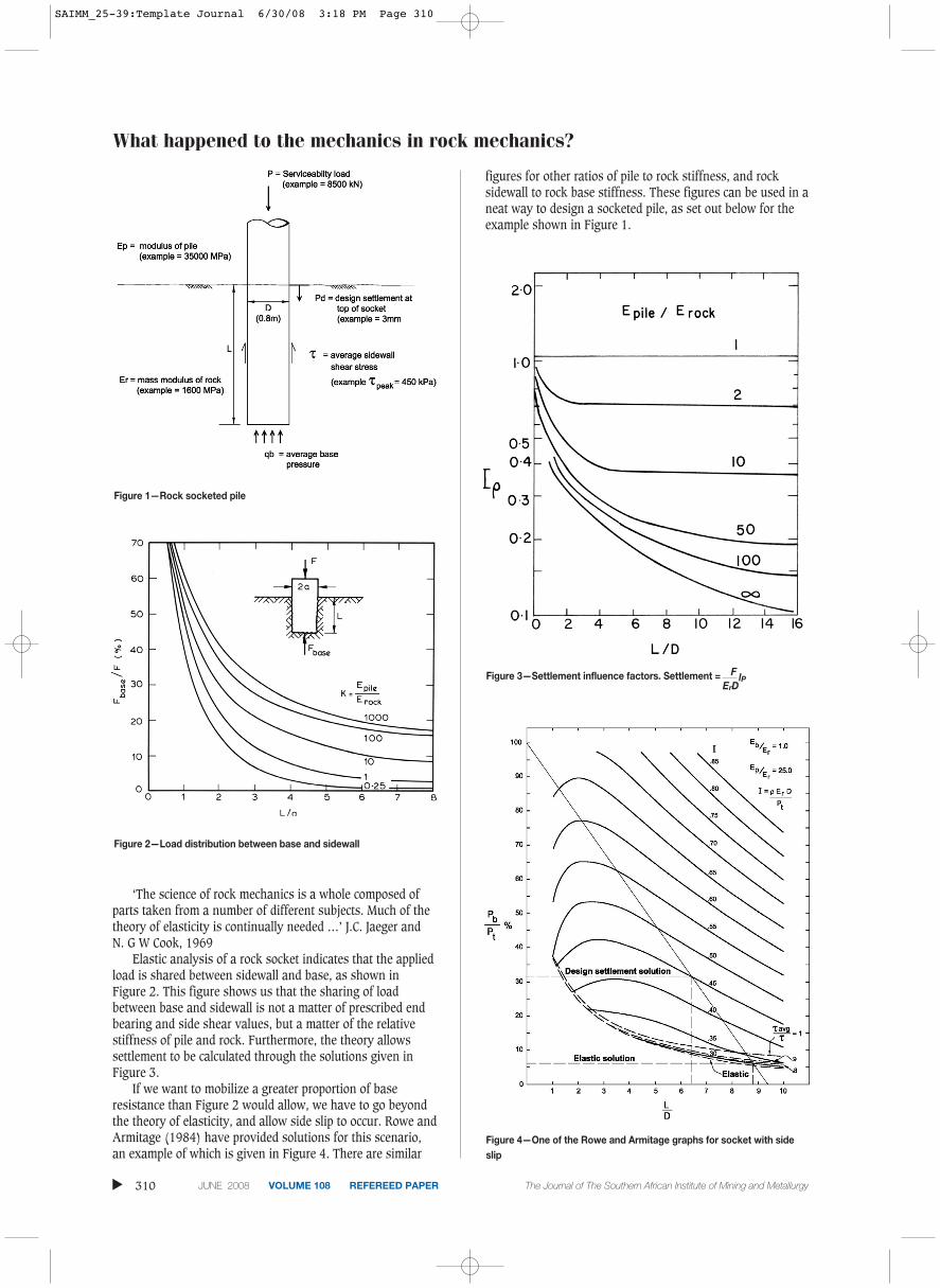
Given ultimate end bearing and side shearvalues, the design of a rock socketed pile, asillustrated in Figure 1, would appear to be atrivial matter. Surely the allowable load shouldbe given by adding the allowable end bearingload to the allowable side shear?
Is not the equation as follows?
[1]
whereAbase = area of baseAside = sidewall areaqbuilt = ultimate base resistanceτult = ultimate side shearFOS = Factor of Safety
Nice and simple, but the applied mechanicsis wrong. To obtain an appropriate answer wehave to find recourse in the theory of elasticity.As stated by two other fathers of rockmechanics:
What happened to the mechanics inrock mechanics and the geology inengineering geologyby P.J.N. Pells*
Synopsis
A good thing is becoming a bad thing. Rock mass classificationsystems, that are so excellent for communications betweenengineers and geologists, and that can be valuable in categorizingproject experience, are emasculating engineering geology and rockmechanics. Some engineering geologists have been sucked intothinking that Q and RMR values are all that is needed forengineering purposes, and seem to have put aside what can belearned from structural geology and geomorphology. Many rockmechanics engineers seem to have forgotten the scientific method.This paper attempts to redress the situation by showing howmechanics can be used in rock engineering to design with a similarrigour to that used in the fields of structural engineering, hydraulicsand soil mechanics. It also attempts to remind practitioners of whatcan be achieved by skilled engineering geology.
* Pells Sullivan Meynink Pty Ltd.© The Southern African Institute of Mining and
Metallurgy, 2008. SA ISSN 0038–223X/3.00 +0.00. This paper was first published at the SAIMM Symposium, Ground Support in Miningand Civil Engineering Construction, 30 March–3 April 2008.
309The Journal of The Southern African Institute of Mining and Metallurgy VOLUME 108 REFEREED PAPER JUNE 2008 ▲
SAIMM_25-39:Template Journal 6/30/08 3:18 PM Page 309
What happened to the mechanics in rock mechanics?
‘The science of rock mechanics is a whole composed ofparts taken from a number of different subjects. Much of thetheory of elasticity is continually needed …’ J.C. Jaeger and N. G W Cook, 1969
Elastic analysis of a rock socket indicates that the appliedload is shared between sidewall and base, as shown in Figure 2. This figure shows us that the sharing of loadbetween base and sidewall is not a matter of prescribed endbearing and side shear values, but a matter of the relativestiffness of pile and rock. Furthermore, the theory allowssettlement to be calculated through the solutions given inFigure 3.
If we want to mobilize a greater proportion of baseresistance than Figure 2 would allow, we have to go beyondthe theory of elasticity, and allow side slip to occur. Rowe andArmitage (1984) have provided solutions for this scenario,an example of which is given in Figure 4. There are similar
figures for other ratios of pile to rock stiffness, and rocksidewall to rock base stiffness. These figures can be used in aneat way to design a socketed pile, as set out below for theexample shown in Figure 1.
▲
310 JUNE 2008 VOLUME 108 REFEREED PAPER The Journal of The Southern African Institute of Mining and Metallurgy
Figure 1—Rock socketed pile
Figure 2—Load distribution between base and sidewall
Figure 3—Settlement influence factors. Settlement = FErD
lP
Figure 4—One of the Rowe and Armitage graphs for socket with sideslip
SAIMM_25-39:Template Journal 6/30/08 3:18 PM Page 310
➤ Step 1—Calculate the length of socket as if all the loadwere taken in side shear.
8500Length = Π x 0.8 x 450
= 7.5 m
7.5Hench L/D = 0.8
= 9.4
➤ Step 2—Plot this point on the x-axis of Figure 4 anddraw a straight line to the 100% mark on the y-axis.This line represents all solutions that obey therequirement of an average side shear value of 450 kPa.
➤ Step 3—Calculate the settlement influence factor.
l = ρErD
Pt
l = 0.003 x 1600 x 0.88.5
=0.45
➤ Step 4—Where the straight line intersects the influencefactor line for 0.45 is the design solution, if you areprepared to accept side slip. The design would be:
Socket length = 6.4 x 0.8 = 5.1 m
0.32 x 8.5 x 4 = 5.4 MPaEnd bearing pressure = Π x 0.82
If 5.4 MPa is considered too high for end bearingpressure then other points can be chosen along the straightline, as far down as the elastic solution. For these solutionssettlements will be less than 3 mm. The limit is the elasticsolution where
Socket length = 8.8 x 0.8 = 7 m
0.06 x 8.5 x 4 = 1.0 MPaEnd bearing pressure = Π x 0.82
Thus proper applied mechanics gives an elegant designmethod.
Mechanics of support design in horizontal beddedstrat
Scope of application
In many parts of the world there occur near horizontallybedded sandstones and shales in which to a depth of severalhundred metres the natural horizontal stresses are higherthan overburden pressure. Examples include the Karoo bedsof South Africa, the Bunter Sandstone of the UK and theTriassic strata of the Sydney region.
Fundamentals
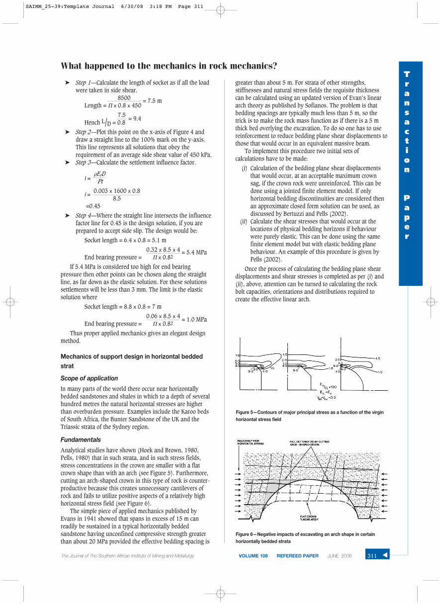
Analytical studies have shown (Hoek and Brown, 1980,Pells, 1980) that in such strata, and in such stress fields,stress concentrations in the crown are smaller with a flatcrown shape than with an arch (see Figure 5). Furthermore,cutting an arch-shaped crown in this type of rock is counter-productive because this creates unnecessary cantilevers ofrock and fails to utilize positive aspects of a relatively highhorizontal stress field (see Figure 6).
The simple piece of applied mechanics published byEvans in 1941 showed that spans in excess of 15 m canreadily be sustained in a typical horizontally beddedsandstone having unconfined compressive strength greaterthan about 20 MPa provided the effective bedding spacing is
greater than about 5 m. For strata of other strengths,stiffnesses and natural stress fields the requisite thicknesscan be calculated using an updated version of Evan’s lineararch theory as published by Sofianos. The problem is thatbedding spacings are typically much less than 5 m, so thetrick is to make the rock mass function as if there is a 5 mthick bed overlying the excavation. To do so one has to usereinforcement to reduce bedding plane shear displacements tothose that would occur in an equivalent massive beam.
To implement this procedure two initial sets ofcalculations have to be made:
(i) Calculation of the bedding plane shear displacementsthat would occur, at an acceptable maximum crownsag, if the crown rock were unreinforced. This can bedone using a jointed finite element model. If onlyhorizontal bedding discontinuities are considered thenan approximate closed form solution can be used, asdiscussed by Bertuzzi and Pells (2002).
(ii) Calculate the shear stresses that would occur at thelocations of physical bedding horizons if behaviourwere purely elastic. This can be done using the samefinite element model but with elastic bedding planebehaviour. An example of this procedure is given byPells (2002).
Once the process of calculating the bedding plane sheardisplacements and shear stresses is completed as per (i) and(ii), above, attention can be turned to calculating the rockbolt capacities, orientations and distributions required tocreate the effective linear arch.
What happened to the mechanics in rock mechanics?Transaction
Paper
311The Journal of The Southern African Institute of Mining and Metallurgy VOLUME 108 REFEREED PAPER JUNE 2008 ▲
Figure 5—Contours of major principal stress as a function of the virginhorizontal stress field
Figure 6—Negative impacts of excavating an arch shape in certainhorizontally bedded strata
SAIMM_25-39:Template Journal 6/30/08 3:18 PM Page 311
What happened to the mechanics in rock mechanics?
Calculation of rockbolt capacities
Forces
At the outset it should be noted that consideration is givenhere only to fully grouted rockbolts. These are typically so farsuperior to end anchored bolts in their influence on rockmass behaviour that the latter should be used only for localsupport of isolated loosened blocks of rock.
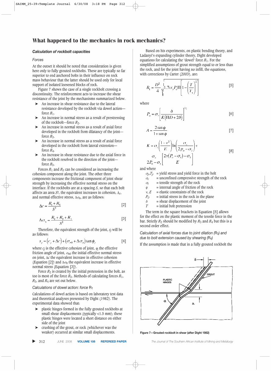
Figure 7 shows the case of a single rockbolt crossing adiscontinuity. The reinforcement acts to increase the shearresistance of the joint by the mechanisms summarized below.
➤ An increase in shear resistance due to the lateralresistance developed by the rockbolt via dowel action—force R1.
➤ An increase in normal stress as a result of prestressingof the rockbolt—force R2.
➤ An increase in normal stress as a result of axial forcedeveloped in the rockbolt from dilatancy of the joint—force R3.
➤ An increase in normal stress as a result of axial forcedeveloped in the rockbolt from lateral extension—force R4.
➤ An increase in shear resistance due to the axial force inthe rockbolt resolved in the direction of the joint—force R5.
Forces R1 and R5 can be considered as increasing thecohesion component along the joint. The other threecomponents increase the frictional component of joint shearstrength by increasing the effective normal stress on theinterface. If the rockbolts are at a spacing S, so that each boltaffects an area S2, the equivalent increases in cohesion, Δc,and normal effective stress, Δσn, are as follows:
[2]
[3]
Therefore, the equivalent strength of the joint, sj will beas follows:
[4]
where cj is the effective cohesion of joint, φj the effectivefriction angle of joint, σn0 the initial effective normal stresson joint, Δc the equivalent increase in effective cohesion(Equation [2]) and Δσn the equivalent increase in effectivenormal stress (Equation [3]).
Force R2 is created by the initial pretension in the bolt, astoo is most of the force R5. Methods of calculating forces R1,R3, and R4 are set out below.
Calculations of dowel action: force R1
Calculations of dowel action is based on laboratory test dataand theoretical analyses presented by Dight (1982). Theexperimental data showed that:
➤ plastic hinges formed in the fully grouted rockbolts atsmall shear displacements (typically <1.5 mm); theseplastic hinges were located a short distance on eitherside of the joint
➤ crushing of the grout, or rock (whichever was theweaker) occurred at similar small displacements.
Based on his experiments, on plastic bending theory, andLadanyi’s expanding cylinder theory, Dight developedequations for calculating the ‘dowel’ force R1. For thesimplified assumptions of grout strength equal to or less thanthe rock, and for the joint having no infill, the equations,with corrections by Carter (2003), are:
[5]
where
[6]
[7]
[8]
and whereσy,Ty = yield stress and yield force in the boltσc = unconfined compressive strength of the rockσt = tensile strength of the rockφ = internal angle of friction of the rockν, E = elastic constraints of the rockP0 = initial stress in the rock in the planeδ = shear displacement of the jointT = initial bolt pretension
The term in the square brackets in Equation [5] allowsfor the effect on the plastic moment of the tensile force in thebar. Strictly R2 should be modified by R3 and R4 but this is asecond order effect.
Calculation of axial forces due to joint dilation (R3) anddue to bolt extension caused by shearing (R4)
If the assumption is made that in a fully grouted rockbolt the
▲
312 JUNE 2008 VOLUME 108 REFEREED PAPER The Journal of The Southern African Institute of Mining and Metallurgy
Figure 7—Grouted rockbolt in shear (after Dight 1982)
SAIMM_25-39:Template Journal 6/30/08 3:18 PM Page 312
incremental axial strain in the bolt is dominantly between thetwo plastic hinges (see Figure 7) then the normal forcegenerated by dilation is:
[9]
whereα = angle between bolt and bedding planei = dilation angleThe axial force due to lengthening is:
[10]
[11]
Components due to bolt prestressing
If a bolt is prestressed to a force Pst prior to grouting then thenormal force on the joint is:
[12]
and the force along the joint is
[13]
Equations [9] to [13 presume that rockbolts are inclinedso that movements on bedding planes increase theireffectiveness.
Relative Importance of the forces R1 to R5
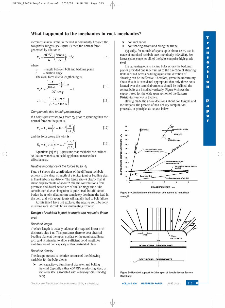
Figure 8 shows the contributions of the different rockboltactions to the shear strength of a typical joint or bedding planin Hawkesbury sandstone. The figure shows clearly that atshear displacements of about 2 mm the contributions fromprestress and dowel action are of similar magnitude. Thecontribution due to elongation is quite small but the contri-bution from joint dilation can completely dominate the load inthe bolt, and with rough joints will rapidly lead to bolt failure.
At this time I have not explored the relative contributionsin strong rock; it could be an illuminating exercise.
Design of rockbolt layout to create the requisite lineararch
Rockbolt lengthThe bolt length is usually taken as the required linear archthickness plus 1 m. This presumes there to be a physicalbedding plane at the upper surface of the nominated lineararch and is intended to allow sufficient bond length formobilization of bolt capacity at this postulated plane.
Rockbolt densityThe design process is iterative because of the followingvariables for the bolts alone:
➤ bolt capacity—a function of diameter and boltingmaterial (typically either 400 MPa reinforcing steel, or950 MPa steel associated with Macalloy/VSL/Diwidagbars)
➤ bolt inclination➤ bolt spacing across and along the tunnel.
Typically, for tunnels of spans up to about 12 m, use ismade of standard rockbolt steel (nominally 400 MPa). Forlarger spans some, or all, of the bolts comprise high-gradesteel.
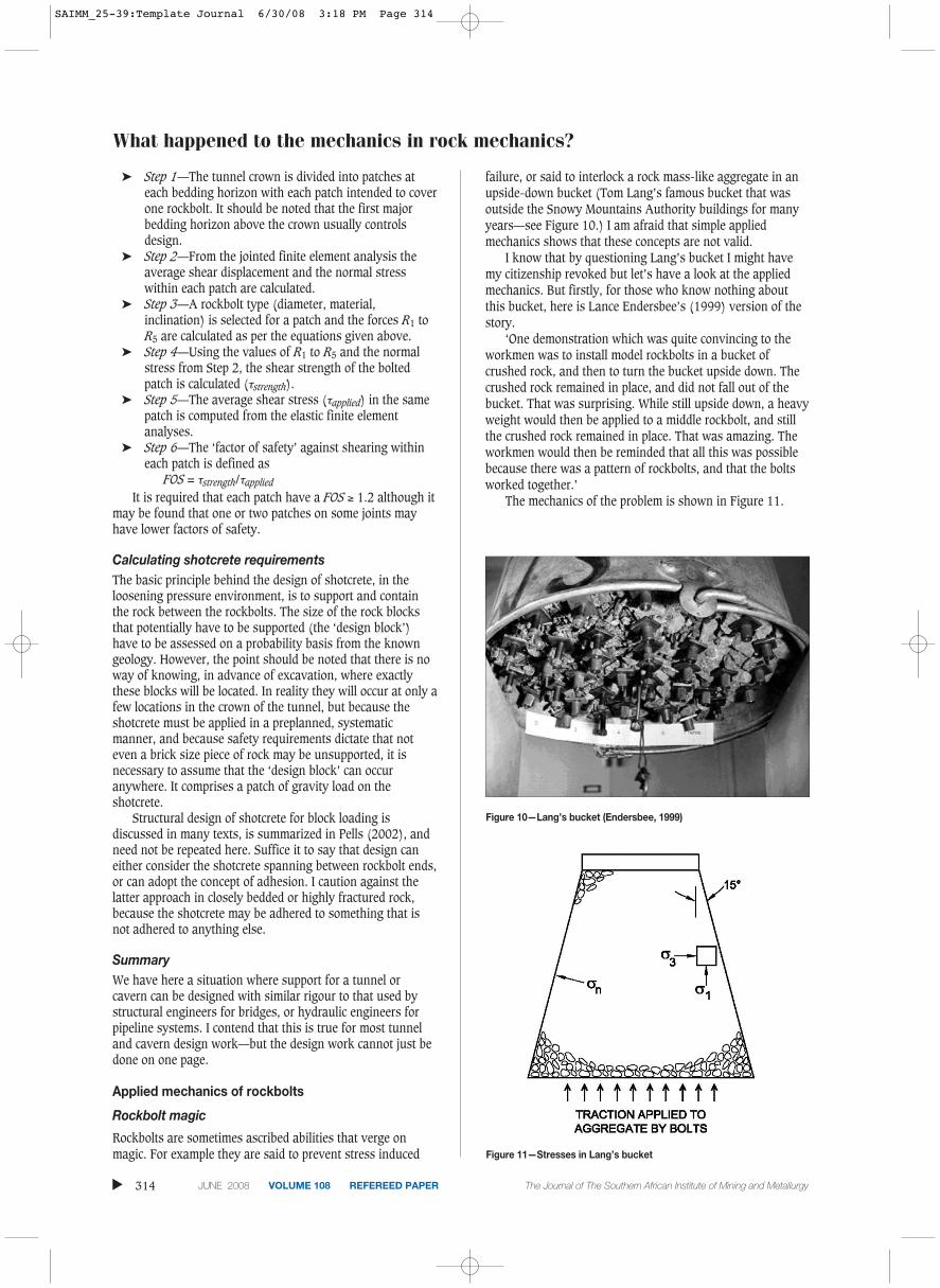
It is advantageous to incline bolts across the beddingplanes provided one is certain as to the direction of shearing.Bolts inclined across bedding against the direction ofshearing can be ineffective. Therefore, given the uncertaintyabout this, it is considered appropriate that only those boltslocated over the tunnel abutments should be inclined, thecentral bolts are installed vertically. Figure 9 shows thesupport used for the wide span section of the EasternDistributor tunnels in Sydney.
Having made the above decisions about bolt lengths andinclinations, the process of bolt density computationproceeds, in principle, as set out below.
What happened to the mechanics in rock mechanics?Transaction
Paper
The Journal of The Southern African Institute of Mining and Metallurgy VOLUME 108 REFEREED PAPER JUNE 2008 313 ▲
Figure 9—Rockbolt support for 24 m span of double decker EasternDistributor
Figure 8—Contribution of the different bolt actions to joint shearstrength
SAIMM_25-39:Template Journal 6/30/08 3:18 PM Page 313
What happened to the mechanics in rock mechanics?
➤ Step 1—The tunnel crown is divided into patches ateach bedding horizon with each patch intended to coverone rockbolt. It should be noted that the first majorbedding horizon above the crown usually controlsdesign.
➤ Step 2—From the jointed finite element analysis theaverage shear displacement and the normal stresswithin each patch are calculated.
➤ Step 3—A rockbolt type (diameter, material,inclination) is selected for a patch and the forces R1 toR5 are calculated as per the equations given above.
➤ Step 4—Using the values of R1 to R5 and the normalstress from Step 2, the shear strength of the boltedpatch is calculated (τstrength).
➤ Step 5—The average shear stress (τapplied) in the samepatch is computed from the elastic finite elementanalyses.
➤ Step 6—The ‘factor of safety’ against shearing withineach patch is defined as
FOS = τstrength/τapplied
It is required that each patch have a FOS ≥ 1.2 although itmay be found that one or two patches on some joints mayhave lower factors of safety.
Calculating shotcrete requirementsThe basic principle behind the design of shotcrete, in theloosening pressure environment, is to support and containthe rock between the rockbolts. The size of the rock blocksthat potentially have to be supported (the ‘design block’)have to be assessed on a probability basis from the knowngeology. However, the point should be noted that there is noway of knowing, in advance of excavation, where exactlythese blocks will be located. In reality they will occur at only afew locations in the crown of the tunnel, but because theshotcrete must be applied in a preplanned, systematicmanner, and because safety requirements dictate that noteven a brick size piece of rock may be unsupported, it isnecessary to assume that the ‘design block’ can occuranywhere. It comprises a patch of gravity load on theshotcrete.
Structural design of shotcrete for block loading isdiscussed in many texts, is summarized in Pells (2002), andneed not be repeated here. Suffice it to say that design caneither consider the shotcrete spanning between rockbolt ends,or can adopt the concept of adhesion. I caution against thelatter approach in closely bedded or highly fractured rock,because the shotcrete may be adhered to something that isnot adhered to anything else.
SummaryWe have here a situation where support for a tunnel orcavern can be designed with similar rigour to that used bystructural engineers for bridges, or hydraulic engineers forpipeline systems. I contend that this is true for most tunneland cavern design work—but the design work cannot just bedone on one page.
Applied mechanics of rockbolts
Rockbolt magic
Rockbolts are sometimes ascribed abilities that verge onmagic. For example they are said to prevent stress induced
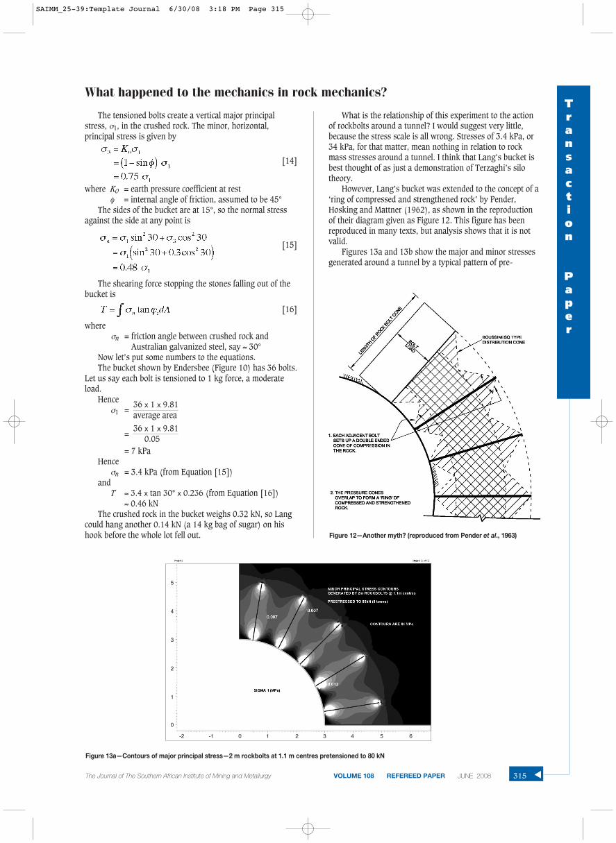
failure, or said to interlock a rock mass-like aggregate in anupside-down bucket (Tom Lang’s famous bucket that wasoutside the Snowy Mountains Authority buildings for manyyears—see Figure 10.) I am afraid that simple appliedmechanics shows that these concepts are not valid.
I know that by questioning Lang’s bucket I might havemy citizenship revoked but let’s have a look at the appliedmechanics. But firstly, for those who know nothing aboutthis bucket, here is Lance Endersbee’s (1999) version of thestory.
‘One demonstration which was quite convincing to theworkmen was to install model rockbolts in a bucket ofcrushed rock, and then to turn the bucket upside down. Thecrushed rock remained in place, and did not fall out of thebucket. That was surprising. While still upside down, a heavyweight would then be applied to a middle rockbolt, and stillthe crushed rock remained in place. That was amazing. Theworkmen would then be reminded that all this was possiblebecause there was a pattern of rockbolts, and that the boltsworked together.’
The mechanics of the problem is shown in Figure 11.
▲
314 JUNE 2008 VOLUME 108 REFEREED PAPER The Journal of The Southern African Institute of Mining and Metallurgy
Figure 10—Lang’s bucket (Endersbee, 1999)
Figure 11—Stresses in Lang’s bucket
SAIMM_25-39:Template Journal 6/30/08 3:18 PM Page 314
The tensioned bolts create a vertical major principalstress, σ1, in the crushed rock. The minor, horizontal,principal stress is given by
[14]
where K0 = earth pressure coefficient at restφ = internal angle of friction, assumed to be 45°
The sides of the bucket are at 15°, so the normal stressagainst the side at any point is
[15]
The shearing force stopping the stones falling out of thebucket is
[16]
whereσn = friction angle between crushed rock and
Australian galvanized steel, say ≈ 30°Now let’s put some numbers to the equations.The bucket shown by Endersbee (Figure 10) has 36 bolts.
Let us say each bolt is tensioned to 1 kg force, a moderateload.
Henceσ1 =
36 x 1 x 9.81average area
= 36 x 1 x 9.81
0.05= 7 kPa
Henceσn = 3.4 kPa (from Equation [15])
andT ≈ 3.4 x tan 30° x 0.236 (from Equation [16])
≈ 0.46 kNThe crushed rock in the bucket weighs 0.32 kN, so Lang
could hang another 0.14 kN (a 14 kg bag of sugar) on hishook before the whole lot fell out.
What is the relationship of this experiment to the actionof rockbolts around a tunnel? I would suggest very little,because the stress scale is all wrong. Stresses of 3.4 kPa, or34 kPa, for that matter, mean nothing in relation to rockmass stresses around a tunnel. I think that Lang’s bucket isbest thought of as just a demonstration of Terzaghi’s silotheory.
However, Lang’s bucket was extended to the concept of a‘ring of compressed and strengthened rock’ by Pender,Hosking and Mattner (1962), as shown in the reproductionof their diagram given as Figure 12. This figure has beenreproduced in many texts, but analysis shows that it is notvalid.
Figures 13a and 13b show the major and minor stressesgenerated around a tunnel by a typical pattern of pre-
What happened to the mechanics in rock mechanics?Transaction
Paper
The Journal of The Southern African Institute of Mining and Metallurgy VOLUME 108 REFEREED PAPER JUNE 2008 315 ▲Figure 12—Another myth? (reproduced from Pender et al., 1963)
Figure 13a—Contours of major principal stress—2 m rockbolts at 1.1 m centres pretensioned to 80 kN
-2 -1 0 1 2 3 4 5 6
5
4
3
2
1
0
SAIMM_25-39:Template Journal 6/30/08 3:18 PM Page 315
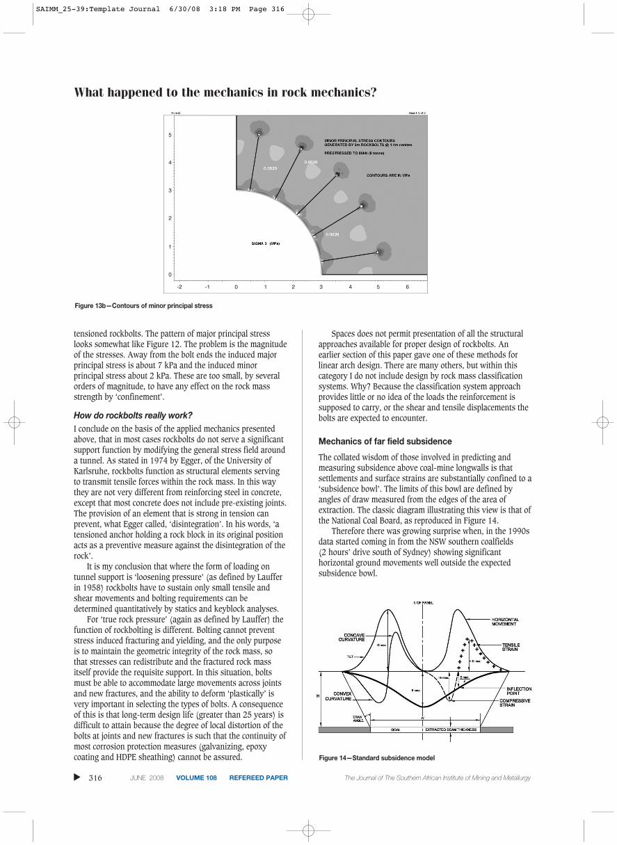
What happened to the mechanics in rock mechanics?
tensioned rockbolts. The pattern of major principal stresslooks somewhat like Figure 12. The problem is the magnitudeof the stresses. Away from the bolt ends the induced majorprincipal stress is about 7 kPa and the induced minorprincipal stress about 2 kPa. These are too small, by severalorders of magnitude, to have any effect on the rock massstrength by ‘confinement’.
How do rockbolts really work?I conclude on the basis of the applied mechanics presentedabove, that in most cases rockbolts do not serve a significantsupport function by modifying the general stress field arounda tunnel. As stated in 1974 by Egger, of the University ofKarlsruhe, rockbolts function as structural elements servingto transmit tensile forces within the rock mass. In this waythey are not very different from reinforcing steel in concrete,except that most concrete does not include pre-existing joints.The provision of an element that is strong in tension canprevent, what Egger called, ‘disintegration’. In his words, ‘atensioned anchor holding a rock block in its original positionacts as a preventive measure against the disintegration of therock’.
It is my conclusion that where the form of loading ontunnel support is ‘loosening pressure’ (as defined by Laufferin 1958) rockbolts have to sustain only small tensile andshear movements and bolting requirements can bedetermined quantitatively by statics and keyblock analyses.
For ‘true rock pressure’ (again as defined by Lauffer) thefunction of rockbolting is different. Bolting cannot preventstress induced fracturing and yielding, and the only purposeis to maintain the geometric integrity of the rock mass, sothat stresses can redistribute and the fractured rock massitself provide the requisite support. In this situation, boltsmust be able to accommodate large movements across jointsand new fractures, and the ability to deform ‘plastically’ isvery important in selecting the types of bolts. A consequenceof this is that long-term design life (greater than 25 years) isdifficult to attain because the degree of local distortion of thebolts at joints and new fractures is such that the continuity ofmost corrosion protection measures (galvanizing, epoxycoating and HDPE sheathing) cannot be assured.
Spaces does not permit presentation of all the structuralapproaches available for proper design of rockbolts. Anearlier section of this paper gave one of these methods forlinear arch design. There are many others, but within thiscategory I do not include design by rock mass classificationsystems. Why? Because the classification system approachprovides little or no idea of the loads the reinforcement issupposed to carry, or the shear and tensile displacements thebolts are expected to encounter.
Mechanics of far field subsidence
The collated wisdom of those involved in predicting andmeasuring subsidence above coal-mine longwalls is thatsettlements and surface strains are substantially confined to a‘subsidence bowl’. The limits of this bowl are defined byangles of draw measured from the edges of the area ofextraction. The classic diagram illustrating this view is that ofthe National Coal Board, as reproduced in Figure 14.
Therefore there was growing surprise when, in the 1990sdata started coming in from the NSW southern coalfields (2 hours’ drive south of Sydney) showing significanthorizontal ground movements well outside the expectedsubsidence bowl.
▲
316 JUNE 2008 VOLUME 108 REFEREED PAPER The Journal of The Southern African Institute of Mining and Metallurgy
Figure 14—Standard subsidence model
Figure 13b—Contours of minor principal stress
-2 -1 0 1 2 3 4 5 6
5
4
3
2
1
0
SAIMM_25-39:Template Journal 6/30/08 3:18 PM Page 316
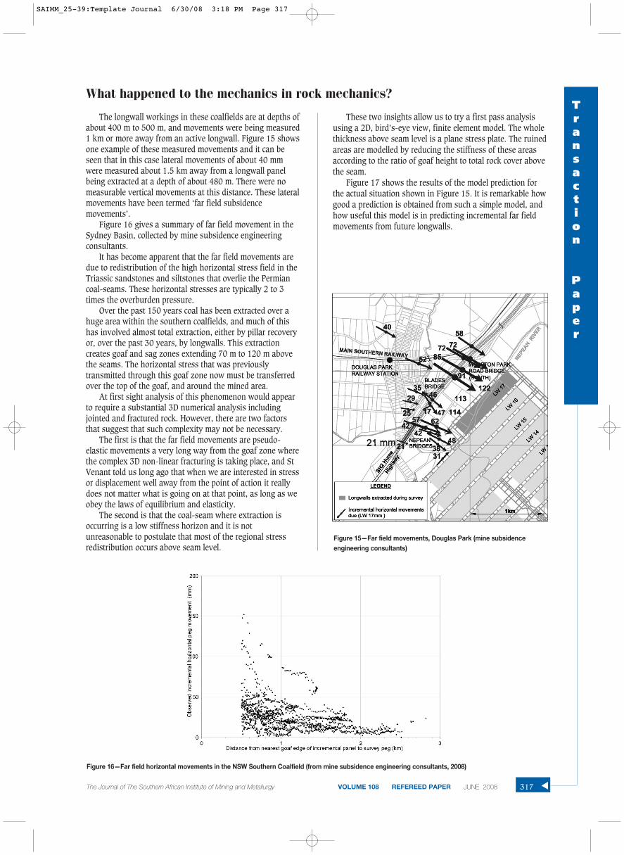
The longwall workings in these coalfields are at depths ofabout 400 m to 500 m, and movements were being measured1 km or more away from an active longwall. Figure 15 showsone example of these measured movements and it can beseen that in this case lateral movements of about 40 mmwere measured about 1.5 km away from a longwall panelbeing extracted at a depth of about 480 m. There were nomeasurable vertical movements at this distance. These lateralmovements have been termed ‘far field subsidencemovements’.
Figure 16 gives a summary of far field movement in theSydney Basin, collected by mine subsidence engineeringconsultants.
It has become apparent that the far field movements aredue to redistribution of the high horizontal stress field in theTriassic sandstones and siltstones that overlie the Permiancoal-seams. These horizontal stresses are typically 2 to 3times the overburden pressure.
Over the past 150 years coal has been extracted over ahuge area within the southern coalfields, and much of thishas involved almost total extraction, either by pillar recoveryor, over the past 30 years, by longwalls. This extractioncreates goaf and sag zones extending 70 m to 120 m abovethe seams. The horizontal stress that was previouslytransmitted through this goaf zone now must be transferredover the top of the goaf, and around the mined area.
At first sight analysis of this phenomenon would appearto require a substantial 3D numerical analysis includingjointed and fractured rock. However, there are two factorsthat suggest that such complexity may not be necessary.
The first is that the far field movements are pseudo-elastic movements a very long way from the goaf zone wherethe complex 3D non-linear fracturing is taking place, and StVenant told us long ago that when we are interested in stressor displacement well away from the point of action it reallydoes not matter what is going on at that point, as long as weobey the laws of equilibrium and elasticity.
The second is that the coal-seam where extraction isoccurring is a low stiffness horizon and it is notunreasonable to postulate that most of the regional stressredistribution occurs above seam level.
These two insights allow us to try a first pass analysisusing a 2D, bird’s-eye view, finite element model. The wholethickness above seam level is a plane stress plate. The ruinedareas are modelled by reducing the stiffness of these areasaccording to the ratio of goaf height to total rock cover abovethe seam.
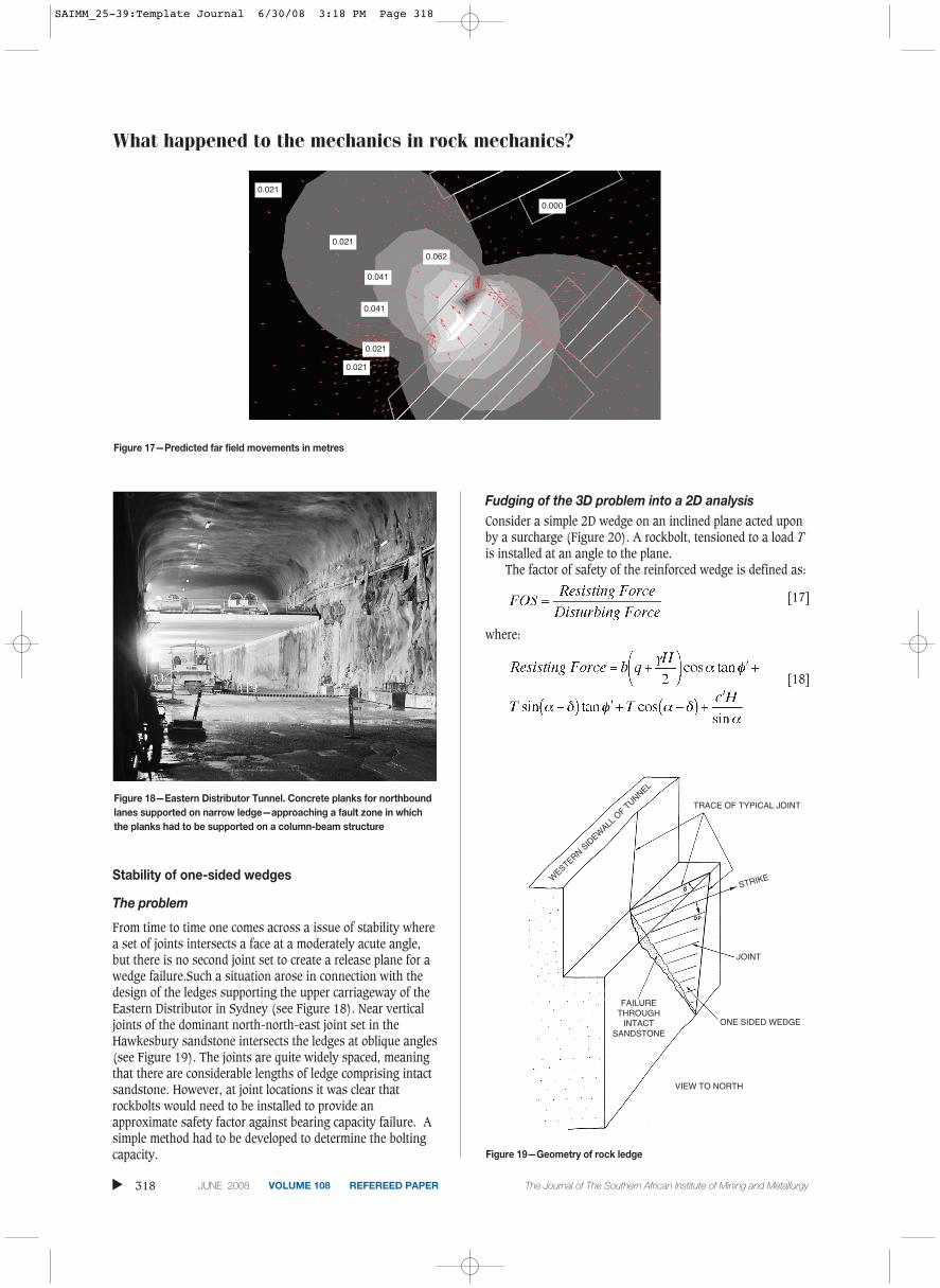
Figure 17 shows the results of the model prediction forthe actual situation shown in Figure 15. It is remarkable howgood a prediction is obtained from such a simple model, andhow useful this model is in predicting incremental far fieldmovements from future longwalls.
What happened to the mechanics in rock mechanics?Transaction
Paper
The Journal of The Southern African Institute of Mining and Metallurgy VOLUME 108 REFEREED PAPER JUNE 2008 317 ▲Figure 15—Far field movements, Douglas Park (mine subsidenceengineering consultants)
Figure 16—Far field horizontal movements in the NSW Southern Coalfield (from mine subsidence engineering consultants, 2008)
SAIMM_25-39:Template Journal 6/30/08 3:18 PM Page 317
What happened to the mechanics in rock mechanics?
Stability of one-sided wedges
The problem
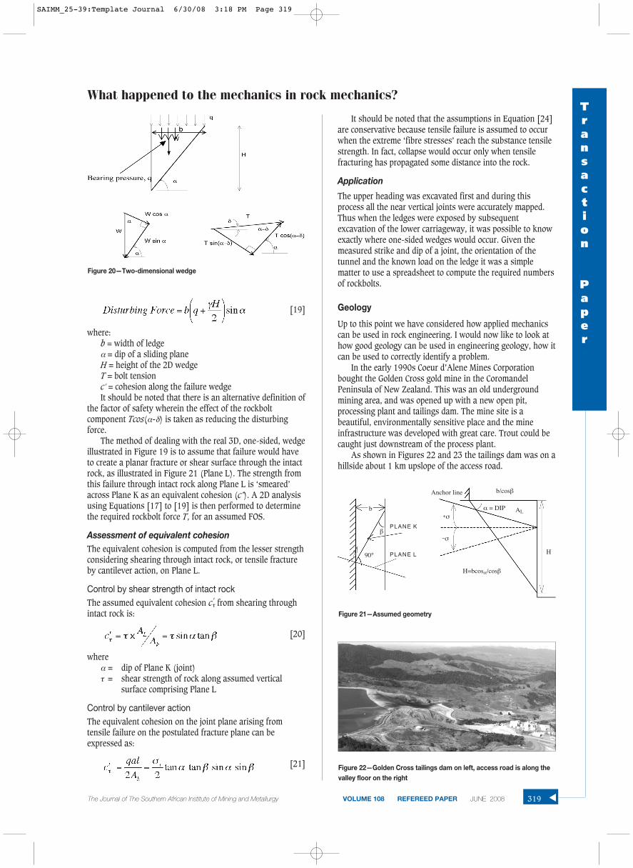
From time to time one comes across a issue of stability wherea set of joints intersects a face at a moderately acute angle,but there is no second joint set to create a release plane for awedge failure.Such a situation arose in connection with thedesign of the ledges supporting the upper carriageway of theEastern Distributor in Sydney (see Figure 18). Near verticaljoints of the dominant north-north-east joint set in theHawkesbury sandstone intersects the ledges at oblique angles(see Figure 19). The joints are quite widely spaced, meaningthat there are considerable lengths of ledge comprising intactsandstone. However, at joint locations it was clear thatrockbolts would need to be installed to provide anapproximate safety factor against bearing capacity failure. Asimple method had to be developed to determine the boltingcapacity.
Fudging of the 3D problem into a 2D analysisConsider a simple 2D wedge on an inclined plane acted uponby a surcharge (Figure 20). A rockbolt, tensioned to a load Tis installed at an angle to the plane.
The factor of safety of the reinforced wedge is defined as:
[17]
where:
[18]
▲
318 JUNE 2008 VOLUME 108 REFEREED PAPER The Journal of The Southern African Institute of Mining and Metallurgy
Figure 17—Predicted far field movements in metres
Figure 18—Eastern Distributor Tunnel. Concrete planks for northboundlanes supported on narrow ledge—approaching a fault zone in whichthe planks had to be supported on a column-beam structure
Figure 19—Geometry of rock ledge
0.021
0.021
0.062
0.041
0.041
0.021
0.021
0.000
VIEW TO NORTH
ONE SIDED WEDGE
WESTERN S
IDEW
ALL O
F TUNNEL
FAILURETHROUGH
INTACTSANDSTONE
JOINT
STRIKE
TRACE OF TYPICAL JOINT
SAIMM_25-39:Template Journal 6/30/08 3:18 PM Page 318
[19]
where:b = width of ledgeα = dip of a sliding plane H = height of the 2D wedgeT = bolt tensionc′ = cohesion along the failure wedgeIt should be noted that there is an alternative definition of
the factor of safety wherein the effect of the rockboltcomponent Tcos(α-δ) is taken as reducing the disturbingforce.
The method of dealing with the real 3D, one-sided, wedgeillustrated in Figure 19 is to assume that failure would haveto create a planar fracture or shear surface through the intactrock, as illustrated in Figure 21 (Plane L). The strength fromthis failure through intact rock along Plane L is ‘smeared’across Plane K as an equivalent cohesion (c’). A 2D analysisusing Equations [17] to [19] is then performed to determinethe required rockbolt force T, for an assumed FOS.
Assessment of equivalent cohesionThe equivalent cohesion is computed from the lesser strengthconsidering shearing through intact rock, or tensile fractureby cantilever action, on Plane L.
Control by shear strength of intact rockThe assumed equivalent cohesion c′τ from shearing throughintact rock is:
[20]
whereα = dip of Plane K (joint)τ = shear strength of rock along assumed vertical
surface comprising Plane L
Control by cantilever actionThe equivalent cohesion on the joint plane arising fromtensile failure on the postulated fracture plane can beexpressed as:
[21]
It should be noted that the assumptions in Equation [24]are conservative because tensile failure is assumed to occurwhen the extreme ‘fibre stresses’ reach the substance tensilestrength. In fact, collapse would occur only when tensilefracturing has propagated some distance into the rock.
Application
The upper heading was excavated first and during thisprocess all the near vertical joints were accurately mapped.Thus when the ledges were exposed by subsequentexcavation of the lower carriageway, it was possible to knowexactly where one-sided wedges would occur. Given themeasured strike and dip of a joint, the orientation of thetunnel and the known load on the ledge it was a simplematter to use a spreadsheet to compute the required numbersof rockbolts.
Geology
Up to this point we have considered how applied mechanicscan be used in rock engineering. I would now like to look athow good geology can be used in engineering geology, how itcan be used to correctly identify a problem.
In the early 1990s Coeur d’Alene Mines Corporationbought the Golden Cross gold mine in the CoromandelPeninsula of New Zealand. This was an old undergroundmining area, and was opened up with a new open pit,processing plant and tailings dam. The mine site is abeautiful, environmentally sensitive place and the mineinfrastructure was developed with great care. Trout could becaught just downstream of the process plant.
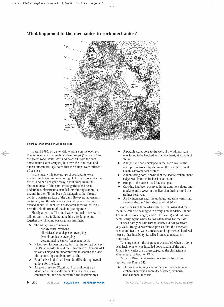
As shown in Figures 22 and 23 the tailings dam was on ahillside about 1 km upslope of the access road.
What happened to the mechanics in rock mechanics?Transaction
Paper
The Journal of The Southern African Institute of Mining and Metallurgy VOLUME 108 REFEREED PAPER JUNE 2008 319 ▲
Figure 20—Two-dimensional wedge
Figure 21—Assumed geometry
Figure 22—Golden Cross tailings dam on left, access road is along thevalley floor on the right
H=bcosα/cosβ
H
AL
90°
b
Anchor line
PLANE K
PLANE L
b/cosβ
β
α = DIP+σ
−σ
SAIMM_25-39:Template Journal 6/30/08 3:18 PM Page 319
What happened to the mechanics in rock mechanics?
In April 1995, on a site visit to advise on the open pit,Tim Sullivan noted, at night, certain bumps (‘two steps’) inthe access road, south-west and downhill from the dam.Some months later (August) he drove the same road and,almost subconsciously, noted that the bumps were different(‘five steps’).
In the meanwhile two groups of consultants wereinvolved in design and monitoring of the dam. Concerns hadarisen, and had not gone away, about cracking in theabutment areas of the dam. Investigations had beenundertaken, piezometers installed, monitoring stations setup, and further fill had been placed against the, alreadygentle, downstream face of the dam. However, movementscontinued, and the whole issue heated up when a crackopened about 100 mm, with associated shearing, at Trig Jnear the left abutment of the dam (see Figure 23).
Shortly after this, Tim and I were retained to review thetailings dam area. It did not take him very long to puttogether the following observations and facts.
➤ The site geology comprises- ash (recent), overlying- alluvial/colluvial deposits, overlying- Omahia andesite, overlying- Coromandel volcanics (basement rock).
➤ It had been known for decades that the contact betweenthe Omahia ardesite and the, smectite-rich, Coromandelvolcanics played an important role in shaping the land.The contact dips at about 10° south.
➤ Four ‘active faults’ had been identified during investi-gations for the dam.
➤ An area of tomos (Maori word for sinkhole) wasidentified in the saddle embankment area duringconstruction, and another within the reservoir area.
➤ A potable water bore to the west of the tailings damwas found to be blocked, or the pipe bent, at a depth of34 m.
➤ A large slide had developed in the north wall of theopen pit, controlled by sliding on the near horizontalOmahia-Coromandel contact.
➤ A monitoring bore, downhill of the saddle embankmentridge, was found to be blocked at 25 m.
➤ Bumps in the access road had changed.➤ Cracking had been observed in the abutment ridge, and
cracking and a tomo in the diversion drain around thetailings reservoir.
➤ An inclinometer near the underground mine vent shaft(west of the dam) had sheared off at 20 m.
On the basis of these observations Tim postulated thatthe mine could be dealing with a very large landslide (about1.5 km downslope length, and 0.5 km width) and unknowndepth, carrying the whole tailings dam along for the ride.
It need hardly be said that this view did not go acrossvery well. Strong views were expressed that the observedevents and features were unrelated and represented localizednear-surface instability. Localized remedial measurescontinued.
To a large extent the argument was sealed when a 100 mdeep inclinometer was installed downstream of the dam.After a few weeks or so there appeared the characteristicshear step, at a depth of 80 m.
By early 1996 the following conclusions had beenreached (see Figure 24).
➤ The area containing and to the south of the tailingsembankment was a large deep-seated, primarilytranslational landslide.
▲
320 JUNE 2008 VOLUME 108 REFEREED PAPER The Journal of The Southern African Institute of Mining and Metallurgy
Figure 23—Plan of Golden Cross mine site
SAIMM_25-39:Template Journal 6/30/08 3:18 PM Page 320
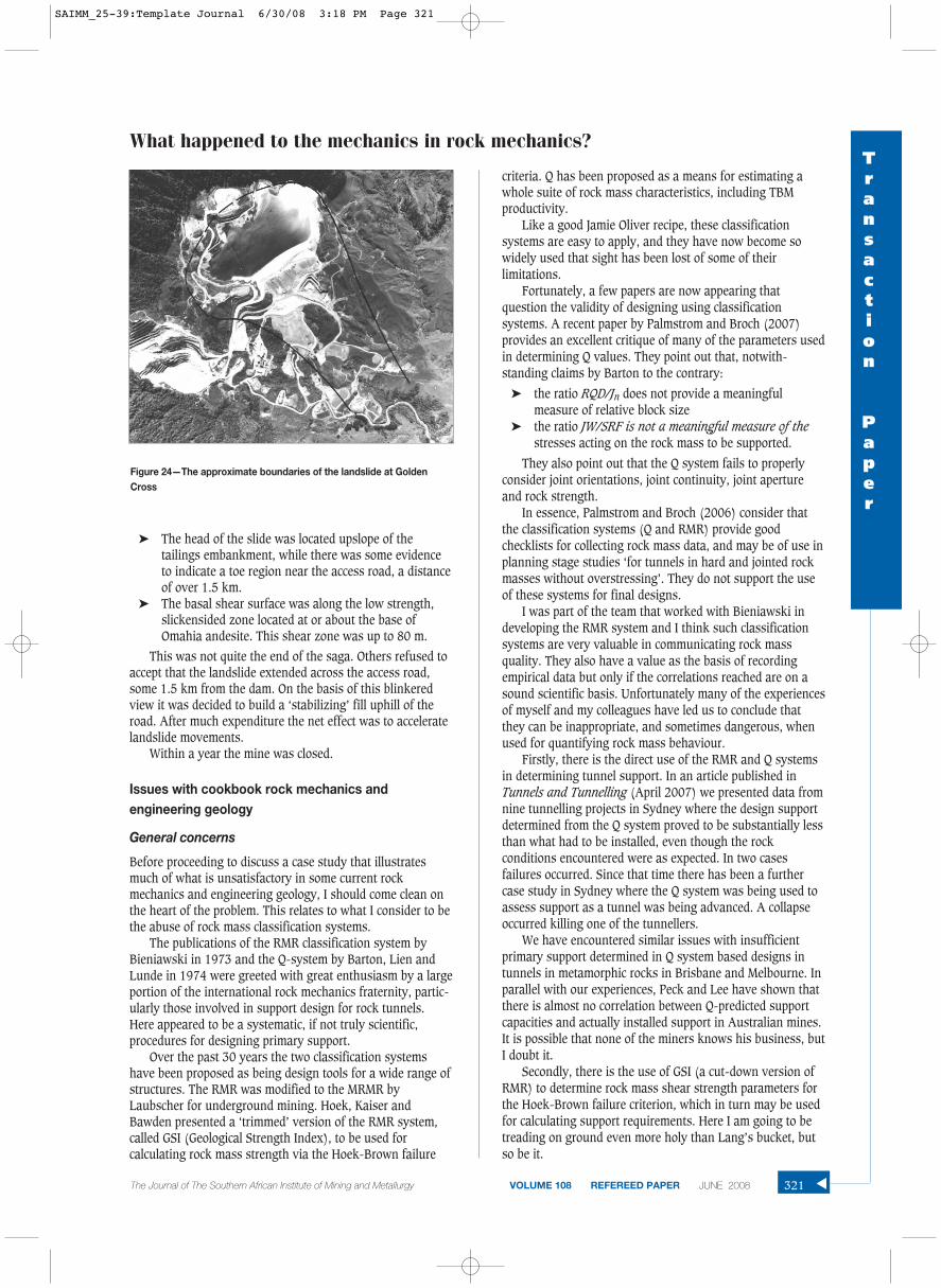
➤ The head of the slide was located upslope of thetailings embankment, while there was some evidenceto indicate a toe region near the access road, a distanceof over 1.5 km.
➤ The basal shear surface was along the low strength,slickensided zone located at or about the base ofOmahia andesite. This shear zone was up to 80 m.
This was not quite the end of the saga. Others refused toaccept that the landslide extended across the access road,some 1.5 km from the dam. On the basis of this blinkeredview it was decided to build a ‘stabilizing’ fill uphill of theroad. After much expenditure the net effect was to acceleratelandslide movements.
Within a year the mine was closed.
Issues with cookbook rock mechanics andengineering geology
General concerns
Before proceeding to discuss a case study that illustratesmuch of what is unsatisfactory in some current rockmechanics and engineering geology, I should come clean onthe heart of the problem. This relates to what I consider to bethe abuse of rock mass classification systems.
The publications of the RMR classification system byBieniawski in 1973 and the Q-system by Barton, Lien andLunde in 1974 were greeted with great enthusiasm by a largeportion of the international rock mechanics fraternity, partic-ularly those involved in support design for rock tunnels.Here appeared to be a systematic, if not truly scientific,procedures for designing primary support.
Over the past 30 years the two classification systemshave been proposed as being design tools for a wide range ofstructures. The RMR was modified to the MRMR byLaubscher for underground mining. Hoek, Kaiser andBawden presented a ‘trimmed’ version of the RMR system,called GSI (Geological Strength Index), to be used forcalculating rock mass strength via the Hoek-Brown failure
criteria. Q has been proposed as a means for estimating awhole suite of rock mass characteristics, including TBMproductivity.
Like a good Jamie Oliver recipe, these classificationsystems are easy to apply, and they have now become sowidely used that sight has been lost of some of theirlimitations.
Fortunately, a few papers are now appearing thatquestion the validity of designing using classificationsystems. A recent paper by Palmstrom and Broch (2007)provides an excellent critique of many of the parameters usedin determining Q values. They point out that, notwith-standing claims by Barton to the contrary:
➤ the ratio RQD/Jn does not provide a meaningfulmeasure of relative block size
➤ the ratio JW/SRF is not a meaningful measure of thestresses acting on the rock mass to be supported.
They also point out that the Q system fails to properlyconsider joint orientations, joint continuity, joint apertureand rock strength.
In essence, Palmstrom and Broch (2006) consider thatthe classification systems (Q and RMR) provide goodchecklists for collecting rock mass data, and may be of use inplanning stage studies ‘for tunnels in hard and jointed rockmasses without overstressing’. They do not support the useof these systems for final designs.
I was part of the team that worked with Bieniawski indeveloping the RMR system and I think such classificationsystems are very valuable in communicating rock massquality. They also have a value as the basis of recordingempirical data but only if the correlations reached are on asound scientific basis. Unfortunately many of the experiencesof myself and my colleagues have led us to conclude thatthey can be inappropriate, and sometimes dangerous, whenused for quantifying rock mass behaviour.
Firstly, there is the direct use of the RMR and Q systemsin determining tunnel support. In an article published inTunnels and Tunnelling (April 2007) we presented data fromnine tunnelling projects in Sydney where the design supportdetermined from the Q system proved to be substantially lessthan what had to be installed, even though the rockconditions encountered were as expected. In two casesfailures occurred. Since that time there has been a furthercase study in Sydney where the Q system was being used toassess support as a tunnel was being advanced. A collapseoccurred killing one of the tunnellers.
We have encountered similar issues with insufficientprimary support determined in Q system based designs intunnels in metamorphic rocks in Brisbane and Melbourne. Inparallel with our experiences, Peck and Lee have shown thatthere is almost no correlation between Q-predicted supportcapacities and actually installed support in Australian mines.It is possible that none of the miners knows his business, butI doubt it.
Secondly, there is the use of GSI (a cut-down version ofRMR) to determine rock mass shear strength parameters forthe Hoek-Brown failure criterion, which in turn may be usedfor calculating support requirements. Here I am going to betreading on ground even more holy than Lang’s bucket, butso be it.
What happened to the mechanics in rock mechanics?Transaction
Paper
The Journal of The Southern African Institute of Mining and Metallurgy VOLUME 108 REFEREED PAPER JUNE 2008 321 ▲
Figure 24—The approximate boundaries of the landslide at GoldenCross
SAIMM_25-39:Template Journal 6/30/08 3:18 PM Page 321
What happened to the mechanics in rock mechanics?
Mostyn and Douglas (2000) provide a detailed critique ofthe Hoek-Brown failure criterion for intact rock. Theyconclude that:
‘… there are inadequacies in the Hoek-Brown empiricalfailure criterion as currently proposed for intact rock and, byinference, as extended to rock mass strength. The parametermi can be misleading, as mi does not appear to be related torock type. The Hoek-Brown criterion can be generalised byallowing the exponent to vary. This change results in a bettermodel of the experimental data.’
Mostyn and Douglas then proceed to discuss the Hoek-Brown failure criterion for rock masses, as given by theequation:
[22]
where mb and s are calculated from a GSI value. They notethe following:
‘The only ‘rock mass’ tested and used in the originaldevelopment of the Hoek-Brown criterion was 152 mm coresamples of Panguna andesite from Bougainville in PapuaNew Guinea (Hoek and Brown, 1980). Hoek and Brown(1988) later noted that it was likely this material was in fact‘disturbed’. The validation of the updates of the Hoek-Browncriterion have been based on experience gained whilst usingthis criterion. To the authors’ knowledge the data supportingthis experience has not been published.’
I considered it to be extraordinary that a failure criterion,widely used around the world, is based on such a paucity ofdata. Mostyn and Douglas discuss various improvements thatshould be made to the Hoek-Brown mass criterion for slopeanalysis but they too have only one case study plus a lowerbound based on the shear strength properties of rockfill.They fully acknowledge the limited experimental data base.To my knowledge nobody has published a comparable studyof this criterion for underground excavations.
I think matters are made even worse by the provision,through the computer program RocLab, of ‘calculating’ therock mass ‘modulus of deformation’. This is one area where,in the Sydney rock, we have plenty of good field experimental
data. Table I shows this field data in comparison with theHoek-Brown (RocLab) computed values. For these rockmasses the RocLab values are nonsense.
I think that available evidence places the Hoek-Browncriterion for rock masses as no more than a hypothesis. Itmay be a good hypothesis, but until it is properly supportedby, or modified as a result of, proper field experimental datait is not wise to use it as the basis of major design decisions.It has nowhere near the experimental foundation as theMohr-Coulomb criterion has in the field of soil mechanics.
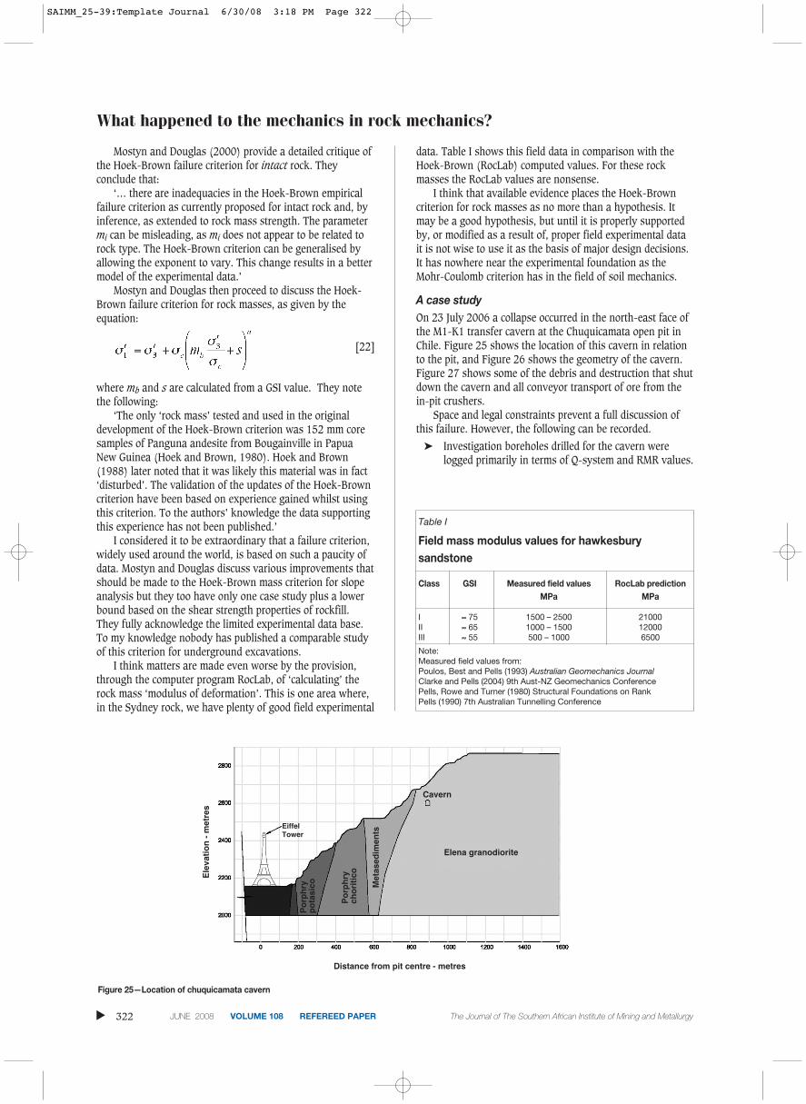
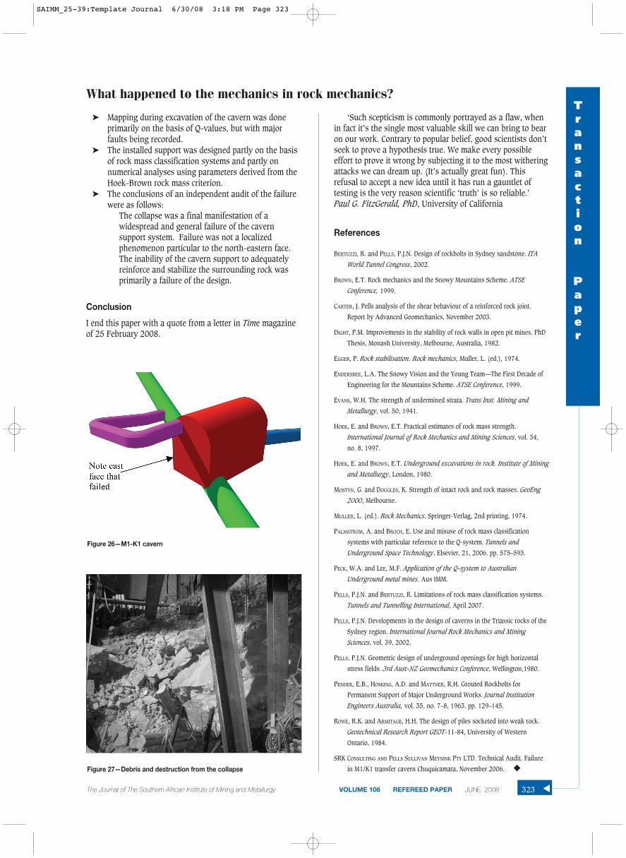
A case studyOn 23 July 2006 a collapse occurred in the north-east face ofthe M1-K1 transfer cavern at the Chuquicamata open pit inChile. Figure 25 shows the location of this cavern in relationto the pit, and Figure 26 shows the geometry of the cavern.Figure 27 shows some of the debris and destruction that shutdown the cavern and all conveyor transport of ore from thein-pit crushers.
Space and legal constraints prevent a full discussion ofthis failure. However, the following can be recorded.
➤ Investigation boreholes drilled for the cavern werelogged primarily in terms of Q-system and RMR values.
▲
322 JUNE 2008 VOLUME 108 REFEREED PAPER The Journal of The Southern African Institute of Mining and Metallurgy
Table I
Field mass modulus values for hawkesburysandstone
Class GSI Measured field values RocLab predictionMPa MPa
I ≈ 75 1500 – 2500 21000II ≈ 65 1000 – 1500 12000III ≈ 55 500 – 1000 6500
Note:Measured field values from:Poulos, Best and Pells (1993) Australian Geomechanics JournalClarke and Pells (2004) 9th Aust-NZ Geomechanics ConferencePells, Rowe and Turner (1980) Structural Foundations on RankPells (1990) 7th Australian Tunnelling Conference
Figure 25—Location of chuquicamata cavern
Elena granodiorite
Distance from pit centre - metres
Ele
vati
on
- m
etre
s
Cavern
EiffelTower
Met
ased
imen
ts
Po
rph
ryp
ota
sico
Po
rph
rych
ori
tico
SAIMM_25-39:Template Journal 6/30/08 3:18 PM Page 322
➤ Mapping during excavation of the cavern was doneprimarily on the basis of Q-values, but with majorfaults being recorded.
➤ The installed support was designed partly on the basisof rock mass classification systems and partly onnumerical analyses using parameters derived from theHoek-Brown rock mass criterion.
➤ The conclusions of an independent audit of the failurewere as follows:
The collapse was a final manifestation of awidespread and general failure of the cavernsupport system. Failure was not a localizedphenomenon particular to the north-eastern face.The inability of the cavern support to adequatelyreinforce and stabilize the surrounding rock wasprimarily a failure of the design.
Conclusion
I end this paper with a quote from a letter in Time magazineof 25 February 2008.
‘Such scepticism is commonly portrayed as a flaw, whenin fact it’s the single most valuable skill we can bring to bearon our work. Contrary to popular belief, good scientists don’tseek to prove a hypothesis true. We make every possibleeffort to prove it wrong by subjecting it to the most witheringattacks we can dream up. (It’s actually great fun). Thisrefusal to accept a new idea until it has run a gauntlet oftesting is the very reason scientific ‘truth’ is so reliable.’ Paul G. FitzGerald, PhD, University of California
References
BERTUZZI, R. and PELLS, P.J.N. Design of rockbolts in Sydney sandstone. ITA
World Tunnel Congress, 2002.
BROWN, E.T. Rock mechanics and the Snowy Mountains Scheme. ATSE
Conference, 1999.
CARTER, J. Pells analysis of the shear behaviour of a reinforced rock joint.
Report by Advanced Geomechanics, November 2003.
DIGHT, P.M. Improvements in the stability of rock walls in open pit mines. PhD
Thesis, Monash University, Melbourne, Australia, 1982.
EGGER, P. Rock stabilisation. Rock mechanics, Muller, L. (ed.), 1974.
ENDERSBEE, L.A. The Snowy Vision and the Young Team—The First Decade of
Engineering for the Mountains Scheme. ATSE Conference, 1999.
EVANS, W.H. The strength of undermined strata. Trans Inst. Mining and
Metallurgy, vol. 50, 1941.
HOEK, E. and BROWN, E.T. Practical estimates of rock mass strength.
International Journal of Rock Mechanics and Mining Sciences, vol. 34,
no. 8, 1997.
HOEK, E. and BROWN, E.T. Underground excavations in rock. Institute of Mining
and Metallurgy, London, 1980.
MOSTYN, G. and DOUGLES, K. Strength of intact rock and rock masses. GeoEng
2000, Melbourne.
MULLER, L. (ed.). Rock Mechanics, Springer-Verlag, 2nd printing, 1974.
PALMSTROM, A. and BROCH, E. Use and misuse of rock mass classification
systems with particular reference to the Q-system. Tunnels and
Underground Space Technology, Elsevier, 21, 2006. pp. 575–593.
PECK, W.A. and LEE, M.F. Application of the Q-system to Australian
Underground metal mines. Aus IMM.
PELLS, P.J.N. and BERTUZZI, R. Limitations of rock mass classification systems.
Tunnels and Tunnelling International, April 2007.
PELLS, P.J.N. Developments in the design of caverns in the Triassic rocks of the
Sydney region. International Journal Rock Mechanics and Mining
Sciences, vol. 39, 2002.
PELLS, P.J.N. Geometric design of underground openings for high horizontal
stress fields. 3rd Aust-NZ Geomechanics Conference, Wellington,1980.
PENDER, E.B., HOSKING, A.D. and MATTNER, R.H. Grouted Rockbolts for
Permanent Support of Major Underground Works. Journal Institution
Engineers Australia, vol. 35, no. 7–8, 1963. pp. 129–145.
ROWE, R.K. and ARMITAGE, H.H. The design of piles socketed into weak rock.
Geotechnical Research Report GEOT-11-84, University of Western
Ontario, 1984.
SRK CONSULTING AND PELLS SULLIVAN MEYNINK PTY LTD. Technical Audit. Failure
in M1/K1 transfer cavern Chuquicamata, November 2006. ◆
What happened to the mechanics in rock mechanics?Transaction
Paper
The Journal of The Southern African Institute of Mining and Metallurgy VOLUME 108 REFEREED PAPER JUNE 2008 323 ▲Figure 26—M1-K1 cavern
Figure 27—Debris and destruction from the collapse
SAIMM_25-39:Template Journal 6/30/08 3:18 PM Page 323