r&d on integration and packaging technologies for...
TRANSCRIPT

© IMEC 2010
R&D on integration and packaging technologies
for wearable and implantable devices
Maaike Op de BeeckImec, Leuven, Belgium
iNEMI workshop Santa Clara, May 2011

© IMEC 2011
IMEC: independent research instituteLocations in the world
- CONFIDENTIAL - INEMI WORKSHOP MAY 2011 - MAAIKE OP DE BEECK
imecBelgium
imec The Netherlands
imecTaiwan
imec office Japan
imec office US imecChina
2

© IMEC 2011
IMEC: growing research institutewith broadening research focus
PayrollNon-payroll
ICT
Healthcare
Energy
ICT
- CONFIDENTIAL - INEMI WORKSHOP MAY 2011 - MAAIKE OP DE BEECK 3

© IMEC 2011
ADVANCED MULTI-CORE RESEARCH FACILITIES
200/300mm clean room • biosensors and bioelectronics lab • organic electronics lab • SiPV/OPV pilot lines • microfluidics lab • RF lab • material/device characterization lab
- CONFIDENTIAL - INEMI WORKSHOP MAY 2011 - MAAIKE OP DE BEECK 4

© IMEC 2011
HUMAN++: merging biology and electronics for a better life
Biomolecular diagnostics and imaging
Cellular interfacing
Wearable health and comfort monitoring
Smart implants
- CONFIDENTIAL - INEMI WORKSHOP MAY 2011 - MAAIKE OP DE BEECK 5

© IMEC 20102011
HUMAN++: Packaging and Integration technologiesActivities related to wearable & implantable packaging
- CONFIDENTIAL - INEMI WORKSHOP MAY 2011 - MAAIKE OP DE BEECK
Hermetic and biocompatible packaging for in vivo
applications
FLEX Embedding
Hermetic chip encapsulationPhase 1:
Biocompatible device encapsulationPhase 2:
Functional layersDry electrodes
in-vivo electrodes & interconnects
STRETCH carriers
UTCP
Antenna design & integration
antennabattery
skin
6

© IMEC 2011
Typical Packaging Requirements
- CONFIDENTIAL - INEMI WORKSHOP MAY 2011 - MAAIKE OP DE BEECK
Wearing comfort importantsmall, thinflex, stretch
Reliability: very good• mechanical properties• storage environment
life time: days ... weeks ... monthstesting: duration is long but feasible
acceleration models?
Cheap disposable device
Wearable packaging
Shape, size: small, thin, flex, biomimeticpackage for less pronounced inflammation and FBR, and higher user comfort
Reliability: extremely good over (long) lifetime
• mechanical properties• storage environment• hermeticity / diffusion barrier
properties • biocompatibility ( ~application)Testing: - duration??
- uncertainty of bio-testing- strongly dependent on
application
Cost can be higher (operation cost, insurance)
Implantable packaging
7

© IMEC 20102011
Activities related to wearable & implantable packaging
- CONFIDENTIAL - INEMI WORKSHOP MAY 2011 - MAAIKE OP DE BEECK
Hermetic and biocompatible packaging for in vivo
applications
FLEX Embedding
Hermetic chip encapsulationPhase 1:
Biocompatible device encapsulationPhase 2:
Functional layersDry electrodes
in-vivo electrodes & interconnects
STRETCH carriers
UTCP
Antenna design & integration
antennabattery
skin
8

© IMEC 20102011 - CONFIDENTIAL - INEMI WORKSHOP MAY 2011 - MAAIKE OP DE BEECK
2.2 µm
15.4 µm
15.9 µm
18.5 µm
Die
PI
PIrelease from carrier
Ultra-Thin Chip Package (UTCP) processing
Ultra Thin Chip Embedding in Flexboard level ‘UTCP’ process
Die thinning < 30um
Cross section
die packaging in between 2 polyimide (PI)
layers
UTCP
Top view: die & fan out
glue
9

© IMEC 20102011
UTCP: ultra thin chip package
Highly flexible packageMiniaturizationChemically inert
Typical:- Si chip: 20-30µm thick- Total UTCP: 60-70µm thickPI: chemically inert
- CONFIDENTIAL - INEMI WORKSHOP MAY 2011 - MAAIKE OP DE BEECK
Die
PI
PI
glue
15.4 µm
15.9 µm
18.5 µm
2.2 µm
10

© IMEC 20102011
Embedding of UTCP into std. multilayer flex PCB
• Thin package laminated in adhesive layer between two (large) flex PCB’s
• Chip contacting through standard via drilling & metallization process
• Only minor modifications to flex PCB processing line needed
UTCP provides 2 fan-outs :(1) Easy testing before integration(2) Compatible with std. flex substr.
(2)(1)
- CONFIDENTIAL - INEMI WORKSHOP MAY 2011 - MAAIKE OP DE BEECK
Dedicated test fan-out is used during
testing
After testing, test fan-out is removed
11

© IMEC 20102011
UTCP integration in std. flex PCB: example
- CONFIDENTIAL - INEMI WORKSHOP MAY 2011 - MAAIKE OP DE BEECK
UTCP
12
© IMEC 20102011
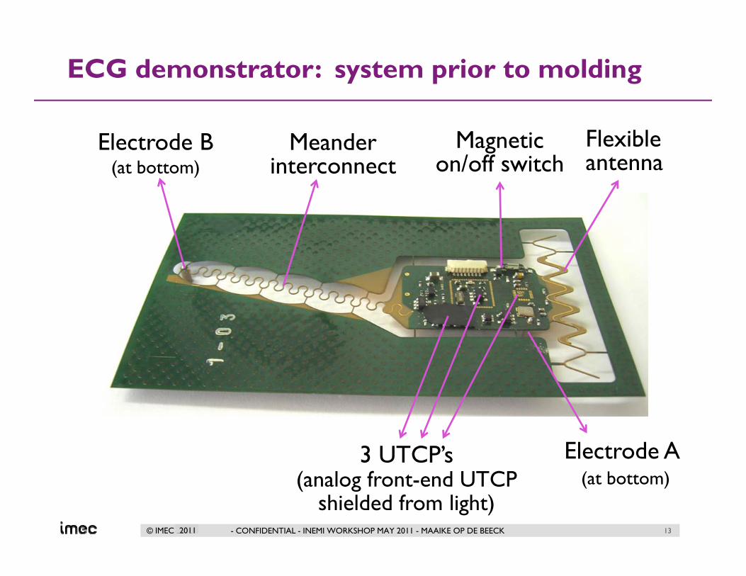
ECG demonstrator: system prior to molding
- CONFIDENTIAL - INEMI WORKSHOP MAY 2011 - MAAIKE OP DE BEECK
Flexibleantenna
Electrode B(at bottom)
3 UTCP’s(analog front-end UTCP
shielded from light)
Meander interconnect
Magnetic on/off switch
Electrode A (at bottom)
13

© IMEC 20102011
ECG demonstrator: final system
- CONFIDENTIAL - INEMI WORKSHOP MAY 2011 - MAAIKE OP DE BEECK 14
• ECG patch can function continuously for at least 7 days
• Wireless communication
• Comfortable: flexible, stretchable, thin package

© IMEC 2010 - CONFIDENTIAL - INEMI WORKSHOP MAY 2011 - MAAIKE OP DE BEECK 15
UTCP: recent and ongoing activities
• improvement of UTCP fabrication technology towards higher yieldand throughput
• ‘lab-to-fab’ activities: developments in order to facilitate transfer of UTCP process towards larger scale production:
• purchase of dedicated tools
• adjustment of fabrication steps
• transfer of UTCP techno to company ‘HighTec’
• New technology developments related to:• fabrication of flat UCTP• stacked UCTP (vertical chip integration, very compact system)• multiple chip- UTCP (horizontal chip integration, very thin
and flexible system)
© IMEC 20102011
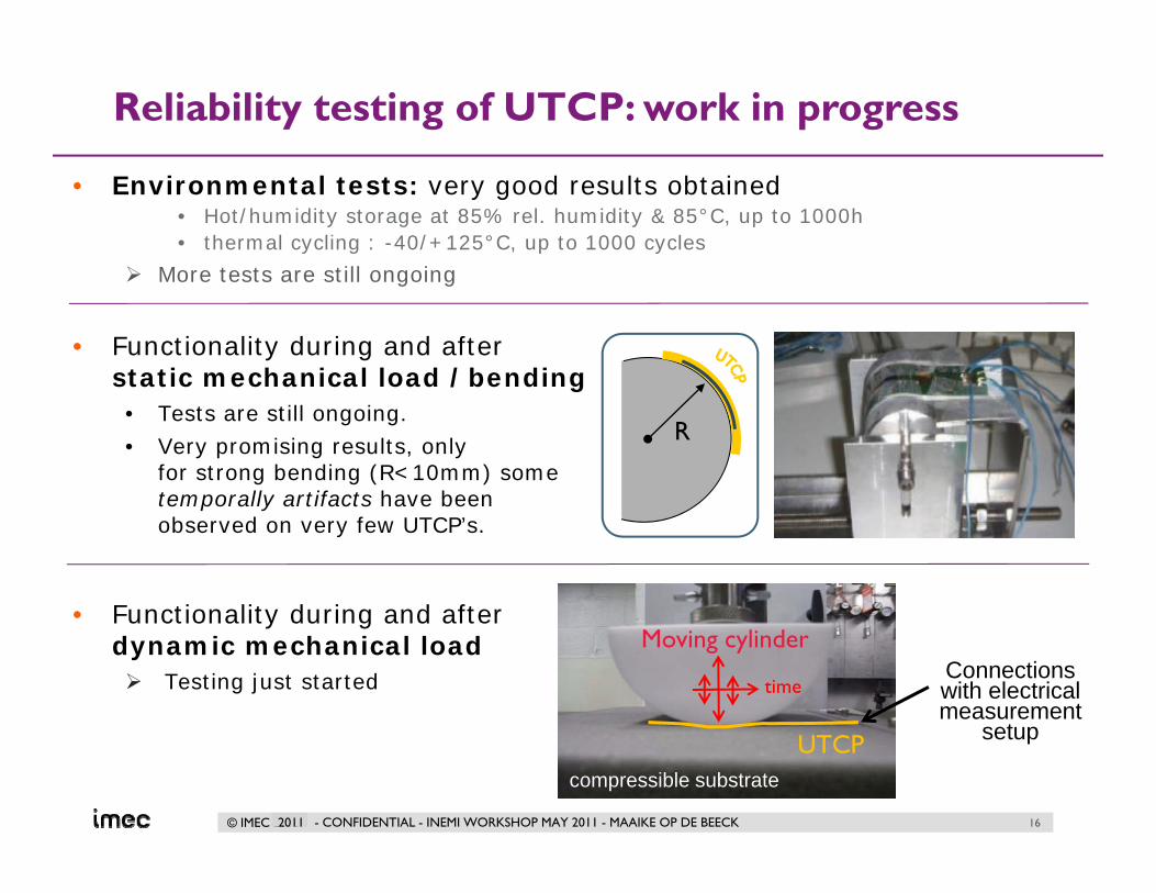
Reliability testing of UTCP: work in progress
• Environmental tests: very good results obtained• Hot/humidity storage at 85% rel. humidity & 85°C, up to 1000h• thermal cycling : -40/+125°C, up to 1000 cycles
More tests are still ongoing
• Functionality during and after static mechanical load /bending
• Tests are still ongoing. • Very promising results, only
for strong bending (R<10mm) some temporally artifacts have been observed on very few UTCP’s.
• Functionality during and after dynamic mechanical load
Testing just started
R
timeConnections with electrical measurement
setupUTCPcompressible substrate
Moving cylinder
- CONFIDENTIAL - INEMI WORKSHOP MAY 2011 - MAAIKE OP DE BEECK 16

© IMEC 20102011
Activities related to wearable & implantable packaging
- CONFIDENTIAL - INEMI WORKSHOP MAY 2011 - MAAIKE OP DE BEECK
Hermetic and biocompatible packaging for in vivo
applications
FLEX Embedding
Hermetic chip encapsulationPhase 1:
Biocompatible device encapsulationPhase 2:
Functional layersDry electrodes
in-vivo electrodes & interconnects
STRETCH carriers
UTCP
Antenna design & integration
antennabattery
skin
17

© IMEC 20102011
SMI: stretchable mould interconnect
Stretchablematrix
Fabrication of stretchable wiring to connectIndividual components rigid/flexible component islands
stretchable wiring meander-shaped interconnects
Molding of device in silicone:to provide stretchable matrix for
• good mechanical support • corrosion resistance
Functional‘non-stretchable’
island
Fabrication of non-stretchable islands using:• conventionally packaged electronic
components• UTCP embedded in flex
- CONFIDENTIAL - INEMI WORKSHOP MAY 2011 - MAAIKE OP DE BEECK 18

© IMEC 20102011
Demonstrators SMI technology
Fitness monitor (with third party) Baby monitor (with third party)
R���������� ������ �����������
B����� �����������
Lesson learned: attention for transition stretch/flex/rigid for optimum reliability
- CONFIDENTIAL - INEMI WORKSHOP MAY 2011 - MAAIKE OP DE BEECK 19

© IMEC 20102011
Reliability characterization : detailed analysis of failure mechanisms
Design improvements based on FEM-simulation and experiments- horse shoe shape- multi-line design
Predicted failure locations after stretching
Shear strain induced local distortion
Failure mode
EXAMPLE: In-plane shear strain contour mapping @ 30% strain (In-situ stretching SEM micrograph vs. FEM modeling)
Before stretchingAfter a few stretch cycles
After many stretch cycles
- CONFIDENTIAL - INEMI WORKSHOP MAY 2011 - MAAIKE OP DE BEECK 20

© IMEC 20102011
Current focus of SMI: process optimization towards high reliability and process throughput
‘Old’ samples improved samples
Process improvements: related to flex-stretch transition
time
improved technostrongly improved lifetime!
Reliability test : cyclic strain of 2.5-10% @ 1%/s strain rate
- CONFIDENTIAL - INEMI WORKSHOP MAY 2011 - MAAIKE OP DE BEECK
older techno
% strain
Life
time
(# c
ycle
s)
Interconnectlifetime
vs strain
1 2 3 4 5 10 20 30
21

© IMEC 20102011
Activities related to wearable & implantable packaging
- CONFIDENTIAL - INEMI WORKSHOP MAY 2011 - MAAIKE OP DE BEECK
Hermetic and biocompatible packaging for in vivo
applications
FLEX Embedding
Hermetic chip encapsulationPhase 1:
Biocompatible device encapsulationPhase 2:
Functional layersDry electrodes
in-vivo electrodes & interconnects
STRETCH carriers
UTCP
Antenna design & integration
antennabattery
skin
22

© IMEC 2011
PACKAGING FOR IMPLANTABLE APPLICATIONSConventional biomedical packaging• Typical packaging for medical electronic implant: Ti can
– Well known, biocompatible safe, NDA-approved– Large container compared to ‘active’ content of packaging– Rigid package: mechanical mismatch with softer tissue
• Example: pacemaker:
• Disadvantage of large size / rigid ‘foreign’ material:– Larger implant: larger incision, more invasive for patient (short/long term)
more risk of infection, biofilm formation…more pronounced foreign body reaction (FBR)
– Rigid package risk of irritation & infection due to mechanical friction– FBR often results in malfunctioning of sensors or electrodes
More advanced package? Requirements?
- CONFIDENTIAL - INEMI WORKSHOP MAY 2011 -MAAIKE OP DE BEECK
23
© IMEC 2011
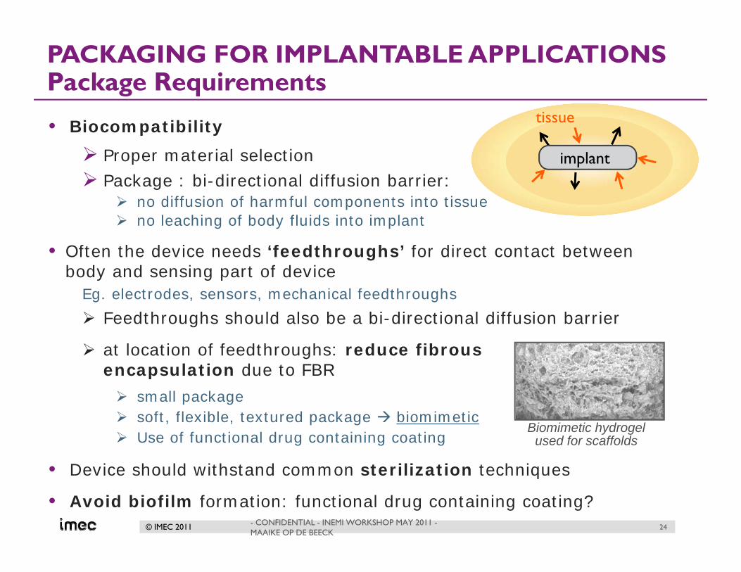
PACKAGING FOR IMPLANTABLE APPLICATIONSPackage Requirements
• Biocompatibility
Proper material selectionPackage : bi-directional diffusion barrier:
no diffusion of harmful components into tissueno leaching of body fluids into implant
• Often the device needs ‘feedthroughs’ for direct contact between body and sensing part of device
Eg. electrodes, sensors, mechanical feedthroughs
Feedthroughs should also be a bi-directional diffusion barrier
at location of feedthroughs: reduce fibrous encapsulation due to FBR
small package soft, flexible, textured package biomimeticUse of functional drug containing coating
• Device should withstand common sterilization techniques
• Avoid biofilm formation: functional drug containing coating?
Biomimetic hydrogelused for scaffolds
tissue
implant
- CONFIDENTIAL - INEMI WORKSHOP MAY 2011 -MAAIKE OP DE BEECK
24

© IMEC 2011
PACKAGING FOR IMPLANTABLE APPLICATIONSimec’s biocompatible packaging approach (1)
(6) electrode
(2) Rounded edges, to enhance step coverage of capping layers and
avoid damage of encapsulating material or injury of tissue after implantation
(3) first top encapsulation: biocompatible capping layers, being also a diffusion barrier
(7) Global feedthrough(for sensing)
(5) Optional: second encapsulation:
embedding in i.e. parylene,...
IC (i.e. CMOS,..)Active part of IC, microsystem,..
Passivation layer(s)
(1) Thinned die
(4) first bottom encapsulation: biocompatible capping layers, being also a diffusion barrier
Phase 1: wafer level chip encapsulationGoal: creation of a bi-directional diffusion barrier
- CONFIDENTIAL - INEMI WORKSHOP MAY 2011 - MAAIKE OP DE BEECK 25

© IMEC 2011
PACKAGING FOR IMPLANTABLE APPLICATIONSimec’s biocompatible packaging approach (2)
Phase 3: system package: .global biocompatible interconnect and embedding of various dies, battery,...
die 1 die 2 battery
Second flexible global embedding
Metallization to connect various sub-parts
Global feedthrough
main function:- mechanical support of total system- electrical connections between dies- creation of functional feedthroughsrequirements:- all materials are ‘biocompatible’- flexible package to reduce body
reaction after implantation
Phase 2: (sub-)system package / interposer:
biocompatible interconnect and embedding of various dies
die 1 die 2
- CONFIDENTIAL - INEMI WORKSHOP MAY 2011 - MAAIKE OP DE BEECK 26

© IMEC 2011
Processing of first phase
encapsulation
Conventional chips(non-biocompatible) are encapsulated.
Encapsulation layers: - biocompatible- bi-directional
diffusion barrier.
All processing is carried out at wafer level
for high throughput and hence low cost
- CONFIDENTIAL - INEMI WORKSHOP MAY 2011 - MAAIKE OP DE BEECK 27

© IMEC 2011
Processing of first phase
encapsulation
- CONFIDENTIAL - INEMI WORKSHOP MAY 2011 - MAAIKE OP DE BEECK 28

© IMEC 2011
PACKAGING FOR IMPLANTABLE APPLICATIONSFirst Phase Encapsulation Validation: oxide step coverage
1
SEM pictures showing the excellent step coverage of a ~1.5um thick oxide used as top capping layer.
A dedicated low temperature oxide deposition process at 350°C is used.
3
oxide
copper
nitrideoxide
silicon
1.65µm
2
nitrideoxide
silicon
oxide
1.4µm
1.56µm
Thinned Si chip
21
3
- CONFIDENTIAL - INEMI WORKSHOP MAY 2011 - MAAIKE OP DE BEECK 29

© IMEC 2011 - CONFIDENTIAL - INEMI WORKSHOP MAY 2011 - MAAIKE OP DE BEECK
Test tableISO10993
• = ISO Evaluation tests for consideration
F = additional tests which may be required for US submissions
1: tissue includes tissue fluids and subcutaneous spaces
2: for all devices used in extracorporeal circuits
3: depends on specific nature of the device and its component materials
ISO10993: document describing biocompatibility tests
is only a guidelineit remains difficult to
determine best testing procedure
Type of test
Type
and
dur
atio
n of
con
tact
cytotoxicity
30

© IMEC 2011
Testing of biocompatibility and diffusion barrier properties?
- CONFIDENTIAL - INEMI WORKSHOP MAY 2011 - MAAIKE OP DE BEECK 31
Final device should be biocompatible
Start with cytotoxicity tests for materials used in package
tissue
biomaterial
Develop in house a test procedure based on the definition of biocompatibility, & following test descriptions in ISO 10993 std.
start with cytotoxicity tests
followed by other in vitrobiocompatibility tests
much later in vivo testing
compare the results
ask specialists in the field to test some of our materials• certified laboratory • Professor A of university X
specialized in biocompatibility• Professor B of university Y
specialized in biocompatibility
start with cytotoxicity tests

© IMEC 2011
Cytotoxicity testing by various specialists
- CONFIDENTIAL - INEMI WORKSHOP MAY 2011 - MAAIKE OP DE BEECK 32
silicon nickel copper platinum
literature
Certified laboratory
Prof. A, Univ. X
Prof. BUniv. Y
Is materialcytotoxic?
Samples: plane layers on Si substrate (Ti adhesion layer if necessary)All testing is in accordance with ISO 10993 (long term implantation is soft tissue)

© IMEC 2011
Cytotoxicity testing by various specialists
- CONFIDENTIAL - INEMI WORKSHOP MAY 2011 - MAAIKE OP DE BEECK 33
silicon nickel copper platinum
literature
Certified laboratory
L929 fibroblast cell line, 24 h elution, 48h cell culture using elution fluid
Prof. A, Univ. X
Fibroblast type cell line, various elution times incl. long periods, cell culture using elution fluid
Prof. BUniv. Y
4 different cell lines (also 3T3 fibroblasts), up to 72h. Co-culture, various evaluation methods
Is materialcytotoxic? No ??? ??? No
Samples: plane layers on Si substrate (Ti adhesion layer if necessary)All testing is in accordance with ISO 10993 (long term implantation is soft tissue)
Even cytotoxicity tests are not easy

© IMEC 2011
Biocompatibility / cytotoxicity based on ISO 10993Testing of medical devices
- CONFIDENTIAL - INEMI WORKSHOP MAY 2011 - MAAIKE OP DE BEECK 34
cytotoxicity based on ISO 10993: variables:• # of cells, growth phase of cells, cell line versus primary cells, cell type • test sample size, exposed surface area, duration of elution• duration of culture, type of culture (elution, co-culture)
▸ select suitable test with final application in mind- Don’t make tests too easy, you will pass this test but fail in a later (in-vivo) test. - Don’t make test too difficult either...
Situation is similar for other standards related to testing of medical devices or biomaterials. These standards are guidances, not a directive to follow. A lot of freedom in testing still exists. Tests have to be defined for each individual device, based on ‘purpose and intentional use of a product’ , but also with risks related to wrong usage in mind.
IEC 60601-1 standard (“General requirements for basic safety and essential performance” of an electric medical device) is recently updated (3rd edition): even more ‘freedom’ in testing is given, in order to perform best suited tests for intended use of a medical device.
Appropriate testing is a challenge (correct, efficient, according to stds)

© IMEC 2011
PACKAGING FOR IMPLANTABLE APPLICATIONSValidation: in vitro co-culture – 3T3 fibroblast
co-culture with 3T3 fibroblasts (cell line) and 1 single test dieAfter 1 week : morphology test
Control: 3T3
medium
copper
passivation
passivation + oxide
copper passivation passivation + oxide
Control: cells in good
condition
Almost no cells alive,cells in bad condition
Most cells in good condition: Cu diffusion is significantly reduced
- CONFIDENTIAL - INEMI WORKSHOP MAY 2011 - MAAIKE OP DE BEECK 35

© IMEC 2011
PACKAGING FOR IMPLANTABLE APPLICATIONSValidation: in vitro co-culture - cardiomyocytes
co-culture with neonatal cardiomyocytes (primary cells)After 5 days: live/dead cell assay with Calcein-AM
copper
passivation
passivation + oxide
Fluorescent intensityfigure of merit for amount of cells being alive
Encapsulation is functioning very well as
diffusion barrier forimplants in heart tissue
- CONFIDENTIAL - INEMI WORKSHOP MAY 2011 - MAAIKE OP DE BEECK 36

© IMEC 2011
Work ongoing - phase 2: Interposer-like package
- CONFIDENTIAL - INEMI WORKSHOP MAY 2011 - MAAIKE OP DE BEECK
IMEC’s board level ultra thin chip package (UTCP)
• biocompatible interconnect and embedding of various dies • might be board level (cheaper) or wafer level (higher pitch density)• biocompatible materials required
for an ‘implantable’ UTCP: - PI selection depends on application (wearable or implantable device): photopatternable PI is not biocompatible.
- metallization (now Cu) needs to be adjusted for long term implants: Pt and Au metallization is needed
die 1 die 2
37

© IMEC 2011
Work ongoing - phase 3: global embedding
- CONFIDENTIAL - INEMI WORKSHOP MAY 2011 - MAAIKE OP DE BEECK
Only a very thin silicone layer is covering the
pressure sensor in order to realize sufficient hermeticity without loosing the sensor
functionality.
battery
Electronics on PCB
Pressure sensor
die 1 die 2 battery
silicone molding interconnect (SMI) technology using biomedical grade siliconefabrication of an implantable bladder pressure sensor:
Packaging and integration: IMEC: electronic system design: by KUL (SBO-Bioflex project)
• to embed all sub-devices• typical board level process (cost)• biocompatible and corrosion resistant materials required
IMEC’s SMI process: metallization (now Cu) needs to be adjusted for long term implants (Au, Pt)encapsulation by implantable silicones or polyurethanesfuture alternatives: biomimetic encapsulation? Drug containing encapsulation?
38

© IMEC 2011
ConclusionsPackaging and integration for wearable and implantable medical devices: dedicated packaging techniques have important advantages!
wearable devices: - small flexible/stretchable package for enhanced user comfort- optimized antenna design longer battery usage / smaller battery size
implantable devices: - miniaturization for reduced foreign body reaction and enhanced user comfort- many challenges to overcome: biocompatibility, realization of bi-directional diffusion barrier, stability over (long) lifetime, power management- additional needs possible such as a drug releasing coating, an anti-microbial layer, a biomimetic surface,..
Appropriate testing of these dedicated packaging techniques is a challenge.
- CONFIDENTIAL - INEMI WORKSHOP MAY 2011 - MAAIKE OP DE BEECK 39

© IMEC 2010
THANK YOU