ptsp+ 12-84v powertrac™ 2.1 software reference guide
TRANSCRIPT

MAN-100001-00 REV A
PTSP+ 12-84V
PowerTrac™ 2.1 Software Reference Guide
4005 Felland Road, Suite 116 Madison, WI 53718
USA
© Power Designers USA LLC
MAN-100001-00 REV A
TABLE OF CONTENTS
SOFTWARE INSTALLATION ................................................................................... 1
USING POWERTRAC™ SP+ PC SOFTWARE ......................................................... 6
CREATING CHARTS AND GENERATING REPORTS ........................................... 15
MANAGING DATABASES ...................................................................................... 28
SOFTWARE LICENSE AGREEMENT .................................................................... 33
CONTACTING POWER DESIGNERS USA ............................................................ 34

MAN-100001-00 REV A 1
SOFTWARE INSTALLATION Minimum System Requirements Windows® Operating systems: XP, Windows Vista®, Windows® 7 Communication port: One serial or USB port Required preinstalled: .NET Framework 2.0 or greater
Microsoft ActiveSync® Version 4.5 for Windows® XP or Windows® Mobile Device Center Version 6.1 for Vista® or Windows® 7
NOTES: 1. All previous versions of PowerTrac™ software must first be uninstalled
from the PC for proper operation. 2. If an earlier version of the Microsoft ActiveSync® software is installed, the latest
must be downloaded from the Microsoft® website: http://www.microsoft.com/windowsmobile/en-us/help/synchronize/device-synch.mspx.
3. The account has administrator rights. Installing the Windows® Application The following summary is a guide for the PowerTrac™ SP+ installation software. 1. Uninstall all previously installed PowerTrac™ Windows® software.
Uninstalling prior versions of PowerTrac™ Windows® software will not remove or delete any previously saved data in the computer. It is essential that all previous versions of PowerTrac™ Windows® software is uninstalled before installation of an updated version to ensure reliable, continuous operation.
2. Select Start then Control Panel and then Add/Remove Programs. Find and select PowerTrac. Then select Remove button.
3. Double-click the file from the installation CD.

MAN-100001-00 REV A 2
4. A new window appears. Select Next to continue.
5. After reading the agreement, select I Agree and then select Next.
MAN-100001-00 REV A 3
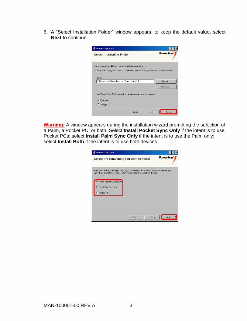
6. A “Select Installation Folder” window appears; to keep the default value, select Next to continue.
Warning: A window appears during the installation wizard prompting the selection of a Palm, a Pocket PC, or both. Select Install Pocket Sync Only if the intent is to use Pocket PCs; select Install Palm Sync Only if the intent is to use the Palm only; select Install Both if the intent is to use both devices.

MAN-100001-00 REV A 4
7. A window appears indicating the PowerTrac™ software is being installed.
8. An “Installation Complete” window appears indicating the installation procedure
was successful. Select Close to exit.
MAN-100001-00 REV A 5
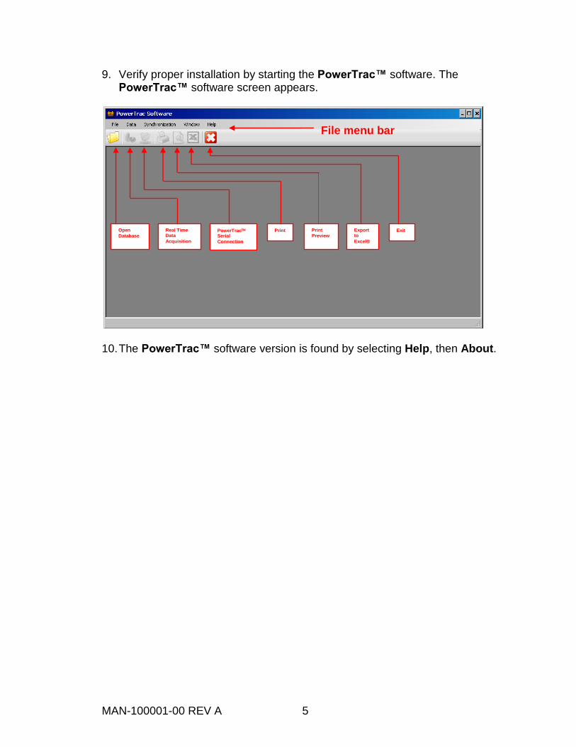
9. Verify proper installation by starting the PowerTrac™ software. The PowerTrac™ software screen appears.
10. The PowerTrac™ software version is found by selecting Help, then About.
File menu bar
Exit Export to
Excel
Preview Print PowerTrac
Serial
Connection
Real Time Data
Acquisition
Open
Database

MAN-100001-00 REV A 6
USING POWERTRAC™ SP+ PC SOFTWARE The Graphical User Interface (GUI) The following appears when the PowerTrac™ SP+ software is started. (The labels and arrows are added to the figure for clarity.)
PowerTrac™ SP+ Serial Connection (RS-232) The PowerTrac™ SP+, with the optional RS-232 communication installed, has an additional cable and connector exiting the enclosure opposite the power, shunt, and temperature cables. 1. Connect the serial cable between the PowerTrac™ and the computer. 2. Start the PowerTrac™ Windows® software, and then verify PowerTrac™ is
operating by observing that one or more Light Emitting Diodes (LEDs) are illuminated.
3. Select File then select Open Database; select a database, then select Open. A new window appears listing all stored data files in the selected database.
File menu bar
Exit Export to
Excel
Preview Print PowerTrac
Serial
Connection
Real Time Data
Acquisition
Open
Database

MAN-100001-00 REV A 7
4. Select the PowerTrac Serial Connection button. A “PowerTrac Direct Connection” window appears.
5. Select the desired COM Port. 6. Select the Connect button. The button reads “Disconnect” while the port is open. 7. Select the Quick Look button. This fills the blank cells and is similar to
performing a quick look with a Palm or Pocket PC. NOTE: Attempting a quick look without an open port causes an error message to appear.
8. To program PowerTrac™ settings, select the Settings tab. 9. After changing parameters select Save Config or press the disk icon adjacent to
the changed parameter.
6 78
5

MAN-100001-00 REV A 8
Other Direct Connection (RS-232) Features Downloading Events. Event download is only available after a quick look has been performed. A download progress bar is located at the bottom of the window. When the progress bar disappears the download is complete. The downloaded record is located by default in the “PowerTracSPDB” database file in the PowerTrac™ v2.1 folder. Clear Events. To clear the events in the PowerTrac™ SP+ select the Clear Events button. Start Continuous Report. Selecting Continuous Report performs a quick look every 1.5 seconds. Modem Dial. This feature allows interface with PowerTrac™ at remote locations. Contact Power Designers USA LLC for assistance in use of this function. Viewing the PowerTrac™ SP+ Data on the PC 1. To view data, start the PowerTrac™ SP+ Windows® software. 2. Select File, then select Open Database; select a database, then select Open. A
new window appears listing all stored data files in the selected database.

MAN-100001-00 REV A 9
3. Select one of the databases and select the Open button. A new window appears showing a list of all stored data files in the selected database.
4. Any file listed may be selected to view events, generate reports or create charts. Pocket PC Real Time Data Acquisition Real time data from the PowerTrac™ SP+ internal memory may be transferred using Pocket PC. This feature is not supported by Palm devices. 1. Open the database file containing the PowerTrac™ Pocket PC data located by
default in the “PowerTracSPDB.mdb” file. 2. Select Real Time Data Acquisition from the File menu, or select the second
icon on the toolbar.

MAN-100001-00 REV A 10
3. A “Real Time Monitor” window appears.
4. To view the collected data, select a file name from the grid view and select the Data Table button located at the right bottom of the window.
Real time data transferred from
Pocket PC
4
6

MAN-100001-00 REV A 11
5. The “Real Time Data” table window appears.
6. Select the Chart button to create the chart. Serial Real Time Data Acquisition The real time data acquisition feature of the PowerTrac™ SP+ hardware and software is most often used in a lab or R&D environment to track battery, truck or charger performance. The use of this feature requires the RS-232 option and continuous connection to a PC that records the information. 1. Connect the RS-232 cable to the PC and PowerTrac™ device and start the
PowerTrac™ Windows® software. 2. From the File menu bar select File, then select Real Time Data Acquisition.
2

MAN-100001-00 REV A 12
3. The following window appears:
4. Select the desired Com port and select Connect. The button reads “Disconnect”
while the port is open. 5. In the “Data Acquisition” section, set the “Data Sample” rate to 1–60 seconds,
then select Start Data Acquisition. 6. A “Test Data” window appears.
7. Select Continue Existing File to continue recording data into a previously created file, or select Start New File to create a new file.
4 5

MAN-100001-00 REV A 13
8. Select OK to start recording.
9. Each new sample is displayed in the “Last Sample” section.
NOTE: The software attempts to connect six times to the PowerTrac™. If there is no connection established with the PowerTrac™ after the sixth attempt, a warning message is displayed. Verify the PowerTrac™ is energized by observing that at least one LED is illuminated. Verify the serial cable is connected, and then attempt to connect again.

MAN-100001-00 REV A 14
10. To generate charts while data is being gathered, select Flow Chart.
11. To stop the real time data acquisition, select the Stop Data Acq button. 12. To view the collected data, select the Data Table button.
13. To view the collected data in a chart, select the Chart button.

MAN-100001-00 REV A 15
CREATING CHARTS AND GENERATING REPORTS Creating Charts 1. To create charts using downloaded data, select the desired battery file. 2. In the “Settings” area, select the time interval of interest, all events, or a specific
time interval. Select the format for Battery Voltage (V) or Volts Per Cell (VPC) and the temperature (°C or °F).
3. Choose the desired chart from the “Charts” drop-down menu. 4. Select Single Chart to the right of the drop-down menu.
1 2
3
4

MAN-100001-00 REV A 16
This figure depicts a sample chart for the battery minimum discharge voltage in VPC for the period of 7/27/06 through 4/23/07.
Chart Options After the chart is displayed, further options are available to enhance its presentation. Some of the chart options include: Showing the date and time of individual data points Showing values of individual data points Adding lines for minimum and maximum operating limits Changing the graph type: line, line markers or column Adding names to the X and Y axes To view the “Chart Options” window, right select the chart and select Chart Settings. Multi Charts The Multi Charts button allows the display of up to six charts in a grid. The resolution of multiple charts is not as detailed as a single chart.

MAN-100001-00 REV A 17
Available Charts
Chart Action
Max Charge Voltage
Charts the maximum voltages for all charge events that occurred for the selected time interval.
Min Discharge Voltage
(two second average)
Charts the minimum voltages for all discharge events that occurred for the selected time interval.
End of Discharge Voltage
(30 second average)
Charts the end of discharge voltages for all discharge events that occurred for the selected time interval.
Ahrs Charge Charts in bar format the charge amp-hours for the selected time interval.
Ahrs Discharge Charts in bar format the discharge amp-hours for the selected time interval.
Battery Utility Charts in two-bar format the charge and discharge amp-hours.
Max Charge Temp
Charts in bar format the maximum temperature during charge for the selected time interval.
Max Discharge Temp
Charts in bar format the maximum temperature during discharge for the selected time interval.
Battery SOC (State of Charge)
Charts the percentage of total battery capacity available.
Daily Ahr Usage
Charts amp-hour usage on a daily basis.
Battery Assessment
Charts in pie format: Battery Usage Summary, Battery Ahr Usage, Equalize Charge Summary, Battery Temp. Distribution, End Discharge Voltage, Battery SOC.
Daily Ahr Turnover
Charts the battery amp-hour utility for a single day.
Ahr Turnover Charts in two-bar format the cumulative charge and discharge amp hours.

MAN-100001-00 REV A 18
Generating Reports—Battery Performance Report 1. Generate a Battery Performance Report by selecting the desired battery and time
interval.
2. Select the Battery Report button at the bottom of the screen. A progress bar appears. The battery report shows summary data including: Battery Info
Number of cells, nominal voltage and capacity
Number of posts (intercell connectors) and shunt size PowerTrac™ SP+ Settings
Programmed settings of the PowerTrac™ PowerTrac™ Lifetime Accumulated Summary
Date and time of installation and first discharge cycle
Cumulative amp-hours and hours of charge, discharge, and open circuit
Warranted amp-hours and remaining amp-hours under warranty Event Summary [Over the Selected Time Interval]
Total amp-hours and hours of charge, discharge, and open circuit
Percent usage of each event state
The minimum and maximum event voltage, current, and temperature with time stamps
Equalize opportunities and times performed
State-of-charge distribution and low-electrolyte level

MAN-100001-00 REV A 19
Sample Battery Performance Report

MAN-100001-00 REV A 20

MAN-100001-00 REV A 21
Adjusting Report Settings Report Settings enables customization of the battery report to reflect specific acceptable operating parameters. Access the Report Settings screen by: 1. Selecting the desired battery file. 2. Selecting Data, and then selecting Report Settings.
3. A new window appears, where parameters may be adjusted as desired for the battery. These settings affect minimum discharge voltage, end of discharge voltage, battery temperature distribution, equalization charge summary, state-of-charge distribution, low-level electrolyte, and amp-hour turnover. NOTE: Settings must be adjusted prior to generating a report. If a report has already been generated, the current report must be closed and regenerated for the changes to take effect.
2
1

MAN-100001-00 REV A 22
Generating Reports—Daily Report The PowerTrac™ SP+ Daily Report feature is the best method of analyzing battery usage. A daily report tabulates total amp-hours removed and returned to the battery, and a summary of the accumulated hours of charge, discharge, turnover, and open time. The end voltage is a 30-second average value. Other items reported are lowest daily value, maximum temperature, minimum and maximum percent of state of charge and electrolyte level. This report also provides total, minimum, maximum, and average of the daily values for the selected interval. 1. Access the daily report by selecting the desired battery file and the time interval.
2
1

MAN-100001-00 REV A 23
2. Select Daily Report.
Creating an Events Table The Events Table displays battery states—charge, discharge, or open—as a unique, time-stamped item. 1. Select the desired battery file to be loaded. 2. Use the settings area of the screen to select the time interval of interest and the
format for battery voltage and temperature.
1 2
3

MAN-100001-00 REV A 24
3. Select the Events Table button at the bottom of the screen. An “Events Type” dialog box appears.
4. Select the desired data columns and filters to be displayed.
5. The event table may be exported to Excel® by selecting the Export to Excel® button located on the submenu. A “Save As” window appears. An Excel® sheet with the event table appears. Use the Excel® application to print or otherwise display the data.
4
5

MAN-100001-00 REV A 25
Creating a Cycles Table The Cycles Table uses information taken from the events table and groups the events into cycles of charge, discharge, and open. For example, when the events logged are discharge, charge, discharge, each event is a cycle. When the logged events are charge, open, charge, open, charge, the cycles table logs a single charge and a single open cycle by combining the three charges into one cycle and the two opens into one cycle. 1. Select the desired battery file and the time interval.
2. Select the Cycles Table button. 3. A window appears allowing selection of the data columns to be displayed. Select
the Show Cycles button.
2
1
3
MAN-100001-00 REV A 26
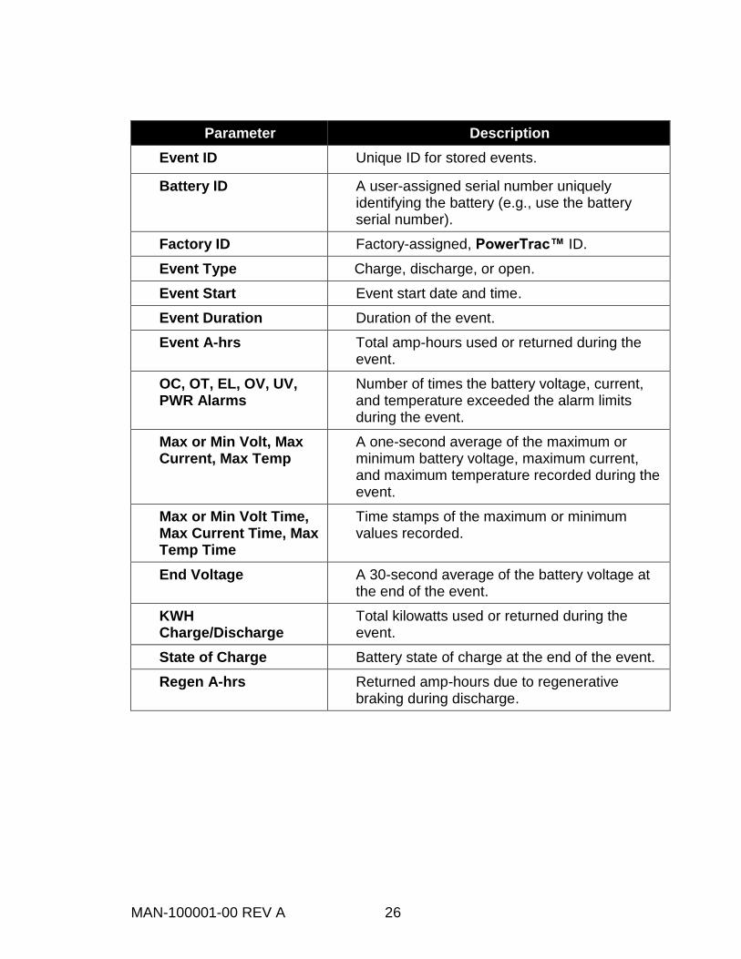
Parameter Description
Event ID Unique ID for stored events.
Battery ID A user-assigned serial number uniquely identifying the battery (e.g., use the battery serial number).
Factory ID Factory-assigned, PowerTrac™ ID.
Event Type Charge, discharge, or open.
Event Start Event start date and time.
Event Duration Duration of the event.
Event A-hrs Total amp-hours used or returned during the event.
OC, OT, EL, OV, UV, PWR Alarms
Number of times the battery voltage, current, and temperature exceeded the alarm limits during the event.
Max or Min Volt, Max Current, Max Temp
A one-second average of the maximum or minimum battery voltage, maximum current, and maximum temperature recorded during the event.
Max or Min Volt Time, Max Current Time, Max Temp Time
Time stamps of the maximum or minimum values recorded.
End Voltage A 30-second average of the battery voltage at the end of the event.
KWH Charge/Discharge
Total kilowatts used or returned during the event.
State of Charge Battery state of charge at the end of the event.
Regen A-hrs Returned amp-hours due to regenerative braking during discharge.

MAN-100001-00 REV A 27
Creating a Site Analysis Site Analysis compares a group of batteries to a set of predetermined limits. Exceptions to the limits are highlighted in red in the report. Analysis limits must be set prior to running the site analysis. Analysis Settings Analysis Settings is a tool that allows users to easily generate exception reports for a given site. 1. Select the desired file. 2. Select Data; then select Analysis Settings.
3. A window appears. Adjust the desired limits and then select OK.
2
1

MAN-100001-00 REV A 28
MANAGING DATABASES Opening a Database File 1. Start the PowerTrac™ SP+ Windows® software.
2. Select Open Database using either the button on the top menu bar, or by using the command from the file menu. A new window appears listing all database files.
3. Select one of the databases followed by the Open button. A new window
appears showing a list of battery files in the selected database. 4. Select the battery file of interest to view events, generate reports or create
charts.

MAN-100001-00 REV A 29
Deleting a Record From a Database File 1. Open the database containing the file to delete, and then select the file. 2. Select the Data button at the top menu bar and then select Delete Data.
Exporting Data to a New Database File 1. Open the database containing the file to export and then select the file. 2. Select the Data button at the top menu bar and select the Export to new
database option from the pull-down menu.
2
1
1
2

MAN-100001-00 REV A 30
3. An “Export Selection” window appears, showing a list of all existing battery files. From the “Export Selection” window, select the batteries to export and then select the Export button.
4. Enter a new database file name. Select the Save button to move data into the
new database.
4
3

MAN-100001-00 REV A 31
Importing Data into an Existing Database File 1. Open the database that will contain the file after import. 2. Select the Data button at the top menu bar and select the Import from
Database option from the pull-down menu as shown.
3. From the pull-down menu locate the database to import.
2

MAN-100001-00 REV A 32
4. The “Import Selection” window appears; select the batteries to import. Select the Import button. A progress bar appears.
5. When the import completes, a “Success” window appears, select OK to continue.
The battery record will now appear in the list of batteries in the exported database and the original database.

MAN-100001-00 REV A 33
SOFTWARE LICENSE AGREEMENT This license agreement is a legal agreement between Power Designers USA LLC of Madison, Wisconsin, the author and licensor of the software, and the end user licensee of the software. Installation or other use of this software by the licensee constitutes agreement to all terms and conditions of this license. In the event the licensee does not agree to all terms and conditions of this agreement the software may not be installed or otherwise used. The following terms apply:
1. Licensee may not redistribute any files, including but not limited to any setup or installation files created by this software.
2. Licensee may not disassemble or reverse engineer any part of this software.
3. Licensee may not resell, rent or lease the software.
4. Licensor owns all rights in the software including any incorporated images or text.
5. Should the licensee fail to comply with any terms or conditions of this agreement this agreement will immediately and automatically terminate without notice.
6. The licensor of this software does not guarantee that this software is free from bugs or free from viruses.
To the maximum extent permitted by applicable law, the software and documentation are provided "as is" and the licensor disclaims all other warranties and conditions, expressed or implied, including, but not limited to, implied warranties of merchantability, fitness for a particular purpose, conformance with description, title and non-infringement of third party rights. To the maximum extent permitted by applicable law, in no event shall the licensor be liable for any indirect, incidental, consequential, special or exemplary damages or lost profits whatsoever (including, without limitation, damages for loss of business profits, business interruption, loss of business information, or any other pecuniary loss) arising out of the use or inability to use the software product, even if the licensor has been advised of the possibility of such damages. In any case, the licensors’ cumulative and entire liability to the licensee or any other party for any loss or damages resulting from any claims, demands or actions arising out of or relating to this agreement shall not exceed the purchase price paid for this license. Should any term of these terms and conditions be declared void or unenforceable by any court of competent jurisdiction, such declaration shall have no effect on the remaining terms hereof.

MAN-100001-00 REV A 34
CONTACTING POWER DESIGNERS USA
Power Designers USA LLC 4005 Felland Road, Suite 116
Madison, WI 53718 USA
www.powerdesigners.com
Main Office Phone: 608.231.0450 Main Office Fax: 608.231.9979
Service Department: 608.216.9295 Phones are answered between 9 a.m. and 5 p.m., Monday through Friday Central Time. After-hours calls are answered by voice mail and returned on the next business day. Questions and comments can also be submitted via fax or email.