projecting forces
DESCRIPTION
Projecting ForcesTRANSCRIPT

Projecting forces – Inclined Plane Case This is a step-by-step tutorial on the process of projecting vectors (in this case forces) along two perpendicular directions, in this case along the x and y axis. Let’s assume that the only force acting on the object is force F as illustrated below in either one of the four cases presented below. a) 1) First draw in a line parallel to the incline, passing through the point on which force F is anchored, then a line perpendicular to the incline. Use a triangle as it allows you to best represent perpendiculars, or 90o angles.
Drawing in the parallel direction Drawing in the perpendicular direction I marked these directions as and ! . We will use these lines to project the force F along them. Projecting is a procedure that must be done properly. It is not a random act!

2) Projecting F onto the perpendicular direction. Place the triangle as seen below and draw a dashed line from the tip of F perpendicularly onto the line marked with ⊥. The place where the dashed line intersects the line marked with ⊥ uniquely defines the perpendicular component of the force F,
!F! .
3) Projecting F onto the parallel direction. Notice that in drawing the dashed lines I constructed a rectangle.

Below is the result of my projections, with the perpendicular and parallel components of the force neatly presented.
(a) You can repeat this procedure for case b. Finding
!F :
Finding
!F! :
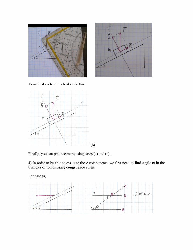
Your final sketch then looks like this:
(b) Finally, you can practice more using cases (c) and (d). 4) In order to be able to evaluate these components, we first need to find angle α in the triangles of forces using congruence rules. For case (a):

Angle !COA is congruent to angle α because lines A and B are parallel to each other and intersected by line C. These two angles are called corresponding angles. In fact, angles !COA and !MON are also congruent as vertical angles. In our figure, we can thus now identify angle α for case (a) as seen below:
For case (b) we make use of a congruence rule involving angles whose legs are perpendicular. For example, in the figure below, I marked the two corresponding perpendicular legs with green and pink, respectively.
We thus found angle α for case (b).
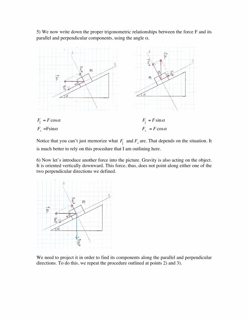
5) We now write down the proper trigonometric relationships between the force F and its parallel and perpendicular components, using the angle α.
F = F cos! F = F sin!
F! =Fsin! F! = F cos!
Notice that you can’t just memorize what F and F! are. That depends on the situation. It is much better to rely on this procedure that I am outlining here. 6) Now let’s introduce another force into the picture. Gravity is also acting on the object. It is oriented vertically downward. This force, thus, does not point along either one of the two perpendicular directions we defined.
We need to project it in order to find its components along the parallel and perpendicular directions. To do this, we repeat the procedure outlined at points 2) and 3).

Projecting Gravity along the perpendicular direction (finding !FG! ):
Projecting Gravity along the parallel direction (finding
!FG|| ):
Identifying angle α in the triangle of forces (I marked the respectively perpendicular legs with like color):
Lastly, we write down the components:
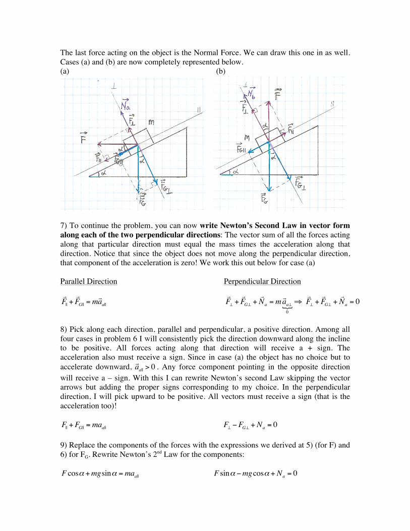
The last force acting on the object is the Normal Force. We can draw this one in as well. Cases (a) and (b) are now completely represented below. (a) (b)
7) To continue the problem, you can now write Newton’s Second Law in vector form along each of the two perpendicular directions: The vector sum of all the forces acting along that particular direction must equal the mass times the acceleration along that direction. Notice that since the object does not move along the perpendicular direction, that component of the acceleration is zero! We work this out below for case (a) Parallel Direction Perpendicular Direction !F|| +!FG|| =m
!aa|| !F! +
!FG! +
!Na =m
!aa!0!"
!F! +
!FG! +
!Na = 0
8) Pick along each direction, parallel and perpendicular, a positive direction. Among all four cases in problem 6 I will consistently pick the direction downward along the incline to be positive. All forces acting along that direction will receive a + sign. The acceleration also must receive a sign. Since in case (a) the object has no choice but to accelerate downward, !aa|| > 0 . Any force component pointing in the opposite direction will receive a – sign. With this I can rewrite Newton’s second Law skipping the vector arrows but adding the proper signs corresponding to my choice. In the perpendicular direction, I will pick upward to be positive. All vectors must receive a sign (that is the acceleration too)! F|| +FG|| =maa|| F! "FG! + Na = 0 9) Replace the components of the forces with the expressions we derived at 5) (for F) and 6) for FG. Rewrite Newton’s 2nd Law for the components: F cos! +mgsin! =maa|| F sin! !mgcos! + Na = 0

10) Solve for N and a||:
aa|| = gsin! + Fm
cos! Na =mgcos! !F sin!
aa|| = 0.5g+ 0.866 " Fm
Na = 0.866mg! 0.5F
This is because α=30o. For case (b) you actually don’t know whether the object will accelerate downward or upward along the incline, because you don’t have information about the magnitude of F and the mass of the object. Take a look at the figure below to notice that if F|| is larger than FG||, the object will be moving upward and the acceleration would be pointing that way. Since we don’t know, and to stay consistent with case (a), I will pick the acceleration to be downward still. In the case that numbers are given, if you made the wrong guess about the direction of the acceleration, your answer will have the correct magnitude but the wrong sign. In that case, you will only have to flip the sign.
Now respect this procedure for all other cases. Don’t skip any of the above steps until you are absolutely confident that you know what you are doing!