programming manual aristo 320/450, aristo … manual aristo 320/450, aristo 320w/450w 104. english...
TRANSCRIPT

Valid for program version 2.0 ?A0456 685 005 98.12.10
PUA 1Programming manualAristo 320/450,Aristo 320W/450W
104

ENGLISH
TOCe -- 2 --
1 INTRODUCTION 4. . . . . . . . . . . . . . . . . . . . . . . . . . . . . . . . . . . . . . . . . . . . . . . . . . .1.1 Main menu 4. . . . . . . . . . . . . . . . . . . . . . . . . . . . . . . . . . . . . . . . . . . . . . . . . . . . . . . . . . . . . . .1.3 Choice of language 5. . . . . . . . . . . . . . . . . . . . . . . . . . . . . . . . . . . . . . . . . . . . . . . . . . . . . . . .1.4 Display 6. . . . . . . . . . . . . . . . . . . . . . . . . . . . . . . . . . . . . . . . . . . . . . . . . . . . . . . . . . . . . . . . . . .1.5 Keys 7. . . . . . . . . . . . . . . . . . . . . . . . . . . . . . . . . . . . . . . . . . . . . . . . . . . . . . . . . . . . . . . . . . . . .1.6 Settings in general 7. . . . . . . . . . . . . . . . . . . . . . . . . . . . . . . . . . . . . . . . . . . . . . . . . . . . . . . . .1.7 ENTER and QUIT 8. . . . . . . . . . . . . . . . . . . . . . . . . . . . . . . . . . . . . . . . . . . . . . . . . . . . . . . . .
2 MIG/MAG welding 9. . . . . . . . . . . . . . . . . . . . . . . . . . . . . . . . . . . . . . . . . . . . . . . . . .2.1 The expression “wire“ 9. . . . . . . . . . . . . . . . . . . . . . . . . . . . . . . . . . . . . . . . . . . . . . . . . . . . . .2.2 Synergic welding 9. . . . . . . . . . . . . . . . . . . . . . . . . . . . . . . . . . . . . . . . . . . . . . . . . . . . . . . . . .2.3 Basic settings 9. . . . . . . . . . . . . . . . . . . . . . . . . . . . . . . . . . . . . . . . . . . . . . . . . . . . . . . . . . . . .2.4 Welding data settings 12. . . . . . . . . . . . . . . . . . . . . . . . . . . . . . . . . . . . . . . . . . . . . . . . . . . . . .2.5 Start and stop settings 12. . . . . . . . . . . . . . . . . . . . . . . . . . . . . . . . . . . . . . . . . . . . . . . . . . . . .2.6 Gas purge, cold wire feed and trigger latch 13. . . . . . . . . . . . . . . . . . . . . . . . . . . . . . . . . . . .2.7 MIG/MAG configuration 15. . . . . . . . . . . . . . . . . . . . . . . . . . . . . . . . . . . . . . . . . . . . . . . . . . . .2.8 Setting--up example MIG/MAG 15. . . . . . . . . . . . . . . . . . . . . . . . . . . . . . . . . . . . . . . . . . . . . .
3 MMA welding 24. . . . . . . . . . . . . . . . . . . . . . . . . . . . . . . . . . . . . . . . . . . . . . . . . . . . . .3.1 Synergic mode 24. . . . . . . . . . . . . . . . . . . . . . . . . . . . . . . . . . . . . . . . . . . . . . . . . . . . . . . . . . . .3.2 Basic settings 24. . . . . . . . . . . . . . . . . . . . . . . . . . . . . . . . . . . . . . . . . . . . . . . . . . . . . . . . . . . . .3.3 Welding data 25. . . . . . . . . . . . . . . . . . . . . . . . . . . . . . . . . . . . . . . . . . . . . . . . . . . . . . . . . . . . . .3.4 MMA--configuration 26. . . . . . . . . . . . . . . . . . . . . . . . . . . . . . . . . . . . . . . . . . . . . . . . . . . . . . . .3.5 Setting--up example MMA 26. . . . . . . . . . . . . . . . . . . . . . . . . . . . . . . . . . . . . . . . . . . . . . . . . .
4 TIG welding 28. . . . . . . . . . . . . . . . . . . . . . . . . . . . . . . . . . . . . . . . . . . . . . . . . . . . . . .4.1 Basic settings 28. . . . . . . . . . . . . . . . . . . . . . . . . . . . . . . . . . . . . . . . . . . . . . . . . . . . . . . . . . . . .4.2 Welding data settings 29. . . . . . . . . . . . . . . . . . . . . . . . . . . . . . . . . . . . . . . . . . . . . . . . . . . . . .4.3 TIG--configuration 31. . . . . . . . . . . . . . . . . . . . . . . . . . . . . . . . . . . . . . . . . . . . . . . . . . . . . . . . .4.4 Setting--up example TIG 31. . . . . . . . . . . . . . . . . . . . . . . . . . . . . . . . . . . . . . . . . . . . . . . . . . . .
5 Arc air gouging 36. . . . . . . . . . . . . . . . . . . . . . . . . . . . . . . . . . . . . . . . . . . . . . . . . . . .5.1 Synergic mode 36. . . . . . . . . . . . . . . . . . . . . . . . . . . . . . . . . . . . . . . . . . . . . . . . . . . . . . . . . . . .5.2 Basic settings 36. . . . . . . . . . . . . . . . . . . . . . . . . . . . . . . . . . . . . . . . . . . . . . . . . . . . . . . . . . . . .5.3 Welding data 36. . . . . . . . . . . . . . . . . . . . . . . . . . . . . . . . . . . . . . . . . . . . . . . . . . . . . . . . . . . . . .5.4 Setting--up example for arc air gouging 37. . . . . . . . . . . . . . . . . . . . . . . . . . . . . . . . . . . . . . .
6 MEASURED VALUE DISPLAY 39. . . . . . . . . . . . . . . . . . . . . . . . . . . . . . . . . . . . . . .6.1 Description of measured value display 39. . . . . . . . . . . . . . . . . . . . . . . . . . . . . . . . . . . . . . . .6.2 Changing set values 40. . . . . . . . . . . . . . . . . . . . . . . . . . . . . . . . . . . . . . . . . . . . . . . . . . . . . . .
7 MEMORY 41. . . . . . . . . . . . . . . . . . . . . . . . . . . . . . . . . . . . . . . . . . . . . . . . . . . . . . . . . .7.1 Store 41. . . . . . . . . . . . . . . . . . . . . . . . . . . . . . . . . . . . . . . . . . . . . . . . . . . . . . . . . . . . . . . . . . . .7.2 Delete 43. . . . . . . . . . . . . . . . . . . . . . . . . . . . . . . . . . . . . . . . . . . . . . . . . . . . . . . . . . . . . . . . . . .7.3 Recall 44. . . . . . . . . . . . . . . . . . . . . . . . . . . . . . . . . . . . . . . . . . . . . . . . . . . . . . . . . . . . . . . . . . . .7.4 Copy 44. . . . . . . . . . . . . . . . . . . . . . . . . . . . . . . . . . . . . . . . . . . . . . . . . . . . . . . . . . . . . . . . . . . . .7.5 Remote control 46. . . . . . . . . . . . . . . . . . . . . . . . . . . . . . . . . . . . . . . . . . . . . . . . . . . . . . . . . . . .
8 FAST MODE 47. . . . . . . . . . . . . . . . . . . . . . . . . . . . . . . . . . . . . . . . . . . . . . . . . . . . . . .8.1 Description of fast mode 47. . . . . . . . . . . . . . . . . . . . . . . . . . . . . . . . . . . . . . . . . . . . . . . . . . . .8.2 Configuring the fast mode keys 47. . . . . . . . . . . . . . . . . . . . . . . . . . . . . . . . . . . . . . . . . . . . . .
ENGLISH
TOCe -- 3 --
9 AUXILIARY FUNCTIONS 48. . . . . . . . . . . . . . . . . . . . . . . . . . . . . . . . . . . . . . . . . . . .9.1 Memory card operations 48. . . . . . . . . . . . . . . . . . . . . . . . . . . . . . . . . . . . . . . . . . . . . . . . . . . .9.2 Configuration 50. . . . . . . . . . . . . . . . . . . . . . . . . . . . . . . . . . . . . . . . . . . . . . . . . . . . . . . . . . . . .9.3 Quality functions 61. . . . . . . . . . . . . . . . . . . . . . . . . . . . . . . . . . . . . . . . . . . . . . . . . . . . . . . . . .9.4 Production statistics 62. . . . . . . . . . . . . . . . . . . . . . . . . . . . . . . . . . . . . . . . . . . . . . . . . . . . . . .9.5 Error log 63. . . . . . . . . . . . . . . . . . . . . . . . . . . . . . . . . . . . . . . . . . . . . . . . . . . . . . . . . . . . . . . . . .9.6 User--defined synergic lines for MIG/MAG 66. . . . . . . . . . . . . . . . . . . . . . . . . . . . . . . . . . . .9.7 Serial communication 69. . . . . . . . . . . . . . . . . . . . . . . . . . . . . . . . . . . . . . . . . . . . . . . . . . . . . .9.8 Upgrading software 70. . . . . . . . . . . . . . . . . . . . . . . . . . . . . . . . . . . . . . . . . . . . . . . . . . . . . . . .
10 APPENDIX 73. . . . . . . . . . . . . . . . . . . . . . . . . . . . . . . . . . . . . . . . . . . . . . . . . . . . . . . . .10.1 Setting ranges and setting steps 73. . . . . . . . . . . . . . . . . . . . . . . . . . . . . . . . . . . . . . . . . . . . .10.2 Menu structure 75. . . . . . . . . . . . . . . . . . . . . . . . . . . . . . . . . . . . . . . . . . . . . . . . . . . . . . . . . . . .

-- 4 --bu10d12e
1 INTRODUCTION
ARISTO 2000 is one of the most practical welding power sources on the market.In order to get the maximum benefit from your welding equipment we recommendthat you read this manual carefully.You will find that there are many features to improve your work and make it easier.
All settings are made using the PUA 1 controller.
You will quickly find this very easy to use. To help you find the sections of the manualthat are of special interest see the following:
Section 1: Introduction and basicsSections 2--5: MIG/MAG, MMA, TIG and arc--air gouging, settings directlyrelated to these parameters.Sections 6--8: Measured value display, using the memory and quick settings.Sections 9--10: Auxiliary functions and appendix.
See also the menu structure on the last page of this manual.
1.1 Main menu
ESAB LUD 450
PROCESS: MIG/MAGMETHOD: DIP/SPRAYWIRE TYPE: FeSHIELDING GAS: Ar+2O% CO2WIRE DIMENSION: 1.2 mmAUXILIARY FUNCTIONS
SET MEASURE MEMORYFASTMODE ENTER
1.2 Using the controller
The controller can be said to consist of two units; the working memory and theweld data memory.
WELD DATAMEMORY
WORKINGMEMORY
COLLECT
STORE
The working memory is used to store a complete set of welding parameters, whichcan then be saved in the weld data memory.
The welding process is always controlled by the contents of the working memory.This also makes it possible to download a set of welding parameters from the welddata memory to the working memory.
Note that the working memory always contains the last set of welding parametersthat were used, in other words the working memory is never empty or “initialised“.

-- 5 --bu10d12e
1.3 Choice of language
The controller is programmed in up to four different languages, one of which isalways English.
Controller 456 290--881 Controller 456 290--882English EnglishGerman SwedishFrench FinnishItalian Danish
Controller 456 290--883 Controller 456 290--884English EnglishDutch HungarianSpanish PolishPortuguese
How to choose the language:
We start by pressing the MENU key to call up the main menu.
ESAB LUD 450
Using the arrowkeys, move thecursor to theline AUXILIARYFUNCTIONSand pressENTER.
PROCESS: MIG/MAGMETHOD: DIP/SPRAYWIRE TYPE: FeSHIELDING GAS: Ar+8%CO2WIRE DIMENSION: 1.2 mmAUXILIARY FUNCTIONS "
SET MEASURE MEMORYFASTMODE ENTER
AUXILIARY FUNCTIONS
Position the cursoron the lineCONFIGURATIONand press ENTER.
MEMORY CARDS OPERATIONSCONFIGURATIONQUALITY FUNCTIONSPRODUCTION STATISTICSERROR LOGUSER DEFINED SYNERGIC DATASERIAL COMMUNICATIONSOFTWARE UPDATE
QUIT ENTER

ENGLISHSVENSKASUOMIDANISH
-- 6 --bu10d12e
AUXILIARY FUNCTIONS -- CONFIGURATION
Press ENTER todisplay the list ofoptions.
LANGUAGE: SVENSKALOCK FUNCTION: OFFREMOTE CONTROLSMIG/MAG DEFAULTSMMA DEFAULTSTIG DEFAULTSGENERAL DEFAULTS
QUIT ENTER
Position the cursor on the line forChoice of language in the list and press ENTER again.Now we have set LANGUAGE = ENGLISH
1.4 Display
ESAB LUD 450
PROCESS: MIG/MAGMETHOD: DIP/SPRAYWIRE TYPE: FeSHIELDING GAS: Ar+2O%CO2WIRE DIMENSION: 1.2 mmAUXILIARY FUNCTIONS
SET MEASURE MEMORYFASTMODE ENTER
Cursor
The cursor is shown in this manual as a box around the selected text. The controllercursor actually appears as a shaded field with the selected text highlighted in white.
Text boxes
At the bottom of the display are five boxes containing text that explains the currentfunctions of the five keys in a line below them.
Saver mode
To extend the life of the display illumination it is switched off after three minutes ifthere is no activity.

-- 7 --bu10d12e
1.5 Keys
By using the cursor keys you can move the cursor to different lines inthe display.
Pressing the menu key always brings you back to the main menu.
The plus/minus keys are used to increase (+) or decrease (--) the value ofa setting.The two plus/minus keys are each marked with their own symbol. Most settings canbe entered with either the plus or minus key, but certain settings must be made with
the key marked or the key marked (the symbols are visible in the display).
Pressing a key rapidly increases or decreases a setting in small steps. If the key isheld down for longer the size of the steps increases.
Soft keys
The five keys in a row under the display havea variety of functions, these are “softkeys“, i.e. they can have different functionsdepending on which menu you are using. Thecurrent functions of these keys are shown bythe text in the bottom line of the display(when a function is active this is shown by awhite dot alongside the text).
DCRATRFILL
1.6 Settings in general
There are three main types of settings:
S Settings with numerical values
S Settings with fixed options
S Settings of the type ON/OFF or YES/NO
1.6.1 Numerical settings
To set a numerical value you use either the plus or minus key to increase ordecrease the existing setting.

-- 8 --bu10d12e
1.6.2 Settings with fixed options
Certain settings are made by selecting an alternative from a list. The list might looklike this:
Here the cursor is positioned on the line for MIG/MAG. By pressing the ENTER keynow you would select the MIG/MAG option.If instead you wanted to choose another option then you would move the cursor to
the chosen line by moving up or down using the cursor keys . Then you press
the ENTER key.If you wanted to exit the list without making a selection you would simply press theQUIT key.
For some settings there are so many options that they cannot all be displayed at thesame time. An arrow at the top or bottom of the list indicates that more options willbecome visible if you scroll up or down using the cursor keys.
1.6.3 ON/OFF or YES/NO settings
With certain functions you can switch the setting to ON or OFF, or to YES or NO. Thesynergic function in MIG/MAG and MMA welding is an example of such a function.ON/OFF or YES/NO settings can be selected in either of two ways:
You can select ON or OFF or YES or NO from a list of options as described above.
Or you can use the plus/minus keys to select ON/OFF or YES/NO.
S + (plus) = ON or YES
S -- (minus) = OFF or NO
1.7 ENTER and QUIT
Both of the “soft“ keys at the bottom right are reserved for ENTER and QUIT.
S By pressing ENTER you confirm the selected option in a menu or list.
S By pressing QUIT you return to the previous menu or display.
MIG/MAG
MMATIGCARBON, ArcAir
-- 9 --bu10d12e
2 MIG/MAG welding
2.1 The expression “wire“
In MIG/MAG welding you use an electrode that is wound on a reel (or drum). In thismanual this type of electrode is always referred to as wire.
2.2 Synergic welding
Each combination of wire type, wire diameter and gas mixture requires its ownunique combination of wire feed speed and voltage (arc length) in order to produce astable arc. ARISTO 2000 has several pre--programmed “synergic lines“.Once you have chosen the pre--programmed synergic line that matches your choiceof wire type, wire diameter and gas mixture all you need to do is select a suitablewire feed speed for the welding job. The voltage (arc length) automatically followsthe pre--programmed synergic line you have chosen, which makes it much easier tofind the right welding parameters quickly.
In MIG/MAG welding there is an option to use the welding power source in synergicmode. This means that the user chooses a setting or value for:
S method
S wire type
S shielding gas
S wire diameterOn the basis of these basic settings and the selected value of wire feed speed amicroprocessor then selects appropriate values for the various welding parameters.The values of these parameters are linked to the method you have chosen;dip/spray or pulse. See also “Weld data settings“ under section 2.4.
It is also possible to weld with a combination of wire and shielding gas other thanthose offered by the controller. This could however mean that the user will have toset one or more parameters himself.
2.3 Basic settings
Basic settings are chosen from the controller’s main menu.
1. Welding process = MIG/MAG
2. Welding method
In the case of MIG/MAG welding you can choose between two different weldingmethods.
S Dip/spray
S Short/Pulse
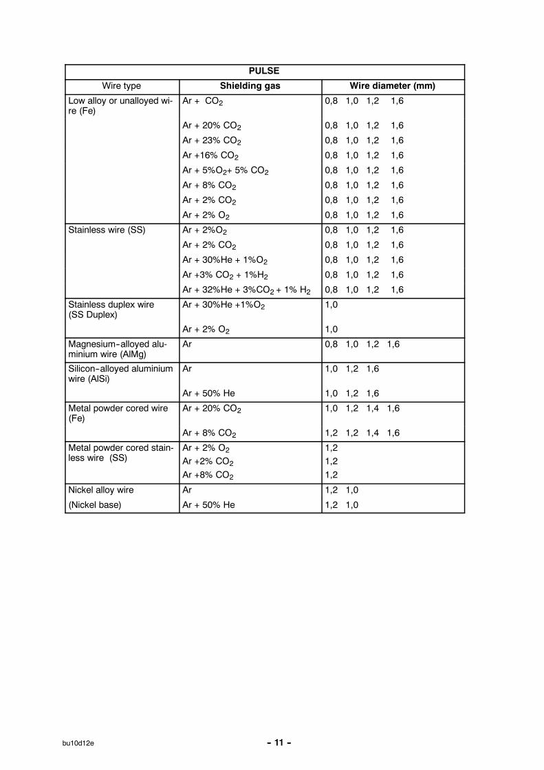
3. Wire type, shielding gas, wire size
The following tables show the combinations of wire type, shielding gas and wiresize that can be selected when the welding power source is in synergic mode.

-- 10 --bu10d12e
DIP/SPRAY
Wire type Shielding gas Wire diameter (mm)
Low alloy or unalloyedwire (Fe)
CO2 0,8 1,0 1,2 1,6
Ar + 23% CO2 0,8 1,0 1,2 1,6
Ar + 25% CO2 0,8 1,0 1,2 1,6
Ar + 20% CO2 0,8 1,0 1,2 1,6
Ar + 15% CO2 + 5%O2 0,8 1,0 1,2 1,6
Ar +16% CO2 0,8 1,0 1,2 1,6
Ar + 5%O2+ 5% CO2 0,8 1,0 1,2 1,6
Ar + 8% CO2 0,8 1,0 1,2 1,6
Ar + 2% CO2 0,8 1,0 1,2 1,6
Ar + 2% O2 0,8 1,0 1,2 1,6
Duplex stainless solidwire (SS)
Ar + 2%O2 0,8 1,0 1,2 1,6
Ar + 2% CO2 0,8 1,0 1,2 1,6
Ar + 3%CO2 + 1%H2 0,8 1,0 1,2 1,6
Ar + 30%He + 1%O2 0,8 1,0 1,2 1,6
Ar + 32%He + 3%CO2 + 1% H2 0,8 1,0 1,2 1,6
Stainless duplex wire(Ss duplex)
Ar + 2% O2 1,0
Ar +30% He +1%O2 1,0
Magnesium--alloyedaluminium wire (AlMg)
Ar 1,0 1,2 1,6
Silicon--alloyed alumini-um wire (AlSi)
Ar 1,0 1,2 1,6
Ar + 50% He 1,0 1,2 1,6
Metal powder cored wi-re (Fe)
Ar + 20% CO2 1,0 1,2 1,4 1,6
Ar+ 8% CO2 1,0 1,2 1,4 1,6
Rutile flux cored wire(Fe)
CO2 1,2 1,4 1,6
Ar + 20% CO2 1,2 1,4 1,6
Basic flux cored wire(Fe)
CO2 1,0 1,2 1,4 1,6
Ar + 20% CO2 1,0 1,2 1,4 1,6
Stainless flux cored wi-re (SS)
Ar + 20% CO2 1,2
Ar + 8% CO2 1,2
SELF SHIELDED 1,6 2,4
Duplex rutile flux coredwire SS
Ar + 20% CO2 1,2
Metal powder coredstainless wire
Ar + 2% O2
Ar +2% CO2
Ar +8% CO2
Ar + 20% CO2
1,21,21,21,2
-- 11 --bu10d12e
PULSE
Wire type Shielding gas Wire diameter (mm)
Low alloy or unalloyed wi-re (Fe)
Ar + CO2 0,8 1,0 1,2 1,6
Ar + 20% CO2 0,8 1,0 1,2 1,6
Ar + 23% CO2 0,8 1,0 1,2 1,6
Ar +16% CO2 0,8 1,0 1,2 1,6
Ar + 5%O2+ 5% CO2 0,8 1,0 1,2 1,6
Ar + 8% CO2 0,8 1,0 1,2 1,6
Ar + 2% CO2 0,8 1,0 1,2 1,6
Ar + 2% O2 0,8 1,0 1,2 1,6
Stainless wire (SS) Ar + 2%O2 0,8 1,0 1,2 1,6
Ar + 2% CO2 0,8 1,0 1,2 1,6
Ar + 30%He + 1%O2 0,8 1,0 1,2 1,6
Ar +3% CO2 + 1%H2 0,8 1,0 1,2 1,6
Ar + 32%He + 3%CO2 + 1% H2 0,8 1,0 1,2 1,6
Stainless duplex wire(SS Duplex)
Ar + 30%He +1%O2 1,0
Ar + 2% O2 1,0
Magnesium--alloyed alu-minium wire (AlMg)
Ar 0,8 1,0 1,2 1,6
Silicon--alloyed aluminiumwire (AlSi)
Ar 1,0 1,2 1,6
Ar + 50% He 1,0 1,2 1,6
Metal powder cored wire(Fe)
Ar + 20% CO2 1,0 1,2 1,4 1,6
Ar + 8% CO2 1,2 1,2 1,4 1,6
Metal powder cored stain-less wire (SS)
Ar + 2% O2
Ar +2% CO2
Ar +8% CO2
1,21,21,2
Nickel alloy wire Ar 1,2 1,0
(Nickel base) Ar + 50% He 1,2 1,0

-- 12 --bu10d12e
2.4 Welding data settings
The following is an summary of the welding parameters that affect the weldingprocess when using MIG and MAG welding methods.
With the power source in synergic mode it is only necessary to set the wire feedspeed.The voltage parameter may also be adjusted if required.
When the wire feed speed is adjusted the synergic control system automaticallyadjusts certain other parameters to compensate. The parameters in italics remainconstant and are unaffected by changes in the wire feed speed.
Method DIP/SPRAY Method PULSING
S Wire feed speed S Wire feed speed
S Voltage S Voltage
S Inductance S Pulse current
S Control type S Pulse time
S Pulse frequency
S Background current
S Ka
S Ki
A table of parameter setting ranges is given in the APPENDIX see step 10.
2.5 Start and stop settings
The following settings affect the start and stop cycle during MIG/MAG welding.All the settings that affect the start/stop cycle and the way welding finishes aredescribed under the following headings.
Start settings Stop settings
S Gas pre--flow S Gas post--flow
S Creep startS Hot start
S Hot start timeS Increase wire feed speed
(2 m/min unless statedotherwise)
S Increase voltage (onlywhen not in synergicmode)
S Burnback timeS Shake--off pulse (only for DIP/SPRAY
when not in synergic mode)S Crater fill
S Crater fill timeS Final wire feed speedS Final voltage (only when not in
synergic mode)
There are three different functions that are designed to meet special requirements atthe start and end of welding. These functions and auxiliary settings are made in thestart data menu and stop data menu.
-- 13 --bu10d12e
Hot start
Hot start should be selected if you want a hotter arc at the start of the welding cycleto prevent welding defects at the start of the weld.
Crater fill
The crater fill function makes it easier to avoid porosity, hot cracks and cratercracking in the weld when you stop welding.
Creep start
The creep start function gives a lower wire feed speed and is suitable to use whenwanting to obtain the best possible start. The creep start speed is 50% of the setwire feed speed. The function is activated on delivery.
TIP! The hot start, creep start and crater fill functions can be switched on or off usingthe “soft keys“, see the section on “MIG/MAG configuration“ see step 9.2.4.2.
The start data and stop data menus are used to set the values for the followingparameters.
Gas pre-- and post--flow
The parameters gas pre--flow and gas post--flow specify the length of time that thegas continues to flow before and after welding.
Burnback time
Burn--back time is used to adjust the electrode stick--out at the end of welding.
2.6 Gas purge, cold wire feed and trigger latch
Like hot start and the others the following three functions can be controlled using thesoft keys. To find out how to do this see “MIG/MAG configuration“ see step 9.2.4.2.
Gas purge
The gas purge function is used to fill the gas hoses with shielding gas, or in order tomeasure the gas flow rate. The gas flows when you press the key and stops whenyou release it.
Cold wire feed
This function is used to feed wire out manually when fitting a new reel of wire. Whenthe key is pressed the wire is fed forward, and when it is released the wire stops.
Gun trigger mode
In MIG/MAG welding the torch switch can operate in two ways; with trigger latch offor trigger latch on. Trigger latch off/on can be assigned to one of the soft keys.The difference between having the trigger latch off or on is illustrated in the followingdiagrams, together with other functions in the start/stop cycle.

-- 14 --bu10d12e
Trigger latch off (2--Stroke)
1
2
HotStart
Gas pre--flow
Crater-fill
Gas post--flow
Welding
Craterfill stop data
With the trigger latch off the gas pre--flow (if set) begins when the gun trigger ispressed (1). The welding parameters then rise to their set values or (if set) Hot startvalues.When the gun trigger is released (2) the crater fill period begins. After this haselapsed the welding parameters drop to back zero and the gas post--flow (if set)finishes the welding sequence.
TIP! If the gun trigger is pressed in again during the crater fill period then you cancontinue welding using the final crater fill parameters for as long as required (dottedline). Crater fill can also be cut short by pressing and releasing the gun triggerquickly during the crater fill period.
Trigger latch on (4--Stroke)
HotStart
Gas pre--flow
Crater-fill
Gas post--flow
Welding
1
2
Craterfill stop data
3
4
When the trigger latch is on the gas pre--flow begins when the gun trigger is pressed(1). When the trigger latch is released (2) the welding parameters rise to their setvalues. When the gun trigger is pressed again (3) the crater fill period begins. Whenthis has elapsed the values of the welding parameters drop to stop data.The gas post--flow period begins when the gun trigger is released (4).
TIP! Crater fill stops when the gun trigger is released (4). If instead the trigger is heldin for longer then you can continue welding using the final crater fill parameters(dotted line).

-- 15 --bu10d12e
2.7 MIG/MAG configuration
See step 9.2.4.
2.8 Setting--up example MIG/MAG
The following is an example of how to set up the controller for MIG/MAG weldingusing dip/spray transfer. Setting up for pulse welding is done in a similar way. Theexample assumes that the power source is in synergic mode.
2.8.1 Basic settings
You use the main menu to make settings such as wire, method and material type.
We start by pressing the MENU key to call up the main menu.We will make the following five settings:
S PROCESS = MIG/MAG
S METHOD = DIP/SPRAY
S WIRE TYPE = Fe
S SHIELDING GAS = Ar+8%CO2
S WIRE DIAMETER = 1.2 mm
Process
ESAB LUD 450
The first setting isthe type of weldingprocess. Use thearrow keys to selectthe line forPROCESS. PressENTER to displaythe list of options.
PROCESS: MIG/MAGMETHOD: PULSEWIRE TYPE: AlSiSHIELDING GAS: Ar+20%CO2WIRE DIMENSION: 1.0 mmAUXILIARY FUNCTIONS
SET MEASURE MEMORYFASTMODE ENTER
Position the cursor on the line for MIG/MAG in thelist and press ENTER again. Now we have setPROCESS = MIG/MAG.
MIG/MAG
MMATIGCARBON, ArcAir

DIP/SPRAYPULSE
FeSs (Stainless)Ss duplexAlMgAlSiMetal cored FeRutile FC Fe
-- 16 --bu10d12e
Method
ESAB LUD 450
Position the cursoron the line forMETHOD. PressENTER to displaythe list of options.
PROCESS: MIG/MAGMETHOD: PULSEWIRE TYPE: AlSiSHIELDING GAS: Ar+20%CO2WIRE DIMENSION: 1.0 mmAUXILIARY FUNCTIONS
SET MEASURE MEMORYFASTMODE ENTER
Position the cursor on the line for DIP/SPRAYin the list and press ENTER. We have now set theMETHOD = DIP/SPRAY.
Wire type
ESAB LUD 450
Position the cursoron the line for WIRETYPE. Press ENTERto display the list ofoptions.
PROCESS: MIG/MAGMETHOD: DIP/SPRAYWIRE TYPE: AlSiSHIELDING GAS: Ar+20%CO2WIRE DIMENSION: 1.0 mmAUXILIARY FUNCTIONS
SET MEASURE MEMORYFASTMODE ENTER
Here is an example of a list that has so many optionsthat they cannot all be displayed at the same time.The arrow in the bottom right cordown of the listindicates that more options will become visible as youscroll down the list.
Now position the cursor on the line for Fe and pressENTER.We have now set the WIRE TYPE = Fe.

CO2Ar+20 % CO2Ar+2 % O2Ar+5 % O2+5 % CO2Ar+8 % CO2Ar+23 % CO2Ar+15 % CO2+5 % O2
0.8 mm1.0 mm1.2 mm1.6 mm
-- 17 --bu10d12e
Shielding gas
ESAB LUD 450
Position the cursoron the line forSHIELDING GAS.Press ENTER todisplay the list ofoptions.
PROCESS: MIG/MAGMETHOD: DIP/SPRAYWIRE TYPE: FeSHIELDING GAS: Ar + 20% CO2WIRE DIMENSION: 1.0 mmAUXILIARY FUNCTIONS
SET MEASURE MEMORYFASTMODE ENTER
Position the cursor on the line for Ar+8%CO2 andpress ENTER. We have now set theSHIELDING GAS = Ar+8%CO2.
Wire dimension
ESAB LUD 450
Position the cursoron the line for WIREDIMENSION. PressENTER to displaythe list of options.
PROCESS: MIG/MAGMETHOD: DIP/SPRAYWIRE TYPE: FeSHIELDING GAS: Ar8%CO2WIRE DIMENSION: 1.0 mmAUXILIARY FUNCTIONS
SET MEASURE MEMORYFASTMODE ENTER
Position the cursor on the line for 1.2 mm and pressENTER. We have now set the WIRE DIMENSION =1.2 mm.
-- 18 --bu10d12e
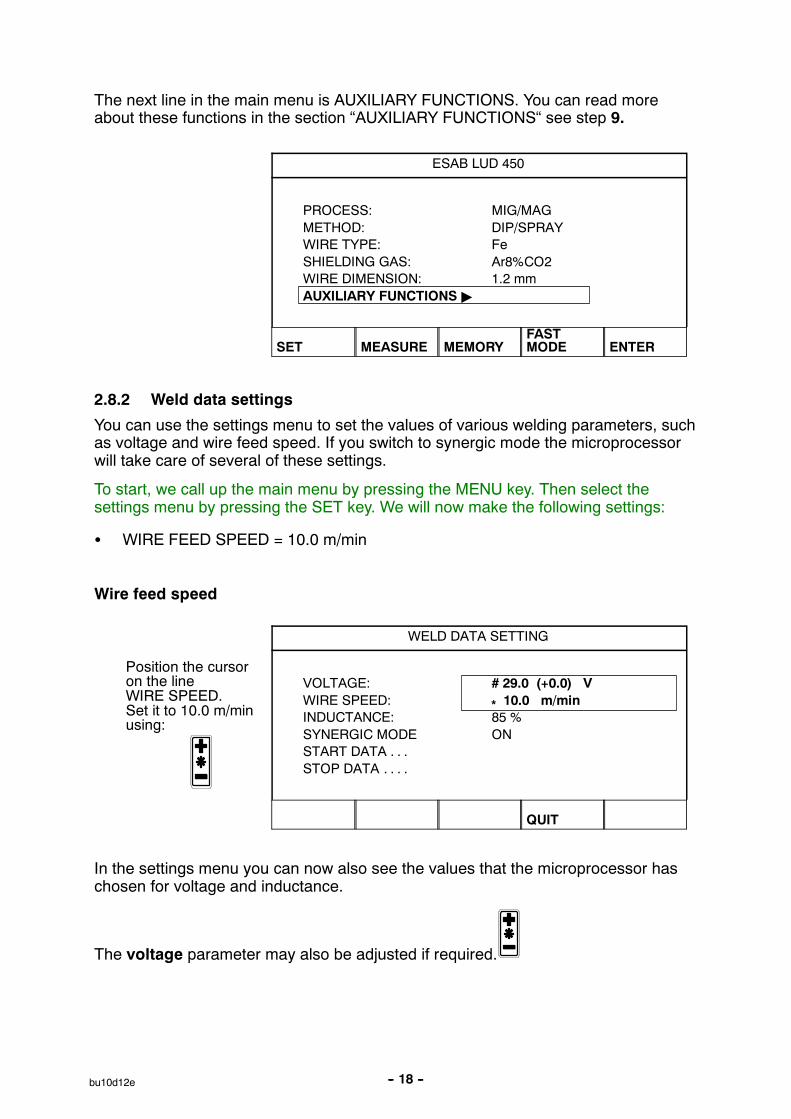
The next line in the main menu is AUXILIARY FUNCTIONS. You can read moreabout these functions in the section “AUXILIARY FUNCTIONS“ see step 9.
ESAB LUD 450
PROCESS: MIG/MAGMETHOD: DIP/SPRAYWIRE TYPE: FeSHIELDING GAS: Ar8%CO2WIRE DIMENSION: 1.2 mmAUXILIARY FUNCTIONS "
SET MEASURE MEMORYFASTMODE ENTER
2.8.2 Weld data settings
You can use the settings menu to set the values of various welding parameters, suchas voltage and wire feed speed. If you switch to synergic mode the microprocessorwill take care of several of these settings.
To start, we call up the main menu by pressing the MENU key. Then select thesettings menu by pressing the SET key. We will now make the following settings:
S WIRE FEED SPEED = 10.0 m/min
Wire feed speed
WELD DATA SETTING
Position the cursoron the lineWIRE SPEED.Set it to 10.0 m/minusing:
VOLTAGE: # 29.0 (+0.0) VWIRE SPEED: * 10.0 m/minINDUCTANCE: 85 %SYNERGIC MODE ONSTART DATA . . .STOP DATA . . . .
QUIT
In the settings menu you can now also see the values that the microprocessor haschosen for voltage and inductance.
The voltage parameter may also be adjusted if required.

-- 19 --bu10d12e
2.8.3 Start data settings
Using the start data menu you can adjust the settings that affect the startingsequence during MIG/MAG welding. We will set the following:
S GAS PRE--FLOW = 0.8 s
S CREEP START = YES
S HOT START = YES
S HOT START time = 1.0 s
S HOT START wire feed speed = +2.5 m/min
Start by opening the main menu, by pressing the MENU key.Then go to the settings menu by pressing the SET key.
WELD DATA SETTING
Position the cursoron the line STARTDATA and pressENTER.
VOLTAGE: # 29.0 (+0.0) VWIRE SPEED: * 10.0 m/minINDUCTANCE: 70 %SYNERGIC MODE ONSTART DATA . .STOP DATA . . . .
CRATRFILL
HOTSTART
4--STROKE QUIT
Gas pre--flow time
Here you enter the length of time you want the shielding gas to flow before weldingbegins.
START DATA, SYNERGIC MODE
Position the cursoron the line for GASPREFLOW. Set it to0.8 s using one ofthe plus/minus keys
GASPREFLOW: 0.8 sCREEPSTART: YESHOTSTART: NO
CRATRFILL
HOTSTART
4--STROKE QUIT

-- 20 --bu10d12e
Creep start
Here you simply choose whether you want to use the creep start function or not, i.e.YES or NO. Wire feed speed and creep start time are preset and cannot bechanged.
START DATA, SYNERGIC MODE
Position the cursoron the line CREEPSTART. Set it toYES by pressingone of theplus/minus keys.
GASPREFLOW: 0.8 sCREEPSTART: YESHOT START: NO
CRATRFILL
HOTSTART
4--STROKE QUIT ENTER
Hot start
To begin with you choose whether you want to use the hot start function or not. If youdecide to use the hot start function, you should then enter the hot start time and anyincrease in the wire feed speed.
START DATA, SYNERGIC MODE
Position the cursoron the line HOTSTART. ChooseYES using one ofthe plus/minuskeys.
GASPREFLOW: 0.8 sCREEPSTART: YESHOT START: YES
HOT START TIME: 1.5 sWIRE SP: 2.0 m/min
CRATRFILL
HOT DSTART
4--STROKE QUIT ENTER
START DATA, SYNERGIC MODE
Position the cursoron the line HOTSTART TIME. Setit to 1.0 s using oneof the plus/minuskeys.
GASPREFLOW: 0.8 sCREEPSTART: YESHOTSTART: YES
HOT START TIME: 1.0 sWIRE SP: 2.0 m/min
CRATRFILL
HOT DSTART
4--STROKE QUIT

-- 21 --bu10d12e
START DATA, SYNERGIC MODE
Position the cursoron the lineWIRE SP.Set it to 2.5 m/min.
GASPREFLOW: 0.8 sCREEPSTART: YESHOTSTART: YES
HOT START TIME: 1.0 sWIRE SP: 2.5 m/min
CRATRFILL
HOT DSTART
4--STROKE QUIT
All the start settings have now been made.
START DATA, SYNERGIC MODE
Return to thesettings menu bypressing QUIT.
GASPREFLOW: 0.8 sCREEPSTART: YESHOTSTART: YES
HOT START TIME: 1.0 sWIRE SP: 2.5 m/min
CRATRFILL
HOT DSTART
4--STROKE QUIT
2.8.4 Stop data settingsThe stop data menu is used to make the settings that affect the stop sequenceduring MIG/MAG welding.We will enter the following stop data:
S CRATER FILL = YESS CRATER FILL TIME =1.5 sS FINAL WIRE FEED SPEED = 3.0 m/minS BURNBACK TIME =0.11 sS GAS POST--FLOW =2.0 s
WELD DATA SETTING
Position the cursoron the line STOPDATA and pressENTER.
VOLTAGE: # 29.0 (+0.0) VWIRE SPEED: * 10.0 m/minINDUCTANCE: 70 %SYNERGIC MODE ONSTART DATA . . .STOP DATA . . .
CRATRFILL
HOT DSTART
4--STROKE QUIT ENTER
-- 22 --bu10d12e
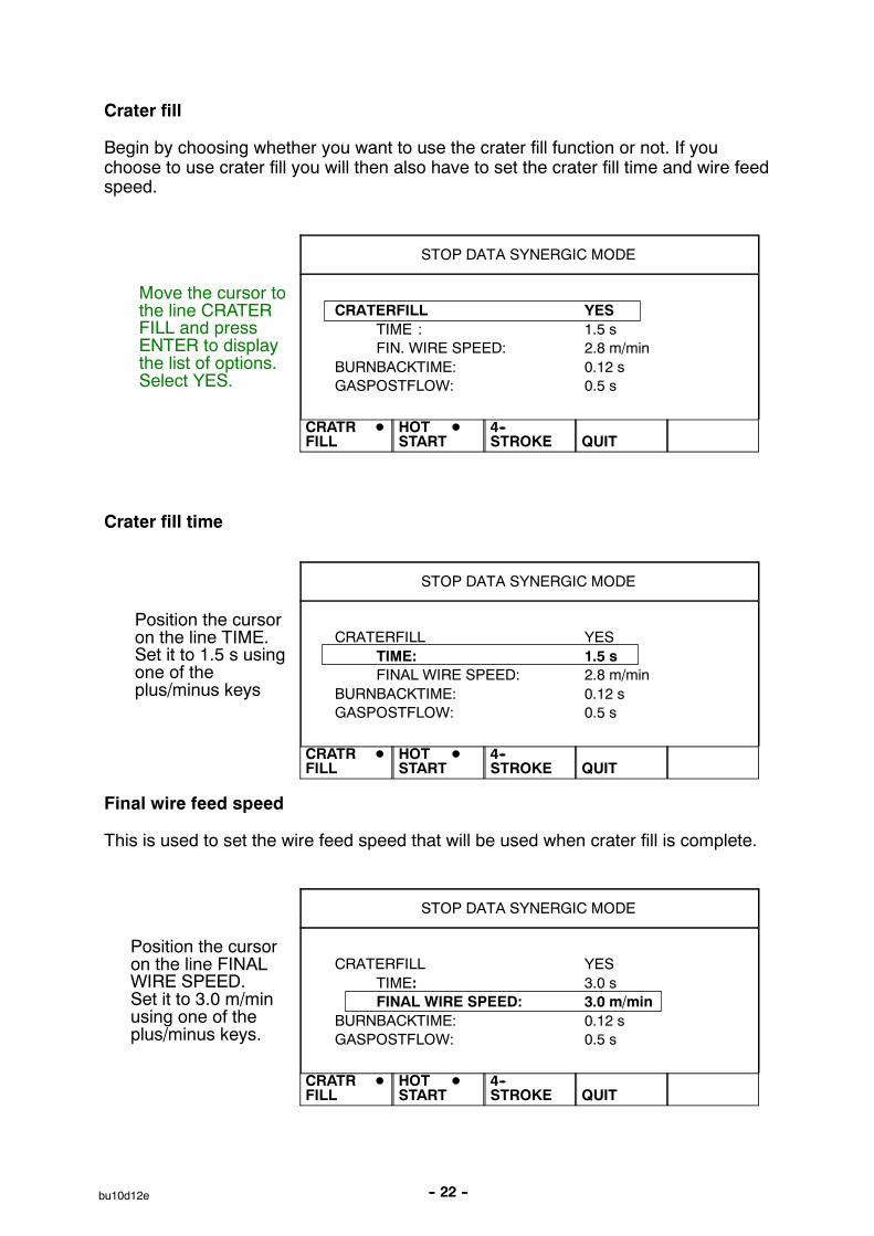
Crater fill
Begin by choosing whether you want to use the crater fill function or not. If youchoose to use crater fill you will then also have to set the crater fill time and wire feedspeed.
STOP DATA SYNERGIC MODE
Move the cursor tothe line CRATERFILL and pressENTER to displaythe list of options.Select YES.
CRATERFILL YESTIME : 1.5 sFIN. WIRE SPEED: 2.8 m/min
BURNBACKTIME: 0.12 sGASPOSTFLOW: 0.5 s
CRATR DFILL
HOT DSTART
4--STROKE QUIT
Crater fill time
STOP DATA SYNERGIC MODE
Position the cursoron the line TIME.Set it to 1.5 s usingone of theplus/minus keys
CRATERFILL YESTIME: 1.5 sFINAL WIRE SPEED: 2.8 m/min
BURNBACKTIME: 0.12 sGASPOSTFLOW: 0.5 s
CRATR DFILL
HOT DSTART
4--STROKE QUIT
Final wire feed speed
This is used to set the wire feed speed that will be used when crater fill is complete.
STOP DATA SYNERGIC MODE
Position the cursoron the line FINALWIRE SPEED.Set it to 3.0 m/minusing one of theplus/minus keys.
CRATERFILL YESTIME: 3.0 sFINAL WIRE SPEED: 3.0 m/min
BURNBACKTIME: 0.12 sGASPOSTFLOW: 0.5 s
CRATR DFILL
HOT DSTART
4--STROKE QUIT

-- 23 --bu10d12e
Burnback time
STOP DATA SYNERGIC MODE
Position the cursoron the lineBURNBACK TIME.Set it to 0.11 s usingone of theplus/minus keys.
CRATERFILL YESTIME: 3.0 sFINAL WIRE SPEED: 4.0 m/min
BURNBACKTIME: 0.11 sGASPOSTFLOW: 0.5 s
CRATR DFILL
HOT DSTART
4--STROKE QUIT
Gas post--flow
Use this to set the time for which the gas continues to flow after welding is complete.
STOP DATA SYNERGIC MODE
Position the cursoron the line GASPOST--FLOW. Setit to 2.0 s using oneof the plus/minuskeys.
CRATERFILL YESTIME: 1.5 sFINAL WIRE SPEED: 3.0 m/min
BURNBACKTIME: 0.11 sGASPOSTFLOW: 2.0 s
CRATR DFILL
HOT DSTART
4--STROKE QUIT
This completes the stop data settings and means that all the weld data settings forMIG/MAG welding have been entered.

-- 24 --bu10d12e
3 MMA welding
3.1 Synergic mode
The welding power source also has a synergic mode for MMA welding.This means that the welding power source automatically optimises the weldingcharacteristics to suit the type and size of electrode you have chosen.
3.2 Basic settings
The basic settings for MMA welding are entered using the controller’s main menu.
1. Welding process = MMA
2. Electrode type
Three different types of electrode can be chosen if you want to weld in synergicmode.
S Basic
S Rutile
S Cellulosic
3. Electrode diameterThe table below shows the electrode diameters that can be selected when the powersource is in synergic mode.
Electrode type Electrode diameter (mm)
Basic 1.6 2.0 2.5 3.25 4.0 5.0 6.0
Rutile 1.6 2.0 2.5 3.25 4.0 5.0 6.0
Cellulosic 2.5 3.25

-- 25 --bu10d12e
3.3 Welding data
If you stay in synergic mode you only need to set the welding current.The welding current can also be adjusted during welding by using the +/-- keys.When you adjust the welding current the arc force is automatically adjusted tocompensate if the welding power source is in synergic mode.
In the settings menu you can see what value has been chosen for the parameterwelding current.
ESAB LUD 450
Display the SETUPmenu by pressingthe SET key.
PROCESS: MMAELECTRODE TYPE: RUTILEELECTRODE DIAMETER: 2.5 mmAUXILIARY FUNCTIONS "
SET MEASURE MEMORYFASTMODE ENTER
WELD DATA SETTING
With our chosencombination ofelectrode type andelectrode diameterthe power sourcehas set the weldingcurrent to 80 A.
CURRENT: 80 ASYNERGIC MODE: ON
QUIT

-- 26 --bu10d12e
3.4 MMA--configuration
See step 9.2.5.
3.5 Setting--up example MMA
Here is an example of how to set up for MMA welding.
3.5.1 Basic settingsThe main menu is used to make the settings that concern choice of electrode.
First we call up the main menu, if this has not already been done, by pressing theMENU key.We will make the following three settings:
S PROCESS = MMAS ELECTRODE TYPE= RUTILES ELECTRODE DIAMETER = 2.5 mm
Process
ESAB LUD 450
Use the arrow keysto selectPROCESS. PressENTER to displaythe list of options.
PROCESS: MMAELECTRODE TYPE: BASICELECTRODE DIAMETER: 6 mmAUXILIARY FUNCTIONS
SET MEASURE MEMORYFASTMODE ENTER
Position the cursor over the MMA option in the list andpress ENTER. We have now set the PROCESS = MMA.
Electrode type
ESAB LUD 450
Use the arrow keysto selectELECTRODE TYPE.Press ENTER todisplay the list ofoptions.
PROCESS: MMAELECTRODE TYPE: BASICELECTRODE DIAMETER: 6 mmAUXILIARY FUNCTIONS
SET MEASURE MEMORYFASTMODE ENTER
MIG/MAG
MMATIGCARBON, ArcAir

1.6 mm2 mm2.5 mm3.25 mm4 mm5 mm6 mm
-- 27 --bu10d12e
Position the cursor over the RUTILE option in the listand press ENTER. We have now set the ELECTRODETYPE = RUTILE.
Electrode diameter
ESAB LUD 450
Use the arrow keysto selectELECTRODEDIAMETER. PressENTER to displaythe list of options.
PROCESS: MMAELECTRODE TYPE: RUTILEELECTRODE DIAMETER: 6 mmAUXILIARY FUNCTIONS
SET MEASURE MEMORYFASTMODE ENTER
Position the cursor over the value 2.5 mm in the listand press ENTER. We have now set the ELECTRODEDIAMETER = 2.5 mm.
ESAB LUD 450
PROCESS: MMAELECTRODE TYPE: RUTILEELECTRODE DIAMETER: 2.5 mmAUXILIARY FUNCTIONS "
SET MEASURE MEMORYFASTMODE ENTER
The next line in the menu is AUXILIARY FUNCTIONS. You can read more aboutthese functions in the section “AUXILIARY FUNCTIONS“ See step 9.
We have now completed the settings for MMA welding.
BASIC
RUTILECELLULOSA

-- 28 --bu10d12e
4 TIG welding
4.1 Basic settings
The basic settings for TIG welding are made in the main menu.
1. Welding process = TIG
2. Welding method
With TIG welding you have a choice of two different welding methods.
S Constant current
S Pulse
3. Start method
There is also a choice of two start methods.
S Liftarc
S HF--START
With Liftarc start you touch the electrode to the workpiece to strike the arc, thenraise it slightly. With HF start the arc is struck by a high frequency spark that isproduced when the electrode is a certain distance from the workpiece.
4. Gun trigger mode
In TIG welding you can choose whether you want the TIG torch to operate withthe trigger latch off or on. The main difference is that with the trigger latch off youhave to hold the trigger in during welding, but when it is on you can release thetrigger during welding. The difference between having the trigger latch off or onis illustrated in the following diagrams, along with the other functions in thestart/stop cycle.
Trigger latch off
Slopeup
Slopedown
1
2
Gas pre--flow Gaspost--flow
With the trigger latch off, gas pre--flow begins when the TIG gun trigger is pressed(1). The current then rises to the pilot level (a couple of amperes) and the arc ignites.The current then rises to the set value (following the Slope--up slope if applicable).When the trigger is released (2) the current falls back to the pilot level (following theSlope--down slope if applicable) and the arc is extinguished. The gas continues toflow for the post--flow period, if applicable.

-- 29 --bu10d12e
Trigger latch on
Slopeup
Slopedown
1 2
3
4
Gas pre--flow Gaspost--flow
With the trigger latch on, gas pre--flow begins when the TIG gun trigger is pressed(1). When the gas pre--flow period has elapsed the current rises to the pilot level (acouple of amperes) and the arc ignites.When the trigger is released (2) the current rises to the set value (following theSlope--up slope if applicable).When the trigger is pressed again (3) the current again rises to the pilotlevel(following the Slope--down slope if applicable).When the trigger is released again (4) the arc is extinguished and the gas post--flowperiod begins (if applicable).
When you are in the weld data settings menu or the measure menu you can switchthe trigger latch off or on using one of the soft keys.
4.2 Welding data settings
The values of the welding parameters are set using the settings menu. Certainparameters are specific to the chosen method and certain are common to both TIGmethods. The following parameters can be set for TIG welding.
See the APPENDIX step 10. for details of parameter setting ranges.
Method CONSTANT CURRENT Method PULSE
S Current S Pulse current
S Slope--up S Background current
S Slope--down S Pulse time
S Gas pre--flow S Background time
S Gas post--flow S Slope--up
S Slope--down
S Gas pre--flow
S Gas post--flow
-- 30 --bu10d12e
Current
The term current refers here to the welding current when welding with constantcurrent.
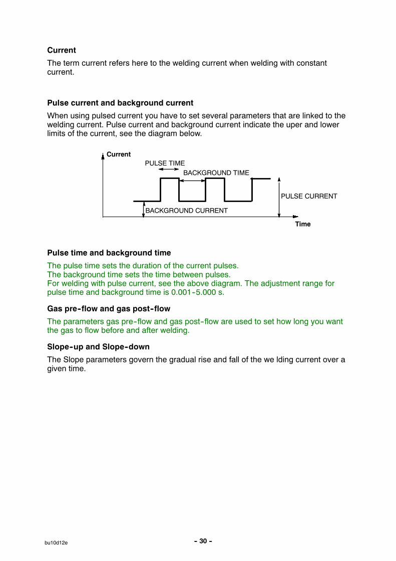
Pulse current and background current
When using pulsed current you have to set several parameters that are linked to thewelding current. Pulse current and background current indicate the uper and lowerlimits of the current, see the diagram below.
PULSE CURRENT
PULSE TIMEBACKGROUND TIME
Current
Time
BACKGROUND CURRENT
Pulse time and background time
The pulse time sets the duration of the current pulses.The background time sets the time between pulses.For welding with pulse current, see the above diagram. The adjustment range forpulse time and background time is 0.001--5.000 s.
Gas pre--flow and gas post--flow
The parameters gas pre--flow and gas post--flow are used to set how long you wantthe gas to flow before and after welding.
Slope--up and Slope--down
The Slope parameters govern the gradual rise and fall of the we lding current over agiven time.
-- 31 --bu10d12e
4.3 TIG--configuration
See step 9.2.6.
4.4 Setting--up example TIG
The following explains how to set up for TIG welding using the constant currentmethod. The setting--up procedure is similar for pulse welding.
4.4.1 Basic settings
We start by displaying the main menu, if this has not already been done, by pressingthe MENU key.We will make the following four settings:
S PROCESS = TIG
S METHOD = CONSTANT CURRENT
S START METHOD = LIFT ARC
S GUN TRIGGER MODE= 2--STROKE
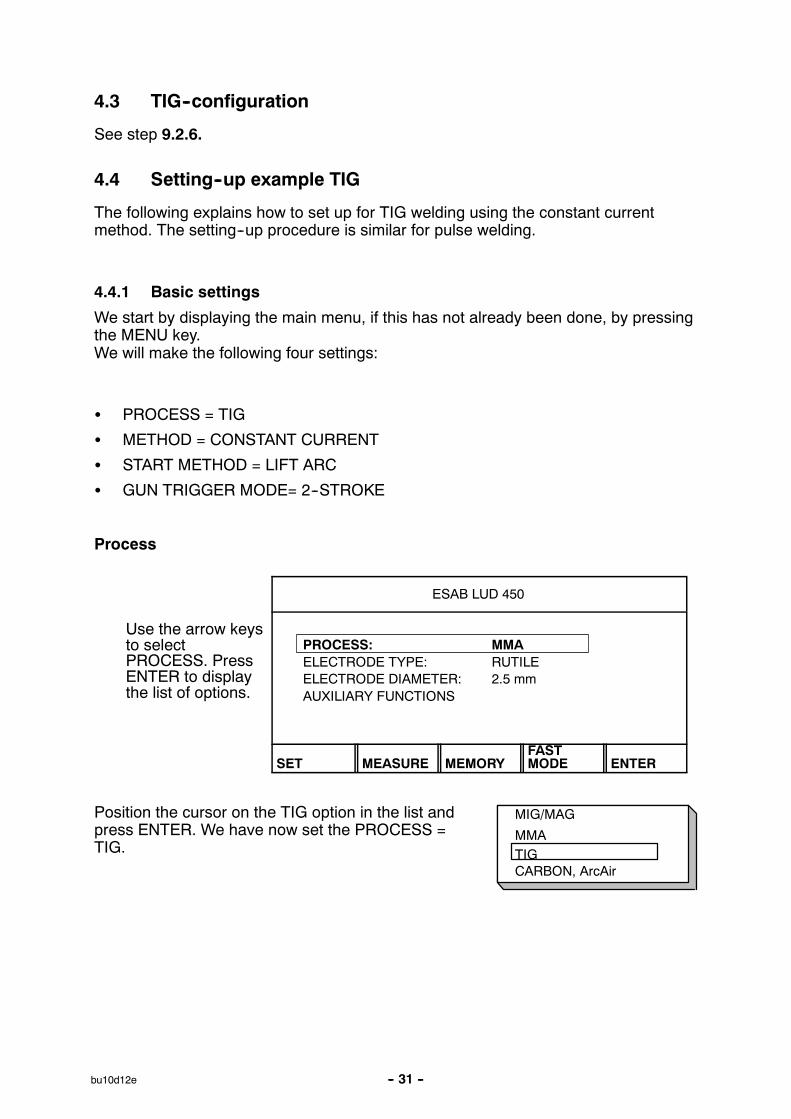
Process
ESAB LUD 450
Use the arrow keysto selectPROCESS. PressENTER to displaythe list of options.
PROCESS: MMAELECTRODE TYPE: RUTILEELECTRODE DIAMETER: 2.5 mmAUXILIARY FUNCTIONS
SET MEASURE MEMORYFASTMODE ENTER
Position the cursor on the TIG option in the list andpress ENTER. We have now set the PROCESS =TIG.
MIG/MAG
MMATIGCARBON, ArcAir

CONSTANT IPULSED I
HF--STARTLIFTARC
-- 32 --bu10d12e
Method
ESAB LUD 450
Position the cursoron the lineMETHOD. PressENTER to displaythe list of options.
PROCESS: TIGMETHOD: PULSED ISTART METHOD: LIFTARCGUN TRIGGER MODE: 4--STROKEAUXILIARY FUNCTIONS
SET MEASURE MEMORYFASTMODE ENTER
Position the cursor on the line for CONSTANT Iin the list and press ENTER.We have now set the METHOD = CONSTANTCURRENT.
Start method
ESAB LUD 450
Position the cursoron the line STARTMETHOD. PressENTER to displaythe list of options.
PROCESS: TIGMETHOD: CONSTANT ISTART METHOD: LIFTARCGUN TRIGGER MODE: 4--STROKEAUXILIARY FUNCTIONS
SET MEASURE MEMORYFASTMODE ENTER
Position the cursor on the line for LIFTARC in thelist and press ENTER. We have now set theSTART METHOD = LIFTARC.

4--STROKE2--STROKE
-- 33 --bu10d12e
Gun trigger mode
ESAB LUD 450
Position the cursoron the line GUNTRIGGER MODE.Press ENTER todisplay a list ofoptions.
PROCESS: TIGMETHOD: CONSTANT ISTART METHOD: LIFTARCGUN TRIGGER MODE: 4--STROKEAUXILIARY FUNCTIONS
SET MEASURE MEMORYFASTMODE ENTER
Position the cursor on the line for 2--STROKE inthe list and press ENTER. We have now set theGUN TRIGGER MODE = 2--STROKE (trigger latch off).
ESAB LUD 450
PROCESS: TIGMETHOD: CONSTANT ISTART METHOD : LIFTARCGUN TRIGGER MODE: 2--STROKEAUXILIARY FUNCTIONS "
SET MEASURE MEMORYFASTMODE ENTER
The next line in the menu is AUXILIARY FUNCTIONS. See the section “AUXILIARYFUNCTIONS“ See step 9. for more information.

-- 34 --bu10d12e
4.4.2 Weld data settings
Use the settings menu to set the values of the various welding parameters.
We will make the following settings:
S CURRENT = 200 A
S SLOPE--UP TIME = 2.0 s
S SLOPE--DOWN TIME = 1.4 s
S GAS PRE--FLOW = 3.0 s
S GAS POST--FLOW = 5.0 s
Press MENU key, call up the settings menu by pressing the SET key.
Current
WELD DATA SETTING
Position the cursoron the line forCURRENT.Set the value to200 A using one ofthe plus/minuskeys.
CURRENT: 200 ASLOPE UP TIME: 4,0 sSLOPE DOWN TIME: 6,0 sGASPREFLOW: 2.5 sGASPOSTFLOW: 3.3 s
GASPURGE
4STROKE QUIT
Slope--up and Slope--down
The Slope--up and Slope--down parameters are each linked to the plus and minuskeys respectively. To set the Slope--up time use the uper key, and to set theSlope--down time use the lower key.
WELD DATA SETTING
Move the cursor to theline for SLOPE UP andSLOPE DOWN TIME.Set theSLOPE UP TIME to2.0 s by stepping withthe upper plus/minuskey.
CURRENT: 200 ASLOPE UP TIME: # 2.0 sSLOPE DOWN TIME: * 6.0 sGAS PRE--FLOW: 2.5 sGAS POST--FLOW: 3.3 s
GASPURGE
4STROKE QUIT

-- 35 --bu10d12e
WELD DATA SETTING
Set the SLOPE DOWNTIME to 1.4 s bystepping with the lowerplus/minus-- key.
CURRENT: 200 ASLOPE UP TIME: # 2.0 sSLOPE DOWN TIME: *1.4 sGASPREFLOW: 2.5 sGASPOSTFLOW: 3.3 s
GASPURGE
4STROKE QUIT
Gas pre--flow and gas post--flow
The parameters gas pre--flow and gas post--flow are each linked to their own specificplus/minus key in the same way as the Slope parameters above. The uperplus/minus key is used to set the gas pre--flow and the lower one is used to set thegas post--flow.
WELD DATA SETTING
Move the cursor to theline for GASPRE--FLOW and GASPOST--FLOW.Set the GASPRE--FLOW to 3.0 s bystepping with the upperplus/minus key.
CURRENT: 200 ASLOPE UP TIME: 2.0 sSLOPE DOWN TIME: 1.4 sGASPREFLOW: # 3.0 sGASPOSTFLOW: * 3.3 s
GASPURGE
4STROKE QUIT
WELD DATA SETTING
Set the GASPRE--FLOW to 5.0 s bystepping with the lowerplus/minus key.
CURRENT: 200 ASLOPE UP: 2.0 sSLOPE DOWN: 1.4 sGASPREFLOW: # 3.0GASPOSTFLOW: * 5.0
GASPURGE
4STROKE QUIT
We have now completed the set--up procedure for TIG welding.

-- 36 --bu10d12e
5 Arc air gouging
5.1 Synergic mode
The power source has a synergic mode for arc air gouging.This means that the power source automatically selects a suitable value for thevoltage on the basis of the chosen electrode diameter.
It is possible to use electrodes with a different diameter to those displayed on thecontroller, but this means that the user must make the necessary settings for certainparameters.
5.2 Basic settings
The basic settings for arc air gouging are made in the controller’s main menu.
1. Welding process = ARC AIR GOUGING (Carbon, ArcAir)
2. Electrode diameterThe table below shows the electrode diameters that can be used when the powersource is in synergic mode.
Electrode diameter
4 mm
5 mm
6 mm
8 mm
5.3 Welding data
If you use the power source in synergic mode there is actually no need to set any ofthe welding parameters. The voltage parameter can however be adjusted if wished.The parameters shown in italics are constant, i.e. they are unaffected by any changein voltage.
Welding parameters for arc air gouging
S Voltage
S Inductance
S Control type
See the “APPENDIX“ See step 10. for a table giving the full range of parametersettings.
-- 37 --bu10d12e
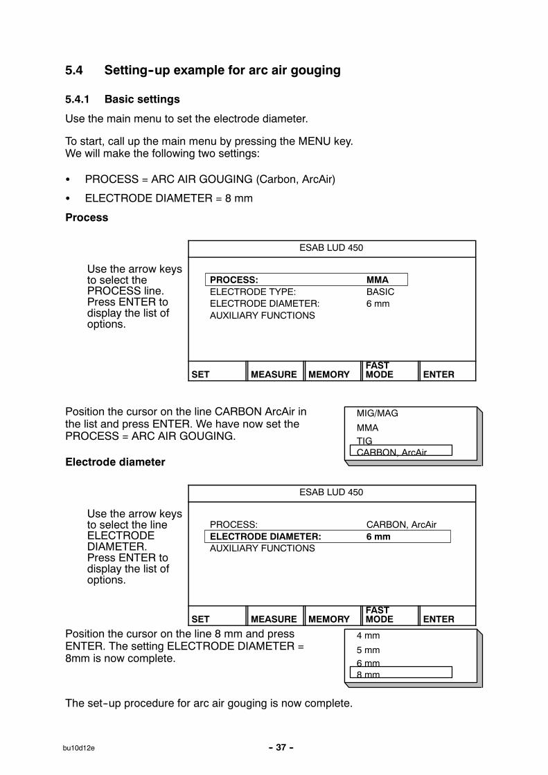
5.4 Setting--up example for arc air gouging
5.4.1 Basic settings
Use the main menu to set the electrode diameter.
To start, call up the main menu by pressing the MENU key.We will make the following two settings:
S PROCESS = ARC AIR GOUGING (Carbon, ArcAir)
S ELECTRODE DIAMETER = 8 mm
Process
ESAB LUD 450
Use the arrow keysto select thePROCESS line.Press ENTER todisplay the list ofoptions.
PROCESS: MMAELECTRODE TYPE: BASICELECTRODE DIAMETER: 6 mmAUXILIARY FUNCTIONS
SET MEASURE MEMORYFASTMODE ENTER
Position the cursor on the line CARBON ArcAir inthe list and press ENTER. We have now set thePROCESS = ARC AIR GOUGING.
Electrode diameter
ESAB LUD 450
Use the arrow keysto select the lineELECTRODEDIAMETER.Press ENTER todisplay the list ofoptions.
PROCESS: CARBON, ArcAirELECTRODE DIAMETER: 6 mmAUXILIARY FUNCTIONS
SET MEASURE MEMORYFASTMODE ENTER
Position the cursor on the line 8 mm and pressENTER. The setting ELECTRODE DIAMETER =8mm is now complete.
The set--up procedure for arc air gouging is now complete.
MIG/MAG
MMATIGCARBON, ArcAir
4 mm
5 mm6 mm8 mm

-- 38 --bu10d12e
5.4.2 Welding data
In the settings menu you can see what value has been selected for the voltageparameter. If necessary you can also adjust the voltage setting.
ESAB LUD 450
Go to the settingsmenu by pressingthe SET key.
PROCESS: CARBON, ArcAirELECTRODE DIAMETER: 8 mmAUXILIARY FUNCTIONS
SET MEASURE MEMORYFASTMODE ENTER
WELD DATA SETTING
On the basis of ourelectrode diametersetting the powersource has set thevoltage to 43 V.
VOLTAGE: 43.0 VSYNERGIC MODE: ON
QUIT
-- 39 --bu10d12e
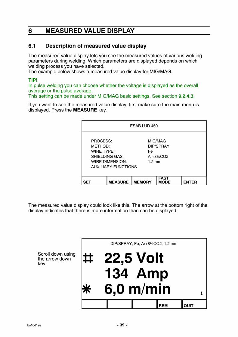
6 MEASURED VALUE DISPLAY
6.1 Description of measured value display
The measured value display lets you see the measured values of various weldingparameters during welding. Which parameters are displayed depends on whichwelding process you have selected.The example below shows a measured value display for MIG/MAG.
TIP!In pulse welding you can choose whether the voltage is displayed as the overallaverage or the pulse average.This setting can be made under MIG/MAG basic settings. See section 9.2.4.3.
If you want to see the measured value display; first make sure the main menu isdisplayed. Press the MEASURE key.
ESAB LUD 450
PROCESS: MIG/MAGMETHOD: DIP/SPRAYWIRE TYPE: FeSHIELDING GAS: Ar+8%CO2WIRE DIMENSION: 1.2 mmAUXILIARY FUNCTIONS
SET MEASURE MEMORYFASTMODE ENTER
The measured value display could look like this. The arrow at the bottom right of thedisplay indicates that there is more information than can be displayed.
DIP/SPRAY, Fe, Ar+8%CO2, 1.2 mm
Scroll down usingthe arrow downkey. 22,5 Volt
134 Amp6,0 m/min
REM QUIT

-- 40 --bu10d12e
A fourth value is visible in the display.
DIP/SPRAY, Fe, Ar+8%CO2, 1.2 mm
134 Amp6,0 m/min3,01 kW
REM QUIT
6.2 Changing set values
You can change the value of certain parameters in the measured value display.Which parameters can be changed depends on which welding process is selected.
The parameter values that can be changed are always identified by or .
DIP/SPRAY, Fe, Ar+8%CO2, 1.2 mm
Change by pressing
or
The window thatpops up willdisappear after 1.5 sif neither of thebuttons are used.
22,5 Volt134 Amp6,0 m/min
VOLTAGE: 22,5 (+3,5) V
REM QUIT

-- 41 --bu10d12e
7 MEMORY
The controller can store up to 99 sets of weld data. Each of these sets is given anumber from 1 to 99. If the weld data memory is full, i.e. if 99 sets of data arealready stored and you want to save an additional set of data, then the oldest set ofweld data is automatically deleted.
You can also delete and copy sets of weld data and recall a set of weld data to theworking memory.
Here is an example showing how to store, recall, copy and delete data.
7.1 Store
When you want to store a set of data, first make sure the main menu is displayed.Press the MEMORY key. If the weld data memory is empty the display will appear asfollows.
MEMORY FUNCTIONS -- STORED DATA SETS
: NO STORED DATA SETS :
STORE QUIT
Example
We will now store a set of weld data. We will store it in memory location 10. Pressthe STORE key. The display will appear as follows.
STORE IN DATA NR. 1
If you pressENTER now theset of data will besaved as number1, as indicated bythe top line of thedisplay.
QUIT ENTER
You can use the plus/minus keys to select the memory location you want to store theset of data in. This is shown in the top line of the display.

-- 42 --bu10d12e
The number shown in the top line of the display is the first empty position found inthe memory.
STORE IN DATA NR. 10
Select number 10using theplus/minuskeys. PressENTER.
QUIT ENTER
The set of data is now stored as number 10. At the bottom of the display you cansee part of the contents of data set 10.
STORE IN DATA NR. 10
10
" DIP/SPRAY, Fe, CO2, 1.2 mm
QUIT ENTER
To return to the memory menu press the QUIT key.
Tip!If the display indicates STORE IN DATA NR. 1, you can go directly to set 99 by
pressing the minus on either or .
-- 43 --bu10d12e
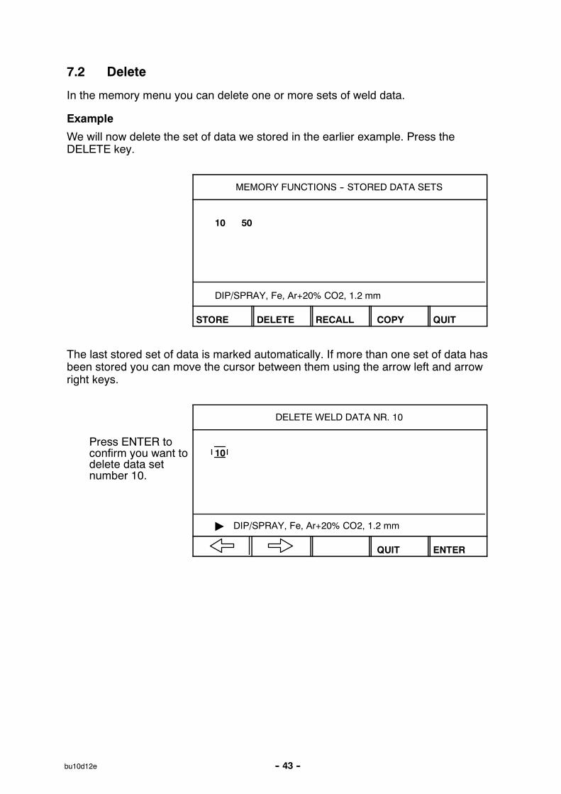
7.2 Delete
In the memory menu you can delete one or more sets of weld data.
Example
We will now delete the set of data we stored in the earlier example. Press theDELETE key.
MEMORY FUNCTIONS -- STORED DATA SETS
10 50
DIP/SPRAY, Fe, Ar+20% CO2, 1.2 mm
STORE DELETE RECALL COPY QUIT
The last stored set of data is marked automatically. If more than one set of data hasbeen stored you can move the cursor between them using the arrow left and arrowright keys.
DELETE WELD DATA NR. 10
Press ENTER toconfirm you want todelete data setnumber 10.
10
" DIP/SPRAY, Fe, Ar+20% CO2, 1.2 mm
QUIT ENTER

-- 44 --bu10d12e
7.3 Recall
To recall a previously stored set of data; first check that the memory menu isdisplayed. Press the RECALL key.
MEMORY FUNCTIONS -- STORED DATA SETS
10
STORE DELETE RECALL COPY QUIT
Example
The last stored set of data is marked automatically. If there is more than one set ofdata you can move the cursor between them using the arrow left and arrow rightkeys.
RECALL WELD DATA NR. 10
Press ENTER toconfirm that youwant to recall dataset number 10.
10
" DIP/SPRAY, Fe, Ar+20% CO2, 1.2 mm
QUIT ENTER
Return to the memory menu by pressing the QUIT key.
7.4 Copy
You can copy the contents of a previously stored set of data into another memorylocation. Start by pressing the COPY key.
MEMORY FUNCTIONS -- STORED DATA SETS
10
DIP/SPRAY, Fe, Ar+20% CO2, 1.2 mm
STORE DELETE RECALL COPY QUIT

-- 45 --bu10d12e
Example
The last stored set of data is marked automatically. If more than one set of data hasbeen stored you can move the cursor between them using the arrow left and arrowright keys. We will now copy the contents of memory location 10 into location 50.
Use either of the plus/minus keys to mark the memory location you want to copy to.
COPY WELD DATA NR. 10 TILL NR. 50
Scroll forward tonumber 50 usingthe plus key andENTER.
10
" DIP/SPRAY,Fe, Ar+20% CO2, 1.2 mm
QUIT ENTER
The weld data in location 10 has now been copied to memory location 50.
If memory location 50 was already occupied a message appears in the display.
STORE OVER EXISTING WELD DATA ?
10 50
" DIP/SPRAY,Fe, Ar+20% CO2, 1.2 mm
NO YES
Press the QUIT key to return to the memory menu.

-- 46 --bu10d12e
7.5 Remote control
To start, we call up the main menu by pressing the MENU key. Then select themeasure menu by pressing the MEASURE key.
DIP/SPRAY, Fe, Ar+8%CO2, 1.2 mm
From the measuremenu you can switch tooperating theequipment by remotecontrol by pressing the“Remote“ key.There are four differentremote control devices:
22,5 Volt134 Amp6,0 m/min
REM
Digital remote control
The digital remote control is used when you want to recall weld data settings fromthe weld data memory without using the standard controller.
S Aristo Control 5--program.This remote control lets you recall 5 different sets of weld data settings frommemory. You save them in memories 1--5.You can also adjust the voltage for the welding program you have recalled.
Analogue remote control
With an analogue remote control you can control the primary parameters of thewelding process from a unit other than the standard controller.
S Aristo Control Synergic PAE 2.With this remote control you can increase/decrease the wire feed speed andvoltage either side of the synergic line you have chosen.
S Esab PSF welding torch with 2 knobs.This welding torch has 2 knobs that allow you to increase/decrease the wire feedspeed and voltage either side of the synergic line you have chosen. It is alsopossible to adjust these during welding.
S Esab PSF welding torch with 3 programs.This welding torch has a three position key.The key lets you recall 3 different sets of weld data settings from memory, forexample for root beads and filler beads. It is also possible to change weldingprogram during welding.
7.5.1 Configuring a remote control
See step 9.2.3.

-- 47 --bu10d12e
8 FAST MODE
8.1 Description of fast mode
If you have stored one or more sets of weld data in the weld data memory you canmake one or more of them (maximum of four) available through the FAST MODEkey in the main menu.
ESAB LUD 450
PROCESS: MIG/MAGMETHOD: DIP/SPRAYWIRE TYPE: FeSHIELDING GAS: Ar+8%CO2WIRE DIMENSION: 1.2 mmAUXILIARY FUNCTIONS "
SET MEASURE MEMORYFASTMODE ENTER
When you press the fast mode key the display may appear like this.
DIP/SPRAY, Fe,Ar+20% CO2, 1.2 mm
22,5 Volt134 Amp6,0 m/min
WELDDATA 1
WELDDATA 2
WELDDATA 3
WELDDATA 4
4STROKE
Four of the soft keys can be linked to their own sets of weld data in the weld datamemory. The fifth soft key is reserved for switching the gun trigger latch on and off(MIG/MAG and TIG).
8.2 Configuring the fast mode keys
See step 9.2.7.1.

Insert PC--card here
-- 48 --bu10d12e
9 AUXILIARY FUNCTIONS
9.1 Memory card operations
In order to use the memory card functions you mustfirst install the PC card.
1. Turn off the power to the welding machine
2. Insert the PC card
3. Turn on the power
4. Press auxiliary functions, ENTER
5. Press memory card operation, ENTER
The following display appears:
MEMORY CARD OPERATIONS
WELD DATA SETS
STORE DELETE RECALL QUIT
STOREThis is used to save weld data settings (in memory locations 1--99) to the PC cardusing the controller.If the same weld data is already stored on the card it will be written over by the datain the controller’s own memory.
Exempel
The weld datasettings in thecontroller are.
The PCcardis empty
PC cardSetting control
1 2 3 10 12 50
PC card
1 2 3 10 12 50
Press STORE.The weld data settings from the controller are nowstored on the PC card

-- 49 --bu10d12e
DELETEUse this if you want to delete the contents of the PC card memory (all weld datasettings).
Example
The weld data settings on the PC card are:
PC--card
1 2 3 10 12 50
Press DELETE. The PC card’s memory isnow empty.
PC--card
RECALLThis is used to copy weld data settings from the PC card to the controller.If a weld data setting is already stored in the controller’s own memory it will bewritten over by the settings stored on the PC card.
Example
Press RECALL.
PC--cardSetting control
1 2 3 10 12 50 2 3 4 5 6
Setting control
1 2 3 4 5 610 12 50
The controller now has 3 new sets of weld datasettings (4, 5, 6) and sets 2 and 3 have beenupdated with the settings that were stored on thePC card.
Error codes
If the controller detects an error in the PC card you will see an error code that brieflydescribes the error in question.
Check the following:
S That the PC card is properly installed.
S That the PC card is not of an unknown or unapproved make.
S That the data stored on the card is compatible with the software in the controller.
S That the PC card has the correct version number and is using the correct format.

-- 50 --bu10d12e
9.2 Configuration
9.2.1 Language
See step 1.3.
9.2.2 Lock function
MAIN MENU
AUXILIARY FUNCTIONS
CONFIGURATION
LOCK FUNCTION
Sometimes you may want to restrict access to certain controller functions to preventsomeone else from changing important parameters or settings.When the password function is active and the measure, (remote control) or fastmode menus are selected, a password is requested whenever you try to return tothe main menu by pressing the QUIT or MENU keys.Normally the equipment starts up in one of these three menus when you first switchit on, and the only way to exit in order to go to other memories is to give the rightpassword.
LOCK FUNCTION
LOCK STATUS OFFSET/CHANGE LOCK CODE
QUIT ENTER
In PASSWORD MODE the password function can be switched off without deletingthe existing password. If you try to switch on the password function when nopassword is stored, the display shows a computer--like “keyboard“ which you canuse to enter a new password.
When you activate the password a small icon of a key appears on the first line of thedisplay to show that the password function is activated. You can then move freelybetween the menus until you go into the measure menu or fast mode menu, whichtrigger the password function and prevent the user from exiting these menus withoutfirst entering the password.
In ENTER/CHANGE PASSWORD you can edit the existing password or enter a newone.The password can consist of up to any10 letters or numbers.

-- 51 --bu10d12e
Deactivating password function
When you are in the measure menu or fast mode menu with the password functiondeactivated, you can exit these menus at any time by pressing QUIT or the MENUkey to get back to the main menu.If the lock function is active and you try to exit, the following message will bedisplayed to warn the user about the password protection.
PRESS ENTER TOLOCK CODE
From here you can choose QUIT if you change your mind and want to go back to theprevious menu, or continue by pressing ENTER to input the password.This will take you to the keyboard display so that you can type in the password andconfirm it by pressing the enter key on the keyboard.
If the password is incorrect, you will see an error message that gives the user theoption of trying again or going back to the original menu, i.e. the measure menu orfast mode menu.
If the password is correct, all restrictions on moving to another menu will be lifted,but the password function will still remain active, this means that you can leave themeasure/fast mode menus temporarily, but when you go back to them the passwordwill be activated again.
If you want to make changes outside the measure/fast mode menus (e.g. changesettings, deactivate password function, etc.) you can return to them and passwordmode and reactivate the password to restrict the user to the measure/fast modemenus again.

BINARY CODED5--PROG
-- 52 --bu10d12e
9.2.3 Remote controls
MAIN MENU
AUXILIARY FUNCTIONS
CONFIGURATION
REMOTE CONTROLS
All remote control configurations apply to any wire feed unit that is connected.If you deselect ANALOG1 this will affect both wire feed units if you are using twinwire feed units.
MIG/MAG--REMOTE CONTROLS
FORGET OVERRIDE ENABLEDDIGITAL OP: 5--PROGANALOG 1: NONEANALOG 2: NONE
QUIT ENTER
Move the cursor to the line FORGET CHANGE, and press ENTER to display a list ofoptions.
The forget change function in “on“ mode means you always have access to theoriginal weld data in the selected memory location when you come to the end of aweld.In other words, if you have made a change to a synergic line, for example increasedthe voltage by 2 V, when you finish the current weld that change will be cancelledand the original data will be recalled.This is useful when testing new welding parameters, for example.
Configuring a digital remote control
When using a digital remote control you must specify the type of device that is used;a 5--program device or 32--program device (BINARY CODED).If you position the cursor on the line DIGITAL OP and press ENTER you will see alist of the available options.
NONEVOLTAGE
NONEWIRE SPEED
-- 53 --bu10d12e
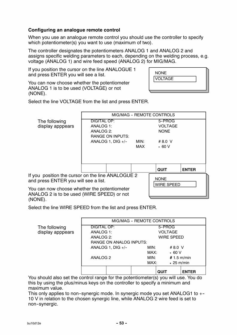
Configuring an analogue remote control
When you use an analogue remote control you should use the controller to specifywhich potentiometer(s) you want to use (maximum of two).
The controller designates the potentiometers ANALOG 1 and ANALOG 2 andassigns specific welding parameters to each, depending on the welding process, e.g.voltage (ANALOG 1) and wire feed speed (ANALOG 2) for MIG/MAG.
If you position the cursor on the line ANALOGUE 1and press ENTER you will see a list.
You can now choose whether the potentiometerANALOG 1 is to be used (VOLTAGE) or not(NONE).
Select the line VOLTAGE from the list and press ENTER.
MIG/MAG -- REMOTE CONTROLS
The followingdisplay apppears
DIGITAL OP: 5--PROGANALOG 1: VOLTAGEANALOG 2: NONERANGE ON INPUTS:ANALOG 1, DIG +/-- MIN: # 8.0 V
MAX * 60 V
QUIT ENTERIf you position the cursor on the line ANALOGUE 2and press ENTER you will see a list.
You can now choose whether the potentiometerANALOG 2 is to be used (WIRE SPEED) or not(NONE).
Select the line WIRE SPEED from the list and press ENTER.
MIG/MAG -- REMOTE CONTROLS
The followingdisplay apppears
DIGITAL OP: 5--PROGANALOG 1: VOLTAGEANALOG 2: WIRE SPEEDRANGE ON ANALOG INPUTS:ANALOG 1, DIG +/-- MIN: # 8.0 V
MAX: * 60 VANALOG 2 MIN: # 1.5 m/min
MAX: * 25 m/min
QUIT ENTERYou should also set the control range for the potentiometer(s) you will use. You dothis by using the plus/minus keys on the controller to specify a minimum andmaximum value.This only applies to non--synergic mode. In synergic mode you set ANALOG1 to +--10 V in relation to the chosen synergic line, while ANALOG 2 wire feed is set tonon--synergic.

4--STROKE2--STROKE
-- 54 --bu10d12e
9.2.4 MIG/MAG defaults
MAIN MENU
AUXILIARY FUNCTIONS
CONFIGURATION
MIG/MAG DEFAULTS
9.2.4.1 Trigger functions
CONFIGURATION--MIG/MAG DEFAULTS
Use the arrow keysto select the lineGUN TRIGGERMODE.Press ENTER todisplay the list ofoptions.
GUN TRIGGER MODE: 4--STROKESOFT KEYS SETUP:VOLT. MEASURE IN PULSED: AVERAGE
QUIT ENTER
Position the cursor on the line for 2--STROKEin the list and press ENTER. We have now set theGUN TRIGGER MODE = 2--STROKE (trigger latch off).
CONFIGURATION--MIG/MAG DEFAULTS
GUN TRIGGER MODE: 2--STROKESOFT KEYS SETUP:VOLT. MEASURE IN PULSED: AVERAGE
AVBRYT ENTER
-- 55 --bu10d12e
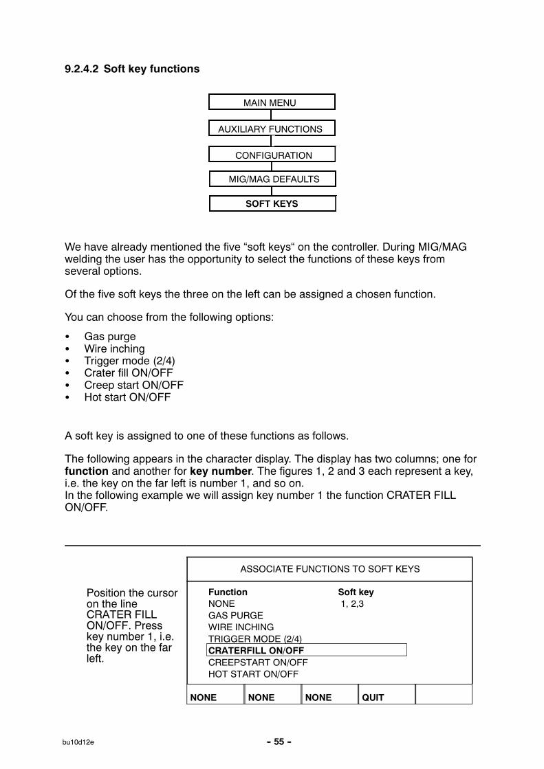
9.2.4.2 Soft key functions
MAIN MENU
AUXILIARY FUNCTIONS
CONFIGURATION
MIG/MAG DEFAULTS
SOFT KEYS
We have already mentioned the five “soft keys“ on the controller. During MIG/MAGwelding the user has the opportunity to select the functions of these keys fromseveral options.
Of the five soft keys the three on the left can be assigned a chosen function.
You can choose from the following options:
S Gas purgeS Wire inchingS Trigger mode (2/4)S Crater fill ON/OFFS Creep start ON/OFFS Hot start ON/OFF
A soft key is assigned to one of these functions as follows.
The following appears in the character display. The display has two columns; one forfunction and another for key number. The figures 1, 2 and 3 each represent a key,i.e. the key on the far left is number 1, and so on.In the following example we will assign key number 1 the function CRATER FILLON/OFF.
ASSOCIATE FUNCTIONS TO SOFT KEYS
Position the cursoron the lineCRATER FILLON/OFF. Presskey number 1, i.e.the key on the farleft.
Function Soft keyNONE 1, 2,3GAS PURGEWIRE INCHINGTRIGGER MODE (2/4)CRATERFILL ON/OFFCREEPSTART ON/OFFHOT START ON/OFF
NONE NONE NONE QUIT

-- 56 --bu10d12e
The display shows that key number 1 has now been assigned the function CRATERFILL ON/OFF. The number 1 has moved down to the line CRATER FILL ON/OFFand at the bottom of the display you can see the key caption CRATERFILL for theleft hand key.
ASSOCIATE FUNCTIONS TO SOFT KEYS
Function Soft keyNONE 2,3GAS PURGEWIRE INCHINGTRIGGER MODE (2/4)CRATERFILL ON/OFF 1CREEPSTART ON/OFFHOT START ON/OFF
CRATRFILL NONE NONE QUIT
The other two keys can each be assigned a function in the same way by matchingone of the functions in the left column with a key number in the right column.
If you want to assign a new function to a key, move the cursor to the line NONEand press the soft key you want to assign the function to. The display will show thekey text NONE, and this can now be reassigned a new function.
9.2.4.3 Voltage measurement for dip
MAIN MENU
AUXILIARY FUNCTIONS
CONFIGURATION
MIG/MAG DEFAULTS
VOLTAGE MEASUR. DIP
The voltage measurement options for dip welding are as follows:--average pulse voltage.--average overall voltage.
Average pulse voltageThe voltage is only measured during pulses and is filtered before displaying thevoltage value.
Average overall voltageThe voltage is measured continuously and is filtered before displaying the voltagevalue.
The measured values that are displayed are used as input data for internal andexternal quality functions.

-- 57 --bu10d12e
9.2.5 MMA defaults
Function intended for future use.
9.2.6 TIG defaults
Function intended for future use.
9.2.7 General defaults
9.2.7.1 Fast set--up limits
MAIN MENU
AUXILIARY FUNCTIONS
CONFIGURATION
GENERAL DEFAULTS
FAST MODE LIMITS
To configure a soft key for fast mode, proceed as described below.
GENERAL DEFAULTS -- FAST MODE
Position the cursoron the line for keynumber.
SOFT KEY NUMBER: 1
VOLTAGE: + 0.0 V-- 0.0 V
WIRE SPEED: + 0.0 m/min-- 0.0 m/min
ASSOCIATED WELD DATA: 16DIP/SPRAY, Fe, aR+20%CO2, 1.2 mm
QUIT
The keys are numbered 1--4 from left to right. Choose the desired key by selectingits number using the plus/minus keys.
Then scroll down with the arrow down key onto the line “ASSOCIATED WELDDATA“. Here you can browse through the sets of weld data that are stored in theweld data memory. Choose the desired weld data number using the plus/minus keys.
When you recall a set of weld data using the fast mode key you still have the optionof adjusting the available welding parameters. If you want to restrict the range ofadjustment for these parameters you can set uper and lower limits for eachparameter.

-- 58 --bu10d12e
The following welding parameters can be adjusted:
S for MIG/MAGS Wire feed speed
andS Voltage
S for MMAS Welding current
S for TIGS Welding current
S for Arc air gougingS Voltage
To set the limits for parameter adjustment do as follows.
For each parameter you specify a plus value (uper limit) and a minus value (lowerlimit) using the original weld data setting as a reference point.
GENERAL DEFAULTS -- FASTMODE
Position the cursoron the line for thechosen parameter,e.g. VOLTAGE.
SOFT KEY NUMBER: 1
VOLTAGE: # + 0.0 V* -- 0.0 V
WIRE SPEED: # + 0.0 m/min* -- 0.0 m/min
ASSOCIATED WELD DATA: 16DIP/SPRAY, Fe, aR 20%CO2, 1.2 mm
QUIT
Specify the desired value for the uper and lower limits using the plus/minus keys.
9.2.7.2 Twin start signals
CONFIGURATION -- GENERAL DEFAULTS
FAST MODE LIMITSDOUBLE START SOURCES OFF
QUIT ENTER
This option allows you to start the MIG/MAG wire feed unit from the TIG card(universal).It also enables the TIG torch to be started from the wire feed unit.This function can be used for mechanised applications.

-- 59 --bu10d12e
9.2.8 Multiple wire feed units
MAIN MENU
AUXILIARY FUNCTIONS
CONFIGURATION
MULTIPLE WIRE FEEDERS
All new wire feed units are delivered to the customer with the identity number 0.The first thing you need to do is change the ID number (node address) of one of thewire feed units (this only applies to multiple wire feed units).
AUXILIARY FUNCTIONS -- CONFIGURATION
Move the cursor tothe line for multiplewire feed units,press ENTER
LANGUAGE: ENGLISHLOCK FUNCTION:REMOTE CONTROLSMIG/MAG DEFAULTS.MMA DEFAULTS.TIG DEFAULTS.GENERAL DEFAULTS.MULTIPLA WIRE FEEDERS
QUIT ENTER
Change the ID number as follows:First connect a new wire feed unit, go to the “MULTIPLE WIRE FEED UNITS“ menuand press the torch trigger to activate the wire feed unit, then read the ID number ofthe wire feed unit from the top line (should be 0 first time). Now select a new IDnumber between 0--3.

-- 60 --bu10d12e
MULTIPLE WIRE FEEDERS
Move the cursor to theline CHOOSE NEW IDNUMBER. Set therequired numberbetween 0--3 bystepping with theplus/minus keys. PressENTER.
CURRENT ID NUMBERSELECT A NEW ID NUMBER 0
CONNECTED WIRE FEEDERS ID
QUIT ENTER
The ID number on the top line will change to the chosen number.
Now connect the next wire feed unit and press the torch trigger to activate this unit.This wire feed unit will probably have an ID number of 0 as well.
Configuration is now complete and you can start using the equipment as normal.It is now also possible to configure and run four different wire feed units in the sameway.It does not matter which ID number you assign to each wire feed unit, but it isimportant that you give each one a different ID number to distinguish between them.
If you accidentally give two wire feed units the same ID number then error message15 will be displayed continuously.If this happens you should disconnect one of the wire feed units and repeat theabove procedure.You can always return to the configuration display and check the ID numbers of theconnected wire feed units by pressing the torch trigger.
The line CONNECTED WIRE FEED IDs shows the ID numbers of all the wire feedunits connected.
9.2.9 Multipla wire feeders
Weld data can be individually assigned to each wire feed unit. To assign data to awire feed unit it must first be active. When it is active you can recall data as normal(see memory use in section 7) and make any adjustments. These will be assigned tothe active wire feed unit.For the next wire feed unit you again press the torch trigger to make this feed unitactive, then recall the data you want to assign to this feed unit.You can assign any weld data number you want to any wire feed unit you choose.
9.2.10 Multipla wire feeders
Remote control units control the wire feed units they are connected to. The digital5--program remote control recalls data from various memory locations depending onits ID number.The wire feed unit with ID number 0 recalls weld data from locations 1--5The wire feed unit with ID number 1 recalls weld data from locations 11--15The wire feed unit with ID number 2 recalls weld data from locations 21--25The wire feed unit with ID number 3 recalls weld data from locations 31--35
All limits that are set in fast mode and the remote control configuration menu apply toall wire feed units.

-- 61 --bu10d12e
9.3 Quality functions
MAIN MENU
AUXILIARY FUNCTIONS
QUALITY FUNCTIONS
The quality functions keep track of a range of useful data about individual welds.These functions are:
Time of weld startHow long the weld tookMean, maximum and minimum current for weldMean, maximum and minimum voltage for weldMean, maximum and minimum power for weld
You can also key in the length of the joint manually and the weld data unit willcalculate the heat input.
The number of welds made since the last reset is also displayed. Information on upto 100 different welds can be stored. The weld must take longer than 4.0 seconds inorder to register.
The last recorded weld is shown on the display, but you can also scroll through allthe other recorded welds.When you press RESET, all the variables are zeroed.
QUALITY FUNCTIONS
WELD 1 START: 01--JUN--97 12:00.02WELD TIME: 0.0sW LENGTH 0 cm HEAT INPUT 0.0kJ/cm
AVE. MAX MINI(Amp) 0.00 0.00 0.00U(V) 0.00 0.00 0.00P(kW) 0.00 0.00 0.00NUMBER OF WELDS SINCE LAST RESET: 0
RESET QUIT
You can choose a particular weld by scrolling up or down using or to
position the cursor on the line that shows the chosen weld.
You can enter the length of the weld in the appropriate field to obtain the heat inputin the same way.

-- 62 --bu10d12e
9.4 Production statistics
MAIN MENU
AUXILIARY FUNCTIONS
PRODUCTIONS STATISTIC
The production statistics keep track of the total arc time, the total mass of wire usedand the number of welds made since the last reset. They also record the arc timeand the amount of wire used during the last weld. For additional reference thedisplay also tells you what value of mass per length the wire consumption is basedon, and when the last restart took place.
The weld count does not increase if the arc time is less than 4 seconds. For thisreason the wire consumption is not displayed for welds this short. However, the wireconsumption and time for such welds are both included in the total figures for wireconsumption and arc time.
When you press RESET, all the counters are reset to zero and the last reset displayshows the current date and time.
PRODUCTION STATISTICS
LAST WELD TOTALARCTIME 181 min 24s 0sCONSUMED WIRE 0g 0gBASED ON 0.09g/mNUMBER OF WELD 0
LAST RESET 01--JUN--97 12:00.02
RESET QUIT

-- 63 --bu10d12e
9.5 Error log
MAIN MENU
AUXILIARY FUNCTIONS
ERROR LOG
All faults that occur while the welding equipment is in use are recorded as errormessages in the error log. Up to 99 error messages can be stored. If the error logbecomes full, i.e. if 99 error messages have been saved, then the oldest errormessage is automatically deleted when the next fault occurs.
12" Date Time Unit Error
970422 15:52,24 CBOX 18Lost contact with wire feeder970422 16:54.04 CBOX 12Lost contact with power source970423 09:14,33 PSOURCE 6High temperature
DELETEDELETEALL
VIEWTOTAL QUIT
9.5.1 Deleting error messages
If you want to delete error messages there are two options, each with their own key.
S Delete marked messages
S Delete all messages
9.5.2 Reviewing errors
By pressing the VIEW TOTAL key you can view all the recorded error messages inthe error log. You can also see the date and time of the most recent recorded errormessage.
ERROR LOG -- TOTAL LISTING
TOTAL ERROR MESSAGES: 12
OLDEST ERROR: 970417, 11:09,11
LATEST ERROR: 970429, 13:04,45
QUIT

-- 64 --bu10d12e
9.5.3 Error messages
This is a list of the error messages that may appear.
1 CBOXPSOURCEWFEED
Checksum control failed in EPROM:Program memory error -- Testonly carried out on start--up when power is switched on. This errordoes not override any functions.
2 CBOXPSOURCEWFEED
RAM test failed in microprocessor:Error in microprocessor’s inter-nal RAM -- Test only carried out on start--up when power is switchedon. This error does not override any functions.
3 CBOX Failed external RAM test:Test only carried out on start--up whenpower is switched on. This error does not override any functions.
4 CBOXPSOURCEWFEED
Drop down in 5V supply line:Computer supply voltage has droppedfor some reason. May occur if machine is switched off, but may alsobe due to fault in voltage supply to card.
5 PSOURCE DC voltage outside limit:DC voltage from rectifier is either too highor too low, possibly as a result of mains voltage spikes or low mainsvoltage. The inverter is automatically shut down immediately and pow-er is only restored when the voltage drops below the limit.
6 PSOURCE High temperature:The temperature of the welding power source istoo high, possibly as a result of overloading, a defective cooling fan orsome other component fault.
7 PSOURCE High primary current:The inverter is drawing too much current fromthe rectifier that supplies it. The inverter is automatically shut downimmediately and power is only restored when the problem has beencorrected.
8 CBOXPSOURCEWFEED
DC voltage 1 outside safe limits:CBOX: Battery voltage is too low.PSOURCE: The internal +15VC supply is either too high or too low.WFEED: The internal +15V supply is either too high or too low.
9 PSOURCEWFEED
DC voltage 2 outside safe limits:PSOURCE: The internal +15Vsupply is either too high or too low.WFEED: The internal +20V supply is either too high or too low.
10 PSOURCE DC voltage 3 outside safe limitsThe internal +15VB supply is either too high or too low.
11 PSOURCEWFEED
Servo error: PSOURCE: The current servo cannot supply the currentdemanded by the microprocessor. There is a persistent difference be-tween the shunt response and the set current.WFEDD: The wire feed servo is unable to provide the wire feed speeddemanded by the microprocessor.
12 CBOXPSOURCEWFEED
Warning state in bus interface: The bus circuit error count hasreached a value that triggers the error message. If the error countcontinues to rise the bus circuit is switched to the “bus--off“ state andcontact with the weld data unit (controller) is broken.
14 CBOX Bus off state -- communication breakdown: The bus circuit errorcount has reached a value that switches it to the “bus--off“ state. Thepower must be turned off and on again to reset.
15 CBOXPSOURCEWFEED
Message lost in bus communication: The bus circuit detects that amessage has been lost because a later message has been writtenover it.This error does not override any fun.
17 CBOX Lost contact with wire feeder: An identification message is used tokeep an ongoing check that a certain unit is still in the network. Thismessage appears if there is no response within the “Time out“. Thestop command is immediately sent to the power source.
18 CBOX Lost contact with power source: An identification message is usedto keep an ongoing check that a certain unit is still in the network. Thismessage appears if there is no response within the “Time out“. Thestop command is immediately sent to the wire feeder.
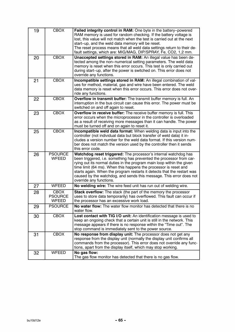
-- 65 --bu10d12e
19 CBOX Failed integrity control in RAM: One byte in the battery--poweredRAM memory is used for random checking. If the battery voltage islost, this value will not match when the test is carried out at the nextstart--up, and the weld data memory will be reset.The reset process means that all weld data settings return to their de-fault settings, which are: MIG/MAG, DIP/SPRAY, Fe, CO2, 1,2 mm.
20 CBOX Unaccepted settings stored in RAM: An illegal value has been de-tected among the non--numerical setting parameters. The weld datamemory is reset when this error occurs. This test is only carried outduring start--up, after the power is switched on. This error does notoverride any functions.
21 CBOX Incompatible settings stored in RAM: An illegal combination of val-ues for method, material, gas and wire have been entered. The welddata memory is reset when this error occurs. This error does not over-ride any functions.
22 CBOX Overflow in transmit buffer: The transmit buffer memory is full. Aninterruption in the bus circuit can cause this error. The power must beswitched on and off again to reset.
23 CBOX Overflow in receive buffer: The receive buffer memory is full. Thiserror occurs when the microprocessor in the controller is overloadedas a result of receiving more messages than it can handle. The powermust be turned off and on again to reset it.
25 CBOX Incompatible weld data format: When welding data is input into thecontroller (not individual data but block transfer of weld data) it in-cludes a version number for the weld data format. If this version num-ber does not match the version used by the controller then it sendsthis error code.
26 PSOURCEWFEED
Watchdog reset triggered: The processor’s internal watchdog hasbeen triggered, i.e. something has prevented the processor from car-rying out its normal duties in the program main loop within the giventime limit (64 ms). When this happens the processor is reset andstarts again. When the program restarts it detects that the restart wascaused by the watchdog, and sends this message. This error does notoverride any functions.
27 WFEED No welding wire: The wire feed unit has run out of welding wire.
28 CBOXPSOURCEWFEED
Stack overflow: The stack (the part of the memory the processoruses to store data temporarily) has overflowed. This fault can occur ifthe processor has an excessive work load.
29 PSOURCE No water flow: The water flow monitor has detected that there is nowater flow.
30 CBOX Lost contact with TIG I/O unit: An identification message is used tokeep an ongoing check that a certain unit is still in the network. Thismessage appears if there is no response within the “Time out“. Thestop command is immediately sent to the power source.
31 CBOX No response from display unit: The processor does not get anyresponse from the display unit (normally the display unit confirms allcommands from the processor). This error does not override any func-tions, apart from the display itself, which may stop working.
32 WFEED No gas flow:The gas flow monitor has detected that there is no gas flow.

-- 66 --bu10d12e
9.6 User--defined synergic lines for MIG/MAG
MAIN MENU
AUXILIARY FUNCTIONS
USER DEFINED SYN. DATA
It is possible to create user--defined synergic lines that relate the wire feed speed tothe voltage. A maximum of ten such synergic lines can be saved.Creating a new synergic line is done in two stages.
1. Define the new synergic line by specifying a number of voltage--wire feed speedcoordinates, see steps A--D in the following diagram.
Voltage
Wire feed
AB
CD
2. Specify which wire--gas combination the new synergic line will apply to.
9.6.1 Specify feed speed--voltage coordinates
To create a new synergic line for dip/spray welding you need four coordinates, whilefor pulse welding you need two coordinates. These coordinates must then be savedunder special weld data numbers in the weld data memory.
Do as follows:
1. Call up the main menu and choose the MIG/MAG method (dip/spray or pulse)that you intend to use with the new synergic line.
2. Key in the desired values of voltage and wire feed speed for the first coordinate.
3. Call up the memory menu and save the first coordinate as weld data number 96.
S The four coordinates for a dip/spray synergic line must be saved as numbers96, 97, 98 and 99.In addition:
S each weld data number must contain higher values of voltage and wirefeed speed than the weld data number that precedes it.
S the parameters inductance, regulatortype and hot start voltage musthave the same values in all four weld data numbers.
S The two coordinates for a pulse welding line must be saved as numbers 96and 97. In addition:

-- 67 --bu10d12e
S the higher weld data number must contain higher values of voltage, wirefeed speed, pulse frequency, pulse amplitude and background currentthan the weld data number that precedes it.
S the parameters pulse time, hot start voltage, Ka, Ki and the Slopeparameters must have the same values in both weld data numbers.
S Crater fill data must be saved as weld data number 96(for both methods, dip/spray and pulse)
4. Define the number of coordinates that are needed, then move on to “Specifyingthe relevant wire--gas combination“.
9.6.2 Specifying the relevant gas--wire combination
Do as follows:
1. Set up the display to handle user--defined synergic lines.
MAIN MENU
AUXILIARY FUNCTIONS
USER DEFINED SYN. DATA
MAKE CUSTOMISED SYNERGIC LINES
Position the cursoron the line WIRETYPE and pressENTER.
WIRE TYPE: FeSHIELDING GAS: Ar+20%CO2WIRE DIMENSION: 1.2 mm
STORE NEW LINE FROMWELD DATA MEMORY 96, 97, 98, 99
DELETE SYNERGIC LINE
QUIT ENTER
Choose an option from the list displayed (mark the option and press ENTER).2. Now choose a shielding gas and the wire diameter in the same way.3. Mark the line STORE NEW LINE.... and press ENTER.The process is now complete - a new synergic line has been defined.
NOTE!
If you want to use the crater fill function when pulse welding then there must be acorresponding synergic line for dip/spray welding since all crater fill data is based ondip/spray parameters.
When you create a new synergic line for pulse welding you will therefore always bewarned if a corresponding line has not been created for dip/spray welding.
WARNING!
No corresponding synergic line
for dip/spray welding

CO2Ar+20 % CO2
Ar+2 % O2Ar+5 % O2+5 % CO2
Ar+8 % CO2Ar+23 % CO2--------------
-- 68 --bu10d12e
9.6.3 Creating user--defined wire/gas options.
The list of wire and gas options can be extended to include up to 10 user--definedoptions. At the bottom of each list is an empty line (------). By placing the cursor onthis line and pressing ENTER you gain access to a “keyboard“ that allows you totype in your own options.
The controller “keyboard“ is used as follows:
S Position the cursor over the chosen keyboard character using the arrow keys.Press the soft key “PRESS KEY“.Type in a string of text of up to 20 characters in this way.
S Mark the “keyboard’s“ ENTER key () and press the soft key “PRESS KEY“, andthe name of your user--defined option will appear in the list.
Deleting a user--defined gas/wire option:
Mark the user--defined wire or gas option in the current list.
MAKE CUSTOMISED SYNERGIC LINES
Press the DELETEkey
WIRE TYPE: FeSHIELDING GAS: Ar+20%CO2WIRE DIMENSION: 1.2 mm
STORE NEW LINE FROMWELD DATA MEMORY 96, 97, 98, 99
DELETE SYNERGIC LINE
DELETE QUIT ENTER
A user--defined wire or gas option cannot be deleted if it forms part of a set of welddata that is currently in the working memory.

-- 69 --bu10d12e
9.6.4 Deleting a user--defined synergic line
A user--defined synergic line can be deleted if it is not active, i.e. if it is not part of aset of weld data that is currently in the working memory.
MAKE CUSTOMISED SYNERGIC LINES
Position the cursoron the line DELETESYNERGIC LINE.Press ENTER.
WIRE TYPE: FeSHIELDING GAS: Ar+20%CO2WIRE DIMENSION: 1.2 mm
STORE NEW LINE FROMWELD DATA MEMORY 96, 97
DELETE SYNERGIC LINE
QUIT ENTER
The display will change. By using the NEXT key you can scroll through theuser--defined synergic lines that have been saved.
MAKE CUSTOMISED SYNERGIC LINES
Scroll to the line youwant to delete andpress the DELETEkey.
CHOOSE SYNERGIC LINE TO BE DELETED
" PULSE, Ss duplex, Ar, 1.4 mm
NEXT DELETE QUIT
9.7 Serial communication
Function intended for future use.

-- 70 --bu10d12e
9.8 Upgrading software
MAIN MENU
AUXILIARY FUNCTIONS
UPGR. SOFTWARE
Applications
This function can be used to upgrade the software in the controller, power sourceand wire feed unit from a PC card.
SOFTWARE UPGRADE
Unit Curr..ver PC--card
1.00B1.12
1.50B2.00A
1.31F
POWER SOURCE
WIRE FEED UNIT
WELD DATA UNIT
SYSTEM VERSIONBOOT SOFTWARE
1.50A
1.31E
2.00A
QUITUPGRADENOW
Current version Describes which version of the program is currently usedby this unit.
PC card Describes which version of the program is stored on thePC card of this unit.
? A unit is present but the computer does not know whichversion it uses.
-- There is no program for this unit on the PC card.
System version Indicates which set of programs is stored on the PCcard. A set of programs can consist of 1--4 programs (1for each unit).
Boot program Program which controls installation of the upgrade.
Power source Circuit board for controlling welding power source.
Wire feed unit Circuit board for controlling wire feed unit.
Weld data unit Circuit board in controller.

-- 71 --bu10d12e
How to upgrade:
Select the unit(s) that require upgrading by moving the cursor to the relevant linesand marking ( ) them. When you have marked all those to be upgraded, press“UPGRADE“ and confirm by pressing “yes“ to start the upgrade process.
SOFTWARE UPGRADE
Move the cursor tothe line for the unit tobe upgraded.
Unit Curr.ver PC--card
1.00B1.12
1.50B2.00A
1.31F
POWER SOURCE
WIRE FEED UNIT
WELD DATA UNIT
SYSTEM VERSIONBOOT SOFTWARE
1.50A
1.31E
2.00A
QUITUPGRADENOW
S Then press the first key to select the unit (shown by a tick).By pressing the key again you can deselect the marked unit (tick disappears).If there are any other units to be upgraded, mark them in the same way.
SOFTWARE UPGRADE
Press YES toupgrade. Upgradingmay take up to 5min.
Unit Curr.ver PC--card
THE SOFTWARE UPGRADING CAN TAKE UP TO 5MINUTES AND CANNOT BE INTERRUPTED.
DO YOU STILL WANT TO DO IT?
NO YES

-- 72 --bu10d12e
The following dialogue box will be displayed during upgrading.
SOFTWARE UPGRADE
DO NOT SWITCH OFF THE EQUIPMENT DURING THISPROCESS!!
UPGRADING POWER SOURCE.......23% Compl.
When upgrading is complete the display will appear as follows.
SOFTWARE UPGRADE
SUCCESSFUL UPGRADEYOU MAY NOW RESTART THE EQUIPMENT
The selected units have now been upgraded.In order to use the welding equipment the welding power source must first berestarted.
S Turn the power switch on the welding power source to position 0.
S Then turn the power switch to position 1.
WARNING! Make sure the power supply to the welding power source is notinterrupted during upgrading. If this happens during an early stage ofupgrading you should call ESAB’s service engineers.

-- 73 --bu10d12e
10 APPENDIX
10.1 Setting ranges and setting steps
MIG/MAG
Parameter Setting range Setting steps
Wire feed speed 1.5--25.0 m/min 0.1 m/min
Voltage 8.0--60.0 V 0.25 V
Inductance 0--100 % 1 %
Pulse current 100--600 A 4 A
Pulse time 1,7 -- 25,5 ms 0.1 ms
Pulse frequency 20 -- 312 Hz 2 Hz
Background current 12--300 A 4 A
Slope time 1--9 1
Ka 0--100 % 1 %
Ki 0--100 % 1 %
Gas pre--flow time 0.0--25.0 s 0.1 s
Gas post--flow time 0.0--25.0 s 0.1 s
Burnback time 0.00--1.00 s 0.01 s
Hot start time 0.0--10.0 s 0.1 s
Wire feed speed, Hot start 0.0--20.0 m/min 0.1 m/min
Voltage increase, Hot start 0.0--60.0 V 0.25 V
Crate fill time 0.0--10.0 s 0.1 s
Final wire feed speed, Crater fill 1.5--25.0 m/min 0.1 m/min
Final voltage, Crater fill 8.0--60.0 V 0.25 V
Shake--off pulse 10--120 % 1 %
Regulator type Type number 1--12 --
The parameters in italics are not available in synergic mode.
The parameter control type does not have a true setting range. In MIG/MAGwelding you can choose from twelve different control types numbered 1--12.
MMA
Parameter Setting range Setting step
Welding current 16--320 A (Aristo 320)16--450 A (Aristo 450)
1 A1 A
Arc force 0--100 % 1 %
The parameters in italics are not available in synergic mode.

-- 74 --bu10d12e
TIG
Parameter Setting range Setting step
Current, Pulse current, Backgroundcurrent
4--320 A (Aristo 320)4--450 A (Aristo 450)
4 A4 A
Pulse time 0.001--5.000 s 0.001 s
Background time 0.001--5.000 s 0.001 s
Slope--up time 0.0--25.0 s 0.1 s
Slope--down time 0.0--25.0 s 0.1 s
Gas pre--flow time 0.0--25.0 s 0.1 s
Gas post--flow time 0.0--25.0 s 0.1 s
Arc air gouging
Parameter Setting range Setting step
Voltage 8.0--60.0 V 0.25 V
Inductance 0--100 % 1 %
Control type Type number 1, 2, 5 --
The parameters in italics are not available in sudowngic mode.
The parameter control type does not have a true setting range. In arc air gougingyou can choose from three different control types numbered 1, 2 and 5.

-- 75 --bu10d12e
10.2 Menu structure
MAIN MENU
SET MEASUREDVALUES
MEMORYHANDLING
FAST MODE AUXILIARYFUNCTIONS
STARTDATAMIG/MAG
STOP--DATAMIG/MAG
STORE ERASE RECALL COPY
MEMORYCARD
CONFIGU--RATION
Q FUNC-TIONS
PRODUC-TION STA-TISTICS
ERROR--LOG
USER--DE-FINED SYN-ERGY DATA
SERIALCOMMU-NICATION
(NOT USED)
LANGU-AGE
LOCKFUNCTION
REMOTECONTROLS
MIG/MAGDEFAULTS
MMADEFAULTS
TIGDEFAULTS
GENERALDEFAULTS
SOFTWAREUPGRADE
sid.4
sid.7 sid.39 sid.41 sid.47 sid.48
sid.12 sid.12
sid.41 sid.43 sid.44 sid.44
MULTIPLAWIRE FEE-DERS
sid.48 sid.50 sid.61 sid.62 sid.63 sid.66 sid.69 sid.70
sid.50 sid.50 sid.52 sid.54 sid.57 sid57 sid.57 sid.59

Esab Welding Equipment ABS--695 81 LAXÅSWEDENPhone +46 584 81 000Fax +46 584 123 08Tgm esablaxTelex 73108 esab s
Member of The Esab Group
980430
Group H.Q. International directory of subsidiary and associated companies.Agency network, by countries.
Group HeadquartersSWEDENEsab ABGothenburgTel: +46 31 50 90 00Fax: +46 31 50 92 61
ESAB International ABGothenburgTel: +46 31 50 90 00Fax: +46 31 50 93 60
Nordic CountriesDENMARKESAB A/SKöpenhavn--ValbyTel: +45 36 30 01 11Fax: +45 36 30 40 03
FINLANDEsab OyHelsinkiTel: +358 9 547 761Fax: +358 9 547 77 71
NORWAYAS EsabLarvikTel: +47 33 12 10 00Fax: +47 33 11 52 03
SWEDENEsab Sverige ABGothenburgTel: +46 31 50 95 00Fax: +46 31 50 92 22
Europe excl. Nordic CountriesAUSTRIAEsab Ges.m.b.HVienna--LiesingTel: +43 1 888 25 11Fax: +43 1 888 25 11 85
BELGIUMS.A. Esab N.V.BrusselsTel: +32 2 745 11 00Fax: +32 2 726 80 05
THE CZECH REPUBLICESAB s.r.o.Tel: +420 2 819 40 885Fax: +420 2 819 40 120
FRANCEEsab France S.A.Cergy Pontoise CedexTel: +33 1 30 75 55 00Fax: +33 1 30 75 55 24
GERMANYESAB GmbHSolingenTel: +49 212 298 0Fax: +49 212 298 204
ESAB--Hancock GmbHKarbenTel: +49 6039 400Fax: +49 6039 40 301
KEBE--Ersatzteile GmbHRosbachTel: +49 6007 500Fax: +49 6007 1216
GREAT BRITAINEsab Group (UK) LtdWaltham CrossTel: +44 1992 76 85 15Fax: +44 1992 71 58 03
ESAB Automation LtdAndoverTel: +44 1264 33 22 33Fax: +44 1264 33 20 74
HUNGARYESAB KftBudapestTel: +36 1 20 44 182Fax: +36 1 20 44 186
ITALYEsab Saldatura S.p.A.Mesero (Mi)Tel: +39 2 97 96 81Fax: +39 2 97 28 91 81
THE NETHERLANDSEsab Nederland B.V.UtrechtTel: +31 30 248 59 22Fax: +31 30 248 52 60
POLANDESABOddzial w PolsceTel: +48 22 813 99 63Fax: +48 22 813 98 81
PORTUGALESAB LdaLisbon CodexTel: +351 1 837 1527Fax: +351 1 859 1277
SLOVAKIAESAB Slovakia s.r.o.BratislavaTel: +421 7 429 23 71Fax: +421 7 288 741
SPAINEsab Ibérica S.A.Alcobendas (Madrid)Tel: +34 91 661 55 80Fax: +34 91 661 23 13
SWITZERLANDESAB AGDietikonTel: +41 1 741 25 25Fax: +41 1 740 30 55
North and South AmericaBRAZILESAB S.A.Contagem--MGTel: +55 31 333 43 33Fax: +55 31 333 50 00
CANADAEsab Group CanadaMissisauga, OntarioTel: +1 905 670 02 20Fax: +1 905 670 48 79
USAEsab Welding & Cutting ProductsFlorence, SCTel: +1 803 669 44 11Fax: +1 803 664 42 58
Far EastAUSTRALIAESAB Australia Pty LtdErmingtonTel: +61 2 9647 1232Fax: +61 2 9748 1685
INDONESIAP.T. Esabindo PratamaJakartaTel: +62 21 460 01 88Fax: +62 21 461 29 29
MALAYSIAESAB (Malaysia) Snd BhdPetaling JayaTel: +60 3 703 36 51Fax: +60 3 703 35 52
SINGAPOREESAB Singapore PTE LtdSingaporeTel: +65 861 43 22Fax: +65 861 31 95
Esab Asia/Pacific Pte Ltd.SingaporeTel: +65 861 74 42Fax: +65 863 08 39
THAILANDESAB (Thailand) LtdBangkokTel: +66 2 393 60 62Fax: +66 2 748 71 11
U.A.E.ESAB Middle EastDubaiTel: +971 4 38 88 29Fax: +971 4 38 87 29
Associated companiesINDIAESAB India LtdCalcuttaTel: +91 33 478 45 17Fax: +91 33 468 18 80
SWEDENGas Control Equipment ABMalmöTel: +46 40 38 83 00Fax: +46 40 38 83 30
Representative officesALGERIAESAB Bureau de LiaisonAlgerTel: +213 2 67 24 93Fax: +213 2 68 32 90
BULGARIAINTESASofiaTel: +359 2 980 17 15Fax: +359 2 980 08 42
CHINAESAB Representative OfficeBeijingTel: +86 10 6410 6493Fax: +86 10 6410 6530
EGYPTESAB EgyptDokki--CairoTel: +20 2 390 96 69Fax: +20 2 393 32 13
IRANESAB International ABTeheranTel: +98 21 884 39 14Fax: +98 21 884 13 36
ROMANIAESAB Representative OfficeBucharestTel: +40 1 211 75 02
RUSSIA--CISESAB Representative OfficeMoscowTel: +7 095 9379 820Fax: +7 095 2468 906
AgentsEUROPECyprus, Greece, Malta
AFRICAAngola, Cameron, Ethiopia,Gabon, Ghana, Kenya, Israel,Liberia, Morocco, Mocambique,Nigeria, Senegal, South Africa,Tanzania, Togo, Tunisia,Zambia, Zimbabwe
ASIABahrain, Hongkong, Japan,Jordania, Korea, Kuwait,Lebanon, New Guinea, Oman,Pakistan, The Philippines,Quatar, Saudi Arabia,Sri Lanka, Syria, Taiwan,Turkey, Vietnam, Yemen
LATIN AMERICAArgentina, Bolivia, Chile,Colombia, Costa Rica, Curacao,Equador, El Salvador,Guatemala, Honduras, Jamaica,Paraguay, Peru, Trinidad,Uruguay, Venezuela