sae mini baja: suspension and steering steering angles inside wheel turns at greater angle than...
TRANSCRIPT
SAE Mini Baja: Suspension and Steering
Zane Cross, Kyle Egan, Nick Garry, Trevor Hochhaus
Design Selection and Analysis
November 19, 2014NAU

Overview● Recap of Suspension and Steering Designs● Suspension Analysis● Steering Analysis● Conclusion
Trevor Hochhaus2
Recap● Front Suspension
○ Double A Arms
● Rear Suspension○ Double A Arms
● Steering○ Back Mounted
3 Kyle Egan
Suspension Analysis-Final Design
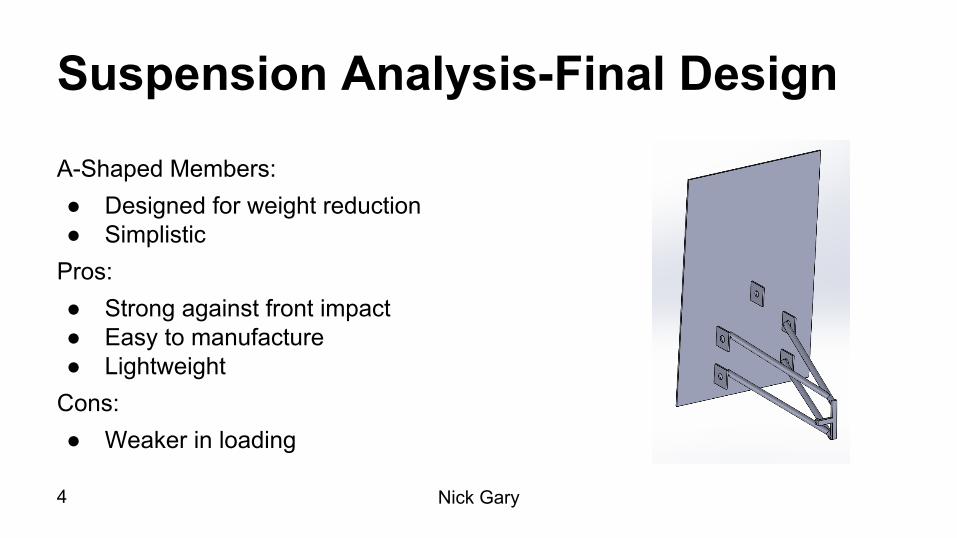
A-Shaped Members:● Designed for weight reduction● Simplistic
Pros:● Strong against front impact● Easy to manufacture● Lightweight
Cons:● Weaker in loading
Nick Gary4
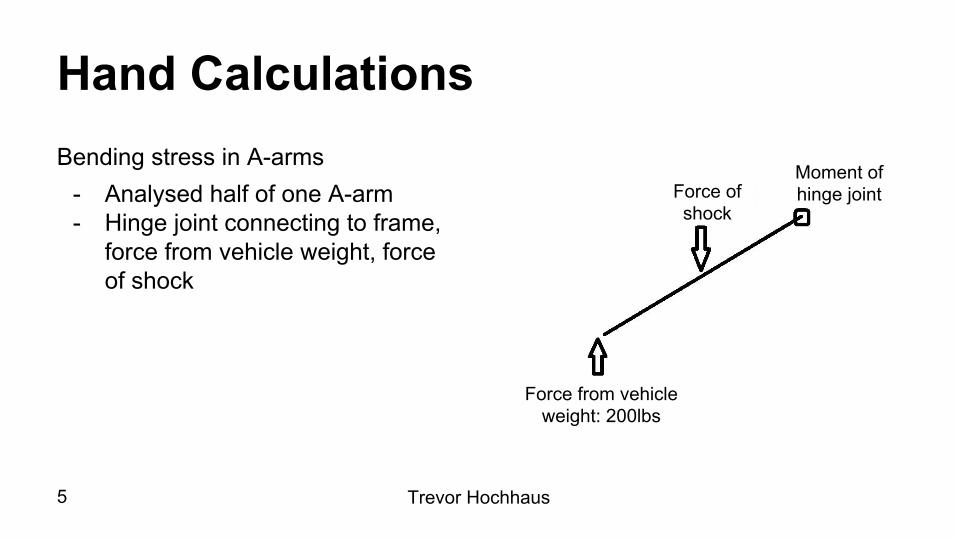
Hand CalculationsBending stress in A-arms
- Analysed half of one A-arm- Hinge joint connecting to frame,
force from vehicle weight, force of shock
Moment of hinge jointForce of
shock
Force from vehicle weight: 200lbs
Trevor Hochhaus5

Hand Calculations Cont.Moment around hinge:Force of shock= 325.83lbf
Sum of forces in Y direction:Force of hinge Y dir=51.85lbf
Sum of forces in X direction:Force of hinge X dir=124.66lbf
Half forces due to symmetric geometry:
Force of shock= 162.92lbfForce of hinge Y dir= 25.93lbfForce of hinge X dir= 62.33lbf
Trevor Hochhaus6

Hand Calculations Cont.
Max Moment = 337.04 lb-in
Trevor Hochhaus7

Hand Calculations Cont.M= 337.04lb-in = 36ksi for Structural A36d=0.8D
Output:D=.78in, d=.624in
FOS of 2:D=.98in, d=.78in
Trevor Hochhaus8

Shock Placement● After performing dynamic analysis on the suspension design, the forces
experienced by the members can be greatly mitigated by mounting the shock as close as possible to the wheel hub.
● There are physical limitations on how close to the hub the shocks can get, such as: extended length of the shocks, desired ride height, and potential interference.
9 Nick Gary
Stress Analysis● Axial loading of the members is going to be ignored, because stresses
caused by bending will far exceed them.● The member the shock mounts to will experience the largest force in the
system, so it will fail first.● The bolts for the members will also be a mode of failure when the
suspension receives a front or side impact. The shear stress on the bolts will be calculated using the axial loading on the members.
Nick Gary10
Stress Analysis- Front ImpactSituation:● 25 mph impact on one tire● Simulates the car suddenly hitting an object, like a tree or rock, and
coming to a full stop● The chosen material is 4130 steel with a OD of 1.25in and an ID of 1.15in● The load was applied to the end of one A arm, with the a arm fixed to
where it would mount to the chassis
11
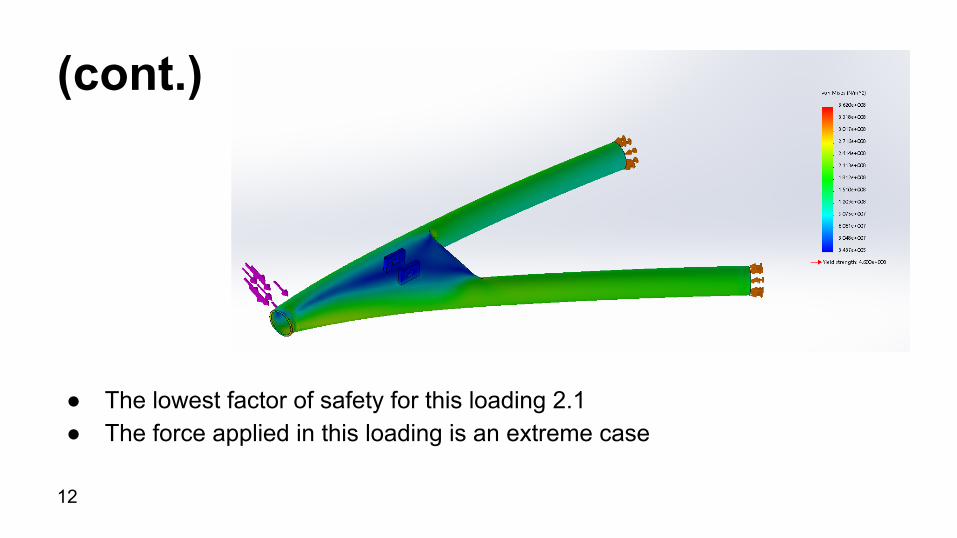
(cont.)
● The lowest factor of safety for this loading 2.1 ● The force applied in this loading is an extreme case
12
Stress Analysis-Vertical LoadingSituation:● The car jumps off a surface from 3 ft and lands crooked on only one wheel● Same material and dimensions as the previous design scenario ● The load is applied vertically to the end of the A arm as well as axially ● The A arm is pinned at the shock mount and the chassis mount
13
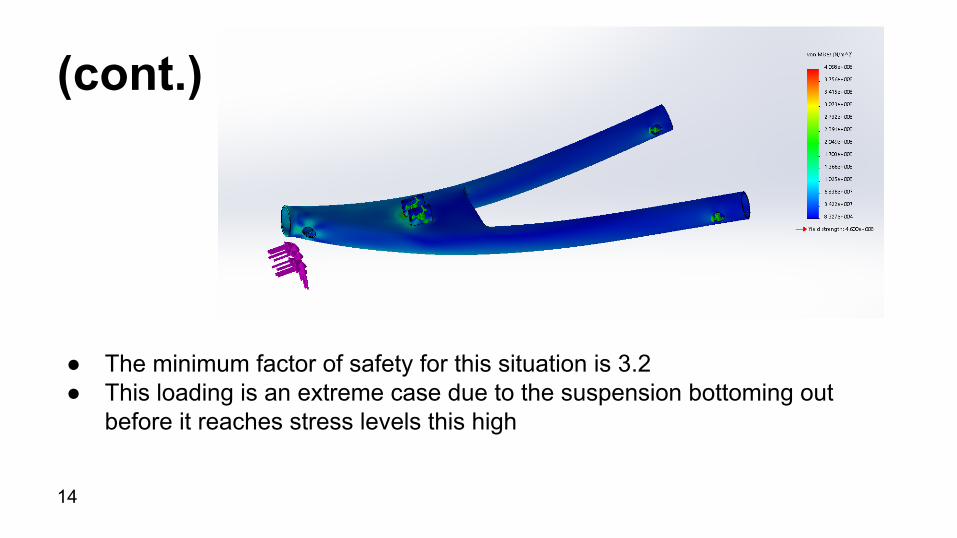
(cont.)
● The minimum factor of safety for this situation is 3.2● This loading is an extreme case due to the suspension bottoming out
before it reaches stress levels this high
14
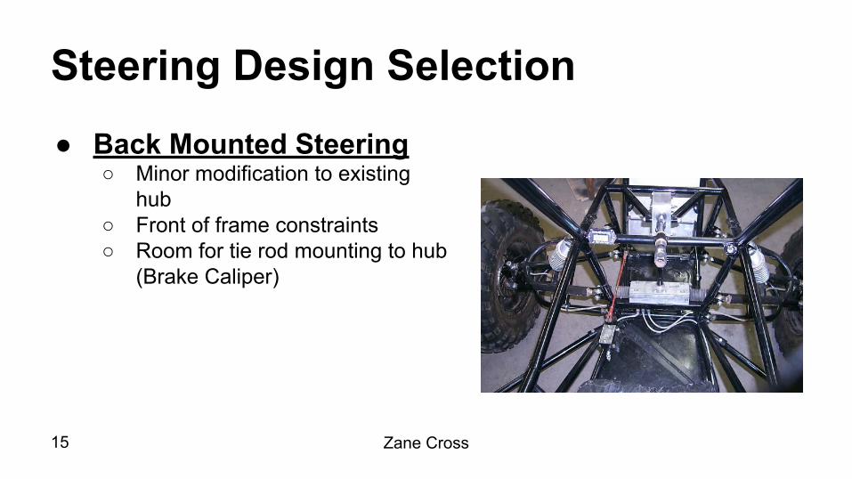
Steering Design Selection ● Back Mounted Steering
○ Minor modification to existing hub
○ Front of frame constraints○ Room for tie rod mounting to hub
(Brake Caliper)
15 Zane Cross

Steering Analysis - Akerman Angles ● Ackerman Steering Angles
○ Inside wheel turns at greater angle than outside wheel
○ Determine max angle of both tires such that a U-turn can be achieved within a width of 2 lanes (144 in)
16 Zane Cross
Inside Tire Maximum Angle Outside Tire Maximum Angle

Ackerman Angles Calculations
17 Zane Cross
● Track Width = W = 49 in● Wheelbase = L = 65 in● Mid-Radius = R(1) = 155.5 in
After inputting variables into formula and solving……
Max Turning Angles
● Inside Tire = 35.54 Degrees● Outside Tire = 24.90 Degrees
Turning Radius
● 9.63 ft
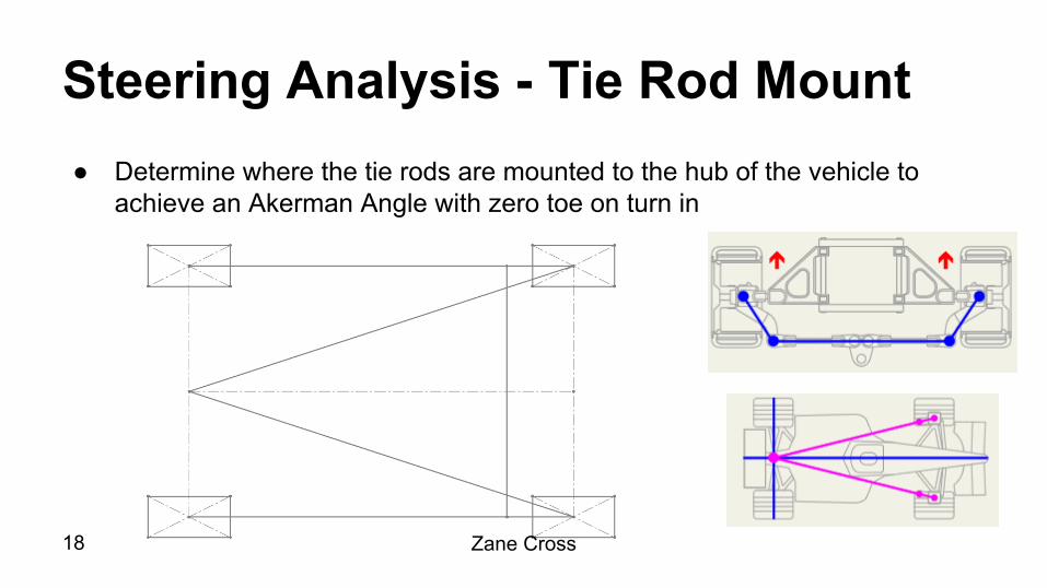
Steering Analysis - Tie Rod Mount ● Determine where the tie rods are mounted to the hub of the vehicle to
achieve an Akerman Angle with zero toe on turn in
18 Zane Cross

Tie Rod Mount Calculations● Through the use of similar
triangles…..
19

Steering Analysis - Steering Ratios● Determine the ratio of the rack to pinion
to give the right amount of assist in the steering system
● 1:2 Steering Quickener currently installed
● Remove steering quickener to regain 12:1 steering ratio of original steering rack
20 Zane Cross

Steering Analysis - Tie Rod Force ● Determine axial force tie rod encounters when
hitting an obstacle and coming to a complete stopSituation
● Velocity of Vehicle is 20 mph ● After hitting obstacle, vehicle comes to a
complete stop in 0.5 sec
Solution● = 1,269.86 lbf
21
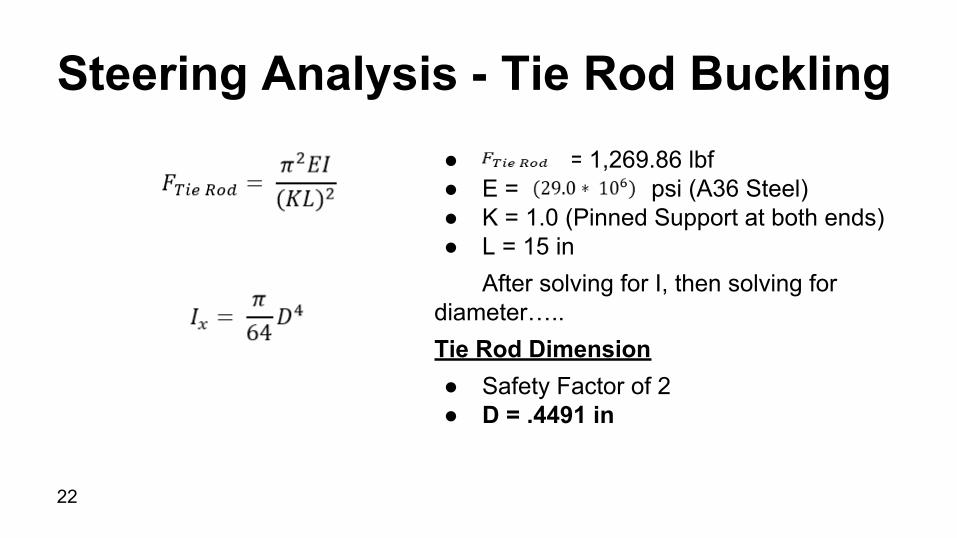
Steering Analysis - Tie Rod Buckling● = 1,269.86 lbf● E = psi (A36 Steel)● K = 1.0 (Pinned Support at both ends)● L = 15 in
After solving for I, then solving for diameter…..Tie Rod Dimension● Safety Factor of 2● D = .4491 in
22

Final Assembly Front Isometric View Back Isometric View
23

Conclusion● Front Suspension
○ Double A-Arm○ Material chosen is 4130 steel with a OD of 1.25in and an ID of 1.15in
● Steering○ Back Mounted Steering ○ D = .4491 in
Trevor Hochhaus24

References● www.lostjeeps.com● brenthelindustries.com● www.ultimatecarpage.com● tortoracer.blogspot.com● www.mech.utah.edu● www.cougar-racing.com● http://forum.kerbalspaceprogram.com/threads/42596-Rover-Steering-to-use-Ackerman-Principle● http://www.idsc.ethz.ch/Courses/vehicle_dynamics_and_design/11_0_0_Steering_Theroy.pdf● http://www.rctek.com/technical/handling/ackerman_steering_principle.html● www.desertkarts.com● R. Hibbeler, Mechanics of Materials, Upper Saddle River : Pearson Prentice Hall, 2011.
25